SERVICE MANUAL - My Generator...2 3 5 6 1 8 7 9 9 9 9 9 0 0 0 q e t y u i o p f d g h j k l; z x c s...
178
SERVICE MANUAL EF7000 EF7000E EF7200 EF7200E EF7200DE 7P6-F8197-E0
Transcript of SERVICE MANUAL - My Generator...2 3 5 6 1 8 7 9 9 9 9 9 0 0 0 q e t y u i o p f d g h j k l; z x c s...

SERVICE MANUAL
EF7000EF7000E
EF7200EF7200E
EF7200DE
7P6-F8197-E0
2014_05×1 !
7P6-F8197-E0_cover.indd 1 2014/05/29 15:46:41

2
3
5
6
1
8
7
9
99
9
9
00
0
q
e
t
y
iu
o
p
f
d
g
h
j
k
l
;z
x
c
s
a
w
4
r
1Generator
2Rotorassembly
3Exciterfieldcoil
4Subcoil
5Maincoil
6Statorassembly
7Controlbox
8Voltage/hourmeter
9ACswitch(N.F.B.)
0ACreceptacle
qEngineswitch
wRectifier
eRemotecontrolterminal
rFuse
tRectifier/regulator
yVoltageadjuster
uCondenser
iAVR(AutomaticVoltage
Regulator)
oOilwarningunit
pEconomycontrolunit
aOilwarninglight
sEconomycontrolswitch
dEngine
fEconomycontrolsolenoid
gStarterrelay
hStartermotor
jAutochoke
kFuelcutsolenoidvalve
lBattery
;Chargingcoil
zTCIunit
xSparkplug
cOillevelswitch
Co
lor
cod
eBBlack
BrBrown
GGreen
LBlue
LgLightgreen
OOrange
RRed
WWhite
EF7200DE (CAN)2014 CIRCUIT DIAGRAM
YYellow
B/WBlack/White
G/RGreen/Red
G/YGreen/Yellow
L/RBlue/Red
L/WBlue/White
R/BRed/Black
R/GRed/Green
R/WRed/White
7P6-F8197-E0_cover.indd 2 2014/05/29 15:46:42
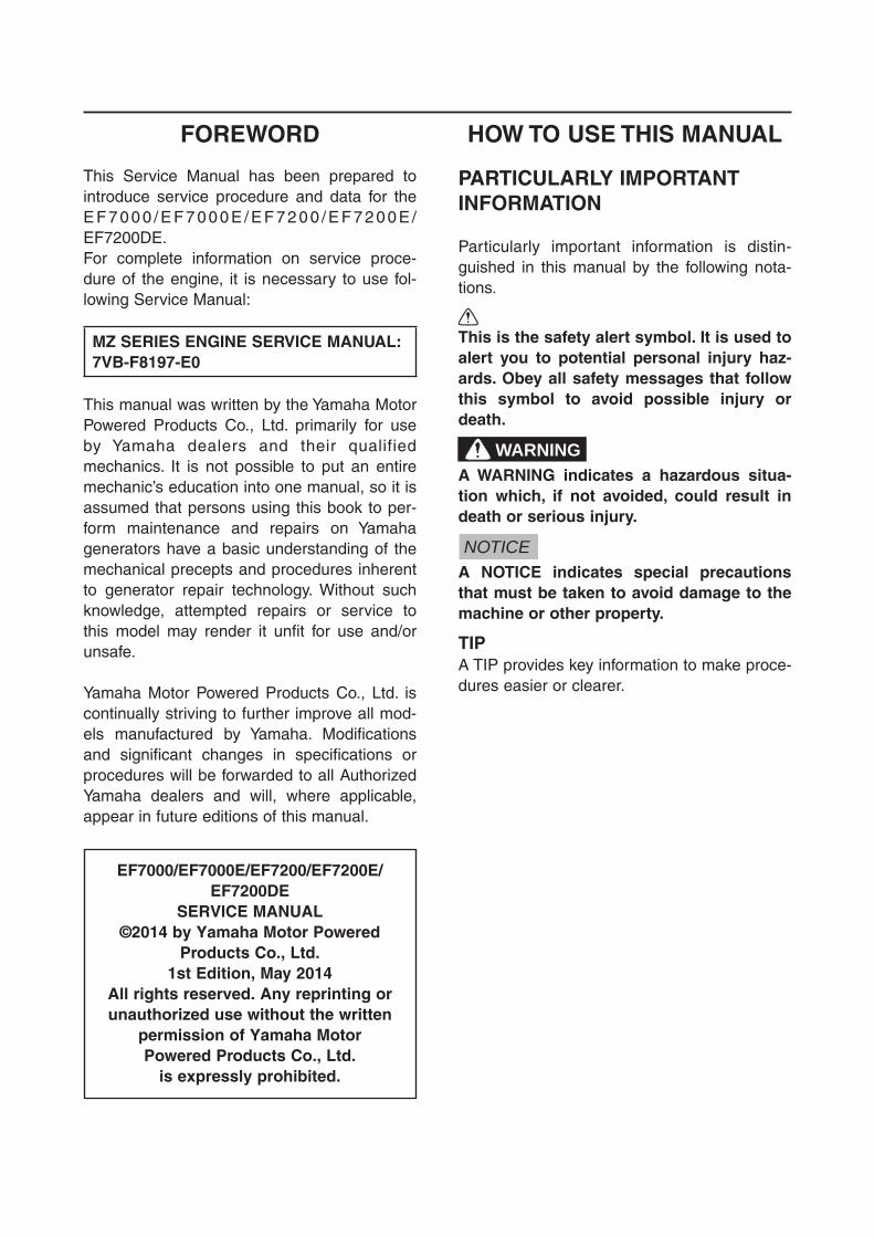
FOREWORD
This Service Manual has been prepared to introduce service procedure and data for the E F 7 0 0 0 / E F 7 0 0 0 E / E F 7 2 0 0 / E F 7 2 0 0 E /EF7200DE.For complete information on service proce-dure of the engine, it is necessary to use fol-lowing Service Manual:
MZ SERIES ENGINE SERVICE MANUAL:7VB-F8197-E0
This manual was written by the Yamaha Motor Powered Products Co., Ltd. primarily for use by Yamaha dealers and their qualified mechanics. It is not possible to put an entire mechanic’s education into one manual, so it is assumed that persons using this book to per-form maintenance and repairs on Yamaha generators have a basic understanding of the mechanical precepts and procedures inherent to generator repair technology. Without such knowledge, attempted repairs or service to this model may render it unfit for use and/or unsafe.
Yamaha Motor Powered Products Co., Ltd. is continually striving to further improve all mod-els manufactured by Yamaha. Modifications and significant changes in specifications or procedures will be forwarded to all Authorized Yamaha dealers and will, where applicable, appear in future editions of this manual.
EF7000/EF7000E/EF7200/EF7200E/EF7200DE
SERVICE MANUAL©2014 by Yamaha Motor Powered
Products Co., Ltd.1st Edition, May 2014
All rights reserved. Any reprinting orunauthorized use without the written
permission of Yamaha Motor Powered Products Co., Ltd.
is expressly prohibited.
HOW TO USE THIS MANUAL
PARTICULARLY IMPORTANT INFORMATION
Particularly important information is distin-guished in this manual by the following nota-tions.
This is the safety alert symbol. It is used to alert you to potential personal injury haz-ards. Obey all safety messages that follow this symbol to avoid possible injury or death.
WARNINGA WARNING indicates a hazardous situa-tion which, if not avoided, could result in death or serious injury.
NOTICEA NOTICE indicates special precautions that must be taken to avoid damage to the machine or other property.
TIPA TIP provides key information to make proce-dures easier or clearer.

HOW TO USE THIS MANUALThis manual is intended as a handy, easy-to-read reference book for the mechanic. Comprehensive explanations of all installation, removal, disassembly, assembly, repair and check procedures are laid out with the individual steps in sequential order.9 The manual is divided into chapters and each chapter is divided into sections. The current sec-
tion title is shown at the top of each page 1.9 Sub-section titles appear in smaller print than the section title 2.9 To help identify parts and clarify procedure steps, there are exploded diagrams at the start of
each removal and disassembly section 3.9 Numbers are given in the order of the jobs in the exploded diagram. A number indicates a dis-
assembly step 4.9 Symbols indicate parts to be lubricated or replaced 5. Refer to “ILLUSTRATED SYMBOLS”.9 A job instruction chart accompanies the exploded diagram, providing the order of jobs, names of
parts, notes in jobs, etc. 6. This step explains removal procedure only. For installation, reverse the steps.
9 Jobs requiring more information (such as special tools and technical data) are described sequentially 7.
3-20
ENGPISTON, CAMSHAFT, CRANKCASE, AND
CRANKSHAFT
1
2
3
34
5
6
7
7
8
9
10
20 Nm (2.0 m á kgf, 14 ft á lbf)
Order Job/Parts to remove Q’ty RemarksRemoving the piston, camshaft and crankshaft
Remove the parts in the order listed.
Crankcase Refer to “CRANKCASE” on 3-18.1 Balancer shaft 12 Camshaft 13 Valve lifter 24 Connecting rod cap 15 Crankshaft 16 Connecting rod 17 Piston pin circlip 28 Piston pin 19 Piston 110 Piston ring set 1
PISTON, CAMSHAFT AND CRANKSHAFT
3-21
ENGPISTON, CAMSHAFT, CRANKCASE, AND
CRANKSHAFT
REMOVING THE BALANCER SHAFT, CAMSHAFT, AND VALVE LIFTER 1. Remove:
9 Balancer shaft 1
TIPRemove the balancer shaft 1 when the bal-ancer shaft gear mark a and the crankshaft gear mark b are aligned.
2. Remove: 9 Camshaft 2
TIPRemove the camshaft 2 when the camshaft gear mark c and the crankshaft gear mark d are aligned.
3. Remove: 9 Intake valve lifter 9 Exhaust valve lifter
CHECKING THE BALANCER SHAFT 1. Check:
9 Balancer gear teeth 9 Balancer shaft Wear/damage → Replace.
21b
ac
d
1
3
4
5
6
7
2

ILLUSTRATED SYMBOLS(Refer to the illustration)
SYMBOL DEFINITION SYMBOL DEFINITION
General informationPeriodic checks and adjustments
Engine Carburetor
Electrical Troubleshooting
Specifications Filling fluid
Lubricant Special tool
T R..
Tightening torque Wear limit, clearance
Engine speed Electrical data
Replace the part with a new one. LS Lithium-soap base grease
M Molybdenum disulfide greaseE
Engine oil
MMolybdenum disulfide oil
LTApply locking agent (LOCTITE®)


INDEXGENERAL INFORMATION GEN
INFO
PERIODIC CHECKSAND ADJUSTMENTS CHK
ADJ
ENGINEENG
CARBURETOR
ELECTRICAL
TROUBLESHOOTING
CARB
ELEC
TRBL
SPECIFICATIONSSPEC
1
2
3
4
5
6
7

CHAPTER 1.GENERAL INFORMATION
MODEL VARIATIONS ................................1-1
MACHINE IDENTIFICATION .....................1-2SERIAL NUMBER ................................1-2
IMPORTANT INFORMATION ....................1-3PREPARATION FOR REMOVAL AND DISASSEMBLY CAUTION ON SERVICE ........................................1-3NOTES ON SERVICE...........................1-3ALL REPLACEMENT PARTS ...............1-4GASKETS, OIL SEALS, AND O-RINGS ...............................................1-4BEARINGS AND OIL SEALS ...............1-4
BASIC SERVICE INFORMATION ..............1-5ELECTRICAL SYSTEM ........................1-5
SPECIAL TOOLS AND TESTERS .............1-8
CHAPTER 2.PERIODIC CHECKS AND
ADJUSTMENTS
INTRODUCTION ........................................2-1
MAINTENANCE INTERVALS CHART ......2-1
PERIODIC MAINTENANCE/ LUBRICATION INTERVALS ......................2-1
PERIODIC MAINTENANCE ......................2-3SPARK PLUG .......................................2-3FUEL LEAKAGE ...................................2-5ENGINE OIL LEAKAGE .......................2-5ENGINE OIL LEVEL .............................2-5REPLACING THE ENGINE OIL ...........2-6AIR FILTER ELEMENT .........................2-7MUFFLER .............................................2-8FUEL TANK FILTER ............................2-10FUEL COCK STRAINER ....................2-11BREATHER HOSE..............................2-12CYLINDER HEAD DECARBONIZATION ..........................2-12ADJUSTING THE VALVE CLEARANCE ......................................2-12
ADJUSTING THE ENGINE SPEED (Except for EF7000/EF7200) ..............2-15ADJUSTING THE ENGINE SPEED (For EF7000/EF7200) .........................2-16RECOIL STARTER .............................2-17FITTINGS AND FASTENERS ............2-17
CHAPTER 3.ENGINE
CONTROL BOX .........................................3-1EF7200DE ............................................3-1Except for EF7200DE ...........................3-3INSTALLING THE CONTROL BOX ......3-5
AIR FILTER ................................................3-6
FUEL TANK, CANISTER ...........................3-7CHECKING THE CANISTER (For EF7200DE CAN) ...........................3-9
MUFFLER ................................................3-10INSTALLING THE MUFFLER .............3-11
ENGINE ....................................................3-12
GENERATOR ...........................................3-13REMOVING THE STATOR ASSEMBLY AND ROTOR ASSEMBLY .........................................3-15INSTALLING THE STATOR ASSEMBLY AND ROTOR ASSEMBLY .........................................3-17
PISTON, CAMSHAFT, CRANKCASE, AND CRANKSHAFT ................................3-18
CRANKCASE ......................................3-18PISTON, CAMSHAFT AND CRANKSHAFT ....................................3-20REMOVING THE BALANCER SHAFT, CAMSHAFT, AND VALVE LIFTER ................................................3-21CHECKING THE BALANCER SHAFT ................................................3-21INSTALLING THE VALVE LIFTER, BALANCER SHAFT, AND CAMSHAFT ........................................3-22INSTALLING THE CRANKCASE COVER ...............................................3-22

HANDLE AND WHEELS (FOR EF7200DE CAN) ............................3-23
INSTALLING THE HANDLE ................3-25INSTALLING THE WHEELS ...............3-28
CHAPTER 4.CARBURETOR
REMOVING THE CARBURETOR ..............4-1
DISASSEMBLING THE CARBURETOR ...4-3EF7000/EF7200 ....................................4-3EF7000E/EF7200E/EF7200DE ............4-5CHECKING THE FUEL CUT SOLENOID VALVE ................................4-7
CHAPTER 5.ELECTRICAL
ELECTRICAL COMPONENTS ..................5-1EF7000 (CHN) ......................................5-2EF7000E (CHN) ....................................5-2EF7200 (SEA/AFR/RUS) ......................5-2EF7200E (Except for OCE) ..................5-2EF7200E (OCE) ....................................5-3EF7200DE (Except for CAN) ................5-3EF7200DE (CAN) .................................5-3
CIRCUIT DIAGRAM ...................................5-4EF7000/EF7200 ....................................5-4EF7000E/EF7200E ...............................5-5EF7200DE (Except for CAN) ................5-6EF7200DE (CAN) .................................5-7
CONTROL PANEL .....................................5-8EF7000/EF7200 ....................................5-8EF7000E/EF7200E (Except for OCE) ................................5-10EF7200E (OCE) ..................................5-12EF7200DE (Except for CAN) ..............5-14EF7200DE (CAN) ...............................5-16
BATTERY (EF7000E/EF7200E/EF7200DE) ..............5-18
CHECKING AND CHARGING THE BATTERY ............................................5-19
FUSE (EF7000E/EF7200E/EF7200DE) ...5-26CHECKING THE FUSE ......................5-26
SWITCHES ...............................................5-28CHECKING THE SWITCH CONTINUITY .....................................5-28
IGNITION SYSTEM ..................................5-29TROUBLESHOOTING CHART ...........5-29
ELECTRIC STARTING SYSTEM (EF7000E/EF7200E/EF7200DE) ..............5-35
TROUBLESHOOTING CHART ...........5-35REMOVING THE STARTER MOTOR ...............................................5-37DISASSEMBLING THE STARTER MOTOR ...............................................5-38CHECKING THE BRUSH ...................5-39ASSEMBLING THE STARTER MOTOR ...............................................5-39
CHARGING SYSTEM (EF7000E/EF7200E/EF7200DE) ..............5-40
TROUBLESHOOTING CHART ...........5-40
GENERATOR SYSTEM ...........................5-43TROUBLESHOOTING CHART ...........5-43
ECONOMY CONTROL SYSTEM (EF7000E/EF7200E/EF7200DE) ..............5-54
ECONOMY CONTROL SOLENOID ...5-54INSTALLING THE ECONOMY CONTROL SOLENOID .......................5-55ECONOMY CONTROL SYSTEM DIAGRAM ...........................................5-56TROUBLESHOOTING CHART ...........5-57
CHAPTER 6.TROUBLESHOOTING
ENGINE ......................................................6-1
CHAPTER 7.SPECIFICATIONS
GENERAL SPECIFICATIONS ...................7-1
MAINTENANCE SPECIFICATIONS ..........7-4ENGINE ................................................7-4ELECTRICAL ........................................7-7GENERATOR ........................................7-8

TIGHTENING TORQUES .........................7-10
GENERAL TORQUE SPECIFICATIONS ....................................7-12
LUBRICATION POINTS AND TYPE OF LUBRICANTS ..........................................7-13
WIRE ROUTING DIAGRAM ....................7-14CONTROL PANEL AND CONTROL BOX (EF7000/EF7200) .......................7-14CONTROL PANEL AND CONTROL BOX (EF7000E/EF7200E) ..................7-16CONTROL PANEL AND CONTROL BOX (Except for EF7200DE CAN)......7-18CONTROL PANEL AND CONTROL BOX (For EF7200DE CAN) ................7-20BACK SIDE AND LEFT SIDE VIEW (For EF7200DE CAN) .........................7-22UPPER SIDE VIEW (EF7000E/EF7200E/EF7200DE) ........7-23UPPER SIDE VIEW (EF7000/EF7200) ...............................7-24ENGINE ..............................................7-25GENERATOR (EF7000/EF7000E/ EF7200/EF7200E) ..............................7-26GENERATOR (Except for EF7200DE CAN) ..............7-27GENERATOR (For EF7200DE CAN) .........................7-28
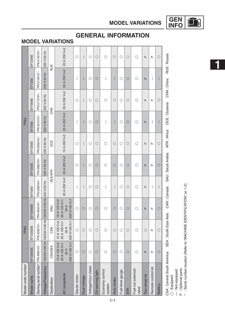
1-1
GENINFOMODEL VARIATIONS
GENERAL INFORMATIONMODEL VARIATIONS
Mod
el c
ode
num
ber
7P62
7P63
Mod
el n
ame
EF
7200
DE
EF
7200
DE
EF
7200
DE
EF
7200
EF
7200
EE
F72
00E
EF
7000
EF
7000
EE
F72
00E
F72
00E
Sta
rting
ser
ial n
umbe
r*7P
6-40
0010
1–7P
6-40
3010
1–7P
6-40
4010
1–7P
6-03
0010
1–7P
6-03
6010
1–7P
6-50
0010
1–7P
6-50
1010
1–7P
6-51
1010
1–7P
6-51
3010
1–7P
6-51
4010
1–
Vol
tage
/Fre
quen
cy12
0/24
0 V-
60 H
z12
0/24
0 V-
60 H
z12
0/24
0 V-
60 H
z22
0 V-
50 H
z22
0 V-
50 H
z23
0 V-
50 H
z22
0 V-
50 H
z22
0 V-
50 H
z22
0 V-
50 H
z22
0 V-
50 H
z
Des
tinat
ion
CS
A/S
EA
CA
NS
AU
SE
A/A
FR
OC
EC
HN
RU
S
AC
rec
epta
cle
15 A
125
V×
2 30
A 1
25 V
×1
30 A
25
0 V
/125
V×
1
15 A
125
V×
2 30
A 1
25 V
×1
30 A
25
0 V
/125
V×
1
15 A
125
V×
2 30
A 1
25 V
×1
30 A
25
0 V
/125
V×
1
20 A
250
V×
2 20
A 2
50 V
×2
15 A
250
V×
2 20
A 2
50 V
×2
20 A
250
V×
2 20
A 2
50 V
×2
20 A
250
V×
2
Sta
rter
mot
or3
33
—3
3—
3—
3
Dua
l vol
tage
33
3—
——
——
——
Vol
tage
/hou
r m
eter
33
33
33
33
33
Oil
war
ning
ligh
t3
33
33
33
33
3
Eco
nom
y co
ntro
l sy
stem
33
3—
33
—3
—3
Aut
o ch
oke
33
3—
33
—3
—3
Fue
l lev
el g
auge
33
33
33
33
33
AVR
33
33
33
33
33
Fue
l cut
sol
enoi
d va
lve
33
33
33
33
33
Two
whe
el k
itP
3P
PP
PP
PP
P
Rem
ote
cont
rol k
itP
PP
—P
P—
P—
P
Bat
tery
33
3—
33
—3
—3
CS
A :
Cen
tral
Sou
th A
mer
ica
S
EA
: S
outh
Eas
t Asi
a
CA
N :
Can
ada
S
AU
: S
audi
Ara
bia
A
FR
: A
fric
a
OC
E :
Oce
ania
C
HN
: C
hina
R
US
: R
ussi
a3
: E
quip
ped
— :
Not
equ
ippe
dP
: O
ptio
nal p
arts
* : S
eria
l num
ber
loca
tion
(Ref
er to
“M
AC
HIN
E ID
EN
TIF
ICAT
ION
” on
1-2)
1

1-2
GENINFOMACHINE IDENTIFICATION
MACHINE IDENTIFICATIONSERIAL NUMBERThe serial number is printed on the label 1
affixed to the position 2 of the generator as shown in the illustration.
A For EF7200DE CANB Except for EF7200DE CAN
TIP9 The first three digits identify the model, and
the remaining digits indicates the production number.
9 Designs and specifications are subject to change without notice.
12
1
2
A
B
1-3
GENINFOIMPORTANT INFORMATION
SVU1030
SVU1040
SVU1050
SVU1060
SVU1070
SVU1080
SVU1090
SVU1100
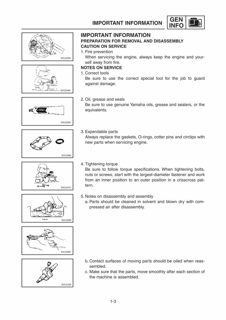
IMPORTANT INFORMATIONPREPARATION FOR REMOVAL AND DISASSEMBLY CAUTION ON SERVICE1. Fire prevention When servicing the engine, always keep the engine and your-
self away from fire.NOTES ON SERVICE1. Correct tools Be sure to use the correct special tool for the job to guard
against damage.
2. Oil, grease and seals Be sure to use genuine Yamaha oils, grease and sealers, or the
equivalents.
3. Expendable parts Always replace the gaskets, O-rings, cotter pins and circlips with
new parts when servicing engine.
4. Tightening torque Be sure to follow torque specifications. When tightening bolts,
nuts or screws, start with the largest-diameter fastener and work from an inner position to an outer position in a crisscross pat-tern.
5. Notes on disassembly and assembly a. Parts should be cleaned in solvent and blown dry with com-
pressed air after disassembly.
b. Contact surfaces of moving parts should be oiled when reas-sembled.
c. Make sure that the parts, move smoothly after each section of the machine is assembled.

1-4
GENINFOIMPORTANT INFORMATION
SVU1110
SVU1120
ALL REPLACEMENT PARTSWe recommend the use of genuine Yamaha parts for all replace-ments. Use oil and/or grease, recommended by Yamaha, for assembly and adjustment.
GASKETS, OIL SEALS, AND O-RINGS1. All gaskets, seals, and O-rings should be replaced when an
engine is overhauled. All gaskets surfaces, oil seal lips, and O-rings must be cleaned.
2. Properly oil all mating parts and bearings during reassembly. Apply grease to the oil seal lips.
BEARINGS AND OIL SEALSInstall the bearing(s) 1 and oil seal(s) 2 with their manufacture’s marks or numbers facing outward. (In other words, the stamped letters must be on the side exposed to view.) When installing oil seal(s), apply a light coating of lightweight lithium base grease to the seal lip(s). Oil the bearings liberally when installing.
NOTICEDo not use compressed air to spin the bearings dry. This causes damage to the bearing surfaces.

1-5
GENINFOBASIC SERVICE INFORMATION
BASIC SERVICE INFORMATIONELECTRICAL SYSTEMChecking the electrical system
TIPBefore checking the electrical system, make sure that the battery voltage is at least 12 V.
NOTICENever insert the tester probes into the coupler terminal slots. Always insert the probes from the opposite end a of the cou-pler, taking care not to loosen or damage the leads.
a
Checking the connectionsCheck the leads, couplers, and connectors for stains, rust, mois-ture, etc. 1. Disconnect:
9 Lead 9 Coupler 9 Connector
NOTICE9 When disconnecting a coupler, release the coupler lock,
hold both sections of the coupler securely, and then dis-connect the coupler.
9 There are many types of coupler locks; therefore, be sure to check the type of coupler lock before
disconnecting the coupler.
NOTICEWhen disconnecting a connector, do not pull the leads. Hold both sections of the connector securely, and then disconnect the connector.

1-6
GENINFOBASIC SERVICE INFORMATION
2. Check: 9 Lead 9 Coupler 9 Connector Moisture → Dry with an air blower. Rust/stains → Connect and disconnect several times.
3. Connect: 9 Lead 9 Coupler 9 Connector
TIP9 When connecting a coupler or connector, push both sections of
the coupler or connector together until they are connected securely.
9 Make sure all connections are tight.
4. Check: 9 Continuity (with the pocket tester)
Analog pocket tester: YU-03112-CPocket tester: 90890-03112
TIP9 If there is no continuity, clean the terminals.9 When checking the wire harness, perform steps (1) to (3).9 Make sure to check the connector and coupler of the TCI unit/
CDI unit when replacing the TCI unit/CDI unit.9 As a quick remedy, use a contact revitalizer available at most
part stores.

1-7
GENINFOBASIC SERVICE INFORMATION
NOTICEFor waterproof couplers, never insert the tester leads directly into the coupler. When performing any checks using a water-proof coupler, use the specified test harness or a suitable commercially available test harness.
5. Check: 9 Resistance
Analog pocket tester: YU-03112-CPocket tester: 90890-03112
TIPThe resistance values shown were obtained at the standard meas-uring temperature of 20 °C (68 °F). If the measuring temperature is not 20 °C (68 °F), the specified measuring conditions will be shown.
Intake air temperature sensor resistance: 5.40–6.60 kW at 0 °C (32 °F) 290–390 W at 80 °C (176 °F)

1-8
GENINFOSPECIAL TOOLS AND TESTERS
SVU1160
SPECIAL TOOLS AND TESTERSThe proper special tools are necessary for complete and accurate tune-up and assembly. Using the correct special tool will help pre-vent damage caused by the use of improper tools or improvised techniques.
TIP9 For U.S.A. and Canada, use part number starting with “YM-”,
“YU-”, or “ACC-”.9 For others, use part number starting with “90890-”.
1. Feeler gauge set P/N. YU-26900-9 Thickness gauge P/N. 90890-03180 This gauge is used to adjust valve clearance, piston clearance
and piston ring end gap.
2. Cylinder gauge Commercially obtainable This instrument is used for checking cylinder bore size and
condition.
3. Digital tachometer P/N. YU-39951-B, 90890-06760 This tool is needed for observing engine r/min.
4. Engine compression tester P/N. YU-33223 Compression gauge P/N. 90890-03081 This tool is used for checking engine compression.
5. Extension P/N. 90890-04082 This tool is used for checking engine compression.

1-9
GENINFOSPECIAL TOOLS AND TESTERS
ø9ø8 ø10
ø3 ø4
YM-A5970
9. Primary clutch holder P/N. YS-01880-A Sheave holder P/N. 90890-01701 This tool is necessary for holding the flywheel.
10. Six piece tappet set P/N. YM-A5970 Tappet adjusting tool P/N. 90890-01311 This tool is used to adjust the valve clearances.
90890-01311
3mm
SVU1220
11. Heavy duty puller P/N. YU-33270-B Flywheel puller P/N. 90890-01362 This tool is necessary for removing the flywheel.
SVU1230
7. Analog pocket tester P/N. YU-03112-C Pocket tester P/N. 90890-03112 This instrument is necessary for checking the electrical system.
8. Oppama pet-4000 spark checker P/N. YM-34487 Ignition checker P/N. 90890-06754 This instrument is necessary for checking the ignition system components.
SVU1190
6. Dial indicator gauge P/N. YU-A8428 Dial gauge P/N. 90890-03097 This instrument is used for checking crankshaft side clearance.

1-10
GENINFO
12. Valve spring compressor P/N. 90890-01253 This tool is used to remove the valve springs.
13. Piston ring compressor P/N. YM-08037, 90890-05158 This tool is used to compress the piston rings when installing
the piston.
SPECIAL TOOLS AND TESTERS
14. Rotor shock puller assy. P/N. YU-1047, 90890-01259 This tool is used to remove the rotor assembly.
15. Rotor puller attachment (M14 × P1.25) P/N. YU-1379, 90890-01379 This tool is used to remove the rotor assembly.
M14XP1.25

1-11
GENINFO

2-1
CHKADJ
INTRODUCTION/MAINTENANCE INTERVALS CHART/PERIODIC MAINTENANCE/LUBRICATION INTERVALS
PERIODIC CHECKS AND ADJUSTMENTS
INTRODUCTIONThis chapter includes all information necessary to perform recommended checks and adjustments. These preventive maintenance procedures, if followed, will ensure more reliable machine opera-tion and a longer service life. The need for costly overhaul work will be greatly reduced. This infor-mation applies to machines already in service as well as new machines that are being prepared for sale. All service technicians should be familiar with this entire chapter.
MAINTENANCE INTERVALS CHARTProper periodic maintenance is important. Especially important are the maintenance services related to emissions control. These controls not only function to ensure air filter but are also vital to proper engine operation and maximum performance.
PERIODIC MAINTENANCE/LUBRICATION INTERVALS
Item RoutinePre-
operation check
Every6 months or 100 Hr
12 months or 300 Hr
Spark plug• Check condition.
å Clean and replace if necessary.
Fuel • Check fuel level and leakage. √
Fuel hose• Check fuel hose for cracks or dam-
age. å Replace if necessary.
Engine oil• Check oil level in engine. √• Replace. √ (*1)
Air filter element• Check condition.
√ (*2)• Clean.
Muffler screen• Check condition.
å Clean and replace if necessary.
Fuel tank filter • Clean and replace if necessary. √Fuel strainer • Clean and replace if necessary. √
Crankcase breather hose
• Check breather hose for cracks or damage. √
• Replace if necessary.
Cylinder head• Decarbonize cylinder head.
After every 500 Hrs.• More frequently if necessary.
Valve clearance • Check and adjust valve clearance. Idle speed • Check and adjust idle speed. Recoil starter • Check recoil starter for damage.
Fittings/fasteners• Check all fittings and fasteners.
• Correct if necessary.
The point where abnormality was recognized by use. √

2-2
CHKADJ
2
PERIODIC MAINTENANCE/LUBRICATION INTERVALS
*1····· Initial replacement of the engine oil is after one month or 20 hours of operation.*2····· The air filter element needs to be cleaned more frequently when using in unusually wet or
dusty areas.····· Since these items require special tools, data and technical skills, have a Yamaha dealer per-
form the service.

2-3
CHKADJPERIODIC MAINTENANCE
PERIODIC MAINTENANCESPARK PLUG
WARNINGCheck and adjust the areas around the cyl-inder head after the engine has cooled down completely.
1. Remove: 9 Spark plug cap 1 9 Spark plug
NOTICEBefore removing the spark plug, use com-pressed air to clean the cylinder head cover to prevent dirt from falling into the engine.
2. Check: 9 Spark plug type Not correct → Replace
Spark plug type: BPR4ES (NGK)
9 Electrode 1 Wear/damage → Replace. 9 Insulator color 2 Not normal → Replace.
a1
2
1

2-4
CHKADJPERIODIC MAINTENANCE
4. Install: 9 Spark plug
20 Nm (2.0 m · kgf, 14 ft · lbf)
TIPTo prevent threads from being damaged, tem-porally tighten a the spark plug before tight-ening it to the specified torque b.
a
b
3. Measure: 9 Spark plug gap a Use a wire gauge or thickness gauge. Out of specification → Regap. If necessary, clean the spark plug with
a spark plug cleaner.
Feeler gauge set: YU-26900-9Thickness gauge: 90890-03180
Spark plug gap: 0.7–0.8 mm (0.028–0.031 in)
TIPBefore installing the spark plug, clean the gas-ket surface and plug surface.

2-5
CHKADJPERIODIC MAINTENANCE
FUEL LEAKAGE 1. Check:
9 Leakage Check at fuel tank, fuel cock, fuel hose,
and carburetor.
NOTICEReplace fuel hose every four years.
ENGINE OIL LEAKAGE 1. Place the generator on a level surface. 2. Check the areas outside of the engine for
oil leakage. Oil leakage → Replace the gasket, oil
seal, or O-ring.
1
a
1
ENGINE OIL LEVEL 1. Check:
9 Oil level with the oil warning light 1 Check whether the oil warning light
comes on by operating the recoil start-er or turn the engine switch.
Oil warning light comes on → Add oil. Oil warning light does not comes on →
OK
2. Remove: 9 Oil filler cap 1
3. Check: 9 Check that engine oil is at the specified
level a. Oil level checking steps:
a. Place the engine on a level surface. b. Warm up the engine for several min-
utes. c. Stop the engine. d. Remove the oil filler cap. e. Check that engine oil is at the specified
level a. Add oil if necessary. 4. Install:
9 Oil filler cap
2-6
CHKADJPERIODIC MAINTENANCE
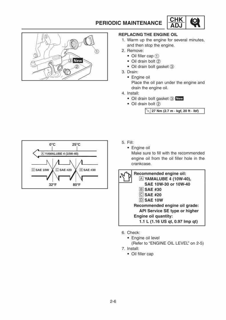
REPLACING THE ENGINE OIL 1. Warm up the engine for several minutes,
and then stop the engine. 2. Remove:
9 Oil filler cap 1 9 Oil drain bolt 2 9 Oil drain bolt gasket 3
3. Drain: 9 Engine oil Place the oil pan under the engine and
drain the engine oil. 4. Install:
9 Oil drain bolt gasket 3 9 Oil drain bolt 2
27 Nm (2.7 m · kgf, 20 ft · lbf)
5. Fill: 9 Engine oil Make sure to fill with the recommended
engine oil from the oil filler hole in the crankcase.
Recommended engine oil: A YAMALUBE 4 (10W-40), SAE 10W-30 or 10W-40 B SAE #30 C SAE #20 D SAE 10WRecommended engine oil grade: API Service SE type or higherEngine oil quantity: 1.1 L (1.16 US qt, 0.97 Imp qt)
6. Check: 9 Engine oil level (Refer to “ENGINE OIL LEVEL” on 2-5)
7. Install: 9 Oil filler cap
1
2
3
0°C
å YAMALUBE 4 (10W-40)
∂ SAE 10W ç SAE #20 ∫ SAE #30
32°F
25°C
80°F
2-7
CHKADJPERIODIC MAINTENANCE
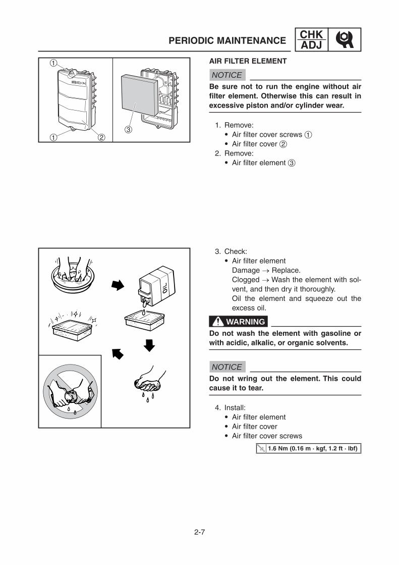
AIR FILTER ELEMENT
NOTICEBe sure not to run the engine without air filter element. Otherwise this can result in excessive piston and/or cylinder wear.
1. Remove: 9 Air filter cover screws 1 9 Air filter cover 2
2. Remove: 9 Air filter element 3
3. Check: 9 Air filter element Damage → Replace. Clogged → Wash the element with sol-
vent, and then dry it thoroughly. Oil the element and squeeze out the
excess oil.
WARNINGDo not wash the element with gasoline or with acidic, alkalic, or organic solvents.
NOTICEDo not wring out the element. This could cause it to tear.
4. Install: 9 Air filter element 9 Air filter cover 9 Air filter cover screws
1.6 Nm (0.16 m · kgf, 1.2 ft · lbf)
1 23
1

2-8
CHKADJPERIODIC MAINTENANCE
MUFFLER
WARNINGThe engine and muffler will be very hot after the engine has been run.Avoid touching the engine and muffler while they are still hot with any part of your body or clothing during check or repair.
1
2
1
1
2
34
1. Remove: 9 Muffler cover bolts 1 9 Muffler cover 2
2. Remove: 9 Muffler band 1 9 Muffler cap 2 9 Muffler screen 3 9 Washer 4
3. Remove: 9 Muffler (Refer to “MUFFLER” on 3-10)

2-9
CHKADJ
4. Decarbonize: 9 Muffler Tap on the muffler in the area shown in
the illustration to loosen carbon build-up, and then shake it out from the end of the muffler.
NOTICEDo not use a wire to clean, otherwise the noise damping material may come out, and the damping effect may be reduced.
5. Decarbonize: 9 Muffler screen
NOTICEWhen cleaning with a wire brush, use it softly to avoid damage or scratch the muf-fler screen.
6. Install: 9 Muffler (Refer to “MUFFLER” on 3-10) 9 Washer 9 Muffler screen 9 Muffler cap 9 Muffler band
2.0 Nm (0.20 m · kgf, 1.4 ft · lbf)
9 Muffler cover 9 Muffler cover bolts
12 Nm (1.2 m · kgf, 8.7 ft · lbf)
PERIODIC MAINTENANCE

2-10
CHKADJPERIODIC MAINTENANCE
FUEL TANK FILTER
WARNINGDo not smoke, and keep away from open flames, sparks, or any other source of fire when handling or in the vicinity of fuel.
1. Remove: 9 Fuel tank cap 1 9 Fuel tank filter 2
2. Check: 9 Fuel tank filter Damage → Replace. Dirt/clog → Clean.
TIPClean the fuel tank filter with clean gasoline, and then dry it thoroughly.
3. Install: 9 Fuel tank filter 9 Fuel tank cap
WARNINGMake sure that the fuel tank cap is tight-ened securely.
1
2

2-11
CHKADJPERIODIC MAINTENANCE
FUEL COCK STRAINER
WARNINGDo not smoke, and keep away from open flames, sparks, or any other source of fire when handling or in the vicinity of fuel.
1. Turn the fuel cock lever to the “OFF” posi-tion.
2. Remove: 9 Strainer cup 1 9 Gasket 2 9 Fuel cock strainer 3
3. Check:
9 Fuel cock strainer Damage → Replace. Dirt/clog → Clean.
TIPClean the fuel cock strainer with clean gaso-line, and then dry it thoroughly.
4. Install: 9 Fuel cock strainer 9 Gasket 9 Strainer cup
1.3 Nm (0.13 m · kgf, 0.94 ft · lbf)
WARNINGMake sure that the strainer cup is tight-ened securely.
12
3

2-12
CHKADJPERIODIC MAINTENANCE
BREATHER HOSE 1. Check:
9 Breather hose 1 Crack/damage → Replace. Poor connection → Correct.
1
CYLINDER HEAD DECARBONIZATION 1. Remove:
9 Cylinder head (Refer to “CYLINDER HEAD COVER,
CYLINDER HEAD” in 7VB-F8197-E0 chapter 3)
2. Eliminate: 9 Carbon deposits (Refer to “CHECKING THE CYLINDER
HEAD” in 7VB-F8197-E0 chapter 3) 3. Install:
9 Cylinder head ( R e fe r t o “ I N S TA L L I N G T H E
CYLINDER HEAD ASSEMBLY” in 7VB-F8197-E0 chapter 3)
ADJUSTING THE VALVE CLEARANCE 1. Remove:
9 Spark plug cap 1 9 Spark plug 2
NOTICEBefore removing the spark plug, use com-pressed air to clean the cylinder head cover to prevent dirt from falling into the engine.
2. Remove: 9 Breather hose 3 9 Cylinder head cover 4 9 Cylinder head cover gasket
1
3
4
2

2-13
CHKADJPERIODIC MAINTENANCE
4. Measure: 9 Valve clearance (Between the rocker arm and valve
stem end) Out of specification → Adjust.
TIPValve clearance must be measured when the engine has cooled down enough to be touched.
Feeler gauge set: YU-26900-9Thickness gauge: 90890-03180
Valve clearance: Intake valve (cold): 0.05–0.09 mm (0.0020–0.0035 in) Exhaust valve (cold): 0.05–0.09 mm (0.0020–0.0035 in)
3. Pull the recoil starter slowly, and then set the piston at TDC (top-dead-center) on the compression stroke.
TIPCheck the piston position by inserting a screw driver into the spark plug hole.

2-14
CHKADJPERIODIC MAINTENANCE
1
3
2
5. Adjust: 9 Valve clearance Adjustment steps: a. Loosen the locknuts 1 and insert the
0.07 mm (0.0028 in) thickness gauge between the rocker arm and the valve tip.
b. Using the tappet adjusting tool 2 turn the adjuster 3 in or out to obtain the proper valve clearance. Move the thick-ness gauge up and down to check for the proper resistance.
Six piece tappet set: YM-A5970Tappet adjusting tool: 90890-01311Feeler gauge set: YU-26900-9Thickness gauge: 90890-03180
Adjuster Valve clearance
Turn clockwise Decrease
Turn counterclockwise Increase
c. Tighten the locknuts 1.
7 Nm (0.7 m · kgf, 5.1 ft · lbf)
6. Install: 9 Cylinder head cover gasket 9 Cylinder head cover
11 Nm (1.1 m · kgf, 8.0 ft · lbf)
9 Breather hose 9 Spark plug
20 Nm (2.0 m · kgf, 14 ft · lbf)
9 Spark plug cap

2-15
CHKADJPERIODIC MAINTENANCE
1
1
a b
ADJUSTING THE ENGINE SPEED (Except for EF7000/EF7200) 1. Warm up the engine for a few minutes. 2. Attach:
9 Digital tachometer 1
Digital tachometer: YU-39951-B, 90890-06760
3. Measure: 9 Economy control engine speed and
engine speed (with no load) Out of specification → Adjust
Economy control engine speed (with no load): 2300–2400 r/minEngine speed (with no load): 3110–3210 r/min
4. Adjust: 9 Economy control engine speed Adjustment steps: a. Turn the economy control switch 1 to “I”
(ON). b. Turn the adjusting screw to obtain the
proper engine speed.
9 Engine speed Adjustment steps: a. Turn the economy control switch 1 to
“3” (OFF). b. Turn the adjusting screw to obtain the
proper engine speed.
Turn to a The engine speed decreases. Turn to b The engine speed increases.

2-16
CHKADJPERIODIC MAINTENANCE
1
a b
ADJUSTING THE ENGINE SPEED (For EF7000/EF7200) 1. Warm up the engine for a few minutes. 2. Attach:
9 Digital tachometer 1
Digital tachometer: YU-39951-B, 90890-06760
4. Adjust: 9 Engine speed Adjustment step: a. Turn the adjusting screw to obtain the
proper engine speed.
Turn to a The engine speed decreases. Turn to b The engine speed increases.
3. Measure: 9 Engine speed (with no load) Out of specification → Adjust
Engine speed (with no load): 3110–3210 r/min

2-17
CHKADJPERIODIC MAINTENANCE
RECOIL STARTER 1. Check:
9 Recoil starter operate smoothly Rough movement → Replace the
defective part(s). (Refer to “RECOIL STARTER” in
7VB-F8197-E0 chapter 3)
FITTINGS AND FASTENERS 1. Check:
9 All fittings and fasteners Looseness → Tighten. Rough movement → Replace the
defective part(s). Damage/pitting → Replace.
3-1
ENGCONTROL BOX
12
3
4
56
5
6
34
3.8 Nm (0.38 m á kgf, 2.8 ft á lbf)
7 Nm (0.7 m á kgf, 5.1 ft á lbf)
7 Nm (0.7 m á kgf, 5.1 ft á lbf)
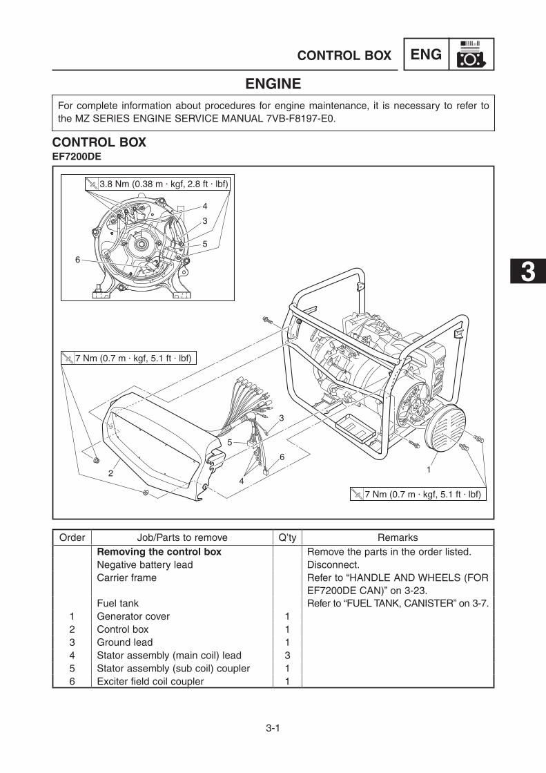
Order Job/Parts to remove Q’ty RemarksRemoving the control box Remove the parts in the order listed.Negative battery lead Disconnect. Carrier frame Refer to “HANDLE AND WHEELS (FOR
EF7200DE CAN)” on 3-23.Fuel tank Refer to “FUEL TANK, CANISTER” on 3-7.
1 Generator cover 12 Control box 13 Ground lead 14 Stator assembly (main coil) lead 35 Stator assembly (sub coil) coupler 16 Exciter field coil coupler 1
ENGINEFor complete information about procedures for engine maintenance, it is necessary to refer to the MZ SERIES ENGINE SERVICE MANUAL 7VB-F8197-E0.
CONTROL BOXEF7200DE
3

3-2
ENGCONTROL BOX
3.8 Nm (0.38 m á kgf, 2.8 ft á lbf)
7 Nm (0.7 m á kgf, 5.1 ft á lbf)
7 Nm (0.7 m á kgf, 5.1 ft á lbf)
10 1112
1314
78 9
Order Job/Parts to remove Q’ty Remarks7 Economy control solenoid lead con-
nector2
8 Oil level switch lead connector 19 TCI unit lead connector 210 Starter relay lead connector 111 Charging coil lead connector 212 Auto choke lead connector 213 Fuel cut solenoid valve lead connec-
tor2
14 Positive battery lead connector 1
3-3
ENGCONTROL BOX
12
3
4
56
7
7 Nm (0.7 m á kgf, 5.1 ft á lbf)
7 Nm (0.7 m á kgf, 5.1 ft á lbf)
5
6
34
3.8 Nm (0.38 m á kgf, 2.8 ft á lbf)
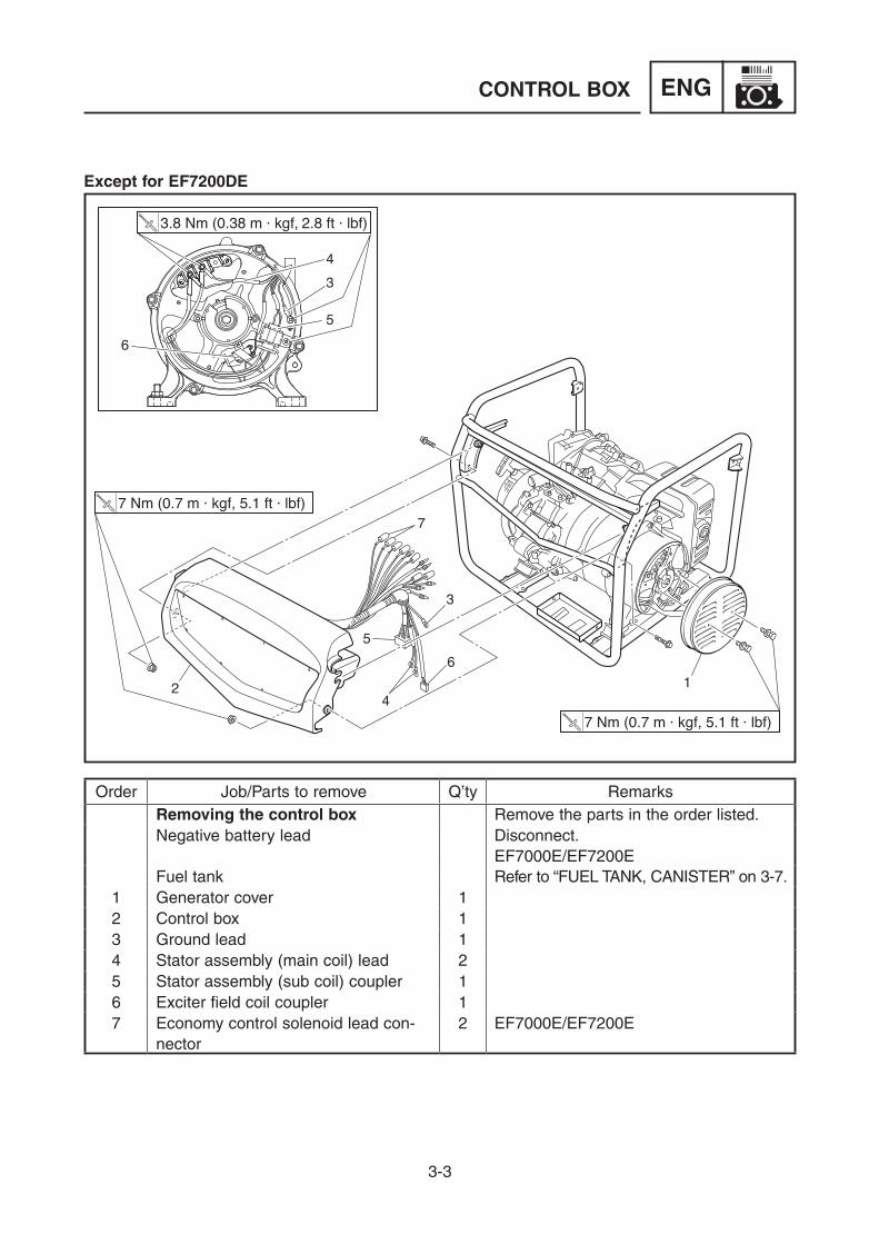
Order Job/Parts to remove Q’ty RemarksRemoving the control box Remove the parts in the order listed.Negative battery lead Disconnect.
EF7000E/EF7200EFuel tank Refer to “FUEL TANK, CANISTER” on 3-7.
1 Generator cover 12 Control box 13 Ground lead 14 Stator assembly (main coil) lead 25 Stator assembly (sub coil) coupler 16 Exciter field coil coupler 17 Economy control solenoid lead con-
nector2 EF7000E/EF7200E
Except for EF7200DE

3-4
ENGCONTROL BOX
7 Nm (0.7 m á kgf, 5.1 ft á lbf)
7 Nm (0.7 m á kgf, 5.1 ft á lbf)
3.8 Nm (0.38 m á kgf, 2.8 ft á lbf)
10 1112
98
1314
Order Job/Parts to remove Q’ty Remarks8 Oil level switch lead connector 19 TCI unit lead connector 210 Starter relay lead connector 1 EF7000E/EF7200E11 Charging coil lead connector 212 Auto choke lead connector 2 EF7000E/EF7200E13 Fuel cut solenoid valve lead connec-
tor2
14 Positive battery lead connector 1 EF7000E/EF7200E

3-5
ENGCONTROL BOX
1
a
b
INSTALLING THE CONTROL BOX 1. Install:
9 Control box 1 9 Control box bolts 9 Control box nuts
7 Nm (0.7 m · kgf, 5.1 ft · lbf)
c
A A Behind the control box
TIP9 Install the a portion of the control box to
the frame b at both sides.9 When installing the grommet c, make sure
that it is facing direction shown in the illus-tration.

3-6
ENGAIR FILTER
4
6
1
2
3
11 Nm (1.1 m á kgf, 8.0 ft á lbf)
5
7
10 Nm (1.0 m á kgf, 7.2 ft á lbf)
1.6 Nm (0.16 m á kgf, 1.2 ft á lbf)
Order Job/Parts to remove Q’ty RemarksRemoving the air filter Remove the parts in the order listed.
1 Air filter cover 12 Air filter element 13 Element fitting plate 14 Plate 15 Air filter case 16 Breather hose 17 Gasket 1
AIR FILTER

3-7
ENGFUEL TANK, CANISTER
24
36
5
9
2
10
8
1
7
7 Nm (0.7 m á kgf, 5.1 ft á lbf)
7 Nm (0.7 m á kgf, 5.1 ft á lbf)
0.8 Nm (0.08 m á kgf, 0.58 ft á lbf)
1.3 Nm (0.13 m á kgf, 0.94 ft á lbf)
16 Nm (1.6 m á kgf, 12 ft á lbf)
10
Order Job/Parts to remove Q’ty RemarksRemoving the fuel tank, canister Remove the parts in the order listed.Carrier frame Refer to “HANDLE AND WHEELS (FOR
EF7200DE CAN)” on 3-23.Control box Refer to “CONTROL BOX” on 3-1.
1 Fuel hose 1 Turn the fuel cock lever to the “OFF” position.
2 Clip 23 Pipe 2 1
For EF7200DE CAN4 Pipe 3 15 Canister 16 Pipe 4 17 Canister bracket 18 Member 19 Fuel tank 110 Locating damper 1 2
FUEL TANK, CANISTER

3-8
ENGFUEL TANK, CANISTER
7 Nm (0.7 m á kgf, 5.1 ft á lbf)
7 Nm (0.7 m á kgf, 5.1 ft á lbf)
0.8 Nm (0.08 m á kgf, 0.58 ft á lbf)
1.3 Nm (0.13 m á kgf, 0.94 ft á lbf)
16 Nm (1.6 m á kgf, 12 ft á lbf)
11
12
14
151617
1819
13
Order Job/Parts to remove Q’ty Remarks11 Fuel tank cap 112 Fuel tank filter 113 Fuel level gauge 114 Fuel cock 115 Strainer cup 116 Gasket 117 Fuel cock strainer 118 Gasket 119 O-ring 1

3-9
ENGFUEL TANK, CANISTER
CHECKING THE CANISTER (For EF7200DE CAN) 1. Check:
9 Pipes 1 Cracks/damage → Replace. Poor connection → Correct. 9 Canister 2 Cracks/damage → Replace.
1
1
1
2

3-10
ENGMUFFLER
1
2
34
56
7 8
2
12 Nm (1.2 m · kgf, 8.7 ft · lbf)
2.0 Nm (0.20 m · kgf, 1.4 ft · lbf)
16 Nm (1.6 m · kgf, 12 ft · lbf)
16 Nm (1.6 m · kgf, 12 ft · lbf)
Order Job/Parts to remove Q’ty RemarksRemoving the muffler Remove the parts in the order listed.
1 Muffler cover 12 Muffler damper 23 Muffler band 14 Muffler cap 15 Muffler screen 16 Washer 17 Muffler 18 Exhaust gasket 1
MUFFLER

3-11
ENGMUFFLER
1
5
2
4
3
5
INSTALLING THE MUFFLER 1. Install:
9 Exhaust gasket 1 9 Muffler assembly 9 Exhaust nuts 2 9 Muffler bolt 3 9 Muffler bolt 4
TIPTemporarily tighten the nuts 2, and bolts 3, 4 until just comes in contact with the surface.
2. Tighten: 9 Exhaust nuts 2 9 Muffler bolt 3 9 Muffler bolt 4
16 Nm (1.6 m · kgf, 12 ft · lbf)
TIPTighten the nuts and bolts to the specified torque in order of exhaust nuts 2, muffler bolt 3 and muffler bolt 4.
3. Install: 9 Muffler damper 9 Muffler cover 5
12 Nm (1.2 m · kgf, 8.7 ft · lbf)

3-12
ENGENGINE
1
2
3
10 Nm (1.0 m á kgf, 7.2 ft á lbf)
2
32 Nm (3.2 m á kgf, 23 ft á lbf)
32 Nm (3.2 m á kgf, 23 ft á lbf)
Order Job/Parts to remove Q’ty RemarksRemoving the engine Remove the parts in the order listed.Engine oil Drain.
Refer to “REPLACING THE ENGINE OIL” on 2-6.
Handle and wheels Refer to “HANDLE AND WHEELS (FOR EF7200DE CAN)” on 3-23.
Control box Refer to “CONTROL BOX” on 3-1.Fuel tank/Canister Refer to “FUEL TANK, CANISTER” on 3-7.Air filter Refer to “AIR FILTER” on 3-6.Muffler Refer to “MUFFLER” on 3-10.Battery Refer to “BATTERY (EF7000E/
EF7200E/EF7200DE)” on 5-18.1 Ground lead 1 For EF7200DE CAN2 Engine mounting nut 43 Engine assembly 1
ENGINE

3-13
ENGGENERATOR
42 Nm (4.2 m · kgf, 30 ft · lbf)
7 Nm (0.7 m · kgf, 5.1 ft · lbf)
4
1
2
3
10 Nm (1.0 m · kgf, 7.2 ft · lbf)
4.5 Nm (0.45 m · kgf, 3.3 ft · lbf)
9 Nm (0.9 m · kgf, 6.5 ft · lbf) 4
3.8 Nm (0.38 m · kgf, 2.8 ft · lbf)
3.8 Nm (0.38 m · kgf, 2.8 ft · lbf)
Order Job/Parts to remove Q’ty RemarksRemoving the generator Remove the parts in the order listed.Handle and wheels Refer to “HANDLE AND WHEELS (FOR
EF7200DE CAN)” on 3-23.Control box Refer to “CONTROL BOX” on 3-1.Air filter Refer to “AIR FILTER” on 3-6.Muffler Refer to “MUFFLER” on 3-10.Fuel tank Refer to “FUEL TANK, CANISTER” on 3-7.Engine assembly Refer to “ENGINE” on 3-12.Recoil starter Refer to “RECOIL STARTER” in
7VB-F8197-E0 chapter 3.1 Rear frame 1 Put a support under the crankcase.2 Exciter field coil 13 Stator cover 14 Stator assembly 1
GENERATOR

3-14
ENGGENERATOR
42 Nm (4.2 m · kgf, 30 ft · lbf)
7 Nm (0.7 m · kgf, 5.1 ft · lbf)
5
6
10 Nm (1.0 m · kgf, 7.2 ft · lbf)
4.5 Nm (0.45 m · kgf, 3.3 ft · lbf)
9 Nm (0.9 m · kgf, 6.5 ft · lbf)
3.8 Nm (0.38 m · kgf, 2.8 ft · lbf)
3.8 Nm (0.38 m · kgf, 2.8 ft · lbf)
Order Job/Parts to remove Q’ty Remarks5 Rotor assembly 16 Generator fan 1
A For EF7200DEB Except for EF7200DE

3-15
ENGGENERATOR
REMOVING THE STATOR ASSEMBLY AND ROTOR ASSEMBLY 1. Remove:
9 Rear frame 1
TIPTo remove the rear frame 1, strike it with a rubber hammer, since the bearing may be stuck in the frame.
2. Remove: 9 Stator cover 1 9 Stator assembly 2
NOTICEDo not drop or damage the stator assem-bly 2.
1
1
1
2
1
2
1
3. Remove: 9 Exciter field coil screws 1 9 Exciter field coil 2

3-16
ENG
4. Remove: 9 Recoil starter 9 Rotor assembly bolt 1
TIPAttach the sheave holder 2 to hold the fly-wheel 3.
Primary clutch holder: YS-01880-ASheave holder: 90890-01701
1
2
3
GENERATOR
6. Remove: 9 Rotor assembly 1
NOTICEDo not drop or damage the rotor assembly 1.
TIPRemove the rotor assembly 1 using the rotor shock puller assy 2.
1
2
12
5. Assemble the special tools: 9 Rotor shock puller assy 1 9 Rotor puller attachment 2
Rotor shock puller assy.: YU-1047, 90890-01259Rotor puller attachment (M14 × 1.25): YU-1379, 90890-01379

3-17
ENG
a
b
1
b
1
a
c
1
d
3. Install: 9 Stator assembly 1 9 Stator cover
TIPAlign the projection a on the stator assembly 1 with the slot b on the crankcase cover.
4. Install: 9 Rear frame 1
10 Nm (1.0 m · kgf, 7.2 ft · lbf)
TIP9 Align the pin a on the rotor bearing with
the slot b on the rear frame.9 Align the projection c on the stator assem-
bly with the slot d on the rear frame.
INSTALLING THE STATOR ASSEMBLY AND ROTOR ASSEMBLY 1. Install:
9 Rotor assembly 2. Tighten:
9 Rotor assembly bolt 1
42 Nm (4.2 m · kgf, 30 ft · lbf)
TIPTighten the rotor assembly bolt 1 by attach-ing the sheave holder 2 to hold the flywheel 3.
Primary clutch holder: YS-01880-ASheave holder: 90890-01701
1
2
3
GENERATOR

3-18
ENGPISTON, CAMSHAFT, CRANKCASE, AND
CRANKSHAFT
1
2
3
4
4
5
6
10 Nm (1.0 m · kgf, 7.2 ft · lbf)
7 Nm (0.7 m · kgf, 5.1 ft · lbf)27 Nm (2.7 m · kgf, 20 ft · lbf)
12 Nm (1.2 m · kgf, 8.7 ft · lbf)30 Nm (3.0 m · kgf, 22 ft · lbf)
1st2nd
27 Nm (2.7 m · kgf, 20 ft · lbf)
10 Nm (1.0 m · kgf, 7.2 ft · lbf)
Order Job/Parts to remove Q’ty RemarksRemoving the crankcase Remove the parts in the order listed.Engine assembly Refer to “ENGINE” on 3-12.Generator assembly Refer to “GENERATOR” on 3-13.Cylinder head assembly Refer to “CYLINDER HEAD COVER,
CYLINDER HEAD” in 7VB-F8197-E0 chapter 3.
Flywheel Refer to “FLYWHEEL” in 7VB-F8197-E0 chapter 3.
1 Crankcase cover 12 Oil filler cap 13 Gasket 14 Dowel pin 25 Clamp 16 Oil level switch 1
PISTON, CAMSHAFT, CRANKCASE, AND CRANKSHAFTCRANKCASE

3-19
ENGPISTON, CAMSHAFT, CRANKCASE, AND
CRANKSHAFT
10
10 Nm (1.0 m · kgf, 7.2 ft · lbf)
7 Nm (0.7 m · kgf, 5.1 ft · lbf)27 Nm (2.7 m · kgf, 20 ft · lbf)
12 Nm (1.2 m · kgf, 8.7 ft · lbf)30 Nm (3.0 m · kgf, 22 ft · lbf)
1st2nd
27 Nm (2.7 m · kgf, 20 ft · lbf)
10 Nm (1.0 m · kgf, 7.2 ft · lbf)
9
8
7
Order Job/Parts to remove Q’ty Remarks7 Flyweight shaft assembly 18 Clip 19 Governor shaft 110 Negative battery lead 1 EF7000E/EF7200E/EF7200DE

3-20
ENGPISTON, CAMSHAFT, CRANKCASE, AND
CRANKSHAFT
1
2
3
34
5
6
7
7
8
9
10
20 Nm (2.0 m á kgf, 14 ft á lbf)
Order Job/Parts to remove Q’ty RemarksRemoving the piston, camshaft and crankshaft
Remove the parts in the order listed.
Crankcase Refer to “CRANKCASE” on 3-18.1 Balancer shaft 12 Camshaft 13 Valve lifter 24 Connecting rod cap 15 Crankshaft 16 Connecting rod 17 Piston pin circlip 28 Piston pin 19 Piston 110 Piston ring set 1
PISTON, CAMSHAFT AND CRANKSHAFT

3-21
ENGPISTON, CAMSHAFT, CRANKCASE, AND
CRANKSHAFT
REMOVING THE BALANCER SHAFT, CAMSHAFT, AND VALVE LIFTER 1. Remove:
9 Balancer shaft 1
TIPRemove the balancer shaft 1 when the bal-ancer shaft gear mark a and the crankshaft gear mark b are aligned.
2. Remove: 9 Camshaft 2
TIPRemove the camshaft 2 when the camshaft gear mark c and the crankshaft gear mark d are aligned.
3. Remove: 9 Intake valve lifter 9 Exhaust valve lifter
CHECKING THE BALANCER SHAFT 1. Check:
9 Balancer gear teeth 9 Balancer shaft Wear/damage → Replace.
21b
ac
d

3-22
ENGPISTON, CAMSHAFT, CRANKCASE, AND
CRANKSHAFT
b
1
a
b
1
a
INSTALLING THE VALVE LIFTER, BALANCER SHAFT, AND CAMSHAFT 1. Install:
9 Intake valve lifter 9 Exhaust valve lifter
2. Install: 9 Balancer shaft 1
NOTICEBe sure to align the balancer shaft 1 gear mark a with the crankshaft gear mark b.
3. Install: 9 Camshaft 1
NOTICEBe sure to align the camshaft 1 gear mark a with the crankshaft gear mark b.
1
5
3
7
26
4
8
8
INSTALLING THE CRANKCASE COVER 1. Install:
9 Crankcase cover 9 Crankcase cover bolts 1 to 8
TIPTighten the bolts to the specified torque in two stages and in order from 1 to 8.
1st: 12 Nm (1.2 m · kgf, 8.7 ft · lbf)
2nd: 30 Nm (3.0 m · kgf, 22 ft · lbf)
3-23
ENGHANDLE AND WHEELS (FOR EF7200DE CAN)
6
7
9
8
10
1010
10
13
1211
1
5
4 2
2
4
3
3
5
7 Nm (0.7 m · kgf, 5.1 ft · lbf)
16 Nm (1.6 m · kgf, 12 ft · lbf)
16 Nm (1.6 m · kgf, 12 ft · lbf)
16 Nm (1.6 m · kgf, 12 ft · lbf)
16 Nm (1.6 m · kgf, 12 ft · lbf)
16 Nm (1.6 m · kgf, 12 ft · lbf)
HANDLE AND WHEELS (FOR EF7200DE CAN)
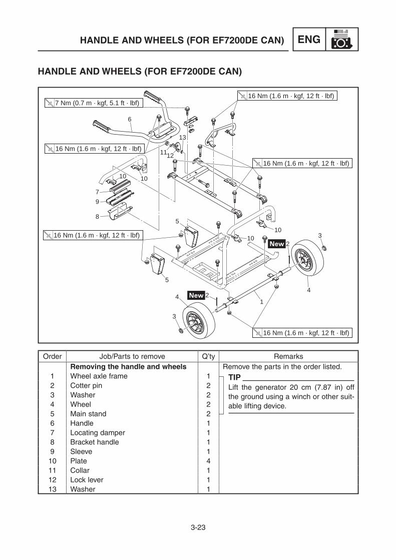
Order Job/Parts to remove Q’ty RemarksRemoving the handle and wheels Remove the parts in the order listed.
1 Wheel axle frame 1 TIPLift the generator 20 cm (7.87 in) off the ground using a winch or other suit-able lifting device.
2 Cotter pin 23 Washer 24 Wheel 25 Main stand 26 Handle 17 Locating damper 18 Bracket handle 19 Sleeve 110 Plate 411 Collar 112 Lock lever 113 Washer 1

3-24
ENGHANDLE AND WHEELS (FOR EF7200DE CAN)
17
18
7 Nm (0.7 m · kgf, 5.1 ft · lbf)
16 Nm (1.6 m · kgf, 12 ft · lbf)
16 Nm (1.6 m · kgf, 12 ft · lbf)
16 Nm (1.6 m · kgf, 12 ft · lbf)
16 Nm (1.6 m · kgf, 12 ft · lbf)
16 Nm (1.6 m · kgf, 12 ft · lbf)
141516
Order Job/Parts to remove Q’ty Remarks14 Stopper 115 Plate 116 Damper 117 Engine hanger 118 Carrier frame 1

3-25
ENGHANDLE AND WHEELS (FOR EF7200DE CAN)
INSTALLING THE HANDLE 1. Install:
9 Engine hanger 1 9 Carrier frame 2 9 Engine hanger bolts 3
16 Nm (1.6 m · kgf, 12 ft · lbf)
TIP9 Fasten the engine hanger 1 to the carrier
frame 2 with the engine hanger bolts 3.9 Match the punch marks a as shown in the
illustration.
2. Install: 9 Damper 1 9 Plate 2 9 Stopper 3 9 Stopper bolt 4
7 Nm (0.7 m · kgf, 5.1 ft · lbf)
TIPInstall the damper 1 and plate 2 into the stopper 3, and tightly fasten it to carrier frame with the stopper bolt 4.
1
2
33
a
1
1
2
3
4
3-26
ENGHANDLE AND WHEELS (FOR EF7200DE CAN)
6
23
45
1
4
7
a
1
1
2
3
2
1
2
32
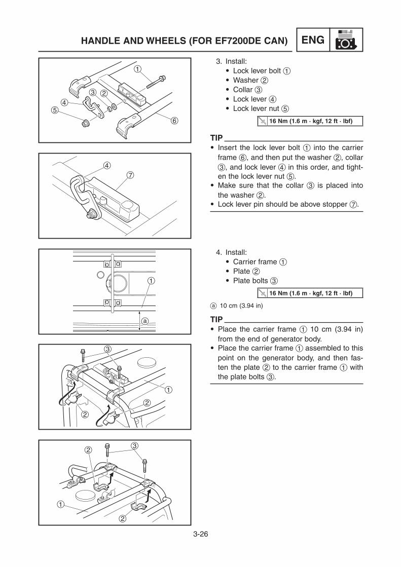
3. Install: 9 Lock lever bolt 1 9 Washer 2 9 Collar 3 9 Lock lever 4 9 Lock lever nut 5
16 Nm (1.6 m · kgf, 12 ft · lbf)
TIP9 Insert the lock lever bolt 1 into the carrier
frame 6, and then put the washer 2, collar 3, and lock lever 4 in this order, and tight-en the lock lever nut 5.
9 Make sure that the collar 3 is placed into the washer 2.
9 Lock lever pin should be above stopper 7.
4. Install: 9 Carrier frame 1 9 Plate 2 9 Plate bolts 3
16 Nm (1.6 m · kgf, 12 ft · lbf)
a 10 cm (3.94 in)
TIP9 Place the carrier frame 1 10 cm (3.94 in)
from the end of generator body.9 Place the carrier frame 1 assembled to this
point on the generator body, and then fas-ten the plate 2 to the carrier frame 1 with the plate bolts 3.

3-27
ENGHANDLE AND WHEELS (FOR EF7200DE CAN)
1 2
1
2
1
2
2
2
3
1
1
5. Install: 9 Sleeve 1
TIPInstall the sleeve 1 on the generator frame 2.
6. Install: 9 Bracket handle 1
TIPInstall the bracket handle 1 to the sleeve 2.
7. Install: 9 Locating damper 1
TIPInstall the locating damper 1 on the sleeve 2.
8. Install: 9 Handle 1 9 Handle bolts 2
16 Nm (1.6 m · kgf, 12 ft · lbf)
TIP9 Place the handle 1 on the carrier frame,
and then fasten with the handle bolts 2.9 Lock the handle 1 into position with the
lock lever 3.

3-28
ENGHANDLE AND WHEELS (FOR EF7200DE CAN)
INSTALLING THE WHEELS 1. Install:
9 Main stand 1 9 Main stand bolts 2 9 Main stand nuts 3
16 Nm (1.6 m · kgf, 12 ft · lbf)
TIP9 Lift the generator 20 cm (7.87 in) off the
ground using a winch or other suitable lift-ing device.
9 Fasten the main stand 1 to the left side of the generator frame as viewed when look-ing at the control panel with the main stand bolts 2 and nuts 3.
2. Install: 9 Wheels 1 9 Wheel axle frame 2
TIP9 Install the wheels 1 into wheel axle frame
2.9 Make sure the installation direction a of the
wheels 1 are correct.
12
33
1
2
33
1
2
1
2
a

3-29
ENGHANDLE AND WHEELS (FOR EF7200DE CAN)
3. Install: 9 Washers 1 9 Cotter pins 2
TIP9 Install the washers 1 into wheel axle.9 Insert cotter pins 2 into wheel axle frame,
and then bend as shown in the illustration.
4. Install: 9 Wheel axle frame 1 9 Wheel axle frame bolts 2 9 Wheel axle frame nuts 3
16 Nm (1.6 m · kgf, 12 ft · lbf)
TIPFasten the wheel axle frame 1 to the genera-tor frame with the wheel axle frame bolts 2 and nuts 3.
1
2
1
2
2
1
2
3
2
3

4-1
CARBREMOVING THE CARBURETOR
1
2
3
1
3
Order Job/Parts to remove Q’ty RemarksRemoving the carburetor Remove the parts in the order listed.
Negative battery lead
Turn the fuel cock lever to the “OFF” position.Disconnect.EF7000E/EF7200E/EF7200DE
Carrier frame Refer to “HANDLE AND WHEELS (FOR EF7200DE CAN)” on 3-23.
Fuel tank Refer to “FUEL TANK, CANISTER” on 3-7.Air filter Refer to “AIR FILTER” on 3-6.
1 Fuel cut solenoid valve lead 22 Auto choke lead 2 EF7000E/EF7200E/EF7200DE3 Carburetor assembly 1
CARBURETORFor complete information about procedures for carburetor maintenance, it is necessary to refer to the MZ SERIES ENGINE SERVICE MANUAL 7VB-F8197-E0.
REMOVING THE CARBURETOR

4-2
CARB
4
REMOVING THE CARBURETOR
67
5
4
Order Job/Parts to remove Q’ty Remarks4 Link rod/Spring 1/15 Gasket 16 Joint 17 Gasket 1
A EF7000/EF7200

4-3
CARB
DISASSEMBLING THE CARBURETOREF7000/EF7200
DISASSEMBLING THE CARBURETOR
1
4
5
3
2
2.5 Nm (0.25 m · kgf, 1.8 ft · lbf)
1.0 Nm (0.10 m · kgf, 0.72 ft · lbf)
4.0 Nm (0.40 m · kgf, 2.9 ft · lbf)
7 Nm (0.7 m · kgf, 5.1 ft · lbf)
0.7 Nm (0.07 m · kgf, 0.51 ft · lbf)
3.5 Nm (0.35 m · kgf, 2.5 ft · lbf)
0.7 Nm (0.07 m · kgf, 0.51 ft · lbf)
6
7
8
9
0q
w
Order Job/Parts to remove Q’ty RemarksDisassembling the carburetor Disassemble the parts in the order listed.
1 Drain screw 12 Main jet holder 13 O-ring 14 Gasket 15 Main jet 16 Float chamber 17 Gasket 18 Main nozzle 19 Needle assembly 10 Float pin 1q Float 1w Cap 1 Except for EF7200 SEA/AFR

4-4
CARB
Order Job/Parts to remove Q’ty Remarkse Pilot adjusting screw/Spring 1/1 2-1/2 turns out. (Except for EF7200
SEA/AFR)2 turns out. (For EF7200 SEA/AFR)
r Throttle screw/Spring 1/1t Pilot jet/O-ring 1/1
DISASSEMBLING THE CARBURETOR
2.5 Nm (0.25 m · kgf, 1.8 ft · lbf)
1.0 Nm (0.10 m · kgf, 0.72 ft · lbf)
4.0 Nm (0.40 m · kgf, 2.9 ft · lbf)
7 Nm (0.7 m · kgf, 5.1 ft · lbf)
0.7 Nm (0.07 m · kgf, 0.51 ft · lbf)
3.5 Nm (0.35 m · kgf, 2.5 ft · lbf)
0.7 Nm (0.07 m · kgf, 0.51 ft · lbf)
r
t
e
4-5
CARBDISASSEMBLING THE CARBURETOR
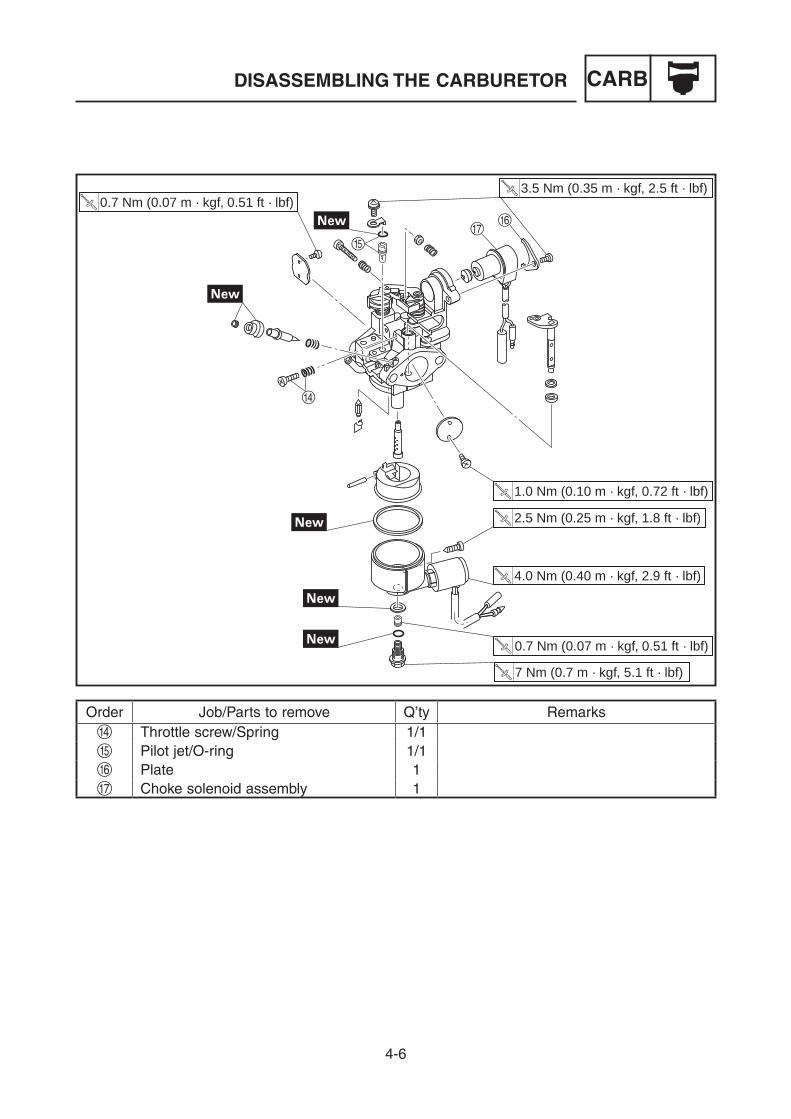
EF7000E/EF7200E/EF7200DE
1
4
5
3
2
2.5 Nm (0.25 m · kgf, 1.8 ft · lbf)
1.0 Nm (0.10 m · kgf, 0.72 ft · lbf)
4.0 Nm (0.40 m · kgf, 2.9 ft · lbf)
7 Nm (0.7 m · kgf, 5.1 ft · lbf)
0.7 Nm (0.07 m · kgf, 0.51 ft · lbf)
3.5 Nm (0.35 m · kgf, 2.5 ft · lbf)0.7 Nm (0.07 m · kgf, 0.51 ft · lbf)
6
7
8
9
0q
we
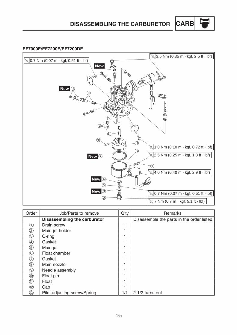
Order Job/Parts to remove Q’ty RemarksDisassembling the carburetor Disassemble the parts in the order listed.
1 Drain screw 12 Main jet holder 13 O-ring 14 Gasket 15 Main jet 16 Float chamber 17 Gasket 18 Main nozzle 19 Needle assembly 10 Float pin 1q Float 1w Cap 1e Pilot adjusting screw/Spring 1/1 2-1/2 turns out.
4-6
CARBDISASSEMBLING THE CARBURETOR
2.5 Nm (0.25 m · kgf, 1.8 ft · lbf)
1.0 Nm (0.10 m · kgf, 0.72 ft · lbf)
4.0 Nm (0.40 m · kgf, 2.9 ft · lbf)
7 Nm (0.7 m · kgf, 5.1 ft · lbf)
0.7 Nm (0.07 m · kgf, 0.51 ft · lbf)
3.5 Nm (0.35 m · kgf, 2.5 ft · lbf)0.7 Nm (0.07 m · kgf, 0.51 ft · lbf)
r
y
tu
Order Job/Parts to remove Q’ty Remarksr Throttle screw/Spring 1/1t Pilot jet/O-ring 1/1y Plate 1u Choke solenoid assembly 1
4-7
CARB
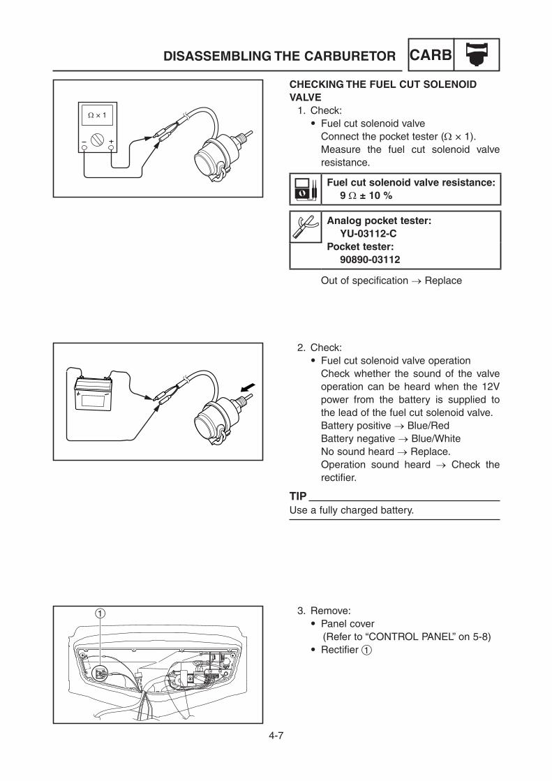
CHECKING THE FUEL CUT SOLENOID VALVE 1. Check:
9 Fuel cut solenoid valve Connect the pocket tester (W × 1). Measure the fuel cut solenoid valve
resistance.
Fuel cut solenoid valve resistance: 9 W ± 10 %
Analog pocket tester: YU-03112-CPocket tester: 90890-03112
Out of specification → Replace
W × 1
DISASSEMBLING THE CARBURETOR
3. Remove: 9 Panel cover
(Refer to “CONTROL PANEL” on 5-8) 9 Rectifier 1
1
2. Check: 9 Fuel cut solenoid valve operation Check whether the sound of the valve
operation can be heard when the 12V power from the battery is supplied to the lead of the fuel cut solenoid valve.
Battery positive → Blue/Red Battery negative → Blue/White No sound heard → Replace. Operation sound heard → Check the
rectifier.
TIPUse a fully charged battery.

4-8
CARB
2
1
3
4
2
1
3
4
4. Check: 9 Rectifier Connect the pocket tester (W × 1). Check for continuity between the termi-
nals.
Rectifier continuity:
1 2 3 4
1 1 1 1
2 — 1 —
3 — — —
4 — — 1
Replace if any faults are found.
Tester (–)leadTester
(+) lead
DISASSEMBLING THE CARBURETOR

5-1
ELECELECTRICAL COMPONENTS
ELECTRICALFor complete information about procedures for electrical maintenance, it is necessary to refer to the MZ SERIES ENGINE SERVICE MANUAL 7VB-F8197-E0.
1
2
7
89
0
3 4 5 6
q
1
2
7
890
3 4 5 6
q
ELECTRICAL COMPONENTS1 Control box2 Oil warning unit3 Rectifier4 Economy control solenoid
(EF7000E/EF7200E/EF7200DE)5 Economy control unit
(EF7000E/EF7200E/EF7200DE)6 Spark plug7 AVR (Automatic Voltage Regulator)8 Stator and rotor assembly9 Battery (EF7000E/EF7200E/EF7200DE)0 TCI unitq Starter motor
(EF7000E/EF7200E/EF7200DE)
A For EF7200DE CANB Except for EF7200DE CAN
A
B

5-2
ELECELECTRICAL COMPONENTS
EF7000 (CHN)1 Oil warning light2 Engine switch3 Voltage/hour meter4 AC receptacle5 AC switch (N.F.B.)
EF7200 (SEA/AFR/RUS)1 Oil warning light2 Engine switch3 Voltage/hour meter4 AC receptacle5 AC switch (N.F.B.)
EF7000E (CHN)1 Oil warning light2 Economy control switch3 Engine switch4 Voltage/hour meter5 AC receptacle6 AC switch (N.F.B.)
EF7200E (Except for OCE)1 Oil warning light2 Economy control switch3 Engine switch4 Voltage/hour meter5 AC receptacle6 AC switch (N.F.B.)
2 31 4 5
2 31 4 5
32 41 5 6
32 41 5 6
EF7000 (CHN)
EF7200 (SEA/AFR/RUS)
EF7000E (CHN)
EF7200E (Except for OCE)
5

5-3
ELECELECTRICAL COMPONENTS
EF7200E (OCE)1 Oil warning light2 Economy control switch3 Engine switch4 Voltage/hour meter5 AC receptacle6 AC switch (N.F.B.)
EF7200DE (CAN)1 Oil warning light2 Economy control switch3 Engine switch4 Voltage/hour meter5 AC receptacle6 AC switch (N.F.B.)
EF7200DE (Except for CAN)1 Oil warning light2 Economy control switch3 Engine switch4 Voltage/hour meter5 AC receptacle6 AC switch (N.F.B.)
32 41 5 6
3 4 5 5 621
6 6
32 41 5 6
EF7200E (OCE)
EF7200DE (CAN)
EF7200DE (Except for CAN)

5-4
ELECCIRCUIT DIAGRAM
2
3
5
6
17
8
9
00
q
e
r
y
u
op
a
i
s
d
t
4
w
CIRCUIT DIAGRAMEF7000/EF7200
1 G
ener
ator
2 R
otor
ass
embl
y 3
Exc
iter
field
coi
l4
Sub
coi
l5
Mai
n co
il6
Sta
tor
asse
mbl
y7
Con
trol
box
8 V
olta
ge/h
our
met
er9
AC
sw
itch
(N.F
.B.)
0 A
C r
ecep
tacl
eq
Rec
tifie
rw
Eng
ine
switc
he
Vol
tage
adj
uste
rr
Con
dens
ert
AV
R
(Aut
omat
ic
Vol
tage
R
egul
ator
)y
Oil
war
ning
uni
tu
Oil
war
ning
ligh
t
i E
ngin
eo
Fue
l cut
sol
enoi
d va
lve
p C
harg
ing
coil
a T
CI
unit
s S
park
plu
gd
Oil
leve
l sw
itch
Co
lor
cod
eB
B
lack
Br
Bro
wn
G
Gre
enL
Blu
eLg
Ligh
t gr
een
O
Ora
nge
R
Red
W
W
hite
Y
Yello
wB
/W
Bla
ck/W
hite
G/R
G
reen
/Red
G/Y
G
reen
/Yel
low
L/R
B
lue/
Red
L/W
B
lue/
Whi
teR
/G
Red
/Gre
en

5-5
ELEC
2
3
5
6
17
8
9
00
00
w
er
y
t
u
o
a
f
s
g
h
j
k
l
;z
x
c
d
p
i
4
q
å
∫
EF7000E/EF7200E
CIRCUIT DIAGRAM
1 G
ener
ator
2 R
otor
ass
embl
y 3
Exc
iter
field
coi
l4
Sub
coi
l5
Mai
n co
il6
Sta
tor
asse
mbl
y7
Con
trol
box
8 V
olta
ge/h
our
met
er9
AC
sw
itch
(N.F
.B.)
0 A
C r
ecep
tacl
eq
Eng
ine
switc
hw
Rec
tifie
re
Rem
ote
cont
rol t
erm
inal
r F
use
t R
ectif
ier/
regu
lato
ry
Vol
tage
adj
uste
ru
Con
dens
eri
AV
R
(Aut
omat
ic
Vol
tage
R
egul
ator
)
o O
il w
arni
ng u
nit
p E
cono
my
cont
rol u
nit
a O
il w
arni
ng li
ght
s E
cono
my
cont
rol s
witc
hd
Eng
ine
f E
cono
my
cont
rol s
olen
oid
g S
tart
er r
elay
h S
tart
er m
otor
j A
uto
chok
ek
Fue
l cut
sol
enoi
d va
lve
l B
atte
ry;
Cha
rgin
g co
ilz
TC
I un
itx
Spa
rk p
lug
c O
il le
vel s
witc
h
Co
lor
cod
eB
B
lack
Br
Bro
wn
G
Gre
enL
Blu
eLg
Ligh
t gr
een
O
Ora
nge
R
Red
W
W
hite
Y
Yello
w
B/W
B
lack
/Whi
teG
/R
Gre
en/R
edG
/Y
Gre
en/Y
ello
wL/
R
Blu
e/R
edL/
W
Blu
e/W
hite
R/B
R
ed/B
lack
R/G
R
ed/G
reen
R/W
R
ed/W
hite
A E
xcep
t fo
r O
CE
B F
or O
CE
5-6
ELECCIRCUIT DIAGRAM
2
3
17
6
8
99
00
00
w
er
y
t
u
o
a
f
s
g
h
j
k
l
;z
x
c
d
p
i
45
q
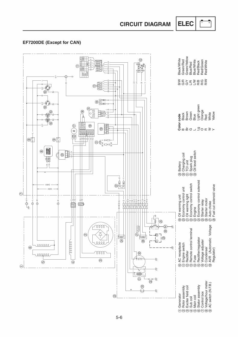
EF7200DE (Except for CAN)
1 G
ener
ator
2 R
otor
ass
embl
y 3
Exc
iter
field
coi
l4
Sub
coi
l5
Mai
n co
il6
Sta
tor
asse
mbl
y7
Con
trol
box
8 V
olta
ge/h
our
met
er9
AC
sw
itch
(N.F
.B.)
0 A
C r
ecep
tacl
eq
Eng
ine
switc
hw
Rec
tifie
re
Rem
ote
cont
rol t
erm
inal
r F
use
t R
ectif
ier/
regu
lato
ry
Vol
tage
adj
uste
ru
Con
dens
eri
AV
R
(Aut
omat
ic
Vol
tage
R
egul
ator
)
o O
il w
arni
ng u
nit
p E
cono
my
cont
rol u
nit
a O
il w
arni
ng li
ght
s E
cono
my
cont
rol s
witc
hd
Eng
ine
f E
cono
my
cont
rol s
olen
oid
g S
tart
er r
elay
h S
tart
er m
otor
j A
uto
chok
ek
Fue
l cut
sol
enoi
d va
lve
l B
atte
ry;
Cha
rgin
g co
ilz
TC
I un
itx
Spa
rk p
lug
c O
il le
vel s
witc
h
Co
lor
cod
eB
B
lack
Br
Bro
wn
G
Gre
enL
Blu
eLg
Ligh
t gr
een
O
Ora
nge
R
Red
W
W
hite
Y
Yello
w
B/W
B
lack
/Whi
teG
/R
Gre
en/R
edG
/Y
Gre
en/Y
ello
wL/
R
Blu
e/R
edL/
W
Blu
e/W
hite
R/B
R
ed/B
lack
R/G
R
ed/G
reen
R/W
R
ed/W
hite

5-7
ELECCIRCUIT DIAGRAM
2
3
5
6
1
8
7
9
99
9
9
00
0
q
e
t
y
iu
o
p
f
d
g
h
j
k
l
;z
x
c
s
a
w
4
r
EF7200DE (CAN)
1 G
ener
ator
2 R
otor
ass
embl
y 3
Exc
iter
field
coi
l4
Sub
coi
l5
Mai
n co
il6
Sta
tor
asse
mbl
y7
Con
trol
box
8 V
olta
ge/h
our
met
er9
AC
sw
itch
(N.F
.B.)
0 A
C r
ecep
tacl
eq
Eng
ine
switc
hw
Rec
tifie
re
Rem
ote
cont
rol t
erm
inal
r F
use
t R
ectif
ier/
regu
lato
ry
Vol
tage
adj
uste
ru
Con
dens
eri
AV
R
(Aut
omat
ic
Vol
tage
R
egul
ator
)
o O
il w
arni
ng u
nit
p E
cono
my
cont
rol u
nit
a O
il w
arni
ng li
ght
s E
cono
my
cont
rol s
witc
hd
Eng
ine
f E
cono
my
cont
rol s
olen
oid
g S
tart
er r
elay
h S
tart
er m
otor
j A
uto
chok
ek
Fue
l cut
sol
enoi
d va
lve
l B
atte
ry;
Cha
rgin
g co
ilz
TC
I un
itx
Spa
rk p
lug
c O
il le
vel s
witc
h
Co
lor
cod
eB
B
lack
Br
Bro
wn
G
Gre
enL
Blu
eLg
Ligh
t gr
een
O
Ora
nge
R
Red
W
W
hite
Y
Yello
w
B/W
B
lack
/Whi
teG
/R
Gre
en/R
edG
/Y
Gre
en/Y
ello
wL/
R
Blu
e/R
edL/
W
Blu
e/W
hite
R/B
R
ed/B
lack
R/G
R
ed/G
reen
R/W
R
ed/W
hite

5-8
ELEC
8
7
9
10
23
41
5
5
6
7 Nm (0.7 m á kgf, 5.1 ft á lbf)
0.4 Nm (0.04 m á kgf, 0.29 ft á lbf)
0.4 Nm (0.04 m á kgf, 0.29 ft á lbf)
1.4 Nm (0.14 m á kgf, 1.0 ft á lbf)
1.3 Nm (0.13 m á kgf, 0.94 ft á lbf)
1.8 Nm (0.18 m á kgf, 1.3 ft á lbf)
1.7 Nm (0.17 m á kgf, 1.2 ft á lbf)
Order Job/Parts to remove Q’ty RemarksRemoving the control panel Remove the parts in the order listed.
1 Panel cover 12 Voltage/hour meter 13 Oil warning light 14 Engine switch 15 AC receptacle 26 AC switch (N.F.B.) 1 Lever switch7 Oil warning unit 18 Rectifier 19 Condenser holder 110 Condenser 1
CONTROL PANELEF7000/EF7200
CONTROL PANEL

5-9
ELEC
13
1211
7 Nm (0.7 m á kgf, 5.1 ft á lbf)
0.4 Nm (0.04 m á kgf, 0.29 ft á lbf)
0.4 Nm (0.04 m á kgf, 0.29 ft á lbf)
1.4 Nm (0.14 m á kgf, 1.0 ft á lbf)
1.3 Nm (0.13 m á kgf, 0.94 ft á lbf)
1.8 Nm (0.18 m á kgf, 1.3 ft á lbf)
1.7 Nm (0.17 m á kgf, 1.2 ft á lbf)
Order Job/Parts to remove Q’ty Remarks11 Voltage adjuster 112 AVR 1 Automatic Voltage Regulator13 Control box 1
CONTROL PANEL

5-10
ELEC
10
11
9
1312
8
2
34
5
1
6
6
7
7 Nm (0.7 m á kgf, 5.1 ft á lbf)
0.4 Nm (0.04 m á kgf, 0.29 ft á lbf)
0.4 Nm (0.04 m á kgf, 0.29 ft á lbf)
1.4 Nm (0.14 m á kgf, 1.0 ft á lbf)
1.3 Nm (0.13 m á kgf, 0.94 ft á lbf)
1.8 Nm (0.18 m á kgf, 1.3 ft á lbf)
1.8 Nm (0.18 m á kgf, 1.3 ft á lbf)
1.8 Nm (0.18 m á kgf, 1.3 ft á lbf)
1.7 Nm (0.17 m á kgf, 1.2 ft á lbf)
Order Job/Parts to remove Q’ty RemarksRemoving the control panel Remove the parts in the order listed.
1 Panel cover 12 Economy control switch 13 Voltage/hour meter 14 Oil warning light 15 Engine switch 16 AC receptacle 27 AC switch (N.F.B.) 1 Lever switch8 Fuse 19 Oil warning unit 110 Rectifier 111 Economy control unit 112 Condenser holder 113 Condenser 1
EF7000E/EF7200E (Except for OCE)
CONTROL PANEL

5-11
ELEC
1617
1514
7 Nm (0.7 m á kgf, 5.1 ft á lbf)
0.4 Nm (0.04 m á kgf, 0.29 ft á lbf)
0.4 Nm (0.04 m á kgf, 0.29 ft á lbf)
1.4 Nm (0.14 m á kgf, 1.0 ft á lbf)
1.3 Nm (0.13 m á kgf, 0.94 ft á lbf)
1.8 Nm (0.18 m á kgf, 1.3 ft á lbf)
1.8 Nm (0.18 m á kgf, 1.3 ft á lbf)
1.8 Nm (0.18 m á kgf, 1.3 ft á lbf)
1.7 Nm (0.17 m á kgf, 1.2 ft á lbf)
Order Job/Parts to remove Q’ty Remarks14 Voltage adjuster 115 AVR 1 Automatic Voltage Regulator16 Control box 117 Rectifier/regulator 1
CONTROL PANEL

5-12
ELECCONTROL PANEL
10
11
9
1312
8
23
45
1
6
7
7 Nm (0.7 m á kgf, 5.1 ft á lbf)
0.4 Nm (0.04 m á kgf, 0.29 ft á lbf)
0.4 Nm (0.04 m á kgf, 0.29 ft á lbf)
0.6 Nm (0.06 m á kgf, 0.43 ft á lbf)
1.4 Nm (0.14 m á kgf, 1.0 ft á lbf)
1.3 Nm (0.13 m á kgf, 0.94 ft á lbf)
1.8 Nm (0.18 m á kgf, 1.3 ft á lbf)
1.8 Nm (0.18 m á kgf, 1.3 ft á lbf)1.7 Nm (0.17 m á kgf, 1.2 ft á lbf)
Order Job/Parts to remove Q’ty RemarksRemoving the control panel Remove the parts in the order listed.
1 Panel cover 12 Economy control switch 13 Voltage/hour meter 14 Oil warning light 15 AC receptacle 26 Engine switch 17 AC switch (N.F.B.) 1 Lever switch8 Fuse 19 Oil warning unit 110 Rectifier 111 Economy control unit 112 Condenser holder 113 Condenser 1
EF7200E (OCE)

5-13
ELECCONTROL PANEL
16
17
1514
7 Nm (0.7 m á kgf, 5.1 ft á lbf)
0.4 Nm (0.04 m á kgf, 0.29 ft á lbf)
0.4 Nm (0.04 m á kgf, 0.29 ft á lbf)
0.6 Nm (0.06 m á kgf, 0.43 ft á lbf)
1.4 Nm (0.14 m á kgf, 1.0 ft á lbf)
1.3 Nm (0.13 m á kgf, 0.94 ft á lbf)
1.8 Nm (0.18 m á kgf, 1.3 ft á lbf)
1.8 Nm (0.18 m á kgf, 1.3 ft á lbf)1.7 Nm (0.17 m á kgf, 1.2 ft á lbf)
Order Job/Parts to remove Q’ty Remarks14 Voltage adjuster 115 AVR 1 Automatic Voltage Regulator16 Control box 117 Rectifier/regulator 1
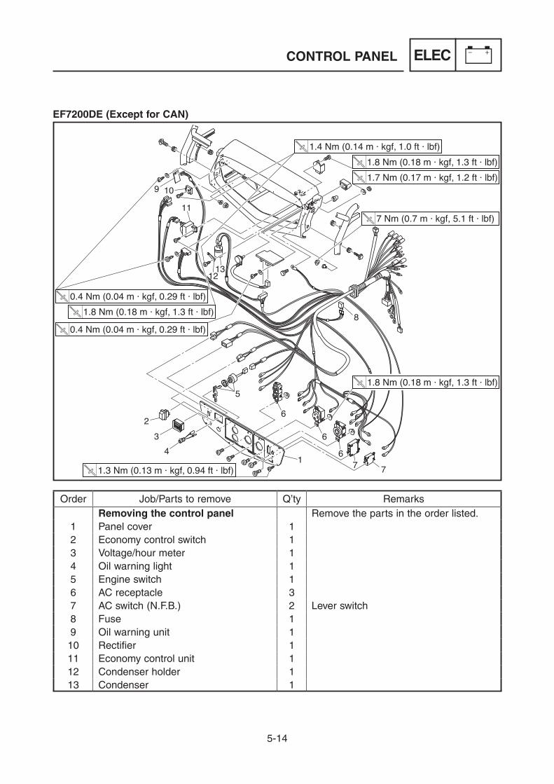
5-14
ELECCONTROL PANEL
10
11
9
1312
8
23
4
5
1
6
6
7 7
6
7 Nm (0.7 m á kgf, 5.1 ft á lbf)
0.4 Nm (0.04 m á kgf, 0.29 ft á lbf)
0.4 Nm (0.04 m á kgf, 0.29 ft á lbf)
1.4 Nm (0.14 m á kgf, 1.0 ft á lbf)
1.3 Nm (0.13 m á kgf, 0.94 ft á lbf)
1.8 Nm (0.18 m á kgf, 1.3 ft á lbf)
1.8 Nm (0.18 m á kgf, 1.3 ft á lbf)
1.8 Nm (0.18 m á kgf, 1.3 ft á lbf)
1.7 Nm (0.17 m á kgf, 1.2 ft á lbf)
Order Job/Parts to remove Q’ty RemarksRemoving the control panel Remove the parts in the order listed.
1 Panel cover 12 Economy control switch 13 Voltage/hour meter 14 Oil warning light 15 Engine switch 16 AC receptacle 37 AC switch (N.F.B.) 2 Lever switch8 Fuse 19 Oil warning unit 110 Rectifier 111 Economy control unit 112 Condenser holder 113 Condenser 1
EF7200DE (Except for CAN)

5-15
ELECCONTROL PANEL
17
16
1514
7 Nm (0.7 m á kgf, 5.1 ft á lbf)
0.4 Nm (0.04 m á kgf, 0.29 ft á lbf)
0.4 Nm (0.04 m á kgf, 0.29 ft á lbf)
1.4 Nm (0.14 m á kgf, 1.0 ft á lbf)
1.3 Nm (0.13 m á kgf, 0.94 ft á lbf)
1.8 Nm (0.18 m á kgf, 1.3 ft á lbf)
1.8 Nm (0.18 m á kgf, 1.3 ft á lbf)
1.8 Nm (0.18 m á kgf, 1.3 ft á lbf)
1.7 Nm (0.17 m á kgf, 1.2 ft á lbf)
Order Job/Parts to remove Q’ty Remarks14 Voltage adjuster 115 AVR 1 Automatic Voltage Regulator16 Control box 117 Rectifier/regulator 1

5-16
ELECCONTROL PANEL
1112
10
13
9
23
4
5
1
6
6
86
8
7
77
1.4 Nm (0.14 m á kgf, 1.0 ft á lbf)1.8 Nm (0.18 m á kgf, 1.3 ft á lbf)1.7 Nm (0.17 m á kgf, 1.2 ft á lbf)
7 Nm (0.7 m á kgf, 5.1 ft á lbf)
0.4 Nm (0.04 m á kgf, 0.29 ft á lbf)
0.4 Nm (0.04 m á kgf, 0.29 ft á lbf)
1.3 Nm (0.13 m á kgf, 0.94 ft á lbf)1.8 Nm (0.18 m á kgf, 1.3 ft á lbf)
1.8 Nm (0.18 m á kgf, 1.3 ft á lbf)
Order Job/Parts to remove Q’ty RemarksRemoving the control panel Remove the parts in the order listed.
1 Panel cover 12 Economy control switch 13 Voltage/hour meter 14 Oil warning light 15 Engine switch 16 AC receptacle 37 AC switch (N.F.B.) 3 Push switch8 AC switch (N.F.B.) 2 Lever switch9 Fuse 110 Oil warning unit 111 Rectifier 112 Economy control unit 113 Condenser holder 1
EF7200DE (CAN)

5-17
ELECCONTROL PANEL
18
17
1615
14
1.4 Nm (0.14 m á kgf, 1.0 ft á lbf)1.8 Nm (0.18 m á kgf, 1.3 ft á lbf)1.7 Nm (0.17 m á kgf, 1.2 ft á lbf)
7 Nm (0.7 m á kgf, 5.1 ft á lbf)
0.4 Nm (0.04 m á kgf, 0.29 ft á lbf)
1.3 Nm (0.13 m á kgf, 0.94 ft á lbf)1.8 Nm (0.18 m á kgf, 1.3 ft á lbf)
1.8 Nm (0.18 m á kgf, 1.3 ft á lbf)
0.4 Nm (0.04 m á kgf, 0.29 ft á lbf)
Order Job/Parts to remove Q’ty Remarks14 Condenser 115 Voltage adjuster 116 AVR 1 Automatic Voltage Regulator17 Control box 118 Rectifier/regulator 1

5-18
ELECBATTERY (EF7000E/EF7200E/EF7200DE)
12
33
4
5
6
Order Job/Parts to remove Q’ty RemarksRemoving the battery Remove the parts in the order listed.
1 Negative battery lead 1 Disconnect.2 Positive battery lead 1 Disconnect.3 Wing nut 24 Battery mounting plate 15 Battery mounting rod 26 Battery 1
BATTERY (EF7000E/EF7200E/EF7200DE)

5-19
ELECBATTERY (EF7000E/EF7200E/EF7200DE)
CHECKING AND CHARGING THE BATTERY
WARNINGBatteries generate explosive hydrogen gas and contain electrolyte which is made of poisonous and highly caustic sulfuric acid. Therefore, always follow these preventive measures:9 Wear protective eye gear when handling
or working near batteries.9 Charge batteries in a well-ventilated
area.9 Keep batteries away from fire, sparks or
open flames (e.g., welding equipment, lighted cigarettes).
9 DO NOT SMOKE when charging or han-dling batteries.
9 KEEP BATTERIES AND ELECTROLYTE OUT OF REACH OF CHILDREN.
9 Avoid bodily contact with electrolyte as it can cause severe burns or permanent eye injury.
FIRST AID IN CASE OF BODILY CONTACT:EXTERNAL9 Skin – Wash with water.9 Eyes – Flush with water for 15 minutes
and get immediate medical attention.INTERNAL9 Drink large quantities of water or milk
followed with milk of magnesia, beaten egg or vegetable oil. Get immediate med-ical attention.

5-20
ELECBATTERY (EF7000E/EF7200E/EF7200DE)
NOTICE9 This is a VRLA (Valve Regulated Lead
Acid) battery. Never remove the sealing caps because the balance between cells will not be maintained and battery per-formance will deteriorate.
9 Charging time, charging amperage and charging voltage for a VRLA (Valve Regulated Lead Acid) battery are differ-ent from those of conventional batteries. The VRLA (Valve Regulated Lead Acid) battery should be charged as explained in the charging method. If the battery is overcharged, the electrolyte level will drop considerably. Therefore, take spe-cial care when charging the battery.
TIPSince VRLA (Valve Regulated Lead Acid) bat-teries are sealed, it is not possible to check the charge state of the battery by measuring the specific gravity of the electrolyte. Therefore, the charge of the battery has to be checked by measuring the voltage at the bat-tery terminals.
1. Disconnect: 9 Negative battery lead 1
NOTICEFirst, disconnect the negative battery lead 1, and then positive battery lead 2.
2. Disconnect: 9 Positive battery lead 2
3. Remove: 9 Battery mounting plate 3 9 Battery 4
4. Check: 9 Battery terminal voltage a. Connect a pocket tester to the battery
terminals.
12
3
4

5-21
ELECBATTERY (EF7000E/EF7200E/EF7200DE)
9 Positive tester probe → positive battery terminal9 Negative tester probe → negative battery terminal
Analog pocket tester: YU-03112-CPocket tester: 90890-03112
TIP9 The charge state of a VRLA (Valve
Regulated Lead Acid) battery can be checked by measuring its open-circuit volt-age (i.e., the voltage when the positive bat-tery terminal is disconnected).
9 No charging is necessary when the open-circuit voltage equals or exceeds 12.8 V.
b. Check the charge of the battery, as shown in the charts and the following example.
A. Open-circuit voltage (V)
B. Charging time (hours)
C. Relationship between the open-circuit voltage and
the charging time at 20 °C (68 °F)
D. These values vary with the temperature, the con-
dition of the battery plates, and the electrolyte
level.
ExampleOpen-circuit voltage = 12.0 VCharging time = 6.5 hoursCharge of the battery = 20–30 %
A. Open-circuit voltage (V)
B. Charging condition of the battery (%)
C. Ambient temperature 20 °C (68 °F)
5. Charge: 9 Battery (refer to the appropriate charging meth-
od)
WARNINGDo not quick charge a battery.

5-22
ELECBATTERY (EF7000E/EF7200E/EF7200DE)
NOTICE9 Do not use a high-rate battery charger
since it forces a high-amperage current into the battery quickly and can cause battery overheating and battery plate damage.
9 If it is impossible to regulate the charg-ing current on the battery charger, be careful not to overcharge the battery.
9 When charging a battery, be sure to remove it from the generator. (If charging has to be done with the battery mounted on the generator, disconnect the nega-tive battery lead from the battery termi-nal.)
9 To reduce the chance of sparks, do not plug in the battery charger until the bat-tery charger leads are connected to the battery.
9 Before removing the battery charger lead clips from the battery terminals, be sure to turn off the battery charger.
9 Make sure the battery charger lead clips are in full contact with the battery termi-nal and that they are not shorted. A cor-roded battery charger lead clip may gen-erate heat in the contact area and a weak clip spring may cause sparks.
9 If the battery becomes hot to the touch at any time during the charging process, disconnect the battery charger and let the battery cool before reconnecting it. Hot batteries can explode!
9 As shown in the following illustration, the open-circuit voltage of a VRLA (Valve Regulated Lead Acid) battery stabilizes about 30 minutes after charging has been completed. Therefore, wait 30 min-utes after charging is completed before measuring the open-circuit voltage.

5-23
ELECBATTERY (EF7000E/EF7200E/EF7200DE)
Charging method using a variable-current (voltage) chargera. Measure the open-circuit voltage prior to
charging.
TIPVoltage should be measured 30 minutes after the engine is stopped.
b. Connect a charged and ammeter to the bat-tery and start charging.
TIPSet the charging voltage at 16–17 V. If the set-ting is lower, charging will be insufficient. If too high, the battery will be over-charged.
c. Make sure that the current is higher than the standard charging current written on the battery.
TIPIf the current is lower than the standard charg-ing current written on the battery, set the charging voltage adjust dial at 20–24 V and monitor the amperage for 3–5 minutes to check the battery.
9 Standard charging current is reached Battery is good.9 Standard charging current is not
reached Replace the battery.
A. Open-circuit voltage (V)
B. Time (minutes)
C. Charging
D. Ambient temperature 20 °C (68 °F)
E. Check the open-circuit voltage.

5-24
ELECBATTERY (EF7000E/EF7200E/EF7200DE)
Charging method using a constant voltage chargera. Measure the open-circuit voltage prior to
charging.
TIPVoltage should be measured 30 minutes after the engine is stopped.
b. Connect a charger and ammeter to the bat-tery and start charging.
c. Make sure that the current is higher than the standard charging current written on the battery.
TIPIf the current is lower than the standard charg-ing current written on the battery, This type of battery charger cannot charge the VRLA (Valve Regulated Lead Acid) battery. A varia-ble voltage charger is recommended.
d. Charge the battery until the battery’s charg-ing voltage is 15 V.
TIPSet the charging time at 20 hours (maximum).
d. Adjust the voltage so that the current is at the standard charging level.
e. Set the time according to the charging time suitable for the open-circuit voltage.
f. If charging requires more than 5 hours, it is advisable to check the charging current after a lapse of 5 hours. If there is any change in the amperage, readjust the volt-age to obtain the standard charging current.
g. Measure the battery open-circuit voltage after leaving the battery unused for more than 30 minutes.
12.8 V or more --- Charging is complete.12.7 V or less --- Recharging is required.Under 12.0 V --- Replace the battery.
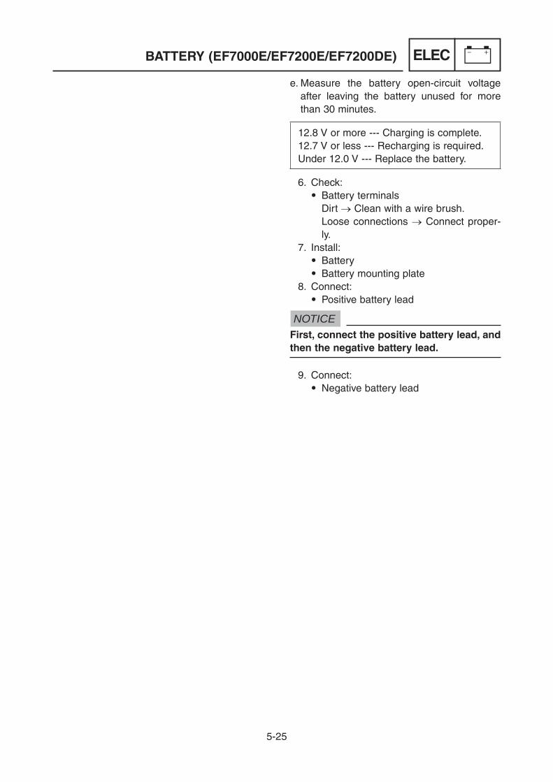
5-25
ELECBATTERY (EF7000E/EF7200E/EF7200DE)
e. Measure the battery open-circuit voltage after leaving the battery unused for more than 30 minutes.
12.8 V or more --- Charging is complete.12.7 V or less --- Recharging is required.Under 12.0 V --- Replace the battery.
6. Check: 9 Battery terminals Dirt → Clean with a wire brush. Loose connections → Connect proper-
ly. 7. Install:
9 Battery 9 Battery mounting plate
8. Connect: 9 Positive battery lead
NOTICEFirst, connect the positive battery lead, and then the negative battery lead.
9. Connect: 9 Negative battery lead

5-26
ELECFUSE (EF7000E/EF7200E/EF7200DE)
1
1
FUSE (EF7000E/EF7200E/EF7200DE)CHECKING THE FUSE
NOTICETo avoid a short circuit, always set the engine switch to “STOP” when checking or replacing a fuse.
1. Remove: 9 Panel cover 9 Panel cover screws 1
1
2. Remove: 9 Fuse 1
3. Check: 9 Fuse Checking steps: a. Connect the pocket tester (W × 1) to
the fuse and check the continuity.
TIPSet the pocket tester selector to “W × 1”.
Analog pocket tester: YU-03112-CPocket tester: 90890-03112
b. If the pocket tester indicates “ ”, replace the fuse.

5-27
ELECFUSE (EF7000E/EF7200E/EF7200DE)
4. Replace: 9 Blown fuse Replacing steps: a. Set the engine switch to “STOP”. b. Install a new fuse of the correct amper-
age. c. Set the engine switch to “ON” and veri-
fy if the electrical circuit is operational. d. If the fuse immediately blows again,
check the electrical circuit.
Fuse amperage: 20 A
WARNINGNever use a fuse with an amperage other than that specified. Improvising or using a fuse with the wrong amperage rating may cause extensive damage to the electrical system and could possibly cause a fire.
5. Install: 9 Fuse
6. Install: 9 Panel cover 9 Panel cover screws
1.3 Nm (0.13 m · kgf, 0.94 ft · lbf)
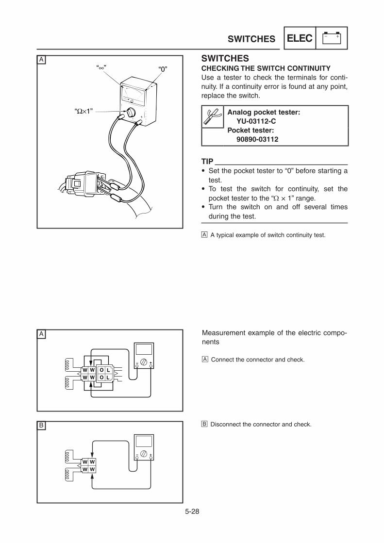
5-28
ELEC
SWITCHESCHECKING THE SWITCH CONTINUITY Use a tester to check the terminals for conti-nuity. If a continuity error is found at any point, replace the switch.
Analog pocket tester: YU-03112-CPocket tester: 90890-03112
TIP9 Set the pocket tester to “0” before starting a
test.9 To test the switch for continuity, set the
pocket tester to the “W × 1” range.9 Turn the switch on and off several times
during the test.
A A typical example of switch continuity test.
Measurement example of the electric compo-nents
A Connect the connector and check.
WW
WW
A
A
B B Disconnect the connector and check.
SWITCHES

5-29
ELECIGNITION SYSTEM
IGNITION SYSTEMTROUBLESHOOTING CHART
NO SPARK OR WEAK SPARK
1. Engine oil level
9 Check the oil level. (Refer to “ENGINE OIL LEVEL” on 2-5)
2. Spark plug
9 Check the spark plug condition. (Refer to “SPARK PLUG” on 2-3)
Add engine oil.MEETS SPECIFICATION
OUT OF SPECIFICATION
Repair or replace the spark plug.GOODNOT GOOD
Inspection steps:1. Engine oil level2. Spark plug3. Ignition spark gap4. Spark plug cap resistance5. Ignition coil (TCI unit) resistance
6. Ignition coil (TCI unit) resistance7. Air gap8. Engine switch9. Oil level switch10. Wire harness
TIP9 Remove the following part(s) before troubleshooting. 1) Control panel 2) Recoil starter9 Use the following special tool(s) for troubleshooting.
Analog pocket tester: YU-03112-CPocket tester: 90890-03112
Oppama pet-4000 spark checker: YM-34487Ignition checker: 90890-06754

5-30
ELECIGNITION SYSTEM
3. Ignition spark gap
9 Disconnect the spark plug cap 1 from the spark plug.9 Connect the ignition checker 2 as
shown.
3
2
1
a
Spark plug cap 1 → Ignition checker 2Ignition checker lead → Spark plug 39 Turn the crankshaft and measure the
ignition spark gap a.
Minimum spark gap: 6.0 mm (0.236 in)
MEETS SPECIFICATION
OUT OF SPECIFICATION OR NO SPARK
The ignition system is good.

5-31
ELECIGNITION SYSTEM
4. Spark plug cap resistance
9 Remove the spark plug cap from the high tension cord.9 Connect the pocket tester (W × 1k) to the
spark plug cap.
2
1
Ω × 1k
Tester + lead → Spark plug side 1Tester - lead → High tension cord side 2
Spark plug cap resistance: 4.0–6.0 kW
5. Ignition coil (TCI unit) resistance
9 Remove the ignition coil (TCI unit).9 Connect the pocket tester (W × 1) to the
primary terminal.
12
Tester + lead → Black/White terminal 1Tester - lead → Body ground 2
Primary coil resistance: 0.6 W ± 20 %
TIP9 Do not pull out the spark plug cap from the
high tension cord. 9 Remove → Turn the spark plug cap coun-
terclockwise. 9 Install → Turn the spark plug cap clock-
wise.9 Check the high tension cord for cracks or
deterioration before installing the spark plug cap.
9 Cut 5 mm off the end of the high tension cord, and then connect it to the spark plug cap.
Replace the spark plug cap.MEETS SPECIFICATION
OUT OF SPECIFICATION
Replace the TCI unit.MEETS SPECIFICATION
OUT OF SPECIFICATION

5-32
ELEC
6. Ignition coil (TCI unit) resistance
9 Remove the ignition coil (TCI unit).9 Connect the pocket tester (W × 1k) to the
secondary terminal.
1
2
Tester + lead → High tension cord 1Tester - lead → Black/White terminal 2
Secondary coil resistance: 12 kW ± 20 %
7. Air gap
9 Measure the thickness between the magnet rotor and TCI unit.
TCI unit air gap: 0.4–0.6 mm (0.0157–0.0236 in)
Replace the TCI unit.MEETS SPECIFICATION
OUT OF SPECIFICATION
Adjust the air gap.MEETS SPECIFICATION
OUT OF SPECIFICATION
IGNITION SYSTEM

5-33
ELECIGNITION SYSTEM
8. Engine switch
9 Disconnect the engine switch coupler in the control box.9 Connect the pocket tester (W × 1) to the
engine switch terminal.9 Check the engine switch continuity.
1
3 4
2
A
B/W B
L/RY
1234B
A EF7000/EF7200B Except for EF7000/EF7200
Tester + lead → Yellow terminal 1Tester - lead → Blue/Red terminal 2Tester + lead → Black/White terminal 3Tester - lead → Black terminal 4
Switch “ON” → ContinuitySwitch “STOP” → No continuity
Replace the engine switch.MEETSSPECIFICATION
OUT OFSPECIFICATION

5-34
ELEC
9. Oil level switch
9 Remove the oil level switch from the bot-tom of the crankcase.
(Refer to “CRANKCASE” on 3-18)9 Connect the pocket tester (W × 1) to the
oil level switch lead and check for conti-nuity.
1
2
1
2
A B
Tester + lead → Oil level switch lead 1Tester - lead → Body ground 2
A Continuity → CorrectB No continuity → Correct
10. Wire harness
9 Check the terminal of the connector for contamination, rust, or disconnection.
Replace the oil level switch.MEETSSPECIFICATION
OUT OFSPECIFICATION
Correct or replace the connector.
Replace the TCI unit.
GOOD NOT GOOD
IGNITION SYSTEM

5-35
ELECELECTRIC STARTING SYSTEM (EF7000E/EF7200E/EF7200DE)
ELECTRIC STARTING SYSTEM (EF7000E/EF7200E/EF7200DE)TROUBLESHOOTING CHART
THE STARTER MOTOR DOES NOT OPERATE
1. Fuse
9 Remove the fuse.9 Connect the pocket tester (W × 1) to the
fuse.9 Check the fuse for continuity. (Refer to “FUSE (EF7000E/EF7200E/
EF7200DE)” on 5-26)
2. Battery voltage
9 Connect the pocket tester (DC 20 V) to the battery terminals.9 Measure the battery voltage.
Tester + lead → battery positive terminalTester - lead → battery negative terminal
Battery voltage: 12.8 V or more
Replace the fuse.
9 Clean the battery terminals.9 Recharge or replace the battery.
CONTINUITYNO CONTINUITY
OUT OF SPECIFICATIONMEETS
SPECIFICATION
Inspection steps:1. Fuse2. Battery voltage
3. Starter motor4. Starter relay
TIP9 Remove the following part(s) before troubleshooting. 1) Control box 2) Control panel 3) Fuel tank9 Use the following special tool(s) for troubleshooting.
Analog pocket tester: YU-03112-CPocket tester: 90890-03112
Digital tachometer: YU-39951-B, 90890-06760

5-36
ELECELECTRIC STARTING SYSTEM (EF7000E/EF7200E/EF7200DE)
3. Starter motor
9 Connect the jumper lead to the starter relay terminals on the battery side and the starter motor side.
9 Check the starter motor operation.
4. Starter relay
9 Disconnect the engine switch connector.9 Connect the jumper lead to the starter
relay connector.
9 Check the starter motor operation.
Replace the engine switch.
MOVES
MOVES
1 Jumper lead
1 Jumper lead
Replace the starter relay.DOES NOT MOVE
Check the battery.(Refer to “BATTERY (EF7000E/EF7200E/EF7200DE)” on 5-18)
DOES NOT MOVE
GOOD NOT GOOD
Repair and/or charge the battery.
Repair and/or replace the starter motor.
WARNING9 A wire that is used as a jumper lead
must have the equivalent capacity or more as that of the battery lead, other-wise the jumper lead may burn.
9 This check is likely to produce sparks, so be sure that no flammable gas or fluid is in the vicinity.

5-37
ELECELECTRIC STARTING SYSTEM (EF7000E/EF7200E/EF7200DE)
1
3
16 Nm (1.6 m · kgf, 12 ft · lbf)2
9 Nm (0.9 m · kgf, 6.5 ft · lbf)
Order Job/Parts to remove Q’ty RemarksRemoving the starter motor Remove the parts in the order listed.Negative battery lead Disconnect.Carrier frame Refer to “HANDLE AND WHEELS (FOR
EF7200DE CAN)” on 3-23.Control box Refer to “CONTROL BOX” on 3-1.Fuel tank Refer to “FUEL TANK, CANISTER” on 3-7.
1 Positive battery lead 1 Disconnect.2 Starter relay lead 1 Disconnect.3 Starter motor assembly 1
REMOVING THE STARTER MOTOR

5-38
ELECELECTRIC STARTING SYSTEM (EF7000E/EF7200E/EF7200DE)
DISASSEMBLING THE STARTER MOTOR
6 Nm (0.6 m · kgf, 4.3 ft · lbf)
9 Nm (0.9 m · kgf, 6.5 ft · lbf)
11 Nm (1.1 m · kgf, 8.0 ft · lbf)
1
9
87
6
23
4
5
Order Job/Parts to remove Q’ty RemarksDisassembling the starter motor Disassemble the parts in the order listed.
1 Rear bracket 12 Insulator 13 Brush spring 44 Brush 45 Yoke 16 Armature 17 Starter relay 18 Starter drive lever 19 Starter case 1
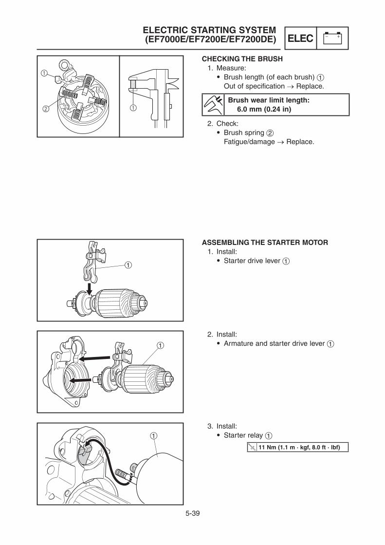
5-39
ELECELECTRIC STARTING SYSTEM (EF7000E/EF7200E/EF7200DE)
1
1
1
CHECKING THE BRUSH 1. Measure:
9 Brush length (of each brush) 1 Out of specification → Replace.
Brush wear limit length: 6.0 mm (0.24 in)
2. Check: 9 Brush spring 2 Fatigue/damage → Replace.
ASSEMBLING THE STARTER MOTOR 1. Install:
9 Starter drive lever 1
2. Install: 9 Armature and starter drive lever 1
3. Install: 9 Starter relay 1
11 Nm (1.1 m · kgf, 8.0 ft · lbf)

5-40
ELECCHARGING SYSTEM (EF7000E/EF7200E/EF7200DE)
CHARGING SYSTEM (EF7000E/EF7200E/EF7200DE)TROUBLESHOOTING CHART
THE BATTERY IS NOT CHARGED
1. Battery voltage
9 Connect the pocket tester (DC 20 V) to the battery terminals.9 Measure the battery voltage.
Tester + lead → battery positive terminalTester - lead → battery negative termi-nal
Battery voltage: 12 V
9 Clean the battery terminals.9 Recharge or replace the battery.
OUT OF SPECIFICATION
MEETSSPECIFICATION
Inspection steps:1. Battery voltage2. Charging voltage
3. Fuse4. Charging coil resistance
TIP9 Remove the following part(s) before troubleshooting. 1) Control panel 2) Recoil starter 3) Flywheel9 Use the following special tool(s) for troubleshooting.
Analog pocket tester: YU-03112-CPocket tester: 90890-03112
Digital tachometer: YU-39951-B, 90890-06760

5-41
ELECCHARGING SYSTEM (EF7000E/EF7200E/EF7200DE)
3. Fuse
9 Remove the fuse.9 Connect the pocket tester (W × 1) to the
fuse.9 Check the fuse for continuity. (Refer to “FUSE (EF7000E/EF7200E/
EF7200DE)” on 5-26)
Replace the fuse.NO CONTINUITYCONTINUITY
2. Charging voltage
9 Start the engine.9 Accelerate to 3600 r/min.9 Measure the charging voltage.
DC20V
Battery charging voltage: More than 14.0 V
MORE THAN 14.0 V
Properly connect the charging system.MEETSSPECIFICATION

5-42
ELECCHARGING SYSTEM (EF7000E/EF7200E/EF7200DE)
4. Charging coil resistance
9 Disconnect the charging coil leads.9 Connect the pocket tester (W × 1).
1
2
3
W
G/R
9 Measure the charging coil resistance.
Charging coil resistance: White 1–Ground 2: 2.0 W ± 20 % Green/Red 3–Ground 2: 1.8 W ± 20 %
Replace the charging coil.
OUT OF SPECIFICATION
Replace the regulator.
MEETSSPECIFICATION
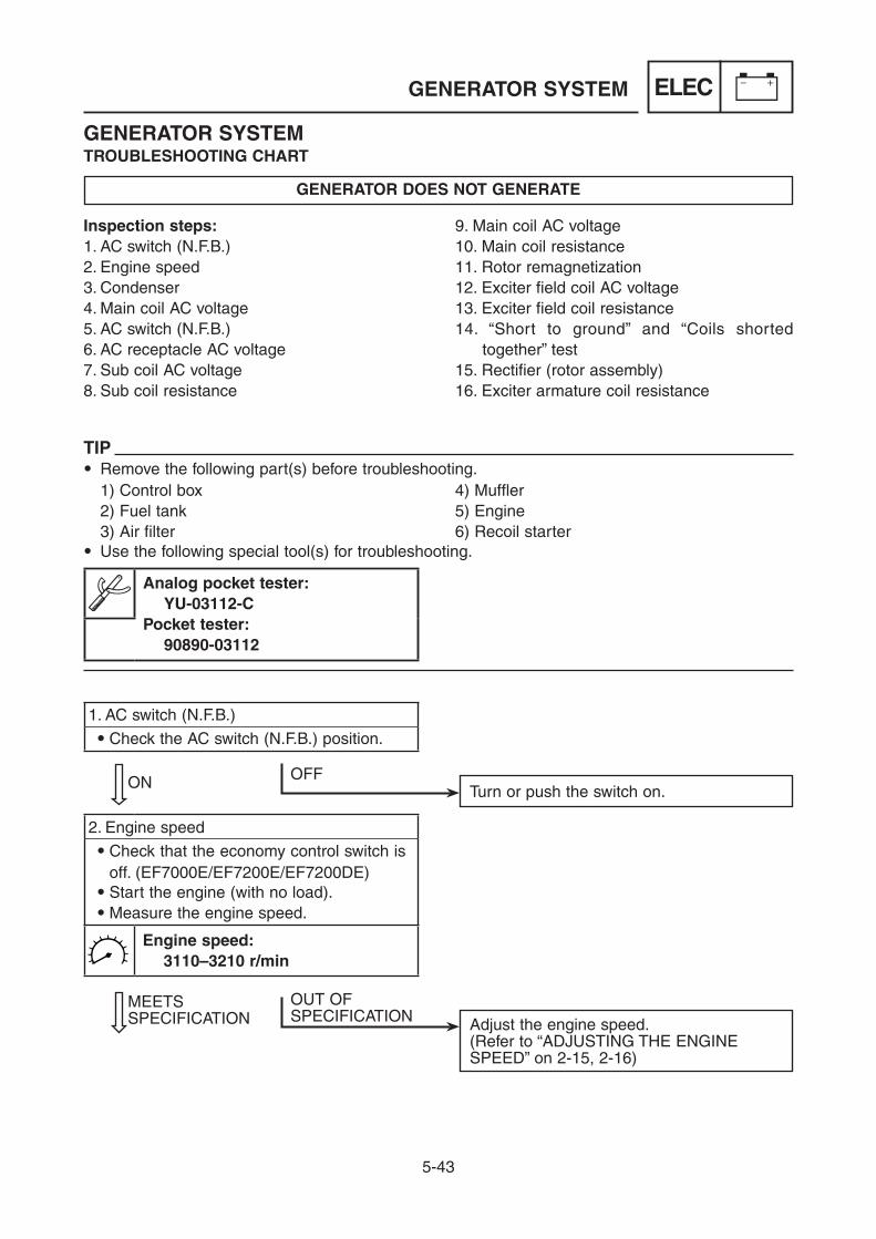
5-43
ELECGENERATOR SYSTEM
GENERATOR SYSTEMTROUBLESHOOTING CHART
GENERATOR DOES NOT GENERATE
1. AC switch (N.F.B.)
9 Check the AC switch (N.F.B.) position.
2. Engine speed
9 Check that the economy control switch is off. (EF7000E/EF7200E/EF7200DE)9 Start the engine (with no load).9 Measure the engine speed.
Engine speed: 3110–3210 r/min
ON OFFTurn or push the switch on.
Adjust the engine speed.(Refer to “ADJUSTING THE ENGINE SPEED” on 2-15, 2-16)
MEETSSPECIFICATION
OUT OF SPECIFICATION
Inspection steps:1. AC switch (N.F.B.)2. Engine speed3. Condenser4. Main coil AC voltage5. AC switch (N.F.B.)6. AC receptacle AC voltage7. Sub coil AC voltage8. Sub coil resistance
9. Main coil AC voltage10. Main coil resistance11. Rotor remagnetization12. Exciter field coil AC voltage13. Exciter field coil resistance14. “Short to ground” and “Coils shorted
together” test15. Rectifier (rotor assembly)16. Exciter armature coil resistance
TIP9 Remove the following part(s) before troubleshooting. 1) Control box 4) Muffler 2) Fuel tank 5) Engine 3) Air filter 6) Recoil starter9 Use the following special tool(s) for troubleshooting.
Analog pocket tester: YU-03112-CPocket tester: 90890-03112

5-44
ELEC
3. Condenser
9 Connect the pocket tester.9 Turn the pocket tester switch from the
“OFF” position to the “W × 1k” position.
CORRECT FAULTY
1 The needle swings and returns back quickly.
2 The needle does not swing.
3 The needle does not return.
GOOD Replace the condenser.(Refer to “CONTROL PANEL” on 5-8)
WARNING9 Discharge the old condenser by short-
ing the two terminals together.9 Use an insulated screwdriver.9 Do not touch either of the terminals or
the ground before the condenser is dis-charged.
NOT GOOD
W×1k W×1k W×1k
GENERATOR SYSTEM
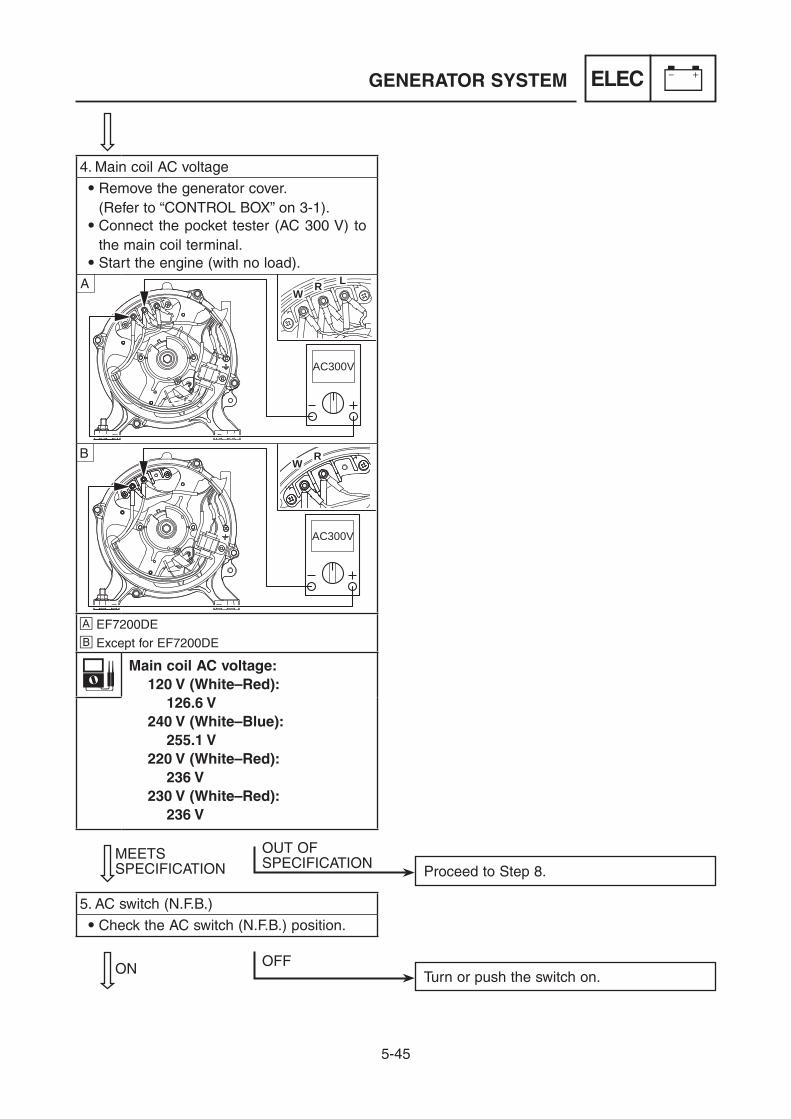
5-45
ELEC
4. Main coil AC voltage
9 Remove the generator cover. (Refer to “CONTROL BOX” on 3-1).9 Connect the pocket tester (AC 300 V) to
the main coil terminal.9 Start the engine (with no load).
AC300V
WR LA
AC300V
WRB
A EF7200DEB Except for EF7200DE
Main coil AC voltage: 120 V (White–Red): 126.6 V 240 V (White–Blue): 255.1 V 220 V (White–Red): 236 V 230 V (White–Red): 236 V
5. AC switch (N.F.B.)
9 Check the AC switch (N.F.B.) position.
OUT OF SPECIFICATION Proceed to Step 8.
MEETSSPECIFICATION
ON OFFTurn or push the switch on.
GENERATOR SYSTEM

5-46
ELEC
Replace the AC switch (N.F.B.).
6. AC receptacle AC voltage
9 Start the engine (with no load).9 Connect the pocket tester (AC 300 V) to
the AC receptacle.
Tester + lead → AC receptacleTester - lead → AC receptacle
AC receptacle AC voltage: 126.6 V (120 V receptacle) 255.1 V (240 V receptacle) 236 V (220 V receptacle) 236 V (230 V receptacle)
Check for damaged AC receptacle.
DAMAGED
Check and repair wiring from the generator to the control panel.
OK
Replace the AC receptacle.
OUT OF SPECIFICATION
MEETSSPECIFICATION
No further action necessary.
CONTINUITY
Check AC switch (N.F.B.) for continuity in the on position.
NO CONTINUITY
GENERATOR SYSTEM

5-47
ELECGENERATOR SYSTEM
7. Sub coil AC voltage
9 Disconnect the stator assembly (sub coil) coupler.9 Connect the pocket tester (AC 20 V) as
shown.9 Start the engine (with no load).
AC20V
GW
G
A
AC20V
GW
G
B
A EF7200DEB Except for EF7200DE
Tester + lead → Green terminalTester - lead → Green terminal
Sub coil AC voltage: 120/240 V: 9.9/9.9 V 220 V: 8.9 V 230 V: 8.9 V
MEETS SPECIFICATION
8. Sub coil resistance
9 Connect the pocket tester (W × 1) as shown.
Ω×1
GW
G
A
Ω×1
GW
G
B
A EF7200DEB Except for EF7200DE
Tester + lead → Green terminalTester - lead → Green terminal
Sub coil resistance: 120/240 V: 0.366 W ± 10 % 220 V: 0.508 W ± 10 % 230 V: 0.508 W ± 10 %
OUT OF SPECIFICATION
OUT OF SPECIFICATION
Replace the stator assembly.

5-48
ELEC
9. Main coil AC voltage
9 Disconnect the stator assembly (main coil) leads and stator assembly (sub coil) coupler.9 Connect the pocket tester (AC 120 V) to
the stator assembly (main coil) lead ter-minal.9 Start the engine (with no load).
AC120V
WR
LA
AC120V
WR
B
A EF7200DEB Except for EF7200DE
Main coil AC voltage: 120 V (White–Red): 26 V 240 V (White–Blue): 51 V 220 V (White–Red): 36 V 230 V (White–Red): 36 V
10. Main coil resistance
9 Connect the pocket tester (W × 1) to the stator assembly (main coil) lead.
Ω×1
WR
LA
Ω×1
WR
B
A EF7200DEB Except for EF7200DE
Main coil resistance: 120 V (White–Red): 0.218 W ± 10 % 240 V (White–Blue): 0.507 W ± 10 % 220 V (White–Red): 0.503 W ± 10 % 230 V (White–Red): 0.503 W ± 10 %
OUT OF SPECIFICATION
Replace the stator assembly.
MEETSSPECIFICATION
GENERATOR SYSTEM
OUT OF SPECIFICATION

5-49
ELECGENERATOR SYSTEM
11. Rotor remagnetization
9 Disconnect the exciter field coil coupler (Black–White) at the end of the genera-tor unit.9 Start the engine (with no load).9 Connect the DC 12 V battery to the sta-
tor side of the exciter field coil coupler, battery - to coupler terminal (Black), and battery + to coupler terminal (White), for 2–5 seconds.9 Remove the battery and reconnect the
exciter field coil coupler.9 Recheck the main coil AC output voltage.
OUT OF SPECIFICATION Proceed to step 12.
MEETSSPECIFICATION
No further action necessary.
NOTICEDo not connect the battery for more than a few seconds. This may deteriorate the bat-tery.

5-50
ELECGENERATOR SYSTEM
12. Exciter field coil AC voltage
9 Disconnect the exciter field coil coupler.9 Connect the pocket tester (AC 20 V) as
shown.9 Start and run the engine.
B
W
9 Measure the exciter field coil voltage.
Exciter field coil AC voltage (Black–White): 17 V
OUT OF SPECIFICATION
MEETS SPECIFICATION
13. Exciter field coil resistance
9 Disconnect the exciter field coil coupler.9 Connect the pocket tester (W × 1) as
shown.
B
W
9 Measure the exciter field coil resistance.
Exciter field coil resistance (Black–White): 46.5 W ± 10 %
OUT OF SPECIFICATION
Replace the exciter field coil.

5-51
ELECGENERATOR SYSTEM
14. “Short to ground” and “Coils shorted together” test
9 Disconnect the stator assembly (main coil) leads, stator assembly (sub coil) coupler, and exciter field coil coupler.
Set the meter to the highest ohm setting.
“Short to ground test”Connect the - lead to the stator housing and + lead to any wire of the main coil.Repeat same procedure with the sub and exciter field coils.“Coils shorted together test”Connect the - lead to any wire of main coil and + lead to either green wire on the sub coil.
9 Measure resistance.
All tests should read an open circuit or dis-continuity; any other reading indicates a defective main coil assembly or exciter field coil.
GOOD NOT GOODReplace defective coil.

5-52
ELECGENERATOR SYSTEM
15. Rectifier (rotor assembly)
9 Remove the rotor assembly.9 Connect the pocket tester (W × 1) as
shown.
1
4
3
2
Rectifier continuity:
Pocket testerconnecting point Good
+ (Red) - (Black)1 2 2
2 1 ×1 3 ×3 1 ×1 4 ×4 1 2
2 3 ×3 2 2
2 4 ×4 2 2
3 4 ×4 3 2
2: Continuity ×: No continuity ( )
NOT GOODReplace the rectifier.
GOOD

5-53
ELECGENERATOR SYSTEM
16. Exciter armature coil resistance
9 Connect the pocket tester (W × 1) as shown.
Ω × 1
Exciter armature coil resistance: 1.82 W ± 10 %
MEETSSPECIFICATION
OUT OF SPECIFICATION Replace the rotor assembly.
Replace the AVR 1.
1

5-54
ELEC
2
7 Nm (0.7 m á kgf, 5.1 ft á lbf)
1
16 Nm (1.6 m á kgf, 12 ft á lbf)
3
16 Nm (1.6 m á kgf, 12 ft á lbf)
Order Job/Parts to remove Q’ty RemarksRemoving the economy control solenoid
Remove the parts in the order listed.
Carrier frame Refer to “HANDLE AND WHEELS (FOR EF7200DE CAN)” on 3-23.
Control box Refer to “CONTROL BOX” on 3-1.Fuel tank Refer to “FUEL TANK, CANISTER” on 3-7.
1 Economy control solenoid 12 Spring 13 Bracket 1
ECONOMY CONTROL SYSTEM (EF7000E/EF7200E/EF7200DE)ECONOMY CONTROL SOLENOID
ECONOMY CONTROL SYSTEM (EF7000E/EF7200E/EF7200DE)

5-55
ELECECONOMY CONTROL SYSTEM (EF7000E/EF7200E/EF7200DE)
1
2
2
1
3
INSTALLING THE ECONOMY CONTROL SOLENOID 1. Install:
9 Economy control solenoid 1 9 Economy control solenoid bolts 2
TIPTemporary tighten the economy control sole-noid bolts.
2. Adjust: 9 Economy control solenoid
Adjustment steps: a. Turn the governor arm 1 counterclock-
wise until it stops. b. Pull the plunger 2 in direction of the
arrow to the position shown in the illus-tration.
c. Keep the position on step (a) and step (b), tighten the economy control sole-noid bolts 3.
7 Nm (0.7 m · kgf, 5.1 ft · lbf)

5-56
ELECECONOMY CONTROL SYSTEM (EF7000E/EF7200E/EF7200DE)
1
4
5
3
2
6
7
Order Part name Remarks1 Economy control solenoid Operate the governor arm.2 Throttle valve Control the engine speed.3 Economy control switch Switching.4 Economy control unit Control the economy control solenoid.5 Receptacle —6 Governor weight Check the engine speed.7 Governor arm —
ECONOMY CONTROL SYSTEM DIAGRAM
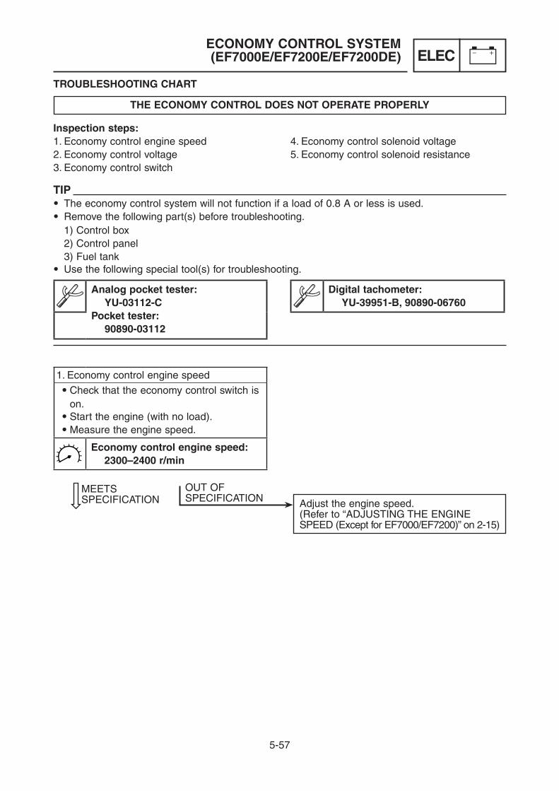
5-57
ELEC
TROUBLESHOOTING CHART
THE ECONOMY CONTROL DOES NOT OPERATE PROPERLY
1. Economy control engine speed
9 Check that the economy control switch is on.9 Start the engine (with no load).9 Measure the engine speed.
Economy control engine speed: 2300–2400 r/min
Adjust the engine speed.(Refer to “ADJUSTING THE ENGINE SPEED (Except for EF7000/EF7200)” on 2-15)
MEETSSPECIFICATION
OUT OF SPECIFICATION
ECONOMY CONTROL SYSTEM (EF7000E/EF7200E/EF7200DE)
Inspection steps:1. Economy control engine speed2. Economy control voltage3. Economy control switch
4. Economy control solenoid voltage5. Economy control solenoid resistance
TIP9 The economy control system will not function if a load of 0.8 A or less is used.9 Remove the following part(s) before troubleshooting. 1) Control box 2) Control panel 3) Fuel tank9 Use the following special tool(s) for troubleshooting.
Analog pocket tester: YU-03112-CPocket tester: 90890-03112
Digital tachometer: YU-39951-B, 90890-06760
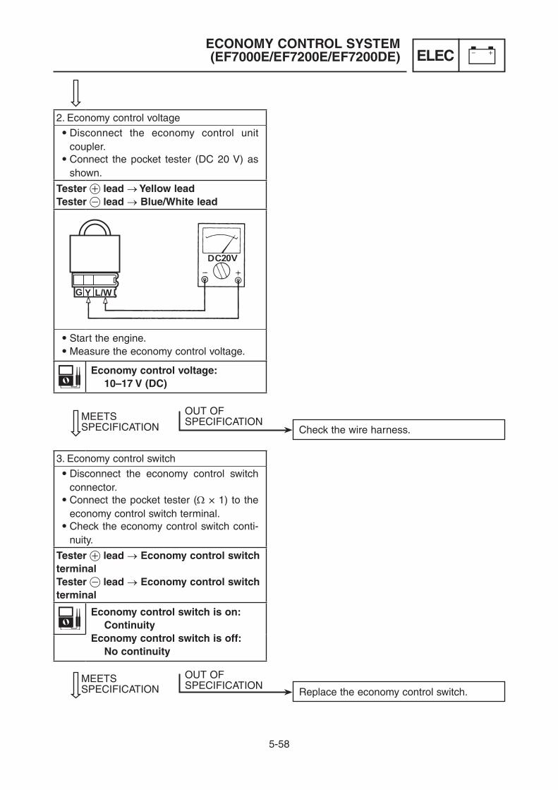
5-58
ELECECONOMY CONTROL SYSTEM (EF7000E/EF7200E/EF7200DE)
2. Economy control voltage
9 Disconnect the economy control unit coupler.9 Connect the pocket tester (DC 20 V) as
shown.
Tester + lead → Yellow leadTester - lead → Blue/White lead
G Y L/W
9 Start the engine.9 Measure the economy control voltage.
Economy control voltage: 10–17 V (DC)
3. Economy control switch
9 Disconnect the economy control switch connector.9 Connect the pocket tester (W × 1) to the
economy control switch terminal.9 Check the economy control switch conti-
nuity.
Tester + lead → Economy control switch terminalTester - lead → Economy control switch terminal
Economy control switch is on: ContinuityEconomy control switch is off: No continuity
Replace the economy control switch.MEETSSPECIFICATION
OUT OF SPECIFICATION
Check the wire harness.MEETSSPECIFICATION
OUT OFSPECIFICATION

5-59
ELECECONOMY CONTROL SYSTEM (EF7000E/EF7200E/EF7200DE)
Replace the economy control solenoid.MEETSSPECIFICATION
OUT OF SPECIFICATION
4. Economy control solenoid voltage
9 Connect the pocket tester (DC 20 V) to the economy control solenoid connector.
Tester + lead → Orange leadTester - lead → Green lead
DC20V
GO
9 Start the engine.9 Measure the economy control solenoid
voltage.
Economy control solenoid voltage: 10.8–13.2 V (DC)

5-60
ELECECONOMY CONTROL SYSTEM (EF7000E/EF7200E/EF7200DE)
5. Economy control solenoid resistance
9 Disconnect the economy control solenoid connector.9 Connect the pocket tester (W × 10) as
shown.
Ω×10
9 Measure the economy control solenoid resistance.
Economy control solenoid resistance: 26 W ± 5 %
Replace the economy control solenoid.
OUT OF SPECIFICATION

6-1
TRBLENGINE
TROUBLESHOOTINGENGINE
ENGINE DOES NOT START
Add.
Check the engine oil level.
SUFFICIENT INSUFFICIENT
Add.
Check the fuel level.
SUFFICIENT INSUFFICIENT
Replace.
Check if fuel has deteriorated.
GOOD DETERIORATED
Clean or replace.
Check if the fuel tank cap is clogged.
GOOD CLOGGED
Set to “ON”.
Check the fuel cock lever position.
“ON” “OFF”
Clean or replace the fuel tank or fuel hose.
Check if fuel flows to fuel cock.
FLOW OK NO FLOW
Check that the oil warning light comes on by pull-ing the starter rope or turn the engine switch.
LIGHTS ON DOSE NOT LIGHT
Check the connections between the oil warning unit and oil level switch.
GOOD NOT GOOD
Replace the oil warning light, oil warning unit, or oil level switch.
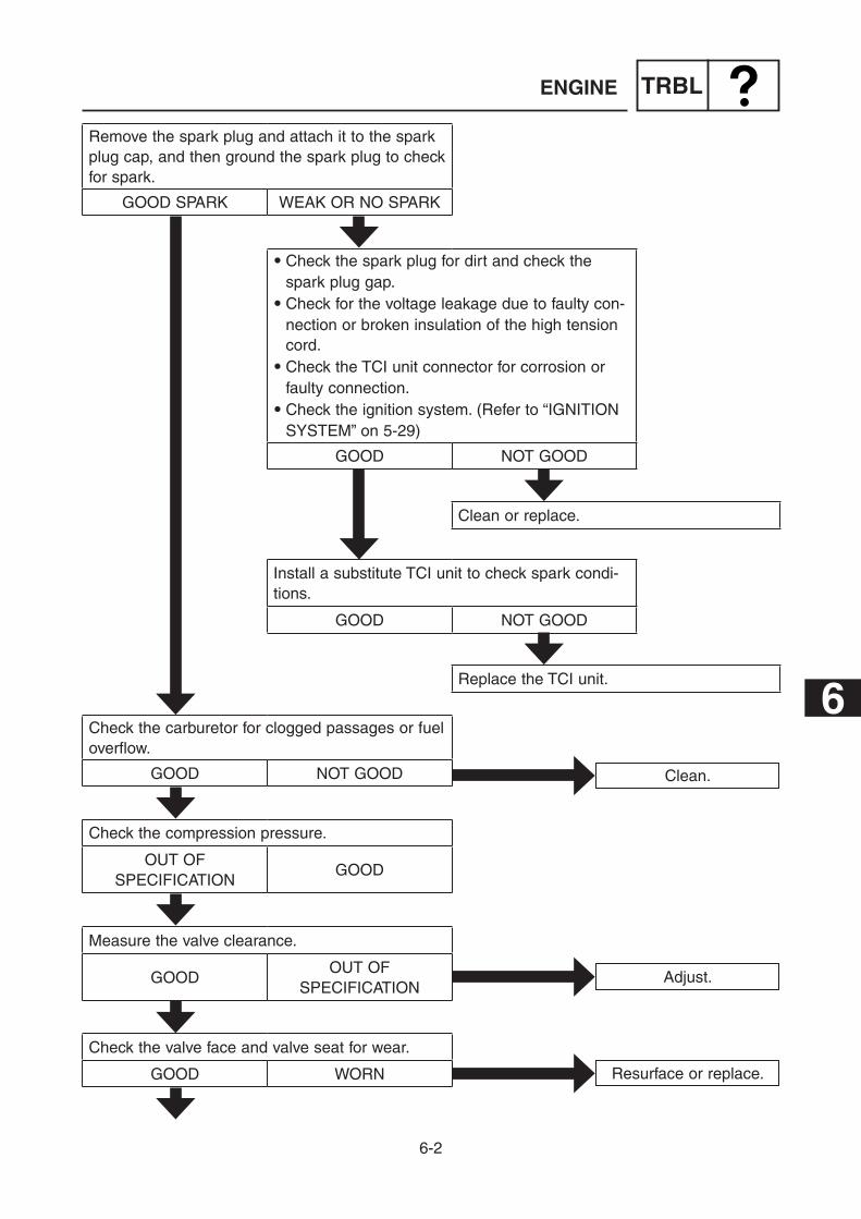
6-2
TRBL
6
Clean.
Check the carburetor for clogged passages or fuel overflow.
GOOD NOT GOOD
Check the compression pressure.
OUT OF SPECIFICATION
GOOD
Adjust.
Measure the valve clearance.
GOODOUT OF
SPECIFICATION
Resurface or replace.
Check the valve face and valve seat for wear.
GOOD WORN
Remove the spark plug and attach it to the spark plug cap, and then ground the spark plug to check for spark.
GOOD SPARK WEAK OR NO SPARK
Clean or replace.
9 Check the spark plug for dirt and check the spark plug gap.9 Check for the voltage leakage due to faulty con-
nection or broken insulation of the high tension cord.9 Check the TCI unit connector for corrosion or
faulty connection.9 Check the ignition system. (Refer to “IGNITION
SYSTEM” on 5-29)
GOOD NOT GOOD
Replace the TCI unit.
Install a substitute TCI unit to check spark condi-tions.
GOOD NOT GOOD
ENGINE

6-3
TRBLENGINE
Correct.
Check if the marks on the crankshaft and cam-shaft are aligned.
ALIGNED NOT ALIGNED
Rebore or replace.
Check if there is seizure, wear, or damage on the piston, piston ring, or cylinder.
GOOD SEIZURE OR WORN
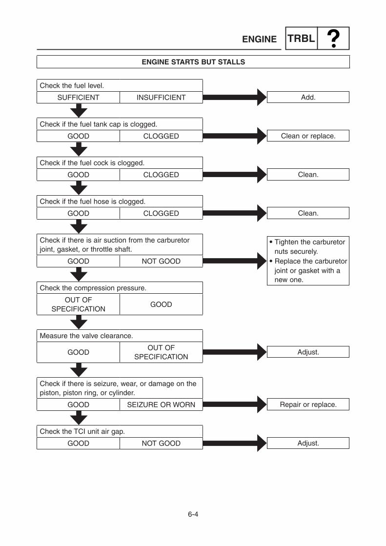
6-4
TRBLENGINE
ENGINE STARTS BUT STALLS
Add.
Check the fuel level.
SUFFICIENT INSUFFICIENT
Clean or replace.
Check if the fuel tank cap is clogged.
GOOD CLOGGED
Clean.
Check if the fuel cock is clogged.
GOOD CLOGGED
Check the compression pressure.
OUT OF SPECIFICATION
GOOD
9 Tighten the carburetor nuts securely.9 Replace the carburetor
joint or gasket with a new one.
Check if there is air suction from the carburetor joint, gasket, or throttle shaft.
GOOD NOT GOOD
Adjust.
Measure the valve clearance.
GOODOUT OF
SPECIFICATION
Clean.
Check if the fuel hose is clogged.
GOOD CLOGGED
Adjust.
Check the TCI unit air gap.
GOOD NOT GOOD
Repair or replace.
Check if there is seizure, wear, or damage on the piston, piston ring, or cylinder.
GOOD SEIZURE OR WORN

6-5
TRBLENGINE
ENGINE SPEED DOES NOT INCREASE
Remove the electric equipment with too much wattage.
Check if the electric equipment consumes too much wattage for this generator.
GOOD TOO MUCH
Decarbonize the com-bustion chamber if there is carbon deposits.
Check the compression pressure.
GOODTOO HIGH
TOO LOW
Clean.
Check the air filter element for dirt.
GOOD DIRTY
Clean, adjust, or replace.
Check the spark plug for dirt and check the spark plug gap.
GOODDIRTY OR OUT OF
SPECIFICATION
Adjust.
Measure the valve clearance.
GOODOUT OF
SPECIFICATION
Resurface or replace.
Check the valve face and valve seat for wear.
GOOD WORN
Correct.
Check if the marks on the crankshaft and cam-shaft are aligned.
GOOD NOT GOOD
Rebore or replace.
Check if there is seizure, wear, or damage on the piston, piston ring, or cylinder.
GOOD SEIZURE OR WORN

6-6
TRBLENGINE
Clean the parts.
Check if the main passages, such as the main jet in the carburetor, are clogged.
GOOD CLOGGED
9 Tighten the carburetor nuts securely.9 Replace the carburetor
joint or gasket with a new one.
Check if there is air suction from the carburetor joint, gasket, or throttle shaft.
GOOD NOT GOOD

6-7
TRBLENGINE
ENGINE SPEED IS UNEVEN
Add.
Check the fuel level.
SUFFICIENT INSUFFICIENT
Replace.
Check if fuel has deteriorated.
GOOD DETERIORATED
Replace.
Check if the fuel tank cap is clogged.
GOOD CLOGGED
Clean.
Check if the fuel cock is clogged.
GOOD CLOGGED
Clean, adjust, or replace.
Check the spark plug for dirt and check the spark plug gap.
GOODDIRTY OR OUT OF
SPECIFICATION
9 Tighten the carburetor nuts securely.9 Replace the carburetor
joint or gasket with a new one.
Check if there is air suction from the carburetor joint, gasket, or throttle shaft.
GOOD NOT GOOD
Clean the parts.
Check if the slow or main passages such as, pilot jet and main jet, in the carburetor are clogged.
GOOD NOT GOOD
Adjust or replace.
Check the carburetor pilot screw turn out and float height.
GOODOUT OF
SPECIFICATION

6-8
TRBLENGINE
Rebore or replace.
Check if there is seizure, wear, or damage on the piston, piston ring, or cylinder.
GOOD SEIZURE OR WORN
Resurface or replace.
Check the valve face and valve seat for wear.
GOOD WORN
Adjust.
Check the valve clearance.
SUFFICIENTOUT OF
SPECIFICATION

6-9
TRBLENGINE
GOVERNOR OPERATION
Adjust or replace.
Check that the governor link operate smoothly.
GOOD NO GOOD
Replace.
Check that the governor spring is stretched.
GOOD STRETCHED
Adjust.
Check the governor adjustment.
GOOD NOT GOOD
Adjust or replace.
Check the governor weight and governor bushing function.
GOOD NOT GOOD

7-1
SPECGENERAL SPECIFICATIONS
SPECIFICATIONSGENERAL SPECIFICATIONS
Model code number: 7P6202 (EF7200DE) (CSA/SEA)7P6203 (EF7200DE) (CAN)7P6204 (EF7200DE) (SAU)7P6300 (EF7200) (AFR/SEA)7P6301 (EF7200E) (AFR/SEA)7P6302 (EF7200E) (OCE)7P6303 (EF7000) (CHN)7P6304 (EF7000E) (CHN)7P6305 (EF7200) (RUS)7P6306 (EF7200E) (RUS)
Dimensions: Overall length (*1) mm (in) 740 (29.1) (For EF7200DE CAN) Overall length (*2) 1070 (42.1) (For EF7200DE CAN) Overall length 670 (26.4) Overall width mm (in) 720 (28.3) (For EF7200DE CAN)
535 (21.1) Overall height mm (in) 800 (31.5) (For EF7200DE CAN)
565 (22.2) Dry weight kg (lb) 106 (233.7) (For EF7200DE CAN)
94 (207.2) (EF7200DE)93 (205.0) (EF7200E/EF7000E)84 (185.2) (EF7200/EF7000)
Noise level(*): dB/LWA 100.0 (EF7200DE)96.5
dB (A)/7m 74.5 (EF7200DE)71.0
Engine: Engine type Air cooled 4-stroke gasoline OHV Cylinder arrangement Inclined, 1 cylinder Displacement L (cm3) 0.358 (358) Bore × Stroke mm (in) 85.0 × 63.2 (3.35 × 2.49) Compression ratio 8.2:1 Standard compression
pressure kPa (kg/cm2, psi) 1100–1250 (11.0–12.5, 157–179) Operating hours (Rated load) Hrs/Hz 8.0/60 (For EF7200DE CAN/SAU)
8.5/60 (For EF7200DE CSA/SEA)12.0/50 (For EF7200 SEA/AFR)11.0/50
Fuel Unleaded gasoline Fuel tank capacity L (US gal, Imp gal) 26 (6.87, 5.72) (For EF7200DE CAN)
28 (7.40, 6.16) Engine oil quantity L (US qt, Imp qt) 1.1 (1.16, 0.97)
7

7-2
SPECGENERAL SPECIFICATIONS
Recommended engine oil A YAMALUBE 4 (10W-40), SAE 10W-30 or 10W-40
B SAE #30C SAE #20D SAE 10W
A YAMALUBE 4 (10W-40)
B SAE #30C SAE #20D SAE 10W
Recommended engine oil grade API Service SE type or higher Lubrication system Forced splashing Air filter system Semi-wet (urethane foam) Cooling system Air cooled Starting system Recoil starter (EF7000/EF7200)
Electric and recoil starter (EF7000E/EF7200E/EF7200DE)
Stopping system Misfire Rotating direction Clockwise (from flywheel) Governor type Centrifugal weight systemElectrical: Ignition system Ignition timing (3600 r/min) Spark plug type Spark plug gap mm (in)
TCIBTDC 20° ± 3°BPR4ES (NGK)0.7–0.8 (0.028–0.031)
Generator: Type Brushless, self-exciting, single-phase, synchro-
nous generator Number of phase Single phase Number of poles 2 Excitation Self magnetization Initial excitation Residual magnetization Driving method Direct connection Rated power factor 1.0 Frequency variation Less than 5 % Voltage fluctuation Less than 10 % AC output Rated voltage V 120/240 (EF7200DE)
230 (For EF7200E OCE)220
Frequency Hz 60 (EF7200DE)50
Rated output kVA 6.0 (EF7200DE)5.0

7-3
SPECGENERAL SPECIFICATIONS
Rated current A 50.0/25.0 (EF7200DE)21.7 (For EF7200E OCE)22.7
Safety device type N.F.B. (No Fuse Breaker) Rated engine speed r/min 3600 Economy control engine speed r/min 2300–2400 (EF7000E/EF7200E/EF7200DE) Engine speed r/min 3110–3210 Voltage regulation AVR Insulation resistance(*3) MW More than 10 Insulation class Stator E class Rotor B class Receptacle AC 15 A 125 V × 2 (EF7200DE)
30 A 125 V × 1 (EF7200DE)30 A 250 V/125 V × 1 (EF7200DE)15 A 250 V × 2 (For EF7200E OCE)20 A 250 V × 2
(*) : Noise level is measured when the economy control switch is turned to “I” (ON). LWA shows the sound power level under the ISO3744 satisfied test conditions. The noise level in “dB (A)/7 m” is the arithmetic mean value in four directions measured 7
meters away from each side of the generator. The noise level may vary in different environments.(*1) : Handle folded, with two wheel kit installed.(*2) : Handle deployment, with two wheel kit installed.(*3) : The insulation resistance of the individual parts measures higher than the generator itself
because of lower electric leakage.

7-4
SPECMAINTENANCE SPECIFICATIONS
Piston: mm (in) Piston clearance 0.015–0.029 (0.0006–0.0011) <Limit> 0.150 (0.0059) Piston skirt “D” 84.977–84.998 (3.3456–3.3464) <Limit> 84.900 (3.3425) Measuring point “H” 10 (0.4) Oversize 1st 85.25 (3.3563) 2nd 85.50 (3.3661) Piston pin hole inside diameter 20.004–20.015 (0.7876–0.7880) <Limit> 20.045 (0.7892)Piston pin: mm (in) Piston pin diameter 19.955–20.000 (0.7856–0.7874) <Limit> 19.930 (0.7846)Piston ring: mm (in) Top ring Type Barrel Dimensions “B × T” 1.2 × 3.1 (0.0472 × 0.1220) End gap 0.20–0.35 (0.008–0.014) <Limit> 0.6 (0.0236) Side clearance 0.04–0.08 (0.0016–0.0031) <Limit> 0.13 (0.0051) 2nd ring Type Taper Dimensions “B × T” 1.2 × 3.2 (0.0472 × 0.1260) End gap 0.30–0.45 (0.0118–0.0177) <Limit> 0.8 (0.0315) Side clearance 0.03–0.07 (0.0012–0.0028) <Limit> 0.13 (0.0051) Oil ring Type 3-piece type Dimensions “B × T” 2.5 × 2.5 (0.0984 × 0.0984) End gap 0.20–0.70 (0.008–0.028)Cylinder head: mm (in) Warpage limit 0.1 (0.0039)Cylinder: mm (in) Inside diameter “D” 85.000–85.020 (3.3465–3.3472) <Limit> 85.020 (3.3472) Taper limit 0.05 (0.002) Warpage limit 0.05 (0.002)
MAINTENANCE SPECIFICATIONSENGINE
B
T

7-5
SPECMAINTENANCE SPECIFICATIONS
Crankshaft: mm (in) Big end side clearance “A” 0.20–0.65 (0.008–0.026) <Limit> 0.5 (0.0197) Runout “B” <Limit> 0.03 (0.0012) Crank pin outside diameter “C” 35.969–35.984 (1.4161–1.4167) <Limit> 35.9 (1.4134)Connecting rod: mm (in) Small end diameter “A” 20.006–20.020 (0.7876–0.7882) Oil clearance 0.006–0.025 (0.0002–0.0010) Big end diameter “B” 36.000–36.015 (1.4173–1.4179) Oil clearance 0.016–0.046 (0.0006–0.0018) <Limit> 0.10 (0.0040)Camshaft: mm (in) Camshaft outside diameter Cam dimension “A” IN 32.55 ± 0.05 (1.281 ± 0.002) <Limit> 32.40 (1.276) “A” EX 32.55 ± 0.05 (1.281 ± 0.002) <Limit> 32.40 (1.276) “B” IN 26.08 ± 0.05 (1.027 ± 0.002) <Limit> 25.93 (1.021) “B” EX 26.08 ± 0.05 (1.027 ± 0.002) <Limit> 25.93 (1.021) Camshaft journal diameter 15.965–15.990 (0.6285–0.6295) <Limit> 15.950 (0.6280)

7-6
SPECMAINTENANCE SPECIFICATIONS
Valve: mm (in) Valve Head diameter “A” IN 32.0 (1.26) EX 28.0 (1.10) Stem diameter “B” IN 5.948–5.963 (0.2342–0.2348) EX 5.940–5.955 (0.2339–0.2344) <Limit> IN 5.918 (0.2330) EX 5.910 (0.2327) Stem length “C” IN 88.1 (3.47) EX 88.1 (3.47) Valve face contact width “D” IN 0.9–1.1 (0.0354–0.0433) EX 0.9–1.1 (0.0354–0.0433) <Limit> IN 1.6 (0.063) EX 1.6 (0.063) Valve seat contact width IN 0.9–1.1 (0.0354–0.0433) EX 0.9–1.1 (0.0354–0.0433) <Limit> IN 1.6 (0.063) EX 1.6 (0.063) Valve stem runout limit 0.01 (0.0004) “θ” 90° Valve guide Guide inside diameter IN 6.000–6.012 (0.2362–0.2367) EX 6.000–6.012 (0.2362–0.2367) Stem to guide clearance IN 0.037–0.064 (0.00146–0.00252) EX 0.045–0.072 (0.00177–0.00283) Valve clearance (cold) IN 0.05–0.09 (0.0020–0.0035) EX 0.05–0.09 (0.0020–0.0035)Push rod: mm (in) Runout limit 0.5 (0.02)Valve spring: mm (in) Free length IN 36.2 (1.4252) EX 36.2 (1.4252) <Limit> IN 34.39 (1.35) EX 34.39 (1.35) Set length IN 29.0 (1.14) EX 29.0 (1.14) Set force IN N (kgf, lbf) 91.20–104.92 (9.30–10.70, 20.50–23.59) EX N (kgf, lbf) 91.20–104.92 (9.30–10.70, 20.50–23.59) Tilt limit mm (in) 1.2 (0.047)

7-7
SPECMAINTENANCE SPECIFICATIONS
Carburetor: mm (in) Type BV26-20 I.D. mark 7CH00
7CH10 (For EF7200 SEA/AFR)7HD00 (EF7000E/EF7200E/EF7200DE)
Bore size ø20 Main jet #105 Main air jet ø1.4 (0.055)
ø1.5 (0.059) (For EF7200 SEA/AFR) Pilot air jet ø0.9 (0.053) Pilot outlet ø0.9 (0.053) Valve seat size ø1.8 (0.071) Main nozzle 63C
65A (For EF7200 SEA/AFR) Pilot jet #53.8 Pilot adjusting screw 2-1/2 turns out
2 turns out (For EF7200 SEA/AFR) Throttle valve #120 Float height “H” 14.9 (0.59)Governor arm: Tension spring attach hole* 2
4 (EF7200DE)
* Holes numbers are #1–#5 from right to left, when looking down the governor arm from the panel side.
ELECTRICAL
Electrical: Ignition system Ignition timing at 3600 r/min BTDC 20° ± 3° Spark plug type BPR4ES (NGK) Gap mm (in) 0.7–0.8 (0.028–0.031) Primary coil resistance (W ± 20 %) 0.6 Secondary coil resistance (kW ± 20 %) 12 Spark plug cap resistance kW 4.0–6.0 TCI unit air gap mm (in) 0.4–0.6 (0.0157–0.0236) Minimum spark gap mm (in) 6.0 (0.236) Charging coil resistance Green/Red–Ground (W ± 20 %) 1.8 White–Ground (W ± 20 %) 2.0 Economy control system (EF7000E/EF7200E/EF7200DE) Economy control voltage (DC) (economy control unit) V 10–17 Solenoid voltage (DC) V 10.8–13.2 Solenoid resistance (W ± 5 %) 26
12345

7-8
SPECMAINTENANCE SPECIFICATIONS
Electric starting system (EF7000E/EF7200E/EF7200DE) Depth of insulator mm (in) 0.4–0.8 (0.0157–0.0315) Brush spring pressure N (kgf, lbf) 11.73–15.35(1.20–1.57, 2.64–3.45) Insulation resistance MW More than 1.0 Brush wear limit length mm (in) 6.0 (0.24) Starter relay holding coil resistance (W ± 20 %) 1.1 Starter relay pull-in coil resistance (W ± 20 %) 0.5 Battery (EF7000E/EF7200E/EF7200DE) Voltage, capacity 12 V-12 Ah Fuse amperage A 20 (EF7000E/EF7200E/EF7200DE)
GENERATOR
Generator: Type Brushless, exciting, single-phase, synchronous
generator Main coil AC voltage (with the sub coil coupler connected, no load) 120 V (White–Red) V 126.6 (EF7200DE) 240 V (White–Blue) V 255.1 (EF7200DE) 230 V (White–Red) V 236 (For EF7200E OCE) 220 V (White–Red) V 236 (EF7000/EF7000E/EF7200/EF7200E) Main coil AC voltage (with the sub coil coupler disconnected, no
load) 120 V (White–Red) V 26 (EF7200DE) 240 V (White–Blue) V 51 (EF7200DE) 230 V (White–Red) V 36 (For EF7200E OCE) 220 V (White–Red) V 36 (EF7000/EF7000E/EF7200/EF7200E) Sub coil AC voltage (with the sub coil coupler disconnected, no
load) 120/240 V (Green–Green) V 9.9/9.9 (EF7200DE) 230 V (Green–Green) V 8.9 (For EF7200E OCE) 220 V (Green–Green) V 8.9 (EF7000/EF7000E/EF7200/EF7200E) Exciter field coil AC voltage (Black–White) V 17 Main coil resistance 120 V (White–Red) (W ± 10 %) 0.218 (EF7200DE) 240 V (White–Blue) (W ± 10 %) 0.507 (EF7200DE) 230 V (White–Red) (W ± 10 %) 0.503 (For EF7200E OCE) 220 V (White–Red) (W ± 10 %) 0.503 (EF7000/EF7000E/EF7200/EF7200E)
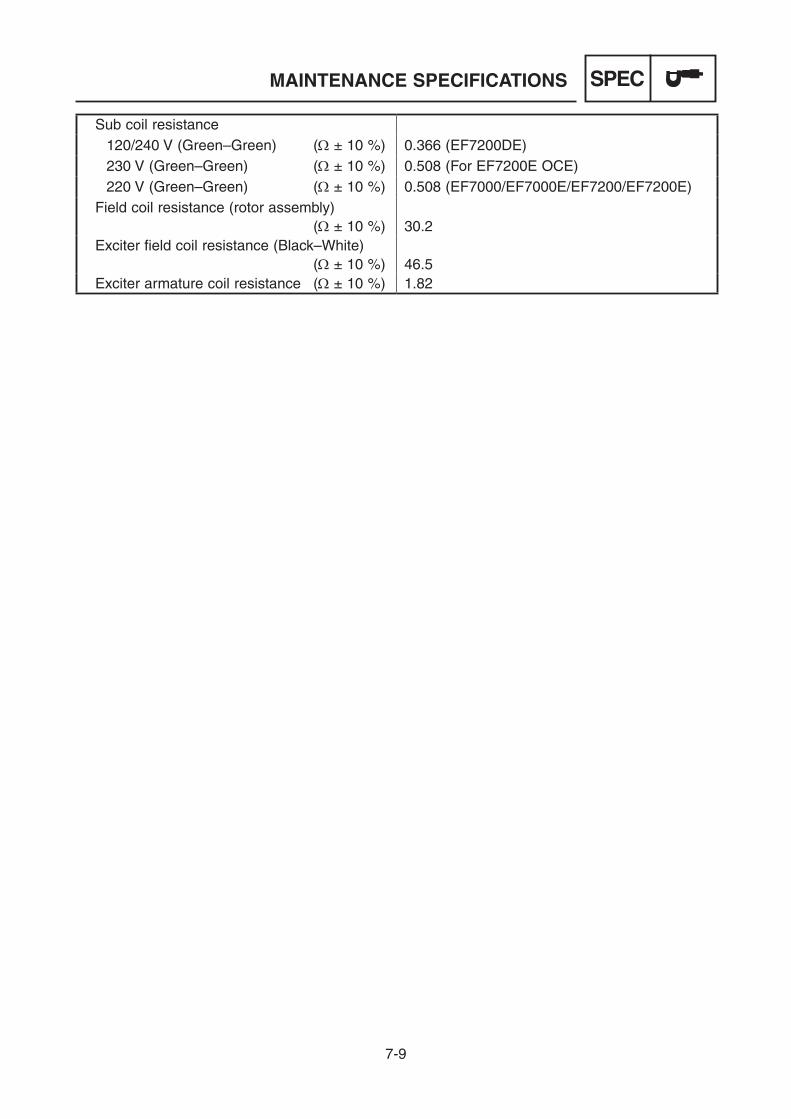
7-9
SPECMAINTENANCE SPECIFICATIONS
Sub coil resistance 120/240 V (Green–Green) (W ± 10 %) 0.366 (EF7200DE) 230 V (Green–Green) (W ± 10 %) 0.508 (For EF7200E OCE) 220 V (Green–Green) (W ± 10 %) 0.508 (EF7000/EF7000E/EF7200/EF7200E) Field coil resistance (rotor assembly) (W ± 10 %) 30.2 Exciter field coil resistance (Black–White) (W ± 10 %) 46.5 Exciter armature coil resistance (W ± 10 %) 1.82

7-10
SPECTIGHTENING TORQUES
TIGHTENING TORQUES
Item Thread sizeTightening torqueNm (m·kgf, ft·lbf)
Generator cover bolt M6 × 1.0 7 (0.7, 5.1)
Control box bolt/nut M6 × 1.0 7 (0.7, 5.1)Stator assembly (main coil) lead nut
M5 × 0.8 3.8 (0.38, 2.8)
Ground lead (wire harness) screw
M5 × 0.8 3.8 (0.38, 2.8)
Stator assembly (sub coil) cou-pler clamp screw
M5 × 0.8 3.8 (0.38, 2.8)
Air filter cover screw — 1.6 (0.16, 1.2)
Air filter case bolt M6 × 1.0 10 (1.0, 7.2)
Air filter case nut M8 × 1.25 11 (1.1, 8.0)
Fuel tank bolt M6 × 1.0 7 (0.7, 5.1)
Canister bracket nut M6 × 1.0 7 (0.7, 5.1)
Fuel cock screw — 0.8 (0.08, 0.58)
Strainer cup — 1.3 (0.13, 0.94)
Exhaust nut M8 × 1.25 16 (1.6, 12)
Muffler bolt M8 × 1.25 16 (1.6, 12)
Muffler cover bolt M6 × 1.0 12 (1.2, 8.7)
Muffler band screw — 2.0 (0.20, 1.4)
Rear frame bolt M6 × 1.0 10 (1.0, 7.2)
Engine mounting nut M10 × 1.25 32 (3.2, 23)
Recoil starter bolt M6 × 1.0 7 (0.7, 5.1)
Flywheel cover bolt M6 × 1.0 7 (0.7, 5.1)
TCI unit bolt M6 × 1.0 10 (1.0, 7.2)
Flywheel nut M18 × 1.5 100 (10, 72)
Charging coil bolt M6 × 1.0 7 (0.7, 5.1)
Charging coil clamp bolt M6 × 1.0 7 (0.7, 5.1)
Rotor assembly bolt M10 × 1.25 42 (4.2, 30)
Generator fan bolt M6 × 1.0 9 (0.9, 6.5)
Exciter field coil screw M5 × 0.8 4.5 (0.45, 3.3)
Governor adjusting plate bolt M6 × 1.0 7 (0.7, 5.1)
Governor arm bolt M6 × 1.0 8 (0.8, 5.8)Economy control solenoid bolt (EF7000E/EF7200E/EF7200DE)
M6 × 1.0 7 (0.7, 5.1)
Economy control solenoid bracket bolt (EF7000E/EF7200E/EF7200DE)
M8 × 1.25 16 (1.6, 12)
Air shroud M6 × 1.0 10 (1.0, 7.2)
Spark plug M14S × 1.25 20 (2.0, 14)

7-11
SPECTIGHTENING TORQUES
Item Thread sizeTightening torqueNm (m·kgf, ft·lbf)
Cylinder head cover bolt M6 × 1.0 11 (1.1, 8.0)
Cylinder head bolt M10 × 1.251st: 12 (1.2, 8.7)2nd: 50 (5.0, 36)
Intake stud bolt M8 × 1.25 9 (0.9, 6.5)
Exhaust stud bolt M8 × 1.25 11 (1.1, 8.0)
Valve adjuster locknut M5 × 0.5 7 (0.7, 5.1)
Rocker arm shaft screw M5 × 0.8 2.3 (0.23, 1.7)
Crankcase cover bolt M8 × 1.251st: 12 (1.2, 8.7)2nd: 30 (3.0, 22)
Oil level switch bolt M6 × 1.0 10 (1.0, 7.2)
Oil level switch clamp bolt M6 × 1.0 10 (1.0, 7.2)
Oil drain bolt M12 × 1.5 27 (2.7, 20)
Wire harness clamp bolt M6 × 1.0 7 (0.7, 5.1)
Connecting rod cap bolt M8 × 1.25 20 (2.0, 14)
Carburetor drain screw — 2.5 (0.25, 1.8)
Main jet holder — 7 (0.7, 5.1)
Main jet — 0.7 (0.07, 0.51)
Fuel cut solenoid valve — 4.0 (0.40, 2.9)
Panel cover screw — 1.3 (0.13, 0.94)
AC switch (N.F.B.) screw M3 × 5.0 0.6 (0.06, 0.43)AC switch (N.F.B.) nut (For EF7200DE CAN)
M11 1.4 (0.14, 1.0)
AC switch (N.F.B.) terminal nut (EF7200DE)
M5 × 3.9 3.0 (0.30, 2.2)
AC switch (N.F.B.) terminal screw
M4 1.3 (0.13, 0.94)
AC receptacle nut M4 1.8 (0.18, 1.3)
AC receptacle terminal screw M4 1.3 (0.13, 0.94)AC receptacle terminal screw (For EF7200E OCE)
M4 1.1 (0.11, 0.80)
AC receptacle nut (For EF7200E OCE)
M3 0.6 (0.06, 0.43)
Condenser holder screw — 1.4 (0.14, 1.0)
Rectifier screw — 1.4 (0.14, 1.0)Rectifier/regulator screw (EF7000E/EF7200E/EF7200DE)
— 1.8 (0.18, 1.3)
Oil warning unit screw — 0.4 (0.04, 0.29)
AVR screw — 0.4 (0.04, 0.29)Control box ground terminal nut
M6 × 1.0 1.7 (0.17, 1.2)

7-12
SPEC
Item Thread sizeTightening torqueNm (m·kgf, ft·lbf)
Economy control unit screw (EF7000E/EF7200E/EF7200DE)
— 1.8 (0.18, 1.3)
Oil warning light nut M10 × 1.0 0.7 (0.07, 0.51)
Voltage adjuster nut M8 × 0.75 1.3 (0.13, 0.94)Starter motor bolt (EF7000E/EF7200E/EF7200DE)
M8 × 1.25 16 (1.6, 12)
Starter motor rear bracket bolt (EF7000E/EF7200E/EF7200DE)
M6 × 1.0 6 (0.6, 4.3)
Starter relay nut (EF7000E/EF7200E/EF7200DE)
M6 × 1.0 11 (1.1, 8.0)
Starter relay terminal nut (EF7000E/EF7200E/EF7200DE)
M8 × 1.25 9 (0.9, 6.5)
Engine switch nut (EF7000E/EF7200E/EF7200DE)
M16 1.3 (0.13, 0.94)
Engine hanger bolt (For EF7200DE CAN)
M8 × 1.25 16 (1.6, 12)
Stopper bolt (For EF7200DE CAN)
M6 × 1.0 7 (0.7, 5.1)
Lock lever nut (For EF7200DE CAN)
M8 × 1.25 16 (1.6, 12)
Plate bolt (For EF7200DE CAN)
M8 × 1.25 16 (1.6, 12)
Handle bolt (For EF7200DE CAN)
M8 × 1.25 16 (1.6, 12)
Main stand nut (For EF7200DE CAN)
M8 × 1.25 16 (1.6, 12)
Wheel axle frame nut (For EF7200DE CAN)
M8 × 1.25 16 (1.6, 12)
TIGHTENING TORQUES/ GENERAL TORQUE SPECIFICATIONS
GENERAL TORQUE SPECIFICATIONSThis chart specifies torque for standard fas-teners with standard I.S.O. pitch treads. Torque specifications for special components or assemblies are included in the applicable sections of this book. To avoid warpage, tight-en multi fastener assemblies in a crisscross fashion, in progressive stages, until full torque is reached. Unless otherwise specifications call for clean, dry treads. Components should be at room temperature.
Tread sizeTightening torque
Nm m·kgf ft·lbf
M4 2 0.2 1.5M5 3 0.3 2.2M6 7 0.7 5.2M7 10 1.0 7.4M8 15 1.5 11.1M10 30 3.0 22.1M12 60 6.0 44.3

7-13
SPECLUBRICATION POINTS AND TYPE OF LUBRICANTS
LUBRICATION POINTS AND TYPE OF LUBRICANTS
Part name Type of lubricant
Oil seal lip LS
Governor shaft oil seal lip E
Bearing E
Connecting rod big end E
Crank pin E
Crankshaft journal
Connecting rod cap bolt E
Piston pin E
Piston E
Balancer shaft journal E
Balancer shaft gear teeth E
Crankshaft gear teeth E
Valve stem E
Valve stem end
Valve rocker arm shaft
Valve push rod E
Valve lifter stem E
Camshaft lobe E
Camshaft gear teeth E
Decompressor pin E
Camshaft journal E
Governor collar internal surface E
Governor shaft meet surface E
Governor weight contact surface E

7-14
SPECWIRE ROUTING DIAGRAM
WIRE ROUTING DIAGRAMCONTROL PANEL AND CONTROL BOX (EF7000/EF7200)
1 Oil warning light2 Engine switch3 Voltage/hour meter4 AC receptacle5 AC switch (N.F.B.)6 Oil warning unit7 Rectifier8 AVR9 Voltage adjuster0 Condenser holderq Condenserw Wire harness
e Ground (earth) terminalr Panel cover
A Control boxB 32.6 mm (1.28 in)C 16 mm (0.63 in)D Behind the control box panelE Connect the condenser lead
coupler as shown in the illus-tration, paying attention to polarity.
F Negative side mark
G Pay attention to the polarity when connecting the lead to the condenser.
H Pawls on voltage/hour meter properly engaged
I Pawls on voltage/hour meter improperly engaged
J Make sure that the pawls are properly engaged on both sides of the panel cover.
K Behind the control boxL To engine

7-15
SPECWIRE ROUTING DIAGRAM
M To generator Color codeB .........BlackBr ........BrownR .........RedW ........WhiteY .........YellowB/W .....Black/WhiteG/R .....Green/RedG/Y .....Green/YellowL/R ......Blue/RedL/W .....Blue/White

7-16
SPECWIRE ROUTING DIAGRAM
1 Oil warning light2 Economy control switch3 Engine switch4 Voltage/hour meter5 AC receptacle6 AC switch (N.F.B.)7 Oil warning unit8 Rectifier9 Fuse0 AVRq Voltage adjusterw Condenser holdere Condenserr Economy control unit
t Wire harnessy Ground (earth) terminalu Panel coveri Rectifier/regulator
A Control boxB Except for OCEC For OCED 32.6 mm (1.28 in)E 16 mm (0.63 in)F Route the brown lead through
the coil of the economy control unit.
G Behind the control box panel
H Connect the condenser lead coupler as shown in the illus-tration, paying attention to polarity.
I Negative side markJ Pay attention to the polarity
when connecting the lead to the condenser.
K Pawls on voltage/hour meter properly engaged
L Pawls on voltage/hour meter improperly engaged
CONTROL PANEL AND CONTROL BOX (EF7000E/EF7200E)
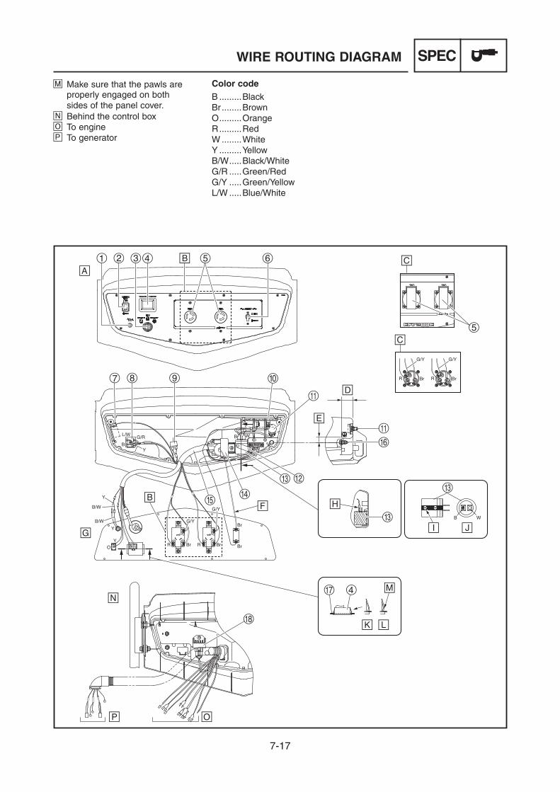
7-17
SPECWIRE ROUTING DIAGRAM
M Make sure that the pawls are properly engaged on both sides of the panel cover.
N Behind the control boxO To engineP To generator
Color codeB .........BlackBr ........BrownO .........OrangeR .........RedW ........WhiteY .........YellowB/W .....Black/WhiteG/R .....Green/RedG/Y .....Green/YellowL/W .....Blue/White

7-18
SPECWIRE ROUTING DIAGRAM
1 Oil warning light2 Economy control switch3 Engine switch4 Voltage/hour meter5 AC receptacle6 AC switch (N.F.B.)7 Oil warning unit8 Rectifier9 Fuse0 AVRq Voltage adjusterw Condenser holdere Condenserr Economy control unit
t Wire harnessy Ground (earth) terminalu Sub-wire harnessi Panel covero Rectifier/regulator
A Control boxB 32.6 mm (1.28 in)C 16 mm (0.63 in)D Route the brown lead through
the coil of the economy control unit.
E Behind the control box panel
F Connect the condenser lead coupler as shown in the illus-tration, paying attention to polarity.
G Pawls on voltage/hour meter properly engaged
H Pawls on voltage/hour meter improperly engaged
I Make sure that the pawls are properly engaged on both sides of the panel cover.
J Negative side mark
CONTROL PANEL AND CONTROL BOX (Except for EF7200DE CAN)
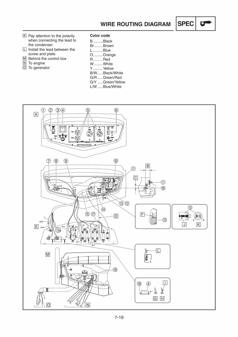
7-19
SPECWIRE ROUTING DIAGRAM
K Pay attention to the polarity when connecting the lead to the condenser.
L Install the lead between the screw and plate.
M Behind the control boxN To engineO To generator
Color codeB .........BlackBr ........BrownL..........BlueO .........OrangeR .........RedW ........WhiteY .........YellowB/W .....Black/WhiteG/R .....Green/RedG/Y .....Green/YellowL/W .....Blue/White
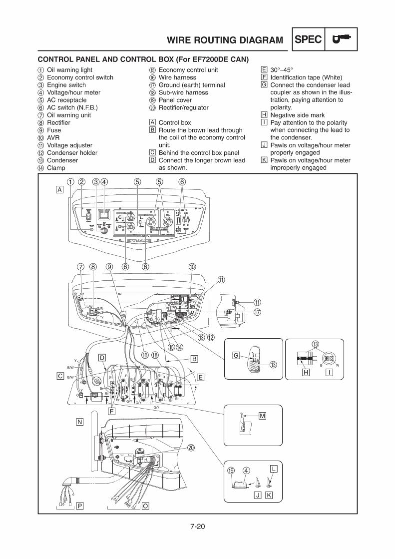
7-20
SPECWIRE ROUTING DIAGRAM
1 Oil warning light2 Economy control switch3 Engine switch4 Voltage/hour meter5 AC receptacle6 AC switch (N.F.B.)7 Oil warning unit8 Rectifier9 Fuse0 AVRq Voltage adjusterw Condenser holdere Condenserr Clamp
t Economy control unity Wire harnessu Ground (earth) terminali Sub-wire harnesso Panel coverp Rectifier/regulator
A Control boxB Route the brown lead through
the coil of the economy control unit.
C Behind the control box panelD Connect the longer brown lead
as shown.
E 30°–45°F Identification tape (White)G Connect the condenser lead
coupler as shown in the illus-tration, paying attention to polarity.
H Negative side markI Pay attention to the polarity
when connecting the lead to the condenser.
J Pawls on voltage/hour meter properly engaged
K Pawls on voltage/hour meter improperly engaged
CONTROL PANEL AND CONTROL BOX (For EF7200DE CAN)

7-21
SPECWIRE ROUTING DIAGRAM
L Make sure that the pawls are properly engaged on both sides of the panel cover.
M Install the lead between the screw and plate.
N Behind the control boxO To engineP To generator
Color codeB .........BlackBr ........BrownL..........BlueO .........OrangeR .........RedW ........WhiteY .........YellowB/W .....Black/WhiteG/R .....Green/RedG/Y .....Green/YellowL/W .....Blue/White
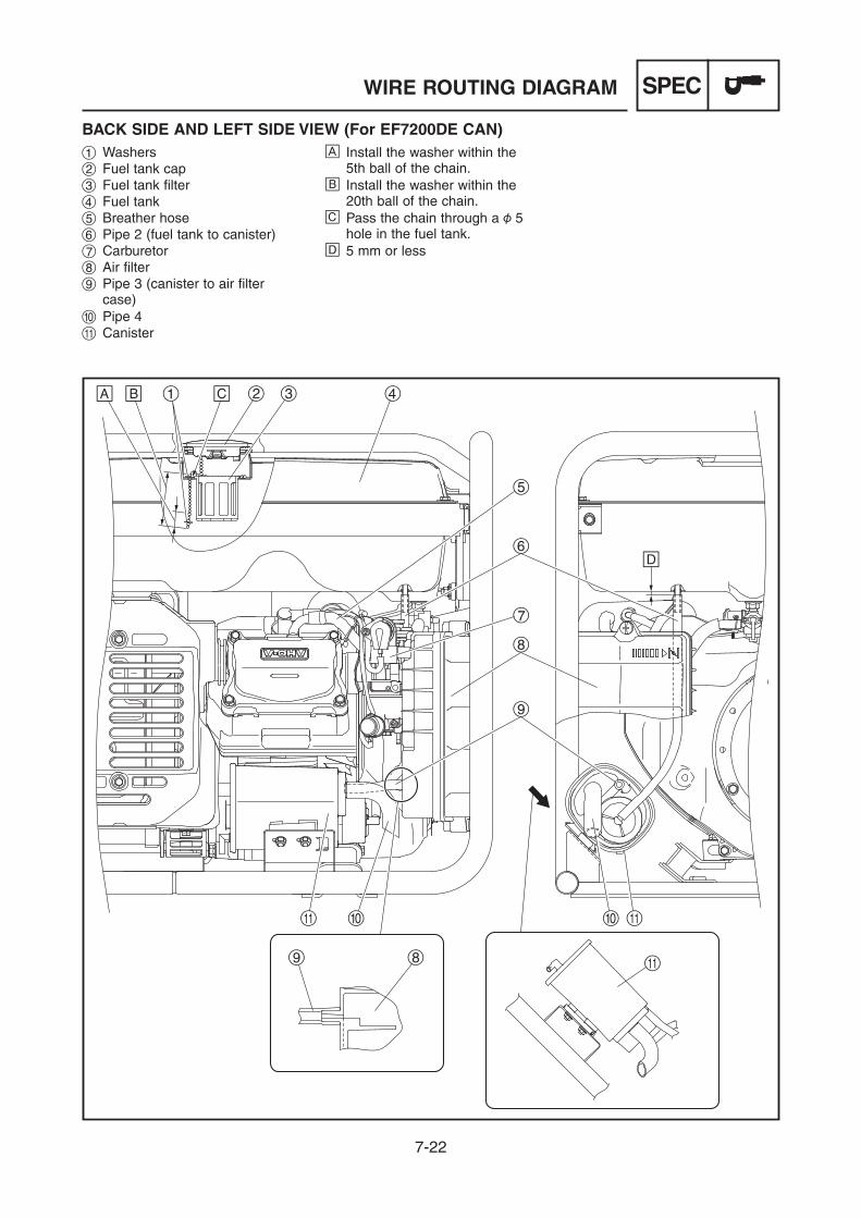
7-22
SPECWIRE ROUTING DIAGRAM
1 Washers2 Fuel tank cap3 Fuel tank filter4 Fuel tank5 Breather hose6 Pipe 2 (fuel tank to canister)7 Carburetor8 Air filter9 Pipe 3 (canister to air filter
case)0 Pipe 4q Canister
A Install the washer within the 5th ball of the chain.
B Install the washer within the 20th ball of the chain.
C Pass the chain through a 5 hole in the fuel tank.
D 5 mm or less
BACK SIDE AND LEFT SIDE VIEW (For EF7200DE CAN)

7-23
SPECWIRE ROUTING DIAGRAM
1 Auto choke lead connector2 Clamp3 Starter relay lead connector4 TCI unit lead connector5 Wire harness6 Positive battery lead connector
(battery to fuse)7 Positive battery lead (battery
to starter motor)8 Clamp9 Control box0 Batteryq Negative battery leadw Charging coil lead connector
e Oil level switch lead connectorr Economy control solenoid lead
connectort Starter motory Economy control solenoidu Fuel cut solenoid valve lead
connector
A Avoid contact of the lead with the muffler and governor arm by making an adjustment with the clamp.
B 25°
B .........BlackG .........GreenL..........BlueO .........OrangeR .........RedW ........WhiteB/W .....Black/WhiteG/R .....Green/RedL/R ......Blue/RedL/W .....Blue/WhiteR/W .....Red/White
UPPER SIDE VIEW (EF7000E/EF7200E/EF7200DE) Color code
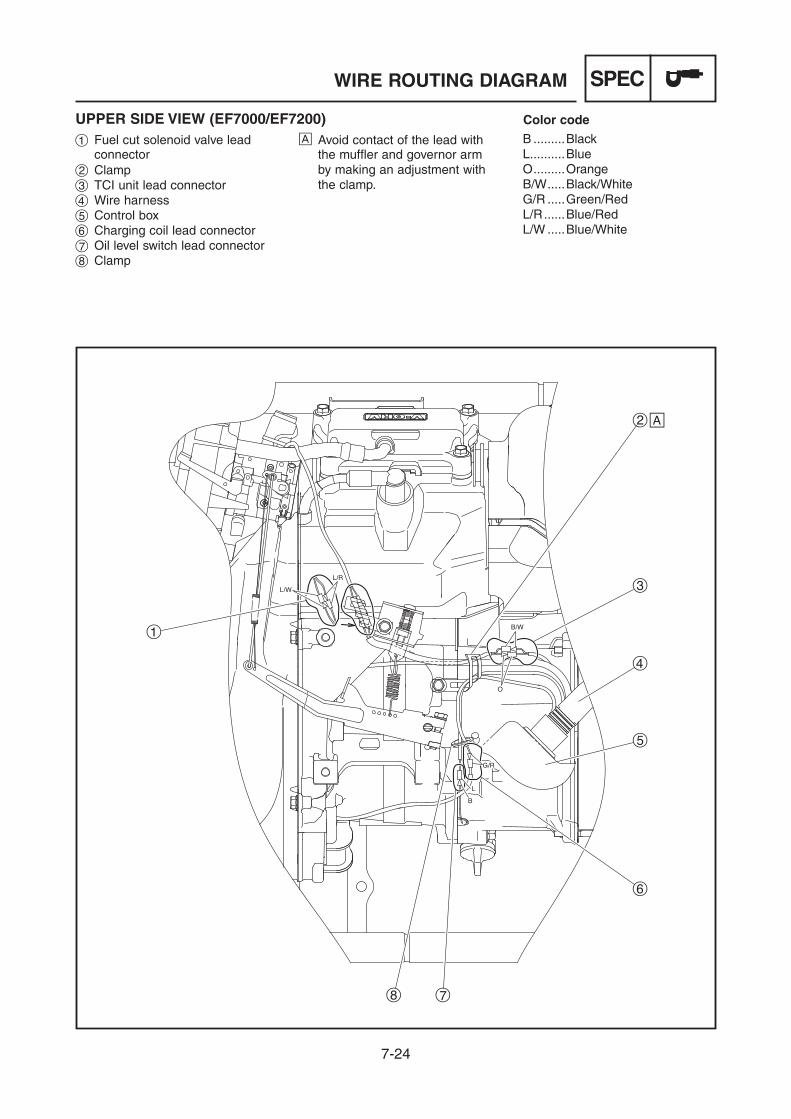
7-24
SPEC
1 Fuel cut solenoid valve lead connector
2 Clamp3 TCI unit lead connector4 Wire harness5 Control box6 Charging coil lead connector7 Oil level switch lead connector8 Clamp
A Avoid contact of the lead with the muffler and governor arm by making an adjustment with the clamp.
B .........BlackL..........BlueO .........OrangeB/W .....Black/WhiteG/R .....Green/RedL/R ......Blue/RedL/W .....Blue/White
UPPER SIDE VIEW (EF7000/EF7200)
WIRE ROUTING DIAGRAM
Color code

7-25
SPECWIRE ROUTING DIAGRAM
1 Oil level switch lead2 Clamp3 Oil level switch4 Spark plug cap5 High tension cord6 TCI unit lead7 Charging coil8 Clamp9 Charging coil lead0 TCI unitq Starter motor (EF7000E/
EF7200E/EF7200DE)w Starter relay lead (EF7000E/
EF7200E/EF7200DE)
A Install the grommet so that it contact with the gray tube.
B Route the oil level switch lead as shown.
C Make sure that the high ten-sion cord is not pinched when installing the flywheel cover.
D Place the lead on the TCI unit side to secure.
E Secure the lead with the cover installed.
F Route the TCI unit lead through the hole in the crank-case.
G Adjust the TCI unit air gap between to 0.4–0.6 mm (0.0157–0.0236 in) on both sides.
H Install the lead so that there is no slack or pinching.
I Install the spark plug cap in the direction shown.
J Screw in the high tension cord until it touches the spark plug cap.
ENGINE

7-26
SPECWIRE ROUTING DIAGRAM
1 Terminal2 Wire harness (stator assembly
lead)3 Wire harness (exciter field coil
lead)4 Wire harness (ground lead)5 Stator assembly (sub coil) cou-
pler6 Damper7 Holder8 Clamp9 Stator assembly (sub coil) lead0 Stator assembly (main coil)
lead
A Details of the stator assembly lead installation.
B Details of the stator assembly lead coupler installation.
C Do not bend the exciter field coil lead when connecting.
Br ........BrownR .........RedW ........White
GENERATOR (EF7000/EF7000E/EF7200/EF7200E) Color code

7-27
SPECWIRE ROUTING DIAGRAM
1 Terminal2 Wire harness (stator assembly
lead)3 Wire harness (exciter field coil
lead)4 Wire harness (ground lead)5 Stator assembly (sub coil) cou-
pler6 Damper7 Holder8 Clamp9 Stator assembly (sub coil) lead0 Stator assembly (main coil)
lead
A Details of the stator assembly lead installation.
B Details of the stator assembly lead coupler installation.
C Do not bend the exciter field coil lead when connecting.
Br ........BrownL..........BlueR .........RedW ........White
GENERATOR (Except for EF7200DE CAN) Color code

7-28
SPECWIRE ROUTING DIAGRAM
1 Terminal2 Wire harness (stator assembly
lead)3 Lead4 Wire harness (exciter field coil
lead)5 Wire harness (ground lead)6 Stator assembly (sub coil) cou-
pler7 Damper8 Holder9 Clamp0 Ground leadq Stator assembly (sub coil) lead
w Stator assembly (main coil) lead
A Details of the stator assembly lead installation.
B Details of the stator assembly lead coupler installation.
C Do not bend the exciter field coil lead when connecting.
D 30°–60°
Br ........BrownL..........BlueR .........RedW ........White
GENERATOR (For EF7200DE CAN) Color code


2
3
5
6
17
8
9
00
q
e
r
y
u
op
a
i
s
d
t
4
w
1 G
ener
ator
2 R
otor
ass
embl
y 3
Exc
iter
field
coi
l4
Sub
coi
l5
Mai
n co
il6
Sta
tor
asse
mbl
y7
Con
trol
box
8 V
olta
ge/h
our
met
er9
AC
sw
itch
(N.F
.B.)
0 A
C r
ecep
tacl
eq
Rec
tifie
rw
Eng
ine
switc
he
Vol
tage
adj
uste
rr
Con
dens
ert
AV
R
(Aut
omat
ic
Vol
tage
R
egul
ator
)y
Oil
war
ning
uni
tu
Oil
war
ning
ligh
t
i E
ngin
eo
Fue
l cut
sol
enoi
d va
lve
p C
harg
ing
coil
a T
CI
unit
s S
park
plu
gd
Oil
leve
l sw
itch
Co
lor
cod
eB
B
lack
Br
Bro
wn
G
Gre
enL
Blu
eLg
Ligh
t gr
een
O
Ora
nge
R
Red
W
W
hite
Y
Yello
wB
/W
Bla
ck/W
hite
G/R
G
reen
/Red
G/Y
G
reen
/Yel
low
L/R
B
lue/
Red
L/W
B
lue/
Whi
teR
/G
Red
/Gre
en
EF7000/EF72002014 CIRCUIT DIAGRAM

2
3
5
6
17
8
9
00
00
w
er
y
t
u
o
a
f
s
g
h
j
k
l
;z
x
c
d
p
i
4
q
å
∫
1 G
ener
ator
2 R
otor
ass
embl
y 3
Exc
iter
field
coi
l4
Sub
coi
l5
Mai
n co
il6
Sta
tor
asse
mbl
y7
Con
trol
box
8 V
olta
ge/h
our
met
er9
AC
sw
itch
(N.F
.B.)
0 A
C r
ecep
tacl
eq
Eng
ine
switc
hw
Rec
tifie
re
Rem
ote
cont
rol t
erm
inal
r F
use
t R
ectif
ier/
regu
lato
ry
Vol
tage
adj
uste
ru
Con
dens
er
i A
VR
(A
utom
atic
V
olta
ge
Reg
ulat
or)
o O
il w
arni
ng u
nit
p E
cono
my
cont
rol u
nit
a O
il w
arni
ng li
ght
s E
cono
my
cont
rol s
witc
hd
Eng
ine
f E
cono
my
cont
rol s
olen
oid
g S
tart
er r
elay
h S
tart
er m
otor
j A
uto
chok
ek
Fue
l cut
sol
enoi
d va
lve
l B
atte
ry;
Cha
rgin
g co
ilz
TC
I un
itx
Spa
rk p
lug
c O
il le
vel s
witc
h
Co
lor
cod
eB
B
lack
Br
Bro
wn
G
Gre
enL
Blu
eLg
Ligh
t gr
een
O
Ora
nge
R
Red
W
W
hite
EF7000E/EF7200E2014 CIRCUIT DIAGRAM
Y
Yello
wB
/W
Bla
ck/W
hite
G/R
G
reen
/Red
G/Y
G
reen
/Yel
low
L/R
B
lue/
Red
L/W
B
lue/
Whi
teR
/B
Red
/Bla
ckR
/G
Red
/Gre
enR
/W
Red
/Whi
te
A E
xcep
t fo
r O
CE
B F
or O
CE

2
3
17
6
8
99
00
00
w
er
y
t
u
o
a
f
s
g
h
j
k
l
;z
x
c
d
p
i
45
q
EF7200DE (Except for CAN)2014 CIRCUIT DIAGRAM
1 G
ener
ator
2 R
otor
ass
embl
y 3
Exc
iter
field
coi
l4
Sub
coi
l5
Mai
n co
il6
Sta
tor
asse
mbl
y7
Con
trol
box
8 V
olta
ge/h
our
met
er9
AC
sw
itch
(N.F
.B.)
0 A
C r
ecep
tacl
eq
Eng
ine
switc
hw
Rec
tifie
re
Rem
ote
cont
rol t
erm
inal
r F
use
t R
ectif
ier/
regu
lato
ry
Vol
tage
adj
uste
ru
Con
dens
eri
AV
R
(Aut
omat
ic
Vol
tage
R
egul
ator
)
o O
il w
arni
ng u
nit
p E
cono
my
cont
rol u
nit
a O
il w
arni
ng li
ght
s E
cono
my
cont
rol s
witc
hd
Eng
ine
f E
cono
my
cont
rol s
olen
oid
g S
tart
er r
elay
h S
tart
er m
otor
j A
uto
chok
ek
Fue
l cut
sol
enoi
d va
lve
l B
atte
ry;
Cha
rgin
g co
ilz
TC
I un
itx
Spa
rk p
lug
c O
il le
vel s
witc
h
Co
lor
cod
eB
B
lack
Br
Bro
wn
G
Gre
enL
Blu
eLg
Ligh
t gr
een
O
Ora
nge
R
Red
W
W
hite
Y
Yello
w
B/W
B
lack
/Whi
teG
/R
Gre
en/R
edG
/Y
Gre
en/Y
ello
wL/
R
Blu
e/R
edL/
W
Blu
e/W
hite
R/B
R
ed/B
lack
R/G
R
ed/G
reen
R/W
R
ed/W
hite

2
3
5
6
1
8
7
9
99
9
9
00
0
q
e
t
y
iu
o
p
f
d
g
h
j
k
l
;z
x
c
s
a
w
4
r
1Generator
2Rotorassembly
3Exciterfieldcoil
4Subcoil
5Maincoil
6Statorassembly
7Controlbox
8Voltage/hourmeter
9ACswitch(N.F.B.)
0ACreceptacle
qEngineswitch
wRectifier
eRemotecontrolterminal
rFuse
tRectifier/regulator
yVoltageadjuster
uCondenser
iAVR(AutomaticVoltage
Regulator)
oOilwarningunit
pEconomycontrolunit
aOilwarninglight
sEconomycontrolswitch
dEngine
fEconomycontrolsolenoid
gStarterrelay
hStartermotor
jAutochoke
kFuelcutsolenoidvalve
lBattery
;Chargingcoil
zTCIunit
xSparkplug
cOillevelswitch
Co
lor
cod
eBBlack
BrBrown
GGreen
LBlue
LgLightgreen
OOrange
RRed
WWhite
EF7200DE (CAN)2014 CIRCUIT DIAGRAM
YYellow
B/WBlack/White
G/RGreen/Red
G/YGreen/Yellow
L/RBlue/Red
L/WBlue/White
R/BRed/Black
R/GRed/Green
R/WRed/White
7P6-F8197-E0_cover.indd 2 2014/05/29 15:46:42

SERVICE MANUAL
EF7000EF7000E
EF7200EF7200E
EF7200DE
7P6-F8197-E0
2014_05×1 !
7P6-F8197-E0_cover.indd 1 2014/05/29 15:46:41