Silica Analyser Digox 601 silica - Dr....
40
Operating Manual Silica Analyser Digox 601 silica
Transcript of Silica Analyser Digox 601 silica - Dr....

Operating Manual
Silica Analyser
Digox 601 silica

Digox 601 silica
Copyright August 2008, Dr. Thiedig + Co, Berlin. All rights reserved. OM_digox601silica.doc
Copyright Lesen Sie diese Dokumentation vor der Installation
oder Inbetriebnahme sorgfältig und beachten Sie die Sicherheitshinweise. Bei Schäden, die durch Nichtbeachtung der Bedienungsanweisungen
entstehen, kann die Dr. Thiedig + Co keine Haftung übernehmen. Garantieansprüche erlöschen ebenfalls bei Verwendung von Ersatzteilen und
Betriebschemikalien, die nicht von der Dr. Thiedig + Co stammen.
Die in dieser Dokumentation enthaltenen Informationen können ohne Vorankündigung geändert werden und stellen keine Verpflichtung
seitens der Dr. Thiedig + Co dar. Diese Dokumentation darf weder vollständig noch
auszugsweise mit irgendwelchen Mitteln, elektronisch oder mechanisch, ohne vorherige schriftliche Genehmigung der Dr. Thiedig + Co reproduziert oder
übertragen werden. Wenn die Dokumentation in verschiedene Sprachen
übersetzt wurde, ist die deutsche Fassung als Original anzusehen.
Copyright Make sure to read the documentation carefully before
installing or commissioning the unit, and ensure compliance with all safety regulations. Dr. Thiedig + Co shall not assume any liability for
damage caused by non-compliance with the Operating Instructions. The use of spare parts other than those coming from Dr. Thiedig + Co shall
invalidate all warranty claims. Any information contained in the Operating
Instruction shall be subject to modification without prior notice, and shall not be construed as constituting a commitment on the part of
Dr. Thiedig + Co. This Operating Instruction shall not be reproduced or
transmitted in full or in part by any means, electronic or mechanical, without the prior written approval of Dr. Thiedig + Co.
If the Operating Instruction is translated into different
languages, the German version shall be deemed the original one.
Digox 601 silica
3/40
List of content
List of content ........................................................................................................................................................3 General notes.........................................................................................................................................................5 Safety notes............................................................................................................................................................6 1. Field of application and layout of silica analyser ...............................................................................7
1.1 Field of application.......................................................................................................................7 1.2 Layout ..........................................................................................................................................7
2. Components of silica analyser .............................................................................................................8 2.1 Control unit ..................................................................................................................................8 2.2 Photometer ..................................................................................................................................8 2.3 Feed unit with reagent pumps, Valves and Flow meter ..............................................................9
3. Installation.............................................................................................................................................10 3.1 Installation requirements ...........................................................................................................10 3.2 Mounting....................................................................................................................................10 3.3 Connection of sample................................................................................................................11 3.4 Electrical connections................................................................................................................12
4. Commissioning.....................................................................................................................................13 4.1 Initial commissioning .................................................................................................................13 4.2 Putting the unit back into operation ...........................................................................................13 4.3 Reagent exchange ....................................................................................................................13 4.4 Execution Maintenance .............................................................................................................14 4.5 Shut down..................................................................................................................................14
5. Operation...............................................................................................................................................15 5.1 Principal of operation.................................................................................................................15 5.2 Structure of menu ......................................................................................................................16 5.3 Measured value display.............................................................................................................18 5.4 Submenu Diagnostics................................................................................................................19 5.4.1 General ......................................................................................................................................19 5.4.2 Protocol......................................................................................................................................20 5.4.3 Logbook .....................................................................................................................................21 5.4.4 Status.........................................................................................................................................21 5.4.5 Limits .........................................................................................................................................22 5.4.6 Reagent level.............................................................................................................................22 5.4.7 Rest service life .........................................................................................................................23 5.4.8 Software version........................................................................................................................23 5.5 Maintenance submenu ..............................................................................................................24 5.5.1 Password...................................................................................................................................24 5.5.2 General ......................................................................................................................................24 5.5.3 Operation mode.........................................................................................................................25 5.5.4 Reagent exchange: ...................................................................................................................26 5.5.5 Device maintenance: .................................................................................................................27

Digox 601 silica
4/40
5.6 Parameter submenu ..................................................................................................................28 5.6.1 Password request......................................................................................................................28 5.6.2 General ......................................................................................................................................28 5.6.3 Basic settings.............................................................................................................................28 5.6.4 Measuring frequency .................................................................................................................29 5.6.5 Limits .........................................................................................................................................30 5.6.6 Current outputs..........................................................................................................................31 5.6.7 Names of measuring points.......................................................................................................31 5.6.8 Passwords .................................................................................................................................32 5.6.9 Factory setting ...........................................................................................................................33
6. Chemicals and consumption solutions .............................................................................................34 7. Spare parts and consumables ............................................................................................................35 8. Analytical and technical parameter, operating conditions ..............................................................36 9. Alarm / malfunction and warning messages.....................................................................................37 10. Factory settings....................................................................................................................................38

Digox 601 silica
5/40
General notes
This Operating Manual contains instructions for the installation, commissioning as well as maintenance and repair of the measuring instrument Digox 601 silica described below.
For reasons of clarity, however, this manual cannot cover all details for all types or any conceivable circumstances of installation and operation.
Should you require any further information or encounter any problems not discussed in detail in the present manual, please turn directly to:
DR. THIEDIG + CO Prinzenallee 78-79
13357 Berlin Germany
Phone: +49 30 / 49 77 69-0 Fax: +49 30 / 49 77 69-25
Email: [email protected] www.thiedig.com
Please note that the warranty granted by us in accordance with our general terms and conditions of delivery will be effective only if:
the installation, connection, setting, commissioning and maintenance of the instrument are carried out exclusively by authorised skilled personnel having the required qualification,
exclusively genuine spare parts are used in case of repairs, and
the instrument is used solely in conformity with the directions given in this Operating Manual.
The safety notes highlighted in this document must be strictly observed.
Digox 601 silica
6/40
Safety notes
The units have been tested for electrical safety:
Protective conductor resistance < 0.3 Ω
Insulation resistance > 30 MΩ
The unit should be installed and commissioned by qualified personnel. Connections may be made exclusively in
the zero-potential condition of the unit! Use a three-pole mains cable for connection. Any interruptions of the protective conductor must be regarded as
potentially hazardous and, thus, are not permissible! If there is a suspicion that damage to the unit no longer ensures safe operation of the same, the unit must be put out of operation immediately!
Caution! The process measuring instrument may be operated exclusively with the finished reagents or with reagents
prepared of the dry chemical reagent set supplied by the Dr. Thiedig + Co. The reagent solutions and sets contain hazardous substances which, when improperly handled, may pose a
hazard to human health and the environment. Consequently, the regulations of the hazard classification code (Gef.StoffV) must be strictly observed.
Only persons who have the required skills and qualifications (completed training) or who have been thoroughly inducted and instructed by authorised qualified personnel on the individual steps of the manufacturing process, the handling of chemicals, and the required safety measures may be deployed for producing and handling reagents.
Safety data sheets upon request. Each container for chemicals of the formulated set is marked by an appropriate label indicating:
o the name of the reagent,
o the hazard symbol, and
o the date of preparation.
The reagent cans (bottles) are marked by a label containing the reagent number, the hazard symbol and the date of preparation.

Digox 601 silica
7/40
1. Field of application and layout of silica analyser
1.1 Field of application
The silica analyser is a process measuring instrument designed for determining the dissolved silicic acid (dissolved
silicate) in the process water of power stations. The silica analyzer is used mostly in the water-steam-circuit or at the water treatment. The Digox 601 silica is also qualified for the determination from the silicic acid concentration in process water of the semiconductor- and electronic industry. The unit primarily covers the measuring range from 0
to 500 µg/l SiO2. As analytic method is the determination of the dissolved (molybdate active) silicic acid towards the VGB standard
method adapted. The limit of detection of this photometrical analysis method is 4 µg/l SiO2.
1.2 Layout
The silica analyser consists of a control unit, pump- and valve - unit, precision photometer including reaction / measuring vessel, tempering and stirring unit, reagent cans and the hoses used for liquid transport.
In the basic version, the unit is designed for the analysis of samples taken from two sampling points (2-channel). Furthermore, versions till 6 sampling channels can be delivered. Optional the analysis of a grab sample is possible.
Figure 1: inside view
control unit
sample conditioning unit
pump and valve unit
photometer unit
reagent RL1, RL2 RL3
stock solution

Digox 601 silica
8/40
2. Components of silica analyser
2.1 Control unit
The control unit is designed for
o controlling the active components of the pump- and valve - unit and measuring facility in accordance with the respective programs,
o measuring data logging and processing,
o calculation and output of results (display and data outputs),
o monitoring processes and states (e.g. control of standard and reagent solution, flow control)
o outputting fault messages and maintenance details.
Operation via the keyboard allows users to:
o enter - menu-assisted - calibration parameters, limit values and communication parameters,
o enter data for an automatic sequence (measuring frequency of automatic calibration and sample analysis),
o interrupt an automatic sequence for the purpose of entering parameters and special programs
o entering the protocol, which stores the last 450 entrees with time and date
o use password protection for menu items maintenance and parameter
The following interfaces exhibit the Digox 601 silica
o 2 (4 / 6 - optional) output 4...20 mA for the analogue measuring value output
o collecting alarm and message Reagent exchange over potential free contacts
o RS 232C-interface for Software-Updates
The number of the outputs is dependent on the device accomplishment (2 till 6-channels).
2.2 Photometer
The precision photometer contains as a special module a thermoblock for thermostatisation the measuring vessel
and a stirrer for mixing the sample. The cuvette is used at the same time as reaction vessel for the three-stage reaction. It is flushed and filled by the necessary pre-pressure (guaranteed by the backpressure valve). The exact media volume is guaranteed by a intelligent siphoning. The measurements are performed after an intensive mixing
phase (stirring is performed during certain reaction times) and after the expiry of a calming down period.

Digox 601 silica
9/40
2.3 Feed unit with reagent pumps, Valves and Flow meter
Figure 2 shows the flow diagram of the silica analyser. The sample is transported with a pressure of max. 1 bar from the medium over the Valves V1, ... (till V6 for the 6-chanal-Silicometer) in the reaction vessel (cuvette). For the media transport no pump are necessary. Downstream the inlet valve a flow meter is installed, which controls
the sample flow. If the adjusted flow value is not reached, than the analyser stops the process, displays the alarm “No Water” and start analysing the next channel. For flushing purposes, calibration and zero compensation the medium is flowing through the mixed bed exchanger to create silicate free water. Before flushing the cuvette, it is
emptied via valve H. Optional there is possibility to measure a grab sample. In such case the grab sample is transported by a diaphragm pump.
The reagent pumps RP1, RP2, RP3 supply the reagent solutions RL1, RL2, RL3 (time-controlled, taking into account the respective reaction times) into the reaction vessel. For one analysis 0,5 ml of each reagent are needed.
The stirrer operates at a constant speed and produces an efficiently mixed bubble-free measuring solution. In case of extinction measuring the stirrer is off.
On the right outside of the analysers the sample condition unit is installed. The basic type is designed for 2 sample channels (optional upgradable: till 6 sample channels). The Silica analyser needs minimal 1 bar pre-pressure and
minimal 10 l/h sample flow per channel.
Figure 2: Flow diagram

Digox 601 silica
10/40
3. Installation
3.1 Installation requirements
Power supply: 100 - 230 VAC 15 %, 140 VA
Ambient air temperature: 10 – 40°C
Sample temperature: max. 40°C
Sample pressure: min. 1 bar
Sample flow: min. 10 l/h; max. 20 l/h
3.2 Mounting
Drill the mounting holes into a vertical wall in accordance with Figure 3.
Figure 3: Mounting dimensions
ø9

Digox 601 silica
11/40
3.3 Connection of sample
The connection of the samples is executed on the right side of the analyser on the sample conditioning unit. Therefore outer tolerated hoses (6x1 mm) must be used.
The delivered hoses must be connected on the hose nozzle of the drain pipe and on the back pressure valves of the sample conditioning unit to dispose the waste water.
Figure 4: Sample conditioning unit The reagent hoses must be pulled over the reagent pumps as shown in Figure 5 and Figure 6.
Figure 5: reagent pump Figure 6: reagent pump (delivery status) (ready for operation)
Pressure gauge
Sample inlet (hose 6x4)
Pressure relief (hose 8x5)

Digox 601 silica
12/40
3.4 Electrical connections
The following connections must be made:
o Connection of a three-pole power supply cable, 1.5 mm² cross-chapter, to the connection box (see Figure 8) to a three-pole socket-outlet with earth connection (230 V AC)
o Connection of analogue outputs according to Figure 8
o Connection of digital outputs according to Figure 8
Figure 7: Power supply unit
NO
C
NC
NO
C
NC
+
-
+
-
+
-
+
-
+
-
+
-
24V DC
stirrer RS 232
Relay1 Relay 2 C1 C2 C3 C4 C5 C6
+
-
bn
wh
GN
D
RX
TX
IN 1 IN 2
L1
N
PE
PE
1 2 3 4 5 6 11
12
13
14
15
16
17
18
19
20
21
22
23
24
25
26
27
28
29
30
31
32
33
NO
C
NC
NO
C
NC
+
-
+
-
+
-
+
-
+
-
+
-
rd
bk
wh
vi
bu
bn
gy
Digi-
talin-
put 1
Digi-
talin-
put 2
Power
supply 230V AC / 50Hz Relay 1 Relay 2
4/20
mA C 1
4/20
mA C 2
4/20
mA C 3
4/20
mA C 4
4/20
mA C 5
4/20
mA C 6
Photometer
Figure 8: connection box: terminals
Main voltage For operation on 115VAC supply system, shift
switch S1 to position 115VAC
Analogue outputs: SAK 1: Current output channel 1 (C1) SAK 2: Current output channel 2 (C2)
Digital outputs:
Relay 1: Limit violation K1 or K2 Relay 2: Liquid quantity < lower limit
Open contact in case of fault: COM-NC Closed contact in case of fault: COM-NO
transformer

Digox 601 silica
13/40
4. Commissioning
4.1 Initial commissioning
For commissioning the unit after shipment from the factory, the following requirements must be satisfied:
Electrical connections have been properly made
The samples (in analyser display “CANAL”) must abut on the sample conditioning unit. (pressure manometer 0,8 bar)
Reagent and standard solution vessels must be filled and the hoses must be immersed in the reagents up to the bottom.
1. Power supply on: A zero compensation starts automatically. There are the following sequences in progress: - flushing and charging the hoses - temper the photometer - zero compensation of the photometer
2. If the zero compensation is ended, the analyser is changing in the Stand By-Modus and can be parameterised.
3. Choose the program „R. fill“ in the menu point operation mode Manual (Chapter 6) and activate it with OK. Now the analyser fills automatically all reagent hoses. After this the program “Cuv.fill“ must be started, to flush and fill the cuvette.
4. Now the individual adjustment for the operation parameter: measuring frequency, current outputs, limits, names of measuring points and passwords; shown in chapter 6, have to be made.
5. If all settings, which are necessary, are made the analyser can be set in the operation mode to AUTOMATIC, therefore please see chapter 5.5.1.
6. Now the analyser begins automatically with the measuring and works after the set measuring frequency.
7. With touching the ESC-Key for 4 seconds, the display is set back to the measured value menu. The initial commissioning is completed.
4.2 Putting the unit back into operation
To put the unit back into operation, proceed as described in chapter 5.1. If the analyser has been reset to the factory settings, all individual parameters have to be controlled and parameterised if necessary.
4.3 Reagent exchange
Before starting the reagent exchange, you have to switch the analyser from the automatic mode to the standby
mode. To this end, switch off the sequence in menu item „Manual operation“ – „Operating mode“ as described in chapter 5.5.3.
The running program will interrupted and the cuvette is emptying and flushing with ultra pure water. Then the analyser switches to the standby mode.

Digox 601 silica
14/40
Now you can renew the reagents as follows:
Screw off the lid and cautiously pull it out of the empty can together with the guiding hose and reagent hose. Insert lid together with the other components into the full can and screw in. Make sure that the reagent hose is carried in up to the stop (until it contacts the bottom), and insert an additional length of reagent hose, if necessary. When
doing so, make sure that the reagent hoses remain filled. After the reagent change remove the volume of the reagent solution as described in chapter 5.5.4.
After this start the analyser by setting the AUTOMATIC on in the menu point operation mode. With pushing the ESC-button for 4 seconds, you get back to the measured value menu. The analyser is in the automatic mode and
works after the set measuring frequency.
4.4 Execution Maintenance
The maintenance of the analyser which is in the standby-modus includes the check of the electrical in and outputs, the control of the mechanical components and the exchange of reagent, reagent pumps and valve hoses. The maintenance should be executed after 1 year the latest also if the message “Execute Maintenance” was not
displayed. After execution of the maintenance, reset the availability as described in chapter 5.5.3.
4.5 Shut down
If the analyser should be shut down only for a short time (a few hours), no special arrangements are required. For this, set the automatic mode OFF, which is described in chapter 5.5.1.
If the analyser should be shut down for a longer period (> 1 day), the reagents should be discharged from the hoses by means of the pumps.
For doing so the automatic mode from the analyser is to be set OFF. After this pull the reagent hoses out of the reagent tubes and start the manual program “fill R.“. After the end of this program the cuvette must be emptied and flushed with ultra pure water. For this start the program “fill Cuv.”. After this the power supply can turned off.
After longer shut down periods it is necessary to control the durability of the reagents.
To put the unit back into operation, proceed as described in chapter 4.2.
Digox 601 silica
15/40
5. Operation
5.1 Principal of operation
The handling of the analyser is made with the following Main menus: Diagnostics Maintenance Parameter
The main menus are classified in submenus, which are shown in chapter 5.2 Menu structure. By selection of a submenu you get to the input menu, which are described in detail up to chapter 5.4. The handling is available with
the 6 Keys from the handle panel. The individual keys have the following functions.
OK – Key: Measured value display Main menu Main menu Submenu Submenu Input menu Input menu Input modus Input modus Input menu with acceptance the input value
ESC – Key: Input modus Input menu without acceptance the input value Input menu Submenu Submenu Main menu Main menu Measured value display ESC (press 3s) Measured value display
- Keys: Measured value display: Measured value display (canal) Measured value display (overview canal) Menus: Choice menu point Input menu: Choice input block Input modus: Signs choice / lists choice
- Keys: Measured value display: Canal switching Menus: no function Input menu: block choice (if more than one column) Input modus: position choice

Digox 601 silica
16/40
5.2 Structure of menu
Maintenance Password W scan Operation mode
Reagent exchange
Device maintenance
Measured value display
Diagnostics Protocol
Logbook
Status
Limits
Reagent level
Rest Service Life
Software version

Digox 601 silica
17/40
Parameter Password P scan Basic settings
Measuring frequency
Limits
Current outputs
Name of meas. points
Passwords
Factory settings

Digox 601 silica
18/40
5.3 Measured value display
In the measured value display is shown the concentration of the actual measured channel (in display CANAL). The channel description (factory side MST ...) can individual changed, how described in chapter 5.6.7 (f.e. KKS description). The third line is for the alarm and failure advice. Furthermore in the seventh line the actual status of
the analyser is shown. In the bottom line the time is displayed till the next analysis for this channel started (explained in chapter 5.6.4 Measuring frequency).
With actuation the key or follows a change to the channel overview: In the channel (in display CANAL) overview the actual determined concentrations of all measured channels are
listed. In the last line stands the status advice, which inform about the actual measuring activity.
C a n a l 1
M S T 1 1 5 . 7 µ g / l
S t a t u s : M e a s u r e C a n a l 2
N e w A n a l y s i s : 8 m i n
A l l C a n a l s
C a n a l 1 1 5 . 7 µ g / l
C a n a l 2 - - - - - µ g / l
S t a t u s : M e a s u r e C a n a l 2

Digox 601 silica
19/40
By pushing the OK button in the measured value display or in the channel overview you get into the main menu.
This is subdivided into the sub menus diagnostics, maintenance and parameter. The choice of the submenus is made with the keys or . With the OK button you select the submenu.
5.4 Submenu Diagnostics
5.4.1 General
The submenu Diagnostics is not secured with password and so for every user accessible. It comprised the
Protocol, the Logbook and the Status menu. Furthermore, the adjusted limits, the reagent level, the rest service life and the programmed software version can be displayer. The choice of the sub menus is made with the keys or . With the OK button you select the menu.
M e n ü
D i a g n o s t i c s
M a i t e n a n c e
P a r a m e t e r
D i a g n o s t i c s
P r o t o c o l
L o g b o o k
S t a t u s
L i m i t s
R e a g e n L e v e l
R e s t S e r v i c e L i f e
S o f t w a r e v e r s i o n
Digox 601 silica
20/40
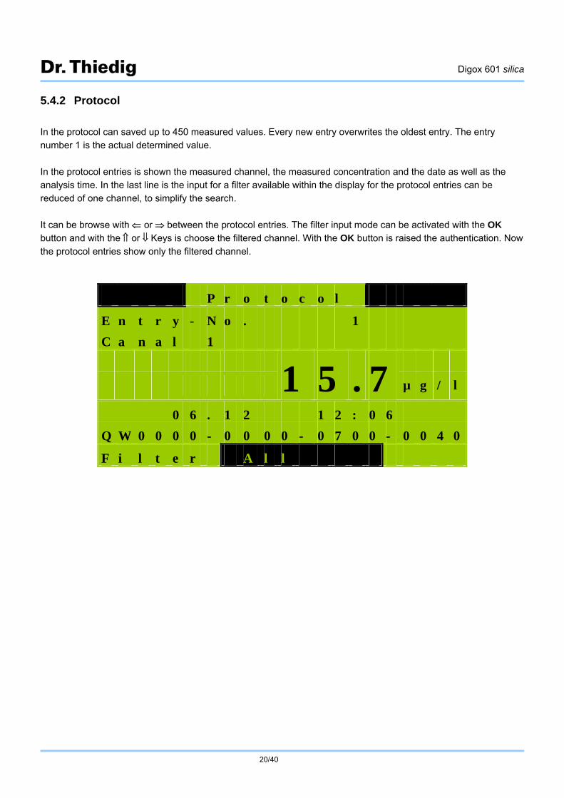
5.4.2 Protocol
In the protocol can saved up to 450 measured values. Every new entry overwrites the oldest entry. The entry number 1 is the actual determined value.
In the protocol entries is shown the measured channel, the measured concentration and the date as well as the analysis time. In the last line is the input for a filter available within the display for the protocol entries can be reduced of one channel, to simplify the search.
It can be browse with or between the protocol entries. The filter input mode can be activated with the OK button and with the or Keys is choose the filtered channel. With the OK button is raised the authentication. Now
the protocol entries show only the filtered channel.
P r o t o c o l
E n t r y - N o . 1
C a n a l 1
1 5 . 7 µ g / l
0 6 . 1 2 1 2 : 0 6
Q W 0 0 0 0 - 0 0 0 0 - 0 7 0 0 - 0 0 4 0
F i l t e r A l l
Digox 601 silica
21/40
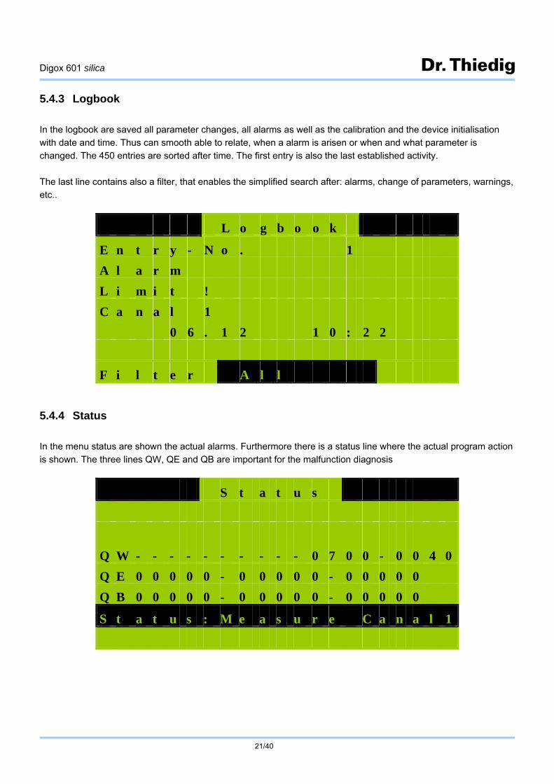
5.4.3 Logbook
In the logbook are saved all parameter changes, all alarms as well as the calibration and the device initialisation with date and time. Thus can smooth able to relate, when a alarm is arisen or when and what parameter is changed. The 450 entries are sorted after time. The first entry is also the last established activity.
The last line contains also a filter, that enables the simplified search after: alarms, change of parameters, warnings, etc..
5.4.4 Status
In the menu status are shown the actual alarms. Furthermore there is a status line where the actual program action
is shown. The three lines QW, QE and QB are important for the malfunction diagnosis
L o g b o o k
E n t r y - N o . 1
A l a r m
L i m i t !
C a n a l 1
0 6 . 1 2 1 0 : 2 2
F i l t e r A l l
S t a t u s
Q W - - - - - - - - - - 0 7 0 0 - 0 0 4 0
Q E 0 0 0 0 0 - 0 0 0 0 0 - 0 0 0 0 0
Q B 0 0 0 0 0 - 0 0 0 0 0 - 0 0 0 0 0
S t a t u s : M e a s u r e C a n a l 1

Digox 601 silica
22/40
5.4.5 Limits
In this menu are shown the adjusted limits for all channels. They could not parameterise in this menu. Therefore please read chapter 5.6.5.
5.4.6 Reagent level
It is shown the rest volume of the standard and the three reagent tanks as percentages in a bar chart. The reagent levels are reduced after each analysis. For one analysis 0,5 ml of every reagent is needed. The analyser uses for
one calibration approx. 1 ml of the standard solution. If the reagent levels are under 10% of the tank size, than the warning „Exchange Reagents!“ is shown. The reagent exchange authentication is described in chapter 5.5.4.
L i m i t s
C a n a l 1 1 0 0 . 0 µ g / l
C a n a l 2 1 0 0 . 0 µ g / l
R e a g e n t L e v e l
1 0 0 % 1 0 0 % 1 0 0 % 1 0 0 %
R 1 R 2 R 3 S t

Digox 601 silica
23/40
5.4.7 Rest service life
The rest service life shows the availability till the next maintenance must be executed. The hoses for the reagent pumps and valves should be exchanged not later than one year or at the advice „Execute Maintenance!“. The availability bar shows the percentage mass of analysis, which can be made with the installed hoses set. Under 10
% availability the warning „Execute Maintenance!“ is shown.
5.4.8 Software version
In this menu the version of the installed software is shown. At questions and problems which are arising by
operation, it is important to advise the sevice engineer the installed softwareversion.
R e s t S e r v i c e L i f e
A v a i l b i l i t y 1 0 0 %
S o f w a r e v e r s i o n
D r . T h i e d i g + C o
D i g o x 6 0 1 s i l i c a
V 3 . 1 2 0 8 - 0 8 - 2 1
Digox 601 silica
24/40
5.5 Maintenance submenu
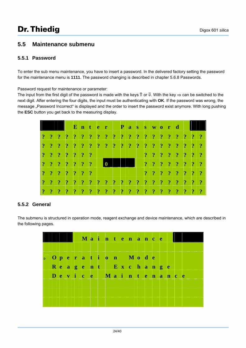
5.5.1 Password
To enter the sub menu maintenance, you have to insert a password. In the delivered factory setting the password for the maintenance menu is 1111. The password changing is described in chapter 5.6.8 Passwords.
Password request for maintenance or parameter: The input from the first digit of the password is made with the keys or . With the key can be switched to the
next digit. After entering the four digits, the input must be authenticating with OK. If the password was wrong, the message „Password Incorrect“ is displayed and the order to insert the password exist anymore. With long pushing the ESC button you get back to the measuring display.
5.5.2 General
The submenu is structured in operation mode, reagent exchange and device maintenance, which are described in the following pages.
E n t e r P a s s w o r d
? ? ? ? ? ? ? ? ? ? ? ? ? ? ? ? ? ? ? ? ?
? ? ? ? ? ? ? ? ? ? ? ? ? ? ? ? ? ? ? ? ?
? ? ? ? ? ? ? ? ? ? ? ? ? ? ?
? ? ? ? ? ? ? 0 ? ? ? ? ? ? ? ?
? ? ? ? ? ? ? ? ? ? ? ? ? ? ?
? ? ? ? ? ? ? ? ? ? ? ? ? ? ? ? ? ? ? ? ?
? ? ? ? ? ? ? ? ? ? ? ? ? ? ? ? ? ? ? ? ?
M a i n t e n a n c e
O p e r a t i o n M o d e
R e a g e n t E x c h a n g e
D e v i c e M a i n t e n a n c e

Digox 601 silica
25/40
5.5.3 Operation mode
AUTOMATIC
In the menu operation mode several analysis programs and the automatic program can be started. With the keys
and you can switch between Modus and Manuel settings. The OK key activates the chosen setting. In modus you can switch with and between AUTOMATIC and OFF, this means you can switch on
(AUTOMATIC) or off (OFF the automatic program of the analyser. The choice must be approved with OK. If the automatic mode was chosen, the analyser begins with the analysis of the first channel which is given a measuring frequency. This is followed by the analysis activity according the adjusted measuring frequency for the individual
channels. The parameterisation of the measuring frequency is described in chapter 5.6.4. An activated automatic mode can be interrupted every time, by setting the mode from AUTOMATIC of OFF. The analyser interrupts the actual program sequence and flushes the cuvette with ultra pure water.
Manual
In the manual command line could be chosen the following programs:
o OFF no program is chosen
o CALIB. Calibration is started. The analyser executes a blind-value and a standard analysis. Out of these measuring the two-point calibration is calculated.
o CANAL 1 Analysis of Channel 1 is carried out
o CANAL 2 Analysis of Channel 2 is carried out
o CANAL 3 Analysis of Channel 3 is carried out
o CANAL 4 Analysis of Channel 4 is carried out
o CANAL 5 Analysis of Channel 5 is carried out
o CANAL 6 Analysis of Channel 6 is carried out
O p e r a t i o n M o d e
M o d e A U T O M A T I C
M a n u a l O F F

Digox 601 silica
26/40
o R.Fill the reagent hoses are filled, for this all hoses (3 reagents, 1 standard) must be putting in the respective tanks.
o Cuv.fill. flush and fill the cuvette with ultra pure water
o ZERO Zero compensation of the photometer
o Grab sample Analysis of optional grab sample
Analysis of the grab sample
The grab sample must be filled in the very well flushed 1 litre bottle, which is placed on the right side of the
analyser. After this start the programme grab sample. If the automatic mode is activated, the actual analysis will be executed and afterwards the grab sample is measured. The grab sample is transported by a diaphragm pump. The result of the analysis is only displayed in the measured value display and not stored in the protocol.
5.5.4 Reagent exchange:
After the reagent exchange, it must be approved in the menu reagent exchange. For this push OK and choose with
the or keys the exchanged reagent in the second line and confirm with OK. With the key and the or the field „Exchanged Yes“ can be chosen and confirm with OK. Hereupon it is shown the advice „Reagent Exchanged!“ and the respective bar gets 100%. For the other changed reagents you have to make the same procedure.
R e a g e n t E x c h a n g e
R e a g n t S t a n d a r d
E x c h a n g e d Y e s N o
S t R 1 R 2 R 3

Digox 601 silica
27/40
5.5.5 Device maintenance:
To confirm the device maintenance you have to answer the question „Device maintained?“ in the menu Device Maintenance with Yes and then with OK. After this is shown the message „Device new maint.!“ and the availability bar is filled to 100%.
R e s t S e r v i c e L i f e
A v a i l a b i l i t y 5 0 %
D e v i c e m a i n t a i n e d ?
Y e s N o

Digox 601 silica
28/40
5.6 Parameter submenu
5.6.1 Password request
To enter the menu parameter, the password P is needed. In the delivered factory settings the password P is 2222. The input follows like the description in chapter 5.5 for the password maintenance. The change of the password is
described in chapter 5.6.8. 5.6.2 General
In the sub menu parameter the basic settings, the measuring frequency, the limits and the current outputs can be adjusted. It is anymore available to change the names of measuring points and the passwords. In the factory settings all adjustable parameter were set back to the delivery status.
5.6.3 Basic settings
The menu basic settings comprise the input of the standard concentration, the choice of the menu speech, the
parameterisation of the flow control and the date as well as time setting. The used standard concentration is shown in line 2 in µg/l. A standard concentration of 100 µg/l SiO2 is factory set.
Important!
Observe that always 100 µg/l is set, otherwise it can cause malfunction. Other standard concentrations can only
be set by a service engineer.
In line 3 can switched the menu speech between English, German or Spanish.
It is recommended to control the sample flow with the flow meter (shown in flow diagram). Therefore the water control in line 4 must be activated and the minimum flow must be adjusted at 5 impulses/s (equal to 0,5 ml/s). If this
flow value is not achieved by an analysis, the analyser switches automatically to the next channel. If there is a measuring frequency which causes that there is no channel left, the analyser switches into standby mode. A new
P a r a m e t e r
B a s i c S e t t i n g s
M e a s u r i n g F r e q u e n c y
L i m i t s
C u r r e n t o u t p u t s
N a m e s o f M e a s . P o i n t s
P a s s w o r d s
F a c t o r y s e t t i n g s

Digox 601 silica
29/40
start takes place after the time that is set in line 5. For the time from the new start the following time intervals can
be set: --, cont., 30 min, 60 min, 90 min, 2 h, 3 h, 4 h, 6 h, 8 h, 12 h, 24 h, 48 h, 72 h and 96 h. The date and the time of the analyser are shown in line 7 and line 8. If there are larger discrepancies, they should be updated. For doing so, the value to be modified (year, month, day, hour, minute, second) must be chosen and
activated with OK. After the parameterisation with the keys or the input must be saved with OK.
5.6.4 Measuring frequency
The measuring frequency indicates the time interval in which the respective channel or calibration should be determined. The following measuring frequency could be adjusted for the channels or the calibration:
o -- (Channel off)
o cont. (without break)
o 30 min
o 60 min
o 90 min
o 2 h
o 3 h
o 4 h
o 12 h
o 24 h
o 48 h
o 72 h
o 96 h
If the analyser is set from OFF to AUTOMATIC in the menu operation mode, than the device began to analyse serial all channels (in display CANAL), which have a measuring frequency. The following analyses were made according to the measuring frequency of each channel (in display CANAL).
The measuring display line 8 shows the rest time till the next analysis started for the shown channel (in display CANAL). After this rest time is expired (0 min in measuring display), the device began with a new analysis of this
B a s i c S e t t i n g s
S t a n d a r d 1 0 0 . 0 µ g / l
L a n g u a g e E n g l i s h
W a t e r O n
m i n . F l o w 5 l / s
N e w S t a r t 1 0 m i n
D a t e 2 0 . 0 6 . 0 8
S c a n T i m e 1 0 : 3 5 : 4 8

Digox 601 silica
30/40
channel (in display CANAL). If the time of more than one channel (in display CANAL) is expired the analyser
executes the channels (in display CANAL) sequentially.
5.6.5 Limits
In the menu limits the upper limits of the concentration of each channel (in display CANAL) can be set. If the analysed concentration exceeds this limit, an alarm message is displayed and the analogue current output of the respective channel (in display CANAL) is set to 23 mA. The limit parameterisation (max. 999,9 µg/l) can be made
analogous to the time and date setting described in chapter 5.6.3.
M e a s . F r e q u e n c y
C a l i b r . : 2 4 h
C a n a l 1 : c o n t .
C a n a l 2 : 3 h
L i m i t I n p u t
C a n a l 1 1 0 0 . 0 µ g / l
C a n a l 2 1 0 0 . 0 µ g / l

Digox 601 silica
31/40
5.6.6 Current outputs
In the menu current outputs silica concentrations can be allocated to the 4 mA and 20 mA. The input of the concentration must be made in µg/l. The current output parameterisation is made analogous to the time and date setting described in chapter 5.6.3.
5.6.7 Names of measuring points
In the menu names of measuring points individual names can be adjusted for each channel, e.g. KKS-numbers, short cuts, ... . The description may consist of maximal 7 letters or numbers. With the keys or the measuring point will be chosen and with OK activated. The last digit began to flashing. With the key you get to the first digit.
It can changed with the keys or . By pushing the key the other digits of the measuring points name can be parameterised. After inputting the name it must be accepted with the OK button. The individual measuring point description is only shown in the measured value display.
C u r r e n t o u t p u t s
i n µ g / l 4 m A 2 0 m A
C a n a l 1 4 . 0 1 0 0 . 0
C a n a l 2 4 . 0 1 0 0 . 0
M e a s . P o i n t s
C a n a l 1 M S T 1
C a n a l 2 M S T 2

Digox 601 silica
32/40
5.6.8 Passwords
In that menu the passwords for the entry to the menu maintenance and the menu parameter can be changed. The passwords have max. 4 numbers and they are set from the factory to 1111 for maintenance and 2222 for parameter. The password changing is made analogous to the adjustment of the standard concentration in chapter
5.6.3. The changing of a password should only be made from an authorised person and should be very well documented. By losing the passwords the assignment of a service engineer is necessary!
P a s s w o r d s
P a s s w o r d W 1 1 1 1
P a s s w o r d P 2 2 2 2

Digox 601 silica
33/40
5.6.9 Factory setting
In the menu factory setting the analyser can set back to the parameterisation of the delivery status. That function should be started, if the suspicion exist, that the analyser have malfunction as a result of false parameterisation. The factory setting overwrites all parameter, which can be changed (Passwords, current outputs, measuring
frequency, ...). After the accomplishment of the reset to the factory setting, all settings for the respective application must be set.
The accomplishment of the factory setting is made by pushing the key to jump from NO (is activated at menu activating) to YES. By approving with the OK key the safety request „Execute now?“ will displayed. If this question is also answered with Yes, the parameters of the factory setting (chapter 10) are loaded. If all parameters are
signed over, the message „Parameter loaded!“ is shown. With the ESC button you get back to the parameter menu.
F a c t o r y S e t t i n g
L o a d i n g P a r a m e t e r ?
Y e s N o

Digox 601 silica
34/40
6. Chemicals and consumption solutions
The reagents and consumption solutions are supplied as dry chemicals, which must be dissolved in silica free water (ultra pure water).
Dry chemical set (order no.: 53570009): reagent 1 reagent 2a reagent 2b reagent 3
Local purchasing: 1 Litre Sulphuric Acid, 25 %, puriss. p.a. FLUKA 84736 (MERCK 100716)
Water:
Silica-free ultrapure water (cleaned by means of a strongly alkaline anion exchanger or suitable mixed-bed ion exchanger) is used for producing the reagent and standard solutions.
Reagent solution 1 (RL 1) – colouring solution
Dissolve reagent 1 and 462 ml sulphuric acid 25% in about 1.5 l water. Use a 2 litre polyethylene can. Then fill up
with water to a volume of 2500 ml ( marking).
Reagent solution 2 (RL 2) – masking solution
Dissolve reagent 2a and reagent 2b in about 1.5 l water. Use a 2 litre polyethylene can. Then fill up with water to a volume of 2500 ml ( marking).
Reagent solution 3 (RL 3) – reduction solution
Dissolve reagent 3 and 109 ml sulphuric acid 25% in about 1.5 l water. Use a 2 litre polyethylene can. Then fill up with water to a volume of 2500 ml ( marking).
Stock solution 2000 µg/l SiO2 (order no.: 53570011): 250 ml silica stock solution, SiO2 2000ppb
Digox 601 silica
35/40
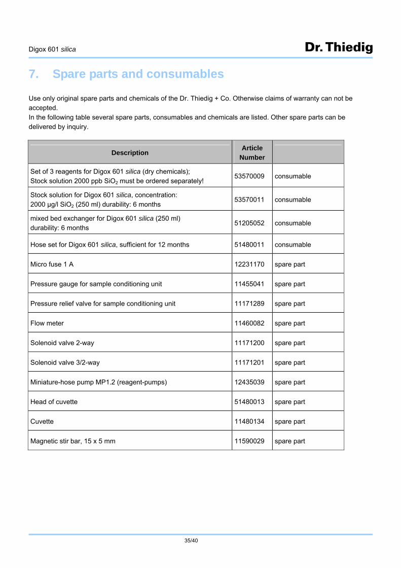
7. Spare parts and consumables
Use only original spare parts and chemicals of the Dr. Thiedig + Co. Otherwise claims of warranty can not be accepted.
In the following table several spare parts, consumables and chemicals are listed. Other spare parts can be delivered by inquiry.
Description Article
Number
Set of 3 reagents for Digox 601 silica (dry chemicals); Stock solution 2000 ppb SiO2 must be ordered separately!
53570009 consumable
Stock solution for Digox 601 silica, concentration: 2000 µg/l SiO2 (250 ml) durability: 6 months
53570011 consumable
mixed bed exchanger for Digox 601 silica (250 ml) durability: 6 months
51205052 consumable
Hose set for Digox 601 silica, sufficient for 12 months 51480011 consumable
Micro fuse 1 A 12231170 spare part
Pressure gauge for sample conditioning unit 11455041 spare part
Pressure relief valve for sample conditioning unit 11171289 spare part
Flow meter 11460082 spare part
Solenoid valve 2-way 11171200 spare part
Solenoid valve 3/2-way 11171201 spare part
Miniature-hose pump MP1.2 (reagent-pumps) 12435039 spare part
Head of cuvette 51480013 spare part
Cuvette 11480134 spare part
Magnetic stir bar, 15 x 5 mm 11590029 spare part

Digox 601 silica
36/40
8. Analytical and technical parameter, operating conditions
Analytical parameters
Field of application Determination of dissolved silicic acid in power station process water
Method Same method as described in VGB-Ringbuch for determining dissolved molybdate active silicic acid according Sheet 3.3.1.1
Measuring range 0 ... 500 µg/l SiO2
Determination limit 4 µg/l SiO2
Accuracy 3 % or 3 ppb SiO2
Repeatability 2 % or 2 ppb SiO2
Channels
2 - 6 sample channels
Grab sample (Option)
1 ultra pure water with ion-exchanger
Reagents quantity
consumption per analysis reserve
3 (by elimination of phosphate influence) 1 silica stock solution, 250 ml
0,5 ml per reagent 2500 ml per reagent (sufficient for 5000 analysis)
Duration of one analysis approx. 12 min
Technical parameters
Power input 140 Watt, fuses 2 A
Electrical specifications Factory setting: 230V AC; 50/ 60 Hz
Option: (s. Fig.4: S1) 115V AC; 50/ 60 Hz
Enclosure Cabinet, wall mounted
Dimensions W x H x D: 500x700x280 mm
Weight 30 kg
Degree of protection IP 65 (enclosure)
Interface Analogue outputs
Digital outputs
2 (4 / 6) x 4 ... 20 mA measuring values
2 x relay alarm outputs Relay 1: Limit values for sample channel 1, 2, …, 6
Relay 2: Residual reagent quantities
Operation conditions
Ambient temperature 10 – 40°C
Sample pre-pressure min. 1 bar
Sample flow min. 10 l/h, max. 20 l/h
Sample temperature 15 – 40°C

Digox 601 silica
37/40
9. Alarm / malfunction and warning messages
Message Cause Trouble shooting
No Sample!
sample failed
blocked hoses
Check pressure on the sample conditioning unit (pressure gauge)
Check and clean valves, hoses and cuvette
No MBF-Water!
sample failed
blocked hoses
Check pressure on the sample conditioning unit
(pressure gauge)
Check and clean valves, hoses and cuvette
No Zero Compensation! Is shown after enabling the analyser
Zero compensation is starting automatically after enabling, duration approx.10 minutes!
Manual starting of the zero compensation in menu
Maintenance Operation mode Manual
Limit! measuring value greater than adjusted limit value
Check adjusted limit value
Check sample (fouling)
Calibration F1 – F5! Calibration failure Check pump for stock solution, mix bed exchanger and sample flow
Warnings
Exchange Reagents! Reagent Level below
10% Exchange the reagents as described in chapter 5.5
Execute Maintenance! Availability below 10% Execute the maintenance as described in chapter
5.5
The alarm is deactivated, when the malfunction, which activates the alarm, disappeared.
The relay 1 is activated in case off all alarms and malfunctions.
In case of any warnings (exchange reagents or execute maintenance) the relay 2 is activated.

Digox 601 silica
38/40
10. Factory settings
The execution of factory setting is described in chapter 5.6.9. The table shows the parameter values, which are set at factory settings.
Basic settings Standard: 100,0 µg/l
Sprache: Deutsch
Wasser: Aus
min. Flow: 5 Imp/s
neuer Start: sofort
Measuring frequency Kalibrierung: 48 h
Kanal 1: 3 h
Kanal 2: 3 h
Kanal 3: 3 h
Kanal 4: 3 h
Kanal 5: 3 h
Kanal 6: 3 h
limits Kanal 1: 100,0 µg/l
Kanal 2: 100,0 µg/l
Kanal 3: 100,0 µg/l
Kanal 4: 100,0 µg/l
Kanal 5: 100,0 µg/l
Kanal 6: 100,0 µg/l
Current outputs 4 mA 20 mA
Kanal 1: 0,0 100,0
Kanal 2: 0,0 100,0
Kanal 3: 0,0 100,0
Kanal 4: 0,0 100,0
Kanal 5: 0,0 100,0
Kanal 6: 0,0 100,0
Names of meas. points Kanal 1: MST 1
Kanal 2: MST 2
Kanal 3: MST 3
Kanal 4: MST 4
Kanal 5: MST 5
Kanal 6: MST 6
Passwords W: 1111
P: 2222

Digox 601 silica
39/40
Notes:

Dr. Thiedig + Co. Prinzenallee 78-79
13357 Berlin Deutschland Telefon 030 / 49 77 69-0
Telefax 030 / 49 77 69-25 E-mail: [email protected] www.thiedig.com Service hotline: (+49) 30 49 77 69-42


![Polymers from the natural product Betulin : a ... · extraction.[30] The first prominent largely ordered mesoporous silica, MCM‐41, The first prominent largely ordered mesoporous](https://static.fdokument.com/doc/165x107/5d59e74c88c993462c8b6bce/polymers-from-the-natural-product-betulin-a-extraction30-the-first.jpg)