Space Instrumentation: Measuring Magnetic Fields in Space ...
55
Space Instrumentation: Measuring Magnetic Fields in Space Dr. Ingo Richter i.richter @tu-bs.de Institute for Geophysics and extraterrestrial Physics TU- Braunschweig MPS Lindau 27.10.2010
Transcript of Space Instrumentation: Measuring Magnetic Fields in Space ...
Space Instrumentation:
Measuring Magnetic Fields in Space
Dr. Ingo Richter
i.richter
@tu-bs.deInstitute for Geophysics and extraterrestrial Physics
TU-
BraunschweigMPS Lindau
27.10.2010
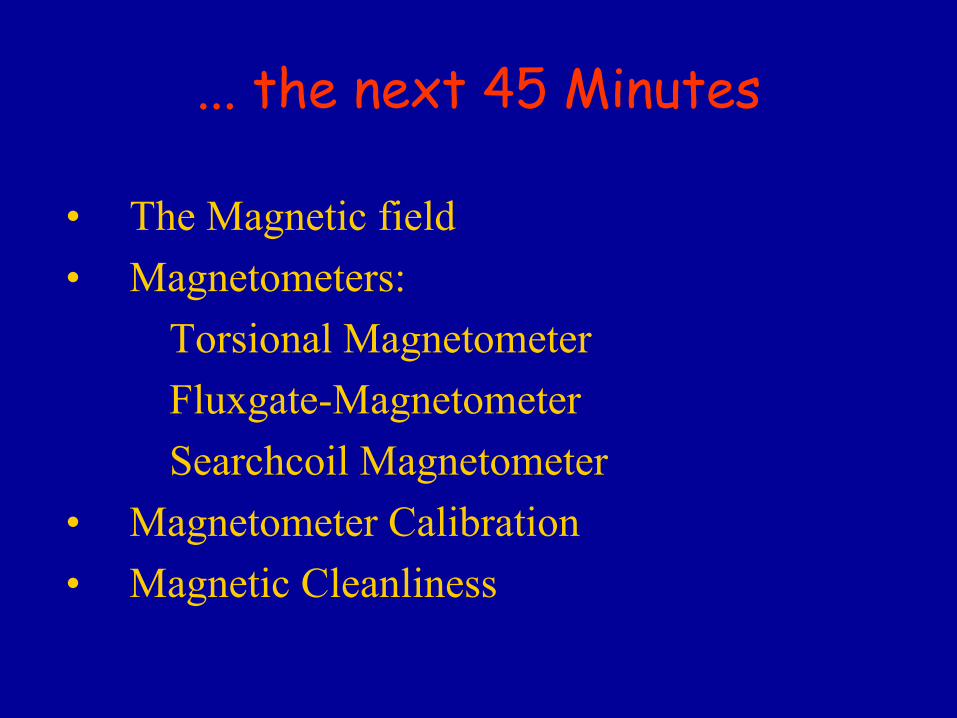
... the
next
45 Minutes
• The
Magnetic
field
• Magnetometers:
Torsional
MagnetometerFluxgate-MagnetometerSearchcoil
Magnetometer
• Magnetometer Calibration
• Magnetic
Cleanliness

The
Magnetic
field
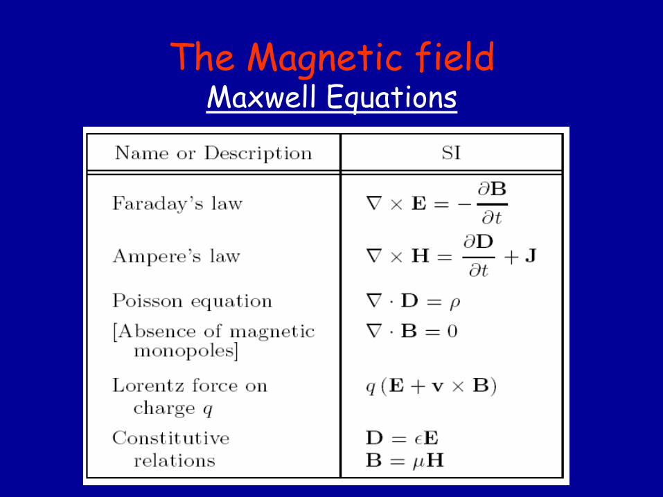
The
Magnetic
field Maxwell Equations

The
Magnetic
field The
pure Earth
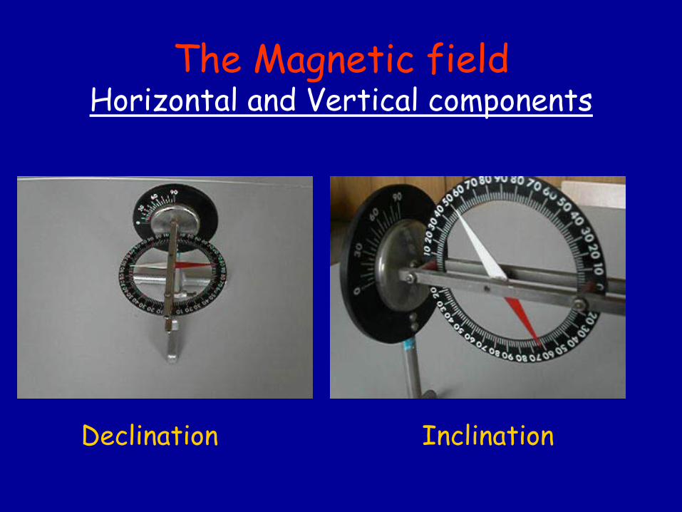
The
Magnetic
field Horizontal and Vertical
components
Declination
Inclination
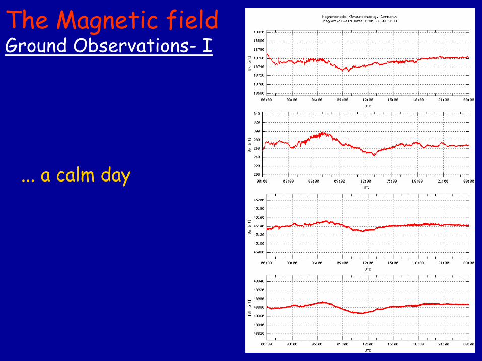
The
Magnetic
field Ground
Observations-
I
... a calm
day
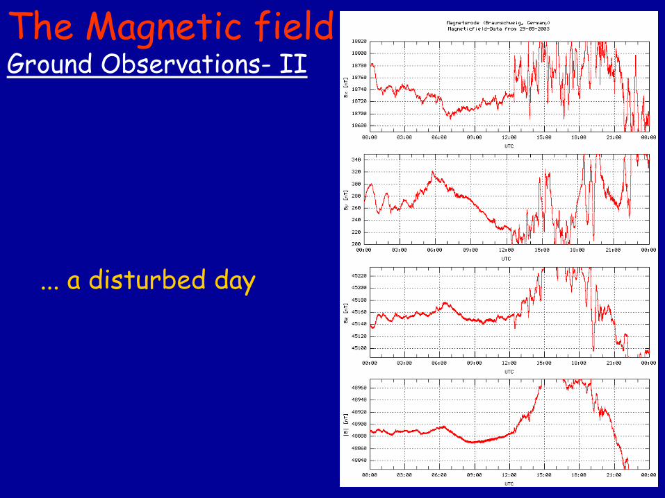
The
Magnetic
field Ground
Observations-
II
... a disturbed
day
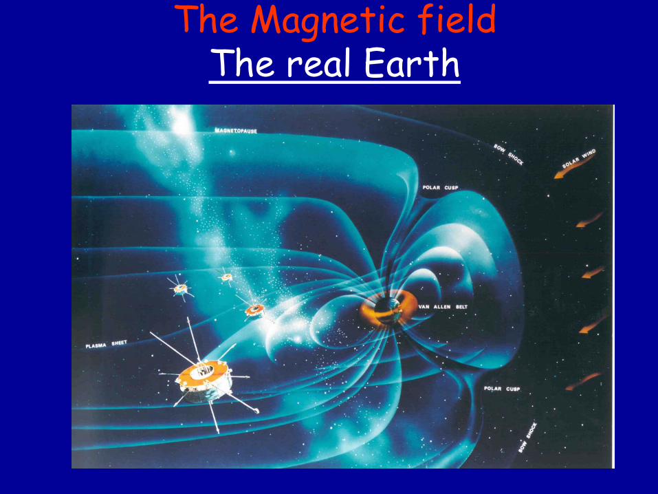
The
Magnetic
field The
real Earth
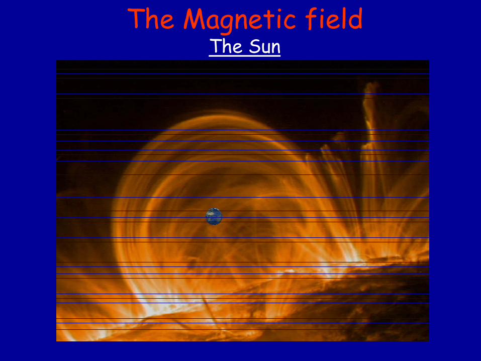
The
Magnetic
field The
Sun
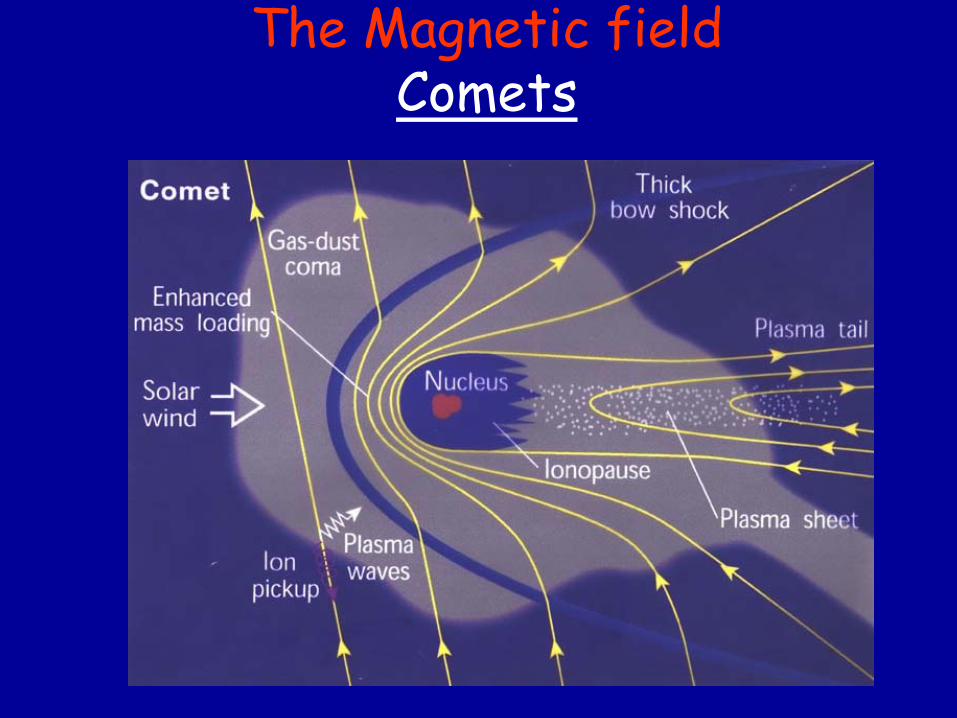
The
Magnetic
field Comets
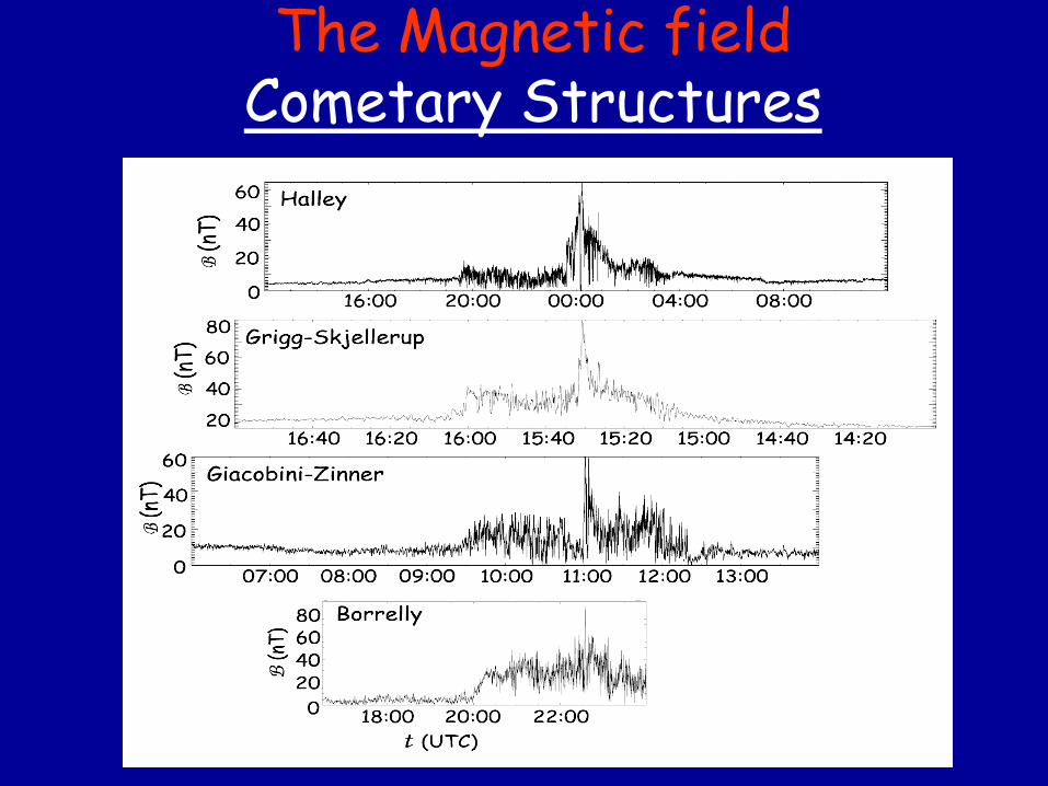
The
Magnetic
field Cometary
Structures
Magnetometers
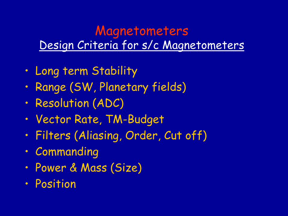
Magnetometers Design Criteria
for
s/c Magnetometers
•
Long term
Stability•
Range (SW, Planetary
fields)
•
Resolution (ADC)•
Vector Rate, TM-Budget
•
Filters (Aliasing, Order, Cut off)•
Commanding
•
Power & Mass
(Size)•
Position
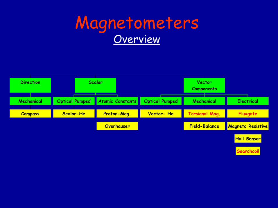
Compass
Mechanical
Direction
Scalar-He
Optical Pumped
Overhauser
Proton-Mag.
Atomic Constants
Scalar
Vector- He
Optical Pumped
Field-Balance
Torsional Mag.
Mechanical
Searchcoil
Hall Sensor
Magneto Resistive
Fluxgate
Electrical
VectorComponents
Magnetometers Overview
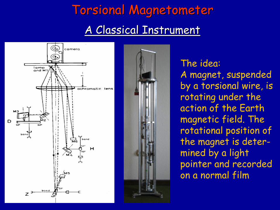
The
idea:A magnet, suspendedby
a torsional
wire, is
rotating
under
theaction
of the
Earth
magnetic
field. Therotational
position
of
the
magnet
is
deter-mined
by
a light
pointer
and recordedon a normal film
TorsionalTorsional
MagnetometerMagnetometer A A ClassicalClassical
InstrumentInstrument
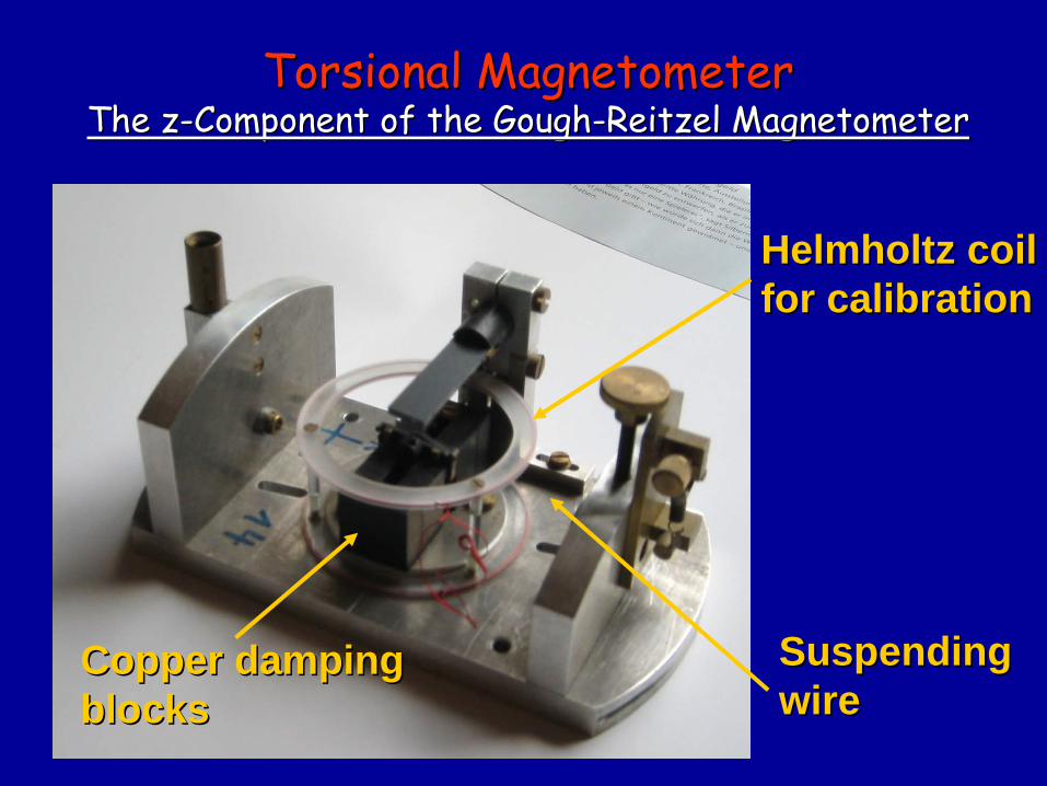
Helmholtz Helmholtz coilcoilforfor calibrationcalibration
CopperCopper dampingdampingblocksblocks
SuspendingSuspendingwirewire
TorsionalTorsional
MagnetometerMagnetometer TheThe
zz--ComponentComponent
of of thethe
GoughGough--ReitzelReitzel
MagnetometerMagnetometer
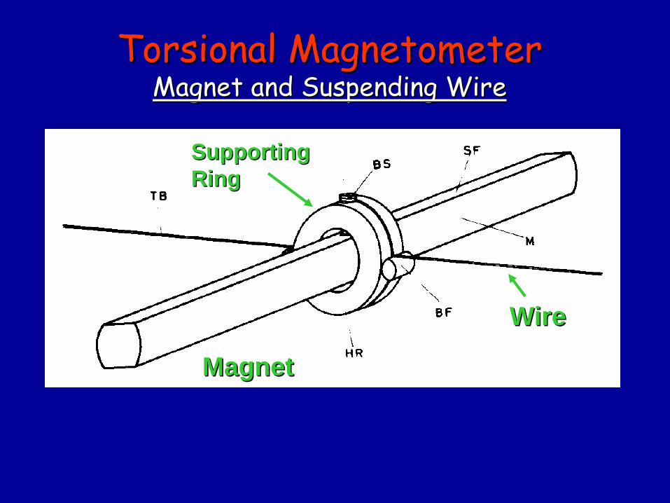
WireWire
MagnetMagnet
SupportingSupportingRingRing
TorsionalTorsional
MagnetometerMagnetometer Magnet and Magnet and SuspendingSuspending
WireWire
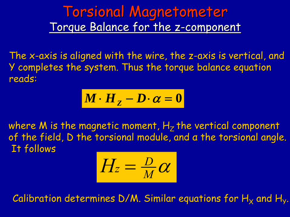
TheThe
xx--axisaxis
isis
alignedaligned
withwith
thethe
wirewire, , thethe
zz--axisaxis
isis
verticalvertical, and , and Y Y completescompletes
thethe
system. system. ThusThus
thethe
torquetorque
balancebalance
equationequation
readsreads::
0 DHM Z
wherewhere
M M isis
thethe
magneticmagnetic
momentmoment, H, HZ Z thethe
verticalvertical
componentcomponentof of thethe
fieldfield, D , D thethe
torsionaltorsional
modulemodule, , and and αα
thethe
torsionaltorsional
angle.angle.
ItIt
followsfollows
CalibrationCalibration
determinesdetermines
D/M. D/M. SimilarSimilar
equationsequations
forfor
HHXX
and Hand HYY
..
MDzH
TorsionalTorsional
MagnetometerMagnetometer TorqueTorque
Balance Balance forfor
thethe
zz--componentcomponent
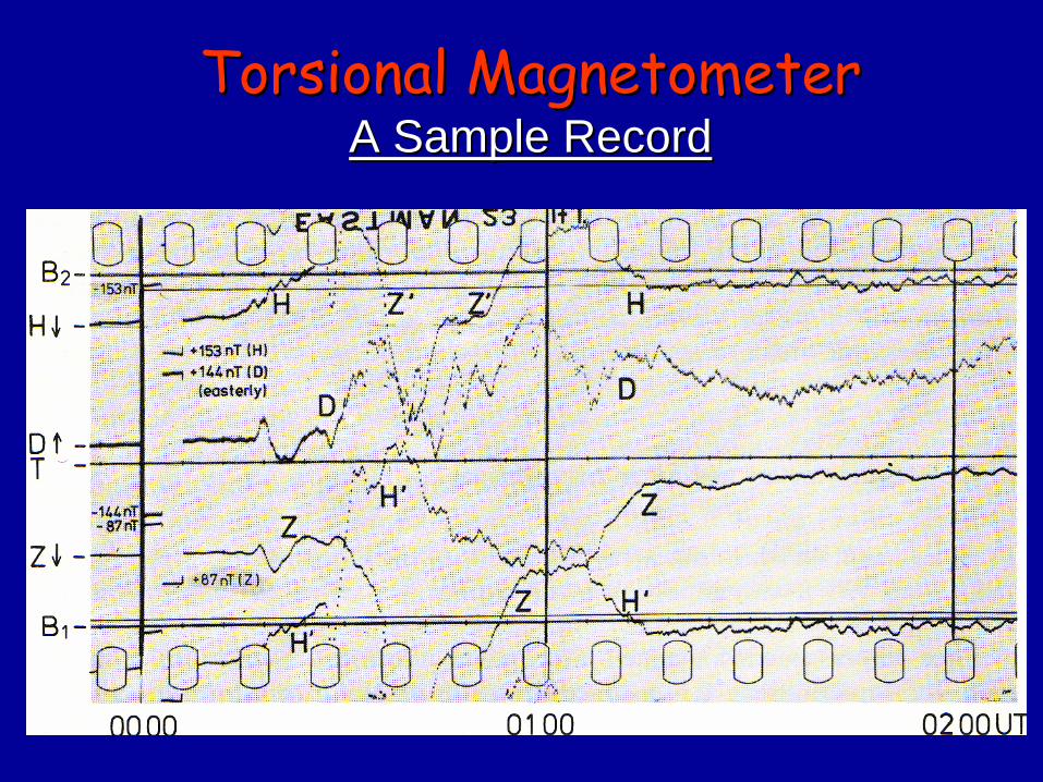
TorsionalTorsional
MagnetometerMagnetometer A Sample A Sample RecordRecord
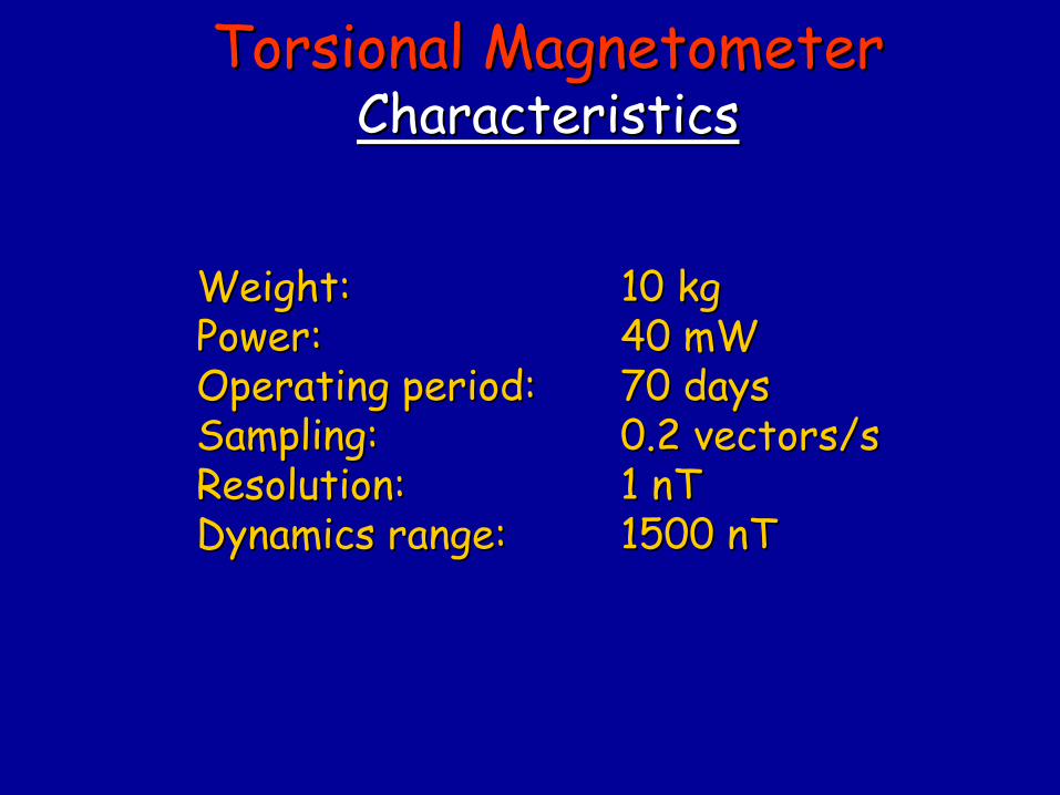
WeightWeight: : 10 kg10 kgPower:Power:
40 mW40 mW
OperatingOperating
periodperiod::
70 70 daysdaysSamplingSampling::
0.2 0.2 vectorsvectors/s/s
Resolution:Resolution:
1 nT1 nTDynamicsDynamics
rangerange::
1500 nT1500 nT
TorsionalTorsional
MagnetometerMagnetometer CharacteristicsCharacteristics
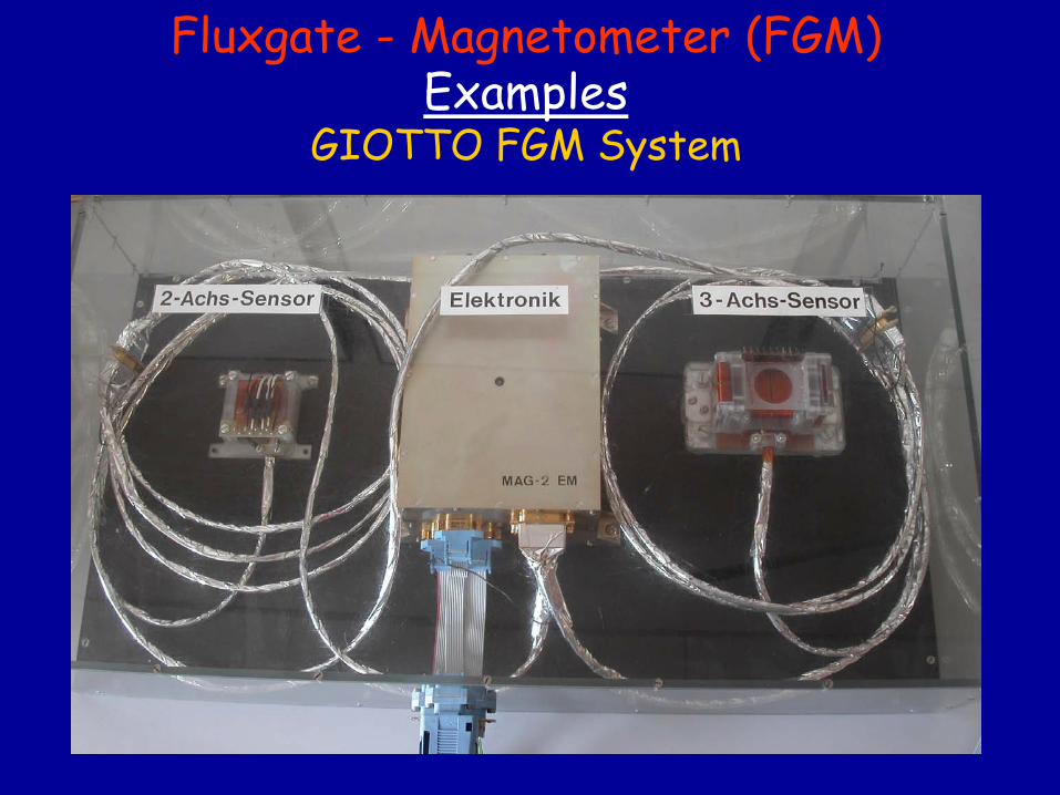
Fluxgate
-
Magnetometer (FGM) Examples
GIOTTO FGM System

Fluxgate
-
Magnetometer (FGM) Classification
•
Saturated-Core-Magnetometer •
Vector measurements possible
•
No absolute measurements•
Temperature Dependency
•
Lightweight, compact construction •
Low power consumption
•
Qualified for space applications
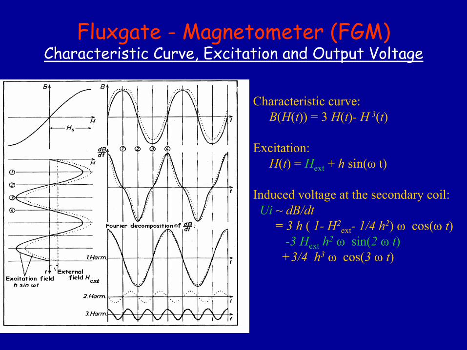
Fluxgate
-
Magnetometer (FGM) Characteristic Curve, Excitation and Output Voltage
Characteristic curve: B(H(t)) = 3 H(t)- H 3(t)
Excitation:H(t) = Hext
+ h sin(ω
t)
Induced voltage at the secondary coil: Ui
~
dB/dt= 3 h
(
1-
H2ext
- 1/4 h2)
ω
cos(ω
t) -3 Hext
h2
ω
sin(2
ω
t)+3/4
h3
ω
cos(3 ω
t)
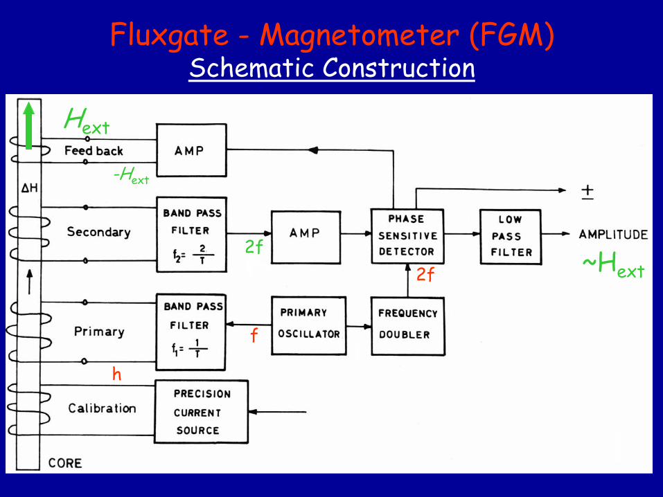
Fluxgate
-
Magnetometer (FGM) Schematic
Construction
Hext
-Hext
~Hext
f
2f
h
2f
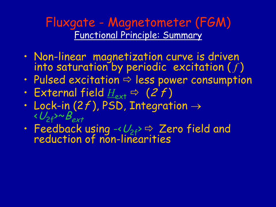
Fluxgate
-
Magnetometer (FGM) Functional
Principle: Summary
•
Non-linear magnetization curve is driven into saturation
by periodic excitation ( f
)
•
Pulsed excitation
less power consumption •
External field Hext
(2 f ) •
Lock-in (2f ), PSD, Integration
<U2f
>~Bext•
Feedback using -<U2f
>
Zero field
and reduction of non-linearities
Fluxgate
-
Magnetometer (FGM) Sensor Design
Problem:Decoupling
of small
2nd
harmonic
from
the
excitation
signal
Solution:Suitable
sensor
geometry
for
suppression
of
odd
harmonics
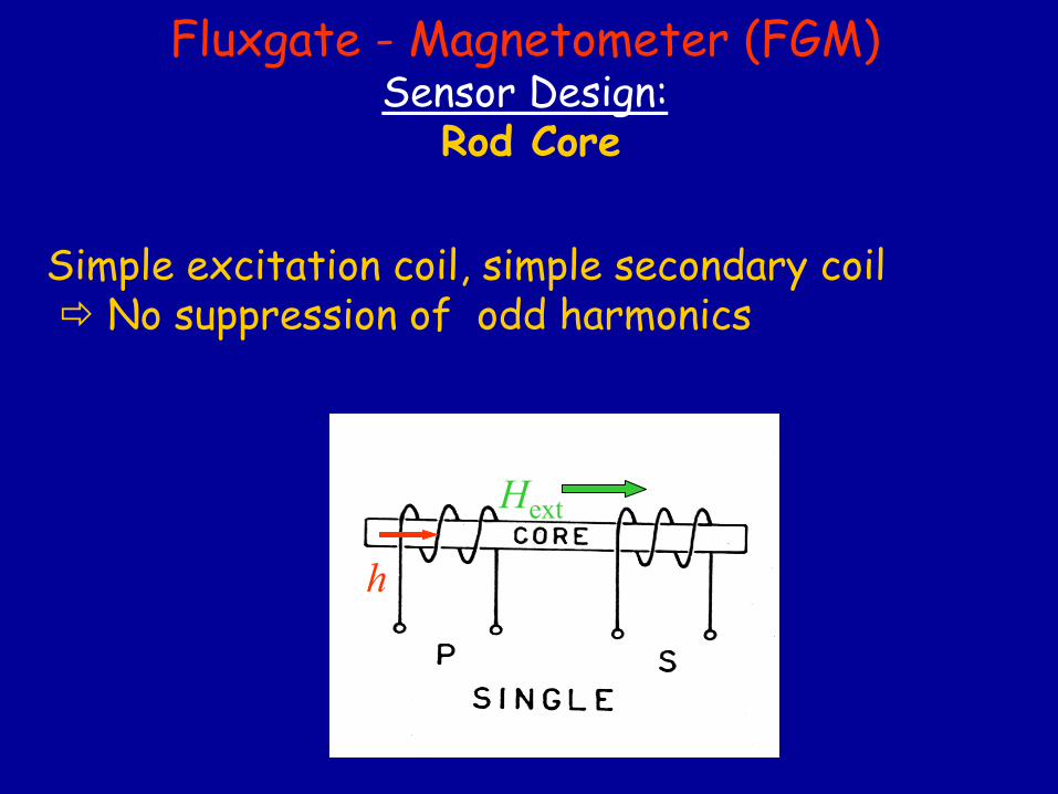
Fluxgate
-
Magnetometer (FGM) Sensor Design:
Rod Core
Simple excitation coil, simple secondary coil
No suppression
of odd
harmonics
Hext
h
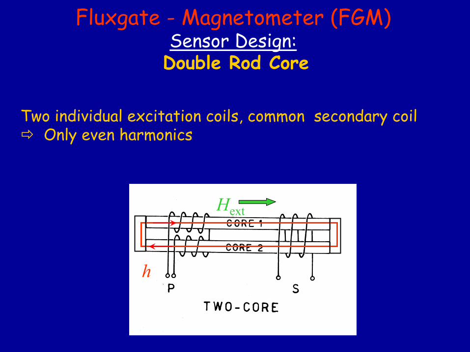
Fluxgate
-
Magnetometer (FGM) Sensor Design:
Double Rod Core
Two
individual excitation coils, common secondary coil
Only even harmonics
Hext
h
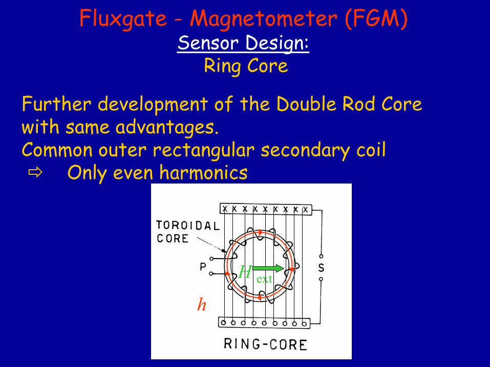
Fluxgate
-
Magnetometer (FGM) Sensor Design:
Ring Core
Further development of the Double Rod Core with same advantages. Common outer rectangular secondary coil
Only even harmonics
H ext
h
4
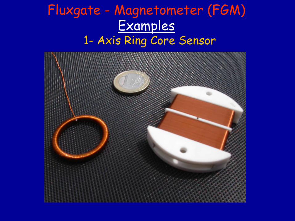
Fluxgate
-
Magnetometer (FGM) Examples
1-
Axis
Ring Core
Sensor
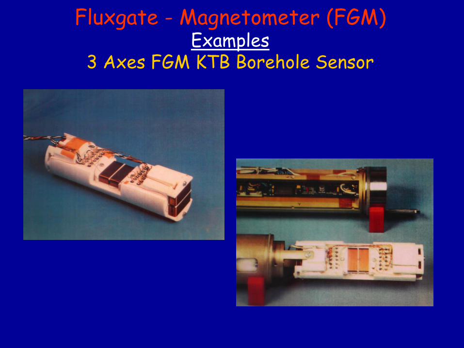
Fluxgate
-
Magnetometer (FGM) Examples
3 Axes
FGM KTB Borehole
Sensor
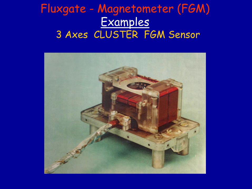
Fluxgate
-
Magnetometer (FGM) Examples
3 Axes
CLUSTER FGM Sensor
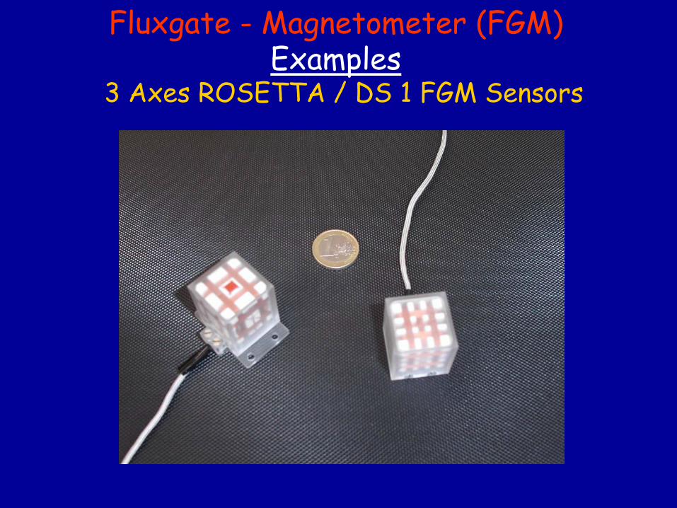
Fluxgate
-
Magnetometer (FGM) Examples
3 Axes
ROSETTA / DS 1 FGM Sensors
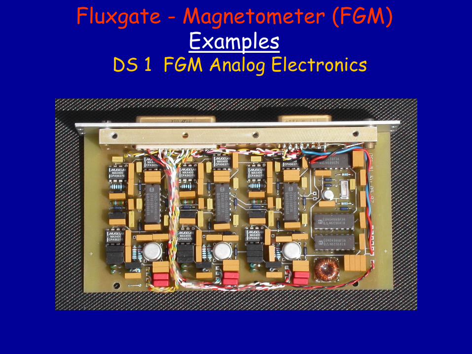
Fluxgate
-
Magnetometer (FGM) Examples
DS 1 FGM Analog Electronics
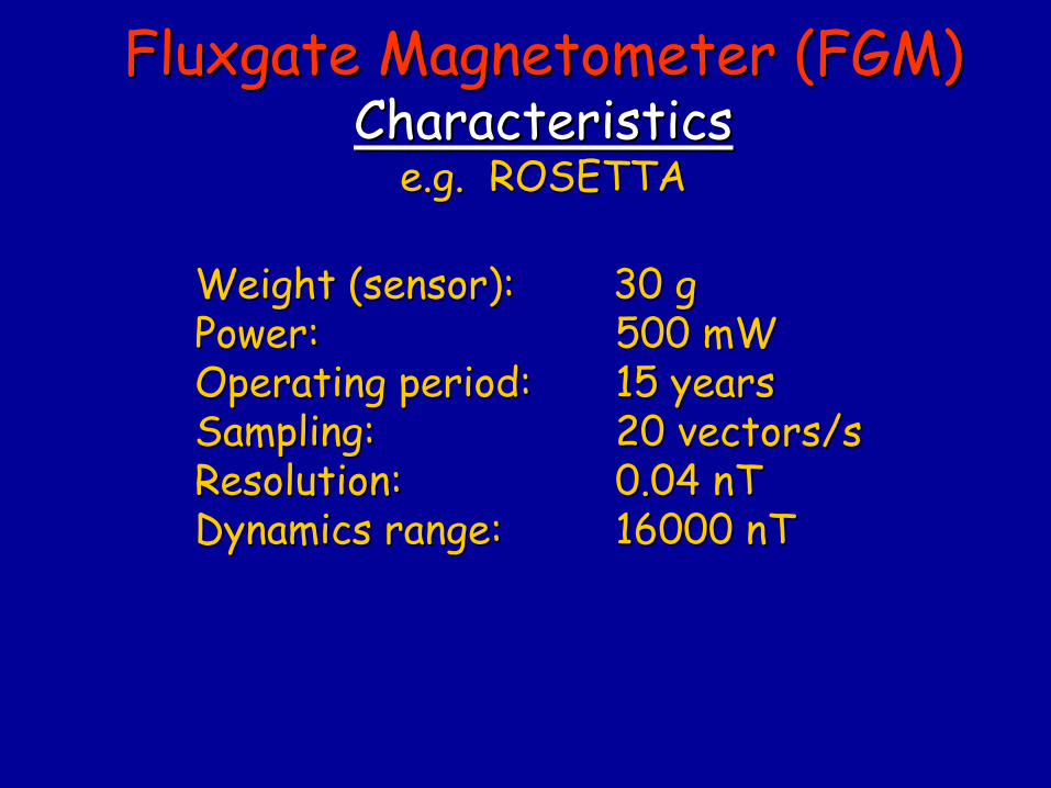
WeightWeight
((sensorsensor): 30 g): 30 gPower:Power:
500 mW500 mW
OperatingOperating
periodperiod::
15 15 yearsyearsSamplingSampling::
20 20 vectorsvectors/s/s
Resolution:Resolution:
0.04 nT0.04 nTDynamicsDynamics
rangerange::
16000 nT16000 nT
FluxgateFluxgate
Magnetometer (FGM)Magnetometer (FGM) CharacteristicsCharacteristics
e.g. ROSETTAe.g. ROSETTA
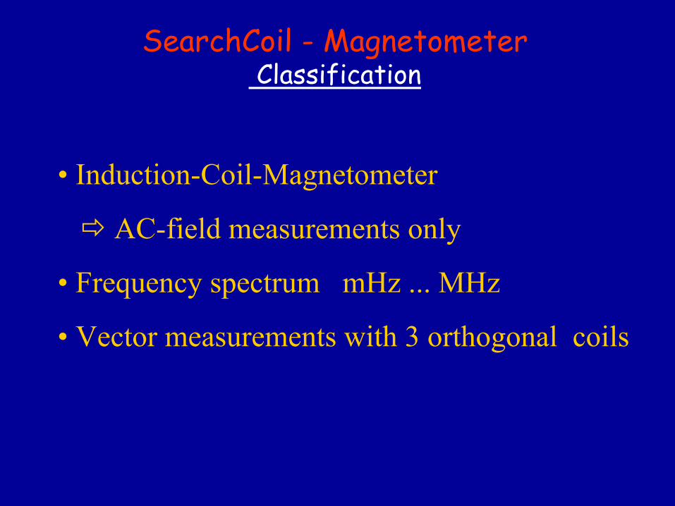
SearchCoil
-
Magnetometer Classification
• Induction-Coil-Magnetometer
AC-field measurements only
• Frequency
spectrum mHz
...
MHz
• Vector measurements with 3 orthogonal
coils
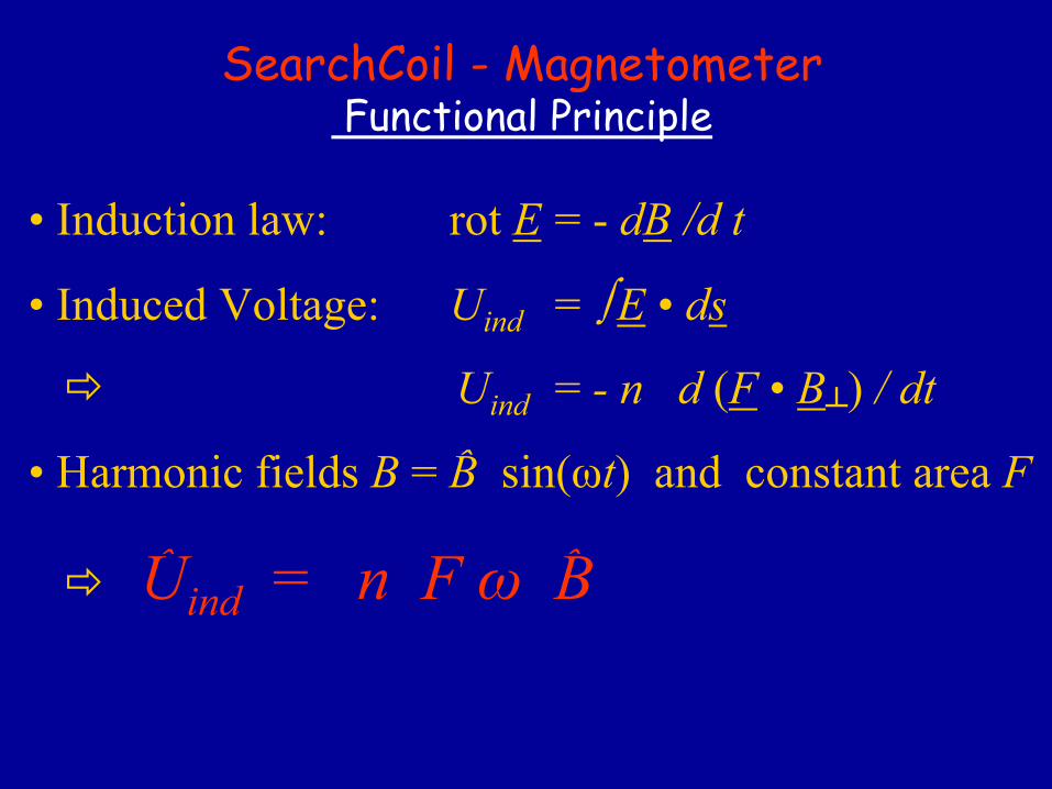
SearchCoil
-
Magnetometer Functional
Principle
• Induction law:
rot
E
= -
dB
/d
t
• Induced
Voltage: Uind
=
E
• ds
Uind
=
- n d (F
• B┴
)
/ dt
• Harmonic
fields
B
= B
sin(ωt)
and
constant area F
Uind
= n F ω
B
ˆ
ˆ ˆ
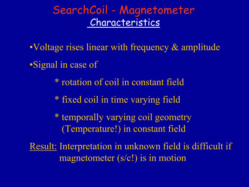
SearchCoil
-
Magnetometer Characteristics
•Voltage rises linear with frequency & amplitude
•Signal in case of
*
rotation of coil in constant field
*
fixed coil in time varying field
* temporally varying coil geometry (Temperature!) in constant field
Result:
Interpretation in unknown field is
difficult
if magnetometer (s/c!) is
in motion
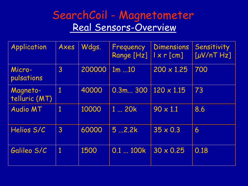
SearchCoil
-
Magnetometer Real Sensors-Overview
Application Axes Wdgs. Frequency
Range [Hz]Dimensions
l x r [cm]Sensitivity
[µV/nT Hz]
Micro-
pulsations 3 200000 1m ...10 200 x 1.25 700
Magneto-
telluric
(MT)1 40000 0.3m... 300 120 x 1.15 73
Audio MT 1 10000 1 ... 20k 90 x 1.1 8.6
Helios S/C 3 60000 5 ...2.2k 35 x 0.3 6
Galileo S/C 1 1500 0.1 ... 100k 30 x 0.25 0.18
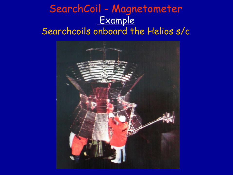
SearchCoil
-
Magnetometer Example
Searchcoils
onboard
the
Helios
s/c
Magnetometer Calibration
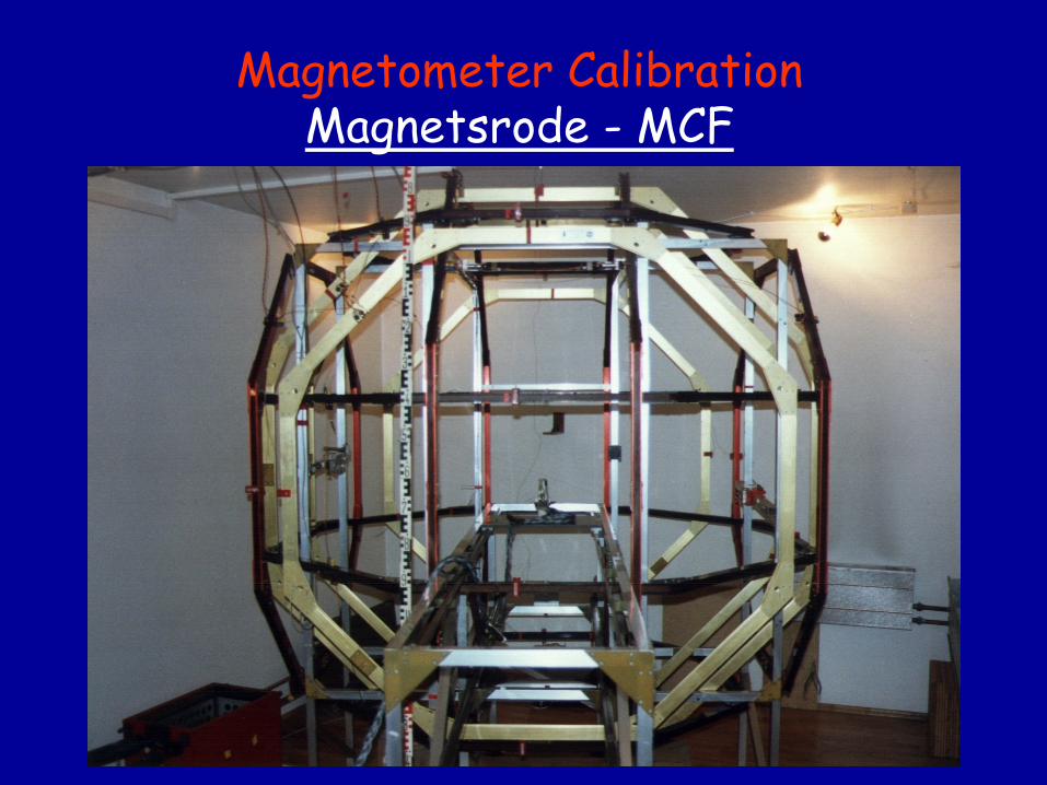
Magnetometer Calibration Magnetsrode
-
MCF
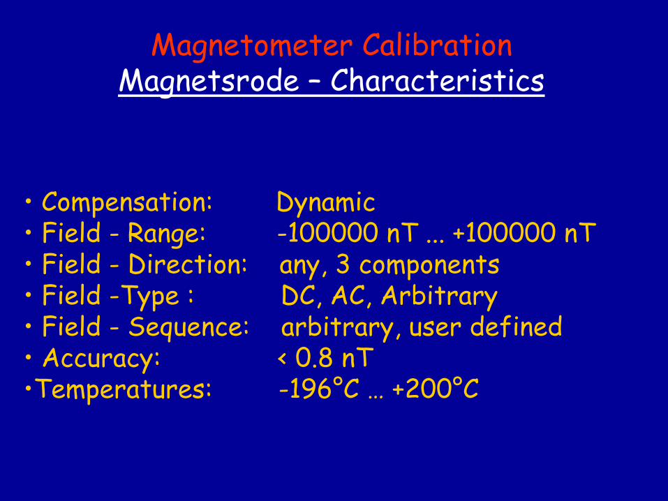
Magnetometer Calibration Magnetsrode
–
Characteristics
• Compensation: Dynamic• Field
-
Range: -100000 nT ... +100000 nT
• Field
-
Direction: any, 3 components• Field
-Type : DC, AC, Arbitrary
• Field
-
Sequence: arbitrary, user
defined• Accuracy: < 0.8 nT•Temperatures: -196°C … +200°C
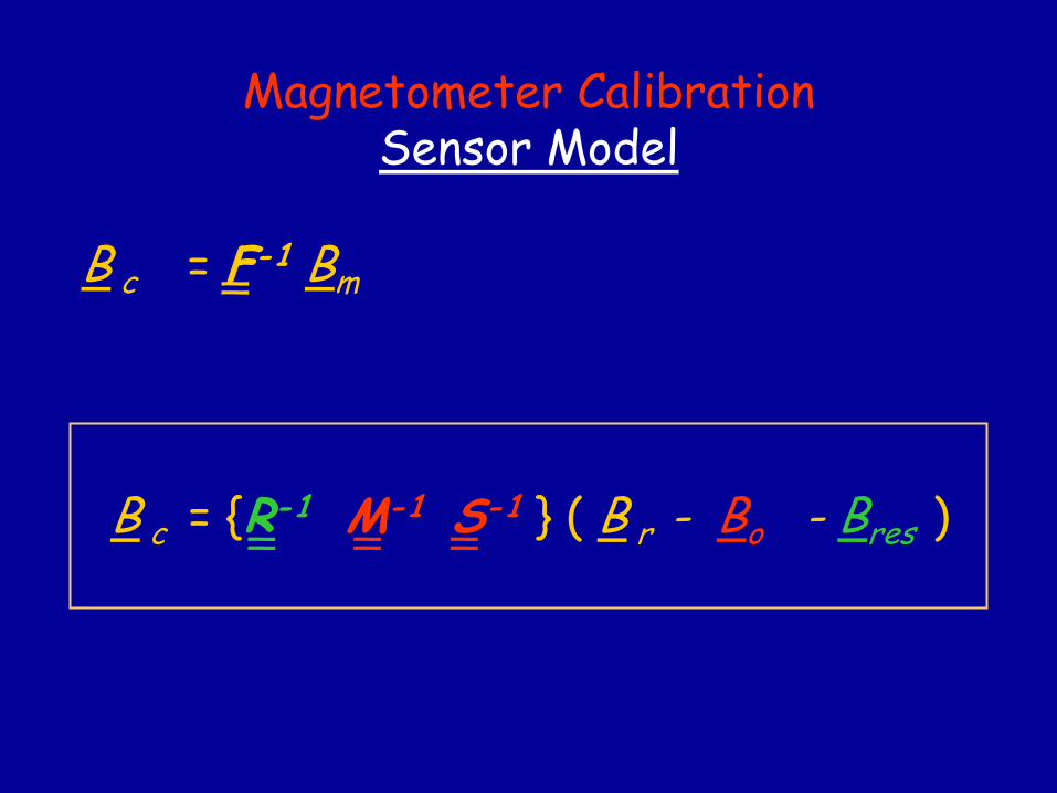
B c
= F-1 Bm
Magnetometer Calibration Sensor Model
B c
= {R-1
M-1 S-1 } ( B r - Bo - Bres
)
__
__ _ ___
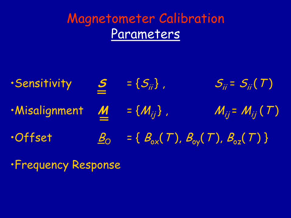
•Sensitivity
S = {Sii
} ,
Sii
= Sii
(T )
•Misalignment M
= {Mij
} ,
Mij
= Mij
(T )
•Offset
BO
= { Box
(T ), Boy
(T ), Boz
(T ) }
•Frequency
Response
Magnetometer Calibration Parameters
_
_
_
_
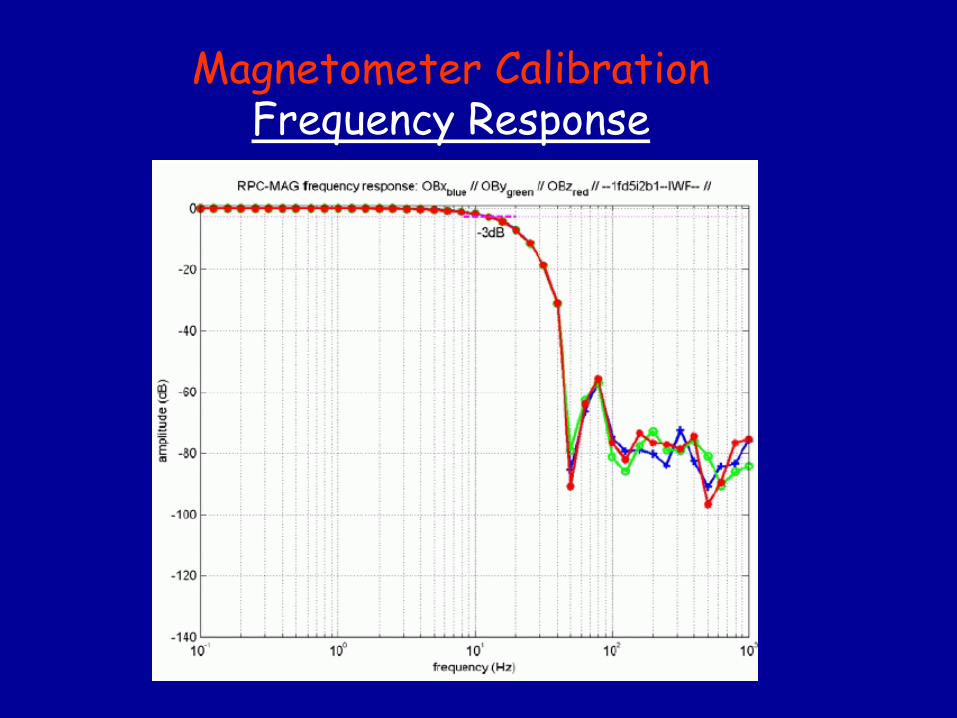
Magnetometer Calibration Frequency
Response
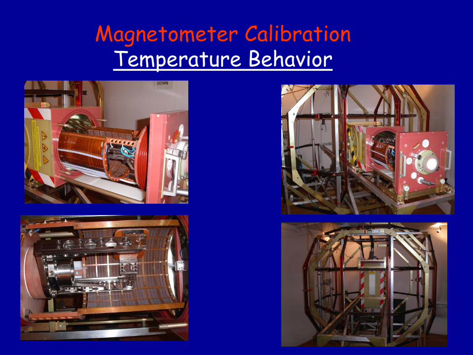
Magnetometer Calibration Temperature
Behavior

Magnetic
Cleanliness
Magnetic
Cleanliness Basic Ideas
• Magnetic
properties
of the
s/c have
to be
known
toperform
excellent
measurements
in space
Every
unit
has to be
mapped
before
integration
• S/C is
represented
by
a model
of n Dipoles• Usage
of Compensation-Magnets
Magnetic
field
at the
location
of the
MAG canbe
minimized
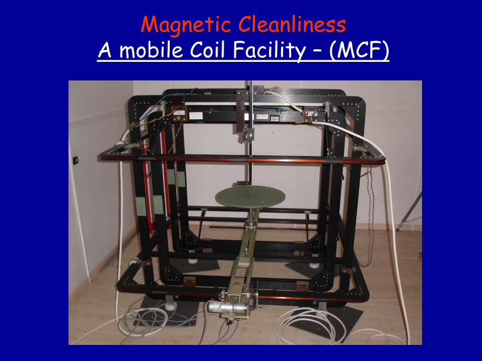
Magnetic
Cleanliness A mobile Coil
Facility
–
(MCF)
Magnetic
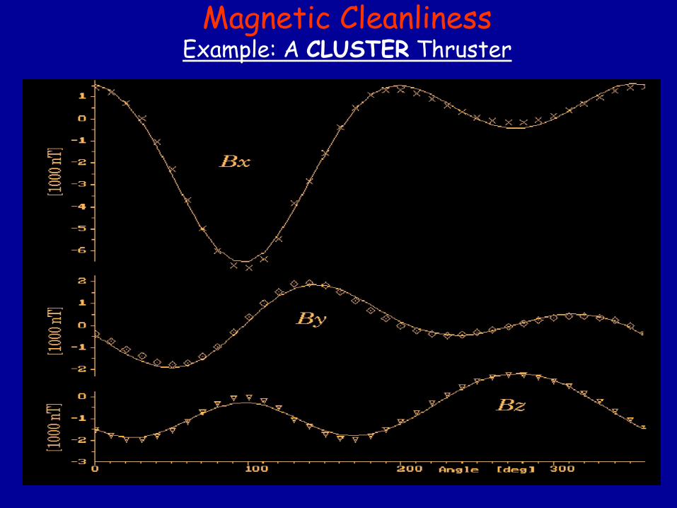
Cleanliness Example: A CLUSTER
Thruster
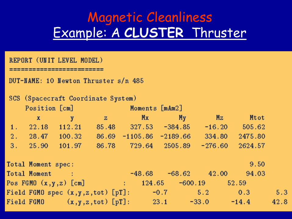
Magnetic
Cleanliness Example: A CLUSTER
Thruster
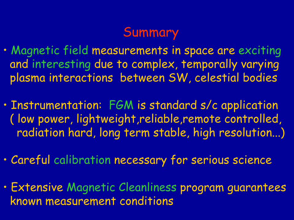
Summary• Magnetic
field
measurements
in space
are
exciting
and interesting
due
to complex, temporally
varyingplasma
interactions
between
SW, celestial
bodies
• Instrumentation: FGM
is
standard
s/c application( low
power, lightweight,reliable,remote
controlled,
radiation
hard, long
term
stable, high resolution...)
• Careful
calibration
necessary
for
serious
science
• Extensive Magnetic
Cleanliness
program
guaranteesknown
measurement
conditions
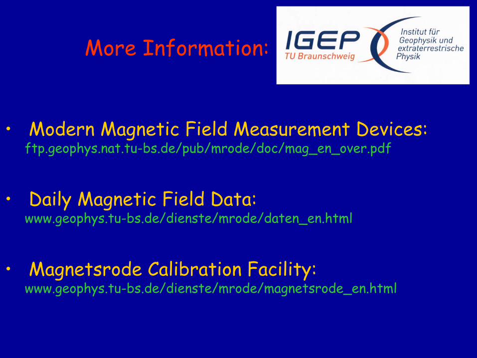
More
Information:
•
Modern Magnetic
Field
Measurement
Devices:ftp.geophys.nat.tu-bs.de/pub/mrode/doc/mag_en_over.pdf
•
Daily Magnetic
Field
Data:www.geophys.tu-bs.de/dienste/mrode/daten_en.html
•
Magnetsrode
Calibration
Facility:www.geophys.tu-bs.de/dienste/mrode/magnetsrode_en.html