Study on smoke production, development and toxicity in bus ...
76
Study on smoke production, development and toxicity in bus fires Berichte der Bundesanstalt für Straßenwesen Fahrzeugtechnik Heft F 99
Transcript of Study on smoke production, development and toxicity in bus ...
Study on smoke production
development and toxicity in bus fires
Berichte derBundesanstalt fuumlr Straszligenwesen
Fahrzeugtechnik Heft F 99
Ber
icht
e d
er B
und
esan
stal
t fuuml
r S
traszlig
enw
esen
H
eft
F 99
ISSN 0943-9307ISBN 978-3-95606-121-9
20141103_Umschlag F 99indd 1 031114 0729
by
Anja HofmannSteffen Duumllsen
BAMBundesanstalt fuumlr Materialforschung und -pruumlfungArbeitsgruppe Brandszenarien und Brandanalytik
Berlin
Berichte derBundesanstalt fuumlr Straszligenwesen
Fahrzeugtechnik Heft F 99
Study on smoke production
development and toxicity in bus fires
20141103_Umschlag F 99indd 2 031114 0729
Die Bundesanstalt fuumlr Straszligenwesenveroumlffentlicht ihre Arbeits- und Forschungs-ergebnisse in der Schriftenreihe Berichte der Bundesanstalt fuumlr Straszligenwesen Die Reihebesteht aus folgenden Unterreihen
A - AllgemeinesB - Bruumlcken- und IngenieurbauF - FahrzeugtechnikM - Mensch und SicherheitS - StraszligenbauV - Verkehrstechnik
Es wird darauf hingewiesen dass die unterdem Namen der Verfasser veroumlffentlichtenBerichte nicht in jedem Fall die Ansicht desHerausgebers wiedergeben
Nachdruck und photomechanische Wieder-gabe auch auszugsweise nur mit Genehmi-gung der Bundesanstalt fuumlr StraszligenwesenStabsstelle Presse und Oumlffentlichkeitsarbeit
Die Hefte der Schriftenreihe Berichte der Bundesanstalt fuumlr Straszligenwesen koumlnnendirekt bei der Carl Schuumlnemann Verlag GmbHZweite Schlachtpforte 7 D-28195 BremenTelefon (04 21) 3 69 03 - 53 bezogen werden
Uumlber die Forschungsergebnisse und ihre Veroumlffentlichungen wird in der Regel in Kurzform im Informationsdienst Forschung kompakt berichtetDieser Dienst wird kostenlos angebotenInteressenten wenden sich bitte an dieBundesanstalt fuumlr StraszligenwesenStabsstelle Presse und Oumlffentlichkeitsarbeit
Ab dem Jahrgang 2003 stehen die Berichte derBundesanstalt fuumlr Straszligenwesen (BASt)zum Teil als kostenfreier Download im elektronischen BASt-Archiv ELBA zur Verfuumlgung httpbastopushbz-nrwde
Impressum
Bericht zum Forschungsprojekt FE 8203772009Entstehung Ausbreitung und Toxizitaumlt von Rauch bei BusbraumlndenStudy on smoke production development and toxicity in bus fires [engl]
FachbetreuungJost Gail
HerausgeberBundesanstalt fuumlr StraszligenwesenBruumlderstraszlige 53 D-51427 Bergisch GladbachTelefon (0 22 04) 43 - 0 middot Telefax (0 22 04) 43 - 674
RedaktionStabsstelle Presse und Oumlffentlichkeitsarbeit
Druck und VerlagFachverlag NW in derCarl Schuumlnemann Verlag GmbHZweite Schlachtpforte 7 D-28195 BremenTelefon (04 21) 3 69 03 - 53 middot Telefax (04 21) 3 69 03 - 48wwwschuenemann-verlagde
ISSN 0943-9307ISBN 978-3-95606-121-9
Bergisch Gladbach November 2014
20141103_Impressum F 99indd 1 131114 1016
3
Abstract ndash Kurzfassung
Study on smoke production development and toxicity in bus fires
Although the bus belongs to the safest traffic means single accidents can be particularly severe and concern many passengers Especially in case of fires a high number of injured and killed persons can be the outcome Fire safety of buses therefore is of high importance With the increase of plastic materials as a material for the interior equipment of buses and coaches due to their good mechanical properties combined with low weight the question arises whether the safety level has decreased in case of a fire during the last years ndash also compared to other means of transport Because of the combustible plastics and their ability to release a high amount of heat the main fire load in buses is no longer the fuel but the plastic materials which are also often easy to ignite Besides the flammability of the equipments also the production of smoke the smoke development and propagation as well as its toxicity are of interest That counts for the passengers as well as for the test methods and its limit values The severe fire in Germany near Hanover in 2008 with 20 fatalities showed how disastrous such fires can be
For those reasons several research projects were initiated on behalf of the German Federal Highway Research Institute At the one hand the fire behaviour of coach interiors was examined in general focusing on fire propagation as well as fire detection and signalling As result recommendations with regard to early fire detection systems for the engine compartments and onshyboard extinguishing equipment were elaborated
On the other hand research was carried out to examine heat release smoke smoke propagation and its toxicity due to burning bus interior materials In this project small and real scale experiments on material specimens interior parts and vehicles were performed
Trains and buses often have very similar operation conditions Consequently bus interior material was tested according to the regulations for rail vehicles ie DIN EN 45545 as well as DIN 5510 None of the tested bus interior materials would have been allowed to use in a train The fire safety regulations for bus materials are on a low level compared to
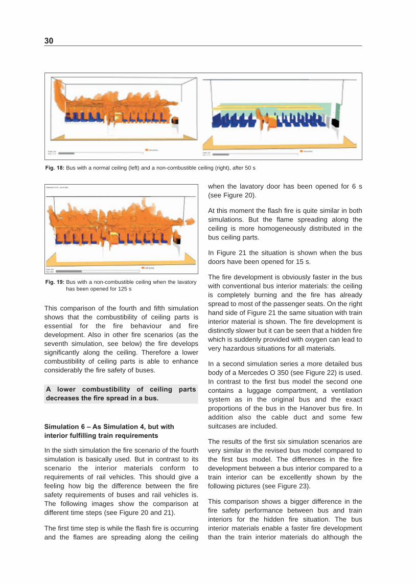
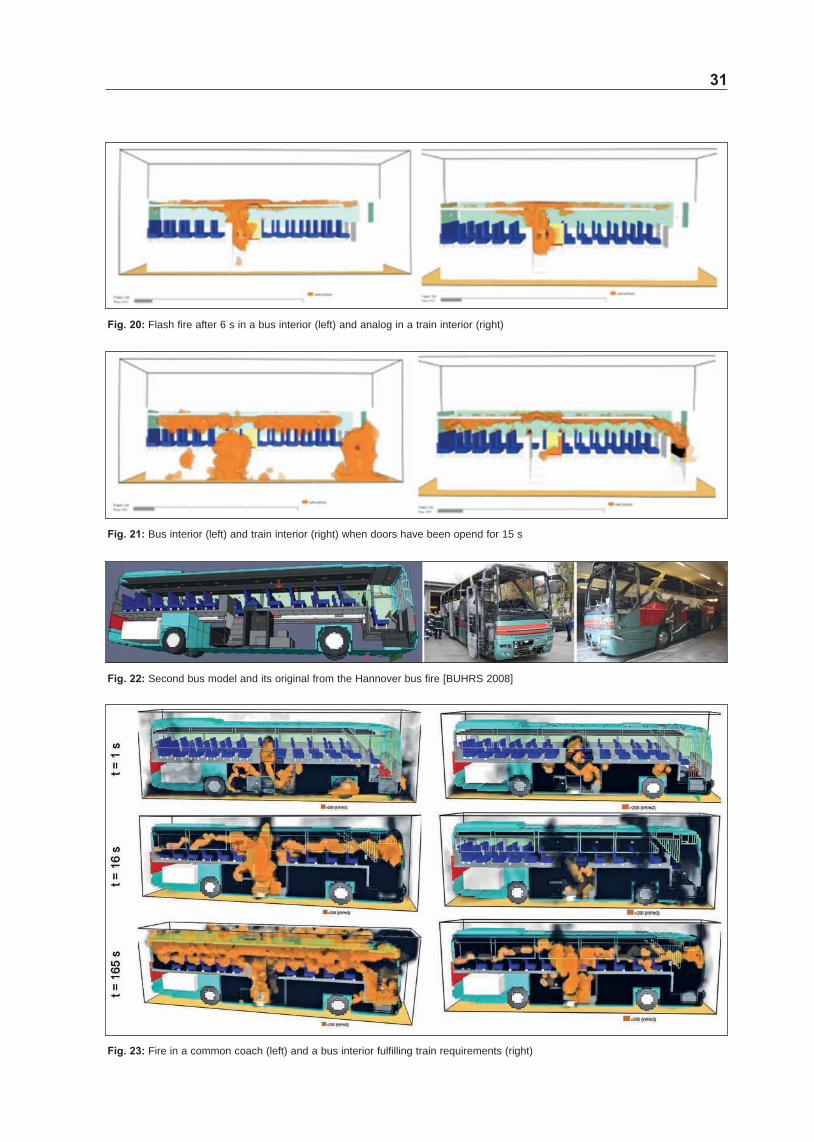
other transport sectors ie railway ship and aircraft Also numerical investigations with the Fire Dynamics Simulator (FDS) were performed The very rapid fire development during the severe bus fire from 2008 could be predicted with the numerical model The model was then used to investigate the influence of different materials ventilation conditions and ignition sources The bus materials contribute significantly to a very rapid fire development in bus fires Especially the flammable ceiling and the passenger seats were identified to be key issues of the fire propagation in a bus and can be explained by the rapid fire spread along the ceiling and the high fire load of passenger seats
As conclusion of the project effective and economically reasonable fire safety requirements for interiors of buses are recommended which would improve the current situation Proposals for amendments of current requirements are recommended including the specification of appropriate limit values In particular it is taken into consideration which reasonable fire safety standards from other transport sectors especially the rail sector should be transferred to buses
Entstehung Ausbreitung und Toxizitaumlt von Rauch bei Busbraumlnden
Obwohl der Bus einer der sichersten Verkehrsmittel ist koumlnnen insbesondere einzelne Unfaumllle sehr schwer sein und viele Passagiere betreffen Besonshyders bei Braumlnden kann eine groszlige Anzahl an Vershyletzten und Toten die Folge sein Brandsicherheit ist bei Bussen daher von groszliger Bedeutung Mit der Zunahme von Kunststoffen als Werkstoff fuumlr die Inneneinrichtung von Linienshy und Reisebussen aufshygrund der guten mechanischen Eigenschaften bei niedrigem Gewicht wirft die Frage auf ob das Sicherheitsniveau bezogen auf Braumlnde in den letzshyten Jahren gesunken ist ndash besonders auch im Vershygleich mit anderen Transportmitteln Wegen der Brennbarkeit der Kunstoffe und ihrer Eigenschaft im Brandfall groszlige Waumlrmemengen freizusetzen ist die Hauptbrandlast in Busbraumlnden oft nicht mehr der mitgefuumlhrte Brennstoff sondern die Kunststoffe im Bus die zudem auch leicht zu entzuumlnden sind Neben der Entflammbarkeit der Materialien ist aber
4
fuumlr die Brandsicherheit auch die Rauchproduktion die Rauchentwicklung und shyausbreitung sowie deren Toxizitaumlt sehr wichtig Das zaumlhlt sowohl fuumlr die Passagiere waumlhrend des Brandereignisses sowie fuumlr die Pruumlfverfahren und ihre Grenzwerte Der schwere Busbrand in Deutschland 2008 in der Naumlhe von Hannover mit 20 Toten zeigte wie vershyheerend solche Braumlnde verlaufen koumlnnen
Aus den oben genannten Gruumlnden wurden von der Bundesanstalt fuumlr Straszligenwesen mehrere Forshyschungsprojekte in Auftrag gegeben Auf der einen Seite wurde das Brandverhalten von Innenraumshymaterialien in Bussen hinsichtlich Brandausbreishytung und Branddetektion mit Warnsystemen untershysucht Als Ergebnis wurde Branddetektion fuumlr den Motorraum und Feuerloumlscher im Innenraum empshyfohlen
Auf der anderen Seite wurde die Waumlrmeshy und Rauchfreisetzung die Rauchausbreitung und die Toxizitaumlt des Brandrauchs bei brennenden Bus shyinnenraummaterialien untersucht In diesem Proshyjekt wurden Kleinversuche und Versuche im Realshymaszligstab an Materialien Teilen des Innenraums und Fahrzeugen durchgefuumlhrt
Zuumlge und Busse haben oft aumlhnliche Bedingungen bezuumlglich der Fluchtmoumlglichkeiten von Passagieshyren Deswegen wurden Businnenraummaterialien nach den Pruumlfmethoden die fuumlr Schienenfahr shyzeuge gelten (DIN EN 45545 und DIN 5510) geshytestet Keines der getesteten Businnenraummateshyrialien haumltte im Zug eingesetzt werden duumlrfen Die Brandschutzvorshyschriften fuumlr Busmaterialien sind verglichen mit den Vorschriften anderer Transportshybereiche (Schienenverkehr Schifffahrt und Luftshyfahrt) auf einem sehr niedrigen Niveau Zusaumltzshylich zu den experimentellen Untersuchungen wurshyden numerische Berechnungen mit dem Fire Dynamics Simulator (FDS) durchgefuumlhrt Die sehr schnelle Brandausbreitung in dem schweren Busshybrand von 2008 konnte mit dem Modell berechnet werden Das numerische Modell wurde dann vershywendet um den Einfluss verschiedener Materiashylien Beluumlftungen und Brandquellen zu untershysuchen Die Businnenraummaterialien tragen signifikant zu der sehr schnellen Brandausbreitung bei Besonders die brennbare Decke und die Fahrshygastsitze wurden als Hauptprobleme bei der Brandausbreitung in einem Bus ausgemacht und koumlnnen durch die schnelle Brandbrandausbreitung entlang der Decke und der hohen Brandlast in Fahrgastsitzen erklaumlrt werden
Als Ergebnis des Projekts wurden Empfehlungen zur Verbesserung der Brandsicherheit fuumlr Busse gegeben Die Empfehlungen beziehen sich zum einen auf die Verbesserungen der bisherigen Vorshyschriften aber auch auf das Uumlbernehmen von Vorshyschriften aus anderen Transportbereichen ndash insbeshysondere dem Schienenfahrzeugbereich
5
Content
Abbreviations 6
Technical terms 7
Vehicle categories 8
1 Introduction 9
2 Bus fire cases and statistics 9
3 Existing fire safety requirements and tests for buses 11
4 Test methods of other passenger transport sectors 19
5 Toxicity of smoke gas components 22
6 Bus fire simulations 26
7 Investigations on bus interior materials 32
71 Attenuated Total Reflectance (ATR) Spectrometer 33
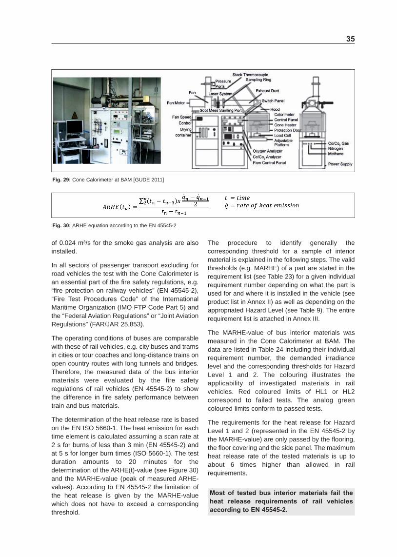
72 Cone Calorimeter (EN ISO 5660) 34
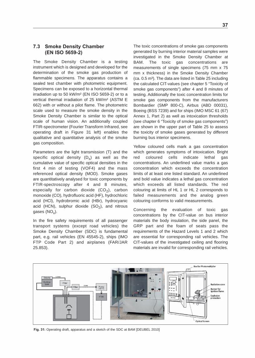
73 Smoke Density Chamber (EN ISO 5659shy2) 37
74 Singleshyflame Source Test (EN ISO 11925shy2) 41
8 Real scale fire tests 42
81 Tests on passenger seats 42
82 Tests on a real bus 44
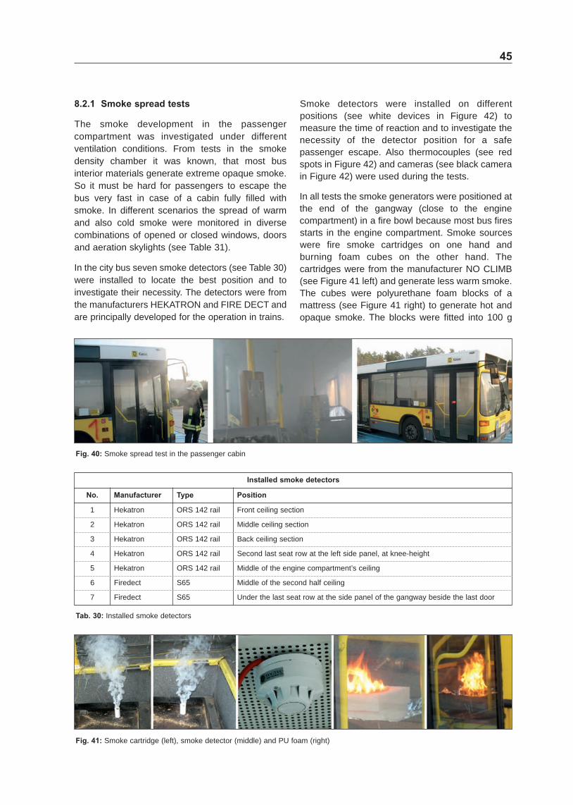
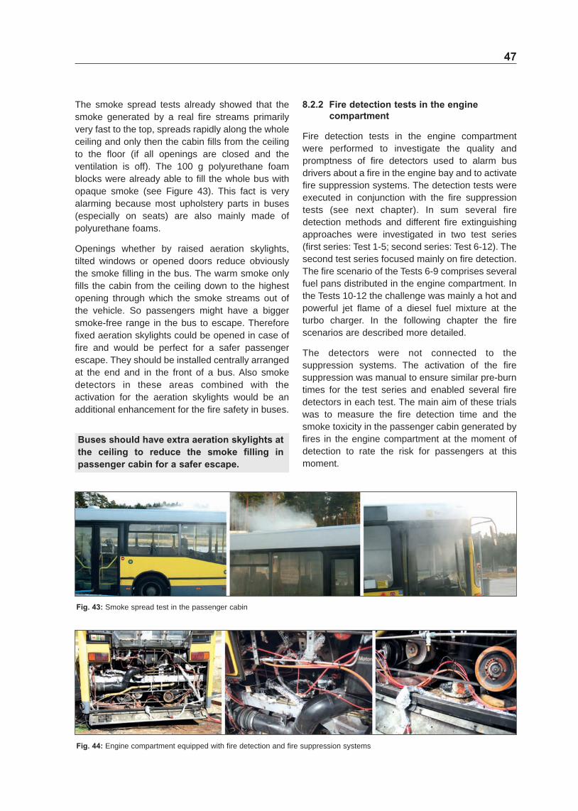
821 Smoke spread tests 45
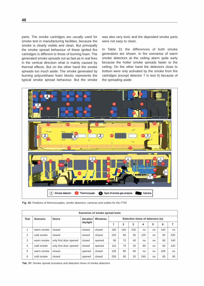
822 Fire detection tests in the engine compartment 47
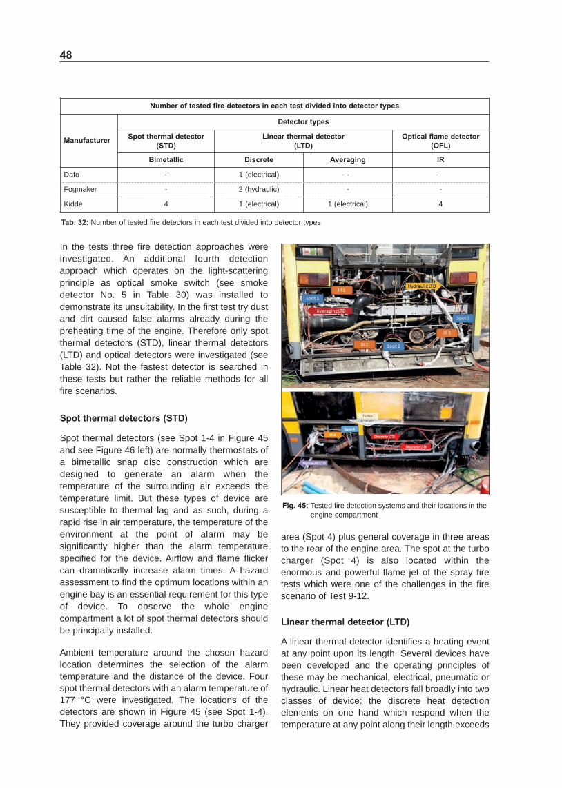
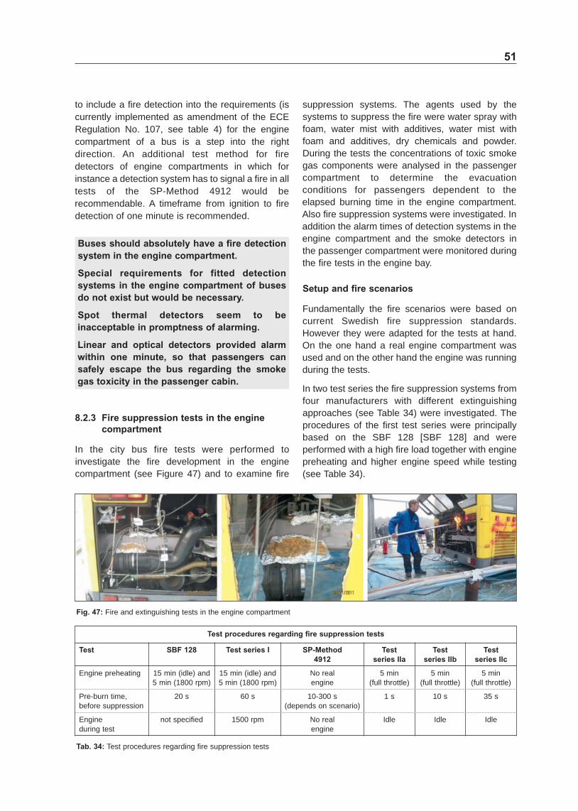
823 Fire suppression tests in the engine compartment 51
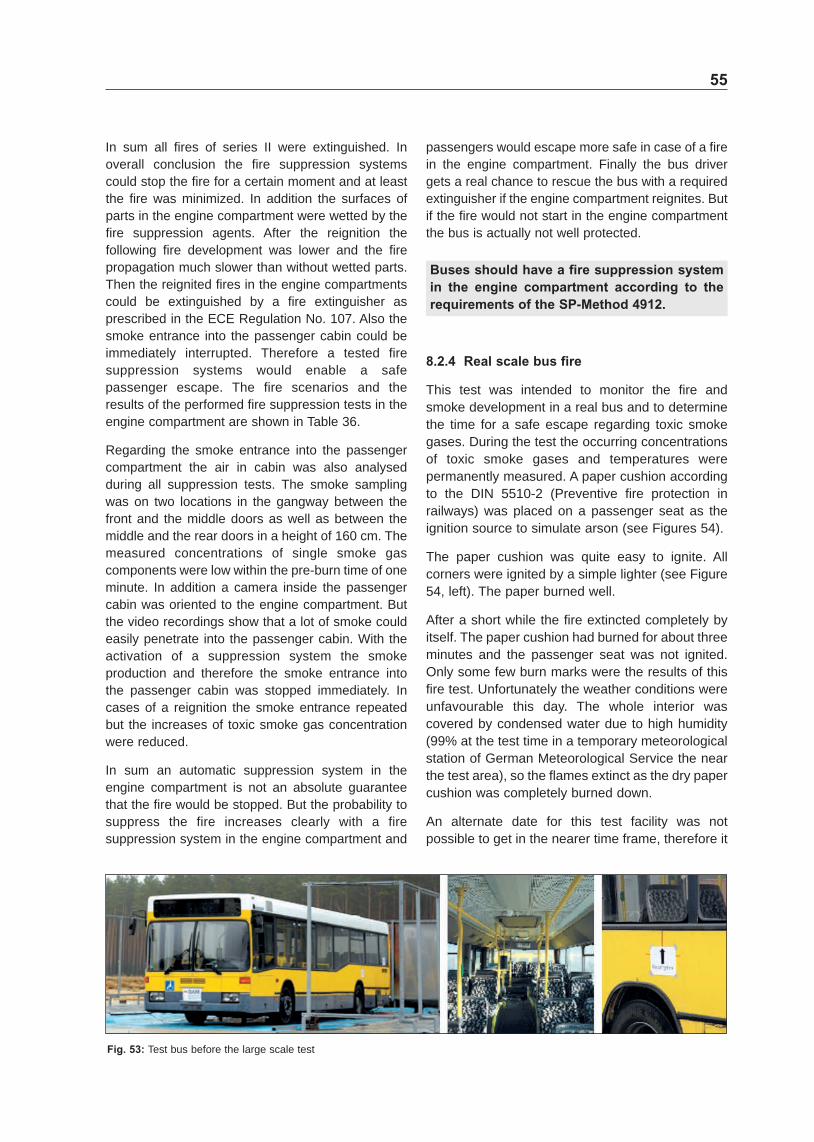
824 Real scale bus fire 55
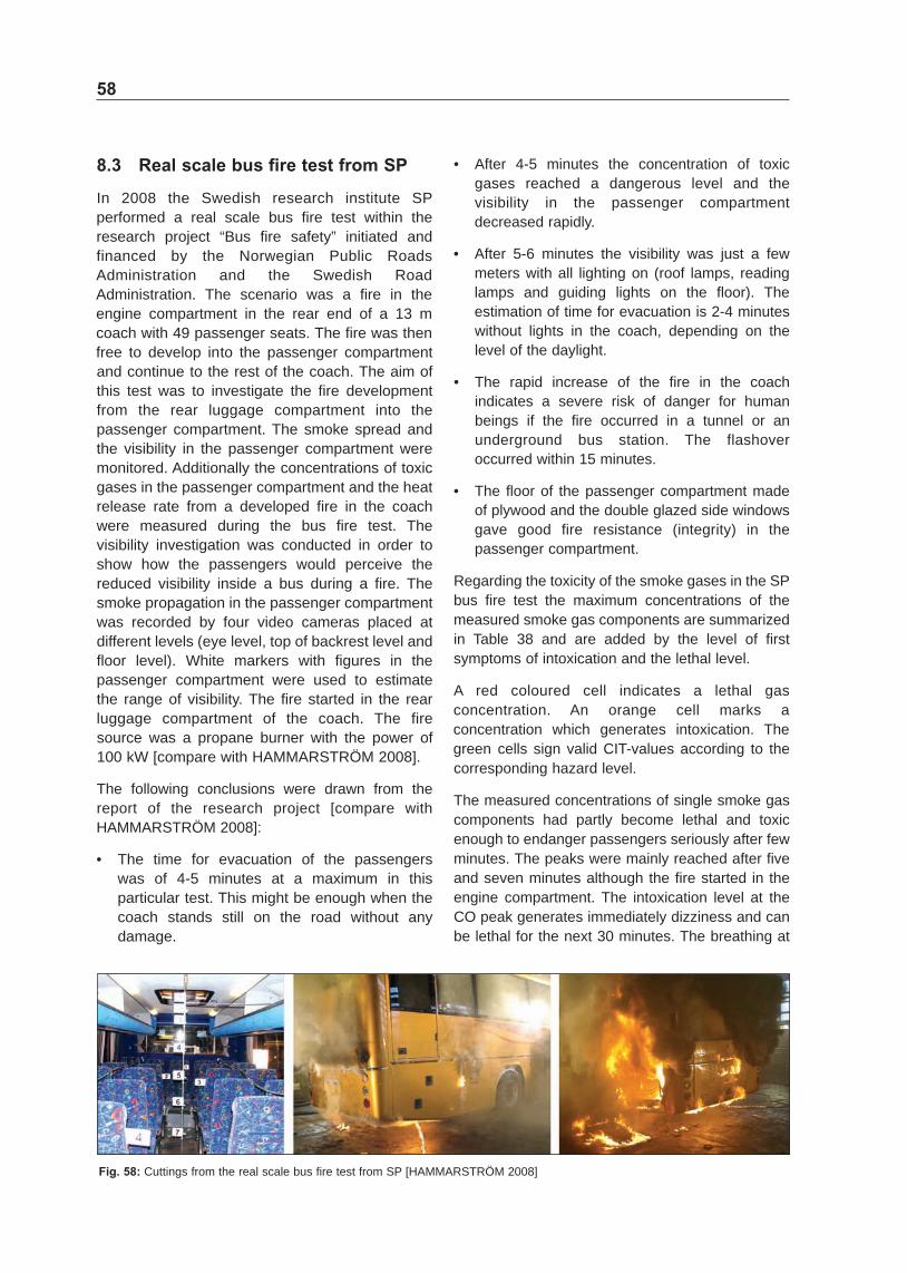
83 Real scale bus fire test from SP 58
9 Recommendations for the upgrade of the fire safety requirements for bus interior materials 59
91 General recommendations 60
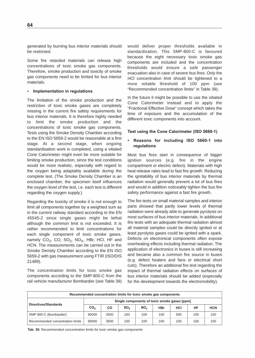
92 Specific proposals for the regulations 62
93 Further suggestions 68
10 Conclusion 71
11 Literature 71
Annex
Annex I ndash Some bus fires in the year 2010 in Germany
Annex II ndash Product list of the EN 45545shy2
Annex III ndash Material requirement list of the EN 45545shy2
Annex IV ndash Measured gas concentrations in smoke
Annex V ndash List of publications
The annexes to this report are accessible at the electronic archive ELBA under httpbastopushbzshynrwde
6
IMO International Maritime Organization
IR MidshyInfrared
JAR Joint Aviation Requirements
LES Large Eddy Simulation
LTD Linear Thermal Detector
MAC Maximum Allowable Concentration
MAK Maximum workplace Concentrations
MARHE Maximum Average Rate of Heat Emission
MLR Mass Loss Rate
MOD Mass referenced Optical Density
NO Nitrous gases x
OC Operation Category
OI Oxygen Index
PA Polyamide
PE Polyethylene
PES Polyester
PP Polypropylene
PU Polyurethane
PVC Polyvinyl Chloride
SBF Swedish Fire Protection Association
SBI Single Burning Item
SO2 Sulphur Dioxide
SOLAS International convention for the Safety of Life at Sea
SP Technical Research Institute of Sweden
StVZO German Road Traffic Licensing Regulation
T Transmitted luminous flux
THR Total Heat Release
Tig Time to ignition
TLSE Terminal Lug Sensing Element
TRGS Technical Rules for Hazardous Substances
UNECE United Nations Economic Commission for Europe
VOF4 Cumulative value of specific optical densities in the first 4 min of the test
Abbreviations
AGW Maximum allowable concentration
AHRE Average Heat Release Emission
ATR Attenuated Total Reflectance spectroscopy
BAM Federal Institute for Materials Research and Testing
BASt Federal Highway Research Institute
BMVBS Federal Ministry of Transport Building and Urban Development
CFAST Consolidated model of Fire And Smoke Transport
CFD Computational Fluid Dynamics
CFE Critical Flux at Extinguishment
CHF Critical Heat Flux at Extinguishment
CIT Conventional Index of Toxicity
CITC Conventional Index of Toxicity for cables
CITG Conventional Index of Toxicity for listed products in EN 45545shy2
CITNLP Conventional Index of Toxicity for nonshylisted products in EN 45545shy2
CO Carbon Monoxide
CO 2 Carbon Dioxide
CS Certification Specification of the European Aviation Safety Agency
Ds Specific optical density
FAR Federal Aviation Regulations
FED Fractional Effective Dose
FDS Fire Dynamic Simulator
FTIR Fourier Transform Infrared spectroscopy
FTP Fire Test Procedure (Code)
GRP Glass fibre Reinforced Plastic
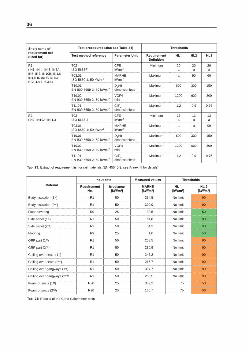
HBr Hydrogen Bromide
HCl Hydrogen Chloride
HCN Hydrogen Cyanide
HF Hydrogen Fluoride
HL Hazard Level
HRR Heat Release Rate
HVAC Heating Ventilation and Air Conditioning
I Incident luminous flux
ILV Indicative Limit Values
7
Technical terms
The bus fire safety is mainly based on two issues the prevention measures and the impact reduction The aim of preventive measures is to avoid a fire A fire development requires three main factors combustible material oxygen and enough energy for an ignition Because oxygen is always present in the air the fire safety requirements are focused on the restriction of combustible materials and the reduction of ignition sources
The main combustionshyrelevant terms and material properties according to the ISO 13943 are eg
Burn is an intransitive verb to undergo combustion
Char is the carbonaceous residue resulting from pyrolysis or incomplete combustion
Combustion is an exothermic reaction of a substance with an oxidizer
Fire is a (uncontrolled) selfshysupporting combustion which spreads uncontrolled in time and space
Fire behaviour is the change in the physical andor chemical properties of an item andor structure exposed to fire
Fire effluent is the totality of gases andor aerosols (including suspended particles) created by combustion or pyrolysis
Fire load is the quantity of heat which could be released by the complete combustion of all the combustible materials in a volume including the facings of all bounding surfaces
Fire resistance is the ability of an item to fulfil for a stated period of time the required stability andor integrity andor thermal insulation andor other expected duty specified in a standard fireshyresistance test
Fire retardant is a substance added or a treatment applied to a material in order to delay ignition or to reduce the rate of combustion
Fire scenario is a detailed description of conditions including environmental of one or more stages from before ignition to after completion of combustion in an actual fire at a specific location or in a realshyscale simulation
Fire spread is a temporal quantity for the flame propagation Fundamentally a fire spread is divided into a vertical and a horizontal flame spread
Flame is the zone of combustion in the gaseous phase usually with emission of light
Flame retardant is a substance added or a treatment applied to a material in order to suppress or delay the appearance of a flame andor reduce its propagation (spread) rate is the zone of combustion in the gaseous phase usually with emission of light
Flaming debris and flaming droplets are material separating from a burning item during the fire test procedure and continuing to flame
Flame spread is the propagation of a fire front
Flammability is the ability of a material or product to burn with a flame under specified conditions
Flash fire is a rapid fire spread after supply of oxygen to a fire in an enclosure (oxygenshylimited conditions) known as smoke explosion for explosive fire spread
Flash-over is a transition to a state of total surface involvement in a fire of combustible materials within an enclosure
Glowing is made luminous by heat
Heat flux is the amount of thermal energy emitted transmitted or received per unit area and unit time
Heat release rate is the thermal energy released per unit time by an item during combustion under specified conditions
Ignition source is a source of energy that initiates combustion
Intermediate-scale test is a test performed on an item of medium dimensions
Large-scale test is a test which cannot be carried out in a typical laboratory chamber performed on an item of large dimensions
Mass loss rate is the mass of material lost per unit time under specified conditions
Opacity of smoke is the measure of the attenuation of a light beam passing through smoke expressed as the ratio (IT) of incident luminous flux (I) to transmitted luminous flux (T) through smoke under specified conditions
Optical density of smoke is a measure of the attenuation of a light beam passing through smoke expressed as the common logarithm (ie logarithm to the base 10) Ig (IT) of the opacity of smoke
8
Products of combustion are solid liquid and gaseous materials resulting from combustion
Pyrolysis is that part of the irreversible chemical decomposition caused solely by a rise in temperature
Reaction-to-fire is the response of a material in contributing by its own decomposition to a fire to which it is exposed under specified conditions
Real-scale test is a test which simulates a given application taking into account the real scale the real way of working or installation and the environment
Small-scale test is a test performed on an item of small dimensions
Smoke is the visible part of fire effluent
Specific optical density of smoke is a measure of the opacity of the smoke produced by a specimen taking into account the optical density and factors characteristic of the specified test method
Thermal radiation is the transfer of thermal energy by electromagnetic waves
Toxicity is the ability of a substance to produce adverse effects upon a living organism
Vehicle categories
According to the UNECE Regulations buses are defined as being vehicles belonging to one of the following categories
Category M2 Vehicles used for the carriage of passengers comprising more than eight seats in addition to the drivers seat and having a maximum mass not exceeding 5 tonnes
Category M3 Vehicles used for the carriage of passengers comprising more than eight seats in addition to the drivers seat and having a maximum mass exceeding 5 tonnes
For vehicles of category M2 and M3 having a capacity exceeding 22 passengers in addition to the driver there are three classes of vehicles to which they belong
Class I Vehicles constructed with areas for standing passengers to allow frequent passenger movement
Class II Vehicles constructed principally for the carriage of seated passengers and designed to allow the carriage of standing passengers in the gangway andor in an area which does not exceed the space provided for two double seats
Class III Vehicles constructed exclusively for the carriage of seated passengers
For vehicles of category M2 and M3 having a capacity not exceeding 22 passengers in addition to the driver there are two classes of vehicles
Class A Vehicles designed to carry standing passengers a vehicle of this class has seats and shall have provisions for standing passengers
Class B Vehicles not designed to carry standing passengers a vehicle of this class has no provision for standing passengers
9
1 Introduction
The amount of plastic and synthetic materials is still growing in all sectors of everyday life In the automotive industry plastic materials have become fundamental materials Today they are widely used in vehicles because of their excellent mechanical properties and their light weight combined with low production costs But plastic materials can generate extremely toxic smoke gases which highly endanger passengers in case of fire In road traffic bus fires occur relatively frequently Fortunately most cases were without any seriously injuries But in the severe bus fire from 2008 which occurred in Germany near Hanover 20 of 32 passengers lost their life
Requirements regarding the smoke production development and toxicity do not exist for bus interior materials up to now Therefore a research project initiated and financed by the BASt (Federal Highway Research Institute Germany) was carried out at BAM (Federal Institute for Materials Research and Testing Germany) to investigate the fire safety performance of buses with focus on the smoke gas toxicity
Real bus fires were evaluated in detail and as many statistical data as possible were collected from different sources The current fire safety requirements for buses and other sectors of passenger transport were assessed by the fire science basis and the experimental complexity as well as the generalizability and the reproducibility
Numerical fire simulations were used to investigate the fire development and the fire behaviour of modern bus interiors to explore proper upgrade alternatives In addition fire tests were performed to evaluate bus interior materials Also fire safety requirements from other transport sectors were used to assess the interior components of buses Therefore fire tests were run on material specimens interior parts and vehicles Finally the applications of fire and smoke detection systems as well as fire suppression systems were investigated in fire tests Also the question where to install smoke detectors was treated
In conclusion suggestions for an upgrade of the fire safety requirements including proper thresholds are presented In addition also recommendations for improving the construction design as well as for implementing fire detectors and fire suppression systems are given
2 Bus fire cases and statistics
Generally buses are one of the safest transportation means But bus fires occur relatively frequently Almost every1 day a bus burns in Germany which conforms to rate of circa 05 of 76433 registered buses in Germany [BDO 2010] An internal investigation of a big German bus association also found out that every year circa 1 of all buses had a fire incident This value was confirmed by several interviewed bus operators
In 2009 the insurance companies of the German Insurance Association (GDV) counted circa 35000 comprehensively insured buses in Germany whereof 161 had a fire The rate of bus fires was circa 05 But the data of the GDV only contain comprehensively insured vehicles Cases of buses without a comprehensive insurance (eg partly are not comprehensively insured) are not considered Also bus fire cases as a result of an accident are also not included Therefore the real number of bus fire cases might be considerably higher However a reliable statistic is missing
An own web research for bus fires in 2010 (see Annex I) based on reports of fire brigades and news items confirms that bus fires occurred relative frequently The reports described additionally in many cases that the fire development was very fast
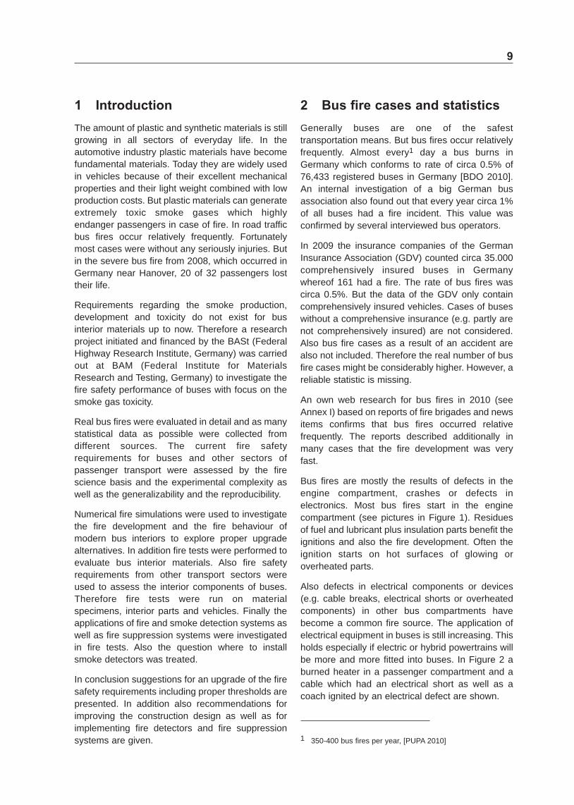
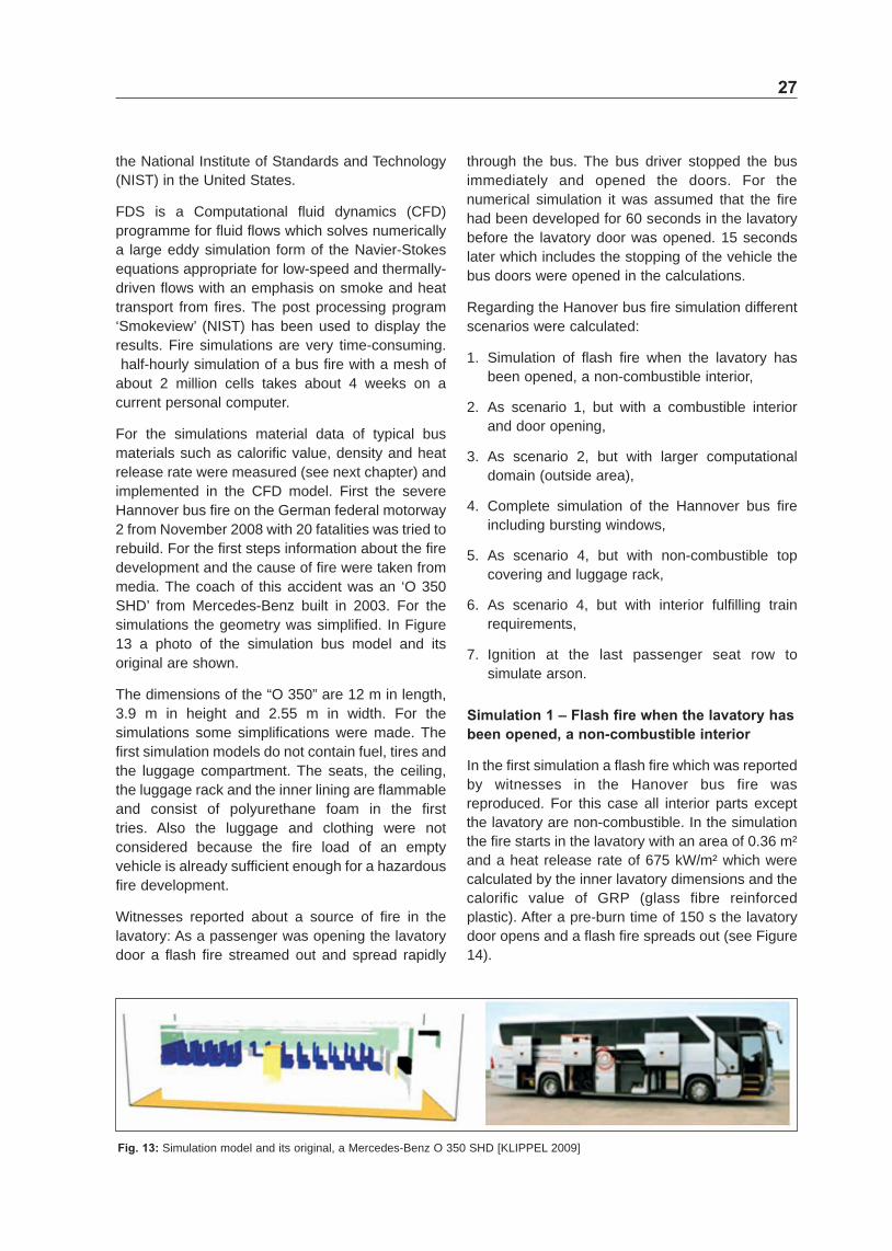
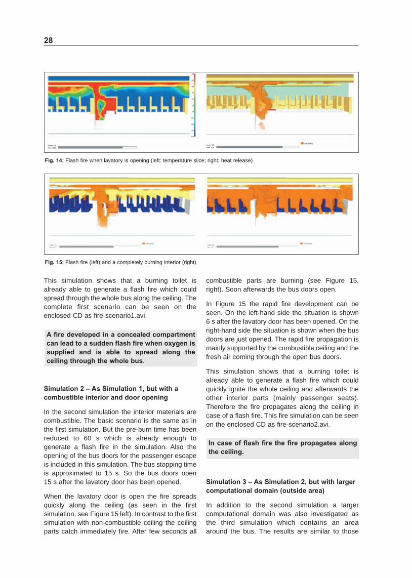
Bus fires are mostly the results of defects in the engine compartment crashes or defects in electronics Most bus fires start in the engine compartment (see pictures in Figure 1) Residues of fuel and lubricant plus insulation parts benefit the ignitions and also the fire development Often the ignition starts on hot surfaces of glowing or overheated parts
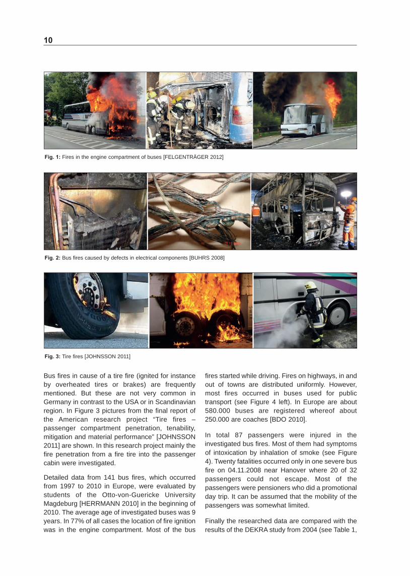
Also defects in electrical components or devices (eg cable breaks electrical shorts or overheated components) in other bus compartments have become a common fire source The application of electrical equipment in buses is still increasing This holds especially if electric or hybrid powertrains will be more and more fitted into buses In Figure 2 a burned heater in a passenger compartment and a cable which had an electrical short as well as a coach ignited by an electrical defect are shown
1 350shy400 bus fires per year [PUPA 2010]
10
Fig 1 Fires in the engine compartment of buses [FELGENTRAumlGER 2012]
Fig 2 Bus fires caused by defects in electrical components [BUHRS 2008]
Fig 3 Tire fires [JOHNSSON 2011]
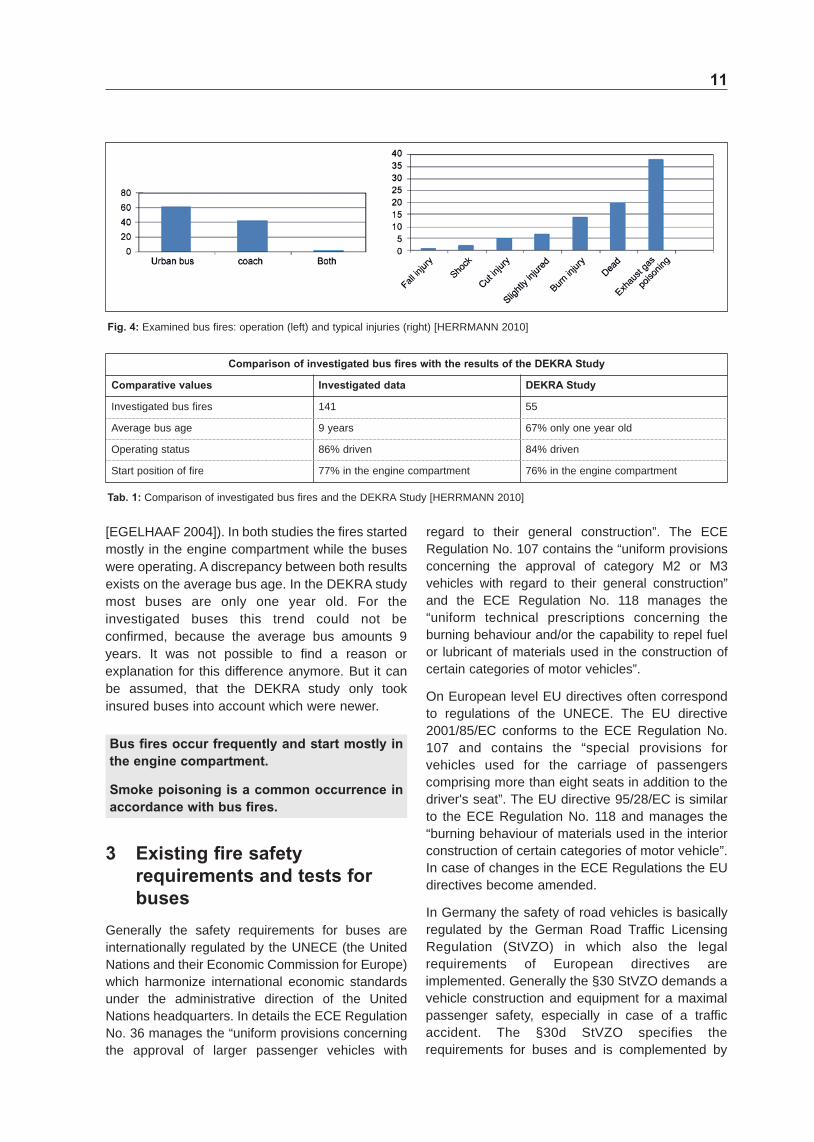
Bus fires in cause of a tire fire (ignited for instance by overheated tires or brakes) are frequently mentioned But these are not very common in Germany in contrast to the USA or in Scandinavian region In Figure 3 pictures from the final report of the American research project ldquoTire fires ndash passenger compartment penetration tenability mitigation and material performancerdquo [JOHNSSON 2011] are shown In this research project mainly the fire penetration from a fire tire into the passenger cabin were investigated
Detailed data from 141 bus fires which occurred from 1997 to 2010 in Europe were evaluated by students of the OttoshyvonshyGuericke University Magdeburg [HERRMANN 2010] in the beginning of 2010 The average age of investigated buses was 9 years In 77 of all cases the location of fire ignition was in the engine compartment Most of the bus
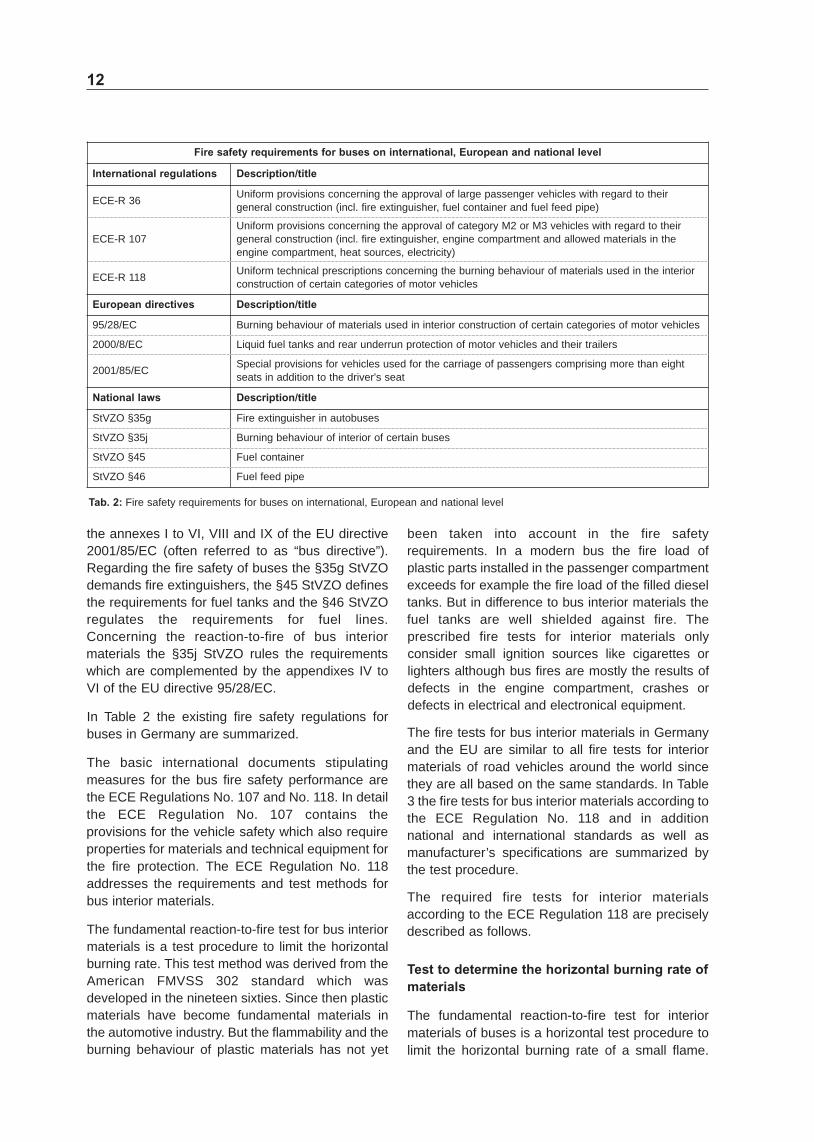
fires started while driving Fires on highways in and out of towns are distributed uniformly However most fires occurred in buses used for public transport (see Figure 4 left) In Europe are about 580000 buses are registered whereof about 250000 are coaches [BDO 2010]
In total 87 passengers were injured in the investigated bus fires Most of them had symptoms of intoxication by inhalation of smoke (see Figure 4) Twenty fatalities occurred only in one severe bus fire on 04112008 near Hanover where 20 of 32 passengers could not escape Most of the passengers were pensioners who did a promotional day trip It can be assumed that the mobility of the passengers was somewhat limited
Finally the researched data are compared with the results of the DEKRA study from 2004 (see Table 1
Comparison of investigated bus fires with the results of the DEKRA Study
Comparative values Investigated data DEKRA Study
Investigated bus fires 141 55
Average bus age 9 years 67 only one year old
Operating status 86 driven 84 driven
Start position of fire 77 in the engine compartment 76 in the engine compartment
Tab 1 Comparison of investigated bus fires and the DEKRA Study [HERRMANN 2010]
11
Fig 4 Examined bus fires operation (left) and typical injuries (right) [HERRMANN 2010]
[EGELHAAF 2004]) In both studies the fires started mostly in the engine compartment while the buses were operating A discrepancy between both results exists on the average bus age In the DEKRA study most buses are only one year old For the investigated buses this trend could not be confirmed because the average bus amounts 9 years It was not possible to find a reason or explanation for this difference anymore But it can be assumed that the DEKRA study only took insured buses into account which were newer
Bus fires occur frequently and start mostly in the engine compartment
Smoke poisoning is a common occurrence in accordance with bus fires
3 Existing fire safety requirements and tests for buses
Generally the safety requirements for buses are internationally regulated by the UNECE (the United Nations and their Economic Commission for Europe) which harmonize international economic standards under the administrative direction of the United Nations headquarters In details the ECE Regulation No 36 manages the ldquouniform provisions concerning the approval of larger passenger vehicles with
regard to their general constructionrdquo The ECE Regulation No 107 contains the ldquouniform provisions concerning the approval of category M2 or M3 vehicles with regard to their general constructionrdquo and the ECE Regulation No 118 manages the ldquouniform technical prescriptions concerning the burning behaviour andor the capability to repel fuel or lubricant of materials used in the construction of certain categories of motor vehiclesrdquo
On European level EU directives often correspond to regulations of the UNECE The EU directive 200185EC conforms to the ECE Regulation No 107 and contains the ldquospecial provisions for vehicles used for the carriage of passengers comprising more than eight seats in addition to the drivers seatrdquo The EU directive 9528EC is similar to the ECE Regulation No 118 and manages the ldquoburning behaviour of materials used in the interior construction of certain categories of motor vehiclerdquo In case of changes in the ECE Regulations the EU directives become amended
In Germany the safety of road vehicles is basically regulated by the German Road Traffic Licensing Regulation (StVZO) in which also the legal requirements of European directives are implemented Generally the sect30 StVZO demands a vehicle construction and equipment for a maximal passenger safety especially in case of a traffic accident The sect30d StVZO specifies the requirements for buses and is complemented by
12
Fire safety requirements for buses on international European and national level
International regulations Descriptiontitle
ECEshyR 36 Uniform provisions concerning the approval of large passenger vehicles with regard to their general construction (incl fire extinguisher fuel container and fuel feed pipe)
ECEshyR 107 Uniform provisions concerning the approval of category M2 or M3 vehicles with regard to their general construction (incl fire extinguisher engine compartment and allowed materials in the engine compartment heat sources electricity)
ECEshyR 118 Uniform technical prescriptions concerning the burning behaviour of materials used in the interior construction of certain categories of motor vehicles
European directives Descriptiontitle
9528EC Burning behaviour of materials used in interior construction of certain categories of motor vehicles
20008EC Liquid fuel tanks and rear underrun protection of motor vehicles and their trailers
200185EC Special provisions for vehicles used for the carriage of passengers comprising more than eight seats in addition to the drivers seat
National laws Descriptiontitle
StVZO sect35g Fire extinguisher in autobuses
StVZO sect35j Burning behaviour of interior of certain buses
StVZO sect45 Fuel container
StVZO sect46 Fuel feed pipe
Tab 2 Fire safety requirements for buses on international European and national level
the annexes I to VI VIII and IX of the EU directive 200185EC (often referred to as ldquobus directiverdquo) Regarding the fire safety of buses the sect35g StVZO demands fire extinguishers the sect45 StVZO defines the requirements for fuel tanks and the sect46 StVZO regulates the requirements for fuel lines Concerning the reactionshytoshyfire of bus interior materials the sect35j StVZO rules the requirements which are complemented by the appendixes IV to VI of the EU directive 9528EC
In Table 2 the existing fire safety regulations for buses in Germany are summarized
The basic international documents stipulating measures for the bus fire safety performance are the ECE Regulations No 107 and No 118 In detail the ECE Regulation No 107 contains the provisions for the vehicle safety which also require properties for materials and technical equipment for the fire protection The ECE Regulation No 118 addresses the requirements and test methods for bus interior materials
The fundamental reactionshytoshyfire test for bus interior materials is a test procedure to limit the horizontal burning rate This test method was derived from the American FMVSS 302 standard which was developed in the nineteen sixties Since then plastic materials have become fundamental materials in the automotive industry But the flammability and the burning behaviour of plastic materials has not yet
been taken into account in the fire safety requirements In a modern bus the fire load of plastic parts installed in the passenger compartment exceeds for example the fire load of the filled diesel tanks But in difference to bus interior materials the fuel tanks are well shielded against fire The prescribed fire tests for interior materials only consider small ignition sources like cigarettes or lighters although bus fires are mostly the results of defects in the engine compartment crashes or defects in electrical and electronical equipment
The fire tests for bus interior materials in Germany and the EU are similar to all fire tests for interior materials of road vehicles around the world since they are all based on the same standards In Table 3 the fire tests for bus interior materials according to the ECE Regulation No 118 and in addition national and international standards as well as manufacturerrsquos specifications are summarized by the test procedure
The required fire tests for interior materials according to the ECE Regulation 118 are precisely described as follows
Test to determine the horizontal burning rate of materials
The fundamental reactionshytoshyfire test for interior materials of buses is a horizontal test procedure to limit the horizontal burning rate of a small flame
13
Fire Tests for bus interior materials according to the ECE Regulation No 118
To find in
Test procedure Standards Manufacturerrsquos specification
Appendix VI Test to determine the horizontal burning rate of materials
ISO 3795 (Int) 9528EC DIN 75200 (D) FMVSS 302 (USA) UTAC 18shy5021 (F) BS AU 169 (GB) JIS D 1201 (J)
GS 97038 (BMW) DBL 5307 (Daimler) FLTMshyBN 24shy2 (Ford) GM 6090 M (GM) MES DF 050D (Mazda) ESndashX60410 (Mitsubishi) PTL 8501 (Porsche) D45 1333 (Renault) STD 50311 (Volvo) TL 1010 (VW)
Appendix VII Test to determine the melting behaviour of materials
NF P92shy505 (F) UTAC 18shy5022 (F)
Appendix VIII Test to determine the vertical burning rate of materials
ENshyISO 6941 (Int)
Tab 3 Fire Tests for bus interior materials according to the ECE Regulation No 118
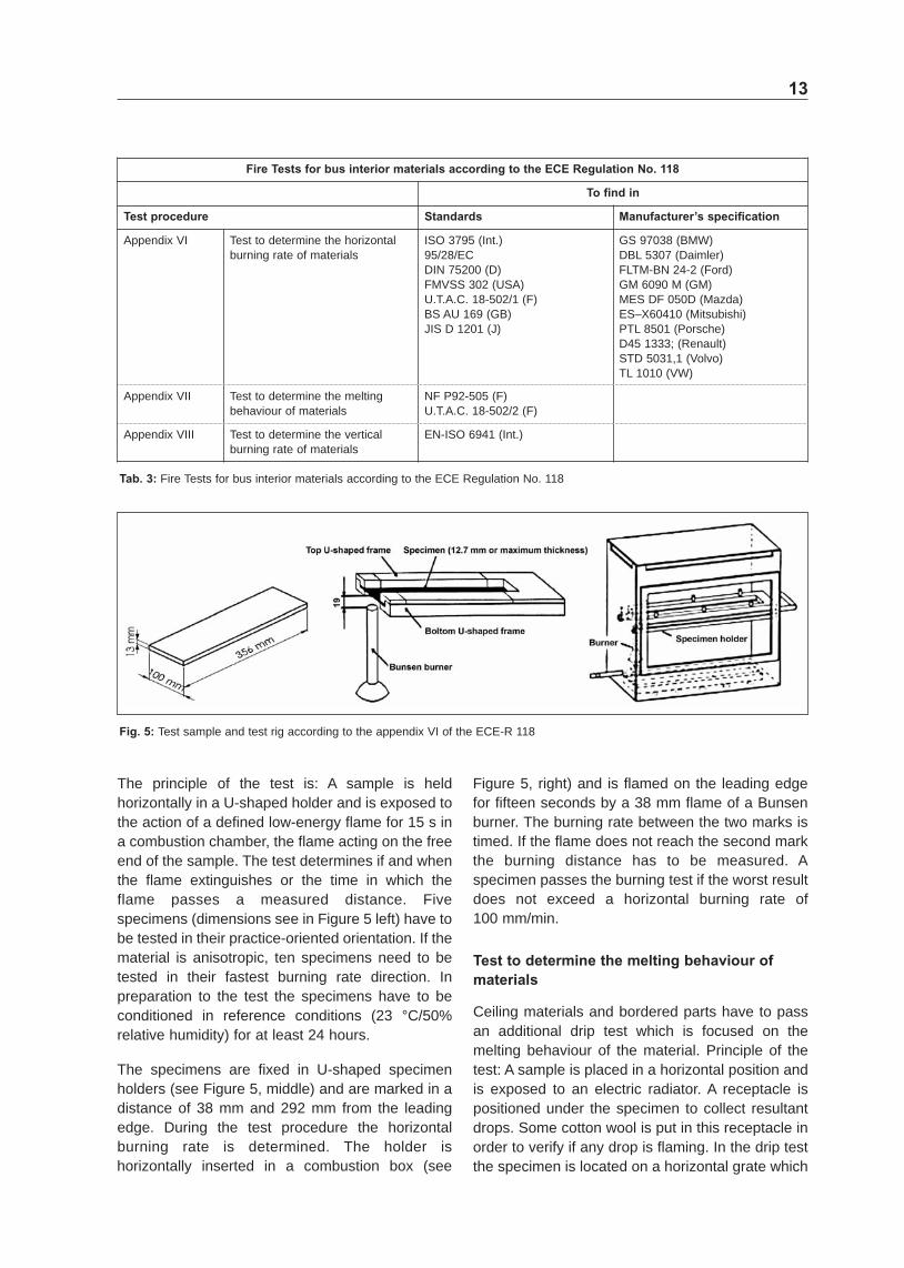
Fig 5 Test sample and test rig according to the appendix VI of the ECEshyR 118
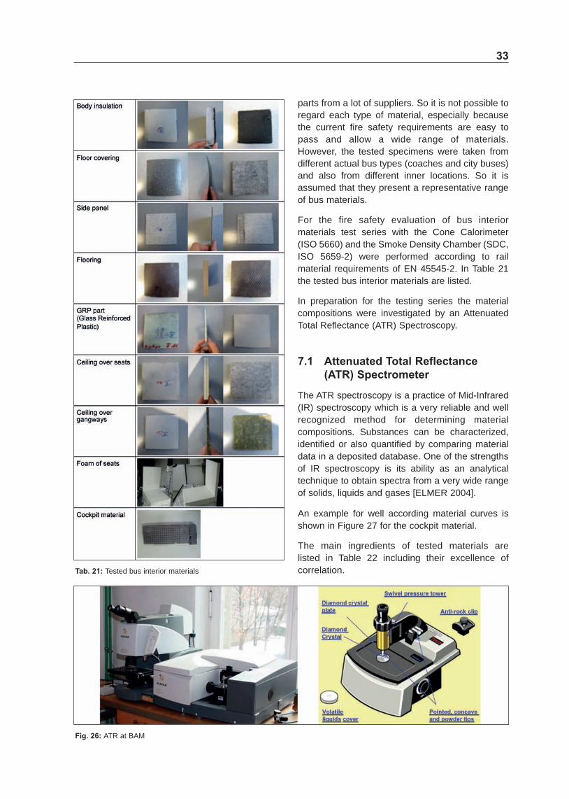
The principle of the test is A sample is held horizontally in a Ushyshaped holder and is exposed to the action of a defined lowshyenergy flame for 15 s in a combustion chamber the flame acting on the free end of the sample The test determines if and when the flame extinguishes or the time in which the flame passes a measured distance Five specimens (dimensions see in Figure 5 left) have to be tested in their practiceshyoriented orientation If the material is anisotropic ten specimens need to be tested in their fastest burning rate direction In preparation to the test the specimens have to be conditioned in reference conditions (23 degC50 relative humidity) for at least 24 hours
The specimens are fixed in Ushyshaped specimen holders (see Figure 5 middle) and are marked in a distance of 38 mm and 292 mm from the leading edge During the test procedure the horizontal burning rate is determined The holder is horizontally inserted in a combustion box (see
Figure 5 right) and is flamed on the leading edge for fifteen seconds by a 38 mm flame of a Bunsen burner The burning rate between the two marks is timed If the flame does not reach the second mark the burning distance has to be measured A specimen passes the burning test if the worst result does not exceed a horizontal burning rate of 100 mmmin
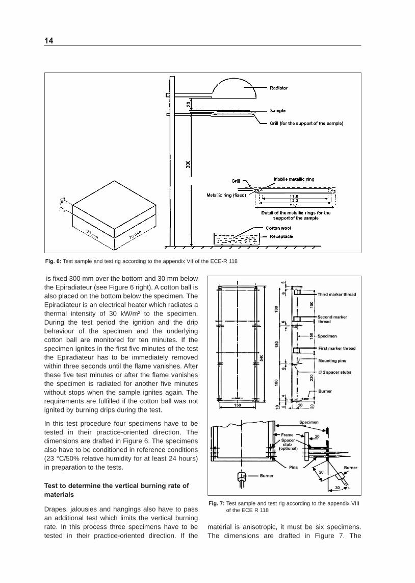
Test to determine the melting behaviour of materials
Ceiling materials and bordered parts have to pass an additional drip test which is focused on the melting behaviour of the material Principle of the test A sample is placed in a horizontal position and is exposed to an electric radiator A receptacle is positioned under the specimen to collect resultant drops Some cotton wool is put in this receptacle in order to verify if any drop is flaming In the drip test the specimen is located on a horizontal grate which
14
Fig 6 Test sample and test rig according to the appendix VII of the ECEshyR 118
is fixed 300 mm over the bottom and 30 mm below the Epiradiateur (see Figure 6 right) A cotton ball is also placed on the bottom below the specimen The Epiradiateur is an electrical heater which radiates a thermal intensity of 30 kWmsup2 to the specimen During the test period the ignition and the drip behaviour of the specimen and the underlying cotton ball are monitored for ten minutes If the specimen ignites in the first five minutes of the test the Epiradiateur has to be immediately removed within three seconds until the flame vanishes After these five test minutes or after the flame vanishes the specimen is radiated for another five minutes without stops when the sample ignites again The requirements are fulfilled if the cotton ball was not ignited by burning drips during the test
In this test procedure four specimens have to be tested in their practiceshyoriented direction The dimensions are drafted in Figure 6 The specimens also have to be conditioned in reference conditions (23 degC50 relative humidity for at least 24 hours) in preparation to the tests
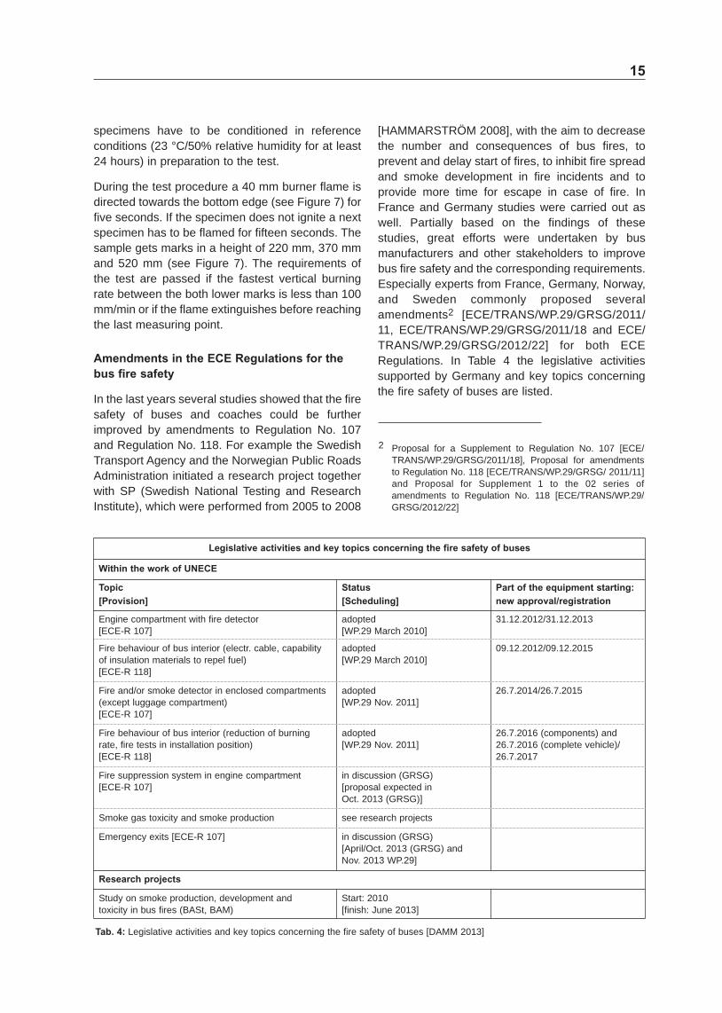
Test to determine the vertical burning rate of materials
Drapes jalousies and hangings also have to pass an additional test which limits the vertical burning rate In this process three specimens have to be tested in their practiceshyoriented direction If the
Fig 7 Test sample and test rig according to the appendix VIII of the ECE R 118
material is anisotropic it must be six specimens The dimensions are drafted in Figure 7 The
15
specimens have to be conditioned in reference conditions (23 degC50 relative humidity for at least 24 hours) in preparation to the test
During the test procedure a 40 mm burner flame is directed towards the bottom edge (see Figure 7) for five seconds If the specimen does not ignite a next specimen has to be flamed for fifteen seconds The sample gets marks in a height of 220 mm 370 mm and 520 mm (see Figure 7) The requirements of the test are passed if the fastest vertical burning rate between the both lower marks is less than 100 mmmin or if the flame extinguishes before reaching the last measuring point
Amendments in the ECE Regulations for the bus fire safety
In the last years several studies showed that the fire safety of buses and coaches could be further improved by amendments to Regulation No 107 and Regulation No 118 For example the Swedish Transport Agency and the Norwegian Public Roads Administration initiated a research project together with SP (Swedish National Testing and Research Institute) which were performed from 2005 to 2008
[HAMMARSTROumlM 2008] with the aim to decrease the number and consequences of bus fires to prevent and delay start of fires to inhibit fire spread and smoke development in fire incidents and to provide more time for escape in case of fire In France and Germany studies were carried out as well Partially based on the findings of these studies great efforts were undertaken by bus manufacturers and other stakeholders to improve bus fire safety and the corresponding requirements Especially experts from France Germany Norway and Sweden commonly proposed several amendments2 [ECETRANSWP29GRSG2011 11 ECETRANSWP29GRSG201118 and ECE TRANSWP29GRSG201222] for both ECE Regulations In Table 4 the legislative activities supported by Germany and key topics concerning the fire safety of buses are listed
2 Proposal for a Supplement to Regulation No 107 [ECE TRANSWP29GRSG201118] Proposal for amendments to Regulation No 118 [ECETRANSWP29GRSG 201111] and Proposal for Supplement 1 to the 02 series of amendments to Regulation No 118 [ECETRANSWP29 GRSG201222]
Legislative activities and key topics concerning the fire safety of buses
Within the work of UNECE
Topic [Provision]
Status [Scheduling]
Part of the equipment starting new approvalregistration
Engine compartment with fire detector [ECEshyR 107]
adopted [WP29 March 2010]
3112201231122013
Fire behaviour of bus interior (electr cable capability of insulation materials to repel fuel) [ECEshyR 118]
adopted [WP29 March 2010]
0912201209122015
Fire andor smoke detector in enclosed compartments (except luggage compartment) [ECEshyR 107]
adopted [WP29 Nov 2011]
26720142672015
Fire behaviour of bus interior (reduction of burning rate fire tests in installation position) [ECEshyR 118]
adopted [WP29 Nov 2011]
2672016 (components) and 2672016 (complete vehicle) 2672017
Fire suppression system in engine compartment [ECEshyR 107]
in discussion (GRSG) [proposal expected in Oct 2013 (GRSG)]
Smoke gas toxicity and smoke production see research projects
Emergency exits [ECEshyR 107] in discussion (GRSG) [AprilOct 2013 (GRSG) and Nov 2013 WP29]
Research projects
Study on smoke production development and toxicity in bus fires (BASt BAM)
Start 2010 [finish June 2013]
Tab 4 Legislative activities and key topics concerning the fire safety of buses [DAMM 2013]
16
ECE Regulation No 107
The actual document of the ECE Regulation No 107 (end of the year 2012) is the 05 series of amendments of revision 3 of ECEshyR 107 which entered into force on 26 July 2012 Within ECE Regulation No 107 the following main requirements with regard to the protection against fire risks have to be met by all vehicles For the engine compartment special properties of used materials and a detector system for high temperatures are required In detail the regulation demands
bull ldquoNo flammable soundshyproofing material or material liable to become impregnated with fuel lubricant or other combustible material shall be used in the engine compartment unless the material is covered by an impermeable sheet
bull ldquoIn the case of vehicles having the engine located to the rear of the drivers compartment the compartment shall be equipped with an alarm system providing the driver with both an acoustic and a visual signal in the event of excess temperature in the engine compartment and in each compartment where a combustion heater is located The alarm system shall be designed so as to detect a temperature in the engine compartment and in each compartment where a combustion heater is located in excess of the temperature occurring during normal operationrdquo
Also for other separate compartments than the engine compartment fire detection systems are required
bull ldquoVehicles shall be equipped with an alarm system detecting either an excess temperature or smoke in toilet compartments driverrsquos sleeping compartments and other separate compartments Upon detection the system shall provide the driver with both an acoustic and a visual signal in the driverrsquos compartment The alarm system shall be at least operational whenever the engine start device is operated until such time as the engine stop device is operated regardless of the vehicles attituderdquo
However transitional provisions are given within the regulation which schedule when certain measures will become mandatory so that some
requirements do not have to be fulfilled at present but in the future Fire detectors in the engine compartment have had to be installed since 31 December 2012 for new bus types and will have to be installed from 31 December 2013 for the first registrations Fire detectors (temperature or smoke) in other separate compartments become mandatory 26 July 2014 for new types and 26 July 2015 for first entry into service
ECE Regulation No 118
The actual document of the Regulation No 118 (end of the year 2012) is the revision 1 incorporating the 02 series of amendments (date of entry into force 26 July 2012) Within ECE Regulation No 118 in essence specifications are given with regard to the burning behaviour of the components used in the interior compartment in the engine compartment and in any separate heating compartment as well as the capability to repel fuel or lubricant of insulation materials used in the engine compartment and in any separate heating compartment
On the one hand ldquoThe materials andor equipment used in the interior compartment in the engine compartment and in any separate heating compartment andor in devices approved as components shall be so installed as to minimise the risk of flame development and flame propagationrdquo And on the other hand ldquoSuch materials andor equipment shall only be installed in accordance with their intended purposes and the tests which they have undergone especially in relation to their burning and melting behaviour (horizontalvertical direction) andor their capability to repel fuel or lubricantrdquo In addition also ldquoAny adhesive agent used to affix the interior material to its supporting structure shall not as far as possible exacerbate the burning behaviour of the materialrdquo
There are five main tests (each described in a separate annex of ECEshyR 118) which have to be passed by the materials depending on where they are fitted in the bus (parts made of metal or glass do not have to be tested) In detail the regulation requires
bull Materials and composite materials installed in a horizontal position have to undergo a test to determine the horizontal burning rate The test is passed if the horizontal burning rate is not more than 100 mmminute or if the flame extinguishes before reaching the last measuring point (see
17
above in ldquoTest to determine the horizontal burning rate of materialsrdquo)
bull Materials and composite materials installed more than 500 mm above the seat cushion and in the roof of the vehicle as well as insulation materials installed in the engine compartment and any separate heating compartments have to fulfil a ldquodrop test in which the melting behaviour of materials is determined The result of the test is considered satisfactory if no drop is formed which ignites the cotton wool beneath the specimen (see above in ldquoTest to determine the melting behaviour of materialsrdquo)
bull Materials and composite materials installed in a vertical position have to undergo a test to determine the vertical burning rate of materials The test is passed if the vertical burning rate is not more than 100 mmminute or if the flame extinguishes before the destruction of one of the first marker threads occurred (see above in ldquoTest to determine the vertical burning rate of materialsrdquo)
bull All insulation materials installed in the engine compartment and any separate heating compartments have to be tested to determine the capability of materials to repel fuel or lubricant The increase of the weight of the test sample must not exceed 1 g (see below in ldquoAmendment test to determine the capability of materials to repel fuel or lubricantrdquo)
bull Electric cables have to undergo the resistance to flame propagation test described in ISO standard 67222006 paragraph 12 Any combustion flame of insulating material must extinguish within 70 seconds and a minimum of 50 mm insulation at the top of the test sample must remain unburned (see below in ldquoAmendment test method for electric cables regarding resistance to flame propagationrdquo)
Instead of the drop test and the vertical burning test described in the annexes of ECEshyR 118 also testing according to ISO 5658shy2 which is required in the rail sector is allowed
bull Materials achieving an average CFE (critical heat flux at extinguishment) value greater or equal to 20 kWmsup2 when tested according to ISO 5658shy2 are deemed to comply with the requirements provided no burning drops are observed when taking the worst test results into
account (see below in ldquoAmendment acceptance of materials which fulfil ISO 5658shy2rdquo)
Again transitional provisions are given within the regulation which schedule when certain measures become mandatory With the 01 series of amendments (date of entry into force 9 December 2010) the test to determine the capability of materials to repel fuel or lubricant and tests for electric cables were added It becomes mandatory on 9th of December 2012 for new bus types and component types and on 9th of December 2015 for first registrations
With the 02 series of amendments (date of entry into force 26 July 2012) the requirements for material installed in a vertical position with regard to the vertical burning rate were extended and the possibility to use the tests of the railway standard was introduced These requirements become mandatory on 26th of July 2016 for new component types 26th of July 2017 for new vehicle types and on 26th of July 2020 for first registrations
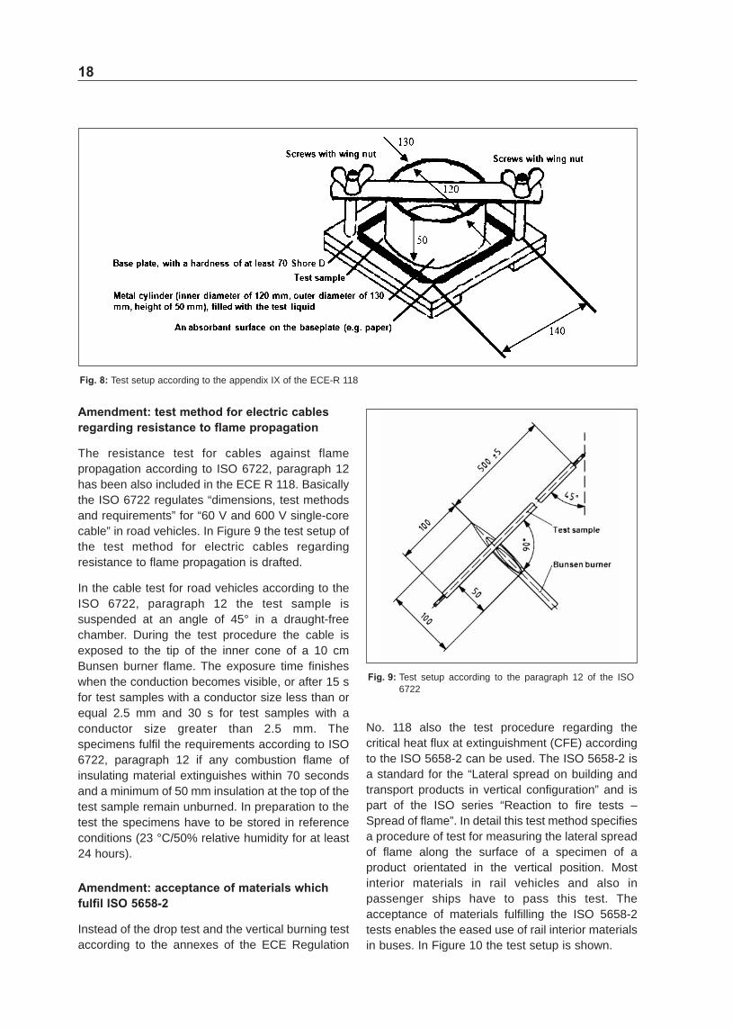
Amendment test to determine the capability of materials to repel fuel or lubricant
Since insulation materials were commonly drenched with operation fluids from the engine which supported the ignition and fire propagation in engine compartments the ECE Regulation No 118 got an additional test to determine the capability of materials to repel fuel or lubricant This test rules for materials and composite materials in a horizontal position in the interior compartment and insulation materials installed in a horizontal position in the engine bay or any separate heating compartment In the test procedure four specimens (140 x 140 x 5 mm) of a material stored before in reference conditions (23 degC50 relative humidity for at least 24 hours) have to be tested The test setup is shown in Figure 8
Basically a metal cylinder is pressed in the test sample of an insulation material The cylinder is filled with a test liquid (diesel fuel) to a height of 20 mm and is rest during the test procedure for 24 hours Afterwards the test liquid and the test sample are removed from the apparatus If residue of the test liquid is found on the test sample it shall be removed without compressing the test sample The test is fulfilled if the increase of the weight of the worst test result does not exceed 1 g
18
Fig 8 Test setup according to the appendix IX of the ECEshyR 118
Amendment test method for electric cables regarding resistance to flame propagation
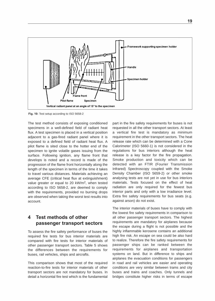
The resistance test for cables against flame propagation according to ISO 6722 paragraph 12 has been also included in the ECE R 118 Basically the ISO 6722 regulates ldquodimensions test methods and requirementsrdquo for ldquo60 V and 600 V singleshycore cablerdquo in road vehicles In Figure 9 the test setup of the test method for electric cables regarding resistance to flame propagation is drafted
In the cable test for road vehicles according to the ISO 6722 paragraph 12 the test sample is suspended at an angle of 45deg in a draughtshyfree chamber During the test procedure the cable is exposed to the tip of the inner cone of a 10 cm Bunsen burner flame The exposure time finishes when the conduction becomes visible or after 15 s for test samples with a conductor size less than or equal 25 mm and 30 s for test samples with a conductor size greater than 25 mm The specimens fulfil the requirements according to ISO 6722 paragraph 12 if any combustion flame of insulating material extinguishes within 70 seconds and a minimum of 50 mm insulation at the top of the test sample remain unburned In preparation to the test the specimens have to be stored in reference conditions (23 degC50 relative humidity for at least 24 hours)
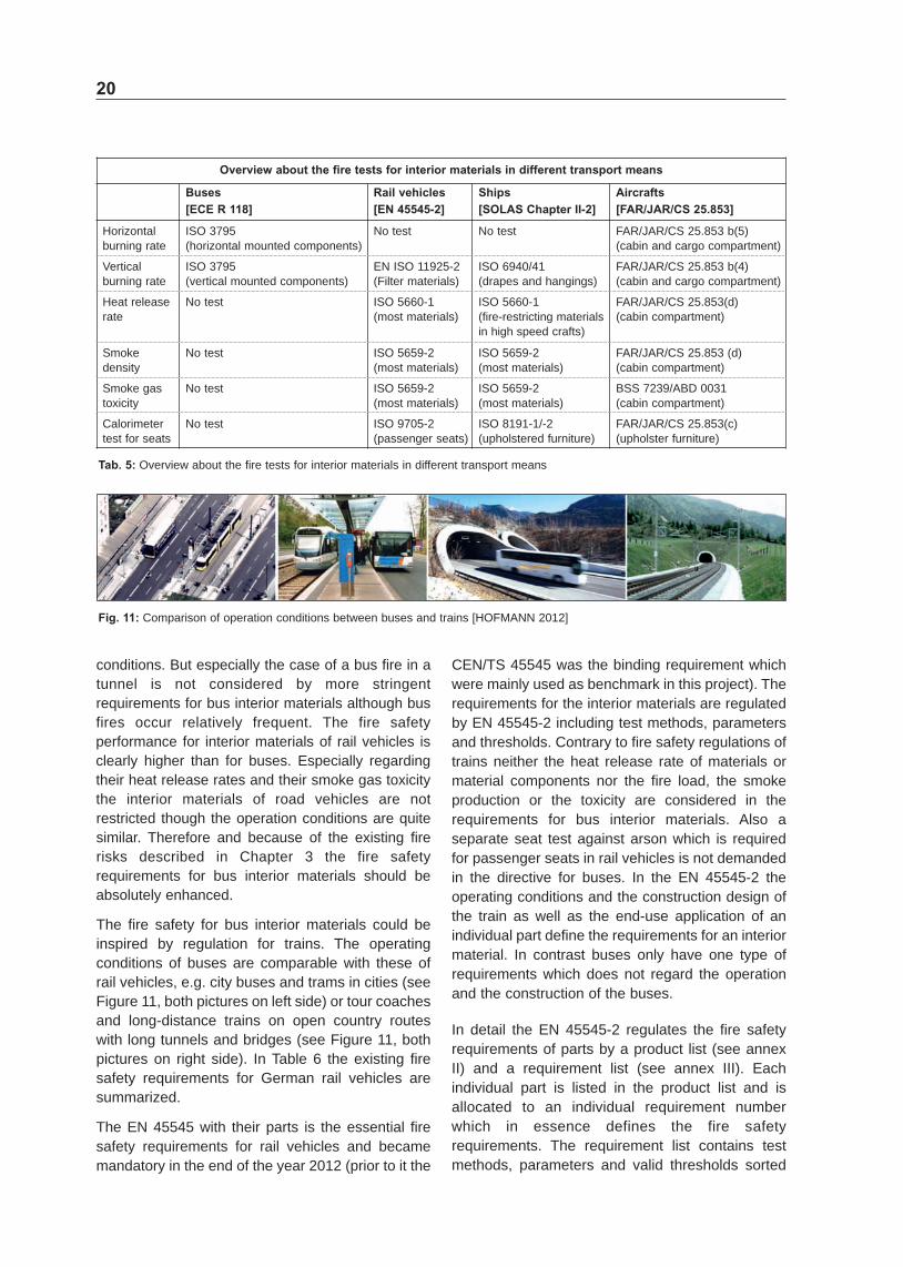
Amendment acceptance of materials which fulfil ISO 5658-2
Instead of the drop test and the vertical burning test according to the annexes of the ECE Regulation
Fig 9 Test setup according to the paragraph 12 of the ISO 6722
No 118 also the test procedure regarding the critical heat flux at extinguishment (CFE) according to the ISO 5658shy2 can be used The ISO 5658shy2 is a standard for the ldquoLateral spread on building and transport products in vertical configurationrdquo and is part of the ISO series ldquoReaction to fire tests ndash Spread of flamerdquo In detail this test method specifies a procedure of test for measuring the lateral spread of flame along the surface of a specimen of a product orientated in the vertical position Most interior materials in rail vehicles and also in passenger ships have to pass this test The acceptance of materials fulfilling the ISO 5658shy2 tests enables the eased use of rail interior materials in buses In Figure 10 the test setup is shown
19
Fig 10 Test setup according to ISO 5658shy2
The test method consists of exposing conditioned specimens in a wellshydefined field of radiant heat flux A test specimen is placed in a vertical position adjacent to a gasshyfired radiant panel where it is exposed to a defined field of radiant heat flux A pilot flame is sited close to the hotter end of the specimen to ignite volatile gases issuing from the surface Following ignition any flame front that develops is noted and a record is made of the progression of the flame front horizontally along the length of the specimen in terms of the time it takes to travel various distances Materials achieving an average CFE (critical heat flux at extinguishment) value greater or equal to 20 kWm2 when tested according to ISO 5658shy2 are deemed to comply with the requirements provided no burning drops are observed when taking the worst test results into account
4 Test methods of other passenger transport sectors
To assess the fire safety performance of buses the required fire tests for bus interior materials are compared with fire tests for interior materials of other passenger transport sectors Table 5 shows the differences between the requirements for buses rail vehicles ships and aircrafts
This comparison shows that most of the required reactionshytoshyfire tests for interior materials of other transport sectors are not mandatory for buses In detail a horizontal fire test which is the fundamental
part in the fire safety requirements for buses is not requested in all the other transport sectors At least a vertical fire test is mandatory as minimum requirement in the other transport sectors The heat release rate which can be determined with a Cone Calorimeter (ISO 5660shy1) is not considered in the regulations for bus interiors although the heat release is a key factor for the fire propagation Smoke production and toxicity which can be detected with an FTIR (Fourier Transmission Infrared) Spectroscopy coupled with the Smoke Density Chamber (ISO 5659shy2) or other smoke analysing tests are not yet in use for bus interiors materials Tests focused on the effect of heat radiation are only required for the fewest bus interior parts and only with a low irradiance level Extra fire safety requirements for bus seats (eg against arson) do not exist
The interior materials of buses have to comply with the lowest fire safety requirements in comparison to all other passenger transport sectors The highest requirements are mandatory for airplanes because the escape during a flight is not possible and the highly inflammable kerosene contains an additional high fire risk An escape on sea could be also hard to realize Therefore the fire safety requirements for passenger ships can be ranked between the requirements for airplanes and transportation systems on land But in difference to ships and airplanes the evacuation conditions for passengers in road and rail vehicles are easier and operating conditions are very similar between trams and city buses and trains and coaches Only tunnels and bridges constitute higher risks in terms of escape
20
Overview about the fire tests for interior materials in different transport means
Buses [ECE R 118]
Rail vehicles [EN 45545-2]
Ships [SOLAS Chapter II-2]
Aircrafts [FARJARCS 25853]
Horizontal burning rate
ISO 3795 (horizontal mounted components)
No test No test FARJARCS 25853 b(5) (cabin and cargo compartment)
Vertical burning rate
ISO 3795 (vertical mounted components)
EN ISO 11925shy2 (Filter materials)
ISO 694041 (drapes and hangings)
FARJARCS 25853 b(4) (cabin and cargo compartment)
Heat release rate
No test ISO 5660shy1 (most materials)
ISO 5660shy1 (fireshyrestricting materials in high speed crafts)
FARJARCS 25853(d) (cabin compartment)
Smoke density
No test ISO 5659shy2 (most materials)
ISO 5659shy2 (most materials)
FARJARCS 25853 (d) (cabin compartment)
Smoke gas toxicity
No test ISO 5659shy2 (most materials)
ISO 5659shy2 (most materials)
BSS 7239ABD 0031 (cabin compartment)
Calorimeter test for seats
No test ISO 9705shy2 (passenger seats)
ISO 8191shy1shy2 (upholstered furniture)
FARJARCS 25853(c) (upholster furniture)
Tab 5 Overview about the fire tests for interior materials in different transport means
Fig 11 Comparison of operation conditions between buses and trains [HOFMANN 2012]
conditions But especially the case of a bus fire in a tunnel is not considered by more stringent requirements for bus interior materials although bus fires occur relatively frequent The fire safety performance for interior materials of rail vehicles is clearly higher than for buses Especially regarding their heat release rates and their smoke gas toxicity the interior materials of road vehicles are not restricted though the operation conditions are quite similar Therefore and because of the existing fire risks described in Chapter 3 the fire safety requirements for bus interior materials should be absolutely enhanced
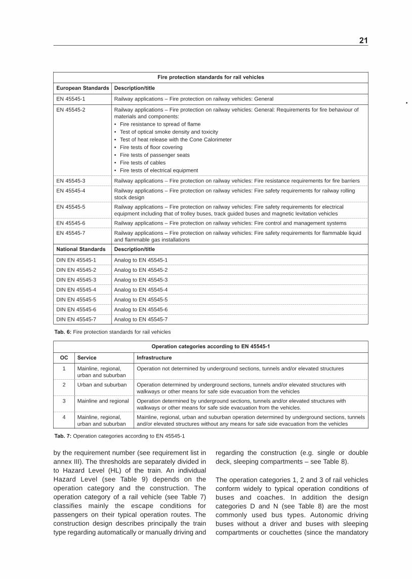
The fire safety for bus interior materials could be inspired by regulation for trains The operating conditions of buses are comparable with these of rail vehicles eg city buses and trams in cities (see Figure 11 both pictures on left side) or tour coaches and longshydistance trains on open country routes with long tunnels and bridges (see Figure 11 both pictures on right side) In Table 6 the existing fire safety requirements for German rail vehicles are summarized
The EN 45545 with their parts is the essential fire safety requirements for rail vehicles and became mandatory in the end of the year 2012 (prior to it the
CENTS 45545 was the binding requirement which were mainly used as benchmark in this project) The requirements for the interior materials are regulated by EN 45545shy2 including test methods parameters and thresholds Contrary to fire safety regulations of trains neither the heat release rate of materials or material components nor the fire load the smoke production or the toxicity are considered in the requirements for bus interior materials Also a separate seat test against arson which is required for passenger seats in rail vehicles is not demanded in the directive for buses In the EN 45545shy2 the operating conditions and the construction design of the train as well as the endshyuse application of an individual part define the requirements for an interior material In contrast buses only have one type of requirements which does not regard the operation and the construction of the buses
In detail the EN 45545shy2 regulates the fire safety requirements of parts by a product list (see annex II) and a requirement list (see annex III) Each individual part is listed in the product list and is allocated to an individual requirement number which in essence defines the fire safety requirements The requirement list contains test methods parameters and valid thresholds sorted
21
Fire protection standards for rail vehicles
European Standards Descriptiontitle
EN 45545shy1 Railway applications ndash Fire protection on railway vehicles General
EN 45545shy2 Railway applications ndash Fire protection on railway vehicles General Requirements for fire behaviour of materials and components bull Fire resistance to spread of flame bull Test of optical smoke density and toxicity bull Test of heat release with the Cone Calorimeter bull Fire tests of floor covering bull Fire tests of passenger seats bull Fire tests of cables bull Fire tests of electrical equipment
EN 45545shy3 Railway applications ndash Fire protection on railway vehicles Fire resistance requirements for fire barriers
EN 45545shy4 Railway applications ndash Fire protection on railway vehicles Fire safety requirements for railway rolling stock design
EN 45545shy5 Railway applications ndash Fire protection on railway vehicles Fire safety requirements for electrical equipment including that of trolley buses track guided buses and magnetic levitation vehicles
EN 45545shy6 Railway applications ndash Fire protection on railway vehicles Fire control and management systems
EN 45545shy7 Railway applications ndash Fire protection on railway vehicles Fire safety requirements for flammable liquid and flammable gas installations
National Standards Descriptiontitle
DIN EN 45545shy1 Analog to EN 45545shy1
DIN EN 45545shy2 Analog to EN 45545shy2
DIN EN 45545shy3 Analog to EN 45545shy3
DIN EN 45545shy4 Analog to EN 45545shy4
DIN EN 45545shy5 Analog to EN 45545shy5
DIN EN 45545shy6 Analog to EN 45545shy6
DIN EN 45545shy7 Analog to EN 45545shy7
bull
Tab 6 Fire protection standards for rail vehicles
Operation categories according to EN 45545-1
OC Service Infrastructure
1 Mainline regional urban and suburban
Operation not determined by underground sections tunnels andor elevated structures
2 Urban and suburban Operation determined by underground sections tunnels andor elevated structures with walkways or other means for safe side evacuation from the vehicles
3 Mainline and regional Operation determined by underground sections tunnels andor elevated structures with walkways or other means for safe side evacuation from the vehicles
4 Mainline regional urban and suburban
Mainline regional urban and suburban operation determined by underground sections tunnels andor elevated structures without any means for safe side evacuation from the vehicles
Tab 7 Operation categories according to EN 45545shy1
by the requirement number (see requirement list in annex III) The thresholds are separately divided in to Hazard Level (HL) of the train An individual Hazard Level (see Table 9) depends on the operation category and the construction The operation category of a rail vehicle (see Table 7) classifies mainly the escape conditions for passengers on their typical operation routes The construction design describes principally the train type regarding automatically or manually driving and
regarding the construction (eg single or double deck sleeping compartments ndash see Table 8)
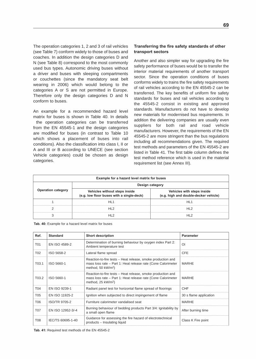
The operation categories 1 2 and 3 of rail vehicles conform widely to typical operation conditions of buses and coaches In addition the design categories D and N (see Table 8) are the most commonly used bus types Autonomic driving buses without a driver and buses with sleeping compartments or couchettes (since the mandatory
22
seat belt wearing in 2006) are not permitted in Europe Therefore only the design categories D and N conform to buses
The Hazard Level of a rail vehicle is regulated by the following matrix (see Table 9) For the operation category 1 2 and 3 which match to the operation conditions of buses as well as to the design categories N and D only the Hazard Levels 1or 2 are requested
In sum the Hazard Level of a train is mainly defined by the escape conditions for the passengers An example for a Hazard Level matrix for buses is shown in Table 10
In conclusion for city buses the requirements of Hazard Level 1 would be applicable and for coaches the requirements of Hazard Level 2 would be applicable in accordance to EN 45545
5 Toxicity of smoke gas components
In the topic of smoke gas toxicity the combustion of plastic and synthetic materials is the main issue The hazard in a burning bus during the first minutes can be primarily the smoke which is very toxic The most common plastic components in bus interior materials are polypropylene (PP) polyamide (PA) polyurethane (PU) and polyethylene (PE) Under ideal combustion conditions these are completely converted to carbon dioxide (CO and water 2) vapour But usually the combustion products additionally contain carbon monoxide (CO) as well as other toxic smoke gas components such as nitrous gases (NO ) x hydrogen bromide (HBr) hydrogen chloride (HCl) hydrogen cyanide (HCN) hydrogen fluoride (HF) and sulphur dioxide (SO2) These toxic smoke gas components are reasoned by organic molecules which are commonly derived from petrochemicals
A method to assess the toxicity of smoke gases delivers the Conventional Index of Toxicity (CIT) which is for instance the main parameter for smoke gas toxicity of railway materials according to EN 45545shy2 The CITshyvalue consists principally of the ratios of measured concentrations of toxic smoke gas components to their reference concentrations (see the formula in Figure 12 and the reference concentrations in Table 11)
Design categories according to EN 45545-1
Design category
Description
A Vehicles forming part of an automatic train having no emergency trained staff on board
D Double decked vehicles
S Sleeping and couchette vehicles
N All other vehicles (standard vehicles)
Tab 8 Design categories according to EN 45545shy1
Tab 9 Matrix of Hazard Levels according to EN 45545shy2
Matrix of Hazard Levels according to EN 45545-2
Operation category
Design category
N (Standard vehicles)
A
(Automatic vehicles having no emergency trained staff on board)
D (Double decked vehicle)
S (Sleeping and couchette cars double decked or single deck)
1 HL1 HL1 HL1 HL2
2 HL2 HL2 HL2 HL2
3 HL2 HL2 HL2 HL3
4 HL3 HL3 HL3 HL3
Example for a Hazard Level matrix for buses
Operation category Design category
Standard vehicles High and double-deck vehicles
1 HL1 HL1
2 HL2 HL2
3 HL2 HL2
Tab 10 Example for a Hazard Level matrix for buses
23
Fig 12 Formula for calculating the CITshyvalue according to the EN 45545shy2
Smoke gas component CO2 CO HBr HCl HCN HF NOx SO2
Reference concentration 72000 1380 99 75 55 25 38 262
Tab 11 Reference concentrations of toxic smoke gas components for CITshyvalue
Interior plastic parts of road vehicle and their main combustion gases
Plastics Part Combustion gases
Polyurethane foam (PUR foam) Dashboard door and side panel consoles steering wheel seats insulation
CO CO2 HCN NH3
Acrylonitrile butadiene styrene (ABS) Dashboard door and side panel console CO CO2 HCN
Polyvinyl chloride (PVC) Inner lining console cable insulation CO CO2 HCl
Polyamide (PA) Inner lining seat cover doormat CO CO2 tar HCN
Polyester (PES) Inner lining seat cover doormat CO CO2 HCN acetaldehyde
Artificial leather Door and side panel seat cover CO CO2 HCl HCN NH3
Tab 12 Interior parts of road vehicles and their main combustion gases [GUDE 2010]
In Table 12 diverse plastic parts of road vehicles are listed including their scope of application and their combustion product gases
The quantitatively most common combustion product gas is carbon dioxide But especially the extreme toxic gases are hard to perceive for humans Therefore an overview of the toxic smoke gas components (according to the constituents of the CIT value) generated by burning bus interior materials is outlined
The given limits are average values and can be lower for children or persons with health problems
Carbon dioxide (CO2)
Carbon dioxide is a chemical carbonshyoxygen compound which is colourless and inodorous CO2 is generated in a complete oxidation of carbonic substances with sufficient oxygen The directive of workplace limits (TRGS 900) of the German Federal Institute for Occupational Safety and Health prescribes a CO2 concentration limit of 5000 mlmsup3 which conforms to 05 volume percent in the inhaled air In the atmosphere the value of carbon dioxide is about 0035 volume percent and in exhaled air about 4 volume percent If the CO2 value of the inhaled air increases over 4 volume percent CO2 accumulations occur in the blood If
Impacts of CO2-concentrations
CO2-concentration in inhaled air
Inhalation time and symptoms
5000 ppm Maximum allowable concentration (AGW according to the TRGS 900)
20000 ppm Increasing irritation of respiratory centre with increased pulse rate
40000 ppm Amplification of previous symptoms plus disturbance of blood supply in the brain dizziness nausea tinnitus
80000 ppm Amplification of previous symptoms up to spasms and unconsciousness with a shortshytermed death
100000 ppm fatal after a short time
Tab 13 Dangers and impacts of CO2 concentrations
the CO2 value of inhaled air increases over 8 volume percent the death can occur very rapidly In Table 13 the impacts of CO2 concentrations are summarized
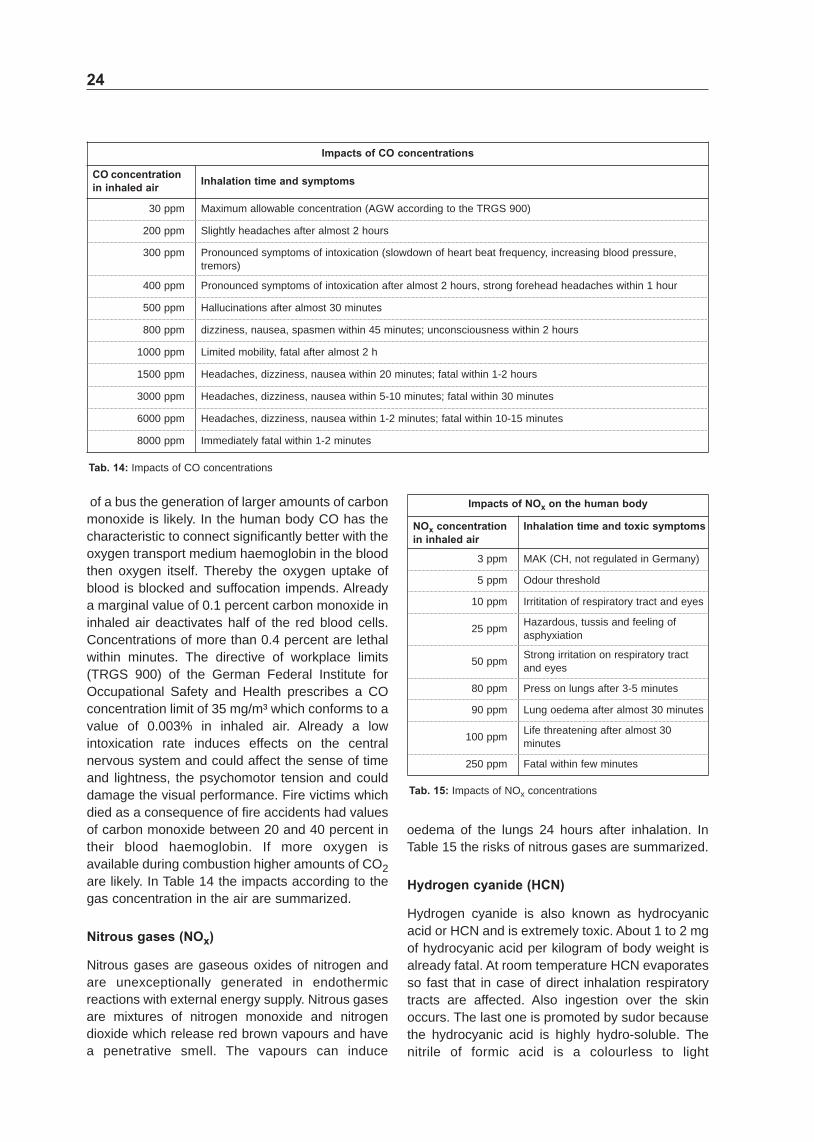
Carbon monoxide (CO)
Carbon monoxide is a chemical carbonshyoxygen compound (CO) and a not irritant colourless odourless and unflavoured gas generated by an incomplete oxidation In fires with insufficient oxygen such as a fire in a closed passenger cabin
24
Impacts of CO concentrations
CO concentration in inhaled air
Inhalation time and symptoms
30 ppm Maximum allowable concentration (AGW according to the TRGS 900)
200 ppm Slightly headaches after almost 2 hours
300 ppm Pronounced symptoms of intoxication (slowdown of heart beat frequency increasing blood pressure tremors)
400 ppm Pronounced symptoms of intoxication after almost 2 hours strong forehead headaches within 1 hour
500 ppm Hallucinations after almost 30 minutes
800 ppm dizziness nausea spasmen within 45 minutes unconsciousness within 2 hours
1000 ppm Limited mobility fatal after almost 2 h
1500 ppm Headaches dizziness nausea within 20 minutes fatal within 1shy2 hours
3000 ppm Headaches dizziness nausea within 5shy10 minutes fatal within 30 minutes
6000 ppm Headaches dizziness nausea within 1shy2 minutes fatal within 10shy15 minutes
8000 ppm Immediately fatal within 1shy2 minutes
Tab 14 Impacts of CO concentrations
of a bus the generation of larger amounts of carbon monoxide is likely In the human body CO has the characteristic to connect significantly better with the oxygen transport medium haemoglobin in the blood then oxygen itself Thereby the oxygen uptake of blood is blocked and suffocation impends Already a marginal value of 01 percent carbon monoxide in inhaled air deactivates half of the red blood cells Concentrations of more than 04 percent are lethal within minutes The directive of workplace limits (TRGS 900) of the German Federal Institute for Occupational Safety and Health prescribes a CO concentration limit of 35 mgmsup3 which conforms to a value of 0003 in inhaled air Already a low intoxication rate induces effects on the central nervous system and could affect the sense of time and lightness the psychomotor tension and could damage the visual performance Fire victims which died as a consequence of fire accidents had values of carbon monoxide between 20 and 40 percent in their blood haemoglobin If more oxygen is available during combustion higher amounts of CO2 are likely In Table 14 the impacts according to the gas concentration in the air are summarized
Nitrous gases (NOx)
Nitrous gases are gaseous oxides of nitrogen and are unexceptionally generated in endothermic reactions with external energy supply Nitrous gases are mixtures of nitrogen monoxide and nitrogen dioxide which release red brown vapours and have a penetrative smell The vapours can induce
Impacts of NOx on the human body
NOx concentration in inhaled air
Inhalation time and toxic symptoms
3 ppm MAK (CH not regulated in Germany)
5 ppm Odour threshold
10 ppm Irrititation of respiratory tract and eyes
25 ppm Hazardous tussis and feeling of asphyxiation
50 ppm Strong irritation on respiratory tract and eyes
80 ppm Press on lungs after 3shy5 minutes
90 ppm Lung oedema after almost 30 minutes
100 ppm Life threatening after almost 30 minutes
250 ppm Fatal within few minutes
Tab 15 Impacts of NOx concentrations
oedema of the lungs 24 hours after inhalation In Table 15 the risks of nitrous gases are summarized
Hydrogen cyanide (HCN)
Hydrogen cyanide is also known as hydrocyanic acid or HCN and is extremely toxic About 1 to 2 mg of hydrocyanic acid per kilogram of body weight is already fatal At room temperature HCN evaporates so fast that in case of direct inhalation respiratory tracts are affected Also ingestion over the skin occurs The last one is promoted by sudor because the hydrocyanic acid is highly hydroshysoluble The nitrile of formic acid is a colourless to light
25
yellowish flammable very volatile and hydroshysoluble liquid with a characteristic and unsavoury smell of bitter almonds A hydrocyanic acid contamination is an intoxication by hydrogen cyanide which connects to the iron of the mitochondria so that these are blocked The cell respiration disrupts because the cell cannot use the oxygen anymore and inner suffocation occurs Genetically determined 30 to 40 of people cannot smell the typical bitter almond smell of hydrogen cyanide In case of high contamination a
Impacts of hydrogen cyanide concentrations
HCN concentrations in inhaled air
Inhalation time and symptoms
19 ppm MAK (CH not regulated in Germany)
51 ppm Odour threshold
180 ppm Slightly poisoning headaches
1000 ppm Fatal after almost 1 hour
1100 ppm Fatal after almost 30 minutes
1800 ppm Fatal after 10 minutes
2800 ppm Instantaneously fatal
Tab 16 Impacts of hydrogen cyanide concentrations
Tab 17 Impacts of hydrogen bromide concentrations
hyperventilation an apnoea and unconsciousness starts in few seconds and after a few minutes the heart fails In Table 16 the risks of HCN concentrations are summarized
Hydrogen bromide (HBr)
Hydrogen bromide is a colourless till faint yellow gas with a sharp and acrid odour which dissolves to hydrobromic acid in water It is an extremely dangerous substance and must be handled with caution as it can cause severe health effects and death In Table 17 the impacts of HBr concentrations are summarized
Hydrogen chloride (HCl)
Hydrogen chloride is a colourless gas of strong odour which dissolves to hydrochloric acid in water It is corrosive to the eyes skin and mucous membranes An acute inhalation exposure may cause coughing hoarseness inflammation and ulceration of the respiratory tract chest pain and pulmonary oedema in humans In Table 18 the risks of HCl concentrations are summarized
Impacts of hydrogen bromide concentrations
HBr concentrations Inhalation time and symptoms
1 ppm Noticeably indisposition after almost 10 minutes
2 ppm Maximum allowable concentration (AGW according to the TRGS 900) ILV for 15 minutes
22 ppm Hard incapacitating impact on escape after almost 1 hours
43 ppm Hard incapacitating impact on escape after almost 30 minutes
100 ppm Hard incapacitating impact on escape after almost 10 minutes
120 ppm Fatal after almost 1 hour
250 ppm Fatal after almost 30 minutes
740 ppm Fatal within 10 min
Impacts of hydrogen chloride concentrations
HCl concentrations in inhaled air
Inhalation time and symptoms
1 ppm Odour threshold
2 ppm Maximum allowable concentration (AGW according to the TRGS 900)
5 ppm ILV (EU) for 8 hours
5 ppm Slightly and painful mucosal irritation
10 ppm ILV (EU) for 15 minutes
35 ppm Lung irritation after almost few breaths as well as irritation conjunctiva and pharynx
50 ppm Breathes stopped by lung irritation
1000 ppm Lung oedema within few breaths danger of live
Tab 18 Impacts of hydrogen chloride concentrations
26
Hydrogen fluoride (HF) 6 Bus fire simulations Hydrogen fluoride is a colourless and fuming gas with a strong and irritating odour Short and cute inhalation exposure to hydrogen fluoride can cause severe respiratory damage in humans including severe irritation and pulmonary oedema Severe ocular irritation and dermal burns may occur following eye or skin exposure In Table 19 the risks of hydrogen fluoride concentrations are summarized
Sulphur dioxide (SO2)
Sulphur dioxide is a colourless gas with a penetrating and faint sweetish odour Inhaling sulphur dioxide is associated with increased respiratory symptoms and disease difficulty in breathing and premature death In Table 20 the risks of sulphur dioxide concentrations are summarized
Tab 19 Impacts of hydrogen fluoride concentrations
Numerical simulations were used first to reproduce the severe bus fire near Hanover in 2008 This bus fire did not start in the engine compartment The survey report for the court was used to collect as many details of the fire development and the smoke spread as possible In addition further simulations were performed on the reproduced bus fire scenario to investigate changes in the fire development and the smoke spread if materials with enhanced fire performance are used Also different ignition sources and locations were investigated numerically Finally the typical development of temperatures and smoke in the different bus fire scenarios were analyzed to estimate the optimal positions for fire and smoke detectors All performed simulations were calculated with the version 5 of the Fire Dynamics Simulator (FDS) FDS is a freeware developed by
Impacts of hydrogen fluoride concentrations
HF concentrations in inhaled air
Inhalation time and symptoms
10 ppm Maximum allowable concentration (AGW according to the TRGS 900)
18 ppm ILV (EU) for 8 hours
30 ppm ILV (EU) for 15 minutes
240 ppm Hard incapacitating impact on escape after almost 1 hour
340 ppm Hard incapacitating impact on escape after almost 30 minutes
440 ppm Fatal after almost 60 minutes
620 ppm Fatal after almost 30 minutes
950 ppm Hard incapacitating impact on escape after almost 10 minutes
1700 ppm Fatal within 10 min
Impacts of sulphur dioxide concentrations
SO2 concentrations in inhaled air
Inhalation time and symptoms
05 ppm MAK (CH not regulated in Germany) odour threshold
30 ppm Irritation of eyes and lungs
40 ppm Smooth irritation of eyes and respiratory tract
80 ppm Low irritation of eyes and respiratory tract
100 ppm Raised respiratory tract resistance
200 ppm Tussis eye irritation
1000 ppm Lifeshythreatening
6000 ppm Fatal within few minutes
Tab 20 Impacts of sulphur dioxide concentrations
27
the National Institute of Standards and Technology (NIST) in the United States
FDS is a Computational fluid dynamics (CFD) programme for fluid flows which solves numerically a large eddy simulation form of the NaviershyStokes equations appropriate for lowshyspeed and thermallyshydriven flows with an emphasis on smoke and heat transport from fires The post processing program lsquoSmokeviewrsquo (NIST) has been used to display the results Fire simulations are very timeshyconsuming halfshyhourly simulation of a bus fire with a mesh of about 2 million cells takes about 4 weeks on a current personal computer
For the simulations material data of typical bus materials such as calorific value density and heat release rate were measured (see next chapter) and implemented in the CFD model First the severe Hannover bus fire on the German federal motorway 2 from November 2008 with 20 fatalities was tried to rebuild For the first steps information about the fire development and the cause of fire were taken from media The coach of this accident was an lsquoO 350 SHDrsquo from MercedesshyBenz built in 2003 For the simulations the geometry was simplified In Figure 13 a photo of the simulation bus model and its original are shown
The dimensions of the ldquoO 350rdquo are 12 m in length 39 m in height and 255 m in width For the simulations some simplifications were made The first simulation models do not contain fuel tires and the luggage compartment The seats the ceiling the luggage rack and the inner lining are flammable and consist of polyurethane foam in the first tries Also the luggage and clothing were not considered because the fire load of an empty vehicle is already sufficient enough for a hazardous fire development
Witnesses reported about a source of fire in the lavatory As a passenger was opening the lavatory door a flash fire streamed out and spread rapidly
through the bus The bus driver stopped the bus immediately and opened the doors For the numerical simulation it was assumed that the fire had been developed for 60 seconds in the lavatory before the lavatory door was opened 15 seconds later which includes the stopping of the vehicle the bus doors were opened in the calculations
Regarding the Hanover bus fire simulation different scenarios were calculated
1 Simulation of flash fire when the lavatory has been opened a nonshycombustible interior
2 As scenario 1 but with a combustible interior and door opening
3 As scenario 2 but with larger computational domain (outside area)
4 Complete simulation of the Hannover bus fire including bursting windows
5 As scenario 4 but with nonshycombustible top covering and luggage rack
6 As scenario 4 but with interior fulfilling train requirements
7 Ignition at the last passenger seat row to simulate arson
Simulation 1 ndash Flash fire when the lavatory has been opened a non-combustible interior
In the first simulation a flash fire which was reported by witnesses in the Hanover bus fire was reproduced For this case all interior parts except the lavatory are nonshycombustible In the simulation the fire starts in the lavatory with an area of 036 msup2 and a heat release rate of 675 kWmsup2 which were calculated by the inner lavatory dimensions and the calorific value of GRP (glass fibre reinforced plastic) After a preshyburn time of 150 s the lavatory door opens and a flash fire spreads out (see Figure 14)
Fig 13 Simulation model and its original a MercedesshyBenz O 350 SHD [KLIPPEL 2009]
28
Fig 14 Flash fire when lavatory is opening (left temperature slice right heat release)
Fig 15 Flash fire (left) and a completely burning interior (right)
This simulation shows that a burning toilet is already able to generate a flash fire which could spread through the whole bus along the ceiling The complete first scenario can be seen on the enclosed CD as fireshyscenario1avi
A fire developed in a concealed compartment can lead to a sudden flash fire when oxygen is supplied and is able to spread along the ceiling through the whole bus
Simulation 2 ndash As Simulation 1 but with a combustible interior and door opening
In the second simulation the interior materials are combustible The basic scenario is the same as in the first simulation But the preshyburn time has been reduced to 60 s which is already enough to generate a flash fire in the simulation Also the opening of the bus doors for the passenger escape is included in this simulation The bus stopping time is approximated to 15 s So the bus doors open 15 s after the lavatory door has been opened
When the lavatory door is open the fire spreads quickly along the ceiling (as seen in the first simulation see Figure 15 left) In contrast to the first simulation with nonshycombustible ceiling the ceiling parts catch immediately fire After few seconds all
combustible parts are burning (see Figure 15 right) Soon afterwards the bus doors open
In Figure 15 the rapid fire development can be seen On the leftshyhand side the situation is shown 6 s after the lavatory door has been opened On the rightshyhand side the situation is shown when the bus doors are just opened The rapid fire propagation is mainly supported by the combustible ceiling and the fresh air coming through the open bus doors
This simulation shows that a burning toilet is already able to generate a flash fire which could quickly ignite the whole ceiling and afterwards the other interior parts (mainly passenger seats) Therefore the fire propagates along the ceiling in case of a flash fire This fire simulation can be seen on the enclosed CD as fireshyscenario2avi
In case of flash fire the fire propagates along the ceiling
Simulation 3 ndash As Simulation 2 but with larger computational domain (outside area)
In addition to the second simulation a larger computational domain was also investigated as the third simulation which contains an area around the bus The results are similar to those
29
from the second simulation The third simulation is attached on the enclosed CD as fireshyscenario3 avi
Simulation 4 ndash Complete simulation of the Hanover bus fire including bursting windows
In the fourth simulation the Hanover bus fire is completely reconstructed based on information from witnesses Also the bursting of single window screens is included in this simulation model When the temperature of the surrounding air exceeds 300 degC the window is removed and fresh air supports the fire development (see Figure 16) This simulation was compared with pictures and videos from real bus fires (as a bus fire in Kassel or Salzburg shown in Figure 16)
The results of the simulation confirm that in a bus fire extremely high amounts of heat and smoke are released The video can be seen on the enclosed CD as fireshyscenario4avi
A bus fire releases extremely high amounts of heat and smoke
Simulation 5 ndash As Simulation 4 but with non-combustible top covering and luggage rack
In the fifth simulation a fire scenario regarding the enhancement of the fire safety performance is investigated A nonshycombustible ceiling is used The basic procedure is as in simulation 4 except for the non combustible ceiling Figures 17 and 18 show the differences
This simulation shows also a fire spread as in the first simulation But in detail the comparison between the fourth and the fifth simulation demonstrates that the fire development in the bus with the conventional ceiling parts is obviously faster That aspect could only be explained by the support of combustible ceiling parts
After a burning time of 50 seconds the bus with the conventional ceiling is completely burning In contrast the fire development in the bus with the nonshycombustible ceiling parts is slower and has only reached the first passenger seat (see Figure 18)
Nevertheless it is merely a matter of time that the bus is also completely burning as Figure 19 shows But a combustible ceiling leads to extremely fast fire spread along the ceiling
Fig 16 Simulation compared to photos (left at Kassel right at Salzburg) [GUDE 2011]
Fig 17 Normal ceiling (left) and a nonshycombustible ceiling (right) after 6 s
30
Fig 18 Bus with a normal ceiling (left) and a nonshycombustible ceiling (right) after 50 s
Fig 19 Bus with a nonshycombustible ceiling when the lavatory has been opened for 125 s
This comparison of the fourth and fifth simulation shows that the combustibility of ceiling parts is essential for the fire behaviour and fire development Also in other fire scenarios (as the seventh simulation see below) the fire develops significantly along the ceiling Therefore a lower combustibility of ceiling parts is able to enhance considerably the fire safety of buses
A lower combustibility of ceiling parts decreases the fire spread in a bus
Simulation 6 ndash As Simulation 4 but with interior fulfilling train requirements
In the sixth simulation the fire scenario of the fourth simulation is basically used But in contrast to its scenario the interior materials conform to requirements of rail vehicles This should give a feeling how big the difference between the fire safety requirements of buses and rail vehicles is The following images show the comparison at different time steps (see Figure 20 and 21)
The first time step is while the flash fire is occurring and the flames are spreading along the ceiling
when the lavatory door has been opened for 6 s (see Figure 20)
At this moment the flash fire is quite similar in both simulations But the flame spreading along the ceiling is more homogeneously distributed in the bus ceiling parts
In Figure 21 the situation is shown when the bus doors have been opened for 15 s
The fire development is obviously faster in the bus with conventional bus interior materials the ceiling is completely burning and the fire has already spread to most of the passenger seats On the right hand side of Figure 21 the same situation with train interior material is shown The fire development is distinctly slower but it can be seen that a hidden fire which is suddenly provided with oxygen can lead to very hazardous situations for all materials
In a second simulation series a more detailed bus body of a Mercedes O 350 (see Figure 22) is used In contrast to the first bus model the second one contains a luggage compartment a ventilation system as in the original bus and the exact proportions of the bus in the Hanover bus fire In addition also the cable duct and some few suitcases are included
The results of the first six simulation scenarios are very similar in the revised bus model compared to the first bus model The differences in the fire development between a bus interior compared to a train interior can be excellently shown by the following pictures (see Figure 23)
This comparison shows a bigger difference in the fire safety performance between bus and train interiors for the hidden fire situation The bus interior materials enable a faster fire development than the train interior materials do although the
31
Fig 20 Flash fire after 6 s in a bus interior (left) and analog in a train interior (right)
Fig 21 Bus interior (left) and train interior (right) when doors have been opend for 15 s
Fig 22 Second bus model and its original from the Hannover bus fire [BUHRS 2008]
Fig 23 Fire in a common coach (left) and a bus interior fulfilling train requirements (right)
32
hidden fire which is suddenly supplied with oxygen is a very hazardous situation itself because it leads to a fire flash through the bus because of the suddenly available oxygen
Bus interior materials enable a faster fire development than interior materials of rail vehicles do
Simulation 7 ndash As Simulation 4 but with interior fulfilling train requirements
In the seventh simulation of the first simulation series arson on one of the rear seats is simulated (see Figure 24) The ignition starts by a burning paper cushion (as supposed in the railway standard according to DIN 5510) For this simulation parameters were used from own experiments with burning paper cushions on passenger seats
In the following figures (see Figure 24 to 25) a simulation of a bus interior (left pictures) is directly confronted to a simulation of a ldquotrain interiorrdquo (right pictures) In the beginning both simulations are widely similar because only the paper cushion is burning When the paper cushion has burnt only for 40 s the paper cushion and a small area around are burning in both interiors
When the paper cushion has burnt for 66 s the paper cushion is completely consumed and the ceiling of the bus is completely in flames for the bus interior materials (see Figure 25 left) In distinctive contrast the fire in the bus with train interior materials is selfshysuppressed at the same time (see Figure 25 right)
These simulations show that the interior materials of rail vehicles prevent arson far better than bus interior materials The fire development in the bus interior is comparable to the fire development of the fourth simulation in which the fire generated by another ignition source also spreads along the ceiling parts
Bus interior materials do not prevent arson effectively
7 Investigations on bus interior materials
Worldwide there are more than 100 bus manufacturers [WIKIPEDIA 2011] which in turn have a large number of suppliers In Germany alone the manufacturers have a wide variety of bus models And each bus model is assembled by
Fig 24 Arson in a bus interior (left) and analog in a train interior (right) 40 s after ignition
Fig 25 Arson in a bus interior (left) and analog in a train interior (right) 66 s after ignition
33
Tab 21 Tested bus interior materials
parts from a lot of suppliers So it is not possible to regard each type of material especially because the current fire safety requirements are easy to pass and allow a wide range of materials However the tested specimens were taken from different actual bus types (coaches and city buses) and also from different inner locations So it is assumed that they present a representative range of bus materials
For the fire safety evaluation of bus interior materials test series with the Cone Calorimeter (ISO 5660) and the Smoke Density Chamber (SDC ISO 5659shy2) were performed according to rail material requirements of EN 45545shy2 In Table 21 the tested bus interior materials are listed
In preparation for the testing series the material compositions were investigated by an Attenuated Total Reflectance (ATR) Spectroscopy
71 Attenuated Total Reflectance (ATR) Spectrometer
The ATR spectroscopy is a practice of MidshyInfrared (IR) spectroscopy which is a very reliable and well recognized method for determining material compositions Substances can be characterized identified or also quantified by comparing material data in a deposited database One of the strengths of IR spectroscopy is its ability as an analytical technique to obtain spectra from a very wide range of solids liquids and gases [ELMER 2004]
An example for well according material curves is shown in Figure 27 for the cockpit material
The main ingredients of tested materials are listed in Table 22 including their excellence of correlation
Fig 26 ATR at BAM
34
Fig 27 ATR curves of cockpit material and styreneacrypolite propolymer 25
Material Main material composition Excellence Remark
Body insulation Melamineshyformaldehyde condensate 7958
Floor covering Isodecyl diphenyl phosphate 7219
Side panel Undefined
Flooring Undefined
GRP part Styrenebutyl methacrylate (50) copolymer 6808
Ceiling over seats Polyether urethane polypropylene oxide and methylene 7079 White sample
Acrylic polymer 7855 Grey sample
Ceiling over gangways Undefined Green sample
Poly (vinyl acetatethylene) 31 7318 Grey sample
Foam of seats Polyether urethane PPO+ MBI pyrol 7921
Cockpit material Styreneacrypolite propolymer 25 9378
Tab 22 Main ingredients of tested bus interior materials
72 Cone Calorimeter (EN ISO 5660)
The Cone Calorimeter is one of the fundamental measuring instruments for quantitative analysis in the materials flammability research This apparatus contains a uniform and wellshycharacterized conical heat irradiance source (see Figure 28) Investigation parameters are heat release rate (HRR) time to ignition (TTI) total heat release (THR) and mass loss rate (MLR) The measurements of the HRR can be used to calculate the average rate of heat emission (ARHE) the maximum average rate of heat emission (MARHE) and the time to reach the maximum heat release rate The Cone Calorimeter can also measure the smoke production as well as the COCO2 release rates [BABRAUSKAS 1987 and MORGAN 2007]
A standardized specimen size of 100 mm x 100 mm and a maximum thickness of 50 mm can be irradiated up to 100 kWmsup2 by the heat source in the Cone Calorimeter The thermal stress on the material surface generates a pyrolysis which also
Fig 28 Inner parts of the Cone Calorimeter [GUDE 2011]
reproduces consequences of the heat radiation of burning materials to a not yet burning material The ignition of the pyrolysis gases is supported by a 10 kV spark ignition In the Cone Calorimeter a mass loss scale for burning material specimens and a special exhaust system with an adjusted flow rate
35
Fig 29 Cone Calorimeter at BAM [GUDE 2011]
Fig 30 ARHE equation according to the EN 45545shy2
of 0024 msup3s for the smoke gas analysis are also installed
In all sectors of passenger transport excluding for road vehicles the test with the Cone Calorimeter is an essential part of the fire safety regulations eg ldquofire protection on railway vehiclesrdquo (EN 45545shy2) ldquoFire Test Procedures Coderdquo of the International Maritime Organization (IMO FTP Code Part 5) and the ldquoFederal Aviation Regulationsrdquo or ldquoJoint Aviation Regulationsrdquo (FARJAR 25853)
The operating conditions of buses are comparable with these of rail vehicles eg city buses and trams in cities or tour coaches and longshydistance trains on open country routes with long tunnels and bridges Therefore the measured data of the bus interior materials were evaluated by the fire safety regulations of rail vehicles (EN 45545shy2) to show the difference in fire safety performance between train and bus materials
The determination of the heat release rate is based on the EN ISO 5660shy1 The heat emission for each time element is calculated assuming a scan rate at 2 s for burns of less than 3 min (EN 45545shy2) and at 5 s for longer burn times (ISO 5660shy1) The test duration amounts to 20 minutes for the determination of the ARHE(t)shyvalue (see Figure 30) and the MARHEshyvalue (peak of measured ARHEshyvalues) According to EN 45545shy2 the limitation of the heat release is given by the MARHEshyvalue which does not have to exceed a corresponding threshold
The procedure to identify generally the corresponding threshold for a sample of interior material is explained in the following steps The valid thresholds (eg MARHE) of a part are stated in the requirement list (see Table 23) for a given individual requirement number depending on what the part is used for and where it is installed in the vehicle (see product list in Annex II) as well as depending on the appropriated Hazard Level (see Table 9) The entire requirement list is attached in Annex III
The MARHEshyvalue of bus interior materials was measured in the Cone Calorimeter at BAM The data are listed in Table 24 including their individual requirement number the demanded irradiance level and the corresponding thresholds for Hazard Level 1 and 2 The colouring illustrates the applicability of investigated materials in rail vehicles Red coloured limits of HL1 or HL2 correspond to failed tests The analog green coloured limits conform to passed tests
The requirements for the heat release for Hazard Level 1 and 2 (represented in the EN 45545shy2 by the MARHEshyvalue) are only passed by the flooring the floor covering and the side panel The maximum heat release rate of the tested materials is up to about 6 times higher than allowed in rail requirements
Most of tested bus interior materials fail the heat release requirements of rail vehicles according to EN 45545-2
36
Short name of requirement set (used for)
Test procedures (also see Table 41) Thresholds
Test method reference Parameter Unit Requirement Definition
HL1 HL2 HL3
R1 (IN1 IN 4 IN 5 IN6A IN7 IN8 IN10B IN12 IN13 IN15 F7B E3 E2A 441 534)
T02 ISO 5658shy2
CFE kWmshy2
Minimum 20 a
20 a
20 a
T0301 ISO 5660shy1 50 kWmshy2
MARHE kWmshy2
Maximum a shy
90 60
T1001 EN ISO 5659shy2 50 kWmshy2
Ds(4) dimensionless
Maximum 600 300 150
T1002 EN ISO 5659shy2 50 kWmshy2
VOF4 min
Maximum 1200 600 300
T1101 EN ISO 5659shy2 50 kWmshy2
CITG dimensionless
Maximum 12 09 075
R2 (IN2 IN10A IN 11)
T02 ISO 5658shy2
CFE kWmshy2
Minimum 13 a
13 a
13 a
T0301 ISO 5660shy1 50 kWmshy2
MARHE kWmshy2
Maximum a shy
a shy
90
T1001 EN ISO 5659shy2 50 kWmshy2
Ds(4) dimensionless
Maximum 600 300 150
T1002 EN ISO 5659shy2 50 kWmshy2
VOF4 min
Maximum 1200 600 300
T1101 EN ISO 5659shy2 50 kWmshy2
CITG dimensionless
Maximum 12 09 075
Tab 23 Extract of requirement list for rail materials (EN 45545shy2 see Annex III for details)
Material
Input data Measured values Thresholds
Requirement No
Irradiance [kWmsup2]
MARHE [kWmsup2]
HL 1 [kWmsup2]
HL 2 [kWmsup2]
Body insulation (1st) R1 50 3345 No limit 90
Body insulation (2nd) R1 50 3090 No limit 90
Floor covering R9 25 325 No limit 50
Side panel (1st) R1 50 648 No limit 90
Side panel (2nd) R1 50 542 No limit 90
Flooring R9 25 16 No limit 50
GRP part (1st) R1 50 2585 No limit 90
GRP part (2nd) R1 50 2809 No limit 90
Ceiling over seats (1st) R1 50 2472 No limit 90
Ceiling over seats (2nd) R1 50 2157 No limit 90
Ceiling over gangways (1st) R1 50 3077 No limit 90
Ceiling over gangways (2nd) R1 50 2555 No limit 90
Foam of seats (1st) R20 25 3092 75 50
Foam of seats (2nd) R20 25 1667 75 50
Tab 24 Results of the Cone Calorimeter tests
37
73 Smoke Density Chamber (EN ISO 5659-2)
The Smoke Density Chamber is a testing instrument which is designed and developed for the determination of the smoke gas production of flammable specimens The apparatus contains a sealed test chamber with photometric equipment Specimens can be exposed to a horizontal thermal irradiation up to 50 kWmsup2 (EN ISO 5659shy2) or to a vertical thermal irradiation of 25 kWmsup2 (ASTM E 662) with or without a pilot flame The photometric scale used to measure the smoke density in the Smoke Density Chamber is similar to the optical scale of human vision An additionally coupled FTIRshyspectrometer (Fourier Transform Infrared see operating draft in Figure 31 left) enables the qualitative and quantitative analysis of the smoke gas composition
Parameters are the light transmission (T) and the specific optical density (Ds) as well as the cumulative value of specific optical densities in the first 4 min of testing (VOF4) and the mass referenced optical density (MOD) Smoke gases are quantitatively analysed for toxic components by FTIRshyspectroscopy after 4 and 8 minutes especially for carbon dioxide (CO2) carbon monoxide (CO) hydrofluoric acid (HF) hydrochloric acid (HCl) hydrobromic acid (HBr) hydrocyanic acid (HCN) sulphur dioxide (SO2) and nitrous gases (NOx)
In the fire safety requirements of all passenger transport systems (except road vehicles) the Smoke Density Chamber (SDC) is fundamental part eg rail vehicles (EN 45545shy2) ships (IMO FTP Code Part 2) and airplanes (FARJAR 25853)
The toxic concentrations of smoke gas components generated by burning interior material samples were investigated in the Smoke Density Chamber at BAM The toxic gas concentrations are measurements of single specimens (75 mm x 75 mm x thickness) in the Smoke Density Chamber (ca 05 msup3) The data are listed in Table 25 including the calculated CITshyvalues (see chapter 5 ldquoToxicity of smoke gas componentsrdquo) after 4 and 8 minutes of testing Additionally the toxic concentration limits for smoke gas components from the manufacturers Bombardier (SMP 800shyC) Airbus (ABD 00031) Boeing (BSS 7239) and for ships (IMO MSC 61 (67) Annex 1 Part 2) as well as intoxication thresholds (see chapter 6 ldquoToxicity of smoke gas componentsrdquo) are shown in the upper part of Table 25 to assess the toxicity of smoke gases generated by different burning bus interior specimens
Yellow coloured cells mark a gas concentration which generates symptoms of intoxication Bright red coloured cells indicate lethal gas concentrations An underlined value marks a gas concentration which exceeds the concentration limits of at least one listed standard An underlined and bold value indicates a lethal gas concentration which exceeds all listed standards The red colouring at limits of HL 1 or HL 2 corresponds to failed measurements and the analog green colouring conforms to valid measurements
Concerning the evaluation of toxic gas concentrations by the CITshyvalue on bus interior materials the body insulation the side panel the GRP part and the foam of seats pass the requirements of the Hazard Levels 1 and 2 which are essential for corresponding rail vehicles The CITshyvalues of the investigated ceiling and flooring materials are invalid for corresponding rail vehicles
Fig 31 Operating draft apparatus and a sketch of the SDC at BAM [DEUBEL 2010]
38
Material (material requirement)
Components of CIT-value CIT-value
CO2 [ppm]
CO [ppm]
SO2 [ppm]
NOx [ppm]
HBr [ppm]
HCl [ppm]
HF [ppm]
HCN [ppm]
Calculated CITG
HL1 (EN 45545)
HL2 (EN 45545)
IMO MSC 61(67) Annex 1 Part 2 shy 1450 120 350 600 600 600 140 shy shy shy
ABD 00031 (Airbus) shy 1000 100 100 shy 150 100 150
BSS 7239 (Boeing) shy 3500 100 100 shy 500 200 150 shy shy shy
SMP 800shyC (Bombardier) 90000 3500 100 100 100 500 100 100 shy shy shy
First symptoms of intoxication 20000 200 4 10 22 5 10 18
Lethal concentrations 80000 1000 100 100 120 50 44 100
Body insulation (R1)
4 min 5900 99 5 73 0 1 0 36 03 12 09
8 min 6900 168 25 54 0 3 4 52 03 12 09
Floor covering (R9)
4 min 7500 793 0 31 0 4050 2 3 66 12 09
8 min 10100 931 0 8 0 3572 4 5 58 12 09
Side panel (R1)
4 min 3600 1076 80 0 1 0 0 167 04 12 09
8 min 4400 2004 41 1 0 0 0 245 06 12 09
GRP part (R1)
4 min 19800 682 0 0 4 0 0 10 01 12 09
8 min 35700 1122 0 0 7 2 0 16 02 12 09
Ceiling over seats (R1)
4 min 11900 668 0 87 0 1013 1 39 19 12 09
8 min 14700 967 0 97 1 923 0 40 18 12 09
Ceiling over gangways (R1)
4 min 16500 762 52 111 0 1528 3 33 29 12 09
8 min 20000 984 40 149 0 1385 0 40 27 12 09
Foam of seats (R20)
4 min 14200 23 1 82 0 0 0 5 03 12 09
8 min 15800 53 0 74 0 1 0 7 02 12 09
Tab 25 Measured concentrations of toxic smoke gas components
Regarding the concentrations of single smoke gas components the CITshyvalue method reveals a weakness in the evaluation of toxicity Especially the measured values of the side panel which has a valid CITshyvalue according to EN 45545shy2 contains extremely toxic concentrations of single smoke gas components generated by a burning specimen Also the GRP part which has a valid CITshyvalue according to EN 45545shy2 generates lethal concentrations of single toxic smoke gas components The HClshyconcentration in the smoke gas of a burning floor covering specimen increases to the 81 times of the lethal concentration
In conclusion all bus interior materials generate hazardous till lethal concentrations of toxic smoke gases components in very few minutes (see Annex IV) This could be prevented if the toxic smoke gas components were restricted by fire safety requirements Furthermore the limitation of toxic
smoke by evaluating the CITshyvalue according to EN 45545shy2 is not fully reliable because toxic concentrations of single smoke gas components are not limited
All tested bus interior materials generated hazard till lethal concentrations of toxic smoke gas components
Limiting toxic concentrations of single smoke gas components is more reasonable than limiting the CIT value
The following diagrams show exemplarily the concentrations of HCl and NOx in smoke gases of burning interior material samples (figure 32 and 33) The both chosen demonstrate a very fast exceeding of lethal concentrations by several materials Especially the HCl concentration generated by the floor covering becomes
39
Fig 32 Concentrations of HCl in smoke gases
Fig 33 Concentrations of NOx in smoke gases
immediately lethal and reaches the 81shyfold of the lethal level in nearly two minutes The complete diagram series is attached in Annex IV
Concerning the investigation of the light transmission in smoke gases the specific optical density (Ds) and the cumulative value of specific optical densities in the first 4 test minutes (VOF4) were measured The results are listed in Table 26 as well as the corresponding limits of the Hazard Level 1 and 2
Regarding the optical density (Ds) only the body insulation and the foam of seats pass the requirements of Hazard Level 1 and 2 (essential for the operating in tunnels see Table 7) City buses usually do not need to pass the extra tunnel requirements of Hazard Level 2 (operation category 2 see Table 7) In this case the side panel is additionally valid as rail material
Regarding the cumulative value of specific optical densities in the first 4 min of testing (VOF4) the body insulation and the floor covering are principally allowed for the operation in Hazard Level 1 and 2 But VOF4shythresholds do not exist for the floor covering and the foam of seats though the Dsshythresholds are partially exceeded Therefore the admissibility of the floor covering and the foam of seats should be treated carefully In case of a city bus (only HL1 see Table 7) the side panel is additionally valid as a rail material
In summary of light transmission aspects only the body insulation and the foam of seats are valid as a material for rail vehicles according to EN 45545shy2
Most of tested bus interior materials fail the smoke production requirements of rail vehicles according to EN 45545-2
40
Material Requirements
No
Ds(4)Dsmax VOF4
Measured HL 1 HL 2 Measured HL 1 HL 2
Body insulation (1st) R1 1275 600 300 2608 1200 600
Body insulation (2nd) R1 700 600 300 2335 1200 600
Floor covering (1st) R9 6201 600 300 Not required
Floor covering (2nd) R9 6954 600 300 Not required
Side panel (1st) R1 4538 600 300 9187 1200 600
Side panel (2nd) R1 5602 600 300 11027 1200 600
GRP part (1st) R1 7975 600 300 11941 1200 600
GRP part (2nd) R1 13200 600 300 18439 1200 600
Ceiling over seats (1st) R1 8395 600 300 23899 1200 600
Ceiling over seats (2nd) R1 8039 600 300 20136 1200 600
Ceiling over gangways (1st) R1 6018 600 300 21336 1200 600
Ceiling over gangways (2nd) R1 6225 600 300 22248 1200 600
Foam of seats R20 1005 300 300 Not required
Tab 26 Measurements regarding the light transmission according to EN 45545shy2
Material Requirement No
MARHE [kWmsup2]
CITG
[1] Ds(4)Dsmax
[1] VOF4 [min]
Valid for
HL1 HL2
Body insulation R1 3345 03 1275 2608 No No
Floor covering R9 325 66 6954 Not required No No
Side panel R1 648 06 5602 11027 Yes No
GRP part R1 2809 02 13200 18439 No No
Ceiling over seats R1 2472 19 8395 23899 No No
Ceiling over gangways R1 3077 29 6225 22248 No No
Foam of seats R20 3092 03 1005 Not required No No
Tab 27 Summary of measurements according to EN 45545shy2
In Table 27 the findings according to the EN 45545shy2 are summarized and their permissibility in passenger trains is visualized The red coloured cells correspond to invalid values the green coloured cells conform to valid values and the yellow coloured cells correspond to valid values of Hazard Level 1 which do not pass the requirements of Hazard Level 2
In summary it can be said that almost all investigated bus interior materials fail the requirements of similar rail vehicles with Hazard Level 1 and 2 according to EN 45545shy2 (representative for tour coaches) And only the side panel passes at least the requirements of Hazard Level 1 (representative for city buses) Particularly the toxic smoke gases show that the fire safety requirements of current road vehicle standards are not adequate
All tested bus interior materials fail the requirements for an unrestricted use in rail vehicles according to EN 45545-2
74 Single-flame Source Test (EN ISO 11925-2)
The Singleshyflame Source Test is the fundamental test for building products (construction products directive 89106EEC) and is based on the German Kleinbrenner (DIN 4102 see Figure 34) for determining the vertical ignitability of building products In the requirements of rail vehicles according to EN 45545shy2 the Singleshyflame Source Test is principally used as a test method for the ignitability of air filter materials for equipment ventilators heaters and air conditioners (IN14 see
41
Fig 34 Singleshyflame Source Test at BAM
Material
Ignition [yn]
Mark reached [s]
Ignition of filter paper [yn]
Extinguished after [s]
EN 45545-2 (Class D) [le 60s]
(Class E) [le 20s]
Body insulation Yes 10 No 30 No No
Floor covering No shy No no flame Yes Yes
GRP part Yes shy No 90 Yes Yes
Ceiling over seats Yes 27 No 180 No Yes
Ceiling over gangways Yes shy No 90 Yes Yes
Cockpit Yes shy No 90 Yes Yes
Tab 28 Measurements in the Singleshyflame Source Test
Annex II) But if flaming droplets or particles occur during the Lateral Flame Spread Test (ISO 5658shy2) or for the special case of materials which do not ignite in the Lateral Flame Spread Test the Singleshyflame Source Test is required In essence this test method is used to restrict a rapid and easy ignition of materials as well as a fast vertical flame spread
The test method of the Singleshyflame Source Test contains a 20 mm high propane gas flame which flames a test specimen (250 mm x 90 mm x material thickness) attached on a Ushyshaped specimen holder Filter paper is placed below the specimen holder to observe the falling of flaming debris In the test procedure the specimen is flamed for 30 s at the lower edge The requirements of this test method are fulfilled if the flame top does not reach the height of 150 mm within 60 s and if burning droplets or particles do not occur This procedure is similar to the requirements of the Class D according to EN 13501shy1 which classifies the reactionshytoshyfire behaviour of building products Class D is the second lowest classification level with requirements to the material Class E demands a flaming of 15 s and a burning time of 20 s in which
the height of 150 mm must not be reached and burning debris must not occur Materials which do not fulfil the requirements of Class E are automatically Class F which characterises a product with no reactionshytoshyfire performances Materials with a Class E or a Class F do not conform to Singleshyflame Source Test according to the EN 45545shy2
Tested materials are the body insulation the floor covering and the GRP part as well as the ceiling over seats and over gangways (see Table 28)
The Singleshyflame Source Test according to EN 45545shy2 is failed by the body insulation and the ceiling over seats In fact the body insulation also fails the requirements of class E and is therefore rated as class F (no reactionshytoshyfire performance) In Figure 35 photos of before during and after the Singleshyflame Source Test for the cockpit material (upper photo series) and for body insulation (lower photo series) are shown
In summary the Singleshyflame Source Test shows that some bus interior materials ignite quickly and also have a rapid vertical fire spread
42
Fig 35 Bus materials in Singleshyflame Source Test
Some bus interior materials fail the requirements for passenger trains against a quick ignition and against a fast vertical flame spread
8 Real scale fire tests
In addition to the small scale tests described in the previous chapter a set of realshyscale fire tests was performed on interior parts and in different compartments of a city bus In detail several types of passenger seats were tested on the one hand Passenger seats usually contain larger amounts of foam and are one of the major fire loads in buses On the other hand separate fire tests regarding the smoke spread in the passenger compartment and for the determination of efficient positions for smoke detectors were performed Also several fire tests to examine fire detectors and fire suppression systems for engine compartments were run
81 Tests on passenger seats
The fire safety performance of passenger seats was separately investigated in calorimeter tests because the seats represent the highest number of
bigger interior parts in a bus All other transport sectors require additional reactionshytoshyfire tests for passenger seats Therefore tests with different types of passenger seats were performed in a test rig of a Single Burning Item (SBI) A modified SBI test apparatus is used which enables a test similar to an open calorimeter test
The passenger seats of rail vehicles are extra restricted by an additional fire test (Furniture calorimeter according to ISO 9705) which simulates arson In some cases the seat foam is cut for the test The tests must meet several requirements such as fire duration spread or flame height During the test the flue gases are collected (see Figure 36) In the test according to the DIN 5510 the passenger seats are ignited by a standardised paper cushion which weighs 100 g and simulates a 7 kW burner In seat tests according to the EN 45545shy2 the ignition source is a 7 kW propane gas burner
The analyser for the gases in the SBI apparatus is the same as in the furniture calorimeter Only the hood of the SBI apparatus is smaller and the test is restricted to smaller specimens than the furniture calorimeter In detail passenger seats of city buses (2005 model and 1995 model see first and second row in Figure 37) as well as from a coach and a
43
Fig 36 Seat test according to the DIN 5510shy2 [KLIPPEL 2009]
Fig 37 Passenger seats in calorimeter tests
train (both constructions of typical foams used for passenger seats see third and fourth row in Figure 37) were tested The ignition sources were paper cushions with a weight of each 100 g according to the DIN 5510
The differences in the fire behaviour of tested passenger seats are significant and are also mirrored in the measured heat release data (see Figure 38) The city bus seat and the coach seat generated very high levels of heat release rates
Only the train materials and the older city bus seat could present a better fire safety performance It is presumed that the amount of well burning plastics in buses must have been increased significantly in the last 15 to 20 years The older city bus seat has an obviously better fire safety performance than the current city bus seat and the construction of a coach seat
In comparison to the requirements for rail vehicles according to EN 45545shy2 only the passenger seat
44
of a 1995 city bus and the train seat pass the passenger seat test (see Figure 38)
Especially because passenger seats represent the highest number of bigger interior parts and therefore contain a significant part of the fire load the seats should be separately investigated as common in other transport means Also the facts that an arsonist might try to ignite a passenger seat at first and that passenger seats have an essential impact on the fire development an extra fire safety test for passenger seats in buses (eg a calorimeter test) should be considered
Fig 38 Heat release rates of different passenger seats
Passenger seats should have separate fire safety requirements restricting the heat release
82 Tests on a real bus
In addition to small scale and intermediate scale tests also several real scale fire tests were performed in a city bus The fire scenarios represent different fire sources in the engine compartment and in the passenger cabin The fire and smoke development were monitored and single concentrations of toxic smoke gas components were analysed during the tests The main aim of these tests was to determine the time for a safe passenger escape regarding the smoke toxicity in different fire scenarios Also tests to determine the benefits of fire detection systems (in passenger cabin and in engine compartment) and of extinguishing systems (in engine compartment) were performed
The test bus is a city bus from 1995 which was decommissioned by a public transport company Technical data of the bus are listed in Table 29
Fig 39 The test bus on the test area
Data of the test bus
Registration date 071995 (production period 1990shy2001)
Mileage 881000 km (status roadworthy)
Engine power 184 kW250 HP
Length 1191 m
Width 250 m
Height 294 m
Seatingstanding capacity 3868
Curb weight 10350 kg
Maximum permissible weight 18000 kg
Tab 29 Data of the test bus
45
821 Smoke spread tests Smoke detectors were installed on different
The smoke development in the passenger compartment was investigated under different ventilation conditions From tests in the smoke density chamber it was known that most bus interior materials generate extreme opaque smoke So it must be hard for passengers to escape the bus very fast in case of a cabin fully filled with smoke In different scenarios the spread of warm and also cold smoke were monitored in diverse combinations of opened or closed windows doors and aeration skylights (see Table 31)
In the city bus seven smoke detectors (see Table 30) were installed to locate the best position and to investigate their necessity The detectors were from the manufacturers HEKATRON and FIRE DECT and are principally developed for the operation in trains
positions (see white devices in Figure 42) to measure the time of reaction and to investigate the necessity of the detector position for a safe passenger escape Also thermocouples (see red spots in Figure 42) and cameras (see black camera in Figure 42) were used during the tests
In all tests the smoke generators were positioned at the end of the gangway (close to the engine compartment) in a fire bowl because most bus fires starts in the engine compartment Smoke sources were fire smoke cartridges on one hand and burning foam cubes on the other hand The cartridges were from the manufacturer NO CLIMB (see Figure 41 left) and generate less warm smoke The cubes were polyurethane foam blocks of a mattress (see Figure 41 right) to generate hot and opaque smoke The blocks were fitted into 100 g
Fig 40 Smoke spread test in the passenger cabin
Installed smoke detectors
No Manufacturer Type Position
1 Hekatron ORS 142 rail Front ceiling section
2 Hekatron ORS 142 rail Middle ceiling section
3 Hekatron ORS 142 rail Back ceiling section
4 Hekatron ORS 142 rail Second last seat row at the left side panel at kneeshyheight
5 Hekatron ORS 142 rail Middle of the engine compartmentrsquos ceiling
6 Firedect S65 Middle of the second half ceiling
7 Firedect S65 Under the last seat row at the side panel of the gangway beside the last door
Tab 30 Installed smoke detectors
Fig 41 Smoke cartridge (left) smoke detector (middle) and PU foam (right)
46
parts The smoke cartridges are usually used for smoke test in manufacturing facilities because the smoke is clearly visible and clean But principally the smoke spread behaviour of these ignited fire cartridges is different to those of burning foam The generated smoke spreads not as fast as in real fires in the vertical direction what is mainly caused by thermal effects But on the other hand the smoke spreads too much aside The smoke generated by burning polyurethane foam blocks represents the typical smoke spread behaviour But the smoke
was also very toxic and the deposited smoke parts were not easy to clean
In Table 31 the differences of both smoke generators are shown In fire scenarios of warm smoke detectors at the ceiling alarm quite early because the hotter smoke spreads faster to the ceiling On the other hand the detectors close to bottom were only activated by the smoke from fire cartridges (except detector 7 in test 4) because of the spreading aside
Fig 42 Positions of thermocouples smoke detectors cameras and outlets for the FTIR
Scenarios of smoke spread tests
Test Scenario Doors Aeration skylight
Windows Detection times of detectors [s]
1 2 3 4 5 6 7
1 warm smoke closed closed closed 160 160 150 no no 140 no
2 cold smoke closed closed closed 220 85 35 120 no 65 235
3 warm smoke only first door opened closed opened 90 70 40 no no 90 140
4 cold smoke only first door opened closed opened 115 70 30 80 no 60 120
5 warm smoke closed opened closed 105 85 60 no no 105 no
6 cold smoke closed opened closed 250 95 20 240 no 65 95
Tab 31 Smoke spread scenarios and detection times of smoke detectors
47
The smoke spread tests already showed that the smoke generated by a real fire streams primarily very fast to the top spreads rapidly along the whole ceiling and only then the cabin fills from the ceiling to the floor (if all openings are closed and the ventilation is off) The 100 g polyurethane foam blocks were already able to fill the whole bus with opaque smoke (see Figure 43) This fact is very alarming because most upholstery parts in buses (especially on seats) are also mainly made of polyurethane foams
Openings whether by raised aeration skylights tilted windows or opened doors reduce obviously the smoke filling in the bus The warm smoke only fills the cabin from the ceiling down to the highest opening through which the smoke streams out of the vehicle So passengers might have a bigger smokeshyfree range in the bus to escape Therefore fixed aeration skylights could be opened in case of fire and would be perfect for a safer passenger escape They should be installed centrally arranged at the end and in the front of a bus Also smoke detectors in these areas combined with the activation for the aeration skylights would be an additional enhancement for the fire safety in buses
Buses should have extra aeration skylights at the ceiling to reduce the smoke filling in passenger cabin for a safer escape
822 Fire detection tests in the engine compartment
Fire detection tests in the engine compartment were performed to investigate the quality and promptness of fire detectors used to alarm bus drivers about a fire in the engine bay and to activate fire suppression systems The detection tests were executed in conjunction with the fire suppression tests (see next chapter) In sum several fire detection methods and different fire extinguishing approaches were investigated in two test series (first series Test 1shy5 second series Test 6shy12) The second test series focused mainly on fire detection The fire scenario of the Tests 6shy9 comprises several fuel pans distributed in the engine compartment In the Tests 10shy12 the challenge was mainly a hot and powerful jet flame of a diesel fuel mixture at the turbo charger In the following chapter the fire scenarios are described more detailed
The detectors were not connected to the suppression systems The activation of the fire suppression was manual to ensure similar preshyburn times for the test series and enabled several fire detectors in each test The main aim of these trials was to measure the fire detection time and the smoke toxicity in the passenger cabin generated by fires in the engine compartment at the moment of detection to rate the risk for passengers at this moment
Fig 43 Smoke spread test in the passenger cabin
Fig 44 Engine compartment equipped with fire detection and fire suppression systems
48
Number of tested fire detectors in each test divided into detector types
Manufacturer
Detector types
Spot thermal detector (STD)
Linear thermal detector (LTD)
Optical flame detector (OFL)
Bimetallic Discrete Averaging IR
Dafo shy 1 (electrical) shy shy
Fogmaker shy 2 (hydraulic) shy shy
Kidde 4 1 (electrical) 1 (electrical) 4
Tab 32 Number of tested fire detectors in each test divided into detector types
In the tests three fire detection approaches were investigated An additional fourth detection approach which operates on the lightshyscattering principle as optical smoke switch (see smoke detector No 5 in Table 30) was installed to demonstrate its unsuitability In the first test try dust and dirt caused false alarms already during the preheating time of the engine Therefore only spot thermal detectors (STD) linear thermal detectors (LTD) and optical detectors were investigated (see Table 32) Not the fastest detector is searched in these tests but rather the reliable methods for all fire scenarios
Spot thermal detectors (STD)
Spot thermal detectors (see Spot 1shy4 in Figure 45 and see Figure 46 left) are normally thermostats of a bimetallic snap disc construction which are designed to generate an alarm when the temperature of the surrounding air exceeds the temperature limit But these types of device are susceptible to thermal lag and as such during a rapid rise in air temperature the temperature of the environment at the point of alarm may be significantly higher than the alarm temperature specified for the device Airflow and flame flicker can dramatically increase alarm times A hazard assessment to find the optimum locations within an engine bay is an essential requirement for this type of device To observe the whole engine compartment a lot of spot thermal detectors should be principally installed
Ambient temperature around the chosen hazard location determines the selection of the alarm temperature and the distance of the device Four spot thermal detectors with an alarm temperature of 177 degC were investigated The locations of the detectors are shown in Figure 45 (see Spot 1shy4) They provided coverage around the turbo charger
Fig 45 Tested fire detection systems and their locations in the engine compartment
area (Spot 4) plus general coverage in three areas to the rear of the engine area The spot at the turbo charger (Spot 4) is also located within the enormous and powerful flame jet of the spray fire tests which were one of the challenges in the fire scenario of Test 9shy12
Linear thermal detector (LTD)
A linear thermal detector identifies a heating event at any point upon its length Several devices have been developed and the operating principles of these may be mechanical electrical pneumatic or hydraulic Linear heat detectors fall broadly into two classes of device the discrete heat detection elements on one hand which respond when the temperature at any point along their length exceeds
49
an alarm threshold and the averaging elements on the other hand which respond when the average temperature along the whole length of the sensing element exceeds a certain value Care must be taken when installing linear heat sensors that they are not positioned too close to hot surfaces as over a period of time this can cause degradation of the sensor which may result in false alarms
Discrete LTD from the systems of Dafo Fogmaker and Kidde were installed (see Figure 45) In detail Dafo and Kidde had discrete electrical type LTD which is a twin conductor fusible cable with temperature sensitive insulation protected by an outer sheath It operates by shortshycircuiting within a hot zone Both sensors had an alarm temperature of around 177 degC The installed LTD from Fogmaker were hydraulically filled plastic tubes (see Figure 45 and 46) 6 mm and 4 mm diameter respectively The alarm starts when fire burns through the plastic tube and the pressure in the tube decreases
An Average LTD was installed from the manufacturer Kidde This type is also referred to as terminal lug sensing element (TLSE see Figure 46) which comprised a pair of conductors separated by a negative temperature coefficient semiconductor material The impedance between conductors is monitored and an alarm generated when the impedance falls below a certain value The negative temperature coefficient semiconductor material has an exponential dependence of resistance on temperature and this gives the detector an averaging characteristically biased towards the hottest part of the detector If only a small length of element is heated a higher temperature is required to generate an alarm if a greater length of sensing element is heated a lower temperature is required This feature enables averaging type linear heat detectors to be routed near recognised localised ldquohot spotsrdquo for example turbo chargers and exhaust manifolds whilst still providing a lower temperature alarm
threshold for monitoring the surrounding ambient environment A benefit of this detector is also the robustness This device does not need to be replaced after a fire or overheat event The location of all the linear sensors used in tests is shown in Figure 45 (averaging LTD discrete LTD and hydraulic LTD)
Optical Flame Detector (OFD)
An optical sensor (see Figure 47 right) was installed from the manufacturer Kidde In general terms optical flame detectors respond to the radiant energy emitted by a flame and can utilise light in either the IR visible or UV spectrum The tested optical detectors use Dual IR which has been shown to be particularly well suited to detect hydrocarbon fuel fires within the dirty environment of an engine compartment Detection times are affected somewhat by fire size location and surrounding clutter but the times are usually an order of magnitude faster than linear and spot thermal type devices This OFD is also robust and can be reshyset following a fire or an overheat event
A summary of the detection times provided by all installed detectors for the seven tests of the second test series are shown in Table 33 It should be noted that the timing for each test starts when the first fire was ignited within the engine compartment It often took several seconds to ignite all fires sources which make absolute detection times difficult to determine
The four spot thermal sensors were fitted throughout this test program but did not provide any alarm signals while most of the other detectors did it Especially the STD which was located over the turbo charger should have given alarm in the preshyburn time before fire suppression because this was in the jet flame of the spray fire set and also directly beside a pan fire
Fig 46 STD (left) different LTD (both in the middle) and OFD (right)
50
Fire detection times
Test
Spot thermal detector Linear thermal detector Optical detector
Comments
Kidde 1
Kidde 2
Kidde 3
Kidde 4
Fogmaker 1 (hydraulic)
Fogmaker 2 (hydraulic)
Dafo (discrete)
Kidde (discrete)
Kidde (average)
Kidde 1 (IR left back)
Kidde 2 (IR mid back)
Kidde 3 (IR right back)
Kidde 4 (IR side)
Test 6 na na na na 45 43 44 37 40 25 1 na na
Test 7 na na na na 42 30 41 32 53 3 1 na na
Test 8 na na na na na na nt na na na na na na Very small fire fuel spilled out
Test 9 na na na na nc nc 29 27 20 na na na 3
Test 10 na na na na nc 7 15 12 11 na na na 3
Test 11 na na na na 12 14 12 12 9 na na 11 1
Test 12 na na na na nt nt nt 27 28 8 10 1 5 Only Kidde detectors installed
time [s] na = no alarm nt = not tested nc = not captured reliably but alarmed
Tab 33 Fire detection times
Linear thermal detectors provided detection times between 7 s and 15 s when they were in direct contact with the spray fire Longer detection times of between 20 s and 53 s were also observed and appeared to depend greatly on the location of the sensor with respect to the flame the heat energy plus instability around the flame zone
In sum all linear heat detectors provided an alarm within one minute so that the passengers inside the bus could safely escape regarding the smoke gas toxicity in the passenger cabin
Optical sensors detected most fires from big fuel pans and fuel spray which were in the viewing angle in less than 1 s For fires generated from the small 100 mm squared fuel pans the detection time increased somewhat to around 5 s For these less energetic fires detection times increased up to 11 s as the object in the viewing angle and the distance from the detector increased In sum the optical sensors were the fastest detectors
In conclusion seven fire tests were carried out to compare the performance of several types of detection systems currently available on the market for this type of application The fire scenarios were principally based on tests of the SPshyMethod 4912 because a standard for detection systems in a bus engine compartment does not exist Spot thermal detectors which are favoured by some bus manufacturers did not detect any fires during the
test series Generally the location of detectors is an important issue for all detection types But a fire could principally start everywhere in the engine compartment so the subjection of a detection system to a location of a fire cannot be considered The alarm promptness of spot thermal detectors seems to depend highly from distance to the fire But four distributed STD whereof one STD was directly located in the jet flame of the spray fire or a pan fire should give an alarm within one minute In contrast linear thermal detectors sensed fires within one minute in almost each test Only one linear detector observes solidly the engine compartment In detail the averaging linear detector allows a greater closeness in contract to the discrete LTD and can be reshyused after a fire event However in sum linear thermal detectors seem to be ideal for the fire detection in a bus engine compartment Optical detectors provided the fastest detection and a surprisingly good resistance to a dirty environment But several IR sensors were used to observe the whole engine compartment But all in all the tested optical IR detectors were also suitable for the fire detection in a bus engine compartment
Finally the LTD and OFD work reliably and detect fires within one minute In combination with the activation of the fire suppression system in the engine compartment this point of time should be sufficiently fast enough for a safe passenger escape also for older people Therefore the action
51
to include a fire detection into the requirements (is currently implemented as amendment of the ECE Regulation No 107 see table 4) for the engine compartment of a bus is a step into the right direction An additional test method for fire detectors of engine compartments in which for instance a detection system has to signal a fire in all tests of the SPshyMethod 4912 would be recommendable A timeframe from ignition to fire detection of one minute is recommended
Buses should absolutely have a fire detection system in the engine compartment
Special requirements for fitted detection systems in the engine compartment of buses do not exist but would be necessary
Spot thermal detectors seem to be inacceptable in promptness of alarming
Linear and optical detectors provided alarm within one minute so that passengers can safely escape the bus regarding the smoke gas toxicity in the passenger cabin
823 Fire suppression tests in the engine compartment
In the city bus fire tests were performed to investigate the fire development in the engine compartment (see Figure 47) and to examine fire
suppression systems The agents used by the systems to suppress the fire were water spray with foam water mist with additives water mist with foam and additives dry chemicals and powder During the tests the concentrations of toxic smoke gas components were analysed in the passenger compartment to determine the evacuation conditions for passengers dependent to the elapsed burning time in the engine compartment Also fire suppression systems were investigated In addition the alarm times of detection systems in the engine compartment and the smoke detectors in the passenger compartment were monitored during the fire tests in the engine bay
Setup and fire scenarios
Fundamentally the fire scenarios were based on current Swedish fire suppression standards However they were adapted for the tests at hand On the one hand a real engine compartment was used and on the other hand the engine was running during the tests
In two test series the fire suppression systems from four manufacturers with different extinguishing approaches (see Table 34) were investigated The procedures of the first test series were principally based on the SBF 128 [SBF 128] and were performed with a high fire load together with engine preheating and higher engine speed while testing (see Table 34)
Fig 47 Fire and extinguishing tests in the engine compartment
Test procedures regarding fire suppression tests
Test SBF 128 Test series I SP-Method 4912
Test series IIa
Test series IIb
Test series IIc
Engine preheating 15 min (idle) and 5 min (1800 rpm)
15 min (idle) and 5 min (1800 rpm)
No real engine
5 min (full throttle)
5 min (full throttle)
5 min (full throttle)
Preshyburn time before suppression
20 s 60 s 10shy300 s (depends on scenario)
1 s 10 s 35 s
Engine during test
not specified 1500 rpm No real engine
Idle Idle Idle
Tab 34 Test procedures regarding fire suppression tests
52
The second test series was based on Test 4 orand Test 13 of the newly developed SPshyMethod 4912 [SPshyMethod 4912] which in its entirety has good opportunities to become a part in the ECEshyRegulation No 107 In contrast to the requirements of the SPshyMethod 4912 which describes a test procedure in a precisely defined engine compartment test rig in laboratory conditions the tests were performed in an engine compartment of a real bus with a running engine
In all tests also the smoke gas penetration into the passenger cabin was monitored and especially the concentrations of toxic smoke gas components were measured in the passenger compartment during the tests
In the first test series (Test No 1 to 5 see Table 36) the fire load mixtures according to the SBFshyTest were used For the SBFshyTest a 3 kg mixture of 3 l dry sawdust equally drenched in 50 of diesel oil 25 of hydraulic oil and 25 raw industrial oil had to be prepared 24 hours before the test start Also a 200 g entwined cotton pulp had to be drenched with lighter fluid for at least five minutes before the test Finally a 15 l fluid consisting of 60 diesel oil 20 hydraulic oil and 20 of lighter fluid was mixed and pressurised at 14 MPa in a pressure sprayer The drenched sawdust was divided into 9 portions put
into aluminium foil pans To simulate the leaking of a fuel pipe the liquid mixture of the pressure sprayer was spread into the engine compartment and the pans as well as the drenched cotton were also uniformly distributed Then the engine compartment was preheated by running the engine according to the procedure of the SBF 128 For the ignition procedure the engine was briefly stopped to ignite all mixture packages Then the engine was immediately started again When the engine had been running for one minute at 1500 rpm (preshyburning period) the fire suppression system was manually activated
In the second test series scenarios derived from tests of the SPshyMethod 4912 were chosen Normally the SP standard contains 13 fire scenarios in sum The essential difference between the fire scenarios of the SP standard and our test series consisted in the test setup Usually the tests according to the SPshyMethod 4912 are performed in an engine compartment test rig (see Figure 48) which is also regulated in this standard The tests in the engine compartment test rig are normally performed in laboratory conditions In contrast to that our test series were run in a real bus with a running engine
Basically the second test series contained three different test scenarios (see Test series IIa to IIc in Table 35 and 36) The test series IIa was adapted to
Fig 48 Engine compartment test rig according to the SPshyMethod 4912 at SP
Tested suppression systems
Tested system
Extinguishing system Used in
Fabricator Fire suppression agent Volume Nozzles Series I Series II
1 Dafo Water spray with foam (Forrex) 15 l 16 Once Twice
2 Firedect Water mist with additives 7 l 10 Once None
3 Fogmaker Water mist with foam and additives 13 l (2 bottles) 14 Once Twice
4 Kidde Liquid (Clean Agent Novec 1230) 4 l 4 Once None
5 Kidde Dry chemical (BC 101 powder) 10 kg 5 Once Once
6 Kidde Dry chemical (BC 101 powder) 10 kg 2 None Once
Tab 35 Tested suppression systems
53
Scenarios of fire suppression tests in the engine compartment
Test No
Tested system
Fires scenario based on (number of test series)
Preheating by running engine
Pre-burning time before suppression
Fire out
1 4 SBF 128 (I) See SBF 128 60 s No
2 3 SBF 128 (I) See SBF 128 60 s No
3 2 SBF 128 (I) See SBF 128 60 s No
4 1 SBF 128 (I) See SBF 128 60 s No
5 5 SBF 128 (I) See SBF 128 60 s No
6 5 Test 4 of the SPshyMethod 4912 (IIa) 5 min at full throttle 10 s Yes
7 3 Test 4 of the SPshyMethod 4912 (IIa) 5 min at full throttle 10 s Yes
8 1 Test 4 of the SPshyMethod 4912 (IIa) 5 min at full throttle 10 s Yes
9 1 Test 13 of the SPshyMethod 4912 (IIb) 5 min at full throttle 10 s Yes
10 3 Test 13 of the SPshyMethod 4912 (IIb) 5 min at full throttle 10 s Yes
11 6 Test 13 of the SPshyMethod 4912 (IIb) 5 min at full throttle 10 s Yes
12 6 Test 4 and 13 of SPshyMethod 4912 (IIc) 5 min at full throttle 20 s Yes
Tab 36 Scenarios of fire suppression tests in the engine compartment
Fig 49 Tubes of fire suppression systems lettered by manushyfacturers
the Test 4 of the SPshyMethod 4912 which represents a smaller fire scenario by three 50 kW pool fires in the engine compartment A small and hidden fire is harder to detect and fire suppression agents which need high temperatures to expand have a little bit more difficulties with small and hidden fires The test series IIb was based on the test 13 of the SPshyMethod 4912 which represents a heavy spray fire at the turbo charger A spray fire could occur if a pressure line is leaking and a hot surface such as the turbo charger ignites the fuel mist The challenge in this scenario is a huge and very hot fire which is also not easy for most fire suppression agents An additional third fire scenario was performed (test series IIc) by request of the fire suppression system manufacturers In this scenario all available pans and the spray fire were used But because the engine compartment had been suffered during the fire tests performed in the engine compartment only one additional fire test was run Probably all tested fire suppression would be certainly successful in this fire scenario
In Figure 49 the view into the engine compartment including the tubes of the suppressions systems lettered by the manufacturers is shown
Results of the fire suppression tests
The challenge of the first test series (Test No 1shy5) consisted mainly of a high fire load by the distributed mixtures of sawdust cotton pulp and liquids as well as of a strong airflow generated by the fast spinning cooling fan in the engine compartment Especially the strong airflow supported the fire growth in the engine compartment and hindered the suppression agents to spread out through the whole compartment In case of the dry chemical agent which was the sole nonliquid fire suppression agent in the tests most of the agent was immediately blown away by the airflow and could not reach all parts of the engine compartment In conclusion the chosen fire scenario of the first test series could absolutely not be mastered by all tested suppression systems In all tests of the first series the suppression systems seemed to manage the challenges of the hard fires scenario But in each test the fire reignites some seconds later Mainly the insulation foam which curbs noise pollution around the engine could hold the fire Especially the insulations parts beside the ventilator near the turbo charger or along the underside of the passenger cabin were areas in which the fire could survive But probably with the last revision of the requirements for insulation
54
materials installed in the engine compartment according to the ECE Regulation No 107 (end of the year 2012) the actual insulation materials would not hold the fire
In the second test series further fire scenarios were chosen for the fire suppression systems in addition to the first test series Prior to each test the bus engine was run at full throttle for five minutes to simulate inshyservice conditions and to preheat the components in the engine compartment Afterwards the engine was running at idle during the tests The first scenario (series IIa) incorporated several pans located within the engine bay In detail three 300 ml foil trays (see Figure 50 middle and right) filled with a mixture of 200 ml diesel and spirit for 50 kW fire sources were used This scenario should mainly simulate small and hidden fires which are especially hard to detect and are not easy to extinguish for some fire suppress approaches
The second scenario (series IIb) contains the challenge of a fuel spray fire around the turbo charger area (see Figure 51) which simulates a leaked tube filled with fuel or hydraulic oil under pressure
In addition to the first both fire scenarios in the test series II an extra fire scenario (IIc) was performed in which all nine fuel pools located evenly around the engine bay and the spray fire were used Also the preshyburn time was increased to 35 s This scenario should demonstrate an enormously hazardous and powerful fire in the engine compartment Because this fire scenario is also very dangerous for the test stuff and the engine would not sustain further tests this scenario was only performed once In Figure 52 the fire the fire suppression process and the engine compartment after suppression are shown for series IIc
Fig 50 Engine compartment prepared for pool fire tests
Fig 51 Spray fire at the turbo charger
Fig 52 Engine compartment before while and after the fire suppression in fire series IIc
55
In sum all fires of series II were extinguished In overall conclusion the fire suppression systems could stop the fire for a certain moment and at least the fire was minimized In addition the surfaces of parts in the engine compartment were wetted by the fire suppression agents After the reignition the following fire development was lower and the fire propagation much slower than without wetted parts Then the reignited fires in the engine compartments could be extinguished by a fire extinguisher as prescribed in the ECE Regulation No 107 Also the smoke entrance into the passenger cabin could be immediately interrupted Therefore a tested fire suppression systems would enable a safe passenger escape The fire scenarios and the results of the performed fire suppression tests in the engine compartment are shown in Table 36
Regarding the smoke entrance into the passenger compartment the air in cabin was also analysed during all suppression tests The smoke sampling was on two locations in the gangway between the front and the middle doors as well as between the middle and the rear doors in a height of 160 cm The measured concentrations of single smoke gas components were low within the preshyburn time of one minute In addition a camera inside the passenger cabin was oriented to the engine compartment But the video recordings show that a lot of smoke could easily penetrate into the passenger cabin With the activation of a suppression system the smoke production and therefore the smoke entrance into the passenger cabin was stopped immediately In cases of a reignition the smoke entrance repeated but the increases of toxic smoke gas concentration were reduced
In sum an automatic suppression system in the engine compartment is not an absolute guarantee that the fire would be stopped But the probability to suppress the fire increases clearly with a fire suppression system in the engine compartment and
passengers would escape more safe in case of a fire in the engine compartment Finally the bus driver gets a real chance to rescue the bus with a required extinguisher if the engine compartment reignites But if the fire would not start in the engine compartment the bus is actually not well protected
Buses should have a fire suppression system in the engine compartment according to the requirements of the SP-Method 4912
824 Real scale bus fire
This test was intended to monitor the fire and smoke development in a real bus and to determine the time for a safe escape regarding toxic smoke gases During the test the occurring concentrations of toxic smoke gases and temperatures were permanently measured A paper cushion according to the DIN 5510shy2 (Preventive fire protection in railways) was placed on a passenger seat as the ignition source to simulate arson (see Figures 54)
The paper cushion was quite easy to ignite All corners were ignited by a simple lighter (see Figure 54 left) The paper burned well
After a short while the fire extincted completely by itself The paper cushion had burned for about three minutes and the passenger seat was not ignited Only some few burn marks were the results of this fire test Unfortunately the weather conditions were unfavourable this day The whole interior was covered by condensed water due to high humidity (99 at the test time in a temporary meteorological station of German Meteorological Service the near the test area) so the flames extinct as the dry paper cushion was completely burned down
An alternate date for this test facility was not possible to get in the nearer time frame therefore it
Fig 53 Test bus before the large scale test
56
Fig 54 Large scale test the first try (ignition burning paper remains)
Fig 55 Large scale test the second try (ignition burnt paper remains)
Fig 56 Large scale test the third try (burning clothes burning seat remains)
Fig 57 Burning passenger seat in the third try of the large scale test
was decided to start a second try on this November day The passenger cabin was aired to remove the smoke gases inside the bus and a second paper cushion was ignited on the same place (see Figure 55 left)
The paper cushion had burned again for about three minutes and a small flame emerged through the remains of the burned paper cushion The fire had smouldered for additional 10 minutes before it
extincted completely again The burn marks increased primarily by some small additional areas in the second try
A third ignition try was started on the same passenger seat with three 100 g clothes coiled and drenched with 200 ml gasoline per cloth Previously the cabin was aired again The clothes burned well (see Figures 56 and 57)
57
Maximum concentrations of toxic smoke gas components in the large scale test
CO2 [ppm]
CO [ppm]
SO2 [ppm]
NOx [ppm]
HBr [ppm]
HCl [ppm]
HF [ppm]
HCN [ppm]
Calculated
CIT-value
HL1
(EN 45545-2)
HL2
(EN 45545-2)
First symptoms of intoxication 20000 200 4 10 22 5 10 18
Lethal concentrations 80000 1000 100 100 120 50 44 100
Bus fire test 9200 174 37 17 1 26 4 7 01 12 09
Tab 37 Maximum concentrations of toxic smoke gas components in the large scale test
The burning clothes could ignite the passenger seat During the combustion the attached seats were also ignited as well as the side panel beside The window at the seat had broken after about 3 minutes (see Figure 57 middle) and the GRPshyparts of the ceiling above the fire had begun to melt and were nearby to ignite
In sum the fire development did not represent the burning behaviour (especially the burning rate) of a real bus fire as described in fire reports and as supposed by small scale tests in the laboratory Because of the weak results the test procedure was completely stopped after about 30 minutes Afterwards different interior parts of this bus were tested in the laboratory The material samples of this bus which were not used for the small scale tests (chapter ldquoInvestigations on bus interior materialsrdquo) were widely comparable to corresponding material specimens tested in the laboratory But the passenger seat did not show the typical combustion behaviour of plastic and foam parts seen in other bus seat tests (compare the second series of pictures in Figure 37 to the first or third series of pictures) In detail the passenger seats of the test bus were ignitable but not as easy as other tested passenger seats More importantly the burning rate and the heat release rate were limited on a comparatively low level
Later we got the clarification from the supplier for the foam of these seats The previous bus operator changed all passenger seats in their bus in the year 2000 The requirements for these seats had to conform to the German rail standard DIN 5510 Therefore the bus fire test became involuntarily a test try for seats which satisfy the fire safety performance we recommend (see ldquoTest using the Furniture Calorimeter (ISOTR 9705shy2) for passenger seatsrdquo in chapter ldquoRecommendations for the upgrade of the fire safety requirements for bus
interior materialsrdquo) It could be shown that an upgrade for passenger seats (as suggested) restricted obviously the fire development and reduced also significantly the smoke production The toxic smoke gas components did not reach lethal concentrations In Table 37 the maximum concentration of the measured smoke gas components are summarized and added by the level of first symptoms of intoxication and the lethal level An orange cell marks a concentration which generates intoxication The green cells sign valid CITshyvalues according to the corresponding hazard level
During the bus fire tests the concentrations of toxic smoke gases were analysed in the passenger cabin The peak concentrations of single smoke gas components (see Table 37) did not reach lethal values The symbolically calculated CITshyvalue is below comparable limits of Hazard Level 1 and 2 (reference requirement R1 see Annex II)
In conclusion the passenger seats according to the German rail standard DIN 5510 showed a fire safety performance which should be transferred to passenger seats in buses Especially the low concentration of toxic smoke gas components and also the slow fire development would enable a safe passenger escape in case of a fire in the passenger cabin It can be assumed that in a modern bus with actual passenger seat types if they showed the weak fire protection as in the tests of complete passenger seats (see coach seat in Chapter ldquoTests on Passenger seatsrdquo) a faster fire development might had occurred in addition with higher toxic smoke gas concentrations in the passenger cabin Therefore a bus fire test from SP is cited at this point in the following section
Passenger seats in buses should fulfil the rail standard (DIN 5510 or EN 45545-2)
58
83 Real scale bus fire test from SP
In 2008 the Swedish research institute SP performed a real scale bus fire test within the research project ldquoBus fire safetyrdquo initiated and financed by the Norwegian Public Roads Administration and the Swedish Road Administration The scenario was a fire in the engine compartment in the rear end of a 13 m coach with 49 passenger seats The fire was then free to develop into the passenger compartment and continue to the rest of the coach The aim of this test was to investigate the fire development from the rear luggage compartment into the passenger compartment The smoke spread and the visibility in the passenger compartment were monitored Additionally the concentrations of toxic gases in the passenger compartment and the heat release rate from a developed fire in the coach were measured during the bus fire test The visibility investigation was conducted in order to show how the passengers would perceive the reduced visibility inside a bus during a fire The smoke propagation in the passenger compartment was recorded by four video cameras placed at different levels (eye level top of backrest level and floor level) White markers with figures in the passenger compartment were used to estimate the range of visibility The fire started in the rear luggage compartment of the coach The fire source was a propane burner with the power of 100 kW [compare with HAMMARSTROumlM 2008]
The following conclusions were drawn from the report of the research project [compare with HAMMARSTROumlM 2008]
bull The time for evacuation of the passengers was of 4shy5 minutes at a maximum in this particular test This might be enough when the coach stands still on the road without any damage
bull After 4shy5 minutes the concentration of toxic gases reached a dangerous level and the visibility in the passenger compartment decreased rapidly
bull After 5shy6 minutes the visibility was just a few meters with all lighting on (roof lamps reading lamps and guiding lights on the floor) The estimation of time for evacuation is 2shy4 minutes without lights in the coach depending on the level of the daylight
bull The rapid increase of the fire in the coach indicates a severe risk of danger for human beings if the fire occurred in a tunnel or an underground bus station The flashover occurred within 15 minutes
bull The floor of the passenger compartment made of plywood and the double glazed side windows gave good fire resistance (integrity) in the passenger compartment
Regarding the toxicity of the smoke gases in the SP bus fire test the maximum concentrations of the measured smoke gas components are summarized in Table 38 and are added by the level of first symptoms of intoxication and the lethal level
A red coloured cell indicates a lethal gas concentration An orange cell marks a concentration which generates intoxication The green cells sign valid CITshyvalues according to the corresponding hazard level
The measured concentrations of single smoke gas components had partly become lethal and toxic enough to endanger passengers seriously after few minutes The peaks were mainly reached after five and seven minutes although the fire started in the engine compartment The intoxication level at the CO peak generates immediately dizziness and can be lethal for the next 30 minutes The breathing at
Fig 58 Cuttings from the real scale bus fire test from SP [HAMMARSTROumlM 2008]
Maximum concentrations of toxic smoke gas components in the SP bus fire test
CO2 [ppm]
CO [ppm]
SO2 [ppm]
NOx [ppm]
HBr [ppm]
HCl [ppm]
HF [ppm]
HCN [ppm]
Calculated
CIT-value
HL1
(CENTS 45545-2)
HL2
(CENTS 45545-2)
First symptoms of intoxication 20000 200 4 10 22 5 10 18
Lethal concentrations 80000 1000 100 100 120 50 44 100
SP Bus fire test 17100 3030 lt10 lt20 lt10 51 lt 5 65 04 12 09
Tab 38 Maximum concentrations of toxic smoke gas components in the SP bus fire test
Fig 59 Total heat release rate during the SP bus fire test
59
the HCl concentration peak is impossible because of a prompt and strong lung irritation
The heat release rate from the bus fire is shown in Figure 59 Due to overflow in the measuring system the test had been cancelled after 19 minutes and 12 MW heat release were reached at this point in time (little red circle in Figure 59) SP estimates the total HRR at 20 minutes would have reached a level between 15shy20 MW
The bus fire test from SP underlines our own results Although the fire started in the engine compartment and the fire did not spread into the passenger cabin the air in the passenger compartment became toxic in a few minutes So a safe passenger escape could not be guaranteed This again shows that limits for the toxicity of smoke gases are necessary
Also the summation of the heat release rates from all interior materials resulted in a hardly manageable total heat release rate which would be
able to damage deeply infrastructures as bridges and tunnels as well as buildings around So also limiting the heat release of burning bus interior materials is needed
Limits for the toxicity of smoke gases are necessary
Limiting the heat release of bus interior materials is needed
9 Recommendations for the upgrade of the fire safety requirements for bus interior materials
In the past the fundamental reactionshytoshyfire test for bus interior materials focused primarily on the horizontal burning rate Taking new findings into account partly elaborated within German studies among them the study at hand extensive revisions of the UNECE Regulations were discussed in the last years with the following results which constitute a great progress for the bus fire safety In detail a vertical test for vertical mounted materials was foreseen reactionshytoshyfire tests were tightened fire detectors in the engine compartments became mandatory and fire or smoke detectors in closed bus compartments will have to be installed By doing this a major step forward regarding an adequate fire safety performance of buses was done
However there are still weaknesses up to now which can in case of fire seriously endanger passengers in a short time Therefore the following amendments are presented as a supplement to enhance the fire safety performance for bus interior
60
materials The recommendations are divided into ldquoGeneral recommendationsrdquo which mainly describe the weak points of the current fire safety performance and ldquoSpecific proposals for the regulationsrdquo which recommend test procedures and thresholds for the implementation in the directives Additionally also ldquoFurther suggestionsrdquo are presented to demonstrate suggestions which would make sense for next investigations enhancing the fire protection and the escape conditions of buses in case of fire
91 General recommendations
Restriction of ignitions
At present a fire could principally occur everywhere everytime and also unnoticed in a bus The basic problem is that some bus interior materials could be ignited already by a small fire source such as a lighter But most cases of bus fires start in consequence of bigger ignition sources (eg fire in the engine compartment or electric defect) which are not considered in the current fire safety standards In fact the fire tests of the ECE R 118 allow principally a fast ignition of materials The experiments on bus interior parts showed that a lot of bus interior materials can be easily and quickly ignited with several ignition sources Thus a general protection against a quick and easy ignition for bus interior parts is needed
Fundamentally an ignition could be initiated by direct flame contact and by contact with overheated parts (thermal radiation or heat transfer) due to a hot or burning component Therefore the requirements of bus interior materials should be more stringent against both ignition opportunities
Restriction of the vertical fire spread
The fundamental fire test of the ECE Regulation No 118 is a horizontal fire test which determines the horizontal burning rate However a fire under optimal conditions such as in fire test procedures spreads mainly upwards at first This is caused by a vertical heat convection generated by the ignition sources and is enhanced by the burning material Above the combustion the heat convection also generates the pyrolysis on the material surface whereby the flame spreads upwards Therefore the burning rate restriction in vertical direction is more reasonable to ensure the fire protection of a material than in a horizontal direction
In the past the ECE Regulation No 118 contained a vertical fire test only for drapes jalousies and hangings In the last revision (end of year 2012) the ECE Regulation No 118 was enhanced Now the vertical fire test has to be fulfilled by all vertically mounted parts in a bus This is a major progress regarding the fire safety performance of buses But the conditions in bus fires are not comparable to those in fire test procedures in which the fire propagation can easily be divided into a vertical and horizontal fire spread Especially the fluid processes and the fire dynamics are not foreseeable in a bus fire and not like in the laboratory tests The naturally vertical fire propagation is influenced eg by air conditioning heater and ventilators as well as opened doors and windows Therefore the restriction of the vertical burning rate should be enhanced for all interior parts
As well in the situation when a bus is set aside in an accident or in cause of inattention of the driver and a fire occurs simultaneously the escape conditions for passengers would be obviously harder and a fire would additionally complicate the situation In this case the fire safety performance of a bus is less stringent because the horizontal parts become vertical and the vertical parts turn into horizontal interior parts Also because of this the vertical fire test should be required for all interior parts
Reaction on thermal radiation
The fire tests on material samples and interior parts showed that lower levels of thermal radiation generated the pyrolysis on most surfaces of bus interior materials Among an adequate thermal radiation almost all material samples could be directly ignited or could be at least ignited with a spark
Basically thermal radiation can easily enable a forced pyrolysis on surfaces of plastic materials The pyrolysis which is the release of flammable gases on material surfaces is the fundamental condition for an ignition and is essential for an extensive fire propagation In the fire test to determine the melting behaviour of materials of the ECE Regulation No 118 thermal radiation is part of this test method But this test procedure is only required for materials installed more than 500 mm above the seat cushion and in the roof of the vehicle as well as insulation materials installed in the engine compartment and any separate heating
61
compartment In this test method also the thermal radiation level is not adequate to the thermal radiation the materials could generate during a combustion Therefore the ignitability on thermal radiation should be adequately restricted and should be applied for all interior materials
Limitation of smoke gas production
Fire tests in a bus could show that the passenger cabin of a bus is quickly filled with smoke although the fire had not started in the passenger compartment or only a smaller interior part in the passenger cabin had burnt Interior parts are primarily manufactured of light and robust plastic materials But in case of a fire a lot of these materials generate extreme amounts of smoke The poor visibility and the missing oxygen in the smoke can hinder the passengers to escape quickly out of the bus
Under ideal combustion conditions plastic materials are completely converted to carbon dioxide and water vapour But usually the combustion especially in buses does not conform to ideal combustion conditions Therefore opaque smoke in form of incomplete combustion products is produced in a bus fire The incomplete combustion products consist mainly of unburnt remains from the pyrolysis Beside the opaque smoke and the low oxygen proportion the incomplete combustion products are able to ignite immediately when oxygen is supplied This effect is known as flash fire or smoke gas explosion which can extend along the whole bus within fractions of seconds and which can ignite a large portion of the bus interior at once
A limitation of the smoke production is completely missing in the current fire safety requirements for bus interior materials Therefore the smoke production of burning interior parts should be definitely restricted
Limitation of toxic smoke gas components
Why ever a fire starts in a bus the first mortal danger for passengers is often the toxicity of smoke Fire tests in a bus confirmed that in case of fire the gases in a bus cabin became rapidly extremely lethal although the fire had not started in the passenger compartment Also small scale tests for the determination of the smoke gas toxicity showed that the smoke gases from material samples of bus interior parts reached quickly a
lethal level Toxic smoke gases of burning interior parts could poison a passenger in few breaths and were for instance the causes for fatalities in bus fires (eg near Hanover in 2008) That is why in case of fire passengers have to leave the vehicle as fast as possible (also if flames are not visible)
Most common plastic components in bus interior materials are polypropylene polyamide polyurethane and polyethylene In incomplete combustions which mainly occur in bus fires unburnt pyrolysis gases are part of the smoke Usually the combustion products of these plastic materials contain carbon monoxide as well as other toxic smoke gas components such as nitrous gases hydrogen bromide hydrogen chloride hydrogen cyanide hydrogen fluoride and sulphur dioxide
Some fire retardants in materials added to delay ignitions or to reduce heat release rates can release high concentrations of toxic smoke gas components Also to limit these negative effects the toxicity of smoke gases should be limited without compromising fire prohibiting properties
In the regulations for the fire safety performance of buses a limitation of the smoke gas toxicity is missing but is absolutely necessary
Limitation of heat release
The fire tests on material samples and interior parts showed that most of the bus interior materials reached extreme levels of heat release Most peaks of heat release were higher than the levels which were used to ignite the sample
Heat radiation on a material can lead to the release of flammable gases (pyrolysis) which can be further ignited by themselves or by a spark Basically the heat release is the reason for hot smoke temperatures and fast fire growth
In the current regulation for bus interior materials the heat release is not restricted Therefore an additional test regarding the heat release should be added in the fire safety requirements for bus interior materials
Application of technical assistance systems
Driver assistance systems have been developed to a major safety feature of modern road vehicles Concerning the fire protection of buses a lot of fire
62
detection and fire suppression systems are available on the market Most bus fires start in enclosed compartments in which the driver cannot see while driving But the earlier a fire is detected the longer is the time available for a safe escape Therefore fire and smoke detectors should be installed in all hidden compartments of a bus In this point the ECE Regulation No 107 was tightened by requiring ldquoan alarm system providing the driver with both an acoustic and a visual signal in the event of excess temperature in the engine compartment and in each compartment where a combustion heater is locatedrdquo and also by ldquoan alarm system detecting either an excess temperature or smoke in toilet compartments driverrsquos sleeping compartments and other separate compartmentsrdquo
Most bus fires start in the engine compartment where a wide range of fire scenarios can occur In detail a lot of flammable materials and also pressurised oil and fuel in plastic tubes are in the engine compartment as well as hot surfaces and mechanical parts which can quickly overheat in case of a defect Furthermore electric and electronical components have also the potential to ignite a fire in case of a defect (eg overheating or electrical shorts) Therefore a reliable fire detection system in the engine compartment is absolutely necessary and will be required by the ECE Regulation No 107 beginning in 2014 But the current praxis regarding the new requirement seems to be to install single bimetallic snap disc thermostats which showed an unreliable performance in our fire tests performed in a bus engine compartment In the same tests almost all other detection methods developed for engine compartments of buses detected the fires within one minute But the requirements in the regulation for a fast fire alarm in the engine compartment do not take the detection principle into account and should therefore be amended Currently no test standard for fire detection systems in engine compartments of buses exists To provide fast and reliable fire detection a new test standard adapted to the conditions in engine bays of buses should be developed
In addition to a fire detection system a connected fire suppression system should be installed in engine compartments Fire tests performed in the engine compartment of a bus showed that fire suppression systems extinguished most fire scenarios within few seconds after activation and that at least the fire propagation and the smoke
production were considerably delayed After the activation of the fire suppression system in the engine compartment the fire was at least minimized so far that it could be finally extinguished by an extinguisher or the fire service Therefore a fire suppression system connected to reliable fire detectors in the engine compartment gives more escape time for passenger evacuation and supports property conservation
Currently the Swedish SP research institute is developing a requirement standard for effective suppression systems in engine compartments (SPshyMethod 4912) which contains the most common fire scenarios It is planned to include this standard into the ECE Regulation No 107 We strongly support this
92 Specific proposals for the regulations
The following specific suggestions are given for bus interior materials to reach an adequate fire safety performance All of these are important issues and should be implemented in the corresponding regulations Some of the recommendations conform to items which have recently become legal or are going to be mandatory These tightened or amended requirements are nevertheless listed in the recommendations to highlight the missing of these regulations in the past before the project start and to underline the correct decision to implement them The performed enhancements are directly mentioned
Single-Flame Source Test (EN ISO 11925-2)
bull Reasons for including the EN ISO 11925-2 into regulations
Nowadays most bus fires start in consequence of bigger ignition sources (eg fire in the engine compartment or due to an electric defect) High flammability of bus interior materials lead to fast fire spread Reducing the flammability of bus interior materials could prevent bus fires due to smaller ignition sources and would additionally tighten the bus fire safety against a fast fire propagation In the second step of an ignition under optimal conditions the flames spread upwards at first due to the heat convection The ignition is therefore directly connected to the vertical fire propagation The SingleshyFlame Source Test according to the EN ISO
63
11925shy2 contains both In detail a Bunsen burner flame is directed to the bottom edge of a test sample for 30 s The vertical fire propagation is limited by a mark line in a predefined height which must not be reached within 60 s
The vertical fire propagation is influenced eg by air conditioning heater and ventilators as well as opened doors and windows For instance the stream of hot smoke along the ceiling or under horizontally mounted interior parts transferred the naturally vertical heat convection into a horizontal effect In contrast to the horizontal fire test a vertical fire test such as the SingleshyFlame Source Test would model adequately the heat convection in a test rig The horizontal fire test according to the appendix VI of the ECE Regulation No 118 is not a fully adequate test to enhance fire safety in buses Therefore the SingleshyFlame Source Test according to the EN ISO 11925shy2 should be used for all bus interior materials horizontally and vertically mounted
In case of an accident if a bus is set aside and a fire occurs as a result of the accident all horizontal parts are vertical and vice versa anyway In this case the escape conditions for passengers would be obviously harder because a fire would additionally complicate the situation Also because of this fact the EN ISO 11925shy2 as a vertical fire test should be required for all interior parts
In addition to the restriction of a fast ignition and of the vertical flame spread the SingleshyFlame Source Test according to the EN ISO 11925shy2 restricts also burning dripping by positioning filter paper below the specimen which must not be ignited by flame drips This fact would also enhance the fire safety performance of bus interior materials regarding the restriction of flaming debris
bull Implementation in regulations
In the past the ECE Regulation No 118 contained a vertical fire test only for drapes jalousies and hangings In the last revision (end of year 2012) the ECE Regulation No 118 was enhanced Now the vertical fire test has to be fulfilled for all vertical mounted parts in a bus This is a major step forward regarding the fire safety performance of buses But the conditions in fire test procedures are not comparable to those in bus fires in which the fire propagation cannot be easily divided into a vertical and horizontal fire spread Therefore the restriction of the vertical burning rate according to the EN ISO 11925shy2 should be applied for all interior parts
In addition to the procedure of the EN ISO 11925shy2 the flaming time and the time for reaching the mark line should be raised to one minute to lower the flammability of bus interior materials significantly
If the implementation of the EN ISO 11925shy2 in the ECE Regulation No 118 is unenforceable an adjustment of the vertical fire test according to the appendix VIII of the ECEshyR 118 would also give comparable results In this case the test should be also applied to all interior materials and in addition filter paper for restriction of flame dripping should be included below the test sample according to the procedure of the EN ISO 11925shy2
Tests using the Smoke Density Chamber (EN ISO 5659-2)
bull Reasons for including EN ISO 5659-2 into regulations
During a bus fire the toxicity of generated smoke gases is the most imminent danger for the passengers and that already in the first few minutes of a bus fire Fire tests in the passenger compartment of a bus could show that the passenger cabin was quickly filled with opaque smoke released by smaller burning interior parts inside the passenger cabin The same was shown in further fire scenarios by fires in other bus compartments In addition to that the smoke in the passenger compartment also became rapidly extremely toxic The measured concentration of toxic smoke gas components generated by burning interior parts can poison a passenger within seconds This occurred for instance in the severe German bus fire in 2008 in which several of the fatalities were still belted to their seats when they were found after the fire It can be assumed that they were immobile through smoke gas inhalation during the very first minutes of the fire
Interiors parts are primarily manufactured of light and robust plastic materials But in case of a fire a lot of these materials generate extreme amounts of toxic smoke gases Usually the combustion in buses does not conform to ideal combustion conditions whereby opaque and especially toxic smoke in form of incomplete combustion products is often generated The poor visibility the missing oxygen and the lethal concentration of toxic smoke gas components hinder or even prevent the safe escape of passengers Therefore the smoke production and the toxicity of smoke gases
64
generated by burning bus interior materials should would deliver proper thresholds available in be restricted standardization This SMPshy800shyC is favoured
Some fire retarded materials can release high concentrations of toxic smoke gas components Therefore smoke production and toxicity of smoke gas components need to be limited for bus interior materials
bull Implementation in regulations
The limitation of the smoke production and the restriction of toxic smoke gases are completely missing in the current fire safety requirements for bus interior materials It is therefore highly needed to limit the smoke production and the concentrations of toxic smoke gas components Tests using the Smoke Density Chamber according to the EN ISO 5659shy2 would be reasonable at a first stage At a second stage when ongoing standardisation work is completed using a vitiated Cone Calorimeter might even be more suitable for limiting smoke production since the test conditions would be more realistic especially with regard to the oxygen being adaptably available during the complete test (The Smoke Density Chamber is an enclosed chamber the specimen itself influences the oxygen level of the test ie each test is different regarding the oxygen supply)
Regarding the toxicity of smoke it is not enough to limit all components together by a weighted sum as in the current railway standard according to the EN 45545shy2 since single gases might be lethal although the common limit is not exceeded It is rather recommended to limit concentrations for each single component of toxic smoke gases namely CO2 CO SO2 NOX HBr HCl HF and HCN The measurements can be carried out in the Smoke Density Chamber according to the EN ISO 5659shy2 with gas measurement using FTIR (ISODIS 21489)
The concentration limits for toxic smoke gas components according to the SMPshy800shyC from the rail vehicle manufacturer Bombardier (see Table 39)
because the eight necessary toxic smoke gas components are included and the concentration thresholds would ensure a safe passenger evacuation also in case of severe bus fires Only the HCl concentration limit should be tightened to a more reliable threshold of 100 ppm (see ldquoRecommended concentration limitsrdquo in Table 39)
In the future it might be possible to use the vitiated Cone Calorimeter instead and to apply the ldquoFractional Effective Doserdquo concept which takes the time of exposure and the accumulation of the different toxic components into account
Test using the Cone Calorimeter (ISO 5660-1)
bull Reasons for including ISO 5660-1 into regulations
Most bus fires start in consequence of bigger ignition sources (eg fire in the engine compartment or electric defect) Materials with high heat release rates lead to fast fire growth Reducing the ignitability of bus interior materials by thermal radiation would generally prevent a lot of bus fires and would in addition noticeably tighten the bus fire safety performance against a fast fire growth
The fire tests on small material samples and interior parts showed that partly lower levels of thermal radiation were already able to generate pyrolysis on most surfaces of bus interior materials In additional fire tests with an adequate thermal radiation almost all material samples could be directly ignited or at least pyrolysis gases could be ignited with a spark Defects on electronical components often expose overheating effects including thermal radiation The application of electronics in buses is still increasing and became also a common fire source in buses (eg defect heaters and fans or electrical short cuts) Therefore an additional fire test regarding the impact of thermal radiation effects on surfaces of bus interior materials should be added (especially for the development towards the electromobility)
Recommended concentration limits for toxic smoke gas components
DirectivesStandards Single components of toxic smoke gases [ppm]
CO2 CO SO2 NOx HBr HCl HF HCN
SMP 800shyC (Bombardier) 90000 3500 100 100 100 500 100 100
Recommended concentration limits 90000 3500 100 100 100 100 100 100
Tab 39 Recommended concentration limits for toxic smoke gas components
65
In addition to the impact of thermal radiation especially the heat release in a combustion constitutes a weakness in the fire safety performance of bus interior materials Fire tests on already small material samples and also on interior parts showed that the heat release rate of most bus interior materials reached quickly extreme levels Most peaks of heat release were significantly higher than the levels which were needed to ignite the sample Also the released smoke gases are often very hot which generates a strong heat convection and leads to rapid fire spread In addition the high heat release rates of burning bus interior materials are also the cause for very fast fire growth Therefore a restriction of heat release is necessary
bull Implementation in regulations
In current regulations there is no restriction for the heat release of burning bus interior materials and only some few material samples have to undergo a fire test with thermal radiation as ignition source (test to determine the melting behaviour of materials according to the appendix VII of the ECE Regulation No 118) But this test procedure is only required for materials installed more than 500 mm above the seat cushion and in the roof of the vehicle as well as for insulation materials installed in the engine compartment and any separate heating compartment Also the thermal radiation level is not adequate to the thermal radiation which can be generated by bus interior materials during a combustion Therefore the ignitability under thermal radiation should be adequately restricted and should be applied for all interior materials with the proper test method of the Cone Calorimeter according to the EN ISO 5660shy1
However most bus interior materials generate extreme heat release rates just after ignition and lead therefore to rapid fire propagation In order to avoid this it is recommended to transfer the requirements (test procedure and thresholds) including the Cone Calorimeter (ISO 5660shy1) from the railway standard (EN 45545shy2) since in this point the conditions of buses and trains are widely comparable In the test procedure of the Cone Calorimeter a material specimen is irradiated by a conical heater The time to ignition and the heat release rates are determined This test should be applied on all bus interior materials
Later when ongoing standardisation work is completed using the Vitiated Cone Calorimeter for
toxicity testing is preferable because one test apparatus could be used to determine the heat release rate the ignitability by a radiant heat source as well as the smoke gas production and toxicity
Test using the Furniture Calorimeter (ISOTR 9705-2) for passenger seats
bull Reasons for including the passenger seat test according to EN 45545-2 into regulations
With regard to the heat release not only specimens of bus interior materials should be tested but also complete interior components Especially passenger seats should undergo a separate fire test because a bus is equipped with numerous passenger seats of which most contain a high fire load In a modern bus the fire load of plastic parts installed in the passenger compartment mainly given by passenger seats exceeds for example the fire load of the filled diesel tanks But in difference to bus interior materials the fuel tanks are well separated against the passenger compartment The prescribed fire tests for interior materials only consider smaller ignition sources although bus fires are mostly the results of defects in the engine compartment or defects in electrics and electronics In case of passenger seats the upholstery and the composition of many different plastic and synthetic materials result mostly in a hazardous mixture regarding the fire safety performance although each material fulfils the current requirements for bus interior materials
Fire tests in a calorimeter showed that in contrast to passenger seats from trains all tested passenger seats from buses could be ignited with a 100 g paper cushion consisting of crumpled newspaper according to the DIN 5510 Therefore in case of a directed arson a bus could be easily ignited on passenger seats In order to avoid this a test procedure simulating arson on passenger seats should be included in the regulations In addition especially the heat release of well upholstered seats of coaches and almost all passenger seats of city buses can be one of the main reasons for a fast fire propagation in a bus Tests showed that the passenger seats are able to release high amounts of hot smoke and that the flames generated by burning passenger seats could simply reach the ceiling In this way the fire spreads first up and then along the ceiling In the fire simulations it could be shown that this fire scenario is a typical fire
66
propagation in buses in which the whole passenger compartment is set in fire within few minutes Therefore passenger seats should undergo a separate calorimeter test for the determination of the heat release rates
bull Implementation in regulations
The fire safety requirements for bus interiors do not contain a separate fire test for passenger seats although passenger seats represent the highest number of bigger interior parts in a bus including a high fire load Single material components of a passenger seat have to fulfil the fire tests according to the ECE Regulation No 118 But the ignitability due to fire sources bigger than a lighter and also the heat release rates are not restricted either for single materials or especially as recommended for the material composition of a complete passenger seat
In order to avoid the ignitability eg by arson and an excessive heat release it is recommended to transfer the requirements (test method and thresholds including the Furniture Calorimeter (ISOTR 9705shy2) as test tool) from the railway standard since in this point the conditions of buses and trains are widely similar According to the EN 45545shy2 the complete passenger seat including upholstery head rest seat shell and arm rest is tested In the test procedure of the Furniture Calorimeter a passenger seat is vandalised by two slits each on the backrest and base The ignition source is a square shaped gas burner releasing 7 kW which conforms to a burning 100 g paper cushion and simulates adequately arson
Implementation of smoke detectors in secluded bus compartments
bull Reasons for implementing smoke detectors in secluded compartments
Most bus fires start in enclosed compartments in which the driver cannot see while driving But the smoke gases can quickly penetrate the passenger cabin what is the first imminent danger for passengers Toxic and opaque smoke gases prevent or hinder at least the escape Therefore fire andor smoke detectors should be installed in all hidden compartments of a bus to recognise soon the fire for a safe passenger evacuation and to initiate measures against the fire
Beside the opaque smoke and the low oxygen proportion the incomplete combustion products
are able to ignite immediately when oxygen obtains the hot smoke This effect is known as flashshyover which can extend along the whole bus within fractions of seconds and would ignite a large portion of the bus interior at once In this moment passengers would get severe burns and would also lose their last chance to escape the bus alive Also because of this fact smoke detectors are absolutely necessary
Simulations and fire tests with smoke detectors yielded that an early detection of smoke generated by a fire is possible which then delivers more time for evacuation Therefore smoke detectors should be installed in all bus compartments which are not accessible to the drivers view ie toilet cabin luggage compartment and sleepingshycab
In this point the ECE Regulation No 107 was tightened by requiring ldquoan alarm system providing the driver with both an acoustic and a visual signal in the event of excess temperature in the engine compartment and in each compartment where a combustion heater is locatedrdquo and also by ldquoan alarm system detecting either an excess temperature or smoke in toilet compartments driverrsquos sleeping compartments and other separate compartmentsrdquo
For the fire detection in the engine compartment separate recommendations are given in the item ldquoA reliable fire detection combined with an adequate fire suppression system in the engine compartmentrdquo below
bull Implementation in regulations
The actual document of the ECE Regulation No 107 (end of the year 2012) contains requirements with regard to the protection against fire risks in secluded compartments and also fire detection systems are required ldquoVehicles shall be equipped with an alarm system detecting either an excess temperature or smoke in toilet compartments driverrsquos sleeping compartments and other separate compartments Upon detection the system shall provide the driver with both an acoustic and a visual signal in the driverrsquos compartment The alarm system shall be at least operational whenever the engine start device is operated until such time as the engine stop device is operated regardless of the vehicles attitude
That is exact that suggestion which the findings in this research project ought to have recommended
67
A reliable fire detection combined with an adequate fire suppression system in the engine compartment
bull Reasons for including specific requirements for fire detection and fire suppression systems used in engine compartments into regulations
Most bus fires start in the engine compartment with a wide range of fire scenarios In detail a lot of combustible materials and also pressurised oil and fuel in plastic tubes are in the engine compartment There are also many hot surfaces and a lot of mechanical parts which can highly overheat when a defect occurs Electrical components which have anywhere the potential to ignite a fire in case of a defect by overheating or electrical shorts could be also the causes for fires Within few minutes the complete engine compartment can extremely burn so that the fire would easily propagate into the passenger cabin A reliable fire detection system can timely alarm the driver who can further evacuate safely the passengers and initiate measures to suppress the fire
Fire tests in the engine compartment of a real bus and on a test rig showed that also a small and hidden fire can occur Those fires are hard to detect in the warm and dirty environment of an engine compartment and are already able to generate toxic smoke gases which also penetrate easily into passenger cabin Especially spot thermal detectors for the engine compartment did not recognize the smaller fires In addition also severe spray fires with a huge flame which can occur for instance when a fuel or oilshyhydraulic pipe bursts and pressurized liquid leaks as spray were not detected from those within one minute although at least one spot thermal detector was near the fire source Therefore a reliable fire detection system in the engine compartment is absolutely needed However the current praxis is to install single bimetallic snap disc thermostats which showed an unreliable performance in the tests in which almost all other detection methods developed for engine compartments of buses detected the fires within one minute In fact smoke detectors installed on the back of the ceiling alarmed but not the spot thermal detectors which were distributed to several position in the engine compartment Technical solutions for a fast fire alarming like averaging LTD are available on the market But the requirements in the regulation for a fast fire alarm in the engine
compartment do not take the detection principles into account and should be therefore amended since a solid and fast alarming is not ensured A separate detection test for investigating the reaction performance and the robustness against false alarms of a detector should be developed and implemented in the regulations
In addition to a fire detection system a fire suppression system connected to a reliable fire detector should be installed in engine compartments Fire tests performed in the engine compartment of a bus showed that fire suppression systems extinguished most fire scenarios within few seconds after activation and that at least the fire propagation and the smoke production were considerably interrupted for a while Thereby passengers get a guaranteed time span for a safe evacuation After the activation of the fire suppression system in the engine compartment the fire was at least minimized so far that it could be finally extinguished by an extinguisher Therefore a fire suppression system connected to a reliable fire detector in the engine compartment would enable a safe passenger evacuation and support the receipt of the bus in case of a fire in the engine compartment
Currently the Swedish SP research institute is developing a requirement standard for effective suppression systems in engine compartments (SPshyMethod 4912) which contains the commonest fire scenarios It is planned to include this standard into the ECE Regulation No 107 Therefore it is recommended to support this
Since most bus fires start in engine compartments a mandatory installation of the combination of a fire suppression system certified according to the SPshyMethod 4912 and a reliable fire detection system for engine compartments would quickly stop most severe bus fires in the beginning of the fire development and would also interrupt the smoke penetration into the passenger cabin Therefore both a fire suppression system certified according to the SPshyMethod 4912 and a reliable fire detection system (certified to a standard developed for the fire detection in engine compartments of buses) are highly recommended
bull Implementation in regulations
The actual document of the ECE Regulation No 107 (end of the year 2012) requires a fire detector in the engine compartment beginning in 2014 But
68
in the current praxis often a single bimetallic snap disc thermostat is used which showed an unreliable performance in different fire detection tests with several fire scenarios in the engine compartment of a real bus A more solid and a fast alarming within for instance one minute should be required Different proper detection systems are available on the market Therefore standardisation of specific requirements for fire detectors that have to be fitted in the engine compartment is needed
In contrast to the fire detection systems for the engine compartments the fire suppression systems are not required by ECE Regulations and an expedient standardization is available by the SPshyMethod 4912 But an implementation of the SPshyMethod 4912 is going to become a part in the ECEshyR 107 It is also highly recommended to support this
Implementation of skylights in the ceiling
bull Reasons for including skylights in the ceiling into regulations
Fire tests in a bus could show that the passenger cabin of a bus is quickly filled with smoke although the fire had not started in the passenger compartment or only a smaller interior part in the passenger cabin burnt In almost all fire scenarios in a bus the smoke gases became quickly toxic and opaque In order to reduce the smoke in the passenger cabin while a bus fire takes place also automatic skylight openers coupled with smoke detectors can be regarded as reasonable equipment to ensure a sufficient evacuation time for the passengers
bull Implementation in regulations
The requirements for the fire safety equipment in buses are basically prescribed by the ECE Regulation No 107 The actual document is from end of the year 2012 and does not contain requirements with regard to openings through which removing smoke in case of fire is possible Also smoke detectors installed under the ceiling of the passenger cabin are not required Both should be added in the ECE Regulation No 107
Smoke tests in a passenger compartment showed that smoke detectors should be positioned central in the front and back on the highest level at the ceiling in the upper deck Concrete requirements for
the number opening sizes and the reaction times for skylights were not further investigated in this project It can be assumed that the skylights should be near the smoke detectors But it is recommended to examine this more precisely
93 Further suggestions
In this chapter additional suggestions are presented which are not primarilly necessary to ensure an adequate fire safety performance for buses But these items could be seen as additional enhancements for the fire protection on one hand or as a simplification of the procedure for reaching an adequate fire safety on the other hand It is recommended to do further investigation with these issues
Classifying different bus types into hazard levels
Generally buses operate in a wide range of passenger transportation The fire safety requirements for buses have to ensure adequately a safe passenger evacuation when a bus fire occurs To do this different requirements are stipulated by regulations Also amendments against weak points were worked out by research projects However the evacuation conditions in various bus types are partly very different Some buses are outfitted with a luggage compartment or a doubleshydeck Well upholstered passenger seats on which for instance passenger can finely sleep for hours are mainly installed in coaches In contrast often small plastic trays and standing areas for short bus trips are available in most city buses Also the evacuation condition around a vehicle can be very different (eg in a large tunnel or on a tall bridge) In sum almost all buses have to fulfil the same requirements
Another approach for the fire safety requirements in accordance to different evacuation conditions in and around a vehicle is implemented in the regulation for rail vehicles according to the EN 45545shy1 which divides the vehicles into different hazard levels based on the operation categories and the design categories In detail three hazard levels which define different thresholds for the test methods are foreseen for the rail vehicles Hazard Level 2 is more stringent than Hazard Level 1 and Hazard Level 3 contains the strongest limits regarding the fire safety performance
69
The operation categories 1 2 and 3 of rail vehicles (see Table 7) conform widely to those of buses and coaches In addition the design categories D and N (see Table 8) correspond to the most commonly used bus types Autonomic driving buses without a driver and buses with sleeping compartments or couchettes (since the mandatory seat belt wearing in 2006) which would belong to the categories A or S are not permitted in Europe Therefore only the design categories D and N conform to buses
An example for a recommended hazard level matrix for buses is shown in Table 40 In details the operation categories can be transferred
from the EN 45545shy1 and the design categories are modified for buses (in contrast to Table 10 which shows a placement of buses into rail conditions) Also the classification into class I II or A and III or B according to UNECE (see section Vehicle categories) could be chosen as design categories
Example for a hazard level matrix for buses
Operation category
Design category
Vehicles without steps inside (eg low floor buses with a single-deck)
Vehicles with steps inside (eg high and double-decker vehicle)
1 HL1 HL1
2 HL2 HL2
3 HL2 HL2
Tab 40 Example for a hazard level matrix for buses
Transferring the fire safety standards of other transport sectors
Another and also simpler way for upgrading the fire safety performance of buses would be to transfer the interior material requirements of another transport sector Since the operation conditions of buses conforms widely to trains the fire safety requirements of rail vehicles according to the EN 45545shy2 can be transferred The key benefits of uniform fire safety standards for buses and rail vehicles according to the 45545shy2 consist in existing and approved standards Manufacturers do not have to develop new materials for modernised bus requirements In addition the delivering companies are usually even suppliers for both rail and road vehicle manufacturers However the requirements of the EN 45545shy2 are more stringent than the bus regulations including all recommendations given The required test methods and parameters of the EN 45545shy2 are listed in Table 41 The first table column defines the test method reference which is used in the material requirement list (see Annex III)
Ref Standard Short description Parameter
T01 EN ISO 4589shy2 Determination of burning behaviour by oxygen index Part 2 Ambient temperature test OI
T02 ISO 5658shy2 Lateral flame spread CFE
T031 ISO 5660shy1 Reactionshytoshyfire tests ndash Heat release smoke production and mass loss rate ndash Part 1 Heat release rate (Cone Calorimeter method 50 kWm2)
MARHE
T032 ISO 5660shy1 Reactionshytoshyfire tests ndash Heat release smoke production and mass loss rate ndash Part 1 Heat release rate (Cone Calorimeter method 25 kWm2)
MARHE
T04 EN ISO 9239shy1 Radiant panel test for horizontal flame spread of floorings CHF
T05 EN ISO 11925shy2 Ignition when subjected to direct impingement of flame 30 s flame application
T06 ISOTR 9705shy2 Furniture calorimeter vandalised seat MARHE
T07 EN ISO 12952shy3shy4 Burning behaviour of bedding products Part 34 Ignitability by a small open flame
After burning time
T08 IECTS 60695shy1shy40 Guidance for assessing the fire hazard of electrotechnical products ndash Insulating liquid
Class K Fire point
Tab 41 Required test methods of the EN 45545shy2
70
Ref Standard Short description Parameter
T091 EN 60332shy1shy2
Tests on electric and optical fibre cables under fire conditions ndash Part 1shy2 Test for vertical flame propagation for a single insulated wire or cable ndash Procedure for 1 kW preshymixed flame
Height of burned zone and height of unburned zone
T092 EN 50266shy2shy4 Common test methods for cables under fire conditionsshy Test for vertical flame spread of vertically mounted bunched wires or cables Part 2 to 4 Procedures ndash Category C
Height of burned zone front side and backside
T093 EN 503052002 911 Railway applications ndash Railway rolling stock cables having special fire performance ndash Test methods
Height of burned zone front side and backside
T094 EN 503052002 912 Railway applications ndash Railway rolling stock cables having special fire performance ndash Test methods
Height of burned zone front side and backside
T101 EN ISO 5659shy2 Plastics ndash Smoke generation Part 2 Determination of optical density by a singleshychamber test (Heat flux 50 kWm2 without pilot flame)
Ds (4)
T102 EN ISO 5659shy2 Plastics ndash Smoke generation Part 2 Determination of optical density by a singleshychamber test (Heat flux 50 kWm2 without pilot flame)
VOF4
T103 EN ISO 5659shy2 Plastics ndash Smoke generation Part 2 Determination of optical density by a single chamber test (Heat flux 25 kWm2 with pilot flame)
Ds max
T104 EN ISO 5659shy2 Plastics ndash Smoke generation Part 2 Determination of optical density by a singleshychamber Test (Heat flux 50 kWm2 without pilot flame)
Ds max
T111 EN 45545shy2 Annex C Gas analysis in the smoke box EN ISO 5659shy2 using FTIR technique (Heat flux 50 kWm2 without pilot flame)
CITG at 4 and 8 min
T112 EN 45545shy2 Annex C Gas analysis in the smoke box EN ISO 5659shy2 using FTIR technique (Heat flux 50 kWm2 with pilot flame)
CITG at 4 and 8 min
T12 NF X70shy100shy1 NF X70shy100shy2
Gas analysis for the 8 gases described on 315 CITC CITNLP
T13 EN 61034shy2 Measurement of smoke density of cables burning under defined conditions ndash Part 2 Test procedure and requirements
Transmission
T14 EN 13501shy1 Fire classification of construction products and building elements ndash Part 1 Classification using test data from reaction to fire tests
classification of construction products
Tab 41 Continuation
An additional door in the rear of a bus
Most buses only have two doors whereof one is located in the front of the bus and the other closely behind the middle A third door in the rear of the bus would considerably support the evacuation of passengers in danger Especially the rear of most buses is designed as a blind end although the area is furthermore above the engine Most bus fires start in the engine compartment and in most severe bus fires the smoke and a moment later the fire penetrated there into the passenger cabin Therefore sitting in the rear of a bus could be hazardous in case of a bus fire
Passengers sitting in the front and middle part of the bus and therefore between the front door and the door closely behind the middle part could
decide through which door they could easier escape In contrast to those the passengers in the rear of a bus only have to leave via the door near the middle Therefore passengers sitting in the last seat row have additionally the longest and most difficult escape route
In case that a fire occurs near the door in the middle of a bus (eg as the burning lavatory in the Hanover bus fire in 2008) and no third door exists in the rear the passengers are captured in the rear Only an escape by destroying windows and jumping out is the last chance for them But especially the jump out of a highshydecker could be seriously injuring A more safe evacuation would be achieved by a third door in the rear of a bus and is therefore suggested
71
10 Conclusion
Bus fires occur frequently and it can be said that annually about one percent of the buses have a fire In most of the cases the fire starts in the engine compartment Also defects in electric and electronical components or devices have become a common fire source and the application of electronical equipment in buses is still increasing (especially regarding electromobility)
Commonly passengers can leave the bus in time and bus fires are usually rarely accompanied with severe injuries However single accidents in which the fire enters quickly the passenger compartment resulted in a high number of fatalities An extremely rapid fire propagation in the bus can occur in several fire scenarios More dangerous than the fire itself is the toxicity of smoke gases due to burning interior parts made of plastic materials
Although buses and trains are operated in a similar way rail standards for the fire safety performance comprise more relevant parameters and are more stringent than bus requirements
Therefore a lot of burning behaviour tests with specimens of bus interior material with complete seats and using whole buses were carried out in order to examine possibilities to further increase the bus fire safety and to determine how far it is possible to transfer and adapt the rail requirements to buses
Especially ECE Regulations No 107 and 118 cover bus fire safety performance Some of the outcome of the research experiments is already incorporated into international legislation E g fire detection systems in the engine compartment and smoke detection systems in separate interior compartments which turned out to be very useful are already required Also the recommendations to test certain properties of insulation materials to repel fuel or lubricant as well as to perform a vertical burning test for vertically mounted parts are specified in the ECE Regulations However some of the fixed measures will become mandatory only in the coming years due to transitional provisions and some few requirements should be amended a little bit further in order to clarify certain items and to tighten some of them (eg vertical fire spread or the reaction on thermal radiation)
The most important results of the work concern smoke development and toxicity of smoke gas
components which are still not covered by legislation Revised requirements would help to increase the time of escape for passengers in case of a bus fire so that they are not exposed to the toxic smoke gas components that are produced when bus parts are burning Smoke density and toxic smoke gas concentrations should be limited It is not sufficient to limit all components together by a weighted sum as in the current rail standard since single gases might be lethal although the sum limit is not exceeded It is rather recommended to limit concentrations for each single component
Besides smoke also the heat release of burning parts and the ignitability should be limited in order to avoid ignition of adjacent parts and thus minimise fire propagation To ensure a quick and reliable fire detection in the engine compartment new specific requirements for fitted fire detection systems should be stipulated The concept to use fire suppression systems in the engine compartment also should be perused further
11 Literature
9528EC Burning behaviour of materials used in interior construction of certain categories of motor vehicles Directive 9528EC of the European Parliament and of the Council 24101995
BABRAUSKAS V and PARKER W J (1987) Ignitability Measurements with the Cone Calorimeter article in Fam Fire and Materials Vol 11
BDO (2010) Branchendaten httpwwwbdoshyon linedezahlenshyfaktenbranchendaten (from 01 062010)
BUHRS (2010) Gutachten zu den Untersuchungen nach dem Brandungluumlck eines Reisebusses mit mehrenen verletzten und getoumlteten Personen auf der Autobahn A2 am 04 November 2008 TUumlVshyBerichtsshyNr 0025G96118 TUumlV NORD Mobilitaumlt GmbH ampCo KG
CS 25853 Fire test to aircraft material Certification Specification of the European Aviation Safety Agency
DAMM R (2013) BMVBS Aktivitaumlten zum Thema Brandschutz bei KOM Stand 22052013 BMVBS
72
DEUBEL J et al (2010) Chemische Brandanalyshytik Workshop Brandschutz forschung OttoshyvonshyGuerickeshyUniversitaumlt Magdeburg 45 Oktober 2010
ECE Regulation No 107 Uniform provisions concerning the approval of category M2
or M3 vehicles with regard to their general construction EECE324Rev2Add106Rev3 minus EECETRANS505Rev2Add106Rev3 18 October 2011
ECE Regulation No 118 Uniform technical prescriptions concerning the burning behaviour andor the capability to repel fuel or lubricant of materials used in the construction of certain categories of motor vehicles EECE324Rev2Add117Rev1 minus EECE TRANS505Rev2 Add117Rev1 4 December 2012
ECETRANSWP29GRSG201111 (20011) Proposal for amendments to Regulation No 118 (Burning behaviour of materials) ECETRANS WP29GRSG201111 31 January 2011
ECETRANSWP29GRSG201118 (2011) Proposal for a Supplement to Regulation No 107 (M2 and M3 vehicles) ECETRANSWP29 GRSG201118 31 January 2011
ECETRANSWP29GRSG201222 (2012) Proposal for Supplement 1 to the 02 series of amendments to Regulation No 118 (Burning behaviour material) ECETRANSWP29 GRSG201222 19 July 2012
EGELHAAF M et al (2004) Brandverhalten der Innenausstattung von Reisebussen Forshyschungsprojekt im Auftrag der BASt (BAStshyBeshyricht bdquoFahrzeugtechnikldquo Band F 51) ISBN 978shy3shy86509shy161shy1 Verlag fuumlr Neue Wissenschaft
ELMER P (2004) FTshyIR Spectroscopy ndash Attenued Total Reflectance (ATR) technical note PerkinElmer Life and Analytical Sciences Shelton
EN 45545shy2 Railway applications ndash Fire protection on railway vehicles ndash Part 2 Requirements for fire behaviour of materials and components Comiteacute Europeacuteen de Normalisation 2012
EN ISO 11925shy2Reaction to fire tests ndash Ignitability of products subjected to direct impingement of flame ndash Part 2 Singleshyflame source test 2010
EN ISO 5659shy2 Plastics ndash Smoke generation ndash Part 2 Determination of optical density by a singlechamber test 2012
EN ISO 5660 Reactionshytoshyfire tests ndash Heat release smoke production and mass loss rate October 2002
FAR 25853 Fire test to aircraft material Federal Aviation Regulations of the Federal Aviation Administration
FELGENTRAumlGER (2012) Reisebus ausgebrannt ndash 27 Schuumller entkamen den Flammen wwwruhr nachrichtende from 21112012
GUDE N (2011) Experimentelle und numerische Untersuchung des Einflusses unterschiedlicher Materialien auf den Brandverlauf in Autobussen Diplomarbeit BAMTU Berlin
GUDE N (2010) Experimentelle und numerische Untersuchung von Fahrzeugbraumlnden Studien shyarbeit BAMTU Berlin
HAMMARSTROumlM R et al (2008) Bus fire safety SP report 200841 SP Technical Research Institute of Sweden
HERRMANN L (2010) Projektarbeit Busbraumlnde Praumlsentation der Universitaumlt Magdeburg bei der Bundesanstalt fuumlr Materialforschung und shypruuml shyfung Berlin 3 October 2010
HOFMANN A DUumlLSEN S (2012) Fire safety performance of buses 2nd International Conference on FIVE ndash Fires In Vehicles BAM
ISO 5658shy2 Reaction to fire tests ndash spread of flame ndash Part 2 Lateral spread on building and transport products in vertical configuration 2006
JAR 25853 Fire test to aircraft material Joint aviation regulations of the Joint Aviation Authorities
JOHNSSON E L YANG J C (2011) Motorcoach flammability project Final report Tire fires ndash passenger compartment penetration tenability mitigation and material performance NIST
KLIPPEL A Untersuchung von Busbraumlnden Studienarbeit BAMTU Berlin 2009
KRUumlGER S HOFMANN A (2010) Investigations of smoke gas composition during a car fire Interflam 2010 ndash 12th International fire science amp engineering conference (Proceedings) UK
73
MORGAN A B and BUNDY M (2007) Cone calorimeter analysis of ULshy94 Vshyrated plastics article in FAM FIRES AND MATERIALS Vol 32
PUPA (2010) Jaumlhrlich rund 400 Busbraumlnde ndash Versicherungen zahlen meist nur durchsshychnittlichen Fahrzeugwert httpwwwpupaat newsshydetailsitemsjaehrlichshyrundshy400shybusbrae ndeshyversicherungenshyzahlenshymeistshynurshydurchsch nittlichenshyfahrzeugwerthtml article from 2009 2010 Pupa Versicherungsmakler GmbH
SBF 128 Guideline for fixed automatic fire suppression systems on buses and Coaches Swedish Fire Protection Association
SMP 800shyC Toxicity Testing and Analysis manufacturer specification from Bombardier
SOLAS Chapter IIshy2 Construction ndash Fire protection fire detection and fire extinction International Maritime Organization 1 July 2002
SPshyMethod 4912 Method for testing the suppression performance of fire suppression systems installed in engine compartments of buses and coaches Edition 2 Technical Research Institute of Sweden 2012
StVZO StraszligenverkehrsshyZulassungsshyOrdnung 1 November 2012
Wikipedia (2011) Liste der Nutzfahrzeugher steller httpdewikipediaorgwikiListe_der_Nutzfahr zeughersteller Stand 23112011
74
Schriftenreihe
Berichte der Bundesanstaltfuumlr Straszligenwesen
Unterreihe bdquoFahrzeugtechnikldquo
2002 F 39 Optimierung des ruumlckwaumlrtigen Signalbildes zur Reduzierungvon Auffahrunfaumlllen bei Gefahrenbremsung Gail Lorig Gelau Heuzeroth Sievert E 1950
F 40 Entwicklung eines Pruumlfverfahrens fuumlr Spritzschutzsystemean KraftfahrzeugenDomsch Sandkuumlhler Wallentowitz E 1650
2003 F 41 Abgasuntersuchung DieselfahrzeugeAfflerbach Hassel Maumlurer Schmidt Weber E 1400
F 42 Schwachstellenanalyse zur Optimierung des Notausstieg-
-
r
-
r
systems bei Reisebussen Krieg Ruumlter Weiszliggerber E 1500
F 43 Testverfahren zur Bewertung und Verbesserung von Kinderschutzsystemen beim Pkw-Seitenaufprall Nett E 1650
F 44 Aktive und passive Sicherheit gebrauchter LeichtkraftfahrzeugeGail Pastor Spiering Sander Lorig E 1200
2004
F 45 Untersuchungen zur Abgasemission von Motorraumldern imRahmen der WMTC-Aktivitaumlten Steven E 1250
F 46 Anforderungen an zukuumlnftige Kraftrad-Bremssysteme zuSteigerung der Fahrsicherheit Funke Winner E 1200
F 47 Kompetenzerwerb im Umgang mit Fahrerinformations-systemen Jahn Oehme Roumlsler Krems E 1350
F 48 Standgeraumluschmessung an Motorraumldern im Verkehr undbei der Hauptuntersuchung nach sect 29 StVZO Pullwitt Redmann E 1350
F 49 Pruumlfverfahren fuumlr die passive Sicherheit motorisierter ZweiraumldeBerg Ruumlcker Buumlrkle Mattern Kallieris E 1800
F 50 Seitenairbag und KinderruumlckhaltesystemeGehre Kramer Schindler E 1450
F 51 Brandverhalten der Innenausstattung von ReisebussenEgelhaaf Berg Staubach Lange E 1650
F 52 Intelligente RuumlckhaltesystemeSchindler Kuumlhn Siegler E 1600
F 53 Unfallverletzungen in Fahrzeugen mit AirbagKlanner Ambos Paulus Hummel Langwieder Koumlster E 1500
F 54 Gefaumlhrdung von Fuszliggaumlngern und Radfahrern an Kreuzungendurch rechts abbiegende Lkw Niewoumlhner Berg E 1650
2005F 55 1st International Conference on ESAR bdquoExpert Symposium on Accident Researchldquo ndash Reports on the ESAR-Conference on 3rd4th September 2004 at Hannover Medical School E 2900
2006
F 56 Untersuchung von Verkehrssicherheitsaspekten durch die Verwendung asphaumlrischer Auszligenspiegel Bach Ruumlter Carstengerdes Wender Otte E 1700
F 57 Untersuchung von Reifen mit NotlaufeigenschaftenGail Pullwitt Sander Lorig Bartels E 1500
F 58 Bestimmung von NutzfahrzeugemissionsfaktorenSteven Kleinebrahm E 1550
F 59 Hochrechnung von Daten aus Erhebungen am UnfallortHautzinger Pfeiffer Schmidt E 1550
F 60 Ableitung von Anforderungen an Fahrerassistenzsysteme aus Sicht der VerkehrssicherheitVollrath Briest Schieszligl Drewes Becker E 1650
2007
F 61 2nd International Conference on ESAR bdquoExpert Symposium on Accident Researchldquo ndash Reports on the ESAR-Conference on 1st2nd September 2006 at Hannover Medical School E 3000
F 62 Einfluss des Versicherungs-Einstufungstests auf die Belan-ge der passiven Sicherheit Ruumlter Zoppke Bach Carstengerdes E 1650
F 63 Nutzerseitiger Fehlgebrauch von FahrerassistenzsystemenMarberger E 1450
F 64 Anforderungen an Helme fuumlr Motorradfahrer zur Motorrad-sicherheit Dieser Bericht liegt nur in digitaler Form vor und kann kostenpflich-tig unter wwwnw-verlagde heruntergeladen werdenSchuumller Adoplh Steinmann Ionescu E 2200
F 65 Entwicklung von Kriterien zur Bewertung der Fahrzeugbel-euchtung im Hinblick auf ein NCAP fuumlr aktive Fahrzeugsicherheit Manz Kooszlig Klinger Schellinger E 1750
2008
F 66 Optimierung der Beleuchtung von Personenwagen und Nutzfahrzeugen Jebas Schellinger Klinger Manz Kooszlig E 1550
F 67 Optimierung von Kinderschutzsystemen im PkwWeber E 2000
F 68 Cost-benefit analysis for ABS of motorcyclesBaum Westerkamp Geiszligler E 2000
F 69 Fahrzeuggestuumltzte Notrufsysteme (eCall) fuumlr die Verkehrs-sicherheit in Deutschland Auerbach Issing Karrer Steffens E 1800
F 70 Einfluss verbesserter Fahrzeugsicherheit bei Pkw auf die Entwicklung von Landstraszligenunfaumlllen Gail Poumlppel-Decker Lorig Eggers Lerner Ellmers E 1350
2009
F 71 Erkennbarkeit von Motorraumldern am Tag ndash Untersuchungen zum vorderen Signalbild Bartels Sander E 1350
F 72 3rd International Conference on ESAR bdquoExpert Symposium on Accident Researchldquo ndash Reports on the ESAR-Conference on 5th 6th September 2008 at Hannover Medical School E 2950
75
F 73 Objektive Erkennung kritischer Fahrsituationen von Motor-raumldern Seiniger Winner E 1650
2010
F 74 Auswirkungen des Fahrens mit Tempomat und ACC auf das Fahrerverhalten Vollrath Briest Oeltze E 1550
F 75 Fehlgebrauch der Airbagabschaltung bei der Befoumlrderung von Kindern in Kinderschutzsystemen Muumlller Johannsen Fastenmaier E 1550
2011
F 76 Schutz von Fuszliggaumlngern beim Scheibenanprall IIDieser Bericht liegt nur in digitaler Form vor und kann kostenpflich-tig unter wwwnw-verlagde heruntergeladen werdenBovenkerk Gies Urban E 1950
F 77 4th International Conference on ESAR bdquoExpert Symposium on Accident Researchldquo Dieser Bericht liegt nur in digitaler Form vor und kann kostenpflich-tig unter wwwnw-verlagde heruntergeladen werden E 2950
F 78 Elektronische Manipulation von Fahrzeug- und Infrastruktur- systemen Dittmann Hoppe Kiltz Tuchscheerer E 1750
F 79 Internationale und nationale Telematik-Leitbilder und IST-Architekturen im Straszligenverkehr Boltze Kruumlger Reusswig Hillebrand E 2200
F 80 Untersuchungskonzepte fuumlr die Evaluation von Systemen zur Erkennung des Fahrerzustands Eichinger E 1500
F 81 Potential aktiver Fahrwerke fuumlr die Fahrsicherheit von Motor- raumldernWunram Eckstein Rettweiler E 1550
F 82 Qualitaumlt von on-trip Verkehrsinformationen im Straszligenver-kehr ndash Quality of on-trip road traffic information ndash BASt-Kolloqui-um 23 amp 24032011Lotz Luks E 1750Dieser Bericht liegt nur in digitaler Form vor und kann kostenpflich-tig unter wwwnw-verlagde heruntergeladen werden
2012F 83 Rechtsfolgen zunehmender Fahrzeugautomatisierung ndash Gemeinsamer Schlussbericht der ProjektgruppeGasser Arzt Ayoubi Bartels Buumlrkle Eier FlemischHaumlcker Hesse Huber Lotz Maurer Ruth-SchumacherSchwarz Vogt E 1950
F 84 Sicherheitswirkungen von Verkehrsinformationen ndash Ent-wicklung und Evaluation verschiedener Warnkonzepte fuumlr Stau-endewarnungenBogenberger Dinkel Totzke Naujoks Muumlhlbacher E 1700
F 85 Cooperative Systems Stakeholder AnalysisSchindhelm Calderaro Udin Larsson KernstockJandrisits Ricci Geiszligler Herb Vierkoumltter E 1550
2013F 86 Experimentelle Untersuchung zur Unterstuumltzung der Ent-wicklung von Fahrerassistenzsystemen fuumlr aumlltere KraftfahrerHoffmann Wipking Blanke Falkenstein E 1650
F 87 5th International Conference on ESAR bdquoExpert Symposium on Accident ResearchldquoDieser Bericht liegt nur in digitaler Form vor und kann unter httpbastopushbz-nrwde heruntergeladen werden
F 88 Comparative tests with laminated safety glass panes and polycarbonate panesGehring Zander E 1400
F 89 Erfassung der FahrermuumldigkeitPlatho Pietrek Kolrep E 1650
F 90 Aktive Systeme der passiven FahrzeugsicherheitNuszlig Eckstein Berger E 1790
F 91 Standardisierungsprozess fuumlr offene Systeme der Straszligen-verkehrstelematikKroen E 1700
F 92 Elektrofahrzeuge ndash Auswirkungen auf die periodisch tech-nische UumlberwachungBeyer Blumenschein Boumlnninger Grohmann Lehmann MeiszlignerPaulan Richter Stiller Calker E 1700
2014F 93 Entwicklung eines Verfahrens zur Erfassung der Fahrerbe-anspruchung beim MotorradfahrenBuld Will Kaussner Kruumlger E 1750
F 94 Biokraftstoffe ndash Fahrzeugtechnische Voraussetzungen und EmissionenPellmann Schmidt Eckhardt Wagner E 1950
F 95 Taxonomie von Fehlhandlungen bei der Fahrzeugfuumlhrung Oehme Kolrep Person Byl E 1650
F 96 Auswirkungen alternativer Antriebskonzepte auf die Fahr-dynamik von Pkw Schoumlnemann Henze E 1550
F 97 Matrix von Loumlsungsvarianten Intelligenter Verkehrssysteme (IVS) im StraszligenverkehrMatrix of alternative implementation approaches of Intelligent Transport Systems (ITS) in road traffic Lotz Herb Schindhelm VierkoumltterDieser Bericht liegt nur in digitaler Form vor und kann unter httpbastopushbz-nrwde heruntergeladen werden
F 98 Absicherungsstrategien fuumlr Fahrerassistenzsysteme mit Umfeldwahrnehmung Weitzel Winner Peng Geyer Lotz Sefati E 1650
F 99 Study on smoke production development and toxicity in bus fires Hofmann Duumllsen E 1650
Alle Berichte sind zu beziehen im
Carl Schuumlnemann Verlag GmbHZweite Schlachtpforte 728195 BremenTel (0421) 3 69 03-53Fax (0421) 3 69 03-48wwwschuenemann-verlagde
Dort ist auch ein Komplettverzeichnis erhaumlltlich
- Abstract ndash Kurzfassung
- Content
- Abbreviations
- Technical terms
- Vehicle categories
- 1 Introduction
- 2 Bus fire cases and statistics
- 3 Existing fire safetyrequirements and tests forbuses
- 4 Test methods of otherpassenger transport sectors
- 5 Toxicity of smoke gascomponents
- 6 Bus fire simulations
- 7 Investigations on bus interiormaterials
-
- 71 Attenuated Total Reflectance(ATR) Spectrometer
- 72 Cone Calorimeter (EN ISO 5660)
- 73 Smoke Density Chamber(EN ISO 5659-2)
- 74 Single-flame Source Test(EN ISO 11925-2)
-
- 8 Real scale fire tests
-
- 81 Tests on passenger seats
- 82 Tests on a real bus
-
- 821 Smoke spread tests
- 822 Fire detection tests in the enginecompartment
- 823 Fire suppression tests in the enginecompartment
- 824 Real scale bus fire
-
- 83 Real scale bus fire test from SP
-
- 9 Recommendations for theupgrade of the fire safetyrequirements for bus interiormaterials
-
- 91 General recommendations
- 92 Specific proposals for theregulations
- 93 Further suggestions
-
- 10 Conclusion
- 11 Literature
- SchriftenreiheBerichte der Bundesanstaltfuumlr StraszligenwesenUnterreihe bdquoFahrzeugtechnikldquo
-
by
Anja HofmannSteffen Duumllsen
BAMBundesanstalt fuumlr Materialforschung und -pruumlfungArbeitsgruppe Brandszenarien und Brandanalytik
Berlin
Berichte derBundesanstalt fuumlr Straszligenwesen
Fahrzeugtechnik Heft F 99
Study on smoke production
development and toxicity in bus fires
20141103_Umschlag F 99indd 2 031114 0729
Die Bundesanstalt fuumlr Straszligenwesenveroumlffentlicht ihre Arbeits- und Forschungs-ergebnisse in der Schriftenreihe Berichte der Bundesanstalt fuumlr Straszligenwesen Die Reihebesteht aus folgenden Unterreihen
A - AllgemeinesB - Bruumlcken- und IngenieurbauF - FahrzeugtechnikM - Mensch und SicherheitS - StraszligenbauV - Verkehrstechnik
Es wird darauf hingewiesen dass die unterdem Namen der Verfasser veroumlffentlichtenBerichte nicht in jedem Fall die Ansicht desHerausgebers wiedergeben
Nachdruck und photomechanische Wieder-gabe auch auszugsweise nur mit Genehmi-gung der Bundesanstalt fuumlr StraszligenwesenStabsstelle Presse und Oumlffentlichkeitsarbeit
Die Hefte der Schriftenreihe Berichte der Bundesanstalt fuumlr Straszligenwesen koumlnnendirekt bei der Carl Schuumlnemann Verlag GmbHZweite Schlachtpforte 7 D-28195 BremenTelefon (04 21) 3 69 03 - 53 bezogen werden
Uumlber die Forschungsergebnisse und ihre Veroumlffentlichungen wird in der Regel in Kurzform im Informationsdienst Forschung kompakt berichtetDieser Dienst wird kostenlos angebotenInteressenten wenden sich bitte an dieBundesanstalt fuumlr StraszligenwesenStabsstelle Presse und Oumlffentlichkeitsarbeit
Ab dem Jahrgang 2003 stehen die Berichte derBundesanstalt fuumlr Straszligenwesen (BASt)zum Teil als kostenfreier Download im elektronischen BASt-Archiv ELBA zur Verfuumlgung httpbastopushbz-nrwde
Impressum
Bericht zum Forschungsprojekt FE 8203772009Entstehung Ausbreitung und Toxizitaumlt von Rauch bei BusbraumlndenStudy on smoke production development and toxicity in bus fires [engl]
FachbetreuungJost Gail
HerausgeberBundesanstalt fuumlr StraszligenwesenBruumlderstraszlige 53 D-51427 Bergisch GladbachTelefon (0 22 04) 43 - 0 middot Telefax (0 22 04) 43 - 674
RedaktionStabsstelle Presse und Oumlffentlichkeitsarbeit
Druck und VerlagFachverlag NW in derCarl Schuumlnemann Verlag GmbHZweite Schlachtpforte 7 D-28195 BremenTelefon (04 21) 3 69 03 - 53 middot Telefax (04 21) 3 69 03 - 48wwwschuenemann-verlagde
ISSN 0943-9307ISBN 978-3-95606-121-9
Bergisch Gladbach November 2014
20141103_Impressum F 99indd 1 131114 1016
3
Abstract ndash Kurzfassung
Study on smoke production development and toxicity in bus fires
Although the bus belongs to the safest traffic means single accidents can be particularly severe and concern many passengers Especially in case of fires a high number of injured and killed persons can be the outcome Fire safety of buses therefore is of high importance With the increase of plastic materials as a material for the interior equipment of buses and coaches due to their good mechanical properties combined with low weight the question arises whether the safety level has decreased in case of a fire during the last years ndash also compared to other means of transport Because of the combustible plastics and their ability to release a high amount of heat the main fire load in buses is no longer the fuel but the plastic materials which are also often easy to ignite Besides the flammability of the equipments also the production of smoke the smoke development and propagation as well as its toxicity are of interest That counts for the passengers as well as for the test methods and its limit values The severe fire in Germany near Hanover in 2008 with 20 fatalities showed how disastrous such fires can be
For those reasons several research projects were initiated on behalf of the German Federal Highway Research Institute At the one hand the fire behaviour of coach interiors was examined in general focusing on fire propagation as well as fire detection and signalling As result recommendations with regard to early fire detection systems for the engine compartments and onshyboard extinguishing equipment were elaborated
On the other hand research was carried out to examine heat release smoke smoke propagation and its toxicity due to burning bus interior materials In this project small and real scale experiments on material specimens interior parts and vehicles were performed
Trains and buses often have very similar operation conditions Consequently bus interior material was tested according to the regulations for rail vehicles ie DIN EN 45545 as well as DIN 5510 None of the tested bus interior materials would have been allowed to use in a train The fire safety regulations for bus materials are on a low level compared to
other transport sectors ie railway ship and aircraft Also numerical investigations with the Fire Dynamics Simulator (FDS) were performed The very rapid fire development during the severe bus fire from 2008 could be predicted with the numerical model The model was then used to investigate the influence of different materials ventilation conditions and ignition sources The bus materials contribute significantly to a very rapid fire development in bus fires Especially the flammable ceiling and the passenger seats were identified to be key issues of the fire propagation in a bus and can be explained by the rapid fire spread along the ceiling and the high fire load of passenger seats
As conclusion of the project effective and economically reasonable fire safety requirements for interiors of buses are recommended which would improve the current situation Proposals for amendments of current requirements are recommended including the specification of appropriate limit values In particular it is taken into consideration which reasonable fire safety standards from other transport sectors especially the rail sector should be transferred to buses
Entstehung Ausbreitung und Toxizitaumlt von Rauch bei Busbraumlnden
Obwohl der Bus einer der sichersten Verkehrsmittel ist koumlnnen insbesondere einzelne Unfaumllle sehr schwer sein und viele Passagiere betreffen Besonshyders bei Braumlnden kann eine groszlige Anzahl an Vershyletzten und Toten die Folge sein Brandsicherheit ist bei Bussen daher von groszliger Bedeutung Mit der Zunahme von Kunststoffen als Werkstoff fuumlr die Inneneinrichtung von Linienshy und Reisebussen aufshygrund der guten mechanischen Eigenschaften bei niedrigem Gewicht wirft die Frage auf ob das Sicherheitsniveau bezogen auf Braumlnde in den letzshyten Jahren gesunken ist ndash besonders auch im Vershygleich mit anderen Transportmitteln Wegen der Brennbarkeit der Kunstoffe und ihrer Eigenschaft im Brandfall groszlige Waumlrmemengen freizusetzen ist die Hauptbrandlast in Busbraumlnden oft nicht mehr der mitgefuumlhrte Brennstoff sondern die Kunststoffe im Bus die zudem auch leicht zu entzuumlnden sind Neben der Entflammbarkeit der Materialien ist aber
4
fuumlr die Brandsicherheit auch die Rauchproduktion die Rauchentwicklung und shyausbreitung sowie deren Toxizitaumlt sehr wichtig Das zaumlhlt sowohl fuumlr die Passagiere waumlhrend des Brandereignisses sowie fuumlr die Pruumlfverfahren und ihre Grenzwerte Der schwere Busbrand in Deutschland 2008 in der Naumlhe von Hannover mit 20 Toten zeigte wie vershyheerend solche Braumlnde verlaufen koumlnnen
Aus den oben genannten Gruumlnden wurden von der Bundesanstalt fuumlr Straszligenwesen mehrere Forshyschungsprojekte in Auftrag gegeben Auf der einen Seite wurde das Brandverhalten von Innenraumshymaterialien in Bussen hinsichtlich Brandausbreishytung und Branddetektion mit Warnsystemen untershysucht Als Ergebnis wurde Branddetektion fuumlr den Motorraum und Feuerloumlscher im Innenraum empshyfohlen
Auf der anderen Seite wurde die Waumlrmeshy und Rauchfreisetzung die Rauchausbreitung und die Toxizitaumlt des Brandrauchs bei brennenden Bus shyinnenraummaterialien untersucht In diesem Proshyjekt wurden Kleinversuche und Versuche im Realshymaszligstab an Materialien Teilen des Innenraums und Fahrzeugen durchgefuumlhrt
Zuumlge und Busse haben oft aumlhnliche Bedingungen bezuumlglich der Fluchtmoumlglichkeiten von Passagieshyren Deswegen wurden Businnenraummaterialien nach den Pruumlfmethoden die fuumlr Schienenfahr shyzeuge gelten (DIN EN 45545 und DIN 5510) geshytestet Keines der getesteten Businnenraummateshyrialien haumltte im Zug eingesetzt werden duumlrfen Die Brandschutzvorshyschriften fuumlr Busmaterialien sind verglichen mit den Vorschriften anderer Transportshybereiche (Schienenverkehr Schifffahrt und Luftshyfahrt) auf einem sehr niedrigen Niveau Zusaumltzshylich zu den experimentellen Untersuchungen wurshyden numerische Berechnungen mit dem Fire Dynamics Simulator (FDS) durchgefuumlhrt Die sehr schnelle Brandausbreitung in dem schweren Busshybrand von 2008 konnte mit dem Modell berechnet werden Das numerische Modell wurde dann vershywendet um den Einfluss verschiedener Materiashylien Beluumlftungen und Brandquellen zu untershysuchen Die Businnenraummaterialien tragen signifikant zu der sehr schnellen Brandausbreitung bei Besonders die brennbare Decke und die Fahrshygastsitze wurden als Hauptprobleme bei der Brandausbreitung in einem Bus ausgemacht und koumlnnen durch die schnelle Brandbrandausbreitung entlang der Decke und der hohen Brandlast in Fahrgastsitzen erklaumlrt werden
Als Ergebnis des Projekts wurden Empfehlungen zur Verbesserung der Brandsicherheit fuumlr Busse gegeben Die Empfehlungen beziehen sich zum einen auf die Verbesserungen der bisherigen Vorshyschriften aber auch auf das Uumlbernehmen von Vorshyschriften aus anderen Transportbereichen ndash insbeshysondere dem Schienenfahrzeugbereich
5
Content
Abbreviations 6
Technical terms 7
Vehicle categories 8
1 Introduction 9
2 Bus fire cases and statistics 9
3 Existing fire safety requirements and tests for buses 11
4 Test methods of other passenger transport sectors 19
5 Toxicity of smoke gas components 22
6 Bus fire simulations 26
7 Investigations on bus interior materials 32
71 Attenuated Total Reflectance (ATR) Spectrometer 33
72 Cone Calorimeter (EN ISO 5660) 34
73 Smoke Density Chamber (EN ISO 5659shy2) 37
74 Singleshyflame Source Test (EN ISO 11925shy2) 41
8 Real scale fire tests 42
81 Tests on passenger seats 42
82 Tests on a real bus 44
821 Smoke spread tests 45
822 Fire detection tests in the engine compartment 47
823 Fire suppression tests in the engine compartment 51
824 Real scale bus fire 55
83 Real scale bus fire test from SP 58
9 Recommendations for the upgrade of the fire safety requirements for bus interior materials 59
91 General recommendations 60
92 Specific proposals for the regulations 62
93 Further suggestions 68
10 Conclusion 71
11 Literature 71
Annex
Annex I ndash Some bus fires in the year 2010 in Germany
Annex II ndash Product list of the EN 45545shy2
Annex III ndash Material requirement list of the EN 45545shy2
Annex IV ndash Measured gas concentrations in smoke
Annex V ndash List of publications
The annexes to this report are accessible at the electronic archive ELBA under httpbastopushbzshynrwde
6
IMO International Maritime Organization
IR MidshyInfrared
JAR Joint Aviation Requirements
LES Large Eddy Simulation
LTD Linear Thermal Detector
MAC Maximum Allowable Concentration
MAK Maximum workplace Concentrations
MARHE Maximum Average Rate of Heat Emission
MLR Mass Loss Rate
MOD Mass referenced Optical Density
NO Nitrous gases x
OC Operation Category
OI Oxygen Index
PA Polyamide
PE Polyethylene
PES Polyester
PP Polypropylene
PU Polyurethane
PVC Polyvinyl Chloride
SBF Swedish Fire Protection Association
SBI Single Burning Item
SO2 Sulphur Dioxide
SOLAS International convention for the Safety of Life at Sea
SP Technical Research Institute of Sweden
StVZO German Road Traffic Licensing Regulation
T Transmitted luminous flux
THR Total Heat Release
Tig Time to ignition
TLSE Terminal Lug Sensing Element
TRGS Technical Rules for Hazardous Substances
UNECE United Nations Economic Commission for Europe
VOF4 Cumulative value of specific optical densities in the first 4 min of the test
Abbreviations
AGW Maximum allowable concentration
AHRE Average Heat Release Emission
ATR Attenuated Total Reflectance spectroscopy
BAM Federal Institute for Materials Research and Testing
BASt Federal Highway Research Institute
BMVBS Federal Ministry of Transport Building and Urban Development
CFAST Consolidated model of Fire And Smoke Transport
CFD Computational Fluid Dynamics
CFE Critical Flux at Extinguishment
CHF Critical Heat Flux at Extinguishment
CIT Conventional Index of Toxicity
CITC Conventional Index of Toxicity for cables
CITG Conventional Index of Toxicity for listed products in EN 45545shy2
CITNLP Conventional Index of Toxicity for nonshylisted products in EN 45545shy2
CO Carbon Monoxide
CO 2 Carbon Dioxide
CS Certification Specification of the European Aviation Safety Agency
Ds Specific optical density
FAR Federal Aviation Regulations
FED Fractional Effective Dose
FDS Fire Dynamic Simulator
FTIR Fourier Transform Infrared spectroscopy
FTP Fire Test Procedure (Code)
GRP Glass fibre Reinforced Plastic
HBr Hydrogen Bromide
HCl Hydrogen Chloride
HCN Hydrogen Cyanide
HF Hydrogen Fluoride
HL Hazard Level
HRR Heat Release Rate
HVAC Heating Ventilation and Air Conditioning
I Incident luminous flux
ILV Indicative Limit Values
7
Technical terms
The bus fire safety is mainly based on two issues the prevention measures and the impact reduction The aim of preventive measures is to avoid a fire A fire development requires three main factors combustible material oxygen and enough energy for an ignition Because oxygen is always present in the air the fire safety requirements are focused on the restriction of combustible materials and the reduction of ignition sources
The main combustionshyrelevant terms and material properties according to the ISO 13943 are eg
Burn is an intransitive verb to undergo combustion
Char is the carbonaceous residue resulting from pyrolysis or incomplete combustion
Combustion is an exothermic reaction of a substance with an oxidizer
Fire is a (uncontrolled) selfshysupporting combustion which spreads uncontrolled in time and space
Fire behaviour is the change in the physical andor chemical properties of an item andor structure exposed to fire
Fire effluent is the totality of gases andor aerosols (including suspended particles) created by combustion or pyrolysis
Fire load is the quantity of heat which could be released by the complete combustion of all the combustible materials in a volume including the facings of all bounding surfaces
Fire resistance is the ability of an item to fulfil for a stated period of time the required stability andor integrity andor thermal insulation andor other expected duty specified in a standard fireshyresistance test
Fire retardant is a substance added or a treatment applied to a material in order to delay ignition or to reduce the rate of combustion
Fire scenario is a detailed description of conditions including environmental of one or more stages from before ignition to after completion of combustion in an actual fire at a specific location or in a realshyscale simulation
Fire spread is a temporal quantity for the flame propagation Fundamentally a fire spread is divided into a vertical and a horizontal flame spread
Flame is the zone of combustion in the gaseous phase usually with emission of light
Flame retardant is a substance added or a treatment applied to a material in order to suppress or delay the appearance of a flame andor reduce its propagation (spread) rate is the zone of combustion in the gaseous phase usually with emission of light
Flaming debris and flaming droplets are material separating from a burning item during the fire test procedure and continuing to flame
Flame spread is the propagation of a fire front
Flammability is the ability of a material or product to burn with a flame under specified conditions
Flash fire is a rapid fire spread after supply of oxygen to a fire in an enclosure (oxygenshylimited conditions) known as smoke explosion for explosive fire spread
Flash-over is a transition to a state of total surface involvement in a fire of combustible materials within an enclosure
Glowing is made luminous by heat
Heat flux is the amount of thermal energy emitted transmitted or received per unit area and unit time
Heat release rate is the thermal energy released per unit time by an item during combustion under specified conditions
Ignition source is a source of energy that initiates combustion
Intermediate-scale test is a test performed on an item of medium dimensions
Large-scale test is a test which cannot be carried out in a typical laboratory chamber performed on an item of large dimensions
Mass loss rate is the mass of material lost per unit time under specified conditions
Opacity of smoke is the measure of the attenuation of a light beam passing through smoke expressed as the ratio (IT) of incident luminous flux (I) to transmitted luminous flux (T) through smoke under specified conditions
Optical density of smoke is a measure of the attenuation of a light beam passing through smoke expressed as the common logarithm (ie logarithm to the base 10) Ig (IT) of the opacity of smoke
8
Products of combustion are solid liquid and gaseous materials resulting from combustion
Pyrolysis is that part of the irreversible chemical decomposition caused solely by a rise in temperature
Reaction-to-fire is the response of a material in contributing by its own decomposition to a fire to which it is exposed under specified conditions
Real-scale test is a test which simulates a given application taking into account the real scale the real way of working or installation and the environment
Small-scale test is a test performed on an item of small dimensions
Smoke is the visible part of fire effluent
Specific optical density of smoke is a measure of the opacity of the smoke produced by a specimen taking into account the optical density and factors characteristic of the specified test method
Thermal radiation is the transfer of thermal energy by electromagnetic waves
Toxicity is the ability of a substance to produce adverse effects upon a living organism
Vehicle categories
According to the UNECE Regulations buses are defined as being vehicles belonging to one of the following categories
Category M2 Vehicles used for the carriage of passengers comprising more than eight seats in addition to the drivers seat and having a maximum mass not exceeding 5 tonnes
Category M3 Vehicles used for the carriage of passengers comprising more than eight seats in addition to the drivers seat and having a maximum mass exceeding 5 tonnes
For vehicles of category M2 and M3 having a capacity exceeding 22 passengers in addition to the driver there are three classes of vehicles to which they belong
Class I Vehicles constructed with areas for standing passengers to allow frequent passenger movement
Class II Vehicles constructed principally for the carriage of seated passengers and designed to allow the carriage of standing passengers in the gangway andor in an area which does not exceed the space provided for two double seats
Class III Vehicles constructed exclusively for the carriage of seated passengers
For vehicles of category M2 and M3 having a capacity not exceeding 22 passengers in addition to the driver there are two classes of vehicles
Class A Vehicles designed to carry standing passengers a vehicle of this class has seats and shall have provisions for standing passengers
Class B Vehicles not designed to carry standing passengers a vehicle of this class has no provision for standing passengers
9
1 Introduction
The amount of plastic and synthetic materials is still growing in all sectors of everyday life In the automotive industry plastic materials have become fundamental materials Today they are widely used in vehicles because of their excellent mechanical properties and their light weight combined with low production costs But plastic materials can generate extremely toxic smoke gases which highly endanger passengers in case of fire In road traffic bus fires occur relatively frequently Fortunately most cases were without any seriously injuries But in the severe bus fire from 2008 which occurred in Germany near Hanover 20 of 32 passengers lost their life
Requirements regarding the smoke production development and toxicity do not exist for bus interior materials up to now Therefore a research project initiated and financed by the BASt (Federal Highway Research Institute Germany) was carried out at BAM (Federal Institute for Materials Research and Testing Germany) to investigate the fire safety performance of buses with focus on the smoke gas toxicity
Real bus fires were evaluated in detail and as many statistical data as possible were collected from different sources The current fire safety requirements for buses and other sectors of passenger transport were assessed by the fire science basis and the experimental complexity as well as the generalizability and the reproducibility
Numerical fire simulations were used to investigate the fire development and the fire behaviour of modern bus interiors to explore proper upgrade alternatives In addition fire tests were performed to evaluate bus interior materials Also fire safety requirements from other transport sectors were used to assess the interior components of buses Therefore fire tests were run on material specimens interior parts and vehicles Finally the applications of fire and smoke detection systems as well as fire suppression systems were investigated in fire tests Also the question where to install smoke detectors was treated
In conclusion suggestions for an upgrade of the fire safety requirements including proper thresholds are presented In addition also recommendations for improving the construction design as well as for implementing fire detectors and fire suppression systems are given
2 Bus fire cases and statistics
Generally buses are one of the safest transportation means But bus fires occur relatively frequently Almost every1 day a bus burns in Germany which conforms to rate of circa 05 of 76433 registered buses in Germany [BDO 2010] An internal investigation of a big German bus association also found out that every year circa 1 of all buses had a fire incident This value was confirmed by several interviewed bus operators
In 2009 the insurance companies of the German Insurance Association (GDV) counted circa 35000 comprehensively insured buses in Germany whereof 161 had a fire The rate of bus fires was circa 05 But the data of the GDV only contain comprehensively insured vehicles Cases of buses without a comprehensive insurance (eg partly are not comprehensively insured) are not considered Also bus fire cases as a result of an accident are also not included Therefore the real number of bus fire cases might be considerably higher However a reliable statistic is missing
An own web research for bus fires in 2010 (see Annex I) based on reports of fire brigades and news items confirms that bus fires occurred relative frequently The reports described additionally in many cases that the fire development was very fast
Bus fires are mostly the results of defects in the engine compartment crashes or defects in electronics Most bus fires start in the engine compartment (see pictures in Figure 1) Residues of fuel and lubricant plus insulation parts benefit the ignitions and also the fire development Often the ignition starts on hot surfaces of glowing or overheated parts
Also defects in electrical components or devices (eg cable breaks electrical shorts or overheated components) in other bus compartments have become a common fire source The application of electrical equipment in buses is still increasing This holds especially if electric or hybrid powertrains will be more and more fitted into buses In Figure 2 a burned heater in a passenger compartment and a cable which had an electrical short as well as a coach ignited by an electrical defect are shown
1 350shy400 bus fires per year [PUPA 2010]
10
Fig 1 Fires in the engine compartment of buses [FELGENTRAumlGER 2012]
Fig 2 Bus fires caused by defects in electrical components [BUHRS 2008]
Fig 3 Tire fires [JOHNSSON 2011]
Bus fires in cause of a tire fire (ignited for instance by overheated tires or brakes) are frequently mentioned But these are not very common in Germany in contrast to the USA or in Scandinavian region In Figure 3 pictures from the final report of the American research project ldquoTire fires ndash passenger compartment penetration tenability mitigation and material performancerdquo [JOHNSSON 2011] are shown In this research project mainly the fire penetration from a fire tire into the passenger cabin were investigated
Detailed data from 141 bus fires which occurred from 1997 to 2010 in Europe were evaluated by students of the OttoshyvonshyGuericke University Magdeburg [HERRMANN 2010] in the beginning of 2010 The average age of investigated buses was 9 years In 77 of all cases the location of fire ignition was in the engine compartment Most of the bus
fires started while driving Fires on highways in and out of towns are distributed uniformly However most fires occurred in buses used for public transport (see Figure 4 left) In Europe are about 580000 buses are registered whereof about 250000 are coaches [BDO 2010]
In total 87 passengers were injured in the investigated bus fires Most of them had symptoms of intoxication by inhalation of smoke (see Figure 4) Twenty fatalities occurred only in one severe bus fire on 04112008 near Hanover where 20 of 32 passengers could not escape Most of the passengers were pensioners who did a promotional day trip It can be assumed that the mobility of the passengers was somewhat limited
Finally the researched data are compared with the results of the DEKRA study from 2004 (see Table 1
Comparison of investigated bus fires with the results of the DEKRA Study
Comparative values Investigated data DEKRA Study
Investigated bus fires 141 55
Average bus age 9 years 67 only one year old
Operating status 86 driven 84 driven
Start position of fire 77 in the engine compartment 76 in the engine compartment
Tab 1 Comparison of investigated bus fires and the DEKRA Study [HERRMANN 2010]
11
Fig 4 Examined bus fires operation (left) and typical injuries (right) [HERRMANN 2010]
[EGELHAAF 2004]) In both studies the fires started mostly in the engine compartment while the buses were operating A discrepancy between both results exists on the average bus age In the DEKRA study most buses are only one year old For the investigated buses this trend could not be confirmed because the average bus amounts 9 years It was not possible to find a reason or explanation for this difference anymore But it can be assumed that the DEKRA study only took insured buses into account which were newer
Bus fires occur frequently and start mostly in the engine compartment
Smoke poisoning is a common occurrence in accordance with bus fires
3 Existing fire safety requirements and tests for buses
Generally the safety requirements for buses are internationally regulated by the UNECE (the United Nations and their Economic Commission for Europe) which harmonize international economic standards under the administrative direction of the United Nations headquarters In details the ECE Regulation No 36 manages the ldquouniform provisions concerning the approval of larger passenger vehicles with
regard to their general constructionrdquo The ECE Regulation No 107 contains the ldquouniform provisions concerning the approval of category M2 or M3 vehicles with regard to their general constructionrdquo and the ECE Regulation No 118 manages the ldquouniform technical prescriptions concerning the burning behaviour andor the capability to repel fuel or lubricant of materials used in the construction of certain categories of motor vehiclesrdquo
On European level EU directives often correspond to regulations of the UNECE The EU directive 200185EC conforms to the ECE Regulation No 107 and contains the ldquospecial provisions for vehicles used for the carriage of passengers comprising more than eight seats in addition to the drivers seatrdquo The EU directive 9528EC is similar to the ECE Regulation No 118 and manages the ldquoburning behaviour of materials used in the interior construction of certain categories of motor vehiclerdquo In case of changes in the ECE Regulations the EU directives become amended
In Germany the safety of road vehicles is basically regulated by the German Road Traffic Licensing Regulation (StVZO) in which also the legal requirements of European directives are implemented Generally the sect30 StVZO demands a vehicle construction and equipment for a maximal passenger safety especially in case of a traffic accident The sect30d StVZO specifies the requirements for buses and is complemented by
12
Fire safety requirements for buses on international European and national level
International regulations Descriptiontitle
ECEshyR 36 Uniform provisions concerning the approval of large passenger vehicles with regard to their general construction (incl fire extinguisher fuel container and fuel feed pipe)
ECEshyR 107 Uniform provisions concerning the approval of category M2 or M3 vehicles with regard to their general construction (incl fire extinguisher engine compartment and allowed materials in the engine compartment heat sources electricity)
ECEshyR 118 Uniform technical prescriptions concerning the burning behaviour of materials used in the interior construction of certain categories of motor vehicles
European directives Descriptiontitle
9528EC Burning behaviour of materials used in interior construction of certain categories of motor vehicles
20008EC Liquid fuel tanks and rear underrun protection of motor vehicles and their trailers
200185EC Special provisions for vehicles used for the carriage of passengers comprising more than eight seats in addition to the drivers seat
National laws Descriptiontitle
StVZO sect35g Fire extinguisher in autobuses
StVZO sect35j Burning behaviour of interior of certain buses
StVZO sect45 Fuel container
StVZO sect46 Fuel feed pipe
Tab 2 Fire safety requirements for buses on international European and national level
the annexes I to VI VIII and IX of the EU directive 200185EC (often referred to as ldquobus directiverdquo) Regarding the fire safety of buses the sect35g StVZO demands fire extinguishers the sect45 StVZO defines the requirements for fuel tanks and the sect46 StVZO regulates the requirements for fuel lines Concerning the reactionshytoshyfire of bus interior materials the sect35j StVZO rules the requirements which are complemented by the appendixes IV to VI of the EU directive 9528EC
In Table 2 the existing fire safety regulations for buses in Germany are summarized
The basic international documents stipulating measures for the bus fire safety performance are the ECE Regulations No 107 and No 118 In detail the ECE Regulation No 107 contains the provisions for the vehicle safety which also require properties for materials and technical equipment for the fire protection The ECE Regulation No 118 addresses the requirements and test methods for bus interior materials
The fundamental reactionshytoshyfire test for bus interior materials is a test procedure to limit the horizontal burning rate This test method was derived from the American FMVSS 302 standard which was developed in the nineteen sixties Since then plastic materials have become fundamental materials in the automotive industry But the flammability and the burning behaviour of plastic materials has not yet
been taken into account in the fire safety requirements In a modern bus the fire load of plastic parts installed in the passenger compartment exceeds for example the fire load of the filled diesel tanks But in difference to bus interior materials the fuel tanks are well shielded against fire The prescribed fire tests for interior materials only consider small ignition sources like cigarettes or lighters although bus fires are mostly the results of defects in the engine compartment crashes or defects in electrical and electronical equipment
The fire tests for bus interior materials in Germany and the EU are similar to all fire tests for interior materials of road vehicles around the world since they are all based on the same standards In Table 3 the fire tests for bus interior materials according to the ECE Regulation No 118 and in addition national and international standards as well as manufacturerrsquos specifications are summarized by the test procedure
The required fire tests for interior materials according to the ECE Regulation 118 are precisely described as follows
Test to determine the horizontal burning rate of materials
The fundamental reactionshytoshyfire test for interior materials of buses is a horizontal test procedure to limit the horizontal burning rate of a small flame
13
Fire Tests for bus interior materials according to the ECE Regulation No 118
To find in
Test procedure Standards Manufacturerrsquos specification
Appendix VI Test to determine the horizontal burning rate of materials
ISO 3795 (Int) 9528EC DIN 75200 (D) FMVSS 302 (USA) UTAC 18shy5021 (F) BS AU 169 (GB) JIS D 1201 (J)
GS 97038 (BMW) DBL 5307 (Daimler) FLTMshyBN 24shy2 (Ford) GM 6090 M (GM) MES DF 050D (Mazda) ESndashX60410 (Mitsubishi) PTL 8501 (Porsche) D45 1333 (Renault) STD 50311 (Volvo) TL 1010 (VW)
Appendix VII Test to determine the melting behaviour of materials
NF P92shy505 (F) UTAC 18shy5022 (F)
Appendix VIII Test to determine the vertical burning rate of materials
ENshyISO 6941 (Int)
Tab 3 Fire Tests for bus interior materials according to the ECE Regulation No 118
Fig 5 Test sample and test rig according to the appendix VI of the ECEshyR 118
The principle of the test is A sample is held horizontally in a Ushyshaped holder and is exposed to the action of a defined lowshyenergy flame for 15 s in a combustion chamber the flame acting on the free end of the sample The test determines if and when the flame extinguishes or the time in which the flame passes a measured distance Five specimens (dimensions see in Figure 5 left) have to be tested in their practiceshyoriented orientation If the material is anisotropic ten specimens need to be tested in their fastest burning rate direction In preparation to the test the specimens have to be conditioned in reference conditions (23 degC50 relative humidity) for at least 24 hours
The specimens are fixed in Ushyshaped specimen holders (see Figure 5 middle) and are marked in a distance of 38 mm and 292 mm from the leading edge During the test procedure the horizontal burning rate is determined The holder is horizontally inserted in a combustion box (see
Figure 5 right) and is flamed on the leading edge for fifteen seconds by a 38 mm flame of a Bunsen burner The burning rate between the two marks is timed If the flame does not reach the second mark the burning distance has to be measured A specimen passes the burning test if the worst result does not exceed a horizontal burning rate of 100 mmmin
Test to determine the melting behaviour of materials
Ceiling materials and bordered parts have to pass an additional drip test which is focused on the melting behaviour of the material Principle of the test A sample is placed in a horizontal position and is exposed to an electric radiator A receptacle is positioned under the specimen to collect resultant drops Some cotton wool is put in this receptacle in order to verify if any drop is flaming In the drip test the specimen is located on a horizontal grate which
14
Fig 6 Test sample and test rig according to the appendix VII of the ECEshyR 118
is fixed 300 mm over the bottom and 30 mm below the Epiradiateur (see Figure 6 right) A cotton ball is also placed on the bottom below the specimen The Epiradiateur is an electrical heater which radiates a thermal intensity of 30 kWmsup2 to the specimen During the test period the ignition and the drip behaviour of the specimen and the underlying cotton ball are monitored for ten minutes If the specimen ignites in the first five minutes of the test the Epiradiateur has to be immediately removed within three seconds until the flame vanishes After these five test minutes or after the flame vanishes the specimen is radiated for another five minutes without stops when the sample ignites again The requirements are fulfilled if the cotton ball was not ignited by burning drips during the test
In this test procedure four specimens have to be tested in their practiceshyoriented direction The dimensions are drafted in Figure 6 The specimens also have to be conditioned in reference conditions (23 degC50 relative humidity for at least 24 hours) in preparation to the tests
Test to determine the vertical burning rate of materials
Drapes jalousies and hangings also have to pass an additional test which limits the vertical burning rate In this process three specimens have to be tested in their practiceshyoriented direction If the
Fig 7 Test sample and test rig according to the appendix VIII of the ECE R 118
material is anisotropic it must be six specimens The dimensions are drafted in Figure 7 The
15
specimens have to be conditioned in reference conditions (23 degC50 relative humidity for at least 24 hours) in preparation to the test
During the test procedure a 40 mm burner flame is directed towards the bottom edge (see Figure 7) for five seconds If the specimen does not ignite a next specimen has to be flamed for fifteen seconds The sample gets marks in a height of 220 mm 370 mm and 520 mm (see Figure 7) The requirements of the test are passed if the fastest vertical burning rate between the both lower marks is less than 100 mmmin or if the flame extinguishes before reaching the last measuring point
Amendments in the ECE Regulations for the bus fire safety
In the last years several studies showed that the fire safety of buses and coaches could be further improved by amendments to Regulation No 107 and Regulation No 118 For example the Swedish Transport Agency and the Norwegian Public Roads Administration initiated a research project together with SP (Swedish National Testing and Research Institute) which were performed from 2005 to 2008
[HAMMARSTROumlM 2008] with the aim to decrease the number and consequences of bus fires to prevent and delay start of fires to inhibit fire spread and smoke development in fire incidents and to provide more time for escape in case of fire In France and Germany studies were carried out as well Partially based on the findings of these studies great efforts were undertaken by bus manufacturers and other stakeholders to improve bus fire safety and the corresponding requirements Especially experts from France Germany Norway and Sweden commonly proposed several amendments2 [ECETRANSWP29GRSG2011 11 ECETRANSWP29GRSG201118 and ECE TRANSWP29GRSG201222] for both ECE Regulations In Table 4 the legislative activities supported by Germany and key topics concerning the fire safety of buses are listed
2 Proposal for a Supplement to Regulation No 107 [ECE TRANSWP29GRSG201118] Proposal for amendments to Regulation No 118 [ECETRANSWP29GRSG 201111] and Proposal for Supplement 1 to the 02 series of amendments to Regulation No 118 [ECETRANSWP29 GRSG201222]
Legislative activities and key topics concerning the fire safety of buses
Within the work of UNECE
Topic [Provision]
Status [Scheduling]
Part of the equipment starting new approvalregistration
Engine compartment with fire detector [ECEshyR 107]
adopted [WP29 March 2010]
3112201231122013
Fire behaviour of bus interior (electr cable capability of insulation materials to repel fuel) [ECEshyR 118]
adopted [WP29 March 2010]
0912201209122015
Fire andor smoke detector in enclosed compartments (except luggage compartment) [ECEshyR 107]
adopted [WP29 Nov 2011]
26720142672015
Fire behaviour of bus interior (reduction of burning rate fire tests in installation position) [ECEshyR 118]
adopted [WP29 Nov 2011]
2672016 (components) and 2672016 (complete vehicle) 2672017
Fire suppression system in engine compartment [ECEshyR 107]
in discussion (GRSG) [proposal expected in Oct 2013 (GRSG)]
Smoke gas toxicity and smoke production see research projects
Emergency exits [ECEshyR 107] in discussion (GRSG) [AprilOct 2013 (GRSG) and Nov 2013 WP29]
Research projects
Study on smoke production development and toxicity in bus fires (BASt BAM)
Start 2010 [finish June 2013]
Tab 4 Legislative activities and key topics concerning the fire safety of buses [DAMM 2013]
16
ECE Regulation No 107
The actual document of the ECE Regulation No 107 (end of the year 2012) is the 05 series of amendments of revision 3 of ECEshyR 107 which entered into force on 26 July 2012 Within ECE Regulation No 107 the following main requirements with regard to the protection against fire risks have to be met by all vehicles For the engine compartment special properties of used materials and a detector system for high temperatures are required In detail the regulation demands
bull ldquoNo flammable soundshyproofing material or material liable to become impregnated with fuel lubricant or other combustible material shall be used in the engine compartment unless the material is covered by an impermeable sheet
bull ldquoIn the case of vehicles having the engine located to the rear of the drivers compartment the compartment shall be equipped with an alarm system providing the driver with both an acoustic and a visual signal in the event of excess temperature in the engine compartment and in each compartment where a combustion heater is located The alarm system shall be designed so as to detect a temperature in the engine compartment and in each compartment where a combustion heater is located in excess of the temperature occurring during normal operationrdquo
Also for other separate compartments than the engine compartment fire detection systems are required
bull ldquoVehicles shall be equipped with an alarm system detecting either an excess temperature or smoke in toilet compartments driverrsquos sleeping compartments and other separate compartments Upon detection the system shall provide the driver with both an acoustic and a visual signal in the driverrsquos compartment The alarm system shall be at least operational whenever the engine start device is operated until such time as the engine stop device is operated regardless of the vehicles attituderdquo
However transitional provisions are given within the regulation which schedule when certain measures will become mandatory so that some
requirements do not have to be fulfilled at present but in the future Fire detectors in the engine compartment have had to be installed since 31 December 2012 for new bus types and will have to be installed from 31 December 2013 for the first registrations Fire detectors (temperature or smoke) in other separate compartments become mandatory 26 July 2014 for new types and 26 July 2015 for first entry into service
ECE Regulation No 118
The actual document of the Regulation No 118 (end of the year 2012) is the revision 1 incorporating the 02 series of amendments (date of entry into force 26 July 2012) Within ECE Regulation No 118 in essence specifications are given with regard to the burning behaviour of the components used in the interior compartment in the engine compartment and in any separate heating compartment as well as the capability to repel fuel or lubricant of insulation materials used in the engine compartment and in any separate heating compartment
On the one hand ldquoThe materials andor equipment used in the interior compartment in the engine compartment and in any separate heating compartment andor in devices approved as components shall be so installed as to minimise the risk of flame development and flame propagationrdquo And on the other hand ldquoSuch materials andor equipment shall only be installed in accordance with their intended purposes and the tests which they have undergone especially in relation to their burning and melting behaviour (horizontalvertical direction) andor their capability to repel fuel or lubricantrdquo In addition also ldquoAny adhesive agent used to affix the interior material to its supporting structure shall not as far as possible exacerbate the burning behaviour of the materialrdquo
There are five main tests (each described in a separate annex of ECEshyR 118) which have to be passed by the materials depending on where they are fitted in the bus (parts made of metal or glass do not have to be tested) In detail the regulation requires
bull Materials and composite materials installed in a horizontal position have to undergo a test to determine the horizontal burning rate The test is passed if the horizontal burning rate is not more than 100 mmminute or if the flame extinguishes before reaching the last measuring point (see
17
above in ldquoTest to determine the horizontal burning rate of materialsrdquo)
bull Materials and composite materials installed more than 500 mm above the seat cushion and in the roof of the vehicle as well as insulation materials installed in the engine compartment and any separate heating compartments have to fulfil a ldquodrop test in which the melting behaviour of materials is determined The result of the test is considered satisfactory if no drop is formed which ignites the cotton wool beneath the specimen (see above in ldquoTest to determine the melting behaviour of materialsrdquo)
bull Materials and composite materials installed in a vertical position have to undergo a test to determine the vertical burning rate of materials The test is passed if the vertical burning rate is not more than 100 mmminute or if the flame extinguishes before the destruction of one of the first marker threads occurred (see above in ldquoTest to determine the vertical burning rate of materialsrdquo)
bull All insulation materials installed in the engine compartment and any separate heating compartments have to be tested to determine the capability of materials to repel fuel or lubricant The increase of the weight of the test sample must not exceed 1 g (see below in ldquoAmendment test to determine the capability of materials to repel fuel or lubricantrdquo)
bull Electric cables have to undergo the resistance to flame propagation test described in ISO standard 67222006 paragraph 12 Any combustion flame of insulating material must extinguish within 70 seconds and a minimum of 50 mm insulation at the top of the test sample must remain unburned (see below in ldquoAmendment test method for electric cables regarding resistance to flame propagationrdquo)
Instead of the drop test and the vertical burning test described in the annexes of ECEshyR 118 also testing according to ISO 5658shy2 which is required in the rail sector is allowed
bull Materials achieving an average CFE (critical heat flux at extinguishment) value greater or equal to 20 kWmsup2 when tested according to ISO 5658shy2 are deemed to comply with the requirements provided no burning drops are observed when taking the worst test results into
account (see below in ldquoAmendment acceptance of materials which fulfil ISO 5658shy2rdquo)
Again transitional provisions are given within the regulation which schedule when certain measures become mandatory With the 01 series of amendments (date of entry into force 9 December 2010) the test to determine the capability of materials to repel fuel or lubricant and tests for electric cables were added It becomes mandatory on 9th of December 2012 for new bus types and component types and on 9th of December 2015 for first registrations
With the 02 series of amendments (date of entry into force 26 July 2012) the requirements for material installed in a vertical position with regard to the vertical burning rate were extended and the possibility to use the tests of the railway standard was introduced These requirements become mandatory on 26th of July 2016 for new component types 26th of July 2017 for new vehicle types and on 26th of July 2020 for first registrations
Amendment test to determine the capability of materials to repel fuel or lubricant
Since insulation materials were commonly drenched with operation fluids from the engine which supported the ignition and fire propagation in engine compartments the ECE Regulation No 118 got an additional test to determine the capability of materials to repel fuel or lubricant This test rules for materials and composite materials in a horizontal position in the interior compartment and insulation materials installed in a horizontal position in the engine bay or any separate heating compartment In the test procedure four specimens (140 x 140 x 5 mm) of a material stored before in reference conditions (23 degC50 relative humidity for at least 24 hours) have to be tested The test setup is shown in Figure 8
Basically a metal cylinder is pressed in the test sample of an insulation material The cylinder is filled with a test liquid (diesel fuel) to a height of 20 mm and is rest during the test procedure for 24 hours Afterwards the test liquid and the test sample are removed from the apparatus If residue of the test liquid is found on the test sample it shall be removed without compressing the test sample The test is fulfilled if the increase of the weight of the worst test result does not exceed 1 g
18
Fig 8 Test setup according to the appendix IX of the ECEshyR 118
Amendment test method for electric cables regarding resistance to flame propagation
The resistance test for cables against flame propagation according to ISO 6722 paragraph 12 has been also included in the ECE R 118 Basically the ISO 6722 regulates ldquodimensions test methods and requirementsrdquo for ldquo60 V and 600 V singleshycore cablerdquo in road vehicles In Figure 9 the test setup of the test method for electric cables regarding resistance to flame propagation is drafted
In the cable test for road vehicles according to the ISO 6722 paragraph 12 the test sample is suspended at an angle of 45deg in a draughtshyfree chamber During the test procedure the cable is exposed to the tip of the inner cone of a 10 cm Bunsen burner flame The exposure time finishes when the conduction becomes visible or after 15 s for test samples with a conductor size less than or equal 25 mm and 30 s for test samples with a conductor size greater than 25 mm The specimens fulfil the requirements according to ISO 6722 paragraph 12 if any combustion flame of insulating material extinguishes within 70 seconds and a minimum of 50 mm insulation at the top of the test sample remain unburned In preparation to the test the specimens have to be stored in reference conditions (23 degC50 relative humidity for at least 24 hours)
Amendment acceptance of materials which fulfil ISO 5658-2
Instead of the drop test and the vertical burning test according to the annexes of the ECE Regulation
Fig 9 Test setup according to the paragraph 12 of the ISO 6722
No 118 also the test procedure regarding the critical heat flux at extinguishment (CFE) according to the ISO 5658shy2 can be used The ISO 5658shy2 is a standard for the ldquoLateral spread on building and transport products in vertical configurationrdquo and is part of the ISO series ldquoReaction to fire tests ndash Spread of flamerdquo In detail this test method specifies a procedure of test for measuring the lateral spread of flame along the surface of a specimen of a product orientated in the vertical position Most interior materials in rail vehicles and also in passenger ships have to pass this test The acceptance of materials fulfilling the ISO 5658shy2 tests enables the eased use of rail interior materials in buses In Figure 10 the test setup is shown
19
Fig 10 Test setup according to ISO 5658shy2
The test method consists of exposing conditioned specimens in a wellshydefined field of radiant heat flux A test specimen is placed in a vertical position adjacent to a gasshyfired radiant panel where it is exposed to a defined field of radiant heat flux A pilot flame is sited close to the hotter end of the specimen to ignite volatile gases issuing from the surface Following ignition any flame front that develops is noted and a record is made of the progression of the flame front horizontally along the length of the specimen in terms of the time it takes to travel various distances Materials achieving an average CFE (critical heat flux at extinguishment) value greater or equal to 20 kWm2 when tested according to ISO 5658shy2 are deemed to comply with the requirements provided no burning drops are observed when taking the worst test results into account
4 Test methods of other passenger transport sectors
To assess the fire safety performance of buses the required fire tests for bus interior materials are compared with fire tests for interior materials of other passenger transport sectors Table 5 shows the differences between the requirements for buses rail vehicles ships and aircrafts
This comparison shows that most of the required reactionshytoshyfire tests for interior materials of other transport sectors are not mandatory for buses In detail a horizontal fire test which is the fundamental
part in the fire safety requirements for buses is not requested in all the other transport sectors At least a vertical fire test is mandatory as minimum requirement in the other transport sectors The heat release rate which can be determined with a Cone Calorimeter (ISO 5660shy1) is not considered in the regulations for bus interiors although the heat release is a key factor for the fire propagation Smoke production and toxicity which can be detected with an FTIR (Fourier Transmission Infrared) Spectroscopy coupled with the Smoke Density Chamber (ISO 5659shy2) or other smoke analysing tests are not yet in use for bus interiors materials Tests focused on the effect of heat radiation are only required for the fewest bus interior parts and only with a low irradiance level Extra fire safety requirements for bus seats (eg against arson) do not exist
The interior materials of buses have to comply with the lowest fire safety requirements in comparison to all other passenger transport sectors The highest requirements are mandatory for airplanes because the escape during a flight is not possible and the highly inflammable kerosene contains an additional high fire risk An escape on sea could be also hard to realize Therefore the fire safety requirements for passenger ships can be ranked between the requirements for airplanes and transportation systems on land But in difference to ships and airplanes the evacuation conditions for passengers in road and rail vehicles are easier and operating conditions are very similar between trams and city buses and trains and coaches Only tunnels and bridges constitute higher risks in terms of escape
20
Overview about the fire tests for interior materials in different transport means
Buses [ECE R 118]
Rail vehicles [EN 45545-2]
Ships [SOLAS Chapter II-2]
Aircrafts [FARJARCS 25853]
Horizontal burning rate
ISO 3795 (horizontal mounted components)
No test No test FARJARCS 25853 b(5) (cabin and cargo compartment)
Vertical burning rate
ISO 3795 (vertical mounted components)
EN ISO 11925shy2 (Filter materials)
ISO 694041 (drapes and hangings)
FARJARCS 25853 b(4) (cabin and cargo compartment)
Heat release rate
No test ISO 5660shy1 (most materials)
ISO 5660shy1 (fireshyrestricting materials in high speed crafts)
FARJARCS 25853(d) (cabin compartment)
Smoke density
No test ISO 5659shy2 (most materials)
ISO 5659shy2 (most materials)
FARJARCS 25853 (d) (cabin compartment)
Smoke gas toxicity
No test ISO 5659shy2 (most materials)
ISO 5659shy2 (most materials)
BSS 7239ABD 0031 (cabin compartment)
Calorimeter test for seats
No test ISO 9705shy2 (passenger seats)
ISO 8191shy1shy2 (upholstered furniture)
FARJARCS 25853(c) (upholster furniture)
Tab 5 Overview about the fire tests for interior materials in different transport means
Fig 11 Comparison of operation conditions between buses and trains [HOFMANN 2012]
conditions But especially the case of a bus fire in a tunnel is not considered by more stringent requirements for bus interior materials although bus fires occur relatively frequent The fire safety performance for interior materials of rail vehicles is clearly higher than for buses Especially regarding their heat release rates and their smoke gas toxicity the interior materials of road vehicles are not restricted though the operation conditions are quite similar Therefore and because of the existing fire risks described in Chapter 3 the fire safety requirements for bus interior materials should be absolutely enhanced
The fire safety for bus interior materials could be inspired by regulation for trains The operating conditions of buses are comparable with these of rail vehicles eg city buses and trams in cities (see Figure 11 both pictures on left side) or tour coaches and longshydistance trains on open country routes with long tunnels and bridges (see Figure 11 both pictures on right side) In Table 6 the existing fire safety requirements for German rail vehicles are summarized
The EN 45545 with their parts is the essential fire safety requirements for rail vehicles and became mandatory in the end of the year 2012 (prior to it the
CENTS 45545 was the binding requirement which were mainly used as benchmark in this project) The requirements for the interior materials are regulated by EN 45545shy2 including test methods parameters and thresholds Contrary to fire safety regulations of trains neither the heat release rate of materials or material components nor the fire load the smoke production or the toxicity are considered in the requirements for bus interior materials Also a separate seat test against arson which is required for passenger seats in rail vehicles is not demanded in the directive for buses In the EN 45545shy2 the operating conditions and the construction design of the train as well as the endshyuse application of an individual part define the requirements for an interior material In contrast buses only have one type of requirements which does not regard the operation and the construction of the buses
In detail the EN 45545shy2 regulates the fire safety requirements of parts by a product list (see annex II) and a requirement list (see annex III) Each individual part is listed in the product list and is allocated to an individual requirement number which in essence defines the fire safety requirements The requirement list contains test methods parameters and valid thresholds sorted
21
Fire protection standards for rail vehicles
European Standards Descriptiontitle
EN 45545shy1 Railway applications ndash Fire protection on railway vehicles General
EN 45545shy2 Railway applications ndash Fire protection on railway vehicles General Requirements for fire behaviour of materials and components bull Fire resistance to spread of flame bull Test of optical smoke density and toxicity bull Test of heat release with the Cone Calorimeter bull Fire tests of floor covering bull Fire tests of passenger seats bull Fire tests of cables bull Fire tests of electrical equipment
EN 45545shy3 Railway applications ndash Fire protection on railway vehicles Fire resistance requirements for fire barriers
EN 45545shy4 Railway applications ndash Fire protection on railway vehicles Fire safety requirements for railway rolling stock design
EN 45545shy5 Railway applications ndash Fire protection on railway vehicles Fire safety requirements for electrical equipment including that of trolley buses track guided buses and magnetic levitation vehicles
EN 45545shy6 Railway applications ndash Fire protection on railway vehicles Fire control and management systems
EN 45545shy7 Railway applications ndash Fire protection on railway vehicles Fire safety requirements for flammable liquid and flammable gas installations
National Standards Descriptiontitle
DIN EN 45545shy1 Analog to EN 45545shy1
DIN EN 45545shy2 Analog to EN 45545shy2
DIN EN 45545shy3 Analog to EN 45545shy3
DIN EN 45545shy4 Analog to EN 45545shy4
DIN EN 45545shy5 Analog to EN 45545shy5
DIN EN 45545shy6 Analog to EN 45545shy6
DIN EN 45545shy7 Analog to EN 45545shy7
bull
Tab 6 Fire protection standards for rail vehicles
Operation categories according to EN 45545-1
OC Service Infrastructure
1 Mainline regional urban and suburban
Operation not determined by underground sections tunnels andor elevated structures
2 Urban and suburban Operation determined by underground sections tunnels andor elevated structures with walkways or other means for safe side evacuation from the vehicles
3 Mainline and regional Operation determined by underground sections tunnels andor elevated structures with walkways or other means for safe side evacuation from the vehicles
4 Mainline regional urban and suburban
Mainline regional urban and suburban operation determined by underground sections tunnels andor elevated structures without any means for safe side evacuation from the vehicles
Tab 7 Operation categories according to EN 45545shy1
by the requirement number (see requirement list in annex III) The thresholds are separately divided in to Hazard Level (HL) of the train An individual Hazard Level (see Table 9) depends on the operation category and the construction The operation category of a rail vehicle (see Table 7) classifies mainly the escape conditions for passengers on their typical operation routes The construction design describes principally the train type regarding automatically or manually driving and
regarding the construction (eg single or double deck sleeping compartments ndash see Table 8)
The operation categories 1 2 and 3 of rail vehicles conform widely to typical operation conditions of buses and coaches In addition the design categories D and N (see Table 8) are the most commonly used bus types Autonomic driving buses without a driver and buses with sleeping compartments or couchettes (since the mandatory
22
seat belt wearing in 2006) are not permitted in Europe Therefore only the design categories D and N conform to buses
The Hazard Level of a rail vehicle is regulated by the following matrix (see Table 9) For the operation category 1 2 and 3 which match to the operation conditions of buses as well as to the design categories N and D only the Hazard Levels 1or 2 are requested
In sum the Hazard Level of a train is mainly defined by the escape conditions for the passengers An example for a Hazard Level matrix for buses is shown in Table 10
In conclusion for city buses the requirements of Hazard Level 1 would be applicable and for coaches the requirements of Hazard Level 2 would be applicable in accordance to EN 45545
5 Toxicity of smoke gas components
In the topic of smoke gas toxicity the combustion of plastic and synthetic materials is the main issue The hazard in a burning bus during the first minutes can be primarily the smoke which is very toxic The most common plastic components in bus interior materials are polypropylene (PP) polyamide (PA) polyurethane (PU) and polyethylene (PE) Under ideal combustion conditions these are completely converted to carbon dioxide (CO and water 2) vapour But usually the combustion products additionally contain carbon monoxide (CO) as well as other toxic smoke gas components such as nitrous gases (NO ) x hydrogen bromide (HBr) hydrogen chloride (HCl) hydrogen cyanide (HCN) hydrogen fluoride (HF) and sulphur dioxide (SO2) These toxic smoke gas components are reasoned by organic molecules which are commonly derived from petrochemicals
A method to assess the toxicity of smoke gases delivers the Conventional Index of Toxicity (CIT) which is for instance the main parameter for smoke gas toxicity of railway materials according to EN 45545shy2 The CITshyvalue consists principally of the ratios of measured concentrations of toxic smoke gas components to their reference concentrations (see the formula in Figure 12 and the reference concentrations in Table 11)
Design categories according to EN 45545-1
Design category
Description
A Vehicles forming part of an automatic train having no emergency trained staff on board
D Double decked vehicles
S Sleeping and couchette vehicles
N All other vehicles (standard vehicles)
Tab 8 Design categories according to EN 45545shy1
Tab 9 Matrix of Hazard Levels according to EN 45545shy2
Matrix of Hazard Levels according to EN 45545-2
Operation category
Design category
N (Standard vehicles)
A
(Automatic vehicles having no emergency trained staff on board)
D (Double decked vehicle)
S (Sleeping and couchette cars double decked or single deck)
1 HL1 HL1 HL1 HL2
2 HL2 HL2 HL2 HL2
3 HL2 HL2 HL2 HL3
4 HL3 HL3 HL3 HL3
Example for a Hazard Level matrix for buses
Operation category Design category
Standard vehicles High and double-deck vehicles
1 HL1 HL1
2 HL2 HL2
3 HL2 HL2
Tab 10 Example for a Hazard Level matrix for buses
23
Fig 12 Formula for calculating the CITshyvalue according to the EN 45545shy2
Smoke gas component CO2 CO HBr HCl HCN HF NOx SO2
Reference concentration 72000 1380 99 75 55 25 38 262
Tab 11 Reference concentrations of toxic smoke gas components for CITshyvalue
Interior plastic parts of road vehicle and their main combustion gases
Plastics Part Combustion gases
Polyurethane foam (PUR foam) Dashboard door and side panel consoles steering wheel seats insulation
CO CO2 HCN NH3
Acrylonitrile butadiene styrene (ABS) Dashboard door and side panel console CO CO2 HCN
Polyvinyl chloride (PVC) Inner lining console cable insulation CO CO2 HCl
Polyamide (PA) Inner lining seat cover doormat CO CO2 tar HCN
Polyester (PES) Inner lining seat cover doormat CO CO2 HCN acetaldehyde
Artificial leather Door and side panel seat cover CO CO2 HCl HCN NH3
Tab 12 Interior parts of road vehicles and their main combustion gases [GUDE 2010]
In Table 12 diverse plastic parts of road vehicles are listed including their scope of application and their combustion product gases
The quantitatively most common combustion product gas is carbon dioxide But especially the extreme toxic gases are hard to perceive for humans Therefore an overview of the toxic smoke gas components (according to the constituents of the CIT value) generated by burning bus interior materials is outlined
The given limits are average values and can be lower for children or persons with health problems
Carbon dioxide (CO2)
Carbon dioxide is a chemical carbonshyoxygen compound which is colourless and inodorous CO2 is generated in a complete oxidation of carbonic substances with sufficient oxygen The directive of workplace limits (TRGS 900) of the German Federal Institute for Occupational Safety and Health prescribes a CO2 concentration limit of 5000 mlmsup3 which conforms to 05 volume percent in the inhaled air In the atmosphere the value of carbon dioxide is about 0035 volume percent and in exhaled air about 4 volume percent If the CO2 value of the inhaled air increases over 4 volume percent CO2 accumulations occur in the blood If
Impacts of CO2-concentrations
CO2-concentration in inhaled air
Inhalation time and symptoms
5000 ppm Maximum allowable concentration (AGW according to the TRGS 900)
20000 ppm Increasing irritation of respiratory centre with increased pulse rate
40000 ppm Amplification of previous symptoms plus disturbance of blood supply in the brain dizziness nausea tinnitus
80000 ppm Amplification of previous symptoms up to spasms and unconsciousness with a shortshytermed death
100000 ppm fatal after a short time
Tab 13 Dangers and impacts of CO2 concentrations
the CO2 value of inhaled air increases over 8 volume percent the death can occur very rapidly In Table 13 the impacts of CO2 concentrations are summarized
Carbon monoxide (CO)
Carbon monoxide is a chemical carbonshyoxygen compound (CO) and a not irritant colourless odourless and unflavoured gas generated by an incomplete oxidation In fires with insufficient oxygen such as a fire in a closed passenger cabin
24
Impacts of CO concentrations
CO concentration in inhaled air
Inhalation time and symptoms
30 ppm Maximum allowable concentration (AGW according to the TRGS 900)
200 ppm Slightly headaches after almost 2 hours
300 ppm Pronounced symptoms of intoxication (slowdown of heart beat frequency increasing blood pressure tremors)
400 ppm Pronounced symptoms of intoxication after almost 2 hours strong forehead headaches within 1 hour
500 ppm Hallucinations after almost 30 minutes
800 ppm dizziness nausea spasmen within 45 minutes unconsciousness within 2 hours
1000 ppm Limited mobility fatal after almost 2 h
1500 ppm Headaches dizziness nausea within 20 minutes fatal within 1shy2 hours
3000 ppm Headaches dizziness nausea within 5shy10 minutes fatal within 30 minutes
6000 ppm Headaches dizziness nausea within 1shy2 minutes fatal within 10shy15 minutes
8000 ppm Immediately fatal within 1shy2 minutes
Tab 14 Impacts of CO concentrations
of a bus the generation of larger amounts of carbon monoxide is likely In the human body CO has the characteristic to connect significantly better with the oxygen transport medium haemoglobin in the blood then oxygen itself Thereby the oxygen uptake of blood is blocked and suffocation impends Already a marginal value of 01 percent carbon monoxide in inhaled air deactivates half of the red blood cells Concentrations of more than 04 percent are lethal within minutes The directive of workplace limits (TRGS 900) of the German Federal Institute for Occupational Safety and Health prescribes a CO concentration limit of 35 mgmsup3 which conforms to a value of 0003 in inhaled air Already a low intoxication rate induces effects on the central nervous system and could affect the sense of time and lightness the psychomotor tension and could damage the visual performance Fire victims which died as a consequence of fire accidents had values of carbon monoxide between 20 and 40 percent in their blood haemoglobin If more oxygen is available during combustion higher amounts of CO2 are likely In Table 14 the impacts according to the gas concentration in the air are summarized
Nitrous gases (NOx)
Nitrous gases are gaseous oxides of nitrogen and are unexceptionally generated in endothermic reactions with external energy supply Nitrous gases are mixtures of nitrogen monoxide and nitrogen dioxide which release red brown vapours and have a penetrative smell The vapours can induce
Impacts of NOx on the human body
NOx concentration in inhaled air
Inhalation time and toxic symptoms
3 ppm MAK (CH not regulated in Germany)
5 ppm Odour threshold
10 ppm Irrititation of respiratory tract and eyes
25 ppm Hazardous tussis and feeling of asphyxiation
50 ppm Strong irritation on respiratory tract and eyes
80 ppm Press on lungs after 3shy5 minutes
90 ppm Lung oedema after almost 30 minutes
100 ppm Life threatening after almost 30 minutes
250 ppm Fatal within few minutes
Tab 15 Impacts of NOx concentrations
oedema of the lungs 24 hours after inhalation In Table 15 the risks of nitrous gases are summarized
Hydrogen cyanide (HCN)
Hydrogen cyanide is also known as hydrocyanic acid or HCN and is extremely toxic About 1 to 2 mg of hydrocyanic acid per kilogram of body weight is already fatal At room temperature HCN evaporates so fast that in case of direct inhalation respiratory tracts are affected Also ingestion over the skin occurs The last one is promoted by sudor because the hydrocyanic acid is highly hydroshysoluble The nitrile of formic acid is a colourless to light
25
yellowish flammable very volatile and hydroshysoluble liquid with a characteristic and unsavoury smell of bitter almonds A hydrocyanic acid contamination is an intoxication by hydrogen cyanide which connects to the iron of the mitochondria so that these are blocked The cell respiration disrupts because the cell cannot use the oxygen anymore and inner suffocation occurs Genetically determined 30 to 40 of people cannot smell the typical bitter almond smell of hydrogen cyanide In case of high contamination a
Impacts of hydrogen cyanide concentrations
HCN concentrations in inhaled air
Inhalation time and symptoms
19 ppm MAK (CH not regulated in Germany)
51 ppm Odour threshold
180 ppm Slightly poisoning headaches
1000 ppm Fatal after almost 1 hour
1100 ppm Fatal after almost 30 minutes
1800 ppm Fatal after 10 minutes
2800 ppm Instantaneously fatal
Tab 16 Impacts of hydrogen cyanide concentrations
Tab 17 Impacts of hydrogen bromide concentrations
hyperventilation an apnoea and unconsciousness starts in few seconds and after a few minutes the heart fails In Table 16 the risks of HCN concentrations are summarized
Hydrogen bromide (HBr)
Hydrogen bromide is a colourless till faint yellow gas with a sharp and acrid odour which dissolves to hydrobromic acid in water It is an extremely dangerous substance and must be handled with caution as it can cause severe health effects and death In Table 17 the impacts of HBr concentrations are summarized
Hydrogen chloride (HCl)
Hydrogen chloride is a colourless gas of strong odour which dissolves to hydrochloric acid in water It is corrosive to the eyes skin and mucous membranes An acute inhalation exposure may cause coughing hoarseness inflammation and ulceration of the respiratory tract chest pain and pulmonary oedema in humans In Table 18 the risks of HCl concentrations are summarized
Impacts of hydrogen bromide concentrations
HBr concentrations Inhalation time and symptoms
1 ppm Noticeably indisposition after almost 10 minutes
2 ppm Maximum allowable concentration (AGW according to the TRGS 900) ILV for 15 minutes
22 ppm Hard incapacitating impact on escape after almost 1 hours
43 ppm Hard incapacitating impact on escape after almost 30 minutes
100 ppm Hard incapacitating impact on escape after almost 10 minutes
120 ppm Fatal after almost 1 hour
250 ppm Fatal after almost 30 minutes
740 ppm Fatal within 10 min
Impacts of hydrogen chloride concentrations
HCl concentrations in inhaled air
Inhalation time and symptoms
1 ppm Odour threshold
2 ppm Maximum allowable concentration (AGW according to the TRGS 900)
5 ppm ILV (EU) for 8 hours
5 ppm Slightly and painful mucosal irritation
10 ppm ILV (EU) for 15 minutes
35 ppm Lung irritation after almost few breaths as well as irritation conjunctiva and pharynx
50 ppm Breathes stopped by lung irritation
1000 ppm Lung oedema within few breaths danger of live
Tab 18 Impacts of hydrogen chloride concentrations
26
Hydrogen fluoride (HF) 6 Bus fire simulations Hydrogen fluoride is a colourless and fuming gas with a strong and irritating odour Short and cute inhalation exposure to hydrogen fluoride can cause severe respiratory damage in humans including severe irritation and pulmonary oedema Severe ocular irritation and dermal burns may occur following eye or skin exposure In Table 19 the risks of hydrogen fluoride concentrations are summarized
Sulphur dioxide (SO2)
Sulphur dioxide is a colourless gas with a penetrating and faint sweetish odour Inhaling sulphur dioxide is associated with increased respiratory symptoms and disease difficulty in breathing and premature death In Table 20 the risks of sulphur dioxide concentrations are summarized
Tab 19 Impacts of hydrogen fluoride concentrations
Numerical simulations were used first to reproduce the severe bus fire near Hanover in 2008 This bus fire did not start in the engine compartment The survey report for the court was used to collect as many details of the fire development and the smoke spread as possible In addition further simulations were performed on the reproduced bus fire scenario to investigate changes in the fire development and the smoke spread if materials with enhanced fire performance are used Also different ignition sources and locations were investigated numerically Finally the typical development of temperatures and smoke in the different bus fire scenarios were analyzed to estimate the optimal positions for fire and smoke detectors All performed simulations were calculated with the version 5 of the Fire Dynamics Simulator (FDS) FDS is a freeware developed by
Impacts of hydrogen fluoride concentrations
HF concentrations in inhaled air
Inhalation time and symptoms
10 ppm Maximum allowable concentration (AGW according to the TRGS 900)
18 ppm ILV (EU) for 8 hours
30 ppm ILV (EU) for 15 minutes
240 ppm Hard incapacitating impact on escape after almost 1 hour
340 ppm Hard incapacitating impact on escape after almost 30 minutes
440 ppm Fatal after almost 60 minutes
620 ppm Fatal after almost 30 minutes
950 ppm Hard incapacitating impact on escape after almost 10 minutes
1700 ppm Fatal within 10 min
Impacts of sulphur dioxide concentrations
SO2 concentrations in inhaled air
Inhalation time and symptoms
05 ppm MAK (CH not regulated in Germany) odour threshold
30 ppm Irritation of eyes and lungs
40 ppm Smooth irritation of eyes and respiratory tract
80 ppm Low irritation of eyes and respiratory tract
100 ppm Raised respiratory tract resistance
200 ppm Tussis eye irritation
1000 ppm Lifeshythreatening
6000 ppm Fatal within few minutes
Tab 20 Impacts of sulphur dioxide concentrations
27
the National Institute of Standards and Technology (NIST) in the United States
FDS is a Computational fluid dynamics (CFD) programme for fluid flows which solves numerically a large eddy simulation form of the NaviershyStokes equations appropriate for lowshyspeed and thermallyshydriven flows with an emphasis on smoke and heat transport from fires The post processing program lsquoSmokeviewrsquo (NIST) has been used to display the results Fire simulations are very timeshyconsuming halfshyhourly simulation of a bus fire with a mesh of about 2 million cells takes about 4 weeks on a current personal computer
For the simulations material data of typical bus materials such as calorific value density and heat release rate were measured (see next chapter) and implemented in the CFD model First the severe Hannover bus fire on the German federal motorway 2 from November 2008 with 20 fatalities was tried to rebuild For the first steps information about the fire development and the cause of fire were taken from media The coach of this accident was an lsquoO 350 SHDrsquo from MercedesshyBenz built in 2003 For the simulations the geometry was simplified In Figure 13 a photo of the simulation bus model and its original are shown
The dimensions of the ldquoO 350rdquo are 12 m in length 39 m in height and 255 m in width For the simulations some simplifications were made The first simulation models do not contain fuel tires and the luggage compartment The seats the ceiling the luggage rack and the inner lining are flammable and consist of polyurethane foam in the first tries Also the luggage and clothing were not considered because the fire load of an empty vehicle is already sufficient enough for a hazardous fire development
Witnesses reported about a source of fire in the lavatory As a passenger was opening the lavatory door a flash fire streamed out and spread rapidly
through the bus The bus driver stopped the bus immediately and opened the doors For the numerical simulation it was assumed that the fire had been developed for 60 seconds in the lavatory before the lavatory door was opened 15 seconds later which includes the stopping of the vehicle the bus doors were opened in the calculations
Regarding the Hanover bus fire simulation different scenarios were calculated
1 Simulation of flash fire when the lavatory has been opened a nonshycombustible interior
2 As scenario 1 but with a combustible interior and door opening
3 As scenario 2 but with larger computational domain (outside area)
4 Complete simulation of the Hannover bus fire including bursting windows
5 As scenario 4 but with nonshycombustible top covering and luggage rack
6 As scenario 4 but with interior fulfilling train requirements
7 Ignition at the last passenger seat row to simulate arson
Simulation 1 ndash Flash fire when the lavatory has been opened a non-combustible interior
In the first simulation a flash fire which was reported by witnesses in the Hanover bus fire was reproduced For this case all interior parts except the lavatory are nonshycombustible In the simulation the fire starts in the lavatory with an area of 036 msup2 and a heat release rate of 675 kWmsup2 which were calculated by the inner lavatory dimensions and the calorific value of GRP (glass fibre reinforced plastic) After a preshyburn time of 150 s the lavatory door opens and a flash fire spreads out (see Figure 14)
Fig 13 Simulation model and its original a MercedesshyBenz O 350 SHD [KLIPPEL 2009]
28
Fig 14 Flash fire when lavatory is opening (left temperature slice right heat release)
Fig 15 Flash fire (left) and a completely burning interior (right)
This simulation shows that a burning toilet is already able to generate a flash fire which could spread through the whole bus along the ceiling The complete first scenario can be seen on the enclosed CD as fireshyscenario1avi
A fire developed in a concealed compartment can lead to a sudden flash fire when oxygen is supplied and is able to spread along the ceiling through the whole bus
Simulation 2 ndash As Simulation 1 but with a combustible interior and door opening
In the second simulation the interior materials are combustible The basic scenario is the same as in the first simulation But the preshyburn time has been reduced to 60 s which is already enough to generate a flash fire in the simulation Also the opening of the bus doors for the passenger escape is included in this simulation The bus stopping time is approximated to 15 s So the bus doors open 15 s after the lavatory door has been opened
When the lavatory door is open the fire spreads quickly along the ceiling (as seen in the first simulation see Figure 15 left) In contrast to the first simulation with nonshycombustible ceiling the ceiling parts catch immediately fire After few seconds all
combustible parts are burning (see Figure 15 right) Soon afterwards the bus doors open
In Figure 15 the rapid fire development can be seen On the leftshyhand side the situation is shown 6 s after the lavatory door has been opened On the rightshyhand side the situation is shown when the bus doors are just opened The rapid fire propagation is mainly supported by the combustible ceiling and the fresh air coming through the open bus doors
This simulation shows that a burning toilet is already able to generate a flash fire which could quickly ignite the whole ceiling and afterwards the other interior parts (mainly passenger seats) Therefore the fire propagates along the ceiling in case of a flash fire This fire simulation can be seen on the enclosed CD as fireshyscenario2avi
In case of flash fire the fire propagates along the ceiling
Simulation 3 ndash As Simulation 2 but with larger computational domain (outside area)
In addition to the second simulation a larger computational domain was also investigated as the third simulation which contains an area around the bus The results are similar to those
29
from the second simulation The third simulation is attached on the enclosed CD as fireshyscenario3 avi
Simulation 4 ndash Complete simulation of the Hanover bus fire including bursting windows
In the fourth simulation the Hanover bus fire is completely reconstructed based on information from witnesses Also the bursting of single window screens is included in this simulation model When the temperature of the surrounding air exceeds 300 degC the window is removed and fresh air supports the fire development (see Figure 16) This simulation was compared with pictures and videos from real bus fires (as a bus fire in Kassel or Salzburg shown in Figure 16)
The results of the simulation confirm that in a bus fire extremely high amounts of heat and smoke are released The video can be seen on the enclosed CD as fireshyscenario4avi
A bus fire releases extremely high amounts of heat and smoke
Simulation 5 ndash As Simulation 4 but with non-combustible top covering and luggage rack
In the fifth simulation a fire scenario regarding the enhancement of the fire safety performance is investigated A nonshycombustible ceiling is used The basic procedure is as in simulation 4 except for the non combustible ceiling Figures 17 and 18 show the differences
This simulation shows also a fire spread as in the first simulation But in detail the comparison between the fourth and the fifth simulation demonstrates that the fire development in the bus with the conventional ceiling parts is obviously faster That aspect could only be explained by the support of combustible ceiling parts
After a burning time of 50 seconds the bus with the conventional ceiling is completely burning In contrast the fire development in the bus with the nonshycombustible ceiling parts is slower and has only reached the first passenger seat (see Figure 18)
Nevertheless it is merely a matter of time that the bus is also completely burning as Figure 19 shows But a combustible ceiling leads to extremely fast fire spread along the ceiling
Fig 16 Simulation compared to photos (left at Kassel right at Salzburg) [GUDE 2011]
Fig 17 Normal ceiling (left) and a nonshycombustible ceiling (right) after 6 s
30
Fig 18 Bus with a normal ceiling (left) and a nonshycombustible ceiling (right) after 50 s
Fig 19 Bus with a nonshycombustible ceiling when the lavatory has been opened for 125 s
This comparison of the fourth and fifth simulation shows that the combustibility of ceiling parts is essential for the fire behaviour and fire development Also in other fire scenarios (as the seventh simulation see below) the fire develops significantly along the ceiling Therefore a lower combustibility of ceiling parts is able to enhance considerably the fire safety of buses
A lower combustibility of ceiling parts decreases the fire spread in a bus
Simulation 6 ndash As Simulation 4 but with interior fulfilling train requirements
In the sixth simulation the fire scenario of the fourth simulation is basically used But in contrast to its scenario the interior materials conform to requirements of rail vehicles This should give a feeling how big the difference between the fire safety requirements of buses and rail vehicles is The following images show the comparison at different time steps (see Figure 20 and 21)
The first time step is while the flash fire is occurring and the flames are spreading along the ceiling
when the lavatory door has been opened for 6 s (see Figure 20)
At this moment the flash fire is quite similar in both simulations But the flame spreading along the ceiling is more homogeneously distributed in the bus ceiling parts
In Figure 21 the situation is shown when the bus doors have been opened for 15 s
The fire development is obviously faster in the bus with conventional bus interior materials the ceiling is completely burning and the fire has already spread to most of the passenger seats On the right hand side of Figure 21 the same situation with train interior material is shown The fire development is distinctly slower but it can be seen that a hidden fire which is suddenly provided with oxygen can lead to very hazardous situations for all materials
In a second simulation series a more detailed bus body of a Mercedes O 350 (see Figure 22) is used In contrast to the first bus model the second one contains a luggage compartment a ventilation system as in the original bus and the exact proportions of the bus in the Hanover bus fire In addition also the cable duct and some few suitcases are included
The results of the first six simulation scenarios are very similar in the revised bus model compared to the first bus model The differences in the fire development between a bus interior compared to a train interior can be excellently shown by the following pictures (see Figure 23)
This comparison shows a bigger difference in the fire safety performance between bus and train interiors for the hidden fire situation The bus interior materials enable a faster fire development than the train interior materials do although the
31
Fig 20 Flash fire after 6 s in a bus interior (left) and analog in a train interior (right)
Fig 21 Bus interior (left) and train interior (right) when doors have been opend for 15 s
Fig 22 Second bus model and its original from the Hannover bus fire [BUHRS 2008]
Fig 23 Fire in a common coach (left) and a bus interior fulfilling train requirements (right)
32
hidden fire which is suddenly supplied with oxygen is a very hazardous situation itself because it leads to a fire flash through the bus because of the suddenly available oxygen
Bus interior materials enable a faster fire development than interior materials of rail vehicles do
Simulation 7 ndash As Simulation 4 but with interior fulfilling train requirements
In the seventh simulation of the first simulation series arson on one of the rear seats is simulated (see Figure 24) The ignition starts by a burning paper cushion (as supposed in the railway standard according to DIN 5510) For this simulation parameters were used from own experiments with burning paper cushions on passenger seats
In the following figures (see Figure 24 to 25) a simulation of a bus interior (left pictures) is directly confronted to a simulation of a ldquotrain interiorrdquo (right pictures) In the beginning both simulations are widely similar because only the paper cushion is burning When the paper cushion has burnt only for 40 s the paper cushion and a small area around are burning in both interiors
When the paper cushion has burnt for 66 s the paper cushion is completely consumed and the ceiling of the bus is completely in flames for the bus interior materials (see Figure 25 left) In distinctive contrast the fire in the bus with train interior materials is selfshysuppressed at the same time (see Figure 25 right)
These simulations show that the interior materials of rail vehicles prevent arson far better than bus interior materials The fire development in the bus interior is comparable to the fire development of the fourth simulation in which the fire generated by another ignition source also spreads along the ceiling parts
Bus interior materials do not prevent arson effectively
7 Investigations on bus interior materials
Worldwide there are more than 100 bus manufacturers [WIKIPEDIA 2011] which in turn have a large number of suppliers In Germany alone the manufacturers have a wide variety of bus models And each bus model is assembled by
Fig 24 Arson in a bus interior (left) and analog in a train interior (right) 40 s after ignition
Fig 25 Arson in a bus interior (left) and analog in a train interior (right) 66 s after ignition
33
Tab 21 Tested bus interior materials
parts from a lot of suppliers So it is not possible to regard each type of material especially because the current fire safety requirements are easy to pass and allow a wide range of materials However the tested specimens were taken from different actual bus types (coaches and city buses) and also from different inner locations So it is assumed that they present a representative range of bus materials
For the fire safety evaluation of bus interior materials test series with the Cone Calorimeter (ISO 5660) and the Smoke Density Chamber (SDC ISO 5659shy2) were performed according to rail material requirements of EN 45545shy2 In Table 21 the tested bus interior materials are listed
In preparation for the testing series the material compositions were investigated by an Attenuated Total Reflectance (ATR) Spectroscopy
71 Attenuated Total Reflectance (ATR) Spectrometer
The ATR spectroscopy is a practice of MidshyInfrared (IR) spectroscopy which is a very reliable and well recognized method for determining material compositions Substances can be characterized identified or also quantified by comparing material data in a deposited database One of the strengths of IR spectroscopy is its ability as an analytical technique to obtain spectra from a very wide range of solids liquids and gases [ELMER 2004]
An example for well according material curves is shown in Figure 27 for the cockpit material
The main ingredients of tested materials are listed in Table 22 including their excellence of correlation
Fig 26 ATR at BAM
34
Fig 27 ATR curves of cockpit material and styreneacrypolite propolymer 25
Material Main material composition Excellence Remark
Body insulation Melamineshyformaldehyde condensate 7958
Floor covering Isodecyl diphenyl phosphate 7219
Side panel Undefined
Flooring Undefined
GRP part Styrenebutyl methacrylate (50) copolymer 6808
Ceiling over seats Polyether urethane polypropylene oxide and methylene 7079 White sample
Acrylic polymer 7855 Grey sample
Ceiling over gangways Undefined Green sample
Poly (vinyl acetatethylene) 31 7318 Grey sample
Foam of seats Polyether urethane PPO+ MBI pyrol 7921
Cockpit material Styreneacrypolite propolymer 25 9378
Tab 22 Main ingredients of tested bus interior materials
72 Cone Calorimeter (EN ISO 5660)
The Cone Calorimeter is one of the fundamental measuring instruments for quantitative analysis in the materials flammability research This apparatus contains a uniform and wellshycharacterized conical heat irradiance source (see Figure 28) Investigation parameters are heat release rate (HRR) time to ignition (TTI) total heat release (THR) and mass loss rate (MLR) The measurements of the HRR can be used to calculate the average rate of heat emission (ARHE) the maximum average rate of heat emission (MARHE) and the time to reach the maximum heat release rate The Cone Calorimeter can also measure the smoke production as well as the COCO2 release rates [BABRAUSKAS 1987 and MORGAN 2007]
A standardized specimen size of 100 mm x 100 mm and a maximum thickness of 50 mm can be irradiated up to 100 kWmsup2 by the heat source in the Cone Calorimeter The thermal stress on the material surface generates a pyrolysis which also
Fig 28 Inner parts of the Cone Calorimeter [GUDE 2011]
reproduces consequences of the heat radiation of burning materials to a not yet burning material The ignition of the pyrolysis gases is supported by a 10 kV spark ignition In the Cone Calorimeter a mass loss scale for burning material specimens and a special exhaust system with an adjusted flow rate
35
Fig 29 Cone Calorimeter at BAM [GUDE 2011]
Fig 30 ARHE equation according to the EN 45545shy2
of 0024 msup3s for the smoke gas analysis are also installed
In all sectors of passenger transport excluding for road vehicles the test with the Cone Calorimeter is an essential part of the fire safety regulations eg ldquofire protection on railway vehiclesrdquo (EN 45545shy2) ldquoFire Test Procedures Coderdquo of the International Maritime Organization (IMO FTP Code Part 5) and the ldquoFederal Aviation Regulationsrdquo or ldquoJoint Aviation Regulationsrdquo (FARJAR 25853)
The operating conditions of buses are comparable with these of rail vehicles eg city buses and trams in cities or tour coaches and longshydistance trains on open country routes with long tunnels and bridges Therefore the measured data of the bus interior materials were evaluated by the fire safety regulations of rail vehicles (EN 45545shy2) to show the difference in fire safety performance between train and bus materials
The determination of the heat release rate is based on the EN ISO 5660shy1 The heat emission for each time element is calculated assuming a scan rate at 2 s for burns of less than 3 min (EN 45545shy2) and at 5 s for longer burn times (ISO 5660shy1) The test duration amounts to 20 minutes for the determination of the ARHE(t)shyvalue (see Figure 30) and the MARHEshyvalue (peak of measured ARHEshyvalues) According to EN 45545shy2 the limitation of the heat release is given by the MARHEshyvalue which does not have to exceed a corresponding threshold
The procedure to identify generally the corresponding threshold for a sample of interior material is explained in the following steps The valid thresholds (eg MARHE) of a part are stated in the requirement list (see Table 23) for a given individual requirement number depending on what the part is used for and where it is installed in the vehicle (see product list in Annex II) as well as depending on the appropriated Hazard Level (see Table 9) The entire requirement list is attached in Annex III
The MARHEshyvalue of bus interior materials was measured in the Cone Calorimeter at BAM The data are listed in Table 24 including their individual requirement number the demanded irradiance level and the corresponding thresholds for Hazard Level 1 and 2 The colouring illustrates the applicability of investigated materials in rail vehicles Red coloured limits of HL1 or HL2 correspond to failed tests The analog green coloured limits conform to passed tests
The requirements for the heat release for Hazard Level 1 and 2 (represented in the EN 45545shy2 by the MARHEshyvalue) are only passed by the flooring the floor covering and the side panel The maximum heat release rate of the tested materials is up to about 6 times higher than allowed in rail requirements
Most of tested bus interior materials fail the heat release requirements of rail vehicles according to EN 45545-2
36
Short name of requirement set (used for)
Test procedures (also see Table 41) Thresholds
Test method reference Parameter Unit Requirement Definition
HL1 HL2 HL3
R1 (IN1 IN 4 IN 5 IN6A IN7 IN8 IN10B IN12 IN13 IN15 F7B E3 E2A 441 534)
T02 ISO 5658shy2
CFE kWmshy2
Minimum 20 a
20 a
20 a
T0301 ISO 5660shy1 50 kWmshy2
MARHE kWmshy2
Maximum a shy
90 60
T1001 EN ISO 5659shy2 50 kWmshy2
Ds(4) dimensionless
Maximum 600 300 150
T1002 EN ISO 5659shy2 50 kWmshy2
VOF4 min
Maximum 1200 600 300
T1101 EN ISO 5659shy2 50 kWmshy2
CITG dimensionless
Maximum 12 09 075
R2 (IN2 IN10A IN 11)
T02 ISO 5658shy2
CFE kWmshy2
Minimum 13 a
13 a
13 a
T0301 ISO 5660shy1 50 kWmshy2
MARHE kWmshy2
Maximum a shy
a shy
90
T1001 EN ISO 5659shy2 50 kWmshy2
Ds(4) dimensionless
Maximum 600 300 150
T1002 EN ISO 5659shy2 50 kWmshy2
VOF4 min
Maximum 1200 600 300
T1101 EN ISO 5659shy2 50 kWmshy2
CITG dimensionless
Maximum 12 09 075
Tab 23 Extract of requirement list for rail materials (EN 45545shy2 see Annex III for details)
Material
Input data Measured values Thresholds
Requirement No
Irradiance [kWmsup2]
MARHE [kWmsup2]
HL 1 [kWmsup2]
HL 2 [kWmsup2]
Body insulation (1st) R1 50 3345 No limit 90
Body insulation (2nd) R1 50 3090 No limit 90
Floor covering R9 25 325 No limit 50
Side panel (1st) R1 50 648 No limit 90
Side panel (2nd) R1 50 542 No limit 90
Flooring R9 25 16 No limit 50
GRP part (1st) R1 50 2585 No limit 90
GRP part (2nd) R1 50 2809 No limit 90
Ceiling over seats (1st) R1 50 2472 No limit 90
Ceiling over seats (2nd) R1 50 2157 No limit 90
Ceiling over gangways (1st) R1 50 3077 No limit 90
Ceiling over gangways (2nd) R1 50 2555 No limit 90
Foam of seats (1st) R20 25 3092 75 50
Foam of seats (2nd) R20 25 1667 75 50
Tab 24 Results of the Cone Calorimeter tests
37
73 Smoke Density Chamber (EN ISO 5659-2)
The Smoke Density Chamber is a testing instrument which is designed and developed for the determination of the smoke gas production of flammable specimens The apparatus contains a sealed test chamber with photometric equipment Specimens can be exposed to a horizontal thermal irradiation up to 50 kWmsup2 (EN ISO 5659shy2) or to a vertical thermal irradiation of 25 kWmsup2 (ASTM E 662) with or without a pilot flame The photometric scale used to measure the smoke density in the Smoke Density Chamber is similar to the optical scale of human vision An additionally coupled FTIRshyspectrometer (Fourier Transform Infrared see operating draft in Figure 31 left) enables the qualitative and quantitative analysis of the smoke gas composition
Parameters are the light transmission (T) and the specific optical density (Ds) as well as the cumulative value of specific optical densities in the first 4 min of testing (VOF4) and the mass referenced optical density (MOD) Smoke gases are quantitatively analysed for toxic components by FTIRshyspectroscopy after 4 and 8 minutes especially for carbon dioxide (CO2) carbon monoxide (CO) hydrofluoric acid (HF) hydrochloric acid (HCl) hydrobromic acid (HBr) hydrocyanic acid (HCN) sulphur dioxide (SO2) and nitrous gases (NOx)
In the fire safety requirements of all passenger transport systems (except road vehicles) the Smoke Density Chamber (SDC) is fundamental part eg rail vehicles (EN 45545shy2) ships (IMO FTP Code Part 2) and airplanes (FARJAR 25853)
The toxic concentrations of smoke gas components generated by burning interior material samples were investigated in the Smoke Density Chamber at BAM The toxic gas concentrations are measurements of single specimens (75 mm x 75 mm x thickness) in the Smoke Density Chamber (ca 05 msup3) The data are listed in Table 25 including the calculated CITshyvalues (see chapter 5 ldquoToxicity of smoke gas componentsrdquo) after 4 and 8 minutes of testing Additionally the toxic concentration limits for smoke gas components from the manufacturers Bombardier (SMP 800shyC) Airbus (ABD 00031) Boeing (BSS 7239) and for ships (IMO MSC 61 (67) Annex 1 Part 2) as well as intoxication thresholds (see chapter 6 ldquoToxicity of smoke gas componentsrdquo) are shown in the upper part of Table 25 to assess the toxicity of smoke gases generated by different burning bus interior specimens
Yellow coloured cells mark a gas concentration which generates symptoms of intoxication Bright red coloured cells indicate lethal gas concentrations An underlined value marks a gas concentration which exceeds the concentration limits of at least one listed standard An underlined and bold value indicates a lethal gas concentration which exceeds all listed standards The red colouring at limits of HL 1 or HL 2 corresponds to failed measurements and the analog green colouring conforms to valid measurements
Concerning the evaluation of toxic gas concentrations by the CITshyvalue on bus interior materials the body insulation the side panel the GRP part and the foam of seats pass the requirements of the Hazard Levels 1 and 2 which are essential for corresponding rail vehicles The CITshyvalues of the investigated ceiling and flooring materials are invalid for corresponding rail vehicles
Fig 31 Operating draft apparatus and a sketch of the SDC at BAM [DEUBEL 2010]
38
Material (material requirement)
Components of CIT-value CIT-value
CO2 [ppm]
CO [ppm]
SO2 [ppm]
NOx [ppm]
HBr [ppm]
HCl [ppm]
HF [ppm]
HCN [ppm]
Calculated CITG
HL1 (EN 45545)
HL2 (EN 45545)
IMO MSC 61(67) Annex 1 Part 2 shy 1450 120 350 600 600 600 140 shy shy shy
ABD 00031 (Airbus) shy 1000 100 100 shy 150 100 150
BSS 7239 (Boeing) shy 3500 100 100 shy 500 200 150 shy shy shy
SMP 800shyC (Bombardier) 90000 3500 100 100 100 500 100 100 shy shy shy
First symptoms of intoxication 20000 200 4 10 22 5 10 18
Lethal concentrations 80000 1000 100 100 120 50 44 100
Body insulation (R1)
4 min 5900 99 5 73 0 1 0 36 03 12 09
8 min 6900 168 25 54 0 3 4 52 03 12 09
Floor covering (R9)
4 min 7500 793 0 31 0 4050 2 3 66 12 09
8 min 10100 931 0 8 0 3572 4 5 58 12 09
Side panel (R1)
4 min 3600 1076 80 0 1 0 0 167 04 12 09
8 min 4400 2004 41 1 0 0 0 245 06 12 09
GRP part (R1)
4 min 19800 682 0 0 4 0 0 10 01 12 09
8 min 35700 1122 0 0 7 2 0 16 02 12 09
Ceiling over seats (R1)
4 min 11900 668 0 87 0 1013 1 39 19 12 09
8 min 14700 967 0 97 1 923 0 40 18 12 09
Ceiling over gangways (R1)
4 min 16500 762 52 111 0 1528 3 33 29 12 09
8 min 20000 984 40 149 0 1385 0 40 27 12 09
Foam of seats (R20)
4 min 14200 23 1 82 0 0 0 5 03 12 09
8 min 15800 53 0 74 0 1 0 7 02 12 09
Tab 25 Measured concentrations of toxic smoke gas components
Regarding the concentrations of single smoke gas components the CITshyvalue method reveals a weakness in the evaluation of toxicity Especially the measured values of the side panel which has a valid CITshyvalue according to EN 45545shy2 contains extremely toxic concentrations of single smoke gas components generated by a burning specimen Also the GRP part which has a valid CITshyvalue according to EN 45545shy2 generates lethal concentrations of single toxic smoke gas components The HClshyconcentration in the smoke gas of a burning floor covering specimen increases to the 81 times of the lethal concentration
In conclusion all bus interior materials generate hazardous till lethal concentrations of toxic smoke gases components in very few minutes (see Annex IV) This could be prevented if the toxic smoke gas components were restricted by fire safety requirements Furthermore the limitation of toxic
smoke by evaluating the CITshyvalue according to EN 45545shy2 is not fully reliable because toxic concentrations of single smoke gas components are not limited
All tested bus interior materials generated hazard till lethal concentrations of toxic smoke gas components
Limiting toxic concentrations of single smoke gas components is more reasonable than limiting the CIT value
The following diagrams show exemplarily the concentrations of HCl and NOx in smoke gases of burning interior material samples (figure 32 and 33) The both chosen demonstrate a very fast exceeding of lethal concentrations by several materials Especially the HCl concentration generated by the floor covering becomes
39
Fig 32 Concentrations of HCl in smoke gases
Fig 33 Concentrations of NOx in smoke gases
immediately lethal and reaches the 81shyfold of the lethal level in nearly two minutes The complete diagram series is attached in Annex IV
Concerning the investigation of the light transmission in smoke gases the specific optical density (Ds) and the cumulative value of specific optical densities in the first 4 test minutes (VOF4) were measured The results are listed in Table 26 as well as the corresponding limits of the Hazard Level 1 and 2
Regarding the optical density (Ds) only the body insulation and the foam of seats pass the requirements of Hazard Level 1 and 2 (essential for the operating in tunnels see Table 7) City buses usually do not need to pass the extra tunnel requirements of Hazard Level 2 (operation category 2 see Table 7) In this case the side panel is additionally valid as rail material
Regarding the cumulative value of specific optical densities in the first 4 min of testing (VOF4) the body insulation and the floor covering are principally allowed for the operation in Hazard Level 1 and 2 But VOF4shythresholds do not exist for the floor covering and the foam of seats though the Dsshythresholds are partially exceeded Therefore the admissibility of the floor covering and the foam of seats should be treated carefully In case of a city bus (only HL1 see Table 7) the side panel is additionally valid as a rail material
In summary of light transmission aspects only the body insulation and the foam of seats are valid as a material for rail vehicles according to EN 45545shy2
Most of tested bus interior materials fail the smoke production requirements of rail vehicles according to EN 45545-2
40
Material Requirements
No
Ds(4)Dsmax VOF4
Measured HL 1 HL 2 Measured HL 1 HL 2
Body insulation (1st) R1 1275 600 300 2608 1200 600
Body insulation (2nd) R1 700 600 300 2335 1200 600
Floor covering (1st) R9 6201 600 300 Not required
Floor covering (2nd) R9 6954 600 300 Not required
Side panel (1st) R1 4538 600 300 9187 1200 600
Side panel (2nd) R1 5602 600 300 11027 1200 600
GRP part (1st) R1 7975 600 300 11941 1200 600
GRP part (2nd) R1 13200 600 300 18439 1200 600
Ceiling over seats (1st) R1 8395 600 300 23899 1200 600
Ceiling over seats (2nd) R1 8039 600 300 20136 1200 600
Ceiling over gangways (1st) R1 6018 600 300 21336 1200 600
Ceiling over gangways (2nd) R1 6225 600 300 22248 1200 600
Foam of seats R20 1005 300 300 Not required
Tab 26 Measurements regarding the light transmission according to EN 45545shy2
Material Requirement No
MARHE [kWmsup2]
CITG
[1] Ds(4)Dsmax
[1] VOF4 [min]
Valid for
HL1 HL2
Body insulation R1 3345 03 1275 2608 No No
Floor covering R9 325 66 6954 Not required No No
Side panel R1 648 06 5602 11027 Yes No
GRP part R1 2809 02 13200 18439 No No
Ceiling over seats R1 2472 19 8395 23899 No No
Ceiling over gangways R1 3077 29 6225 22248 No No
Foam of seats R20 3092 03 1005 Not required No No
Tab 27 Summary of measurements according to EN 45545shy2
In Table 27 the findings according to the EN 45545shy2 are summarized and their permissibility in passenger trains is visualized The red coloured cells correspond to invalid values the green coloured cells conform to valid values and the yellow coloured cells correspond to valid values of Hazard Level 1 which do not pass the requirements of Hazard Level 2
In summary it can be said that almost all investigated bus interior materials fail the requirements of similar rail vehicles with Hazard Level 1 and 2 according to EN 45545shy2 (representative for tour coaches) And only the side panel passes at least the requirements of Hazard Level 1 (representative for city buses) Particularly the toxic smoke gases show that the fire safety requirements of current road vehicle standards are not adequate
All tested bus interior materials fail the requirements for an unrestricted use in rail vehicles according to EN 45545-2
74 Single-flame Source Test (EN ISO 11925-2)
The Singleshyflame Source Test is the fundamental test for building products (construction products directive 89106EEC) and is based on the German Kleinbrenner (DIN 4102 see Figure 34) for determining the vertical ignitability of building products In the requirements of rail vehicles according to EN 45545shy2 the Singleshyflame Source Test is principally used as a test method for the ignitability of air filter materials for equipment ventilators heaters and air conditioners (IN14 see
41
Fig 34 Singleshyflame Source Test at BAM
Material
Ignition [yn]
Mark reached [s]
Ignition of filter paper [yn]
Extinguished after [s]
EN 45545-2 (Class D) [le 60s]
(Class E) [le 20s]
Body insulation Yes 10 No 30 No No
Floor covering No shy No no flame Yes Yes
GRP part Yes shy No 90 Yes Yes
Ceiling over seats Yes 27 No 180 No Yes
Ceiling over gangways Yes shy No 90 Yes Yes
Cockpit Yes shy No 90 Yes Yes
Tab 28 Measurements in the Singleshyflame Source Test
Annex II) But if flaming droplets or particles occur during the Lateral Flame Spread Test (ISO 5658shy2) or for the special case of materials which do not ignite in the Lateral Flame Spread Test the Singleshyflame Source Test is required In essence this test method is used to restrict a rapid and easy ignition of materials as well as a fast vertical flame spread
The test method of the Singleshyflame Source Test contains a 20 mm high propane gas flame which flames a test specimen (250 mm x 90 mm x material thickness) attached on a Ushyshaped specimen holder Filter paper is placed below the specimen holder to observe the falling of flaming debris In the test procedure the specimen is flamed for 30 s at the lower edge The requirements of this test method are fulfilled if the flame top does not reach the height of 150 mm within 60 s and if burning droplets or particles do not occur This procedure is similar to the requirements of the Class D according to EN 13501shy1 which classifies the reactionshytoshyfire behaviour of building products Class D is the second lowest classification level with requirements to the material Class E demands a flaming of 15 s and a burning time of 20 s in which
the height of 150 mm must not be reached and burning debris must not occur Materials which do not fulfil the requirements of Class E are automatically Class F which characterises a product with no reactionshytoshyfire performances Materials with a Class E or a Class F do not conform to Singleshyflame Source Test according to the EN 45545shy2
Tested materials are the body insulation the floor covering and the GRP part as well as the ceiling over seats and over gangways (see Table 28)
The Singleshyflame Source Test according to EN 45545shy2 is failed by the body insulation and the ceiling over seats In fact the body insulation also fails the requirements of class E and is therefore rated as class F (no reactionshytoshyfire performance) In Figure 35 photos of before during and after the Singleshyflame Source Test for the cockpit material (upper photo series) and for body insulation (lower photo series) are shown
In summary the Singleshyflame Source Test shows that some bus interior materials ignite quickly and also have a rapid vertical fire spread
42
Fig 35 Bus materials in Singleshyflame Source Test
Some bus interior materials fail the requirements for passenger trains against a quick ignition and against a fast vertical flame spread
8 Real scale fire tests
In addition to the small scale tests described in the previous chapter a set of realshyscale fire tests was performed on interior parts and in different compartments of a city bus In detail several types of passenger seats were tested on the one hand Passenger seats usually contain larger amounts of foam and are one of the major fire loads in buses On the other hand separate fire tests regarding the smoke spread in the passenger compartment and for the determination of efficient positions for smoke detectors were performed Also several fire tests to examine fire detectors and fire suppression systems for engine compartments were run
81 Tests on passenger seats
The fire safety performance of passenger seats was separately investigated in calorimeter tests because the seats represent the highest number of
bigger interior parts in a bus All other transport sectors require additional reactionshytoshyfire tests for passenger seats Therefore tests with different types of passenger seats were performed in a test rig of a Single Burning Item (SBI) A modified SBI test apparatus is used which enables a test similar to an open calorimeter test
The passenger seats of rail vehicles are extra restricted by an additional fire test (Furniture calorimeter according to ISO 9705) which simulates arson In some cases the seat foam is cut for the test The tests must meet several requirements such as fire duration spread or flame height During the test the flue gases are collected (see Figure 36) In the test according to the DIN 5510 the passenger seats are ignited by a standardised paper cushion which weighs 100 g and simulates a 7 kW burner In seat tests according to the EN 45545shy2 the ignition source is a 7 kW propane gas burner
The analyser for the gases in the SBI apparatus is the same as in the furniture calorimeter Only the hood of the SBI apparatus is smaller and the test is restricted to smaller specimens than the furniture calorimeter In detail passenger seats of city buses (2005 model and 1995 model see first and second row in Figure 37) as well as from a coach and a
43
Fig 36 Seat test according to the DIN 5510shy2 [KLIPPEL 2009]
Fig 37 Passenger seats in calorimeter tests
train (both constructions of typical foams used for passenger seats see third and fourth row in Figure 37) were tested The ignition sources were paper cushions with a weight of each 100 g according to the DIN 5510
The differences in the fire behaviour of tested passenger seats are significant and are also mirrored in the measured heat release data (see Figure 38) The city bus seat and the coach seat generated very high levels of heat release rates
Only the train materials and the older city bus seat could present a better fire safety performance It is presumed that the amount of well burning plastics in buses must have been increased significantly in the last 15 to 20 years The older city bus seat has an obviously better fire safety performance than the current city bus seat and the construction of a coach seat
In comparison to the requirements for rail vehicles according to EN 45545shy2 only the passenger seat
44
of a 1995 city bus and the train seat pass the passenger seat test (see Figure 38)
Especially because passenger seats represent the highest number of bigger interior parts and therefore contain a significant part of the fire load the seats should be separately investigated as common in other transport means Also the facts that an arsonist might try to ignite a passenger seat at first and that passenger seats have an essential impact on the fire development an extra fire safety test for passenger seats in buses (eg a calorimeter test) should be considered
Fig 38 Heat release rates of different passenger seats
Passenger seats should have separate fire safety requirements restricting the heat release
82 Tests on a real bus
In addition to small scale and intermediate scale tests also several real scale fire tests were performed in a city bus The fire scenarios represent different fire sources in the engine compartment and in the passenger cabin The fire and smoke development were monitored and single concentrations of toxic smoke gas components were analysed during the tests The main aim of these tests was to determine the time for a safe passenger escape regarding the smoke toxicity in different fire scenarios Also tests to determine the benefits of fire detection systems (in passenger cabin and in engine compartment) and of extinguishing systems (in engine compartment) were performed
The test bus is a city bus from 1995 which was decommissioned by a public transport company Technical data of the bus are listed in Table 29
Fig 39 The test bus on the test area
Data of the test bus
Registration date 071995 (production period 1990shy2001)
Mileage 881000 km (status roadworthy)
Engine power 184 kW250 HP
Length 1191 m
Width 250 m
Height 294 m
Seatingstanding capacity 3868
Curb weight 10350 kg
Maximum permissible weight 18000 kg
Tab 29 Data of the test bus
45
821 Smoke spread tests Smoke detectors were installed on different
The smoke development in the passenger compartment was investigated under different ventilation conditions From tests in the smoke density chamber it was known that most bus interior materials generate extreme opaque smoke So it must be hard for passengers to escape the bus very fast in case of a cabin fully filled with smoke In different scenarios the spread of warm and also cold smoke were monitored in diverse combinations of opened or closed windows doors and aeration skylights (see Table 31)
In the city bus seven smoke detectors (see Table 30) were installed to locate the best position and to investigate their necessity The detectors were from the manufacturers HEKATRON and FIRE DECT and are principally developed for the operation in trains
positions (see white devices in Figure 42) to measure the time of reaction and to investigate the necessity of the detector position for a safe passenger escape Also thermocouples (see red spots in Figure 42) and cameras (see black camera in Figure 42) were used during the tests
In all tests the smoke generators were positioned at the end of the gangway (close to the engine compartment) in a fire bowl because most bus fires starts in the engine compartment Smoke sources were fire smoke cartridges on one hand and burning foam cubes on the other hand The cartridges were from the manufacturer NO CLIMB (see Figure 41 left) and generate less warm smoke The cubes were polyurethane foam blocks of a mattress (see Figure 41 right) to generate hot and opaque smoke The blocks were fitted into 100 g
Fig 40 Smoke spread test in the passenger cabin
Installed smoke detectors
No Manufacturer Type Position
1 Hekatron ORS 142 rail Front ceiling section
2 Hekatron ORS 142 rail Middle ceiling section
3 Hekatron ORS 142 rail Back ceiling section
4 Hekatron ORS 142 rail Second last seat row at the left side panel at kneeshyheight
5 Hekatron ORS 142 rail Middle of the engine compartmentrsquos ceiling
6 Firedect S65 Middle of the second half ceiling
7 Firedect S65 Under the last seat row at the side panel of the gangway beside the last door
Tab 30 Installed smoke detectors
Fig 41 Smoke cartridge (left) smoke detector (middle) and PU foam (right)
46
parts The smoke cartridges are usually used for smoke test in manufacturing facilities because the smoke is clearly visible and clean But principally the smoke spread behaviour of these ignited fire cartridges is different to those of burning foam The generated smoke spreads not as fast as in real fires in the vertical direction what is mainly caused by thermal effects But on the other hand the smoke spreads too much aside The smoke generated by burning polyurethane foam blocks represents the typical smoke spread behaviour But the smoke
was also very toxic and the deposited smoke parts were not easy to clean
In Table 31 the differences of both smoke generators are shown In fire scenarios of warm smoke detectors at the ceiling alarm quite early because the hotter smoke spreads faster to the ceiling On the other hand the detectors close to bottom were only activated by the smoke from fire cartridges (except detector 7 in test 4) because of the spreading aside
Fig 42 Positions of thermocouples smoke detectors cameras and outlets for the FTIR
Scenarios of smoke spread tests
Test Scenario Doors Aeration skylight
Windows Detection times of detectors [s]
1 2 3 4 5 6 7
1 warm smoke closed closed closed 160 160 150 no no 140 no
2 cold smoke closed closed closed 220 85 35 120 no 65 235
3 warm smoke only first door opened closed opened 90 70 40 no no 90 140
4 cold smoke only first door opened closed opened 115 70 30 80 no 60 120
5 warm smoke closed opened closed 105 85 60 no no 105 no
6 cold smoke closed opened closed 250 95 20 240 no 65 95
Tab 31 Smoke spread scenarios and detection times of smoke detectors
47
The smoke spread tests already showed that the smoke generated by a real fire streams primarily very fast to the top spreads rapidly along the whole ceiling and only then the cabin fills from the ceiling to the floor (if all openings are closed and the ventilation is off) The 100 g polyurethane foam blocks were already able to fill the whole bus with opaque smoke (see Figure 43) This fact is very alarming because most upholstery parts in buses (especially on seats) are also mainly made of polyurethane foams
Openings whether by raised aeration skylights tilted windows or opened doors reduce obviously the smoke filling in the bus The warm smoke only fills the cabin from the ceiling down to the highest opening through which the smoke streams out of the vehicle So passengers might have a bigger smokeshyfree range in the bus to escape Therefore fixed aeration skylights could be opened in case of fire and would be perfect for a safer passenger escape They should be installed centrally arranged at the end and in the front of a bus Also smoke detectors in these areas combined with the activation for the aeration skylights would be an additional enhancement for the fire safety in buses
Buses should have extra aeration skylights at the ceiling to reduce the smoke filling in passenger cabin for a safer escape
822 Fire detection tests in the engine compartment
Fire detection tests in the engine compartment were performed to investigate the quality and promptness of fire detectors used to alarm bus drivers about a fire in the engine bay and to activate fire suppression systems The detection tests were executed in conjunction with the fire suppression tests (see next chapter) In sum several fire detection methods and different fire extinguishing approaches were investigated in two test series (first series Test 1shy5 second series Test 6shy12) The second test series focused mainly on fire detection The fire scenario of the Tests 6shy9 comprises several fuel pans distributed in the engine compartment In the Tests 10shy12 the challenge was mainly a hot and powerful jet flame of a diesel fuel mixture at the turbo charger In the following chapter the fire scenarios are described more detailed
The detectors were not connected to the suppression systems The activation of the fire suppression was manual to ensure similar preshyburn times for the test series and enabled several fire detectors in each test The main aim of these trials was to measure the fire detection time and the smoke toxicity in the passenger cabin generated by fires in the engine compartment at the moment of detection to rate the risk for passengers at this moment
Fig 43 Smoke spread test in the passenger cabin
Fig 44 Engine compartment equipped with fire detection and fire suppression systems
48
Number of tested fire detectors in each test divided into detector types
Manufacturer
Detector types
Spot thermal detector (STD)
Linear thermal detector (LTD)
Optical flame detector (OFL)
Bimetallic Discrete Averaging IR
Dafo shy 1 (electrical) shy shy
Fogmaker shy 2 (hydraulic) shy shy
Kidde 4 1 (electrical) 1 (electrical) 4
Tab 32 Number of tested fire detectors in each test divided into detector types
In the tests three fire detection approaches were investigated An additional fourth detection approach which operates on the lightshyscattering principle as optical smoke switch (see smoke detector No 5 in Table 30) was installed to demonstrate its unsuitability In the first test try dust and dirt caused false alarms already during the preheating time of the engine Therefore only spot thermal detectors (STD) linear thermal detectors (LTD) and optical detectors were investigated (see Table 32) Not the fastest detector is searched in these tests but rather the reliable methods for all fire scenarios
Spot thermal detectors (STD)
Spot thermal detectors (see Spot 1shy4 in Figure 45 and see Figure 46 left) are normally thermostats of a bimetallic snap disc construction which are designed to generate an alarm when the temperature of the surrounding air exceeds the temperature limit But these types of device are susceptible to thermal lag and as such during a rapid rise in air temperature the temperature of the environment at the point of alarm may be significantly higher than the alarm temperature specified for the device Airflow and flame flicker can dramatically increase alarm times A hazard assessment to find the optimum locations within an engine bay is an essential requirement for this type of device To observe the whole engine compartment a lot of spot thermal detectors should be principally installed
Ambient temperature around the chosen hazard location determines the selection of the alarm temperature and the distance of the device Four spot thermal detectors with an alarm temperature of 177 degC were investigated The locations of the detectors are shown in Figure 45 (see Spot 1shy4) They provided coverage around the turbo charger
Fig 45 Tested fire detection systems and their locations in the engine compartment
area (Spot 4) plus general coverage in three areas to the rear of the engine area The spot at the turbo charger (Spot 4) is also located within the enormous and powerful flame jet of the spray fire tests which were one of the challenges in the fire scenario of Test 9shy12
Linear thermal detector (LTD)
A linear thermal detector identifies a heating event at any point upon its length Several devices have been developed and the operating principles of these may be mechanical electrical pneumatic or hydraulic Linear heat detectors fall broadly into two classes of device the discrete heat detection elements on one hand which respond when the temperature at any point along their length exceeds
49
an alarm threshold and the averaging elements on the other hand which respond when the average temperature along the whole length of the sensing element exceeds a certain value Care must be taken when installing linear heat sensors that they are not positioned too close to hot surfaces as over a period of time this can cause degradation of the sensor which may result in false alarms
Discrete LTD from the systems of Dafo Fogmaker and Kidde were installed (see Figure 45) In detail Dafo and Kidde had discrete electrical type LTD which is a twin conductor fusible cable with temperature sensitive insulation protected by an outer sheath It operates by shortshycircuiting within a hot zone Both sensors had an alarm temperature of around 177 degC The installed LTD from Fogmaker were hydraulically filled plastic tubes (see Figure 45 and 46) 6 mm and 4 mm diameter respectively The alarm starts when fire burns through the plastic tube and the pressure in the tube decreases
An Average LTD was installed from the manufacturer Kidde This type is also referred to as terminal lug sensing element (TLSE see Figure 46) which comprised a pair of conductors separated by a negative temperature coefficient semiconductor material The impedance between conductors is monitored and an alarm generated when the impedance falls below a certain value The negative temperature coefficient semiconductor material has an exponential dependence of resistance on temperature and this gives the detector an averaging characteristically biased towards the hottest part of the detector If only a small length of element is heated a higher temperature is required to generate an alarm if a greater length of sensing element is heated a lower temperature is required This feature enables averaging type linear heat detectors to be routed near recognised localised ldquohot spotsrdquo for example turbo chargers and exhaust manifolds whilst still providing a lower temperature alarm
threshold for monitoring the surrounding ambient environment A benefit of this detector is also the robustness This device does not need to be replaced after a fire or overheat event The location of all the linear sensors used in tests is shown in Figure 45 (averaging LTD discrete LTD and hydraulic LTD)
Optical Flame Detector (OFD)
An optical sensor (see Figure 47 right) was installed from the manufacturer Kidde In general terms optical flame detectors respond to the radiant energy emitted by a flame and can utilise light in either the IR visible or UV spectrum The tested optical detectors use Dual IR which has been shown to be particularly well suited to detect hydrocarbon fuel fires within the dirty environment of an engine compartment Detection times are affected somewhat by fire size location and surrounding clutter but the times are usually an order of magnitude faster than linear and spot thermal type devices This OFD is also robust and can be reshyset following a fire or an overheat event
A summary of the detection times provided by all installed detectors for the seven tests of the second test series are shown in Table 33 It should be noted that the timing for each test starts when the first fire was ignited within the engine compartment It often took several seconds to ignite all fires sources which make absolute detection times difficult to determine
The four spot thermal sensors were fitted throughout this test program but did not provide any alarm signals while most of the other detectors did it Especially the STD which was located over the turbo charger should have given alarm in the preshyburn time before fire suppression because this was in the jet flame of the spray fire set and also directly beside a pan fire
Fig 46 STD (left) different LTD (both in the middle) and OFD (right)
50
Fire detection times
Test
Spot thermal detector Linear thermal detector Optical detector
Comments
Kidde 1
Kidde 2
Kidde 3
Kidde 4
Fogmaker 1 (hydraulic)
Fogmaker 2 (hydraulic)
Dafo (discrete)
Kidde (discrete)
Kidde (average)
Kidde 1 (IR left back)
Kidde 2 (IR mid back)
Kidde 3 (IR right back)
Kidde 4 (IR side)
Test 6 na na na na 45 43 44 37 40 25 1 na na
Test 7 na na na na 42 30 41 32 53 3 1 na na
Test 8 na na na na na na nt na na na na na na Very small fire fuel spilled out
Test 9 na na na na nc nc 29 27 20 na na na 3
Test 10 na na na na nc 7 15 12 11 na na na 3
Test 11 na na na na 12 14 12 12 9 na na 11 1
Test 12 na na na na nt nt nt 27 28 8 10 1 5 Only Kidde detectors installed
time [s] na = no alarm nt = not tested nc = not captured reliably but alarmed
Tab 33 Fire detection times
Linear thermal detectors provided detection times between 7 s and 15 s when they were in direct contact with the spray fire Longer detection times of between 20 s and 53 s were also observed and appeared to depend greatly on the location of the sensor with respect to the flame the heat energy plus instability around the flame zone
In sum all linear heat detectors provided an alarm within one minute so that the passengers inside the bus could safely escape regarding the smoke gas toxicity in the passenger cabin
Optical sensors detected most fires from big fuel pans and fuel spray which were in the viewing angle in less than 1 s For fires generated from the small 100 mm squared fuel pans the detection time increased somewhat to around 5 s For these less energetic fires detection times increased up to 11 s as the object in the viewing angle and the distance from the detector increased In sum the optical sensors were the fastest detectors
In conclusion seven fire tests were carried out to compare the performance of several types of detection systems currently available on the market for this type of application The fire scenarios were principally based on tests of the SPshyMethod 4912 because a standard for detection systems in a bus engine compartment does not exist Spot thermal detectors which are favoured by some bus manufacturers did not detect any fires during the
test series Generally the location of detectors is an important issue for all detection types But a fire could principally start everywhere in the engine compartment so the subjection of a detection system to a location of a fire cannot be considered The alarm promptness of spot thermal detectors seems to depend highly from distance to the fire But four distributed STD whereof one STD was directly located in the jet flame of the spray fire or a pan fire should give an alarm within one minute In contrast linear thermal detectors sensed fires within one minute in almost each test Only one linear detector observes solidly the engine compartment In detail the averaging linear detector allows a greater closeness in contract to the discrete LTD and can be reshyused after a fire event However in sum linear thermal detectors seem to be ideal for the fire detection in a bus engine compartment Optical detectors provided the fastest detection and a surprisingly good resistance to a dirty environment But several IR sensors were used to observe the whole engine compartment But all in all the tested optical IR detectors were also suitable for the fire detection in a bus engine compartment
Finally the LTD and OFD work reliably and detect fires within one minute In combination with the activation of the fire suppression system in the engine compartment this point of time should be sufficiently fast enough for a safe passenger escape also for older people Therefore the action
51
to include a fire detection into the requirements (is currently implemented as amendment of the ECE Regulation No 107 see table 4) for the engine compartment of a bus is a step into the right direction An additional test method for fire detectors of engine compartments in which for instance a detection system has to signal a fire in all tests of the SPshyMethod 4912 would be recommendable A timeframe from ignition to fire detection of one minute is recommended
Buses should absolutely have a fire detection system in the engine compartment
Special requirements for fitted detection systems in the engine compartment of buses do not exist but would be necessary
Spot thermal detectors seem to be inacceptable in promptness of alarming
Linear and optical detectors provided alarm within one minute so that passengers can safely escape the bus regarding the smoke gas toxicity in the passenger cabin
823 Fire suppression tests in the engine compartment
In the city bus fire tests were performed to investigate the fire development in the engine compartment (see Figure 47) and to examine fire
suppression systems The agents used by the systems to suppress the fire were water spray with foam water mist with additives water mist with foam and additives dry chemicals and powder During the tests the concentrations of toxic smoke gas components were analysed in the passenger compartment to determine the evacuation conditions for passengers dependent to the elapsed burning time in the engine compartment Also fire suppression systems were investigated In addition the alarm times of detection systems in the engine compartment and the smoke detectors in the passenger compartment were monitored during the fire tests in the engine bay
Setup and fire scenarios
Fundamentally the fire scenarios were based on current Swedish fire suppression standards However they were adapted for the tests at hand On the one hand a real engine compartment was used and on the other hand the engine was running during the tests
In two test series the fire suppression systems from four manufacturers with different extinguishing approaches (see Table 34) were investigated The procedures of the first test series were principally based on the SBF 128 [SBF 128] and were performed with a high fire load together with engine preheating and higher engine speed while testing (see Table 34)
Fig 47 Fire and extinguishing tests in the engine compartment
Test procedures regarding fire suppression tests
Test SBF 128 Test series I SP-Method 4912
Test series IIa
Test series IIb
Test series IIc
Engine preheating 15 min (idle) and 5 min (1800 rpm)
15 min (idle) and 5 min (1800 rpm)
No real engine
5 min (full throttle)
5 min (full throttle)
5 min (full throttle)
Preshyburn time before suppression
20 s 60 s 10shy300 s (depends on scenario)
1 s 10 s 35 s
Engine during test
not specified 1500 rpm No real engine
Idle Idle Idle
Tab 34 Test procedures regarding fire suppression tests
52
The second test series was based on Test 4 orand Test 13 of the newly developed SPshyMethod 4912 [SPshyMethod 4912] which in its entirety has good opportunities to become a part in the ECEshyRegulation No 107 In contrast to the requirements of the SPshyMethod 4912 which describes a test procedure in a precisely defined engine compartment test rig in laboratory conditions the tests were performed in an engine compartment of a real bus with a running engine
In all tests also the smoke gas penetration into the passenger cabin was monitored and especially the concentrations of toxic smoke gas components were measured in the passenger compartment during the tests
In the first test series (Test No 1 to 5 see Table 36) the fire load mixtures according to the SBFshyTest were used For the SBFshyTest a 3 kg mixture of 3 l dry sawdust equally drenched in 50 of diesel oil 25 of hydraulic oil and 25 raw industrial oil had to be prepared 24 hours before the test start Also a 200 g entwined cotton pulp had to be drenched with lighter fluid for at least five minutes before the test Finally a 15 l fluid consisting of 60 diesel oil 20 hydraulic oil and 20 of lighter fluid was mixed and pressurised at 14 MPa in a pressure sprayer The drenched sawdust was divided into 9 portions put
into aluminium foil pans To simulate the leaking of a fuel pipe the liquid mixture of the pressure sprayer was spread into the engine compartment and the pans as well as the drenched cotton were also uniformly distributed Then the engine compartment was preheated by running the engine according to the procedure of the SBF 128 For the ignition procedure the engine was briefly stopped to ignite all mixture packages Then the engine was immediately started again When the engine had been running for one minute at 1500 rpm (preshyburning period) the fire suppression system was manually activated
In the second test series scenarios derived from tests of the SPshyMethod 4912 were chosen Normally the SP standard contains 13 fire scenarios in sum The essential difference between the fire scenarios of the SP standard and our test series consisted in the test setup Usually the tests according to the SPshyMethod 4912 are performed in an engine compartment test rig (see Figure 48) which is also regulated in this standard The tests in the engine compartment test rig are normally performed in laboratory conditions In contrast to that our test series were run in a real bus with a running engine
Basically the second test series contained three different test scenarios (see Test series IIa to IIc in Table 35 and 36) The test series IIa was adapted to
Fig 48 Engine compartment test rig according to the SPshyMethod 4912 at SP
Tested suppression systems
Tested system
Extinguishing system Used in
Fabricator Fire suppression agent Volume Nozzles Series I Series II
1 Dafo Water spray with foam (Forrex) 15 l 16 Once Twice
2 Firedect Water mist with additives 7 l 10 Once None
3 Fogmaker Water mist with foam and additives 13 l (2 bottles) 14 Once Twice
4 Kidde Liquid (Clean Agent Novec 1230) 4 l 4 Once None
5 Kidde Dry chemical (BC 101 powder) 10 kg 5 Once Once
6 Kidde Dry chemical (BC 101 powder) 10 kg 2 None Once
Tab 35 Tested suppression systems
53
Scenarios of fire suppression tests in the engine compartment
Test No
Tested system
Fires scenario based on (number of test series)
Preheating by running engine
Pre-burning time before suppression
Fire out
1 4 SBF 128 (I) See SBF 128 60 s No
2 3 SBF 128 (I) See SBF 128 60 s No
3 2 SBF 128 (I) See SBF 128 60 s No
4 1 SBF 128 (I) See SBF 128 60 s No
5 5 SBF 128 (I) See SBF 128 60 s No
6 5 Test 4 of the SPshyMethod 4912 (IIa) 5 min at full throttle 10 s Yes
7 3 Test 4 of the SPshyMethod 4912 (IIa) 5 min at full throttle 10 s Yes
8 1 Test 4 of the SPshyMethod 4912 (IIa) 5 min at full throttle 10 s Yes
9 1 Test 13 of the SPshyMethod 4912 (IIb) 5 min at full throttle 10 s Yes
10 3 Test 13 of the SPshyMethod 4912 (IIb) 5 min at full throttle 10 s Yes
11 6 Test 13 of the SPshyMethod 4912 (IIb) 5 min at full throttle 10 s Yes
12 6 Test 4 and 13 of SPshyMethod 4912 (IIc) 5 min at full throttle 20 s Yes
Tab 36 Scenarios of fire suppression tests in the engine compartment
Fig 49 Tubes of fire suppression systems lettered by manushyfacturers
the Test 4 of the SPshyMethod 4912 which represents a smaller fire scenario by three 50 kW pool fires in the engine compartment A small and hidden fire is harder to detect and fire suppression agents which need high temperatures to expand have a little bit more difficulties with small and hidden fires The test series IIb was based on the test 13 of the SPshyMethod 4912 which represents a heavy spray fire at the turbo charger A spray fire could occur if a pressure line is leaking and a hot surface such as the turbo charger ignites the fuel mist The challenge in this scenario is a huge and very hot fire which is also not easy for most fire suppression agents An additional third fire scenario was performed (test series IIc) by request of the fire suppression system manufacturers In this scenario all available pans and the spray fire were used But because the engine compartment had been suffered during the fire tests performed in the engine compartment only one additional fire test was run Probably all tested fire suppression would be certainly successful in this fire scenario
In Figure 49 the view into the engine compartment including the tubes of the suppressions systems lettered by the manufacturers is shown
Results of the fire suppression tests
The challenge of the first test series (Test No 1shy5) consisted mainly of a high fire load by the distributed mixtures of sawdust cotton pulp and liquids as well as of a strong airflow generated by the fast spinning cooling fan in the engine compartment Especially the strong airflow supported the fire growth in the engine compartment and hindered the suppression agents to spread out through the whole compartment In case of the dry chemical agent which was the sole nonliquid fire suppression agent in the tests most of the agent was immediately blown away by the airflow and could not reach all parts of the engine compartment In conclusion the chosen fire scenario of the first test series could absolutely not be mastered by all tested suppression systems In all tests of the first series the suppression systems seemed to manage the challenges of the hard fires scenario But in each test the fire reignites some seconds later Mainly the insulation foam which curbs noise pollution around the engine could hold the fire Especially the insulations parts beside the ventilator near the turbo charger or along the underside of the passenger cabin were areas in which the fire could survive But probably with the last revision of the requirements for insulation
54
materials installed in the engine compartment according to the ECE Regulation No 107 (end of the year 2012) the actual insulation materials would not hold the fire
In the second test series further fire scenarios were chosen for the fire suppression systems in addition to the first test series Prior to each test the bus engine was run at full throttle for five minutes to simulate inshyservice conditions and to preheat the components in the engine compartment Afterwards the engine was running at idle during the tests The first scenario (series IIa) incorporated several pans located within the engine bay In detail three 300 ml foil trays (see Figure 50 middle and right) filled with a mixture of 200 ml diesel and spirit for 50 kW fire sources were used This scenario should mainly simulate small and hidden fires which are especially hard to detect and are not easy to extinguish for some fire suppress approaches
The second scenario (series IIb) contains the challenge of a fuel spray fire around the turbo charger area (see Figure 51) which simulates a leaked tube filled with fuel or hydraulic oil under pressure
In addition to the first both fire scenarios in the test series II an extra fire scenario (IIc) was performed in which all nine fuel pools located evenly around the engine bay and the spray fire were used Also the preshyburn time was increased to 35 s This scenario should demonstrate an enormously hazardous and powerful fire in the engine compartment Because this fire scenario is also very dangerous for the test stuff and the engine would not sustain further tests this scenario was only performed once In Figure 52 the fire the fire suppression process and the engine compartment after suppression are shown for series IIc
Fig 50 Engine compartment prepared for pool fire tests
Fig 51 Spray fire at the turbo charger
Fig 52 Engine compartment before while and after the fire suppression in fire series IIc
55
In sum all fires of series II were extinguished In overall conclusion the fire suppression systems could stop the fire for a certain moment and at least the fire was minimized In addition the surfaces of parts in the engine compartment were wetted by the fire suppression agents After the reignition the following fire development was lower and the fire propagation much slower than without wetted parts Then the reignited fires in the engine compartments could be extinguished by a fire extinguisher as prescribed in the ECE Regulation No 107 Also the smoke entrance into the passenger cabin could be immediately interrupted Therefore a tested fire suppression systems would enable a safe passenger escape The fire scenarios and the results of the performed fire suppression tests in the engine compartment are shown in Table 36
Regarding the smoke entrance into the passenger compartment the air in cabin was also analysed during all suppression tests The smoke sampling was on two locations in the gangway between the front and the middle doors as well as between the middle and the rear doors in a height of 160 cm The measured concentrations of single smoke gas components were low within the preshyburn time of one minute In addition a camera inside the passenger cabin was oriented to the engine compartment But the video recordings show that a lot of smoke could easily penetrate into the passenger cabin With the activation of a suppression system the smoke production and therefore the smoke entrance into the passenger cabin was stopped immediately In cases of a reignition the smoke entrance repeated but the increases of toxic smoke gas concentration were reduced
In sum an automatic suppression system in the engine compartment is not an absolute guarantee that the fire would be stopped But the probability to suppress the fire increases clearly with a fire suppression system in the engine compartment and
passengers would escape more safe in case of a fire in the engine compartment Finally the bus driver gets a real chance to rescue the bus with a required extinguisher if the engine compartment reignites But if the fire would not start in the engine compartment the bus is actually not well protected
Buses should have a fire suppression system in the engine compartment according to the requirements of the SP-Method 4912
824 Real scale bus fire
This test was intended to monitor the fire and smoke development in a real bus and to determine the time for a safe escape regarding toxic smoke gases During the test the occurring concentrations of toxic smoke gases and temperatures were permanently measured A paper cushion according to the DIN 5510shy2 (Preventive fire protection in railways) was placed on a passenger seat as the ignition source to simulate arson (see Figures 54)
The paper cushion was quite easy to ignite All corners were ignited by a simple lighter (see Figure 54 left) The paper burned well
After a short while the fire extincted completely by itself The paper cushion had burned for about three minutes and the passenger seat was not ignited Only some few burn marks were the results of this fire test Unfortunately the weather conditions were unfavourable this day The whole interior was covered by condensed water due to high humidity (99 at the test time in a temporary meteorological station of German Meteorological Service the near the test area) so the flames extinct as the dry paper cushion was completely burned down
An alternate date for this test facility was not possible to get in the nearer time frame therefore it
Fig 53 Test bus before the large scale test
56
Fig 54 Large scale test the first try (ignition burning paper remains)
Fig 55 Large scale test the second try (ignition burnt paper remains)
Fig 56 Large scale test the third try (burning clothes burning seat remains)
Fig 57 Burning passenger seat in the third try of the large scale test
was decided to start a second try on this November day The passenger cabin was aired to remove the smoke gases inside the bus and a second paper cushion was ignited on the same place (see Figure 55 left)
The paper cushion had burned again for about three minutes and a small flame emerged through the remains of the burned paper cushion The fire had smouldered for additional 10 minutes before it
extincted completely again The burn marks increased primarily by some small additional areas in the second try
A third ignition try was started on the same passenger seat with three 100 g clothes coiled and drenched with 200 ml gasoline per cloth Previously the cabin was aired again The clothes burned well (see Figures 56 and 57)
57
Maximum concentrations of toxic smoke gas components in the large scale test
CO2 [ppm]
CO [ppm]
SO2 [ppm]
NOx [ppm]
HBr [ppm]
HCl [ppm]
HF [ppm]
HCN [ppm]
Calculated
CIT-value
HL1
(EN 45545-2)
HL2
(EN 45545-2)
First symptoms of intoxication 20000 200 4 10 22 5 10 18
Lethal concentrations 80000 1000 100 100 120 50 44 100
Bus fire test 9200 174 37 17 1 26 4 7 01 12 09
Tab 37 Maximum concentrations of toxic smoke gas components in the large scale test
The burning clothes could ignite the passenger seat During the combustion the attached seats were also ignited as well as the side panel beside The window at the seat had broken after about 3 minutes (see Figure 57 middle) and the GRPshyparts of the ceiling above the fire had begun to melt and were nearby to ignite
In sum the fire development did not represent the burning behaviour (especially the burning rate) of a real bus fire as described in fire reports and as supposed by small scale tests in the laboratory Because of the weak results the test procedure was completely stopped after about 30 minutes Afterwards different interior parts of this bus were tested in the laboratory The material samples of this bus which were not used for the small scale tests (chapter ldquoInvestigations on bus interior materialsrdquo) were widely comparable to corresponding material specimens tested in the laboratory But the passenger seat did not show the typical combustion behaviour of plastic and foam parts seen in other bus seat tests (compare the second series of pictures in Figure 37 to the first or third series of pictures) In detail the passenger seats of the test bus were ignitable but not as easy as other tested passenger seats More importantly the burning rate and the heat release rate were limited on a comparatively low level
Later we got the clarification from the supplier for the foam of these seats The previous bus operator changed all passenger seats in their bus in the year 2000 The requirements for these seats had to conform to the German rail standard DIN 5510 Therefore the bus fire test became involuntarily a test try for seats which satisfy the fire safety performance we recommend (see ldquoTest using the Furniture Calorimeter (ISOTR 9705shy2) for passenger seatsrdquo in chapter ldquoRecommendations for the upgrade of the fire safety requirements for bus
interior materialsrdquo) It could be shown that an upgrade for passenger seats (as suggested) restricted obviously the fire development and reduced also significantly the smoke production The toxic smoke gas components did not reach lethal concentrations In Table 37 the maximum concentration of the measured smoke gas components are summarized and added by the level of first symptoms of intoxication and the lethal level An orange cell marks a concentration which generates intoxication The green cells sign valid CITshyvalues according to the corresponding hazard level
During the bus fire tests the concentrations of toxic smoke gases were analysed in the passenger cabin The peak concentrations of single smoke gas components (see Table 37) did not reach lethal values The symbolically calculated CITshyvalue is below comparable limits of Hazard Level 1 and 2 (reference requirement R1 see Annex II)
In conclusion the passenger seats according to the German rail standard DIN 5510 showed a fire safety performance which should be transferred to passenger seats in buses Especially the low concentration of toxic smoke gas components and also the slow fire development would enable a safe passenger escape in case of a fire in the passenger cabin It can be assumed that in a modern bus with actual passenger seat types if they showed the weak fire protection as in the tests of complete passenger seats (see coach seat in Chapter ldquoTests on Passenger seatsrdquo) a faster fire development might had occurred in addition with higher toxic smoke gas concentrations in the passenger cabin Therefore a bus fire test from SP is cited at this point in the following section
Passenger seats in buses should fulfil the rail standard (DIN 5510 or EN 45545-2)
58
83 Real scale bus fire test from SP
In 2008 the Swedish research institute SP performed a real scale bus fire test within the research project ldquoBus fire safetyrdquo initiated and financed by the Norwegian Public Roads Administration and the Swedish Road Administration The scenario was a fire in the engine compartment in the rear end of a 13 m coach with 49 passenger seats The fire was then free to develop into the passenger compartment and continue to the rest of the coach The aim of this test was to investigate the fire development from the rear luggage compartment into the passenger compartment The smoke spread and the visibility in the passenger compartment were monitored Additionally the concentrations of toxic gases in the passenger compartment and the heat release rate from a developed fire in the coach were measured during the bus fire test The visibility investigation was conducted in order to show how the passengers would perceive the reduced visibility inside a bus during a fire The smoke propagation in the passenger compartment was recorded by four video cameras placed at different levels (eye level top of backrest level and floor level) White markers with figures in the passenger compartment were used to estimate the range of visibility The fire started in the rear luggage compartment of the coach The fire source was a propane burner with the power of 100 kW [compare with HAMMARSTROumlM 2008]
The following conclusions were drawn from the report of the research project [compare with HAMMARSTROumlM 2008]
bull The time for evacuation of the passengers was of 4shy5 minutes at a maximum in this particular test This might be enough when the coach stands still on the road without any damage
bull After 4shy5 minutes the concentration of toxic gases reached a dangerous level and the visibility in the passenger compartment decreased rapidly
bull After 5shy6 minutes the visibility was just a few meters with all lighting on (roof lamps reading lamps and guiding lights on the floor) The estimation of time for evacuation is 2shy4 minutes without lights in the coach depending on the level of the daylight
bull The rapid increase of the fire in the coach indicates a severe risk of danger for human beings if the fire occurred in a tunnel or an underground bus station The flashover occurred within 15 minutes
bull The floor of the passenger compartment made of plywood and the double glazed side windows gave good fire resistance (integrity) in the passenger compartment
Regarding the toxicity of the smoke gases in the SP bus fire test the maximum concentrations of the measured smoke gas components are summarized in Table 38 and are added by the level of first symptoms of intoxication and the lethal level
A red coloured cell indicates a lethal gas concentration An orange cell marks a concentration which generates intoxication The green cells sign valid CITshyvalues according to the corresponding hazard level
The measured concentrations of single smoke gas components had partly become lethal and toxic enough to endanger passengers seriously after few minutes The peaks were mainly reached after five and seven minutes although the fire started in the engine compartment The intoxication level at the CO peak generates immediately dizziness and can be lethal for the next 30 minutes The breathing at
Fig 58 Cuttings from the real scale bus fire test from SP [HAMMARSTROumlM 2008]
Maximum concentrations of toxic smoke gas components in the SP bus fire test
CO2 [ppm]
CO [ppm]
SO2 [ppm]
NOx [ppm]
HBr [ppm]
HCl [ppm]
HF [ppm]
HCN [ppm]
Calculated
CIT-value
HL1
(CENTS 45545-2)
HL2
(CENTS 45545-2)
First symptoms of intoxication 20000 200 4 10 22 5 10 18
Lethal concentrations 80000 1000 100 100 120 50 44 100
SP Bus fire test 17100 3030 lt10 lt20 lt10 51 lt 5 65 04 12 09
Tab 38 Maximum concentrations of toxic smoke gas components in the SP bus fire test
Fig 59 Total heat release rate during the SP bus fire test
59
the HCl concentration peak is impossible because of a prompt and strong lung irritation
The heat release rate from the bus fire is shown in Figure 59 Due to overflow in the measuring system the test had been cancelled after 19 minutes and 12 MW heat release were reached at this point in time (little red circle in Figure 59) SP estimates the total HRR at 20 minutes would have reached a level between 15shy20 MW
The bus fire test from SP underlines our own results Although the fire started in the engine compartment and the fire did not spread into the passenger cabin the air in the passenger compartment became toxic in a few minutes So a safe passenger escape could not be guaranteed This again shows that limits for the toxicity of smoke gases are necessary
Also the summation of the heat release rates from all interior materials resulted in a hardly manageable total heat release rate which would be
able to damage deeply infrastructures as bridges and tunnels as well as buildings around So also limiting the heat release of burning bus interior materials is needed
Limits for the toxicity of smoke gases are necessary
Limiting the heat release of bus interior materials is needed
9 Recommendations for the upgrade of the fire safety requirements for bus interior materials
In the past the fundamental reactionshytoshyfire test for bus interior materials focused primarily on the horizontal burning rate Taking new findings into account partly elaborated within German studies among them the study at hand extensive revisions of the UNECE Regulations were discussed in the last years with the following results which constitute a great progress for the bus fire safety In detail a vertical test for vertical mounted materials was foreseen reactionshytoshyfire tests were tightened fire detectors in the engine compartments became mandatory and fire or smoke detectors in closed bus compartments will have to be installed By doing this a major step forward regarding an adequate fire safety performance of buses was done
However there are still weaknesses up to now which can in case of fire seriously endanger passengers in a short time Therefore the following amendments are presented as a supplement to enhance the fire safety performance for bus interior
60
materials The recommendations are divided into ldquoGeneral recommendationsrdquo which mainly describe the weak points of the current fire safety performance and ldquoSpecific proposals for the regulationsrdquo which recommend test procedures and thresholds for the implementation in the directives Additionally also ldquoFurther suggestionsrdquo are presented to demonstrate suggestions which would make sense for next investigations enhancing the fire protection and the escape conditions of buses in case of fire
91 General recommendations
Restriction of ignitions
At present a fire could principally occur everywhere everytime and also unnoticed in a bus The basic problem is that some bus interior materials could be ignited already by a small fire source such as a lighter But most cases of bus fires start in consequence of bigger ignition sources (eg fire in the engine compartment or electric defect) which are not considered in the current fire safety standards In fact the fire tests of the ECE R 118 allow principally a fast ignition of materials The experiments on bus interior parts showed that a lot of bus interior materials can be easily and quickly ignited with several ignition sources Thus a general protection against a quick and easy ignition for bus interior parts is needed
Fundamentally an ignition could be initiated by direct flame contact and by contact with overheated parts (thermal radiation or heat transfer) due to a hot or burning component Therefore the requirements of bus interior materials should be more stringent against both ignition opportunities
Restriction of the vertical fire spread
The fundamental fire test of the ECE Regulation No 118 is a horizontal fire test which determines the horizontal burning rate However a fire under optimal conditions such as in fire test procedures spreads mainly upwards at first This is caused by a vertical heat convection generated by the ignition sources and is enhanced by the burning material Above the combustion the heat convection also generates the pyrolysis on the material surface whereby the flame spreads upwards Therefore the burning rate restriction in vertical direction is more reasonable to ensure the fire protection of a material than in a horizontal direction
In the past the ECE Regulation No 118 contained a vertical fire test only for drapes jalousies and hangings In the last revision (end of year 2012) the ECE Regulation No 118 was enhanced Now the vertical fire test has to be fulfilled by all vertically mounted parts in a bus This is a major progress regarding the fire safety performance of buses But the conditions in bus fires are not comparable to those in fire test procedures in which the fire propagation can easily be divided into a vertical and horizontal fire spread Especially the fluid processes and the fire dynamics are not foreseeable in a bus fire and not like in the laboratory tests The naturally vertical fire propagation is influenced eg by air conditioning heater and ventilators as well as opened doors and windows Therefore the restriction of the vertical burning rate should be enhanced for all interior parts
As well in the situation when a bus is set aside in an accident or in cause of inattention of the driver and a fire occurs simultaneously the escape conditions for passengers would be obviously harder and a fire would additionally complicate the situation In this case the fire safety performance of a bus is less stringent because the horizontal parts become vertical and the vertical parts turn into horizontal interior parts Also because of this the vertical fire test should be required for all interior parts
Reaction on thermal radiation
The fire tests on material samples and interior parts showed that lower levels of thermal radiation generated the pyrolysis on most surfaces of bus interior materials Among an adequate thermal radiation almost all material samples could be directly ignited or could be at least ignited with a spark
Basically thermal radiation can easily enable a forced pyrolysis on surfaces of plastic materials The pyrolysis which is the release of flammable gases on material surfaces is the fundamental condition for an ignition and is essential for an extensive fire propagation In the fire test to determine the melting behaviour of materials of the ECE Regulation No 118 thermal radiation is part of this test method But this test procedure is only required for materials installed more than 500 mm above the seat cushion and in the roof of the vehicle as well as insulation materials installed in the engine compartment and any separate heating
61
compartment In this test method also the thermal radiation level is not adequate to the thermal radiation the materials could generate during a combustion Therefore the ignitability on thermal radiation should be adequately restricted and should be applied for all interior materials
Limitation of smoke gas production
Fire tests in a bus could show that the passenger cabin of a bus is quickly filled with smoke although the fire had not started in the passenger compartment or only a smaller interior part in the passenger cabin had burnt Interior parts are primarily manufactured of light and robust plastic materials But in case of a fire a lot of these materials generate extreme amounts of smoke The poor visibility and the missing oxygen in the smoke can hinder the passengers to escape quickly out of the bus
Under ideal combustion conditions plastic materials are completely converted to carbon dioxide and water vapour But usually the combustion especially in buses does not conform to ideal combustion conditions Therefore opaque smoke in form of incomplete combustion products is produced in a bus fire The incomplete combustion products consist mainly of unburnt remains from the pyrolysis Beside the opaque smoke and the low oxygen proportion the incomplete combustion products are able to ignite immediately when oxygen is supplied This effect is known as flash fire or smoke gas explosion which can extend along the whole bus within fractions of seconds and which can ignite a large portion of the bus interior at once
A limitation of the smoke production is completely missing in the current fire safety requirements for bus interior materials Therefore the smoke production of burning interior parts should be definitely restricted
Limitation of toxic smoke gas components
Why ever a fire starts in a bus the first mortal danger for passengers is often the toxicity of smoke Fire tests in a bus confirmed that in case of fire the gases in a bus cabin became rapidly extremely lethal although the fire had not started in the passenger compartment Also small scale tests for the determination of the smoke gas toxicity showed that the smoke gases from material samples of bus interior parts reached quickly a
lethal level Toxic smoke gases of burning interior parts could poison a passenger in few breaths and were for instance the causes for fatalities in bus fires (eg near Hanover in 2008) That is why in case of fire passengers have to leave the vehicle as fast as possible (also if flames are not visible)
Most common plastic components in bus interior materials are polypropylene polyamide polyurethane and polyethylene In incomplete combustions which mainly occur in bus fires unburnt pyrolysis gases are part of the smoke Usually the combustion products of these plastic materials contain carbon monoxide as well as other toxic smoke gas components such as nitrous gases hydrogen bromide hydrogen chloride hydrogen cyanide hydrogen fluoride and sulphur dioxide
Some fire retardants in materials added to delay ignitions or to reduce heat release rates can release high concentrations of toxic smoke gas components Also to limit these negative effects the toxicity of smoke gases should be limited without compromising fire prohibiting properties
In the regulations for the fire safety performance of buses a limitation of the smoke gas toxicity is missing but is absolutely necessary
Limitation of heat release
The fire tests on material samples and interior parts showed that most of the bus interior materials reached extreme levels of heat release Most peaks of heat release were higher than the levels which were used to ignite the sample
Heat radiation on a material can lead to the release of flammable gases (pyrolysis) which can be further ignited by themselves or by a spark Basically the heat release is the reason for hot smoke temperatures and fast fire growth
In the current regulation for bus interior materials the heat release is not restricted Therefore an additional test regarding the heat release should be added in the fire safety requirements for bus interior materials
Application of technical assistance systems
Driver assistance systems have been developed to a major safety feature of modern road vehicles Concerning the fire protection of buses a lot of fire
62
detection and fire suppression systems are available on the market Most bus fires start in enclosed compartments in which the driver cannot see while driving But the earlier a fire is detected the longer is the time available for a safe escape Therefore fire and smoke detectors should be installed in all hidden compartments of a bus In this point the ECE Regulation No 107 was tightened by requiring ldquoan alarm system providing the driver with both an acoustic and a visual signal in the event of excess temperature in the engine compartment and in each compartment where a combustion heater is locatedrdquo and also by ldquoan alarm system detecting either an excess temperature or smoke in toilet compartments driverrsquos sleeping compartments and other separate compartmentsrdquo
Most bus fires start in the engine compartment where a wide range of fire scenarios can occur In detail a lot of flammable materials and also pressurised oil and fuel in plastic tubes are in the engine compartment as well as hot surfaces and mechanical parts which can quickly overheat in case of a defect Furthermore electric and electronical components have also the potential to ignite a fire in case of a defect (eg overheating or electrical shorts) Therefore a reliable fire detection system in the engine compartment is absolutely necessary and will be required by the ECE Regulation No 107 beginning in 2014 But the current praxis regarding the new requirement seems to be to install single bimetallic snap disc thermostats which showed an unreliable performance in our fire tests performed in a bus engine compartment In the same tests almost all other detection methods developed for engine compartments of buses detected the fires within one minute But the requirements in the regulation for a fast fire alarm in the engine compartment do not take the detection principle into account and should therefore be amended Currently no test standard for fire detection systems in engine compartments of buses exists To provide fast and reliable fire detection a new test standard adapted to the conditions in engine bays of buses should be developed
In addition to a fire detection system a connected fire suppression system should be installed in engine compartments Fire tests performed in the engine compartment of a bus showed that fire suppression systems extinguished most fire scenarios within few seconds after activation and that at least the fire propagation and the smoke
production were considerably delayed After the activation of the fire suppression system in the engine compartment the fire was at least minimized so far that it could be finally extinguished by an extinguisher or the fire service Therefore a fire suppression system connected to reliable fire detectors in the engine compartment gives more escape time for passenger evacuation and supports property conservation
Currently the Swedish SP research institute is developing a requirement standard for effective suppression systems in engine compartments (SPshyMethod 4912) which contains the most common fire scenarios It is planned to include this standard into the ECE Regulation No 107 We strongly support this
92 Specific proposals for the regulations
The following specific suggestions are given for bus interior materials to reach an adequate fire safety performance All of these are important issues and should be implemented in the corresponding regulations Some of the recommendations conform to items which have recently become legal or are going to be mandatory These tightened or amended requirements are nevertheless listed in the recommendations to highlight the missing of these regulations in the past before the project start and to underline the correct decision to implement them The performed enhancements are directly mentioned
Single-Flame Source Test (EN ISO 11925-2)
bull Reasons for including the EN ISO 11925-2 into regulations
Nowadays most bus fires start in consequence of bigger ignition sources (eg fire in the engine compartment or due to an electric defect) High flammability of bus interior materials lead to fast fire spread Reducing the flammability of bus interior materials could prevent bus fires due to smaller ignition sources and would additionally tighten the bus fire safety against a fast fire propagation In the second step of an ignition under optimal conditions the flames spread upwards at first due to the heat convection The ignition is therefore directly connected to the vertical fire propagation The SingleshyFlame Source Test according to the EN ISO
63
11925shy2 contains both In detail a Bunsen burner flame is directed to the bottom edge of a test sample for 30 s The vertical fire propagation is limited by a mark line in a predefined height which must not be reached within 60 s
The vertical fire propagation is influenced eg by air conditioning heater and ventilators as well as opened doors and windows For instance the stream of hot smoke along the ceiling or under horizontally mounted interior parts transferred the naturally vertical heat convection into a horizontal effect In contrast to the horizontal fire test a vertical fire test such as the SingleshyFlame Source Test would model adequately the heat convection in a test rig The horizontal fire test according to the appendix VI of the ECE Regulation No 118 is not a fully adequate test to enhance fire safety in buses Therefore the SingleshyFlame Source Test according to the EN ISO 11925shy2 should be used for all bus interior materials horizontally and vertically mounted
In case of an accident if a bus is set aside and a fire occurs as a result of the accident all horizontal parts are vertical and vice versa anyway In this case the escape conditions for passengers would be obviously harder because a fire would additionally complicate the situation Also because of this fact the EN ISO 11925shy2 as a vertical fire test should be required for all interior parts
In addition to the restriction of a fast ignition and of the vertical flame spread the SingleshyFlame Source Test according to the EN ISO 11925shy2 restricts also burning dripping by positioning filter paper below the specimen which must not be ignited by flame drips This fact would also enhance the fire safety performance of bus interior materials regarding the restriction of flaming debris
bull Implementation in regulations
In the past the ECE Regulation No 118 contained a vertical fire test only for drapes jalousies and hangings In the last revision (end of year 2012) the ECE Regulation No 118 was enhanced Now the vertical fire test has to be fulfilled for all vertical mounted parts in a bus This is a major step forward regarding the fire safety performance of buses But the conditions in fire test procedures are not comparable to those in bus fires in which the fire propagation cannot be easily divided into a vertical and horizontal fire spread Therefore the restriction of the vertical burning rate according to the EN ISO 11925shy2 should be applied for all interior parts
In addition to the procedure of the EN ISO 11925shy2 the flaming time and the time for reaching the mark line should be raised to one minute to lower the flammability of bus interior materials significantly
If the implementation of the EN ISO 11925shy2 in the ECE Regulation No 118 is unenforceable an adjustment of the vertical fire test according to the appendix VIII of the ECEshyR 118 would also give comparable results In this case the test should be also applied to all interior materials and in addition filter paper for restriction of flame dripping should be included below the test sample according to the procedure of the EN ISO 11925shy2
Tests using the Smoke Density Chamber (EN ISO 5659-2)
bull Reasons for including EN ISO 5659-2 into regulations
During a bus fire the toxicity of generated smoke gases is the most imminent danger for the passengers and that already in the first few minutes of a bus fire Fire tests in the passenger compartment of a bus could show that the passenger cabin was quickly filled with opaque smoke released by smaller burning interior parts inside the passenger cabin The same was shown in further fire scenarios by fires in other bus compartments In addition to that the smoke in the passenger compartment also became rapidly extremely toxic The measured concentration of toxic smoke gas components generated by burning interior parts can poison a passenger within seconds This occurred for instance in the severe German bus fire in 2008 in which several of the fatalities were still belted to their seats when they were found after the fire It can be assumed that they were immobile through smoke gas inhalation during the very first minutes of the fire
Interiors parts are primarily manufactured of light and robust plastic materials But in case of a fire a lot of these materials generate extreme amounts of toxic smoke gases Usually the combustion in buses does not conform to ideal combustion conditions whereby opaque and especially toxic smoke in form of incomplete combustion products is often generated The poor visibility the missing oxygen and the lethal concentration of toxic smoke gas components hinder or even prevent the safe escape of passengers Therefore the smoke production and the toxicity of smoke gases
64
generated by burning bus interior materials should would deliver proper thresholds available in be restricted standardization This SMPshy800shyC is favoured
Some fire retarded materials can release high concentrations of toxic smoke gas components Therefore smoke production and toxicity of smoke gas components need to be limited for bus interior materials
bull Implementation in regulations
The limitation of the smoke production and the restriction of toxic smoke gases are completely missing in the current fire safety requirements for bus interior materials It is therefore highly needed to limit the smoke production and the concentrations of toxic smoke gas components Tests using the Smoke Density Chamber according to the EN ISO 5659shy2 would be reasonable at a first stage At a second stage when ongoing standardisation work is completed using a vitiated Cone Calorimeter might even be more suitable for limiting smoke production since the test conditions would be more realistic especially with regard to the oxygen being adaptably available during the complete test (The Smoke Density Chamber is an enclosed chamber the specimen itself influences the oxygen level of the test ie each test is different regarding the oxygen supply)
Regarding the toxicity of smoke it is not enough to limit all components together by a weighted sum as in the current railway standard according to the EN 45545shy2 since single gases might be lethal although the common limit is not exceeded It is rather recommended to limit concentrations for each single component of toxic smoke gases namely CO2 CO SO2 NOX HBr HCl HF and HCN The measurements can be carried out in the Smoke Density Chamber according to the EN ISO 5659shy2 with gas measurement using FTIR (ISODIS 21489)
The concentration limits for toxic smoke gas components according to the SMPshy800shyC from the rail vehicle manufacturer Bombardier (see Table 39)
because the eight necessary toxic smoke gas components are included and the concentration thresholds would ensure a safe passenger evacuation also in case of severe bus fires Only the HCl concentration limit should be tightened to a more reliable threshold of 100 ppm (see ldquoRecommended concentration limitsrdquo in Table 39)
In the future it might be possible to use the vitiated Cone Calorimeter instead and to apply the ldquoFractional Effective Doserdquo concept which takes the time of exposure and the accumulation of the different toxic components into account
Test using the Cone Calorimeter (ISO 5660-1)
bull Reasons for including ISO 5660-1 into regulations
Most bus fires start in consequence of bigger ignition sources (eg fire in the engine compartment or electric defect) Materials with high heat release rates lead to fast fire growth Reducing the ignitability of bus interior materials by thermal radiation would generally prevent a lot of bus fires and would in addition noticeably tighten the bus fire safety performance against a fast fire growth
The fire tests on small material samples and interior parts showed that partly lower levels of thermal radiation were already able to generate pyrolysis on most surfaces of bus interior materials In additional fire tests with an adequate thermal radiation almost all material samples could be directly ignited or at least pyrolysis gases could be ignited with a spark Defects on electronical components often expose overheating effects including thermal radiation The application of electronics in buses is still increasing and became also a common fire source in buses (eg defect heaters and fans or electrical short cuts) Therefore an additional fire test regarding the impact of thermal radiation effects on surfaces of bus interior materials should be added (especially for the development towards the electromobility)
Recommended concentration limits for toxic smoke gas components
DirectivesStandards Single components of toxic smoke gases [ppm]
CO2 CO SO2 NOx HBr HCl HF HCN
SMP 800shyC (Bombardier) 90000 3500 100 100 100 500 100 100
Recommended concentration limits 90000 3500 100 100 100 100 100 100
Tab 39 Recommended concentration limits for toxic smoke gas components
65
In addition to the impact of thermal radiation especially the heat release in a combustion constitutes a weakness in the fire safety performance of bus interior materials Fire tests on already small material samples and also on interior parts showed that the heat release rate of most bus interior materials reached quickly extreme levels Most peaks of heat release were significantly higher than the levels which were needed to ignite the sample Also the released smoke gases are often very hot which generates a strong heat convection and leads to rapid fire spread In addition the high heat release rates of burning bus interior materials are also the cause for very fast fire growth Therefore a restriction of heat release is necessary
bull Implementation in regulations
In current regulations there is no restriction for the heat release of burning bus interior materials and only some few material samples have to undergo a fire test with thermal radiation as ignition source (test to determine the melting behaviour of materials according to the appendix VII of the ECE Regulation No 118) But this test procedure is only required for materials installed more than 500 mm above the seat cushion and in the roof of the vehicle as well as for insulation materials installed in the engine compartment and any separate heating compartment Also the thermal radiation level is not adequate to the thermal radiation which can be generated by bus interior materials during a combustion Therefore the ignitability under thermal radiation should be adequately restricted and should be applied for all interior materials with the proper test method of the Cone Calorimeter according to the EN ISO 5660shy1
However most bus interior materials generate extreme heat release rates just after ignition and lead therefore to rapid fire propagation In order to avoid this it is recommended to transfer the requirements (test procedure and thresholds) including the Cone Calorimeter (ISO 5660shy1) from the railway standard (EN 45545shy2) since in this point the conditions of buses and trains are widely comparable In the test procedure of the Cone Calorimeter a material specimen is irradiated by a conical heater The time to ignition and the heat release rates are determined This test should be applied on all bus interior materials
Later when ongoing standardisation work is completed using the Vitiated Cone Calorimeter for
toxicity testing is preferable because one test apparatus could be used to determine the heat release rate the ignitability by a radiant heat source as well as the smoke gas production and toxicity
Test using the Furniture Calorimeter (ISOTR 9705-2) for passenger seats
bull Reasons for including the passenger seat test according to EN 45545-2 into regulations
With regard to the heat release not only specimens of bus interior materials should be tested but also complete interior components Especially passenger seats should undergo a separate fire test because a bus is equipped with numerous passenger seats of which most contain a high fire load In a modern bus the fire load of plastic parts installed in the passenger compartment mainly given by passenger seats exceeds for example the fire load of the filled diesel tanks But in difference to bus interior materials the fuel tanks are well separated against the passenger compartment The prescribed fire tests for interior materials only consider smaller ignition sources although bus fires are mostly the results of defects in the engine compartment or defects in electrics and electronics In case of passenger seats the upholstery and the composition of many different plastic and synthetic materials result mostly in a hazardous mixture regarding the fire safety performance although each material fulfils the current requirements for bus interior materials
Fire tests in a calorimeter showed that in contrast to passenger seats from trains all tested passenger seats from buses could be ignited with a 100 g paper cushion consisting of crumpled newspaper according to the DIN 5510 Therefore in case of a directed arson a bus could be easily ignited on passenger seats In order to avoid this a test procedure simulating arson on passenger seats should be included in the regulations In addition especially the heat release of well upholstered seats of coaches and almost all passenger seats of city buses can be one of the main reasons for a fast fire propagation in a bus Tests showed that the passenger seats are able to release high amounts of hot smoke and that the flames generated by burning passenger seats could simply reach the ceiling In this way the fire spreads first up and then along the ceiling In the fire simulations it could be shown that this fire scenario is a typical fire
66
propagation in buses in which the whole passenger compartment is set in fire within few minutes Therefore passenger seats should undergo a separate calorimeter test for the determination of the heat release rates
bull Implementation in regulations
The fire safety requirements for bus interiors do not contain a separate fire test for passenger seats although passenger seats represent the highest number of bigger interior parts in a bus including a high fire load Single material components of a passenger seat have to fulfil the fire tests according to the ECE Regulation No 118 But the ignitability due to fire sources bigger than a lighter and also the heat release rates are not restricted either for single materials or especially as recommended for the material composition of a complete passenger seat
In order to avoid the ignitability eg by arson and an excessive heat release it is recommended to transfer the requirements (test method and thresholds including the Furniture Calorimeter (ISOTR 9705shy2) as test tool) from the railway standard since in this point the conditions of buses and trains are widely similar According to the EN 45545shy2 the complete passenger seat including upholstery head rest seat shell and arm rest is tested In the test procedure of the Furniture Calorimeter a passenger seat is vandalised by two slits each on the backrest and base The ignition source is a square shaped gas burner releasing 7 kW which conforms to a burning 100 g paper cushion and simulates adequately arson
Implementation of smoke detectors in secluded bus compartments
bull Reasons for implementing smoke detectors in secluded compartments
Most bus fires start in enclosed compartments in which the driver cannot see while driving But the smoke gases can quickly penetrate the passenger cabin what is the first imminent danger for passengers Toxic and opaque smoke gases prevent or hinder at least the escape Therefore fire andor smoke detectors should be installed in all hidden compartments of a bus to recognise soon the fire for a safe passenger evacuation and to initiate measures against the fire
Beside the opaque smoke and the low oxygen proportion the incomplete combustion products
are able to ignite immediately when oxygen obtains the hot smoke This effect is known as flashshyover which can extend along the whole bus within fractions of seconds and would ignite a large portion of the bus interior at once In this moment passengers would get severe burns and would also lose their last chance to escape the bus alive Also because of this fact smoke detectors are absolutely necessary
Simulations and fire tests with smoke detectors yielded that an early detection of smoke generated by a fire is possible which then delivers more time for evacuation Therefore smoke detectors should be installed in all bus compartments which are not accessible to the drivers view ie toilet cabin luggage compartment and sleepingshycab
In this point the ECE Regulation No 107 was tightened by requiring ldquoan alarm system providing the driver with both an acoustic and a visual signal in the event of excess temperature in the engine compartment and in each compartment where a combustion heater is locatedrdquo and also by ldquoan alarm system detecting either an excess temperature or smoke in toilet compartments driverrsquos sleeping compartments and other separate compartmentsrdquo
For the fire detection in the engine compartment separate recommendations are given in the item ldquoA reliable fire detection combined with an adequate fire suppression system in the engine compartmentrdquo below
bull Implementation in regulations
The actual document of the ECE Regulation No 107 (end of the year 2012) contains requirements with regard to the protection against fire risks in secluded compartments and also fire detection systems are required ldquoVehicles shall be equipped with an alarm system detecting either an excess temperature or smoke in toilet compartments driverrsquos sleeping compartments and other separate compartments Upon detection the system shall provide the driver with both an acoustic and a visual signal in the driverrsquos compartment The alarm system shall be at least operational whenever the engine start device is operated until such time as the engine stop device is operated regardless of the vehicles attitude
That is exact that suggestion which the findings in this research project ought to have recommended
67
A reliable fire detection combined with an adequate fire suppression system in the engine compartment
bull Reasons for including specific requirements for fire detection and fire suppression systems used in engine compartments into regulations
Most bus fires start in the engine compartment with a wide range of fire scenarios In detail a lot of combustible materials and also pressurised oil and fuel in plastic tubes are in the engine compartment There are also many hot surfaces and a lot of mechanical parts which can highly overheat when a defect occurs Electrical components which have anywhere the potential to ignite a fire in case of a defect by overheating or electrical shorts could be also the causes for fires Within few minutes the complete engine compartment can extremely burn so that the fire would easily propagate into the passenger cabin A reliable fire detection system can timely alarm the driver who can further evacuate safely the passengers and initiate measures to suppress the fire
Fire tests in the engine compartment of a real bus and on a test rig showed that also a small and hidden fire can occur Those fires are hard to detect in the warm and dirty environment of an engine compartment and are already able to generate toxic smoke gases which also penetrate easily into passenger cabin Especially spot thermal detectors for the engine compartment did not recognize the smaller fires In addition also severe spray fires with a huge flame which can occur for instance when a fuel or oilshyhydraulic pipe bursts and pressurized liquid leaks as spray were not detected from those within one minute although at least one spot thermal detector was near the fire source Therefore a reliable fire detection system in the engine compartment is absolutely needed However the current praxis is to install single bimetallic snap disc thermostats which showed an unreliable performance in the tests in which almost all other detection methods developed for engine compartments of buses detected the fires within one minute In fact smoke detectors installed on the back of the ceiling alarmed but not the spot thermal detectors which were distributed to several position in the engine compartment Technical solutions for a fast fire alarming like averaging LTD are available on the market But the requirements in the regulation for a fast fire alarm in the engine
compartment do not take the detection principles into account and should be therefore amended since a solid and fast alarming is not ensured A separate detection test for investigating the reaction performance and the robustness against false alarms of a detector should be developed and implemented in the regulations
In addition to a fire detection system a fire suppression system connected to a reliable fire detector should be installed in engine compartments Fire tests performed in the engine compartment of a bus showed that fire suppression systems extinguished most fire scenarios within few seconds after activation and that at least the fire propagation and the smoke production were considerably interrupted for a while Thereby passengers get a guaranteed time span for a safe evacuation After the activation of the fire suppression system in the engine compartment the fire was at least minimized so far that it could be finally extinguished by an extinguisher Therefore a fire suppression system connected to a reliable fire detector in the engine compartment would enable a safe passenger evacuation and support the receipt of the bus in case of a fire in the engine compartment
Currently the Swedish SP research institute is developing a requirement standard for effective suppression systems in engine compartments (SPshyMethod 4912) which contains the commonest fire scenarios It is planned to include this standard into the ECE Regulation No 107 Therefore it is recommended to support this
Since most bus fires start in engine compartments a mandatory installation of the combination of a fire suppression system certified according to the SPshyMethod 4912 and a reliable fire detection system for engine compartments would quickly stop most severe bus fires in the beginning of the fire development and would also interrupt the smoke penetration into the passenger cabin Therefore both a fire suppression system certified according to the SPshyMethod 4912 and a reliable fire detection system (certified to a standard developed for the fire detection in engine compartments of buses) are highly recommended
bull Implementation in regulations
The actual document of the ECE Regulation No 107 (end of the year 2012) requires a fire detector in the engine compartment beginning in 2014 But
68
in the current praxis often a single bimetallic snap disc thermostat is used which showed an unreliable performance in different fire detection tests with several fire scenarios in the engine compartment of a real bus A more solid and a fast alarming within for instance one minute should be required Different proper detection systems are available on the market Therefore standardisation of specific requirements for fire detectors that have to be fitted in the engine compartment is needed
In contrast to the fire detection systems for the engine compartments the fire suppression systems are not required by ECE Regulations and an expedient standardization is available by the SPshyMethod 4912 But an implementation of the SPshyMethod 4912 is going to become a part in the ECEshyR 107 It is also highly recommended to support this
Implementation of skylights in the ceiling
bull Reasons for including skylights in the ceiling into regulations
Fire tests in a bus could show that the passenger cabin of a bus is quickly filled with smoke although the fire had not started in the passenger compartment or only a smaller interior part in the passenger cabin burnt In almost all fire scenarios in a bus the smoke gases became quickly toxic and opaque In order to reduce the smoke in the passenger cabin while a bus fire takes place also automatic skylight openers coupled with smoke detectors can be regarded as reasonable equipment to ensure a sufficient evacuation time for the passengers
bull Implementation in regulations
The requirements for the fire safety equipment in buses are basically prescribed by the ECE Regulation No 107 The actual document is from end of the year 2012 and does not contain requirements with regard to openings through which removing smoke in case of fire is possible Also smoke detectors installed under the ceiling of the passenger cabin are not required Both should be added in the ECE Regulation No 107
Smoke tests in a passenger compartment showed that smoke detectors should be positioned central in the front and back on the highest level at the ceiling in the upper deck Concrete requirements for
the number opening sizes and the reaction times for skylights were not further investigated in this project It can be assumed that the skylights should be near the smoke detectors But it is recommended to examine this more precisely
93 Further suggestions
In this chapter additional suggestions are presented which are not primarilly necessary to ensure an adequate fire safety performance for buses But these items could be seen as additional enhancements for the fire protection on one hand or as a simplification of the procedure for reaching an adequate fire safety on the other hand It is recommended to do further investigation with these issues
Classifying different bus types into hazard levels
Generally buses operate in a wide range of passenger transportation The fire safety requirements for buses have to ensure adequately a safe passenger evacuation when a bus fire occurs To do this different requirements are stipulated by regulations Also amendments against weak points were worked out by research projects However the evacuation conditions in various bus types are partly very different Some buses are outfitted with a luggage compartment or a doubleshydeck Well upholstered passenger seats on which for instance passenger can finely sleep for hours are mainly installed in coaches In contrast often small plastic trays and standing areas for short bus trips are available in most city buses Also the evacuation condition around a vehicle can be very different (eg in a large tunnel or on a tall bridge) In sum almost all buses have to fulfil the same requirements
Another approach for the fire safety requirements in accordance to different evacuation conditions in and around a vehicle is implemented in the regulation for rail vehicles according to the EN 45545shy1 which divides the vehicles into different hazard levels based on the operation categories and the design categories In detail three hazard levels which define different thresholds for the test methods are foreseen for the rail vehicles Hazard Level 2 is more stringent than Hazard Level 1 and Hazard Level 3 contains the strongest limits regarding the fire safety performance
69
The operation categories 1 2 and 3 of rail vehicles (see Table 7) conform widely to those of buses and coaches In addition the design categories D and N (see Table 8) correspond to the most commonly used bus types Autonomic driving buses without a driver and buses with sleeping compartments or couchettes (since the mandatory seat belt wearing in 2006) which would belong to the categories A or S are not permitted in Europe Therefore only the design categories D and N conform to buses
An example for a recommended hazard level matrix for buses is shown in Table 40 In details the operation categories can be transferred
from the EN 45545shy1 and the design categories are modified for buses (in contrast to Table 10 which shows a placement of buses into rail conditions) Also the classification into class I II or A and III or B according to UNECE (see section Vehicle categories) could be chosen as design categories
Example for a hazard level matrix for buses
Operation category
Design category
Vehicles without steps inside (eg low floor buses with a single-deck)
Vehicles with steps inside (eg high and double-decker vehicle)
1 HL1 HL1
2 HL2 HL2
3 HL2 HL2
Tab 40 Example for a hazard level matrix for buses
Transferring the fire safety standards of other transport sectors
Another and also simpler way for upgrading the fire safety performance of buses would be to transfer the interior material requirements of another transport sector Since the operation conditions of buses conforms widely to trains the fire safety requirements of rail vehicles according to the EN 45545shy2 can be transferred The key benefits of uniform fire safety standards for buses and rail vehicles according to the 45545shy2 consist in existing and approved standards Manufacturers do not have to develop new materials for modernised bus requirements In addition the delivering companies are usually even suppliers for both rail and road vehicle manufacturers However the requirements of the EN 45545shy2 are more stringent than the bus regulations including all recommendations given The required test methods and parameters of the EN 45545shy2 are listed in Table 41 The first table column defines the test method reference which is used in the material requirement list (see Annex III)
Ref Standard Short description Parameter
T01 EN ISO 4589shy2 Determination of burning behaviour by oxygen index Part 2 Ambient temperature test OI
T02 ISO 5658shy2 Lateral flame spread CFE
T031 ISO 5660shy1 Reactionshytoshyfire tests ndash Heat release smoke production and mass loss rate ndash Part 1 Heat release rate (Cone Calorimeter method 50 kWm2)
MARHE
T032 ISO 5660shy1 Reactionshytoshyfire tests ndash Heat release smoke production and mass loss rate ndash Part 1 Heat release rate (Cone Calorimeter method 25 kWm2)
MARHE
T04 EN ISO 9239shy1 Radiant panel test for horizontal flame spread of floorings CHF
T05 EN ISO 11925shy2 Ignition when subjected to direct impingement of flame 30 s flame application
T06 ISOTR 9705shy2 Furniture calorimeter vandalised seat MARHE
T07 EN ISO 12952shy3shy4 Burning behaviour of bedding products Part 34 Ignitability by a small open flame
After burning time
T08 IECTS 60695shy1shy40 Guidance for assessing the fire hazard of electrotechnical products ndash Insulating liquid
Class K Fire point
Tab 41 Required test methods of the EN 45545shy2
70
Ref Standard Short description Parameter
T091 EN 60332shy1shy2
Tests on electric and optical fibre cables under fire conditions ndash Part 1shy2 Test for vertical flame propagation for a single insulated wire or cable ndash Procedure for 1 kW preshymixed flame
Height of burned zone and height of unburned zone
T092 EN 50266shy2shy4 Common test methods for cables under fire conditionsshy Test for vertical flame spread of vertically mounted bunched wires or cables Part 2 to 4 Procedures ndash Category C
Height of burned zone front side and backside
T093 EN 503052002 911 Railway applications ndash Railway rolling stock cables having special fire performance ndash Test methods
Height of burned zone front side and backside
T094 EN 503052002 912 Railway applications ndash Railway rolling stock cables having special fire performance ndash Test methods
Height of burned zone front side and backside
T101 EN ISO 5659shy2 Plastics ndash Smoke generation Part 2 Determination of optical density by a singleshychamber test (Heat flux 50 kWm2 without pilot flame)
Ds (4)
T102 EN ISO 5659shy2 Plastics ndash Smoke generation Part 2 Determination of optical density by a singleshychamber test (Heat flux 50 kWm2 without pilot flame)
VOF4
T103 EN ISO 5659shy2 Plastics ndash Smoke generation Part 2 Determination of optical density by a single chamber test (Heat flux 25 kWm2 with pilot flame)
Ds max
T104 EN ISO 5659shy2 Plastics ndash Smoke generation Part 2 Determination of optical density by a singleshychamber Test (Heat flux 50 kWm2 without pilot flame)
Ds max
T111 EN 45545shy2 Annex C Gas analysis in the smoke box EN ISO 5659shy2 using FTIR technique (Heat flux 50 kWm2 without pilot flame)
CITG at 4 and 8 min
T112 EN 45545shy2 Annex C Gas analysis in the smoke box EN ISO 5659shy2 using FTIR technique (Heat flux 50 kWm2 with pilot flame)
CITG at 4 and 8 min
T12 NF X70shy100shy1 NF X70shy100shy2
Gas analysis for the 8 gases described on 315 CITC CITNLP
T13 EN 61034shy2 Measurement of smoke density of cables burning under defined conditions ndash Part 2 Test procedure and requirements
Transmission
T14 EN 13501shy1 Fire classification of construction products and building elements ndash Part 1 Classification using test data from reaction to fire tests
classification of construction products
Tab 41 Continuation
An additional door in the rear of a bus
Most buses only have two doors whereof one is located in the front of the bus and the other closely behind the middle A third door in the rear of the bus would considerably support the evacuation of passengers in danger Especially the rear of most buses is designed as a blind end although the area is furthermore above the engine Most bus fires start in the engine compartment and in most severe bus fires the smoke and a moment later the fire penetrated there into the passenger cabin Therefore sitting in the rear of a bus could be hazardous in case of a bus fire
Passengers sitting in the front and middle part of the bus and therefore between the front door and the door closely behind the middle part could
decide through which door they could easier escape In contrast to those the passengers in the rear of a bus only have to leave via the door near the middle Therefore passengers sitting in the last seat row have additionally the longest and most difficult escape route
In case that a fire occurs near the door in the middle of a bus (eg as the burning lavatory in the Hanover bus fire in 2008) and no third door exists in the rear the passengers are captured in the rear Only an escape by destroying windows and jumping out is the last chance for them But especially the jump out of a highshydecker could be seriously injuring A more safe evacuation would be achieved by a third door in the rear of a bus and is therefore suggested
71
10 Conclusion
Bus fires occur frequently and it can be said that annually about one percent of the buses have a fire In most of the cases the fire starts in the engine compartment Also defects in electric and electronical components or devices have become a common fire source and the application of electronical equipment in buses is still increasing (especially regarding electromobility)
Commonly passengers can leave the bus in time and bus fires are usually rarely accompanied with severe injuries However single accidents in which the fire enters quickly the passenger compartment resulted in a high number of fatalities An extremely rapid fire propagation in the bus can occur in several fire scenarios More dangerous than the fire itself is the toxicity of smoke gases due to burning interior parts made of plastic materials
Although buses and trains are operated in a similar way rail standards for the fire safety performance comprise more relevant parameters and are more stringent than bus requirements
Therefore a lot of burning behaviour tests with specimens of bus interior material with complete seats and using whole buses were carried out in order to examine possibilities to further increase the bus fire safety and to determine how far it is possible to transfer and adapt the rail requirements to buses
Especially ECE Regulations No 107 and 118 cover bus fire safety performance Some of the outcome of the research experiments is already incorporated into international legislation E g fire detection systems in the engine compartment and smoke detection systems in separate interior compartments which turned out to be very useful are already required Also the recommendations to test certain properties of insulation materials to repel fuel or lubricant as well as to perform a vertical burning test for vertically mounted parts are specified in the ECE Regulations However some of the fixed measures will become mandatory only in the coming years due to transitional provisions and some few requirements should be amended a little bit further in order to clarify certain items and to tighten some of them (eg vertical fire spread or the reaction on thermal radiation)
The most important results of the work concern smoke development and toxicity of smoke gas
components which are still not covered by legislation Revised requirements would help to increase the time of escape for passengers in case of a bus fire so that they are not exposed to the toxic smoke gas components that are produced when bus parts are burning Smoke density and toxic smoke gas concentrations should be limited It is not sufficient to limit all components together by a weighted sum as in the current rail standard since single gases might be lethal although the sum limit is not exceeded It is rather recommended to limit concentrations for each single component
Besides smoke also the heat release of burning parts and the ignitability should be limited in order to avoid ignition of adjacent parts and thus minimise fire propagation To ensure a quick and reliable fire detection in the engine compartment new specific requirements for fitted fire detection systems should be stipulated The concept to use fire suppression systems in the engine compartment also should be perused further
11 Literature
9528EC Burning behaviour of materials used in interior construction of certain categories of motor vehicles Directive 9528EC of the European Parliament and of the Council 24101995
BABRAUSKAS V and PARKER W J (1987) Ignitability Measurements with the Cone Calorimeter article in Fam Fire and Materials Vol 11
BDO (2010) Branchendaten httpwwwbdoshyon linedezahlenshyfaktenbranchendaten (from 01 062010)
BUHRS (2010) Gutachten zu den Untersuchungen nach dem Brandungluumlck eines Reisebusses mit mehrenen verletzten und getoumlteten Personen auf der Autobahn A2 am 04 November 2008 TUumlVshyBerichtsshyNr 0025G96118 TUumlV NORD Mobilitaumlt GmbH ampCo KG
CS 25853 Fire test to aircraft material Certification Specification of the European Aviation Safety Agency
DAMM R (2013) BMVBS Aktivitaumlten zum Thema Brandschutz bei KOM Stand 22052013 BMVBS
72
DEUBEL J et al (2010) Chemische Brandanalyshytik Workshop Brandschutz forschung OttoshyvonshyGuerickeshyUniversitaumlt Magdeburg 45 Oktober 2010
ECE Regulation No 107 Uniform provisions concerning the approval of category M2
or M3 vehicles with regard to their general construction EECE324Rev2Add106Rev3 minus EECETRANS505Rev2Add106Rev3 18 October 2011
ECE Regulation No 118 Uniform technical prescriptions concerning the burning behaviour andor the capability to repel fuel or lubricant of materials used in the construction of certain categories of motor vehicles EECE324Rev2Add117Rev1 minus EECE TRANS505Rev2 Add117Rev1 4 December 2012
ECETRANSWP29GRSG201111 (20011) Proposal for amendments to Regulation No 118 (Burning behaviour of materials) ECETRANS WP29GRSG201111 31 January 2011
ECETRANSWP29GRSG201118 (2011) Proposal for a Supplement to Regulation No 107 (M2 and M3 vehicles) ECETRANSWP29 GRSG201118 31 January 2011
ECETRANSWP29GRSG201222 (2012) Proposal for Supplement 1 to the 02 series of amendments to Regulation No 118 (Burning behaviour material) ECETRANSWP29 GRSG201222 19 July 2012
EGELHAAF M et al (2004) Brandverhalten der Innenausstattung von Reisebussen Forshyschungsprojekt im Auftrag der BASt (BAStshyBeshyricht bdquoFahrzeugtechnikldquo Band F 51) ISBN 978shy3shy86509shy161shy1 Verlag fuumlr Neue Wissenschaft
ELMER P (2004) FTshyIR Spectroscopy ndash Attenued Total Reflectance (ATR) technical note PerkinElmer Life and Analytical Sciences Shelton
EN 45545shy2 Railway applications ndash Fire protection on railway vehicles ndash Part 2 Requirements for fire behaviour of materials and components Comiteacute Europeacuteen de Normalisation 2012
EN ISO 11925shy2Reaction to fire tests ndash Ignitability of products subjected to direct impingement of flame ndash Part 2 Singleshyflame source test 2010
EN ISO 5659shy2 Plastics ndash Smoke generation ndash Part 2 Determination of optical density by a singlechamber test 2012
EN ISO 5660 Reactionshytoshyfire tests ndash Heat release smoke production and mass loss rate October 2002
FAR 25853 Fire test to aircraft material Federal Aviation Regulations of the Federal Aviation Administration
FELGENTRAumlGER (2012) Reisebus ausgebrannt ndash 27 Schuumller entkamen den Flammen wwwruhr nachrichtende from 21112012
GUDE N (2011) Experimentelle und numerische Untersuchung des Einflusses unterschiedlicher Materialien auf den Brandverlauf in Autobussen Diplomarbeit BAMTU Berlin
GUDE N (2010) Experimentelle und numerische Untersuchung von Fahrzeugbraumlnden Studien shyarbeit BAMTU Berlin
HAMMARSTROumlM R et al (2008) Bus fire safety SP report 200841 SP Technical Research Institute of Sweden
HERRMANN L (2010) Projektarbeit Busbraumlnde Praumlsentation der Universitaumlt Magdeburg bei der Bundesanstalt fuumlr Materialforschung und shypruuml shyfung Berlin 3 October 2010
HOFMANN A DUumlLSEN S (2012) Fire safety performance of buses 2nd International Conference on FIVE ndash Fires In Vehicles BAM
ISO 5658shy2 Reaction to fire tests ndash spread of flame ndash Part 2 Lateral spread on building and transport products in vertical configuration 2006
JAR 25853 Fire test to aircraft material Joint aviation regulations of the Joint Aviation Authorities
JOHNSSON E L YANG J C (2011) Motorcoach flammability project Final report Tire fires ndash passenger compartment penetration tenability mitigation and material performance NIST
KLIPPEL A Untersuchung von Busbraumlnden Studienarbeit BAMTU Berlin 2009
KRUumlGER S HOFMANN A (2010) Investigations of smoke gas composition during a car fire Interflam 2010 ndash 12th International fire science amp engineering conference (Proceedings) UK
73
MORGAN A B and BUNDY M (2007) Cone calorimeter analysis of ULshy94 Vshyrated plastics article in FAM FIRES AND MATERIALS Vol 32
PUPA (2010) Jaumlhrlich rund 400 Busbraumlnde ndash Versicherungen zahlen meist nur durchsshychnittlichen Fahrzeugwert httpwwwpupaat newsshydetailsitemsjaehrlichshyrundshy400shybusbrae ndeshyversicherungenshyzahlenshymeistshynurshydurchsch nittlichenshyfahrzeugwerthtml article from 2009 2010 Pupa Versicherungsmakler GmbH
SBF 128 Guideline for fixed automatic fire suppression systems on buses and Coaches Swedish Fire Protection Association
SMP 800shyC Toxicity Testing and Analysis manufacturer specification from Bombardier
SOLAS Chapter IIshy2 Construction ndash Fire protection fire detection and fire extinction International Maritime Organization 1 July 2002
SPshyMethod 4912 Method for testing the suppression performance of fire suppression systems installed in engine compartments of buses and coaches Edition 2 Technical Research Institute of Sweden 2012
StVZO StraszligenverkehrsshyZulassungsshyOrdnung 1 November 2012
Wikipedia (2011) Liste der Nutzfahrzeugher steller httpdewikipediaorgwikiListe_der_Nutzfahr zeughersteller Stand 23112011
74
Schriftenreihe
Berichte der Bundesanstaltfuumlr Straszligenwesen
Unterreihe bdquoFahrzeugtechnikldquo
2002 F 39 Optimierung des ruumlckwaumlrtigen Signalbildes zur Reduzierungvon Auffahrunfaumlllen bei Gefahrenbremsung Gail Lorig Gelau Heuzeroth Sievert E 1950
F 40 Entwicklung eines Pruumlfverfahrens fuumlr Spritzschutzsystemean KraftfahrzeugenDomsch Sandkuumlhler Wallentowitz E 1650
2003 F 41 Abgasuntersuchung DieselfahrzeugeAfflerbach Hassel Maumlurer Schmidt Weber E 1400
F 42 Schwachstellenanalyse zur Optimierung des Notausstieg-
-
r
-
r
systems bei Reisebussen Krieg Ruumlter Weiszliggerber E 1500
F 43 Testverfahren zur Bewertung und Verbesserung von Kinderschutzsystemen beim Pkw-Seitenaufprall Nett E 1650
F 44 Aktive und passive Sicherheit gebrauchter LeichtkraftfahrzeugeGail Pastor Spiering Sander Lorig E 1200
2004
F 45 Untersuchungen zur Abgasemission von Motorraumldern imRahmen der WMTC-Aktivitaumlten Steven E 1250
F 46 Anforderungen an zukuumlnftige Kraftrad-Bremssysteme zuSteigerung der Fahrsicherheit Funke Winner E 1200
F 47 Kompetenzerwerb im Umgang mit Fahrerinformations-systemen Jahn Oehme Roumlsler Krems E 1350
F 48 Standgeraumluschmessung an Motorraumldern im Verkehr undbei der Hauptuntersuchung nach sect 29 StVZO Pullwitt Redmann E 1350
F 49 Pruumlfverfahren fuumlr die passive Sicherheit motorisierter ZweiraumldeBerg Ruumlcker Buumlrkle Mattern Kallieris E 1800
F 50 Seitenairbag und KinderruumlckhaltesystemeGehre Kramer Schindler E 1450
F 51 Brandverhalten der Innenausstattung von ReisebussenEgelhaaf Berg Staubach Lange E 1650
F 52 Intelligente RuumlckhaltesystemeSchindler Kuumlhn Siegler E 1600
F 53 Unfallverletzungen in Fahrzeugen mit AirbagKlanner Ambos Paulus Hummel Langwieder Koumlster E 1500
F 54 Gefaumlhrdung von Fuszliggaumlngern und Radfahrern an Kreuzungendurch rechts abbiegende Lkw Niewoumlhner Berg E 1650
2005F 55 1st International Conference on ESAR bdquoExpert Symposium on Accident Researchldquo ndash Reports on the ESAR-Conference on 3rd4th September 2004 at Hannover Medical School E 2900
2006
F 56 Untersuchung von Verkehrssicherheitsaspekten durch die Verwendung asphaumlrischer Auszligenspiegel Bach Ruumlter Carstengerdes Wender Otte E 1700
F 57 Untersuchung von Reifen mit NotlaufeigenschaftenGail Pullwitt Sander Lorig Bartels E 1500
F 58 Bestimmung von NutzfahrzeugemissionsfaktorenSteven Kleinebrahm E 1550
F 59 Hochrechnung von Daten aus Erhebungen am UnfallortHautzinger Pfeiffer Schmidt E 1550
F 60 Ableitung von Anforderungen an Fahrerassistenzsysteme aus Sicht der VerkehrssicherheitVollrath Briest Schieszligl Drewes Becker E 1650
2007
F 61 2nd International Conference on ESAR bdquoExpert Symposium on Accident Researchldquo ndash Reports on the ESAR-Conference on 1st2nd September 2006 at Hannover Medical School E 3000
F 62 Einfluss des Versicherungs-Einstufungstests auf die Belan-ge der passiven Sicherheit Ruumlter Zoppke Bach Carstengerdes E 1650
F 63 Nutzerseitiger Fehlgebrauch von FahrerassistenzsystemenMarberger E 1450
F 64 Anforderungen an Helme fuumlr Motorradfahrer zur Motorrad-sicherheit Dieser Bericht liegt nur in digitaler Form vor und kann kostenpflich-tig unter wwwnw-verlagde heruntergeladen werdenSchuumller Adoplh Steinmann Ionescu E 2200
F 65 Entwicklung von Kriterien zur Bewertung der Fahrzeugbel-euchtung im Hinblick auf ein NCAP fuumlr aktive Fahrzeugsicherheit Manz Kooszlig Klinger Schellinger E 1750
2008
F 66 Optimierung der Beleuchtung von Personenwagen und Nutzfahrzeugen Jebas Schellinger Klinger Manz Kooszlig E 1550
F 67 Optimierung von Kinderschutzsystemen im PkwWeber E 2000
F 68 Cost-benefit analysis for ABS of motorcyclesBaum Westerkamp Geiszligler E 2000
F 69 Fahrzeuggestuumltzte Notrufsysteme (eCall) fuumlr die Verkehrs-sicherheit in Deutschland Auerbach Issing Karrer Steffens E 1800
F 70 Einfluss verbesserter Fahrzeugsicherheit bei Pkw auf die Entwicklung von Landstraszligenunfaumlllen Gail Poumlppel-Decker Lorig Eggers Lerner Ellmers E 1350
2009
F 71 Erkennbarkeit von Motorraumldern am Tag ndash Untersuchungen zum vorderen Signalbild Bartels Sander E 1350
F 72 3rd International Conference on ESAR bdquoExpert Symposium on Accident Researchldquo ndash Reports on the ESAR-Conference on 5th 6th September 2008 at Hannover Medical School E 2950
75
F 73 Objektive Erkennung kritischer Fahrsituationen von Motor-raumldern Seiniger Winner E 1650
2010
F 74 Auswirkungen des Fahrens mit Tempomat und ACC auf das Fahrerverhalten Vollrath Briest Oeltze E 1550
F 75 Fehlgebrauch der Airbagabschaltung bei der Befoumlrderung von Kindern in Kinderschutzsystemen Muumlller Johannsen Fastenmaier E 1550
2011
F 76 Schutz von Fuszliggaumlngern beim Scheibenanprall IIDieser Bericht liegt nur in digitaler Form vor und kann kostenpflich-tig unter wwwnw-verlagde heruntergeladen werdenBovenkerk Gies Urban E 1950
F 77 4th International Conference on ESAR bdquoExpert Symposium on Accident Researchldquo Dieser Bericht liegt nur in digitaler Form vor und kann kostenpflich-tig unter wwwnw-verlagde heruntergeladen werden E 2950
F 78 Elektronische Manipulation von Fahrzeug- und Infrastruktur- systemen Dittmann Hoppe Kiltz Tuchscheerer E 1750
F 79 Internationale und nationale Telematik-Leitbilder und IST-Architekturen im Straszligenverkehr Boltze Kruumlger Reusswig Hillebrand E 2200
F 80 Untersuchungskonzepte fuumlr die Evaluation von Systemen zur Erkennung des Fahrerzustands Eichinger E 1500
F 81 Potential aktiver Fahrwerke fuumlr die Fahrsicherheit von Motor- raumldernWunram Eckstein Rettweiler E 1550
F 82 Qualitaumlt von on-trip Verkehrsinformationen im Straszligenver-kehr ndash Quality of on-trip road traffic information ndash BASt-Kolloqui-um 23 amp 24032011Lotz Luks E 1750Dieser Bericht liegt nur in digitaler Form vor und kann kostenpflich-tig unter wwwnw-verlagde heruntergeladen werden
2012F 83 Rechtsfolgen zunehmender Fahrzeugautomatisierung ndash Gemeinsamer Schlussbericht der ProjektgruppeGasser Arzt Ayoubi Bartels Buumlrkle Eier FlemischHaumlcker Hesse Huber Lotz Maurer Ruth-SchumacherSchwarz Vogt E 1950
F 84 Sicherheitswirkungen von Verkehrsinformationen ndash Ent-wicklung und Evaluation verschiedener Warnkonzepte fuumlr Stau-endewarnungenBogenberger Dinkel Totzke Naujoks Muumlhlbacher E 1700
F 85 Cooperative Systems Stakeholder AnalysisSchindhelm Calderaro Udin Larsson KernstockJandrisits Ricci Geiszligler Herb Vierkoumltter E 1550
2013F 86 Experimentelle Untersuchung zur Unterstuumltzung der Ent-wicklung von Fahrerassistenzsystemen fuumlr aumlltere KraftfahrerHoffmann Wipking Blanke Falkenstein E 1650
F 87 5th International Conference on ESAR bdquoExpert Symposium on Accident ResearchldquoDieser Bericht liegt nur in digitaler Form vor und kann unter httpbastopushbz-nrwde heruntergeladen werden
F 88 Comparative tests with laminated safety glass panes and polycarbonate panesGehring Zander E 1400
F 89 Erfassung der FahrermuumldigkeitPlatho Pietrek Kolrep E 1650
F 90 Aktive Systeme der passiven FahrzeugsicherheitNuszlig Eckstein Berger E 1790
F 91 Standardisierungsprozess fuumlr offene Systeme der Straszligen-verkehrstelematikKroen E 1700
F 92 Elektrofahrzeuge ndash Auswirkungen auf die periodisch tech-nische UumlberwachungBeyer Blumenschein Boumlnninger Grohmann Lehmann MeiszlignerPaulan Richter Stiller Calker E 1700
2014F 93 Entwicklung eines Verfahrens zur Erfassung der Fahrerbe-anspruchung beim MotorradfahrenBuld Will Kaussner Kruumlger E 1750
F 94 Biokraftstoffe ndash Fahrzeugtechnische Voraussetzungen und EmissionenPellmann Schmidt Eckhardt Wagner E 1950
F 95 Taxonomie von Fehlhandlungen bei der Fahrzeugfuumlhrung Oehme Kolrep Person Byl E 1650
F 96 Auswirkungen alternativer Antriebskonzepte auf die Fahr-dynamik von Pkw Schoumlnemann Henze E 1550
F 97 Matrix von Loumlsungsvarianten Intelligenter Verkehrssysteme (IVS) im StraszligenverkehrMatrix of alternative implementation approaches of Intelligent Transport Systems (ITS) in road traffic Lotz Herb Schindhelm VierkoumltterDieser Bericht liegt nur in digitaler Form vor und kann unter httpbastopushbz-nrwde heruntergeladen werden
F 98 Absicherungsstrategien fuumlr Fahrerassistenzsysteme mit Umfeldwahrnehmung Weitzel Winner Peng Geyer Lotz Sefati E 1650
F 99 Study on smoke production development and toxicity in bus fires Hofmann Duumllsen E 1650
Alle Berichte sind zu beziehen im
Carl Schuumlnemann Verlag GmbHZweite Schlachtpforte 728195 BremenTel (0421) 3 69 03-53Fax (0421) 3 69 03-48wwwschuenemann-verlagde
Dort ist auch ein Komplettverzeichnis erhaumlltlich
- Abstract ndash Kurzfassung
- Content
- Abbreviations
- Technical terms
- Vehicle categories
- 1 Introduction
- 2 Bus fire cases and statistics
- 3 Existing fire safetyrequirements and tests forbuses
- 4 Test methods of otherpassenger transport sectors
- 5 Toxicity of smoke gascomponents
- 6 Bus fire simulations
- 7 Investigations on bus interiormaterials
-
- 71 Attenuated Total Reflectance(ATR) Spectrometer
- 72 Cone Calorimeter (EN ISO 5660)
- 73 Smoke Density Chamber(EN ISO 5659-2)
- 74 Single-flame Source Test(EN ISO 11925-2)
-
- 8 Real scale fire tests
-
- 81 Tests on passenger seats
- 82 Tests on a real bus
-
- 821 Smoke spread tests
- 822 Fire detection tests in the enginecompartment
- 823 Fire suppression tests in the enginecompartment
- 824 Real scale bus fire
-
- 83 Real scale bus fire test from SP
-
- 9 Recommendations for theupgrade of the fire safetyrequirements for bus interiormaterials
-
- 91 General recommendations
- 92 Specific proposals for theregulations
- 93 Further suggestions
-
- 10 Conclusion
- 11 Literature
- SchriftenreiheBerichte der Bundesanstaltfuumlr StraszligenwesenUnterreihe bdquoFahrzeugtechnikldquo
-