Szklarnia Gutta instrukcja montażu e-Millennium
21
200 cm 227 cm 228 cm 130 cm 200 cm 227 cm 374 cm 130 cm 200 cm 227 cm 300 cm 130 200 cm 227 cm 448 cm 130 cm F3 F4 F5 F6 Schritt für Schritt erklärt - mit Detailabbildungen 200 cm 227 cm 154 cm 130 cm F2 3,50 m² 5,18 m² 6,81 m² 8,49 m² 10,17 m² Garantie: • 10 Jahre auf alle Stegplatten • 15 Jahre auf alle Aluminium-Profilteile gartentec Alu-Gewächshaus Aufbauanleitung 2-6 Felder Instruction for assembly aluminium greenhouse with 2-6 Fields Instrukcja montażu szklarni aluminiowej 2-6 polowej Montagevoorschriften aluminium broeikas 2-6 velden
-
Upload
cdil-millennium -
Category
Documents
-
view
230 -
download
0
description
Instrukcja montażu szklarni ogrodowej Gutta modele od F2 do F6
Transcript of Szklarnia Gutta instrukcja montażu e-Millennium

200 cm
227 cm228 cm
130 cm 200 cm
227 cm374 cm
130 cm200 cm
227 cm300 cm
130200 cm
227 cm448 cm
130 cm
F3 F4 F5 F6
Schritt für Schritt erklärt - mit Detailabbildungen
200 cm
227 cm 154 cm
130 cm
F2 3,50 m² 5,18 m² 6,81 m² 8,49 m² 10,17 m²
Garantie: • 10 Jahre auf alle Stegplatten • 15 Jahre auf alle Aluminium-Profilteile
gartentec Alu-Gewächshaus Aufbauanleitung 2-6 Felder
Instruction for assembly aluminium greenhouse with 2-6 Fields
Instrukcja montażu szklarni aluminiowej 2-6 polowejMontagevoorschriften aluminium broeikas 2-6 velden
2
Deutsch EnglishPolski Netherlands
3
4
4
3
10
6
3
10
10
10
10
3
37
1
5
8
8
8
8
9
9
20b
11
17 1711
20b11
17
17
17
1
20c
1
2
2
4
5
12
13
14
14
4
1
611
11
11
Deutsch EnglishPolski Netherlands
L
C
B
ca. 2
0-30
cm
ca. 8-10 cm
Typ F2 F3 F4 F5 F6
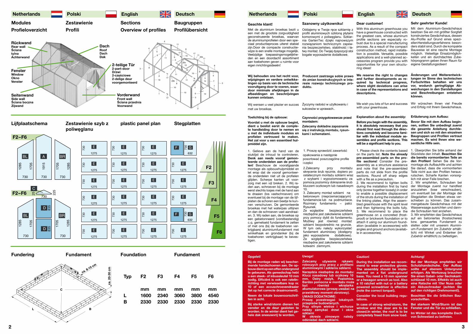
mm mm mm mm mmL 1600 2340 3060 3800 4540B 2330 2330 2330 2330 2330
Sehr geehrter Kunde!Mit dem Aluminium-Gewächshausbesitzen Sie ein mit größter Sorgfaltkonstruiertes Gewächshaus, dessenAlu-Profile auf Grund eines spezi-ellen Herstellungsverfahrens beson-ders stabil sind. Durch die kompakteBauweise ist eine rasche Montagemöglich. Vielseitige Einsatzmöglich-keiten und ein durchdachtes Zube-hörprogramm geben Ihnen Raum füreigene Gestaltungsideen!
Änderungen und Weiterentwick-lungen im Sinne des technischen Fortschrittes behalten wir unsvor, wodurch geringfügige Ab-weichungen in den Darstellungenund Beschreibungen entstehen können.
Wir wünschen Ihnen viel Freudeund Erfolg mit Ihrem Gewächshaus.
Erläuterung zum Aufbau:
Bevor Sie mit dem Aufbau begin-nen, sollten Sie unbedingt zuerst die gesamte Anleitung durchle-sen und sich so mit den einzelnen Baugruppen und Profilen vertraut machen. Es wird Ihnen eine we-sentliche Hilfe sein.
1. Überprüfen Sie bitte anhand derStückliste den Inhalt. Beachten Sie die bereits vormontierten Teile anden Profilen! Sehen Sie die Vor-montage als Aufbauhilfe und achtenSie darauf, dass die vormontiertenTeile nicht aus den Profilen heraus-rutschen. Scharfe Kanten vorsorg-lich mit einer Feile brechen.2. Wir empfehlen, Schrauben beider Montage zuerst nur handfestanzuziehen (lose verschrauben),um eventuell bei der Montage derStegplatten die Streben etwas ver-schieben zu können. Das zusam-mengebaute Gewächshaus mit derWasserwaage ausrichten und dann-die Schrauben fest anziehen. 3. Wir empfehlen das Gewächshausauf ein betoniertes (frostsicheres)bzw. gemauertes Fundament zustellen oder mit unserem Alumini-um-Fundament (im Zubehör erhält-lich) mit Winkel und Erdanker (imZubehör erhältlich) zu befestigen.
Achtung!
Bei der Montage empfehlen wir Schutzhandschuhe. Der Aufbau sollte auf ebenem Untergrunderfolgen. Als Werkzeug brauchen Sie einen Gabel- oder Sechskant-schlüssel 10 mm. Effektiv ist auch eine Ratsche mit 10er Nuss oderein Akkuschrauber (achten Sie auf den richtigen Drehmoment!).
Beachten Sie die örtlichen Bau-vorschriften.
Bei starkem Wind/Sturm ist das Fenster und die Tür zu schließen.
Im Winter ist das komplette Dachvon Schneelast zu befreien.
Dear customer!With this aluminum greenhouse youhave a greenhouse constructed withthe greatest care, whose aluminumprofile sections are especially ro-bust due to a special manufacturingprocess. As a result of the compactconstruction method, rapid installa-tion is possible. Versatile, possibleapplications and a well-planned ac-cessories program provide you withopportunities for your own structu-ring ideas!
We reserve the right to changesand further developments as re-quired by technical progress, where slight deviations can arisein case of the representations anddescriptions.
We wish you lots of fun and successwith your greenhouse.
Explanation about the assembly:
Before you begin with the assembly, it is absolutely necessary that youshould first read through the direc-tions completely and become fami-liar with the individual module as-semblies and profile sections. This will be a significant help to you.
1. Please check the contents basedon the parts list. Note the alreadypre-assembled parts on the pro-file sections! Consider the pre-assembly as a structure assistanceand note that the pre-assembledparts do not slide from the profilesections. Round off sharp edgeswith a file as a precaution.2. We recommend to tighten boltsduring the installation first by handonly (screw together loosely) in orderto enable a possible displacementof the struts during the installation ofthe linking plates. Align the assem-bled greenhouse with the spirit leveland then tightening the bolts fully. 3. We recommend to place thegreenhouse on a concreted (frost-proof) or brickwork foundation or toattach it using our aluminum found-ation (available in accessories) withangles and ground anchors (availab-le in accessories).
Caution!
During the installation we recom-mend to wear protective gloves.The assembly should be imple-mented on a flat undergroundbase. You need a 10 mm spanneror a hexagon wrench as tool. Also a 10 ratchet with nut or a batterypowered screwdriver is effective(note the correct torque!).
Consider the local building regu-lations.
In case of strong wind/storm, the window and the door are to beclosed.In winter, the roof is to becompletely freed from snow load.
Producent zastrzega sobie prawodo zmian konstrukcyjnych w inte-resie rozwoju technicznego pro-duktu.
(
Geachte klant!
Wij behouden ons het recht voor,wijzigingen en verdere ontwikke-lingen op basis van de technischevooruitgang door te voeren, waar-door minimale afwijkingen in deafbeeldingen en beschrijvingenkunnen ontstaan.
Wij wensen u veel plezier en succesmet uw broeikas.
Toelichting bij de opbouw:
Voordat u met de opbouw begint,dient u beslist eerst de comple-te handleiding door te nemen enu met de individuele modules enprofielen vertrouwd te maken. Het zal voor u een essentieel hul-pmiddel zijn.
1. Gelieve aan de hand van destuklijst de inhoud te controleren.Denk aan reeds vooraf gemon-teerde onderdelen aan de profie-len! Beschouw de voorafgaandemontage als opbouwhulpmiddel enlet erop dat de vooraf gemonteer-de onderdelen niet uit de profielenglijden. Scherpe kanten uit voor-zorg met een vijl breken. 2. Wij ra-den aan, schroeven bij de montageeerst slechts losjes met de hand aante draaien (los vastschroeven) omeventueel bij de montage van de lijf-platen de schoren een beetje te kun-nen verschuiven. De gemonteerdebroeikas met het waterpas uitlijnenen dan de schroeven vast aandraai-en. 3. Wij raden aan, de broeikas opeen gebetonneerd (vorstbestendig)c.q. gemetseld fundament te zettenof met ons (bij de toebehoren ver-krijgbare) aluminiumfundament metwinkelhaak en grondanker (bij detoebehoren verkrijgbaar) te beves-tigen.
Opgelet!
Bij de montage raden wij bescher-mende handschoenen aan. De op-bouw dient op een effen ondergrondte gebeuren. Als gereedschap hebt u een steek- of inbussleutel 10 mmnodig. Efficiënt is ook een ratelin-richting met verwisselbare kop nr.10 of een accuschroevendraaier(let op het correcte draaimoment!).
Neem de lokale bouwvoorschrif-ten in acht.
Bij sterke wind/storm dienen het venster en de deur gesloten teworden. In de winter dient het ge-hele dak sneeuwvrij te worden.
Rückwand
Fenster
Seitenwand
Dach
2-teilige Tür
Vorderwand
1285
1705
1705 1
195
1285
1705
730
1285
1285
1705
1705
1915
730 730
BL A BR
730
1275
E
730
730 G730
632
F
730
1275
E
730
1275
E
730
1275
E
730
1275
E
730
1275
E
730
1275
E
730
1275
E
730
1275
E
730
1275
E
730
1275
E
730
1275
E
730
1275
E
730
1275
E
730
1275
E73
0
1275
E
730
1275
E
730
1275
E
730
1275
E
730
1275
E
730
1275
E
730
730 G730
632
F
730
1275
E
F2-F6
F2
F3
F4
F5
F6
F2-F6
730 730
730
25 225
1285
1285
1705
1705
835
835
BL
D
D
BR
C
Met de aluminium broeikas bezit ueen met de grootste zorgvuldigheidgeconstrueerde broeikas, waarvande aluminiumprofielen door een spe-ciaal productieproces uiterst stabielzijn.Door de compacte constructie-wijze is een snelle montage mogelijk.Veelzijdige toepassingsmogelijkhe-den en een doordacht assortimentaan toebehoren geven u ruimte vooreigen inrichtingsideeën!
Modules Zestawienie Sections Baugruppen
Profieloverzicht Profili Overview of profiles Profilübersicht
RoofDachDak
WindowOknoVenster
Side wallŚciana bocznaZijwand
2-part-doorDrzwi2-częściowe2-delige deurvoorgemonteerd
Front wallŚciana przedniaVoorwand
Lijfplaatschema Zestawienie szyb z plastic panel plan Stegplattenpoliwęglanu
Rear wallŚcianatylnaAchterwand
Fundering Fundament Foundation Fundament
Szanowny użytkowniku!
Zalecamy dokładne zapoznaniesię z instrukcją montażu, rysun-kami i schematami.
Życzymy radości w użytkowaniu i
sukcesów w uprawach..
Czynności przygotowawcze przedmontażem:
Oddajemy w Twoje ręce szklarnię zprofili aluminiowych szkloną płytamikomorowymi z poliwęglanu. Szklar-nia GartenTec dzięki najnowszymrozwiązaniom technicznym zapew-nia bezpieczeństwo, stabilność i ła-twy montaż. Do Twojej dyspozycji stoibogate wyposażenie dodatkowe.
Uwaga!
Narzędzia niezbędne do montażu:Klucz nasadowy lub oczkowy 10 mm, Ostry nożyk, Poziomica.Bardzo pomocna w montażu możebyć również wkrętarka akumulatorowa (proszę uważać na
Zalecamy używanie rękawic roboczych przy pracy z profilami aluminiowymi i szkleniu szklarni.
prawidłowy moment obrotowy).UWAGI DODATKOWE:Proszę przestrzegać lokalnych przepisów budowlanych.Przy silnym wietrze i wichurze należy zamykać drzwi i okna szklarni W okresie zimowym należy odśnieżać dach szklarni.
2.Zalecamy przy montażu
10.3. Zalecamy montaż szklarni nabetonowym (nieprzemarzającym)fundamencie lub na podmurówce.Rozmiary fundamentu – patrzRysunek. Ze względów bezpieczeństwaniezbędne jest zakotwienie szklarniprzy pomocy dybli do fundamentu.Możliwy jest również montaższklarni bezpośrednio na gruncie.W tym celu należy wykorzystaćfundament aluminiowy (dostępnyjako wyposażenie dodatkowe).Ze względów bezpieczeństwaniezbędne jest zakotwienie szklarnikotwami ziemnymi.
skręcenie śrub ręcznie, dopiero poostatecznym montażu szklarni wraz z szybami i wypoziomowaniu zapomocą poziomicy dokręcenie śrubkluczem oczkowym lub nasadowym
opakowania a następnie posortować poszczególne profile
1. Proszę sprawdzić zawartość
i części

4
Deutsch EnglishFran Netherlands
5
200 cm
227 cm 154 cm
130 cm
F2200 cm
227 cm228 cm
130 cm
F3200 cm
227 cm300 cm
130
F4200 cm
227 cm374 cm
130 cm
F5200 cm
227 cm448 cm
130 cm
F6
Bodenprofil Seitenwand Profil podłogowy ściany bocznej•Bodemprofiel zijwand • Side wall floor profile section
Bodenprofil Front- u. Rückwand Profil podłogowy ściany przedniej i tylnej•Bodemprofiel voor- en achterwand • Front and back wall floor profile section
Eckprofil Profil narożnikowy• Hoekprofiel • Corner profile section
Giebelprofil Dach Profil szczytowy dachu• Gevelprofiel dak • Roof gable profile section
a) Querstrebe b) Türquerstrebe a) Zastrzał b) Zastrzał drzwiowy (z uszczelką)• a) Dwarsbalk b) Deurdwarsbalk • a) Crossbeam b) Door crossbeam
Strebe Front- u. Rückwand Słupek drzwiowy przedniej i tylnej ściany• Schoor voor- en achterwand • Front and back wall strut
Türscharnierstrebe Słupek drzwiowy z zawiasem drzwi • Deurscharnierschoor • Door hinge strut
Regenrinne Rynienka deszczowa • Regengoot • Rainwater gutter
Firstprofil Profil kalenicy • Nokprofiel • Roof ridge profile section
Seitenstrebe Słupek boczny• Zijschoor • Side strut
Dachstrebe Słupek dachowy • Dakschoor • Roof strut
Fensterquerstrebe Zastrzał okienny • Vensterdwarsbalk • Window crossbe-am
Fenster Okno kompletne • Venster • Window
a) Türteile b) Türdrückergarnitur a) części drzwi b) klamki drzwi • a) Deuronderdelen b) Deurklinkgarnituur • a) Door parts b) Door handle fitting
Bodeneckverbinder Łącznik podłogowy narożnikowy • Bodemhoekverbindingsstuk • Floor corner connector
Giebel- und Firstverbinder Łącznik szczytowy i kalenicowy • Gevel- en nokverbindingsstuk • Gable and roof ridge connector
Strebenverbinder Łączniki z nakrętkami• Schoorverbindingsstuk • Strut connector
Strebenhalter gerade schwarz (ohne Nase) Łącznik prosty czarny (bez noska)• Schoorho-uder recht zwart (zonder neus) • Strut bracket straight, black (without nose)
Strebenhalter gerade weiß (mit Nase) Łącznik prosty biały (z noskiem)
• Schoorhouder recht wit (met neus) • Strut bracket straight, white (with nose)
Strebenverbinder gebogen schwarz (ohne Nase) Łącznik łukowy czarny (bez noska) • Schoorverbindingsstuk gebogen zwart (zonder neus) • Strut connector curved, black (without nose)
Stebenverbinder gebogen weiß (mit Nase) Łącznik łukowy biały (z noskiem) • Schoorverbindingsstuk gebogen wit (met neus) • Strut connector curved, white (with nose)
Stückliste Zestawienie części Stuklijst Bill of Material
English NetherlandsPolski Deutsch
Länge Stück Länge StückLengte stuk(s)Length Piece
Länge Stück Länge StückDługość Ilość sztukLengte stuk(s)Length Piece
Länge StückDługość Ilość sztukLengte stuk(s)Length Piece
2280 2 1500 4 1500 2 2240 42240 2
2 2220 2 2220 2 2220 2 2220 2 2220 2
3 1260 4 1260 4 1260 4 1260 4 1260 4
4 1260 4 1260 4 1260 4 1260 4 1260 4
5 a b 750 2 750 2 750 2 750 2 750 2
6 1680 3 1680 3 1680 3 1680 3 1680 3
7 1680 1 1680 1 1680 1 1680 1 1680 1
8 1540 2 2280 2 1500 4 1500 2 2240 4
2240 2
9 1540 1 2280 1 1500 2 1500 1 2240 22240 1
10 1260 2 1260 4 1260 6 1260 8 1260 10
11 1260 2 1260 4 1260 6 1260 8 1260 10
12 715 1 715 1 715 1 715 2 715 2
13 1 1 1 2 2
14 a b 2 2 2 2 2
15 4 4 4 4 4
16 6 6 6 6 6
17 - - 5 5 5
18 a 2 2 4 6 6
18 b 6 8 8 10 12
19 a 2 2 5 5 5
19 b 3 6 6 9 12
1 1540 2
Lengte stuk(s)Length Piece
Długość Ilość sztuk P
Length Piece
Długość
Długość Ilość sztuk Długość Ilość sztuk
Bezeichnung Oznaczenie • Omschrijving • Designation Lengte stuk(s)

6
Deutsch EnglishFrançai Netherlands
7
Stückliste Zestawiene części Stuklijst Bill of Material
200 cm
227 cm 154 cm
130 cm
F2200 cm
227 cm228 cm
130 cm
F3200 cm
227 cm300 cm
130
F4200 cm
227 cm374 cm
130 cm
F5200 cm
227 cm448 cm
130 cm
F6
Szyby z poliwęglanu
a) Windverband a) Zastrzał wiatrowy • a) Windverband • a) Transverse brace
b) Seitenverbinder b) Zastrzał boczny• b) Zijverbindingsstuk • b) Side connector
c) Dachstrebenverbinder c) Zastrzał dachowy • c) Dakschoorverbindingsstuk • c) Roof strut connector
d) Zusatzverbinder d) Zastrzał dodatkowy • d) Extra verbindingsstuk • d) Additional connector
Regenablauf grau (rechts + links = 1 Paar) Odpływ rynienki deszczowej - szary (1 para=strona lewa i prawa) • Regenwaterput grijs (rechts + links = 1 paar) • Rain run-off, gray (right + left = 1 pair)
Firstabdeckung grau Dekiel profilu kalenicy - szary • Nokafdekking grijs • Ridge cover, gray
Türhalter-unten grau Blokada dolna drzwi - szary • Deurhouder-onderaan grijs • Door holder below, gray
Unterlegscheibe Türmitte grau Przekładka środkowa do zawiasów drzwi - szary •
Clipprofil Giebel Profil zatrzaskowy dach - szczyt • Clipprofiel gevel • Gable clip profile
section
Clipprofil Seite (Regenrinne) Profil zatrzaskowy boczny (do Rynienki deszczowej) •
Clipprofiel zijkant (regengoot ) • Side clip profile section (rainwater gutter)
M6-Schraube Śruby M6 • M6-schroef • M6 bolt
Rhombusschraube Śruba rombowa• Ruitschroef • Rhombus bolt
Dachfensterschraube mit Schutzkappe Śruba blokująca okna dachowego
z żółtym kapturkiem• Dakvensterschroef met beschermkapje • Rooflight bolts with protect-ive cap,
Mutter mit Flansch (*je 3 pro Strebenverbinder) Nakrętka z podkładką (po
3 na łącznik)• Moer met flens (*telkens 3 per schoorverbindingsstuk• Nut with flange
Onderlegplaatje deurmidden grijs • Door middle underlay plate, gray
Fensteröffner manuell schwarz Otwieracz okna z ząbkami– czarny• Vensteropener handmatig zwart • Window opener manual,
Schutzklappe klar Narożnik ochronny – przeźroczysty • Bes-chermkapje transparant • Protective cap, transparent
Schutzprofil Gummi Profil ochronny gumowy • Beschermprofiel rubber • Rubber protective profile section
Rückseite mitte Strona tylna środek• Achterzijde midden • Rear side middle
Rück- & Frontseite seitlich Strona tylna i przednia bok • Achter- & voorzijde zijdelings • Side rear & front side laterally
Rück- & Frontseite seitlich Strona tylna i przednia bok • Achter- & voorzijde zijdelings • Side rear & front side laterally
Front Spitz Strona przednia wierzchołek • Voorzijde uiteinde • Front tip
Türteile vormontiert Drzwi zmontowane• Deuronderdelen vooraf gemonteerd • Door parts pre-assembled
Seite und Dach Boki i Dach• Zijkant en dak • Side and roof
Fenster vormontiert Okno zmontowane • Venster vooraf gemonteerd • Window pre-assembled
Fensterdachfeld Szyba pola okna • Vensterdakveld • Window roof area
English NetherlandsPolski Deutsch
Länge StückDługość Ilość sztukLengte stuk(s)Length Piece
Länge StückDługość Ilość sztukLengte stuk(s)Length Piece
Länge StückDługość Ilość sztukLengte stuk(s)Length Piece
Länge StückDługość Ilość sztukLengte stuk(s)Length Piece
Länge StückDługość Ilość sztukLengte stuk(s)
20 a 355 4 355 4 355 - 355 - 355 -
20 b 260 - 260 - 260 2 260 4 260 6
20 c 465 - 465 - 465 1 465 2 465 3
20 d 810 - 810 - 810 8 810 8 810 8
21 4 4 4 4 4
22 2 2 2 2 2
23 1 1 1 1 1
24 1 1 1 1 1
25 710 4 710 6 710 8 710 10 710 12
1260 4 1260 4 1260 4 1260 4
2220 2 2220 2 2220 2 2220 4710 2 710 4
28 M6x10 62 M6x10 70 M6x10 74 M6x10 84 M6x10 92
29 RHx10 12 RHx10 12 RHx10 26 RHx10 34 RHx10 40
30 M6x70 2 M6x70 2 M6x70 2 M6x70 4 M6x70 4
31 M6 76 M6 84 M6 117 M6 137 M6 151 - - 15* 15* 15*
32 420 1 420 1 420 1 420 2 420 2
33 41 4 4 4 4
34 4 4 4 4 4
A 1915x730 1 1915x730 1 1915x730 1 1915x730 1 1915x730 1BL 1705x730 2 1705x730 2 1705x730 2 1705x730 2 1705x730 2BR 1705x730 2 1705x730 2 1705x730 2 1705x730 2 1705x730 2C 225x730 1 225x730 1 225x730 1 225x730 1 225x730 1D 835x730 2 835x730 2 835x730 2 835x730 2 835x730 2E 1275x730 7 1275x730 11 1275x730 15 1275x730 18 1275x730 22F 650x730 1 650x730 1 650x730 1 650x730 2 650x730 2G 632x730 1 632x730 1 632x730 1 632x730 2 632x730 2
Clipprofil Dach unten (Regenrinne) Profil zatrzaskowy dach- dolny (do Rynienki deszczowej)
• Clipprofiel dak onderaan (regengoot ) • Roof clip profile section below (rainwater gutter)
26 1260 4
27 1480 2
Bezeichnung Oznaczenie • Omschrijving • Designation Length Piece

8
Deutsch EnglishPolski Netherlands
9
A
Montageder Bodenprofile
Einige Montageteile sind bereitsan den Profilen vormontiert.
Die Form der Bodenprofile istidentisch, beachten Sie die Län-ge um die Profile zu definieren.
Beachten Sie, dass das Bo-denprofil Seitenwand, das Bo-denprofil Front- und Rückwandüberlappen muss!
Installation of the floorprofile sections
Some components are alreadypre-assembled on the profilesections.The form of the floor profile sec-tions is identical, note that youdefine the length around theprofile sections.Note that the side wall floor profile section must overlap thefront and rear wall floor profile section!
Montaż profili podło-
gowych
Wybrane elementy są wstępniezmontowane do profili. Przekrójprofili jest identyczny, proszęuważać zatem i dobierać profilezgodnie z długością.
Montage van debodemprofielen
Enkele montageonderdelen zijnreeds vooraf aan de profielengemonteerd.De vorm van de bodemprofielenis identiek, let op de lengte omde profielen te definiëren.
Neem in acht dat het bodem-profiel zijwand het bodemprofielvoor- en achterwand moet over-lappen!
A 1.Bodenseitenprofileverbinden (nur F4 bis F6)
Die zweiteiligen Bodenprofile Sei-tenwand (1) mittels Strebenverbin-der (17) zusammenstecken undmit Muttern (31) fest verschrau-ben. Seitenteilstrebenhalter (18a)in der Mitte anbringen.
A 1. connect floor side profile sections (only F4 to F6)
Interconnect the two-part floor profiles side wall (1) by means ofstrut connector (17) and screwtightly together with nuts (31).Attach side part strut bracket(18a) in the middle.
Złóż dwuczęściowy profil podło-gowy (1) razem za pomocąłącznika (17) i skręć mocno zapomocą nakrętek (31). Przykręćw środku Łącznik prosty czarny18a (bez noska).
A 1.Bodemzijprofielenverbinden (enkel F4 tot F6)
De tweedelige bodemprofie-len zijwand (1) door middelvan schoorverbindingsstuk (17)aaneenspelden en met moe-ren (31) vast dichtschroeven.Zijstukschoorhouder (18a) in hetmidden aanbrengen.
A 2.Bodenprofileaufstecken
Bodeneckverbinder (15) auf Bo-denprofil Seitenwand (1) auf-stecken. Dann das BodenprofilFront- und Rückwand (2) aufden Eckverbinder aufschiebenbis es am Bodenprofil-Seiten-wand (1) ansteht.
Tip: Richtig! Das Seitenprofil über-lappt das Frontprofil!
A 2. insert floor profile sections insert
Insert floor corner connectors (15) onto side wall floor profile section (1). Then slide the frontand rear wall floor profile sec-tion (2) onto the corner connec-tor until it is at the floor profile section side wall (1).
Tip: Correct! The side profile section overlaps the front profile section!
A 2. Łączenie profili podłogo-wych
Łącznik podłogowy narożnikowy(15) wsuń w profil podłogowyboczny (1). Następnie wsuń profilpodłogowy przedni i tylny (2) naŁącznik podłogowy narożnikowy.
Wskazówka: Profil podłogowyboczny przekracza profil podło-gowy przedni.
A 2.Bodemprofielenopsteken
Bodemhoekverbindingsstuk (15) op bodemprofiel zijwand (1)steken. Dan het bodemprofielvoor- en achterwand (2) op hethoekverbindingsstuk schuiventot het tegen de bodempro-fielzijwand (1) staat.
Tip: Correct! Het zijprofiel over-lapt het voorprofiel!
A 3.Bodenprofile 1 und 2 ver-schrauben
Mittels Schrauben (28) und Muttern (31) den Bodeneckverbinder (15) in allen vier Ecken mit denProfilen (1 und 2) verschrauben.
Tip: Falsch! Das Seitenprofil überlappt nicht.
A 3.Screw together floor profi-le sections 1 and 2
Screw the floor corner connec-tor (15) with the profile sections(1 and 2) by means of bolts (28)and nuts (31) in all four corners.
Tip: Incorrect! The side profile section does not overlap.
A 3.Skręcanie profili podło-gowych
Łącznik podłogowy narożnikowy(15) skręć we wszystkich 4narożnikach za pomocą śrub (28)i nakrętek (31) wraz z profilamipodłogowymi (1 i 2).
Wskazówka: Nieprawidłowymontaż. Profil boczny niedochodzi do końca łącznikanarożnikowego
A 3.Bodemprofielen 1 en 2 vastschroeven
Door middel van schroeven (28)en moeren (31) het bodemhoek-verbindingsstuk (15) in alle vierhoeken met de profielen (1 en 2)vastschroeven.
Tip: Fout! Het zijprofiel over-lapt niet.
A 1 A 2
1
18a
17
1 2
15
A1
A2
1. Bodenprofil SeitenwandSide wall floor profile section
Profil podłogowy boczny
Bodemprofiel zijwand
2. Bodenprofil Front und RückwandFloor profile section of front and back wall
Profil podłogowy przedni i tylny
Bodemprofiel voor- en achterwand
1
2
1 2
1
1
2
2
1
1
2
2
Bild: rechts vorne / links hintenIllustration: right in front / left behindFigure : avant droite / arrière gauche
Afbeelding: rechts vooraan / links achteraan
Bild: rechts vorne / links hintenIllustration: right in front / left behindFigure : avant droite / arrière gauche
Afbeelding: rechts vooraan / links achteraan
links vorneleft in front
avant gaucheLinks vooraan
28
31
Tip:
Tip: 4
7
31
A 1.Łączenie profili podło-gowych bocznych (dotyczytylko modeli F4 -F6

10
Deutsch English Polski Netherlands
11
B
Montage der Eck-und Giebelprofile
Eckprofil (3) und Giebelprofil (4)sind sich sehr ähnlich, achtenSie auf die roten Kreise auf denProduktfotos.
Einige Montageteile sind bereitsan den Profilen vormontiert.
Installation of the cornerand gable profile sections
Corner profile section (3) andgable profile section (4) are verysimilar, note the red rings on theproduct photographs.
Some components are alreadypre-assembled on the profilesections.
Montaż profilinarożnikowych i profiliszczytowych dachu
Profil narożnikowy (3) i profilszczytowych dachu (4) sąbardzo podobne, proszę zauważyćszczegóły zaznaczone czer-wonym kółkiem na fotografiach.Wybrane elementy są wstępniezmontowane do profili.
Montage van de hoek-en gevelprofielen
Hoekprofiel (3) en gevelpro-fiel (4) gelijken sterk op elkaar,let op de rode cirkels op deproductfoto’s.
Enkele montageonderdelen zijnreeds vooraf aan de profielengemonteerd.
B 1.Montage Eckprofile
Die Eckprofile (3) werden aufden bereits montierten Boden-eckverbinder (15) aufgestecktund mit Schrauben (28) undMuttern (31) verschraubt.
Tip: Lassen Sie die Schrauben von oben in das Profil fallen.
B 1.Installation of corner profile section
The corner profile sections (3)are inserted onto the already as-sembled floor corner connector (15) and screwed with bolts (28)and nuts (31).
Tip: Allow the bolts to fall from above into the profile section.
B 1.Łączenie profilinarożnikowych
Wsuń Profil narożnikowy (3) nazmontowany Łącznik podło-gowy narożnikowy (15) i skręćza pomocą śrub (28) i nakrętek(31).
Wskazówka: Wsuń łby śrubsześciokątnych przez górnączęść profilu
B 1.Montage hoekprofielen
De hoekprofielen (3) worden ophet reeds gemonteerde bodem-hoekverbindingsstuk (15) gezeten met schroeven (28) en moe-ren (31) vastgeschroefd.
Tip: Laat de schroeven van bo-ven in het profiel vallen.
B 2.Giebelprofile im Firstverbinden
Giebelprofile (4) bis zum Ansch-lag auf den Firstverbinder (16)stecken und verschrauben.
Die Lasche mit der Einkerbung fürdas Firstprofil zeigt nach innen.
B 2.Connect gable profile sec-tions in the roof ridge
Insert gable profile sections (4)up to the stop collar on the roofridge connector (16) and screwtogether.
The strap with the notch for theroof ridge profile section is turnedto inside.
Wsuń Profil szczytowy dachu (4)do oporu na Łącznik kalenicowy iskręć za pomocą śrub (28) i na-krętek (31).
B 2.Gevelprofielen in de nokverbinden
Gevelprofielen (4) tot aan deaanslag op het nokverbindings-stuk (16) zetten en vastschroe-ven.
De lasplaat met de inkeping voorhet nokprofiel wijst naar binnen.
B 3.Eck- und Giebelprofileverbinden
Giebelverbinder (16) auf die Gie-belprofile (4) stecken und ver-schrauben. Danach die Giebel-verbinder (16) auf das Eckprofil (3) aufschieben und mit Schrau-ben (28) und Muttern (31) ver-schrauben. Die Lasche mit derEinkerbung für das Firstprofilzeigt nach innen.Tip: Achten Sie auf die richtige Lasche beim aufstecken.
B 3.Connect corner and gableprofile sections
Insert gable connectors (16) ontothe gable profile sections (4) andscrew together. After that, insertthe gable connectors (16) ontothe corner profile section (3) andscrew together with bolts (28)and nuts (31). The strap with thenotch for the roof ridge profilesection is turned to inside.Tip: Note the correct strap withinsertion.
Łącznik szczytowy (16) wsuń wProfil szczytowy dachu (4) i skręćza pomocą śrub (28) i nakrętek(31). Następnie Łącznik szczytowy(16) wsuń w Profil narożnikowy(3) i skręć za pomocą śrub (28) inakrętek (31).
Wskazówka: Uważaj naprawidłowe wsunięcie łącznikaw profil
B 3.Hoek- en gevelprofielen verbinden
Gevelverbindingsstuk (16) opde gevelprofielen (4) zetten envastschroeven. Daarna de ge-velverbindingsstukken (16) ophet hoekprofiel (3) schuiven enmet schroeven (28) en moeren (31) vastschroeven. De lasplaatmet de inkeping voor het nok-profiel wijst naar binnen.Tip: Let op de correcte lasplaatbij het opsteken.
3
4
28
31
16
16
A 2
B1
3. EckprofilCorner profile section
Profil narożnikowy
Hoekprofiel
4. GiebelprofilGable profile section
Profil szczytowy dachu
Gevelprofiel
B3
B2
28
31
28
31
Tip:
Tip:
B 2.Łączenie profiliszczytowych dachu wkalenicy
B 3.Łączenie profili narożnikowych i szczytowych dachu

12
Deutsch EnglishPolski Netherlands
13
Montage derRückwand
Entscheiden Sie nun auf wel-cher Seite der Eingang des Ge-wächshauses sein soll.
Danach beginnen Sie mit derRückwandmontage.
Einige Montageteile sind bereitsan den Profilen vormontiert.
Installation ofback wall
Decide now on which side theentrance of the greenhouseshould be.
After that, begin with the backwall installation.
Some components are alreadypre-assembled on the profilesections.
Montaż ścianytylnej
Wybrane elementy są wstępniezmontowane do profili.
Montage van deachterwand
Beslis nu aan welke zijde de in-gang van de broeikas dient tezijn.
Daarna begint u met de monta-ge van de achterwand.
Enkele montageonderdelen zijnreeds vooraf aan de profielengemonteerd.
C 2.Rückwandstrebemontieren
Beide Rückwandstreben (6) mitden vormontierten Strebenhal-tern (18b) unten am Bodenprofilmit Schrauben (28) und Muttern (31) lose verschrauben.
Tip: Hier die Außenansicht der Rückwandstrebe.
C 2.Mount backwall strut
Screw both back wall struts (6)with the pre-assembled strutbrackets (18b) below looselyto the floor profile section with bolts (28) and nuts (31).
Tip: Here is the outside viewof the back wall strut.
C 2.Montaż słupków ścianytylnej
Obydwa Słupki drzwiowe (6) zewstępnie zmontowanymŁącznikiem prostym białym(18b) (z noskiem) skręć luźnoza pomocą śrub (28) i nakrętek(31).
Wskazówka: na fotografiiwidok z zewnątrz słupkówściany tylnej.
C 2.Achterwandschoormonteren
Beide achterwandschoren (6)met de vooraf gemonteerdeschoorhouders (18b) ondera-an aan het bodemprofiel metschroeven (28) en moeren (31)los vastschroeven.
Tip: Hier het buitenaanzicht van de achterwandschoor.
C 1.Querstrebemontieren
Querstrebe (5a) waagerecht mitder Lasche von innen nach au-ßen einsetzen und mit dem Gie-belprofil verschrauben.
Die Schrauben (28) werden vomGiebel in das Profil eingescho-ben und mit den Muttern (31)verschraubt.
C 1.Mountcrossbeam
Insert crossbeam (5a) horizon-tal with the strap from inside tooutside and screw together withthe gable profile section.
The bolts (28) are inserted fromthe gable into the profile sectionand screwed together with thenuts (31).
C 1.Łączenie profilinarożnikowych
Zastrzał (5a) umieść w pozycjipoziomej i przykręć do profiluszczytowego dachu.
Śruby (28) wprowadzonewcześniej przez koniec profiluprzykręć za pomocą nakrętek(31).
C 1.Dwarsbalkmonteren
Dwarsbalk (5a) waterpas met delasplaat van binnen naar buitenaanbrengen en aan het gevel-profiel vastschroeven.
De schroeven (28) worden vande gevel in het profiel gescho-ven en met de moeren (31)vastgeschroefd.
C 3.Streben verbinden
Querstrebe (5a) von innen mitden Rückwandstreben (6) festverschrauben.
C 3.Connect struts
Screw crossbeam (5a) tightly to-gether with the back wall struts (6) from inside.
C 3.Łączenie słupków ścianytylnejZastrzał (5a) skręć mocno zeSłupkiem drzwiowym (6) zapomocą śrub (28) i nakrętek (31).
C 3.Schoren verbinden
Dwarsbalk (5a) van binnenuitmet de achterwandschoren (6)vast dichtschroeven.
18b
6
28
28
31
28
31
5a
C5a. Querstrebe Cross-
beam
Zastrzał
Dwarsbalk
6. RückwandstrebeBack wall strut
Słupek
Achterwandschoor
C2
C1 / C3
Tip:
31
Następnie rozpocznij budowęściany tylnej szklarni.
Sprawdź najpierw naschematach, po której stronie,patrząc od wejścia powinny byćwybrane elementy.

14
Deutsch EnglishPolski Netherlands
15
Montage Eingang
Das Scharnier der Türschar-nierstrebe (7) muss immer nachaußen zeigen.
Entscheiden Sie sich vor derMontage der Türscharnierstrebe,ob die Tür von rechts nach linksoder andersherum geöffnet wer-den soll. Die Türscharnierstrebehält die Tür.Einige Montageteile sind bereitsan dem Profilen vormontiert.
Entrance assembly
The hinge of the door hingestrut (7) must always be turnedto outside.
Montage ingang
Het scharnier van de deurschar-nierschoor (7) moet altijd naarbuiten wijzen.
D 2.Türscharnierstrebeanbringen
Türscharnierstrebe (7) mit demvormontierten Strebenhalter (18b)unten lose verschrauben.
Türscharnierstrebe (7) mit derTürquerstrebe (5b) oben von in-nen verschrauben.
Frontwandstrebe (6) wie Tür-scharnierstrebe einsetzen.
D 2.Attach door hinge strut
Screw door hinge strut (7) togetherloosely with the pre-assembledstrut bracket (18b) below.
Screw door hinge strut (7) to-gether with the door crossbeam(5b) above from inside.
Insert front wall strut (6) as doorhinge strut.
D 2.Deurscharnierschooraanbrengen
Deurscharnierschoor (7) met devooraf gemonteerde schoor-houder (18b) onderaan losdichtschroeven.Deurscharnierschoor (7) met dedeurdwarsbalk (5b) bovenaanvan binnenuit vastschroeven.
Voorwandschoor (6) zoals deur-scharnierschoor aanbrengen.
D 1.Türquerstrebemontieren
Türquerstrebe (5b) waagerechtmit der Lasche nach außen ein-setzen und mit dem Giebelprofilvon innen verschrauben.
Die Schrauben (28) werden vomGiebel in das Profil eingescho-ben und mit den Muttern (31)verschraubt.
D 1.Mount doorcrossbeam
Insert door crossbeam (5b) hori-zontal with the strap outside andscrew together with the gableprofile section from inside.
The bolts (28) are inserted fromthe gable into the profile sectionand screwed together with thenuts (31).
D 1.Deurdwarsbalkmonteren
Deurdwarsbalk (5b) waterpasmet de lasplaat naar buiten aan-brengen en met het gevelprofielvan binnenuit vastschroeven.
De schroeven (28) worden vande gevel in het profiel gescho-ven en met de moeren (31)vastgeschroefd.
D 3.Türhalter-Unteneinsetzen
Türhalter aus der Schablone*ausbrechen oder mit einem(Cutter-) Messer ausschneiden.*Kunststoffgussteil
An der Türscharnierstrebe (7)unten die Schraube lösen unddas Profil etwas anheben. Tür-halter (23) unten einschieben undSchraube wieder anziehen.
D 3.Insert door holder below
Break door holders out from thetemplate* or cut out with a boxcutter*Plastic die-cast part
Loosen the bolts on the doorhinge strut (7) below and raisethe profile section a little. Insertdoor holder (23) below and tigh-ten bolts again.
D 3.Deurhouder - onderaanaanbrengen
Deurhouder uit de sjabloon*uitslaan of met een (cutter)mesuitsnijden.*Kunststofgietstuk
Aan de deurscharnierschoor (7)onderaan de schroef losdraaien enhet profiel een beetje optillen. Deur-houder - (23) onderaan inschuivenen schroef weer aandraaien.
18b
7
23
28
31
28
31
5b
DD1 / D2
5b. Türquerstrebe
7. Türscharnierstrebe
D2 / D3
6. Frontwandstrebe
6
22
24
23
22
Montaż wejścia do szklarni
Zawias drzwiowy w Słupkudrzwiowym musi być zawszeustawiony na zewnątrz.
Decide, before the installation ofthe door hinge strut, whether the door should be ope-ned from the right to the left or theother way round. The door hingestrut holds the door.Some components are alreadypre-assembled on the profilesections.
Użytkownik dokonuje wyborusposobu kierunku otwieraniadrzwi, jest on możliwy w pozycjiprawostronnej lub lewostronnej.Fotografie ukazują Słupekdrzwiowy z zawiasem drzwiumieszczony z prawej strony.Wybrane elementy są wstępniezmontowane do profili.
Beslis vóór de montage van dedeurscharnierschoor, of de deurvan rechts naar links of ander-som gepend dient te worden. Dedeurscharnierschoor houdt dedeur tegen.Enkele montageonderdelen zijnreeds vooraf aan de profielengemonteerd.
D 1.Montaż Zastrzałudrzwiowego
Śruby (28) wprowadzonewcześniej przez koniec profiluprzykręć za pomocą nakrętek (31).
D 2.Montaż Słupka drzwiowego z zawiasem drzwi
D 3.Montaż Blokady dolnejdrzwi
Door hinge strutSłupek drzwiowy z zawiasemDeurscharnierschoor
Front wall strutSłupek drzwiowyVoorwandschoor
Zastrzał drzwiowy (z uszczelką)(5b) umieść w pozycji poziomej iprzykręć od wewnątrz do profiluszczytowego dachu.
Door crossbeamZastrzał drzwiowyDeurdwarsbalk
Wytnij ostrym nożykiem Blokadędolną drzwi – szary zdostarczonego w pakiecieszablonu (odlewu z tworzywasztucznego).
Słupek drzwiowy z zawiasemdrzwi (7) skręć lekko zewstępnie zmontowanymŁącznikiem prostym białym (znoskiem) (18b). Słupekdrzwiowy z zawiasem drzwi (7)skręć na górze z Zastrzałemdrzwiowym (z uszczelką) (5b).Słupek drzwiowy (6) zmontujtak, jak wcześniej Słupekdrzwiowy z zawiasem drzwi.
Poluzuj lekko Słupek drzwiowy zzawiasem drzwi (7), podnieś go iwprowadź Blokadę dolną drzwi (23) w profilpodłogowy, przykręćponownieśrubę.
16
Deutsch English Polski Netherlands
17
MontageRegenrinne
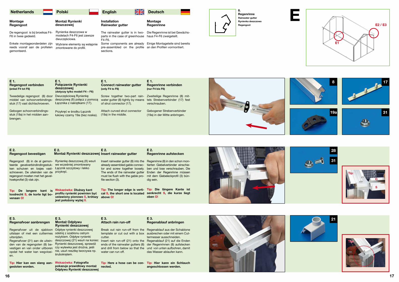
Die Regenrinne ist bei Gewächs-haus F4-F6 zweigeteilt.
Einige Montageteile sind bereitsan den Profilen vormontiert.
InstallationRainwater gutter
The rainwater gutter is in two-parts in the case of greenhouseF4-F6.Some components are alreadypre-assembled on the profilesections.
MontageRegengoot
De regengoot is bij broeikas F4-F6 in twee gedeeld.
Enkele montageonderdelen zijnreeds vooraf aan de profielengemonteerd.
E 2.Regenrinne aufstecken
Regenrinne (8) in den schon mon-tierten Giebelverbinder einschie-ben und lose verschrauben. DieEnden der Regenrinne müssenmit dem Giebeleckprofil (3) bün-dig sein.
Tip: Die längere Kante ist senkrecht S, die kurze liegt oben O!
E 2.Insert rainwater gutter
Tip: The longer edge is verti-cal S, the short one is locatedabove O!
E 2.Regengoot bevestigen
Tip: De langere kant isloodrecht S, de korte ligt bo-venaan O!
E 1.Regenrinne verbinden(nur F4 bis F6)
Zweiteilige Regenrinne (8) mit-tels Strebenverbinder (17) festverschrauben.
Gebogener Strebenverbinder(19a) in der Mitte anbringen.
E 1.Connect rainwater gutter (only F4 to F6)
Screw together two-part rain-water gutter (8) tightly by meansof strut connector (17).
Attach curved strut connector(19a) in the middle.
E 1.Regengoot verbinden(enkel F4 tot F6)
Tweedelige regengoot (8) doormiddel van schoorverbindings-stuk (17) vast dichtschroeven.
Gebogen schoorverbindings-stuk (19a) in het midden aan-brengen.
E 3.Regenablauf anbringen
Regenablauf aus der Schabloneausbrechen oder mit einem Cut-termesser ausschneiden.Regenablauf (21) auf die Endender Regenrinnen (8) aufsteckenund von unten aufbohren, damitdas Wasser ablaufen kann.
Tip: Hier kann ein Schlauch angeschlossen werden.
E 3.Attach rain run-off
Tip: Here a hose can be con-nected.
E 3.Regenafvoer aanbrengen
Tip: Hier kan een slang aan-gesloten worden.
21
28
31
178
31
EE2 / E3
8. Regenrinne
E1
19a
Tip:
Tip: Tip:
O
S
Wybrane elementy są wstępniezmontowane do profili.
E 1.Połączenie Rynienkideszczowej (dotyczy tylko modeli F4 – F6)Dwuczęściową Rynienkędeszczową (8) połącz z pomocąŁącznika z nakrętkami (17).
Przykręć w środku Łącznikłukowy czarny 19a (bez noska).
E 2.Montaż Rynienki deszczowej
E 3.Montaż Odpływu Rynienki deszczowej
Rainwater gutterRynienka deszczowaRegengoot
Rynienka deszczowa wmodelach F4-F6 jest zawszedwuczęściowa.
Montaż Rynienkideszczowej
Wskazówka: Dłuższy kantprofilu rynienki powinien byćustawiony pionowo S, krótszyjest położony wyżej 0.
Wskazówka: Fotografiapokazuje prawidłowy montażOdpływu Rynienki deszczowej
Regengoot (8) in de al gemon-teerde gevelverbindindingsstuk-ken schuiven en losjes vast-schroeven. De uiteinden van deregengoot moeten met het gevel-hoekprofiel (3) vlak zijn.
Rynienkę deszczową (8) wsuńwe wcześniej zmontowanyŁącznik szczytowy i lekkoprzykręć.
Insert rainwater gutter (8) into thealready assembled gable connec-tor and screw together loosely.The ends of the rainwater guttermust be flush with the gable pro-file section (3).
Break out rain run-off from thetemplate or cut out with a boxcutter.Insert rain run-off (21) onto theends of the rainwater gutters (8)and drill from below so that thewater can run off.
Regenafvoer uit de sjabloonuitslaan of met een cuttermesuitsnijden.Regenafvoer (21) aan de uitein-den van de regengoten (8) be-vestigen en van onder uitborenopdat het water kan wegvloei-en.
Odpływ rynienki deszczowejodetnij z szablonu ostrymnożykiem. Odpływ rynienkideszczowej (21) wsuń na koniecRynienki deszczowej, sprawdźczy wylewka jest drożna, jeślinie, usuń resztkę tworzywa np.śrubokrętem.

18
Deutsch English Polski Netherlands
19
Stegplatten einsetzen
Beachten Sie die Stegplatten-Übersicht auf Seite 2.
Stegplatten vorsichtig von obeneinschieben, keine Gewalt an-wenden. Die blaue Schutzfolie nach außen (UV-geschützte Seite)!
Achten Sie darauf, dass die Stegplatten ganz in die Nut der Bodenprofile eingeschoben werden.
Insert linking plates
Note the linking plate overviewon side 2.
Insert linking plates carefullyfrom above, do not use force.
The outside blue protective foil(UV protected side)!
Note that the linking plates isinserted completely into the slotof the floor profile sections.
Lijfplaten aanbrengen
Neem het overzicht van de lijf-platen op pagina 2 in acht.
Zonder geweld lijfplaten voor-zichtig langs boven inschuiven.
De blauwe beschermende folienaar buiten (UV-beschermde zijde)!
Let erop dat de lijfplaten hele-maal in de gleuf van de bodem-profielen geschoven worden.
F 2.Stegplatten Fronteinsetzen
Tip: Der Frontspitz (C) wird nur vom Clipprofil (26) gehalten.
F 2.Insert linkingplates front
Tip: The front tip (C) is held only by the clip profile section (26).
F 2.Lijfplaten voorkantaanbrengen
Tip: Het voorste uiteinde (C) wordt enkel door het clippro-fiel (26) tegengehouden.
F 1.Stegplatten Rückseiteeinsetzen
Stegplatte (A) von oben in dieStreben einsetzen. Danach die beiden seitlichenStegplatten (BL links und BRrechts) in die Streben einsetzen.
Tip: Sollte die Stegplatte klem-men, einfach die Schrauben lösen und das Profil verschie-ben, bis die Platte reinrutscht. Anschließend fest anziehen.
F 1.Insert linkingplates rear side
Insert linking plate (A) into thestruts from above.After that, insert the two side lin-king plates (BL left and BR right)into the struts.
Tip: If the linking plate shouldjam, simply loosen the boltsand displace the profile sec-tion until the plate slides in. Then tighten up again.
F 1.Lijfplaten achterzijdeaanbrengen
Lijfplaat (A) langs boven in deschoren aanbrengen. Daarna de beide zijdelingse lijf-platen (BL links en BR rechts) inde schoren aanbrengen.
Tip: Indien de lijfplaat klemt,gewoon de schroeven los-draaien en het profiel verschu-iven tot de plaat erin glijdt. Ver-volgens vast aandraaien.
1285
1705
1705
1915
1285
1705
730
1285
1285
1705
1705
1915
730 730
BL A BR
730 730
730
25 225
1285
1285
1705
1705
835
835
BL
D
D
BR
C
26F 3.Clipprofile anbringen
Entfernen Sie nun die Schutzfolienauf beiden Seiten der Stegplatten(blaue und weiße Folie). BefestigenSie die Stegplatten am Giebel mitden passenden Clipprofilen (26). Die lange Seite des Clips über-deckt dabei die Stegplatte. Mitetwas Druck rastet das Clipprofilmit einem stillen, leicht spürbaren„click“ in das Aluprofil ein.Tip: Sie beginnen bündig an der Regenrinne und arbeiten sichlangsam nach oben.
F 3.Attach clip profile sections
Now remove the protective foils onboth sides of the linking plates (blueand white film). Attach the linkingplates to the gable with the appro-priate clip profile sections (26). Thelong side of the clip covers the lin-king plate in this case. With somepressure, the profile section latchesinto the aluminum profile section witha quiet, slightly perceptible „click“Tip: Begin flush with the rainwater gutter and work slowly to above.
F 3.Clipprofielen aanbrengen
Verwijder nu de beschermende fo-lie aan beide zijden van de lijfplaten(blauwe en witte folie). Bevestig de li-jfplaten aan de gevel met de passen-de clipprofielen (26). De lange zijdevan de clip bedekt daarbij de lijfplaat.Met een beetje druk klikt het profielmet een zachte, gemakkelijk waar tenemen „klik“ in het aluminiumprofielvast.Tip: Begin vlak aan de regengoot en werk langzaam naar boven.
FF2
A, B, CStegplatten
F1
D: Deur / Porte / Door / Tür
Tip:
Tip:
Tip:
26Clipprofil Giebel
Montaż szyb z poliwęglanukomorowego Przed montażem sprawdź zestawienie szyb z poliwęglanuze strony 2. Wsuwaj szyby od góry delikatniew profile, nie używając siły.
Zawsze na zewnątrz stronąniebieską folii ochronnej (tostrona szyby poliwęglanowejodporna na promieniowanie UV)!Uważaj przy tym by szybabyła wsunięta całkowicie wprofil podłogowy.
F 1.Montaż szyb stronytylnej
Wskazówka: Jeśli przywsuwaniu szyb pojawią siętrudności, poluzuj śruby,przesuń lekko słupek aższyba będzie pasowała,następnie przykręć mocnośruby.
F 2.Montaż szyb stronyprzedniej
Wskazówka: Szyba wierzchołka (C) jest utrzymywana tylkoprzez Profil zatrzaskowy dach –szczyt (26).
F 3.Montaż profili zatrzaskowych
Zdejmij folię ochronną z obydwóchstron szyby (niebieska i biała).Zablokuj szyby do profilu za pomocąpasującego Profilu zatrzaskowegodach – szczyt (26). Dłuższy bokProfilu zatrzaskowego przykrywaszybę. Z pomocą lekkiego nacisku,profil zatrzaskowy wydając lekkidźwięk „klik”, zatrzaskuje się naprofilu aluminiowym.Wskazówka: rozpocznij montażProfilu zatrzaskowego od rynienkideszczowej i posuwaj się powoli w górę.
Linking platesSzyby z poliwęglanukomorowegoLijfplaten
Gable clip profile section
Profil zatrzaskowyClipprofiel gevel
Wsuń od góry szybę stronytylnej środek (A) w profilsłupków. Następnie wsuńobydwie szyby boczne BL lewa iBR prawa.
Insert both side linking plates(BL left and BR right) into thestruts.Place front tip (C) from abovecentrally onto the door struts,do not insert.The door is inserted later.
Beide zijdelingse lijfplaten (BLlinks en BR rechts) in de schorenaanbrengen. Voorste uiteinde (C) langs boven in het middenop de deurschoren plaatsen,niet inschuiven. De deur wordtlater aangebracht.
Beide seitlichen Stegplatten (BLlinks und BR rechts) in die Stre-ben einsetzen.Frontspitz (C) von oben mittigauf die Türstreben aufstellen,nicht einschieben.Die Tür wird später eingesetzt.
Wsuń obydwie szyby boczne BLlewą i BR prawą w profilsłupków. Szybę wierzchołka (C)umieść powyżej Zastrzałudrzwiowego. Drzwi będąmontowane później.

20
Deutsch English Polski Netherlands
21
MontageFirstprofil
Das Firstprofil ist bei Gewächs-haus F4-F6 zweigeteilt.
Einige Montageteile sind bereitsan den Profilen vormontiert.
Installation Roof ridgeprofile section
The roof ridge profile section is atwo-part item in case of green-house F4-F6.
Some components are alreadypre-assembled on the profilesections.
MontageNokprofiel
Het nokprofiel is bij broeikas F4-F6 in twee gedeeld.
Enkele montageonderdelen zijnreeds vooraf aan de profielengemonteerd.
G 2.Fistprofil aufstecken
Firstprofil (9) in den Firstverbin-der (16) einschieben und loseverschrauben. Die Enden des Firstprofilesmüssen (auf beiden Seiten) ca.2 mm über das Clipprofil (26)überstehen!
Tip: Das Profilende überlappt 2 mm das Clipprofil.
G 2.Insert roof ridge profile section
Insert roof ridge profile section (9) into the roof ridge connector (16) and screw together loosely.The ends of the roof ridge profilesection must protrude (on bothsides) approx. 2 mm over theclip profile section (26)!
Tip: The profile section end overlaps the clip profile sec-tion by 2 mm.
G 2.Nokprofiel opsteken
Nokprofiel (9) in het nokverbin-dingsstuk (16) schuiven en los-jes vastschroeven. De uiteinden van het nokprofielmoeten (aan beide zijden) ca.2 mm over het clipprofiel (26)uitsteken!
Tip: Het profieluiteinde over-lapt het clipprofiel 2 mm.
G 1.Firstprofil verbinden(nur F4 bis F6)
Zweiteiliges Firstprofil (9) mittelsStrebenverbinder (17) und Mut-tern (31) fest verschrauben.
Der gebogene Strebenverbinder(19a) wird in der Mitte ange-bracht.
G 1.Connect roof ridge profile section (only F4 to F6)
Screw together securely thetwo-part roof ridge profile sec-tion (9) by means of strut con-nector (17) and nuts (31).
The curved strut connector (19a)is attached in the middle.
G 1.Nokprofiel verbinden(enkel F4 tot F6)
Tweedelig nokprofiel (9) doormiddel van schoorverbindings-stuk (17) en moeren (31) vastdichtschroeven.
Het gebogen schoorverbin-dingsstuk (19a) wordt in het midden aangebracht.
G 3.Firstabdeckung
Mit der Firstabdeckung (22)muss das Firstprofil auf beidenSeiten verschlossen werden.
Die Firstabdeckung (22) kannam Ende des Aufbaus mit kunst-stoffverträglichem Silikon (nicht im Lieferumfang) fixiert werden.
G 3.Roof ridge cover
With the roof ridge cover (22), theroof ridge profile section must beclosed off on both sides.
The ridge cover (22) can be fixedat the end of the structure withplastic-compatible silicone (not in the scope of delivery).
G 3.Nokafdekking
MMet de nokafdekking (22)moet het nokprofiel aan beidezijden afgesloten worden.
De nokafdekking (22) kan ophet uiteinde van de opbouwmet (niet tot het leveringspak-ket behorende en met kunststofverenigbare) silicone bevestigdworden.
22
28
31
17
3119a
G9. Firstprofil
G1
G2
9
9
Tip:
22
24
23
22
Montaż Profilukalenicy
Profil kalenicy w modelachszklarni F4 –F6 jestdwuczęściowy.
Wybrane elementy sąwstępnie zmontowane doprofili.
G 1.Łączenie Profilu kalenicy(dotyczy tylko modeli F4 – F6)
Złóż dwuczęściowy Profilkalenicy (9) razem za pomocąłącznika (17) i skręć mocno zapomocą nakrętek (31).
Przykręć w środku Łącznikłukowy czarny 19a (bez noska).
G 2.Montaż Profilu kalenicy
Wskazówka: Koniec Profilukalenicy przekracza o ok. 2mm profil zatrzaskowy
G 3.Montaż Dekla profilukalenicyDekiel profilu kalenicy - szary (22) zamontuj na obydwóchkońcach profilu kalenicy (9).
Zalecamy użycie silikonu dotworzyw sztucznych doprzyklejenia Dekla profilukalenicy (nie jest dostępny wpakiecie szklarni).
Roof ridge profile sectionProfil kalenicyNokprofiel
Wsuń Profil kalenicy (9) wŁącznik kalenicowy (16),następnie przykręć lekko Śruby (28) za pomocą nakrętek (31).Koniec Profilu kalenicy powinien(na obydwóch końcach)wystawać ok. 2 mm ponad profilzatrzaskowy (26).
22
Deutsch English Polski Netherlands
23
Seitenstrebenmontieren
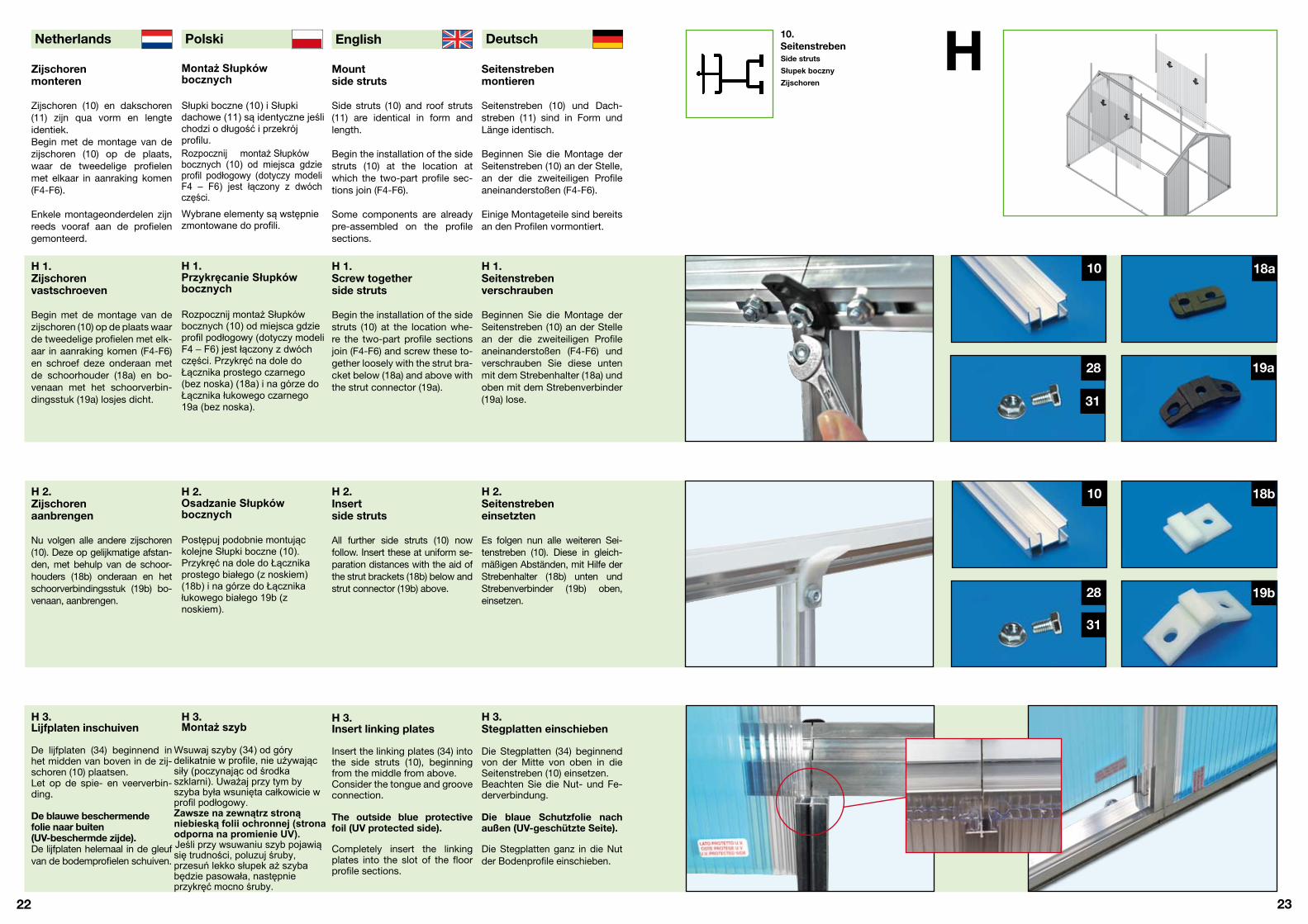
Seitenstreben (10) und Dach-streben (11) sind in Form undLänge identisch.
Beginnen Sie die Montage derSeitenstreben (10) an der Stelle,an der die zweiteiligen Profileaneinanderstoßen (F4-F6).
Einige Montageteile sind bereitsan den Profilen vormontiert.
Mountside struts
Side struts (10) and roof struts (11) are identical in form andlength.
Begin the installation of the sidestruts (10) at the location atwhich the two-part profile sec-tions join (F4-F6).
Some components are alreadypre-assembled on the profilesections.
Zijschorenmonteren
Zijschoren (10) en dakschoren (11) zijn qua vorm en lengteidentiek.Begin met de montage van dezijschoren (10) op de plaats,waar de tweedelige profielenmet elkaar in aanraking komen(F4-F6).
Enkele montageonderdelen zijnreeds vooraf aan de profielengemonteerd.
H 2.Seitenstrebeneinsetzten
Es folgen nun alle weiteren Sei-tenstreben (10). Diese in gleich-mäßigen Abständen, mit Hilfe derStrebenhalter (18b) unten undStrebenverbinder (19b) oben,einsetzen.
H 2.Insertside struts
All further side struts (10) nowfollow. Insert these at uniform se-paration distances with the aid ofthe strut brackets (18b) below andstrut connector (19b) above.
H 2.Zijschorenaanbrengen
Nu volgen alle andere zijschoren (10). Deze op gelijkmatige afstan-den, met behulp van de schoor-houders (18b) onderaan en hetschoorverbindingsstuk (19b) bo-venaan, aanbrengen.
H 1.Seitenstrebenverschrauben
Beginnen Sie die Montage derSeitenstreben (10) an der Stellean der die zweiteiligen Profileaneinanderstoßen (F4-F6) undverschrauben Sie diese untenmit dem Strebenhalter (18a) undoben mit dem Strebenverbinder(19a) lose.
H 1.Screw togetherside struts
Begin the installation of the sidestruts (10) at the location whe-re the two-part profile sectionsjoin (F4-F6) and screw these to-gether loosely with the strut bra-cket below (18a) and above withthe strut connector (19a).
H 1.Zijschorenvastschroeven
Begin met de montage van dezijschoren (10) op de plaats waarde tweedelige profielen met elk-aar in aanraking komen (F4-F6)en schroef deze onderaan metde schoorhouder (18a) en bo-venaan met het schoorverbin-dingsstuk (19a) losjes dicht.
H 3.Stegplatten einschieben
Die Stegplatten (34) beginnendvon der Mitte von oben in dieSeitenstreben (10) einsetzen.Beachten Sie die Nut- und Fe-derverbindung.
Die blaue Schutzfolie nach außen (UV-geschützte Seite).
Die Stegplatten ganz in die Nutder Bodenprofile einschieben.
H 3.Insert linking plates
Insert the linking plates (34) intothe side struts (10), beginningfrom the middle from above.Consider the tongue and grooveconnection.
The outside blue protectivefoil (UV protected side).
Completely insert the linkingplates into the slot of the floor profile sections.
H 3.Lijfplaten inschuiven
De lijfplaten (34) beginnend inhet midden van boven in de zij-schoren (10) plaatsen.Let op de spie- en veerverbin-ding.
De blauwe beschermendefolie naar buiten(UV-beschermde zijde).De lijfplaten helemaal in de gleufvan de bodemprofielen schuiven.
28
31
10
28
19b
18b10
H10. Seitenstreben
18a
19a
31
Montaż Słupkówbocznych
Słupki boczne (10) i Słupkidachowe (11) są identyczne jeślichodzi o długość i przekrójprofilu.Rozpocznij montaż Słupkówbocznych (10) od miejsca gdzieprofil podłogowy (dotyczy modeliF4 – F6) jest łączony z dwóchczęści.
Wybrane elementy są wstępniezmontowane do profili.
H 1.Przykręcanie Słupkówbocznych
H 2.Osadzanie Słupkówbocznych
Postępuj podobnie montująckolejne Słupki boczne (10). Przykręć na dole do Łącznikaprostego białego (z noskiem)(18b) i na górze do Łącznikałukowego białego 19b (znoskiem).
H 3.Montaż szyb
Wsuwaj szyby (34) od górydelikatnie w profile, nie używającsiły (poczynając od środkaszklarni). Uważaj przy tym byszyba była wsunięta całkowicie wprofil podłogowy. Zawsze na zewnątrz stronąniebieską folii ochronnej (stronaodporna na promienie UV).Jeśli przy wsuwaniu szyb pojawiąsię trudności, poluzuj śruby,przesuń lekko słupek aż szybabędzie pasowała, następnieprzykręć mocno śruby.
Side struts
Słupek bocznyZijschoren
Rozpocznij montaż Słupkówbocznych (10) od miejsca gdzieprofil podłogowy (dotyczy modeliF4 – F6) jest łączony z dwóchczęści. Przykręć na dole doŁącznika prostego czarnego(bez noska) (18a) i na górze doŁącznika łukowego czarnego19a (bez noska).

24
Deutsch English Polski Netherlands
25
Dachstrebenmontieren
Seitenstreben (10) und Dach-streben (11) sind in Form undLänge identisch.
Beginnen Sie die Montage derDachstreben (11) an der Stellean der die zweiteiligen Profileaneinanderstoßen (F4-F6).
Einige Montageteile sind bereitsan den Profilen vormontiert.
Mountroof struts
Side struts (10) and roof struts (11) are identical in form andlength.
Begin the installation of the sidestruts (11) at the location wherethe two-part profile sections join(F4-F6).
Some components are alreadypre-assembled on the profilesections.
Dakschorenmonteren
Zijschoren (10) en dakschoren (11) zijn qua vorm en lengteidentiek.
Begin met de montage van dedakschoren (11) op de plaats waarde tweedelige profielen met elkaarin aanraking komen (F4-F6).
Enkele montageonderdelen zijnreeds vooraf aan de profielengemonteerd.
I 2.Dachstrebeneinsetzen
Es folgen nun alle weiterenDachstreben (11) welche mitHilfe der Strebenverbinder (19b)an der Regenrinne und im Firstlose verschraubt werden.
Tip: Die Profile müssen so gut wie möglich aneinander ge-schraubt werden.
I 2.Insertroof struts
All further roof struts (11) nowfollow, where these are screwedtogether loosely with the aid ofthe strut connectors (19b) onthe rainwater gutter and in theroof ridge.
Tip: The profile sections must be screwed together with eachother as well as possible.
I 2.Dakschorenaanbrengen
Nu volgen alle andere dakscho-ren (11), die met behulp van deschoorverbindingsstukken (19b)aan de regengoot en in de noklosjes vastgeschroefd worden.
Tip: De profielen moeten zo goed mogelijk aan elkaar ge-schroefd worden.
28
31
19b11
I 1.Dachstrebenverschrauben
Beginnen Sie die Montage derDachstreben (11) an der Stelle,an der die zweiteiligen Profileaneinanderstoßen (F4-F6) undverschrauben diese lose mitden vormontierten Stebenver-bindern (19a) an der Regenrinneund am First.
I 1.Screw roof strutstogether
Begin the installation of the sidestruts (11) at the location wherethe two-part profile sectionsjoin (F4-F6) and screw thesetogether loosely with the pre-assembled strut connectors(19a) on the rainwater gutterand on the roof ridge.
I 1.Dakschorenvastschroeven
Begin met de montage van dedakschoren (11) op de plaatswaar de tweedelige profielenmet elkaar in aanraking komen(F4-F6) en schroef deze losjesmet de vooraf gemonteerdeschoorverbindingsstukken (19a)aan de regengoot en aan de nokvast.
11
28
31
11.Dachstreben
19a
I
I 3.Fensterstrebeeinsetzen
Strebenhalter gerade (18a) mitSchrauben (28) und Muttern (31) an beiden Enden der Fens-terquerstrebe (12) anbringen.
Fensterquerstrebe (12) in dasgewünschte Dachfeld (Laschenach oben!) mit Rhombus-schrauben (29) und Muttern (31) in der Dachstrebe lose ver-schrauben.
I 3.Insertwindow strut
Attach strut bracket (18a) withbolts (28) and nuts (31) direct-ly at both ends of the windowcrossbeam (12).
Screw window crossbeam (12)loosely into the required roofarea (strap above!) with rhom-bus bolts (29) and nuts (31) inthe roof strut.
I 3.Vensterschooraanbrengen
Schoorhouder recht (18a) metschroeven (28) en moeren (31)aan beide uiteinden van de vens-terdwarsbalk (12) aanbrengen.
Vensterdwarsbalk (12) in het ge-wenste dakveld (lasplaat naarboven!) met ruitschroeven (29)en moeren (31) in de dakschoorlosjes vastschroeven.
18a
28
31
Tip:
29
31
Montaż Słupkówdachowych
Słupki boczne (10) i Słupkidachowe (11) są identycznejeśli chodzi o długość i przekrójprofilu.Rozpocznij montaż Słupkówdachowych (11) od miejscagdzie profil podłogowy (dotyczymodeli F4 – F6) jest łączony zdwóch części.Wybrane elementy są wstępniezmontowane do profili.
I 1.Przykręcanie Słupkówdachowych
Rozpocznij montaż Słupkówdachowych (11) od miejscagdzie profil (dotyczy modeli F4 –
do kalenicy.
I 2.Osadzanie Słupkówdachowych
Postępuj podobnie montująckolejne Słupki dachowe (11).Przykręć do Łącznika łukowegobiałego 19b (z noskiem) nakalenicy i do rynienkideszczowej.
Wskazówka: Profile musząbyć dobrze przykręcone.
I 3.Montaż zastrzałuokiennego
Zastrzał okienny (12) skręć zŁącznikami prostymi (czarny-bez noska) (18a) za pomocąśrub (28) i nakrętek (31).
Roof struts
Słupek dachowyDakschoren
F6) jest łączony z dwóchczęści. Przykręć do Łącznikałukowego czarnego 19a (beznoska) na rynience deszczowej i
Umieść Zastrzał okienny (12) wdowolnie wybranym poludachowym (listwą do góry) iprzykręć do Słupków dachowych zapomocą śrub rombowych (29) inakrętek (31).

26
Deutsch English Polski Netherlands
27
Stegplatten Dach undClipprofile anbringen
Beachten Sie die Nut- und Fe-derverbindung.
Die blaue Schutzfolie nach au-ßen (UV-geschützte Seite).Die Stegplatten ganz in die Nutder Profile einschieben.
Die Clipprofile sind bereits aufdie richtige Endlänge zuge-schnitten.
Linking plate roofAttach clip profile sections
Consider the tongue and grooveconnection. The blue protective foil facingout (UV protected side).Completely insert the linkingplates into the slot of the profilesections.
The clip profile sections are al-ready tailored to the correct finallength.
Lijfplaten daken Clippro-fielen aanbrengen
Let op de spie- en veerverbin-ding.
De blauwe beschermende folienaar buiten (UV-beschermde zi-jde).
De lijfplaten helemaal in de gleufvan de profielen schuiven.De clipprofielen zijn reeds op decorrecte eindlengte geknipt.
J 3. Clipprofile und Schutzprofil anbringen
Befestigen Sie zuerst die Stegplat-ten Dach an der Regenrinne mit denpassenden Clipprofilen (25). Danachfolgen die seitlichen Stegplattenmit den Clipprofilen (27) von obenan der Regenrinne. Die lange Seitedes Clipprofils überdeckt dabei dieStegplatte. Mit etwas Druck rastetdas Clipprofil mit einem stillen, leichtspürbaren „Click“ in das Alu-Profilein. Die vier Schutzprofile (34) wer-den einfach auf die obere Alukante der Regenrinne (8) aufgesteckt.
J 3. Attach clip profile sec-tions and protective profile section
First, attach the roof linking plates tothe rainwater gutter with the appro-priate clip profile sections (25). Afterthat follow the side linking plates withthe clip profile sections (27) from abo-ve on the rainwater gutter. The longside of the clip profile section coversover the linking plate in this case. Withsome pressure, the profile sectionlatches into the profile section with aquiet, slightly perceptible „click“. Thefour protective profile sections (34) aresimply placed onto the upper alumi-num edge of the rainwater gutter (8).
J 3. Clipprofielen en be-schermingsprofiel aan-brengen
Bevestig eerst de lijfplaten dak aan deregengoot met de passende clipprofie-len (25). Daarna volgen de zijdelingselijfplaten met de clipprofielen (27) langsboven aan de regengoot. De lange zi-jde van het clipprofiel bedekt daarbijde lijfplaat. Met een beetje druk klikthet profiel met een zachte, gemakke-lijk waar te nemen „klik“ in het profielvast. De vier beschermingsprofielen (34) worden gewoon op de bovenstealuminiumkant van de regengoot (8)gespeld.
25
J 1.Stegplatten einschieben
Die Stegplatten (E), beginnend vonder Mitte von unten, in die Dachstre-ben (11) einsetzen.
Die Stegplatte Fensterfeld (G), be-ginnend von unten, in die Dachstre-ben (11) einsetzen. Schieben Sie diePlatten ganz in die Nut des Firstpro-files (bzw. Fensterquerprofiles) ein.
Tip: Sollte die Stegplatte klem-men, einfach die Schrauben lösen und das Profil verschieben, bis die Platte reinrutscht. Abschließend die Schrauben wieder anziehen.
J 1.Insert linking plates
Insert the linking plates (E), begin-ning from the middle from below,into the roof struts (11).Insert the window linking plate (G),beginning from below, into the roofstruts (11). Completely insert theplates into the slot of the roof ridgeprofile section (and window crossprofile section).
Tip: If the linking plate should jam,simply loosen the bolts and dis-place the profile section
J 1.Lijfplaten inschuiven
De lijfplaten (E), beginnend van hetmidden langs onder, in de dakscho-ren (11) aanbrengen. De lijfplaatvensterveld (G), beginnend van on-der, in de dakschoren (11) aanbren-gen. Schuif de platen helemaal in degleuf van het nokprofiel (c.q. van hetvensterdwarsprofiel).
Tip: Indien de lijfplaat klemt,gewoon de schroeven losdraaienen het profiel verschuiven tot de plaat erin glijdt. Tot slot deschroeven weer aandraaien.
27
J
J 2.Folie abziehen
Ziehen Sie nun die blaueSchutzfolie außen und die wei-ße Schutzfolie innen von allenStegplatten ab.
Klemmt die Schutzfolie in derNut des Profils, erleichtert einleichtes Drücken gegen dieStegplatte das Abziehen derFolie.
J 2.Pull off film
Now pull off the outside blueprotective foil and the insidewhite protective foil from all lin-king plates.
If the protective foil sticks in theslot of the profile section, a slightpressing against the linking pla-te facilitates the stripping of thefilm.
J 2.Folie aftrekken
Trek nu de blauwe bescher-mende folie buiten en de wittebeschermende folie binnen vanalle lijfplaten af.
Indien de beschermende folie inde gleuf van het profiel klemt, ishet door te duwen tegen de lijf-plaat gemakkelijker om de folieaf te trekken.
E und G Stegplatten
25 und 27 Clipprofil Dach unten und Regenrinne
en regengoot
Tip:
34
Montaż Szyb dachowych iProfili zatrzaskowych
Zawsze na zewnątrz stronąniebieską folii ochronnej (tostrona szyby poliwęglanowejodporna na promienie UV). Uważaj przy tym by szyba byławsunięta całkowicie w profil.
Profile zatrzaskowe są przyciętedo odpowiedniej długości igotowe do montażu.
J 1.Montaż Szyb dachowych
Wsuwaj szyby od dołu (poczynającod środka szklarni) delikatnie wsłupki dachowe (11), nie używającsiły. Wsuń szybę pola dachowego G oddołu delikatnie w słupki dachowe (11), nie używając siły.
Wskazówka: Jeśli przy wsuwaniuszyb pojawią się trudności,poluzuj śruby, przesuń lekkosłupek, aż szyba będzie pasowała,następnie przykręć mocno śruby.
J 2.Demontaż folii ochronnej
Zedrzyj folię ochronną zobydwóch stron szyby, niebieska (z zewnątrz), biała (odwewnątrz).
J 3. Montaż profilizatrzaskowych i profiliochronnychNajpierw zablokuj szyby dachowe doprofila rynienki deszczowej zapomocą pasującego Profiluzatrzaskowego (25). Następniezablokuj szyby boczne szklarni zapomocą pasującego Profiluzatrzaskowego (27) na górze rynienkideszczowej. Dłuższy bok Profiluzatrzaskowego przykrywa szybę. Zpomocą lekkiego nacisku, profilzatrzaskowy wydając lekki dźwięk„klik”, zatrzaskuje się na profilualuminiowym.Cztery Profile ochronnegumowe (34) umieść na górnychkantach Rynienki deszczowej (8).
25 and 27 Roof clip profile section below and rainwater gutter25 i 27 - Profil zatrzaskowy25 en 27 Clipprofiel dak onderaan
E and G Linking platesE i G - Szyby dachoweE en G Lijfplaten
28
Deutsch English Polski Netherlands
29
K
K 1.Fenster einschieben
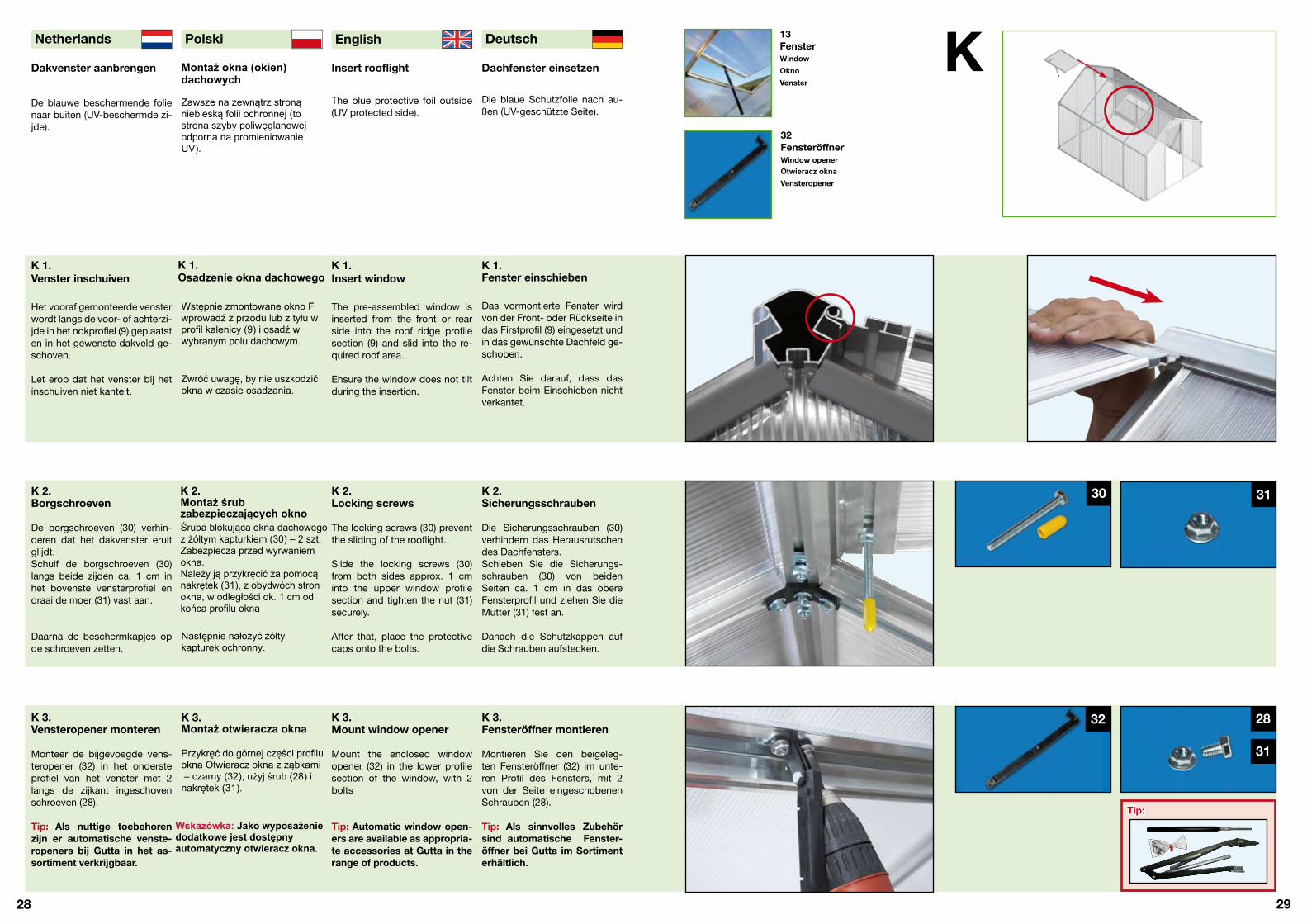
Das vormontierte Fenster wirdvon der Front- oder Rückseite indas Firstprofil (9) eingesetzt undin das gewünschte Dachfeld ge-schoben.
Achten Sie darauf, dass dasFenster beim Einschieben nichtverkantet.
K 1.Insert window
The pre-assembled window isinserted from the front or rearside into the roof ridge profilesection (9) and slid into the re-quired roof area.
Ensure the window does not tiltduring the insertion.
K 1.Venster inschuiven
Het vooraf gemonteerde vensterwordt langs de voor- of achterzi-jde in het nokprofiel (9) geplaatsten in het gewenste dakveld ge-schoven.
Let erop dat het venster bij hetinschuiven niet kantelt.
Dachfenster einsetzen
Die blaue Schutzfolie nach au-ßen (UV-geschützte Seite).
Insert rooflight
The blue protective foil outside(UV protected side).
Dakvenster aanbrengen
De blauwe beschermende folienaar buiten (UV-beschermde zi-jde).
K 2.Sicherungsschrauben
Die Sicherungsschrauben (30)verhindern das Herausrutschendes Dachfensters.Schieben Sie die Sicherungs-schrauben (30) von beidenSeiten ca. 1 cm in das obereFensterprofil und ziehen Sie dieMutter (31) fest an.
Danach die Schutzkappen aufdie Schrauben aufstecken.
K 2.Locking screws
The locking screws (30) preventthe sliding of the rooflight.
Slide the locking screws (30)from both sides approx. 1 cminto the upper window profilesection and tighten the nut (31)securely.
After that, place the protectivecaps onto the bolts.
K 2.Borgschroeven
De borgschroeven (30) verhin-deren dat het dakvenster eruitglijdt.Schuif de borgschroeven (30)langs beide zijden ca. 1 cm inhet bovenste vensterprofiel endraai de moer (31) vast aan.
Daarna de beschermkapjes opde schroeven zetten.
K 3.Fensteröffner montieren
Montieren Sie den beigeleg-ten Fensteröffner (32) im unte-ren Profil des Fensters, mit 2von der Seite eingeschobenenSchrauben (28).
Tip: Als sinnvolles Zubehör sind automatische Fenster-öffner bei Gutta im Sortiment erhältlich.
K 3.Mount window opener
Mount the enclosed windowopener (32) in the lower profilesection of the window, with 2bolts
Tip: Automatic window open-ers are available as appropria-te accessories at Gutta in therange of products.
K 3.Vensteropener monteren
Monteer de bijgevoegde vens-teropener (32) in het ondersteprofiel van het venster met 2langs de zijkant ingeschovenschroeven (28).
Tip: Als nuttige toebehoren zijn er automatische venste-ropeners bij Gutta in het as-sortiment verkrijgbaar.
13Fenster
32Fensteröffner
30
32 28
31
31
Tip:
Montaż okna (okien)dachowych
Zawsze na zewnątrz stronąniebieską folii ochronnej (tostrona szyby poliwęglanowejodporna na promieniowanieUV).
K 1.Osadzenie okna dachowego
Wstępnie zmontowane okno Fwprowadź z przodu lub z tyłu wprofil kalenicy (9) i osadź wwybranym polu dachowym.
Zwróć uwagę, by nie uszkodzićokna w czasie osadzania.
Śruba blokująca okna dachowegoz żółtym kapturkiem (30) – 2 szt.Zabezpiecza przed wyrwaniemokna.Należy ją przykręcić za pomocąnakrętek (31), z obydwóch stronokna, w odległości ok. 1 cm odkońca profilu okna
Następnie nałożyć żółtykapturek ochronny.
K 3.Montaż otwieracza okna
Wskazówka: Jako wyposażeniedodatkowe jest dostępnyautomatyczny otwieracz okna.
Window
OknoVenster
Window openerOtwieracz oknaVensteropener
K 2.Montaż śrubzabezpieczających okno
Przykręć do górnej części profiluokna Otwieracz okna z ząbkami – czarny (32), użyj śrub (28) inakrętek (31).

30
Deutsch English Polski Netherlands
31
Türteileeinsetzen
Türunterteil und Türoberteil sindidentisch.
Achten Sie darauf, dass sichbeim einschieben das Profilnicht verkantet.
Insertdoor parts
Door lower part and door upperpart are identical.
Note that the profile section isnot tilted when inserting.
Deurdelenaanbrengen
Onderste deurdeel en bovenste deurdeel zijn identiek.
Let erop dat het profiel bij hetinschuiven niet kantelt.
L 2.Unterlegscheibe undTüroberteil einsetzen
Als Distanz führen Sie nun dieUnterlegescheibe (24) in dieStrebe ein und danach das Tü-roberteil (14a).
Tip: Nur mit der Unterleg-scheibe lassen sich die Tür-teile getrennt öffnen.
L 2.Spacing washer and door upper part insert
Now insert the underlay plate (24) as a spacer into the strutand after that the door upperpart (14a).
Tip: Only with the spacing washer can the door parts beopened separately.
L 2.Onderlegplaatje en bovens-te deurdeel aanbrengen
Als afstand brengt u nu het on-derlegplaatje (24) in de schoorin en daarna het bovenste deur-deel (14a).
Tip: Enkel met het onderleg-plaatje kunnen de deurdelen gescheiden geopend worden.
L 1.Türunterteileinsetzen
Türunterteil (14a) von oben indie Türscharnierstrebe (7) ein-schieben.
Tip: Passt das Türscharnier nicht, müssen Sie das Alupro-fil am Türteil ablösen und dre-hen. Die Scharnierprofile an den Türteilen sind nur aufgesteckt.
L 1.Insertdoor lower part
Insert door lower part (14a) intothe door hinge strut (7) fromabove.
Tip: If the door hinge doesnot fit, the aluminum profile section on the door part mustbe loosened and rotated. Thehinge profile sections on the door parts are only pinned.
L 1.Onderste deurdeelaanbrengen
Onderste deurdeel (14a) langs boven in de deurscharnier-schoor (7) schuiven.
Tip: Indien het deurscharnierniet past, moet u het alumi-niumprofiel aan het deur-deel losmaken en draaien.De scharnierprofielen aan de deurdelen zijn er slechts op-gestoken.
24
L14zweiteilige Tür
24Unterlegscheibe
Tip:
Tip:
L 3.Türgriff und Türgriffanschlag
Türgriffe (14b) durch die Öffnungder Stegplatte zusammenste-cken. Imbusschraube im Türgrifffest anziehen.Montieren Sie jeweils an derInnenseite der Frontstrebe (6)unterhalb der Türgriffe einenStrebenverbinder (19a) als Tür-griffanschlag mit Rhombus-schraube (29) und Mutter (31).
L 3.Door handle anddoor handle stop
Connect door handles (14b)through the opening of the lin-king plate. Tighten socket boltssecurely in the door handle.Mount one strut connector ineach case on the inner side ofthe front strut (6) below the doorhandles (19a) as a door handlestop with rhombus bolt (29) andnut (31).
L 3.Deurgreep endeurgreepaanslag
de voorschoor (6) onderde deurgrepen een schoorver-bindingsstuk (19a) als deurgree-paanslag met ruitschroef (29) enmoer (31).
19a
29
31
14b
22
24
23
22
Montaż drzwi
Część górna i dolna drzwi sąidentyczne.
L 1.Osadzenie drzwi(część dolna)
Dolną część drzwi wprowadź odgóry w zawias.
Wskazówka: Jeśli zawiasdrzwi nie pasuje stroną,należy szybę wysunąć zprofilu, obrócić i ponownienasunąć na szybę.
L 2.Osadzenie drzwi(część górna)
Niezbędny jest montaż Przekładkiśrodkowej do zawiasów drzwi – szary (24)pomiędzy częścią dolnąa częściągórną drzwi. Wytnij ją ostrym nożykiemz dostarczonego w pakiecie szablonu(odlewu z tworzywa sztucznego).Wsuń Przekładkę środkową dozawiasów drzwi – szary (24) dozawiasów drzwi. Następnie górnączęść drzwi wprowadź od góry wzawias.
L 3.Montaż klamki drzwi
Two-part door
Drzwi dwuczęścioweTweedelige deur
Underlay plate
Przekładka środkowa do zawiasów drzwiOnderlegplaatje
Deurgrepen (14b) door de ope-ning van de lijfplaat aan elkaarzetten. Inbusschroef in de deur-greep vast aandraaien.Monteer telkens aan de binnen-zijde van
Złóż części klamki razem,poprzez otwór w szybie drzwiużywając bolca o kształcieczworokątnym.Zamontuj na profilu Słupkadrzwiowego ogranicznik klamki.W tym celu przykręć odwewnątrz Łącznik łukowy czarny19a (bez noska). Użyj śrubrombowych (29) i nakrętek (31).
Wskazówka: Tylko przyosadzeniu Przekładkiśrodkowej do zawiasów drzwijest możliwe prawidłowerozdzielenie i otwieranie drzwi.

32
Deutsch English Polski Netherlands
33
Windverband oderSeiten- und Dachstreben-verbinder einsetzen
Die Verbinder erzeugen einehöhere Stabilität und schützendas Gewächshaus vor stärkerenWindlasten und Sturmböen.
Montieren Sie unbedingt allegelieferten Verstrebungen imGewächshaus. Die Menge derVerstrebungen hängt von derGröße des Geächshauses ab.
Insert transverse brace orside and roof strut con-nector
The connectors generate a high-er level of stability and protectthe greenhouse against severewind loads and storm gusts.
It is absolutely necessary tomount all supplied bracings inthe greenhouse. The quantityof the bracings depends on thesize of the greenhouse.
Windverband ofzij- en dakschoorverbin-dingsstuk aanbrengen
De verbindingsstukken zorgenvoor een hogere stabiliteit enbeschermen de broeikas tegensterkere windbelasting en stor-machtige rukwinden.Monteer beslist alle gelever-de schoren in de broeikas. Hetaantal schoren hangt af van hetformaat van de broeikas.
M 2.Seitenverbindermontieren (nur F4 bis F6)
Befestigen Sie die Seitenverbin-der (20b) an den inneren Seiten-streben (10) und Dachstreben (11) mit Rhombusschrauben (29) und Muttern (31) .Muttern fest anziehen.
M 2.Mount side connector(only F4 to F6)
Fasten the side connectors(20b) to the inner side struts (10)and roof struts (11) with rhom-bus bolts (29) and nuts (31).Tighten the nuts securely.
M 2.Zijverbindingsstukkenmonteren (enkel F4 tot F6)
Bevestig de zijverbindingsstuk-ken (20b) aan de binnenste zij-schoren (10) en dakschoren (11)met ruitschroeven (29) en moe-ren (31). Moeren vast aandraai-en. Moeren vast aandraaien.
M 1.Windverband (nur F2 bis F3)
Die Windverbände werden in al-len vier Ecken des Gewächshau-ses von Eckprofil (3) zu Regen-rinne (8) mit Rhombusschraubenund Muttern befestigt.Muttern fest anziehen.
M 1.Transverse brace (only F2 to F3)
The transverse braces are atta-ched at all four corners of thegreenhouse from corner profilesection (3) to rainwater gutter (8)with rhombus bolts and nuts.Tighten nuts securely.
M 1.Windverband (enkel F2 tot F3)
De windverbanden worden in alde vier hoeken van de broeikasvan hoekprofiel (3) naar regen-goot (8) met ruitschroeven enmoeren bevestigd.Moeren vast aandraaien.
M 3.Dachstrebenverbindermontieren (nur F4 bis F6)
Montieren Sie die Dachstre-benverbinder (20c) im First vonDachstrebe (11) zu Dachstrebe (11) mit Rhombusschrauben undMuttern. Beginnen Sie dabei inder Mitte des Gewächshauses.
Tip: Richten Sie das Gewächs-haus mit einer Wasserwaageaus und ziehen Sie nun alle Schrauben fest an.
M 3.Mount roof strutconnector(only F4 to F6)
Mount the roof strut connector(20c) in the roof ridge from roofstrut (11) to roof strut (11) withrhombus bolts and nuts. Beginin the middle of the greenhousein this case.
Tip: Align the greenhouse with a water level and now tightenall bolts securely.
M 3.Dakschoorverbindings-stukken monteren(enkel F4 tot F6)
Monteer de dakschoorverbin-dingsstukken (20c) in de nok vandakschoor (11) naar dakschoor (11) met ruitschroeven en moe-ren. Begin daarbij in het middenvan de broeikas.
Tip: Lijn de broeikas met eenwaterpas uit en draai nu alleschroeven vast aan.
20c
20a
20b
M20 a, b, cVerbinder
M2
M1
M3
Tip:
29
31
29
31
29
31
Montaż zastrzałówstalowych
Zastrzały pozwalają zachowaćdużą stabilność szklarni izabezpieczają jej konstrukcjęprzed nadmiernym obciążeniemwiatrem.Zamontuj wszystkie dostarczonezastrzały w szklarni. Ilośćzastrzałów zależy od wybranegomodelu.
M 1.Zastrzał wiatrowy (dotyczy wyłącznie modelu F2 i F3)
Zastrzały wiatrowe należyzamontować we wszystkichczterech rogach szklarni. Używając śrub rombowych (29) inakrętek (31) skręć Profilnarożnikowy (3) z profilemRynienki deszczowej (8).Przykręć mocno nakrętki.
M 2.Zastrzał boczny (dotyczy wyłącznie modeli F4 – F6)
Skręć Zastrzał boczny (20b) zeSłupkiem bocznym (10) i Słupkiem dachowym (11). Użyjśrub rombowych (29) i nakrętek (31).Przykręć mocno nakrętki.
M 3.Zastrzał dachowy (dotyczy wyłącznie modeli F4 – F6)
Skręć Zastrzał dachowy (20c)ze Słupkiem dachowym (11) iSłupkiem dachowym (11) podrugiej stronie kalenicy. Użyjśrub rombowych (29) i nakrętek (31). Rozpocznij montaż odśrodka szklarni.Wskazówka: Użyj poziomicy,następnie przykręć mocnonakrętki.
Connector
Zastrzał stalowyVerbindingsstukken

34
Deutsch English Polski Netherlands
35
Zusatzsverbinder,Schutzkappen undBodenbefestigung
Durch die Zusatzverbinder erhal-ten die großen Gewächshäuser(F4 bis F6) erheblich mehr Sta-bilität und sind gegen stärke-re Windlasten gewappnet. DieKunststoffkappen (33) sind zumSchutz der scharfen Kanten umVerletzungen vorzubeugen.
Additional connector,protective caps andFloor fastening
Extra verbindingsstuk-ken, beschermkapjes enbodemversteviging
Door de extra verbindingsstuk-ken krijgen de grote broeikassen(F4 tot F6) aanzienlijk meer sta-biliteit en zijn ze tegen sterkerewindbelasting gewapend. Dekunststofkapjes (33) dienen terbescherming tegen de scher-pe kanten om verwondingen tevoorkomen.
N 2.Schutzkappen aufkleben
Die Schutzkappen (33) auf dieäußeren Ecken der Bodenprofileaufkleben.
Wir empfehlen Silikon (kunst-stoffverträglich) oder Heißkle-ber.
N 2.Stick on theprotective caps
Stick the protective caps (33)onto the external corners of thefloor profile sections.
We recommend silicone (plastic-compatible) or hot adhesive.
N 2.Beschermkapjes opplakken
De beschermkapjes (33) op debuitenste hoeken van de bo-demprofielen kleven.
Wij raden (met kunststof vere-nigbare) silicone of warme lijmaan.
N 1.Zusatzsverbindereinsetzen (nur F4 bis F6)
Bringen Sie je 2 Zusatzsverbin-der (20d) in allen vier Ecken mitRhombuschrauben und Mutternan. Dabei wird das Bodenprofil(1, 2) mit dem Eckprofil (3) ver-bunden.
Muttern fest anziehen.
N 1.Insert additionalconnector (only F4 to F6)
Attach each 2 additional con-nectors (20d) in all four cornerswith rhombus bolts and nuts.The floor profile section is con-nected (1, 2) with the cornerprofile section (3) in this case.
Tighten nuts securely.
N 1.Extra verbindingsstukkenaanbrengen (enkel F4 tot F6)
Breng telkens 2 extra verbin-dingsstukken (20d) in al de vierhoeken met ruitschroeven enmoeren aan. Daarbij wordt hetbodemprofiel (1, 2) met het ho-ekprofiel (3) verbonden.
Moeren vast aandraaien.
N 3.Bodenbefestigung
A: Rhombusschraube (29) in dasBodenprofil (1, 2) einsetzen unddas Gewächshaus mit Winkeln*am betonierten Fundament, odermit Erdankern* befestigen.*Nicht im Lieferumfang! (s. Seite 36/37)
B: Gewächshaus auf das Alu-Fundament setzen und mit denFundamenthalterungen (im Fun-damentzubehör) verschrauben.
N 3.Floor fastening
A: Insert rhombus bolts (29) intothe floor profile section (1, 2) and attach the greenhouse to the con-creted foundation with angles* orwith ground anchors*.*Not in the scope of delivery! (See Page 36/37)
B: Place greenhouse onto thealuminum foundation and screwtogether with the foundationbrackets (in the foundation ac-cessory).
N 3.Bodemversteviging
A: Ruitschroef (29) in het bodem-profiel (1, 2) aanbrengen en debroeikas met winkelhaken* aan hetgebetonneerde fundament of metgrondankers* bevestigen.*Behoort niet tot het leveringspakket! (Zie pagina 36/37)
B: Broeikas op het aluminiumfun-dament zetten en met de funda-menthouders (in de fundament-toebehoren) vastschroeven.
N
20d
33
N3
N1
N2
A B
29
31
20dZusatzsverbinder
33Schutzkappe
Montaż dodatkowychzastrzałów stalowych,narożników ochronnych ,montaż szklarni do podłoża.
As a result of the additional con-nectors, the large greenhouses(F4 to F6) are provided with con-siderably more stability and arereinforced against strong windloads. The plastic caps (33) arefor protection against sharp ed-ges to avoid injuries.
Zastrzały dodatkowe w dużychszklarniach (modele F4 – F6)pozwalają zachować dużąstabilność szklarni izabezpieczają jej konstrukcjęprzed sztormowym wiatrem.Narożniki ochronne (33)zabezpieczają ostre kanty profilialuminiowych.
N 1.Montaż dodatkowychzastrzałów stalowych (dotyczy wyłącznie modelu F4 - F6)Zastrzały dodatkowe (20d)należy zamontować po dwa, wewszystkich czterech rogachszklarni. Używając śrubrombowych (29) i nakrętek (31)skręć Profil podłogowy (1,2) zprofilem narożnikowym (3).Przykręć mocno nakrętki.
N 2.Montaż Narożnikówochronnych
Narożnik ochronny –przeźroczysty (33) należyprzykleić do zewnętrznychnarożników profilu podłogowego.Zalecamy użycie silikonu dotworzyw sztucznych (nie jestdostępny w pakiecie szklarni)lub użycie gorącego klejupistoletowego.
N 3.Montaż szklarni do podłoża A : Wsuń śruby rombowe (29) wprofil podłogowy (1 i 2) i zapomocą kątowników i dybli (*)przykręć do fundamentu
* kątowniki i dyble nie są dostarczane wpakiecie szklarni (więcej na stronie 36,37)
B : Zamontuj szklarnię nadodatkowym fundamenciealuminiowym, z pomocądodatkowych kątowników(wyposażenie dodatkowe)
RaccordDodatkowy zastrzałstalowy
Protective capNarożnik ochronny

36
Deutsch English Polski Netherlands
37
Zubehör / Extras:
Achtung: Produkte dieser Seite sind nicht im Lieferumfang undmüssen auf Wunsch sepa-rat bestellt werden.
A = LängeB = BreiteC = HöheD = Stärke
Accessories / Extras:
Caution:Products of this side are not in the scope of deliveryand must be ordered sepa-rately on request.
A = lengthB = widthC = heightD = thickness
Toebehoren / extra’s:
Opgelet: Producten op deze pagina behoren niet tot het lever-ingspakket en moeten opverzoek apart besteld wor-den.
A = lengteB = breedteC = hoogteD = dikte
Aluminium Fundament
Passend für alle Gewächshaus-größen (F2-F6).Komplett mit Schrauben, Winkelund Aufbauanleitung.Stabilisiert, verstärkt und erhöht(11 cm) das Gewächshaus.
Aluminum foundation
Adapted for all greenhousesizes (F2-F6).Complete with bolts, anglesand building instructions.Stabilizes, reinforces and raisesthe greenhouse (11 cm).
Aluminiumfundament
Passend voor alle broeikasfor-maten (F2-F6).Compleet met schroeven, win-kelhaak en opbouwhandleiding.Stabiliseert, versterkt en verh-oogt (11 cm) de broeikas.
AutomatischerFensteröffner
Komplett mit Schrauben undMontageanleitung. Öffnet hyd-raulisch ohne Strom.
Automaticwindow opener
Complete with bolts and ins-tallation instructions. Opens hydraulically without electricalpower.
Automatischevensteropener
Compleet met schroeven eninbouwhandleiding. Opent hyd-raulisch zonder stroom.
Regalboard/Arbeitstisch
Passend für alle Gewächshaus-größen (F2-F6).
Komplett mit Schrauben,Winkel und Aufbauanleitung.
Rack board / worktable
Adapted for all greenhousesizes (F2-F6).
Complete with bolts, anglesand building instructions.
Rekplank/werktafel
Passend voor alle broeikasfor-maten (F2-F6).
Compleet met schroeven, win-kelhaak en opbouwhandleiding.
AA
BB
A = 77 cmB = 24 cmC = 3 cm
A = 77 cmB = 68 cmC = 3 cm
Befestigungsset mit Dübel
Zur Befestigung des Gewächs-hauses (mit/ohne Aluminium Fun-dament) am Betonuntergrund.Wir empfehlen: Set F2 = 8 Dübel (G) usw...
Fastening setwith anchor
For the fixing of the greenhouse(with/without aluminum foundati-on) to the concrete substrate.We recommend:Set F2 = 8 anchors (G) etc ...
Bevestigingsset met pluggen
Voor de bevestiging van de bro-eikas (met/zonder aluminiumfun-dament) op een betonnen onder-grond. Wij raden aan:Set F2 = 8 pluggen (E) enz. ...
Befestigungsset mit Erdanker
Zur Befestigung des Gewächs-hauses (mit oder ohne AluminiumFundament) im Erdboden.Wir empfehlen: Set F2 = 4 Erdanker (E) usw...
Fastening setwith ground anchor
For the fixing of the greenhouse(with or without aluminum found-ation) in the ground.We recommend: Set F2 = 4 ground anchor (E) etc...
Bevestigingsset met grondanker
Voor de bevestiging van de broei-kas (met of zonder aluminiumfun-dament) op de grond. Wij raden aan:Set F2 = 4 grondanker (E) enz. … E
F
FG
Art.-Nr.:
Set - F2 = 4 x E - 8 x F - 8 x 29 - 8 x 30 - 16 x 31Set - F3 = 4 x E - 8 x F - 8 x 29 - 8 x 30 - 16 x 31Set - F4 = 6 x E - 10 x F - 10 x 29 - 10 x 30 - 20 x 31Set - F5 = 6 x E - 10 x F - 10 x 29 - 10 x 30 - 20 x 31Set - F6 = 6 x E - 10 x F - 10 x 29 - 10 x 30 - 20 x 31
Set - F2 = 8 x G - 8 x F - 8 x 29 - 8 x 30 - 16 x 31Set - F3 = 8 x G - 8 x F - 8 x 29 - 8 x 30 - 16 x 31Set - F4 = 10 x G - 10 x F - 10 x 29 - 10 x 30 - 20 x 31Set - F5 = 10 x G - 10 x F - 10 x 29 - 10 x 30 - 20 x 31Set - F6 = 12 x G - 12 x F - 12 x 29 - 12 x 30 - 24 x 31
4290373
4290353
Art.-Nr.: 4290409
4290373
4290353
Art.-Nr.: 4290403
4290376
4290356
Art.-Nr.: 4290406
4290376
4290356
4290376
4290359
A x B x C x D Set - F2 154 x 227 x 11,1 x 2,5 cm 4290303
Set - F3 228 x 227 x 11,1 x 2,5 cm 4290306
Set - F4 300 x 227 x 11,1 x 2,5 cm 4290309
Set - F5 374 x 227 x 11,1 x 2,5 cm 4290312
Set - F6 448 x 227 x 11,1 x 2,5 cm 4290315
Wyposażenie dodatkoweszklarni (Opcja): Uwaga: Poniższe produkty nie sądostępne w pakiecieszklarni i występująwyłącznie jako wyposażenie dodatkowe.
A = DługośćB = SzerokośćC = WysokośćD = Grubość
Fundament aluminiowy
Jest dostępny dla wszystkichmodeli szklarni (F2 – F6).Kompletny, wraz ze śrubami,kątownikami i instrukcją montażu.Stabilizuje, wzmacnia ipodwyższa szklarnię o 11 cm.
Komplet montażowy zkołkami
Do posadowienia szklarni(z/bez) fundamentemaluminiowym na fundamenciebetonowym/podmurówce.
Komplet montażowyz kotwami ziemnymi
Do posadowienia szklarni(z/bez) fundamentemaluminiowym na gruncie.
Stolik roboczy
Jest dostępny dla wszystkichmodeli szklarni (F2 – F6).
Kompletny, wraz ze śrubami,kątownikami i instrukcjąmontażu.
Automatyczny otwieraczokna dachowego
Kompletny, wraz ze śrubami iinstrukcją montażu. Otwieraokno dachowe automatycznienie używając energiielektrycznej.
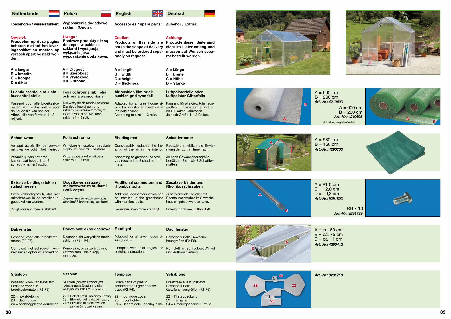
38
Deutsch English Polski Netherlands
39
Luftpolsterfolie oderLuftpolster-Gitterfolie
Passend für alle Gewächshaus-größen. Für zusätzliche Isolati-on zur kalten Jahreszeit.Je nach Größe 1 - 3 Rollen.
Air cushion film or air cushion grid-type foil
Adapted for all greenhouse si-zes. For additional insulation inthe cold season.According to size 1 - 3 rolls.
Luchtkussenfolie of lucht-kussentraliefolie
Passend voor alle broeikasfor-maten. Voor extra isolatie voorde koude tijd van het jaar.Afhankelijk van formaat 1 - 3rol(len).
Zusatzverbinder undRhombusschrauben
Zusatzverbinder welcher mitRhombusschrauben im Gewächs-haus eingebaut werden kann.
Erzeugt noch mehr Stabilität!
Additional connectors andrhombus bolts
Additional connectors which canbe installed in the greenhousewith rhombus bolts.
Generates even more stability!
Extra verbindingsstuk enruitschroeven
Extra verbindingsstuk, dat metruitschroeven in de broeikas in-gebouwd kan worden.
Zorgt voor nog meer stabiliteit!
Dachfenster
Passend für alle Gewächs-hausgrößen (F2-F6).
Komplett mit Schrauben, Winkelund Aufbauanleitung.
Rooflight
Adapted for all greenhouse si-zes (F2-F6).
Complete with bolts, angles andbuilding instructions.
Dakvenster
Passend voor alle broeikasfor-maten (F2-F6).
Compleet met schroeven, win-kelhaak en opbouwhandleiding.
Schablone
Ersatzteile aus Kunststoff.Passend für alle Gewächshausgrößen (F2-F6).
22 = Firstabdeckung23 = Türhalter24 = Unterlegscheibe Türteile
Template
Spare parts of plastic.Adapted for all greenhousesizes (F2-F6).
22 = roof ridge cover23 = door holder24 = Door middle underlay plate
Sjabloon
Wisselstukken van kunststof.Passend voor allebroeikasformaten (F2-F6).
22 = nokafdekking23 = deurhouder24 = onderlegplaatje deurdelen
A = 81,0 cmB = 2,0 cmD = 0,3 cm
RH x 10
A = ca. 60 cmB = ca. 75 cmD = ca. 1 cm
A = 600 cmB = 200 cm
A = 600 cmB = 200 cm
(Abbildung zeigt Großrolle!)
Art.-Nr.: 4210603
Art.-Nr.: 4210603
Art.-Nr.: 4290703
Art.-Nr.: 9291803
Art.-Nr.: 9291739
Art.-Nr.: 4290412
Art.-Nr.: 9291718
Zubehör / Extras:
Achtung: Produkte dieser Seite sind nicht im Lieferumfang undmüssen auf Wunsch sepa-rat bestellt werden.
A = LängeB = BreiteC = HöheD = Stärke
Accessories / spare parts:
Caution:Products of this side are not in the scope of deliveryand must be ordered sepa-rately on request.
A = lengthB = widthC = heightD = thickness
Toebehoren / wisselstukken:
Opgelet: Producten op deze pagina behoren niet tot het lever-ingspakket en moeten opverzoek apart besteld wor-den.
A = lengteB = breedteC = hoogteD = dikte
22
24
23
22
Schattiermatte
Reduziert erheblich die Erwär-mung der Luft im Innenraum.
Je nach Gewächshausgrößebenötigen Sie 1 bis 3 Schattier-matten.
Shading mat
Considerably reduces the he-ating of the air in the interior.
According to greenhouse size,you require 1 to 3 shadingmats.
Schaduwmat
Verlaagt aanzienlijk de verwar-ming van de lucht in het interieur.
Afhankelijk van het broei-kasformaat hebt u 1 tot 3schaduwmat(ten) nodig.
A = 580 cmB = 150 cmA
B
A
A
A
B
B
B
AB
Wyposażenie dodatkoweszklarni (Opcja):
Uwaga : Poniższe produkty nie sądostępne w pakiecieszklarni i występująwyłącznie jako wyposażenie dodatkowe.
A = DługośćB = SzerokośćC = WysokośćD = Grubość
Folia ochronna lub Foliaochronna wzmocnionaDla wszystkich modeli szklarni.Dla dodatkowej ochronyszklarni w okresie zimowym.W zależności od wielkościszklarni1 – 3 rolki.
Folia ochronna
W okresie upałów redukujeciepło we wnętrzu szklarni.
W zależności od wielkościszklarni1 – 3 rolki.
Zapewniają jeszcze większąstabilność konstrukcji szklarni.
Dodatkowe zastrzałystalowewraz ze śrubamirombowymi
Dodatkowe okno dachowe
Dostępne dla wszystkich modeliszklarni (F2 – F6).
Kompletne, wraz ze śrubami,kątownikami i instrukcjąmontażu.
Szablon
Szablon (odlew z tworzywasztucznego).Dostępny dlawszystkich szklarni (F2 –F6).
22 = Dekiel profilu kalenicy - szary23 = Blokada dolna drzwi - szary 24 = Przekładka środkowa do zawiasów drzwi - szary

40
Deutsch English Polski Netherlands
Garantieurkunde:
• 10 Jahre Garantie auf alle Stegplatten.
• 15 Jahre Garantie auf alle Aluminium-Profilteile.
Guarantee document:
• 10 years guarantee on all lin-king plates.
• 15 years guarantee on all alu-minum profile section parts.
Garantiecertificaat:
• 10 jaar garantie op alle lijf-platen.
• 15 jaar garantie op alle alu-minium profielonderdelen.
Gwarancja:
• 10 lat na szyby zpoliwęglanu komorowego
• 15 lat na profile aluminiowe
www.gutta.pl • [email protected]