
Technische Berichte Nr. 16
184
Fundamentals of Service-Oriented Engineering Stefan Hüttenrauch, Uwe Kylau, Martin Grund, Tobias Queck, Anna Ploskonos, Torben Schreiter, Martin Breest, Sören Haubrock, Paul Bouché Technische Berichte Nr. 16 des Hasso-Plattner-Instituts für Softwaresystemtechnik an der Universität Potsdam
Transcript of Technische Berichte Nr. 16
Fundamentals of Service-OrientedEngineering
Stefan Hüttenrauch, Uwe Kylau, Martin Grund, Tobias Queck, Anna Ploskonos, Torben Schreiter, Martin Breest, Sören Haubrock, Paul Bouché
Technische Berichte Nr. 16des Hasso-Plattner-Instituts für Softwaresystemtechnik an der Universität Potsdam

Technische Berichte des Hasso-Plattner-Instituts für Softwaresystemtechnik an der Universität Potsdam
Nr. 16
Fundamentals of Service-Oriented Engineering
Stefan Hüttenrauch, Uwe Kylau, Martin Grund, Tobias Queck, Anna Ploskonos, Torben Schreiter, Martin Breest, Sören Haubrock, Paul Bouché
Potsdam 2006

Bibliografische Information der Deutschen Bibliothek Die Deutsche Bibliothek verzeichnet diese Publikation in der Deutschen Nationalbibliografie; detaillierte bibliografische Daten sind im Internet über http://dnb.ddb.de abrufbar. Die Reihe Technische Berichte des Hasso-Plattner-Instituts für Softwaresystemtechnik an der Universität Potsdam erscheint aperiodisch. Herausgeber: Editoren Email: Vertrieb: Druck:
Professoren des Hasso-Plattner-Instituts für Softwaresystemtechnik an der Universität Potsdam Andreas Polze, Nikola Milanovic, Michael Schöbel {andreas.polze; nikola.milanovic, michael.schoebel}@.hpi.uni-potsdam.de Universitätsverlag Potsdam Postfach 60 15 53 14415 Potsdam Fon +49 (0) 331 977 4517 Fax +49 (0) 331 977 4625 e-mail: ubpub@uni-potsdamde http://info.ub.uni-potsdam.de/verlag.htm allprintmedia gmbH Blomberger Weg 6a 13437 Berlin email: [email protected]
© Hasso-Plattner-Institut für Softwaresystemtechnik an der Universität Potsdam, 2005 Dieses Manuskript ist urheberrechtlich geschützt. Es darf ohne vorherige Genehmigung der Herausgeber nicht vervielfältigt werden. Heft Nr 16 (2006) ISBN 3-939469-35-1 ISBN 978-3-939469-35-3 ISSN 1613-5652
Fundamentals of Service-Oriented Engineering
Prof. Dr. rer. nat. habil. Andreas Polze Dr.-Ing. Nikola Milanovic M.Sc. Michael Schöbel
In the summer term of 2006 the “Operating Systems and Middleware” chair at the Hasso-Plattner-Institute held the seminar “Fundamentals of Service-Oriented Engineering”. This technical report summarizes the student papers, which were created during the seminar. The term service-oriented engineering describes practice of design and implementation of service-based IT systems. The goal of the seminar was to introduce the discipline of service-oriented software engineering to the students through understanding of basic standards, technologies, tools and methodologies. The seminar topics were structured in the bottom up fashion across the following layers:
• Native capabilities (publication, discovery, selection, binding)
• Interaction (coordination, conformance, monitoring, QoS) • Management (certification, rating, trust, liability,
dependability) The field of service-oriented computing was defined (Stefan Hüttenrauch), and the basic properties of service-oriented systems, such as description, discovery and communication were described (Uwe Kylau, Martin Grund). In order to emphasise that not all services are Web services, and that service-oriented computing is a concept instead of a fixed technology or implementation platform, the role of JINI in service-oriented computing has been investigated (Tobias Queck). Interaction of the services deployed within a service landscape enables design and implementation of dynamic and adaptive applications. In this context service composition, as a method of building composite service-based applications and
creating added-value, was explored (Anna Ploskonos) and the significance of semantic information for complex service interactions was demonstrated (Torben Schreiter). Property of loose coupling has been also investigated in this context (Soeren-Nils Haubrock). Finally, service management was described using enterprise service bus architecture as an example (Martin Breest) and “real-world” issues and limitations were shown on the example of serialization and deserialization in the context of client-service interaction (Paul Bouche). Through the choice of topics we tried to cover the complete lifecycle of a service-oriented software system: design, development, deployment, verification and validation and maintenance. We also introduced “real-world” examples in order to show the open issues and limitations and demonstrate that service-oriented computing is not a “silver bullet” but only a software engineering paradigm specifically tailored to the needs of interoperation and dynamic interactions in the current IT landscape. Editors, Potsdam/Berlin, December 2006.
Content
1. Definitions, Historical Development, Advantages and Drawbacks of Service-Oriented Computing Stefan Hüttenrauch
2. Service Description
Uwe Kylau
3. Service Communication and Discovery Martin Grund
4. Role, capabilities and position of JINI Network
Technology in SOC Tobias Queck
5. Service Composition
Anna Ploskonos
6. Semantic Web Services Torben Schreiter
7. Enterprise Service Bus
Martin Breest
8. Loosely couples services with JMS and JavaSpaces Sören Haubrock
9. Serialization / Deserialization in the context of SOAP
and Web Services Paul Bouché

Fundamentals of Service-Oriented Engineering 1-1
Stefan Hüttenrauch
[email protected] [email protected]
Since 2002, keywords like service-oriented engineering, service-oriented
computing, and service-oriented architecture have been widely used in research, education, and enterprises. These and related terms are often misunderstood or used incorrectly. To correct these misunderstandings, a deeper knowledge of the concepts, the historical backgrounds, and an overview of service-oriented architectures is demanded and given in this paper.
Keywords: Service-Oriented Engineering, Service-Oriented Architecture, SOA, Web Service, Distributed Objects, Service Design, Service Science
1 Overview Since this paper is an introduction to service-oriented engineering, associated
terms will first be defined. The rest of this document is organized as follows. In chapter 3 the historical background of service-oriented computing (SOC) is analyzed, including the roots of SOC and middleware concepts connected to SOC. Chapter 4 focuses on service-oriented architecture (SOA) as a common SOC approach. The final chapters 5 and 6 summarize the advantages and disadvantages of SOC, draw a conclusion, and provide an outlook into the future of SOA.
The content of this paper refers to SOC and SOA in an equal measure. Therefore the terms SOC and SOA are often used synonymously.
2 Definitions This chapter concentrates on defining the terms correlated to service-oriented
engineering to sensitize the reader to the following chapters and to impart knowledge about the most important service-oriented concepts.
2.1 Service The word service is used in many contexts, not only in reference to IT systems.
For example, Merriam Webster Online describes a service as “a facility supplying some public demand” [2], which implies that a service can be performed by nearly anyone (e.g. craftsman, enterprises, hardware systems, or software) following the
Definitions, Historical Development, Advantages and Drawbacks
of Service- Oriented Computing
Definitions, Historical Development, Advantages and Drawbacks of SOC
1-2 Fundamentals of Service-Oriented Engineering
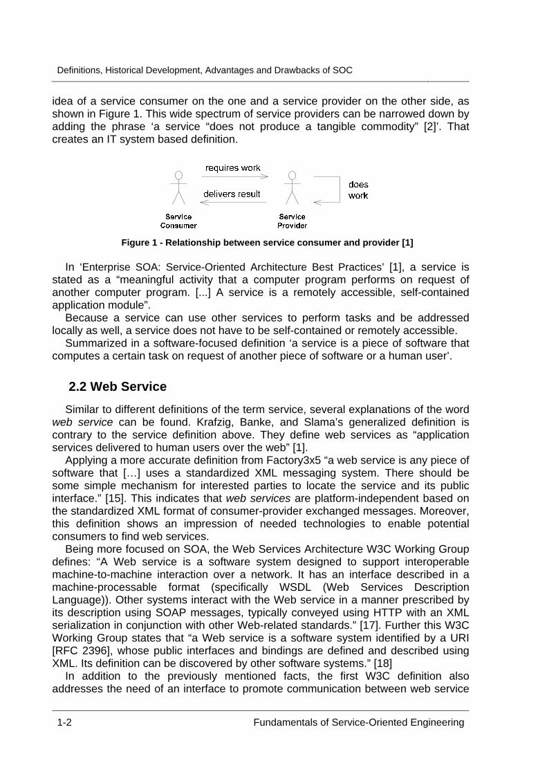
idea of a service consumer on the one and a service provider on the other side, as shown in Figure 1. This wide spectrum of service providers can be narrowed down by adding the phrase ‘a service “does not produce a tangible commodity” [2]’. That creates an IT system based definition.
Figure 1 - Relationship between service consumer and provider [1]
In ‘Enterprise SOA: Service-Oriented Architecture Best Practices’ [1], a service is
stated as a “meaningful activity that a computer program performs on request of another computer program. [...] A service is a remotely accessible, self-contained application module”.
Because a service can use other services to perform tasks and be addressed locally as well, a service does not have to be self-contained or remotely accessible.
Summarized in a software-focused definition ‘a service is a piece of software that computes a certain task on request of another piece of software or a human user’.
2.2 Web Service Similar to different definitions of the term service, several explanations of the word
web service can be found. Krafzig, Banke, and Slama’s generalized definition is contrary to the service definition above. They define web services as “application services delivered to human users over the web” [1].
Applying a more accurate definition from Factory3x5 “a web service is any piece of software that […] uses a standardized XML messaging system. There should be some simple mechanism for interested parties to locate the service and its public interface.” [15]. This indicates that web services are platform-independent based on the standardized XML format of consumer-provider exchanged messages. Moreover, this definition shows an impression of needed technologies to enable potential consumers to find web services.
Being more focused on SOA, the Web Services Architecture W3C Working Group defines: “A Web service is a software system designed to support interoperable machine-to-machine interaction over a network. It has an interface described in a machine-processable format (specifically WSDL (Web Services Description Language)). Other systems interact with the Web service in a manner prescribed by its description using SOAP messages, typically conveyed using HTTP with an XML serialization in conjunction with other Web-related standards.” [17]. Further this W3C Working Group states that “a Web service is a software system identified by a URI [RFC 2396], whose public interfaces and bindings are defined and described using XML. Its definition can be discovered by other software systems.” [18]
In addition to the previously mentioned facts, the first W3C definition also addresses the need of an interface to promote communication between web service
2 DEFINITIONS
Fundamentals of Service-Oriented Engineering 1-3
consumers and providers. The latter definition emphasizes the need to explicitly identify a web service using an URI.
Thus, a web service consists of the three parts: a service (functionality, including the interface definition), platform-independent messages (request and reply), and address or port reference [10]. Web services in general are stateless.
2.3 Service-Oriented Architecture “SOA refers to service creation, interaction, presentation, and integration
infrastructure capabilities” [5] to build software on a more abstract level (also known as business-level software) based on reusable components, an approach already used with distributed technologies.
Today’s SOA hype arises from multiple new concepts: “application front-end, service, service repository, and service bus” [1] (see below for more details). Now, the introduction of a new layer of abstraction bridges the communication gap between IT developers and enterprise experts proposing a new, business process-driven approach.
To build SOAs web services are most commonly used, because of their associated platform-independent standards like XML, Web Service Description Language (WSDL), and SOAP. SOA, as a set of development pattern, focuses on service design, reuse, and accessibility to build highly flexible and agile software systems, but is also an architectural approach.
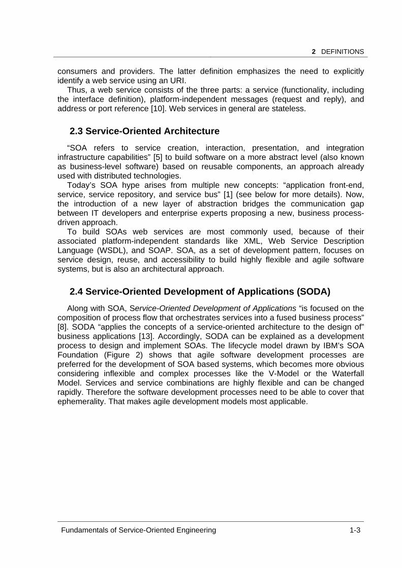
2.4 Service-Oriented Development of Applications (SODA) Along with SOA, Service-Oriented Development of Applications “is focused on the
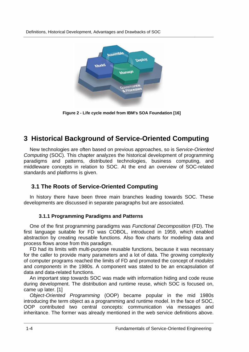
composition of process flow that orchestrates services into a fused business process” [8]. SODA “applies the concepts of a service-oriented architecture to the design of” business applications [13]. Accordingly, SODA can be explained as a development process to design and implement SOAs. The lifecycle model drawn by IBM’s SOA Foundation (Figure 2) shows that agile software development processes are preferred for the development of SOA based systems, which becomes more obvious considering inflexible and complex processes like the V-Model or the Waterfall Model. Services and service combinations are highly flexible and can be changed rapidly. Therefore the software development processes need to be able to cover that ephemerality. That makes agile development models most applicable.
Definitions, Historical Development, Advantages and Drawbacks of SOC
1-4 Fundamentals of Service-Oriented Engineering
Figure 2 - Life cycle model from IBM's SOA Foundation [16]
3 Historical Background of Service-Oriented Computing New technologies are often based on previous approaches, so is Service-Oriented
Computing (SOC). This chapter analyzes the historical development of programming paradigms and patterns, distributed technologies, business computing, and middleware concepts in relation to SOC. At the end an overview of SOC-related standards and platforms is given.
3.1 The Roots of Service-Oriented Computing In history there have been three main branches leading towards SOC. These
developments are discussed in separate paragraphs but are associated.
3.1.1 Programming Paradigms and Patterns
One of the first programming paradigms was Functional Decomposition (FD). The first language suitable for FD was COBOL, introduced in 1959, which enabled abstraction by creating reusable functions. Also flow charts for modeling data and process flows arose from this paradigm.
FD had its limits with multi-purpose reusable functions, because it was necessary for the caller to provide many parameters and a lot of data. The growing complexity of computer programs reached the limits of FD and promoted the concept of modules and components in the 1980s. A component was stated to be an encapsulation of data and data-related functions.
An important step towards SOC was made with information hiding and code reuse during development. The distribution and runtime reuse, which SOC is focused on, came up later. [1]
Object-Oriented Programming (OOP) became popular in the mid 1980s introducing the term object as a programming and runtime model. In the face of SOC, OOP contributed two central concepts: communication via messages and inheritance. The former was already mentioned in the web service definitions above.
3 HISTORICAL BACKGROUND OF SERVICE-O CO G
Fundamentals of Service-Oriented Engineering 1-5
The latter initiated the programming-by-interface paradigm and will be discussed below in the context of service contracts.
One problem of OOP is its interface granularity exposed to a client. This aspect of OOP makes OOP difficult to use in a distributed computing environment with distributed objects. SOC try to solve this problem with a more abstract level of granularity and specific access patterns for remote services. [1]
SOC is an aggregation of many positive aspects of previous concepts regarding
distribution, encapsulation, and reuse. Yet, SOC also has its drawbacks which will be discussed later.
3.1.2 Distributed Technologies
As mentioned earlier in this paper, distribution plays an important role in the context of SOC. As a result, the idea of service orientation is about ten years old. Parallel to the development of programming paradigms and patterns, the use of distributed technologies has also increased and became indispensable for business software in particular.
The introduction of mainframe computing was the origin of distributed technologies. Data and displays were distributed, but not computing power. Nevertheless such systems had to share data and output devices (e.g. printers).
When hardware became cheaper in the early 1970s, computers could operate more economically and more independently. Especially with the development of the UNIX operating system, the network became an essential part of the growing system environment. Thereby, communication between operating nodes was introduced to share functionality and hardware resources throughout the enterprise. The so-called client-server approach led to the distribution of functionality, first by using stored procedures in databases and Novell’s NetWare Loadable Modules, which were small programs that run on server side.
As the evolution of distributed technologies continued, the Distributed Computing Environment (DCE) and the Common Object Request Broker Architecture (CORBA) were created, thereby blurring the differences between client and server. With CORBA the functionality is broken down into remotely accessible objects which communicate with each other using an Object Request Broker (ORB). ORBs forward requests and provide abstraction mechanisms (e.g. naming service). Also, the programming-by-interface paradigm was adapted to attain programming language independence. Using an Interface Definition Language (IDL) the objects could be implemented in different programming languages, whereas the IDL is mapped upon language specific constructs [1]
With DCE and CORBA, functionality was distributed and platform-independence was achieved. Problems arose with the more complex interaction patterns, object lifecycle and reference management, and the often fine-grained object model. However, the CORBA Component Model is still widely used, also to realize SOAs.
In the mid 1990s, objects were clustered inside a single server increasing the functionality a server can offer to its clients. A higher level of abstraction was provided with application containers being responsible for resource, lifecycle, transaction, and security management. Sun Microsystems’ Enterprise Java Bean
Definitions, Historical Development, Advantages and Drawbacks of SOC
1-6 Fundamentals of Service-Oriented Engineering
(EJB) technology in particular made lifecycle management almost dispensable and focused on more coarse-grained components.
With these advances, challenges arose especially with the communication between heterogeneous middleware. One solution to this problem was the platform-independent XML. Today, it is used among others for message exchange and service description languages or transmission protocols, such as WSDL or SOAP. [1]
3.1.3 Business Computing
Another keystone of SOC is the aggregation of business data and business logic. In history and even today the development of computer science was and is coupled with the demands of enterprises.
As businesses grew, they required more computing power, distributed databases and functionality, as well as increasing flexibility to meet every day’s needs. As a result, information technology targeted to equip enterprises and their employees with needed hardware and software.
Database systems have been developed to store enterprise related data. Distributed systems and grid technologies were using computing power even between different enterprises. Terms like service and business workflow came up in parallel with the need to change workflows as easy and as fast as possible. Later, this led to the necessity of agile and flexible service-oriented architectures, where services can be connected and arranged according to business’ needs. [1]
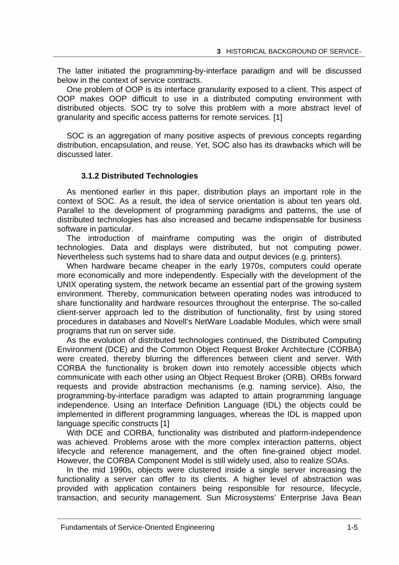
Figure 3, as a summary, gives an overview of the development of programming
languages, distribution technologies, and business computing with respect to SOA.
SO
A
Busin
ess Com
putin
gD
istributio
nTech
nolo
gy
Pro
gram
min
gLan
guages
content: data & business logic
remote access &infrastructure
implementation platform, interfacing techniques, interaction patterns
1950 1960 1970 1980 1990 2000
C#
Java
Ada
Prolog
C++
Pascal Modula 2
Smalltalk
Simula
Assembler
Cobol
VT3270
VT100
TCP/IPSockets
RPC
Client/Server
NFS
storedprocedures
CORBA
EAI
WWW
MQ
EJB
SOAP
WSDL
Mainframe
batch processingDatabases
SQL
Visicalc
R/2
IBM PC
Data Warehouse
EAI
R/3WWW
BPM
packagedapplications
MDA
Figure 3 - Historical development towards service-oriented computing [1]
3.2 Middleware Concepts Together with distributed technologies, middleware concepts were developed to fill
the gap between OS and applications.
3 HISTORICAL BACKGROUND OF SERVICE-O CO G
Fundamentals of Service-Oriented Engineering 1-7
The first well-liked approach towards distributed functionality was the Remote Procedure Call (RPC), created to access remote file systems. Later it was adapted to realize platform-independent services as well as location transparency on basis of RPC stubs and libraries.
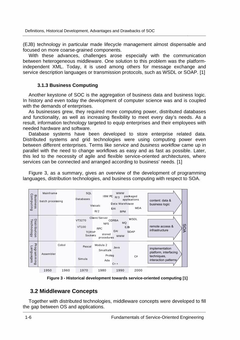
In the 1990s Distributed Objects were introduced to use the object-oriented programming style for distributed applications. As mentioned above, ORBs enabled remote object lifecycle management. They were based on the Interoperable Object References concept for remote object creation, location, invocation, and deletion (Figure 4). Reputed ORB implementations are CORBA, RMI, and Microsoft’s COM/DCOM. [1]
client application
client proxy
ORB
networkprotocol
call method
server application
server skeleton
ORB
networkprotocol
execute method
create, locate, delete, invoke
Figure 4 - Remote creation, location, deletion, and invocation of objects via an ORB [1] Around 1995 Message-Oriented Middleware (MOM) became part of the
communication infrastructure of enterprises. One main concept of MOM was message queuing to ensure reliable distribution. This concept decouples message senders and receivers enabling new sender-receiver combinations (e.g. 1:n; n:m). With MOM XML-based messages and quality of service parameters were established which are taken into consideration for service negotiation today. As a result, MOM allows for “dynamic, reliable, flexible, high-performance systems” [1].
Beginning in the late 1990s the introduction of application servers achieved mediation between presentation logic and enterprise backend systems (databases and/or functionality). For example, with the EJB technology service-like modules can be created to access enterprise’ functionality or data. EJBs are container-managed (automatic or semi-automatic caching, load balancing, transaction management) and can produce platform-independent HTTP replies.
3.2.1 The Difference between Distributed Objects and Web Services
Many people think of web services as distributed objects. In spite of many similarities they also have a number of significant differences. (For more details see W. Vogels [10].)
Distributed objects have a lifecycle model. Hence, the instance using a remote object is responsible for its lifecycle management after asking for the object’s instantiation. Having a reference to an object, the client can use the same object
Definitions, Historical Development, Advantages and Drawbacks of SOC
1-8 Fundamentals of Service-Oriented Engineering
several times. It is stateful and object methods can be called. In addition, distributed objects can hold references to other objects as well.
On the other hand, web services do not have these properties: no object instantiation, no reference handling, no state, and no lifecycle management. Web services instead are stateless and deal “with XML documents and document encapsulation” [10] or, for very simple services, with mechanisms like REST (Representational State Transfer) or JSON (JavaScript Object Notation).
Moreover the data flow is different. While the information exchanged with a web service is based on the structure of an XML document, the data flow between a distributed object and its caller is based on the interface an object supports. [10]
3.3 Standards and Tools and Platforms Athough SOC is well-researched, standardization of SOC is not yet complete.
Thus, some standards might change in the near future and new products to support service-oriented software development will come to market.
The de facto standards for dynamic discovery and invocation of web services are WSDL 1.11 and SOAP 1.22. The latter is often used via HTTP to be as platform-independent as possible. (A simpler but not standardized ‘protocol’ is REST3.) The standard for messages is, as mentioned above, XML4. Modeling of processes is often done with BPEL5.
Many platforms and tools are available to build service-oriented architectures. Engineers can choose between open-source or commercial solutions. For example, existing products are:
Eclipse-based SOA Tools Platform Project6 BEA WebLogicTM Product Family7 IBM SOA Foundation8 Oracle SOA Suite9 JINI (Java Intelligent Network Infrastructure)10
4 An Overview of Service-Oriented Architectures Before discussing the basic concepts of SOA and services in its context, the three
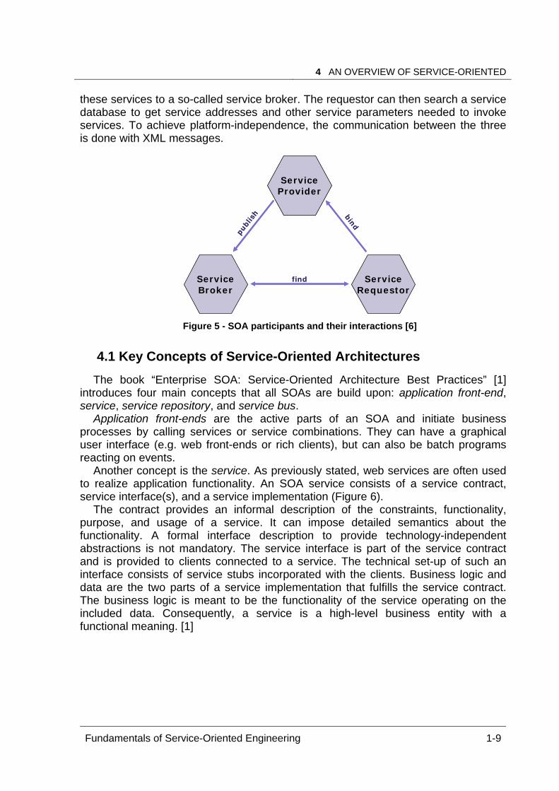
main protagonists are explained; namely the service provider, the service broker, and the service requestor (Figure 5). Service providers develop services to be used by service requestors (consumers). Therefore the provider publishes descriptions of
1 http://www.w3.org/TR/wsdl 2 http://www.w3.org/TR/soap/ 3 http://www.xfront.com/REST-Web-Services.html) 4 http://www.w3.org/XML/ 5 www.ibm.com/developerworks/library/ws-bpel 6 http://www.eclipse.org/stp/ 7 http://www.bea.com/framework.jsp?CNT=index.htm&FP=/content/products/weblogic 8 http://www-306.ibm.com/software/info/soa/flexibility/index.jsp 9 http://www.oracle.com/technologies/soa/soa-suite.html 10 http://www.jini.org/
4 AN OVERVIEW OF SERVICE-ORIENTED C C S
Fundamentals of Service-Oriented Engineering 1-9
these services to a so-called service broker. The requestor can then search a service database to get service addresses and other service parameters needed to invoke services. To achieve platform-independence, the communication between the three is done with XML messages.
ServiceProvider
ServiceRequestor
ServiceBroker
publish bind
find
ServiceProvider
ServiceRequestor
ServiceBroker
publish bind
find
Figure 5 - SOA participants and their interactions [6]
4.1 Key Concepts of Service-Oriented Architectures The book “Enterprise SOA: Service-Oriented Architecture Best Practices” [1]
introduces four main concepts that all SOAs are build upon: application front-end, service, service repository, and service bus.
Application front-ends are the active parts of an SOA and initiate business processes by calling services or service combinations. They can have a graphical user interface (e.g. web front-ends or rich clients), but can also be batch programs reacting on events.
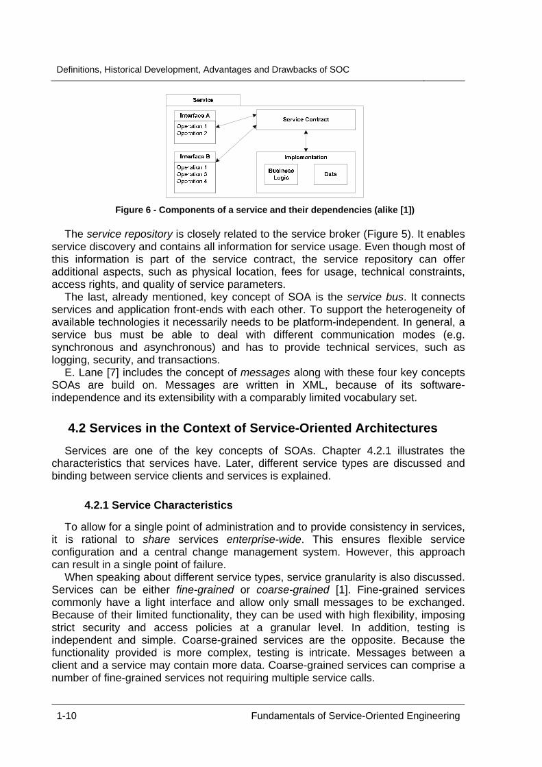
Another concept is the service. As previously stated, web services are often used to realize application functionality. An SOA service consists of a service contract, service interface(s), and a service implementation (Figure 6).
The contract provides an informal description of the constraints, functionality, purpose, and usage of a service. It can impose detailed semantics about the functionality. A formal interface description to provide technology-independent abstractions is not mandatory. The service interface is part of the service contract and is provided to clients connected to a service. The technical set-up of such an interface consists of service stubs incorporated with the clients. Business logic and data are the two parts of a service implementation that fulfills the service contract. The business logic is meant to be the functionality of the service operating on the included data. Consequently, a service is a high-level business entity with a functional meaning. [1]
Definitions, Historical Development, Advantages and Drawbacks of SOC
1-10 Fundamentals of Service-Oriented Engineering
Figure 6 - Components of a service and their dependencies (alike [1])
The service repository is closely related to the service broker (Figure 5). It enables
service discovery and contains all information for service usage. Even though most of this information is part of the service contract, the service repository can offer additional aspects, such as physical location, fees for usage, technical constraints, access rights, and quality of service parameters.
The last, already mentioned, key concept of SOA is the service bus. It connects services and application front-ends with each other. To support the heterogeneity of available technologies it necessarily needs to be platform-independent. In general, a service bus must be able to deal with different communication modes (e.g. synchronous and asynchronous) and has to provide technical services, such as logging, security, and transactions.
E. Lane [7] includes the concept of messages along with these four key concepts SOAs are build on. Messages are written in XML, because of its software-independence and its extensibility with a comparably limited vocabulary set.
4.2 Services in the Context of Service-Oriented Architectures Services are one of the key concepts of SOAs. Chapter 4.2.1 illustrates the
characteristics that services have. Later, different service types are discussed and binding between service clients and services is explained.
4.2.1 Service Characteristics
To allow for a single point of administration and to provide consistency in services, it is rational to share services enterprise-wide. This ensures flexible service configuration and a central change management system. However, this approach can result in a single point of failure.
When speaking about different service types, service granularity is also discussed. Services can be either fine-grained or coarse-grained [1]. Fine-grained services commonly have a light interface and allow only small messages to be exchanged. Because of their limited functionality, they can be used with high flexibility, imposing strict security and access policies at a granular level. In addition, testing is independent and simple. Coarse-grained services are the opposite. Because the functionality provided is more complex, testing is intricate. Messages between a client and a service may contain more data. Coarse-grained services can comprise a number of fine-grained services not requiring multiple service calls.
4 AN OVERVIEW OF SERVICE-ORIENTED C C S
Fundamentals of Service-Oriented Engineering 1-11
There are additional service characteristics that merit to be mentioned. For this purpose, Lane [3] again offers a short summary: “Services in SOA are: loosely coupled, asynchronous, platform- [and language-] independent, dynamically located and invoked, and are self-contained”. The asynchrony of services should be seen as a characteristic of the API/transport infrastructure rather than a service attribute.
4.2.2 Service Types
Basic Services form the foundation of SOAs. They do not maintain any state and can be either data-centric or logic-centric. Data-centric services handle persistent data (storage, retrieval, locking, etc.) for one major business entity and provide strict interfaces to access data. Logic-centric services encapsulate implementation for business rules and difficult calculations. For example a service calculating income taxes is logic-centric. In practice there is a soft transition between both types, as data-centric services can also include logic.
Uncontrolled invocation of basic services can cause inconsistencies, e.g. in enterprise databases. (Consider a booking item that has changed. The billing has to be adapted accordingly.) Thus, Intermediary Services are used to bridge the mentioned inconsistencies. These services are stateless and can act as client and server at the same time. They split into gateways, adapters, facades, and functionality-adding services. Intermediary services are more business-process-centric as they can implement simple (in general project-specific) business workflows that are in general projec-specific. [1]
More complex workflows are realized with (often state-enhanced) Process-Centric Services. Encapsulating the knowledge of the organization’s business processes, process-centric services use basic or intermediary services to perform tasks and to deal with business data. Process-Centric Services separate process logic from presentation to enable load balancing and encapsulate process logic and complexity for a single point of administration. A common example is an online shopping process, which includes filling the shopping cart, ordering products, and execute billing.
To suit Business to Business (B2B) computing, Public Enterprise Services are commonly used. These services are offered to partner companies as an interface to in-house systems. The interfaces in turn have the granularity of business documents and are coarse-grained. As decoupling between business partners is frequently needed, public enterprise services are accessed asynchronously. To offer public enterprise services, security standards as well as service level agreements have to be considered in the service’s design phase. [1]
These different service types aim to increase the flexibility and agility of SOA
design, which is further discussed below, focusing on the layered design of SOAs.
4.2.3 Service Bindings
To enable the service requestor to use a service (Figure 5), service binding is required, which exist in three different types.
Definitions, Historical Development, Advantages and Drawbacks of SOC
1-12 Fundamentals of Service-Oriented Engineering
The simplest binding is called development-time binding and is preferred if the service to be used is fixed and its protocol, physical location, and parameter set are known at design time.
More complex bindings are runtime bindings, which split into look-up by name, look-up by properties, and discovery based on reflection. The first is most generally used [1]. The service definition is known at development time. The client then selects a specific service to bind to at runtime. For example, an end user can select a specific billing service to pay for a flight. The program then binds to that service, looked-up by the given name.
Look-up by properties is similar. The service is selected on base of client-given properties. For example, imagine that a client wants to pay with Visa card. Thus a billing service supporting Visa cards needs to be invoked.
The most complex runtime binding is based on reflection. At development time only the semantic of the service is known. Hence, a reflection mechanism must be implemented on the client side to discover the interfaces of services with the desired semantic to invoke a context-suitable service with an appropriate message. [1]
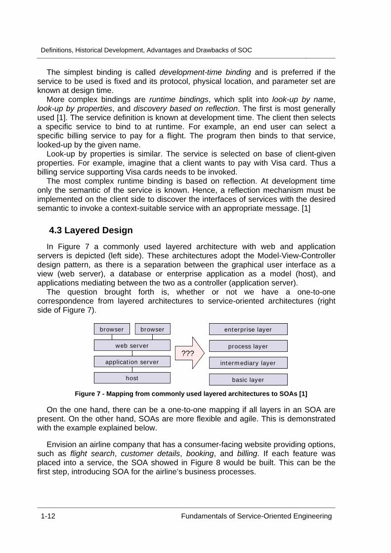
4.3 Layered Design In Figure 7 a commonly used layered architecture with web and application
servers is depicted (left side). These architectures adopt the Model-View-Controller design pattern, as there is a separation between the graphical user interface as a view (web server), a database or enterprise application as a model (host), and applications mediating between the two as a controller (application server).
The question brought forth is, whether or not we have a one-to-one correspondence from layered architectures to service-oriented architectures (right side of Figure 7).
browser browser
web server
application server
host
enterprise layer
process layer
intermediary layer
basic layer
???
browser browser
web server
application server
host
browser browser
web server
application server
host
enterprise layer
process layer
intermediary layer
basic layer
enterprise layer
process layer
intermediary layer
basic layer
???
Figure 7 - Mapping from commonly used layered architectures to SOAs [1]
On the one hand, there can be a one-to-one mapping if all layers in an SOA are
present. On the other hand, SOAs are more flexible and agile. This is demonstrated with the example explained below.
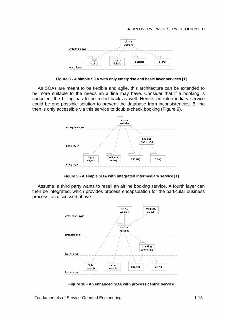
Envision an airline company that has a consumer-facing website providing options,
such as flight search, customer details, booking, and billing. If each feature was placed into a service, the SOA showed in Figure 8 would be built. This can be the first step, introducing SOA for the airline’s business processes.
4 AN OVERVIEW OF SERVICE-ORIENTED C C S
Fundamentals of Service-Oriented Engineering 1-13
Figure 8 - A simple SOA with only enterprise and basic layer services [1]
As SOAs are meant to be flexible and agile, this architecture can be extended to
be more suitable to the needs an airline may have. Consider that if a booking is canceled, the billing has to be rolled back as well. Hence, an intermediary service could be one possible solution to prevent the database from inconsistencies. Billing then is only accessible via this service to double-check booking (Figure 9).
Figure 9 - A simple SOA with integrated intermediary service [1]
Assume, a third party wants to resell an airline booking service. A fourth layer can
then be integrated, which provides process encapsulation for the particular business process, as discussed above.
Figure 10 - An enhanced SOA with process centric service
Definitions, Historical Development, Advantages and Drawbacks of SOC
1-14 Fundamentals of Service-Oriented Engineering
This short example indicates that service-oriented architectures are flexible and can be built step-by-step. Moreover, they are easy to adapt and extendable, if needed. The loosely coupled services used, have limited functionality and can be developed separately.
5 Benefits and Drawbacks of Service-Oriented Archi-tecture and Computing
The benefits of SOAs as well as of SOC were discussed simultaneously throughout this paper. This chapter summarizes their advantages and disadvantages. Within the next two subchapters the applicability and limits of this technology are touched.
5.1 Advantages The most important attributes of SOA are high level agility and flexibility. For these
reasons, SOAs are independent from different technologies using XML as a generic message format. Combining a number of small services and focusing on service reuse, development processes are supposed to be more efficient and cost-saving. Speaking in terms of advertisement, SOA concentrates on building more stable and load-balanced, high performance applications, which is at least partly true (see chapter 5.2). The evolutionary approach of building SOAs results in adequate business infrastructures suitable for and easy adaptable to current business needs. As there might be no need to plan large business applications with development times of several months or even years, SOAs reduce the risk of erroneous trends, software migration, complex component integration, and can also reduce time to market. Although SOAs are not a panacea, they are more business-oriented, enabling a better communication between IT developers and often workflow-focused business people.
5.2 Disadvantages The last chapter mentioned the cost effectiveness of SOA and SOC. Nevertheless,
this cost effectiveness depends on the actual level of reuse achieved and the number of customers using the built services. As previously stated, standardization of service-related technologies is not yet completed. This can cause problems with future service developments and influence the cost factor.
In addition, the introduction phase of an SOA must be taken into account. New technologies require new software frameworks as well as trainings and lectures for employees. Developers have to adopt new, more agile, development processes, in which especially the inter-enterprise communication to design service interfaces and the reflection of service reuse need to be considered.
Also error tracking is an issue to be discussed. As application servers became the central point of coordination across multiple client-server systems, it is hard to track failures along the transaction path. Moreover, with a fast, agile, and flexible
6 CONCLUSION AND OUTLOOK
Fundamentals of Service-Oriented Engineering 1-15
infrastructure it may be difficult to define “which service was deployed at the time of the error” [14].
Two essential drawbacks of SOC are performance and security. Response times are difficult to calculate and to ensure, because the concrete system load the time a request is served can not always be foreseen. Vise versa, load characteristics are hard to plan and to predict. This becomes more obvious thinking about what knowledge a developer has about a service. In many cases it is unidentified how many and what kind of services are used invoking one single service. For performance reasons, also the message passing and parsing overhead must be considered. Even though XML parsers and message bus systems are well explored and optimized, it costs time and resources to forward and parse messages. Other aspects include concurrent database access of loosely coupled services and the access of several sources.
With the introduction of service-oriented architectures, overall security mechanisms do not work in most cases. As services are supposed to be stateless and services can invoke other services without forwarding the user context, it is not always known, who is requesting a certain service. Hence, there is an absolute need for suitable security policies and identity management for the participating back-end systems. That, though, produces administration overhead.
6 Conclusion and Outlook This paper discussed several definitions of terms associated with SOC. As seen,
the approach of SOC is based on an evolution of former technologies and patterns. As a result, designing SOAs means using a pattern of how to build agile and flexible, loosely coupled applications.
The future of SOC is quite uncertain. Some people see Service Science as a new field of research, merging the traditional management, computer, social, legal, and psychological sciences to develop skills required in a services-led economy. Like a cross-disciplinary approach, service science states that innovative services are the key to economic success to meet the real needs of customers maximizing customer satisfaction while minimizing costs. [11]
It remains open, whether SOC will be used for several years or if it will be replaced by newer technologies in the short-term future.
Definitions, Historical Development, Advantages and Drawbacks of SOC
1-16 Fundamentals of Service-Oriented Engineering
References [1] D. Krafzig and K. Banke and D. Slama. Enterprise SOA: Service-Oriented
Architecture Best Practices. Prentice Hall, 2004. [2] Merriam Webster OnLine. http://www.m-w.com/dictionary/service, April 2006. [3] Edward Lane. Demystifying Service-Oriented Architecture.
http://www.itweb.co.za/sections/industryinsight/java/lane040615.asp, 2004. [4] Edward Lane. SOA Design Goals and Benefits.
http://www.itweb.co.za/sections/industryinsight/java/lane041026.asp, 2004. [5] S. Nigam. Service Oriented Development of Applications (SODA) in Sybase
Workspace. http://searchvb.bitpipe.com/detail/RES/1120843540_325.html, April 2006.
[6] S. Burbeck. The Tao of e-business Services, Emerging Technologies. IBM Software Group, ftp://www6.software.ibm.com/software/developer/library/ws-tao.pdf, 2000.
[7] Edward Lane. SOA Fundamentals and Characteristics. http://www.itweb.co.za/sections/industryinsight/java/lane040806.asp, 2004.
[8] M. Dolgicer. How Service Oriented Architectures Enable Business Process Fusion. Technology Transfer, http://www.tti.it/, April 2006.
[9] M. Singh, M. Huhns. Service-Oriented Computing. John Wiley & Sons, Ltd., 2005. [10] W. Vogels. Web Services are not Distributed Objects. Common Misconceptions
about the Fundamentals of Web Service Technology, IEEE Internet Computing, 7(6), 59-66, 2003.
[11] J.M. Tien and D. Berg. A Case for Service Systems Engineering. Journal of Systems Science and Engineering, 12(1), 13-38, 2003.
[12] Compuware. SOASODASurvey2005. http://www.compuware.com.au/resources/SOASODASurvey2005.pdf, 2005.
[13] Monomentum Software. SODA - Service Oriented Development of Applications. http://www.serviceoriented.org/soda.html, 2003.
[14] Wily Technology Division. SOA and Web Services: the Performance Paradox, www.wilytech.com, California, 2006.
[15] Factory3x5. Web Service Definition. www.factory3x5.com, April 2006. [16] IBM SOA Foundation. SOA design & development. http://www-
306.ibm.com/software/info/developer/solutions/soadev/index.jsp, April 2006. [17] W3C Working Group. Web Services Architecture.
http://www.w3.org/TR/2004/NOTE-ws-arch-20040211/#whatis, November 2006. [18] W3C Working Group. Web Services Architecture Requirements.
http://www.w3.org/TR/2004/NOTE-wsa-reqs-20040211/#id2604831, November 2006
Service Description
Uwe Kylau
The emerging concept of service-orientation in the area of enterprise computing isconsidered by many as the next step to integrate businesses into collaborations. Forthis purpose an open and universal architecture is proposed, called Service-OrientedArchitecture (SOA). An important aspect of the integration, that must be addressedin the architecture, is the capability to establish trusted relationships, essential to thebusiness world. Qualified description of services are identified as the means to formu-late terms of a contract between service consumer and provider. This document dealswith the characteristics of service descriptions and presents a concrete language, theWeb Services Description Language (WSDL). WSDL version 1.1 is studied in detail,whereas evolvement to version 2.0 is only outlined. The question, whether WSDL fa-cilitates qualified descriptions, is also answered in the course of the examinations.
Keywords: Service-Oriented Architecture, Web Services, Web Services DescriptionLanguage, software specification, Design by ContractTM
1 Introduction
Currently, research and industry in the field of Information Technology (IT) Systemselaborate on a new promising paradigm, the Service-Oriented Architecture. SOA is anarchitectural concept that heavily relies on services as the main building blocks of en-terprise applications. The main goal behind a SOA is to create a uniform collaborationplatform to conduct electronic business, which is sometimes referred to as an openmarketplace for services. It defines a common foundation to build various concretearchitectures, without demanding particular technologies for implementation. However,there are prerequisites that must be considered for all types of adopting SOA to theworld of enterprise computing. The environment underlying a SOA is highly distributedand heterogeneous, i.e. many different kinds of local infrastructures exist, all globallyconnected via the Internet. This definitely requires standardized protocols.
Other features of a SOA that must be supported by those protocols are loose cou-pling, dynamic discovery and late binding of services. Years of work in distributed com-puting have shown that these are necessary to develop flexible applications sufficientfor business needs. Most prominent Among theses needs is a trend to concentrateon core business and outsource unprofitable functions (single tasks or whole businesssectors). Service-orientation offers the means to extend and shift this trend in order todirectly support it with IT systems. In this context it is desirable to have the possibilityto adaptively decide who will execute outsourced business functions. The best solutionwould be to base the decision on most up-to-date information, which are available right
Fundamentals of Service-Oriented Engineering 2-1

Service Description
before enactment of a task, at runtime. Thus, a SOA can be employed to increasethe benefits of electronic collaboration and outsourcing (cost reduction, speed up ofbusiness procedures, etc.).
There are a few key requirements for a SOA in order to establish an open merket-place (see also [11]). On of them is to provide descriptions of the services that areoffered. On the one hand this is necessary to tell the consumer how to access and usethe service, but another aspect is at least equally important. Consumers in a businessscenario will only rely and trust services, if they know “what they do and what dataelements they manipulate mean” [2]. An expressive description is the key to this re-quirement. Expressive here means, that essential aspects of the service are included.Briefly summarized, operational properties and their semantics must be described. Asservices are used to expose software components, service descriptions are a new formof software specification.
To further motivate the central role of the service description, take into account thatSOA defines a general application scenario, depicted in Fig. 1. Three roles are distin-guished: service provider, service requestor and service broker. The entities participat-ing in a SOA are limited to a single role only for the time of a single interaction. In thescenario service providers publish their services at one or more service broker, eachmaintaining a registry of services. On service publishing, the description is supplied,which in turn is used by the broker to categorize the service. Service requestors onthe other side use a search facility at the broker to find a desired service. The searchcan be performed based on different criteria, e.g. category or functionality. If it hasbeen successful, a set of service descriptions is delivered to the requestor, who thenchooses the service most suitable for the intended purpose. With the information in thedescription a connection to the service endpoint at the provider can be established, i.e.the requestor’s client application binds itself to the service endpoint for invocation.
Figure 1: SOA roles and their basic interactions
As delineated above, service descriptions contain the information to enable the in-teractions that take place in a SOA. Furthermore, they are also used to form an agree-ment on what is expected by the requestor and what is delivered by the provider. In
2-2 Fundamentals of Service-Oriented Engineering
2 SPECIFYING PIECES OF SOFTWARE
other words the description represents a specification of the service. The characteris-tics of software specifications will be explained in section 2. In addition, particularitiesof service descriptions in comparison to traditional specifications are delimited. This isconnected to the question, whether service descriptions are sufficient as an agreement.Section 3 introduces the Web Services Description Language. It is the de-facto stan-dard for describing services in a Web-/XML-based SOA. Section 4 will discuss what ismissing in WSDL to form a capable service description for a mature SOA (referring tothe results of section 2) Finally, section 5 summarizes and concludes the examinationson service descriptions.
2 Specifying Pieces of Software
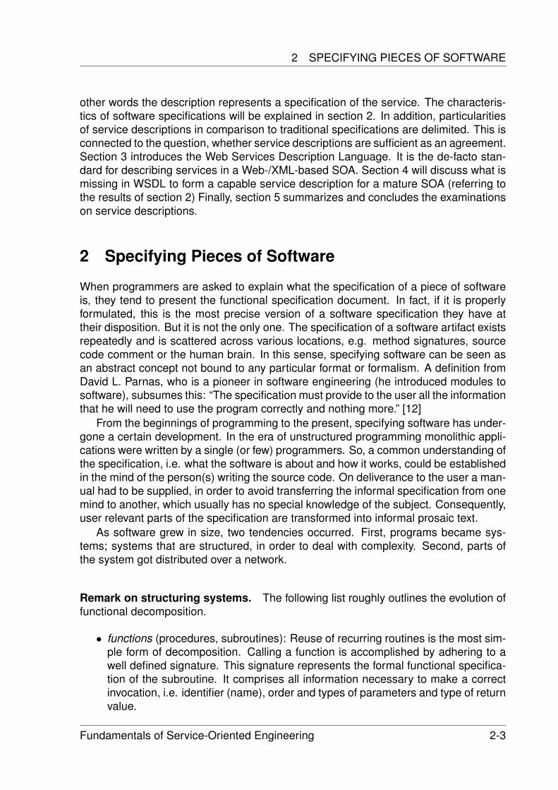
When programmers are asked to explain what the specification of a piece of softwareis, they tend to present the functional specification document. In fact, if it is properlyformulated, this is the most precise version of a software specification they have attheir disposition. But it is not the only one. The specification of a software artifact existsrepeatedly and is scattered across various locations, e.g. method signatures, sourcecode comment or the human brain. In this sense, specifying software can be seen asan abstract concept not bound to any particular format or formalism. A definition fromDavid L. Parnas, who is a pioneer in software engineering (he introduced modules tosoftware), subsumes this: “The specification must provide to the user all the informationthat he will need to use the program correctly and nothing more.” [12]
From the beginnings of programming to the present, specifying software has under-gone a certain development. In the era of unstructured programming monolithic appli-cations were written by a single (or few) programmers. So, a common understanding ofthe specification, i.e. what the software is about and how it works, could be establishedin the mind of the person(s) writing the source code. On deliverance to the user a man-ual had to be supplied, in order to avoid transferring the informal specification from onemind to another, which usually has no special knowledge of the subject. Consequently,user relevant parts of the specification are transformed into informal prosaic text.
As software grew in size, two tendencies occurred. First, programs became sys-tems; systems that are structured, in order to deal with complexity. Second, parts ofthe system got distributed over a network.
Remark on structuring systems. The following list roughly outlines the evolution offunctional decomposition.
• functions (procedures, subroutines): Reuse of recurring routines is the most sim-ple form of decomposition. Calling a function is accomplished by adhering to awell defined signature. This signature represents the formal functional specifica-tion of the subroutine. It comprises all information necessary to make a correctinvocation, i.e. identifier (name), order and types of parameters and type of returnvalue.
Fundamentals of Service-Oriented Engineering 2-3
Service Description
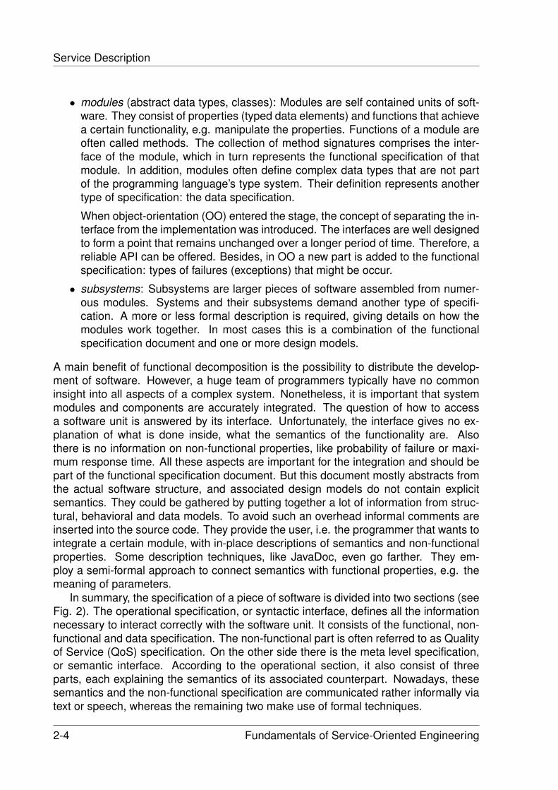
• modules (abstract data types, classes): Modules are self contained units of soft-ware. They consist of properties (typed data elements) and functions that achievea certain functionality, e.g. manipulate the properties. Functions of a module areoften called methods. The collection of method signatures comprises the inter-face of the module, which in turn represents the functional specification of thatmodule. In addition, modules often define complex data types that are not partof the programming language’s type system. Their definition represents anothertype of specification: the data specification.
When object-orientation (OO) entered the stage, the concept of separating the in-terface from the implementation was introduced. The interfaces are well designedto form a point that remains unchanged over a longer period of time. Therefore, areliable API can be offered. Besides, in OO a new part is added to the functionalspecification: types of failures (exceptions) that might be occur.
• subsystems: Subsystems are larger pieces of software assembled from numer-ous modules. Systems and their subsystems demand another type of specifi-cation. A more or less formal description is required, giving details on how themodules work together. In most cases this is a combination of the functionalspecification document and one or more design models.
A main benefit of functional decomposition is the possibility to distribute the develop-ment of software. However, a huge team of programmers typically have no commoninsight into all aspects of a complex system. Nonetheless, it is important that systemmodules and components are accurately integrated. The question of how to accessa software unit is answered by its interface. Unfortunately, the interface gives no ex-planation of what is done inside, what the semantics of the functionality are. Alsothere is no information on non-functional properties, like probability of failure or maxi-mum response time. All these aspects are important for the integration and should bepart of the functional specification document. But this document mostly abstracts fromthe actual software structure, and associated design models do not contain explicitsemantics. They could be gathered by putting together a lot of information from struc-tural, behavioral and data models. To avoid such an overhead informal comments areinserted into the source code. They provide the user, i.e. the programmer that wants tointegrate a certain module, with in-place descriptions of semantics and non-functionalproperties. Some description techniques, like JavaDoc, even go farther. They em-ploy a semi-formal approach to connect semantics with functional properties, e.g. themeaning of parameters.
In summary, the specification of a piece of software is divided into two sections (seeFig. 2). The operational specification, or syntactic interface, defines all the informationnecessary to interact correctly with the software unit. It consists of the functional, non-functional and data specification. The non-functional part is often referred to as Qualityof Service (QoS) specification. On the other side there is the meta level specification,or semantic interface. According to the operational section, it also consist of threeparts, each explaining the semantics of its associated counterpart. Nowadays, thesesemantics and the non-functional specification are communicated rather informally viatext or speech, whereas the remaining two make use of formal techniques.
2-4 Fundamentals of Service-Oriented Engineering

2 SPECIFYING PIECES OF SOFTWARE
Figure 2: Entity-relationship diagram depicting a model for a component specification(notation: Fundamental Modeling Concept (FMC), [10])
Remark on distribution of systems. In contrast to its non-distributed counterpart,a distributed system involves middleware, which abstracts from communication andother common infrastructure issues. Most middleware architectures define a compo-nent model. This model provides conventions on how to develop modules (now calledcomponents), on how to assemble them to a distributed application and how to enforcespecific middleware services for the application, e.g. security or persistence. A SOAmust unify different types of middleware systems and their component models. Therehas to be an agreement that directs, in what way entities of one component system aremapped to corresponding entities of another system. The component’s formal specifi-cation can be used as a point of connection. For this purpose, SOA applies universalspecification standards with semantics defined as precisely as possible. From this extralayer of abstraction a particular component architecture can derive its custom, but con-stant, mapping. Next to the heterogeneity of middleware architectures, the nature ofdistribution and feature of loose, dynamic coupling have caused a temporal shift in theprocess of integrating components into an application. Classical component program-ming makes design time decisions which component is used. In a highly adaptive SOAthis decision is now made at runtime. But, such an approach has to entail a specifica-tion, that is completely machine-parsable. Hence, the entire specification must adhereto a formal definition and informal parts (in comments, etc.) must be minimized.
A subsequent step in distributed computing was to spread applications across orga-nizational boundaries and develop real business-to-business (B2B) scenarios. Again,the factor of trust must be mentioned, that is an essential precondition for businesses tocollaborate. Trusted relationships require each party to be sure of, not only the identityclaimed by the other side, but of the correctness of remote components they want tooperate on. In this context, it should be stated that correctness in computer science isalways relative. A component behaves correctly according to its specification. In or-
Fundamentals of Service-Oriented Engineering 2-5
Service Description
der to confirm this and make accurate usage possible, a more advanced specificationmethod is necessary. For that reason, Design by ContractTM ( [14]) was developed byBertrand Meyer. The concept demands to clearly specify (prior to component design):
• What is the offered functionality of the component? Which input data is consumedand which output data is delivered?
• What are the preconditions the requestor is expected to assert prior to execution?
• What are the effects (postconditions) the provider will guarantee after execution?
• Which invariants remain unaffected during execution?
• What are the semantics of specified elements?
The concept is also known as IOPE, a lineup of the first characters of terms input,output, precondition and effect. If Design by ContractTM is applied, an increment inexpressiveness of the specification can be identified. Beside functionality and its se-mantics, requestor and provider additionally assert certain conditions. This means,each side is obliged to ensure that its respective parts of these conditions hold true.On the other hand, it has the right to insist on validity of assertions made by the otherside. Generally, such characteristics define a contractual relationship. Thus, the spec-ification of a component is augmented to a contract regulating the interaction with thatcomponent.
The description of services. As stated earlier, services are the building blocks ofa SOA. They make business entities available to the open marketplace, which is cre-ated by a particular SOA. Functionality of these entities is implemented by softwarecomponents. Consequently, techniques that are necessary and proved to be practicalfor component specifications, should be transferred to service descriptions. First, thedescription must be complete, i.e. must contain all types of specifications, which weredistinguished above. Here attention should be drawn to the fact that non-functionalproperties and formal semantics are scarcely put into practice in classical componentprogramming. Rather interface matching is employed to find a suitable candidate. Butthis procedure is unsatisfying for an open, dynamic SOA, where the set of offeredservices changes constantly. And the question, what a service does, can hardly beanswered just by looking at the functional specification, at least for a software client.
It was also mentioned above that services are supposed to be discovered, enactedand invoked by machines in a heterogeneous infrastructure. That makes open, formaland accepted standards indispensable for their description. These standards have tobe extensible, since an evolution of the service concept cannot be ruled out. In addition,Design by ContractTM becomes more important than ever before. The reason is, that ina SOA consumer (requestors) demands meet provider offers with the goal to perform atask or request a service. Real business relationships are established and their termsare settled in a contract. These terms are expressed in the service description andrepresent the agreement brought up in section 1.
Alltogether, the service description is used to advertise capabilities, interface, be-havior, quality and meaning of a service on the open marketplace. To which extent thisis achieved in the area of Web Services, will be presented in the next section.
2-6 Fundamentals of Service-Oriented Engineering
3 WEB SERVICES DESCRIPTION LANGUAGE (WSDL)
3 Web Services Description Language (WSDL)
The Web Services Description Language originates from a combination of IBM’s Net-work Accessible Services Specification Language (NASSL) and Microsoft’s ServiceDescription Language (SDL). Its development was one of the first efforts to realize aninitial Web services landscape that spans across multiple organizations. Namely, acoalition of 36 companies formed an initiative to create a directory for Web services,that soon required a platform-independent language to describe the services. There-fore, it might not be astonishing, that an XML-based approach was chosen for WSDL.
These early beginnings of service-orientation go back to the year 2000. After releas-ing WSDL 1.0 in September 2000, a submission to the World Wide Web Consortium(W3C) was made, already backed by several major software vendors. WSDL Version1.1 became an adopted specification in March 2001.
During the following years WSDL 1.1 emerged as the de-facto standard for describ-ing Web services. Nowadays, it represents one cornerstone of a whole Web ServicesArchitecture, that was designed to achieve a common understanding among Web ser-vices software vendors. This so called Web Services Stack is assembled from numer-ous Web Services specifications, e.g. UDDI, WS-Policy, WS-Addressing or WS-BPEL(see Glossary for complete names). But, academic examination of WSDL and its appli-cation in real world industry scenarios quickly showed some limitations. Its expressivecapabilities are sometimes too restrictive and sometimes not restrictive enough. Ad-ditionally, ambiguities within the specification occurred. Altogether, this caused a lotof difficulties with interoperability, which is the main idea behind WSDL. The problemswere addressed by the Web Services Interoperability (WS-I) Organization that defineda Web Services Interoperability Basic Profile. The profile is a collection of rules on howto use WSDL, SOAP and UDDI to build interoperable Web service systems.
Nevertheless, the WSDL specification itself, i.e. its structures and definitions, hadsome weak spots. These resulted from intentions of the authors, that proved to beimpractical, but also from developments in the Web Services world, that could not beforeseen. Accordingly, the Web Services Description Working Group at W3C evolvedthe specification to the next stage. First, they planned to create a version 1.2. Then,some major changes were proposed, that lead to an increment of a full version number.The overall work on WSDL 2.0 took about three years and its final draft is still underrevision. But standardization process is expected to finish within 2006 or 2007 andthe main authors state: “[...] it is unlikely that the WSDL specification will be furtherevolved.” [15]
3.1 WSDL 1.1
The Web Services Description Language defines the structure of an XML document. Itis comprised of an ordered list of child elements. This list can be divided in an abstractpart and a concrete part. The abstract part describes the abstract interface of the Webservice in terms of message structures and operation signatures with their parameters.It is often called the WHAT, whereas the concrete part refers to the HOW (bindings)and WHERE (endpoint ports). Bindings specify which transport and message protocol
Fundamentals of Service-Oriented Engineering 2-7
Service Description
to use. Endpoint ports give a network address where the Web service can be invoked.These different elements of the WSDL document are interconnected (as explainedbelow in this section).
Architectural Concepts. It should be pointed out that WSDL documents, containingonly elements of the specification (pure WSDL), are restricted to be functional speci-fications of the Web service components they describe. Within this sentence two ar-chitectural concepts can be identified, which among others were chosen as guidingprinciples for the development of WSDL. First, the language is extensible. Other XML-fragments that reside in a XML namespace different from the WSDL namespace canbe embedded into the description. This allows for integration of supplementary WebServices specifications, as well as any other XML syntax. That might be, for instance,WS-Policy or XML Schema (which is extensively used in WSDL). The second discov-erable concept: no semantics. Semantic descriptions were omitted on purpose, whichis also true for non-functional properties. The authors of WSDL decided, that it simplywould have been too early to consider a fully equipped component specification. Atthe time WSDL came into play, research in the field of non-functional properties andsemantics had just begun.
Another architectural concept is the separation of WHAT from HOW and WHERE,that was already mentioned above. Hence, it is possible to use the abstract part ofthe description for various types of bindings and an arbitrary number of endpoint ports,even across different WSDL documents. This reuse makes sense, because there isalso the concept to support multiple message formats and transport protocols. As it isnot predictable which communication means, today’s and future one’s, will be availableto Web service implementers, the service description language should not be restrictedto a single technology. Same applies to the type system used for definition of messagetypes. Thus, representation of data types in form of schemas or other data modelsremains independent of the service description. The extensibility concept ensures thatdefined data types can be embedded into the description.
To complete the list, two more concepts must be named that were taken into ac-count when WSDL was developed. The authors designed WSDL to unify the worldof message-oriented middleware with the world of object-oriented systems. Conse-quently, interaction with a Web service can be described as a flow of messages, thatare processed by the Web service implementation. On the other hand, the interactioncan also be described as a remote procedure call (RPC), where the invocation of a Webservice operation is mapped to a method of the Web service implementation. Besides,the number of operations a Web service defines is not limited. And in some casesthe whole service may be structured into multiple steps, offered via several operations.In order to consume the service correctly, the operations must be invoked in the rightorder. The last architectural concept of WSDL forbids these implications. The order ofoperations in the description does not resemble the order of invocation. In fact, a Webservice client should clearly not assume any connection between offered operations. Achoreography of invocations is subject to other Web Services specifications.
2-8 Fundamentals of Service-Oriented Engineering
3 WEB SERVICES DESCRIPTION LANGUAGE (WSDL)
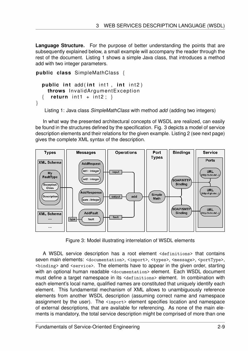
Language Structure. For the purpose of better understanding the points that aresubsequently explained below, a small example will accompany the reader through therest of the document. Listing 1 shows a simple Java class, that introduces a methodadd with two integer parameters.
public class SimpleMathClass {
public i n t add ( i n t i n t1 , i n t i n t 2 )throws Inva l idArgumentExcept ion
{ return i n t 1 + i n t 2 ; }}
Listing 1: Java class SimpleMathClass with method add (adding two integers)
In what way the presented architectural concepts of WSDL are realized, can easilybe found in the structures defined by the specification. Fig. 3 depicts a model of servicedescription elements and their relations for the given example. Listing 2 (see next page)gives the complete XML syntax of the description.
Figure 3: Model illustrating interrelation of WSDL elements
A WSDL service description has a root element <definitions> that containsseven main elements: <documentation>, <import>, <types>, <message>, <portType>,<binding> and <service>. The elements have to appear in the given order, startingwith an optional human readable <documentation> element. Each WSDL documentmust define a target namespace in its <definitions> element. In combination witheach element’s local name, qualified names are constituted that uniquely identify eachelement. This fundamental mechanism of XML allows to unambiguously referenceelements from another WSDL description (assuming correct name and namespaceassignment by the user). The <import> element specifies location and namespaceof external descriptions, that are available for referencing. As none of the main ele-ments is mandatory, the total service description might be comprised of more than one
Fundamentals of Service-Oriented Engineering 2-9
Service Description
WSDL document, consequently increasing modularity (separating WHAT from HOWand WHERE).
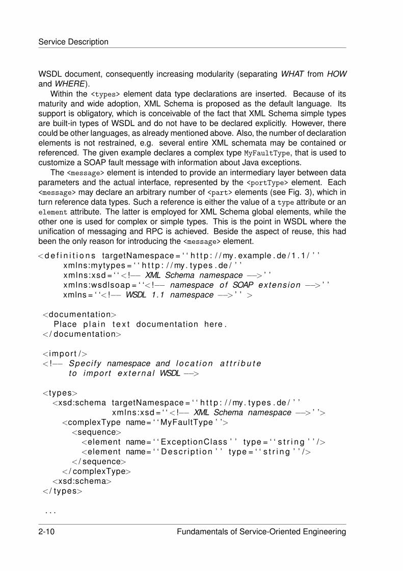
Within the <types> element data type declarations are inserted. Because of itsmaturity and wide adoption, XML Schema is proposed as the default language. Itssupport is obligatory, which is conceivable of the fact that XML Schema simple typesare built-in types of WSDL and do not have to be declared explicitly. However, therecould be other languages, as already mentioned above. Also, the number of declarationelements is not restrained, e.g. several entire XML schemata may be contained orreferenced. The given example declares a complex type MyFaultType, that is used tocustomize a SOAP fault message with information about Java exceptions.
The <message> element is intended to provide an intermediary layer between dataparameters and the actual interface, represented by the <portType> element. Each<message> may declare an arbitrary number of <part> elements (see Fig. 3), which inturn reference data types. Such a reference is either the value of a type attribute or anelement attribute. The latter is employed for XML Schema global elements, while theother one is used for complex or simple types. This is the point in WSDL where theunification of messaging and RPC is achieved. Beside the aspect of reuse, this hadbeen the only reason for introducing the <message> element.
<d e f i n i t i o n s targetNamespace = ‘ ‘ h t t p : / / my. example . de / 1 . 1 / ’ ’xmlns:mytypes = ‘ ‘ h t t p : / / my. types . de / ’ ’xmlns:xsd = ‘ ‘ < !−− XML Schema namespace −−> ’ ’xmlns:wsdlsoap = ‘ ‘< !−− namespace of SOAP extens ion −−> ’ ’xmlns = ‘ ‘< !−− WSDL 1.1 namespace −−> ’ ’ >
<documentation>Place p l a i n t e x t documentation here .
< / documentation>
<impor t />< !−− Spec i fy namespace and l o c a t i o n a t t r i b u t e
to impor t ex te rna l WSDL −−>
<types><xsd:schema targetNamespace = ‘ ‘ h t t p : / / my. types . de / ’ ’
xmlns:xsd = ‘ ‘ < !−− XML Schema namespace −−> ’ ’><complexType name= ‘ ‘ MyFaultType ’ ’>
<sequence><element name= ‘ ‘ Except ionClass ’ ’ type = ‘ ‘ s t r i n g ’ ’ /><element name= ‘ ‘ Desc r i p t i on ’ ’ type = ‘ ‘ s t r i n g ’ ’ />
< / sequence>< / complexType>
<xsd:schema>< / types>
. . .
2-10 Fundamentals of Service-Oriented Engineering
3 WEB SERVICES DESCRIPTION LANGUAGE (WSDL)
<message name= ‘ ‘ AddRequest ’ ’><pa r t name= ‘ ‘ i n t 1 ’ ’ type = ‘ ‘ x s d : i n t e g e r ’ ’ /><pa r t name= ‘ ‘ i n t 2 ’ ’ type = ‘ ‘ x s d : i n t e g e r ’ ’ />
< / message><message name= ‘ ‘ AddResponse ’ ’>
<pa r t name= ‘ ‘sum ’ ’ type = ‘ ‘ x s d : i n t e g e r ’ ’ />< / message><message name= ‘ ‘ AddFault ’ ’>
<pa r t name= ‘ ‘ f a u l t ’ ’ type = ‘ ‘ mytypes:MyFaultType ’ ’ />< / message>
<portType name= ‘ ‘ SimpleMath ’ ’><opera t ion name= ‘ ‘ add ’ ’>
< i npu t name= ‘ ‘AddReqMess ’ ’ message = ‘ ‘ AddRequest ’ ’ /><output name= ‘ ‘AddRespMess ’ ’ message = ‘ ‘ AddResponse ’ ’ />< f a u l t name= ‘ ‘ AddFaultMessage ’ ’ message = ‘ ‘ AddFault ’ ’ />
< / opera t ion>< / portType>
<b ind ing name= ‘ ‘ SimpleMathSOAPBinding ’ ’ type = ‘ ‘ SimpleMath ’ ’><wsdlsoap:b ind ing s t y l e = ‘ ‘ rpc ’ ’
t r a n s p o r t = ‘ ‘ h t t p : / / schemas . xmlsoap . org / soap / h t t p ’ ’ /><opera t ion name= ‘ ‘ add ’ ’>
< i npu t> <wsdlsoap:body use = ‘ ‘ l i t e r a l ’ ’ />< / i npu t><output> <wsdlsoap:body use = ‘ ‘ l i t e r a l ’ ’ />< / ou tput>< f a u l t>
<wsd l soap : f au l t name= ‘ ‘ AddFaultMessage ’ ’use = ‘ ‘ l i t e r a l ’ ’ />
< / f a u l t>< / opera t ion>
< / b ind ing>
<serv i ce name= ‘ ‘ SimpleMathService ’ ’><po r t name= ‘ ‘ SOAPPort ’ ’ b ind ing = ‘ ‘ SimpleMathSOAPBinding ’ ’>
<wsdlsoap:address l o c a t i o n = ‘ ‘ < !−− place URL here −−> ’ ’ />< / po r t>
< / se rv i ce>< / d e f i n i t i o n s>
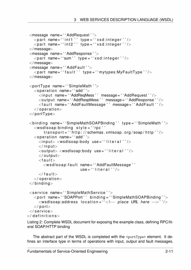
Listing 2: Complete WSDL document for exposing the example class, defining RPC/lit-eral SOAP/HTTP binding
The abstract part of the WSDL is completed with the <portType> element. It de-fines an interface type in terms of operations with input, output and fault messages.
Fundamentals of Service-Oriented Engineering 2-11
Service Description
Depending on the type of the operation, the occurrence and ordering of these elementsis constrained. Four types are distinguished.
• one-way operation: one input message must be declared
• request-response operation: one input message, followed by one output mes-sage must be declared, optionally several fault messages are allowed
• notification operation: one output message must be declared
• solicit-response operation: one output message, followed by one input messagemust be declared, optionally several fault messages are allowed
The list of fault message is not restricted. Therefore different types of faults canbe indicated, that might occur during operation execution. In the example a request-response operation add is defined, according to the Java method. Until here only WHAThas been described with HOW and WHERE remaining.
The <binding> element first identifies via its type attribute which interface type itimplements. For each operation of the <portType> the <binding> defines how to for-mat the messages and what transport protocol to use for their exchange. A <portType>
can be bound to numerous communication technologies. Most common is a combina-tion of SOAP as packaging format and HTTP(S) as transport protocol (see example).Aside, there exist many more types of bindings, e.g. HTTP/MIME or SOAP over SMTP(omitted in Listing 2). For more information on those, please refer to the WSDL specifi-cations ( [7], [1], [6], [5]). Details on the SOAP/HTTP binding are examined in the nextsubsection.
Finally, the <service> element accumulates a group of endpoint ports. Each portassociates an interface and transport protocol with a network address by referencinga binding that must be used for the invocation on this port. WSDL extensibility is em-ployed to define the concrete address, since different binding types may require differ-ent types of endpoint addresses. The SOAP/HTTP binding uses <wsdlsoap:address>
element, that has a location attribute with the endpoint URL as value. The prefixwsdlsoap resolves to the namespace of extensibility elements for the SOAP binding.
3.2 WSDL Usage Scenarios
This subsection concentrates on two aspects of WSDL that might be of particular inter-est. On the one hand, a SOAP/HTTP binding can have different characteristics. Thesehave impact on other parts of the descriptions. What effects are implied by a certaintype, will be examined first (see also [3]). Then some small examples for complex typedeclarations are presented, that are necessary, if array and object parameters are to beexposed. Please note that the scenario already takes conformance to the WS-I BasicProfile 1.0 into account. At the appropriate position some important rules of the profileare mentioned. For the full collection see [4].
2-12 Fundamentals of Service-Oriented Engineering
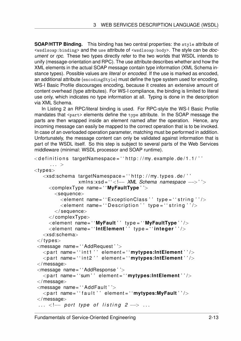
3 WEB SERVICES DESCRIPTION LANGUAGE (WSDL)
SOAP/HTTP Binding. This binding has two central properties: the style attribute of<wsdlsoap:binding> and the use attribute of <wsdlsoap:body>. The style can be doc-ument or rpc. These two types directly refer to the two worlds that WSDL intends tounify (message-orientation and RPC). The use attribute describes whether and how theXML elements in the actual SOAP message contain type information (XML Schema in-stance types). Possible values are literal or encoded. If the use is marked as encoded,an additional attribute (encodingStyle) must define the type system used for encoding.WS-I Basic Profile discourages encoding, because it creates an extensive amount ofcontent overhead (type attributes). For WS-I compliance, the binding is limited to literaluse only, which indicates no type information at all. Typing is done in the descriptionvia XML Schema.
In Listing 2 an RPC/literal binding is used. For RPC-style the WS-I Basic Profilemandates that <part> elements define the type attribute. In the SOAP message theparts are then wrapped inside an element named after the operation. Hence, anyincoming message can easily be mapped to the correct operation that is to be invoked.In case of an overloaded operation parameter, matching must be performed in addition.Unfortunately, the message content can only be validated against information that ispart of the WSDL itself. So this step is subject to several parts of the Web Servicesmiddleware (minimal: WSDL processor and SOAP runtime).
<d e f i n i t i o n s targetNamespace = ‘ ‘ h t t p : / / my. example . de / 1 . 1 / ’ ’. . . >
<types><xsd:schema targetNamespace = ‘ ‘ h t t p : / / my. types . de / ’ ’
xmlns:xsd = ‘ ‘ < !−− XML Schema namespace −−> ’ ’><complexType name= ‘ ‘ MyFaultType ’ ’>
<sequence><element name= ‘ ‘ Except ionClass ’ ’ type = ‘ ‘ s t r i n g ’ ’ /><element name= ‘ ‘ Desc r i p t i on ’ ’ type = ‘ ‘ s t r i n g ’ ’ />
< / sequence>< / complexType><element name= ‘ ‘ MyFault ’ ’ type = ‘ ‘ MyFaultType ’ ’ /><element name= ‘ ‘ IntElement ’ ’ type = ‘ ‘ integer ’ ’ />
<xsd:schema>< / types><message name= ‘ ‘ AddRequest ’ ’>
<pa r t name= ‘ ‘ i n t 1 ’ ’ element = ‘ ‘ mytypes:IntElement ’ ’ /><pa r t name= ‘ ‘ i n t 2 ’ ’ element = ‘ ‘ mytypes:IntElement ’ ’ />
< / message><message name= ‘ ‘ AddResponse ’ ’>
<pa r t name= ‘ ‘sum ’ ’ element = ‘ ‘ mytypes:IntElement ’ ’ />< / message><message name= ‘ ‘ AddFault ’ ’>
<pa r t name= ‘ ‘ f a u l t ’ ’ element = ‘ ‘ mytypes:MyFault ’ ’ />< / message>. . . < !−− po r t type of l i s t i n g 2 −−> . . .
Fundamentals of Service-Oriented Engineering 2-13
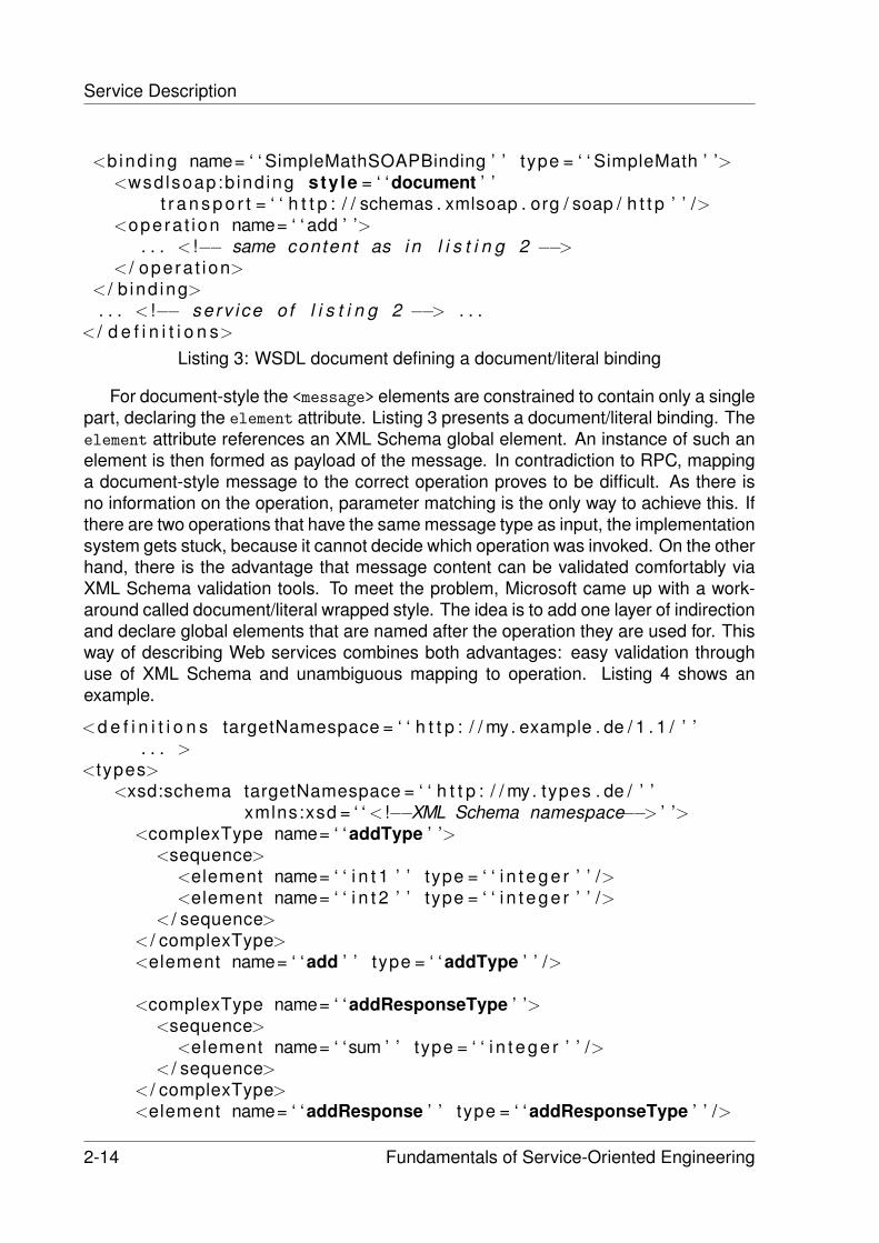
Service Description
<b ind ing name= ‘ ‘ SimpleMathSOAPBinding ’ ’ type = ‘ ‘ SimpleMath ’ ’><wsdlsoap:b ind ing sty le = ‘ ‘document ’ ’
t r a n s p o r t = ‘ ‘ h t t p : / / schemas . xmlsoap . org / soap / h t t p ’ ’ /><opera t ion name= ‘ ‘ add ’ ’>
. . . < !−− same content as i n l i s t i n g 2 −−>< / opera t ion>
< / b ind ing>. . . < !−− serv i ce o f l i s t i n g 2 −−> . . .
< / d e f i n i t i o n s>
Listing 3: WSDL document defining a document/literal binding
For document-style the <message> elements are constrained to contain only a singlepart, declaring the element attribute. Listing 3 presents a document/literal binding. Theelement attribute references an XML Schema global element. An instance of such anelement is then formed as payload of the message. In contradiction to RPC, mappinga document-style message to the correct operation proves to be difficult. As there isno information on the operation, parameter matching is the only way to achieve this. Ifthere are two operations that have the same message type as input, the implementationsystem gets stuck, because it cannot decide which operation was invoked. On the otherhand, there is the advantage that message content can be validated comfortably viaXML Schema validation tools. To meet the problem, Microsoft came up with a work-around called document/literal wrapped style. The idea is to add one layer of indirectionand declare global elements that are named after the operation they are used for. Thisway of describing Web services combines both advantages: easy validation throughuse of XML Schema and unambiguous mapping to operation. Listing 4 shows anexample.
<d e f i n i t i o n s targetNamespace = ‘ ‘ h t t p : / / my. example . de / 1 . 1 / ’ ’. . . >
<types><xsd:schema targetNamespace = ‘ ‘ h t t p : / / my. types . de / ’ ’
xmlns:xsd = ‘ ‘ < !−−XML Schema namespace−−> ’ ’><complexType name= ‘ ‘ addType ’ ’>
<sequence><element name= ‘ ‘ i n t 1 ’ ’ type = ‘ ‘ i n t e g e r ’ ’ /><element name= ‘ ‘ i n t 2 ’ ’ type = ‘ ‘ i n t e g e r ’ ’ />
< / sequence>< / complexType><element name= ‘ ‘add ’ ’ type = ‘ ‘ addType ’ ’ />
<complexType name= ‘ ‘addResponseType ’ ’><sequence>
<element name= ‘ ‘sum ’ ’ type = ‘ ‘ i n t e g e r ’ ’ />< / sequence>
< / complexType><element name= ‘ ‘addResponse ’ ’ type = ‘ ‘addResponseType ’ ’ />
2-14 Fundamentals of Service-Oriented Engineering
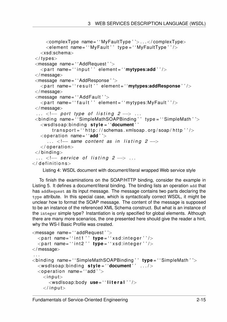
3 WEB SERVICES DESCRIPTION LANGUAGE (WSDL)
<complexType name= ‘ ‘ MyFaultType ’ ’> . . .< / complexType><element name= ‘ ‘ MyFault ’ ’ type = ‘ ‘ MyFaultType ’ ’ />
<xsd:schema>< / types><message name= ‘ ‘ AddRequest ’ ’>
<pa r t name= ‘ ‘ i npu t ’ ’ element = ‘ ‘ mytypes:add ’ ’ />< / message><message name= ‘ ‘ AddResponse ’ ’>
<pa r t name= ‘ ‘ r e s u l t ’ ’ element = ‘ ‘ mytypes:addResponse ’ ’ />< / message><message name= ‘ ‘ AddFault ’ ’>
<pa r t name= ‘ ‘ f a u l t ’ ’ element = ‘ ‘ mytypes:MyFault ’ ’ />< / message>. . . < !−− po r t type of l i s t i n g 2 −−> . . .
<b ind ing name= ‘ ‘ SimpleMathSOAPBinding ’ ’ type = ‘ ‘ SimpleMath ’ ’><wsdlsoap:b ind ing sty le = ‘ ‘document ’ ’
t r a n s p o r t = ‘ ‘ h t t p : / / schemas . xmlsoap . org / soap / h t t p ’ ’ /><opera t ion name= ‘ ‘add ’ ’>
. . . < !−− same content as i n l i s t i n g 2 −−>< / opera t ion>
< / b ind ing>. . . < !−− serv i ce o f l i s t i n g 2 −−> . . .
< / d e f i n i t i o n s>
Listing 4: WSDL document with document/literal wrapped Web service style
To finish the examinations on the SOAP/HTTP binding, consider the example inListing 5. It defines a document/literal binding. The binding lists an operation add thathas addRequest as its input message. The message contains two parts declaring thetype attribute. In this special case, which is syntactically correct WSDL, it might beunclear how to format the SOAP message. The content of the message is supposedto be an instance of the referenced XML Schema construct. But what is an instance ofthe integer simple type? Instantiation is only specified for global elements. Althoughthere are many more scenarios, the one presented here should give the reader a hint,why the WS-I Basic Profile was created.
<message name= ‘ ‘ addRequest ’ ’><pa r t name= ‘ ‘ i n t 1 ’ ’ type = ‘ ‘ x s d : i n t e g e r ’ ’ /><pa r t name= ‘ ‘ i n t 2 ’ ’ type = ‘ ‘ x s d : i n t e g e r ’ ’ />
< / message>. . .
<b ind ing name= ‘ ‘ SimpleMathSOAPBinding ’ ’ type = ‘ ‘ SimpleMath ’ ’><wsdlsoap:b ind ing sty le = ‘ ‘document ’ ’ . . . /><opera t ion name= ‘ ‘ add ’ ’>
< i npu t><wsdlsoap:body use = ‘ ‘ l i t e r a l ’ ’ />
< / i npu t>
Fundamentals of Service-Oriented Engineering 2-15
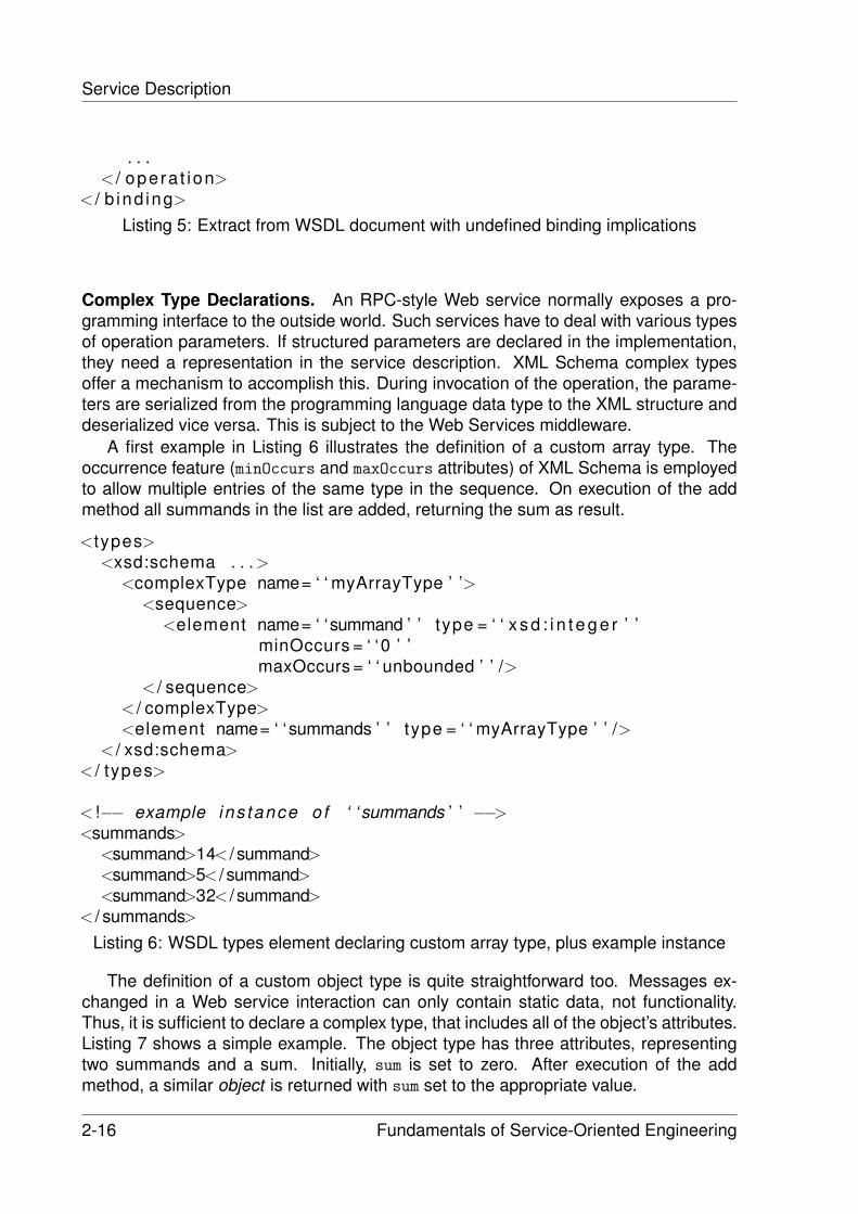
Service Description
. . .< / opera t ion>
< / b ind ing>
Listing 5: Extract from WSDL document with undefined binding implications
Complex Type Declarations. An RPC-style Web service normally exposes a pro-gramming interface to the outside world. Such services have to deal with various typesof operation parameters. If structured parameters are declared in the implementation,they need a representation in the service description. XML Schema complex typesoffer a mechanism to accomplish this. During invocation of the operation, the parame-ters are serialized from the programming language data type to the XML structure anddeserialized vice versa. This is subject to the Web Services middleware.
A first example in Listing 6 illustrates the definition of a custom array type. Theoccurrence feature (minOccurs and maxOccurs attributes) of XML Schema is employedto allow multiple entries of the same type in the sequence. On execution of the addmethod all summands in the list are added, returning the sum as result.
<types><xsd:schema . . .>
<complexType name= ‘ ‘ myArrayType ’ ’><sequence>
<element name= ‘ ‘summand ’ ’ type = ‘ ‘ x s d : i n t e g e r ’ ’minOccurs = ‘ ‘0 ’ ’maxOccurs = ‘ ‘ unbounded ’ ’ />
< / sequence>< / complexType><element name= ‘ ‘summands ’ ’ type = ‘ ‘ myArrayType ’ ’ />
< / xsd:schema>< / types>
< !−− example ins tance of ‘ ‘ summands ’ ’ −−><summands>
<summand>14< / summand><summand>5< / summand><summand>32< / summand>
< / summands>Listing 6: WSDL types element declaring custom array type, plus example instance
The definition of a custom object type is quite straightforward too. Messages ex-changed in a Web service interaction can only contain static data, not functionality.Thus, it is sufficient to declare a complex type, that includes all of the object’s attributes.Listing 7 shows a simple example. The object type has three attributes, representingtwo summands and a sum. Initially, sum is set to zero. After execution of the addmethod, a similar object is returned with sum set to the appropriate value.
2-16 Fundamentals of Service-Oriented Engineering
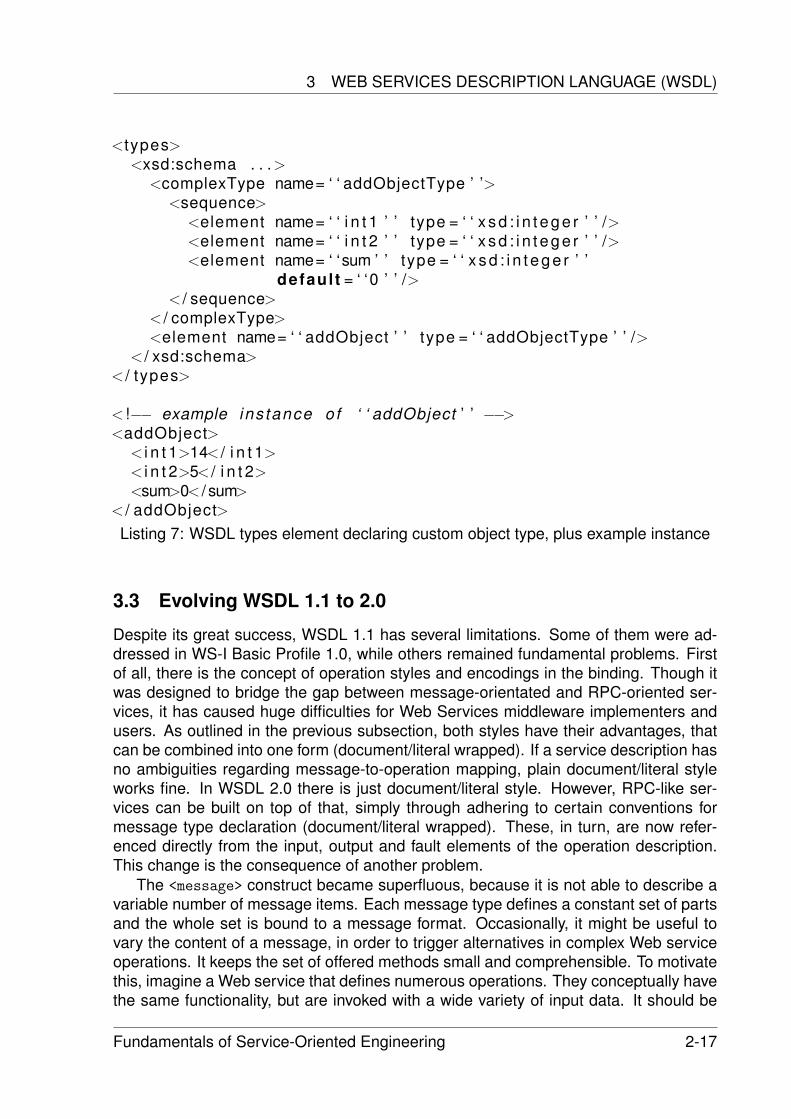
3 WEB SERVICES DESCRIPTION LANGUAGE (WSDL)
<types><xsd:schema . . .>
<complexType name= ‘ ‘ addObjectType ’ ’><sequence>
<element name= ‘ ‘ i n t 1 ’ ’ type = ‘ ‘ x s d : i n t e g e r ’ ’ /><element name= ‘ ‘ i n t 2 ’ ’ type = ‘ ‘ x s d : i n t e g e r ’ ’ /><element name= ‘ ‘sum ’ ’ type = ‘ ‘ x s d : i n t e g e r ’ ’
defaul t = ‘ ‘0 ’ ’ />< / sequence>
< / complexType><element name= ‘ ‘ addObject ’ ’ type = ‘ ‘ addObjectType ’ ’ />
< / xsd:schema>< / types>
< !−− example ins tance of ‘ ‘ addObject ’ ’ −−><addObject>
< i n t 1>14< / i n t 1>< i n t 2>5< / i n t 2><sum>0< / sum>
< / addObject>Listing 7: WSDL types element declaring custom object type, plus example instance
3.3 Evolving WSDL 1.1 to 2.0
Despite its great success, WSDL 1.1 has several limitations. Some of them were ad-dressed in WS-I Basic Profile 1.0, while others remained fundamental problems. Firstof all, there is the concept of operation styles and encodings in the binding. Though itwas designed to bridge the gap between message-orientated and RPC-oriented ser-vices, it has caused huge difficulties for Web Services middleware implementers andusers. As outlined in the previous subsection, both styles have their advantages, thatcan be combined into one form (document/literal wrapped). If a service description hasno ambiguities regarding message-to-operation mapping, plain document/literal styleworks fine. In WSDL 2.0 there is just document/literal style. However, RPC-like ser-vices can be built on top of that, simply through adhering to certain conventions formessage type declaration (document/literal wrapped). These, in turn, are now refer-enced directly from the input, output and fault elements of the operation description.This change is the consequence of another problem.
The <message> construct became superfluous, because it is not able to describe avariable number of message items. Each message type defines a constant set of partsand the whole set is bound to a message format. Occasionally, it might be useful tovary the content of a message, in order to trigger alternatives in complex Web serviceoperations. It keeps the set of offered methods small and comprehensible. To motivatethis, imagine a Web service that defines numerous operations. They conceptually havethe same functionality, but are invoked with a wide variety of input data. It should be
Fundamentals of Service-Oriented Engineering 2-17
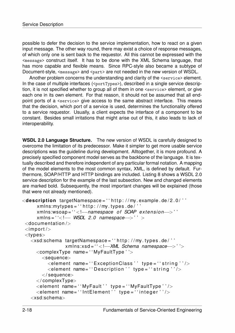
Service Description
possible to defer the decision to the service implementation, how to react on a giveninput message. The other way round, there may exist a choice of response messages,of which only one is sent back to the requestor. All this cannot be expressed with the<message> construct itself. It has to be done with the XML Schema language, thathas more capable and flexible means. Since RPC-style also became a subtype ofDocument-style, <message> and <part> are not needed in the new version of WSDL.
Another problem concerns the understanding and clarity of the <service> element.In the case of multiple interfaces (<portTypes>), described in a single service descrip-tion, it is not specified whether to group all of them in one <service> element, or giveeach one in its own element. For that reason, it should not be assumed that all end-point ports of a <service> give access to the same abstract interface. This meansthat the decision, which port of a service is used, determines the functionality offeredto a service requestor. Usually, a client expects the interface of a component to beconstant. Besides small irritations that might arise out of this, it also leads to lack ofinteroperability.
WSDL 2.0 Language Structure. The new version of WSDL is carefully designed toovercome the limitation of its predecessor. Make it simpler to get more usable servicedescriptions was the guideline during development. Alltogether, it is more profound. Aprecisely specified component model serves as the backbone of the language. It is tex-tually described and therefore independent of any particular formal notation. A mappingof the model elements to the most common syntax, XML, is defined by default. Fur-thermore, SOAP/HTTP and HTTP bindings are included. Listing 8 shows a WSDL 2.0service description for the example of the last subsection. New and changed elementsare marked bold. Subsequently, the most important changes will be explained (thosethat were not already mentioned).
<description targetNamespace = ‘ ‘ h t t p : / / my. example . de / 2 . 0 / ’ ’xmlns:mytypes = ‘ ‘ h t t p : / / my. types . de / ’ ’xmlns:wsoap = ‘ ‘ < !−−namespace of SOAP extens ion−−> ’ ’xmlns = ‘ ‘< !−− WSDL 2.0 namespace−−> ’ ’ >
<documentation /><impor t /><types>
<xsd:schema targetNamespace = ‘ ‘ h t t p : / / my. types . de / ’ ’xmlns:xsd = ‘ ‘ < !−−XML Schema namespace−−> ’ ’>
<complexType name= ‘ ‘ MyFaultType ’ ’><sequence>
<element name= ‘ ‘ Except ionClass ’ ’ type = ‘ ‘ s t r i n g ’ ’ /><element name= ‘ ‘ Desc r i p t i on ’ ’ type = ‘ ‘ s t r i n g ’ ’ />
< / sequence>< / complexType><element name= ‘ ‘ MyFault ’ ’ type = ‘ ‘ MyFaultType ’ ’ /><element name= ‘ ‘ In tE lement ’ ’ type = ‘ ‘ i n t e g e r ’ ’ />
<xsd:schema>
2-18 Fundamentals of Service-Oriented Engineering
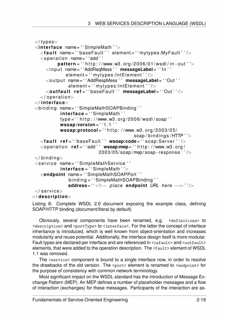
3 WEB SERVICES DESCRIPTION LANGUAGE (WSDL)
< / types><in ter face name= ‘ ‘ SimpleMath ’ ’>
<f a u l t name= ‘ ‘ baseFault ’ ’ element = ‘ ‘ mytypes:MyFault ’ ’ /><opera t ion name= ‘ ‘ add ’ ’
pattern = ‘ ‘ h t t p : / /www.w3 . org /2006/01 / wsdl / in−out ’ ’>< i npu t name= ‘ ‘AddReqMess ’ ’ messageLabel = ‘ ‘ In ’ ’
element = ‘ ‘ mytypes: IntElement ’ ’ /><output name= ‘ ‘AddRespMess ’ ’ messageLabel = ‘ ‘ Out ’ ’
element = ‘ ‘ mytypes: IntElement ’ ’ /><out fau l t re f = ‘ ‘ baseFaul t ’ ’ messageLabel = ‘ ‘ Out ’ ’ />
< / opera t ion>< / in ter face><b ind ing name= ‘ ‘ SimpleMathSOAPBinding ’ ’
in ter face = ‘ ‘ SimpleMath ’ ’type = ‘ ‘ h t t p : / /www.w3 . org /2006/ wsdl / soap ’ ’wsoap:version = ‘ ‘ 1 .1 ’ ’wsoap:protocol = ‘ ‘ h t t p : / /www.w3 . org /2003/05 /
soap / b ind ings /HTTP ’ ’><f a u l t re f = ‘ ‘ baseFaul t ’ ’ wsoap:code = ‘ ‘ soap:Server ’ ’ /><opera t ion re f = ‘ ‘ add ’ ’ wsoap:mep= ‘ ‘ h t t p : / /www.w3 . org /
2003/05/ soap /mep/ soap−response ’ ’ />< / b ind ing><serv i ce name= ‘ ‘ SimpleMathService ’ ’
in ter face = ‘ ‘ SimpleMath ’ ’><endpoint name= ‘ ‘ SimpleMathSOAPPort ’ ’
b ind ing = ‘ ‘ SimpleMathSOAPBinding ’ ’address = ‘ ‘ < !−− place endpoint URL here −−> ’ ’ />
< / se rv i ce>< / description>
Listing 8: Complete WSDL 2.0 document exposing the example class, definingSOAP/HTTP binding (document/literal by default)
Obviously, several components have been renamed, e.g. <definitions> to<description> and <portType> to <interface>. For the latter the concept of interfaceinheritance is introduced, which is well known from object-orientation and increasesmodularity and reuse potential. Additionally, the interface design itself is more modular.Fault types are declared per interface and are referenced in <infault> and <outfault>
elements, that were added to the operation description. The <fault> element of WSDL1.1 was removed.
The <service> component is bound to a single interface now, in order to resolvethe drawbacks of the old version. The <port> element is renamed to <endpoint> forthe purpose of consistency with common network terminology.
Most significant impact on the WSDL standard has the introduction of Message Ex-change Pattern (MEP). An MEP defines a number of placeholder messages and a flowof interaction (exchanges) for these messages. Participants of the interaction are as-
Fundamentals of Service-Oriented Engineering 2-19
Service Description
signed as source and destination of messages. The set of participants is not limited toclient and service, but allows any third-party actor to be included. As a result, complexMEP can be created, that go beyond the four standard operation types of WSDL 1.1.An MEP is applied to an operation by specifying its unique URI as value of the oper-ation’s pattern attribute. The child elements of <operation> are abstract messagesthat define an attribute messageLabel. It is used to indicate which placeholder the mes-sage refers to. In the SOAP binding, WSDL MEPs are mapped to (realized by) SOAPMEPs. Eventually, at runtime the placeholders in the interaction flow are substitutedwith concrete messages, e.g. SOAP messages.
A last innovation is that each component in WSDL 2.0 may declare <feature> and<property> elements. The former is intended to associate non-functional propertieswith the component, whereas the latter is used to express deploy-/runtime invariants.There is a controversial discussion whether WSDL should contain these elements,because they overlap with features of the WS-Policy specification. Most likely, theproblem will be solved in favor of WS-Policy. An overview of this and other supportingspecifications will be given in the next section.
4 WSDL Enrichment
Investigations on WSDL in the previous section have shown that it is only concernedwith two types of specification. On the on hand, there is a data specification rep-resented by XML Schema entries in the <types> element and built-in XML Schemasimple types. From this universal type system each underlying component architecturecan map data types to its proprietary type system. On the other hand, the functionalspecification is provided in form of a classical interface. First, functionality itself ispresented in the <portType> / <interface> element. Then, with the <binding> and<service> elements, information is given on how to and where to invoke the function-ality. But, nothing is said about non-functional properties and semantics of declaredelements. If results of section 2 are taken into account, this means that WSDL clearlylacks expressiveness. However, this was intended, because separation of concerns isone guiding principle for the definition of WS-* family specifications. There are severalof them that these address the types of an overall component specification that aremissing in a WSDL service description. In the same way as XML schemata are em-bedded, the extensibility mechanism is used to supplement the description with othernon-WSDL elements. The rest of the section briefly outlines what can be done to attaina more capable service description.
The WS-Policy family of specifications (see [15], [9]) defines a framework to declarecapabilities and requirements without referring to a particular subject, where theseshould apply to. Proclaimed assertions are collected in a policy container, in whichconditional and set operators are used to express options and alternatives. A policyintersection mechanism is also specified. This can be employed in a SOA to match re-questor demands with provider offers. Take the case where each side presents its ownpolicy. If an intersection is found, i.e. both policies have a common set of assertions,then a match can be indicated. In order to associate a policy with a subject, two ways
2-20 Fundamentals of Service-Oriented Engineering
4 WSDL ENRICHMENT
of attachment are available. Both make use of URIs to identify the policy documents.Either PolicyURIs attribute is declared at a WSDL element or <PolicyReference> ele-ments are added as child of a WSDL element.
There are four types of subjects distinguished in a WSDL description: service, end-point, operation and message. Each entry of the list is parent to its successor. Theeffective policy of an individual subject is a union of policies declared at different WSDLelements. For the actual message exchange an overall policy is applied, aggregatedfrom the effective policies of the individual message subject and the three implicitlyassociated subjects. This concept allows for modularization of a policy according tothe different entities taking part in a Web service interaction (namely the four subjecttypes).
The peculiarity of WS-Policy is, that it does not declare particular policy types, e.g.transaction or security properties. These should be defined in independent domain-specific policy schemes, following again the principle of separation of concerns. Withsuch a flexible mechanism any conceivable type and format of policies can be em-ployed. This includes QoS parameters, as well as support for Design by ContractTM,which also is not covered in WSDL. Already existing schemes were created with re-spect to higher-level WS-* specifications that address QoS concerns (WS-Security,WS-Transaction, WS-ReliableMessaging, etc.).
Upcoming trend in Web technologies is the use of semantics. A promising approachto add semantics to XML-based resources is the Web Ontology Language (OWL, [13]).It is based on the Resource Description Framework (RDF), in WSDL 2.0 conceived asa type system alternative to XML Schema. The idea behind an ontology is relatedto the concept of a knowledge domain. To put it simple, entities of a certain field ofknowledge are detailed with attributes, delimited from disjoint entities and their associ-ations to other entities are defined. The logical constraints described in this way permitreasoning about the concepts of the ontology. Thus, semantics can be deduced.
A concrete OWL ontology deals with the semantic description of Web services:OWL-S ( [8]). As this is an ontology with general concepts, orthogonal to real worldapplication domains, it is called upper ontology. A service is described in terms of aservice profile, service model and service grounding. The profile is used to advertisecapabilities and requirements of the service and presents functional (IOPE) and non-functional properties, plus supporting information. Elements of the profile are linked tocorresponding elements in the service model. This model, in turn, describes the be-havior of the service through classification in a small set of predefined process models.Most likely, a service will be an unstructured atomic process. Additionally, functionalityand non-functional properties are declared in detail and, in order to associate seman-tics, are mapped to entities of a certain application ontology. Finally, the groundingconnects the service with a concrete implementation, i.e. a WSDL description and itsWeb service. In this way semantics are added to WSDL documents.
As a result it can be stated, that a complete service description is distributed acrossvarious documents of different specifications (WSDL, WS-Policy and OWL-S). A lot ofinformation exist redundantly in several documents, e.g. functionality or QoS param-eters, but it is used to glue the parts together. An increment in expressiveness of theoverall description undoubtedly exists. Whether this leverages the description to be
Fundamentals of Service-Oriented Engineering 2-21
Service Description
completely qualified (referring to the results of section 2), was not yet proven. Anyhow,it is now possible to provide a description that covers all types of specifications.
5 Conclusion
The previous sections have shown various issues with regard to the description of ser-vices. It should be clear at this point that a service description is indispensable. Notonly to provide a necessary interface for service invocation, but also to constitute acontract for interaction in electronic business. Providers specify their terms and capa-bilities in the description to advertise the contract they offer. Consumers that demandcertain capabilities and agree to follow certain contract terms can use the description todiscover matching services. The evolution of component specifications to a contractualservice description is a natural one, driven by the requirements the open marketplaceof a SOA dictates.
Implementation of a SOA with XML- and Web-based technologies is addressed inthe Web Services Architecture. Basically, this architecture is described with a stackof Web Services specifications, of which several became widely adopted in today’ssoftware industry. As no major vendor can ignore service-orientation, the need for in-teroperable standards is intensified even more. However, these standards must be all-embracing, i.e. must concern all aspects of their problem domain. Service Descriptionis a fundamental domain of a SOA and WSDL the language to express definitions inthat domain. Unfortunately, the task of describing turned out to be complex and WSDLwas only a first step towards a mature technique. Therefore, WSDL must be enrichedwith other forms of description. Non-functional issues are covered with WS-Policy andits supporting specifications, while semantics can be provided with OWL-S. The lat-ter will probably progress to be the center of an overall service description, becausesemantic service discovery is more flexible and capable.
References
[1] David Booth and Canyang K. Liu. Web Services Description Language (WSDL)2.0, part 0: Primer. http://www.w3.org/TR/wsdl20-primer/, 2006. W3C.
[2] Steve Burbeck. The Tao of e-business services: The evolution of Web ap-plications into service-oriented components with Web services. http://www-128.ibm.com/developerworks/webservices/library/ws-tao/, 2000. Emerging Tech-nologies, IBM Software Group.
[3] Richard Butek. Which style of WSDL should I use? http://www-128.ibm.com/developerworks/webservices/library/ws-whichwsdl/, 2005. IBM De-veloperWorks.
2-22 Fundamentals of Service-Oriented Engineering
REFERENCES
[4] Roberto Chinnici, Hugo Haas, Amelia A. Lewis, Jean-Jacques Moreau, DavidOrchard, and Sanjiva Weerawarana. Basic Profile Version 1.0. http://www.ws-i.org/Profiles/BasicProfile-1.0/, 2004. Web Services Interoperability Organization.
[5] Roberto Chinnici, Hugo Haas, Amelia A. Lewis, Jean-Jacques Moreau, David Or-chard, and Sanjiva Weerawarana. Web Services Description Language (WSDL)2.0, part 2: Adjuncts. http://www.w3.org/TR/wsdl20-adjuncts/, 2006. W3C.
[6] Roberto Chinnici, Jean-Jacques Moreau, Arthur Ryman, and Sanjiva Weer-awarana. Web Services Description Language (WSDL) 2.0, part 1: Core.http://www.w3.org/TR/wsdl20/, 2006. W3C.
[7] Erik Christensen, Francisco Curbera, Greg Meredith, and Sanjiva Weerawarana.Web Services Description Language (WSDL) 1.1. http://www.w3.org/TR/wsdl/,2001. W3C.
[8] The OWL Services Coalition. OWL-S: Semantic Markup for Web Services.http://www.daml.org/services/owl-s/1.0/owl-s/, 2003.
[9] Francisco Curbera et al. Web Services Policy Attachment (WS-PolicyAttachment)1.2. http://specs.xmlsoap.org/ws/2004/09/policy/ws-policyattachment.pdf, 2006.
[10] Andreas Knopfel, Bernhard Grone, and Peter Tabeling. Fundamental ModelingConcept: Effective Communication of IT Systems. Wiley, 2006.
[11] Mike P. Papazoglou and Dimitrios Georgakopoulos. Service Oriented Computing.Communication of the ACM, 46(10):25–28, 2003.
[12] David L. Parnas. A technique for software module specification with examples.Communication of the ACM, 15(5):330–336, 1972.
[13] Michael K. Smith, Chris Welty, and Deborah L. McGuinness. OWL Web OntologyLanguage Guide. http://www.w3.org/TR/owl-guide/, 2004. W3C.
[14] Eiffel Software. Building bug-free O-O software: An introduction to Design byContractTM. http://archive.eiffel.com/doc/manuals/technology/contract/, 2006.
[15] Sanjiva Weerawarana, Francisco Curbera, Frank Leymann, Tony Storey, and Don-ald F. Ferguson. Web Services Platform Architecture: SOAP, WSDL, WS-Policy,WS-Addressing, WS-BPEL, WS-Reliable Messaging, and More. Prentice HallPTR, 2005.
Fundamentals of Service-Oriented Engineering 2-23

Service Communication and Discovery
Martin Grund
This paper deals with two basic elements within the service world - Service Commu-nication and Service Discovery. Service communication is possibly the most importantpart. Without the knowledge on how to communicate or which language to speak, in-teraction between services will not be possible. Service Discovery on the other handtakes into account the service communication and wants to support the service re-quester to find the correct service to fulfill a certain business need. This paper concen-trates thereby on web services using SOAP as a communication layer and UDDI as adiscovery facility.
Keywords: SOAP, UDDI, Service Oriented Architecture, Introduction, Discovery, Di-rectory
1 Introduction
Looking at the evolution of software systems within the last decades, it is possible todiscover a new trend. Old monolithic systems evolved to modern client-server systems.By today the client server principle was pushed forward to a new software paradigm -Service Oriented Architecture. The new feature of this design paradigm is the so calledservice. A single service provides functionality to fulfill a certain task to accomplish abusiness need. Services can be discovered at runtime and bound dynamically to theunderlying software. The acronym SOA in itself does not describe a brand new technol-ogy, but describes the industry need for a more flexible, reusable software architecture.
As a first step to understand the topics Service Discovery and Service Communi-cation in the context of Service Oriented Computing, the keywords Service Communi-cation, Service Discovery and Service Directory are specified in detail.
1.1 Context Definition
For normal people and even people with a technical background, it is very hard to un-derstand the main principles of Service Oriented Computing. All terms and keywordsused in this area of information technology industry are often claimed by marketingdepartments and thereby evolved to buzzwords for that nobody is able to give a cleardefinition. Therefore some of the most important keywords for this paper will be ex-plained.
Service A Service is a piece of software to accomplish a certain task in a businessenvironment. Compared to real life an example for a service can be a typical parcel
Fundamentals of Service-Oriented Engineering 3-1
Service Communication and Discovery
service. The service, the parcel service provider provides is to deliver a certain goodto a specific location. Input parameters for this service are the destination, the sourcelocation and the freight weight. The service itself acts as a black box. The parcelservice provider is called a service provider. The person engaging the parcel serviceis called a service requester.
Service Communication Since it is defined now, what is a service and the two mostsimple roles within this environment. The next definition to follow, is about how partiesin this process communicate. In the normal world we assume, that people, trying toengage in a contract, speak the same language to be sure everybody understands thecontents of this contract. The situation is not too different in the environment of ServiceOriented Computing. It is even harder to communicate, since the humans intelligenceis able to help in situations a language is not spoken correctly, the humans brain willput everything in a more or less correct context. For the computer world this is notpossible to achieve. Either a system speaks the desired language or no communicationis possible.
Service Communication defines the communication between two endpoints - e.g.the service requester and the service provider. Since both need to understand thesame communication protocol communication must be standardized.
Service Discovery The role of a service requester is defined by the need to executea specific task. By now there are two possibilities on how to fulfill this task. Eitherthe service requester has already knowledge about the service providers location andinterface for its application. Or on the other hand the knowledge is not available and theservice requester has to gain this knowledge. In the human world, the person acting asa service requester will use specific search facilities to find a suitable service provider.These search facilities can be yellow pages or industry specific guides.
In the computer world the process of finding and binding to a service is called Ser-vice Discovery.
Service Directory Since yellow pages are often paper based knowledge, there is aneed for software based solutions - a Service Directory. Furthermore this solution doesnot only allow humans to browse and search for suitable services but allows machinesas well to search and extract the information. Therefor the application programminginterface to a service directory must be specified and of course the communicationbetween the service directory and a requesting endpoint.
Web Service Following to available definitions a web service is characterized as asoftware system designed to support inter-operable machine-to-machine communica-tion over a network. Since as many parties as possible should integrate into this net-work, during the specification process a focus was set on open standards like XML andHTTP. These standards are available for everybody and at no license fees.
3-2 Fundamentals of Service-Oriented Engineering
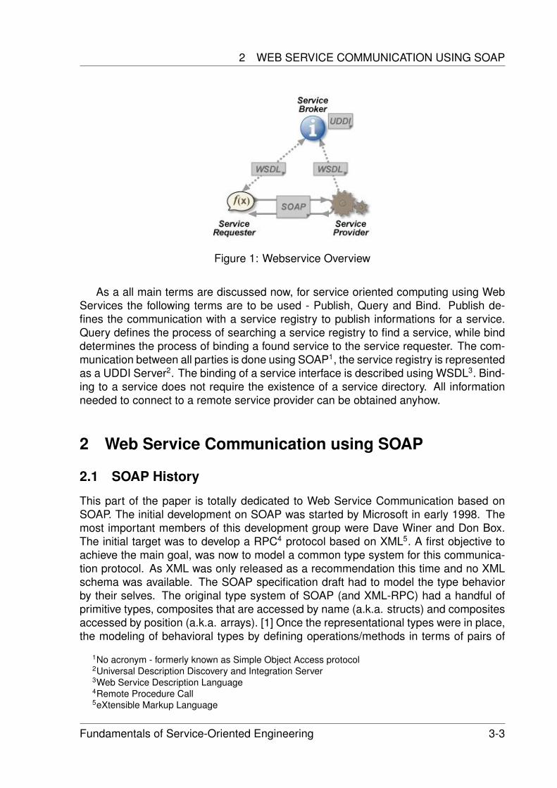
2 WEB SERVICE COMMUNICATION USING SOAP
Figure 1: Webservice Overview
As a all main terms are discussed now, for service oriented computing using WebServices the following terms are to be used - Publish, Query and Bind. Publish de-fines the communication with a service registry to publish informations for a service.Query defines the process of searching a service registry to find a service, while binddetermines the process of binding a found service to the service requester. The com-munication between all parties is done using SOAP1, the service registry is representedas a UDDI Server2. The binding of a service interface is described using WSDL3. Bind-ing to a service does not require the existence of a service directory. All informationneeded to connect to a remote service provider can be obtained anyhow.
2 Web Service Communication using SOAP
2.1 SOAP History
This part of the paper is totally dedicated to Web Service Communication based onSOAP. The initial development on SOAP was started by Microsoft in early 1998. Themost important members of this development group were Dave Winer and Don Box.The initial target was to develop a RPC4 protocol based on XML5. A first objective toachieve the main goal, was now to model a common type system for this communica-tion protocol. As XML was only released as a recommendation this time and no XMLschema was available. The SOAP specification draft had to model the type behaviorby their selves. The original type system of SOAP (and XML-RPC) had a handful ofprimitive types, composites that are accessed by name (a.k.a. structs) and compositesaccessed by position (a.k.a. arrays). [1] Once the representational types were in place,the modeling of behavioral types by defining operations/methods in terms of pairs of
1No acronym - formerly known as Simple Object Access protocol2Universal Description Discovery and Integration Server3Web Service Description Language4Remote Procedure Call5eXtensible Markup Language
Fundamentals of Service-Oriented Engineering 3-3
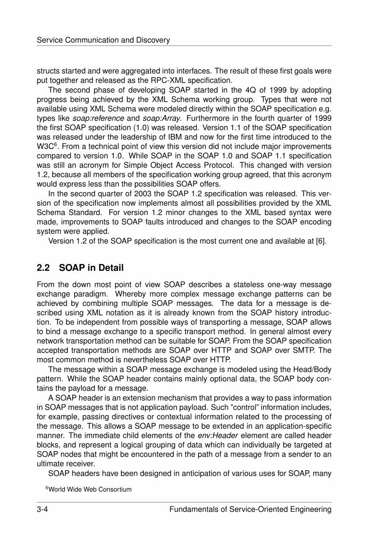
Service Communication and Discovery
structs started and were aggregated into interfaces. The result of these first goals wereput together and released as the RPC-XML specification.
The second phase of developing SOAP started in the 4Q of 1999 by adoptingprogress being achieved by the XML Schema working group. Types that were notavailable using XML Schema were modeled directly within the SOAP specification e.g.types like soap:reference and soap:Array. Furthermore in the fourth quarter of 1999the first SOAP specification (1.0) was released. Version 1.1 of the SOAP specificationwas released under the leadership of IBM and now for the first time introduced to theW3C6. From a technical point of view this version did not include major improvementscompared to version 1.0. While SOAP in the SOAP 1.0 and SOAP 1.1 specificationwas still an acronym for Simple Object Access Protocol. This changed with version1.2, because all members of the specification working group agreed, that this acronymwould express less than the possibilities SOAP offers.
In the second quarter of 2003 the SOAP 1.2 specification was released. This ver-sion of the specification now implements almost all possibilities provided by the XMLSchema Standard. For version 1.2 minor changes to the XML based syntax weremade, improvements to SOAP faults introduced and changes to the SOAP encodingsystem were applied.
Version 1.2 of the SOAP specification is the most current one and available at [6].
2.2 SOAP in Detail
From the down most point of view SOAP describes a stateless one-way messageexchange paradigm. Whereby more complex message exchange patterns can beachieved by combining multiple SOAP messages. The data for a message is de-scribed using XML notation as it is already known from the SOAP history introduc-tion. To be independent from possible ways of transporting a message, SOAP allowsto bind a message exchange to a specific transport method. In general almost everynetwork transportation method can be suitable for SOAP. From the SOAP specificationaccepted transportation methods are SOAP over HTTP and SOAP over SMTP. Themost common method is nevertheless SOAP over HTTP.
The message within a SOAP message exchange is modeled using the Head/Bodypattern. While the SOAP header contains mainly optional data, the SOAP body con-tains the payload for a message.
A SOAP header is an extension mechanism that provides a way to pass informationin SOAP messages that is not application payload. Such ”control” information includes,for example, passing directives or contextual information related to the processing ofthe message. This allows a SOAP message to be extended in an application-specificmanner. The immediate child elements of the env:Header element are called headerblocks, and represent a logical grouping of data which can individually be targeted atSOAP nodes that might be encountered in the path of a message from a sender to anultimate receiver.
SOAP headers have been designed in anticipation of various uses for SOAP, many
6World Wide Web Consortium
3-4 Fundamentals of Service-Oriented Engineering
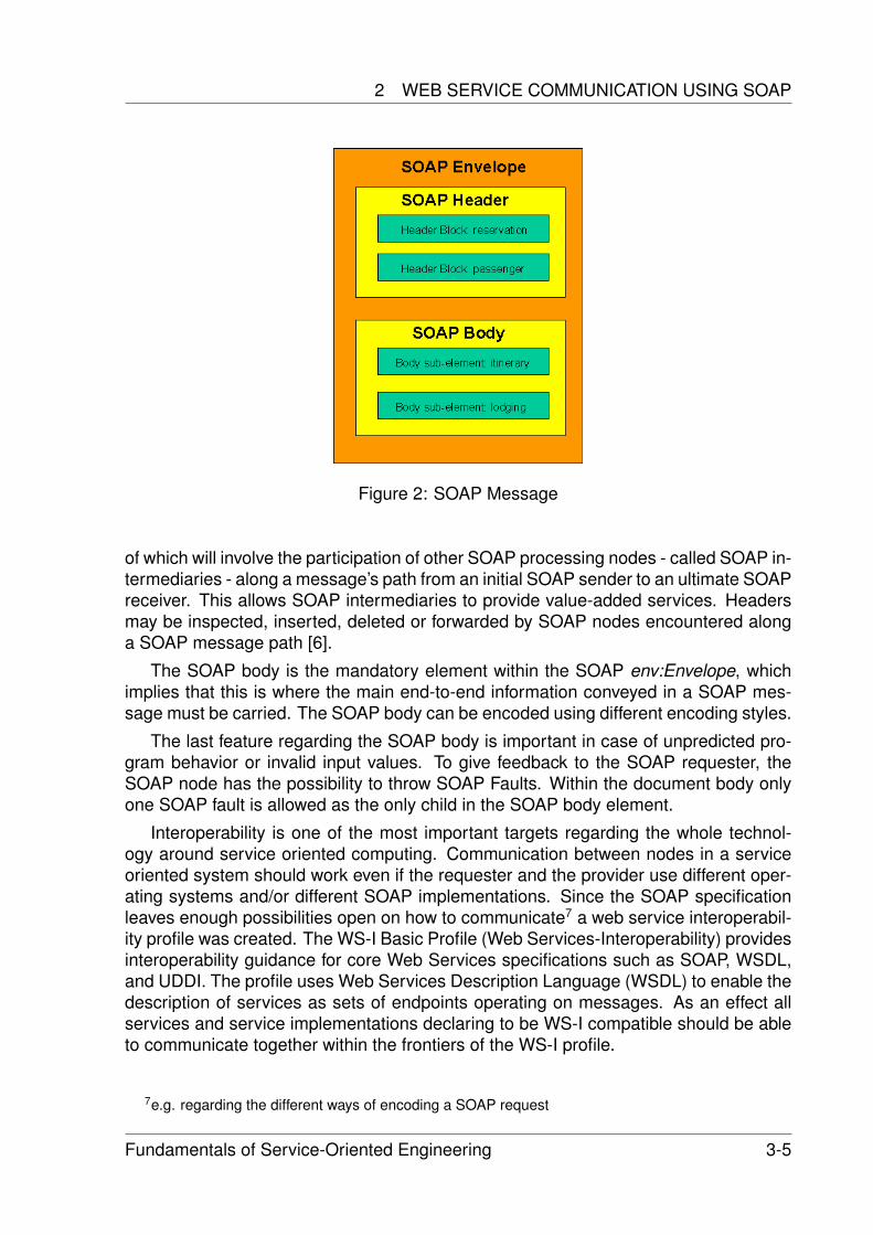
2 WEB SERVICE COMMUNICATION USING SOAP
Figure 2: SOAP Message
of which will involve the participation of other SOAP processing nodes - called SOAP in-termediaries - along a message’s path from an initial SOAP sender to an ultimate SOAPreceiver. This allows SOAP intermediaries to provide value-added services. Headersmay be inspected, inserted, deleted or forwarded by SOAP nodes encountered alonga SOAP message path [6].
The SOAP body is the mandatory element within the SOAP env:Envelope, whichimplies that this is where the main end-to-end information conveyed in a SOAP mes-sage must be carried. The SOAP body can be encoded using different encoding styles.
The last feature regarding the SOAP body is important in case of unpredicted pro-gram behavior or invalid input values. To give feedback to the SOAP requester, theSOAP node has the possibility to throw SOAP Faults. Within the document body onlyone SOAP fault is allowed as the only child in the SOAP body element.
Interoperability is one of the most important targets regarding the whole technol-ogy around service oriented computing. Communication between nodes in a serviceoriented system should work even if the requester and the provider use different oper-ating systems and/or different SOAP implementations. Since the SOAP specificationleaves enough possibilities open on how to communicate7 a web service interoperabil-ity profile was created. The WS-I Basic Profile (Web Services-Interoperability) providesinteroperability guidance for core Web Services specifications such as SOAP, WSDL,and UDDI. The profile uses Web Services Description Language (WSDL) to enable thedescription of services as sets of endpoints operating on messages. As an effect allservices and service implementations declaring to be WS-I compatible should be ableto communicate together within the frontiers of the WS-I profile.
7e.g. regarding the different ways of encoding a SOAP request
Fundamentals of Service-Oriented Engineering 3-5
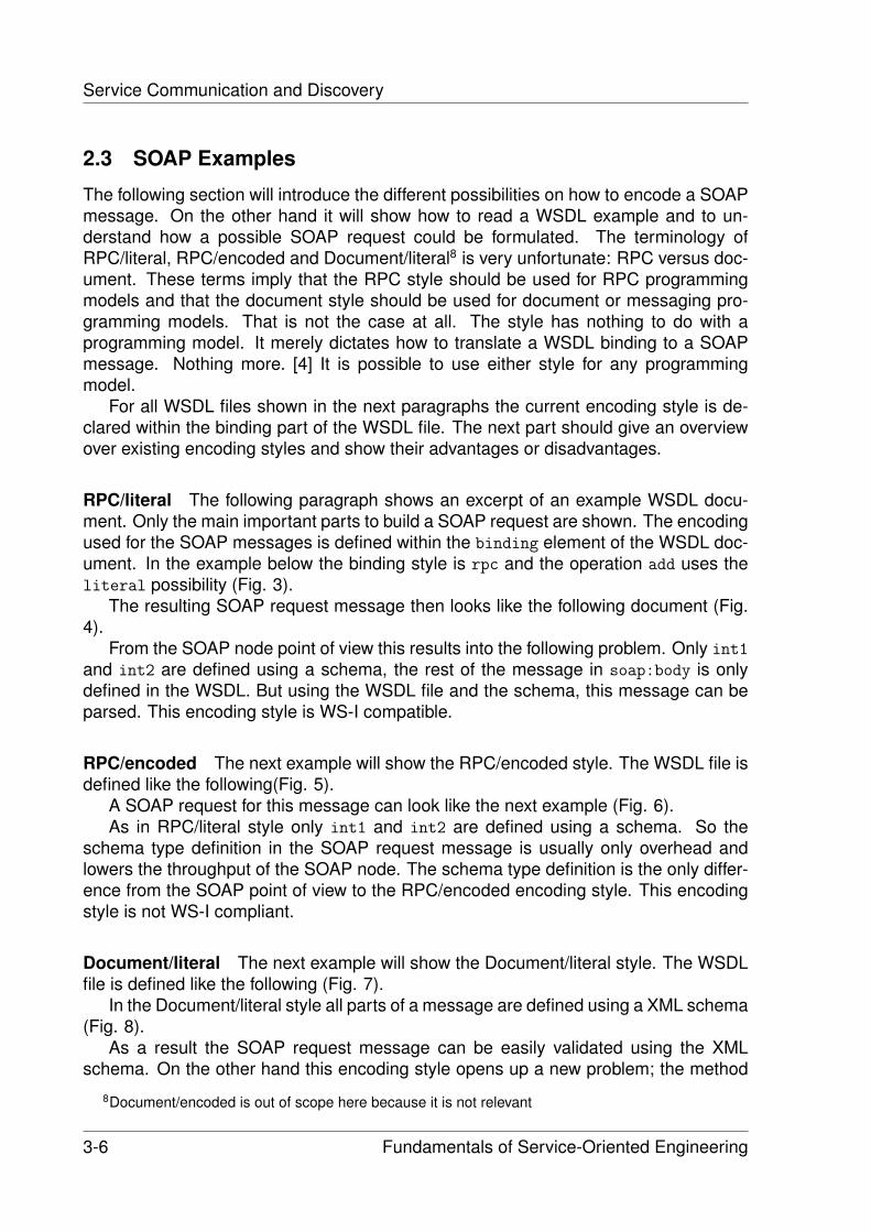
Service Communication and Discovery
2.3 SOAP Examples
The following section will introduce the different possibilities on how to encode a SOAPmessage. On the other hand it will show how to read a WSDL example and to un-derstand how a possible SOAP request could be formulated. The terminology ofRPC/literal, RPC/encoded and Document/literal8 is very unfortunate: RPC versus doc-ument. These terms imply that the RPC style should be used for RPC programmingmodels and that the document style should be used for document or messaging pro-gramming models. That is not the case at all. The style has nothing to do with aprogramming model. It merely dictates how to translate a WSDL binding to a SOAPmessage. Nothing more. [4] It is possible to use either style for any programmingmodel.
For all WSDL files shown in the next paragraphs the current encoding style is de-clared within the binding part of the WSDL file. The next part should give an overviewover existing encoding styles and show their advantages or disadvantages.
RPC/literal The following paragraph shows an excerpt of an example WSDL docu-ment. Only the main important parts to build a SOAP request are shown. The encodingused for the SOAP messages is defined within the binding element of the WSDL doc-ument. In the example below the binding style is rpc and the operation add uses theliteral possibility (Fig. 3).
The resulting SOAP request message then looks like the following document (Fig.4).
From the SOAP node point of view this results into the following problem. Only int1
and int2 are defined using a schema, the rest of the message in soap:body is onlydefined in the WSDL. But using the WSDL file and the schema, this message can beparsed. This encoding style is WS-I compatible.
RPC/encoded The next example will show the RPC/encoded style. The WSDL file isdefined like the following(Fig. 5).
A SOAP request for this message can look like the next example (Fig. 6).As in RPC/literal style only int1 and int2 are defined using a schema. So the
schema type definition in the SOAP request message is usually only overhead andlowers the throughput of the SOAP node. The schema type definition is the only differ-ence from the SOAP point of view to the RPC/encoded encoding style. This encodingstyle is not WS-I compliant.
Document/literal The next example will show the Document/literal style. The WSDLfile is defined like the following (Fig. 7).
In the Document/literal style all parts of a message are defined using a XML schema(Fig. 8).
As a result the SOAP request message can be easily validated using the XMLschema. On the other hand this encoding style opens up a new problem; the method
8Document/encoded is out of scope here because it is not relevant
3-6 Fundamentals of Service-Oriented Engineering
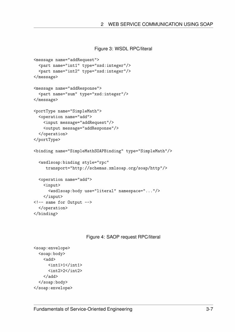
2 WEB SERVICE COMMUNICATION USING SOAP
Figure 3: WSDL RPC/literal
<message name="addRequest">
<part name="int1" type="xsd:integer"/>
<part name="int2" type="xsd:integer"/>
</message>
<message name="addResponse">
<part name="sum" type="xsd:integer"/>
</message>
<portType name="SimpleMath">
<operation name="add">
<input message="addRequest"/>
<output message="addResponse"/>
</operation>
</portType>
<binding name="SimpleMathSOAPBinding" type="SimpleMath"/>
<wsdlsoap:binding style="rpc"
transport="http://schemas.xmlsoap.org/soap/http"/>
<operation name="add">
<input>
<wsdlsoap:body use="literal" namespace="..."/>
</input>
<!-- same for Output -->
</operation>
</binding>
Figure 4: SAOP request RPC/literal
<soap:envelope>
<soap:body>
<add>
<int1>1</int1>
<int2>2</int2>
</add>
</soap:body>
</soap:envelope>
Fundamentals of Service-Oriented Engineering 3-7
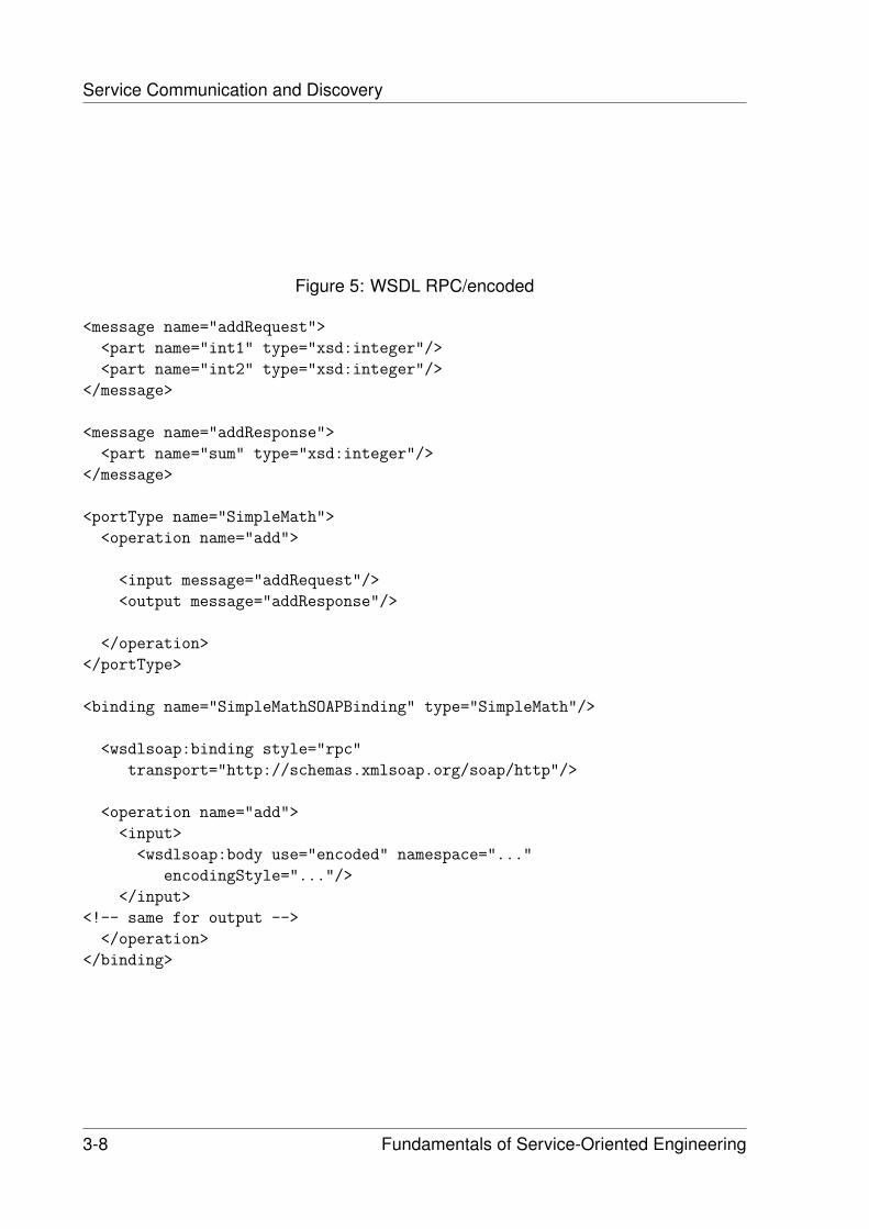
Service Communication and Discovery
Figure 5: WSDL RPC/encoded
<message name="addRequest">
<part name="int1" type="xsd:integer"/>
<part name="int2" type="xsd:integer"/>
</message>
<message name="addResponse">
<part name="sum" type="xsd:integer"/>
</message>
<portType name="SimpleMath">
<operation name="add">
<input message="addRequest"/>
<output message="addResponse"/>
</operation>
</portType>
<binding name="SimpleMathSOAPBinding" type="SimpleMath"/>
<wsdlsoap:binding style="rpc"
transport="http://schemas.xmlsoap.org/soap/http"/>
<operation name="add">
<input>
<wsdlsoap:body use="encoded" namespace="..."
encodingStyle="..."/>
</input>
<!-- same for output -->
</operation>
</binding>
3-8 Fundamentals of Service-Oriented Engineering
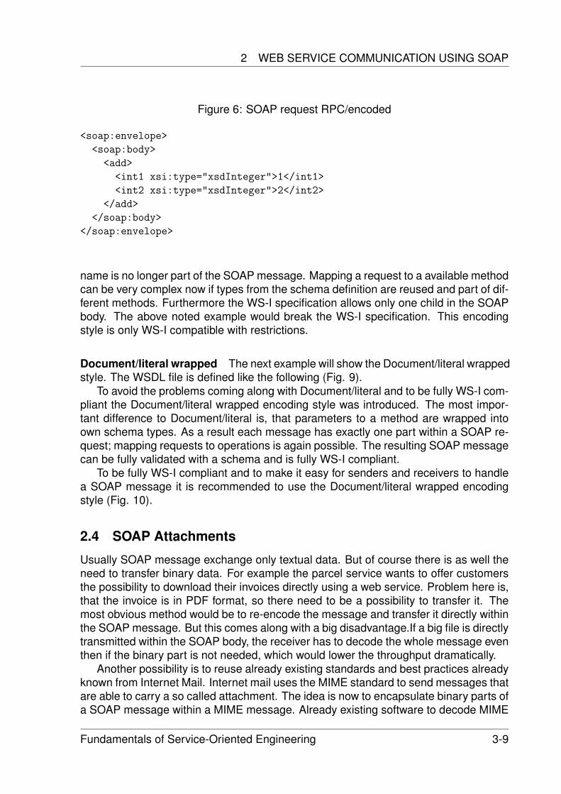
2 WEB SERVICE COMMUNICATION USING SOAP
Figure 6: SOAP request RPC/encoded
<soap:envelope>
<soap:body>
<add>
<int1 xsi:type="xsdInteger">1</int1>
<int2 xsi:type="xsdInteger">2</int2>
</add>
</soap:body>
</soap:envelope>
name is no longer part of the SOAP message. Mapping a request to a available methodcan be very complex now if types from the schema definition are reused and part of dif-ferent methods. Furthermore the WS-I specification allows only one child in the SOAPbody. The above noted example would break the WS-I specification. This encodingstyle is only WS-I compatible with restrictions.
Document/literal wrapped The next example will show the Document/literal wrappedstyle. The WSDL file is defined like the following (Fig. 9).
To avoid the problems coming along with Document/literal and to be fully WS-I com-pliant the Document/literal wrapped encoding style was introduced. The most impor-tant difference to Document/literal is, that parameters to a method are wrapped intoown schema types. As a result each message has exactly one part within a SOAP re-quest; mapping requests to operations is again possible. The resulting SOAP messagecan be fully validated with a schema and is fully WS-I compliant.
To be fully WS-I compliant and to make it easy for senders and receivers to handlea SOAP message it is recommended to use the Document/literal wrapped encodingstyle (Fig. 10).
2.4 SOAP Attachments
Usually SOAP message exchange only textual data. But of course there is as well theneed to transfer binary data. For example the parcel service wants to offer customersthe possibility to download their invoices directly using a web service. Problem here is,that the invoice is in PDF format, so there need to be a possibility to transfer it. Themost obvious method would be to re-encode the message and transfer it directly withinthe SOAP message. But this comes along with a big disadvantage.If a big file is directlytransmitted within the SOAP body, the receiver has to decode the whole message eventhen if the binary part is not needed, which would lower the throughput dramatically.
Another possibility is to reuse already existing standards and best practices alreadyknown from Internet Mail. Internet mail uses the MIME standard to send messages thatare able to carry a so called attachment. The idea is now to encapsulate binary parts ofa SOAP message within a MIME message. Already existing software to decode MIME
Fundamentals of Service-Oriented Engineering 3-9
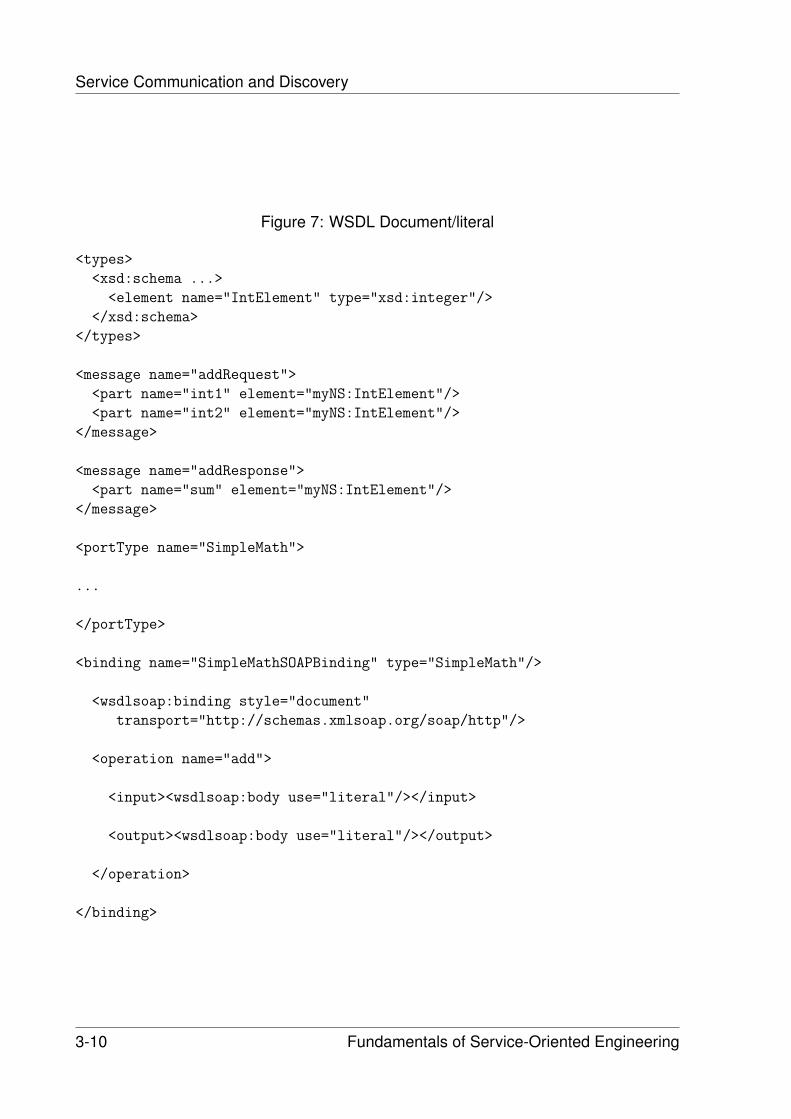
Service Communication and Discovery
Figure 7: WSDL Document/literal
<types>
<xsd:schema ...>
<element name="IntElement" type="xsd:integer"/>
</xsd:schema>
</types>
<message name="addRequest">
<part name="int1" element="myNS:IntElement"/>
<part name="int2" element="myNS:IntElement"/>
</message>
<message name="addResponse">
<part name="sum" element="myNS:IntElement"/>
</message>
<portType name="SimpleMath">
...
</portType>
<binding name="SimpleMathSOAPBinding" type="SimpleMath"/>
<wsdlsoap:binding style="document"
transport="http://schemas.xmlsoap.org/soap/http"/>
<operation name="add">
<input><wsdlsoap:body use="literal"/></input>
<output><wsdlsoap:body use="literal"/></output>
</operation>
</binding>
3-10 Fundamentals of Service-Oriented Engineering
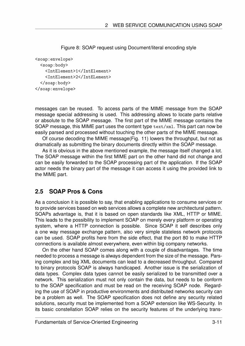
2 WEB SERVICE COMMUNICATION USING SOAP
Figure 8: SOAP request using Document/literal encoding style
<soap:envelope>
<soap:body>
<IntElement>1</IntElement>
<IntElement>2</IntELement>
</soap:body>
</soap:envelope>
messages can be reused. To access parts of the MIME message from the SOAPmessage special addressing is used. This addressing allows to locate parts relativeor absolute to the SOAP message. The first part of the MIME message contains theSOAP message, this MIME part uses the content type text/xml. This part can now beeasily parsed and processed without touching the other parts of the MIME message.
Of course decoding the MIME message(Fig. 11) lowers the throughput, but not asdramatically as submitting the binary documents directly within the SOAP message.
As it is obvious in the above mentioned example, the message itself changed a lot.The SOAP message within the first MIME part on the other hand did not change andcan be easily forwarded to the SOAP processing part of the application. If the SOAPactor needs the binary part of the message it can access it using the provided link tothe MIME part.
2.5 SOAP Pros & Cons
As a conclusion it is possible to say, that enabling applications to consume services orto provide services based on web services allows a complete new architectural pattern.SOAPs advantage is, that it is based on open standards like XML, HTTP or MIME.This leads to the possibility to implement SOAP on merely every platform or operatingsystem, where a HTTP connection is possible. Since SOAP it self describes onlya one way message exchange pattern, also very simple stateless network protocolscan be used. SOAP profits here from the side effect, that the port 80 to make HTTPconnections is available almost everywhere, even within big company networks.
On the other hand SOAP comes along with a couple of disadvantages. The timeneeded to process a message is always dependent from the size of the message. Pars-ing complex and big XML documents can lead to a decreased throughput. Comparedto binary protocols SOAP is always handicaped. Another issue is the serialization ofdata types. Complex data types cannot be easily serialized to be transmitted over anetwork. This serialization must not only contain the data, but needs to be conformto the SOAP specification and must be read on the receiving SOAP node. Regard-ing the use of SOAP in productive environments and distributed networks security canbe a problem as well. The SOAP specification does not define any security relatedsolutions, security must be implemented from a SOAP extension like WS-Security. Inits basic constellation SOAP relies on the security features of the underlying trans-
Fundamentals of Service-Oriented Engineering 3-11
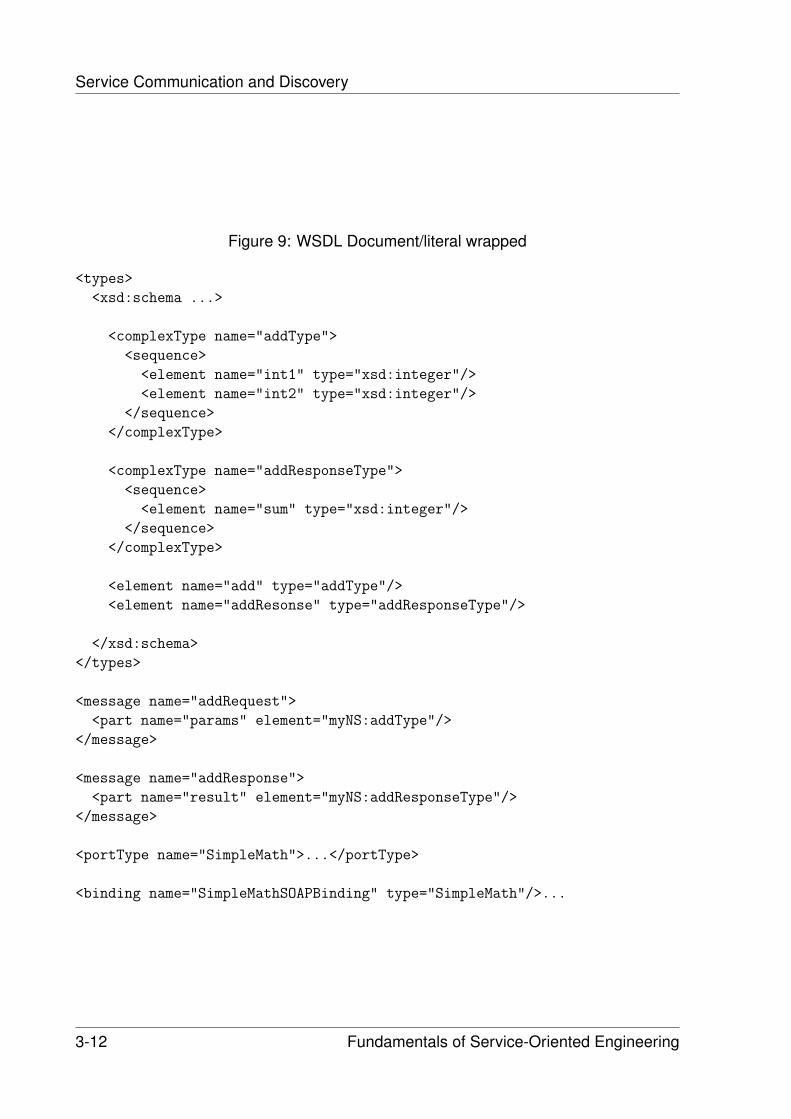
Service Communication and Discovery
Figure 9: WSDL Document/literal wrapped
<types>
<xsd:schema ...>
<complexType name="addType">
<sequence>
<element name="int1" type="xsd:integer"/>
<element name="int2" type="xsd:integer"/>
</sequence>
</complexType>
<complexType name="addResponseType">
<sequence>
<element name="sum" type="xsd:integer"/>
</sequence>
</complexType>
<element name="add" type="addType"/>
<element name="addResonse" type="addResponseType"/>
</xsd:schema>
</types>
<message name="addRequest">
<part name="params" element="myNS:addType"/>
</message>
<message name="addResponse">
<part name="result" element="myNS:addResponseType"/>
</message>
<portType name="SimpleMath">...</portType>
<binding name="SimpleMathSOAPBinding" type="SimpleMath"/>...
3-12 Fundamentals of Service-Oriented Engineering
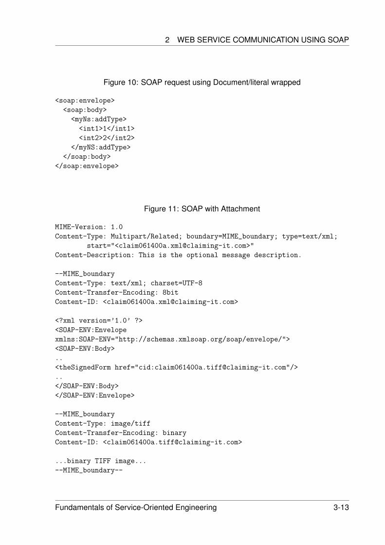
2 WEB SERVICE COMMUNICATION USING SOAP
Figure 10: SOAP request using Document/literal wrapped
<soap:envelope>
<soap:body>
<myNs:addType>
<int1>1</int1>
<int2>2</int2>
</myNS:addType>
</soap:body>
</soap:envelope>
Figure 11: SOAP with Attachment
MIME-Version: 1.0
Content-Type: Multipart/Related; boundary=MIME_boundary; type=text/xml;
start="<[email protected]>"
Content-Description: This is the optional message description.
--MIME_boundary
Content-Type: text/xml; charset=UTF-8
Content-Transfer-Encoding: 8bit
Content-ID: <[email protected]>
<?xml version=’1.0’ ?>
<SOAP-ENV:Envelope
xmlns:SOAP-ENV="http://schemas.xmlsoap.org/soap/envelope/">
<SOAP-ENV:Body>
..
<theSignedForm href="cid:[email protected]"/>
..
</SOAP-ENV:Body>
</SOAP-ENV:Envelope>
--MIME_boundary
Content-Type: image/tiff
Content-Transfer-Encoding: binary
Content-ID: <[email protected]>
...binary TIFF image...
--MIME_boundary--
Fundamentals of Service-Oriented Engineering 3-13
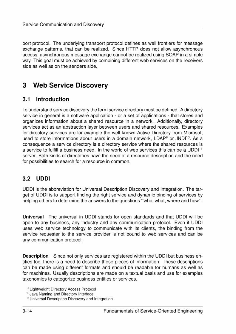
Service Communication and Discovery
port protocol. The underlying transport protocol defines as well frontiers for messageexchange patterns, that can be realized. Since HTTP does not allow asynchronousaccess, asynchronous message exchange cannot be realized using SOAP in a simpleway. This goal must be achieved by combining different web services on the receiversside as well as on the senders side.
3 Web Service Discovery
3.1 Introduction
To understand service discovery the term service directory must be defined. A directoryservice in general is a software application - or a set of applications - that stores andorganizes information about a shared resource in a network. Additionally, directoryservices act as an abstraction layer between users and shared resources. Examplesfor directory services are for example the well known Active Directory from Microsoftused to store informations about users in a domain network, LDAP9 or JNDI10. As aconsequence a service directory is a directory service where the shared resources isa service to fulfill a business need. In the world of web services this can be a UDDI11
server. Both kinds of directories have the need of a resource description and the needfor possibilities to search for a resource in common.
3.2 UDDI
UDDI is the abbreviation for Universal Description Discovery and Integration. The tar-get of UDDI is to support finding the right service and dynamic binding of services byhelping others to determine the answers to the questions ”‘who, what, where and how”’.
Universal The universal in UDDI stands for open standards and that UDDI will beopen to any business, any industry and any communication protocol. Even if UDDIuses web service technology to communicate with its clients, the binding from theservice requester to the service provider is not bound to web services and can beany communication protocol.
Description Since not only services are registered within the UDDI but business en-tities too, there is a need to describe these pieces of information. These descriptionscan be made using different formats and should be readable for humans as well asfor machines. Usually descriptions are made on a textual basis and use for examplestaxonomies to categorize business entities or services.
9Lightweight Directory Access Protocol10Java Naming and Directory Interface11Universal Description Discovery and Integration
3-14 Fundamentals of Service-Oriented Engineering
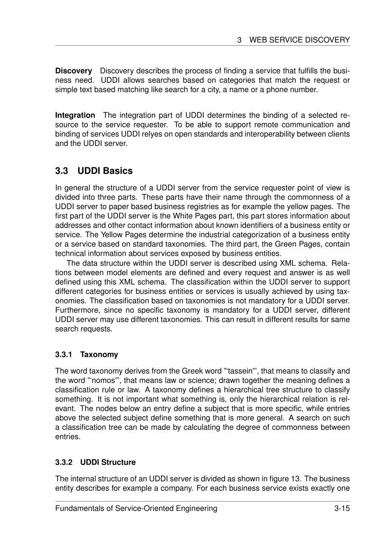
3 WEB SERVICE DISCOVERY
Discovery Discovery describes the process of finding a service that fulfills the busi-ness need. UDDI allows searches based on categories that match the request orsimple text based matching like search for a city, a name or a phone number.
Integration The integration part of UDDI determines the binding of a selected re-source to the service requester. To be able to support remote communication andbinding of services UDDI relyes on open standards and interoperability between clientsand the UDDI server.
3.3 UDDI Basics
In general the structure of a UDDI server from the service requester point of view isdivided into three parts. These parts have their name through the commonness of aUDDI server to paper based business registries as for example the yellow pages. Thefirst part of the UDDI server is the White Pages part, this part stores information aboutaddresses and other contact information about known identifiers of a business entity orservice. The Yellow Pages determine the industrial categorization of a business entityor a service based on standard taxonomies. The third part, the Green Pages, containtechnical information about services exposed by business entities.
The data structure within the UDDI server is described using XML schema. Rela-tions between model elements are defined and every request and answer is as welldefined using this XML schema. The classification within the UDDI server to supportdifferent categories for business entities or services is usually achieved by using tax-onomies. The classification based on taxonomies is not mandatory for a UDDI server.Furthermore, since no specific taxonomy is mandatory for a UDDI server, differentUDDI server may use different taxonomies. This can result in different results for samesearch requests.
3.3.1 Taxonomy
The word taxonomy derives from the Greek word ”‘tassein”’, that means to classify andthe word ”‘nomos”’, that means law or science; drawn together the meaning defines aclassification rule or law. A taxonomy defines a hierarchical tree structure to classifysomething. It is not important what something is, only the hierarchical relation is rel-evant. The nodes below an entry define a subject that is more specific, while entriesabove the selected subject define something that is more general. A search on sucha classification tree can be made by calculating the degree of commonness betweenentries.
3.3.2 UDDI Structure
The internal structure of an UDDI server is divided as shown in figure 13. The businessentity describes for example a company. For each business service exists exactly one
Fundamentals of Service-Oriented Engineering 3-15
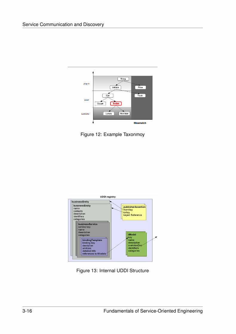
Service Communication and Discovery
Figure 12: Example Taxonmoy
Figure 13: Internal UDDI Structure
3-16 Fundamentals of Service-Oriented Engineering
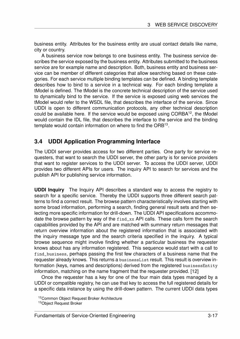
3 WEB SERVICE DISCOVERY
business entity. Attributes for the business entity are usual contact details like name,city or country.
A business service now belongs to one business entity. The business service de-scribes the service exposed by the business entity. Attributes submitted to the businessservice are for example name and description. Both, business entity and business ser-vice can be member of different categories that allow searching based on these cate-gories. For each service multiple binding templates can be defined. A binding templatedescribes how to bind to a service in a technical way. For each binding template atModel is defined. The tModel is the concrete technical description of the service usedto dynamically bind to the service. If the service is exposed using web services thetModel would refer to the WSDL file, that describes the interface of the service. SinceUDDI is open to different communication protocols, any other technical descriptioncould be available here. If the service would be exposed using CORBA12, the tModelwould contain the IDL file, that describes the interface to the service and the bindingtemplate would contain information on where to find the ORB13.
3.4 UDDI Application Programming Interface
The UDDI server provides access for two different parties. One party for service re-questers, that want to search the UDDI server, the other party is for service providersthat want to register services to the UDDI server. To access the UDDI server, UDDIprovides two different APIs for users. The inquiry API to search for services and thepublish API for publishing service information.
UDDI Inquiry The Inquiry API describes a standard way to access the registry tosearch for a specific service. Thereby the UDDI supports three different search pat-terns to find a correct result. The browse pattern characteristically involves starting withsome broad information, performing a search, finding general result sets and then se-lecting more specific information for drill-down. The UDDI API specifications accommo-date the browse pattern by way of the find_xx API calls. These calls form the searchcapabilities provided by the API and are matched with summary return messages thatreturn overview information about the registered information that is associated withthe inquiry message type and the search criteria specified in the inquiry. A typicalbrowse sequence might involve finding whether a particular business the requesterknows about has any information registered. This sequence would start with a call tofind_business, perhaps passing the first few characters of a business name that therequester already knows. This returns a businessList result. This result is overview in-formation (keys, names and descriptions) derived from the registered businessEntity
information, matching on the name fragment that the requester provided. [12]Once the requester has a key for one of the four main data types managed by a
UDDI or compatible registry, he can use that key to access the full registered details fora specific data instance by using the drill-down pattern. The current UDDI data types
12Common Object Request Broker Architecture13Object Request Broker
Fundamentals of Service-Oriented Engineering 3-17
Service Communication and Discovery
are businessEntity, businessService, bindingTemplate and tModel. The requestercan access the full registered information for any of these structures by passing arelevant key type to one of the get_xx API calls. [12]
The invocation pattern as a last step uses the retrieved key to fetch a binding tem-plate for a registered service and uses the technical description from the service reg-istry to bind to the service. Binding to the service can either be done at developmenttime or at runtime. Once the service requester bound to the service, it is able to com-municate with the remote service.
Figure 14: find business API call
The image shown in figure 14 describes the schema for a find_business API call.An example call to the UDDI server could look like the following example (example 3.4).Additional attributes to the call may specify the maximum number of results displayedor include wildcards to allow a more general search. The result of this API call will bea businessList containing all entries, that match the query. This API call corespondsto the browse-pattern.
UDDI Publish The messages for publishing represent commands that require au-thenticated access to an UDDI Operator Site, and are used to publish and updateinformation contained in a UDDI compatible registry. Each business should initially se-lect one Operator Site to host their information. Once chosen, information can only beupdated at the site originally selected. UDDI provides no automated means to recon-cile multiple or duplicate registrations. The messages defined for publishing all behavesynchronously and are callable via HTTP-POST only. HTTPS is used exclusively for
<find_business maxRows="100">
<name>%Car Rental</name>
</find_business>
3-18 Fundamentals of Service-Oriented Engineering
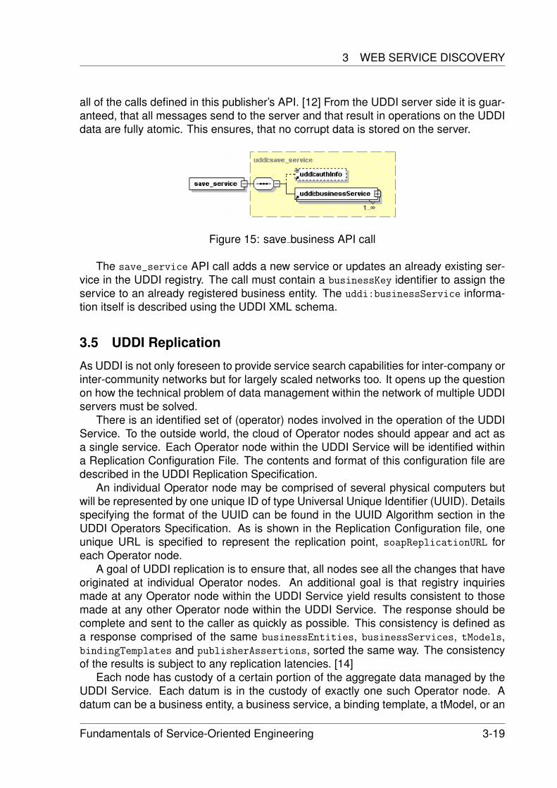
3 WEB SERVICE DISCOVERY
all of the calls defined in this publisher’s API. [12] From the UDDI server side it is guar-anteed, that all messages send to the server and that result in operations on the UDDIdata are fully atomic. This ensures, that no corrupt data is stored on the server.
Figure 15: save business API call
The save_service API call adds a new service or updates an already existing ser-vice in the UDDI registry. The call must contain a businessKey identifier to assign theservice to an already registered business entity. The uddi:businessService informa-tion itself is described using the UDDI XML schema.
3.5 UDDI Replication
As UDDI is not only foreseen to provide service search capabilities for inter-company orinter-community networks but for largely scaled networks too. It opens up the questionon how the technical problem of data management within the network of multiple UDDIservers must be solved.
There is an identified set of (operator) nodes involved in the operation of the UDDIService. To the outside world, the cloud of Operator nodes should appear and act asa single service. Each Operator node within the UDDI Service will be identified withina Replication Configuration File. The contents and format of this configuration file aredescribed in the UDDI Replication Specification.
An individual Operator node may be comprised of several physical computers butwill be represented by one unique ID of type Universal Unique Identifier (UUID). Detailsspecifying the format of the UUID can be found in the UUID Algorithm section in theUDDI Operators Specification. As is shown in the Replication Configuration file, oneunique URL is specified to represent the replication point, soapReplicationURL foreach Operator node.
A goal of UDDI replication is to ensure that, all nodes see all the changes that haveoriginated at individual Operator nodes. An additional goal is that registry inquiriesmade at any Operator node within the UDDI Service yield results consistent to thosemade at any other Operator node within the UDDI Service. The response should becomplete and sent to the caller as quickly as possible. This consistency is defined asa response comprised of the same businessEntities, businessServices, tModels,bindingTemplates and publisherAssertions, sorted the same way. The consistencyof the results is subject to any replication latencies. [14]
Each node has custody of a certain portion of the aggregate data managed by theUDDI Service. Each datum is in the custody of exactly one such Operator node. Adatum can be a business entity, a business service, a binding template, a tModel, or an
Fundamentals of Service-Oriented Engineering 3-19
Service Communication and Discovery
assertion within a business relationship. Changes to a datum in the UDDI Service canonly be made at the node in whose custody the datum resides. Although Publishersinitiate the changes by their inserts, updates, or deletes of the actual data, Operatornodes are said to ”‘originate changes”’ for such data into the Replication stream. TheOperator node that is the custodian of a datum can be changed. The Change of Cus-tody process utilizes a multi-step process and utilizes ”‘replication”’ to accomplish thefinal steps within this process. The complete Change of Custody Process is definedwithin the UDDI Operators Specification. [14]
An example implementation of UDDI Replication was provided by SAP, IBM, Mi-crosoft and others, called the UDDI Business Registry(UBR). The UBR was shut-downon January first 2006, because all parties agreed, that all goals - e.g. to show thatUDDI Replication works - where accomplished.
3.6 UDDI Limits and UDDIv3
UDDIv3 When UDDIv1 was introduced it provided only basic features needed for abusiness registry, in terms that storing data was possible, but searching for businesseswas implemented only rudimental. As an improvement in UDDIv2 searching capabil-ities where extended. But still the service registry lacked fine-granular security con-cepts. These security concepts where introduced in UDDIv3. As main improvementscertificate based and token based authentication where integrated. By now it is possi-ble to limit the search capabilities for specific parties by defining policies for accessingthe UDDI server.
Limits of UDDI Still one of the main drawbacks of UDDI is the lack of semantic ser-vice discovery. This means to search for a service on the basis what the service doesinstead of how the service is described. In general it is really difficult to implementsuch a semantic based search capability because everybody would have to agree onone specific semantic implementation. [18] Furthermore this would require a generalspecification algorithm for service providers if they register their services.
From the technical point of view UDDI already offers almost all functionality neededto create a reliable and functional service registry. But another drawback is, the lackof functionality to validate a published service and a possibility to check for updates orchanges of the requested service.
4 Conclusion
In terms of service oriented computing service communication using SOAP is a veryinteresting possibility. Its main advantage is the use of open standard and its simplicity.It is possible to implement a SOAP stack on nearly every platform and so to connectdivers devices in a service oriented environment. On the other hand its ease leads tovarious problems. Since Web Services using SOAP rely on the underlaying transportstack, not every communication scenario can be realized easily (see asynchronous
3-20 Fundamentals of Service-Oriented Engineering
REFERENCES
communication). Furthermore security and performance can be major issues for SOAPbased applications. But beeing open to domain specific add-ons SOAP is able to solvethese problems as well.
UDDI on the other side does not focus on the service communication but on servicediscovery. Based on SOAP UDDI provides a framework for service discovery. Theadvantage of UDDI is its openness to the used technologies. Besides using SOAPas a communication protocol, there is no restriction on communication protocols thatare used within the registered components. With UDDIv3 a better authorization andauthentication support was integrated. As a drawback UDDI still lacks a standardizedinterface to allow semantic searches for registered services. Furthermore by January1st 2006 all UDDI industry partners stopped their effort in providing sample serviceregistries, that independent software vendors could use for reference implementations.By now UDDI only exist on a specification sheet and future support by industry leadersis still unclear.
References
[1] SOAP History by Don Box
[2] SOAP History by Dave Winerhttp://webservices.xml.com/pub/a/ws/2001/04/04/soap.html
[3] SOAP in Wikipediahttp://en.wikipedia.org/wiki/SOAP
[4] SOAP Message Encodinghttp://www-128.ibm.com/developerworks/library/ws-whichwsdl/
[5] SOAP w/ Attachmentshttp://www.w3.org/TR/SOAP-attachments
[6] SOAP Specification 1.2
[7] Ontology by Wikipediahttp://en.wikipedia.org/wiki/Ontology_\%28computer_science\%29
[8] Taxonomy by Wikipediahttp://en.wikipedia.org/wiki/Taxonomy
[9] Web Service Transactionshttp://www.w3.org/TR/2003/REC-soap12-part0-20030624/#L1177
[10] Web Service Securityhttp://www-128.ibm.com/developerworks/library/specification/ws-secure/
[11] UDDI v3 Specificationhttp://www.oasis-open.org/committees/uddi-spec/doc/spec/v3/uddi-v3.0.
2-20041019.htm
Fundamentals of Service-Oriented Engineering 3-21
Service Communication and Discovery
[12] UDDI v2 Specificationhttp://uddi.org/pubs/ProgrammersAPI-V2.04-Published-20020719.htm
[13] UDDI and WSDLhttp://www.w3schools.com/wsdl/wsdl_uddi.asp
[14] UDDI Replication Specificationhttp://uddi.org/pubs/Replication-V2.03-Published-20020719.htm
[15] OASIS Homepagehttp://www.oasis-open.org
[16] Web Service Discovery: UDDI and beyondhttp://wwwcs.uni-paderborn.de/cs/ag-kao/de/teaching/ws05/ws/03\%20-\
%20SemWS\%20-\%20Ausarbeitung\%20-\%20Hans\%20Gossen\%20-\%20UDDI\
%20and\%20beyond.pdf
[17] What’s new in UDDIv3http://www.webservices.org/categories/technology/registry_uddi/what_s_
new_in_uddi_3_0_part_1/(go)/Articles
[18] Paolucci et al: Importing the Semantic Web in UDDI. In Proceedings of Web Ser-vices, E-business and Semantic Web Workshop, 2002
3-22 Fundamentals of Service-Oriented Engineering
Fundamentals of Service-Oriented Engineering 4-1
Role, capabilities and position of JINI Network Technology in SOC
B.Sc.Tobias Queck
Diese Ausarbeitung beschäftigt sich mit der von Sun entwickelten Technologie
JINI. Zu Beginn wird ein Überblick über JINI gegeben, auf den dann eine Beschreibung der JINI Architektur folgt. Daran angeschlossen wird diskutiert, ob JINI eine Service-orientierte Architektur besitzt und welche Rolle diese in der Service-orientierten Welt spielt. Zum Schluss wird ein Vergleich zwischen Webservices mit JINI durchgeführt an welchen sich ein abschließendes Fazit des Autors anschließt.
Keywords: JINI, SOA, Webservices, JavaSpaces, Leasing, Distributed Events
1 Einleitung und Grundlagen Der Mitbegründer von Sun Microsystems, Bill Joy verkündete am Anfang der 90er
Jahre seine Vision von einer verteilten (Computer-) Welt, in der Software auf jedem Computer unabhängig von seiner Architektur oder seines Betriebssystems ausgeführt werden kann und mit anderen transparent kommuniziert. Um diese Vision zu verwirklichen Trieb er die Entwicklung von Java voran. Dadurch wurde eine Technologie geschaffen, die es ermöglicht Software zu entwickeln, die in einer Virtuellen Maschine abgewickelt wird, unabhängig von den darunter liegenden Schichten.
Der nächste Abstraktionsschritt sollte die Computergrenzen beseitigen. Dazu sollten die Java Konzepte so erweitert werden, so dass Programme transparent über Computergrenzen hinweg interagieren können. Erste Ideen wurden bei Sun von Bill Joy zusammen mit den Ideen für Java entwickelt. Die Umsetzung erfolgte bis 1999 mit der ersten Veröffentlichung von JINI. [1][12]
1.1 Ziele Ziel eines JINI Systems ist es einerseits dem Benutzer die Möglichkeit zu geben
Dienste und Ressourcen in einem Netzwerk zur Verfügung zu stellen. Andererseits soll es auch für Benutzer leicht sein, Ressourcen und Dienste Anderer zu finden und zu verwenden. Dabei soll der administrative Aufwand zur Erstellung, Wartung und Erweiterung des Netzwerkes so gering wie Möglich bleiben.
Netzwerke werden bei JINI nicht als starre immer funktionierende Konstrukte betrachtet, sondern als flexible Gebilde, in denen keine Garantien für Durchsatz oder
Role, capabilities and position of JINI Network Technology in SOC
4-2 Fundamentals of Service-Oriented Engineering
Erreichbarkeit gegeben werden können. Daher werden Aspekte wie Skalierbarkeit oder Ausfallbehandlung besonders betrachtet. Weiterhin muss ein Netzwerk nicht nur aus leistungsstarken Computern bestehen, sondern kann ebenso Geräte, wie eine Kamera oder ein Drucker, enthalten, die aber selbst in der Lage sind einen Dienst anzubieten oder zu nutzen.
Für die Umsetzung wird das Java Konzept der Ausführung von Programmen in einer virtuellen Maschine (VM) erweitert. Mit JINI soll es möglich sein zwischen verschiedenen VMs zu kommunizieren, und dabei sowohl Daten als auch Code zu transferieren. [2]
1.2 Anwendungsszenario Das typische Anwendungsszenario für JINI beinhaltet ein variierendes Netzwerk
bestehend aus Computer und Geräten, wie z.B. in einer Firma mit Innen- und Außendienstmitarbeitern, beispielsweise in der Immobilienbranche.
Angenommen es gäbe ein Bürogebäude mit mehreren Computern, Druckern und Beamern, die alle einem Netzwerk angehören. Auf allen Geräten sind JINI Dienste entweder zum anzeigen, drucken oder speichern von Fotos vorhanden. All diese Dienste sind auf einem zentralen Server registriert. Zusätzlich gibt es noch ein Bluetooth Empfänger über den es möglich ist mobile Geräte in das Netzwerk zu integrieren.
Kommt nun ein Außendienstmitarbeiter, der eine Bluetoothfähige Digitalkamera dabei hat, auf der ebenfalls JINI Dienste vorhanden sind, in das Büro, so kann dieser seine Kamera aktivieren und diese integriert sich automatisch in das Netzwerk. Danach kann über ein Benutzerinterface auf der Kamera nach einem Anzeige-Dienst auf einem Beamer gesucht werden und die Fotos den Kollegen gezeigt werden. Jetzt kann im Büro über die Bilder diskutiert werden und die benötigten aussortiert werden. Diese können dann über einen anderen JINI Dienst gedruckt oder gesichert werden. Danach deaktiviert er die Kamera wieder und verlässt das Büro.
1.3 Konzepte Das wichtigste Konzept eines JINI Systems ist der Dienst. In einem JINI System
ist alles ein Dienst, das beinhaltet Programme, Programme und Daten, Geräte und auch den Benutzer selbst. Diese Dienste und ihre Kommunikation bilden zusammen das Gesamtsystem. Um die Kommunikation untereinander zu ermöglich gibt es einen zentralen Dienst, den Lookup Service. Andere Dienste müssen sich bei ihm anmelden, damit sie gefunden werden können (join – siehe 2.2 ) und wiederum müssen sie ihn kontaktieren wenn sie andere Dienste finden wollen (lookup – siehe 2.3 ).
Als darunter liegende Infrastruktur wird die Java Technologie RMI (Remote Method Invocation) verwendet. Damit ist es möglich Objekte zu finden, zu aktivieren und auch zu versenden. Insbesondere ist es mit RMI möglich nicht nur Daten zu verschicken, sondern komplette Objekte mit ausführbarer Programmlogik. Weiterhin bringt RMI ein Sicherheitsmodell mit, welches den Zugriff auf Objekte und deren Rechte über die Grenzen der Virtuellen Maschine hinweg regelt. Dazu werden policy Dateien verwendet, in denen genau festgelegt werden kann, von wem ein
1 EINLEITUNG UND GRUNDLAGEN
Fundamentals of Service-Oriented Engineering 4-3
bestimmtes Objekt aufgerufen werden kann, und welche Funktionalitäten erlaubt sind. [5]
Der Zugriff auf die meisten Dienste ist über Leasing regelt. Das heißt, Dienstanbieter und -nutzer handeln eine Zeitperiode aus in der dem Nutzer der Zugriff auf den Dienst garantiert wird. Ist diese Periode abgelaufen und es wurde keine Verlängerung ausgehandelt, verfällt das Zugriffsrecht des Nutzers und auf Nutzer- und Anbieterseite werden die reservierten Ressourcen wieder freigegeben. Dementsprechend muss das Recht zu Nutzung immer wieder vor Ablauf der Zeitperiode erneuert werden, wenn ein Dienst weiter verfügbar sein soll. Treten nun Netzwerkprobleme auf, so dass eine Verlängerung nicht möglich ist, verfällt Nutzungsrecht nach Ablauf des der ausgehandelten Zeitperiode. Damit können einerseits Ressourcen für längere Zeit nicht mehr verfügbare Dienstnutzer freigeben werden und andererseits kurzeitige Netzwerkprobleme ignoriert werden, was in Netzwerken mit einer dynamischen Infrastruktur essentiell ist.
Beim Leasing können entweder exklusive oder nicht-exklusive Rechte auf Ressourcen vergeben werden. Bei einem exklusiven Zugriff wird dem Dienstanbieter ein alleiniges Recht auf die zur Verfügung gestellten Ressourcen gewehrt, wobei bei einem nicht-exklusiven Lease mehrere Nutzer gleichzeitig die Ressourcen eines Dienstes teilen können.
Des Weiteren enthält JINI die Möglichkeit Transaktionen zu verwenden, das heißt einzelne Dienste können miteinander zu einer Transaktion verknüpft werden, um gegebenenfalls bei einem Fehler durch einen Rollback inkonsistente Zustände zu vermeiden. In JINI wird dafür das 2-Phase-Commit Protokoll verwendet. Die Implementierung des Protokolls ist aber dem Entwickler selbst überlassen, es müssen nur die angebotenen Interfaces implementiert werden.
.Abschließend wird in JINI eine verteilte Lösung für das bereits in Java vorhandene Konzept für Events angeboten. Dazu wird das Event-Modell von JavaBeans erweitert indem Events über das Netzwerk verschickt werden können, und Aspekte wie Verzögerung und nicht Erreichbarkeitsprobleme beachtet werden. Dies wird erreicht indem zwischen dem Eventgenerator und dem Eventinteressenten eine zusätzliche Komponente, der Event Listener, eingebaut wird. Dieser erhält die Events vom Eventgenerator und leitet sie dann nach einem frei implementierbaren Algorithmus weiter. So könnten z.B. alle Events die durch eine Verzögerung schon zu alt sind, ignoriert werden und nur aktuelle Events and den Eventinteressenten weitergeleitet werden. Ebenso sind Konzepte wie Notification Filter, Step-and-Forward Agents oder Notifaction Mailboxes denkbar. [8]
1.4 Komponenten Um die im vorherigen Kapitel erläuterten Konzepte umzusetzen, besteht das JINI
System aus Komponenten, die in die drei Bereiche Infrastruktur, Programmiermodell und Dienste eingeteilt werden. Dazu wird durch JINI nicht alles neu umgesetzt, sondern es wird auf vorhandene Java Komponenten aufgebaut (siehe Abbildung 1). Demzufolge kann JINI nicht getrennt von Java betrachtet werden, sondern ist als eine Erweiterung dieser Technologie einzuordnen.
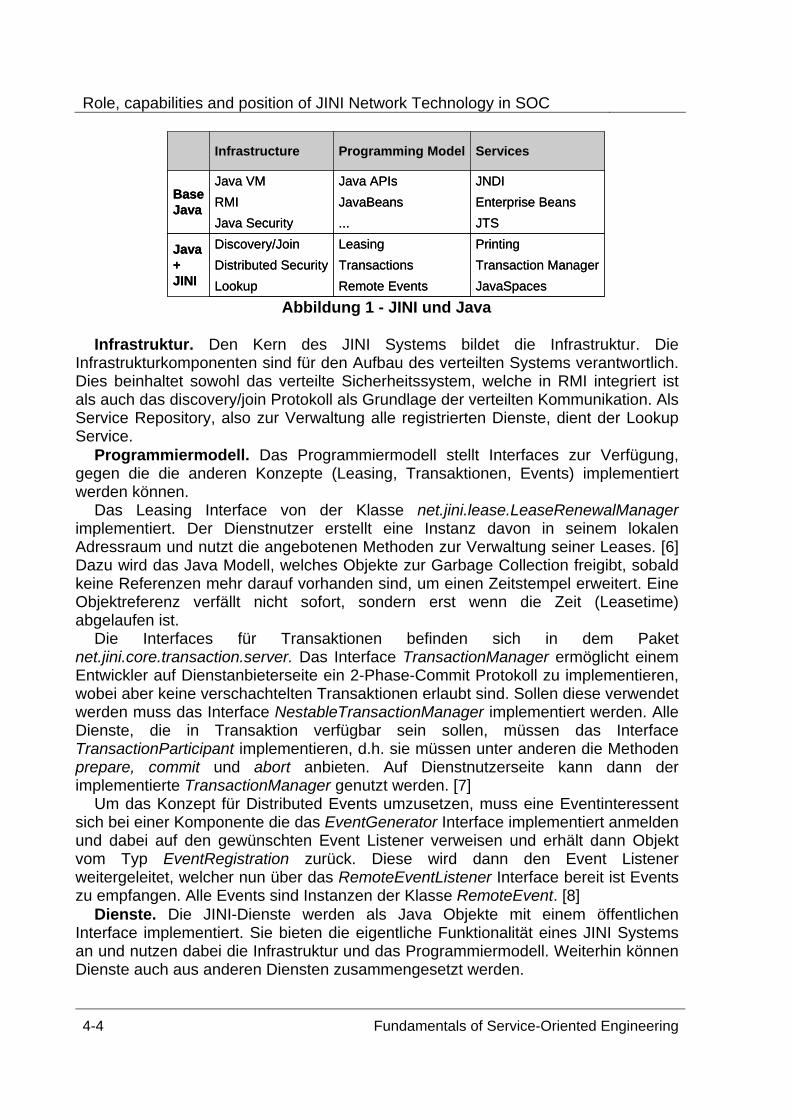
Role, capabilities and position of JINI Network Technology in SOC
4-4 Fundamentals of Service-Oriented Engineering
JavaSpacesRemote EventsLookupTransaction ManagerTransactionsDistributed SecurityPrintingLeasingDiscovery/JoinJava
+JINI
JTS...Java SecurityEnterprise BeansJavaBeansRMIJNDIJava APIsJava VM
BaseJava
ServicesProgramming ModelInfrastructure
JavaSpacesRemote EventsLookupTransaction ManagerTransactionsDistributed SecurityPrintingLeasingDiscovery/JoinJava
+JINI
JTS...Java SecurityEnterprise BeansJavaBeansRMIJNDIJava APIsJava VM
BaseJava
ServicesProgramming ModelInfrastructure
Abbildung 1 - JINI und Java
Infrastruktur. Den Kern des JINI Systems bildet die Infrastruktur. Die
Infrastrukturkomponenten sind für den Aufbau des verteilten Systems verantwortlich. Dies beinhaltet sowohl das verteilte Sicherheitssystem, welche in RMI integriert ist als auch das discovery/join Protokoll als Grundlage der verteilten Kommunikation. Als Service Repository, also zur Verwaltung alle registrierten Dienste, dient der Lookup Service.
Programmiermodell. Das Programmiermodell stellt Interfaces zur Verfügung, gegen die die anderen Konzepte (Leasing, Transaktionen, Events) implementiert werden können.
Das Leasing Interface von der Klasse net.jini.lease.LeaseRenewalManager implementiert. Der Dienstnutzer erstellt eine Instanz davon in seinem lokalen Adressraum und nutzt die angebotenen Methoden zur Verwaltung seiner Leases. [6] Dazu wird das Java Modell, welches Objekte zur Garbage Collection freigibt, sobald keine Referenzen mehr darauf vorhanden sind, um einen Zeitstempel erweitert. Eine Objektreferenz verfällt nicht sofort, sondern erst wenn die Zeit (Leasetime) abgelaufen ist.
Die Interfaces für Transaktionen befinden sich in dem Paket net.jini.core.transaction.server. Das Interface TransactionManager ermöglicht einem Entwickler auf Dienstanbieterseite ein 2-Phase-Commit Protokoll zu implementieren, wobei aber keine verschachtelten Transaktionen erlaubt sind. Sollen diese verwendet werden muss das Interface NestableTransactionManager implementiert werden. Alle Dienste, die in Transaktion verfügbar sein sollen, müssen das Interface TransactionParticipant implementieren, d.h. sie müssen unter anderen die Methoden prepare, commit und abort anbieten. Auf Dienstnutzerseite kann dann der implementierte TransactionManager genutzt werden. [7]
Um das Konzept für Distributed Events umzusetzen, muss eine Eventinteressent sich bei einer Komponente die das EventGenerator Interface implementiert anmelden und dabei auf den gewünschten Event Listener verweisen und erhält dann Objekt vom Typ EventRegistration zurück. Diese wird dann den Event Listener weitergeleitet, welcher nun über das RemoteEventListener Interface bereit ist Events zu empfangen. Alle Events sind Instanzen der Klasse RemoteEvent. [8]
Dienste. Die JINI-Dienste werden als Java Objekte mit einem öffentlichen Interface implementiert. Sie bieten die eigentliche Funktionalität eines JINI Systems an und nutzen dabei die Infrastruktur und das Programmiermodell. Weiterhin können Dienste auch aus anderen Diensten zusammengesetzt werden.
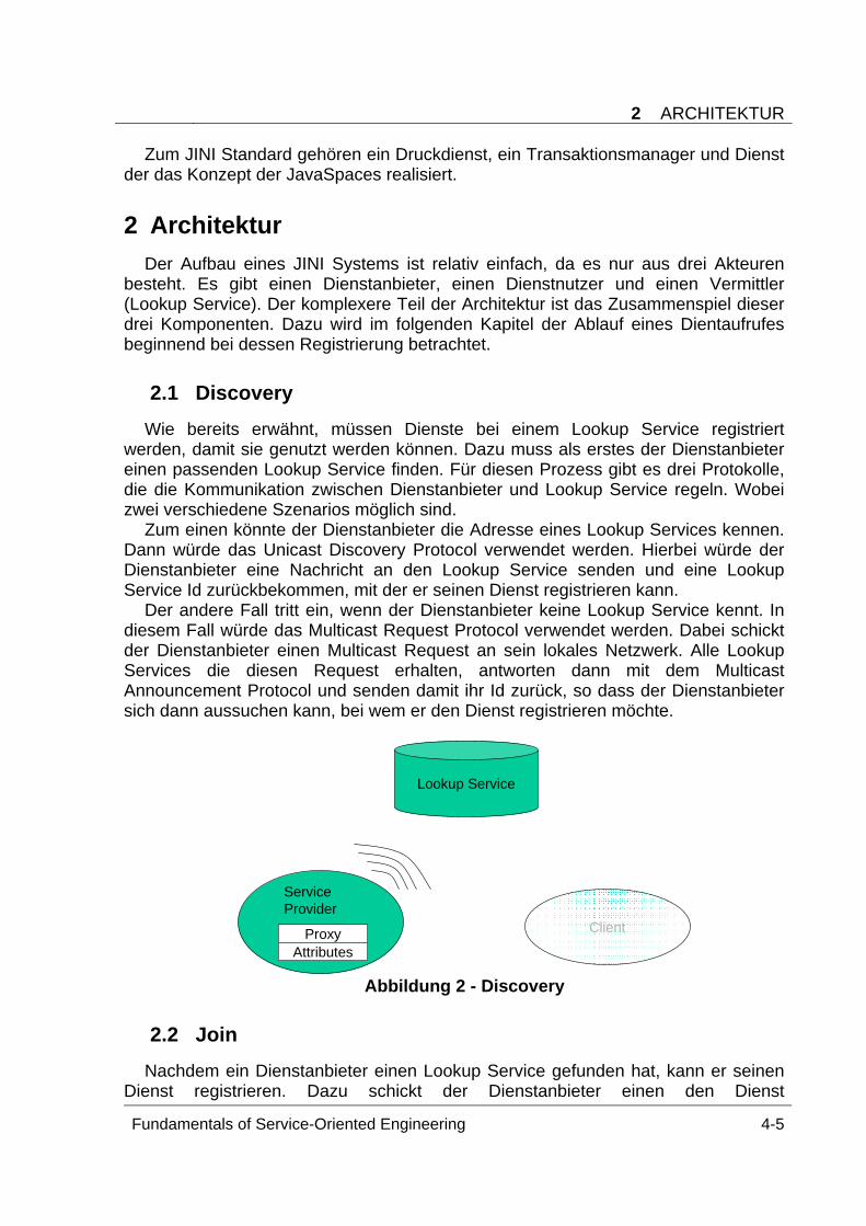
2 ARCHITEKTUR
Fundamentals of Service-Oriented Engineering 4-5
Zum JINI Standard gehören ein Druckdienst, ein Transaktionsmanager und Dienst der das Konzept der JavaSpaces realisiert.
2 Architektur Der Aufbau eines JINI Systems ist relativ einfach, da es nur aus drei Akteuren
besteht. Es gibt einen Dienstanbieter, einen Dienstnutzer und einen Vermittler (Lookup Service). Der komplexere Teil der Architektur ist das Zusammenspiel dieser drei Komponenten. Dazu wird im folgenden Kapitel der Ablauf eines Dientaufrufes beginnend bei dessen Registrierung betrachtet.
2.1 Discovery Wie bereits erwähnt, müssen Dienste bei einem Lookup Service registriert
werden, damit sie genutzt werden können. Dazu muss als erstes der Dienstanbieter einen passenden Lookup Service finden. Für diesen Prozess gibt es drei Protokolle, die die Kommunikation zwischen Dienstanbieter und Lookup Service regeln. Wobei zwei verschiedene Szenarios möglich sind.
Zum einen könnte der Dienstanbieter die Adresse eines Lookup Services kennen. Dann würde das Unicast Discovery Protocol verwendet werden. Hierbei würde der Dienstanbieter eine Nachricht an den Lookup Service senden und eine Lookup Service Id zurückbekommen, mit der er seinen Dienst registrieren kann.
Der andere Fall tritt ein, wenn der Dienstanbieter keine Lookup Service kennt. In diesem Fall würde das Multicast Request Protocol verwendet werden. Dabei schickt der Dienstanbieter einen Multicast Request an sein lokales Netzwerk. Alle Lookup Services die diesen Request erhalten, antworten dann mit dem Multicast Announcement Protocol und senden damit ihr Id zurück, so dass der Dienstanbieter sich dann aussuchen kann, bei wem er den Dienst registrieren möchte.
Service Provider
ProxyAttributes
Lookup Service
Client
Abbildung 2 - Discovery
2.2 Join Nachdem ein Dienstanbieter einen Lookup Service gefunden hat, kann er seinen
Dienst registrieren. Dazu schickt der Dienstanbieter einen den Dienst
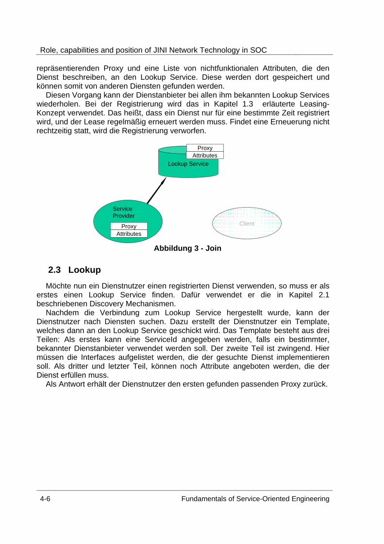
Role, capabilities and position of JINI Network Technology in SOC
4-6 Fundamentals of Service-Oriented Engineering
repräsentierenden Proxy und eine Liste von nichtfunktionalen Attributen, die den Dienst beschreiben, an den Lookup Service. Diese werden dort gespeichert und können somit von anderen Diensten gefunden werden.
Diesen Vorgang kann der Dienstanbieter bei allen ihm bekannten Lookup Services wiederholen. Bei der Registrierung wird das in Kapitel 1.3 erläuterte Leasing-Konzept verwendet. Das heißt, dass ein Dienst nur für eine bestimmte Zeit registriert wird, und der Lease regelmäßig erneuert werden muss. Findet eine Erneuerung nicht rechtzeitig statt, wird die Registrierung verworfen.
Service Provider
ProxyAttributes
Lookup Service
Client
ProxyAttributes
Abbildung 3 - Join
2.3 Lookup Möchte nun ein Dienstnutzer einen registrierten Dienst verwenden, so muss er als
erstes einen Lookup Service finden. Dafür verwendet er die in Kapitel 2.1 beschriebenen Discovery Mechanismen.
Nachdem die Verbindung zum Lookup Service hergestellt wurde, kann der Dienstnutzer nach Diensten suchen. Dazu erstellt der Dienstnutzer ein Template, welches dann an den Lookup Service geschickt wird. Das Template besteht aus drei Teilen: Als erstes kann eine ServiceId angegeben werden, falls ein bestimmter, bekannter Dienstanbieter verwendet werden soll. Der zweite Teil ist zwingend. Hier müssen die Interfaces aufgelistet werden, die der gesuchte Dienst implementieren soll. Als dritter und letzter Teil, können noch Attribute angeboten werden, die der Dienst erfüllen muss.
Als Antwort erhält der Dienstnutzer den ersten gefunden passenden Proxy zurück.
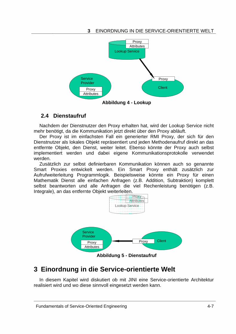
3 EINORDNUNG IN DIE SERVICE-ORIENTIERTE WELT
Fundamentals of Service-Oriented Engineering 4-7
Service Provider
ProxyAttributes
Lookup Service
Client
ProxyAttributes
Proxy
Abbildung 4 - Lookup
2.4 Dienstaufruf Nachdem der Dienstnutzer den Proxy erhalten hat, wird der Lookup Service nicht
mehr benötigt, da die Kommunikation jetzt direkt über den Proxy abläuft. Der Proxy ist im einfachsten Fall ein generierter RMI Proxy, der sich für den
Dienstnutzer als lokales Objekt repräsentiert und jeden Methodenaufruf direkt an das entfernte Objekt, den Dienst, weiter leitet. Ebenso könnte der Proxy auch selbst implementiert werden und dabei eigene Kommunikationsprotokolle verwendet werden.
Zusätzlich zur selbst definierbaren Kommunikation können auch so genannte Smart Proxies entwickelt werden. Ein Smart Proxy enthält zusätzlich zur Aufrufweiterleitung Programmlogik. Beispielsweise könnte ein Proxy für einen Mathematik Dienst alle einfachen Anfragen (z.B. Addition, Subtraktion) komplett selbst beantworten und alle Anfragen die viel Rechenleistung benötigen (z.B. Integrale), an das entfernte Objekt weiterleiten.
Service Provider
ProxyAttributes
Client
Lookup Service
ProxyAttributes
Lookup Service
ProxyAttributes
Proxy
Abbildung 5 - Dienstaufruf
3 Einordnung in die Service-orientierte Welt In diesem Kapitel wird diskutiert ob mit JINI eine Service-orientierte Architektur
realisiert wird und wo diese sinnvoll eingesetzt werden kann.
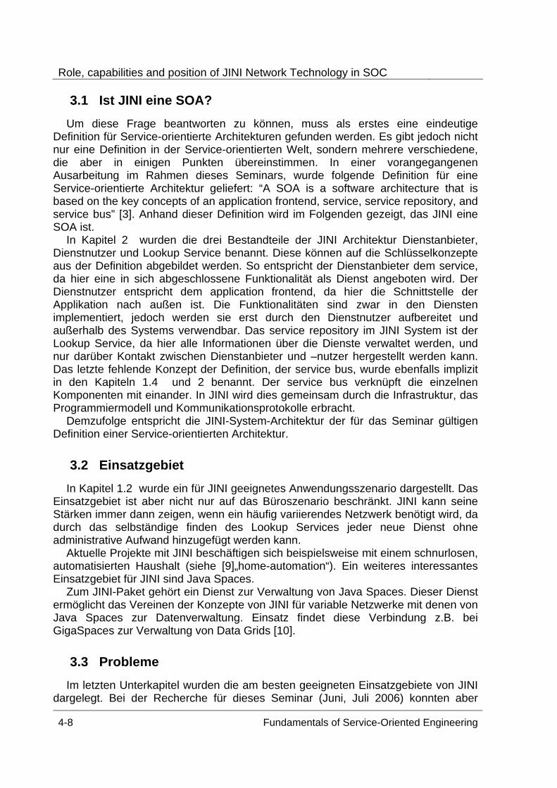
Role, capabilities and position of JINI Network Technology in SOC
4-8 Fundamentals of Service-Oriented Engineering
3.1 Ist JINI eine SOA? Um diese Frage beantworten zu können, muss als erstes eine eindeutige
Definition für Service-orientierte Architekturen gefunden werden. Es gibt jedoch nicht nur eine Definition in der Service-orientierten Welt, sondern mehrere verschiedene, die aber in einigen Punkten übereinstimmen. In einer vorangegangenen Ausarbeitung im Rahmen dieses Seminars, wurde folgende Definition für eine Service-orientierte Architektur geliefert: “A SOA is a software architecture that is based on the key concepts of an application frontend, service, service repository, and service bus” [3]. Anhand dieser Definition wird im Folgenden gezeigt, das JINI eine SOA ist.
In Kapitel 2 wurden die drei Bestandteile der JINI Architektur Dienstanbieter, Dienstnutzer und Lookup Service benannt. Diese können auf die Schlüsselkonzepte aus der Definition abgebildet werden. So entspricht der Dienstanbieter dem service, da hier eine in sich abgeschlossene Funktionalität als Dienst angeboten wird. Der Dienstnutzer entspricht dem application frontend, da hier die Schnittstelle der Applikation nach außen ist. Die Funktionalitäten sind zwar in den Diensten implementiert, jedoch werden sie erst durch den Dienstnutzer aufbereitet und außerhalb des Systems verwendbar. Das service repository im JINI System ist der Lookup Service, da hier alle Informationen über die Dienste verwaltet werden, und nur darüber Kontakt zwischen Dienstanbieter und –nutzer hergestellt werden kann. Das letzte fehlende Konzept der Definition, der service bus, wurde ebenfalls implizit in den Kapiteln 1.4 und 2 benannt. Der service bus verknüpft die einzelnen Komponenten mit einander. In JINI wird dies gemeinsam durch die Infrastruktur, das Programmiermodell und Kommunikationsprotokolle erbracht.
Demzufolge entspricht die JINI-System-Architektur der für das Seminar gültigen Definition einer Service-orientierten Architektur.
3.2 Einsatzgebiet In Kapitel 1.2 wurde ein für JINI geeignetes Anwendungsszenario dargestellt. Das
Einsatzgebiet ist aber nicht nur auf das Büroszenario beschränkt. JINI kann seine Stärken immer dann zeigen, wenn ein häufig variierendes Netzwerk benötigt wird, da durch das selbständige finden des Lookup Services jeder neue Dienst ohne administrative Aufwand hinzugefügt werden kann.
Aktuelle Projekte mit JINI beschäftigen sich beispielsweise mit einem schnurlosen, automatisierten Haushalt (siehe [9]„home-automation“). Ein weiteres interessantes Einsatzgebiet für JINI sind Java Spaces.
Zum JINI-Paket gehört ein Dienst zur Verwaltung von Java Spaces. Dieser Dienst ermöglicht das Vereinen der Konzepte von JINI für variable Netzwerke mit denen von Java Spaces zur Datenverwaltung. Einsatz findet diese Verbindung z.B. bei GigaSpaces zur Verwaltung von Data Grids [10].
3.3 Probleme Im letzten Unterkapitel wurden die am besten geeigneten Einsatzgebiete von JINI
dargelegt. Bei der Recherche für dieses Seminar (Juni, Juli 2006) konnten aber
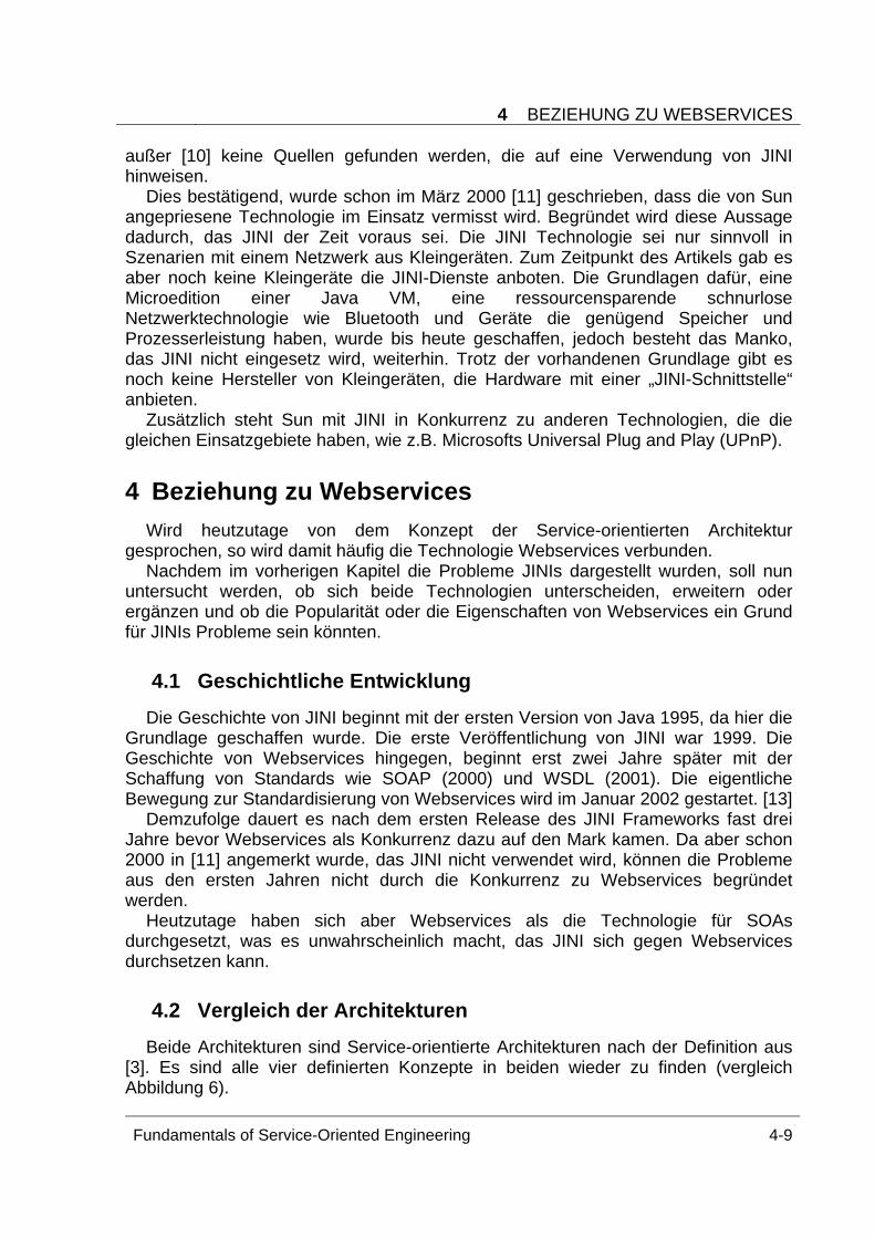
4 BEZIEHUNG ZU WEBSERVICES
Fundamentals of Service-Oriented Engineering 4-9
außer [10] keine Quellen gefunden werden, die auf eine Verwendung von JINI hinweisen.
Dies bestätigend, wurde schon im März 2000 [11] geschrieben, dass die von Sun angepriesene Technologie im Einsatz vermisst wird. Begründet wird diese Aussage dadurch, das JINI der Zeit voraus sei. Die JINI Technologie sei nur sinnvoll in Szenarien mit einem Netzwerk aus Kleingeräten. Zum Zeitpunkt des Artikels gab es aber noch keine Kleingeräte die JINI-Dienste anboten. Die Grundlagen dafür, eine Microedition einer Java VM, eine ressourcensparende schnurlose Netzwerktechnologie wie Bluetooth und Geräte die genügend Speicher und Prozesserleistung haben, wurde bis heute geschaffen, jedoch besteht das Manko, das JINI nicht eingesetz wird, weiterhin. Trotz der vorhandenen Grundlage gibt es noch keine Hersteller von Kleingeräten, die Hardware mit einer „JINI-Schnittstelle“ anbieten.
Zusätzlich steht Sun mit JINI in Konkurrenz zu anderen Technologien, die die gleichen Einsatzgebiete haben, wie z.B. Microsofts Universal Plug and Play (UPnP).
4 Beziehung zu Webservices Wird heutzutage von dem Konzept der Service-orientierten Architektur
gesprochen, so wird damit häufig die Technologie Webservices verbunden. Nachdem im vorherigen Kapitel die Probleme JINIs dargestellt wurden, soll nun
untersucht werden, ob sich beide Technologien unterscheiden, erweitern oder ergänzen und ob die Popularität oder die Eigenschaften von Webservices ein Grund für JINIs Probleme sein könnten.
4.1 Geschichtliche Entwicklung Die Geschichte von JINI beginnt mit der ersten Version von Java 1995, da hier die
Grundlage geschaffen wurde. Die erste Veröffentlichung von JINI war 1999. Die Geschichte von Webservices hingegen, beginnt erst zwei Jahre später mit der Schaffung von Standards wie SOAP (2000) und WSDL (2001). Die eigentliche Bewegung zur Standardisierung von Webservices wird im Januar 2002 gestartet. [13]
Demzufolge dauert es nach dem ersten Release des JINI Frameworks fast drei Jahre bevor Webservices als Konkurrenz dazu auf den Mark kamen. Da aber schon 2000 in [11] angemerkt wurde, das JINI nicht verwendet wird, können die Probleme aus den ersten Jahren nicht durch die Konkurrenz zu Webservices begründet werden.
Heutzutage haben sich aber Webservices als die Technologie für SOAs durchgesetzt, was es unwahrscheinlich macht, das JINI sich gegen Webservices durchsetzen kann.
4.2 Vergleich der Architekturen Beide Architekturen sind Service-orientierte Architekturen nach der Definition aus
[3]. Es sind alle vier definierten Konzepte in beiden wieder zu finden (vergleich Abbildung 6).
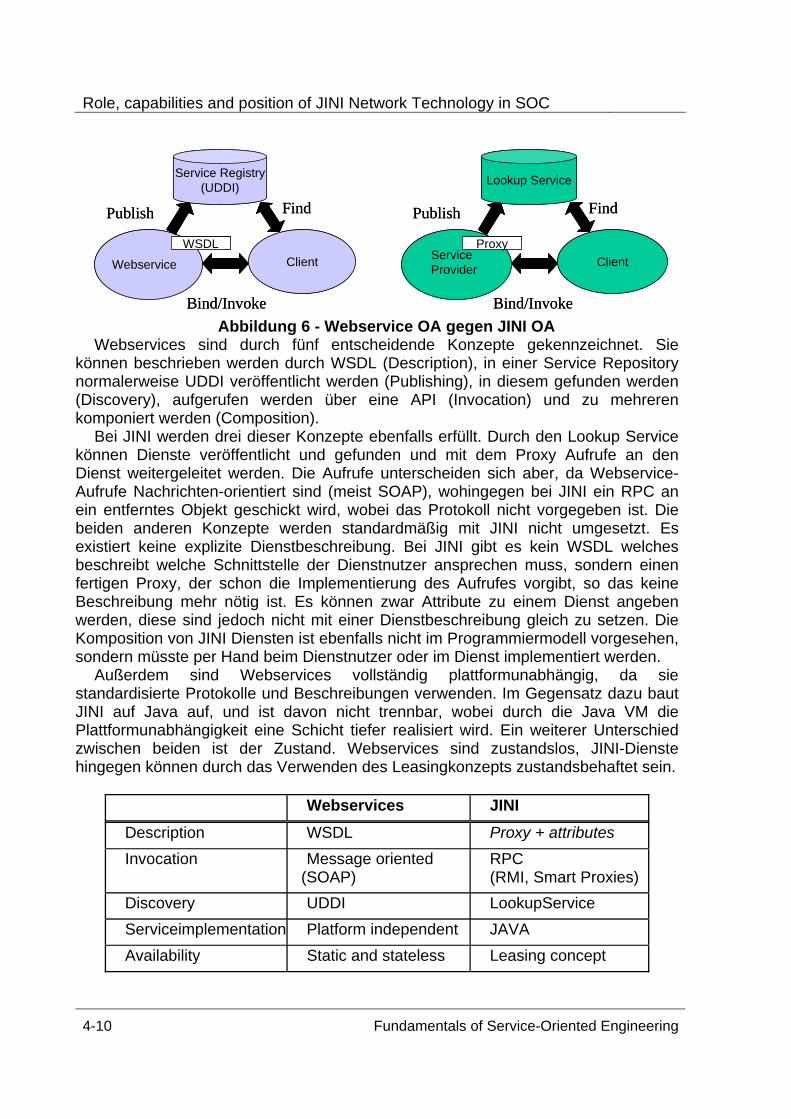
Role, capabilities and position of JINI Network Technology in SOC
4-10 Fundamentals of Service-Oriented Engineering
Service Provider
Lookup Service
ClientWebservice
Service Registry(UDDI)
ClientProxyWSDL
Publish Find
Bind/Invoke
Publish Find
Bind/Invoke
Service Provider
Lookup Service
ClientWebservice
Service Registry(UDDI)
ClientProxyWSDL
Publish Find
Bind/Invoke
Publish Find
Bind/Invoke Abbildung 6 - Webservice OA gegen JINI OA
Webservices sind durch fünf entscheidende Konzepte gekennzeichnet. Sie können beschrieben werden durch WSDL (Description), in einer Service Repository normalerweise UDDI veröffentlicht werden (Publishing), in diesem gefunden werden (Discovery), aufgerufen werden über eine API (Invocation) und zu mehreren komponiert werden (Composition).
Bei JINI werden drei dieser Konzepte ebenfalls erfüllt. Durch den Lookup Service können Dienste veröffentlicht und gefunden und mit dem Proxy Aufrufe an den Dienst weitergeleitet werden. Die Aufrufe unterscheiden sich aber, da Webservice-Aufrufe Nachrichten-orientiert sind (meist SOAP), wohingegen bei JINI ein RPC an ein entferntes Objekt geschickt wird, wobei das Protokoll nicht vorgegeben ist. Die beiden anderen Konzepte werden standardmäßig mit JINI nicht umgesetzt. Es existiert keine explizite Dienstbeschreibung. Bei JINI gibt es kein WSDL welches beschreibt welche Schnittstelle der Dienstnutzer ansprechen muss, sondern einen fertigen Proxy, der schon die Implementierung des Aufrufes vorgibt, so das keine Beschreibung mehr nötig ist. Es können zwar Attribute zu einem Dienst angeben werden, diese sind jedoch nicht mit einer Dienstbeschreibung gleich zu setzen. Die Komposition von JINI Diensten ist ebenfalls nicht im Programmiermodell vorgesehen, sondern müsste per Hand beim Dienstnutzer oder im Dienst implementiert werden.
Außerdem sind Webservices vollständig plattformunabhängig, da sie standardisierte Protokolle und Beschreibungen verwenden. Im Gegensatz dazu baut JINI auf Java auf, und ist davon nicht trennbar, wobei durch die Java VM die Plattformunabhängigkeit eine Schicht tiefer realisiert wird. Ein weiterer Unterschied zwischen beiden ist der Zustand. Webservices sind zustandslos, JINI-Dienste hingegen können durch das Verwenden des Leasingkonzepts zustandsbehaftet sein.
Webservices JINI Description WSDL Proxy + attributes Invocation Message oriented
(SOAP) RPC (RMI, Smart Proxies)
Discovery UDDI LookupService Serviceimplementation Platform independent JAVA Availability Static and stateless Leasing concept
5 FAZIT UND AUSBLICK
Fundamentals of Service-Oriented Engineering 4-11
4.3 JISGA Projekt JISGA (JINI based Service oriented Grid Architecture) ist ein Projekt, welches
versucht bei Technologien miteinander zu verknüpfen. Es soll damit ermöglicht werden, dass auch auf ein lokales JINI System über Webservicestandards zugegriffen werden kann. Dafür werden JINI-Dienste die auch nach Außen verfügbar sein sollen mit einer zusätzlichen Schnittstelle für Webservice-Aufrufe versehen. [14]
Dieses Projekt zeigt, dass sich beide Technologien nicht gegenseitig ausschließen müssen, sondern dass sie geschickt miteinander verknüpft die Vorteile beider Ideen nutzen können.
4.4 Fazit Abschließend kann festgestellt werden, dass beide Technologien eine Umsetzung
einer Service-orientierten Architektur sind. Trotzdem stehen sie nicht in Konkurrenz zueinander, da sie unterschiedliche Einsatzgebiete haben. JINI wurde für dynamische lokale Netzwerke entwickelt und Webservices für ein B2B Kommunikation über das Internet. Folglich hängen die Probleme JINIs in der Verbreitung nicht mit Webservices zusammen. Ebenso ist die Kombination beider möglich, was das JISGA Projekt zeigt.
5 Fazit und Ausblick Nachdem in der bisherigen Ausarbeitung eine möglichst objektive Sicht auf JINI
dargelegt worden ist, wird im folgenden Kapitel, das wichtigste noch einmal benannt und vom Autor bewertet.
5.1 Fazit JINI ist als eine Erweiterung zu Java zu sehen, die es ermöglicht dynamische
Netzwerke aufzubauen, wobei ein geringer Wartungsaufwand benötigt wird. Die Konzepte auf denen die JINI-Architektur aufbaut ist laut Definition eindeutig eine Service-orientierten Architektur. Im Vergleich mit Webservices wurde festgestellt, dass sich beide Ansätze unterscheiden und nicht miteinander konkurrieren.
Ich selbst würde JINI als eine interessante Technologie bezeichnen, die wirklich Erfolgreich bei der Idee des schnurlosen Haushalts werden könnte. Zusätzlich ist JINI für den Aufbau einer SOA innerhalb eines Firmen-LANs ebenfalls eine sehr gute Lösung.
5.2 Ausblick Wenn die Entwicklung irgendwann soweit ist, dass alle Haushaltsgeräte mit
einander vernetzt werden sollen, so dass sie automatisch gesteuert werden können, dann könnte JINI endlich in den Vordergrund treten. Eine weitere Möglichkeit JINI zu etablieren wäre der Zusammenhang mit Java Spaces. Jedoch ist diese Technologie auch ohne JINI verwendbar. JINI könnte nur als Netzwerkerweiterung auftreten. Bei
Role, capabilities and position of JINI Network Technology in SOC
4-12 Fundamentals of Service-Oriented Engineering
meiner abschließenden Recherche fand ich eine relativ neue Ausarbeitung (Januar 2006) die über die Nutzung von JINI in dynamischen Clustern spricht [15]. Möglicherweise könnte JINI dort zum Standard werden.
Dessen ungeachtet ist JINI jetzt schon so lange auf dem Markt und noch nicht durchgebrochen, so dass ich vermute, dass JINI unter diesem Namen nicht mehr erfolgreich sein wird. Möglicherweise wird Sun einen erneuten Versuch starten, wenn die Zeit für JINI reif ist und eine neue Technologie herausbringen, die nicht mehr JINI heißt, aber die Ideen und Konzepte von JINI enthalten wird.
Literatur [1] Bill Venners, “The JINI Technology Vision”, Reprinted from JavaWorld, August
1999. http://java.sun.com/developer/technicalArticles/jini/JINIVision/jiniology.html [2] Sun Microsystems Inc., “JINI™Architectural Overview”, Palo Alto 1999. [3] D. Krafzig, K. Banke and D. Siama, “Enterprise SOA: Service-Oriented
Architecture Best Practices”. Prentice Hall 2004 [4] “JINI™Technology Core Platform Specification”, Version 2.0, June 2003.
http://www.sun.com/software/jini/specs/core2_0.pdf [5] Sun Developers Network, RMI Whitepaper.
http://java.sun.com/javase/technologies/core/basic/rmi/whitepaper/index.jsp [6] Jini.org, Jini Lease Utility Specification.
http://www.jini.org/wiki/Jini_Lease_Utilities_Specification [7] Jini.org, Jini Transaction Specification.
http://www.jini.org/wiki/Jini_Transaction_Specification [8] Jini.org, Jini Distributed Events Specification.
http://www.jini.org/wiki/Jini_Distributed_Events_Specification [9] Java.net, “The Source for Java Technology collaboration”. https://jini.dev.java.net/ [10] Gigaspaces, “Documents”. http://www.gigaspaces.com/os_docs.html [11] Stephen Shankland (Staff Writer, CNET News.com), “What is holding up Sun's
much-hyped technology?“, 15. März 2000. http://news.com.com/JINIs+bottleneck/2009-1001_3-237378.html?tag=st.num
[12] Bill Joy, „Java and JINI: Towards a Science of Computing“. http://technetcast.ddj.com/tnc_program.html?program_id=63&page_id=1
[13] W3C, “History”. http://www.w3.org/Consortium/history [14] Yan Huang, “JISGA: A JINI-Based Web Service-Oriented Grid Architecture”.
http://www.wesc.ac.uk/resources/publications/pdf/JISGA.pdf [15] Frank Sommers, “Dynamic Clustering with JINI Technology”, Januar 2006.
http://www.artima.com/lejava/articles/dynamic_clustering.html
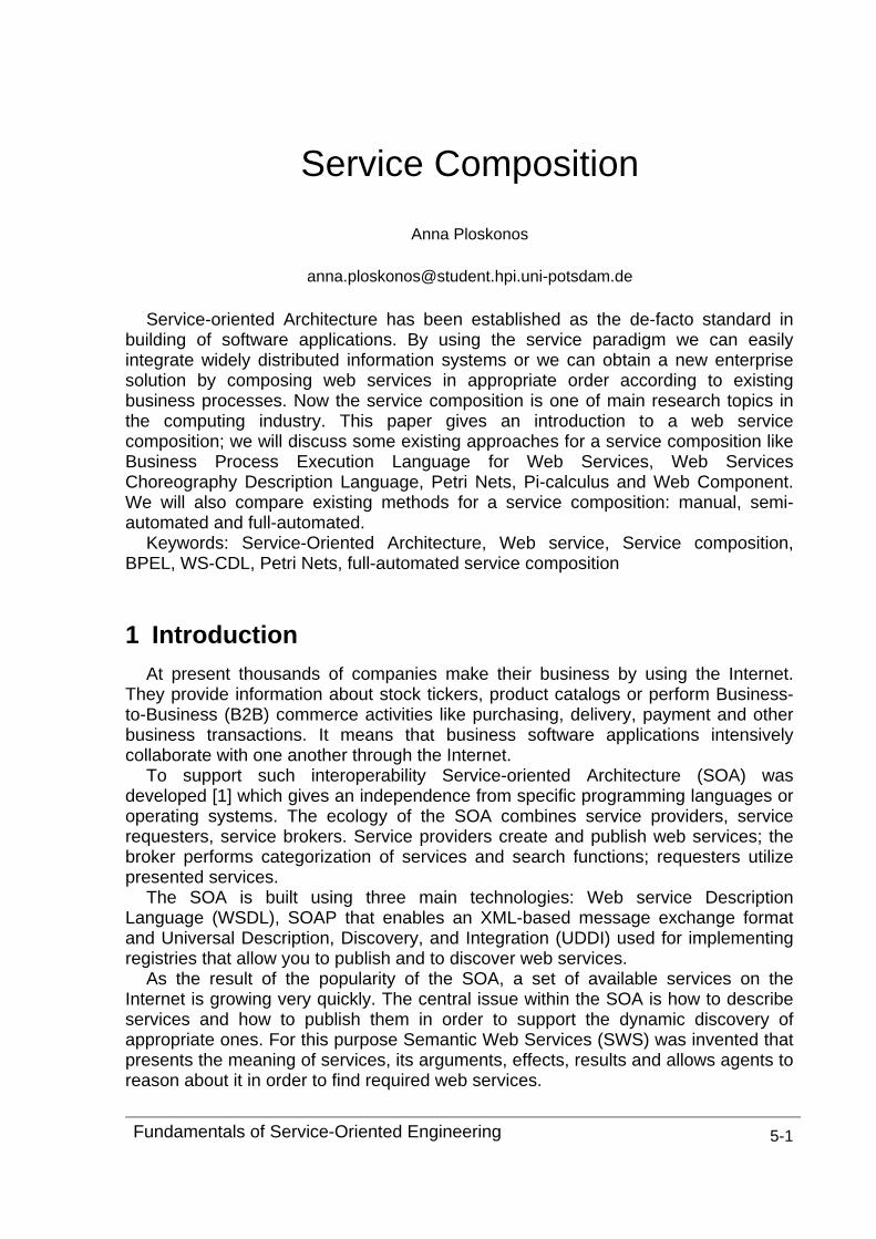
Fundamentals of Service-Oriented Engineering 5-1
Service Composition
Anna Ploskonos
Service-oriented Architecture has been established as the de-facto standard in building of software applications. By using the service paradigm we can easily integrate widely distributed information systems or we can obtain a new enterprise solution by composing web services in appropriate order according to existing business processes. Now the service composition is one of main research topics in the computing industry. This paper gives an introduction to a web service composition; we will discuss some existing approaches for a service composition like Business Process Execution Language for Web Services, Web Services Choreography Description Language, Petri Nets, Pi-calculus and Web Component. We will also compare existing methods for a service composition: manual, semi-automated and full-automated.
Keywords: Service-Oriented Architecture, Web service, Service composition, BPEL, WS-CDL, Petri Nets, full-automated service composition
1 Introduction At present thousands of companies make their business by using the Internet.
They provide information about stock tickers, product catalogs or perform Business-to-Business (B2B) commerce activities like purchasing, delivery, payment and other business transactions. It means that business software applications intensively collaborate with one another through the Internet.
To support such interoperability Service-oriented Architecture (SOA) was developed [1] which gives an independence from specific programming languages or operating systems. The ecology of the SOA combines service providers, service requesters, service brokers. Service providers create and publish web services; the broker performs categorization of services and search functions; requesters utilize presented services.
The SOA is built using three main technologies: Web service Description Language (WSDL), SOAP that enables an XML-based message exchange format and Universal Description, Discovery, and Integration (UDDI) used for implementing registries that allow you to publish and to discover web services.
As the result of the popularity of the SOA, a set of available services on the Internet is growing very quickly. The central issue within the SOA is how to describe services and how to publish them in order to support the dynamic discovery of appropriate ones. For this purpose Semantic Web Services (SWS) was invented that presents the meaning of services, its arguments, effects, results and allows agents to reason about it in order to find required web services.
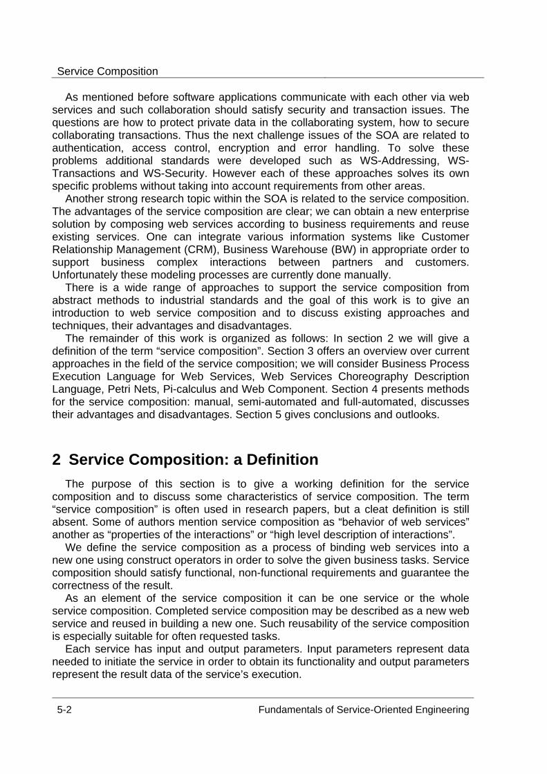
Service Composition
5-2 Fundamentals of Service-Oriented Engineering
As mentioned before software applications communicate with each other via web services and such collaboration should satisfy security and transaction issues. The questions are how to protect private data in the collaborating system, how to secure collaborating transactions. Thus the next challenge issues of the SOA are related to authentication, access control, encryption and error handling. To solve these problems additional standards were developed such as WS-Addressing, WS-Transactions and WS-Security. However each of these approaches solves its own specific problems without taking into account requirements from other areas.
Another strong research topic within the SOA is related to the service composition. The advantages of the service composition are clear; we can obtain a new enterprise solution by composing web services according to business requirements and reuse existing services. One can integrate various information systems like Customer Relationship Management (CRM), Business Warehouse (BW) in appropriate order to support business complex interactions between partners and customers. Unfortunately these modeling processes are currently done manually.
There is a wide range of approaches to support the service composition from abstract methods to industrial standards and the goal of this work is to give an introduction to web service composition and to discuss existing approaches and techniques, their advantages and disadvantages.
The remainder of this work is organized as follows: In section 2 we will give a definition of the term “service composition”. Section 3 offers an overview over current approaches in the field of the service composition; we will consider Business Process Execution Language for Web Services, Web Services Choreography Description Language, Petri Nets, Pi-calculus and Web Component. Section 4 presents methods for the service composition: manual, semi-automated and full-automated, discusses their advantages and disadvantages. Section 5 gives conclusions and outlooks.
2 Service Composition: a Definition The purpose of this section is to give a working definition for the service
composition and to discuss some characteristics of service composition. The term “service composition” is often used in research papers, but a cleat definition is still absent. Some of authors mention service composition as “behavior of web services” another as “properties of the interactions” or “high level description of interactions”.
We define the service composition as a process of binding web services into a new one using construct operators in order to solve the given business tasks. Service composition should satisfy functional, non-functional requirements and guarantee the correctness of the result.
As an element of the service composition it can be one service or the whole service composition. Completed service composition may be described as a new web service and reused in building a new one. Such reusability of the service composition is especially suitable for often requested tasks.
Each service has input and output parameters. Input parameters represent data needed to initiate the service in order to obtain its functionality and output parameters represent the result data of the service’s execution.
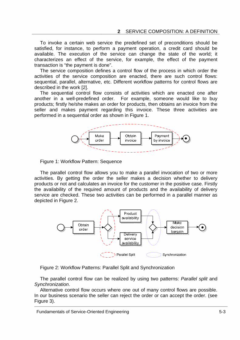
2 SERVICE COMPOSITION: A DEFINITION
Fundamentals of Service-Oriented Engineering 5-3
To invoke a certain web service the predefined set of preconditions should be satisfied, for instance, to perform a payment operation, a credit card should be available. The execution of the service can change the state of the world; it characterizes an effect of the service, for example, the effect of the payment transaction is “the payment is done”.
The service composition defines a control flow of the process in which order the activities of the service composition are enacted, there are such control flows: sequential, parallel, alternative, etc. Different workflow patterns for control flows are described in the work [2].
The sequential control flow consists of activities which are enacted one after another in a well-predefined order. For example, someone would like to buy products; firstly he/she makes an order for products, then obtains an invoice from the seller and makes payment regarding this invoice. These three activities are performed in a sequential order as shown in Figure 1.
Figure 1: Workflow Pattern: Sequence The parallel control flow allows you to make a parallel invocation of two or more
activities. By getting the order the seller makes a decision whether to delivery products or not and calculates an invoice for the customer in the positive case. Firstly the availability of the required amount of products and the availability of delivery service are checked. These two activities can be performed in a parallel manner as depicted in Figure 2.
Figure 2: Workflow Patterns: Parallel Split and Synchronization The parallel control flow can be realized by using two patterns: Parallel split and
Synchronization. Alternative control flow occurs where one out of many control flows are possible.
In our business scenario the seller can reject the order or can accept the order. (see Figure 3).
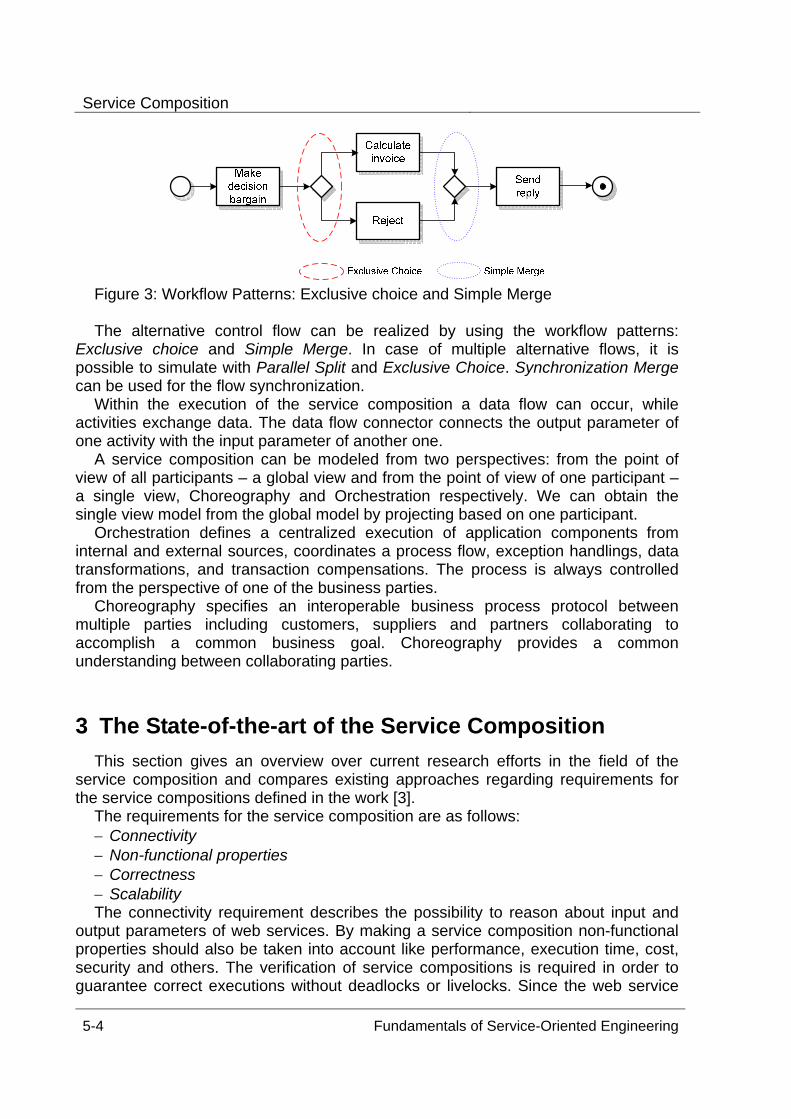
Service Composition
5-4 Fundamentals of Service-Oriented Engineering
Figure 3: Workflow Patterns: Exclusive choice and Simple Merge The alternative control flow can be realized by using the workflow patterns:
Exclusive choice and Simple Merge. In case of multiple alternative flows, it is possible to simulate with Parallel Split and Exclusive Choice. Synchronization Merge can be used for the flow synchronization.
Within the execution of the service composition a data flow can occur, while activities exchange data. The data flow connector connects the output parameter of one activity with the input parameter of another one.
A service composition can be modeled from two perspectives: from the point of view of all participants – a global view and from the point of view of one participant – a single view, Choreography and Orchestration respectively. We can obtain the single view model from the global model by projecting based on one participant.
Orchestration defines a centralized execution of application components from internal and external sources, coordinates a process flow, exception handlings, data transformations, and transaction compensations. The process is always controlled from the perspective of one of the business parties.
Choreography specifies an interoperable business process protocol between multiple parties including customers, suppliers and partners collaborating to accomplish a common business goal. Choreography provides a common understanding between collaborating parties.
3 The State-of-the-art of the Service Composition This section gives an overview over current research efforts in the field of the
service composition and compares existing approaches regarding requirements for the service compositions defined in the work [3].
The requirements for the service composition are as follows: − Connectivity − Non-functional properties − Correctness − Scalability The connectivity requirement describes the possibility to reason about input and
output parameters of web services. By making a service composition non-functional properties should also be taken into account like performance, execution time, cost, security and others. The verification of service compositions is required in order to guarantee correct executions without deadlocks or livelocks. Since the web service
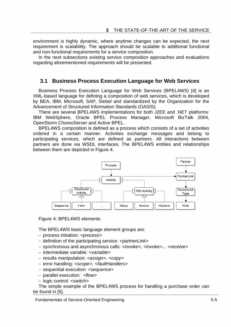
3 THE STATE-OF-THE-ART OF THE SERVICE
Fundamentals of Service-Oriented Engineering 5-5
environment is highly dynamic, where anytime changes can be expected, the next requirement is scalability. The approach should be scalable to additional functional and non-functional requirements for a service composition.
In the next subsections existing service composition approaches and evaluations regarding aforementioned requirements will be presented.
3.1 Business Process Execution Language for Web Services Business Process Execution Language for Web Services (BPEL4WS) [4] is an
XML-based language for defining a composition of web services, which is developed by BEA, IBM, Microsoft, SAP, Siebel and standardized by the Organization for the Advancement of Structured Information Standards (OASIS).
There are several BPEL4WS implementations for both J2EE and .NET platforms: IBM WebSphere, Oracle BPEL Process Manager, Microsoft BizTalk 2004, OpenStorm ChoreoServer and Active BPEL.
BPEL4WS composition is defined as a process which consists of a set of activities ordered in a certain manner. Activities exchange messages and belong to participating services, which are defined as partners. All interactions between partners are done via WSDL interfaces. The BPEL4WS entities and relationships between them are depicted in Figure 4.
Figure 4: BPEL4WS elements The BPEL4WS basic language element groups are: − process initiation: <process> − definition of the participating service: <partnerLink> − synchronous and asynchronous calls: <invoke>, <invoke>... <receive> − intermediate variable: <variable> − results manipulation: <assign>, <copy> − error handling: <scope>, <faultHandlers> − sequential execution: <sequence> − parallel execution: <flow> − logic control: <switch> The simple example of the BPEL4WS process for handling a purchase order can
be found in [5].
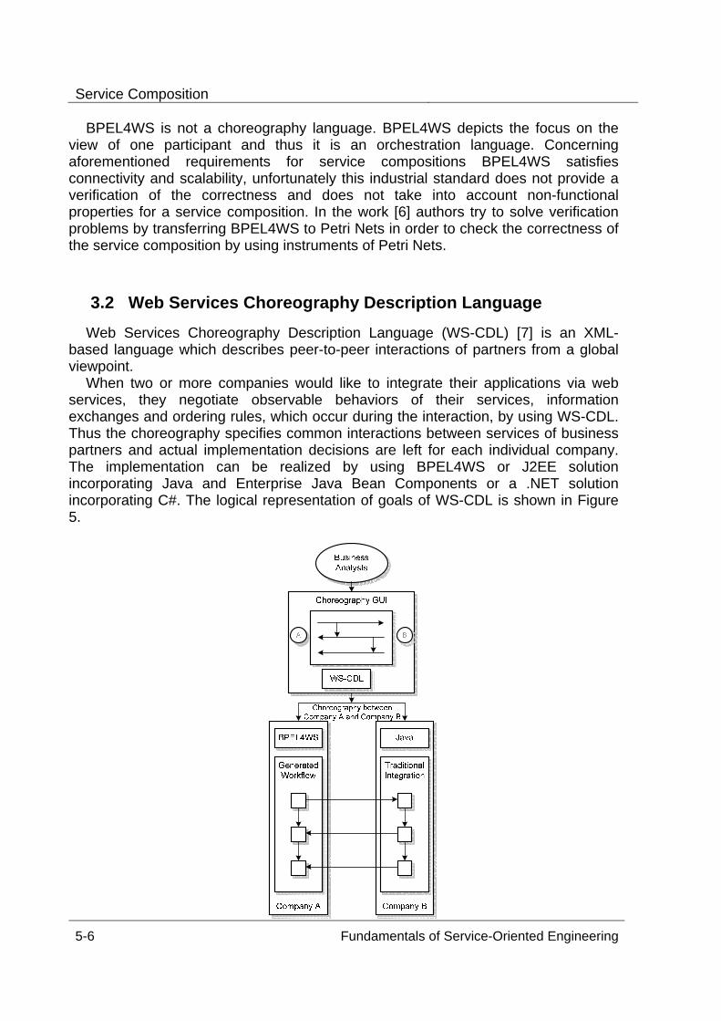
Service Composition
5-6 Fundamentals of Service-Oriented Engineering
BPEL4WS is not a choreography language. BPEL4WS depicts the focus on the view of one participant and thus it is an orchestration language. Concerning aforementioned requirements for service compositions BPEL4WS satisfies connectivity and scalability, unfortunately this industrial standard does not provide a verification of the correctness and does not take into account non-functional properties for a service composition. In the work [6] authors try to solve verification problems by transferring BPEL4WS to Petri Nets in order to check the correctness of the service composition by using instruments of Petri Nets.
3.2 Web Services Choreography Description Language Web Services Choreography Description Language (WS-CDL) [7] is an XML-
based language which describes peer-to-peer interactions of partners from a global viewpoint.
When two or more companies would like to integrate their applications via web services, they negotiate observable behaviors of their services, information exchanges and ordering rules, which occur during the interaction, by using WS-CDL. Thus the choreography specifies common interactions between services of business partners and actual implementation decisions are left for each individual company. The implementation can be realized by using BPEL4WS or J2EE solution incorporating Java and Enterprise Java Bean Components or a .NET solution incorporating C#. The logical representation of goals of WS-CDL is shown in Figure 5.
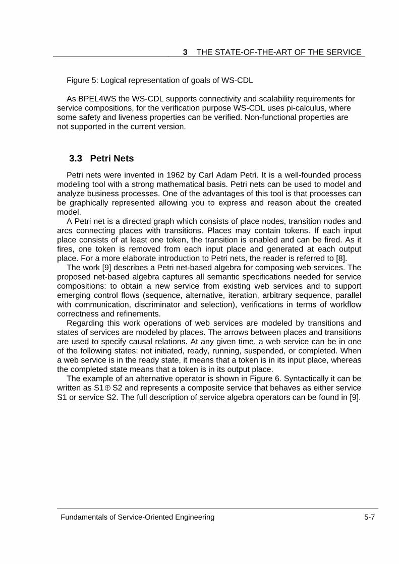
3 THE STATE-OF-THE-ART OF THE SERVICE
Fundamentals of Service-Oriented Engineering 5-7
Figure 5: Logical representation of goals of WS-CDL As BPEL4WS the WS-CDL supports connectivity and scalability requirements for
service compositions, for the verification purpose WS-CDL uses pi-calculus, where some safety and liveness properties can be verified. Non-functional properties are not supported in the current version.
3.3 Petri Nets Petri nets were invented in 1962 by Carl Adam Petri. It is a well-founded process
modeling tool with a strong mathematical basis. Petri nets can be used to model and analyze business processes. One of the advantages of this tool is that processes can be graphically represented allowing you to express and reason about the created model.
A Petri net is a directed graph which consists of place nodes, transition nodes and arcs connecting places with transitions. Places may contain tokens. If each input place consists of at least one token, the transition is enabled and can be fired. As it fires, one token is removed from each input place and generated at each output place. For a more elaborate introduction to Petri nets, the reader is referred to [8].
The work [9] describes a Petri net-based algebra for composing web services. The proposed net-based algebra captures all semantic specifications needed for service compositions: to obtain a new service from existing web services and to support emerging control flows (sequence, alternative, iteration, arbitrary sequence, parallel with communication, discriminator and selection), verifications in terms of workflow correctness and refinements.
Regarding this work operations of web services are modeled by transitions and states of services are modeled by places. The arrows between places and transitions are used to specify causal relations. At any given time, a web service can be in one of the following states: not initiated, ready, running, suspended, or completed. When a web service is in the ready state, it means that a token is in its input place, whereas the completed state means that a token is in its output place.
The example of an alternative operator is shown in Figure 6. Syntactically it can be written as S1⊕S2 and represents a composite service that behaves as either service S1 or service S2. The full description of service algebra operators can be found in [9].
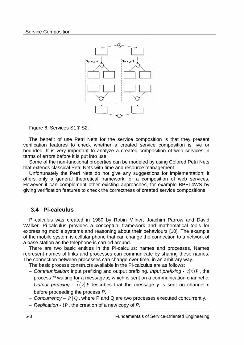
Service Composition
5-8 Fundamentals of Service-Oriented Engineering
Figure 6: Services S1⊕S2. The benefit of use Petri Nets for the service composition is that they present
verification features to check whether a created service composition is live or bounded. It is very important to analyze a created composition of web services in terms of errors before it is put into use.
Some of the non-functional properties can be modeled by using Colored Petri Nets that extends classical Petri Nets with time and resource management.
Unfortunately the Petri Nets do not give any suggestions for implementation; it offers only a general theoretical framework for a composition of web services. However it can complement other existing approaches, for example BPEL4WS by giving verification features to check the correctness of created service compositions.
3.4 Pi-calculus Pi-calculus was created in 1980 by Robin Milner, Joachim Parrow and David
Walker. Pi-calculus provides a conceptual framework and mathematical tools for expressing mobile systems and reasoning about their behaviours [10]. The example of the mobile system is cellular phone that can change the connection to a network of a base station as the telephone is carried around.
There are two basic entities in the Pi-calculus: names and processes. Names represent names of links and processes can communicate by sharing these names. The connection between processes can change over time, in an arbitrary way.
The basic process constructs available in the Pi-calculus are as follows: − Communication: input prefixing and output prefixing. Input prefixing - ( )Pxc . , the
process P waiting for a message x, which is sent on a communication channel c. Output prefixing - Pyc . describes that the message y is sent on channel c before proceeding the process P.
− Concurrency – QP | , where P and Q are two processes executed concurrently. − Replication - P! , the creation of a new copy of P.
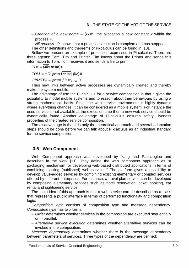
3 THE STATE-OF-THE-ART OF THE SERVICE
Fundamentals of Service-Oriented Engineering 5-9
− Creation of a new name – ( )Pxν , the allocation a new constant x within the process P.
− Nil process - 0, shows that a process execution is complete and has stopped. The other definitions and theorems of Pi-calculus can be found in [10]. Bellow we present an example of processes expressed in Pi-calculus. There are
three agents: Tom, Tim and Printer. Tim knows about the Printer and sends this information to Tom. Tom receives it and sends a file to print.
( )( ) 0..int!
0.int.int
0.int
PRINTfileprPRINTERfileprprtalkTOM
prtalkTIM
τ=
=
=
Thus new links between active processes are dynamically created and thereby make the system mobile.
The advantage of use the Pi-calculus for a service composition is that it gives the possibility to model mobile systems and to reason about their behaviours by using a strong mathematical basis. Since the web service environment is highly dynamic where everything changes, it can be considered as a mobile system. For instance the used service is not available at the execution time then a new web service should be dynamically found. Another advantage of Pi-calculus ensures safety, liveness properties of the created service composition.
The disadvantage is that it is only the theoretical approach and several adaptation steps should be done before we can talk about PI-calculus as an industrial standard for the service composition.
3.5 Web Component Web Component approach was developed by Yang and Papazoglou and
described in the work [11]. They define the web component approach as “a packaging mechanism for developing web-based distributed applications in terms of combining existing (published) web services.” The platform gives a possibility to develop value-added services by combining existing elementary or complex services offered by different enterprises. For instance, a travel plan service can be developed by composing elementary services such as hotel reservation, ticket booking, car rental and sightseeing service.
The main idea of this approach is that a web service can be described as a class that represents a public interface in terms of performed functionality and composition logic.
Composition logic consists of composition type and message dependency. Composition type has two forms:
− Order determines whether services in the composition are executed sequentially or in parallel.
− Alternative service execution determines whether alternative services can be invoked in the composition.
Message dependency determines whether there is the message dependency between parameters of services. Three types of the dependency are defined:
Service Composition
5-10 Fundamentals of Service-Oriented Engineering
− Message synthesis combines the output messages of elementary services with the output message of the compose service.
− Message decomposition decomposes the input message of the composite service into the input messages of the elementary services.
− Message mapping allows mapping between the input and output messages of elementary services.
The created public interface can be published, discovered and used by applications like any other normal web services. A web component is specified in two forms: first as a class definition and second as an XML specification expressed in Service Composition Specification Language (SCSL). Thus, the process of the web service composition deals with reusing, specializing and extending the available web components.
3.6 Summary We have considered some existing approaches for the service composition from
industrial standards like BPEL4WS, WS-CDL to abstract methods like Petri Nets, Pi-calculus and Web Component. And we have found that there is a big gap between industrial standards and theoretical approaches. The main problem of industrial standards is that they do not recommend correct verifications of created service compositions, but deal with real implementation. On the other hand, abstract methods have a strong theoretical background with mathematical instruments, suggest correct verifications. They are often used as a theoretical backbone for other languages.
4 Service Composition Methods This section discusses methods for the service composition – manual, semi-
automated, full-automated, their advantages and disadvantages. By making a service composition there are such common steps: to discover appropriate web services from existing ones that will be composed to solve a given business problem, then to make data and control-flow linkages between them. In the following subsections we will consider each method by taking into account these assembling steps: − service discovery; − service matchmaking; − data-, control-flow linkages.
4.1 Manual Composition of Services Now a composition of services is usually made manually. Staring from the process
description a composer try to compose web services, firstly he/she looks for proper services using textual descriptions provided by service providers in order to
4 SERVICE COMPOSITION METHODS
Fundamentals of Service-Oriented Engineering 5-11
understand web service capabilities and their non-functional properties. Then he/she connects web services in an appropriate order. By matching output parameters with input parameters it can happen that parameters have different data structures and he/she should handle it by finding a transformation mechanism. Such assembling steps are made step by step until achieving the sequence of web services corresponding to the desired business goals.
Modeling all these aspects by using a service composition language like BPEL4WS it is impossible to ensure all feasible and future situations that can occur during the execution of the process. Also it is not possible to consider all failures. And that's nature a composer can make errors (or deficits) in the service composition. All these factors do not guarantee that the service composition created manually is correctly modeled.
The created service composition is not flexible to changes in the environment during its execution. One of the composed services may become unavailable when the composition is enacted, hence the service composition should be immediately rebuilt by the composer.
Therefore we need fast adaptive approaches for modeling of a service composition. For this reason semi-automated and full-automated approaches for the service composition are strong research topics now.
4.2 Semi-automated Composition of Services The main idea of semi-automated method is to support users in creating a service
composition by giving the possibility to filter, select web services and by providing intelligent suggestions. The service composition system should be able to analyze a partial service composition created by the user, notify the user of issues that have to be resolved in the current situation and suggest the user what actions could be taken next.
By making a service composition the user may use different strategies: 1) top-down selection of components, for instance, the user does not have an explicit description of the desired result, they may start making a composition from abstract model and then specify it; 2) result-based selection of components, the user has an explicit description of the desired result and would like to simulate the situation that leads to this desired result; 3) situation-based of components, the user has only a description of initial states and wants to get a simulating model that describes possible results.
To perform aforementioned tasks semi-automated service composition tools and methods provide service discovery, matchmaking tasks in automatic way and difficult tasks of control- and data-flow linkages they leave for the user.
Service discovery can be performed by using service repositories like UDDI provided by the OASIS. It gives the possibility to register and advertise web services in order to discover by service requestors.
Since the number of potential services may be huge in the repository, we need matchmaking mechanisms that can be able to find a proper service by using semantic descriptions. Unfortunately the current standards for service descriptions - WSDL and UDDI do not provide semantics. WSDL includes information about how a
Service Composition
5-12 Fundamentals of Service-Oriented Engineering
service has to be invoked and what the structure of the input and output parameters are, but does not say about functionalities of the service and the meaning of its input and output massages. For this purpose semantic descriptions are used that provide meanings for agents so that they can reason about web services to perform automatic web service discovery, execution and composition.
Now the four major semantic web service specifications are recommended by the World Wide Web Consortium (W3C): OWL-based Web service ontology (OWL-S), Semantic Web Service Language (SWSL), Web Service Semantics - WSDL-S and Web Service Modeling Ontology (WSMO).
OWL-S [12] is an OWL based upper ontology semantically representing web services and consists of three main elements: service profile for advertising and discovering services, service model, which gives a detailed description of service's operations, service grounding, which provides details on how to interoperate with a service via messages. The formalism mechanism is accomplished by using description logic.
SWSL [13] is a logic-based language for specifying ontology as well as individual web services. The language consists of two parts: a first-order logic language (SWSLFOL), which is used for the formal specification of ontology and a rule-based language (SWSL-Rules), which provides an actual language for the service specification.
WSDL-S [14] extends WSDL elements by adding references to a part of the domain ontology.
WSMO [15] provides a conceptual framework, a formal language for semantically describing web services. The four main elements are ontologies, which provide the terminology, web service descriptions, which describe functional and behavioral aspects of a web service, goals that represent user desires and mediators, which aim for handling interoperability problems between different WSMO elements.
The aforementioned semantic technologies are complex in use and require from the user additional knowledge about semantic specifications. All of them use different ontology formats to represent domain knowledge making it difficult to integrate them. The existing semi-automated tools use these semantic standards in order to make automatic Web service discovery and matchmaking tasks.
The most known tools for semi-automated service composition are Web Service Composer created by Sirin, Parsia and Hendler [16], Composition Analysis Tool (CAT) developed by Kim, Spraragen and Gil [17], Internet Reasoning Service created by Hakimpour [18].
The tool presented by Sirin, Parsia and Hendler works based on OWL-S semantic standard where functional and non-functional attributes of web services presented by OWL classes. The process of compositing services starts from the specification of the desired result and then the user composes web services by interacting with the system until achieving known input parameters to the whole composition. The composition system has following components: an inference engine, a composer and a graphical user interface, though which users can establish their preferences for the workflow and make the service composition by selecting components. The inference engine stores service advertisements, process requests and performs the role of OWL reasoner. OWL reasoner matches two services if an output parameter of one service is the same OWL class or subclass of an input parameter of another service.
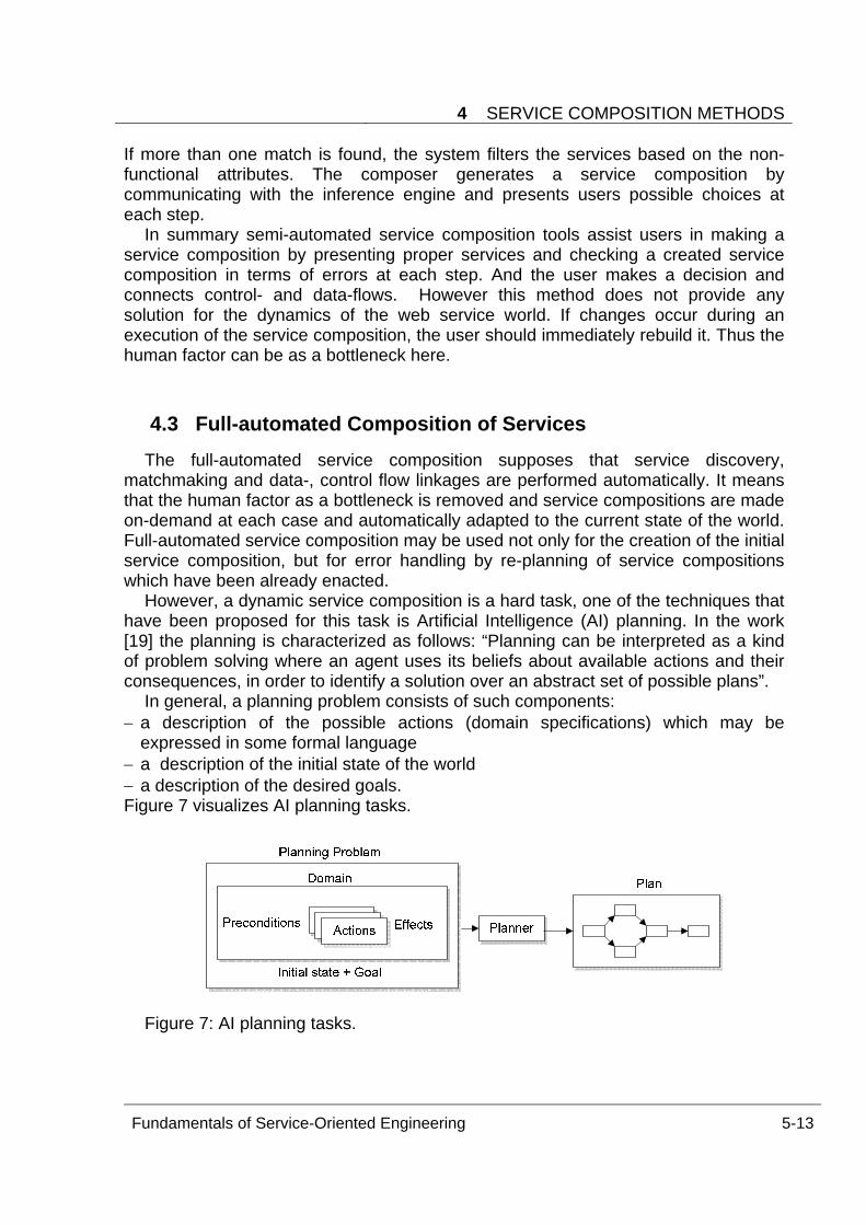
4 SERVICE COMPOSITION METHODS
Fundamentals of Service-Oriented Engineering 5-13
If more than one match is found, the system filters the services based on the non-functional attributes. The composer generates a service composition by communicating with the inference engine and presents users possible choices at each step.
In summary semi-automated service composition tools assist users in making a service composition by presenting proper services and checking a created service composition in terms of errors at each step. And the user makes a decision and connects control- and data-flows. However this method does not provide any solution for the dynamics of the web service world. If changes occur during an execution of the service composition, the user should immediately rebuild it. Thus the human factor can be as a bottleneck here.
4.3 Full-automated Composition of Services The full-automated service composition supposes that service discovery,
matchmaking and data-, control flow linkages are performed automatically. It means that the human factor as a bottleneck is removed and service compositions are made on-demand at each case and automatically adapted to the current state of the world. Full-automated service composition may be used not only for the creation of the initial service composition, but for error handling by re-planning of service compositions which have been already enacted.
However, a dynamic service composition is a hard task, one of the techniques that have been proposed for this task is Artificial Intelligence (AI) planning. In the work [19] the planning is characterized as follows: “Planning can be interpreted as a kind of problem solving where an agent uses its beliefs about available actions and their consequences, in order to identify a solution over an abstract set of possible plans”.
In general, a planning problem consists of such components: − a description of the possible actions (domain specifications) which may be
expressed in some formal language − a description of the initial state of the world − a description of the desired goals. Figure 7 visualizes AI planning tasks.
Figure 7: AI planning tasks.
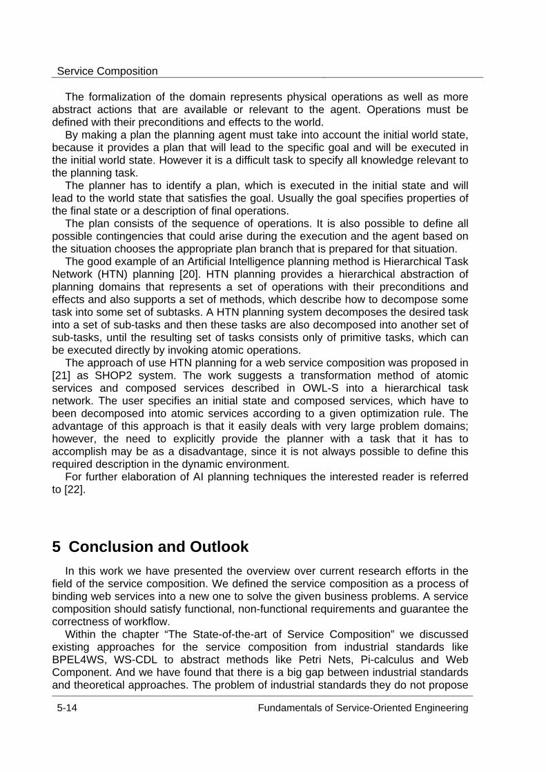
Service Composition
5-14 Fundamentals of Service-Oriented Engineering
The formalization of the domain represents physical operations as well as more abstract actions that are available or relevant to the agent. Operations must be defined with their preconditions and effects to the world.
By making a plan the planning agent must take into account the initial world state, because it provides a plan that will lead to the specific goal and will be executed in the initial world state. However it is a difficult task to specify all knowledge relevant to the planning task.
The planner has to identify a plan, which is executed in the initial state and will lead to the world state that satisfies the goal. Usually the goal specifies properties of the final state or a description of final operations.
The plan consists of the sequence of operations. It is also possible to define all possible contingencies that could arise during the execution and the agent based on the situation chooses the appropriate plan branch that is prepared for that situation.
The good example of an Artificial Intelligence planning method is Hierarchical Task Network (HTN) planning [20]. HTN planning provides a hierarchical abstraction of planning domains that represents a set of operations with their preconditions and effects and also supports a set of methods, which describe how to decompose some task into some set of subtasks. A HTN planning system decomposes the desired task into a set of sub-tasks and then these tasks are also decomposed into another set of sub-tasks, until the resulting set of tasks consists only of primitive tasks, which can be executed directly by invoking atomic operations.
The approach of use HTN planning for a web service composition was proposed in [21] as SHOP2 system. The work suggests a transformation method of atomic services and composed services described in OWL-S into a hierarchical task network. The user specifies an initial state and composed services, which have to been decomposed into atomic services according to a given optimization rule. The advantage of this approach is that it easily deals with very large problem domains; however, the need to explicitly provide the planner with a task that it has to accomplish may be as a disadvantage, since it is not always possible to define this required description in the dynamic environment.
For further elaboration of AI planning techniques the interested reader is referred to [22].
5 Conclusion and Outlook In this work we have presented the overview over current research efforts in the
field of the service composition. We defined the service composition as a process of binding web services into a new one to solve the given business problems. A service composition should satisfy functional, non-functional requirements and guarantee the correctness of workflow.
Within the chapter “The State-of-the-art of Service Composition” we discussed existing approaches for the service composition from industrial standards like BPEL4WS, WS-CDL to abstract methods like Petri Nets, Pi-calculus and Web Component. And we have found that there is a big gap between industrial standards and theoretical approaches. The problem of industrial standards they do not propose
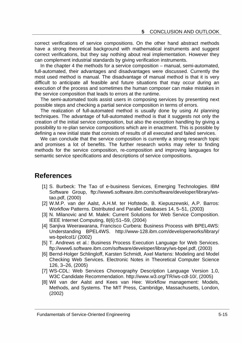
5 CONCLUSION AND OUTLOOK
Fundamentals of Service-Oriented Engineering 5-15
correct verifications of service compositions. On the other hand abstract methods have a strong theoretical background with mathematical instruments and suggest correct verifications, but they say nothing about real implementation. However they can complement industrial standards by giving verification instruments.
In the chapter 4 the methods for a service composition – manual, semi-automated, full-automated, their advantages and disadvantages were discussed. Currently the most used method is manual. The disadvantage of manual method is that it is very difficult to anticipate all feasible and future situations that may occur during an execution of the process and sometimes the human composer can make mistakes in the service composition that leads to errors at the runtime.
The semi-automated tools assist users in composing services by presenting next possible steps and checking a partial service composition in terms of errors.
The realization of full-automated method is usually done by using AI planning techniques. The advantage of full-automated method is that it suggests not only the creation of the initial service composition, but also the exception handling by giving a possibility to re-plan service compositions which are in enactment. This is possible by defining a new initial state that consists of results of all executed and failed services.
We can conclude that the service composition is currently a strong research topic and promises a lot of benefits. The further research works may refer to finding methods for the service composition, re-composition and improving languages for semantic service specifications and descriptions of service compositions.
References [1] S. Burbeck: The Tao of e-business Services, Emerging Technologies. IBM
Software Group, ftp://www6.software.ibm.com/software/developer/library/ws-tao.pdf, (2000)
[2] W.M.P. van der Aalst, A.H.M. ter Hofstede, B. Kiepuszewski, A.P. Barros: Workflow Patterns. Distributed and Parallel Databases 14, 5–51, (2003)
[3] N. Milanovic and M. Malek: Current Solutions for Web Service Composition. IEEE Internet Computing, 8(6):51–59, (2004)
[4] Sanjiva Weerawarana, Francisco Curbera: Business Process with BPEL4WS: Understanding BPEL4WS. http://www-128.ibm.com/developerworks/library/ ws-bpelcol1/ (2002)
[5] T. Andrews et al.: Business Process Execution Language for Web Services. ftp://www6.software.ibm.com/software/developer/library/ws-bpel.pdf, (2003)
[6] Bernd-Holger Schlingloff, Karsten Schmidt, Axel Martens: Modeling and Model Checking Web Services. Electronic Notes in Theoretical Computer Science 126, 3–26, (2005)
[7] WS-CDL: Web Services Choreography Description Language Version 1.0, W3C Candidate Recommendation. http://www.w3.org/TR/ws-cdl-10/, (2005)
[8] Wil van der Aalst and Kees van Hee: Workflow management: Models, Methods, and Systems. The MIT Press, Cambridge, Massachusetts, London, (2002)
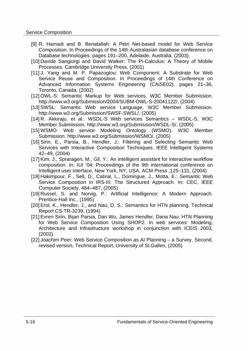
Service Composition
5-16 Fundamentals of Service-Oriented Engineering
[9] R. Hamadi and B. Benatallah: A Petri Net-based model for Web Service Composition. In Proceedings of the 14th Australasian database conference on Database technologies, pages 191–200, Adelaide, Australia, (2003).
[10] Davide Sangiorgi and David Walker: The Pi-Calculus: A Theory of Mobile Processes. Cambridge University Press, (2001)
[11] J. Yang and M. P. Papazoglou: Web Component: A Substrate for Web Service Reuse and Composition. In Proceedings of 14th Conference on Advanced Information Systems Engineering (CAiSE02), pages 21–36, Toronto, Canada, (2002)
[12] OWL-S: Semantic Markup for Web services, W3C Member Submission. http://www.w3.org/Submission/2004/SUBM-OWL-S-20041122/, (2004)
[13] SWSL: Semantic Web service Language, W3C Member Submission. http://www.w3.org/Submission/SWSF-SWSL/, (2005)
[14] R. Akkiraju, et al.: WSDL-S Web services Semantics – WSDL-S, W3C Member Submission. http://www.w3.org/Submission/WSDL-S/, (2005)
[15] WSMO: Web service Modeling Ontology (WSMO), W3C Member Submission. http://www.w3.org/Submission/WSMO/, (2005)
[16] Sirin, E., Parsia, B., Hendler, J.: Filtering and Selecting Semantic Web Services with Interactive Composition Techniques. IEEE Intelligent Systems 42–49, (2004)
[17] Kim, J., Spraragen, M., Gil, Y.: An intelligent assistant for interactive workflow composition. In: IUI ’04: Proceedings of the 9th international conference on Intelligent user interface, New York, NY, USA, ACM Press ,125–131, (2004)
[18] Hakimpour, F., Sell, D., Cabral, L., Domingue, J., Motta, E.: Semantic Web Service Composition in IRS-III: The Structured Approach. In: CEC, IEEE Computer Society, 484–487, (2005)
[19] Russel, S. and Norvig, P.: Artificial Intelligence: A Modern Approach. Prentice-Hall Inc., (1995)
[20] Erol, K., Hendler, J., and Nau, D. S.: Semantics for HTN planning. Technical Report CS-TR-3239, (1994)
[21] Evren Sirin, Bijan Parsia, Dan Wu, James Hendler, Dana Nau: HTN Planning for Web Service Composition Using SHOP2. In web services: Modeling, Architecture and Infrastructure workshop in conjunction with ICEIS 2003, (2002)
[22] Joachim Peer: Web Service Composition as AI Planning – a Survey. Second, revised version, Technical Report, University of St.Gallen, (2005)
Semantic Web Services
Torben Schreiter
The recent deployment of a large variety of web services available through theInternet identified a number of problems regarding ambiguity of service descriptions.Semantic web services are a promising approach towards machine-processability ofweb service’s functional and non-functional capabilities.
This paper aims at introducing the general concepts of semantic annotation of webservices. Therefore, ontologies will be explained first. The concrete ontology represen-tation language OWL (Web Ontology Language) as well as its foundation, the ResourceDescription Framework (RDF), are described. Furthermore, by means of OWL-S as anupper ontology for services, it is illustrated how web services can be semantically de-scribed. Finally, the characteristics of semantic matching algorithms are defined andthe architecture of the METEOR-S framework as an environment for adaptive and mostoptimal execution of web processes is explained.
Keywords: Semantic, Webservice, Ontology, OWL, OWL-S, METEOR-S, RDF
1 Introduction
Web services have become very popular amongst providers of various commercial(e.g. B2B) and non-commercial services on the web due to the opportunity to interop-erate with a large number of service requestors. This interoperability of different servicerequestors and providers has been facilitated by a (small) set of standardized technolo-gies. Currently, the practical interoperability of web services is based on syntacticalservice descriptions using e.g. the widely spread Web Services Description Language(WSDL) [1]. However, it is desired to automate service discovery and service composi-tion during the execution of web processes. Furthermore, the consideration of variousQuality of Service (QoS) constraints is desirable. In general a more flexible and advan-tageous selection of services at run-time is expected to improve overall effectivenessand efficiency of the process since the range of services is also expected to changecontinuously. Regarding the process’s entire lifecycle, it is e.g. conceivable that certainservices are no longer available, whereas in other cases services might evolve, whichare more suitable than those initially selected.
Current service descriptions do not provide any means of stating any informationabout the semantics of a service’s characteristics and capabilities. Thus, services can-not be unambiguously described. Problematically, as a requirement for automation ofaspects like service discovery and service composition, machines have to be able toprocess services’ descriptions in order to determine their applicability in certain (busi-ness) context. Currently, high research efforts are invested in the field of semantic
Fundamentals of Service-Oriented Engineering 6-1
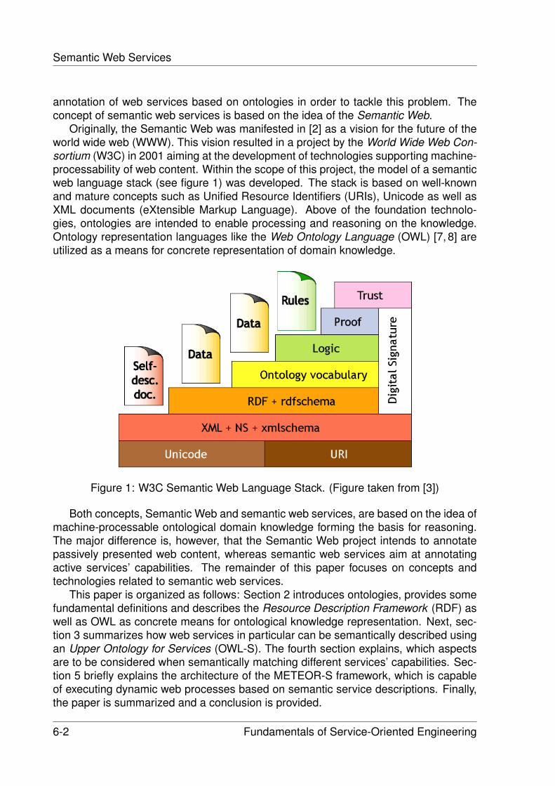
Semantic Web Services
annotation of web services based on ontologies in order to tackle this problem. Theconcept of semantic web services is based on the idea of the Semantic Web.
Originally, the Semantic Web was manifested in [2] as a vision for the future of theworld wide web (WWW). This vision resulted in a project by the World Wide Web Con-sortium (W3C) in 2001 aiming at the development of technologies supporting machine-processability of web content. Within the scope of this project, the model of a semanticweb language stack (see figure 1) was developed. The stack is based on well-knownand mature concepts such as Unified Resource Identifiers (URIs), Unicode as well asXML documents (eXtensible Markup Language). Above of the foundation technolo-gies, ontologies are intended to enable processing and reasoning on the knowledge.Ontology representation languages like the Web Ontology Language (OWL) [7, 8] areutilized as a means for concrete representation of domain knowledge.
Figure 1: W3C Semantic Web Language Stack. (Figure taken from [3])
Both concepts, Semantic Web and semantic web services, are based on the idea ofmachine-processable ontological domain knowledge forming the basis for reasoning.The major difference is, however, that the Semantic Web project intends to annotatepassively presented web content, whereas semantic web services aim at annotatingactive services’ capabilities. The remainder of this paper focuses on concepts andtechnologies related to semantic web services.
This paper is organized as follows: Section 2 introduces ontologies, provides somefundamental definitions and describes the Resource Description Framework (RDF) aswell as OWL as concrete means for ontological knowledge representation. Next, sec-tion 3 summarizes how web services in particular can be semantically described usingan Upper Ontology for Services (OWL-S). The fourth section explains, which aspectsare to be considered when semantically matching different services’ capabilities. Sec-tion 5 briefly explains the architecture of the METEOR-S framework, which is capableof executing dynamic web processes based on semantic service descriptions. Finally,the paper is summarized and a conclusion is provided.
6-2 Fundamentals of Service-Oriented Engineering
2 ONTOLOGIES
2 Ontologies
Ontologies are the foundation of semantic knowledge representation. They are crucialfor reasoning on domain knowledge. This section starts giving a set of definitions inorder to properly achieve a common understanding of what is meant by an ontologythroughout this paper.
Definition 1. Ontology is the metaphysical study of the nature of being and existence.
Since the term ”ontology” originates from the field of philosophy, definition 1 is tobe seen in this context. Ontology tries to find answers for questions like the followingones:
What characterizes being?Eventually, what is being?
Of course, this definition is not helpful concerning the field of semantic web services.Therefore, definition 2 is more appropriate for an ontology in the context of computerscience.
Definition 2. An Ontology in computer science is a controlled vocabulary andassociated phrasings, i.e., representation language, used to express the content of aparticular domain or field of knowledge.
When using the term ”ontology” in the following, it is meant in the context of com-puter science as defined in definition 2. Additionally, the term ”upper ontology” occa-sionally shows up. When speaking of an upper ontology, a special kind of ontology ismeant. This kind of ontology usually describes very general concepts that are orthog-onal to specific domains. The Dublin Core Metadata Element Set [4] is an example forgeneral descriptions of resources including such elements as e.g. title, creator, subject,language, and date.
Generally, an ontology defines different types of elements. These are conceptsand individuals (sometimes also referred to as classes and instances), attributes, anddifferent kinds of relations (e.g. is-a relations, part-of relations, amongst others). Addi-tionally, a set of grammar rules can defined in order to express logical constraints.
Ontologies are usually related to a corresponding data model represented in XML.Reasoning engines and query languages operate on top of this data model. A rea-soning engine is a software system capable of gaining further knowledge based on theinformation included in the ontologies using e.g. first-order logic. Query languages fa-cilitate querying an ontology. An exemplary query might be: What are the sub-conceptsof person? Please note that even though one particular representation language foran ontological data model is described later in this section (OWL), a detailed survey ofreasoning engines and query languages is out of scope of this paper.
Fundamentals of Service-Oriented Engineering 6-3
Semantic Web Services
2.1 Related concepts in Knowledge Representation
As stated above, an ontology is a concept intended for knowledge representation. Ad-ditionally, there are a number of similar concepts for representing knowledge. Theseinclude taxonomies and thesauri. This section intends to demarcate the different con-cepts and to pinpoint their individual properties.
2.1.1 Taxonomy
A taxonomy is a primarily hierarchically structured terminology. It contains a number ofterms, which are arranged in a hierarchy. A common example for this is the biologicaltaxonomy of species. In some cases of a taxonomy, it is permitted that one term ischild of not only one other term, but of two or more.
2.1.2 Thesaurus
A thesaurus is a hierarchical structure of terms similar to a taxonomy. Additionally,there is a very limited set of relation types between terms available. Common relationtypes are for instance the similarity and the synonymity of terms. Consequently, onlyinformation regarding the similarity and synonymity of two terms in the vocabulary canbe expressed apart from the hierarchical relation.
Compared with taxonomies and thesauri, ontologies are the most expressive andpowerful approach for knowledge representation. They allow an arbitrary number ofdifferent types of relations and, furthermore, allow to define logical constraints in orderto define certain restrictions on the vocabulary.
2.2 The Resource Description Framework (RDF)
The Resource Description Framework (RDF) provides basic fact-stating facilities [5,6].With RDF, any resource (identified through an URI1) can be described. Similarly tonatural languages, these descriptions follow the scheme subject, predicate, object.This scheme is called a triple.
A basic fact-stating example is depicted in listing 1. The subject constitutes theresource to be described (in this case: http://example.org/ ). Next, the predicate ex-presses a relationship between subject and object (here: ”has creator” 2). Finally, theobject is defined (”Torben” ).
1 < r d f : D e s c r i p t i o n r d f : a b o u t = ” h t t p : / / example . org / ”>2 <dc :Creator>Torben< / dc :Crea tor>3 < / r d f : D e s c r i p t i o n>
Listing 1: Simple example of stating a fact in RDF.
1Uniform Resource Identifier2The namespace dc: references the previously mentioned Dublin Core elements as defined in [4].
6-4 Fundamentals of Service-Oriented Engineering
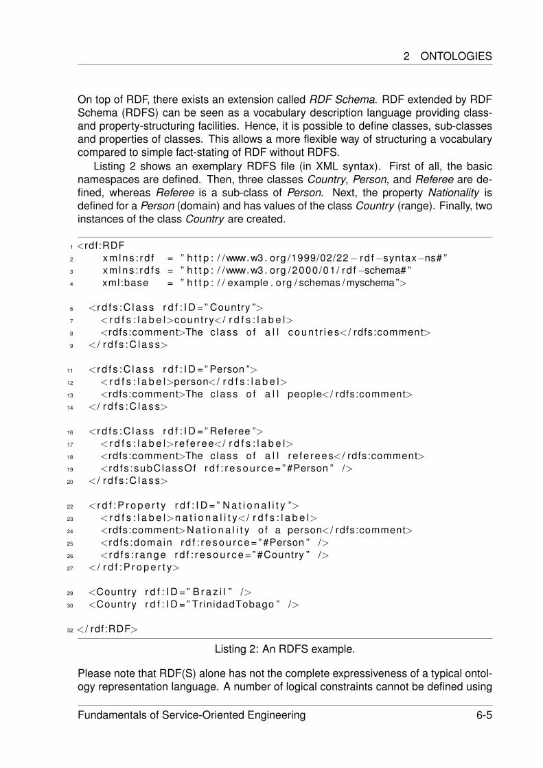
2 ONTOLOGIES
On top of RDF, there exists an extension called RDF Schema. RDF extended by RDFSchema (RDFS) can be seen as a vocabulary description language providing class-and property-structuring facilities. Hence, it is possible to define classes, sub-classesand properties of classes. This allows a more flexible way of structuring a vocabularycompared to simple fact-stating of RDF without RDFS.
Listing 2 shows an exemplary RDFS file (in XML syntax). First of all, the basicnamespaces are defined. Then, three classes Country, Person, and Referee are de-fined, whereas Referee is a sub-class of Person. Next, the property Nationality isdefined for a Person (domain) and has values of the class Country (range). Finally, twoinstances of the class Country are created.
1 <rdf:RDF2 xm lns : rd f = ” h t t p : / /www.w3 . org /1999/02/22− rd f−syntax−ns# ”3 xmlns : rd f s = ” h t t p : / /www.w3 . org /2000/01 / rd f−schema# ”4 xml:base = ” h t t p : / / example . org / schemas / myschema”>
6 <r d f s : C l a s s r d f : I D = ” Country ”>7 < r d f s : l a b e l>count ry< / r d f s : l a b e l>8 <rdfs:comment>The c lass o f a l l coun t r i es< / rdfs:comment>9 < / r d f s : C l a s s>
11 <r d f s : C l a s s r d f : I D = ” Person ”>12 < r d f s : l a b e l>person< / r d f s : l a b e l>13 <rdfs:comment>The c lass o f a l l people< / rdfs:comment>14 < / r d f s : C l a s s>
16 <r d f s : C l a s s r d f : I D = ” Referee ”>17 < r d f s : l a b e l>re fe ree< / r d f s : l a b e l>18 <rdfs:comment>The c lass o f a l l re fe rees< / rdfs:comment>19 <rd fs :subClassOf r d f : r e s o u r c e = ” #Person ” />20 < / r d f s : C l a s s>
22 <r d f : P r o p e r t y r d f : I D = ” N a t i o n a l i t y ”>23 < r d f s : l a b e l>n a t i o n a l i t y< / r d f s : l a b e l>24 <rdfs:comment>N a t i o n a l i t y o f a person< / rdfs:comment>25 <rd fs :domain r d f : r e s o u r c e = ” #Person ” />26 <r d f s : r ange r d f : r e s o u r c e = ” #Country ” />27 < / r d f : P r o p e r t y>
29 <Country r d f : I D = ” B r a z i l ” />30 <Country r d f : I D = ” TrinidadTobago ” />
32 < / rdf:RDF>
Listing 2: An RDFS example.
Please note that RDF(S) alone has not the complete expressiveness of a typical ontol-ogy representation language. A number of logical constraints cannot be defined using
Fundamentals of Service-Oriented Engineering 6-5
Semantic Web Services
RDF(S). This results in the inability of expressing the following cases (amongst others):
• logical combinations of classes (intersection, union, complement)
• advanced attributes of properties (transitive, symmetric, functional, inverse)
• restrictions on local properties (e.g. one value must come from a particular classor at most 11 values are allowed)
• equivalence and disjointness of classes
As a result of the last issue, notion of contradiction might be impossible with the lim-ited set of information expressable using RDF(S). Consider the following example: therange of a property is both the class Metal and the class Plant. Based on the informa-tion stated using RDF(S), the reasoner has to assume that all values of this propertyare members of the class of plants and of the class of metals. However, there cannever be any value for this property since there exists no instance that can be mem-ber of both classes. Problematically about this is, that a reasoner is unable to detectthis contradiction, because it is not possible to state that Metal and Plant are disjointclasses.
2.3 The Web Ontology Language (OWL)
The Web Ontology Language is an ontology representation language standardized bythe W3C. Ontology representation languages have evolved over the years. Originally,two major projects were involved in the development of two separate ontology rep-resentation languages, which later were incorporated into OWL. These projects werethose of the Ontology Interchange Language (OIL) and the DARPA Agent Markup Lan-guage (DAML). Both projects were merged into the DAML+OIL project. The resultingontology representation language was submitted to the World Wide Web Consortiumand was adopted by the WebOnt working group as the basis for their development ofthe Web Ontology Language.
OWL is conceptionally based on top of RDFS. Practically, it is realized as vocabularyextension of RDF(S). This can also be seen in figure 2. All major classes of OWL arederived from corresponding RDFS base classes.
Considering the example depicted in listing 3, OWL enables the definition of moreadvanced aspects than in RDF(S). Following the RDF header, the ontology itself is de-fined. Next, the classes Country and Person are declared to be disjoint. Two objectproperties InNationalTeam and HasCitizen are defined, whereas HasCitizen is addi-tionally declared as the inverse property of Nationality3. Finally, a new class National-TeamMember is defined, having precisely those members of Player that have exactlyone value for the property InNationalTeam.
1 <rdf:RDF2 xmlns:owl = ” h t t p : / /www.w3 . org /2002/07 / owl# ”
3Range and domain have, of course, been swapped compared to the property Nationality.
6-6 Fundamentals of Service-Oriented Engineering
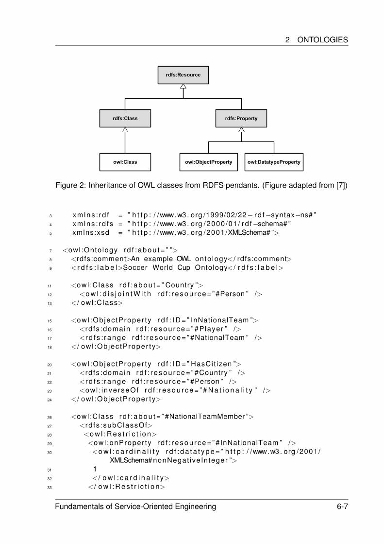
2 ONTOLOGIES
Figure 2: Inheritance of OWL classes from RDFS pendants. (Figure adapted from [7])
3 xm lns : rd f = ” h t t p : / /www.w3 . org /1999/02/22− rd f−syntax−ns# ”4 xmlns : rd f s = ” h t t p : / /www.w3 . org /2000/01 / rd f−schema# ”5 xmlns:xsd = ” h t t p : / /www.w3 . org /2001/XMLSchema# ”>
7 <owl :Onto logy r d f : a b o u t = ” ”>8 <rdfs:comment>An example OWL onto logy< / rdfs:comment>9 < r d f s : l a b e l>Soccer World Cup Ontology< / r d f s : l a b e l>
11 <owl :Class r d f : a b o u t = ” Country ”>12 <o w l : d i s j o i n t W i t h r d f : r e s o u r c e = ” #Person ” />13 < / owl :Class>
15 <owl :Ob jec tProper ty r d f : I D = ” InNationalTeam ”>16 <rd fs :domain r d f : r e s o u r c e = ” #Player ” />17 <r d f s : r ange r d f : r e s o u r c e = ” #NationalTeam ” />18 < / ow l :Ob jec tProper ty>
20 <owl :Ob jec tProper ty r d f : I D = ” HasCi t izen ”>21 <rd fs :domain r d f : r e s o u r c e = ” #Country ” />22 <r d f s : r ange r d f : r e s o u r c e = ” #Person ” />23 <owl : inverseOf r d f : r e s o u r c e = ” # N a t i o n a l i t y ” />24 < / ow l :Ob jec tProper ty>
26 <owl :Class r d f : a b o u t = ” #NationalTeamMember ”>27 <rd fs :subClassOf>28 <o w l : R e s t r i c t i o n>29 <owl :onProper ty r d f : r e s o u r c e = ” #InNationalTeam ” />30 <o w l : c a r d i n a l i t y r d f : d a t a t y p e = ” h t t p : / /www.w3 . org /2001/
XMLSchema#nonNegat iveInteger ”>31 132 < / o w l : c a r d i n a l i t y>33 < / o w l : R e s t r i c t i o n>
Fundamentals of Service-Oriented Engineering 6-7
Semantic Web Services
34 < / rd fs :subClassOf>35 < / owl :Class>
37 < / owl :Onto logy>
39 < / rdf:RDF>
Listing 3: An OWL example.
2.3.1 Variations of OWL
Since the universal expressivity has a critical impact on the practical computability,three differently powerful variations of OWL are available. Therefore, the variationsdiffer in terms of expressivity. These variations are:
• OWL Full
• OWL DL (Description Logic)
• OWL Lite
OWL Full includes all language primitives and, thus, poses the most powerful OWLvariation. Unfortunately, this high level of expressiveness leads to computational unde-cidability. Advantageous about OWL Full is, however, that it is the only variation fullyupward compatible with RDF. I.e. any correct RDF document is, at the same time, acorrect OWL Full document.
OWL DL on the other hand is not fully compatible with RDF(S) anymore. The lan-guage is partially restrained, enabling efficient reasoning support. Some of the limita-tions compared to OWL Full are described in the following. Please note that the list oflimitations is not exhaustive. For instance, in OWL DL it is disallowed to define cardinal-ity restrictions on transitive properties. Moreover, the vocabulary has to be partitioned,meaning that a particular resource is only allowed to be either a class, a datatype, adatatype property, an object property, an individual, a data value or part of the built-invocabulary at a time. Additionally, the partitioned resources have to be explicitly typed.If a certain resource is e.g. referred to as a class, it is necessary to explicitly define thisresource as a class. Consequently, all named resources that are used in a OWL DLdocument have to be explicitly defined.
The least powerful variation is OWL Lite. OWL Lite is a real subset of OWL DL. It issupposed to be easier to learn and was also intended to push the development of tools.Again only a subset of all limitations is presented. Additionally to the limitations of OWLDL, cardinalities different from 0 or 1 are excluded as well as e.g. enumerated classesand disjointness statements. Please refer to [7] for further information on limitations ofthe OWL variations.
6-8 Fundamentals of Service-Oriented Engineering
3 SEMANTIC SERVICE DESCRIPTIONS
3 Semantic Service Descriptions
Any given service has a number of functional and non-functional properties. Further-more, there usually exists additional information about the service such as e.g. legalinformation about the service provider that might be of interest when describing a ser-vice. As explained in the previous sections, it is a non-trivial challenge to semanticallydescribe all of these capabilities of a web service and, therefore, to enable (semi-)automated service discovery and composition.
Different technologies exist that enable semantic annotation of web services in orderto tackle this problem. Currently, none of the eligible technologies has been declaredas standard (e.g. by W3C) so far. However, this paper intends to describe only oneof the available technologies (OWL-S) in detail, whereas competing technologies suchas WSDL-S (Web Service Semantics) [28] and WSMO (Web Service Modeling On-tology) [29] are only named. Please have a look at [16], which provides an excellentoverview and an evaluation of the three most popular technologies enabling semanticdescription of web services: OWL-S, WSMO and WSDL-S.
3.1 OWL-S: An Upper Ontology for Services
The previous section described how ontologies can be defined in order to be process-able by a computer. This definition of ontologies is not restricted to concrete domainontologies capturing information about a certain business domain for instance. Anontology representation language such as OWL can also be used in order to definean upper ontology capturing different aspects that are orthogonal to specific domainaspects. OWL-S is an upper ontology for services. Therefore, it provides a set of con-cepts necessary for the semantic description of (web) services. OWL-S originates fromDAML-S, and is developed and maintained by the OWL-S Coalition (former DAML-SCoalition).
According to OWL-S, a service is described by the following aspects, each of whichis usually captured in a separate XML file.
• The Service Profile describes what the service does.
• The Service Model describes how to use the service.
• The Service Grounding describes how to access the service.
The different aspects reflect different views on a service defining a set of details relevantfor this particular view. The specifics of each view is described in the following sections.Listing 4 shows an exemplary OWL-S service definition. The following sections containlistings continuing this example.
1 <se rv i ce :Se rv i ce r d f : I D = ” WCTicketPurchaseService ”>2 <se rv i ce :p resen ts r d f : r e s o u r c e = ” P r o f i l e . owl#
P ro f i l e T i cke tPu rchase Serv i ce ” />3 <serv ice :descr ibedBy r d f : r e s o u r c e = ” Process . owl#BasicTicketPurchase ”
/>
Fundamentals of Service-Oriented Engineering 6-9
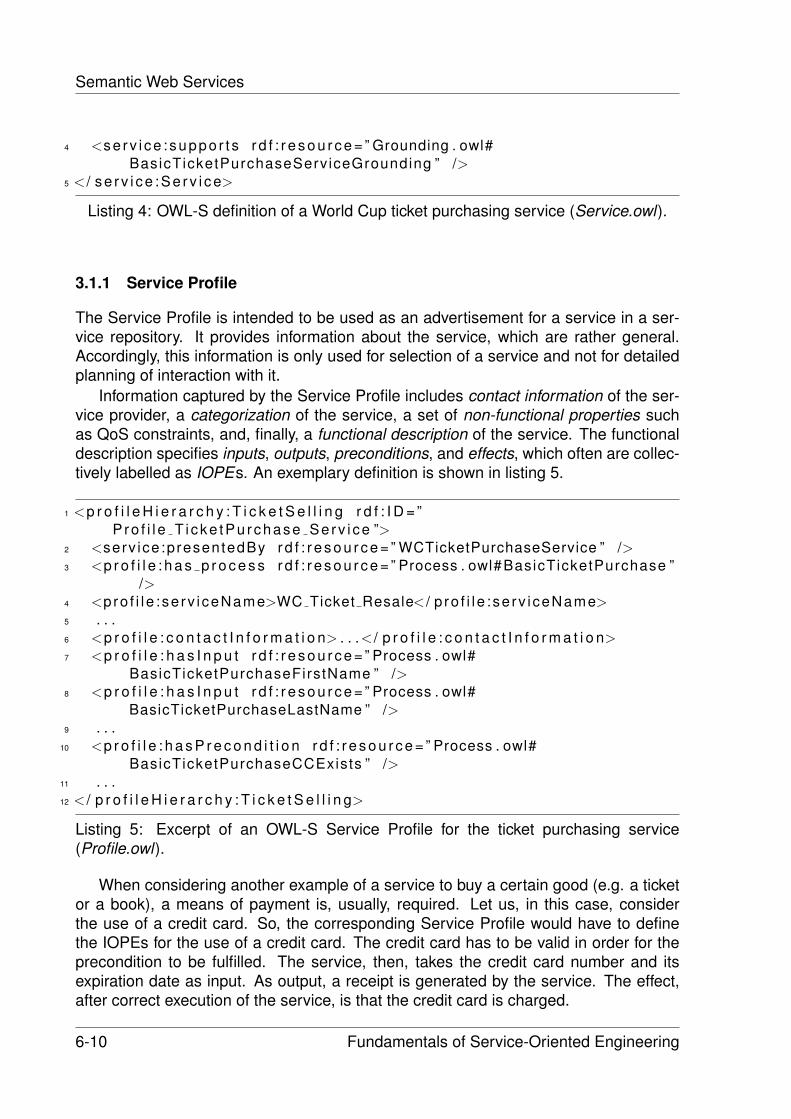
Semantic Web Services
4 <se rv i ce : suppo r t s r d f : r e s o u r c e = ” Grounding . owl#BasicTicketPurchaseServiceGrounding ” />
5 < / se r v i ce :Se rv i ce>
Listing 4: OWL-S definition of a World Cup ticket purchasing service (Service.owl).
3.1.1 Service Profile
The Service Profile is intended to be used as an advertisement for a service in a ser-vice repository. It provides information about the service, which are rather general.Accordingly, this information is only used for selection of a service and not for detailedplanning of interaction with it.
Information captured by the Service Profile includes contact information of the ser-vice provider, a categorization of the service, a set of non-functional properties suchas QoS constraints, and, finally, a functional description of the service. The functionaldescription specifies inputs, outputs, preconditions, and effects, which often are collec-tively labelled as IOPEs. An exemplary definition is shown in listing 5.
1 <p r o f i l e H i e r a r c h y : T i c k e t S e l l i n g r d f : I D = ”P ro f i l e T i cke tPu rchase Serv i ce ”>
2 <serv ice :presentedBy r d f : r e s o u r c e = ” WCTicketPurchaseService ” />3 <p r o f i l e : h a s p r o c e s s r d f : r e s o u r c e = ” Process . owl#BasicTicketPurchase ”
/>4 <pro f i l e : se rv i ceName>WC Ticket Resale< / p ro f i l e : se rv i ceName>5 . . .6 <p r o f i l e : c o n t a c t I n f o r m a t i o n> . . .< / p r o f i l e : c o n t a c t I n f o r m a t i o n>7 <p r o f i l e : h a s I n p u t r d f : r e s o u r c e = ” Process . owl#
BasicTicketPurchaseFirstName ” />8 <p r o f i l e : h a s I n p u t r d f : r e s o u r c e = ” Process . owl#
BasicTicketPurchaseLastName ” />9 . . .
10 <p r o f i l e : h a s P r e c o n d i t i o n r d f : r e s o u r c e = ” Process . owl#BasicTicketPurchaseCCExists ” />
11 . . .12 < / p r o f i l e H i e r a r c h y : T i c k e t S e l l i n g>
Listing 5: Excerpt of an OWL-S Service Profile for the ticket purchasing service(Profile.owl).
When considering another example of a service to buy a certain good (e.g. a ticketor a book), a means of payment is, usually, required. Let us, in this case, considerthe use of a credit card. So, the corresponding Service Profile would have to definethe IOPEs for the use of a credit card. The credit card has to be valid in order for theprecondition to be fulfilled. The service, then, takes the credit card number and itsexpiration date as input. As output, a receipt is generated by the service. The effect,after correct execution of the service, is that the credit card is charged.
6-10 Fundamentals of Service-Oriented Engineering
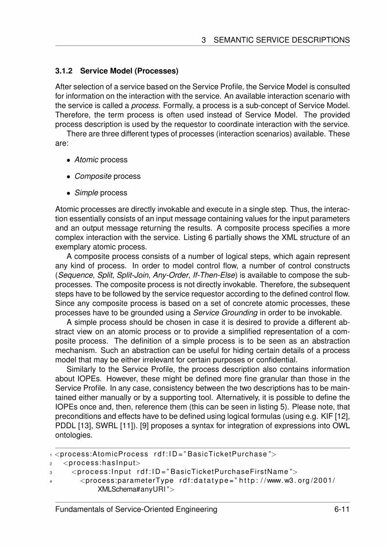
3 SEMANTIC SERVICE DESCRIPTIONS
3.1.2 Service Model (Processes)
After selection of a service based on the Service Profile, the Service Model is consultedfor information on the interaction with the service. An available interaction scenario withthe service is called a process. Formally, a process is a sub-concept of Service Model.Therefore, the term process is often used instead of Service Model. The providedprocess description is used by the requestor to coordinate interaction with the service.
There are three different types of processes (interaction scenarios) available. Theseare:
• Atomic process
• Composite process
• Simple process
Atomic processes are directly invokable and execute in a single step. Thus, the interac-tion essentially consists of an input message containing values for the input parametersand an output message returning the results. A composite process specifies a morecomplex interaction with the service. Listing 6 partially shows the XML structure of anexemplary atomic process.
A composite process consists of a number of logical steps, which again representany kind of process. In order to model control flow, a number of control constructs(Sequence, Split, Split-Join, Any-Order, If-Then-Else) is available to compose the sub-processes. The composite process is not directly invokable. Therefore, the subsequentsteps have to be followed by the service requestor according to the defined control flow.Since any composite process is based on a set of concrete atomic processes, theseprocesses have to be grounded using a Service Grounding in order to be invokable.
A simple process should be chosen in case it is desired to provide a different ab-stract view on an atomic process or to provide a simplified representation of a com-posite process. The definition of a simple process is to be seen as an abstractionmechanism. Such an abstraction can be useful for hiding certain details of a processmodel that may be either irrelevant for certain purposes or confidential.
Similarly to the Service Profile, the process description also contains informationabout IOPEs. However, these might be defined more fine granular than those in theService Profile. In any case, consistency between the two descriptions has to be main-tained either manually or by a supporting tool. Alternatively, it is possible to define theIOPEs once and, then, reference them (this can be seen in listing 5). Please note, thatpreconditions and effects have to be defined using logical formulas (using e.g. KIF [12],PDDL [13], SWRL [11]). [9] proposes a syntax for integration of expressions into OWLontologies.
1 <process:AtomicProcess r d f : I D = ” BasicTicketPurchase ”>2 <process:hasInput>3 <process : Inpu t r d f : I D = ” BasicTicketPurchaseFirstName ”>4 <process:parameterType r d f : d a t a t y p e = ” h t t p : / /www.w3 . org /2001/
XMLSchema#anyURI ”>
Fundamentals of Service-Oriented Engineering 6-11
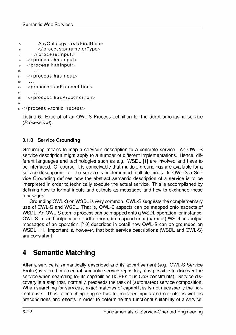
Semantic Web Services
5 AnyOntology . owl#FirstName6 < / process:parameterType>7 < / p rocess : Inpu t>8 < / p rocess:hasInput>9 <process:hasInput>
10 . . .11 < / p rocess:hasInput>12 . . .13 <process :hasPrecond i t ion>14 . . .15 < / p rocess :hasPrecond i t ion>16 . . .17 < / process:AtomicProcess>
Listing 6: Excerpt of an OWL-S Process definition for the ticket purchasing service(Process.owl).
3.1.3 Service Grounding
Grounding means to map a service’s description to a concrete service. An OWL-Sservice description might apply to a number of different implementations. Hence, dif-ferent languages and technologies such as e.g. WSDL [1] are involved and have tobe interfaced. Of course, it is conceivable that multiple groundings are available for aservice description, i.e. the service is implemented multiple times. In OWL-S a Ser-vice Grounding defines how the abstract semantic description of a service is to beinterpreted in order to technically execute the actual service. This is accomplished bydefining how to format inputs and outputs as messages and how to exchange thesemessages.
Grounding OWL-S on WSDL is very common. OWL-S suggests the complementaryuse of OWL-S and WSDL. That is, OWL-S aspects can be mapped onto aspects ofWSDL. An OWL-S atomic process can be mapped onto a WSDL operation for instance.OWL-S in- and outputs can, furthermore, be mapped onto (parts of) WSDL in-/outputmessages of an operation. [10] describes in detail how OWL-S can be grounded onWSDL 1.1. Important is, however, that both service descriptions (WSDL and OWL-S)are consistent.
4 Semantic Matching
After a service is semantically described and its advertisement (e.g. OWL-S ServiceProfile) is stored in a central semantic service repository, it is possible to discover theservice when searching for its capabilities (IOPEs plus QoS constraints). Service dis-covery is a step that, normally, preceeds the task of (automated) service composition.When searching for services, exact matches of capabilities is not necessarily the nor-mal case. Thus, a matching engine has to consider inputs and outputs as well aspreconditions and effects in order to determine the functional suitability of a service.
6-12 Fundamentals of Service-Oriented Engineering
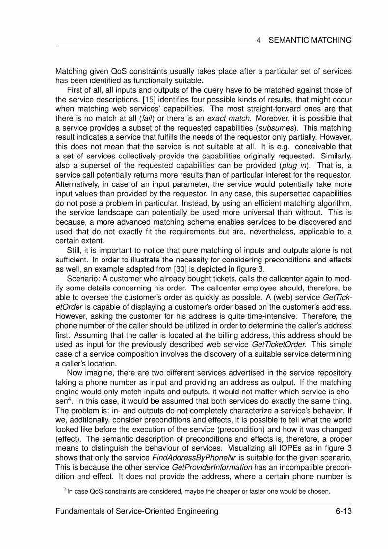
4 SEMANTIC MATCHING
Matching given QoS constraints usually takes place after a particular set of serviceshas been identified as functionally suitable.
First of all, all inputs and outputs of the query have to be matched against those ofthe service descriptions. [15] identifies four possible kinds of results, that might occurwhen matching web services’ capabilities. The most straight-forward ones are thatthere is no match at all (fail) or there is an exact match. Moreover, it is possible thata service provides a subset of the requested capabilities (subsumes). This matchingresult indicates a service that fulfills the needs of the requestor only partially. However,this does not mean that the service is not suitable at all. It is e.g. conceivable thata set of services collectively provide the capabilities originally requested. Similarly,also a superset of the requested capabilities can be provided (plug in). That is, aservice call potentially returns more results than of particular interest for the requestor.Alternatively, in case of an input parameter, the service would potentially take moreinput values than provided by the requestor. In any case, this supersetted capabilitiesdo not pose a problem in particular. Instead, by using an efficient matching algorithm,the service landscape can potentially be used more universal than without. This isbecause, a more advanced matching scheme enables services to be discovered andused that do not exactly fit the requirements but are, nevertheless, applicable to acertain extent.
Still, it is important to notice that pure matching of inputs and outputs alone is notsufficient. In order to illustrate the necessity for considering preconditions and effectsas well, an example adapted from [30] is depicted in figure 3.
Scenario: A customer who already bought tickets, calls the callcenter again to mod-ify some details concerning his order. The callcenter employee should, therefore, beable to oversee the customer’s order as quickly as possible. A (web) service GetTick-etOrder is capable of displaying a customer’s order based on the customer’s address.However, asking the customer for his address is quite time-intensive. Therefore, thephone number of the caller should be utilized in order to determine the caller’s addressfirst. Assuming that the caller is located at the billing address, this address should beused as input for the previously described web service GetTicketOrder. This simplecase of a service composition involves the discovery of a suitable service determininga caller’s location.
Now imagine, there are two different services advertised in the service repositorytaking a phone number as input and providing an address as output. If the matchingengine would only match inputs and outputs, it would not matter which service is cho-sen4. In this case, it would be assumed that both services do exactly the same thing.The problem is: in- and outputs do not completely characterize a service’s behavior. Ifwe, additionally, consider preconditions and effects, it is possible to tell what the worldlooked like before the execution of the service (precondition) and how it was changed(effect). The semantic description of preconditions and effects is, therefore, a propermeans to distinguish the behaviour of services. Visualizing all IOPEs as in figure 3shows that only the service FindAddressByPhoneNr is suitable for the given scenario.This is because the other service GetProviderInformation has an incompatible precon-dition and effect. It does not provide the address, where a certain phone number is
4In case QoS constraints are considered, maybe the cheaper or faster one would be chosen.
Fundamentals of Service-Oriented Engineering 6-13
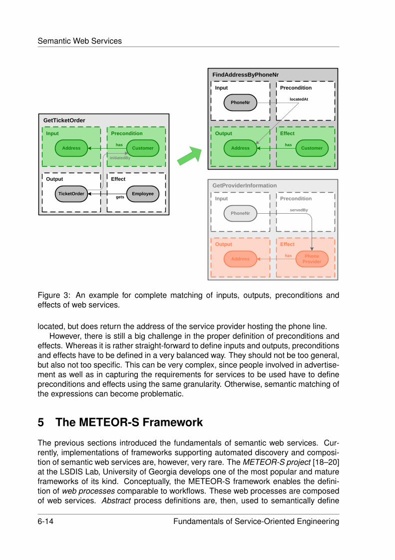
Semantic Web Services
GetTicketOrder
Input
Output
Precondition
Effect
Address Customerhas
TicketOrder Employee
initiatedBy
gets
FindAddressByPhoneNr
Input
Output
Precondition
Effect
PhoneNr
Address Customerhas
locatedAt
GetProviderInformation
Input
Output
Precondition
Effect
PhoneNr
Address PhoneProvider
has
servedBy
Figure 3: An example for complete matching of inputs, outputs, preconditions andeffects of web services.
located, but does return the address of the service provider hosting the phone line.However, there is still a big challenge in the proper definition of preconditions and
effects. Whereas it is rather straight-forward to define inputs and outputs, preconditionsand effects have to be defined in a very balanced way. They should not be too general,but also not too specific. This can be very complex, since people involved in advertise-ment as well as in capturing the requirements for services to be used have to definepreconditions and effects using the same granularity. Otherwise, semantic matching ofthe expressions can become problematic.
5 The METEOR-S Framework
The previous sections introduced the fundamentals of semantic web services. Cur-rently, implementations of frameworks supporting automated discovery and composi-tion of semantic web services are, however, very rare. The METEOR-S project [18–20]at the LSDIS Lab, University of Georgia develops one of the most popular and matureframeworks of its kind. Conceptually, the METEOR-S framework enables the defini-tion of web processes comparable to workflows. These web processes are composedof web services. Abstract process definitions are, then, used to semantically define
6-14 Fundamentals of Service-Oriented Engineering
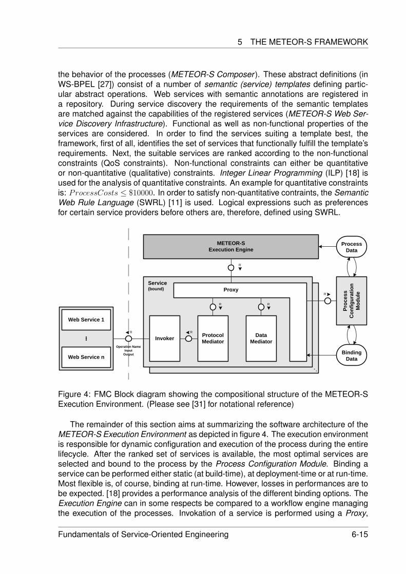
5 THE METEOR-S FRAMEWORK
the behavior of the processes (METEOR-S Composer ). These abstract definitions (inWS-BPEL [27]) consist of a number of semantic (service) templates defining partic-ular abstract operations. Web services with semantic annotations are registered ina repository. During service discovery the requirements of the semantic templatesare matched against the capabilities of the registered services (METEOR-S Web Ser-vice Discovery Infrastructure). Functional as well as non-functional properties of theservices are considered. In order to find the services suiting a template best, theframework, first of all, identifies the set of services that functionally fulfill the template’srequirements. Next, the suitable services are ranked according to the non-functionalconstraints (QoS constraints). Non-functional constraints can either be quantitativeor non-quantitative (qualitative) constraints. Integer Linear Programming (ILP) [18] isused for the analysis of quantitative constraints. An example for quantitative constraintsis: ProcessCosts ≤ $10000. In order to satisfy non-quantitative contraints, the SemanticWeb Rule Language (SWRL) [11] is used. Logical expressions such as preferencesfor certain service providers before others are, therefore, defined using SWRL.
Service(bound)
InvokerR
Operation NameInput
Output
Protocol Mediator
R
METEOR-S Execution Engine
R
Data Mediator
Proc
ess
Con
figur
atio
n M
odul
eR
BindingData
Proxy
RR
Web Service 1
Web Service n
ProcessData
Figure 4: FMC Block diagram showing the compositional structure of the METEOR-SExecution Environment. (Please see [31] for notational reference)
The remainder of this section aims at summarizing the software architecture of theMETEOR-S Execution Environment as depicted in figure 4. The execution environmentis responsible for dynamic configuration and execution of the process during the entirelifecycle. After the ranked set of services is available, the most optimal services areselected and bound to the process by the Process Configuration Module. Binding aservice can be performed either static (at build-time), at deployment-time or at run-time.Most flexible is, of course, binding at run-time. However, losses in performances are tobe expected. [18] provides a performance analysis of the different binding options. TheExecution Engine can in some respects be compared to a workflow engine managingthe execution of the processes. Invokation of a service is performed using a Proxy,
Fundamentals of Service-Oriented Engineering 6-15
Semantic Web Services
which is dependent on the binding. Mediation takes place in case of protocol and dataheterogeneities (Protocol Mediator, Data Mediator ). Due to the use of proxies, theprocess can be dynamically re-configured on failure of a service.
6 Conclusion
We provided an overview of the field of semantic web services by introducing a re-duced subset of available technologies and putting them into context of the conceptof semantic web services. Firstly, we pointed out the commonalities as well as thedifferences between the Semantic Web project and and the concept of semantic webservices. Generally, this paper is not intended to provide a detailed comparison andevaluation of major existing technologies. Instead, we concentrated on one particulartechnology for each of the aspects introduced.
Ontologies are the foundation for semantic annotation of web services. They aredefined using ontology representation languages. This paper provided a brief overviewof the history of ontologies and their representation as well as of related concepts inknowledge representation. Furthermore, we introduced the Web Ontology Languageand the Resource Description Framework, which, together, enable the development ofdomain ontologies. Both languages were illustrated using an example. Next, we pro-vided an overview of OWL-S as an upper ontology for services. It enables the semanticdescription of web services. The different parts of an OWL-S description - Service Pro-file, Service Model and Service Grounding - were introduced and described. Importantaspects concerning semantic matching of web services’ capabilities were discussed insection 4. Finally, we described the architecture of the METEOR-S framework, whichis capable of executing workflow-like web processes composed of semantically anno-tated web services. This framework provides support for dynamic re-configuration atrun-time as well as consideration of QoS constraints for service selection. Data andprotocol mediation is performed in order to guarantee interoperability of heterogeneousservices.
However, the field of semantic web services is, generally, still a dedicated researchtopic. Consequently, there is a lack of accepted standards. Existing implementationscomparable to METEOR-S are very rare and still in development. Additionally, the ser-vice landscape is, currently, in most domains still not rich enough in order to enablecomfortable automated service composition. Moreover, it is questionable if (fully) auto-mated service composition will ever be facilitated with a reasonable effort. There area number of drawbacks, turning the semantic description of web services into a com-plex problem. First of all, high quality domain ontologies do not exist in an acceptablequantity. They are difficult to develop and to maintain. It is not clear who could beresponsible for standardization of the domain ontologies. Potential conflicts and incon-sistencies between different ontologies are to be resolved. Next, defining preconditionsand effects of services in a way that they are universally applicable is extremely difficult.Finding the correct granularity and ’completeness’ are complex tasks.
Semi-automated service composition, on the other hand, seems to be a very promis-ing approach. Semi-automatism would enable (human) process designers to efficiently
6-16 Fundamentals of Service-Oriented Engineering
REFERENCES
compose a process of services supported by a tool. Such a tool could possibly presenta set of preselected services for a certain purpose based on semantic annotations.Compared to fully automated composition, this would be much easier to accomplish.Of course, flexibility at run-time is limited.
References
[1] Christensen, E. et al.: Web Services Description Language (WSDL) 1.1. (March2001)http://www.w3.org/TR/2001/NOTE-wsdl-20010315
[2] Berners-Lee, T. et al.: The Semantic Web. Scientific American. (2001)http://www.sciam.com/article.cfm?articleID=00048144-10D2-1C70-84A9809EC588EF21&ref=sciam
[3] Nykanen, O.: W3C FI & W3C Semantic Web. (2002)http://www.w3c.tut.fi/talks/2002/0923sw-vtt-on/
[4] Dublin Core Metadata Initiative: Dublin Core Metadata Element Set, Version 1.1:Reference Description. (2004)http://dublincore.org/documents/2004/12/20/dces/
[5] Beckett, D., McBride, B.: W3C: RDF/XML Syntax Specification. (February 2004)http://www.w3.org/TR/2004/REC-rdf-syntax-grammar-20040210/
[6] McBride, B.: The Resource Description Framework (RDF) and its Vocabulary De-scription Language RDFS. in: The Handbook on Ontologies in Information Sys-tems, S. Staab, R. Studer (eds.), Springer Verlag. (2003)
[7] Antoniou, G., van Harmelen, F.: Web Ontology Language: OWL.
[8] Horrocks, I., Patel-Schneider, P., van Harmelen, F.: From SHIQ and RDF to OWL:The Making of a Web Ontology Language. (2003)
[9] OWL-S Coalition: OWL-S: Semantic Markup for Web Services.
[10] Martin, D. et al.: Describing Web Services using OWL-S and WSDL. (2004)http://www.daml.org/services/owl-s/1.1/owl-s-wsdl.html
[11] Horrocks, I., Patel-Schneider, P. F., Boley, H., Tabet, S., Grosof, B., and Dean,M.: SWRL - A semantic web rule language combining owl and ruleml. (2003)http://www.daml.org/2003/11/swrl/
[12] KIF: Knowledge Interchange Format - Draft proposed American National Standard(dpans). Technical Report 2/98-004, ANS. (1998)http://logic.stanford.edu/kif/dpans.html
[13] Ghallab, M. et al.: PDDL - The Planning Domain Definition Language V.2. Tech-nical Report, report CVC TR-98-003/DCS TR-1165, Yale Center for ComputationalVision and Control. (1998)
Fundamentals of Service-Oriented Engineering 6-17
Semantic Web Services
[14] Paolucci, M., Kawamura, T., Payne, T., Sycara, K.: Importing the Semantic Webin UDDI. (2002)
[15] Paolucci, M. et al.: Semantic Matching of Web Services Capabilities. (2002)
[16] Schaffner, J.: Paving the Way for Automated Web Service Composition. (2005)
[17] Naumenko, A., Nikitin, S., Terziyan, V., Veijalainen, J.: Using UDDI for PublishingMetadata of the Semantic Web. University of Jyvaskyla, Finland. (2005)
[18] Sheth, A. et al.: The METEOR-S Approach for Configuring and Executing Dy-namic Web Processes. (2005)
[19] Sheth, A. et al.: METEOR-SWSDI: A Scalable P2P Infrastructure of Registries forSemantic Publication and Discovery of Web Services. (2005)
[20] Sheth, A., Cardoso, J.: Semantic E-Workflow Composition. (2003)
[21] Van den Heuvel, W., Maamar, Z.: Moving Toward a Framework to Compose Intel-ligent Web Services. (2005)
[22] Object Management Group: Ontology Definition Metamodel. IBM, Sandpiper Soft-ware, Inc. (August 2005)
[23] Sirin, E., Hendler, J., Parsia, B.: Semi-automatic Composition of Web Servicesusing Semantic Descriptions. (2002)
[24] McIlraith, S., Cao Son, T.: Adapting Golog for Composition of Semantic Web Ser-vices. (2002)
[25] Ullrich, M., Maier, A., Angele, J.: Taxonomie, Thesaurus, Topic Map, Ontologie -ein Vergleich. v1.4 Ontoprise Whitepaper Series. (2004)http://www.ullri.ch/download/Ontologien/ttto13.pdf
[26] Pidcock, W.: What are the differences between a vocabulary, a taxonomy, a the-saurus, an ontology, and a meta-model?. Boeing. (2003)http://www.metamodel.com/article.php?story=20030115211223271
[27] IBM, BEA Systems, Microsoft, SAP AG, Siebel Systems: Business Process Exe-cution Language for Web Services version 1.1. (2005)http://www-128.ibm.com/developerworks/library/specification/ws-bpel/
[28] Akkiraju, R. et al.: Web Service Semantics - WSDL-S. W3C Member Submission.(November 2005)http://www.metamodel.com/article.php?story=20030115211223271
[29] Roman, D. et al.: Web Service Modeling Ontology. Applied Ontology 1 (2005)77106 77, IOS Press. (2005)
[30] Weske, M.: Business Process Management Lecture Notes. Hasso-Plattner-Institute Potsdam. (2006)
6-18 Fundamentals of Service-Oriented Engineering
REFERENCES
[31] Tabeling, P., Grone, B., Knopfel, A.: Fundamental Modeling Concepts - EffectiveCommunication of IT Systems. John Wiley & Sons, Ltd. (2006)
Fundamentals of Service-Oriented Engineering 6-19

Enterprise Service Bus
Martin Breest
The enterprise service bus (ESB) is the most promising approach to enterprise ap-plication integration (EAI) of the last years. It promises to build up a service-orientedarchitecture (SOA) by iteratively integrating all kinds of isolated applications into a de-centralized infrastructure. This infrastructure combines best practices from EAI, likemessage-oriented middleware (MOM), (Web) services, routing and XML processingfacilities, in order to provide, use and compose (Web) services.
Because the term ESB is often used to name different things, for example an archi-tecture, a product or a ”way of doing things”, we point out in this paper what exactly anESB is. Therefore, we first describe what distinguishes the ESB from former EAI solu-tions. Second, we show what the key components of an ESB are. Finally, we explainhow these key components function alone and how they work together to achieve theaforementioned goal.
Keywords: ESB, SOA, EAI, Enterprise Service Bus, Service Oriented Architecture,Enterprise Application Integration
1 Introduction
Due to the ongoing globalization, enterprises all over the world have to face a fiercecompetition. In order to stay in business, they constantly have to automate their busi-ness processes, integrate with their business partners and provide new services totheir customers.
With the changing demands in business, the goal of IT has also changed. Today,IT has to actively support enterprises in global competition. Therefore, it has to makebusiness functionality and information available across the enterprise in order to allowsoftware engineers to create, automate and integrate business processes and com-pany workers to access all kinds of information in a unified way via a department- orenterprise-wide portal.
Today, most companies try to achieve the aforementioned goal by developing aservice-oriented architecture (SOA) [1, 7, 9, 10]. In a SOA, the business functionality,implemented by different applications in the enterprise, is provided via coarse-grained,loosely-coupled business services. These business services allow to easily create andautomate business processes by using, reusing and composing the provided businessfunctionality.
The enterprise service bus (ESB) [2–4,12] promises to build up a SOA by iterativelyintegrating isolated applications into a decentralized infrastructure. Various researchand consulting companies like Forrester Research, IDC or Gartner Inc. believe that
Fundamentals of Service-Oriented Engineering 7-1
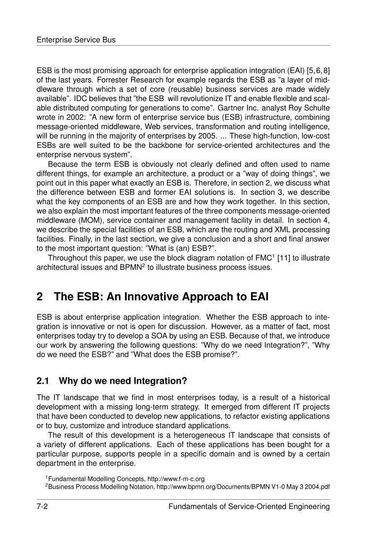
Enterprise Service Bus
ESB is the most promising approach for enterprise application integration (EAI) [5,6,8]of the last years. Forrester Research for example regards the ESB as ”a layer of mid-dleware through which a set of core (reusable) business services are made widelyavailable”. IDC believes that ”the ESB will revolutionize IT and enable flexible and scal-able distributed computing for generations to come”. Gartner Inc. analyst Roy Schultewrote in 2002: ”A new form of enterprise service bus (ESB) infrastructure, combiningmessage-oriented middleware, Web services, transformation and routing intelligence,will be running in the majority of enterprises by 2005. ... These high-function, low-costESBs are well suited to be the backbone for service-oriented architectures and theenterprise nervous system”.
Because the term ESB is obviously not clearly defined and often used to namedifferent things, for example an architecture, a product or a ”way of doing things”, wepoint out in this paper what exactly an ESB is. Therefore, in section 2, we discuss whatthe difference between ESB and former EAI solutions is. In section 3, we describewhat the key components of an ESB are and how they work together. In this section,we also explain the most important features of the three components message-orientedmiddleware (MOM), service container and management facility in detail. In section 4,we describe the special facilities of an ESB, which are the routing and XML processingfacilities. Finally, in the last section, we give a conclusion and a short and final answerto the most important question: ”What is (an) ESB?”.
Throughout this paper, we use the block diagram notation of FMC1 [11] to illustratearchitectural issues and BPMN2 to illustrate business process issues.
2 The ESB: An Innovative Approach to EAI
ESB is about enterprise application integration. Whether the ESB approach to inte-gration is innovative or not is open for discussion. However, as a matter of fact, mostenterprises today try to develop a SOA by using an ESB. Because of that, we introduceour work by answering the following questions: ”Why do we need Integration?”, ”Whydo we need the ESB?” and ”What does the ESB promise?”.
2.1 Why do we need Integration?
The IT landscape that we find in most enterprises today, is a result of a historicaldevelopment with a missing long-term strategy. It emerged from different IT projectsthat have been conducted to develop new applications, to refactor existing applicationsor to buy, customize and introduce standard applications.
The result of this development is a heterogeneous IT landscape that consists ofa variety of different applications. Each of these applications has been bought for aparticular purpose, supports people in a specific domain and is owned by a certaindepartment in the enterprise.
1Fundamental Modelling Concepts, http://www.f-m-c.org2Business Process Modelling Notation, http://www.bpmn.org/Documents/BPMN V1-0 May 3 2004.pdf
7-2 Fundamentals of Service-Oriented Engineering
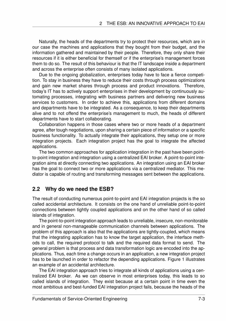
2 THE ESB: AN INNOVATIVE APPROACH TO EAI
Naturally, the heads of the departments try to protect their resources, which are inour case the machines and applications that they bought from their budget, and theinformation gathered and maintained by their people. Therefore, they only share theirresources if it is either beneficial for themself or if the enterprise’s management forcesthem to do so. The result of this behaviour is that the IT landscape inside a departmentand across the enterprise often consists of many isolated applications.
Due to the ongoing globalization, enterprises today have to face a fierce competi-tion. To stay in business they have to reduce their costs through process optimizationsand gain new market shares through process and product innovations. Therefore,today’s IT has to actively support enterprises in their development by continuously au-tomating processes, integrating with business partners and delivering new businessservices to customers. In order to achieve this, applications from different domainsand departments have to be integrated. As a consequence, to keep their departmentsalive and to not offend the enterprise’s management to much, the heads of differentdepartments have to start collaborating.
Collaboration happens in those cases where two or more heads of a departmentagree, after tough negotiations, upon sharing a certain piece of information or a specificbusiness functionality. To actually integrate their applications, they setup one or moreintegration projects. Each integration project has the goal to integrate the affectedapplications.
The two common approaches for application integration in the past have been point-to-point integration and integration using a centralized EAI broker. A point-to-point inte-gration aims at directly connecting two applications. An integration using an EAI brokerhas the goal to connect two or more applications via a centralized mediator. This me-diator is capable of routing and transforming messages sent between the applications.
2.2 Why do we need the ESB?
The result of conducting numerous point-to-point and EAI integration projects is the socalled accidental architecture. It consists on the one hand of unreliable point-to-pointconnections between tightly coupled applications and on the other hand of so calledislands of integration.
The point-to-point integration approach leads to unreliable, insecure, non-monitorableand in general non-manageable communication channels between applications. Theproblem of this approach is also that the applications are tightly-coupled, which meansthat the integrating application has to know the target application, the interface meth-ods to call, the required protocol to talk and the required data format to send. Thegeneral problem is that process and data transformation logic are encoded into the ap-plications. Thus, each time a change occurs in an application, a new integration projecthas to be launched in order to refactor the depending applications. Figure 1 illustratesan example of an accidental architecture.
The EAI integration approach tries to integrate all kinds of applications using a cen-tralized EAI broker. As we can observe in most enterprises today, this leads to socalled islands of integration. They exist because at a certain point in time even themost ambitious and best-funded EAI integration project fails, because the heads of the
Fundamentals of Service-Oriented Engineering 7-3
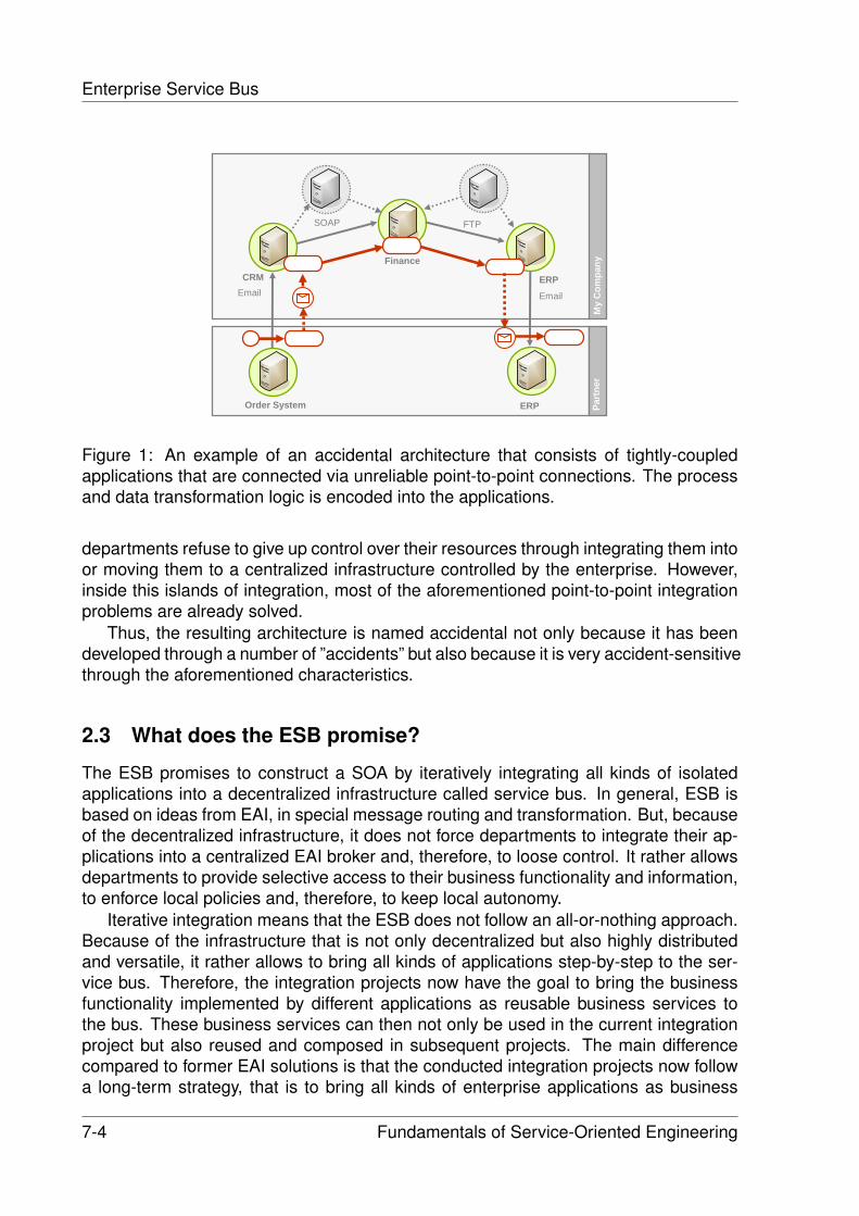
Enterprise Service Bus
My
Com
pany
Part
ner
ERP
Finance
ERPOrder System
CRMEmail
SOAP FTP
Figure 1: An example of an accidental architecture that consists of tightly-coupledapplications that are connected via unreliable point-to-point connections. The processand data transformation logic is encoded into the applications.
departments refuse to give up control over their resources through integrating them intoor moving them to a centralized infrastructure controlled by the enterprise. However,inside this islands of integration, most of the aforementioned point-to-point integrationproblems are already solved.
Thus, the resulting architecture is named accidental not only because it has beendeveloped through a number of ”accidents” but also because it is very accident-sensitivethrough the aforementioned characteristics.
2.3 What does the ESB promise?
The ESB promises to construct a SOA by iteratively integrating all kinds of isolatedapplications into a decentralized infrastructure called service bus. In general, ESB isbased on ideas from EAI, in special message routing and transformation. But, becauseof the decentralized infrastructure, it does not force departments to integrate their ap-plications into a centralized EAI broker and, therefore, to loose control. It rather allowsdepartments to provide selective access to their business functionality and information,to enforce local policies and, therefore, to keep local autonomy.
Iterative integration means that the ESB does not follow an all-or-nothing approach.Because of the infrastructure that is not only decentralized but also highly distributedand versatile, it rather allows to bring all kinds of applications step-by-step to the ser-vice bus. Therefore, the integration projects now have the goal to bring the businessfunctionality implemented by different applications as reusable business services tothe bus. These business services can then not only be used in the current integrationproject but also reused and composed in subsequent projects. The main differencecompared to former EAI solutions is that the conducted integration projects now followa long-term strategy, that is to bring all kinds of enterprise applications as business
7-4 Fundamentals of Service-Oriented Engineering
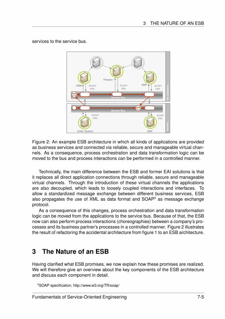
3 THE NATURE OF AN ESB
services to the service bus.
My
Com
pany
Part
ner
ERP
Finance
ERPOrder System
Service Bus
SOAP FTP
Service Bus
CRM SOAP/XML
SOAP/XML
SOAP/XML
SOAP/XML
SOAP/XML
Figure 2: An example ESB architecture in which all kinds of applications are providedas business services and connected via reliable, secure and manageable virtual chan-nels. As a consequence, process orchestration and data transformation logic can bemoved to the bus and process interactions can be performed in a controlled manner.
Technically, the main difference between the ESB and former EAI solutions is thatit replaces all direct application connections through reliable, secure and manageablevirtual channels. Through the introduction of these virtual channels the applicationsare also decoupled, which leads to loosely coupled interactions and interfaces. Toallow a standardized message exchange between different business services, ESBalso propagates the use of XML as data format and SOAP3 as message exchangeprotocol.
As a consequence of this changes, process orchestration and data transformationlogic can be moved from the applications to the service bus. Because of that, the ESBnow can also perform process interactions (choreographies) between a company’s pro-cesses and its business partner’s processes in a controlled manner. Figure 2 illustratesthe result of refactoring the accidental architecture from figure 1 to an ESB architecture.
3 The Nature of an ESB
Having clarified what ESB promises, we now explain how these promises are realized.We will therefore give an overview about the key components of the ESB architectureand discuss each component in detail.
3SOAP specification, http://www.w3.org/TR/soap/
Fundamentals of Service-Oriented Engineering 7-5
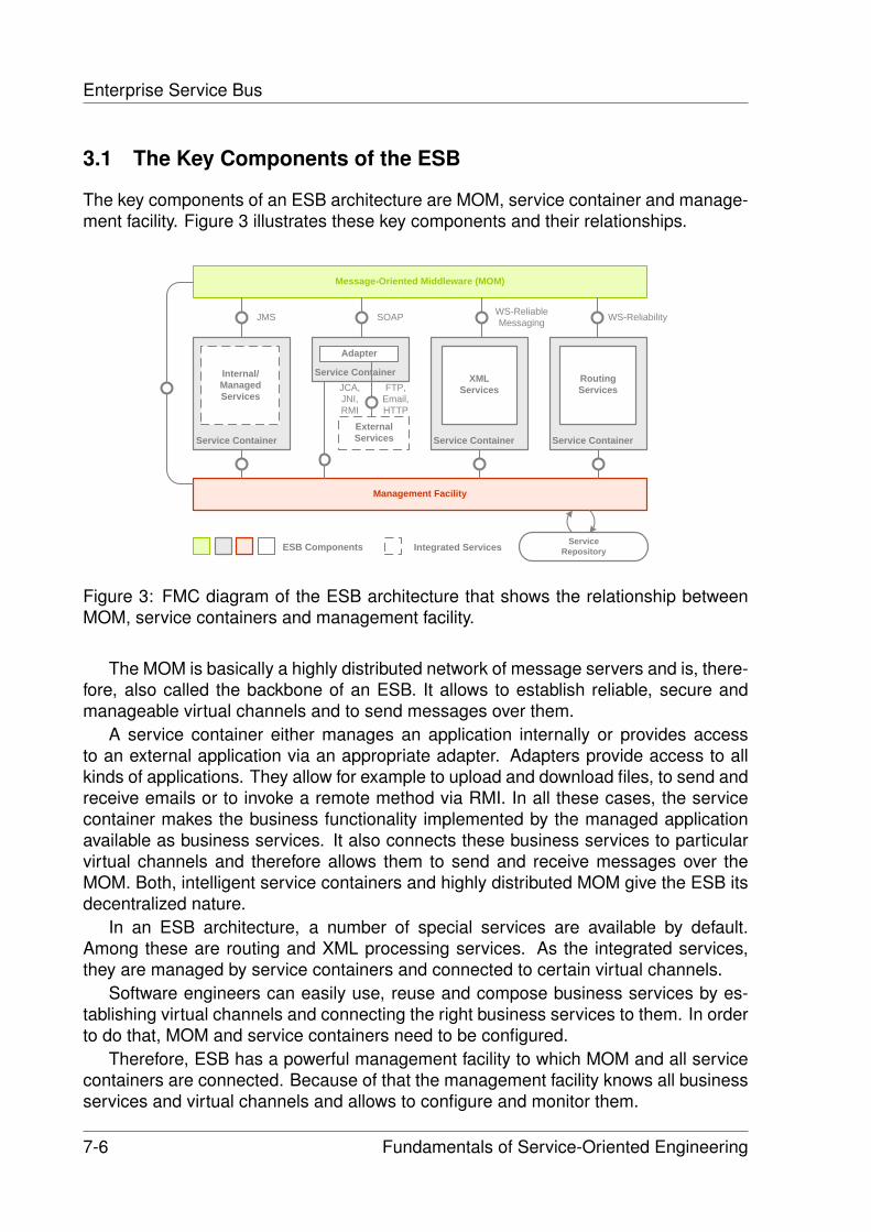
Enterprise Service Bus
3.1 The Key Components of the ESB
The key components of an ESB architecture are MOM, service container and manage-ment facility. Figure 3 illustrates these key components and their relationships.
Service Container
Message-Oriented Middleware (MOM)
Management Facility
Service Container
XML Services
Internal/ManagedServices
Service Container
Service ContainerExternalServices
Routing Services
Adapter
JMS WS-ReliabilityWS-ReliableMessagingSOAP
FTP, Email,HTTP
JCA, JNI,RMI
ESB Components Integrated Services Service Repository
Figure 3: FMC diagram of the ESB architecture that shows the relationship betweenMOM, service containers and management facility.
The MOM is basically a highly distributed network of message servers and is, there-fore, also called the backbone of an ESB. It allows to establish reliable, secure andmanageable virtual channels and to send messages over them.
A service container either manages an application internally or provides accessto an external application via an appropriate adapter. Adapters provide access to allkinds of applications. They allow for example to upload and download files, to send andreceive emails or to invoke a remote method via RMI. In all these cases, the servicecontainer makes the business functionality implemented by the managed applicationavailable as business services. It also connects these business services to particularvirtual channels and therefore allows them to send and receive messages over theMOM. Both, intelligent service containers and highly distributed MOM give the ESB itsdecentralized nature.
In an ESB architecture, a number of special services are available by default.Among these are routing and XML processing services. As the integrated services,they are managed by service containers and connected to certain virtual channels.
Software engineers can easily use, reuse and compose business services by es-tablishing virtual channels and connecting the right business services to them. In orderto do that, MOM and service containers need to be configured.
Therefore, ESB has a powerful management facility to which MOM and all servicecontainers are connected. Because of that the management facility knows all businessservices and virtual channels and allows to configure and monitor them.
7-6 Fundamentals of Service-Oriented Engineering
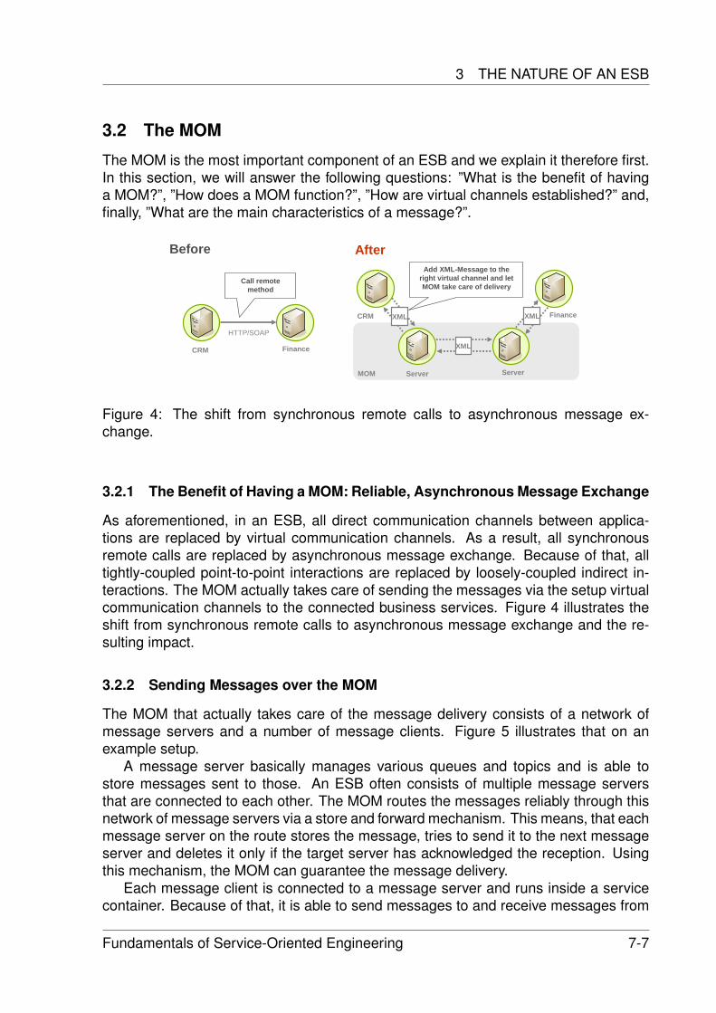
3 THE NATURE OF AN ESB
3.2 The MOM
The MOM is the most important component of an ESB and we explain it therefore first.In this section, we will answer the following questions: ”What is the benefit of havinga MOM?”, ”How does a MOM function?”, ”How are virtual channels established?” and,finally, ”What are the main characteristics of a message?”.
CRM Finance
Before
HTTP/SOAP
Call remote method
Server Server
After
CRM Finance
XML
Add XML-Message to the right virtual channel and let MOM take care of delivery
XML XML
MOM
Figure 4: The shift from synchronous remote calls to asynchronous message ex-change.
3.2.1 The Benefit of Having a MOM: Reliable, Asynchronous Message Exchange
As aforementioned, in an ESB, all direct communication channels between applica-tions are replaced by virtual communication channels. As a result, all synchronousremote calls are replaced by asynchronous message exchange. Because of that, alltightly-coupled point-to-point interactions are replaced by loosely-coupled indirect in-teractions. The MOM actually takes care of sending the messages via the setup virtualcommunication channels to the connected business services. Figure 4 illustrates theshift from synchronous remote calls to asynchronous message exchange and the re-sulting impact.
3.2.2 Sending Messages over the MOM
The MOM that actually takes care of the message delivery consists of a network ofmessage servers and a number of message clients. Figure 5 illustrates that on anexample setup.
A message server basically manages various queues and topics and is able tostore messages sent to those. An ESB often consists of multiple message serversthat are connected to each other. The MOM routes the messages reliably through thisnetwork of message servers via a store and forward mechanism. This means, that eachmessage server on the route stores the message, tries to send it to the next messageserver and deletes it only if the target server has acknowledged the reception. Usingthis mechanism, the MOM can guarantee the message delivery.
Each message client is connected to a message server and runs inside a servicecontainer. Because of that, it is able to send messages to and receive messages from
Fundamentals of Service-Oriented Engineering 7-7
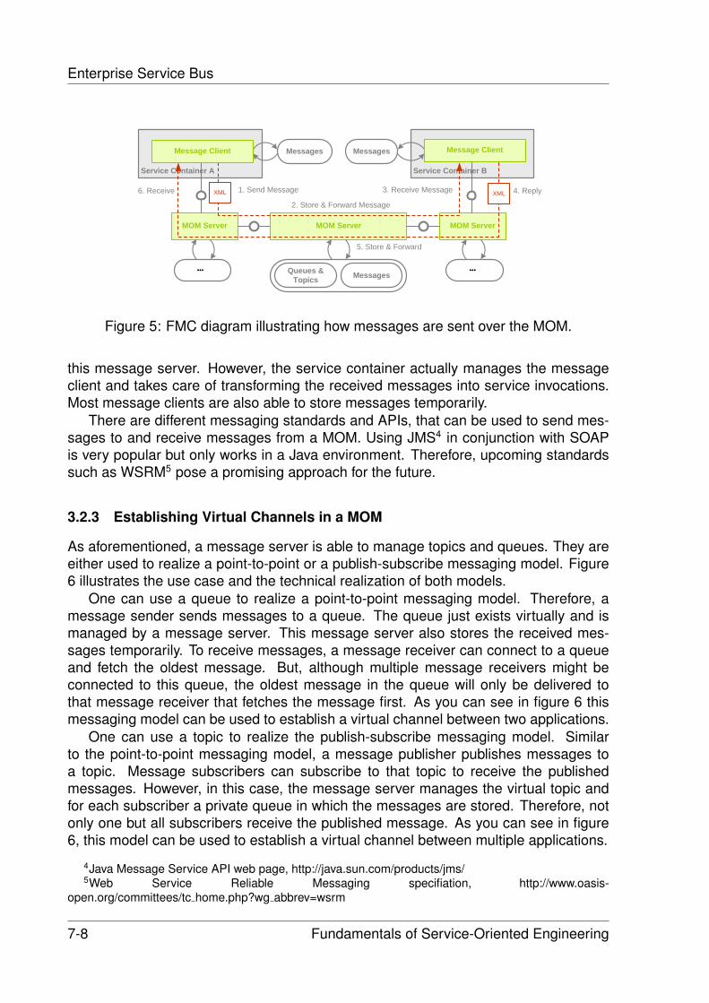
Enterprise Service Bus
Service Container A
MOM Server MOM Server MOM Server
Service Container B
Queues &Topics Messages
Messages Messages
1. Send MessageXML XML
2. Store & Forward Message
3. Receive Message 4. Reply6. Receive
5. Store & Forward
Message Client Message Client
Figure 5: FMC diagram illustrating how messages are sent over the MOM.
this message server. However, the service container actually manages the messageclient and takes care of transforming the received messages into service invocations.Most message clients are also able to store messages temporarily.
There are different messaging standards and APIs, that can be used to send mes-sages to and receive messages from a MOM. Using JMS4 in conjunction with SOAPis very popular but only works in a Java environment. Therefore, upcoming standardssuch as WSRM5 pose a promising approach for the future.
3.2.3 Establishing Virtual Channels in a MOM
As aforementioned, a message server is able to manage topics and queues. They areeither used to realize a point-to-point or a publish-subscribe messaging model. Figure6 illustrates the use case and the technical realization of both models.
One can use a queue to realize a point-to-point messaging model. Therefore, amessage sender sends messages to a queue. The queue just exists virtually and ismanaged by a message server. This message server also stores the received mes-sages temporarily. To receive messages, a message receiver can connect to a queueand fetch the oldest message. But, although multiple message receivers might beconnected to this queue, the oldest message in the queue will only be delivered tothat message receiver that fetches the message first. As you can see in figure 6 thismessaging model can be used to establish a virtual channel between two applications.
One can use a topic to realize the publish-subscribe messaging model. Similarto the point-to-point messaging model, a message publisher publishes messages toa topic. Message subscribers can subscribe to that topic to receive the publishedmessages. However, in this case, the message server manages the virtual topic andfor each subscriber a private queue in which the messages are stored. Therefore, notonly one but all subscribers receive the published message. As you can see in figure6, this model can be used to establish a virtual channel between multiple applications.
4Java Message Service API web page, http://java.sun.com/products/jms/5Web Service Reliable Messaging specifiation, http://www.oasis-
open.org/committees/tc home.php?wg abbrev=wsrm
7-8 Fundamentals of Service-Oriented Engineering
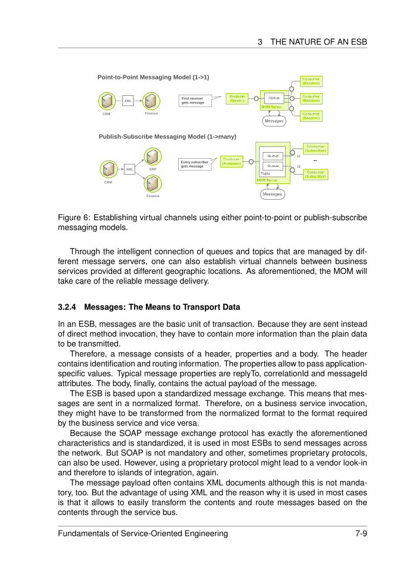
3 THE NATURE OF AN ESB
Point-to-Point Messaging Model (1->1)
Publish-Subscribe Messaging Model (1->many)
Every subscriber gets message
First receiver gets message
CRM Finance
XML
CRM
ERP
Finance
XML
Figure 6: Establishing virtual channels using either point-to-point or publish-subscribemessaging models.
Through the intelligent connection of queues and topics that are managed by dif-ferent message servers, one can also establish virtual channels between businessservices provided at different geographic locations. As aforementioned, the MOM willtake care of the reliable message delivery.
3.2.4 Messages: The Means to Transport Data
In an ESB, messages are the basic unit of transaction. Because they are sent insteadof direct method invocation, they have to contain more information than the plain datato be transmitted.
Therefore, a message consists of a header, properties and a body. The headercontains identification and routing information. The properties allow to pass application-specific values. Typical message properties are replyTo, correlationId and messageIdattributes. The body, finally, contains the actual payload of the message.
The ESB is based upon a standardized message exchange. This means that mes-sages are sent in a normalized format. Therefore, on a business service invocation,they might have to be transformed from the normalized format to the format requiredby the business service and vice versa.
Because the SOAP message exchange protocol has exactly the aforementionedcharacteristics and is standardized, it is used in most ESBs to send messages acrossthe network. But SOAP is not mandatory and other, sometimes proprietary protocols,can also be used. However, using a proprietary protocol might lead to a vendor look-inand therefore to islands of integration, again.
The message payload often contains XML documents although this is not manda-tory, too. But the advantage of using XML and the reason why it is used in most casesis that it allows to easily transform the contents and route messages based on thecontents through the service bus.
Fundamentals of Service-Oriented Engineering 7-9
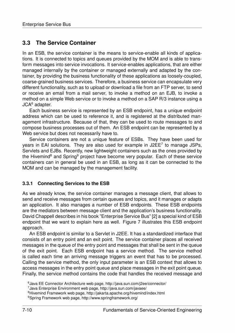
Enterprise Service Bus
3.3 The Service Container
In an ESB, the service container is the means to service-enable all kinds of applica-tions. It is connected to topics and queues provided by the MOM and is able to trans-form messages into service invocations. It service-enables applications, that are eithermanaged internally by the container or managed externally and adapted by the con-tainer, by providing the business functionality of these applications as loosely-coupled,coarse-grained business services. Therefore, a business service can encapsulate verydifferent functionality, such as to upload or download a file from an FTP server, to sendor receive an email from a mail server, to invoke a method on an EJB, to invoke amethod on a simple Web service or to invoke a method on a SAP R/3 instance using aJCA6 adapter.
Each business service is represented by an ESB endpoint, has a unique endpointaddress which can be used to reference it, and is registered at the distributed man-agement infrastructure. Because of that, they can be used to route messages to andcompose business processes out of them. An ESB endpoint can be represented by aWeb service but does not necessarily have to.
Service containers are not a unique feature of ESBs. They have been used foryears in EAI solutions. They are also used for example in J2EE7 to manage JSPs,Servlets and EJBs. Recently, new lightweight containers such as the ones provided bythe Hivemind8 and Spring9 project have become very popular. Each of these servicecontainers can in general be used in an ESB, as long as it can be connected to theMOM and can be managed by the management facility.
3.3.1 Connecting Services to the ESB
As we already know, the service container manages a message client, that allows tosend and receive messages from certain queues and topics, and it manages or adaptsan application. It also manages a number of ESB endpoints. These ESB endpointsare the mediators between message client and the application’s business functionality.David Chappell describes in his book ”Enterprise Service Bus” [2] a special kind of ESBendpoint that we want to explain here as well. Figure 7 illustrates this ESB endpointapproach.
An ESB endpoint is similar to a Servlet in J2EE. It has a standardized interface thatconsists of an entry point and an exit point. The service container places all receivedmessages in the queue of the entry point and messages that shall be sent in the queueof the exit point. Each ESB endpoint has a service method. The service methodis called each time an arriving message triggers an event that has to be processed.Calling the service method, the only input parameter is an ESB context that allows toaccess messages in the entry point queue and place messages in the exit point queue.Finally, the service method contains the code that handles the received message and
6Java EE Connector Architecture web page, http://java.sun.com/j2ee/connector/7Java Enterprise Environment web page, http://java.sun.com/javaee/8Hivemind Framework web page, http://jakarta.apache.org/hivemind/index.html9Spring Framework web page, http://www.springframework.org/
7-10 Fundamentals of Service-Oriented Engineering
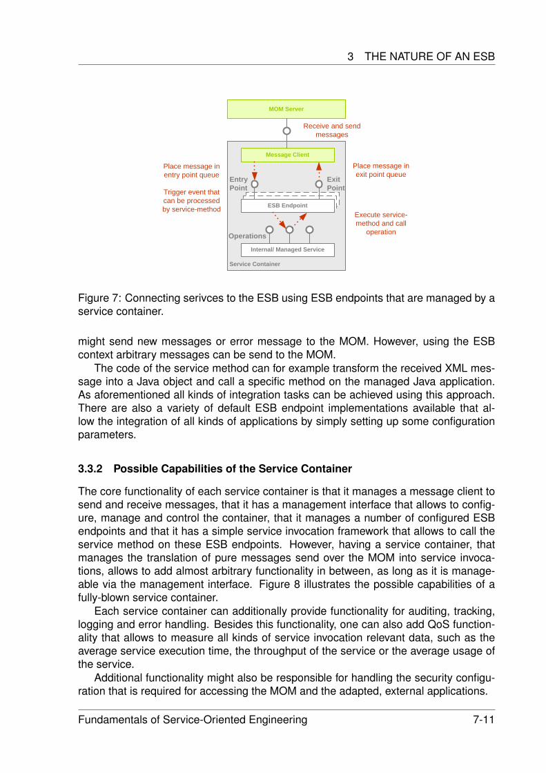
3 THE NATURE OF AN ESB
Service Container
ESB EndpointESB Endpoint
MOM Server
Message Client
ESB Endpoint
Internal/ Managed Service
Entry Point
Exit Point
Operations
Place message in entry point queue
Trigger event that can be processed by service-method
Place message in exit point queue
Execute service-method and call
operation
Receive and sendmessages
Figure 7: Connecting serivces to the ESB using ESB endpoints that are managed by aservice container.
might send new messages or error message to the MOM. However, using the ESBcontext arbitrary messages can be send to the MOM.
The code of the service method can for example transform the received XML mes-sage into a Java object and call a specific method on the managed Java application.As aforementioned all kinds of integration tasks can be achieved using this approach.There are also a variety of default ESB endpoint implementations available that al-low the integration of all kinds of applications by simply setting up some configurationparameters.
3.3.2 Possible Capabilities of the Service Container
The core functionality of each service container is that it manages a message client tosend and receive messages, that it has a management interface that allows to config-ure, manage and control the container, that it manages a number of configured ESBendpoints and that it has a simple service invocation framework that allows to call theservice method on these ESB endpoints. However, having a service container, thatmanages the translation of pure messages send over the MOM into service invoca-tions, allows to add almost arbitrary functionality in between, as long as it is manage-able via the management interface. Figure 8 illustrates the possible capabilities of afully-blown service container.
Each service container can additionally provide functionality for auditing, tracking,logging and error handling. Besides this functionality, one can also add QoS function-ality that allows to measure all kinds of service invocation relevant data, such as theaverage service execution time, the throughput of the service or the average usage ofthe service.
Additional functionality might also be responsible for handling the security configu-ration that is required for accessing the MOM and the adapted, external applications.
Fundamentals of Service-Oriented Engineering 7-11
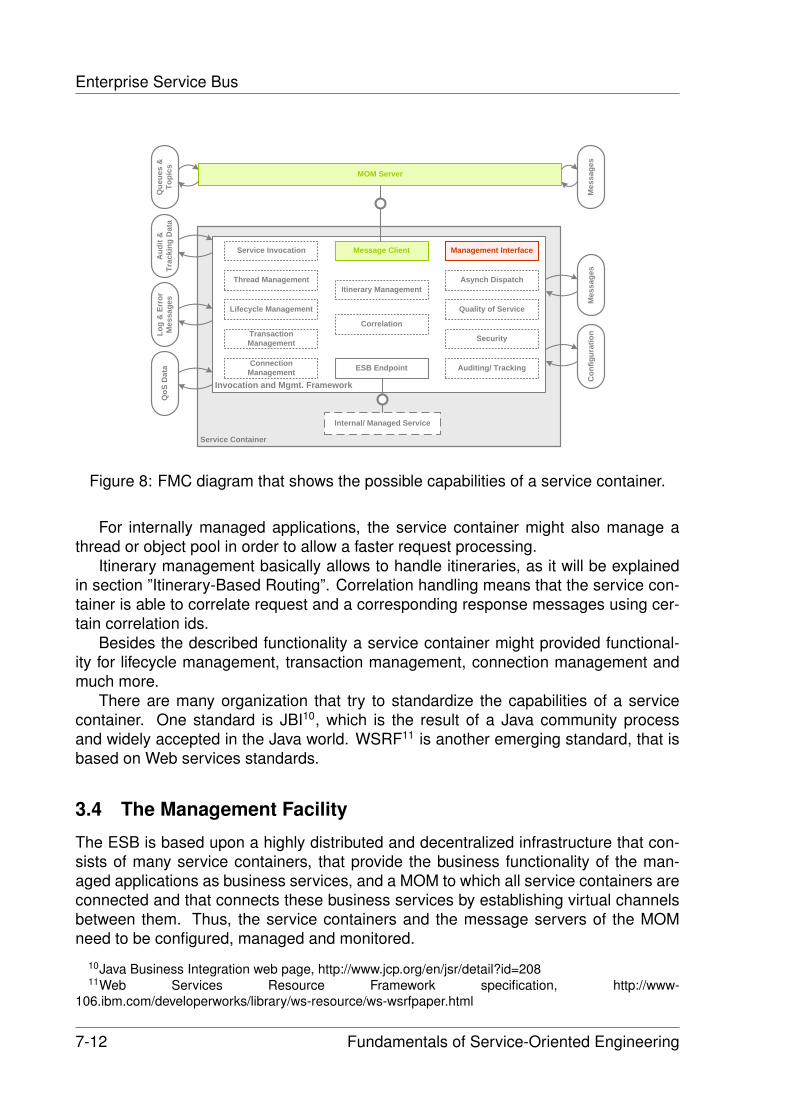
Enterprise Service Bus
Service Container
MOM Server
Internal/ Managed Service
Invocation and Mgmt. Framework
Message Client
ESB Endpoint
Mes
sage
sC
onfig
urat
ion
Service Invocation
Thread Management
Lifecycle Management
Connection Management
Asynch Dispatch
Auditing/ Tracking
Itinerary Management
Quality of Service
Security
Management Interface
CorrelationTransaction Management
Aud
it &
Tr
acki
ng D
ata
Log
& E
rror
M
essa
ges
QoS
Dat
a
Mes
sage
s
Que
ues
&
Topi
cs
Figure 8: FMC diagram that shows the possible capabilities of a service container.
For internally managed applications, the service container might also manage athread or object pool in order to allow a faster request processing.
Itinerary management basically allows to handle itineraries, as it will be explainedin section ”Itinerary-Based Routing”. Correlation handling means that the service con-tainer is able to correlate request and a corresponding response messages using cer-tain correlation ids.
Besides the described functionality a service container might provided functional-ity for lifecycle management, transaction management, connection management andmuch more.
There are many organization that try to standardize the capabilities of a servicecontainer. One standard is JBI10, which is the result of a Java community processand widely accepted in the Java world. WSRF11 is another emerging standard, that isbased on Web services standards.
3.4 The Management Facility
The ESB is based upon a highly distributed and decentralized infrastructure that con-sists of many service containers, that provide the business functionality of the man-aged applications as business services, and a MOM to which all service containers areconnected and that connects these business services by establishing virtual channelsbetween them. Thus, the service containers and the message servers of the MOMneed to be configured, managed and monitored.
10Java Business Integration web page, http://www.jcp.org/en/jsr/detail?id=20811Web Services Resource Framework specification, http://www-
106.ibm.com/developerworks/library/ws-resource/ws-wsrfpaper.html
7-12 Fundamentals of Service-Oriented Engineering
3 THE NATURE OF AN ESB
Service ContainerMOM Server
Internal/ Managed Service
Invocation and Mgmt. Framework
Message Client
Mes
sage
sC
onfig
urat
ion
& D
ata
Management Interface
Cod
e/ S
crip
ts/
Proc
esse
s
......
Management Interface
Mes
sage
sTo
pics
&
Que
ues
Con
figur
atio
n&
Dat
a
Management Facility
Configuration Service Repository
Management Tool Code/ Scripts/Processes
Manage and monitor
Manage and monitor
Message exchange
Figure 9: FMC diagram illustrating the key components of the management facility ofan ESB.
Because of the variety of managed applications, ranging from simple EJBs thatare deployed via an deployment archive to transformation engines that require XSLT12
scripts to BPEL13 engines that require process definitions, and possibly different mes-sage servers, very different requirements concerning configuration, deployment, man-agement, and monitoring have to be satisfied.
The basic idea of an ESB is to have a decentralized infrastructure but to manageit centrally. Each ESB, therefore, has a powerful and versatile management facility.This management facility basically consists of a central repository, a network of man-agement servers, management interfaces at message servers and service containers,and different configuration, management and monitoring tools. Figure 9 illustrates therelationship between the aforementioned components.
3.4.1 The Central Repository: The Means to Store all Kinds of Artifacts
In the central repository, all kinds of ESB related artifacts are stored. Besides the ESBendpoint configuration for the service containers and the topic and queue configura-tion for the message servers it also contains program code, deployment descriptors,deployment archives and XSLT scripts. The central repository also contains a list ofavailable business services and their ESB endpoints, BPEL process definitions andmessage routing configurations. Because the management facility monitors all kindsof components, it also contains different monitoring data.
12XML transformations specification, http://www.w3.org/TR/xslt13Business Process Execution Language specification, http://www- 128.ibm.com/developerworks/
library/specification/ws-bpel/
Fundamentals of Service-Oriented Engineering 7-13
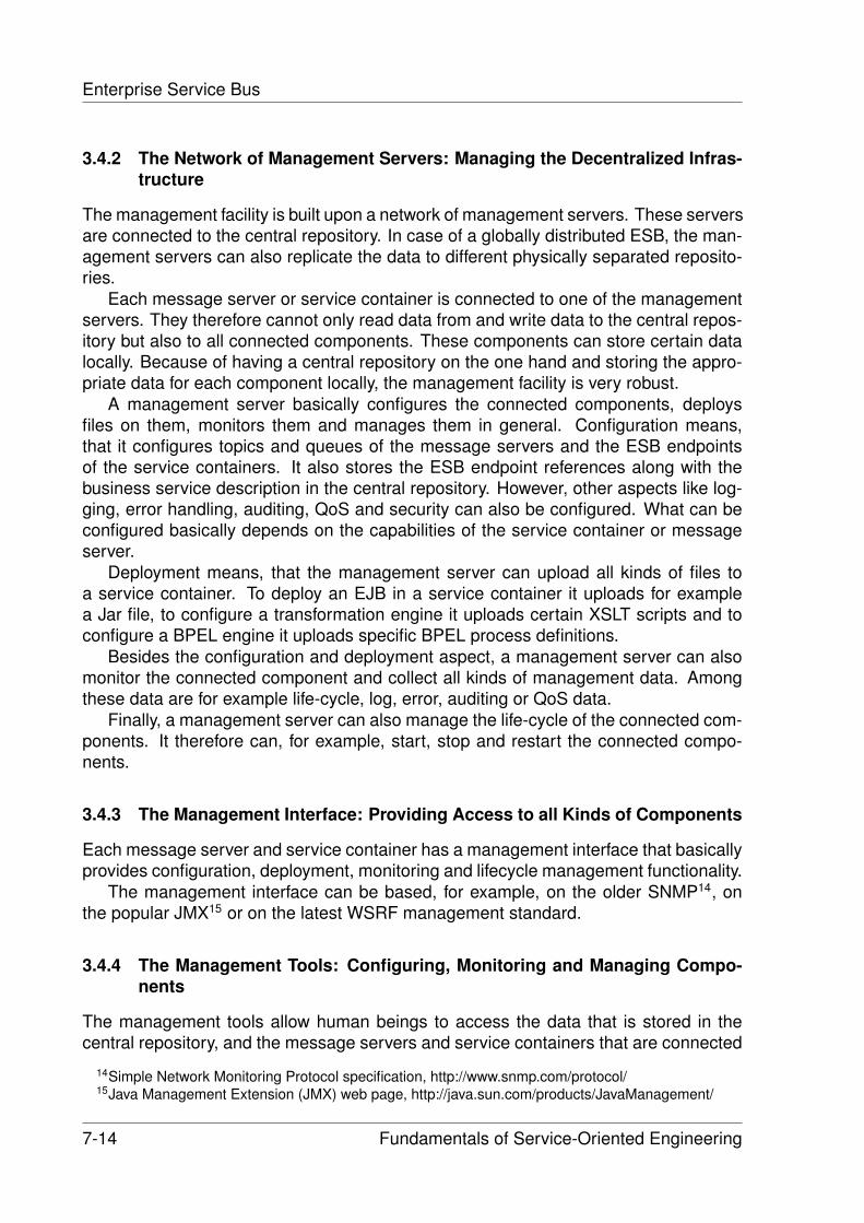
Enterprise Service Bus
3.4.2 The Network of Management Servers: Managing the Decentralized Infras-tructure
The management facility is built upon a network of management servers. These serversare connected to the central repository. In case of a globally distributed ESB, the man-agement servers can also replicate the data to different physically separated reposito-ries.
Each message server or service container is connected to one of the managementservers. They therefore cannot only read data from and write data to the central repos-itory but also to all connected components. These components can store certain datalocally. Because of having a central repository on the one hand and storing the appro-priate data for each component locally, the management facility is very robust.
A management server basically configures the connected components, deploysfiles on them, monitors them and manages them in general. Configuration means,that it configures topics and queues of the message servers and the ESB endpointsof the service containers. It also stores the ESB endpoint references along with thebusiness service description in the central repository. However, other aspects like log-ging, error handling, auditing, QoS and security can also be configured. What can beconfigured basically depends on the capabilities of the service container or messageserver.
Deployment means, that the management server can upload all kinds of files toa service container. To deploy an EJB in a service container it uploads for examplea Jar file, to configure a transformation engine it uploads certain XSLT scripts and toconfigure a BPEL engine it uploads specific BPEL process definitions.
Besides the configuration and deployment aspect, a management server can alsomonitor the connected component and collect all kinds of management data. Amongthese data are for example life-cycle, log, error, auditing or QoS data.
Finally, a management server can also manage the life-cycle of the connected com-ponents. It therefore can, for example, start, stop and restart the connected compo-nents.
3.4.3 The Management Interface: Providing Access to all Kinds of Components
Each message server and service container has a management interface that basicallyprovides configuration, deployment, monitoring and lifecycle management functionality.
The management interface can be based, for example, on the older SNMP14, onthe popular JMX15 or on the latest WSRF management standard.
3.4.4 The Management Tools: Configuring, Monitoring and Managing Compo-nents
The management tools allow human beings to access the data that is stored in thecentral repository, and the message servers and service containers that are connected
14Simple Network Monitoring Protocol specification, http://www.snmp.com/protocol/15Java Management Extension (JMX) web page, http://java.sun.com/products/JavaManagement/
7-14 Fundamentals of Service-Oriented Engineering
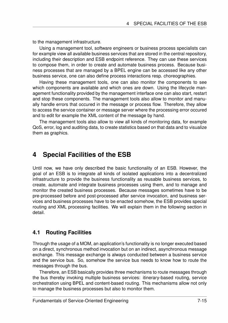
4 SPECIAL FACILITIES OF THE ESB
to the management infrastructure.Using a management tool, software engineers or business process specialists can
for example view all available business services that are stored in the central repository,including their description and ESB endpoint reference. They can use these servicesto compose them, in order to create and automate business process. Because busi-ness processes that are managed by a BPEL engine can be accessed like any otherbusiness service, one can also define process interactions resp. choreographies.
Having these management tools, one can also monitor the components to seewhich components are available and which ones are down. Using the lifecycle man-agement functionality provided by the management interface one can also start, restartand stop these components. The management tools also allow to monitor and manu-ally handle errors that occured in the message or process flow. Therefore, they allowto access the service container or message server where the processing error occuredand to edit for example the XML content of the message by hand.
The management tools also allow to view all kinds of monitoring data, for exampleQoS, error, log and auditing data, to create statistics based on that data and to visualizethem as graphics.
4 Special Facilities of the ESB
Until now, we have only described the basic functionality of an ESB. However, thegoal of an ESB is to integrate all kinds of isolated applications into a decentralizedinfrastructure to provide the business functionality as reusable business services, tocreate, automate and integrate business processes using them, and to manage andmonitor the created business processes. Because messages sometimes have to bepre-processed before and post-processed after service invocation, and business ser-vices and business processes have to be enacted somehow, the ESB provides specialrouting and XML processing facilities. We will explain them in the following section indetail.
4.1 Routing Facilities
Through the usage of a MOM, an application’s functionality is no longer executed basedon a direct, synchronous method invocation but on an indirect, asynchronous messageexchange. This message exchange is always conducted between a business serviceand the service bus. So, somehow the service bus needs to know how to route themessages through the bus.
Therefore, an ESB basically provides three mechanisms to route messages throughthe bus thereby invoking multiple business services: itinerary-based routing, serviceorchestration using BPEL and content-based routing. This mechanisms allow not onlyto manage the business processes but also to monitor them.
Fundamentals of Service-Oriented Engineering 7-15
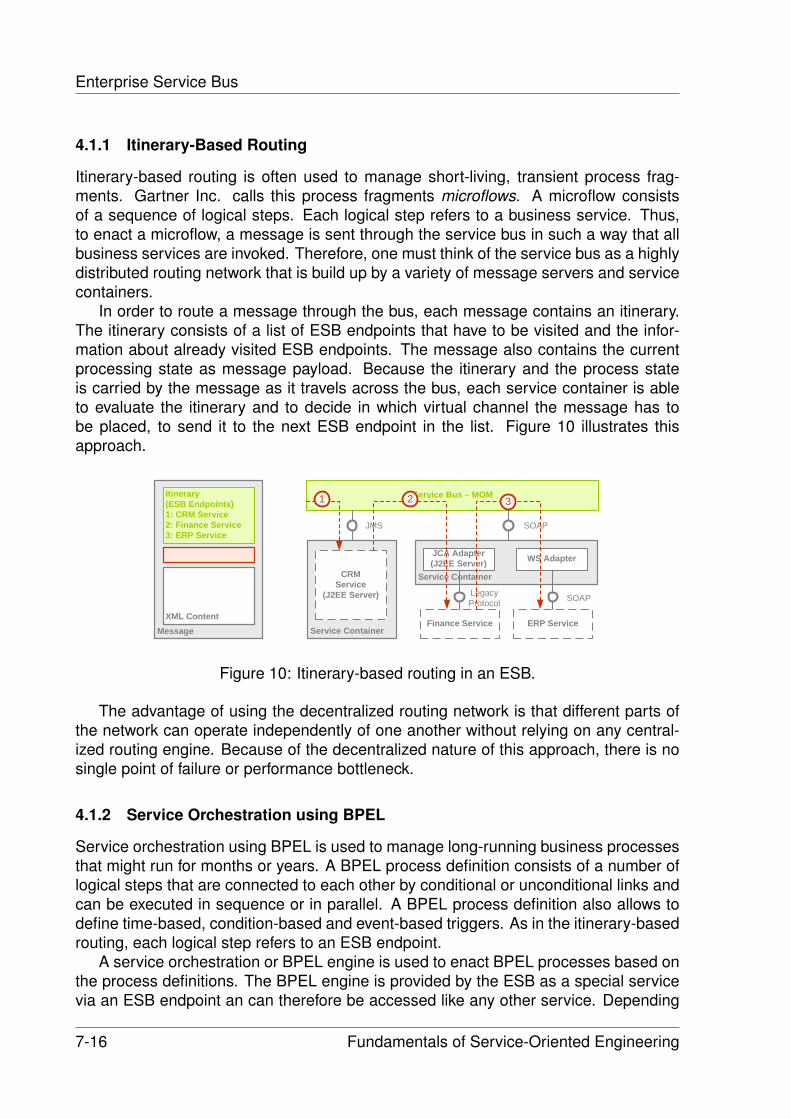
Enterprise Service Bus
4.1.1 Itinerary-Based Routing
Itinerary-based routing is often used to manage short-living, transient process frag-ments. Gartner Inc. calls this process fragments microflows. A microflow consistsof a sequence of logical steps. Each logical step refers to a business service. Thus,to enact a microflow, a message is sent through the service bus in such a way that allbusiness services are invoked. Therefore, one must think of the service bus as a highlydistributed routing network that is build up by a variety of message servers and servicecontainers.
In order to route a message through the bus, each message contains an itinerary.The itinerary consists of a list of ESB endpoints that have to be visited and the infor-mation about already visited ESB endpoints. The message also contains the currentprocessing state as message payload. Because the itinerary and the process stateis carried by the message as it travels across the bus, each service container is ableto evaluate the itinerary and to decide in which virtual channel the message has tobe placed, to send it to the next ESB endpoint in the list. Figure 10 illustrates thisapproach.
MessageXML Content
Itinerary(ESB Endpoints)1: CRM Service2: Finance Service3: ERP Service
Service Container
Service Bus – MOM
CRMService
(J2EE Server)
Service Container
Finance Service
JCA Adapter(J2EE Server)
JMS SOAP
LegacyProtocol
WS Adapter
ERP Service
SOAP
1 2 3
Figure 10: Itinerary-based routing in an ESB.
The advantage of using the decentralized routing network is that different parts ofthe network can operate independently of one another without relying on any central-ized routing engine. Because of the decentralized nature of this approach, there is nosingle point of failure or performance bottleneck.
4.1.2 Service Orchestration using BPEL
Service orchestration using BPEL is used to manage long-running business processesthat might run for months or years. A BPEL process definition consists of a number oflogical steps that are connected to each other by conditional or unconditional links andcan be executed in sequence or in parallel. A BPEL process definition also allows todefine time-based, condition-based and event-based triggers. As in the itinerary-basedrouting, each logical step refers to an ESB endpoint.
A service orchestration or BPEL engine is used to enact BPEL processes based onthe process definitions. The BPEL engine is provided by the ESB as a special servicevia an ESB endpoint an can therefore be accessed like any other service. Depending
7-16 Fundamentals of Service-Oriented Engineering
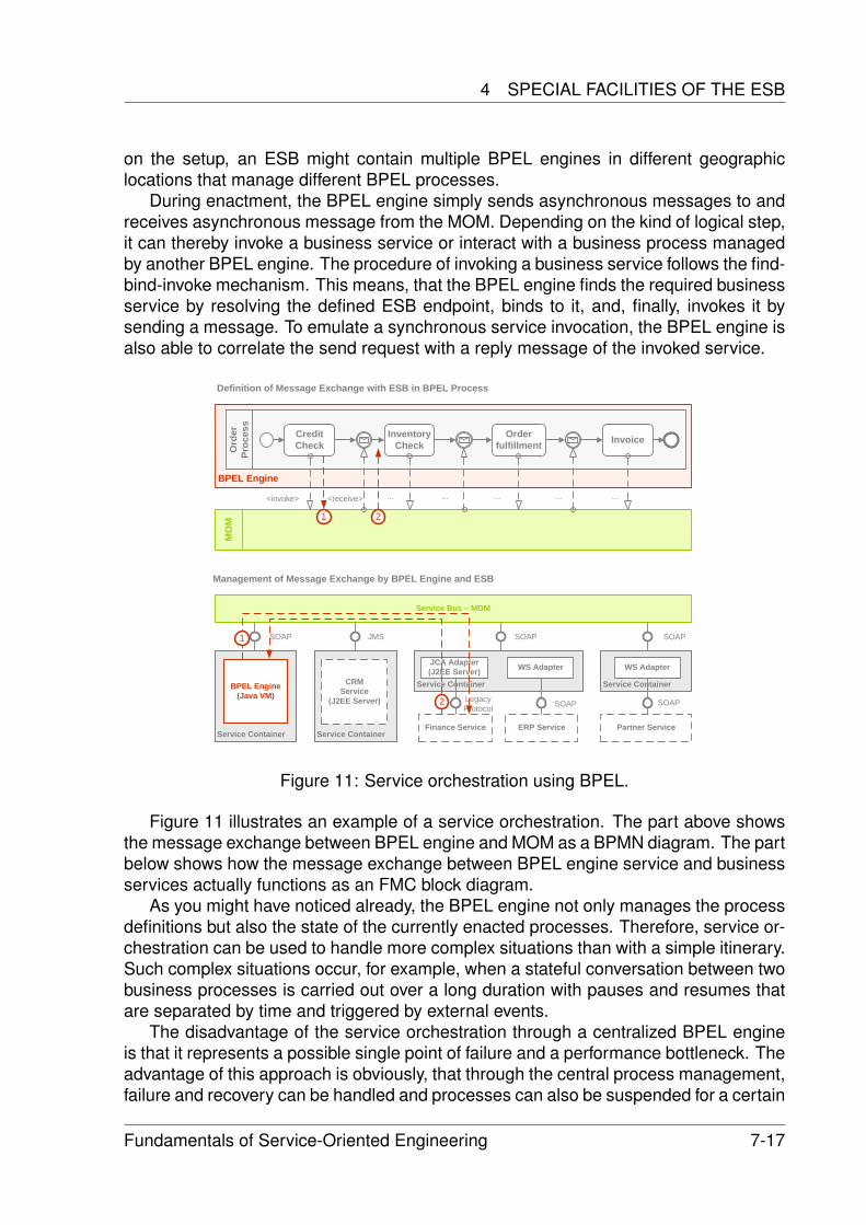
4 SPECIAL FACILITIES OF THE ESB
on the setup, an ESB might contain multiple BPEL engines in different geographiclocations that manage different BPEL processes.
During enactment, the BPEL engine simply sends asynchronous messages to andreceives asynchronous message from the MOM. Depending on the kind of logical step,it can thereby invoke a business service or interact with a business process managedby another BPEL engine. The procedure of invoking a business service follows the find-bind-invoke mechanism. This means, that the BPEL engine finds the required businessservice by resolving the defined ESB endpoint, binds to it, and, finally, invokes it bysending a message. To emulate a synchronous service invocation, the BPEL engine isalso able to correlate the send request with a reply message of the invoked service.
BPEL Engine
Ord
er
Proc
ess
MO
M
Credit Check
Inventory Check
Order fulfillment Invoice
<invoke> <receive> ... ... ... ... ...
Service Container
Service Bus – MOM
CRMService
(J2EE Server)
Service Container
Service Container
BPEL Engine(Java VM)
JCA Adapter(J2EE Server)
JMS SOAPSOAP
LegacyProtocol
WS Adapter
ERP Service
SOAP
Service Container
SOAP
Partner Service
WS Adapter
SOAP
Finance Service
1 2
1
2
Definition of Message Exchange with ESB in BPEL Process
Management of Message Exchange by BPEL Engine and ESB
Figure 11: Service orchestration using BPEL.
Figure 11 illustrates an example of a service orchestration. The part above showsthe message exchange between BPEL engine and MOM as a BPMN diagram. The partbelow shows how the message exchange between BPEL engine service and businessservices actually functions as an FMC block diagram.
As you might have noticed already, the BPEL engine not only manages the processdefinitions but also the state of the currently enacted processes. Therefore, service or-chestration can be used to handle more complex situations than with a simple itinerary.Such complex situations occur, for example, when a stateful conversation between twobusiness processes is carried out over a long duration with pauses and resumes thatare separated by time and triggered by external events.
The disadvantage of the service orchestration through a centralized BPEL engineis that it represents a possible single point of failure and a performance bottleneck. Theadvantage of this approach is obviously, that through the central process management,failure and recovery can be handled and processes can also be suspended for a certain
Fundamentals of Service-Oriented Engineering 7-17
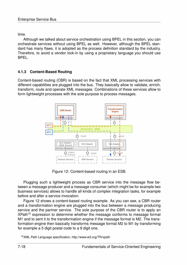
Enterprise Service Bus
time.Although we talked about service orchestration using BPEL in this section, you can
orchestrate services without using BPEL as well. However, although the BPEL stan-dard has many flaws, it is adopted as the process definition standard by the industry.Therefore, to avoid a vendor lock-in by using a proprietary language you should useBPEL.
4.1.3 Content-Based Routing
Content-based routing (CBR) is based on the fact that XML processing services withdifferent capabilities are plugged into the bus. They basically allow to validate, enrich,transform, route and operate XML messages. Combinations of these services allow toform lightweight processes with the sole purpose to process messages.
Service Container
Service Bus – MOM
Transformation Engine
Service Container
Service Container
Finance Service
CBR Router
JCA Adapter(J2EE Server)
SOAP
LegacyProtocol
WS Adapter
ERP Service
SOAP
Service Container
SOAP
Partner Service
WS Adapter
SOAP
MT2
MT1
Figure 12: Content-based routing in an ESB.
Plugging such a lightweight process as CBR service into the message flow be-tween a message producer and a message consumer (which might be for example twobusiness services) allows to handle all kinds of complex integration tasks, for examplebefore and after a service invocation.
Figure 12 shows a content-based routing example. As you can see, a CBR routerand a transformation engine are plugged into the bus between a message producingservice and the partner service. The sole purpose of the CBR router is to apply anXPath16 expression to determine whether the message conforms to message formatM1 and to sent it to the transformation engine if the message format is M2. The trans-formation engine then basically transforms message format M2 to M1 by transformingfor example a 5 digit postal code to a 9 digit one.
16XML Path Language specification, http://www.w3.org/TR/xpath
7-18 Fundamentals of Service-Oriented Engineering
5 CONCLUSION
4.2 XML Processing Facilities
Because an ESB is used to integrate all kinds of applications, and for really integratingan application it might require more than one simple step, the ESB provides a widerange of XML processing facilities, that can be plugged together as described in thecontent-based routing section to handle all kinds of complex integration tasks.
These XML processing facilities allow, among others, to validate, transform, andpersist messages. They are either provided by the service containers or by specialXML services that are plugged into the bus.
Message validation means that validation services are plugged into the bus thatare capable of checking whether a message conforms to a certain message or dataformat. Therefore, it either checks the XML payload for the existence of certain at-tributes and tags or evaluates the contents using configured validation rules. Validationservices have often some routing intelligence and transformation capabilities that al-low them to modify the processed message or the routing information (the itinerary) ofthe processed message based on the validation result. In order to validate messages,validation services use XML standards, such as XPath or XQuery17.
Message transformation means that transformation services in the bus or transfor-mation functionality implemented in the service container is used to change, extract,enrich or aggregate the XML payload of the processed messages. In order to do that,transformation facilities use XML standards, such as XSLT, XPath or XQuery.
Message persistence means that special services are plugged into the bus that areconnected to XML or relational databases and are able of storing XML messages ortheir payload.
As mentioned above, XML processing services are mostly used in content-basedrouting scenarios. However, because these services are accessible via an ESB end-point like any other service in the ESB, they can easily be used in microflows and BPELprocesses, as well.
5 Conclusion
In this paper, we gave an introduction to the ESB. Therefore, we described what the ba-sic promises of ESB and the main differences to former EAI solutions are. We explainedthe key components of an ESB, which are MOM, service container and managementfacility, in detail. We also described the special facilities, which are routing and XMLprocessing facilities, that actually make up an ESB.
As a conclusion of our work, we can say that ESB combines best practices from EAIof the last years, reuses and integrates components that have been on the market foryears, and makes it more manageable. It combines best practices from EAI because itis based on concepts from MOM, event-driven architecture (EDA) and SOA. It reusescomponents, such as messaging systems, J2EE servers, integration adapters fromcentralized EAI solutions, business process management engines and XML processingservices, and integrates them to provide added-value. Finally, it makes the integrated
17XML Query Language specification, http://www.w3.org/TR/xquery/
Fundamentals of Service-Oriented Engineering 7-19
Enterprise Service Bus
components more manageable and therefore more valuable by providing a powerfulmanagement facility and integrating them into it.
5.1 What is (an) ESB?
Having clarified the advantages and disadvantages of an ESB, let us finally answer thequestion: ”What is (an) ESB?”.
5.1.1 A ”Way of Doing Things”?
Yes, the ESB is definitively a ”way of doing things”. It is an incremental approach of con-structing a SOA by connecting all kinds of applications to a enterprise-wide distributedinfrastructure.
5.1.2 An Architecture?
Yes, the ESB is an architectural style in which applications are service-enabled throughservice containers and connected to a MOM based service bus, that is not only capa-ble of routing messages but also of transforming them. This architectural style allowsto iteratively construct a SOA, to create, automate and integrate business processesbased on the provided business services, and to easily manage and monitor thesebusiness processes.
5.1.3 A new Type of Product?
Yes, somehow. There are many companies that sell ESB infrastructure products allow-ing enterprises to build up an ESB. These products are often composed out of existingcomponents, such as MOMs, J2EE servers and EAI integration adapters, and providedin a manageable manner.
Software companies, such as IBM18, Sonic Software19, Seebeyond20 and CapeClear21 are very active participants in this market. They are fighting for market sharesby selling there own ESB infrastructure products and offering consulting services tohelp enterprises in realizing their ESB.
There are also a number of open source projects, such as Open ESB22 sponsoredby Sun and Mule23 sponsored by Codehaus that try to provide enterprises with freeESB infrastructure implementations.
18IBM Websphere ESB product page, http://www-306.ibm.com/software/integration/wsesb/19Sonic Software ESB product page, http://www.sonicsoftware.com/products/sonic esb/index.ssp20Seebeyond eInsight ESB product page, http://www.seebeyond.com/software/einsightenterprise.asp21Cape Clear ESB product page, http://www.capeclear.com/products/cc6.shtml22Open ESB project page, https://open-esb.dev.java.net/23Mule ESB project page, http://mule.codehaus.org/
7-20 Fundamentals of Service-Oriented Engineering
REFERENCES
References
[1] Gustavo Alonso, Fabio Casati, Harumi Kuno, and Vijay Machiraju. Web Services:Concepts, Architectures and Applications. Springer-Verlag, 2004.
[2] David A. Chappell. Enterprise Service Bus. O’Reilly Media Inc., 2004.
[3] M. Keen et al. Implementing an SOA using an Enterprise Service Bus. IBMRedbook, 2004. http://www.redbooks.ibm.com/redpieces/pdfs/sg246346.pdf.
[4] M. Keen et al. SOA with an Enterprise Service Bus in WebSpehere. IBM Redbook,2005. http://www.redbooks.ibm.com/redbooks/pdfs/sg246494.pdf.
[5] Martin Fowler. Patterns of Enterprise Application Architecture. Addison Wesley,2002.
[6] Gregor Hohpe and Bobby Woolf. Enterprise Integration Patterns. Pearson Edu-cation, 2004.
[7] Dirk Krafzig, Karl Banke, and Dirk Slama. Enterprise SOA: Service-Oriented Ar-chitecture Best Practices. Prentice Hall, 2004.
[8] Sun Microsystems. Service oriented business integration.http://java.sun.com/integration/.
[9] Mike P. Papazoglou and Dimitrios Georgakopoulos. Service oriented computing.Communications of the ACM, 2003.
[10] Eric Pulier, Hugh Taylor, and Paul Gaffney. Understanding Enterprise SOA. Man-ning, 2006.
[11] Peter Tabeling, Bernhard Groene, and Andreas Knoepfel. Fundamental ModelingConcepts - Effective Communication of IT Systems. John Wiley & Sons, Ltd.,2006.
[12] PolarLake: Understanding the ESB. http://www.polarlake.com/en/assets/ whitepa-pers/esb.pdf.
Fundamentals of Service-Oriented Engineering 7-21

Fundamentals of Service-Oriented Engineering 8-1
Loosely coupled services with JMS and JavaSpaces
Sören Haubrock
Loose coupling is a central aspect in service-oriented computing. While the general concept of service-oriented architectures (SOAs) does not imply any particular restrictions on how to realize this aim, certain technologies provide ways to support loose coupling and thereby follow different approaches.
In the Java world, two technologies are particularly aiming at providing middleware components to support message and workload exchange in an asynchronous fashion. While the Java Message System (JMS) follows the idea of a central platform for message exchange in order to de-couple the communicating partners, the JavaSpaces approach relies on the concept of a space-based object and data exchange repository in order to distribute workloads among several participants in a highly-flexible way.
In the scope of this paper, these two approaches are described, exemplified and analysed with respect to their role in service-oriented computing.
Keywords: JMS, JavaSpaces, SOA, Loose Coupling
1 Loose coupling in service-oriented computing The concept of a service-oriented architecture (SOA) relies on a set of certain
aspects, which can be summarised by the definition of Wilkes [1]: “[A SOA is] a way of designing and implementing enterprise applications that deals with the intercommunication of loosely coupled, coarse grained (business level), reusable artefacts (services) that are accessed through well-defined, platform independent, interface contracts.“
Loose coupling is a fundamental aim in service-oriented computing. „It describes a resilient relationship between two or more computer systems that are exchanging data. […] with few assumptions about the other end“[3].
The benefits of loose coupling are seen in the transparency, flexibility in large application composition and resource binding[4,5]. Hereby, the aspects of de-coupling in terms of location, time and reference at build-time are to be differentiated.
De-coupling in terms of reference is already realised in the SOA-implementation of SOAP web services. While the interface of such a service needs to be known a-priori (or at least to be found and understood), the actual instance of a service can be deployed and exchanged at run-time.
In the same case, the location of a web service is de-coupled from the client in the sense that it can be looked up at run-time from a registry. The location of a service itself might change from one URL to another as long as the registry consistently
Loosely coupled services with JMS and JavaSpaces
8-2 Fundamentals of Service-Oriented Engineering
updates the location changes. However, once a consumer of a web service does not use the registry anymore (to find the service) or the address in the WSDL document is not up-to-date, the invocation of a service leads to malfunction. Therefore, the realisation of space-de-coupling in SOAP web service implementations strongly depends on the policy of both, the service provider and the service consumer.
Regarding the time aspect, the current standard SOAP web services do not provide a means to systematically de-couple communicating end points from each other. However, only when components are de-coupled not only by reference, but also by location and time, the establishment of SOAs with asynchronous information exchange becomes feasible. As an example, memory- and time-consuming processes encapsulated by services might run in the background after being invoked, while a client disconnects from the service and proceeds with other tasks without waiting for the service to be finished. Later on, the client may fetch the result data either by asking for the state of a service process or by being informed through the service or some other component after the completion of the job. Both approaches sketched in this paper realise time-decoupling in a specific way.
2 Java Message Service (JMS)
2.1 Loose coupling in messaging systems In messaging systems, applications are loosely coupled through the exchange of
self-describing messages. In theory, these messages can contain any information needed by the implicit communication protocol between sender and receiver, i.e. some text information, an XML-document (e.g. SOAP message) or binary data.
In such a system, a component is needed to receive, store and send messages for all participating endpoints. In most cases, this functionality is provided by a service, which can be accessed by the communication partners. The components responsible for the messaging process including these access services are subsumed as Message Oriented Middleware (MOM). Obviously, there are certain requirements to be fulfilled by such a messaging system in terms of reliability, accessibility, security and performance.
With the message service as a central component in this architecture, communication partners in a messaging architecture are de-coupled in all relevant aspects. The endpoints do not communicate directly with each other, but rather send messages to the service. Thus, each communication partner only needs to know the reference and location of the message service itself.
With respect to time, the messaging approach provides a highly flexible way to realise de-coupled communication. After sending a message to a messaging system, it either remains there until the (set of) client(s) fetch(es) it, or a certain time-out policy prevents the server from being overloaded.
2 JAVA MESSAGE SERVICE (JMS)
Fundamentals of Service-Oriented Engineering 8-3
2.2 What is JMS? The Java Message Service API is a messaging standard that allows application
components based on the J2EE platform to create, send, receive, and read messages. It enables distributed communication that is loosely coupled, reliable, and asynchronous [6].
Existing messaging systems, such as Bea WebLogic, IBM MQSeries or MSMQ, each have their specific, non-standardised interface and are therefore not compliant with one another. JMS provides a standard Java-based interface to these messaging systems. The idea of the Java Message Service is to provide a message transport service, called the provider, implementing the JMS interface and giving access to the proprietary system. The specification does not define how messages need to be transported within a particular implementation. This clear separation of concerns was essential in order to allow vendors of existing messaging products, to support the JMS specification.
2.3 JMS messaging approaches In the JMS context, the co-called endpoints play an important role. Instead of
sending a message directly to its receiver address (tight coupling), the sender delivers the data to an abstract endpoint, which takes care of the following tasks.
On the other side, the receiver to whom the message is dedicated, does not fetch it from the sender, but rather determines, from which endpoint it is willed to receive messages. It is therefore possible, that multiple receivers consume messages from the same sender, as long as they all determine the same endpoint to communicate with. The communicating partners do not need to “know” about each other.
At the same time, the receiver might fetch messages from multiple senders. This is the case, when each of the senders puts its messages to an endpoint that the receiver communicates with.
The two implementations of the different messaging approaches are described in the following: p2p and publish/subscribe messaging.
2.3.1 Point-to-point messaging (p2p)
Messages are most often dedicated to one specific receiver. In this case, the task of a messaging system is to provide a storage capacity accessible via endpoints that receive messages from the sender and store them in a queue, meaning that a message fetched from the queue (consumed) is gone and therefore not accessible by other consumers anymore. The message system schedules the message forwarding in a FIFO order, the next query for a message at the same endpoint serves the following message. Figure 1 shows the p2p approach for a simple set-up of two message exchanging communication partners. In figure 2, the case of two receivers fetching from the same queue is depicted exemplary.
The two core characteristics of this concept are on the one hand the fact that each message can be consumed at most once due to the queue storage system. On the other hand, the dynamic addition of senders and receivers to the infrastructure at
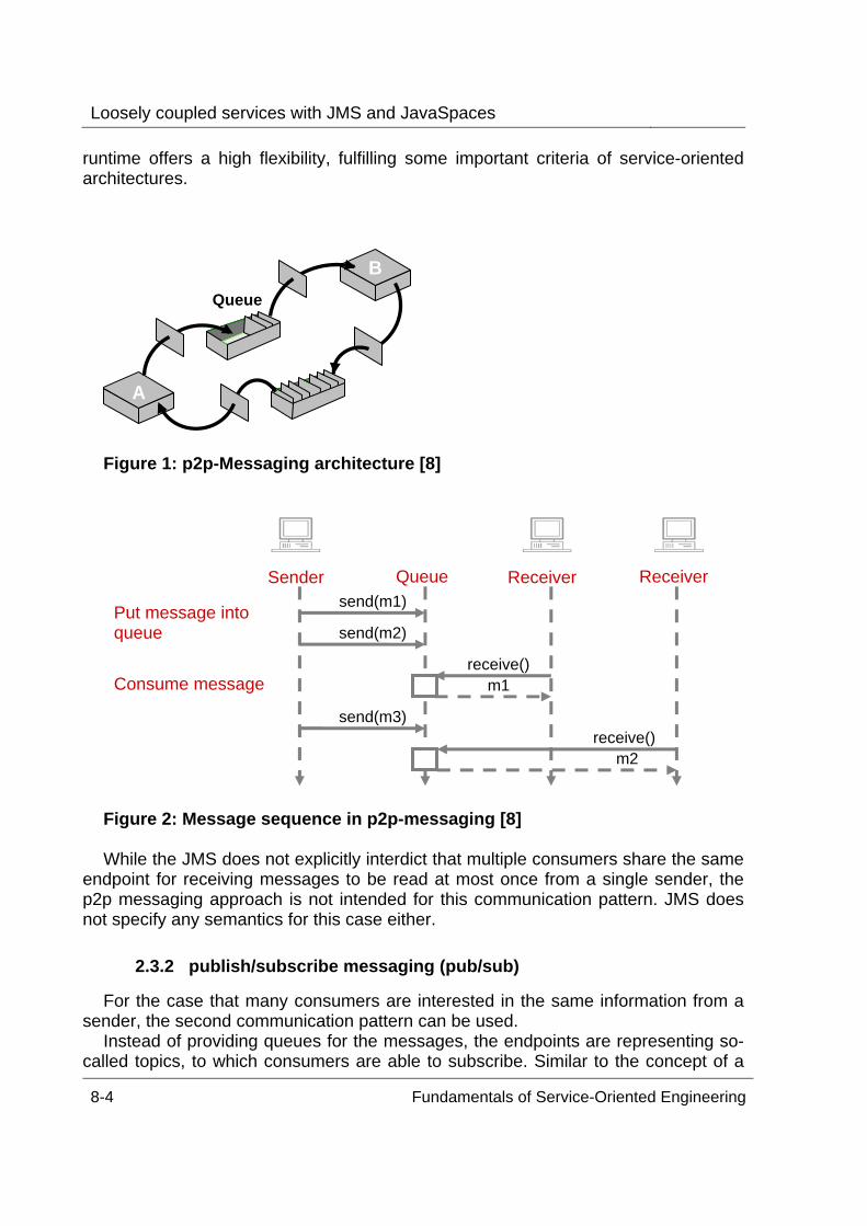
Loosely coupled services with JMS and JavaSpaces
8-4 Fundamentals of Service-Oriented Engineering
runtime offers a high flexibility, fulfilling some important criteria of service-oriented architectures.
Figure 1: p2p-Messaging architecture [8]
Figure 2: Message sequence in p2p-messaging [8] While the JMS does not explicitly interdict that multiple consumers share the same
endpoint for receiving messages to be read at most once from a single sender, the p2p messaging approach is not intended for this communication pattern. JMS does not specify any semantics for this case either.
2.3.2 publish/subscribe messaging (pub/sub)
For the case that many consumers are interested in the same information from a sender, the second communication pattern can be used.
Instead of providing queues for the messages, the endpoints are representing so-called topics, to which consumers are able to subscribe. Similar to the concept of a
AA
BBQueue
Sender Queue Receiver send(m1)
send(m3)
send(m2)
receive() m1
m2 receive()
Put message into queue
Consume message
Receiver
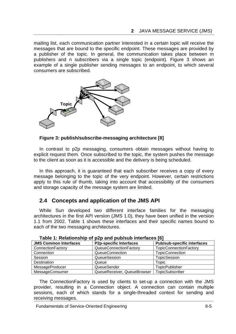
2 JAVA MESSAGE SERVICE (JMS)
Fundamentals of Service-Oriented Engineering 8-5
mailing list, each communication partner interested in a certain topic will receive the messages that are bound to the specific endpoint. These messages are provided by a publisher of the topic. In general, the communication takes place between m publishers and n subscribers via a single topic (endpoint). Figure 3 shows an example of a single publisher sending messages to an endpoint, to which several consumers are subscribed.
Figure 3: publish/subscribe-messaging architecture [8] In contrast to p2p messaging, consumers obtain messages without having to
explicit request them. Once subscribed to the topic, the system pushes the message to the client as soon as it is accessible and the delivery is being scheduled.
In this approach, it is guaranteed that each subscriber receives a copy of every
message belonging to the topic of the very endpoint. However, certain restrictions apply to this rule of thumb, taking into account that accessibility of the consumers and storage capacity of the message system are limited.
2.4 Concepts and application of the JMS API While Sun developed two different interface families for the messaging
architectures in the first API version (JMS 1.0), they have been unified in the version 1.1 from 2002. Table 1 shows these interfaces and their specific names bound to each of the two messaging architectures.
Table 1: Relationship of p2p and pub/sub interfaces [6]
JMS Common Interfaces P2p-specific Interfaces Pub/sub-specific interfaces ConnectionFactory QueueConnectionFactory TopicConnectionFactory Connection QueueConnection TopicConnection Session QueueSession TopicSession Destination Queue Topic MessageProducer QueueSender TopicPublisher MessageConsumer QueueReceiver, QueueBrowser TopicSubscriber
The ConnectionFactory is used by clients to set-up a connection with the JMS provider, resulting in a Connection object. A connection can contain multiple sessions, each of which stands for a single-threaded context for sending and receiving messages.
SS
Topic SS
SS
SSSS
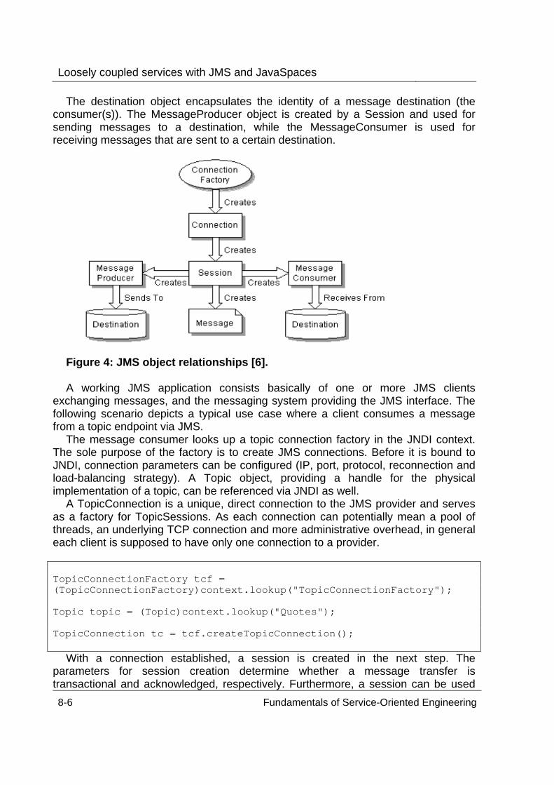
Loosely coupled services with JMS and JavaSpaces
8-6 Fundamentals of Service-Oriented Engineering
The destination object encapsulates the identity of a message destination (the consumer(s)). The MessageProducer object is created by a Session and used for sending messages to a destination, while the MessageConsumer is used for receiving messages that are sent to a certain destination.
Figure 4: JMS object relationships [6]. A working JMS application consists basically of one or more JMS clients
exchanging messages, and the messaging system providing the JMS interface. The following scenario depicts a typical use case where a client consumes a message from a topic endpoint via JMS.
The message consumer looks up a topic connection factory in the JNDI context. The sole purpose of the factory is to create JMS connections. Before it is bound to JNDI, connection parameters can be configured (IP, port, protocol, reconnection and load-balancing strategy). A Topic object, providing a handle for the physical implementation of a topic, can be referenced via JNDI as well.
A TopicConnection is a unique, direct connection to the JMS provider and serves as a factory for TopicSessions. As each connection can potentially mean a pool of threads, an underlying TCP connection and more administrative overhead, in general each client is supposed to have only one connection to a provider.
TopicConnectionFactory tcf = (TopicConnectionFactory)context.lookup("TopicConnectionFactory"); Topic topic = (Topic)context.lookup("Quotes");
TopicConnection tc = tcf.createTopicConnection();
With a connection established, a session is created in the next step. The parameters for session creation determine whether a message transfer is transactional and acknowledged, respectively. Furthermore, a session can be used
3 JAVA MESSAGE SERVICE (JMS)
Fundamentals of Service-Oriented Engineering 8-7
as a factory for messages, topic subscribers and topic publishers. Sessions are not thread-safe.
TopicSession ts = tc.createTopicSession(false,Session.AUTO_ACKNOWLEDGE); Once the session object is created, it is possible to create its TopicPublisher object
and start the session. Messages can then be sent to the topic with the publish-method. TopicPublisher tp = ts.createPublisher(topic); tc.start(); String quoteStr = "HPIStocks, 23.31"; TextMessage quote = ts.createTextMessage(quoteStr); tp.publish(quote); On the other side of the communication, the subscriber object is created and can
be used in two different forms. With the explicit call of the receive-method, messages are fetched synchronously. As an alternative, the listener concept can be utilized in order to inform subscribers automatically when a new message arrives for a certain topic. A MessageListener object is used for events of this type, while objects of type ErrorListener are used to handle exceptions that might occur (typically security exception or transport failure).
TopicSubscriber tSub = ts.createSubscriber(topic); //synchronous message fetch Message msg = tSub.receive(); String message = ((TextMessage)msg).getText(); //asynchronous message fetch tSub.setMessageListener(new MyMessageListener()); tc.setExceptionListener(new ErrorListener());
Loosely coupled services with JMS and JavaSpaces
8-8 Fundamentals of Service-Oriented Engineering
3 JavaSpaces In distributed computing, one approach for a client-server system is based on the
use of a virtual compute server implemented on a number of co-operating workstations or PCs. Hereby, clients send requests (jobs) to the virtual compute server, where one or more of its processors complete the job. Since the computational power of the server derives from an aggregation of machines, it is possible to scale the system by changing the number of machines without affecting ongoing activities. In theory, the server can be expanded on the fly to meet peaks in demand by adding machines temporarily. Due to the distribution of processing power, the system can be up and running full time, with hardware maintenance and updates handled incrementally, a few machines at a time.
The overall idea of such a system is to perform a number of jobs simultaneously in a reliable and flexible way at locations that may be physically dispersed. In the context of service-oriented computing, this approach is particularly interesting when processes need to be distributed due to high demands on processing power.
3.1 Virtual shared memory and the space concept A virtual shared memory is a shared object repository that can be used to store
data, which is shared among the components of a distributed program. It is virtual in the sense that no physically-shared memory is required to create it. Its potentials in load balancing, high performance and fault tolerance are seen as the key advantages of such a system [12].
Tuple spaces are one way to implement virtual shared memory. A tuple is a simple vector of typed values (field). Each field may have one of the three basic forms: a constant, an expression that evaluates to a constant or a formal parameter. The tuple space provides a repository of tuples that can be accessed concurrently. Producers post their data as tuples in the space, and the consumers then retrieve data from the space through a certain pattern matching approach. Thus, the tuple space realizes a logical associative memory.
The tuple space concept originates from the Linda parallel programming language, developed by David Gelernter and Nicholas Carriero at Yale University [13]. Linda is implemented as an extension of other (sequential) languages [14]. It consists fundamentally of four operations through which the tuples can be added, retrieved or destructively retrieved from the tuple space.
With the concept of virtual shared memory in form of tuple spaces, it becomes possible to communicate asynchronously and anonymously in a distributed and persistent way.
3.2 What are JavaSpaces? The JavaSpaces technology is an implementation of the tuple space concept in
the Java programming language based on the JINI architecture. It can therefore be
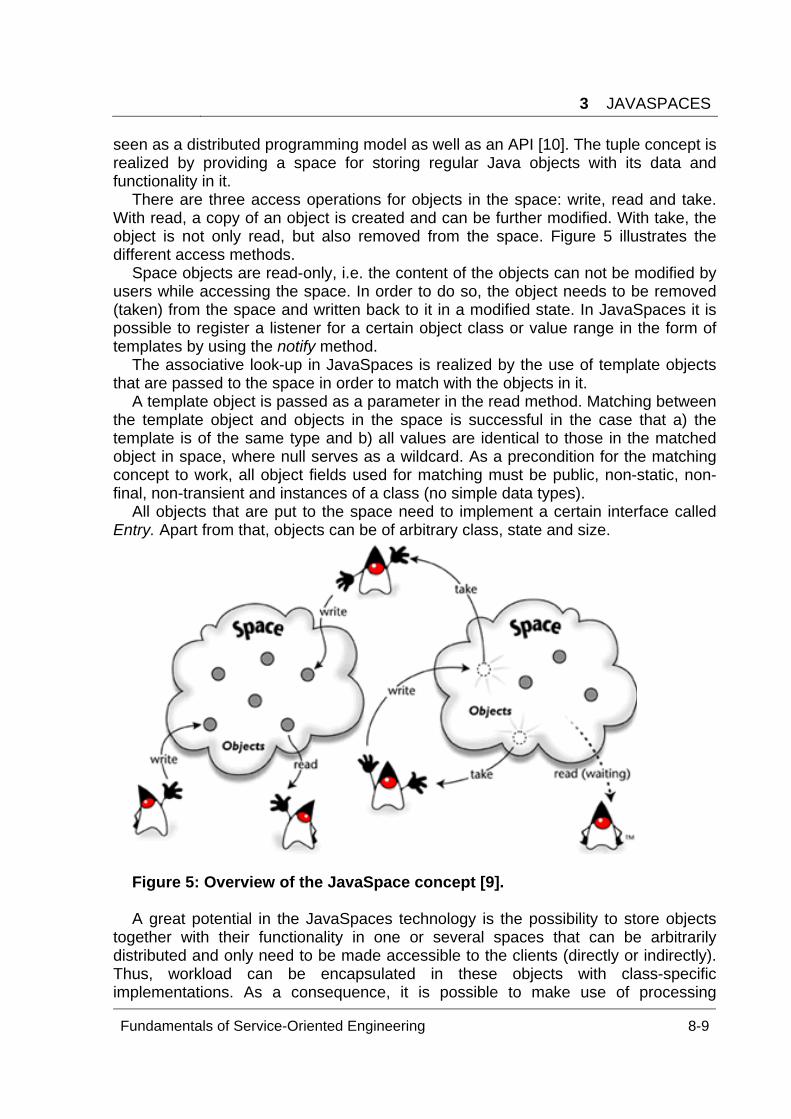
3 JAVASPACES
Fundamentals of Service-Oriented Engineering 8-9
seen as a distributed programming model as well as an API [10]. The tuple concept is realized by providing a space for storing regular Java objects with its data and functionality in it.
There are three access operations for objects in the space: write, read and take. With read, a copy of an object is created and can be further modified. With take, the object is not only read, but also removed from the space. Figure 5 illustrates the different access methods.
Space objects are read-only, i.e. the content of the objects can not be modified by users while accessing the space. In order to do so, the object needs to be removed (taken) from the space and written back to it in a modified state. In JavaSpaces it is possible to register a listener for a certain object class or value range in the form of templates by using the notify method.
The associative look-up in JavaSpaces is realized by the use of template objects that are passed to the space in order to match with the objects in it.
A template object is passed as a parameter in the read method. Matching between the template object and objects in the space is successful in the case that a) the template is of the same type and b) all values are identical to those in the matched object in space, where null serves as a wildcard. As a precondition for the matching concept to work, all object fields used for matching must be public, non-static, non-final, non-transient and instances of a class (no simple data types).
All objects that are put to the space need to implement a certain interface called Entry. Apart from that, objects can be of arbitrary class, state and size.
Figure 5: Overview of the JavaSpace concept [9]. A great potential in the JavaSpaces technology is the possibility to store objects
together with their functionality in one or several spaces that can be arbitrarily distributed and only need to be made accessible to the clients (directly or indirectly). Thus, workload can be encapsulated in these objects with class-specific implementations. As a consequence, it is possible to make use of processing
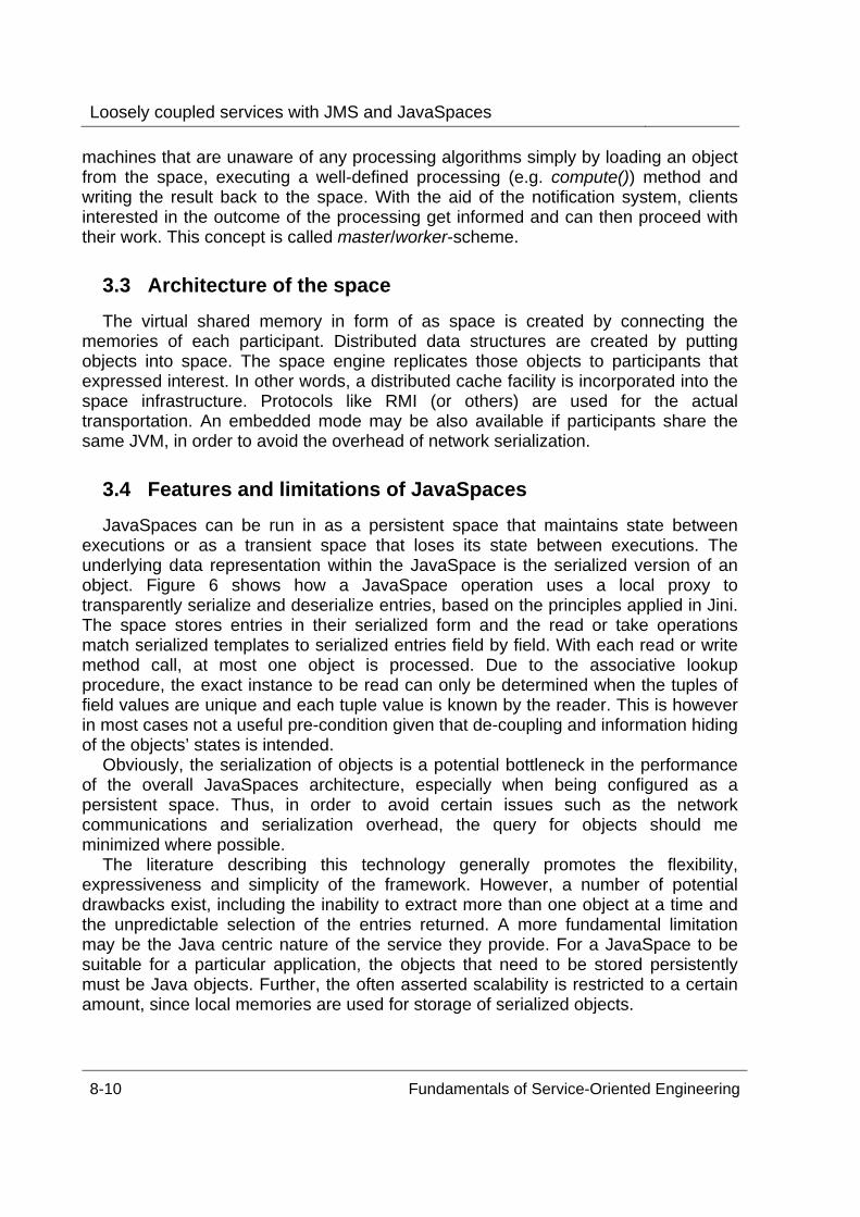
Loosely coupled services with JMS and JavaSpaces
8-10 Fundamentals of Service-Oriented Engineering
machines that are unaware of any processing algorithms simply by loading an object from the space, executing a well-defined processing (e.g. compute()) method and writing the result back to the space. With the aid of the notification system, clients interested in the outcome of the processing get informed and can then proceed with their work. This concept is called master/worker-scheme.
3.3 Architecture of the space The virtual shared memory in form of as space is created by connecting the
memories of each participant. Distributed data structures are created by putting objects into space. The space engine replicates those objects to participants that expressed interest. In other words, a distributed cache facility is incorporated into the space infrastructure. Protocols like RMI (or others) are used for the actual transportation. An embedded mode may be also available if participants share the same JVM, in order to avoid the overhead of network serialization.
3.4 Features and limitations of JavaSpaces JavaSpaces can be run in as a persistent space that maintains state between
executions or as a transient space that loses its state between executions. The underlying data representation within the JavaSpace is the serialized version of an object. Figure 6 shows how a JavaSpace operation uses a local proxy to transparently serialize and deserialize entries, based on the principles applied in Jini. The space stores entries in their serialized form and the read or take operations match serialized templates to serialized entries field by field. With each read or write method call, at most one object is processed. Due to the associative lookup procedure, the exact instance to be read can only be determined when the tuples of field values are unique and each tuple value is known by the reader. This is however in most cases not a useful pre-condition given that de-coupling and information hiding of the objects’ states is intended.
Obviously, the serialization of objects is a potential bottleneck in the performance of the overall JavaSpaces architecture, especially when being configured as a persistent space. Thus, in order to avoid certain issues such as the network communications and serialization overhead, the query for objects should me minimized where possible.
The literature describing this technology generally promotes the flexibility, expressiveness and simplicity of the framework. However, a number of potential drawbacks exist, including the inability to extract more than one object at a time and the unpredictable selection of the entries returned. A more fundamental limitation may be the Java centric nature of the service they provide. For a JavaSpace to be suitable for a particular application, the objects that need to be stored persistently must be Java objects. Further, the often asserted scalability is restricted to a certain amount, since local memories are used for storage of serialized objects.
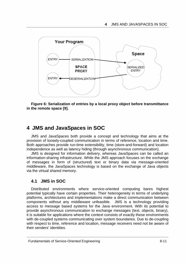
4 JMS AND JAVASPACES IN SOC
Fundamentals of Service-Oriented Engineering 8-11
Figure 6: Serialization of entries by a local proxy object before transmittance
in the remote space [9].
4 JMS and JavaSpaces in SOC JMS and JavaSpaces both provide a concept and technology that aims at the
provision of loosely-coupled communication in terms of reference, location and time. Both approaches provide run-time extensibility, time (store-and-forward) and location independence as well as latency hiding (through asynchronous communication).
JMS is designed for information delivery, whereas JavaSpaces can be called an information-sharing infrastructure. While the JMS approach focuses on the exchange of messages in form of (structured) text or binary data via message-oriented middleware, the JavaSpaces technology is based on the exchange of Java objects via the virtual shared memory.
4.1 JMS in SOC Distributed environments where service-oriented computing bares highest
potential typically have certain properties. Their heterogeneity in terms of underlying platforms, architectures and implementations make a direct communication between components without any middleware unfeasible. JMS is a technology providing access to message based systems for the Java environment. With its potential to provide asynchronous communication to exchange messages (text, objects, binary), it is suitable for applications where the context consists of exactly these environments with de-coupled systems communicating over system boundaries. Due to de-coupling with respect to time, reference and location, message receivers need not be aware of their senders’ identities.
Loosely coupled services with JMS and JavaSpaces
8-12 Fundamentals of Service-Oriented Engineering
In contrast to standard service-oriented architectures, JMS as a MOM does not by definition connect services to each other, but rather couples distributed messaging clients. However, in the context of service-oriented architectures, the JMS messages are suitable to convey service calls between multiple components. The P2P approach hereby provides the base mechanism of delivering a message from the caller over the queue to a certain callee. The messaging clients can hereby take the role of the client and service, respectively. The queue contains all messages/service calls that are related to a certain service instance.
With the aid of the publish/subscribe mechanism, the issue of long service delay due to queuing might be overcome by bringing in certain redundancy. It is imaginable that multiple service instances of this very class exist at the server side and register with a certain JMS message (service) type in order to share the workload of service requests on a “first available, first served” basis. The first service instance finishing the received task can be configured to send the result back to the JMS server, which forwards it to the initial service caller. Since a service caller is generally interested in making use of a service class rather than in an actual instance of that class, this approach would be transparent to the service consumer. However, this architecture is not at all efficient and only makes sense when the cost of redundancy is weighed up with the advantage of fast service execution in high workload situations.
4.1.1 Feasibility of JMS
JMS is an especially feasible approach for service-oriented computing when certain characteristics apply to the communication infrastructure.
In the case that no immediate response is required or expected from the underlying service, which might be the case for computing-intense processes or high workload and potential congestion situations at the service input, JMS offers a reliable mechanism for storing and forwarding the messages. Messages are delivered to the service endpoint when resources become available, allowing for an efficient utilization ratio. In the case of synchronous services, however, the messaging system is not appropriate since the middleware has no direct control over the actual service component in the background (the message receiver or subscriber).
When guaranteed delivery of the service request may be necessary, sending or receiving the message may be part of a transaction and security mechanism, which is partly integrated in the JMS architecture provided by the API. JMS supports the concepts of message acknowledgment, message persistence, message priority, expiration time and temporary destinations in order to support reliability and prioritization.
A typical application domain for the JMS technology in the context of service-
oriented computing can therefore be found in the mobile application context, where message exchange heavily relies on message storage capacities working on a 24/7 basis. Since the availability of communicating devices cannot be guaranteed, asynchronous communication needs to be realized. Hereby, both messaging approaches can be useful. While p2p messaging enables communication between
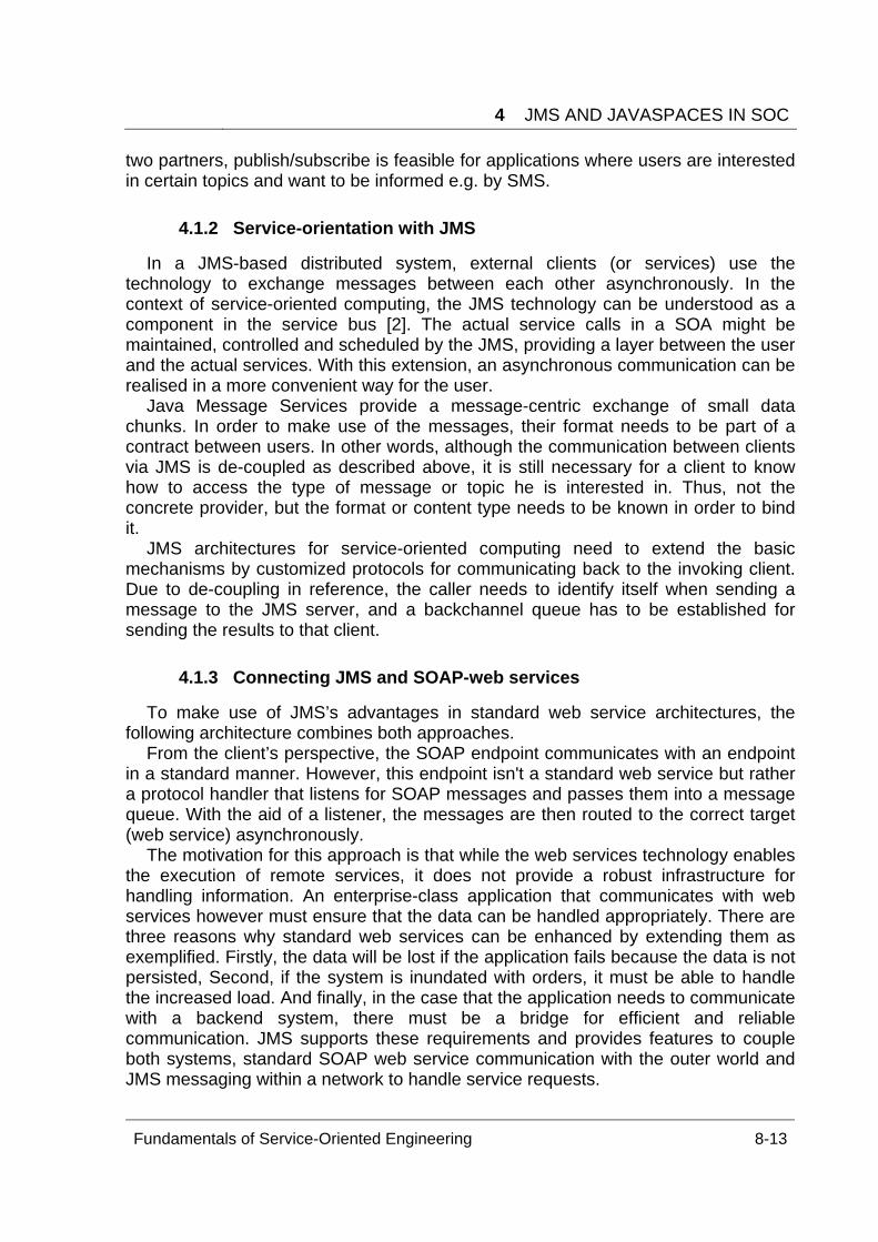
4 JMS AND JAVASPACES IN SOC
Fundamentals of Service-Oriented Engineering 8-13
two partners, publish/subscribe is feasible for applications where users are interested in certain topics and want to be informed e.g. by SMS.
4.1.2 Service-orientation with JMS
In a JMS-based distributed system, external clients (or services) use the technology to exchange messages between each other asynchronously. In the context of service-oriented computing, the JMS technology can be understood as a component in the service bus [2]. The actual service calls in a SOA might be maintained, controlled and scheduled by the JMS, providing a layer between the user and the actual services. With this extension, an asynchronous communication can be realised in a more convenient way for the user.
Java Message Services provide a message-centric exchange of small data chunks. In order to make use of the messages, their format needs to be part of a contract between users. In other words, although the communication between clients via JMS is de-coupled as described above, it is still necessary for a client to know how to access the type of message or topic he is interested in. Thus, not the concrete provider, but the format or content type needs to be known in order to bind it.
JMS architectures for service-oriented computing need to extend the basic mechanisms by customized protocols for communicating back to the invoking client. Due to de-coupling in reference, the caller needs to identify itself when sending a message to the JMS server, and a backchannel queue has to be established for sending the results to that client.
4.1.3 Connecting JMS and SOAP-web services
To make use of JMS’s advantages in standard web service architectures, the following architecture combines both approaches.
From the client’s perspective, the SOAP endpoint communicates with an endpoint in a standard manner. However, this endpoint isn't a standard web service but rather a protocol handler that listens for SOAP messages and passes them into a message queue. With the aid of a listener, the messages are then routed to the correct target (web service) asynchronously.
The motivation for this approach is that while the web services technology enables the execution of remote services, it does not provide a robust infrastructure for handling information. An enterprise-class application that communicates with web services however must ensure that the data can be handled appropriately. There are three reasons why standard web services can be enhanced by extending them as exemplified. Firstly, the data will be lost if the application fails because the data is not persisted, Second, if the system is inundated with orders, it must be able to handle the increased load. And finally, in the case that the application needs to communicate with a backend system, there must be a bridge for efficient and reliable communication. JMS supports these requirements and provides features to couple both systems, standard SOAP web service communication with the outer world and JMS messaging within a network to handle service requests.
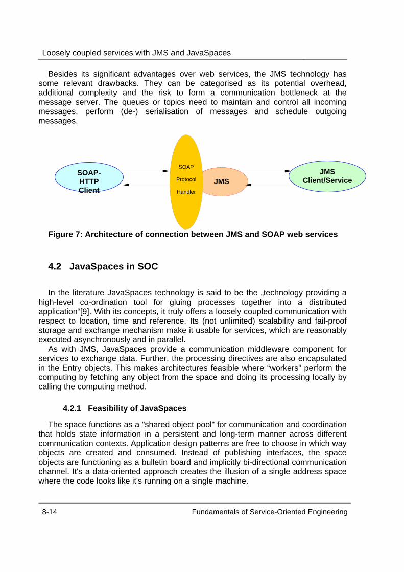
Loosely coupled services with JMS and JavaSpaces
8-14 Fundamentals of Service-Oriented Engineering
Besides its significant advantages over web services, the JMS technology has some relevant drawbacks. They can be categorised as its potential overhead, additional complexity and the risk to form a communication bottleneck at the message server. The queues or topics need to maintain and control all incoming messages, perform (de-) serialisation of messages and schedule outgoing messages.
Figure 7: Architecture of connection between JMS and SOAP web services
4.2 JavaSpaces in SOC In the literature JavaSpaces technology is said to be the „technology providing a
high-level co-ordination tool for gluing processes together into a distributed application“[9]. With its concepts, it truly offers a loosely coupled communication with respect to location, time and reference. Its (not unlimited) scalability and fail-proof storage and exchange mechanism make it usable for services, which are reasonably executed asynchronously and in parallel.
As with JMS, JavaSpaces provide a communication middleware component for services to exchange data. Further, the processing directives are also encapsulated in the Entry objects. This makes architectures feasible where “workers” perform the computing by fetching any object from the space and doing its processing locally by calling the computing method.
4.2.1 Feasibility of JavaSpaces
The space functions as a "shared object pool" for communication and coordination that holds state information in a persistent and long-term manner across different communication contexts. Application design patterns are free to choose in which way objects are created and consumed. Instead of publishing interfaces, the space objects are functioning as a bulletin board and implicitly bi-directional communication channel. It's a data-oriented approach creates the illusion of a single address space where the code looks like it's running on a single machine.
SOAP-HTTP Client
JMS Client/ServiceJMS
SOAP Protocol Handler
5 CONCLUSION AND OUTLOOK
Fundamentals of Service-Oriented Engineering 8-15
Especially its potential in flexible workload-distribution, scalability (up to a certain point) and reliability make it feasible for a range of application classes, where the combination of distributed caching and easy distribution of load is relevant. Typical examples are workflow systems, parallel computing servers, or collaborative systems. In the context of SOA, JavaSpaces provide a valuable component “behind” existing services.
4.2.2 Service-orientation with JavaSpaces
In the JavaSpaces approach, the term service is interpreted in a slightly different
way then it is the case for SOAP web services. The service as an open, self-descriptive component that provides a contract between provider and consumer in SOA does not explicitly exist in this architecture. JavaSpaces comprise object-centric data structures while each object can contain service logic. In fact, since the processing is performed by objects with access to the space, the service itself is distributed over an unknown and not controllable number of systems consuming space objects. When a service is distributed as a data structure written to the space, no service level agreement can be verified.
However, JavaSpaces can be combined with standard web services in the same manner as it was the case for JMS. The web service client hereby uses the well-known SOAP interface to call a gateway which distributes the service execution in a space. The difference hereby is that with JavaSpaces the main purpose is to distribute workload, not to call third-party systems (like JMS clients).
5 Conclusion and Outlook JMS and JavaSpaces can provide significant components in a SOA
by supporting loose coupling in the sense of location, time and reference. Especially when asynchronous communication between client and server is necessary, these concepts show their potential. Integration into standard web services can be realised by providing additional components in the architecture, which pass SOAP calls to an internal message server or space. But both concepts can also be integrated into a SOA without making use of web services.
The major limitations of both approaches are technical. They are restricted to the Java context and form certain bottlenecks in terms of memory and processing.
Both technologies provide an Java API for concepts that are significantly older.
JMS 1.0.2b originates from 2001, the actual version 1.1 has been released in March 2002. The idea of message servers is however somewhat older. The concept of tuple spaces has been developed in 1982, while JavaSpaces has been released in 1998.
There has been a tremendous hype about these two technologies. JavaSpaces were claimed to be „[...] a full generation ahead of anything else on the market“ and that „the power of such systems would bring multicomputing to the masses.“[11]
Today, only few new articles or books are published about these two technologies. In the case of JavaSpaces, their application area seems to be restricted to scientific Grid-Computing while JMS is mainly used as SOAP transport mechanism.
Loosely coupled services with JMS and JavaSpaces
8-16 Fundamentals of Service-Oriented Engineering
Although both technologies do not yet play the role that have been predicted, the
concepts behind both technologies bare high potential for a real loosely-coupled service-oriented computing environment. When certain issues in the architecture are addressed by applying additional mechanisms (e.g. components to administer and control JMS servers or the space workload), powerful SOAs can be set-up in the Java environment quite easily.
References [1] S. Wilkes: SOA - Much More Than Web Services.
http://dev2dev.bea.com/pub/a/2004/05/soa_wilkes.html. [2] D. Krafzig, K. Banke and D. Slama. Enterprise SOA: service-Oriented
Architecture Best Practices. Prentice Hall, 2004. [3] Wikipedia: Loosely Coupled, http://en.wikipedia.org/wiki/Loosely_Coupled. [4] B. Angerer and A. Erlacher: Loosely Coupled Communication and Coordination in
Next- Generation Java Middleware, today.java.net/pub/a/today/2005/06/03/loose.html, 2005.
[5] J. Hanson: Take Advantage of the benefits of loosely coupled Web Services, builder.com.com/5100-6386-1050425.html, 2002.
[6] Java Message Service Specification: http://java.sun.com/products/jms/. [7] G. van Huizen. JMS: An Infrastructure for XML-based Business-to-Business.
Communication. http://www.javaworld.com/javaworld/jw-02-2000/jw-02-jmsxml.html, 2000.
[8] S. Maffeis. Introduction to the Java Message Service (JMS) Standard, http://www.ch-open.ch/html/ws/ws01/11_jms.html#Download.
[9] E. Freeman, S. Hupfer and K. Arnold: JavaSpaces Principles, Patterns, and Practice. Addison-Wesley, 1999.
[10] JavaSpaces, http://www.javaspaces.homestead.com/files/javaspaces.html. [11] R. Shah: The skinny on Jini, http://www.javaworld.com/jw-08-1998/jw-08-jini.html. [12] Scientific Computing. Virtual Shared Memory and the Paradise System for
Distributed Computing. Technical white paper, 1999. [13] D. Gelernter: An Integrated Microcomputer Network for Experiments in
Distributed Programming. PhD thesis, State University of New, 1982. [14] Wikipedia: Linda, http://en.wikipedia.org/wiki/Linda.
Fundamentals of Fundamentals of Service-Oriented Engineering 9-1
Serialization / Deserialization In the context of SOAP and Web Services
Paul Bouché
This paper deals with the problems of automatic serialization and deserialization in
the context of Web Services and the JAX-RPC specifications. First the general different approaches of message and RPC orientation are presented. Secondly an analysis of both versions of JAX-RPC is conducted. Thirdly possible solution approaches are presented and evaluated in the conclusion. A general comparison of message orientation and RPC orientation is carried out in the conclusion. Depending on the requirements for a service either one needs to be taken. We suggest a varying degree of abstraction from XML suiting the needs of the service implementation. The conclusion is completed with a short summary of this paper’s findings and possible future work.
Keywords: WEB SERVICES, JAVA, JAX-RPC 1.1, JAX-RPC 2.0, JAX-WS, SOAP, WSDL, AXIS
1 Introduction One of the motivations and design goals for SOAP [11, 12, 13] was to allow
interoperable business-2-business integration in a cost effective and standard way. SOAP nodes communicate via HTTP and send XML documents. Web Service implementers use programming language specific data like objects and classes. Hence the SOAP stack has to provide a mapping from objects to XML and vice-versa. In this paper we refer to this mapping, the implementing process respectively as serialization (from objects to XML) and deserialization (from XML to objects). De-/Serialization is also known as Un-/Marshalling.
We observe naming the mappings this way indicates an object centric viewpoint. One could have also named the mapping from XML to objects as serialization. We further observe that serialization / deserialization is not necessarily a problem of every service oriented architecture (SOA) but only of the Web Services world.
The problems that exist with the mapping of objects to XML and vice-versa are the focus of this paper. We will first introduce the general notions of RPC orientation and message orientation in this context in section 2. In section 3 we will conduct an analysis of the current specifications for Java in the context of Web Services with a main focus on the Java API for XML-based RPC (JAX-RPC) 1.1 [5]. Section 3 has four parts. In part one an overview of the related specification is given. In part two an analysis of JAX-RPC is carried out including positive and negative aspects of JAX-RPC. In part three possible solution approaches are presented and in part four the progress that JAX-RPC 2.0 has made in resolving the found issues is investigated.
Serialization / Deserialization
9-2 Fundamentals of Service-Oriented Engineering
We conclude this paper in section 4 with comparing the two general approaches introduced in section 2 and summarizing and evaluating our findings.
2 Preliminaries In the context of web services and serialization / deserialization one can take two
different approaches: a message oriented one and a remote procedure call (RPC) oriented one.
RPC orientation. RPC orientation in this context means that the main focus lies in executing RPCs. The transport medium, the transport format and transport errors are abstracted from. XML in this context is the transport format. Objects need to be transported, so the underlying XML representation of these objects is viewed as almost irrelevant and should be transparent, i.e. objects should be transported from A to B, have the same state at B which they had at A and the XML representation will appear neither to A nor to B. Along with that also SOAP and HTTP are just means and should be transparent to the application. If there are errors in the underlying transport / network structure these should be automatically covered and the RPC application should be oblivious to these. RPCs can be carried out asynchronously and synchronously.
Due to the fact that all XML, SOAP, SOAP stack related set-up and WSDL [14] should be transparent a high automation is needed. Services are developed just as if executing normal RPCs and after that all Web Service related set-up is automatically covered, i.e. the XML schema [25] for representing objects, WSDL descriptions and serializers and deserializers are generated automatically from the service implementation. Along with these, configuration information for the SOAP stack is also automatically generated.
RPC as a concept has been criticized as a bad concept [1, 2, 3] because the things that are abstracted from should not be abstracted from in this manner. It supplies to the developer an ideal world that does not exist. Transportation and network errors that are likely to occur in Internet architecture should not be automatically handled, but be propagated to the application. Especially synchronous RPC suffers from the complete abstraction very much in the case of network lag or data loss: due to its the blocking nature, it will lead to very long execution times.
Message orientation. Message orientation in context of Web Services means that
the focus lies in sending and receiving messages. Message formats and transport medium are important. The interpretation of the message or the results of the message reception are not important. The basic operation here is the sending of a message and forgetting about it (“fire and forget” principle). In this context an RPC is just an interpretation of a SOAP message, i.e. that the contained XML document of a message triggers a method call at the receiving end is just a pre-agreed interpretation and the contained XML document could be interpreted completely different. With message orientation in the context of Web Services an XML centric approach is taken. Hence, the first question is what are the XML data types, XML schema respectively and of secondary nature is the question of how this XML data can be accessed programmatically.
3 JAVA WEB SERVICE TECHNOLOGY
Fundamentals of Service-Oriented Engineering 9-3
We will investigate what implications each of these approaches have and will evaluate both at the end of this paper.
3 Java Web Service Technology In this section we will give an overview of the current state of the Java Web
Service world, i.e. the specifications and technologies in conjunction with Web Services. Afterwards, we will analyze the main specification in this context, the Java API for XML-Based RPC Version 1.1, from a XML viewpoint and from a Java viewpoint. Finally, we will try to show possible solutions for the problems encountered in the analysis.
3.1 The Java Web Services World In conjunction with realizing Web Services in Java several specifications have
been published: • Java API for XML-Based RPC (JAX-RPC) 1.1 [5], • Java API for XML Web Services (JAX-WS) 2.0 [6] • Java Architecture for XML Binding (JAXB) 1.0 [7], • Java Architecture for XML Binding (JAXB) 2.0 [10], • Java API for XML Messaging (JAX-M) 1.1 [8] and • Java API for XML Processing (JAX-P) 1.3 [9].
Both Versions of JAX-RPC specify how to create and execute RPCs using the SOAP protocol along with WSDL. In version 1.1 the mapping of java types to XML types and vice versa and all other serialization and deserialization related things are specified. Version 2.0 refers to JAX-B 2.0 for this. JAX-RPC 2.0 extends version 1.1 in the following areas: support for SOAP 1.2, WSDL 2.0, WS-I Basic Profile 1.1 [16] and better support for document/message1 centric usage. JAX-RPC is obviously RPC oriented.
JAXB specifies a complete serialization and deserialization framework to/from XML. More specifically it defines a mapping of Java classes to XML schema and vice versa. We observe based on the fact that both versions of JAXB try to hide all XML related things (for example SAX, DOM or any other XML parsing) and provide the developer with just Java classes to work with it is RPC oriented.
The JAX-M specification defines an API for sending and receiving XML messages (XML documents) based on the SOAP 1.1 with attachments specification. XML documents are represented syntactically differing from JAXB where they are represented semantically. It provides a Document Object Model (DOM) like interface.
JAX-P is not Web Service focused but focused on XML in general. It is included here because SOAP documents are XML documents and hence can be processed using this API. This API provides an abstraction layer from concrete underlying technology implementations such as SAX, DOM, XSLT etc. It has become a standard
1 Document/literal refers to a scheme (x/y) which indicates the style of Web Service usage where the first part
indicates the encoding of the data either document (doc) or RPC (rpc) and the second the usage of the data either encoded (enc) or literal (lit). For more information please refer to [18].
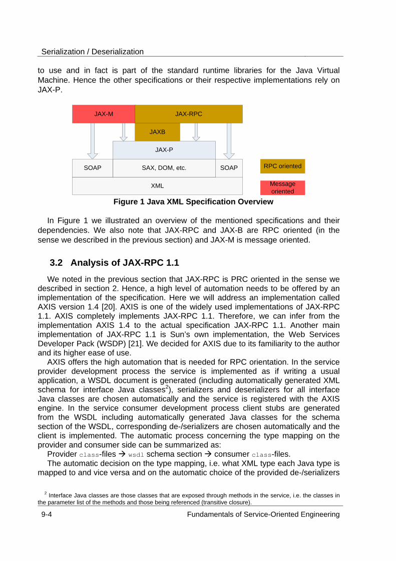
Serialization / Deserialization
9-4 Fundamentals of Service-Oriented Engineering
to use and in fact is part of the standard runtime libraries for the Java Virtual Machine. Hence the other specifications or their respective implementations rely on JAX-P.
JAX-RPCJAX-M
JAXB
JAX-P
SOAP
XML
SAX, DOM, etc.SOAP
Message oriented
RPC oriented
Figure 1 Java XML Specification Overview
In Figure 1 we illustrated an overview of the mentioned specifications and their
dependencies. We also note that JAX-RPC and JAX-B are RPC oriented (in the sense we described in the previous section) and JAX-M is message oriented.
3.2 Analysis of JAX-RPC 1.1 We noted in the previous section that JAX-RPC is PRC oriented in the sense we
described in section 2. Hence, a high level of automation needs to be offered by an implementation of the specification. Here we will address an implementation called AXIS version 1.4 [20]. AXIS is one of the widely used implementations of JAX-RPC 1.1. AXIS completely implements JAX-RPC 1.1. Therefore, we can infer from the implementation AXIS 1.4 to the actual specification JAX-RPC 1.1. Another main implementation of JAX-RPC 1.1 is Sun’s own implementation, the Web Services Developer Pack (WSDP) [21]. We decided for AXIS due to its familiarity to the author and its higher ease of use.
AXIS offers the high automation that is needed for RPC orientation. In the service provider development process the service is implemented as if writing a usual application, a WSDL document is generated (including automatically generated XML schema for interface Java classes2), serializers and deserializers for all interface Java classes are chosen automatically and the service is registered with the AXIS engine. In the service consumer development process client stubs are generated from the WSDL including automatically generated Java classes for the schema section of the WSDL, corresponding de-/serializers are chosen automatically and the client is implemented. The automatic process concerning the type mapping on the provider and consumer side can be summarized as:
Provider class-files wsdl schema section consumer class-files. The automatic decision on the type mapping, i.e. what XML type each Java type is
mapped to and vice versa and on the automatic choice of the provided de-/serializers
2 Interface Java classes are those classes that are exposed through methods in the service, i.e. the classes in
the parameter list of the methods and those being referenced (transitive closure).
3 JAVA WEB SERVICE TECHNOLOGY
Fundamentals of Service-Oriented Engineering 9-5
has implications that we will look at in this section. This “automatic” decision is derived from the type mapping specified in JAX-RPC 1.1 and is done exactly according to the specification where applicable. First, we will present the positive aspects of JAX-RPC, i.e. everything that is functioning well with JAX-RPC. Second, we will present the negative aspects of JAX-RPC, i.e. problems that arise with this fully automated de-/serialization system and aspects that were not covered by JAX-RPC. This will also include some interoperability aspects.
3.2.1 Positive Aspects of JAX-RPC 1.1
To construct a fully automated de-/serialization system that covers all possible Java class hierarchies and all possible XML type hierarchies is a non-trivial, very hard task. As stated in [1] this problem can be called the O/X-mapping problem. It seems to be has hard as solving the O/R-mapping problem from the domain of relational databases. Completely solving O/R-mapping problem with only very few uncovered scenarios has taken many years of brain and engineering work. Because the O/X-mapping problem seems to be so hard it is worth mentioning the progress that has been made towards solving it on the one hand and on the other how much of the actual real life scenarios are covered by this progress.
We will look at what Java types can be successfully processed using a JAX-RPC implementation, in our case AXIS 1.4. When we refer to “successfully processing a type” we mean that if this types is an interface Java type (for a definition see footnote 2) there occur no problems, i.e. instances of this type are sent without information loss, the state of the instance at the receiver is the same as at the sender and all serialization and deserialization works without problems.
The basic components of Java classes are primitive types, namely byte, short, int, long, float, double, boolean, char and java.lang.String where java.lang.String is an object type already but is counted as a basic building block for more complex types. The basic Java types are successfully processed. Thus the corresponding XML types are also processed successfully.
Basic Java types can be combined into more complex types using arrays of such types and creating classes that have fields of these types. Arrays of primitive types are processed successfully. Nested arrays of primitive types (a.k.a. multi dimensional arrays) are also processed successfully. The nesting depth is limited only by the stack size due to the recursive calls done during the automatic type mapping phase. Arrays of JavaBeans [22] can be processed successfully as well.
Classes that correspond to the JavaBean [22] specification at least for the purpose as a data container, i.e. fields with corresponding getter/setter-methods and a public parameterless constructor exists, can be processed successfully. The field’s type can be a basic Java type, a JavaBean class, an array of a basic type or an array of a JavaBean. Here an arbitrary nesting depth of a JavaBean referencing another Java Bean is possible only limited by the stack size. We tested the nesting depth with AXIS 1.4 on a system with Windows XP SP 1, 512 MB RAM, JDK 1.5.3, JVM HotSpot (build 1.5.0_03-b07, mixed mode, sharing) and Tomcat 4.1. The result was a maximum nesting depth of 200 that should be sufficient for most real life scenarios.
Therefore rather complex Java classes can be processed successfully. The
Serialization / Deserialization
9-6 Fundamentals of Service-Oriented Engineering
complexity that is covered should also cover most real life scenarios. This is a very promising and positive fact about JAX-RPC 1.1. The coverage of arbitrary JavaBeans is also an extension by AXIS 1.4 and is not covered by JAX-RPC per se. Yet there are Java types for which it is desirable to be successfully processed, but which are not. There are also XML types and other XML related problems that arise with JAX-RPC 1.1. We will address both of these issues in the next section.
3.2.2 Negative aspects of JAX-RPC 1.1
This section deals with the problems that arise with JAX-RPC 1.1. There are two approaches taken, first from a Java point of view, and second from an XML point of view.
Problems from a Java Point of View. There exist Java types for which the
specification does not define a standard mapping to XML but which are used frequently in real life scenarios. When these types occur as interface types, i.e. as part of the parameter list for a given method or referenced by it, a mapping cannot be performed automatically. These types include java.util.HashMap, java.util.ArrayList and classes that implement the java.util.Collection interface. For the java.util types JAX-RPC does not define a standard mapping and they do not follow the JavaBean scheme so AXIS 1.4 cannot send them automatically in a standardized way. Yet there exist de-/serializers for these types, but especially java.util.HashMap has proven to be a very uninteroperable type. The type mapping applied by AXIS 1.4 to the mentioned types produces most of the time uninteroperable XML schema either because when serializing actual instances they do not conform to the previous generated schema themselves (namespace problems) or because the schema will contain references to xsd:anyType which poses problems. The problem with processing xsd:anyType is that any XML can be sent including types that are not part of the type section of the WSDL document (a small help may be xsi:type attributes). The type xsd:anyType in the generated schema is of course due to the fact that these types contain java.lang.Object in the parameter lists of their methods. This can be helped using generics, yet those were to part of the Java Language Specification at the time when JAX-RPC 1.1 was created.
If processing a java.util.Calendar, the sender being in a different time zone than the receiver and the receiver being for example a .NET service then hours are added or subtracted unexpectedly and the result is undefined behavior. The reason may be that the mapping for java.util.Calendar is xsd:dateTime and if the time zone information for xsd:dateTime is omitted then according to ISO 8601 the time zone is considered undetermined [23].
Array encoding though it works now has been a problematic issue in the past because according to the SOAP specification there are several valid ways to encode arrays. Yet with the creation of the WS-I Basic Profile this issue is settled because it now defines only one interoperable way to encode arrays and all other ways are defined as uninteroperable. Though the question remains why it was not possible to
3 JAVA WEB SERVICE TECHNOLOGY
Fundamentals of Service-Oriented Engineering 9-7
have an interoperable array encoding from the beginning since interoperability was one of the main goals for the SOAP specification.
A reference to one object usually incorporates a whole graph of objects referencing each other. If there are cycles in the object graph, the serialization of it fails because in the currently accepted doc/lit Web Service style the cycles cannot be resolved (trying to serialize a cyclic object graph will result in a StackOverFlowError). This was only possible with rpc/enc (which is seen as deprecated in the Web Service community). If there are cross-references in the object graph the cross-references are resolved using copying, but at the receiving end the object identity is lost and the object graph is not the same as at the sending end. The copying of objects can also create memory space issues.
If the service provider has Java classes with fields that have initial values attached then these values are not propagated to the service consumer generated classes because XML schema does not support initial values for elements of complex types. Hence the consumer classes are not equivalent to the provider classes. This effect appeared when implementing an echo function on the provider side which simply echoes back the value it receives, yet when the consumer sends instances of these classes with null values for fields where the provider class has initial values the consumer receives a different object then he sent, i.e. the fields that had null values are now initialized with the initial values from the provider side.
Please see section appendix I.1 for examples on the mentioned issues. Problems from an XML Point of View. In the case where a JAX-RPC 1.1
implementation has to process a WSDL document that was not automatically generated from service implementation code but manually written there arise problems. XML types may appear that the automatic generation of XML schema for Java classes would never generate. Hence also Java classes will be generated that would not normally be generated and the generated XML schema in turn from those generated Java classes may generate a different XML schema from the original one (ignoring any annotation tags or the alike of course). So the process XML schema A
Java class XML schema A’ may result in unequal XML schema A and A’ (defining a formal equality for XML schema instances is out of the scope of this paper). Many of the mentioned problems in this section have been adopted from [1]. Those XML types (mainly XML Schema defined types) that appear which “normally” wouldn’t pose the problems that we discuss here. They range from specific problems that appear in the detail but cause irritation on higher levels to more general problems that seem to be inherent in the approach that JAX-RPC took with SOAP.
The obvious equivalent of a Java identifier is a name in XML: an element has to have a name, a complex type as has name, etc. The problem is that all possible Java identifiers almost comprise a real subset of the possible XML names. Therefore a lot of XML names may exist that cannot be expressed with Java identifiers. For example a complex type may have a child element named name.public. This name cannot be mapped to a Java identifier directly due to the “.” (dot) and the Java keyword public. According to the JAX-RPC XML name mapping algorithm it will be mapped to namePublic. Another example would be a child element named crazy-name which
Serialization / Deserialization
9-8 Fundamentals of Service-Oriented Engineering
would map to crazyName. Any name that contains Unicode characters that may not be part of Java identifiers poses this problem. In the mapping process characters are added to or omitted from the original name or the their case is changed. This may result in obfuscation and the semantic of the original name may be lost. For more examples see section appendix I.2.1
The type system of XML Schema is much richer than that of Java and there exist schemes or concepts that have no real counterpart in Java. For example in XML Schema new simpleType’s can be defined by restricting existing simpleType’s. This mechanism is commonly used to define enumeration types or limited value ranged types. JAX-RPC does not deal with this mechanism well. An example for such a type would be defining a type of xsd:string that only holds alphanumeric characters. This type is based on xsd:string and would carry the information that valid values conform to the regular expression ([a-z]|[A-Z]|[0-9])* , i.e. only small letters, tall letters and numbers in any combination are valid values. JAX-RPC maps this to a java.lang.String and the restriction information is completely lost. The intuitive approach for this case would have been to extend the java.lang.String in a suitable way, yet java.lang.String cannot be extended because it is declared final. For the full example see section appendix I.2.2 (AlphanumericString).
JAX-RPC maps the values of an enumeration type, for instance values of the grade scale A+, A, A-, B+ etc. to Java identifiers that ideally have the same name as the value of the enumeration. The base type of the enumeration value will be mapped to the corresponding Java type. A Java 1.4 enumeration class will be generated which will have the same name as the enumeration type, static fields whose type are the generated class with identifiers that are the same as the enumeration values and internal static fields which carry the actual enumeration value information. Static initialization connects the right fields with the right values. The example value of A+ cannot be mapped to a Java identifier because of the “+” (plus) sign. The mechanism applied in this case is that all values that cannot be mapped to a Java identifier directly will be mapped to identifiers of the scheme valueX where X is a number from 1 to n. The above example enumeration list is mapped to value1, value2, etc. Thus the actual information about the enumeration value is lost. The fields valueX may carry a completely different semantic if the underlying schema is modified (for example for extension purposes), the enumeration values are reordered and the corresponding code is regenerated. Yet this is not apparent at all and the resulting semantic is unclear. For the full example see section appendix I.2.3 (GradeValue).
Namespace identifiers in XML are Uniform Resource Identifiers (URIs) [24]. Examples for uniform resource identifiers are http://www.example.org/Foo, urn:Foo, mailTo:[email protected]. In a WSDL document the portType (the description of the service in methods and their parameter types) is defined within a certain name space and each XML type is defined within a certain namespace. Namespaces are required to be mapped to unique package names by the JAX-RPC but an exact mapping is not defined. AXIS 1.4 has a mapping algorithm that works well for most cases but the problem is that not all possible URIs are mapped to valid package names. From the example only the first and second URI map well to a package name. The third URI is
3 JAVA WEB SERVICE TECHNOLOGY
Fundamentals of Service-Oriented Engineering 9-9
mapped to the package name .any@address_com, which is not a valid package identifier. Hence the generated source code does not compile. The designers of JAX-RPC seemed to only have URIs in mind which are of the form http://... or urn:. This issue could be helped in overriding the default mapping and mapping all types to one single package, yet this does not work if there exist types with the same name in different namespaces. Another solution could be using annotations as per Java 1.5.
In XML schema some types are defined that can have an arbitrary length or precision. Yet it is well known that on computers there is always a storage limit. If for example the device communicated with is a SOAP aware smart phone or any other mobile device this storage limit may be below the normal expectations in comparison to a standard desktop computer. Additional to the inherent space limitations each programming language has its limitations. If an xsd:string which maps to java.lang.String is received that exceeds the current limitations (either by stack size limit or by max memory size limit etc.) no processing is possible at all and probably no error for the sender will be generated other than a timeout error. This may as well be the case with xsd:decimal.
SOAP Faults are mapped to exceptions by JAX-RPC, yet a soap fault can contain arbitrary instances of XML types that may or may not be part of the type section of the corresponding WSDL document. Even if the types are known at build time the additional information is most of the time lost at runtime.
The concept of data validation that is inherent in XML does not have any counterpart in Java and the JAX-RPC does not provide for it at all. Not any validation process related things are mentioned in the JAX-RPC specification. The developer is left alone with the rather hard and tedious task of implementing validation. This is can be especially tricky as in the example with the AlphanumericString. The behavior that should be exposed when invalid data is received is completely left open to the developer’s determination.
Appendix I.2 contains examples corresponding to this section.
3.3 Solution approaches to the mentioned problems In the previous section we looked areas of JAX-RPC where there are no problems
and where problems are. In this section we want to propose some solution approaches. These approaches are just that: approaches. Some of these may not even be seen as a solution in the narrow sense, but rather as a workaround or avoidance of the problems. Additional to all of the presented solutions should be interoperability testing with at least one other SOAP stack.
3.3.1 Custom Serialization and Deserialization
One approach to the problems of fully automatic serialization and deserialization is to include manual work into the fully automatic process, to adopt the generated classes or to completely avoid all fully automatic de-/serialization altogether. In other words, to customize the de-/serialization process and the applied type mapping, i.e. to adjust the generated classes, to decide yourself on the mapping of XML to Java
Serialization / Deserialization
9-10 Fundamentals of Service-Oriented Engineering
types or vice-versa. This adjustment can include a varying level of automation. Either one works completely manually on the raw XML and SOAP messages without any automation or one adjusts the generated classes or de-/serializers a little bit.
We want to present here our experiences with custom serialization and deserialization. We implemented custom de-/serializers for the types we presented here as examples for the problems of XML to Java mapping in section 3.2.2 mainly AlphanumericString and ComplexData. We note that this was the author's first time of implementing serializers and deserializers. For the source code see appendix I.3.
After the required learning phase we were fully able to map the XML types to the desired Java classes.
The AXIS components are not at all or not that well documented. That leads to a shallow learning curve, i.e. it takes a long time to learn a small amount or make some progress towards the goal. So, it takes a long time for the first time to fully understand the de-/serialization system of AXIS and implement custom de-/serializers.
The syntax of the schema for the XML type has to be hard coded into the serializer or at least a hard coded reference to a file as to be included. The semantic of the schema and its structure is also hard coded and not obviously visible for another person than the code’s author. Thus the code becomes very hard to maintain because changes of the schema will require changes in the code, yet it may not be obvious where the change needs to take place and a small change in one place of the schema may require changes in several places of the code.
If a semi-automatic approach is taken, i.e. client side and server side stubs are generated along with the automatic type mapped classes by AXIS. The server side and client side stubs need to be adjusted in order to use the custom de-/serializers. There need to be adjustments in several places and they may vary depending upon the XML schema from the type section of the WSDL. It is very badly maintainable to adjust generated code because every time the code is regenerated the manual adjustments need to be redone. To automate this process (the changing of the generated code) a diff to the original has to be maintained and full automation may not be possible.
Yet there exists a hierarchical structure in the de-/serialization framework that increases the maintainability of the de-/serializer code. Since XML is a tree structure for each sub tree there exists a de-/serializer. Each simpleType has a de-/serializer and each complexType has a de-/serializer. If one complexType references other complexTypes in its child elements the corresponding de-/serializer will also just reference those de-/serializers and refer the de-/serialization of the contents for this element to this referenced de-/serializer. Actually the de-/serialization is referred back to a SerializationContext or DeserializationContext, which will determine the right de-/serializer for this type and invoke it.
All custom de-/serializers have to be registered with the AXIS framework. There is a different mechanism for this on the client and server side. This could also be done programmatically, but this is as well poorly documented.
For serialization AXIS has an own API of startElement(), writeString() and endElement() to write the needed XML data into the SOAP document. For
3 JAVA WEB SERVICE TECHNOLOGY
Fundamentals of Service-Oriented Engineering 9-11
deserialization AXIS uses the SAX API. Yet in the deserialization phase there is also a DOM object of the SOAP body available, but its contents are undefined and vary from time to time. This led to much confusion in implementing the deserializer.
Validation for the XML types is hard to implement and can only be done on a per element, per attribute basis. There exist no predefined structures in helping with this task and to signal to a referring deserializer that the value for an element is invalid is almost not possible because AXIS determines at runtime when and what deserializers are called.
The implementation of doc/lit or rpc/enc de-/serializers does not vary much because AXIS provides full own functionality of resolving the HREF references that are used in rpc/enc. Yet to resolve this automatically leads to a rather complex reflection and call back structure, i.e. the time when a deserializer is invoked varies and the time when the value of an element is known and ready for processing varies as well.
3.3.2 Pure Development Approach
In the Web Service community there has been long discussions about what development process should be taken when developing Web Services in order to avoid most of the problems and pit falls with this technology. There had been discussion on several mailing lists between implementers of SOAP stacks and users of those. The result has been a best practice approach that here we call “Pure Development Approach”. The word “pure” in the name should not be taken too literally. This is to indicate with a little bit of irony that of course this approach has its price and does not avoid all problems, but helps to avoid some (so in this sense it is not pure, for then it would guarantee problem freedom, where of course no such thing exists).
This approach is also known as contract first design. In this perspective the WSDL document for a service is seen as a contract with potential business partners as service consumers. Thus the design of the contract should be the beginning and the rest should follow afterwards. The main part of the contract is the data types and the methods to be invokable (the functionality offered). Hence in effect this approach is the same as contract first design. The development approach is depicted in Figure 2.
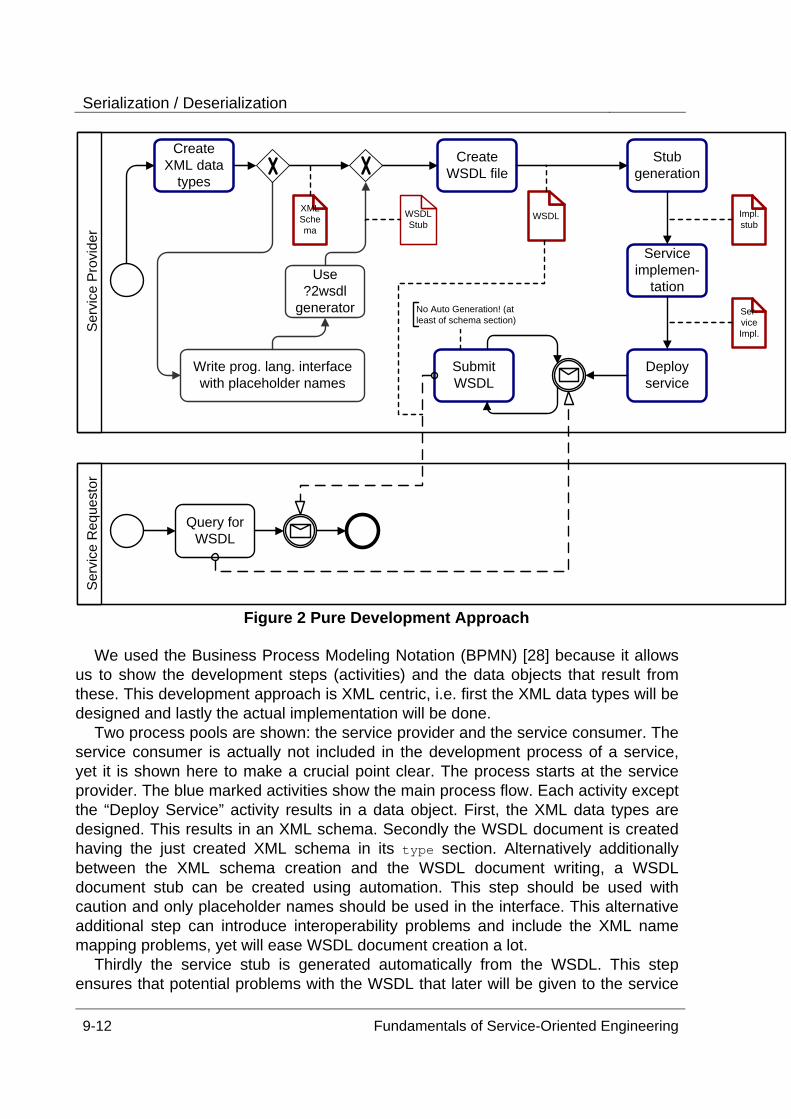
Serialization / Deserialization
9-12 Fundamentals of Service-Oriented Engineering
Ser
vice
Pro
vide
r
Create XML data
types
Create WSDL file
Write prog. lang. interface with placeholder names
Use ?2wsdl
generator
Stub generation
Service implemen-
tation
Deployservice
Ser
vice
Req
uest
or
Query for WSDL
XML Schema
WSDL Impl. stub
Ser-vice Impl.
WSDL Stub
Submit WSDL
No Auto Generation! (at least of schema section)
Figure 2 Pure Development Approach We used the Business Process Modeling Notation (BPMN) [28] because it allows
us to show the development steps (activities) and the data objects that result from these. This development approach is XML centric, i.e. first the XML data types will be designed and lastly the actual implementation will be done.
Two process pools are shown: the service provider and the service consumer. The service consumer is actually not included in the development process of a service, yet it is shown here to make a crucial point clear. The process starts at the service provider. The blue marked activities show the main process flow. Each activity except the “Deploy Service” activity results in a data object. First, the XML data types are designed. This results in an XML schema. Secondly the WSDL document is created having the just created XML schema in its type section. Alternatively additionally between the XML schema creation and the WSDL document writing, a WSDL document stub can be created using automation. This step should be used with caution and only placeholder names should be used in the interface. This alternative additional step can introduce interoperability problems and include the XML name mapping problems, yet will ease WSDL document creation a lot.
Thirdly the service stub is generated automatically from the WSDL. This step ensures that potential problems with the WSDL that later will be given to the service
3 JAVA WEB SERVICE TECHNOLOGY
Fundamentals of Service-Oriented Engineering 9-13
consumer appear and can be dealt with accordingly (i.e. custom de-/serialization may have to be applied and the type mapping may have to be adjusted). Thus a high level of interoperability (one of the main reasons for SOAP and Web Services) is ensured. A step not shown in the above diagram is to go back and adjust the created WSDL to help solve the problems that appear with stub creation. That introduces a cycle in the development process and thus reflects reality better.
Using the generated service stubs the service is implemented. In AXIS this amounts to implementing a generated interface class. This step should not mean to edit generated code. That should be avoided because regeneration will delete the modifications and thus potentially the implementation. Next the service implementation is deployed along with the additional generated classes and possible custom de-/serializers. Now the service is ready to be consumed.
The service consumer starts its development process with querying for service provider’s WSDL document. The service provider does not automatically generate the WSDL for the service implementation, but provides the previously manually written WSDL to the service consumer as depicted in the above diagram. This is a crucial point because WSDL auto-generation from service implementation introduces a lot of the problems that we discussed in this paper. It has to be ensured that the SOAP stack does not automatically generate the WSDL but in fact provides the manually written WSDL. With AXIS this is ensured using the tag <wsdlFile>/path/to/wsdl/file</wsdlFile> in the WSDD-file for the service (deployment descriptor).
Hence the pure development approach tries to avoid many of the problems of automatic type mapping or at least makes them apparent. A high level of interoperability is provided, but the price for this is possible longer development time. It completely avoids the problems we described in section 3.2.2 from a Java point of view.
3.3.3 Using a different data binding framework
The core of the problems lies in the data binding framework. The data binding framework will map the XML and Java and defines what types to map to what types. There exist several other XML data binding frameworks for Java. We want to mention XMLBeans [29] and Castor [4] here. JAX-RPC and AXIS allow plugging in a completely different data binding mechanism and thus some of the existing problems may be solved. The effort to seamlessly integrate other data binding frameworks in AXIS is not null but not overly much either. For Castor there exists already a pair of de-/serializers that completely wraps all de-/serialization in AXIS.
XMLBeans and Castor are a lot more XML centric than the JAX-RPC data binding framework and thus most of the problems will be resolved and manually written XML schema are processed with less problems.
Testing exactly which of the mentioned problems can be solved this way remains future work and consequently leads to a set of criteria with which to measure the quality and performance of XML data binding frameworks in the context of Web Services.
We have done some exemplary testing with Castor and were able to map the
Serialization / Deserialization
9-14 Fundamentals of Service-Oriented Engineering
example XML types AlphanumericString and GradeValue with fewer problems. The former is mapped to a class with the same name, the regular pattern and a validation check is included in the generated class. The latter is mapped much in the same way as with JAX-RPC (the name problem remains) but the actual enumeration values are included in a JavaDoc comment for each of the valueX. This is thus a medium improvement. Still a better name mapping would be desirable, for example the value A+ could be mapped to value A_plus.
3.3.4 Avoiding problematic Java types
Avoiding the problematic Java types as interface types is rather a work-around than a problem solution, but may be seen as best practice to ensure higher interoperability. The types that should be avoided as interface types include basically all types from the java.util package and java.lang.Object. Preferably only basic types, arrays and JavaBeans built with those should be used as interface types.
3.4 Evaluation of JAX-WS 2.0 (formerly JAX-RPC 2.0) In this section we want to investigate how much progress JAX-WS 2.0 made
towards solving the problems of JAX-RPC 1.1 we discussed here. JAX-WS 2.0 refers all type mapping to JAXB 2.0. Hence JAXB 2.0 has to be
investigated as well. We will shortly present an analysis of the progress made from both the Java and XML point of view by investigating for each of the issues weather or not it was resolved. We will use the categories resolved, partly / possibly resolved, poorly resolved and unresolved. Where the former two constitute a positive tendency and the latter two a negative tendency.
Java Point of View. • java.util.HashMap – resolved, Generics are used when in place, a standard mapping
is defined, the mapping is customizable through annotations; interoperability testing remains future work
• java.util.ArrayList – see java.util.HashMap • java.util.Collection – see java.util.HashMap • java.util.Calendar – to be tested, remains future work, time zone problem not
specifically addressed • object graph, cycles – poorly resolved, only resolvable by reference, customizable by
annotation, results in an extra element of type xsd:ID, developer has to ensure referential integrity, introduces interoperability issues, to be tested, remains future work
• object graph, cross-references – poorly resolved through annotations, may introduce interoperability issues because of extra xsd:ID used in the semantics of a reference, to be tested, remains future work
• classes with initial values – to be tested, not explicitly mentioned, remains future work XML Point of View.
• name mapping problem (Name.Public, null) – poorly resolved, mapped by the name mapping algorithm; omission, addition of characters; name collisions resolvable by a customized binding (configuration of JAXB engine)
• mapping of enumeration types (AlphanumericString) – resolved, mapped to java.lang.String with attributes enforcing the pattern, type checking is done at construction or serialization
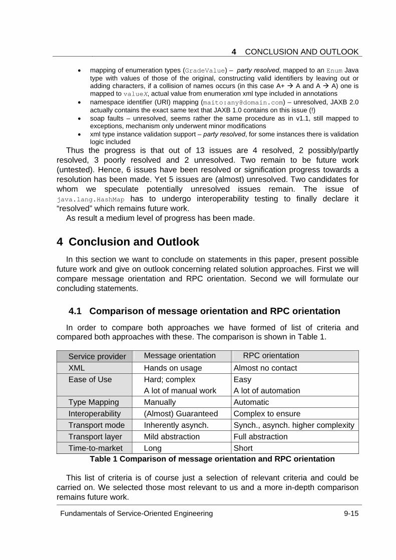
4 CONCLUSION AND OUTLOOK
Fundamentals of Service-Oriented Engineering 9-15
• mapping of enumeration types (GradeValue) – party resolved, mapped to an Enum Java type with values of those of the original, constructing valid identifiers by leaving out or adding characters, if a collision of names occurs (in this case A+ A and A A) one is mapped to valueX, actual value from enumeration xml type included in annotations
• namespace identifier (URI) mapping (maito:[email protected]) – unresolved, JAXB 2.0 actually contains the exact same text that JAXB 1.0 contains on this issue (!)
• soap faults – unresolved, seems rather the same procedure as in v1.1, still mapped to exceptions, mechanism only underwent minor modifications
• xml type instance validation support – party resolved, for some instances there is validation logic included
Thus the progress is that out of 13 issues are 4 resolved, 2 possibly/partly resolved, 3 poorly resolved and 2 unresolved. Two remain to be future work (untested). Hence, 6 issues have been resolved or signification progress towards a resolution has been made. Yet 5 issues are (almost) unresolved. Two candidates for whom we speculate potentially unresolved issues remain. The issue of java.lang.HashMap has to undergo interoperability testing to finally declare it “resolved” which remains future work.
As result a medium level of progress has been made.
4 Conclusion and Outlook In this section we want to conclude on statements in this paper, present possible
future work and give on outlook concerning related solution approaches. First we will compare message orientation and RPC orientation. Second we will formulate our concluding statements.
4.1 Comparison of message orientation and RPC orientation In order to compare both approaches we have formed of list of criteria and
compared both approaches with these. The comparison is shown in Table 1. Service provider Message orientation RPC orientation XML Hands on usage Almost no contact Ease of Use Hard; complex
A lot of manual work Easy A lot of automation
Type Mapping Manually Automatic Interoperability (Almost) Guaranteed Complex to ensure Transport mode Inherently asynch. Synch., asynch. higher complexityTransport layer Mild abstraction Full abstraction Time-to-market Long Short
Table 1 Comparison of message orientation and RPC orientation This list of criteria is of course just a selection of relevant criteria and could be
carried on. We selected those most relevant to us and a more in-depth comparison remains future work.
Serialization / Deserialization
9-16 Fundamentals of Service-Oriented Engineering
The comparison has been done from a service provider point of view. In order to safe space we will refer to RPC orientation as RPC and message orientation as MSG. The developer has almost no contact with XML in RPC and will have to deal with a lot of XML in MSG. Creating good XML schema and WSDL documents manually and writing custom de-/serializers is a hard task and much more complex than using the full automation offered with RPC.
In MSG the type mapping has to be decided manually but offers a lot higher flexibility than with RPC. As we have shown, in RPC the type mapping is flawed as per JAX-RPC, yet demands a lot less complexity than with MSG. Thus the interoperability in MSG is almost guaranteed because the messages are constructed manually and all XML constructs can be processed whereas in RPC interoperability is a lot more complex to ensure and may not be fully achieved.
Asynchronous communication is rather complex with RPC, but inherent in MSG due to the transport layer abstraction and supported transport modes.
Resulting from the previous properties for each of the approaches is the time-to-market for a service provider. We mean with time-to-market the time it takes for a potential service provider from the initial decision to offer a service until a functional implementation. In MSG the time-to-market is rather longer than in RPC due to the more complex tasks of manual work involved.
It seems inappropriate to us to evaluate based on this comparison one approach per se better than other. Rather it depends on the requirements and constrains on the service to be implemented what approach should be taken. If a fast implementation is needed where interoperability as a low priority clearly RPC orientation should be taken, yet if later on interoperability becomes an issue the price paid to provide better interoperability will be higher than with message orientation (from a cumulative point of view). Before taking one orientation or the other a well reasoned decision should be taken and all requirements should be taken into account.
A mix of both worlds, i.e. a semi message oriented approach with some automation or a semi RPC oriented approach with customization might be the more ideal solution if that is possible with the SOAP stack at hand.
4.2 Concluding statements JAX-RPC and JAXB are RPC oriented. From the investigation into the Java Web
Service related specification it seems that into message orientation has not been put as much development effort as into RPC orientation. Thus there seems to be a bias towards RPC orientation where such a bias is not justified as we tried to show in the previous section (4.1).
JAX-M provides a syntactic mapping of XML/Java and JAXB a semantic one. Rather complex Java classes (JavaBeans with some restrictions) can be
processed successfully with JAX-RPC. The problem lies in the detail and in receiving manually written WSDL / XML Schema with XML types which JAX-RPC would never generate. Several Java classes cannot be processed without failure. The semantic of some Java classes simply cannot be expressed well in XML or not at all. The tree
4 CONCLUSION AND OUTLOOK
Fundamentals of Service-Oriented Engineering 9-17
structure of XML is a sub set of the possible objects graphs of Java. Valid values of XML schema types and validation have no counter part as a concept in Java and are not supported natively.
Hence, in both worlds concepts exist that have no counterpart in the other or cannot be expressed in the other. Therefore some authors call the general O/X-mapping problem ill posed and fundamentally flawed as among others in [1]. It has also been stated that there is an “impedance mismatch” between Java and XML to express the same.
We looked at the problems that exist from a Java and XML point of view with JAX-RPC 1.1. There were several. The improvements from JAX-RPC 1.1 to JAX-RPC 2.0 are medium and some problems remained the same. As of the date of this writing we could not finish the needed testing to declare some issues resolved or unresolved.
We posed solution approaches. Custom de-/serialization costs more time, yet will ensure higher interoperability and may be unavoidable if certain XML constructs and/or Java classes need / want to be used. The "Pure Development Approach" was presented which is a best-practice recommendation of the Web Service community and has trade-offs as the other solution approaches. It will help avoid problems and / or make the developer aware of problems. A different data binding framework can be used to solve some mapping problems and the problematic Java types can be avoided completely.
All these solutions leave out parts of JAX-RPC in one way or the other. It is obvious that either there needs to be much more work put into it to archive seamless fully automated RPC orientation or RPC orientation in decentralized environments such as the Internet with the O/X-mapping problem is in deed an inherently flawed approach and high interoperability cannot be achieved this way.
A good SOAP stack should offer the developer varying degrees of XML abstraction from full message orientation to full RPC orientation. JAX-RPC 2.0 has better support for message orientation than JAX-RPC 1.1 and offers some varying degree of abstraction from XML to choose from.
Future work. Generalizing the found problems to quality criteria for XML data binding frameworks for Web Services and evaluating with these the major SOAP stacks: .NET 2.0, WSDP, AXIS 2.0 etc. is possible future work.
Outlook. To solve the O/X-mapping problem generally and fully the approach to include the XML type system natively into a programming language as been taken. An example for this is an extension to C# called Comega [30, 31]. It will have to be observed how this approach develops as it matures and if it will be adopted in the mainstream technology. It seems promising nevertheless.
Another approach taken is XML Language (XL) [32] that is a completely new programming language just designed for the domain of Web Services and object-relational-data-mapping (O/R-mapping). The type system of XL is that of XML Schema. It allows logic to be written in XL and no “classic” programming language like Java or C# is needed. If XML is the type system there neither exist an impedance mismatch nor an O/X mapping problem. Yet, if a connection between XL and Java or C# has to be performed, the same impedance mismatch will arise at the interface between XL and Java or C#. It will also have to be seen how this research project develops in the future.
Serialization / Deserialization
9-18 Fundamentals of Service-Oriented Engineering
References [1] S. Loughran, E. Smith, Rethinking the Java SOAP Stack, HP Laboratories Bristol,
University of Edinburgh, IEEE ICWS 2005, July 2005 [2] Richard Monson-Haefel, JAX-RPC is Bad, Bad, Bad!, personal blog, June, 2006,
http://rmh.blogs.com/weblog/2005/06/jaxrpc_is_bad_b.html [3] Steve Vinoski, RPC Under Fire, IEEE Internet Computing, vol. 09, no. 5, pp. 93-
95, Sept/Oct, 2005 [4] Castor, An Open Source Data Binding Framework for Java, Werner Guttmann,
Keith Visco, Ralf Joachim, et. al., Castor, ExoLab Project, Intalio Inc., Version 1.0.2, Aug 2006, see http://www.castor.org/
[5] JSR-101 Expert Group, Java API for XML-based RPC, Version 1.1, Final, Sun Microsystems, October 14th 2003
[6] Sun Community, Java API XML Web Services, Version 2.0, Proposed Final Draft, Sun Microsystems, October 7th 2005
[7] Sun Community, Java Architecture for XML Binding, Version 1.0, Final, Sun Microsystems, January 8th 2003
[8] Sun Community, Java API for XML Messaging, Version 1.1, Final, Sun Microsystems, June 11th 2002
[9] Sun Community, Java API for XML Processing, Version 1.3, Final, Sun Microsystems, September 1st 2004
[10] Sun Comminity, Java Architecture for XML Binding, Version 2.0, Final, Sun Microsystems, April 19th 2006
[11] Don Box, David Ehnebuske, Gopal Kakivaya, Andrew Layman et. al., Simple Object Access Protocol (SOAP) 1.1, Status: Note, W3C, May 2000, see http://www.w3.org/TR/SOAP/
[12] Martin Gudgin, Marc Hadley, Noah Mendelsohn et. al., SOAP Version 1.2 Part 1: Messaging Framework, Status: Recommendation, W3C, June 2003, see http://www.w3.org/TR/2003/REC-soap12-part1-20030624
[13] Martin Gudgin, Marc Hadley, Noah Mendelsohn et. al., SOAP Version 1.2 Part 2: Adjuncts, Status: Recommendation, W3C, June 2003, see http://www.w3.org/TR/2003/REC-soap12-part2-20030624
[14] Erik Christensen, Francisco Curbera, Greg Meredith et. al., Web Services Description Language (WSDL) 1.1, Status: Note, W3C, March 2001, see http://www.w3.org/TR/2001/NOTE-wsdl-20010315.
[15] Keith Ballinger, David Ehnebuske, Martin Gudgin et. al., Basic Profile Version 1.0, Final Material, WS-I [17], April 2004, see http://www.ws-i.org/Profiles/BasicProfile-1.0-2004-04-16.html
[16] Keith Ballinger, David Ehnebuske, Christopher Ferris et. al., Basic Profile Version 1.1, Final Material, WS-I [17], April 2006, see http://www.ws-i.org/Profiles/BasicProfile-1.1.html
[17] Web Services Interoperability Organization (WS-I), Community of SAP AG, BEA Systems, Fujitsu, Helett-Packard, Sun Microsystems, IBM, Intel, Microsoft, Oracle and webMethods, see http://www.ws-i.org
4 CONCLUSION AND OUTLOOK
Fundamentals of Service-Oriented Engineering 9-19
[18] Martin Grund, Service communication and discovery, Service Oriented Computing Seminar, Hasso-Plattner-Institute, unpublished, Mai 2006
[19] Arnaud Le Hors, Philippe Le Hégaret, Lauren Wood, et. al., Document Object Model (DOM) Level 3 Core Specification, Status : Recommendation, W3C, April 2004, see http://www.w3.org/TR/DOM-Level-3-Core/
[20] Andras Avar, David Chappell, Glen Daniels, et. al., Apache eXtensible Interaction System – AXIS, Version 1.4 Final, The Apache Software Foundation, April 2006, see http://ws.apache.org/axis/
[21] Sun Mircosystems, Java Web Services Developer Pack, various versions, Sun Microsystems Inc., 2005 – 2006, see http://java.sun.com/webservices/jwsdp/
[22] Graham Hamilton, Tom Ball, Jeff Bonar, et. al., Java Beans™, Version 1.01, Final Version, Sun Microsystems Inc., August 1997, see http://java.sun.com/beans/
[23] Eric van der Vlist, RELAX NG, Part II, Ch. 17, Element Reference, O'Reilly, December 2003, ISBN 0-596-00421-4, see http://books.xmlschemata.org/relaxng/relax-CHP-17.html
[24] T. Berners-Lee, R. Fielding, L. Masinter, Uniform Resource Identifier (URI): Generic Syntax, Request for Comment Document No. 3986, Internet Engineering Task Force, The Internet Society, January 2005, see http://www.ietf.org/rfc/rfc3986.txt
[25] Priscilla Walmsley, David C. Fallside, XML Schema Part 0: Primer Second Edition, Status : Recommendation, W3C, October 2004, see http://www.w3.org/TR/xmlschema-0/
[26] Noah Mendelsohn, Henry S. Thompson, David Beech, et. al., XML Schema Part 1: Structures Second Edition, Status : Recommendation, W3C, October 2004, see http://www.w3.org/TR/xmlschema-1/
[27] Ashok Malhotra, Paul V. Biron, XML Schema Part 2: Datatypes Second Edition, Status: Recommendation, W3C, October 2004, see http://www.w3.org/TR/xmlschema-1/
[28] S. White (Editor), et. al., Business Process Modeling Notation, Business Process Management Initiative & Object Management Group (OMG), OMG Final Adopted, Version 1.0, Feb 2006, see http://www.omg.org/cgi-bin/apps/doc?dtc/06-02-01.pdf
[29] BEA Systems, David Blau, Apache Software Foundation, XMLBeans, Apache Software Foundation, Version 2.2.0 and 1.0.4, June 2006, see http://xmlbeans.apache.org/
[30] Gavin Bierman, Erik Meijer, Wolfram Schulte, The essence of data access in Cω, In: Andrew Black, Editor: ECOOP 2005 - Object-Oriented Programming, 19th European Conference, Glasgow, UK, July 2005, Proceedings. Lecture Notes in Computer Science 3586, Springer, 2005. pp. 287-311, see http://research.microsoft.com/Users/gmb/Papers/ecoop-corrected.pdf
[31] Erik Meijer, Wolfram Schulte and Gavin Bierman, Unifying Tables, Objects and Documents, updated version to appear, In the proceedings of DP-COOL 2003, year 2003, see
Serialization / Deserialization
9-20 Fundamentals of Service-Oriented Engineering
http://research.microsoft.com/users/schulte/Papers/UnifyingTablesObjectsAndDocuments(DPCOOL2003).pdf
[32] Daniela Florescu, Donald Kossmann, An XML Programming Language for Web Service Specification and Composition, IEEE Data Engineering Bulletin, June 2001, Vol. 24 No. 2, pages 48-56, see http://xl.inf.ethz.ch/publ/debull01.pdf
Hyperlinks last visited on August 11th 2006
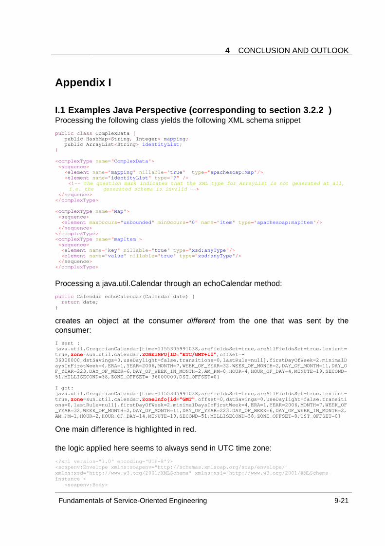
4 CONCLUSION AND OUTLOOK
Fundamentals of Service-Oriented Engineering 9-21
Appendix I
I.1 Examples Java Perspective (corresponding to section 3.2.2 ) Processing the following class yields the following XML schema snippet public class ComplexData { public HashMap<String, Integer> mapping; public ArrayList<String> identityList; } <complexType name="ComplexData"> <sequence> <element name="mapping" nillable="true" type="apachesoap:Map"/> <element name="identityList" type="?" />
<!-- the question mark indicates that the XML type for ArrayList is not generated at all, i.e. the generated schema is invalid -->
</sequence> </complexType> <complexType name="Map"> <sequence> <element maxOccurs="unbounded" minOccurs="0" name="item" type="apachesoap:mapItem"/> </sequence> </complexType> <complexType name="mapItem"> <sequence> <element name="key" nillable="true" type="xsd:anyType"/> <element name="value" nillable="true" type="xsd:anyType"/> </sequence> </complexType> Processing a java.util.Calendar through an echoCalendar method: public Calendar echoCalendar(Calendar date) { return date; }
creates an object at the consumer different from the one that was sent by the consumer: I sent : java.util.GregorianCalendar[time=1155305991038,areFieldsSet=true,areAllFieldsSet=true,lenient=true,zone=sun.util.calendar.ZONEINFO[ID="ETC/GMT+10",offset=-36000000,dstSavings=0,useDaylight=false,transitions=0,lastRule=null],firstDayOfWeek=2,minimalDaysInFirstWeek=4,ERA=1,YEAR=2006,MONTH=7,WEEK_OF_YEAR=32,WEEK_OF_MONTH=2,DAY_OF_MONTH=11,DAY_OF_YEAR=223,DAY_OF_WEEK=6,DAY_OF_WEEK_IN_MONTH=2,AM_PM=0,HOUR=4,HOUR_OF_DAY=4,MINUTE=19,SECOND=51,MILLISECOND=38,ZONE_OFFSET=-36000000,DST_OFFSET=0] I got: java.util.GregorianCalendar[time=1155305991038,areFieldsSet=true,areAllFieldsSet=true,lenient=true,zone=sun.util.calendar.ZoneInfo[id="GMT",offset=0,dstSavings=0,useDaylight=false,transitions=0,lastRule=null],firstDayOfWeek=2,minimalDaysInFirstWeek=4,ERA=1,YEAR=2006,MONTH=7,WEEK_OF_YEAR=32,WEEK_OF_MONTH=2,DAY_OF_MONTH=11,DAY_OF_YEAR=223,DAY_OF_WEEK=6,DAY_OF_WEEK_IN_MONTH=2,AM_PM=1,HOUR=2,HOUR_OF_DAY=14,MINUTE=19,SECOND=51,MILLISECOND=38,ZONE_OFFSET=0,DST_OFFSET=0]
One main difference is highlighted in red. the logic applied here seems to always send in UTC time zone: <?xml version="1.0" encoding="UTF-8"?> <soapenv:Envelope xmlns:soapenv="http://schemas.xmlsoap.org/soap/envelope/" xmlns:xsd="http://www.w3.org/2001/XMLSchema" xmlns:xsi="http://www.w3.org/2001/XMLSchema-instance"> <soapenv:Body>
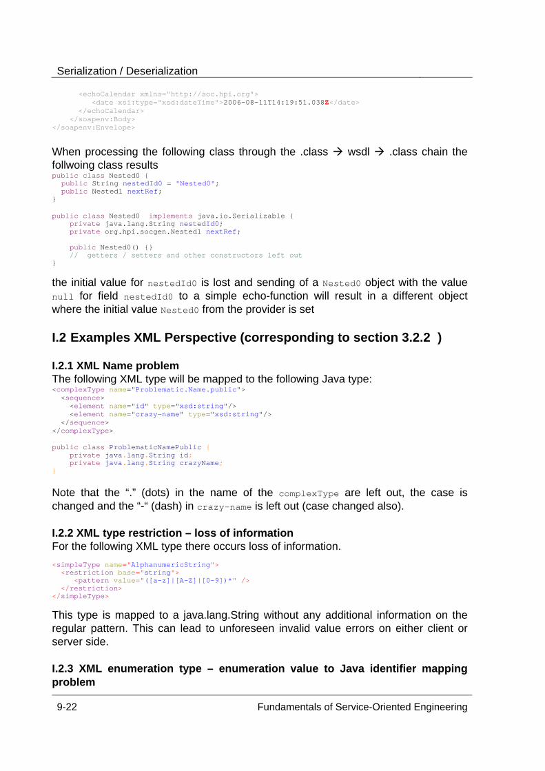
Serialization / Deserialization
9-22 Fundamentals of Service-Oriented Engineering
<echoCalendar xmlns="http://soc.hpi.org"> <date xsi:type="xsd:dateTime">2006-08-11T14:19:51.038Z</date> </echoCalendar> </soapenv:Body> </soapenv:Envelope> When processing the following class through the .class wsdl .class chain the follwoing class results public class Nested0 { public String nestedId0 = "Nested0"; public Nested1 nextRef; } public class Nested0 implements java.io.Serializable { private java.lang.String nestedId0; private org.hpi.socgen.Nested1 nextRef; public Nested0() {} // getters / setters and other constructors left out }
the initial value for nestedId0 is lost and sending of a Nested0 object with the value null for field nestedId0 to a simple echo-function will result in a different object where the initial value Nested0 from the provider is set I.2 Examples XML Perspective (corresponding to section 3.2.2 ) I.2.1 XML Name problem The following XML type will be mapped to the following Java type: <complexType name="Problematic.Name.public"> <sequence> <element name="id" type="xsd:string"/> <element name="crazy-name" type="xsd:string"/> </sequence> </complexType> public class ProblematicNamePublic { private java.lang.String id; private java.lang.String crazyName; } Note that the “.” (dots) in the name of the complexType are left out, the case is changed and the “-“ (dash) in crazy-name is left out (case changed also). I.2.2 XML type restriction – loss of information For the following XML type there occurs loss of information. <simpleType name="AlphanumericString"> <restriction base="string"> <pattern value="([a-z]|[A-Z]|[0-9])*" /> </restriction> </simpleType>
This type is mapped to a java.lang.String without any additional information on the regular pattern. This can lead to unforeseen invalid value errors on either client or server side. I.2.3 XML enumeration type – enumeration value to Java identifier mapping problem
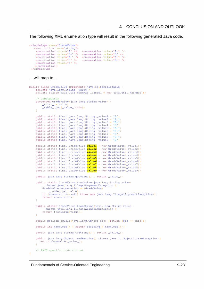
4 CONCLUSION AND OUTLOOK
Fundamentals of Service-Oriented Engineering 9-23
The following XML enumeration type will result in the following generated Java code. <simpleType name="GradeValue"> <restriction base="string"> <enumeration value="A" /> <enumeration value="A-" /> <enumeration value="B+" /> <enumeration value="B" /> <enumeration value="B-" /> <enumeration value="C+" /> <enumeration value="C" /> <enumeration value="C-" /> <enumeration value="D" /> </restriction> </simpleType> ... will map to... public class GradeValue implements java.io.Serializable { private java.lang.String _value_; private static java.util.HashMap _table_ = new java.util.HashMap(); // Constructor protected GradeValue(java.lang.String value) { _value_ = value; _table_.put(_value_,this); } public static final java.lang.String _value1 = "A"; public static final java.lang.String _value2 = "A-"; public static final java.lang.String _value3 = "B+"; public static final java.lang.String _value4 = "B"; public static final java.lang.String _value5 = "B-"; public static final java.lang.String _value6 = "C+"; public static final java.lang.String _value7 = "C"; public static final java.lang.String _value8 = "C-"; public static final java.lang.String _value9 = "D"; public static final GradeValue value1 = new GradeValue(_value1); public static final GradeValue value2 = new GradeValue(_value2); public static final GradeValue value3 = new GradeValue(_value3); public static final GradeValue value4 = new GradeValue(_value4); public static final GradeValue value5 = new GradeValue(_value5); public static final GradeValue value6 = new GradeValue(_value6); public static final GradeValue value7 = new GradeValue(_value7); public static final GradeValue value8 = new GradeValue(_value8); public static final GradeValue value9 = new GradeValue(_value9); public java.lang.String getValue() { return _value_;} public static GradeValue fromValue(java.lang.String value) throws java.lang.IllegalArgumentException { GradeValue enumeration = (GradeValue) _table_.get(value); if (enumeration==null) throw new java.lang.IllegalArgumentException(); return enumeration; } public static GradeValue fromString(java.lang.String value) throws java.lang.IllegalArgumentException { return fromValue(value); } public boolean equals(java.lang.Object obj) {return (obj == this);} public int hashCode() { return toString().hashCode();} public java.lang.String toString() { return _value_;} public java.lang.Object readResolve() throws java.io.ObjectStreamException {
return fromValue(_value_); }
// AXIS specific code cut out }
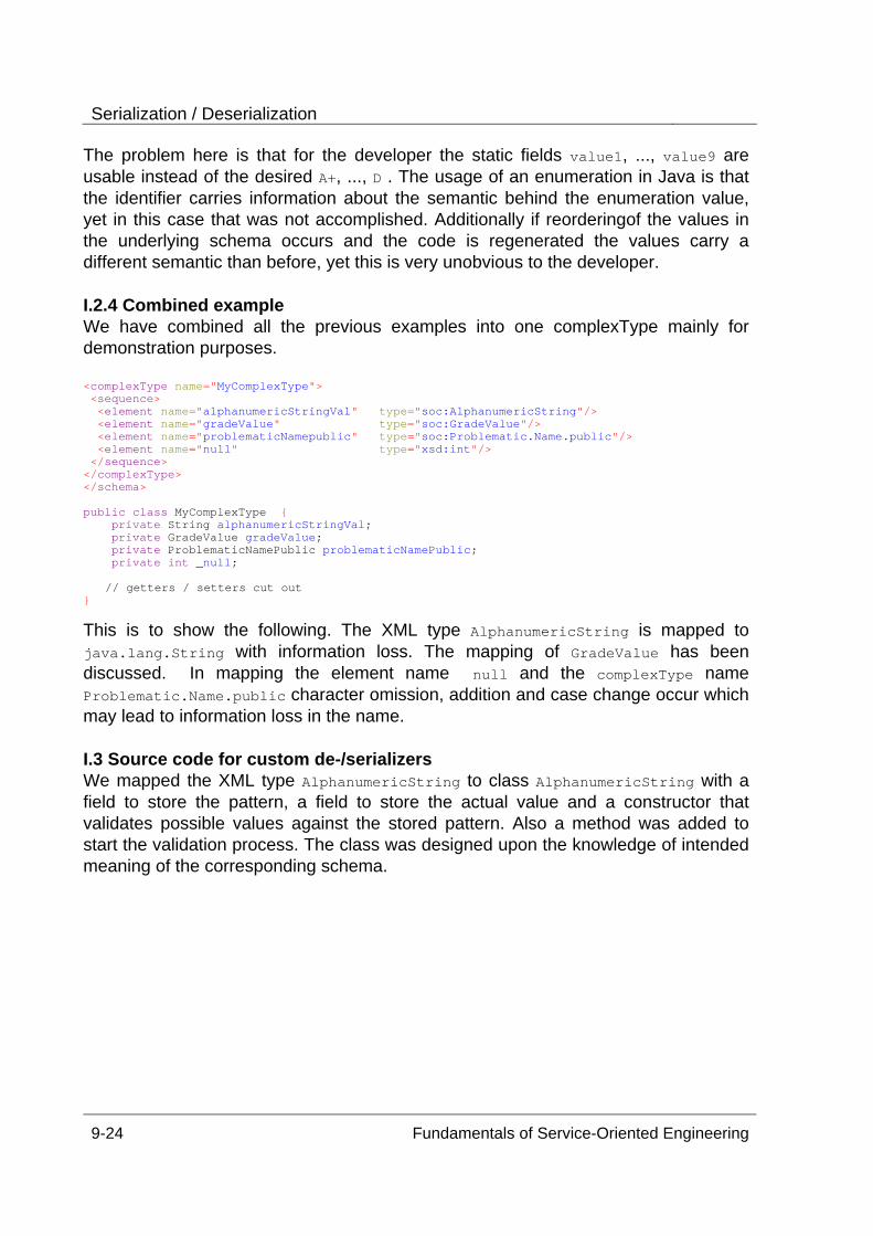
Serialization / Deserialization
9-24 Fundamentals of Service-Oriented Engineering
The problem here is that for the developer the static fields value1, ..., value9 are usable instead of the desired A+, ..., D . The usage of an enumeration in Java is that the identifier carries information about the semantic behind the enumeration value, yet in this case that was not accomplished. Additionally if reorderingof the values in the underlying schema occurs and the code is regenerated the values carry a different semantic than before, yet this is very unobvious to the developer. I.2.4 Combined example We have combined all the previous examples into one complexType mainly for demonstration purposes. <complexType name="MyComplexType"> <sequence> <element name="alphanumericStringVal" type="soc:AlphanumericString"/> <element name="gradeValue" type="soc:GradeValue"/> <element name="problematicNamepublic" type="soc:Problematic.Name.public"/> <element name="null" type="xsd:int"/> </sequence> </complexType> </schema> public class MyComplexType { private String alphanumericStringVal; private GradeValue gradeValue; private ProblematicNamePublic problematicNamePublic; private int _null; // getters / setters cut out }
This is to show the following. The XML type AlphanumericString is mapped to java.lang.String with information loss. The mapping of GradeValue has been discussed. In mapping the element name null and the complexType name Problematic.Name.public character omission, addition and case change occur which may lead to information loss in the name. I.3 Source code for custom de-/serializers We mapped the XML type AlphanumericString to class AlphanumericString with a field to store the pattern, a field to store the actual value and a constructor that validates possible values against the stored pattern. Also a method was added to start the validation process. The class was designed upon the knowledge of intended meaning of the corresponding schema.
Technische Berichte des Hasso-Plattner-Institut Band ISBN Titel Autoren / Redaktion
1 3-937786-37-6 Auf dem Weg zu einem Softwareingenieurwesen
Prof. Dr. Ing. S. Wendt
2 3-935024-98-3 Conceptual Architecture Pattern Bernhard Gröne, Frank Keller
3 3-937786-28-7 Grid-Computing Dipl.-Inf. Peter Tröger; Sabine Wagner
4 3-937786-10-4 JAVA Language Conversion Assitant An Analysis
Stefan Richter, Stefan Henze, Eiko Büttner, Steffen Bach, Andreas Polze
5 9-937786-14-7 The Apache Modeling Project
Bernhard Gröne, Andreas Knöpfel, Rudolf Kugel und Oliver Schmidt
6 3-937786-54-6
Konzepte der Softwarevisualisierung für komplexe, objektorientierte Softwaresysteme
Prof. Dr. Jürgen Döllner, Johannes Bohnet
7 3-937786-56-2 Visualizing Design and Spatial Assembly of Interactive CSG
Prof. Dr. Jürgen Döllner, Florian Kirsch, Marc Nienhaus
8 3-937786-72-4 Resourtcenpartitionierung für Grid-Systeme
Prof. Dr. A. Polze Matthias Lendholt, Peter Tröger
9 3-937786-73-2 Sichere Ausführung nich vertrauenswürdiger Programme
Prof. Dr. A. Polze Johannes Nicolai, Peter Tröger
10 3-937786-78-3 Survey on Service Composition Prof. Dr. M. Weske Dominik Kuropka Harald Meyer
11 3-937786-81-3 Requirements for Service Cinoisutuib Prof. Dr. M. Weske Dominik Kuropka Harald Meyer
12
3-937786-89-9 / 978-3-937786-89-6
An e-Librarian Service - Natural Anguage Interface for an Efficient Semantic Search within Multimedia Resources Serge Linckels, Christoph Meinel
13
3-939469-13-0 / 978-3-939469-13-1
A Virtual Machine Architecture for Creating IT-Security Labs
Ji Hu, Dirk Cordel, Christoph Meinel
14
3-939469-23-8 / 978-3-939469-23-0
Aspektorientierte Programmierung – Überblick über Techniken und Werkzeuge
Janin Jeske, Bastian Brehmer, Falko Menge, Stefan Hüttenrauch, Christian Adam, Benjamin Schüler, Wolfgang Schult, Andreas Rasche, Andreas Polze

15
3-939469-34-3 / 978-3-939469-34-6
Concepts and Technology of SAP Web Application Server and Service Oriented Architecture Products
Peter Tabeling, Bernhard Gröne, Konrad Hübner


ISBN 3-939469-35-1 ISBN 978-3-939469-35-3 ISSN 1613-5652