TEIL 2: UNTERFLURKONSTRUKTIONEN
30
Leitlinie für die europäische technische Zulassung (ETAG) ETAG 032 DEHNFUGEN FÜR STRASSENBRÜCKEN TEIL 2: UNTERFLURKONSTRUKTIONEN Ausgabe 2013 OIB-467-066/13
Transcript of TEIL 2: UNTERFLURKONSTRUKTIONEN
Leitlinie für die europäische technische Zulassung (ETAG)
ETAG 032
DEHNFUGEN FÜR STRASSENBRÜCKEN
TEIL 2: UNTERFLURKONSTRUKTIONEN
Ausgabe 2013 OIB-467-066/13
Vorbemerkungen zur Leitlinie für die europäische technische Zulassung für
DEHNFUGEN FÜR STRASSENBRÜCKEN TEIL 2: UNTERFLURKONSTRUKTIONEN
Vorbemerkungen
Leitlinien für die europäische technische Zulassung wurden aufgrund eines von der Kommission der Europäischen Gemeinschaften nach Art. 11 Abs. 1 der Richtlinie des Rates vom 21. Dezember 1988 zur Angleichung der Rechts- und Verwaltungsvorschriften der Mitgliedstaaten über Bauprodukte (89/106/EWG) (Bauproduktenrichtlinie) erteilten Auftrages vom Gremium der von den Mitgliedstaaten bestimmten Zulassungsstellen (EOTA) erarbeitet. Leitlinien für die europäische technische Zulassung können von Technischen Bewertungsstellen gemäß Art. 66 Abs. 3 der Verordnung (EU) Nr. 305/2011 (Bauproduktenverordnung) als Europäisches Bewertungsdokument verwendet werden. Leitlinien sind damit die Grundlage für Europäische Technische Bewertungen. In Zweifelsfällen bzw. in Fällen von Übersetzungsfehlern ist die im EOTA-Sekretariat (Kunstlaan 40, Avenue des Arts, 1040 Bruxelles, Belgien) vorliegende Originalfassung der Leitlinie maßgebend.
Stand, August 2013
1/28
© EOTA 2013KUNSTLAAN 40, AVENUE DES ARTS
1040 BRUSSELSBELGIUM
European Organisation for Technical Approvals
Europäische Organisation für Technische Zulassungen
Organisation Européenne pour l’Agrément Technique
ETAG n°032Edition of May 2013
GUIDELINE FOR EUROPEAN TECHNICALAPPROVAL
ofEXPANSION JOINTS FOR ROAD BRIDGES
PART 2: BURIED EXPANSION JOINTS
2/28
Table of ContentsFOREWORD...................................................................................................................................................4
REFERENCE DOCUMENTS ...........................................................................................................................4
SECTION ONE: INTRODUCTION .............................................................................................................5
1. PRELIMINARIES.................................................................................................................................51.1 Legal basis...........................................................................................................................................51.2 Status of ETAG ....................................................................................................................................5
2. SCOPE...................................................................................................................................................52.1 Scope and definition ............................................................................................................................5
2.1.1 General...........................................................................................................................................................52.1.2 Definitions .....................................................................................................................................................5
2.2 USE CATEGORY AND KITS ..............................................................................................................62.2.1 Use categories ................................................................................................................................................62.2.2 Kits ................................................................................................................................................................6
2.3 Assumptions.........................................................................................................................................62.3.1 Main structure................................................................................................................................................62.3.2 Temperatures .................................................................................................................................................62.3.3 Installation .....................................................................................................................................................72.3.4 Working life...................................................................................................................................................7
3. TERMINOLOGY..................................................................................................................................73.1 Common terminology and abbreviations ............................................................................................73.2 Terminology and abbreviations specific to this ETAG........................................................................7
3.2.1 Terminology...................................................................................................................................................73.2.2 Abbreviations.................................................................................................................................................8
SECTION TWO: GUIDANCE FOR THE ASSESSMENT OF THE FITNESS FOR USE .....................9
GENERAL NOTES .........................................................................................................................................94. REQUIREMENTS ................................................................................................................................9
4.0 TABLE linking the Essential Requirements to Road Bridge Expansion Joint performance................94.1 KITS.....................................................................................................................................................9
4.1.1 Mechanical resistance and stability................................................................................................................94.1.1.1 General ...................................................................................................................................................94.1.1.2 Mechanical resistance...........................................................................................................................104.1.1.3 Fatigue..................................................................................................................................................114.1.1.4 Seismic behaviour ................................................................................................................................114.1.1.5 Movement capacity...............................................................................................................................114.1.1.6 Cleanability ..........................................................................................................................................114.1.1.7 Resistance to wear ................................................................................................................................114.1.1.8 Watertightness ......................................................................................................................................11
4.1.2 Safety in case of fire.....................................................................................................................................124.1.3 Hygiene, health and environment ................................................................................................................124.1.4 Safety in use.................................................................................................................................................12
4.1.4.1 Ability to bridge gaps and levels in the running surface.......................................................................124.1.4.2 Skid resistance......................................................................................................................................124.1.4.3 Drainage capacity .................................................................................................................................12
4.1.5 Protection against noise ...............................................................................................................................124.1.6 Energy, economy and heat retention ............................................................................................................124.1.7 Aspects of durability, serviceability and identification of the products .......................................................12
4.1.7.1 Aspects of durability.............................................................................................................................124.1.7.2 Aspects of serviceability.......................................................................................................................124.1.7.3 Aspects of identification.......................................................................................................................12
4.2 Components .......................................................................................................................................135. METHODS OF VERIFICATION .......................................................................................................13
General....................................................................................................................................................135.1 Kits ....................................................................................................................................................13
5.1.1 Mechanical resistance and stability..............................................................................................................135.1.1.1 General .................................................................................................................................................135.1.1.2 Mechanical resistance...........................................................................................................................135.1.1.3 Resistance to fatigue.............................................................................................................................135.1.1.4 Seismic behaviour ................................................................................................................................135.1.1.5 Movement capacity...............................................................................................................................145.1.1.6 Cleanability ..........................................................................................................................................145.1.1.7 Resistance to wear ................................................................................................................................145.1.1.8 Watertightness ......................................................................................................................................14
3/28
5.1.2 Safety in case of fire.....................................................................................................................................145.1.3 Hygiene, health and environment ................................................................................................................145.1.4 Safety in use.................................................................................................................................................14
5.1.4.1 Ability to bridge gaps and levels in the running surface.......................................................................145.1.4.2 Skid resistance......................................................................................................................................145.1.4.3 Drainage capacity .................................................................................................................................14
5.1.5 Protection against noise ...............................................................................................................................155.1.6 Energy economy and heat retention .............................................................................................................155.1.7 Aspects of durability, serviceability and identification ................................................................................15
5.1.7.1 Aspects of durability.............................................................................................................................155.1.7.2 Aspects of serviceability.......................................................................................................................155.1.7.3 Aspects of identification of the product................................................................................................15
5.2 Components .......................................................................................................................................156. ASSESSING AND JUDGING THE FITNESS OF PRODUCTS FOR AN INTENDED USE...........17
6.0 Table linking the Essential Requirements to product requirements ..................................................176.1 Kits ....................................................................................................................................................18
6.1.1 Mechanical resistance and stability..............................................................................................................186.1.1.1 General .................................................................................................................................................186.1.1.2 Mechanical resistance...........................................................................................................................186.1.1.3 Resistance to fatigue.............................................................................................................................186.1.1.4 Seismic behaviour ................................................................................................................................186.1.1.5 Movement capacity...............................................................................................................................186.1.1.6 Cleanability ..........................................................................................................................................186.1.1.7 Resistance to wear ................................................................................................................................186.1.1.8 Watertightness ......................................................................................................................................18
6.1.2 Safety in case of fire.....................................................................................................................................186.1.3 Hygiene, health and environment (ER 3).....................................................................................................19
6.1.3.1 Release of dangerous substances ..........................................................................................................196.1.4 Safety in use.................................................................................................................................................19
6.1.4.1 Ability to bridge gaps and levels in the running surface.......................................................................196.1.4.2 Skid resistance......................................................................................................................................196.1.4.3 Drainage capacity .................................................................................................................................19
6.1.5 Protection against noise ...............................................................................................................................196.1.6 Energy economy and heat retention .............................................................................................................196.1.7 Aspects of durability, serviceability and identification of the products .......................................................19
6.1.7.1 Aspects of durability.............................................................................................................................196.1.7.2 Aspects of serviceability.......................................................................................................................196.1.7.3 Aspects of identification of the product................................................................................................19
6.2 Components .......................................................................................................................................197. ASSUMPTIONS AND RECOMMENDATIONS UNDER WHICH THE FITNESS FOR USE OFTHE PRODUCTS IS ASSESSED...............................................................................................................22
7.0 General..............................................................................................................................................227.1 Design of works .................................................................................................................................227.2 Packaging, transport and storage .....................................................................................................22
7.2.1 Packaging.....................................................................................................................................................227.2.2 Transport and storage...................................................................................................................................22
7.3 Execution of works ............................................................................................................................227.4 Maintenance and repair ....................................................................................................................22
SECTION THREE: ATTESTATION OF CONFORMITY (AC) ............................................................23
8. ATTESTATION AND EVALUATION OF CONFORMITY.............................................................238.1 EC DECISION...................................................................................................................................238.2 RESPONSIBILITIES .........................................................................................................................23
8.2.1 Tasks for the manufacturer...........................................................................................................................238.2.1.1 Factory production control (FPC) ........................................................................................................238.2.1.2 Testing of samples taken at the factory – Prescribed Test Plan ............................................................23
8.2.2 Tasks of the approved body (or in some cases, the manufacturer) ...............................................................238.2.2.1 General .................................................................................................................................................238.2.2.2 Initial Type Testing and Factory Production Control ...........................................................................238.2.2.3 Assessment of the factory production control system. Initial inspection and continuous surveillance.248.2.2.4 Certification..........................................................................................................................................24
8.3 Documentation ..................................................................................................................................248.4 EC marking and information.............................................................................................................24
SECTION FOUR: ETA CONTENT............................................................................................................25
9. THE ETA CONTENT .........................................................................................................................25
ANNEXES TO THIS ETAG FAMILY PART............................................................................................26
ANNEX 2-M EXAMPLES OF BURIED JOINTS .....................................................................................27
4/28
FOREWORDSee Part 1 of this ETAG N° 032.
REFERENCE DOCUMENTS
See Part 1 of this ETAG N° 032.
Additional list of standards referred to in this family Part
StandardsClause inthis partof ETAG
Title
EN 573 Table 8.1 Aluminium and aluminium alloys – Chemical composition and form ofwrought products
EN 755-2 Table 5.2 Aluminium and aluminium alloys – Extruded rod/bar, tube and profiles –Part 2: Mechanical properties
EN 1676 Table 8.1 Aluminium and aluminium alloys – Alloyed ingots for remelting –Specifications
EN 1991-1-3 Table 5.2 Eurocode 1: Actions on structures – General actions – Snow loadsEN 1991-2 4.1.1.2 Eurocode 1: Actions on structures – Part 2: Traffic loads on bridgesEN 1999 Table 5.2
6.1.1.2Eurocode 9: Design of aluminium structures
EN 1999-1-3 Table 6.2 Eurocode 9: Design of aluminium structures – Part 1-3: Structuressusceptible to fatigue
EN 10025 Tables 5.2and 8.1
Hot rolled products of structural steel
EN 10088 Tables 5.2and 8.1
Stainless steels – All parts
EN 10204 Tables 5.2and 8.1
Metallic products – Types of inspection documents
EN ISO 1461 Table 8.1 Hot dip galvanized coatings on fabricated iron and steel articles –Specifications and test methods
ISO 34-1 Tables 5.2and 8.1
Rubber, vulcanized or thermoplastic – Determination of tear strength –Part 1: Trouser, angle and crescent test pieces
ISO 37 Tables 5.2and 8.1
Rubber, vulcanized or thermoplastic – Determination of tensile stress-strainproperties
ISO 48 Tables 5.2and 8.1
Rubber, vulcanized or thermoplastic – Determination of hardness (hardnessbetween 10 IRHD and 100 IRHD)
ISO 812 (2006) Table 5.2 Rubber, vulcanized or thermoplastic – Determination of low-temperaturebrittleness
ISO 1817 Table 5.2 Rubber, vulcanized – Determination of the effect of liquidsISO 2781 (1996) Tables 5.2
and 8.1Rubber, vulcanized – Determination of density
ISO 7619-2 Tables 5.2and 8.1
Rubber, vulcanized or thermoplastic – Determination of indentation hardness– Part 2: IRHD pocket meter method
Note: Some of these standards are also referred to in Part 1.
5/28
SECTION ONE:INTRODUCTION
1. PRELIMINARIES
1.1 LEGAL BASIS
See Part 1 of this ETAG N° 032.
1.2 STATUS OF ETAG
See Part 1 of this ETAG N° 032.
2. SCOPE
This document shall be used in conjunction with ETAG N° 032, Expansion joints for road bridgesPart 1. If the text in Part 1 applies to this family of products then reference will be made to theappropriate clause in Part 1 ("See Part 1 of this ETAG N° 032").
2.1 SCOPE AND DEFINITION
2.1.1 General
This Part of ETAG N° 032 specifies the product performance characteristics, methods ofverification and assessment procedures for Buried Expansion Joints (BEJ) for road bridges toensure the fitness of the products for their intended use.
Note: The working life of the product and of the surfacing above this type of joint dependsvery much on the thickness of surfacing. The choice of this thickness should be definedaccording to the type of product, the movement capacity and the formulation of thesurfacing.
The surfacing itself is not within the scope of the expansion joint product or kit (the informationconcerning the function of surfacing layer according to 7.1 shall be given in the ETA). For furtherinformation, see Part 1 of this ETAG N° 032.
2.1.2 Definitions
The following definition details the general definition given in 2.1.2.2 of Part 1. The following sub-categories exist.
Polymeric Buried Expansion Joints that are attached by bonding or mechanical fixing, defined as:
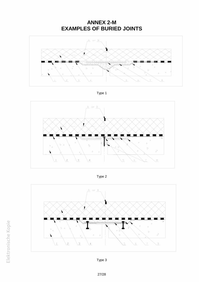
- Buried flashing: formed in situ using a thin elastomeric strip (bonded or with debondinglayer) in combination with the waterproofing layer to bridge the deck joint gap, with allconstruction above deck level. See Annex 2M Figure type 1.
- Buried pad: formed in a recess at deck level using a preformed elastomeric bridging pad orelastomeric flashing and in combination with the waterproofing. See Annex 2M Figuretype 2.
- Buried flexible plug: consists in principle of a flexible plug joint that is formed in a recess atdeck level. See Annex 2M Figure type 2.
- Buried Expansion Joints with Mechanical Fixing formed in a recess at deck level attachedby anchor loops or bolts incorporating an elastomeric sealing element protected by a plate.See Annex 2M Figure type 3.
Other additional components may be included to accommodate other features or functions (e.g.mesh in the surfacing).
Note: Continuous waterproofing consisting of the waterproofing material only and may becontaining local reinforcement by additional layers is not considered as an expansion joint.
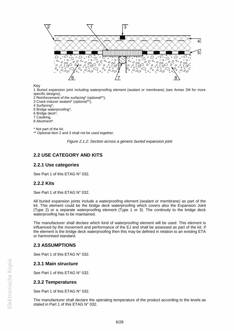
A generic example of a Buried Expansion Joint is shown below with other more specific designsshown in Annex 2M.
6/28
Key1 Buried expansion joint including waterproofing element (sealant or membrane) (see Annex 2M for morespecific designs),2 Reinforcement of the surfacing* (optional**),3 Crack inducer sealant* (optional**),4 Surfacing*,5 Bridge waterproofing*,6 Bridge deck*,7 Caulking,8 Abutment*.
* Not part of the kit.** Optional item 2 and 3 shall not be used together.
Figure 2.1.2: Section across a generic buried expansion joint
2.2 USE CATEGORY AND KITS
2.2.1 Use categories
See Part 1 of this ETAG N° 032.
2.2.2 Kits
See Part 1 of this ETAG N° 032.
All buried expansion joints include a waterproofing element (sealant or membrane) as part of thekit. This element could be the bridge deck waterproofing which covers also the Expansion Joint(Type 2) or a separate waterproofing element (Type 1 or 3). The continuity to the bridge deckwaterproofing has to be maintained.
The manufacturer shall declare which kind of waterproofing element will be used. This element isinfluenced by the movement and performance of the EJ and shall be assessed as part of the kit. Ifthe element is the bridge deck waterproofing then this may be defined in relation to an existing ETAor harmonised standard.
2.3 ASSUMPTIONS
See Part 1 of this ETAG N° 032.
2.3.1 Main structure
See Part 1 of this ETAG N° 032.
2.3.2 Temperatures
See Part 1 of this ETAG N° 032.
The manufacturer shall declare the operating temperature of the product according to the levels asstated in Part 1 of this ETAG N° 032.
7/28
Testing methods described in this part of the ETAG generally cover the operating temperaturerange -30 °C to +45 °C. For materials used outside this temperature range, it shall be assessedwhether the materials show changes of their properties in the concerned range of temperature. Ifso, these effects shall be considered in the approval procedure.
2.3.3 Installation
See Part 1 of this ETAG N° 032.
In addition, the manufacturer shall declare the limitations of the product in term of bridge surfacing,for example, minimum thickness of surfacing, type, application temperature, etc. This shall bestated in the ETA.
Note: Certain designs of BEJ may cause a reduction of thickness of surfacing above thelocation of the EJ. These designs may not be permitted in some Member States.
2.3.4 Working life
See Part 1 of this ETAG N° 032.
The working life category for Buried Expansion Joints shall be selected from the table of WorkingLife in Part 1 of this ETAG 032. It is assumed that a buried expansion joint is suitable for theworking life categories 1, 2 or 3 as stated in Part 1 of this ETAG N° 032 when it is tested accordingto the procedures stated in Chapter 5, as meeting the requirements stated in Chapter 4 of thisETAG Part.
It is important to note that the working life of the expansion joint is influenced by the ability of thesurfacing to accommodate the movement of the expansion joint taking into account thickness,mechanical characteristics, optional devices, etc. The appropriate characteristics of the surfacelayer(s), necessary for the accommodation of the movement of the expansion joint, shall bedeclared by the joint manufacturer and included in the ETA.
For this family Part, there are no components which are replaceable.
3. TERMINOLOGY
3.1 COMMON TERMINOLOGY AND ABBREVIATIONS
See Part 1 of this ETAG N° 032.
3.2 TERMINOLOGY AND ABBREVIATIONS SPECIFIC TO THIS ETAG
3.2.1 Terminology
See Part 1 of this ETAG N° 032.
For additional terms and definitions specific for this family product: see the following table.
Caulking A packing material which is placed in the expansion gap to providesupport for sealant in an expansion joint
Debonding layer A lubricant or thin sheet of flexible material installed as a componentpart of the Buried Expansion Joint to prevent adhesion betweenselected components
Crack inducer A saw cut above the joint (e.g. 20 mm width) that is installed toinfluence and control cracking in the surfacing above the joint, whichnormally occurs in service (not part of the kit)
Crack inducer sealant A flexible and durable material (not part of the kit) that is inserted inthe crack inducer to prevent the ingress of water through the surfacingto the joint
Flashing Thin elastomeric strip either bonded or with debonding layer, bridgingthe gap
Pad Preformed elastomeric bridging pad
8/28
Plate A thin plate of metal (or other suitable material) over the bridge deckgap and which prevents ingress of aggregate into the bridge deck gap
Sealing element Elastomeric sealing element preventing ingress of water into bridgegap
Supporting element Load carrying support for flexible joint components above e.g. metalbridging plate
Tanking A precoat layer applied to the internal surfaces of the recess formedfor the buried flexible plug. The purpose of the tanking is to improveadhesion and seal between the flexible plug and the internal faces ofthe recess
3.2.2 Abbreviations
See Part 1 of this ETAG N° 032.
9/28
SECTION TWO:GUIDANCE FOR THE ASSESSMENT OF
THE FITNESS FOR USE
GENERAL NOTES
See Part 1 of this ETAG N° 032.
4. REQUIREMENTS
For works and their relationship to the Road Bridge Expansion Joint characteristics
See Part 1 of this ETAG N° 032.
4.0 TABLE LINKING THE ESSENTIAL REQUIREMENTS TO ROAD BRIDGEEXPANSION JOINT PERFORMANCE
Comprehensive table
See the comprehensive table of Part 1 of this ETAG N° 032 but the clauses in the last column referto this Part of the ETAG.
4.1 KITS
4.1.1 Mechanical resistance and stability
4.1.1.1 General
See Part 1 of this ETAG N° 032.
ULS criteria for imposed displacements at ULS of the main structure are not relevant for BuriedExpansion Joints.
Note: It is a characteristic of Buried Expansion Joints that as the structure expands andcontracts tension or compression may be generated in the joint and the surfacing materialabove the joint. It is considered that the surfacing material shall be able to sustain theseloading effects as well as not causing detrimental effects to the joint and the structure. Thesurfacing is considered to maintain composite action with the waterproofing and BuriedExpansion Joint throughout the working life.
For this reason the manufacturer declares the movement capacity of the joint and therecommended overall thickness of surfacing (see 2.3.3 and Chapter 7) that will be requiredfor acceptable performance.
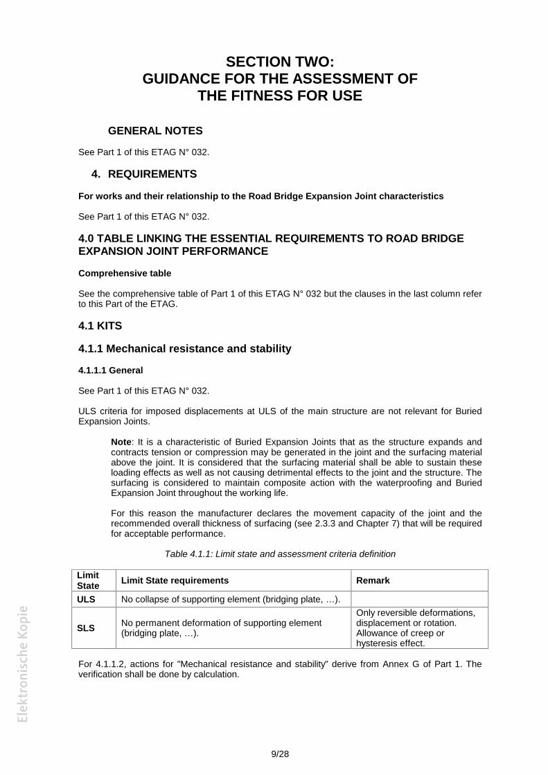
Table 4.1.1: Limit state and assessment criteria definition
LimitState Limit State requirements Remark
ULS No collapse of supporting element (bridging plate, …).
SLS No permanent deformation of supporting element(bridging plate, …).
Only reversible deformations,displacement or rotation.Allowance of creep orhysteresis effect.
For 4.1.1.2, actions for "Mechanical resistance and stability” derive from Annex G of Part 1. Theverification shall be done by calculation.
10/28
4.1.1.2 Mechanical resistance
4.1.1.2.1 General
Traffic induced stresses shall only be considered for the verification of the supporting elementcomponents (e.g. bridging plate).
The expansion joint shall withstand loading from traffic. The static load model, LM1, TS1 in ETAGN° 032, Part 1, Annex G.2 shall be used.
Load conditions as relevant to the bridging plate of the EJ and its required performance arerepresented by the following formulas. This clause is not relevant for type 1 BEJ. For this type 1, noverification is required.
Note: The mechanical resistance of this product family is mainly influenced by thebehaviour of the supporting element. Its verification is made taking into account the factthat this supporting element is under a surfacing.
Expansion joint parameters (Part 1 Figure G2 and Table G2):
Lj(Bej) 0,5 m; Wj(Bej) 1,2 m; Q1k = 300 kN
4.1.1.2.2 ULS requirement
At ULS, the requirement for BEJ type products is that the bridging plate shall not collapse.
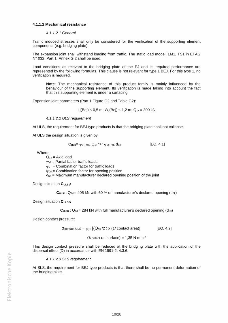
At ULS the design situation is given by:
CULS= 0T Q1 Q1k "+" 0d dE dEk [EQ. 4.1]
Where:Q1k = Axle loadQ1 = Partial factor traffic loads0T = Combination factor for traffic loads0d = Combination factor for opening positiondEk = Maximum manufacturer declared opening position of the joint
Design situation CULS1:
CULS1: Q1d = 405 kN with 60 % of manufacturer’s declared opening (dEk)
Design situation CULS2:
CULS2 : Q1d = 284 kN with full manufacturer’s declared opening (dEk)
Design contact pressure:
σcontact,ULS = Q1 [(Q1k /2 ) x (1/ contact area)] [EQ. 4.2]
σcontact (at surface) = 1,35 N mm-2
This design contact pressure shall be reduced at the bridging plate with the application of thedispersal effect (D) in accordance with EN 1991-2, 4.3.6.
4.1.1.2.3 SLS requirement
At SLS, the requirement for BEJ type products is that there shall be no permanent deformation ofthe bridging plate.
11/28
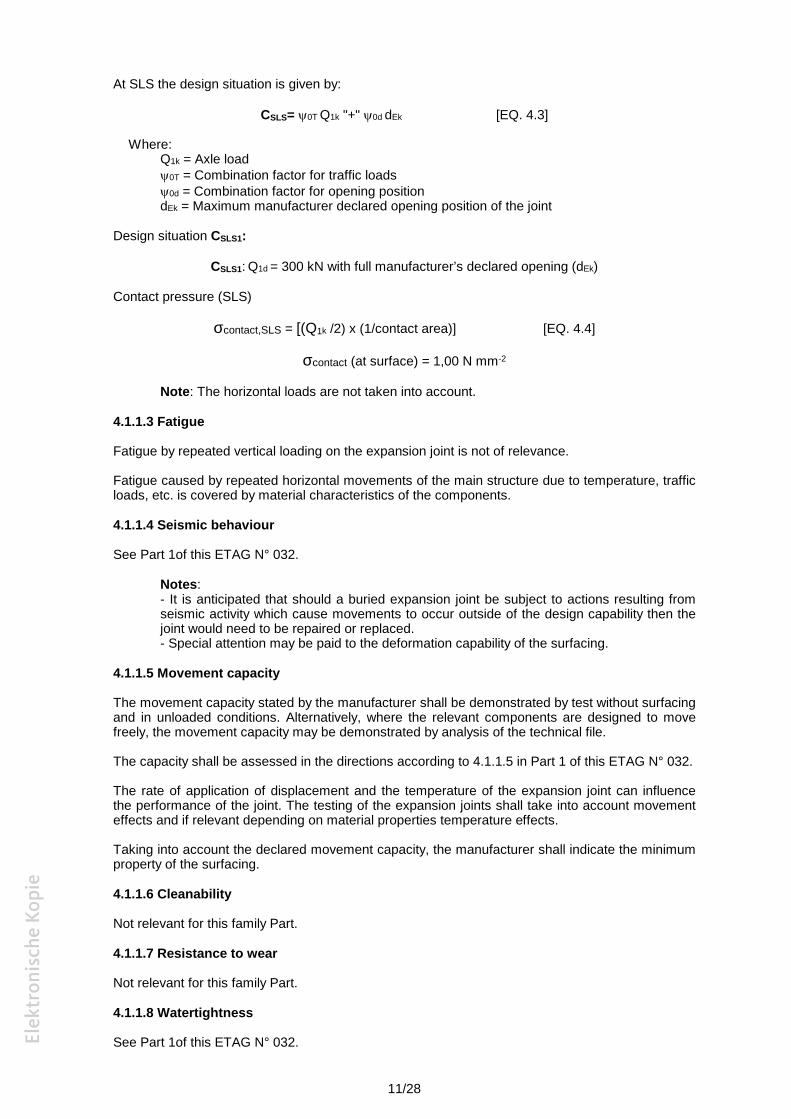
At SLS the design situation is given by:
CSLS= 0T Q1k "+" 0d dEk [EQ. 4.3]
Where:Q1k = Axle load0T = Combination factor for traffic loads0d = Combination factor for opening positiondEk = Maximum manufacturer declared opening position of the joint
Design situation CSLS1:
CSLS1: Q1d = 300 kN with full manufacturer’s declared opening (dEk)
Contact pressure (SLS)
σcontact,SLS = [(Q1k /2) x (1/contact area)] [EQ. 4.4]
σcontact (at surface) = 1,00 N mm-2
Note: The horizontal loads are not taken into account.
4.1.1.3 Fatigue
Fatigue by repeated vertical loading on the expansion joint is not of relevance.
Fatigue caused by repeated horizontal movements of the main structure due to temperature, trafficloads, etc. is covered by material characteristics of the components.
4.1.1.4 Seismic behaviour
See Part 1of this ETAG N° 032.
Notes:- It is anticipated that should a buried expansion joint be subject to actions resulting fromseismic activity which cause movements to occur outside of the design capability then thejoint would need to be repaired or replaced.- Special attention may be paid to the deformation capability of the surfacing.
4.1.1.5 Movement capacity
The movement capacity stated by the manufacturer shall be demonstrated by test without surfacingand in unloaded conditions. Alternatively, where the relevant components are designed to movefreely, the movement capacity may be demonstrated by analysis of the technical file.
The capacity shall be assessed in the directions according to 4.1.1.5 in Part 1 of this ETAG N° 032.
The rate of application of displacement and the temperature of the expansion joint can influencethe performance of the joint. The testing of the expansion joints shall take into account movementeffects and if relevant depending on material properties temperature effects.
Taking into account the declared movement capacity, the manufacturer shall indicate the minimumproperty of the surfacing.
4.1.1.6 Cleanability
Not relevant for this family Part.
4.1.1.7 Resistance to wear
Not relevant for this family Part.
4.1.1.8 Watertightness
See Part 1of this ETAG N° 032.
12/28
4.1.2 Safety in case of fire
According to Part 1: Not relevant.
4.1.3 Hygiene, health and environment
See Part 1 of this ETAG N° 032.
4.1.4 Safety in use
4.1.4.1 Ability to bridge gaps and levels in the running surface
Not relevant for this family Part.
4.1.4.2 Skid resistance
Not relevant for this family Part.
4.1.4.3 Drainage capacity
See Part 1 of this ETAG N° 032.
4.1.5 Protection against noise
According to Part 1: Not relevant.
4.1.6 Energy, economy and heat retention
According to Part 1: Not relevant.
4.1.7 Aspects of durability, serviceability and identification of the products
See Part 1 of this ETAG N° 032.
4.1.7.1 Aspects of durability
The durability of the expansion joint depends mainly on the durability of its components, theachieved quality at manufacture and the achieved quality of installation and the propermaintenance.
In general, the durability of the Buried Expansion Joint can be influenced by:
a) Corrosion. Buried Expansion Joints may contain metal components, for example a bridgeor cover plate. All components used in Buried Expansion Joints shall be non-corrodible orcorrosion protected.
b) Chemicals. The materials used in Buried Expansion Joints are not required to demonstrateresistance to solvents and fuels. Materials shall be compatible and shall not deteriorate asa result of chemical or electrochemical interaction.
Buried Expansion Joints are protected by the surfacing and, consequently, they are not exposed toultra-violet light or ozone and there is no significant historical record that freeze thaw has been aproblem with these expansion joints. It is not required to demonstrate resistance to freeze thaw orto ageing for the whole expansion joint. When relevant, ageing is covered by component testing.
4.1.7.2 Aspects of serviceability
See Part 1 of this ETAG N° 032.
Accessibility for inspection is not considered relevant to BEJ.
4.1.7.3 Aspects of identification
See Part 1 of this ETAG N° 032.
13/28
4.2 COMPONENTS
See Part 1 of this ETAG N° 032.
Components shall be defined and specified in the Technical Manual according to their function andtheir role in the product. This shall include their characteristics, method of handling and their sourceof supply.
The tests determine the material characteristics and performance.
The manufacturer shall present a list of components with the material characteristics (includingtolerances) as given in Table 5.2. Testing shall be carried out to demonstrate that the productmeets the declared characteristics.
5. METHODS OF VERIFICATION
See Part 1 of this ETAG N° 032.
GENERAL
Comprehensive table
See the comprehensive table of Part 1 of this ETAG N° 032 but the clauses in the last column referto this part of the ETAG.
5.1 KITS
5.1.1 Mechanical resistance and stability
5.1.1.1 General
See Part 1 of this ETAG N° 032.
5.1.1.2 Mechanical resistance
The verification according to Part 1 of this ETAG N° 032 is not applicable to Buried ExpansionJoints, except supporting components (bridging plate, …). For these supporting componentscalculation is sufficient.
5.1.1.3 Resistance to fatigue
Resistance to fatigue due to traffic loads is not applicable to Buried Expansion Joints.
Resistance to fatigue due to repeated movement of the bridge structure is assessed by Annex K ofPart 1 of this ETAG N° 032 with K.7.2 modified as follow:
- For Working Life Category 1: 1 000 cycles,- For Working Life Category 2: 1 500 cycles,- For Working Life Category 3: 2 500 cycles.
One cycle covers the maximum relative displacement (from maximum to minimum opening andback to maximum).
The test is executed with a displacement in one horizontal direction according to K.3.3 in Annex Kof Part 1 of this ETAG N° 032.
Deviating from K.7.2 in Annex K of Part 1 of this ETAG N° 032, the cycles are not subdivided intosteps.
5.1.1.4 Seismic behaviour
See Part 1 of this ETAG N° 032.
14/28
5.1.1.5 Movement capacity
See Part 1 of this ETAG N° 032.
The test method is described in Part 1 of this ETAG N° 032, Annex K, with the followingmodifications in K.7.2:
“The testing cycle shall be carried out 5 times.
During the 5th cycle, the spectrum of transverse movement capacity is verified for the total range oflongitudinal movement and the values of corresponding reaction forces are recorded.”
Concerning the influence of temperature on the behaviour of the product during the movementcapacity test, verification of the movement capacity of the component under operating temperaturedeclared by the manufacturer (see 2.3.2 in this family Part) shall be checked by appropriate test onthis component.
Note: The test is carried out without surfacing.
5.1.1.6 Cleanability
Not relevant for this family Part.
5.1.1.7 Resistance to wear
Not relevant for this family Part.
5.1.1.8 Watertightness
See Part 1 of this ETAG N° 032.
The test shall be carried out with the joint in the maximum opening position.
Note: Maximum opening position is defined in Part 1 of this ETAG N° 032.
5.1.2 Safety in case of fire
According to Part 1: Not relevant.
5.1.3 Hygiene, health and environment
See Part 1 of this ETAG N° 032.
5.1.4 Safety in use
5.1.4.1 Ability to bridge gaps and levels in the running surface
5.1.4.1.1 Allowable surface gaps and voids
Not relevant for this family Part.
5.1.4.1.2 Level differences in the running surface
Not relevant for this family Part.
5.1.4.2 Skid resistance
Not relevant for this family Part.
5.1.4.3 Drainage capacity
See Part 1 of this ETAG N° 032.
15/28
5.1.5 Protection against noise
According to Part 1: Not relevant.
5.1.6 Energy economy and heat retention
According to Part 1: Not relevant.
5.1.7 Aspects of durability, serviceability and identification
See Part 1 of this ETAG N°032.
5.1.7.1 Aspects of durability
See Part 1 of this ETAG N° 032.
5.1.7.2 Aspects of serviceability
See Part 1 of this ETAG N° 032.
5.1.7.3 Aspects of identification of the product
Buried Expansion Joints are supplied to construction sites as a kit of components. Themanufacturer shall identify the product and components with manufacturers name and address,product/grade, batch number and date of manufacture. The components and the test certificationshall be checked to verify identification of the components.
5.2 COMPONENTS
See Part 1 of this ETAG N° 032.
The manufacturer shall present a list of components with test methods and/or standards.
The table below gives assessment methods which shall be used where they are applicable. Wherethe methods do not apply or do not assess the correct characteristics for that component/material,alternative assessment methods, based in preference on European or ISO standards, shall beused by agreement between the ETA applicant and the Approval Body. Details shall be given in theEvaluation Report.
16/28
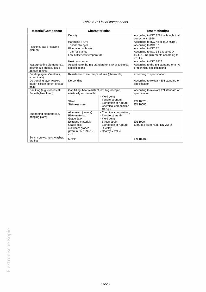
Table 5.2: List of components
Material/Component Characteristics Test method(s)
Flashing, pad or sealingelement
Density According to ISO 2781 with technicalcorrections 1996
Hardness IRDH According to ISO 48 or ISO 7619-2Tensile strength According to ISO 37Elongation at break According to ISO 37Tear resistance According to ISO 34-1 Method ALow brittleness temperature ISO 812 Requirements according to
7.1.1.4Heat resistance According to ISO 1817
Waterproofing element (e.g.bituminous sheets, liquidapplied resins)
According to the EN standard or ETA or technicalspecifications
According to the EN standard or ETAor technical specifications
Bonding agents/sealants,(chemicals)
Resistance to low temperatures (chemicals) according to specification
De-bonding layer (waxedpaper, silicon spray, greasepaint)
De-bonding According to relevant EN standard orspecification
Caulking (e.g. closed cellPolyethylene foam)
Gap filling, heat resistant, not hygroscopic,elastically recoverable
According to relevant EN standard orspecification
Supporting element (e.g.bridging plate)
SteelStainless steel
- Yield point,- Tensile strength,- Elongation at rupture,- Chemical composition
(C-eq.)
EN 10025EN 10088
Aluminium (covers):Plate material:Grade 5xxxExtruded material:Grade 6xxxexcluded: gradesgiven in EN 1999-1-3,cl. 3
- Chemical composition,- Tensile strength,- Yield point,- Stress-strain,- Elongation at rupture,- Ductility,- Charpy-V value
EN 1999Extruded aluminium: EN 755-2
Bolts, screws, nuts, washer,profiles Metals EN 10204
17/28
6. ASSESSING AND JUDGING THE FITNESS OF PRODUCTS FOR ANINTENDED USE
This chapter details the performance requirements to be met (Chapter 4) in precise andmeasurable (as far as possible and proportional to the importance of the risk) or qualitative terms,related to the product and its intended use, using the outcome of the verification methods(Chapter 5).
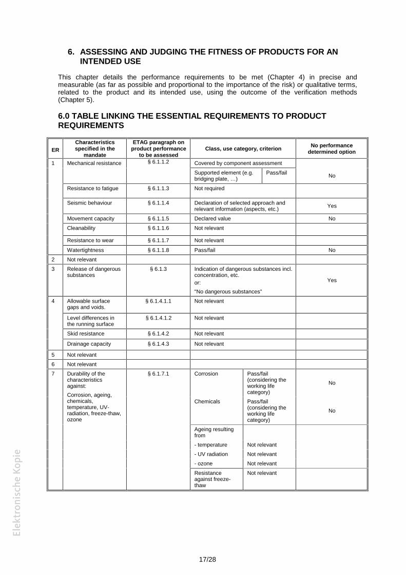
6.0 TABLE LINKING THE ESSENTIAL REQUIREMENTS TO PRODUCTREQUIREMENTS
ERCharacteristicsspecified in the
mandate
ETAG paragraph onproduct performance
to be assessedClass, use category, criterion No performance
determined option
1 Mechanical resistance § 6.1.1.2 Covered by component assessment
Supported element (e.g.bridging plate, …)
Pass/fail No
Resistance to fatigue § 6.1.1.3 Not required
Seismic behaviour § 6.1.1.4 Declaration of selected approach andrelevant information (aspects, etc.) Yes
Movement capacity § 6.1.1.5 Declared value No
Cleanability § 6.1.1.6 Not relevant
Resistance to wear § 6.1.1.7 Not relevant
Watertightness § 6.1.1.8 Pass/fail No
2 Not relevant
3 Release of dangeroussubstances
§ 6.1.3 Indication of dangerous substances incl.concentration, etc.or:"No dangerous substances”
Yes
4 Allowable surfacegaps and voids.
§ 6.1.4.1.1 Not relevant
Level differences inthe running surface
§ 6.1.4.1.2 Not relevant
Skid resistance § 6.1.4.2 Not relevant
Drainage capacity § 6.1.4.3 Not relevant
5 Not relevant
6 Not relevant
7 Durability of thecharacteristicsagainst:Corrosion, ageing,chemicals,temperature, UV-radiation, freeze-thaw,ozone
§ 6.1.7.1 Corrosion Pass/fail(considering theworking lifecategory)
No
Chemicals Pass/fail(considering theworking lifecategory)
No
Ageing resultingfrom- temperature Not relevant- UV radiation Not relevant- ozone Not relevant
Resistanceagainst freeze-thaw
Not relevant
18/28
6.1 KITS
6.1.1 Mechanical resistance and stability
6.1.1.1 General
6.1.1.2 Mechanical resistance
For supported element (e.g. bridging plate):
The product will be judged as fit for purpose, for the designated use categories given in 2.2.1,provided that it satisfies the performance requirements in 4.1.1.2 by the verification procedure asdescribed in 5.1.1.2.
ULS condition: At ULS the bridge plate shall be judged as fit for purpose if it satisfies the designcriteria as defined in Chapter 4 of this Part.
SLS condition: The Buried expansion Joint up to SLS conditions shall be judged as fit for purpose ifit is verified according the methods given in Chapter 5.
6.1.1.3 Resistance to fatigue
The product will be judged as fit for purpose provided that it satisfies the performance requirementsin 4.1.1.3 by the verification procedure as described in 5.1.1.3.
6.1.1.4 Seismic behaviour
Not relevant for this family Part.
6.1.1.5 Movement capacity
The results shall be stated in the ETA.
The BEJ product is judged fit for purpose when it meets the requirements of 4.1.1.5, by analysis ofthe Technical File or by testing, according to 5.1.1.5.
The values achieved in the works may deviate from the tests results because of possible influenceof type and bonding of surfacing layer. This information shall be given in the ETA.
Specific information adaptation in the surfacing layer stated by the manufacturer shall beconsidered, if relevant.
6.1.1.6 Cleanability
Not relevant for this family Part.
6.1.1.7 Resistance to wear
Not relevant for this family Part.
6.1.1.8 Watertightness
After testing in accordance with 5.1.1.8 the product shall remain watertight.
6.1.2 Safety in case of fire
According to Part 1 of this ETAG 032: Not relevant.
19/28
6.1.3 Hygiene, health and environment (ER 3)
6.1.3.1 Release of dangerous substances
The expansion joint shall comply with all relevant European and national provisions applicable forthe uses for which it is brought to the market. The attention of the applicant shall be drawn on thefact that for other uses or other Member States of destination there may be other requirementswhich would have to be respected. For dangerous substances contained in the expansion joint, theNPD option (no performance determined) is applicable.
The expansion joint and/or constituents of the expansion joint listed in the EOTA TR 034: "GeneralChecklist for ETAGs/CUAPs/ETAs -Content and/or release of dangerous substances inproducts/kits”, which have to be considered will be verified by the given methods taking intoaccount the installation conditions of the construction product and the release scenarios resultingfrom there. Regulations related to placing the product on the market may also need to be taken intoaccount.
Regarding the release scenarios referred to in the EOTA TR 034, the use category S/W2 (Productwith no direct contact to but possible impact on soil, ground and surface water have to beconsidered.
6.1.4 Safety in use
6.1.4.1 Ability to bridge gaps and levels in the running surface
Not relevant for this family Part.
6.1.4.2 Skid resistance
Not relevant for this family Part.
6.1.4.3 Drainage capacity
Not relevant for this family Part.
6.1.5 Protection against noise
According to Part 1: Not relevant.
6.1.6 Energy economy and heat retention
According to Part 1: Not relevant.
6.1.7 Aspects of durability, serviceability and identification of the products
6.1.7.1 Aspects of durability
The product shall be judged as fit for purpose when it meets the requirements of 4.1.7.1.
6.1.7.2 Aspects of serviceability
The assessment shall be undertaken according to the verification method given in 5.1.7.2.
6.1.7.3 Aspects of identification of the product
The product is supplied to the construction site as a kit of components. The product shall be judgedas fit for purpose when the individual components are identified in accordance with 4.1.7.3.
6.2 COMPONENTS
The Approval Body shall assess the possible effects on the performance of the expansion joint dueto the variability of the elements and materials characteristics and, where applicable, declaredtolerances.
20/28
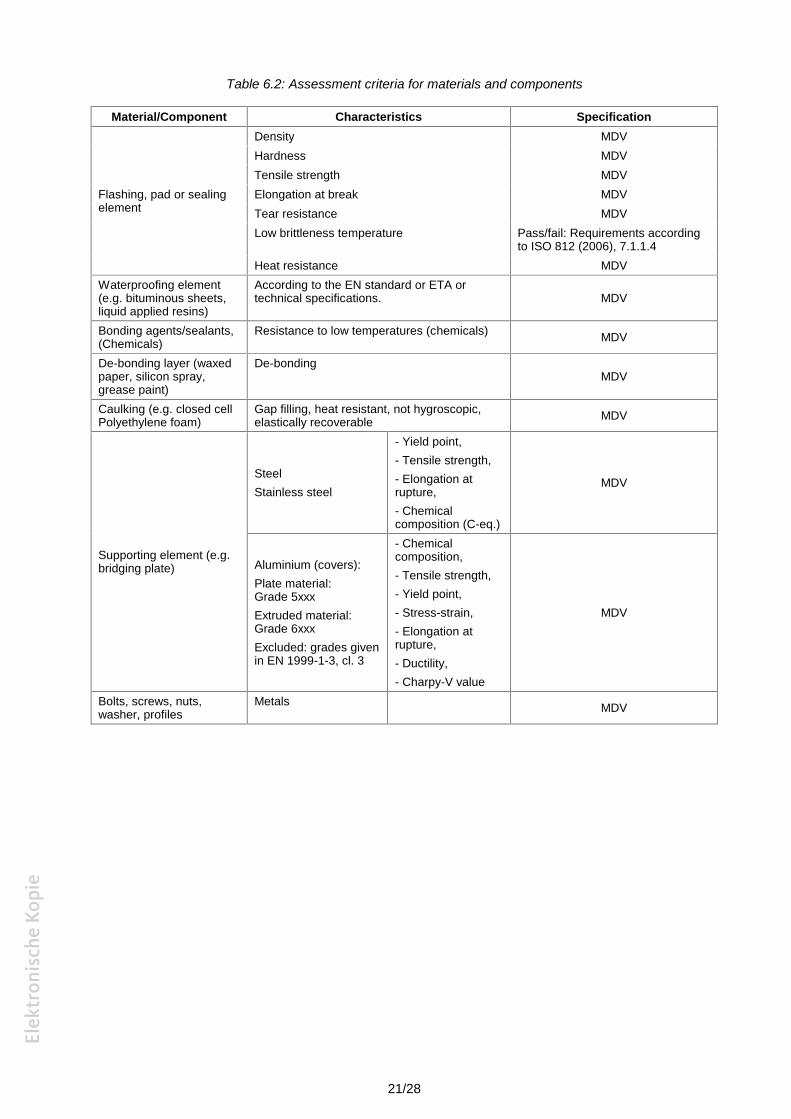
Table 6.2 below presents assessment criteria for materials for the components, defined in 5.2. Forcomponent materials not covered in the table below, appropriate assessment criteria shall be used.The Approval Body shall assess the fitness for purpose of the components based onmanufacturer’s stated values.
Related tolerances shall be declared by the manufacturer and shall be assessed by the ApprovalBody in respect to possible effects on the performance of the product/kit.
21/28
Table 6.2: Assessment criteria for materials and components
Material/Component Characteristics Specification
Flashing, pad or sealingelement
Density MDVHardness MDVTensile strength MDVElongation at break MDVTear resistance MDVLow brittleness temperature Pass/fail: Requirements according
to ISO 812 (2006), 7.1.1.4Heat resistance MDV
Waterproofing element(e.g. bituminous sheets,liquid applied resins)
According to the EN standard or ETA ortechnical specifications. MDV
Bonding agents/sealants,(Chemicals)
Resistance to low temperatures (chemicals) MDV
De-bonding layer (waxedpaper, silicon spray,grease paint)
De-bondingMDV
Caulking (e.g. closed cellPolyethylene foam)
Gap filling, heat resistant, not hygroscopic,elastically recoverable MDV
Supporting element (e.g.bridging plate)
SteelStainless steel
- Yield point,- Tensile strength,- Elongation atrupture,- Chemicalcomposition (C-eq.)
MDV
Aluminium (covers):Plate material:Grade 5xxxExtruded material:Grade 6xxxExcluded: grades givenin EN 1999-1-3, cl. 3
- Chemicalcomposition,- Tensile strength,- Yield point,- Stress-strain,- Elongation atrupture,- Ductility,- Charpy-V value
MDV
Bolts, screws, nuts,washer, profiles
Metals MDV

22/28
7. ASSUMPTIONS AND RECOMMENDATIONS UNDER WHICH THEFITNESS FOR USE OF THE PRODUCTS IS ASSESSED
7.0 GENERAL
See Part 1 of this ETAG.
7.1 DESIGN OF WORKS
(Including, if necessary, indications on project testing)
While the surfacing is not part of the kit, the properties and performance of the surfacing can havea major influence on how the buried expansion joint will perform. Therefore it is very important toensure that the design of the buried expansion joint system is carried out in conjunction with thedesign of the surfacing system. The factors that should be considered to be most important are themovements (including vertical and rotational) and any bonding or de-bonding layers that arerequired in the design of the buried expansion joint. The manufacturer may wish to recommendadditional specific tests for their product that will demonstrate they can provide the requiredperformance. They may also wish to recommend surfacing specifications that have demonstratedthat their buried expansion joint will provide satisfactory service.
7.2 PACKAGING, TRANSPORT AND STORAGE
7.2.1 Packaging
See Part 1 of this ETAG N° 032.
7.2.2 Transport and storage
See Part 1 of this ETAG N° 032.
7.3 EXECUTION OF WORKS
See Part 1 of this ETAG N° 032.
The manufacturer shall show in his Technical Manual how the system will cope with leveldifferences outside the required tolerance. Buried Expansion Joints shall be installed underneath toform continuity of the surfacing across the deck gap.
It is furthermore assumed that the location of installation is absolutely clean and dry beforeinstallation of the kit. If the kit requires for specific pre-treatment of the installation surface themanufacturer shall describe this pre-treatment in the Technical Manual.
7.4 MAINTENANCE AND REPAIR
Because Buried Expansion Joints are covered by surfacing it is not normally possible to carry outmaintenance and repairs to this family of expansion joints. If there are any guidelines formaintenance and repair, including inspection sequences, these shall be part of the Manufacturer’sTechnical File.

23/28
SECTION THREE:ATTESTATION OF CONFORMITY (AC)
8. ATTESTATION AND EVALUATION OF CONFORMITY
8.1 EC DECISION
See Part 1 of this ETAG N° 032.
8.2 RESPONSIBILITIES
8.2.1 Tasks for the manufacturer
The kit manufacturer shall keep available an updated list of component manufacturers. Copies ofthis list shall be made available to the CB1 and may be made available to the Approval Body forinformation.
At least once a year each component manufacturer shall be audited by the kit manufacturer. Eachaudit shall be made available to the CB. These audit reports shall typically include:
Identification of the component manufacturer, Date of audit of component manufacturer, Summary of the results and records of the Factory Production Control (FPC) since last audit, Summary of the complaint records, Evaluation of the component manufacturer concerning FPC, Specific remarks as relevant, Clear and unique statement whether the requirement of the ETA are met, Name and position of signatory, Date of signature, Signature.
The kit manufacturer shall make available all records of relevant results concerning the ETA andthe audit reports concerning the component manufacturers.
However, as a derogation from the audit, where the ETA holder can presume that the componentshave the properties declared of them and have been manufactured according to an appropriateFPC system (e.g. by them bearing the CE marking), the audit is not necessary.
8.2.1.1 Factory production control (FPC)
See Part 1 of this ETAG N° 032.
8.2.1.2 Testing of samples taken at the factory – Prescribed Test Plan
See Part 1 of this ETAG N° 032.
8.2.2 Tasks of the approved body (or in some cases, the manufacturer)
8.2.2.1 General
See Part 1 of this ETAG N° 032.
8.2.2.2 Initial Type Testing and Factory Production Control
See Part 1 of this ETAG N° 032.
As the buried expansion joints are usually assembled at site in general the component testsconducted during type test shall be repeated in the factory production control.
1 CB: Certification Body
24/28
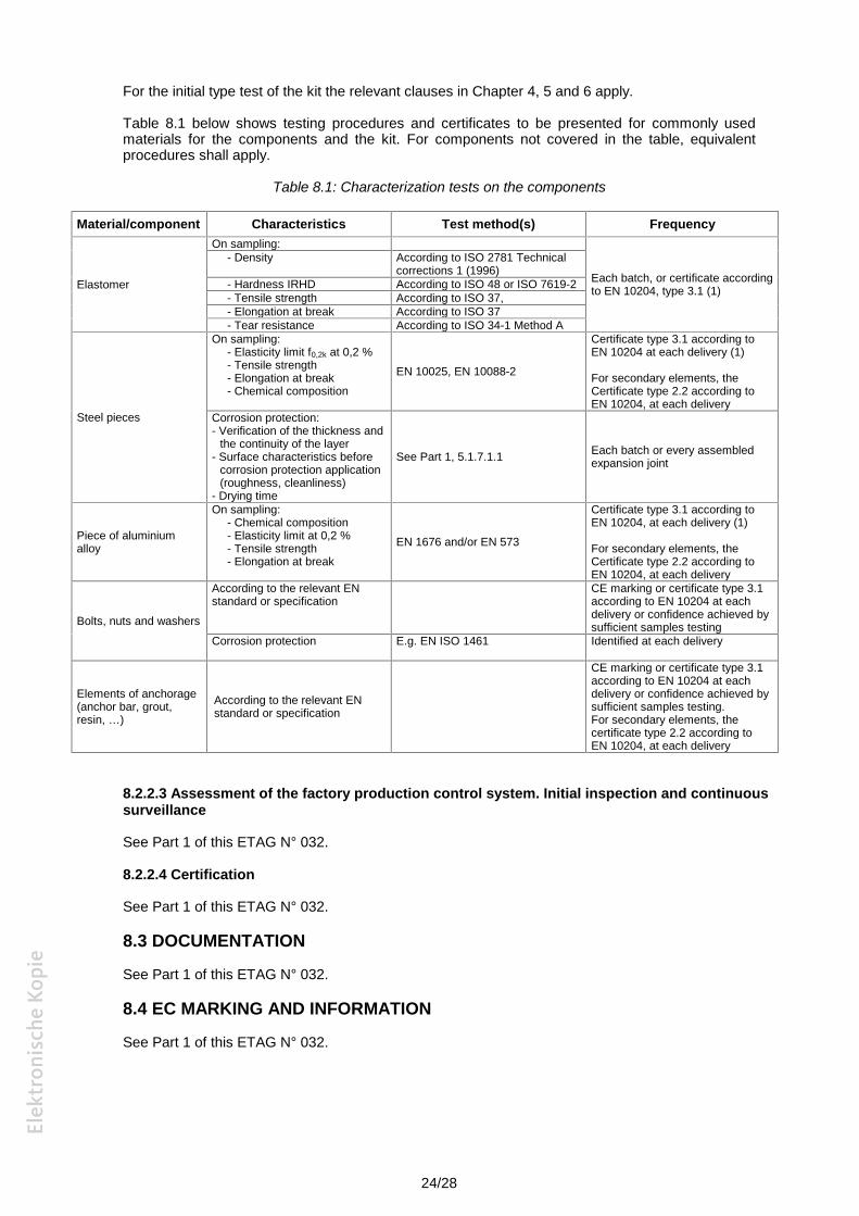
For the initial type test of the kit the relevant clauses in Chapter 4, 5 and 6 apply.
Table 8.1 below shows testing procedures and certificates to be presented for commonly usedmaterials for the components and the kit. For components not covered in the table, equivalentprocedures shall apply.
Table 8.1: Characterization tests on the components
Material/component Characteristics Test method(s) Frequency
Elastomer
On sampling:
Each batch, or certificate accordingto EN 10204, type 3.1 (1)
- Density According to ISO 2781 Technicalcorrections 1 (1996)
- Hardness IRHD According to ISO 48 or ISO 7619-2- Tensile strength According to ISO 37,- Elongation at break According to ISO 37- Tear resistance According to ISO 34-1 Method A
Steel pieces
On sampling:- Elasticity limit f0,2k at 0,2 %- Tensile strength- Elongation at break- Chemical composition
EN 10025, EN 10088-2
Certificate type 3.1 according toEN 10204 at each delivery (1)
For secondary elements, theCertificate type 2.2 according toEN 10204, at each delivery
Corrosion protection:- Verification of the thickness and
the continuity of the layer- Surface characteristics before
corrosion protection application(roughness, cleanliness)
- Drying time
See Part 1, 5.1.7.1.1 Each batch or every assembledexpansion joint
Piece of aluminiumalloy
On sampling:- Chemical composition- Elasticity limit at 0,2 %- Tensile strength- Elongation at break
EN 1676 and/or EN 573
Certificate type 3.1 according toEN 10204, at each delivery (1)
For secondary elements, theCertificate type 2.2 according toEN 10204, at each delivery
Bolts, nuts and washers
According to the relevant ENstandard or specification
CE marking or certificate type 3.1according to EN 10204 at eachdelivery or confidence achieved bysufficient samples testing
Corrosion protection E.g. EN ISO 1461 Identified at each delivery
Elements of anchorage(anchor bar, grout,resin, …)
According to the relevant ENstandard or specification
CE marking or certificate type 3.1according to EN 10204 at eachdelivery or confidence achieved bysufficient samples testing.For secondary elements, thecertificate type 2.2 according toEN 10204, at each delivery
8.2.2.3 Assessment of the factory production control system. Initial inspection and continuoussurveillance
See Part 1 of this ETAG N° 032.
8.2.2.4 Certification
See Part 1 of this ETAG N° 032.
8.3 DOCUMENTATION
See Part 1 of this ETAG N° 032.
8.4 EC MARKING AND INFORMATION
See Part 1 of this ETAG N° 032.
25/28
SECTION FOUR:ETA CONTENT
9. THE ETA CONTENT
See Part 1 of this ETAG N° 032.
26/28
ANNEXES TO THIS ETAG FAMILY PARTAnnexes 2-A to 2-L for this family Part correspond to Annexes A – L in Part 1 of this ETAG N°032,if applicable.
27/28
ANNEX 2-MEXAMPLES OF BURIED JOINTS
Type 1
Type 2
Type 3
28/28
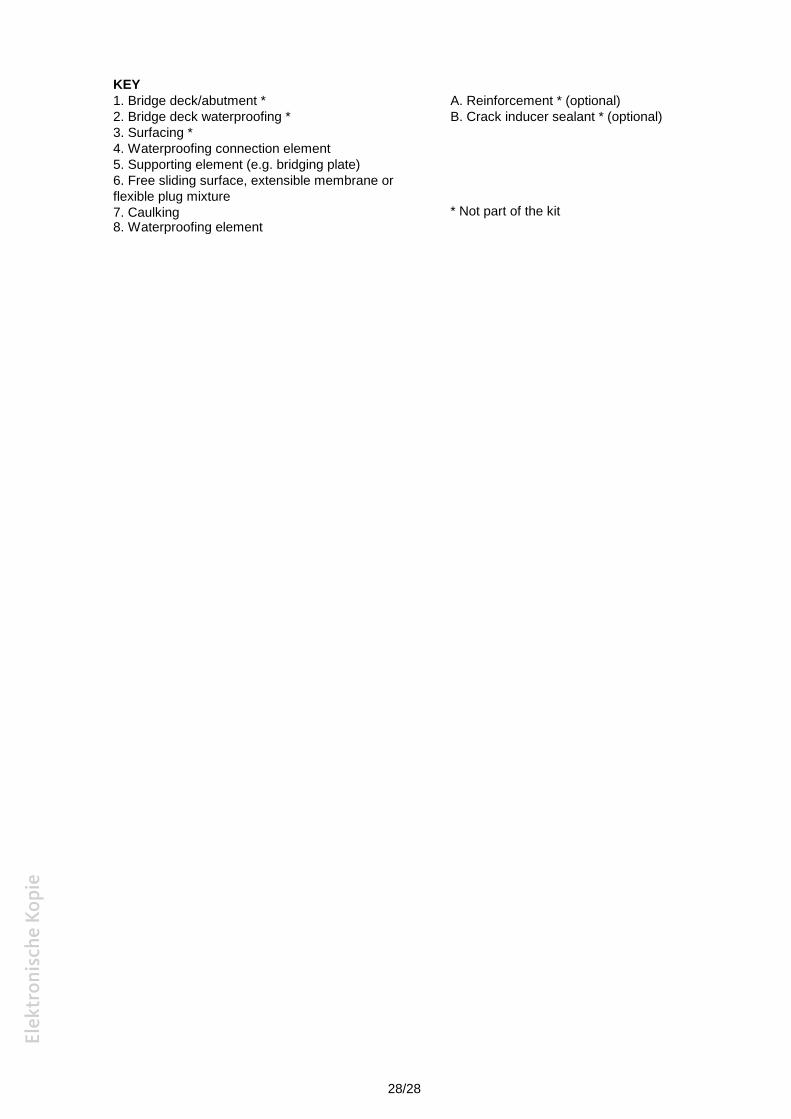
KEY1. Bridge deck/abutment *2. Bridge deck waterproofing *3. Surfacing *4. Waterproofing connection element5. Supporting element (e.g. bridging plate)6. Free sliding surface, extensible membrane orflexible plug mixture7. Caulking8. Waterproofing element
A. Reinforcement * (optional)B. Crack inducer sealant * (optional)
* Not part of the kit