
Throughout Simulation of Manufacturing of Longitudinally ...
17
1 Throughout Simulation of Manufacturing of Longitudinally Welded Steel Pipe with SYSWELD Thilo Reichel 1 , Vitaliy Pavlyk 1 and Tobias Loose 2 1 Eisenbau Krämer GmbH, Karl-Krämer-Str. 12, Kreuztal-Kredenbach, Germany E-Mail: [email protected] , [email protected] 2 Ingenieurbüro Tobias Loose GbR, Haid-und-Neu-Straße 7, Karlsruhe, Germany E-Mail: [email protected] ZUSAMMENFASSUNG Die technologische Herstellungskette eines längsnahtgeschweißten Rohres aus Stahl beinhaltet u.a. folgende Schlüsselprozesse: das Blechbiegen, das Heften mit dem Metall-Schutzgas-Schweißen (MSG), das Unterpulverschweißen (UP), die Einstellung der Form mit einer Kalibrierpresse (Kalibrieren), die Kaltwasserdruckprüfung (KWP) und die Wärmebehandlung. Im Falle eines CLAD-Rohres, das aus einem C-Mn Trägerteil und einem korrosionsbeständigen dünnen Auflagewerkstoff besteht, wird die korrosionsbeständige CLAD-Schicht mittels eines Elektroschlackeschweißens (ESW) entlang der Längsnaht wieder aufgetragen. Alle genannte Schritte beeinflussen den Spannungs- Dehnungszustand des Rohres, die Dimensionstoleranzen und die mechanischen Werkstoffeigenschaften des Produktes. Für die Untersuchung dieser Einflüsse hat eine numerische Simulation einen großen Vorteil, weil Experimente mit einem realen Rohr sehr kosten- und zeitintensiv sind. Dies gilt insbesondere für die Untersuchung der neuen Kalibrierpresse Impander®, die von EBK entwickelt worden ist, und der entsprechenden Kalibriertechnologie für die Herstellung von Impanded Pipes® mittels einer Kompression des Rohres von außen. Dafür hat EBK in Zusammenarbeit mit dem Ingenieurbüro Tobias Loose GbR ein umfassendes Modell des Biegens, des Schweißens, der KWP und der Wärmebehandlung auf Basis von SYSWELD entwickelt und für eine durchgehende Simulation der Rohrherstellung eingesetzt. Dieser Beitrag präsentiert die Methodik der Einbindung einzelner Simulationsschritte mit der Datenübertragung vom vorherigen zum nachfolgenden Herstellungsprozess und die Simulationsergebnisse, die auch eine experimentelle Bestätigung gefunden haben. ABSTRACT The technological production chain of a longitudinally welded steel pipe includes, among other, the following key steps: the plate bending, the tack welding with a gas-metall-arc process (GMAW), the submerged-arc-welding (SAW), the cold sizing of shape with a calibration press (Calibration), the hydro-testing and the heat treatment. In the case of a clad pipe, which consist of a C-Mn bearing part and a thin corrosion resistant clad layer (CRA), the CRA layer is re-deposited along the longitudional seam with resistance electro-slag-welding (ESW). All above steps has impact on the stress-strain state of the pipe, the dimensional tolerances and the mechanical properties of the final product. A numerical simulation for investigation of these influences is of a great advantage, because the experimentations with a real pipe are very time consuming and costly. Especially, the newly developed by EBK calibration machine called Impander® and corresponding cold sizing technology to produce Impanded Pipes® by means of pipe compression from
Transcript of Throughout Simulation of Manufacturing of Longitudinally ...
1
Throughout Simulation of Manufacturing of Longitudinally Welded Steel Pipe with SYSWELD
Thilo Reichel1, Vitaliy Pavlyk
1 and Tobias Loose
2
1 Eisenbau Krämer GmbH, Karl-Krämer-Str. 12, Kreuztal-Kredenbach, Germany
E-Mail: [email protected], [email protected] 2 Ingenieurbüro Tobias Loose GbR, Haid-und-Neu-Straße 7, Karlsruhe, Germany
E-Mail: [email protected]
ZUSAMMENFASSUNG
Die technologische Herstellungskette eines längsnahtgeschweißten Rohres aus
Stahl beinhaltet u.a. folgende Schlüsselprozesse: das Blechbiegen, das Heften mit
dem Metall-Schutzgas-Schweißen (MSG), das Unterpulverschweißen (UP), die
Einstellung der Form mit einer Kalibrierpresse (Kalibrieren), die
Kaltwasserdruckprüfung (KWP) und die Wärmebehandlung. Im Falle eines
CLAD-Rohres, das aus einem C-Mn Trägerteil und einem korrosionsbeständigen
dünnen Auflagewerkstoff besteht, wird die korrosionsbeständige CLAD-Schicht
mittels eines Elektroschlackeschweißens (ESW) entlang der Längsnaht wieder
aufgetragen. Alle genannte Schritte beeinflussen den Spannungs-
Dehnungszustand des Rohres, die Dimensionstoleranzen und die mechanischen
Werkstoffeigenschaften des Produktes. Für die Untersuchung dieser Einflüsse hat
eine numerische Simulation einen großen Vorteil, weil Experimente mit einem
realen Rohr sehr kosten- und zeitintensiv sind. Dies gilt insbesondere für die
Untersuchung der neuen Kalibrierpresse Impander®, die von EBK entwickelt
worden ist, und der entsprechenden Kalibriertechnologie für die Herstellung von
Impanded Pipes® mittels einer Kompression des Rohres von außen. Dafür hat
EBK in Zusammenarbeit mit dem Ingenieurbüro Tobias Loose GbR ein
umfassendes Modell des Biegens, des Schweißens, der KWP und der
Wärmebehandlung auf Basis von SYSWELD entwickelt und für eine durchgehende
Simulation der Rohrherstellung eingesetzt. Dieser Beitrag präsentiert die Methodik
der Einbindung einzelner Simulationsschritte mit der Datenübertragung vom
vorherigen zum nachfolgenden Herstellungsprozess und die
Simulationsergebnisse, die auch eine experimentelle Bestätigung gefunden haben.
ABSTRACT
The technological production chain of a longitudinally welded steel pipe includes,
among other, the following key steps: the plate bending, the tack welding with a
gas-metall-arc process (GMAW), the submerged-arc-welding (SAW), the cold
sizing of shape with a calibration press (Calibration), the hydro-testing and the heat
treatment. In the case of a clad pipe, which consist of a C-Mn bearing part and a
thin corrosion resistant clad layer (CRA), the CRA layer is re-deposited along the
longitudional seam with resistance electro-slag-welding (ESW). All above steps has
impact on the stress-strain state of the pipe, the dimensional tolerances and the
mechanical properties of the final product. A numerical simulation for investigation
of these influences is of a great advantage, because the experimentations with a
real pipe are very time consuming and costly. Especially, the newly developed by
EBK calibration machine called Impander® and corresponding cold sizing
technology to produce Impanded Pipes® by means of pipe compression from
2
outside was in the focus of interest. For this purpose, EBK has developed, in
co-operation with Ingenieurbüro Tobias Loose GbR, a comprehensive model of
bending, welding, hydro-testing and heat treatment, based on SYSWELD. The
model was applied for a throughout simulation of pipe manufacturing process. This
contribution presents the methodology of integration of individual simulation steps
with a data transfer from a previous to the next production step and the simulation
results, which were also validated experimentally.
1 Introduction
Metallurgically cladded pipes are increasingly used in oil and gas industry for transportation of
corrosive products. A combination of a thin layer of corrosion resistant alloy (CRA) and a thick
but cheap carbon steel bulk (usually X52 to X65), which covers the structural task, provides the
best advantage of both types of materials at lowest costs. A tight dimensional tolerance
especially of clad pipe ends, is of great importance for the field welding of girth welds, because
the thickness of a clad layer is usually small (around 3mm). A good matching of two pipe ends
saves time for their adjustment for girth welding and consequently the pipeline manufacturing
costs. The pipe ovality, i.e. the deviation from an ideal round shape results from a non-perfectly
round bending of the plate and from the distortions caused by the longitudinal weld. Moreover,
the residual stresses in the pipe cause a shape change when the pipe is cut in shorter pieces.
Thus, control of residual stresses during the pipe manufacturing is a key issue in achieving good
dimensional tolerances. Changes of internal stress distribution take place in the plate during
bending and closing the gap in course of tack-welding, as well as in the pipe during longitudinal
welding and final sizing. Therefore a calibration procedure for rounding the pipes with
simultaneous reduction of residual stresses is of great importance.
In addition to the above mentioned manufacturing procedures, hydro-testing of the pipe with
internal pressure, post weld heat treatment, machining, expansion and a newly at EBK
developed compression technology called ‘impansion’ change the residual stress distribution in
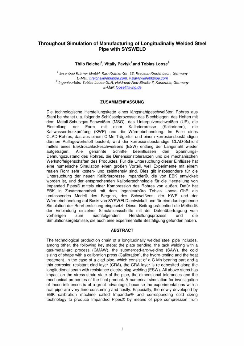
the pipe. We can refer to the available set of manufacturing processes as a ‘tool-box’, with
which the pipe conditions can be modified. This is schematically shown in Figure 1, together
with the illustration of the impact of pipe state on pipe resistance to operational environment
variables, such as internal or external pressure, temperature, corrosive media, fatigue loads, etc.
Under the term ‘pipe conditions’ we mean here the mechanical properties, corrosion resistance,
residual stresses and dimensional variations of the pipe geometry (tolerances). It is also pointed
out, that the tolerances exert a backward influence upon the manufacturing, namely upon the
girth welding of pipe ends during a pipeline construction. Thus, an important improvement of the
pipe properties by means of choice and parameter variations of manufacturing steps can only
be achieved on the basis of a deeper investigation and understanding of the influence that each
manufacturing process exerts on the pipe conditions.
Hereafter in this paper we will consider plate bending, welding, pipe sizing with the Impander®
technology, PWHT and hydro-testing with respect to their influence on the residual stresses and
dimensional pipe tolerances. The carried out investigations and presented results include both,
numerical simulations and experimental studies.
2 Key production steps of clad pipes
A detailed description of clad plate and pipe manufacturing was published previously [Beissel
et al., 2008]] and is additionally supplemented by information in a special brochure [Eisenbau
Krämer, 2007]. Therefore, here we only shortly dwell on the key manufacturing steps, which are
especially important for the residual stress-strain conditions in a pipe.
3
Figure 1 : ‘Tool box’ of manufacturing processes which determine the pipe conditions
and their correlation with operating requirements
2.1 Bending
Plate bending in cold state for circularity shaping is the first manufacturing step, at which
residual stresses arise and essential local plastic strains are induced. Therefore, the influence of
this process on the final pipe state must be considered. When manufacturing clad pipes, EBK
uses a press bending process, called JOC, at which the plate is step-wise formed to ‘J’, ‘C’ and
then ‘O’-shape. The plate edges are either pre-bended or post-bended with additional special
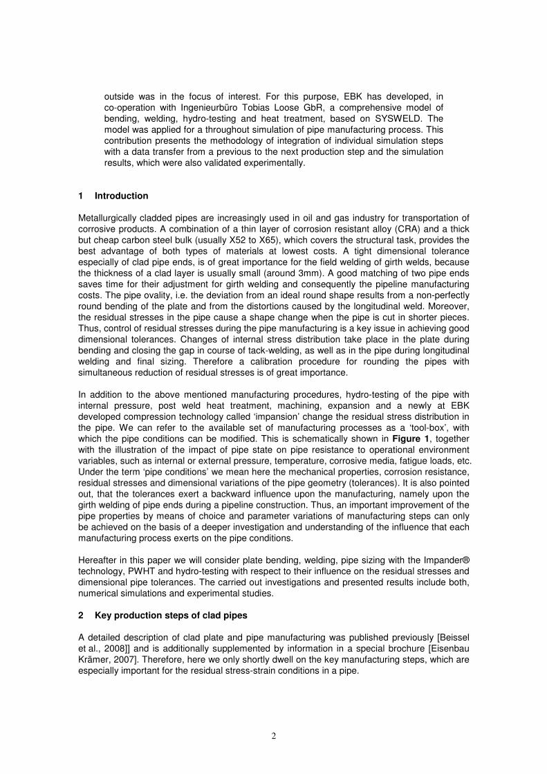
machines. The principle of the press bending process is shown in Figure 2. The 6.200 tonnes
bending press can produce single pipe lengths of up to 44 feet (13.4 m) without circumferential
welds. Pipes can be produced with outside diameters ranging from 12” (323 mm) to 60” (1524
mm). Each bending step, characterised by bending force, tool displacement and plate position,
can be recorded, to be used later as input data for simulation of the plate forming.
2.2 Gap closing and tack welding
After having been formed, the pipe is tack welded from the outside using a GMA welding
process. At this time the remaining after the plate bending gap is closed in a special tack
welding machine with hydraulic cylinder forces, which are applied to the outer side of the pipe in
order to bring both edges of the bent plate in contact. This induces a bending moment across
the pipe wall thickness. As a result, after tack welding is finished and the pipe is released, the
outer part of pipe remains under tension whereas the inner part remains under compression in
circumferential direction. Thus, the gap closing with the tack welding must be considered when
predicting the final pipe stress-strain conditions.
4
Figure 2: JCO bending press
2.3 Submerged-Arc-Welding (SAW)
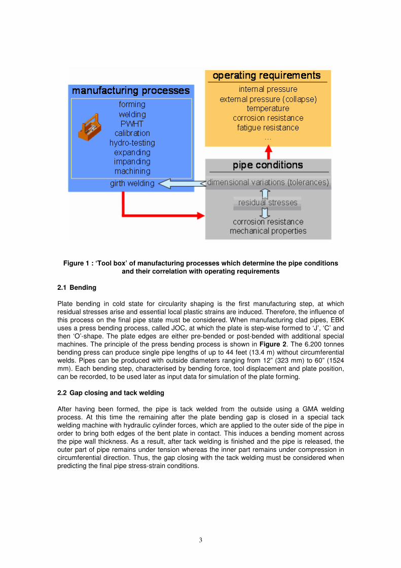
The inside and then the outside part of the base pipe part (e.g. X60) is welded using a single
and/or multilayer SAW technology with square wave power sources (Figure 3). Either 1- or up
to 4-wire process can be utilized, depending on material, wall thickness and toughness
requirements in the weld and HAZ. The heat input during welding induces phase
transformations, thermal stresses and is a major reason for high residual stresses in and around
the weld. Thus, a monitoring of welding parameters (current, voltage, welding and wire feed
speed, etc.) is indispensable for an accurate capture of the input energy, which is necessary for
the simulation of the heat affect of welding.
Figure 3: Submerged-Arc-Welding process
5
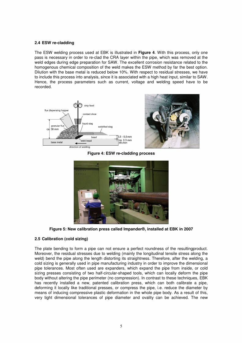
2.4 ESW re-cladding
The ESW welding process used at EBK is illustrated in Figure 4. With this process, only one
pass is necessary in order to re-clad the CRA layer within the pipe, which was removed at the
weld edges during edge preparation for SAW. The excellent corrosion resistance related to the
homogenous chemical composition of the weld makes the ESW method by far the best option.
Dilution with the base metal is reduced below 10%. With respect to residual stresses, we have
to include this process into analysis, since it is associated with a high heat input, similar to SAW.
Hence, the process parameters such as current, voltage and welding speed have to be
recorded.
Figure 4: ESW re-cladding process
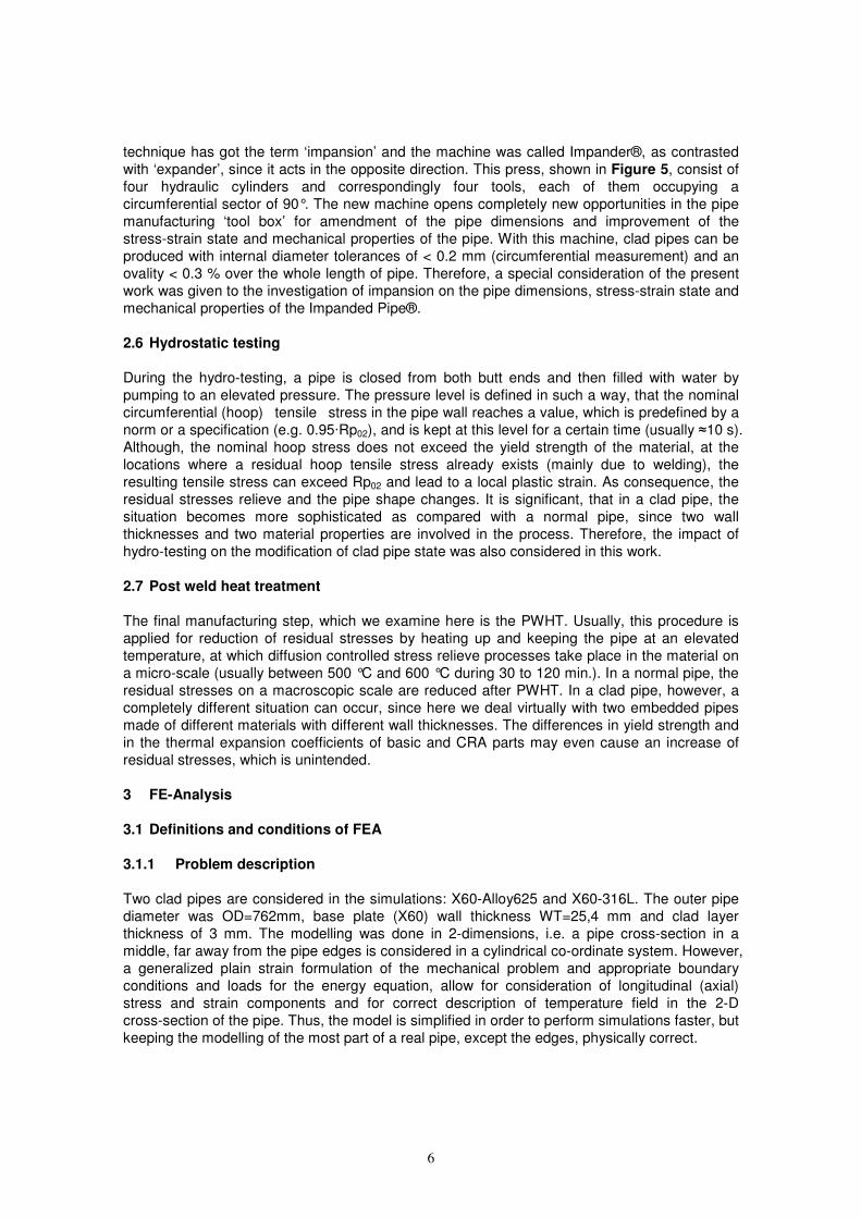
Figure 5: New calibration press called Impander®, installed at EBK in 2007
2.5 Calibration (cold sizing)
The plate bending to form a pipe can not ensure a perfect roundness of the resultingproduct.
Moreover, the residual stresses due to welding (mainly the longitudinal tensile stress along the
weld) bend the pipe along the length distorting its straightness. Therefore, after the welding, a
cold sizing is generally used in pipe manufacturing industry in order to improve the dimensional
pipe tolerances. Most often used are expanders, which expand the pipe from inside, or cold
sizing presses consisting of two half-circular-shaped tools, which can locally deform the pipe
body without altering the pipe perimeter (no compression). In contrast to these techniques, EBK
has recently installed a new, patented calibration press, which can both calibrate a pipe,
deforming it locally like traditional presses, or compress the pipe, i.e. reduce the diameter by
means of inducing compressive plastic deformation in the whole pipe body. As a result of this,
very tight dimensional tolerances of pipe diameter and ovality can be achieved. The new
6
technique has got the term ‘impansion’ and the machine was called Impander®, as contrasted
with ‘expander’, since it acts in the opposite direction. This press, shown in Figure 5, consist of
four hydraulic cylinders and correspondingly four tools, each of them occupying a
circumferential sector of 90°. The new machine opens completely new opportunities in the pipe
manufacturing ‘tool box’ for amendment of the pipe dimensions and improvement of the
stress-strain state and mechanical properties of the pipe. With this machine, clad pipes can be
produced with internal diameter tolerances of < 0.2 mm (circumferential measurement) and an
ovality < 0.3 % over the whole length of pipe. Therefore, a special consideration of the present
work was given to the investigation of impansion on the pipe dimensions, stress-strain state and
mechanical properties of the Impanded Pipe®.
2.6 Hydrostatic testing
During the hydro-testing, a pipe is closed from both butt ends and then filled with water by
pumping to an elevated pressure. The pressure level is defined in such a way, that the nominal
circumferential (hoop) tensile stress in the pipe wall reaches a value, which is predefined by a
norm or a specification (e.g. 0.95·Rp02), and is kept at this level for a certain time (usually ≈10 s).
Although, the nominal hoop stress does not exceed the yield strength of the material, at the
locations where a residual hoop tensile stress already exists (mainly due to welding), the
resulting tensile stress can exceed Rp02 and lead to a local plastic strain. As consequence, the
residual stresses relieve and the pipe shape changes. It is significant, that in a clad pipe, the
situation becomes more sophisticated as compared with a normal pipe, since two wall
thicknesses and two material properties are involved in the process. Therefore, the impact of
hydro-testing on the modification of clad pipe state was also considered in this work.
2.7 Post weld heat treatment
The final manufacturing step, which we examine here is the PWHT. Usually, this procedure is
applied for reduction of residual stresses by heating up and keeping the pipe at an elevated
temperature, at which diffusion controlled stress relieve processes take place in the material on
a micro-scale (usually between 500 °C and 600 °C during 30 to 120 min.). In a normal pipe, the
residual stresses on a macroscopic scale are reduced after PWHT. In a clad pipe, however, a
completely different situation can occur, since here we deal virtually with two embedded pipes
made of different materials with different wall thicknesses. The differences in yield strength and
in the thermal expansion coefficients of basic and CRA parts may even cause an increase of
residual stresses, which is unintended.
3 FE-Analysis
3.1 Definitions and conditions of FEA
3.1.1 Problem description
Two clad pipes are considered in the simulations: X60-Alloy625 and X60-316L. The outer pipe
diameter was OD=762mm, base plate (X60) wall thickness WT=25,4 mm and clad layer
thickness of 3 mm. The modelling was done in 2-dimensions, i.e. a pipe cross-section in a
middle, far away from the pipe edges is considered in a cylindrical co-ordinate system. However,
a generalized plain strain formulation of the mechanical problem and appropriate boundary
conditions and loads for the energy equation, allow for consideration of longitudinal (axial)
stress and strain components and for correct description of temperature field in the 2-D
cross-section of the pipe. Thus, the model is simplified in order to perform simulations faster, but
keeping the modelling of the most part of a real pipe, except the edges, physically correct.
7
3.1.2 Software tool
The simulations were performed using the general purpose FEM software tool SYSWELD®,
which is especially designed for welding and heat treatment processes [ESI, eternal]. The
modelling tools of SYSWELD® allow to carry out thermal, metallurgical and mechanical analysis
simultaneously, using the same FE grid model.
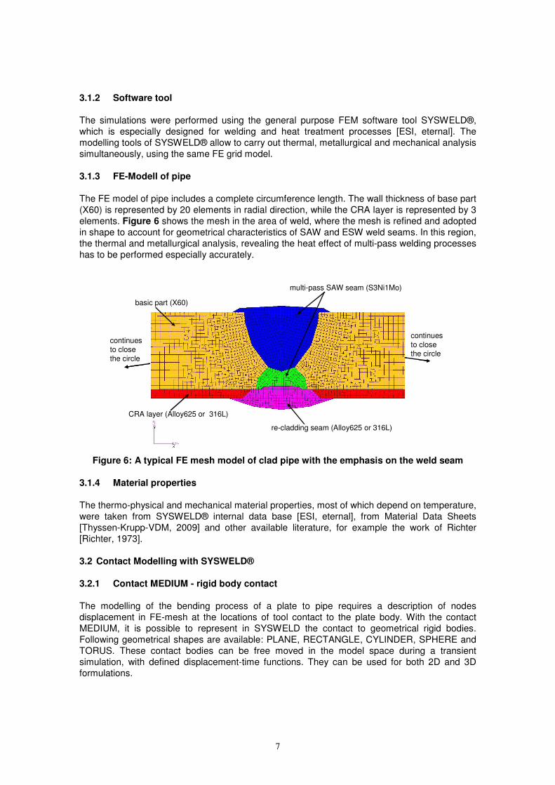
3.1.3 FE-Modell of pipe
The FE model of pipe includes a complete circumference length. The wall thickness of base part
(X60) is represented by 20 elements in radial direction, while the CRA layer is represented by 3
elements. Figure 6 shows the mesh in the area of weld, where the mesh is refined and adopted
in shape to account for geometrical characteristics of SAW and ESW weld seams. In this region,
the thermal and metallurgical analysis, revealing the heat effect of multi-pass welding processes
has to be performed especially accurately.
basic part (X60)
CRA layer (Alloy625 or 316L)
multi-pass SAW seam (S3Ni1Mo)
re-cladding seam (Alloy625 or 316L)
continues
to close the circle
continues to close
the circle
basic part (X60)
CRA layer (Alloy625 or 316L)
multi-pass SAW seam (S3Ni1Mo)
re-cladding seam (Alloy625 or 316L)
continues
to close the circle
continues to close
the circle
Figure 6: A typical FE mesh model of clad pipe with the emphasis on the weld seam
3.1.4 Material properties
The thermo-physical and mechanical material properties, most of which depend on temperature,
were taken from SYSWELD® internal data base [ESI, eternal], from Material Data Sheets
[Thyssen-Krupp-VDM, 2009] and other available literature, for example the work of Richter
[Richter, 1973].
3.2 Contact Modelling with SYSWELD®
3.2.1 Contact MEDIUM - rigid body contact
The modelling of the bending process of a plate to pipe requires a description of nodes
displacement in FE-mesh at the locations of tool contact to the plate body. With the contact
MEDIUM, it is possible to represent in SYSWELD the contact to geometrical rigid bodies.
Following geometrical shapes are available: PLANE, RECTANGLE, CYLINDER, SPHERE and
TORUS. These contact bodies can be free moved in the model space during a transient
simulation, with defined displacement-time functions. They can be used for both 2D and 3D
formulations.
8
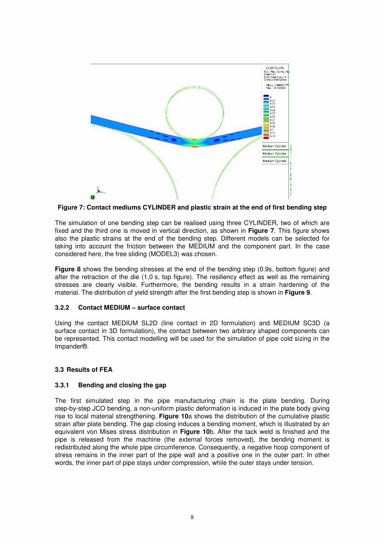
Figure 7: Contact mediums CYLINDER and plastic strain at the end of first bending step
The simulation of one bending step can be realised using three CYLINDER, two of which are
fixed and the third one is moved in vertical direction, as shown in Figure 7. This figure shows
also the plastic strains at the end of the bending step. Different models can be selected for
taking into account the friction between the MEDIUM and the component part. In the case
considered here, the free sliding (MODEL3) was chosen.
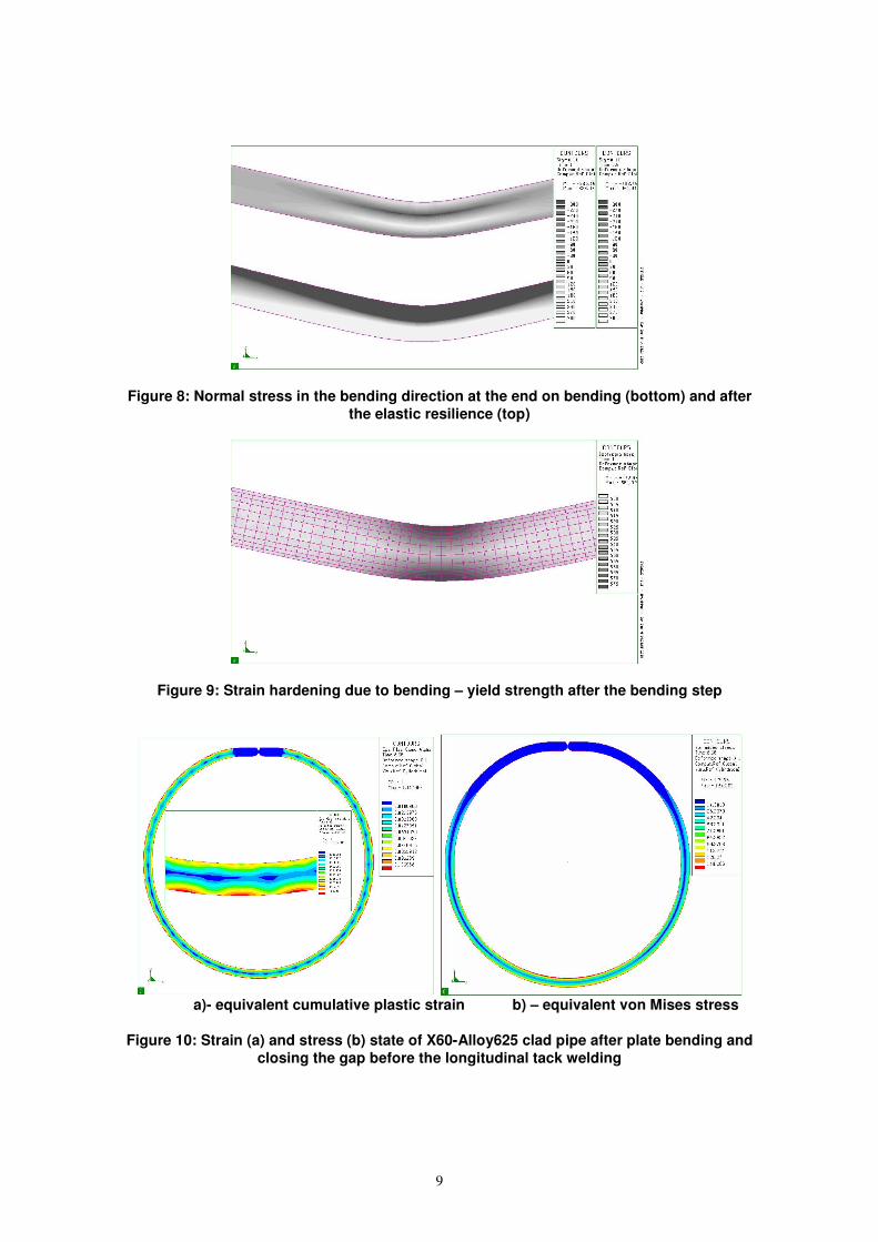
Figure 8 shows the bending stresses at the end of the bending step (0.9s, bottom figure) and
after the retraction of the die (1,0 s, top figure). The resiliency effect as well as the remaining
stresses are clearly visible. Furthermore, the bending results in a strain hardening of the
material. The distribution of yield strength after the first bending step is shown in Figure 9. 3.2.2 Contact MEDIUM – surface contact
Using the contact MEDIUM SL2D (line contact in 2D formulation) and MEDIUM SC3D (a
surface contact in 3D formulation), the contact between two arbitrary shaped components can
be represented. This contact modelling will be used for the simulation of pipe cold sizing in the
Impander®.
3.3 Results of FEA
3.3.1 Bending and closing the gap
The first simulated step in the pipe manufacturing chain is the plate bending. During
step-by-step JCO bending, a non-uniform plastic deformation is induced in the plate body giving
rise to local material strengthening. Figure 10a shows the distribution of the cumulative plastic
strain after plate bending. The gap closing induces a bending moment, which is illustrated by an
equivalent von Mises stress distribution in Figure 10b. After the tack weld is finished and the
pipe is released from the machine (the external forces removed), the bending moment is
redistributed along the whole pipe circumference. Consequently, a negative hoop component of
stress remains in the inner part of the pipe wall and a positive one in the outer part. In other
words, the inner part of pipe stays under compression, while the outer stays under tension.
9
Figure 8: Normal stress in the bending direction at the end on bending (bottom) and after
the elastic resilience (top)
Figure 9: Strain hardening due to bending – yield strength after the bending step
a)- equivalent cumulative plastic strain b) – equivalent von Mises stress
Figure 10: Strain (a) and stress (b) state of X60-Alloy625 clad pipe after plate bending and
closing the gap before the longitudinal tack welding
10
The calculated cumulative strains and stress distributions are passed on to the next simulation
step, as initial pipe state. The cumulative strains modify the yield point locally, in accordance
with the hardening curves of base and CRA materials.
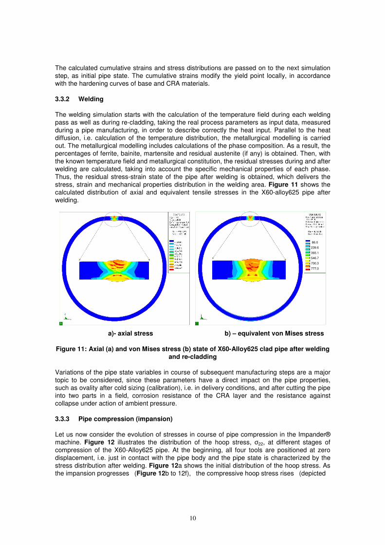
3.3.2 Welding
The welding simulation starts with the calculation of the temperature field during each welding
pass as well as during re-cladding, taking the real process parameters as input data, measured
during a pipe manufacturing, in order to describe correctly the heat input. Parallel to the heat
diffusion, i.e. calculation of the temperature distribution, the metallurgical modelling is carried
out. The metallurgical modelling includes calculations of the phase composition. As a result, the
percentages of ferrite, bainite, martensite and residual austenite (if any) is obtained. Then, with
the known temperature field and metallurgical constitution, the residual stresses during and after
welding are calculated, taking into account the specific mechanical properties of each phase.
Thus, the residual stress-strain state of the pipe after welding is obtained, which delivers the
stress, strain and mechanical properties distribution in the welding area. Figure 11 shows the
calculated distribution of axial and equivalent tensile stresses in the X60-alloy625 pipe after
welding.
86.0
239.6
393.1
546.7
700.3
777.0
86.0
239.6
393.1
546.7
700.3
777.0
a)- axial stress b) – equivalent von Mises stress
Figure 11: Axial (a) and von Mises stress (b) state of X60-Alloy625 clad pipe after welding
and re-cladding
Variations of the pipe state variables in course of subsequent manufacturing steps are a major
topic to be considered, since these parameters have a direct impact on the pipe properties,
such as ovality after cold sizing (calibration), i.e. in delivery conditions, and after cutting the pipe
into two parts in a field, corrosion resistance of the CRA layer and the resistance against
collapse under action of ambient pressure.
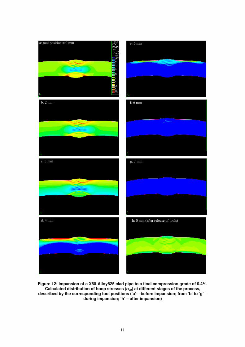
3.3.3 Pipe compression (impansion)
Let us now consider the evolution of stresses in course of pipe compression in the Impander®
machine. Figure 12 illustrates the distribution of the hoop stress, σ22, at different stages of
compression of the X60-Alloy625 pipe. At the beginning, all four tools are positioned at zero
displacement, i.e. just in contact with the pipe body and the pipe state is characterized by the
stress distribution after welding. Figure 12a shows the initial distribution of the hoop stress. As
the impansion progresses (Figure 12b to 12f), the compressive hoop stress rises (depicted
11
Figure 12: Impansion of a X60-Alloy625 clad pipe to a final compression grade of 0.4%.
Calculated distribution of hoop stresses (σσσσ22) at different stages of the process,
described by the corresponding tool positions (‘a’ – before impansion; from ‘b’ to ‘g’ –
during impansion; ‘h’ – after impansion)
a: tool position = 0 mm
b: 2 mm
350
MPa
:-450
с: 3 mm
d: 4 mm
e: 5 mm
f: 6 mm
g: 7 mm
h: 0 mm (after release of tools)
12
0 200 400 600 800 10000
100
200
300
400
500
600
T, [°
C]
t, [min]
0 200 400 600 800 10000
100
200
300
400
500
600
T,
[°C
]
t, [min]
0 200 400 600 800 10000
100
200
300
400
500
600
T,
[°C
]
t, [min]
0 200 400 600 800 10000
100
200
300
400
500
600
T,
[°C
]
t, [min]
0 200 400 600 800 10000
100
200
300
400
500
600
T,
[°C
]
t, [min]
0 200 400 600 800 10000
100
200
300
400
500
600
T,
[°C
]
t, [min]
0 200 400 600 800 10000
100
200
300
400
500
600
T,
[°C
]
t, [min]
0 200 400 600 800 10000
100
200
300
400
500
600
T,
[°C
]
t, [min]
0 200 400 600 800 10000
100
200
300
400
500
600
T,
[°C
]
t, [min]
0 200 400 600 800 1000
0
100
200
300
400
500
600
T,
[°C
]
t, [min]
0 200 400 600 800 10000
100
200
300
400
500
600
T,
[°C
]
t, [min]
0 200 400 600 800 10000
100
200
300
400
500
600
T,
[°C
]
t, [min]
0 200 400 600 800 10000
100
200
300
400
500
600
T,
[°C
]
t, [min]
0 200 400 600 800 10000
100
200
300
400
500
600
T,
[°C
]
t, [min]
0 200 400 600 800 10000
100
200
300
400
500
600
T,
[°C
]
t, [min]
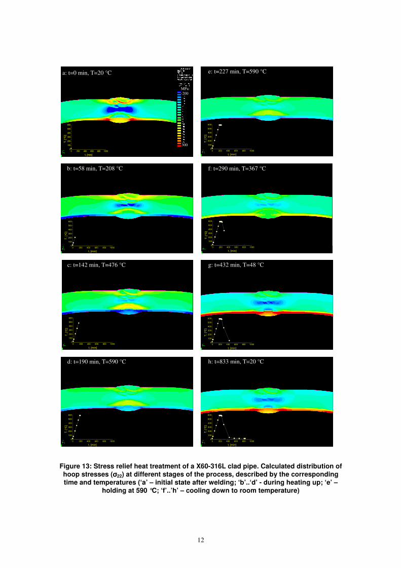
Figure 13: Stress relief heat treatment of a X60-316L clad pipe. Calculated distribution of
hoop stresses (σσσσ22) at different stages of the process, described by the corresponding
time and temperatures (‘a’ – initial state after welding; ‘b’..‘d’ - during heating up; ‘e’ –
holding at 590 °C; ‘f’..’h’ – cooling down to room temperature)
a: t=0 min, T=20 °C
300
MPa:
-200
e: t=227 min, T=590 °C
b: t=58 min, T=208 °C f: t=290 min, T=367 °C
c: t=142 min, T=476 °C g: t=432 min, T=48 °C
h: t=833 min, T=20 °C d: t=190 min, T=590 °C
13
with blue colour), and dominates over the complete pipe body when the tool displacement
reaches the maximum value of 7mm (Figure 12g). We can also observe an increase of tensile
stress (red colour) in the top part of the pipe from both sides of weld (Figure 12d and 12e) due
to a back-bending of the pipe at the plate edges, which were not completely formed to a circular
shape before the welding. After the pipe was released from the tools, a substantially reduced
residual stress level remains in the pipe, as shown in Figure 12h.
3.3.4 Stress relief heat treatment
The evolution of residual stresses in pipe during a stress relief heat treatment will be illustrated
on example of the X60-319L pipe. The temperature circle consists of heating from 20 to 590 °C
within 177 min, holding at 590 °C for 60 min followed by cooling at still air down to room
temperature (graph in Figure 13h). The temperature course in the cooling part was calculated
by solving the heat diffusion with convective heat exchange with air.
The initial residual hoop stress distribution, σ22, after welding is shown in Figure 10a. As
temperature rises, both base and CRA materials expand, which brings about a reduction of
tension (Figure 13b-13d). But, a substantially higher coefficient of thermal expansion of 316L
steel in comparison with X60 (mean integral CTE between 20 and 600 °C: 19*10-6
°C-1
for 316L
vs. 14*10-6
°C-1
for X60), results in a high level of compressive stresses in the CRA part of pipe.
Simultaneously with the expansion a stress relaxation sets on at heating and continues to
proceeds during holding at elevated temperature. Moreover, when the compressive yield point
of 316L is reached, it starts to plasticize limiting the upper compression stress value in the CRA
layer. The stress relaxation results in reduction of both tension and compression stress levels
(Figure 13e) during holding. During cooling, the difference in CTE gives rise to an opposite
effect as during heating, namely an induction of high level of tension in the CRA (Figure
13f-13h). In contrast to heating, during cooling, the yield point of materials gets higher and the
stress relaxation mechanisms slow down. Thus, a higher level of residual stresses compared to
heating is reached. Comparing the initial (Figure 13a) and final (Figure 13h) stress distribution
in the pipe, we can see a significant reduction in residual stresses in the basic X60 part. But, in
the CRA layer, the heat treatment has increased the tension hoop stress level. The tension
stresses in CRA can reduce corrosion resistance, and tend to disconnect the CRA layer from
the basic part. This important effect depends on the material combination (CTE of CRA must be
higher than CTE of the base part) and has to be taken into account when specifying a heat
treatment procedure for clad pipe, especially, if the bonding strength between the parts is
weaker than an ideal metallurgical fusion.
3.4 Summary of maximum stress levels after different manufacturing steps
In order to obtain a comparative information about the effect of different manufacturing steps on
the residual stresses, a set of simulation runs was performed. The state after welding was taken
as initial, with which the comparison will also be performed. Then impansion to 1%;
hydro-testing at a pressure corresponding to 95% of the effective yield of clad pipe (Rp02eff
=
(Rp02X60·WT
X60+Rp02
CRA·WT
CRA)/(WT
X60+WT
CRA)) held for 10 s; and the heat treatment, described
in the previous section were simulated for two combinations of basic part and CRA. In each
case, maximum stress levels in the basic part and in the CRA were evaluated separately.
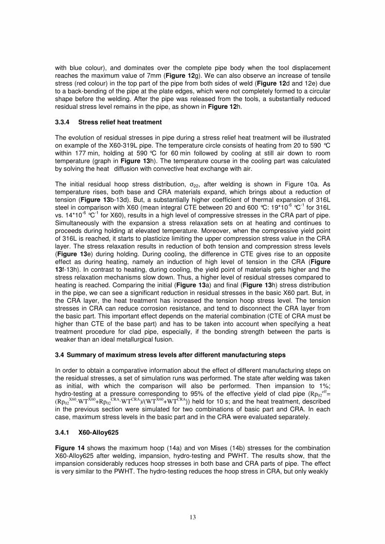
3.4.1 X60-Alloy625
Figure 14 shows the maximum hoop (14a) and von Mises (14b) stresses for the combination
X60-Alloy625 after welding, impansion, hydro-testing and PWHT. The results show, that the
impansion considerably reduces hoop stresses in both base and CRA parts of pipe. The effect
is very similar to the PWHT. The hydro-testing reduces the hoop stress in CRA, but only weakly
14
a)
a)
b)
Figure 14: Influence of different manufacturing processes on maximum stress levels in
base and CRA parts of a X60-Alloy625 clad pipe (‘a’ – hoop stress; ‘b’ -von Mises stress).
Simulations were performed for impansion grade of 1% and for hydro-testing at 95% of
Rp02eff
affects the base part of pipe. This is attributed to a lower yield point, but stronger hardening due
to plastic deformation of Alloy625 in comparison with X60. The highest reduction of von Mises
stress levels is achieved by PWHT (70%) followed by Impansion (50%) (Figure 14b). The effect
of hydro-testing on von Mises stresses is minor.
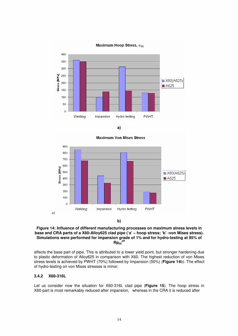
3.4.2 X60-316L
Let us consider now the situation for X60-316L clad pipe (Figure 15). The hoop stress in
X60-part is most remarkably reduced after impansion, whereas in the CRA it is reduced after
15
a)
b)
Figure 15: Influence of different manufacturing processes on maximum stress levels in
base and CRA parts of a X60-316L clad pipe (‘a’ – hoop stress; ‘b’ -von Mises stress).
Simulations were performed for impansion grade of 1% and for hydro-testing at 95% of
Rp02eff
the hydro-testing. So, a combination of impansion followed by the hydro-testing may reduce
hoop stresses in both parts of the pipe. The PWHT reduces the hoop stresses in the base part
at the expense of increasing them in the CRA. Thus, PWHT must be considered very critically in
case of X60-316L clad pipes. Impansion and PWHT reduce the equivalent von Mises stresses
in the X60-part, and only slightly influence them in the CRA layer (Figure 15b).
The hydro-testing has practically no effect on equivalent stresses, much the same like in the
case of X60-Alloy625.
16
The above results, presented in Figure 14 and Figure 15, give us an overview of how the
internal pipe stress state can be changed by different pipe manufacturing processes. A task for
the future is to study the influence of different process combinations on the final stress state in a
clad pipe.
4 Experiment: ring-splitting-test
A method for a quick estimation of residual hoop stresses in a pipe is the so-called
ring-spliting-test. For this, an experimental pipe was manufactured from a X65-Alloy625 clad
plate with the base part wall thickness of 21.6 mm, a CRA layer thickness of 3.6mm and a
length of 5445 mm. A part of pipe was not impanded, other one was impanded to 1% reduction
of diameter. A ring of about 150 mm is cut from the pipe. Then, this ring is saw cut longitudinally
and the displacements of 2 points left and right from the cut position is measured with respect to
their positions before the longitudinal cut. From these measurements, also knowing the pipe
dimensions and Young modulus, the maximum level of hoop stress can be estimated.
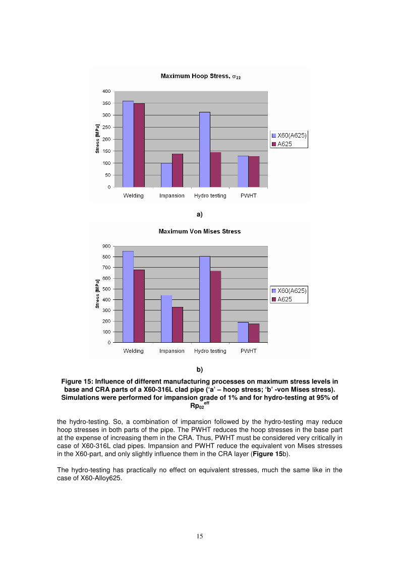
A ring made of a normal (not a clad) pipe, after it has been welded longitudinally, usually opens,
due to a tensile stress in the outer and a compression stress in the inner part of the pipe. The
situation for a clad pipe, however can be completely different. When we perform the
ring-splitting-test at the part of our pipe, which was not impanded, i.e. it was in as-welded
conditions, the cut tends to close. Thus we had to make an additional cut, in order to measure
the displacements of measurement points (Figure 16a).
From the other hand, the impanded portion of the pipe, shows opening of the ring after the cut
(Figure 16b). Thus, after the SAW of X65-part and ESW of CRA layer, a hoop tension at the
inside and compression at the outside part of the wall must be present. The impansion process
appears to reverse the distribution of residual stresses, namely to tension inside and
compression outside, as it follows from the experiment. These conclusions are completely
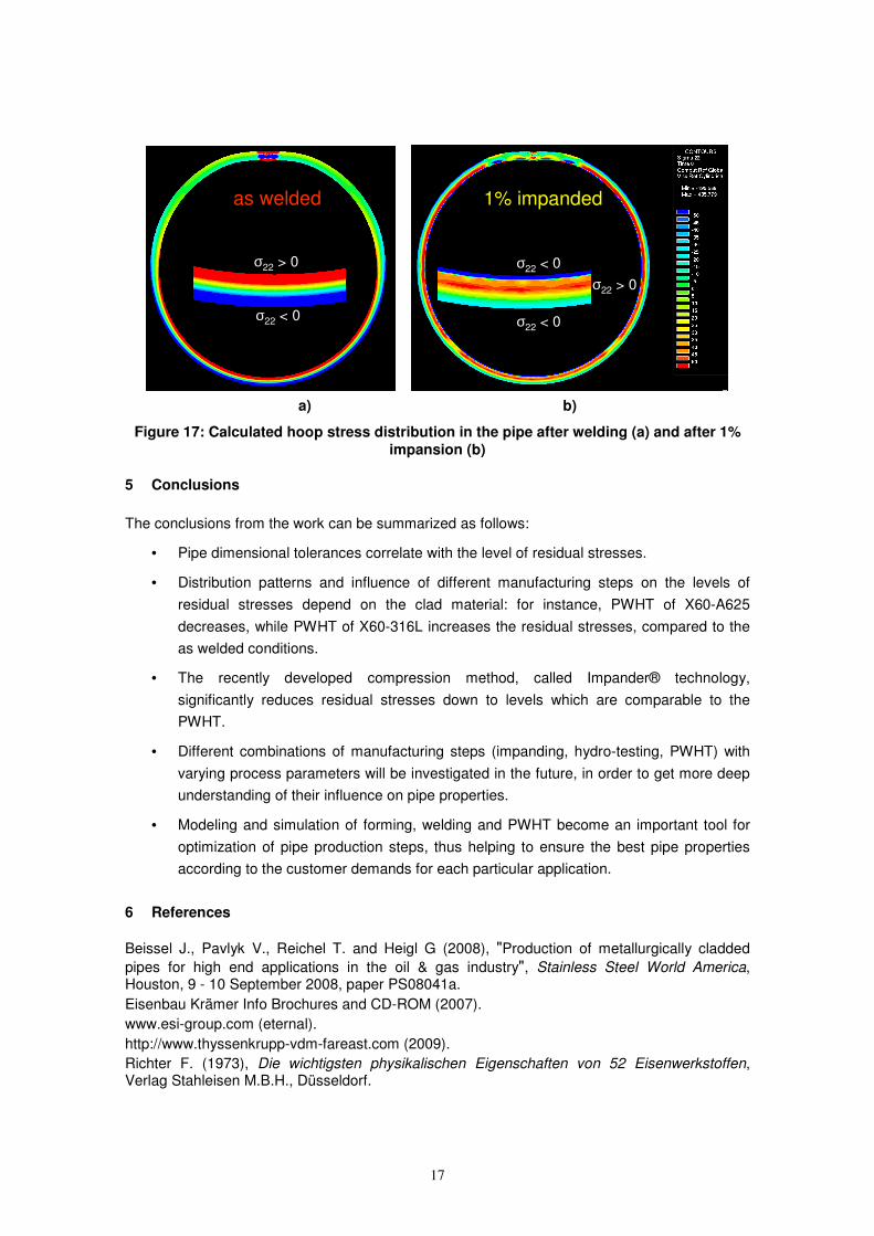
confirmed by the simulation results, described above. Figure 17 shows the distribution of
residual hoop stresses after welding, including ESW (Figure 17a), and after impansion to 1%
(Figure 17b). The colour scale of stresses is restricted to a shorter range from -50 to 50 MPa in
order to point out the signs of the stresses. After welding, we clearly see the tension in the inner
part of the pipe. After the impansion, the distribution becomes more complicated, but with a
clear domination of compression at inner part of the pipe in the CRA layer.
a) b)
Figure 16: Ring splitting test. The pipe ring in the conditions after welding (a) tends to
close the cut gap, while after impansion (b) it tends to open the cut gap
17
as welded
σ22 < 0
σ22 > 0
as welded
σ22 < 0
σ22 > 0
1% impanded
σ22 < 0
σ22 < 0
σ22 > 0
1% impanded
σ22 < 0
σ22 < 0
σ22 > 0
a) b)
Figure 17: Calculated hoop stress distribution in the pipe after welding (a) and after 1%
impansion (b)
5 Conclusions
The conclusions from the work can be summarized as follows:
• Pipe dimensional tolerances correlate with the level of residual stresses.
• Distribution patterns and influence of different manufacturing steps on the levels of
residual stresses depend on the clad material: for instance, PWHT of X60-A625
decreases, while PWHT of X60-316L increases the residual stresses, compared to the
as welded conditions.
• The recently developed compression method, called Impander® technology,
significantly reduces residual stresses down to levels which are comparable to the
PWHT.
• Different combinations of manufacturing steps (impanding, hydro-testing, PWHT) with
varying process parameters will be investigated in the future, in order to get more deep
understanding of their influence on pipe properties.
• Modeling and simulation of forming, welding and PWHT become an important tool for
optimization of pipe production steps, thus helping to ensure the best pipe properties
according to the customer demands for each particular application.
6 References
Beissel J., Pavlyk V., Reichel T. and Heigl G (2008), "Production of metallurgically cladded
pipes for high end applications in the oil & gas industry", Stainless Steel World America, Houston, 9 - 10 September 2008, paper PS08041a.
Eisenbau Krämer Info Brochures and CD-ROM (2007).
www.esi-group.com (eternal).
http://www.thyssenkrupp-vdm-fareast.com (2009).
Richter F. (1973), Die wichtigsten physikalischen Eigenschaften von 52 Eisenwerkstoffen, Verlag Stahleisen M.B.H., Düsseldorf.