Trio Manual de eng 1
56
MANUAL www.mindprint.com MANUAL 1.0 DEUTSCH ENGLISH
Transcript of Trio Manual de eng 1

MANUALw
ww
.min
dpri
nt.c
om
MANUAL
1.0
DE
UT
SC
HE
NG
LIS
H

MindPrint® T.R.I.O.
Important:Please read safety instructions on page 50 - 51 before use!
Wichtig:Bitte lesen Sie vor der Inbetriebnahme die Sicherheitshinweise auf Seite 50!
Important :Avant la mise en service, prière de lire les consignes de sécurité à la page 51 !
Importante:Prima di utilizzare lo strumento, leggere attentamente gli avvisi di sicurezza su pagina 52!
Importante:¡Antes de la puesta en servicio lea por favor las indicaciones de seguridaden la página 52!
3
MindPrint® T.R.I.O.
EN
GL
ISH
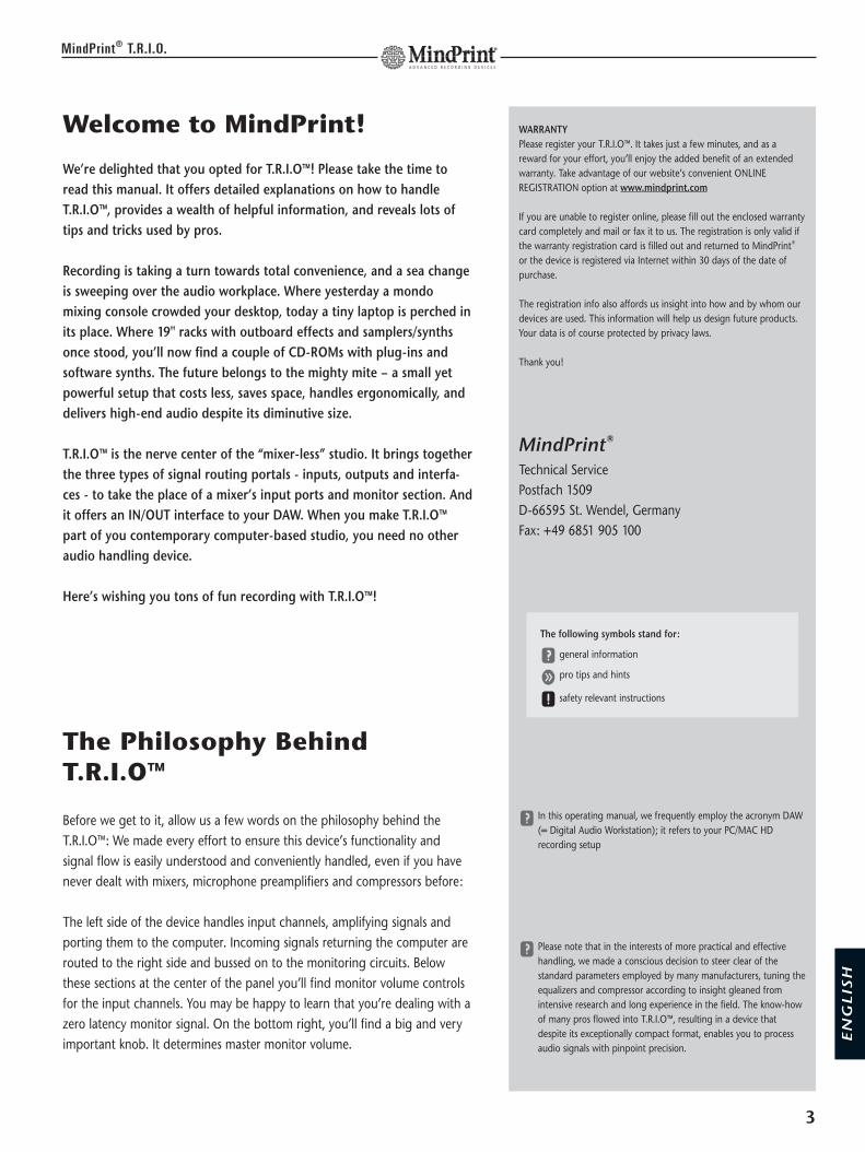
Welcome to MindPrint!
We’re delighted that you opted for T.R.I.O™! Please take the time toread this manual. It offers detailed explanations on how to handleT.R.I.O™, provides a wealth of helpful information, and reveals lots oftips and tricks used by pros.
Recording is taking a turn towards total convenience, and a sea changeis sweeping over the audio workplace. Where yesterday a mondomixing console crowded your desktop, today a tiny laptop is perched inits place. Where 19" racks with outboard effects and samplers/synthsonce stood, you’ll now find a couple of CD-ROMs with plug-ins andsoftware synths. The future belongs to the mighty mite – a small yetpowerful setup that costs less, saves space, handles ergonomically, anddelivers high-end audio despite its diminutive size.
T.R.I.O™ is the nerve center of the “mixer-less” studio. It brings togetherthe three types of signal routing portals - inputs, outputs and interfa-ces - to take the place of a mixer’s input ports and monitor section. Andit offers an IN/OUT interface to your DAW. When you make T.R.I.O™part of you contemporary computer-based studio, you need no otheraudio handling device.
Here’s wishing you tons of fun recording with T.R.I.O™!
The Philosophy BehindT.R.I.O™
Before we get to it, allow us a few words on the philosophy behind theT.R.I.O™: We made every effort to ensure this device’s functionality andsignal flow is easily understood and conveniently handled, even if you havenever dealt with mixers, microphone preamplifiers and compressors before:
The left side of the device handles input channels, amplifying signals andporting them to the computer. Incoming signals returning the computer arerouted to the right side and bussed on to the monitoring circuits. Belowthese sections at the center of the panel you’ll find monitor volume controlsfor the input channels. You may be happy to learn that you’re dealing with azero latency monitor signal. On the bottom right, you’ll find a big and veryimportant knob. It determines master monitor volume.
WARRANTYPlease register your T.R.I.O™. It takes just a few minutes, and as areward for your effort, you’ll enjoy the added benefit of an extendedwarranty. Take advantage of our website’s convenient ONLINEREGISTRATION option at www.mindprint.com
If you are unable to register online, please fill out the enclosed warrantycard completely and mail or fax it to us. The registration is only valid ifthe warranty registration card is filled out and returned to MindPrint®
or the device is registered via Internet within 30 days of the date ofpurchase.
The registration info also affords us insight into how and by whom ourdevices are used. This information will help us design future products.Your data is of course protected by privacy laws.
Thank you!
MindPrint®
Technical ServicePostfach 1509D-66595 St. Wendel, GermanyFax: +49 6851 905 100
y In this operating manual, we frequently employ the acronym DAW(= Digital Audio Workstation); it refers to your PC/MAC HDrecording setup
y Please note that in the interests of more practical and effectivehandling, we made a conscious decision to steer clear of thestandard parameters employed by many manufacturers, tuning theequalizers and compressor according to insight gleaned fromintensive research and long experience in the field. The know-howof many pros flowed into T.R.I.O™, resulting in a device thatdespite its exceptionally compact format, enables you to processaudio signals with pinpoint precision.
The following symbols stand for:
y general information
g pro tips and hints
x safety relevant instructions

Table of contents
Front View . . . . . . . . . . . . . . . . . . . . . . . . . . . . . . . . . . . . 5
Rear Panel . . . . . . . . . . . . . . . . . . . . . . . . . . . . . . . . . . . . 6
Bottom View . . . . . . . . . . . . . . . . . . . . . . . . . . . . . . . . . . 6
Getting started . . . . . . . . . . . . . . . . . . . . . . . . . . . . . . . . . 7
1. MIC/INSTR. input . . . . . . . . . . . . . . . . . . . . . . . . . . . 81.1 GAIN . . . . . . . . . . . . . . . . . . . . . . . . . . . . . . . . . . . . . . .81.2 HF . . . . . . . . . . . . . . . . . . . . . . . . . . . . . . . . . . . . . . . . .81.3 LF . . . . . . . . . . . . . . . . . . . . . . . . . . . . . . . . . . . . . . . . .81.4 FAT . . . . . . . . . . . . . . . . . . . . . . . . . . . . . . . . . . . . . . . .91.5 REC VOL. . . . . . . . . . . . . . . . . . . . . . . . . . . . . . . . . . . . .91.6 MUTE . . . . . . . . . . . . . . . . . . . . . . . . . . . . . . . . . . . . . .91.7 48 V . . . . . . . . . . . . . . . . . . . . . . . . . . . . . . . . . . . . . . .91.8 LOW CUT . . . . . . . . . . . . . . . . . . . . . . . . . . . . . . . . . . .91.9 INSERT . . . . . . . . . . . . . . . . . . . . . . . . . . . . . . . . . . . . .10
2. Stereo LINE input . . . . . . . . . . . . . . . . . . . . . . . . . . 102.1 L/MONO . . . . . . . . . . . . . . . . . . . . . . . . . . . . . . . . . . .102.2 R . . . . . . . . . . . . . . . . . . . . . . . . . . . . . . . . . . . . . . . . .102.3 HF . . . . . . . . . . . . . . . . . . . . . . . . . . . . . . . . . . . . . . . .102.4 LF . . . . . . . . . . . . . . . . . . . . . . . . . . . . . . . . . . . . . . . .112.5 REC VOL. . . . . . . . . . . . . . . . . . . . . . . . . . . . . . . . . . . .112.6 MUTE . . . . . . . . . . . . . . . . . . . . . . . . . . . . . . . . . . . . .11
3. ZERO LATENCY MONITOR VOLUMES . . . . . . . . . . . 123.1 MIC/INSTR. . . . . . . . . . . . . . . . . . . . . . . . . . . . . . . . . .123.2 LINE . . . . . . . . . . . . . . . . . . . . . . . . . . . . . . . . . . . . . . .123.3 AUX input . . . . . . . . . . . . . . . . . . . . . . . . . . . . . . . . . .123.4 MONITOR ON . . . . . . . . . . . . . . . . . . . . . . . . . . . . . . .123.5 DAW ON . . . . . . . . . . . . . . . . . . . . . . . . . . . . . . . . . . .13
4. Monitor Management Section . . . . . . . . . . . . . . . . 134.1 VOLUME . . . . . . . . . . . . . . . . . . . . . . . . . . . . . . . . . . .134.2 SPEAKERS A, B und C . . . . . . . . . . . . . . . . . . . . . . . . .134.3 DIRECT OUT . . . . . . . . . . . . . . . . . . . . . . . . . . . . . . . .144.4 MONO . . . . . . . . . . . . . . . . . . . . . . . . . . . . . . . . . . . . .144.5 DIM . . . . . . . . . . . . . . . . . . . . . . . . . . . . . . . . . . . . . . .144.6 SPEAKERS B LEVEL ADJUST . . . . . . . . . . . . . . . . . . . . .14
5. Metering Section . . . . . . . . . . . . . . . . . . . . . . . . . . 155.1 METER SELECT . . . . . . . . . . . . . . . . . . . . . . . . . . . . . .15
6. Headphones Section . . . . . . . . . . . . . . . . . . . . . . . 166.1 PHONES A . . . . . . . . . . . . . . . . . . . . . . . . . . . . . . . . . .166.2 PHONES B . . . . . . . . . . . . . . . . . . . . . . . . . . . . . . . . . .16
7. Talkback Section . . . . . . . . . . . . . . . . . . . . . . . . . . . 177.1 TALKBACK . . . . . . . . . . . . . . . . . . . . . . . . . . . . . . . . . .177.2 TB VOLUME . . . . . . . . . . . . . . . . . . . . . . . . . . . . . . . . .177.3 TB MIC . . . . . . . . . . . . . . . . . . . . . . . . . . . . . . . . . . . .17
8. DAW INTERFACE . . . . . . . . . . . . . . . . . . . . . . . . . . . 188.1 ANALOG OUT L/R . . . . . . . . . . . . . . . . . . . . . . . . . . . .188.2 ANALOG OUTPUT LEVEL ADJUST . . . . . . . . . . . . . . . .188.3 ANALOG IN L/R . . . . . . . . . . . . . . . . . . . . . . . . . . . . . .188.4 ANALOG INPUT LEVEL ADJUST . . . . . . . . . . . . . . . . . .188.5 DIGITAL INTERFACE . . . . . . . . . . . . . . . . . . . . . . . . . . .188.6 SYNCHRONISATION . . . . . . . . . . . . . . . . . . . . . . . . . .18
9. DIGITAL INTERFACE . . . . . . . . . . . . . . . . . . . . . . . . 199.1 S/P-DIF IN . . . . . . . . . . . . . . . . . . . . . . . . . . . . . . . . . .199.2 S/P-DIF OUT . . . . . . . . . . . . . . . . . . . . . . . . . . . . . . . .199.3 SYNC LED . . . . . . . . . . . . . . . . . . . . . . . . . . . . . . . . . .199.4 44,1/48 . . . . . . . . . . . . . . . . . . . . . . . . . . . . . . . . . . . .199.5 x1/x2 . . . . . . . . . . . . . . . . . . . . . . . . . . . . . . . . . . . . . .199.6 MASTER/SLAVE . . . . . . . . . . . . . . . . . . . . . . . . . . . . . .20
10. RECORD/MONITOR MODE SELECTOR . . . . . . . . . . 2010.1 MIC/INSTR. RECORD . . . . . . . . . . . . . . . . . . . . . . . . . .2010.2 MIC/INSTR. MONITOR . . . . . . . . . . . . . . . . . . . . . . . .2010.3 LINE RECORD . . . . . . . . . . . . . . . . . . . . . . . . . . . . . . .2010.4 LINE MONITOR . . . . . . . . . . . . . . . . . . . . . . . . . . . . . .20
11. Other Features . . . . . . . . . . . . . . . . . . . . . . . . . . . . 2111.1 POWER Switch . . . . . . . . . . . . . . . . . . . . . . . . . . . . . . .2111.2 Mains Socket . . . . . . . . . . . . . . . . . . . . . . . . . . . . . . . .2111.3 GND . . . . . . . . . . . . . . . . . . . . . . . . . . . . . . . . . . . . . .21
12. Fault Diagnosis . . . . . . . . . . . . . . . . . . . . . . . . . . . 22
13. Technical Specification . . . . . . . . . . . . . . . . . . . . . . 23
14. Block Diagram . . . . . . . . . . . . . . . . . . . . . . . . . . . . 55
15. Safety Instructions . . . . . . . . . . . . . . . . . . . . . . 50/51
4
MindPrint® T.R.I.O.
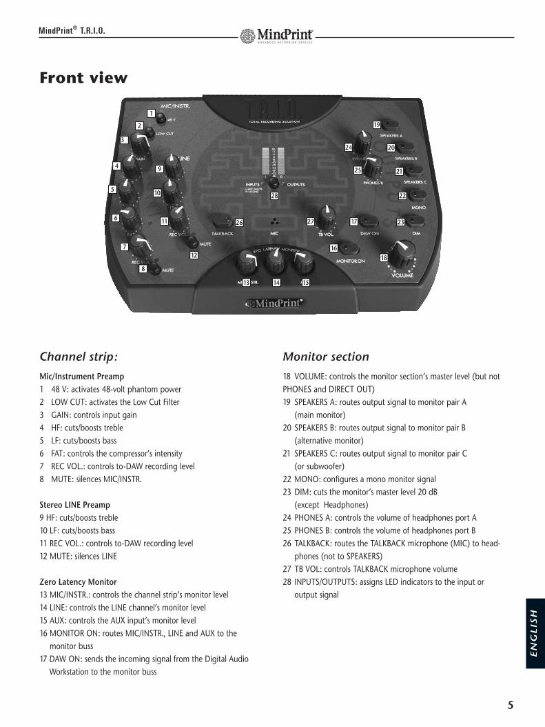
Front view
Channel strip:
Mic/Instrument Preamp1 48 V: activates 48-volt phantom power 2 LOW CUT: activates the Low Cut Filter 3 GAIN: controls input gain4 HF: cuts/boosts treble5 LF: cuts/boosts bass6 FAT: controls the compressor’s intensity7 REC VOL.: controls to-DAW recording level8 MUTE: silences MIC/INSTR.
Stereo LINE Preamp9 HF: cuts/boosts treble10 LF: cuts/boosts bass11 REC VOL.: controls to-DAW recording level12 MUTE: silences LINE
Zero Latency Monitor13 MIC/INSTR.: controls the channel strip’s monitor level14 LINE: controls the LINE channel’s monitor level15 AUX: controls the AUX input’s monitor level16 MONITOR ON: routes MIC/INSTR., LINE and AUX to the
monitor buss17 DAW ON: sends the incoming signal from the Digital Audio
Workstation to the monitor buss
Monitor section
18 VOLUME: controls the monitor section’s master level (but notPHONES and DIRECT OUT)19 SPEAKERS A: routes output signal to monitor pair A
(main monitor)20 SPEAKERS B: routes output signal to monitor pair B
(alternative monitor)21 SPEAKERS C: routes output signal to monitor pair C
(or subwoofer)22 MONO: configures a mono monitor signal23 DIM: cuts the monitor’s master level 20 dB
(except Headphones)24 PHONES A: controls the volume of headphones port A25 PHONES B: controls the volume of headphones port B26 TALKBACK: routes the TALKBACK microphone (MIC) to head-
phones (not to SPEAKERS)27 TB VOL: controls TALKBACK microphone volume28 INPUTS/OUTPUTS: assigns LED indicators to the input or
output signal
5
MindPrint® T.R.I.O.
EN
GL
ISH
1
3
4
5
6
7
8
9
10
11
12
26
13 14 15
28
24
25
27
16
17
18
23
22
21
20
192
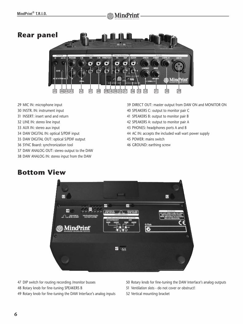
29 MIC IN: microphone input 30 INSTR. IN: instrument input 31 INSERT: insert send and return 32 LINE IN: stereo line input33 AUX IN: stereo aux input 34 DAW DIGITAL IN: optical S/PDIF input35 DAW DIGITAL OUT: optical S/PDIF output36 SYNC Board: synchronization tool37 DAW ANALOG OUT: stereo output to the DAW 38 DAW ANALOG IN: stereo input from the DAW
39 DIRECT OUT: master output from DAW ON and MONITOR ON 40 SPEAKERS C: output to monitor pair C41 SPEAKERS B: output to monitor pair B42 SPEAKERS A: output to monitor pair A43 PHONES: headphones ports A and B44 AC IN: accepts the included wall wart power supply45 POWER: mains switch46 GROUND: earthing screw
Rear panel
6
MindPrint® T.R.I.O.
47 DIP switch for routing recording /monitor busses48 Rotary knob for fine-tuning SPEAKERS B 49 Rotary knob for fine-tuning the DAW Interface’s analog inputs
50 Rotary knob for fine-tuning the DAW Interface’s analog outputs51 Ventilation slots - do not cover or obstruct!52 Vertical mounting bracket
Bottom View
29303132333635 37383439404142434445
49 5051
5252
47
48
46

Getting Started
Before you fire up T.R.I.O™ for the first time, take a moment or two toconfigure your rig. With our suggested setup, handling will be a pleasurerather than a pain. If your recording rig comprises a computer, capacitormicrophone, keyboard, CD player and monitors, then a basic configurationthat lets you deal with all connected signal sources directly looks like this:
Input Section
T.R.I.O™ features a full-fledged input section comprising a low-noise, class Amicrophone input stage featuring switchable phantom power for capacitormicrophones, a high-impedance instrument input and a studio level lineinput.
7
MindPrint® T.R.I.O.
FOR QUICK-STARTERSIf you’re accustomed to working with conventional mixers, you shouldhave no trouble handling T.R.I.O™ without further fuss.
However, there are a few things you should bear in mind: The two RECVOL. knobs control the recording levels of the signals sent to the DAW,and NOT the monitor busses’ levels! Twist the knobs at the bottomcenter (in the ZERO LATENCY MONITORING section) to adjust themonitor volume. So, don’t be surprised to hear the LINE signal evenwhen the LINE REC VOL. knob at the bottom left is turned all theway down.
y The MIC/INSTR. input and LINE input may be used and recordedsimultaneously.
EN
GL
ISH
Basic settings to hear all signals of T.R.I.O.™
to monitor speakers
microphone phantom power
microphone input gain
microphonerecordinglevel
line recording level
speaker on
DAW return on
monitor section on
master volumecontrol
to/from computer DAW) from line (key-board/sampler)
from microphonefrom CD-player
monitor volume for:
mic line cd player

1. MIC/INSTR. Input
Connecting signal sources:
Located on the T.R.I.O™’s rear panel is an XLR port designed to accept amicrophone. It is wired in compliance with the international standard (pin 2= hot). Switchable 48-volt phantom power is available for condenser micro-phones. T.R.I.O™ also offers a switchable low-cut filter for suppressing low-frequency noise.
Connect instruments such as guitar/bass to the INSTRUMENT IN jack. Whenyou plug a mono 6.3 mm (1/4“)plug into the high-impedance instrumentinput, T.R.I.O™ automatically enables this port, and it has priority over themicrophone input.
The microphone/instrument input takes a mono signal. A dip switch on thebottom panel of the device lets you determine whether this signal is routedto the left recording and monitoring channel only or distributed evenly toboth channels. See 10.1. to learn more.
Handling:
1.1 GAIN
This knob controls the amount of increase in microphones’and instruments’ audio signal strength. Use this knob to
adjust the level for the microphone/instrument patched into the T.R.I.O™’schannel strip. Control range for microphones: -56 dB to +4 dBControl range for instruments: -40 dB to +14 dB
1.2 HFTwist this knob to adjust the amount of treble in the signal.Characteristic: Chebyshev type high shelving filter(Vintage dip-before-boost design)
Corner frequency: 7.5 kHz Control range: +/- 12 dB
1.3 LFTwist this knob to adjust the amount of bass frequencies inthe signal.
Characteristic: Chebyshev type low shelving filterCorner frequency: 100 Hz Control range: +/- 12 dB
8
MindPrint® T.R.I.O.
THE ONBOARD CHANNEL STRIPThe MIC/INSTR. input is more than merely a preamp circuit.It comprises a full-fledged mixer channel strip offering hipfeatures like low cut, EQ and a compressor. It lets you processthe frequencies and dynamics of a signal before recording it.
x Switch phantom power on only for microphones thatrequire it. Never feed power to unbalanced and ribbonmicrophones! Do not connect line level devices to themicrophone input - this can damage T.R.I.O™.
g The microphone input is automatically disabled when aplug is inserted into the INSTRUMENT IN jack. This meansthat for the sake of convenience, you can opt to leave amicrophone cord connected to MIC input.
INPUT SENSITIVITYDesigned to handle instrument levels, the instrument inputaccepts guitar and bass signals directly. With an impedanceof 1 M-ohm, it does not load instrument’s pickups or degra-de their sound. The technology that powers this input comescourtesy of MindPrint®'s sister company Hughes & Kettner®,whose guitar amp know-how we have to thank for thisinput’s top-drawer audio quality.
PREAMPLIFICATIONBecause the T.R.I.O™’s GAIN knob has such a formativeimpact on incoming signals, it’s a good idea to be very fussyabout setting its level. If the input level is too high, the signalmay distort audibly. This kind of saturation is more thanannoying – it can render a great performance unusable. So,proceed judiciously, dialing in settings so that signals peaksnever (or rarely and then only briefly) trigger the red LED.
REFRESHING SIGNALS Most microphones tend to deliver fairly dark signals. You canmake signals such as vocals more articulate by boosting highfrequencies. The MIC/INSTR. Channel’s HF EQ is similar indesign to the circuitry found in coveted analog high-endequalizers. Its Chebyshev-type filtering was borrowed fromthe MindPrint® DTC: High mids are scooped slightly beforetreble frequencies are boosted. This adds a silken sheen tovocals while suppressing hissy-sounding sibilants. The LFband of the MIC/INSTR. EQ also features Chebyshev filtering.

1.4 FATThis is a soft knee-type compressor with auto gain makeup and program-dependent adjustment of time
constants. Though that sounds pretty complicated, handling is as easy as it is effective: Far left setting = zero compression. Twist the knob clockwise todial in everything from slight compression to ultra fat signals. An LEDprovides visual indication of compression amounts.LED display: green - no compression orange - normal compression red - strong compression
1.5 REC VOL.Twist this knob to adjust the recording level of the MIC/INSTR.signal sent to the DAW (independently of monitor volume).When turned fully anti-clockwise, no signal is sent to the DAW-interface.
1.6 MUTESilences the MIC/INSTR input. When this button is engaged,its red LED lights up. MUTE affects the recording bus andmonitor bus.
1.7 48 VSwitches on +48V phantom power for the microphone input.This button’s yellow LED lights up when power is activated.Power is fed to the XLR port labeled MIC Input.
1.8 LOW CUT Inserts a high-pass filter into the signal path; a yellow LEDindicates the given switching status. LOW CUT is locateddirectly behind the input stage in the signal path
Linkwitz-Riley characteristic80Hz center frequency; 12dB/oct slope
9
MindPrint® T.R.I.O.
SIGNAL COMPRESSIONAs first impressions go, the FAT knob may not bowl you ever, but it putsa bona fide analog compressor at your fingertips. And though it bringsconsiderable sound-shaping power to the T.R.I.O™, it handles very easi-ly. It literally lets you dial in great-sounding results for all micro-phone/instrument signals at the twist of your wrist.
y REC VOL. determines the level of the signal recorded to the DAW,and not the monitoring level. Adjust the monitoring level using theMIC/INSTR. knob in the monitor section.
y The analog VOL. REC level depends on the setting of a trim knobon the bottom panel of the device with the wordy name DAWINTERFACE ANALOG OUT LEVEL ADJUST (see 8.1 to learn more).
g MUTE comes in handy when you want to silence the mike during abreak or swap instruments.
gTRIO is the perfect sidekick for laptop-based audio presentationswith a headset microphone. To conveniently switch off the micro-phone during breaks, simply hit the MUTE button.
PHANTOM POWEREquipped with a robust wall wart, T.R.I.O is able to provide 48 V phan-tom power that is stable enough to satisfy the demanding requirementsof high-quality capacitor microphones.
y Most condenser microphones will work with less than 48 volts.However, any reduction in voltage lowers the peak gain level anddegrades sound quality.
y LOW CUT attenuates bass frequencies. This feature serves to filterout low-frequency noise, for example, footsteps or popping noisesassociated with close-miking vocals.
EN
GL
ISH

1.9 INSERTConnecting signal sources: To insert external processorsinto the MIC/INSTR. circuit, connect them to the SEND andRETURN jacks located on the rear panel.
Handling: When a plug is inserted into the RETURN jack,T.R.I.O™ automatically injects the incoming signal into the
signal path. The SEND jack is permanently enabled; use it as an additionalsignal tap, if you wish.
2. Stereo Line Input
Connect line level devices (such as keyboards, line mixers or drum compu-ters) to the LINE input. Equipped with a two-band EQ, it may be configuredfor both mono and stereo signals. If a source signal is patched into theL/MONO jack only, it is automatically distributed to both channels.
Connecting signal sources:Patch line level signals into the two mono 6.3 mm (1/4“) jacks on the rearpanel. Use the four-way DIP switch on the bottom panel of the device toconfigure recording and monitor routing busses. See 10.1 to learn moreabout this.
2.1 L/MONOThis jack accepts the left channel of a stereo signal orchannel 1 of any line source.
2.2 RThis jack accepts the right channel of a stereo signal orchannel 2 of any line source.
Bedienung:
2.3 HF
Twist this knob to adjust the Line signal’s treble amount. Characteristic: Chebyshev type high shelving filter
Corner frequency: 9 kHz Control range: +/- 12 dB
10
MindPrint® T.R.I.O.
g The INSERT SEND may also be employed as an aux send, for exam-ple, to address an external reverb unit.
g What’s more, you can connect a tuning device to INSERT SEND. Thisway, an instrument’s tuning can be checked and adjusted on the flywithout unplugging it.
g The signal of an external device (for instance, EN-VOICE®) may bepatched into INSERT RETURN. Because INSERT RETURN is locatedpost EQ/compressor, this option lets you bypass the T.R.I.O™‘sinput stage and EQ/compressor. The external signal is routed direc-tly to the A/D converter and into the monitor section.
y The term “routing" is studio-speak for the process of assigningsignals to different destinations. In other words, routing is theprocess of mapping a signal from, say, a microphone via a circuitsuch as input 1 or input 2 to a target such as your recordingsoftware.
y Connect line level devices equipped with a single output (mono)to the LEFT/MONO jack. Then the same signal is on both channelsof the Line input.
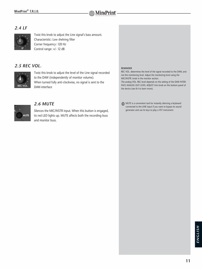
2.4 LF Twist this knob to adjust the Line signal’s bass amount. Characteristic: Low shelving filterCorner frequency: 120 Hz Control range: +/- 12 dB
2.5 REC VOL. Twist this knob to adjust the level of the Line signal recordedto the DAW (independently of monitor volume). When turned fully anti-clockwise, no signal is sent to theDAW-interface
2.6 MUTE Silences the MIC/INSTR input. When this button is engaged,its red LED lights up. MUTE affects both the recording bussand monitor buss.
11
MindPrint® T.R.I.O.
REMINDERREC VOL. determines the level of the signal recorded to the DAW, andnot the monitoring level. Adjust the monitoring level using theMIC/INSTR. knob in the monitor section. The analog VOL. REC level depends on the setting of the DAW INTER-FACE ANALOG OUT LEVEL ADJUST trim knob on the bottom panel ofthe device (see 8.4 to learn more).
g MUTE is a convenient tool for instantly silencing a keyboardconnected to the LINE input if you want to bypass its soundgenerator and use its keys to play a VST instrument.
EN
GL
ISH

3. ZERO LATENCY MONITOR VOLUMES
In this section, you can route input signals directly to the monitor buss forthe purpose of latency-free monitoring. A dip switch on the bottom panelof the device configures monitor routing busses. See 10.2 to learn more.
3.1 MIC/INSTR. Twist this knob to adjust the MIC/INSTR. channel’s monitorlevel. The signal is tapped post equalizer/compressor.
3.2 LINETwist this knob to adjust the Line channel’s monitor level.The signal is tapped post equalizer.
3.3 AUX InputOffering an ancillary stereo feed, the AUX input serves to connect consumerlevel devices (such as CD and minidisk players). This signal is routed to themonitor section.
Connecting signal sources:Patch consumer level devices into the two LEFT and RIGHT RCAconnector ports on the rear panel.
Handling:AUX: Twist this knob to adjust the level of signals sent from theAUX inputs to the monitor section.
3.4 MONITOR ONRoutes the input section’s signals as well as signals sent from theAUX input to the monitor buss. The LED on the button lights upto indicate MONITOR ON is active.
12
MindPrint® T.R.I.O.
ZERO LATENCY MONITORINGWhen recording to a digital medium, there is a certain amount oflatency inherent in the recorded signal. This delay is due to the time ittakes to convert the signal from analog to digital when it is patchedinto the computer and vice versa when it comes back out. You can wellimagine the annoyance this causes musicians and vocalists. So can we,which is why endowed T.R.I.O™ with a very practical DIRECTMONITORING section. A classic case of a fancy name for a straightforward feature, the ZEROLATENCY MONITORING section lets you hear input signals withoutdelay because they are routed directly to the outputs rather than to thecomputer and back via the DAW INTERFACE. We recommend that you configure your recording software so that therecorded signal is not routed out via the DAW’s outputs (INPUTMONITORING = OFF ).
y The AUX inputs’ signal is sent to the monitoring section only, andcannot be recorded. The reasoning here is that the most commonsignal source connected to an aux input is a CD player. If you wantto load a CD’s audio tracks to your computer, the more convenientoption is to use the computer’s CD-ROM disk drive.
y You can connect other sources to the AUX input, for instance, areverb unit whose dry signal is provided via INSERT SEND. Thus youcan offer the vocalist some "working" reverb. Though the vocalisthears the wet signal over the headphones, the actual vocal track isrecorded dry, that is, without reverb.
g The AUX input is also a cool tool for tweaking T.R.I.O™’s masterlevel. Simply connect a CD player and adjust the AUX knob so thatthe red output LEDs illuminate briefly and intermittently. (Some-where around 12 o’clock, depending on the CD player’s level.) Usethis level as a reference for the monitor volume.
g Want to make A/B comparisons to a reference CD? Simply switchback and forth between DAW ON and MONITOR ON to comparethe DAW’s signal to the reference CD’s signal.

3.5 DAW ONRoutes the incoming signal from the DAW to the monitorbuss. The LED on the button lights up to indicate DAW ONis active.
4. Monitor Management Section
This section lets you access a blend of monitor mix and DAW return signal,adjust monitor volume, select monitor outputs and connect a DAT/MDrecorder to record reference or backup tracks.
4.1 VOLUME Twist this knob to adjust the master volume of theSPEAKERS A, B and C monitor outputs. Level is equal onall three outputs, SPEAKERS B output can be fine-trimmed, see 4.5 to learn more
4.2 SPEAKERS A, B and C
Connections:
On the rear panel you’ll find three stereo outputsfor connecting monitor speakers or other amplifi-cation systems. Output A (two 6.3 mm (1/4“)mono jacks) serves to connect the first-choicemonitor speakers; output B (a pair of RCAconnectors) serves to connect an alternative
monitor pair. Output C (a pair of RCA connectors) serves to connect asubwoofer or a third pair of monitors.
Handling:SPEAKERS A, B, CSends the monitor signal to the selected outputs.The LED on the button lights up to indicate thegiven output is active. You can opt to addressseveral pairs of speakers simultaneously.
13
MindPrint® T.R.I.O.
x In most scenarios, T.R.I.O™ is connected directly to active speakersor power amps that are able to put to painfully high volume levels.Do your hearing and your speakers the favor of always exercisingutmost caution when twisting the VOLUME knob. When in doubt,roll back the VOLUME knob rather than cranking it wide open.
y The VOLUME knob is of extra big size making it easy to beaccessed even in stress situations.
g If you own a pair of speakers and a subwoofer, you can connectthe two satellites to SPEAKERS A and the subwoofer to SPEAKERS Bor C. This lets you address the speakers and subwoofer separatelyand easily switch the latter off whenever you wish.
y We opted to pass on a MUTE button for the simple reason thatyou can enjoy the same functionality (silencing speakers) by simplyengaging the SPEAKER A/B/C buttons or turning down thevolume!
EN
GL
ISH
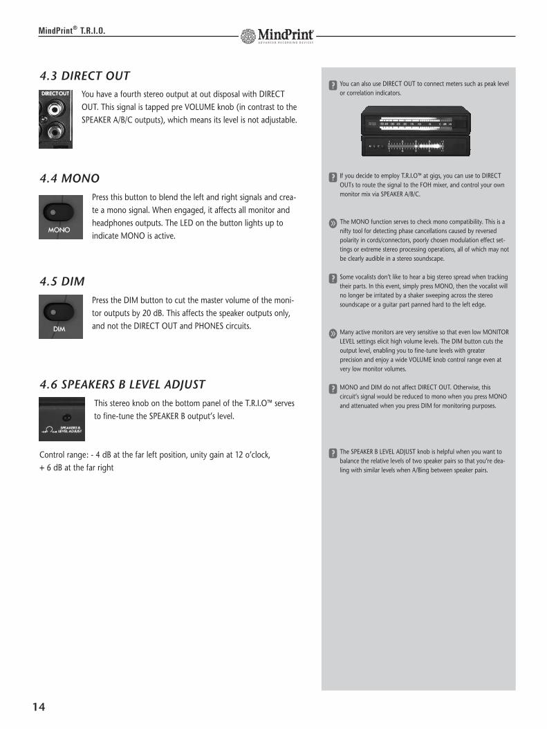
4.3 DIRECT OUTYou have a fourth stereo output at out disposal with DIRECTOUT. This signal is tapped pre VOLUME knob (in contrast to theSPEAKER A/B/C outputs), which means its level is not adjustable.
4.4 MONOPress this button to blend the left and right signals and crea-te a mono signal. When engaged, it affects all monitor andheadphones outputs. The LED on the button lights up toindicate MONO is active.
4.5 DIM Press the DIM button to cut the master volume of the moni-tor outputs by 20 dB. This affects the speaker outputs only,and not the DIRECT OUT and PHONES circuits.
4.6 SPEAKERS B LEVEL ADJUSTThis stereo knob on the bottom panel of the T.R.I.O™ servesto fine-tune the SPEAKER B output’s level.
Control range: - 4 dB at the far left position, unity gain at 12 o’clock, + 6 dB at the far right
14
MindPrint® T.R.I.O.
y You can also use DIRECT OUT to connect meters such as peak levelor correlation indicators.
y If you decide to employ T.R.I.O™ at gigs, you can use to DIRECTOUTs to route the signal to the FOH mixer, and control your ownmonitor mix via SPEAKER A/B/C.
g The MONO function serves to check mono compatibility. This is anifty tool for detecting phase cancellations caused by reversedpolarity in cords/connectors, poorly chosen modulation effect set-tings or extreme stereo processing operations, all of which may notbe clearly audible in a stereo soundscape.
y Some vocalists don’t like to hear a big stereo spread when trackingtheir parts. In this event, simply press MONO, then the vocalist willno longer be irritated by a shaker sweeping across the stereosoundscape or a guitar part panned hard to the left edge.
g Many active monitors are very sensitive so that even low MONITORLEVEL settings elicit high volume levels. The DIM button cuts theoutput level, enabling you to fine-tune levels with greaterprecision and enjoy a wide VOLUME knob control range even atvery low monitor volumes.
y MONO and DIM do not affect DIRECT OUT. Otherwise, thiscircuit’s signal would be reduced to mono when you press MONOand attenuated when you press DIM for monitoring purposes.
y The SPEAKER B LEVEL ADJUST knob is helpful when you want tobalance the relative levels of two speaker pairs so that you’re dea-ling with similar levels when A/Bing between speaker pairs.

5. Metering Section
L (Left Meter)The left LED chain indicates the level of the signal assignedto the left side.R (Right Meter)The right LED chain indicates the level of the signal assignedto the right side.
5.1 METER SELECTAssigns the level meter to input signals or monitor signals. A correspondingLED lights up to indicate the assignment status.
INPUTS:When set to this position, the left LED chain indicatesthe MIC/INSTR channel’s input gain. In order to make
best recording level possible, the source signal for the meter is tapped direc-tly behind the input stage. The right LED chain indicates the LINE channel’sinput gain. If the LINE signal is mono, the LED indicates its input gain. If thesignal is stereo, the LED indicates the mono composite’s input gain.
OUTPUTS:When set to this position, the LED chains indicate thecomposite level of the monitoring section (MONITOR
ON) and the DAW return (DAW ON) signals. The source signal for the meteris tapped pre OUTPUT VOLUME knob. In other words, it indicates the levelof the signal routed to DIRECT OUT.
15
MindPrint® T.R.I.O.
THE RIGHT INPUT LEVELThe red level LEDs illuminate at a fairly low peak level of 1 dB. Thesignal is not necessarily saturated if they light up briefly. However, itcertainly is in the red zone and on the brink of overloading the input.Your best bet is to adjust the gain so the red LEDs light up from timeto time.
y If a high-level signal is sent from DAW ON and signals are playedback via the MONITOR ON section, the LED meters may well lungeinto the red zone because signal levels add up. T.R.I.O™ has plentyof headroom to handle saturated signals such as these withoutgiving cause to worry about audible distortion.
y When set to INPUTS, the LED chains do not indicate the levels ofthe signal recorded to the DAW. Instead, they offer a view ofMIC/INSTR. and LINE input levels. In other words, the VOL. RECknob’s setting has no influence on T.R.I.O™’s level meter.
The reasoning here this is that levels tend tovary depending on the given DAW hard-ware/software, and level matching will differaccordingly. All popular recordingapplications feature very precise digital inputlevel meters. This means you can easily viewand adjust the level of the signal sent to theDAW using your recording software’s levelmeter.
x When set to INPUTS, only the right LED chain indicates the Lineinput signal level, even if you’re dealing with a stereo signal. Why?Because if you’re recording to multiple channels, this lets youmonitor the input levels of the MIC/INSTR. channels (on the leftLED chain) and the LINE channels (L+R on the right LED chain)simultaneously.
EN
GL
ISH

6. Headphones Section
Connections:
Connect standard headphones to the two stereo 6.3 mm (1/4“) jacks on therear panel. The two headphones amps are equipped with plenty of powerto drive even weaker headphones and deliver enough volume to enablesatisfactory monitoring.
Handling:
6.1 PHONES A
Twist this knob to adjust the first headphones output’svolume.
6.2 PHONES BTwist this knob to adjust the second headphones output’svolume.
16
MindPrint® T.R.I.O.
x We strongly suggest that you always employ headphones with animpedance greater than 30 ohms. Lower impedances or a shortcircuit caused by mono jack plugs can do permanent damage toT.R.I.O™’s headphones outputs.
x Do not connect headphones to SPEAKERS A jacks because this canharm T.R.I.O™.
y Savvy recordists may want to use PHONES outputs for a purposeother than intended – to connect further speakers via Y adapters(stereo jack on one end; two mono jacks on the other), to drivespeakers sited in the studio’s recording room. This lets you controlthese speakers’ volume separately and communicate withmusicians using the TALKBACK microphone. But whatever you do,never insert mono plugs into the PHONES jack.
y For a happier and more congenial recording experience, it’s a goodidea for the vocalist and producer to don the same model of head-phones when tracking vocals.

7. Talkback Section
T.R.I.O™ comes with a full-fledged talkback section featuring a built-in talkbackmicrophone.
7.1 TALKBACKPush this button to activate the talkback microphone. Thesignal is routed to the headphones outputs until you releasethe button. The monitor signal sent to the headphones out-puts is automatically cut by 12 dB.
7.2 TB VOLUMETwist this knob to adjust the volume of signal the sent fromthe built-in talkback microphone to the headphones busses.
7.3 TB MICThe talkback microphone is sited midway between theTALKBACK button and the TB VOLUME knob, below thethree little holes in the housing.
17
MindPrint® T.R.I.O.
g ""Talkback" is the term used for a neat feature found on big studioconsoles that allows producers/engineers in the control room tospeak to the artist in the studio via a microphone built into theconsole. To this end, the talkback microphone signal is sent to theheadphones busses.
y You may have little reason to like the TALKBACK function now, butyou may learn to love it later when you discover your recordingmic capturing the rattling of your computer’s fan or other ambientnoise (the classic culprit being the creaking of chairs). In this event,relocate the vocalist and microphone to a quiet room and commu-nicate via TALKBACK.
g In the heat of the moment, producers sometimes begin addressingthe vocalist before pressing the TALKBACK button. If vocalists can’thear the beginning of a sentence, they won’t understand you.Misunderstanding breeds insecurity; an insecure artist can’t delivera compelling performance. So in the interests of capturing hap-pening performances make a habit of pressing TALKBACK FIRST,and then talking.
y You’ll hear a soft “pong” sound when you press the TALKBACKbutton. This not a malfunction. The TB microphone is extremelysensitive; indeed, it’s so delicate it transmits the sound the buttonengaging. Eventually, you’ll find this to be an advantage: the"pong" signals to vocalists that words of wisdom are coming theirway! :o)
x Do not place objects on the TB microphone or push in the micro-phone covering with pointed objects.
EN
GL
ISH
8. DAW INTERFACE
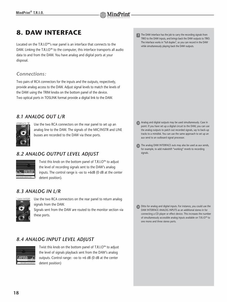
Located on the T.R.I.O™’s rear panel is an interface that connects to theDAW. Linking the T.R.I.O™ to the computer, this interface transports all audiodata to and from the DAW. You have analog and digital ports at yourdisposal.
Connections:Two pairs of RCA connectors for the inputs and the outputs, respectively,provide analog access to the DAW. Adjust signal levels to match the levels ofthe DAW using the TRIM knobs on the bottom panel of the device.Two optical ports in TOSLINK format provide a digital link to the DAW.
8.1 ANALOG OUT L/RUse the two RCA connectors on the rear panel to set up ananalog line to the DAW. The signals of the MIC/INSTR and LINEbusses are recorded to the DAW via these ports.
8.2 ANALOG OUTPUT LEVEL ADJUSTTwist this knob on the bottom panel of T.R.I.O™ to adjustthe level of recording signals sent to the DAW’s analoginputs. The control range is -oo to +6dB (0 dB at the centerdetent position).
8.3 ANALOG IN L/RUse the two RCA connectors on the rear panel to return analogsignals from the DAW.Signals sent from the DAW are routed to the monitor section viathese ports.
8.4 ANALOG INPUT LEVEL ADJUSTTwist this knob on the bottom panel of T.R.I.O™ to adjustthe level of signals playback sent from the DAW’s analogoutputs. Control range: -oo to +6 dB (0 dB at the centerdetent position)
18
MindPrint® T.R.I.O.
y The DAW interface has the job to carry the recording signals fromTRIO to the DAW inputs, and brings back the DAW outputs to TRIO.The interface works in "full duplex", so you can record in the DAWwhile simultaneously playing back the DAW outputs.
g Analog and digital outputs may be used simultaneously. Case inpoint: If you have set up a digital circuit to the DAW, you can usethe analog outputs to patch out recorded signals, say to back-uptracks to a minidisk. You can use the same approach to set up anaux send to an outboard signal processor.
g The analog DAW INTERFACE outs may also be used as aux sends,for example, to add makeshift “working“ reverb to recordingsignals.
g Ditto for analog and digital inputs. For instance, you could use theDAW INTERFACE ANALOG INPUTS as an additional stereo in forconnecting a CD player or effect device. This increases the numberof simultaneously accessible analog inputs available on T.R.I.O™ toone mono and three stereo ports.

9. DIGITAL-INTERFACE
T.R.I.O™ comes with a digital interface in optical S/PDIF format (TOSLINK)that lets you integrate the device into a digital recording environment.
9.1 S/PDIF INThe digital output of the DAW connects to this input via thecomputer interface. The converted signal is sent directly to themonitor buss.
9.2 S/PDIF OUTThis port connects to the DAW’s S/PDIF digital input. The A-to-D converted signals of the MIC/INSTR. and LINEbusses are sent to this port.
9.3 SYNC LEDThis LED lights up when the S/PDIF input receives a viabledigital signal.
Synchronization
Affording flexible connections to digital studio environments,T.R.I.O™’s digital interface features a three-way selectorproviding all the options you need to configure a digitalsetup.
9.4 44,1/48: This button (in combination with the neighboring "x2" button) determinesthe sampling rate for T.R.I.O™ in stand-alone mode.Position 1 selects 44.1 kHz.When set to position 2, T.R.I.O™ runs on 48 kHz.
9.5 x1/x2 (= Double Sampling Rate)When this button is set to position 1, the device operates on the frequencydetermined by the neighboring 44.1/48 button’s setting. In position 2, thedevice works with double the sampling rate defined by the 44.1/48 button;that is, 88.2 kHz or 96 kHz.
19
MindPrint® T.R.I.O.
y Developed by SONY and Philips and standardized by the IEC in1987, S/PDIF is designed for semiprofessional and home use.Providing an unbalanced circuit, S/PDIF is today the de factostandard worldwide.
S/P-DIF optical (TOSLINK)The optical interface has some advantages over its electrical coaxialcounterpart:• Special optical fiber cords rules out problems associated with using
the wrong cables.• Many devices’ optical ADAT interfaces may be set to S/PDIF optical
format.• Galvanic separation prevents ground loops and pickup of stray
interference.• Optical is more common than coaxial.
y If your DAW offers coaxial rather than optical S/PDIF ports, you’llfind S/P-DIF optical-to-coaxial converters in well-stocked musicstores.
g The SYNC LED tells you that a viable signal is patched into theS/PDIF INPUT. If your setup isn’t working properly, this light helpsyou narrow down the cause.
SYNCHRONIZATIONOnce digital audio devices are connected, their internal clock frequen-cies must be synchronized. To this end, one device acts as the master,dictating the sampling rate and bit rate to the rest, which are calledslaves in this type of configuration. Symptoms such as popping noisesduring recording are typical indications that devices aren’t in sync andthat settings require review.
SAMPLING RATEThe sampling rate is the frequency at which digital audio signals aremeasured (sampled) at discrete points in time. In the case of an audioCD, this is 44,100 times per second, which equals a frequency of44.1 KHz. As a rule, the higher the selected sampling rate, the "better"the audio signal quality; that is, the more accurately the original analogsignal is rendered. Note that higher sampling rates require proportionately more memory.
x As both TRIO and the DAW can be work in MASTER mode, audibleinterferences might occur because both units use their ownfrequency. An indication for this is e.g. when the DAW playbacksignal sounds dull and muddy. In case of doubt please doublecheck the sync settings of both units and make sure there is oneMASTER and one SLAVE.
y T.R.I.O™’s digital interface processes audio at a resolution of up to96kHz / 24bits.
EN
GL
ISH

9.6 MASTER/SLAVEIn position 1, T.R.I.O.™ is the MASTER, and runs on the internally selectedsampling frequency. To ensure proper synchronization, the connected DAWmust be configured as "slave" or "external".In position 2 (=SLAVE), T.R.I.O.™ automatically slaves to an incoming digitalsignal once it has determined that this signal is viable. The device runs insync with the DAW’s sampling rate. The SYNC LED lights to indicate it isreceiving a viable digital signal.
10. RECORD/MONITOR MODE SELECTOR
Located on the bottom panel of the T.R.I.OTM isa miniature four-way DIP switch that serves toconfigure recording and monitoring busses.
10.1 MIC/INSTR RECORD (1)Activate this switch to send the left side (= channel 1 of the recording soft-ware) of the MIC/INSTR. channel’s signal to the left and right sides of therecording buss (signal is routed to both channels simultaneously).
10.2 MIC/INSTR. MONITOR (2)Activate this switch to send the left side of the MIC/INSTR. channel’s signalto the left and right sides (stereo center) of the monitor buss. This settingapplies to PHONES, DIRECT OUT and SPEAKERS.
10.3 LINE RECORD (3)Activate this switch to send the right side (= channel 2 of recording soft-ware; possibly the mono composite) of the LINE channel’s signal to the leftand right sides (stereo) of the recording buss.
10.4 LINE MONITOR (4)Activate this switch to send the right side (possibly the mono composite) ofthe LINE channel’s signal to the left and right sides (stereo) of the monitorbuss. This setting applies to PHONES, DIRECT OUT and SPEAKERS.
20
MindPrint® T.R.I.O.
y The S/P-DIF interface offers separate digital input/output ports.The advantage here is that this allows you to introduce otherdevices into your DAW’s digital setup. For instance, you couldconnect another device equipped with a digital output (say, a DI-PORT for tracking with stereo microphones) to record to the DAW,and use T.R.I.O™ for monitoring purposes only for the duration ofthis little exercise in flexibility.
y Though T.R.I.O™ is a device with two input channels, the twochannels do not automatically equate to a stereo setup. In purelystereo devices, channel 1 is always on the left; channel 2 is always onthe right. T.R.I.O™ is more flexible: You are free to route the mono aswell as the stereo channel to the DAW input of your choosing and todetermine to which side(s) of the headphones/speaker they are sent.
y In the factory default configuration, all four switches are set to ON= L/R. This means that the MIC/INSTR. signal as well as the LINEsignal are sent to the DAW’s input as well as to both sides of theheadphones/speaker circuits. This gives you flexible routing optionsfor both signals, for example, by simply arming the desired DAWinputs.
y RECORD/MONITOR MODE SELECTOR settings apply to both theheadphones, the DIRECT OUT and the speaker outputs. Dependingon DIP switch settings, you may encounter some “interesting”monitoring scenarios, for example, where the monitor signal isaudible on the left speaker only.
y Though the RECORD/MONITOR MODE SELECTOR may not meanmuch to you now, it offers some very convenient options that youwill come to appreciate later: Say a guitarist wants to double apreviously recorded track: You can let him hear the canned trackon the left side of the headphones/speaker system and the liverecording signal on the right. Another example: Say you want torecord a guitar along with a stereo effect generated by a signalprocessor. Simply set all switches to ON (=default) to receive asignal where the guitar is centered and the effect signal isrendered in true stereo.
11. Other Features
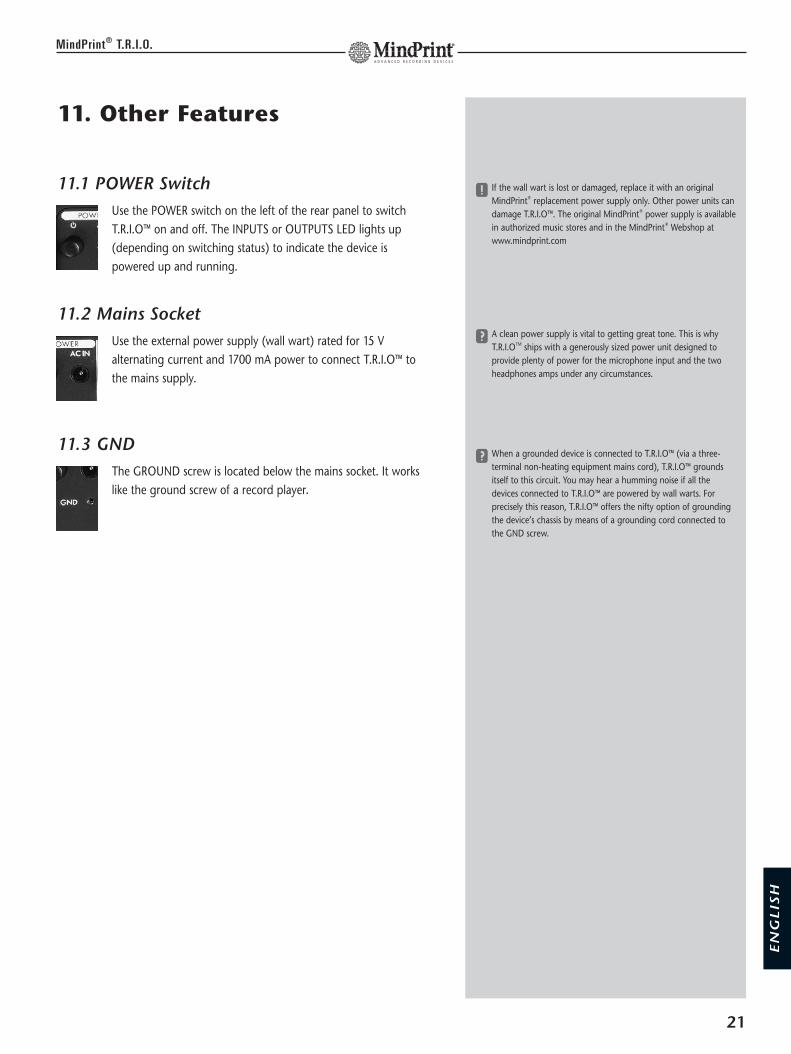
11.1 POWER SwitchUse the POWER switch on the left of the rear panel to switchT.R.I.O™ on and off. The INPUTS or OUTPUTS LED lights up(depending on switching status) to indicate the device ispowered up and running.
11.2 Mains SocketUse the external power supply (wall wart) rated for 15 Valternating current and 1700 mA power to connect T.R.I.O™ tothe mains supply.
11.3 GNDThe GROUND screw is located below the mains socket. It workslike the ground screw of a record player.
21
MindPrint® T.R.I.O.
x If the wall wart is lost or damaged, replace it with an originalMindPrint® replacement power supply only. Other power units candamage T.R.I.O™. The original MindPrint® power supply is availablein authorized music stores and in the MindPrint® Webshop atwww.mindprint.com
y A clean power supply is vital to getting great tone. This is whyT.R.I.OTM ships with a generously sized power unit designed toprovide plenty of power for the microphone input and the twoheadphones amps under any circumstances.
y When a grounded device is connected to T.R.I.O™ (via a three-terminal non-heating equipment mains cord), T.R.I.O™ groundsitself to this circuit. You may hear a humming noise if all thedevices connected to T.R.I.O™ are powered by wall warts. Forprecisely this reason, T.R.I.O™ offers the nifty option of groundingthe device’s chassis by means of a grounding cord connected tothe GND screw.
EN
GL
ISH
12. Troubleshooting
If you encounter problems when you’re working with T.R.I.O™, run down thefollowing checklist. It will help troubleshoot errors.
The LED chain lights up to indicate an incoming microphone signal, butI can’t hear anything. Is the:• MIC/INSTR. LEVEL knob in the monitoring section turned up? (see 3.1)• MONITOR ON button engaged? (see 3.4)• SPEAKERS A/B/C button engaged? (see 4.2)• is there accidentally a jack in the INSERT RETURN? (see 1.9)• MUTE button pressed? (see 1.6)
The microphone signal is audible, but I can’t record it. Is the:• REC VOL. knob of the microphone channel turned up? (see 1.5)• ANALOG OUT LEVEL ADJUST knob turned down? (applies in case of an
analog connection to the DAW only; see 8.1) • SYNC settings to DAW checked ? (see 8.4)• proper setting selected in the recording software?
The microphone signal is audible on one speaker/headphones side only.Is the:• RECORD/MONITOR MODE SELECTOR on the bottom set to the correct
position? (see 9.1)
The record signal is distorted. Is the:• GAIN knob turned up too high? (see 1.1/5.1)• REC VOL. knob turned down too low? (see 1.5/2.5/5.1
The DAW’s output is inaudible although visible. Is the:• DAW ON button engaged? (see 3.5)• ANALOG IN LEVEL ADJUST knob turned down? (applies in case of an ana-
log connection to the DAW only; see 8.2)• SPEAKERS A/B/C button engaged? (see 4.2)• proper setting selected in the recording software?
The line signal is visible on the right LED chain only (Switch set toINPUTS):• Only the right LED chain indicates the Line channel’s input signal, even if
it's a stereo signal (see 5.1).
The AUX signal is audible, but I can’t record it:• The AUX input addresses the monitor section ONLY and cannot be
recorded – connect the source you want to record to the Line input!
22
MindPrint® T.R.I.O.
y Are all external devices powered up, fully functional andconnected correctly? Are you certain the cause is not a handlingerror? Often enough, the complete service department was in biginsurrection until it turned out that a broken fuse or a wrongconnection was the reason.

EN
GL
ISH
13. Technical Specifications
13.1 Mechanical DataDimensionsDevice: 260mm (width) X 195mm (depth) X 66mm (height)Power unit: 65mm (width) X 128mm (depth) X 52mm (height)
WeightDevice: 1550 gPower unit: 650 g
13.2 Electrical DataMains inputPower unit Primary: 230V AC/100V AC/117V ACSecondary: 15V 1700mA
13.3 Inputs and outputsMIC IN:Port: XLR ( 1 = ground; 2 = +; 3 = -; )
Input type: Electronically balanced & floatingInput impedance: 10 kOhmMin. input level: -34 dBu (GAIN at peak setting, +12dBu
Speaker Out)-51 dBu (GAIN at peak setting, 0dBu SpeakerOut)
Max. input level: 4 dBu (GAIN no higher than 12 o’clock)Gain control range: -74...-14 dBu = 60dB @SEND, -40dBu input
with compressorGain control range: -74...-10 dBu = 64dB @SEND -40dBu input
without compressor
Peak amplification: 30 dB without compressorPhantom power: +48 VDC switchable
INSTR. IN:Port: 1/4“ jack ( tip = +; ring = -; ); MIC disabled
when in use Input type: unbalanced Input impedance: 1MegOhmMin. input level: -25 dBu (GAIN at peak setting, +12dBu
Speaker Out, - 3dBFS)-39.5 dBu (GAIN at peak setting, 0dBuSpeaker Out, -14dBFS)
Max. input level: +14 dBu (GAIN at 12 o’clock)-18 dBu (GAIN at peak setting)
Gain control range: -∞...19 dB (-10dBu to SEND , -29dBu input,without compressor)
Peak amplification: 19 dB
LINE IN:Port: 1/4“ jack ( tip = +; ring = -; ) Input type: unbalancedInput impedance: 51 kOhmMin. input level: 0 dBu (+12dBu Speaker Out)
-6dBu (+6dBu Speaker Out, -1dBFS) Max. input level: + 21 dB
AUX IN:Port: RCA ( tip = +; ring = -; ) Input type: unbalancedInput impedance: 51 kOhmMin. input level: 0 dBu (+12dBu Speaker Out)
-6 dBu (+6dBu Speaker Out, -1dBFS) Max. input level: + 12 dB
23
MindPrint® T.R.I.O.

DAW IN:Port: RCA ( tip = +; ring = -; ) Input type: unbalancedInput impedance: 7 kOhm Min. input level: 0 dBu (+12dBu Speaker Out) Gain control range: -∞...6 dB (0dB at 12 o’clock) Max. input level: + 10 dB (GAIN knob at 12 o’clock)
DAW OUT:Port: RCA ( tip = +; ring = -; ) Input type: unbalancedMax. output imp.: 7 kOhmOutput level: 0 dBu (0 dBu LINE IN) Gain control range: -∞...6 dB (0dB at 12 o’clock)
SPEAKERS OUT:Port: SPEAKER A 1/4“ jack ( tip = +; ring = -; )
SPEAKER B RCA ( tip = +; ring = -; )SPEAKER C RCA ( tip = +; ring = -; )
Input type: unbalancedOutput impedance: 47 OhmOutput level: 12 dBu (0 dBu LINE IN, MASTER Gain maxed, MONITOR Gain maxed)Gain control range: -∞...6 dB (SPEAKER B only, 0dB at 12 o’clock)
DIGITAL INTERFACEFormat: S/PDIFInput: optical, ToslinkOutput: optical, ToslinkResolution: 24 bits @ 44.1, 48, 88.2, 96 kHzDynamic Range: >105 dB(a)
The device’s design and circuits are subject to change due to ongoingdevelopment and improvement. Right to technical changes reserved.
This manual is copyright protected. All rights, technical changes andmisprints reserved. All depictions are the property of the respective brands. Reprints or any use in electronic form in whole or in part require the priorwritten consent of Music & Sales P.E. GmbH.
24
MindPrint® T.R.I.O.
25
MindPrint® T.R.I.O.
EN
GL
ISH

MindPrint® T.R.I.O.

27
MindPrint® T.R.I.O.
DE
UT
SC
H
Willkommen bei MindPrint!
Wir freuen uns, dass Sie sich für den T.R.I.O™ entschieden haben!Bitte nehmen Sie sich die Zeit, dieses Handbuch zu lesen - es bietet einendetaillierten Überblick über die Bedienung des T.R.I.O™ und liefert wichtigeZusatzinformationen und Profi-Tipps und Tricks.
"Recording is changing": der Audio-Arbeitsplatz unterliegt dem Wandel der Zeit. Wo gestern noch das große Mischpult stand, steht heute derLaptop. Wo gestern noch 19"-Racks mit Outboard-Effekten und Sampler/Synthies standen, liegen heute ein paar CD-Roms mit Plug-Ins und Software-Synthies. Die Zukunft gehört einem kleinen, aber feinen Setup: preisgünstig,platzsparend, ergonomisch, aber trotzdem „High-End-Sound“.
T.R.I.O™ bildet die Zentrale im „mischpultlosen“ Studio. T.R.I.O™ vereint diedrei Bereiche "Inputs", "Outputs" und "Interface" - und ersetzt somit Ein-gangskanäle und Monitorsektion eines Mischpultes und bietet darüber hin-aus ein IN/OUT-Interface zur DAW. Im modernen Computerstudio ist keinweiteres Gerät zum Audiohandling notwendig.
Wir wünschen Ihnen viel Spaß beim Recorden mit dem T.R.I.O™!
Die Philosophie des T.R.I.O.™
Bevor es ans Werk geht, möchten wir noch kurz auf die Philosophie desT.R.I.O.™ eingehen: Wir haben uns bemüht, die Funktionalität und denSignalfluss auch für jemanden, der noch nie mit Mischpulten, Mikrofonvor-verstärkern und Kompressoren zu tun hatte, praktikabel und überschaubarzu halten:
Auf der linken Seite werden die Eingangskanäle vorverstärkt, Sound „gemacht“und zum Rechner geschickt, auf der rechten Seite kommen Signale vomRechner zurück und gehen auf die Abhörschiene. Unten in der Mitte werdendie Abhörpegel der Eingangskanäle, die auf dem Monitor wiedergegebenwerden, latenzfrei eingestellt, und unten rechts befindet sich der große,wichtige Knopf zum einstellen der Gesamtabhörlautstärke.
GARANTIEBitte registrieren Sie Ihren T.R.I.O.™ - das dauert nicht lange, und Sieprofitieren davon in Form einer erweiterten Garantieleistung. Ambesten nutzen Sie einfach die komfortable ONLINE-REGISTRIERUNGüber unsere Webseite www.mindprint.com
Falls Sie keine Möglichkeit der Online-Registrierung haben, füllen Siebitte die beiliegende Garantiekarte vollständig aus und senden dieseper Post oder Fax an uns. Die Registrierung ist nur gültig, wenn dievollständig ausgefüllte Registrirungskarte innerhalb von 30 Tagen abKaufdatum an MindPrint® eingesendet wurde bzw. die fristgerechteRegistrierung über das Internet erfolgte.
Die Registrierung gibt uns auch Aufschluss darüber, wo und von wemunsere Geräte eingesetzt werden. Diese Informationen unterstützenunsere zukünftige Produktentwicklung. Ihre Angaben unterliegenselbstverständlich dem Datenschutz.
Vielen Dank!
MindPrint®
Technischer ServicePostfach 1509D-66595 St. WendelFax: +49 6851 905 100
y Wir verwenden in dieser Bedienungsanleitung die BezeichnungDAW (= Digital Audio Workstation), welche als Synonym für IhrPC/MAC HD-Recording-Setup steht.
y Bezüglich der Soundabstimmung haben wir uns bewusst von denweit verbreiteten Standardparametern vieler Hersteller gelöst und die Equalizer und den Kompressor nach intensiver Forschung undlangjährigen Erfahrungen funktionell und praxisnah abgestimmt. Im T.R.I.O.™ steckt das Know-how vieler Profis. Er wurde speziellentwickelt, um präzise Audioverarbeitung im äußerst kompaktenFormat zu ermöglichen.
Die folgenden Symbole stehen für:
y Allgemeine Informationen
g Spezielle Tipps
x Sicherheitsrelevante Hinweise
Inhalt
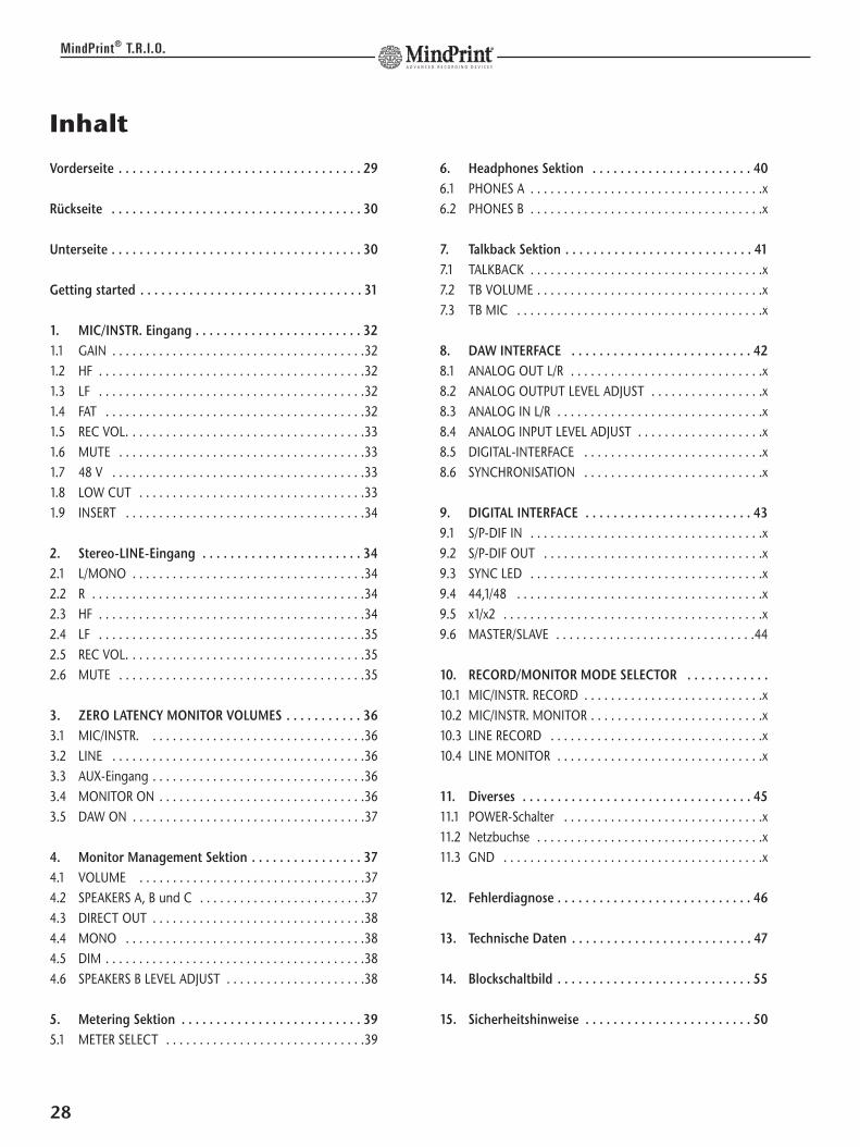
Vorderseite . . . . . . . . . . . . . . . . . . . . . . . . . . . . . . . . . . . 29
Rückseite . . . . . . . . . . . . . . . . . . . . . . . . . . . . . . . . . . . . 30
Unterseite . . . . . . . . . . . . . . . . . . . . . . . . . . . . . . . . . . . . 30
Getting started . . . . . . . . . . . . . . . . . . . . . . . . . . . . . . . . 31
1. MIC/INSTR. Eingang . . . . . . . . . . . . . . . . . . . . . . . . 321.1 GAIN . . . . . . . . . . . . . . . . . . . . . . . . . . . . . . . . . . . . . .321.2 HF . . . . . . . . . . . . . . . . . . . . . . . . . . . . . . . . . . . . . . . .321.3 LF . . . . . . . . . . . . . . . . . . . . . . . . . . . . . . . . . . . . . . . .321.4 FAT . . . . . . . . . . . . . . . . . . . . . . . . . . . . . . . . . . . . . . .321.5 REC VOL. . . . . . . . . . . . . . . . . . . . . . . . . . . . . . . . . . . .331.6 MUTE . . . . . . . . . . . . . . . . . . . . . . . . . . . . . . . . . . . . .331.7 48 V . . . . . . . . . . . . . . . . . . . . . . . . . . . . . . . . . . . . . .331.8 LOW CUT . . . . . . . . . . . . . . . . . . . . . . . . . . . . . . . . . .331.9 INSERT . . . . . . . . . . . . . . . . . . . . . . . . . . . . . . . . . . . .34
2. Stereo-LINE-Eingang . . . . . . . . . . . . . . . . . . . . . . . 342.1 L/MONO . . . . . . . . . . . . . . . . . . . . . . . . . . . . . . . . . . .342.2 R . . . . . . . . . . . . . . . . . . . . . . . . . . . . . . . . . . . . . . . . .342.3 HF . . . . . . . . . . . . . . . . . . . . . . . . . . . . . . . . . . . . . . . .342.4 LF . . . . . . . . . . . . . . . . . . . . . . . . . . . . . . . . . . . . . . . .352.5 REC VOL. . . . . . . . . . . . . . . . . . . . . . . . . . . . . . . . . . . .352.6 MUTE . . . . . . . . . . . . . . . . . . . . . . . . . . . . . . . . . . . . .35
3. ZERO LATENCY MONITOR VOLUMES . . . . . . . . . . . 363.1 MIC/INSTR. . . . . . . . . . . . . . . . . . . . . . . . . . . . . . . . .363.2 LINE . . . . . . . . . . . . . . . . . . . . . . . . . . . . . . . . . . . . . .363.3 AUX-Eingang . . . . . . . . . . . . . . . . . . . . . . . . . . . . . . . .363.4 MONITOR ON . . . . . . . . . . . . . . . . . . . . . . . . . . . . . . .363.5 DAW ON . . . . . . . . . . . . . . . . . . . . . . . . . . . . . . . . . . .37
4. Monitor Management Sektion . . . . . . . . . . . . . . . . 374.1 VOLUME . . . . . . . . . . . . . . . . . . . . . . . . . . . . . . . . . .374.2 SPEAKERS A, B und C . . . . . . . . . . . . . . . . . . . . . . . . .374.3 DIRECT OUT . . . . . . . . . . . . . . . . . . . . . . . . . . . . . . . .384.4 MONO . . . . . . . . . . . . . . . . . . . . . . . . . . . . . . . . . . . .384.5 DIM . . . . . . . . . . . . . . . . . . . . . . . . . . . . . . . . . . . . . . .384.6 SPEAKERS B LEVEL ADJUST . . . . . . . . . . . . . . . . . . . . .38
5. Metering Sektion . . . . . . . . . . . . . . . . . . . . . . . . . . 395.1 METER SELECT . . . . . . . . . . . . . . . . . . . . . . . . . . . . . .39
6. Headphones Sektion . . . . . . . . . . . . . . . . . . . . . . . 406.1 PHONES A . . . . . . . . . . . . . . . . . . . . . . . . . . . . . . . . . . .x6.2 PHONES B . . . . . . . . . . . . . . . . . . . . . . . . . . . . . . . . . . .x
7. Talkback Sektion . . . . . . . . . . . . . . . . . . . . . . . . . . . 417.1 TALKBACK . . . . . . . . . . . . . . . . . . . . . . . . . . . . . . . . . . .x7.2 TB VOLUME . . . . . . . . . . . . . . . . . . . . . . . . . . . . . . . . . .x7.3 TB MIC . . . . . . . . . . . . . . . . . . . . . . . . . . . . . . . . . . . . .x
8. DAW INTERFACE . . . . . . . . . . . . . . . . . . . . . . . . . . 428.1 ANALOG OUT L/R . . . . . . . . . . . . . . . . . . . . . . . . . . . . .x8.2 ANALOG OUTPUT LEVEL ADJUST . . . . . . . . . . . . . . . . .x8.3 ANALOG IN L/R . . . . . . . . . . . . . . . . . . . . . . . . . . . . . . .x8.4 ANALOG INPUT LEVEL ADJUST . . . . . . . . . . . . . . . . . . .x8.5 DIGITAL-INTERFACE . . . . . . . . . . . . . . . . . . . . . . . . . . .x8.6 SYNCHRONISATION . . . . . . . . . . . . . . . . . . . . . . . . . . .x
9. DIGITAL INTERFACE . . . . . . . . . . . . . . . . . . . . . . . . 439.1 S/P-DIF IN . . . . . . . . . . . . . . . . . . . . . . . . . . . . . . . . . . .x9.2 S/P-DIF OUT . . . . . . . . . . . . . . . . . . . . . . . . . . . . . . . . .x9.3 SYNC LED . . . . . . . . . . . . . . . . . . . . . . . . . . . . . . . . . . .x9.4 44,1/48 . . . . . . . . . . . . . . . . . . . . . . . . . . . . . . . . . . . . .x9.5 x1/x2 . . . . . . . . . . . . . . . . . . . . . . . . . . . . . . . . . . . . . . .x9.6 MASTER/SLAVE . . . . . . . . . . . . . . . . . . . . . . . . . . . . . .44
10. RECORD/MONITOR MODE SELECTOR . . . . . . . . . . . .10.1 MIC/INSTR. RECORD . . . . . . . . . . . . . . . . . . . . . . . . . . .x10.2 MIC/INSTR. MONITOR . . . . . . . . . . . . . . . . . . . . . . . . . .x10.3 LINE RECORD . . . . . . . . . . . . . . . . . . . . . . . . . . . . . . . .x10.4 LINE MONITOR . . . . . . . . . . . . . . . . . . . . . . . . . . . . . . .x
11. Diverses . . . . . . . . . . . . . . . . . . . . . . . . . . . . . . . . . 4511.1 POWER-Schalter . . . . . . . . . . . . . . . . . . . . . . . . . . . . . .x11.2 Netzbuchse . . . . . . . . . . . . . . . . . . . . . . . . . . . . . . . . . .x11.3 GND . . . . . . . . . . . . . . . . . . . . . . . . . . . . . . . . . . . . . . .x
12. Fehlerdiagnose . . . . . . . . . . . . . . . . . . . . . . . . . . . . 46
13. Technische Daten . . . . . . . . . . . . . . . . . . . . . . . . . . 47
14. Blockschaltbild . . . . . . . . . . . . . . . . . . . . . . . . . . . . 55
15. Sicherheitshinweise . . . . . . . . . . . . . . . . . . . . . . . . 50
28
MindPrint® T.R.I.O.

Vorderseite
Channelstrip:
Mic-/Instrument-Preamp1 48 V: aktiviert die 48 Volt Phantomspeisung 2 LOW CUT: aktiviert das Low-Cut Filter 3 GAIN: regelt den Eingangspegel4 HF: regelt die Höhenanhebung/-absenkung5 LF: regelt die Bassanhebung/-absenkung6 FAT: regelt die Signalverdichtung des Kompressors7 REC VOL.: regelt den Aufnahmepegel zur DAW8 MUTE: schaltet den MIC/INSTR. Kanal stumm
Stereo Line-Preamp9 HF: regelt die Höhenanhebung/-absenkung10 LF: regelt die Bassanhebung/-absenkung11 REC VOL.: regelt den Aufnahmepegel zur DAW12 MUTE: schaltet den LINE-Kanal stumm
Zero Latency Monitor13 MIC/INSTR.: regelt den Abhörpegel des Channelstrips14 LINE: regelt den Abhörpegel des LINE-Kanals15 AUX: regelt den Abhörpegel des AUX-Einganges16 MONITOR ON: schaltet MIC/INSTR., LINE und AUX
auf die Monitorschiene17 DAW ON: schaltet das von der Digital-Audio-Workstation
kommende Signal auf die Monitorschiene
Abhörsektion
18 VOLUME: regelt die Gesamtlautstärke der Monitorsektion (außer Headphones und DIRECT OUT)
19 SPEAKERS A: aktiviert den Ausgang zum Monitor-Paar A (Haupt-Monitore)
20 SPEAKERS B: aktiviert den Ausgang zum Monitor-Paar B (Alternativ-Monitore)
21 SPEAKERS C: aktiviert den Ausgang zum Monitor-Paar C (bzw. Subwoofer)
22 MONO: schaltet das Monitorsignal auf Mono 23 DIM: reduziert die Gesamtlautstärke der Monitor-Sektion um
20 dB (außer Headphones)24 PHONES A: regelt die Lautstärke von Kopfhöreranschluss A25 PHONES B: regelt die Lautstärke von Kopfhöreranschluss B26 TALKBACK: schaltet das TALKBACK-Mikrofon (MIC) auf die
Kopfhörer (nicht auf die SPEAKERS)27 TB VOL: regelt die Lautstärke des TALKBACK-Mikrofones28 INPUTS/OUTPUTS: schaltet die LED-Anzeigen von Eingang
auf Ausgang um
29
MindPrint® T.R.I.O.
DE
UT
SC
H
1
3
4
5
6
7
8
9
10
11
12
26
13 14 15
28
24
25
27
16
17
18
23
22
21
20
192
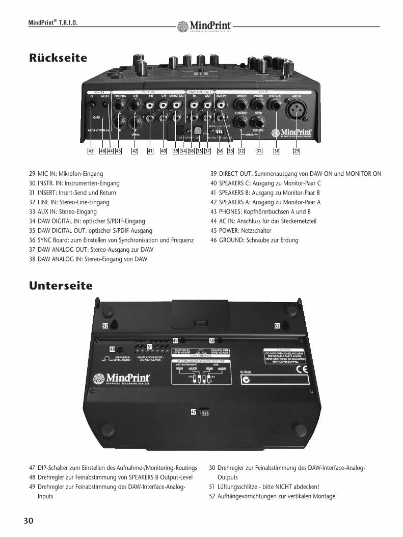
29 MIC IN: Mikrofon-Eingang 30 INSTR. IN: Instrumenten-Eingang 31 INSERT: Insert-Send und Return 32 LINE IN: Stereo-Line-Eingang33 AUX IN: Stereo-Eingang 34 DAW DIGITAL IN: optischer S/PDIF-Eingang35 DAW DIGITAL OUT: optischer S/PDIF-Ausgang36 SYNC Board: zum Einstellen von Synchronisation und Frequenz37 DAW ANALOG OUT: Stereo-Ausgang zur DAW 38 DAW ANALOG IN: Stereo-Eingang von DAW
39 DIRECT OUT: Summenausgang von DAW ON und MONITOR ON40 SPEAKERS C: Ausgang zu Monitor-Paar C41 SPEAKERS B: Ausgang zu Monitor-Paar B42 SPEAKERS A: Ausgang zu Monitor-Paar A43 PHONES: Kopfhörerbuchsen A und B44 AC IN: Anschluss für das Steckernetzteil 45 POWER: Netzschalter46 GROUND: Schraube zur Erdung
Rückseite
30
MindPrint® T.R.I.O.
47 DIP-Schalter zum Einstellen des Aufnahme-/Monitoring-Routings48 Drehregler zur Feinabstimmung von SPEAKERS B Output-Level49 Drehregler zur Feinabstimmung des DAW-Interface-Analog-
Inputs
50 Drehregler zur Feinabstimmung des DAW-Interface-Analog-Outputs
51 Lüftungsschlitze - bitte NICHT abdecken!52 Aufhängevorrichtungen zur vertikalen Montage
Unterseite
29303132333635 37383439404142434445
49 5051
5252
47
48
46
Getting Started
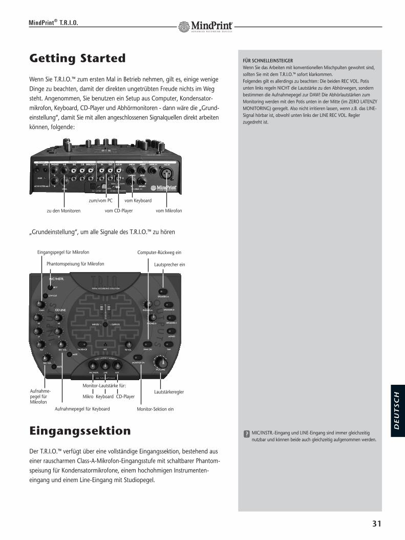
Wenn Sie T.R.I.O.™ zum ersten Mal in Betrieb nehmen, gilt es, einige wenigeDinge zu beachten, damit der direkten ungetrübten Freude nichts im Wegsteht. Angenommen, Sie benutzen ein Setup aus Computer, Kondensator-mikrofon, Keyboard, CD-Player und Abhörmonitoren - dann wäre die „Grund-einstellung“, damit Sie mit allen angeschlossenen Signalquellen direkt arbeitenkönnen, folgende:
Eingangssektion
Der T.R.I.O.™ verfügt über eine vollständige Eingangssektion, bestehend auseiner rauscharmen Class-A-Mikrofon-Eingangsstufe mit schaltbarer Phantom-speisung für Kondensatormikrofone, einem hochohmigen Instrumenten-eingang und einem Line-Eingang mit Studiopegel.
31
MindPrint® T.R.I.O.
FÜR SCHNELLEINSTEIGERWenn Sie das Arbeiten mit konventionellen Mischpulten gewohnt sind,sollten Sie mit dem T.R.I.O.™ sofort klarkommen.Folgendes gilt es allerdings zu beachten: Die beiden REC VOL. Potisunten links regeln NICHT die Lautstärke zu den Abhörwegen, sondernbestimmen die Aufnahmepegel zur DAW! Die Abhörlautstärken zumMonitoring werden mit den Potis unten in der Mitte (im ZERO LATENZYMONITORING) geregelt. Also nicht irritieren lassen, wenn z.B. das LINE-Signal hörbar ist, obwohl unten links der LINE REC VOL. Reglerzugedreht ist.
y MIC/INSTR.-Eingang und LINE-Eingang sind immer gleichzeitignutzbar und können beide auch gleichzeitig aufgenommen werden.
DE
UT
SC
H
„Grundeinstellung“, um alle Signale des T.R.I.O.™ zu hören
zu den Monitoren
Phantomspeisung für Mikrofon
Eingangspegel für Mikrofon
Aufnahme-pegel fürMikrofon
Aufnahmepegel für Keyboard
Lautsprecher ein
Computer-Rückweg ein
Monitor-Sektion ein
Lautstärkeregler
zum/vom PC vom Keyboard
vom Mikrofonvom CD-Player
Monitor-Lautstärke für:
Mikro Keyboard CD-Player

1. MIC/INSTR.-Eingang
Anschluss:
Auf der Rückseite des T.R.I.O.™ befindet sich eine XLR-Buchse zum Anschlusseines Mikrofons, die Beschaltung ist gemäß internationaler Norm (Pin 2 = hot).Für die Verwendung von Kondensatormikrofonen steht eine schaltbare 48-Volt-Phantomspeisung zur Verfügung. Zur Unterdrückung tieffrequenter Stör-geräuschen bietet der T.R.I.O.™ ein schaltbares Low-Cut-Filter.Instrumente wie Gitarre/Bass werden an die INSTRUMENT IN-Buchse ange-schlossen. Bei Belegung der entsprechenden 6,3 mm Mono-Klinkenbuchseschaltet T.R.I.O.™ automatisch auf den hochohmigen Instrumenteneingang;dieser hat Priorität vor dem Mikrofoneingang.
Beim Mikrofon-/Instrumenteneingang handelt es sich um ein Monosignal;über einen DIP-Schalter auf der Geräteunterseite lässt sich wählen, ob es nurauf dem linken Recording- und Monitoring-Kanal oder auf beiden Kanälengleich verteilt ausgegeben wird, siehe dazu 10.1.
Bedienung:
1.1 GAIN
Dieses Poti regelt die Vorverstärkung für Mikrofon undInstrument, d.h. mit diesem Regler bestimmt man, wie vielPegel vom Mikrofon/Instrument in den Channelstrip desT.R.I.O.™ gelangt.
Regelbereich für Mikrofon: -56 dB bis +4 dBRegelbereich für Instrument: -40 dB bis +14 dB
1.2 HFMit diesem Poti bestimmt man den Höhenanteil des Signals.Charakteristik: High Shelving Filter, Typ „Chebyshev“(Vintage Design: „Dip before Boost“)Eckfrequenz: 7,5 kHz
Regelbereich: +/- 12 dB
1.3 LFMit diesem Poti bestimmt man den Bassanteil des Signals. Charakteristik: Low Shelving Filter Typ „Chebyshev“Eckfrequenz: 100 Hz Regelbereich: +/- 12 dB
32
MindPrint® T.R.I.O.
DER EINGEBAUTE CHANNELSTRIPDer MIC/INSTR.-Eingang besteht nicht nur aus Vorverstärker,sondern ist ein kompletter Mischpult-Kanalzug. Er bietet mitLow-Cut, dem EQ und dem Kompressor sowohl Frequenz- alsauch Dynamikbearbeitung, um bereits vor der Aufnahme einaufbereitetes Signal zu erhalten.
x Die Phantomspeisung darf nur bei dafür geeigneten Mikro-fonen eingeschaltet werden, auf keinen Fall bei Anschlussvon unsymmetrischen und Bändchen-Mikrofonen!Schließen Sie an den Mikrofoneingang keine Geräte mitLine-Level an – dies kann zu einer Beschädigung desT.R.I.O.™ führen.
g Da der Mikrofoneingang automatisch deaktiviert wird,sobald ein Stecker in die INSTRUMENT IN-Buchsegesteckt wird, kann der Mikrofoneingang immer festverkabelt bleiben.
EINGANGSEMPFINDLICHKEITDie Empfindlichkeit des Instrumenten-Eingangs wurde sodimensioniert, dass Gitarren und Bässe direkt angeschlossenwerden können. Mit seiner Impedanz von 1 MOhm stellt derInstrumenteneingang sicher, dass der Pickup des Instrumentsnicht zu stark bedämpft wird und gut klingt. Die Technologiedes Instrumenteneingangs stammt von MindPrint®'s Schwester-firma Hughes & Kettner®; deren langjähriges Gitarrenamp-Know-how garantiert beste Soundqualität.
VORVERSTÄRKUNGDer GAIN ist die Eintrittsstufe in den T.R.I.O.™ - gerade hiermuss besonders sorgsam ausgesteuert werden. Ist das Ein-gangssignal zu hoch, kann es zu hörbaren Übersteuerungenkommen und eine wertvolle Aufnahme unbrauchbar werden.Also lieber etwas vorsichtiger aussteuern, so dass auch beiden lautesten Signalen niemals (oder nur kurz) die rote LEDaufleuchtet.
SIGNALAUFFRISCHUNGDie meisten Mikrofonsignale sind von Natur aus eher dumpf;die Sprachverständlichkeit z.B. kann mit einer Höhenanhebungdeutlich gesteigert werden. Der HF-EQ des MIC/INSTR. Kanals wurde dem Schaltungsbildberühmter analoger High-End-Equalizer nachempfunden undweist als Besonderheit eine spezielle Kennlinie („Chebyshev“)auf, bekannt aus dem MindPrint® DTC: vor der eigentlichenAnhebung der Höhen erfolgt eine leichte Absenkung derhohen Mitten - das verleiht Stimmen einen seidigen Glanzunter gleichzeitiger Zurücknahme der sonst problematischenZischlaute. Auch das LF-Band des MIC/INSTR. EQ besitztdiese "Chebyshev"-Charakteristik.
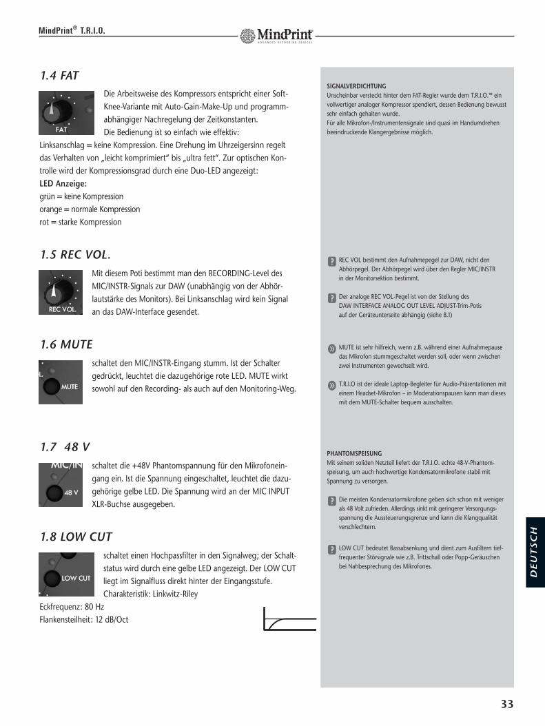
1.4 FATDie Arbeitsweise des Kompressors entspricht einer Soft-Knee-Variante mit Auto-Gain-Make-Up und programm-abhängiger Nachregelung der Zeitkonstanten. Die Bedienung ist so einfach wie effektiv:
Linksanschlag = keine Kompression. Eine Drehung im Uhrzeigersinn regeltdas Verhalten von „leicht komprimiert“ bis „ultra fett“. Zur optischen Kon-trolle wird der Kompressionsgrad durch eine Duo-LED angezeigt:LED Anzeige: grün = keine Kompressionorange = normale Kompressionrot = starke Kompression
1.5 REC VOL.Mit diesem Poti bestimmt man den RECORDING-Level desMIC/INSTR-Signals zur DAW (unabhängig von der Abhör-lautstärke des Monitors). Bei Linksanschlag wird kein Signalan das DAW-Interface gesendet.
1.6 MUTEschaltet den MIC/INSTR-Eingang stumm. Ist der Schaltergedrückt, leuchtet die dazugehörige rote LED. MUTE wirktsowohl auf den Recording- als auch auf den Monitoring-Weg.
1.7 48 Vschaltet die +48V Phantomspannung für den Mikrofonein-gang ein. Ist die Spannung eingeschaltet, leuchtet die dazu-gehörige gelbe LED. Die Spannung wird an der MIC INPUTXLR-Buchse ausgegeben.
1.8 LOW CUT schaltet einen Hochpassfilter in den Signalweg; der Schalt-status wird durch eine gelbe LED angezeigt. Der LOW CUTliegt im Signalfluss direkt hinter der Eingangsstufe.Charakteristik: Linkwitz-Riley
Eckfrequenz: 80 HzFlankensteilheit: 12 dB/Oct
33
MindPrint® T.R.I.O.
SIGNALVERDICHTUNGUnscheinbar versteckt hinter dem FAT-Regler wurde dem T.R.I.O.™ einvollwertiger analoger Kompressor spendiert, dessen Bedienung bewusstsehr einfach gehalten wurde. Für alle Mikrofon-/Instrumentensignale sind quasi im Handumdrehenbeeindruckende Klangergebnisse möglich.
y REC VOL bestimmt den Aufnahmepegel zur DAW, nicht denAbhörpegel. Der Abhörpegel wird über den Regler MIC/INSTR in der Monitorsektion bestimmt.
y Der analoge REC VOL-Pegel ist von der Stellung des DAW INTERFACE ANALOG OUT LEVEL ADJUST-Trim-Potis auf der Geräteunterseite abhängig (siehe 8.1)
g MUTE ist sehr hilfreich, wenn z.B. während einer Aufnahmepausedas Mikrofon stummgeschaltet werden soll, oder wenn zwischenzwei Instrumenten gewechselt wird.
g T.R.I.O ist der ideale Laptop-Begleiter für Audio-Präsentationen miteinem Headset-Mikrofon – in Moderationspausen kann man diesesmit dem MUTE-Schalter bequem ausschalten.
PHANTOMSPEISUNGMit seinem soliden Netzteil liefert der T.R.I.O. echte 48-V-Phantom-speisung, um auch hochwertige Kondensatormikrofone stabil mitSpannung zu versorgen.
y Die meisten Kondensatormikrofone geben sich schon mit wenigerals 48 Volt zufrieden. Allerdings sinkt mit geringerer Versorgungs-spannung die Aussteuerungsgrenze und kann die Klangqualitätverschlechtern.
y LOW CUT bedeutet Bassabsenkung und dient zum Ausfiltern tief-frequenter Störsignale wie z.B. Trittschall oder Popp-Geräuschenbei Nahbesprechung des Mikrofones.
DE
UT
SC
H

1.9 INSERTAnschluss: Zum Einschleifen von externen Signalprozessorenin den Signalweg des MIC/INSTR-Eingangs befinden sich aufder Rückseite eine SEND- und eine RETURN-Klinkenbuchse.
Bedienung: Sobald ein Klinkenstecker an die RETURN-Buchseangeschlossen wird, schaltet der T.R.I.O.™ automatisch den
Insert in den Signalweg. Die SEND-Buchse ist immer aktiv und kann auch als zusätzlicher Abgriff genutzt werden.
2. Stereo-Line-Eingang
Der LINE-Eingang dient zum Anschluss von Geräten mit Line-Pegel (wie Key-board, Line-Mixer oder Drum-Computer). Er verfügt über eine 2-Band-Klangregelung und kann sowohl Mono als auch Stereo sein. Wird nur dieL/MONO-Buchse verwendet, wird das Signal automatisch auf beide Kanäleverteilt.
Anschluss: Zum Anschluss von Signalen mit Line-Pegel befinden sich auf der Rückseitezwei 6,3 mm Mono-Klinkenbuchsen. Das Aufnahme- und Monitor-Routingwird über einen DIP-Schalter auf der Geräteunterseite bestimmt, siehe dazu10.3.
2.1 L/MONODiese Buchse dient zum Anschluss des linken Kanals einerStereo-Signals oder „Kanal 1“ einer beliebigen Line-Quelle.
2.2 RDiese Buchse dient zum Anschluss des rechten Kanals einesStereo-Signals oder „Kanal 2“ einer beliebigen Line-Quelle.
Bedienung:
2.3 HF
Mit diesem Poti bestimmt man den Höhen-Anteil des Line-Signals. Charakteristik: High Shelving Filter, Typ „Chebyshev“, Eckfrequenz: 9 kHz, Regelbereich: +/- 12 dB
34
MindPrint® T.R.I.O.
g Der INSERT SEND lässt sich auch als "Aux Send" verwenden, um z.B. ein externes Hallgerät anzusteuern.
g Am INSERT SEND kann auch ein Stimmgerät angeschlossen werden.So muss das Instrument nicht immer zum Stimmen "ausgestöpselt"werden und man kann jederzeit schnell das Tuning überprüfen.
g Über den INSERT RETURN lässt sich das Signal eines externenGerätes (z.B. EN-VOICE®) einzuschleifen. Da der INSERT RETURNPunkt "post EQ/Kompressor" liegt, umgeht man somit Eingangs-stufe und EQ/Kompressor vom T.R.I.O.™; das externe Signal wirdunmittelbar zum A/D-Wandler und in die Monitorsektion geführt.
y "Routing" nennt man in der Studiotechnik das Zuweisen einesSignales auf verschiedene Ziele, z.B., ob man ein Mikrofonsignal aufEingang 1 oder Eingang 2 der Recordingsoftware aufnehmen möchte.
y Geräte mit nur einem Line-Ausgang (mono) werden an dieLEFT/MONO Buchse angeschlossen; dann liegt das Signal aufbeiden Kanälen des LINE Eingangs an.

2.4 LF Mit diesem Poti bestimmt man den Bass-Anteil des LINE-Signals. Charakteristik: Low Shelving FilterEckfrequenz: 120 Hz
Regelbereich: +/- 12 dB
2.5 REC VOL. Mit diesem Poti bestimmt man den RECORDING-Level desLINE-Signals zur DAW (unabhängig von der Abhörlautstärkedes Monitors). Bei Linksanschlag wird kein Signal an dasDAW-Interface gesendet.
2.6 MUTE schaltet den LINE-Eingang stumm. Ist der Kanal stumm geschaltet, leuchtet die dazugehörige rote LED. MUTE wirkt sowohl auf den Recording- als auch auf den Monitoring-Weg.
35
MindPrint® T.R.I.O.
ERINNERUNGREC VOL bestimmt den Aufnahmepegel zur DAW, nicht den Abhör-pegel. Der Abhörpegel wird über den Line-Regler in der Monitorsektionbestimmt.Der analoge REC VOL-Pegel ist von der Stellung des DAW INTERFACEANALOG OUT LEVEL ADJUST Trim-Potis auf der Geräteunterseite ab-hängig (siehe 8.4)
g MUTE ist praktisch, um z.B. den Sound des am Line-Eingang ange-schlossenes Keyboards stumm zu schalten, wenn man nur dessenTastatur nutzen möchte, um ein VST-Instrument zu spielen.
DE
UT
SC
H

3. ZERO LATENCY MONITOR VOLUMES
In dieser Sektion können Sie die Eingangssignale direkt auf die Abhörschieneleiten, um latenzfreies Monitoring zu ermöglichen. Das Monitor-Routing wirdüber einen DIP-Schalter auf der Geräteunterseite bestimmt, siehe dazu 10.2.
3.1 MIC/INSTR. Mit diesem Poti bestimmt man den Monitor-Pegel desMIC/INSTR. Kanals. Das Signal wird hinter dem Equalizer/-Kompressor abgegriffen.
3.2 LINEMit diesem Poti bestimmt man den Monitor-Pegel des LINE-Kanals. Das Signal wird hinter dem Equalizer abgegriffen.
3.3 AUX-EingangDer AUX-Eingang ist ein weiterer Stereo-Eingang, er dient zum Anschlussvon Geräten mit Consumer-Pegel (wie CD-Player oder Minidisk). Dieses Sig-nal wird auf die Monitorsektion geführt.
Anschluss: Zum Anschluss von Geräten mit Consumer Pegel befinden sichauf der Rückseite zwei Cinch-Buchsen LEFT und RIGHT.
Bedienung:AUX: Mit diesem Poti bestimmt man, wieviel Pegel des AUX-Eingangs auf die Monitorsektion geführt wird.
3.4 MONITOR ONSchaltet die Signale der Input-Sektion und das vom AUX-Eingangkommende Signal auf die Abhörschiene. Ist MONITOR ONaktiv, leuchtet die im Schalter integrierte LED.
36
MindPrint® T.R.I.O.
ZERO LATENCY MONITORINGBei einer Aufnahme auf ein digitales Medium ist das Aufnahmesignaldurch die A/D-Wandlung in den Computer und die D/A-Rückwandlungaus dem Computer mit einer gewissen Latenz (=Zeitverzögerung)versehen. Da dies beim Einsingen oder Einspielen naturgemäß alsstörend empfunden wird, ist im T.R.I.O.™ eine sehr funktionale DIRECT MONITORING-Sektion integriert. Über die ZERO LATENCY MONITORING Sektion hört man nicht dieSignale, die über die DAW INTERFACE-Schnittstelle vom Computerzurückkommen, sondern die Eingangssignale, die zum Abhören direktan die Ausgänge durchgeleitet werden. Es empfiehlt sich, die RecordingSoftware so einzustellen, dass das aufzunehmende Signal nicht an dieAusgänge der DAW weitergegeben wird ("INPUT MONITORING =OFF").
y Das Signal des AUX-Inputs wird ausschließlich der MonitoringSektion zugeführt; es kann nicht aufgenommen werden. Hintergrund: I.d.R. ist hier ein CD-Player angeschlossen; brauchtman Audiotracks von CD im Computer, lässt sich das komfortabelüber das CD-ROM Laufwerk des Computers bewerkstelligen.
y Am AUX-Eingang kann z.B. auch ein Hallgerät angeschlossen werden,welches das Signal aus dem INSERT SEND erhält. Auf diese Weisekann man dem Sänger einen „Arbeitshall“ auf den Kopfhörergeben, der nicht mit aufgenommen wird.
g Der AUX-Eingang bietet sich gut dazu an, den gesamten Arbeits-pegel des T.R.I.O.™ abzugleichen: man schließt einen CD-Playeran, stellt das AUX-Poti so ein, dass die roten Output LED's nurgelegentlich aufflackern (auf ca. 12 Uhr, abhängig vom Pegel des CD-Players), und nimmt diesen Pegel als Referenz für die Abhörlautstärke.
g A/B-Vergleich mit einer Referenz-CD: durch gleichzeitiges Umschaltenzwischen MONITOR ON und DAW ON kann man das DAW-Signalmit der Referenz-CD vergleichen.

3.5 DAW ONSchaltet das von der DAW kommende Signal auf die Abhör-schiene. Wenn DAW ON aktiv ist, leuchtet die im Schalterintegrierte LED.
4. Monitor Management Sektion
In dieser Sektion kann man die Mischung aus Monitor Mix und DAW ReturnSignal abgreifen, die Abhörlautstärke einstellen, die Monitorausgängeanwählen und z.B. einen DAT-/MD-Recorder zum Kontrollmitschnitt ansch-ließen.
4.1 VOLUME Dieses Poti regelt die Gesamtlautstärke der Monitor-ausgänge SPEAKERS A, B und C. Der Pegel ist auf allen3 Ausgängen gleich; für SPEAKERS B kann eine Anpas-
sung per TRIM Poti erfolgen, siehe 4.5.
4.2 SPEAKERS A, B und C
Anschlüsse:
Auf der Rückseite befinden sich 3 Stereo-Ausgängezum Anschluss von Monitorboxen oder sonstigenVerstärkeranlagen. Ausgang A (2x 6,3 mm Mono-Klinke) ist zum Anschluss der bevorzugten Monitor-boxen, Ausgang B (2x Cinch) zum Anschluss einesalternativen Monitorpaares gedacht.
An Ausgang C (2x Cinch) kann z.B. ein Subwoofer oder ein weiteres Boxen-Pärchen angeschlossen werden.
Bedienung:SPEAKERS A, B, CSchaltet das Monitorsignal auf die angewähltenAusgänge. Ist ein Ausgang aktiv, leuchtet die imSchalter integrierte LED. Es ist auch möglich, mehrereLautsprecherpaare gleichzeitig zu betreiben.
37
MindPrint® T.R.I.O.
x Der T.R.I.O.™ ist i.d.R. direkt mit Aktivlautsprechern oder Endstufenverbunden, die sehr hohe Lautstärken wiedergeben können.Zum Schutz des Gehörs und der Lautsprecher bitte den VOLUME-Regler immer VORSICHTIG bedienen und im Zweifelsfall lieber mal zurückdrehen.
y Wenn z.B. Gesang zu einem sehr lauten Playback aufgenommenwerden soll, empfiehlt es sich, das Playback im Rechner ein paar dBleiser zu stellen, damit man genügend Reserven hat, um das Mikrofon-signal auf den Kopfhörern laut genug zu hören.
y Das VOLUME Poti ist extra groß und auffällig platziert, damit manauch in Streßsituationen sofort den Lautstärkeregler findet.
g Besitzt man ein Boxenpaar mit Subwoofer, kann man die beidenSatelliten an SPEAKERS A anschließen und den Subwoofer an SPEAKERS B oder C - dann lassen sich die Boxen separat betreibenund der Subwoofer kann bei Bedarf auch mal abgeschaltet werden.
y Der MUTE Schalter wurde bewusst eingespart: Die gleiche Funktionalität (=Stummschalten der Lautsprecher)erreicht man auch, indem man die SPEAKERS A/B/C Schaltereinfach ausschaltet oder die Lautstärke herunterdreht!
DE
UT
SC
H

4.3 DIRECT OUTMit dem DIRECT OUT steht noch ein 4. Stereo-Ausgang zur Ver-fügung, dessen Abgriff (im Gegensatz zu den SPEAKERS A/B/CAusgängen) vor dem VOLUME Regler stattfindet und somitnicht regelbar ist.
4.4 MONODieser Schalter mischt das linke und rechte Signal zu einemMono-Signal. Er wirkt auf alle Monitor- und Kopfhörer-ausgänge (außer DIRECT OUT). Ist MONO aktiviert, leuchtetdie im Schalter integrierte LED.
4.5 DIM Der DIM Schalter senkt die Gesamtlautstärke der Monitor-ausgänge um 20 dB ab. Er wirkt ausschließlich auf SPEAKERSA/B/C, nicht auf DIRECT OUT und die Kopfhörer. Ist DIM akti-viert, leuchtet die im Schalter integrierte LED.
4.6 SPEAKERS B LEVEL ADJUSTDieses Stereo-Poti auf der Unterseite des T.R.I.O.™ dient zurFeinjustage des Ausgangspegels vom SPEAKERS B Ausgang.
Regelbereich: - 4 dB bei Linksanschlag, Unity Gain in Mittelstellung, + 6 dB bei Rechtsanschlag
38
MindPrint® T.R.I.O.
y DIRECT OUT lässt sich zum Anschluss von Anzeigeinstrumentenwie z.B. Peak- oder Korrelationsgradmesser verwenden.
y Kommt der TRIO live zum Einsatz, kann man die DIRECT OUTSzum Senden an das FOH-Mischpult verwenden, und über dieSPEAKERS A/B/C seinen eigenen Monitormix steuern.
g Die MONO-Funktion dient der Überprüfung der Monokompatibi-lität. Phasenauslöschungen, z.B. durch verpolte Kable, falsch einge-stellte Modulationseffekte oder extreme Stereobasisbearbeitung,die im Stereobild oft nicht sofort auffallen, werden so hörbar.
y Viele Sänger irritiert bei einer Gesangsaufnahme z.B. ein "breites"Stereo-Playback. In so einem Fall hilft es, MONO zu drücken –dann wird der Sänger nicht mehr von dem wild im Stereobildrumwandernden Shaker und der stark linkslastigen Gitarre irritiert...
g Bei vielen Aktiv-Monitoren ist die Empfindlichkeit sehr hoch, sodass schon bei geringer VOLUME Einstellung eine hohe Lautstärkeherrscht. Die Absenkung per DIM Schalter erlaubt eine feinereDosierung der Lautstärke. So lässt sich auch bei sehr geringen Abhör-lautstärken ein großer Lautstärke-Regelbereich des VOLUME-Potisnutzen.
y MONO und DIM wirken nicht auf den DIRECT OUT Ausgang –sonst wäre das dort ausgespielte Signal auch mono bzw. leiser, wennman zur Abhörkontrolle den entsprechenden Schalter drückt.
y Das SPEAKERS B LEVEL ADJUST Poti ist zum exakten Abgleichzweier Lautsprecherpaare sehr hilfreich, damit beim Umschaltenvon einem Boxenpaar auf das andere keine Pegelsprünge entstehen.

5. Metering-Sektion
L (Left Meter)die linke LED-Kette zeigt den Pegel des zugeordneten linken Signals an.R (Right Meter)die rechte LED-Kette zeigt den Pegel des zugeordnetenrechten Signals an.
5.1 METER SELECTSchaltet die Aussteuerungsanzeige zwischen den Input Signalen und denMonitor Signalen um. Der Schaltzustand wird durch eine entsprechende LEDangezeigt.
INPUTS:In dieser Stellung zeigt die linke LED-Kette den InputGain des MIC/INSTR Kanals an; um ein optimales Aus-
steuern zu ermöglichen, erfolgt der Abgriff für die Anzeige direkt hinter derEingangsstufe. Die rechte LED-Kette zeigt den Input Gain des LINE Kanalsan. Ist das LINE- Signal mono, wird dessen Input Gain angezeigt; bei einemStereo Signal wird dessen Monosumme angezeigt.
OUTPUTS:In dieser Stellung zeigen die LED-Ketten die Pegel der summierten Signale von der Monitoring Sektion
(MONITOR ON) und des DAW Return Signals (DAW ON) an. Der Abgriff fürdie Anzeige erfolgt vor dem OUTPUT VOLUME Regler, zeigt also den Pegel,der am DIRECT OUT ausgegeben wird.
39
MindPrint® T.R.I.O.
DER RICHTIGE PEGELDie roten Austeuerungs-LEDs gehen bereits bei 1dB unter Vollaus-steuerung an. Wenn sie also mal kurz aufblitzen, heißt das nicht gleich,dass das Signal definitiv übersteuert ist – aber es signalisiert, dass mansich "im roten Bereich" befindet und Übersteuerung droht. Also ambesten so aussteuern, dass die roten LEDs nur gelegentlich aufflackern.
y Wenn aus DAW ON ein pegelstarkes Signal kommt und zusätzlichaus der MONITOR ON Sektion Signale abgespielt werden, könnendie LED-Anzeigen durchaus "ins Rote" gehen, da sich die Signaleaddieren. Der T.R.I.O.™ verfügt aber über ausreichend Headroom,um diese Übersteuerungen zu verarbeiten, ohne dass gleich Ver-zerrungen zu befürchten sind.
y In Stellung INPUTS zeigen die LED-Ketten nicht die Aufnahmepegelzur DAW, sondern die Eingangspegel von MIC/INSTR. und LINE an;die Stellung der REC VOL. Regler hat also keinen Einfluss auf diePegelanzeige am T.R.I.O.™.
Hintergrund: Da die Pegelanpassung, abhängig von der verwendeten DAW-Hard-ware/Software, durchaus leicht differiert undda die gängigen Recording-Programme über eine genaue digitale INPUT-Anzeigeverfügen, kann die Aussteuerungskontrolle,wieviel Pegel zur DAW gesendet wird, kom-fortabel in der Recording-Software erfolgen.
x In Stellung INPUTS zeigt die nur rechte LED-Kette das Signal desLINE Eingangs, selbst wenn dieses ein Stereosignal ist.Hintergrund: So kann man bei Mehrkanalaufnahmen die Eingangs-pegel des MIC/INSTR. Kanals (auf der linken LED-Kette) und desLINE-Kanals (L+R auf der rechten LED-Kette) gleichzeitig überwachen.
DE
UT
SC
H

6. Headphones-Sektion
Anschlüsse:Auf der Rückseite befinden sich zwei 6,3mm Stereo-Klinkenbuchsen zumAnschluss von handelsüblichen Kopfhörern.
Die beiden Kopfhörerverstärker verfügen über genügend Leistung, um auchleise Kopfhörermodelle mit ausreichend „Lautstärke“ zu versorgen und einangemessenes Monitoring zu ermöglichen.
Bedienung:
6.1 PHONES A
Dieses Poti regelt die Lautstärke des ersten Kopfhörer-ausganges.
6.2 PHONES BDieses Poti regelt die Lautstärke des zweiten Kopfhörer-ausganges.
40
MindPrint® T.R.I.O.
x Wir empfehlen, nur Kopfhörer mit einer Impedanz größer 30 Ohmzu verwenden. Eine Unterschreitung der Impedanz oder ein Kurz-schluss durch Mono-Klinkenstecker kann die Kopfhörerausgängedes T.R.I.O.™ dauerhaft beschädigen.
x Niemals Kopfhörer an die SPEAKERS A Buchsen anschließen – dieskann zu einer Beschädigung des T.R.I.O.™. führen.
y Mit Y-Adaptern (z.B. Stereoklinke auf 2x Monoklinke) lassen sichdie PHONES Ausgänge auch zum Anschluss weiterer Lautsprecherzweckentfremden, z.B. für Einspielboxen im Aufnahmeraum. Diese kann man so separat in der Lautstärke regeln und mit demTALKBACK Mikrofon An-/Durchsagen machen. Aber niemals Mono-Klinkenstecker in die PHONES-Buchsen stecken!
y Viele Missverständnisse erübrigen sich, wenn Sänger und Produzentbei einer Gesangsaufnahme das gleiche Kopfhörermodell verwen-den...
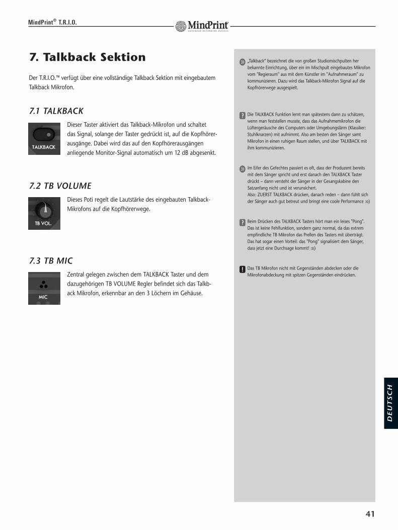
7. Talkback Sektion
Der T.R.I.O.™ verfügt über eine vollständige Talkback Sektion mit eingebautemTalkback Mikrofon.
7.1 TALKBACKDieser Taster aktiviert das Talkback-Mikrofon und schaltet das Signal, solange der Taster gedrückt ist, auf die Kopfhörer-ausgänge. Dabei wird das auf den Kopfhörerausgängenanliegende Monitor-Signal automatisch um 12 dB abgesenkt.
7.2 TB VOLUMEDieses Poti regelt die Lautstärke des eingebauten Talkback-Mikrofons auf die Kopfhörerwege.
7.3 TB MICZentral gelegen zwischen dem TALKBACK Taster und demdazugehörigen TB VOLUME Regler befindet sich das Talkb-ack Mikrofon, erkennbar an den 3 Löchern im Gehäuse.
41
MindPrint® T.R.I.O.
g „Talkback“ bezeichnet die von großen Studiomischpulten herbekannte Einrichtung, über ein im Mischpult eingebautes Mikrofonvom "Regieraum" aus mit dem Künstler im "Aufnahmeraum" zukommunizieren. Dazu wird das Talkback-Mikrofon Signal auf dieKopfhörerwege ausgespielt.
y Die TALKBACK Funktion lernt man spätestens dann zu schätzen,wenn man feststellen musste, dass das Aufnahmemikrofon dieLüftergeräusche des Computers oder Umgebungslärm (Klassiker:Stuhlknarzen) mit aufnimmt. Also am besten den Sänger samtMikrofon in einen ruhigen Raum stellen, und über TALKBACK mitihm kommunizieren.
g Im Eifer des Gefechtes passiert es oft, dass der Produzent bereitsmit dem Sänger spricht und erst danach den TALKBACK Tasterdrückt – dann versteht der Sänger in der Gesangskabine denSatzanfang nicht und ist verunsichert.Also: ZUERST TALKBACK drücken, danach reden – dann fühlt sichder Sänger auch gut betreut und bringt eine coole Performance :o)
y Beim Drücken des TALKBACK Tasters hört man ein leises "Pong".Das ist keine Fehlfunktion, sondern ganz normal, da das extremempfindliche TB Mikrofon das Prellen des Tasters mit überträgt. Das hat sogar einen Vorteil: das "Pong" signalisiert dem Sänger,dass jetzt eine Durchsage kommt! :o)
x Das TB Mikrofon nicht mit Gegenständen abdecken oder dieMikrofonabdeckung mit spitzen Gegenständen eindrücken.
DE
UT
SC
H

8. DAW INTERFACE
Auf der Rückseite des T.R.I.O.™ befinden sich das Interface zur Verbindungmit der DAW. Das DAW Interface ist die Verbindung von T.R.I.O.™ zumComputer und transportiert alle Audiodaten von der/zur DAW. Die Anschlüsse stehen sowohl analog als auch digital zur Verfügung.
Anschlüsse:Zur analogen Anbindung an die DAW stehen je 2 Cinchbuchsen für die Inputsund die Outputs zur Verfügung . Die Pegel können über TRIM Potis an derGeräteunterseite an die Pegel der DAW angepasst werden.Zur digitalen Anbindung an die DAW stehen 2 optische Buchsen im TOS-LINK-Format zur Verfügung.
8.1 ANALOG OUT L/RZur analogen Anbindung an die DAW befinden sich auf derRückseite zwei Cinchbuchsen. Über diese Buchsen werden dieaufzunehmenden Signale von MIC/INSTR. und LINE an die DAWgeschickt.
8.2 ANALOG OUTPUT LEVEL ADJUSTMit diesem Regler auf der Unterseite des T.R.I.O.™ lässt sich der Recordingpegel zu den analogen Eingängen der DAW justieren; der Regelbereich ist von -oo bis +6dB(0dB in Mittenrastung)
8.3 ANALOG IN L/RFür die analoge Rückführung der Signale von der DAW befindensich auf der Rückseite zwei Cinchbuchsen. Über diese Buchsenwerden von der DAW kommende Signale auf die Monitorsektiongeschickt.
8.4 ANALOG INPUT LEVEL ADJUSTMit diesem Regler auf der Unterseite des T.R.I.O.™ lässt sichder Playbackpegel von den analogen Ausgängen der DAWjustieren; Regelbereich: -oo bis +6dB (0dB in Mittenrastung)
42
MindPrint® T.R.I.O.
y Das DAW Interface transportiert die aufzunehmenden Signale vomT.R.I.O. zu den Inputs der DAW und bringt die Outputs der DAWzurück zum T.R.I.O.. Das Interface funktioniert „full duplex“ , d.h.man kann in die DAW aufnehmen und gleichzeitig die Ausgänge derDAW abspielen/abhören.
g Die analogen Ausgänge lassen sich gleichzeitig zu den digitalennutzen. So kann man bei digitaler Anbindung an die DAW dieanalogen Ausgänge dazu verwenden, die aufzunehmenden Signaleseparat abzugreifen und z.B. als Backup auf MiniDisk aufzunehmen.
g Auch die analogen DAW INTERFACE Ausgänge lassen sich z.B. als"Aux Send" zu einem Effektgerät benutzen, um die aufzunehmen-den Signale mit einem "Arbeitshall" zu versehen.
g Auch die analogen Eingänge lassen sich gleichzeitig zu den digitalenverwenden. So kann man die DAW INTERFACE ANALOG INPUTSals weiteren Stereoeingang zum Anschluss eines CD-Players oderEffektgerät-Returns verwenden. Die Anzahl der am T.R.I.O.™ gleich-zeitig verfügbaren Analogeingänge steigt somit auf 1x Mono und3x Stereo.

9. DIGITAL-INTERFACE
Zur Integration in eine digitale Recording-Umgebung verfügt der T.R.I.O.™über eine Digitalschnittstelle im optischen S/P-DIF-Format (TOSLINK).
9.1 S/P-DIF INAn diesen Eingang wird der digitale Ausgang der DAW bzw. desComputerinterfaces angeschlossen. Das gewandelte Signal liegtdirekt am Monitor an.
9.2 S/P-DIF OUTDiese Buchse wird mit dem S/P-DIF Digitaleingang der DAWverbunden. Hier werden die A/D-gewandelten Signale vonMIC/INSTR. und LINE ausgegeben.
9.3 SYNC LEDDiese LED leuchtet, sobald ein gültiges Digitalsignal am S/PDIFEingang des T.R.I.O. anliegt.
Synchronisation
Zur flexiblen Anbindung an die digitale Studioumgebungverfügt das Digitalinterface des T.R.I.O.™ über einen 3-fachWahlschalter, mit dem sich alle notwendigen Einstellungenfür den Digitalverbund vornehmen lassen.
9.4 44,1/48: Dieser Schalter wählt (in Kombination mit dem benachbarten „x2“-Schalter)die Samplingfrequenz, mit der T.R.I.O.™ im Stand Alone Betrieb arbeitet.- in Schalterposition 1 gilt die Frequenz 44,1 kHz- in Schalterstellung 2 arbeitet der T.R.I.O.™ mit 48 kHz Samplingfrequenz
9.5 x1/x2 (= Double Sampling Rate)Ist dieser Schalter in Position 1, so gilt die am benachbarten Schalter"44,1/48" eingestellte Frequenz. In Position 2 gilt die doppelte Sampling Rateder an Schalter "44,1/48" eingestellten Frequenz, also 88,2 kHz bzw. 96 kHz.
43
MindPrint® T.R.I.O.
y Die von SONY und Philips entwickelte, von der IEC 1987 standardi-sierte Schnittstelle S/P-DIF ist für den semiprofessionellen und denHeimbereich gedacht, die Signalführung ist unsymmetrisch.S/P-DIF hat sich als De Facto Standard weltweit etabliert.
S/P-DIF optical (TOSLINK)Die optische Schnittstelle bietet gegenüber der elektrischen COAXIAL-Variante viele Vorteile, zB.:• keine Fehlbedienung durch falsche Anschlusskabel möglich (spezielle
Lichtleiterkabel)• die optische ADAT-Schnittstelle vieler Geräte ist auf S/P-DIF optical
umschaltbar• galvanische Trennung, deswegen keine Ground Loops und elektrische
Einstreuungen• weiter verbreitet als coaxial
y Falls Ihre DAW keine optischen, sondern coaxiale S/P-DIF Anschlüs-se besitzt: Formatwandler S/P-DIF optisch/coaxial gibt es im gutsortierten Musikfachhandel.
g Die SYNC LED signalisiert, wenn ein gültiges Signal an der S/PDIFINPUT Buchse erkannt wird; das erleichtert die Fehlersuche ineinem nicht funktionierenden Setup.
SYNCHRONISATIONSobald digitale Audiogeräte miteinander verbunden werden, müssenihre internen Taktfrequenzen synchronisiert werden. Ein Gerät fungiertals MASTER und gibt Sampling Rate und Bitrate vor, das/die übrige/nGeräte folgen als SLAVE. Symptome wie Knackser während der Aufnah-me sind typische Indikatoren dafür, dass die die Synchonisation nichtstimmt und die Einstellung überprüft werden müssen.
SAMPLING RATEbezeichnet die Abtastrate bei digitalen Audiosignalen – also, in wievielen Einzelschritten das Signal pro Sekunde abgelesen wird (bei derAudio-CD ist dies 44100 mal pro Sekunde, also 44.1 KHz).Es gilt: Je höher die eingestellte Samplerate beim Aufnehmen, desto"besser" die Qualität des Audiosignals, bzw. "genauer" die Abbildungdes analogen Ursprungssignals. Der Speicherbedarf steigt allerdingsproportional zur Samplerate an.
x Wenn sowohl T.R.I.O. als auch die DAW als MASTER arbeiten, kannes durch Überlagerungen zu Störungen im hörbaren Bereich kom-men, da dann beide Geräte mit ihren eigenen Frequenzen arbei-ten. Ein Indikator dafür ist z.B., wenn das aus der DAW abgespielteSignal dumpf klingt. Im Zweifelsfall lieber nochmal die Synchroni-sationseinstellungen beider Geräte überprüfen und einen MASTERund einen SLAVE bestimmen.
y Die Digitalschnittstelle des T.R.I.O.™ verabeitet Audio in einer Auf-lösung von bis zu 96kHz/24bit.
DE
UT
SC
H

9.6 MASTER/SLAVEIn Position 1 arbeitet T.R.I.O.™ als MASTER mit internem Takt und der ein-gestellten Samplingfrequenz; zur fehlerfreien Synchronisation muss dieangeschlossenen DAW auf „Slave“ bzw. „extern“ gestellt werden.In Position 2 (= SLAVE) loggt sich T.R.I.O.™ bei Erkennen eines gültigen an-liegenden Digitalsignals automatisch darauf ein und läuft in Sync zur DAWmit der dort eingestellten Sampling Rate. Wenn ein gültiges Digitalsignalanliegt, leuchtet die SYNC LED.
10. RECORD/MONITOR MODE SELECTOR
Auf der Unterseite des T.R.I.O.™ befindet sich einein 4-fach Miniatur-DIP-Schalter, mit dem sichZuordnungen für Aufnahme- und Abhörpfadeinstellen lassen.
10.1 MIC/INSTR RECORD (1)Schaltet das Signal des MIC/INSTR. Kanals im Aufnahmeweg von „nur Links“(= Kanal 1 der Recording Software) nach "Links & Rechts" (Signal auf beidenKanälen gleichzeitig)
10.2 MIC/INSTR. MONITOR (2)Schaltet das Signal des MIC/INSTR. Kanals im Monitorweg von „nur Links“nach "Links & Rechts" (Stereomitte); dies gilt für PHONES, DIRECT OUT undSPEAKERS A/B/C.
10.3 LINE RECORD (3)Schaltet das Signal des LINE Kanals im Aufnahmeweg von „nur Rechts“ (=Kanal 2 der Recording Software, evtl. Monosumme) nach "Links & Rechts"(Stereo)
10.4 LINE MONITOR (4)Schaltet das Signal des LINE Kanals im Monitorweg von „nur Rechts“ (evtl.Monosumme) nach "Links & Rechts" (Stereo); dies gilt für PHONES, DIRECTOUT und SPEAKERS A/B/C.
44
MindPrint® T.R.I.O.
y Die S/P-DIF Schnittstelle stellt den digitalen Ein- und Ausgang überseparate Buchsen zur Verfügung.Vorteil: T.R.I.O.™ muss nicht zwingend das einzige Gerät im Digital-verbund der DAW sein; so kann ein anderes Gerät mit Digitalaus-gang (z.B. DI-PORT für Stereo-Mikrofonaufnahmen) für die Auf-nahme zur DAW verwendet werden, und T.R.I.O.™ übernimmtsolange nur das Monitoring...
y Der T.R.I.O.™ ist ein Gerät mit zwei Eingangskanälen. Die Bedeutungvon zwei Kanälen ist hier nicht zwingend mit der Bedeutung vonStereo gleichzusetzen. Bei reinen Stereo-Geräten entspricht Kanal 1immer links, Kanal 2 immer rechts. Beim T.R.I.O.™ kann man sowohlfür den Mono Kanal als auch den Stereo-Kanal entscheiden, aufwelche DAW-Eingänge sie geroutet werden und auf welchen Kopf-hörer-/Boxenseiten sie ausgegeben werden.
y Im Lieferzustand stehen alle 4 Schalter auf Stellung ON = L/R. Dasbedeutet, dass sowohl das MIC/INSTR.-Signal als auch das LINE-Signal an beiden DAW- Inputs und auf beiden Kopfhörer-/Laut-sprecherseiten anliegt und so z.B. schon allein durch das Scharf-schalten der entsprechenden DAW-Inputs flexibel geroutet werdenkann.
y Die Einstellungen am RECORD/MONITOR MODE SELECTOR wirkenauf die gesamte Monitorsektion, also sowohl auf die Kopfhörer alsauch auf DIRECT OUT und die Lautsprecherausgänge. Kann alsoschon mal vorkommen, dass das Monitorsignal auf nur einer Boxen-seite hörbar ist - dann ist wahrscheinlich der entsprechende DIP-Schalter dementsprechend eingestellt.
y Der RECORD/MONITOR MODE SELECTOR wird im normalenBetrieb zwar gar nicht auffallen, er bietet allerdings sehr nützlicheOptionen: Will der Gitarrist z.B. eine bereits eingespielte Gitarredoppeln, hat er dadurch die Möglichkeit, die bereits eingespielteGitarre nur auf der linken Kopfhörerseite/Box zu hören, und die,die er jetzt einspielen will, auf der rechten.Anderes Beispiel: Will man die Gitarre zusammen mit einem Stereo-effekt aus einem Effektgerät aufnehmen, dann stellt man alle Schalterauf Position ON (= Defaulteinstellung) und erhält so eine Stereo-aufnahme, bei der die Gitarrensignal in der Mitte liegt und dasEffektsignal echt Stereo ist.

11. Diverses
11.1 POWER SchalterAuf der Rückseite links befindet sich der POWER Schalter, der den T.R.I.O.™ ein-und ausschaltet. In eingeschaltetem Zustandleuchtet entweder die INPUTS oder OUTPUTS LED (abhängigvom Schaltzustand).
11.2 NetzbuchseÜber das externe Steckernetzteil mit 15V Wechselspannung und1700mA Leistung wird T.R.I.O.™ an das Stromnetz angeschlossen.
11.3 GNDUnterhalb der Netzbuchse befindet sich die GROUND-Schraube,deren Funktionsweise der einer Ground Schraube beim Schall-plattenspieler entspricht.
45
MindPrint® T.R.I.O.
x Bei Verlust/Defekt des Steckernetzteiles nur ein original MindPrint®
Ersatz-Steckernetzteil verwenden; andere Netzteile können zu einer Beschädigung des T.R.I.O.™ führen. Das original MindPrint®
Steckernetzteil gibt's im autorisierten Fachhandel oder im MindPrint® Webshop unter www.mindprint.com
y Eine saubere Stromversorgung ist eine entscheidende Vorausset-zung für klanglich hervorragende Gesamtergebnisse. Deshalb hatder T.R.I.O.™ ein grosszügig dimensioniertes externes Netzteil, umin jeder Betriebssituation ausreichend Power für den Mikrofonein-gang und die beiden Kopfhörerverstärker zu gewährleisten.
y Sobald eines der am T.R.I.O.™ angeschlossenen Geräte geerdetangeschlossen ist (über ein 3pol. Kaltgeräte-Netzkabel), "nimmt"sich T.R.I.O.™ von dort die Erdung. Werden ausschließlich Gerätemit Steckernetzteilen am T.R.I.O.™ angeschlossen, so kann es schonmal zu Brummeinstreuungen kommen. Deshalb bietet T.R.I.O.™das schöne Feature, das Gerätechassis mittels einem an der GNDSchraube angeschlossenen Erdungskabel zu erden.
DE
UT
SC
H

12. Fehlerdiagnose
Wenn bei der Arbeit mit T.R.I.O.™ irgendwelche Probleme auftreten, solltenSie die folgenden Punkte prüfen – die folgende Liste hilft bei der Suche nachmöglichen Ursachen für eine Störung:
Mikrofonsignal schlägt auf der LED Kette aus, aber ich höre nichts:• MIC/INSTR LEVEL-Regler in der Monitoring-Sektion aufgedreht? (vgl. 3.1)• MONITOR ON-Schalter gedrückt? (vgl. 3.4)• SPEAKERS A/B/C-Schalter gedrückt? (vgl. 4.2)• Steckt ein Stecker im INSERT RETURN? (vgl. 1.9)• MUTE Schalter gedrückt? (vgl. 1.6)
Mikrofonsignal ist hörbar, aber ich kann es nicht aufnehmen:• REC VOL. Regler des Mikrofonkanals aufgedreht? (vgl. 1.5)• ANALOG OUT LEVEL ADJUST-Regler zugedreht? (nur bei analoger Verbin-
dung zur DAW, vgl. 8.1) • Synchronisation zur DAW überprüft? (vgl. 8.4)• richtige Einstellung in der Recording Software angewählt?
Mikrofonsignal ist nur auf einer Boxen-/Kopfhörerseite hörbar:• RECORD/MONITOR MODE SELECTOR auf der Unterseite richtig eingestellt?
(vgl. 9.1)
Aufgenommenes Signal zerrt:• GAIN-Regler zu weit aufgedreht? (vgl. 1.1/5.1)• REC VOL.-Regler zu weit zugedreht? (vgl. 1.5/2.5/5.1)
DAW-Output ist nicht hörbar, aber in der DAW sichtbar:• DAW ON-Schalter gedrückt? (vgl. 3.5)• ANALOG IN LEVEL ADJUST-Regler zugedreht? (nur bei analoger Verbin-
dung zur DAW, vgl. 8.2)• SPEAKERS A/B/C-Schalter gedrückt? (vgl. 4.2)• richtige Einstellung in der Recording Software angewählt?
Line-Signal ist nur auf der rechten LED-Kette sichtbar (bei Schalter-stellung INPUTS):• Nur die rechte LED-Kette zeigt das Eingangssignal des Line-Kanals, auch
wenn es sich um ein Stereosignal handelt (vgl. 5.1)
AUX-Signal ist hörbar, aber ich kann es nicht aufnehmen:• Der AUX Input wirkt NUR auf die Monitorsektion und kann NICHT auf-
genommen werden – aufzunehmende Quelle am LINE-Input anschließen!
46
MindPrint® T.R.I.O.
y Sind alle externen Geräte eingeschaltet, funktionstüchtig und kor-rekt verkabelt? Ist eine Fehlbedienung auszuschließen? Schon oftwar die komplette Serviceabteilung in Aufruhr, bis sich herausge-stellt hat, dass nur eine Sicherung defekt oder ein Kabel falschgesteckt war...

DE
UT
SC
H
13. Technische Spezifikationen
13.1 Mechanische DatenAbmessungenGrundgerät: 260mm (Breite) X 195mm (Tiefe) X 66mm (Höhe)Netzteil: 65mm (Breite) X 128mm (Tiefe) X 52mm (Höhe)
GewichtGrundgerät: 1550 gNetzteil: 650 g
13.2 Elektrische DatenNetzeingangSteckernetzteile Primär: 230V AC/100V AC/117V ACSekundär: 15 V 1700 mA
13.3 Eingänge und AusgängeMIC IN:Buchse: XLR ( 1 = Ground; 2 = +; 3 = -; )
Bauart Eingang: elektronisch symmetriert & floatingEingangsimpedanz: 10 kOhmmin. Eingangspegel: -34 dBu (GAIN in max. Stellung, +12dBu
Speaker Out)-51 dBu (GAIN in max. Stellung, 0dBu Speaker Out)
max. Eingangspegel: 4 dBu (GAIN maximal in Mittelstellung)Gain- Regelbereich: -74...-14 dBu = 60 dB@SEND,
-40dBu Eingang mit KompressorGain- Regelbereich: -74...-10 dBu = 64 dB@SEND
-40 dBu Eingang ohne KompressorMax. Verstärkung: 30 dB ohne KompressorPhantomspeisung: <+48 V DC schaltbar
INSTR. IN:Buchse: Klinke ( Tip = +; Ring = - )
bei Belegung wird MIC abgeschaltetBauart Eingang: unsymmetrischEingangsimpedanz: 1 MOhmmin. Eingangspegel: -25 dBu (GAIN in max. Stellung,
+12 dBu Speaker Out, - 3dBFS)-39.5 dBu (GAIN in max. Stellung, 0dBu Speaker Out, -14 dBFS)
max. Eingangspegel: +14 dBu (GAIN in Mittelstellung)-18 dBu (GAIN in max. Stellung)
Gain- Regelbereich: -∞...19 dB (-10dBu an SEND , -29 dBu Eingang, ohne Kompressor)
Max. Verstärkung: 19 dB
LINE IN:Buchse: Klinke ( Tip = +; Ring = - )Bauart Eingang: unsymmetrisch
Eingangsimpedanz: 51 kOhmMin. Eingangspegel: 0 dBu (+12dBu Speaker Out)
-6 dBu (+6dBu Speaker Out, -1dBFS)max. Eingangspegel: +21 dB
AUX IN:Buchse: Cinch ( Tip = +; Ring = - )Bauart Eingang: unsymmetrischEingangsimpedanz: 51 kOhmMin. Eingangspegel: 0 dBu (+12 dBu Speaker Out)
-6 dBu (+6 dBu Speaker Out, -1 dBFS)max. Eingangspegel: +12 dB
47
MindPrint® T.R.I.O.
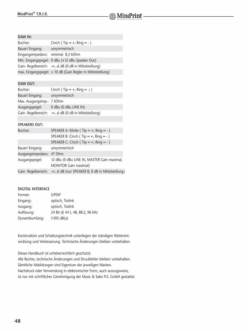
DAW IN:Buchse: Cinch ( Tip = +; Ring = - )Bauart Eingang: unsymmetrischEingangsimpedanz: minimal 8,3 kOhmMin. Eingangspegel: 0 dBu (+12 dBu Speaker Out)Gain- Regelbereich: -∞...6 dB (0 dB in Mittelstellung)max. Eingangspegel: + 10 dB (Gain Regler in Mittelstellung)
DAW OUT:Buchse: Cinch ( Tip = +; Ring = -; )Bauart Eingang: unsymmetrischMax. Ausgangsimp.: 7 kOhmAusgangspegel: 0 dBu (0 dBu LINE IN)Gain- Regelbereich: -∞...6 dB (0 dB in Mittelstellung)
SPEAKERS OUT:Buchse: SPEAKER A: Klinke ( Tip = +; Ring = - )
SPEAKER B: Cinch ( Tip = +; Ring = - )SPEAKER C: Cinch ( Tip = +; Ring = - )
Bauart Eingang: unsymmetrischAusgangsimpedanz: 47 OhmAusgangspegel: 12 dBu (0 dBu LINE IN, MASTER Gain maximal,
MONITOR Gain maximal)Gain- Regelbereich: -∞...6 dB (nur SPEAKER B, 0 dB in Mittelstellung)
DIGITAL INTERFACEFormat: S/PDIFEingang: optisch, ToslinkAusgang: optisch, ToslinkAuflösung: 24 Bit @ 44.1, 48, 88.2, 96 kHzDynamikumfang: >105 dB(a)
Konstruktion und Schaltungstechnik unterliegen der ständigen Weiterent-wicklung und Verbesserung. Technische Änderungen bleiben vorbehalten.
Dieses Handbuch ist urheberrechtlich geschützt. Alle Rechte, technische Änderungen und Druckfehler bleiben vorbehalten. Sämtliche Abbildungen sind Eigentum der jeweiligen Marken. Nachdruck oder Verwendung in elektronischer Form, auch auszugsweise, ist nur mit schriftlicher Genehmigung der Music & Sales P.E. GmbH gestattet.
48
MindPrint® T.R.I.O.
49
MindPrint® T.R.I.O.
DE
UT
SC
H

Important Safety Instructions
Before connecting, read instructions
• Read all of these instructions!• Save these instructions for later use!• Follow all warnings and instructions marked on the product!• Do not use this product near water, i.e. bathtub, sink, swimming pool, wet basement, etc.• Do not place this product on an unstable cart, stand or table.
The product may fall, causing serious damage to the product or to persons!• Slots and openings in the cabinet and the back or bottom are provided for ventilation; to
ensure reliable operation of the product and to protect it from overheating, these openingsmust not be blocked or covered. This product should not be placed in a built-in installationunless proper ventilation is provided.
• This product should not be placed near a source of heat such as a stove, radiator, or anotherheat producing amplifier.
• Use only the supplied power supply or power cord. If you are not sure of the type of poweravailable, consult your dealer or local power company.
• Do not allow anything to rest on the power cord. Do not locate this product where personswill walk on the cord.
• Never break off the ground pin on the power supply cord.• Power supply cords should always be handled carefully. Periodically check cords for cuts or
sign of stress, especially at the plug and the point where the cord exits the unit.• The power supply cord should be unplugged when the unit is to be unused for long periods
of time.• If this product is to be mounted in an equipment rack, rear support should be provided.• This product should be used only with a cart or stand that is recommended by MindPrint®.• Never push objects of any kind into this product through cabinet slots as they may touch
dangerous voltage points or short out parts that could result in risk of fire or electric shock.Never spill liquid of any kind on the product.
• Do not attempt to service this product yourself, as opening or removing covers may exposeyou to dangerous voltage points or other risks. Refer all servicing to qualified service personnel.
• Clean only with dry cloth.• Do not defeat the safety purpose of the polarized or grounding-type plug.
A polarized plug has two blades with one wider than the other. A grounding type plug hastwo blades and a third grounding prong. The wide blade or the third prong are provided forthe safety. If the provided plug does not fit into your outlet, consult an electrician for replace-ment of the obsolete outlet.
• Unplug this product from the wall outlet and refer servicing to qualified service personnelunder the following conditions:
• When the power cord or plug is damaged or frayed.• If liquid has been spilled into the product.• If the product has been exposed to rain or water.• If the product does not operate normally when the operating instructions are followed.• If the product has been dropped or the cabinet has been damaged.• If the product exhibits a distinct change in performance, indicating a need of service!• Adjust only these controls that are covered by the operating instructions since improper
adjustment of other controls may result in damage and will often require extensive work by aqualified technician to restore the product to normal operation.
• Exposure to extremely high noise levels may cause a permanent hearing loss. • Individuals vary considerably in susceptibility to noise induced hearig loss, but nearly everyone
will lose some hearing if exposed to sufficiently intense noise for a sufficient time. The U.S.Government´s Occupational Safety and Health Administration (OSHA) has specified the follo-wing permissible noise level exposures:
Duration Per Day In Hours Sound LeveldBA, Slow Response8 906 924 953 972 10011/2 1021 1051/2 1101/4 or less 115
• According to OSHA, any exposure in excess of the above permissible limits could result insome hearing loss.
• Ear plug protectors in the ear canals or over the ears must be worn when operating thisamplification system in order to prevent a permanent hearing loss if exposure is in excess ofthe limits as set forth above. To ensure against potentially dangerous exposure to high soundpressure levels, it is recommended that all persons exposed to equipment capable of producinghigh sound pressure levels such as this amplification system be protected by hearing protectorswhile this unit is in operation.
• Fuses: Replace with IEC 127 (5x 20 mms) type and rated fuse for best performance only.
TO PREVENT THE RISK OF FIRE AND SHOCK HAZARD, DO NOT EXPOSE THIS APPLIANCE TOMOISTURE OR RAIN. DO NOT OPEN CASE; NO USER SERVICE-ABLE PARTS INSIDE.REFER SERVICING TO QUALIFIED SERVICE PERSONNEL.
Wichtige Sicherheitshinweise!
Bitte vor Gebrauch lesen und für späteren Gebrauch aufbewahren!
• Das Gerät wurde von MindPrint® gemäß IEC 60065 gebaut und hat das Werk in sicherheits-technisch einwandfreiem Zustand verlassen. Um diesen Zustand zu erhalten und einen gefahr-losen Betrieb sicherzustellen, muss der Anwender die Hinweise und die Warnvermerke beachten,die in der Bedienungsanleitung enthalten sind. Das Gerät entspricht der Schutzklasse I(schutzgeerdet).
DIE SICHERHEIT, ZUVERLÄSSIGKEIT UND LEISTUNG DES GERÄTES WIRD VON MindPrint® NURDANN GEWÄHRLEISTET, WENN:• Montage, Erweiterung, Neueinstellung, Änderungen oder Reparaturen von MindPrint® oder
von dazu ermächtigten Personen ausgeführt werden.• die elektrische Installation des betreffenden Raumes den Anforderungen von IEC (ANSI)-
Festlegungen entspricht.• das Gerät in Übereinstimmung mit der Gebrauchsanweisung verwendet wird.
WARNUNG:• Wenn Abdeckungen geöffnet oder Gehäuseteile entfernt werden, außer wenn dies von Hand
möglich ist, können Teile freigelegt werden, die Spannung führen.• Wenn ein Öffnen des Gerätes erforderlich ist, muss das Gerät von allen Spannungsquellen
getrennt sein. Berücksichtigen Sie dies vor dem Abgleich, vor einer Wartung, vor einerInstandsetzung und vor einem Austausch von Teilen.
• Ein Abgleich, eine Wartung oder eine Reparatur am geöffneten Gerät unter Spannung darfnur durch eine vom Hersteller autorisierte Fachkraft (nach VBG 4) geschehen, die mit den ver-bundenen Gefahren vertraut ist.
• Lautsprecher-Ausgänge, die mit dem IEC 417/5036-Zeichen (Abb.1, s.unten) versehen sindkönnen berührungsgefährliche Spannungen führen. Deshalb vor dem Einschalten des GerätesVerbindung nur mit dem vom Hersteller empfohlenen Anschlusskabel zum Lautsprecherherstellen.
• Alle Stecker an Verbindungskabeln müssen mit dem Gehäuse verschraubt oder verriegelt sein,sofern möglich.
• Es dürfen nur Sicherungen vom Typ IEC 127 und der angegebenen Nennstromstärke verwen-det werden.
• Eine Verwendung von geflickten Sicherungen oder Kurzschließen des Halters ist unzulässig.• Niemals die Schutzleiterverbindung unterbrechen.• Oberflächen, die mit dem "HOT"-Zeichen (Abb.2, s.unten) versehen sind, Rückwände oder
Abdeckungen mit Kühlschlitzen, Kühlkörper und deren Abdeckungen, sowie Röhren undderen Abdeckungen können im Betrieb erhöhte Temperaturen annehmen und sollten deshalbnicht berührt werden.
• Hohe Lautstärkepegel können dauernde Gehörschäden verursachen. Vermeiden Sie deshalbdie direkte Nähe von Lautsprechern, die mit hohen Pegeln betrieben werden. Verwenden Sieeinen Gehörschutz bei dauernder Einwirkung hoher Pegel.
NETZANSCHLUSS:• Das Gerät ist für Dauerbetrieb ausgelegt.• Die eingestellte Betriebsspannung muss mit der örtlichen Netzspannung übereinstimmen.• Der Anschluss an das Stromnetz erfolgt mit dem mitgelieferten Netzteil oder Netzkabel.• Netzteil: Eine beschädigte Anschlussleitung kann nicht ersetzt werden. Das Netzteil darf nicht
mehr betrieben werden.• Vermeiden Sie einen Anschluss an das Stromnetz in Verteilerdosen zusammen mit vielen anderen
Stromverbrauchern.• Die Steckdose für die Stromversorgung muss nahe am Gerät angebracht und leicht zugänglich
sein.
AUFSTELLUNGSORT:• Das Gerät sollte nur auf einer sauberen, waagerechten Arbeitsfläche stehen.• Das Gerät darf während des Betriebs keinen Erschütterungen ausgesetzt sein.• Feuchtigkeit und Staub sind nach Möglichkeit fernzuhalten.• Das Gerät darf nicht in der Nähe von Wasser, Badewanne, Waschbecken, Küchenspüle, Nas-
sraum, Swimmingpool oder feuchten Räumen betrieben werden. Keine mit Flüssigkeit gefüll-ten Gegenstände -Vase, Gläser, Flaschen etc. auf das Gerät stellen.
• Sorgen Sie für ausreichende Belüftung der Geräte.• Eventuelle Ventilationsöffnungen dürfen niemals blockiert oder abgedeckt werden. Das Gerät
muß mindestens 20 cm von Wänden entfernt aufgestellt werden. Das Gerät darf nur dann inein Rack eingebaut werden, wenn für ausreichende Ventilation gesorgt ist und die Einbau-anweisungen des Herstellers eingehalten werden.
• Vermeiden Sie direkte Sonneneinstrahlung sowie die unmittelbare Nähe von Heizkörpern undHeizstrahlern oder ähnlicher Geräte.
• Wenn das Gerät plötzlich von einem kalten an einen warmen Ort gebracht wird, kann sich imGeräteinnern Kondensfeuchtigkeit bilden. Dies ist insbesondere bei Röhrengeräten zu beach-ten. Vor dem Einschalten solange warten bis das Gerät Raumtemperatur angenommen hat.
• Zubehör: Das Gerät nicht auf einen instabilen Wagen, Ständer, Dreifuß, Untersatz oder Tischstellen. Wenn das Gerät herunterfällt, kann es Personenschäden verursachen und selbstbeschädigt werden. Verwenden Sie das Gerät nur mit einem vom Hersteller empfohlenen oderzusammen mit dem Gerät verkauften Wagen, Rack, Ständer, Dreifuß oder Untersatz. Bei derAufstellung des Gerätes müssen die Anweisungen des Herstellers befolgt und muss das vomHersteller empfohlene Aufstellzubehör verwendet werden. Eine Kombination aus Gerät undGestell muss vorsichtigt bewegt werden. Plötzliches Anhalten, übermäßige Kraftanwendungund ungleichmäßige Böden können das Umkippen der Kombination aus Gerät und Gestellbewirken.
• Zusatzvorrichtungen: Verwenden Sie niemals Zusatzvorrichtungen, die nicht vom Herstellerempfohlen wurden, weil dadurch Unfälle verursacht werden können
• Zum Schutz des Gerätes bei Gewitter oder wenn es längere Zeit nicht beaufsichtigt oderbenutzt wird, sollte der Netzstecker gezogen werden. Dies verhindert Schäden am Gerät auf-grund von Blitzschlag und Spannungsstößen im Wechselstromnetz.
Abb.1 Abb.2
50
Important Advice on Safety!
Please read before use and keep for later use!
• The unit has been built by MindPrint® in accordance with IEC 60065 and left the factory insafe working order. To maintain this condition and ensure non-risk operation, the user mustfollow the advice and warning comments found in the operating instructions. The unit con-forms to Protection Class 1 (protectively earthed).
• MindPrint® ONLY GUARANTEE THE SAFETY, RELIABILITY AND EFFICIENCY OF THE UNIT IF:• Assembly, extension, re-adjustment, modifications or repairs are carried out by MindPrint® or
by persons authorized to do so.• The electrical installation of the relevant area complies with the requirements of IEC (ANSI)
specifications.• The unit is used in accordance with the operating instructions.• The unit is regularly checked and tested for electrical safety by a competent technician.
WARNING:• If covers are opened or sections of casing are removed, except where this can be done
manually, live parts can become exposed.• If it is necessary to open the unit this must be isolated from all power sources. Please take this
into account before carrying out adjustments, maintenance, repairs and before replacingparts.
• Adjustment, maintenance and repairs carried out when the unit has been opened and is stilllive may only be performed by specialist personnel who are authorized by the manufacturer(in accordance with VBG 4) and who are aware of the associated hazards.
• Loudspeaker outputs which have the IEC 417/5036 symbol (Diagram 1, below) can carryvoltages which are hazardous if they are made contact with. Before the unit is switched on,the loudspeaker should therefore only be connected using the lead recommended by themanufacturer.
• Where possible, all plugs on connection cables must be screwed or locked onto the casing.• Replace with IEC 127 (5x 20 mms) type and rated fuse for best performance only.• It is not permitted to use repaired fuses or to short-circuit the fuse holder.• Never interrupt the protective conductor connection.• Surfaces which are equipped with the "HOT" mark (Diagram 2, below), rear panels or covers
with cooling slits, cooling bodies and their covers, as well as tubes and their covers arepurposely designed to dissipate high temperatures and should therefore not be touched.
• High loudspeaker levels can cause permanent hearing damage. You should therefore avoidthe direct vicinity of loudspeakers operating at high levels. Wear hearing protection ifcontinuously exposed to high levels.
MAINS CONNECTION:• The unit is designed for continuous operation.• The set operating voltage must match the local mains supply voltage.• The unit is connected to the mains via the supplied power unit or power cable.• Power unit: Never use a damaged connection lead. Any damage must be rectified by a
competent technician.• Avoid connection to the mains supply in distributor boxes together with several other power
consumers.• The plug socket for the power supply must be positioned near the unit and must be easily
accessible.
PLACE OF INSTALLATION:• The unit should stand only on a clean, horizontal working surface.• The unit must not be exposed to vibrations during operation.• Keep away from moisture and dust where possible.• Do not place the unit near water, baths, wash basins, kitchen sinks, wet areas, swimming
pools or damp rooms. Do not place objects containing liquid on the unit - vases, glasses,bottles etc.
• Ensure that the unit is well ventilated.• Any ventilation openings must never be blocked or covered. The unit must be positioned at
least 20 cm away from walls. The unit may only be fitted in a rack if adequate ventilation isensured and if the manufacturer's installation instructions are followed.
• Keep away from direct sunlight and the immediate vicinity of heating elements and radiantheaters or similar devices.
• If the unit is suddenly moved from a cold to a warm location, condensation can form inside it.This must be taken into account particularly in the case of tube units. Before switching on,wait until the unit has reached room temperature.
• Accessories: Do not place the unit on an unsteady trolley, stand, tripod, base or table. If theunit falls down, it can cause personal injury and itself become damaged. Use the unit onlywith the trolley, rack stand, tripod or base recommended by the manufacturer or purchasedtogether with the unit. When setting the unit up, all the manufacturer's instructions must befollowed and the setup accessories recommended by the manufacturer must be used. Any combination of unit and stand must be moved carefully. A sudden stop, excessive use offorce and uneven floors can cause the combination of unit and stand to tip over.
• Additional equipment: Never use additional equipment which has not been recommended bythe manufacturer as this can cause accidents.
• To protect the unit during bad weather or when left unattended for prolonged periods, themains plug should be disconnected. This prevents the unit being damaged by lightning andpower surges in the AC mains supply.
Diagram 1 Diagram 2
Conseils de Securite Importants!Priere de lire avant l'emploi et a conserver pour utilisation ulterieure!
• L'appareil a été conçu par MindPrint® selon la norme IEC 60065 et a quitté l'entreprise dansun état irréprochable. Afin de conserver cet état et d'assurer un fonctionnement sans dangerde l'appareil nous conseillons à l'utilisateur la lecture des indications de sécurité contenuesdans le mode d'emploi. L'appareil est conforme à la classification I (mise à terre de protection).
• SURETE, FIABILITE ET EFFICACITE DE L'APPAREIL NE SONT GARANTIS PAR MindPrint® QUE SI:• Montage, extension, nouveau réglage, modification ou réparation sont effectués par Mind-
Print® ou par toute personne autorisée par MindPrint®.• L'installation électrique de la pièce concernée correspond aux normes IEC (ANSI).• L'utilisation de l'appareil suit le mode d'emploi.
AVERTISSEMENT:• A moins que cela ne soit manuellement possible, tout enlèvement ou ouverture du boîtier
peut entrainer la mise au jour de pieces sous tension.• Si l'ouverture de l'appareil est nécessaire, celui-ci doit être coupé de chaque source de courant.
Ceci est à prendre en considération avant tout ajustement, entretien, réparation ou changementde pieces.
• Ajustement, entretien ou réparation sur l'appareil ouvert et sous tension ne peuvent êtreéffectués que par un spécialiste autorisé par le fabricant (selon VBG4). Le spécialiste étantconscient des dangers liés à ce genre de réparation.
• Les sorties de baffles qui portent le signe IEC 417/5036 (fig. 1, voir en bas) peuvent être soustension dangereuse. Avant de brancher l'appareil utiliser uniquement le câble de raccorde-ment conseillé par le fabricant pour raccorder les baffles.
• Toutes les prises des câbles de raccordement doivent être, si possible, vissées ou verrouilléessur le boîtier.
• L’utilisation de fusibles rafistolés ou court-circuites est inadmissible – seulement: IEC127.• L'utilisation de fusibles rafistolés ou court-circuites est inadmissible.• Ne jamais interrompre la connexion du circuit protecteur.• Il est conseillé de ne pas toucher aux surfaces pourvues du signe "HOT" (fig. 2, voir en bas),
aux parois arrières ou caches munis de fentes d'aération, éléments d'aération et leurs cachesansi qu'aux tubes et leurs caches. Ces éléments pouvant atteindre des températures élévéespendant l'utilisation de l'appareil.
• Les Niveaux de puissance élévés peuvent entrainer des lésions auditives durables. Evitez doncla proximité de haut-parleurs utilisés à haute puissance. Lors de haute puissance continueutilisez une protection auditive.
BRANCHEMENT SUR LE SECTEUR:• L'appareil est conçu pour une utilisation continue.• La tension de fonctionnement doit concorder avec la tension secteur locale.• Le raccordement au réseau éléctrique s'effectue avec l'adaptateur ou le cordon d´alimentation
livré avec l'appareil.• Adaptateur: Un câble de raccordement abimé ne peut être remplacé. L'adaptateur
est inutilisable.• Evitez un raccordement au réseau par des boîtes de distribution surchargées.• La prise de courant doit être placée à proximité de l'appareil et facile à atteindre.
LIEU D'INSTALLATION:• L'appareil doit être placé sur une surface de travail propre et horizontale.• L'appareil en marche ne doit en aucun cas subir des vibrations.• Evitez dans la mesure du possible poussière et humidité.• L'appareil ne doit pas être placé à proximité d'eau, de baignoire, lavabo, évier, pièce d'eau,
piscine ou dans une pièce humide. Ne placez aucun vase, verre, bouteille ou tout objet remplide liquide sur l'appareil.
• L'appareil doit être suffisamment aéré.• Ne jamais recouvrir les ouvertures d'aération. L'appareil doit être placé à 20 cm du mur au
minimum. L'appareil peut être monté dans un Rack si une ventilation suffisante est possible et si les conseils de montage du fabricant sont suivis.
• Evitez les rayons de soleil et la proximité de radiateurs, chauffages etc.• Une condensation d'eau peut se former dans l'appareil si celui-ci est transporté brusquement
d'un endroit froid à un endroit chaud. Ceci est particulièrement important pour des appareilsà tubes. Avant de brancher l'appareil attendre qu'il ait la température ambiante.
• Accessoires: L'appareil ne doit être placé sur un chariot, support, trépied, bâti ou table instable.Une chute de l'appareil peut entrainer aussi bien des dommages corporels que techniques.Utilisez l'appareil uniquement avec un chariot, Rack, support, trépied ou bâti conseillé par lefabricant ou vendu en combinaison avec l'appareil. Les indications du fabricant pour l'installationde l'appareil sont à suivre, et les accessoires d'installation conseillés par le fabricant sont à utiliser.Un ensemble support et appareil doit être déplacé avec précaution. Des mouvements brusqueset des revêtements de sol irreguliers peuvent entrainer la chute de l´ensemble.
• Equipements supplémentaires: Ne jamais utiliser un équipement supplémentaire n'ayant pasété conseillé par le fabricant, ceci pouvant entrainer des accidents.
• Afin de protéger l'appareil pendant un orage ou s'il ne doit pas être utilisé pendant un certaintemps, il est conseillé d'enlever la prise au secteur. Ceci évite des dommages dûs à la foudreou à des coups de tension dans le réseau à courant alternatif.
Fig. 1 Fig. 2
51

Importanti avvertimenti di sicurezza!
Leggere attentamente prima dell'uso e conservare per un utilizzosuccessivo:
• L'apparecchio è stato costruito dalla MindPrint® secondo la normativa europea IEC 60065 edha lasciato il nostro stabilimento in stato ineccepibile. Per garantire il mantenimento di talestato e un utilizzo assolutamente privo di rischi l'utente è tenuto ad osservare le indicazioni egli avvertimenti di sicurezza contenuti nelle istruzioni per l'uso. L'apparecchio rispecchia illivello di sicurezza I (collegato a terra).
• SICUREZZA, AFFIDABILITÀ E PRESTAZIONI DELL'APPARECCHIO VENGONO GARANTITI DALLAMINDPRINT® SOLO ED ESCLUSIVAMENTE SE:
• Montaggio, ampliamento, rimessa a punto, modifiche e riparazioni vengono eseguite dallaMindPrint® stessa o da personale da essa autorizzato.
• Gli impianti elettrici nei locali prescelti per l'uso dell'apparecchio rispondono alle normativestabilite dall'ANSI.
• L'apparecchio viene utilizzato come indicato nel libretto delle istruzioni per l'uso.
Avvertimenti:• In caso di apertura di parti di rivestimento o rimozione di parti dell'involucro, a meno che non
si tratti di pezzi rimovibili semplicemente a mano, possono venire alla luce parti dell'apparecchioconduttrici di tensione.
• Se l'apertura dell'apparecchio dovesse risultare necessaria è indispensabile staccare preceden-temente quest'ultimo da tutte le fonti di tensione. Rispettare tale misura di prevenzione ancheprima di un allineamento, di operazioni di manutenzione, della messa in esercizio o della sosti-tuzione di componenti all'interno dell'apparecchio.
• Allineamento, operazioni di manutenzione o eventuali riparazioni dell'apparecchio in presenzadi tensione vanno eseguite esclusivamente da personale specializzato ed autorizzato, in gradodi eseguire tali operazioni evitandone i rischi connessi.
• Le uscite degli altoparlanti contrassegnate dai caratteri IEC 417/5036 (vedi illustrazione 1 afondo pag.) possono essere conduttrici di tensione pericolosa con cui evitare il contatto. Per questo motivo, prima di accendere l'apparecchio, collegare quest'ultimo agli altoparlantiservendosi esclusivamente del cavetto d'allacciamento indicato dal produttore.
• Tutte le spine e i cavi di collegamento devono essere avvitati o fissati all'involucro dell'appa-recchio per quanto possibile.
• Utilizzare esclusivamente fusibili del tipo IEC 127 con la indicata corrente nominale.• L'utilizzo di fusibili di sicurezza non integri e la messa in corto circuito del sostegno di metallo
sono proibite.• Non interrompere mai il collegamento con il circuito di protezione.• Superfici contrassegnate dalla parola "HOT" (vedi illustrazione 2 a fondo pag.), cosi come
griglie di aerazione, dispositivi di raffreddamento e i loro rivestimenti di protezione, oppurevalvole e i relativi rivestimenti protettivi possono surriscaldarsi notevolmente durante l'uso eper questo motivo non vanno toccate.
• L'ascolto di suoni ad alto volume può provocare danni permanenti all'udito. Evitate perciò ladiretta vicinanza con altoparlanti ad alta emissione di suono e utilizzate cuffie protettive incaso ciò non sia possibile.
Alimentazione:• L'apparecchio è concepito per il funzionamento continuo.• La tensione di esercizio deve corrispondere alla tensione di rete a cui ci si allaccia.• L'allacciamento alla rete elettrica avviene tramite alimentatore o cavetto d'alimentazione con-
segnato insieme all'apparecchio.• Alimentatore: un cavo di connessione danneggiato non può essere sostituito. L'alimentatore
non può più essere utilizzato.• Evitate un allacciamento alla rete di corrente utilizzando cassette di distribuzione sovraccariche.• La spina di corrente deve essere situata nelle vicinanze dell'apparecchio e facilmente raggiun-
gibile in qualsiasi momento.
Locali di collocamento:• Opportuno collocare l'apparecchio su una superficie pulita e orizzontale.• Non sottoporre l'apparecchio in funzione a scosse e vibrazioni.• Proteggere l'apparecchio per quanto possibile da umidità e polvere.• Non collocare l'apparecchio vicino ad acqua, vasche da bagno, lavandini, lavelli da cucina,
locali umidi o piscine. Non appoggiare recipienti contenenti liquidi - vasi, bicchieri, bottiglie,ecc. - sull'apparecchio.
• Provvedere ad una buone aerazione dell'apparecchio.• Eventuali aperture previste per la ventilazione dell'apparecchio non vanno ne bloccate, ne mai
coperte. L'apparecchio va collocato ad almeno 20 cm di distanza dalle pareti circostanti e puòessere inserito tra altre componenti di un impianto solo in caso di sufficiente ventilazione equalora le direttive di montaggio del produttore vengano rispettate.
• Evitare di esporre l'apparecchio ai raggi del sole e di collocarlo direttamente nelle vicinanze difonti di calore come caloriferi, stufette, ecc.
• Se l'apparecchio viene trasportato rapidamente da un locale freddo ad uno riscaldato puòsuccedere che al suo interno si crei della condensa. Ciò va tenuto in considerazione soprattuttoin caso di apparecchi a valvole. Attendere che l'apparecchio abbia assunto la temperaturaambiente prima di accenderlo.
• Accessori: non collocare l'apparecchio su carrelli, supporti, treppiedi, superfici o tavoli instabili.Se l'apparecchio dovesse cadere a terra potrebbe causare danni a terzi o danneggiarsi irrepara-bilmente. Utilizzate per il collocamento dell'apparecchio supporti, treppiedi e superfici chesiano consigliate dal produttore o direttamente comprese nell'offerta di vendita. Per il colloca-mento dell'apparecchio attenetevi strettamente alle istruzioni del produttore, utilizzandoesclusivamente accessori da esso consigliati. L'apparecchio in combinazione ad un supporto vaspostato con molta attenzione. Movimenti bruschi o il collocamento su pavimenti non pianipossono provocare la caduta dell'apparecchio e del suo supporto.
• Accessori supplementari: non utilizzate mai accessori supplementari che non siano consigliatidal produttore, potendo essere ciò causa di incidenti.
• Per proteggere l'apparecchio in caso di temporali o nel caso questo non venisse utilizzato perdiverso tempo si consiglia di staccarne la spina di corrente. In questo modo si evitano danniall'apparecchio dovuti a colpi di fulmine o ad improvvisi aumenti di tensione nel circuito dicorrente alternata.
Illustrazione 1 Illustrazione 2
¡Indicaciones de seguridad importantes!
¡Léanse antes de utilizar el aparato y guardense para so uso posterior!
• El aparato ha sido producido por MindPrint® según el IEC 60065 y salió de la fábrica en unestado técnicamente perfecto. Para conservar este estado y asegurar un funcionamiento sinpeligros el usuario debe tener en cuenta las indicaciones y advertencias contenidas en lasinstrucciones de manejo. l aparato corresponde a la clase de protección l (toma de tierra pro-tegida).
• LA SEGURIDAD, LA FIABILIDAD Y EL RENDIMIENTO DEL APARATO SOLO ESTAN GARANTIZA-DOS POR MindPrint® CUANDO:
• el montaje, la ampliación, el reajuste, los cambios o las reparaciones se realicen por MindPrint®
o por personas autorizadas para ello;• la instalación eléctrica del recinto en cuestión corresponda a los requisitos de la determinación
del IEC (ANSI);• el aparato se use de acuerdo con las indicaciones de uso.
ADVERTENCIA:• Si se destapan protecciones o se retiran piezas de la carcasa, exceptuando si
se puede hacer manualmente, se pueden dejar piezas al descubierto que sean conductoras detensión.
• Si es necesario abrir el aparato, éste tiene que estar aislado de todas las fuentes de alimenta-ción. Esto se debe tener en cuenta antes del ajuste, de un entretenimiento, de una reparacióny de una sustitución de las piezas.
• Un ajuste, un entretenimiento o una reparación en el aparato abierto y bajo tensión sólopuede ser llevado a cabo por un especialista autorizado por el productor (según VBG 4) queconozca a fondo los peligros que ello conlleva.
• Las salidas de altavoces que estén provistas de la característica IEC 417/5036 (figura 1, véaseabajo) pueden conducir tensiones peligrosas al contacto. Por ello es indispensable que antesde poner en marcha el aparato; la conexión se haya realizado únicamente con el cable deempalmes recomendado por el productor.
• Las clavijas de contacto al final de los cables conectores tienen que estar atornilladas o encla-vadas a la carcasa, en tanto que sea posible.
• Sólo se pueden utilizar fusibles del tipo IEC 127 con la intensidad de corriente nominal indicada.• El uso de fusibles reparados o la puesta en cortocircuito del soporte es inadmisible.• El empalme del conductor de protección no se puede interrumpir en ningún caso.• Las superficies provistas de la característica "HOT" (figura 2, véase abajo), los paneles de
fondo trasero o las protecciones con ranuras de ventilación, los cuerpos de ventilación y sus protecciones, así como las válvulas electrónicas y sus protecciones pueden alcanzartemperaturas muy altas durante el funcionamiento y por ello no se deberían tocar.
• Niveles elevados de la intensidad de sonido pueden causar continuos daños auditivos; por ello debe evitar acercarse demasiado a altavoces que funcionen a altos niveles. En tales casosutilice protecciones auditivas.
ACOMETIDA A LA RED:• El aparato está proyectado para un funcionamiento continuo.• La tensión de funcionamiento ajustada tiene que coincidir con la tensión de la red del lugar.• La conexión a la red eléctrica se efectuará con la fuente de alimentación o con el cable de red
que se entreguen con el aparato.• Fuente de alimentación: una linea de conexión dañada no se puede sustituir. La fuente de
alimentación no puede volver a ponerse en funcionamiento.• Evite una conexión de la red eléctrica a distribuidores con muchas tomas de corriente.• El enchufe para el suministro de corriente tiene que estar cerca del aparato y ser de fácil acceso.
SITUACION:• El aparato debería estar situado en una superficie limpia y totalmente horizontal.• El aparato no puede estar expuesto a ningún tipo de sacudidas durante su funcionamiento.• Se deben evitar la humedad y el polvo.• El aparato no puede ponerse en funcionamiento cerca del agua, la bañera, el lavamanos, la
pila de la cocina, un recinto con tuberías de agua, la piscina o en habitaciones húmedas. Tam-poco se pueden poner objetos llenos de líquido - jarrones, vasos, botellas, etc. - encima de él.
• Procure que el aparato tenga suficiente ventilación.• Las aberturas de ventilación existentes no se deben bloquear ni tapar nunca. El aparato debe
estar situado como mínimo a 20 cm de la pared. El aparato sólo se puede montar en un rack,si se ha procurado la suficiente ventilación y se han cumplido las indicaciones de montaje delproductor.
• Evite los rayos del sol directos así como la proximidad a radiadores, electro-radiadores oaparatos similares.
• Si el aparato pasa repentinamente de un lugar frío a otro caliente, se puede condensar humedaden su interior. Esto se debe tener en cuenta sobretodo en los aparatos con válvulas electrónicas.Antes de poner en marcha el aparato se debe esperar hasta que éste haya adquirido la tempe-ratura ambiental.
• Accesorios: el aparato no se puede colocar encima de carros, estantes, trípodes, soportes omesas inestables. Si el aparato se cae puede causar daños personales y se puede estropear.Coloque el aparato sólo en un carro, rack, estante, trípode o soporte recomendado por elproductor o que se le haya vendido junto con el aparato. En la instalación se deben seguir lasindicaciones del productor así como utilizar los accesorios recomendados por el mismo paracolocarlo encima. El conjunto del aparato con el pedestal se debe mover con mucho cuidado.Un paro brusco, la aplicación de una fuerza desmesurada o un suelo irregular puede ocasionarla caida de todo el conjunto.
• Piezas adicionales: no utilice nunca piezas adicionales que no estén recomendadas por elproductor, ya que se podrían provocar accidentes.
• Para protejer el aparato de una tormenta o si no se supervisa ni utiliza durante algún tiempo,se debería desconectar la clavija de la red. Así se evitan daños en el aparato a causa de unrayo y golpes de tensión en la red de corriente alterna.
Figura 1 Figura 2
52

MindPrint® T.R.I.O.
Für das folgend bezeichnete Erzeugnis
T.R.I.O Total Recording Solution
wird hiermit bestätigt, dass es den wesentlichen Schutzanforderungenentspricht, die in der Richtlinie des Rates zur Angleichung der Rechts-vorschriften der Mitgliedsstaaten über die elektromagnetische Verträglich-keit (89/336/EWG) und der Niederspannungsrichtlinie (73/23/EWG)festgelegt sind. Diese Erklärung gilt für alle Exemplare und bestätigt dieErgebnisse der Messungen, die durch die Qualitätssicherung der Fa. StamerMusikanlagen GmbH durchgeführt wurden. Zur Beurteilung des Erzeugnisseshinsichtlich elektromagnetischer Verträglichkeit wurden folgende Normenherangezogen: EN 50081-1 • EN 50082-1. Zur Beurteilung der Einhaltung der Niederspannungsrichtlinie wurde folgendeNorm herangezogen: EN 60065
Diese Erklärung wird verantwortlich für den Hersteller
abgegeben durch
Lothar Stamer Dipl.Ing.GeschäftsführerSt.Wendel, den 14/10/04
* Stamer Musikanlagen stellt exklusiv für MindPrint her.
Stamer Musikanlagen GmbH*Magdeburger Str. 866606 St.Wendel
This is to certify that
T.R.I.O Total Recording Solution
complies with the provisions of the Directive of the Council of the EuropeanCommunities on the approximation of the laws of the Member Statesrelating to electromagnetic compatibility (EMC Directive 89/336/EEC) andthe low voltage Directive (73/23/EEC).This declaration of conformity of the European Communities is the result of an examination carried out by the Quality Assurance Department ofSTAMER GmbH in accordance with European Standards EN 50081-1, EN 50082-1and EN 60065 for low voltage, as laid down in Article 10 ofthe EMC Directive.
Lothar Stamer Dipl.Ing.Managing DirectorSt.Wendel, 10/14/04
* Stamer Musikanlagen manufactures exclusively for MindPrint.
Stamer Musikanlagen GmbH*Magdeburger Str. 866606 St.Wendel
53

54
MindPrint® T.R.I.O.

55
MindPrint® T.R.I.O.

MindPrint® T.R.I.O.
www.mindprint.com
MUSIC & SALES GmbH • Postfach 1509 • 66595 St. WendelTel. 0 68 51 - 90 50 • Fax 0 68 51 - 90 5100
E-mail: [email protected]
D-1
200
12/0
4