Tu3 Co 01 3003 Kks Handbook
103
KKS – MASTER LIST Project: STANDARD Document No.: LH-DE011017-REV01 VA TECH HYDRO M:\KH\STANDARD\KKS\KKS-MasterList-Hydro-english-REV01.doc LH-DE / H. Eder Sprache / Language: E erstellt am / created 2001-10-17 Dokumentenart / Documenttype: E-DOC geändert am / modified 2003-02-14 geprüft von/am / checked by/on: Dendl / 2003-02-14 gedruckt am / printed 2003-02-14 1/103 Standard HYDRO POWER PLANTS KKS - HANDBOOK Release „KKS - Handbook“ LH-DE LH Date / Mr. Dendl Date / Mr. Holzer All rights reserved. No part of these documents may be reproduced, copied, distributed, adapted or recorded in any form or by any means (by photocopying, microfilming or by any other technique) without the written permission of the VA TECH HYDRO GmbH. Furthermore, manufacturing and copying of the represented products, plants, systems and technical procedures are prohibited. Alle Rechte vorbehalten. Kein Teil dieser Unterlagen darf in irgendeiner Form (durch Photokopie, Mikrofilm oder ein anderes Verfahren) ohne schriftliche Genehmigung der VA TECH HYDRO GmbH reproduziert oder unter Verwendung elektronischer Systeme gespeichert, bearbeitet, vervielfältigt oder verbreitet werden. Ebenso ist jeder Nachbau bzw. jede Nachahmung von in diesen Unterlagen beschriebenen Geräten, Anlagen, Systemen, Verfahren ua. verboten. Copyright © 2001 VA TECH HYDRO GmbH
description
kks
Transcript of Tu3 Co 01 3003 Kks Handbook
KKS – MASTER LIST
Project: STANDARD Document No.: LH-DE011017-REV01 VA TECH HYDRO
M:\KH\STANDARD\KKS\KKS-MasterList-Hydro-english-REV01.doc
LH-DE / H. Eder Sprache / Language: E erstellt am / created 2001-10-17 Dokumentenart / Documenttype: E-DOC geändert am / modified 2003-02-14 geprüft von/am / checked by/on: Dendl / 2003-02-14 gedruckt am / printed 2003-02-14
1/103
Standard
HYDRO POWER PLANTS
KKS - HANDBOOK
Release „KKS - Handbook“ LH-DE LH
Date / Mr. Dendl Date / Mr. Holzer All rights reserved. No part of these documents may be reproduced, copied, distributed, adapted or recorded in any form or by any means (by photocopying, microfilming or by any other technique) without the written permission of the VA TECH HYDRO GmbH. Furthermore, manufacturing and copying of the represented products, plants, systems and technical procedures are prohibited. Alle Rechte vorbehalten. Kein Teil dieser Unterlagen darf in irgendeiner Form (durch Photokopie, Mikrofilm oder ein anderes Verfahren) ohne schriftliche Genehmigung der VA TECH HYDRO GmbH reproduziert oder unter Verwendung elektronischer Systeme gespeichert, bearbeitet, vervielfältigt oder verbreitet werden. Ebenso ist jeder Nachbau bzw. jede Nachahmung von in diesen Unterlagen beschriebenen Geräten, Anlagen, Systemen, Verfahren ua. verboten. Copyright © 2001 VA TECH HYDRO GmbH
KKS – MASTER LIST
Project: STANDARD Document No.: LH-DE011017-REV01 VA TECH HYDRO
M:\KH\STANDARD\KKS\KKS-MasterList-Hydro-english-REV01.doc
LH-DE / H. Eder Sprache / Language: E erstellt am / created 2001-10-17 Dokumentenart / Documenttype: E-DOC geändert am / modified 2003-02-14 geprüft von/am / checked by/on: Dendl / 2003-02-14 gedruckt am / printed 2003-02-14
2/103
Contents list Part I: KKS: Structure and application 4 Part II: KKS – Master list 45
KKS – MASTER LIST
Project: STANDARD Document No.: LH-DE011017-REV01 VA TECH HYDRO
M:\KH\STANDARD\KKS\KKS-MasterList-Hydro-english-REV01.doc
LH-DE / H. Eder Sprache / Language: E erstellt am / created 2001-10-17 Dokumentenart / Documenttype: E-DOC geändert am / modified 2003-02-14 geprüft von/am / checked by/on: Dendl / 2003-02-14 gedruckt am / printed 2003-02-14
3/103
Part I: KKS: Structure and application
Contents
1 INTRODUCTION ________________________________________________________________________4
2 STRUCTURE OF KKS ____________________________________________________________________5
2.1 BREAKDOWN LEVELS _____________________________________________________________________5 2.2 BREAKDOWN LEVEL 0 – TOTAL PLANT _____________________________________________________6 2.3 BREAKDOWN LEVEL 1 – FUNCTION KEY ____________________________________________________7 2.4 BREAKDOWN LEVEL 2 – EQUIPMENT UNIT KEY _____________________________________________7 2.5 BREAKDOWN LEVEL 3 – COMPONENT KEY__________________________________________________8 2.6 NOTATION OF BREAKDOWN LEVELS _________________________________________________________8 2.7 NAMING OF THE BREAKDOWN LEVELS________________________________________________________9 2.8 PREFIXES _____________________________________________________________________________10
3 APPLICATION OF KKS _________________________________________________________________11
3.1 PROCESS-RELATED IDENTIFICATION ________________________________________________________11 3.2 POINT OF INSTALLATION-IDENTIFICATION ____________________________________________________11 3.3 LOCATION IDENTIFICATION _______________________________________________________________12 3.4 IDENTIFICATION OF CONNECTIONS __________________________________________________________12 3.5 IDENTIFICATION OF SIGNALS ______________________________________________________________12 3.6 IDENTIFICATION OF CABLES _______________________________________________________________13 3.7 IDENTIFICATION OF DOCUMENTS ___________________________________________________________15 3.8 EXAMPLE OF KKS APPLICATION____________________________________________________________15 3.9 REGISTRATION IN GRAPHICAL SYMBOLS______________________________________________________28 3.10 LOOPS WITH MULTIPLE PROBES AT ONE LOCATION____________________________________________30 3.11 GATING OF LOOPS ____________________________________________________________________31 3.12 IDENTIFICATION OF LOOPS ______________________________________________________________32
3.12.1 Identification of direct loops________________________________________________________32 3.12.2 Identification of indirect loops ______________________________________________________34
4 EXTENDED KKS – KEY (STANDARD) ____________________________________________________38
5 IDENTIFICATION OF C&I COMPONENTS ________________________________________________40
5.1 SIGNAL IDENTIFICATION __________________________________________________________________40 5.1.1 General Signal Identification _________________________________________________________40 5.1.2 Designation letter for the signal range/application (Standard / Overview) ______________________41
5.2 BINARY SIGNALS (CONTACTS) AND LIMIT VALUES FROM SIGNAL CONDITIONING _______________________42 5.2.1 Designation letter (signal range) ______________________________________________________42 5.2.2 Signal numbers for binary process signals (contacts)_______________________________________42 5.2.3 Signal numbers for limit values derived from analog process signals __________________________42
6 INTEGRATION OF GE (GENERAL ELECTRICS) IDENTIFICATION SYSTEM IN KKS _________44
KKS – MASTER LIST
Project: STANDARD Document No.: LH-DE011017-REV01 VA TECH HYDRO
M:\KH\STANDARD\KKS\KKS-MasterList-Hydro-english-REV01.doc
LH-DE / H. Eder Sprache / Language: E erstellt am / created 2001-10-17 Dokumentenart / Documenttype: E-DOC geändert am / modified 2003-02-14 geprüft von/am / checked by/on: Dendl / 2003-02-14 gedruckt am / printed 2003-02-14
4/103
1 I N T R O D U C T I O N
The design of complex technical plants involves an enormous number of data to be exchanged between the parties concerned. The identification of plant systems, sections and individual components therefore has to be centralised for the whole plant. The identification system provides a common language for the design and documentation of the scope of work and services. Due to their complexity, modern power stations, where civil works, mechanical- and electrical sections as well as electronic systems are related to each other, require an identification system to avoid disagreement between the parties and unforeseeable costs and time delays during construction.
The identification system KKS (Kraftwerks-Kennzeichen-System) represents a technological and logical classification for modern power stations. All plant sections and components will be identified on a system-related basis in order to satisfy the requirements of the manufacturer, plant owner and operators as well as experts in view of design, erection, operation and maintenance. KKS includes:
- Design and construction - Verification - Assembly - Manufacturing - Erection - Acceptance - Documentation - Operation - Maintenance - Recruiting and replacement administration - Outage statistics - Plant accounting - Industrial economics
The KKS identification system for power stations was developed by the KKS-workout involving designers, plant operators and power authority members and was published in two sections by the VGB-Verlag 1989:
- KKS-Guidelines - KKS-Key
The 2nd edition containing complements to the KKS-Key was published in 1992 by the VGB-Verlag publishing house. The indicated breakdown levels 1, 2, 3 in this document are those dated 1998.
The KKS in its characteristics will be in accordance with DIN 40 719, part 2 and made with due consideration to other standards like IEC (International Electric Commission) and ISO (International Standard Organisation).
The following information represents a general overview regarding the structure and use of KKS. The KKS-Key contained in part two will form a basic platform for utilising KKS for the sole internal use of VA TECH HYDRO GmbH for plants designed and executed by VA TECH HYDRO GmbH.
KKS – MASTER LIST
Project: STANDARD Document No.: LH-DE011017-REV01 VA TECH HYDRO
M:\KH\STANDARD\KKS\KKS-MasterList-Hydro-english-REV01.doc
LH-DE / H. Eder Sprache / Language: E erstellt am / created 2001-10-17 Dokumentenart / Documenttype: E-DOC geändert am / modified 2003-02-14 geprüft von/am / checked by/on: Dendl / 2003-02-14 gedruckt am / printed 2003-02-14
5/103
2 S T R U C T U R E O F K K S
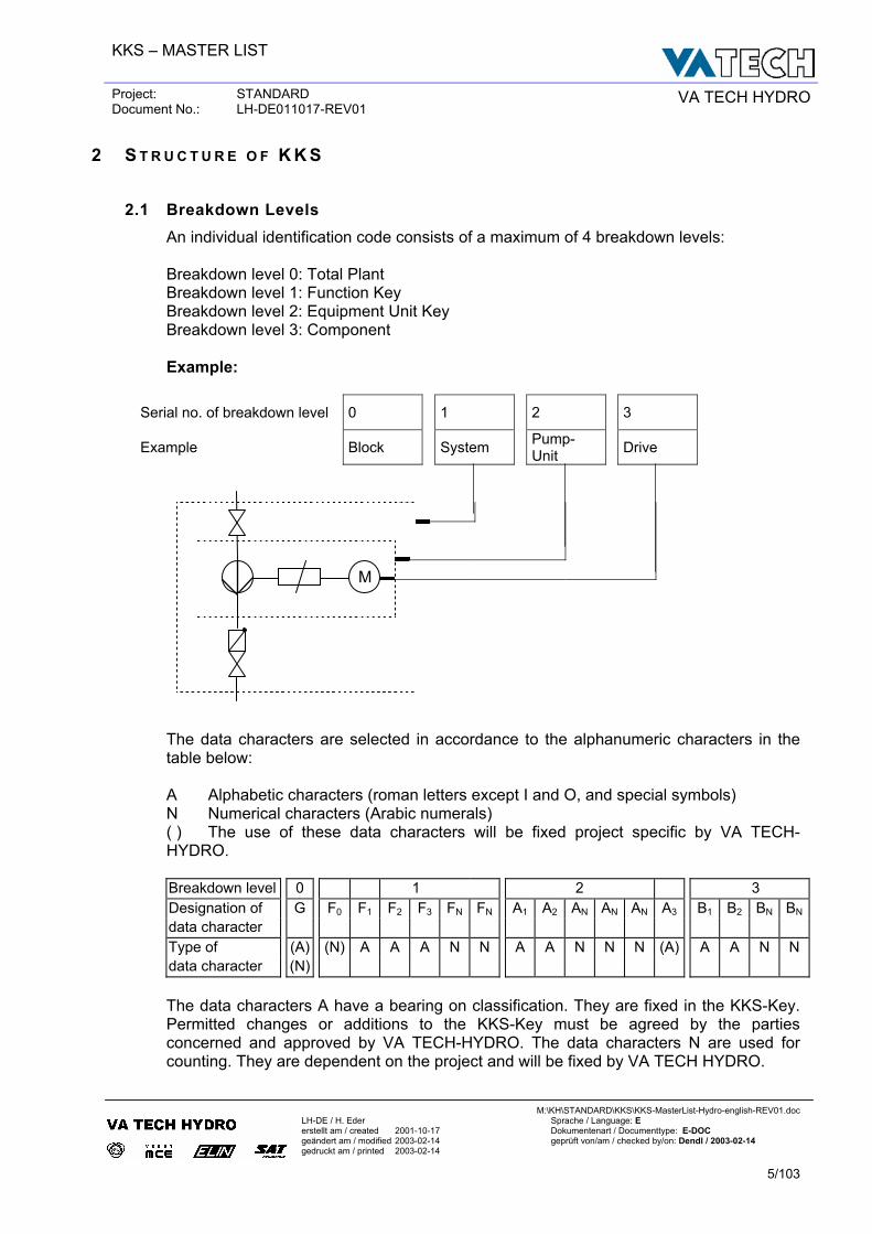
2.1 Breakdown Levels An individual identification code consists of a maximum of 4 breakdown levels: Breakdown level 0: Total Plant Breakdown level 1: Function Key Breakdown level 2: Equipment Unit Key Breakdown level 3: Component
Example:
Serial no. of breakdown level 0 1 2 3
Example Block System Pump-Unit Drive
The data characters are selected in accordance to the alphanumeric characters in the table below: A Alphabetic characters (roman letters except I and O, and special symbols) N Numerical characters (Arabic numerals) ( ) The use of these data characters will be fixed project specific by VA TECH-HYDRO. Breakdown level 0 1 2 3 Designation of G F0 F1 F2 F3 FN FN A1 A2 AN AN AN A3 B1 B2 BN BN
data character Type of (A) (N) A A A N N A A N N N (A) A A N N data character (N)
The data characters A have a bearing on classification. They are fixed in the KKS-Key. Permitted changes or additions to the KKS-Key must be agreed by the parties concerned and approved by VA TECH-HYDRO. The data characters N are used for counting. They are dependent on the project and will be fixed by VA TECH HYDRO.
M
KKS – MASTER LIST
Project: STANDARD Document No.: LH-DE011017-REV01 VA TECH HYDRO
M:\KH\STANDARD\KKS\KKS-MasterList-Hydro-english-REV01.doc
LH-DE / H. Eder Sprache / Language: E erstellt am / created 2001-10-17 Dokumentenart / Documenttype: E-DOC geändert am / modified 2003-02-14 geprüft von/am / checked by/on: Dendl / 2003-02-14 gedruckt am / printed 2003-02-14
6/103
- Numbering starts new when one of the preceding code elements changes. - Redundant zeros must be written:
correct wrong LAC01AA001 LAC1AA1 LAC10AA010 LAC10AA10
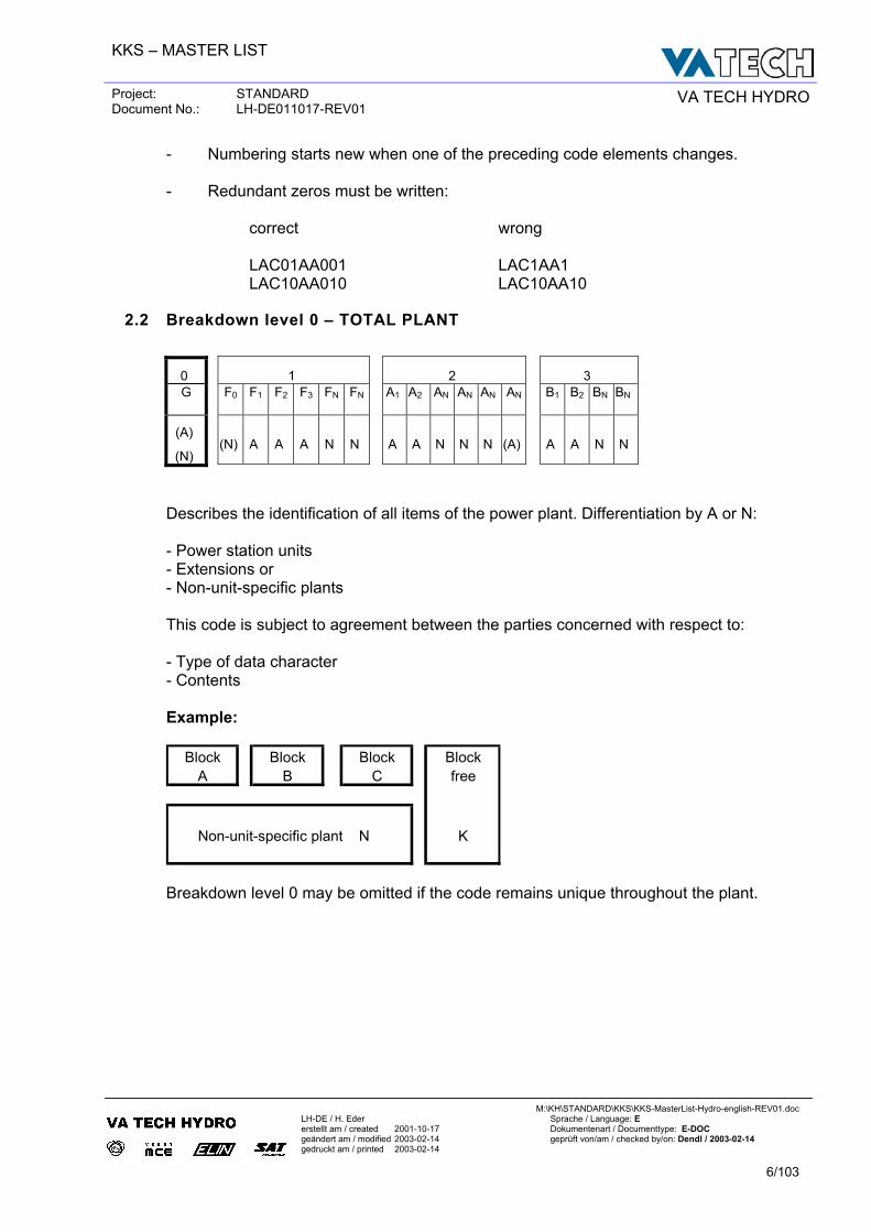
2.2 Breakdown level 0 – TOTAL PLANT
0 1 2 3 G F0
F1
F2
F3
FN
FN
A1
A2
AN
AN
AN
AN
B1
B2
BN
BN
(A)
(N) (N) A A A N N A A N N N (A) A A N N
Describes the identification of all items of the power plant. Differentiation by A or N: - Power station units - Extensions or - Non-unit-specific plants This code is subject to agreement between the parties concerned with respect to: - Type of data character - Contents Example:
Block Block Block BlockA B C free
Non-unit-specific plant N K
Breakdown level 0 may be omitted if the code remains unique throughout the plant.
KKS – MASTER LIST
Project: STANDARD Document No.: LH-DE011017-REV01 VA TECH HYDRO
M:\KH\STANDARD\KKS\KKS-MasterList-Hydro-english-REV01.doc
LH-DE / H. Eder Sprache / Language: E erstellt am / created 2001-10-17 Dokumentenart / Documenttype: E-DOC geändert am / modified 2003-02-14 geprüft von/am / checked by/on: Dendl / 2003-02-14 gedruckt am / printed 2003-02-14
7/103
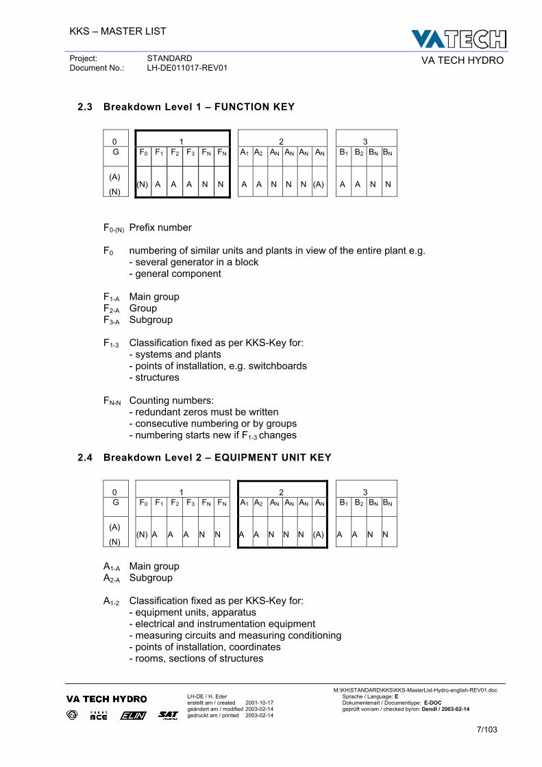
2.3 Breakdown Level 1 – FUNCTION KEY
0 1 2 3 G F0
F1
F2
F3
FN
FN
A1
A2
AN
AN
AN
AN
B1
B2
BN
BN
(A)
(N) (N) A A A N N A A N N N (A) A A N N
F0-(N) Prefix number F0 numbering of similar units and plants in view of the entire plant e.g.
- several generator in a block - general component
F1-A Main group F2-A Group F3-A Subgroup F1-3 Classification fixed as per KKS-Key for: - systems and plants - points of installation, e.g. switchboards - structures FN-N Counting numbers: - redundant zeros must be written - consecutive numbering or by groups - numbering starts new if F1-3 changes
2.4 Breakdown Level 2 – EQUIPMENT UNIT KEY
0 1 2 3 G F0
F1
F2
F3
FN
FN
A1
A2
AN
AN
AN
AN
B1
B2
BN
BN
(A)
(N) (N) A A A N N A A N N N (A) A A N N
A1-A Main group A2-A Subgroup A1-2 Classification fixed as per KKS-Key for: - equipment units, apparatus - electrical and instrumentation equipment - measuring circuits and measuring conditioning - points of installation, coordinates - rooms, sections of structures
KKS – MASTER LIST
Project: STANDARD Document No.: LH-DE011017-REV01 VA TECH HYDRO
M:\KH\STANDARD\KKS\KKS-MasterList-Hydro-english-REV01.doc
LH-DE / H. Eder Sprache / Language: E erstellt am / created 2001-10-17 Dokumentenart / Documenttype: E-DOC geändert am / modified 2003-02-14 geprüft von/am / checked by/on: Dendl / 2003-02-14 gedruckt am / printed 2003-02-14
8/103
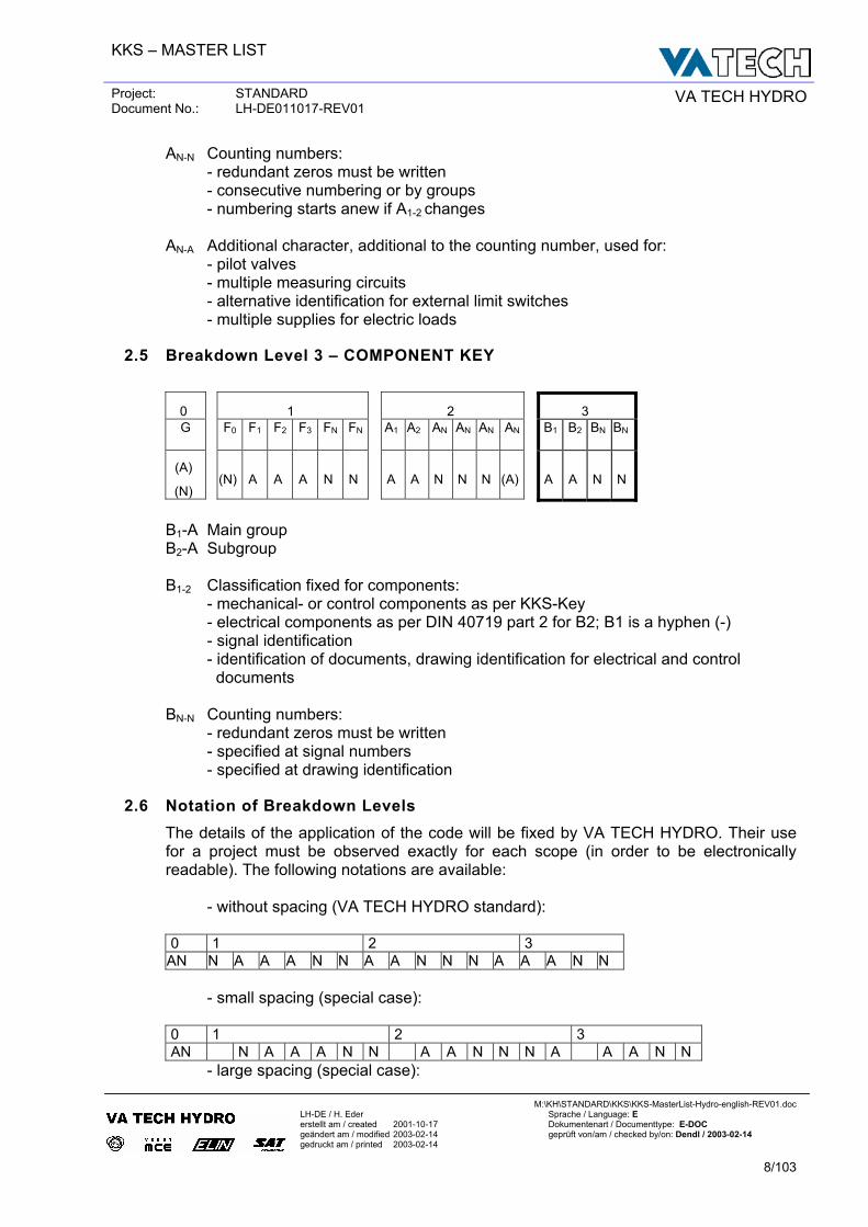
AN-N Counting numbers: - redundant zeros must be written - consecutive numbering or by groups - numbering starts anew if A1-2 changes AN-A Additional character, additional to the counting number, used for: - pilot valves - multiple measuring circuits - alternative identification for external limit switches - multiple supplies for electric loads
2.5 Breakdown Level 3 – COMPONENT KEY
0 1 2 3 G F0
F1
F2
F3
FN
FN
A1
A2
AN
AN
AN
AN
B1
B2
BN
BN
(A)
(N) (N) A A A N N A A N N N (A) A A N N
B1-A Main group B2-A Subgroup B1-2 Classification fixed for components: - mechanical- or control components as per KKS-Key - electrical components as per DIN 40719 part 2 for B2; B1 is a hyphen (-) - signal identification
- identification of documents, drawing identification for electrical and control documents
BN-N Counting numbers: - redundant zeros must be written - specified at signal numbers - specified at drawing identification
2.6 Notation of Breakdown Levels The details of the application of the code will be fixed by VA TECH HYDRO. Their use for a project must be observed exactly for each scope (in order to be electronically readable). The following notations are available: - without spacing (VA TECH HYDRO standard):
0 1 2 3
AN N A A A N N A A N N N A A A N N
- small spacing (special case):
0 1 2 3 AN N A A A N N A A N N N A A A N N
- large spacing (special case):
KKS – MASTER LIST
Project: STANDARD Document No.: LH-DE011017-REV01 VA TECH HYDRO
M:\KH\STANDARD\KKS\KKS-MasterList-Hydro-english-REV01.doc
LH-DE / H. Eder Sprache / Language: E erstellt am / created 2001-10-17 Dokumentenart / Documenttype: E-DOC geändert am / modified 2003-02-14 geprüft von/am / checked by/on: Dendl / 2003-02-14 gedruckt am / printed 2003-02-14
9/103
0 1 2 3
AN N A A A N N A A N N N A A A N N
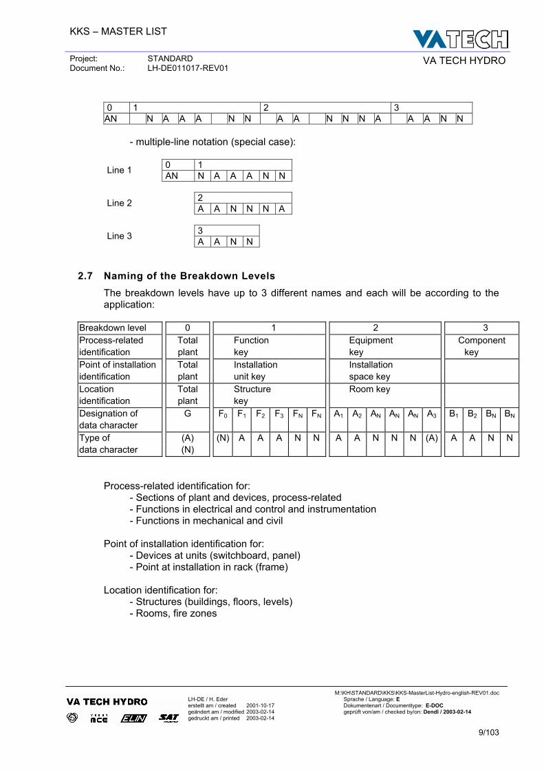
- multiple-line notation (special case):
0 1 Line 1 AN N A A A N N 2 Line 2 A A N N N A 3 Line 3 A A N N
2.7 Naming of the Breakdown Levels The breakdown levels have up to 3 different names and each will be according to the application:
Breakdown level 0 1 2 3 Process-related Total Function Equipment Component identification plant key key key Point of installation Total Installation Installation identification plant unit key space key Location Total Structure Room key identification plant key Designation of G F0 F1 F2 F3 FN FN A1 A2 AN AN AN A3 B1 B2 BN BN
data character Type of (A) (N) A A A N N A A N N N (A) A A N N data character (N)
Process-related identification for: - Sections of plant and devices, process-related - Functions in electrical and control and instrumentation - Functions in mechanical and civil Point of installation identification for: - Devices at units (switchboard, panel) - Point at installation in rack (frame) Location identification for: - Structures (buildings, floors, levels) - Rooms, fire zones
KKS – MASTER LIST
Project: STANDARD Document No.: LH-DE011017-REV01 VA TECH HYDRO
M:\KH\STANDARD\KKS\KKS-MasterList-Hydro-english-REV01.doc
LH-DE / H. Eder Sprache / Language: E erstellt am / created 2001-10-17 Dokumentenart / Documenttype: E-DOC geändert am / modified 2003-02-14 geprüft von/am / checked by/on: Dendl / 2003-02-14 gedruckt am / printed 2003-02-14
10/103
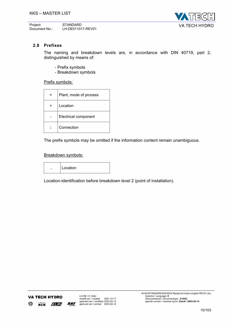
2.8 Prefixes The naming and breakdown levels are, in accordance with DIN 40719, part 2, distinguished by means of: - Prefix symbols - Breakdown symbols Prefix symbols:
= Plant, mode of process
+ Location
- Electrical component
: Connection
The prefix symbols may be omitted if the information content remain unambiguous. Breakdown symbols:
. Location
Location-identification before breakdown level 2 (point of installation).
KKS – MASTER LIST
Project: STANDARD Document No.: LH-DE011017-REV01 VA TECH HYDRO
M:\KH\STANDARD\KKS\KKS-MasterList-Hydro-english-REV01.doc
LH-DE / H. Eder Sprache / Language: E erstellt am / created 2001-10-17 Dokumentenart / Documenttype: E-DOC geändert am / modified 2003-02-14 geprüft von/am / checked by/on: Dendl / 2003-02-14 gedruckt am / printed 2003-02-14
11/103
3 A P P L I C A T I O N O F K K S
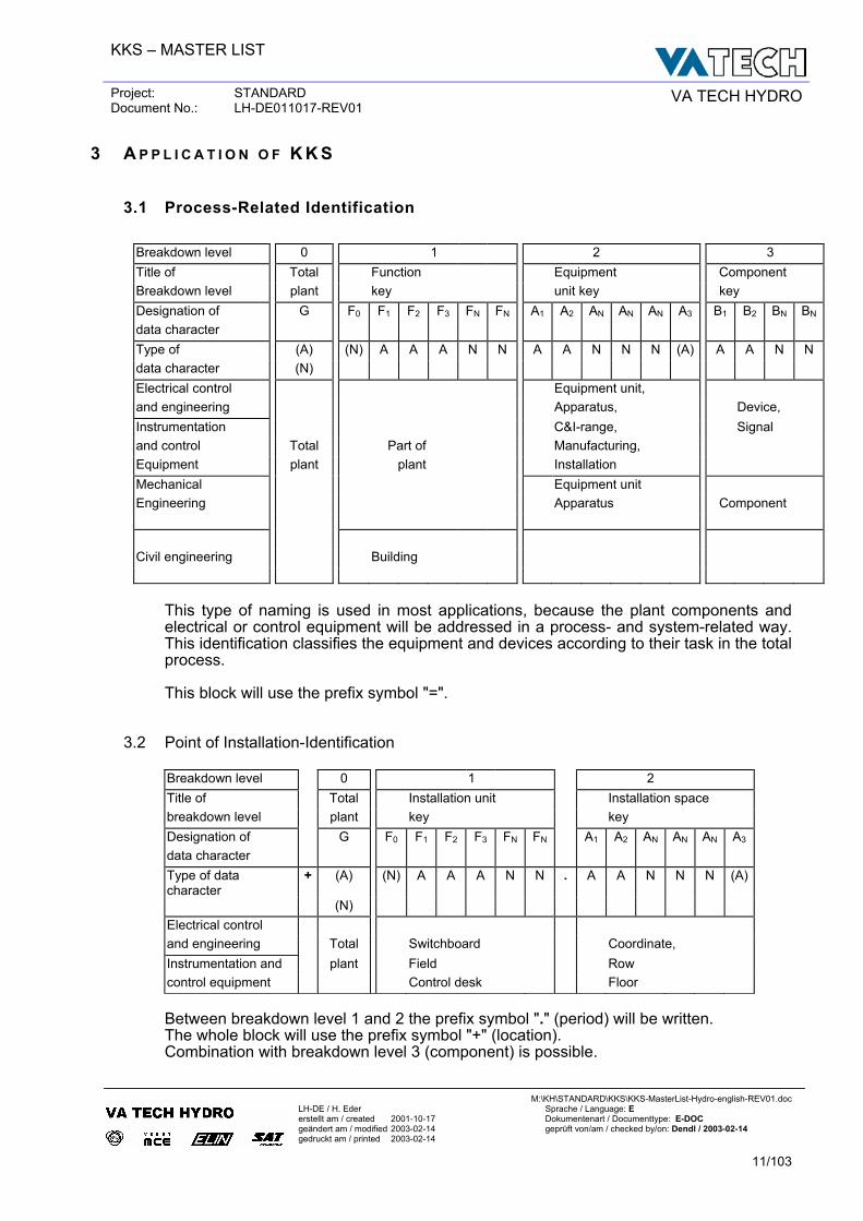
3.1 Process-Related Identification
Breakdown level 0 1 2 3 Title of Total Function Equipment Component Breakdown level plant key unit key key Designation of G F0 F1 F2 F3 FN FN A1 A2 AN AN AN A3 B1 B2 BN BN
data character Type of (A) (N) A A A N N A A N N N (A) A A N N data character (N) Electrical control Equipment unit, and engineering Apparatus, Device, Instrumentation C&I-range, Signal and control Total Part of Manufacturing, Equipment plant plant Installation Mechanical Equipment unit Engineering Apparatus Component
Civil engineering Building
This type of naming is used in most applications, because the plant components and electrical or control equipment will be addressed in a process- and system-related way. This identification classifies the equipment and devices according to their task in the total process. This block will use the prefix symbol "=".
3.2 Point of Installation-Identification Breakdown level 0 1 2 Title of Total Installation unit Installation space breakdown level plant key key Designation of G F0 F1 F2 F3 FN FN A1 A2 AN AN AN A3 data character Type of data character
+ (A) (N) A A A N N . A A N N N (A)
(N) Electrical control and engineering Total Switchboard Coordinate, Instrumentation and plant Field Row control equipment Control desk Floor Between breakdown level 1 and 2 the prefix symbol "." (period) will be written. The whole block will use the prefix symbol "+" (location). Combination with breakdown level 3 (component) is possible.
KKS – MASTER LIST
Project: STANDARD Document No.: LH-DE011017-REV01 VA TECH HYDRO
M:\KH\STANDARD\KKS\KKS-MasterList-Hydro-english-REV01.doc
LH-DE / H. Eder Sprache / Language: E erstellt am / created 2001-10-17 Dokumentenart / Documenttype: E-DOC geändert am / modified 2003-02-14 geprüft von/am / checked by/on: Dendl / 2003-02-14 gedruckt am / printed 2003-02-14
12/103
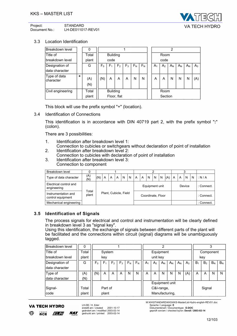
3.3 Location Identification
Breakdown level 0 1 2 Title of Total Building Room breakdown level plant code code Designation of G F0 F1 F2 F3 FN FN A1 A2 AN AN AN A3 data character Type of data character
+ (A)
(N) A A A N N A A N N N (A)
(N)
Civil engineering Total Building Room plant Floor, flat Section
This block will use the prefix symbol "+" (location).
3.4 Identification of Connections
This identification is in accordance with DIN 40719 part 2, with the prefix symbol ":" (colon). There are 3 possibilities: 1. Identification after breakdown level 1:
Connection to cubicles or switchgears without declaration of point of installation 2. Identification after breakdown level 2: Connection to cubicles with declaration of point of installation 3. Identification after breakdown level 3: Connection to component
Breakdown level 0 1 2 3
Type of data character (A) (N) (N) A A A N N A A N N N (A) A A N N : N / A
Electrical control and engineering Equipment unit Device : Connect.
Instrumentation and control equipment Coordinate, Floor : Connect.
Mechanical engineering
Total plant Plant, Cubicle, Field
: Connect.
3.5 Identification of Signals The process signals for electrical and control and instrumentation will be clearly defined in breakdown level 3 as "signal key". Using this identification, the exchange of signals between different parts of the plant will be facilitated and the connections within circuit (signal) diagrams will be unambiguously tagged. Breakdown level 0 1 2 3 Title of Total System Equipment Component breakdown level plant key unit key key Designation of G F0 F1 F2 F3 FN FN A1 A2 AN AN AN A3 B1 B2 BN BN
data character Type of (A) (N) A A A N N A A N N N (A) A A N N data character (N)
Equipment unit Signal- Total Part of C&I-range, Signal code plant plant Manufacturing,
KKS – MASTER LIST
Project: STANDARD Document No.: LH-DE011017-REV01 VA TECH HYDRO
M:\KH\STANDARD\KKS\KKS-MasterList-Hydro-english-REV01.doc
LH-DE / H. Eder Sprache / Language: E erstellt am / created 2001-10-17 Dokumentenart / Documenttype: E-DOC geändert am / modified 2003-02-14 geprüft von/am / checked by/on: Dendl / 2003-02-14 gedruckt am / printed 2003-02-14
13/103
Identification of signals in breakdown level 3: Prefix in position B1 :
X ....... Signal origins - according to origins of defined signal application Y ....... Signal application - according to application hierarchy defined Z ....... according to origins and defined like X, gated or calculated.
Signal type in position B2 :
These data characters are generally fixed by VA TECH HYDRO. Standard see chapter 5.1.
Counting number in positions BN :
Running number from 01 to 99. For various signal types the running number shall be fixed. Standard see chapter 5.1.
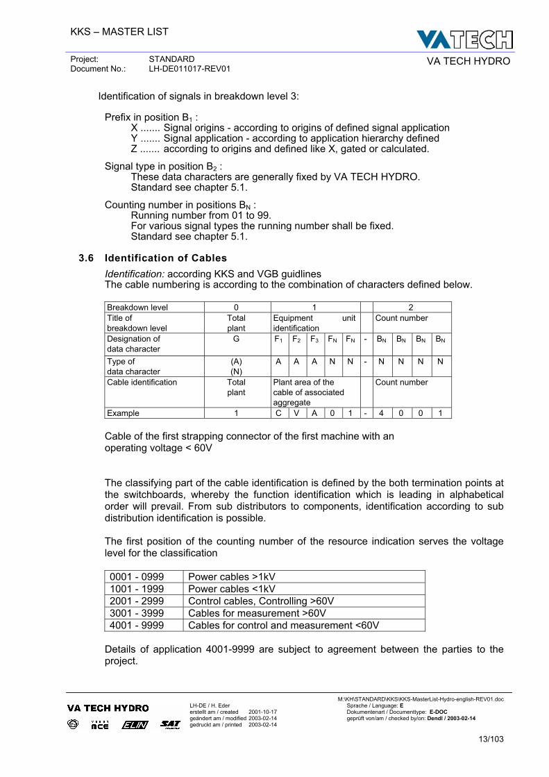
3.6 Identification of Cables Identification: according KKS and VGB guidlines The cable numbering is according to the combination of characters defined below. Breakdown level 0 1 2 Title of breakdown level
Total plant
Equipment unit identification
Count number
Designation of data character
G F1 F2 F3 FN FN - BN BN BN BN
Type of data character
(A) (N)
A A A N N - N N N N
Cable identification Total plant
Plant area of the cable of associated aggregate
Count number
Example 1 C V A 0 1 - 4 0 0 1
Cable of the first strapping connector of the first machine with an operating voltage < 60V
The classifying part of the cable identification is defined by the both termination points at the switchboards, whereby the function identification which is leading in alphabetical order will prevail. From sub distributors to components, identification according to sub distribution identification is possible.
The first position of the counting number of the resource indication serves the voltage level for the classification
0001 - 0999 Power cables >1kV 1001 - 1999 Power cables <1kV 2001 - 2999 Control cables, Controlling >60V 3001 - 3999 Cables for measurement >60V 4001 - 9999 Cables for control and measurement <60V
Details of application 4001-9999 are subject to agreement between the parties to the project.
KKS – MASTER LIST
Project: STANDARD Document No.: LH-DE011017-REV01 VA TECH HYDRO
M:\KH\STANDARD\KKS\KKS-MasterList-Hydro-english-REV01.doc
LH-DE / H. Eder Sprache / Language: E erstellt am / created 2001-10-17 Dokumentenart / Documenttype: E-DOC geändert am / modified 2003-02-14 geprüft von/am / checked by/on: Dendl / 2003-02-14 gedruckt am / printed 2003-02-14
14/103
1CVA
01-4
001 1C
FA02
-400
1
0BBA
01-4
001
0BJA
02-4
001
0BBA
01-0
002
0BBA
01-0
001
0BJA
02-1
001
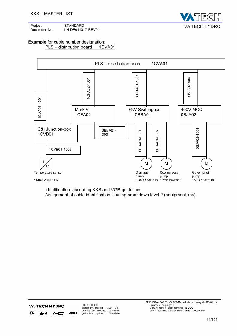
Example for cable number designation: PLS – distribution board 1CVA01
Temperature sensor Drainage Cooling water Governor oil pump pump pump 1MKA20CP902 0GMA10AP010 1PCB10AP010 1MEX10AP010
Identification: according KKS and VGB-guidelines Assignment of cable identification is using breakdown level 2 (equipment key)
PLS – distribution board 1CVA01
0BBA01-3001
Mark V 1CFA02
6kV Switchgear 0BBA01
400V MCC 0BJA02
C&I Junction-box 1CVB01
M M MI P
1CVB01-4002
KKS – MASTER LIST
Project: STANDARD Document No.: LH-DE011017-REV01 VA TECH HYDRO
M:\KH\STANDARD\KKS\KKS-MasterList-Hydro-english-REV01.doc
LH-DE / H. Eder Sprache / Language: E erstellt am / created 2001-10-17 Dokumentenart / Documenttype: E-DOC geändert am / modified 2003-02-14 geprüft von/am / checked by/on: Dendl / 2003-02-14 gedruckt am / printed 2003-02-14
15/103
3.7 Identification of Documents Documents that will be supplied and are necessary for operation of the plant are: - general technical documents - electrical and control and instrumentation documents - mechanical documents - civil documents For these documents, a separate identification will be provided. This identification of documents serves to address a document and to define its location in the whole documentation - regardless of the drawing numbers of the different subcontractors. The documentation identification consists of 3 parts: - Equipment identification: KKS-breakdown level 0-2 - Type of document key: classified by a combination of characters
- Counting number The exact structure for the total plant is defined by VA TECH HYDRO documentation guidelines.
3.8 Example of KKS application The previous examples of KKS use give a general overview of the structure and main uses of KKS. Part A General KKS application commentaries Part B Engineering discipline-specific application commentaries B1 Mechanical engineering B2 Civil engineering B3 Electrical engineering and control and instrumentation B4 Coding of process control and instrumentation
KKS – MASTER LIST
Project: STANDARD Document No.: LH-DE011017-REV01 VA TECH HYDRO
M:\KH\STANDARD\KKS\KKS-MasterList-Hydro-english-REV01.doc
LH-DE / H. Eder Sprache / Language: E erstellt am / created 2001-10-17 Dokumentenart / Documenttype: E-DOC geändert am / modified 2003-02-14 geprüft von/am / checked by/on: Dendl / 2003-02-14 gedruckt am / printed 2003-02-14
16/103
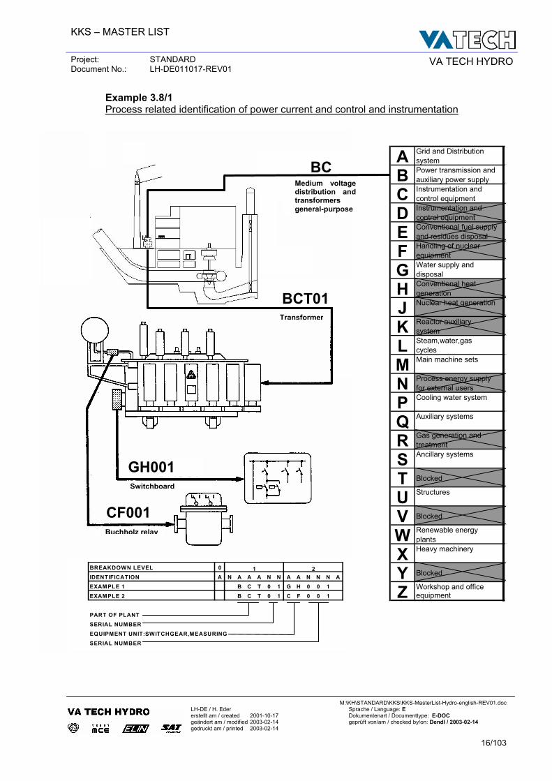
Example 3.8/1 Process related identification of power current and control and instrumentation
Transformer
BCT01
Grid and Distribution systemPower transmission and auxiliary power supplyInstrumentation and control equipmentInstrumentation and control equipmentConventional fuel supply and residues disposalHandling of nuclearequipmentWater supply anddisposalConventional heatgenerationNuclear heat generation
Reactor auxiliarysystemSteam,water,gascyclesMain machine sets
Process energy supplyfor external usersCooling water system
Auxiliary systems
Gas generation andtreatmentAncillary systems
Structures
Renewable energy plantsHeavy machinery
Workshop and office equipment
Blocked
Blocked
Blocked
ABCDEFGHJKLMNPQRSTUVWXYZ
Medium voltage distribution and transformers general-purpose
BC
BREAKDOWN LEVEL 0IDENTIFICATION A N A A A N N A A N N N AEXAMPLE 1 B C T 0 1 G H 0 0 1EXAMPLE 2 B C T 0 1 C F 0 0 1
PART OF PLANTSERIAL NUMBEREQUIPMENT UNIT:SWITCHGEAR,MEASURINGSERIAL NUMBER
1 2
Switchboard
GH001
Buchholz relay
CF001
KKS – MASTER LIST
Project: STANDARD Document No.: LH-DE011017-REV01 VA TECH HYDRO
M:\KH\STANDARD\KKS\KKS-MasterList-Hydro-english-REV01.doc
LH-DE / H. Eder Sprache / Language: E erstellt am / created 2001-10-17 Dokumentenart / Documenttype: E-DOC geändert am / modified 2003-02-14 geprüft von/am / checked by/on: Dendl / 2003-02-14 gedruckt am / printed 2003-02-14
17/103
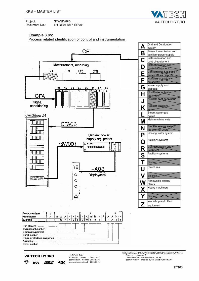
Example 3.8/2 Process related identification of control and instrumentation
Grid and Distribution systemPower transmission and auxiliary power supplyInstrumentation and control equipmentInstrumentation and control equipmentConventional fuel supply and residues disposalHandling of nuclearequipmentWater supply anddisposalConventional heatgenerationNuclear heat generation
Reactor auxiliarysystemSteam,water,gascyclesMain machine sets
Process energy supplyfor external usersCooling water system
Auxiliary systems
Gas generation andtreatmentAncillary systems
Structures
Renewable energy plantsHeavy machinery
Workshop and office equipment
ABCDEFGHJKLMNPQR
Z
STUV
Blocked
Blocked
Blocked
WXY
KKS – MASTER LIST
Project: STANDARD Document No.: LH-DE011017-REV01 VA TECH HYDRO
M:\KH\STANDARD\KKS\KKS-MasterList-Hydro-english-REV01.doc
LH-DE / H. Eder Sprache / Language: E erstellt am / created 2001-10-17 Dokumentenart / Documenttype: E-DOC geändert am / modified 2003-02-14 geprüft von/am / checked by/on: Dendl / 2003-02-14 gedruckt am / printed 2003-02-14
18/103
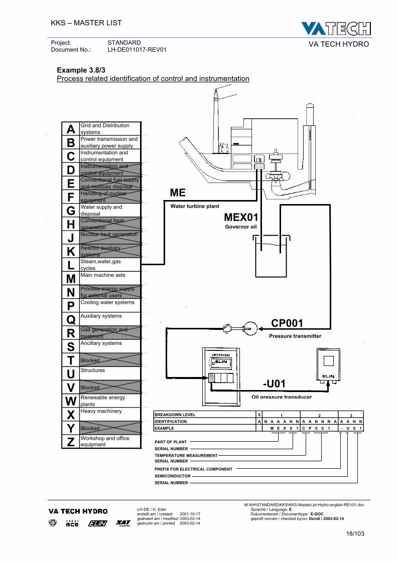
Example 3.8/3 Process related identification of control and instrumentation
MEWater turbine plant
MEX01 Governor oil
Pressure transmitter
CP001
Oil pressure transducer
BREAKDOWN LEVEL 0IDENTIFICATION A N A A A N N A A N N N A A A N NEXAMPLE M E X 0 1 C P 0 0 1 - U 0 1
PART OF PLANTSERIAL NUMBERTEMPERATURE MEASUREMENTSERIAL NUMBER
PREFIX FOR ELECTRICAL COMPONENTSEMICONDUCTORSERIAL NUMBER
1 2 3
-U01
Grid and Distribution systemsPower transmission and auxiliary power supplyInstrumentation and control equipmentInstrumentation and control equipmentConventional fuel supply and residues disposalHandling of nuclearequipmentWater supply anddisposalConventional heatgenerationNuclear heat generation
Reactor auxiliarysystemsSteam,water,gascyclesMain machine sets
Process energy supplyfor external usersCooling water systems
Auxiliary systems
Gas generation andtreatmentAncillary systems
Structures
Renewable energy plantsHeavy machinery
Workshop and office equipmentZ
VWXY
RSTU
MNPQ
HJKL
Blocked
Blocked
Blocked
ABCDEFG
KKS – MASTER LIST
Project: STANDARD Document No.: LH-DE011017-REV01 VA TECH HYDRO
M:\KH\STANDARD\KKS\KKS-MasterList-Hydro-english-REV01.doc
LH-DE / H. Eder Sprache / Language: E erstellt am / created 2001-10-17 Dokumentenart / Documenttype: E-DOC geändert am / modified 2003-02-14 geprüft von/am / checked by/on: Dendl / 2003-02-14 gedruckt am / printed 2003-02-14
19/103
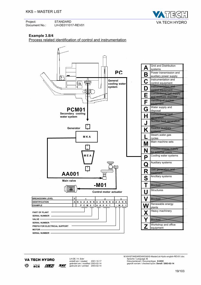
Example 3.8/4 Process related identification of control and instrumentation
PCM01Secondary cooling water system
PC
Generator
M K A
M E A
General cooling water system
Main valve
Control motor actuator
AA001
-M01
BREAKDOWN LEVEL 0IDENTIFICATION A N A A A N N A A N N N A A A N NEXAMPLE P C M 0 1 A A 0 0 1 - M 0 1
PART OF PLANTSERIAL NUMBERVALVESERIAL NUMBERPREFIX FOR ELECTRICAL SUPPORTMOTORSERIAL NUMBER
1 2 3
Grid and Distribution systemsPower transmission and auxiliary power supplyInstrumentation and control equipmentInstrumentation and control equipmentConventional fuel supply and residues disposalHandling of nuclearequipmentWater supply anddisposalConventional heatgenerationNuclear heat generation
Reactor auxiliarysystemsSteam,water,gascyclesMain machine sets
Process energy supplyfor external usersCooling water systems
Auxiliary systems
Gas generation andtreatmentAncillary systems
Structures
Renewable energy plantsHeavy machinery
Workshop and office equipmentZ
VWXY
RSTU
MNPQ
HJKL
Blocked
Blocked
Blocked
ABCDEFG
KKS – MASTER LIST
Project: STANDARD Document No.: LH-DE011017-REV01 VA TECH HYDRO
M:\KH\STANDARD\KKS\KKS-MasterList-Hydro-english-REV01.doc
LH-DE / H. Eder Sprache / Language: E erstellt am / created 2001-10-17 Dokumentenart / Documenttype: E-DOC geändert am / modified 2003-02-14 geprüft von/am / checked by/on: Dendl / 2003-02-14 gedruckt am / printed 2003-02-14
20/103
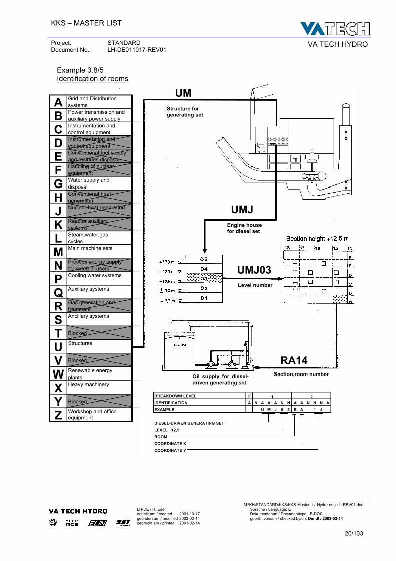
Example 3.8/5 Identification of rooms
UMStructure for generating set
UMJ
UMJ03
BREAKDOWN LEVEL 0IDENTIFICATION A N A A A N N A A N N N AEXAMPLE U M J 0 3 R A 1 4
DIESEL-DRIVEN GENERATING SETLEVEL +12,5ROOMCOORDINATE XCOORDINATE Y
1 2
Engine housefor diesel set
Oil supply for diesel-driven generating set
Level number
RA14 Section,room number
Grid and Distribution systemsPower transmission and auxiliary power supplyInstrumentation and control equipmentInstrumentation and control equipmentConventional fuel supply and residues disposalHandling of nuclearequipmentWater supply anddisposalConventional heatgenerationNuclear heat generation
Reactor auxiliarysystemsSteam,water,gascyclesMain machine sets
Process energy supplyfor external usersCooling water systems
Auxiliary systems
Gas generation andtreatmentAncillary systems
Structures
Renewable energy plantsHeavy machinery
Workshop and office equipmentZ
VWXY
RSTU
MNPQ
HJKL
Blocked
Blocked
Blocked
ABCDEFG
KKS – MASTER LIST
Project: STANDARD Document No.: LH-DE011017-REV01 VA TECH HYDRO
M:\KH\STANDARD\KKS\KKS-MasterList-Hydro-english-REV01.doc
LH-DE / H. Eder Sprache / Language: E erstellt am / created 2001-10-17 Dokumentenart / Documenttype: E-DOC geändert am / modified 2003-02-14 geprüft von/am / checked by/on: Dendl / 2003-02-14 gedruckt am / printed 2003-02-14
21/103
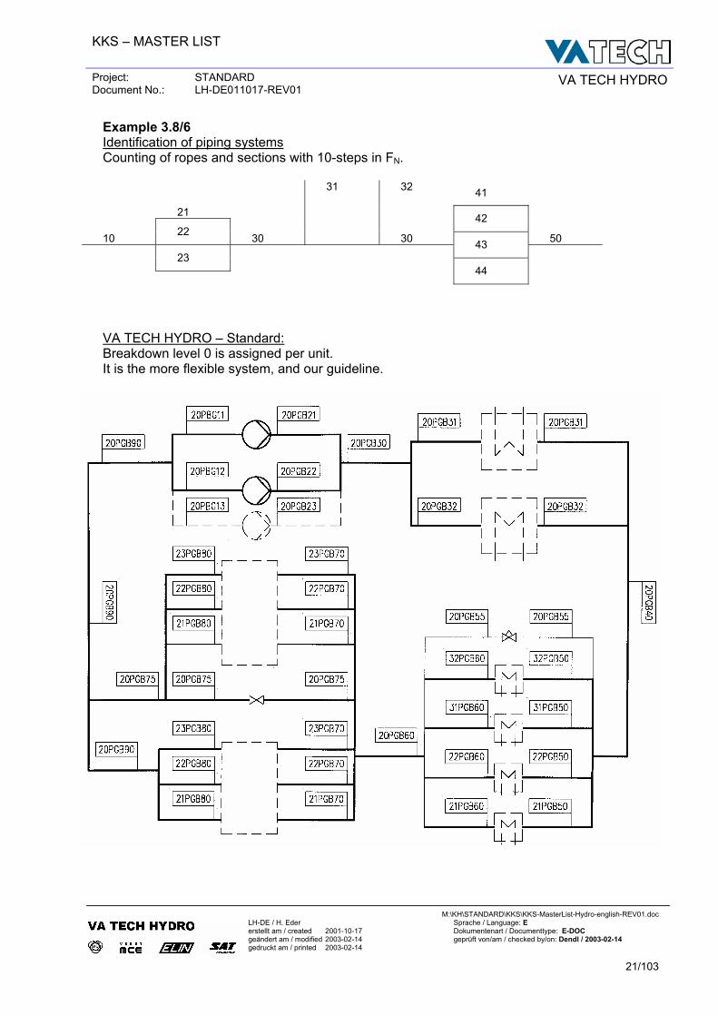
Example 3.8/6 Identification of piping systems Counting of ropes and sections with 10-steps in FN. 31 32 41 21 42 10 22 30 30 50 43 23 44 VA TECH HYDRO – Standard: Breakdown level 0 is assigned per unit. It is the more flexible system, and our guideline.
KKS – MASTER LIST
Project: STANDARD Document No.: LH-DE011017-REV01 VA TECH HYDRO
M:\KH\STANDARD\KKS\KKS-MasterList-Hydro-english-REV01.doc
LH-DE / H. Eder Sprache / Language: E erstellt am / created 2001-10-17 Dokumentenart / Documenttype: E-DOC geändert am / modified 2003-02-14 geprüft von/am / checked by/on: Dendl / 2003-02-14 gedruckt am / printed 2003-02-14
22/103
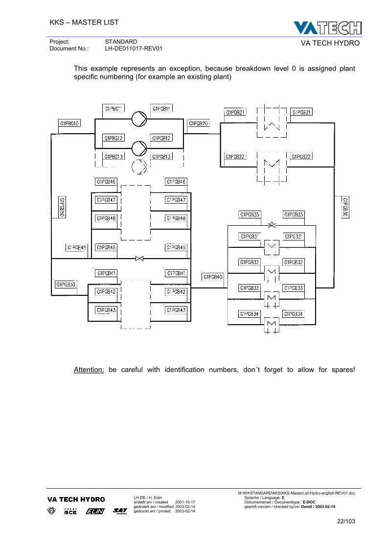
This example represents an exception, because breakdown level 0 is assigned plant specific numbering (for example an existing plant)
Attention: be careful with identification numbers, don´t forget to allow for spares!
KKS – MASTER LIST
Project: STANDARD Document No.: LH-DE011017-REV01 VA TECH HYDRO
M:\KH\STANDARD\KKS\KKS-MasterList-Hydro-english-REV01.doc
LH-DE / H. Eder Sprache / Language: E erstellt am / created 2001-10-17 Dokumentenart / Documenttype: E-DOC geändert am / modified 2003-02-14 geprüft von/am / checked by/on: Dendl / 2003-02-14 gedruckt am / printed 2003-02-14
23/103
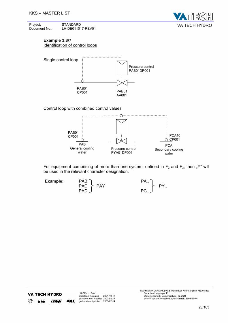
Example 3.8/7 Identification of control loops
Single control loop
Control loop with combined control values
For equipment comprising of more than one system, defined in F2 and F3, then „Y“ will be used in the relevant character designation.
Example: PAB PA.. PAC PAY PY.. PAD PC..
PAB01 CP001 PAB01
AA001
Pressure control PAB01DP001
PAB01 CP001 PCA10
CP001
Pressure control PYA01DP001
PAB General cooling
water
PCA Secondary cooling
water
KKS – MASTER LIST
Project: STANDARD Document No.: LH-DE011017-REV01 VA TECH HYDRO
M:\KH\STANDARD\KKS\KKS-MasterList-Hydro-english-REV01.doc
LH-DE / H. Eder Sprache / Language: E erstellt am / created 2001-10-17 Dokumentenart / Documenttype: E-DOC geändert am / modified 2003-02-14 geprüft von/am / checked by/on: Dendl / 2003-02-14 gedruckt am / printed 2003-02-14
24/103
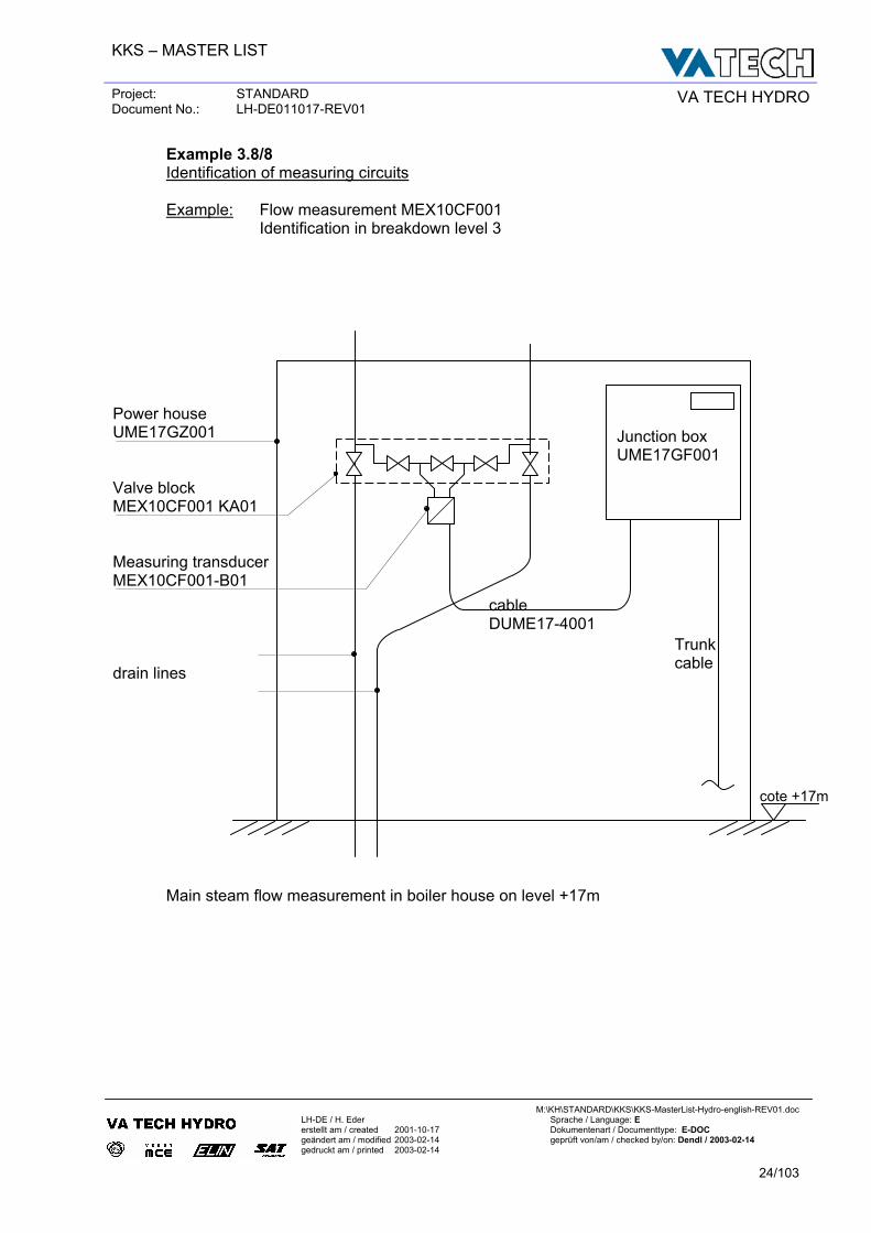
Example 3.8/8 Identification of measuring circuits Example: Flow measurement MEX10CF001 Identification in breakdown level 3
Power house UME17GZ001 Valve block MEX10CF001 KA01 Measuring transducer MEX10CF001-B01 drain lines
Main steam flow measurement in boiler house on level +17m
Junction box UME17GF001
Trunk cable
cote +17m
cable DUME17-4001
KKS – MASTER LIST
Project: STANDARD Document No.: LH-DE011017-REV01 VA TECH HYDRO
M:\KH\STANDARD\KKS\KKS-MasterList-Hydro-english-REV01.doc
LH-DE / H. Eder Sprache / Language: E erstellt am / created 2001-10-17 Dokumentenart / Documenttype: E-DOC geändert am / modified 2003-02-14 geprüft von/am / checked by/on: Dendl / 2003-02-14 gedruckt am / printed 2003-02-14
25/103
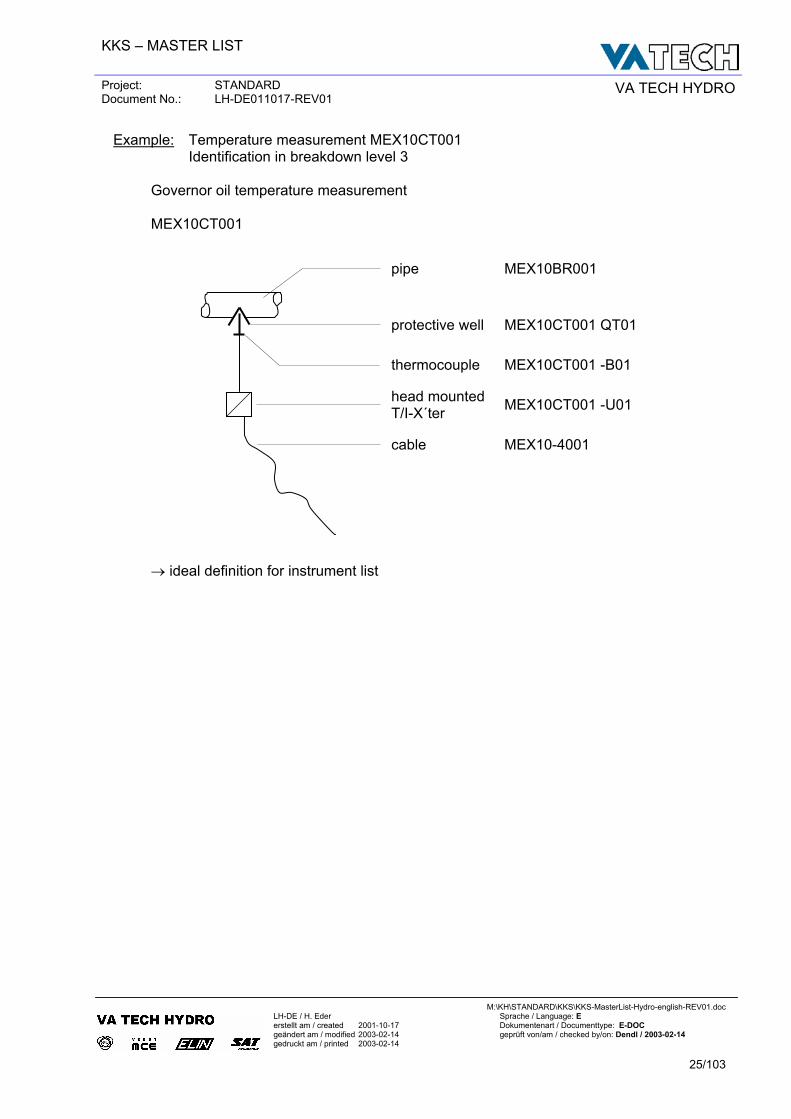
Example: Temperature measurement MEX10CT001 Identification in breakdown level 3 Governor oil temperature measurement MEX10CT001
pipe
MEX10BR001
protective well MEX10CT001 QT01
thermocouple MEX10CT001 -B01
head mounted T/I-X´ter MEX10CT001 -U01
cable MEX10-4001
→ ideal definition for instrument list
KKS – MASTER LIST
Project: STANDARD Document No.: LH-DE011017-REV01 VA TECH HYDRO
M:\KH\STANDARD\KKS\KKS-MasterList-Hydro-english-REV01.doc
LH-DE / H. Eder Sprache / Language: E erstellt am / created 2001-10-17 Dokumentenart / Documenttype: E-DOC geändert am / modified 2003-02-14 geprüft von/am / checked by/on: Dendl / 2003-02-14 gedruckt am / printed 2003-02-14
26/103
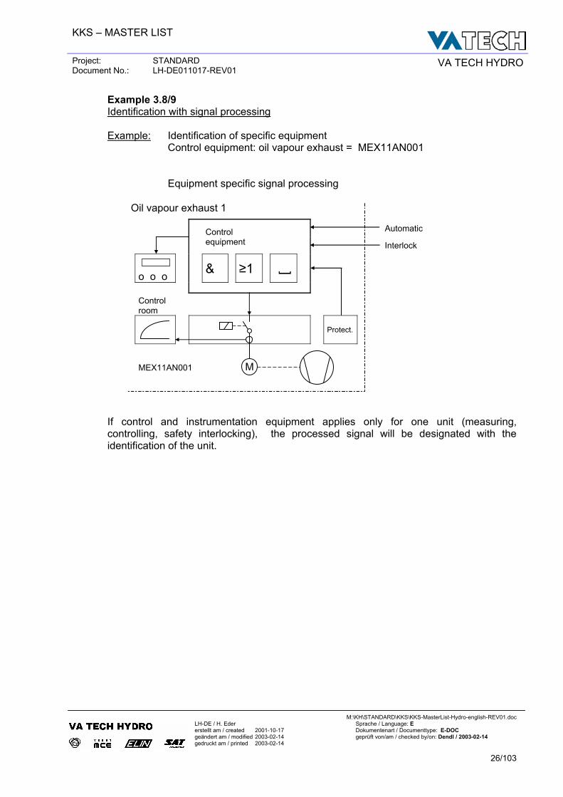
Example 3.8/9 Identification with signal processing Example: Identification of specific equipment Control equipment: oil vapour exhaust = MEX11AN001 Equipment specific signal processing
Oil vapour exhaust 1
Control Automatic
equipment Interlock
o o o
& ≥1 [
Control room
Protect.
MEX11AN001
If control and instrumentation equipment applies only for one unit (measuring, controlling, safety interlocking), the processed signal will be designated with the identification of the unit.
M
KKS – MASTER LIST
Project: STANDARD Document No.: LH-DE011017-REV01 VA TECH HYDRO
M:\KH\STANDARD\KKS\KKS-MasterList-Hydro-english-REV01.doc
LH-DE / H. Eder Sprache / Language: E erstellt am / created 2001-10-17 Dokumentenart / Documenttype: E-DOC geändert am / modified 2003-02-14 geprüft von/am / checked by/on: Dendl / 2003-02-14 gedruckt am / printed 2003-02-14
27/103
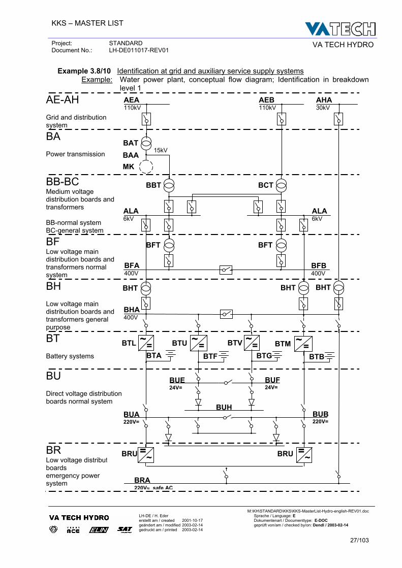
Example 3.8/10 Identification at grid and auxiliary service supply systems Example: Water power plant, conceptual flow diagram; Identification in breakdown
level 1
AE-AH Grid and distribution system
BA Power transmission
BB-BC Medium voltage distribution boards and transformers BB-normal system BC-general system
BF Low voltage main distribution boards and transformers normal system
BH Low voltage main distribution boards and transformers general purpose
BT Battery systems
BU Direct voltage distribution boards normal system
BR Low voltage distribution boards emergency power system
BRU BRU
BAT
BHT
BAA MK
15kV
AEA 110kV
AEB 110kV
AHA 30kV
BBT BCT
ALA 6kV
ALA 6kV
BFTBFT
BFB 400V
BFA 400V
=~BTU
BHT BHT
= ~ BTM
BTB BTF= ~ BTL BTA
=~BTVBTG
BHA 400V
BUH
BUE 24V=
BUF24V=
BUB 220V=
BUA 220V=
~ =
BRA 220V≈ safe AC
~ =
KKS – MASTER LIST
Project: STANDARD Document No.: LH-DE011017-REV01 VA TECH HYDRO
M:\KH\STANDARD\KKS\KKS-MasterList-Hydro-english-REV01.doc
LH-DE / H. Eder Sprache / Language: E erstellt am / created 2001-10-17 Dokumentenart / Documenttype: E-DOC geändert am / modified 2003-02-14 geprüft von/am / checked by/on: Dendl / 2003-02-14 gedruckt am / printed 2003-02-14
28/103
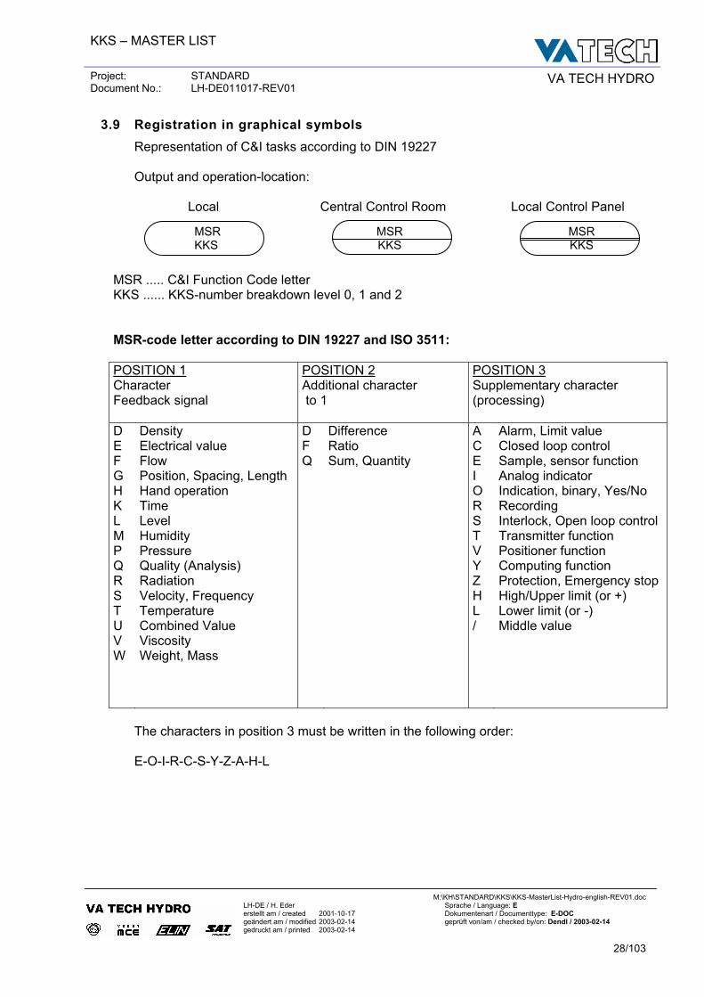
3.9 Registration in graphical symbols Representation of C&I tasks according to DIN 19227 Output and operation-location:
Local Central Control Room Local Control Panel
MSR ..... C&I Function Code letter KKS ...... KKS-number breakdown level 0, 1 and 2 MSR-code letter according to DIN 19227 and ISO 3511: POSITION 1 Character Feedback signal
POSITION 2 Additional character to 1
POSITION 3 Supplementary character (processing)
D E F G H K L M P Q R S T U V W
Density Electrical value Flow Position, Spacing, Length Hand operation Time Level Humidity Pressure Quality (Analysis) Radiation Velocity, Frequency Temperature Combined Value Viscosity Weight, Mass
D F Q
Difference Ratio Sum, Quantity
A C E I O R S T V Y Z H L /
Alarm, Limit value Closed loop control Sample, sensor function Analog indicator Indication, binary, Yes/No Recording Interlock, Open loop control Transmitter function Positioner function Computing function Protection, Emergency stop High/Upper limit (or +) Lower limit (or -) Middle value
The characters in position 3 must be written in the following order: E-O-I-R-C-S-Y-Z-A-H-L
MSR KKS
MSR KKS
MSR KKS
KKS – MASTER LIST
Project: STANDARD Document No.: LH-DE011017-REV01 VA TECH HYDRO
M:\KH\STANDARD\KKS\KKS-MasterList-Hydro-english-REV01.doc
LH-DE / H. Eder Sprache / Language: E erstellt am / created 2001-10-17 Dokumentenart / Documenttype: E-DOC geändert am / modified 2003-02-14 geprüft von/am / checked by/on: Dendl / 2003-02-14 gedruckt am / printed 2003-02-14
29/103
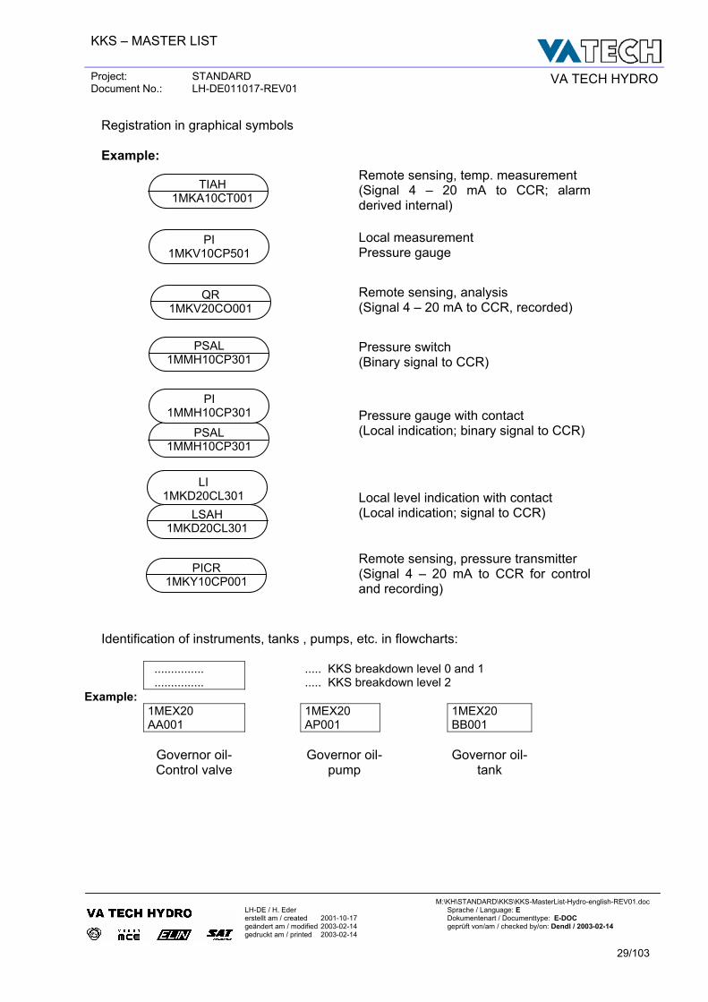
Registration in graphical symbols Example:
Remote sensing, temp. measurement (Signal 4 – 20 mA to CCR; alarm derived internal)
Local measurement Pressure gauge
Remote sensing, analysis (Signal 4 – 20 mA to CCR, recorded)
Pressure switch (Binary signal to CCR)
Pressure gauge with contact (Local indication; binary signal to CCR)
Local level indication with contact (Local indication; signal to CCR)
Remote sensing, pressure transmitter (Signal 4 – 20 mA to CCR for control and recording)
Identification of instruments, tanks , pumps, etc. in flowcharts:
............... ...............
..... KKS breakdown level 0 and 1 ..... KKS breakdown level 2
Example: 1MEX20
AA001 1MEX20
AP001 1MEX20
BB001
Governor oil- Control valve
Governor oil-
pump
Governor oil-
tank
PI 1MKV10CP501
TIAH 1MKA10CT001
QR 1MKV20CO001
PICR 1MKY10CP001
LSAH 1MKD20CL301
LI 1MKD20CL301
PSAL 1MMH10CP301
PSAL 1MMH10CP301
PI 1MMH10CP301
KKS – MASTER LIST
Project: STANDARD Document No.: LH-DE011017-REV01 VA TECH HYDRO
M:\KH\STANDARD\KKS\KKS-MasterList-Hydro-english-REV01.doc
LH-DE / H. Eder Sprache / Language: E erstellt am / created 2001-10-17 Dokumentenart / Documenttype: E-DOC geändert am / modified 2003-02-14 geprüft von/am / checked by/on: Dendl / 2003-02-14 gedruckt am / printed 2003-02-14
30/103
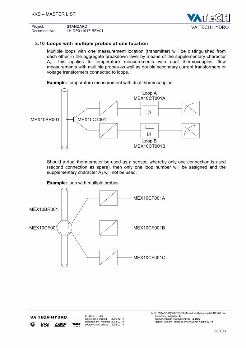
3.10 Loops with multiple probes at one location Multiple loops with one measurement location (transmitter) will be distinguished from each other in the aggregate breakdown level by means of the supplementary character A3. This applies to temperature measurements with dual thermocouples, flow measurements with multiple probes as well as double secondary current transformers or voltage transformers connected to loops.
Example: temperature measurement with dual thermocouples
Loop A MEX10CT001A
MEX10BR001 MEX10CT001
Loop B MEX10CT001B
Should a dual thermometer be used as a sensor, whereby only one connection is used (second connection as spare), then only one loop number will be assigned and the supplementary character A3 will not be used. Example: loop with multiple probes
MEX10CF001A
MEX10BR001
MEX10CF001
MEX10CF001B
MEX10CF001C
KKS – MASTER LIST
Project: STANDARD Document No.: LH-DE011017-REV01 VA TECH HYDRO
M:\KH\STANDARD\KKS\KKS-MasterList-Hydro-english-REV01.doc
LH-DE / H. Eder Sprache / Language: E erstellt am / created 2001-10-17 Dokumentenart / Documenttype: E-DOC geändert am / modified 2003-02-14 geprüft von/am / checked by/on: Dendl / 2003-02-14 gedruckt am / printed 2003-02-14
31/103
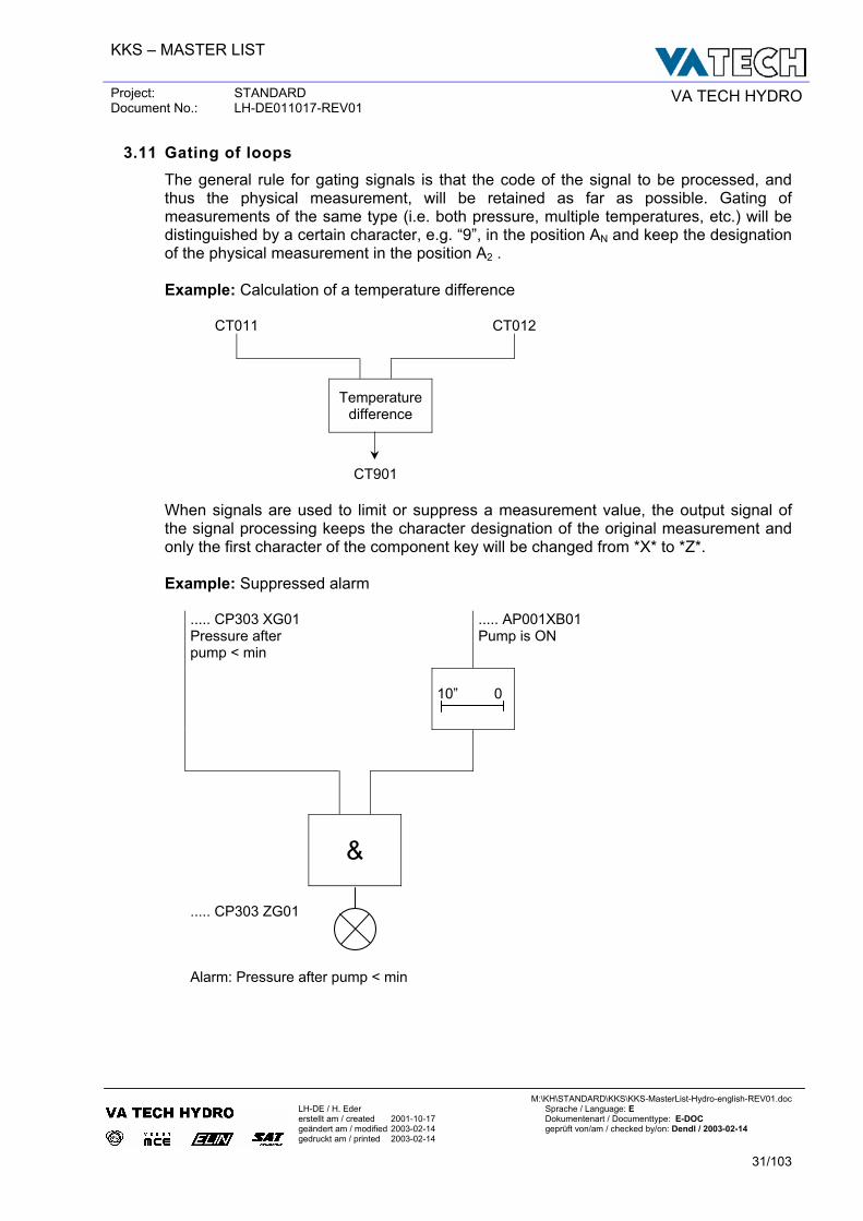
3.11 Gating of loops The general rule for gating signals is that the code of the signal to be processed, and thus the physical measurement, will be retained as far as possible. Gating of measurements of the same type (i.e. both pressure, multiple temperatures, etc.) will be distinguished by a certain character, e.g. “9”, in the position AN and keep the designation of the physical measurement in the position A2 . Example: Calculation of a temperature difference
CT011 CT012
Temperature
difference
CT901
When signals are used to limit or suppress a measurement value, the output signal of the signal processing keeps the character designation of the original measurement and only the first character of the component key will be changed from *X* to *Z*. Example: Suppressed alarm
..... CP303 XG01 Pressure after pump < min
..... AP001XB01 Pump is ON
10” 0
&
..... CP303 ZG01
Alarm: Pressure after pump < min
KKS – MASTER LIST
Project: STANDARD Document No.: LH-DE011017-REV01 VA TECH HYDRO
M:\KH\STANDARD\KKS\KKS-MasterList-Hydro-english-REV01.doc
LH-DE / H. Eder Sprache / Language: E erstellt am / created 2001-10-17 Dokumentenart / Documenttype: E-DOC geändert am / modified 2003-02-14 geprüft von/am / checked by/on: Dendl / 2003-02-14 gedruckt am / printed 2003-02-14
32/103
3.12 Identification of Loops
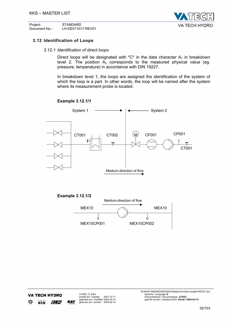
3.12.1 Identification of direct loops
Direct loops will be designated with *C* in the data character A1 in breakdown level 2. The position A2 corresponds to the measured physical value (eg. pressure, temperature) in accordance with DIN 19227. In breakdown level 1, the loops are assigned the identification of the system of which the loop is a part. In other words, the loop will be named after the system where its measurement probe is located. Example 3.12.1/1
System 1 System 2
Example 3.12.1/2
MEX10 MEX10
MEX10CP001 MEX10CP002
M CT001 CT002 CF001 CP001
CT001
Medium-direction of flow
Medium-direction of flow
KKS – MASTER LIST
Project: STANDARD Document No.: LH-DE011017-REV01 VA TECH HYDRO
M:\KH\STANDARD\KKS\KKS-MasterList-Hydro-english-REV01.doc
LH-DE / H. Eder Sprache / Language: E erstellt am / created 2001-10-17 Dokumentenart / Documenttype: E-DOC geändert am / modified 2003-02-14 geprüft von/am / checked by/on: Dendl / 2003-02-14 gedruckt am / printed 2003-02-14
33/103
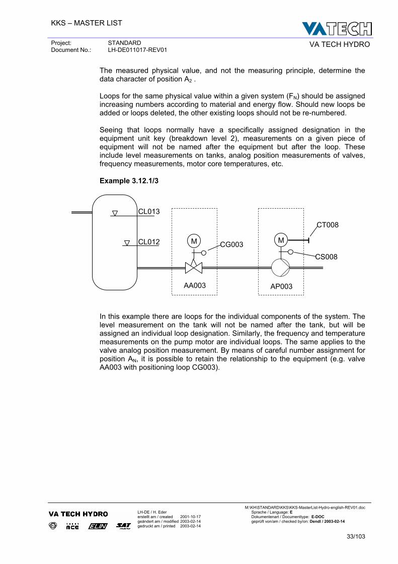
The measured physical value, and not the measuring principle, determine the data character of position A2 . Loops for the same physical value within a given system (FN) should be assigned increasing numbers according to material and energy flow. Should new loops be added or loops deleted, the other existing loops should not be re-numbered. Seeing that loops normally have a specifically assigned designation in the equipment unit key (breakdown level 2), measurements on a given piece of equipment will not be named after the equipment but after the loop. These include level measurements on tanks, analog position measurements of valves, frequency measurements, motor core temperatures, etc.
Example 3.12.1/3
In this example there are loops for the individual components of the system. The level measurement on the tank will not be named after the tank, but will be assigned an individual loop designation. Similarly, the frequency and temperature measurements on the pump motor are individual loops. The same applies to the valve analog position measurement. By means of careful number assignment for position AN, it is possible to retain the relationship to the equipment (e.g. valve AA003 with positioning loop CG003).
M M
AA003
CG003
CS008
CT008
CL012
CL013
AP003
KKS – MASTER LIST
Project: STANDARD Document No.: LH-DE011017-REV01 VA TECH HYDRO
M:\KH\STANDARD\KKS\KKS-MasterList-Hydro-english-REV01.doc
LH-DE / H. Eder Sprache / Language: E erstellt am / created 2001-10-17 Dokumentenart / Documenttype: E-DOC geändert am / modified 2003-02-14 geprüft von/am / checked by/on: Dendl / 2003-02-14 gedruckt am / printed 2003-02-14
34/103
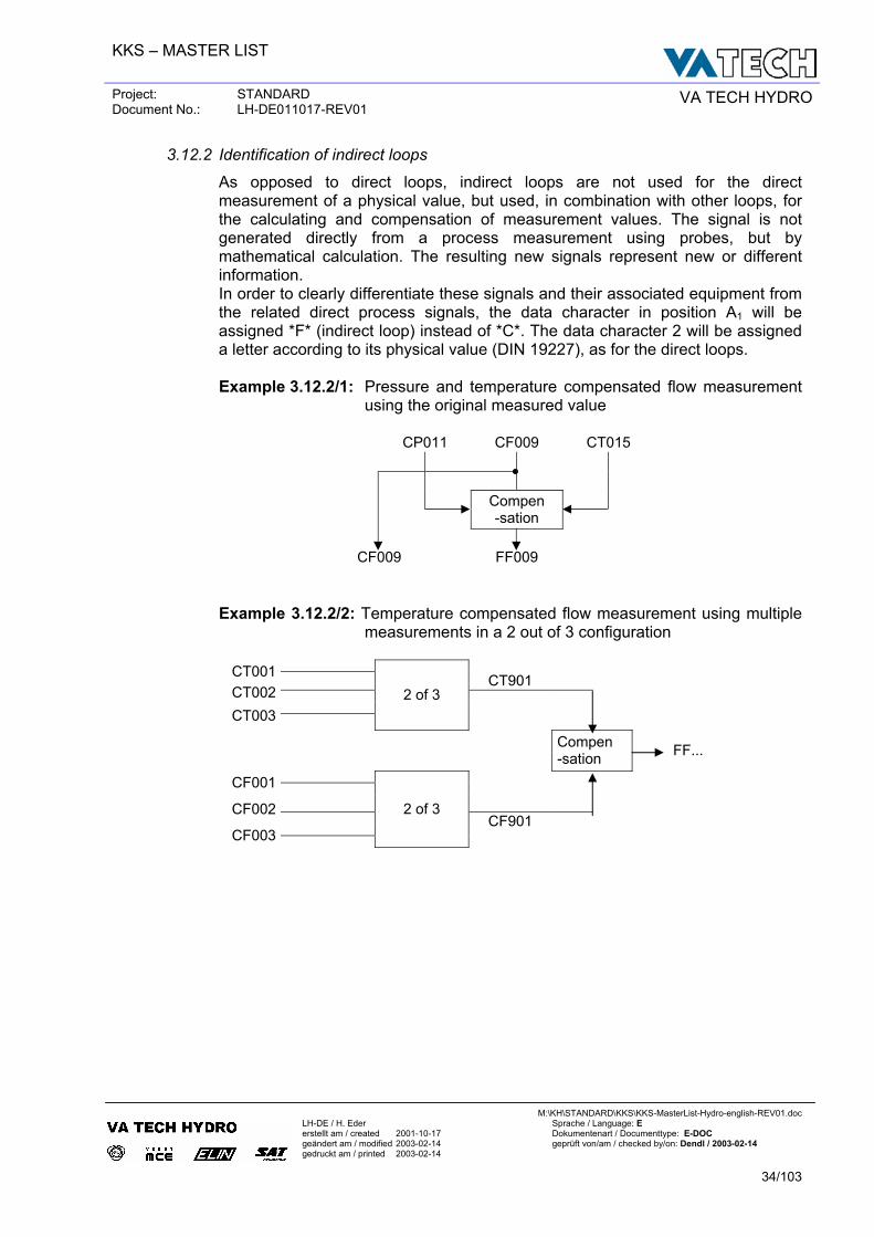
3.12.2 Identification of indirect loops
As opposed to direct loops, indirect loops are not used for the direct measurement of a physical value, but used, in combination with other loops, for the calculating and compensation of measurement values. The signal is not generated directly from a process measurement using probes, but by mathematical calculation. The resulting new signals represent new or different information. In order to clearly differentiate these signals and their associated equipment from the related direct process signals, the data character in position A1 will be assigned *F* (indirect loop) instead of *C*. The data character 2 will be assigned a letter according to its physical value (DIN 19227), as for the direct loops. Example 3.12.2/1: Pressure and temperature compensated flow measurement
using the original measured value CP011 CF009 CT015
Compen -sation
CF009 FF009
Example 3.12.2/2: Temperature compensated flow measurement using multiple measurements in a 2 out of 3 configuration
CT001 CT901 CT002 CT003
2 of 3
Compen -sation FF...
CF001 CF002
CF901 CF003
2 of 3
KKS – MASTER LIST
Project: STANDARD Document No.: LH-DE011017-REV01 VA TECH HYDRO
M:\KH\STANDARD\KKS\KKS-MasterList-Hydro-english-REV01.doc
LH-DE / H. Eder Sprache / Language: E erstellt am / created 2001-10-17 Dokumentenart / Documenttype: E-DOC geändert am / modified 2003-02-14 geprüft von/am / checked by/on: Dendl / 2003-02-14 gedruckt am / printed 2003-02-14
35/103
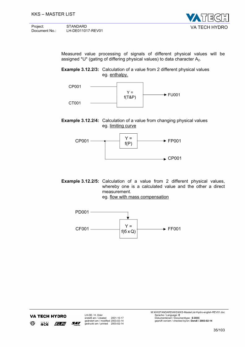
Measured value processing of signals of different physical values will be assigned *U* (gating of differing physical values) to data character A2. Example 3.12.2/3: Calculation of a value from 2 different physical values eg. enthalpy.
CP001 FU001 CT001
Y = f(T&P)
Example 3.12.2/4: Calculation of a value from changing physical values eg. limiting curve
CP001
Y = f(P)
FP001
CP001
Example 3.12.2/5: Calculation of a value from 2 different physical values, whereby one is a calculated value and the other a direct measurement.
eg. flow with mass compensation
PD001
CF001
Y = f(б x Q)
FF001
KKS – MASTER LIST
Project: STANDARD Document No.: LH-DE011017-REV01 VA TECH HYDRO
M:\KH\STANDARD\KKS\KKS-MasterList-Hydro-english-REV01.doc
LH-DE / H. Eder Sprache / Language: E erstellt am / created 2001-10-17 Dokumentenart / Documenttype: E-DOC geändert am / modified 2003-02-14 geprüft von/am / checked by/on: Dendl / 2003-02-14 gedruckt am / printed 2003-02-14
36/103
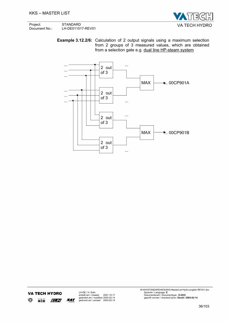
Example 3.12.2/6: Calculation of 2 output signals using a maximum selection from 2 groups of 3 measured values, which are obtained from a selection gate e.g. dual line HP-steam system
... ...
...
...
2 out of 3
... 00CP901AMAX
...
...
...
2 out of 3
...
...
2 out of 3
... 00CP901BMAX
2 out of 3
...
KKS – MASTER LIST
Project: STANDARD Document No.: LH-DE011017-REV01 VA TECH HYDRO
M:\KH\STANDARD\KKS\KKS-MasterList-Hydro-english-REV01.doc
LH-DE / H. Eder Sprache / Language: E erstellt am / created 2001-10-17 Dokumentenart / Documenttype: E-DOC geändert am / modified 2003-02-14 geprüft von/am / checked by/on: Dendl / 2003-02-14 gedruckt am / printed 2003-02-14
37/103
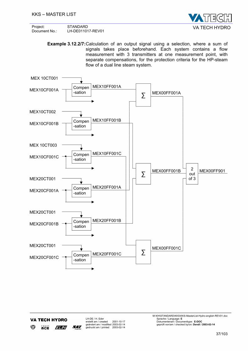
Example 3.12.2/7: Calculation of an output signal using a selection, where a sum of signals takes place beforehand. Each system contains a flow measurement with 3 transmitters at one measurement point, with separate compensations, for the protection criteria for the HP-steam flow of a dual line steam system.
MEX 10CT001 MEX10FF001A
MEX10CF001A
Compen-sation MEX00FF001A
∑
MEX10CT002
MEX10FF001B MEX10CF001B
Compen-sation
MEX 10CT003
MEX10FF001C MEX10CF001C
Compen-sation
MEX00FF001B MEX00FF901
MEX20CT001
∑
2 out of 3
MEX20FF001A
MEX20CF001A
Compen-sation
MEX20CT001
MEX20FF001B MEX20CF001B
Compen-sation
MEX20CT001 MEX00FF001C
MEX20FF001C MEX20CF001C
Compen-sation
∑
KKS – MASTER LIST
Project: STANDARD Document No.: LH-DE011017-REV01 VA TECH HYDRO
M:\KH\STANDARD\KKS\KKS-MasterList-Hydro-english-REV01.doc
LH-DE / H. Eder Sprache / Language: E erstellt am / created 2001-10-17 Dokumentenart / Documenttype: E-DOC geändert am / modified 2003-02-14 geprüft von/am / checked by/on: Dendl / 2003-02-14 gedruckt am / printed 2003-02-14
38/103
4 E X T E N D E D K K S – K E Y ( S T A N D A R D )
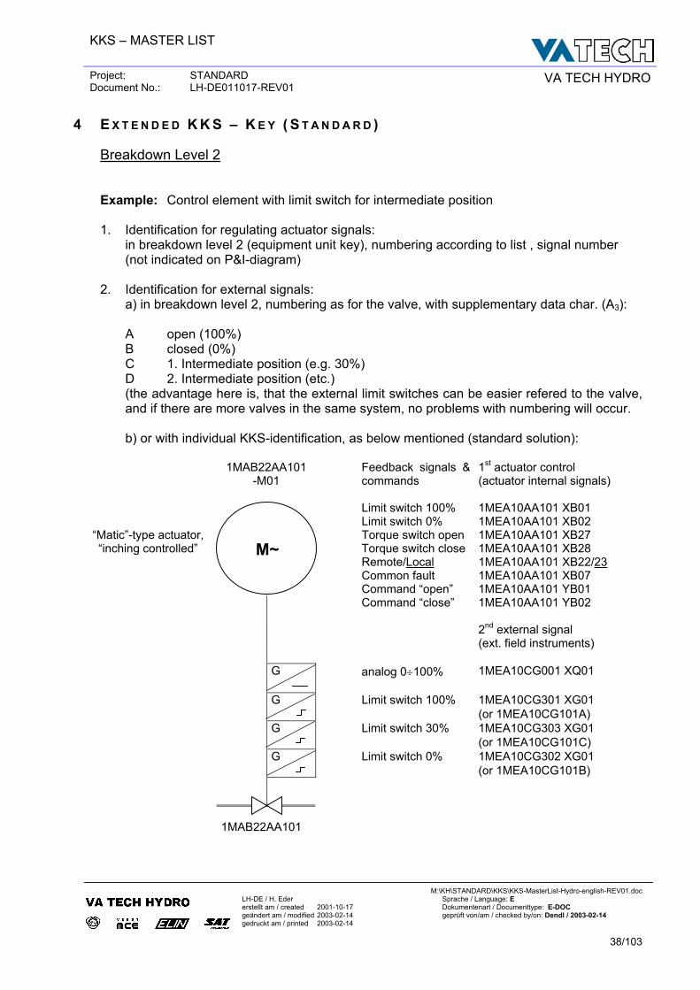
Breakdown Level 2 Example: Control element with limit switch for intermediate position 1. Identification for regulating actuator signals: in breakdown level 2 (equipment unit key), numbering according to list , signal number (not indicated on P&I-diagram) 2. Identification for external signals:
a) in breakdown level 2, numbering as for the valve, with supplementary data char. (A3):
A open (100%) B closed (0%) C 1. Intermediate position (e.g. 30%) D 2. Intermediate position (etc.) (the advantage here is, that the external limit switches can be easier refered to the valve, and if there are more valves in the same system, no problems with numbering will occur.
b) or with individual KKS-identification, as below mentioned (standard solution):
1MAB22AA101-M01
Feedback signals &commands
1st actuator control (actuator internal signals)
Limit switch 100% 1MEA10AA101 XB01 Limit switch 0% 1MEA10AA101 XB02
“Matic”-type actuator, Torque switch open 1MEA10AA101 XB27 “inching controlled” Torque switch close 1MEA10AA101 XB28
Remote/Local 1MEA10AA101 XB22/23 Common fault 1MEA10AA101 XB07
Command “open” 1MEA10AA101 YB01 Command “close” 1MEA10AA101 YB02 2nd external signal
(ext. field instruments) analog 0÷100% 1MEA10CG001 XQ01
G
Limit switch 100% 1MEA10CG301 XG01
G (or 1MEA10CG101A)
Limit switch 30% 1MEA10CG303 XG01
G (or 1MEA10CG101C)
Limit switch 0% 1MEA10CG302 XG01
G (or 1MEA10CG101B)
1MAB22AA101
M~
KKS – MASTER LIST
Project: STANDARD Document No.: LH-DE011017-REV01 VA TECH HYDRO
M:\KH\STANDARD\KKS\KKS-MasterList-Hydro-english-REV01.doc
LH-DE / H. Eder Sprache / Language: E erstellt am / created 2001-10-17 Dokumentenart / Documenttype: E-DOC geändert am / modified 2003-02-14 geprüft von/am / checked by/on: Dendl / 2003-02-14 gedruckt am / printed 2003-02-14
39/103
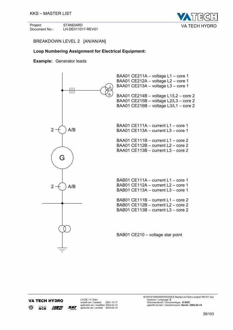
BREAKDOWN LEVEL 2 [AN/AN/AN] Loop Numbering Assignment for Electrical Equipment: Example: Generator leads
BAA01 CE211A – voltage L1 – core 1 BAA01 CE212A – voltage L2 – core 1 BAA01 CE213A – voltage L3 – core 1 BAA01 CE214B – voltage L1/L2 – core 2 BAA01 CE215B – voltage L2/L3 – core 2 BAA01 CE216B – voltage L3/L1 – core 2 BAA01 CE111A – current L1 – core 1 BAA01 CE113A – current L3 – core 1 BAA01 CE111B – current L1 – core 2 BAA01 CE112B – current L2 – core 2 BAA01 CE113B – current L3 – core 2 BAB01 CE111A – current L1 – core 1 BAB01 CE112A – current L2 – core 1 BAB01 CE113A – current L3 – core 1 BAB01 CE111B – current L1 – core 2 BAB01 CE112B – current L2 – core 2 BAB01 CE113B – current L3 – core 2 BAB01 CE210 – voltage star point
2 A/B
2 A/B
G
KKS – MASTER LIST
Project: STANDARD Document No.: LH-DE011017-REV01 VA TECH HYDRO
M:\KH\STANDARD\KKS\KKS-MasterList-Hydro-english-REV01.doc
LH-DE / H. Eder Sprache / Language: E erstellt am / created 2001-10-17 Dokumentenart / Documenttype: E-DOC geändert am / modified 2003-02-14 geprüft von/am / checked by/on: Dendl / 2003-02-14 gedruckt am / printed 2003-02-14
40/103
5 I D E N T I F I C A T I O N O F C & I C O M P O N E N T S
5.1 Signal identification
5.1.1 General Signal Identification
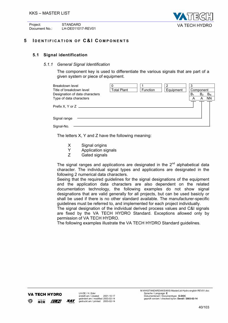
The component key is used to differentiate the various signals that are part of a given system or piece of equipment.
Breakdown level 0 1 2 3 Title of breakdown level Total Plant Function Equipment Component Designation of data characters B1 B2 BN Type of data characters A A NN Prefix X, Y or Z
Signal range
Signal-No.
The letters X, Y and Z have the following meaning: X Signal origins Y Application signals Z Gated signals The signal ranges and applications are designated in the 2nd alphabetical data character. The individual signal types and applications are designated in the following 2 numerical data characters. Seeing that the required guidelines for the signal designations of the equipment and the application data characters are also dependent on the related documentation technology, the following examples do not show signal designations that are valid generally for all projects, but can be used basicly or shall be used if there is no other standard available. The manufacturer-specific guidelines must be referred to, and implemented for each project individually. The signal designation of the individual derived process values and C&I signals are fixed by the VA TECH HYDRO Standard. Exceptions allowed only by permission of VA TECH HYDRO. The following examples illustrate the VA TECH HYDRO Standard guidelines.
KKS – MASTER LIST
Project: STANDARD Document No.: LH-DE011017-REV01 VA TECH HYDRO
M:\KH\STANDARD\KKS\KKS-MasterList-Hydro-english-REV01.doc
LH-DE / H. Eder Sprache / Language: E erstellt am / created 2001-10-17 Dokumentenart / Documenttype: E-DOC geändert am / modified 2003-02-14 geprüft von/am / checked by/on: Dendl / 2003-02-14 gedruckt am / printed 2003-02-14
41/103
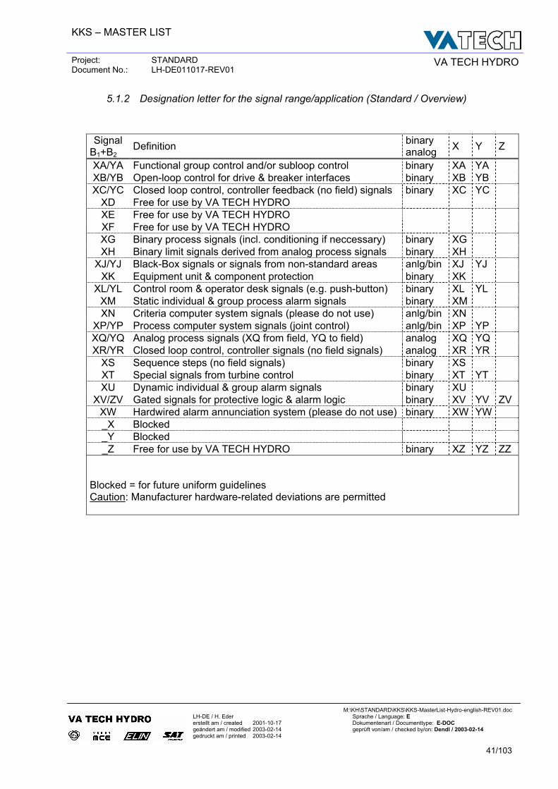
5.1.2 Designation letter for the signal range/application (Standard / Overview)
Signal B1+B2
Definition binary analog X Y Z
XA/YA Functional group control and/or subloop control binary XA YA XB/YB Open-loop control for drive & breaker interfaces binary XB YB XC/YC Closed loop control, controller feedback (no field) signals binary XC YC
XD Free for use by VA TECH HYDRO XE Free for use by VA TECH HYDRO XF Free for use by VA TECH HYDRO XG Binary process signals (incl. conditioning if neccessary) binary XG XH Binary limit signals derived from analog process signals binary XH
XJ/YJ Black-Box signals or signals from non-standard areas anlg/bin XJ YJ XK Equipment unit & component protection binary XK
XL/YL Control room & operator desk signals (e.g. push-button) binary XL YL XM Static individual & group process alarm signals binary XM XN Criteria computer system signals (please do not use) anlg/bin XN
XP/YP Process computer system signals (joint control) anlg/bin XP YP XQ/YQ Analog process signals (XQ from field, YQ to field) analog XQ YQ XR/YR Closed loop control, controller signals (no field signals) analog XR YR
XS Sequence steps (no field signals) binary XS XT Special signals from turbine control binary XT YT XU Dynamic individual & group alarm signals binary XU
XV/ZV Gated signals for protective logic & alarm logic binary XV YV ZV XW Hardwired alarm annunciation system (please do not use) binary XW YW _X Blocked _Y Blocked _Z Free for use by VA TECH HYDRO binary XZ YZ ZZ
Blocked = for future uniform guidelines Caution: Manufacturer hardware-related deviations are permitted
KKS – MASTER LIST
Project: STANDARD Document No.: LH-DE011017-REV01 VA TECH HYDRO
M:\KH\STANDARD\KKS\KKS-MasterList-Hydro-english-REV01.doc
LH-DE / H. Eder Sprache / Language: E erstellt am / created 2001-10-17 Dokumentenart / Documenttype: E-DOC geändert am / modified 2003-02-14 geprüft von/am / checked by/on: Dendl / 2003-02-14 gedruckt am / printed 2003-02-14
42/103
5.2 Binary signals (contacts) and limit values from signal conditioning
5.2.1 Designation letter (signal range)
G = contact (binary process signal incl. conditioning for contacts) H = limit value (derived from analog measurement signals)
5.2.2 Signal numbers for binary process signals (contacts)
Most of the binary process signals (contacts) are signals from field instruments as follows:
-limit switches -pressure switches -temperature switches -level switches
with only one contact. Each instrument will have an individual KKS-Number. The contact/signal from each field instrument will get therefore the same signal code:
XG01 for “normally open”-contact, and XG51 for “normally close”-contact.
For field instruments with tandem (or triple) switches with same limit value, we recommend:
XG01/51 for the first switch XG11/61 for the second switch XG21/71 for the third switch
For field instruments with two (or more) switches with individual limit value, we recommend “odd”-numbers for “high”-limit values, “even”-numbers for “low”-limit values:
XG01/51 for the “high”-limit value XG02/52 for the “low”-limit value XG03/53 for the “high/high”-limit value XG04/54 for the “low/low”-limit value XG05/55 for the “high/high/high”-limit value XG06/56 for the “low/low/low”-limit value
5.2.3 Signal numbers for limit values derived from analog process signals
The analog process signal will have normally the signal code XQ01 for standard transmitters. The derived binary limit values will be produced internal in the DCS/PLC, standard as follows: “odd”-numbers for “high”-limit values, “even”-numbers for “low”-limit values:
XH01/51 for the “high”-limit value XH02/52 for the “low”-limit value XH03/53 for the “high/high”-limit value XH04/54 for the “low/low”-limit value XH05/55 for the “high/high/high”-limit value XH06/56 for the “low/low/low”-limit value
KKS – MASTER LIST
Project: STANDARD Document No.: LH-DE011017-REV01 VA TECH HYDRO
M:\KH\STANDARD\KKS\KKS-MasterList-Hydro-english-REV01.doc
LH-DE / H. Eder Sprache / Language: E erstellt am / created 2001-10-17 Dokumentenart / Documenttype: E-DOC geändert am / modified 2003-02-14 geprüft von/am / checked by/on: Dendl / 2003-02-14 gedruckt am / printed 2003-02-14
43/103
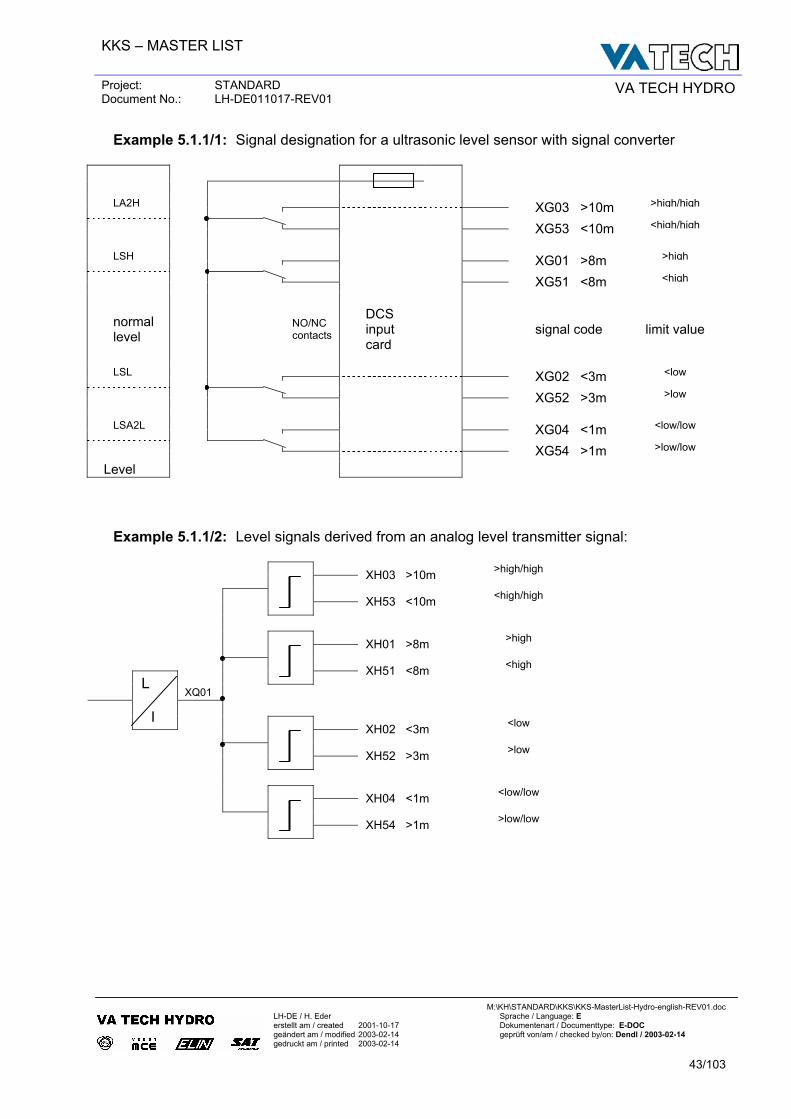
Example 5.1.1/1: Signal designation for a ultrasonic level sensor with signal converter LA2H >high/high XG03 >10m <high/high XG53 <10m LSH >high XG01 >8m <high XG51 <8m
normal level
NO/NC contacts
DCS input card
signal code limit value
LSL <low XG02 <3m >low XG52 >3m LSA2L <low/low XG04 <1m >low/low XG54 >1m
Level Example 5.1.1/2: Level signals derived from an analog level transmitter signal: >high/high XH03 >10m <high/high
XH53 <10m
>high XH01 >8m <high
XH51 <8m
XQ01
L
I <low XH02 <3m >low
XH52 >3m
<low/low XH04 <1m >low/low
XH54 >1m
KKS – MASTER LIST
Project: STANDARD Document No.: LH-DE011017-REV01 VA TECH HYDRO
M:\KH\STANDARD\KKS\KKS-MasterList-Hydro-english-REV01.doc
LH-DE / H. Eder Sprache / Language: E erstellt am / created 2001-10-17 Dokumentenart / Documenttype: E-DOC geändert am / modified 2003-02-14 geprüft von/am / checked by/on: Dendl / 2003-02-14 gedruckt am / printed 2003-02-14
44/103
6 I N T E G R A T I O N O F G E ( G E N E R A L E L E C T R I C S ) I D E N T I F I C A T I O N S Y S T E M I N K K S
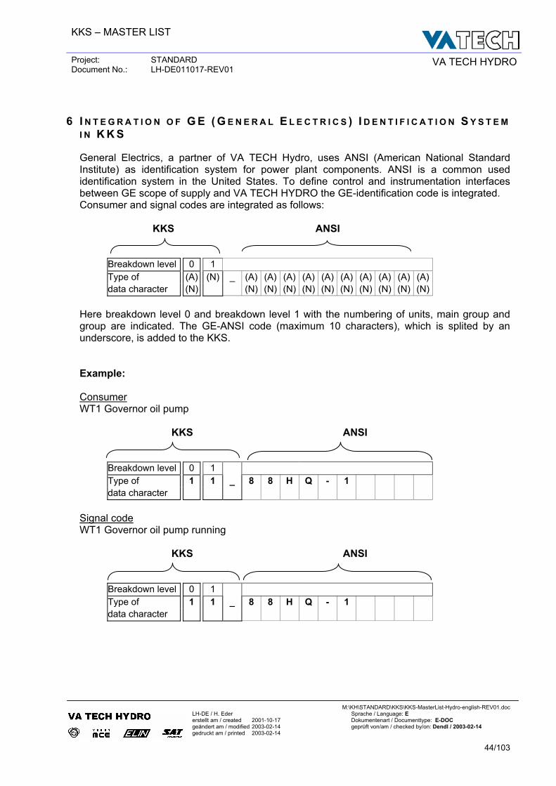
General Electrics, a partner of VA TECH Hydro, uses ANSI (American National Standard Institute) as identification system for power plant components. ANSI is a common used identification system in the United States. To define control and instrumentation interfaces between GE scope of supply and VA TECH HYDRO the GE-identification code is integrated. Consumer and signal codes are integrated as follows: KKS ANSI
Breakdown level 0 1 Type of (A) (N) _ (A) (A) (A) (A) (A) (A) (A) (A) (A) (A) data character (N) (N) (N) (N) (N) (N) (N) (N) (N) (N) (N)
Here breakdown level 0 and breakdown level 1 with the numbering of units, main group and group are indicated. The GE-ANSI code (maximum 10 characters), which is splited by an underscore, is added to the KKS. Example: Consumer WT1 Governor oil pump KKS ANSI
Breakdown level 0 1 Type of 1 1 _ 8 8 H Q - 1 data character
Signal code WT1 Governor oil pump running KKS ANSI
Breakdown level 0 1 Type of 1 1 _ 8 8 H Q - 1 data character
KKS – MASTER LIST
Project: STANDARD Document No.: LH-DE011017-REV01 VA TECH HYDRO
M:\KH\STANDARD\KKS\KKS-MasterList-Hydro-english-REV01.doc
LH-DE / H. Eder Sprache / Language: E erstellt am / created 2001-10-17 Dokumentenart / Documenttype: E-DOC geändert am / modified 2003-02-14 geprüft von/am / checked by/on: Dendl / 2003-02-14 gedruckt am / printed 2003-02-14
45/103
Part II: KKS – Master List
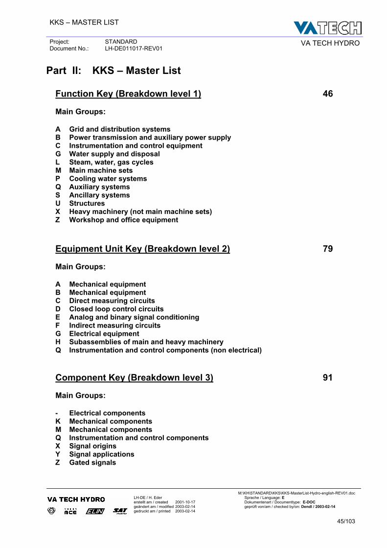
Function Key (Breakdown level 1) 46 Main Groups: A Grid and distribution systems B Power transmission and auxiliary power supply C Instrumentation and control equipment G Water supply and disposal L Steam, water, gas cycles M Main machine sets P Cooling water systems Q Auxiliary systems S Ancillary systems U Structures X Heavy machinery (not main machine sets) Z Workshop and office equipment
Equipment Unit Key (Breakdown level 2) 79 Main Groups: A Mechanical equipment B Mechanical equipment C Direct measuring circuits D Closed loop control circuits E Analog and binary signal conditioning F Indirect measuring circuits G Electrical equipment H Subassemblies of main and heavy machinery Q Instrumentation and control components (non electrical)
Component Key (Breakdown level 3) 91 Main Groups: - Electrical components K Mechanical components M Mechanical components Q Instrumentation and control components X Signal origins Y Signal applications Z Gated signals
KKS – MASTER LIST
Project: STANDARD Document No.: LH-DE011017-REV01 VA TECH HYDRO
M:\KH\STANDARD\KKS\KKS-MasterList-Hydro-english-REV01.doc
LH-DE / H. Eder Sprache / Language: E erstellt am / created 2001-10-17 Dokumentenart / Documenttype: E-DOC geändert am / modified 2003-02-14 geprüft von/am / checked by/on: Dendl / 2003-02-14 gedruckt am / printed 2003-02-14
46/103
Function Key (Breakdown level 1) KKS-Code
Text Remark
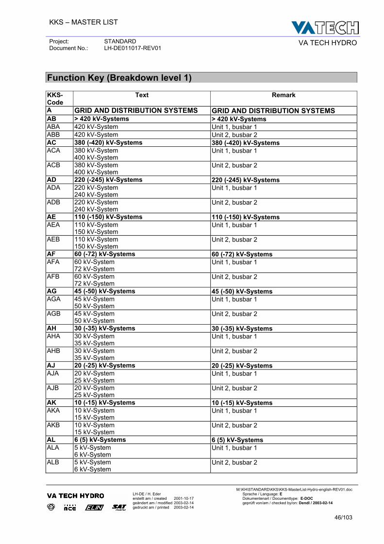
A GRID AND DISTRIBUTION SYSTEMS GRID AND DISTRIBUTION SYSTEMS AB > 420 kV-Systems > 420 kV-Systems ABA 420 kV-System Unit 1, busbar 1 ABB 420 kV-System Unit 2, busbar 2 AC 380 (-420) kV-Systems 380 (-420) kV-Systems ACA 380 kV-System
400 kV-System Unit 1, busbar 1
ACB 380 kV-System 400 kV-System
Unit 2, busbar 2
AD 220 (-245) kV-Systems 220 (-245) kV-Systems ADA 220 kV-System
240 kV-System Unit 1, busbar 1
ADB 220 kV-System 240 kV-System
Unit 2, busbar 2
AE 110 (-150) kV-Systems 110 (-150) kV-Systems AEA 110 kV-System
150 kV-System Unit 1, busbar 1
AEB 110 kV-System 150 kV-System
Unit 2, busbar 2
AF 60 (-72) kV-Systems 60 (-72) kV-Systems AFA 60 kV-System
72 kV-System Unit 1, busbar 1
AFB 60 kV-System 72 kV-System
Unit 2, busbar 2
AG 45 (-50) kV-Systems 45 (-50) kV-Systems AGA 45 kV-System
50 kV-System Unit 1, busbar 1
AGB 45 kV-System 50 kV-System
Unit 2, busbar 2
AH 30 (-35) kV-Systems 30 (-35) kV-Systems AHA 30 kV-System
35 kV-System Unit 1, busbar 1
AHB 30 kV-System 35 kV-System
Unit 2, busbar 2
AJ 20 (-25) kV-Systems 20 (-25) kV-Systems AJA 20 kV-System
25 kV-System Unit 1, busbar 1
AJB 20 kV-System 25 kV-System
Unit 2, busbar 2
AK 10 (-15) kV-Systems 10 (-15) kV-Systems AKA 10 kV-System
15 kV-System Unit 1, busbar 1
AKB 10 kV-System 15 kV-System
Unit 2, busbar 2
AL 6 (5) kV-Systems 6 (5) kV-Systems ALA 5 kV-System
6 kV-System Unit 1, busbar 1
ALB 5 kV-System 6 kV-System
Unit 2, busbar 2
KKS – MASTER LIST
Project: STANDARD Document No.: LH-DE011017-REV01 VA TECH HYDRO
M:\KH\STANDARD\KKS\KKS-MasterList-Hydro-english-REV01.doc
LH-DE / H. Eder Sprache / Language: E erstellt am / created 2001-10-17 Dokumentenart / Documenttype: E-DOC geändert am / modified 2003-02-14 geprüft von/am / checked by/on: Dendl / 2003-02-14 gedruckt am / printed 2003-02-14
47/103
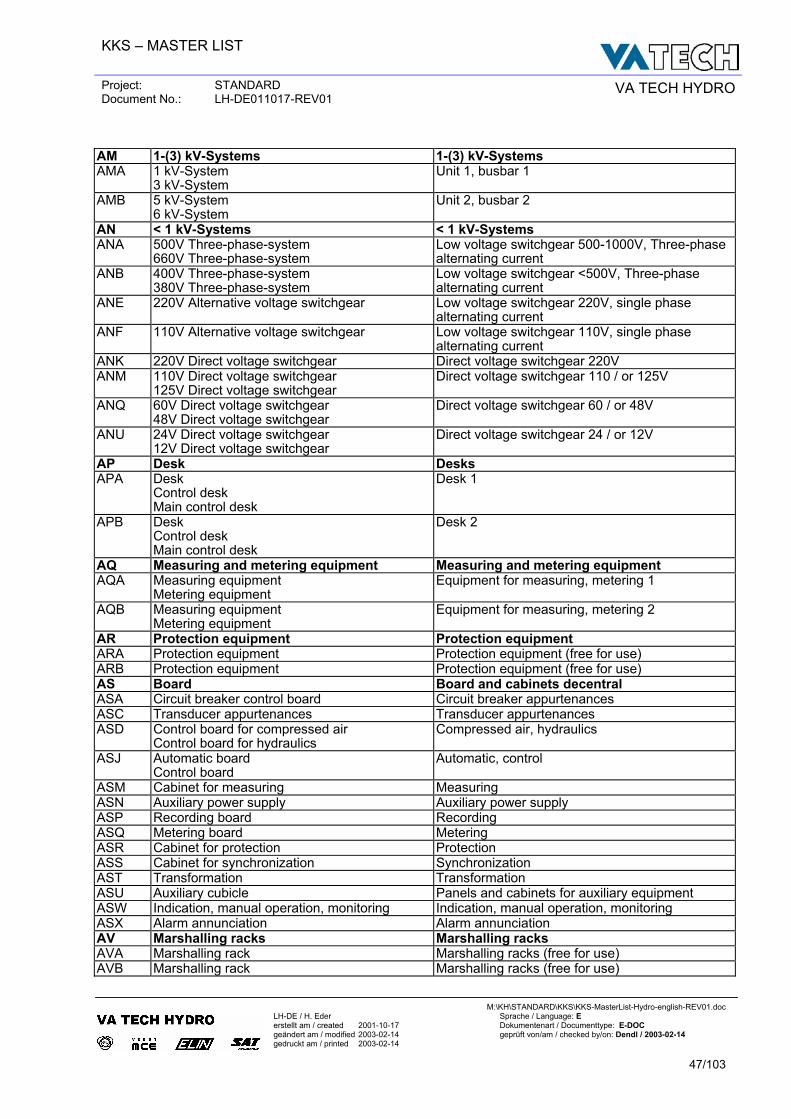
AM 1-(3) kV-Systems 1-(3) kV-Systems AMA 1 kV-System
3 kV-System Unit 1, busbar 1
AMB 5 kV-System 6 kV-System
Unit 2, busbar 2
AN < 1 kV-Systems < 1 kV-Systems ANA 500V Three-phase-system
660V Three-phase-system Low voltage switchgear 500-1000V, Three-phase alternating current
ANB 400V Three-phase-system 380V Three-phase-system
Low voltage switchgear <500V, Three-phase alternating current
ANE 220V Alternative voltage switchgear Low voltage switchgear 220V, single phase alternating current
ANF 110V Alternative voltage switchgear Low voltage switchgear 110V, single phase alternating current
ANK 220V Direct voltage switchgear Direct voltage switchgear 220V ANM 110V Direct voltage switchgear
125V Direct voltage switchgear Direct voltage switchgear 110 / or 125V
ANQ 60V Direct voltage switchgear 48V Direct voltage switchgear
Direct voltage switchgear 60 / or 48V
ANU 24V Direct voltage switchgear 12V Direct voltage switchgear
Direct voltage switchgear 24 / or 12V
AP Desk Desks APA Desk
Control desk Main control desk
Desk 1
APB Desk Control desk Main control desk
Desk 2
AQ Measuring and metering equipment Measuring and metering equipment AQA Measuring equipment
Metering equipment Equipment for measuring, metering 1
AQB Measuring equipment Metering equipment
Equipment for measuring, metering 2
AR Protection equipment Protection equipment ARA Protection equipment Protection equipment (free for use) ARB Protection equipment Protection equipment (free for use) AS Board Board and cabinets decentral ASA Circuit breaker control board Circuit breaker appurtenances ASC Transducer appurtenances Transducer appurtenances ASD Control board for compressed air
Control board for hydraulics Compressed air, hydraulics
ASJ Automatic board Control board
Automatic, control
ASM Cabinet for measuring Measuring ASN Auxiliary power supply Auxiliary power supply ASP Recording board Recording ASQ Metering board Metering ASR Cabinet for protection Protection ASS Cabinet for synchronization Synchronization AST Transformation Transformation ASU Auxiliary cubicle Panels and cabinets for auxiliary equipment ASW Indication, manual operation, monitoring Indication, manual operation, monitoring ASX Alarm annunciation Alarm annunciation AV Marshalling racks Marshalling racks AVA Marshalling rack Marshalling racks (free for use) AVB Marshalling rack Marshalling racks (free for use)
KKS – MASTER LIST
Project: STANDARD Document No.: LH-DE011017-REV01 VA TECH HYDRO
M:\KH\STANDARD\KKS\KKS-MasterList-Hydro-english-REV01.doc
LH-DE / H. Eder Sprache / Language: E erstellt am / created 2001-10-17 Dokumentenart / Documenttype: E-DOC geändert am / modified 2003-02-14 geprüft von/am / checked by/on: Dendl / 2003-02-14 gedruckt am / printed 2003-02-14
48/103
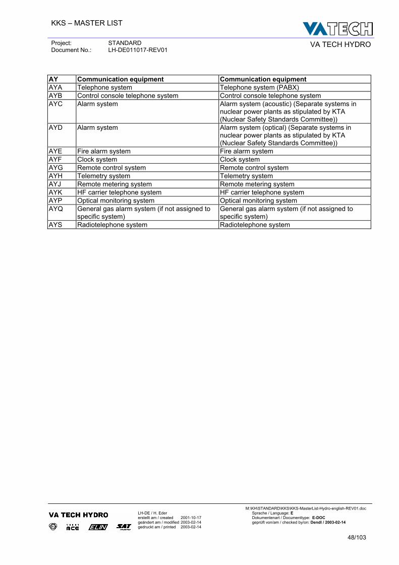
AY Communication equipment Communication equipment AYA Telephone system Telephone system (PABX) AYB Control console telephone system Control console telephone system AYC Alarm system Alarm system (acoustic) (Separate systems in
nuclear power plants as stipulated by KTA (Nuclear Safety Standards Committee))
AYD Alarm system Alarm system (optical) (Separate systems in nuclear power plants as stipulated by KTA (Nuclear Safety Standards Committee))
AYE Fire alarm system Fire alarm system AYF Clock system Clock system AYG Remote control system Remote control system AYH Telemetry system Telemetry system AYJ Remote metering system Remote metering system AYK HF carrier telephone system HF carrier telephone system AYP Optical monitoring system Optical monitoring system AYQ General gas alarm system (if not assigned to
specific system) General gas alarm system (if not assigned to specific system)
AYS Radiotelephone system Radiotelephone system
KKS – MASTER LIST
Project: STANDARD Document No.: LH-DE011017-REV01 VA TECH HYDRO
M:\KH\STANDARD\KKS\KKS-MasterList-Hydro-english-REV01.doc
LH-DE / H. Eder Sprache / Language: E erstellt am / created 2001-10-17 Dokumentenart / Documenttype: E-DOC geändert am / modified 2003-02-14 geprüft von/am / checked by/on: Dendl / 2003-02-14 gedruckt am / printed 2003-02-14
49/103
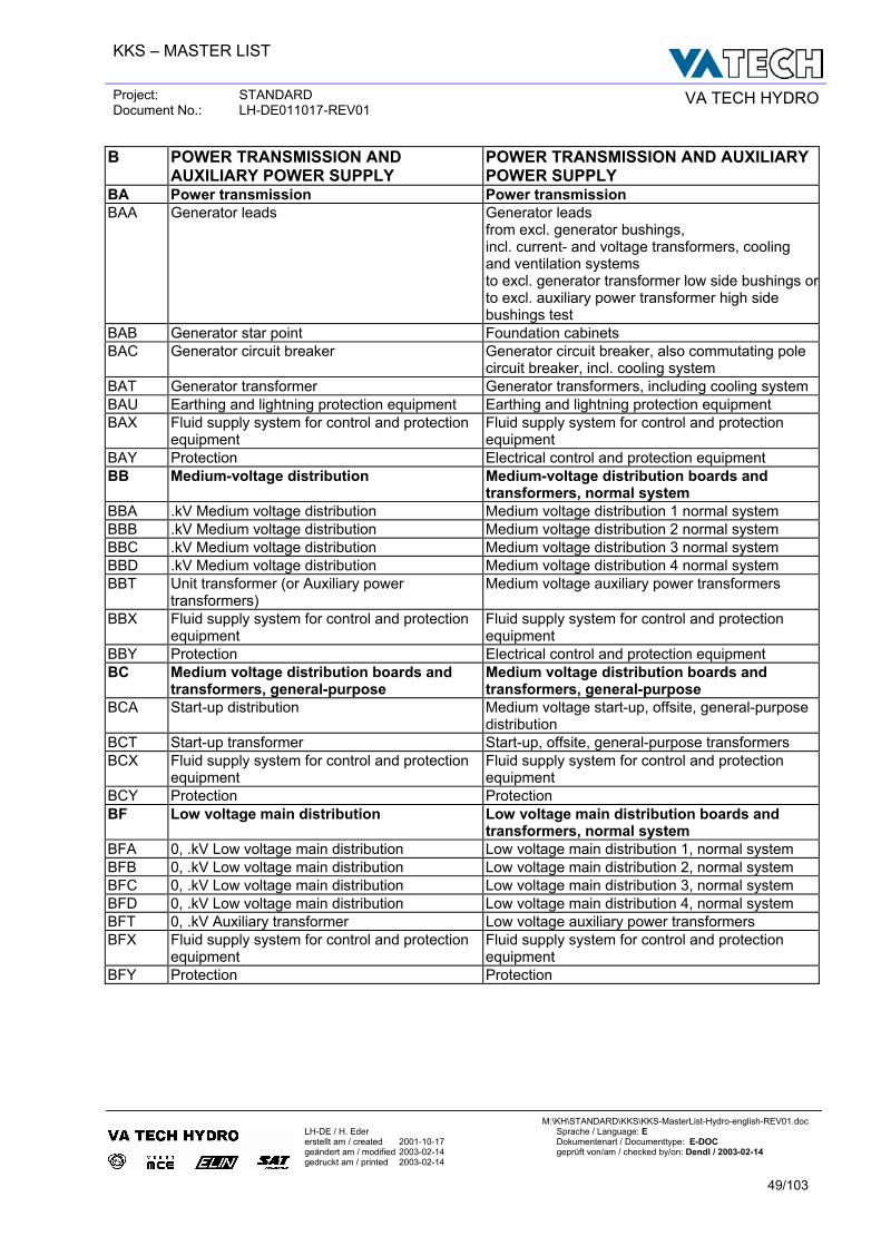
B POWER TRANSMISSION AND AUXILIARY POWER SUPPLY
POWER TRANSMISSION AND AUXILIARY POWER SUPPLY
BA Power transmission Power transmission BAA Generator leads Generator leads
from excl. generator bushings, incl. current- and voltage transformers, cooling and ventilation systems to excl. generator transformer low side bushings orto excl. auxiliary power transformer high side bushings test
BAB Generator star point Foundation cabinets BAC Generator circuit breaker Generator circuit breaker, also commutating pole
circuit breaker, incl. cooling system BAT Generator transformer Generator transformers, including cooling system BAU Earthing and lightning protection equipment Earthing and lightning protection equipment BAX Fluid supply system for control and protection
equipment Fluid supply system for control and protection equipment
BAY Protection Electrical control and protection equipment BB Medium-voltage distribution Medium-voltage distribution boards and
transformers, normal system BBA .kV Medium voltage distribution Medium voltage distribution 1 normal system BBB .kV Medium voltage distribution Medium voltage distribution 2 normal system BBC .kV Medium voltage distribution Medium voltage distribution 3 normal system BBD .kV Medium voltage distribution Medium voltage distribution 4 normal system BBT Unit transformer (or Auxiliary power
transformers) Medium voltage auxiliary power transformers
BBX Fluid supply system for control and protection equipment
Fluid supply system for control and protection equipment
BBY Protection Electrical control and protection equipment BC Medium voltage distribution boards and
transformers, general-purpose Medium voltage distribution boards and transformers, general-purpose
BCA Start-up distribution Medium voltage start-up, offsite, general-purpose distribution
BCT Start-up transformer Start-up, offsite, general-purpose transformers BCX Fluid supply system for control and protection
equipment Fluid supply system for control and protection equipment
BCY Protection Protection BF Low voltage main distribution Low voltage main distribution boards and
transformers, normal system BFA 0, .kV Low voltage main distribution Low voltage main distribution 1, normal system BFB 0, .kV Low voltage main distribution Low voltage main distribution 2, normal system BFC 0, .kV Low voltage main distribution Low voltage main distribution 3, normal system BFD 0, .kV Low voltage main distribution Low voltage main distribution 4, normal system BFT 0, .kV Auxiliary transformer Low voltage auxiliary power transformers BFX Fluid supply system for control and protection
equipment Fluid supply system for control and protection equipment
BFY Protection Protection
KKS – MASTER LIST
Project: STANDARD Document No.: LH-DE011017-REV01 VA TECH HYDRO
M:\KH\STANDARD\KKS\KKS-MasterList-Hydro-english-REV01.doc
LH-DE / H. Eder Sprache / Language: E erstellt am / created 2001-10-17 Dokumentenart / Documenttype: E-DOC geändert am / modified 2003-02-14 geprüft von/am / checked by/on: Dendl / 2003-02-14 gedruckt am / printed 2003-02-14
50/103
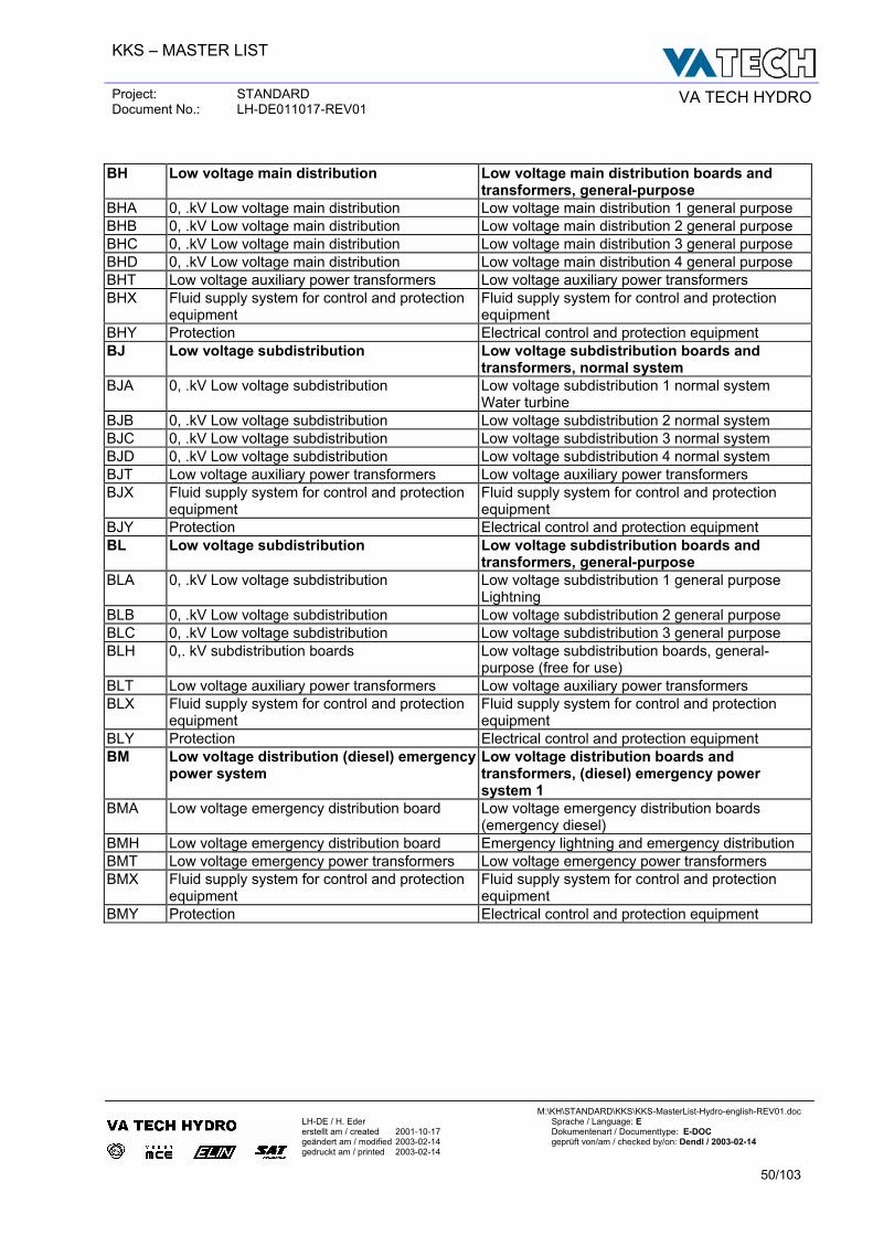
BH Low voltage main distribution Low voltage main distribution boards and
transformers, general-purpose BHA 0, .kV Low voltage main distribution Low voltage main distribution 1 general purpose BHB 0, .kV Low voltage main distribution Low voltage main distribution 2 general purpose BHC 0, .kV Low voltage main distribution Low voltage main distribution 3 general purpose BHD 0, .kV Low voltage main distribution Low voltage main distribution 4 general purpose BHT Low voltage auxiliary power transformers Low voltage auxiliary power transformers BHX Fluid supply system for control and protection
equipment Fluid supply system for control and protection equipment
BHY Protection Electrical control and protection equipment BJ Low voltage subdistribution Low voltage subdistribution boards and
transformers, normal system BJA 0, .kV Low voltage subdistribution Low voltage subdistribution 1 normal system
Water turbine BJB 0, .kV Low voltage subdistribution Low voltage subdistribution 2 normal system BJC 0, .kV Low voltage subdistribution Low voltage subdistribution 3 normal system BJD 0, .kV Low voltage subdistribution Low voltage subdistribution 4 normal system BJT Low voltage auxiliary power transformers Low voltage auxiliary power transformers BJX Fluid supply system for control and protection
equipment Fluid supply system for control and protection equipment
BJY Protection Electrical control and protection equipment BL Low voltage subdistribution Low voltage subdistribution boards and
transformers, general-purpose BLA 0, .kV Low voltage subdistribution Low voltage subdistribution 1 general purpose
Lightning BLB 0, .kV Low voltage subdistribution Low voltage subdistribution 2 general purpose BLC 0, .kV Low voltage subdistribution Low voltage subdistribution 3 general purpose BLH 0,. kV subdistribution boards Low voltage subdistribution boards, general-
purpose (free for use) BLT Low voltage auxiliary power transformers Low voltage auxiliary power transformers BLX Fluid supply system for control and protection
equipment Fluid supply system for control and protection equipment
BLY Protection Electrical control and protection equipment BM Low voltage distribution (diesel) emergency
power system Low voltage distribution boards and transformers, (diesel) emergency power system 1
BMA Low voltage emergency distribution board Low voltage emergency distribution boards (emergency diesel)
BMH Low voltage emergency distribution board Emergency lightning and emergency distribution BMT Low voltage emergency power transformers Low voltage emergency power transformers BMX Fluid supply system for control and protection
equipment Fluid supply system for control and protection equipment
BMY Protection Electrical control and protection equipment
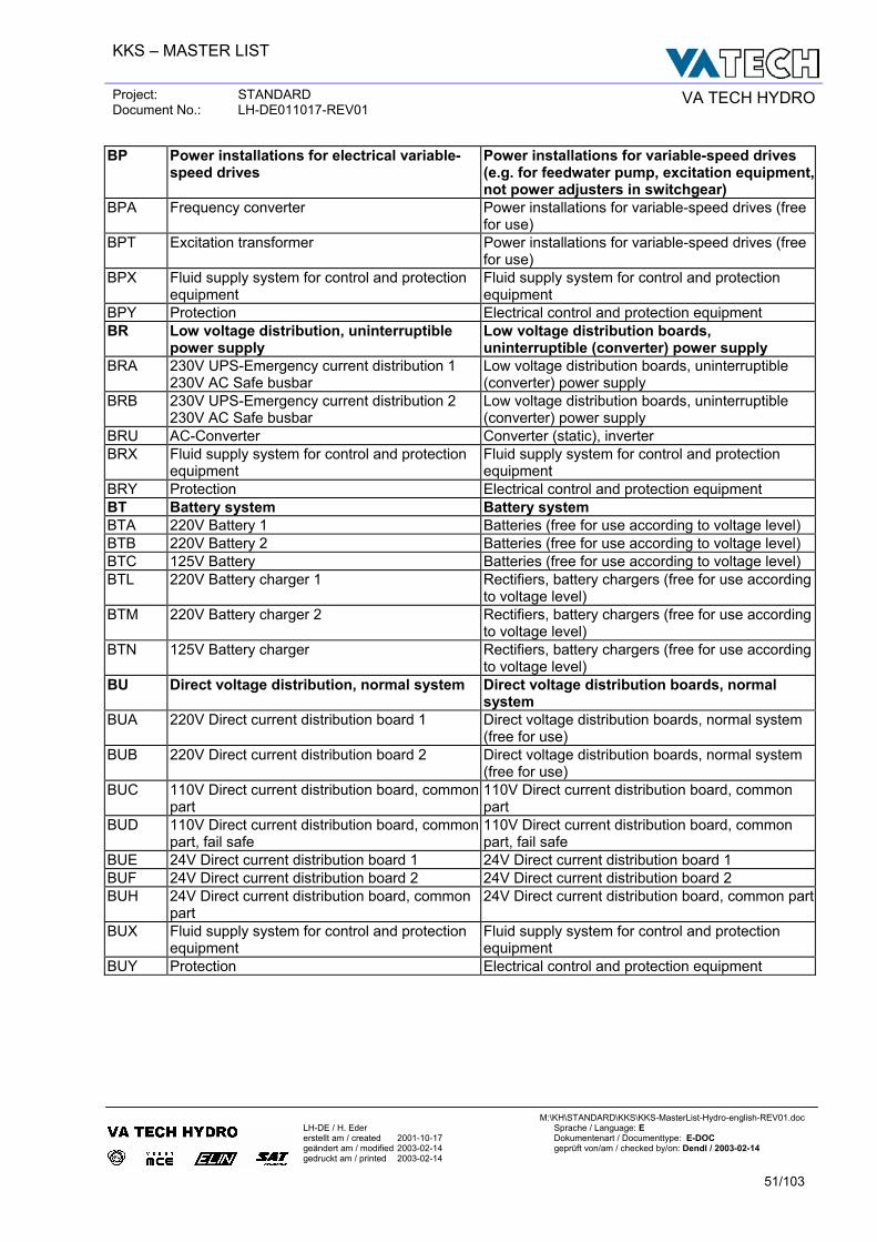
KKS – MASTER LIST
Project: STANDARD Document No.: LH-DE011017-REV01 VA TECH HYDRO
M:\KH\STANDARD\KKS\KKS-MasterList-Hydro-english-REV01.doc
LH-DE / H. Eder Sprache / Language: E erstellt am / created 2001-10-17 Dokumentenart / Documenttype: E-DOC geändert am / modified 2003-02-14 geprüft von/am / checked by/on: Dendl / 2003-02-14 gedruckt am / printed 2003-02-14
51/103
BP Power installations for electrical variable-speed drives
Power installations for variable-speed drives (e.g. for feedwater pump, excitation equipment, not power adjusters in switchgear)
BPA Frequency converter Power installations for variable-speed drives (free for use)
BPT Excitation transformer Power installations for variable-speed drives (free for use)
BPX Fluid supply system for control and protection equipment
Fluid supply system for control and protection equipment
BPY Protection Electrical control and protection equipment BR Low voltage distribution, uninterruptible
power supply Low voltage distribution boards, uninterruptible (converter) power supply
BRA 230V UPS-Emergency current distribution 1 230V AC Safe busbar
Low voltage distribution boards, uninterruptible (converter) power supply
BRB 230V UPS-Emergency current distribution 2 230V AC Safe busbar
Low voltage distribution boards, uninterruptible (converter) power supply
BRU AC-Converter Converter (static), inverter BRX Fluid supply system for control and protection
equipment Fluid supply system for control and protection equipment
BRY Protection Electrical control and protection equipment BT Battery system Battery system BTA 220V Battery 1 Batteries (free for use according to voltage level) BTB 220V Battery 2 Batteries (free for use according to voltage level) BTC 125V Battery Batteries (free for use according to voltage level) BTL 220V Battery charger 1 Rectifiers, battery chargers (free for use according
to voltage level) BTM 220V Battery charger 2 Rectifiers, battery chargers (free for use according
to voltage level) BTN 125V Battery charger Rectifiers, battery chargers (free for use according
to voltage level) BU Direct voltage distribution, normal system Direct voltage distribution boards, normal
system BUA 220V Direct current distribution board 1 Direct voltage distribution boards, normal system
(free for use) BUB 220V Direct current distribution board 2 Direct voltage distribution boards, normal system
(free for use) BUC 110V Direct current distribution board, common
part 110V Direct current distribution board, common part
BUD 110V Direct current distribution board, common part, fail safe
110V Direct current distribution board, common part, fail safe
BUE 24V Direct current distribution board 1 24V Direct current distribution board 1 BUF 24V Direct current distribution board 2 24V Direct current distribution board 2 BUH 24V Direct current distribution board, common
part 24V Direct current distribution board, common part
BUX Fluid supply system for control and protection equipment
Fluid supply system for control and protection equipment
BUY Protection Electrical control and protection equipment
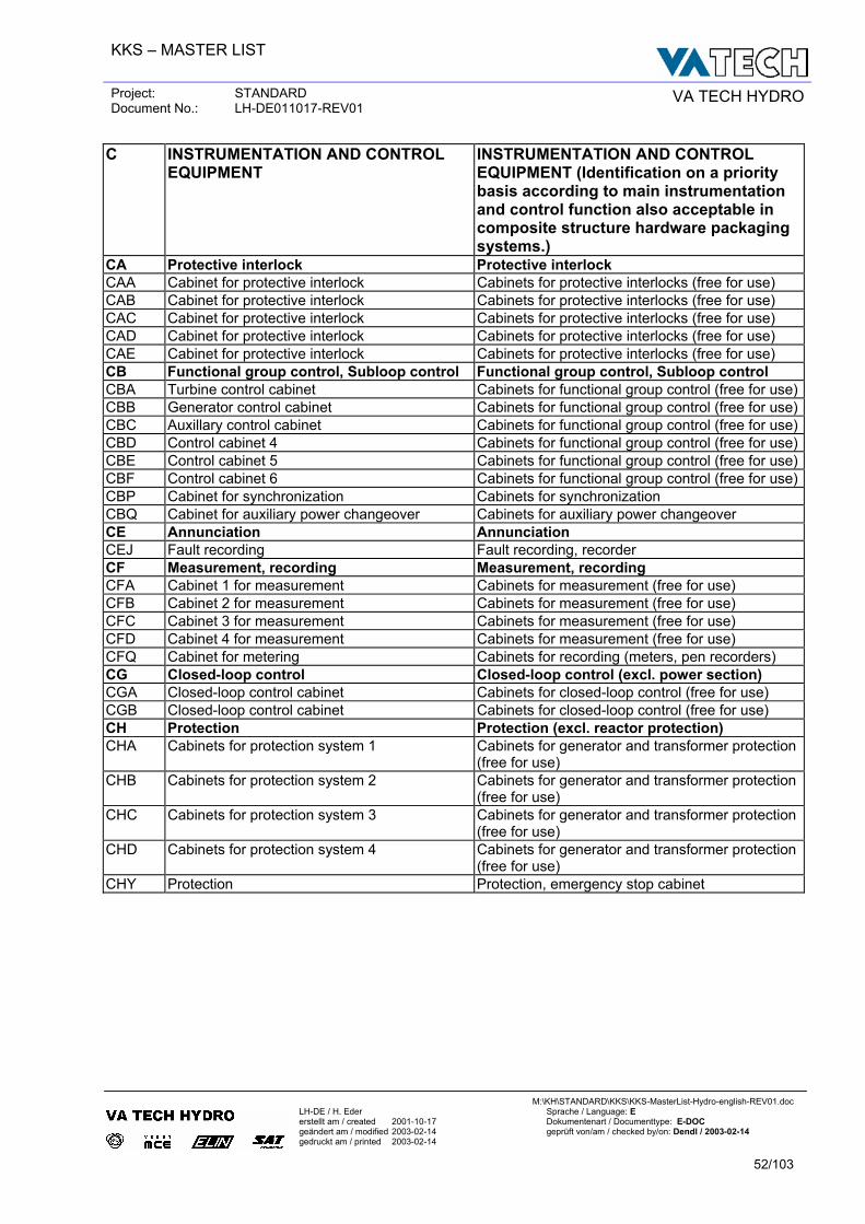
KKS – MASTER LIST
Project: STANDARD Document No.: LH-DE011017-REV01 VA TECH HYDRO
M:\KH\STANDARD\KKS\KKS-MasterList-Hydro-english-REV01.doc
LH-DE / H. Eder Sprache / Language: E erstellt am / created 2001-10-17 Dokumentenart / Documenttype: E-DOC geändert am / modified 2003-02-14 geprüft von/am / checked by/on: Dendl / 2003-02-14 gedruckt am / printed 2003-02-14
52/103
C INSTRUMENTATION AND CONTROL EQUIPMENT
INSTRUMENTATION AND CONTROL EQUIPMENT (Identification on a priority basis according to main instrumentation and control function also acceptable in composite structure hardware packaging systems.)
CA Protective interlock Protective interlock CAA Cabinet for protective interlock Cabinets for protective interlocks (free for use) CAB Cabinet for protective interlock Cabinets for protective interlocks (free for use) CAC Cabinet for protective interlock Cabinets for protective interlocks (free for use) CAD Cabinet for protective interlock Cabinets for protective interlocks (free for use) CAE Cabinet for protective interlock Cabinets for protective interlocks (free for use) CB Functional group control, Subloop control Functional group control, Subloop control CBA Turbine control cabinet Cabinets for functional group control (free for use)CBB Generator control cabinet Cabinets for functional group control (free for use)CBC Auxillary control cabinet Cabinets for functional group control (free for use)CBD Control cabinet 4 Cabinets for functional group control (free for use)CBE Control cabinet 5 Cabinets for functional group control (free for use)CBF Control cabinet 6 Cabinets for functional group control (free for use)CBP Cabinet for synchronization Cabinets for synchronization CBQ Cabinet for auxiliary power changeover Cabinets for auxiliary power changeover CE Annunciation Annunciation CEJ Fault recording Fault recording, recorder CF Measurement, recording Measurement, recording CFA Cabinet 1 for measurement Cabinets for measurement (free for use) CFB Cabinet 2 for measurement Cabinets for measurement (free for use) CFC Cabinet 3 for measurement Cabinets for measurement (free for use) CFD Cabinet 4 for measurement Cabinets for measurement (free for use) CFQ Cabinet for metering Cabinets for recording (meters, pen recorders) CG Closed-loop control Closed-loop control (excl. power section) CGA Closed-loop control cabinet Cabinets for closed-loop control (free for use) CGB Closed-loop control cabinet Cabinets for closed-loop control (free for use) CH Protection Protection (excl. reactor protection) CHA Cabinets for protection system 1 Cabinets for generator and transformer protection
(free for use) CHB Cabinets for protection system 2 Cabinets for generator and transformer protection
(free for use) CHC Cabinets for protection system 3 Cabinets for generator and transformer protection
(free for use) CHD Cabinets for protection system 4 Cabinets for generator and transformer protection
(free for use) CHY Protection Protection, emergency stop cabinet
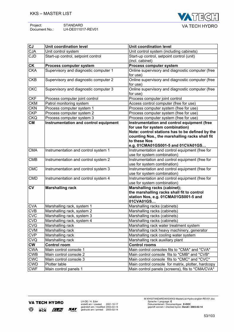
KKS – MASTER LIST
Project: STANDARD Document No.: LH-DE011017-REV01 VA TECH HYDRO
M:\KH\STANDARD\KKS\KKS-MasterList-Hydro-english-REV01.doc
LH-DE / H. Eder Sprache / Language: E erstellt am / created 2001-10-17 Dokumentenart / Documenttype: E-DOC geändert am / modified 2003-02-14 geprüft von/am / checked by/on: Dendl / 2003-02-14 gedruckt am / printed 2003-02-14
53/103
CJ Unit coordination level Unit coordination level CJA Unit control system Unit control system (including cabinets) CJD Start-up control, setpoint control Start-up control, setpoint control (unit)
(incl. cabinet) CK Process computer system Process computer system CKA Supervisory and diagnostic computer 1 Online supervisory and diagnostic computer (free
for use) CKB Supervisory and diagnostic computer 2 Online supervisory and diagnostic computer (free
for use) CKC Supervisory and diagnostic computer 3 Online supervisory and diagnostic computer (free
for use) CKF Process computer joint control Process computer joint control CKM Patrol monitoring system Access control computer (free for use) CKN Process computer system 1 Process computer system (free for use) CKP Process computer system 2 Process computer system (free for use) CKQ Process computer system 3 Process computer system (free for use) CM Instrumentation and control equipment Instrumentation and control equipment (free
for use for system combination) Note: control stations has to be defined by the counting Nos., the marshalling racks shall fit to these Nos e.g. 01CMA01GS001-5 and 01CVA01GS…
CMA Instrumentation and control system 1 Instrumentation and control equipment (free for use for system combination)
CMB Instrumentation and control system 2 Instrumentation and control equipment (free for use for system combination)
CMC Instrumentation and control system 3 Instrumentation and control equipment (free for use for system combination)
CMD Instrumentation and control system 4 Instrumentation and control equipment (free for use for system combination)
CV Marshalling rack Marshalling racks (cabinet); the marshalling racks shall fit to control station Nos, e.g. 01CMA01GS001-5 and 01CVA01GS…
CVA Marshalling rack, system 1 Marshalling racks (cabinets) CVB Marshalling rack, system 2 Marshalling racks (cabinets) CVC Marshalling rack, system 3 Marshalling racks (cabinets) CVD Marshalling rack, system 4 Marshalling racks (cabinets) CVG Marshalling rack Marshalling rack water treatment system CVM Marshalling rack Marshalling rack heavy machinery, generator CVP Marshalling rack Marshalling rack cooling water system CVQ Marshalling rack Marshalling rack auxiliary plant CW Control room Control rooms CWA Main control console 1 Main control consoles fits to *CMA* and *CVA* CWB Main control console 2 Main control console fits to *CMB* and *CVB* CWC Main control console 3 Main control console fits to *CMC* and *CVC* CWD Plotter table Main control console for matrix, plotter, hardcopy CWF Main control panels 1 Main control panels (screens), fits to *CMA/CVA*
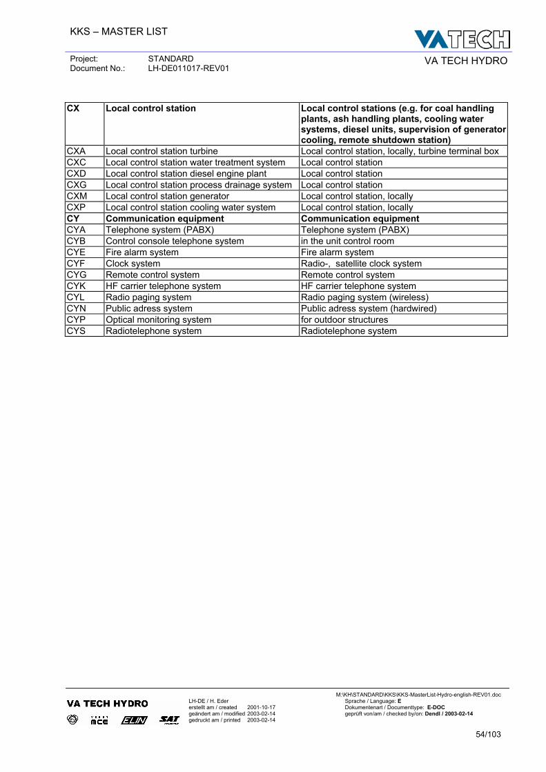
KKS – MASTER LIST
Project: STANDARD Document No.: LH-DE011017-REV01 VA TECH HYDRO
M:\KH\STANDARD\KKS\KKS-MasterList-Hydro-english-REV01.doc
LH-DE / H. Eder Sprache / Language: E erstellt am / created 2001-10-17 Dokumentenart / Documenttype: E-DOC geändert am / modified 2003-02-14 geprüft von/am / checked by/on: Dendl / 2003-02-14 gedruckt am / printed 2003-02-14
54/103
CX Local control station Local control stations (e.g. for coal handling
plants, ash handling plants, cooling water systems, diesel units, supervision of generator cooling, remote shutdown station)
CXA Local control station turbine Local control station, locally, turbine terminal box CXC Local control station water treatment system Local control station CXD Local control station diesel engine plant Local control station CXG Local control station process drainage system Local control station CXM Local control station generator Local control station, locally CXP Local control station cooling water system Local control station, locally CY Communication equipment Communication equipment CYA Telephone system (PABX) Telephone system (PABX) CYB Control console telephone system in the unit control room CYE Fire alarm system Fire alarm system CYF Clock system Radio-, satellite clock system CYG Remote control system Remote control system CYK HF carrier telephone system HF carrier telephone system CYL Radio paging system Radio paging system (wireless) CYN Public adress system Public adress system (hardwired) CYP Optical monitoring system for outdoor structures CYS Radiotelephone system Radiotelephone system
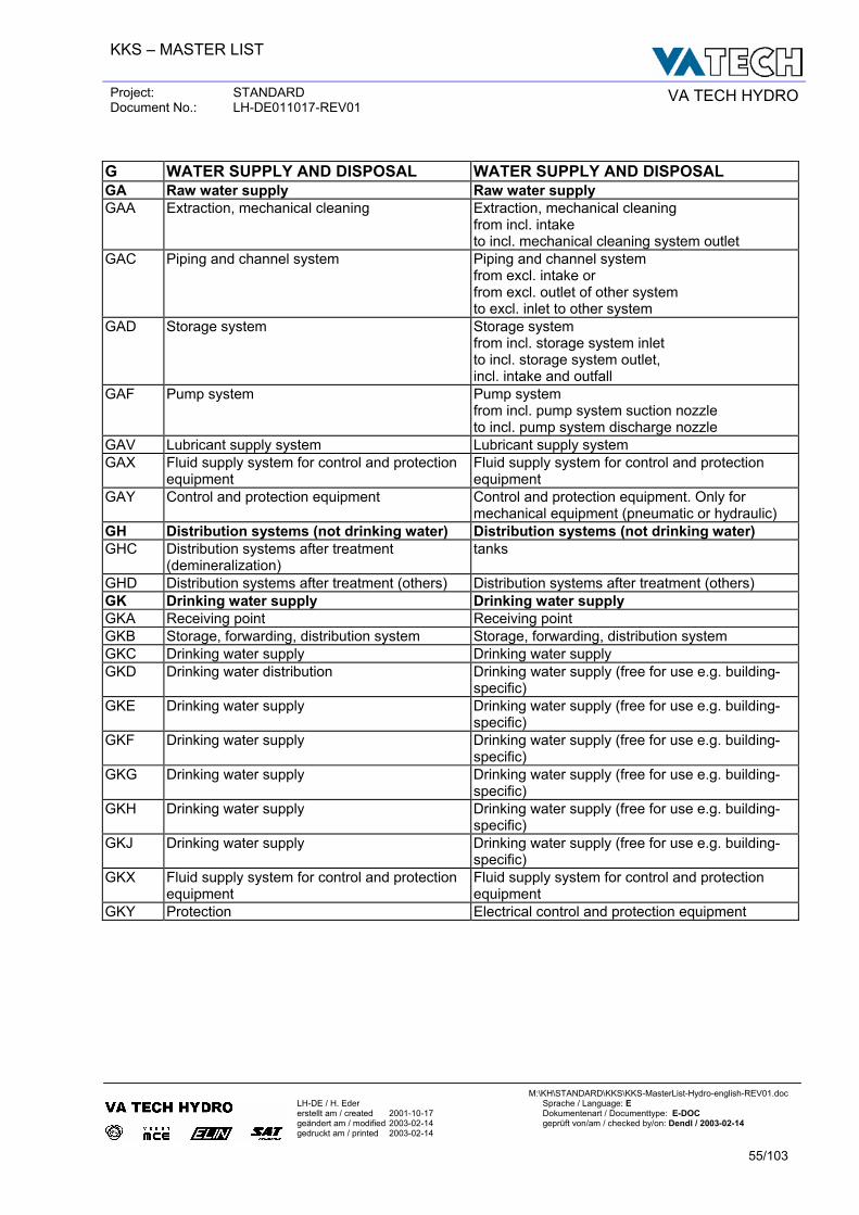
KKS – MASTER LIST
Project: STANDARD Document No.: LH-DE011017-REV01 VA TECH HYDRO
M:\KH\STANDARD\KKS\KKS-MasterList-Hydro-english-REV01.doc
LH-DE / H. Eder Sprache / Language: E erstellt am / created 2001-10-17 Dokumentenart / Documenttype: E-DOC geändert am / modified 2003-02-14 geprüft von/am / checked by/on: Dendl / 2003-02-14 gedruckt am / printed 2003-02-14
55/103
G WATER SUPPLY AND DISPOSAL WATER SUPPLY AND DISPOSAL GA Raw water supply Raw water supply GAA Extraction, mechanical cleaning Extraction, mechanical cleaning
from incl. intake to incl. mechanical cleaning system outlet
GAC Piping and channel system Piping and channel system from excl. intake or from excl. outlet of other system to excl. inlet to other system
GAD Storage system Storage system from incl. storage system inlet to incl. storage system outlet, incl. intake and outfall
GAF Pump system Pump system from incl. pump system suction nozzle to incl. pump system discharge nozzle
GAV Lubricant supply system Lubricant supply system GAX Fluid supply system for control and protection
equipment Fluid supply system for control and protection equipment
GAY Control and protection equipment Control and protection equipment. Only for mechanical equipment (pneumatic or hydraulic)
GH Distribution systems (not drinking water) Distribution systems (not drinking water) GHC Distribution systems after treatment
(demineralization) tanks
GHD Distribution systems after treatment (others) Distribution systems after treatment (others) GK Drinking water supply Drinking water supply GKA Receiving point Receiving point GKB Storage, forwarding, distribution system Storage, forwarding, distribution system GKC Drinking water supply Drinking water supply GKD Drinking water distribution Drinking water supply (free for use e.g. building-
specific) GKE Drinking water supply Drinking water supply (free for use e.g. building-
specific) GKF Drinking water supply Drinking water supply (free for use e.g. building-
specific) GKG Drinking water supply Drinking water supply (free for use e.g. building-
specific) GKH Drinking water supply Drinking water supply (free for use e.g. building-
specific) GKJ Drinking water supply Drinking water supply (free for use e.g. building-
specific) GKX Fluid supply system for control and protection
equipment Fluid supply system for control and protection equipment
GKY Protection Electrical control and protection equipment
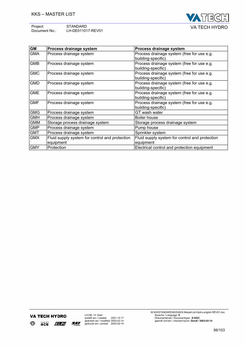
KKS – MASTER LIST
Project: STANDARD Document No.: LH-DE011017-REV01 VA TECH HYDRO
M:\KH\STANDARD\KKS\KKS-MasterList-Hydro-english-REV01.doc
LH-DE / H. Eder Sprache / Language: E erstellt am / created 2001-10-17 Dokumentenart / Documenttype: E-DOC geändert am / modified 2003-02-14 geprüft von/am / checked by/on: Dendl / 2003-02-14 gedruckt am / printed 2003-02-14
56/103
GM Process drainage system Process drainage system GMA Process drainage system Process drainage system (free for use e.g.
building-specific) GMB Process drainage system Process drainage system (free for use e.g.
building-specific) GMC Process drainage system Process drainage system (free for use e.g.
building-specific) GMD Process drainage system Process drainage system (free for use e.g.
building-specific) GME Process drainage system Process drainage system (free for use e.g.
building-specific) GMF Process drainage system Process drainage system (free for use e.g.
building-specific) GMG Process drainage system GT wash water GMH Process drainage system Boiler house GMM Storage process drainage system Storage process drainage system GMP Process drainage system Pump house GMT Process drainage system Sprinkler system GMX Fluid supply system for control and protection
equipment Fluid supply system for control and protection equipment
GMY Protection Electrical control and protection equipment
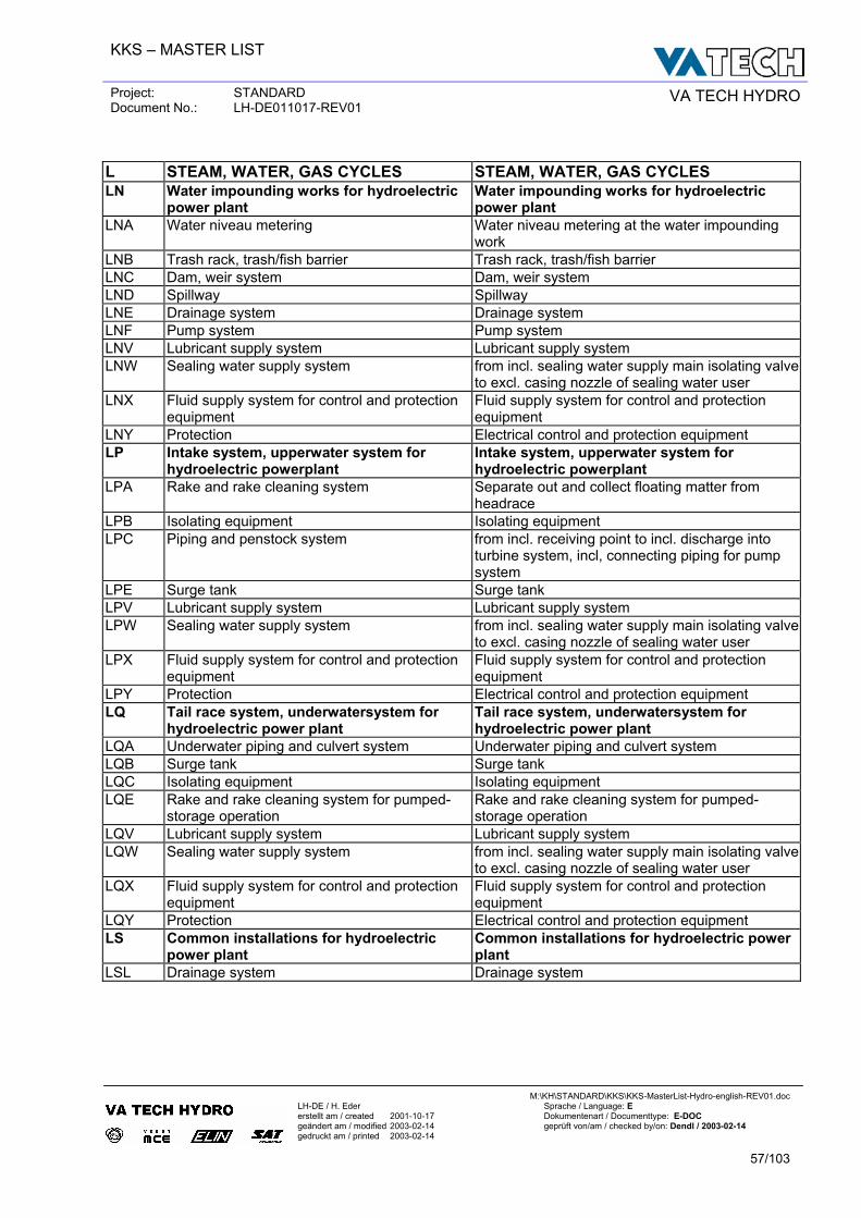
KKS – MASTER LIST
Project: STANDARD Document No.: LH-DE011017-REV01 VA TECH HYDRO
M:\KH\STANDARD\KKS\KKS-MasterList-Hydro-english-REV01.doc
LH-DE / H. Eder Sprache / Language: E erstellt am / created 2001-10-17 Dokumentenart / Documenttype: E-DOC geändert am / modified 2003-02-14 geprüft von/am / checked by/on: Dendl / 2003-02-14 gedruckt am / printed 2003-02-14
57/103
L STEAM, WATER, GAS CYCLES STEAM, WATER, GAS CYCLES LN Water impounding works for hydroelectric
power plant Water impounding works for hydroelectric power plant
LNA Water niveau metering Water niveau metering at the water impounding work
LNB Trash rack, trash/fish barrier Trash rack, trash/fish barrier LNC Dam, weir system Dam, weir system LND Spillway Spillway LNE Drainage system Drainage system LNF Pump system Pump system LNV Lubricant supply system Lubricant supply system LNW Sealing water supply system from incl. sealing water supply main isolating valve
to excl. casing nozzle of sealing water user LNX Fluid supply system for control and protection
equipment Fluid supply system for control and protection equipment
LNY Protection Electrical control and protection equipment LP Intake system, upperwater system for
hydroelectric powerplant Intake system, upperwater system for hydroelectric powerplant
LPA Rake and rake cleaning system Separate out and collect floating matter from headrace
LPB Isolating equipment Isolating equipment LPC Piping and penstock system from incl. receiving point to incl. discharge into
turbine system, incl, connecting piping for pump system
LPE Surge tank Surge tank LPV Lubricant supply system Lubricant supply system LPW Sealing water supply system from incl. sealing water supply main isolating valve
to excl. casing nozzle of sealing water user LPX Fluid supply system for control and protection
equipment Fluid supply system for control and protection equipment
LPY Protection Electrical control and protection equipment LQ Tail race system, underwatersystem for
hydroelectric power plant Tail race system, underwatersystem for hydroelectric power plant
LQA Underwater piping and culvert system Underwater piping and culvert system LQB Surge tank Surge tank LQC Isolating equipment Isolating equipment LQE Rake and rake cleaning system for pumped-
storage operation Rake and rake cleaning system for pumped-storage operation
LQV Lubricant supply system Lubricant supply system LQW Sealing water supply system from incl. sealing water supply main isolating valve
to excl. casing nozzle of sealing water user LQX Fluid supply system for control and protection
equipment Fluid supply system for control and protection equipment
LQY Protection Electrical control and protection equipment LS Common installations for hydroelectric
power plant Common installations for hydroelectric power plant
LSL Drainage system Drainage system
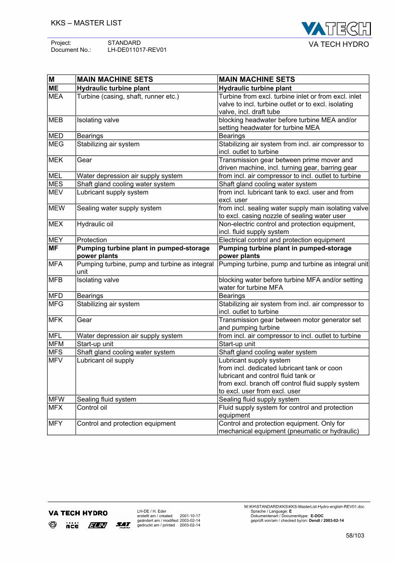
KKS – MASTER LIST
Project: STANDARD Document No.: LH-DE011017-REV01 VA TECH HYDRO
M:\KH\STANDARD\KKS\KKS-MasterList-Hydro-english-REV01.doc
LH-DE / H. Eder Sprache / Language: E erstellt am / created 2001-10-17 Dokumentenart / Documenttype: E-DOC geändert am / modified 2003-02-14 geprüft von/am / checked by/on: Dendl / 2003-02-14 gedruckt am / printed 2003-02-14
58/103
M MAIN MACHINE SETS MAIN MACHINE SETS ME Hydraulic turbine plant Hydraulic turbine plant MEA Turbine (casing, shaft, runner etc.) Turbine from excl. turbine inlet or from excl. inlet
valve to incl. turbine outlet or to excl. isolating valve, incl. draft tube
MEB Isolating valve blocking headwater before turbine MEA and/or setting headwater for turbine MEA
MED Bearings Bearings MEG Stabilizing air system Stabilizing air system from incl. air compressor to
incl. outlet to turbine MEK Gear Transmission gear between prime mover and
driven machine, incl. turning gear, barring gear MEL Water depression air supply system from incl. air compressor to incl. outlet to turbine MES Shaft gland cooling water system Shaft gland cooling water system MEV Lubricant supply system from incl. lubricant tank to excl. user and from
excl. user MEW Sealing water supply system from incl. sealing water supply main isolating valve
to excl. casing nozzle of sealing water user MEX Hydraulic oil Non-electric control and protection equipment,
incl. fluid supply system MEY Protection Electrical control and protection equipment MF Pumping turbine plant in pumped-storage
power plants Pumping turbine plant in pumped-storage power plants
MFA Pumping turbine, pump and turbine as integral unit
Pumping turbine, pump and turbine as integral unit
MFB Isolating valve blocking water before turbine MFA and/or setting water for turbine MFA
MFD Bearings Bearings MFG Stabilizing air system Stabilizing air system from incl. air compressor to
incl. outlet to turbine MFK Gear Transmission gear between motor generator set
and pumping turbine MFL Water depression air supply system from incl. air compressor to incl. outlet to turbine MFM Start-up unit Start-up unit MFS Shaft gland cooling water system Shaft gland cooling water system MFV Lubricant oil supply Lubricant supply system
from incl. dedicated lubricant tank or coon lubricant and control fluid tank or from excl. branch off control fluid supply system to excl. user from excl. user
MFW Sealing fluid system Sealing fluid supply system MFX Control oil Fluid supply system for control and protection
equipment MFY Control and protection equipment Control and protection equipment. Only for
mechanical equipment (pneumatic or hydraulic)
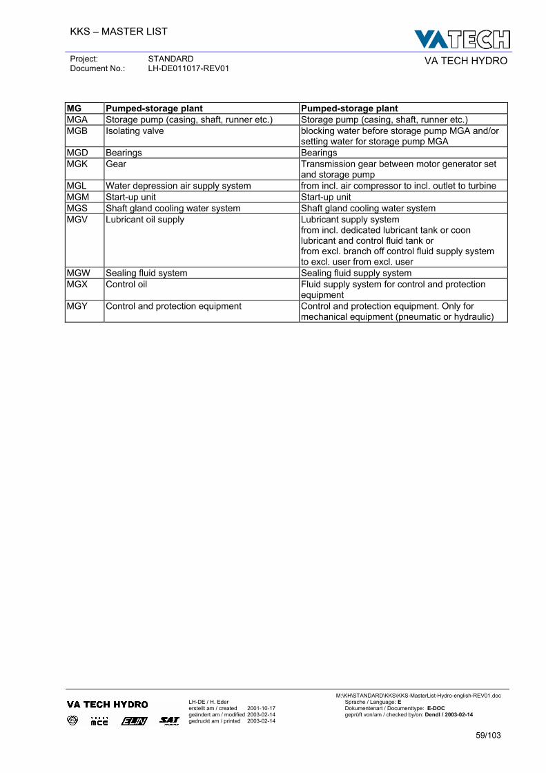
KKS – MASTER LIST
Project: STANDARD Document No.: LH-DE011017-REV01 VA TECH HYDRO
M:\KH\STANDARD\KKS\KKS-MasterList-Hydro-english-REV01.doc
LH-DE / H. Eder Sprache / Language: E erstellt am / created 2001-10-17 Dokumentenart / Documenttype: E-DOC geändert am / modified 2003-02-14 geprüft von/am / checked by/on: Dendl / 2003-02-14 gedruckt am / printed 2003-02-14
59/103
MG Pumped-storage plant Pumped-storage plant MGA Storage pump (casing, shaft, runner etc.) Storage pump (casing, shaft, runner etc.) MGB Isolating valve blocking water before storage pump MGA and/or
setting water for storage pump MGA MGD Bearings Bearings MGK Gear Transmission gear between motor generator set
and storage pump MGL Water depression air supply system from incl. air compressor to incl. outlet to turbine MGM Start-up unit Start-up unit MGS Shaft gland cooling water system Shaft gland cooling water system MGV Lubricant oil supply Lubricant supply system
from incl. dedicated lubricant tank or coon lubricant and control fluid tank or from excl. branch off control fluid supply system to excl. user from excl. user
MGW Sealing fluid system Sealing fluid supply system MGX Control oil Fluid supply system for control and protection
equipment MGY Control and protection equipment Control and protection equipment. Only for
mechanical equipment (pneumatic or hydraulic)
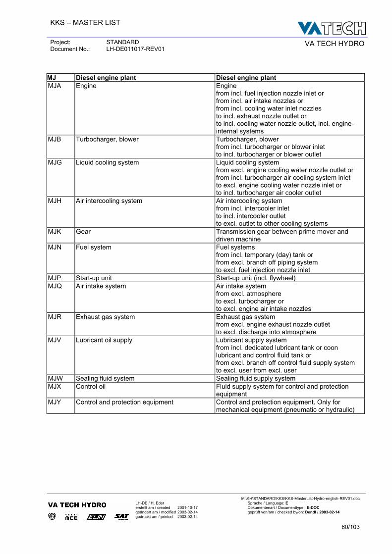
KKS – MASTER LIST
Project: STANDARD Document No.: LH-DE011017-REV01 VA TECH HYDRO
M:\KH\STANDARD\KKS\KKS-MasterList-Hydro-english-REV01.doc
LH-DE / H. Eder Sprache / Language: E erstellt am / created 2001-10-17 Dokumentenart / Documenttype: E-DOC geändert am / modified 2003-02-14 geprüft von/am / checked by/on: Dendl / 2003-02-14 gedruckt am / printed 2003-02-14
60/103
MJ Diesel engine plant Diesel engine plant MJA Engine Engine
from incl. fuel injection nozzle inlet or from incl. air intake nozzles or from incl. cooling water inlet nozzles to incl. exhaust nozzle outlet or to incl. cooling water nozzle outlet, incl. engine- internal systems
MJB Turbocharger, blower Turbocharger, blower from incl. turbocharger or blower inlet to incl. turbocharger or blower outlet
MJG Liquid cooling system Liquid cooling system from excl. engine cooling water nozzle outlet or from incl. turbocharger air cooling system inlet to excl. engine cooling water nozzle inlet or to incl. turbocharger air cooler outlet
MJH Air intercooling system Air intercooling system from incl. intercooler inlet to incl. intercooler outlet to excl. outlet to other cooling systems
MJK Gear Transmission gear between prime mover and driven machine
MJN Fuel system Fuel systems from incl. temporary (day) tank or from excl. branch off piping system to excl. fuel injection nozzle inlet
MJP Start-up unit Start-up unit (incl. flywheel) MJQ Air intake system Air intake system
from excl. atmosphere to excl. turbocharger or to excl. engine air intake nozzles
MJR Exhaust gas system Exhaust gas system from excl. engine exhaust nozzle outlet to excl. discharge into atmosphere
MJV Lubricant oil supply Lubricant supply system from incl. dedicated lubricant tank or coon lubricant and control fluid tank or from excl. branch off control fluid supply system to excl. user from excl. user
MJW Sealing fluid system Sealing fluid supply system MJX Control oil Fluid supply system for control and protection
equipment MJY Control and protection equipment Control and protection equipment. Only for
mechanical equipment (pneumatic or hydraulic)
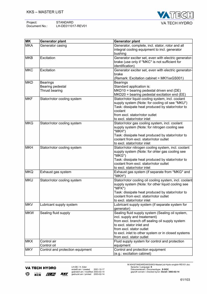
KKS – MASTER LIST
Project: STANDARD Document No.: LH-DE011017-REV01 VA TECH HYDRO
M:\KH\STANDARD\KKS\KKS-MasterList-Hydro-english-REV01.doc
LH-DE / H. Eder Sprache / Language: E erstellt am / created 2001-10-17 Dokumentenart / Documenttype: E-DOC geändert am / modified 2003-02-14 geprüft von/am / checked by/on: Dendl / 2003-02-14 gedruckt am / printed 2003-02-14
61/103
MK Generator plant Generator plant MKA Generator casing Generator, complete, incl. stator, rotor and all
integral cooling equipment to incl. generator bushing
MKB Excitation Generator exciter set, even with electric generator-brake (use only if *MKC* is not sufficient for identification)
MKC Excitation Generator exciter set, even with electric generator-brake (Remark: Excitation cabinet = MKYxxGS001)
MKD Bearings Bearing pedestal Thrust bearing
Bearings Standard application is: MKD10 = bearing pedestal driven end (DE) MKD20 = bearing pedestal excitation end (EE)
MKF Stator/rotor cooling system Stator/rotor liquid cooling system, incl. coolant supply system (Note: for cooling oil see *MKU*) Task: dissipate heat produced by stator/rotor to coolant from excl. stator/rotor outlet to excl. stator/rotor inlet
MKG Stator/rotor cooling system Stator/rotor gas cooling system, incl. coolant supply system (Note: for nitrogen cooling see *MKH*) Task: dissipate heat produced by stator/rotor to coolant from excl. stator/rotor outlet to excl. stator/rotor inlet
MKH Stator/rotor cooling system Stator/rotor nitrogen cooling system, incl. coolant supply system (Note: for ohter gas cooling see *MKG*) Task: dissipate heat produced by stator/rotor to coolant from excl. stator/rotor outlet to excl. stator/rotor inlet
MKQ Exhaust gas system Exhaust gas system (if separate from *MKG* and *MKH*)
MKU Stator/rotor cooling system Stator/rotor cooling oil cooling system, incl. coolant supply system (Note: for other liquid cooling see *MFK*) Task: dissipate heat produced by stator/rotor to coolant from excl. stator/rotor outlet to excl. stator/rotor inlet
MKV Lubricant supply system Lubricant supply system (if separate system for generator)
MKW Sealing fluid supply Sealing fluid supply system (Sealing oil system, incl. supply and treatement) from excl. branch off sealing oil supply system to excl. stator inlet and from excl. stator outlet to excl. inlet to other system or in closed systems from excl. stator outlet
MKX Control air Control oil
Fluid supply system for control and protection equipment
MKY Control and protection equipment Control and protection equipment (e.g.: excitation cabinet)
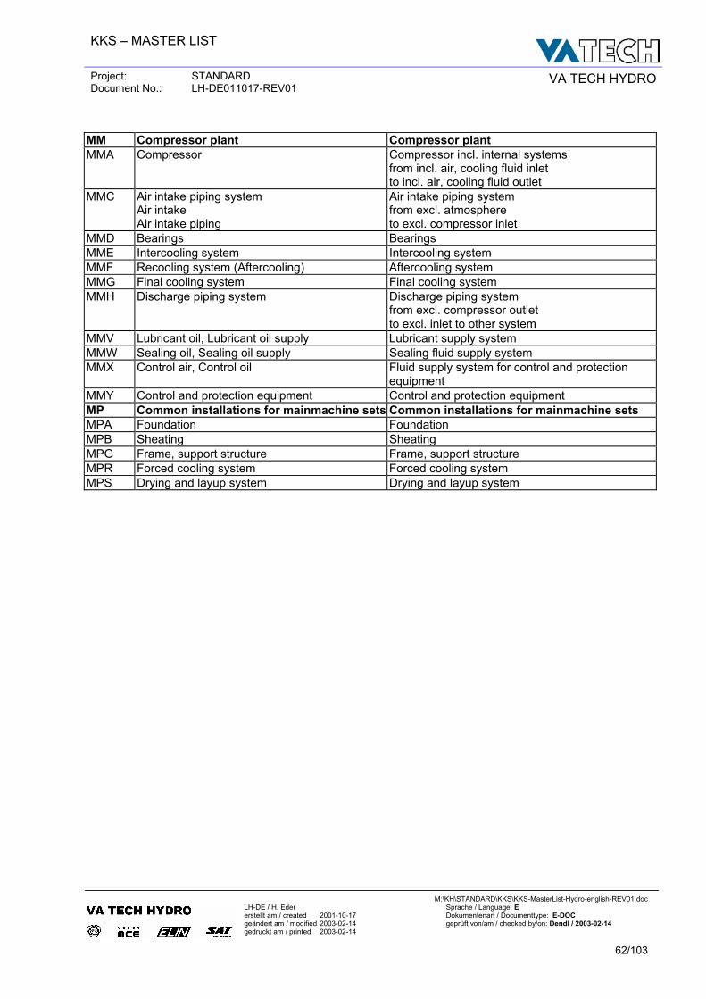
KKS – MASTER LIST
Project: STANDARD Document No.: LH-DE011017-REV01 VA TECH HYDRO
M:\KH\STANDARD\KKS\KKS-MasterList-Hydro-english-REV01.doc
LH-DE / H. Eder Sprache / Language: E erstellt am / created 2001-10-17 Dokumentenart / Documenttype: E-DOC geändert am / modified 2003-02-14 geprüft von/am / checked by/on: Dendl / 2003-02-14 gedruckt am / printed 2003-02-14
62/103
MM Compressor plant Compressor plant MMA Compressor Compressor incl. internal systems
from incl. air, cooling fluid inlet to incl. air, cooling fluid outlet
MMC Air intake piping system Air intake Air intake piping
Air intake piping system from excl. atmosphere to excl. compressor inlet
MMD Bearings Bearings MME Intercooling system Intercooling system MMF Recooling system (Aftercooling) Aftercooling system MMG Final cooling system Final cooling system MMH Discharge piping system Discharge piping system
from excl. compressor outlet to excl. inlet to other system
MMV Lubricant oil, Lubricant oil supply Lubricant supply system MMW Sealing oil, Sealing oil supply Sealing fluid supply system MMX Control air, Control oil Fluid supply system for control and protection
equipment MMY Control and protection equipment Control and protection equipment MP Common installations for mainmachine sets Common installations for mainmachine sets MPA Foundation Foundation MPB Sheating Sheating MPG Frame, support structure Frame, support structure MPR Forced cooling system Forced cooling system MPS Drying and layup system Drying and layup system
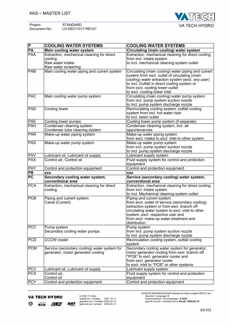
KKS – MASTER LIST
Project: STANDARD Document No.: LH-DE011017-REV01 VA TECH HYDRO
M:\KH\STANDARD\KKS\KKS-MasterList-Hydro-english-REV01.doc
LH-DE / H. Eder Sprache / Language: E erstellt am / created 2001-10-17 Dokumentenart / Documenttype: E-DOC geändert am / modified 2003-02-14 geprüft von/am / checked by/on: Dendl / 2003-02-14 gedruckt am / printed 2003-02-14
63/103
P COOLING WATER SYSTEMS COOLING WATER SYSTEMS PA Main cooling water system Circulating (main cooling) water system PAA Extraction, mechanical cleaning for direct
cooling Raw water intake Raw water screening
Extraction, mechanical cleaning for direct cooling from incl. intake system to incl. mechanical cleaning system outlet
PAB Main cooling water piping and culvert system Circulating (main cooling) water piping and culvert system from excl. outlet of circulating (main cooling) water extraction system (excl. any user) to incl. Outfall in direct cooling system or from excl. cooling tower outlet to excl. cooling tower inlet
PAC Main cooling water pump system Circulating (main cooling) water pump system from incl. pump system suction nozzle to incl. pump system discharge nozzle
PAD Cooling tower Recirculating cooling system, outfall cooling system from incl. hot water riser to incl. basin outlet
PAE Cooling tower pumps Cooling tower pump system (if separate) PAH Condenser cleaning system
Condenser tube cleaning system Condenser cleaning system, incl. all appurtenances
PAR Make-up water piping system Make-up water piping system from excl. intake to excl. inlet to other system
PAS Make-up water pump system Make-up water pump system from incl. pump system suction nozzle to incl. pump system discharge nozzle
PAV Lubricant oil, Lubricant oil supply Lubricant supply system PAX Control air, Control oil Fluid supply system for control and protection
equipment PAY Control and protection equipment Control and protection equipment PB xxx xxx PC Secondary cooling water system,
conventional area Service (secondary cooling) water system, conventional area
PCA Extraction, mechanical cleaning for direct cooling
Extraction, mechanical cleaning for direct cooling from incl. intake system to incl. Mechanical cleaning system outlet
PCB Piping and culvert system Canal (Culvert)
Piping and culvert system from excl. outlet of service (secondary cooling) extraction system or from excl. branch off circulating water system to excl. inlet to other system, excl. respective user and from excl. make-up water treatment and distribution
PCC Pump system Secondary cooling water pumps
Pump system from incl. pump system suction nozzle to incl. pump system discharge nozzle
PCD CCCW cooler Recirculation cooling system, outfall cooling system
PCM Service (secondary cooling) water system for generator, motor generator cooling
Secondary cooling water system for generator, motor generator cooling from excl. branch off *PCB* to excl. generator cooler and from excl. generator cooler to excl. inlet to *PCB* or other systems
PCV Lubricant oil, Lubricant oil supply Lubricant supply system PCX Control air,
Control oil Fluid supply system for control and protection equipment
PCY Control and protection equipment Control and protection equipment
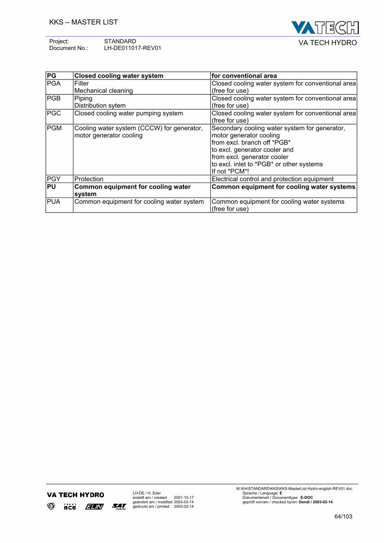
KKS – MASTER LIST
Project: STANDARD Document No.: LH-DE011017-REV01 VA TECH HYDRO
M:\KH\STANDARD\KKS\KKS-MasterList-Hydro-english-REV01.doc
LH-DE / H. Eder Sprache / Language: E erstellt am / created 2001-10-17 Dokumentenart / Documenttype: E-DOC geändert am / modified 2003-02-14 geprüft von/am / checked by/on: Dendl / 2003-02-14 gedruckt am / printed 2003-02-14
64/103
PG Closed cooling water system for conventional area PGA Filter
Mechanical cleaning Closed cooling water system for conventional area (free for use)
PGB Piping Distribution sytem
Closed cooling water system for conventional area (free for use)
PGC Closed cooling water pumping system Closed cooling water system for conventional area (free for use)
PGM Cooling water system (CCCW) for generator, motor generator cooling
Secondary cooling water system for generator, motor generator cooling from excl. branch off *PGB* to excl. generator cooler and from excl. generator cooler to excl. inlet to *PGB* or other systems If not *PCM*!
PGY Protection Electrical control and protection equipment PU Common equipment for cooling water
system Common equipment for cooling water systems
PUA Common equipment for cooling water system Common equipment for cooling water systems (free for use)
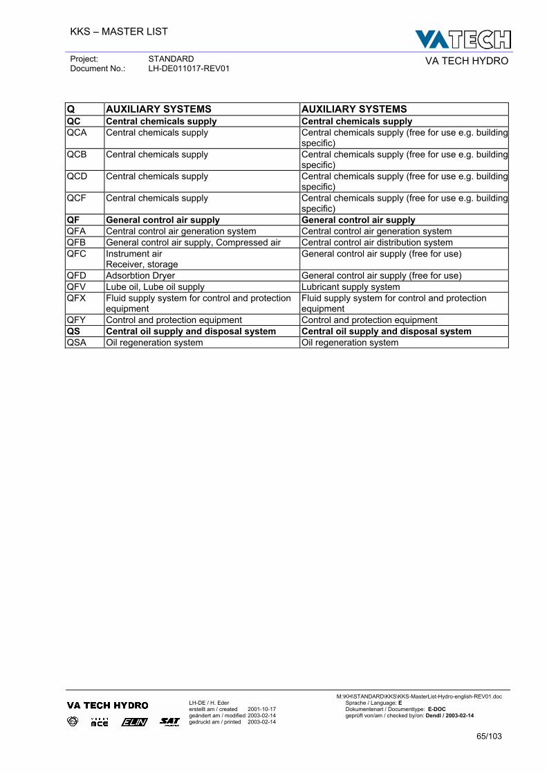
KKS – MASTER LIST
Project: STANDARD Document No.: LH-DE011017-REV01 VA TECH HYDRO
M:\KH\STANDARD\KKS\KKS-MasterList-Hydro-english-REV01.doc
LH-DE / H. Eder Sprache / Language: E erstellt am / created 2001-10-17 Dokumentenart / Documenttype: E-DOC geändert am / modified 2003-02-14 geprüft von/am / checked by/on: Dendl / 2003-02-14 gedruckt am / printed 2003-02-14
65/103
Q AUXILIARY SYSTEMS AUXILIARY SYSTEMS QC Central chemicals supply Central chemicals supply QCA Central chemicals supply Central chemicals supply (free for use e.g. building
specific) QCB Central chemicals supply Central chemicals supply (free for use e.g. building
specific) QCD Central chemicals supply Central chemicals supply (free for use e.g. building
specific) QCF Central chemicals supply Central chemicals supply (free for use e.g. building
specific) QF General control air supply General control air supply QFA Central control air generation system Central control air generation system QFB General control air supply, Compressed air Central control air distribution system QFC Instrument air
Receiver, storage General control air supply (free for use)
QFD Adsorbtion Dryer General control air supply (free for use) QFV Lube oil, Lube oil supply Lubricant supply system QFX Fluid supply system for control and protection
equipment Fluid supply system for control and protection equipment
QFY Control and protection equipment Control and protection equipment QS Central oil supply and disposal system Central oil supply and disposal system QSA Oil regeneration system Oil regeneration system
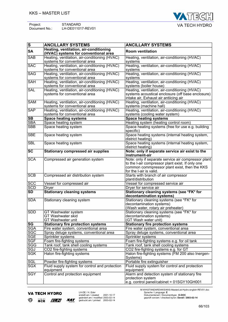
KKS – MASTER LIST
Project: STANDARD Document No.: LH-DE011017-REV01 VA TECH HYDRO
M:\KH\STANDARD\KKS\KKS-MasterList-Hydro-english-REV01.doc
LH-DE / H. Eder Sprache / Language: E erstellt am / created 2001-10-17 Dokumentenart / Documenttype: E-DOC geändert am / modified 2003-02-14 geprüft von/am / checked by/on: Dendl / 2003-02-14 gedruckt am / printed 2003-02-14
66/103
S ANCILLARY SYSTEMS ANCILLARY SYSTEMS SA Heating, ventilation, air-conditioning
(HVAC) systems for conventional area Room ventilation SAB Heating, ventilation, air-conditioning (HVAC)
systems for conventional area Heating, ventilation, air-conditioning (HVAC) systems
SAC Heating, ventilation, air-conditioning (HVAC) systems for conventional area
Heating, ventilation, air-conditioning (HVAC) systems
SAG Heating, ventilation, air-conditioning (HVAC) systems for conventional area
Heating, ventilation, air-conditioning (HVAC) systems
SAH Heating, ventilation, air-conditioning (HVAC) systems for conventional area
Heating, ventilation, air-conditioning (HVAC) systems (boiler house)
SAL Heating, ventilation, air-conditioning (HVAC) systems for conventional area
Heating, ventilation, air-conditioning (HVAC) systems acoustical enclosure (off base enclosure)intake air, Exhaust air antiicing air
SAM Heating, ventilation, air-conditioning (HVAC) systems for conventional area
Heating, ventilation, air-conditioning (HVAC) systems (machine hall)
SAP Heating, ventilation, air-conditioning (HVAC) systems for conventional area
Heating, ventilation, air-conditioning (HVAC) systems (cooling water system)
SB Space heating systems Space heating systems SBA Space heating system Heating system (heating control room) SBB Space heating system Space heating systems (free for use e.g. building
specific) SBE Space heating system Space heating systems (internal heating system,
district heating) SBL Space heating system Space heating systems (internal heating system,
district heating) SC Stationary compressed air supplies Note: only if separate service air exist to the
instrument-air SCA Compressed air generation system Note: only if separate service air compressor plant
to the I-air compressor plant exist. If only one common commpressor plant exist, then the KKS for the I-air is valid.
SCB Compressed air distribution system Starts with branch of air compressor plant/distribution
SCC Vessel for compressed air Vessel for compressed service air SCD Dryer Dryer for service air SD Stationary cleaning systems Stationary cleaning systems (see *FK* for
decontamination systems) SDA Stationary cleaning system Stationary cleaning systems (see *FK* for
decontamination systems) (Wash water, rotary air preheater)
SDD GT Washwater system GT Washwater skid GT Washwater unit
Stationary cleaning systems (see *FK* for decontamination systems) (GT Wash water unit)
SG Stationary fire protection systems Stationary fire protection systems SGA Fire water system, conventional area Fire water system, conventional area SGC Spray deluge systems, conventional area Spray deluge systems, conventional area SGE Sprinkler systems Sprinkler systems SGF Foam fire-fighting systems Foam fire-fighting systems e.g. for oil tank SGG Tank roof, tank shell cooling systems Tank roof, tank shell cooling systems SGJ CO2 fire-fighting systems CO2 fire-fighting systems e.g. for GT SGK Halon fire-fighting systems Halon fire-fighting systems (FM 200 also Inergen-
Systems) SGL Powder fire-fighting systems Portable fire extinguisher SGX Fluid supply system for control and protection
equipment Fluid supply system for control and protection equipment
SGY Control and protection equipment Alarm and detection system of stationary fire protection system e.g. control panel/cabinet = 01SGY10GH001
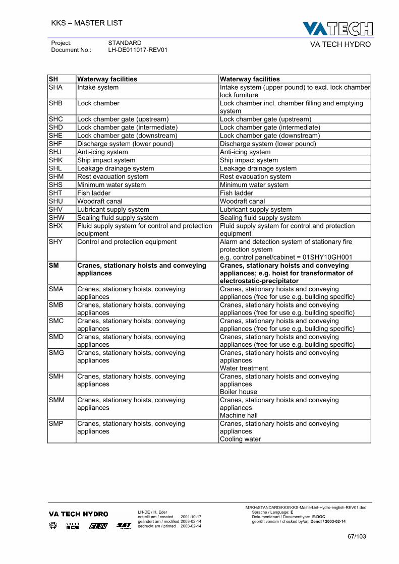
KKS – MASTER LIST
Project: STANDARD Document No.: LH-DE011017-REV01 VA TECH HYDRO
M:\KH\STANDARD\KKS\KKS-MasterList-Hydro-english-REV01.doc
LH-DE / H. Eder Sprache / Language: E erstellt am / created 2001-10-17 Dokumentenart / Documenttype: E-DOC geändert am / modified 2003-02-14 geprüft von/am / checked by/on: Dendl / 2003-02-14 gedruckt am / printed 2003-02-14
67/103
SH Waterway facilities Waterway facilities SHA Intake system Intake system (upper pound) to excl. lock chamber
lock furniture SHB Lock chamber Lock chamber incl. chamber filling and emptying
system SHC Lock chamber gate (upstream) Lock chamber gate (upstream) SHD Lock chamber gate (intermediate) Lock chamber gate (intermediate) SHE Lock chamber gate (downstream) Lock chamber gate (downstream) SHF Discharge system (lower pound) Discharge system (lower pound) SHJ Anti-icing system Anti-icing system SHK Ship impact system Ship impact system SHL Leakage drainage system Leakage drainage system SHM Rest evacuation system Rest evacuation system SHS Minimum water system Minimum water system SHT Fish ladder Fish ladder SHU Woodraft canal Woodraft canal SHV Lubricant supply system Lubricant supply system SHW Sealing fluid supply system Sealing fluid supply system SHX Fluid supply system for control and protection
equipment Fluid supply system for control and protection equipment
SHY Control and protection equipment Alarm and detection system of stationary fire protection system e.g. control panel/cabinet = 01SHY10GH001
SM Cranes, stationary hoists and conveying appliances
Cranes, stationary hoists and conveying appliances; e.g. hoist for transformator of electrostatic-precipitator
SMA Cranes, stationary hoists, conveying appliances
Cranes, stationary hoists and conveying appliances (free for use e.g. building specific)
SMB Cranes, stationary hoists, conveying appliances
Cranes, stationary hoists and conveying appliances (free for use e.g. building specific)
SMC Cranes, stationary hoists, conveying appliances
Cranes, stationary hoists and conveying appliances (free for use e.g. building specific)
SMD Cranes, stationary hoists, conveying appliances
Cranes, stationary hoists and conveying appliances (free for use e.g. building specific)
SMG Cranes, stationary hoists, conveying appliances
Cranes, stationary hoists and conveying appliances Water treatment
SMH Cranes, stationary hoists, conveying appliances
Cranes, stationary hoists and conveying appliances Boiler house
SMM Cranes, stationary hoists, conveying appliances
Cranes, stationary hoists and conveying appliances Machine hall
SMP Cranes, stationary hoists, conveying appliances
Cranes, stationary hoists and conveying appliances Cooling water
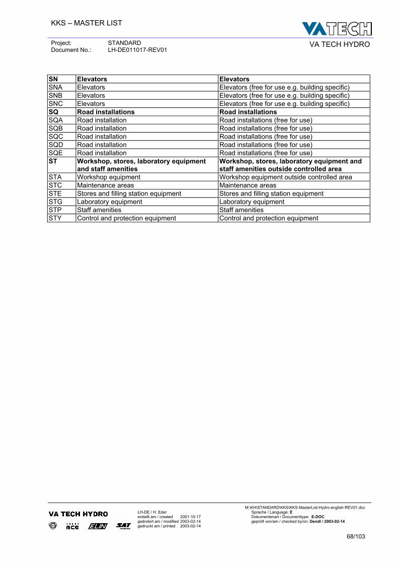
KKS – MASTER LIST
Project: STANDARD Document No.: LH-DE011017-REV01 VA TECH HYDRO
M:\KH\STANDARD\KKS\KKS-MasterList-Hydro-english-REV01.doc
LH-DE / H. Eder Sprache / Language: E erstellt am / created 2001-10-17 Dokumentenart / Documenttype: E-DOC geändert am / modified 2003-02-14 geprüft von/am / checked by/on: Dendl / 2003-02-14 gedruckt am / printed 2003-02-14
68/103
SN Elevators Elevators SNA Elevators Elevators (free for use e.g. building specific) SNB Elevators Elevators (free for use e.g. building specific) SNC Elevators Elevators (free for use e.g. building specific) SQ Road installations Road installations SQA Road installation Road installations (free for use) SQB Road installation Road installations (free for use) SQC Road installation Road installations (free for use) SQD Road installation Road installations (free for use) SQE Road installation Road installations (free for use) ST Workshop, stores, laboratory equipment
and staff amenities Workshop, stores, laboratory equipment and staff amenities outside controlled area
STA Workshop equipment Workshop equipment outside controlled area STC Maintenance areas Maintenance areas STE Stores and filling station equipment Stores and filling station equipment STG Laboratory equipment Laboratory equipment STP Staff amenities Staff amenities STY Control and protection equipment Control and protection equipment
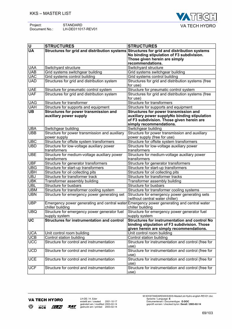
KKS – MASTER LIST
Project: STANDARD Document No.: LH-DE011017-REV01 VA TECH HYDRO
M:\KH\STANDARD\KKS\KKS-MasterList-Hydro-english-REV01.doc
LH-DE / H. Eder Sprache / Language: E erstellt am / created 2001-10-17 Dokumentenart / Documenttype: E-DOC geändert am / modified 2003-02-14 geprüft von/am / checked by/on: Dendl / 2003-02-14 gedruckt am / printed 2003-02-14
69/103
U STRUCTURES STRUCTURES UA Structures for grid and distribution systems Structures for grid and distribution systems
No binding stipulation of F3 subdivision. Those given herein are simply recommendations.
UAA Switchyard structure Switchyard structure UAB Grid systems switchgear building Grid systems switchgear building UAC Grid systems control building Grid systems control building UAD Structures for grid and distribution system Structures for grid and distribution systems (free
for use) UAE Structure for pneumatic control system Structure for pneumatic control system UAF Structures for grid and distribution system Structures for grid and distribution systems (free
for use) UAG Structure for transformer Structure for transformers UAH Structure for supports and equipment Structure for supports and equipment UB Structures for power transmission and
auxiliary power supply Structures for power transmission and auxiliary power supplyNo binding stipulation of F3 subdivision. Those given herein are simply recommendations.
UBA Switchgear building Switchgear building UBB Structure for power transmission and auxiliary
power supply Structure for power transmission and auxiliary power supply (free for use)
UBC Structure for offsite system transformers Structure for offsite system transformers UBD Structure for low-voltage auxiliary power
transformers Structure for low-voltage auxiliary power transformers
UBE Structure for medium-voltage auxiliary power transformers
Structure for medium-voltage auxiliary power transformers
UBF Structure for generator transformers Structure for generator transformers UBG Structure for start-up transformers Structure for start-up transformers UBH Structure for oil collecting pits Structure for oil collecting pits UBJ Structure for transformer track Structure for transformer tracks UBK Transformer assembly building Transformer assembly building UBL Structure for busbars Structure for busbars UBM Structure for transformer cooling system Structure for transformer cooling systems UBN Structure for emergency power generating set Structure for emergency power generating sets
(without central water chiller) UBP Emergency power generating and central water
chiller building Emergency power generating and central water chiller building
UBQ Structure for emergency power generator fuel supply system
Structure for emergency power generator fuel supply system
UC Structures for instrumentation and control Structures for instrumentation and control No binding stipulation of F3 subdivision. Those given herein are simply recommendations.
UCA Unit control room building Unit control room building UCB Control station building Control station building UCC Structure for control and instrumentation Structure for instrumentation and control (free for
use) UCD Structure for control and instrumentation Structure for instrumentation and control (free for
use) UCE Structure for control and instrumentation Structure for instrumentation and control (free for
use) UCF Structure for control and instrumentation Structure for instrumentation and control (free for
use)
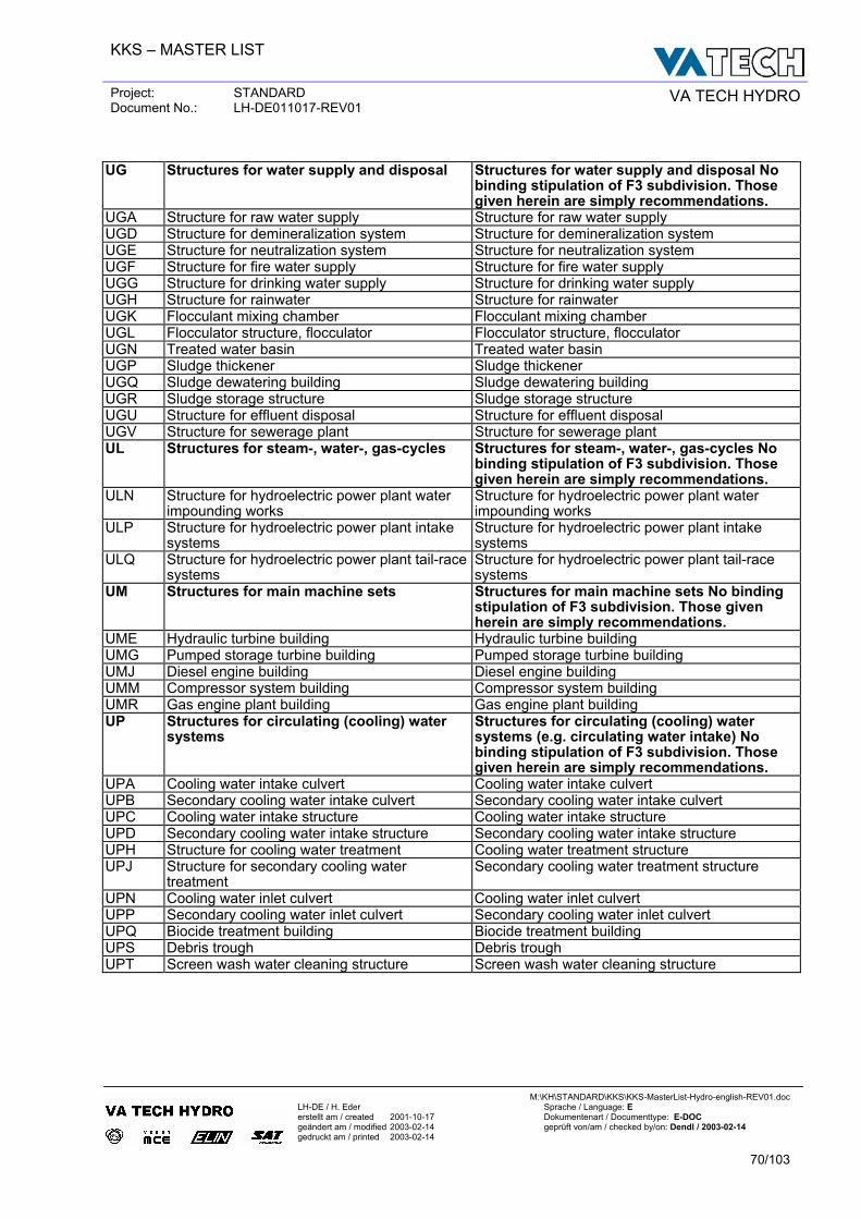
KKS – MASTER LIST
Project: STANDARD Document No.: LH-DE011017-REV01 VA TECH HYDRO
M:\KH\STANDARD\KKS\KKS-MasterList-Hydro-english-REV01.doc
LH-DE / H. Eder Sprache / Language: E erstellt am / created 2001-10-17 Dokumentenart / Documenttype: E-DOC geändert am / modified 2003-02-14 geprüft von/am / checked by/on: Dendl / 2003-02-14 gedruckt am / printed 2003-02-14
70/103
UG Structures for water supply and disposal Structures for water supply and disposal No
binding stipulation of F3 subdivision. Those given herein are simply recommendations.
UGA Structure for raw water supply Structure for raw water supply UGD Structure for demineralization system Structure for demineralization system UGE Structure for neutralization system Structure for neutralization system UGF Structure for fire water supply Structure for fire water supply UGG Structure for drinking water supply Structure for drinking water supply UGH Structure for rainwater Structure for rainwater UGK Flocculant mixing chamber Flocculant mixing chamber UGL Flocculator structure, flocculator Flocculator structure, flocculator UGN Treated water basin Treated water basin UGP Sludge thickener Sludge thickener UGQ Sludge dewatering building Sludge dewatering building UGR Sludge storage structure Sludge storage structure UGU Structure for effluent disposal Structure for effluent disposal UGV Structure for sewerage plant Structure for sewerage plant UL Structures for steam-, water-, gas-cycles Structures for steam-, water-, gas-cycles No
binding stipulation of F3 subdivision. Those given herein are simply recommendations.
ULN Structure for hydroelectric power plant water impounding works
Structure for hydroelectric power plant water impounding works
ULP Structure for hydroelectric power plant intake systems
Structure for hydroelectric power plant intake systems
ULQ Structure for hydroelectric power plant tail-race systems
Structure for hydroelectric power plant tail-race systems
UM Structures for main machine sets Structures for main machine sets No binding stipulation of F3 subdivision. Those given herein are simply recommendations.
UME Hydraulic turbine building Hydraulic turbine building UMG Pumped storage turbine building Pumped storage turbine building UMJ Diesel engine building Diesel engine building UMM Compressor system building Compressor system building UMR Gas engine plant building Gas engine plant building UP Structures for circulating (cooling) water
systems Structures for circulating (cooling) water systems (e.g. circulating water intake) No binding stipulation of F3 subdivision. Those given herein are simply recommendations.
UPA Cooling water intake culvert Cooling water intake culvert UPB Secondary cooling water intake culvert Secondary cooling water intake culvert UPC Cooling water intake structure Cooling water intake structure UPD Secondary cooling water intake structure Secondary cooling water intake structure UPH Structure for cooling water treatment Cooling water treatment structure UPJ Structure for secondary cooling water
treatment Secondary cooling water treatment structure
UPN Cooling water inlet culvert Cooling water inlet culvert UPP Secondary cooling water inlet culvert Secondary cooling water inlet culvert UPQ Biocide treatment building Biocide treatment building UPS Debris trough Debris trough UPT Screen wash water cleaning structure Screen wash water cleaning structure
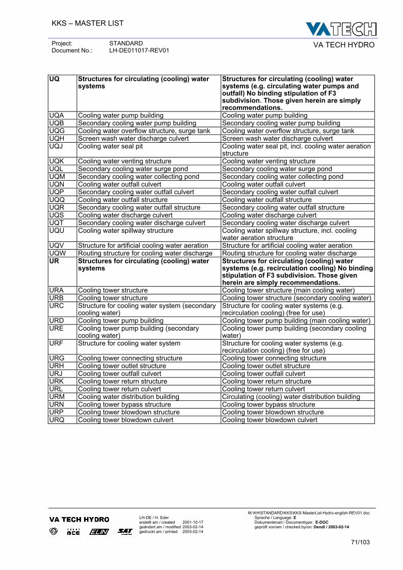
KKS – MASTER LIST
Project: STANDARD Document No.: LH-DE011017-REV01 VA TECH HYDRO
M:\KH\STANDARD\KKS\KKS-MasterList-Hydro-english-REV01.doc
LH-DE / H. Eder Sprache / Language: E erstellt am / created 2001-10-17 Dokumentenart / Documenttype: E-DOC geändert am / modified 2003-02-14 geprüft von/am / checked by/on: Dendl / 2003-02-14 gedruckt am / printed 2003-02-14
71/103
UQ Structures for circulating (cooling) water
systems Structures for circulating (cooling) water systems (e.g. circulating water pumps and outfall) No binding stipulation of F3 subdivision. Those given herein are simply recommendations.
UQA Cooling water pump building Cooling water pump building UQB Secondary cooling water pump building Secondary cooling water pump building UQG Cooling water overflow structure, surge tank Cooling water overflow structure, surge tank UQH Screen wash water discharge culvert Screen wash water discharge culvert UQJ Cooling water seal pit Cooling water seal pit, incl. cooling water aeration
structure UQK Cooling water venting structure Cooling water venting structure UQL Secondary cooling water surge pond Secondary cooling water surge pond UQM Secondary cooling water collecting pond Secondary cooling water collecting pond UQN Cooling water outfall culvert Cooling water outfall culvert UQP Secondary cooling water outfall culvert Secondary cooling water outfall culvert UQQ Cooling water outfall structure Cooling water outfall structure UQR Secondary cooling water outfall structure Secondary cooling water outfall structure UQS Cooling water discharge culvert Cooling water discharge culvert UQT Secondary cooling water discharge culvert Secondary cooling water discharge culvert UQU Cooling water spillway structure Cooling water spillway structure, incl. cooling
water aeration structure UQV Structure for artificial cooling water aeration Structure for artificial cooling water aeration UQW Routing structure for cooling water discharge Routing structure for cooling water discharge UR Structures for circulating (cooling) water
systems Structures for circulating (cooling) water systems (e.g. recirculation cooling) No bindingstipulation of F3 subdivision. Those given herein are simply recommendations.
URA Cooling tower structure Cooling tower structure (main cooling water) URB Cooling tower structure Cooling tower structure (secondary cooling water)URC Structure for cooling water system (secondary
cooling water) Structure for cooling water systems (e.g. recirculation cooling) (free for use)
URD Cooling tower pump building Cooling tower pump building (main cooling water) URE Cooling tower pump building (secondary
cooling water) Cooling tower pump building (secondary cooling water)
URF Structure for cooling water system Structure for cooling water systems (e.g. recirculation cooling) (free for use)
URG Cooling tower connecting structure Cooling tower connecting structure URH Cooling tower outlet structure Cooling tower outlet structure URJ Cooling tower outfall culvert Cooling tower outfall culvert URK Cooling tower return structure Cooling tower return structure URL Cooling tower return culvert Cooling tower return culvert URM Cooling water distribution building Circulating (cooling) water distribution building URN Cooling tower bypass structure Cooling tower bypass structure URP Cooling tower blowdown structure Cooling tower blowdown structure URQ Cooling tower blowdown culvert Cooling tower blowdown culvert
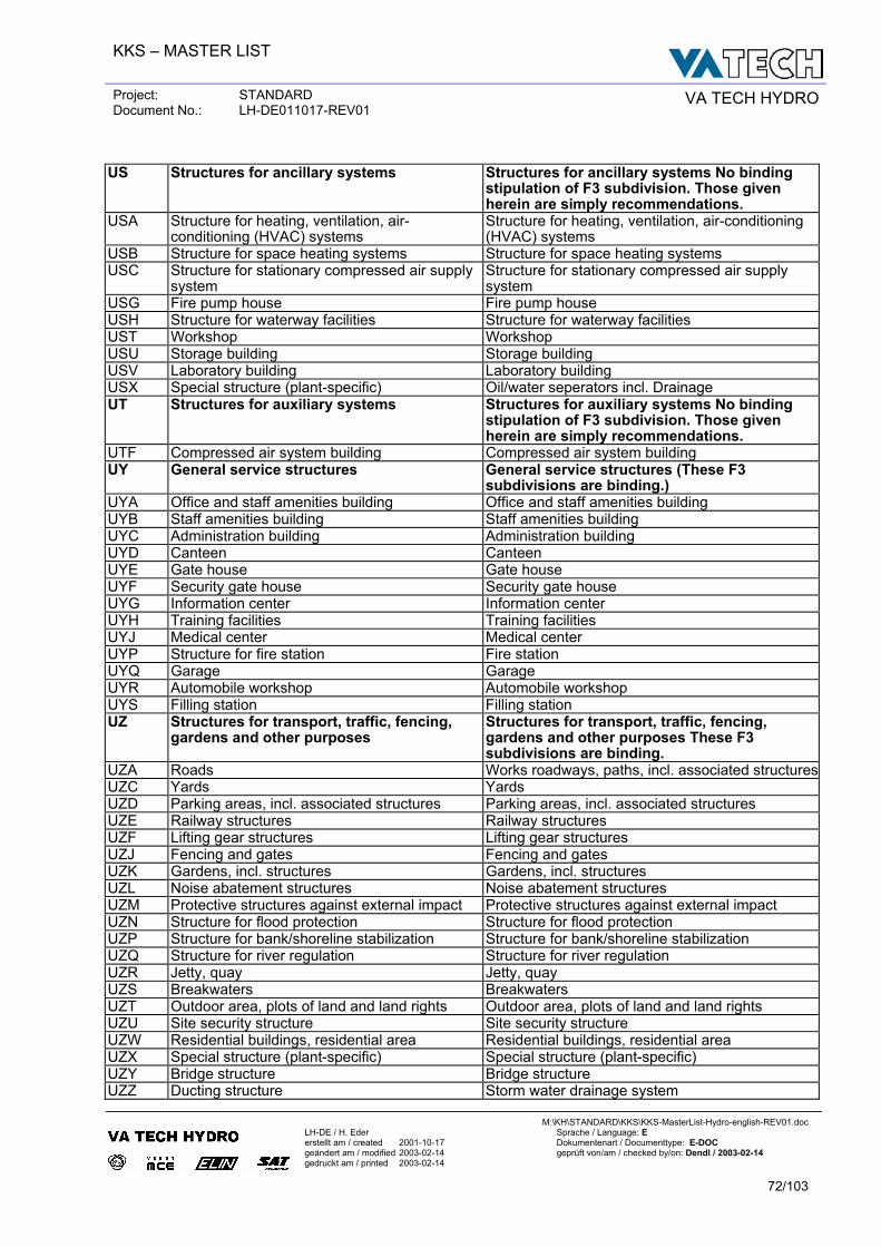
KKS – MASTER LIST
Project: STANDARD Document No.: LH-DE011017-REV01 VA TECH HYDRO
M:\KH\STANDARD\KKS\KKS-MasterList-Hydro-english-REV01.doc
LH-DE / H. Eder Sprache / Language: E erstellt am / created 2001-10-17 Dokumentenart / Documenttype: E-DOC geändert am / modified 2003-02-14 geprüft von/am / checked by/on: Dendl / 2003-02-14 gedruckt am / printed 2003-02-14
72/103
US Structures for ancillary systems Structures for ancillary systems No binding
stipulation of F3 subdivision. Those given herein are simply recommendations.
USA Structure for heating, ventilation, air-conditioning (HVAC) systems
Structure for heating, ventilation, air-conditioning (HVAC) systems
USB Structure for space heating systems Structure for space heating systems USC Structure for stationary compressed air supply
system Structure for stationary compressed air supply system
USG Fire pump house Fire pump house USH Structure for waterway facilities Structure for waterway facilities UST Workshop Workshop USU Storage building Storage building USV Laboratory building Laboratory building USX Special structure (plant-specific) Oil/water seperators incl. Drainage UT Structures for auxiliary systems Structures for auxiliary systems No binding
stipulation of F3 subdivision. Those given herein are simply recommendations.
UTF Compressed air system building Compressed air system building UY General service structures General service structures (These F3
subdivisions are binding.) UYA Office and staff amenities building Office and staff amenities building UYB Staff amenities building Staff amenities building UYC Administration building Administration building UYD Canteen Canteen UYE Gate house Gate house UYF Security gate house Security gate house UYG Information center Information center UYH Training facilities Training facilities UYJ Medical center Medical center UYP Structure for fire station Fire station UYQ Garage Garage UYR Automobile workshop Automobile workshop UYS Filling station Filling station UZ Structures for transport, traffic, fencing,
gardens and other purposes Structures for transport, traffic, fencing, gardens and other purposes These F3 subdivisions are binding.
UZA Roads Works roadways, paths, incl. associated structuresUZC Yards Yards UZD Parking areas, incl. associated structures Parking areas, incl. associated structures UZE Railway structures Railway structures UZF Lifting gear structures Lifting gear structures UZJ Fencing and gates Fencing and gates UZK Gardens, incl. structures Gardens, incl. structures UZL Noise abatement structures Noise abatement structures UZM Protective structures against external impact Protective structures against external impact UZN Structure for flood protection Structure for flood protection UZP Structure for bank/shoreline stabilization Structure for bank/shoreline stabilization UZQ Structure for river regulation Structure for river regulation UZR Jetty, quay Jetty, quay UZS Breakwaters Breakwaters UZT Outdoor area, plots of land and land rights Outdoor area, plots of land and land rights UZU Site security structure Site security structure UZW Residential buildings, residential area Residential buildings, residential area UZX Special structure (plant-specific) Special structure (plant-specific) UZY Bridge structure Bridge structure UZZ Ducting structure Storm water drainage system
KKS – MASTER LIST
Project: STANDARD Document No.: LH-DE011017-REV01 VA TECH HYDRO
M:\KH\STANDARD\KKS\KKS-MasterList-Hydro-english-REV01.doc
LH-DE / H. Eder Sprache / Language: E erstellt am / created 2001-10-17 Dokumentenart / Documenttype: E-DOC geändert am / modified 2003-02-14 geprüft von/am / checked by/on: Dendl / 2003-02-14 gedruckt am / printed 2003-02-14
73/103
W RENEWABLE ENERGY PLANTS RENEWABLE ENERGY PLANTS WA Solar systems (free for use for coordinates) Solar systems (free for use for coordinates)
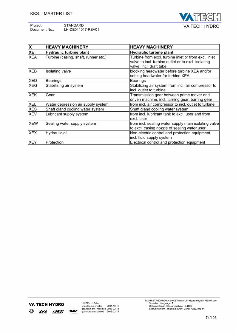
KKS – MASTER LIST
Project: STANDARD Document No.: LH-DE011017-REV01 VA TECH HYDRO
M:\KH\STANDARD\KKS\KKS-MasterList-Hydro-english-REV01.doc
LH-DE / H. Eder Sprache / Language: E erstellt am / created 2001-10-17 Dokumentenart / Documenttype: E-DOC geändert am / modified 2003-02-14 geprüft von/am / checked by/on: Dendl / 2003-02-14 gedruckt am / printed 2003-02-14
74/103
X HEAVY MACHINERY HEAVY MACHINERY XE Hydraulic turbine plant Hydraulic turbine plant XEA Turbine (casing, shaft, runner etc.) Turbine from excl. turbine inlet or from excl. inlet
valve to incl. turbine outlet or to excl. isolating valve, incl. draft tube
XEB Isolating valve blocking headwater before turbine XEA and/or setting headwater for turbine XEA
XED Bearings Bearings XEG Stabilizing air system Stabilizing air system from incl. air compressor to
incl. outlet to turbine XEK Gear Transmission gear between prime mover and
driven machine, incl. turning gear, barring gear XEL Water depression air supply system from incl. air compressor to incl. outlet to turbine XES Shaft gland cooling water system Shaft gland cooling water system XEV Lubricant supply system from incl. lubricant tank to excl. user and from
excl. user XEW Sealing water supply system from incl. sealing water supply main isolating valve
to excl. casing nozzle of sealing water user XEX Hydraulic oil Non-electric control and protection equipment,
incl. fluid supply system XEY Protection Electrical control and protection equipment
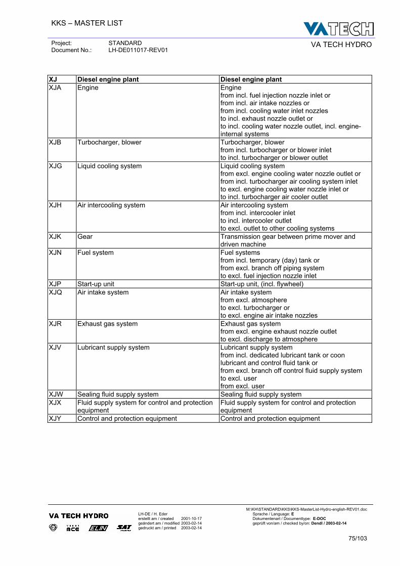
KKS – MASTER LIST
Project: STANDARD Document No.: LH-DE011017-REV01 VA TECH HYDRO
M:\KH\STANDARD\KKS\KKS-MasterList-Hydro-english-REV01.doc
LH-DE / H. Eder Sprache / Language: E erstellt am / created 2001-10-17 Dokumentenart / Documenttype: E-DOC geändert am / modified 2003-02-14 geprüft von/am / checked by/on: Dendl / 2003-02-14 gedruckt am / printed 2003-02-14
75/103
XJ Diesel engine plant Diesel engine plant XJA Engine Engine
from incl. fuel injection nozzle inlet or from incl. air intake nozzles or from incl. cooling water inlet nozzles to incl. exhaust nozzle outlet or to incl. cooling water nozzle outlet, incl. engine- internal systems
XJB Turbocharger, blower Turbocharger, blower from incl. turbocharger or blower inlet to incl. turbocharger or blower outlet
XJG Liquid cooling system Liquid cooling system from excl. engine cooling water nozzle outlet or from incl. turbocharger air cooling system inlet to excl. engine cooling water nozzle inlet or to incl. turbocharger air cooler outlet
XJH Air intercooling system Air intercooling system from incl. intercooler inlet to incl. intercooler outlet to excl. outlet to other cooling systems
XJK Gear Transmission gear between prime mover and driven machine
XJN Fuel system Fuel systems from incl. temporary (day) tank or from excl. branch off piping system to excl. fuel injection nozzle inlet
XJP Start-up unit Start-up unit, (incl. flywheel) XJQ Air intake system Air intake system
from excl. atmosphere to excl. turbocharger or to excl. engine air intake nozzles
XJR Exhaust gas system Exhaust gas system from excl. engine exhaust nozzle outlet to excl. discharge to atmosphere
XJV Lubricant supply system Lubricant supply system from incl. dedicated lubricant tank or coon lubricant and control fluid tank or from excl. branch off control fluid supply system to excl. user from excl. user
XJW Sealing fluid supply system Sealing fluid supply system XJX Fluid supply system for control and protection
equipment Fluid supply system for control and protection equipment
XJY Control and protection equipment Control and protection equipment
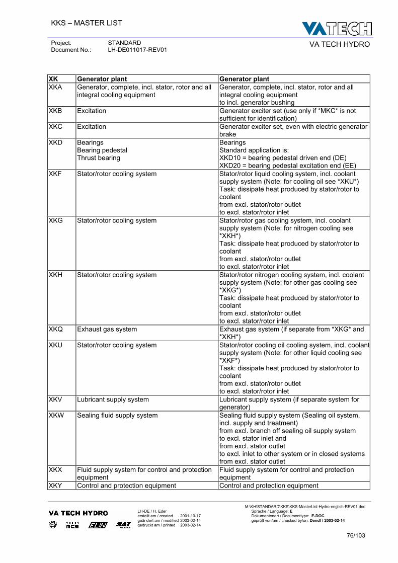
KKS – MASTER LIST
Project: STANDARD Document No.: LH-DE011017-REV01 VA TECH HYDRO
M:\KH\STANDARD\KKS\KKS-MasterList-Hydro-english-REV01.doc
LH-DE / H. Eder Sprache / Language: E erstellt am / created 2001-10-17 Dokumentenart / Documenttype: E-DOC geändert am / modified 2003-02-14 geprüft von/am / checked by/on: Dendl / 2003-02-14 gedruckt am / printed 2003-02-14
76/103
XK Generator plant Generator plant XKA Generator, complete, incl. stator, rotor and all
integral cooling equipment Generator, complete, incl. stator, rotor and all integral cooling equipment to incl. generator bushing
XKB Excitation Generator exciter set (use only if *MKC* is not sufficient for identification)
XKC Excitation Generator exciter set, even with electric generator brake
XKD Bearings Bearing pedestal Thrust bearing
Bearings Standard application is: XKD10 = bearing pedestal driven end (DE) XKD20 = bearing pedestal excitation end (EE)
XKF Stator/rotor cooling system Stator/rotor liquid cooling system, incl. coolant supply system (Note: for cooling oil see *XKU*) Task: dissipate heat produced by stator/rotor to coolant from excl. stator/rotor outlet to excl. stator/rotor inlet
XKG Stator/rotor cooling system Stator/rotor gas cooling system, incl. coolant supply system (Note: for nitrogen cooling see *XKH*) Task: dissipate heat produced by stator/rotor to coolant from excl. stator/rotor outlet to excl. stator/rotor inlet
XKH Stator/rotor cooling system Stator/rotor nitrogen cooling system, incl. coolant supply system (Note: for other gas cooling see *XKG*) Task: dissipate heat produced by stator/rotor to coolant from excl. stator/rotor outlet to excl. stator/rotor inlet
XKQ Exhaust gas system Exhaust gas system (if separate from *XKG* and *XKH*)
XKU Stator/rotor cooling system Stator/rotor cooling oil cooling system, incl. coolant supply system (Note: for other liquid cooling see *XKF*) Task: dissipate heat produced by stator/rotor to coolant from excl. stator/rotor outlet to excl. stator/rotor inlet
XKV Lubricant supply system Lubricant supply system (if separate system for generator)
XKW Sealing fluid supply system Sealing fluid supply system (Sealing oil system, incl. supply and treatment) from excl. branch off sealing oil supply system to excl. stator inlet and from excl. stator outlet to excl. inlet to other system or in closed systems from excl. stator outlet
XKX Fluid supply system for control and protection equipment
Fluid supply system for control and protection equipment
XKY Control and protection equipment Control and protection equipment
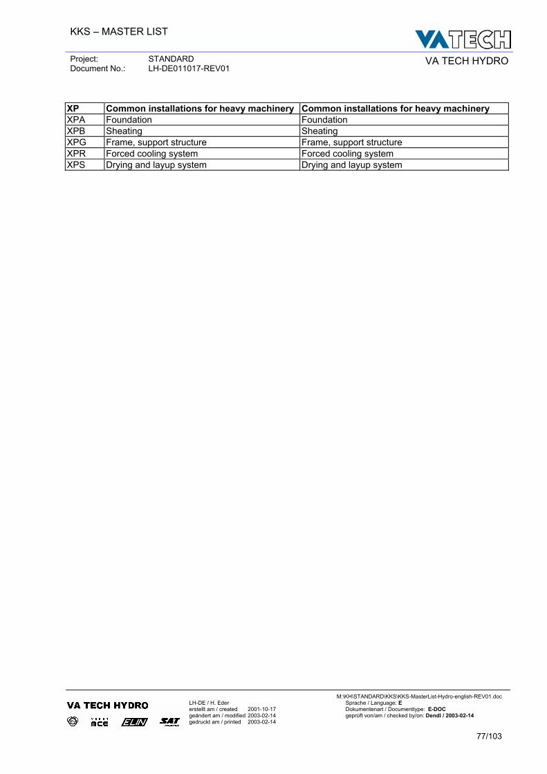
KKS – MASTER LIST
Project: STANDARD Document No.: LH-DE011017-REV01 VA TECH HYDRO
M:\KH\STANDARD\KKS\KKS-MasterList-Hydro-english-REV01.doc
LH-DE / H. Eder Sprache / Language: E erstellt am / created 2001-10-17 Dokumentenart / Documenttype: E-DOC geändert am / modified 2003-02-14 geprüft von/am / checked by/on: Dendl / 2003-02-14 gedruckt am / printed 2003-02-14
77/103
XP Common installations for heavy machinery Common installations for heavy machinery XPA Foundation Foundation XPB Sheating Sheating XPG Frame, support structure Frame, support structure XPR Forced cooling system Forced cooling system XPS Drying and layup system Drying and layup system
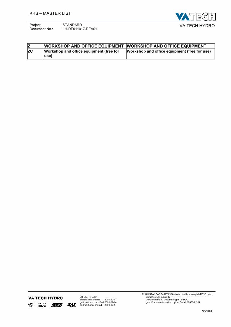
KKS – MASTER LIST
Project: STANDARD Document No.: LH-DE011017-REV01 VA TECH HYDRO
M:\KH\STANDARD\KKS\KKS-MasterList-Hydro-english-REV01.doc
LH-DE / H. Eder Sprache / Language: E erstellt am / created 2001-10-17 Dokumentenart / Documenttype: E-DOC geändert am / modified 2003-02-14 geprüft von/am / checked by/on: Dendl / 2003-02-14 gedruckt am / printed 2003-02-14
78/103
Z WORKSHOP AND OFFICE EQUIPMENT WORKSHOP AND OFFICE EQUIPMENT ZC Workshop and office equipment (free for
use) Workshop and office equipment (free for use)
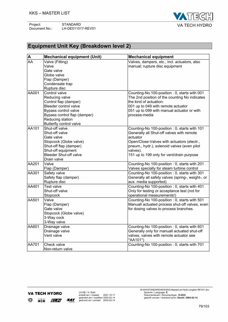
KKS – MASTER LIST
Project: STANDARD Document No.: LH-DE011017-REV01 VA TECH HYDRO
M:\KH\STANDARD\KKS\KKS-MasterList-Hydro-english-REV01.doc
LH-DE / H. Eder Sprache / Language: E erstellt am / created 2001-10-17 Dokumentenart / Documenttype: E-DOC geändert am / modified 2003-02-14 geprüft von/am / checked by/on: Dendl / 2003-02-14 gedruckt am / printed 2003-02-14
79/103
Equipment Unit Key (Breakdown level 2)
A Mechanical equipment (Unit) Mechanical equipment AA Valve (Fitting)
Valve Gate valve Globe valve Flap (Damper) Condensate trap Rupture disc
Valves, dampers, etc., incl. actuators, also manual; rupture disc equipment
AA001 Control valve Reducing valve Control flap (damper) Bleeder control valve Bypass control valve Bypass control flap (damper) Reducing station Butterfly control valve
Counting-No 100-position : 0, starts with 001 The 2nd position of the counting No indicates the kind of actuation: 001 up to 049 with remote actuator 051 up to 099 with manual actuator or with process-media
AA101 Shut-off valve Shut-off valve Gate valve Stopcock (Globe valve) Shut-off flap (damper) Shut-off equipment Bleeder Shut-off valve Drain valve
Counting-No 100-position : 0, starts with 101 Generally all Shut-off valves with remote actuator Open/Close-Valves with actuators (electr., pneum., hydr.), solenoid valves (even pilot valves). 151 up to 199 only for vent/drain purpose
AA201 Valve Flap (Damper)
Counting-No 100-position : 0, starts with 201 Valves specially for steam turbine control
AA301 Safety valve Safety flap (damper) Rupture disc
Counting-No 100-position : 0, starts with 301 Generally all safety valves (spring-, weight-, or aux. media supported)
AA401 Test valve Shut-off valve Stopcock
Counting-No 100-position : 0, starts with 401 Only for testing or acceptance test (not for operational measurements!)
AA501 Valve Flap (Damper) Gate valve Stopcock (Globe valve) 3-Way cock 3-Way valve
Counting-No 100-position : 0, starts with 501 Manuall actuated process shut-off valves, even for dosing valves to process branches.
AA601 Drainage valve Drainage valve Vent valve
Counting-No 100-position : 0, starts with 601 Generally only for manuall actuated shut-off valves, valves with remote actuator see *AA101*)
AA701 Check valve Non-return valve
Counting-No 100-position : 0, starts with 701
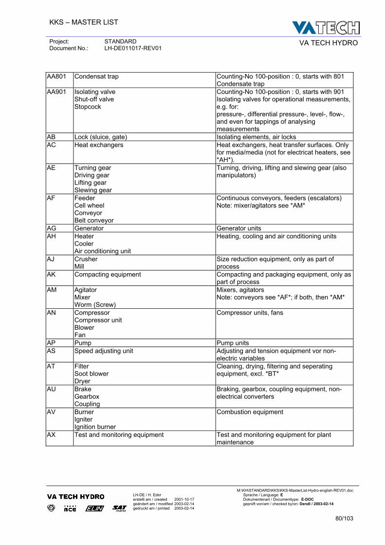
KKS – MASTER LIST
Project: STANDARD Document No.: LH-DE011017-REV01 VA TECH HYDRO
M:\KH\STANDARD\KKS\KKS-MasterList-Hydro-english-REV01.doc
LH-DE / H. Eder Sprache / Language: E erstellt am / created 2001-10-17 Dokumentenart / Documenttype: E-DOC geändert am / modified 2003-02-14 geprüft von/am / checked by/on: Dendl / 2003-02-14 gedruckt am / printed 2003-02-14
80/103
AA801 Condensat trap Counting-No 100-position : 0, starts with 801
Condensate trap AA901 Isolating valve
Shut-off valve Stopcock
Counting-No 100-position : 0, starts with 901 Isolating valves for operational measurements, e.g. for: pressure-, differential pressure-, level-, flow-, and even for tappings of analysing measurements
AB Lock (sluice, gate) Isolating elements, air locks AC Heat exchangers Heat exchangers, heat transfer surfaces. Only
for media/media (not for electricat heaters, see *AH*).
AE Turning gear Driving gear Lifting gear Slewing gear
Turning, driving, lifting and slewing gear (also manipulators)
AF Feeder Cell wheel Conveyor Belt conveyor
Continuous conveyors, feeders (escalators) Note: mixer/agitators see *AM*
AG Generator Generator units AH Heater
Cooler Air conditioning unit
Heating, cooling and air conditioning units
AJ Crusher Mill
Size reduction equipment, only as part of process
AK Compacting equipment Compacting and packaging equipment, only as part of process
AM Agitator Mixer Worm (Screw)
Mixers, agitators Note: conveyors see *AF*; if both, then *AM*
AN Compressor Compressor unit Blower Fan
Compressor units, fans
AP Pump Pump units AS Speed adjusting unit Adjusting and tension equipment vor non-
electric variables AT Filter
Soot blower Dryer
Cleaning, drying, filtering and seperating equipment, excl. *BT*
AU Brake Gearbox Coupling
Braking, gearbox, coupling equipment, non-electrical converters
AV Burner Igniter Ignition burner
Combustion equipment
AX Test and monitoring equipment Test and monitoring equipment for plant maintenance
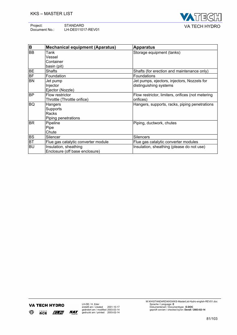
KKS – MASTER LIST
Project: STANDARD Document No.: LH-DE011017-REV01 VA TECH HYDRO
M:\KH\STANDARD\KKS\KKS-MasterList-Hydro-english-REV01.doc
LH-DE / H. Eder Sprache / Language: E erstellt am / created 2001-10-17 Dokumentenart / Documenttype: E-DOC geändert am / modified 2003-02-14 geprüft von/am / checked by/on: Dendl / 2003-02-14 gedruckt am / printed 2003-02-14
81/103
B Mechanical equipment (Aparatus) Apparatus BB Tank
Vessel Container basin (pit)
Storage equipment (tanks)
BE Shafts Shafts (for erection and maintenance only) BF Foundation Foundations BN Jet pump
Injector Ejector (Nozzle)
Jet pumps, ejectors, injectors, Nozzels for distinguishing systems
BP Flow restrictor Throttle (Throttle orifice)
Flow restrictor, limiters, orifices (not metering orifices)
BQ Hangers Supports Racks Piping penetrations
Hangers, supports, racks, piping penetrations
BR Pipeline Pipe Chute
Piping, ductwork, chutes
BS Silencer Silencers BT Flue gas catalytic converter module Flue gas catalytic converter modules BU Insulation, sheathing
Enclosure (off base enclosure) Insulation, sheathing (please do not use)
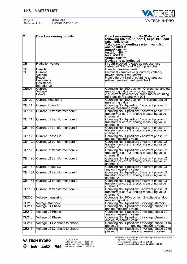
KKS – MASTER LIST
Project: STANDARD Document No.: LH-DE011017-REV01 VA TECH HYDRO
M:\KH\STANDARD\KKS\KKS-MasterList-Hydro-english-REV01.doc
LH-DE / H. Eder Sprache / Language: E erstellt am / created 2001-10-17 Dokumentenart / Documenttype: E-DOC geändert am / modified 2003-02-14 geprüft von/am / checked by/on: Dendl / 2003-02-14 gedruckt am / printed 2003-02-14
82/103
C Direct measuring circuits Direct measuring circuits (Data char. A2
following DIN 19227, part 1, Sept. 1973 edit., tab.1, init. letter) Take care of counting system, valid is: analog =001 ff binary =301 ff testing =401 ff local =501 ff virtuel =901 ff Deviations as indicated
CB Radiation values in VGB blocked (please do not use, use instead of *CR* and *CQ* if possible)
CD Density Density measurements CE Current
Voltage Power Frequency Resistance Impedance
Electrical variables (e.g. current, voltage, power, electr. Frequency) Note different kind of counting to process relevant measurment variables !
CE001 Current Voltage Power
Counting No. 100-position: 0=electrical analog measuring value, only for aggregats e.g. current governor oil-pump motor counting no.1-position: starts with 001
CE100 Current Measuring Counting No. 100-position: 1=current analog measuring value
CE111 Current Phase L1 Counting No. 1-position: 1=current phase L1 analog measuring value
CE111A Current L1 transformer core 1 Counting No. 1-position: 1=current phase L1 transformer core 1 analog measuring value channel A
CE111B Current L1 transformer core 2 Counting No. 1-position: 1=current phase L1 transformer core 2 analog measuring value channel B
CE111C Current L1 transformer core 3 Counting No. 1-position: 1=current phase L1 transformer core 3 analog measuring value channel C
CE112 Current Phase L2 Counting No. 1-position: 2=current phase L2 analog measuring value
CE112A Current L2 transformer core 1 Counting No. 1-position: 2=current phase L2 transformer core 1 analog measuring value channel A
CE112B Current L2 transformer core 2 Counting No. 1-position: 2=current phase L2 transformer core 2 analog measuring value channel B
CE112C Current L2 transformer core 3 Counting No. 1-position: 2=current phase L2 transformer core 3 analog measuring value channel C
CE113 Current Phase L3 Counting No. 1-position: 3=current phase L3 analog measuring value
CE113A Current L3 transformer core 1 Counting No. 1-position: 3=current phase L3 transformer core 1 analog measuring value channel A
CE113B Current L3 transformer core 2 Counting No. 1-position: 3=current phase L3 transformer core 2 analog measuring value channel B
CE113C Current L3 transformer core 3 Counting No. 1-position: 3=current phase L3 transformer core 3 analog measuring value channel C
CE200 Voltage measuring Counting No. 100-position: 2=voltage analog measuring value
CE210 Voltage star point Counting No. 1-position: 0=voltage starpoint CE211 Voltage L1 Phase Counting No. 1-position: 1=voltage phase L1
analog measuring value CE212 Voltage L2 Phase Counting No. 1-position: 2=voltage phase L2
analog measuring value CE213 Voltage L3 Phase Counting No. 1-position: 3=voltage phase L3
analog measuring value CE214 Voltage L1-L2 phase to phase Counting No. 1-position: 4=voltage phase L1 to
phase L2 analog measuring value CE215 Voltage L2-L3 phase to phase Counting No. 1-position: 5=voltage phase L2 to
phase L3 analog measuring value
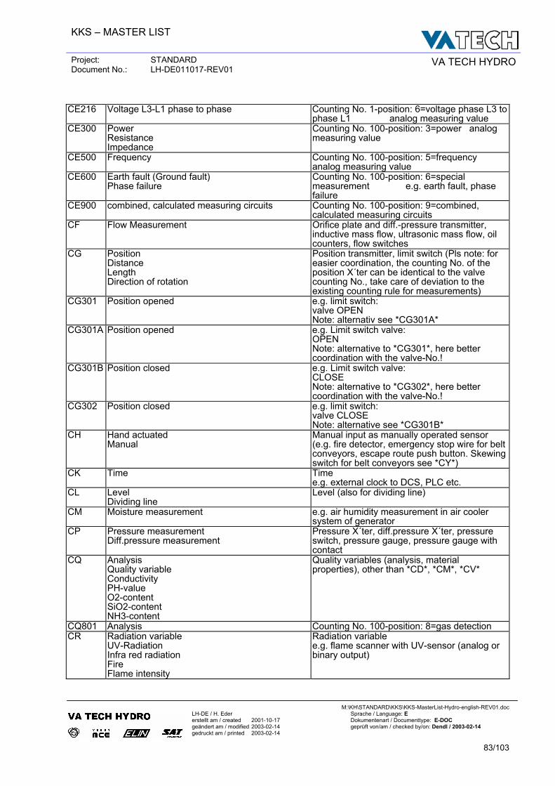
KKS – MASTER LIST
Project: STANDARD Document No.: LH-DE011017-REV01 VA TECH HYDRO
M:\KH\STANDARD\KKS\KKS-MasterList-Hydro-english-REV01.doc
LH-DE / H. Eder Sprache / Language: E erstellt am / created 2001-10-17 Dokumentenart / Documenttype: E-DOC geändert am / modified 2003-02-14 geprüft von/am / checked by/on: Dendl / 2003-02-14 gedruckt am / printed 2003-02-14
83/103
CE216 Voltage L3-L1 phase to phase Counting No. 1-position: 6=voltage phase L3 to
phase L1 analog measuring value CE300 Power
Resistance Impedance
Counting No. 100-position: 3=power analog measuring value
CE500 Frequency Counting No. 100-position: 5=frequency analog measuring value
CE600 Earth fault (Ground fault) Phase failure
Counting No. 100-position: 6=special measurement e.g. earth fault, phase failure
CE900 combined, calculated measuring circuits Counting No. 100-position: 9=combined, calculated measuring circuits
CF Flow Measurement Orifice plate and diff.-pressure transmitter, inductive mass flow, ultrasonic mass flow, oil counters, flow switches
CG Position Distance Length Direction of rotation
Position transmitter, limit switch (Pls note: for easier coordination, the counting No. of the position X´ter can be identical to the valve counting No., take care of deviation to the existing counting rule for measurements)
CG301 Position opened e.g. limit switch: valve OPEN Note: alternativ see *CG301A*
CG301A Position opened e.g. Limit switch valve: OPEN Note: alternative to *CG301*, here better coordination with the valve-No.!
CG301B Position closed e.g. Limit switch valve: CLOSE Note: alternative to *CG302*, here better coordination with the valve-No.!
CG302 Position closed e.g. limit switch: valve CLOSE Note: alternative see *CG301B*
CH Hand actuated Manual
Manual input as manually operated sensor (e.g. fire detector, emergency stop wire for belt conveyors, escape route push button. Skewing switch for belt conveyors see *CY*)
CK Time Time e.g. external clock to DCS, PLC etc.
CL Level Dividing line
Level (also for dividing line)
CM Moisture measurement e.g. air humidity measurement in air cooler system of generator
CP Pressure measurement Diff.pressure measurement
Pressure X´ter, diff.pressure X´ter, pressure switch, pressure gauge, pressure gauge with contact
CQ Analysis Quality variable Conductivity PH-value O2-content SiO2-content NH3-content
Quality variables (analysis, material properties), other than *CD*, *CM*, *CV*
CQ801 Analysis Counting No. 100-position: 8=gas detection CR Radiation variable
UV-Radiation Infra red radiation Fire Flame intensity
Radiation variable e.g. flame scanner with UV-sensor (analog or binary output)
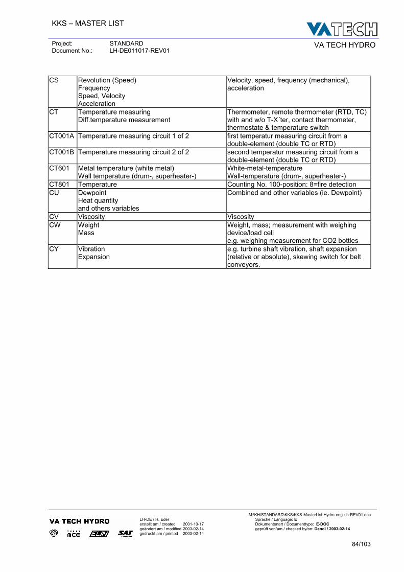
KKS – MASTER LIST
Project: STANDARD Document No.: LH-DE011017-REV01 VA TECH HYDRO
M:\KH\STANDARD\KKS\KKS-MasterList-Hydro-english-REV01.doc
LH-DE / H. Eder Sprache / Language: E erstellt am / created 2001-10-17 Dokumentenart / Documenttype: E-DOC geändert am / modified 2003-02-14 geprüft von/am / checked by/on: Dendl / 2003-02-14 gedruckt am / printed 2003-02-14
84/103
CS Revolution (Speed)
Frequency Speed, Velocity Acceleration
Velocity, speed, frequency (mechanical), acceleration
CT Temperature measuring Diff.temperature measurement
Thermometer, remote thermometer (RTD, TC) with and w/o T-X´ter, contact thermometer, thermostate & temperature switch
CT001A Temperature measuring circuit 1 of 2 first temperatur measuring circuit from a double-element (double TC or RTD)
CT001B Temperature measuring circuit 2 of 2 second temperatur measuring circuit from a double-element (double TC or RTD)
CT601 Metal temperature (white metal) Wall temperature (drum-, superheater-)
White-metal-temperature Wall-temperature (drum-, superheater-)
CT801 Temperature Counting No. 100-position: 8=fire detection CU Dewpoint
Heat quantity and others variables
Combined and other variables (ie. Dewpoint)
CV Viscosity Viscosity CW Weight
Mass Weight, mass; measurement with weighing device/load cell e.g. weighing measurement for CO2 bottles
CY Vibration Expansion
e.g. turbine shaft vibration, shaft expansion (relative or absolute), skewing switch for belt conveyors.
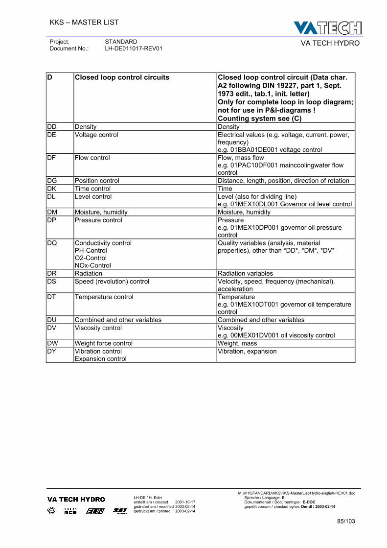
KKS – MASTER LIST
Project: STANDARD Document No.: LH-DE011017-REV01 VA TECH HYDRO
M:\KH\STANDARD\KKS\KKS-MasterList-Hydro-english-REV01.doc
LH-DE / H. Eder Sprache / Language: E erstellt am / created 2001-10-17 Dokumentenart / Documenttype: E-DOC geändert am / modified 2003-02-14 geprüft von/am / checked by/on: Dendl / 2003-02-14 gedruckt am / printed 2003-02-14
85/103
D Closed loop control circuits Closed loop control circuit (Data char.
A2 following DIN 19227, part 1, Sept. 1973 edit., tab.1, init. letter) Only for complete loop in loop diagram; not for use in P&I-diagrams ! Counting system see (C)
DD Density Density DE Voltage control Electrical values (e.g. voltage, current, power,
frequency) e.g. 01BBA01DE001 voltage control
DF Flow control Flow, mass flow e.g. 01PAC10DF001 maincoolingwater flow control
DG Position control Distance, length, position, direction of rotation DK Time control Time DL Level control Level (also for dividing line)
e.g. 01MEX10DL001 Governor oil level controlDM Moisture, humidity Moisture, humidity DP Pressure control Pressure
e.g. 01MEX10DP001 governor oil pressure control
DQ Conductivity control PH-Control O2-Control NOx-Control
Quality variables (analysis, material properties), other than *DD*, *DM*, *DV*
DR Radiation Radiation variables DS Speed (revolution) control Velocity, speed, frequency (mechanical),
acceleration DT Temperature control Temperature
e.g. 01MEX10DT001 governor oil temperature control
DU Combined and other variables Combined and other variables DV Viscosity control Viscosity
e.g. 00MEX01DV001 oil viscosity control DW Weight force control Weight, mass DY Vibration control
Expansion control Vibration, expansion
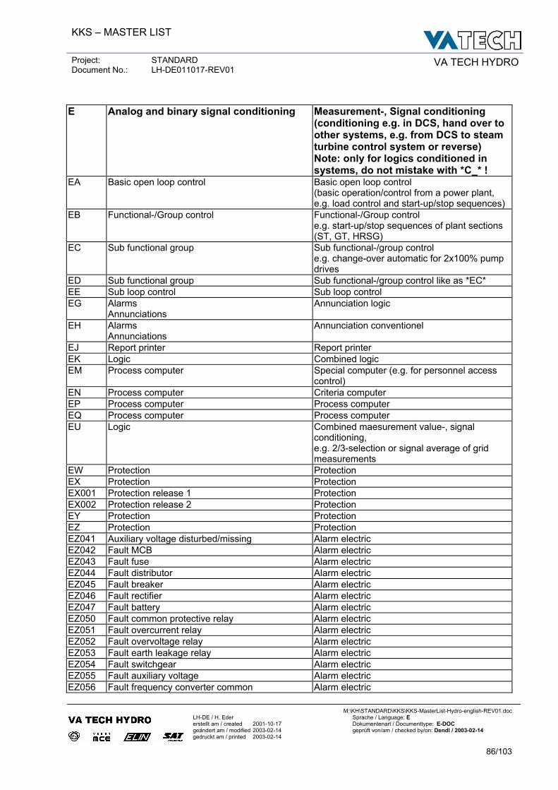
KKS – MASTER LIST
Project: STANDARD Document No.: LH-DE011017-REV01 VA TECH HYDRO
M:\KH\STANDARD\KKS\KKS-MasterList-Hydro-english-REV01.doc
LH-DE / H. Eder Sprache / Language: E erstellt am / created 2001-10-17 Dokumentenart / Documenttype: E-DOC geändert am / modified 2003-02-14 geprüft von/am / checked by/on: Dendl / 2003-02-14 gedruckt am / printed 2003-02-14
86/103
E Analog and binary signal conditioning Measurement-, Signal conditioning
(conditioning e.g. in DCS, hand over to other systems, e.g. from DCS to steam turbine control system or reverse) Note: only for logics conditioned in systems, do not mistake with *C_* !
EA Basic open loop control Basic open loop control (basic operation/control from a power plant, e.g. load control and start-up/stop sequences)
EB Functional-/Group control Functional-/Group control e.g. start-up/stop sequences of plant sections (ST, GT, HRSG)
EC Sub functional group Sub functional-/group control e.g. change-over automatic for 2x100% pump drives
ED Sub functional group Sub functional-/group control like as *EC* EE Sub loop control Sub loop control EG Alarms
Annunciations Annunciation logic
EH Alarms Annunciations
Annunciation conventionel
EJ Report printer Report printer EK Logic Combined logic EM Process computer Special computer (e.g. for personnel access
control) EN Process computer Criteria computer EP Process computer Process computer EQ Process computer Process computer EU Logic Combined maesurement value-, signal
conditioning, e.g. 2/3-selection or signal average of grid measurements
EW Protection Protection EX Protection Protection EX001 Protection release 1 Protection EX002 Protection release 2 Protection EY Protection Protection EZ Protection Protection EZ041 Auxiliary voltage disturbed/missing Alarm electric EZ042 Fault MCB Alarm electric EZ043 Fault fuse Alarm electric EZ044 Fault distributor Alarm electric EZ045 Fault breaker Alarm electric EZ046 Fault rectifier Alarm electric EZ047 Fault battery Alarm electric EZ050 Fault common protective relay Alarm electric EZ051 Fault overcurrent relay Alarm electric EZ052 Fault overvoltage relay Alarm electric EZ053 Fault earth leakage relay Alarm electric EZ054 Fault switchgear Alarm electric EZ055 Fault auxiliary voltage Alarm electric EZ056 Fault frequency converter common Alarm electric
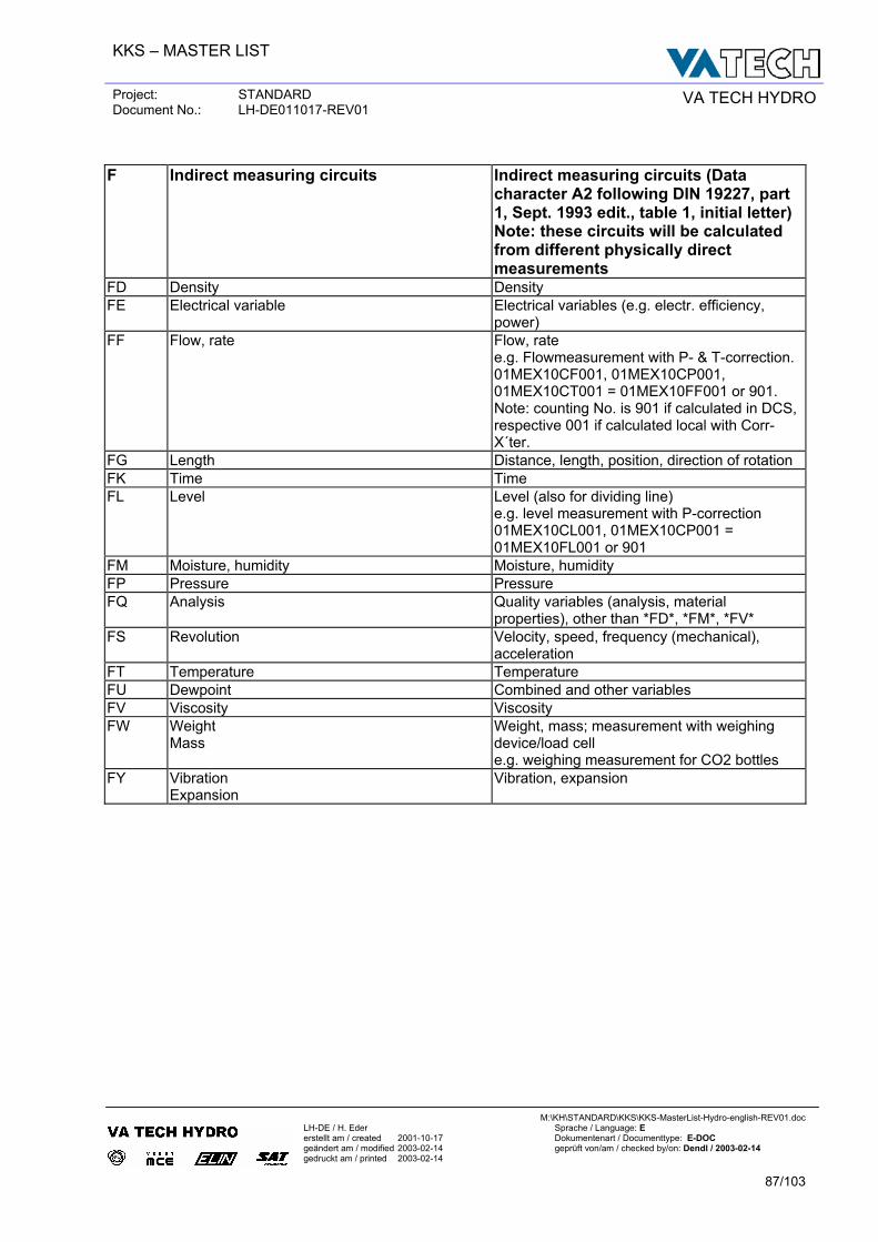
KKS – MASTER LIST
Project: STANDARD Document No.: LH-DE011017-REV01 VA TECH HYDRO
M:\KH\STANDARD\KKS\KKS-MasterList-Hydro-english-REV01.doc
LH-DE / H. Eder Sprache / Language: E erstellt am / created 2001-10-17 Dokumentenart / Documenttype: E-DOC geändert am / modified 2003-02-14 geprüft von/am / checked by/on: Dendl / 2003-02-14 gedruckt am / printed 2003-02-14
87/103
F Indirect measuring circuits Indirect measuring circuits (Data
character A2 following DIN 19227, part 1, Sept. 1993 edit., table 1, initial letter) Note: these circuits will be calculated from different physically direct measurements
FD Density Density FE Electrical variable Electrical variables (e.g. electr. efficiency,
power) FF Flow, rate Flow, rate
e.g. Flowmeasurement with P- & T-correction. 01MEX10CF001, 01MEX10CP001, 01MEX10CT001 = 01MEX10FF001 or 901. Note: counting No. is 901 if calculated in DCS, respective 001 if calculated local with Corr-X´ter.
FG Length Distance, length, position, direction of rotation FK Time Time FL Level Level (also for dividing line)
e.g. level measurement with P-correction 01MEX10CL001, 01MEX10CP001 = 01MEX10FL001 or 901
FM Moisture, humidity Moisture, humidity FP Pressure Pressure FQ Analysis Quality variables (analysis, material
properties), other than *FD*, *FM*, *FV* FS Revolution Velocity, speed, frequency (mechanical),
acceleration FT Temperature Temperature FU Dewpoint Combined and other variables FV Viscosity Viscosity FW Weight
Mass Weight, mass; measurement with weighing device/load cell e.g. weighing measurement for CO2 bottles
FY Vibration Expansion
Vibration, expansion
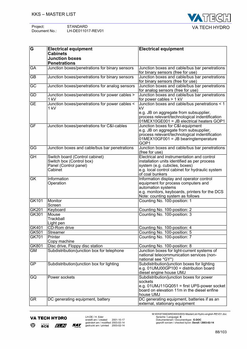
KKS – MASTER LIST
Project: STANDARD Document No.: LH-DE011017-REV01 VA TECH HYDRO
M:\KH\STANDARD\KKS\KKS-MasterList-Hydro-english-REV01.doc
LH-DE / H. Eder Sprache / Language: E erstellt am / created 2001-10-17 Dokumentenart / Documenttype: E-DOC geändert am / modified 2003-02-14 geprüft von/am / checked by/on: Dendl / 2003-02-14 gedruckt am / printed 2003-02-14
88/103
G Electrical equipment
Cabinets Junction boxes Penetrations
Electrical equipment
GA Junction boxes/penetrations for binary sensors Junction boxes and cable/bus bar penetrations for binary sensors (free for use)
GB Junction boxes/penetrations for binary sensors Junction boxes and cable/bus bar penetrations for binary sensors (free for use)
GC Junction boxes/penetrations for analog sensors Junction boxes and cable/bus bar penetrations for analog sensors (free for use)
GD Junction boxes/penetrations for power cables > 1 kV
Junction boxes and cable/bus bar penetrations for power cables > 1 kV
GE Junction boxes/penetrations for power cables < 1 kV
Junction boxes and cable/bus penetrations < 1 kV e.g. JB on aggregate from subsupplier, process relevant/technological indentification 01MEX10GE001 = JB electrical heaters GOP1
GF Junction boxes/penetrations for C&I-cables Junction boxes for C&I-equipment e.g. JB on aggregate from subsupplier, process relevant/technological indentification 01MEX10GF001 = JB bearingtemperature GOP1
GG Junction boxes and cable/bus bar penetrations Junction boxes and cable/bus bar penetrations (free for use)
GH Switch board (Control cabinet) Switch box (Control box) Panel (Control panel) Cabinet
Electrical and instrumentation and control installation units identified as per process system (e.g. cubicles, boxes) e.g. local control cabinet for hydraulic system of coal bunkers
GK Information Operation
Information display and operator control equipment for process computers and automation systems e.g. monitors, keyboards, printers for the DCS Note: counting system as follows
GK101 Monitor Screen
Counting No. 100-position: 1
GK201 Keyboard Counting No. 100-position: 2 GK301 Mouse
Trackball Light pen
Counting No. 100-position: 3
GK401 CD-Rom drive Counting No. 100-position: 4 GK501 Streamer Counting No. 100-position: 5 GK701 Printer
Copy machine Counting No. 100-position: 7
GK801 Disc drive, Floppy disc station Counting No. 100-position: 8 GM Subdistribution/junction box for telephone Junction boxes for light-current systems of
national telecommunication services (non-national see *GY*)
GP Subdistribution/junction box for lighting Subdistribution/junction boxes for lighting e.g. 01UMJ00GP100 = distribution board diesel engine house UMJ
GQ Power sockets Subdistribution/junction boxes for power sockets e.g. 01UMJ11GQ051 = first UPS-power socket board on elevation 11m in the diesel enfine house UMJ
GR DC generating equipment, battery DC generating equipment, batteries if as an external, stationary equipment
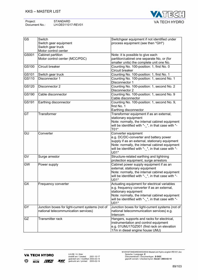
KKS – MASTER LIST
Project: STANDARD Document No.: LH-DE011017-REV01 VA TECH HYDRO
M:\KH\STANDARD\KKS\KKS-MasterList-Hydro-english-REV01.doc
LH-DE / H. Eder Sprache / Language: E erstellt am / created 2001-10-17 Dokumentenart / Documenttype: E-DOC geändert am / modified 2003-02-14 geprüft von/am / checked by/on: Dendl / 2003-02-14 gedruckt am / printed 2003-02-14
89/103
GS Switch
Switch gear equipment Switch gear truck Motor control center
Switchgear equipment if not identified under process equipment (see then *GH*)
GS001 Cabinet partition Motor control center (MCC/PDC)
Note: it is possible to give each partition/cabinet one separate No, or (for smaller units) the complete unit one No.
GS100 Circuit breaker Counting No. 100-position: 1, first No. 0 Circuit breaker
GS101 Switch gear truck Counting No. 100-position: 1, first No. 1 GS110 Disconnector 1 Counting No. 100-position: 1, second No. 1
Disconnector 1 GS120 Disconnector 2 Counting No. 100-position: 1, second No. 2
Disconnector 2 GS190 Cable disconnector Counting No. 100-position: 1, second No. 9
Cable disconnector GS191 Earthing disconnector Counting No. 100-position: 1, second No. 9,
first No. 1 Earthing disconnector
GT Transformer Transformer equipment if as an external, stationary equipment Note: normally, the internal cabinet equipment will be identified with *-_*, in that case with *-T01*
GU Converter Converter equipment e.g. DC/DC-converter and battery power supply if as an external, stationary equipment Note: normally, the internal cabinet equipment will be identified with *-_*, in that case with *-U01*
GV Surge arrestor Structure-related earthing and lightning protection equipment, surge arrestors
GW Power supply Cabinet power supply equipment if as an external, stationary equipment Note: normally, the internal cabinet equipment will be identified with *-_*, in that case with *-U01*
GX Frequency converter Actuating equipment for electrical variables e.g. frequency converter if as an external, stationary equipment Note: normally, the internal cabinet equipment will be identified with *-_*, in that case with *-U01*
GY Junction boxes for light-current systems (not of national telecommunication services)
Junction boxes for light-current systems (not of national telecommunication services) e.g. Intercom
GZ Transmitter rack Hangers, supports and racks for electrical, instrumentation and control equipment e.g. 01UMJ17GZ001 (first rack on elevation 17m in diesel engine house UMJ)
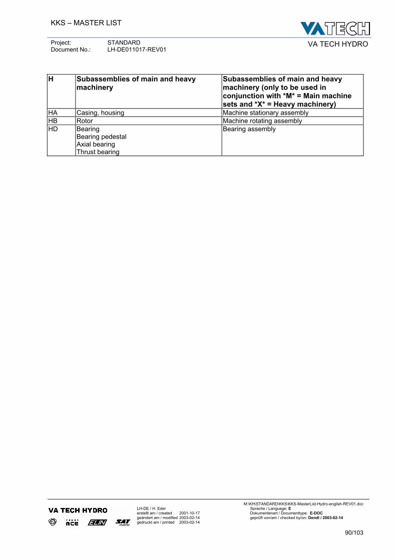
KKS – MASTER LIST
Project: STANDARD Document No.: LH-DE011017-REV01 VA TECH HYDRO
M:\KH\STANDARD\KKS\KKS-MasterList-Hydro-english-REV01.doc
LH-DE / H. Eder Sprache / Language: E erstellt am / created 2001-10-17 Dokumentenart / Documenttype: E-DOC geändert am / modified 2003-02-14 geprüft von/am / checked by/on: Dendl / 2003-02-14 gedruckt am / printed 2003-02-14
90/103
H Subassemblies of main and heavy
machinery Subassemblies of main and heavy machinery (only to be used in conjunction with *M* = Main machine sets and *X* = Heavy machinery)
HA Casing, housing Machine stationary assembly HB Rotor Machine rotating assembly HD Bearing
Bearing pedestal Axial bearing Thrust bearing
Bearing assembly
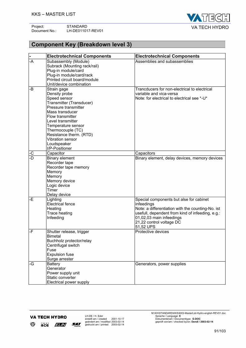
KKS – MASTER LIST
Project: STANDARD Document No.: LH-DE011017-REV01 VA TECH HYDRO
M:\KH\STANDARD\KKS\KKS-MasterList-Hydro-english-REV01.doc
LH-DE / H. Eder Sprache / Language: E erstellt am / created 2001-10-17 Dokumentenart / Documenttype: E-DOC geändert am / modified 2003-02-14 geprüft von/am / checked by/on: Dendl / 2003-02-14 gedruckt am / printed 2003-02-14
91/103
Component Key (Breakdown level 3)
- Electrotechnical Components Electrotechnical Components -A Subassembly (Module)
Subrack (Mounting rack/rail) Plug-in module/card Plug-in module/card/rack Printed circuit board/module Unit/device combination
Assemblies and subassemblies
-B Strain gage Density probe Speed sensor Transmitter (Transducer) Pressure transmitter Mass transducer Flow transmitter Level transmitter Temperature sensor Thermocouple (TC) Resistance therm. (RTD) Vibration sensor Loudspeaker I/P-Positioner
Trancducers for non-electrical to electrical variable and vica-versa Note: for electrical to electrical see *-U*
-C Capacitor Capacitors -D Binary element
Recorder tape Recorder tape memory Memory Memory Memory device Logic device Timer Delay device
Binary element, delay devices, memory devices
-E Lighting Electrical fence Heating Trace heating Infeeding
Special components but alse for cabinet infeedings Note: a differentiation with the counting-No. ist usefull, dependent from kind of infeeding, e.g.: 01,02,03 main infeedings 21,22 control voltage DC 51,52 UPS
-F Shutter release, trigger Bimetal Buchholz protector/relay Centrifugal switch Fuse Expulsion fuse Surge arrester
Protective devices
-G Battery Generator Power supply unit Static converter Electrical power supply
Generators, power supplies
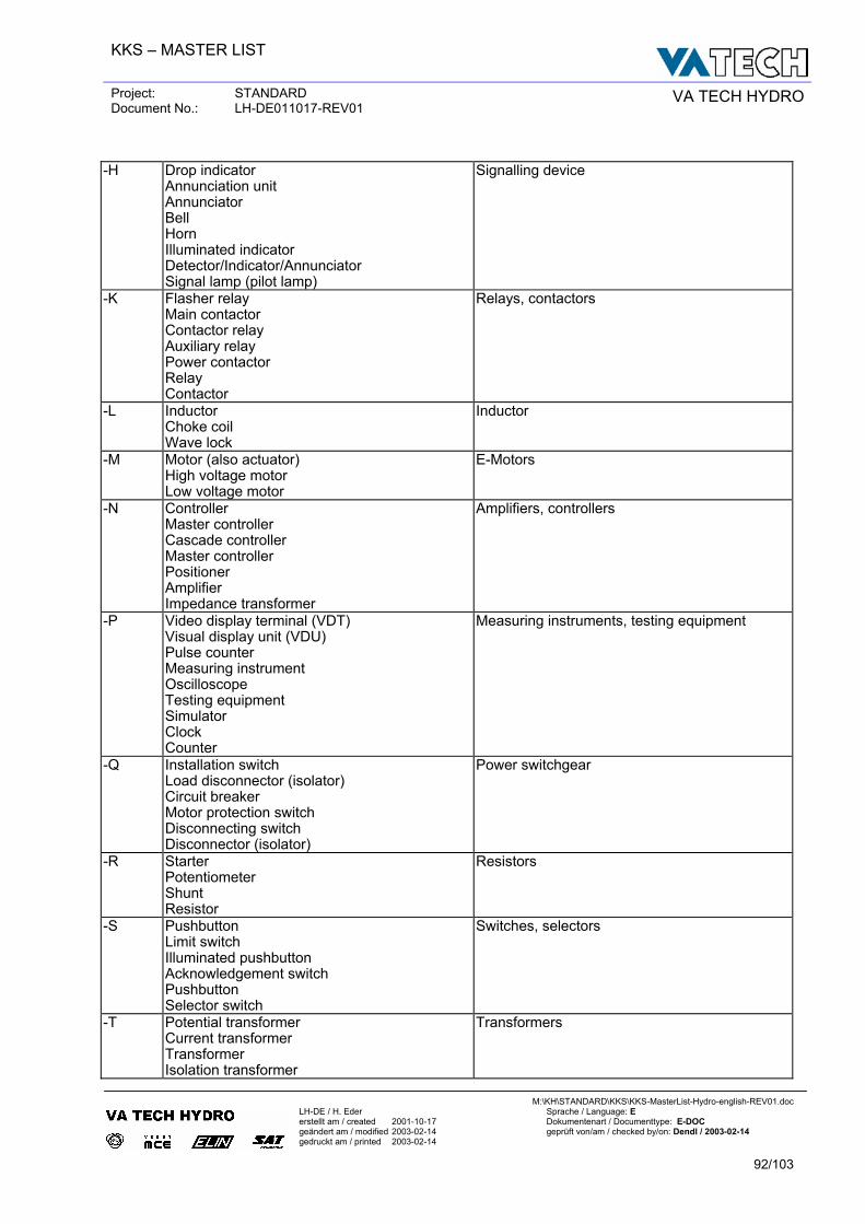
KKS – MASTER LIST
Project: STANDARD Document No.: LH-DE011017-REV01 VA TECH HYDRO
M:\KH\STANDARD\KKS\KKS-MasterList-Hydro-english-REV01.doc
LH-DE / H. Eder Sprache / Language: E erstellt am / created 2001-10-17 Dokumentenart / Documenttype: E-DOC geändert am / modified 2003-02-14 geprüft von/am / checked by/on: Dendl / 2003-02-14 gedruckt am / printed 2003-02-14
92/103
-H Drop indicator
Annunciation unit Annunciator Bell Horn Illuminated indicator Detector/Indicator/Annunciator Signal lamp (pilot lamp)
Signalling device
-K Flasher relay Main contactor Contactor relay Auxiliary relay Power contactor Relay Contactor
Relays, contactors
-L Inductor Choke coil Wave lock
Inductor
-M Motor (also actuator) High voltage motor Low voltage motor
E-Motors
-N Controller Master controller Cascade controller Master controller Positioner Amplifier Impedance transformer
Amplifiers, controllers
-P Video display terminal (VDT) Visual display unit (VDU) Pulse counter Measuring instrument Oscilloscope Testing equipment Simulator Clock Counter
Measuring instruments, testing equipment
-Q Installation switch Load disconnector (isolator) Circuit breaker Motor protection switch Disconnecting switch Disconnector (isolator)
Power switchgear
-R Starter Potentiometer Shunt Resistor
Resistors
-S Pushbutton Limit switch Illuminated pushbutton Acknowledgement switch Pushbutton Selector switch
Switches, selectors
-T Potential transformer Current transformer Transformer Isolation transformer
Transformers
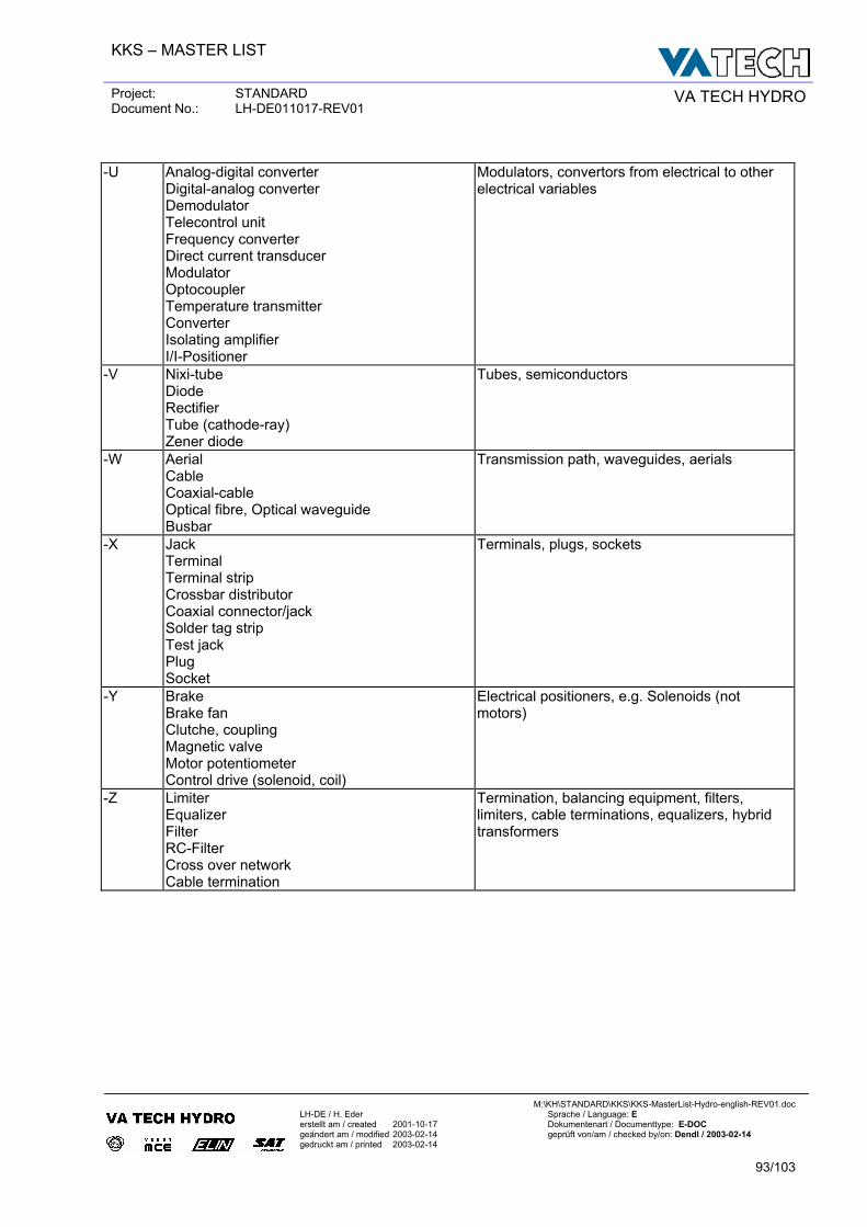
KKS – MASTER LIST
Project: STANDARD Document No.: LH-DE011017-REV01 VA TECH HYDRO
M:\KH\STANDARD\KKS\KKS-MasterList-Hydro-english-REV01.doc
LH-DE / H. Eder Sprache / Language: E erstellt am / created 2001-10-17 Dokumentenart / Documenttype: E-DOC geändert am / modified 2003-02-14 geprüft von/am / checked by/on: Dendl / 2003-02-14 gedruckt am / printed 2003-02-14
93/103
-U Analog-digital converter
Digital-analog converter Demodulator Telecontrol unit Frequency converter Direct current transducer Modulator Optocoupler Temperature transmitter Converter Isolating amplifier I/I-Positioner
Modulators, convertors from electrical to other electrical variables
-V Nixi-tube Diode Rectifier Tube (cathode-ray) Zener diode
Tubes, semiconductors
-W Aerial Cable Coaxial-cable Optical fibre, Optical waveguide Busbar
Transmission path, waveguides, aerials
-X Jack Terminal Terminal strip Crossbar distributor Coaxial connector/jack Solder tag strip Test jack Plug Socket
Terminals, plugs, sockets
-Y Brake Brake fan Clutche, coupling Magnetic valve Motor potentiometer Control drive (solenoid, coil)
Electrical positioners, e.g. Solenoids (not motors)
-Z Limiter Equalizer Filter RC-Filter Cross over network Cable termination
Termination, balancing equipment, filters, limiters, cable terminations, equalizers, hybrid transformers
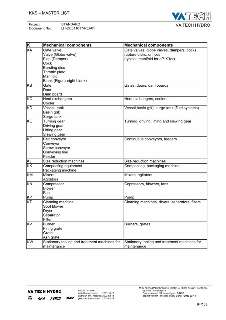
KKS – MASTER LIST
Project: STANDARD Document No.: LH-DE011017-REV01 VA TECH HYDRO
M:\KH\STANDARD\KKS\KKS-MasterList-Hydro-english-REV01.doc
LH-DE / H. Eder Sprache / Language: E erstellt am / created 2001-10-17 Dokumentenart / Documenttype: E-DOC geändert am / modified 2003-02-14 geprüft von/am / checked by/on: Dendl / 2003-02-14 gedruckt am / printed 2003-02-14
94/103
K Mechanical components Mechanical components KA Gate valve
Valve (Globe valve) Flap (Damper) Cock Bursting disc Throttle plate Manifold Blank (Figure-eight blank)
Gate valves, globe valves, dampers, cocks, rupture disks, orifices (typical: manifold for dP-X´ter)
KB Gate Door Dam board
Gates, doors, dam boards
KC Heat exchangers Cooler
Heat exchangers, coolers
KD Vessel, tank Basin (pit) Surge tank
Vessel,basin (pit), surge tank (fluid systems)
KE Turning gear Driving gear Lifting gear Slewing gear
Turning, driving, lifting and slewing gear
KF Belt conveyor Conveyor Screw conveyor Conveying line Feeder
Continuous conveyors, feeders
KJ Size reduction machines Size reduction machines KK Compacting equipment
Packaging machine Compacting, packaging machine
KM Mixers Agitators
Mixers, agitators
KN Compressor Blower Fan
Copressors, blowers, fans
KP Pump Pump KT Cleaning machine
Soot blower Dryer Separator Filter
Cleaning machines, dryers, separators, filters
KV Burner Firing grate Grate Ash grate
Burners, grates
KW Stationary tooling and treatment machines for maintenance
Stationary tooling and treatment machines for maintenance
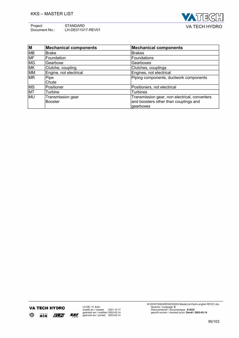
KKS – MASTER LIST
Project: STANDARD Document No.: LH-DE011017-REV01 VA TECH HYDRO
M:\KH\STANDARD\KKS\KKS-MasterList-Hydro-english-REV01.doc
LH-DE / H. Eder Sprache / Language: E erstellt am / created 2001-10-17 Dokumentenart / Documenttype: E-DOC geändert am / modified 2003-02-14 geprüft von/am / checked by/on: Dendl / 2003-02-14 gedruckt am / printed 2003-02-14
95/103
M Mechanical components Mechanical components MB Brake Brakes MF Foundation Foundations MG Gearboxe Gearboxes MK Clutche, coupling Clutches, couplings MM Engine, not electrical Engines, not electrical MR Pipe
Chute Piping components, ductwork components
MS Positioner Positioners, not electrical MT Turbine Turbines MU Transmission gear
Booster Transmission gear, non electrical, converters and boosters other than couplings and gearboxes
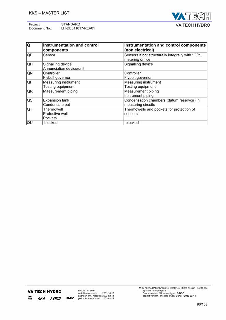
KKS – MASTER LIST
Project: STANDARD Document No.: LH-DE011017-REV01 VA TECH HYDRO
M:\KH\STANDARD\KKS\KKS-MasterList-Hydro-english-REV01.doc
LH-DE / H. Eder Sprache / Language: E erstellt am / created 2001-10-17 Dokumentenart / Documenttype: E-DOC geändert am / modified 2003-02-14 geprüft von/am / checked by/on: Dendl / 2003-02-14 gedruckt am / printed 2003-02-14
96/103
Q Instrumentation and control
components Instrumentation and control components (non electrical)
QB Sensor Sensors if not structurally integrally with *QP*, metering orifice
QH Signalling device Annunciation device/unit
Signalling device
QN Controller Flybolt governor
Controller Flybolt governor
QP Measuring instrument Testing equipment
Measuring instrument Testing equipment
QR Maesurement piping Measurement piping Instrument piping
QS Expansion tank Condensate pot
Condensation chambers (datum reservoir) in measuring circuits
QT Thermowell Protective well Pockets
Thermowells and pockets for protection of sensors
QU -blocked- -blocked-
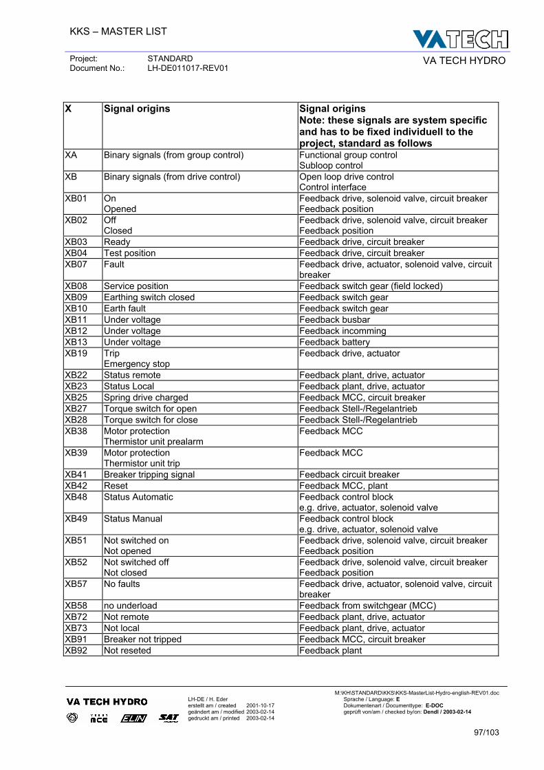
KKS – MASTER LIST
Project: STANDARD Document No.: LH-DE011017-REV01 VA TECH HYDRO
M:\KH\STANDARD\KKS\KKS-MasterList-Hydro-english-REV01.doc
LH-DE / H. Eder Sprache / Language: E erstellt am / created 2001-10-17 Dokumentenart / Documenttype: E-DOC geändert am / modified 2003-02-14 geprüft von/am / checked by/on: Dendl / 2003-02-14 gedruckt am / printed 2003-02-14
97/103
X Signal origins Signal origins
Note: these signals are system specific and has to be fixed individuell to the project, standard as follows
XA Binary signals (from group control) Functional group control Subloop control
XB Binary signals (from drive control) Open loop drive control Control interface
XB01 On Opened
Feedback drive, solenoid valve, circuit breaker Feedback position
XB02 Off Closed
Feedback drive, solenoid valve, circuit breaker Feedback position
XB03 Ready Feedback drive, circuit breaker XB04 Test position Feedback drive, circuit breaker XB07 Fault Feedback drive, actuator, solenoid valve, circuit
breaker XB08 Service position Feedback switch gear (field locked) XB09 Earthing switch closed Feedback switch gear XB10 Earth fault Feedback switch gear XB11 Under voltage Feedback busbar XB12 Under voltage Feedback incomming XB13 Under voltage Feedback battery XB19 Trip
Emergency stop Feedback drive, actuator
XB22 Status remote Feedback plant, drive, actuator XB23 Status Local Feedback plant, drive, actuator XB25 Spring drive charged Feedback MCC, circuit breaker XB27 Torque switch for open Feedback Stell-/Regelantrieb XB28 Torque switch for close Feedback Stell-/Regelantrieb XB38 Motor protection
Thermistor unit prealarm Feedback MCC
XB39 Motor protection Thermistor unit trip
Feedback MCC
XB41 Breaker tripping signal Feedback circuit breaker XB42 Reset Feedback MCC, plant XB48 Status Automatic Feedback control block
e.g. drive, actuator, solenoid valve XB49 Status Manual Feedback control block
e.g. drive, actuator, solenoid valve XB51 Not switched on
Not opened Feedback drive, solenoid valve, circuit breaker Feedback position
XB52 Not switched off Not closed
Feedback drive, solenoid valve, circuit breaker Feedback position
XB57 No faults Feedback drive, actuator, solenoid valve, circuit breaker
XB58 no underload Feedback from switchgear (MCC) XB72 Not remote Feedback plant, drive, actuator XB73 Not local Feedback plant, drive, actuator XB91 Breaker not tripped Feedback MCC, circuit breaker XB92 Not reseted Feedback plant
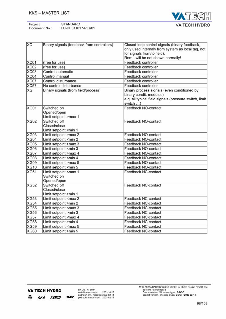
KKS – MASTER LIST
Project: STANDARD Document No.: LH-DE011017-REV01 VA TECH HYDRO
M:\KH\STANDARD\KKS\KKS-MasterList-Hydro-english-REV01.doc
LH-DE / H. Eder Sprache / Language: E erstellt am / created 2001-10-17 Dokumentenart / Documenttype: E-DOC geändert am / modified 2003-02-14 geprüft von/am / checked by/on: Dendl / 2003-02-14 gedruckt am / printed 2003-02-14
98/103
XC Binary signals (feedback from controllers) Closed-loop control signals (binary feedback,
only used internaly from system as local tag, not for signals from/to field). Rem.: will be not shown normally!
XC01 (free for use) Feedback controller XC02 (free for use) Feedback controller XC03 Control automatic Feedback controller XC04 Control manual Feedback controller XC07 Control disturbance Feedback controller XC57 No control disturbance Feedback controller XG Binary signals (from field/process) Binary process signals (even conditioned by
binary condit. modules) e.g. all typical field signals (pressure switch, limit switch …)
XG01 Switched on Opened/open Limit setpoint >max 1
Feedback NO-contact
XG02 Switched off Closed/close Limit setpoint <min 1
Feedback NO-contact
XG03 Limit setpoint >max 2 Feedback NO-contact XG04 Limit setpoint <min 2 Feedback NO-contact XG05 Limit setpoint >max 3 Feedback NO-contact XG06 Limit setpoint <min 3 Feedback NO-contact XG07 Limit setpoint >max 4 Feedback NO-contact XG08 Limit setpoint <min 4 Feedback NO-contact XG09 Limit setpoint >max 5 Feedback NO-contact XG10 Limit setpoint <min 5 Feedback NO-contact XG51 Limit setpoint <max 1
Switched on Opened/open
Feedback NC-contact
XG52 Switched off Closed/close Limit setpoint >min 1
Feedback NC-contact
XG53 Limit setpoint <max 2 Feedback NC-contact XG54 Limit setpoint >min 2 Feedback NC-contact XG55 Limit setpoint <max 3 Feedback NC-contact XG56 Limit setpoint >min 3 Feedback NC-contact XG57 Limit setpoint <max 4 Feedback NC-contact XG58 Limit setpoint >min 4 Feedback NC-contact XG59 Limit setpoint <max 5 Feedback NC-contact XG60 Limit setpoint >min 5 Feedback NC-contact
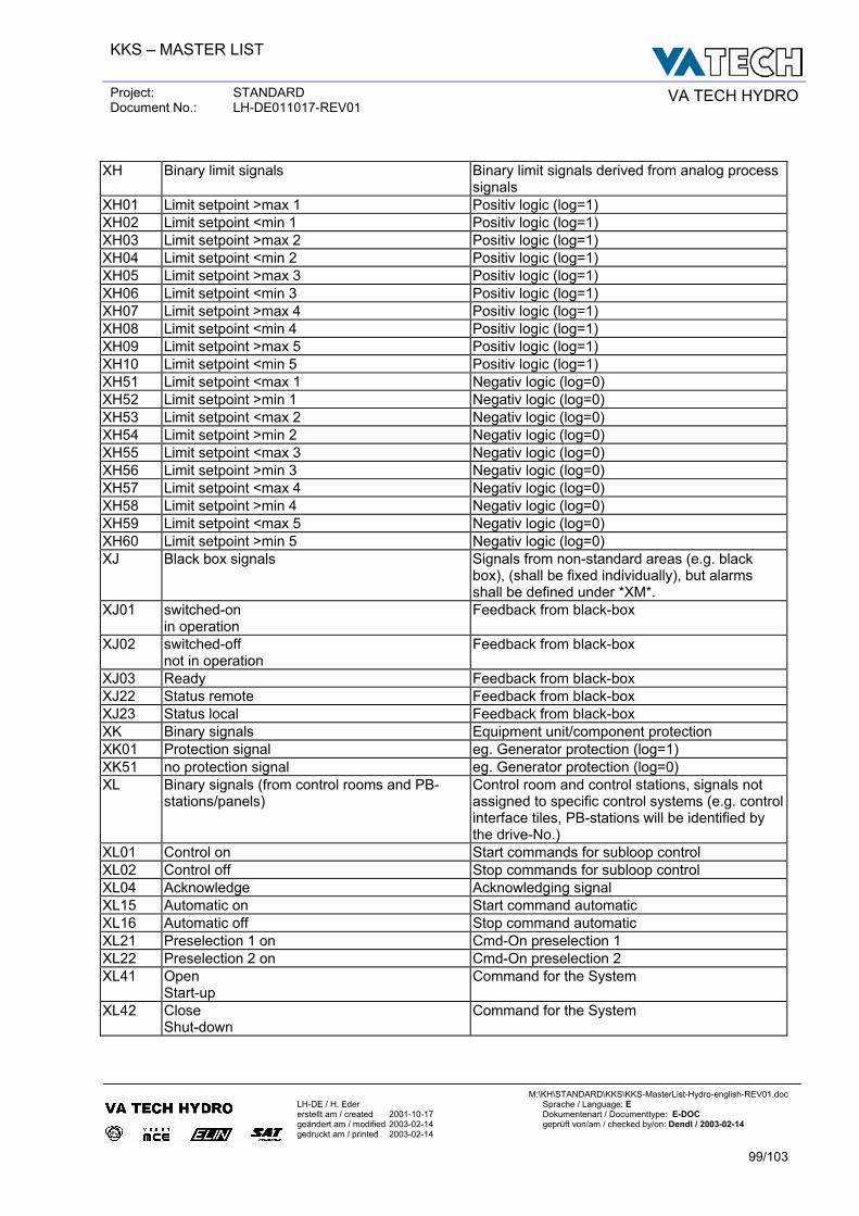
KKS – MASTER LIST
Project: STANDARD Document No.: LH-DE011017-REV01 VA TECH HYDRO
M:\KH\STANDARD\KKS\KKS-MasterList-Hydro-english-REV01.doc
LH-DE / H. Eder Sprache / Language: E erstellt am / created 2001-10-17 Dokumentenart / Documenttype: E-DOC geändert am / modified 2003-02-14 geprüft von/am / checked by/on: Dendl / 2003-02-14 gedruckt am / printed 2003-02-14
99/103
XH Binary limit signals Binary limit signals derived from analog process
signals XH01 Limit setpoint >max 1 Positiv logic (log=1) XH02 Limit setpoint <min 1 Positiv logic (log=1) XH03 Limit setpoint >max 2 Positiv logic (log=1) XH04 Limit setpoint <min 2 Positiv logic (log=1) XH05 Limit setpoint >max 3 Positiv logic (log=1) XH06 Limit setpoint <min 3 Positiv logic (log=1) XH07 Limit setpoint >max 4 Positiv logic (log=1) XH08 Limit setpoint <min 4 Positiv logic (log=1) XH09 Limit setpoint >max 5 Positiv logic (log=1) XH10 Limit setpoint <min 5 Positiv logic (log=1) XH51 Limit setpoint <max 1 Negativ logic (log=0) XH52 Limit setpoint >min 1 Negativ logic (log=0) XH53 Limit setpoint <max 2 Negativ logic (log=0) XH54 Limit setpoint >min 2 Negativ logic (log=0) XH55 Limit setpoint <max 3 Negativ logic (log=0) XH56 Limit setpoint >min 3 Negativ logic (log=0) XH57 Limit setpoint <max 4 Negativ logic (log=0) XH58 Limit setpoint >min 4 Negativ logic (log=0) XH59 Limit setpoint <max 5 Negativ logic (log=0) XH60 Limit setpoint >min 5 Negativ logic (log=0) XJ Black box signals Signals from non-standard areas (e.g. black
box), (shall be fixed individually), but alarms shall be defined under *XM*.
XJ01 switched-on in operation
Feedback from black-box
XJ02 switched-off not in operation
Feedback from black-box
XJ03 Ready Feedback from black-box XJ22 Status remote Feedback from black-box XJ23 Status local Feedback from black-box XK Binary signals Equipment unit/component protection XK01 Protection signal eg. Generator protection (log=1) XK51 no protection signal eg. Generator protection (log=0) XL Binary signals (from control rooms and PB-
stations/panels) Control room and control stations, signals not assigned to specific control systems (e.g. control interface tiles, PB-stations will be identified by the drive-No.)
XL01 Control on Start commands for subloop control XL02 Control off Stop commands for subloop control XL04 Acknowledge Acknowledging signal XL15 Automatic on Start command automatic XL16 Automatic off Stop command automatic XL21 Preselection 1 on Cmd-On preselection 1 XL22 Preselection 2 on Cmd-On preselection 2 XL41 Open
Start-up Command for the System
XL42 Close Shut-down
Command for the System
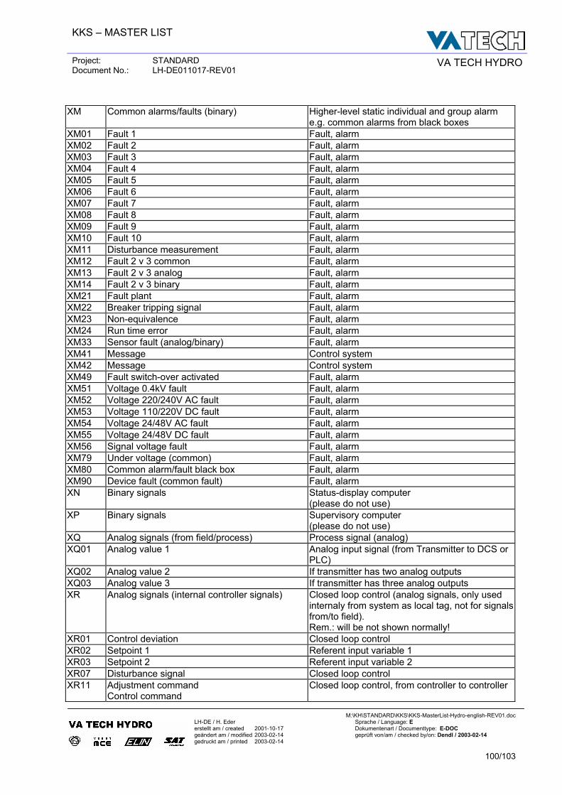
KKS – MASTER LIST
Project: STANDARD Document No.: LH-DE011017-REV01 VA TECH HYDRO
M:\KH\STANDARD\KKS\KKS-MasterList-Hydro-english-REV01.doc
LH-DE / H. Eder Sprache / Language: E erstellt am / created 2001-10-17 Dokumentenart / Documenttype: E-DOC geändert am / modified 2003-02-14 geprüft von/am / checked by/on: Dendl / 2003-02-14 gedruckt am / printed 2003-02-14
100/103
XM Common alarms/faults (binary) Higher-level static individual and group alarm
e.g. common alarms from black boxes XM01 Fault 1 Fault, alarm XM02 Fault 2 Fault, alarm XM03 Fault 3 Fault, alarm XM04 Fault 4 Fault, alarm XM05 Fault 5 Fault, alarm XM06 Fault 6 Fault, alarm XM07 Fault 7 Fault, alarm XM08 Fault 8 Fault, alarm XM09 Fault 9 Fault, alarm XM10 Fault 10 Fault, alarm XM11 Disturbance measurement Fault, alarm XM12 Fault 2 v 3 common Fault, alarm XM13 Fault 2 v 3 analog Fault, alarm XM14 Fault 2 v 3 binary Fault, alarm XM21 Fault plant Fault, alarm XM22 Breaker tripping signal Fault, alarm XM23 Non-equivalence Fault, alarm XM24 Run time error Fault, alarm XM33 Sensor fault (analog/binary) Fault, alarm XM41 Message Control system XM42 Message Control system XM49 Fault switch-over activated Fault, alarm XM51 Voltage 0.4kV fault Fault, alarm XM52 Voltage 220/240V AC fault Fault, alarm XM53 Voltage 110/220V DC fault Fault, alarm XM54 Voltage 24/48V AC fault Fault, alarm XM55 Voltage 24/48V DC fault Fault, alarm XM56 Signal voltage fault Fault, alarm XM79 Under voltage (common) Fault, alarm XM80 Common alarm/fault black box Fault, alarm XM90 Device fault (common fault) Fault, alarm XN Binary signals Status-display computer
(please do not use) XP Binary signals Supervisory computer
(please do not use) XQ Analog signals (from field/process) Process signal (analog) XQ01 Analog value 1 Analog input signal (from Transmitter to DCS or
PLC) XQ02 Analog value 2 If transmitter has two analog outputs XQ03 Analog value 3 If transmitter has three analog outputs XR Analog signals (internal controller signals) Closed loop control (analog signals, only used
internaly from system as local tag, not for signals from/to field). Rem.: will be not shown normally!
XR01 Control deviation Closed loop control XR02 Setpoint 1 Referent input variable 1 XR03 Setpoint 2 Referent input variable 2 XR07 Disturbance signal Closed loop control XR11 Adjustment command
Control command Closed loop control, from controller to controller
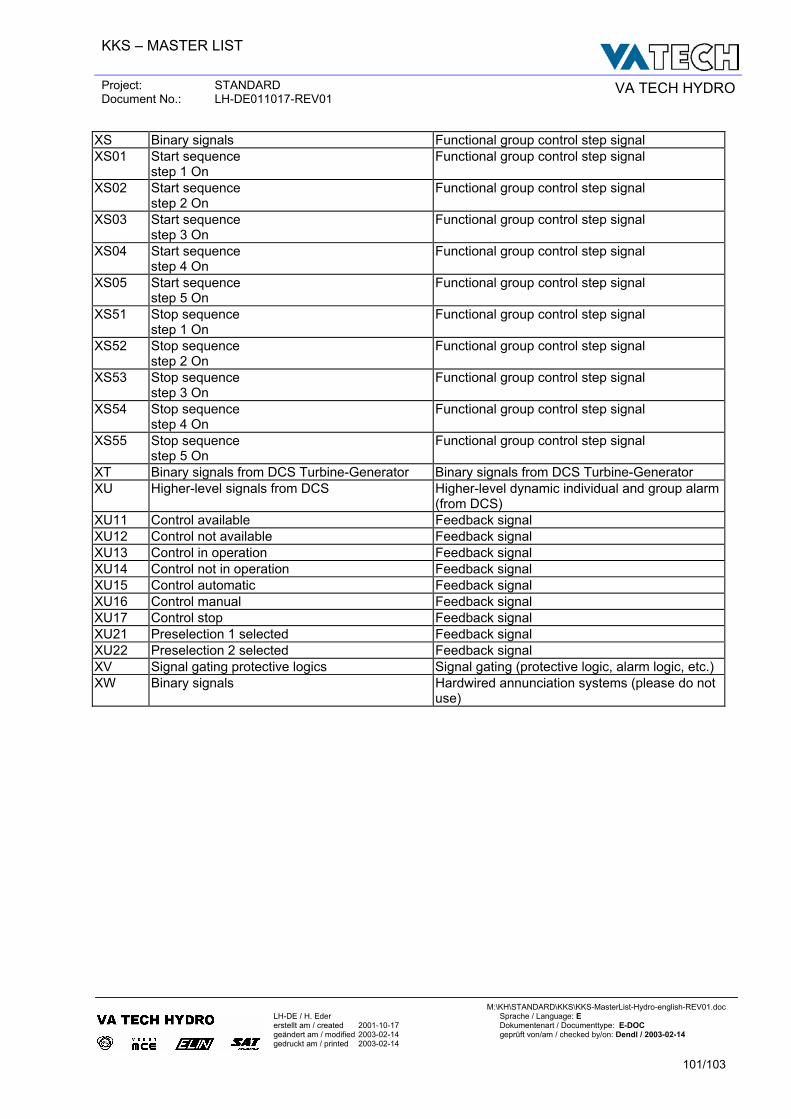
KKS – MASTER LIST
Project: STANDARD Document No.: LH-DE011017-REV01 VA TECH HYDRO
M:\KH\STANDARD\KKS\KKS-MasterList-Hydro-english-REV01.doc
LH-DE / H. Eder Sprache / Language: E erstellt am / created 2001-10-17 Dokumentenart / Documenttype: E-DOC geändert am / modified 2003-02-14 geprüft von/am / checked by/on: Dendl / 2003-02-14 gedruckt am / printed 2003-02-14
101/103
XS Binary signals Functional group control step signal XS01 Start sequence
step 1 On Functional group control step signal
XS02 Start sequence step 2 On
Functional group control step signal
XS03 Start sequence step 3 On
Functional group control step signal
XS04 Start sequence step 4 On
Functional group control step signal
XS05 Start sequence step 5 On
Functional group control step signal
XS51 Stop sequence step 1 On
Functional group control step signal
XS52 Stop sequence step 2 On
Functional group control step signal
XS53 Stop sequence step 3 On
Functional group control step signal
XS54 Stop sequence step 4 On
Functional group control step signal
XS55 Stop sequence step 5 On
Functional group control step signal
XT Binary signals from DCS Turbine-Generator Binary signals from DCS Turbine-Generator XU Higher-level signals from DCS Higher-level dynamic individual and group alarm
(from DCS) XU11 Control available Feedback signal XU12 Control not available Feedback signal XU13 Control in operation Feedback signal XU14 Control not in operation Feedback signal XU15 Control automatic Feedback signal XU16 Control manual Feedback signal XU17 Control stop Feedback signal XU21 Preselection 1 selected Feedback signal XU22 Preselection 2 selected Feedback signal XV Signal gating protective logics Signal gating (protective logic, alarm logic, etc.) XW Binary signals Hardwired annunciation systems (please do not
use)
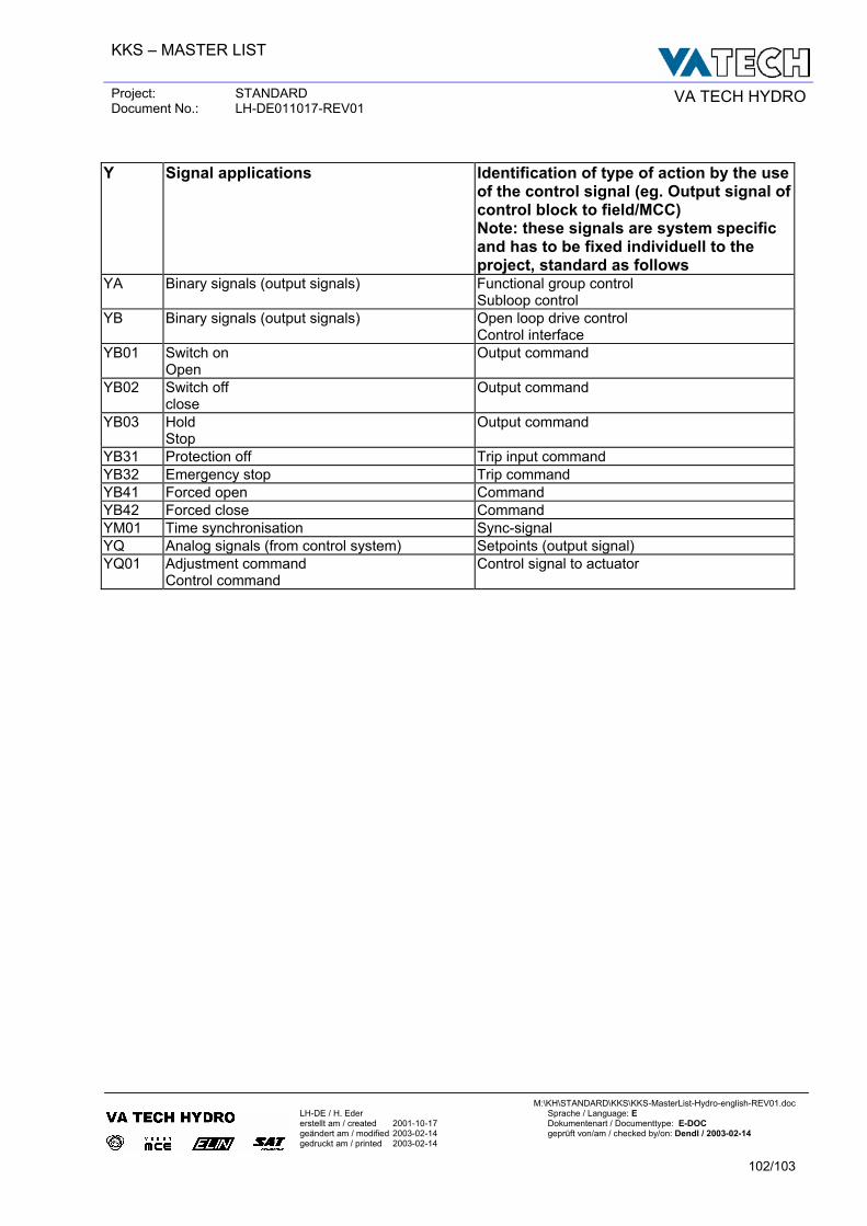
KKS – MASTER LIST
Project: STANDARD Document No.: LH-DE011017-REV01 VA TECH HYDRO
M:\KH\STANDARD\KKS\KKS-MasterList-Hydro-english-REV01.doc
LH-DE / H. Eder Sprache / Language: E erstellt am / created 2001-10-17 Dokumentenart / Documenttype: E-DOC geändert am / modified 2003-02-14 geprüft von/am / checked by/on: Dendl / 2003-02-14 gedruckt am / printed 2003-02-14
102/103
Y Signal applications Identification of type of action by the use
of the control signal (eg. Output signal of control block to field/MCC) Note: these signals are system specific and has to be fixed individuell to the project, standard as follows
YA Binary signals (output signals) Functional group control Subloop control
YB Binary signals (output signals) Open loop drive control Control interface
YB01 Switch on Open
Output command
YB02 Switch off close
Output command
YB03 Hold Stop
Output command
YB31 Protection off Trip input command YB32 Emergency stop Trip command YB41 Forced open Command YB42 Forced close Command YM01 Time synchronisation Sync-signal YQ Analog signals (from control system) Setpoints (output signal) YQ01 Adjustment command
Control command Control signal to actuator
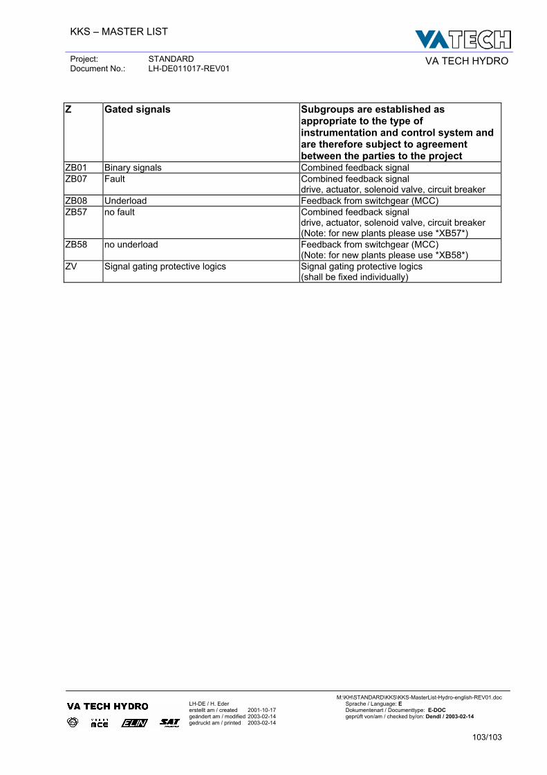
KKS – MASTER LIST
Project: STANDARD Document No.: LH-DE011017-REV01 VA TECH HYDRO
M:\KH\STANDARD\KKS\KKS-MasterList-Hydro-english-REV01.doc
LH-DE / H. Eder Sprache / Language: E erstellt am / created 2001-10-17 Dokumentenart / Documenttype: E-DOC geändert am / modified 2003-02-14 geprüft von/am / checked by/on: Dendl / 2003-02-14 gedruckt am / printed 2003-02-14
103/103
Z Gated signals Subgroups are established as
appropriate to the type of instrumentation and control system and are therefore subject to agreement between the parties to the project
ZB01 Binary signals Combined feedback signal ZB07 Fault Combined feedback signal
drive, actuator, solenoid valve, circuit breaker ZB08 Underload Feedback from switchgear (MCC) ZB57 no fault Combined feedback signal
drive, actuator, solenoid valve, circuit breaker (Note: for new plants please use *XB57*)
ZB58 no underload Feedback from switchgear (MCC) (Note: for new plants please use *XB58*)
ZV Signal gating protective logics Signal gating protective logics (shall be fixed individually)