TŁUMACZENIE ORYGINALNEJ INSTRUKCJI NITOWNICA … · rivettatrice oleopneumatica per inserti m3/m8...
44
KJ 60 - ISTRUZIONI ORIGINALI RIVETTATRICE OLEOPNEUMATICA PER INSERTI M3/M8 ISTRUZIONI D’USO - PARTI DI RICAMBIO - TRANSLATION OF ORIGINAL INSTRUCTIONS OIL PNEUMATIC RIVETING TOOL FOR INSERTS M3/M8 INSTRUCTIONS FOR USE - SPARE PARTS - TRADUCTION DES INSTRUCTIONS ORIGINALES MACHINE A SERTIR OLEOPNEUMATIQUE POUR INSERTS M3/M8 MODE D’EMPLOI - PIECES DETACHEES - ÜBERSETZUNG VON ORIGINALANLEITUNGEN ÖLPNEUMATISCHES NIETWERKZEUG FÜR BLINDNIETMUTTERN M3/M8 BEDIENUNGSANLEITUNG - ERSATZTEILE - TRADUCCION DE LAS ISTRUCCIONES ORIGINALES REMACHADORA OLEONEUMATICA PARA INSERTOS M3/M8 INSTRUCCIONES DE USO - PIEZAS DE REPUESTO - TŁUMACZENIE ORYGINALNEJ INSTRUKCJI NITOWNICA OLEOPNEUMATYCZNA DO NITONAKRĘTEK M3-M8 INSTRUKCJA OBSŁUGI - CZĘŚCI ZAMIENNE I GB F E D PL
Transcript of TŁUMACZENIE ORYGINALNEJ INSTRUKCJI NITOWNICA … · rivettatrice oleopneumatica per inserti m3/m8...
KJ 60 - ISTRUZIONI ORIGINALIRIVETTATRICE OLEOPNEUMATICA PER INSERTI M3/M8ISTRUZIONI D’USO - PARTI DI RICAMBIO
- TRANSLATION OF ORIGINAL INSTRUCTIONSOIL PNEUMATIC RIVETING TOOL FOR INSERTS M3/M8INSTRUCTIONS FOR USE - SPARE PARTS
- TRADUCTION DES INSTRUCTIONS ORIGINALESMACHINE A SERTIR OLEOPNEUMATIQUE POUR INSERTS M3/M8MODE D’EMPLOI - PIECES DETACHEES
- ÜBERSETZUNG VON ORIGINALANLEITUNGENÖLPNEUMATISCHES NIETWERKZEUG FÜR BLINDNIETMUTTERN M3/M8BEDIENUNGSANLEITUNG - ERSATZTEILE
- TRADUCCION DE LAS ISTRUCCIONES ORIGINALESREMACHADORA OLEONEUMATICA PARA INSERTOS M3/M8INSTRUCCIONES DE USO - PIEZAS DE REPUESTO
- TŁUMACZENIE ORYGINALNEJ INSTRUKCJINITOWNICA OLEOPNEUMATYCZNADO NITONAKRĘTEK M3-M8INSTRUKCJA OBSŁUGI - CZĘŚCI ZAMIENNE
I
GB
F
E
D
PL

KJ 60
Far S.r.l. - Giacomo Generali
(Presidente del Consiglio di Amministrazione)(Chairman of the Board of Directors)
(Président du Conseil d’Administration)(Vorsitzender des Verwaltungsrates)
(Presidente del Consejo de Administración)(Prezes Zarzadu)
.............................................
La sottoscritta Far S.r.l., con sede in Quarto Inferiore (BO) alla via Giovanni XXIII n° 2, DICHIARAsotto la propria esclusiva responsabilità che la rivettatrice Modello: KJ 60 - Rivettatrice oleopneumaticaUtilizzo: per inserti filettati M3÷M8alla quale questa dichiarazione si riferisce è conforme ai requisiti essenziali di sicurezza previsti dal D. Lgs. 17/2010 di recepimento della Direttiva Macchine 2006/42/CE e successive modificazioni ed integrazioni.La persona autorizzata a costituire il fascicolo tecnico risponde al nome di Giacomo Generali, presso la Far S.r.l., con sede in Quarto Inferiore (BO) alla via Giovanni XXIII n° 2.
The undersigned Far S.r.l., having its office in Quarto Inferiore (BO), Via Giovanni XXIII No. 2, herewith DECLARESon its sole responsability that the riveting machine Type: KJ 60 - Hydropneumatic toolApplication: for threaded inserts M3÷M8which is the object of this declaration complies with the basic safety requirements estabilished in the law decree Leg. D. 17/2010 of the Machinery Directive 2006/42/CE acknowledge and subsequent amendments and integrations.The person who is authorized to create the technical brochure is Giacomo Generali, c/o Far S.r.l., head office in Quarto Inferiore (BO), via Giovanni XXIII n. 2.
La société Far S.r.l. soussignée avec siège à Quarto Inferiore (BO), Via Giovanni XXIII n° 2, DECLAREsous sa seule responsabilité que la riveteuse Modèle: KJ 60 - Machine à sertir oléopneumatiqueUtilisation: pour inserts filetés M3÷M8à laquelle cette déclaration se rapporte est conforme aux conditions essentielles de sécurité requises par la loi 17/2010 d’acceptation de la Directive Machines 2006/42/CE et modifications et intégrations successives.La personne autorisée à constituer le dossier technique est Giacomo Generali chez FAR S.r.l., avec siège à Quarto Inferiore (BO) – Via Giovanni XXIII. n.2.
Die Unterzeichnete, Fa. Far S.r.l., mit Sitz in Quarto Inferiore (BO), Via Giovanni XXIII Nr. 2, ERKLÄRThiermit auf ihre alleinige Verantwortung, daß die Nietmaschine Typ: KJ 60 - Hydraulisch-pneumatisches NietwerkzeugAnwendung: für Blindnietmuttern M3÷M8auf das sich diese Erklärung bezieht, den wesentlichen Sicherheitsanforderungen des Gesetzesdekrets 17/2010 von Umsetzung der Maschinenrichtlinie 2006/42/CE und den nachfolgenden Änderungen und Anfügungen entspricht.Der Berechtigte zur Bildung der technische Broschüre ist Giacomo Generali, bei der Firma Far S.r.l., mit Sitz in Quarto Inferiore (BO), via Giovanni XXIII Nr. 2.
La firmataria Far S.r.l., domiciliada en Quarto Inferiore (BO) en via Giovanni XXIII n° 2, DECLARAbajo su exclusiva responsabilidad que la remachadora Modelo: KJ 60 - Remachadora oleoneumáticaEmpleo: para remaches roscados M3÷M8a la cual la presente declaración se refiere corresponde a los requisitos esenciales de seguridad previstos por el D. Lay 17/2010 de recepción de la Directiva Maquinas 2006/42/CE y sucesivas modificaciones e integraciones.La persona autirizada a constituir el fasciculo tecnico es Giacomo Generali, cerca FAR S.r.l., con sede a Quarto Inferiore (BO) – Via Giovanni XXIII n.2.
Niżej podpisana firma Far S.r.l., z siedzibą w Quarto Inferiore (BO), via Giovanni XXIII nr 2, OŚWIADCZAna własną i wyłączną odpowiedzialność, że nitownica Model: KJ 60 - Nitownica oleopneumatycznaZastosowanie: do nitonakrętek gwintowanych M3÷M8do której odnosi się niniejsza deklaracja, jest zgodna z wymogami bezpieczeństwa przewidzianymi przez D. Lgs. 17/2010implementujący Dyrektywę Maszynową 2006/42/WE wraz z późniejszymi zmianami i uzupełnieniami.Osoba upoważniona do utworzenia dokumentacji technicznej to Giacomo Generali z firmy Far S.r.l.mającej siedzibę w Quarto Inferiore (BO), via Giovanni XXIII nr 2
Quarto Inferiore, 23-03-2010
I
GB
F
E
D
PL

I
I
F
F
E
PL
PL
ISTRUZIONI D’USO.................................................4
INSTRUCTIONS FOR USE .......................................9
MODE D’EMPLOI ..................................................14
BEDIENUNGSANLEITUNG .....................................19
INSTRUCCIONES DE USO .....................................24
INSTRUKCJA OBSŁUGI.................................................29
PARTI DI RICAMBIO .............................................34
SPARE PARTS .......................................................35
PIECES DETACHEES .............................................36
ERSATZTEILE ........................................................37
CZĘŚCI ZAMIENNE ......................................................38
KJ 60GB
GB
D
D
I KJ 60
4 Date 10-2013 Revisione - 19
ISTRUZIONI D’USO
INDICE
GARANZIA E ASSISTENZA TECNICA.....................................4AVVERTENZE E MISURE DI SICUREZZA ...............................4IDENTIFICAZIONE DELLA RIVETTATRICE .............................5NOTE GENERALI E CAMPO DI APPLICAZIONE .....................5PARTI PRINCIPALI ................................................................5DATI TECNICI ........................................................................5POSA IN OPERA DELL’INSERTO ...........................................6CAMBIO DI FORMATO ..........................................................7RABBOCCO OLIO CIRCUITO OLEODINAMICO ......................8SMALTIMENTO DELLA RIVETTATRICE .................................8
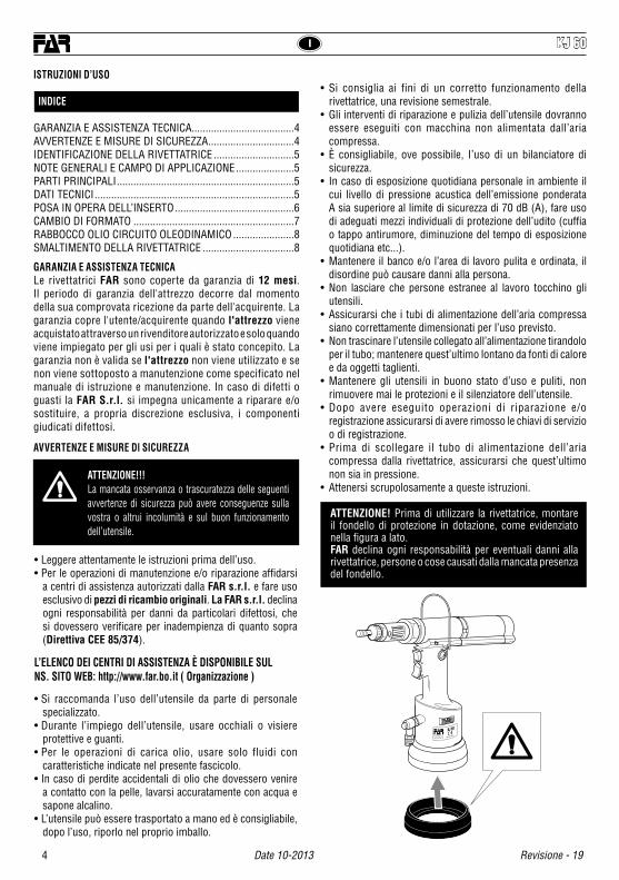
ATTENZIONE!!!La mancata osservanza o trascuratezza delle seguenti avvertenze di sicurezza può avere conseguenze sulla vostra o altrui incolumità e sul buon funzionamento dell’utensile.
• Leggere attentamente le istruzioni prima dell’uso.• Per le operazioni di manutenzione e/o riparazione affidarsi
a centri di assistenza autorizzati dalla FAR s.r.l. e fare uso esclusivo di pezzi di ricambio originali. La FAR s.r.l. declina ogni responsabilità per danni da particolari difettosi, che si dovessero verificare per inadempienza di quanto sopra (Direttiva CEE 85/374).
L’ELENCO DEI CENTRI DI ASSISTENZA È DISPONIBILE SULNS. SITO WEB: http://www.far.bo.it ( Organizzazione )
• Si raccomanda l’uso dell’utensile da parte di personale specializzato.
• Durante l’impiego dell’utensile, usare occhiali o visiere protettive e guanti.
• Per le operazioni di carica olio, usare solo fluidi con caratteristiche indicate nel presente fascicolo.
• In caso di perdite accidentali di olio che dovessero venire a contatto con la pelle, lavarsi accuratamente con acqua e sapone alcalino.
• L’utensile può essere trasportato a mano ed è consigliabile, dopo l’uso, riporlo nel proprio imballo.
ATTENZIONE! Prima di utilizzare la rivettatrice, montare il fondello di protezione in dotazione, come evidenziato nella figura a lato.FAR declina ogni responsabilità per eventuali danni alla rivettatrice, persone o cose causati dalla mancata presenza del fondello.
GARANZIA E ASSISTENZA TECNICALe rivettatrici FAR sono coperte da garanzia di 12 mesi. Il periodo di garanzia dell'attrezzo decorre dal momento della sua comprovata ricezione da parte dell'acquirente. La garanzia copre l'utente/acquirente quando l'attrezzo viene acquistato attraverso un rivenditore autorizzato e solo quando viene impiegato per gli usi per i quali è stato concepito. La garanzia non è valida se l'attrezzo non viene utilizzato e se non viene sottoposto a manutenzione come specificato nel manuale di istruzione e manutenzione. In caso di difetti o guasti la FAR S.r.l. si impegna unicamente a riparare e/o sostituire, a propria discrezione esclusiva, i componenti giudicati difettosi.
AVVERTENZE E MISURE Dl SICUREZZA
• Si consiglia ai fini di un corretto funzionamento della rivettatrice, una revisione semestrale.
• Gli interventi di riparazione e pulizia dell’utensile dovranno essere eseguiti con macchina non alimentata dall’aria compressa.
• È consigliabile, ove possibile, I’uso di un bilanciatore di sicurezza.
• In caso di esposizione quotidiana personale in ambiente il cui livello di pressione acustica dell’emissione ponderata A sia superiore al limite di sicurezza di 70 dB (A), fare uso di adeguati mezzi individuali di protezione dell’udito (cuffia o tappo antirumore, diminuzione del tempo di esposizione quotidiana etc...).
• Mantenere il banco e/o l’area di lavoro pulita e ordinata, il disordine può causare danni alla persona.
• Non lasciare che persone estranee al lavoro tocchino gli utensili.
• Assicurarsi che i tubi di alimentazione dell’aria compressa siano correttamente dimensionati per l’uso previsto.
• Non trascinare l’utensile collegato all’alimentazione tirandolo per il tubo; mantenere quest’ultimo lontano da fonti di calore e da oggetti taglienti.
• Mantenere gli utensili in buono stato d’uso e puliti, non rimuovere mai le protezioni e il silenziatore dell’utensile.
• Dopo avere eseguito operazioni di riparazione e/o registrazione assicurarsi di avere rimosso le chiavi di servizio o di registrazione.
• Prima di scollegare il tubo di alimentazione dell’aria compressa dalla rivettatrice, assicurarsi che quest’ultimo non sia in pressione.
• Attenersi scrupolosamente a queste istruzioni.
KJ 60
5
IKJ 60
Revisione - 19 Date 10-2013
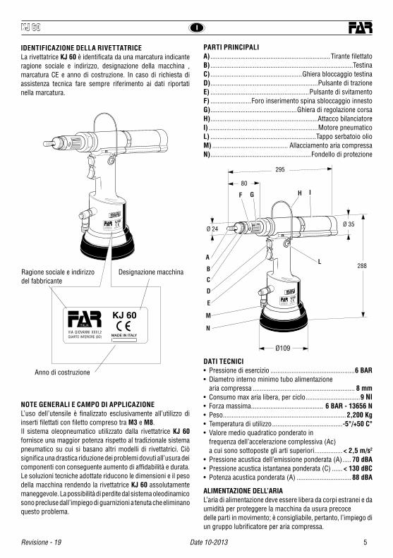
IDENTIFICAZIONE DELLA RIVETTATRICELa rivettatrice KJ 60 è identificata da una marcatura indicante ragione sociale e indirizzo, designazione della macchina , marcatura CE e anno di costruzione. In caso di richiesta di assistenza tecnica fare sempre riferimento ai dati riportati nella marcatura.
NOTE GENERALI E CAMPO DI APPLICAZIONE L’uso dell’utensile è finalizzato esclusivamente all’utilizzo di inserti filettati con filetto compreso tra M3 e M8.Il sistema oleopneumatico utilizzato dalla rivettatrice KJ 60 fornisce una maggior potenza rispetto al tradizionale sistema pneumatico su cui si basano altri modelli di rivettatrici. Ciò significa una drastica riduzione dei problemi dovuti all’usura dei componenti con conseguente aumento di affidabilità e durata. Le soluzioni tecniche adottate riducono le dimensioni e il peso della macchina rendendo la rivettatrice KJ 60 assolutamente maneggevole. La possibilità di perdite dal sistema oleodinamico sono precluse dall’impiego di guarnizioni a tenuta che eliminano questo problema.
DATI TECNICI• Pressione di esercizio ................................................6 BAR• Diametro interno minimo tubo alimentazione aria compressa .......................................................... 8 mm• Consumo max aria libera, per ciclo ...............................9 Nl• Forza massima ......................................... 6 BAR - 13656 N• Peso ......................................................................2,200 Kg• Temperatura di utilizzo ........................................-5°/+50 C°• Valore medio quadratico ponderato in frequenza dell’accelerazione complessiva (Ac) a cui sono sottoposte gli arti superiori ................ < 2,5 m/s2
• Pressione acustica dell’emissione ponderata (A) ..... 70 dBA• Pressione acustica istantanea ponderata (C) ...... < 130 dBC• Potenza acustica ponderata (A) ............................... 88 dBA
PARTI PRINCIPALIA) ....................................................................Tirante filettatoB) .................................................................................TestinaC) ....................................................Ghiera bloccaggio testinaD) .............................................................Pulsante di trazioneE) ........................................................Pulsante di svitamentoF) .......................Foro inserimento spina sbloccaggio innestoG) .................................................Ghiera di regolazione corsaH) .............................................................Attacco bilanciatoreI) ..............................................................Motore pneumaticoL) ............................................................Tappo serbatoio olioM) ........................................... Allacciamento aria compressaN) .........................................................Fondello di protezione
KJ 60
KJ 60
Ragione sociale e indirizzo del fabbricante
Designazione macchina
Anno di costruzione
80
Ø 35
295
288
Ø109
Ø 24
KJ 60
L
F
E
A
B
C
M
D
G H I
N
ALIMENTAZIONE DELL’ARIAL’aria di alimentazione deve essere libera da corpi estranei e da umidità per proteggere la macchina da usura precocedelle parti in movimento; è consigliabile, pertanto, l’impiego di un gruppo lubrificatore per aria compressa.

I KJ 60
6 Date 10-2013 Revisione - 19
ATTENZIONE!!! LA REGOLAZIONE NON CORRETTA DELLA CORSA DELLA RIVETTATRICE PUÒ CAUSARE IL CATTIVO SERRAGGIO DEGLI INSERTI E LA ROTTURA DEL TIRANTE!
POSA IN OPERA DELL’INSERTOVerificare che la coppia tirante-testina montata sulla rivettatrice sia adeguata alla misura dell’inserto che si vuole serrare; in caso contrario procedere al cambio di formato. Solitamente la coppia tirante-testina montata sulla rivettatrice in confezione corrisponde ad una filettatura di M8. Prima di utilizzare la rivettatrice e dopo ogni cambio di formato occorre eseguire le seguenti operazioni in funzione del formato e dello spessore del materiale da serrare:Regolare la corsa della rivettatrice al minimo, ruotando per quanto possibile la ghiera “G” nel senso indicato dal simbolo “–”. Inserire l’inserto sul tirante ed esercitare su di esso una leggera pressione; in questo modo l’inserto si avvita automaticamente sul tirante. Assicurarsi che la testa dell’inserto vada in battuta con la testina della rivettatrice. Fissare l’inserto e verificare il serraggio che questo opera sullo spessore del materiale. Regolare la corsa della rivettatrice mediante la rotazione della ghiera “G”, in funzione del serraggio desiderato, considerando che all’aumentare della corsa (rotazione della ghiera “G” nel senso indicato dal simbolo “+”) la distanza “h” tra testa e deformazione dell’inserto diminuisce con conseguente aumento dell’azione di serraggio.
+
–
HH
G
7
IKJ 60
Revisione - 19 Date 10-2013
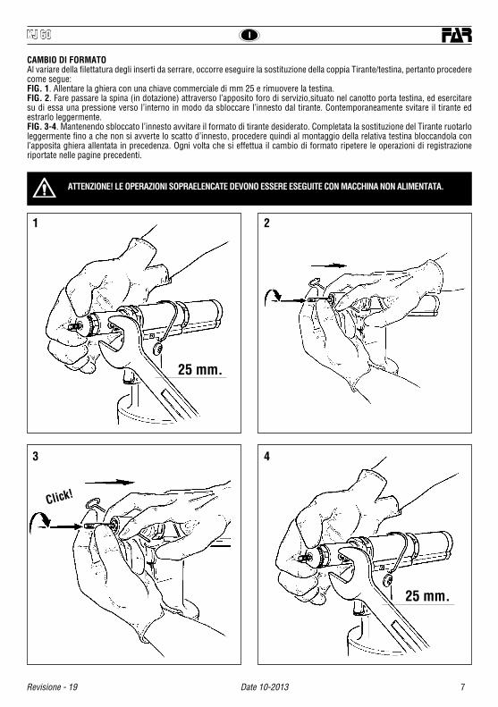
CAMBIO DI FORMATOAl variare della filettatura degli inserti da serrare, occorre eseguire la sostituzione della coppia Tirante/testina, pertanto procedere come segue:FIG. 1. Allentare la ghiera con una chiave commerciale di mm 25 e rimuovere la testina.FIG. 2. Fare passare la spina (in dotazione) attraverso l’apposito foro di servizio,situato nel canotto porta testina, ed esercitare su di essa una pressione verso l’interno in modo da sbloccare l’innesto dal tirante. Contemporaneamente svitare il tirante ed estrarlo leggermente. FIG. 3-4. Mantenendo sbloccato l’innesto avvitare il formato di tirante desiderato. Completata la sostituzione del Tirante ruotarlo leggermente fino a che non si avverte lo scatto d’innesto, procedere quindi al montaggio della relativa testina bloccandola con l’apposita ghiera allentata in precedenza. Ogni volta che si effettua il cambio di formato ripetere le operazioni di registrazione riportate nelle pagine precedenti.
ATTENZIONE! LE OPERAZIONI SOPRAELENCATE DEVONO ESSERE ESEGUITE CON MACCHINA NON ALIMENTATA.
1
3
2
4
25 mm.
25 mm.
Click!
I KJ 60
8 Date 10-2013 Revisione - 19
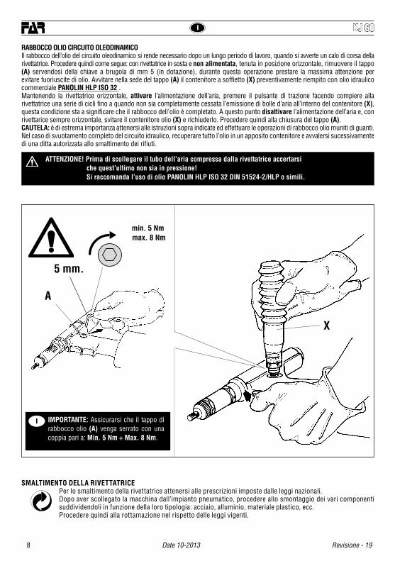
RABBOCCO OLIO CIRCUITO OLEODINAMICOIl rabbocco dell’olio del circuito oleodinamico si rende necessario dopo un lungo periodo di lavoro, quando si avverte un calo di corsa della rivettatrice. Procedere quindi come segue: con rivettatrice in sosta e non alimentata, tenuta in posizione orizzontale, rimuovere il tappo (A) servendosi della chiave a brugola di mm 5 (in dotazione), durante questa operazione prestare la massima attenzione per evitare fuoriuscite di olio. Avvitare nella sede del tappo (A) il contenitore a soffietto (X) preventivamente riempito con olio idraulico commerciale PANOLIN HLP ISO 32 .Mantenendo la rivettatrice orizzontale, attivare l’alimentazione dell’aria, premere il pulsante di trazione facendo compiere alla rivettatrice una serie di cicli fino a quando non sia completamente cessata l’emissione di bolle d’aria all’interno del contenitore (X), questa condizione sta a significare che il rabbocco dell’olio è completato. A questo punto disattivare l’alimentazione dell’aria e, con rivettarice sempre orizzontale, svitare il contenitore olio (X) e richiuderlo. Procedere quindi alla chiusura del tappo (A).CAUTELA: è di estrema importanza attenersi alle istruzioni sopra indicate ed effettuare le operazioni di rabbocco olio muniti di guanti.Nel caso di svuotamento completo del circuito idraulico, recuperare tutto l’olio in un apposito contenitore e avvalersi sucessivamente di una ditta autorizzata allo smaltimento dei rifiuti.
ATTENZIONE! Prima di scollegare il tubo dell’aria compressa dalla rivettatrice accertarsi che quest’ultimo non sia in pressione! Si raccomanda l’uso di olio PANOLIN HLP ISO 32 DIN 51524-2/HLP o simili.
I IMPORTANTE: Assicurarsi che il tappo di rabbocco olio (A) venga serrato con una coppia pari a: Min. 5 Nm ÷ Max. 8 Nm.
A
X
5 mm.
min. 5 Nm max. 8 Nm
SMALTIMENTO DELLA RIVETTATRICEPer lo smaltimento della rivettatrice attenersi alle prescrizioni imposte dalle leggi nazionali.Dopo aver scollegato la macchina dall’impianto pneumatico, procedere allo smontaggio dei vari componenti suddividendoli in funzione della loro tipologia: acciaio, alluminio, materiale plastico, ecc.Procedere quindi alla rottamazione nel rispetto delle leggi vigenti.

9
KJ 60
Revisione - 19 Date 10-2013
INSTRUCTIONS FOR USE I
INDEX
GUARANTEE AND TECHNICAL ASSISTANCE .............................. 9SAFETY MEASURES AND REQUIREMENTS ............................... 9TOOL IDENTIFICATION ............................................................. 10GENERAL NOTES AND USE ...................................................... 10MAIN COMPONENTS ................................................................ 10TECHNICAL DATA ..................................................................... 10PLACING OF THE INSERT ......................................................... 11CHANGE OF SIZE ..................................................................... 12TOOPING UP THE OIL-DYNAMIC CIRCUIT ............................... 13DISPOSAL OF THE RIVETING TOOL ......................................... 13
CAUTION!!!All the operations must be done in conformity with the safety requirements, in order to avoid any consequence for your and other people security and to allow the best tool work way.
• Read the instructions carefully before using the tool.• For all maintenance and/or repairs please contact FAR s.r.l.
authorized service centers and use only original spare parts. FAR s.r.l. may not be held liable for damages from defective parts caused by failure to observe what mentioned above (EEC directive85/374).
The list of the service centres is available on our website http://www.far.bo.it ( Organization )
• The tool must be used only by expert workers.• A protective visor and gloves must be put on when using the
tool.• For topping up the oil, we suggest using only fluids in accordance
with the features specified in this working book.• If any drop of oil touches your skin, you must wash with water
and alkaline soap.• The tool can be carried and we suggest putting it into its box
after using.• The tool needs a thorough six-monthly overhaul.
GUARANTEE AND TECHNICAL ASSISTANCE
FAR riveting tools are covered by a 12-month warranty. The tool warranty period starts on the date of delivery to the buyer, as specified in the relevant document. The warranty covers the user/buyer provided that the tool is purchased through an authorized dealer and only if it is used for the purposes for which it was conceived. The warranty shall not be valid if the tool is not used or maintained as specified in the instruction and maintenance handbook. In the event of defects or failures, FAR S.r.l. shall undertake solely to repair and/or replace the components it judges to be faulty.
SAFETY MEASURES AND REQUIREMENTS
• Repairing and cleaning operations must be done when the tool is not fed.
• A safety balancer is suggested when it is possible.• If the A-weighted emission sound pressure level is more than
70 dB (A), you must use some hearing protections (anti-noise headset, etc.).
• The workbench and the work surface must be always clean and tidy. The untidy can cause damages to people.
• Do not allow unauthorized persons to use the working tools.• Make you sure that the compressed air feeding hoses have the
correct size to be used. • Do not carry the connected tool by pulling the hose. The hole
must be far from any heating sources or from cutting parts.• Keep the tools in good conditions; do not remove either safety
parts or silencers.• After repairing and/or adjusting, make sure you have already
removed the adjusting spanners.• Before disconnecting the compressed air hose from the tool
make sure that there is no pressure in the hose.• These instructions must be carefully followed.
WARNING! Before using the tool, assemble the protection bottom supplied with the tool, as indicated in the picture on side.FAR has no responsibility for any damages on the tool, persons or things caused by lack of the protection bottom.
KJ 60
GB
GB KJ 60
10 Date 10-2013 Revisione - 19
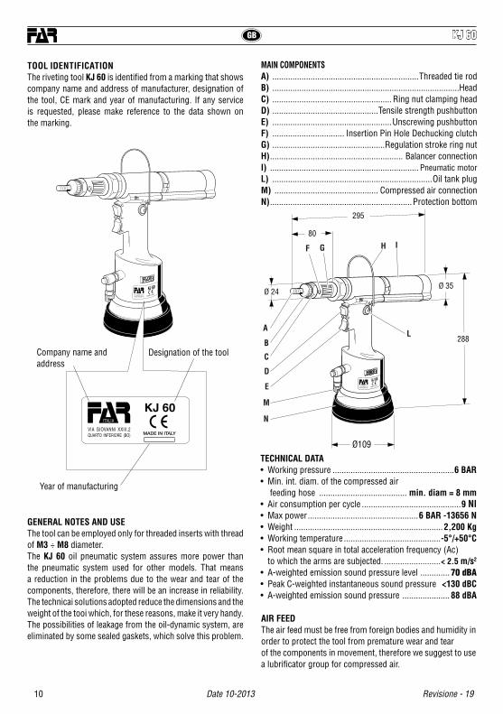
TOOL IDENTIFICATIONThe riveting tool KJ 60 is identified from a marking that shows company name and address of manufacturer, designation of the tool, CE mark and year of manufacturing. If any service is requested, please make reference to the data shown on the marking.
GENERAL NOTES AND USEThe tool can be employed only for threaded inserts with thread of M3 ÷ M8 diameter.The KJ 60 oil pneumatic system assures more power than the pneumatic system used for other models. That means a reduction in the problems due to the wear and tear of the components, therefore, there will be an increase in reliability. The technicai solutions adopted reduce the dimensions and the weight of the tooi which, for these reasons, make it very handy. The possibilities of leakage from the oil-dynamic system, are eliminated by some sealed gaskets, which solve this problem.
TECHNICAL DATA• Working pressure ......................................................6 BAR• Min. int. diam. of the compressed air feeding hose ....................................... min. diam = 8 mm• Air consumption per cycle ............................................9 Nl• Max power .................................................6 BAR -13656 N• Weight ..................................................................2,200 Kg• Working temperature ...........................................-5°/+50°C• Root mean square in total acceleration frequency (Ac) to which the arms are subjected. .........................< 2.5 m/s2
• A-weighted emission sound pressure level ............. 70 dBA• Peak C-weighted instantaneous sound pressure <130 dBC• A-weighted emission sound pressure ..................... 88 dBA
MAIN COMPONENTSA) .................................................................Threaded tie rodB) ...................................................................................HeadC) ..................................................... Ring nut clamping headD) ...............................................Tensile strength pushbuttonE) .....................................................Unscrewing pushbuttonF) ................................ Insertion Pin Hole Dechucking clutch G) ..................................................Regulation stroke ring nutH) ........................................................... Balancer connection I) .................................................................. Pneumatic motorL) .......................................................................Oil tank plugM) .............................................. Compressed air connectionN) ...............................................................Protection bottom
KJ 60
KJ 60
80
Ø 35
295
288
Ø109
Ø 24
KJ 60
L
F
E
A
B
C
M
D
G H I
N
AIR FEEDThe air feed must be free from foreign bodies and humidity in order to protect the tool from premature wear and tear of the components in movement, therefore we suggest to use a lubrificator group for compressed air.
Company name and address
Designation of the tool
Year of manufacturing

11
GBKJ 60
Revisione - 19 Date 10-2013
WARNING!!! A WRONG ADJUSTMENT OF THE RIVETING TOOL STROKE MAY CAUSE A FAULTY CLAMPING OF INSERTS AND MAY BRAKE THE TIE ROD!
PLACING OF THE INSERTMake sure that the couple tie-rod/head mounted on your riveting tool is suitable for the insert to clamp; otherwise, change size accordingly. Usually the riveting tool is supplied with the couple tie-rod/head corresponding to a M8 thread. Before using the riveting tool and after any change of size, perform the following operations according to the size and thickness of the part to clamp. Adjust the riveting tool stroke to the minimum by turning the ring nut “G” to “–” marked on the tool. Place the insert on the tie rod and push slightly on it so as to make it clamp automatically. Make sure the insert head touches the riveting tool head properly. Fasten the insert and in order to ensure a proper clamping of the material, adjust the riveting tool stroke by turning the ring nut “G” accordingly. By increasing stroke, i.e. by turning the ring nut “G” to “+”, the distance “h” between head and insert deformation will decrease and clamping will result more effective.
+
–
HH
G
GB KJ 60
12 Date 10-2013 Revisione - 19
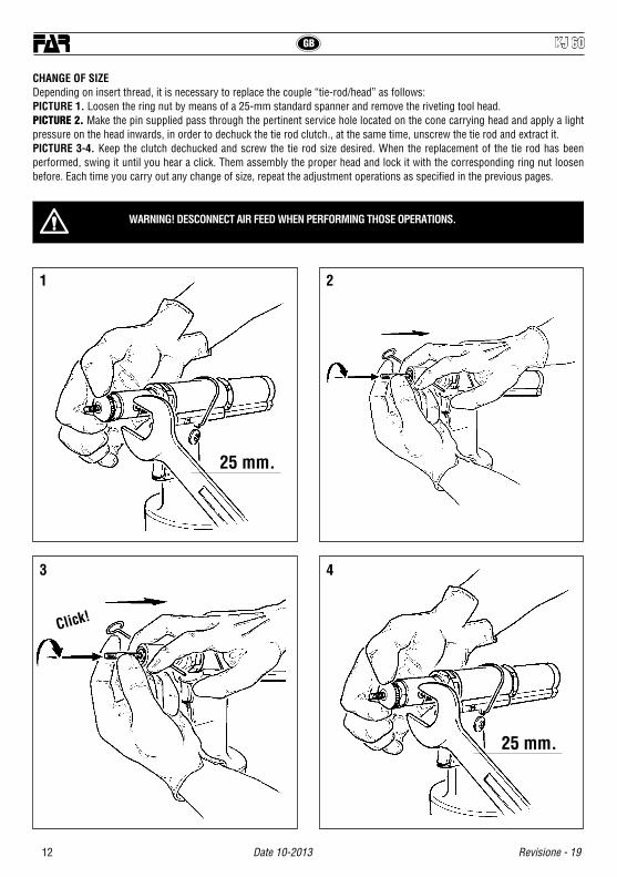
CHANGE OF SIZEDepending on insert thread, it is necessary to replace the couple “tie-rod/head” as follows:PICTURE 1. Loosen the ring nut by means of a 25-mm standard spanner and remove the riveting tool head.PICTURE 2. Make the pin supplied pass through the pertinent service hole located on the cone carrying head and apply a light pressure on the head inwards, in order to dechuck the tie rod clutch., at the same time, unscrew the tie rod and extract it.PICTURE 3-4. Keep the clutch dechucked and screw the tie rod size desired. When the replacement of the tie rod has been performed, swing it until you hear a click. Them assembly the proper head and lock it with the corresponding ring nut loosen before. Each time you carry out any change of size, repeat the adjustment operations as specified in the previous pages.
WARNING! DESCONNECT AIR FEED WHEN PERFORMING THOSE OPERATIONS.
1
3
2
4
25 mm.
25 mm.
Click!

13
GBKJ 60
Revisione - 19 Date 10-2013
TOPPING UP THE OIL-DYNAMIC CIRCUITYou need to top up the oil-dynamic circuit after a long period of work, when you note a power loss. Put the riveting tool (DWELL AND NOT FED) in a horizontal position and remove the plug (A), by means of a 5 mm Allen wrench (equipped with the riveting tool); during this operation, check the oil level in order to avoid any overflowing. Then, slowly pour the oil PANOLIN HLP ISO 32 into the bellows container (X) which shall be screwed to its seat on the plug (A). While keeping the riveting tool in a horizontal position and starting air feeding, push the tensile strength button and make the riveting tool carry out some cycles until air bubbles inside the container (X) stop coming out. This condition indicates that the topping up of the oil has fully been achieved. At this point stop the air feeding and, while keeping the riveting tool in a horizontal position, unscrew and close up the container (X) and the plug (A).WARNING: it is very important to follow the about mentioned instructions and use gloves. If you need to empty fully the hydraulic circuit, you must put the oil in a suitable container and contact a Company that is authorized to discharge any waste
WARNING! Before disconnecting the compressed air hose, make sure that it is not under pressure! We recommend to use oil PANOLIN HLP ISO 32 DIN 51524-2/HLP or similars.
WARNING: Make sure that the oil filler cap (A) is tightened at a torque corresponding to Min. 5 Nm ÷ Max. 8 Nm.
A
X
5 mm.
min. 5 Nm max. 8 Nm
DISPOSAL OF THE RIVETING TOOLFollow the prescriptions of the national laws for disposing of the riveting tool.After disconnecting the tool from the pneumatic system, disassemble and split all the components according to the material: steel, aluminium, plastic material, etc.Then proceed to scrap the materials in accordance with current laws.
GB
F KJ 60
14 Date 10-2013 Revisione - 19
MODE D’EMPLOI
INDEX
GARANTIE ET ASSISTANCE TECHNIQUE .................................. 14INSTRUCTIONS ET MESURES DE SECURITE ........................... 14IDENTIFICATION DE L’OUTIL DE POSE ..................................... 15CARACTERISTIQUES ET EMPLOI ............................................. 15 PARTIES PRINCIPALES ............................................................ 15CARACTERISTIQUES TECHNIQUES .......................................... 15POSE DE L’INSERT.................................................................... 16CHANGEMENT DE FORMAT ...................................................... 17REMPLISSAGE DE L’HUILE DU CIRCUIT HYDRAULIQUE ......... 18ELIMINATION DE LA RIVETEUSE .............................................. 18
ATTENTION!!!Le non respect des instructions suivantes peut avoir des conséquences désagréables pour vous-mêmes et pour l’intégrité d’autrui.
• Lisez avec soin la notice avant l’usage.• Pour les opérations d’entretien et/ou réparations, adressez-vous
aux centres de service après-vente autorisés de FAR s.r.l. et n’utilisez que des pièces détachées originales. FAR s.r.l. décline toute responsabilité pour les dommages dus à des pièces défectueuses qui interviendraient suite au non-respect de la notice ci-dessus (Directive CEE 85/374).
La liste des centres d’assistance est disponible sur notre site internet http://www.far.bo.it ( Organisation )
• L’outil de pose doit être utilisé par le personnel spécialisé.• Pendant l’utilisation de l’outil utiliser des gants et des lunettes
de protections ou une visière• Pour le remplissage de l’huile, il faut utiliser les fluides indiqués
dans ce dossier.• En cas de fuites imprévues de huile (au contact de la peau), il
faut se laver soigneusement avec de l’eau et du savon alcalin.• L’outil de pose peut être transporté à la main et il doit être remis
dans sa boîte après l’usage.
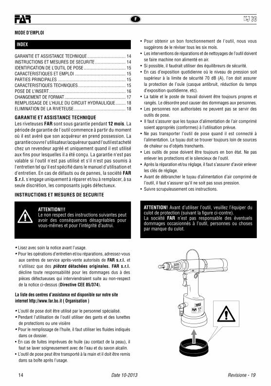
ATTENTION! Avant d’utiliser l’outil, veuillez l’équiper du culot de protection (suivant la figure ci-contre).La société FAR n’est pas responsable des éventuels dommages occasionnés à l’outil, personnes ou choses par manque du culot.
GARANTIE ET ASSISTANCE TECHNIQUELes riveteuses FAR sont sous garantie pendant 12 mois. La période de garantie de l'outil commence à partir du moment où il est avéré que son acquéreur en prend possession. La garantie couvre l'utilisateur/acquéreur quand l'outil est acheté chez un revendeur agréé et uniquement quand il est utilisé aux fins pour lesquelles il a été conçu. La garantie n'est pas valable si l'outil n'est pas utilisé et s'il n'est pas soumis à l'entretien tel qu'il est spécifié dans le manuel d'utilisation et d'entretien. En cas de défauts ou de pannes, la société FAR S.r.l. s'engage uniquement à réparer et/ou à remplacer, à sa seule discrétion, les composants jugés défectueux.
INSTRUCTIONS ET MESURES DE SECURITE
• Pour obtenir un bon fonctionnement de l’outil, nous vous suggérons de le réviser tous les six mois.
• Les interventions de réparations et de nettoyages de l’outil doivent se faire machine non alimenté en air.
• Si possible, il faudrait utiliser des équilibreurs de sécurité.• En cas d’exposition quotidienne où le niveau de pression soit
supérieur à la limite de sécurité 70 dB (A), l’on doit assurer la protection de l’ouïe (casque antibruit, réduction du temps d’exposition quotidienne, etc).
• La table et le poste de travail doivent être toujours propres et rangés. Le désordre peut causer des dommages aux personnes.
• Les personnes non authorisées ne peuvent pas se servir des outils de pose.
• Il faut s’assurer que les tuyaux d’alimentation de l’air comprimé soient appropriés (conformes) à l’utilisation prévue.
• Ne pas transporter l’outil de pose quand il est connecté à l’alimentation. Le tuyau doit se trouver toujours loin de sources de chaleur ou d’objets tranchants.
• Les outils de pose doivent être toujours en bon état. Ne pas enlever les protections et le silencieux de l’outil.
• Après la réparation et/ou réglage, il faut s’assurer d’avoir enlever les clés de réglage.
• Avant de débrancher le tuyau d’alimentation d’air comprimé de l’outil, il faut s’assurer qu’il ne soit pas sous pression.
• Suivre scrupuleusement ces instructions.
KJ 60

15
FKJ 60
Revisione - 19 Date 10-2013
IDENTIFICATION DE L’OUTIL DE POSE L’outil de pose KJ 60 est identifié par un marquage indiquant raison sociale et adresse du fabricant, désignation de l’outil de pose, marquage CE et année de fabrication.En cas de réclamation auprès de nos services techniques, il faut toujours se référer aux données indiquées dans le marquage.
CARACTERISTIQUES ET EMPLOIL’outil peut être utilisé seulement pour inserts filetés avec filet M3 ÷ M8.Le système oléopneumatique de l’outil KJ 60 permet d’obtenir un puissance supérieure par rapport au système pneumatique traditionnel.Cela signifie une réduction des problemes provoques par l’usure des composants, donc, une plus grande longevité. Les solutions techniques adoptées réduisent les dimensions et le poids du pistolet en la rendant très maniable. Les risques de fuites du système oléodynamique sont éliminés par l’utilisation de joints à haute résistance.
CARACTERISTIQUES TECHNIQUES• Pression d’utilization ..................................................6 BAR• Diamètre int. min. tuyau alimentation air comprima ............................................................ 8 mm• Consommation d’air par cycle ......................................9 Nl• Force maximum ....................................... 6 BAR - 13656 N• Poids ....................................................................2,200 Kg• Température d’utilisation ....................................-5°/+50 C°• Valeur moyenne quadratique pondérée en fréquence de l’accélération totale (Ac) à laquelle les bras sont soumis .......................................... < 2,5 m/s2
• Pression acoustique de l’émission pondéré (A) ....... 70 dBA• Pression acoustique instantanée pondéré (C) .... < 130 dBC• Puissance acoustique pondérée (A) ......................... 88 dBA
PARTIES PRINCIPALESA) ......................................................................... Tirant filetéB) .................................................................................... Tête C) ............................................................. Ecrou blocage têteD) .............................................. Bouton-poussoir de tractionE) ...........................................Bouton-poussoir de devissageF) ................Trou pour passage de la broche pour deblocage ........................................................................de l’embrayage G) ........................................... Bague de réglage de la courseH) ............................................................... Etrier de support I) ............................................................. Moteur pneumatiqueL) .............................................Orifice de remplissage d’huileM) ....................................................Raccord d’air compriméN) ..............................................................Culot de protection
KJ 60
KJ 60
80
Ø 35
295
288
Ø109
Ø 24
KJ 60
L
F
E
A
B
C
M
D
G H I
N
ALIMENTATION EN AIRL’air d’alimentation doit être libre de corps étrangers et d’humidité pour sauvegarder l’outil de l’usure précoce desparties en mouvement, donc il est recommandé d’employer un groupe de graissage pour air comprimè.
Raison sociale et adresse Designation de l’outil de pose
Année de fabrication

F KJ 60
16 Date 10-2013 Revisione - 19
ATTENTION!!! LE REGLAGE INCORRECT DE LA COURSE DE L’OUTIL DE POSE PEUT PROVOQUER LE MAUVAIS SERRAGE DES INSERTS ET LA RUPTURE DU TIRANT!
POSE DE L’INSERTVérifier si le couple tirant-tête monté sur l’outil de pose correspond à la mesure de l’insert à serrer; dans le cas contraire procéder au changement du format. Généralement le couple tirant-tête fourni avec l’outil de pose correspond à un filet M8. Avant d’utiliser l’outil et après tout changement du format il faut effectuer les opérations suivantes selon le format et l’épaisseur de la pièce à serrer: Régler la course de l’outil de pose au minimum, en tournant autant que possible l’embout de réglage “G” dans le sens indiqué par le symbole “–”. Embrocher l’insert sur le tirant et faire une légère pression sur l’insert; de cette façon il se visse automatiquement sur le tirant. Il faut s’assurer que la tête de l’insert touche la tête de l’outil de pose. Fixer l’insert et en vérifier le serrage sur l’épaisseur du matériel à serrer. Régler la course de l’outil de pose en tournant l’embout “G” selon le serrage voulu. La distance “h” entre tête et déformation de l’insert est réduite quand l’on augmente la course (rotation de l’embout “G” dans le sens indiqué par le symbole “+”), le serrage est par conséquent augmenté.
+
–
HH
G

17
FKJ 60
Revisione - 19 Date 10-2013
CHANGEMENT DE FORMATLors de la modification du filet des inserts à serrer il faut remplacer le couple tirant/tête. Procéder comme suit:FIG. 1. Dévisser l’embout au moyen d’une clé plate standard de 25 mm et enlever la tête.FIG. 2. Faire passer la broche (fournie) par le trou de service se trouvant sur le cône porte-têtes et faire sur la broche une pression vers l’arrière pour débloquer l’embrayage du tirant. En même temps, dévisser le tirant et le faire sortir.FIG. 3-4. Toujours avec l’embrayage débloqué, visser le format de tirant choisi. Terminé le remplacement du couple tirant/tête, tourner légèrement le tirant même jusqu’au moment où l’on remarque le déclic d’embrayage. Ensuite, monter la tête correspondante et la bloquer par l’embout prévu à cet effet et précédemment dévissé. Chaque fois que l’on effectue le changement de format, on doit répéter les opérations indiquées dans les chapitres précédents.
ATTENTION! EFFECTUER LES OPERATIONS SUSMENTIONNEES LE PISTOLET N’ETANT PAS ALIMENTE.
1
3
2
4
25 mm.
25 mm.
Click!

KJ 60
18 Date 10-2013 Revisione - 19
F
REMPLISSAGE DE L’HUILE DU CIRCUIT HYDRAULIQUELe remplissage de l’huile du circuit hydraulique est nécessaire après une longue période de travail, quand l’on remarque une diminution de puissance. Mettre l’outil de pose (déconnecté) en position horizontale, enlever le bouchon (A) en utilisant la clé de 5 mm (fournie); pendant cette opération, il faut soigneusement éviter d’écoulements d’huile. Ensuite visser dans le logement du bouchon (A) le conteneur à soufflet (X) après l’avoir rempli d’huile PANOLIN HLP ISO 32. En retenant l’outil de pose en position horizontale, mettre en route l’alimentation de l’air, presser le bouton de traction et faire effectuer à l’outil quelques cycles jusqu’à ce qu’il n’y ait plus de bulles d’air à l’intérieur du conteneur (X). Cette condition signifie que le remplissage de l’huile est achevé. A ce point, il faut désactiver l’alimentation de l’air et, avec l’outil de pose en position horizontale, dévisser le conteneur (X) et le refermer. Ensuite, il faut fermer le bouchon (A).PRECAUTION: il faut suivre impérativement les instructions ci-dessus et se munir de gants avant l’opération de remplissage de l’huile.En cas de vidange totale du circuit hydraulique, l’on doit verser l’huile dans un conteneur spécial et ensuite, il faut contacter une maison (société) autorisée à l’écoulement des ordures.
ATTENTION! Avant de déconnecter le tuyau de l’air comprimé, il faut s’assurer qu’il ne soit pas en pression! Nous recommandons l'utilisation d'huile PANOLIN HLP ISO 32 DIN 51524-2/HLP ou similaires
IMPORTANT: S’assurer que le bouchon de remplissage d’huile (A) soit vissé avec couple de Min. 5 Nm ÷ Max. 8 Nm.
A
X
5 mm.
min. 5 Nm max. 8 Nm
ELIMINATION DE LA RIVETEUSEPour l’élimination de la riveteuse, veiller au respect des dispositions légales en vigueur dans le pays où l’élimination s’effectue.Après avoir débranché la machine de l’alimentation pneumatique, procéder au démontage des différents composants en fonction de la nature des matériaux : acier, aluminium, matières plastiques, etc…Procéder à la démolition dans le respect de la réglementation en vigueur.
F
19
KJ 60
Revisione - 19 Date 10-2013
D
BEDIENUNGSANLEITUNG I
INHALTSVERZEICHNIS
GEWÄHRLEISTUNG UND TECHNISCHER KUNDENDIENST ...... 19SICHERHEITSMASSNAHMEN UND ANWEISUNGEN ................ 19WERKZEUGIDENTIFIZIERUNG .................................................. 20ALLGEMEINES UND ANWENDUNGSBEREICH .......................... 20HAUPTTEILE ............................................................................. 20TECHNISCHE DATEN................................................................. 20SETZVORGANG ......................................................................... 21DIMENSIONSWECHSEL ............................................................ 22NACHFÜLLEN VON ÖL IN DEM ÖLDYNAMISCHEN KREIS........ 23ENTSORGUNG DER NIETMASCHINE ........................................ 23
Alle Arbeiten müssen in Übereinstimmung mit den Sicherheitsvorschriften durchgeführt werden, um die eigene Sicherheit und die anderer Personen zu gewährleisten und die beste zu erreichen.
• Die Anleitung vor Gebrauch des Geräts aufmerksam lesen.• Die Wartungs- und/oder Reparaturarbeiten von den autorisierten
Kundendienststellen von FAR s.r.l. ausführen lassen und ausschließlich Originalersatzteile verwenden. Die Firma FAR s.r.l. haftet nicht für durch defekte Teile verursachte Schäden, sofern diese auf die Mißachtung der o.g. Vorschrift zurückzuführen sind (Richtlinie 85/374/EWG).
Die Liste der Reparaturservices ist verfügbar unter unserer Webseite http://www.far.bo.it ( Organisation )
• Das Werkzeug darf nur von Facharbeitern benütz werden. • Bei Gebrauch des Werkzeuges sind Schutzbrille und Handschuhe
zu verwenden.• Beim Ölwechsel verwenden Sie nur Öle die den empfohlenen
Ölen dieser Anleitung entsprechen.• Falls Sie Öl auf die Haut bekommen, waschen Sie die mit Wasser
und Alkaliseife ab.• Wir empfehlen das Werkzeug nach Gebrauch in den Koffer zu
geben, in der es auch transportiert werden kann.
GEWÄHRLEISTUNG UND TECHNISCHER KUNDENDIENST
Auf die Nietwerkzeuge von FAR wird eine Garantie von 12 Monaten gewährt. Der Garantiezeitraum beginnt in dem Moment, in dem der Käufer das Gerät nachweislich in Empfang genommen hat. Die Garantie ist nur gültig, wenn das Gerät bei einem Vertragshändler erworben und ausschließlich zu den Zwecken verwendet wird, für die es konzipiert wurde. Die Garantie wird ungültig, wenn das Gerät nicht in Einklang mit den Anweisungen in der Betriebs- und Wartungsanleitung verwendet und gewartet wird. Die Firma FAR s.r.l. verpflichtet einzig zur Reparatur bzw. zum Austausch, nach ihrem ausschließlichen Ermessen, der Komponenten, die für mangelhaft befunden werden.
SICHERHEITSMASSNAHMEN UND ANWEISUNGEN
• Das Werkzeug soll alle sechs Monate gründlich überholt werden.• Bei Reparatur und Reinigung des Werkzeuges ist das Gerät immer
vom Druckluftnetz zu trennen.• Wenn notwendig verwenden Sie einen Sicherheits-Balancer.• F a l l s d a s P e r s o n a l t ä g l i c h e i n e m A - b e w e r t e t e n
Emissionsschalldruckpegel über die gesetzliche Grenze von 70 dB (A) ausgesetzt ist, muss immer ein Ohrenschutz getragen werden (wie Gehörschutzkapseln oder -pfropfen, Verkürzung des täglichen Aufenthalts im Lärmbereich usw.)
• Die Werkbank und/oder Arbeitsfläche sollen immer rein sein; die Unordnung kann Personenschaden verursachen.
• Werkzeuge dürfen durch Unbefugte nicht betrieben werden. • Versichern Sie sich, daß der Druckluftschlauch in der richtigen
Dimension ist.• Nehmen Sie das angeschlossene Werkzeug nie am
Druckluftschlauch. Das gesamte Werkzeug soll fern von Hitze und schneidenden
Teilen gehalten werden. • Halten Sie das Werkzeug sauber und in gutem Zustand und
nehmen Sie weder Schutzvorrichtungen noch Schalldämpfer weg. • Nach Reparatur und/oder Einstellung vergewissern Sie sich, daß
die Dienst- oder Einstellschlüssel entfernt wurden.• Bevor Sie den Druckluftschlauch vom Werkzeug abschalten,
vergewissern Sie sich, dass dieser drucklos ist.• Diese Anweisungen müssen sorgfältig beachtet werden.
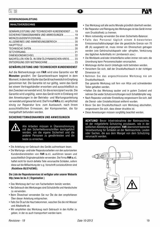
ACHTUNG! Bevor Inbetriebnahme der Nietmaschine, ist der mitgelieferte Schutzring anzubauen, wie in der seitlichen Abbildung angegeben. FAR übernimmt keinerlei Verantwortung für Schäden an der Nietmaschine, Leuten oder Sachen, die aus dem Mangel von dem Schutzring verursacht werden.
KJ 60
D KJ 60
20 Date 10-2013 Revisione - 19
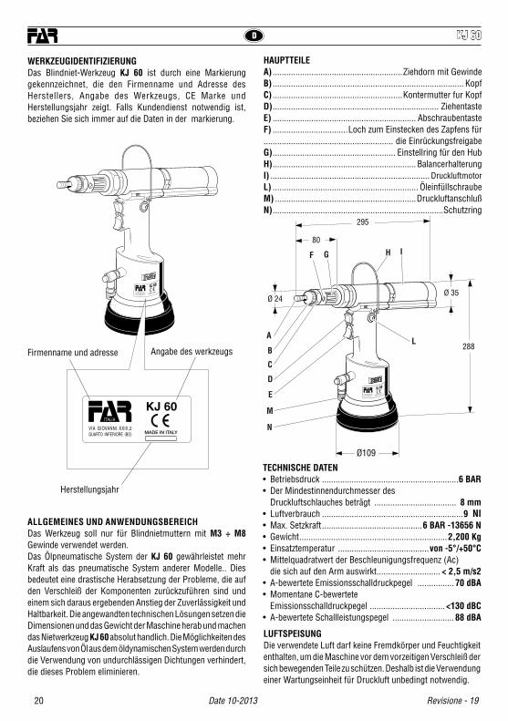
WERKZEUGIDENTIFIZIERUNG Das Blindniet-Werkzeug KJ 60 ist durch eine Markierung gekennzeichnet, die den Firmenname und Adresse des Herstellers, Angabe des Werkzeugs, CE Marke und Herstellungsjahr zeigt. Falls Kundendienst notwendig ist, beziehen Sie sich immer auf die Daten in der markierung.
ALLGEMEINES UND ANWENDUNGSBEREICH Das Werkzeug soll nur für Blindnietmuttern mit M3 ÷ M8 Gewinde verwendet werden. Das Ölpneumatische System der KJ 60 gewährleistet mehr Kraft als das pneumatische System anderer Modelle.. Dies bedeutet eine drastische Herabsetzung der Probleme, die auf den Verschleiß der Komponenten zurückzuführen sind und einem sich daraus ergebenden Anstieg der Zuverlässigkeit und Haltbarkeit. Die angewandten technischen Lösungen setzen die Dimensionen und das Gewicht der Maschine herab und machen das Nietwerkzeug KJ 60 absolut handlich. Die Möglichkeiten des Auslaufens von Öl aus dem öldynamischen System werden durch die Verwendung von undurchlässigen Dichtungen verhindert, die dieses Problem eliminieren.
TECHNISCHE DATEN• Betriebsdruck ............................................................6 BAR• Der Mindestinnendurchmesser des Druckluftschlauches beträgt .................................... 8 mm• Luftverbrauch ..............................................................9 Nl• Max. Setzkraft ............................................6 BAR -13656 N• Gewicht .................................................................2,200 Kg• Einsatztemperatur ........................................von -5°/+50°C• Mittelquadratwert der Beschleunigungsfrequenz (Ac) die sich auf den Arm auswirkt ............................ < 2,5 m/s2• A-bewertete Emissionsschalldruckpegel ................ 70 dBA• Momentane C-bewertete Emissionsschalldruckpegel ................................. <130 dBC• A-bewertete Schallleistungspegel ........................... 88 dBA
HAUPTTEILEA) .........................................................Ziehdorn mit GewindeB) .................................................................................... KopfC) .........................................................Kontermutter fur KopfD) ......................................................................... Ziehentaste E) ............................................................... Abschraubentaste F) .................................Loch zum Einstecken des Zapfens für......................................................... die EinrückungsfreigabeG) ...................................................... Einstellring für den HubH) ............................................................... BalancerhalterungI) ...................................................................... DruckluftmotorL) ................................................................ ÖleinfüllschraubeM) ..............................................................DruckluftanschlußN) ...........................................................................Schutzring
KJ 60
KJ 60
80
Ø 35
295
288
Ø109
Ø 24
KJ 60
L
F
E
A
B
C
M
D
G H I
N
LUFTSPEISUNG Die verwendete Luft darf keine Fremdkörper und Feuchtigkeit enthalten, um die Maschine vor dem vorzeitigen Verschleiß der sich bewegenden Teile zu schützen. Deshalb ist die Verwendung einer Wartungseinheit für Druckluft unbedingt notwendig.
Firmenname und adresse Angabe des werkzeugs
Herstellungsjahr
21
DKJ 60
Revisione - 19 Date 10-2013
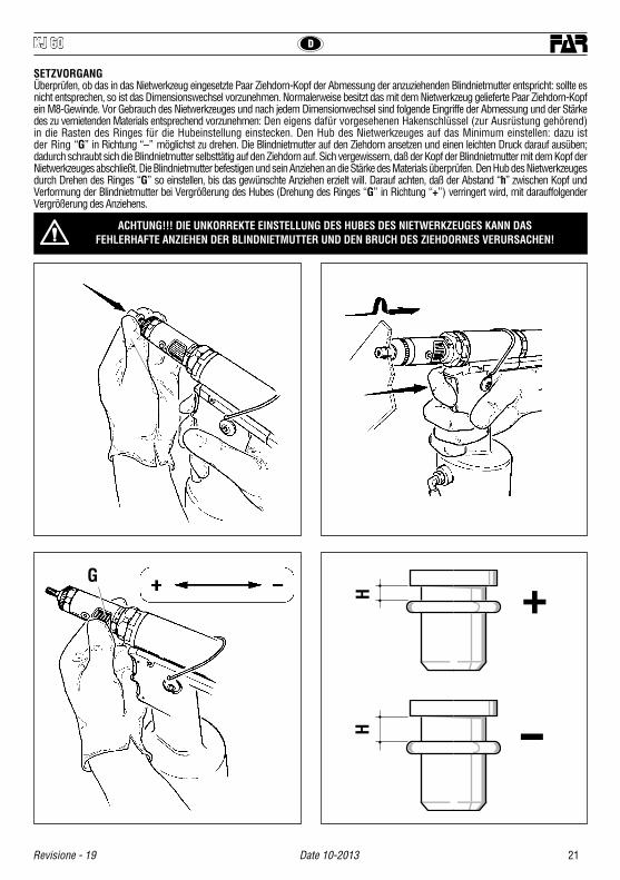
ACHTUNG!!! DIE UNKORREKTE EINSTELLUNG DES HUBES DES NIETWERKZEUGES KANN DAS FEHLERHAFTE ANZIEHEN DER BLINDNIETMUTTER UND DEN BRUCH DES ZIEHDORNES VERURSACHEN!
SETZVORGANGÜberprüfen, ob das in das Nietwerkzeug eingesetzte Paar Ziehdorn-Kopf der Abmessung der anzuziehenden Blindnietmutter entspricht: sollte es nicht entsprechen, so ist das Dimensionswechsel vorzunehmen. Normalerweise besitzt das mit dem Nietwerkzeug gelieferte Paar Ziehdorn-Kopf ein M8-Gewinde. Vor Gebrauch des Nietwerkzeuges und nach jedem Dimensionwechsel sind folgende Eingriffe der Abmessung und der Stärke des zu vernietenden Materials entsprechend vorzunehmen: Den eigens dafür vorgesehenen Hakenschlüssel (zur Ausrüstung gehörend) in die Rasten des Ringes für die Hubeinstellung einstecken. Den Hub des Nietwerkzeuges auf das Minimum einstellen: dazu ist der Ring “G” in Richtung “–” möglichst zu drehen. Die Blindnietmutter auf den Ziehdorn ansetzen und einen leichten Druck darauf ausüben; dadurch schraubt sich die Blindnietmutter selbsttätig auf den Ziehdorn auf. Sich vergewissern, daß der Kopf der Blindnietmutter mit dem Kopf der Nietwerkzeuges abschließt. Die Blindnietmutter befestigen und sein Anziehen an die Stärke des Materials überprüfen. Den Hub des Nietwerkzeuges durch Drehen des Ringes “G” so einstellen, bis das gewünschte Anziehen erzielt will. Darauf achten, daß der Abstand “h” zwischen Kopf und Verformung der Blindnietmutter bei Vergrößerung des Hubes (Drehung des Ringes “G” in Richtung “+”) verringert wird, mit darauffolgender Vergrößerung des Anziehens.
+
–
HH
G

D KJ 60
22 Date 10-2013 Revisione - 19
DIMENSIONSWECHSEL Beim Änderung des Gewindes der zu vernietenden Blindnietmuttern ist das Paar Ziehdorn/Kopf auszutauschen. Dazu wie folgt vorgehen:Abb. 1 Die Kontermutter mittels eines handelsüblichen 25 mm-Gabelschlüssels lockern und den Kopf abnehmen.Abb. 2 Den Zapfen (zur Ausrüstung gehöhend) durch die eigens dafür vorgesehene, an Kopfträger befindliche Serviceöffnung stecken und damit einen Druck nach hinten ausüben, sodaß die Einrückung aus dem Ziehdorn gelöst wird. Gleichzeitig den Ziehdorn ausschrauben und herausziehen.Abb. 3-4 Indem man weiterhin die Einrückung gelöst hält, den gewünschten Ziehdorn einschrauben. Nach dem Austauschen des Ziehdornes, ihn leicht drehen, bis er gut einrastet. Danach den entsprechenden Kopf einbauen und diesen mit dem dazu gehöhrenden, vorher gelösten Ring blockieren. Bei jedem Formatwechsel sind die auf vorstehenden Seiten angegebenden Einstellungen zu wiederholen.
ACHTUNG! OBENGENANNTE EINGRIFFE BEI NICHT LUFTGESPEISTEM NIETWERKZEUG AUSFÜHREN.
1
3
2
4
25 mm.
25 mm.
Click!
23
DKJ 60
Revisione - 19 Date 10-2013
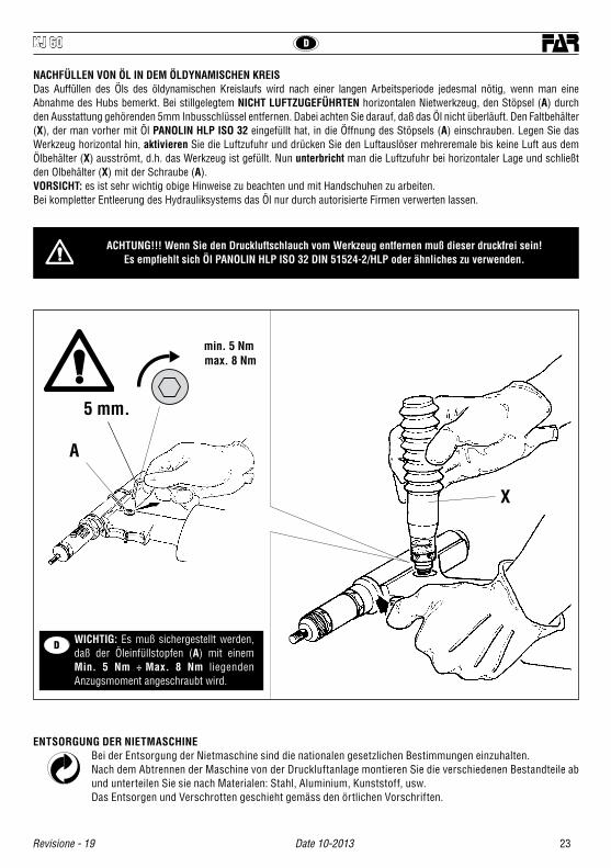
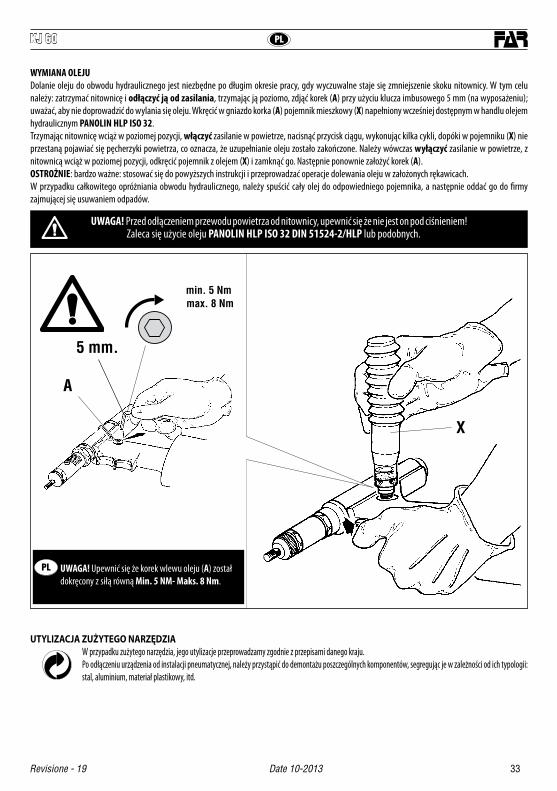
NACHFÜLLEN VON ÖL IN DEM ÖLDYNAMISCHEN KREISDas Auffüllen des Öls des öldynamischen Kreislaufs wird nach einer langen Arbeitsperiode jedesmal nötig, wenn man eine Abnahme des Hubs bemerkt. Bei stillgelegtem NICHT LUFTZUGEFÜHRTEN horizontalen Nietwerkzeug, den Stöpsel (A) durch den Ausstattung gehörenden 5mm Inbusschlüssel entfernen. Dabei achten Sie darauf, daß das Öl nicht überläuft. Den Faltbehälter (X), der man vorher mit Öl PANOLIN HLP ISO 32 eingefüllt hat, in die Öffnung des Stöpsels (A) einschrauben. Legen Sie das Werkzeug horizontal hin, aktivieren Sie die Luftzufuhr und drücken Sie den Luftauslöser mehreremale bis keine Luft aus dem Ölbehälter (X) ausströmt, d.h. das Werkzeug ist gefüllt. Nun unterbricht man die Luftzufuhr bei horizontaler Lage und schließt den Olbehälter (X) mit der Schraube (A). VORSICHT: es ist sehr wichtig obige Hinweise zu beachten und mit Handschuhen zu arbeiten.Bei kompletter Entleerung des Hydrauliksystems das Öl nur durch autorisierte Firmen verwerten lassen.
ACHTUNG!!! Wenn Sie den Druckluftschlauch vom Werkzeug entfernen muß dieser druckfrei sein!Es empfiehlt sich Öl PANOLIN HLP ISO 32 DIN 51524-2/HLP oder ähnliches zu verwenden.
WICHTIG: Es muß sichergestellt werden, daß der Öleinfüllstopfen (A) mit einem Min. 5 Nm ÷ Max. 8 Nm liegenden Anzugsmoment angeschraubt wird.
A
X
5 mm.
min. 5 Nm max. 8 Nm
ENTSORGUNG DER NIETMASCHINEBei der Entsorgung der Nietmaschine sind die nationalen gesetzlichen Bestimmungen einzuhalten. Nach dem Abtrennen der Maschine von der Druckluftanlage montieren Sie die verschiedenen Bestandteile ab und unterteilen Sie sie nach Materialen: Stahl, Aluminium, Kunststoff, usw.Das Entsorgen und Verschrotten geschieht gemäss den örtlichen Vorschriften.
D

E KJ 60
24 Date 10-2013 Revisione - 19
INSTRUCCIONES DE USO
INDICE
GARANTÍA Y ASISTENCIA TÉCNICA ......................................... 24ADVERTENCIAS Y MEDIDAS DE SALVAGUARDIA .................... 24IDENTIFICACIÓN DE LA REMACHADORA ................................. 25NOTAS GENERALES Y AMBITO DE APLICACIÓN ...................... 25PARTES PRINCIPALES .............................................................. 25DATOS TÉCNICOS ..................................................................... 25COLOCACIÓN DE LA TUERCA REMACHABLE ........................... 26CAMBIO DE FORMATO.............................................................. 27LLENADO DE ACEITE DEL CIRCUITO OLEODINÁMICO............. 28ELIMINACIÓN DE LA REMACHADORA ..................................... 28
¡¡¡ATENCION!!!No cumplir o despreciar las advertencias de seguridad puede prejudicar su incolumidad o la incolumidad de otras gentes y también el funcionamiento del equipo
• Leer atentamente las instrucciones antes del uso.• Para las operaciones de mantenimiento y/o reparación, dirigirse
a centros de postventa autorizados por FAR s.r.l. y utilizar exclusivamente repuestos originales. FAR s.r.l. declina cualquier responsabilidad por daños ocasionados por piezas defectuosas y si no se ha cumplido por inobservancia cuanto arriba (Directiva CEE 85/374).
La lista de los servicios postventa es disponible en nuestro sitio web http://www.far.bo.it ( Organización )
• El equipo tiene que ser empleado sólo por personas especializadas.• Durante el empleo del equipo ponerse gafas de protectoras o
visieras y guantes.• Al efectuar las operaciones de carga aceite se recomienda emplear
sólo fluidos según las características indicadas en eso fascículo.• En caso de pérdidas casuales de aceite que entren en contacto con
la piel se aconseja limpiar la piel cuidadosamente con agua y jabón alcalino.
¡CUIDADO! Antes de utilizar la remachadora, montar el fondillo de protección en el equipamiento base, como indicado en la figura al lado. FAR declina toda responsabilidad por los eventuales daños de la remachadora, personas o cosas que pueden ser causados por la falta del fondillo.
GARANTÍA Y ASISTENCIA TÉCNICA
Las remachadoras FAR cuentan con garantía de 12 meses. El período de garantía de la herramienta comienza en el momento de su comprobada recepción de parte del comprador. La garantía protege al usuario/comprador cuando la herramienta es adquirida a través de un revendedor autorizado y solo cuando es utilizada para los usos previstos según su diseño. La garantía no es válida si la herramienta no es utilizada o no es sometida a mantenimiento de conformidad con las especificaciones del manual de instrucciones y mantenimiento. En caso de verificarse defectos o averías, FAR S.r.l. se compromete únicamente a reparar y/o sustituir, a su propia exclusiva discreción, los componentes estimados como defectuosos.
ADVERTENCIAS Y MEDIDAS DE SALVAGUARDIA
• Es posible transportar la herramienta a mano pero, después su utilización, se aconseja volver a colocarla en su embalaje.
• Para el correcto funcionamiento de la remachadora se aconseja su revisión semestral.
• Se ha de cortar siempre la alimentación de corrente antes de ponerse a hacer reparaciones o antes de limpiar la herramienta.
• Se aconseja, si posible, el empleo de un balanceador de seguridad.• En caso de exposición diaria en un lugar donde el nivel de Presión
acústica emisión ponderada sea mayor que el límite de seguridad de 70- dB (A), utilizar medidas de protección del oído (auriculares o tapón supresor de ruidos, disminución del tiempo de exposición diaria, etc.).
• Mantener el banco y/o la zona de trabajo limpia, pues el desorden puede ocasionar daños a las personas.
• No se permite a personas inexpertas tocar los equipos.• Asegurarse que los tubos de alimentación del aire comprimido tengan
la dimensión idónea según la utilización prevista.• Jamás se arrastrará el equipo conectado a la alimentación tirando su
tubo; mantener siempre el tubo lejos de fuentes de calor y de objetos contundentes.
• Mantener los equipos en buena condición y limpios. Jamás se quitarán las protecciones o el silenciador del equipo.
• Se han de remover siempre las llaves de servicio y de ajuste después las operaciones de reparación y/o de ajuste.
• Antes de desconectar el tubo de alimentacion del aire comprimido de la remachadora, asegurarse que este no esté bajo presion.
• Se han de cumplir detenidamente estas instrucciones.
KJ 60

25
EKJ 60
Revisione - 19 Date 10-2013
IDENTIFICACION DE LA REMACHADORALa remachadora KJ 60 es identificada por una marca con razón sociale y dirección del productor, designación de la remachadora, marca CE y año de construcción. Al consultar con el servicio de asistencia tecnica, mencionar siempre los datos citados sobre la marca.
NOTAS GENERALES Y AMBITO DE APLICACION La herramienta puede utilizarse sólo para insertos fileteados con rosca de díametro M3 ÷ M8.Gracias al sistema oleoneumático, la remachadora KJ 60 brinda una potencia mayor respecto a las tradicionales remachadoras neumáticas. Esto significa una notable reducción de los problemas causados por el desgaste de los componentes y como consecuencia un aumento de la fiabilidad y duración. Las soluciones técnicas adoptadas reducen las dimensiones y el peso de la máquina rindiendo la remachadora KJ 60 absolutamente maniobrable. Las posibilidades de perdida por et sistema oleodinámico son eliminadas con el uso de retenes que eliminan este problema.
DATOS TÉCNICOS• Presión de trabajo ...........................................................6 BAR• Diámetro interno mínimo tubo alimentación aire comprimido ...............................................................8 mm• Consumo máx. aire libre por ciclo ...................................... 9 Nl• Potencia maxima ....................................... 6,5 BAR - 13656 N• Peso ...........................................................................2,200 Kg• Temperatura de utilización ...........................................-5°/+50°• Valor medio cuadrático de la aceleración total registrado en frecuencia (Ac) ejercitado sobre los miembros superiores ...............< 2,5 m/s2• Presión acústica emisión ponderata (A) ....................... 70 dBA• Presión acústica istantánea emisión ponderata (C) ...<130 dBC• Potencia acustica ponderata (A) .................................... 88 dBA
PARTES PRINCIPALESA) ................................................................. Tirante fileteadoB) ............................................................................... Cabeza C) ....................................................... Tuerca bloquea cabeza D) .......................................................... Pulsador de tracciónE) ........................................... Pulsador de destornillamiento F) .........Orificio introducción enchufe desbloqueo embrague G) ............................................... Virola de regulación carreraH) ...................................................... Enganche balanceador I) .................................................................. Motor neumático L) ............................................................ Tapón tanque aceite M) ................................................Conexión aire comprimidoN) .........................................................Fondillo de protección
KJ 60
KJ 60
80
Ø 35
295
288
Ø109
Ø 24
KJ 60
L
F
E
A
B
C
M
D
G H I
N
ALIMENTACIÓN DEL AIREEl aire de alimentación debe estar libre de cuerpos extraños y de humedad para proteger la máquina de usura precoz de las partes en movimiento, se aconseja el uso de un grupo de lubricación para aire comprimido.
Razon social y direccionDesignacion de la remachadora
Año de construcción
E KJ 60
26 Date 10-2013 Revisione - 19
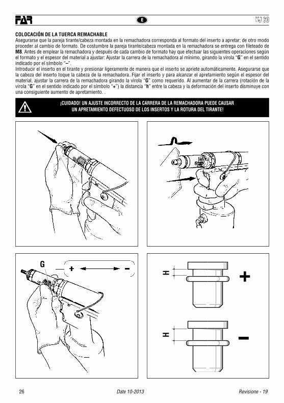
¡CUIDADO! UN AJUSTE INCORRECTO DE LA CARRERA DE LA REMACHADORA PUEDE CAUSAR UN APRETAMIENTO DEFECTUOSO DE LOS INSERTOS Y LA ROTURA DEL TIRANTE!
COLOCACIÓN DE LA TUERCA REMACHABLEAsegurarse que la pareja tirante/cabeza montada en la remachadora corresponda al formato del inserto a apretar; de otro modo proceder al cambio de formato. De costumbre la pareja tirante/cabeza montada en la remachadora se entrega con fileteado de M8. Antes de emplear la remachadora y después de cada cambio de formato hay que efectuar las siguientes operaciones según el formato y el espesor del material a ajustar: Ajustar la carrera de la remachadora al mínimo, girando la virola “G” en el sentido indicado por el símbolo “–”. Introducir el inserto en el tirante y presionar ligeramente de manera que el inserto se apriete automáticamente. Asegurarse que la cabeza del inserto toque la cabeza de la remachadora. Fijar el inserto y para alcanzar el apretamiento según el espesor del material, ajustar la carrera de la remachadora girando la virola “G” como requerido. Al aumentar de la carrera (rotación de la virola “G” en el sentido indicado por el símbolo “+”) la distancia “h” entre la cabeza y la deformación del inserto disminuye con una consiguiente aumento de apretamiento. .
+
–
HH
G

27
EKJ 60
Revisione - 19 Date 10-2013
CAMBIO DE FORMATOPues el fileteado de los insertos varia, hay que reemplazar la pareja tirante/cabeza como sigue:FIG. 1. Aflojar la virola por medio de una llave estandard de 25 mm y remover la cabeza de la remachadora.FIG. 2. Hacer pasar el enchufe (en dotación) a través del agujero se servicio ubicado en el tubo portacabeza y ejercer sobre esta una presión hacia el interior de modo de desbloquear el embrague del tirante, contemporáneamente desenroscar el tirante y extraerlo.FIG. 3-4. Quitar el embrague desbloqueado y atornillar el tirante de formato deseado. Completada la sustitución del tirante, girarlo ligeramente hasta que se conecte el embrague. Luego montar la apropiada cabeza y bloquearla por la virola aflojada. Cada vez que se efectúa el cambio de formato repetir las operaciones de ajuste describidas en las paginas anteriores.
¡CUIDADO! AL EFECTUAR ESAS OPERACIONES CORTAR LA ALIMENTACION DE AIRE A LA REMACHADORA.
1
3
2
4
25 mm.
25 mm.
Click!

KJ 60
28 Date 10-2013 Revisione - 19
E
LLENADO DE ACEITE DEL CIRCUITO OLEODINAMICOEs necesario llenar el circuito oleodinámico de aceite luego de un prolongado periodo de trabajo, cuando se advierte una disminución de potencia de la remachadora. Proceder como sigue: cortar la alimentación y con la remachadora parada y en posición horizontal, quitar el tapón (A) por medio de la llave Allen de 5 mm (en el equipamiento base). Al efectuar esa operación hay que cuidar de que no se hayan desbordamientos de aceite. Atornillar en el asiento del tapón (A) el contenedor de fuelle (X) lleno de aceite hidráulico de tipo comercial con PANOLIN HLP ISO 32. A continuación, con la remachadora horizontal, conectar la alimentación del aire y apretar el pulsador de tracción de manera que la remachadora cumpla una serie di ciclos y acabe la emisión de burbujas de aire en el contenedor (X). Una vez alcanzada esa condición, se acaba la restauración de nivel de aceite. Luego, desconectar la alimentación de aire y con la remachadora horizontal, destornillar el contenedor de aceite (X) y cerrarlo. Seguir a cerrar el tapón (A).ATENCION: se han de cumplir siempre las instrucciones arriba mencionadas y efectuar todas las operaciones de restauración de nivel de aceite por medio de guantes. Si se efectúa el vaciado completo del circuito hidráulico, hay que coger el aceite en un contenedor apropiado y contactar con una firma autorizada para la eliminación de desechos.
¡¡¡ATENCION!!! Antes de desconectar el tubo del aire comprimido de la remachadora asegurarse que éste no esté bajo presión!
Nosotros aconsejamos el uso del aceite PANOLIN HLP ISO 32 DIN 51524-2/HLP o similares.
IMPORTANTE: Asegurarse que el tapón de llenado aceite (A) sea enroscado con un par de acople correspondiente a: Mín. 5 Nm ÷ Máx. 8 Nm.
A
X
5 mm.
min. 5 Nm max. 8 Nm
ELIMINACIÓN DE LA REMACHADORA Para eliminar la remachadora seguir con atención cuanto establecido por las leyes nacionales.Despues de haber desconectado la remachadora respecto del sistema neumatico, proceder con el desmontaje de todos los componentes dividendoles segun sus categorias: acero, aluminio, material plastico, ecc.La eliminación de los componentes deberá efectuarse según lo dispuesto por las normas vigentes.
E

29
KJ 60
Revisione - 19 Date 10-2013
PL
INSTRUKCJA OBSŁUGI I
SPIS TREŚCI
GWARANCJA I SERWIS .............................................................................29BEZPIECZNA PRACA Z NARZĘDZIEM .........................................................29IDENTYFIKACJA NARZĘDZIA .....................................................................30UWAGI OGÓLNE I ZAKRES ZASTOSOWANIA ..............................................30GŁÓWNE CZĘŚCI SKŁADOWE ....................................................................30DANE TECHNICZNE ...................................................................................30MONTAŻ NITONAKRĘTKI ..........................................................................31ZMIANA FORMATU...................................................................................32WYMIANA OLEJU .....................................................................................33UTYLIZACJA ZUŻYTEGO NARZĘDZIA .........................................................33
Nie przestrzeganie podanych zaleceń bezpiecznej pracy, może skutkować wypadkiem.
• Przed rozpoczęciem pracy należy zapoznań się z niniejszą instrukcją.• W przypadku konieczności serwisowania narzędzia, należy
skontaktować się z autoryzowanym przedstawicielem firmy FAR; używać tylko oryginalnych części zamiennych, firma FAR nie ponosi żadnej odpowiedzialności za wypadki powstałe na skutek niewłaściwego użycia narzędzia (Dyrektywa UE 85/374).
Lista punktów serwisowych jest dostępna na naszej stronie internetowej http://www.far.bo.it ( Organizacja )
• Narzędzie może być stosowane tylko przez odpowiednio przeszkolone osoby.
• W czasie pracy z urządzeniem, należy korzystać z okularów lub osłon ochronnych oraz rękawic.
• Przy wymianie oleju należy stosować olej o parametrach podanych w instrukcji.
• W razie kontaktu skóry z olejem należy umyć ręce mydłem alkalicznym.• Narzędzie może być przenoszone ręcznie, po skończonej pracy zaleca
się jego przechowywanie w oryginalnym opakowaniu.• W celu przedłużenia żywotności narzędzia zaleca się jego kwartalną
konserwację i przegląd.• Prace naprawcze oraz czyszczenie maszyny należy przeprowadzać przy
urządzeniu odłączonym od zasilania w sprężone powietrze.• Tam gdzie to możliwe zaleca się podwieszenie narzędzia na balanserze.
GWARANCJA I SERWIS
Nitownice FAR są objęte 12-miesięczną gwarancją. Okres gwarancyjny rozpoczyna się w chwili poświadczonego odbioru narzędzia przez klienta. Użytkownikowi / kupującemu przysługuje gwarancja, jeśli narzędzie zostało zakupione u autoryzowanego sprzedawcy i tylko w przypadu jego użytkowania zgodnie z przeznaczeniem. Gwarancja nie obowiązuje, jeśli narzędzie nie jest używanie lub jeśli nie jest poddawane pracom konserwacyjnym opisanym w instrukcji obsługi i konserwacji. W przypadku wad lub usterek, firma FAR S.r.l. zobowiązuje się wyłącznie do naprawy i/lub wymiany, według własnego uznania, komponentów uznanych za wadliwe.
BEZPIECZNA PRACA Z NARZĘDZIEM
• W przypadku codziennej ekspozycji personelu w otoczeniu, w którym poziom ciśnienia akustycznego emisji skorygowanego charakterystyką
A przekracza wartość bezpieczeństwa 70 dB (A), należy korzystać z indywidualnych środków ochrony słuchu (nauszniki lub zatyczki przeciwhałasowe, redukcja dziennego czasu ekspozycji, itd.)
• Miejsce pracy należy utrzymywać w czystości i porządku co zmniejsza ryzyko wypadku.
• Narzędzia mogą używać tylko osoby do tego uprawnione.• Upewnić się że przewody zasilające powietrza są odpowiednia dla
narzędzia.• Narzędzie należy utrzymywać w czystości, nie wolno zdejmować
osłony tłumika.• Nie szarpać narzędzia za przewód zasilania powietrzem, przewód z
powietrzem powinien być oddalony od źródeł ciepła.• Po skończonej naprawie, upewnić się iż wewnątrz narzędzia nie zostały
klucze serwisowe.• Przed odłączeniem rury sprężonego powietrza od nitownicy, należy
upewnić się, że nie jest ona pod ciśnieniem.• Stosować się skrupulatnie do powyższych zaleceń.
UWAGA! Przed użyciem nitownicy, należy zamontować dostarczone denko zabezpieczające, tak jak to przedstawiono na rysunku obok.FAR nie ponosi żadnej odpowiedzialności za uszkodzenia nitownicy, obrażenia osób lub szkody spowodowane brakiem denka.
KJ 60

PL KJ 60
30 Date 10-2013 Revisione - 19
IDENTYFIKACJA NARZĘDZIANitownica KJ 60 jest identyfikowana poprzez tabliczkę podającą nazwę i adres producenta, określenie maszyny, oznakowanie CE oraz rok produkcji. W przypadku zgłoszenia się do serwisu technicznego, należy zawsze podać powyższe dane.
UWAGI OGÓLNE I ZAKRES ZASTOSOWANIANarzędzie jest przeznaczone do użycia wyłącznie z nitonakrętkami gwintowanymi z gwintem od M3 do M8.System oleopneumatyczny zastosowany w KJ 60 nadaje urządzeniu dodatkowej mocy, względem tradycyjnego systemu pneumatycznego,na którym bazują inne modele nitownic. Oznacza to diametralne zmniejszenie ilości problemów związanych ze zużyciem komponentów przy równoczesnym zwiększeniu niezawodności i żywotności. Zastosowane rozwiązania techniczne pozwoliły na redukcję wymiarów oraz wagi maszyny, dzięki czemu nitownica KJ 60 jest niezwykle wygodna w obsłudze. Możliwość wycieków w systemu oleodynamicznego została wykluczona dzięki zastosowaniu uszczelek eliminujących ten problem.
DANE TECHNICZNE• Ciśnienie robocze .......................................................6 BAR• Minimalna średnica wewn. przewodu zasilania ................................................................. 8 mm• Zużycie maks. powietrza na cykl .........................................9 Nl• Siła maksymalna .......................................6 BAR - 13656 N• Waga .................................................................2,200 Kg• Temperatura otoczenia .............................................-5°/+50°• Częstotliwość przyspieszenia (Ac) ............................. < 2,5 m/s2
• Ciśnienie akustyczne emisji skorygowane charakterystyką A .. 70 dBA• Chwilowe ciśnienie akustyczne skorygowane charakterystyką C ................................ <130 dBC• Moc akustyczna skorygowana charakterystyką A ................ 88 dBA
GŁÓWNE CZĘŚCI SKŁADOWEA) .................................................................................... Śruba imbusowaB) .................................................................................................. GłowicaC) ..................................................................Pierścień kontrujący głowicyD) ...........................................................Przycisk uruchamiania nitownicyE) ................................................................................Przycisk odkrecaniaF) ....................................................Otwór na kolek odblokowujacy zlacze G) .................................................. Nasadka pierscieniowa regulacji skokuH) ............................................................................... Zaczep do balansera I) ...............................................................................Silnik pneumatycznyL) ..............................................................................Korek zbiornika olejuM) ..........................................................Zasilanie sprężonym powietrzemN) ................................................................................. Nakładka ochronna
KJ 60
KJ 60
80
Ø 35
295
288
Ø109
Ø 24
KJ 60
L
F
E
A
B
C
M
D
G H I
N
ZASILANIE W POWIETRZEDostarczane powietrze musi być wolne od ciał obcych oraz wilgoci, aby chronić nitownicę przed przedwczesnym zużyciem ruchomych części; zaleca się więc zastosowanie zespołu smarującego do sprężonego powietrza.
Firma i adres Określenie maszynya
Rok produkcji

31
PLKJ 60
Revisione - 19 Date 10-2013
UWAGA! Nieprawidłowa regulacja skoku trzpien może powodować złe mocowanie nitonakrętki lub uszkodzenie samego trzpien!
MONTAŻ NITONAKRĘTKIUpewnić się, czy trzpien i głowica zamontowane na nitownicy są odpowiednie do rozmiaru nitonakrętki, którą chce się zacisnąć, w przeciwnym wypadku, należy przeprowadzić zmianę formatu. Zazwyczaj trzpien i głowica zamontowane na nitownicy w opakowaniu odpowiadają gwintowi M8. Przed użyciem nitownicy i po każdej zmianie formatu, należy przeprowadzić następujące czynności, w zależności od formatu i grubości łączonego materiału:Wyregulować skok nitownicy na minimum, obracając nasadkę pierścieniową “G” do oporu w kierunku wskazywanym przez symbol “–”.Nałożyć nitonakrętkę na trzpien lekko na nią naciskając; w ten sposób nitonakrętka zakręca się automatycznie na cięgnie. Upewnić się, że główka nitonakrętki jest dociśnięta do głowicy nitownicy. Zacisnąć nitonakrętkę i sprawdzić jak sprawuje się ona dla danej grubości materiału. Wyregulować skok nitownicy przy użyciu nasadki pierścieniowej “G”, w zależności do żądanego docisku, pamiętając, że zwiększenie skoku (obrót nasadki “G” w kierunku symbolu “+”) powoduje zmniejszenie odległości “h” między główką a zniekształceniem nitonakrętki, przy równoczesnym wzroście siły nitowania.
+
–
HH
G
PL KJ 60
32 Date 10-2013 Revisione - 19
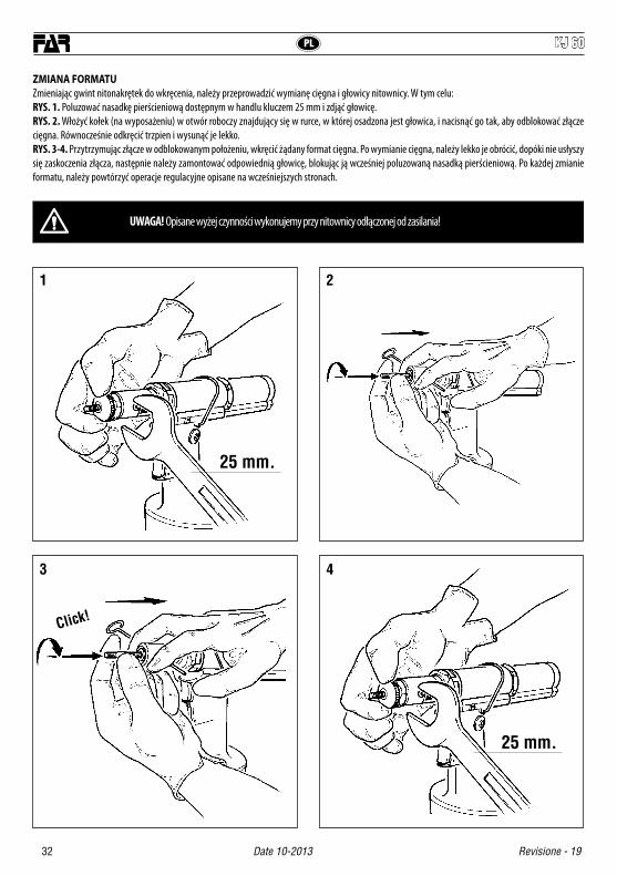
ZMIANA FORMATUZmieniając gwint nitonakrętek do wkręcenia, należy przeprowadzić wymianę cięgna i głowicy nitownicy. W tym celu:RYS. 1. Poluzować nasadkę pierścieniową dostępnym w handlu kluczem 25 mm i zdjąć głowicę.RYS. 2. Włożyć kołek (na wyposażeniu) w otwór roboczy znajdujący się w rurce, w której osadzona jest głowica, i nacisnąć go tak, aby odblokować złącze cięgna. Równocześnie odkręcić trzpien i wysunąć je lekko.RYS. 3-4. Przytrzymując złącze w odblokowanym położeniu, wkręcić żądany format cięgna. Po wymianie cięgna, należy lekko je obrócić, dopóki nie usłyszy się zaskoczenia złącza, następnie należy zamontować odpowiednią głowicę, blokując ją wcześniej poluzowaną nasadką pierścieniową. Po każdej zmianie formatu, należy powtórzyć operacje regulacyjne opisane na wcześniejszych stronach.
UWAGA! Opisane wyżej czynności wykonujemy przy nitownicy odłączonej od zasilania!
1
3
2
4
25 mm.
25 mm.
Click!
33
PLKJ 60
Revisione - 19 Date 10-2013
WYMIANA OLEJUDolanie oleju do obwodu hydraulicznego jest niezbędne po długim okresie pracy, gdy wyczuwalne staje się zmniejszenie skoku nitownicy. W tym celu należy: zatrzymać nitownicę i odłączyć ją od zasilania, trzymając ją poziomo, zdjąć korek (A) przy użyciu klucza imbusowego 5 mm (na wyposażeniu); uważać, aby nie doprowadzić do wylania się oleju. Wkręcić w gniazdo korka (A) pojemnik mieszkowy (X) napełniony wcześniej dostępnym w handlu olejem hydraulicznym PANOLIN HLP ISO 32.Trzymając nitownicę wciąż w poziomej pozycji, włączyć zasilanie w powietrze, nacisnąć przycisk ciągu, wykonując kilka cykli, dopóki w pojemniku (X) nie przestaną pojawiać się pęcherzyki powietrza, co oznacza, że uzupełnianie oleju zostało zakończone. Należy wówczas wyłączyć zasilanie w powietrze, z nitownicą wciąż w poziomej pozycji, odkręcić pojemnik z olejem (X) i zamknąć go. Następnie ponownie założyć korek (A).OSTROŻNIE: bardzo ważne: stosować się do powyższych instrukcji i przeprowadzać operacje dolewania oleju w założonych rękawicach.W przypadku całkowitego opróżniania obwodu hydraulicznego, należy spuścić cały olej do odpowiedniego pojemnika, a następnie oddać go do firmy zajmującej się usuwaniem odpadów.
UWAGA! Przed odłączeniem przewodu powietrza od nitownicy, upewnić się że nie jest on pod ciśnieniem! Zaleca się użycie oleju PANOLIN HLP ISO 32 DIN 51524-2/HLP lub podobnych.
UWAGA! Upewnić się że korek wlewu oleju (A) został dokręcony z siłą równą Min. 5 NM- Maks. 8 Nm.
A
X
5 mm.
min. 5 Nm max. 8 Nm
UTYLIZACJA ZUŻYTEGO NARZĘDZIAW przypadku zużytego narzędzia, jego utylizacje przeprowadzamy zgodnie z przepisami danego kraju.Po odłączeniu urządzenia od instalacji pneumatycznej, należy przystąpić do demontażu poszczególnych komponentów, segregując je w zależności od ich typologii: stal, aluminium, materiał plastikowy, itd.
PL

I KJ 60
34 Date 10-2013 Revisione - 19
N° COD. Qt. DESCRIZIONE KIT N° COD. Qt. DESCRIZIONE KIT
75 711728 2 Guarnizione OR 2-01676 711730 1 Guarnizione OR 2-11977 710367 1 Guarnizione OR 2-00878 710376 2 Guarnizione OR 2-00979 710918 2 Guarnizione OR 2-00580 710919 2 Guarnizione OR 2-00481 710003 2 Guarnizione OR 5-05282 710342 2 Guarnizione OR 2-01783 710594 1 Guarnizione OR 2-01284 711061 1 Guarnizione OR 5-61485 711731 1 Guarnizione OR 2-01886 711732 1 Guarnizione OR 2-11887 710258 3 Guarnizione OR 5-61288 711734 1 Guarnizione OR 2-23289 711735 1 Guarnizione OR 2-04090 711834 2 Silenziatore91 711917 1 Anello Parbak 8-119
92B 711933 1 Anello Seeger JV 24 B95 712159 1 Fondello di protezione96 722047 1 Struttura valvola sicurezza97 712153 1 Molla premi asta98 712132 1 Raccordo girevole
99E 713341 1 Guarnizione OR 1x 4 E
KITN° COD. Qt. DESCRIZIONE
KITA 741702 Kit Piastrina16A 711702 1 Piastrina zincata72A 711727 1 Vite TSCE M4 x 8 UNI 5933
KITB 741713 Kit Distanziale21B 711713 1 Distanziale65B 710902 1 Anello Seeger 16 UNI 743592B 711933 1 Anello Seeger JV 24KITC 741802 Kit Innesto tirante40C 711800 1 Molla disinnesto tirante42C 711802 1 Innesto per tirante60C 710537 1 Spina elastica ø 4 x 12 UNI 6873KITD 741705 Kit Pulsante20D 711705 2 Pulsante59D 711726 3 Spina cilindrica ø 2 x 20 UNI 1707KITE 741792 Kit Bussola32E 711792 1 Bussola porta sfere63E 711816 3 Sfera ø 2,599E 713341 1 Guarnizione OR 1x 4KITF 74000043 Kit Contenitore tirante
F00201 71345169 1 Raccordo02 71C00764 1 Cuscinetto 6180103 71345646 1 Portasatelliti estremo04 71345644 3 Satellite05 71345643 1 Corona06 71345642 1 Rondella07 71C00763 1 Cuscinetto AY7-ZZ08 71345640 1 Raccordo09 71C00761 2 Spina elastica ø 1,5 x 10 UNI 687510 71345639 5 Aletta11 71345638 1 Rotore12 71345637 1 Corpo esterno13 71345641 1 Piattello posteriore14 71C00794 1 Rullino ø 2 X 9,815 71C00762 1 Cuscinetto 695-ZZ16 710376 2 Guarnizione OR 2-00917 71C00529 1 Guarnizione XR 008 PP180 B.18 720025 1 Asta azionamento motore19 711869 1 Molla20 711865 1 TappoA 72A00126 Motore pneumatico F002
KITKITG 74000051 KIT Corpo motore
KIT Indica che il particolare viene venduto in Kit composti da particolari diversi in quantità diverse.
PARTI DI RICAMBIO
01 721779 1 Corpo rivettatrice02 712269 1 Coperchio corpo03 711684 1 Fondello cilindro04 721685 1 Pistone pneumatico05 711780 1 Raccordo06 721689 1 Cilindro Oleodinamico07 711781 1 Stelo08 711691 1 Silenziatore09 711692 1 Vite TE M7 x 1810 711782 1 Ammortizzatore11 711694 1 Spoletta inferiore12 711695 1 Cannotto filettato13 721698 1 Corpo valvola14 711700 1 Spoletta superiore15 711701 1 Corpo valvola superiore
16A 711702 1 Piastrina zincata A17 711703 2 Corpo valvolina18 711704 2 Pistoncino valvola19 710839 1 Tappo serbatoio olio
20D 711705 2 Pulsante D21B 711713 1 Distanziale B22 710854 1 Gancio bilanciatore23 721387 1 Contenitore olio24 711783 1 Coperchio motorino25 72A00126 1 Motore pneumatico F00226 711785 1 Settore protezione motore27 711786 1 Ghiera28 711787 1 Anello di arresto29 712670 1 Innesto composto30 711790 1 Molla ritorno pistone31 711791 1 Molla bloccaggio sfere
32E 711792 1 Bussola porta sfere E33 712270 1 Asta34 711794 1 Pistone oleodinamico35 711795 1 Raccordo anteriore36 711796 1 Albero37 711797 1 Cannotto fresato38 711798 1 Ghiera39 711799 1 Pomello regolazione corsa
40C 711800 1 Molla disinnesto tirante C41 711801 1 Cannotto porta tirante
42C 711802 1 Innesto per tirante C43 711803 1 Ghiera44 711804 1 Ghiera45 711805 1 Testina M 346 711806 1 Testina M 447 711807 1 Testina M 548 711808 1 Testina M 649 711809 1 Testina M 850 711810 1 Tirante M 351 711811 1 Tirante M 452 711812 1 Tirante M 553 711813 1 Tirante M 654 711814 1 Tirante M 855 710876 1 Spina disinnesto tirante56 710906 1 Rondella 400-020-4490
59D 711726 3 Spina cilindrica ø 2 x 20 UNI 1707 D60C 710537 1 Spina elastica ø 4 x 12 UNI 6873 C61 711815 2 Sfera ø 3,562 710911 4 Sfera ø 4
63E 711816 3 Sfera ø 2,5 E64 711817 1 Anello Seeger 18 UNI 7437
65B 710902 1 Anello Seeger 16 UNI 7435 B66 711818 1 Anello Seeger SW 1167 711821 1 Anello Seeger JV 2068 711721 1 Guarnizione B-110078/B/NEO69 711722 1 Guarnizione B-094063/B/NEI70 711819 1 Guarnizione B-070039 / 171 711820 1 Guarnizione TS-10-18-5,8 / L
72A 711727 1 Vite TSCE M4 x 8 UNI 5933 A73 712037 2 Filtro inox ø 6 x 474 711092 1 Chiave a brugola 5 mm
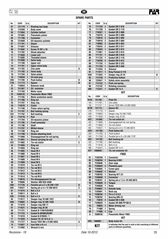
35
KJ 60
Revisione - 19 Date 10-2013
GB
No. CODE Q.ty DESCRIPTION KIT No. CODE Q.ty DESCRIPTION KIT
75 711728 2 Gasket OR 2-01676 711730 1 Gasket OR 2-11977 710367 1 Gasket OR 2-00878 710376 2 Gasket OR 2-00979 710918 2 Gasket OR 2-00580 710919 2 Gasket OR 2-00481 710003 2 Gasket OR 5-05282 710342 2 Gasket OR 2-01783 710594 1 Gasket OR 2-01284 711061 1 Gasket OR 5-61485 711731 1 Gasket OR 2-01886 711732 1 Gasket OR 2-11887 710258 3 Gasket OR 5-61288 711734 1 Gasket OR 2-23289 711735 1 Gasket OR 2-04090 711834 2 Silencer91 711917 1 Ring Parbak 8-119
92B 711933 1 Seeger ring JV 24 B95 712159 1 Protection bottom96 722047 1 Safety valve assembly97 712153 1 Push-rod spring98 712132 1 Rotating connector
99E 713341 1 Gasket OR 1x 4 E
KITNo. CODE Q.ty DESCRIPTION
KITA 741702 Plate Kit16A 711702 1 Zinc plate72A 711727 1 Screw TSCE M4 x 8 UNI 5933
KITB 741713 Spacer Kit21B 711713 1 Spacer65B 710902 1 Seeger ring 16 UNI 743592B 711933 1 Seeger ring JV 24KITC 741802 Tie rod clutch kit40C 711800 1 Disengagement tie rod spring42C 711802 1 Tie rod clutch60C 710537 1 Spring pin ø 4 x 12 UNI 6873KITD 741705 Push-button Kit20D 711705 2 Push-button59D 711726 3 Parallel pin ø 2 x 20 UNI 1707KITE 741792 Ball bushing kit32E 711792 1 Ball bushing63E 711816 3 Ball ø 2,599E 713341 1 Gasket OR 1x 4KITF 74000043 Tie rod container kit
F00201 71345169 1 Connector02 71C00764 1 Bearing 6180103 71345646 1 Gear cage04 71345644 3 Planetary gear05 71345643 1 Crown gear06 71345642 1 Washer07 71C00763 1 Bearing AY7-ZZ08 71345640 1 Connector09 71C00761 2 Spring pin ø 1,5 x 10 UNI 687510 71345639 5 Tongue11 71345638 1 Rotor12 71345637 1 Outside body13 71345641 1 Back cap14 71C00794 1 Pin ø 2 X 9,815 71C00762 1 Bearing 695-ZZ16 710376 2 Gasket OR 2-00917 71C00529 1 Gasket XR 008 PP180 B.18 720025 1 Motor driving rod19 711869 1 Spring20 711865 1 CapA 72A00126 Pneumatic Motor F002
KITKITG 74000051 Body motor kit
KIT It indicates that the part is sold in kits consisting of different parts in different quantities.
SPARE PARTS
01 721779 1 Riveting tool body02 712269 1 Body cover03 711684 1 Cylinder bottom04 721685 1 Pneumatic piston05 711780 1 Connector06 721689 1 Oil-dynamic cylinder07 711781 1 Steam08 711691 1 Silencer09 711692 1 Screw TE M7 x 1810 711782 1 Shock absorber11 711694 1 Lower coil12 711695 1 Threaded sleeve13 721698 1 Valve body14 711700 1 Upper coil15 711701 1 Upper valve body
16A 711702 1 Zinc plate A17 711703 2 Valve body18 711704 2 Valve piston19 710839 1 Oil tank plug
20D 711705 2 Push-button D21B 711713 1 Spacer B22 710854 1 Balancer hook23 721387 1 Oil container24 711783 1 Motor cover25 72A00126 1 Pneumatic Motor F00226 711785 1 Motor protection sector27 711786 1 Ring nut28 711787 1 Stop ring29 712670 1 Clutch30 711790 1 Piston return spring31 711791 1 Ball locking spring
32E 711792 1 Ball bushing E33 712270 1 Rod34 711794 1 Oil-dynamic piston35 711795 1 Front connector36 711796 1 Shaft37 711797 1 Milled sleeve38 711798 1 Ring nut39 711799 1 Stroke-adjusting knob
40C 711800 1 Disengagement tie rod spring C41 711801 1 Sleeve carrying tie rod
42C 711802 1 Tie rod clutch C43 711803 1 Ring nut44 711804 1 Ring nut45 711805 1 Head M 346 711806 1 Head M 447 711807 1 Head M 548 711808 1 Head M 649 711809 1 Head M 850 711810 1 Tie rod M 351 711811 1 Tie rod M 452 711812 1 Tie rod M 553 711813 1 Tie rod M 654 711814 1 Tie rod M 855 710876 1 Pin disengagement tie rod56 710906 1 Washer 400-020-4490
59D 711726 3 Parallel pin ø 2 x 20 UNI 1707 D60C 710537 1 Spring pin ø 4 x 12 UNI 6873 C61 711815 2 Ball ø 3,562 710911 4 Ball ø 4
63E 711816 3 Ball ø 2,5 E64 711817 1 Seeger ring 18 UNI 7437
65B 710902 1 Seeger ring 16 UNI 7435 B66 711818 1 Seeger ring SW 1167 711821 1 Seeger ring JV 2068 711721 1 Gasket B-110078/B/NEO69 711722 1 Gasket B-094063/B/NEI70 711819 1 Gasket B-070039 / 171 711820 1 Gasket TS-10-18-5,8 / L
72A 711727 1 Screw TSCE M4 x 8 UNI 5933 A73 712037 2 Inox filter ø 6 x 474 711092 1 Wrench 5 mm
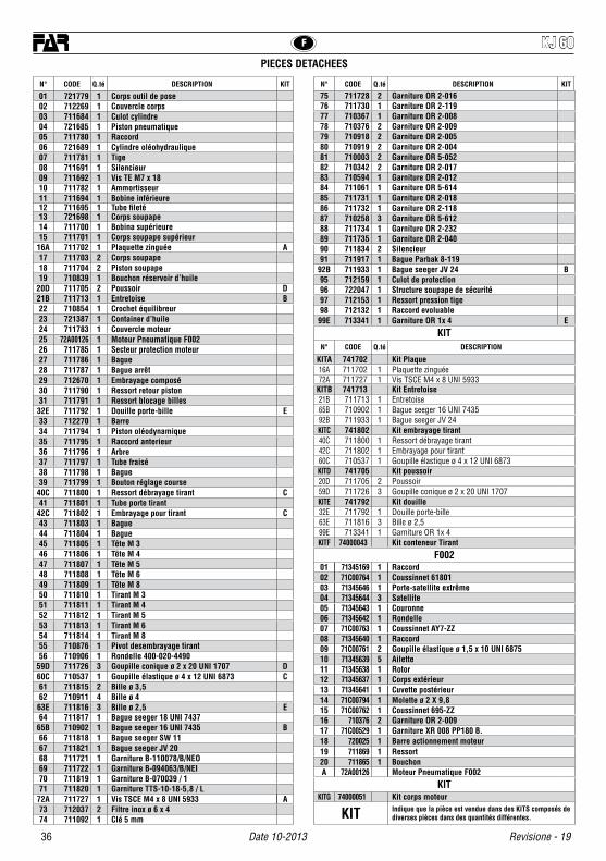
KJ 60
36 Date 10-2013 Revisione - 19
F
N° CODE Q.té DESCRIPTION KIT N° CODE Q.té DESCRIPTION KIT
75 711728 2 Garniture OR 2-01676 711730 1 Garniture OR 2-11977 710367 1 Garniture OR 2-00878 710376 2 Garniture OR 2-00979 710918 2 Garniture OR 2-00580 710919 2 Garniture OR 2-00481 710003 2 Garniture OR 5-05282 710342 2 Garniture OR 2-01783 710594 1 Garniture OR 2-01284 711061 1 Garniture OR 5-61485 711731 1 Garniture OR 2-01886 711732 1 Garniture OR 2-11887 710258 3 Garniture OR 5-61288 711734 1 Garniture OR 2-23289 711735 1 Garniture OR 2-04090 711834 2 Silencieur91 711917 1 Bague Parbak 8-119
92B 711933 1 Bague seeger JV 24 B95 712159 1 Culot de protection96 722047 1 Structure soupape de sécurité97 712153 1 Ressort pression tige98 712132 1 Raccord evoluable
99E 713341 1 Garniture OR 1x 4 E
KITN° CODE Q.té DESCRIPTION
KITA 741702 Kit Plaque16A 711702 1 Plaquette zinguée72A 711727 1 Vis TSCE M4 x 8 UNI 5933
KITB 741713 Kit Entretoise21B 711713 1 Entretoise65B 710902 1 Bague seeger 16 UNI 743592B 711933 1 Bague seeger JV 24KITC 741802 Kit embrayage tirant40C 711800 1 Ressort débrayage tirant42C 711802 1 Embrayage pour tirant60C 710537 1 Goupille élastique ø 4 x 12 UNI 6873KITD 741705 Kit poussoir20D 711705 2 Poussoir59D 711726 3 Goupille conique ø 2 x 20 UNI 1707KITE 741792 Kit douille32E 711792 1 Douille porte-bille63E 711816 3 Bille ø 2,599E 713341 1 Garniture OR 1x 4KITF 74000043 Kit conteneur Tirant
F00201 71345169 1 Raccord02 71C00764 1 Coussinnet 6180103 71345646 1 Porte-satellite extrême04 71345644 3 Satellite05 71345643 1 Couronne06 71345642 1 Rondelle07 71C00763 1 Coussinnet AY7-ZZ08 71345640 1 Raccord09 71C00761 2 Goupille élastique ø 1,5 x 10 UNI 687510 71345639 5 Ailette11 71345638 1 Rotor12 71345637 1 Corps extérieur13 71345641 1 Cuvette postérieur14 71C00794 1 Molette ø 2 X 9,815 71C00762 1 Coussinnet 695-ZZ16 710376 2 Garniture OR 2-00917 71C00529 1 Garniture XR 008 PP180 B.18 720025 1 Barre actionnement moteur19 711869 1 Ressort20 711865 1 BouchonA 72A00126 Moteur Pneumatique F002
KITKITG 74000051 Kit corps moteur
KIT Indique que la pièce est vendue dans des KITS composés de diverses pièces dans des quantités différentes.
PIECES DETACHEES
01 721779 1 Corps outil de pose02 712269 1 Couvercle corps03 711684 1 Culot cylindre04 721685 1 Piston pneumatique05 711780 1 Raccord06 721689 1 Cylindre oléohydraulique07 711781 1 Tige08 711691 1 Silencieur09 711692 1 Vis TE M7 x 1810 711782 1 Ammortisseur11 711694 1 Bobine inférieure12 711695 1 Tube fileté13 721698 1 Corps soupape14 711700 1 Bobina supérieure15 711701 1 Corps soupape supérieur
16A 711702 1 Plaquette zinguée A17 711703 2 Corps soupape18 711704 2 Piston soupape19 710839 1 Bouchon réservoir d’huile
20D 711705 2 Poussoir D21B 711713 1 Entretoise B22 710854 1 Crochet équilibreur23 721387 1 Container d’huile24 711783 1 Couvercle moteur25 72A00126 1 Moteur Pneumatique F00226 711785 1 Secteur protection moteur27 711786 1 Bague28 711787 1 Bague arrêt29 712670 1 Embrayage composé30 711790 1 Ressort retour piston31 711791 1 Ressort blocage billes
32E 711792 1 Douille porte-bille E33 712270 1 Barre34 711794 1 Piston oléodynamique35 711795 1 Raccord anterieur36 711796 1 Arbre37 711797 1 Tube fraisé38 711798 1 Bague39 711799 1 Bouton réglage course
40C 711800 1 Ressort débrayage tirant C41 711801 1 Tube porte tirant
42C 711802 1 Embrayage pour tirant C43 711803 1 Bague44 711804 1 Bague45 711805 1 Tête M 346 711806 1 Tête M 447 711807 1 Tête M 548 711808 1 Tête M 649 711809 1 Tête M 850 711810 1 Tirant M 351 711811 1 Tirant M 452 711812 1 Tirant M 553 711813 1 Tirant M 654 711814 1 Tirant M 855 710876 1 Pivot desembrayage tirant56 710906 1 Rondelle 400-020-4490
59D 711726 3 Goupille conique ø 2 x 20 UNI 1707 D60C 710537 1 Goupille élastique ø 4 x 12 UNI 6873 C61 711815 2 Bille ø 3,562 710911 4 Bille ø 4
63E 711816 3 Bille ø 2,5 E64 711817 1 Bague seeger 18 UNI 7437
65B 710902 1 Bague seeger 16 UNI 7435 B66 711818 1 Bague seeger SW 1167 711821 1 Bague seeger JV 2068 711721 1 Garniture B-110078/B/NEO69 711722 1 Garniture B-094063/B/NEI70 711819 1 Garniture B-070039 / 171 711820 1 Garniture TTS-10-18-5,8 / L
72A 711727 1 Vis TSCE M4 x 8 UNI 5933 A73 712037 2 Filtre inox ø 6 x 474 711092 1 Clé 5 mm
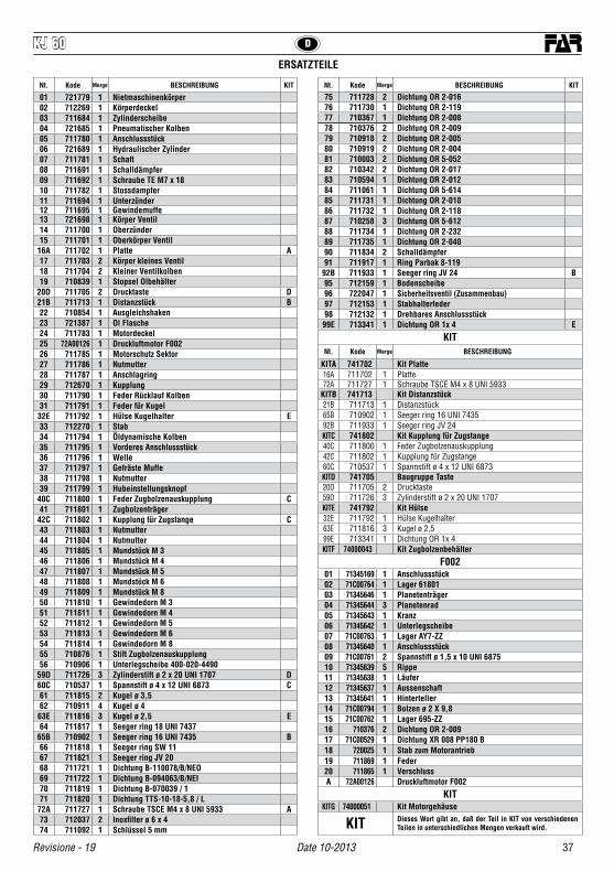
37
KJ 60
Revisione - 19 Date 10-2013
D
Nt. Kode Merge BESCHREIBUNG KIT Nt. Kode Merge BESCHREIBUNG KIT
75 711728 2 Dichtung OR 2-01676 711730 1 Dichtung OR 2-11977 710367 1 Dichtung OR 2-00878 710376 2 Dichtung OR 2-00979 710918 2 Dichtung OR 2-00580 710919 2 Dichtung OR 2-00481 710003 2 Dichtung OR 5-05282 710342 2 Dichtung OR 2-01783 710594 1 Dichtung OR 2-01284 711061 1 Dichtung OR 5-61485 711731 1 Dichtung OR 2-01886 711732 1 Dichtung OR 2-11887 710258 3 Dichtung OR 5-61288 711734 1 Dichtung OR 2-23289 711735 1 Dichtung OR 2-04090 711834 2 Schalldämpfer91 711917 1 Ring Parbak 8-119
92B 711933 1 Seeger ring JV 24 B95 712159 1 Bodenscheibe96 722047 1 Sicherheitsventil (Zusammenbau)97 712153 1 Stabhalterfeder98 712132 1 Drehbares Anschlussstück
99E 713341 1 Dichtung OR 1x 4 E
KITNt. Kode Merge BESCHREIBUNG
KITA 741702 Kit Platte16A 711702 1 Platte72A 711727 1 Schraube TSCE M4 x 8 UNI 5933
KITB 741713 Kit Distanzstück21B 711713 1 Distanzstück65B 710902 1 Seeger ring 16 UNI 743592B 711933 1 Seeger ring JV 24KITC 741802 Kit Kupplung für Zugstange40C 711800 1 Feder Zugbolzenauskupplung42C 711802 1 Kupplung für Zugstange60C 710537 1 Spannstift ø 4 x 12 UNI 6873KITD 741705 Baugruppe Taste20D 711705 2 Drucktaste59D 711726 3 Zylinderstift ø 2 x 20 UNI 1707KITE 741792 Kit Hülse32E 711792 1 Hülse Kugelhalter63E 711816 3 Kugel ø 2,599E 713341 1 Dichtung OR 1x 4KITF 74000043 Kit Zugbolzenbehälter
F00201 71345169 1 Anschlussstück02 71C00764 1 Lager 6180103 71345646 1 Planetenträger04 71345644 3 Planetenrad05 71345643 1 Kranz06 71345642 1 Unterlegscheibe07 71C00763 1 Lager AY7-ZZ08 71345640 1 Anschlussstück09 71C00761 2 Spannstift ø 1,5 x 10 UNI 687510 71345639 5 Rippe11 71345638 1 Läufer12 71345637 1 Aussenschaft13 71345641 1 Hinterteller14 71C00794 1 Bolzen ø 2 X 9,815 71C00762 1 Lager 695-ZZ16 710376 2 Dichtung OR 2-00917 71C00529 1 Dichtung XR 008 PP180 B18 720025 1 Stab zum Motorantrieb19 711869 1 Feder20 711865 1 VerschlussA 72A00126 Druckluftmotor F002
KITKITG 74000051 Kit Motorgehäuse
KIT Dieses Wort gibt an, daß der Teil in KIT von verschiedenen Teilen in unterschiedlichen Mengen verkauft wird.
ERSATZTEILE
01 721779 1 Nietmaschinenkörper02 712269 1 Körperdeckel03 711684 1 Zylinderscheibe04 721685 1 Pneumatischer Kolben05 711780 1 Anschlussstück06 721689 1 Hydraulischer Zylinder07 711781 1 Schaft08 711691 1 Schalldämpfer09 711692 1 Schraube TE M7 x 1810 711782 1 Stossdampfer11 711694 1 Unterzünder12 711695 1 Gewindemuffe13 721698 1 Körper Ventil14 711700 1 Oberzünder15 711701 1 Oberkörper Ventil
16A 711702 1 Platte A17 711703 2 Körper kleines Ventil18 711704 2 Kleiner Ventilkolben19 710839 1 Stopsel Olbehälter
20D 711705 2 Drucktaste D21B 711713 1 Distanzstück B22 710854 1 Ausgleichshaken23 721387 1 Ol Flasche24 711783 1 Motordeckel25 72A00126 1 Druckluftmotor F00226 711785 1 Motorschutz Sektor27 711786 1 Nutmutter28 711787 1 Anschlagring29 712670 1 Kupplung30 711790 1 Feder Rücklauf Kolben31 711791 1 Feder für Kugel
32E 711792 1 Hülse Kugelhalter E33 712270 1 Stab34 711794 1 Öldynamische Kolben35 711795 1 Vorderes Anschlussstück36 711796 1 Welle37 711797 1 Gefräste Muffe38 711798 1 Nutmutter39 711799 1 Hubeinstellungsknopf
40C 711800 1 Feder Zugbolzenauskupplung C41 711801 1 Zugbolzenträger
42C 711802 1 Kupplung für Zugstange C43 711803 1 Nutmutter44 711804 1 Nutmutter45 711805 1 Mundstück M 346 711806 1 Mundstück M 447 711807 1 Mundstück M 548 711808 1 Mundstück M 649 711809 1 Mundstück M 850 711810 1 Gewindedorn M 351 711811 1 Gewindedorn M 452 711812 1 Gewindedorn M 553 711813 1 Gewindedorn M 654 711814 1 Gewindedorn M 855 710876 1 Stift Zugbolzenauskupplung56 710906 1 Unterlegscheibe 400-020-4490
59D 711726 3 Zylinderstift ø 2 x 20 UNI 1707 D60C 710537 1 Spannstift ø 4 x 12 UNI 6873 C61 711815 2 Kugel ø 3,562 710911 4 Kugel ø 4
63E 711816 3 Kugel ø 2,5 E64 711817 1 Seeger ring 18 UNI 7437
65B 710902 1 Seeger ring 16 UNI 7435 B66 711818 1 Seeger ring SW 1167 711821 1 Seeger ring JV 2068 711721 1 Dichtung B-110078/B/NEO69 711722 1 Dichtung B-094063/B/NEI70 711819 1 Dichtung B-070039 / 171 711820 1 Dichtung TTS-10-18-5,8 / L
72A 711727 1 Schraube TSCE M4 x 8 UNI 5933 A73 712037 2 Inoxfilter ø 6 x 474 711092 1 Schlüssel 5 mm

KJ 60
38 Date 10-2013 Revisione - 19
PL
Numer Kod. Ilości OPIS KIT Numer Kod. Ilości OPIS KIT
75 711728 2 Uszczelka OR 2-01676 711730 1 Uszczelka OR 2-11977 710367 1 Uszczelka OR 2-00878 710376 2 Uszczelka OR 2-00979 710918 2 Uszczelka OR 2-00580 710919 2 Uszczelka OR 2-00481 710003 2 Uszczelka OR 5-05282 710342 2 Uszczelka OR 2-01783 710594 1 Uszczelka OR 2-01284 711061 1 Uszczelka OR 5-61485 711731 1 Uszczelka OR 2-01886 711732 1 Uszczelka OR 2-11887 710258 3 Uszczelka OR 5-61288 711734 1 Uszczelka OR 2-23289 711735 1 Uszczelka OR 2-04090 711834 2 Tłumik91 711917 1 Pierścień Parbak 8-119
92B 711933 1 Pierścień Seeger JV 24 B95 712159 1 Denko ochronne96 722047 1 Zespół zaworu bezpieczeństwa97 712153 1 Sprezyna naciskowa drazka98 712132 1 Złączka obrotowa
99E 713341 1 Uszczelka OR 1x 4 E
KITNumer Kod. Ilości OPIS
KITA 741702 Zestaw plytki16A 711702 1 Płytka72A 711727 1 Śruba TSCE M4 x 8 UNI 5933
KITB 741713 Zestaw przekladki21B 711713 1 Przekladka65B 710902 1 Pierścień Seeger 16 UNI 743592B 711933 1 Pierścień Seeger JV 24KITC 741802 Zestaw zlacza Korek40C 711800 1 Sprezyna rozlaczania trzpień42C 711802 1 Sprzeglo trzpienia60C 710537 1 Kolek sprezysty ø 4 x 12 UNI 6873KITD 741705 Zestaw przycisku20D 711705 2 Przycisk59D 711726 3 Kołek cylindryczny ø 2 x 20 UNI 1707KITE 741792 Zestaw tulei32E 711792 1 Tulejka nosna kulek63E 711816 3 Kula ø 2,599E 713341 1 Uszczelka OR 1x 4KITF 74000043 Zestaw pojemnika ciegna
F00201 71345169 1 Złączka02 71C00764 1 Łożysko 6180103 71345646 1 Krzyżak satelitów krańcowy04 71345644 3 Satelita05 71345643 1 Kolo koronowe06 71345642 1 Podkladka07 71C00763 1 Łożysko AY7-ZZ08 71345640 1 Złączka09 71C00761 2 Kolek sprezysty ø 1,5 x 10 UNI 687510 71345639 5 Skrzydełko11 71345638 1 Wirnik12 71345637 1 Korpus zewnetrzny13 71345641 1 Tarcza tylna14 71C00794 1 Waleczek ø 2 X 9,815 71C00762 1 Łożysko 695-ZZ16 710376 2 Uszczelka OR 2-00917 71C00529 1 Uszczelka XR 008 PP180 B.18 720025 1 Drazek uruchamiajacy silnik19 711869 1 Sprężyna20 711865 1 KorekA 72A00126 Silnik Pneumatyczny F002
KITKITG 74000051 Zestaw korpusu silnika
KIT Oznacza, że dany detal jest sprzedawany w Zestawach złożonych z różnych detali w różnych ilościach.
CZĘŚCI ZAMIENNE
01 721779 1 Korpus nitownicy02 712269 1 Pokrywa korpusu03 711684 1 Denko cylindra04 721685 1 Tłok pneumatyczny05 711780 1 Złączka06 721689 1 Cylinder oleodynamiczny07 711781 1 Trzon08 711691 1 Tłumik09 711692 1 Śruba TE M7 x 1810 711782 1 Amortyzator11 711694 1 Cewka dolna12 711695 1 Tulejka gwintowana13 721698 1 Korpus zaworu14 711700 1 Cewka górna15 711701 1 Korpus zaworu górny
16A 711702 1 Płytka A17 711703 2 Korpus zaworku18 711704 2 Tloczek zaworu19 710839 1 Korek zbiornika oleju
20D 711705 2 Przycisk D21B 711713 1 Przekladka B22 710854 1 Hak balansera23 721387 1 Pojemnik oleju24 711783 1 Pokrywa silniczka25 72A00126 1 Silnik Pneumatyczny F00226 711785 1 Sektor oslony silnika27 711786 1 Nasadka pierscieniowa28 711787 1 Pierscien zatrzymujacy29 712670 1 Zlacze zlozone30 711790 1 Sprężyna powrotna tłoka31 711791 1 Sprezyna blokujaca kulki32E 711792 1 Tulejka nosna kulek E33 712270 1 Drazek34 711794 1 Tłok oleodynamiczny35 711795 1 Zlaczka przednia36 711796 1 Wał37 711797 1 Tulejka frezowana38 711798 1 Nasadka pierscieniowa39 711799 1 Pokretlo regulacji skoku
40C 711800 1 Sprezyna rozlaczania trzpień C41 711801 1 Tulejka nosna Korek
42C 711802 1 Sprzeglo trzpienia C43 711803 1 Nasadka pierscieniowa44 711804 1 Nasadka pierscieniowa45 711805 1 Głowica M346 711806 1 Głowica M447 711807 1 Głowica M548 711808 1 Głowica M649 711809 1 Głowica M850 711810 1 Korek M351 711811 1 Korek M452 711812 1 Korek M553 711813 1 Korek M654 711814 1 Korek M855 710876 1 Kolek rozlaczania trzpień56 710906 1 Podkladka 400-020-4490
59D 711726 3 Kołek cylindryczny ø 2 x 20 UNI 1707 D60C 710537 1 Kolek sprezysty ø 4 x 12 UNI 6873 C61 711815 2 Kula ø 3,562 710911 4 Kula ø 4
63E 711816 3 Kula ø 2,5 E64 711817 1 Pierścień Seeger 18 UNI 7437
65B 710902 1 Pierścień Seeger 16 UNI 7435 B66 711818 1 Pierścień Seeger SW 1167 711821 1 Pierścień Seeger JV 2068 711721 1 Uszczelka B-110078/B/NEO69 711722 1 Uszczelka B-094063/B/NEI70 711819 1 Uszczelka B-070039 / 171 711820 1 Uszczelka TTS-10-18-5,8 / L
72A 711727 1 Śruba TSCE M4 x 8 UNI 5933 A73 712037 2 Filtr inox ø 6 x 474 711092 1 Klucz imbusowy 5 mm

39
KJ 60 PARTI DI RICAMBIO • SPARE PARTS • PIECES DETACHEES • ERSATZTEILE • CZĘŚCI ZAMIENNE
Revisione - 19 Date 10-2013
49
38
30 32 E 31 28 29 33 6 27
63 E99 E 8526 62
226173
5619
9025
24
44 35 91 76 75 69
92 B66 65 B
21 B68 34 36
48
47
46
45
53
52
51
50
43 54 42 C 41 40 C
97
67 39 37 8260 C
74
55
23
61
791880
72 A
20 D
788116 A
59 D
17
62
1
64
707186
5
83
7
484
9
3
8
2
95
88
89
10
87
14
75
15
77
82
13
12
11
96
98
72A(x2)
16A(x2)
KIT A
KIT B
KIT C
KIT E
KIT F
20D(x2)
59D(x3)
KIT D
92B(x1)
65B(x1)
21B(x1)
42C(x1)
40C(x1)
60C(x1)
63E(x3)99E(x1)
32E(x1)

40
KJ 60PARTI DI RICAMBIO • SPARE PARTS • PIECES DETACHEES • ERSATZTEILE • CZĘŚCI ZAMIENNE
Date 10-2013 Revisione - 19
1
8
16
17
18
19
20
9
10
11
12
9
13
14
15
2
3
4
5
6
7
KIT G

.....................................................................................................................................................................................................
.....................................................................................................................................................................................................
.....................................................................................................................................................................................................
.....................................................................................................................................................................................................
.....................................................................................................................................................................................................
.....................................................................................................................................................................................................
.....................................................................................................................................................................................................
.....................................................................................................................................................................................................
.....................................................................................................................................................................................................
.....................................................................................................................................................................................................
.....................................................................................................................................................................................................
.....................................................................................................................................................................................................
.....................................................................................................................................................................................................
.....................................................................................................................................................................................................
.....................................................................................................................................................................................................
.....................................................................................................................................................................................................
.....................................................................................................................................................................................................
.....................................................................................................................................................................................................
.....................................................................................................................................................................................................
.....................................................................................................................................................................................................
.....................................................................................................................................................................................................
.....................................................................................................................................................................................................
.....................................................................................................................................................................................................
.....................................................................................................................................................................................................
.....................................................................................................................................................................................................
.....................................................................................................................................................................................................
.....................................................................................................................................................................................................


Date
10-
2013
Re
visi
on -
19
www.far.bo.it
SISTEMI DI FISSAGGIOFASTENING SYSTEMS • SYSTEMES DE FIXATION
VERBINDUNGSSYSTEME • SISTEMAS DE FIJACIONSYSTEMY MOCOWANIA • СИСТЕМЫ КРЕПЛЕНИЯ
L’elenco dei centri di assistenza è disponibile sul Ns. sito web: http://www.far.bo.it ( Organizzazione )
The list of the service centres is available on our website http://www.far.bo.it ( Organization )
La liste des centres d’assistance est disponible sur notre site internet http://www.far.bo.it ( Organisation )
Die Liste der Reparaturservices ist verfügbar unter unserer Webseite http://www.far.bo.it ( Organisation )
La lista de los servicios postventa es disponible en nuestro sitio web http://www.far.bo.it ( Organización )
Lista punktów serwisowych jest dostępna na naszej stronie internetowej http://www.far.bo.it ( Organizacja )
Список сервисных центров приведен на нашем веб-сайте http://www.far.bo.it ( ОРГАНИЗАЦИЯ )
I
F
E
PL
RUS
GB
D
SEDE • HEAD OFFICE • SIEGE HAUPTSITZ • SEDE
SIEDZIBA • ОФИСНЫЙ ЦЕНТР :
40057 Quarto Inferiore - Bologna - Italy Via Giovanni XXIII, 2
Tel. +39 - 051 6009511Ufficio Vendite Fax +39 - 051 767443
E-mail: [email protected] Dpt. Fax +39 - 051 768284
E-mail: [email protected]
DEPOSITO • WAREHOUSE • DEPOT WARENLAGER • ALMACEN
ODDZIAŁ • СКЛАД :
20099 Sesto San Giovanni Milano
ItalyVia Archimede, 8
Tel. +39 - 02 2409634Fax +39 - 02 26222279E-mail: [email protected]