
Tunnelling machines — Air locks — Safety requirements fileprEN 12110:2012 (E) 1 CENTC 151 Date:...
30
prEN 12110:2012 (E) 1 CENTC 151 Date: 2012-07 prEN 12110 CENTC 151 Secretariat: DIN Tunnelling machines — Air locks — Safety requirements Tunnelbaumaschinen — Druckluftschleusen — Sicherheitstechnische Anforderungen Machines pour la construction de tunnels — Sas de transfert — Prescriptions de sécurité ICS: Descriptors:
Transcript of Tunnelling machines — Air locks — Safety requirements fileprEN 12110:2012 (E) 1 CENTC 151 Date:...
prEN 12110:2012 (E)
1
CENTC 151 Date: 2012-07
prEN 12110
CENTC 151
Secretariat: DIN
Tunnelling machines — Air locks — Safety requirements
Tunnelbaumaschinen — Druckluftschleusen — Sicherheitstechnische Anforderungen
Machines pour la construction de tunnels — Sas de transfert — Prescriptions de sécurité
ICS:
Descriptors:
prEN 12110:2012 (E)
2
Contents Page
Foreword ...................................................................................................................................................................... 3
Introduction ................................................................................................................................................................. 4
1 Scope .............................................................................................................................................................. 4
2 Normative references .................................................................................................................................... 4
3 Terms and definitions ................................................................................................................................... 5
4 List of significant hazards ............................................................................................................................ 6
5 Safety requirements and/or protective measures ...................................................................................... 9 5.1 General ............................................................................................................................................................ 9 5.2 General requirements .................................................................................................................................... 9 5.3 Personnel locks ........................................................................................................................................... 12 5.4 Material locks ............................................................................................................................................... 16 5.5 Combined locks ........................................................................................................................................... 17 5.6 Pressure bulkheads ..................................................................................................................................... 17
6 Verification of safety requirements and/or protective measures ........................................................... 17
7 Information for use ...................................................................................................................................... 26 7.1 General .......................................................................................................................................................... 26 7.2 Signals and warning devices ...................................................................................................................... 26 7.3 Instruction handbook .................................................................................................................................. 26 7.4 Signs ............................................................................................................................................................. 27 7.5 Marking ......................................................................................................................................................... 28
Annex ZA (informative) Relationship between this European Standard and the Essential Requirements of EU Directive 2006/42/EC ......................................................................................................................... 29
Bibliography .............................................................................................................................................................. 30

prEN 12110:2012 (E)
3
Foreword
This document (FprEN 12110:2012) has been prepared by Technical Committee CEN/TC 151 “Construction equipment and building material machines - Safety”, the secretariat of which is held by DIN.
This document is currently submitted to the Formal Vote.
This document will supersede EN 12110:2002+A1:2008.
This document has been prepared under a mandate given to CEN by the European Commission and the European Free Trade Association, and supports essential requirements of EU Directive(s).
For relationship with EU Directive(s), see informative Annex ZA, which is an integral part of this document.
prEN 12110:2012 (E)
4
Introduction
This European Standard is a type C standard as stated in EN ISO 12100.
The machinery and equipment concerned and the extent to which hazards, hazardous situations and events are covered are indicated in the scope of this document.
When provisions of this type C standard are different from those which are stated in type A or B standards, the pro-visions of this type C standard take precedence over the provisions of the other standards, for machines that have been designed and built according to the provisions of this type C standard.
1 Scope
This European Standard applies to the design, construction, equipping, marking and testing of air locks as defined in 3.3 including pressure bulkheads as defined in 3.4, which are to be used in tunnelling work. An oxygen breathing system used to provide the breathing supply necessary to conduct a safe decompression is also covered by this standard.
This document is not applicable to machinery and equipment which is manufactured before the date of publication of this document by CEN.
NOTE Air locks can be connected to tunnelling machinery. This standard can help the design of air locks and bulkheads in other compressed air work in construction.
This European Standard deals with all significant hazards, hazardous situations and events relevant to such ma-chinery when they are used as intended and under conditions of misuse which are reasonably foreseeable by the manufacturer (see Clause 4).
This European Standard does not cover the supply of services to the air lock.
Vibration, noise and EMC (Electromagnetic compatibility) hazards are not significant hazards for air locks.
2 Normative references
The following referenced documents are indispensable for the application of this document. For dated references, only the edition cited applies. For undated references, the latest edition of the referenced document (including any amendments) applies.
EN 250:2000+A1:2006, Respiratory equipment — Open-circuit self-contained compressed air diving apparatus — Requirements, testing, marking
EN 12021:1998, Respiratory protective devices — Compressed air for breathing apparatus
EN 12464-1:2011, Light and lighting — Lighting of work places — Part 1: Indoor work places
EN 60204-1:2006/AC:2010, Safety of machinery — Electrical equipment of machines — Part 1: General require-ments
EN 60529:1991+A1:2010, Degrees of protection provided by enclosures (IP code) — Amendment A1 (IEC 60529:1989/A1:1999)
EN 61310-1:2008, Safety of machinery — Indication, marking and actuation — Part 1: Requirements for visual, acoustic and tactile signals (IEC 61310-1:2007)
prEN 12110:2012 (E)
5
EN ISO 3411:2007, Earth-moving machinery — Physical dimensions of operators and minimum operator space envelope (ISO 3411:2007)
EN ISO 5171:2010, Gas welding equipment — Pressure gauges used in welding, cutting and allied processes (ISO 5171:2009)
EN ISO 12100:2010, Safety of machinery — General principles for design — Risk assessment and risk reduction (ISO 12100:2010)
EN ISO 13849-1:2008, Safety of machinery — Safety-related parts of control systems — Part 1: General principles for design (ISO 13849-1:2006)
EN ISO 14113:2008, Gas welding equipment — Rubber and plastics hose and hose assemblies for use with in-dustrial gases up to 450 bar (45 MPa) (ISO 14113:2007)
IEC 60364-7-706:2005, Low-voltage electrical installations — Part 7-706: Requirements for special installations or locations — Conducting locations with restricted movement
IEC/TR3 60877:1999, Procedures for ensuring the cleanliness of industrial-process measurement and control equipment in oxygen service
EN 61000-6-1:2007, Electromagnetic compatibility (EMC) — Part 6-1: Generic standards — Immunity for residen-tial, commercial and light-industrial environments (IEC 61000-6-1:2005)
EN 61000-6-2:2005, Electromagnetic compatibility (EMC) — Part 6-2: Generic standards — Immunity for industrial environments (IEC 61000-6-2:2005)
EN 61000-6-3:2007, Electromagnetic compatibility (EMC) — Part 6-3: Generic standards — Emission standard for residential, commercial and light-industrial environments (IEC 61000-6-3:2006)
EN 61000-6-4:2007, Electromagnetic compatibility (EMC) — Part 6-4: Generic standards — Emission standard for industrial environments (IEC 61000-6-4:2006)
3 Terms and definitions
For the purposes of this document, the terms and definitions given in EN ISO 12100:2010 and the following apply.
3.1 compressed air air with a pressure of more than 0,1 bar, above atmospheric
NOTE All pressures to be measured above atmospheric pressure.
3.2 working chamber space in which work in compressed air is carried out
3.3 air lock self-contained pressure vessel with one or more compartments that permits passage between areas of different pressure
NOTE The pressure vessel is equipped with access doors, which can be sealed and the vessel can be pressurised. It in-cludes equipment for its safe operation.
3.3.1 material lock air lock for the passage of material or equipment only
prEN 12110:2012 (E)
6
3.3.2 personnel lock air lock for the passage of persons only
3.3.3 combined lock air lock for the passage of persons and material or equipment
3.4 pressure bulkhead structure which separates spaces with different pressure levels as part of an air lock
3.5 maximum working pressure highest pressure to which a pressure chamber may be subjected in normal use
3.6 design pressure DP maximum pressure for which the equipment is designed as specified by the manufacturer
NOTE The design pressure is the maximum allowable pressure as derived from the EC directive 97/23/EC concerning Pressure Equipment (PED).
3.7 test pressure TP pressure to which the equipment is tested
3.8 oxygen breathing system plant, pipework and ancillary equipment used to provide oxygen supply necessary for a safe decompression proce-dure
3.9 breathing unit part of the oxygen breathing system comprising a mask and regulator combination
3.10 main chamber compartment of a personnel lock in which decompression is normally carried out
3.11 entrance chamber compartment of a personnel lock which allows passage from atmospheric pressure to the main chamber
3.12 oxygen compatible does not degrade in oxygen
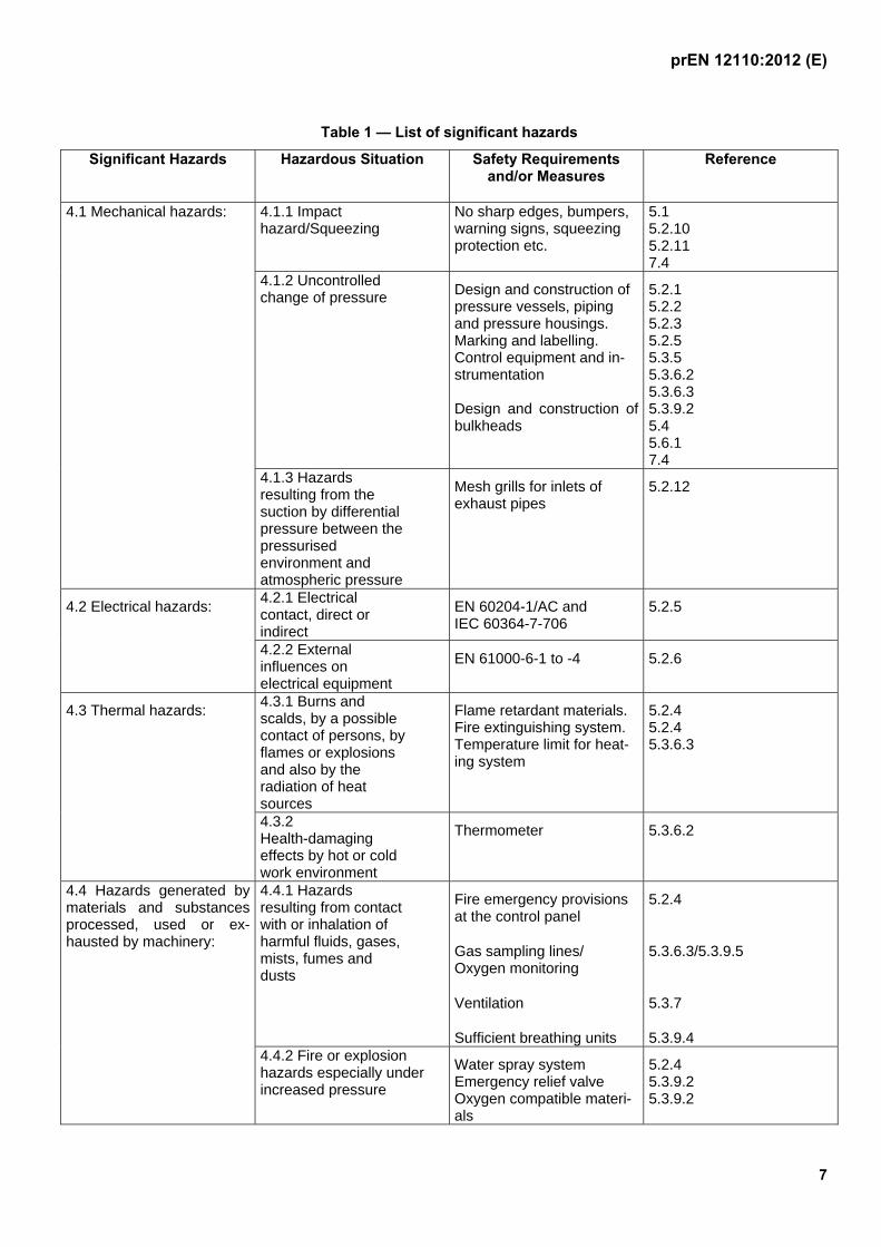
4 List of significant hazards
This clause contains all the significant hazards, hazardous situations and events, identified by risk assessment as significant for this type of machinery and which require action to eliminate or reduce the risk.
prEN 12110:2012 (E)
7
Table 1 — List of significant hazards
Significant Hazards Hazardous Situation Safety Requirements and/or Measures
Reference
4.1 Mechanical hazards: 4.1.1 Impact hazard/Squeezing
No sharp edges, bumpers, warning signs, squeezing protection etc.
5.1 5.2.10 5.2.11 7.4
4.1.2 Uncontrolled change of pressure Design and construction of
pressure vessels, piping and pressure housings. Marking and labelling. Control equipment and in-strumentation Design and construction of bulkheads
5.2.1 5.2.2 5.2.3 5.2.5 5.3.5 5.3.6.2 5.3.6.3 5.3.9.2 5.4 5.6.1 7.4
4.1.3 Hazards resulting from the suction by differential pressure between the pressurised environment and atmospheric pressure
Mesh grills for inlets of exhaust pipes
5.2.12
4.2 Electrical hazards: 4.2.1 Electrical contact, direct or indirect
EN 60204-1/AC and IEC 60364-7-706
5.2.5
4.2.2 External influences on electrical equipment
EN 61000-6-1 to -4 5.2.6
4.3 Thermal hazards: 4.3.1 Burns and scalds, by a possible contact of persons, by flames or explosions and also by the radiation of heat sources
Flame retardant materials. Fire extinguishing system. Temperature limit for heat-ing system
5.2.4 5.2.4 5.3.6.3
4.3.2 Health-damaging effects by hot or cold work environment
Thermometer 5.3.6.2
4.4 Hazards generated by materials and substances processed, used or ex-hausted by machinery:
4.4.1 Hazards resulting from contact with or inhalation of harmful fluids, gases, mists, fumes and dusts
Fire emergency provisions at the control panel
Gas sampling lines/ Oxygen monitoring
Ventilation
Sufficient breathing units
5.2.4
5.3.6.3/5.3.9.5
5.3.7
5.3.9.4 4.4.2 Fire or explosion
hazards especially under increased pressure
Water spray system Emergency relief valve Oxygen compatible materi-als
5.2.4 5.3.9.2 5.3.9.2

prEN 12110:2012 (E)
8
Table 1 ― List of significant hazards (continued)
Significant Hazards Hazardous Situation Safety Requirements and/or Measures
Reference
4.4.3 Use of oxygen Cleaning of oxygen system
Gas sampling lines
Distribution network
Suitable breathing units
5.2.11
5.3.6.3
5.3.9.3
5.3.9.4 4.5 Hazards generated by neglecting ergonomic principles in machine design (mismatch of machinery with human characteristics and abilities):
4.5.1 Unhealthy postures or excessive efforts
Dimensions 5.3.2
5.3.3 4.5.2 Inadequate consideration of human anatomy
Dimensions 5.3.2
5.3.4 4.5.3 Inadequate local lighting Interior Illumination acc. to
EN 12464-1 5.3.6.4
4.5.4 Unhealthy insufficient dimensions and upholstery of the seats
Dimensions and Insulation 5.3.3
4.6 Hazards caused by failure of energy supply, breaking down of machinery parts and other functional disorders:
4.6.1 Failure of energy supply (of energy and/or control circuits)
Emergency Power Supply
Emergency lighting
5.2.7
5.2.7 4.6.2 Errors of fitting Leak test of pressure systems 5.2.11
5.3.9.2
5.3.9.3 4.6.3 Uncontrolled decompression of working chamber or lock
Protection against inlet line breaks
Doors: Self-sealing/Interlock
Pressure indicator
5.3.5, 5.3.8
5.2.10
5.3.6.3 4.6.4 Loss of communication Emergency Power Supply
Second communication net-work
Observation windows/CCTV
5.2.7
5.2.9
5.3.6.3
prEN 12110:2012 (E)
9
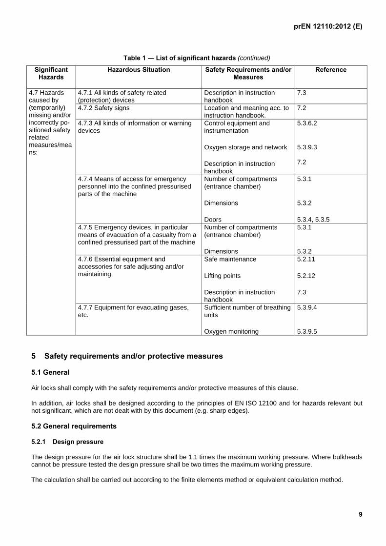
Table 1 ― List of significant hazards (continued)
Significant Hazards
Hazardous Situation Safety Requirements and/or Measures
Reference
4.7 Hazards caused by (temporarily) missing and/or incorrectly po-sitioned safety related measures/means:
4.7.1 All kinds of safety related (protection) devices
Description in instruction handbook
7.3
4.7.2 Safety signs Location and meaning acc. to instruction handbook.
7.2
4.7.3 All kinds of information or warning devices
Control equipment and instrumentation
Oxygen storage and network
Description in instruction handbook
5.3.6.2
5.3.9.3 7.2
4.7.4 Means of access for emergency personnel into the confined pressurised parts of the machine
Number of compartments (entrance chamber)
Dimensions
Doors
5.3.1
5.3.2
5.3.4, 5.3.5 4.7.5 Emergency devices, in particular means of evacuation of a casualty from a confined pressurised part of the machine
Number of compartments (entrance chamber)
Dimensions
5.3.1
5.3.2 4.7.6 Essential equipment and accessories for safe adjusting and/or maintaining
Safe maintenance
Lifting points
Description in instruction handbook
5.2.11
5.2.12
7.3
4.7.7 Equipment for evacuating gases, etc.
Sufficient number of breathing units
Oxygen monitoring
5.3.9.4
5.3.9.5
5 Safety requirements and/or protective measures
5.1 General
Air locks shall comply with the safety requirements and/or protective measures of this clause.
In addition, air locks shall be designed according to the principles of EN ISO 12100 and for hazards relevant but not significant, which are not dealt with by this document (e.g. sharp edges).
5.2 General requirements
5.2.1 Design pressure
The design pressure for the air lock structure shall be 1,1 times the maximum working pressure. Where bulkheads cannot be pressure tested the design pressure shall be two times the maximum working pressure.
The calculation shall be carried out according to the finite elements method or equivalent calculation method.
prEN 12110:2012 (E)
10
5.2.2 Pressure relief valve
Each air lock compartment shall be equipped with a pressure relief valve set at 1,1 times the maximum working pressure and capable of passing the whole air supply to the air lock. Once activated the valve shall close automati-cally when pressure is lowered back to the working pressure.
A quick-closing valve located between the compartment safety valve and the compartment, easily accessible, kept open and sealed by a seal shall be used.
5.2.3 Pipes and hoses
Pipes and hoses which form an integral part of the air locks shall be designed to withstand a maximum working pressures depending on their function
NOTE The maximum working pressure in pipes and hoses can be significantly different to that of the air lock structure.
The use of hoses shall be minimised and if used they shall be as short as possible. They shall withstand a burst pressure of at least 4 times the maximum working pressure of the hose.
5.2.4 Fire protection
Personnel locks and material locks shall consist of materials and components selected to minimize their flammabil-ity under increased air pressure and which are of low toxicity when burning.
Fire fighting and other emergency provisions shall be provided at the control panel. These provisions shall be de-tailed in the instruction handbook. See Clause 7.
It shall be possible to reduce the pressure in each compartment from 2 bar to atmospheric pressure in not more than 2 min in the event of fire by means outside the airlock.
In each compartment the fire extinguishing system shall include either a hand held extinguisher or a water hose inside. There shall also be a water spray system capable of being operated from inside and outside of the air lock; both of these to be suitable for the maximum working pressure of the air lock.
A device for measuring the water supply pressure at the air lock and for displaying it at the control panel shall be installed.
NOTE Criteria for the fire-extinguishing system are given in NFPA 99 and EN 16081.
5.2.5 Electrical equipment
Electrical equipment for air locks shall comply with EN 60204-1:2006/AC:2010. Electrical equipment located inside personnel locks which is an integral part of them and is essential for the air lock operation shall comply with IEC 60364-7-706:2005 and shall be non-sparking.
It shall be suitable for humid and wet spaces and be protected from dust deposits and spraying water to a minimum class of IP 55 of EN 60529:1991+A1:2010, Clause 4.
Electrical equipment shall be designed to minimise the risk of fire and toxic fumes and to withstand pressure changes up to the test pressure of the air lock.
Housings for electrical equipment shall be adequately ventilated or designed and tested to withstand pressure changes up to 1,3 times the design pressure of the air lock.
5.2.6 EMC (Electromagnetic compatibility)
Electrical equipment used for air locks shall comply with the requirements of electromagnetic compatibility as spec-ified in EN 61000-6-1:2007 to -4:2007.
prEN 12110:2012 (E)
11
5.2.7 Emergency Power Supply and Lighting
The air lock shall be designed to accommodate an emergency power supply which shall power safety critical equipment in event of a failure of the main power supply. The emergency power supply shall be either an inde-pendent emergency power supply or part of the overall tunnel emergency power supply.
It shall come into operation automatically when the main power supply fails and have a duration of at least 2 h. Safety critical equipment shall include lighting, communications, atmospheric monitoring equipment, electrically powered airlock pressure control system (if fitted) and Closed Circuit Television (CCTV) (if fitted). The emergency power supply system shall meet performance level c as defined in EN ISO 13849-1:2008. In addition there shall be a separate self-contained emergency lighting system at the control panel and in each compartment of the person-nel lock with a duration of at least 1 h. The intensity of illumination provided by the emergency lighting shall be at least 15 lux at seat level.
5.2.8 Control panel
Control equipment and indicating instruments, see 5.3.6.2, 5.3.9.3 and 5.4, which are outside the air lock shall be assembled in a control panel. They shall be easily readable and designed, constructed, arranged and marked so that their function and switching direction can be clearly recognised, in compliance with EN 61310-1:2008. They shall be illuminated with a nominal intensity of at least 100 lux. The control panel design shall particularly take into account ergonomics to allow the operator (supervisor) of the air lock to carry out his task in the best conditions (see EN 894 series).
The maximum A-weighted sound pressure level at the control panel shall not exceed 80 dB(A) at maximum de-signed flow rate in the pipes.
NOTE The microphone should be arranged in the operator`s position at head level.
5.2.9 Communications
A primary voice communication system shall be installed to connect working chamber, personnel locks and control panel. This system shall be of a push to talk type with speakers inside the compartments.
A secondary communication system, which is independent of the power supply system, shall be installed.
5.2.10 Doors, closing and sealing
Doors of air locks shall be self-sealing and kept shut by differential pressure. If the doors of materials locks cannot be self-sealed, a mechanical interlocking system shall be fitted.
Doors shall have a free operating space without affecting other installations or equipment.
5.2.11 Other requirements
The inlets of pipes exhausting air from the air lock shall be covered by a mesh grill to prevent suction injuries and ingress of debris.
For safe lifting the individual air lock shall be fitted with lifting points when applicable.
In addition to the instruction handbook, basic operating and safety instructions for the air lock shall be clearly dis-played at the lock attendant's control position (control panel) in a waterproof form.
Services not related to the air lock but passing through the air lock shall be in a sleeve, e.g. steel pipe. Differential movement between the bulk heads shall be considered.
prEN 12110:2012 (E)
12
5.3 Personnel locks
5.3.1 Number of compartments
Personnel locks shall consist of at least two directly interconnected compartments, a main chamber and an en-trance chamber accessible from atmospheric pressure, with door openings as specified in 5.3.4.
5.3.2 Dimensions
Personnel locks shall meet the following minimum requirements:
Table 2 — Minimum requirements
Main chamber Entrance chamber
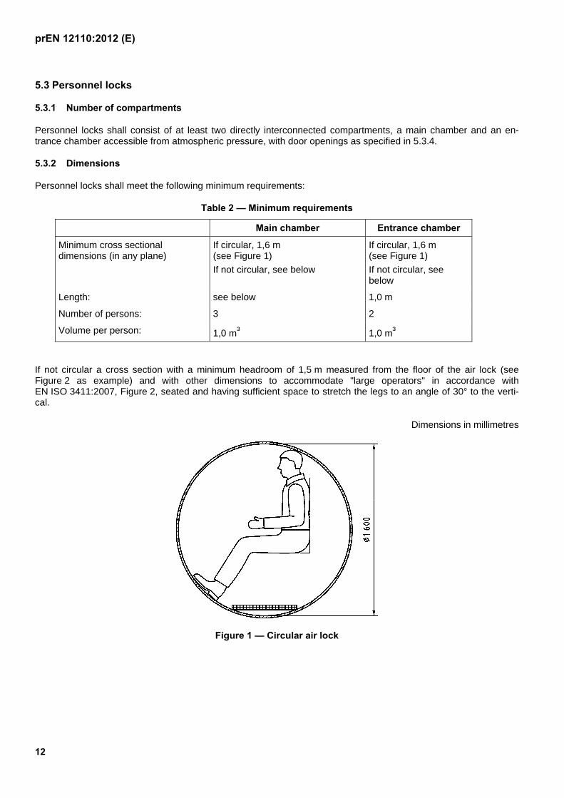
Minimum cross sectional dimensions (in any plane)
If circular, 1,6 m (see Figure 1)
If not circular, see below
If circular, 1,6 m (see Figure 1)
If not circular, see below
Length: see below 1,0 m
Number of persons: 3 2
Volume per person: 1,0 m³ 1,0 m³
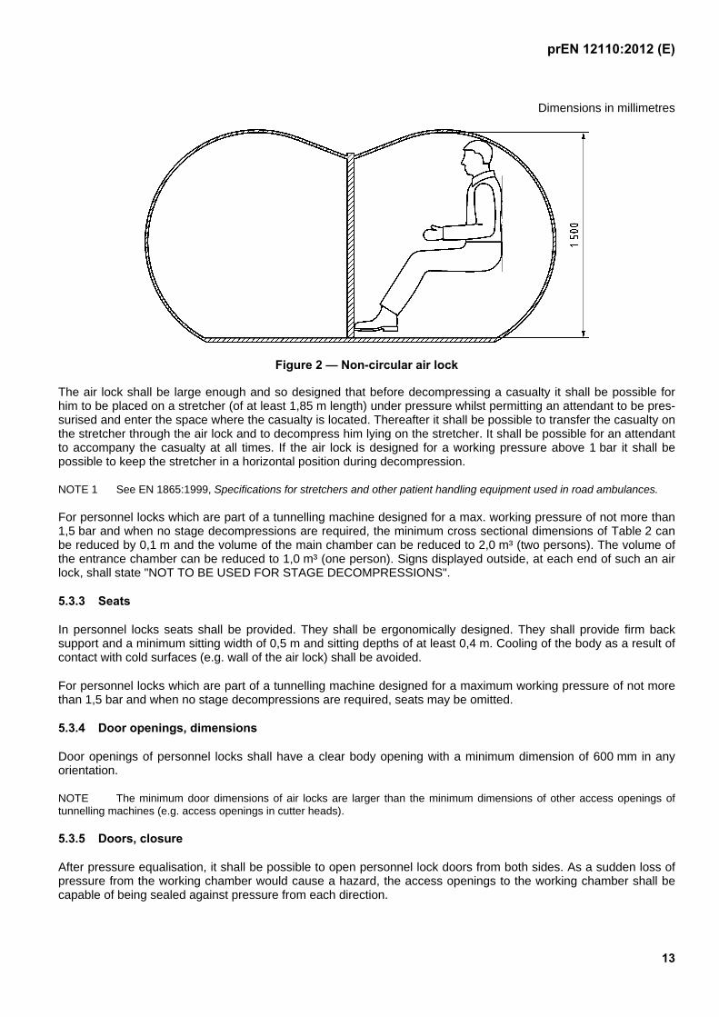
If not circular a cross section with a minimum headroom of 1,5 m measured from the floor of the air lock (see Figure 2 as example) and with other dimensions to accommodate "large operators" in accordance with EN ISO 3411:2007, Figure 2, seated and having sufficient space to stretch the legs to an angle of 30° to the verti-cal.
Dimensions in millimetres
Figure 1 — Circular air lock
prEN 12110:2012 (E)
13
Dimensions in millimetres
Figure 2 — Non-circular air lock
The air lock shall be large enough and so designed that before decompressing a casualty it shall be possible for him to be placed on a stretcher (of at least 1,85 m length) under pressure whilst permitting an attendant to be pres-surised and enter the space where the casualty is located. Thereafter it shall be possible to transfer the casualty on the stretcher through the air lock and to decompress him lying on the stretcher. It shall be possible for an attendant to accompany the casualty at all times. If the air lock is designed for a working pressure above 1 bar it shall be possible to keep the stretcher in a horizontal position during decompression.
NOTE 1 See EN 1865:1999, Specifications for stretchers and other patient handling equipment used in road ambulances.
For personnel locks which are part of a tunnelling machine designed for a max. working pressure of not more than 1,5 bar and when no stage decompressions are required, the minimum cross sectional dimensions of Table 2 can be reduced by 0,1 m and the volume of the main chamber can be reduced to 2,0 m³ (two persons). The volume of the entrance chamber can be reduced to 1,0 m³ (one person). Signs displayed outside, at each end of such an air lock, shall state "NOT TO BE USED FOR STAGE DECOMPRESSIONS".
5.3.3 Seats
In personnel locks seats shall be provided. They shall be ergonomically designed. They shall provide firm back support and a minimum sitting width of 0,5 m and sitting depths of at least 0,4 m. Cooling of the body as a result of contact with cold surfaces (e.g. wall of the air lock) shall be avoided.
For personnel locks which are part of a tunnelling machine designed for a maximum working pressure of not more than 1,5 bar and when no stage decompressions are required, seats may be omitted.
5.3.4 Door openings, dimensions
Door openings of personnel locks shall have a clear body opening with a minimum dimension of 600 mm in any orientation.
NOTE The minimum door dimensions of air locks are larger than the minimum dimensions of other access openings of tunnelling machines (e.g. access openings in cutter heads).
5.3.5 Doors, closure
After pressure equalisation, it shall be possible to open personnel lock doors from both sides. As a sudden loss of pressure from the working chamber would cause a hazard, the access openings to the working chamber shall be capable of being sealed against pressure from each direction.
prEN 12110:2012 (E)
14
5.3.6 Minimum equipment for personnel locks
5.3.6.1 General
Each compartment shall be equipped with control equipment and instrumentation and penetrations.
5.3.6.2 Control equipment and instrumentation
The following equipment and instrumentation shall be provided:
Equipment for the primary control of pressure capable of being operated from outside the airlock;
equipment for emergency control of pressure;
a valve on the compression line inside the airlock secured unintentional use;
an emergency decompression line with a valve on the inside secured against unintentional use and with a valve on the outside capable of being locked open;
a device for measuring internal pressure and displaying it outside at the control panel and inside each compartment capable of being read to an accuracy of 0,05 bar;
a device capable of recording the pressure in each compartment to an accuracy of 0,05 bar and installed out-side the air lock. Recording speed should not be slower than one revolution in 4 h for circular charts or 120 mm/h for strip charts. For circular charts zero bar pressure scale shall be at the periphery. Use of elec-tronic data recording, sampling at a rate of at least once every 10 s, shall be permitted as an alternative to pa-per charts;
a thermometer, inside, measuring range + 50 °C to 0 °C and displaying at the control panel;
a clock, inside and outside, with a display of minutes and seconds;
a device for measuring the supply air pressure at the air lock and for displaying it at the control panel.
5.3.6.3 Additional penetrations
The following shall be provided:
sampling line for gas analysis;
observation windows made of impact resistant material and capable of withstanding the test pressure (see Ta-ble 3). The windows shall have a minimum diameter of 150 mm for visual contact between panel and air lock compartment and between the air lock compartments. If it is not possible to observe the entire lock interior through windows, CCTV shall be provided in addition.
NOTE 1 Criteria for windows made of impact resistant material are given e.g. in ASME PVHO-1:2007.
NOTE 2 It is recommended a number of spare penetrations are provided for future service installations.
5.3.6.4 Other requirements
Devices for measuring the working chamber pressure. This pressure shall be displayed in the compartment giving access to working chamber and outside at the control panel. Reading accuracy to 0,05 bar;
interior illumination shall be at a minimum of 120 lux according to EN 12464-1:2011, measured at a height of 1,4 m above the air lock floor level;
prEN 12110:2012 (E)
15
silencers on all pipe(s) carrying fresh and waste air shall be fitted to ensure that the maximum A-weighted sound pressure level in the compartments caused by the operation of the air lock, shall not exceed 80 dB(A) measured at atmospheric pressure and maximum flow rate in the pipes;
testing: Measurement at atmospheric pressure with ventilation according to the maximum number of per-sons;
NOTE The microphone should be arranged in the pressure chamber centre at a seated person´s head level.
provision shall be made to maintain a temperature in the compartments between 18 °C and 28 °C except dur-ing pressure changes. The heating system shall be warm water convection not exceeding 60 °C.
5.3.7 Ventilation
Personnel air locks shall be capable of being ventilated with fresh air. The air supply rate shall be at least 50 l/min per person, measured at the chamber pressure. Monitoring of ventilation rate shall be possible. If automatically controlled, the ventilation shall be performed with pressure variations less than ± 0,05 bar. The ventilation equip-ment shall be so designed that this range of fluctuation can also be achieved manually.
5.3.8 Protection against inlet line breaks
For protection against sudden pressure loss as a result of inlet line breaks, all inlet lines shall be fitted with devices to shut off the line automatically (e.g. flap valves or non-return valves). These device(s) shall be fitted inside the air lock adjacent to the penetrations.
5.3.9 Oxygen breathing system (including all gas mixtures with more than 23 % oxygen)
5.3.9.1 Safety considerations
When an airlock is designed for oxygen breathing during decompression the following shall be considered:
a) the functional requirements of the supply of oxygen to the breathing units;
b) the selection and installation of the components used for the oxygen supply system;
c) the prevention of leakage of oxygen;
d) the prevention of ignition.
5.3.9.2 Equipment requirements
Only oxygen compatible materials shall be used in the construction of the oxygen breathing installation. Joints can be welded, brazed or utilise compression fittings. Fittings shall be selected based on the pressure rating of the oxy-gen supply system and made from oxygen compatible material. Carbon steel tubing or fittings shall not be used.
All flexible hoses carrying oxygen, except for those attached to the breathing masks, shall be externally stainless steel braided to EN ISO 14113:2008 with heat sink and restraining cable. They shall be lined with a material com-patible with the gas they contain, and which does not give off any harmful gas when in service. Individual hose lengths shall be minimized and shall not exceed 5 m.
Valves and gauges shall be oxygen compatible. Gauges shall comply with EN ISO 5171:2010 and be 63 mm di-ameter or more. Valves shall be slow acting needle or gate valves. Above 20 bar, valves shall be slow acting nee-dle or gate valves.
Ball valves shall be used for safety emergency valves.
prEN 12110:2012 (E)
16
5.3.9.3 Distribution network
The pressure in the distribution pipe work shall be the minimum necessary to ensure the correct operation of the breathing units. The first pressure reduction shall be at the oxygen cylinders.
A pressure gauge shall be provided at the control panel to indicate the supply pressure to the breathing units.
NOTE The storage area for oxygen cylinders shall be marked according to national regulations.
The oxygen pipe work shall be arranged so that a change of supply can be made without an interruption of flow. There shall be sufficient capacity in the distribution network to allow a mean oxygen consumption of at least 20 l/min per person measured at the pressure of each decompression stage. A master valve to interrupt all oxygen supply to the chamber shall be provided at the control panel. In addition, the supply to each breathing unit shall be fitted with a valve.
A device shall be incorporated in the oxygen supply line to prevent leakage in the event of rupture of the line.
Oxygen pipework upstream of the primary regulating valve shall be clearly marked at regular intervals with the legend "High pressure oxygen". All other pipework shall be marked "oxygen". The direction of flow shall also be indicated.
5.3.9.4 Breathing units
There shall be sufficient breathing units corresponding to the max. number of personnel permitted in the air lock and at least one replacement unit.
The breathing units shall be designed for 100 % oxygen breathing under the pressure and in the system for which they are intended to be used. They shall be of a design which allows for easy changing and cleaning. Each breathing unit shall be connected to an overboard dump system which shall discharge the exhaled gas outside the airlock to a place with adequate ventilation. Supply and exhaust connections to the breathing unit shall be irreversible.
The breathing performance of the breathing units shall comply with 5.6.1 of EN 250:2000+A1:2006.
NOTE The area of the oxygen discharge should be marked with "NO SMOKING" signs.
5.3.9.5 Oxygen monitoring
Each chamber of the air lock shall be equipped with at least one device to monitor the oxygen concentration in that chamber. The concentration shall be displayed at the control panel.
A warning device with an audible alarm shall be provided to alarm when the oxygen concentration in the atmosphere of the chamber is less than 19 % or greater than 23 % by volume.
NOTE Exhaust gases should be dumped to an area with sufficient ventilation to minimize the risk of unacceptably high oxygen concentration. Information should be given in the information for use.
5.4 Material locks
A material lock shall have the following minimum equipment:
equipment for pressure control, controllable from outside;
pressure measuring device, reading outside, to an accuracy of 0,1 bar.
If a material lock is designed for a person to enter it for loading or unloading of material, the following additional equipment is required:
prEN 12110:2012 (E)
17
means of observation of the inside of the material lock, if windows are used they shall be of minimum diameter 150 mm;
lighting with a minimum intensity of 120 lux.
Signs displayed outside, at each end of such a material lock, shall state:
"PERSONNEL TRANSFER FORBIDDEN".
The requirements of 5.2.4 for fire extinguishing systems do not apply to material locks not designed for persons to enter for loading and unloading materials.
5.5 Combined locks
The requirements for personnel locks apply for combined locks.
NOTE People and materials may occupy a combined lock simultaneously, provided the minimum dimensions for personnel as defined in 5.3.2 are available for them to occupy.
5.6 Pressure bulkheads
5.6.1 General
Pressure bulkheads shall provide an effective barrier between spaces with different pressures.
5.6.2 Bulkheads forming air locks
An air lock formed by two or more bulkheads shall satisfy the relevant requirements in 5.1, 5.2, 5.3 and 5.4.
6 Verification of safety requirements and/or protective measures
6.1 Verification of compliance with the safety requirements given in this standard shall be made by calculation, inspection and, whenever feasible, testing during manufacture, or on assembly at site, see Table 4.
NOTE Some of the verifications are only possible at the first use of the air lock.
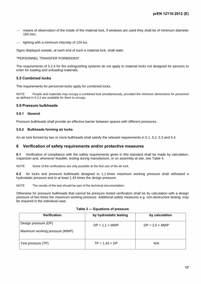
6.2 Air locks and pressure bulkheads designed to 1,1 times maximum working pressure shall withstand a hydrostatic pressure test to at least 1,43 times the design pressure.
NOTE The results of the test should be part of the technical documentation.
Otherwise for pressure bulkheads that cannot be pressure tested verification shall be by calculation with a design pressure of two times the maximum working pressure. Additional safety measures e.g. non-destructive testing, may be required in the individual case.
Table 3 — Equations of pressure
Verification by hydrostatic testing by calculation
Design pressure (DP)
Maximum working pressure (MWP)
DP = 1,1 × MWP
DP = 2,0 × MWP
Test pressure (TP) TP = 1,43 × DP N/A
prEN 12110:2012 (E)
18
NOTE The test pressure of 1,43 × DP is derived from the EC directive 97/23/EC concerning Pressure Equipment (PED) and is usually valid for common pressure vessels of steel construction.
For verification requirements of the pressure test, reference shall be made to the design standard, see 5.2.1.
For special operation conditions and pressure vessel materials the test pressure has to be recalculated.
6.3 The following functions of the oxygen breathing system shall be checked before first use:
a) the proper installation of the supply of oxygen to the breathing units;
b) the prevention of leakage shall be checked by means of a static pressure test at the design pressure of the oxygen breathing system, to confirm that there is no loss of pressure in the system over a 10-minute period;
c) the cleanliness of the oxygen distribution and breathing units.
6.4 The function of the voice communication network shall be subject to a functional check.
6.5 The pressure control equipment and relief valves shall be subject to a functional check.
6.6 The ventilation system of a personnel lock shall be subjected to a flow test based on an air supply of at least 50 l/min per person measured at the chamber pressure and the maximum number of persons that can be accommodated in the chamber. Automatic ventilation shall be performed with pressure variations less than ± 0,05 bar.
6.7 The function of the silencers shall be verified according to the test in 5.2.8 and 5.3.6.4.
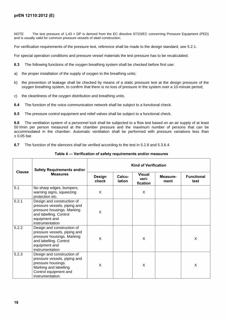
Table 4 — Verification of safety requirements and/or measures
Clause Safety Requirements and/or
Measures
Kind of Verification
Design check
Calcu-lation
Visual veri-
fication
Measure-ment
Functional test
5.1 No sharp edges, bumpers, warning signs, squeezing protection etc.
X X
5.2.1 Design and construction of pressure vessels, piping and pressure housings. Marking and labelling. Control equipment and instrumentation
X
5.2.2 Design and construction of pressure vessels, piping and pressure housings. Marking and labelling. Control equipment and instrumentation
X X X
5.2.3 Design and construction of pressure vessels, piping and pressure housings. Marking and labelling. Control equipment and instrumentation.
X X X
prEN 12110:2012 (E)
19
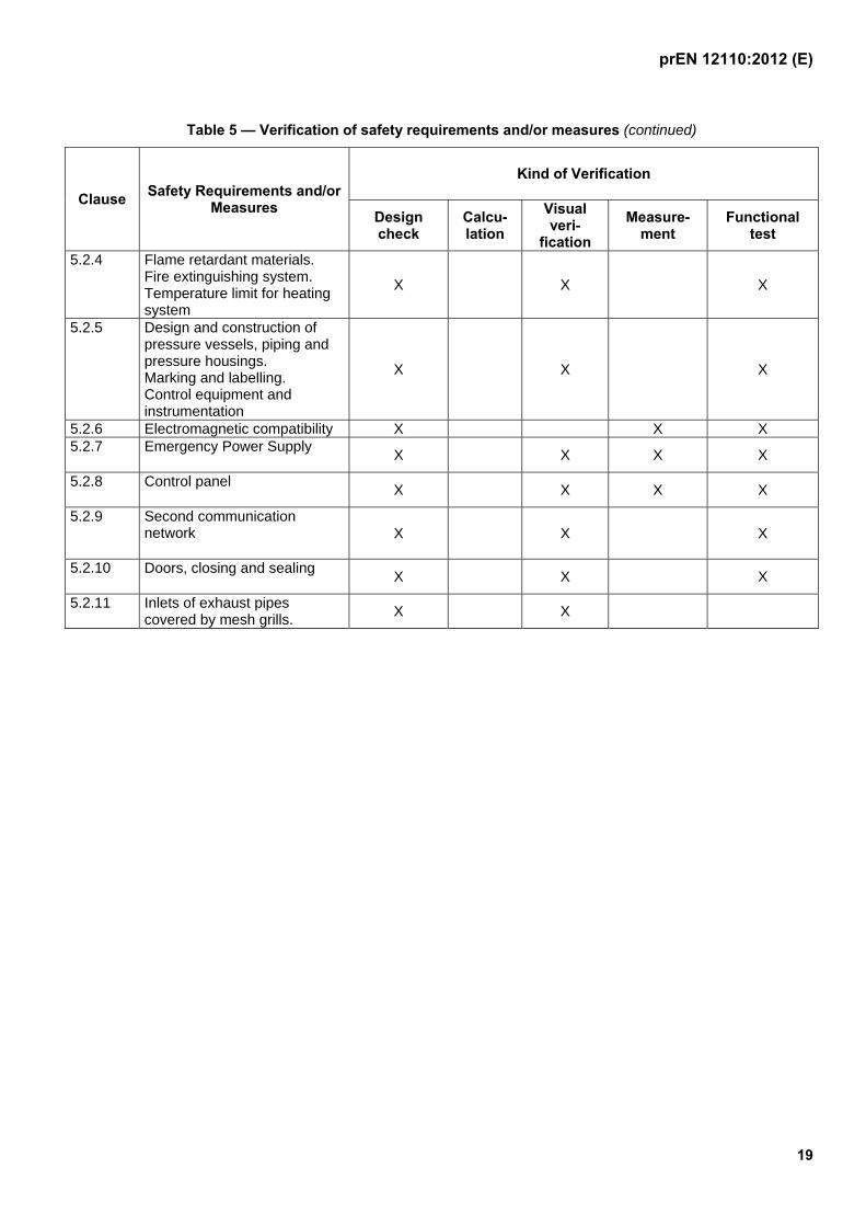
Table 5 — Verification of safety requirements and/or measures (continued)
Clause Safety Requirements and/or
Measures
Kind of Verification
Design check
Calcu-lation
Visual veri-
fication
Measure-ment
Functional test
5.2.4 Flame retardant materials. Fire extinguishing system. Temperature limit for heating system
X X X
5.2.5 Design and construction of pressure vessels, piping and pressure housings. Marking and labelling. Control equipment and instrumentation
X X X
5.2.6 Electromagnetic compatibility X X X 5.2.7 Emergency Power Supply
X X X X
5.2.8 Control panel X X X X
5.2.9 Second communication network X X X
5.2.10 Doors, closing and sealing X X X
5.2.11 Inlets of exhaust pipes covered by mesh grills.
X X
prEN 12110:2012 (E)
20
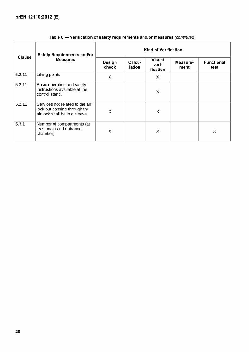
Table 6 — Verification of safety requirements and/or measures (continued)
Clause Safety Requirements and/or
Measures
Kind of Verification
Design check
Calcu-lation
Visual veri-
fication
Measure-ment
Functional test
5.2.11 Lifting points X X
5.2.11 Basic operating and safety instructions available at the control stand. X
5.2.11 Services not related to the air lock but passing through the air lock shall be in a sleeve X X
5.3.1 Number of compartments (at least main and entrance chamber) X X X
prEN 12110:2012 (E)
21
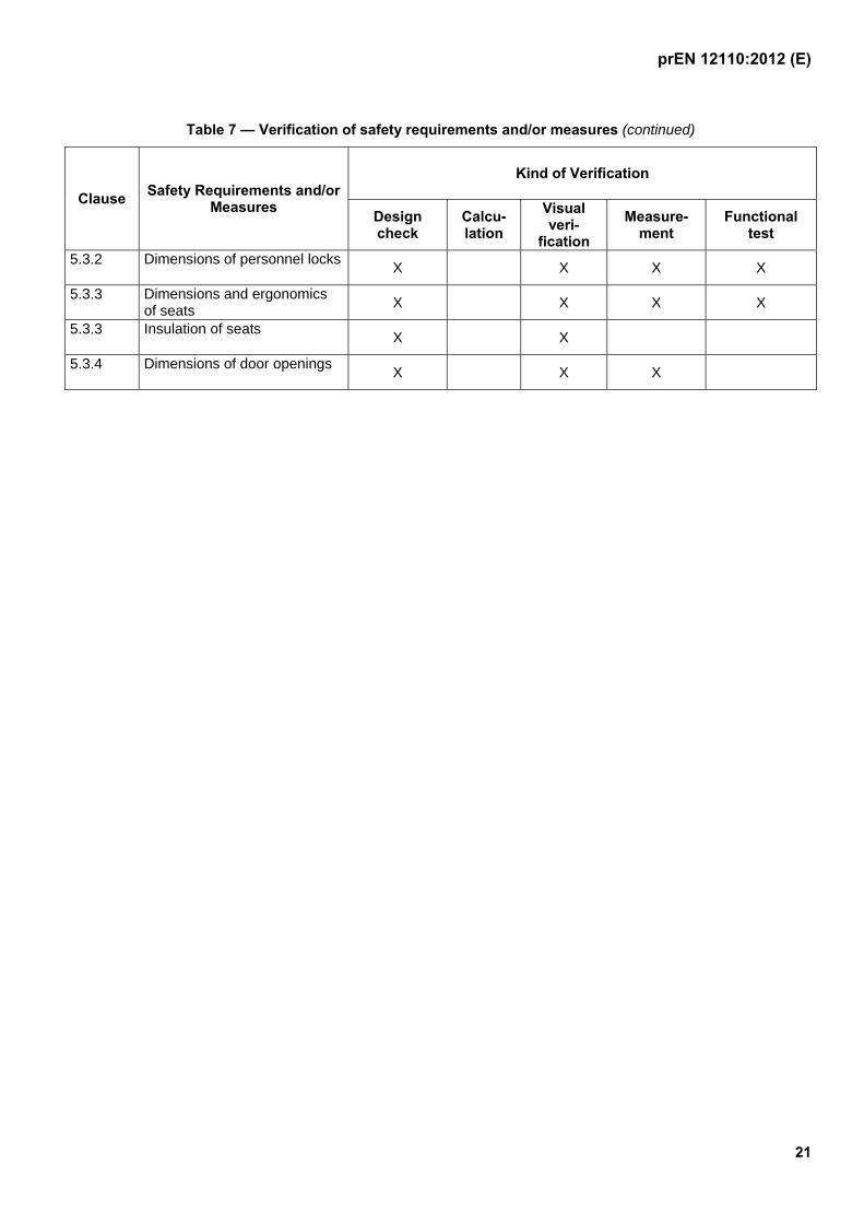
Table 7 — Verification of safety requirements and/or measures (continued)
Clause Safety Requirements and/or
Measures
Kind of Verification
Design check
Calcu-lation
Visual veri-
fication
Measure-ment
Functional test
5.3.2 Dimensions of personnel locks X X X X
5.3.3 Dimensions and ergonomics of seats X X X X
5.3.3 Insulation of seats X X
5.3.4 Dimensions of door openings X X X
prEN 12110:2012 (E)
22
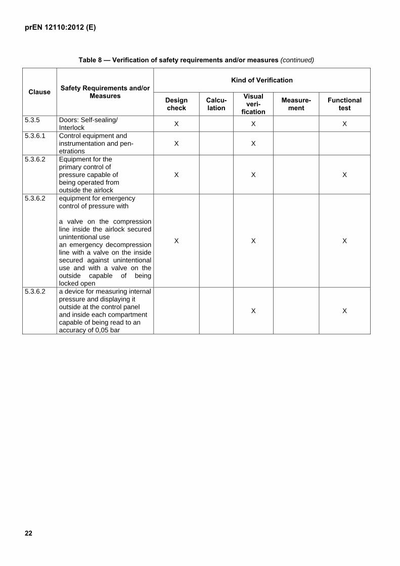
Table 8 — Verification of safety requirements and/or measures (continued)
Clause Safety Requirements and/or
Measures
Kind of Verification
Design check
Calcu-lation
Visual veri-
fication
Measure-ment
Functional test
5.3.5 Doors: Self-sealing/ Interlock
X X X
5.3.6.1 Control equipment and instrumentation and pen-etrations
X X
5.3.6.2 Equipment for the primary control of pressure capable of being operated from outside the airlock
X X X
5.3.6.2 equipment for emergency control of pressure with a valve on the compression line inside the airlock secured unintentional use an emergency decompression line with a valve on the inside secured against unintentional use and with a valve on the outside capable of being locked open
X X X
5.3.6.2 a device for measuring internal pressure and displaying it outside at the control panel and inside each compartment capable of being read to an accuracy of 0,05 bar
X X
prEN 12110:2012 (E)
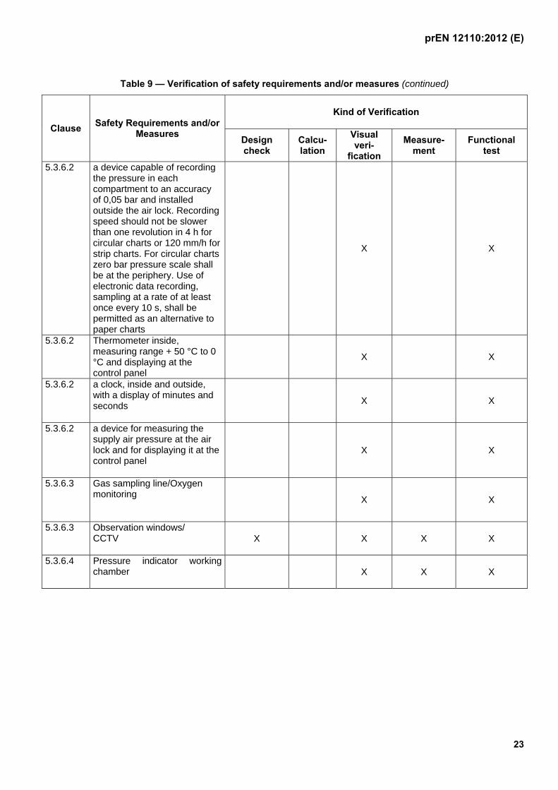
23
Table 9 — Verification of safety requirements and/or measures (continued)
Clause Safety Requirements and/or
Measures
Kind of Verification
Design check
Calcu-lation
Visual veri-
fication
Measure-ment
Functional test
5.3.6.2 a device capable of recording the pressure in each compartment to an accuracy of 0,05 bar and installed outside the air lock. Recording speed should not be slower than one revolution in 4 h for circular charts or 120 mm/h for strip charts. For circular charts zero bar pressure scale shall be at the periphery. Use of electronic data recording, sampling at a rate of at least once every 10 s, shall be permitted as an alternative to paper charts
X X
5.3.6.2 Thermometer inside, measuring range + 50 °C to 0 °C and displaying at the control panel
X X
5.3.6.2 a clock, inside and outside, with a display of minutes and seconds X X
5.3.6.2 a device for measuring the supply air pressure at the air lock and for displaying it at the control panel
X X
5.3.6.3 Gas sampling line/Oxygen monitoring
X X
5.3.6.3 Observation windows/ CCTV X X X X
5.3.6.4 Pressure indicator working chamber X X X
prEN 12110:2012 (E)
24
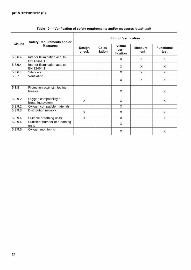
Table 10 — Verification of safety requirements and/or measures (continued)
Clause Safety Requirements and/or
Measures
Kind of Verification
Design check
Calcu-lation
Visual veri-
fication
Measure-ment
Functional test
5.3.6.4 Interior Illumination acc. to EN 12464-1
X X X
5.3.6.4 Interior Illumination acc. to EN 12464-1
X X X
5.3.6.4 Silencers X X X 5.3.7
Ventilation X X X
5.3.8 Protection against inlet line breaks X X
5.3.9.2 Oxygen compatibility of breathing system
X X X
5.3.9.2 Oxygen compatible materials X 5.3.9.3 Distribution network
X X X
5.3.9.4 Suitable breathing units X X X 5.3.9.4 Sufficient number of breathing
units X
5.3.9.5 Oxygen monitoring X X
prEN 12110:2012 (E)
25
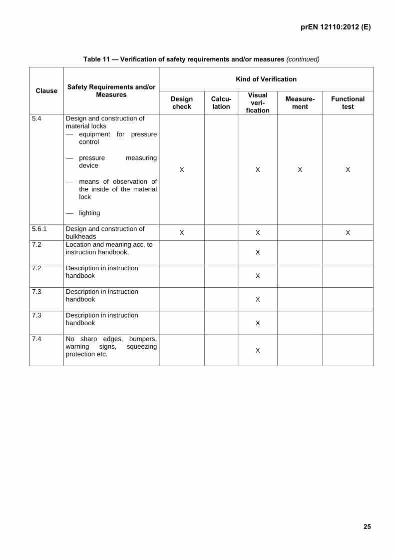
Table 11 — Verification of safety requirements and/or measures (continued)
Clause Safety Requirements and/or
Measures
Kind of Verification
Design check
Calcu-lation
Visual veri-
fication
Measure-ment
Functional test
5.4 Design and construction of material locks equipment for pressure
control
pressure measuring device
means of observation of the inside of the material lock
lighting
X X X X
5.6.1 Design and construction of bulkheads
X X X
7.2 Location and meaning acc. to instruction handbook. X
7.2 Description in instruction handbook X
7.3 Description in instruction handbook X
7.3 Description in instruction handbook X
7.4 No sharp edges, bumpers, warning signs, squeezing protection etc. X
prEN 12110:2012 (E)
26
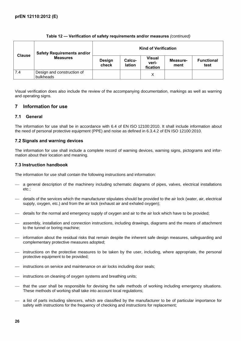
Table 12 — Verification of safety requirements and/or measures (continued)
Clause Safety Requirements and/or
Measures
Kind of Verification
Design check
Calcu-lation
Visual veri-
fication
Measure-ment
Functional test
7.4 Design and construction of bulkheads
X
Visual verification does also include the review of the accompanying documentation, markings as well as warning and operating signs.
7 Information for use
7.1 General
The information for use shall be in accordance with 6.4 of EN ISO 12100:2010. It shall include information about the need of personal protective equipment (PPE) and noise as defined in 6.3.4.2 of EN ISO 12100:2010.
7.2 Signals and warning devices
The information for use shall include a complete record of warning devices, warning signs, pictograms and infor-mation about their location and meaning.
7.3 Instruction handbook
The information for use shall contain the following instructions and information:
a general description of the machinery including schematic diagrams of pipes, valves, electrical installations etc.;
details of the services which the manufacturer stipulates should be provided to the air lock (water, air, electrical supply, oxygen, etc.) and from the air lock (exhaust air and exhaled oxygen);
details for the normal and emergency supply of oxygen and air to the air lock which have to be provided;
assembly, installation and connection instructions, including drawings, diagrams and the means of attachment to the tunnel or boring machine;
information about the residual risks that remain despite the inherent safe design measures, safeguarding and complementary protective measures adopted;
instructions on the protective measures to be taken by the user, including, where appropriate, the personal protective equipment to be provided;
instructions on service and maintenance on air locks including door seals;
instructions on cleaning of oxygen systems and breathing units;
that the user shall be responsible for devising the safe methods of working including emergency situations. These methods of working shall take into account local regulations;
a list of parts including silencers, which are classified by the manufacturer to be of particular importance for safety with instructions for the frequency of checking and instructions for replacement;
prEN 12110:2012 (E)
27
special instruction for the supply and use of hand-held fire extinguishers under hyperbaric conditions;
emergency provisions for evacuation and fire fighting according to 5.2.4.
The pipe work shall be thoroughly clean internally according to IEC/TR3 60877:1999
The manufacturer of air locks and pressure bulkheads shall give all the necessary information for the safe trans-portation, installation, commissioning, inspection, testing, operation, servicing and dismantling in the instruction handbook.
In particular the weights in kilograms of individual transportable parts of the air lock and the pressure bulkhead and the recommended procedures for safe handling shall be detailed in the instruction handbook.
The manufacturer shall give information about the intended use (e.g. maximum working pressure in bar).
All functional, flow and pressure test procedures shall be fully described in the instruction handbook.
Before each use the protection against breaks in flexible lines shall be checked according to the instruction hand-book.
If the air lock is fitted with an oxygen breathing system the instruction handbook shall include information about this system.
If the air lock is fitted with a CCTV, instruction shall be added in the operation manual that the function of CCTV shall be checked before use of the chamber.
The manufacturer shall give information to the user on how the correct functioning of the oxygen breathing system shall be checked after every installation and at minimum every two years.
Spare parts for the oxygen breathing unit shall comply with the requirements of the manufacturer. Information about oxygen compatibility shall be provided.
The manufacturer shall give advice for functional tests after repair for the oxygen breathing system, ventilation system, voice communication network, control equipment and on requirements for pressure testing of the chamber after repair to it.
Instruction shall be given that when personnel are in the working chamber, the linking door to the lock shall be open. One chamber shall be accessible as an escape chamber from the working chamber at any time.
The manufacturer shall give advice that air supplied to the chamber shall comply with the requirements of EN 12021:1998.
The manufacturer shall give advice that pipework and fittings for oxygen shall be grease free and that lubricants shall be suitable for oxygen use.
7.4 Signs
Symbols, pictograms and warning signs shall be displayed in accordance with 7.2.
The following shall be permanently and clearly displayed:
purpose and opening/closing direction of valves;
signs as required in 5.2.8, 5.3.2, 5.3.9.3, 5.3.9.4 (if applicable) and 5.4;
(coloured designation of) oxygen pipework where applicable.
prEN 12110:2012 (E)
28
7.5 Marking
The following shall be permanently and clearly indicated on air locks:
business name and full address of the manufacturer or his authorised representative;
designation of machinery;
year of construction;
designation of series or type, if any;
serial or identification number, if any;
maximum working- and design-pressure in bars;
overall weight in kilograms;
gross volume of each chamber in cubic metres;
maximum number of persons permitted in each chamber;
rating information.
prEN 12110:2012 (E)
29
Annex ZA (informative)
Relationship between this European Standard and the Essential
Requirements of EU Directive 2006/42/EC
This European Standard has been prepared under a mandate given to CEN by the European Commission and the European Free Trade Association to provide a means of conforming to Essential Requirements of the New Approach Directive Machinery 2006/42/EC.
Once this standard is cited in the Official Journal of the European Union under that Directive and has been implemented as a national standard in at least one Member State, compliance with the normative clauses of this standard confers, within the limits of the scope of this standard, a presumption of conformity with the relevant Essential Requirements except those of Chapter 3 of Annex I of that Directive and associated EFTA regulations.
WARNING — Other requirements and other EU Directives may be applicable to the product(s) falling within the scope of this standard.
prEN 12110:2012 (E)
30
Bibliography
[1] ASME PVHO-1:2012, Safety Standard for Pressure Vessels for Human Occupancy
[2] EN 1865-1:2010, Specifications for stretchers and other patient handling equipment used in road ambulances
[3] EN 16081:2011, Hyperbaric chambers — Specific requirements for fire extinguishing systems — Performance, installation and testing
[4] NFPA 99:2012, Standard for Health Care Facilities
[5] Directive 97/23/EC of the European Parliament and of the Council of 29 May 1997 on the approximation of the laws of the Member States concerning pressure equipment