
Understanding Blow Molding (Print-on-Demand) - beck …€¦ · 9 Understanding Extrusion Blow...
12
Understanding Blow Molding (Print-on-Demand) Bearbeitet von Norman C. Lee Neuausgabe 2007. Buch. XIII, 181 S. Hardcover ISBN 978 3 446 41265 1 Format (B x L): 19,8 x 24,6 cm Gewicht: 569 g Weitere Fachgebiete > Technik > Verfahrenstechnik, Chemieingenieurwesen, Lebensmitteltechnik > Technologie der Kunststoffe und Polymere Zu Inhaltsverzeichnis schnell und portofrei erhältlich bei Die Online-Fachbuchhandlung beck-shop.de ist spezialisiert auf Fachbücher, insbesondere Recht, Steuern und Wirtschaft. Im Sortiment finden Sie alle Medien (Bücher, Zeitschriften, CDs, eBooks, etc.) aller Verlage. Ergänzt wird das Programm durch Services wie Neuerscheinungsdienst oder Zusammenstellungen von Büchern zu Sonderpreisen. Der Shop führt mehr als 8 Millionen Produkte.
-
Upload
dangnguyet -
Category
Documents
-
view
229 -
download
1
Transcript of Understanding Blow Molding (Print-on-Demand) - beck …€¦ · 9 Understanding Extrusion Blow...

Understanding Blow Molding (Print-on-Demand)
Bearbeitet vonNorman C. Lee
Neuausgabe 2007. Buch. XIII, 181 S. HardcoverISBN 978 3 446 41265 1
Format (B x L): 19,8 x 24,6 cmGewicht: 569 g
Weitere Fachgebiete > Technik > Verfahrenstechnik, Chemieingenieurwesen,Lebensmitteltechnik > Technologie der Kunststoffe und Polymere
Zu Inhaltsverzeichnis
schnell und portofrei erhältlich bei
Die Online-Fachbuchhandlung beck-shop.de ist spezialisiert auf Fachbücher, insbesondere Recht, Steuern und Wirtschaft.Im Sortiment finden Sie alle Medien (Bücher, Zeitschriften, CDs, eBooks, etc.) aller Verlage. Ergänzt wird das Programmdurch Services wie Neuerscheinungsdienst oder Zusammenstellungen von Büchern zu Sonderpreisen. Der Shop führt mehr
als 8 Millionen Produkte.
Norman C. Lee
Understanding BlowMolding
ISBN-10: 3-446-41265-4ISBN-13: 978-3-446-41265-1
Leseprobe
Weitere Informationen oder Bestellungen unterhttp://www.hanser.de/978-3-446-41265-1
sowie im Buchhandel
9 Understanding Extrusion Blow Molds
The mold determines the shape of the end product with all its details. It helps provide the end product with essential physical properties and the desired appearance. Usually, the mold maker builds the blow mold according to the molder’s or the customer’s specifi cations, but frequently, minor adjustments or improvements which would not justify its return to the mold maker, can be made with equipment and knowledge available in the blow molding shop.
9.1 Main Characteristics of the Mold Halves
The blow mold may have a number of parts, counting its various inserts, but it usually con-sists of two halves. When closed, these halves will form one or more cavities which will enclose one or more parisons for blowing. The two mold halves are usually alike. There are usually no male and female sections.
Pinch-off edges are generally provided at both ends of the mold halves. A blowing pin may have the additional function of shaping and fi nishing the neck inside.
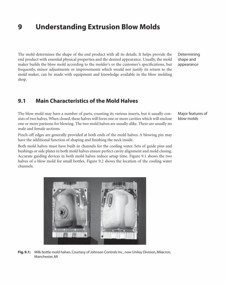
Both mold halves must have built-in channels for the cooling water. Sets of guide pins and bushings or side plates in both mold halves ensure perfect cavity alignment and mold closing. Accurate guiding devices in both mold halves reduce setup time. Figure 9.1 shows the two halves of a blow mold for small bottles. Figure 9.2 shows the location of the cooling water channels.
Fig. 9.1: Milk bottle mold halves. Courtesy of Johnson Controls Inc., now Uniloy Division, Milacron, Manchester, MI
Determining shape and appearance
Major features of blow molds
62
On some blowing presses, mold closing is carried out in two steps, fi rst at high speed, with lower pressure, say, 6.5 to 13 mm (0.25 to 0.5 in) of daylight. The second step is slower with higher pressure to protect the mold from tools or anything else that might have fallen between the halves (which, however, should never happen in a well-kept shop) and for operator safety.
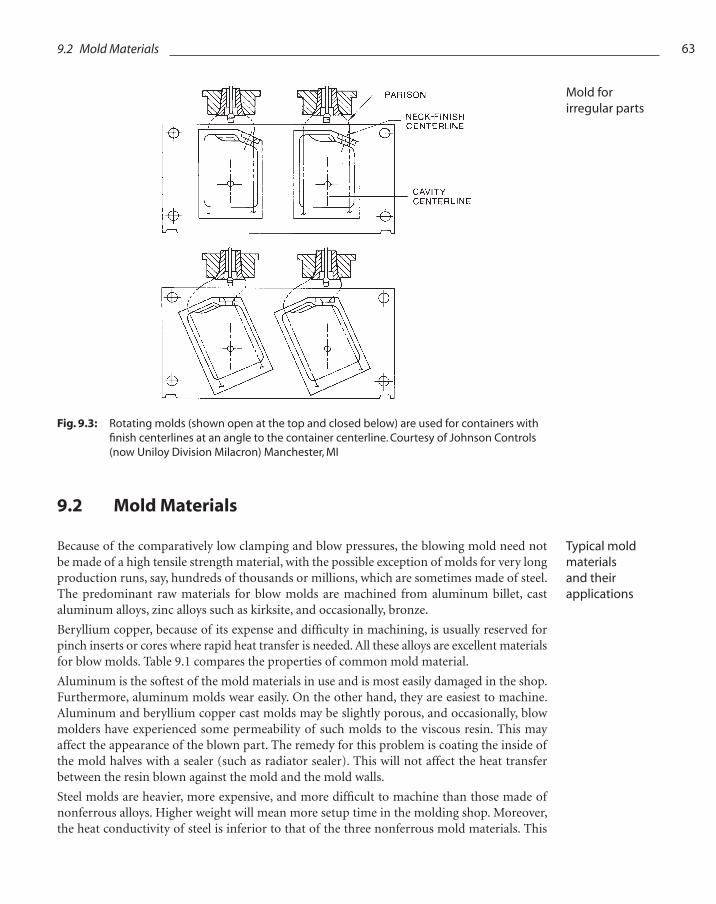
Molds are not necessarily positioned vertically, that is, in line with the parison. They may occasionally be tilted (Fig. 9.3). This will result in a nonuniform distribution of resin which may be helpful, for instance when such irregular pieces as a pitcher with a handle are being blown. It may also result in some savings in parison length.
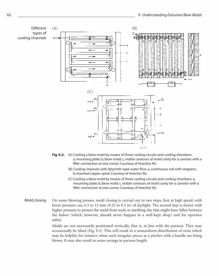
Fig. 9.2: (A) Cooling a blow mold by means of three cooling circuits and cooling chambers: a, mounting plate; b, blow mold; c, visible contours of mold cavity for a canister with a fi ller connection at one corner. Courtesy of Hoechst AG
(B) Cooling channels with labyrinth-type water fl ow: a, continuous rod with stoppers; b, inserted copper spiral. Courtesy of Hoechst AG
(C) Cooling a blow mold by means of three cooling circuits and cooling chambers: a, mounting plate; b, blow mold; c, visible contours of mold cavity for a canister with a fi ller connection at one corner. Courtesy of Hoechst AG
(A) (B)
(C)
9 Understanding Extrusion Blow Molds
Different types of
cooling channels
Mold closing
63
9.2 Mold Materials
Because of the comparatively low clamping and blow pressures, the blowing mold need not be made of a high tensile strength material, with the possible exception of molds for very long production runs, say, hundreds of thousands or millions, which are sometimes made of steel. The predominant raw materials for blow molds are machined from aluminum billet, cast aluminum alloys, zinc alloys such as kirksite, and occasionally, bronze.
Beryllium copper, because of its expense and diffi culty in machining, is usually reserved for pinch inserts or cores where rapid heat transfer is needed. All these alloys are excellent materials for blow molds. Table 9.1 compares the properties of common mold material.
Aluminum is the softest of the mold materials in use and is most easily damaged in the shop. Furthermore, aluminum molds wear easily. On the other hand, they are easiest to machine. Aluminum and beryllium copper cast molds may be slightly porous, and occasionally, blow molders have experienced some permeability of such molds to the viscous resin. This may affect the appearance of the blown part. The remedy for this problem is coating the inside of the mold halves with a sealer (such as radiator sealer). This will not affect the heat transfer between the resin blown against the mold and the mold walls.
Steel molds are heavier, more expensive, and more diffi cult to machine than those made of nonferrous alloys. Higher weight will mean more setup time in the molding shop. Moreover, the heat conductivity of steel is inferior to that of the three nonferrous mold materials. This
Fig. 9.3: Rotating molds (shown open at the top and closed below) are used for containers with fi nish centerlines at an angle to the container centerline. Courtesy of Johnson Controls (now Uniloy Division Milacron) Manchester, MI
9.2 Mold Materials
Mold for irregular parts
Typical mold materials and their applications
64 9 Understanding Extrusion Blow Molds
results in a slower cooling rate and a correspondingly longer cooling cycle and consequently, a lower production rate for steel molds.
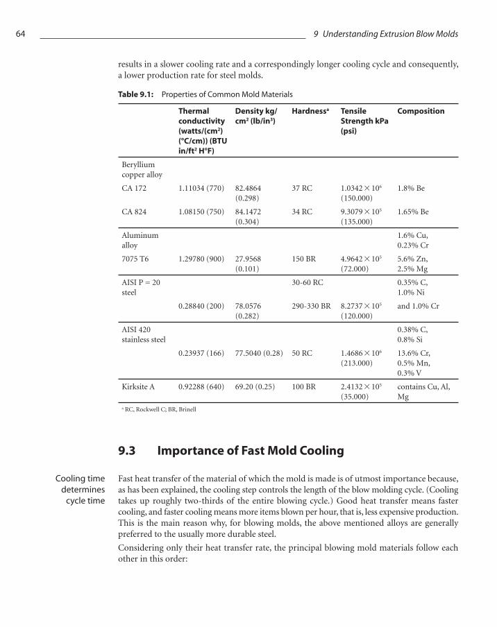
Table 9.1: Properties of Common Mold Materials
Thermal conductivity (watts/(cm2) (°C/cm)) (BTU in/ft2 H°F)
Density kg/cm2 (lb/in3)
Hardnessa Tensile Strength kPa (psi)
Composition
Beryllium copper alloy
CA 172 1.11034 (770) 82.4864 (0.298)
37 RC 1.0342 * 106 (150.000)
1.8% Be
CA 824 1.08150 (750) 84.1472 (0.304)
34 RC 9.3079 * 105 (135.000)
1.65% Be
Aluminum alloy
1.6% Cu, 0.23% Cr
7075 T6 1.29780 (900) 27.9568 (0.101)
150 BR 4.9642 * 105 (72.000)
5.6% Zn, 2.5% Mg
AISI P = 20 steel
30-60 RC 0.35% C, 1.0% Ni
0.28840 (200) 78.0576 (0.282)
290-330 BR 8.2737 * 105 (120.000)
and 1.0% Cr
AISI 420 stainless steel
0.38% C, 0.8% Si
0.23937 (166) 77.5040 (0.28) 50 RC 1.4686 * 106 (213.000)
13.6% Cr, 0.5% Mn, 0.3% V
Kirksite A 0.92288 (640) 69.20 (0.25) 100 BR 2.4132 * 105 (35.000)
contains Cu, Al, Mg
a RC, Rockwell C; BR, Brinell
9.3 Importance of Fast Mold Cooling
Fast heat transfer of the material of which the mold is made is of utmost importance because, as has been explained, the cooling step controls the length of the blow molding cycle. (Cooling takes up roughly two-thirds of the entire blowing cycle.) Good heat transfer means faster cooling, and faster cooling means more items blown per hour, that is, less expensive production. This is the main reason why, for blowing molds, the above mentioned alloys are generally preferred to the usually more durable steel.
Considering only their heat transfer rate, the principal blowing mold materials follow each other in this order:
Cooling time determines
cycle time

65
• Beryllium copper
• Aluminum
• Kirksite
• Steel
Occasionally, several different alloys are used in the same mold to obtain desired strength and special cooling conditions. However, as these mold materials have different heat transfer rates, a blow mold, with the exception of steel pinch-off inserts (see Section 9.4), should be made of only one material. Different materials with consequently different heat conductivity at various points of the mold will result in nonuniform cooling. This, in turn, might set up areas of stress in the fi nished piece, which would be susceptible to splitting in use. The blow mold halves must always be adequately cooled to solidify the part quickly, immediately after the parison has been blown out against the mold walls.
The cooling water may be tap water. If it has a high content of minerals which may settle in the narrow cooling channels, a closed system for circulating purifi ed water should be used. Unless the water is cold enough, as for instance, in winter, it should be chilled by a heat exchanger to 4 to 20 °C (40 to 70 °F). Such low temperatures may, however cause water condensation on the outside mold walls. Some molders, though, use noncooled tap water. Usually, the cooling water is recirculated, that is, reused time and again for a long period. Sometimes it is partly recirculated and mixed with fresh tap water to maintain the desired temperature and to economize.
The water usually circulates through the hollow mold halves. Sometimes, a copper tubing system is cast into the mold. However, to create the most useful fl ow, water channels are machined into the material cast into the mold halves. Well-placed channels will ensure that the cooling water comes as close to the mold cavity as feasible (see Fig. 9.2). Cooling channels should also be as close to the (lengthwise or other) parting lines caused by the separation lines of the two halves or by inserts. Parting lines will practically always show along mold separation lines. Cooling these areas will result in better fi nish of the piece along the parting lines.
Larger molds may be equipped with several – up to three or more – independent cooling zones. Generally, in the top or bottom areas, that is, around a bottleneck or the bottom pinch-off, or both, greater masses of resin are required than along the other areas. Such areas as well as thicker wall sections, therefore, often require additional cooling. Otherwise, these sections would still be viscous while the thinner wall sections have solidifi ed when the piece is ejected. This may result in a deformed piece or one with nonuniform shrinkage and resultant warpage, which the customer will reject. That is why frequently even a simple mold has two or more cooling systems for each half.
Occasionally, the blowing pin is also being cooled. Sometimes, air cooling from the outside is provided for the pinched “tail” of the parison sticking out of the mold bottom. The tail is much thicker than the wall and cools correspondingly slower.
Air may be circulated inside the blown part to speed up its cooling.
Cooling time is strongly affected by the extrusion melt temperature of the blow molding cycle. It has been experienced that an increase, or decrease, of 5 °C (10 °F) in melt temperature can extend, or shorten, the cooling cycle by as much as one second.
9.3 Importance of Fast Mold Cooling
Best heat transfer rates
Water cooling techniques
Multiple cooling zones
Cooling the blowing pin
66 9 Understanding Extrusion Blow Molds
9.4 The Pinch-Off
Because of the comparatively high pressure and mechanical stress exerted on the mold bottom when (in the closing step) it pinches one end of the parison together, the pinch-off in a nonferrous metal mold is frequently an insert made of hard, tough steel. The effect on the blown part always shows in the so-called weld line.
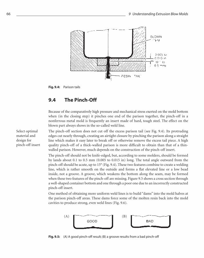
The pinch-off section does not cut off the excess parison tail (see Fig. 9.4). Its protruding edges cut nearly through, creating an airtight closure by pinching the parison along a straight line which makes it easy later to break off or otherwise remove the excess tail piece. A high quality pinch-off of a thick-walled parison is more diffi cult to obtain than that of a thin-walled parison. However, much depends on the construction of the pinch-off insert.
The pinch-off should not be knife-edged, but, according to some molders, should be formed by lands about 0.1 to 0.5 mm (0.005 to 0.015 in) long. The total angle outward from the pinch-off should be acute, up to 15° (Fig. 9.4). These two features combine to create a welding line, which is rather smooth on the outside and forms a fl at elevated line or a low bead inside, not a groove. A groove, which weakens the bottom along the seam, may be formed when these two features of the pinch-off are missing. Figure 9.5 shows a cross section through a well-shaped container bottom and one through a poor one due to an incorrectly constructed pinch-off insert.
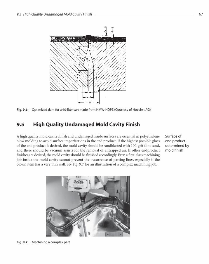
One method of obtaining more uniform weld lines is to build “dams” into the mold halves at the parison pinch-off areas. These dams force some of the molten resin back into the mold cavities to produce strong, even weld lines (Fig. 9.6).
Fig. 9.4: Parison tails
Fig. 9.5: (A) A good pinch-off result; (B) a groove results from a bad pinch-off
(A) (B)
Select optimal material and design for pinch-off insert
67
9.5 High Quality Undamaged Mold Cavity Finish
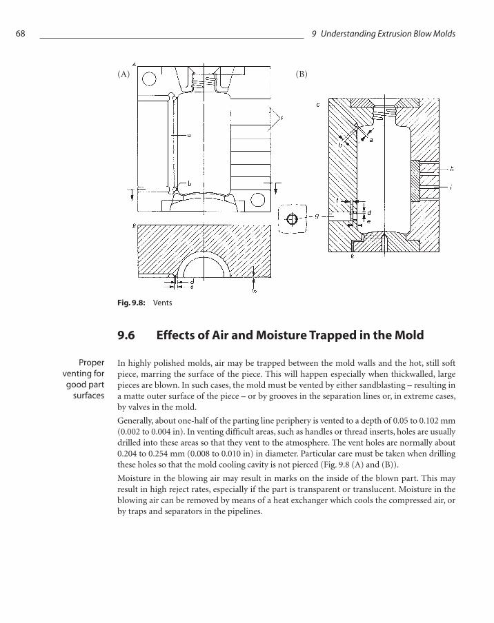
A high quality mold cavity fi nish and undamaged inside surfaces are essential in polyethylene blow molding to avoid surface imperfections in the end product. If the highest possible gloss of the end product is desired, the mold cavity should be sandblasted with 100-grit fl int sand, and there should be vacuum assists for the removal of entrapped air. If other endproduct fi nishes are desired, the mold cavity should be fi nished accordingly. Even a fi rst-class machining job inside the mold cavity cannot prevent the occurrence of parting lines, especially if the blown item has a very thin wall. See Fig. 9.7 for an illustration of a complex machining job.
Fig. 9.6: Optimized dam for a 60-liter can made from HMW-HDPE (Courtesy of Hoechst AG)
Fig. 9.7: Machining a complex part
9.5 High Quality Undamaged Mold Cavity Finish
Surface of end product determined by mold fi nish
68 9 Understanding Extrusion Blow Molds
9.6 Effects of Air and Moisture Trapped in the Mold
In highly polished molds, air may be trapped between the mold walls and the hot, still soft piece, marring the surface of the piece. This will happen especially when thickwalled, large pieces are blown. In such cases, the mold must be vented by either sandblasting – resulting in a matte outer surface of the piece – or by grooves in the separation lines or, in extreme cases, by valves in the mold.
Generally, about one-half of the parting line periphery is vented to a depth of 0.05 to 0.102 mm (0.002 to 0.004 in). In venting diffi cult areas, such as handles or thread inserts, holes are usually drilled into these areas so that they vent to the atmosphere. The vent holes are normally about 0.204 to 0.254 mm (0.008 to 0.010 in) in diameter. Particular care must be taken when drilling these holes so that the mold cooling cavity is not pierced (Fig. 9.8 (A) and (B)).
Moisture in the blowing air may result in marks on the inside of the blown part. This may result in high reject rates, especially if the part is transparent or translucent. Moisture in the blowing air can be removed by means of a heat exchanger which cools the compressed air, or by traps and separators in the pipelines.
(A) (B)
Fig. 9.8: Vents
Proper venting for good part
surfaces
69
9.7 Injection of the Blowing Air
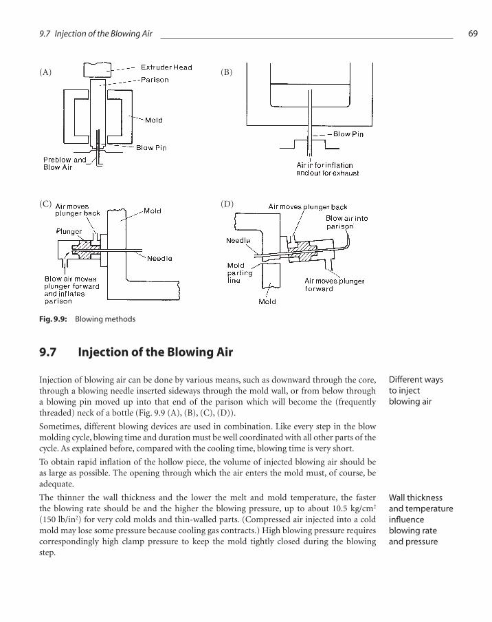
Injection of blowing air can be done by various means, such as downward through the core, through a blowing needle inserted sideways through the mold wall, or from below through a blowing pin moved up into that end of the parison which will become the (frequently threaded) neck of a bottle (Fig. 9.9 (A), (B), (C), (D)).
Sometimes, different blowing devices are used in combination. Like every step in the blow molding cycle, blowing time and duration must be well coordinated with all other parts of the cycle. As explained before, compared with the cooling time, blowing time is very short.
To obtain rapid infl ation of the hollow piece, the volume of injected blowing air should be as large as possible. The opening through which the air enters the mold must, of course, be adequate.
The thinner the wall thickness and the lower the melt and mold temperature, the faster the blowing rate should be and the higher the blowing pressure, up to about 10.5 kg/cm2 (150 lb/in2) for very cold molds and thin-walled parts. (Compressed air injected into a cold mold may lose some pressure because cooling gas contracts.) High blowing pressure requires correspondingly high clamp pressure to keep the mold tightly closed during the blowing step.
Fig. 9.9: Blowing methods
(A) (B)
(C) (D)
9.7 Injection of the Blowing Air
Different ways to inject blowing air
Wall thickness and temperature infl uence blowing rate and pressure
70 9 Understanding Extrusion Blow Molds
9.8 Ejection of the Piece from the Mold
Ejection of the blown piece can be effected forward between the mold halves or downward, provided the press is built in such a way that a free fall from between the open mold halves is possible. Many machines have an automatic ejector, or stripper, assembly. Ejector, or knock-out, pins or plates push the piece out with a rapid motion, preferably hitting it on a trim area so that the piece itself will not be distorted. Ejection of the blown piece is part of the automatic blowing cycle.
If the piece is not too large, it can be blown forward out of the mold by an air jet from behind.
The operator sometimes manually removes very large pieces from the mold. To reach the piece, the operator must fi rst push the protective gate or shield aside, which automatically stops every mold or platen movement so that the operator’s hands are in no danger of being hurt between the mold halves.
Automatic stripping, being a very fast operation, requires a pneumatic (air) pressure system, just as do the blowing proper, the cut-off at the die, the operation of automatic valves in the die head, etc. Because so many moving parts are thus actuated by air, it is sometimes recommended to oil the air in the pneumatic system lightly.
Hydraulic (always oil) systems are generally used for clamping and moving the molds, the platens on which they are mounted, and other heavy parts of the molding equipment (such as rams) which are used in some molding procedures.
Additional Reading
Griep, J., S.P.E. Seminar Presentations. SPE Brookfi eld CT (1993-1999)
Irwin, C., Johnson Controls, Manchester, MI. Company literature
Irwin, C., Extrusion Blow Molding Tools (1985) Center for Professional Advancement, Edison, NJ
Raddatz, E. and Gondo, C., Hoechst Blow Molding Handbook. Hoechst AG, Frankfurt, Germany
Rosato, D. (Ed), Blow Molding Handbook, 2nd ed. (2003) Hanser Publishers, Munich
Suit, M., Blow Molds, In Modern Plastic Encyclopedia (1986) McGraw-Hill, New York
A Short Course in Blow Molding High Density Polyethylene (1970) Chevron Chemical Co., Houston, TX
Automatic removal of parts
Manual removal of parts