UNIVERSITI PUTRA MALAYSIA PEEL STRENGTH AND OTHER...
25
UNIVERSITI PUTRA MALAYSIA PEEL STRENGTH AND OTHER RELATED MECHANICAL PROPERTIES OF COMPOSITE SANDWICH STRUCTURES ZAHURIN BINTI HALIM FK 2002 88
Transcript of UNIVERSITI PUTRA MALAYSIA PEEL STRENGTH AND OTHER...
UNIVERSITI PUTRA MALAYSIA
PEEL STRENGTH AND OTHER RELATED MECHANICAL PROPERTIES OF COMPOSITE
SANDWICH STRUCTURES
ZAHURIN BINTI HALIM
FK 2002 88
PEEL STRENGTH AND OTHER RELATED MECHANICAL PROPERTIES OF COMPOSITE SANDWICH STRUCTURES
By
ZAHURIN BINTI HALIM
Thesis Submitted to the School of Graduate Studies, Universiti Putra Malaysia, in Fulfilment of the Requirement for the Degree of Doctor of Philosophy
November 2002

To My Husband,Parents, Family and Friends
Thank you for being my inspiration and motivator . . . .
11
III
Abstract of thesis presented to the Senate of Universiti Putra Malaysia in fulfilment of the requirement for the degree of Doctor of Philosophy
PEEL STRENGTH AND OTHER RELATED MECHANICAL PROPERTIES OF COMPOSITE SANDWICH STRUCTURES
By
ZAHURIN BINTI HALIM
November 2002
Chairman: Professor ShahNor Bin Basri, Ph.D, PEng
Faculty: Engineering
An experimental and numerical investigation of the peel strength and other
mechanical properties of composite sandwich structures were conducted. The
composite sandwich structure consists of carbon fibre and aramid fibre as facings with
either a honeycomb or foam core.
The peel strength of both types of composite sandwich structure for use at the flap and
aileron was studied. The peel tests showed that the composite sandwich structure
with a honeycomb core is stronger than the composite sandwich structure with a foam
core. The modes of failures or possible path of crack propagation were also studied.
The most critical modes of failure were the adhesion failure to the facing and the
adhesion failure to the core.
A peel model ling was developed using interface elements and the effect of various
modes of fai lures on the strain energy release rate was evaluated by finite element
analysis using LUSAS, a commercial finite element code. A numerical scheme called
iv
virtual crack closure scheme was used to calculate the strain energy release rate at the
peel front in a peel test specimen.
To complement the results on the peel strength, investigations on other related
mechanical properties were conducted and comparisons were made with previous
works in the reference. The important parameters studied were bending, shear and
compression as all of them has a static condition. The results show that experimental,
numerical and validations with parametric studies agree well . The tensile test was
also conducted experimentally to obtain modulus of elasticity that was required in the
computational calculations.
Abstrak tesis dikemukakan kepada Senat Universiti Putra Malaysia sebagai memenuhi keperluan untuk Ijazah Doktor Falsafah
KEKUATAN LEKANG DAN SIFAT-SIFAT MEKANlKAL YANG BERKAITAN UNTUK STRUKTUR KOMPOSIT TERAPIT
Oleh
ZAHURIN BINTI HALIM
Novem ber 2002
Pengerusi: Profesor ShahNor Bin Basri, Ph.D, PEng
Fakulti: Kejuruteraan
v
Kaj ian eksperimen dan berangka telah dijalankan ke atas kekuatan lekang struktur
komposit terapit. Struktur komposit terapit tersebut terdiri daripada gentian karbon
dan gentian aramid sebagai permukaan atas dan samada busa atau indung madu
sebagai teras. Dua bahagian yang pal ing dipengaruhi oleh kesan lekang di dalam
sesebuah kapalterbang adalah aileron dan kepak dan kaj ian terperinci ke atas kedua-
dua bahagian dijalankan.
Uj ian lekang telah menunjukkan bahawa struktur komposit terapit dengan teras
indung madu adalah lebih kuat daripada struktur komposit terapit dengan teras busa.
Mod kegagalan atau laluan yang mungkin bagi perambatan retak juga telah
disel idiki. Mod kegagalan yang paling kritikal adalah kegagalan rekatan pad a
permukaan atas serta kegagalan rekatan pada teras.
Model baru untuk proses lekang dengan menggunakan elemen antaramuka telah di
bangunkan dan kesan pelbagai mod kegagalan ke atas kadar pelepasan tenaga terikan
telah dini lai dengan menggunakan kaedah anal isis unsur terhingga dengan
VI
menggunakan kod komersil analisis unsur LUSAS. Skim berangka yang dipanggil
skim penutupan retak maya digunakan untuk mengira kadar pelepasan tenaga terikan
pada permukaan hadapan lekang dalam spesimen ujian lekang.
Kaj ian ke atas sifat-sifat mekanikal yang lain dijalankan untuk mensahihkan model
lekang dan perbandingan dibuat dengan kaj ian-kaj ian terdahulu dalam rujukan.
Parameter penting yang dikaj i adalah lenturan, ricihan dan mampatan. Daripada
keputusan yang diperolehi, ianya menunj ukkan bahawa kaj ian eksperimen, kaj ian
berangka dan kaj ian sifat-sifat mekanikal untuk pengsahihan adalah sepakat. Ujian
tegangan juga dijalankan secara eksperimen untuk memperolehi modulus elastik
yang diperlukan dalam pengiraan berangka.
VII
ACKNOWLEDGEMENTS
AlhamduliI lah, praise to Allah s.w.t for the completion of this thesis. I would l ike to
thank my supervisor Prof. Dr. ShahNor Basri for his complete support and advice
throughout the course of my degree. Many ideas originate in our frequent discussion
and his constant patience over the years has been of invaluable help.
I am also grateful to co-supervisor Associate Prof. Col. Ramly Aj ir and Associate
Prof. Dr. Mohammad Nor Berhan for their helpful advice. My deep thanks to Dr.
Waqar, Faizal, Aznijar, Encik Ropie and the rest of the staff in Aerospace
Engineering for their continuous support and kind words. To my wonderful friends,
Dayang, Wan, Kak Ina, I1a, Milah, Rosnah and Harlisya, thank you for your help,
advice, support and companionship. It is the most memorable and happiest time in
UPM. Also to my best friends Ajie and Aju, thank you for the moral support,
encouragement and shoulders to cry on.
And last but not least, to my wonderful fami ly especiaJly my husband, Kamaludin
and children, Khairunnas, Khalkhalas and Khaliskhilfi, your unfail ing love and
support have encourage me throughout the years. I wi l l always cherish them.
viii
I certify that an Examination Committee met on 28 November 2002 to conduct the final examination ofZahurin Halim on his Doctor of Philosophy thesis entitled "Peel Strength and Other Related Mechanical Properties of Composite Sandwich Structures" in accordance with Universiti Pertanian Malaysia (Higher Degree) Act 1 980 and Universiti Pertanian Malaysia (Higher Degree) Regulations 1 98 1 . The Committee recommends that the candidate be awarded the relevant degree. Members ofthe Examination Committee are as fol lows:
AHMAD SAMSURI MOKHTAR, Ph.D. Department of Aerospace Engineering, Faculty of Engineering Universiti Putra Malaysia (Chairman)
SHAHNOR BASRI, Ph.D., PEngo Professor Department of Aerospace Engineering, Faculty of Engineering Universiti Putra Malaysia (Member)
MOHAMAD NOR BERHAN, Ph.D., PEngo Associate Professor Faculty of Mechanical Engineering Universiti Teknologi Mara (Member)
MOHD RAML Y AJIR Associate Professor Department of Aerospace Engineering, Faculty of Engineering Universiti Putra Malaysia (Member)
AHMAD FARIS ISMAIL, Ph.D. Associate Professor Kulliyyah of Engineering International Islamic University Malaysia (Independent Examiner)
HAMSHER MOHAMAD RAMADILI, Ph.D, ProfessorlDeputy Dean School of Graduate Studies Universiti Putra Malaysia
Date: 1 9 DEC 2002
IX
This thesis submitted to the Senate ofUniversiti Putra Malaysia has been accepted as fulfilment of the requirement for the degree of Doctor of Philosophy. The members of Supervisory Committee are as fol lows:
SHAHNOR BASRI, Ph.D., PEngo Professor Department of Aerospace Engineering, Faculty of Engineering
Universiti Putra Malaysia (Chairman)
MOHAMAD NOR BERHAN, Ph.D., PEngo Associate Professor Faculty of Mechanical Engineering
Universiti Teknologi Mara (Member)
MOHDRAMLY AJIR Associate Professor Department of Aerospace Engineering, Faculty of Engineering
Universiti Putra Malaysia (Member)
AINI IDERIS, Ph.D. ProfessorlDean School of Graduate Studies
Universiti Putra Malaysia
Date: 1 3 FEB 2003

x
DECLARATION
I hereby declare that the thesis is based on my original work except for quotations and citations which have been duly acknowledged. I also declare that it has not been previously or concurrently submitted for any other degree at UPM or other institutions.
Date: 1-=1- pee- 2.002
DEDICATION ABSTRACT
TABLE OF CONTENTS
ABSTRAK ACKNOWLEDGEMENTS APPROVAL DECLARATION LIST OF TABLES LIST OF FIGURES LIST OF ABBREVIATI ONS
CHAPTER
INTRODUCTION 1 . 1 Background 1 .2 Scope and Objectives of Research 1 .3 Research Achievement
2 LITERATURE REVIEW 2. 1 An Overview 2.2 The Experimental and Numerical Peel Test 2.3 Other Mechanical Properties 2.4 Closure
3 THEORY 3 . 1 Peeling - Fundamental 3.2 Peel Fracture
3 .2. 1 Mechanics of The Peel Test 3 .2.2 Determination of Longitudinal Modulus
3 .3 Other Mechanical Properties 3.3 . 1 Bending 3 .3 .2 Shearing 3 .3.3 Compression
3.4 Closure
4 MODELLING AND NUMERICAL ANALYSIS 4. 1 Theory
4. 1 . 1 Composite Models 4. 1 .2 Local Coordinate System 4. 1 .3 Constitutive Law 4. l .4 Integration of Element Matrices 4. 1 .5 Non-Linear Formulation 4. 1 .6 Non-Linear Solution Procedures 4. 1 .7 Iterative Procedures
4. l .7. 1 Newton Iteration 4. 1 .7.2 Convergence
XI
Page
II i i i V
VII Vlll
X XIV xv
XIX
1 1 8 9
1 0 1 0 1 6 23 34
35 35 39 40 4 1 43 43 46 48 52
53 53 53 54 54 56 58 60 60 6 1 62
5
6
7
8
XII
4.2 Peel Modell ing 64 4.2. 1 Theory-Element Description 64 4.2.2 2D Plane Strain Continuum Elements (QPN8) 64
4.2.2 . 1 Evaluation of Stresses 66 4.2.3 Interface Elements ( lPN6) 68 4.2.4 Interface Models 69 4.2.5 Delamination Damage Model 70 4.2.6 Strain Energy Calculation 72
4.3 LUSAS Peel Modelling 74 4.3 . 1 Analysis Control 78
4.4 Bending Modelling 80 4.5 Shear Modelling 8 1 4.6 Compression Modell ing 8 1 4.7 Closure 82
MATERIALS AND EXPERIMENTAL METHODS 5. 1 Materials Description 5.2 Fabrication Process - Hand Lay-Up
5.2. 1 Testing Machine Apparatus 5.2.2 Peel ing Apparatus
5.3 Cal ibration of Test Apparatus 5.4 Experimental Procedures 5.5 Calculation 5.6 Tensile Test
5.6. 1 Test Method 5.7 Closure
EXPERIMENTAL RESULTS AND DISCUSSION 6. 1 Peel Failure 6.2 Tensile Tests
6.2 . 1 Calculation 6.3 Val idation of Results 6.4 Closure
RESULTS AND DISCUSSION ON NUMERICAL ANALYSIS 7. 1 Peel 7.2 Other Mechanical Properties
7.2 . 1 Bending 7.2.2 Shear 7.2.3 Compression
7.3 Comparison with Published Work 7.4 Closure
GENERAL APPROACH IN DESIGNING COMPOSITE SANDWICH STRUCTURES 8. 1 Relevant Fracture Mechanics
8. 1 . 1 The Energy Release Rate 8.2 Approach
83 83 86 87 88 89 89 90 9 1 9 1 9 1
93 93 1 04 1 04 1 07 1 07
1 09 1 09 1 1 6 1 1 6 1 20 1 24 1 28 1 29
1 37 1 38 1 38 1 39
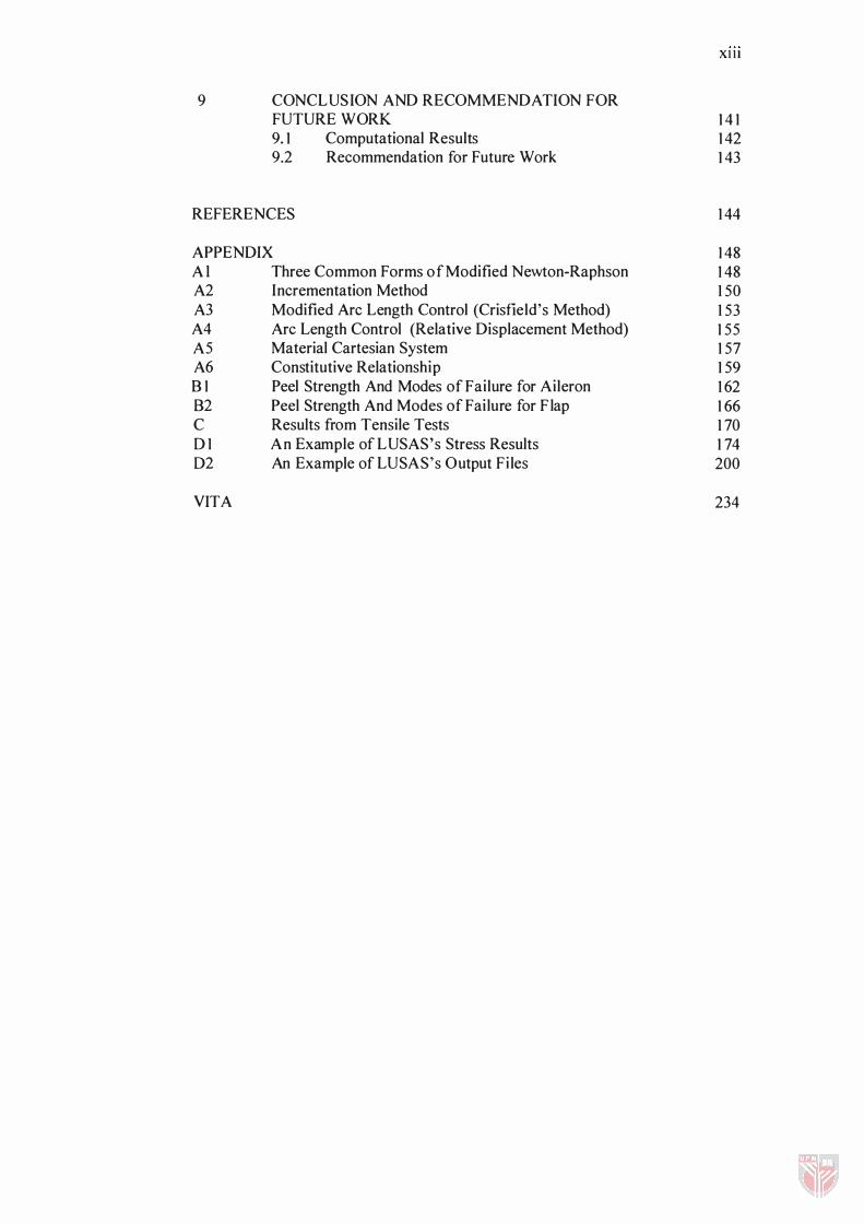
9 CONCLUSION AND RECOMMENDATI ON F OR FUTURE W ORK 9. 1 Computational Results 9.2 Recommendation for Future Work
REFERENCES
APPENDIX Al Three Common Forms of Modified Newton-Raphson A2 Incrementation Method A3 Modified Arc Length Control (Crisfield's Method) A4 Arc Length Control (Relative Displacement Method) A5 Material Cartesian System A6 Constitutive Relationship B 1 Peel Strength And Modes of Failure for Aileron 82 Peel Strength And Modes of Failure for F lap C Results from Tensile Tests 01 An Example ofLUSAS's Stress Results 02 An Example ofLUSAS's Output Files
VITA
Xlll
1 4 1 1 42 1 43
1 44
1 48 1 48 1 50 1 53 1 55 1 57 1 59 1 62 1 66 1 70 1 74 200
234
XIV
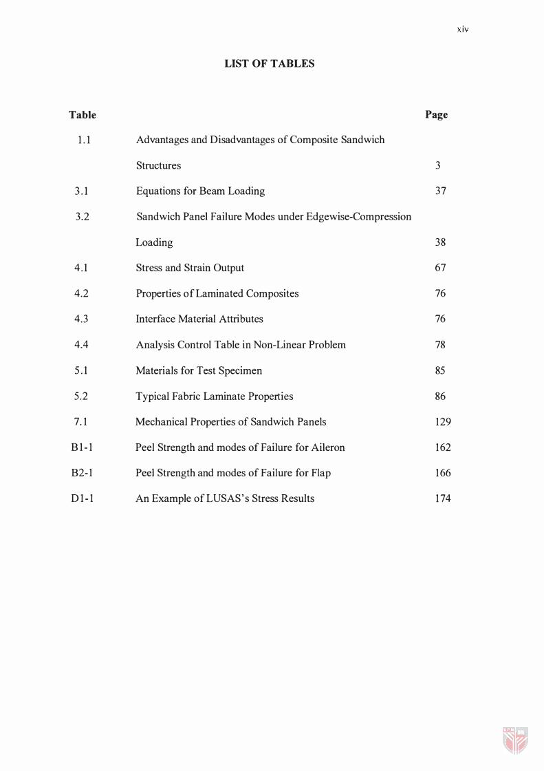
LIST OF TABLES
Table Page
1 . 1 Advantages and Disadvantages of Composite Sandwich
Structures 3
3 . 1 Equations for Beam Loading 37
3.2 Sandwich Panel Failure Modes under Edgewise-Compression
Loading 38
4 . 1 Stress and Strain Output 67
4.2 Properties of Laminated Composites 76
4.3 Interface Material Attributes 76
4.4 Analysis Control Table in Non-Linear Problem 78
5 . 1 Materials for Test Specimen 85
5 .2 Typical Fabric Laminate Properties 86
7. 1 Mechanical Properties of Sandwich Panels 1 29
B 1 - 1 Peel Strength and modes of Failure for Aileron 1 62
B2-1 Peel Strength and modes of Failure for Flap 1 66
D 1 - 1 An Example of LUSAS's Stress Results 1 74
xv
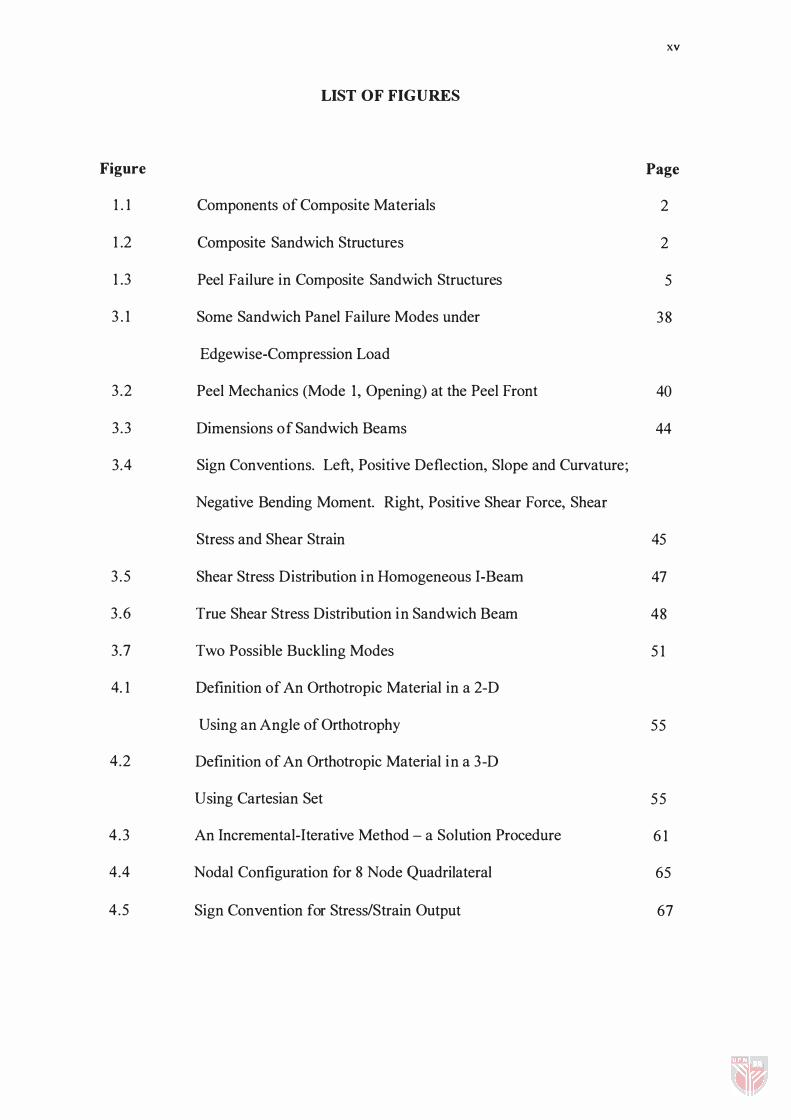
LIST OF FIGURES
Figure Page
1 . 1 Components of Composite Materials 2
1 .2 Composite Sandwich Structures 2
1 .3 Peel Failure in Composite Sandwich Structures 5
3 . 1 Some Sandwich Panel Failure Modes under 38
Edgewise-Compression Load
3.2 Peel Mechanics (Mode 1 , Opening) at the Peel Front 40
3.3 Dimensions of Sandwich Beams 44
3.4 Sign Conventions. Left, Positive Deflection, Slope and Curvature;
Negative Bending Moment. Right, Positive Shear Force, Shear
Stress and Shear Strain 45
3 .5 Shear Stress Distribution in Homogeneous I-Beam 47
3.6 True Shear Stress Distribution in Sandwich Beam 48
3.7 Two Possible Buckling Modes 5 1
4. 1 Definition of An Orthotropic Material in a 2-D
Using an Angle of Orthotrophy 55
4.2 Definition of An Orthotropic Material in a 3-D
U sing Cartesian Set 55
4 .3 An Incremental-Iterative Method - a Solution Procedure 6 1
4.4 Nodal Configuration for 8 Node Quadrilateral 65
4.5 Sign Convention for Stress/Strain Output 67
xvi
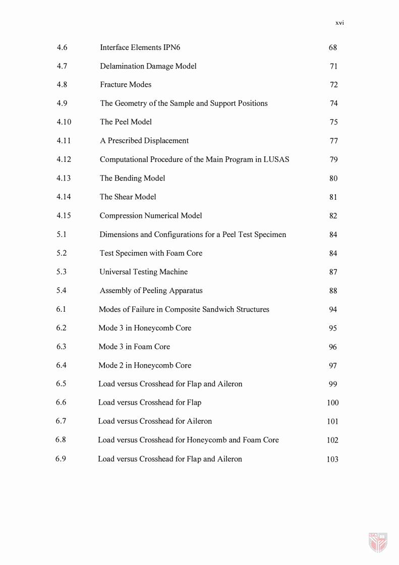
4.6 Interface Elements IPN6 68
4.7 Delamination Damage Model 7 1
4.8 Fracture Modes 72
4.9 The Geometry of the Sample and Support Positions 74
4. 1 0 The Peel Model 75
4. 1 1 A Prescribed Displacement 77
4. 1 2 Computational Procedure of the Main Program in LUSAS 79
4. 1 3 The Bending Model 80
4. 1 4 The Shear Model 8 1
4. 1 5 Compression Numerical Model 82
5 . 1 Dimensions and Configurations for a Peel Test Specimen 84
5 .2 Test Specimen with Foam Core 84
5 .3 Universal Testing Machine 87
5 .4 Assembly of Peeling Apparatus 88
6. 1 Modes of Failure in Composite Sandwich Structures 94
6.2 Mode 3 in Honeycomb Core 95
6.3 Mode 3 in Foam Core 96
6.4 Mode 2 in Honeycomb Core 97
6.5 Load versus Crosshead for Flap and Aileron 99
6.6 Load versus Crosshead for Flap 1 00
6.7 Load versus Crosshead for Aileron 1 01
6 .8 Load versus Crosshead for Honeycomb and Foam Core 1 02
6.9 Load versus Crosshead for Flap and Aileron 1 03

XVII
6. 1 0 Load versus Displacement for Sample with Honeycomb Core 1 05
6. 1 1 Stress versus Strain Curve for Composite Sandwich
Structures 1 06
7. 1 The Deformed Mesh for the Peel Modelling 1 1 0
7.2 Stress Contour in the X-Direction 1 1 1
7.3 Stress Distribution along the Length of a Peel
Test Specimen at the Facings/Core Interface 1 1 3
7.4 Displacement versus Strain Energy Numerically 1 1 4
7.5 Displacement versus Strain Energy Experimentally 1 1 5
7.6 The Deformed Mesh for the Bending Modelling 1 1 6
7.7 Stress Contour in the X-Direction 1 1 7
7.8 Stress Distribution along the Length of the Bending Model 1 1 8
7.9 Strain Distribution along the Length of the Bending Model 1 1 9
7. 1 0 The Deformed Mesh for the Shear Modelling 1 20
7. 1 1 Stress Contour in the Shear Model 1 2 1
7. 1 2 Stress Distribution along the Length of the Shear Model 1 22
7. 1 3 Strain Distribution along the Length of the Shear Model 1 23
7. 1 4 The Deformed Mesh for the Compression Modelling 1 24
7. 1 5 Stress Contour in X Direction 1 25
7. 1 6 Stress Distribution along the Length of the Compression Model 1 26
7. 1 7 Strain Distribution along the Length of the Compression Model 1 27
7. 1 8 Stress Contour i n Peeling at Load 2.5 X 1 0-4 kN 1 30
7. 1 9 Stress Contour in Peeling at Load 5 .0 X 1 0-5 kN 1 3 1
XVIII
7.20 Stress Contour in Peeling at Load 7.5 X 1 0-4 kN 1 32
7 .21 Stress Contour in Peeling at Load 1 .0 X 1 0-3 kN 1 33
7.22 Stress distribution in Peeling at Various Loads 1 34
7.23 Stress Contour in Peeling of E-Glass at Load 1 .0 X 1 0-3 kN 1 35
7.24 Strain Energy Release Rate for Various Modes of Failure 1 36
Al - l Common Fonns of Modified Newton Iteration 1 49
A2-1 Constant Load Level Incremental/Iterative Procedure 1 50
A2-2 I llustration of Limit Points for A One Degree of Freedom Response 1 5 1
A3-1 Modified Arc Length Load Incrementation for A One Degree
of Freedom Response 1 53
AS-l Material Cartesian for Interface Model 1 57
AS-2 Element Topology Defining the In-Plane and Out-of-Plane
Directions for the Interface Model 1 58
A6-1 Yield Surface for the Interface Model 1 60
C-l Load-Displacement Curves for Sandwich Structure with
Honeycomb Core 1 70
C-2 Load-Displacement Curves for Sandwich Structure with
Foam Core 1 7 1
C-3 Stress-Strain Curves for Sandwich Structure with
Honeycomb Core 1 72
C-4 Stress-Strain Curves for Sandwich Structure with
Honeycomb Core 1 73
D
E
Ell
Ec
Er
I
LIST OF ABBREVIATIONS
net cross-sectional area of fibre
cross-sectional area of lamina i
net cross-sectional area of matrix
flexural rigidity
modulus of elasticity
longitudinal elastic modulus of composite facings
modulus of elasticity of the core
modulus of elasticity of the facings
fibre Young's Modulus
modulus of elasticity of lamina I
matrix Young's Modulus
modulus of elasticity of lamina at distance x from neutral axis
yield surface
limited tension criterion
Mohr-Coulomb criterion
load required to overcome resisting load
average load required to bend and peel adherend
strain energy release rate
shear modulus of core
second moment of area
second moment of area of lamina I about neutral axis
xx
XXI
L beam length
M bending moment
N shear stiffness of core
Nj, �, 11 element shape function
P peel strength
P vector of internal forces
£b vectors of the bottom displacements
Per critical buckling load
Pee edge compressive load
Pp point load
£t vectors of the top displacements
Pt tensile force
Q shear force
S first moment of area
U strain energy in the facing at the strain Ell
U, V the nodal degrees of freedom
W work
Wk mid-ordinate integration weights
B strain displacement
B' local strain global displacement
D stiffness matrix
D' matrix of elastic properties
H
J
K
R
x
l /R
a
b
c
t
shape function matrix
Jacobian matrix
element stiffness matrix
load vector
neutral axis location
curvature
global displacement
spacing between points of honeycomb core support for the facings
width of beam
thickness of the core
cohesive strength
distance between the centre lines of the upper and lower facings
thickness of the facing
overall depth of the beam
thickness of the kth layer
constants dependent on the beam loading
theoretical or experimental dimpling coeffecient
theoretical or empirical buckling coefficient
radius of drum
radius of flange
the total thickness of the shell
displacement field
bottom displacement
XXII
XXIII
Yt top displacement
Vf fibre volume fraction
Vm matrix volume fraction
w width of the facing
z depth below the centroid of the cross-section
a peel angle
8 deflection
Ell tensile strain in fibre direction in the facing
Ec longitudinal strain in composite
Em longitudinal strain in matrix
§, Q total strains and stresses
E' a' -,- local strain and stress vector
§o,Qo initial strains and stresses
t/> friction angle
"- an angle of orthotrophy
v Poisson's ratio
Vc Poisson ratio of core
Vr Poisson ratio of faces
all tensile stress in fibre direction in the facing
O"co average tensile stress in the composite
O"fi fibre stress
O"m matrix stress
a bending stress
XXIV
a'c compressive stress in core
cr' f compressive stress in faces
ac bending stress in core, at extreme fibre
crf bending stress in faces
an compressive stress in core
crt threshold strength
aw wrinkling of compressive force
't shear stress
'tc shear stress of the core
�, 11, � parent coordinates in a mapped element
�k within the kth layer of an element
'I' residual force vector
1 .1 Background
CHAPTER 1
INTRODUCTION
Structural materials can be divided into four basic categories: metals, polymers,
ceramics and composites. Composites, which consist of two or more separate materials
combined in a macroscopic structural unit, are made from various combinations of the
three materials. For over 60 years, composite materials have proven to be very
successfully utilized in structural applications. They are used in stiffness-critical
aerospace structures, offshore structures, marine, automotive industries and also in
medical, sports and electrical applications.
Composite materials can be divided into two main groups i.e. particle composites and
fibre-reinforced composites. The detailed types of composite construction are shown in
Figure 1 . 1 [ 1 ] . In this present work only composite sandwich structures will be discussed
thoroughly. The American Society for Testing and Materials (ASTM) defines for a
composite sandwich structure as a construction which consists of high strength
composite facing sheets bonded to a lightweight foam or honeycomb core as shown in
Figure 1 .2[2] .