USER MANUAL INDUCTION HEATERS - timken.com · USER MANUAL INDUCTION HEATERS. READ THE MANUAL AND...
74
VHIN 10 VHIN 33 TURBO VHIS 35 VHIS 75 TURBO VHIS 100 VHIS 150 TURBO VHIS 200 VHIS 400 TURBO VHIN 550 VHIN 600 TURBO VHIN 800 USER MANUAL INDUCTION HEATERS
Transcript of USER MANUAL INDUCTION HEATERS - timken.com · USER MANUAL INDUCTION HEATERS. READ THE MANUAL AND...
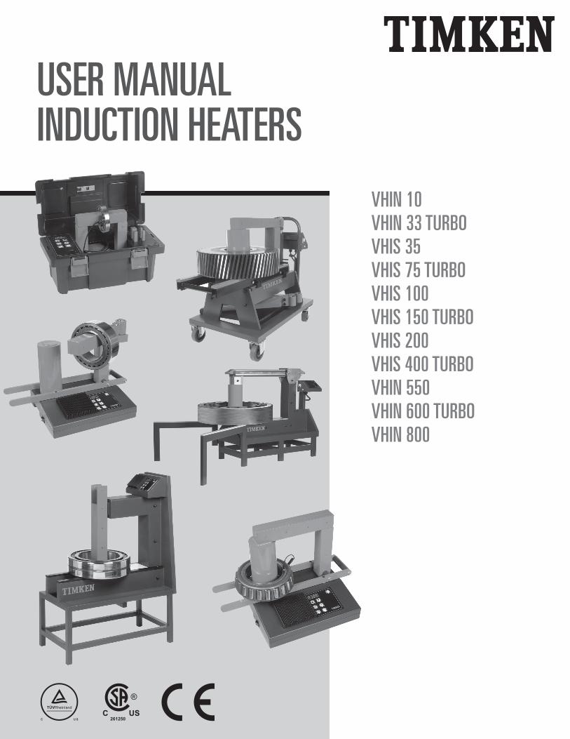
VHIN 10VHIN 33 TURBOVHIS 35VHIS 75 TURBOVHIS 100VHIS 150 TURBOVHIS 200VHIS 400 TURBOVHIN 550VHIN 600 TURBOVHIN 800
USER MANUALINDUCTION HEATERS
READ THE MANUAL AND SAFETY INSTRUCTIONS
Check all parts for possible transport damage.If any damage is apparent, inform carrier immediately.
BITTE LESEN SIE HANDBUCH UND SICHERHEITSHINWEISE
Überprüfen Sie alle Teile auf etwaige Transportschäden.Wenn Schäden offensichtlich sind, benachrichtigen Sie umgehend das
Speditionsunternehmen.
VEUILLEZ LIRE CE MANUEL ET LES CONSIGNES DE SÉCURITÉ
Inspectez toutes les pièces pour vérifier qu’elles n’ont pas été endommagées durant le transport.En cas d’endommagement, prévenez immédiatement le transporteur.
LEGGERE IL MANUALE E LE ISTRUZIONI DI SICUREZZA
Verificare tutti i pezzi per individuare eventuali danni nel trasporto.In caso di danni evidenti, informare immediatamente lo spedizioniere.
请阅读用户手册及安全说明
检查所有部件,检查可能的运输损坏。
如果外观有任何损坏,请立即通知承运人。
IT • Italian • Italiano
CH • Chinese • 中文
FR • French • Français
DE • German • Deutsche

1
Table of Contents
1. Safety Instructions . . . . . . . . . . . . . . . . . . . . . . . . . . . . . . . . . . . . . . . . . . . . . . . . . . . . . . . . . . . . . . . . . . . . . 2
2. Introduction . . . . . . . . . . . . . . . . . . . . . . . . . . . . . . . . . . . . . . . . . . . . . . . . . . . . . . . . . . . . . . . . . . . . . . . . . . . 4
3. Installation . . . . . . . . . . . . . . . . . . . . . . . . . . . . . . . . . . . . . . . . . . . . . . . . . . . . . . . . . . . . . . . . . . . . . . . . . . . 5
4. Symbols and Display . . . . . . . . . . . . . . . . . . . . . . . . . . . . . . . . . . . . . . . . . . . . . . . . . . . . . . . . . . . . . . . . . . . . 5
5. Setting up the Work Piece . . . . . . . . . . . . . . . . . . . . . . . . . . . . . . . . . . . . . . . . . . . . . . . . . . . . . . . . . . . . . . . 65.1. Setting up the work piece . . . . . . . . . . . . . . . . . . . . . . . . . . . . . . . . . . . . . . . . . . . . . . . . . . . . . . . . . . . . . 65.2. Maximum weights for swing-arm models . . . . . . . . . . . . . . . . . . . . . . . . . . . . . . . . . . . . . . . . . . . . . . . . . 6
6. Positioning the Magnetic Temperature Probe . . . . . . . . . . . . . . . . . . . . . . . . . . . . . . . . . . . . . . . . . . . . . . . . . . 7
7. Operation . . . . . . . . . . . . . . . . . . . . . . . . . . . . . . . . . . . . . . . . . . . . . . . . . . . . . . . . . . . . . . . . . . . . . . . . . . . . 8
8. Cleaning and Maintenance . . . . . . . . . . . . . . . . . . . . . . . . . . . . . . . . . . . . . . . . . . . . . . . . . . . . . . . . . . . . . . . 17
9. Technical Data . . . . . . . . . . . . . . . . . . . . . . . . . . . . . . . . . . . . . . . . . . . . . . . . . . . . . . . . . . . . . . . . . . . . . . . 10
10. Electrical Diagrams . . . . . . . . . . . . . . . . . . . . . . . . . . . . . . . . . . . . . . . . . . . . . . . . . . . . . . . . . . . . . . . . . . . A1
2
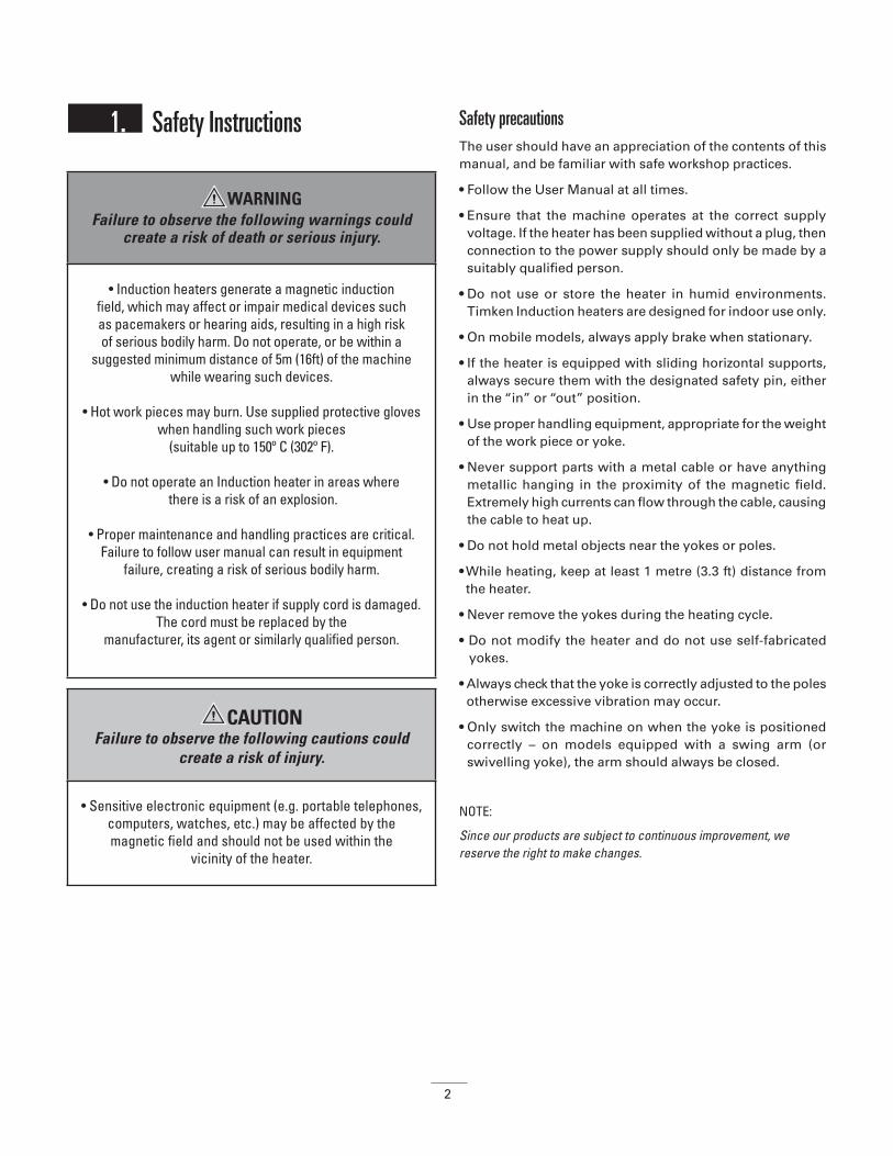
1. Safety Instructions Safety precautions The user should have an appreciation of the contents of this manual, and be familiar with safe workshop practices.
• Follow the User Manual at all times.
• Ensure that the machine operates at the correct supply voltage. If the heater has been supplied without a plug, then connection to the power supply should only be made by a suitably qualified person.
• Do not use or store the heater in humid environments. Timken Induction heaters are designed for indoor use only.
• On mobile models, always apply brake when stationary.
• If the heater is equipped with sliding horizontal supports, always secure them with the designated safety pin, either in the “in” or “out” position.
• Use proper handling equipment, appropriate for the weight of the work piece or yoke.
• Never support parts with a metal cable or have anything metallic hanging in the proximity of the magnetic field. Extremely high currents can flow through the cable, causing the cable to heat up.
• Do not hold metal objects near the yokes or poles.
• While heating, keep at least 1 metre (3.3 ft) distance from the heater.
• Never remove the yokes during the heating cycle.
• Do not modify the heater and do not use self-fabricated yokes.
• Always check that the yoke is correctly adjusted to the poles otherwise excessive vibration may occur.
• Only switch the machine on when the yoke is positioned correctly – on models equipped with a swing arm (or swivelling yoke), the arm should always be closed.
NOTE:
Since our products are subject to continuous improvement, we reserve the right to make changes.
WARNINGFailure to observe the following warnings could
create a risk of death or serious injury.
• Induction heaters generate a magnetic induction field, which may affect or impair medical devices such as pacemakers or hearing aids, resulting in a high risk of serious bodily harm. Do not operate, or be within a
suggested minimum distance of 5m (16ft) of the machinewhile wearing such devices.
• Hot work pieces may burn. Use supplied protective gloves when handling such work pieces
(suitable up to 150º C (302º F).
• Do not operate an Induction heater in areas where there is a risk of an explosion.
• Proper maintenance and handling practices are critical.Failure to follow user manual can result in equipment
failure, creating a risk of serious bodily harm.
• Do not use the induction heater if supply cord is damaged. The cord must be replaced by the
manufacturer, its agent or similarly qualified person.
CAUTION Failure to observe the following cautions could
create a risk of injury.
• Sensitive electronic equipment (e.g. portable telephones, computers, watches, etc.) may be affected by the magnetic field and should not be used within the
vicinity of the heater.

3
Safety features• The heater will switch off automatically if the ambient
temperature exceeds 70º C (158º F).
• When using the temperature mode, the heater will switch off automatically if the rate of temperature rise is too low.
• On models equipped with a swing arm, the arm can be fixed in the open position.
An induction heater works due a magnetic field. In the table below are there are some measured values of the flux density
in milliTesla (mT). These values are measured in different radii and heights around the heater. These measurements can be used as a guide in conforming to local regulations regarding the maximum time exposure of people to magnetic fields.
The values below are only valid for this combination of bearing type and yoke bar.
Different configurations may give different values. Due to the large variety of bearing types in combination with the different yoke bars it is impossible for us to give every possible value.
Heater type Radius/ height
h = 250 mm(10in)
h = 500 mm(20in)
h = 750 mm(30in)
h =1000 mm40in)
h = 1250 mm(49in)
Model VHIN10 Yoke bar 40
Bearing 6215
R = 250 mm 0,785 mT 0,110 mT 0 mT 0 mT 0 mT
R = 500 mm 0,054 mT 0,012 mT 0 mT 0 mT 0 mT
R = 750 mm 0 mT 0 mT 0 mT 0 mT 0 mT
R = 1000 mm 0 mT 0 mT 0 mT 0 mT 0 mT
Model VHIS35 Yoke bar 60
Bearing 6219
R = 250 mm 2,950 mT 1,070 mT 0,120 mT 0 mT 0 mT
R = 500 mm 0,310 mT 0,170 mT 0,050 mT 0 mT 0 mT
R = 750 mm 0,500 mT 0,250 mT 0 mT 0 mT 0 mT
R = 1000 mm 0 mT 00 mT 0 mT 0 mT 0 mT
Model VHIS100 Yoke bar 70
Bearing 6222
R = 250 mm 6,800 mT 4,310 mT 0,590 mT 0,110 mT 0 mT
R = 500 mm 0,935 mT 0,696 mT 0,230 mT 0,042 mT 0 mT
R = 750 mm 0,204 mT 0,152 mT 0,059 mT 0 mT 0 mT
R = 1000 mm 0,034 mT 0,023 mT 0,003 mT 0 mT 0 mT
R = 1250 mm 0 mT 0 mT 0 mT 0 mT 0 mT
Heater type Radius/height*
h = 900 mm (10in)
h=1300 mm (51in)
h=1500 mm (59in)
h =2000 mm (79in)
Models VHIS 200 & VHIS 150 Yoke bar 80
Bearing 229750/03
R = 250 mm 5,800 mT 0,750 mT 0,253 mT 0,010 mT
R = 500 mm 1,070 mT 0,320 mT 0,134 mT 0 mT
R = 750 mm 0,345 mT 0,141 mT 0,068 mT 0 mT
R = 1000 mm 0,121 mT 0,054 mT 0,020 mT 0 mT
R = 1250 mm 0,030 mT 0,006 mT 0 mT 0 mT
Model VHIN550Yoke bar 100
Bearing RH24B
R = 250 mm 6,400 mT 4,100 mT 1,460 mT 0,150 mT
R = 500 mm 1,308 mT 1,050 mT 0,530 mT 0,105 mT
R = 750 mm 0,350 mT 0,298 mT 0,186 mT 0,037 mT
R = 1000 mm 0,116 mT 0,093 mT 0,063 mT 0,010 mT
R = 1250 mm 0,030 mT 0,017 mT 0,010 mT 0 mT
Model VHIN800Yoke bar 150
Bearing 17.52926
R = 500 mm 1,980 mT 1,375 mT 1,020 mT 0,340 mT
R = 50 mm 0,530 mT 0,450 mT 0,370 mT 0,170 mT
R = 1000 mm 0,180 mT 0,180 mT 0,160 mT 0,080 mT
R = 1250 mm 0,070 mT 0,030 mT 0,030 mT 0,030 mT
R = 1500 mm 0,020 mT 0,020 mT 0,010 mT 0 mT
R = 1750 mm 0 mT 0 mT 0 mT 0 mT
4
Heights are measured from the bottom of the heater. To determine where the field is exactly in relation to the floor, the distance from the bottom of the heater to the floor should be added on to the values mentioned in the table. (e.g. the height of a workbench).
2. Introduction
ApplicationTimken Induction Heaters are designed to heat bearings, bushings, gear wheels, couplings or other metallic work pieces which form a closed electrical loop. This will facilitate mounting where an interference fit is required.
The heaters are designed to heat the work piece up to a maximum temperature of 240º C (464º F), with the exception of the VHIN10 series models where the temperature is limited to a maximum of 150º C (302º F) and special custom-designed heaters where the maximum temperature can be as high as 480º C (896º F).
Timken Induction heaters can be used on continuous bases. There is however a limitation; do not operate heater at a temperature of 240° C (464° F) or more for more than half an hour. By heating with the time function this has to be checked with an external temperature meter.
Operating conditionsDesigned to be used in an industrial environment with an ambient temperature of 0º C to 50º C (32º F to 122º F), and an atmospheric humidity of between 5% to 90%. The induction heater is meant for indoor use only.
Principle of operationThe heater works in the same way as a transformer. The primary coil is the heater and the secondary coil is the work piece.
When the heater is switched on, a high voltage, low alternating current passes through the numerous windings of the primary coil. This induces a low voltage, high current in the work piece acting as the secondary coil. This high current results in the heating up of the work piece.
The current is only flowing in the work piece, hence it is only this which starts to heat up. The work piece is automatically demagnetised at the end of each heating cycle.
WARNINGFailure to observe the following warnings could
create a risk of death or serious injury.
• We advise a safety distance of at least 1 metre for people working near the machine.
CAUTION Failure to observe the following cautions could
create a risk of injury.
• The machine produces an induction field that can influence electronic equipment, e.g. watches,
magnetic charts etc.
CAUTION Failure to observe the following cautions could
create a risk of injury.
• Bearings generally should only be heated up to a maximum temperature of 120º C (248º F).
• Precision bearings should only be heated up to a maximum temperature of 70º C (158º F). Heating to higher temperatures
may affect the metallurgical structure and dimensional stability resulting in premature bearing failure or loss of
bearing performance.• Do not use induction heaters for bearings or work pieces, which are outside the minimum, or maximum dimensions as
specified in the technical data (Appendix 1).• Do not switch off the heater with the main switch while
heating cycle is running.
5
3. Installation • Remove packing material and place the induction heater
on a non-ferrous, stable, flat surface. The box will normally contain the heater, a yoke or a set of yokes, the temperature probe, a pair of heat-resistant gloves and a small container of lubricant.
• Check the supply voltage and current meet the specifications on the type plate to be found on the back of the machine.
• As there are a large number of plug types, not every Timken induction heater is provided with a plug. When the heater is not provided with a plug, a suitable plug has to be affixed by a qualified electrician.
• The wires should be connected as follows, there are 3 options depending on what type of cable the heater is supplied with:
• Make sure that the supply cable cannot come into contact with the bearing that is to be heated. Insert the plug into a shockproof wall socket.
• Use the main switch to switch on the current. The machine will emit a short bleep and the display will show a “pre-set goal temperature” set by the manufacturer.
• Connect the temperature probe by inserting the plug in the socket. Make sure that – and + correspond on both plug and socket
• The induction heater is now ready to be used in the temperature function mode.
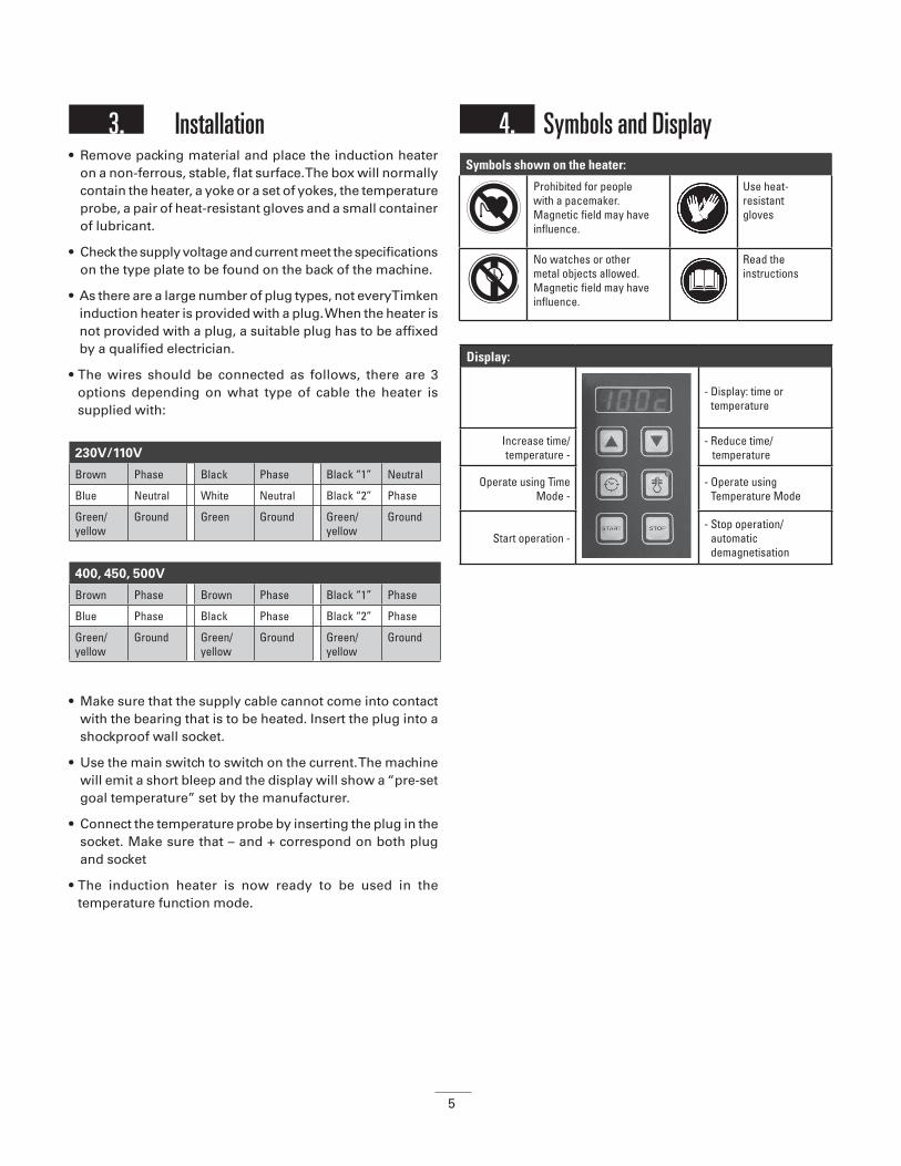
4.
4. Symbols and Display
230V/110V
Brown Phase Black Phase Black “1” Neutral
Blue Neutral White Neutral Black “2” Phase
Green/yellow
Ground Green Ground Green/yellow
Ground
400, 450, 500V
Brown Phase Brown Phase Black “1” Phase
Blue Phase Black Phase Black “2” Phase
Green/yellow
Ground Green/yellow
Ground Green/yellow
Ground
Symbols shown on the heater:
Prohibited for people with a pacemaker. Magnetic field may have influence.
Use heat-resistant gloves
No watches or other metal objects allowed. Magnetic field may have influence.
Read the instructions
Display:
- Display: time or temperature
Increase time/temperature -
- Reduce time/ temperature
Operate using Time Mode -
- Operate using Temperature Mode
Start operation -- Stop operation/
automatic demagnetisation

6
5. Setting up the Work Piece
The work piece can be set up in two different ways:
5.1. Setting up the work piece where the yoke passes through it
• For Swing Arm Yokes: Swing out yoke towards the front of the heater until it falls in the positioning lock of the hinge construction. Slide the workpiece over the yoke till it lies in the middle of the yoke and swing the yoke incl. Work piece back on top of the poles.
• Always make sure that the workpiece has no direct contact with the plastic housing of the heater.
• When heating cycle is ready, follow the above instructions in opposite order to take of the heated work piece. Wear protective clothing like heat resistant gloves because the workpiece is hot now. (Supplied gloves are suitable for 150° C (302° F).
• Always treat yokes carefully falling, jolting, etc, can damage them. Always put the yoke away immediately after use.
5.2. Maximum weights for swing-arm modelsTable showing the maximum permitted weights on the horizontal supports & swiveling yokes:
Yoke passing through the work piece
Yoke in the horizontal position(The bore is large enough for the pole to pass through it. The work piece in this example is shown resting on the horizontal supports).
WARNINGFailure to observe the following warnings could create
a risk of death or serious injury.
• Use appropriate hoisting equipment for heavy components and yokes. The manual lifting of heavy objects is a common
cause of injury.
• The weight of the work-piece should not exceed themaximum weight shown in section 5.2 below, and in the technical data (Appendix 1) at the back of the manual.
Exceeding these limits may result in catastrophic equipment failure leading to personal injury.
• If heater is equipped with sliding horizontal supports, always secure these with the designated safety pin, in
either the ‘in’ or the ‘out’ position. Unexpected movement of the workpiece may lead to personal injury.
• Ensure that the mains cable cannot come into contact with the work piece. Damage to the cable may result in
electrocution.
• Never support components with a metal cable or have any hanging in the proximity of the magnetic field. Extremely
high currents can flow through the cable causing it to heat up quickly, resulting in a risk of burning.
Make sure that the bright sides are greased sufficiently (improve contact, avoid excessive vibration) and are aligned on the top of poles.
Correct Incorrect
Always choose a yoke, which fills the bore of the bearings as fully as possible. You can even combine 2 yokes - this helps to heat more quickly & evenly.
Correct Incorrect
7
• To avoid the heater from tipping and damage to the yokes and the hinge construction, the maximum weight for each size yoke is restricted.
• Parts with a higher weight can rest on the horizontal supports (if fitted), or be supported by a non-metallic rope from a crane, avoiding any weight on the yoke.
Note: Not all ropes have the capacity for temperatures exceeding 100º C and those could possibly pose a safety hazard under repeated use.
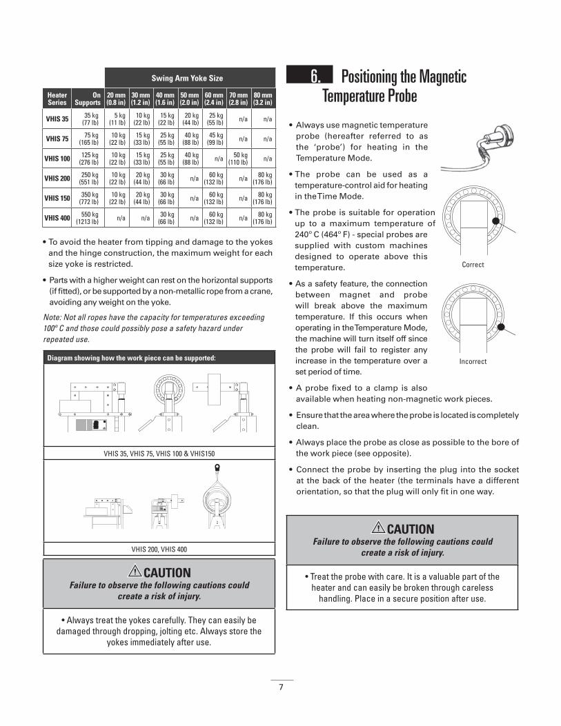
6. Positioning the Magnetic Temperature Probe
• Always use magnetic temperature probe (hereafter referred to as the ‘probe’) for heating in the Temperature Mode.
• The probe can be used as a temperature-control aid for heating in the Time Mode.
• The probe is suitable for operation up to a maximum temperature of 240º C (464º F) - special probes are supplied with custom machines designed to operate above this temperature.
• As a safety feature, the connection between magnet and probe will break above the maximum temperature. If this occurs when operating in the Temperature Mode, the machine will turn itself off since the probe will fail to register any increase in the temperature over a set period of time.
• A probe fixed to a clamp is also available when heating non-magnetic work pieces.
• Ensure that the area where the probe is located is completely clean.
• Always place the probe as close as possible to the bore of the work piece (see opposite).
• Connect the probe by inserting the plug into the socket at the back of the heater (the terminals have a different orientation, so that the plug will only fit in one way.
Swing Arm Yoke Size
Heater Series
On Supports
20 mm(0.8 in)
30 mm(1.2 in)
40 mm(1.6 in)
50 mm(2.0 in)
60 mm(2.4 in)
70 mm(2.8 in)
80 mm(3.2 in)
VHIS 35 35 kg(77 lb)
5 kg(11 lb)
10 kg(22 lb)
15 kg(22 lb)
20 kg(44 lb)
25 kg(55 lb) n/a n/a
VHIS 75 75 kg(165 lb)
10 kg(22 lb)
15 kg(33 lb)
25 kg(55 lb)
40 kg(88 lb)
45 kg(99 lb) n/a n/a
VHIS 100 125 kg(276 lb)
10 kg(22 lb)
15 kg(33 lb)
25 kg(55 lb)
40 kg(88 lb) n/a 50 kg
(110 lb) n/a
VHIS 200 250 kg(551 lb)
10 kg(22 lb)
20 kg(44 lb)
30 kg(66 lb) n/a 60 kg
(132 lb) n/a 80 kg(176 lb)
VHIS 150 350 kg(772 lb)
10 kg(22 lb)
20 kg(44 lb)
30 kg(66 lb) n/a 60 kg
(132 lb) n/a 80 kg(176 lb)
VHIS 400 550 kg(1213 lb) n/a n/a 30 kg
(66 lb) n/a 60 kg(132 lb) n/a 80 kg
(176 lb)
Diagram showing how the work piece can be supported:
VHIS 35, VHIS 75, VHIS 100 & VHIS150
VHIS 200, VHIS 400
Correct
Incorrect
CAUTION Failure to observe the following cautions could
create a risk of injury.
• Always treat the yokes carefully. They can easily be damaged through dropping, jolting etc. Always store the
yokes immediately after use.
CAUTION Failure to observe the following cautions could
create a risk of injury.
• Treat the probe with care. It is a valuable part of the heater and can easily be broken through careless
handling. Place in a secure position after use.

8
7. OperationThere are two modes of heating:
Using the Temperature Mode
(Default mode whenever the machine is switched on)
• Set up the work piece and probe according to the instructions in sections 5 & 6.
• Switch the machine on. The display will show 100º C (or 100º F). Enter the desired temperature to which the work piece will be heated up to using the ‘▲’ or ‘▼’ key (by pressing the temperature mode key ( ) you can choose between steps of 1º or 10º - this is the same whether working in C or F).
• Press the ‘START’ key. Heating starts and a soft buzzing sound will be heard.
• The current temperature of the work piece appears on the display. When the desired temperature has been reached, the display starts to blink and a loud beeping is emitted. Unless you press the ‘STOP’ key, the heat-retention function will keep the bearing at that temperature for 5 minutes. The machine resumes heating after a temperature drop of 3º (C or F). When the set temperature is reached once more the induction heater emits a loud beep. Press the ‘STOP’ key to switch off the machine.
• The heating process or the heat-retention function can be interrupted at any time by pressing the ‘STOP’ key.
Using the Time Mode• Set up the work piece and temperature probe according to
the instructions in sections 5 & 6 (the temperature probe is only necessary if you want to check the temperature).
• Switch the machine on and press the time mode key ‘ ‘. Press the ‘▲’ or ‘▼’ key to set the desired time (by pressing the time mode key ‘ ‘ you can choose between steps of one minute or one second).
• Press the ‘START’ key. Heating starts and a soft buzzing sound will be heard.
• If the temperature key () is pressed while heating, the current temperature is displayed for 3 seconds. After that the countdown is resumed.
• During the heating process the set time runs to 00:00. When 00:00 is reached the induction heater switches off. The work piece is then automatically demagnetised and a loud continuous beeping is emitted. Press the ‘STOP’ key to switch off the machine.
Work piece removal• After pressing the ‘STOP’ key, place the probe on the side
of the vertical pole. Pressing the ‘STOP’ key always causes the work piece to be automatically demagnetised.
• Using heat-resistant gloves, grip the yoke with the bearing on it and place it on a clean, heat-resistant surface. Mount the bearing immediately to prevent cooling. If using a model with a swing arm, swivel the yoke with the bearing on it into the fixed, open position (at 45º). Slide the bearing from the yoke. Mount the bearing immediately to avoid heat loss.
Malfunctioning• If the temperature of the work piece fails to increase by 1º
(either C or F) within a set time-span, the heater switches off automatically. Four blinking dashes will appear (----) in the display, and a loud intermittent beep is emitted. Press the ‘STOP’ key to stop the beeping and check whether:
• the probe is still attached to the work piece, and is connected correctly into its socket.
• the probe wiring has been damaged.
• the probe surface is clean.
• the heater capacity is too small for the work piece.
If the probe is defective, the Time Mode can still be used. The temperature should be checked using an external thermometer.
• If a loud vibrating noise is heard, first check to see that the contact surfaces of the yokes are greased sufficiently. Then check to see that the yoke is making optimal contact with poles. (To adjust yokes: Place yoke on heater, unscrew the bolts in the yoke ¼ turn. Switch on heater and the yoke will set itself. Re-tighten the bolts. You can also use a nylon hammer as an aid to reposition the laminates).
Temperature Mode: Time Mode:
• Used for controlled heating up to the desired temperature.
• Used when you wish to keep the work piece at the desired temperature for up to 15 minutes.
• Suitable for batch production. If the time taken to heat the work piece to the desired temperature is known.
• Emergency use if the temperature probe is lost or defective. The temperature of the work piece should be checked using an external thermometer.
9
8. Cleaning and Maintenance• Store in a dry, frost-proof area, free from humidity.
• Keep clean with a soft, dry cloth.
• Keep the contact parts of the poles clean. Grease regularly with an acid-free grease for optimal contact with the yokes and to prevent corrosion (on swing-arm models, also grease the vertical pin regularly).
• Contact your supplier if there is any suspicion of malfunctioning
WARNINGFailure to observe the following warnings could
create a risk of death or serious injury.
• If in any doubt, isolate the machine and contact your local distributor. Failure to follow proper maintenance and repair procedures can result in equipment failure or create
a risk of serious bodily harm.
The induction heater can be used in º C or º FTo change this follow these steps:
• Press the temperature button for 10 seconds, you will hear a short ‘bleep’
• Then wait, after another 10 seconds a second ‘bleep’ will
sound and in the display the temperature mode will switch from Celsius to Fahrenheit or vice versa.
• The heater is now ready for use in the newly set temperature mode.
WARNINGFailure to observe the following warnings could
create a risk of death or serious injury.
• Proper maintenance and handling practices are critical. Failure to follow installation instructions and to maintain
proper lubrication can result in equipment failure, creating a risk of serious bodily harm.
10
VHIN 10 VHIN 33TURBO
VHIS35VHIS 75TURBO
VHIS 100
ELECTRICITY
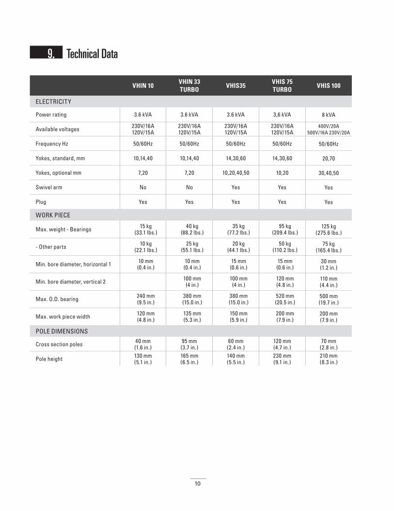
Power rating 3.6 kVA 3.6 kVA 3.6 kVA 3,6 kVA 8 kVA
Available voltages 230V/16A120V/15A
230V/16A120V/15A
230V/16A120V/15A
230V/16A120V/15A
400V/20A500V/16A 230V/20A
Frequency Hz 50/60Hz 50/60Hz 50/60Hz 50/60Hz 50/60Hz
Yokes, standard, mm 10,14,40 10,14,40 14,30,60 14,30,60 20,70
Yokes, optional mm 7,20 7,20 10,20,40,50 10,20 30,40,50
Swivel arm No No Yes Yes Yes
Plug Yes Yes Yes Yes Yes
WORK PIECE
Max. weight - Bearings 15 kg (33.1 lbs.)
40 kg (88.2 lbs.)
35 kg (77.2 lbs.)
95 kg (209.4 lbs.)
125 kg (275.6 lbs.)
- Other parts 10 kg (22.1 lbs.)
25 kg (55.1 lbs.)
20 kg (44.1 lbs.)
50 kg (110.2 lbs.)
75 kg (165.4 lbs.)
Min. bore diameter, horizontal 1 10 mm (0.4 in.)
10 mm (0.4 in.)
15 mm (0.6 in.)
15 mm (0.6 in.)
30 mm (1.2 in.)
Min. bore diameter, vertical 2 100 mm (4 in.)
100 mm (4 in.)
120 mm (4.8 in.)
110 mm (4.4 in.)
Max. O.D. bearing 240 mm (9.5 in.)
380 mm (15.0 in.)
380 mm (15.0 in.)
520 mm (20.5 in.)
500 mm (19.7 in.)
Max. work piece width 120 mm (4.8 in.)
135 mm (5.3 in.)
150 mm (5.9 in.)
200 mm (7.9 in.)
200 mm (7.9 in.)
POLE DIMENSIONS
Cross section poles 40 mm (1.6 in.)
95 mm (3.7 in.)
60 mm (2.4 in.)
120 mm (4.7 in.)
70 mm (2.8 in.)
Pole height 130 mm (5.1 in.)
165 mm (6.5 in.)
140 mm (5.5 in.)
230 mm (9.1 in.)
210 mm (8.3 in.)
9. Technical Data
11
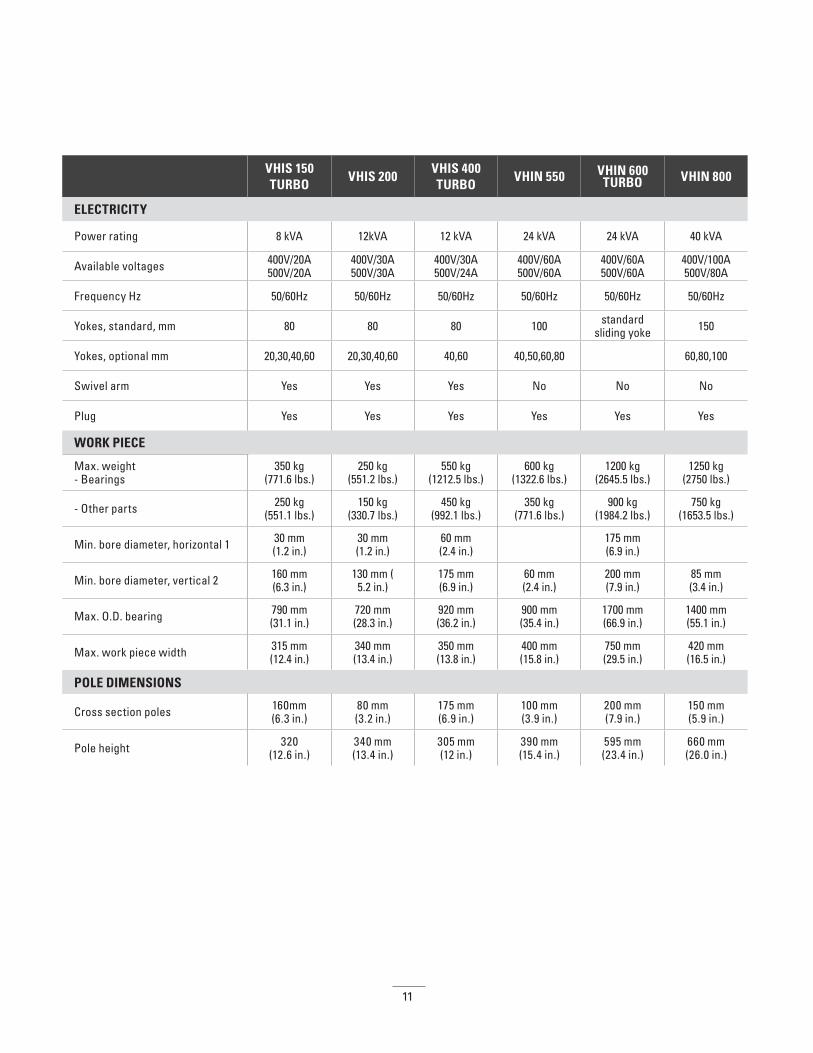
VHIS 150TURBO
VHIS 200VHIS 400TURBO
VHIN 550 VHIN 600TURBO VHIN 800
ELECTRICITY
Power rating 8 kVA 12kVA 12 kVA 24 kVA 24 kVA 40 kVA
Available voltages 400V/20A500V/20A
400V/30A500V/30A
400V/30A500V/24A
400V/60A500V/60A
400V/60A500V/60A
400V/100A500V/80A
Frequency Hz 50/60Hz 50/60Hz 50/60Hz 50/60Hz 50/60Hz 50/60Hz
Yokes, standard, mm 80 80 80 100 standard sliding yoke 150
Yokes, optional mm 20,30,40,60 20,30,40,60 40,60 40,50,60,80 60,80,100
Swivel arm Yes Yes Yes No No No
Plug Yes Yes Yes Yes Yes Yes
WORK PIECE
Max. weight- Bearings
350 kg (771.6 lbs.)
250 kg (551.2 lbs.)
550 kg (1212.5 lbs.)
600 kg (1322.6 lbs.)
1200 kg (2645.5 lbs.)
1250 kg (2750 lbs.)
- Other parts 250 kg (551.1 lbs.)
150 kg(330.7 lbs.)
450 kg (992.1 lbs.)
350 kg (771.6 lbs.)
900 kg (1984.2 lbs.)
750 kg (1653.5 lbs.)
Min. bore diameter, horizontal 1 30 mm (1.2 in.)
30 mm (1.2 in.)
60 mm (2.4 in.) 175 mm
(6.9 in.)
Min. bore diameter, vertical 2 160 mm (6.3 in.)
130 mm (5.2 in.)
175 mm (6.9 in.)
60 mm (2.4 in.)
200 mm (7.9 in.)
85 mm (3.4 in.)
Max. O.D. bearing 790 mm (31.1 in.)
720 mm (28.3 in.)
920 mm (36.2 in.)
900 mm (35.4 in.)
1700 mm (66.9 in.)
1400 mm (55.1 in.)
Max. work piece width 315 mm (12.4 in.)
340 mm (13.4 in.)
350 mm (13.8 in.)
400 mm (15.8 in.)
750 mm (29.5 in.)
420 mm (16.5 in.)
POLE DIMENSIONS
Cross section poles 160mm (6.3 in.)
80 mm (3.2 in.)
175 mm (6.9 in.)
100 mm (3.9 in.)
200 mm (7.9 in.)
150 mm (5.9 in.)
Pole height 320 (12.6 in.)
340 mm (13.4 in.)
305 mm (12 in.)
390 mm (15.4 in.)
595 mm (23.4 in.)
660 mm (26.0 in.)

12
VHIN10 VHIN33TURBO
VHIS35VHIS 75TURBO
VHIS100
CONTROLS
Temperature control- Max. reach
150° C (302° F)
240° C (464° F)
240° C (464° F)
240° C (464° F)
240° C (464° F)
- Magnetic probe Yes Yes Yes Yes Yes
- Digital display Yes Yes Yes Yes Yes
Time control- Max. reach 0-30 min. 0-45 min. 0-45 min. 0-45 min. 0-60 min.
- Digital display Yes Yes Yes Yes Yes
Sound signal Yes Yes Yes Yes Yes
Error report Yes Yes Yes Yes Yes
Temperature hold Yes Yes Yes Yes Yes
Automatic power reduction Yes Yes Yes
Aut. demagnetising, <2A/cm Yes Yes Yes Yes Yes
Thermal safety guard electronics Yes Yes Yes Yes Yes
UNIT DIMENSIONS
Dimensions (lxbxh) 460x240x280 mm 18.1x9.45x11.02 in.
600x220x275 mm 23.6x8.7x10.8 in.
340x290x380 mm 13.4 in.x11.4 in.x12.2 in.
440x370x420 mm 17.3x14.6x14.2 in.
630x365x470 mm 22.8x14.7,18.5 in.
Weight heater21 kg
(46.3 lbs.)(incl. yokes)
23 kg (50.7 lbs.)
(incl. yokes)
31 kg (68.3 lbs.)
37 kg (81.6 lbs.)
53 kg (116.9 lbs.)
Mobile No No No No No
13
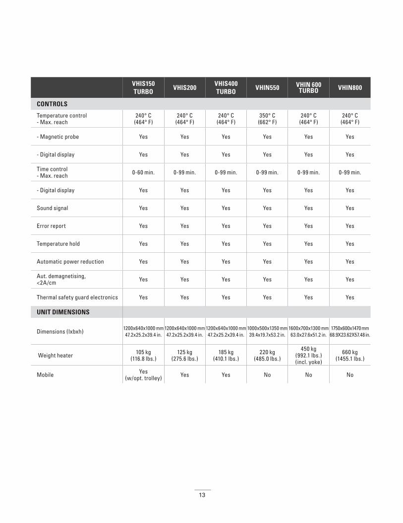
VHIS150TURBO
VHIS200VHIS400TURBO
VHIN550 VHIN 600TURBO VHIN800
CONTROLS
Temperature control- Max. reach
240° C (464° F)
240° C (464° F)
240° C (464° F)
350° C (662° F)
240° C (464° F)
240° C (464° F)
- Magnetic probe Yes Yes Yes Yes Yes Yes
- Digital display Yes Yes Yes Yes Yes Yes
Time control- Max. reach 0-60 min. 0-99 min. 0-99 min. 0-99 min. 0-99 min. 0-99 min.
- Digital display Yes Yes Yes Yes Yes Yes
Sound signal Yes Yes Yes Yes Yes Yes
Error report Yes Yes Yes Yes Yes Yes
Temperature hold Yes Yes Yes Yes Yes Yes
Automatic power reduction Yes Yes Yes Yes Yes Yes
Aut. demagnetising, <2A/cm Yes Yes Yes Yes Yes Yes
Thermal safety guard electronics Yes Yes Yes Yes Yes Yes
UNIT DIMENSIONS
Dimensions (lxbxh) 1200x640x1000 mm 47.2x25.2x39.4 in.
1200x640x1000 mm47.2x25.2x39.4 in.
1200x640x1000 mm 47.2x25.2x39.4 in.
1000x500x1350 mm 39.4x19.7x53.2 in.
1600x700x1300 mm63.0x27.6x51.2 in.
1750x600x1470 mm 68.9X23.62X57.48 in.
Weight heater 105 kg (116.8 lbs.)
125 kg (275.6 lbs.)
185 kg (410.1 lbs.)
220 kg (485.0 lbs.)
450 kg (992.1 lbs.)(incl. yoke)
660 kg (1455.1 lbs.)
Mobile Yes (w/opt. trolley) Yes Yes No No No
14
Inhaltsverzeichnis
1. Sicherheitshinweise . . . . . . . . . . . . . . . . . . . . . . . . . . . . . . . . . . . . . . . . . . . . . . . . . . . . . . . . . . . . . . . . . . . . . . . .15
2. Einführung . . . . . . . . . . . . . . . . . . . . . . . . . . . . . . . . . . . . . . . . . . . . . . . . . . . . . . . . . . . . . . . . . . . . . . . . . . . . . . .17
3. Installation . . . . . . . . . . . . . . . . . . . . . . . . . . . . . . . . . . . . . . . . . . . . . . . . . . . . . . . . . . . . . . . . . . . . . . . . . . . . . .18
4. Symbole und Anzeige . . . . . . . . . . . . . . . . . . . . . . . . . . . . . . . . . . . . . . . . . . . . . . . . . . . . . . . . . . . . . . . . . . . . . .18
5. Einrichtung des Werkstücks . . . . . . . . . . . . . . . . . . . . . . . . . . . . . . . . . . . . . . . . . . . . . . . . . . . . . . . . . . . . . . . . . .195.1. Einrichtung des Werkstücks . . . . . . . . . . . . . . . . . . . . . . . . . . . . . . . . . . . . . . . . . . . . . . . . . . . . . . . . . . . . . .195.2. Maximalgewicht für Schwenkarmmodelle . . . . . . . . . . . . . . . . . . . . . . . . . . . . . . . . . . . . . . . . . . . . . . . . . . . .19
6. Positionieren der magnetischen Temperatursonde . . . . . . . . . . . . . . . . . . . . . . . . . . . . . . . . . . . . . . . . . . . . . . . . . .20
7. Betrieb . . . . . . . . . . . . . . . . . . . . . . . . . . . . . . . . . . . . . . . . . . . . . . . . . . . . . . . . . . . . . . . . . . . . . . . . . . . . . . . . .21
8. Reinigung und Wartung . . . . . . . . . . . . . . . . . . . . . . . . . . . . . . . . . . . . . . . . . . . . . . . . . . . . . . . . . . . . . . . . . . . . .22
9. Technische Daten . . . . . . . . . . . . . . . . . . . . . . . . . . . . . . . . . . . . . . . . . . . . . . . . . . . . . . . . . . . . . . . . . . . . . . . . .23
10. Verdrahtungspläne . . . . . . . . . . . . . . . . . . . . . . . . . . . . . . . . . . . . . . . . . . . . . . . . . . . . . . . . . . . . . . . . . . . . . . . .A1
DEGerman
Deutsche

15
1. Sicherheitshinweise Vorbeugende Sicherheitsmaßnahmen Der Benutzer muss mit dem Inhalt dieses Handbuchs sowie mit sicheren Arbeitspraktiken vertraut sein.
• Befolgen Sie stets die Hinweise im Benutzerhandbuch
• Vergewissern Sie sich, dass das Gerät mit der korrekten Voltspannung arbeitet. Sollte der Wärmer ohne Stecker am Stromversorgungskabel geliefert werden, so darf der Anschluss ans Stromnetz nur von einer entsprechend qualifizierten Person vorgenommen werden.
• Der Wärmer darf in feuchter Umgebung weder verwendet noch aufbewahrt werden. Timken Induktionserwärmer sind nur zur Verwendung in Innenräumen ausgelegt
• Bei mobilen Modellen müssen Sie in feststehender Position immer die Bremse anziehen.
• Falls der Wärmer mit verschiebbaren horizontalen Stützen ausgestattet ist, so müssen diese immer mit dem dafür vorgesehenen Sicherheitsstift gesichert werden, entweder in der „Ein“- oder der „Aus“-Position.
• Verwenden Sie geeignete Ausrüstung zur Handhabung, je nach Gewicht des Werkstücks oder Magnets.
• Es dürfen niemals Teile von einem Metallkabel gehalten werden. In der Umgebung des Magnetfelds dürfen keine metallischen Gegenstände hängen. Extrem hoher Strom kann durch das Kabel fließen, was dazu führt, dass das Kabel sich aufheizt.
• Halten Sie metallische Objekte von Jochen und Polen fern.
• Halten Sie während des Wärmvorgangs mindestens 1 Meter Abstand vom Wärmer.
• Entfernen Sie niemals die Joche während des Wärmzyklus.
• Der Wärmer darf nicht modifiziert werden. Es dürfen keine selbst hergestellten Joche verwendet werden.
• Vergewissern Sie sich immer, dass das Joch korrekt auf die Pfosten abgestimmt ist, da ansonsten übermäßige Vibrationen auftreten können.
• Schalten Sie erst dann das Gerät ein, wenn das Joch korrekt positioniert ist. Bei Modellen mit Schwenkarm (oder Schwenkmagnet) muss der Arm immer geschlossen sein.
HINWEIS:
Da unsere Produkte kontinuierlich verbessert werden, behalten wir uns das Recht zu Änderungen vor.
WARNUNGDie Nichtbeachtung der folgenden Warnhinweise
kann schwere Verletzungen oder Todesfälle zur Folge haben.
• Induktionserwärmer erzeugen ein magnetisches Induktionsfeld, das möglicherweise medizinische Geräte wie Herzschrittmacher
oder Hörgeräte beeinflussen kann, was ein hohes Risiko schwerer Körperverletzungen mit sich bringt. Wenn Sie solche Geräte tragen, dürfen Sie keine Induktionserwärmer betreiben und
müssen sich mindestens 5 m fernhalten.
• Heiße Werkstücke können brennen. Verwenden Sie die beiliegenden Schutzhandschuhe bei der Handhabung derartiger
Werkstücke (geeignet bis zu 150 ºC).
• Betreiben Sie Induktionserwärmer unter keinen Umständen in Bereichen, in denen Explosionsgefahr besteht.
• Ordnungsgemäße Wartung und Handhabung sind von äußerster Wichtigkeit. Die Nichtbefolgung der Hinweise des
Benutzerhandbuchs kann zum Versagen der Ausrüstung führen, was ein Risiko schwerer Körperverletzungen mit sich bringt.
• Verwenden Sie den Induktionserwärmer nicht, wenn das Netzkabel beschädigt ist. Das Kabel muss vom Hersteller, seinem
Agenten oder einer ähnlich qualifizierten Person erneuert werden.
VORSICHT Die Nichtbeachtung der folgenden Vorsichtshinweise
kann Verletzungen zur Folge haben.
• Empfindliche elektronische Geräte (z.B. Mobiltelefone, Computer, Armbanduhren usw.) können durch das Magnetfeld beeinflusst
werden und dürfen in der Nähe des Wärmers nicht verwendet werden.
16
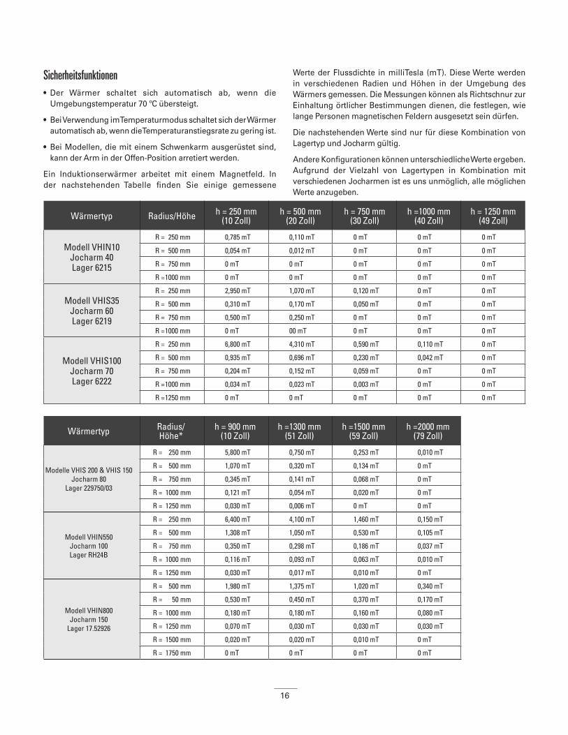
Sicherheitsfunktionen• Der Wärmer schaltet sich automatisch ab, wenn die
Umgebungstemperatur 70 ºC übersteigt.
• Bei Verwendung im Temperaturmodus schaltet sich der Wärmer automatisch ab, wenn die Temperaturanstiegsrate zu gering ist.
• Bei Modellen, die mit einem Schwenkarm ausgerüstet sind, kann der Arm in der Offen-Position arretiert werden.
Ein Induktionserwärmer arbeitet mit einem Magnetfeld. In der nachstehenden Tabelle finden Sie einige gemessene
Werte der Flussdichte in milliTesla (mT). Diese Werte werden in verschiedenen Radien und Höhen in der Umgebung des Wärmers gemessen. Die Messungen können als Richtschnur zur Einhaltung örtlicher Bestimmungen dienen, die festlegen, wie lange Personen magnetischen Feldern ausgesetzt sein dürfen.
Die nachstehenden Werte sind nur für diese Kombination von Lagertyp und Jocharm gültig.
Andere Konfigurationen können unterschiedliche Werte ergeben. Aufgrund der Vielzahl von Lagertypen in Kombination mit verschiedenen Jocharmen ist es uns unmöglich, alle möglichen Werte anzugeben.
Wärmertyp Radius/Höhe h = 250 mm(10 Zoll)
h = 500 mm(20 Zoll)
h = 750 mm(30 Zoll)
h =1000 mm(40 Zoll)
h = 1250 mm(49 Zoll)
Modell VHIN10 Jocharm 40 Lager 6215
R = 250 mm 0,785 mT 0,110 mT 0 mT 0 mT 0 mT
R = 500 mm 0,054 mT 0,012 mT 0 mT 0 mT 0 mT
R = 750 mm 0 mT 0 mT 0 mT 0 mT 0 mT
R = 1000 mm 0 mT 0 mT 0 mT 0 mT 0 mT
Modell VHIS35 Jocharm 60 Lager 6219
R = 250 mm 2,950 mT 1,070 mT 0,120 mT 0 mT 0 mT
R = 500 mm 0,310 mT 0,170 mT 0,050 mT 0 mT 0 mT
R = 750 mm 0,500 mT 0,250 mT 0 mT 0 mT 0 mT
R = 1000 mm 0 mT 00 mT 0 mT 0 mT 0 mT
Modell VHIS100 Jocharm 70 Lager 6222
R = 250 mm 6,800 mT 4,310 mT 0,590 mT 0,110 mT 0 mT
R = 500 mm 0,935 mT 0,696 mT 0,230 mT 0,042 mT 0 mT
R = 750 mm 0,204 mT 0,152 mT 0,059 mT 0 mT 0 mT
R = 1000 mm 0,034 mT 0,023 mT 0,003 mT 0 mT 0 mT
R = 1250 mm 0 mT 0 mT 0 mT 0 mT 0 mT
Wärmertyp Radius/Höhe*
h = 900 mm (10 Zoll)
h =1300 mm (51 Zoll)
h =1500 mm (59 Zoll)
h =2000 mm (79 Zoll)
Modelle VHIS 200 & VHIS 150 Jocharm 80
Lager 229750/03
R = 250 mm 5,800 mT 0,750 mT 0,253 mT 0,010 mT
R = 500 mm 1,070 mT 0,320 mT 0,134 mT 0 mT
R = 750 mm 0,345 mT 0,141 mT 0,068 mT 0 mT
R = 1000 mm 0,121 mT 0,054 mT 0,020 mT 0 mT
R = 1250 mm 0,030 mT 0,006 mT 0 mT 0 mT
Modell VHIN550Jocharm 100Lager RH24B
R = 250 mm 6,400 mT 4,100 mT 1,460 mT 0,150 mT
R = 500 mm 1,308 mT 1,050 mT 0,530 mT 0,105 mT
R = 750 mm 0,350 mT 0,298 mT 0,186 mT 0,037 mT
R = 1000 mm 0,116 mT 0,093 mT 0,063 mT 0,010 mT
R = 1250 mm 0,030 mT 0,017 mT 0,010 mT 0 mT
Modell VHIN800Jocharm 150
Lager 17.52926
R = 500 mm 1,980 mT 1,375 mT 1,020 mT 0,340 mT
R = 50 mm 0,530 mT 0,450 mT 0,370 mT 0,170 mT
R = 1000 mm 0,180 mT 0,180 mT 0,160 mT 0,080 mT
R = 1250 mm 0,070 mT 0,030 mT 0,030 mT 0,030 mT
R = 1500 mm 0,020 mT 0,020 mT 0,010 mT 0 mT
R = 1750 mm 0 mT 0 mT 0 mT 0 mT
17
Die Höhe wird von der Unterseite des Wärmers aus gemessen. Um genau zu bestimmen, wo sich das Feld in Bezug auf den Boden befindet, muss der Abstand von der Unterseite des Wärmers bis zum Boden zu den in der Tabelle aufgeführten Werten hinzugefügt werden. (z.B. die Höhe eines Arbeitstisches).
2. Einführung
AnwendungTimken Induktionserwärmer dienen zum Erwärmen von Lagern, Hülsen, Zahnrädern, Kupplungen und anderen metallischen Werkstücken, die einen geschlossenen elektrischen Kreislauf bilden. Dies erleichtert die Montage dort, wo ein Pressverband benötigt wird.
Die Wärmer sind darauf ausgelegt, das Werkstück auf eine Maximaltemperatur von 240 °C zu erwärmen, mit Ausnahme der Modelle der VHIN10 Serie, wo die Temperatur auf maximal 150 °C begrenzt ist, und speziell entwickelter Wärmer, wo die Maximaltemperatur bis zu 480 °C betragen kann.
Timken Induktionserwärmer können kontinuierlich verwendet werden. Es gibt jedoch eine Einschränkung: Der Wärmer darf nicht länger als eine halbe Stunde mit einer Temperatur von 240 °C oder mehr betrieben werden. Bei Wärmung unter Verwendung der Zeitfunktion muss dies mit einem externen Thermometer geprüft werden.
BetriebsbedingungenAusgelegt für Industrieanwendungen mit einer Umgebungstemperatur von 0 °C bis 50 °C und einer atmosphärischen Luftfeuchte zwischen 5 % und 90 %. Der Induktionserwärmer ist ausschließlich zur Verwendung in Innenräumen vorgesehen.
BetriebsgrundsätzeDer Wärmer arbeitet auf dieselbe Weise wie ein Transformator. Die Primärspule ist der Wärmer und die Sekundärspule ist das Werkstück.
Wenn der Wärmer eingeschaltet wird, so läuft Wechselstrom geringer Stärke und hoher Spannung durch die zahlreichen Windungen der Primärspule. Dies verursacht eine geringe Spannung und hohe Stromstärke im Werkstück, das als Sekundärspule fungiert. Diese hohe Stromstärke führt dazu, dass sich das Werkstück erwärmt.
Der Strom fließt nur im Werkstück. Daher erwärmt sich ausschließlich das Werkstück. Das Werkstück wird am Ende des Erwärmungszyklus automatisch entmagnetisiert.
WARNUNGDie Nichtbeachtung der folgenden Vorsichtshinweise
kann schwere Verletzungen oder Todesfälle zur Folge haben.
• Wir empfehlen, das Arbeiter in der Nähe des Geräts einen Sicherheitsabstand von mindestens 1 Meter einhalten sollten.
VORSICHT Die Nichtbeachtung der folgenden Vorsichtshinweise
kann Verletzungen zur Folge haben.
• Das Gerät erzeugt ein Induktionsfeld, dass elektronische Geräte wie z.B. Armbanduhren, magnetische Aufzeichnungsgeräte usw.
beeinflussen kann.
VORSICHT Die Nichtbeachtung der folgenden Vorsichtshinweise
kann Verletzungen zur Folge haben.
• Lager sollten generell nur bis zu einer Temperatur von maximal 120 ºC erwärmt werden.
• Präzisionslager sollten generell nur bis zu einer Temperatur von maximal 70 ºC erwärmt werden. Das Erwärmen auf
höhere Temperaturen kann die metallurgische Struktur und Formbeständigkeit beeinflussen und vorzeitiges Versagen von
Lagern bzw. geringere Leistungsfähigkeit nach sich ziehen.
• Verwenden Sie Induktionserwärmer nicht für Lager oder Werkstücke, die außerhalb der Minimal- oder
Maximalabmessungen liegen, die im Abschnitt Technische Daten (Anhang 1) aufgeführt sind.
• Vermeiden Sie es, den Wärmer mit dem Hauptschalter auszuschalten, während der Wärmzyklus durchgeführt wird.
18
3. Installation • Entfernen Sie das Verpackungsmaterial und stellen Sie
den Induktionserwärmer auf eine eisenfreie, stabile, ebene Oberfläche. Der Karton enthält normalerweise den Wärmer, ein Joch oder einen Jochensatz, die Temperatursonde, ein Paar hitzebeständiger Handschuhe und einen kleinen Behälter mit Schmiermittel.
• Prüfen Sie, dass Spannung und Stromstärke der Stromzufuhr den Spezifikationen auf dem Typenschild auf der Rückseite des Geräts entsprechen.
• Da es eine Vielzahl von Steckern gibt, sind nicht alle Timken Induktionserwärmer mit einem Stecker versehen. Wenn der Wärmer nicht mit einem Stecker ausgerüstet ist, so muss ein geeigneter Stecker von einem qualifizierten Elektriker angebracht werden.
• Die Kabel sollten wie folgt angeschlossen werden. Es gibt drei verschiedene Optionen, in Abhängigkeit vom Kabeltyp, der mit Ihrem Wärmer geliefert wurde:
• Vergewissern Sie sich, dass das Stromversorgungskabel nicht mit dem zu wärmenden Lager in Kontakt kommt. Stecken Sie den Stecker in eine schutzisolierte Steckdose.
• Verwenden Sie den Hauptschalter, um die Stromversorgung herzustellen. Das Gerät lässt ein kurzes akustisches Signal ertönen und zeigt eine „vordefinierte Zieltemperatur“ an, die ab Werk eingestellt wurde.
• Schließen Sie die Temperatursonde an, indem Sie den Stecker in die Buchse einstecken. Stellen Sie sicher, dass – und + sowohl am Stecker als auch an der Buchse übereinstimmen.
• Der Induktionserwärmer ist nun bereit für die Verwendung im Temperaturfunktionsmodus.
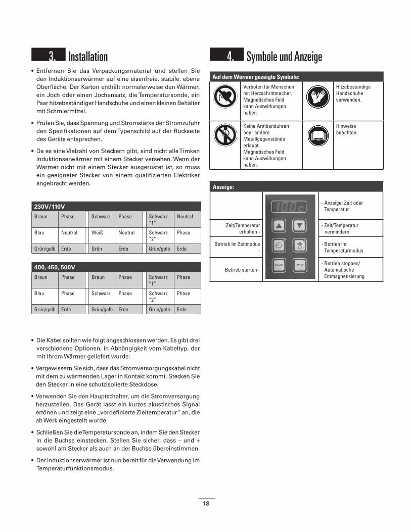
4. Symbole und Anzeige
230V/110V
Braun Phase Schwarz Phase Schwarz “1”
Neutral
Blau Neutral Weiß Neutral Schwarz “2”
Phase
Grün/gelb Erde Grün Erde Grün/gelb Erde
400, 450, 500V
Braun Phase Braun Phase Schwarz “1”
Phase
Blau Phase Schwarz Phase Schwarz “2”
Phase
Grün/gelb Erde Grün/gelb Erde Grün/gelb Erde
Auf dem Wärmer gezeigte Symbole:
Verboten für Menschen mit Herzschrittmacher. Magnetisches Feld kann Auswirkungen haben.
Hitzebeständige Handschuhe verwenden.
Keine Armbanduhren oder andere Metallgegenstände erlaubt. Magnetisches Feld kann Auswirkungen haben.
Hinweise beachten.
Anzeige:
- Anzeige: Zeit oder Temperatur
Zeit/Temperatur erhöhen -
- Zeit/Temperatur vermindern
Betrieb im Zeitmodus -
- Betrieb im Temperaturmodus
Betrieb starten -- Betrieb stoppen/
Automatische Entmagnetisierung

19
5. Einrichtung des Werkstücks
Das Werkstück kann auf zwei verschiedene Arten eingerichtet werden:
5.1. Einrichtung des Werkstücks bei Hindurchführung des Jochs
• Für Schwenkarmjoche: Schwenken Sie das Joch in Richtung der Vorderseite des Wärmers, bis der Feststellmechanismus einrastet. Schieben Sie das Werkstück über das Joch, bis es in der Mitte des Jochs ist. Schwenken Sie dann das Joch und das Werkstück zurück auf die Oberseite der Pfosten.
• Vergewissern Sie sich stets, dass das Werkstück nicht in direktem Kontakt mit dem Plastikgehäuse des Wärmers kommen kann.
• Wenn der Wärmzyklus beendet ist, folgen Sie den obigen Hinweisen in umgekehrter Reihenfolge, um das erwärmte Werkstück zu entnehmen. Tragen Sie Schutzkleidung wie z.B. hitzebeständige Handschuhe, da das Werkstück jetzt heiß ist. (Die mitgelieferten Handschuhe sind bis zu einer Temperatur von 150 °C geeignet.)
• Behandeln Sie die Joche stets vorsichtig. Fallenlassen, Erschütterung usw. kann zu Beschädigungen führen. Verstauen Sie die Joche sofort nach der Verwendung.
5,2. Maximalgewicht für Schwenkarmmodelle
Die Tabelle zeigt das maximal zulässige Gewicht auf den horizontalen Stützen und Schwenkjochen:
Joch wird durch das Werkstück hindurchgeführt
Joch in horizontaler Position (Bohrung ist groß genug, so dass der Pfosten hindurch geführt werden kann. In diesem Beispiel liegt das Werkstück auf den horizontalen Stützen auf).
WARNUNGDie Nichtbeachtung der folgenden Warnungen kann tödliche
oder schwere Verletzungen zur Folge haben.
• Verwenden Sie entsprechende Hebevorrichtungen für schwere Komponenten und Joche. Manuelles Anheben schwerer Gegenstände ist eine häufige Ursache von Verletzungen.
• Das Gewicht des Werkstücks darf das unten in Abschnitt 5.2. und in den Technischen Daten (Anhang 1)
am Ende des Handbuchs aufgeführte Maximalgewicht nicht überschreiten. Ein Überschreiten dieser Grenzen kann zu einem Totalversagen der Ausrüstung führen, was Körperverletzungen
nach sich ziehen kann.
• Falls der Wärmer mit verschiebbaren horizontalen Stützen ausgestattet ist, so müssen diese immer mit dem dafür
vorgesehenen Sicherheitsstift gesichert werden, entweder in der „Ein“- oder der „Aus“-Position. Unerwartetes Bewegen des
Werkstücks kann zu Körperverletzungen führen.
• Vergewissern Sie sich, dass das Hauptkabel nicht mit dem Werkstück in Kontakt kommen kann. Schäden am Kabel können
zu einem elektrischem Schlag führen.
• Komponenten dürfen niemals von einem Metallkabel gehalten werden. In der Umgebung des Magnetfelds dürfen keine
Metallkabel hängen. Extrem hoher Strom kann durch das Kabel fließen, was zu rascher Erhitzung führt und ein Brandrisiko
darstellt.
Vergewissern Sie sich, dass die hellen Seiten ausreichend geschmiert sind (verbesserter Kontakt, Vermeidung übermäßiger Vibrationen) und auf der Oberseite der Pfosten ausgerichtet sind.
Korrekt Inkorrekt
Verwenden Sie stets ein Joch, das die Öffnung des Lagers so vollständig wie möglich ausfüllt. Sie können sogar 2 Joche kombinieren. Dies ermöglicht ein rascheres und gleichmäßigeres Erwärmen.
Korrekt Inkorrekt
20
• Um den Wärmer vor dem Umfallen zu schützen und Schäden an Joch und Schwenkmechanismus zu vermeiden, besteht für jede Jochgröße ein Maximalgewicht.
• Teile mit höherem Gewicht können auf den horizontalen Stützen aufliegen (sofern passend) oder mit einem nichtmetallischen Seil von einem Kran gehängt werden, so dass auf dem Joch kein Gewicht liegt.
Hinweis: Nicht alle Seile sind für Temperaturen über 100 ºC geeignet, was bei wiederholter Verwendung ein potenzielles Sicherheitsrisiko darstellen könnte.
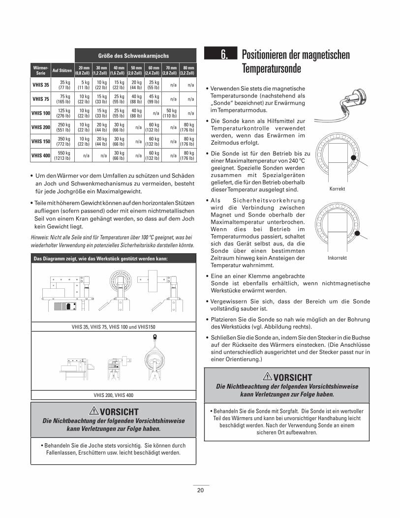
6. Positionieren der magnetischen Temperatursonde
• Verwenden Sie stets die magnetische Temperatursonde (nachstehend als „Sonde“ bezeichnet) zur Erwärmung im Temperaturmodus.
• Die Sonde kann als Hilfsmittel zur Temperaturkontrolle verwendet werden, wenn das Erwärmen im Zeitmodus erfolgt.
• Die Sonde ist für den Betrieb bis zu einer Maximaltemperatur von 240 ºC geeignet. Spezielle Sonden werden zusammen mit Spezialgeräten geliefert, die für den Betrieb oberhalb dieser Temperatur ausgelegt sind.
• Als Sicherhei tsvorkehrung wird die Verbindung zwischen Magnet und Sonde oberhalb der Maximaltemperatur unterbrochen. Wenn dies bei Betrieb im Temperaturmodus passiert, schaltet sich das Gerät selbst aus, da die Sonde über einen bestimmten Zeitraum hinweg kein Ansteigen der Temperatur wahrnimmt.
• Eine an einer Klemme angebrachte Sonde ist ebenfalls erhältlich, wenn nichtmagnetische Werkstücke erwärmt werden.
• Vergewissern Sie sich, dass der Bereich um die Sonde vollständig sauber ist.
• Platzieren Sie die Sonde so nah wie möglich an der Bohrung des Werkstücks (vgl. Abbildung rechts).
• Schließen Sie die Sonde an, indem Sie den Stecker in die Buchse auf der Rückseite des Wärmers einstecken. (Die Anschlüsse sind unterschiedlich ausgerichtet und der Stecker passt nur in einer Orientierung.)
Größe des Schwenkarmjochs
Wärmer- Serie Auf Stützen 20 mm
(0,8 Zoll)30 mm
(1,2 Zoll)40 mm
(1,6 Zoll)50 mm
(2,0 Zoll)60 mm
(2,4 Zoll)70 mm
(2,8 Zoll)80 mm
(3,2 Zoll)
VHIS 35 35 kg(77 lb)
5 kg(11 lb)
10 kg(22 lb)
15 kg(22 lb)
20 kg(44 lb)
25 kg(55 lb) n/a n/a
VHIS 75 75 kg(165 lb)
10 kg(22 lb)
15 kg(33 lb)
25 kg(55 lb)
40 kg(88 lb)
45 kg(99 lb) n/a n/a
VHIS 100 125 kg(276 lb)
10 kg(22 lb)
15 kg(33 lb)
25 kg(55 lb)
40 kg(88 lb) n/a 50 kg
(110 lb) n/a
VHIS 200 250 kg(551 lb)
10 kg(22 lb)
20 kg(44 lb)
30 kg(66 lb) n/a 60 kg
(132 lb) n/a 80 kg(176 lb)
VHIS 150 350 kg(772 lb)
10 kg(22 lb)
20 kg(44 lb)
30 kg(66 lb) n/a 60 kg
(132 lb) n/a 80 kg(176 lb)
VHIS 400 550 kg(1213 lb) n/a n/a 30 kg
(66 lb) n/a 60 kg(132 lb) n/a 80 kg
(176 lb)
Das Diagramm zeigt, wie das Werkstück gestützt werden kann:
VHIS 35, VHIS 75, VHIS 100 und VHIS150
VHIS 200, VHIS 400
Korrekt
Inkorrekt
VORSICHT Die Nichtbeachtung der folgenden Vorsichtshinweise
kann Verletzungen zur Folge haben.
• Behandeln Sie die Joche stets vorsichtig. Sie können durch Fallenlassen, Erschüttern usw. leicht beschädigt werden.
VORSICHT Die Nichtbeachtung der folgenden Vorsichtshinweise
kann Verletzungen zur Folge haben.
• Behandeln Sie die Sonde mit Sorgfalt. Die Sonde ist ein wertvoller Teil des Wärmers und kann bei unvorsichtiger Handhabung leicht
beschädigt werden. Nach der Verwendung Sonde an einem sicheren Ort aufbewahren.
21
7. BetriebEs gibt zwei Arten des Erwärmens:
Verwendung des Temperaturmodus
(Standardmodus bei Einschaltung des Geräts)
• Richten Sie Werkstück und Sonde den Hinweisen in Abschnitt 5 und 6 entsprechend ein.
• Schalten Sie das Gerät ein. Die Anzeige zeigt 100 ºC (oder 100 ºF). Geben Sie die gewünschte Temperatur, auf die das Werkstück erwärmt werden soll, unter Verwendung der ‘▲’ oder ‘▼’ Tasten ein. Durch Drücken der Temperaturmodustaste ( ) können Sie zwischen Schritten von 1º oder 10º wählen. Dies gilt sowohl für C als auch für F).
• Drücken Sie die START-Taste. Das Erwärmen beginnt und ein leises Summen wird hörbar.
• Auf der Anzeige erscheint die aktuelle Temperatur des Werkstücks. Wenn die gewünschte Temperatur erreicht ist, blinkt die Anzeige und ein lautes akustisches Signal ertönt. Solange Sie nicht die ‘STOP’Taste drücken, hält die Temperaturkonstanthaltungsfunktion das Lager 5 Minuten lang bei dieser Temperatur. Das Gerät nimmt nach einem Temperaturabfall von 3° (C oder F) das Erwärmen erneut auf. Wenn die Temperatur erneut erreicht ist, ertönt ein lautes akustisches Signal. Drücken Sie die ‘STOP’-Taste, um das Gerät auszuschalten.
• Der Wärmprozess und die Temperaturkonstanthaltungsfunktion können jederzeit durch Drücken der ‘STOP’-Taste unterbrochen werden.
Verwendung des Zeitmodus• Richten Sie Werkstück und Temperatursonde den Hinweisen in
Abschnitten 5 und 6 entsprechend ein. (Die Temperatursonde ist nur dann notwendig, wenn Sie die Temperatur prüfen möchten.)
• Schalten Sie das Gerät ein und drücken Sie die Zeitmodustaste ‘ ‘. Drücken Sie die ‘▲’ oder ‘▼’ Taste, um die gewünschte Zeit einzustellen. (Durch Drücken der Zeitmodustaste ‘ ‘ können Sie zwischen Schritten von 1 Minute oder 1 Sekunde
wählen.)
• Drücken Sie die START-Taste. Das Erwärmen beginnt und ein leises Summen wird hörbar.
• Wird während des Erwärmens die Temperaturmodustaste () gedrückt, wird 3 Sekunden lang die aktuelle Temperatur angezeigt. Danach wird der Countdown wieder aufgenommen.
• Während des Wärmprozesses läuft die Einstellungszeit auf 00:00 ab. Bei Erreichen von 00:00 schaltet sich der Induktionserwärmer aus. Das Werkstück wird dann automatisch entmagnetisiert und es ertönt ein lautes anhaltendes akustisches Signal. Drücken Sie die ‘STOP’-Taste, um das Gerät auszuschalten.
Entfernen des Werkstücks• Nach Drücken der ‘STOP’-Taste legen Sie die Sonde auf
die Seite des vertikalen Pfostens. Das Drücken der STOP-Taste führt immer dazu, dass das Werkstück automatisch entmagnetisiert wird.
• Unter Verwendung der hitzebeständigen Handschuhe ergreifen Sie das Joch mit Lager und legen es auf eine saubere hitzebeständige Oberfläche. Montieren Sie das Lager sofort, um ein Abkühlen zu vermeiden Bei Verwendung eines Modells mit Schwenkarm bewegen Sie das Joch mit Lager in die arretierte Offen-Position (bei 45º). Schieben Sie das Lager vom Joch. Montieren Sie das Lager sofort, um Wärmeverlust zu vermeiden.
Störungen• Wenn die Temperatur des Werkstücks nicht innerhalb eines bestimmten Zeitraums um 1º (entweder C oder F) ansteigt, schaltet sich der Wärmer automatisch ab. Auf der Anzeige erscheinen vier blinkende Striche (----) und es ertönt ein lautes unterbrochenes akustisches Signal. Drücken Sie die STOP-Taste und prüfen Sie,
• dass die Sonde immer noch mit dem Werkstück verbunden und korrekt in die Buchse eingesteckt ist;
• dass die Kabel der Sonde nicht beschädigt sind;
• dass die Oberfläche der Sonde sauber ist;
• dass die Kapazität des Wärmers für das Werkstück ausreicht.
Ist die Sonde beschädigt, so kann immer noch der Zeitmodus verwendet werden. Die Temperatur muss dann mit Hilfe eines externen Thermometers geprüft werden.
• Wenn ein lautes vibrierendes Geräusch zu hören ist, prüfen Sie zuerst, ob die Kontaktoberflächen der Joche ausreichend geschmiert sind. Prüfen Sie dann, ob das Joch optimalen Kontakt mit den Stützen hat. (Um die Joche zu justieren, gehen Sie folgendermaßen vor: Setzen Sie das Joch auf den Wärmer. Lösen Sie die Bolzen im Joch um eine 1⁄4-Umdrehung. Schalten Sie den Wärmer ein und das Joch wird automatisch ausgerichtet. Ziehen Sie die Bolzen wieder fest. Sie können auch einen Nylonhammer zur Neupositionierung der beschichteten Platten verwenden.)
Temperaturmodus: Zeitmodus:
• Wird zur kontrollierten Erwärmung auf die gewünschte Temperatur verwendet..
• Wird verwendet, wenn die gewünschte Temperatur des Werkstücks für bis zu 15 Minuten konstant gehalten werden soll.
• Für die Serienfertigung geeignet. Wenn die notwendige Zeit für das Erwärmen des Werkstücks auf die gewünschte Temperatur bekannt ist.
• Zur Verwendung im Notfall, wenn die Temperatursonde verloren wurde oder beschädigt ist. Die Temperatur des Werkstücks muss unter Verwendung eines externen Thermometers geprüft werden.

22
8. Reinigung und Wartung• Bewahren Sie das Gerät in einem trockenen, frostfreien Bereich
frei von Feuchtigkeit auf.
• Halten Sie das Gerät mit einem weichen, trockenen Tuch sauber.
• Halten Sie die Kontaktflächen der Pfosten sauber. Schmieren Sie das Gerät regelmäßig mit einem säurefreien Schmiermittel, um optimalen Kontakt mit den Jochen zu gewährleisten und Korrosion zu vermeiden. (Bei Schwenkarmmodellen müssen Sie auch den vertikalen Stift regelmäßig schmieren.)
• Wenn Sie vermuten, dass das Gerät fehlerhaft arbeitet, wenden Sie sich an Ihren Händler.
WARNUNGDie Nichtbeachtung der folgenden Warnhinweise
kann schwere Verletzungen oder Todesfälle zur Folge haben.
• Im Zweifelsfall sollten Sie das das Gerät isolieren und sich an Ihren örtlichen Händler wenden. Die Nichtbefolgung der ordnungsgemäßer Wartungs- und Reparaturverfahren kann
zum Versagen der Ausrüstung führen, was ein Risiko schwerer Körperverletzungen mit sich bringt.
Der Induktionserwärmer lässt sich in Grad Celsius (ºC) oder Grad Fahrenheit (ºF) verwenden.
Um diese Einstellung zu ändern, wird wie folgt vorgegangen:
• Drücken Sie die Temperaturtaste 10 Sekunden lang; es ertönt ein kurzer Piepton.
• Warten Sie dann, bis nach weiteren 10 Sekunden ein zweiter Piepton ertönt und sich der Temperaturmodus in der Anzeige von Celsius nach Fahrenheit bzw. von Fahrenheit nach Celsius ändert.
• Der Wärmer ist jetzt einsatzbereit und kann im soeben eingestellten Temperaturmodus verwendet werden.
WARNUNGDie Nichtbeachtung der folgenden Warnhinweise
kann schwere Verletzungen oder Todesfälle zur Folge haben.
• Ordnungsgemäße Wartung und Handhabung sind von äußerster Wichtigkeit. Die Nichtbeachtung der Installationsanweisungen
und eine unsachgemäße Schmierung können zu Geräteausfällen führen, die ein Risiko schwerer Körperverletzungen mit sich
bringen.

23
VHIN 10 VHIN 33TURBO
VHIS35VHIS 75TURBO
VHIS 100
ELEKTRIZITÄT
Nennleistung 3,6 kVA 3,6 kVA 3,6 kVA 3,6 kVA 8 kVA
Verfügbare Spannungen 230V/16A120V/15A
230V/16A120V/15A
230V/16A120V/15A
230V/16A120V/15A
400V/20A500V/16A 230V/20A
Frequenz Hz 50/60Hz 50/60Hz 50/60Hz 50/60Hz 50/60Hz
Joche, Standard, mm 10,14,40 10,14,40 14,30,60 14,30,60 20,70
Joche, Optional, mm 7,20 7,20 10,20,40,50 10,20 30,40,50
Schwenkarm Nein Nein Ja Ja Ja
Stecker Ja Ja Ja Ja Ja
WERKSTÜCK
Höchstgewicht - Lager 15 kg (33,1 lbs.)
40 kg (88,2 lbs.)
35 kg (77,2 lbs.)
95 kg (209,4 lbs.)
125 kg (275,6 lbs.)
- Sonstige Teile 10 kg (22,1 lbs.)
25 kg (55,1 lbs.)
20 kg (44,1 lbs.)
50 kg (110,2 lbs.)
75 kg (165,4 lbs.)
Min. Bohrungsdurchmesser, horizontal 1 10 mm (0,4 Zoll)
10 mm (0,4 Zoll)
15 mm (0,6 Zoll)
15 mm (0,6 Zoll)
30 mm (1,2 Zoll)
Min. Bohrungsdurchmesser, vertikal 2 100 mm (4 Zoll)
100 mm (4 Zoll)
120 mm (4,8 Zoll)
110 mm (4,4 Zoll)
Max. Lager-Außendurchmesser 240 mm (9,5 Zoll)
380 mm (15,0 Zoll)
380 mm (15,0 Zoll)
520 mm (20,5 Zoll)
500 mm (19,7 Zoll)
Max. Werkstückbreite 120 mm (4,8 Zoll)
135 mm (5,3 Zoll)
150 mm (5,9 Zoll)
200 mm (7,9 Zoll)
200 mm (7,9 Zoll)
PFOSTEN-ABMESSUNGEN
Pfosten-Querschnitt 40 mm (1,6 Zoll)
95 mm (3,7 Zoll)
60 mm (2,4 Zoll)
120 mm (4,7 Zoll)
70 mm (2,8 Zoll)
Pfostenhöhe 130 mm (5,1 Zoll)
165 mm (6,5 Zoll)
140 mm (5,5 Zoll)
230 mm (9,1 Zoll)
210 mm (8,3 Zoll)
9. Technische Daten
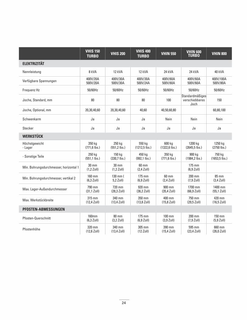
24
VHIS 150TURBO
VHIS 200VHIS 400TURBO
VHIN 550 VHIN 600TURBO VHIN 800
ELEKTRIZITÄT
Nennleistung 8 kVA 12 kVA 12 kVA 24 kVA 24 kVA 40 kVA
Verfügbare Spannungen 400V/20A500V/20A
400V/30A500V/30A
400V/30A500V/24A
400V/60A500V/60A
400V/60A500V/60A
400V/100A500V/80A
Frequenz Hz 50/60Hz 50/60Hz 50/60Hz 50/60Hz 50/60Hz 50/60Hz
Joche, Standard, mm 80 80 80 100Standardmäßiges
verschiebbares Joch
150
Joche, Optional, mm 20,30,40,60 20,30,40,60 40,60 40,50,60,80 60,80,100
Schwenkarm Ja Ja Ja Nein Nein Nein
Stecker Ja Ja Ja Ja Ja Ja
WERKSTÜCK
Höchstgewicht- Lager
350 kg (771,6 lbs.)
250 kg (551,2 lbs.)
550 kg (1212,5 lbs.)
600 kg (1322,6 lbs.)
1200 kg (2645,5 lbs.)
1250 kg (2750 lbs.)
- Sonstige Teile 250 kg (551,1 lbs.)
150 kg(330,7 lbs.)
450 kg (992,1 lbs.)
350 kg (771,6 lbs.)
900 kg (1984,2 lbs.)
750 kg (1653,5 lbs.)
Min. Bohrungsdurchmesser, horizontal 1 30 mm (1,2 Zoll)
30 mm (1,2 Zoll)
60 mm (2,4 Zoll) 175 mm
(6,9 Zoll)
Min. Bohrungsdurchmesser, vertikal 2 160 mm (6,3 Zoll)
130 mm (5,2 Zoll)
175 mm (6,9 Zoll)
60 mm (2,4 Zoll)
200 mm (7,9 Zoll)
85 mm (3,4 Zoll)
Max. Lager-Außendurchmesser 790 mm (31,1 Zoll)
720 mm (28,3 Zoll)
920 mm (36,2 Zoll)
900 mm (35,4 Zoll)
1700 mm (66,9 Zoll)
1400 mm (55,1 Zoll)
Max. Werkstückbreite 315 mm (12,4 Zoll)
340 mm (13,4 Zoll)
350 mm (13,8 Zoll)
400 mm (15,8 Zoll)
750 mm (29,5 Zoll)
420 mm (16,5 Zoll)
PFOSTEN-ABMESSUNGEN
Pfosten-Querschnitt 160mm (6,3 Zoll)
80 mm (3,2 Zoll)
175 mm (6,9 Zoll)
100 mm (3,9 Zoll)
200 mm (7,9 Zoll)
150 mm (5,9 Zoll)
Pfostenhöhe 320 mm (12,6 Zoll)
340 mm (13,4 Zoll)
305 mm (12 Zoll)
390 mm (15,4 Zoll)
595 mm (23,4 Zoll)
660 mm (26,0 Zoll)
25
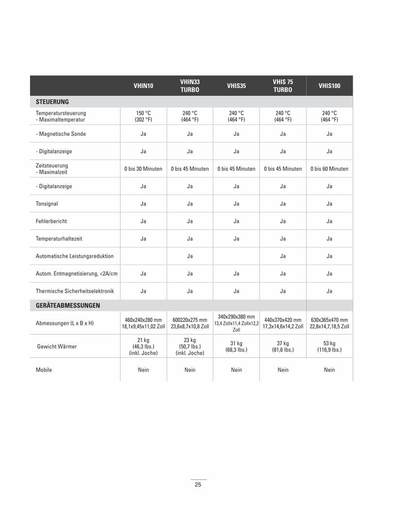
VHIN10 VHIN33TURBO
VHIS35VHIS 75TURBO
VHIS100
STEUERUNG
Temperatursteuerung- Maximaltemperatur
150 °C (302 °F)
240 °C (464 °F)
240 °C (464 °F)
240 °C (464 °F)
240 °C (464 °F)
- Magnetische Sonde Ja Ja Ja Ja Ja
- Digitalanzeige Ja Ja Ja Ja Ja
Zeitsteuerung- Maximalzeit 0 bis 30 Minuten 0 bis 45 Minuten 0 bis 45 Minuten 0 bis 45 Minuten 0 bis 60 Minuten
- Digitalanzeige Ja Ja Ja Ja Ja
Tonsignal Ja Ja Ja Ja Ja
Fehlerbericht Ja Ja Ja Ja Ja
Temperaturhaltezeit Ja Ja Ja Ja Ja
Automatische Leistungsreduktion Ja Ja Ja
Autom. Entmagnetisierung, <2A/cm Ja Ja Ja Ja Ja
Thermische Sicherheitselektronik Ja Ja Ja Ja Ja
GERÄTEABMESSUNGEN
Abmessungen (L x B x H) 460x240x280 mm 18,1x9,45x11,02 Zoll
600220x275 mm 23,6x8,7x10,8 Zoll
340x290x380 mm 13,4 Zollx11,4 Zollx12,2
Zoll
440x370x420 mm 17,3x14,6x14,2 Zoll
630x365x470 mm 22,8x14,7,18,5 Zoll
Gewicht Wärmer21 kg
(46,3 lbs.)(inkl. Joche)
23 kg (50,7 lbs.)
(inkl. Joche)
31 kg (68,3 lbs.)
37 kg (81,6 lbs.)
53 kg (116,9 lbs.)
Mobile Nein Nein Nein Nein Nein
26
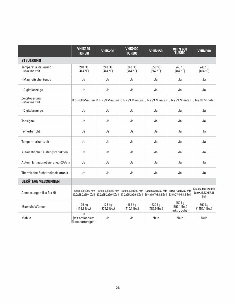
VHIS150TURBO
VHIS200VHIS400TURBO
VHIN550 VHIN 600TURBO VHIN800
STEUERUNG
Temperatursteuerung- Maximalzeit
240 °C (464 °F)
240 °C (464 °F)
240 °C (464 °F)
350 °C (662 °F)
240 °C (464 °F)
240 °C (464 °F)
- Magnetische Sonde Ja Ja Ja Ja Ja Ja
- Digitalanzeige Ja Ja Ja Ja Ja Ja
Zeitsteuerung- Maximalzeit 0 bis 60 Minuten 0 bis 99 Minuten 0 bis 99 Minuten 0 bis 99 Minuten 0 bis 99 Minuten 0 bis 99 Minuten
- Digitalanzeige Ja Ja Ja Ja Ja Ja
Tonsignal Ja Ja Ja Ja Ja Ja
Fehlerbericht Ja Ja Ja Ja Ja Ja
Temperaturhaltezeit Ja Ja Ja Ja Ja Ja
Automatische Leistungsreduktion Ja Ja Ja Ja Ja Ja
Autom. Entmagnetisierung, <2A/cm Ja Ja Ja Ja Ja Ja
Thermische Sicherheitselektronik Ja Ja Ja Ja Ja Ja
GERÄTEABMESSUNGEN
Abmessungen (L x B x H) 1200x640x1000 mm 47,2x25,2x39,4 Zoll
1200x640x1000 mm47,2x25,2x39,4 Zoll
1200x640x1000 mm 47,2x25,2x39,4 Zoll
1000x500x1350 mm 39,4x19,7x53,2 Zoll
1600x700x1300 mm63,0x27,6x51,2 Zoll
1750x600x1470 mm 68,9X23,62X57,48
Zoll
Gewicht Wärmer 105 kg (116,8 lbs.)
125 kg (275,6 lbs.)
185 kg (410,1 lbs.)
220 kg (485,0 lbs.)
450 kg (992,1 lbs.)
(inkl. Joche)
660 kg (1455,1 lbs.)
MobileJa
(mit optionalem Transportwagen)
Ja Ja Nein Nein Nein
27
Table des matières
1. Consignes de sécurité . . . . . . . . . . . . . . . . . . . . . . . . . . . . . . . . . . . . . . . . . . . . . . . . . . . . . . . . . . . . . . . . . . . . . . . .28
2. Introduction . . . . . . . . . . . . . . . . . . . . . . . . . . . . . . . . . . . . . . . . . . . . . . . . . . . . . . . . . . . . . . . . . . . . . . . . . . . . . . .30
3. Installation . . . . . . . . . . . . . . . . . . . . . . . . . . . . . . . . . . . . . . . . . . . . . . . . . . . . . . . . . . . . . . . . . . . . . . . . . . . . . . .31
4. Symboles et affichage . . . . . . . . . . . . . . . . . . . . . . . . . . . . . . . . . . . . . . . . . . . . . . . . . . . . . . . . . . . . . . . . . . . . . . .31
5. Installation de la pièce à chauffer . . . . . . . . . . . . . . . . . . . . . . . . . . . . . . . . . . . . . . . . . . . . . . . . . . . . . . . . . . . . . . .325,1. Installation de la pièce à chauffer . . . . . . . . . . . . . . . . . . . . . . . . . . . . . . . . . . . . . . . . . . . . . . . . . . . . . . . . . . .325,2. Charges maximales pour les modèles à bras pivotant . . . . . . . . . . . . . . . . . . . . . . . . . . . . . . . . . . . . . . . . . . . . .32
6. Positionner la sonde magnétique de température . . . . . . . . . . . . . . . . . . . . . . . . . . . . . . . . . . . . . . . . . . . . . . . . . . . .33
7. Fonctionnement . . . . . . . . . . . . . . . . . . . . . . . . . . . . . . . . . . . . . . . . . . . . . . . . . . . . . . . . . . . . . . . . . . . . . . . . . . .34
8. Nettoyage et entretien . . . . . . . . . . . . . . . . . . . . . . . . . . . . . . . . . . . . . . . . . . . . . . . . . . . . . . . . . . . . . . . . . . . . . . .35
9. Données techniques . . . . . . . . . . . . . . . . . . . . . . . . . . . . . . . . . . . . . . . . . . . . . . . . . . . . . . . . . . . . . . . . . . . . . . . .36
10. Diagrammes électriques . . . . . . . . . . . . . . . . . . . . . . . . . . . . . . . . . . . . . . . . . . . . . . . . . . . . . . . . . . . . . . . . . . . .A1
FRFrench
Français

28
1. Consignes de sécurité Précautions de sécurité L’utilisateur doit connaître le contenu de ce manuel et se familiariser avec des pratiques de travail sures en atelier.
• Suivez toujours les consignes du manuel de l’utilisateur.
• Vérifiez que la machine est alimentée à la tension adéquate. Si le chauffe- roulement a été vendu sans prise d’alimentation, faites-en fabriquer une par un électricien qualifié.
• N’utilisez jamais et ne rangez jamais le chauffe-roulement dans un endroit humide. Les appareils de chauffage à induction de Timken ne peuvent être utilisés qu’à l’intérieur.
• Lorsque les modèles mobiles sont en position d’arrêt, enclenchez toujours le frein.
• Si le chauffe-roulement est équipé de supports horizontaux coulissants, bloquez toujours ces derniers à l’aide de la goupille de sécurité, en position « in » comme en position « out ».
• Utilisez un équipement de manipulation adéquat pour le poids de la pièce usinée ou du barreau.
• Ne soutenez jamais les pièces avec un câble métallique et ne laissez jamais un objet métallique pendre à proximité du champ magnétique. Des courants électriques très élevés passent à travers le câble, entraînant ainsi son réchauffement.
• Ne tenez jamais d’objets métalliques à proximité des barreaux et des montants métalliques.
• Lorsque l’appareil est en chauffe, restez à au moins 1 mètre de distance.
• Ne retirez jamais les barreaux durant le cycle de réchauffement.
• Ne modifiez jamais le chauffe-roulement et n’utilisez jamais des barreaux que vous avez fabriqués vous-même.
• Vérifiez toujours que le barreau est correctement ajusté par rapport aux montants métalliques car le contraire pourrait entraîner des vibrations excessives.
• N’allumez la machine que lorsque le barreau est correctement placé – sur les modèles équipés d’un bras pivotant (ou d’un barreau pivotant), le bras doit toujours être fermé.
REMARQUE :
Nos produits faisant continuellement l’objet d’améliorations, nous nous réservons le droit de les modifier.
AVERTISSEMENTOmettre de suivre les avertissements suivants peut créer un risque de décès ou de blessures graves.
• Les chauffe-roulements à induction génèrent un champ magnétique par induction, qui peut toucher ou nuire aux appareils
médicaux comme les stimulateurs cardiaques ou les prothèses auditives, entraînant un risque élevé de blessures corporelles graves. Ne faites pas fonctionner, ou soyez dans une distance
minimale suggérée de 5 m (16 pi) de la machinelors du port de tels appareils médicaux.
• Les pièces chaudes peuvent brûler. Utilisez les gants de protection fournies lors de la manipulation de telles pièces
(convient jusqu’à 150 ºC/302 ºF).
• Ne faites pas fonctionner un chauffe-roulement à induction dans les zones où il y a un risque d’explosions.
• Il est primordial de respecter les consignes d'entretien et de manipulation.
Omettre de suivre le manuel de l’utilisateur peut entraîner une défaillance du matériel, créant un risque de blessures graves.
• N’utilisez pas le chauffe-roulement à induction si le cordon d’alimentation est endommagé. Le cordon doit être remplacé par le
fabricant, son agent ou une personne similairement qualifiée.
ATTENTION Omettre de suivre les précautions suivantes peut
créer un risque de blessures.
• L’équipement électronique sensible (p.ex., cellulaires, ordinateurs, montres, etc.) peut être touché par le champ
magnétique et ne doit pas être utilisé dans lesalentours du chauffe-roulement.

29
Dispositifs de sécurité• Le chauffe-roulement s’arrête automatiquement lorsque la
température ambiante dépasse 70 ºC (158 ºF)
• Si le chauffe-roulement fonctionne en mode température, il s’arrête automatiquement si le taux d’augmentation de la température est trop faible.
• Le bras pivotant des modèles en étant équipés peut être maintenu en position ouverte.
Un chauffe-roulement à induction fonctionne grâce à la présence d’un champ magnétique. Le tableau ci-dessous fournit des valeurs
mesurées de la densité du flux magnétique en milliTesla (mT). Ces valeurs sont mesurées à différentes distances et hauteurs autour du chauffe-roulement. Elles peuvent être utilisées pour respecter les réglementations locales concernant le temps d’exposition maximum des personnes à des champs magnétiques.
Les valeurs ci-dessous ne sont valables que pour cette combinaison de roulements et de barreaux.
Des configurations différentes fourniront éventuellement des valeurs différentes. Étant donné la gamme étendue de types de roulements combinés aux différents barreaux, nous ne pouvons absolument pas vous fournir toutes les valeurs possibles.
Type de chauffe-roulement
Rayon/ hauteur
h = 250 mm(10 po)
h = 500 mm(20 po)
h = 750 mm(30 po)
h =1 000 mm(40 po)
h = 1 250 mm(49 po)
Modèle VHIN10 Barreau 40
Roulement 6215
R = 250 mm 0,785 mT 0,110 mT 0 mT 0 mT 0 mT
R = 500 mm 0,054 mT 0,012 mT 0 mT 0 mT 0 mT
R = 750 mm 0 mT 0 mT 0 mT 0 mT 0 mT
R = 1 000 mm 0 mT 0 mT 0 mT 0 mT 0 mT
Modèle VHIS35 Barreau 60
Roulement 6219
R = 250 mm 2,950 mT 1,070 mT 0,120 mT 0 mT 0 mT
R = 500 mm 0,310 mT 0,170 mT 0,050 mT 0 mT 0 mT
R = 750 mm 0,500 mT 0,250 mT 0 mT 0 mT 0 mT
R = 1 000 mm 0 mT 00 mT 0 mT 0 mT 0 mT
Modèle VHIS100 Barreau 70
Roulement 6222
R = 250 mm 6,800 mT 4,310 mT 0,590 mT 0,110 mT 0 mT
R = 500 mm 0,935 mT 0,696 mT 0,230 mT 0,042 mT 0 mT
R = 750 mm 0,204 mT 0,152 mT 0,059 mT 0 mT 0 mT
R = 1 000 mm 0,034 mT 0,023 mT 0,003 mT 0 mT 0 mT
R = 1 250 mm 0 mT 0 mT 0 mT 0 mT 0 mT
Type de chauffe-roulement
Rayon/hauteur*
h = 900 mm (10 po)
h = 1 300 mm (51 po)
h = 1 500 mm (59 po)
h = 2 000 mm (79 po)
Modèles VHIS 200 et VHIS 150
Barre 80Roulement 229750/03
R = 250 mm 5,800 mT 0,750 mT 0,253 mT 0,010 mT
R = 500 mm 1,070 mT 0,320 mT 0,134 mT 0 mT
R = 750 mm 0,345 mT 0,141 mT 0,068 mT 0 mT
R = 1 000 mm 0,121 mT 0,054 mT 0,020 mT 0 mT
R = 1 250 mm 0,030 mT 0,006 mT 0 mT 0 mT
Modèle VHIN550Barre 100
Roulement RH24B
R = 250 mm 6,400 mT 4,100 mT 1,460 mT 0,150 mT
R = 500 mm 1,308 mT 1,050 mT 0,530 mT 0,105 mT
R = 750 mm 0,350 mT 0,298 mT 0,186 mT 0,037 mT
R = 1 000 mm 0,116 mT 0,093 mT 0,063 mT 0,010 mT
R = 1 250 mm 0,030 mT 0,017 mT 0,010 mT 0 mT
Modèle VHIN800Barre 150
Roulement 17,52926
R = 500 mm 1,980 mT 1,375 mT 1,020 mT 0,340 mT
R = 50 mm 0,530 mT 0,450 mT 0,370 mT 0,170 mT
R = 1 000 mm 0,180 mT 0,180 mT 0,160 mT 0,080 mT
R = 1 250 mm 0,070 mT 0,030 mT 0,030 mT 0,030 mT
R = 1 500 mm 0,020 mT 0,020 mT 0,010 mT 0 mT
R = 1 750 mm 0 mT 0 mT 0 mT 0 mT
30
Les hauteurs sont mesurées à partir du bas du chauffe-roulement. Pour déterminer la position du champ magnétique par rapport au sol, la distance entre le bas du chauffe-roulement et le sol doit être ajoutée aux valeurs du tableau (c.-à-d. la hauteur de l’établi).
2. Introduction
ApplicationLes chauffe-roulements à induction Timken servent à chauffer les roulements, les bagues, les engrenages et autres pièces métalliques formant un circuit électrique fermé. Ce réchauffement facilite toute opération d’ajustement avec serrage.
Les appareils servent à chauffer la pièce jusqu’à une température maximale de 240 °C (464 ºF), à l’exception des modèles de la série VHIN10 pour lesquels la température ne dépasse pas 150 °C (302 ºF) et les modèles personnalisés dont la température maximale peut aller jusqu’à 480 °C (896 ºF).
Les chauffe-roulements à induction Timken peuvent être utilisés de manière continue. Cependant, ne faites jamais fonctionner l’appareil à une température supérieure ou égale à 240 °C (464 °F) pendant plus d’une demi- heure. Si vous chauffez la pièce en mode durée, la température doit être vérifiée à l’aide d’un thermomètre externe.
Conditions d’exploitationCes appareils sont conçus pour utilisation dans un environnement industriel, à une température ambiante de 0 ºC à 50 ºC (32 ºF à 122 ºF) et à un taux d’humidité atmosphérique allant de 5 à 90 %. Le chauffe-roulement par induction ne peut être utilisé qu’à l’intérieur.
Principes de fonctionnementLe chauffe-roulement fonctionne de la même façon qu’un transformateur. La bobine principale correspond au chauffe-roulement et la deuxième bobine à la pièce à chauffer.
Lorsque l’appareil est sous tension, un courant alternatif faible à forte tension passe dans toute la bobine principale. Cela transmet un courant élevé à faible tension dans la pièce à chauffer qui joue le rôle de bobine secondaire. Ce courant élevé chauffe la pièce.
Comme le courant ne circule que dans la pièce, cette dernière est donc la seule à chauffer. La pièce est automatiquement démagnétisée à la fin de chaque cycle de chauffage.
AVERTISSEMENTOmettre de suivre les avertissements suivants peut créer un risque de décès ou de blessures graves.
• Nous conseillons une distance sécuritaire d'au moins 1 m pour les personnes travaillant près de la machine.
ATTENTION Omettre de suivre les précautions suivantes peut
créer un risque de blessures.
• La machine produit un champ d’induction qui peut influencer l’équipement électronique, p.ex., les montres,
les éléments magnétiques, etc.
ATTENTION Omettre de suivre les précautions suivantes peut
créer un risque de blessures.
• Les roulements doivent généralement être chauffés seulement jusqu’à une température maximale de 120 ºC (248 ºF).
• Les roulements de précision doivent seulement être chauffés à une température maximale de 70 ºC (158 ºF). Chauffer à des
températures plus élevées peut affecter la structure métallurgique et la stabilité dimensionnelle entraînant un échec prématuré des
roulements ou une perte de performances de ceux-ci.
• N’utilisez pas des chauffe-roulements à induction pour les roulements ou les pièces, qui sont hors des dimensions minimum
ou maximum comme indiqué dans les données techniques (Annexe 1).
• N’éteignez pas le chauffe-roulement avec l’interrupteur de secteur lorsque le cycle de chauffage est en cours.
31
3. Installation • Retirez l’emballage et placez le chauffe-roulement sur une
surface plate, stable et non ferreuse. La boîte contient généralement le chauffe-roulement, un barreau ou un jeu de barreaux, la sonde de température, une paire de gants résistant à la chaleur et une petite fiole de lubrifiant.
• Vérifiez que la tension d’alimentation et l’intensité du courant sont conformes aux spécifications de la plaque située à l’arrière de la machine.
• Comme il existe de nombreux types de branchements, tous les chauffe-roulements à induction de Timken ne sont pas fournis avec une prise. Si c’est votre cas, un électricien qualifié peut vous en fabriquer une.
• Les fils doivent être connectés selon une des 3 options suivantes, en fonction du type de câble fourni avec le chauffe-roulement :
• Assurez-vous que le câble d’alimentation ne peut pas entrer en contact avec le roulement devant être chauffé. Branchez la prise de l’appareil sur une prise murale résistant aux décharges électriques.
• Mettez l’appareil sous tension au moyen de l’interrupteur principal. La machine émet un court signal sonore et son écran affiche un « objectif de température préétabli » par le fabricant.
• Connectez la sonde de température en branchant la fiche dans sa prise. Faites correspondre le – et le + des prises mâle et femelle.
• Le chauffe-roulement par induction peut désormais être utilisé en mode température.
4.
4. Symboles et affichage
230 V/110 V
Marron Phase Noir Phase Noir « 1 » Neutre
Bleu Neutre Blanc Neutre Noir « 2 » Phase
Vert/Jaune
Mise à la terre
Vert Mise à la terre
Vert/Jaune
Mise à la terre
400, 450, 500 V
Marron Phase Marron Phase Noir « 1 » Phase
Bleu Phase Noir Phase Noir « 2 » Phase
Vert/Jaune
Mise à la terre
Vert/Jaune
Mise à la terre
Vert/Jaune
Mise à la terre
Symboles illustrés sur le chauffe-roulement.
Interdit pour les porteurs d’un stimulateur cardiaque. Le champ magnétique peut influencer.
Utilisez des gants résistants à la chaleur.
Aucune montre ou autre objet permis. Le champ magnétique peut influencer.
Lisez les instructions.
Écran :
- Écran : durée ou température
Augmenter la durée/température -
- Réduire la durée/ température
Fonctionnement en Mode durée -
- Fonctionnement en Mode température
Commencer le fonctionnement -
- Arrêter le fonctionnement/démagnétisation automatique

32
5. Installation de la pièce à chauffer
La pièce à chauffer peut être installée de deux façons différentes :
5,1. Installation de la pièce à chauffer de manière à ce qu’elle soit traversée par le barreau
• Cas des barreaux pivotant : Faites tourner le barreau vers la partie avant du chauffe-roulement, jusqu’à ce qu’elle s’emboîte dans la charnière. Faites glisser la pièce à chauffer jusqu’à ce qu’elle se trouve au milieu du barreau et faites pivoter ce dernier, ainsi que la pièce, sur la partie supérieure des montants métalliques.
• Faites en sorte que la pièce à chauffer n’entre jamais en contact direct avec le boîtier en plastique du chauffe-roulement.
• Lorsque le cycle de chauffage est terminé, suivez les instructions précédentes, dans l’ordre inverse, pour retirer la pièce chauffée. Portez des vêtements protecteurs, tels des gants résistant à la chaleur, car la pièce est désormais chaude. (Les gants fournis peuvent supporter des températures allant jusqu’à 150 °C [302 °F]).
• Manipulez toujours les barreaux avec soin car toute chute ou secousse peut les endommager. Rangez toujours les barreaux après les avoir utilisés.
5,2. Charges maximales pour les modèles à bras pivotantTableau montrant les poids maximums permis sur les barreaux pivotants et à supports horizontaux :
Barre passant à travers la pièce Barre en position horizontale(L’alésage est assez grand pour que le montant passe au travers. La pièce dans cet exemple est montrée reposant sur les supports horizontaux).
AVERTISSEMENTLe non-respect de ces avertissements peut entraîner un
risque de blessure grave ou mortelle.
• Utilisez un équipement de levage approprié pour les composants lourds et les barres. Le levage manuel d’objets
lourds est une cause courante de blessures.
• Le poids de la pièce ne doit pas dépasser lepoids maximal indiqué à la section 5,2 ci-dessous et dans les
données techniques (Annexe 1) à l'endos du manuel. Dépasser ces limites peut conduire à une défaillance catastrophique de
l’équipement causant des blessures personnelles.
• Si le chauffe-roulement est équipé de supports horizontaux coulissants, bloquez toujours ces derniers à l’aide de la goupille
de sécurité, en position « in » comme en position « out ». Un mouvement inattendu de la pièce peut entraîner des blessures
personnelles.
• Assurez-vous que le câble du secteur ne peut pas entrer en contact avec la pièce. Des dommages au câble peut entraîner
une électrocution.
• Ne soutenez jamais les composants avec un câble métallique et ne laissez jamais un câble métallique pendre à proximité du
champ magnétique. Des courants extrêmement élevés peuvent passer à travers le câble entraînant un chauffage rapide de
celui-ci, donnant lieu à un risque de brûlures.
Assurez-vous que les côtés brillants sont suffisamment graissés (améliore le contact, évite les vibrations excessives) et sont alignés sur le haut des montants.
Correct IncorrectChoisissez toujours une barre qui remplit l'alésage des roulements le plus possible. Vous pouvez même combiner deux barres - cela aide à chauffer plus rapidement et uniformément.
Correct Incorrect
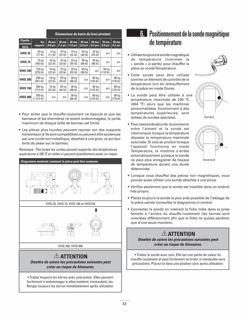
33
• Pour éviter que le chauffe-roulement ne bascule et que les barreaux et les charnières ne soient endommagées, le poids maximum de chaque taille de barreau est limité.
• Les pièces plus lourdes peuvent reposer sur des supports horizontaux (s’ils sont compatibles) ou peuvent être soutenues par une corde non métallique, attachée à une grue, ce qui leur évite de peser sur le barreau.
Remarque : Pas toutes les cordes peuvent supporter des températures supérieures à 100 ºC et celles-ci peuvent possiblement poser un risque
de sécurité lors d’une utilisation répétée.
6. Positionnement de la sonde magnétique de température• Utilisez toujours la sonde magnétique
de température (nommée la « sonde » ci-après) pour chauffer la pièce en mode Température.
• Cette sonde peut être utilisée comme un élément de contrôle de la température lors du réchauffement de la pièce en mode Durée.
• La sonde peut être utilisée à une température maximale de 240 ºC (464 ºF) alors que les machines personnalisées, fonctionnant à des températures supérieures, sont dotées de sondes spéciales.
• Pour raisons de sécurité, la connexion entre l’aimant et la sonde est interrompue lorsque la température dépasse la température maximale autorisée. Si cela se produit lorsque l’appareil fonctionne en mode Température, la machine s’arrête automatiquement puisque la sonde ne peut plus enregistrer de hausse de température durant une durée déterminée.
• Lorsque vous chauffez des pièces non magnétiques, vous pouvez aussi utiliser une sonde attachée à une pince.
• Vérifiez seulement que la sonde est installée dans un endroit très propre.
• Placez toujours la sonde le plus près possible de l’alésage de la pièce usinée (consultez le diagramme ci-contre).
• Connectez la sonde en insérant la fiche mâle dans la prise femelle à l’arrière du chauffe-roulement (les bornes sont orientées différemment afin que la fiche ne puisse pénétrer que d’une seule manière).
Dimensions de barre du bras pivotant
Chauffe-roulement
Série
Sur supports
20 mm(0,8 po)
30 mm(1,2 po)
40 mm(1,6 po)
50 mm(2,0 po)
60 mm(2,4 po)
70 mm(2,8 po)
80 mm(3,2 po)
VHIS 35 35 kg(77 lb)
5 kg(11 lb)
10 kg(22 lb)
15 kg(22 lb)
20 kg(44 lb)
25 kg(55 lb) s/o s/o
VHIS 75 75 kg(165 lb)
10 kg(22 lb)
15 kg(33 lb)
25 kg(55 lb)
40 kg(88 lb)
45 kg(99 lb) s/o s/o
VHIS 100 125 kg(276 lb)
10 kg(22 lb)
15 kg(33 lb)
25 kg(55 lb)
40 kg(88 lb) s/o 50 kg
(110 lb) s/o
VHIS 200 250 kg(551 lb)
10 kg(22 lb)
20 kg(44 lb)
30 kg(66 lb) s/o 60 kg
(132 lb) s/o 80 kg(176 lb)
VHIS 150 350 kg(772 lb)
10 kg(22 lb)
20 kg(44 lb)
30 kg(66 lb) s/o 60 kg
(132 lb) s/o 80 kg(176 lb)
VHIS 400 550 kg(1 213 lb) s/o s/o 30 kg
(66 lb) s/o 60 kg(132 lb) s/o 80 kg
(176 lb)
Diagramme montrant comment la pièce peut être soutenue.
VHIS 35, VHIS 75, VHIS 100 et VHIS150
VHIS 200, VHIS 400
Correct
Incorrect
ATTENTION Omettre de suivre les précautions suivantes peut
créer un risque de blessures.
• Traitez toujours les barres avec précaution. Elles peuvent facilement s'endommager si elles tombent, tressautent, etc. Rangez toujours les barres immédiatement après utilisation.
ATTENTION Omettre de suivre les précautions suivantes peut
créer un risque de blessures.
• Traitez la sonde avec soin. Elle est une partie de valeur du chauffe-roulement et peut facilement se briser si manipulée sans
précautions. Placez-la dans une position sûre après utilisation.
34
7. FonctionnementIl existe deux modes de chauffage :
Utilisation du mode Température
(Mode par défaut lorsque la machine est sous tension)
• Préparez la pièce et la sonde en fonction des instructions des sections 5 et 6.
• Mettez la machine sous tension. L’écran affiche 100 °C (ou 100 °F). À l’aide des touches ‘▲’ ou ‘▼’ saisissez la température à laquelle vous désirez chauffer la pièce (en appuyant sur la touche du mode température ( ) vous pouvez choisir entre des incréments de 1º ou de 10º, que vous travailliez en degrés Celsius ou Fahrenheit).
• Appuyez sur la touche ‘START’. Le cycle de chauffe démarre et fait entendre un faible bourdonnement.
• La température actuelle de la pièce s'affiche à l’écran. Lorsque la température désirée a été atteinte, l’écran clignote et la machine émet un bip sonore. À moins que vous n’appuyiez sur la touche ‘STOP’, la la fonction de conservation de la chaleur maintient le roulement à cette température pendant 5 minutes. La machine recommence à chauffer après une baisse de température de 3° (C ou F). Lorsque la température prévue est à nouveau atteinte, le chauffe- roulement émet un bip sonore. Appuyez sur ‘STOP’ pour arrêter la machine.
• L’opération de chauffage ou la fonction de conservation de chaleur peut être interrompue à n’importe quel moment en appuyant sur la touche ‘STOP’.
Utilisation du mode Durée• Installez la pièce usinée et la sonde de température en
respectant les instructions des sections 5 et 6 (la sonde de température n’est nécessaire que si vous désirez vérifier la température).
• Mettez la machine sous tension et appuyez sur la touche du mode durée ‘ ‘. Appuyez sur les touches ‘▲’ ou ‘▼’ pour régler la durée désirée (en appuyant sur la touche de mode
durée ‘ ‘ vous pouvez choisir entre des incréments de 1 minute ou de 1 seconde).
• Appuyez sur ‘START’. Le cycle de chauffe démarre et fait entendre un faible bourdonnement.
• Si vous appuyez sur la touche () durant le réchauffement, la température actuelle s'affiche pendant trois secondes. Ensuite, le compte à rebours reprend.
• Durant la procédure de chauffage, la durée configurée décroît jusqu’à 00:00 puis le chauffe-roulement par induction s’éteint. La pièce est alors automatiquement démagnétisée et un bip sonore continu retentit. Appuyez sur ‘STOP’ pour arrêter la machine.
Dépose de la pièce usinée• Après avoir appuyé sur ‘STOP’, placez la sonde sur le côté
du montant vertical. Le fait d’appuyer sur ‘STOP’ entraîne la démagnétisation automatique de la pièce.
• En utilisant des gants résistant à la chaleur, empoignez le barreau et le roulement et placez-les sur une surface propre, résistante à la chaleur. Montez immédiatement le roulement, avant qu’il ne refroidisse. Si vous utilisez un modèle doté d’un bras pivotant, faites pivoter le barreau avec le roulement jusqu’à ce qu’il soit en position fixe et ouverte (c.-à-d. à 45°). Faites glisser le roulement et retirez-le du barreau. Installez immédiatement le roulement pour éviter toute perte de chaleur.
Fonctionnement défectueux• Si la température de la pièce usinée n’augmente pas d'1°
(Celsius ou Fahrenheit) sur une durée déterminée, le chauffe-roulement s’arrête automatiquement. Quatre tirets (----) clignotants s'affichent à l’écran et un signal sonore intermittent retentit. Appuyez sur ‘STOP’ pour arrêter le signal sonore et vérifiez que :
• la sonde est toujours attachée à la pièce usinée et elle est branchée correctement dans la prise;
• les fils de la sonde n’ont pas été endommagés;
• la surface de la sonde est propre;
• la capacité du chauffe-roulement n’est pas trop petite pour la pièce usinée.
Si la sonde est défectueuse, le mode Durée peut toujours être utilisé. Vérifiez la température à l’aide d’un thermomètre externe.
• Si vous ressentez une forte vibration, vérifiez tout d’abord que les surfaces de contact des barreaux sont suffisamment graissés. Vérifiez ensuite que le barreau est en contact optimal avec les montants métalliques. (Pour régler les barreaux : Placez le barreau sur le chauffe-roulement et desserrez les boulons d’un quart de tour. Allumez le chauffe-roulement et le barreau s’installera de lui-même. Resserrez les boulons. Vous pouvez aussi utiliser un marteau en nylon pour repositionner les laminés).
Mode Température : Mode Durée :
• Utilisé pour contrôler la chauffe jusqu’à la température désirée.
• Utilisé lorsque vous désirez conserver la pièce à la température désirée pour une période ne dépassant pas 15 minutes.
• Convient à une production par lot. Si la durée à chauffer la pièce à la température désirée est connue.
• Utilisation d’urgence si la sonde de température est perdue ou défectueuse. La température de la pièce doit être vérifiée à l’aide d’un thermomètre externe.
35
8. Nettoyage et entretien• Conservez l’appareil dans un endroit sec, à l’abri du gel et de
l’humilité.
• Nettoyez l’appareil à l’aide d’un chiffon sec et doux.
• Les surfaces de contact des montants métalliques doivent toujours être propres. Graissez-les régulièrement à l’aide d’un lubrifiant sans acide pour obtenir un contact optimal avec les barreaux et empêcher la corrosion (dans le cas de modèles à bras pivotant, graissez aussi régulièrement l’axe vertical).
• Contactez votre fournisseur si vous pensez que l’appareil ne fonctionne pas correctement.
AVERTISSEMENTOmettre de suivre les avertissements suivants peut créer un risque de décès ou de blessures graves.
• En cas de doute, isolez la machine et communiquez avec votre distributeur local. Omettre de suivre les procédures de maintenance et de réparation adéquates peut entraîner une défaillance du matériel, créant un risque de blessure grave.
Le chauffe-roulement par induction peut être utilisé en º C ou º F
Pour changer cela, suivez ces étapes :
• Appuyez sur le bouton température pendant 10 secondes, vous entendrez un court « bip »
• Alors attendez, après un autre 10 secondes, un deuxième « bip » se fera entendre et à l’écran, le mode température
passera de Celsius à Fahrenheit ou vice-versa.
• Le chauffe-roulement est maintenant prêt pour utilisation dans le nouveau mode de température réglé.
AVERTISSEMENTOmettre de suivre les avertissements suivants peut créer un risque de décès ou de blessures graves.
• Il est primordial de respecter les consignes d'entretien et de manipulation. Le non respect des instructions d’installation et le manquement à un graissage correct peut entraînement une
défaillance du matériel, créant un risque de blessure grave.
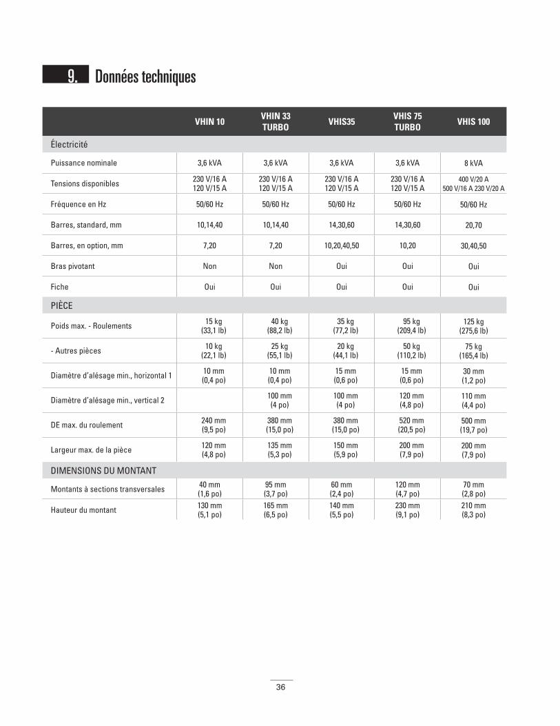
36
VHIN 10 VHIN 33TURBO
VHIS35VHIS 75TURBO
VHIS 100
Électricité
Puissance nominale 3,6 kVA 3,6 kVA 3,6 kVA 3,6 kVA 8 kVA
Tensions disponibles 230 V/16 A120 V/15 A
230 V/16 A120 V/15 A
230 V/16 A120 V/15 A
230 V/16 A120 V/15 A
400 V/20 A500 V/16 A 230 V/20 A
Fréquence en Hz 50/60 Hz 50/60 Hz 50/60 Hz 50/60 Hz 50/60 Hz
Barres, standard, mm 10,14,40 10,14,40 14,30,60 14,30,60 20,70
Barres, en option, mm 7,20 7,20 10,20,40,50 10,20 30,40,50
Bras pivotant Non Non Oui Oui Oui
Fiche Oui Oui Oui Oui Oui
PIÈCE
Poids max. - Roulements 15 kg (33,1 lb)
40 kg (88,2 lb)
35 kg (77,2 lb)
95 kg (209,4 lb)
125 kg (275,6 lb)
- Autres pièces 10 kg (22,1 lb)
25 kg (55,1 lb)
20 kg (44,1 lb)
50 kg (110,2 lb)
75 kg (165,4 lb)
Diamètre d’alésage min., horizontal 1 10 mm (0,4 po)
10 mm (0,4 po)
15 mm (0,6 po)
15 mm (0,6 po)
30 mm (1,2 po)
Diamètre d’alésage min., vertical 2 100 mm (4 po)
100 mm (4 po)
120 mm (4,8 po)
110 mm (4,4 po)
DE max. du roulement 240 mm (9,5 po)
380 mm (15,0 po)
380 mm (15,0 po)
520 mm (20,5 po)
500 mm (19,7 po)
Largeur max. de la pièce 120 mm (4,8 po)
135 mm (5,3 po)
150 mm (5,9 po)
200 mm (7,9 po)
200 mm (7,9 po)
DIMENSIONS DU MONTANT
Montants à sections transversales 40 mm (1,6 po)
95 mm (3,7 po)
60 mm (2,4 po)
120 mm (4,7 po)
70 mm (2,8 po)
Hauteur du montant 130 mm (5,1 po)
165 mm (6,5 po)
140 mm (5,5 po)
230 mm (9,1 po)
210 mm (8,3 po)
9. Données techniques

37
VHIS 150TURBO
VHIS 200VHIS 400TURBO
VHIN 550 VHIN 600TURBO VHIN 800
Électricité
Puissance nominale 8 kVA 12 KVA 12 kVA 24 kVA 24 kVA 40 kVA
Tensions disponibles 400 V/20 A500 V/20 A
400 V/30 A500 V/30 A
400 V/30 A500 V/24 A
400 V/60 A500 V/60 A
400 V/60 A500 V/60 A
400 V/100 A500 V/80 A
Fréquence en Hz 50/60 Hz 50/60 Hz 50/60 Hz 50/60 Hz 50/60 Hz 50/60 Hz
Barres, standard, mm 80 80 80 100barre
coulissante standard
150
Barres, en option, mm 20,30,40,60 20,30,40,60 40,60 40,50,60,80 60,80,100
Bras pivotant Oui Oui Oui Non Non Non
Fiche Oui Oui Oui Oui Oui Oui
PIÈCE
Poids max.- Roulements
350 kg (771,6 lb)
250 kg (551,2 lb)
550 kg (1 212,5 lb)
600 kg (1 322,6 lb)
1 200 kg (2 645,5 lb)
1 250 kg (2 750 lb)
- Autres pièces 250 kg (551,1 lb)
150 kg(330,7 lb)
450 kg (992,1 lb)
350 kg (771,6 lb)
900 kg (1 984,2 lb)
750 kg (1 653,5 lb)
Diamètre d’alésage min., horizontal 1 30 mm (1,2 po)
30 mm (1,2 po)
60 mm (2,4 po) 175 mm
(6,9 po)
Diamètre d’alésage min., vertical 2 160 mm (6,3 po)
130 mm (5,2 po)
175 mm (6,9 po)
60 mm (2,4 po)
200 mm (7,9 po)
85 mm (3,4 po)
DE max. du roulement 790 mm (31,1 po)
720 mm (28,3 po)
920 mm (36,2 po)
900 mm (35,4 po)
1 700 mm (66,9 po)
1 400 mm (55,1 po)
Largeur max. de la pièce 315 mm (12,4 po)
340 mm (13,4 po)
350 mm (13,8 po)
400 mm (15,8 po)
750 mm (29,5 po)
420 mm (16,5 po)
DIMENSIONS DU MONTANT
Montants à sections transversales 160mm (6,3 po)
80 mm (3,2 po)
175 mm (6,9 po)
100 mm (3,9 po)
200 mm (7,9 po)
150 mm (5,9 po)
Hauteur du montant 320 (12,6 po)
340 mm (13,4 po)
305 mm (12 po)
390 mm (15,4 po)
595 mm (23,4 po)
660 mm (26,0 po)
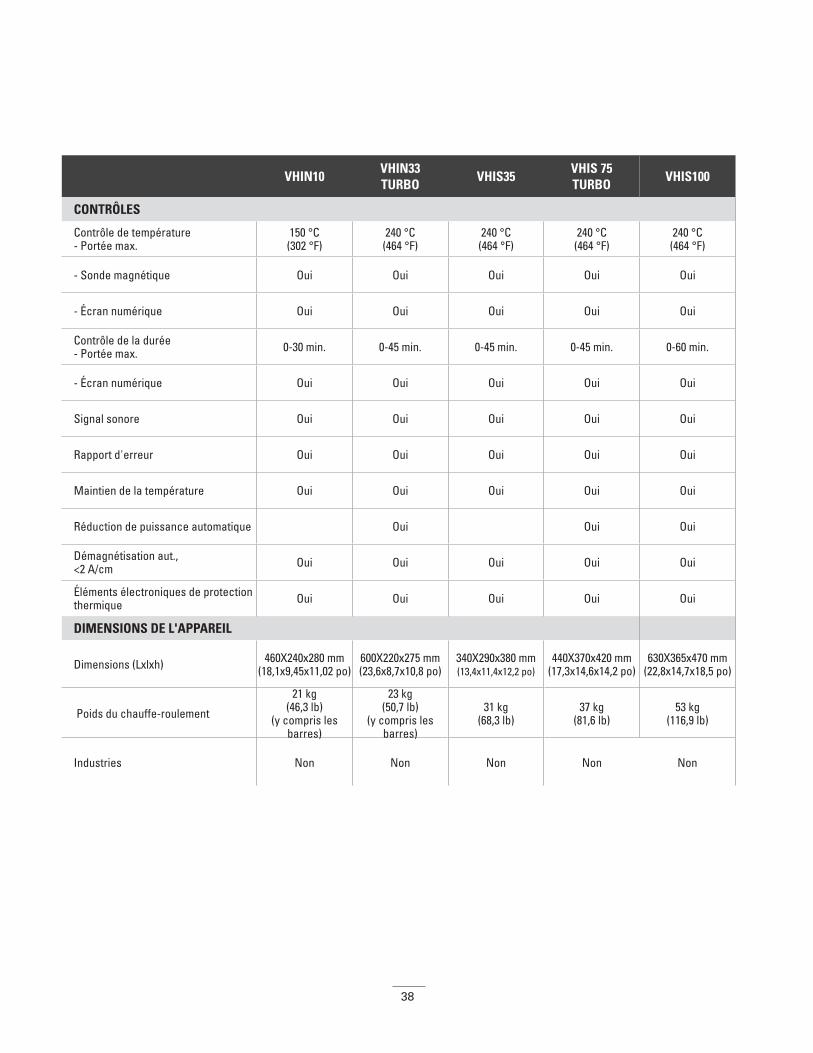
38
VHIN10 VHIN33TURBO
VHIS35VHIS 75TURBO
VHIS100
CONTRÔLES
Contrôle de température- Portée max.
150 °C (302 °F)
240 °C (464 °F)
240 °C (464 °F)
240 °C (464 °F)
240 °C (464 °F)
- Sonde magnétique Oui Oui Oui Oui Oui
- Écran numérique Oui Oui Oui Oui Oui
Contrôle de la durée- Portée max. 0-30 min. 0-45 min. 0-45 min. 0-45 min. 0-60 min.
- Écran numérique Oui Oui Oui Oui Oui
Signal sonore Oui Oui Oui Oui Oui
Rapport d'erreur Oui Oui Oui Oui Oui
Maintien de la température Oui Oui Oui Oui Oui
Réduction de puissance automatique Oui Oui Oui
Démagnétisation aut., <2 A/cm Oui Oui Oui Oui Oui
Éléments électroniques de protection thermique Oui Oui Oui Oui Oui
DIMENSIONS DE L'APPAREIL
Dimensions (Lxlxh) 460X240x280 mm (18,1x9,45x11,02 po)
600X220x275 mm (23,6x8,7x10,8 po)
340X290x380 mm (13,4x11,4x12,2 po)
440X370x420 mm (17,3x14,6x14,2 po)
630X365x470 mm (22,8x14,7x18,5 po)
Poids du chauffe-roulement
21 kg (46,3 lb)
(y compris les barres)
23 kg (50,7 lb)
(y compris les barres)
31 kg (68,3 lb)
37 kg (81,6 lb)
53 kg (116,9 lb)
Industries Non Non Non Non Non
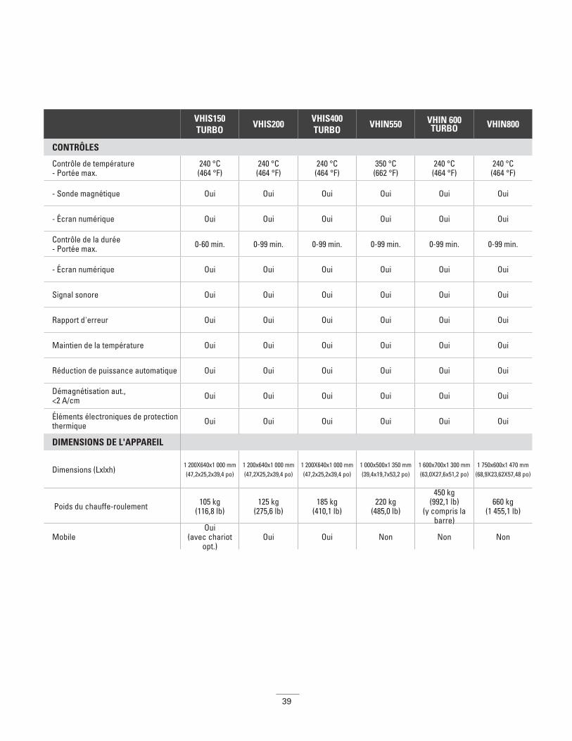
39
VHIS150TURBO
VHIS200VHIS400TURBO
VHIN550 VHIN 600TURBO VHIN800
CONTRÔLES
Contrôle de température- Portée max.
240 °C (464 °F)
240 °C (464 °F)
240 °C (464 °F)
350 °C (662 °F)
240 °C (464 °F)
240 °C (464 °F)
- Sonde magnétique Oui Oui Oui Oui Oui Oui
- Écran numérique Oui Oui Oui Oui Oui Oui
Contrôle de la durée- Portée max. 0-60 min. 0-99 min. 0-99 min. 0-99 min. 0-99 min. 0-99 min.
- Écran numérique Oui Oui Oui Oui Oui Oui
Signal sonore Oui Oui Oui Oui Oui Oui
Rapport d'erreur Oui Oui Oui Oui Oui Oui
Maintien de la température Oui Oui Oui Oui Oui Oui
Réduction de puissance automatique Oui Oui Oui Oui Oui Oui
Démagnétisation aut., <2 A/cm Oui Oui Oui Oui Oui Oui
Éléments électroniques de protection thermique Oui Oui Oui Oui Oui Oui
DIMENSIONS DE L'APPAREIL
Dimensions (Lxlxh)1 200X640x1 000 mm (47,2x25,2x39,4 po)
1 200x640x1 000 mm(47,2X25,2x39,4 po)
1 200X640x1 000 mm (47,2x25,2x39,4 po)
1 000x500x1 350 mm (39,4x19,7x53,2 po)
1 600x700x1 300 mm(63,0X27,6x51,2 po)
1 750x600x1 470 mm (68,9X23,62X57,48 po)
Poids du chauffe-roulement 105 kg (116,8 lb)
125 kg (275,6 lb)
185 kg (410,1 lb)
220 kg (485,0 lb)
450 kg (992,1 lb)
(y compris la barre)
660 kg (1 455,1 lb)
MobileOui
(avec chariot opt.)
Oui Oui Non Non Non
40
Indice
1. Istruzioni di sicurezza . . . . . . . . . . . . . . . . . . . . . . . . . . . . . . . . . . . . . . . . . . . . . . . . . . . . . . . . . . . . . . . . . . . . . . . .41
2. Introduzione . . . . . . . . . . . . . . . . . . . . . . . . . . . . . . . . . . . . . . . . . . . . . . . . . . . . . . . . . . . . . . . . . . . . . . . . . . . . . . .43
3. Installazione . . . . . . . . . . . . . . . . . . . . . . . . . . . . . . . . . . . . . . . . . . . . . . . . . . . . . . . . . . . . . . . . . . . . . . . . . . . . . .44
4. Simboli e display . . . . . . . . . . . . . . . . . . . . . . . . . . . . . . . . . . . . . . . . . . . . . . . . . . . . . . . . . . . . . . . . . . . . . . . . . . .44
5. Preparazione del pezzo da lavorare . . . . . . . . . . . . . . . . . . . . . . . . . . . . . . . . . . . . . . . . . . . . . . . . . . . . . . . . . . . . . .455.1. Preparazione del pezzo da lavorare . . . . . . . . . . . . . . . . . . . . . . . . . . . . . . . . . . . . . . . . . . . . . . . . . . . . . . . . . .455.2. Pesi massimi consentiti per modelli con braccio orientabile . . . . . . . . . . . . . . . . . . . . . . . . . . . . . . . . . . . . . . . .45
6. Posizionamento della sonda magnetica per la temperatura . . . . . . . . . . . . . . . . . . . . . . . . . . . . . . . . . . . . . . . . . . . . .46
7. Funzionamento . . . . . . . . . . . . . . . . . . . . . . . . . . . . . . . . . . . . . . . . . . . . . . . . . . . . . . . . . . . . . . . . . . . . . . . . . . . .47
8. Pulizia e manutenzione . . . . . . . . . . . . . . . . . . . . . . . . . . . . . . . . . . . . . . . . . . . . . . . . . . . . . . . . . . . . . . . . . . . . . . .48
9. Dati tecnici . . . . . . . . . . . . . . . . . . . . . . . . . . . . . . . . . . . . . . . . . . . . . . . . . . . . . . . . . . . . . . . . . . . . . . . . . . . . . . .49
10. Schemi elettrici . . . . . . . . . . . . . . . . . . . . . . . . . . . . . . . . . . . . . . . . . . . . . . . . . . . . . . . . . . . . . . . . . . . . . . . . . . .A1
ITItalian
Italiano
41
1. Istruzioni di sicurezza Precauzioni di sicurezza L’utente è tenuto a conoscere il contenuto di questo manuale e ad avere dimestichezza con le procedure di sicurezza sul luogo di lavoro.
• Attenersi sempre al Manuale per l'utente.
• Controllare che la macchina funzioni alla tensione di rete corretta. Se il riscaldatore è stato fornito senza spina di alimentazione, il collegamento all’impianto di erogazione di energia elettrica deve essere eseguito esclusivamente da una persona adeguatamente qualificata.
• Non utilizzare o conservare il riscaldatore in ambienti umidi. I riscaldatori ad induzione Timken sono progettati solo per uso interno.
• Sui modelli mobili, azionare sempre il freno quando la macchina è ferma.
• Se il riscaldatore è dotato di supporti orizzontali scorrevoli, bloccare sempre tali supporti con l'apposito fermaglio di sicurezza, in posizione “in” o “out”.
• Utilizzare un’attrezzatura per la movimentazione che sia adeguata al peso del pezzo da lavorare o del giogo magnetico.
• Non sostenere mai pezzi con un cavo di metallo o tenere qualcosa di metallico sospeso nei pressi del campo magnetico. Correnti estremamente elevate possono scorrere attraverso il cavo, provocando il riscaldamento dello stesso.
• Non tenere oggetti metallici vicino ai gioghi magnetici e ai poli.
• Durante il riscaldamento, mantenere almeno 1 metro di distanza dal riscaldatore.
• Non rimuovere mai i gioghi magnetici durante il ciclo termico.
• Non apportare modifiche al riscaldatore e non utilizzare gioghi magnetici di produzione propria.
• Verificare sempre che il giogo magnetico sia adattato correttamente ai poli; in caso contrario potrebbe verificarsi un’eccessiva vibrazione.
• Accendere la macchina solo dopo aver posizionato correttamente il giogo magnetico. Sui modelli dotati di braccio orientabile (o giogo magnetico orientabile), il braccio deve sempre essere chiuso.
NOTA:
poiché i nostri prodotti sono soggetti a continui miglioramenti, ci riserviamo il diritto di apportare modifiche.
ATTENZIONEIl mancato rispetto delle avvertenze riportate di seguito potrebbe comportare un rischio di morte o gravi lesioni.
• I riscaldatori ad induzione generano un campo d’induzione magnetica che potrebbe interferire o danneggiare dispositivi
medici come pacemaker o apparecchi acustici, con conseguente rischio elevato di gravi lesioni fisiche. Non mettere
in funzione la macchina o mantenere una distanza minima consigliata di 5 m dalla stessa quando si portano tali dispositivi.
• I pezzi in lavorazione caldi possono provocare ustioni. Utilizzare i guanti protettivi in dotazione durante la manipolazione di tali
pezzi in lavorazione (adatti fino a 150ºC).
• Non mettere in funzione un riscaldatore ad induzione in aree a rischio di esplosioni.
• Un’adeguata manutenzione e un utilizzo corretto sono di fondamentale importanza.
Il mancato rispetto delle istruzioni riportate nel Manuale per l'utente può provocare guasti all’attrezzatura e comportare il
rischio di gravi lesioni fisiche.
• Non usare il riscaldatore ad induzione se il cavo di alimentazione è danneggiato. Il cavo di alimentazione deve
essere sostituito dal produttore, dal suo agente o da una persona con qualifica simile.
ATTENZIONE Il mancato rispetto delle precauzioni riportate di seguito
potrebbe comportare un rischio di lesioni.
• Le apparecchiature elettroniche sensibili (ad esempio, telefoni cellulari, computer, orologi, ecc.) possono subire l’influenza del
campo magnetico e non devono quindi essere utilizzati nellevicinanze del riscaldatore.
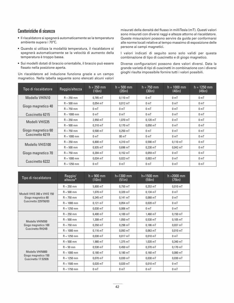
42
Caratteristiche di sicurezza• Il riscaldatore si spegnerà automaticamente se la temperatura
ambiente supera i 70ºC.
• Quando si utilizza la modalità temperatura, il riscaldatore si spegnerà automaticamente se la velocità di aumento della temperatura è troppo bassa.
• Sui modelli dotati di braccio orientabile, il braccio può essere fissato nella posizione aperta.
Un riscaldatore ad induzione funziona grazie a un campo magnetico. Nella tabella seguente sono elencati alcuni valori
misurati della densità del flusso in milliTesla (mT). Questi valori sono misurati con diversi raggi e altezze attorno al riscaldatore. Queste misurazioni possono servire da guida per conformarsi alle norme locali relative al tempo massimo di esposizione delle persone ai campi magnetici.
I valori indicati di seguito sono solo validi per questa combinazione di tipo di cuscinetto e di giogo magnetico.
Diverse configurazioni possono dare valori diversi. Data la grande varietà di tipi di cuscinetti in combinazione con i diversi gioghi risulta impossibile fornire tutti i valori possibili.
Tipo di riscaldatore Raggio/altezza h = 250 mm(10in)
h = 500 mm(20in)
h = 750 mm(30in)
h = 1000 mm(40in)
h = 1250 mm(49in)
Modello VHIN10
Giogo magnetico 40
Cuscinetto 6215
R = 250 mm 0,785 mT 0,110 mT 0 mT 0 mT 0 mT
R = 500 mm 0,054 mT 0,012 mT 0 mT 0 mT 0 mT
R = 750 mm 0 mT 0 mT 0 mT 0 mT 0 mT
R = 1000 mm 0 mT 0 mT 0 mT 0 mT 0 mT
Modelli VHIS35
Giogo magnetico 60 Cuscinetto 6219
R = 250 mm 2,950 mT 1,070 mT 0,120 mT 0 mT 0 mT
R = 500 mm 0,310 mT 0,170 mT 0,050 mT 0 mT 0 mT
R = 750 mm 0,500 mT 0,250 mT 0 mT 0 mT 0 mT
R = 1000 mm 0 mT 00 mT 0 mT 0 mT 0 mT
Modello VHIS100
Giogo magnetico 70
Cuscinetto 6222
R = 250 mm 6,800 mT 4,310 mT 0,590 mT 0,110 mT 0 mT
R = 500 mm 0,935 mT 0,696 mT 0,230 mT 0,042 mT 0 mT
R = 750 mm 0,204 mT 0,152 mT 0,059 mT 0 mT 0 mT
R = 1000 mm 0,034 mT 0,023 mT 0,003 mT 0 mT 0 mT
R = 1250 mm 0 mT 0 mT 0 mT 0 mT 0 mT
Tipo di riscaldatore Raggio/altezza*
h = 900 mm (10in)
h=1300 mm (51in)
h=1500 mm (59in)
h =2000 mm (79in)
Modelli VHIS 200 e VHIS 150 Giogo magnetico 80Cuscinetto 229750/03
R = 250 mm 5,800 mT 0,750 mT 0,253 mT 0,010 mT
R = 500 mm 1,070 mT 0,320 mT 0,134 mT 0 mT
R = 750 mm 0,345 mT 0,141 mT 0,068 mT 0 mT
R = 1000 mm 0,121 mT 0,054 mT 0,020 mT 0 mT
R = 1250 mm 0,030 mT 0,006 mT 0 mT 0 mT
Modello VHIN550Giogo magnetico 100
Cuscinetto RH24B
R = 250 mm 6,400 mT 4,100 mT 1,460 mT 0,150 mT
R = 500 mm 1,308 mT 1,050 mT 0,530 mT 0,105 mT
R = 750 mm 0,350 mT 0,298 mT 0,186 mT 0,037 mT
R = 1000 mm 0,116 mT 0,093 mT 0,063 mT 0,010 mT
R = 1250 mm 0,030 mT 0,017 mT 0,010 mT 0 mT
Modello VHIN800Giogo magnetico 150Cuscinetto 17.52926
R = 500 mm 1,980 mT 1,375 mT 1,020 mT 0,340 mT
R = 50 mm 0,530 mT 0,450 mT 0,370 mT 0,170 mT
R = 1000 mm 0,180 mT 0,180 mT 0,160 mT 0,080 mT
R = 1250 mm 0,070 mT 0,030 mT 0,030 mT 0,030 mT
R = 1500 mm 0,020 mT 0,020 mT 0,010 mT 0 mT
R = 1750 mm 0 mT 0 mT 0 mT 0 mT

43
Le altezze sono misurate dal fondo del riscaldatore. Per stabilire dove si trova esattamente il campo rispetto al suolo, è necessario aggiungere ai valori elencati nella tabella la distanza dal fondo del riscaldatore al suolo. (ad esempio, altezza di un banco da lavoro).
2. Introduzione
ApplicazioneI riscaldatori ad induzione Timken sono progettati per riscaldare cuscinetti, bronzine, ruote dentate, accoppiamenti o altri pezzi metallici da lavorare che formano un circuito elettrico chiuso. In questo modo si facilita il montaggio dove si richiede un accoppiamento con interferenza.
I riscaldatori sono progettati per riscaldare il pezzo da lavorare fino alla temperatura massima di 240ºC, ad eccezione dei modelli della serie VHIN10 in cui la temperatura è limitata ad un massimo di 150ºC, e di determinati riscaldatori speciali progettati su misura dove la temperatura massima può raggiungere i 480ºC.
I riscaldatori ad induzione Timken possono essere utilizzati su basi continue. Esiste comunque una limitazione: non utilizzare il riscaldatore ad una temperatura di 240°C o superiore per oltre mezz’ora. Se si riscalda con la funzione tempo è necessario verificare tale valore con un misuratore della temperatura esterno.
Condizioni operativeProgettato per essere utilizzato in ambito industriale con una temperatura ambiente compresa tra 0ºC e 50ºC e un’umidità atmosferica tra il 5% e il 90%. Il riscaldatore ad induzione è destinato esclusivamente all’uso interno.
Principio di funzionamentoIl riscaldatore funziona allo stesso modo di un trasformatore. La bobina primaria è il riscaldatore e la bobina secondaria è il pezzo da lavorare.
Quando si accende il riscaldatore, una bassa corrente alternata ad alta tensione passa attraverso i numerosi avvolgimenti della bobina primaria. Tutto ciò induce un’alta corrente a bassa tensione nel pezzo in lavorazione, che funge da bobina secondaria, e questa alta corrente comporta il riscaldamento del pezzo in lavorazione.
La corrente scorre solo nel pezzo in lavorazione, provocando un inizio di riscaldamento esclusivamente in tale pezzo. Quest’ultimo viene smagnetizzato automaticamente al termine di ciascun ciclo termico.
ATTENZIONEIl mancato rispetto delle avvertenze riportate di seguito potrebbe comportare un rischio di morte o gravi lesioni.
• Si consiglia di mantenere una distanza di sicurezza di almeno 1 metro per le persone che lavorano nei pressi del macchinario.
ATTENZIONE Il mancato rispetto delle precauzioni riportate di seguito
potrebbe comportare un rischio di lesioni.
• Il macchinario produce un campo di induzione che può interferire con le apparecchiature
elettroniche come orologi, mappe magnetiche, ecc.
ATTENZIONE Il mancato rispetto delle precauzioni riportate di seguito
potrebbe comportare un rischio di lesioni.
In genere i cuscinetti devono essere riscaldati solo fino alla temperatura massima di 120ºC.
• I cuscinetti di precisione devono essere riscaldati solo fino alla temperatura massima di 70°C. Se si riscalda a temperature più elevate c’è il rischio di intaccare la struttura metallurgica e la stabilità dimensionale con conseguente guasto prematuro o
perdita delle prestazioni del cuscinetto.
• Non utilizzare i riscaldatori ad induzione per quei cuscinetti o pezzi da lavorare con dimensioni inferiori o superiori a quanto
specificato nei dati tecnici (Appendice 1).
• Non spegnere il riscaldatore dall’interruttore principale nel corso del ciclo termico.

44
3. Installazione • Rimuovere il materiale d’imballaggio e posizionare il
riscaldatore ad induzione su una superficie piana, stabile e non ferrosa. In genere la scatola contiene il riscaldatore, un giogo o un set di gioghi magnetici, la sonda per la temperatura, un paio di guanti termoresistenti e una piccola confezione di lubrificante.
• Verificare che la corrente e la tensione di rete soddisfino le specifiche riportate sulla targhetta identificativa presente sul retro della macchina.
• Poiché esistono diversi tipi di spine, non tutti i riscaldatori ad induzione Timken vengono forniti con la spina. Nel caso in cui il riscaldatore sia sprovvisto di spina, è necessario farne applicare una adeguata da un elettricista qualificato.
• I fili elettrici dovranno essere collegati come indicato di seguito. Esistono 3 opzioni a seconda del tipo di cavo con cui viene fornito il riscaldatore:
• Assicurarsi che il cavo di alimentazione non venga a contatto con il cuscinetto da riscaldare. Inserire la spina in una presa a muro antishock.
• Utilizzare l’interruttore principale per attivare la corrente. La macchina emette un breve segnale acustico e il display visualizza la “temperatura da raggiungere programmata” impostata dal produttore.
• Collegare la sonda per la temperatura inserendo la spina nella presa. Assicurarsi che – e + corrispondano sia sulla spina che sulla presa.
• Il riscaldatore ad induzione è pronto per essere utilizzato in modalità temperatura.
4.
4. Simboli e display
230V/110V
Marrone Fase Nero Fase Nero “1” Neutro
Blu Neutro Bianco Neutro Nero “2” Fase
Verde/giallo
Terra Verde Terra Verde/giallo
Terra
400, 450, 500V
Marrone Fase Marrone Fase Nero “1” Fase
Blu Fase Nero Fase Nero “2” Fase
Verde/giallo
Terra Verde/giallo
Terra Verde/giallo
Terra
Simboli rappresentati sul riscaldatore:
Vietato ai soggetti portatori di pacemaker. Il campo magnetico potrebbe causare interferenze.
Utilizzare guanti termoresistenti.
Non sono consentiti orologi o altri oggetti in metallo. Il campo magnetico potrebbe causare interferenze.
Leggere le istruzioni.
Display:
- Display: tempo o temperatura
Aumento tempo/temperatura -
- Riduzione tempo/ temperatura
Utilizzare la Modalità tempo -
- Utilizzare la Modalità temperatura
Avvio funzionamento -
- Interruzione funzionamento/smagnetizzazione automatica
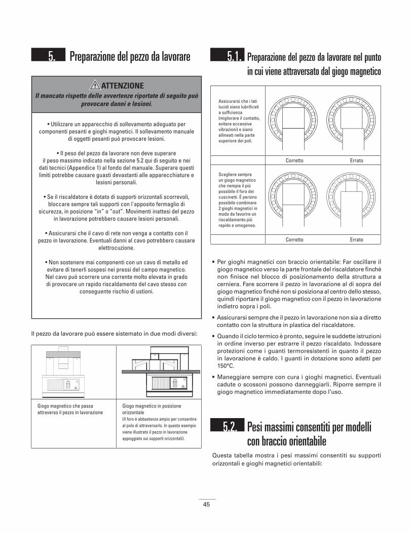
45
5. Preparazione del pezzo da lavorare
Il pezzo da lavorare può essere sistemato in due modi diversi:
5,1. Preparazione del pezzo da lavorare nel punto in cui viene attraversato dal giogo magnetico
• Per gioghi magnetici con braccio orientabile: Far oscillare il giogo magnetico verso la parte frontale del riscaldatore finché non finisce nel blocco di posizionamento della struttura a cerniera. Fare scorrere il pezzo in lavorazione al di sopra del giogo magnetico finché non si posiziona al centro dello stesso, quindi riportare il giogo magnetico con il pezzo in lavorazione indietro sopra i poli.
• Assicurarsi sempre che il pezzo in lavorazione non sia a diretto contatto con la struttura in plastica del riscaldatore.
• Quando il ciclo termico è pronto, seguire le suddette istruzioni in ordine inverso per estrarre il pezzo riscaldato. Indossare protezioni come i guanti termoresistenti in quanto il pezzo in lavorazione è caldo. I guanti in dotazione sono adatti per 150°C.
• Maneggiare sempre con cura i gioghi magnetici. Eventuali cadute o scossoni possono danneggiarli. Riporre sempre il giogo magnetico immediatamente dopo l’uso.
5.2. Pesi massimi consentiti per modelli con braccio orientabile
Questa tabella mostra i pesi massimi consentiti su supporti orizzontali e gioghi magnetici orientabili:
Giogo magnetico che passa attraverso il pezzo in lavorazione
Giogo magnetico in posizione orizzontale(Il foro è abbastanza ampio per consentire al polo di attraversarlo. In questo esempio viene illustrato il pezzo in lavorazione appoggiato sui supporti orizzontali).
ATTENZIONEIl mancato rispetto delle avvertenze riportate di seguito può
provocare danni e lesioni.
• Utilizzare un apparecchio di sollevamento adeguato per componenti pesanti e gioghi magnetici. Il sollevamento manuale
di oggetti pesanti può provocare lesioni.
• Il peso del pezzo da lavorare non deve superareil peso massimo indicato nella sezione 5.2 qui di seguito e nei
dati tecnici (Appendice 1) al fondo del manuale. Superare questi limiti potrebbe causare guasti devastanti alle apparecchiature e
lesioni personali.
• Se il riscaldatore è dotato di supporti orizzontali scorrevoli, bloccare sempre tali supporti con l'apposito fermaglio di
sicurezza, in posizione “in” o “out”. Movimenti inattesi del pezzo in lavorazione potrebbero causare lesioni personali.
• Assicurarsi che il cavo di rete non venga a contatto con il pezzo in lavorazione. Eventuali danni al cavo potrebbero causare
elettrocuzione.
• Non sostenere mai componenti con un cavo di metallo ed evitare di tenerli sospesi nei pressi del campo magnetico.
Nel cavo può scorrere una corrente molto elevata in grado di provocare un rapido riscaldamento del cavo stesso con
conseguente rischio di ustioni.
Assicurarsi che i lati lucidi siano lubrificati a sufficienza (migliorare il contatto, evitare eccessive vibrazioni) e siano allineati nella parte superiore dei poli.
Corretto Errato
Scegliere sempre un giogo magnetico che riempia il più possibile il foro dei cuscinetti. È persino possibile combinare 2 gioghi magnetici in modo da favorire un riscaldamento più rapido e omogeneo.
Corretto Errato
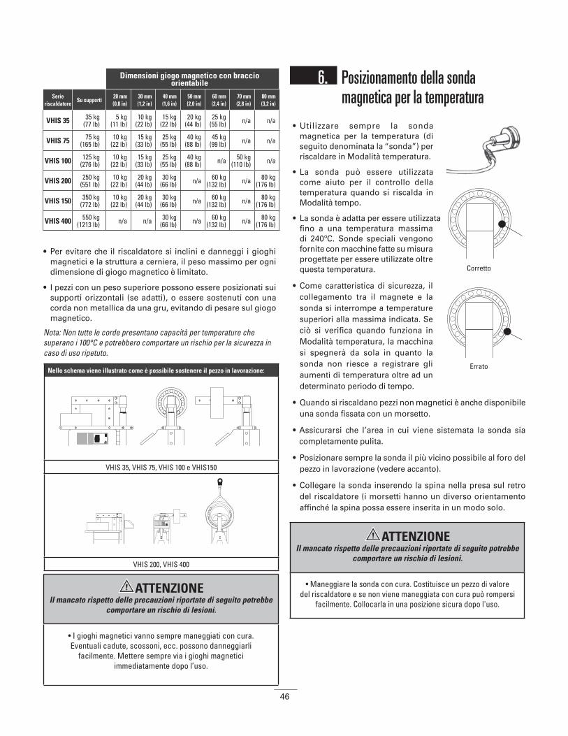
46
• Per evitare che il riscaldatore si inclini e danneggi i gioghi magnetici e la struttura a cerniera, il peso massimo per ogni dimensione di giogo magnetico è limitato.
• I pezzi con un peso superiore possono essere posizionati sui supporti orizzontali (se adatti), o essere sostenuti con una corda non metallica da una gru, evitando di pesare sul giogo magnetico.
Nota: Non tutte le corde presentano capacità per temperature che superano i 100°C e potrebbero comportare un rischio per la sicurezza in caso di uso ripetuto.
6. Posizionamento della sonda magnetica per la temperatura
• Utilizzare sempre la sonda magnetica per la temperatura (di seguito denominata la “sonda”) per riscaldare in Modalità temperatura.
• La sonda può essere utilizzata come aiuto per il controllo della temperatura quando si riscalda in Modalità tempo.
• La sonda è adatta per essere utilizzata fino a una temperatura massima di 240ºC. Sonde speciali vengono fornite con macchine fatte su misura progettate per essere utilizzate oltre questa temperatura.
• Come caratteristica di sicurezza, il collegamento tra il magnete e la sonda si interrompe a temperature superiori alla massima indicata. Se ciò si verifica quando funziona in Modalità temperatura, la macchina si spegnerà da sola in quanto la sonda non riesce a registrare gli aumenti di temperatura oltre ad un determinato periodo di tempo.
• Quando si riscaldano pezzi non magnetici è anche disponibile una sonda fissata con un morsetto.
• Assicurarsi che l’area in cui viene sistemata la sonda sia completamente pulita.
• Posizionare sempre la sonda il più vicino possibile al foro del pezzo in lavorazione (vedere accanto).
• Collegare la sonda inserendo la spina nella presa sul retro del riscaldatore (i morsetti hanno un diverso orientamento affinché la spina possa essere inserita in un modo solo.
Dimensioni giogo magnetico con braccio orientabile
Serie riscaldatore
Su supporti20 mm(0,8 in)
30 mm(1,2 in)
40 mm(1,6 in)
50 mm(2,0 in)
60 mm(2,4 in)
70 mm(2,8 in)
80 mm(3,2 in)
VHIS 35 35 kg(77 lb)
5 kg(11 lb)
10 kg(22 lb)
15 kg(22 lb)
20 kg(44 lb)
25 kg(55 lb) n/a n/a
VHIS 75 75 kg(165 lb)
10 kg(22 lb)
15 kg(33 lb)
25 kg(55 lb)
40 kg(88 lb)
45 kg(99 lb) n/a n/a
VHIS 100 125 kg(276 lb)
10 kg(22 lb)
15 kg(33 lb)
25 kg(55 lb)
40 kg(88 lb) n/a 50 kg
(110 lb) n/a
VHIS 200 250 kg(551 lb)
10 kg(22 lb)
20 kg(44 lb)
30 kg(66 lb) n/a 60 kg
(132 lb) n/a 80 kg(176 lb)
VHIS 150 350 kg(772 lb)
10 kg(22 lb)
20 kg(44 lb)
30 kg(66 lb) n/a 60 kg
(132 lb) n/a 80 kg(176 lb)
VHIS 400 550 kg(1213 lb) n/a n/a 30 kg
(66 lb) n/a 60 kg(132 lb) n/a 80 kg
(176 lb)
Nello schema viene illustrato come è possibile sostenere il pezzo in lavorazione:
VHIS 35, VHIS 75, VHIS 100 e VHIS150
VHIS 200, VHIS 400
Corretto
Errato
ATTENZIONE Il mancato rispetto delle precauzioni riportate di seguito potrebbe
comportare un rischio di lesioni.
• I gioghi magnetici vanno sempre maneggiati con cura. Eventuali cadute, scossoni, ecc. possono danneggiarli
facilmente. Mettere sempre via i gioghi magnetici immediatamente dopo l’uso.
ATTENZIONE Il mancato rispetto delle precauzioni riportate di seguito potrebbe
comportare un rischio di lesioni.
• Maneggiare la sonda con cura. Costituisce un pezzo di valore del riscaldatore e se non viene maneggiata con cura può rompersi
facilmente. Collocarla in una posizione sicura dopo l'uso.

47
7. FunzionamentoEsistono due modalità di riscaldamento:
Utilizzo della Modalità temperatura
(modalità predefinita ad ogni accensione della macchina)
• Preparare il pezzo da lavorare e la sonda in base alle istruzioni riportate alle sezioni 5 e 6.
• Accendere la macchina. Il display visualizza 100º C. Immettere la temperatura desiderata alla quale verrà riscaldato il pezzo in lavorazione servendosi del tasto ‘▲’ o ‘▼’ (premendo il tasto della modalità temperatura ( ), è possibile scegliere tra passaggi di 1º o 10º; è la stessa cosa sia che si lavori in C che in F).
• Premere il tasto ‘START’ . Il riscaldamento ha inizio e si sentirà un leggero ronzio.
• L’attuale temperatura del pezzo in lavorazione viene visualizzata sul display. Quando si raggiunge la temperatura desiderata, il display inizia a lampeggiare e viene emesso un forte segnale acustico. A meno che non si prema il tasto ‘STOP’, la funzionedi ritenzione del calore mantiene il cuscinetto a quella determinata temperatura per 5 minuti. La macchina riprende il riscaldamento dopo un calo della temperatura di 3º (C o F). Quando viene raggiunta la temperatura impostata, il riscaldatore ad induzione emette ancora un forte segnale acustico. Premere il tasto ‘STOP’ per spegnere la macchina.
• Il processo di riscaldamento o la funzione di ritenzione del calore possono essere interrotti in qualsiasi momento premendo il tasto ‘STOP’ .
Utilizzo della Modalità tempo• Preparare il pezzo da lavorare e la sonda per la temperatura in
base alle istruzioni riportate nelle sezioni 5 e 6 (la sonda per la temperatura è necessaria solo se si desidera verificare la temperatura).
• Accendere la macchina e premere il tasto della modalità tempo ‘ ‘. Premere il tasto ‘▲’ o ‘▼’ per impostare il tempo desiderato (premendo il tasto della modalità tempo ‘’, è possibile scegliere tra passaggi di un minuto o di un secondo).
• Premere il tasto ‘START’ key. Il riscaldamento ha inizio e si sentirà un leggero ronzio.
• Se il tasto della temperatura () viene premuto in corso di riscaldamento, la temperatura in corso viene visualizzata per 3 secondi. Successivamente si riprende il conteggio alla rovescia.
• Durante il processo di riscaldamento, il tempo impostato arriva fino a 00:00. Una volta raggiunto 00:00, il riscaldatore ad induzione si spegne. Il pezzo in lavorazione viene poi smagnetizzato automaticamente e la macchina emette un forte segnale acustico continuo. Premere il tasto ‘STOP’ per spegnere la macchina.
Rimozione del pezzo in lavorazione• Dopo aver premuto il tasto ‘STOP’, sistemare la sonda sul
lato del polo verticale. Premendo il tasto ‘STOP’, il pezzo in lavorazione verrà sempre smagnetizzato automaticamente.
• Indossare guanti termoresistenti, quindi afferrare il giogo magnetico con il cuscinetto su di esso e sistemarlo su una superficie pulita e resistente al calore. Montare immediatamente il cuscinetto per evitare che si raffreddi. Se si utilizza un modello con braccio orientabile, orientare il giogo magnetico con il cuscinetto nella posizione aperta fissata (a 45º). Fare scivolare via il cuscinetto dal giogo magnetico. Montare immediatamente il cuscinetto per evitare perdite di calore.
Malfunzionamento• Se la temperatura del pezzo non aumenta di 1º (C o F)
entro un determinato periodo di tempo, il riscaldatore si spegne automaticamente. Sul display compaiono quattro trattini lampeggianti (----) e la macchina emette un forte segnale acustico intermittente. Premere il tasto ‘STOP’ per interrompere il segnale acustico e verificare se:
• la sonda è ancora fissata al pezzo in lavorazione e se è collegata correttamente alla presa.
• i fili elettrici della sonda sono stati danneggiati.
• la superficie della sonda è pulita.
• la capacità del riscaldatore è troppo piccola per il pezzo in lavorazione.
Se la sonda è difettosa, è ancora possibile utilizzare la Modalità tempo. La temperatura deve essere verificata con un termometro esterno.
• Se si sente un forte rumore di vibrazione, per prima cosa verificare che le superfici di contatto dei gioghi magnetici siano lubrificate a sufficienza. Verificare poi che il giogo magnetico abbia un contatto ottimale con i poli. (Per regolare i gioghi magnetici: Posizionare il giogo magnetico sul riscaldatore, allentare i bulloni del giogo di un quarto di giro. Accendere il riscaldatore e il giogo magnetico si sistemerà da solo. Riavvitare a fondo i bulloni. È anche possibile utilizzare un martello di nylon per risistemare i laminati).
Modalità temperatura: Modalità tempo:
• Utilizzata per il riscaldamento controllato fino alla temperatura desiderata.
• Utilizzata quando si desidera mantenere il pezzo in lavorazione alla temperatura desiderata fino a 15 minuti.
• Adatta per produzioni a lotti. Se il tempo necessario per riscaldare il pezzo in lavorazione alla temperatura desiderata è noto.
• Utilizzo di emergenza se la sonda per la temperatura viene persa o è difettosa. La temperatura del pezzo in lavorazione deve essere verificata con un termometro esterno.
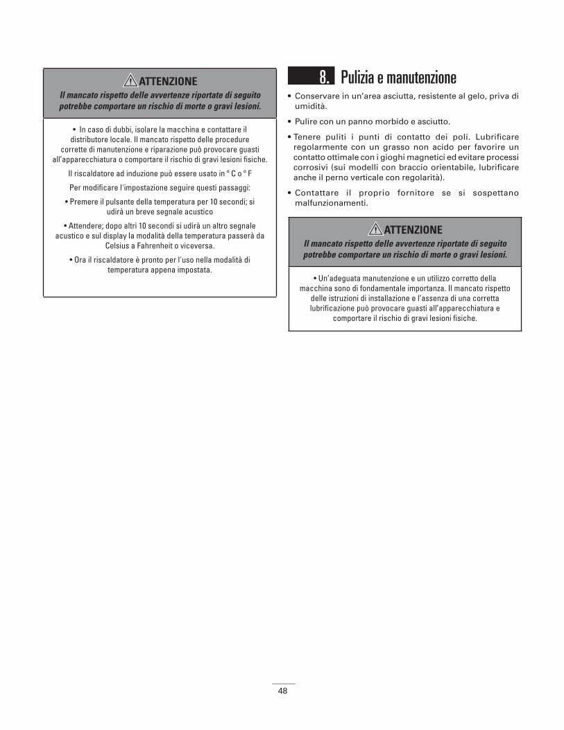
48
8. Pulizia e manutenzione• Conservare in un’area asciutta, resistente al gelo, priva di
umidità.
• Pulire con un panno morbido e asciutto.
• Tenere puliti i punti di contatto dei poli. Lubrificare regolarmente con un grasso non acido per favorire un contatto ottimale con i gioghi magnetici ed evitare processi corrosivi (sui modelli con braccio orientabile, lubrificare anche il perno verticale con regolarità).
• Contattare il proprio fornitore se si sospettano malfunzionamenti.
ATTENZIONEIl mancato rispetto delle avvertenze riportate di seguito potrebbe comportare un rischio di morte o gravi lesioni.
• In caso di dubbi, isolare la macchina e contattare il distributore locale. Il mancato rispetto delle procedure
corrette di manutenzione e riparazione può provocare guasti all’apparecchiatura o comportare il rischio di gravi lesioni fisiche.
Il riscaldatore ad induzione può essere usato in º C o º F
Per modificare l'impostazione seguire questi passaggi:
• Premere il pulsante della temperatura per 10 secondi; si udirà un breve segnale acustico
• Attendere; dopo altri 10 secondi si udirà un altro segnale acustico e sul display la modalità della temperatura passerà da
Celsius a Fahrenheit o viceversa.
• Ora il riscaldatore è pronto per l'uso nella modalità di temperatura appena impostata.
ATTENZIONEIl mancato rispetto delle avvertenze riportate di seguito potrebbe comportare un rischio di morte o gravi lesioni.
• Un’adeguata manutenzione e un utilizzo corretto della macchina sono di fondamentale importanza. Il mancato rispetto
delle istruzioni di installazione e l’assenza di una corretta lubrificazione può provocare guasti all’apparecchiatura e
comportare il rischio di gravi lesioni fisiche.
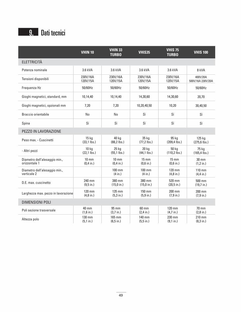
49
VHIN 10 VHIN 33TURBO
VHIS35VHIS 75TURBO
VHIS 100
ELETTRICITÀ
Potenza nominale 3.6 kVA 3.6 kVA 3.6 kVA 3.6 kVA 8 kVA
Tensioni disponibili 230V/16A120V/15A
230V/16A120V/15A
230V/16A120V/15A
230V/16A120V/15A
400V/20A500V/16A 230V/20A
Frequenza Hz 50/60Hz 50/60Hz 50/60Hz 50/60Hz 50/60Hz
Gioghi magnetici, standard, mm 10,14,40 10,14,40 14,30,60 14,30,60 20,70
Gioghi magnetici, opzionali mm 7,20 7,20 10,20,40,50 10,20 30,40,50
Braccio orientabile No No Sì Sì Sì
Spina Sì Sì Sì Sì Sì
PEZZO IN LAVORAZIONE
Peso max. - Cuscinetti 15 kg (33,1 lbs.)
40 kg (88,2 lbs.)
35 kg (77,2 lbs.)
95 kg (209,4 lbs.)
125 kg (275,6 lbs.)
- Altri pezzi 10 kg (22,1 lbs.)
25 kg (55,1 lbs.)
20 kg (44,1 lbs.)
50 kg (110,2 lbs.)
75 kg (165,4 lbs.)
Diametro dell’alesaggio min., orizzontale 1
10 mm (0,4 in.)
10 mm (0,4 in.)
15 mm (0,6 in.)
15 mm (0,6 in.)
30 mm (1,2 in.)
Diametro dell’alesaggio min., verticale 2
100 mm (4 in.)
100 mm (4 in.)
120 mm (4,8 in.)
110 mm (4,4 in.)
D.E. max. cuscinetto 240 mm (9,5 in.)
380 mm (15,0 in.)
380 mm (15,0 in.)
520 mm (20,5 in.)
500 mm (19,7 in.)
Larghezza max. pezzo in lavorazione 120 mm (4,8 in.)
135 mm (5,3 in.)
150 mm (5,9 in.)
200 mm (7,9 in.)
200 mm (7,9 in.)
DIMENSIONI POLI
Poli sezione trasversale 40 mm (1,6 in.)
95 mm (3,7 in.)
60 mm (2,4 in.)
120 mm (4,7 in.)
70 mm (2,8 in.)
Altezza polo 130 mm (5,1 in.)
165 mm (6,5 in.)
140 mm (5,5 in.)
230 mm (9,1 in.)
210 mm (8,3 in.)
9. Dati tecnici
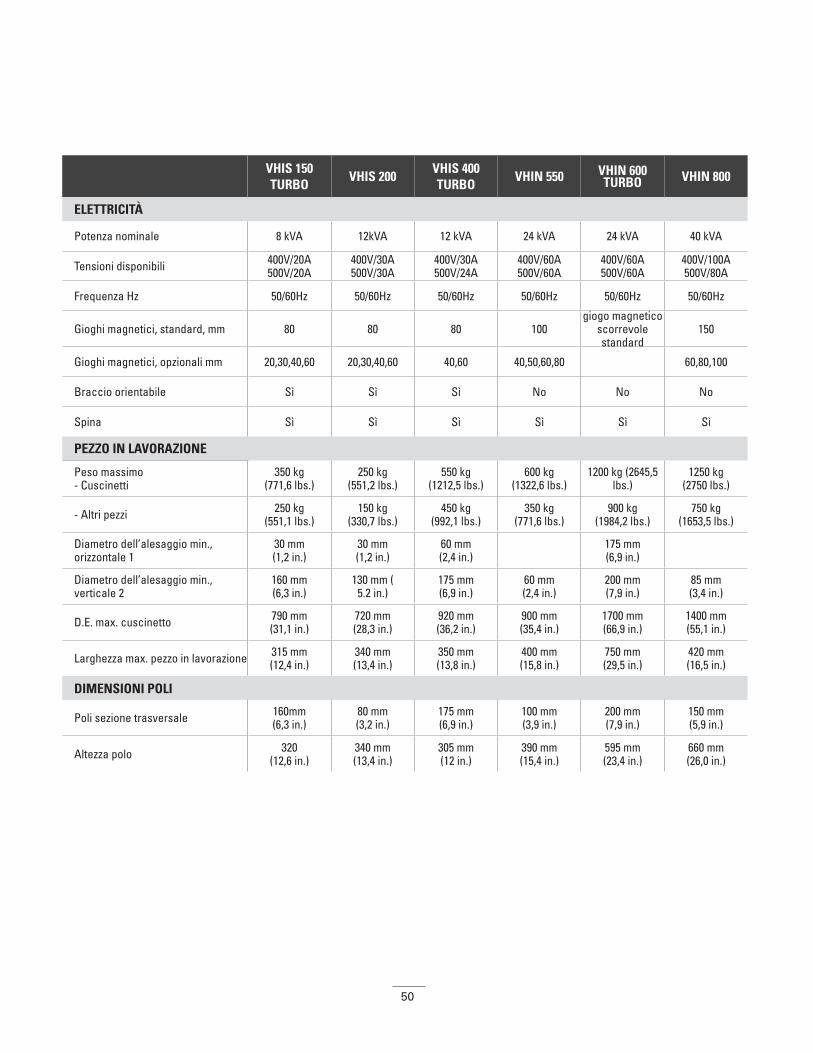
50
VHIS 150TURBO
VHIS 200VHIS 400TURBO
VHIN 550 VHIN 600TURBO VHIN 800
ELETTRICITÀ
Potenza nominale 8 kVA 12kVA 12 kVA 24 kVA 24 kVA 40 kVA
Tensioni disponibili 400V/20A500V/20A
400V/30A500V/30A
400V/30A500V/24A
400V/60A500V/60A
400V/60A500V/60A
400V/100A500V/80A
Frequenza Hz 50/60Hz 50/60Hz 50/60Hz 50/60Hz 50/60Hz 50/60Hz
Gioghi magnetici, standard, mm 80 80 80 100giogo magnetico
scorrevole standard
150
Gioghi magnetici, opzionali mm 20,30,40,60 20,30,40,60 40,60 40,50,60,80 60,80,100
Braccio orientabile Sì Sì Sì No No No
Spina Sì Sì Sì Sì Sì Sì
PEZZO IN LAVORAZIONE
Peso massimo- Cuscinetti
350 kg (771,6 lbs.)
250 kg (551,2 lbs.)
550 kg (1212,5 lbs.)
600 kg (1322,6 lbs.)
1200 kg (2645,5 lbs.)
1250 kg (2750 lbs.)
- Altri pezzi 250 kg (551,1 lbs.)
150 kg(330,7 lbs.)
450 kg (992,1 lbs.)
350 kg (771,6 lbs.)
900 kg (1984,2 lbs.)
750 kg (1653,5 lbs.)
Diametro dell’alesaggio min., orizzontale 1
30 mm (1,2 in.)
30 mm (1,2 in.)
60 mm (2,4 in.) 175 mm
(6,9 in.)
Diametro dell’alesaggio min., verticale 2
160 mm (6,3 in.)
130 mm (5.2 in.)
175 mm (6,9 in.)
60 mm (2,4 in.)
200 mm (7,9 in.)
85 mm (3,4 in.)
D.E. max. cuscinetto 790 mm (31,1 in.)
720 mm (28,3 in.)
920 mm (36,2 in.)
900 mm (35,4 in.)
1700 mm (66,9 in.)
1400 mm (55,1 in.)
Larghezza max. pezzo in lavorazione 315 mm (12,4 in.)
340 mm (13,4 in.)
350 mm (13,8 in.)
400 mm (15,8 in.)
750 mm (29,5 in.)
420 mm (16,5 in.)
DIMENSIONI POLI
Poli sezione trasversale 160mm (6,3 in.)
80 mm (3,2 in.)
175 mm (6,9 in.)
100 mm (3,9 in.)
200 mm (7,9 in.)
150 mm (5,9 in.)
Altezza polo 320 (12,6 in.)
340 mm (13,4 in.)
305 mm (12 in.)
390 mm (15,4 in.)
595 mm (23,4 in.)
660 mm (26,0 in.)

51
VHIN10 VHIN33TURBO
VHIS35VHIS 75TURBO
VHIS100
CONTROLLI
Regolazione temperatura- Portata max.
150° C (302° F)
240° C (464° F)
240° C (464° F)
240° C (464° F)
240° C (464° F)
- Sonda magnetica Sì Sì Sì Sì Sì
- Display digitale Sì Sì Sì Sì Sì
Regolazione tempo- Portata max. 0-30 min. 0-45 min. 0-45 min. 0-45 min. 0-60 min.
- Display digitale Sì Sì Sì Sì Sì
Segnale sonoro Sì Sì Sì Sì Sì
Report errore Sì Sì Sì Sì Sì
Blocco temperatura Sì Sì Sì Sì Sì
Riduzione di potenza automatica Sì Sì Sì
Smagnetizzazione automatica, <2A/cm Sì Sì Sì Sì Sì
Elettronica per protezione sicurezza termica Sì Sì Sì Sì Sì
DIMENSIONI DELL'UNITÀ
Dimensioni (lun x larg x h) 460x240x280 mm 18,1x9,45x11,02 in.
600x220x275 mm 23,6x8,7x10,8 in.
340x290x380 mm 13,4 in.x11,4 in.x12,2 in.
440x370x420 mm 17,3x14,6x14,2 in.
630x365x470 mm 22,8x14,7,18,5 in.
Peso riscaldatore
21 kg (46,3 lbs.)
(incl. gioghi magnetici)
23 kg (50,7 lbs.)
(incl. gioghi magnetici)
31 kg (68,3 lbs.)
37 kg (81,6 lbs.)
53 kg (116,9 lbs.)
Settori No No No No No

52
VHIS150TURBO
VHIS200VHIS400TURBO
VHIN550 VHIN 600TURBO VHIN800
CONTROLLI
Regolazione temperatura- Portata max.
240° C (464° F)
240° C (464° F)
240° C (464° F)
350° C (662° F)
240° C (464° F)
240° C (464° F)
- Sonda magnetica Sì Sì Sì Sì Sì Sì
- Display digitale Sì Sì Sì Sì Sì Sì
Regolazione tempo- Portata max. 0-60 min. 0-99 min. 0-99 min. 0-99 min. 0-99 min. 0-99 min.
- Display digitale Sì Sì Sì Sì Sì Sì
Segnale sonoro Sì Sì Sì Sì Sì Sì
Report errore Sì Sì Sì Sì Sì Sì
Blocco temperatura Sì Sì Sì Sì Sì Sì
Riduzione di potenza automatica Sì Sì Sì Sì Sì Sì
Smagnetizzazione automatica, <2A/cm Sì Sì Sì Sì Sì Sì
Elettronica per protezione termica Sì Sì Sì Sì Sì Sì
DIMENSIONI DELL'UNITÀ
Dimensioni (lun x larg x h) 1200x640x1000 mm 47,2x25,2x39,4 in.
1200x640x1000 mm47,2x25,2x39,4 in.
1200x640x1000 mm 47,2x25,2x39,4 in.
1000x500x1350 mm 39,4x19,7x53,2 in.
1600x700x1300 mm63,0x27,6x51,2 in.
1750x600x1470 mm 68,9X23,62X57,48 in.
Peso riscaldatore 105 kg (116,8 lbs.)
125 kg (275,6 lbs.)
185 kg (410,1 lbs.)
220 kg (485,0 lbs.)
450 kg (992,1 lbs.)
(incl. gioghi magnetici)
660 kg (1455,1 lbs.)
SettoriSì
(con carrello opzionale)
Sì Sì No No No
53
目录
1.安全说明 . . . . . . . . . . . . . . . . . . . . . . . . . . . . . . . . . . . . . . . . . . . . 54
2.概述 . . . . . . . . . . . . . . . . . . . . . . . . . . . . . . . . . . . . . . . . . . . . . . . . 56
3.安装 . . . . . . . . . . . . . . . . . . . . . . . . . . . . . . . . . . . . . . . . . . . . . . . . 57
4.符号及显示 . . . . . . . . . . . . . . . . . . . . . . . . . . . . . . . . . . . . . . . . . . . 57
5.工件放置 . . . . . . . . . . . . . . . . . . . . . . . . . . . . . . . . . . . . . . . . . . . . 58
5.1. 工件放置 . . . . . . . . . . . . . . . . . . . . . . . . . . . . . . . . . . . . . . . . . . 58
5.2.带旋臂型号允许工作最大重量 . . . . . . . . . . . . . . . . . . . . . . . . . . 58
6.磁性温度传感器放置 . . . . . . . . . . . . . . . . . . . . . . . . . . . . . . . . . . . . 59
7.操作 . . . . . . . . . . . . . . . . . . . . . . . . . . . . . . . . . . . . . . . . . . . . . . . . 60
8.清洁及维护 . . . . . . . . . . . . . . . . . . . . . . . . . . . . . . . . . . . . . . . . . . . 61
9.技术数据 . . . . . . . . . . . . . . . . . . . . . . . . . . . . . . . . . . . . . . . . . . . . 62
10.电气图 . . . . . . . . . . . . . . . . . . . . . . . . . . . . . . . . . . . . . . . . . . . . . A1
CHChinese
中文
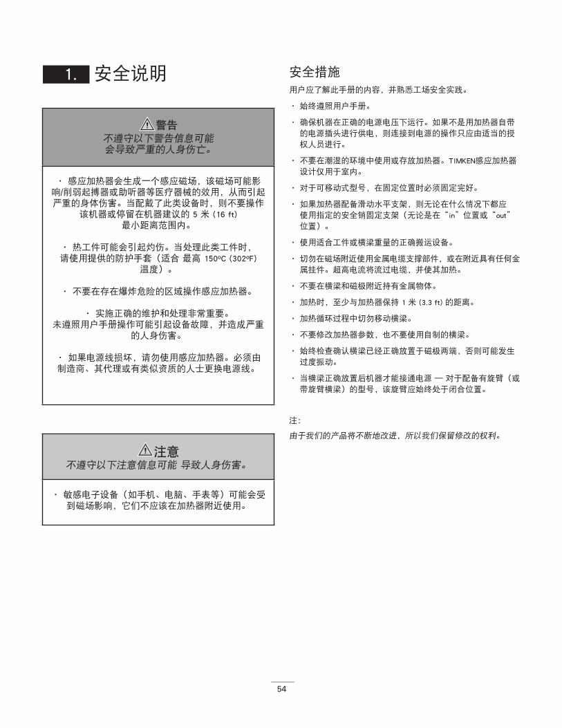
54
1. 安全说明 安全措施
用户应了解此手册的内容,并熟悉工场安全实践。
• 始终遵照用户手册。
• 确保机器在正确的电源电压下运行。如果不是用加热器自带
的电源插头进行供电,则连接到电源的操作只应由适当的授
权人员进行。
• 不要在潮湿的环境中使用或存放加热器。TIMKEN感应加热器
设计仅用于室内。
• 对于可移动式型号,在固定位置时必须固定完好。
• 如果加热器配备滑动水平支架,则无论在什么情况下都应
使用指定的安全销固定支架(无论是在“in”位置或“out”
位置)。
• 使用适合工件或横梁重量的正确搬运设备。
• 切勿在磁场附近使用金属电缆支撑部件,或在附近具有任何金
属挂件。超高电流将流过电缆,并使其加热。
• 不要在横梁和磁极附近持有金属物体。
• 加热时,至少与加热器保持 1 米 (3.3 ft) 的距离。
• 加热循环过程中切勿移动横梁。
• 不要修改加热器参数,也不要使用自制的横梁。
• 始终检查确认横梁已经正确放置于磁极两端,否则可能发生
过度振动。
• 当横梁正确放置后机器才能接通电源 — 对于配备有旋臂(或
带旋臂横梁)的型号,该旋臂应始终处于闭合位置。
注:
由于我们的产品将不断地改进,所以我们保留修改的权利。
警告不遵守以下警告信息可能 会导致严重的人身伤亡。
• 感应加热器会生成一个感应磁场,该磁场可能影响/削弱起搏器或助听器等医疗器械的效用,从而引起严重的身体伤害。当配戴了此类设备时,则不要操作
该机器或停留在机器建议的 5 米 (16 ft)最小距离范围内。
• 热工件可能会引起灼伤。当处理此类工件时, 请使用提供的防护手套(适合 最高 150ºC (302ºF)
温度)。
• 不要在存在爆炸危险的区域操作感应加热器。
• 实施正确的维护和处理非常重要。未遵照用户手册操作可能引起设备故障,并造成严重
的人身伤害。
• 如果电源线损坏,请勿使用感应加热器。必须由 制造商、其代理或有类似资质的人士更换电源线。
注意 不遵守以下注意信息可能 导致人身伤害。
• 敏感电子设备(如手机、电脑、手表等)可能会受到磁场影响,它们不应该在加热器附近使用。
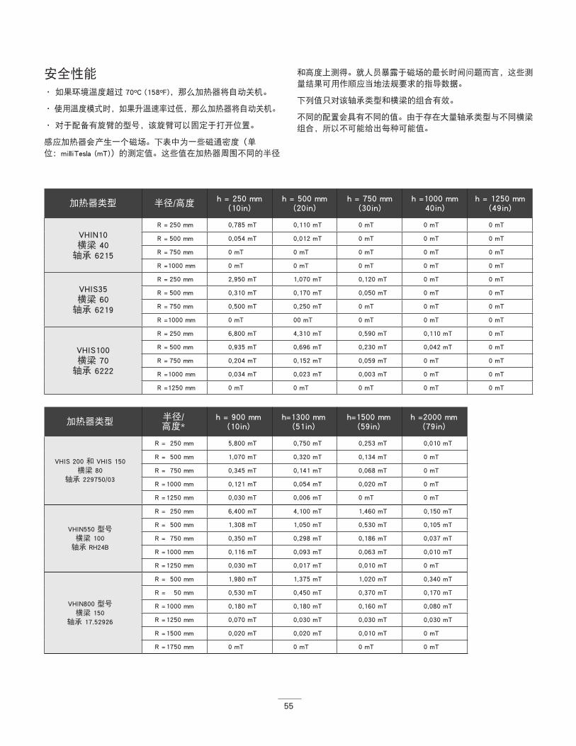
55
安全性能
• 如果环境温度超过 70ºC (158ºF),那么加热器将自动关机。
• 使用温度模式时,如果升温速率过低,那么加热器将自动关机。
• 对于配备有旋臂的型号,该旋臂可以固定于打开位置。
感应加热器会产生一个磁场。下表中为一些磁通密度(单
位:milliTesla (mT))的测定值。这些值在加热器周围不同的半径
和高度上测得。就人员暴露于磁场的最长时间问题而言,这些测
量结果可用作顺应当地法规要求的指导数据。
下列值只对该轴承类型和横梁的组合有效。
不同的配置会具有不同的值。由于存在大量轴承类型与不同横梁
组合,所以不可能给出每种可能值。
加热器类型 半径/高度 h = 250 mm(10in)
h = 500 mm(20in)
h = 750 mm(30in)
h =1000 mm40in)
h = 1250 mm(49in)
VHIN10 横梁 40
轴承 6215
R = 250 mm 0,785 mT 0,110 mT 0 mT 0 mT 0 mT
R = 500 mm 0,054 mT 0,012 mT 0 mT 0 mT 0 mT
R = 750 mm 0 mT 0 mT 0 mT 0 mT 0 mT
R = 1000 mm 0 mT 0 mT 0 mT 0 mT 0 mT
VHIS35 横梁 60
轴承 6219
R = 250 mm 2,950 mT 1,070 mT 0,120 mT 0 mT 0 mT
R = 500 mm 0,310 mT 0,170 mT 0,050 mT 0 mT 0 mT
R = 750 mm 0,500 mT 0,250 mT 0 mT 0 mT 0 mT
R = 1000 mm 0 mT 00 mT 0 mT 0 mT 0 mT
VHIS100 横梁 70
轴承 6222
R = 250 mm 6,800 mT 4,310 mT 0,590 mT 0,110 mT 0 mT
R = 500 mm 0,935 mT 0,696 mT 0,230 mT 0,042 mT 0 mT
R = 750 mm 0,204 mT 0,152 mT 0,059 mT 0 mT 0 mT
R = 1000 mm 0,034 mT 0,023 mT 0,003 mT 0 mT 0 mT
R = 1250 mm 0 mT 0 mT 0 mT 0 mT 0 mT
加热器类型 半径/高度*
h = 900 mm (10in)
h=1300 mm (51in)
h=1500 mm (59in)
h =2000 mm (79in)
VHIS 200 和 VHIS 150 横梁 80
轴承 229750/03
R = 250 mm 5,800 mT 0,750 mT 0,253 mT 0,010 mT
R = 500 mm 1,070 mT 0,320 mT 0,134 mT 0 mT
R = 750 mm 0,345 mT 0,141 mT 0,068 mT 0 mT
R = 1000 mm 0,121 mT 0,054 mT 0,020 mT 0 mT
R = 1250 mm 0,030 mT 0,006 mT 0 mT 0 mT
VHIN550 型号横梁 100
轴承 RH24B
R = 250 mm 6,400 mT 4,100 mT 1,460 mT 0,150 mT
R = 500 mm 1,308 mT 1,050 mT 0,530 mT 0,105 mT
R = 750 mm 0,350 mT 0,298 mT 0,186 mT 0,037 mT
R = 1000 mm 0,116 mT 0,093 mT 0,063 mT 0,010 mT
R = 1250 mm 0,030 mT 0,017 mT 0,010 mT 0 mT
VHIN800 型号横梁 150
轴承 17.52926
R = 500 mm 1,980 mT 1,375 mT 1,020 mT 0,340 mT
R = 50 mm 0,530 mT 0,450 mT 0,370 mT 0,170 mT
R = 1000 mm 0,180 mT 0,180 mT 0,160 mT 0,080 mT
R = 1250 mm 0,070 mT 0,030 mT 0,030 mT 0,030 mT
R = 1500 mm 0,020 mT 0,020 mT 0,010 mT 0 mT
R = 1750 mm 0 mT 0 mT 0 mT 0 mT
56
高度从加热器底部开始测量。如需确定磁场关于地面的确切位
置,则加热器底部至地面的距离应该加入到表中的值中。(例
如工作台的高度)。
2. 概述
应用
TIMKEN感应加热器设计用于加热轴承、衬套、齿轮、联轴器或其
它具有闭合电回路的金属工件。对于需要过盈配合的应用,这将
有助于安装。
加热器设计加热工件最高达 240ºC (464ºF) 的温度,但不包括
VHIN10 系列型号,该型号温度限定最高 150ºC (302ºF)。还有特
殊的定制的加热器,其最高温度可达 480ºC (896ºF)。
TIMKEN感应加热器可以连续使用。但是这里有一个限制,不要在
240ºC (464ºF) 及以上温度使加热器工作超过半小时以上。使用时
间功能加热时,这个限制需使用外部温度计进行检查。
工作条件
该加热器设计用于环境温度为 0ºC 至 50ºC (32ºF 至 122ºF)、
空气湿度在 5% 至 90% 之间的工业环境。感应加热器仅供室内
使用。
工作原理
该加热器工作原理与变压器的相同。主线圈
为加热器,次级线圈为工件。
当加热器接通电源时,高压、低交流电流通
过多个主线圈绕组。这个电流将会在作为次
级线圈的工件中感应出一个低压高电流。此
高电流使工件加热。
电流只是在工件内流动,因此也仅加热工
件。在每个加热循环结束时,工件将被自动消磁。
警告
不遵守以下警告信息可能 会导致严重的人身伤亡。
• 建议至少为 1 米的人员安全距离。
注意 不遵守以下注意信息可能 导致人身伤害。
• 机器产生电磁感应场,这可能影响电子设备,如手表、磁卡等。
注意 不遵守以下注意信息可能 导致人身伤害。
• 通常轴承只应加热至最高 120ºC (248ºF) 的温度。
• 精密轴承只应加热至最高 70ºC (158ºF) 的温度。 加热至更高温度可能会影响金相组织和尺寸稳定性,
从而导致过早的轴承故障或轴承性能降低。
• 不要将感应加热器用于技术数据(附录 1)中指定的最小或最大尺寸之外的轴承或工件。
• 加热循环运行时不要使用总电源开关关闭加热器。
57
3. 安装 • 除去包装材料,将感应加热器放置在稳定且平直的非金属台
面。正常情况下包装盒内应包含加热器、一个或一组横梁、
温度传感器、一副抗热手套以及小盒润滑剂。
• 检查电源电压和电流是否符合机器后面铭牌上的规格。
• 因为有许多插头类型,所以不是每种TIMKEN感应加热器都提
供有插头。当加热器未提供插头时,则需要合格的电工安装
一个合适的插头。
• 电线应按如下连接,根据加热器提供的电缆类型,有 3 种选
项:
• 确保电源电缆不会触及将被加热的轴承。将插头插入防触电
墙插座。
• 使用主开关接通电流。机器将发出一声短嘟声,显示器将显
示工厂设置的“预置目标温度”。
• 连接温度传感器的插头插座。确保插头和插座上的 - 和 + 与
相对应。
• 现在的感应加热器已经可使用温度功能模式。
4.
4. 符号及显示
230V/110V
棕 相线 黑 相线 黑色“1” 零线
蓝 零线 白 零线 黑色“2” 相线
绿/黄 接地 绿 接地 绿/黄 接地
400、450、500V
棕 相线 棕 相线 黑色“1” 相线
蓝 相线 黑 相线 黑色“2” 相线
绿/黄 接地 绿/黄 接地 绿/黄 接地
加热器上显示的符号
禁止戴有起搏器的人员接近。 磁场可能会对其产生影响。
使用抗热手套
不允许携带手表或其它金属物体。 磁场可能会对其产生影响。
阅读说明
显示:
- 显示:时间或温度
减少时间/温度 -- 增加时间/ 温度
使用时间模式工作 - - 使用温度模式工作
开始工作 - - 停止工作/自动消磁

58
5. 工件放置
工件可以以两种不同方式进行放置:
5.1. 工件放置
• 对于旋臂横梁架:将旋臂梁沿着铰链旋转,直至其落在铰链
结构的定位锁定位置。将工件放置在横梁上,直至其位于横
梁的中间,然后将旋臂梁连带工件转回磁极顶部合上。
• 始终确保工件不与加热器的塑料部件直接接触。
• 当加热循环完成时,按照上述说明,以相反顺序取出已加
热的工件。穿着好防护服(如抗热手套),因为这时工件很
热。提供的手套适合于最高 150ºC (302ºF) 的温度。
• 始终小心操作横梁,下落、震动等会损坏横梁。使用之后立
即将横梁移开。
5.2. 带摇臂型号允许工件最大重量表格中给出了水平支架和旋臂梁上的最大允许重量:
横梁通过工件 横梁在水平位置(内径很大,足以使磁极通过。
此例中的工件示出时为放置于水平
支架上)。
警告不遵守以下警告信息可能会导致严重的人身伤害
或死亡。
• 较重的组件和横梁需使用合适的提升设备。手动提升重物通常是导致受伤的通常原因。
• 工件的重量不应超过下面 5.2 节以及手册后面技术数据(附录 1)中给出的最大重量。超过这些极限可能会引起灾难性的设备
故障,从而导致人身伤害。
• 如果加热器配备有滑动水平支架,则始终使用指定的安全销固定支架(无论是在“in”位置,还是“out”位置)。工件的意外移动可能导致人身
伤害。
• 确保电源电缆不能触及工件。电缆损伤可能导致电击致死。
• 切勿在磁场附近使用金属电缆支撑组件,或在附近具有任何金属挂件。超高电流会流过电缆并快速使其
加热,可能有灼伤的危险。
确保光面充分擦拭了润滑脂(改善接触,避免过度振动),并放置在磁极顶部。
正确 不正确
始终选择一个尽可能多填充轴承内径的横梁。甚至可以组合 2 个横梁 — 这有助于更快、更均匀地加热。
正确 不正确
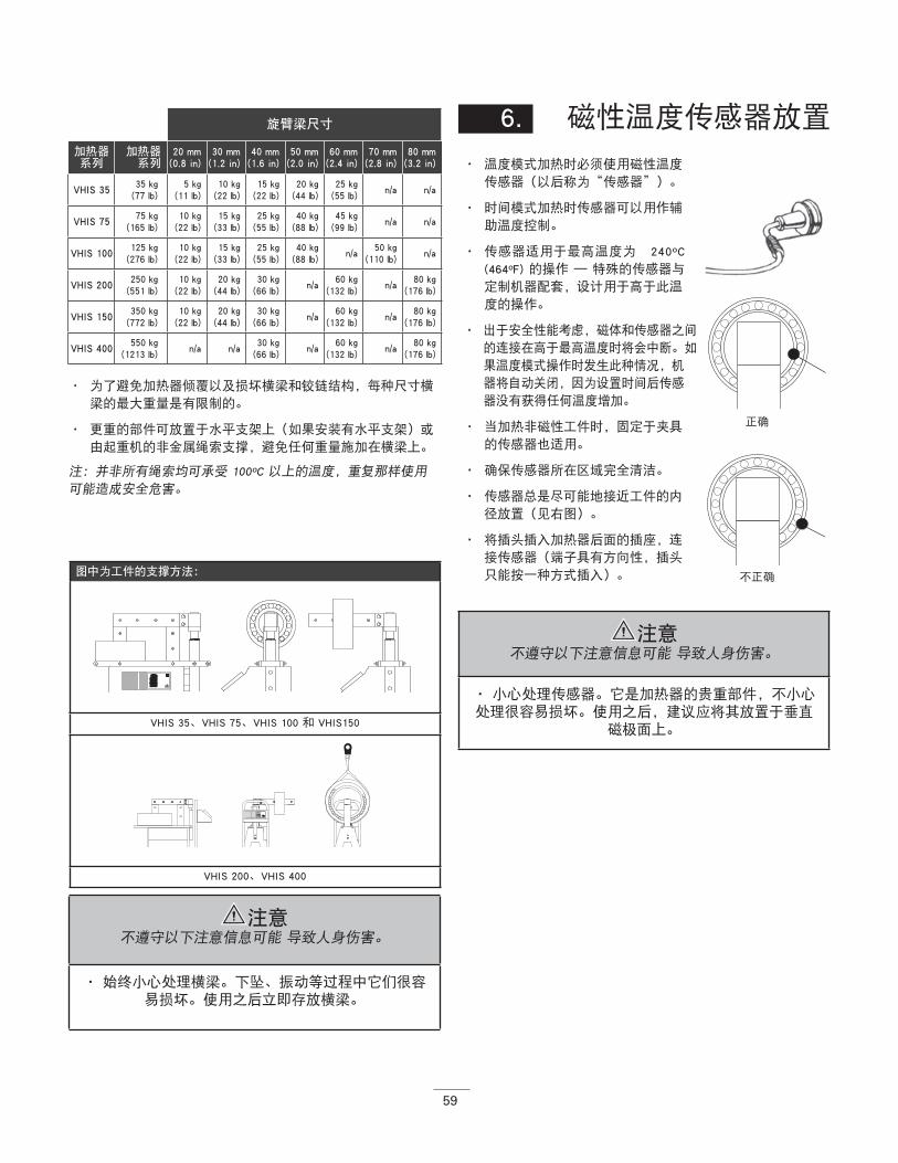
59
• 为了避免加热器倾覆以及损坏横梁和铰链结构,每种尺寸横
梁的最大重量是有限制的。
• 更重的部件可放置于水平支架上(如果安装有水平支架)或
由起重机的非金属绳索支撑,避免任何重量施加在横梁上。
注:并非所有绳索均可承受 100ºC 以上的温度,重复那样使用
可能造成安全危害。
6. 磁性温度传感器放置
• 温度模式加热时必须使用磁性温度
传感器(以后称为“传感器”)。
• 时间模式加热时传感器可以用作辅
助温度控制。
• 传感器适用于最高温度为 240ºC
(464ºF) 的操作 — 特殊的传感器与
定制机器配套,设计用于高于此温
度的操作。
• 出于安全性能考虑,磁体和传感器之间
的连接在高于最高温度时将会中断。如
果温度模式操作时发生此种情况,机
器将自动关闭,因为设置时间后传感
器没有获得任何温度增加。
• 当加热非磁性工件时,固定于夹具
的传感器也适用。
• 确保传感器所在区域完全清洁。
• 传感器总是尽可能地接近工件的内
径放置(见右图)。
• 将插头插入加热器后面的插座,连
接传感器(端子具有方向性,插头
只能按一种方式插入)。
旋臂梁尺寸
加热器 系列
加热器系列
20 mm(0.8 in)
30 mm(1.2 in)
40 mm(1.6 in)
50 mm(2.0 in)
60 mm(2.4 in)
70 mm(2.8 in)
80 mm(3.2 in)
VHIS 3535 kg
(77 lb)5 kg
(11 lb)10 kg
(22 lb)15 kg
(22 lb)20 kg
(44 lb)25 kg
(55 lb)n/a n/a
VHIS 7575 kg
(165 lb)10 kg
(22 lb)15 kg
(33 lb)25 kg
(55 lb)40 kg
(88 lb)45 kg
(99 lb)n/a n/a
VHIS 100125 kg
(276 lb)10 kg
(22 lb)15 kg
(33 lb)25 kg
(55 lb)40 kg
(88 lb)n/a
50 kg(110 lb)
n/a
VHIS 200250 kg
(551 lb)10 kg
(22 lb)20 kg
(44 lb)30 kg
(66 lb)n/a
60 kg(132 lb)
n/a80 kg
(176 lb)
VHIS 150350 kg
(772 lb)10 kg
(22 lb)20 kg
(44 lb)30 kg
(66 lb)n/a
60 kg(132 lb)
n/a80 kg
(176 lb)
VHIS 400550 kg
(1213 lb)n/a n/a
30 kg(66 lb)
n/a60 kg
(132 lb)n/a
80 kg(176 lb)
图中为工件的支撑方法:
VHIS 35、VHIS 75、VHIS 100 和 VHIS150
VHIS 200、VHIS 400
正确
不正确
注意 不遵守以下注意信息可能 导致人身伤害。
• 始终小心处理横梁。下坠、振动等过程中它们很容易损坏。使用之后立即存放横梁。
注意 不遵守以下注意信息可能 导致人身伤害。
• 小心处理传感器。它是加热器的贵重部件,不小心处理很容易损坏。使用之后,建议应将其放置于垂直
磁极面上。
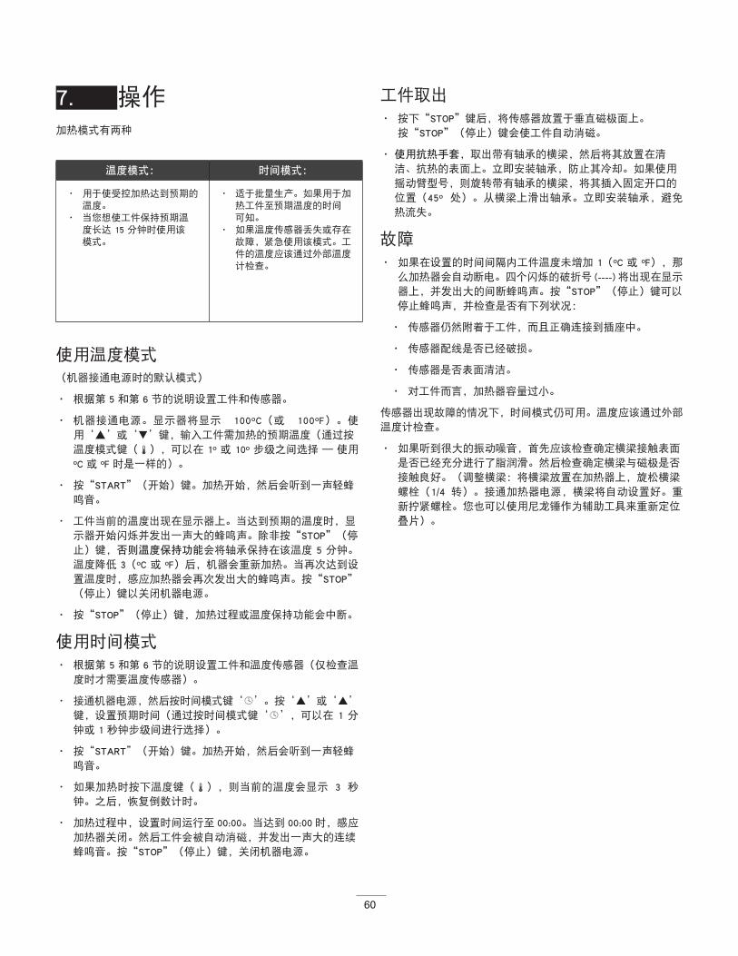
60
7. 操作加热模式有两种
使用温度模式
(机器接通电源时的默认模式)
• 根据第 5 和第 6 节的说明设置工件和传感器。
• 机器接通电源。显示器将显示 100ºC(或 100ºF)。使
用‘▲’或‘▼’键,输入工件需加热的预期温度(通过按
温度模式键(),可以在 1º 或 10º 步级之间选择 — 使用
ºC 或 ºF 时是一样的)。
• 按“START”(开始)键。加热开始,然后会听到一声轻蜂
鸣音。
• 工件当前的温度出现在显示器上。当达到预期的温度时,显
示器开始闪烁并发出一声大的蜂鸣声。除非按“STOP”(停
止)键,否则温度保持功能会将轴承保持在该温度 5 分钟。
温度降低 3(ºC 或 ºF)后,机器会重新加热。当再次达到设
置温度时,感应加热器会再次发出大的蜂鸣声。按“STOP”
(停止)键以关闭机器电源。
• 按“STOP”(停止)键,加热过程或温度保持功能会中断。
使用时间模式
• 根据第 5 和第 6 节的说明设置工件和温度传感器(仅检查温
度时才需要温度传感器)。
• 接通机器电源,然后按时间模式键‘’。按‘’或‘’
键,设置预期时间(通过按时间模式键‘’,可以在 1 分
钟或 1 秒钟步级间进行选择)。
• 按“START”(开始)键。加热开始,然后会听到一声轻蜂
鸣音。
• 如果加热时按下温度键(),则当前的温度会显示 3 秒
钟。之后,恢复倒数计时。
• 加热过程中,设置时间运行至 00:00。当达到 00:00 时,感应
加热器关闭。然后工件会被自动消磁,并发出一声大的连续
蜂鸣音。按“STOP”(停止)键,关闭机器电源。
工件取出
• 按下“STOP”键后,将传感器放置于垂直磁极面上。
按“STOP”(停止)键会使工件自动消磁。
• 使用抗热手套,取出带有轴承的横梁,然后将其放置在清
洁、抗热的表面上。立即安装轴承,防止其冷却。如果使用
摇动臂型号,则旋转带有轴承的横梁,将其插入固定开口的
位置(45º 处)。从横梁上滑出轴承。立即安装轴承,避免
热流失。
故障
• 如果在设置的时间间隔内工件温度未增加 1(ºC 或 ºF),那
么加热器会自动断电。四个闪烁的破折号 (----) 将出现在显示
器上,并发出大的间断蜂鸣声。按“STOP”(停止)键可以
停止蜂鸣声,并检查是否有下列状况:
• 传感器仍然附着于工件,而且正确连接到插座中。
• 传感器配线是否已经破损。
• 传感器是否表面清洁。
• 对工件而言,加热器容量过小。
传感器出现故障的情况下,时间模式仍可用。温度应该通过外部
温度计检查。
• 如果听到很大的振动噪音,首先应该检查确定横梁接触表面
是否已经充分进行了脂润滑。然后检查确定横梁与磁极是否
接触良好。(调整横梁:将横梁放置在加热器上,旋松横梁
螺栓(1/4 转)。接通加热器电源,横梁将自动设置好。重
新拧紧螺栓。您也可以使用尼龙锤作为辅助工具来重新定位
叠片)。
温度模式: 时间模式:
• 用于使受控加热达到预期的温度。
• 当您想使工件保持预期温度长达 15 分钟时使用该模式。
• 适于批量生产。如果用于加热工件至预期温度的时间可知。
• 如果温度传感器丢失或存在故障,紧急使用该模式。工件的温度应该通过外部温度计检查。
61
8. 清洁及维护• 存放在干燥的防冻区域,远离潮湿。
• 使用柔软干燥的布清洁。
• 保持磁极接触部分清洁。使用无酸润滑脂定期润滑,保持与
横梁的最佳接触并防止腐蚀(对于旋臂型号,并定期润滑垂
直销)。
• 如果怀疑存在不正常工作情况,请联系您的供应商。
警告不遵守以下警告信息可能 会导致严重的人身伤亡。
• 如有疑问,请隔离机器,然后联系当地的供应商。未遵照正确的维护和修理程序可能引起设备故
障,或者造成严重的人身伤害。
感应加热器的温度单位可以是 ºC 或 ºF
要切换温度模式,请执行以下操作:
• 长按温度按钮 10 秒钟,会听到“哔”的一声短音
• 然后再等待 10 秒,会再次听到“哔”的一声, 在显示器中,温度模式将从摄氏度切换为华氏度或
相反。
然后就可以在新设置的温度模式下使用加热器了。
警告不遵守以下警告信息可能 会导致严重的人身伤亡。
• 实施正确的维护和处理非常重要。未遵照安装说明操作以及未进行适当润滑都可能引起设备故障,引
起严重人身伤害的危险。
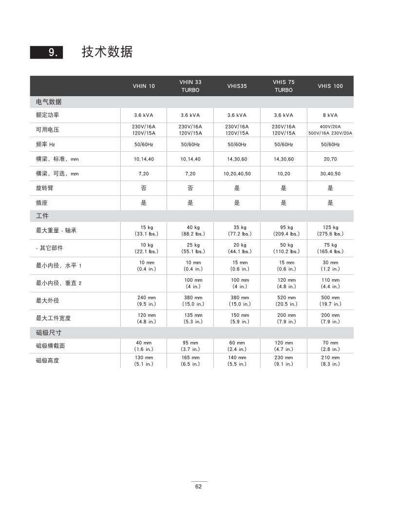
62
VHIN 10 VHIN 33TURBO
VHIS35VHIS 75TURBO
VHIS 100
电气数据
额定功率 3.6 kVA 3.6 kVA 3.6 kVA 3,6 kVA 8 kVA
可用电压230V/16A120V/15A
230V/16A120V/15A
230V/16A120V/15A
230V/16A120V/15A
400V/20A500V/16A 230V/20A
频率 Hz 50/60Hz 50/60Hz 50/60Hz 50/60Hz 50/60Hz
横梁,标准,mm 10,14,40 10,14,40 14,30,60 14,30,60 20,70
横梁,可选,mm 7,20 7,20 10,20,40,50 10,20 30,40,50
旋转臂 否 否 是 是 是
插座 是 是 是 是 是
工件
最大重量 - 轴承15 kg
(33.1 lbs.)40 kg
(88.2 lbs.)35 kg
(77.2 lbs.)95 kg
(209.4 lbs.)125 kg
(275.6 lbs.)
- 其它部件10 kg
(22.1 lbs.)25 kg
(55.1 lbs.)20 kg
(44.1 lbs.)50 kg
(110.2 lbs.)75 kg
(165.4 lbs.)
最小内径,水平 110 mm (0.4 in.)
10 mm (0.4 in.)
15 mm (0.6 in.)
15 mm (0.6 in.)
30 mm (1.2 in.)
最小内径,垂直 2100 mm (4 in.)
100 mm (4 in.)
120 mm (4.8 in.)
110 mm (4.4 in.)
最大外径 240 mm (9.5 in.)
380 mm (15.0 in.)
380 mm (15.0 in.)
520 mm (20.5 in.)
500 mm (19.7 in.)
最大工件宽度120 mm (4.8 in.)
135 mm (5.3 in.)
150 mm (5.9 in.)
200 mm (7.9 in.)
200 mm (7.9 in.)
磁极尺寸
磁极横截面 40 mm (1.6 in.)
95 mm (3.7 in.)
60 mm (2.4 in.)
120 mm (4.7 in.)
70 mm (2.8 in.)
磁极高度130 mm (5.1 in.)
165 mm (6.5 in.)
140 mm (5.5 in.)
230 mm (9.1 in.)
210 mm (8.3 in.)
9. 技术数据
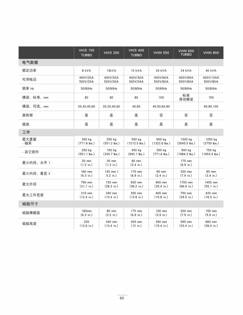
63
VHIS 150TURBO
VHIS 200VHIS 400TURBO
VHIN 550 VHIN 600TURBO VHIN 800
电气数据
额定功率 8 kVA 12kVA 12 kVA 24 kVA 24 kVA 40 kVA
可用电压400V/20A500V/20A
400V/30A500V/30A
400V/30A500V/24A
400V/60A500V/60A
400V/60A500V/60A
400V/100A500V/80A
频率 Hz 50/60Hz 50/60Hz 50/60Hz 50/60Hz 50/60Hz 50/60Hz
横梁,标准,mm 80 80 80 100标准
滑动横梁150
横梁,可选,mm 20,30,40,60 20,30,40,60 40,60 40,50,60,80 60,80,100
旋转臂 是 是 是 否 否 否
插座 是 是 是 是 是 是
工件
最大重量- 轴承
350 kg (771.6 lbs.)
250 kg (551.2 lbs.)
550 kg (1212.5 lbs.)
600 kg (1322.6 lbs.)
1200 kg (2645.5 lbs.)
1250 kg (2750 lbs.)
- 其它部件250 kg
(551.1 lbs.)150 kg
(330.7 lbs.)450 kg
(992.1 lbs.)350 kg
(771.6 lbs.)900 kg
(1984.2 lbs.)750 kg
(1653.5 lbs.)
最小内径,水平 130 mm (1.2 in.)
30 mm (1.2 in.)
60 mm (2.4 in.)
175 mm (6.9 in.)
最小内径,垂直 2160 mm (6.3 in.)
130 mm (5.2 in.)
175 mm (6.9 in.)
60 mm (2.4 in.)
200 mm (7.9 in.)
85 mm (3.4 in.)
最大外径 790 mm (31.1 in.)
720 mm (28.3 in.)
920 mm (36.2 in.)
900 mm (35.4 in.)
1700 mm (66.9 in.)
1400 mm (55.1 in.)
最大工件宽度315 mm (12.4 in.)
340 mm (13.4 in.)
350 mm (13.8 in.)
400 mm (15.8 in.)
750 mm (29.5 in.)
420 mm (16.5 in.)
磁极尺寸
磁极横截面 160mm (6.3 in.)
80 mm (3.2 in.)
175 mm (6.9 in.)
100 mm (3.9 in.)
200 mm (7.9 in.)
150 mm (5.9 in.)
磁极高度320
(12.6 in.)340 mm (13.4 in.)
305 mm (12 in.)
390 mm (15.4 in.)
595 mm (23.4 in.)
660 mm (26.0 in.)
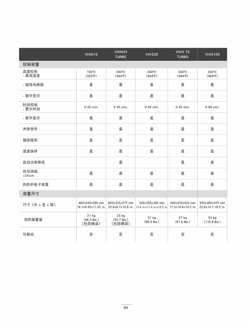
64
VHIN10 VHIN33TURBO
VHIS35VHIS 75TURBO
VHIS100
控制装置
温度控制- 最高温度
150ºC (302ºF)
240ºC (464ºF)
240ºC (464ºF)
240ºC (464ºF)
240ºC (464ºF)
- 磁性传感器 是 是 是 是 是
- 数字显示 是 是 是 是 是
时间控制- 最长时间
0-30 min. 0-45 min. 0-45 min. 0-45 min. 0-60 min.
- 数字显示 是 是 是 是 是
声音信号 是 是 是 是 是
错误报告 是 是 是 是 是
温度保持 是 是 是 是 是
自动功率降低 是 是 是
自动消磁, <2A/cm
是 是 是 是 是
热防护电子装置 是 是 是 是 是
装置尺寸
尺寸(长 x 宽 x 高)460x240x280 mm
18.1x9.45x11.02 in.600x220x275 mm 23.6x8.7x10.8 in.
340x290x380 mm 13.4 in.x11.4 in.x12.2 in.
440x370x420 mm 17.3x14.6x14.2 in.
630x365x470 mm 22.8x14.7,18.5 in.
加热器重量21 kg
(46.3 lbs.)(包括横梁)
23 kg (50.7 lbs.)
(包括横梁)
31 kg (68.3 lbs.)
37 kg (81.6 lbs.)
53 kg (116.9 lbs.)
可移动 否 否 否 否 否
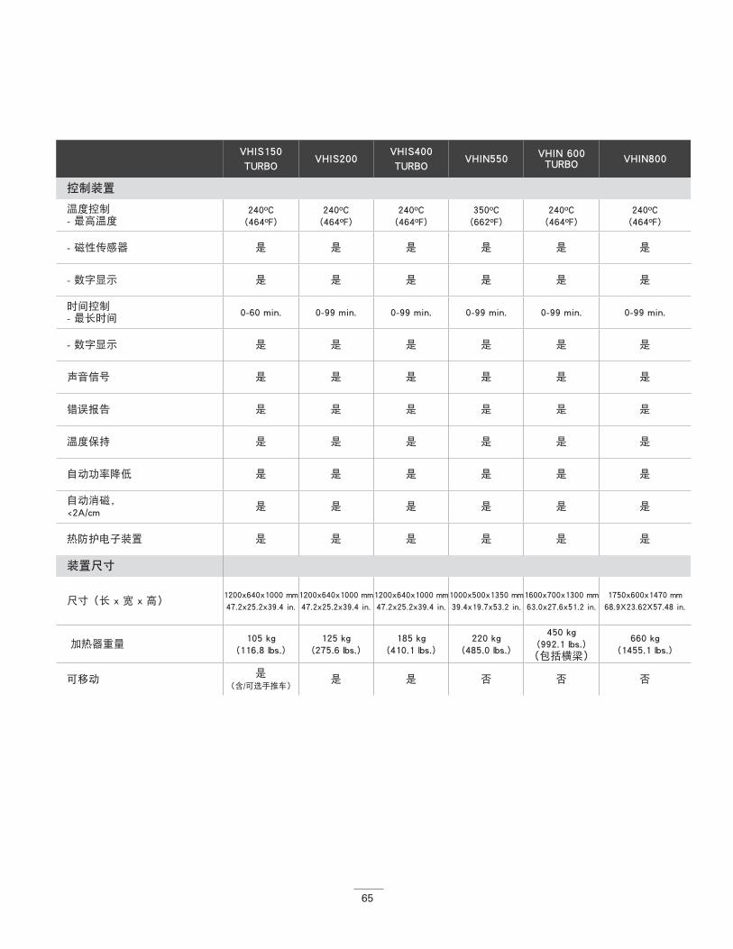
65
VHIS150TURBO
VHIS200VHIS400TURBO
VHIN550 VHIN 600TURBO VHIN800
控制装置
温度控制- 最高温度
240ºC (464ºF)
240ºC (464ºF)
240ºC (464ºF)
350ºC (662ºF)
240ºC (464ºF)
240ºC (464ºF)
- 磁性传感器 是 是 是 是 是 是
- 数字显示 是 是 是 是 是 是
时间控制- 最长时间
0-60 min. 0-99 min. 0-99 min. 0-99 min. 0-99 min. 0-99 min.
- 数字显示 是 是 是 是 是 是
声音信号 是 是 是 是 是 是
错误报告 是 是 是 是 是 是
温度保持 是 是 是 是 是 是
自动功率降低 是 是 是 是 是 是
自动消磁, <2A/cm
是 是 是 是 是 是
热防护电子装置 是 是 是 是 是 是
装置尺寸
尺寸(长 x 宽 x 高)1200x640x1000 mm 47.2x25.2x39.4 in.
1200x640x1000 mm47.2x25.2x39.4 in.
1200x640x1000 mm 47.2x25.2x39.4 in.
1000x500x1350 mm 39.4x19.7x53.2 in.
1600x700x1300 mm63.0x27.6x51.2 in.
1750x600x1470 mm 68.9X23.62X57.48 in.
加热器重量105 kg
(116.8 lbs.)125 kg
(275.6 lbs.)185 kg
(410.1 lbs.)220 kg
(485.0 lbs.)
450 kg (992.1 lbs.)
(包括横梁)
660 kg (1455.1 lbs.)
可移动是
(含/可选手推车)是 是 否 否 否
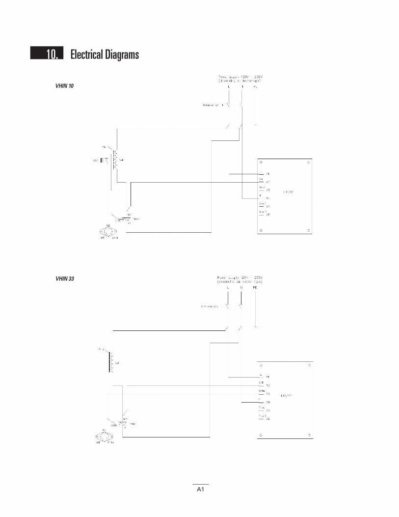
VHIN 10
VHIN 33
10. Electrical Diagrams
A1
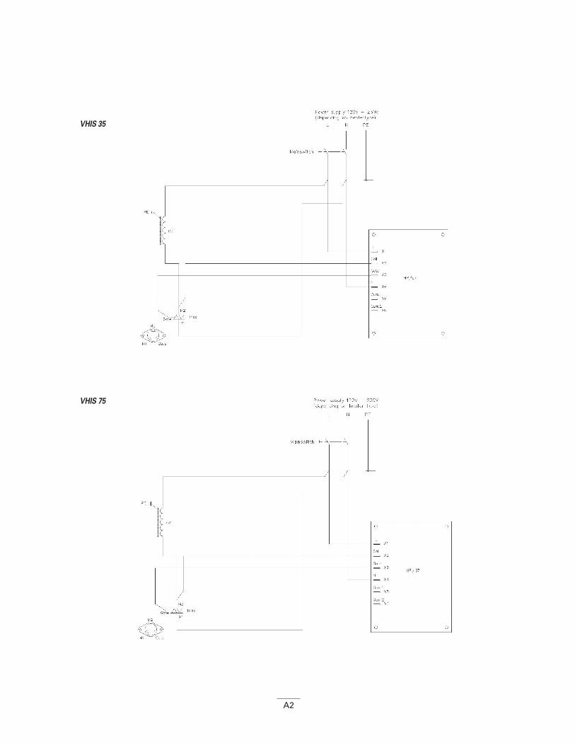
VHIS 35
VHIS 75
A2
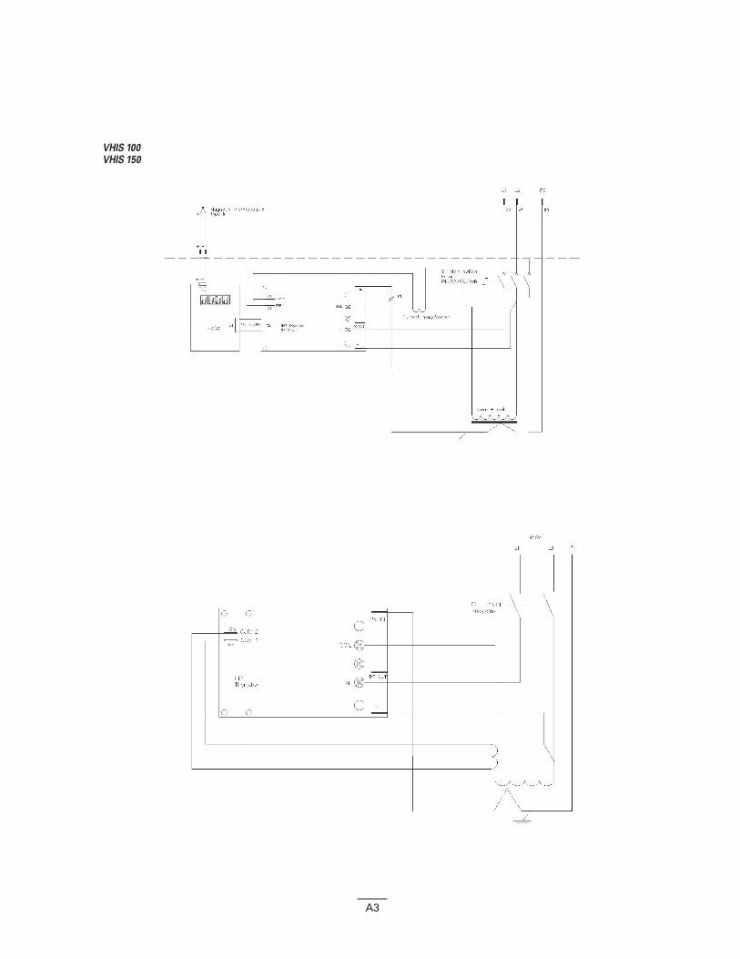
VHIS 100VHIS 150
A3
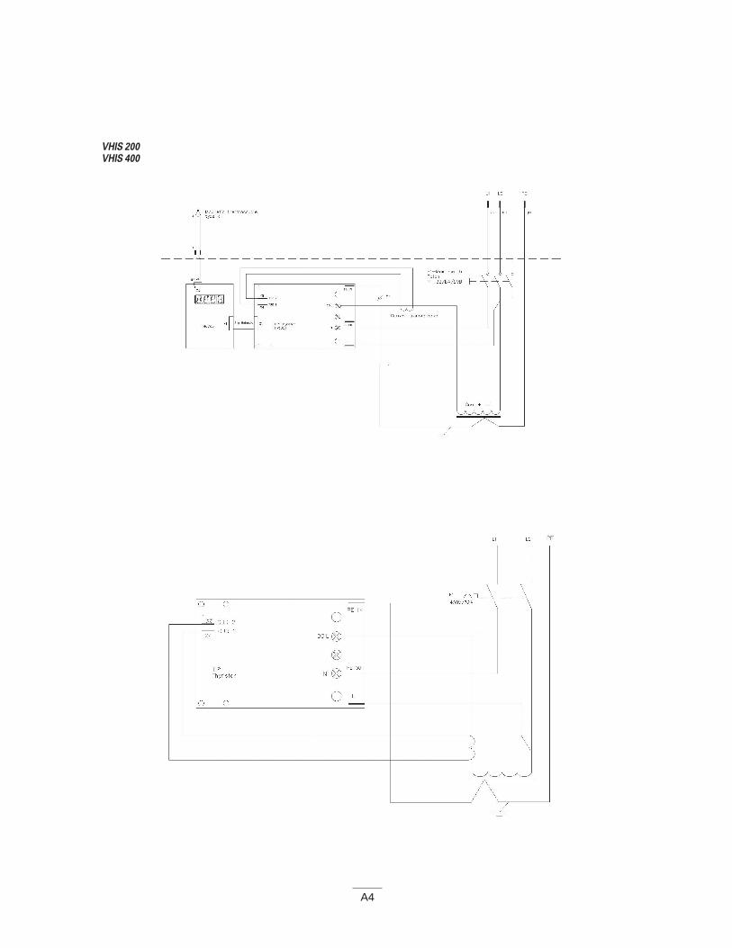
VHIS 200VHIS 400
A4
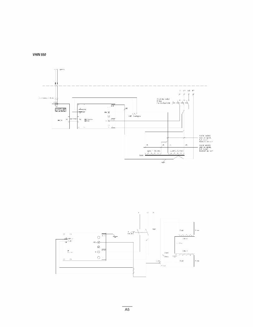
VHIN 550
A5
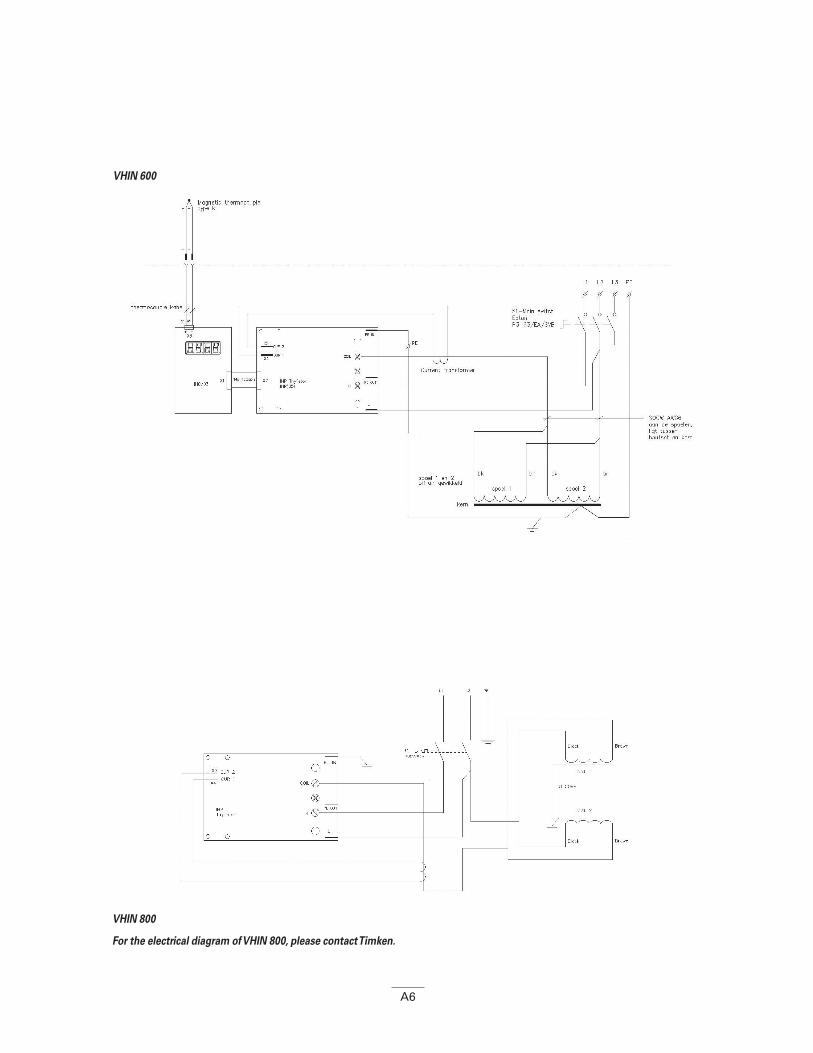
VHIN 600
VHIN 800
For the electrical diagram of VHIN 800, please contact Timken.
A6

www.timken.com
02-1
8 O
rder
No.
110
32 |
Tim
ken®
is a
regi
ster
ed tr
adem
ark
of T
he T
imke
n Co
mpa
ny. |
© 2
018
The
Tim
ken
Com
pany
| Pr
inte
d in
U.S
.A.
The Timken team applies their know-how to improve the reliability and performance of machinery in diverse markets worldwide. The company designs, makes and markets high-performance mechanical components, including bearings, belts, brakes, clutches, chain, couplings, gears and related mechanical power transmission products and services.