
Wassergekühlte Drehstrommotoren - emod- · PDF fileKatalog 837 / 03 / Ausgabe 2014...
44
Wassergekühlte Drehstrommotoren 837 Water-cooled three-phase motors
Transcript of Wassergekühlte Drehstrommotoren - emod- · PDF fileKatalog 837 / 03 / Ausgabe 2014...
Wassergekühlte Drehstrommotoren
837
Water-cooled three-phase motors
Katalog 837 / 03 / Ausgabe 2014
LieferbedingungenUnseren Lieferungen und Leistungen liegen unsere Verkaufs- und Lieferbedingungen sowie die allgemeinen Lieferbedingungen für Erzeugnisse und Leistungen der Elektroindustrie zugrunde.Änderungen der in der Liste angegebenen technischen Daten sowie Maße und Gewichte bleiben vorbehalten.Reklamationen können nur innerhalb 8 Tagen nach Empfang der Ware berücksichtigt werden.
PreiseUnsere Preise gelten ab Werk, ausschließlich Verpackung, zuzüglich der gesetzlich vorgeschriebenen Mehrwert-steuer.Verpackung wird nicht zurückgenommen.Preisänderungen bleiben vorbehalten. Der Berechnung werden jeweils die am Tage der Lieferung gültigen Preise zugrunde gelegt.
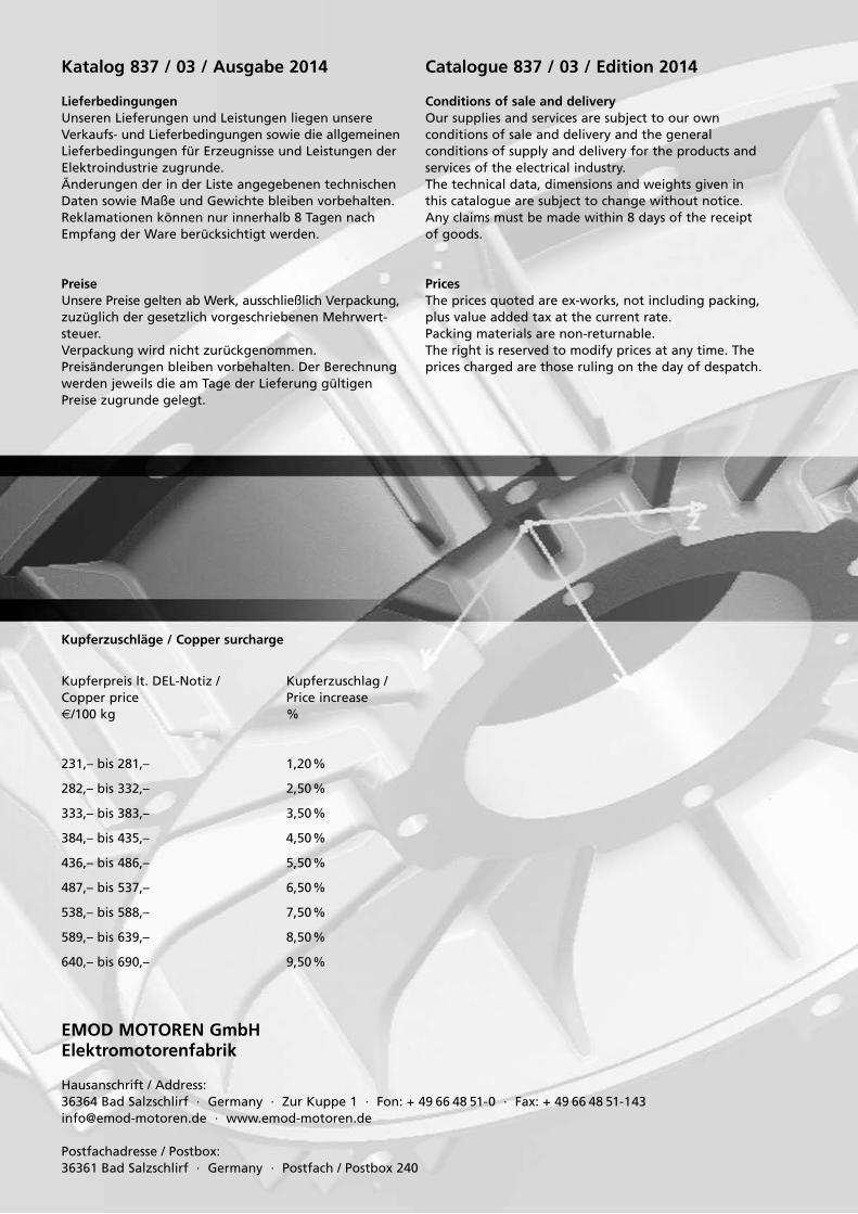
Kupferzuschläge / Copper surcharge
Kupferpreis lt. DEL-Notiz / Kupferzuschlag / Copper price Price increase e/100 kg %
231,– bis 281,– 1,20%
282,– bis 332,– 2,50%
333,– bis 383,– 3,50%
384,– bis 435,– 4,50%
436,– bis 486,– 5,50%
487,– bis 537,– 6,50%
538,– bis 588,– 7,50%
589,– bis 639,– 8,50%
640,– bis 690,– 9,50%
Catalogue 837 / 03 / Edition 2014
Conditions of sale and deliveryOur supplies and services are subject to our own conditions of sale and delivery and the general conditions of supply and delivery for the products and services of the electrical industry.The technical data, dimensions and weights given in this catalogue are subject to change without notice.Any claims must be made within 8 days of the receipt of goods.
PricesThe prices quoted are ex-works, not including packing, plus value added tax at the current rate.Packing materials are non-returnable.The right is reserved to modify prices at any time. The prices charged are those ruling on the day of despatch.
EMOD MOTOREN GmbHElektromotorenfabrik
Hausanschrift / Address:36364 Bad Salzschlirf · Germany · Zur Kuppe 1 · Fon: + 49 66 48 51-0 · Fax: + 49 66 48 [email protected] · www.emod-motoren.de
Postfachadresse / Postbox:36361 Bad Salzschlirf · Germany · Postfach / Postbox 240
Inhaltsverzeichnis / Katalog 837 / 03 / Ausgabe 2014Contents / Catalogue 837 / 03 / Edition 2014
Seite Page
Allgemeine technische Erläuterungen 4 –11 General technical information
Leistungstabellen 12 –19 Rated output
Maßtabellen 20 – 22 Dimension sheets
Lieferbare Flansche 33 Flanges available
· 3 ·
· 4 ·
Bei der WK-Motorenreihe handelt es sich um Kurzschlussläufermotoren mit einem wassergekühlten Gehäusemantel.
Die in der Liste angegebenen Leistungswerte der eintourigen Motoren beziehen sich auf die Betriebsart S1 und eine Kühlmitteleintrittstemperatur von 35 °C.Andere Polzahlen und polumschaltbare Motoren sind auf Anfrage lieferbar.
Die Motoren entsprechen der Schutzart IP 55 nach DIN IEC 34, Teil 5. Höhere Schutzarten auf Anfrage lieferbar.
Allgemeine technische ErläuterungenGeneral technical information
Verwendungszweck
Wassergekühlte Motoren werden eingesetzt:• bei extremen Umweltbedingungen wie z.B. Staub,
Faserflug, Schmutz- und Feuchtigkeitseinwirkungen• für besonders geräuscharme Ausführungen• wenn die Verlustwärme nicht unmittelbar an die
Umgebung abgegeben werden darf (klimatisierte Räume)
• bei erhöhter Raumtemperatur bzw. Strahlungstemperatur
• für Anlagen mit Wärmerückgewinnung zur Nutzung der Abwärme des Motors
• für frequenzregelbare Motoren mit konstantem Drehmoment in einem großen Regelbereich
• bei Schutzarten bis IP 67 ohne Leistungsreduzierung• als Asynchrongeneratoren in Blockheizkraftwerken
The water-cooled motors type WK are squirrel-cage induction motors with a water-cooled housing.
The rated output of the single-speed motors in the catalogue relates to a continuous operating mode and a cooling medium inlet-temperature of 35 °C. Other rated speeds and pole changing motors are available upon request.
The degree of the protection is IP 55 according to DIN IEC 34, part 5. Increased degrees of protection are available upon request.
Application
Water-cooled three-phase motors are used:• at extreme environmental conditions as dust, fibre
material, dirt and moisture• for very low-noise machines• if the heat loss should not be emitted directly to
the ambient atmosphere (air-conditioned rooms)• at increased ambient temperature or radiant heat.• for machines with heat exchanger to use the heat
loss of the motor• for operating at frequency converter with constant
torque and a wide speed range• for degree of protection up to IP 67 without power
reduction• as asynchronous generators for combined heat and
power modules (CHP modules)
Motoren nach ausländischen Vorschriften / Motors according to foreign standards
Vorschrift / Standard Baugröße / Frame size Zulassung / Certification
CSA Kanada 71– 315 CSA report no. LR 34805
UL USA 71– 250 Recognized Component File E 189414

· 5 ·
Allgemeine technische ErläuterungenGeneral technical information
Mechanische Ausführung
Wassergekühltes Gehäuse
Baugröße 71 bis 160:In einem Gehäuse aus Aluminiumlegierung ist ein Wendel aus Edelstahlrohr eingegossen.Durch die Zwangsführung der Kühlung kann der Motor mit der vorgegebenen Position der Wasseranschlüsse unabhängig von der Einbaulage betrieben werden.
Baugröße 180 bis 450:Das Graugussgehäuse zeichnet sich durch eine Zwangsführung des Kühlmediums aus. Abhängig von der veränderbaren Position der Wasseranschlüsse und der Einbaulage kann eine Entlüftung des Kühlsystems erforderlich sein. Die besondere Konstruktion des Gehäuses erlaubt die Reinigung des Kühlwasser-kreislaufes.
Stahlgeschweißte Gehäuse:Für besondere Betriebsbedingungen und Anwendungen wie druck- und vakuumdichte Motoren besteht die Möglichkeit, geschweißte Doppelmantelgehäuse aus Stahl oder Edelstahl zu verwenden.
Anschlußkasten
Die Klemmenkästen sind in Schutzart IP 55 ausgeführt und können um 4 x 90° gedreht werden.Bis zur Baugröße 132 sind die Klemmenkästen aus Aluminium gefertigt, ab Baugröße 160 aus Grauguß.Bei der Normalausführung sind die Klemmenkästen von der A-Seite gesehen rechts.Ausführungen mit Klemmkasten links oder oben sind ebenfalls lieferbar.
Wellenende
In der Normalausführung werden die Motoren mit zylindrischem Wellenende nach DIN 748 aus Werkstoff C45 geliefert.
Motorwellen aus rost-, säure- und hitzebeständigen Stählen sind gegen Mehrpreis lieferbar.
Polumschaltbare Motoren mit 2-poligen Drehzahlstufen haben die gleichen Wellenenden und Lagerungen wie eintourige 2-polige Motoren.
Mechanical design
Water-cooled frame
Frame size 71 to 160:A spiral tube of stainless steel is casted in a motor housing of aluminium alloy.With the forced water cooling the motor can operate with the standard position of the water connections independent from the mounting position.
Frame size 180 to 450:The characteristic of the grey cast iron housing is a forced water-cooling.Dependent on the variable position of the water connections and the mounting position, it can be necessary to use an air relief valve for the cooling system. The special design of the housing allows the cleaning of the water-cooling circuit.
Fabricated steel frame:For special operating conditions and applications e.g. pressure- and vacuum-tight motors it is possible to use fabricated steel double casings of steel or stainless steel.
Terminalbox
The terminalboxes have a degree of protection IP 55 and they are rotatable through 90°.Up to frame size 132 the terminal boxes are of alumi- nium alloy and from frame size 160 of grey cast iron.The terminalbox is alignment in standard version at the right, when looking at drive-end-shaft.Versions with terminalbox at the left or on top are also available.
Shaft
In standard version the motor shaft is cylindric according to DIN 748 of material C45.
Motor shafts of stainless, acid- and heat-resistant steel are available at extra price.
Pole-changing motors with two-pole speeds have the same shaft extensions and bearings as single-speed, two-pole motors.

· 6 ·
Lagerung
Die Motoren der Baugröße 71 bis 160 haben dauergeschmierte Wälzlager.
Ab der Baugröße 180 haben die Motoren eine Nachschmiereinrichtung mit Fettmengenregler.Nachschmierfrist, Fettmenge und Fettqualität sind durch ein Zusatzschild am Motor angegeben.Verstärkte Lagerausführung A-Seite für Antriebe mit erhöhten Querkräften sowie Nachschmiereinrichtung ab Baugröße 90 sind gegen Mehrpreis lieferbar.
Die Motoren der Baugröße 71 bis 112 haben serienmäßig Festlager durch Sicherungsringe auf der B-Seite. Ab der Baugröße 132 ist das Festlager auf der B-Seite durch einen Lagerabschlussdeckel angestellt.
Die Lager der Baugröße 71 bis 180 sind durch axial wirkende Wellenbandfedern vorgespannt, ab Bau- größe 200 über axial wirkende Druckfedern.
Allgemeine technische ErläuterungenGeneral technical information
Bearings
The motor frame sizes 71–160 have permanent grease-lubricated anti-friction bearings.
From frame size 180 the motors have regreasing devices with grease quantity control.Regreasing intervals, quantity of grease and grade of grease are marked on an auxiliary plate on the motor.Heavy-duty bearing arrangements at drive end for increased radial load or regreasing devices from frame size 90 are available at extra price.
The motor frame sizes 71–112 have the locating bearing at non-drive-end by retaining rings. From frame size 132 the locating bearing is at non-drive-end by way of bearing end cover.
Bearings for frame size 71–180 are pre-loaded with axial spring plates, from frame size 200 with axial pre-loading springs.
Lagerzuordnung / Bearing and frame size
71 ≥ 2 6202 2Z 6202 2Z
80 ≥ 2 6204 2Z 6204 2Z
90 ≥ 2 6205 2Z 6205 2Z
100 ≥ 2 6206 2Z 6206 2Z
112 ≥ 2 6306 2Z 6306 2Z
132 ≥ 2 6308 Z 6308 Z
160 ≥ 2 6309 6309 65 / 30 16 / 10
180 ≥ 2 6313 6311 85 / 50 18 / 14
200 ≥ 2 6314 6313 100 / 85 21 / 18
225 ≥ 2 6314 6313 100 / 85 21 / 18
250 ≥ 2 6316 6314 150 / 100 27 / 21
280 2 6316 6316 150 / 150 27 / 27
280 ≥ 4 6317 6316 150 / 150 30 / 27
315 2 6316 6316 150 / 150 27 / 27
315 ≥ 4 6319 6317 170 / 150 36 / 30
355 ≥ 4 6322 6322 350 35
400 ≥ 4 6324 6324 390 42
450 ≥ 4 6326 6326 450 50
Baug
röße
Fram
e si
ze
Polz
ahl
No.
of
pole
s
AS-
Lage
rD
E-be
arin
g
BS-L
ager
ND
E-be
arin
g
Fett
men
geQ
uant
ity o
f gr
ease
Nac
hsch
mie
rmen
ge
Qua
ntity
of
regr
ease

· 7 ·
Allgemeine technische ErläuterungenGeneral technical information
Transportsicherung
Motoren mit eingebauten Rollenlagern sind durch Erschütterungen während des Transports und der Lagerung gefährdet.Die eingebaute Lagerverriegelung schützt vor Beschädigung der Lager.Vor der Inbetriebnahme ist die Transportsicherung zu entfernen.
Wellendichtringe
Flanschmotoren sind in öldichten Ausführungen mit eingebauten Radial-Wellendichtringen lieferbar.Der Dichtringwerkstoff in Normalausführung ist NBR mit der Kurzbezeichnung nach ISO 1629.Der gummielastische Außenring garantiert einen einwandfreien Sitz.Die Schmierung der Dichtstelle muss bereits bei den ersten Wellenumdrehungen sichergestellt sein. Dichtstellen, die oberhalb des Ölspiegels liegen, müs-sen durch Sprühöl oder Ölnebel geschmiert werden.
Je nach den abzudichtenden Medien sowie Medientemperaturen können spezifizierte Dichtringmaterialien eingesetzt werden.
Anstrich
Der Normalanstrich ist ein Nitro-Combi-Decklack mit Farbton nach RAL 7031, der für die Aufstellung in Innenräumen und für die Außenaufstellung ohne besondere klimatische Anforderungen geeignet ist.
Für besondere klimatische Bedingungen und chemisch aggressive Atmosphäre steht ein Sonderanstrich SA1 zur Verfügung.
Es handelt sich um einen 2-Komponenten-Polyurethan-Anstrich mit Epoxid-Zwischenbeschichtung.Abweichende Farbtöne und Ausführungen sind auf Anfrage lieferbar.
Shipping brace
Motors with built-in roller bearings are endangered by vibration during transport and storage.The built-in shipping brace for the bearings protects them from damage.The shipping brace is to be removed before starting up the motor.
Shaft seals
Flange motors are available in oil-tight models with built-in radial shaft seals.The seal material in standard version is NBR with short designation as per ISO 1629.The flexible rubber outer ring ensures a perfect seat.Lubrication of the sealing location must be assured as soon as the shaft makes its first revolutions. Sealing locations lying below the oil level must be lubricated by spray oil or oil mist.
Depending on the media to be sealed and their temperatures, specified seal materials can be used.
Painting
In standard version the painting is of a nitrocellulose combination finish in colours RAL 7031, for indoor and outdoor installation without special climatic conditions.
For special climatic conditions and chemical abrasive atmospheres a special coat SA1 is available.
It concerns of a two-component polyurethane finish with an epoxy resin sealer.Other colours and finishes are available upon request.

· 8 ·
Elektrische Ausführung
Bemessungsspannung und Frequenz
Die wassergekühlten Motoren werden für folgende Bemessungsspannungen geliefert:
3AC, 50 Hz – 400 V, 500 V, 660 V, 690 V3AC, 60 Hz – 440 V, 460 V
Andere Bemessungsspannungen sind gegen Mehrpreis lieferbar.
Wärmeklasse
In der Normalausführung sind die Motoren in Wärme-klasse F ausgeführt.Die Isolierung der Motoren ist tropenfest.Verstärkter Tropen- und Feuchtschutz ist gegen Mehr-preis lieferbar.
Electrical design
Voltage and frequency
The water-cooled motors are available with the following voltages:
3AC, 50Hz – 400V, 500V, 660V, 690V3AC, 60Hz – 440V, 460V
Other voltages upon request at extra price.
Insulating class
In standard version the stator and rotor winding is of insulating class F.The insulating of the motors is tropic-proof.Increased tropic- and moisture-proof insulating is available at extra price.
Allgemeine technische ErläuterungenGeneral technical information
Motorschutz
Bei stromabhängigem Motorschutz muss der Schutz-schalter auf den am Leistungsschild angegebenen Nennstrom eingestellt werden.
Bei Schalthäufigkeit, Kurzzeitbetrieb, Kühlmittelausfall oder großen Kühlmitteltemperaturschwankungen ist der Motorschutz nur mit direkter Temperaturüber- wachung sicher wirksam.Hierzu bieten sich auf Wunsch folgende Möglichkeiten an:
• Temperaturschalter als Öffner Bei Erreichen der Grenztemperatur öffnet dieser
selbsttätig den Hilfsstromkreis und schaltet erst nach wesentlicher Temperaturänderung wieder ein. Schaltleistung: bei Wechselspannung 250 V 1,6 A.
• Kaltleiterschutz Die eingebauten Kaltleiter werden in Verbindung
mit einem Auslösegerät betrieben. Bei Erreichen der Grenztemperatur ändert der Kaltleiterfühler sprunghaft seinen Widerstand. In Verbindung mit dem Auslösegerät wird diese Wirkung zur Überwachung der Motortemperatur ausgenutzt. Das im Gerät eingebaute Relais verfügt über einen Umschaltkontakt, dessen Öffner und Schließer für die Steuerung benutzt werden können.
Vorteil: Schutzeinrichtung überwacht sich selbst; geringe Schalttoleranz; schnelles Wiedereinschalten des Antriebes.
Motor protection
For current-sensitive motor protection, the protective switch has to be set to the rated current given on the name plate.
This motor protection is inadequate for high number of operations, short-time operation, coolant breakdown or for fluctuations in coolant temperature. In these cases motors should be protected by direct temperature protection (extra price):
• Thermal protector switch When reaching the limiting temperature, the switch
opens the control circuit. The NC-switch closes the circuit when the temperature decreases essential. Contact rating: 1.6A for 250VAC.
• Thermistor protection The embedded temperature sensors are able to work
only in conjunction with a tripping unit. When reaching the limiting temperature, the thermistor changes its resistance almost instantaneously. This action is utilized in conjunction with the tripping unit to monitor motor temperature. The relay incorporated in the device has a change-over contact, in which the contacts can be used for the control system.
Advantages: The protection system is self-monitoring; low switching tolerance; quick reconnection of the drive.

· 9 ·
Allgemeine technische ErläuterungenGeneral technical information
Stillstandsheizung
Bei Motoren, die starken Temperaturschwankungen oder extremen klimatischen Verhältnissen ausgesetzt sind, ist die Motorwicklung durch Kondensatbildung oder Betauung gefährdet. Eine auf Wunsch eingebaute Stillstandsheizung erwärmt die Motorwicklung nach dem Abschalten um einige Kelvin über die Außen- temperatur und verhindert einen Feuchtigkeitsnieder-schlag im Motorinneren. Während des Betriebes darf die Stillstandsheizung nicht eingeschaltet werden. Die Heizbänder müssen separat an die dafür vorgesehene Anschlussspannung angeschlossen werden.
Anti-condensation heaters
The windings of motors subjected to extreme temperature fluctuations or severe climatic conditions are endangered by the formation of condensation or moisture. The anti-condensation heaters incorporated raise the temperature of the motor winding a few degrees above the outside temperature after shutdown, and thus prevent the formation of moisture inside the motor. The anti-condensation heaters must not be switched on while the motor is running. The heating strips have to be connected separately to the considered voltage.
Bremsmotoren
Die in der Liste angegebenen wassergekühlten Motoren können durch Anbau einer Federkraftbremse zu Bremsmotoren erweitert werden.
Die angebaute Einscheiben-Federkraftbremse ist eine Sicherheitsbremse, die durch Federkraft bei abgeschalteter Spannung bremst.
Die Gleichstrom-Bremsspule wird über einen im Klemmenkasten eingebauten Gleichrichter gespeist.
Der Motor darf nur in Verbindung mit der Gleichstrombremse eingeschaltet werden.
Brake motors
The water-cooled motors listed in the catalogue can be extended to become brake motors by mounting a spring-loaded brake.
The mounted single-disc, spring-loaded brake is a fail-safe brake acting by spring force with the voltage disconnected.
The DC brake coil is supplied via a rectifier fitted in the terminalbox.
The motor may only be switched on together with the DC brake.
· 10 ·
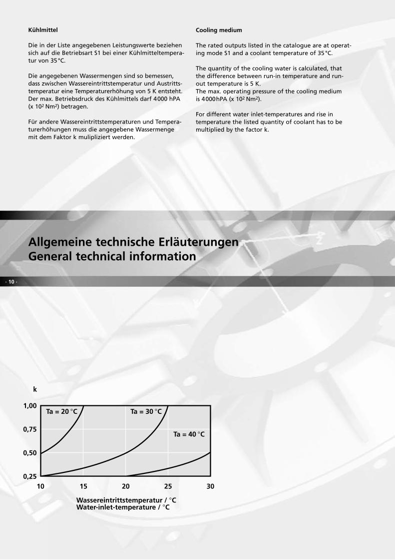
Kühlmittel
Die in der Liste angegebenen Leistungswerte beziehen sich auf die Betriebsart S1 bei einer Kühlmitteltempera-tur von 35 °C.
Die angegebenen Wassermengen sind so bemessen, dass zwischen Wassereintrittstemperatur und Austritts- temperatur eine Temperaturerhöhung von 5 K entsteht.Der max. Betriebsdruck des Kühlmittels darf 4000 hPA (x 102 Nm2) betragen.
Für andere Wassereintrittstemperaturen und Tempera-turerhöhungen muss die angegebene Wassermenge mit dem Faktor k mulipliziert werden.
Cooling medium
The rated outputs listed in the catalogue are at operat- ing mode S1 and a coolant temperature of 35 °C.
The quantity of the cooling water is calculated, that the difference between run-in temperature and run-out temperature is 5 K.The max. operating pressure of the cooling mediumis 4000hPA (x 102 Nm2).
For different water inlet-temperatures and rise in temperature the listed quantity of coolant has to be multiplied by the factor k.
Allgemeine technische ErläuterungenGeneral technical information
0,25
0,50
0,75
1,00
10 15 20 25 30
k
Wassereintrittstemperatur / CWater-inlet-temperature / C
Ta = 40 C
Ta = 30 CTa = 20 C
· 11 ·
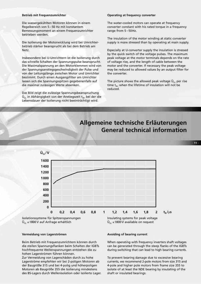
Betrieb mit Frequenzumrichter
Die wassergekühlten Motoren können in einem Regelbereich von 5 – 50 Hz mit konstantem Bemessungsmoment an einem Frequenzumrichter betrieben werden.
Die Isolierung der Motorwicklung wird bei Umrichter-betrieb stärker beansprucht als bei dem Betrieb am Netz.
Insbesondere bei U-Umrichtern ist die Isolierung durch das schnelle Schalten der Spannungspulse beansprucht. Die Maximalspannung an den Motorklemmen wird von der Spannungsanstiegsgeschwindigkeit der Pulse und von der Leitungslänge zwischen Motor und Umrichter bestimmt. Durch einen Ausgangsfilter am Umrichter lassen sich die Spannungsspitzen gegebenenfalls auf die maximal zulässigen Werte absenken.
Das Bild zeigt die zulässige Spannungsbeanspruchung ÛLL in Abhängigkeit von der Anstiegszeit tA, bei der die Lebensdauer der Isolierung nicht beeinträchtigt wird.
Operating at frequency converter
The water-cooled motors can operate at frequency converter constant with his rated torque in a frequency range from 5 – 50Hz.
The insulation of the motor winding at static converter supply is more stressed than by operating at main supply.
Especially at U-converter supply the insulation is stressed by the quick switch of the voltage pulses. The maximum peak voltage at the motor terminals depends on the rate of voltage rise, and the length of cable between the motor and the converter. If necessary the peak voltage may be reduced to allowed values by an output filter for the converter.
The picture shows the allowed peak voltage ÛLL per rise time tA, when the lifetime of insulation will not be reduced.
Allgemeine technische ErläuterungenGeneral technical information
Vermeidung von Lagerströmen
Beim Betrieb mit Frequenzumrichtern können durch die steilen Spannungsflanken beim Schalten der IGBTs hochfrequente Wellenspannungen entstehen die zu hohen Lagerströmen führen können.Zur Vermeidung von Lagerschäden durch zu hohe Lagerströme empfehlen wir bei 2-poligen Motoren ab der Baugröße 315 und bei 4-polig und höherpoligen Motoren ab Baugröße 355 die Isolierung mindestens des BS-Lagers durch Wellenisolation oder isolierte Lager.
Avoiding of bearing current
When operating with frequency inverters shaft voltages can be generated through the steep flanks of the IGBTs during switching that can lead to high bearing currents. To prevent bearing damage due to excessive bearing currents, we recommend 2-pole motors from size 315 and 4-pole and higher pole motors from frame size 355 to isolate of at least the NDE bearing by insulating of the shaft or insulated bearings.
0
200
400
600
800
1000
1200
1400
1600
0 0,2 0,4 0,6 0,8 1 1,2 1,4 1,6 1,8 2
ÛLL/V
tA/
1
2
3
4
5 10 15 20 25 30
k
Wassereintrittstemperatur / CWater-inlet-temperature / C
Ta = 40 C
Ta = 30 C
Ta = 20 C
Isolationssysteme für SpitzenspannungenÛLL ≤1800 V auf Anfrage erhältlich
Insulating systems for peak voltageÛLL ≤1800 V available on request
· 12 ·
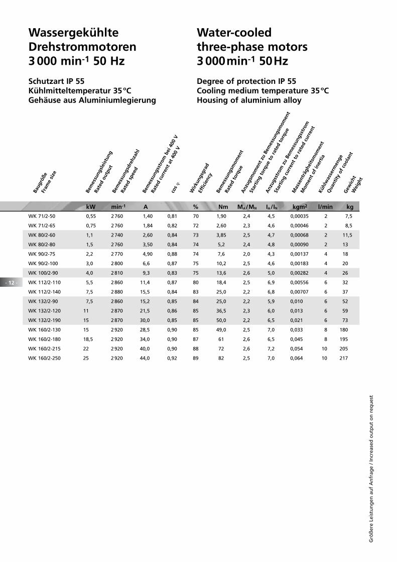
Wassergekühlte Drehstrommotoren 3 000 min-1 50 Hz
Schutzart IP 55Kühlmitteltemperatur 35 ºCGehäuse aus Aluminiumlegierung
Water-cooled three-phase motors3 000min-1 50Hz
Degree of protection IP 55Cooling medium temperature 35 ºCHousing of aluminium alloy
Baug
röße
Fram
e si
ze
Bem
essu
ngsl
eist
ung
Rate
d ou
tput
Be
mes
sung
sdre
hzah
l
Rate
d sp
eed
Bem
essu
ngss
trom
bei
400
V
Rate
d cu
rren
t at
400
Vco
s ϕ
Wirk
ungs
grad
Effic
ienc
y
Bem
essu
ngsm
omen
t
Gew
icht
W
eigh
t
Rate
d to
rque
Anz
ugsm
omen
t zu
Bem
essu
ngsm
omen
t
Star
ting
torq
ue t
o ra
ted
torq
ue
Anz
ugss
trom
zu
Bem
essu
ngss
trom
Star
ting
curr
ent
to r
ated
cur
rent
Mas
sent
rägh
eits
mom
ent
Mom
ent
of in
ertia
Kü
hlw
asse
rmen
ge
Qua
ntity
of
cool
ant
kW min-1 A % Nm MA/MN IA/IN kgm2 l/min kg
Grö
ßer
e Le
istu
ng
en a
uf
An
frag
e /
Incr
ease
d o
utp
ut
on
req
ues
t
WK 71/2-50 0,55 2 760 1,40 0,81 70 1,90 2,4 4,5 0,00035 2 7,5
WK 71/2-65 0,75 2 760 1,84 0,82 72 2,60 2,3 4,6 0,00046 2 8,5
WK 80/2-60 1,1 2 740 2,60 0,84 73 3,85 2,5 4,7 0,00068 2 11,5
WK 80/2-80 1,5 2 760 3,50 0,84 74 5,2 2,4 4,8 0,00090 2 13
WK 90/2-75 2,2 2 770 4,90 0,88 74 7,6 2,0 4,3 0,00137 4 18
WK 90/2-100 3,0 2 800 6,6 0,87 75 10,2 2,5 4,6 0,00183 4 20
WK 100/2-90 4,0 2 810 9,3 0,83 75 13,6 2,6 5,0 0,00282 4 26
WK 112/2-110 5,5 2 860 11,4 0,87 80 18,4 2,5 6,9 0,00556 6 32
WK 112/2-140 7,5 2 880 15,5 0,84 83 25,0 2,2 6,8 0,00707 6 37
WK 132/2-90 7,5 2 860 15,2 0,85 84 25,0 2,2 5,9 0,010 6 52
WK 132/2-120 11 2 870 21,5 0,86 85 36,5 2,3 6,0 0,013 6 59
WK 132/2-190 15 2 870 30,0 0,85 85 50,0 2,2 6,5 0,021 6 73
WK 160/2-130 15 2 920 28,5 0,90 85 49,0 2,5 7,0 0,033 8 180
WK 160/2-180 18,5 2 920 34,0 0,90 87 61 2,6 6,5 0,045 8 195
WK 160/2-215 22 2 920 40,0 0,90 88 72 2,6 7,2 0,054 10 205
WK 160/2-250 25 2 920 44,0 0,92 89 82 2,5 7,0 0,064 10 217
· 13 ·
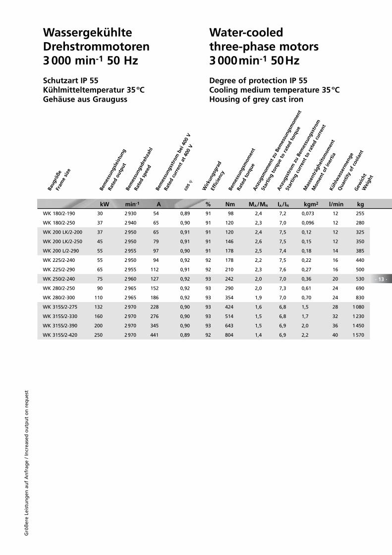
WK 180/2-190 30 2 930 54 0,89 91 98 2,4 7,2 0,073 12 255
WK 180/2-250 37 2 940 65 0,90 91 120 2,3 7,0 0,096 12 280
WK 200 LK/2-200 37 2 950 65 0,91 91 120 2,4 7,5 0,12 12 325
WK 200 LK/2-250 45 2 950 79 0,91 91 146 2,6 7,5 0,15 12 350
WK 200 L/2-290 55 2 955 97 0,90 91 178 2,5 7,4 0,18 14 385
WK 225/2-240 55 2 950 94 0,92 92 178 2,2 7,5 0,22 16 440
WK 225/2-290 65 2 955 112 0,91 92 210 2,3 7,6 0,27 16 500
WK 250/2-240 75 2 960 127 0,92 93 242 2,0 7,0 0,36 20 530
WK 280/2-250 90 2 965 152 0,92 93 290 2,0 7,3 0,61 24 690
WK 280/2-300 110 2 965 186 0,92 93 354 1,9 7,0 0,70 24 830
WK 315S/2-275 132 2 970 228 0,90 93 424 1,6 6,8 1,5 28 1 080
WK 315S/2-330 160 2 970 276 0,90 93 514 1,5 6,8 1,7 32 1 230
WK 315S/2-390 200 2 970 345 0,90 93 643 1,5 6,9 2,0 36 1 450
WK 315S/2-420 250 2 970 441 0,89 92 804 1,4 6,9 2,2 40 1 570
kW min-1 A % Nm MA/MN IA/IN kgm2 l/min kg
Wassergekühlte Drehstrommotoren 3 000 min-1 50 Hz
Schutzart IP 55Kühlmitteltemperatur 35 ºCGehäuse aus Grauguss
Water-cooled three-phase motors3 000min-1 50Hz
Degree of protection IP 55Cooling medium temperature 35 ºCHousing of grey cast iron
Baug
röße
Fram
e si
ze
Bem
essu
ngsl
eist
ung
Rate
d ou
tput
Be
mes
sung
sdre
hzah
l
Rate
d sp
eed
Bem
essu
ngss
trom
bei
400
V
Rate
d cu
rren
t at
400
Vco
s ϕ
Wirk
ungs
grad
Effic
ienc
y
Bem
essu
ngsm
omen
t
Gew
icht
W
eigh
t
Rate
d to
rque
Anz
ugsm
omen
t zu
Bem
essu
ngsm
omen
t
Star
ting
torq
ue t
o ra
ted
torq
ue
Anz
ugss
trom
zu
Bem
essu
ngss
trom
Star
ting
curr
ent
to r
ated
cur
rent
Mas
sent
rägh
eits
mom
ent
Mom
ent
of in
ertia
Kü
hlw
asse
rmen
ge
Qua
ntity
of
cool
ant
Grö
ßer
e Le
istu
ng
en a
uf
An
frag
e /
Incr
ease
d o
utp
ut
on
req
ues
t
· 14 ·
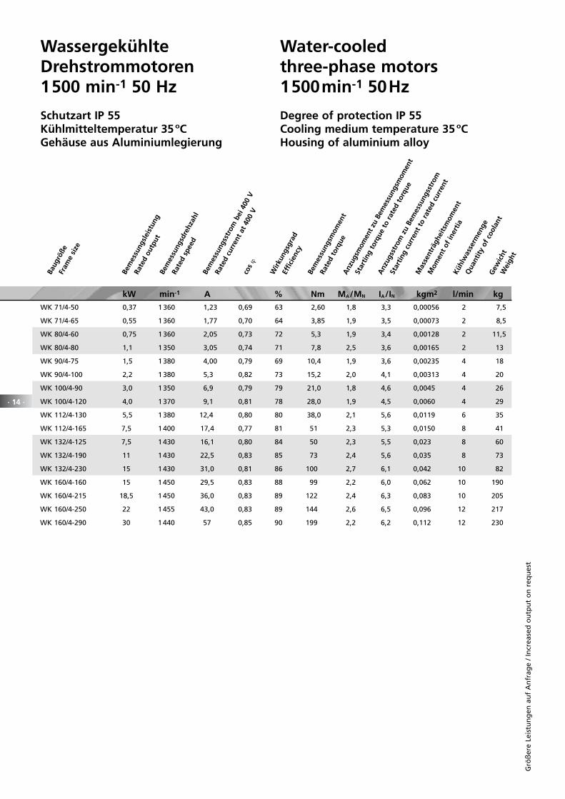
Wassergekühlte Drehstrommotoren 1500 min-1 50 Hz
Schutzart IP 55Kühlmitteltemperatur 35 ºCGehäuse aus Aluminiumlegierung
Water-cooled three-phase motors1500min-1 50Hz
Degree of protection IP 55Cooling medium temperature 35 ºCHousing of aluminium alloy
kW min-1 A % Nm MA/MN IA/IN kgm2 l/min kg
Baug
röße
Fram
e si
ze
Bem
essu
ngsl
eist
ung
Rate
d ou
tput
Be
mes
sung
sdre
hzah
l
Rate
d sp
eed
Bem
essu
ngss
trom
bei
400
V
Rate
d cu
rren
t at
400
Vco
s ϕ
Wirk
ungs
grad
Effic
ienc
y
Bem
essu
ngsm
omen
t
Gew
icht
W
eigh
t
Rate
d to
rque
Anz
ugsm
omen
t zu
Bem
essu
ngsm
omen
t
Star
ting
torq
ue t
o ra
ted
torq
ue
Anz
ugss
trom
zu
Bem
essu
ngss
trom
Star
ting
curr
ent
to r
ated
cur
rent
Mas
sent
rägh
eits
mom
ent
Mom
ent
of in
ertia
Kü
hlw
asse
rmen
ge
Qua
ntity
of
cool
ant
Grö
ßer
e Le
istu
ng
en a
uf
An
frag
e /
Incr
ease
d o
utp
ut
on
req
ues
t
WK 71/4-50 0,37 1 360 1,23 0,69 63 2,60 1,8 3,3 0,00056 2 7,5
WK 71/4-65 0,55 1 360 1,77 0,70 64 3,85 1,9 3,5 0,00073 2 8,5
WK 80/4-60 0,75 1 360 2,05 0,73 72 5,3 1,9 3,4 0,00128 2 11,5
WK 80/4-80 1,1 1 350 3,05 0,74 71 7,8 2,5 3,6 0,00165 2 13
WK 90/4-75 1,5 1 380 4,00 0,79 69 10,4 1,9 3,6 0,00235 4 18
WK 90/4-100 2,2 1 380 5,3 0,82 73 15,2 2,0 4,1 0,00313 4 20
WK 100/4-90 3,0 1 350 6,9 0,79 79 21,0 1,8 4,6 0,0045 4 26
WK 100/4-120 4,0 1 370 9,1 0,81 78 28,0 1,9 4,5 0,0060 4 29
WK 112/4-130 5,5 1 380 12,4 0,80 80 38,0 2,1 5,6 0,0119 6 35
WK 112/4-165 7,5 1 400 17,4 0,77 81 51 2,3 5,3 0,0150 8 41
WK 132/4-125 7,5 1 430 16,1 0,80 84 50 2,3 5,5 0,023 8 60
WK 132/4-190 11 1 430 22,5 0,83 85 73 2,4 5,6 0,035 8 73
WK 132/4-230 15 1 430 31,0 0,81 86 100 2,7 6,1 0,042 10 82
WK 160/4-160 15 1 450 29,5 0,83 88 99 2,2 6,0 0,062 10 190
WK 160/4-215 18,5 1 450 36,0 0,83 89 122 2,4 6,3 0,083 10 205
WK 160/4-250 22 1 455 43,0 0,83 89 144 2,6 6,5 0,096 12 217
WK 160/4-290 30 1 440 57 0,85 90 199 2,2 6,2 0,112 12 230
· 15 ·
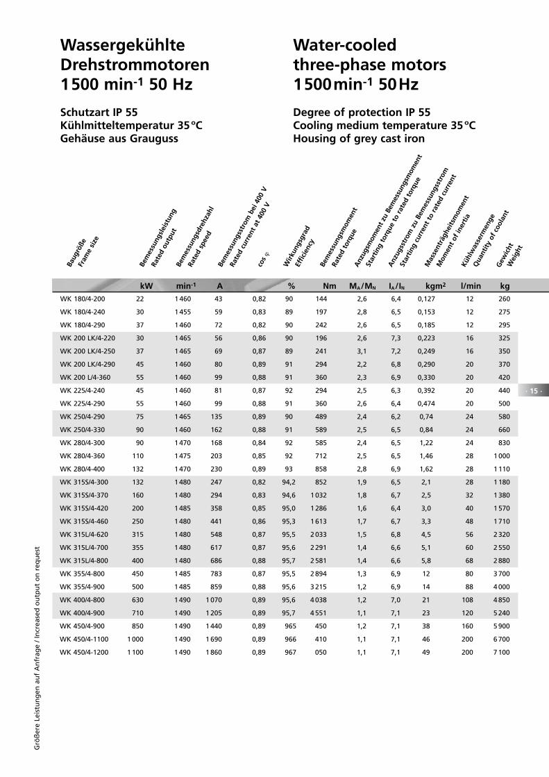
Wassergekühlte Drehstrommotoren 1500 min-1 50 Hz
Schutzart IP 55Kühlmitteltemperatur 35 ºCGehäuse aus Grauguss
Water-cooled three-phase motors1500min-1 50Hz
Degree of protection IP 55Cooling medium temperature 35 ºCHousing of grey cast iron
WK 180/4-200 22 1 460 43 0,82 90 144 2,6 6,4 0,127 12 260
WK 180/4-240 30 1 455 59 0,83 89 197 2,8 6,5 0,153 12 275
WK 180/4-290 37 1 460 72 0,82 90 242 2,6 6,5 0,185 12 295
WK 200 LK/4-220 30 1 465 56 0,86 90 196 2,6 7,3 0,223 16 325
WK 200 LK/4-250 37 1 465 69 0,87 89 241 3,1 7,2 0,249 16 350
WK 200 LK/4-290 45 1 460 80 0,89 91 294 2,2 6,8 0,290 20 370
WK 200 L/4-360 55 1 460 99 0,88 91 360 2,3 6,9 0,330 20 420
WK 225/4-240 45 1 460 81 0,87 92 294 2,5 6,3 0,392 20 440
WK 225/4-290 55 1 460 99 0,88 91 360 2,6 6,4 0,474 20 500
WK 250/4-290 75 1 465 135 0,89 90 489 2,4 6,2 0,74 24 580
WK 250/4-330 90 1 460 162 0,88 91 589 2,5 6,5 0,84 24 660
WK 280/4-300 90 1 470 168 0,84 92 585 2,4 6,5 1,22 24 830
WK 280/4-360 110 1 475 203 0,85 92 712 2,5 6,5 1,46 28 1 000
WK 280/4-400 132 1 470 230 0,89 93 858 2,8 6,9 1,62 28 1 110
WK 315S/4-300 132 1 480 247 0,82 94,2 852 1,9 6,5 2,1 28 1 180
WK 315S/4-370 160 1 480 294 0,83 94,6 1 032 1,8 6,7 2,5 32 1 380
WK 315S/4-420 200 1 485 358 0,85 95,0 1 286 1,6 6,4 3,0 40 1 570
WK 315S/4-460 250 1 480 441 0,86 95,3 1 613 1,7 6,7 3,3 48 1 710
WK 315L/4-620 315 1 480 548 0,87 95,5 2 033 1,5 6,8 4,5 56 2 320
WK 315L/4-700 355 1 480 617 0,87 95,6 2 291 1,4 6,6 5,1 60 2 550
WK 315L/4-800 400 1 480 686 0,88 95,7 2 581 1,4 6,6 5,8 68 2 880
WK 355/4-800 450 1 485 783 0,87 95,5 2 894 1,3 6,9 12 80 3 700
WK 355/4-900 500 1 485 859 0,88 95,6 3 215 1,2 6,9 14 88 4 000
WK 400/4-800 630 1 490 1 070 0,89 95,6 4 038 1,2 7,0 21 108 4 850
WK 400/4-900 710 1 490 1 205 0,89 95,7 4 551 1,1 7,1 23 120 5 240
WK 450/4-900 850 1 490 1 440 0,89 96 5 450 1,2 7,1 38 160 5 900
WK 450/4-1100 1 000 1 490 1 690 0,89 96 6 410 1,1 7,1 46 200 6 700
WK 450/4-1200 1 100 1 490 1 860 0,89 96 7 050 1,1 7,1 49 200 7 100
kW min-1 A % Nm MA/MN IA/IN kgm2 l/min kg
Baug
röße
Fram
e si
ze
Bem
essu
ngsl
eist
ung
Rate
d ou
tput
Be
mes
sung
sdre
hzah
l
Rate
d sp
eed
Bem
essu
ngss
trom
bei
400
V
Rate
d cu
rren
t at
400
Vco
s ϕ
Wirk
ungs
grad
Effic
ienc
y
Bem
essu
ngsm
omen
t
Gew
icht
W
eigh
t
Rate
d to
rque
Anz
ugsm
omen
t zu
Bem
essu
ngsm
omen
t
Star
ting
torq
ue t
o ra
ted
torq
ue
Anz
ugss
trom
zu
Bem
essu
ngss
trom
Star
ting
curr
ent
to r
ated
cur
rent
Mas
sent
rägh
eits
mom
ent
Mom
ent
of in
ertia
Kü
hlw
asse
rmen
ge
Qua
ntity
of
cool
ant
Grö
ßer
e Le
istu
ng
en a
uf
An
frag
e /
Incr
ease
d o
utp
ut
on
req
ues
t
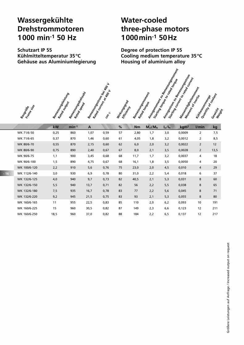
Wassergekühlte Drehstrommotoren 1000 min-1 50 Hz
Schutzart IP 55Kühlmitteltemperatur 35 ºCGehäuse aus Aluminiumlegierung
Water-cooled three-phase motors1000min-1 50Hz
Degree of protection IP 55Cooling medium temperature 35 ºCHousing of aluminium alloy
kW min-1 A % Nm MA/MN IA/IN kgm2 l/min kg
WK 71/6-50 0,25 860 1,07 0,59 57 2,80 1,7 3,0 0,0009 2 7,5
WK 71/6-65 0,37 870 1,46 0,60 61 4,05 1,8 3,2 0,0012 2 8,5
WK 80/6-70 0,55 870 2,15 0,60 62 6,0 2,0 3,2 0,0022 2 12
WK 80/6-90 0,75 890 2,40 0,67 67 8,0 2,1 3,5 0,0028 2 13,5
WK 90/6-75 1,1 900 3,45 0,68 68 11,7 1,7 3,2 0,0037 4 18
WK 90/6-100 1,5 890 4,75 0,67 68 16,1 1,8 3,5 0,0050 4 20
WK 100/6-120 2,2 910 5,6 0,76 75 23,0 2,0 4,5 0,010 4 29
WK 112/6-140 3,0 930 6,9 0,78 80 31,0 2,2 5,4 0,018 6 37
WK 132/6-125 4,0 940 9,7 0,73 82 40,5 2,1 5,3 0,031 8 60
WK 132/6-150 5,5 940 13,7 0,71 82 56 2,2 5,5 0,038 8 65
WK 132/6-180 7,5 935 16,7 0,78 83 77 2,2 5,6 0,045 8 71
WK 132/6-220 9,2 945 21,5 0,75 83 93 2,1 5,3 0,055 8 80
WK 160/6-165 11 955 22,5 0,83 85 110 2,0 6,2 0,093 10 191
WK 160/6-225 15 960 30,5 0,82 87 149 2,3 6,6 0,123 12 211
WK 160/6-250 18,5 960 37,0 0,82 88 184 2,2 6,5 0,137 12 217
Bem
essu
ngsl
eist
ung
Rate
d ou
tput
Be
mes
sung
sdre
hzah
l
Rate
d sp
eed
Bem
essu
ngss
trom
bei
400
V
Rate
d cu
rren
t at
400
Vco
s ϕ
Wirk
ungs
grad
Effic
ienc
y
Bem
essu
ngsm
omen
t
Rate
d to
rque
Anz
ugsm
omen
t zu
Bem
essu
ngsm
omen
t
Star
ting
torq
ue t
o ra
ted
torq
ue
Anz
ugss
trom
zu
Bem
essu
ngss
trom
Star
ting
curr
ent
to r
ated
cur
rent
Mas
sent
rägh
eits
mom
ent
Mom
ent
of in
ertia
Kü
hlw
asse
rmen
ge
Qua
ntity
of
cool
ant
· 16 ·
Grö
ßer
e Le
istu
ng
en a
uf
An
frag
e /
Incr
ease
d o
utp
ut
on
req
ues
t
Baug
röße
Fram
e si
ze
Gew
icht
W
eigh
t
· 17 ·
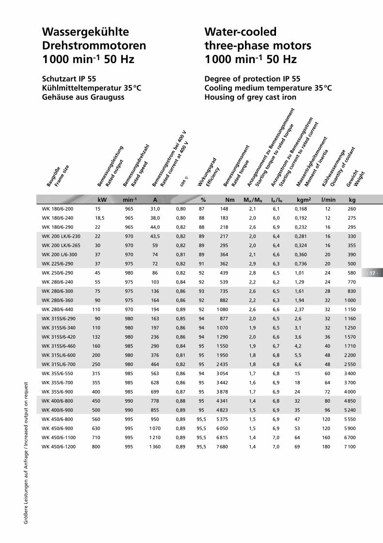
Wassergekühlte Drehstrommotoren 1000 min-1 50 Hz
Schutzart IP 55Kühlmitteltemperatur 35 ºCGehäuse aus Grauguss
Water-cooled three-phase motors1000 min-1 50 Hz
Degree of protection IP 55Cooling medium temperature 35 ºCHousing of grey cast iron
WK 180/6-200 15 965 31,0 0,80 87 148 2,1 6,1 0,168 12 260
WK 180/6-240 18,5 965 38,0 0,80 88 183 2,0 6,0 0,192 12 275
WK 180/6-290 22 965 44,0 0,82 88 218 2,6 6,9 0,232 16 295
WK 200 LK/6-230 22 970 43,5 0,82 89 217 2,0 6,4 0,281 16 330
WK 200 LK/6-265 30 970 59 0,82 89 295 2,0 6,4 0,324 16 355
WK 200 L/6-300 37 970 74 0,81 89 364 2,1 6,6 0,360 20 390
WK 225/6-290 37 975 72 0,82 91 362 2,9 6,3 0,736 20 500
WK 250/6-290 45 980 86 0,82 92 439 2,8 6,5 1,01 24 580
WK 280/6-240 55 975 103 0,84 92 539 2,2 6,2 1,29 24 770
WK 280/6-300 75 975 136 0,86 93 735 2,6 6,5 1,61 28 830
WK 280/6-360 90 975 164 0,86 92 882 2,2 6,3 1,94 32 1 000
WK 280/6-440 110 970 194 0,89 92 1 080 2,6 6,6 2,37 32 1 150
WK 315S/6-290 90 980 163 0,85 94 877 2,0 6,5 2,6 32 1 160
WK 315S/6-340 110 980 197 0,86 94 1 070 1,9 6,5 3,1 32 1 250
WK 315S/6-420 132 980 236 0,86 94 1 290 2,0 6,6 3,6 36 1 570
WK 315S/6-460 160 985 290 0,84 95 1 550 1,9 6,7 4,2 40 1 710
WK 315L/6-600 200 980 376 0,81 95 1 950 1,8 6,8 5,5 48 2 200
WK 315L/6-700 250 980 464 0,82 95 2 435 1,8 6,8 6,6 48 2 550
WK 355/6-550 315 985 563 0,86 94 3 054 1,7 6,8 15 60 3 400
WK 355/6-700 355 985 628 0,86 95 3 442 1,6 6,9 18 64 3 700
WK 355/6-900 400 985 699 0,87 95 3 878 1,7 6,9 24 72 4 000
WK 400/6-800 450 990 778 0,88 95 4 341 1,4 6,8 32 80 4 850
WK 400/6-900 500 990 855 0,89 95 4 823 1,5 6,9 35 96 5 240
WK 450/6-800 560 995 950 0,89 95,5 5 375 1,5 6,9 47 120 5 550
WK 450/6-900 630 995 1 070 0,89 95,5 6 050 1,5 6,9 53 120 5 900
WK 450/6-1100 710 995 1 210 0,89 95,5 6 815 1,4 7,0 64 160 6 700
WK 450/6-1200 800 995 1 360 0,89 95,5 7 680 1,4 7,0 69 180 7 100
kW min-1 A % Nm MA/MN IA/IN kgm2 l/min kg
Baug
röße
Fram
e si
ze
Bem
essu
ngsl
eist
ung
Rate
d ou
tput
Be
mes
sung
sdre
hzah
l
Rate
d sp
eed
Bem
essu
ngss
trom
bei
400
V
Rate
d cu
rren
t at
400
Vco
s ϕ
Wirk
ungs
grad
Effic
ienc
y
Bem
essu
ngsm
omen
t
Gew
icht
W
eigh
t
Rate
d to
rque
Anz
ugsm
omen
t zu
Bem
essu
ngsm
omen
t
Star
ting
torq
ue t
o ra
ted
torq
ue
Anz
ugss
trom
zu
Bem
essu
ngss
trom
Star
ting
curr
ent
to r
ated
cur
rent
Mas
sent
rägh
eits
mom
ent
Mom
ent
of in
ertia
Kü
hlw
asse
rmen
ge
Qua
ntity
of
cool
ant
Grö
ßer
e Le
istu
ng
en a
uf
An
frag
e /
Incr
ease
d o
utp
ut
on
req
ues
t
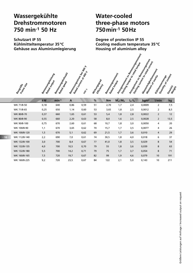
Wassergekühlte Drehstrommotoren 750 min-1 50 Hz
Schutzart IP 55Kühlmitteltemperatur 35 ºCGehäuse aus Aluminiumlegierung
Water-cooled three-phase motors750min-1 50Hz
Degree of protection IP 55Cooling medium temperature 35 ºCHousing of aluminium alloy
kW min-1 A % Nm MA/MN IA/IN kgm2 l/min kg
WK 71/8-50 0,18 640 0,86 0,59 51 2,70 1,7 2,4 0,0009 2 7,5
WK 71/8-65 0,25 650 1,14 0,60 53 3,65 1,8 2,5 0,0012 2 8,5
WK 80/8-70 0,37 660 1,65 0,61 53 5,4 1,8 2,8 0,0022 2 12
WK 80/8-90 0,55 660 2,20 0,63 58 8,0 1,6 2,5 0,0028 2 13,5
WK 90/8-100 0,75 670 2,60 0,61 68 10,7 1,8 3,0 0,0050 4 20
WK 100/8-90 1,1 670 3,65 0,62 70 15,7 1,7 3,5 0,0077 4 26
WK 100/8-120 1,5 670 5,1 0,62 69 21,5 1,7 3,6 0,010 4 29
WK 112/8-140 2,2 690 7,0 0,61 74 30,5 1,8 4,0 0,018 6 37
WK 132/8-100 3,0 700 8,4 0,67 77 41,0 1,8 3,5 0,029 8 54
WK 132/8-135 4,0 700 10,5 0,70 79 55 1,8 3,6 0,039 8 63
WK 132/8-180 5,5 700 14,2 0,71 79 75 1,7 3,7 0,054 8 71
WK 160/8-165 7,5 720 19,7 0,67 82 99 1,9 4,6 0,079 10 191
WK 160/8-225 9,2 720 23,5 0,67 84 122 2,1 5,0 0,143 10 211
Baug
röße
Fram
e si
ze
Bem
essu
ngsl
eist
ung
Rate
d ou
tput
Be
mes
sung
sdre
hzah
l
Rate
d sp
eed
Bem
essu
ngss
trom
bei
400
V
Rate
d cu
rren
t at
400
Vco
s ϕ
Wirk
ungs
grad
Effic
ienc
y
Bem
essu
ngsm
omen
t
Gew
icht
W
eigh
t
Rate
d to
rque
Anz
ugsm
omen
t zu
Bem
essu
ngsm
omen
t
Star
ting
torq
ue t
o ra
ted
torq
ue
Anz
ugss
trom
zu
Bem
essu
ngss
trom
Star
ting
curr
ent
to r
ated
cur
rent
Mas
sent
rägh
eits
mom
ent
Mom
ent
of in
ertia
Kü
hlw
asse
rmen
ge
Qua
ntity
of
cool
ant
· 18 ·
Grö
ßer
e Le
istu
ng
en a
uf
An
frag
e /
Incr
ease
d o
utp
ut
on
req
ues
t
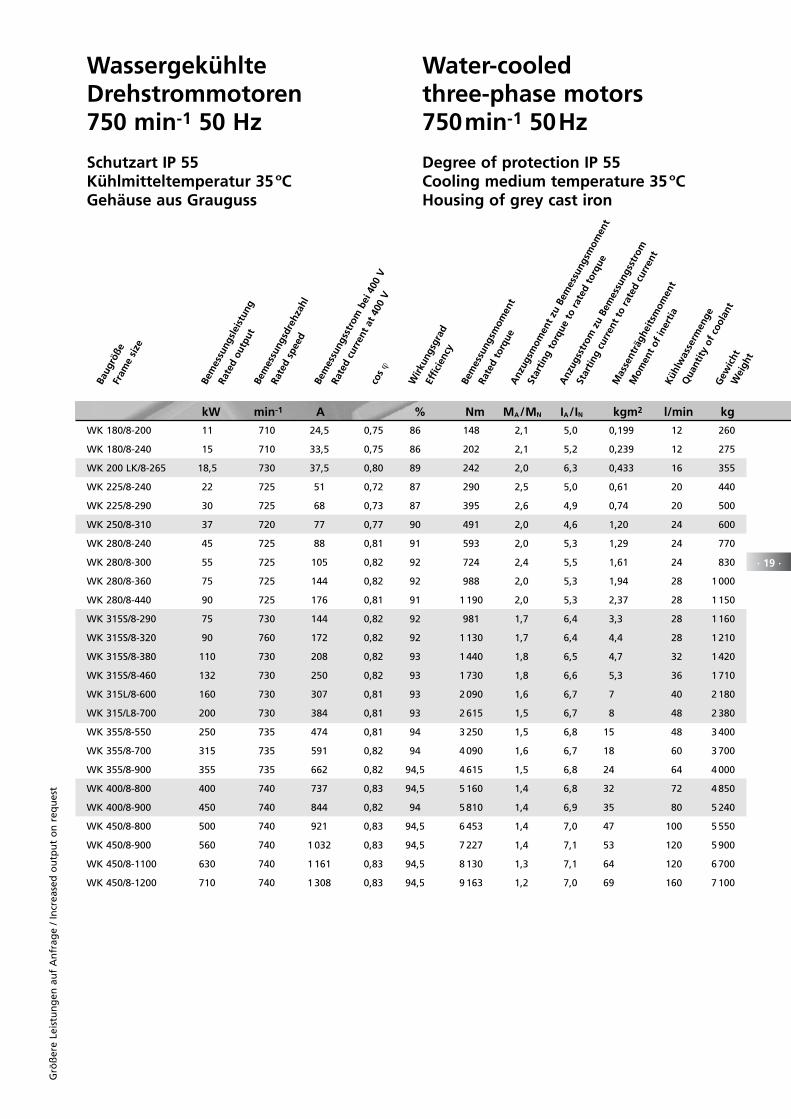
Wassergekühlte Drehstrommotoren 750 min-1 50 Hz
Schutzart IP 55Kühlmitteltemperatur 35 ºCGehäuse aus Grauguss
Water-cooled three-phase motors750min-1 50Hz
Degree of protection IP 55Cooling medium temperature 35 ºCHousing of grey cast iron
WK 180/8-200 11 710 24,5 0,75 86 148 2,1 5,0 0,199 12 260
WK 180/8-240 15 710 33,5 0,75 86 202 2,1 5,2 0,239 12 275
WK 200 LK/8-265 18,5 730 37,5 0,80 89 242 2,0 6,3 0,433 16 355
WK 225/8-240 22 725 51 0,72 87 290 2,5 5,0 0,61 20 440
WK 225/8-290 30 725 68 0,73 87 395 2,6 4,9 0,74 20 500
WK 250/8-310 37 720 77 0,77 90 491 2,0 4,6 1,20 24 600
WK 280/8-240 45 725 88 0,81 91 593 2,0 5,3 1,29 24 770
WK 280/8-300 55 725 105 0,82 92 724 2,4 5,5 1,61 24 830
WK 280/8-360 75 725 144 0,82 92 988 2,0 5,3 1,94 28 1 000
WK 280/8-440 90 725 176 0,81 91 1 190 2,0 5,3 2,37 28 1 150
WK 315S/8-290 75 730 144 0,82 92 981 1,7 6,4 3,3 28 1 160
WK 315S/8-320 90 760 172 0,82 92 1 130 1,7 6,4 4,4 28 1 210
WK 315S/8-380 110 730 208 0,82 93 1 440 1,8 6,5 4,7 32 1 420
WK 315S/8-460 132 730 250 0,82 93 1 730 1,8 6,6 5,3 36 1 710
WK 315L/8-600 160 730 307 0,81 93 2 090 1,6 6,7 7 40 2 180
WK 315/L8-700 200 730 384 0,81 93 2 615 1,5 6,7 8 48 2 380
WK 355/8-550 250 735 474 0,81 94 3 250 1,5 6,8 15 48 3 400
WK 355/8-700 315 735 591 0,82 94 4 090 1,6 6,7 18 60 3 700
WK 355/8-900 355 735 662 0,82 94,5 4 615 1,5 6,8 24 64 4 000
WK 400/8-800 400 740 737 0,83 94,5 5 160 1,4 6,8 32 72 4 850
WK 400/8-900 450 740 844 0,82 94 5 810 1,4 6,9 35 80 5 240
WK 450/8-800 500 740 921 0,83 94,5 6 453 1,4 7,0 47 100 5 550
WK 450/8-900 560 740 1 032 0,83 94,5 7 227 1,4 7,1 53 120 5 900
WK 450/8-1100 630 740 1 161 0,83 94,5 8 130 1,3 7,1 64 120 6 700
WK 450/8-1200 710 740 1 308 0,83 94,5 9 163 1,2 7,0 69 160 7 100
kW min-1 A % Nm MA/MN IA/IN kgm2 l/min kg
Baug
röße
Fram
e si
ze
Bem
essu
ngsl
eist
ung
Rate
d ou
tput
Be
mes
sung
sdre
hzah
l
Rate
d sp
eed
Bem
essu
ngss
trom
bei
400
V
Rate
d cu
rren
t at
400
Vco
s ϕ
Wirk
ungs
grad
Effic
ienc
y
Bem
essu
ngsm
omen
t
Gew
icht
W
eigh
t
Rate
d to
rque
Anz
ugsm
omen
t zu
Bem
essu
ngsm
omen
t
Star
ting
torq
ue t
o ra
ted
torq
ue
Anz
ugss
trom
zu
Bem
essu
ngss
trom
Star
ting
curr
ent
to r
ated
cur
rent
Mas
sent
rägh
eits
mom
ent
Mom
ent
of in
ertia
Kü
hlw
asse
rmen
ge
Qua
ntity
of
cool
ant
· 19 ·
Grö
ßer
e Le
istu
ng
en a
uf
An
frag
e /
Incr
ease
d o
utp
ut
on
req
ues
t
· 20 ·
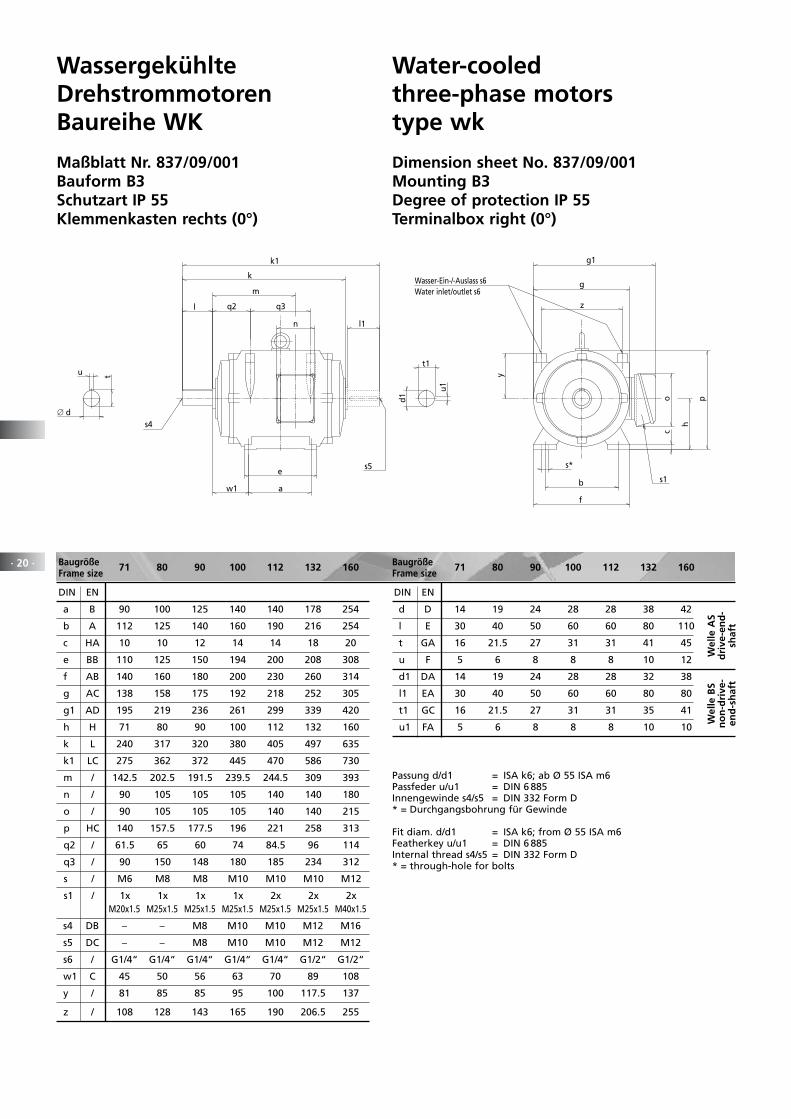
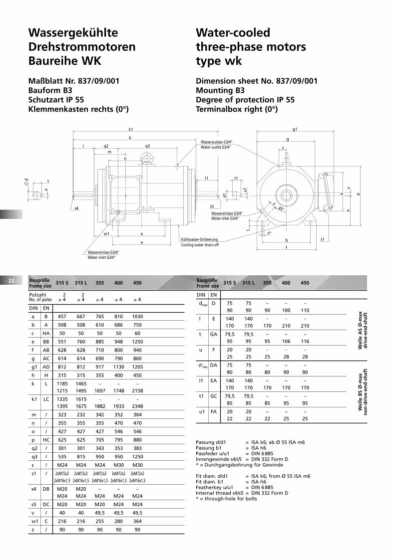
WassergekühlteDrehstrommotorenBaureihe WK
Maßblatt Nr. 837/09/001Bauform B3Schutzart IP 55Klemmenkasten rechts (0°)
Water-cooledthree-phase motorstype wk
Dimension sheet No. 837/09/001Mounting B3Degree of protection IP 55Terminalbox right (0°)
Baugröße 71 80 90 100 112 132 160Frame size
Wasser-Ein-/-Auslass s6
t1
d1
u1
tu
∅ d
l1
s5
k1
n
m
w1 a
e
l
s4
q2 q3
k
o p
c
h
s*
b
f
g
g1
y
z
s1
Water inlet/outlet s6
DIN EN
a B 90 100 125 140 140 178 254
b A 112 125 140 160 190 216 254
c HA 10 10 12 14 14 18 20
e BB 110 125 150 194 200 208 308
f AB 140 160 180 200 230 260 314
g AC 138 158 175 192 218 252 305
g1 AD 195 219 236 261 299 339 420
h H 71 80 90 100 112 132 160
k L 240 317 320 380 405 497 635
k1 LC 275 362 372 445 470 586 730
m / 142.5 202.5 191.5 239.5 244.5 309 393
n / 90 105 105 105 140 140 180
o / 90 105 105 105 140 140 215
p HC 140 157.5 177.5 196 221 258 313
q2 / 61.5 65 60 74 84.5 96 114
q3 / 90 150 148 180 185 234 312
s / M6 M8 M8 M10 M10 M10 M12
s1 / 1x 1x 1x 1x 2x 2x 2x M20x1.5 M25x1.5 M25x1.5 M25x1.5 M25x1.5 M25x1.5 M40x1.5
s4 DB – – M8 M10 M10 M12 M16
s5 DC – – M8 M10 M10 M12 M12
s6 / G1/4“ G1/4“ G1/4“ G1/4“ G1/4“ G1/2“ G1/2“
w1 C 45 50 56 63 70 89 108
y / 81 85 85 95 100 117.5 137
z / 108 128 143 165 190 206.5 255
DIN EN
d D 14 19 24 28 28 38 42
l E 30 40 50 60 60 80 110
t GA 16 21.5 27 31 31 41 45
u F 5 6 8 8 8 10 12
d1 DA 14 19 24 28 28 32 38
l1 EA 30 40 50 60 60 80 80
t1 GC 16 21.5 27 31 31 35 41
u1 FA 5 6 8 8 8 10 10
Baugröße 71 80 90 100 112 132 160Frame size
Wel
le A
Sd
rive
-en
d-
shaf
t
Wel
le B
Sn
on
-dri
ve-
end
-sh
aft
Passung d/d1 = ISA k6; ab Ø 55 ISA m6Passfeder u/u1 = DIN 6 885Innengewinde s4/s5 = DIN 332 Form D* = Durchgangsbohrung für Gewinde
Fit diam. d/d1 = ISA k6; from Ø 55 ISA m6Featherkey u/u1 = DIN 6 885Internal thread s4/s5 = DIN 332 Form D* = through-hole for bolts
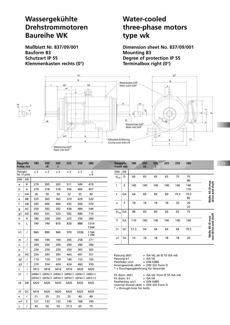
· 21 ·Baugröße 180 200 200 225 250 280 Frame size LK L
Polzahl ≥ 2 ≥ 2 ≥ 2 ≥ 2 ≥ 2 2 No. of poles ≥ 4
DIN EN
a B 279 305 305 311 349 419
b A 279 318 318 356 406 457
c HA 26 30 30 32 35 40
e BB 335 365 365 379 429 529
f AB 345 400 400 435 500 570
g AC 350 392 392 438 484 544
g1 AD 493 535 535 582 680 710
h H 180 200 200 225 250 280
k L 740 740 810 820 888 1014 1044
k1 / 860 890 960 970 1038 1164 1194
m / 184 194 194 205 258 271
n / 200 200 200 200 280 280
o / 250 250 250 250 365 365
p HC 354 395 395 443 491 551
q2 / 119 129 129 140 153 165
q3 / 370 354 424 424 460 550
s / M12 M16 M16 M16 M20 M20
s1 / 2xM40x1.5 2xM50x1.5 2xM50x1.5 2xM50x1.5 2xM50x1.5 2xM63x1.5 2xM16x1.5 2xM16x1.5 2xM16x1.5 2xM16x1.5 2xM16x1.5 2xM16 x1.5
s4 DB M20 M20 M20 M20 M20 M20
s5 DC M16 M20 M20 M20 M20 M20
v / 21 25 25 25 40 40
w1 C 121 133 133 149 168 190
z / 45 50 50 57.5 65 75
DIN EN
dmax D 60 65 65 65 75 75 80
l E 140 140 140 140 140 140 170
t GA 64 69 69 69 79.5 79.5 85
u F 18 18 18 18 20 20 22
d1max DA 48 60 60 60 65 75
l1 EA 110 140 140 140 140 140
t1 GC 51.5 64 64 64 69 79.5
u1 FA 14 18 18 18 18 20
Baugröße 180 200 200 225 250 280 Frame size LK L
Wel
le A
S Ø
-max
dri
ve-e
nd
-sh
aft
Wel
le B
S Ø
-max
no
n-d
rive
-en
d-s
haf
t
Passung d/d1 = ISA k6; ab Ø 55 ISA m6Passung b1 = ISA h6Passfeder u/u1 = DIN 6 885Innengewinde s4/s5 = DIN 332 Form D* = Durchgangsbohrung für Gewinde
Fit diam. d/d1 = ISA k6; from Ø 55 ISA m6Fit diam. b1 = ISA h6Featherkey u/u1 = DIN 6 885Internal thread s4/s5 = DIN 332 Form D* = through-hole for bolts
WassergekühlteDrehstrommotorenBaureihe WK
Maßblatt Nr. 837/09/001Bauform B3Schutzart IP 55Klemmenkasten rechts (0°)
Water-cooledthree-phase motorstype wk
Dimension sheet No. 837/09/001Mounting B3Degree of protection IP 55Terminalbox right (0°)
∅ d
Water outlet G3/4"
Water inlet G3/4"
Cooling water drain-off
Water inlet G3/4"
t1
d1
u1
l1
s5
k1
l
k
a
e
m
n
s4
w1
q2 q3Wasserauslass G3/4"
Wassereinlass G3/4"
Kühlwasser-Entleerung
Wassereinlass G3/4"
v
b
f
s*
h
c
g
g1
po
s1
z
45°
z
t
u
· 22 ·
WassergekühlteDrehstrommotorenBaureihe WK
Maßblatt Nr. 837/09/001Bauform B3Schutzart IP 55Klemmenkasten rechts (0°)
Water-cooledthree-phase motorstype wk
Dimension sheet No. 837/09/001Mounting B3Degree of protection IP 55Terminalbox right (0°)
∅ d
Water outlet G3/4"
Water inlet G3/4"
Cooling water drain-off
Water inlet G3/4"
t1
d1
u1
l1
s5
k1
l
k
a
e
m
n
s4
w1
q2 q3Wasserauslass G3/4"
Wassereinlass G3/4"
Kühlwasser-Entleerung
Wassereinlass G3/4"
v
b
f
s*
h
c
g
g1
po
s1
z
45°
z
t
u
Baugröße 315 S 315 L 355 400 450Frame size
Polzahl 2 2 No. of poles ≥ 4 ≥ 4 ≥ 4 ≥ 4 ≥ 4
DIN EN
a B 457 667 765 810 1030
b A 508 508 610 686 750
c HA 50 50 50 50 60
e BB 551 760 885 948 1250
f AB 628 628 710 800 940
g AC 614 614 690 790 860
g1 AD 812 812 917 1130 1205
h H 315 315 355 400 450
k L 1185 1465 – – – 1215 1495 1697 1748 2158
k1 LC 1335 1615 - - - 1395 1675 1882 1933 2348
m / 323 232 342 352 364
n / 355 355 355 470 470
o / 427 427 427 546 546
p HC 625 625 705 795 880
q2 / 301 301 343 353 383
q3 / 535 815 950 950 1250
s / M24 M24 M24 M30 M30
s1 / 2xM72x2 2xM72x2 2xM72x2 3xM72x2 3xM72x2 2xM16x1,5 2xM16x1,5 2xM16x1,5 2xM16x1,5 2xM16x1,5
s4 DB M20 M20 – – – M24 M24 M24 M24 M24
s5 DC M20 M20 M20 M24 M24
v / 40 40 49,5 49,5 49,5
w1 C 216 216 255 280 364
z / 90 90 90 90 90
DIN EN
dmax D 75 75 – – – 90 90 90 100 110
l E 140 140 - - - 170 170 170 210 210
t GA 79,5 79,5 – – – 95 95 95 106 116
u F 20 20 - - - 25 25 25 28 28
d1max DA 75 75 – – – 80 80 80 90 90
l1 EA 140 140 – – – 170 170 170 170 170
t1 GC 79,5 79,5 – – – 85 85 85 95 95
u1 FA 20 20 – – – 22 22 22 25 25
Baugröße 315 S 315 L 355 400 450Frame size
Wel
le A
S Ø
-max
dri
ve-e
nd
-sh
aft
Wel
le B
S Ø
-max
no
n-d
rive
-en
d-s
haf
t
Passung d/d1 = ISA k6; ab Ø 55 ISA m6Passung b1 = ISA h6Passfeder u/u1 = DIN 6 885Innengewinde s4/s5 = DIN 332 Form D* = Durchgangsbohrung für Gewinde
Fit diam. d/d1 = ISA k6; from Ø 55 ISA m6Fit diam. b1 = ISA h6Featherkey u/u1 = DIN 6 885Internal thread s4/s5 = DIN 332 Form D* = through-hole for bolts
· 23 ·
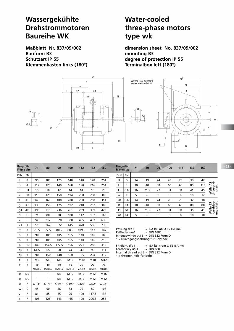
WassergekühlteDrehstrommotorenBaureihe WK
Maßblatt Nr. 837/09/002Bauform B3Schutzart IP 55Klemmenkasten links (180°)
Water-cooledthree-phase motorstype wk
dimension sheet No. 837/09/002mounting B3degree of protection IP 55Terminalbox left (180°)
Wasser-Ein-/-Auslass s6
t1
d1
u1
t
u
∅ d
l1
s5
k1
n
m
w1 a
e
l
s4
q2 q3
k
o p
c
h
s*
b
f
g
z
s1
Water inlet/outlet s6
y
g1
Baugröße 71 80 90 100 112 132 160Frame size
DIN EN
a B 90 100 125 140 140 178 254
b A 112 125 140 160 190 216 254
c H1 10 10 12 14 14 18 20
e BB 110 125 150 194 200 208 308
f AB 140 160 180 200 230 260 314
g AC 138 158 175 192 218 252 305
g1 AD 195 219 236 261 299 339 420
h H 71 80 90 100 112 132 160
k L 240 317 320 380 405 497 635
k1 LC 275 362 372 445 470 586 730
m / 70.5 77.5 80.5 88.5 109.5 117 147
n / 90 105 105 105 140 140 180
o / 90 105 105 105 140 140 215
p HC 140 157.5 177.5 196 221 258 313
q2 / 61.5 65 60 74 84.5 96 114
q3 / 90 150 148 180 185 234 312
s / M6 M8 M8 M10 M10 M10 M12
s1 / 1x 1x 1x 1x 2x 2x 2x M20x1.5 M25x1.5 M25x1.5 M25x1.5 M25x1.5 M25x1.5 M40x1.5
s4 DB – – M8 M10 M10 M12 M16
s5 DC – – M8 M10 M10 M12 M12
s6 / G1/4“ G1/4“ G1/4“ G1/4“ G1/4“ G1/2“ G1/2“
w1 C 45 50 56 63 70 89 108
y / 81 85 85 95 100 117.5 137
z / 108 128 143 165 190 206.5 255
DIN EN
d D 14 19 24 28 28 38 42
l E 30 40 50 60 60 80 110
t GA 16 21.5 27 31 31 41 45
u F 5 6 8 8 8 10 12
d1 DA 14 19 24 28 28 32 38
l1 EA 30 40 50 60 60 80 80
t1 GC 16 21.5 27 31 31 35 41
u1 FA 5 6 8 8 8 10 10
Baugröße 71 80 90 100 112 132 160Frame size
Wel
le A
Sd
rive
-en
d-
shaf
t
Wel
le B
Sn
on
-dri
ve-
end
-sh
aft
Passung d/d1 = ISA k6; ab Ø 55 ISA m6Paßfeder u/u1 = DIN 6885Innengewinde s4/s5 = DIN 332 Form D* = Durchgangsbohrung für Gewinde
Fit diam. d/d1 = ISA k6; from Ø 55 ISA m6Featherkey u/u1 = DIN 6885Internal thread s4/s5 = DIN 332 Form D* = through-hole for bolts
· 24 ·
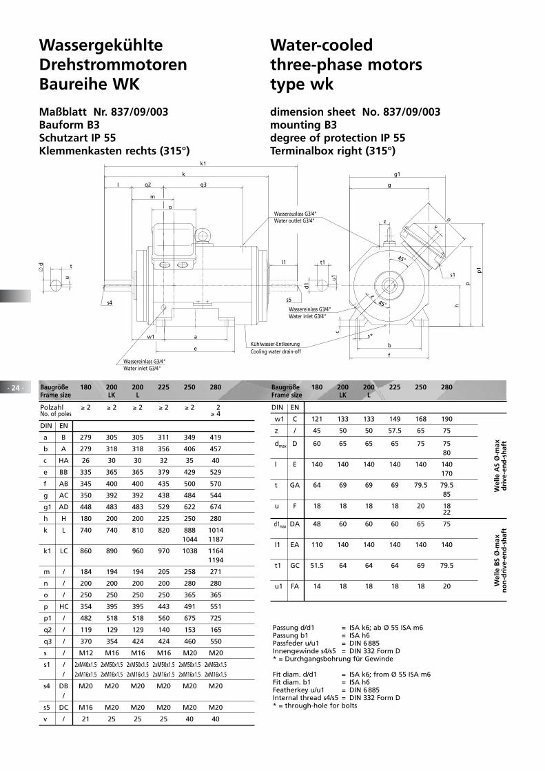
WassergekühlteDrehstrommotorenBaureihe WK
Maßblatt Nr. 837/09/003Bauform B3Schutzart IP 55Klemmenkasten rechts (315°)
Water-cooledthree-phase motorstype wk
dimension sheet No. 837/09/003mounting B3degree of protection IP 55Terminalbox right (315°)
Water inlet G3/4"Wassereinlass G3/4"
Cooling water drain-offKühlwasser-Entleerung
Water inlet G3/4"Wassereinlass G3/4"
Water outlet G3/4"Wasserauslass G3/4"
∅ d t1
d1
u1
s5
k1
k
a
e
m
s4
w1
q2 q3
g1
p1
g
45
b
f
s*
h
c
p
o
s1
z
t
u
o
l
l1
v
z45
Baugröße 180 200 200 225 250 280 Frame size LK L
Polzahl ≥ 2 ≥ 2 ≥ 2 ≥ 2 ≥ 2 2 No. of poles ≥ 4
DIN EN
a B 279 305 305 311 349 419
b A 279 318 318 356 406 457
c HA 26 30 30 32 35 40
e BB 335 365 365 379 429 529
f AB 345 400 400 435 500 570
g AC 350 392 392 438 484 544
g1 AD 448 483 483 529 622 674
h H 180 200 200 225 250 280
k L 740 740 810 820 888 1014 1044 1187
k1 LC 860 890 960 970 1038 1164 1194
m / 184 194 194 205 258 271
n / 200 200 200 200 280 280
o / 250 250 250 250 365 365
p HC 354 395 395 443 491 551
p1 / 482 518 518 560 675 725
q2 / 119 129 129 140 153 165
q3 / 370 354 424 424 460 550
s / M12 M16 M16 M16 M20 M20
s1 / 2xM40x1.5 2xM50x1.5 2xM50x1.5 2xM50x1.5 2xM50x1.5 2xM63x1.5 / 2xM16x1.5 2xM16x1.5 2xM16x1.5 2xM16x1.5 2xM16x1.5 2xM16x1.5
s4 DB M20 M20 M20 M20 M20 M20 /
s5 DC M16 M20 M20 M20 M20 M20
v / 21 25 25 25 40 40
DIN EN
w1 C 121 133 133 149 168 190
z / 45 50 50 57.5 65 75
dmax D 60 65 65 65 75 75 80
l E 140 140 140 140 140 140 170
t GA 64 69 69 69 79.5 79.5 85
u F 18 18 18 18 20 18 22
d1max DA 48 60 60 60 65 75
l1 EA 110 140 140 140 140 140
t1 GC 51.5 64 64 64 69 79.5
u1 FA 14 18 18 18 18 20
Baugröße 180 200 200 225 250 280 Frame size LK L
Wel
le A
S Ø
-max
dri
ve-e
nd
-sh
aft
Wel
le B
S Ø
-max
no
n-d
rive
-en
d-s
haf
t
Passung d/d1 = ISA k6; ab Ø 55 ISA m6Passung b1 = ISA h6Passfeder u/u1 = DIN 6 885Innengewinde s4/s5 = DIN 332 Form D* = Durchgangsbohrung für Gewinde
Fit diam. d/d1 = ISA k6; from Ø 55 ISA m6Fit diam. b1 = ISA h6Featherkey u/u1 = DIN 6 885Internal thread s4/s5 = DIN 332 Form D* = through-hole for bolts
· 25 ·
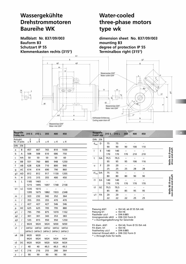
WassergekühlteDrehstrommotorenBaureihe WK
Maßblatt Nr. 837/09/003Bauform B3Schutzart IP 55Klemmenkasten rechts (315°)
Water-cooledthree-phase motorstype wk
dimension sheet No. 837/09/003mounting B3degree of protection IP 55Terminalbox right (315°)
Water inlet G3/4"Wassereinlass G3/4"
Cooling water drain-offKühlwasser-Entleerung
Water inlet G3/4"Wassereinlass G3/4"
Water outlet G3/4"Wasserauslass G3/4"
∅ d t1
d1
u1
s5
k1
k
a
e
m
s4
w1
q2 q3
g1
p1
g
45
b
f
s*
h
c
p
o
s1
z
t
u
o
l
l1
v
z45
Baugröße 315 S 315 L 355 400 450Frame size
Polzahl 2 2 No. of poles ≥ 4 ≥ 4 ≥ 4 ≥ 4 ≥ 4
DIN EN
a B 457 667 765 810 1030
b A 508 508 610 686 750
c HA 50 50 50 50 60
e BB 551 760 885 948 1250
f AB 628 628 710 800 940
g AC 614 614 690 790 860
g1 AD 812 812 917 1130 1205
h H 315 315 355 400 450
k L 1185 1465 – – – 1215 1495 1697 1748 2158
k1 LC 1335 1615 – – – 1395 1675 1882 1933 2348
m / 323 232 342 352 364
n / 355 355 355 470 470
o / 427 427 427 546 546
p HC 625 625 705 795 880
p1 / 795 795 875 1070 1102
q2 / 301 301 343 353 383
q3 / 535 815 950 950 1250
s / M24 M24 M24 M30 M30
s1 / 2xM72x2 2xM72x2 2xM72x2 3xM72x2 3xM72x2 2xM16x1,5 2xM16x1,5 2xM16x1,5 2xM16x1,5 2xM16x1,5
s4 DB M20 M20 – – – M24 M24 M24 M24 M24
s5 DC M20 M20 M20 M24 M24
v / 40 40 49,5 49,5 49,5
w1 C 216 216 255 280 364
z / 90 90 90 90 90
DIN EN
dmax D 75 75 – – – 90 90 90 100 110
l E 140 140 – – – 170 170 170 210 210
t GA 79,5 79,5 – – – 95 95 95 106 116
u F 20 20 – – – 25 25 25 28 28
d1max DA 75 75 – – – 80 80 80 90 90
l1 EA 140 140 – – – 170 170 170 170 170
t1 GC 79,5 79,5 – – – 85 85 85 95 95
u1 FA 20 20 – – – 22 22 22 25 25
Baugröße 315 S 315 L 355 400 450Frame size
Wel
le A
S Ø
-max
dri
ve-e
nd
-sh
aft
Wel
le B
S Ø
-max
no
n-d
rive
-en
d-s
haf
t
Passung d/d1 = ISA k6; ab Ø 55 ISA m6Passung b1 = ISA h6Passfeder u/u1 = DIN 6 885Innengewinde s4/s5 = DIN 332 Form D* = Durchgangsbohrung für Gewinde
Fit diam. d/d1 = ISA k6; from Ø 55 ISA m6Fit diam. b1 = ISA h6Featherkey u/u1 = DIN 6 885Internal thread s4/s5 = DIN 332 Form D* = through-hole for bolts

· 26 · Baugröße 71 80 90 100 112 132 160Frame size
DIN EN
a B 90 100 125 140 140 178 254
b A 112 125 140 160 190 216 254
c HA 10 10 12 14 14 18 20
e BB 110 125 150 194 200 208 308
f AB 140 160 180 200 230 260 314
g AC 138 158 175 192 218 252 305
h H 71 80 90 100 112 132 160
k L 240 317 320 380 405 497 635
k1 LC 275 362 372 445 470 586 730
m / 142.5 202.5 191.5 239.5 244.5 309 393
n / 90 105 105 105 140 140 180
o / 90 105 105 105 140 140 215
p HC 197 220 239 265 302 345 428
q2 / 61.5 65 60 74 84.5 96 114
q3 / 90 150 148 180 185 234 312
s / M6 M8 M8 M10 M10 M10 M12
s1 / 1x 1x 1x 1x 2x 2x 2x DB M20x1.5 M25x1.5 M25x1.5 M25x1.5 M25x1.5 M25x1.5 M40x1.5
s4 DB – – M8 M10 M10 M12 M16
s5 DC – – M8 M10 M10 M12 M12
s6 / G1/4“ G1/4“ G1/4“ G1/4“ G1/4“ G1/2“ G1/2“
w1 C 45 50 56 63 70 89 108
y / 81 85 85 95 100 117.5 137
z / 108 128 143 165 190 206.5 255
DIN EN
d D 14 19 24 28 28 38 42
l E 30 40 50 60 60 80 110
t GA 16 21.5 27 31 31 41 45
u F 5 6 8 8 8 10 12
d1 DA 14 19 24 28 28 32 38
l1 EA 30 40 50 60 60 80 80
t1 GC 16 21.5 27 31 31 35 41
u1 FA 5 6 8 8 8 10 10
Baugröße 71 80 90 100 112 132 160Frame size
Wel
le A
Sd
rive
-en
d-
shaf
t
Wel
le B
Sn
on
-dri
ve-
end
-sh
aft
Passung d/d1 = ISA k6; ab Ø 55 ISA m6Passfeder u/u1 = DIN 6 885Innengewinde s4/s5 = DIN 332 Form D* = Durchgangsbohrung für Gewinde
Fit diam. d/d1 = ISA k6; from Ø 55 ISA m6Featherkey u/u1 = DIN 6 885Internal thread s4/s5 = DIN 332 Form D* = through-hole for bolts
WassergekühlteDrehstrommotorenBaureihe WK
Maßblatt Nr. 837/09/004Bauform B3Schutzart IP 55Klemmenkasten oben (270°)
Water-cooledthree-phase motorstype wk
Dimension sheet No. 837/09/004Mounting B3Degree of protection IP 55Terminalbox on top (270°)
z
Water inlet/outlet s6
t1
d1
u1
tu
∅ d
l1
s5
k1
n
m
w1 a
e
l
s4
q2
q3
k
s1
y
g
Wasser-Ein-/-Auslass s6
o
h
c
p
s*
b
f
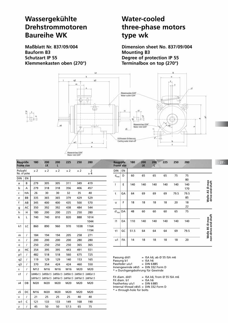
· 27 ·Baugröße 180 200 200 225 250 280 Frame size LK L
Polzahl ≥ 2 ≥ 2 ≥ 2 ≥ 2 ≥ 2 2 No. of poles ≥ 4
DIN EN
a B 279 305 305 311 349 419
b A 279 318 318 356 406 457
c HA 26 30 30 32 35 40
e BB 335 365 365 379 429 529
f AB 345 400 400 435 500 570
g AC 350 392 392 438 484 544
h H 180 200 200 225 250 280
k L 740 740 810 820 888 1014 1044
k1 LC 860 890 960 970 1038 1164 1194
m / 184 194 194 205 258 271
n / 200 200 200 200 280 280
o / 250 250 250 250 365 365
p HC 354 395 395 443 491 551
p1 / 482 518 518 560 675 725
q2 / 119 129 129 140 153 165
q3 / 370 354 424 424 460 550
s / M12 M16 M16 M16 M20 M20
s1 / 2xM40x1.5 2xM50x1.5 2xM50x1.5 2xM50x1.5 2xM50x1.5 2xM63x1.5 2xM16x1.5 2xM16x1.5 2xM16x1.5 2xM16x1.5 2xM16x1.5 2xM16x1.5
s4 DB M20 M20 M20 M20 M20 M20
s5 DC M16 M20 M20 M20 M20 M20
v / 21 25 25 25 40 40
w1 C 121 133 133 149 168 190
z / 45 50 50 57.5 65 75
DIN EN
dmax D 60 65 65 65 75 75 80
l E 140 140 140 140 140 140 170
t GA 64 69 69 69 79.5 79.5 85
u F 18 18 18 18 20 18 22
d1max DA 48 60 60 60 65 75
l1 EA 110 140 140 140 140 140
t1 GC 51.5 64 64 64 69 79.5
u1 FA 14 18 18 18 18 20
Baugröße 180 200 200 225 250 280 Frame size LK L
Passung d/d1 = ISA k6; ab Ø 55 ISA m6Passung b1 = ISA h6Passfeder u/u1 = DIN 6 885Innengewinde s4/s5 = DIN 332 Form D* = Durchgangsbohrung für Gewinde
Fit diam. d/d1 = ISA k6; from Ø 55 ISA m6Fit diam. b1 = ISA h6Featherkey u/u1 = DIN 6 885Internal thread s4/s5 = DIN 332 Form D* = through-hole for bolts
Wel
le A
S Ø
-max
dri
ve-e
nd
-sh
aft
Wel
le B
S Ø
-max
no
n-d
rive
-en
d-s
haf
t
WassergekühlteDrehstrommotorenBaureihe WK
Maßblatt Nr. 837/09/004Bauform B3Schutzart IP 55Klemmenkasten oben (270°)
Water-cooledthree-phase motorstype wk
Dimension sheet No. 837/09/004Mounting B3Degree of protection IP 55Terminalbox on top (270°)
d1
Water outlet G3/4"
Water inlet G3/4"
Cooling water drain-off
Water inlet G3/4"
k
a
e
m
s4
w1
q2
n
q3
t1
u1
k1
s5
l1
l
Wassereinlass G3/4"
Kühlwasser-Entleerung
Wassereinlass G3/4"
b
f
s*
h
c
z
g
p
45z
v
p1
s1
o
t
u
∅ d
Wasserauslass G3/4"
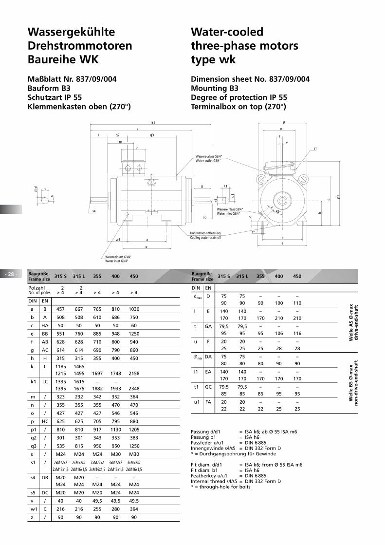
· 28 · Baugröße 315 S 315 L 355 400 450Frame size
Polzahl 2 2 No. of poles ≥ 4 ≥ 4 ≥ 4 ≥ 4 ≥ 4
DIN EN
a B 457 667 765 810 1030
b A 508 508 610 686 750
c HA 50 50 50 50 60
e BB 551 760 885 948 1250
f AB 628 628 710 800 940
g AC 614 614 690 790 860
h H 315 315 355 400 450
k L 1185 1465 – – – 1215 1495 1697 1748 2158
k1 LC 1335 1615 – – – 1395 1675 1882 1933 2348
m / 323 232 342 352 364
n / 355 355 355 470 470
o / 427 427 427 546 546
p HC 625 625 705 795 880
p1 / 810 810 917 1130 1205
q2 / 301 301 343 353 383
q3 / 535 815 950 950 1250
s / M24 M24 M24 M30 M30
s1 / 2xM72x2 2xM72x2 2xM72x2 3xM72x2 3xM72x2 2xM16x1,5 2xM16x1,5 2xM16x1,5 2xM16x1,5 2xM16x1,5
s4 DB M20 M20 – – – M24 M24 M24 M24 M24
s5 DC M20 M20 M20 M24 M24
v / 40 40 49,5 49,5 49,5
w1 C 216 216 255 280 364
z / 90 90 90 90 90
DIN EN
dmax D 75 75 – – – 90 90 90 100 110
l E 140 140 – – – 170 170 170 210 210
t GA 79,5 79,5 – – – 95 95 95 106 116
u F 20 20 – – – 25 25 25 28 28
d1max DA 75 75 – – – 80 80 80 90 90
l1 EA 140 140 – – – 170 170 170 170 170
t1 GC 79,5 79,5 – – – 85 85 85 95 95
u1 FA 20 20 – – – 22 22 22 25 25
Baugröße 315 S 315 L 355 400 450Frame size
Wel
le A
S Ø
-max
dri
ve-e
nd
-sh
aft
Wel
le B
S Ø
-max
no
n-d
rive
-en
d-s
haf
t
Passung d/d1 = ISA k6; ab Ø 55 ISA m6Passung b1 = ISA h6Passfeder u/u1 = DIN 6 885Innengewinde s4/s5 = DIN 332 Form D* = Durchgangsbohrung für Gewinde
Fit diam. d/d1 = ISA k6; from Ø 55 ISA m6Fit diam. b1 = ISA h6Featherkey u/u1 = DIN 6 885Internal thread s4/s5 = DIN 332 Form D* = through-hole for bolts
WassergekühlteDrehstrommotorenBaureihe WK
Maßblatt Nr. 837/09/004Bauform B3Schutzart IP 55Klemmenkasten oben (270°)
Water-cooledthree-phase motorstype wk
Dimension sheet No. 837/09/004Mounting B3Degree of protection IP 55Terminalbox on top (270°)
d1
Water outlet G3/4"
Water inlet G3/4"
Cooling water drain-off
Water inlet G3/4"
k
a
e
m
s4
w1
q2
n
q3
t1
u1
k1
s5
l1
l
Wassereinlass G3/4"
Kühlwasser-Entleerung
Wassereinlass G3/4"
b
f
s*
h
c
z
g
p
45z
v
p1
s1
o
t
u
∅ d
Wasserauslass G3/4"
· 29 ·
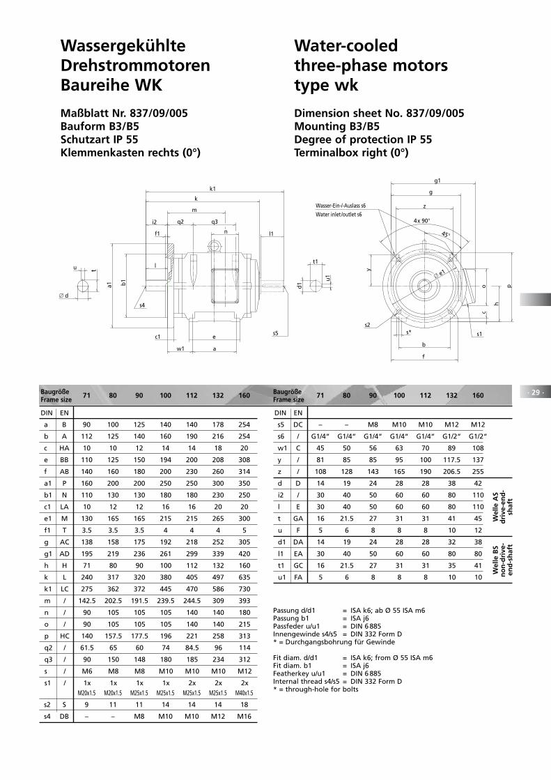
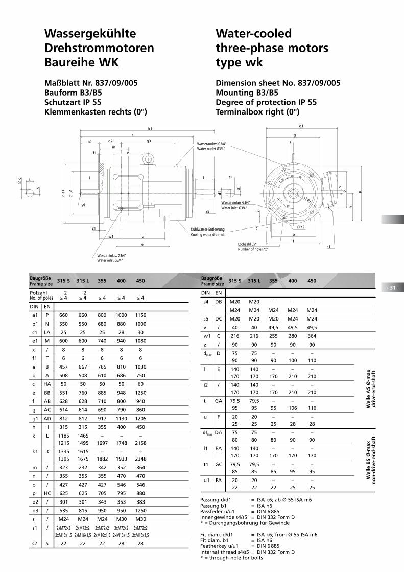
WassergekühlteDrehstrommotorenBaureihe WK
Maßblatt Nr. 837/09/005Bauform B3/B5Schutzart IP 55Klemmenkasten rechts (0°)
Water-cooledthree-phase motorstype wk
Dimension sheet No. 837/09/005Mounting B3/B5Degree of protection IP 55Terminalbox right (0°)
c1
Water inlet/outlet s6
t1
d1
u1
tu
∅ d
y
zWasser-Ein-/-Auslass s6
g1
g
s1
∅ e1
45
4x 90°
s2
o p
c
h
s*
b
f
l1
s5
m
n
k1
i2
s4
q2 q3
l
k
a1 b1
f1
w1 a
e
Baugröße 71 80 90 100 112 132 160Frame size
DIN EN
a B 90 100 125 140 140 178 254
b A 112 125 140 160 190 216 254
c HA 10 10 12 14 14 18 20
e BB 110 125 150 194 200 208 308
f AB 140 160 180 200 230 260 314
a1 P 160 200 200 250 250 300 350
b1 N 110 130 130 180 180 230 250
c1 LA 10 12 12 16 16 20 20
e1 M 130 165 165 215 215 265 300
f1 T 3.5 3.5 3.5 4 4 4 5
g AC 138 158 175 192 218 252 305
g1 AD 195 219 236 261 299 339 420
h H 71 80 90 100 112 132 160
k L 240 317 320 380 405 497 635
k1 LC 275 362 372 445 470 586 730
m / 142.5 202.5 191.5 239.5 244.5 309 393
n / 90 105 105 105 140 140 180
o / 90 105 105 105 140 140 215
p HC 140 157.5 177.5 196 221 258 313
q2 / 61.5 65 60 74 84.5 96 114
q3 / 90 150 148 180 185 234 312
s / M6 M8 M8 M10 M10 M10 M12
s1 / 1x 1x 1x 1x 2x 2x 2x M20x1.5 M20x1.5 M25x1.5 M25x1.5 M25x1.5 M25x1.5 M40x1.5
s2 S 9 11 11 14 14 14 18
s4 DB – – M8 M10 M10 M12 M16
DIN EN
s5 DC – – M8 M10 M10 M12 M12
s6 / G1/4“ G1/4“ G1/4“ G1/4“ G1/4“ G1/2“ G1/2“
w1 C 45 50 56 63 70 89 108
y / 81 85 85 95 100 117.5 137
z / 108 128 143 165 190 206.5 255
d D 14 19 24 28 28 38 42
i2 / 30 40 50 60 60 80 110
l E 30 40 50 60 60 80 110
t GA 16 21.5 27 31 31 41 45
u F 5 6 8 8 8 10 12
d1 DA 14 19 24 28 28 32 38
l1 EA 30 40 50 60 60 80 80
t1 GC 16 21.5 27 31 31 35 41
u1 FA 5 6 8 8 8 10 10
Baugröße 71 80 90 100 112 132 160Frame size
Wel
le A
Sd
rive
-en
d-
shaf
t
Wel
le B
Sn
on
-dri
ve-
end
-sh
aft
Passung d/d1 = ISA k6; ab Ø 55 ISA m6Passung b1 = ISA j6Passfeder u/u1 = DIN 6 885Innengewinde s4/s5 = DIN 332 Form D* = Durchgangsbohrung für Gewinde
Fit diam. d/d1 = ISA k6; from Ø 55 ISA m6Fit diam. b1 = ISA j6Featherkey u/u1 = DIN 6 885Internal thread s4/s5 = DIN 332 Form D* = through-hole for bolts
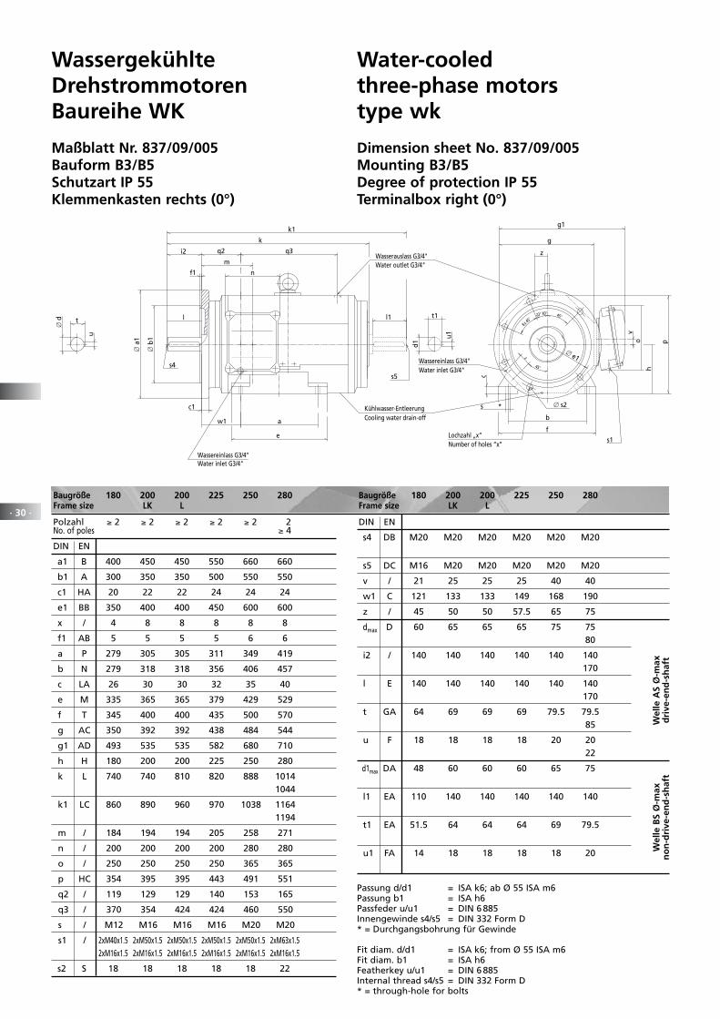
· 30 ·
WassergekühlteDrehstrommotorenBaureihe WK
Maßblatt Nr. 837/09/005Bauform B3/B5Schutzart IP 55Klemmenkasten rechts (0°)
Water-cooledthree-phase motorstype wk
Dimension sheet No. 837/09/005Mounting B3/B5Degree of protection IP 55Terminalbox right (0°)
∅ e1z
45
45
8x 45
22 30
Water outlet G3/4"
Water inlet G3/4"
Cooling water drain-off
Water inlet G3/4"
*
Number of holes “x”
k
a
e
m
n
s4
w1
q2
Wassereinlass G3/4"
Kühlwasser-Entleerung
l
q3i2
c1
∅ b
1
∅ a
1
f1
t1
d1
u1
k1
s5
l1
Wassereinlass G3/4"
Wasserauslass G3/4"
b
f
s
h
c
z
g
g1
p
vo
s1
∅ s2
Lochzahl „x“
t
u
∅ d
Baugröße 180 200 200 225 250 280 Frame size LK L
Polzahl ≥ 2 ≥ 2 ≥ 2 ≥ 2 ≥ 2 2 No. of poles ≥ 4
DIN EN
a1 B 400 450 450 550 660 660
b1 A 300 350 350 500 550 550
c1 HA 20 22 22 24 24 24
e1 BB 350 400 400 450 600 600
x / 4 8 8 8 8 8
f1 AB 5 5 5 5 6 6
a P 279 305 305 311 349 419
b N 279 318 318 356 406 457
c LA 26 30 30 32 35 40
e M 335 365 365 379 429 529
f T 345 400 400 435 500 570
g AC 350 392 392 438 484 544
g1 AD 493 535 535 582 680 710
h H 180 200 200 225 250 280
k L 740 740 810 820 888 1014 1044
k1 LC 860 890 960 970 1038 1164 1194
m / 184 194 194 205 258 271
n / 200 200 200 200 280 280
o / 250 250 250 250 365 365
p HC 354 395 395 443 491 551
q2 / 119 129 129 140 153 165
q3 / 370 354 424 424 460 550
s / M12 M16 M16 M16 M20 M20
s1 / 2xM40x1.5 2xM50x1.5 2xM50x1.5 2xM50x1.5 2xM50x1.5 2xM63x1.5 2xM16x1.5 2xM16x1.5 2xM16x1.5 2xM16x1.5 2xM16x1.5 2xM16x1.5
s2 S 18 18 18 18 18 22
DIN EN
s4 DB M20 M20 M20 M20 M20 M20
s5 DC M16 M20 M20 M20 M20 M20
v / 21 25 25 25 40 40
w1 C 121 133 133 149 168 190
z / 45 50 50 57.5 65 75
dmax D 60 65 65 65 75 75 80
i2 / 140 140 140 140 140 140 170
l E 140 140 140 140 140 140 170
t GA 64 69 69 69 79.5 79.5 85
u F 18 18 18 18 20 20 22
d1max DA 48 60 60 60 65 75
l1 EA 110 140 140 140 140 140
t1 EA 51.5 64 64 64 69 79.5
u1 FA 14 18 18 18 18 20
Baugröße 180 200 200 225 250 280 Frame size LK L
Wel
le A
S Ø
-max
dri
ve-e
nd
-sh
aft
Wel
le B
S Ø
-max
no
n-d
rive
-en
d-s
haf
t
Passung d/d1 = ISA k6; ab Ø 55 ISA m6Passung b1 = ISA h6Passfeder u/u1 = DIN 6 885Innengewinde s4/s5 = DIN 332 Form D* = Durchgangsbohrung für Gewinde
Fit diam. d/d1 = ISA k6; from Ø 55 ISA m6Fit diam. b1 = ISA h6Featherkey u/u1 = DIN 6 885Internal thread s4/s5 = DIN 332 Form D* = through-hole for bolts
· 31 ·
WassergekühlteDrehstrommotorenBaureihe WK
Maßblatt Nr. 837/09/005Bauform B3/B5Schutzart IP 55Klemmenkasten rechts (0°)
Water-cooledthree-phase motorstype wk
Dimension sheet No. 837/09/005Mounting B3/B5Degree of protection IP 55Terminalbox right (0°)
∅ e1z
45
45
8x 45
22 30
Water outlet G3/4"
Water inlet G3/4"
Cooling water drain-off
Water inlet G3/4"
*
Number of holes “x”
k
a
e
m
n
s4
w1
q2
Wassereinlass G3/4"
Kühlwasser-Entleerung
l
q3i2
c1
∅ b
1
∅ a
1
f1
t1
d1
u1
k1
s5
l1
Wassereinlass G3/4"
Wasserauslass G3/4"
b
f
s
h
c
z
g
g1
p
vo
s1
∅ s2
Lochzahl „x“
t
u
∅ d
Baugröße 315 S 315 L 355 400 450Frame size
Polzahl 2 2 No. of poles ≥ 4 ≥ 4 ≥ 4 ≥ 4 ≥ 4
DIN EN
a1 P 660 660 800 1000 1150
b1 N 550 550 680 880 1000
c1 LA 25 25 25 28 30
e1 M 600 600 740 940 1080
x / 8 8 8 8 8
f1 T 6 6 6 6 6
a B 457 667 765 810 1030
b A 508 508 610 686 750
c HA 50 50 50 50 60
e BB 551 760 885 948 1250
f AB 628 628 710 800 940
g AC 614 614 690 790 860
g1 AD 812 812 917 1130 1205
h H 315 315 355 400 450
k L 1185 1465 – – – 1215 1495 1697 1748 2158
k1 LC 1335 1615 – – – 1395 1675 1882 1933 2348
m / 323 232 342 352 364
n / 355 355 355 470 470
o / 427 427 427 546 546
p HC 625 625 705 795 880
q2 / 301 301 343 353 383
q3 / 535 815 950 950 1250
s / M24 M24 M24 M30 M30
s1 / 2xM72x2 2xM72x2 2xM72x2 3xM72x2 3xM72x2 2xM16x1,5 2xM16x1,5 2xM16x1,5 2xM16x1,5 2xM16x1,5
s2 S 22 22 22 28 28
DIN EN
s4 DB M20 M20 – – –
M24 M24 M24 M24 M24
s5 DC M20 M20 M20 M24 M24
v / 40 40 49,5 49,5 49,5
w1 C 216 216 255 280 364
z / 90 90 90 90 90
dmax D 75 75 – – – 90 90 90 100 110
l E 140 140 – – – 170 170 170 210 210
i2 / 140 140 – – – 170 170 170 210 210
t GA 79,5 79,5 – – – 95 95 95 106 116
u F 20 20 – – – 25 25 25 28 28
d1max DA 75 75 – – – 80 80 80 90 90
l1 EA 140 140 – – – 170 170 170 170 170
t1 GC 79,5 79,5 – – – 85 85 85 95 95
u1 FA 20 20 – – – 22 22 22 25 25
Baugröße 315 S 315 L 355 400 450Frame size
Wel
le A
S Ø
-max
dri
ve-e
nd
-sh
aft
Wel
le B
S Ø
-max
no
n-d
rive
-en
d-s
haf
t
Passung d/d1 = ISA k6; ab Ø 55 ISA m6Passung b1 = ISA h6Passfeder u/u1 = DIN 6 885Innengewinde s4/s5 = DIN 332 Form D* = Durchgangsbohrung für Gewinde
Fit diam. d/d1 = ISA k6; from Ø 55 ISA m6Fit diam. b1 = ISA h6Featherkey u/u1 = DIN 6 885Internal thread s4/s5 = DIN 332 Form D* = through-hole for bolts
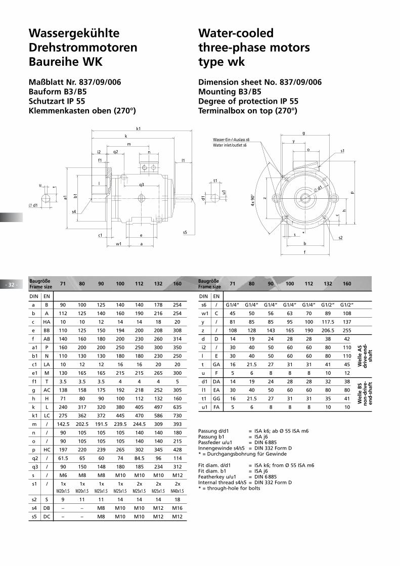
· 32 ·
WassergekühlteDrehstrommotorenBaureihe WK
Maßblatt Nr. 837/09/006Bauform B3/B5Schutzart IP 55Klemmenkasten oben (270°)
Water-cooledthree-phase motorstype wk
Dimension sheet No. 837/09/006Mounting B3/B5Degree of protection IP 55Terminalbox on top (270°)
Baugröße 71 80 90 100 112 132 160Frame size
DIN EN
a B 90 100 125 140 140 178 254
b A 112 125 140 160 190 216 254
c HA 10 10 12 14 14 18 20
e BB 110 125 150 194 200 208 308
f AB 140 160 180 200 230 260 314
a1 P 160 200 200 250 250 300 350
b1 N 110 130 130 180 180 230 250
c1 LA 10 12 12 16 16 20 20
e1 M 130 165 165 215 215 265 300
f1 T 3.5 3.5 3.5 4 4 4 5
g AC 138 158 175 192 218 252 305
h H 71 80 90 100 112 132 160
k L 240 317 320 380 405 497 635
k1 LC 275 362 372 445 470 586 730
m / 142.5 202.5 191.5 239.5 244.5 309 393
n / 90 105 105 105 140 140 180
o / 90 105 105 105 140 140 215
p HC 197 220 239 265 302 345 428
q2 / 61.5 65 60 74 84.5 96 114
q3 / 90 150 148 180 185 234 312
s / M6 M8 M8 M10 M10 M10 M12
s1 / 1x 1x 1x 1x 2x 2x 2x M20x1.5 M20x1.5 M25x1.5 M25x1.5 M25x1.5 M25x1.5 M40x1.5
s2 S 9 11 11 14 14 14 18
s4 DB – – M8 M10 M10 M12 M16
s5 DC – – M8 M10 M10 M12 M12
DIN EN
s6 / G1/4“ G1/4“ G1/4“ G1/4“ G1/4“ G1/2“ G1/2“
w1 C 45 50 56 63 70 89 108
y / 81 85 85 95 100 117.5 137
z / 108 128 143 165 190 206.5 255
d D 14 19 24 28 28 38 42
i2 / 30 40 50 60 60 80 110
l E 30 40 50 60 60 80 110
t GA 16 21.5 27 31 31 41 45
u F 5 6 8 8 8 10 12
d1 DA 14 19 24 28 28 32 38
l1 EA 30 40 50 60 60 80 80
t1 GG 16 21.5 27 31 31 35 41
u1 FA 5 6 8 8 8 10 10
Baugröße 71 80 90 100 112 132 160Frame size
Wel
le A
Sd
rive
-en
d-
shaf
t
Wel
le B
Sn
on
-dri
ve-
end
-sh
aft
Passung d/d1 = ISA k6; ab Ø 55 ISA m6Passung b1 = ISA j6Passfeder u/u1 = DIN 6 885Innengewinde s4/s5 = DIN 332 Form D* = Durchgangsbohrung für Gewinde
Fit diam. d/d1 = ISA k6; from Ø 55 ISA m6Fit diam. b1 = ISA j6Featherkey u/u1 = DIN 6 885Internal thread s4/s5 = DIN 332 Form D* = through-hole for bolts
Water inlet/outlet s6
*
t1
d1
u1
tu
∅ d1
l1
s5
k1
n
m
w1 a
e
s4
q2
q3
k
i2
l
c1
a1 b1
f1
s1
y
g
Wasser-Ein-/-Auslass s6
o
h
c
p
s
b
f
z
∅ d1
s2
4x
90
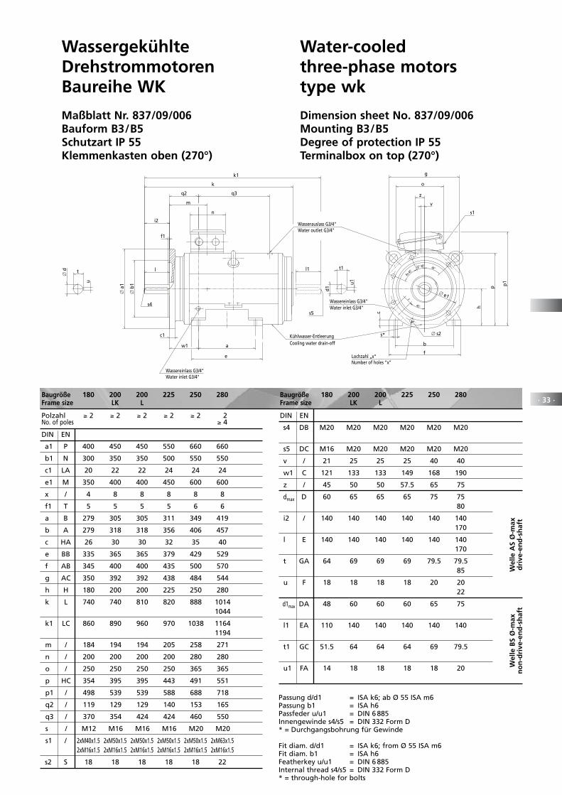
· 33 ·
WassergekühlteDrehstrommotorenBaureihe WK
Maßblatt Nr. 837/09/006Bauform B3/B5Schutzart IP 55Klemmenkasten oben (270°)
Water-cooledthree-phase motorstype wk
Dimension sheet No. 837/09/006Mounting B3/B5Degree of protection IP 55Terminalbox on top (270°)
Baugröße 180 200 200 225 250 280 Frame size LK L
Polzahl ≥ 2 ≥ 2 ≥ 2 ≥ 2 ≥ 2 2 No. of poles ≥ 4
DIN EN
a1 P 400 450 450 550 660 660
b1 N 300 350 350 500 550 550
c1 LA 20 22 22 24 24 24
e1 M 350 400 400 450 600 600
x / 4 8 8 8 8 8
f1 T 5 5 5 5 6 6
a B 279 305 305 311 349 419
b A 279 318 318 356 406 457
c HA 26 30 30 32 35 40
e BB 335 365 365 379 429 529
f AB 345 400 400 435 500 570
g AC 350 392 392 438 484 544
h H 180 200 200 225 250 280
k L 740 740 810 820 888 1014 1044
k1 LC 860 890 960 970 1038 1164 1194
m / 184 194 194 205 258 271
n / 200 200 200 200 280 280
o / 250 250 250 250 365 365
p HC 354 395 395 443 491 551
p1 / 498 539 539 588 688 718
q2 / 119 129 129 140 153 165
q3 / 370 354 424 424 460 550
s / M12 M16 M16 M16 M20 M20
s1 / 2xM40x1.5 2xM50x1.5 2xM50x1.5 2xM50x1.5 2xM50x1.5 2xM63x1.5 2xM16x1.5 2xM16x1.5 2xM16x1.5 2xM16x1.5 2xM16x1.5 2xM16x1.5
s2 S 18 18 18 18 18 22
DIN EN
s4 DB M20 M20 M20 M20 M20 M20
s5 DC M16 M20 M20 M20 M20 M20
v / 21 25 25 25 40 40
w1 C 121 133 133 149 168 190
z / 45 50 50 57.5 65 75
dmax D 60 65 65 65 75 75 80
i2 / 140 140 140 140 140 140 170
l E 140 140 140 140 140 140 170
t GA 64 69 69 69 79.5 79.5 85
u F 18 18 18 18 20 20 22
d1max DA 48 60 60 60 65 75
l1 EA 110 140 140 140 140 140
t1 GC 51.5 64 64 64 69 79.5
u1 FA 14 18 18 18 18 20
Baugröße 180 200 200 225 250 280 Frame size LK L
Passung d/d1 = ISA k6; ab Ø 55 ISA m6Passung b1 = ISA h6Passfeder u/u1 = DIN 6 885Innengewinde s4/s5 = DIN 332 Form D* = Durchgangsbohrung für Gewinde
Fit diam. d/d1 = ISA k6; from Ø 55 ISA m6Fit diam. b1 = ISA h6Featherkey u/u1 = DIN 6 885Internal thread s4/s5 = DIN 332 Form D* = through-hole for bolts
Wel
le A
S Ø
-max
dri
ve-e
nd
-sh
aft
Wel
le B
S Ø
-max
no
n-d
rive
-en
d-s
haf
t
22 30
8x 45
Water outlet G3/4"
Water inlet G3/4"
Cooling water drain-off
Water inlet G3/4"
Number of holes “x”
k
a
e
m
s4
w1
q2
n
q3
i2
c1
∅ b
1
∅ a
1
f1
t1
d1
u1
k1
s5
l1
Wasserauslass G3/4"
l
Wassereinlass G3/4"
Kühlwasser-Entleerung
Wassereinlass G3/4"
b
f
s*
h
c
z
g
p
45
z
v
p1
s1
o
45
∅ s2
Lochzahl „x“
∅ e1
t
u
∅ d
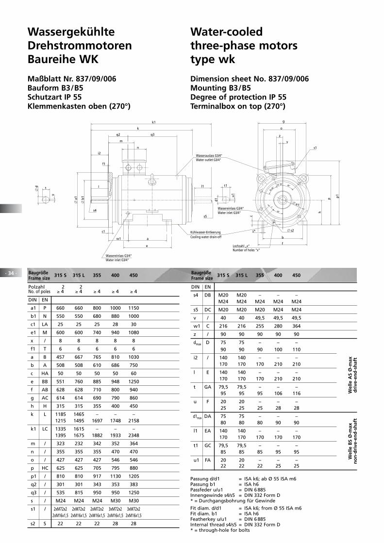
· 34 ·
WassergekühlteDrehstrommotorenBaureihe WK
Maßblatt Nr. 837/09/006Bauform B3/B5Schutzart IP 55Klemmenkasten oben (270°)
Water-cooledthree-phase motorstype wk
Dimension sheet No. 837/09/006Mounting B3/B5Degree of protection IP 55Terminalbox on top (270°)
Baugröße 315 S 315 L 355 400 450Frame size
Polzahl 2 2 No. of poles ≥ 4 ≥ 4 ≥ 4 ≥ 4 ≥ 4
DIN EN
a1 P 660 660 800 1000 1150
b1 N 550 550 680 880 1000
c1 LA 25 25 25 28 30
e1 M 600 600 740 940 1080
x / 8 8 8 8 8
f1 T 6 6 6 6 6
a B 457 667 765 810 1030
b A 508 508 610 686 750
c HA 50 50 50 50 60
e BB 551 760 885 948 1250
f AB 628 628 710 800 940
g AC 614 614 690 790 860
h H 315 315 355 400 450
k L 1185 1465 – – – 1215 1495 1697 1748 2158
k1 LC 1335 1615 – – – 1395 1675 1882 1933 2348
m / 323 232 342 352 364
n / 355 355 355 470 470
o / 427 427 427 546 546
p HC 625 625 705 795 880
p1 / 810 810 917 1130 1205
q2 / 301 301 343 353 383
q3 / 535 815 950 950 1250
s / M24 M24 M24 M30 M30
s1 / 2xM72x2 2xM72x2 2xM72x2 3xM72x2 3xM72x2 2xM16x1,5 2xM16x1,5 2xM16x1,5 2xM16x1,5 2xM16x1,5
s2 S 22 22 22 28 28
DIN EN
s4 DB M20 M20 – – – M24 M24 M24 M24 M24
s5 DC M20 M20 M20 M24 M24
v / 40 40 49,5 49,5 49,5
w1 C 216 216 255 280 364
z / 90 90 90 90 90
dmax D 75 75 – – –
90 90 90 100 110
i2 / 140 140 – – – 170 170 170 210 210
l E 140 140 – – – 170 170 170 210 210
t GA 79,5 79,5 – – – 95 95 95 106 116
u F 20 20 – – – 25 25 25 28 28
d1max DA 75 75 – – – 80 80 80 90 90
l1 EA 140 140 – – – 170 170 170 170 170
t1 GC 79,5 79,5 – – – 85 85 85 95 95
u1 FA 20 20 – – – 22 22 22 25 25
Baugröße 315 S 315 L 355 400 450Frame size
Passung d/d1 = ISA k6; ab Ø 55 ISA m6Passung b1 = ISA h6Passfeder u/u1 = DIN 6 885Innengewinde s4/s5 = DIN 332 Form D* = Durchgangsbohrung für Gewinde
Fit diam. d/d1 = ISA k6; from Ø 55 ISA m6Fit diam. b1 = ISA h6Featherkey u/u1 = DIN 6 885Internal thread s4/s5 = DIN 332 Form D* = through-hole for bolts
Wel
le A
S Ø
-max
dri
ve-e
nd
-sh
aft
Wel
le B
S Ø
-max
no
n-d
rive
-en
d-s
haf
t
22 30
8x 45
Water outlet G3/4"
Water inlet G3/4"
Cooling water drain-off
Water inlet G3/4"
Number of holes “x”
k
a
e
m
s4
w1
q2
n
q3
i2
c1
∅ b
1
∅ a
1
f1
t1
d1
u1
k1
s5
l1
Wasserauslass G3/4"
l
Wassereinlass G3/4"
Kühlwasser-Entleerung
Wassereinlass G3/4"
b
f
s*
h
c
z
g
p
45
z
v
p1
s1
o
45
∅ s2
Lochzahl „x“
∅ e1
t
u
∅ d
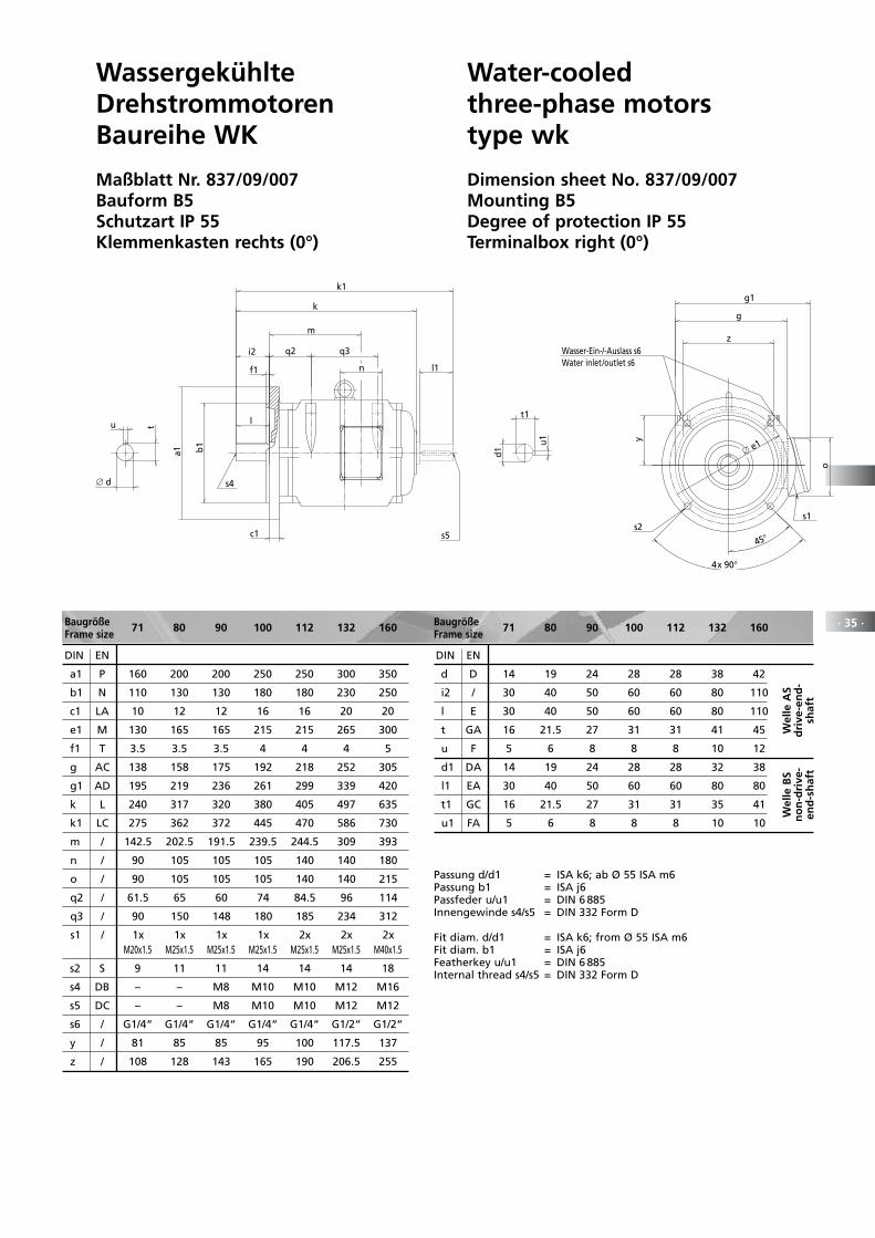
· 35 ·
WassergekühlteDrehstrommotorenBaureihe WK
Maßblatt Nr. 837/09/007Bauform B5Schutzart IP 55Klemmenkasten rechts (0°)
Water-cooledthree-phase motorstype wk
Dimension sheet No. 837/09/007Mounting B5Degree of protection IP 55Terminalbox right (0°)
Water inlet/outlet s6
t1
d1
u1
l1n
m
k1
s5
∅ d
tu
i2
s4
q2 q3
l
k
c1
a1 b1
f1
o
45
4x 90
y
zWasser-Ein-/-Auslass s6
g1
g
s1
∅ e1
s2
Baugröße 71 80 90 100 112 132 160Frame size
DIN EN
a1 P 160 200 200 250 250 300 350
b1 N 110 130 130 180 180 230 250
c1 LA 10 12 12 16 16 20 20
e1 M 130 165 165 215 215 265 300
f1 T 3.5 3.5 3.5 4 4 4 5
g AC 138 158 175 192 218 252 305
g1 AD 195 219 236 261 299 339 420
k L 240 317 320 380 405 497 635
k1 LC 275 362 372 445 470 586 730
m / 142.5 202.5 191.5 239.5 244.5 309 393
n / 90 105 105 105 140 140 180
o / 90 105 105 105 140 140 215
q2 / 61.5 65 60 74 84.5 96 114
q3 / 90 150 148 180 185 234 312
s1 / 1x 1x 1x 1x 2x 2x 2x M20x1.5 M25x1.5 M25x1.5 M25x1.5 M25x1.5 M25x1.5 M40x1.5
s2 S 9 11 11 14 14 14 18
s4 DB – – M8 M10 M10 M12 M16
s5 DC – – M8 M10 M10 M12 M12
s6 / G1/4“ G1/4“ G1/4“ G1/4“ G1/4“ G1/2“ G1/2“
y / 81 85 85 95 100 117.5 137
z / 108 128 143 165 190 206.5 255
DIN EN
d D 14 19 24 28 28 38 42
i2 / 30 40 50 60 60 80 110
l E 30 40 50 60 60 80 110
t GA 16 21.5 27 31 31 41 45
u F 5 6 8 8 8 10 12
d1 DA 14 19 24 28 28 32 38
l1 EA 30 40 50 60 60 80 80
t1 GC 16 21.5 27 31 31 35 41
u1 FA 5 6 8 8 8 10 10
Baugröße 71 80 90 100 112 132 160Frame size
Wel
le A
Sd
rive
-en
d-
shaf
t
Wel
le B
Sn
on
-dri
ve-
end
-sh
aft
Passung d/d1 = ISA k6; ab Ø 55 ISA m6Passung b1 = ISA j6Passfeder u/u1 = DIN 6 885Innengewinde s4/s5 = DIN 332 Form D
Fit diam. d/d1 = ISA k6; from Ø 55 ISA m6Fit diam. b1 = ISA j6Featherkey u/u1 = DIN 6 885Internal thread s4/s5 = DIN 332 Form D
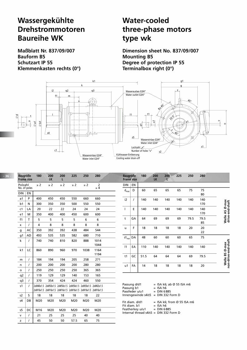
· 36 ·
WassergekühlteDrehstrommotorenBaureihe WK
Maßblatt Nr. 837/09/007Bauform B5Schutzart IP 55Klemmenkasten rechts (0°)
Water-cooledthree-phase motorstype wk
Dimension sheet No. 837/09/007Mounting B5Degree of protection IP 55Terminalbox right (0°)
∅ e1
45
8x 45
Water outlet G3/4"
Water inlet G3/4"
Cooling water drain-offWater inlet G3/4"
Number of holes “x”
i2
k
l
c1
m
∅ b
1
∅ a
1
n
f1
s4
t1
d1
u1
k1
s5
l1
q2 q3 Wasserauslass G3/4"
Wassereinlass G3/4"
Kühlwasser-EntleerungWassereinlass G3/4"
22.5
g
g1
45
s2
o
v
Lochzahl „x“ s1
z
z
t
u
∅ d
Baugröße 180 200 200 225 250 280 Frame size LK L
Polzahl ≥ 2 ≥ 2 ≥ 2 ≥ 2 ≥ 2 2 No. of poles ≥ 4
DIN EN
a1 P 400 450 450 550 660 660
b1 N 300 350 350 500 550 550
c1 LA 20 22 22 24 24 24
e1 M 350 400 400 450 600 600
f1 T 5 5 5 5 6 6
x / 4 8 8 8 8 8
g AC 350 392 392 438 484 544
g1 AD 493 535 535 582 680 710
k / 740 740 810 820 888 1014 1044
k1 LC 860 890 960 970 1038 1164 1194
m / 184 194 194 205 258 271
n / 200 200 200 200 280 280
o / 250 250 250 250 365 365
q2 / 119 129 129 140 153 165
q3 / 370 354 424 424 460 550
s1 / 2xM40x1.5 2xM50x1.5 2xM50x1.5 2xM50x1.5 2xM50x1.5 2xM63x1.5 2xM16x1.5 2xM16x1.5 2xM16x1.5 2xM16x1.5 2xM16x1.5 2xM16x1.5
s2 S 18 18 18 18 18 22
s4 DB M20 M20 M20 M20 M20 M20
s5 DC M16 M20 M20 M20 M20 M20
v / 21 25 25 25 40 40
z / 45 50 50 57.5 65 75
DIN EN
dmax D 60 65 65 65 75 75 80
i2 / 140 140 140 140 140 140 170
l E 140 140 140 140 140 140 170
t GA 64 69 69 69 79.5 79.5 85
u F 18 18 18 18 20 20 22
d1max DA 48 60 60 60 65 75
l1 EA 110 140 140 140 140 140
t1 GC 51.5 64 64 64 69 79.5
u1 FA 14 18 18 18 18 20
Baugröße 180 200 200 225 250 280 Frame size LK L
Wel
le A
S Ø
-max
dri
ve-e
nd
-sh
aft
Wel
le B
S Ø
-max
no
n-d
rive
-en
d-s
haf
t
Passung d/d1 = ISA k6; ab Ø 55 ISA m6Passung b1 = ISA h6Passfeder u/u1 = DIN 6 885Innengewinde s4/s5 = DIN 332 Form D
Fit diam. d/d1 = ISA k6; from Ø 55 ISA m6Fit diam. b1 = ISA h6Featherkey u/u1 = DIN 6 885Internal thread s4/s5 = DIN 332 Form D
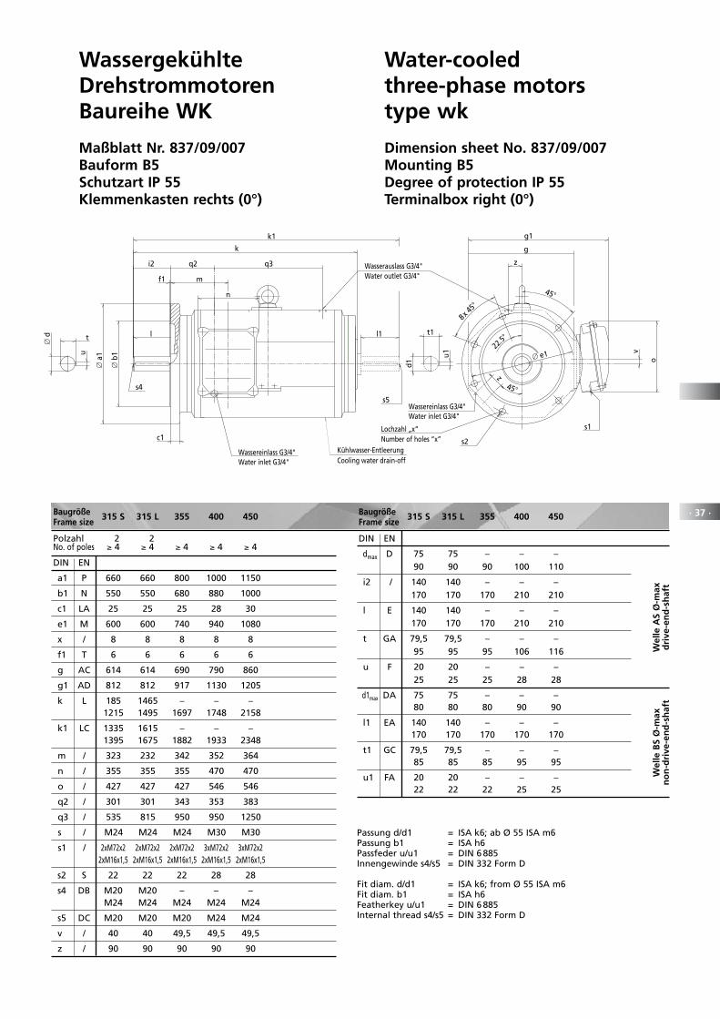
· 37 ·
WassergekühlteDrehstrommotorenBaureihe WK
Maßblatt Nr. 837/09/007Bauform B5Schutzart IP 55Klemmenkasten rechts (0°)
Water-cooledthree-phase motorstype wk
Dimension sheet No. 837/09/007Mounting B5Degree of protection IP 55Terminalbox right (0°)
∅ e1
45
8x 45
Water outlet G3/4"
Water inlet G3/4"
Cooling water drain-offWater inlet G3/4"
Number of holes “x”
i2
k
l
c1
m
∅ b
1
∅ a
1
n
f1
s4
t1
d1
u1
k1
s5
l1
q2 q3 Wasserauslass G3/4"
Wassereinlass G3/4"
Kühlwasser-EntleerungWassereinlass G3/4"
22.5
g
g1
45
s2
o
v
Lochzahl „x“ s1
z
z
t
u
∅ d
Baugröße 315 S 315 L 355 400 450Frame size
Polzahl 2 2 No. of poles ≥ 4 ≥ 4 ≥ 4 ≥ 4 ≥ 4
DIN EN
a1 P 660 660 800 1000 1150
b1 N 550 550 680 880 1000
c1 LA 25 25 25 28 30
e1 M 600 600 740 940 1080
x / 8 8 8 8 8
f1 T 6 6 6 6 6
g AC 614 614 690 790 860
g1 AD 812 812 917 1130 1205
k L 185 1465 – – – 1215 1495 1697 1748 2158
k1 LC 1335 1615 – – – 1395 1675 1882 1933 2348
m / 323 232 342 352 364
n / 355 355 355 470 470
o / 427 427 427 546 546
q2 / 301 301 343 353 383
q3 / 535 815 950 950 1250
s / M24 M24 M24 M30 M30
s1 / 2xM72x2 2xM72x2 2xM72x2 3xM72x2 3xM72x2 2xM16x1,5 2xM16x1,5 2xM16x1,5 2xM16x1,5 2xM16x1,5
s2 S 22 22 22 28 28
s4 DB M20 M20 – – – M24 M24 M24 M24 M24
s5 DC M20 M20 M20 M24 M24
v / 40 40 49,5 49,5 49,5
z / 90 90 90 90 90
DIN EN
dmax D 75 75 – – – 90 90 90 100 110
i2 / 140 140 – – – 170 170 170 210 210
l E 140 140 – – – 170 170 170 210 210
t GA 79,5 79,5 – – – 95 95 95 106 116
u F 20 20 – – – 25 25 25 28 28
d1max DA 75 75 – – – 80 80 80 90 90
l1 EA 140 140 – – – 170 170 170 170 170
t1 GC 79,5 79,5 – – – 85 85 85 95 95
u1 FA 20 20 – – – 22 22 22 25 25
Baugröße 315 S 315 L 355 400 450Frame size
Wel
le A
S Ø
-max
dri
ve-e
nd
-sh
aft
Wel
le B
S Ø
-max
no
n-d
rive
-en
d-s
haf
t
Passung d/d1 = ISA k6; ab Ø 55 ISA m6Passung b1 = ISA h6Passfeder u/u1 = DIN 6 885Innengewinde s4/s5 = DIN 332 Form D
Fit diam. d/d1 = ISA k6; from Ø 55 ISA m6Fit diam. b1 = ISA h6Featherkey u/u1 = DIN 6 885Internal thread s4/s5 = DIN 332 Form D
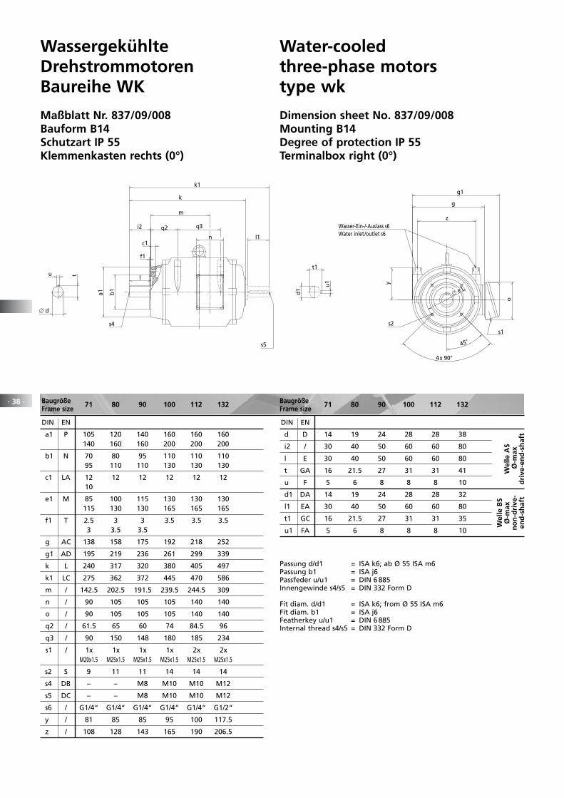
WassergekühlteDrehstrommotorenBaureihe WK
Maßblatt Nr. 837/09/008Bauform B14Schutzart IP 55Klemmenkasten rechts (0°)
Water-cooledthree-phase motorstype wk
Dimension sheet No. 837/09/008Mounting B14Degree of protection IP 55Terminalbox right (0°)
Water inlet/outlet s6
t1
d1
u1
l1n
k1
s5
b1a1
f1
m
∅ d
tu
i2
s4
q2 q3
k
l
c1
o
∅ e1
4x 90
45
y
zWasser-Ein-/-Auslass s6
g1
g
s1s2
· 38 · Baugröße 71 80 90 100 112 132Frame size
DIN EN
a1 P 105 120 140 160 160 160 140 160 160 200 200 200
b1 N 70 80 95 110 110 110 95 110 110 130 130 130
c1 LA 12 12 12 12 12 12 10
e1 M 85 100 115 130 130 130 115 130 130 165 165 165
f1 T 2.5 3 3 3.5 3.5 3.5 3 3.5 3.5
g AC 138 158 175 192 218 252
g1 AD 195 219 236 261 299 339
k L 240 317 320 380 405 497
k1 LC 275 362 372 445 470 586
m / 142.5 202.5 191.5 239.5 244.5 309
n / 90 105 105 105 140 140
o / 90 105 105 105 140 140
q2 / 61.5 65 60 74 84.5 96
q3 / 90 150 148 180 185 234
s1 / 1x 1x 1x 1x 2x 2x M20x1.5 M25x1.5 M25x1.5 M25x1.5 M25x1.5 M25x1.5
s2 S 9 11 11 14 14 14
s4 DB – – M8 M10 M10 M12
s5 DC – – M8 M10 M10 M12
s6 / G1/4“ G1/4“ G1/4“ G1/4“ G1/4“ G1/2“
y / 81 85 85 95 100 117.5
z / 108 128 143 165 190 206.5
DIN EN
d D 14 19 24 28 28 38
i2 / 30 40 50 60 60 80
l E 30 40 50 60 60 80
t GA 16 21.5 27 31 31 41
u F 5 6 8 8 8 10
d1 DA 14 19 24 28 28 32
l1 EA 30 40 50 60 60 80
t1 GC 16 21.5 27 31 31 35
u1 FA 5 6 8 8 8 10
Baugröße 71 80 90 100 112 132Frame size
Passung d/d1 = ISA k6; ab Ø 55 ISA m6Passung b1 = ISA j6Passfeder u/u1 = DIN 6 885Innengewinde s4/s5 = DIN 332 Form D
Fit diam. d/d1 = ISA k6; from Ø 55 ISA m6Fit diam. b1 = ISA j6Featherkey u/u1 = DIN 6 885Internal thread s4/s5 = DIN 332 Form D
Wel
le A
S Ø
-max
dri
ve-e
nd
-sh
aft
Wel
le B
S Ø
-max
no
n-d
rive
-en
d-s
haf
t
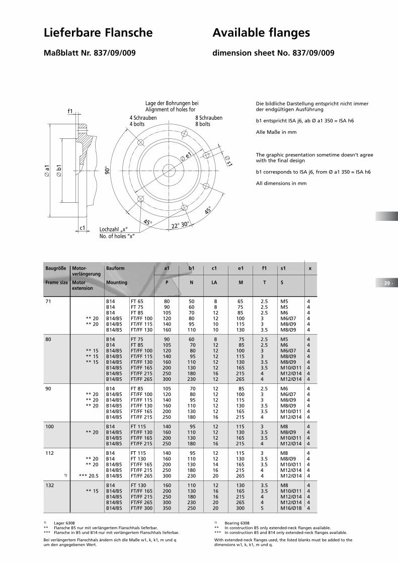
· 39 ·
Lieferbare Flansche
Maßblatt Nr. 837/09/009
Available flanges
dimension sheet No. 837/09/009
Baugröße Motor- Bauform a1 b1 c1 e1 f1 s1 x verlängerung
Frame size Motor Mounting P N LA M T S extension
22 30
∅ s1∅ e1
∅ a
1
∅ b
1
No. of holes “x”
Lage der Bohrungen beiAlignment of holes for
8 Schrauben8 bolts
4 Schrauben4 bolts
f1
c1
45
45
90
Lochzahl „x“
71 B14 FT 65 80 50 8 65 2.5 M5 4 B14 FT 75 90 60 8 75 2.5 M5 4 B14 FT 85 105 70 12 85 2.5 M6 4 ** 20 B14/B5 FT/FF 100 120 80 12 100 3 M6/Ø7 4 *** 20 B14/B5 FT/FF 115 140 95 10 115 3 M8/Ø9 4 ** B14/B5 FT/FF 130 160 110 10 130 3.5 M8/Ø9 4
80 B14 FT 75 90 60 8 75 2.5 M5 4 B14 FT 85 105 70 12 85 2.5 M6 4 *** 15 B14/B5 FT/FF 100 120 80 12 100 3 M6/Ø7 4 *** 15 B14/B5 FT/FF 115 140 95 12 115 3 M8/Ø9 4 **** 15 B14/B5 FT/FF 130 160 110 12 130 3.5 M8/Ø9 4 B14/B5 FT/FF 165 200 130 12 165 3.5 M10/Ø11 4 B14/B5 FT/FF 215 250 180 16 215 4 M12/Ø14 4 B14/B5 FT/FF 265 300 230 12 265 4 M12/Ø14 4
90 B14 FT 85 105 70 12 85 2.5 M6 4 *** 20 B14/B5 FT/FF 100 120 80 12 100 3 M6/Ø7 4 *** 20 B14/B5 FT/FF 115 140 95 12 115 3 M8/Ø9 4 **** 20 B14/B5 FT/FF 130 160 110 12 130 3.5 M8/Ø9 4 B14/B5 FT/FF 165 200 130 12 165 3.5 M10/Ø11 4 B14/B5 FT/FF 215 250 180 16 215 4 M12/Ø14 4
100 B14 FT 115 140 95 12 115 3 M8 4 **** 20 B14/B5 FT/FF 130 160 110 12 130 3.5 M8/Ø9 4 B14/B5 FT/FF 165 200 130 12 165 3.5 M10/Ø11 4 B14/B5 FT/FF 215 250 180 16 215 4 M12/Ø14 4
112 B14 FT 115 140 95 12 115 3 M8 4 *** 20 B14 FT 130 160 110 12 130 3.5 M8/Ø9 4 **** 20 B14/B5 FT/FF 165 200 130 14 165 3.5 M10/Ø11 4 B14/B5 FT/FF 215 250 180 16 215 4 M12/Ø14 4 1) *** 20.5 B14/B5 FT/FF 265 300 230 20 265 4 M12/Ø14 4
132 B14 FT 130 160 110 12 130 3.5 M8 4 *** 15 B14/B5 FT/FF 165 200 130 16 165 3.5 M10/Ø11 4 B14/B5 FT/FF 215 250 180 16 215 4 M12/Ø14 4 B14/B5 FT/FF 265 300 230 20 265 4 M12/Ø14 4 B14/B5 FT/FF 300 350 250 20 300 5 M16/Ø18 4
Die bildliche Darstellung entspricht nicht immer der endgültigen Ausführung
b1 entspricht ISA j6, ab Ø a1 350 = ISA h6
Alle Maße in mm
The graphic presentation sometime doesn’t agree with the final design
b1 corresponds to ISA j6, from Ø a1 350 = ISA h6
All dimensions in mm
1) Lager 6308*** Flansche B5 nur mit verlängertem Flanschhals lieferbar.*** Flansche in B5 und B14 nur mit verlängertem Flanschhals lieferbar.
Bei verlängertem Flanschhals ändern sich die Maße w1, k, k1, m und qum den angegebenen Wert.
1) Bearing 6308*** In construction B5 only extended-neck flanges available.*** In construction B5 and B14 only extended-neck flanges available.
With extended-neck flanges used, the listed blanks must be added to the dimensions w1, k, k1, m und q.
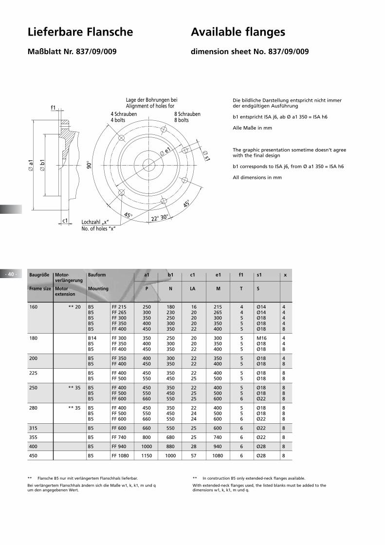
*** Flansche B5 nur mit verlängertem Flanschhals lieferbar.
Bei verlängertem Flanschhals ändern sich die Maße w1, k, k1, m und qum den angegebenen Wert.
*** In construction B5 only extended-neck flanges available.
With extended-neck flanges used, the listed blanks must be added to the dimensions w1, k, k1, m und q.
· 40 ·
Lieferbare Flansche
Maßblatt Nr. 837/09/009
Available flanges
dimension sheet No. 837/09/009
Baugröße Motor- Bauform a1 b1 c1 e1 f1 s1 x verlängerung
Frame size Motor Mounting P N LA M T S extension
22 30
∅ s1∅ e1
∅ a
1
∅ b
1
No. of holes “x”
Lage der Bohrungen beiAlignment of holes for
8 Schrauben8 bolts
4 Schrauben4 bolts
f1
c1
45
45
90
Lochzahl „x“
160 ** 20 B5 FF 215 250 180 16 215 4 Ø14 4 B5 FF 265 300 230 20 265 4 Ø14 4 B5 FF 300 350 250 20 300 5 Ø18 4 B5 FF 350 400 300 20 350 5 Ø18 4 B5 FF 400 450 350 22 400 5 Ø18 8
180 B14 FF 300 350 250 20 300 5 M16 4 B5 FF 350 400 300 20 350 5 Ø18 4 B5 FF 400 450 350 22 400 5 Ø18 8
200 B5 FF 350 400 300 22 350 5 Ø18 4 B5 FF 400 450 350 22 400 5 Ø18 8
225 B5 FF 400 450 350 22 400 5 Ø18 8 B5 FF 500 550 450 25 500 5 Ø18 8
250 ** 35 B5 FF 400 450 350 22 400 5 Ø18 8 B5 FF 500 550 450 25 500 5 Ø18 8 B5 FF 600 660 550 25 600 6 Ø22 8
280 ** 35 B5 FF 400 450 350 22 400 5 Ø18 8 B5 FF 500 550 450 24 500 5 Ø18 8 B5 FF 600 660 550 24 600 6 Ø22 8
315 B5 FF 600 660 550 25 600 6 Ø22 8
355 B5 FF 740 800 680 25 740 6 Ø22 8
400 B5 FF 940 1000 880 28 940 6 Ø28 8
450 B5 FF 1080 1150 1000 57 1080 6 Ø28 8
Die bildliche Darstellung entspricht nicht immer der endgültigen Ausführung
b1 entspricht ISA j6, ab Ø a1 350 = ISA h6
Alle Maße in mm
The graphic presentation sometime doesn’t agree with the final design
b1 corresponds to ISA j6, from Ø a1 350 = ISA h6
All dimensions in mm

94
P R E I S L I S T E 2 0 1 0
· 41 ·


Das EMOD-LieferprogrammDelivery program
Baureihe 820 Einphasenmotoren Schutzart IP 55 bis 2,5 kW
Baureihe 821 Drehstrommotoren IP 55 Basismotoren in Norm- und Sonderausführungen bis 1000 kW
Baureihe 821 IE Drehstrommotoren IP 55 IE2 + IE3 Motoren nach IEC 60034-30 bis 375 kW
Baureihe 822 Drehstrommotoren IP 23 in Norm- und Sonderausführungen bis 1200 kW
Baureihe 823 Außenläufermotoren Baureihe AS
Baureihe 824 Topfmotoren Schutzart IP 67 bis 6 kW
Baureihe 825 Tauchmotoren Schutzart IP 68 bis 1000 kW
Baureihe 826 Fahr- und Hebezeugmotoren bis 2/32-polig und regelbar
Baureihe 827 Positionierantriebe mit höchster Positioniergenauigkeit
Baureihe 828 Frequenzregelbare Drehstrommotoren für 1-, 2- und 4-Quadrantenbetrieb, Schutzart IP 55 und IP 23
Baureihe 829 Schiffsmotoren für Unter- und Oberdeckaufstellung, mit oder ohne Abnahme
Baureihe 831 Gleichstrommotoren Schutzart IP 44
Baureihe 832 Gleichstrommotoren Schutzart IP 23s
Baureihe 834 Reluktanzmotoren mit hohen Außertrittfallmomenten
Baureihe 835 Drehstrom-Servomotoren mit hohem Stillstandsmoment
Baureihe 836 Drehstrom-Schleifringläufermotoren Schutzart IP 54
Baureihe 837 Wassergekühlte Drehstrommotoren Leistungsbereich 0,75 bis 1000 kW
Baureihe 838 Flachmotoren Drehzahlen bis 24.000 U/min
Type 820 Single-phase motors degree of protection IP 55, up to 2.5kW
Type 821 Three-phase motors, IP 55 Basic-line in standard and special configurations up to 1000 kW
Type 821 IE Three-phase motors, IP 55 IE2 + IE3 Motors according to IEC 60034-30 up to 375 kW
Type 822 Three-phase motors, IP 23 in standard and special configurations, up to 1200kW
Type 823 External rotor motors type AS
Type 824 Encapsulated motors degree of protection IP 67, up to 6kW
Type 825 Submersible motors degree of protection IP 68, up to 1000 kW
Type 826 Crane and hoist drive motors with pole switching up to 2/32 poles and variable speed
Type 827 Positioning drives with extremely high positioning accuracy
Type 828 Variable speed polyphase motors 1, 2 and 4 quadrant operation, degrees of protection IP 55 and IP 23
Type 829 Marine motors for on-deck and below-deck applications, with and without certification
Type 831 DC motors degree of protection IP 44
Type 832 DC motors degree of protection IP 23s
Type 834 Reluctance motors for maintaining synchronisation at high torques
Type 835 AC servomotors with increased standstill torques
Type 836 Wound-rotor induction motors degree of protection IP 54
Type 837 Water-cooled three-phase motors rated outputs 0.75kW to 1000kW
Type 838 Flat motors rated speeds up to 24,000rpm
EMOD MOTOREN GmbHElektromotorenfabrik36364 Bad SalzschlirfGermanyFon: + 49 66 48 51-0Fax: + 49 66 48 [email protected]
Motoren nach Maß
©cr
ear
t.d
e