
Zusatzprogramm Supplementary ProgrammeZusatzprogramm 1 Zusatzprogramm Supplementary programme 2 WA...
59
Zusatzprogramm Supplementary Programme
Transcript of Zusatzprogramm Supplementary ProgrammeZusatzprogramm 1 Zusatzprogramm Supplementary programme 2 WA...
ZusatzprogrammSupplementary Programme

1Zusatzprogramm
ZusatzprogrammSupplementary programme
2 WA – Werkzeugaufnahmen WA – Location for tools
6 TE – Gewindebohrerverlängerung TE – Tap extension 10 Drehmoment-Einstellwerkzeuge G-GE Torque adjustment tools G-GE
12 ER/ESX-Spannzange DIN 6499-B ER/ESX collet DIN 6499-B
20 Dichtscheibe für ER/ESX Sealing disc for ER/ESX
21 Zubehör und Ersatzteile Accessories and spare parts
25 HFP – Gewindeschneid-Schnellwechselfutter mit Überwachung HFP – Quick change tapping chucks with monitoring
35 Hydrodehnspannfutter Hydraulic expansion chucks
42 PN-GPK – Pendelhalter PN-GPK – Floating holders
44 Sonderwerkzeuge Special Tools
2 Supplementary Programme
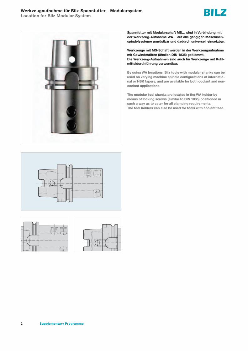
Werkzeugaufnahme für Bilz-Spannfutter – Modularsystem Location for Bilz Modular System
Spannfutter mit Modularschaft MS… sind in Verbindung mit der Werkzeug-Aufnahme WA… auf alle gängigen Maschinen-spindelsysteme umrüstbar und dadurch universell einsetzbar.
Werkzeuge mit MS-Schaft werden in der Werkzeugaufnahme mit Gewindestiften (ähnlich DIN 1835) geklemmt.Die Werkzeug-Aufnahmen sind auch für Werkzeuge mit Kühl-mitteldurchführung verwendbar.
By using WA locations, Bilz tools with modular shanks can be used on varying machine spindle configurations of internatio-nal or HSK tapers, and are available for both coolant and non-coolant applications.
The modular tool shanks are located in the WA holder by means of locking screws (similar to DIN 1835) positioned in such a way as to cater for all clamping requirements.The tool holders can also be used for tools with coolant feed.

3Zusatzprogramm
WA – Werkzeugaufnahme für BILZ-MS-Modularschaft WA – Location for BILZ-MS modular shank
WA…IK/HSK-A...Hohlschaftkegel DIN 69893A, mit Kühlmitteldurchführung, ohne KühlmittelrohrHollow taper shank DlN 69893 A, with coolant feed, without coolant pipe
l1
d2
l
d1H5
l1
d2
l
d1H5
l1
d2
l
d1H5
HSK-A… DIN 69893Bezeichnung
H5
Designation MS d1 d2 l1 HSK50 HSK63 HSK80 HSK100WA25-IK/HSK-A MS25 25 50 54 I 76 78 84 90
Id. No. 6831420 6831400 6800238 6831401WA32-IK/HSK-A MS32 32 53 61 I 86
Id. No. – 6831530 – –WA32-IK/HSK-A MS32 32 63 61 I 90 94
Id. No. – – 6832012 6831531
µm G
N– + – +
K MMSmax
F
LP 10P 50maxµmG
N– + – +
K MMSP 10maxP 50max
F
L
WA/HSK-C...Hohlschaftkegel DIN 69893 C. Auch für Kühlmitteldurchführung geeignetHollow taper shank DIN 69893 C. Also suitable for coolant feed
l1
d2
l
d1H5
l1
d2
l
d1H5
l1
d2
l
d1H5
HSK-A… DIN 69893Bezeichnung
H5 Designation MS d1 d2 l1 HSK50 HSK63 HSK80 HSK100WA25-HSK-C MS25 25 50 54 I 68 68 70 70
Id. No. 6831478 6831479 6831480 6831481WA32-HSK-C MS32 32 63 61 I 77 77
Id. No. – – 6800600 6831482
µm G
N– + – +
K MMSmax
F
LP 10P 50maxµmG
N– + – +
K MMSP 10maxP 50max
F
L

4 Supplementary Programme
WA – Werkzeugaufnahme für BILZ-MS-Modularschaft WA – Location for BILZ-MS modular shank
WA/A73/SKSteilkegel nach MAS 403. Auch für zentrale Kühlmitteldurchführung geeignetTaper 7/24 acc. to MAS 403. Also suitable for coolant feed
l1
d2
l
d1H5
l1
d2
l
d1H5
AD
B
l1
d2
l
d1H5
l1
d2
l
d1H5
SK…MAS 403Bezeichnung
H5
Designation MS d1 l1 SK40 SK45 SK50WA25/A73/SK MS25 25 54 I 35 35 35
d2 63 85 100Id. No. 6831402 6801064 6831403
WA32/A73/SK MS32 32 61 I 35 35 35
d2 63 85 100Id. No. 6831521 6801066 6831933
µm G
N– + – +
K MMSmax
F
LP 10P 50maxµmG
N– + – +
K MMSP 10maxP 50max
F
L
WA/A86/SKSteilkegel nach ANSI B 550. Auch für zentrale Kühlmitteldurchführung geeignetTaper 7/24 acc. to ANSI B 550. Also suitable for coolant feed
l1
d2
l
d1H5
l1
d2
l
d1H5
AD
B
l1
d2
l
d1H5
l1
d2
l
d1H5
SK…MAS 403Bezeichnung
H5
Designation MS d1 l1 SK40 SK45 SK50WA25/A73/SK MS25 25 54 I 35 35 35
d2 63 85 100M 16 20 24
Id. No. 6831512 6801067 6831511
WA32/A73/SK MS32 32 61 I 35 35 35
d2 63 85 100
M 16 20 24Id. No. – 6801068 6801069
µm G
N– + – +
K MMSmax
F
LP 10P 50maxµmG
N– + – +
K MMSP 10maxP 50max
F
L

5Zusatzprogramm
WA – Werkzeugaufnahme für BILZ-MS-Modularschaft WA – Location for BILZ-MS modular shank
WA/A126/...Steilkegel DIN 69871, mit Kühlmitteldurchführung AD bzw. BTaper 7/24 DIN 69871, with coolant feed AD or B
l1
d2
l
d1H5
l1
d2
l
d1H5
AD
B
l1
d2
l
d1H5
l1
d2
l
d1H5
SK…DIN 69871Bezeichnung
H5 Designation MS d1 l1 AD40, B40 AD45, B45 AD50, B50WA25/A126/AD MS25 25 54 I 35 35 35
d2 50 58 70Id. No. 6831405 6831406 6831407
WA25/A126/B MS25 25 54 I 35 35 35d2 50 58 70
Id. No. 6831412 6831413 6831414WA32/A126/AD MS32 32 61 I 45 35 35
d2 50 58 70Id. No. 6831408 6831409 6831410
WA32/A126/B MS32 32 61 I 45 35 35d2 50 58 70
Id. No. 6831416 6831417 6831418
µm G
N– + – +
K MMSmax
F
LP 10P 50maxµmG
N– + – +
K MMSP 10maxP 50max
F
L

6 Supplementary Programme
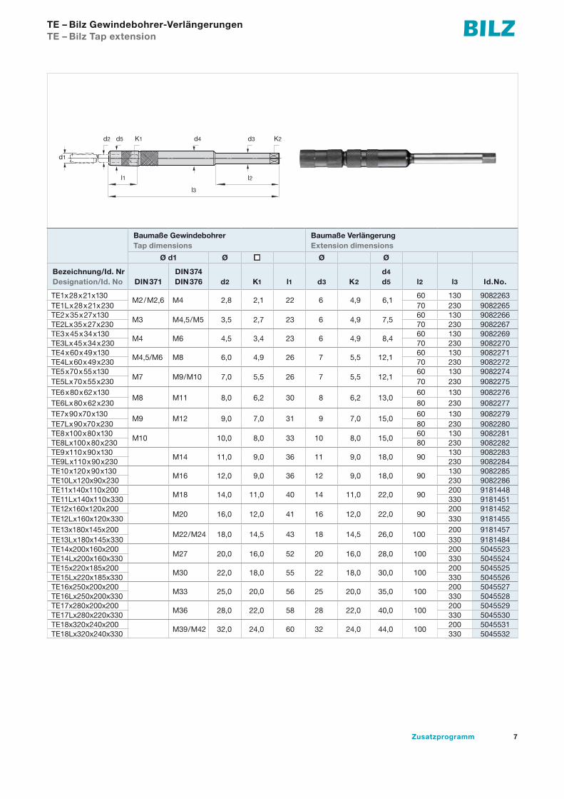
TE – Bilz Gewindebohrer-VerlängerungenTE – Bilz Tap extension
Zum Gewindeschneiden in Werkstücke mit extrem tief liegen-
den Innengewinden oder zum Gewindeschneiden unmittelbar
an Gusswänden, Absätzen, Störkannten von Vorrichtungen
usw. werden Gewindebohrer mit verlängertem Schaft benötigt.
For tapping operations in work pieces with extremely deep
internal threads or for tapping close to cast iron walls,
interference edges or shoulders of fixtures there is the need
of taps with an extended shank.
7Zusatzprogramm
TE – Bilz Gewindebohrer-VerlängerungenTE – Bilz Tap extension
Baumaße Gewindebohrer Tap dimensions
Baumaße VerlängerungExtension dimensions
Ø d1 Ø n Ø Ø
Bezeichnung/Id. Nr Designation/Id. No DIN 371
DIN 374DIN 376 d2 K1 l1 d3 K2
d4
d5 l2 l3 Id.No.
TE1x28x21x130M2/M2,6 M4 2,8 2,1 22 6 4,9 6,1
60 130 9082263TE1Lx28x21x230 70 230 9082265TE2x35x27x130
M3 M4,5/M5 3,5 2,7 23 6 4,9 7,560 130 9082266
TE2Lx35x27x230 70 230 9082267TE3x45x34x130
M4 M6 4,5 3,4 23 6 4,9 8,460 130 9082269
TE3Lx45x34x230 70 230 9082270TE4x60x49x130
M4,5/M6 M8 6,0 4,9 26 7 5,5 12,160 130 9082271
TE4Lx60x49x230 70 230 9082272TE5x70x55x130
M7 M9/M10 7,0 5,5 26 7 5,5 12,160 130 9082274
TE5Lx70x55x230 70 230 9082275TE6x80x62x130
M8 M11 8,0 6,2 30 8 6,2 13,060 130 9082276
TE6Lx80x62x230 80 230 9082277TE7x90x70x130
M9 M12 9,0 7,0 31 9 7,0 15,060 130 9082279
TE7Lx90x70x230 80 230 9082280TE8x100x80x130
M10 10,0 8,0 33 10 8,0 15,060 130 9082281
TE8Lx100x80x230 80 230 9082282TE9x110x90x130
M14 11,0 9,0 36 11 9,0 18,0 90130 9082283
TE9Lx110x90x230 230 9082284TE10x120x90x130
M16 12,0 9,0 36 12 9,0 18,0 90130 9082285
TE10Lx120x90x230 230 9082286TE11x140x110x200
M18 14,0 11,0 40 14 11,0 22,0 90200 9181448
TE11Lx140x110x330 330 9181451TE12x160x120x200
M20 16,0 12,0 41 16 12,0 22,0 90200 9181452
TE12Lx160x120x330 330 9181455TE13x180x145x200
M22/M24 18,0 14,5 43 18 14,5 26,0 100200 9181457
TE13Lx180x145x330 330 9181484TE14x200x160x200
M27 20,0 16,0 52 20 16,0 28,0 100200 5045523
TE14Lx200x160x330 330 5045524TE15x220x185x200
M30 22,0 18,0 55 22 18,0 30,0 100200 5045525
TE15Lx220x185x330 330 5045526TE16x250x200x200
M33 25,0 20,0 56 25 20,0 35,0 100200 5045527
TE16Lx250x200x330 330 5045528TE17x280x200x200
M36 28,0 22,0 58 28 22,0 40,0 100200 5045529
TE17Lx280x220x330 330 5045530TE18x320x240x200
M39/M42 32,0 24,0 60 32 24,0 44,0 100200 5045531
TE18Lx320x240x330 330 5045532
d1
d2 d5 K1 d4 d3 K2
l2
l3
l1

8 Supplementary Programme
TE-IK – Bilz Gewindebohrer-VerlängerungenTE-IK – Bilz Tap extension
Baumaße Gewindebohrer Tap dimensions
Baumaße VerlängerungExtension dimensions
Ø d1 Ø n Ø Ø
Bezeichnung/Id. Nr Designation/Id. No DIN 371
DIN 374DIN 376 d2 K1 l1 d3 K2
d4
d5 l2 l3 Id.No.
TE1-IKx28x21x130M2/M2,6 M4 2,8 2,1 22 6 4,9 6,1 60 130 9082293
TE2-IKx35x27x130M3 M4,5/M5 3,5 2,7 23 6 4,9 7,5 60 130 9082298
TE3-IKx45x34x130M4 M6 4,5 3,4 23 6 4,9 8,4 60 130 9082299
TE4-IKx60x49x130M4,5/M6 M8 6,0 4,9 26 7 5,5 12,1 60 130 9082300
TE5-IKx70x55x130M7 M9/M10 7,0 5,5 26 7 5,5 12,1 60 130 9082301
TE6-IKx80x62x130M8 M11 8,0 6,2 30 8 6,2 13,0
60 130 9082302TE6L-IKx80x62x230 80 230 9082303TE7-IKx90x70x130
M9 M12 9,0 7,0 31 9 7,0 15,060 130 9082304
TE7L-IKx90x70x230 80 230 9082305TE8-IKx100x80x130
M10 10,0 8,0 33 10 8,0 15,060 130 9082306
TE8L-IKx100x80x230 80 230 9082308TE9-IKx110x90x130
M14 11,0 9,0 36 11 9,0 18,0 90130 9082309
TE9L-IKx110x90x230 230 9082310TE10-IKx120x90x130
M16 12,0 9,0 36 12 9,0 18,0 90130 9082311
TE10L-IKx120x90x230 230 9082312TE11-IKx140x110x200
M18 14,0 11,0 40 14 11,0 22,0 90200 9181460
TE11L-IKx140x110x330 330 9181477TE12-IKx160x120x200
M20 16,0 12,0 41 16 12,0 22,0 90200 9181478
TE12L-IKx160x120x330 330 9181479TE13-IKx180x145x200
M22/M24 18,0 14,5 43 18 14,5 26,0 100200 9181480
TE13L-IKx180x145x330 330 9181485TE14-IKx200x160x200
M27 20,0 16,0 52 20 16,0 28,0 100200 5045533
TE14L-IKx200x160x330 330 5045534TE15-IKx220x185x200
M30 22,0 18,0 55 22 18,0 30,0 100200 5045535
TE15L-IKx220x185x330 330 5045536TE16-IKx250x200x200
M33 25,0 20,0 56 25 20,0 35,0 100200 5045537
TE16L-IKx250x200x330 330 5045538TE17-IKx280x220x200
M36 28,0 22,0 58 28 22,0 40,0 100200 5045540
TE17L-IKx280x220x330 330 5045541TE18-IKx320x240x200
M39/M42 32,0 24,0 60 32 24,0 44,0 100200 5045543
TE18L-IKx320x240x330 330 5045544
d1
d2 d5 K1 d4 d3 K2
l2
l3
l1

9Zusatzprogramm
TE-IK-h6 – Bilz Gewindebohrer-VerlängerungenTE-IK-h6 – Bilz Tap extension
Bilz Gewindebohr - Verlängerungen – Zum Einsatz in Schrumpf- und Hydrodehnspannfutter Bilz Tap extension – For usage in Shrinking and hydraulic chucks
Baumaße Gewindebohrer Tap dimensions
Baumaße VerlängerungExtension dimensions
Ø d1 Ø n Ø Ø
Bezeichnung/Id. Nr Designation/Id. No DIN 371
DIN 374DIN 376 d2 K1 l1
h6
d3 K2
d4
d5 l2 l3 Id.No.
TE1-IK-h6x28x21x130M2/M2,6 M4 2,8 2,1 22 6 4,9 6,1 60 130 9082318
TE2-IK-h6x35x27x130M3 M4,5/M5 3,5 2,7 23 6 4,9 7,5 60 130 9082319
TE3-IK-h6x45x34x130M4 M6 4,5 3,4 23 6 4,9 8,4 60 130 9082322
TE4-IK-h6x60x49x130M4,5/M6 M8 6,0 4,9 26 8 6,2 12,1 60 130 9082323
TE5-IK-h6x70x55x130M7 M9/M10 7,0 5,5 26 8 6,2 12,1 60 130 9082324
TE6-IK-h6x80x62x130M8 M11 8,0 6,2 30 8 6,2 13,0
60 130 9082325TE6L-IK-h6x80x62x230 80 230 9082326TE7-IK-h6x90x70x130
M9 M12 9,0 7,0 31 10 8,0 15,060 130 9082327
TE7L-IK-h6x90x70x230 80 230 9082328TE8-IK-h6x100x80x130
M10 10,0 8,0 33 10 8,0 15,060 130 9082329
TE8L-IK-h6x100x80x230 80 230 9082331TE9-IK-h6x110x90x130
M14 11,0 9,0 36 12 9,0 18,0 90130 9082332
TE9L-IK-h6x110x90x230 230 9082333TE10-IK-h6x120x90x130
M16 12,0 9,0 36 12 9,0 18,0 90130 9082334
TE10L-IK-h6x120x90x230 230 9082335TE11-IK-h6x140x110x200
M18 14,0 11,0 40 14 11,0 22,0 90200 9181486
TE11L-IK-h6x140x110x330 330 9181487TE12-IK-h6x160x120x200
M20 16,0 12,0 41 16 12,0 22,0 90200 9181488
TE12L-IK-h6x160x120x330 330 9181489TE13-IK-h6x180x145x200
M22/M24 18,0 14,5 43 18 14,5 26,0 100200 9181491
TE13L-IK-h6x180x145x330 330 9181492TE14-IK-h6x200x160x200
M27 20,0 16,0 52 20 16,0 28,0 100200 5045545
TE14L-IK-h6x200x160x330 330 5045546TE15-IK-h6x220x185x200
M30 22,0 18,0 55 22 18,0 30,0 100200 5045547
TE15L-IK-h6x220x185x330 330 5045548TE16-IK-h6x250x200x200
M33 25,0 20,0 56 25 20,0 35,0 100200 5045549
TE16L-IK-h6x250x200x330 330 5045550TE17-IK-h6x280x220x200
M36 28,0 22,0 58 28 22,0 40,0 100200 5045551
TE17L-IK-h6x280x220x330 330 5045552TE18-IK-h6x320x240x200
M39/M42 32,0 24,0 60 32 24,0 44,0 100200 5045553
TE18L-IK-h6x320x240x330 330 5045554
d1
d2 d5 K1 d4 d3 K2
l2
l3
l1

10 Supplementary Programme
Drehmoment-EinstellwerkzeugeTorque adjustment tools
Bei Bestellung der Einstellschlüssel GS bitte Schaft-Ø und Vierkant oder Gewinde und DIN des in den Einsatz passenden Gewindebohrers angeben.
When ordering setting shanks Type GS, please state shank Ø and square, or thread and DIN of tap used in the adaptor.
Type G
Type GS 13
Type GW
Type WES-WESR
Type GWA
Type Type T G
Type GS 13Type GS 13T
Type GWType GWT
Type WES-WESRType WES-WESRT
Type GWType GWT Aype GWAype GW
G = Drehmomentschlüssel Torque Wrench
GS = Einstellschlüssel Setting shank
WES-WESR = Einsatz Adaptor
GW = Einstellschlüssel Setting socket
GWA = Stirnlochschlüssel Adjustable pin wrench
RD = Ratsche mit Einsatz Ratchet with insert
GE = Drehmomenteinstellgerät Torque adjustment unit
Mtmax
WES-WESR G GE RD Nm GS 13 GS 25 GWA GW
0 I G0 15 2,5-7,2 – GWA0 GW0Id. No. 6721675 – 6721800 6721790
1 I G1 30 3,5-11,3 – GWA1 GW1Id. No. 6721680 – 6721801 6721791
40 I G2 120 6-14 – GWA40 GW40Id. No. 6721684 – 6721803 6721794
2 I G2 120 7-18 – GWA40 GW2Id. No. 6721684 – 6721803 6721792
3 I G3 300 11-28 – GWA3 GW3Id. No. 6721688 – 6721804 6721795
Zubehör Drehmomenteinstellung Accessories torque adjustment
G-GEFür Schnellwechsel-Einsätze. Zum Einstellen und Überprüfen der SicherheitskupplungFor quick change adaptors to adjust and check the safety clutch. For adaptors size 0-3.
Für Einsätze Größe 0-3For adaptors size 0-3

11Zusatzprogramm
Drehmomenteinstell-Set für DIN Gewindebohrer/-formerTorque setting sets for DIN taps/roll formers
BezeichnungWES-WESR Designation Ø x DIN371 DIN374 DIN376 Id. No.
0 G0 6721675GW0 6721790GWA0 6721800GS13-POS.004-2,5 x 2,1 2,8 x 2,1 M1-M1,8 M3,5 M3,5 6721697GS13-POS.004-2,5 x 2,1 2,8 x 2,1 M2-M2,2 M4 M4 6721697GS13-POS.007-3 x 2,5 3,5 x 2,7 M3 M5 M4,5-M5 6721700GS13-POS.009-3,8 x 3 4,0 x 3,0 M3,5 M5,5 6721702GS13-POS.011-4,4 x 3,4 4,5 x 3,4 M4 M6 M6 6721704GS13-POS.016-5 x 4,2 5,5 x 4,3 M7 M7 6721709GS13-POS.018-5,9 x 4,8 6,0 x 4,9 M4,5-M6 M8 M8 6721711GS13-POS.022-7 x 5,4 7,0 x 5,5 M7 M9-M10 M9-M10 6721715
1 G1 6721680GW1 6721791GWA1 6721801GS13-POS.007-3 x 2,5 3,5 x 2,7 M3 M5 M4,5-M5 6721700GS13-POS.009-3,8 x 3 4,0 x 3,0 M3,5 M5,5 6721702GS13-POS.011-4,4 x 3,4 4,5 x 3,4 M4 M6 M6 6721704GS13-POS.016-5 x 4,2 5,5 x 4,3 M7 M7 6721709GS13-POS.018-5,9 x 4,8 6,0 x 4,9 M4,5-M6 M8 M8 6721711GS13-POS.022-7 x 5,4 7,0 x 5,5 M7 M9-M10 M9-M10 6721715GS13-POS.027-7,9 x 6 8,0 x 6,2 M8 M11 6721718GS13-POS.031-9 x 7 9,0 x 7,0 M9 M12 M12 6721722GS13-POS.034-9,8 x 7,75 10,0 x 8,0 M10 6721725GS13-POS.037-10,9 x 9 11,0 x 9,0 M14 M14 6721728
2 G2 6721684GW2 6721792GWA2 6721802GS13-POS.022-7 x 5,4 7,0 x 5,5 M7 M9-M10 M9-M10 6721715GS13-POS.027-7,9 x 6 8,0 x 6,2 M8 M11 6721718GS13-POS.031-9 x 7 9,0 x 7,0 M9 M12 M12 6721722GS13-POS.034-9,8 x 7,75 10,0 x 8,0 M10 6721725GS13-POS.037-10,9 x 9 11,0 x 9,0 M14 M14 6721728GS13-POS.038-11,8 x 9 12,0 x 9,0 M12 M16 M16 6721729GS13-POS.045-14 x 11 14,0 x 11,0 M18 M18 6721736GS13-POS.050-16 x 12 16,0 x 12,0 M20 M20 6721741GS13-POS.055-18 x 14 18,0 x 14,5 M22-M24 M22-M24 6721745
3 G3 6721688GW3 6721795GWA3 6721804GS13-POS.037-10,9 x 9 11,0 x 9,0 M14 M14 6721728GS13-POS.038-11,8 x 9 12,0 x 9,0 M12 M16 M16 6721729GS13-POS.045-14 x 11 14,0 x 11,0 M18 M18 6721736GS13-POS.050-16 x 12 16,0 x 12,0 M20 M20 6721741GS13-POS.055-18 x 14 18,0 x 14,5 M22-M24 M22-M24 6721745GS13-POS.056-20 x 15 20,0 x 16,0 M27 M27 6721746GS13-POS.068-22 x 18 22,0 x 18,0 M30 M30 6721755GS13-POS.069-25 x 20 25,0 x 20,0 M33 M33 6721756GS13-POS.070-27,5 x 22 28,0 x 22,0 M36 M36 6721757
40 G2 6721684GW40 6721792GWA40 6721802GS13-POS.018-5,9 x 4,8 6,0 x 4,9 M4,5-M6 M8 M8 6721711GS13-POS.022-7 x 5,4 7,0 x 5,5 M7 M9-M10 M9-M10 6721715GS13-POS.027-7,9 x 6 8,0 x 6,2 M8 M11 6721718GS13-POS.031-9 x 7 9,0 x 7,0 M9 M12 M12 6721722GS13-POS.034-9,8 x 7,75 10,0 x 8,0 M10 6721725GS13-POS.037-10,9 x 9 11,0 x 9,0 M14 M14 6721728GS13-POS.038-11,8 x 9 12,0 x 9,0 M12 M16 M16 6721729GS13-POS.045-14 x 11 14,0 x 11,0 M18 M18 6721736

12 Supplementary Programme
Bezeichnung/Id. No. Spannbereich Abstufung ÜberbrückungDesignation/Id. No. Collet range Increments of Overlap d I
ESX08 0,5–5 0,5 0,5 8,5 13,5ESX12 1–7 0,5 0,5 11,5 18,0ESX16 1–10 1 1 17,0 27,5ESX20 1–13 1 1 21,0 31,5ESX25 1–16 1 1 26,0 34,0ESX32 2–20 1 1 33,0 40,0ESX40 3–30 1 1 41,0 46,0ESX50 10–34 2 2 52,0 60,0
Von d Nach d ER ER-UPFrom d To d I DIN Standard Ultra Precision
1,0 1,6 6,0 0,015 0,010 0,0051,6 3,0 10,0 0,015 0,010 0,0053,0 6,0 16,0 0,015 0,010 0,0056,0 10,0 25,0 0,015 0,010 0,005
10,0 18,0 40,0 0,020 0,010 0,00518,0 26,0 50,0 0,020 0,010 0,00526,0 34,0 60,0 0,025 0,015 0,010
ER/ESX-Spannzange ISO 15488ER/ESX collet ISO 15488
l
d
l
d
Ød
l
Ød
l
Rundlauf der ER/ESX-SpannzangeConcentricity of ER/ESX collets

13Zusatzprogramm
ER/ESX GB-SpannzangeER/ESX GB collet
Id. No.
d x SW I2 ESX 12 GB ESX 16 GB ESX 20 GB ESX 25 GB ESX 32 GB ESX 40 GB
2,8 x 2,1 12 DIN3,5 x 2,7 14 DIN4,0 x 3,0 14 DIN4,0 x 3,15/3,2 18 ISO,JIS 6949762 69506654,5 x 3,4 14/18 DIN 6951393 6948389 6951218 69525855,0 x 4,0 18 ISO,JIS 6954872 69497635,5 x 4,3 18 DIN 6954656 69497645,5 x 4,5 18 JIS 6952288 69497656,0 x 4,5 14/18 JIS 6952289 6949766 69532206,0 x 4,9 18 DIN 6950826 6951392 6948390 6951544 69499976,2 x 5,0 18 JIS6,3 x 5,0 18 ISO 6946901 6951397 6951217 69469647,0 x 5,5 18 DIN,JIS 6947340 6949767 6951797 69500297,1 x 5,6 18 ISO 6953228 69500298,0 x 6,2/6,3 18 DIN,JISO 6946213 6949202 6951214 6949769 69553968,5 x 6,5 22 JIS 6949768 6954875 69532219,0 x 7,0/7,1 22 DIN,ISO 6947393 6947338 6951216 6946965 695539710,0 x 8,0 22 DIN,ISO 6951396 6949111 6951215 6949998 908001210,5 x 8,0 25 JIS 6953229 6954876 695283511,0 x 9,0 25 DIN 6949177 6946167 6946104 695539811,2 x 9,0 25 ISO 6949353 6951551 695121912,0 x 9,0 25 DIN 6950343 6946106 907474112,5 x 10,0 25 ISO,JIS 6951398 6951553 695149314,0 x 11,0/11,2 25 DIN,ISO,JIS 6951559 6947337 907474215,0 x 12,0 25 JIS 695322216,0 x 12,0 25 DIN 6951399 6948391 908007316,0 x 12,5 25 JIS 6947689 695272217,0 x 13,0 25 JIS18,0 x 14,0/14,5 25 DIN,ISO 6950206 695220720,0 x 16,0 28 DIN,ISO 6948392 694890322,0 x 18,0 28 DIN 6949124
ESX … GB Spannzange mit InnenvierkantESX … GB collet with internal square
14 Supplementary Programme
l
d
l
d
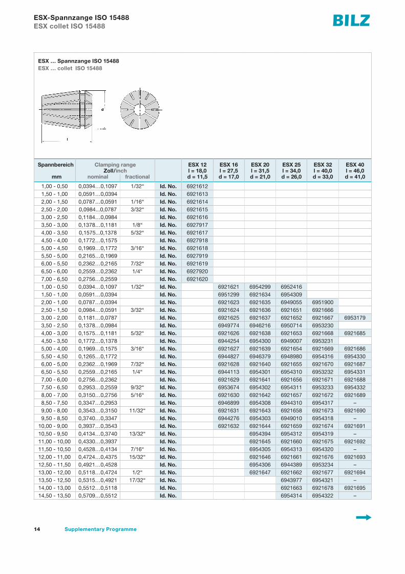
ESX-Spannzange ISO 15488ESX collet ISO 15488
ESX … Spannzange ISO 15488ESX … collet ISO 15488
Spannbereich Clamping range ESX 12 ESX 16 ESX 20 ESX 25 ESX 32 ESX 40Zoll/inch l = 18,0 l = 27,5 l = 31,5 l = 34,0 l = 40,0 l = 46,0
mm nominal fractional d = 11,5 d = 17,0 d = 21,0 d = 26,0 d = 33,0 d = 41,0
1,00 - 0,50 0,0394…0,1097 1/32“ Id. No. 69216121,50 - 1,00 0,0591…0,0394 Id. No. 69216132,00 - 1,50 0,0787…0,0591 1/16“ Id. No. 69216142,50 - 2,00 0,0984...0,0787 3/32“ Id. No. 69216153,00 - 2,50 0,1184…0,0984 Id. No. 69216163,50 - 3,00 0,1378…0,1181 1/8“ Id. No. 69279174,00 - 3,50 0,1575...0,1378 5/32“ Id. No. 69216174,50 - 4,00 0,1772…0,1575 Id. No. 69279185,00 - 4,50 0,1969…0,1772 3/16“ Id. No. 69216185,50 - 5,00 0,2165…0,1969 Id. No. 69279196,00 - 5,50 0,2362…0,2165 7/32“ Id. No. 69216196,50 - 6,00 0,2559…0,2362 1/4“ Id. No. 69279207,00 - 6,50 0,2756…0,2559 Id. No. 69216201,00 - 0,50 0,0394…0,1097 1/32“ Id. No. 6921621 6954299 69524161,50 - 1,00 0,0591…0,0394 Id. No. 6951299 6921634 69543092,00 - 1,00 0,0787…0,0394 Id. No. 6921623 6921635 6949055 69519002,50 - 1,50 0,0984…0,0591 3/32“ Id. No. 6921624 6921636 6921651 69216663,00 - 2,00 0,1181…0,0787 Id. No. 6921625 6921637 6921652 6921667 69531793,50 - 2,50 0,1378…0,0984 Id. No. 6949774 6946216 6950714 69532304,00 - 3,00 0,1575…0,1181 5/32“ Id. No. 6921626 6921638 6921653 6921668 69216854,50 - 3,50 0,1772…0,1378 Id. No. 6944254 6954300 6949007 69532315,00 - 4,00 0,1969…0,1575 3/16“ Id. No. 6921627 6921639 6921654 6921669 69216865,50 - 4,50 0,1265…0,1772 Id. No. 6944827 6946379 6948980 6954316 69543306,00 - 5,00 0,2362…0,1969 7/32“ Id. No. 6921628 6921640 6921655 6921670 69216876,50 - 5,50 0,2559…0,2165 1/4“ Id. No. 6944113 6954301 6954310 6953232 69543317,00 - 6,00 0,2756…0,2362 Id. No. 6921629 6921641 6921656 6921671 69216887,50 - 6,50 0,2953…0,2559 9/32“ Id. No. 6953674 6954302 6954311 6953233 69543328,00 - 7,00 0,3150…0,2756 5/16“ Id. No. 6921630 6921642 6921657 6921672 69216898,50 - 7,50 0,3347…0,2953 Id. No. 6946899 6954308 6944310 6954317 –9,00 - 8,00 0,3543…0,3150 11/32“ Id. No. 6921631 6921643 6921658 6921673 69216909,50 - 8,50 0,3740…0,3347 Id. No. 6944276 6954303 6949010 6954318 –
10,00 - 9,00 0,3937…0,3543 Id. No. 6921632 6921644 6921659 6921674 692169110,50 - 9,50 0,4134…0,3740 13/32“ Id. No. 6954394 6954312 6954319 –11,00 - 10,00 0,4330…0,3937 Id. No. 6921645 6921660 6921675 692169211,50 - 10,50 0,4528…0,4134 7/16“ Id. No. 6954305 6954313 6954320 –12,00 - 11,00 0,4724…0,4375 15/32“ Id. No. 6921646 6921661 6921676 692169312,50 - 11,50 0,4921…0,4528 Id. No. 6954306 6944389 6953234 –13,00 - 12,00 0,5118…0,4724 1/2“ Id. No. 6921647 6921662 6921677 692169413,50 - 12,50 0,5315…0,4921 17/32“ Id. No. 6943977 6954321 –14,00 - 13,00 0,5512…0,5118 Id. No. 6921663 6921678 692169514,50 - 13,50 0,5709…0,5512 Id. No. 6954314 6954322 –

15Zusatzprogramm
l
d
l
d
ESX-Spannzange ISO 15488ESX collet ISO 15488
ESX … Spannzange ISO 15488ESX … collet ISO 15488
Spannbereich Clamping range ESX 12 ESX 16 ESX 20 ESX 25 ESX 32 ESX 40Zoll/inch l = 18,0 l = 27,5 l = 31,5 l = 34,0 l = 40,0 l = 46,0
mm nominal fractional d = 11,5 d = 17,0 d = 21,0 d = 26,0 d = 33,0 d = 41,0
15,00 - 14,00 0,5905…0,5512 Id. No. 6921664 6921679 692169615,50 - 14,50 0,6102…0,5315 19/32“ Id. No. 6954315 6954323 –16,00 - 15,00 0,6300…0,5905 5/8“ Id. No. 6921665 6921680 692169716,50 - 15,50 0,6496…0,6102 Id. No. 6954327 –17,00 - 16,00 0,6693…0,6300 21/32“ Id. No. 6921681 692169817,50 - 16,50 0,6890…0,6496 11/16“ Id. No. 6954324 –18,00 - 17,00 0,7087…0,6693 Id. No. 6921682 692169918,50 - 17,50 0,7284…0,6890 23/32“ Id. No. 6954325 –19,00 - 18,00 0,7480…0,7078 Id. No. 6921683 692170019,50 - 18,50 0,7677…0,7284 3/4“ Id. No. 6954326 –20,00 - 19,00 0,7874…0,7480 25/32“ Id. No. 6921684 692170120,50 - 19,50 0,8071…0,7677 Id. No. –21,00 - 20,00 0,8268…0,7874 13/16“ Id. No. 692170221,50 - 20,50 0,8465…0,8071 27/32“ Id. No. –22,00 - 21,00 0,8661…0,8268 Id. No. 692170322,50 - 21,50 0,8858…0,8465 7/8“ Id. No. –23,00 - 22,00 0,9055…0,8661 Id. No. 692170423,50 - 22,50 0,9252…0,8858 29/32“ Id. No. –24,00 - 23,00 0,9449…0,9055 15/16“ Id. No. 692170524,50 - 23,50 0,9646…0,9252 Id. No. –25,00 - 24,00 0,9843…0,9449 31/32“ Id. No. 692170625,50 - 24,50 1,0039…0,9646 1“ Id. No. –26,00 - 25,00 1,0236…0,9843 Id. No. 692170727,00 - 26,00 1,0630…1,0236 1.1/16“ Id. No. 692395728,00 - 27,00 1,1024…1,0630 1.3/32“ Id. No. 695468029,00 - 28,00 1,1417…1,1024 1.1/8“ Id. No. 695496630,00 - 29,00 1,1811…1,1417 1.5/32“ Id. No. 6953214

16 Supplementary Programme
µm G
N– + – +
K MMSmax
F
LP 10P 50max
BZ18 – SpannzangeBZ18 – Collet
BZ18 – IKBZ18 – IC µm
G N
– + – +K MMS
P 10maxP 50max
F
LµmG
N– + – +
K MMSP 10maxP 50max
F
L
A
N
d
Schraube Screw
Einstecktiefe Nachstellunginserting depth length adjustment
IK oder MMS mit MMS ohne Schraube/Id. No. Dichtscheibe/Id. No.IC or MQL with MQL without Screw/Id. No. Sealing disc/Id. No.
d x / Id. No. A A N
IK/ohne IK IC/without IC
4.0 x 3.15/3.2 27 23 3 BN158-BZ18.0 DS/ER20-4.0 6801791 6951626 6953235
5.0 x 4.0 28 24 4 BN158-BZ18.0 DS/ER20-5.0 6801788 6951626 6953236
5.6 x 4.5 28 24 4 BN158-BZ18.0 DS/ER20-6.0 6801795 6951626 6943901
6.0 x 4.9 29 25 4 BN158-BZ18.0 DS/ER20-6.0 6801792 6951626 6943901
6.3 x 5.0 29 25 4 BN158-BZ18.0 DS/ER20-6.5 6801796 6951626 6953031
7.0 x 5.5 29 25 4 BN158-BZ18.0 DS/ER20-7.0 6801789 6951626 6950178
7.1 x 5.6 29 25 4 BN158-BZ18.0 DS/ER20-7.5 6801797 6951626 6953237
8.0 x 6.2/6.3 30 26 4 BN158-BZ18.0 DS/ER20-8.0 6801790 6951626 6946991
9.0 x 7.0 31 27 4 BN158-BZ18.0 DS/ER20-9.0 6800963 6951626 6947339
9,0 x 7,1 31 27 4 BN158-BZ18.0 DS/ER20-9.0 6800961 6951626 6947339
10.0 x 8.0 32 28 4 BN158-BZ18.0 DS/ER20-10.0 6800960 6951626 6931347
11.0 x 9.0 33 29 4 BN158-BZ18.0 DS/ER20-11.0 6801793 6951626 6944294
11.2 x 9.0 33 29 4 BN158-BZ18.0 DS/ER20-11.5 6801798 6951626 6953239
µmG
N– + – +
K MMSP 10maxP 50max
F
L

17Zusatzprogramm
Einstecktiefe Nachstellunginserting depth length adjustment
MMS mit MMS ohne Schraube/Id. No. Dichtscheibe/Id. No.MQL with MQL without Screw/Id. No. Sealing disc/Id. No.
d x / Id. No. A A N
MMS MQL4.0 x 3.15/3.2 27 23 3 BN158-BZ18.1 DS/ER20-4.0
– 6951623 69532355.0 x 4.0 28 24 4 BN158-BZ18.1 DS/ER20-5.0
– 6951623 69532365.6 x 4.5 28 24 4 BN158-BZ18.1 DS/ER20-6.0
– 6951623 69439016.0 x 4.9 29 25 4 BN158-BZ18.1 DS/ER20-6.06801891 6951623 69439016.3 x 5.0 29 25 4 BN158-BZ18.1 DS/ER20-6.5
– 6951623 69530317.0 x 5.5/5,6 29 25 4 BN158-BZ18.1 DS/ER20-7.06801892 6951623 69501787.1 x 5.6 29 25 4 BN158-BZ18.1 DS/ER20-7.5
– 6951623 69532378.0 x 6.2/6.3 30 26 4 BN158-BZ18.1 DS/ER20-8.06801907 6951623 69469919.0 x 7.0/7.1 31 27 4 BN158-BZ18.1 DS/ER20-9.06801890 6951623 694733910.0 x 8.0 32 28 4 BN158-BZ18.1 DS/ER20-10.0
– 6951623 693134711.0 x 9.0 33 29 4 BN158-BZ18.1 DS/ER20-11.0
– 6951623 694429411.2 x 9.0 33 29 4 BN158-BZ18.1 DS/ER20-11.5
– 6951623 6953239
µm G
N– + – +
K MMSmax
F
LP 10P 50max
BZ18 – Spannzange
BZ18 – Collet
BZ18 – MMSBZ18 – MQL µm
G N
– + – +K MMS
P 10maxP 50max
F
LµmG
N– + – +
K MMSP 10maxP 50max
F
L
A
N
d
Schraube Screw
µmG
N– + – +
K MMSP 10maxP 50max
F
L
18 Supplementary Programme
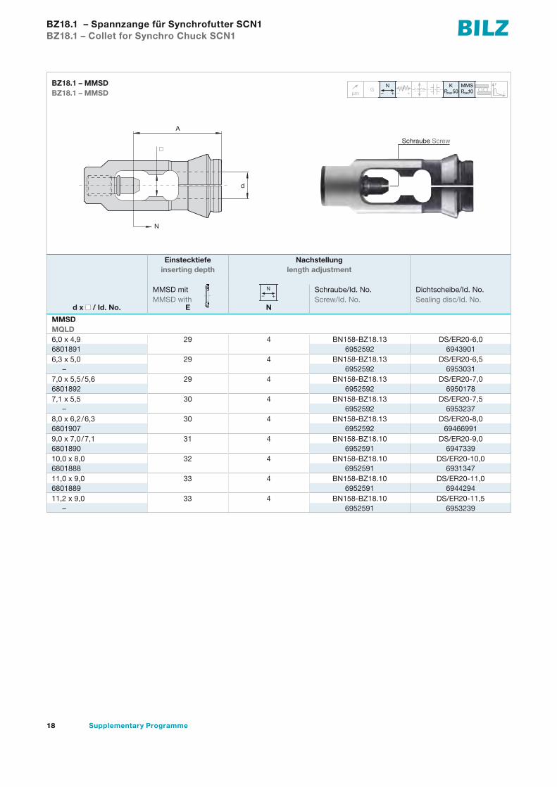
Einstecktiefe Nachstellunginserting depth length adjustment
MMSD mit Schraube/Id. No. Dichtscheibe/Id. No.MMSD with Screw/Id. No. Sealing disc/Id. No.
d x / Id. No. E N
MMSDMQLD6,0 x 4,9 29 4 BN158-BZ18.13 DS/ER20-6,0 6801891 6952592 69439016,3 x 5,0 29 4 BN158-BZ18.13 DS/ER20-6,5
– 6952592 69530317,0 x 5,5/5,6 29 4 BN158-BZ18.13 DS/ER20-7,06801892 6952592 69501787,1 x 5,5 30 4 BN158-BZ18.13 DS/ER20-7,5
– 6952592 69532378,0 x 6,2/6,3 30 4 BN158-BZ18.13 DS/ER20-8,06801907 6952592 694669919,0 x 7,0/7,1 31 4 BN158-BZ18.10 DS/ER20-9,06801890 6952591 694733910,0 x 8,0 32 4 BN158-BZ18.10 DS/ER20-10,06801888 6952591 693134711,0 x 9,0 33 4 BN158-BZ18.10 DS/ER20-11,06801889 6952591 694429411,2 x 9,0 33 4 BN158-BZ18.10 DS/ER20-11,5
– 6952591 6953239
µm G
N– + – +
K MMSmax
F
LP 10P 50max
BZ18.1 – Spannzange für Synchrofutter SCN1
BZ18.1 – Collet for Synchro Chuck SCN1
BZ18.1 – MMSDBZ18.1 – MMSD µm
G N
– + – +K MMS
P 10maxP 50max
F
LµmG
N– + – +
K MMSP 10maxP 50max
F
L
Schraube Screw
µmG
N– + – +
K MMSP 10maxP 50max
F
L
A
N
d

19Zusatzprogramm
Einstecktiefe Nachstellunginserting depth length adjustment
MMSD mit Schraube/Id. No. Dichtscheibe/Id. No.MMSD with Screw/Id. No. Sealing disc/Id. No.
d x / Id. No. E N
MMSDMQLD10,0 x 8,0 41 4 BN158-BZ25.11 DS/ER25-10
– 6955368 694342311,0 x 9,0 42 4 BN158-BZ25.11 DS/ER25-11
– 6955368 694353412,0 x 9,0 42 4 BN158-BZ25.11 DS/ER25-12
– 6955368 694342414,0 x 11,0 44 4 BN158-BZ25.10 DS/ER25-14
– 6955367 694334216,0 x 12,0 45 4 BN158-BZ25.10 DS/ER25-16
– 6955367 6943422*18,0 x 14,5 45 4 BN158-BZ25.10 DS/BZ25-18
– 6955367 9088550
µm G
N– + – +
K MMSmax
F
LP 10P 50max
BZ25.1 – Spannzange BZ25.1 – Collet
BZ25.1 – MMSDBZ25.1 – MMSD µm
G N
– + – +K MMS
P 10maxP 50max
F
LµmG
N– + – +
K MMSP 10maxP 50max
F
L
A
N
d
µmG
N– + – +
K MMSP 10maxP 50max
F
L
*nur für leichte Bearbeitung*only for light machining
Schraube Screw
20 Supplementary Programme
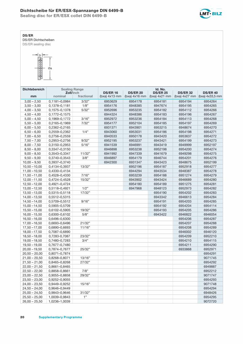
Dichtebereich Sealing Range Id. No.Zoll/inch DS/ER 16 DS/ER 20 DS/ER 25 DS/ER 32 DS/ER 40
mm nominal fractional (bxa) 4x13 mm (bxa) 4x16 mm (bxa) 4x21 mm (bxa) 4x27 mm (bxa) 4x33,5 mm
3,00 – 2,50 0,1181–0,0984 3/32” 6953629 6954178 6954181 6954194 69542643,50 – 3,00 0,1378–0,1181 1/8” 6954176 6948385 6947674 6954195 69542654,00 – 3,50 0,1575–0,1378 5/32” 6952696 6953235 6954182 6954112 69542664,50 – 4,00 0,1772–0,1575 6944324 6948386 6954183 6954196 69542675,00 – 4,50 0,1969–0,1772 3/16” 6952972 6953236 6954184 6954113 69542685,50 – 5,00 0,2165–0,1969 7/32” 6954177 6952104 6954185 6954197 69542696,00 – 5,50 0,2362–0,2165 6931371 6943901 6953215 6948674 69542706,50 – 6,00 0,2559–0,2362 1/4” 6943060 6953031 6954186 6954198 69542717,00 – 6,50 0,2756–0,2559 6940533 6950178 6943420 6953637 69542727,50 – 7,00 0,2953–0,2756 9/32” 6952195 6953237 6943421 6954199 69542738,00 – 7,50 0,3150–0,2953 5/16” 6941539 6946991 6943419 6949999 69521978,50 – 8,00 0,3347–0,3150 6946898 6953238 6952198 6954200 69542749,00 – 8,50 0,3543–0,3347 11/32” 6941992 6947339 6941679 6949298 69542759,50 – 9,00 0,3740–0,3543 3/8” 6946897 6954179 6946744 6954201 6954276
10,00 – 9,50 0,3937–0,3740 6942300 6931347 6943423 6948675 695219910,50 –10,00 0,4134–0,3937 13/32” 6952196 6954187 6952918 695427711,00 –10,50 0,4330–0,4134 6944294 6943534 6948387 695427811,50 –11,00 0,4528–0,4330 7/16” 6953239 6954188 6951274 695427912,00 –11,50 0,4724–0,4528 15/32” 6943902 6943424 6946689 695428012,50 –12,00 0,4921–0,4724 6954180 6954189 6951275 695428113,00 –12,50 0,5118–0,4921 1/2” 6947968 6948123 6952973 695428213,50 –13,00 0,5315–0,5118 17/32” 6954190 6954202 695428314,00 –13,50 0,5512–0,5315 6943342 6946613 695428414,50 –14,00 0,5709–0,5512 9/16” 6954191 6954203 695428515,00 –14,50 0,5905–0,5709 6954192 6954204 695411415,50 –15,00 0,6102–0,5905 19/32” 6954193 6954205 695428616,00 –15,50 0,6300–0,6102 5/8” 6943422 6946822 694605416,50 –16,00 0,6496–0,6300 6954206 695428717,00 –16,50 0,6693–0,6496 21/32” 6954207 695428817,50 –17,00 0,6890–0,6693 11/16” 6954208 695428918,00 –17,50 0,7087–0,6890 6946002 694612018,50 –18,00 0,7283-0,7087 23/32” 6954209 695221019,00 –18,50 0,7480–0,7283 3/4” 6954210 695411519,50 –19,00 0,7677–0,7480 6954211 695429020,00 –19,50 0,7874–0,7677 25/32” 6933868 695297120,50 – 20,00 0,8071–0,7874 695429121,00 – 20,50 0,8268–0,8071 13/16” 907174521,50 – 21,00 0,8465–0,8268 27/32” 695429222,00 – 21,50 0,8661–0,8465 694988722,50 – 22,00 0,8858–0,8661 7/8” 695221223,00 – 22,50 0,9055–0,8858 29/32” 907174723,50 – 23,00 0,9252–0,9055 695429324,00 – 23,50 0,9449–0,9252 15/16” 907174824,50 – 24,00 0,9646–0,9449 695429425,00 – 24,50 0,9843–0,9646 31/32” 694842625,50 – 25,00 1,0039–0,9843 1” 695429526,00 – 25,50 1,0236–1,0039 9072720
Dichtscheibe für ER/ESX-Spannzange DIN 6499-BSealing disc for ER/ESX collet DIN 6499-B
b
Øa
DS/ERDS/ER DichtscheibenDS/ER sealing disc

21Zusatzprogramm
Bezeichnung/Id. No. Spannschlüssel BildDesignation/Id. No. a I Wrench Fig.
E11M 16,8 90 A6942650DIN894–17 32,0 95 B6927729E16M 22,5 110 A6932510DIN894–25 42,0 140 B6927733E20M 29,0 120 A6934089DIN894–30 60,0 135 B6934034E25 65,0 210 C6921608E32 75,0 250 C6921609E40 90,0 290 C6921610E50 110,0 350 C6951711RF42 42,0 160 D6910200RF44 54,0 190 D6910201
ZubehörAccessories
SpannschlüsselWrench
l
a
l
l
a
l
a
l
a
l
aBild A
Fig. A
Bild B
Fig. B
Bild C
Fig. C
Bild D
Fig. D
a
l
22 Supplementary Programme
Ød
l
j
l
j
Ød
l
j j
l
Ød
j
l
Ød
l
j
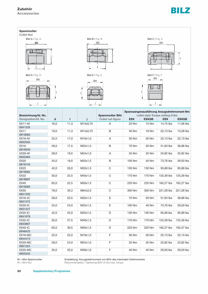
SpannmutterCollet Nut
Bild A / Fig. A Bild B / Fig. B Bild C / Fig. C
M = Mini-Spannmutter M = Mini Nut
Empfehlung: Anzugsdrehmoment von 80% des maximalen DrehmomentsRecommendation: Tightening 80% of the max. torque
ZubehörAccessories
Spannzangenausführung Anzugsdrehmoment Nmcollet style Torque setting ft.IbsBezeichnung/Id. No. Spannmutter Bild
Designation/Id. No. d I j Collet nut figure ESX ESXGB ESX ESXGB
EX11–M 16,0 11,3 M13x0,75 A 20 Nm 15 Nm 14,75 Ibs 11,06 Ibs6941535EX11 19,0 11,3 M14x0,75 B 30 Nm 18 Nm 22,13 Ibs 13,28 Ibs6919083EX16–M 22,0 17,0 M19x1,0 A 30 Nm 30 Nm 22,13 Ibs 22,13 Ibs6932504EX16 28,0 17,5 M22x1,5 B 70 Nm 50 Nm 51,63 Ibs 36,88 Ibs6919040EX20–M 28,0 19,0 M24x1,0 A 35 Nm 35 Nm 25,82 Ibs 25,82 Ibs6940464EX20 34,0 19,0 M25x1,5 B 100 Nm 40 Nm 73,76 Ibs 29,50 Ibs6918743EX25 42,0 20,0 M32x1,5 C 130 Nm 130 Nm 95,89 Ibs 95,89 Ibs6919084EX32 50,0 22,5 M40x1,5 C 170 Nm 170 Nm 125,39 Ibs 125,39 Ibs6918697EX40 63,0 22,5 M50x1,5 C 220 Nm 220 Nm 162,27 Ibs 162,27 Ibs6919085EX50 78,0 35,3 M64x2,0 C 300 Nm 300 Nm 221,28 Ibs 221,28 Ibs6951202EX16–IC 28,0 22,5 M22x1,5 E 70 Nm 50 Nm 51,63 Ibs 36,88 Ibs6931372EX20-IC 34,0 24,0 M25x1,5 E 100 Nm 40 Nm 73,76 Ibs 29,50 Ibs6931227EX25-IC 42,0 25,0 M32x1,5 D 130 Nm 130 Nm 95,89 lbs 95,89 lbs6941678EX32-IC 50,0 27,5 M40x1,5 D 170 Nm 170 Nm 125,39 lbs 125,39 lbs6933897EX40-IC 63,0 30,5 M50x1,5 D 220 Nm 220 Nm 162,27 lbs 162,27 lbs6948425EX16-MC 22,0 22,0 M19x1,0 F 30 Nm 30 Nm 22,13 lbs 22,13 lbs6944413EX20-MC 28,0 24,0 M24x1,0 F 35 Nm 35 Nm 25,82 lbs 25,82 lbs6951224EX25-MC 35,0 25,0 M30x1,0 F 40 Nm 40 Nm 29,50 lbs 29,50 lbs6955533
j
Ød
l
l l
j j
ØdØdBild D / Fig. D Bild E / Fig. E Bild F / Fig. F
j
Ød
l
l l
j j
ØdØd
j
Ød
l
l l
j j
ØdØd

23Zusatzprogramm
SpannmutterCollet Nut
Bild G / Fig. G
M = Mini-Spannmutter M = Mini Nut
Empfehlung: Anzugsdrehmoment von 80% des maximalen DrehmomentsRecommendation: Tightening 80% of the max. torque
ZubehörAccessories
Spannzangenausführung Anzugsdrehmoment Nmcollet style Torque setting ft.IbsBezeichnung/Id. No. Spannmutter Bild
Designation/Id. No. d I j Collet nut figure BZ
BM12-IK 17,0 14 M14x1 15 G 20 Nm–
BM18-IK 25 18 M21x1 23 G 30 Nm6801787BM25-IK 34 24 M30x1 30 G 40 Nm6802418
Ød
l
j

24 Supplementary Programme
ZubehörAccessories
Kegeldorn DIN 238 mit Scheibenfeder DIN 6888 Arbor DIN 238 with woodruff key DIN 6888
l
l1 l2
d1
d
DIN 6888
Bezeichnung/Id. No.Designation/Id. No. Ø d Ø d1 l l1 l2 DIN6888
B16 x MK2 DSP12/B16 17,780 15,733 112 75 24 4 x 7,56816002B16 x MK3 D12/B16 23,825 15,733 134 94 24 4 x 7,56816003B18 x MK3 DSP20/B18 23,825 17,780 140 94 32 5 x 96818003B18 x MK4 D20/B18 31,267 17,780 165 117,5 32 5 x 96818004B22 x MK3 DSP20/B22 23,825 21,793 147 94 40,5 5 x 96822003B22 x MK4 D20/B22 31,267 21,793 176 117,5 40,5 5 x 96822004B24 x MK4 DSP30/B24 31,267 23,825 186 117,5 50,5 6 x 96824004B24 x MK5 D30/B24 44,399 23,825 221 149,5 50,5 6 x 96824005B24 x MK5 D42/B24 44,399 23,825 221 149,5 50,5 6 x 96824005

HFP, drahtlose Überwachung zum mehrspindeligen Gewindeschneiden
HFP, wireless monitoring for multispindle tapping

26 Supplementary Programme
Gewindeschneid-Schnellwechselfutter mit integrierter HFP – TechnikQuick change tapping chucks with integrated HFP – Technology
HFP – die sicherste Methode der drahtlosen Überwachung beim mehrspindligen Gewindeschneiden ist noch sicherer geworden.
Im Zusammenwirken mit den entsprechenden Bilz- Gewinde-schneidfuttern und Einsätzen ist das HFP-System in der Lage, nicht nur den Rechtslauf, sondern auch den Linkslauf zuverlässig zu überwachen. Der im Futter eingebaute Hochfrequenz-Sen-der reagiert auf den Längenausgleich der Gewindeschneidfutter, der beim Ansprechen der Sicherheitskupplung zwangsläufig im Rechtslauf zusammengedrückt und im Linkslauf ausgezogen wird.
Das dadurch ausgelöste Signal wird über die Sendeantenne an den HF-Empfänger geleitet und dann zum Abschalten der Maschine verwendet.
Um auch unter schwierigen Voraussetzungen, z.B. durch Eintau-chen der Gewindeschneidfutter in das Werkstück oder in eine Vor-richtung, ein sicheres Signal zu bekommen, pulst der HF-Sender nach Beendigung der Prozessstörung noch ca. 5 sec.Innerhalb dieser Zeit verändert sich die Position der Gewinde-schneidfutter durch Zurückfahren in die Ausgangsstellung, und das HF-Signal erreicht sicher den Empfänger.
Durch das Überwachen im Rechts-/Linkslauf und das Pulsen des HF-Senders nach dem Ansprechen wird das Gewindeschneiden zuverlässig überwacht, und auftretende Störungen werden sofort erkannt. Ausschuss bzw. kostenintensive Nacharbeit werden dadurch vermieden.
HFP – the safest method of wireless monitoring for multispindle tapping is now even safer.
Together with the Bilz quick change chucks and adaptors the HFP system can securely monitor the right hand rotation as well as the left hand rotation.
The high frequency transmitter integrated in the chuck reacts on the length compensation of the chuck which is pressed together while the safety clutch is engaging in the right hand direction and which is pulled out in the left hand direction.
The released signal is transmitted by the antenna to the HF-recei-ver and then used for stopping the machine.To secure a safe signal also under difficult conditions, for example while the tapping chuck is in the workpiece or in the device, the HF transmitter pulses the signal for 5 sec.The position of the chuck changes in this time while driving back in start position and the HF signal reaches the receiver securely.
The effective monitoring of the right hand rotation and the pulsing of the signal after initialising the tapping operation means that malfunctions are detected immediately. Scrap or expensive sub-sequent machining will be avoided with this system.

27Zusatzprogramm
Bilz-Sender HFS 3100Bilz Transmitter HFS 3100
Der Sender ist in speziell dafür vorbereitete Bilz-Gewindeschneid-futter eingebaut. Ein berührungsloser Schalter (Reedkontakt und Magnet) ermöglicht die Prozessüberwachung sowohl im Druck- als auch im Zugbereich.
Aktivierung des Senders durch Prozessalarm:HF-Signal 1 s an / 1 s aus. Wird ein Prozessalarm aus gelöst, sendet der HF-Sender noch ca. 5 s (andere Zeiten sind optional) nach Beendigung der Prozess störung. Aktivierung des Senders durch Batterieüberwachungsalarm: HF-Signal 0,5 s an / 0,5 s aus. Der Sender wird durch eine Batterie (typ. Standzeit 1– 2 Jahre) betrieben. Eine Batterieüberwachungs-schaltung sorgt für die notwendige Sicherheit. Wird der Grenzwert unterschritten, so sendet der HFS 3100.
Die unterschiedlichen Pulsfrequenzen des HF-Signals erlauben dem Bediener die leichte Unterscheidung zwischen Prozess- und Batterieüberwachungsalarm. Die Sender arbeiten in länderspezifi-schen Frequenzbereichen, z. B. in Deutschland 70-72 Mhz. Bereits installierte Empfänger können weiterverwendet werden, Frequenz bereiche und Kanalraster sind gleich.Die Batterien sind problemlos auswechselbar.
The transmitter is built into a Bilz tapping chuck which has been specially prepared for this purpose. A contactless actuator (Reed contact and magnet) effects monitoring of the process in compres-sion as well as in extension direction.
Activating the transmitter by process alarm:HF signal 1 sec. on / 1 sec. off. If a process alarm is effected, the HF transmittler sends the signal after the end of the process malfunction for another 5 sec. (other times are optionally available).Activating the transmitter by battery check alarm:HF-signal 0,5 sec. on / 0,5 sec. off. The transmitter is powered by a battery. Surveillance of the battery voltage ensures the safety required. If the voltage gets too low, the battery alarm in the recei-ver responds accordingly. The different pulse frequencies of the HF transmitter help the user to distinguish easily between process and battery alarm.
The crystal stabilised transmitter operates at various frequencies, for example at 70-72 Mhz in Germany.The batteries can be changed very easily.

28 Supplementary Programme
Gewindeschneid-Schnellwechselfutter mit integrierter HF – TechnikQuick change tapping chuck with integrated HF Transmitter
Zur sicheren Überwachung des Gewindeschneidens mit der HF-Technik sind Gewindeschneid-Schnellwechselfutter mit nur Druck- oder mit Druck-Zugausgleich und Schnellwechseleinsätze mit Sicherheitskupplung für Rechts- oder Linkslauf erforderlich.
Wenn im Rechtslauf eine Störung auftritt, wird durch den Druck-ausgleich der rote Sichtring verschoben, und tritt die Störung im Linkslauf auf, wird durch den Zugausgleich der Einsatz aus dem Futter gekuppelt und bleibt im Werkstück.In beiden Fällen ist somit leicht erkennbar, welches Futter die Störung verursacht hat.Der Batteriewechsel, der durch den B-Check angezeigt und im Regelfall nach ca. 3 Jahren fällig wird, ist einfach durchzuführen.
Für die Überwachung benachbarter Einheiten ist pro Einheit eine eigene Frequenz zu empfehlen, um Störungen leichter lokalisieren zu können.
To ensure a safe monitoring with the HF technology, a tapping chuck with length compensation on compression and extension and an adaptor with safety clutch is needed.
When a malfunction in right hand rotation is detected, a detector is pushed back by the length compensation on compression. The adaptor is disengaged out of the chuck and is left in the work-piece on a malfunction in left hand rotation.In both cases it is easy to recognize which chuck has caused the problem.The battery change, visulized by the B-check is very easy done. The battery life is approximately 3 years.
For monitoring of adjacent units it is recommended to use a sepa-rate frequency for each unit to localise the failure more easily.
29Zusatzprogramm
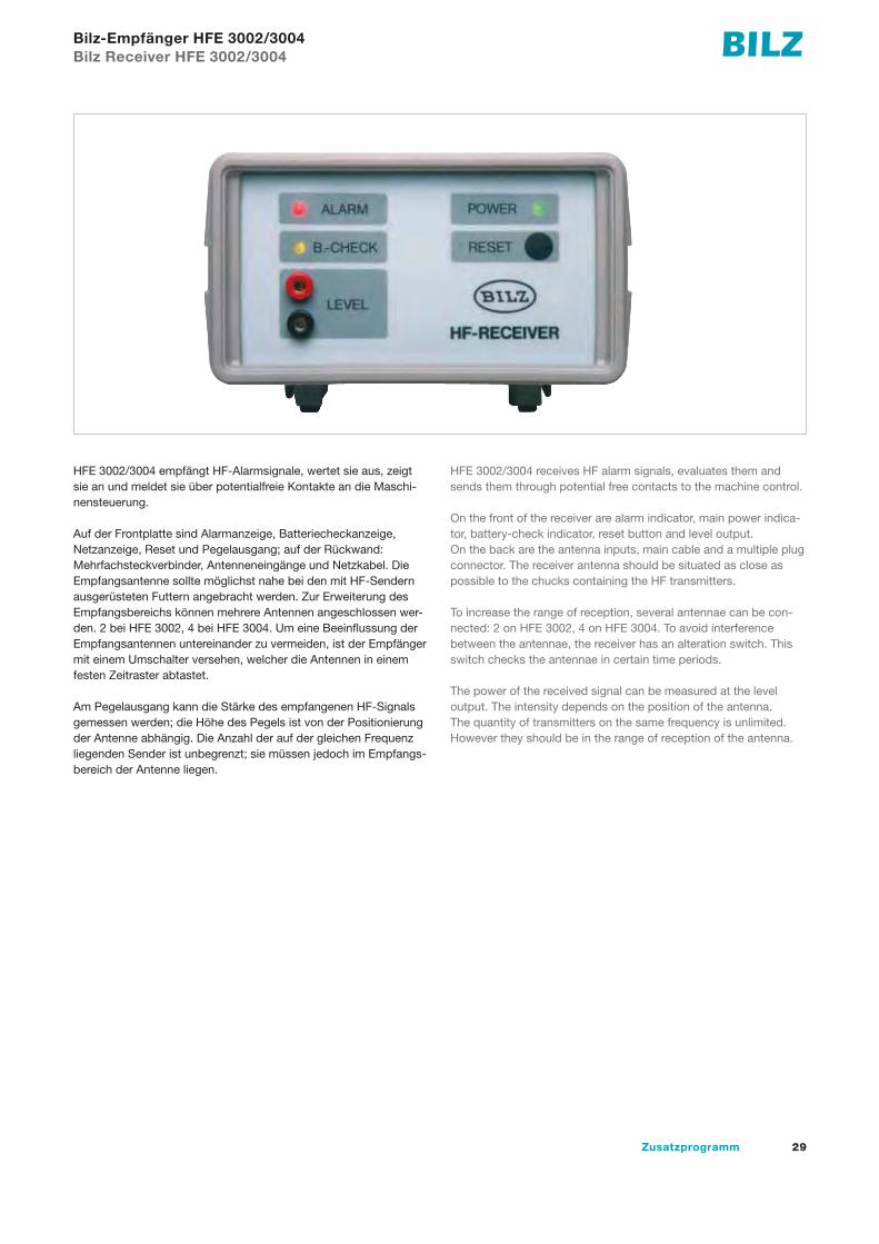
Bilz-Empfänger HFE 3002/3004Bilz Receiver HFE 3002/3004
HFE 3002/3004 empfängt HF-Alarmsignale, wertet sie aus, zeigt sie an und meldet sie über potentialfreie Kontakte an die Maschi-nensteuerung.
Auf der Frontplatte sind Alarmanzeige, Batteriecheckanzeige, Netzanzeige, Reset und Pegel ausgang; auf der Rückwand: Mehrfachsteckverbinder, Antenneneingänge und Netzkabel. Die Empfangsantenne sollte möglichst nahe bei den mit HF-Sendern ausgerüsteten Futtern angebracht werden. Zur Erweiterung des Empfangsbereichs können mehrere Antennen angeschlossen wer-den. 2 bei HFE 3002, 4 bei HFE 3004. Um eine Beeinflussung der Empfangsantennen untereinander zu vermeiden, ist der Empfänger mit einem Umschalter versehen, welcher die Antennen in einem festen Zeitraster abtastet.
Am Pegelausgang kann die Stärke des empfangenen HF-Signals gemessen werden; die Höhe des Pegels ist von der Positionierung der Antenne abhängig. Die Anzahl der auf der gleichen Frequenz liegenden Sender ist unbegrenzt; sie müssen jedoch im Empfangs-bereich der Antenne liegen.
HFE 3002/3004 receives HF alarm signals, evaluates them and sends them through potential free contacts to the machine control.
On the front of the receiver are alarm indicator, main power indica-tor, battery-check indicator, reset button and level output.On the back are the antenna inputs, main cable and a multiple plug connector. The receiver antenna should be situated as close as possible to the chucks containing the HF transmitters.
To increase the range of reception, several antennae can be con-nected: 2 on HFE 3002, 4 on HFE 3004. To avoid interference between the antennae, the receiver has an alteration switch. This switch checks the antennae in certain time periods.
The power of the received signal can be measured at the level output. The intensity depends on the position of the antenna.The quantity of transmitters on the same frequency is unlimited. However they should be in the range of reception of the antenna.

30 Supplementary Programme
EinführungHF-Gewindeschneid-Kontrolleinrichtung (HF = Hochfrequenz)IntroductionHF Tapping control unit (HF = High Frequency)
max. 3 m
Gewindeschneid-Einheit tapping unit
Sendeantennetransmitter antenna
Empfangsantenne HFA 2receiving antenna HFA 2
HF-RECEIVER
ALARM POWER
BILZ
B.-CHECK
LEVEL
RESET
POWERALARM
HF-EmpfängerHFE 3002: 2 AntenneneingängeHFE 3004: 4 AntenneneingängeHF-receiverHFE 3002: 2 antenna inputsHFE 3004: 4 antenna inputs
Maschinensteuerungmachine control
Koaxial-Kabelx = Länge in Meter (max. 25 m)coaxial cablex = length in metres (max. 25 m)
HFK 2.x
Mehrfachkabel zur Maschinensteuerung (Länge beliebig)multiple cable to machine control (optional length)
HFK 0.x
HFK 0.x
Empfangsantenne HFA 0receiving antenna HFA 0
HFA 0Empfangsantennereceiving antenna HFA 2
Einsatz mitSicherheitskupplungadaptor withsafety clutch
Futter mitLängenausgleichchuck withlength compensation
Beim Gewindeschneiden auf Transferstraßen, Sonder-maschinen und Bearbeitungszentren kann eine Beschädigung des Gewindebohrers nicht immer vermieden werden. Manchmal werden die Gewinde nicht auf volle Tiefe geschnitten oder fehlen gänzlich. Solche Fehler bleiben oft bis zum Zusammenbau der Teile unentdeckt. Dadurch fallen hohe Nacharbeitskosten an, und gelegentlich führt dies sogar zum Ausschuss des Werk stücks. Im Zusammenwirken mit BILZ Gewindeschneid-Schnellwechselfuttern WFL, WFLK oder WFLP und Einsätzen mit Sicherheitskupplung kontrolliert die HF-Einrichtung die Gewindetiefe, stellt einen dro-henden Gewindebohrerbruch schon während der Gewindeschneid-operation fest und verhütet derartige Fehler.
When tapping on transfer lines, special purpose machines and machining centres, damage of the tap cannot always be avoided. Occasionally, the threads are not tapped to full depth or are missing completely. Such faults will often be undetected until assembling of the parts. This causes high re-machining costs and sometimes even means the rejection of the component. In combination with the BILZ WFL, WFLK or WFLP quick change tapping chucks and adaptors with safety clutch, the HF unit controls the thread depth, identifies possible tap breakage during tapping operation and prevents from such malfunctions.

31Zusatzprogramm
Bilz-Empfänger HFE 3002/3004Bilz Receiver HFE 3002/3004
Sendeantennetransmitter antenna
Sichtringdetector ring
Gewindeschneidfutterchuck
Schnellwechseleinsatzadaptor
Funkstreckeradio link
Sichtringdetector ring
Funkstreckeradio link
HF-EmpfängerHF-receiver
Schnellwechseleinsatzadaptor
HF-EmpfängerHF-receiver
Pos. 1 Pos. 2 Pos. 3 Pos. 4 Pos. 5
Position 1. Gewindeschneiden bei normalem Ablauf ohne Störung
Position 2.Sicherheitskupplung spricht wegen zu hohem Drehmoment im Rechtslauf an, der Längenausgleich wird durch den Maschinen- vorschub zusammengedrückt und der HF-Sender meldet Störung.
Position 3. Gewindeschneidfutter nach Störmeldung im Rechtslauf in Ausgangsstellung mit Positionsveränderung des Sichtrings
Position 4.Sicherheitskupplung spricht wegen zu hohemDrehmoment im Linkslauf an, der Längenausgleich wird durch den Maschinen- rücklauf ausgezogen, der HF-Sender meldet die Störung, und der Einsatz wird entkuppelt.
Position 5. Gewindeschneidfutter nach Störmeldung im Linkslauf in Ausgangs-stellung mit ausgekuppeltem Einsatz.
Position 1. Tapping without malfunction
Position 2. Safety clutch is engaging in right hand rotation because of too high torque. The length compensation is pushed by the machine feed and the HF transmitter sends alarm.
Position 3. Tapping chuck after alarm in right hand rotation in start position. The detector ring is moved.
Position 4. Safety clutch is engaging in left hand rotation because of too high torque. The length compensation on extension is pulled by the machine feed backward and the HF transmitter sends alarm. The adaptor will be disengaged.
Position 5.Tapping chuck after the alarm in left hand rotation in start position. The adaptor is disengaged.

32 Supplementary Programme
Bedienelemente des HandempfängersOperating elements of the hand-held receiver
Antenneantenna
LED-BalkenanzeigeLED-indication
On-TasteOn button
Batteriekontrollebattery check
Bedienelemente des Handempfängers:– ON - Taste: Während die ON - Taste gedrückt wird, ist der Handempfänger eingeschaltet.– Anzeige der Signalstärke (LED-Balkenanzeige): Die Stärke des über die Stummelantenne empfangenen Signals wird mit einer Leuchtdiodenkette angezeigt. Erst wenn die Spitze der Antenne den Antennenring des sendenden Futters nahezu berührt, ist ein starker Ausschlag zu beobachten.– Batteriekontrolle: Zur Anzeige der Betriebsbereitschaft wird eine rote Leuchtdiode verwendet, die sich am linken Rand der Leuchtdiodenkette befindet.– gute Batterie: Bei der Betätigung der ON - Taste leuchtet die Leuchtdiode kurz auf.– schlechte Batterie: Beim Drücken der ON - Taste leuchtet die Leuchtdiode nicht auf!
Die Batterie ist eine handelsübliche 9V-Blockbatterie.
Operating elements of the hand-held receiver– ON-button: Hand held receiver is switched on as long as ON-button is being pushed.– Indication of signal level (by LED): The level of the signal received by the stub antenna is being shown by LED row. A distinct deflection will be seen only after the antenna bar has nearly touched the antenna ring on the chuck.– Battery check: A red LED in the left corner of the LED row is determined to show operating readiness.– fully charged battery: when pushing ON-button: LED lights up for a short moment– weak battery: when pushing ON-button: LED does not light up The battery is of standard 9 V bloc type.
33Zusatzprogramm
TR... DIN 6327BezeichnungDesignation d d2 TR20x2 TR28x2 TR36x2
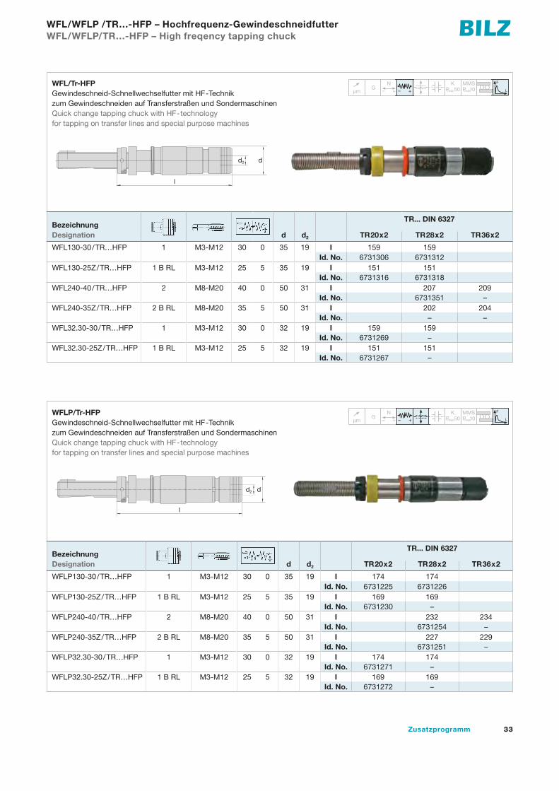
WFLP130-30/TR…HFP 1 M3-M12 30 0 35 19 I 174 174Id. No. 6731225 6731226
WFLP130-25Z/TR…HFP 1 B RL M3-M12 25 5 35 19 I 169 169Id. No. 6731230 –
WFLP240-40/TR…HFP 2 M8-M20 40 0 50 31 I 232 234Id. No. 6731254 –
WFLP240-35Z/TR…HFP 2 B RL M8-M20 35 5 50 31 I 227 229Id. No. 6731251 –
WFLP32.30-30/TR…HFP 1 M3-M12 30 0 32 19 I 174 174Id. No. 6731271 –
WFLP32.30-25Z/TR…HFP 1 B RL M3-M12 25 5 32 19 I 169 169Id. No. 6731272 –
WFL/WFLP /TR…-HFP – Hochfrequenz-GewindeschneidfutterWFL/WFLP/TR…-HFP – High freqency tapping chuck
µm G
N– + – +
K MMSmax
F
LP 10P 50maxµmG
N– + – +
K MMSP 10maxP 50max
F
L
TR... DIN 6327BezeichnungDesignation d d2 TR20x2 TR28x2 TR36x2
WFL130-30/TR…HFP 1 M3-M12 30 0 35 19 I 159 159Id. No. 6731306 6731312
WFL130-25Z/TR…HFP 1 B RL M3-M12 25 5 35 19 I 151 151Id. No. 6731316 6731318
WFL240-40/TR…HFP 2 M8-M20 40 0 50 31 I 207 209Id. No. 6731351 –
WFL240-35Z/TR…HFP 2 B RL M8-M20 35 5 50 31 I 202 204Id. No. – –
WFL32.30-30/TR…HFP 1 M3-M12 30 0 32 19 I 159 159Id. No. 6731269 –
WFL32.30-25Z/TR…HFP 1 B RL M3-M12 25 5 32 19 I 151 151Id. No. 6731267 –
µmG
N– + – +
K MMSP 10maxP 50max
F
L
l
dd2
µm G
N– + – +
K MMSmax
F
LP 10P 50maxµmG
N– + – +
K MMSP 10maxP 50max
F
LµmG
N– + – +
K MMSP 10maxP 50max
F
L
l
dd2
WFL/Tr-HFPGewindeschneid-Schnellwechselfutter mit HF-Technik zum Gewindeschneiden auf Transferstraßen und SondermaschinenQuick change tapping chuck with HF-technology for tapping on transfer lines and special purpose machines
WFLP/Tr-HFPGewindeschneid-Schnellwechselfutter mit HF-Technik zum Gewindeschneiden auf Transferstraßen und SondermaschinenQuick change tapping chuck with HF-technologyfor tapping on transfer lines and special purpose machines
34 Supplementary Programme
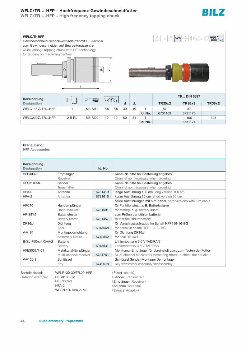
WFLC/TR…-HFP – Hochfrequenz-GewindeschneidfutterWFLC/TR…-HFP – High freqency tapping chuck
µm G
N– + – +
K MMSmax
F
LP 10P 50maxµmG
N– + – +
K MMSP 10maxP 50max
F
L
TR... DIN 6327BezeichnungDesignation d d2 TR20x2 TR28x2 TR36x2
WFLC115Z/TR…HFP 1 M3-M12 7,5 7,5 39 19 I 87 87Id. No. 6731169 6731170
WFLC220Z/TR…HFP 2 B RL M8-M20 10 10 60 31 I 106 108Id. No. 6731174 –
µmG
N– + – +
K MMSP 10maxP 50max
F
L
l
dd2
BezeichnungDesignation Id. No.
HFE3002/… Empfänger Kanal-Nr. bitte bei Bestellung angeben Receiver Channel no. necessary when ordering
HFS3100-K… Sender Kanal-Nr. bitte bei Bestellung angebenTransmitter Channel no. necessary when ordering
HFA-0 Antenne 6731419 lange Ausführung 100 cm long version 100 cmHFA-2 Antenna 6731616 kurze Ausführung 30 cm short version 30 cm
beide Ausführungen mit 5 m Kabel both versions with 5 m cableHFC70 Handempfänger für Funktionstest, z. B. Batteriealarm
Hand receiver 6731591 for testing, e. g. battery arlamHF-BT15 Batterietester zum Prüfen der Lithiumbatterie
Battery tester 6731457 to test the lithiumbatteryDR16x1 Dichtung für Verschlussschraube im Schaft HFP119-16-BG
Seal 6943568 for screw in shank HFP119-16-BGV-V161 Montagevorrichtung für Dichtung DR16x1
Assembly fixture 6742842 for seal DR16x1B/SL-750/s-1/2AA/2 Batterie Lithiumbatterie 3,6 V TADIRAN
Battery 6943531 Lithiumbattery 3,6 V TADIRANHFE3002/1-51 Mehrkanal-Empfänger Mehrkanal-Empfänger für Voreinstellraum; zum Testen der Futter
Multi-channel receiver 6731761 Multi-channel receiver for presetting room; to check the chucksV-V126.3 Schlüssel Schlüssel Sender-Montage/Demontage
Key 6742678 Key transmitter assembly/disassembly
Bestellbeispiel: WFLP130-30/TR.20-HFP (Futter chuck)Ordering example: HFS3100-K2 (Sender Transmitter ) HFE3002/2 (Empfänger Receiver) HFA-2 (Antenne Antenna) WESN 1B-8x6,2-M8 (Einsatz Adaptor)
WFLC/Tr-HFPGewindeschneid-Schnellwechselfutter mit HF-Technik zum Gewindeschneiden auf BearbeitungszentrenQuick change tapping chuck with HF-technology for tapping on machining centres
HFP Zubehör HFP Accessories

Hydrodehnspannfutter Hydraulic expansion chucks
36 Supplementary Programme
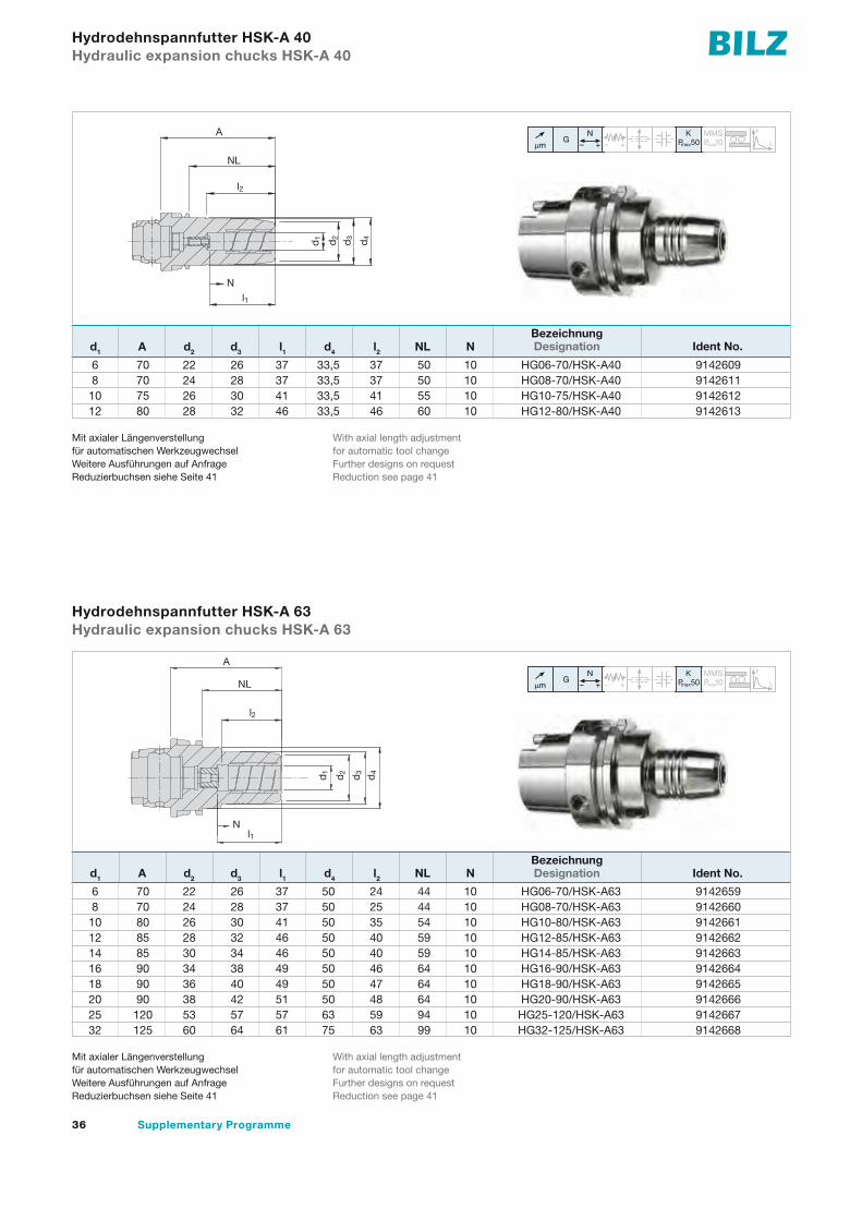
6 70 22 26 37 33,5 37 50 10 HG06-70/HSK-A40 9142609 8 70 24 28 37 33,5 37 50 10 HG08-70/HSK-A40 9142611 10 75 26 30 41 33,5 41 55 10 HG10-75/HSK-A40 9142612 12 80 28 32 46 33,5 46 60 10 HG12-80/HSK-A40 9142613
Hydrodehnspannfutter HSK-A 40 Hydraulic expansion chucks HSK-A 40
d1 A d2 d3 l1 d4 l2 NL N
µm G
N– + – +
K MMSmax
F
LP 10P 50maxµmG
N– + – +
K MMSP 10maxP 50max
F
LµmG
N– + – +
K MMSP 10maxP 50max
F
L
6 70 22 26 37 50 24 44 10 HG06-70/HSK-A63 9142659 8 70 24 28 37 50 25 44 10 HG08-70/HSK-A63 9142660 10 80 26 30 41 50 35 54 10 HG10-80/HSK-A63 9142661 12 85 28 32 46 50 40 59 10 HG12-85/HSK-A63 9142662 14 85 30 34 46 50 40 59 10 HG14-85/HSK-A63 9142663 16 90 34 38 49 50 46 64 10 HG16-90/HSK-A63 9142664 18 90 36 40 49 50 47 64 10 HG18-90/HSK-A63 9142665 20 90 38 42 51 50 48 64 10 HG20-90/HSK-A63 9142666 25 120 53 57 57 63 59 94 10 HG25-120/HSK-A63 9142667 32 125 60 64 61 75 63 99 10 HG32-125/HSK-A63 9142668
d1 A d2 d3 l1 d4 l2 NL N
Mit axialer Längenverstellungfür automatischen WerkzeugwechselWeitere Ausführungen auf AnfrageReduzierbuchsen siehe Seite 41
With axial length adjustmentfor automatic tool changeFurther designs on requestReduction see page 41
Hydrodehnspannfutter HSK-A 63 Hydraulic expansion chucks HSK-A 63
Mit axialer Längenverstellungfür automatischen WerkzeugwechselWeitere Ausführungen auf AnfrageReduzierbuchsen siehe Seite 41
With axial length adjustmentfor automatic tool changeFurther designs on requestReduction see page 41
µm G
N– + – +
K MMSmax
F
LP 10P 50maxµmG
N– + – +
K MMSP 10maxP 50max
F
LµmG
N– + – +
K MMSP 10maxP 50max
F
L
d3
A
l1d
1 d2
d4
l2
NL
N
d3
d1
d2
A
l2
d4
NL
l1N
Bezeichnung Designation Ident No.
Bezeichnung Designation Ident No.
37Zusatzprogramm
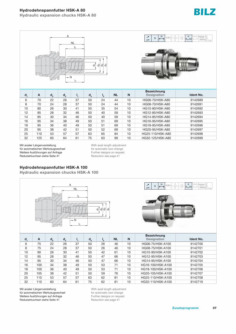
6 70 22 26 37 50 24 44 10 HG06-70/HSK-A80 9142689 8 70 24 28 37 50 24 44 10 HG08-70/HSK-A80 9142691 10 80 26 30 41 50 35 54 10 HG10-80/HSK-A80 9142692 12 85 28 32 46 50 40 59 10 HG12-85/HSK-A80 9142693 14 85 30 34 46 50 40 59 10 HG14-85/HSK-A80 9142694 16 95 34 38 49 50 51 69 10 HG16-95/HSK-A80 9142695 18 95 36 40 49 50 51 69 10 HG18-95/HSK-A80 9142696 20 95 38 42 51 50 52 69 10 HG20-95/HSK-A80 9142697 25 110 53 57 57 63 65 84 10 HG25-110/HSK-A80 9142698 32 125 60 64 61 75 63 99 10 HG32-125/HSK-A80 9142699
Hydrodehnspannfutter HSK-A 80 Hydraulic expansion chucks HSK-A 80
d1 A d2 d3 l1 d4 l2 NL N
µm G
N– + – +
K MMSmax
F
LP 10P 50maxµmG
N– + – +
K MMSP 10maxP 50max
F
LµmG
N– + – +
K MMSP 10maxP 50max
F
L
6 75 22 26 37 50 26 46 10 HG06-75/HSK-A100 9142700 8 75 24 28 37 50 26 46 10 HG08-75/HSK-A100 9142701 10 90 26 30 41 50 42 61 10 HG10-90/HSK-A100 9142702 12 95 28 32 46 50 47 66 10 HG12-95/HSK-A100 9142703 14 95 30 34 46 50 47 66 10 HG14-95/HSK-A100 9142704 16 100 34 38 49 50 53 71 10 HG16-100/HSK-A100 9142705 18 100 36 40 49 50 53 71 10 HG18-100/HSK-A100 9142706 20 105 38 42 51 50 59 76 10 HG20-105/HSK-A100 9142707 25 110 53 57 57 63 62 81 10 HG25-110/HSK-A100 9142708 32 110 60 64 61 75 62 81 10 HG32-110/HSK-A100 9142719
d1 A d2 d3 l1 d4 l2 NL N
Mit axialer Längenverstellungfür automatischen WerkzeugwechselWeitere Ausführungen auf AnfrageReduzierbuchsen siehe Seite 41
With axial length adjustmentfor automatic tool changeFurther designs on requestReduction see page 41
Hydrodehnspannfutter HSK-A 100 Hydraulic expansion chucks HSK-A 100
Mit axialer Längenverstellungfür automatischen WerkzeugwechselWeitere Ausführungen auf AnfrageReduzierbuchsen siehe Seite 41
With axial length adjustmentfor automatic tool changeFurther designs on requestReduction see page 41
µm G
N– + – +
K MMSmax
F
LP 10P 50maxµmG
N– + – +
K MMSP 10maxP 50max
F
LµmG
N– + – +
K MMSP 10maxP 50max
F
L
d3
d1
d2
A
l2
d4
NL
l1N
d3
A
d1
d2
d4
NL
l2
l1
N
Bezeichnung Designation Ident No.
Bezeichnung Designation Ident No.
38 Supplementary Programme
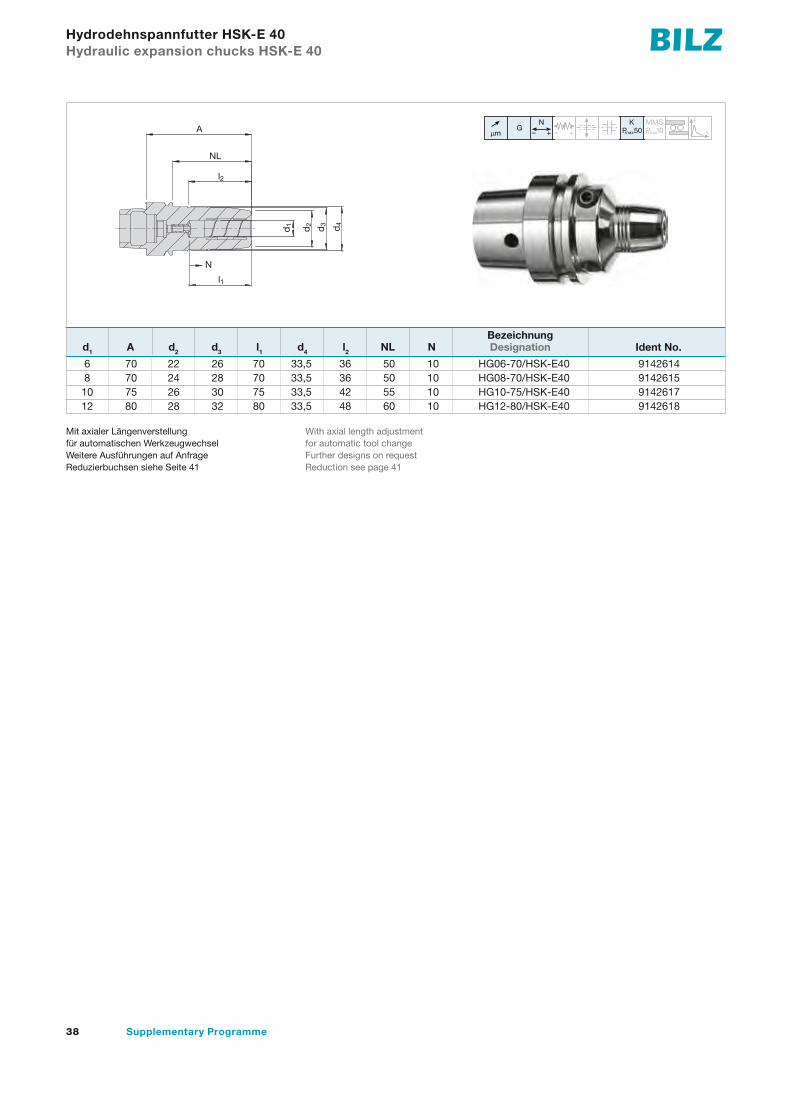
Hydrodehnspannfutter HSK-E 40 Hydraulic expansion chucks HSK-E 40
µm G
N– + – +
K MMSmax
F
LP 10P 50maxµmG
N– + – +
K MMSP 10maxP 50max
F
LµmG
N– + – +
K MMSP 10maxP 50max
F
L
6 70 22 26 70 33,5 36 50 10 HG06-70/HSK-E40 9142614 8 70 24 28 70 33,5 36 50 10 HG08-70/HSK-E40 9142615 10 75 26 30 75 33,5 42 55 10 HG10-75/HSK-E40 9142617 12 80 28 32 80 33,5 48 60 10 HG12-80/HSK-E40 9142618
d1 A d2 d3 l1 d4 l2 NL N
Mit axialer Längenverstellungfür automatischen WerkzeugwechselWeitere Ausführungen auf AnfrageReduzierbuchsen siehe Seite 41
With axial length adjustmentfor automatic tool changeFurther designs on requestReduction see page 41
d3 d4
A
l2
d2
d1
NL
l1
N
Bezeichnung Designation Ident No.

39Zusatzprogramm
6 90 22 26 37 44,5 43 63 10 HG06-90/BT40 9142739 8 90 24 28 37 44,5 44,5 63 10 HG08-90/BT40 9142741 10 90 26 30 41 44,5 44,5 63 10 HG10-90/BT40 9142742 12 90 28 32 46 44,5 44,5 63 10 HG12-90/BT40 9142743 16 90 34 38 49 44,5 47,5 63 10 HG16-90/BT40 9142744 20 90 38 42 51 44,5 47,5 63 10 HG20-90/BT40 9142745 32 83 60 63 61 80 25,5 56 10 HG32-83/BT40 9142746
Hydrodehnspannfutter BT 40 Hydraulic expansion chucks BT 40
d1 A d2 d3 l1 d4 l2 NL N
µm G
N– + – +
K MMSmax
F
LP 10P 50maxµmG
N– + – +
K MMSP 10maxP 50max
F
LµmG
N– + – +
K MMSP 10maxP 50max
F
L
Kurze, schlanke Ausführung mit axialer Längenverstellung Weitere Ausführungen auf AnfrageReduzierbuchsen siehe Seite 41
Short, slim design with axial length adjustment Further designs on requestReduction see page 41
32 90 61 72 61 – – – 10 HG32V-90/BT50 9142748
Hydrodehnspannfutter BT 50 Hydraulic expansion chucks BT 50
d1 A d2 d3 l1 d4 l2 NL N
µm G
N– + – +
K MMSmax
F
LP 10P 50maxµmG
N– + – +
K MMSP 10maxP 50max
F
LµmG
N– + – +
K MMSP 10maxP 50max
F
L
Kurze, verstärkte Ausführungmit axialer LängenverstellungWeitere Ausführungen auf AnfrageReduzierbuchsen siehe Seite 41
Short, reinforced designwith axial length adjustmentFurther designs on requestReduction see page 41
d3
NLA
l1
d2d1
N
Bezeichnung Designation Ident No.
Bezeichnung Designation Ident No.

40 Supplementary Programme
6 80,5 22 26 37 49,5 29,5 61,5 10 HG06-80,5/ADB40 9142720 8 80,5 24 28 37 49,5 30 61,5 10 HG08-80,5/ADB40 9142721 10 80,5 26 30 41 49,5 31 61,5 10 HG10-80,5/ADB40 9142722 12 80,5 28 32 46 49,5 31,5 61,5 10 HG12-80,5/ADB40 9142723 16 80,5 34 38 49 49,5 33 61,5 10 HG16-80,5/ADB40 9142724 20 80,5 38 42 51 49,5 34 61,5 10 HG20-80,5/ADB40 9142725 25 80,5 53 55 57 66 22 61,5 10 HG25-80,5/ADB40 9142726 32 80,5 60 63 61 80 25,5 61,5 10 HG32-80,5/ADB40 9142727
Hydrodehnspannfutter SK 40 Hydraulic expansion chucks SK 40
d1 A d2 d3 l1 d4 l2 NL N Bezeichnung Designation Ident No.
µm G
N– + – +
K MMSmax
F
LP 10P 50maxµmG
N– + – +
K MMSP 10maxP 50max
F
LµmG
N– + – +
K MMSP 10maxP 50max
F
L
Kurze, schlanke Ausführung mit axialer Längenverstellung Weitere Ausführungen auf AnfrageReduzierbuchsen siehe Seite 41
Short, slim design with axial length adjustment Further designs on requestReduction see page 41
32 81 61 72 61 – – – 10 HG32V-81/ADB50 9142728
Hydrodehnspannfutter SK 50 Hydraulic expansion chucks SK 50
d1 A d2 d3 l1 d4 l2 NL N
µm G
N– + – +
K MMSmax
F
LP 10P 50maxµmG
N– + – +
K MMSP 10maxP 50max
F
LµmG
N– + – +
K MMSP 10maxP 50max
F
L
Kurze, verstärkte Ausführungmit axialer LängenverstellungWeitere Ausführungen auf AnfrageReduzierbuchsen siehe Seite 41
Short, reinforced designwith axial length adjustmentFurther designs on requestReduction see page 41
A
l1
d1 d3
d2
l2
d4
NL
N
Bezeichnung Designation Ident No.

41Zusatzprogramm
3 19 12 45 2 HGR12-3 9142816 HGR12D-3 9142752 4 19 12 45 2 HGR12-4 9142817 HGR12D-4 9142753 5 19 12 45 2 HGR12-5 9142818 HGR12D-5 9142754 6 19 12 45 2 HGR12-6 9142829 HGR12D-6 9142755 8 19 12 45 2 HGR12-8 9142830 HGR12D-8 9142756 3 29 20 50,5 2 HGR20-3 9142831 HGR20D-3 9142758 4 29 20 50,5 2 HGR20-4 9142832 HGR20D-4 9142779 5 29 20 50,5 2 HGR20-5 9142833 HGR20D-5 9142780 6 29 20 50,5 2 HGR20-6 9142834 HGR20D-6 9142781 7 29 20 50,5 2 HGR20-7 9142835 HGR20D-7 9142782 8 29 20 50,5 2 HGR20-8 9142836 HGR20D-8 9142784 9 29 20 50,5 2 HGR20-9 9142837 HGR20D-9 9142785 10 29 20 50,5 2 HGR20-10 9142838 HGR20D-10 9142786 11 29 20 50,5 2 HGR20-11 9142839 HGR20D-11 9142787 12 29 20 50,5 2 HGR20-12 9142840 HGR20D-12 9142788 13 29 20 50,5 2 HGR20-13 9142841 HGR20D-13 9142799 14 29 20 50,5 2 HGR20-14 9142842 HGR20D-14 9142800 15 29 20 50,5 2 HGR20-15 9142843 HGR20D-15 9142801 16 29 20 50,5 2 HGR20-16 9142844 HGR20D-16 9142802 17 29 20 50,5 2 HGR20-17 9142845 HGR20D-17 9142803 6 39 32 60,5 3 HGR32-6 9142846 HGR32D-6 9142804 10 39 32 60,5 3 HGR32-10 9142847 HGR32D-10 9142809 12 39 32 60,5 3 HGR32-12 9142848 HGR32D-12 9142810 14 39 32 60,5 3 HGR32-14 9142849 HGR32D-14 9142811 16 39 32 60,5 3 HGR32-16 9142850 HGR32D-16 9142812 18 39 32 60,5 3 HGR32-18 9142851 HGR32D-18 9142813 20 39 32 60,5 3 HGR32-20 9142852 HGR32D-20 9142814 25 39 32 60,5 3 HGR32-25 9142853 HGR32D-25 9142815
Reduzierbuchsen HGR Reduction Sleeves HGR
d1 d2 d3 l1 l2
Peripheriekühlung Innere Kühlmittelzufuhr External cooling Internal coolant supply Bezeichnung Bezeichnung Designation Ident-No. Designation Ident-No.
Bei innerer Kühlmittelzufuhr:Bund geschlossen, kühlmitteldicht bis max. 80 barBei Peripheriekühlung:Bund geschlitzt, nicht kühlmitteldicht
For internal coolant supply: closed collar, coolant proof up to max. 80 barFor external cooling:collar slotted, not coolant proof
HGR/WZ 9142854
Ausziehwerkzeug für Reduzierbuchsen HGR/WZ Sleeve Remover HGR/WZ
Bezeichnung Designation Ident No.
l2l1
d3 d1 d2
Zubehör Accessories

PN-GPK – PendelhalterPN-GPK – Floating holders

43Zusatzprogramm
PN-GPK – Pendelhalter PN-GPK – Floating holders
Bilz Pendelhalter – für ein perfektes Bohrungsfinish bei höchster Qualität und perfekter Maßhaltigkeit
Höchste Bohrungsqualität bei perfekter Maßhaltigkeit ist mit Hoch-leistungsreibahlen nur dann zu erreichen, wenn die Spann mittel keine Belastung auf das Werkzeug ausüben. Die Anforderun gen in Bezug auf den Toleranzbereich, die Rauhtiefe und Rundheit setzen ein Spannmittel voraus, welches die Summe aller auf tretenden Positionsungenauigkeiten kompensiert. Zusätzlich soll das System ohne Verdrehspiel sein. Nur so werden die Schneiden der Reib-ahlen vor Beschädigungen geschützt. Dies alles ist gewähr leistet mit den Bilz Pendelhaltern.
Bilz Floating Holders – highest quality for perfect finish and accuracy
Highest possible drilling quality with perfect accuracy on reaming operations can only be achieved when the clamping system does not cause any force on the cutting tool. The requirement regarding the tolerance zone, the surface roughness and the roundness presupposes a clamping system which compensates all inaccuracy of position occurring. In addition, the system should be without circumferential backlash. Damage to the edges of the tool is thus avoided. This is guaranteed with Bilz floating holders.

SonderwerkzeugeSpecial Tools

45Zusatzprogramm
SonderwerkzeugeSpecial tools
46 formbore-Systemwerkzeuge formbore system tools
54 SFC – Stiftschrauben-Eindrehfutter SFC – Stud driving chucks 55 ET1 – Werkzeughalter Gravierfutter ET1 – Tool holder engraving chucks
56 STF – Werkzeughalter Stempelfutter STF – Tool holder stamping chucks

46 Supplementary Programme
formbore-Systemwerkzeugeformbore system tools
Erstmals können Formprofile, sowie Innen- und Außenkonturen in großer Vielfalt mit höchster Präzision durch einfaches Bohren und Überdrehen auch auf herkömmlichen Bearbeitungszentren gefertigt werden. formbore-Systemwerkzeuge sind einsetzbar auf:– Fräsmaschinen– Bearbeitungszentren – Drehmaschinen– Sondermaschinenformbore-Systemwerkzeuge arbeiten unabhängig von der Dreh- maschinenspindel. Es muss keine Synchronabstimmung zur Maschinenspindel errechnet und programmiert werden. formbore-Systemwerkzeuge sind für unterschiedlichste Profil- formen und Profilgrößen auslegbar. Sie ermöglichen Änderungen im Bearbeitungsprozess wie z.B. die Ablösung von Räumen, Erodieren oder Fräsen.formbore-Systemwerkzeuge reduzieren die Bearbeitungszeit im Vergleich zu den bisher bekannten Vorgehensweisen ganz erheb-lich. Zusätzlich bieten sie noch Vorteile wie Grundlochbohrung ohne Restspäne oder dauerhafte Maßhaltigkeit durch Korrektur des Schneidenverschleißes. Beim Einsatz auf Bearbeitungszentren und Fräsmaschinen sind die Drehmomentstützen und die modu- laren Werkzeugaufnahmen identisch mit denen der bewährten Bilz-Gewindeschneidapparate Typ GNCK /GNCN.
For the first time you can produce a high variety of inner and outer profiles with the highest possible precision by means of simple drilling and turning processes on normal machining centres.formbore system tools can be used on:– milling machines– machining centres– turning machines– special machinesformbore system tools work independently of the machining spindle. It is not necessary to calculate and programme the synchronous coordination to the machine spindle. formbore system tools are designed for different profiles and profile sizes. It is possible to make changes to the working process, for example to separate reaming, erosion or milling.formbore system tools reduce the working time considerably in comparison to the processes currently being used. Further advan-tages are blind holes without residual chips and the constant accuracy due to the correction of the cutter wear. The torque support and the modular tool holders are identical to the ones used on the Bilz GNCK / GNCN tapping attachments.

47Zusatzprogramm
Technische InformationenTechnical information
Ausführung und Arbeitsweise der formbore-Systemwerkzeuge:formbore-Systemwerkzeuge bestehen im Wesentlichen aus zwei Komponenten: einem Antrieb und dem Bohrkopf.Der rotierende Antriebsschaft ist in einem Gehäuse gelagert. Die drehmomentgestützte Zwangssteuerung definiert den Bewegungsablauf des Bohrkopfes. Die Auslenkung der Schneide wird durch rein rollende Elemente erzeugt. formbore-Systemwerkzeuge arbeiten somit praktisch verschleiß- und wartungsfrei. Sie sind zur Bearbeitung nahezu aller Werkstoffe bis 900 N/mm2 Festigkeit geeignet.Für die Innenbearbeitung wird zunächst eine Vorbohrung, bis max. 0,5 mm Durchmesser kleiner als die Schlüssel-weite (SW), hergestellt. Mit profilangepasster Drehzahl und werkstoffentsprechendem Vorschub folgt die eigentliche Formbohrung in einem Arbeitsgang.Das formbore-Systemwerkzeug ist ein System für praxis-nahe Vielseitigkeit, Flexibilität, Zeit- und Kostenersparnis in der täglichen Arbeit. Überzeugen Sie sich selbst von den Vorteilen der formbore-Systemwerkzeuge! Nennen Sie uns Ihre Bearbeitungsanforderungen, und Sie erhalten umgehend unsere Werkzeugempfehlung.
Design and mode of operation of the formbore system tools:formbore system tools consist of two components: drive shaft and drill chuck. The rotating drive shaft is located in the case. The torque driven control determines the movement sequence of the drill chuck. The deflection of the blade is by means of entirely rolling elements. formbore system tools therefore operate practically wear- and maintenance-free and make machining of most materials up to 900 N/mm2 strength possible.For inside processing, a formbore is initially machined upto a maximum of 0,5 mm diameter smaller than the spannersize (SQ). The actual form drilling operation is carried out in a single process with profile adjusted speed and feed appropriate to the material being machined.The formbore system tool is a system for a practical versatility, flexibility and time and cost saving in daily work.Let us know your processing requirements. You will receive our specific tool recommendation and our offer will convince you of the advantages of the new formbore development.
48 Supplementary Programme
AusführungsvariantenVersions available
5
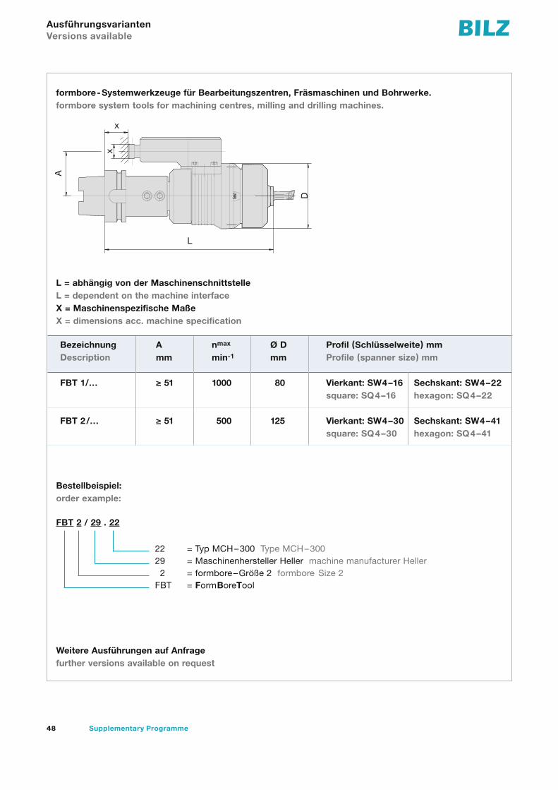
formbore-Systemwerkzeuge für Bearbeitungszentren, Fräsmaschinen und Bohrwerke.formbore system tools for machining centres, milling and drilling machines.
L = abhängig von der MaschinenschnittstelleL = dependent on the machine interfaceX = Maschinenspezifische MaßeX = dimensions acc. machine specification
Bestellbeispiel:order example:
Weitere Ausführungen auf Anfragefurther versions available on request
Bezeichnung A nmax Ø D Profil (Schlüsselweite) mmDescription mm min-1 mm Profile (spanner size) mm
FBT 1/… ≥ 51 1000 80 Vierkant: SW4–14 Sechskant: SW4–21square: SQ4–14 hexagon: SQ4–21
FBT 2/… ≥ 51 500 125 Vierkant: SW4–22 Sechskant: SW4–38square: SQ4–22 hexagon: SQ4–38
FBT 2 / 29 . 22
22 = Typ MCH–300 Type MCH–30029 = Maschinenhersteller Heller machine manufacturer Heller22 = formbore–Größe 2 formbore Size 2FBT = FormBoreTool
x
x
D
A
L
1616
3030
2222
4141
49Zusatzprogramm
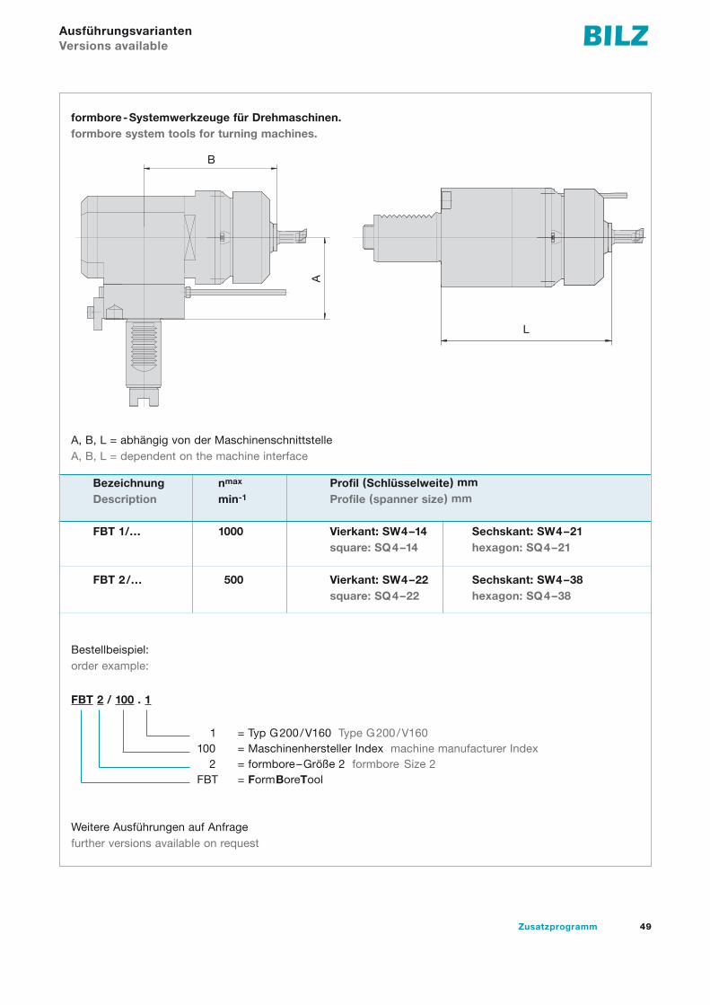
formbore-Systemwerkzeuge für Drehmaschinen.formbore system tools for turning machines.
A, B, L = abhängig von der MaschinenschnittstelleA, B, L = dependent on the machine interface
Bestellbeispiel:order example:
Weitere Ausführungen auf Anfragefurther versions available on request
6
Bezeichnung nmax Profil (Schlüsselweite) mmDescription min-1 Profile (spanner size) mm
FBT 1/… 1000 Vierkant: SW4–14 Sechskant: SW4–21square: SQ4–14 hexagon: SQ4–21
FBT 2/… 500 Vierkant: SW4–22 Sechskant: SW4–38square: SQ4–22 hexagon: SQ4–38
FBT 2 / 100 . 1
1 = Typ G200/V160 Type G200/V160100 = Maschinenhersteller Index machine manufacturer Index
2 = formbore–Größe 2 formbore Size 2FBT = FormBoreTool
B
AL
AusführungsvariantenVersions available

50 Supplementary Programme
Folgende Profile können hergestellt werden:The following profiles can be produced:
Bestellbeispiel:order example:
Weitere Profile auf AnfrageFurther profiles on request
Hinweis:Bitte bei Anfrage und Bestellung immer eine Zeich-nung der herzustellenden Kontur mitsenden,um die genaue Abmessung des Kurvenblockes zudefinieren. Die nachfolgenden formbore-Ausbohr-und formbore-Überdrehstähle sind auf die Konturdes Kurvenblockes ausgelegt.
7
FBK 1 04 – 0810 / 1
1 = Variante variant 1 (z.B. Eckenradius e.g. corner radius)0810 = Abmessung Vierkant= 8,10 mm measurement square= 8,10 mm04 = Vierkant square1 = Kurvenblock für formbore-Systemwerkzeug der Größe 1
= cam block for formbore system tool Size 1FBT = FormBoreKurvenblock formbore cam block
Profile Vierkant Sechskant Achtkant Fläche am Zylinder Schlüsselweite Polygon als Vorbearbeitungprofiles square hexagon octagon area at the cylinder spanner size polygon as pre-processing
Verschlüsselung04 06 08 01 02 21code
Note:Please include a drawing of the contour with all enquiriesand orders in order to define the exact measurements ofthe cam block. The following formbore bore out steels andformbore over turning steels are designed for the contourof the cam block.
formbore-Kurvenblöckeformbore cam blocks

51Zusatzprogramm
Ausbohrstählebore out steel
Identifikation der formbore-Ausbohrstähleidentification of the formbore bore out steel
Die Ausbohrstähle sind auf die Geometrie des jeweiligen Kurvenblockes abgestimmt.The bore out steels are coordinated with the geometry of the respective cam block.
Schneidenträgerinsert holder
Bezeichnungdescription
ASI–26.00–07ASI–31.00–07ASI–38.00–07
Bohrstangeboring bar
Bezeichnungdescription
ASI–26/00–ABS40–44ASI–31/38–ABS40–44
ASI 12 0700 / X
X = Variante variant X (z.B. Bohrtiefe e.g. bore depth)0700 = theoretischer Bohrdurchmesser theoretical bore diameter12 = Schaftdurchmesser Ausbohrstahl shank diameter bore out steelASI = AusbohrStahl Innen bore out steel internal
formbore-Zubehör für die Innenbearbeitungformbore accessories for internal processing
52 Supplementary Programme
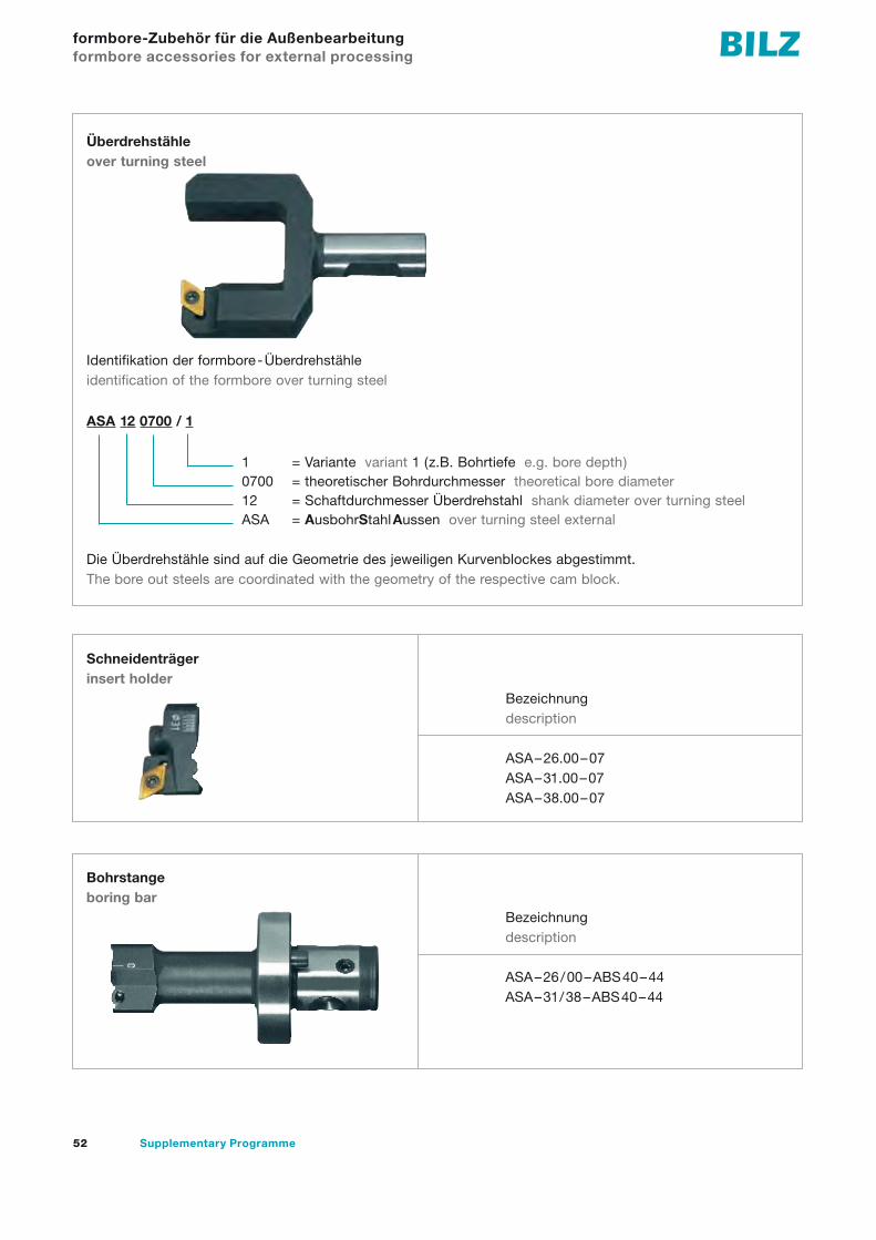
ASA 12 0700 / 1
1 = Variante variant 1 (z.B. Bohrtiefe e.g. bore depth)0700 = theoretischer Bohrdurchmesser theoretical bore diameter12 = Schaftdurchmesser Überdrehstahl shank diameter over turning steelASA = AusbohrStahlAussen over turning steel external
Überdrehstähleover turning steel
Identifikation der formbore-Überdrehstähleidentification of the formbore over turning steel
Die Überdrehstähle sind auf die Geometrie des jeweiligen Kurvenblockes abgestimmt.The bore out steels are coordinated with the geometry of the respective cam block.
Schneidenträgerinsert holder
Bezeichnungdescription
ASA–26.00–07ASA–31.00–07ASA–38.00–07
Bohrstangeboring bar
Bezeichnungdescription
ASA–26/00–ABS40–44ASA–31/38–ABS40–44
formbore-Zubehör für die Außenbearbeitungformbore accessories for external processing
53Zusatzprogramm
Material Drehzahl Vorschub Maschinematerial speed feed machine
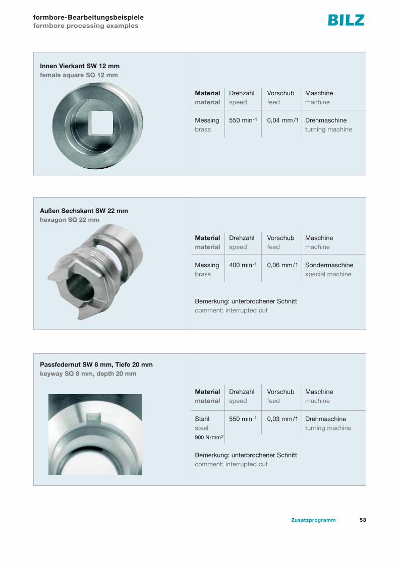
Messing 400 min-1 0,06 mm/1 Sondermaschinebrass special machine
Bemerkung: unterbrochener Schnittcomment: interrupted cut
Material Drehzahl Vorschub Maschinematerial speed feed machine
Messing 550 min-1 0,04 mm/1 Drehmaschinebrass turning machine
Innen Vierkant SW 12 mmfemale square SQ 12 mm
Außen Sechskant SW 22 mmhexagon SQ 22 mm
Passfedernut SW 8 mm, Tiefe 20 mmkeyway SQ 8 mm, depth 20 mm
Material Drehzahl Vorschub Maschinematerial speed feed machine
Stahl 550 min-1 0,03 mm/1 Drehmaschinesteel turning machine900 N/mm2
Bemerkung: unterbrochener Schnittcomment: interrupted cut
formbore-Bearbeitungsbeispieleformbore processing examples

54 Supplementary Programme
SFC – Stiftschrauben-Eindrehfutter SFC – Stud driving chucks
SFC zum Spannen von Stiftschrauben am Gewinde
Das Bilz-Stiftschrauben-Eindrehfutter SFC wurde eigens für diesen Eindrehprozess entwickelt. Mit ihm können Stiftschrauben sowohl auf Überlänge als auch auf Drehmoment, manuell mit Druckschrau-bern oder automatisch mit Montagemaschinen ein- oder mehr-spindelig schnell und sicher eingedreht werden.
Die Stiftschrauben werden im Gewinde der geschlossenen 3-geteilten Klemmbacken im Eindrehfutter aufgenommen und bis zur Anlage an den Sperrbolzen in die Klemmbacken eingedreht.
Danach erfolgt das Eindrehen in das Werkstück auf Überstehlänge oder auf Drehmoment.Nach erfolgtem Eindrehen öffnen sich die Klemmbacken durch Zurückziehen des Eindrehfutters und lösen sich dadurch von der Stiftschraube, ohne diese zu beschädigen. Nach dem Abziehen schließen sich die Klemmbacken wieder automatisch.
Das Lösen des Futters von der Stiftschraube kann im Stillstand oder unter Drehzahl ohne Drehrichtungswechsel der Maschinen-spindel erfolgen.
SFC for gripping the studs on the thread
The Bilz SFC stud driver has been specifically designed for this tightening function. By using this facility, studs can be set quickly and safely to a required torque.
The process can be performed manually using pneumatic drivers, or automatically by means of a single or multi-spindle assembly machine.
The stud is located into the uniquely designed threaded jaws, in the closed position and is screwed into the jaws until it makes contact with the stop pin.
The stud is then driven into the tapped hole in the workpiece until it reaches its pre-set length or the required torque level. When the driver reaches either position, the threaded jaws are automatically opened, allowing the driver to be removed cleanly from the stud.
The driver can be removed from the stud, either with the spindle rotating or stationary.
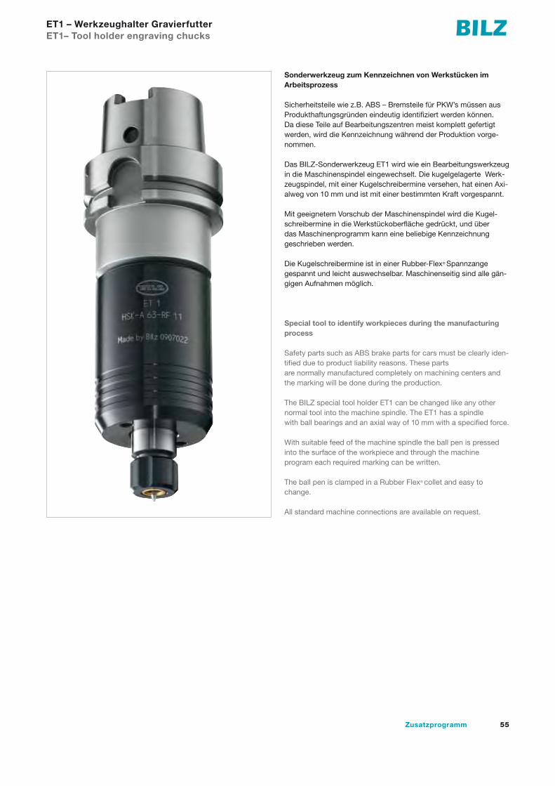
55Zusatzprogramm
ET1 – Werkzeughalter Gravierfutter ET1– Tool holder engraving chucks
Sonderwerkzeug zum Kennzeichnen von Werkstücken im Arbeitsprozess
Sicherheitsteile wie z.B. ABS – Bremsteile für PKW’s müssen aus Produkthaftungsgründen eindeutig identifiziert werden können. Da diese Teile auf Bearbeitungszentren meist komplett gefertigt werden, wird die Kennzeichnung während der Produktion vorge-nommen.
Das BILZ-Sonderwerkzeug ET1 wird wie ein Bearbeitungswerkzeug in die Maschinenspindel eingewechselt. Die kugelgelagerte Werk-zeugspindel, mit einer Kugelschreibermine versehen, hat einen Axi-alweg von 10 mm und ist mit einer bestimmten Kraft vorgespannt.
Mit geeignetem Vorschub der Maschinenspindel wird die Kugel-schreibermine in die Werkstückoberfläche gedrückt, und über das Maschinenprogramm kann eine beliebige Kennzeichnung geschrieben werden.
Die Kugelschreibermine ist in einer Rubber-Flex® Spannzange gespannt und leicht auswechselbar. Maschinenseitig sind alle gän-gigen Aufnahmen möglich.
Special tool to identify workpieces during the manufacturing process
Safety parts such as ABS brake parts for cars must be clearly iden-tified due to product liability reasons. These parts are normally manufactured completely on machining centers and the marking will be done during the production.
The BILZ special tool holder ET1 can be changed like any other normal tool into the machine spindle. The ET1 has a spindle with ball bearings and an axial way of 10 mm with a specified force.
With suitable feed of the machine spindle the ball pen is pressed into the surface of the workpiece and through the machine program each required marking can be written.
The ball pen is clamped in a Rubber Flex® collet and easy to change.
All standard machine connections are available on request.
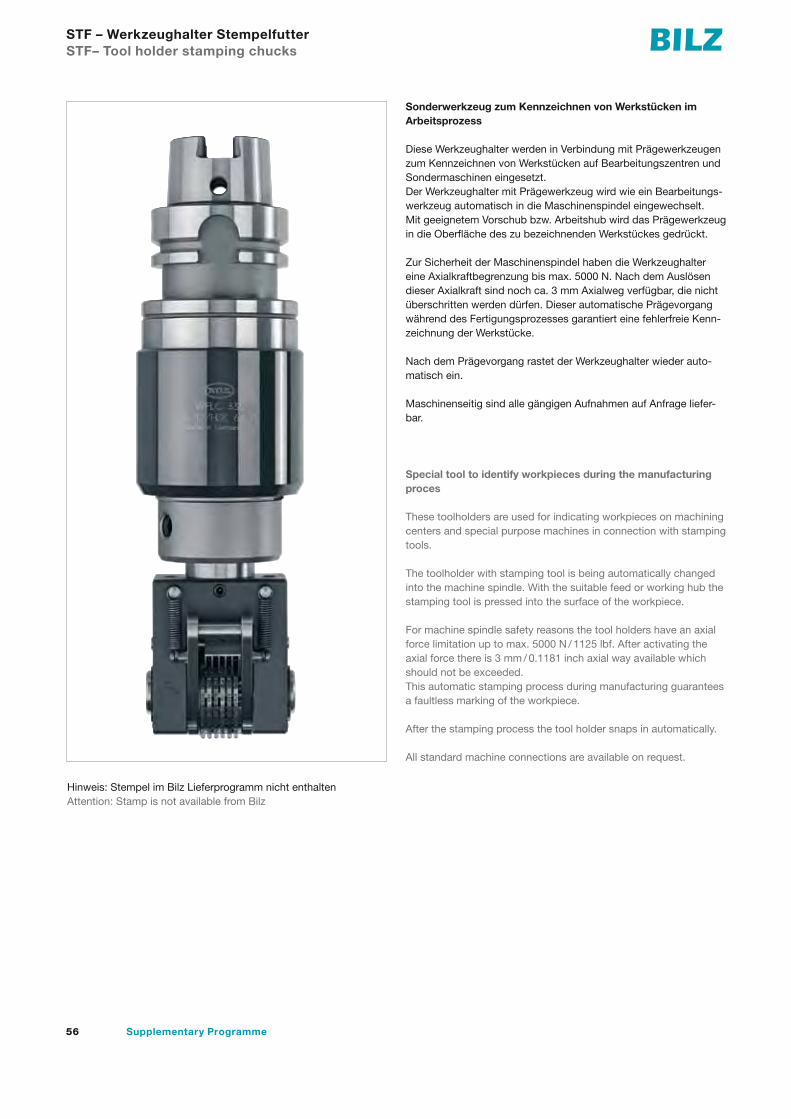
56 Supplementary Programme
STF – Werkzeughalter Stempelfutter STF– Tool holder stamping chucks
Sonderwerkzeug zum Kennzeichnen von Werkstücken im Arbeitsprozess
Diese Werkzeughalter werden in Verbindung mit Prägewerkzeugen zum Kennzeichnen von Werkstücken auf Bearbeitungszentren und Sondermaschinen eingesetzt.Der Werkzeughalter mit Prägewerkzeug wird wie ein Bearbeitungs-werkzeug automatisch in die Maschinenspindel eingewechselt. Mit geeignetem Vorschub bzw. Arbeitshub wird das Prägewerkzeug in die Oberfläche des zu bezeichnenden Werkstückes gedrückt.
Zur Sicherheit der Maschinenspindel haben die Werkzeughalter eine Axialkraftbegrenzung bis max. 5000 N. Nach dem Auslösen dieser Axialkraft sind noch ca. 3 mm Axialweg verfügbar, die nicht überschritten werden dürfen. Dieser automatische Prägevorgang während des Fertigungsprozesses garantiert eine fehlerfreie Kenn-zeichnung der Werkstücke.
Nach dem Prägevorgang rastet der Werkzeughalter wieder auto-matisch ein.
Maschinenseitig sind alle gängigen Aufnahmen auf Anfrage liefer-bar.
Special tool to identify workpieces during the manufacturing proces
These toolholders are used for indicating workpieces on machining centers and special purpose machines in connection with stamping tools.
The toolholder with stamping tool is being automatically changed into the machine spindle. With the suitable feed or working hub the stamping tool is pressed into the surface of the workpiece.
For machine spindle safety reasons the tool holders have an axial force limitation up to max. 5000 N / 1125 lbf. After activating the axial force there is 3 mm / 0.1181 inch axial way available which should not be exceeded.This automatic stamping process during manufacturing guarantees a faultless marking of the workpiece.
After the stamping process the tool holder snaps in automatically.
All standard machine connections are available on request.
Hinweis: Stempel im Bilz Lieferprogramm nicht enthaltenAttention: Stamp is not available from Bilz

57Zusatzprogramm
Wichtige BestellhinweiseImportant Hints
ProgrammaktualitätIm Rahmen der kontinuierlichen Aktualisierung unseres Produkt- programmes nehmen wir nicht nur neue und damit technisch bessere Produkte im Programm auf, sondern führen auch eine intensive Programmbereinigung durch. Es kann also im Einzelfall passieren, dass wir einen von Ihnen bestellten Artikel nicht mehr lagermäßig führen. Sie erhalten dann von uns in der Regel ein technologisch besseres Produkt, mindestens aber eine gleich-wertige Alternative. In Zweifelsfällen wird sich unser Verkaufsteam mit Ihnen in Verbindung setzen, um eine für Sie optimale Ausfüh-rung zu bestimmen. Durch diese Vorgehensweise ist sichergestellt, dass Sie stets mit Werkzeugen beliefert werden, die technisch auf dem neuesten Stand sind.Eine Verpflichtung zur Lieferung von noch im Katalog oder in der Preisliste abgebildeten Werkzeugen, die intern aber bereits programmbereinigt wurden, übernehmen wir deshalb nicht.
Alle Katalogangaben sind unverbindlich. Schreib- und Rechen-fehler sind vorbehalten. Maßgeblich sind die Angaben in der Auf-tragsbestätigung.
IdentnummernUm die Auftragsbearbeitung zu beschleunigen und Verwechse-lungen auszuschließen, bitten wir bei Aufträgen um Angabe der Identnummern.
PreiseDieser Katalog enthält keine Preise. Diese entnehmen Sie bitte der je weils gültigen Preisliste.
MindestauftragswertWir bitten um Verständnis, dass wir Aufträge bis zu einem Gesamt-wert unter € 50,- nur gegen eine zusätzliche Bearbeitungsgebühr in Höhe von € 20,- ausführen können. Die Mindestbestellmenge bei Sonderartikeln beträgt 3 Stück.
SonderformenSollten Sie eines Ihrer Bearbei tungsprobleme nicht mit einem unserer lagergängigen Werkzeuge lösen können, bieten wir Ihnen Sonderformen oder zeichnungsgebundene Werk zeuge auf Anfrage an. Unsere Anwendungstechniker beraten Sie gern.
Updating of our product rangeIn the course of updating of our product range, we are not only constantly adding new and therefore technically improved products to our programme, but at the same time are also continually reas-sessing the product range. In exceptional cases, it can therefore happen that we no longer have a product you order on stock. You will then receive a technically improved product or at least an equivalent alternative. In case of doubt, our sales team will contact you in order to determine the optimal version for you. We ensure that you will always get the most updated tools.We therefore do not assume any obligation to supply tools appear-ing in the catalogue and/or in the price list which have already been adjusted out of the system internally.
Bilz and its partners shall have no liability for indirect, incidental or consequential errors in this catalog.Some mistakes and calculation errors may be present. Orders are subject to approval.
Ident-Nos.Please indicate the ident-nos. in your orders to speed up order processing and avoid confusion.
PricesFor prices, please refer to the current price list.
Minimum order valueAn additional handling fee of EUR 20.00 will be charged for orders with a total value of less than EUR 50.00.The minimum order quantity for special tools is 3 pcs.
Special designsIf you find that your specific machin ing problems cannot be re sol-ved with any of our permanently stocked tools, then we can supply special designs or tools made ac cord ing to drawings. Our applica-tion technicians will be glad to help you.
Nachdruck, auch auszugsweise, ist nur mit unserer Zustimmung gestattet. Alle Rechte vorbehalten. Irrtümer, Satz- oder Druckfehler berechtigen nicht zu irgendwelchen Ansprüchen. Abbildungen, Ausführungen und Maße entsprechen dem neuesten Stand bei Heraus-gabe dieser Druckschrift. Technische Änderungen müssen vorbehalten sein. Die bildliche Darstellung der Produkte muss nicht in jedem Falle und in allen Einzelheiten dem tatsächlichen Aussehen entsprechen.
This publication may not be reprinted in whole or part without our permission. All rights reserved. No rights may be derived from any errors in content or from typographical or typesetting errors. Diagrams, features and dimensions represent the current status on the date of issue of this leaflet. We reserve the right to make technical changes. The visual appearance of the products may not necessarily correspond to the actual appearance in all cases or in every detail.

Pri
nte
d in
Ge
rma
ny,
No
. 91
717
25 1
0/1
0
BILZ WERKZEUGFABRIKGmbH & Co. KGVogelsangstr. 873760 OstfildernDeutschlandFon +49 7 11 3 48 01 - 0Fax +49 7 11 3 48 12 [email protected]