


Sprachen
Seiten
Rechtliche


Cod. F07010411 / Rev. 00 (2005-01)
*) Valido per Paesi UE*) Valid for EU member countries*) Gilt für EU-Mitgliedsländer*) Valable dans les Pays UE*) Válido para Países UE
BAUSO E MANUTENZIONE / PARTI DI RICAMBIOUSE AND MAINTENANCE / SPARE PARTSGEBRAUCH UND WARTUNG / ERSATZTEILEEMPLOI ET ENTRETIEN / PIECES DETACHEESEMPLEO Y MANTENIMIENTO / PIEZAS DE REPUESTO
IT
EN
DE
FR
ES
*)MASCHIO GASPARDO S.p.A.

ITALIANO ENGLISH DEUTSCH ESPAÑOLFRANÇAIS
2
1.0 IDENTIFICAZIONEOgni singola macchina, è dotata di unatarghetta di identificazione (A pagina 7),i cui dati riportano:
1) Indirizzo del Costruttore.2) Tipo della macchina.3) Modello della macchina.4) Numero di matricola.5) Anno di costruzione.6) Peso standard.
Si consiglia di trascrivere i propri datisulla matricola qui sotto rappresenta-ta con la data di acquisto (7) ed il nomedel concessionario (8).
1.0 IDENTIFICATIONEach individual machine has anidentification plate (A page 7) indicatingthe following details:
1) The Manufacturer’s address.2) Machine type.3) Machine model.4) Serial number.5) Year of manufacture.6) Standard weight.
You are advised to note down yourdata on the form below, along with thedate of purchase (7) and the dealer’sname (8).
1.0 IDENTIFIZIERUNGJedes Gerätes ist mit einem Typenschildversehen (A Seite 7), auf dem die folgen-den Daten stehen:
1) Anschrift des Herstellers.2) Typ des Gerätes.3) Modell des Gerätes.4) Serien-Nummer.5) Baujahr.6) Standardgewicht.
Die Kenndaten der eigenen Maschinen,die auf dem Typenschild stehen, soll-ten hier unten eingetragen werden. Siebestehen aus dem Kaufdatum (7) unddem Namen des Vertragshändlers (8).
1.0 IDENTIFICATIONChaque machine est identifiée par uneplaque (A page 7) sur laquelle sont indi-qués:
1) Adresse du Constructeur.2) Type de la machine.3) Modèle de la machine.4) Numéro de série.5) Année de fabrication.6) Poids standard.
Il est conseillé d’écrire vos coordon-nées sur le talon représenté ci-des-sous avec la date d’achat (7) et le nomdu concessionnaire (8).
1.0 IDENTIFICACIONCada máquina posee una placa deidentificación (A pagína 7). Que exponenlos siguientes datos:
1) Dirección de la fabrica constructora.2) Tipo de máquina.3) Modelo de máquina.4) Número de matrícula.5) Año de fabricación.6) Peso estándar.
Se recomienda anotar los propiosdatos en la ficha que abajo se muestracon la fecha de compra (7) y el nombredel concesionario (8).
(8)
(7)
(2)
(3)
(4)
(6)
(1)
(5)

3
ITALIANO ENGLISH DEUTSCH ESPAÑOLFRANÇAIS
INDICE
1.0 IDENTIFICAZIONE .................. 21.1 Dati tecnici ................................ 41.2 Premessa ................................. 61.3 Segnali di avvertenza ............... 81.4 Segnali di pericolo .................... 81.5 Segnali di indicazione ............... 91.6 Garanzia ................................... 91.7 Scadenza della garanzia .......... 9
2.0 NORME DI SICUREZZA EPREVENZIONE INFORTUNI . 10
3.0 NORME D'USO ...................... 173.1 Trasporto ................................ 173.2 Macchine fornite parzialmente
montate .................................. 183.3 Prima dell'uso ......................... 193.4 Applicazione al trattore ........... 193.5 Verifica capacità di
sollevamento e stabilitàdella trattrice abbinataalla macchina ......................... 21
3.6 Albero cardanico .................... 233.7 Regolazione dell’altezza
di lavoro .................................. 243.8 Coltelli ..................................... 243.9 Sostituzione dei coltelli ........... 263.10 Trasmissione laterale ............. 283.11 Sostituzione cinghie ............... 293.12 Trincia reversibile ................... 293.13 In lavoro .................................. 303.14 Come si lavora ....................... 313.15 Consigli utili per il trattorista ... 343.16 Parcheggio ............................. 35
4.0 MANUTENZIONE ................. 354.1 Prime 8 ore lavorative ............ 364.2 Ogni 8 ore lavorative .............. 364.3 Ogni 50 ore lavorative ............ 374.4 Ogni 400 ore lavorative .......... 374.5 Messa a riposo ....................... 374.6 Lubrificazione ......................... 384.7 Inconvenienti cause e rimedi .. 39
5.0 PARTI DI RICAMBIO ............ 42
INDEX
1.0 IDENTIFICATION ..................... 21.1 Technical features .................... 41.2 Foreword .................................. 61.3 Warning signals ........................ 81.4 Danger signals ......................... 81.5 Indicator signals ....................... 91.6 Warranty ................................... 91.7 Warranty becomes void ............ 9
2.0 SAFETY AND ACCIDENTPREVENTING PROVISIONS 10
3.0 USE INSTRUCTIONS ............ 173.1 Transport ................................ 173.2 Machines supplied partly
broken-down ........................... 183.3 Before use .............................. 193.4 Hitching to the tractor ............. 193.5 Check the lifting capacity
and stability of the tractor towhich the machine is hitched . 21
3.6 Cardan shaft ........................... 233.7 Adjustment of working height . 243.8 Blades .................................... 243.9 Replacing blades .................... 263.10 Side transmission ................... 283.11 Replacing the belts ................. 293.12 Reversible chopper ................ 293.13 In work .................................... 303.14 How to works .......................... 313.15 Useful advice for tractor driver 343.16 Parking ................................... 35
4.0 MAINTENANCE .................... 354.1 First 8 hours service ............... 364.2 Every 8 work hours ................. 364.3 Every 50 hours service ........... 374.4 Every 400 hours service ......... 374.5 Storage ................................... 374.6 Lubrication .............................. 384.7 Inconveniences, causes
and remedys ........................... 40
5.0 SPARE PARTS ..................... 42
INHALT
1.0 IDENTIFIZIERUNG .................. 21.1 Technische Daten .................... 41.2 Vorwort ..................................... 61.3 Warnsignale ............................. 81.4 Gefahrsignale ........................... 81.5 Anzeigesignale ......................... 91.6 Garantie .................................... 91.7 Garantieverfall .......................... 9
2.0 SICHERHEITS UNDUNFALLVERHÜTUNGS-BESTIMMUNGEN .................. 10
3.0 BETRIEBS ANLEITUNG ....... 173.1 Transport ................................ 173.2 Teilweise montiert gelieferte
Maschinen .............................. 183.3 Vor der inbetriebnahme .......... 193.4 Anbringung am schlepper ...... 193.5 Prüfung der hubkraft und
standsicherheit des mit dermaschine verbundenen traktors 21
3.6 Gelenkwelle ............................ 233.7 Einstellung der Arbeitshöhe .... 243.8 Messer .................................... 243.9 Auswechseln der Messer ....... 263.10 Seitlicher Antrieb .................... 283.11 Wechsel der Riemen .............. 293.12 Wendehäcksler ....................... 293.13 Bei der arbeit .......................... 303.14 Wie man mit der Maschine
Arbeitet ................................... 313.15 Ratschläge für den Lenker ..... 343.16 Parken .................................... 35
4.0 WARTUNG ............................ 354.1 Erste 8 betriebsstunden ......... 364.2 Alle 8 betriebsstunden ............ 364.3 Alle 50 betriebsstunden .......... 374.4 Alle 400 betriebsstunden ........ 374.5 Ruheperioden ......................... 374.6 Schmierdienst ......................... 384.7 Störungen deren Ursachen
und Behebung ........................ 40
5.0 ERSATZTEILE ...................... 42
TABLE DES MATIERES
1.0 IDENTIFICATION ..................... 21.1 Donées techniques ................... 41.2 Introduction ............................... 61.3 Signaux de recomandation ....... 81.4 Signaux de danger ................... 81.5 Signaux d'indication .................. 91.6 Garantie .................................... 91.7 Expiration de la garantie ........... 9
2.0 CONSIGNES DE SÉCURITÉET DE PREVENTION DESACCIDENTS ......................... 10
3.0 UTILISATION ......................... 173.1 Transport ................................ 173.2 Machines fournies en partie
demontees .............................. 183.3 Avant utilisation ...................... 193.4 Attelage au tracteur ................ 193.5 Controle des capacités de
levage et stabilité du tracteurrelié a la machine ................... 21
3.6 Arbre a cardans ...................... 233.7 Reglage de la hauteur de travail 243.8 Lames ..................................... 243.9 Changement des lames ......... 263.10 Transmission laterale .............. 283.11 Changement des courroies .... 293.12 Broyeur-hacheur reversible .... 293.13 Execution du travail ................ 303.14 Comment travailler avec
la machine .............................. 313.15 Conseils utiles pour le
tractoriste ................................ 343.16 Stationnement ........................ 35
4.0 ENTRETIEN .......................... 354.1 Apres les 8 premieres heures
de travail ................................. 364.2 Toutes les 8 heures de travail . 364.3 Toutes les 50 heures de travail .. 374.4 Toutes les 400 heures de travail . 374.5 Remissage ............................. 374.6 Lubrification ............................ 384.7 Inconvénients, causes et
remèdes ................................. 41
5.0 PIECES DÉTACHÉES .......... 42
INDICE
1.0 IDENTIFICACIÓN .................... 21.1 Datos técnicos .......................... 41.2 Consideraciones ....................... 61.3 Señales de advertencia ............ 81.4 Señales de peligro .................... 81.5 Señales de indicacion .............. 91.6 Garantía ................................... 91.7 Vencimiento de la garantía ....... 9
2.0 NORMAS DE SEGURIDADY PREVENCIONACCIDENTES ........................ 10
3.0 NORMAS DE USO ................. 173.1 Transporte .............................. 173.2 Maquinas suministradas
parcialmente montadas .......... 183.3 Antes del uso .......................... 193.4 Aplicacion al tractor ................ 193.5 Control de la capacidad de
elevación y la estabilidad deltractor enganchado en lamáquina .................................. 21
3.6 Arbol cardanico ...................... 233.7 Regulación de la altura
de trabajo ............................... 243.8 Cuchillas ................................. 243.9 Sostitución de las cuchillas .... 263.10 Transmissión lateral ............... 283.11 Sostitución de las correas ...... 293.12 Cortador reversible ................. 293.13 En funcionamiento .................. 303.14 Como se trabaja ..................... 313.15 Consejos utiles para el
tractorista ................................ 343.16 Aparcamiento ......................... 35
4.0 MANTENIMIENTO ................ 354.1 Primeras 8 horas de trabajo ... 364.2 Cada 8 horas de trabajo ......... 364.3 Cada 50 horas de trabajo ....... 374.4 Cada 400 horas de trabajo ..... 374.5 Periodos de reposo ................ 374.6 Lubricacion ............................. 384.7 Inconvenientes, causas y
solucións ................................ 41
5.0 PIEZAS DE REPUESTO ....... 42
ITALIANO ENGLISH DEUTSCH ESPAÑOLFRANÇAIS
4
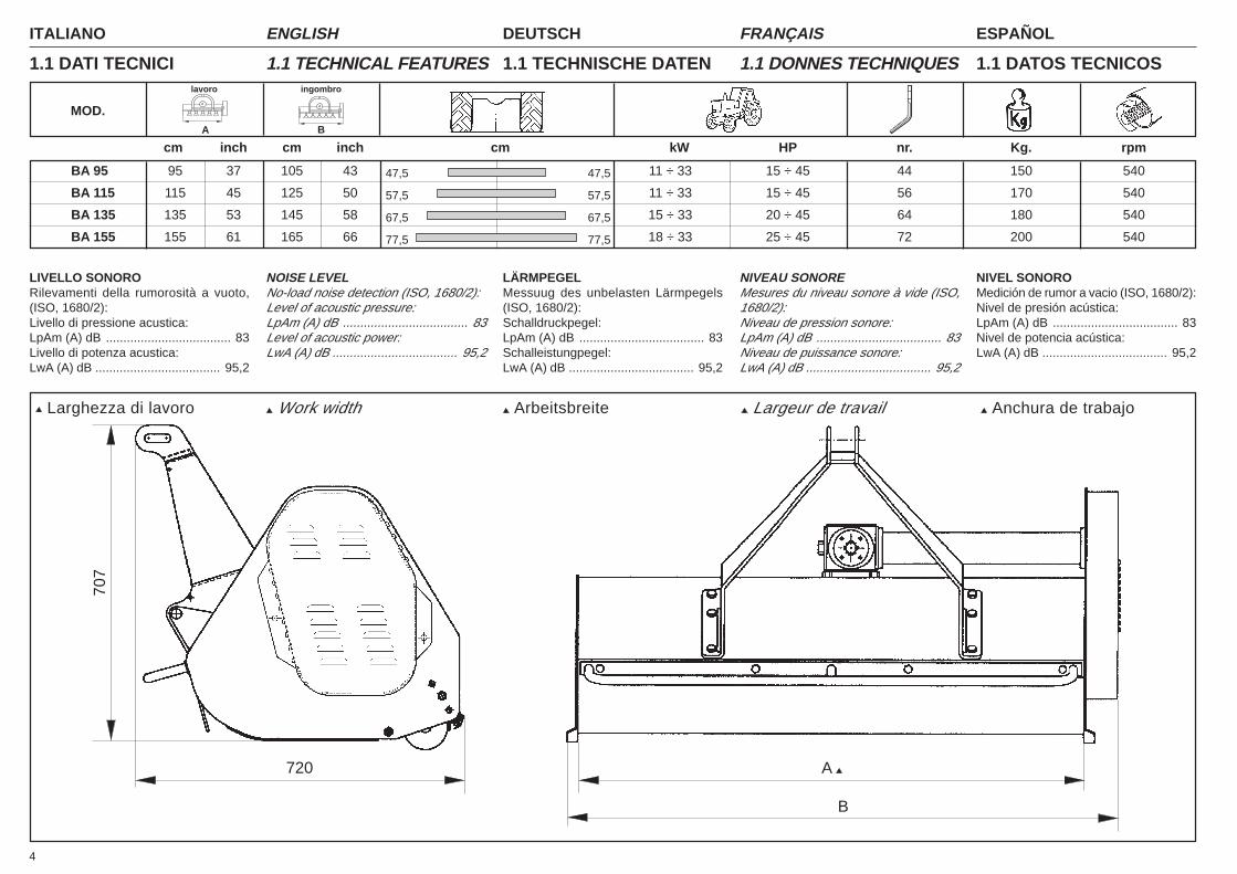
1.1 DATI TECNICI 1.1 TECHNICAL FEATURES 1.1 TECHNISCHE DATEN 1.1 DONNES TECHNIQUES 1.1 DATOS TECNICOS
BA 95 95 37 105 43 11 ÷ 33 15 ÷ 45 44 150 540
BA 115 115 45 125 50 11 ÷ 33 15 ÷ 45 56 170 540
BA 135 135 53 145 58 15 ÷ 33 20 ÷ 45 64 180 540
BA 155 155 61 165 66 18 ÷ 33 25 ÷ 45 72 200 540
47,5 47,5
57,5 57,5
67,5 67,5
77,5 77,5
MOD.A B
lavoro ingombro
cm inch cm inch cm kW HP nr. Kg. rpm
720
707
Work width Arbeitsbreite Largeur de travail Larghezza di lavoro
B
A
LIVELLO SONORORilevamenti della rumorosità a vuoto,(ISO, 1680/2):Livello di pressione acustica:LpAm (A) dB .................................... 83Livello di potenza acustica:LwA (A) dB .................................... 95,2
NOISE LEVELNo-load noise detection (ISO, 1680/2):Level of acoustic pressure:LpAm (A) dB .................................... 83Level of acoustic power:LwA (A) dB .................................... 95,2
LÄRMPEGELMessuug des unbelasten Lärmpegels(ISO, 1680/2):Schalldruckpegel:LpAm (A) dB .................................... 83Schalleistungpegel:LwA (A) dB .................................... 95,2
NIVEAU SONOREMesures du niveau sonore à vide (ISO,1680/2):Niveau de pression sonore:LpAm (A) dB .................................... 83Niveau de puissance sonore:LwA (A) dB .................................... 95,2
NIVEL SONOROMedición de rumor a vacio (ISO, 1680/2):Nivel de presión acústica:LpAm (A) dB .................................... 83Nivel de potencia acústica:LwA (A) dB .................................... 95,2
Anchura de trabajo
5
ITALIANO ENGLISH DEUTSCH ESPAÑOLFRANÇAIS
➬
II
I III
IV
Fig. 1
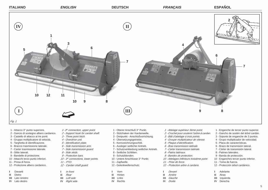
1 - Attacco 3° punto superiore.2 - Gancio di sostegno albero cardanico.3 - Castello di attacco ai tre punti.4 - Gruppo moltiplicatore di velocità.5 - Targhetta di identificazione.6 - Braccio trasmissione laterale.7 - Carter trasmissione laterale.8 - Slitte laterali.9 - Bandelle di protezione.
10 - Attacchi terzo punto inferiori.11 - Presa di forza.12 - Protezione albero cardanico.
I DavantiII DietroIII Lato sinistroIV Lato destro
1 - Oberer Anschluß 3° Punkt.2 - Stützhaken der Kardanwelle.3 - Dreipunkt - Anschlußvorrichtung.4 - Übersetzungsgetriebe.5 - Kennzeichnungsschild.6 - Ausleger seitlicher Antrieb.7 - Schutzverkleidung seitlicher Antrieb.8 - Seitliche Schlitten.9 - Schutzblenden.
10 - Untere Anschlüsse 3° Punkt.11 - Zapfwelle.12 - Gelenkwellenschutz.
I VornII HintenIII LinksIV Rechts
1 - Enganche de tercer punto superior. 2 - Gancho de sostén del árbol cardán.3 - Soporte de enganche de 3 puntos.4 - Grupo multiplicador de velocidad.5 - Placa de características.6 - Brazo de transmisión lateral.7 - Cárter de transmisión lateral.8 - Patines laterales.9 - Banda de protección.
10 - Enganches tercer punto inferior.11 - Toma de fuerza.12 - Protección árbol cardánico.
I AdelanteII AtrasIII IzquierdaIV Derecha
1- 3rd connection, upper point.2 - Support hook for cardan shaft.3 - Three point hitch.4 - Overdrive unit.5 - Identification plate.6 - Side transmission arm.7 - Side transmission guard.8 - Side skids.9 - Protection bars.
10 - 3rd connections, lower points.11 - PTO.12 - Cardan shaft guard.
I In frontII RearIII Left sideIV Right side
1 - Attelage supérieur 3ème point.2 - Crochet pour soutenir l’arbre à cardan.3 - Bâti d’attelage à trois points.4 - Groupe multiplicateur de vitesse.5 - Plaque d’identification.6 - Bras transmission latérale.7 - Carter transmission latérale.8 - Patins latéraux.9 - Bandes de protection.
10 - Attelages inférieurs troisième point.11 - Prise de force.12 - Protection arbre à cardans.
I DevantII ArriéreIII GaucheIV Droite
2
3
5
1
64
6
10 12 11
10 9 8
9 8
77
ITALIANO ENGLISH DEUTSCH ESPAÑOLFRANÇAIS
6
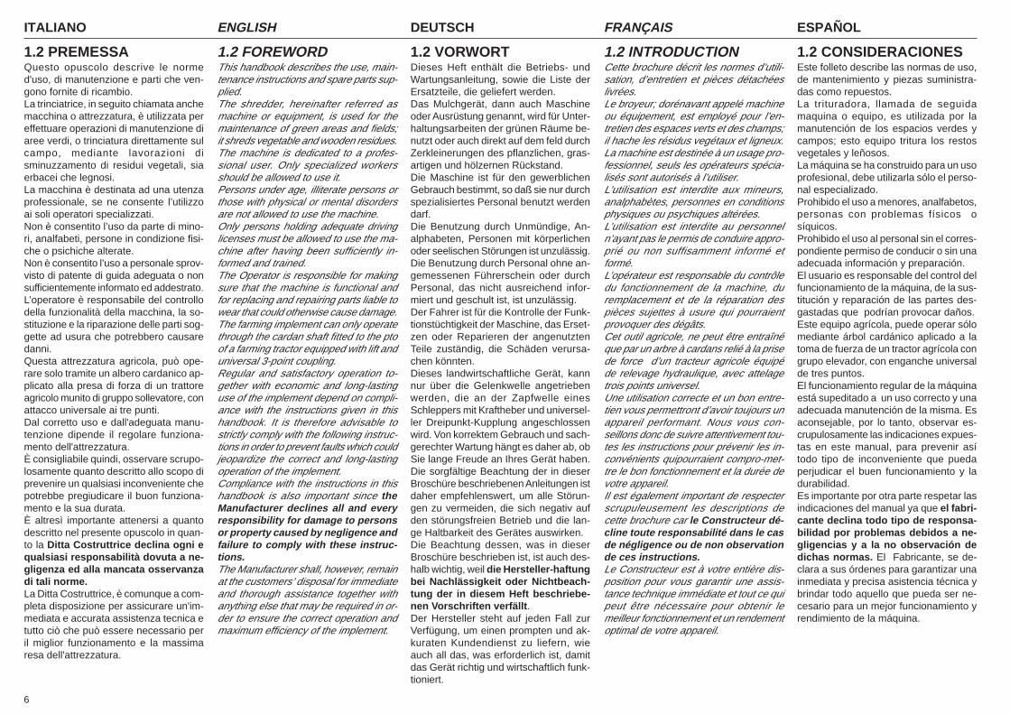
1.2 PREMESSAQuesto opuscolo descrive le normed'uso, di manutenzione e parti che ven-gono fornite di ricambio.La trinciatrice, in seguito chiamata anchemacchina o attrezzatura, è utilizzata pereffettuare operazioni di manutenzione diaree verdi, o trinciatura direttamente sulcampo, mediante lavorazioni disminuzzamento di residui vegetali, siaerbacei che legnosi.La macchina è destinata ad una utenzaprofessionale, se ne consente l’utilizzoai soli operatori specializzati.Non è consentito l’uso da parte di mino-ri, analfabeti, persone in condizione fisi-che o psichiche alterate.Non è consentito l’uso a personale sprov-visto di patente di guida adeguata o nonsufficientemente informato ed addestrato.L’operatore è responsabile del controllodella funzionalità della macchina, la so-stituzione e la riparazione delle parti sog-gette ad usura che potrebbero causaredanni.Questa attrezzatura agricola, può ope-rare solo tramite un albero cardanico ap-plicato alla presa di forza di un trattoreagricolo munito di gruppo sollevatore, conattacco universale ai tre punti.Dal corretto uso e dall'adeguata manu-tenzione dipende il regolare funziona-mento dell'attrezzatura.È consigliabile quindi, osservare scrupo-losamente quanto descritto allo scopo diprevenire un qualsiasi inconveniente chepotrebbe pregiudicare il buon funziona-mento e la sua durata.È altresì importante attenersi a quantodescritto nel presente opuscolo in quan-to la Ditta Costruttrice declina ogni equalsiasi responsabilità dovuta a ne-gligenza ed alla mancata osservanzadi tali norme.La Ditta Costruttrice, è comunque a com-pleta disposizione per assicurare un'im-mediata e accurata assistenza tecnica etutto ciò che può essere necessario peril miglior funzionamento e la massimaresa dell'attrezzatura.
1.2 FOREWORDThis handbook describes the use, main-tenance instructions and spare parts sup-plied.The shredder, hereinafter referred asmachine or equipment, is used for themaintenance of green areas and fields;it shreds vegetable and wooden residues.The machine is dedicated to a profes-sional user. Only specialized workersshould be allowed to use it.Persons under age, illiterate persons orthose with physical or mental disordersare not allowed to use the machine.Only persons holding adequate drivinglicenses must be allowed to use the ma-chine after having been sufficiently in-formed and trained.The Operator is responsible for makingsure that the machine is functional andfor replacing and repairing parts liable towear that could otherwise cause damage.The farming implement can only operatethrough the cardan shaft fitted to the ptoof a farming tractor equipped with lift anduniversal 3-point coupling.Regular and satisfactory operation to-gether with economic and long-lastinguse of the implement depend on compli-ance with the instructions given in thishandbook. It is therefore advisable tostrictly comply with the following instruc-tions in order to prevent faults which couldjeopardize the correct and long-lastingoperation of the implement.Compliance with the instructions in thishandbook is also important since theManufacturer declines all and everyresponsibility for damage to personsor property caused by negligence andfailure to comply with these instruc-tions.The Manufacturer shall, however, remainat the customers’ disposal for immediateand thorough assistance together withanything else that may be required in or-der to ensure the correct operation andmaximum efficiency of the implement.
1.2 VORWORTDieses Heft enthält die Betriebs- undWartungsanleitung, sowie die Liste derErsatzteile, die geliefert werden.Das Mulchgerät, dann auch Maschineoder Ausrüstung genannt, wird für Unter-haltungsarbeiten der grünen Räume be-nutzt oder auch direkt auf dem feld durchZerkleinerungen des pflanzlichen, gras-artigen und hölzernen Rückstand.Die Maschine ist für den gewerblichenGebrauch bestimmt, so daß sie nur durchspezialisiertes Personal benutzt werdendarf.Die Benutzung durch Unmündige, An-alphabeten, Personen mit körperlichenoder seelischen Störungen ist unzulässig.Die Benutzung durch Personal ohne an-gemessenen Führerschein oder durchPersonal, das nicht ausreichend infor-miert und geschult ist, ist unzulässig.Der Fahrer ist für die Kontrolle der Funk-tionstüchtigkeit der Maschine, das Erset-zen oder Reparieren der angenutztenTeile zuständig, die Schäden verursa-chen könnten.Dieses landwirtschaftliche Gerät, kannnur über die Gelenkwelle angetriebenwerden, die an der Zapfwelle einesSchleppers mit Kraftheber und universel-ler Dreipunkt-Kupplung angeschlossenwird. Von korrektem Gebrauch und sach-gerechter Wartung hängt es daher ab, obSie lange Freude an Ihres Gerät haben.Die sorgfältige Beachtung der in dieserBroschüre beschriebenen Anleitungen istdaher empfehlenswert, um alle Störun-gen zu vermeiden, die sich negativ aufden störungsfreien Betrieb und die lan-ge Haltbarkeit des Gerätes auswirken.Die Beachtung dessen, was in dieserBroschüre beschrieben ist, ist auch des-halb wichtig, weil die Hersteller-haftungbei Nachlässigkeit oder Nichtbeach-tung der in diesem Heft beschriebe-nen Vorschriften verfällt.Der Hersteller steht auf jeden Fall zurVerfügung, um einen prompten und ak-kuraten Kundendienst zu liefern, wieauch all das, was erforderlich ist, damitdas Gerät richtig und wirtschaftlich funk-tioniert.
1.2 INTRODUCTIONCette brochure décrit les normes d’utili-sation, d’entretien et pièces détachéeslivrées.Le broyeur; dorénavant appelé machineou équipement, est employé pour l’en-tretien des espaces verts et des champs;il hache les résidus vegétaux et ligneux.La machine est destinée à un usage pro-fessionnel, seuls les opérateurs spécia-lisés sont autorisés à l’utiliser.L’utilisation est interdite aux mineurs,analphabètes, personnes en conditionsphysiques ou psychiques altérées.L’utilisation est interdite au personneln’ayant pas le permis de conduire appro-prié ou non suffisamment informé etformé.L’opérateur est responsable du contrôledu fonctionnement de la machine, duremplacement et de la réparation despièces sujettes à usure qui pourraientprovoquer des dégâts.Cet outil agricole, ne peut être entraînéque par un arbre à cardans relié à la prisede force d’un tracteur agricole équipéde relevage hydraulique, avec attelagetrois points universel.Une utilisation correcte et un bon entre-tien vous permettront d’avoir toujours unappareil performant. Nous vous con-seillons donc de suivre attentivement tou-tes les instructions pour prévenir les in-convénients quipourraient compro-met-tre le bon fonctionnement et la durée devotre appareil.Il est également important de respecterscrupuleusement les descriptions decette brochure car le Constructeur dé-cline toute responsabilité dans le casde négligence ou de non observationde ces instructions.Le Constructeur est à votre entière dis-position pour vous garantir une assis-tance technique immédiate et tout ce quipeut être nécessaire pour obtenir lemeilleur fonctionnement et un rendementoptimal de votre appareil.
1.2 CONSIDERACIONESEste folleto describe las normas de uso,de mantenimiento y piezas suministra-das como repuestos.La trituradora, llamada de seguidamaquina o equipo, es utilizada por lamanutención de los espacios verdes ycampos; esto equipo tritura los restosvegetales y leñosos.La máquina se ha construido para un usoprofesional, debe utilizarla sólo el perso-nal especializado.Prohibido el uso a menores, analfabetos,personas con problemas físicos osíquicos.Prohibido el uso al personal sin el corres-pondiente permiso de conducir o sin unaadecuada información y preparación.El usuario es responsable del control delfuncionamiento de la máquina, de la sus-titución y reparación de las partes des-gastadas que podrían provocar daños.Este equipo agrícola, puede operar sólomediante árbol cardánico aplicado a latoma de fuerza de un tractor agrícola congrupo elevador, con enganche universalde tres puntos.El funcionamiento regular de la máquinaestá supeditado a un uso correcto y unaadecuada manutención de la misma. Esaconsejable, por lo tanto, observar es-crupulosamente las indicaciones expues-tas en este manual, para prevenir asítodo tipo de inconveniente que puedaperjudicar el buen funcionamiento y ladurabilidad.Es importante por otra parte respetar lasindicaciones del manual ya que el fabri-cante declina todo tipo de responsa-bilidad por problemas debidos a ne-gligencias y a la no observación dedichas normas. El Fabricante, se de-clara a sus órdenes para garantizar unainmediata y precisa asistencia técnica ybrindar todo aquello que pueda ser ne-cesario para un mejor funcionamiento yrendimiento de la máquina.
7
ITALIANO ENGLISH DEUTSCH ESPAÑOLFRANÇAIS
16
21 12
15
11
7 43
6
2110
20
GREASE
17
OIL
18
OIL19
OIL
LEVEL
7
13
4
1231
13
2
5
8
14
Fig. 2
9
A
TRINCIA ATTACCO FRONTALEFRONT FINISHING SHREDDERBROYEUR AVANTSCHLEGELMÄHER FUER FRONTANBAUTRITURADORA FRONTAL
21
ITALIANO ENGLISH DEUTSCH ESPAÑOLFRANÇAIS
8
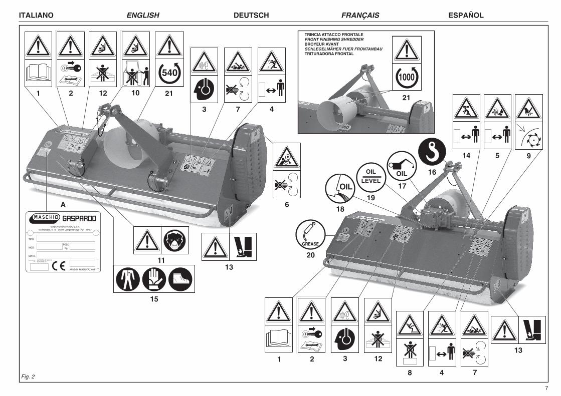
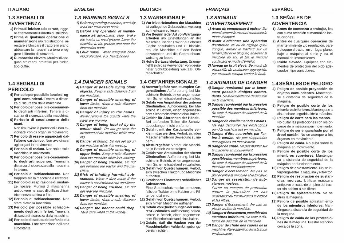
1.3 SEGNALI DIAVVERTENZA
1) Prima di iniziare ad operare, legge-re attentamente il libretto di istruzioni.
2) Prima di qualsiasi operazione dimanutenzione e/o registrazione, ar-restare e bloccare il trattore in piano,abbassare la macchina a terra e leg-gere il libretto di istruzioni.
3) Rumorosità elevata. Munirsi di ade-guati strumenti protettivi per l'udito,tipo cuffie.
1.4 SEGNALI DIPERICOLO
4) Pericolo per possibile lancio di og-getti contundenti. Tenersi a distan-za di sicurezza dalla macchina.
5) Pericolo per possibile cesoiamen-to degli arti inferiori. Tenersi a di-stanza di sicurezza dalla macchina.
6) Pericolo di cesoiamento dellemani.Non rimuovere le protezioni e non av-vicinarsi con gli organi in movimento.
7) Pericolo di essere agganciati dal-l'albero cardanico. Non avvicinarsiagli organi in movimento.
8) Pericolo di caduta. Non salire sullamacchina in movimento.
9) Pericolo per possibile cesoiamen-to degli arti superiori. Tenersi adistanza di sicurezza dalla macchinain lavoro.
10) Pericolo di schiacciamento. Nonfrapporsi tra la macchina e il trattore.
11) Pericolo di respirazione di sostan-ze nocive. Munirsi di mascherinaantipolvere nel caso di utilizzo di trat-trice senza cabina e filtri.
12) Pericolo di schiacciamento. Nonstare dietro la macchina.
13) Pericolo per possibile schiaccia-mento degli arti inferiori. Tenersi adistanza di sicurezza dalla macchina.
14) Pericolo di caduta dei cofani dellamacchina. Fare attenzione nell’areacircostante.
1.3 WARNSIGNALE1) Vor Inbetriebnahme der Maschine
ist vorliegende Gebrauchsanweisungaufmerksam zu lesen.
2) Vor Beginn jeder Art von Wartungs-arbeiten u/o Einstellungen an derMaschine, ist der Traktor auf ebenerFläche anzuhalten und zu blockie-ren, die Maschine auf den Bodenabzusenken und die Gebrauchsan-weisung zu lesen.
3) Hohe Geräuschbelastung. Es emp-fiehlt sich das Verwenden von geeig-neter Schutzkleidung wie z.B. Oh-renschützer.
1.4 GEFAHRENSIGNALE4) Auswurfgefahr von stumpfen Ge-
genständen: Aufforderung, bei Ma-schine in Betrieb, einen angemesse-nem Sicherheitsabstand einzuhalten.
5) Gefahr von Amputation der unterenGliedmaßen: Aufforderung, bei Ma-schine in Betrieb, einen angemesse-nem Sicherheitsabstand einzuhalten.
6) Gefahr für Abtrennen der Hände.Bei laufenden Teilen die Schutz-abdeckungen nicht entfernen.
7) Gefahr, mit der Kardanwelle ver-klemmt zu werden: Verbot, sich denMaschinenteilen in Bewegung zu nä-hern.
8) Absturzgefahr: Verbot, die Maschi-ne in Betrieb zu besteigen.
9) Gefahr von Amputation der oberenGliedmaßen: Aufforderung, bei Ma-schine in Betrieb, einen angemesse-nem Sicherheitsabstand einzuhalten.
10) Gefahr von Quetschungen: Verbot,sich zwischen Traktor und Maschineaufhalten.
11) Gefahr des Einatmens schädlicherSubstanzen.Eine Staubschutzmaske benutzen,falls der Traktor ohne Kabine und Fil-ter benutzt wird.
12) Gefahr von Quetschungen: Verbot,sich hinten Maschine aufhalten.
13) Gefahr von Quetschungen der unte-ren Gliedmaßen. Aufforderung, bei Ma-schine in Betrieb, einen angemesse-nem Sicherheitsabstand einzuhalten.
14) Gefahr, daß die Hauben von derMaschine fallen. Auf den Umgebungs-bereich achten.
1.3 SIGNAUXD’AVERTISSEMENT
1) Avant de commencer à opérer, lireattentivement le manuel contenant lemode d’emploi.
2) Avant d’effectuer une opérationd’entretien et/ ou de réglage quel-conque, arrêter le tracteur sur unterrain plat et le bloquer, abaisser lamachine au sol, et lire le manuelcontenant le mode d’emploi.
3) Niveau de bruit élevé. Se munir dedispositifs de protection appropriés,par exemple casque contre le bruit.
1.4 SIGNAUX DE DANGER4) Danger représenté par le lance-
ment possible d’objets conton-dants. Se tenir à distance de sécuritéde la machine.
5) Danger représenté par la pressionpossible des membres inférieurs.Se tenir à distance de sécurité de lamachine.
6) Danger de cisaillement des mains.Ne pas démonter les protectionsqund la machine est en marche.
7) Danger d’être accrochés par l’ar-bre à cardan. Ne pas s’approcherdes organes en mouvement.
8) Danger de chute. Ne pas monter surla machine en mouvement.
9) Danger représenté par la pressionpossible des membres supérieurs.Se tenir à distance de sécurité de lamachine en fonctionnement.
10) Danger d’écrasement. Ne pas seplacer entre la machine et le tracteur.
11) Danger de respiration de sub-stances nocives.Porter un masque de protectioncontre la poussière en casd’utilisation du tracteur sans la cabineet les filtres.
12) Danger d’écrasement. Ne pas seplacer arriére la machine.
13) Danger d’écrasement possible desmembres inférieurs. Se tenir à dis-tance de sécurité de la machine.
14) Danger de chute des capots de lamachine. Faire attention dans la zoneenvironnante.
1.3 SEÑALES DEADVERTENCIA1) Antes de comenzar a trabajar, lea
con suma atención el manual de ins-trucciones.
2) Antes de cualquier operación demantenimiento y/o regulación, parey bloquee el tractor en un lugar plano,baje la máquina al suelo y lea elmanual de instrucciones.
3) Ruido elevado. Equípese con ele-mentos de protección del oído ade-cuados, tipo auriculares.
1.4 SEÑALES DE PELIGRO4) Peligro de posible proyección de
objetos contundentes. Manténga-se a distancia de seguridad de lamáquina.
5) Peligro de posible corte de losmiembros inferiores. Manténgase adistancia de seguridad de la máquina.
6) Peligro de corte para las manos.No quitar las protecciones con los ór-ganos de la méaquina en movimiento.
7) Peligro de ser enganchado por elárbol cardán. No se acerque a losórganos en movimiento.
8) Peligro de caída. No suba sobre lamáquina en movimiento.
9) Peligro de posible corte de losmiembros superiores. Manténga-se a distancia de seguridad de lamáquina en funcionamiento.
10) Peligro de aplastamiento. No se in-terponga entre la máquina y el tractor.
11) Peligro de respiración de sustan-cias nocivas. Utilizar máscaraantipolvo en caso de empleo del trac-tor sin cabina o sin filtros.
12) Peligro de aplastamiento. No seatras la máquina.
13) Peligro de posible aplastamientode los miembros inferiores. Man-téngase a distancia de seguridad dela máquina.
14) Peligro de caída de las proteccio-nes de la máquina. Prestar atencióncerca de la zona.
1.3 WARNING SIGNALS1) Before operating machine, carefully
read the instruction book.2) Before any operation of mainte-
nance a/o adjustment, stop, brakethe tractor on level ground, lower themachine to the ground and read theinstruction book.
3) Loud noise. Wear adequate hear-ing protection, e.g. headphones.
1.4 DANGER SIGNALS4) Danger of possible flying blunt
objects. Keep a safe distance fromthe machine.
5) Danger of possible shearing oflower limbs. Keep a safe distancefrom the machine.
6) Danger of injury to the hands.Never remove the guards while theparts are mowing.
7) Danger of being hooked by thecardan shaft. Do not go near themembers of the machine while mov-ing.
8) Danger of falling. Do not get up onthe machine while it is moving.
9) Danger of possible shearing ofupper limbs. Keep a safe distancefrom the machine while it is working.
10) Danger of being crushed. Do notget between the tractor and the ma-chine.
11) Risk of inhaling harmful sub-stances. Wear a dust mask if thetractor is used without cab and filters.
12) Danger of being crushed. Do notget rear the machine.
13) Danger of possible shearing oflower limbs. Keep a safe distancefrom the machine.
14) Danger: the bonnet could drop.Take care when in the vicinity.

9
ITALIANO ENGLISH DEUTSCH ESPAÑOLFRANÇAIS
1.5 SEGNALI DIINDICAZIONE15) Munirsi di un’abbigliamento antinfor-
tunistico.16) Punto di aggancio per il sollevamen-
to (è indicata la portata max).17) Tappo per l'introduzione dell'olio.18) Tappo per lo scarico dell'olio.19) Tappo per il controllo dell'olio.20) Punto di ingrassaggio.21) Numero giri presa di forza.A) Targhetta d’identificazione.
1.6 GARANZIAVerificare all'atto della consegna che lamacchina non abbia subito danni duran-te il trasporto e che gli accessori sianointegri e al completo.EVENTUALI RECLAMI DOVRANNOESSERE PRESENTATI PER ISCRITTOENTRO 8 GIORNI DAL RICEVIMENTOPRESSO IL CONCESSIONARIO.L'acquirente potrà far valere i suoi dirittisulla garanzia solo quando egli abbia ri-spettato le condizioni concernenti la pre-stazione della garanzia, riportate nel con-tratto di fornitura.
1.7 SCADENZA DELLAGARANZIAOltre a quanto riportato nel contrattodi fornitura, la garanzia decade:- Qualora si dovesse oltrepassare il li-
mite di potenza consentito riportatonella tabella dei dati tecnici a pag. 4.
- Qualora, mediante riparazioni esegui-te dall'utilizzatore senza il consensodella Ditta Costruttrice o a causa delmontaggio di pezzi di ricambio non ori-ginali, la macchina dovesse subirecambiamenti e il danno dovesse es-sere causato da tali cambiamenti.
- Qualora non fossero state seguite leistruzioni descritte in questo opuscolo.
1.5 INDICATION SIGNALS15) Wear safety clothing.16) Coupling point for lifting (indicating
the maximun capacity).17) Oil fill plug.18) Oil drain plug.19) Oil level plug.20) Greasing point.21) Number of revolutions of power take-
off.A) Identification plate.
1.6 WARRANTYWhen the machine is delivered, checkthat it has not been subjected to damageduring transport and that the accessoriesare in a perfect condition and complete.ANY CLAIMS FOLLOWING THE RE-CEIPT OF DAMAGED GOODS SHALLBE PRESENTED IN WRITING WITHIN8 DAYS FROM RECEIPT OF THEGOODS THEMSELVES FROM YOURLOCAL DEALER.The purchaser may only make claimsunder guarantee when he has compliedwith the warranty conditions in the sup-ply contract.
1.7 WHEN THE WARRANTYBECOMES VOIDBesides the cases specified in thesupply agreement, the guarantee shallin any case become void:- When the implement has been used
beyond the specified power limit, asgiven in the technical data chart onpage 4.
- When, following repairs made by thecustomer without authorization fromthe Manufacturer or owing to installa-tion of spurious spare parts, themachine is subjected to variations andthe damage can be ascribed to thesevariations.
- When the user has failed to complywith the instructions in this handbook.
1.5 HINWEISSIGNALE15) Unfallschutzbekleidung tragen.16) Kupplungspunkt zum Ausheben
(max. Tragvermögen ist angegeben).17) Einfüllstopfen Getriebeöl.18) Ablaßstopfen Getriebeöl.19) Ölstandsstopfen Getriebeöl.20) Schmierstellen.21) Umdrehungszahl der Kraftübertragung.A) Typenschield.
1.6 GARANTIEBei der Übergabe der Maschine sicher-stellen, daß das Gerät keine Transport-schäden aufweist und alle Zubehörteilevorhanden und unbe-schädigt sind.ETWAIGE REKLAMATIONEN SINDSCHRIFTLICH INNERHALB BINNEN 8TAGEN AB DEM ERHALT BEIMVERTRAGSHÄNDLER.Der Käufer kann seinen Anspruch aufGarantie nur dann geltend machen, wenner sich an die Garantiebedingungen hält,die im Liefervertrag wiedergegeben sind.
1.7 GARANTIEVERFALLDer Garantieanspruch verfälltaußerdem auch immer:- Wenn die zulässigen Leistung-
sgrenzwerte überschritten werden, diein der Tabelle der technischen Datenauf Seite 4 stehen.
- Wenn das Gerät infolge Reparaturen,die der Benutzer ohne die Geneh-migung des Herstellers ausführen läßt,oder infolge der Verwendung von Er-satzteilen, die kein Original sind, ge-ändert wird und der Schaden auf die-sen Umständen beruht.
- Wenn die in diesem Heft stehendenAnleitungen nicht beachtet wordensind.
1.5 SIGNAUXD’INDICATION15) Porter des vêtements de sécurité
contre les accidents du travail.16) Point d'attelage pour le relevage (in-
dication de la portée maxi).17) Bouchon de huile.18) Bouchon de vidange huile.19) Bouchon de niveau huile.20) Point de graissage.21) Nombre de tours de la prise de force.A) Plaque segnalétique.
1.6 GARANTIEAu moment de la livraison de votre ap-pareil vérifiez qu’il n’a pas été endom-magé pendant le transport et que tousles accessoires sont en bon état.LES RÉCLAMATIONS ÉVENTUELLESDEVRONT ÊTRE PRÉSENTÉES PARÉCRIT DANS UN DÉLAI DE 8 JOURSÀ COMPTER DE LA RÉCEPTION CHEZLE CONCESSIONAIRE.L’acheteur pourra faire valoir ses droitsde garantie uniquement s’il aura respectéles conditions contenues dans le contratde fourniture.
1.7 EXPIRATION DE LAGARANTIELesconditions du contrat de fournituredemeurant valables, la garantie estsupprimée dans les cas suivants:- En cas de dépassement de la limite
de puissance admise (voir tableau desdonnées techniques, page 4).
- En cas de réparations effectuées parl’utilisateur sans l’autorisation du Cons-tructeur ou en cas de montage de piè-ces qui ne sont pas d’origine nécessi-tant des modifications qui comporte-raient les dommages constatés.
- En cas de non observation des instruc-tions décrites dans ce guide.
1.5 SEÑALES DEINDICACIÓN15) Llevar ropa de trabajo adecuada con-
tra accidentes.16) Punto de enganche para el alzamien-
to (la capacidad máxima).17) Tapón introducción aceite.18) Tapón descarga aceite.19) Tapón de nivel aceite.20) Punto de engrase.21) Número de revoluciones de la toma
de fuerza.A) Placa de identificacíon.
1.6 GARANTIAEn el momento de la recepción de lamáquina controlar que no haya sufridodaños por el transporte y que estén to-dos los accesorios en perfecto estado.EVENTUALES RECLAMOS SE DEBE-RÁN PRESENTAR POR ESCRITODENTRO DE LOS 8 DÍAS DEL MOMEN-TO DE RECEPCIÓN EN EL CONCE-SIONARIO.El comprador podrá gozar de la garantíasólo si ha respetado las condiciones re-lativas a la garantía, expuestas en el con-trato de provisión.
1.7 VENCIMIENTO DE LAGARANTIAAdemás de los casos previstos en elcontrato de provisión, la garantía pier-de todo valor si:- Si se supera el límite de potencia per-
mitido expuesto en la tabla de los da-tos técnicos de la pág. 4.
- Si la máquina sufre modificacionesseguidamente a reparaciones efectua-das por el usuario sin la debida autori-zación o por el montaje de repuestosno originales, y si dichas modificacio-nes provocan averías.
- Por la no observación de las normasque se describen en este manual.
ITALIANO ENGLISH DEUTSCH ESPAÑOLFRANÇAIS
10
2.0 NORME DISICUREZZA EPREVENZIONEINFORTUNIFare attenzione al segnale di pericolo,dove riportato, in questo opuscolo.
I segnali di pericolo sono di tre livelli:
PERICOLO: Questo segnale avverte chese le operazioni descritte non sono cor-rettamente eseguite, causano gravi le-sioni, morte o rischi a lungo termine perla salute.
AVVERTENZA: Questo segnale avver-te che se le operazioni descritte non sonocorrettamente eseguite, possono cau-sare gravi lesioni, morte o rischi a lungotermine per la salute.
CAUTELA: Questo segnale avverte chese le operazioni descritte non sono cor-rettamente eseguite, possono causaredanni alla macchina.
A completamento della descrizione deivari livelli di pericolo, vengono di seguitodescritte situazioni, e definizioni specifi-che, che possono coinvolgere diretta-mente la macchina o le persone.
• ZONA PERICOLOSA: Qualsiasi zonaall’interno e/o in prossimità di una mac-china in cui la presenza di una personaesposta costituisca un rischio per lasicurezza e la salute di detta persona.
• PERSONA ESPOSTA: Qualsiasi per-sona che si trovi interamente o in partein una zona pericolosa.
• OPERATORE: La, o le persone, inca-ricate di installare, di far funzionare, diregolare, di eseguire la manutenzione,di pulire, di riparare e di trasportare unamacchina.
2.0 SAFETY ANDACCIDENTPREVENTINGPROVISIONSPay great attention to the danger sig-nal where indicated in this handbook.
There are three types of danger sig-nal:
DANGER: This signal warns when seri-ous injuries, death or long-term healthrisks would be caused by failure to cor-rectly carry out the described operations.
WARNING: This signal warns when se-rious injuries, death or long-term healthrisks could be caused by failure to cor-rectly carry out the described operations.
CAUTION: This signal warns when dam-age to the machine could be caused byfailure to carry out the described opera-tions.
In order to complete the various levels ofdanger, the following describe situationsand specific definitions that may directlyinvolve the machine or persons.
• DANGER ZONE: any area inside a/onear a machine in which the presenceof an exposed person constitutes a riskfor the safety and health of that per-son.
• EXPOSED PERSON: Any person whohappens to be completely or partiallyin a danger zone.
• OPERATOR: The person/s chargedwith installing, starting up, adjusting,carrying out maintenance, cleaning,repairing or transporting a machine.
2.0 SICHERHEITS UNDUNFALLVERHÜTUNGSBESTIMMUNGENAchten Sie auf dieses Gefahr-signal,wenn es in diesem Heft erscheint.
Es gibt Gefahr-signale drei unter-schiedlicher Stufen:
GEFAHR: Dieses Signal weist darauf hin,daß der beschriebene Vorgang, wenn ernicht korrekt ausgeführt wird, schwereVerletzungen, den Tod oder langfristigeGefahren für die Gesundheit verursacht.
ACHTUNG: Dieses Signal weist daraufhin, daß der beschriebene Vorgang,wenn er nicht korrekt ausgeführt wird,schwere Verletzungen, den Tod oderlangfristige Gefahren für die Gesundheitverursachen kann.
VORSICHT: Dieses Signal weist daraufhin, daß der beschriebene Vorgang,wenn er nicht korrekt ausgeführt wird, zuSchäden an dem Gewrät führen kann.
Zur Vervollständigung der einzelnenGefahrenstufen werden nachstehendeinige Situationen und spezifische Defi-nitionen beschrieben, die einen direktenEinfluß auf Maschine oder Personen aus-üben können.
• GEFAHRENBEREICH: Jeder Bereichinnerhalb bzw. in der Nähe der Maschi-ne, wo die Anwesenheit einer Personeine Gefahr für deren Sicherheit undGesundheit bedeutet.
• GEFÄHRDETE PERSON: Jede Person,die sich vollkommen oder teilweise inner-halb eines Gefahrenbereichs befinde.
• BEDIENUNGSPERSONAL: Die Per-son oder die Personen, die mit derInstallation, dem Betrieb, der Einstel-lung, der Wartung, der Reinigung, derReparatur und dem Transport der Ma-schine beauftragt sind.
2.0 CONSIGNES DESECURITE ET DEPREVENTION DESACCIDENTSFaites attention au signal de dangerchaque fois quevous le rencontrezdans cette brochure.
Les signaux de danger sont de troisniveaux:
DANGER: Ce signal informe que l’exé-cution incorrecte des opérations décritesprovoque des accidents graves, la mortou des risques à long terme pour la santédes personnes.
ATTENTION: Ce signal informe quel’exécution incorrecte des opérationsdécrites peut provoquer des accidentsgraves, la mort ou des risques à longterme pour la santé des personnes.
IMPORTANT: Ce signal informe quel’exécution incorrecte des opérationsdécrites peut provoquer des dégâts gra-ves à la machine.
Pour compléter la description des diffé-rents niveaux de danger, nous reportonsci-dessous, la description des différentessituations et les définitions spécifiquespouvant impliquer directement la machineou les personnes.
• ZONE DANGEREUSE: Toute zone àl’intérieur et/ ou à proximité d’une ma-chine où la présence d’une personneexposée constitue un risque pour lasécurité et la santé de cette personne.
• PERSONNE EXPOSÉE: Toute per-sonne se trouvant entièrement ou enpartie dans une zone dangereuse.
• OPÉRATEUR: La ou les personneschargées d’installer, de faire fonction-ner, de régler, d’effectuer l’entretien,de nettoyer, de réparer et de transpor-ter une machine.
2.0 NORMAS DESEGURIDAD YPREVENCIONACCIDENTESPrestar atención cuando aparece estaindicación de peligro en el manual.
Las indicaciones de peligro puedenser de tres niveles.
PELIGRO: Esta indicación advierte quesi las operaciones descriptas no seefectuan en modo correcto, causan gra-ves lesiones, muerte o riesgos gravespara la salud.
ATENCION: Esta indicación nos advier-te que si las operaciones descriptas nose efectúan correctamente, pueden cau-sar graves lesiones, muerte o riesgosgraves para la salud.
CAUTELA: Esta indicación advierte quesi las operaciones descriptas no se efec-túan correctamente, pueden causardaños a la máquina.
Para completar la descripción de los di-versos niveles de peligro, a continuaciónse describen situaciones y definicionesespecíficas que pueden involucrar direc-tamente a la máquina o las personas.
• ZONA PELIGROSA: Cualquier zonaen el interior y/o en proximidad de unamáquina en la cual la presencia de unapersona expuesta constituya un peli-gro para la seguridad y la salud de di-cha persona.
• PERSONA EXPUESTA: Toda perso-na que se encuentre total o parcial-mente en una zona peligrosa.
• OPERADOR: La, o las personas, en-cargadas de instalar, hacer funcionar,ajustar, mantener, limpiar, reparar ytransportar una máquina.

11
ITALIANO ENGLISH DEUTSCH ESPAÑOLFRANÇAIS
• UTENTE: L’utente è la persona, o l’en-te o la società, che ha acquistato oaffittato la macchina e che intende usar-la per gli usi concepiti allo scopo.
• PERSONALE SPECIALIZZATO:Come tali si intendono quelle personeappositamente addestrate ed abilitatead effettuare interventi di manutenzio-ne o riparazione che richiedono unaparticolare conoscenza della macchi-na, del suo funzionamento, delle sicu-rezze, delle modalità di intervento eche sono in grado di riconoscere ipericoli derivanti dall’utilizzo della mac-china e quindi possono essere in gradodi evitarli.
• CENTRO DI ASSISTENZA AUTORIZ-ZATO: Il Centro di Assistenza autoriz-zato è la struttura, legalmente autoriz-zata dalla Ditta Costruttrice, che dispo-ne di personale specializzato e abilitatoad effettuare tutte le operazioni di assi-stenza, manutenzione e riparazione,anche di una certa complessità, che sirendono necessarie per il mantenimen-to della macchina in perfetto ordine.
Leggere attentamente tutte le istruzio-ni prima dell'impiego della macchina,in caso di dubbi rivolgersi direttamen-te ai tecnici dei Concessionari dellaDitta Costruttrice.La Ditta Costruttrice declina ogni equalsiasi responsabilità per la manca-ta osservanza delle norme di sicurez-za e di prevenzione infortuni di segui-to descritte.
1) Fare attenzione ai simboli di pericoloriportati in questo opuscolo e sullamacchina.
2) Evitare assolutamente di toccare inqualsiasi modo le parti in movimento.
3) Interventi e regolazioni devono esse-re sempre effettuate a motore spen-to e trattore bloccato.
4) Si fa assoluto divieto di trasportarepersone o animali.
5) È assolutamente vietato condurre ofar condurre il trattore, con la mac-china applicata, da personale sprov-
• USER: The user is the person or theorganization or the firm which has pur-chased or rented the machine and in-tends to use it for the purposes it wasconceived for.
• SPECIALIZED PERSONNEL: Thosepersons who have been speciallytrained and qualified to carry out inter-ventions of maintenance or repair re-quiring a particular knowledge of themachine, its functioning, safety meas-ures, methods of intervention - andwho are in a position to recognize thepotential dangers when using the ma-chine and are able to avoid them.
• AUTHORIZED SERVICE CENTER:The authorized Service Center is astructure legally authorized by themanufacturer which disposes of per-sonnel specialized and qualified tocarry out all the operations of assist-ance, maintenance and repair - evenof a certain complexity - found neces-sary to keep the machine in perfectworking order.
Become thoroughly familiar with allthe instructions before using the ma-chine. Contact the technicians of theManufacturer’s concessionaires incase of doubt.The Manufacturer declines all andevery responsibility for failure to com-ply with the safety and accident-pre-vention regulations described herein.
1) Comply with the instructions given bythe danger symbols in this handbookand affixed to the machine itself.
2) Never ever touch any moving part.3) Operations and adjustments to must
always be carried out when the en-gine is off and the tractor braked.
4) It is absolutely forbidden to carry pas-sengers or animals.
5) It is absolutely forbidden for personswithout a driving license, inexpertpersons or those in precarious health
• KONSUMENT: Der Konsument ist jenePerson, Behörde oder Firma, die dieMaschine gekauft oder gemietet hatund vorhat, diese für den vorgesehe-nen Zweck zu nützen.
• FACHPERSONAL: Als Fachpersonalwerden jene Personen verstanden, dieüber eine, zur Reparatur und Wartungder Maschine nötige, berufliche Aus-bildung verfügen und daher imstandesind, bei Eingriffen an der Maschinedie mit diesen Tätigkeiten einherge-henden Gefahren und Risiken zu beur-teilen und zu vermeiden.
• GENEHMIGTE SERVICESTELLE:Die genehmigte Servicestelle ist jenesUnternehmen, welches von der Her-stellerfirma gesetzlich dazu berechtigtwurde, sowohl den technischen Kun-dendienst, als auch sämtlicheWartungs- und Reparaturarbeiten ander Maschine, die sich zur Beibehal-tung ihres einwandfreien Betriebs alsnötig erweisen sollte, zu übernehmen.
Vor der ersten Benutzung des Maschi-nen allen Anweisungen aufmerksamdurchlesen.Im Zweifelsfall wenden Sie sich direktan die Techniker des Vertragshändlersder Herstellerfirma. Der Herstellerlehnt jegliche Haftung ab, wenn die imfolgenden beschriebenen Sicherheits-und Unfallverhütungsbestimmungennicht beachtet worden sind.
1) Auf das Gefahrsignal achten, das indiesem Heft und auf der Maschineselbst vorhanden ist.
2) Es ist auf jeden Fall zu vermeiden,die sich bewegenden Teile auf irgend-eine Weise anzufassen.
3) Eingriffe und Einstellungen, dürfennur bei abgestelltem Motor und beiblockiertem Schlepper vorgenom-men werden.
4) Es ist absolut verboten, auf dem Ge-rät Personen oder Tiere zu befördern.
5) Es ist absolut verboten, den Schlep-per mit angebrachtem Gerät von Per-sonen fahren zu lassen, die keinen
• UTILISATEUR: L’utilisateur est la per-sonne, l’organisme ou la société qui aacheté ou loué la machine et qui veuts’en servir pour les usages prévus.
• PERSONNEL SPÉCIALISÉ: Ce termeindique les personnes ayant reçu uneformation appropriée et qui sont aptesà effectuer des opérations d’entretienou de réparation qui demandent uneconnaissance particulière de la ma-chine, de son fonctionnement, des dis-positifs de sécurité, des modalités d’in-tervention. Ces personnes sont enmesure de reconnaître les dangersdérivant de l’utilisation de la machineet peuvent donc les éviter.
• SERVICE APRÈS-VENTE AGRÉÉ: LeService après-vente agréé est unestructure, autorisée légalement par leConstructeur, qui dispose de person-nel spécialisé et apte à effectuer toutesles opérations d’assistance, d’entre-tien et de réparation, même assez com-plexes, qui sont nécessaires pour con-server la machine en parfait état.
Lisez attentivement toutes les instruc-tions avant d’utiliser la machine; encas de doutes, adressez-vous direc-tement aux techniciens des Conces-sionnaires du Constructeur.Le Constructeur décline toute respon-sabilité dans le cas de non observa-tion des consignes suivantes de sé-curité et de prévention des accidents.
1) Faites attention aux symboles dedanger que vous trouverez dans cettebrochure et sur votre machine.
2) Evitez absolument de toucher lesparties en mouvement.
3) Les interventions ou les réglages, neseront effectués que si le moteur estéteint et le tracteur bloqué.
4) Il est absolument interdit de transpor-ter des passagers ou des animaux.
5) Il est absolument interdit de laisserconduire le tracteur, quand la ma-chine est montée, par des personnes
• USUARIO: El usuario es la persona,institución o sociedad, que compró oalquiló la máquina para emplearla paralos usos propios de la misma.
• PERSONAL ESPECIALIZADO:Como tales se consideran las perso-nas expresamente instruidas y habili-tadas para efectuar intervenciones demantenimiento, o reparaciones, querequieran un conocimiento particularde la máquina, su funcionamiento, dis-positivos de seguridad, modo de inter-vención, y que son capaces de reco-nocer los peligros resultantes del em-pleo de la máquina y, por lo tanto, pue-den evitarlos.
• CENTRO DE ASISTENCIA AUTORI-ZADO: El centro de asistencia autori-zado es la estructura legalmente au-torizada por el fabricante, que dispo-ne de personal especializado y habili-tado para efectuar todas las operacio-nes de asistencia, mantenimiento y re-paración, incluso de una cierta com-plejidad, que se hacen necesarias parael mantenimiento de la máquina enperfectas condiciones.
Leer atentamente todas las instruccio-nes antes del empleo de la máquina,en caso de dudas ponerse en contac-to directamente con los téncicos delos Concesionarios del fabricante.El fabricante declina toda responsa-bilidad frente a inconvenientes causa-dos por la no observación de las nor-mas de seguridad y de prevención deaccidentes descriptas a continuación.
1) Prestar atención a los símbolos depeligro expuestos en este manual ypresentes en la máquina.
2) No tocar jamás las partes en movimiento.3) Reparaciones y regulaciones se de-
ben siempre efectuar con el motorapagado y el tractor bloqueado.
4) Está terminantemente prohibidotransportar personas o animales.
5) Está terminantemente prohibido confiarla conducción del tractor, con l'equipoaplicado, a personas sin permiso de

ITALIANO ENGLISH DEUTSCH ESPAÑOLFRANÇAIS
12
visto di patente di guida adeguata,inesperto e non in buone condizionidi salute.
6) Osservare scrupolosamente tutte le mi-sure di prevenzione infortuni raccoman-date e descritte in questo opuscolo.
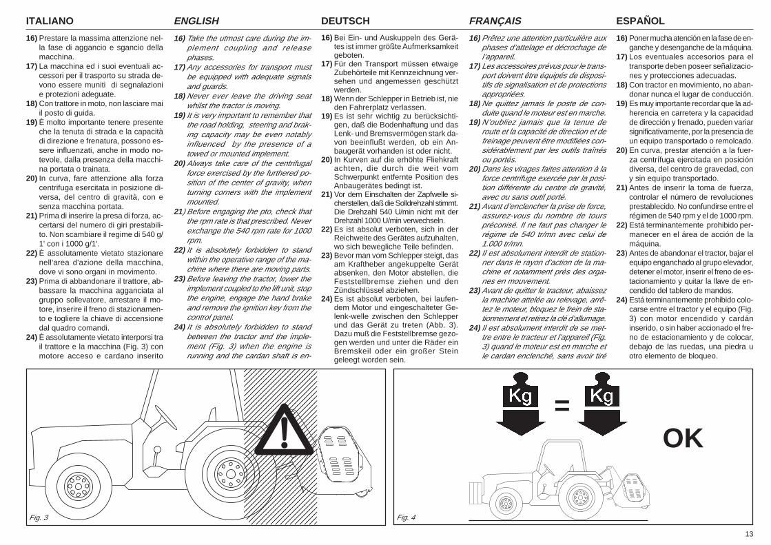
7) L'applicazione della macchina al trat-tore, comporta una diversa distribu-zione dei pesi sugli assi. È consiglia-bile pertanto aggiungere apposite za-vorre nella parte anteriore del tratto-re in modo da ripartire adeguatamen-te il peso sugli assi (Fig. 4).
8) La macchina applicata, può essere co-mandato solo con albero cardanicocompleto delle necessarie sicurezze peri sovraccarichi e delle protezioni fissatecon l'apposita catenella. Fare attenzio-ne al cardano in rotazione.
9) Prima di mettere in funzione il tratto-re e la macchina stessa, controllarela perfetta integrità di tutte le sicurez-ze per il trasporto e l'uso.
10) Le etichette con le istruzioni, appli-cate sulla macchina, danno gli oppor-tuni consigli in forma essenziale perevitare gli infortuni.
11) Per la circolazione su strada, è ne-cessario attenersi alle normative delcodice stradale in vigore nel relativoPaese.
12) Il trasporto su strada avviene sotto latotale responsabilità dell'utente, cheè tenuto a verificare l'adeguatezzaalle norme del codice della strada invigore nel Paese di utilizzo.Rispettare il peso massimo previstosull'asse del trattore, il peso totalemobile, la regolamentazione sul tra-sporto e il codice stradale.
13) Prima di iniziare il lavoro, familiariz-zare con i dispositivi di comando e leloro funzioni.
14) Usare un abbigliamento idoneo. Evi-tare assolutamente abiti svolazzantio con lembi che in qualche modo po-trebbero impigliarsi in parti rotanti ein organi in movimento.
15) Agganciare la macchina, come pre-visto, su di un trattore di adeguata po-tenza e configurazione mediante l'ap-posito dispositivo (sollevatore), con-forme alle norme.
conditions to drive the tractor with themachine mounted.
6) Strictly comply with all the recom-mended accident preventingmeasures described in this hand-book.
7) Assembly of a implement on the trac-tor will shift the weights on the axles.It is there fore advisable to addweights to the front part of the tractorin order to balance the weights on theaxles themselves (Fig. 4).
8) The coupled implement may only becontrolled through the cardan shaftcomplete with the necessary safetydevices for overloads and with theguards fixed with the relative latch.Keep away from the cardan shaftwhile it is turning.
9) Before starting the tractor and imple-ment, always check that all safetydevices guarding transport and useare in a perfect condition.
10) The instruction labels affixed to themachine give useful advice on howto prevent accidents.
11) Always comply with the highway codein force in your country when travel-ling on public roads.
12) Transport on roads takes place un-der the total responsibility of theuser, who is obliged to verify the ad-equacy of the machine to the rulesof the road traffic code in force in thatcountry.Comply with the maximum permis-sible weight on the axle of the tractor,the total adjustable weight, transportregulations and the highway code.
13) Always become familiar with the con-trols and their operation beforestarting work.
14) Always wear suitable clothing. Neverever wear loose garments or thosewith edges that could in some waybecome caught up in rotating partsor moving mechanisms.
15) As indicated, couple the implementto a tractor of adequate power andconfiguration, using a device (lift)conforming to the prescriptions.
Führerschein haben, die unerfahrensind oder deren Gesundheitszustandzu wünschen läßt.
6) Alle Maßnahmen zur Unfallverhütung,die in diesem Heft beschrieben sind,müssen genauestens beachtet werden.
7) Der Anbau eines Zusatzgerätes amSchlepper führt zur Verlagerung derAchslasten. Am Schlepper ist daherFrontballast anzubringen, um das Gleich-gewicht wieder herzustellen (Abb. 4).
8) Das Anbaugerät kann nur dann ge-steuert werden, wenn seine Gelenk-welle mit Überlastsicherungen undSchutz versehen ist und dieser mitseiner Kette befestigt ist. Vorsicht vorder sich drehenden Gelenkwelle!
9) Bevor der Schlepper und das Gerät inBetrieb genommen werden, sind alleSicherheiten für Transport und Benut-zung auf ihre Unversehrtheit zu prüfen.
10) Die Etiketten mit Hinweisen, die aufdem Gerät aufgeklebt sind, geben inknapper Form Anweisungen, umUnfälle zu vermeiden.
11) Bei der Teilnahme am Straßenver-kehr sind die Bestimmungen der Stra-ßenverkehrsordnung zu beachten,die in dem jeweiligen Land gelten.
12) Der Transport auf öffentlichen Stra-ßen liegt einzig und allein unter derVerantwortung des Konsumenten,der für die Befolgung der aufgrundder landesgültigen Straßenverkehrs-ordnung vorgeschriebenen Angabenzu sorgen hat. Das für die Achse vor-gesehene Höchstgewicht, das be-wegliche Gesamtgewicht, die Trans-port-bestimmungen und die Straßen-verkehrsordnung beachten.
13) Bevor man mit der Arbeit beginnt,sollte man sich mit den Stellteilen undihrer Funktion vertraut machen.
14) Geeignete Arbeitskleidung verwen-den.Flatternde Kleidungsstücke ab-solut vermeiden, weil diese sich inden in Rotation befindlichen Teilenverfangen könnten.
15) Das Gerät wie vorgesehen an einemSchlepper geeigneter Zugkraft undKonfiguration ankuppeln, und zwarmit einer Vorrichtung (Kraftheber), dieden Normen entspricht.
sans permis, inexpéri-mentées ou quiont des problèmes de santé.
6) Observez scrupuleusement toutesles mesures de prévention des acci-dents recommandées ou décritesdans cette brochure.
7) L’application d’un équipement sup-plémentaire au tracteur entraîne unerépartition différente des poids sur lesessieux. Ajoutez donc les masses delestage nécessaires à l’avant du trac-teur de manière à équilibrer les poids(Fig. 4).
8) L’outil adapté au tracteur ne peut êtrecommandé que par l’arbre à cardanséquipé de tous les dispositifs de sé-curité contre les surcharges et cou-vert par les protections qui serontfixées par la chaînette spécialementprévue. Faites très attention au car-dan en rotation!
9) Avant de mettre en marche le trac-teur et l’appareil, contrôlez si toutesles sécurités pour le travail et le trans-port sont en parfait état.
10) Les étiquettes avec les instructions,appliquées sur la machine, vous don-nent les conseils utiles pour éviter lesaccidents.
11) Lors de la circulation sur route, res-pectez le code de la route en vigueurdans votre Pays.
12) Le transport sur route est effectuésous l’entière responsabilité de l’uti-lisateur qui est tenu à contrôler qu’ilsoit conforme aux normes du codede la route en vigueur dans le Paysd’utilisation.Respectez le poids maximum auto-risé sur l’essieu par le tracteur, lepoids total roulant, la réglementationsur le transport et le code de la route.
13) Avant de commencer le travail, ap-prenez à utiliser les dispositifs decommande.
14) Mettez toujours des vêtements ap-propriés. Evitez les habits amples quipourraient s’encastrer dans les orga-nes en mouvement.
15) Attelez l’appareil à un tracteur d’unepuissance appropriée au moyen d’undispositif (relevage) conforme auxnormes.
conducir, inexpertas o que no estén enbuenas condiciones de salud.
6) Observar escrupulosamente todaslas medidas de prevención de acci-dentes aconsejadas y descriptas eneste manual.
7) La aplicación de un equipo adicionalal tractor, implica una distribución delpeso distinta sobre los ejes. Es acon-sejable por lo tanto agregar oportu-nos contrapesos en la parte delante-ra del tractor para así equilibrar lospesos sobre los ejes (Fig. 4).
8) La herramienta aplicada se puede co-mandar sólo con el árbol cardánicoprovisto de los correspondientes ele-mentos de seguridad contra sobre-cargas y con las protecciones fijadascon la relativa cadena. Tener cuida-do con el cardán en rotación.
9) Antes de poner en función el tractor y laherramienta misma, controlar el perfec-to estado de todos los elementos deseguridad para el transporte y el uso.
10) Las etiquetas con las instrucciones,aplicadas en la máquina, dan las opor-tunas sugerencias en forma esencialpara el tranporte y el empleo.
11) Para circular en carreteras es nece-sario respetar las normas del códigovial en vigor en el país de empleo.
12) El transporte sobre la vía pública seefectúa bajo la total responsabilidaddel usuario, quien tiene que verificarla adecuación a las normas de circu-lación en vigor en el país de empleode la máquina.Respetar el peso máximo previstosobre el eje del tractor, el peso totalmóvil, la reglamentación relativa altransporte y el código vial.
13) Antes de iniciar el trabajo, familiari-zarse con los dispositivos de mandoy las relativas funciones.
14) Usar vestidos adaptos. Evitar siemprelas prendas amplias y con volados, quepodrían engancharse en partesrotantes y en órganos en movimiento.
15) Enganchar la máquina, como previs-to, en un tractor con potencia idóneay configuración adecuada, medianteel específico dispositivo (elevador)conforme con las normas.
13
ITALIANO ENGLISH DEUTSCH ESPAÑOLFRANÇAIS
123456789012345612345678901234561234567890123456123456789012345612345678901234561234567890123456123456789012345612345678901234561234567890123456123456789012345612345678901234561234567890123456123456789012345612345678901234561234567890123456123456789012345612345678901234561234567890123456123456789012345612345678901234561234567890123456123456789012345612345678901234561234567890123456123456789012345612345678901234561234567890123456123456789012345612345678901234561234567890123456123456789012345612345678901234561234567890123456
16) Prestare la massima attenzione nel-la fase di aggancio e sgancio dellamacchina.
17) La macchina ed i suoi eventuali ac-cessori per il trasporto su strada de-vono essere muniti di segnalazionie protezioni adeguate.
18) Con trattore in moto, non lasciare maiil posto di guida.
19) È molto importante tenere presenteche la tenuta di strada e la capacitàdi direzione e frenatura, possono es-sere influenzati, anche in modo no-tevole, dalla presenza della macchi-na portata o trainata.
20) In curva, fare attenzione alla forzacentrifuga esercitata in posizione di-versa, del centro di gravità, con esenza macchina portata.
21) Prima di inserire la presa di forza, ac-certarsi del numero di giri prestabili-to. Non scambiare il regime di 540 g/1' con i 1000 g/1'.
22) È assolutamente vietato stazionarenell'area d'azione della macchina,dove vi sono organi in movimento.
23) Prima di abbandonare il trattore, ab-bassare la macchina agganciata algruppo sollevatore, arrestare il mo-tore, inserire il freno di stazionamen-to e togliere la chiave di accensionedal quadro comandi.
24) È assolutamente vietato interporsi trail trattore e la macchina (Fig. 3) conmotore acceso e cardano inserito
16) Take the utmost care during the im-plement coupling and releasephases.
17) Any accessories for transport mustbe equipped with adequate signalsand guards.
18) Never ever leave the driving seatwhilst the tractor is moving.
19) It is very important to remember thatthe road holding, steering and brak-ing capacity may be even notablyinfluenced by the presence of atowed or mounted implement.
20) Always take care of the centrifugalforce exercised by the furthered po-sition of the center of gravity, whenturning corners with the implementmounted.
21) Before engaging the pto, check thatthe rpm rate is that prescribed. Neverexchange the 540 rpm rate for 1000rpm.
22) It is absolutely forbidden to standwithin the operative range of the ma-chine where there are moving parts.
23) Before leaving the tractor, lower theimplement coupled to the lift unit, stopthe engine, engage the hand brakeand remove the ignition key from thecontrol panel.
24) It is absolutely forbidden to standbetween the tractor and the imple-ment (Fig. 3) when the engine isrunning and the cardan shaft is en-
16) Bei Ein- und Auskuppeln des Gerä-tes ist immer größte Aufmerksamkeitgeboten.
17) Für den Transport müssen etwaigeZubehörteile mit Kennzeichnung ver-sehen und angemessen geschütztwerden.
18) Wenn der Schlepper in Betrieb ist, nieden Fahrerplatz verlassen.
19) Es ist sehr wichtig zu berücksichti-gen, daß die Bodenhaftung und dasLenk- und Bremsvermögen stark da-von beeinflußt werden, ob ein An-baugerät vorhanden ist oder nicht.
20) In Kurven auf die erhöhte Fliehkraftachten, die durch die weit vomSchwerpunkt entfernte Position desAnbaugerätes bedingt ist.
21) Vor dem Einschalten der Zapfwelle si-cherstellen, daß die Solldrehzahl stimmt.Die Drehzahl 540 U/min nicht mit derDrehzahl 1000 U/min verwechseln.
22) Es ist absolut verboten, sich in derReichweite des Gerätes aufzuhalten,wo sich bewegliche Teile befinden.
23) Bevor man vom Schlepper steigt, dasam Kraftheber angekuppelte Gerätabsenken, den Motor abstellen, dieFeststellbremse ziehen und denZündschlüssel abziehen.
24) Es ist absolut verboten, bei laufen-dem Motor und eingeschalteter Ge-lenk-welle zwischen den Schlepperund das Gerät zu treten (Abb. 3).Dazu muß die Feststellbremse gezo-gen werden und unter die Räder einBremskeil oder ein großer Steingeleegt worden sein.
16) Prêtez une attention particulière auxphases d’attelage et décrochage del’appareil.
17) Les accessoires prévus pour le trans-port doivent être équipés de disposi-tifs de signalisation et de protectionsappropriées.
18) Ne quittez jamais le poste de con-duite quand le moteur est en marche.
19) N’oubliez jamais que la tenue deroute et la capacité de direction et defreinage peuvent être modifiées con-sidérablement par les outils traînésou portés.
20) Dans les virages faites attention à laforce centrifuge exercée par la posi-tion différente du centre de gravité,avec ou sans outil porté.
21) Avant d’enclencher la prise de force,assurez-vous du nombre de tourspréconisé. Il ne faut pas changer lerégime de 540 tr/mn avec celui de1.000 tr/mn.
22) Il est absolument interdit de station-ner dans le rayon d’action de la ma-chine et notamment près des orga-nes en mouvement.
23) Avant de quitter le tracteur, abaissezla machine attelée au relevage, arrê-tez le moteur, bloquez le frein de sta-tionnement et retirez la clé d’allumage.
24) Il est absolument interdit de se met-tre entre le tracteur et l’appareil (Fig.3) quand le moteur est en marche etle cardan enclenché, sans avoir tiré
16) Poner mucha atención en la fase de en-ganche y desenganche de la máquina.
17) Los eventuales accesorios para eltransporte deben poseer señalizacio-nes y protecciones adecuadas.
18) Con tractor en movimiento, no aban-donar nunca el lugar de conducción.
19) Es muy importante recordar que la ad-herencia en carretera y la capacidadde dirección y frenado, pueden variarsignificativamente, por la presencia deun equipo transportado o remolcado.
20) En curva, prestar atención a la fuer-za centrífuga ejercitada en posicióndiversa, del centro de gravedad, cony sin equipo transportado.
21) Antes de inserir la toma de fuerza,controlar el número de revolucionesprestablecido. No confundirse entre elrégimen de 540 rpm y el de 1000 rpm.
22) Está terminantemente prohibido per-manecer en el área de acción de lamáquina.
23) Antes de abandonar el tractor, bajar elequipo enganchado al grupo elevador,detener el motor, inserir el freno de es-tacionamiento y quitar la llave de en-cendido del tablero de mandos.
24) Está terminantemente prohibido colo-carse entre el tractor y el equipo (Fig.3) con motor encendido y cardáninserido, o sin haber accionado el fre-no de estacionamiento y de colocar,debajo de las ruedas, una piedra uotro elemento de bloqueo.
Fig. 3 Fig. 4
OK=
ITALIANO ENGLISH DEUTSCH ESPAÑOLFRANÇAIS
14
nonché senza aver azionato il frenodi stazionamento ed aver inserito,sotto le ruote, un ceppo o un sassodi bloccaggio.Mantenersi ad una distanza di sicu-rezza dalla macchina in lavoro, perpossibili lanci di corpi contundenti.
25) Prima di agganciare o sganciare lamacchina dall'attacco tre punti, met-tere in posizione di blocco la leva dicomando sollevatore.
26) La categoria dei perni di attacco del-la macchina deve corrispondere aquella dell'attacco del sollevatore.
27) Fare attenzione quando si lavoranella zona dei bracci del sollevamen-to, è un'area molto pericolosa.
28) È assolutamente vietato interporsi frail trattore e l'attacco della macchinaper manovrare il comando dall'ester-no per il sollevamento (Fig. 3).
29) In fase di trasporto, fissare con le re-lative catene e tenditori i bracci late-rali di sollevamento.
30) In fase di trasporto su strada, con lamacchina sollevata, mettere in posi-zione di blocco la leva di comandodel sollevatore idraulico del trattore.In fase di sollevamento dal terreno, igiunti dell'albero cardanico vengonopiegati a più di 40° (P.d.F. ferma),staccare l'albero dalla P.d.F. della trat-trice.
31) Utilizzare esclusivamente l'alberocardanico previsto dal Costruttore.
32) Controllare spesso e con periodicitàle protezioni dell'albero cardanico,deve essere sempre in ottimo statoe saldamente fissato.
33) Fare molta attenzione alla protezio-ne dell'albero cardanico , sia in posi-zione di trasporto che di lavoro.
34) L'installazione e lo smontaggio del-l'albero cardanico deve essere sem-pre fatta a motore spento.
35) Fare molta attenzione al corretto mon-taggio e alla sicurezza dell'alberocardanico, (e sia alla P.d.F. della mac-china che alla P.T.O. del trattore).
36) Bloccare la rotazione della protezio-ne dell'albero cardanico con la cate-nella in dotazione.
gaged without having first engagedthe hand brake and placed a blockor stone under the wheels to pre-vent them from moving.Keep a safe distance from the shred-der at work to avoid being hit bypossible flying stones, etc.
25) Always set the lift control lever to thelocked position before coupling orreleasing the implement from thethree-point coupling.
26) The category of the implement cou-pling pins must correspond to that ofthe lift coupling.
27) Take care when working near the liftlinks.This is a very dangerous zone.
28) It is absolutely forbidden to standbetween the tractor and the imple-ment when manoeuvering the liftcontrol from the outside (Fig. 3).
29) Fix the side lift links with the relativechains and idlers during the transportphase.
30) Set the control lever of the hydrauliclift to the locked position during roadtransport with the implement raised.When hoisting from the ground , thejoints of the cardan shaft are bent tomore than 40° (power takeoff turnedoff). Detach the shaft from the powertakeoff of the tractor.
31) Only use the cardan shaft recom-mended by the Manufacturer.
32) Frequently and periodically check thecardan shaft guard. It must always bein an excellent condition and well-welded.
33) Take great care of the the cardanshaft guard, both in the transport andwork positions.
34) The cardan shaft must only be in-stalled or dismantled whilst theengine is off.
35) Take great care to ensure that thecardan shaft is correctly assembledand safe, (and carefully check theP.d.F. of the machine and the P.T.O.of the tractor).
36) Use the supplied latch to prevent thecardan shaft guard from turning.
Achten Sie bei der Arbeit mit derHäckselmaschine auf den nötigen Si-cherheitsabstand aufgrund der Aus-wurfgefahr stumpfer Gegenstände.
25) Bevor das Gerät am oberenKupplungspunkt ein oder ausge-kup-pelt wird, ist der Schalthebel desKrafthebers zu blockieren.
26) Die Kategorie der Anschlußbolzendes Gerätes muß zum Anschluß desKrafthebers passen.
27) Vorsicht beim Arbeiten im Bereich derHeberarme. Dieser Bereich ist eineGefahrenzone.
28) Es ist absolut verboten, zwischen denSchlepper und den Anschluß zu tre-ten, um die Aushebung von außen zubetätigen (Abb. 3).
29) Beim Transport müssen die seitlichenLenker mit den Stabilisierungsketten undSpannvorrichtungen befestigt werden.
30) Beim Straßentransport mit ausge-hobenem Anbaugerät ist der Schalt-hebel des Krafthebers in die blockier-te Stellung zu setzen.Bei Anheben der Maschine werdendie Kupplungsstücke der Kardanwel-le um mehr als 40° abgebogen (Kraft-übertragung stillstehend); die Kar-danwelle von der Kraftübertragungdes Traktors abschließen.
31) Nur die vom Hersteller vorgeseheneGelenkwelle verwenden.
32) Den Gelenkwellenschutz in regel-mä-ßigen Abständen prüfen. Er muß im-mer einen ausgezeichneten Zustandaufweisen und fest verankert sein.
33) Stets auf den Gelenkwellenschutzachten, sowohl in der Arbeits- alsauch der Transportposition.
34) Installation und Ausbau der Gelenk-welle dürfen nur bei stehendem Mo-tor ausgeführt werden.
35) Besonders auf die korrekte Montageund die Sicherheit der Gelenkwelleachten, (sowohl an der Zapfwelle derder Maschine als auch an der Schlep-per-Zapfwelle).
36)Die Rotation des Gelenkwellen-schutzes anhand der mitgeliefertenKette verhindern.
37) Bevor die Zapfwelle eingeschaltetwird, sicherstellen, daß sich wederPersonen noch Tiere in der Reich-weite aufhalten und daß die Drehzahlder Zapfwelle der Solldrehzahl ent-
le frein de stationnement et bloquéles roues avec une cale ou un caillou.Se tenir à une distance de sécuritédu broyeur en fonctionnement, àcause du lancement possible d’ob-jets contondants.
25) Avant de fixer ou décrocher l’appa-reil sur le troisième point d’attelage,mettez le levier de commande durelevage en position de blocage.
26) La catégorie des pivots d’attelage doitcorrespondre à celle de l’attelage durelevage.
27) Faites attention quand vous travaillezprès des bras relevage: c’est trèsdangereux.
28) Il est absolument interdit de se met-tre entre le tracteur et l’attelage pourmanoeuvrer la commande derelevage de l’extérieur (Fig. 3).
29) Lors du transport, fixez les barres derelevage par les chaînes et les ten-deurs.
30) Lors des déplacements sur route, lamachine étant soulevée, mettez le le-vier de commande du relevage hy-draulique en position de blocage.En phase de soulèvement du sol, lesjoints de l’arbre à cardan sont pliés àplus de 40° (Prise de force arrêtée),détacher l’arbre de la prise de forcedu tracteur.
31) Utilisez exclusivement l’arbre à car-dans prévu par le Constructeur.
32) Contrôlez souvent et régulièrementla protection de l’arbre à cardans; elledoit être toujours en parfait état.
33) Vérifiez attentivement la protection del’arbre à cardans, aussi bien en posi-tion de transport que de travail.
34) La mise en place et le démontage del’arbre à cardans ne seront effectuésque si le moteur est arrêté.
35) Attention au montage parfait et à lasécurité de l’arbre à cardans.
36) Bloquez la rotation de la protectionde l’arbre à cardans avec la chaînetteprévue à cet effet.
37) Avant d’embrayer la prise de force,assurez-vous que personne ne setrouve dans son rayon d’action; véri-fiez d’avoir choisi le régime autorisé.
Manténgase a una distancia de se-guridad del triturador durante el tra-bajo, porque puede proyectar objetos.
25) Antes de enganchar o desengancharel equipo en el tercer punto, poneren posición de bloqueo la palanca demando elevador.
26) La categoría de los pernos de engan-che del equipo debe correspondercon la del enganche del elevador.
27) Prestar atención cuando se trabajaen la zona de los brazos de eleva-ción, es un área muy peligrosa.
28) Está absolutamente prohibido colocar-se entre el tractor y el enganche paramaniobrar el mando desde el externoen la fase de elevación (Fig. 3).
29) En fase de transporte, fijar con lasrelativas cadenas y tensores los bra-zos laterales de elevación.
30) En fase de transporte en carretera,con equipo alzado, poner en posiciónde bloqueo la palanca de mando delelevador hidráulico.Durante le levantamiento del terre-no, las juntas del árbol cardán se plie-gan a más de 40° (toma de fuerzaparada), desconecte el árbol de latoma de fuerza del tractor.
31) Utilizar exclusivamente el árbol car-dánico previstopor el Fabricante.
32) Controlar frecuentemente en modo pe-riódico la protección del árbol cardáni-co, debe encontrarse siempre en per-fecto estado y fijado en modo seguro.
33) Prestar mucha atención a la protec-ción del árbol cardánico tanto en po-sición de transporte como también enposición de trabajo.
34) La instalación y el desmontaje delárbol cardánico debe hacerse siem-pre con el motor apagado.
35) Prestar mucha atención al correctomontaje y a las seguridades del árbolcardánico, (como así también a lasT.d.F. de la máquina y del tractor).
36) Bloquear la rotación de la proteccióndel árbol cardánico con la cadena deserie.
37) Antes de inserir la toma de fuerza,controlar que no existan personas oanimales en la zona de acción y queel régimen elegido corresponda con
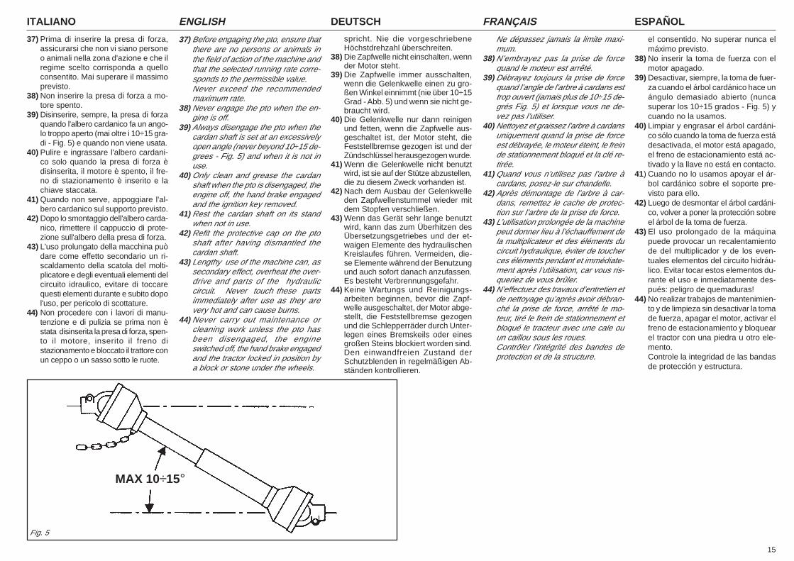
15
ITALIANO ENGLISH DEUTSCH ESPAÑOLFRANÇAIS
37) Prima di inserire la presa di forza,assicurarsi che non vi siano personeo animali nella zona d'azione e che ilregime scelto corrisponda a quelloconsentito. Mai superare il massimoprevisto.
38) Non inserire la presa di forza a mo-tore spento.
39) Disinserire, sempre, la presa di forzaquando l'albero cardanico fa un ango-lo troppo aperto (mai oltre i 10÷15 gra-di - Fig. 5) e quando non viene usata.
40) Pulire e ingrassare l'albero cardani-co solo quando la presa di forza èdisinserita, il motore è spento, il fre-no di stazionamento è inserito e lachiave staccata.
41) Quando non serve, appoggiare l'al-bero cardanico sul supporto previsto.
42) Dopo lo smontaggio dell'albero carda-nico, rimettere il cappuccio di prote-zione sull'albero della presa di forza.
43) L'uso prolungato della macchina puòdare come effetto secondario un ri-scaldamento della scatola del molti-plicatore e degli eventuali elementi delcircuito idraulico, evitare di toccarequesti elementi durante e subito dopol'uso, per pericolo di scottature.
44) Non procedere con i lavori di manu-tenzione e di pulizia se prima non èstata disinserita la presa di forza, spen-to il motore, inserito il freno distazionamento e bloccato il trattore conun ceppo o un sasso sotto le ruote.
37) Before engaging the pto, ensure thatthere are no persons or animals inthe field of action of the machine andthat the selected running rate corre-sponds to the permissible value.Never exceed the recommendedmaximum rate.
38) Never engage the pto when the en-gine is off.
39) Always disengage the pto when thecardan shaft is set at an excessivelyopen angle (never beyond 10÷15 de-grees - Fig. 5) and when it is not inuse.
40) Only clean and grease the cardanshaft when the pto is disengaged, theengine off, the hand brake engagedand the ignition key removed.
41) Rest the cardan shaft on its standwhen not in use.
42) Refit the protective cap on the ptoshaft after having dismantled thecardan shaft.
43) Lengthy use of the machine can, assecondary effect, overheat the over-drive and parts of the hydrauliccircuit. Never touch these partsimmediately after use as they arevery hot and can cause burns.
44) Never carry out maintenance orcleaning work unless the pto hasbeen disengaged, the engineswitched off, the hand brake engagedand the tractor locked in position bya block or stone under the wheels.
spricht. Nie die vorgeschriebeneHöchstdrehzahl überschreiten.
38) Die Zapfwelle nicht einschalten, wennder Motor steht.
39) Die Zapfwelle immer ausschalten,wenn die Gelenkwelle einen zu gro-ßen Winkel einnimmt (nie über 10÷15Grad - Abb. 5) und wenn sie nicht ge-braucht wird.
40) Die Gelenkwelle nur dann reinigenund fetten, wenn die Zapfwelle aus-geschaltet ist, der Motor steht, dieFeststellbremse gezogen ist und derZündschlüssel herausgezogen wurde.
41) Wenn die Gelenkwelle nicht benutztwird, ist sie auf der Stütze abzustellen,die zu diesem Zweck vorhanden ist.
42) Nach dem Ausbau der Gelenkwelleden Zapfwellenstummel wieder mitdem Stopfen verschließen.
43) Wenn das Gerät sehr lange benutztwird, kann das zum Überhitzen desÜbersetzungsgetriebes und der et-waigen Elemente des hydraulischenKreislaufes führen. Vermeiden, die-se Elemente während der Benutzungund auch sofort danach anzufassen.Es besteht Verbrennungsgefahr.
44) Keine Wartungs und Reinigungs-arbeiten beginnen, bevor die Zapf-welle ausgeschaltet, der Motor abge-stellt, die Feststellbremse gezogenund die Schlepperräder durch Unter-legen eines Bremskeils oder einesgroßen Steins blockiert worden sind.Den einwandfreien Zustand derSchutzblenden in regelmäßigen Ab-ständen kontrollieren.
Ne dépassez jamais la limite maxi-mum.
38) N’embrayez pas la prise de forcequand le moteur est arrêté.
39) Débrayez toujours la prise de forcequand l’angle de l’arbre à cardans esttrop ouvert (jamais plus de 10÷15 de-grés Fig. 5) et lorsque vous ne de-vez pas l’utiliser.
40) Nettoyez et graissez l’arbre à cardansuniquement quand la prise de forceest débrayée, le moteur éteint, le freinde stationnement bloqué et la clé re-tirée.
41) Quand vous n’utilisez pas l’arbre àcardans, posez-le sur chandelle.
42) Après démontage de l’arbre à car-dans, remettez le cache de protec-tion sur l’arbre de la prise de force.
43) L’utilisation prolongée de la machinepeut donner lieu à l’échauffement dela multiplicateur et des éléments ducircuit hydraulique, éviter de toucherces éléments pendant et immédiate-ment après l’utilisation, car vous ris-queriez de vous brûler.
44) N’effectuez des travaux d’entretien etde nettoyage qu’après avoir débran-ché la prise de force, arrêté le mo-teur, tiré le frein de stationnement etbloqué le tracteur avec une cale ouun caillou sous les roues.Contrôler l’intégrité des bandes deprotection et de la structure.
MAX 10÷15°
Fig. 5
el consentido. No superar nunca elmáximo previsto.
38) No inserir la toma de fuerza con elmotor apagado.
39) Desactivar, siempre, la toma de fuer-za cuando el árbol cardánico hace unángulo demasiado abierto (nuncasuperar los 10÷15 grados - Fig. 5) ycuando no la usamos.
40) Limpiar y engrasar el árbol cardáni-co sólo cuando la toma de fuerza estádesactivada, el motor está apagado,el freno de estacionamiento está ac-tivado y la llave no está en contacto.
41) Cuando no lo usamos apoyar el ár-bol cardánico sobre el soporte pre-visto para ello.
42) Luego de desmontar el árbol cardáni-co, volver a poner la protección sobreel árbol de la toma de fuerza.
43) El uso prolongado de la máquinapuede provocar un recalentamientode del multiplicador y de los even-tuales elementos del circuito hidráu-lico. Evitar tocar estos elementos du-rante el uso e inmediatamente des-pués: peligro de quemaduras!
44) No realizar trabajos de mantenimien-to y de limpieza sin desactivar la tomade fuerza, apagar el motor, activar elfreno de estacionamiento y bloquearel tractor con una piedra u otro ele-mento.Controle la integridad de las bandasde protección y estructura.
ITALIANO ENGLISH DEUTSCH ESPAÑOLFRANÇAIS
16
Controllare l'integrità delle bandelledi protezione e della struttura.
45) Periodicamente verificare il serraggioe la tenuta delle viti e dadi, eventual-mente riserrarli.
46) Nei lavori di manutenzione e di sosti-tuzione dei coltelli con la macchina sol-levato, mettere per precauzione ade-guati sostegni sotto l'attrezzatura.
47) Prima di lavorare sugli utensili da ta-glio; staccare la presa di forza, spe-gnere il trattore, inserire il freno distazionamento ed assicurarsi che gliutensili siano completamente fermi.
48) Rispettare la conformità degli olii con-sigliati.
49) Le parti di ricambio devono corrispon-dere alle esigenze definite dalcostruttore. Usare solo ricambi originali.
50) Le decalcomanie relative alla sicu-rezza devono essere sempre benevidenti; vanno tenute pulite e vannosostituite se diventano poco leggibili(eventualmente possono essere ri-chieste al concessionario).
51) Il libretto delle istruzioni per l'uso,deve essere conservato per tutta ladurata della macchina.
ATTENZIONENel caso si utilizzi una trattice priva dicabina insonorizzata e pressurizzata,è necessario che l'operatore utilizzi si-stemi individuali di protezione:- Cuffia protettiva per il rumore, se si
eccedono i livelli di esposizione di nor-ma.
- Maschera antipolvere, se a causa deltipo di prodotto lavorato o del terrenomolto polveroso, o uso di macchinaaperta, si sollevi una notevole quanti-tà di polvere.
45) Alle Schrauben und Muttern regelmä-ßig auf festen Sitz prüfen und ggf.nachziehen.
46) Bei Wartungsarbeiten und beim Er-setzen der Hackmesser bei aufge-bocktem Gerät ist dieses zur Vorsichtmit geeigneten Vorrichtungen abzu-stützen.
47) Bevor man an den Schneide-werkzeugen arbeitet, die Zapfwelleausschalten, den Motor abstellen, dieFeststellbremse ziehen und sicher-stellen, daß die Werkzeuge ganz still-stehen.
48) Darauf achten, die empfohlenenSchmierstoffe zu benutzen.
49) Die Ersatzteile müssen den Ansprü-chen gerecht werden, die der Herstel-ler angibt. Nur Original-Ersatzteileverwenden.
50) Die Sicherheitsaufkleber müssen im-mer gut sichtbar sein. Sie sind dahersauber zu halten und zu ersetzen,wenn sie unleserlich werden (Kön-nen ggf. beim Vertragshändlerangefordert werden).
51) Die Betriebsanleitung der Maschineist sorgfältig aufzubewahren, solan-ge die Maschine Vorhanden ist.
ACHTUNGSollte ein Traktor ohne schallgedämpf-ter Druckkabine verwendet werden, sohat der Lenker des Traktors mit folgen-den individuellen Schutzvorrichtun-gen ausgestattet zu werden:- Ohrenschützer, falls die gesetzlich ge-
nehmigte Geräuschbelastung über-schritten wird.
- Staubschutzmaske, falls aufgrund deszu behandelnden Materials, bzw. auf-grund besonders staubigen Bodensbeim Betrieb der Maschine große Men-gen an Staub anfallen.
45) Vérifiez périodiquement le serrage etla tenue des vis et des écrous. Aubesoin resserrez-les.
46) Quand vous devez remplacer lescouteaux ou effectuer des interven-tions sur l’outil soulevé, n’oubliez pasde mettre des supports appropriéssous l’appareil.
47) Avant d’intervenir sur les outils decoupe, débrayez la prise de force,arrêtez le moteur, bloquez le frein destationnement et assurez-vous queles outils sont arrêtés.
48) Utilisez exclusivement les huiles pré-conisées.
49) Les pièces détachées doivent corres-pondre aux exigences définies par leconstructeur. Utilisez unique-mentdes pièces d’origine.
50) Les décalcomanies relatives à la sé-curité doivent être toujours visables.Il faut les garder bien propres et lesremplacer dès qu’elles sont peu lisi-bles (vous pouvez éventuellement lesdemander au concessionnaire).
51) La notice d’instructions doit être con-servée pour toute la durée de lamachine.
ATTENTIONS’il se sert d’un tracteur sans cabineinsonorisée et pressurisée, l’opéra-teur doit utiliser des systèmes indivi-duels de protection tels que:- Casque de protection contre le bruit si
le niveau dépasse celui prévu par lanorme.
- Masque anti-poussière si on soulèveune grande quantité de poussière àcause du type de produit travaillé, duterrain très poussiéreux ou si on uti-lise la machine ouverte.
Check the state and condition of theprotection bars.
45) Periodically check that all nuts andbolts are fully tightened. Re-tightenthem if necessary.
46) Always place adequate supports un-der the implement when servicing themachine or replacing the hoe bladeswith the implement raised.
47) Before working on the cutting tools,disengage the pto, switch off the trac-tor engine, engage the hand brakeand check that the blades are com-pletely at a standstill.
48) Only use the recommended oils.49) The spare parts must correspond to
the requirements established by themanufacturer. Only use genuinespare parts.
50) The safety transfers must always beperfectly visible. They must be keptclean and should be replaced if theybecome illegible. Replacements areavailable on request from your localdealer.
51) The instruction manual must be keptfor as long as the machine lasts.
ATTENTIONIn the event a tractor is used that hasno pressurized, soundproof cabin theoperator must use individual methodsof protection.- Protective headphones for noise in
case the standard levels of exposureare exceeded.
- Anti-dust mask, if a considerable quan-tity of dust is raised caused by the typeof product cut, by very dusty earth, orby the use of an open machine.
45) Periódicamente controlar el ajuste delos tornillos y tuercas, eventualmen-te apretarlos.
46) En los trabajos de mantenimiento yde sustitución de las azadas con elequipo alzado, poner por precauciónadecuados soportes debajo de elequipo.
47) Antes de trabajar con las herramien-tas de corte: desenganchar la tomade fuerza, apagar el tractor, activarel freno de estacionamiento y con-trolar que las herramientas esténdetenidas.
48) Respetar las características de losaceite aconsejados.
49) Los repuestos deben corresponder alas exigencias definidas por el fabri-cante. Usar siempre repuestos origi-nales.
50) Las calcomanias correspondientes ala seguridad deben siempre ser evi-dentes; hay que limpiarlas y sustituirlassi no son leibles (eventualmente po-demos solicitarlos al concesionario).
51) El manual de las instrucciones deempleo debe guardarse durante todala vida de la maquina.
ATENCIÓNEn el caso se utilice un tractor sin ca-bina insonorizada y presurizada, esnecesario che el operador utilice lossistemas individuales de protección:- Auriculares para el ruido, si se exceden
los niveles de exposición de norma.- Máscara para el polvo si a causa del
tipo de producto elaborado, del terre-no polvoroso, o de la máquina abierta,se levanta una cantidad de polvo con-siderable.
17
ITALIANO ENGLISH DEUTSCH ESPAÑOLFRANÇAIS
3.0 NORME D'USO
3.1 TRASPORTOSe si rendesse necessario trasportare lamacchina su di un lungo percorso, que-sta può essere caricata sia su vagoni fer-roviari che su autocarri.A tale scopo consultare «Dati tecnici», peril peso e le dimensioni specifiche. Questeultime sono molto utili per controllare lapossibilità di passaggio in zone anguste.La macchina viene solitamente fornita li-bera da imballi e in posizione orizzontale,è necessario quindi adottare un sistemadi sollevamento con gru e funi, o catene,di adeguata portata, agganciandolo aipunti di sollevamento predisposti e segna-lati con il simbolo «gancio» (16 Fig. 2).
CAUTELAPrima di procedere alle operazioni disollevamento, assicurarsi che even-tuali elementi mobili della macchinasiano ben bloccati.Assicurarsi di avere una gru di porta-ta adeguata al sollevamento dellamacchina.Sollevare la macchina con estremacautela e trasferirlo lentamente, sen-za scosse o movimenti bruschi.
PERICOLOLe operazioni di sollevamento e tra-sporto possono essere molto perico-lose se non effettuate con la massimacautela: allontanare perciò i non ad-detti; pulire, sgomberare e delimitarela zona di trasferimento; verificare l’in-tegrità e l’idoneità dei mezzi a dispo-sizione; non toccare i carichi sospesie rimanervi a distanza di sicurezza; du-rante il trasporto, i carichi non dovran-no essere sollevati più di 20 centime-tri dal suolo.Ci si deve accertare inoltre che la zonain cui si opera, sia sgombra da osta-coli e che vi sia un sufficiente «spazio
3.0 USE INSTRUCTIONS
3.1 TRANSPORTIf it becomes necessary to transport themachine for a long distance, it can beloaded onto a railway wagon or a truck.For this purpose, consult «Technical fea-tures» for weight and specific dimen-sions. The latter are very useful to checkthe possibility of driving along all typesof roads. The machine is generally sup-plied in a horizontal position with no pack-ing material. It is therefore necessary touse a system of hoisting with a craneand cables, or chains of adequate capac-ity, hooking onto the machine at the hoist-ing points marked with the «hook» sym-bol (16 Fig. 2).
CAUTIONBefore proceeding to the hoisting op-erations, make sure that any any mo-bile elements of the machine areblocked.Make sure to use a crane with an ad-equate hoisting capacity to lift themachine.Hoist the machine with extreme cau-tion and transfer it slowly, withoutjerks or abrupt movements.
DANGERThe operations of hoisting and trans-port can be very dangerous if not car-ried out with the maximum caution;persons not directly involved shouldbe moved away. Clean, evacuate thearea and delimit the transfer zone.Check the state, condition and suit-ability of the means at disposition.Do not touch suspended loads, keep-ing them at a safe distanceDuring transport, the loads should notbe raised more than 20 cm. from theground.It most be further ascertained that theoperational area is free of obstacles
3.0 BETRIEBSANLEITUNG
3.1 TRANSPORTSollte sich ein Transport der Maschineüber längere Strecken als nötig erweisen,so kann diese sowohl auf einen Trans-portwagon oder einen Lastwagenan-hänger aufgeladen werden. Die Angabenund Hinweise hinsichtlich Gewicht undAusmaße der Maschine (besonderswichtig bei Transport auf engen Straßen)finden Sie unter dem Abschnitt «Techni-sche Daten». In der Regel wird die Ma-schine unverpackt und in horizontalerLage geliefert. Man benötigt daher einHebesystem mit Seilen oder Ketten dervorgeschriebenen Tragkraft, die an denfür diesen Zweck vorgesehenen Punk-ten angeschlossen werden. Siehe Sym-bol «Anschluß» (16 Abb. 2).
VORSICHTVor dem Anheben der Maschine ist si-cherzustellen, daß eventuell beweglicheTeile der Maschine gut blockiert wurden.Achten Sie darauf, daß die Tragkraft desHubwerks für das Gewicht der Maschi-ne geeignet ist. Die Maschine unter äu-ßerster Sorgfalt anheben und nur lang-sam weiterbefördern. Vermeiden Sieruckartige Bewegungen oder Stöße.
GEFAHRDas Anheben und die Beförderung derMaschine ist äußerst gefährlich. Ge-hen Sie dabei mit größter Vorsicht vor;nicht mit der Arbeit betraute Personenhaben sich von der Maschine zu ent-fernen; der Bereich, in dem die Ma-schine befördert werden soll, ist zureinigen und hat frei von Hindernissenzu sein; die zur Verfügung stehendenHilfsmittel zur Beförderung auf ihreEignung und ihren Zustand hin über-prüfen; die angehobenen Lasten nichtberühren und einen Sicherheitsab-stand einhalten; während der Beför-derung dürfen die Lasten nur 20 cmüber den Boden angehoben werden.
3.0 UTILISATION
3.1 TRANSPORTS’il faut transporter le machine sur unlong parcours, on peut le charger aussibien sur un wagon de chemin de fer quesur un camion. Dans ce but, consulterles «Donnes Techniques» pour le poidset les dimensions spécifiques. Ces der-nières sont très utiles pour contrôler si lamachine peut passer dans des endroitsétroits. Le machine est normalementfourni en position horizontale et sansemballage, il faut donc adopter un sys-tème de soulèvement avec grue et cor-des ou chaînes, ayant une charge ap-propriée, en l’accrochant aux points desoulèvement prévus et qui sont signaléspar le symbole «crochet» (16 Fig. 2).
PRUDENCEAvant de procéder aux opérations desoulèvement, contrôler que les élé-ments mobiles éventuels de machinesoient bien bloqués. Contrôler que lagrue ait une charge appropriée au sou-lèvement de machine. Soulever lemachine avec beaucoup de précau-tion et le déplacer lentement, sanssecousses ni mouvements brusques.
DANGERLes opérations de soulèvement et detransport peuvent être très dangereu-ses si elles ne sont pas effectuéesavec beaucoup de précaution: il fautdonc éloigner les personnes étrangè-res au service; nettoyer, débarrasseret délimiter la zone de déplacement;contrôler l’intégrité et la conformitédes moyens à disposition; ne pas tou-cher les chargements suspendus et setenir à une distance de sécurité; du-rant le transport, les chargements nedevront pas être soulevés à plus de20 cm du sol.
3.0 NORMAS DE USO
3.1 TRANSPORTESi fuera necesario transportar la máquinapor un trayecto largo, puede cargárselotanto sobre un vagón ferroviario comosobre camión A tal fin, consulte las «Da-tos Técnicos» para el peso y dimensio-nes específicas. Éstas últimas son muyútiles para controlar la posibilidad de pasoen zonas estrechas. Habitualmente, lamáquina se suministra sin embalajes y enposición horizontal, por lo cual, es nece-sario emplear un sistema de levantamien-to con grúa y cables, o cadenas, con unaresistencia adecuada, enganchándolos delos puntos destinados e señalados con elsímbolo «gancho» (16 Fig. 2).
ADVERTENCIAAntes de proceder a levantarlo, con-trole que los elementos móviles de lamáquina estén bien sujetados.Cerciórese que la grúa tenga una ca-pacidad de carga adecuada para le-vantar la máquina. Levante la máqui-na con suma cautela y trasládelo len-tamente, sin sacudidas ni movimien-tos bruscos.
PELIGROLas operaciones de levantamiento ytransporte pueden ser muy peligrosassi no se efectúan con la máxima cau-tela: aleje a las personas ajenas al tra-bajo; limpie, libere de estorbos y deli-mite la zona de traslado; controle elestado y la idoneidad de los equiposa disposición; no toque las cargassuspendidas y permanezca a una dis-tancia segura; durante el transporteno hay que levantar las cargas másde 20 cm del piso.Además, la zona en que se trabaja tie-ne que estar libre de estorbos y tenerun «espacio de fuga» suficiente, éstetermino significa que tiene que haber
ITALIANO ENGLISH DEUTSCH ESPAÑOLFRANÇAIS
18
di fuga», intendendo con questo ter-mine, una zona libera e sicura, in cuipotersi spostare rapidamente qualo-ra il carico cadesse.Il piano su cui si intende caricare lamacchina, deve essere orizzontale perevitare possibili spostamenti del cari-co.
Una volta posta la macchina sull'even-tuale mezzo di trasporto, assicurarsi cherimanga bloccata nella sua posizione.Fissare la macchina al piano su cui èappoggiato mediante l’ausilio di funi adat-te alla massa di cui si intende bloccare ilmovimento (vedere «Dati tecnici» per ilpeso).Dette funi devono essere fissate saldamen-te alla macchina e ben tese verso il puntodi ancoraggio sul piano di appoggio.Una volta effettuato il trasporto, prima diliberare la macchina da tutti i vincoli, ve-rificare che lo stato e la posizione dellostesso siano tali da non costituire peri-colo.Togliere quindi le funi, e procedere alloscarico con gli stessi mezzi e modalitàprevisti per il carico.
3.2 MACCHINE FORNITEPARZIALMENTEMONTATEPer motivi di ingombro possono esserefornite macchine con gruppi sciolti o stac-cati (comunque contenuti nello stessoimballaggio).Normalmente è il castello 3° punto cheviene allegato a parte e che deve esserefissato successivamente alla macchinadal cliente.Curare il montaggio di queste parti, rife-rendosi anche alle tavole del catalogo ri-cambi. In particolare, rispettare i valoridella coppie di serraggio delle viti a cor-redo, come indicato in tabella a pag. 25.
and that there is sufficient «escapespace», meaning an area which is freeand secure into which one could moverapidly in case a load should fall.The surface on which the machine isto be loaded must be horizontal in or-der to prevent possible shifting.
Once the machine is positioned on thevehicle, make sure that it remainsblocked in its position.Fasten the machine on the platform ofthe vehicle by means of cables suitablefor the mass which must be blocked (see«Technical features» for the weight).The cables must be firmly fastened to themachine and pulled taut to the anchor-age point on the platform.Once transport has been carried out andbefore freeing the machine from all itsfastenings, make sure that its state andposition are such as not to constitutedanger.Remove the cables and proceed to un-loading with the same means and meth-ods used for loading.
3.2 MACHINES SUPPLIEDPARTLY BROKEN-DOWNWhen large volumes are involved, ma-chines can be supplied with parts de-tached or removed (but always in thesame packing units).Normally the 3-point frame is shippedseparate and will later be fixed to themachine at the customer’s premises.Execute these installation operations withthe utmost care.Refer to the list of partsin the Spare Parts Catalogue. In particu-lar, apply the screw tightening torques aslisted in the Chart on page 25.
Versichern Sie sich, daß der gesamteBereich, in dem die Maschine befördertwerden soll, frei von jeder Art von Hin-dernissen ist und daß «Fluchtwege» be-stehen, die dem Betriebspersonal einunverzügliches Verlassen des Bereichsermöglichen, sollte die Last herabfallen.Die Unterlage, auf die die Maschineabgestellt werden soll, hat horizontalund vollkommen eben zu sein, um einKippen der Last zu vermeiden.
Ist die Maschine auf das Transportmittelaufgeladen, ist sicherzustellen, daß die-se gut blockiert und befestigt ist.Die Maschine mithilfe geeigneter Seile(siehe Masse der Maschine - Abschnitt«Technische Daten») mit der Unterlagedes Transportmittels verbinden, um eineBewegung der Maschine während desTransports zu vermeiden.Befestigen Sie diese Seile mit der Ma-schine und achten sie darauf, daß sie mitder geeigneten Spannung an der Unter-lage befestigt wurden.Nach Beendigung des Transports und vor-dem neuerlichen Abladen der Maschine istdarauf zu achten, daß sich diese in einerPosition befindet, in der das Loslösen derBefestigungen keine Gefahr darstellt.Anschließend die Seile lösen und dieMaschine unter den, zum Aufladen an-geführten, Voraussetzungen abladen.
3.2 TEILWEISEMONTIERTGELIEFERTEMASCHINENAus Gründen der Platzeinsparung kön-nen Maschinen mit abgelösten oder ab-getrennten Untergruppen ausgeliefertwerden (die aber stets in der gleichenVerpackung enthalten sind).In der Regel wird der Oberlenkeran-schluß der Maschine separat beigepacktund muß dann anschließend vom Kun-den an der Maschine befestigt werden.Die Montage dieser Teile ist sorgfältigvorzunehmen. Dabei ist Bezug auf dieTafeln des Ersatzteilkatalogs zu nehmen.Insbesondere die Werte der Anzugsmo-mente der zum Lieferumfang gehören-den Schrauben beachten, die in der Ta-belle auf Seite 25 stehen.
Par ailleurs, il faut contrôler que lazone où l’on opère soit libre d’obsta-cles et qu’il y ait un «espace de fuite»suffisant, c’est-à-dire une zone libre etsûre pour pouvoir s’y réfugier rapide-ment si le chargement devait tomber.La plate-forme sur laquelle on veutcharger le broyeur doit être horizon-tale pour éviter les déplacements pos-sibles du chargement.
Après avoir placé le machine sur lemoyen de transport éventuel, contrôlerqu’il reste bien bloqué dans cette posi-tion.Fixer le machine à la plate-forme sur la-quelle il est posé à l’aide de cordes ap-propriées à la masse dont on veut blo-quer le mouvement (pour le poids, voir«Donnes Techniques»).Ces cordes doivent être fixées solide-ment au machine et doivent être bien ten-dues vers le point d’ancrage sur le pland’appui.Après avoir effectué le transport et avantde détacher le machine, contrôler quel’état et la position de celui-ci ne repré-sentent pas un danger.Enlever ensuite les cordes et déchargerde la même façon et en utilisant les mê-mes moyens que pour le chargement.
3.2 MACHINES FOURNIESEN PARTIE DEMONTEESPour des raisons d’encombrement lesmachines peuvent être fournies avec desgroupes non assemblés ou démontés(contenus dans le même emballage).Normalement le châssis du 3 point d’at-telage est livré à part et il doit être fixé àla machine par le client.Effectuer le montage des ces pièces trèsattentivement, en consultant les tables ducatalogue des pièces détachées.Notamment respecter les valeurs descouples de serrage des vis en dotation,comme indiqué dans le tableau à lapage 25.
una zona libre y segura, a la cual po-der desplazarse rápidamente si la car-ga cayera. El plano sobre el que sedescargará la máquina tiene que serhorizontal para evitar posibles despla-zamientos de la carga.
Una vez cargado la sobre el medio detransporte, controle que quede bloquea-do en su posición.Fije la máquina al plano sobre el cual estáapoyado mediante cables adecuados alpeso del cual se desea bloquear el mo-vimiento (para el peso, véase «DatosTécnicos»).Dichos cables deben estar firmementefijados la máquina y bien tensos hacia elpunto de anclaje sobre el plano de apo-yo.Una vez efectuado el transporte, antesde liberar la máquina de todas las liga-duras, controle que el estado y la posi-ción del mismo no constituyan un peli-gro.Entonces, quite los cables; y descárgue-lo con los mismos medios y modos pre-vistos para la carga.
3.2 MAQUINASSUMINISTRADASPARCIALMENTEMONTADASPara razones de espacio pueden sersuministradas máquinas con gruposdesensamblados o bien separados (detodas maneras incluidos en el mismoembalaje). Normalmente el bastidor 3°punto se adjunta por separado y debeser fijado sucesivamente a la máquinapor el cliente. Cuidar el montaje de es-tas piezas, haciendo referencia tambiéna las tablas del catálogo repuestos.En particular, respetar los valores de lospares de torsión de los tornillos en dota-ción, según lo indicado en la tabla a lapágina 25.
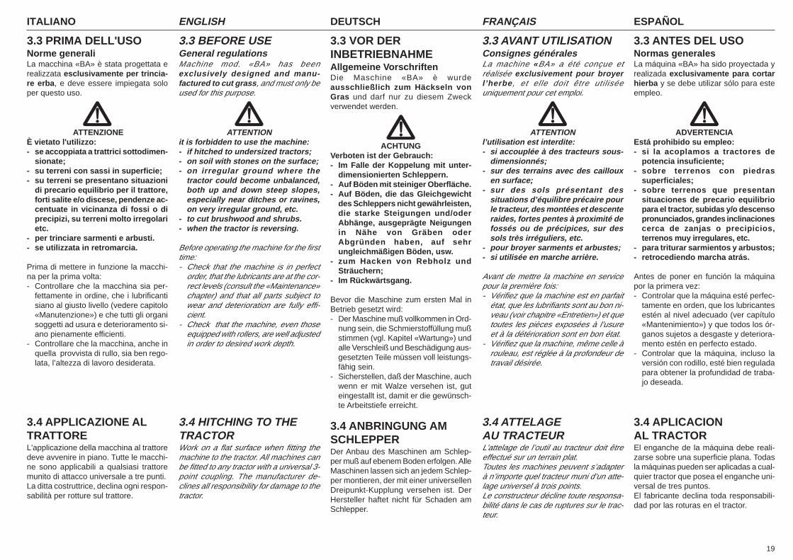
19
ITALIANO ENGLISH DEUTSCH ESPAÑOLFRANÇAIS
3.3 PRIMA DELL'USONorme generaliLa macchina «BA» è stata progettata erealizzata esclusivamente per trincia-re erba, e deve essere impiegata soloper questo uso.
ATTENZIONEÈ vietato l'utilizzo:- se accoppiata a trattrici sottodimen-
sionate;- su terreni con sassi in superficie;- su terreni se presentano situazioni
di precario equilibrio per il trattore,forti salite e/o discese, pendenze ac-centuate in vicinanza di fossi o diprecipizi, su terreni molto irregolarietc.
- per trinciare sarmenti e arbusti.- se utilizzata in retromarcia.
Prima di mettere in funzione la macchi-na per la prima volta:- Controllare che la macchina sia per-
fettamente in ordine, che i lubrificantisiano al giusto livello (vedere capitolo«Manutenzione») e che tutti gli organisoggetti ad usura e deterioramento si-ano pienamente efficienti.
- Controllare che la macchina, anche inquella provvista di rullo, sia ben rego-lata, l’altezza di lavoro desiderata.
3.4 APPLICAZIONE ALTRATTOREL'applicazione della macchina al trattoredeve avvenire in piano. Tutte le macchi-ne sono applicabili a qualsiasi trattoremunito di attacco universale a tre punti.La ditta costruttrice, declina ogni respon-sabilità per rotture sul trattore.
3.3 BEFORE USEGeneral regulationsMachine mod. «BA» has beenexclusively designed and manu-factured to cut grass, and must only beused for this purpose.
ATTENTIONit is forbidden to use the machine:- if hitched to undersized tractors;- on soil with stones on the surface;- on irregular ground where the
tractor could become unbalanced,both up and down steep slopes,especially near ditches or ravines,on very irregular ground, etc.
- to cut brushwood and shrubs.- when the tractor is reversing.
Before operating the machine for the firsttime:- Check that the machine is in perfect
order, that the lubricants are at the cor-rect levels (consult the «Maintenance»chapter) and that all parts subject towear and deterioration are fully effi-cient.
- Check that the machine, even thoseequipped with rollers, are well adjustedin order to desired work depth.
3.4 HITCHING TO THETRACTORWork on a flat surface when fitting themachine to the tractor. All machines canbe fitted to any tractor with a universal 3-point coupling. The manufacturer de-clines all responsibility for damage to thetractor.
3.3 VOR DERINBETRIEBNAHMEAllgemeine VorschriftenDie Maschine «BA» è wurdeausschließlich zum Häckseln vonGras und darf nur zu diesem Zweckverwendet werden.
ACHTUNGVerboten ist der Gebrauch:- Im Falle der Koppelung mit unter-
dimensionierten Schleppern.- Auf Böden mit steiniger Oberfläche.- Auf Böden, die das Gleichgewicht
des Schleppers nicht gewährleisten,die starke Steigungen und/oderAbhänge, ausgeprägte Neigungenin Nähe von Gräben oderAbgründen haben, auf sehrungleichmäßigen Böden, usw.
- zum Hacken von Rebholz undSträuchern;
- Im Rückwärtsgang.
Bevor die Maschine zum ersten Mal inBetrieb gesetzt wird:- Der Maschine muß vollkommen in Ord-
nung sein, die Schmierstoffüllung mußstimmen (vgl. Kapitel «Wartung») undalle Verschleiß und Beschädigung aus-gesetzten Teile müssen voll leistungs-fähig sein.
- Sicherstellen, daß der Maschine, auchwenn er mit Walze versehen ist, guteingestallt ist, damit er die gewünsch-te Arbeitstiefe erreicht.
3.4 ANBRINGUNG AMSCHLEPPERDer Anbau des Maschinen am Schlep-per muß auf ebenem Boden erfolgen. AlleMaschinen lassen sich an jedem Schlep-per montieren, der mit einer universellenDreipunkt-Kupplung versehen ist. DerHersteller haftet nicht für Schaden amSchlepper.
3.3 AVANT UTILISATIONConsignes généralesLa machine «BA» a été conçue etréalisée exclusivement pour broyerl’herbe, et elle doit être utiliséeuniquement pour cet emploi.
ATTENTIONl’utilisation est interdite:- si accouplée à des tracteurs sous-
dimensionnés;- sur des terrains avec des cailloux
en surface;- sur des sols présentant des
situations d’équilibre précaire pourle tracteur, des montées et descenteraides, fortes pentes à proximité defossés ou de précipices, sur dessols très irréguliers, etc.
- pour broyer sarments et arbustes;- si utilisée en marche arrière.
Avant de mettre la machine en servicepour la première fois:- Vérifiez que la machine est en parfait
état, que les lubrifiants sont au bon ni-veau (voir chapitre «Entretien») et quetoutes les pièces exposées à l’usureet à la détérioration sont en bon état.
- Vérifiez que la machine, même celle àrouleau, est réglée à la profondeur detravail désirée.
3.4 ATTELAGEAU TRACTEURL’attelage de l’outil au tracteur doit êtreeffectué sur un terrain plat.Toutes les machines peuvent s’adapterà n’importe quel tracteur muni d’un atte-lage universel à trois points.Le constructeur décline toute responsa-bilité dans le cas de ruptures sur le trac-teur.
3.3 ANTES DEL USONormas generalesLa máquina «BA» ha sido proyectada yrealizada exclusivamente para cortarhierba y se debe utilizar sólo para esteempleo.
ADVERTENCIAEstá prohibido su empleo:- si la acoplamos a tractores de
potencia insuficiente;- sobre terrenos con piedras
superficiales;- sobre terrenos que presentan
situaciones de precario equilibriopara el tractor, subidas y/o descensopronunciados, grandes inclinacionescerca de zanjas o precipicios,terrenos muy irregulares, etc.
- para triturar sarmientos y arbustos;- retrocediendo marcha atrás.
Antes de poner en función la máquinapor la primera vez:- Controlar que la máquina esté perfec-
tamente en orden, que los lubricantesestén al nivel adecuado (ver capítulo«Mantenimiento») y que todos los ór-ganos sujetos a desgaste y deteriora-mento estén en perfecto estado.
- Controlar que la máquina, incluso laversión con rodillo, esté bien reguladapara obtener la profundidad de traba-jo deseada.
3.4 APLICACIONAL TRACTOREl enganche de la máquina debe reali-zarse sobre una superficie plana. Todasla máquinas pueden ser aplicadas a cual-quier tractor que posea el enganche uni-versal de tres puntos.El fabricante declina toda responsabili-dad por las roturas en el tractor.
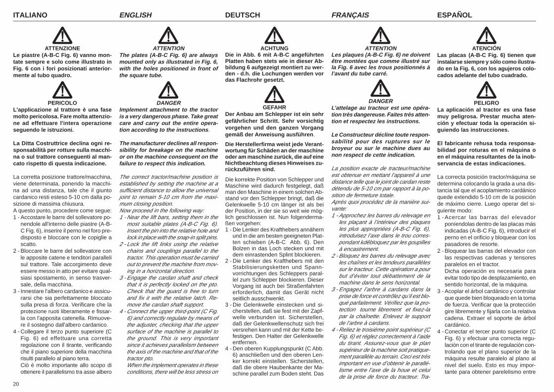
ITALIANO ENGLISH DEUTSCH ESPAÑOLFRANÇAIS
20
ATENCIÓNLas placas (A-B-C Fig. 6) tienen queinstalarse siempre y sólo como ilustra-do en la Fig. 6, con los agujeros colo-cados adelante del tubo cuadrado.
PELIGROLa aplicación al tractor es una fasemuy peligrosa. Prestar mucha aten-ción y efectuar toda la operación si-guiendo las instrucciones.
El fabricante rehusa toda responsa-bilidad por roturas en el máquina oen el máquina resultantes de la inob-servancia de estas indicaciones.
La correcta posición tractor/máquina sedetermina colocando la grada a una dis-tancia tal que el acoplamiento cardánicoquede extendido 5-10 cm de la posiciónde máximo cierre. Luego operar del si-guiente modo:1 - Acercar las barras del elevador
poníendolas dentro de las placas másindicadas (A-B-C Fig. 6), introducir elperno en el orificio y bloquear con lospasadores de resorte.
2 - Bloquear las barras del elevador conlas respectivas cadenas y tensoresparalelos en el tractor.Dicha operación es necesaria paraevitar todo tipo de desplazamiento, ensentido horizontal, de la máquina.
3 - Acoplar el árbol cardánico y controlarque quede bien bloqueado en la tomade fuerza. Verificar que la proteccióngire libremente y fijarla con la relativacadena. Extraer el soporte de árbolcardánico.
4 - Conectar el tercer punto superior (CFig. 6) y efectuar una correcta regu-lación con el tirante de regulación con-trolando que el plano superior de lamáquina resulte paralelo al plano alnivel del suelo. Esto es muy impor-tante para obtener parelelismo entre
ATTENZIONELe piastre (A-B-C Fig. 6) vanno mon-tate sempre e solo come illustrato inFig. 6 con i fori posizionati anterior-mente al tubo quadro.
PERICOLOL'applicazione al trattore è una fasemolto pericolosa. Fare molta attenzio-ne ad effettuare l'intera operazioneseguendo le istruzioni.
La Ditta Costruttrice declina ogni re-sponsabilità per rotture sulla macchi-na o sul trattore conseguenti al man-cato rispetto di questa indicazione.
La corretta posizione trattore/macchina,viene determinata, ponendo la macchi-na ad una distanza, tale che il giuntocardanico resti esteso 5-10 cm dalla po-sizione di massima chiusura.A questo punto, procedere come segue:1 - Accostare le barre del sollevatore po-
nendole all'interno delle piastre (A-B-C Fig. 6), inserire il perno nel foro pre-disposto e bloccare con le copiglie ascatto.
2 - Bloccare le barre del sollevatore conle apposite catene e tenditori parallelisul trattore. Tale accorgimento deveessere messo in atto per evitare qual-siasi spostamento, in senso trasver-sale, della macchina.
3 - Innestare l'albero cardanico e assicu-rarsi che sia perfettamente bloccatosulla presa di forza. Verificare che laprotezione ruoti liberamente e fissar-la con l'apposita catenella. Rimuove-re il sostegno dall'albero cardanico.
4 - Collegare il terzo punto superiore (CFig. 6) ed effettuare una correttaregolazione con il tirante, verificandoche il piano superiore della macchinarisulti parallelo al piano terra.Ciò è molto importante allo scopo diottenere il parallelismo tra asse albero
ATTENTIONThe plates (A-B-C Fig. 6) are alwaysmounted only as illustrated in Fig. 6,with the holes positioned in front ofthe square tube.
DANGERImplement attachment to the tractoris a very dangerous phase. Take greatcare and carry out the entire opera-tion according to the instructions.
The manufacturer declines all respon-sibility for breakage on the machineor on the machine consequent on thefailure to respect this indication.
The correct tractor/machine position isestablished by setting the machine at asufficient distance to allow the universaljoint to remain 5-10 cm from the maxi-mum closing position.Now proceed in the following way:1 - Near the lift bars, setting them in the
most suitable plates (A-B-C Fig. 6).Insert the pin into the relative hole andlock in place with the snap-in split pins.
2 - Lock the lift links using the relativechains and couplings parallel to thetractor. This operation must be carriedout to prevent the machine from mov-ing in a horizontal direction.
3 - Engage the cardan shaft and checkthat it is perfectly locked on the pto.Check that the guard is free to turnand fix it with the relative latch. Re-move the cardan shaft support.
4 - Connect the upper third-point (C Fig.6) and correctly regulate by means ofthe adjuster, checking that the uppersurface of the machine is parallel tothe ground. This is very importantsince it achieves parallelism betweenthe axis of the machine and that of thetractor pto.When the implement operates in theseconditions, there will be less stress on
ACHTUNGDie in Abb. 6 mit A-B-C angeführtenPlatten haben stets wie in dieser Ab-bildung 6 aufgezeigt montiert zu wer-den - d.h. die Lochungen werden vordas Flachrohr gesetzt.
GEFAHRDer Anbau am Schlepper ist ein sehrgefährlicher Schritt. Sehr vorsichtigvorgehen und den ganzen Vorganggemäß der Anweisung ausführen.
Die Herstellerfirma weist jede Verant-wortung für Schäden an der maschineoder am maschine zurück, die auf eineNichtbeachtung dieses Hinweises zu-rückzuführen sind.
Die korrekte Position von Schlepper undMaschine wird dadurch festgelegt, daßman den Maschine in einem solchen Ab-stand vor den Schlepper bringt, daß dieGelenkwelle 5-10 cm länger ist als beider Position, in der sie so weit wie mög-lich geschlossen ist. Nun folgenderma-ßen vorgehen:1 - Die Lenker des Krafthebers annähern
und in die am besten geeigneten Plat-ten schieben (A-B-C Abb. 6). DenBolzen in das Loch stecken und mitdem einrastenden Splint blockieren.
2 - Die Lenker des Krafthebers mit denStabilisierungsketten und Spann-vorrichtungen des Schleppers paral-lel zum Schlepper blockieren. DieserVorgang ist auch bei Straßenfahrtenerforderlich, damit das Gerät nichtseitlich ausschwenkt.
3 - Die Gelenkwelle einstecken und si-cherstellen, daß sie fest mit der Zapf-welle verbunden ist. Sicherstellen,daß der Gelenkwellenschutz sich freiversrehen kann und mit der Kette be-festigen. Den Halter der Gelenkwelleentfernen.
4 - Den oberen Kupplungspunkt (C Abb.6) anschließen und den oberen Len-ker korrekt einstellen. Sicherstellen,daß die obere Haubenkante der Ma-schine parallel zum Boden steht. Das
ATTENTIONLes plaques (A-B-C Fig. 6) ne doiventêtre montées que comme illustré surla Fig. 6 avec les trous positionnés àl’avant du tube carré.
DANGERL’attelage au tracteur est une opéra-tion très dangereuse. Faites très atten-tion et respectez les instructions.
Le Constructeur décline toute respon-sabilité pour des ruptures sur lebroyeur ou sur le machine dues aunon respect de cette indication.
La position exacte de tracteur/machineest obtenue en mettant l’appareil à unedistance telle que le joint de cardan restedétendu de 5-10 cm par rapport à la po-sition de fermeture totale.Après quoi procédez de la manière sui-vante:1 - Approchez les barres du relevage en
les plaçant à l’intérieur des plaquesles plus appropriées (A-B-C Fig. 6),introduisez l’axe dans le trou corres-pondant kdêbloquez par les goupillesà encastrement.
2 - Bloquez les barres du relevage avecles chaînes et les tendeurs parallèlessur le tracteur. Cette opération a pourbut d’éviter tout débattement de lamachine dans le sens horizontal.
3 - Engagez l’arbre à cardans dans laprise de force et contrôlez qu’il est blo-qué parfaitement. Vérifiez que la pro-tection tourne librement et fixez-lapar la chaînette. Enlevez le supportde l’arbre à cardans.
4 - Reliez le troisième point supérieur (CFig. 6) et réglez correctement à l’aidedu tirant. Assurez-vous que le plansupérieur de la machine soit pratique-ment parallèle au terrain. Ceci est trèsimportant en vue d’obtenir le parallé-lisme entre l’axe de la houe et celuide la prise de force du tracteur. Tra-
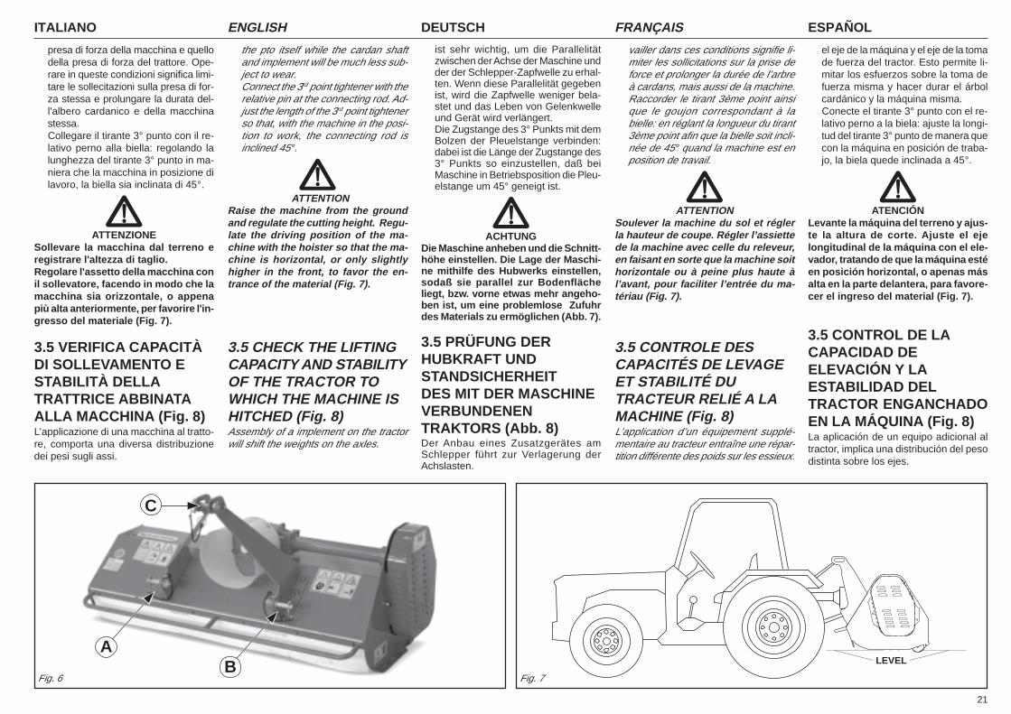
21
ITALIANO ENGLISH DEUTSCH ESPAÑOLFRANÇAIS
presa di forza della macchina e quellodella presa di forza del trattore. Ope-rare in queste condizioni significa limi-tare le sollecitazioni sulla presa di for-za stessa e prolungare la durata del-l'albero cardanico e della macchinastessa.Collegare il tirante 3° punto con il re-lativo perno alla biella: regolando lalunghezza del tirante 3° punto in ma-niera che la macchina in posizione dilavoro, la biella sia inclinata di 45°.
ATTENZIONESollevare la macchina dal terreno eregistrare l'altezza di taglio.Regolare l'assetto della macchina conil sollevatore, facendo in modo che lamacchina sia orizzontale, o appenapiù alta anteriormente, per favorire l'in-gresso del materiale (Fig. 7).
3.5 VERIFICA CAPACITÀDI SOLLEVAMENTO ESTABILITÀ DELLATRATTRICE ABBINATAALLA MACCHINA (Fig. 8)L’applicazione di una macchina al tratto-re, comporta una diversa distribuzionedei pesi sugli assi.
the pto itself while the cardan shaftand implement will be much less sub-ject to wear.Connect the 3rd point tightener with therelative pin at the connecting rod. Ad-just the length of the 3rd point tightenerso that, with the machine in the posi-tion to work, the connecting rod isinclined 45°.
ATTENTIONRaise the machine from the groundand regulate the cutting height. Regu-late the driving position of the ma-chine with the hoister so that the ma-chine is horizontal, or only slightlyhigher in the front, to favor the en-trance of the material (Fig. 7).
3.5 CHECK THE LIFTINGCAPACITY AND STABILITYOF THE TRACTOR TOWHICH THE MACHINE ISHITCHED (Fig. 8)Assembly of a implement on the tractorwill shift the weights on the axles.
ist sehr wichtig, um die Parallelitätzwischen der Achse der Maschine undder der Schlepper-Zapfwelle zu erhal-ten. Wenn diese Parallelität gegebenist, wird die Zapfwelle weniger bela-stet und das Leben von Gelenkwelleund Gerät wird verlängert.Die Zugstange des 3° Punkts mit demBolzen der Pleuelstange verbinden:dabei ist die Länge der Zugstange des3° Punkts so einzustellen, daß beiMaschine in Betriebsposition die Pleu-elstange um 45° geneigt ist.
ACHTUNGDie Maschine anheben und die Schnitt-höhe einstellen. Die Lage der Maschi-ne mithilfe des Hubwerks einstellen,sodaß sie parallel zur Bodenflächeliegt, bzw. vorne etwas mehr angeho-ben ist, um eine problemlose Zufuhrdes Materials zu ermöglichen (Abb. 7).
3.5 PRÜFUNG DERHUBKRAFT UNDSTANDSICHERHEITDES MIT DER MASCHINEVERBUNDENENTRAKTORS (Abb. 8)Der Anbau eines Zusatzgerätes amSchlepper führt zur Verlagerung derAchslasten.
vailler dans ces conditions signifie li-miter les sollicitations sur la prise deforce et prolonger la durée de l’arbreà cardans, mais aussi de la machine.Raccorder le tirant 3ème point ainsique le goujon correspondant à labielle: en réglant la longueur du tirant3ème point afin que la bielle soit incli-née de 45° quand la machine est enposition de travail.
ATTENTIONSoulever la machine du sol et réglerla hauteur de coupe. Régler l’assiettede la machine avec celle du releveur,en faisant en sorte que la machine soithorizontale ou à peine plus haute àl’avant, pour faciliter l’entrée du ma-tériau (Fig. 7).
3.5 CONTROLE DESCAPACITÉS DE LEVAGEET STABILITÉ DUTRACTEUR RELIÉ A LAMACHINE (Fig. 8)L’application d’un équipement supplé-mentaire au tracteur entraîne une répar-tition différente des poids sur les essieux.
el eje de la máquina y el eje de la tomade fuerza del tractor. Esto permite li-mitar los esfuerzos sobre la toma defuerza misma y hacer durar el árbolcardánico y la máquina misma.Conecte el tirante 3° punto con el re-lativo perno a la biela: ajuste la longi-tud del tirante 3° punto de manera quecon la máquina en posición de traba-jo, la biela quede inclinada a 45°.
ATENCIÓNLevante la máquina del terreno y ajus-te la altura de corte. Ajuste el ejelongitudinal de la máquina con el ele-vador, tratando de que la máquina estéen posición horizontal, o apenas másalta en la parte delantera, para favore-cer el ingreso del material (Fig. 7).
3.5 CONTROL DE LACAPACIDAD DEELEVACIÓN Y LAESTABILIDAD DELTRACTOR ENGANCHADOEN LA MÁQUINA (Fig. 8)La aplicación de un equipo adicional altractor, implica una distribución del pesodistinta sobre los ejes.
Fig. 6
C
Fig. 7
LEVELBA
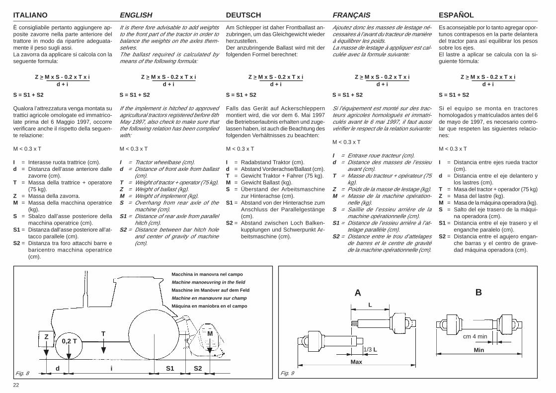
ITALIANO ENGLISH DEUTSCH ESPAÑOLFRANÇAIS
22
È consigliabile pertanto aggiungere ap-posite zavorre nella parte anteriore deltrattore in modo da ripartire adeguata-mente il peso sugli assi.La zavorra da applicare si calcola con laseguente formula:
S = S1 + S2
Qualora l’attrezzatura venga montata sutrattici agricole omologate ed immatrico-late prima del 6 Maggio 1997, occorreverificare anche il rispetto della seguen-te relazione:
M < 0.3 x T
I = Interasse ruota trattrice (cm).d = Distanza dell’asse anteriore dalle
zavorre (cm).T = Massa della trattrice + operatore
(75 kg).Z = Massa della zavorra.M = Massa della macchina operatrice
(kg).S = Sbalzo dall’asse posteriore della
macchina operatrice (cm).S1 = Distanza dall’asse posteriore all’at-
tacco parallele (cm).S2 = Distanza tra foro attacchi barre e
baricentro macchina operatrice(cm).
It is there fore advisable to add weightsto the front part of the tractor in order tobalance the weights on the axles them-selves.The ballast required is calculated bymeans of the following formula:
S = S1 + S2
If the implement is hitched to approvedagricultural tractors registered before 6thMay 1997, also check to make sure thatthe following relation has been compliedwith:
M < 0.3 x T
I = Tractor wheelbase (cm).d = Distance of front axle from ballast
(cm).T = Weight of tractor + operator (75 kg).Z = Weight of ballast (kg).M = Weight of implement (kg).S = Overhang from rear axle of the
machine (cm).S1 = Distance of rear axle from parallel
hitch (cm).S2 = Distance between bar hitch hole
and center of gravity of machine(cm).
Am Schlepper ist daher Frontballast an-zubringen, um das Gleichgewicht wiederherzustellen.Der anzubringende Ballast wird mit derfolgenden Formel berechnet:
S = S1 + S2
Falls das Gerät auf Ackerschleppernmontiert wird, die vor dem 6. Mai 1997die Betriebserlaubnis erhalten und zuge-lassen haben, ist auch die Beachtung desfolgenden Verhältnisses zu beachten:
M < 0.3 x T
I = Radabstand Traktor (cm).d = Abstand Vorderachse/Ballast (cm).T = Gewicht Traktor + Fahrer (75 kg).M = Gewicht Ballast (kg).S = Überstand der Arbeitsmaschine
zur Hinterachse (cm).S1 = Abstand von der Hinterachse zum
Anschluss der Parallelgestänge(cm).
S2 = Abstand zwischen Loch Balken-kupplungen und Schwerpunkt Ar-beitsmaschine (cm).
Ajoutez donc les masses de lestage né-cessaires à l’avant du tracteur de manièreà équilibrer les poids.La masse de lestage à appliquer est cal-culée avec la formule suivante:
S = S1 + S2
Si l’équipement est monté sur des trac-teurs agricoles homologués et immatri-culés avant le 6 mai 1997, il faut aussivérifier le respect de la relation suivante:
M < 0.3 x T
I = Entraxe roue tracteur (cm).d = Distance des masses de l’essieu
avant (cm).T = Masse du tracteur + opérateur (75
kg).Z = Poids de la masse de lestage (kg).M = Masse de la machine opération-
nelle (kg).S = Saillie de l’essieu arrière de la
machine opérationnelle (cm).S1 = Distance de l’essieu arrière à l’at-
telage parallèle (cm).S2 = Distance entre le trou d’attelages
de barres et le centre de gravitéde la machine opérationnelle (cm).
Es aconsejable por lo tanto agregar opor-tunos contrapesos en la parte delanteradel tractor para así equilibrar los pesossobre los ejes.El lastre a aplicar se calcula con la si-guiente fórmula:
S = S1 + S2
Si el equipo se monta en tractoreshomologados y matriculados antes del 6de mayo de 1997, es necesario contro-lar que respeten las siguientes relacio-nes:
M < 0.3 x T
I = Distancia entre ejes rueda tractor(cm).
d = Distancia entre el eje delantero ylos lastres (cm).
T = Masa del tractor + operador (75 kg)Z = Masa del lastre (kg).M = Masa de la máquina operadora (kg).S = Salto del eje trasero de la máqui-
na operadora (cm).S1 = Distancia entre el eje trasero y el
enganche paralelo (cm).S2 = Distancia entre el agujero engan-
che barras y el centro de grave-dad máquina operadora (cm).
Z > M x S - 0.2 x T x id + i
Z > M x S - 0.2 x T x id + i
Z > M x S - 0.2 x T x id + i
Z > M x S - 0.2 x T x id + i
Z > M x S - 0.2 x T x id + i
Fig. 8
Z0,2 T
T M
S2S1id
Macchina in manovra nel campo
Machine manoeuvring in the field
Maschine im Manöver auf dem Feld
Machine en manœuvre sur champ
Máquina en maniobra en el campo
Fig. 9
Min
cm 4 min
Max
A B
1/3 L
L
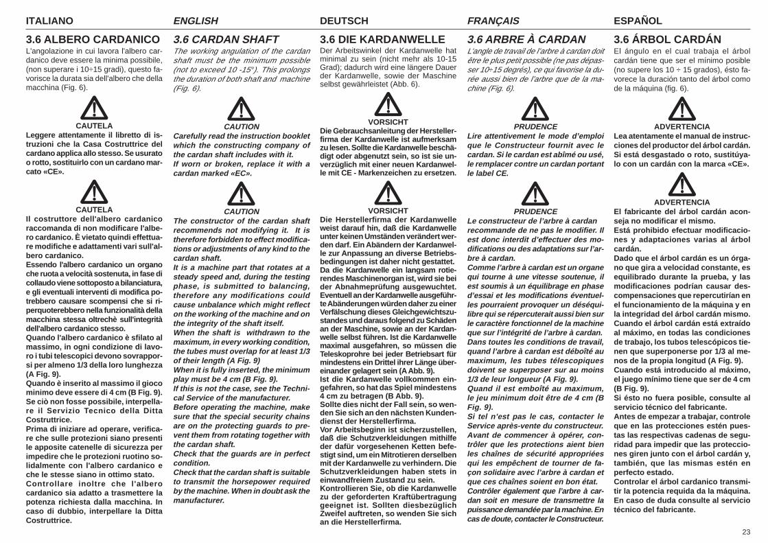
23
ITALIANO ENGLISH DEUTSCH ESPAÑOLFRANÇAIS
3.6 ALBERO CARDANICOL'angolazione in cui lavora l'albero car-danico deve essere la minima possibile,(non superare i 10÷15 gradi), questo fa-vorisce la durata sia dell'albero che dellamacchina (Fig. 6).
CAUTELALeggere attentamente il libretto di is-truzioni che la Casa Costruttrice delcardano applica allo stesso. Se usuratoo rotto, sostituirlo con un cardano mar-cato «CE».
CAUTELAIl costruttore dell'albero cardanicoraccomanda di non modificare l'albe-ro cardanico. È vietato quindi effettua-re modifiche e adattamenti vari sull'al-bero cardanico.Essendo l'albero cardanico un organoche ruota a velocità sostenuta, in fase dicollaudo viene sottoposto a bilanciatura,e gli eventuali interventi di modifica po-trebbero causare scompensi che si ri-perquoterebbero nella funzionalità dellamacchina stessa oltrechè sull'integritàdell'albero cardanico stesso.Quando l'albero cardanico è sfilato almassimo, in ogni condizione di lavo-ro i tubi telescopici devono sovrappor-si per almeno 1/3 della loro lunghezza(A Fig. 9).Quando è inserito al massimo il giocominimo deve essere di 4 cm (B Fig. 9).Se ciò non fosse possibile, interpella-re il Servizio Tecnico della DittaCostruttrice.Prima di iniziare ad operare, verifica-re che sulle protezioni siano presentile apposite catenelle di sicurezza perimpedire che le protezioni ruotino so-lidalmente con l'albero cardanico eche le stesse siano in ottimo stato.Controllare inoltre che l'alberocardanico sia adatto a trasmettere lapotenza richiesta dalla macchina. Incaso di dubbio, interpellare la DittaCostruttrice.
3.6 CARDAN SHAFTThe working angulation of the cardanshaft must be the minimum possible(not to exceed 10 -15°). This prolongsthe duration of both shaft and machine(Fig. 6).
CAUTIONCarefully read the instruction bookletwhich the constructing company ofthe cardan shaft includes with it.If worn or broken, replace it with acardan marked «EC».
CAUTIONThe constructor of the cardan shaftrecommends not modifying it. It istherefore forbidden to effect modifica-tions or adjustments of any kind to thecardan shaft.It is a machine part that rotates at asteady speed and, during the testingphase, is submitted to balancing,therefore any modifications couldcause unbalance which might reflecton the working of the machine and onthe integrity of the shaft itself.When the shaft is withdrawn to themaximum, in every working condition,the tubes must overlap for at least 1/3of their length (A Fig. 9)When it is fully inserted, the minimumplay must be 4 cm (B Fig. 9).If this is not the case, see the Techni-cal Service of the manufacturer.Before operating the machine, makesure that the special security chainsare on the protecting guards to pre-vent them from rotating together withthe cardan shaft.Check that the guards are in perfectcondition.Check that the cardan shaft is suitableto transmit the horsepower requiredby the machine. When in doubt ask themanufacturer.
3.6 DIE KARDANWELLEDer Arbeitswinkel der Kardanwelle hatminimal zu sein (nicht mehr als 10-15Grad); dadurch wird eine längere Dauerder Kardanwelle, sowie der Maschineselbst gewährleistet (Abb. 6).
VORSICHTDie Gebrauchsanleitung der Hersteller-firma der Kardanwelle ist aufmerksamzu lesen. Sollte die Kardanwelle beschä-digt oder abgenutzt sein, so ist sie un-verzüglich mit einer neuen Kardanwel-le mit CE - Markenzeichen zu ersetzen.
VORSICHTDie Herstellerfirma der Kardanwelleweist darauf hin, daß die Kardanwelleunter keinen Umständen verändert wer-den darf. Ein Abändern der Kardanwel-le zur Anpassung an diverse Betriebs-bedingungen ist daher nicht gestattet.Da die Kardanwelle ein langsam rotie-rendes Maschinenorgan ist, wird sie beider Abnahmeprüfung ausgewuchtet.Eventuell an der Kardanwelle ausgeführ-te Abänderungen würden daher zu einerVerfälschung dieses Gleichgewichtszu-standes und daraus folgend zu Schädenan der Maschine, sowie an der Kardan-welle selbst führen. Ist die Kardanwellemaximal ausgefahren, so müssen dieTeleskoprohre bei jeder Betriebsart fürmindestens ein Drittel ihrer Länge über-einander gelagert sein (A Abb. 9).Ist die Kardanwelle vollkommen ein-gefahren, so hat das Spiel mindestens4 cm zu betragen (B Abb. 9).Sollte dies nicht der Fall sein, so wen-den Sie sich an den nächsten Kunden-dienst der Herstellerfirma.Vor Arbeitsbeginn ist sicherzustellen,daß die Schutzverkleidungen mithilfeder dafür vorgesehenen Ketten befe-stigt sind, um ein Mitrotieren derselbenmit der Kardanwelle zu verhindern. DieSchutzverkleidungen haben stets ineinwandfreiem Zustand zu sein.Kontrollieren Sie, ob die Kardanwellezu der geforderten Kraftübertragunggeeignet ist. Sollten diesbezüglichZweifel auftreten, so wenden Sie sichan die Herstellerfirma.
3.6 ARBRE À CARDANL’angle de travail de l’arbre à cardan doitêtre le plus petit possible (ne pas dépas-ser 10÷15 degrés), ce qui favorise la du-rée aussi bien de l’arbre que de la ma-chine (Fig. 6).
PRUDENCELire attentivement le mode d’emploique le Constructeur fournit avec lecardan. Si le cardan est abîmé ou usé,le remplacer contre un cardan portantle label CE.
PRUDENCELe constructeur de l’arbre à cardanrecommande de ne pas le modifier. Ilest donc interdit d’effectuer des mo-difications ou des adaptations sur l’ar-bre à cardan.Comme l’arbre à cardan est un organequi tourne à une vitesse soutenue, ilest soumis à un équilibrage en phased’essai et les modifications éventuel-les pourraient provoquer un déséqui-libre qui se répercuterait aussi bien surle caractère fonctionnel de la machineque sur l’intégrité de l’arbre à cardan.Dans toutes les conditions de travail,quand l’arbre à cardan est déboîté aumaximum, les tubes télescopiquesdoivent se superposer sur au moins1/3 de leur longueur (A Fig. 9).Quand il est emboîté au maximum,le jeu minimum doit être de 4 cm (BFig. 9).Si tel n’est pas le cas, contacter leService après-vente du constructeur.Avant de commencer à opérer, con-trôler que les protections aient bienles chaînes de sécurité appropriéesqui les empêchent de tourner de fa-çon solidaire avec l’arbre à cardan etque ces chaînes soient en bon état.Contrôler également que l’arbre à car-dan soit en mesure de transmettre lapuissance demandée par la machine. Encas de doute, contacter le Constructeur.
3.6 ÁRBOL CARDÁNEl ángulo en el cual trabaja el árbolcardán tiene que ser el mínimo posible(no supere los 10 ÷ 15 grados), ésto fa-vorece la duración tanto del árbol comode la máquina (fig. 6).
ADVERTENCIALea atentamente el manual de instruc-ciones del productor del árbol cardán.Si está desgastado o roto, sustitúya-lo con un cardán con la marca «CE».
ADVERTENCIAEl fabricante del árbol cardán acon-seja no modificar el mismo.Está prohibido efectuar modificacio-nes y adaptaciones varias al árbolcardán.Dado que el árbol cardán es un órga-no que gira a velocidad constante, esequilibrado durante la prueba, y lasmodificaciones podrían causar des-compensaciones que repercutirían enel funcionamiento de la máquina y enla integridad del árbol cardán mismo.Cuando el árbol cardán está extraídoal máximo, en todas las condicionesde trabajo, los tubos telescópicos tie-nen que superponerse por 1/3 al me-nos de la propia longitud (A Fig. 9).Cuando está introducido al máximo,el juego mínimo tiene que ser de 4 cm(B Fig. 9).Si ésto no fuera posible, consulte alservicio técnico del fabricante.Antes de empezar a trabajar, controleque en las protecciones estén pues-tas las respectivas cadenas de segu-ridad para impedir que las proteccio-nes giren junto con el árbol cardán y,también, que las mismas estén enperfecto estado.Controlar el árbol cardanico transmi-tir la potencia requida da la máquina.En caso de duda consulte al serviciotécnico del fabricante.
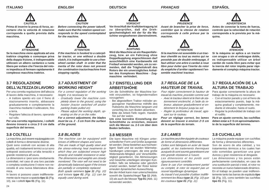
ITALIANO ENGLISH DEUTSCH ESPAÑOLFRANÇAIS
24
CAUTELAPrima di inserire la presa di forza, ac-certarsi che la velocità di rotazionecorrisponda a quella prevista dallamacchina.
ATTENZIONESe la macchina viene applicata ad unatrattrice cingolata o comunque privadella doppia frizione, è indispensabileutilizzare un albero cardanico a ruotalibera per evitare che l'inerzia del roto-re impedisca di fermare rapidamente ilcomplesso macchina trattrice.
3.7 REGOLAZIONEDELL'ALTEZZA DI LAVOROPer una corretta regolazione dell'altezzadi lavoro della macchina, è necessario:- A trattore spento e/o con il freno di
stazionamento inserito, abbassaregraduatamente e completamente lamacchina mediante il sollevatore, finoa terra.
- Regolare l'altezza di lavoro, operandosul rullo.
Per una corretta regolazione, i coltellidevono trovarsi a circa 2÷3 cm dallasuperficie del terreno.
3.8 COLTELLILa macchina, può essere equipaggiata concoltelli di forma e dimensione diverse.Qusti sono costruiti con acciaio di altaqualità, ed i trattamenti termici a cui sonosottoposti assicurano un'alta tenacità egrande resistenza all'usura.Le dimensioni e i pesi sono strettamentecontrollati; nel caso di una loro parzialeo completa sostituzione il rotore non ne-cessità di una nuova bilanciatura dina-mica.In lavoro si possono usare indifferente-mente sia le mazze a spatola tipo 11 (Fig.10), sia i coltelli tipo 01 (Fig. 11).
CAUTIONBefore connecting the power takeoff,make sure that the rotation speed cor-responds to the speed contemplatedfor the machine.
ATTENTIONIf the machine is hooked to a caterpil-lar tractor, or one without a doubleclutch, it is indispensable to use a free-wheel cardan shaft in order that theinertia of the rotor does not preventthe combination tractor/machine fromstopping rapidly.
3.7 ADJUSTMENT OFWORKING HEIGHTFor a correct regulation of the workingheight, it is necessary to:- Gradually lower the machine com-
pletely down to the ground, using thehoister (tractor switched off and/orparking brake pulled on).
- Please adjust the working depth, op-erating on the or on the roller.
For a correct adjustment, the bladesmust be ca. 2 - 3 cm from the surfaceof the ground.
3.8 BLADESThe machine can be equipped withknives of different shapes and sizes.This are made of high quality steel andthe stress-relieving heat treatments towhich they are subjected ensure hightenacity and notable resistance to wear.The dimensions and weights are closelymonitored. The rotor will not need to bedynamically balanced again if the knivesare partially or completely replaced.Both spade rammers type 11 (Fig. 10)and knives type 01 (Fig. 11) can beequally used during work.
VORSICHTVor Anschluß der Kraftübertragung istzu überprüfen, daß die Dreh-geschwindigkeit mit der für die Ma-schine vorgesehenen übereinstimmt.
ACHTUNGWird die Maschine an ein Raupenfahr-zeug, bzw. an ein Fahrzeug ohneDoppelkupplung angeschlossen darfausschließlich eine Kardanwelle mitFreilauf verwendet werden, um zu ver-meiden, daß die Trägheitskraft desRotors der ein unverzügliches Anhal-ten des Komplexes Maschine - Zug-maschine verhindert.
3.7 EINSTELLUNG DERARBEITSHÖHEUm die Schnitthöhe der Maschine kor-rekt einzustellen, ist folgendermaßenvorzugehen:- Bei abgestelltem Traktor mit/oder an-
gezogener Handbremse mithilfe desHubwerks die Maschine langsam undvorsichtig bis zum Boden absenken.
- Bitte die Arbeit-Tiefe regeln. HandelnSie auf der walze.
Um eine korrekte Einstellung derSchnitthöhe zu erreichen, müssensich die Messer ca. 2-3 cm über demBoden befinden.
3.8 MESSERDie kann Maschine mit Klingen unter-schiedlicher Form und Größe ausgestat-tet werden. Diese bestehen aus hochwer-tigem Stahl und sie wurden Wärmebe-handlungen unterzogen, die eine großeWiderstands-fähigkeit und Verschleißfe-stigkeit garantieren. Die Abmessungenund Gewichte unterliegen strengen Kon-trollen; falls sie teilweise oder gänzlichersetzt werden, bedarf der Rotor keinererneuten dynamischen Auswuchtung.Bei der Arbeit kann man unterschiedslossowohl die Spatelschlegel Typ 11 (Abb.10) als auch die Messer Typ 01 (Abb. 11)verwendet werden.
PRUDENCEAvant de brancher la prise de force,contrôler que la vitesse de rotationcorresponde à celle prévue par lamachine.
ATTENTIONSi la machine est assemblée à un trac-teur chenillé ou tout au moins qui nepossède pas de double embrayage, ilfaut utiliser une arbre à cardan à rouelibre pour éviter que l’inertie du rotordu empêche d’arrêter rapidement l’en-semble machine/ tracteur.
3.7 REGLAGE DE LAHAUTEUR DE TRAVAILPour régler correctement la hauteur detravail du machine, procéder comme suit:- Avec le tracteur éteint et le frein de sta-
tionnement enclenché, à l’aide du re-leveur, abaisser graduellement et en-tièrement le broyeur jusqu’au sol.
- Regler la profondeur de travail, agis-sant sur le rouleau.
Pour un réglage correct, les lamesdoivent se trouver à environ 2÷3 cmde la superficie du terrain.
3.8 LAMESLe machine peut être équipée de couteauxde forme et dimensions différentes.Cettes sont fabriqués en acier de hautequalité, et les traitements thermiquesauxquels ils sont soumis garantissent unetrès grande résistance à l’usure.Les dimensions et les poids sontrigoureusement contrôlés.Dans le cas d’un remplacement partielou complet, le rotor ne requiert pas unnouvel équilibrage dynamique.Au travail il est possible d’utiliser indiffé-remment les fléaux type 11 (Fig. 10) queles couteaux type 01 (Fig. 11).
ADVERTENCIAAntes de conectar la toma de fuerza,controle que la velocidad de rotacióncorresponda a la prevista por la má-quina.
ATENCIÓNSi la máquina se aplica a un tractorcon orugas o sin el embrague doble,es indispensable utilizar un árbolcardán de rueda libre para evitar quela inercia del rotor impida parar rápi-damente el complejo máquina tractor.
3.7 REGULACIÓN DE LAALTURA DE TRABAJOPara ajustar correctamente la altura detrabajo de la máquina es necesario:- Con el tractor parado y con el freno de
estacionamiento puesto, baje la má-quina gradual y completamente, me-diante el elevador, hasta el suelo.
- Regular la profundidad de trabajo conel rodillo.
Para un ajuste correcto, las cuchillasdeben estar a 2÷3 cm aproximadamen-te de la superficie del terreno.
3.8 CUCHILLASLa máquina puede equipar con cuchillasde forma y dimensiones diferentes.Son de acero de alta calidad, y lostratamientos térmicos a los cuales hansido sometidas garantizan una grandureza y gran resistencia al desgaste.Las dimensiones y los pesos estánperfectamente controlados; en caso deuna sustitución parcial o total, el rotor nonecesita un nuevo balanceado dinámico.En el trabajo se pueden usar indiferen-temente tanto las barras de espátula tipo11 (Fig. 10), como también las cuchillastipo 01 (Fig. 11).
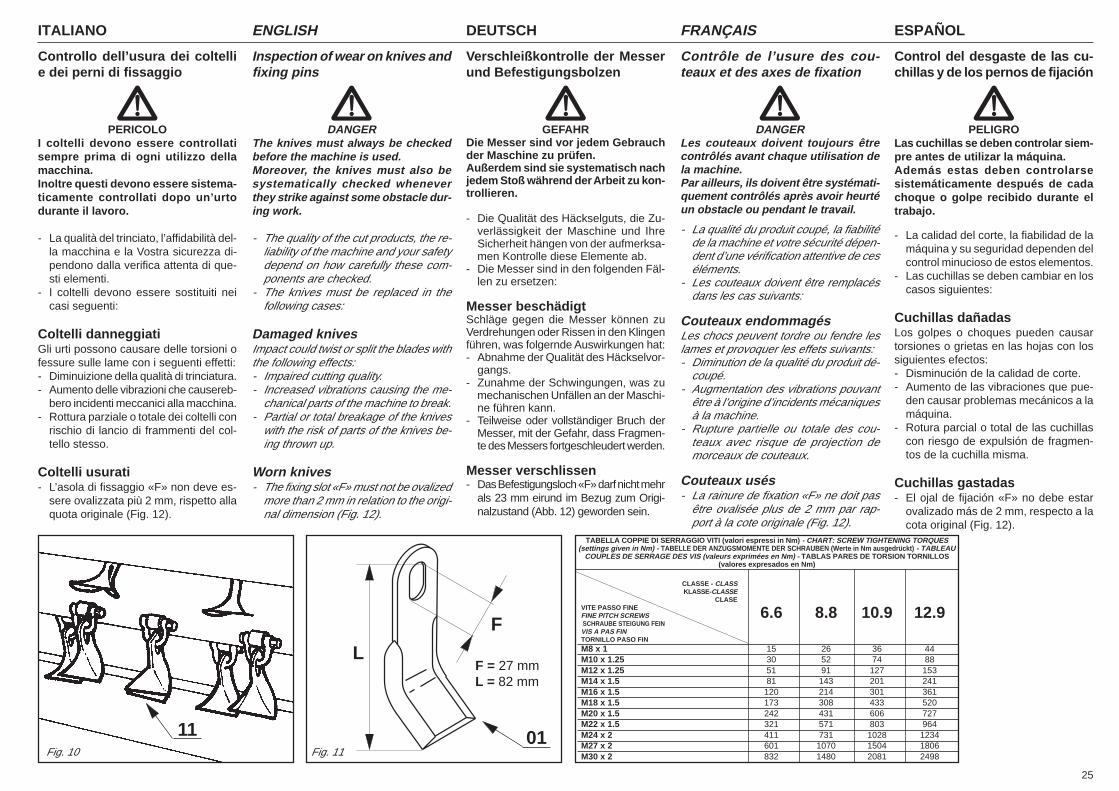
25
ITALIANO ENGLISH DEUTSCH ESPAÑOLFRANÇAIS
TABELLA COPPIE DI SERRAGGIO VITI (valori espressi in Nm) - CHART: SCREW TIGHTENING TORQUES(settings given in Nm) - TABELLE DER ANZUGSMOMENTE DER SCHRAUBEN (Werte in Nm ausgedrückt) - TABLEAU
COUPLES DE SERRAGE DES VIS (valeurs exprimées en Nm) - TABLAS PARES DE TORSION TORNILLOS(valores expresados en Nm)
CLASSE - CLASSKLASSE-CLASSE
CLASEVITE PASSO FINEFINE PITCH SCREWS 6.6 8.8 10.9 12.9 SCHRAUBE STEIGUNG FEINVIS A PAS FINTORNILLO PASO FIN
M8 x 1 15 26 36 44M10 x 1.25 30 52 74 88M12 x 1.25 51 91 127 153M14 x 1.5 81 143 201 241M16 x 1.5 120 214 301 361M18 x 1.5 173 308 433 520M20 x 1.5 242 431 606 727M22 x 1.5 321 571 803 964M24 x 2 411 731 1028 1234M27 x 2 601 1070 1504 1806M30 x 2 832 1480 2081 2498
11Fig. 10 Fig. 11
F
LF = 27 mmL = 82 mm
01
Controllo dell’usura dei coltellie dei perni di fissaggio
PERICOLOI coltelli devono essere controllatisempre prima di ogni utilizzo dellamacchina.Inoltre questi devono essere sistema-ticamente controllati dopo un’urtodurante il lavoro.
- La qualità del trinciato, l’affidabilità del-la macchina e la Vostra sicurezza di-pendono dalla verifica attenta di que-sti elementi.
- I coltelli devono essere sostituiti neicasi seguenti:
Coltelli danneggiatiGli urti possono causare delle torsioni ofessure sulle lame con i seguenti effetti:- Diminuizione della qualità di trinciatura.- Aumento delle vibrazioni che causereb-
bero incidenti meccanici alla macchina.- Rottura parziale o totale dei coltelli con
rischio di lancio di frammenti del col-tello stesso.
Coltelli usurati- L’asola di fissaggio «F» non deve es-
sere ovalizzata più 2 mm, rispetto allaquota originale (Fig. 12).
Inspection of wear on knives andfixing pins
DANGERThe knives must always be checkedbefore the machine is used.Moreover, the knives must also besystematically checked wheneverthey strike against some obstacle dur-ing work.
- The quality of the cut products, the re-liability of the machine and your safetydepend on how carefully these com-ponents are checked.
- The knives must be replaced in thefollowing cases:
Damaged knivesImpact could twist or split the blades withthe following effects:- Impaired cutting quality.- Increased vibrations causing the me-
chanical parts of the machine to break.- Partial or total breakage of the knives
with the risk of parts of the knives be-ing thrown up.
Worn knives- The fixing slot «F» must not be ovalized
more than 2 mm in relation to the origi-nal dimension (Fig. 12).
Verschleißkontrolle der Messerund Befestigungsbolzen
GEFAHRDie Messer sind vor jedem Gebrauchder Maschine zu prüfen.Außerdem sind sie systematisch nachjedem Stoß während der Arbeit zu kon-trollieren.
- Die Qualität des Häckselguts, die Zu-verlässigkeit der Maschine und IhreSicherheit hängen von der aufmerksa-men Kontrolle diese Elemente ab.
- Die Messer sind in den folgenden Fäl-len zu ersetzen:
Messer beschädigtSchläge gegen die Messer können zuVerdrehungen oder Rissen in den Klingenführen, was folgernde Auswirkungen hat:- Abnahme der Qualität des Häckselvor-
gangs.- Zunahme der Schwingungen, was zu
mechanischen Unfällen an der Maschi-ne führen kann.
- Teilweise oder vollständiger Bruch derMesser, mit der Gefahr, dass Fragmen-te des Messers fortgeschleudert werden.
Messer verschlissen- Das Befestigungsloch «F» darf nicht mehr
als 23 mm eirund im Bezug zum Origi-nalzustand (Abb. 12) geworden sein.
Contrôle de l’usure des cou-teaux et des axes de fixation
DANGERLes couteaux doivent toujours êtrecontrôlés avant chaque utilisation dela machine.Par ailleurs, ils doivent être systémati-quement contrôlés après avoir heurtéun obstacle ou pendant le travail.
- La qualité du produit coupé, la fiabilitéde la machine et votre sécurité dépen-dent d’une vérification attentive de ceséléments.
- Les couteaux doivent être remplacésdans les cas suivants:
Couteaux endommagésLes chocs peuvent tordre ou fendre leslames et provoquer les effets suivants:- Diminution de la qualité du produit dé-
coupé.- Augmentation des vibrations pouvant
être à l’origine d’incidents mécaniquesà la machine.
- Rupture partielle ou totale des cou-teaux avec risque de projection demorceaux de couteaux.
Couteaux usés- La rainure de fixation «F» ne doit pas
être ovalisée plus de 2 mm par rap-port à la cote originale (Fig. 12).
Control del desgaste de las cu-chillas y de los pernos de fijación
PELIGROLas cuchillas se deben controlar siem-pre antes de utilizar la máquina.Además estas deben controlarsesistemáticamente después de cadachoque o golpe recibido durante eltrabajo.
- La calidad del corte, la fiabilidad de lamáquina y su seguridad dependen delcontrol minucioso de estos elementos.
- Las cuchillas se deben cambiar en loscasos siguientes:
Cuchillas dañadasLos golpes o choques pueden causartorsiones o grietas en las hojas con lossiguientes efectos:- Disminución de la calidad de corte.- Aumento de las vibraciones que pue-
den causar problemas mecánicos a lamáquina.
- Rotura parcial o total de las cuchillascon riesgo de expulsión de fragmen-tos de la cuchilla misma.
Cuchillas gastadas- El ojal de fijación «F» no debe estar
ovalizado más de 2 mm, respecto a lacota original (Fig. 12).
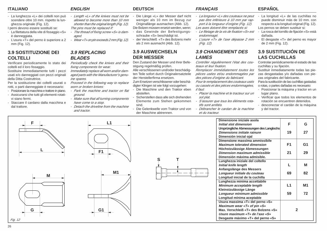
ITALIANO ENGLISH DEUTSCH ESPAÑOLFRANÇAIS
26
- La lunghezza «L» dei coltelli non puòscendere oltre 10 mm. rispetto la lun-ghezza originale (Fig. 12).
I perni devono essere sostituiti se:- La filettatura della vite di fissaggio «S»
è danneggiata.- L’usura «T» del perno è superiore a 2
mm (Fig. 12).
3.9 SOSTITUZIONE DEICOLTELLIVerificare periodicamente lo stato deicoltelli ed il loro fissaggio.Sostituire immediatamente tutti i pezziusati e/o danneggiati con pezzi originalidella Ditta Costruttrice.Per la sostituzione dei coltelli usurati orotti, o parti danneggiate è necessario:- Posizionare la macchina e trattore in piano.- Assicurarsi che tutti gli elementi rotati-
vi siano fermi.- Staccare il cardano dalla macchina e
dal trattore.
- Length «L» of the knives must not beallowed to become more than 10 mmshorter than the original length (Fig. 12).
The pins must be replaced if:- The thread of fixing screw «S» is dam-
aged.- Wear «T» on pin exceeds 2 mm (Fig. 12).
3.9 REPLACINGBLADESPeriodically check the knives and theirfixing components for wear.Immediately replace all worn and/or dam-aged parts with the Manufacturer’s genu-ine spares.Proceed in the following way to replaceworn or broken knives:- Park the machine and tractor on flat
ground.- Make sure that all turning components
have come to a stop.- Detach the driveline from the machine
and tractor.
- Die Länge «L» der Messer darf nichtweniger als 10 mm im Bezug zurOriginallänge ausmachen (Abb. 12).
Die Bolzen müssen ersetzt werden, wenn:- das Gewinde der Befestigungs-
schraube «S» beschädigt ist.- der Verschleiß «T» des Bolzens mehr
als 2 mm ausmacht (Abb. 12).
3.9 AUSWECHSELNDER MESSERDen Zustand der Messer und ihrer Befe-stigung regelmäßig prüfen.Alle verschlissenen und/oder beschädig-ten Teile sofort durch Originalersatzteileder Herstellerfirma ersetzen.Zum Ersetzen verschlissener oder beschä-digter Klingen ist wie folgt vorzugehen:- Die Maschine und den Traktor eben
abstellen.- Sicherstellen dass alle sich drehenden
Elemente zum Stehen gekommensind.
- Die Gelenkwelle vom Traktor und vonder Maschine abtrennen.
- La longueur «L» des couteaux ne peutpas être inférieure à 10 mm par rap-port à la longueur d’origine (Fig. 12).
Les axes doivent être remplacés si:- Le filetage de la vis de fixation «S» est
endommagé.- L’usure «T» de l’axe dépasse 2 mm
(Fig. 12).
3.9 CHANGEMENT DESLAMESContrôler régulièrement l’état des cou-teaux et leur fixation.Remplacer immédiatement toutes lespièces usées et/ou endommagées pardes pièces d’origine du fabricant.Pour le remplacement des couteaux usésou cassés et des pièces endommagées,il faut:- Placer la machine et le tracteur sur un
sol plat.- S’assurer que tous les éléments rota-
tifs sont arrêtés.- Débrancher le cardan de la machine
et du tracteur.
- La longitud «L» de las cuchillas nopuede disminuir más de 10 mm. conrespecto a la longitud original (Fig. 12).
Los pernos se deben sustituir si:- La rosca del tornillo de fijación «S» está
dañada.- El desgaste «T» del perno es mayor
de 2 mm (Fig. 12).
3.9 SUSTITUCIÓN DELAS CUCHILLASControlar periódicamente el estado de lascuchillas y su fijación.Sustituir inmediatamente todas las pie-zas desgastadas y/o dañadas con pie-zas originales del fabricante.Para la sustitución de las cuchillas gastadaso rotas, o partes dañadas es necesario:- Posicionar la máquina y tractor en un
lugar plano.- Verificar que todos los elementos de
rotación se encuentren detenidos.- desconectar el cardán de la máquina
y del tractor.
Fig. 12
L
F L1
F1
G
M
G1
M1
S T
Dimensione iniziale asolaInitial slot dimension F GUrsprüngliche Abmessungen des LanglochsDimensions initiale rainure 19 27Dimensión inicial ojalDimensione massima ammissibileMaximum tolerated dimension F1 G1Höchstzulässige AbmessungenDimension maximum admissible 21 29Dimensión máxima admisible.Lunghezza iniziale del coltelloInitial knife length L MAnfangslänge des MessersLongueur initiale du couteau 69 82Longitud inicial de la cuchillaLunghezza minima accettabileMinimum acceptable length L1 M1Kleinstzulässige LängeLongueur minimum admissible 59 72Longitud mínima aceptableUsura massima «T» del perno «S»Maximum wear «T» of pin «S»Max. Verschleiß «T» des Bolzens «S» 2Usure maximum «T» de l’axe «S»Desgaste máximo «T» del perno «S»
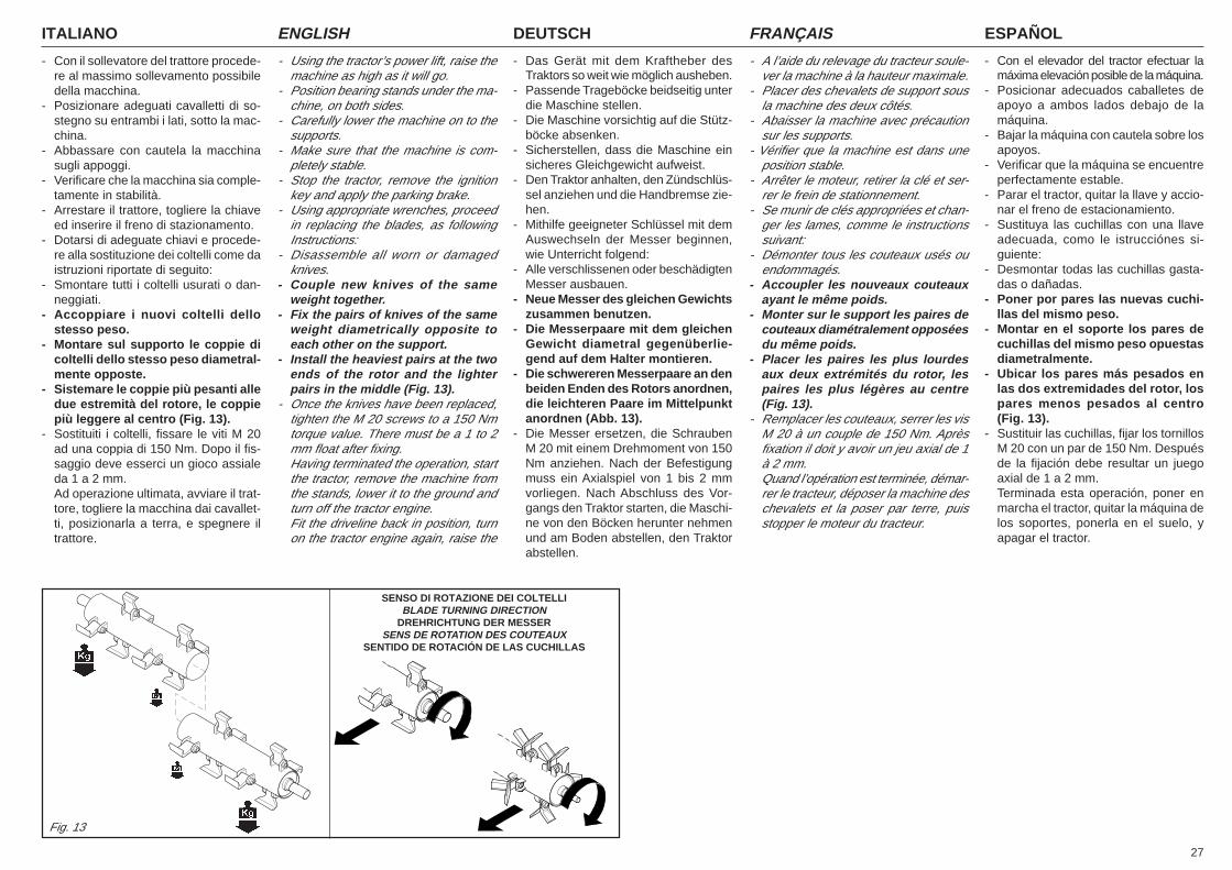
27
ITALIANO ENGLISH DEUTSCH ESPAÑOLFRANÇAIS
- Con il sollevatore del trattore procede-re al massimo sollevamento possibiledella macchina.
- Posizionare adeguati cavalletti di so-stegno su entrambi i lati, sotto la mac-china.
- Abbassare con cautela la macchinasugli appoggi.
- Verificare che la macchina sia comple-tamente in stabilità.
- Arrestare il trattore, togliere la chiaveed inserire il freno di stazionamento.
- Dotarsi di adeguate chiavi e procede-re alla sostituzione dei coltelli come daistruzioni riportate di seguito:
- Smontare tutti i coltelli usurati o dan-neggiati.
- Accoppiare i nuovi coltelli dellostesso peso.
- Montare sul supporto le coppie dicoltelli dello stesso peso diametral-mente opposte.
- Sistemare le coppie più pesanti alledue estremità del rotore, le coppiepiù leggere al centro (Fig. 13).
- Sostituiti i coltelli, fissare le viti M 20ad una coppia di 150 Nm. Dopo il fis-saggio deve esserci un gioco assialeda 1 a 2 mm.Ad operazione ultimata, avviare il trat-tore, togliere la macchina dai cavallet-ti, posizionarla a terra, e spegnere iltrattore.
- Using the tractor’s power lift, raise themachine as high as it will go.
- Position bearing stands under the ma-chine, on both sides.
- Carefully lower the machine on to thesupports.
- Make sure that the machine is com-pletely stable.
- Stop the tractor, remove the ignitionkey and apply the parking brake.
- Using appropriate wrenches, proceedin replacing the blades, as followingInstructions:
- Disassemble all worn or damagedknives.
- Couple new knives of the sameweight together.
- Fix the pairs of knives of the sameweight diametrically opposite toeach other on the support.
- Install the heaviest pairs at the twoends of the rotor and the lighterpairs in the middle (Fig. 13).
- Once the knives have been replaced,tighten the M 20 screws to a 150 Nmtorque value. There must be a 1 to 2mm float after fixing.Having terminated the operation, startthe tractor, remove the machine fromthe stands, lower it to the ground andturn off the tractor engine.Fit the driveline back in position, turnon the tractor engine again, raise the
- Das Gerät mit dem Kraftheber desTraktors so weit wie möglich ausheben.
- Passende Trageböcke beidseitig unterdie Maschine stellen.
- Die Maschine vorsichtig auf die Stütz-böcke absenken.
- Sicherstellen, dass die Maschine einsicheres Gleichgewicht aufweist.
- Den Traktor anhalten, den Zündschlüs-sel anziehen und die Handbremse zie-hen.
- Mithilfe geeigneter Schlüssel mit demAuswechseln der Messer beginnen,wie Unterricht folgend:
- Alle verschlissenen oder beschädigtenMesser ausbauen.
- Neue Messer des gleichen Gewichtszusammen benutzen.
- Die Messerpaare mit dem gleichenGewicht diametral gegenüberlie-gend auf dem Halter montieren.
- Die schwereren Messerpaare an denbeiden Enden des Rotors anordnen,die leichteren Paare im Mittelpunktanordnen (Abb. 13).
- Die Messer ersetzen, die SchraubenM 20 mit einem Drehmoment von 150Nm anziehen. Nach der Befestigungmuss ein Axialspiel von 1 bis 2 mmvorliegen. Nach Abschluss des Vor-gangs den Traktor starten, die Maschi-ne von den Böcken herunter nehmenund am Boden abstellen, den Traktorabstellen.
- A l’aide du relevage du tracteur soule-ver la machine à la hauteur maximale.
- Placer des chevalets de support sousla machine des deux côtés.
- Abaisser la machine avec précautionsur les supports.
- Vérifier que la machine est dans uneposition stable.
- Arrêter le moteur, retirer la clé et ser-rer le frein de stationnement.
- Se munir de clés appropriées et chan-ger les lames, comme le instructionssuivant:
- Démonter tous les couteaux usés ouendommagés.
- Accoupler les nouveaux couteauxayant le même poids.
- Monter sur le support les paires decouteaux diamétralement opposéesdu même poids.
- Placer les paires les plus lourdesaux deux extrémités du rotor, lespaires les plus légères au centre(Fig. 13).
- Remplacer les couteaux, serrer les visM 20 à un couple de 150 Nm. Aprèsfixation il doit y avoir un jeu axial de 1à 2 mm.Quand l’opération est terminée, démar-rer le tracteur, déposer la machine deschevalets et la poser par terre, puisstopper le moteur du tracteur.
- Con el elevador del tractor efectuar lamáxima elevación posible de la máquina.
- Posicionar adecuados caballetes deapoyo a ambos lados debajo de lamáquina.
- Bajar la máquina con cautela sobre losapoyos.
- Verificar que la máquina se encuentreperfectamente estable.
- Parar el tractor, quitar la llave y accio-nar el freno de estacionamiento.
- Sustituya las cuchillas con una llaveadecuada, como le istrucciónes si-guiente:
- Desmontar todas las cuchillas gasta-das o dañadas.
- Poner por pares las nuevas cuchi-llas del mismo peso.
- Montar en el soporte los pares decuchillas del mismo peso opuestasdiametralmente.
- Ubicar los pares más pesados enlas dos extremidades del rotor, lospares menos pesados al centro(Fig. 13).
- Sustituir las cuchillas, fijar los tornillosM 20 con un par de 150 Nm. Despuésde la fijación debe resultar un juegoaxial de 1 a 2 mm.Terminada esta operación, poner enmarcha el tractor, quitar la máquina delos soportes, ponerla en el suelo, yapagar el tractor.
Fig. 13
SENSO DI ROTAZIONE DEI COLTELLIBLADE TURNING DIRECTION
DREHRICHTUNG DER MESSERSENS DE ROTATION DES COUTEAUX
SENTIDO DE ROTACIÓN DE LAS CUCHILLAS
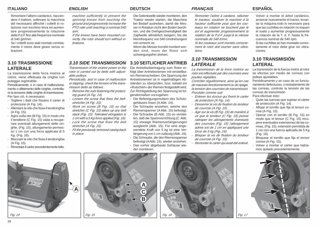
ITALIANO ENGLISH DEUTSCH ESPAÑOLFRANÇAIS
28
Rimontare l’albero cardanico, riaccen-dere il trattore, sollevare la macchinadel necessario affinché i coltelli in ro-tazione non tocchino terra ed aumen-tare progressivamente la rotazionedella P.d.F fino alla frequenza nominaledi 540 giri/min.Se i coltelli sono stati montati corretta-mente il rotore deve girare senza vi-brazioni.
3.10 TRASMISSIONELATERALELa trasmissione della forza motrice alrotore, viene effettuata da cinghie conpuleggia registrabile.Periodicamente, e in caso di malfunziona-mento o slittamento delle cinghie, controlla-re la tensione delle cinghie di trasmissione.Per fare ciò, è necessario:- Togliere i dadi che fissano il carter di
protezione (A Fig. 14).- Allentare la vite che fissa il tendicinghia
(A Fig. 15).- Agire sulla vite (B Fig. 15) in modo che
il tenditore (C Fig. 15) vada a recupe-rare eventuali allungamenti delle cin-ghie, (Fig. 15), allungamento permes-so 1 cm con una forza applicata di 5Kg. (Fig. 16).
- Bloccare la vite che fissa il tendicinghia(A Fig. 15).
- Rimontare il carter precedentemente tolto.
machine sufficiently to prevent thespinning knives from touching theground and progressively increase thePTO rate until reaching a nominal 540rpm.If the knives have been mounted cor-rectly, the rotor should turn without vi-brations.
3.10 SIDE TRANSMISSIONTransmission of the motive power to therotor is carried out by belts with adjust-able pulleys.Periodically, and in case of malfunctionor slipping, check the tension of the trans-mission belts as follows:- Remove the nuts fastening the protect-
ing guard (A Fig. 14).- Loosen the screw that fixes the belt-
stretcher (A Fig. 15).- Work on screw (B Fig. 15) so that
stretcher (C Fig. 15) takes up any beltslack (Fig. 15). Tolerated elongation is1 cm with a 5 Kg force applied (Fig. 16).
- Lock the screw that fixes the beltstretcher (A Fig. 15).
- Fit the previously removed casing backin place.
Die Gelenkwelle wieder montieren, denTraktor wieder starten, die Maschinebei Bedarf ausheben, damit die Mes-ser in Rotation nicht den Boden berüh-ren, und die Drehgeschwindigkeit derZapfwelle allmählich steigern, bis dieNennfrequenz von 540 Umdrehungen/min erreicht ist.Wenn die Messer korrekt montiert wor-den sind, muss der Rotor sichschwingungsfrei drehen.
3.10 SEITLICHER ANTRIEBDie Antriebsübertragung zum Rotor er-folgt über Antriebsriemen mit einstellba-ren Riemenscheiben. Die Spannung derAntriebsriemen ist in regelmäßigen Ab-ständen zu überprüfen, bzw. sobald ein«Rutschen» der Riemen festgestellt wird.Zur Richtigstellung der Spannung ist fol-gendermaßen vorzugehen:- Die Befestigungsmuttern des Schutz-
gehäuses lösen (A Abb. 14).- Die Schraube anziehen, welche den
Riemenspanner (A Abb. 15) befestigt.- Die Schraube (B Abb. 15) so verstel-
len, daß die Spannvorrichtung (C Abb.15) etwaige Riemenverlängerungenausgleicht (Abb. 15). Für eine ange-wendete Kraft von 5 kg ist eine Ver-längerung von 1 cm zulässig (Abb. 16).
- Die Schraube, die den Riemenspannerbefestigt (A Abb. 15), wieder anziehen.
- Das vorher abgebaute Gehäuse wie-der montieren.
Remonter l’arbre à cardans, rallumerle tracteur, soulever la machine à lahauteur suffisante pour que les cou-teaux en rotation ne touchent pas lesol et augmenter progressivement larotation de la P.d.F. jusqu’à la vitessenominale de 540 tr/mn.Si les couteaux sont montés correcte-ment le rotor doit tourner sans vibra-tions.
3.10 TRANSMISSIONLATÉRALELa transmission de la force motrice aurotor est effectuée par des courroies avecpoulies réglables.Contrôler régulièrement, ainsi qu’en casde mauvais fonctionnement ou de ripage,la tension des courroies de transmission.Procéder comme suit:- Enlever les écrous qui fixent le carter
de protection (A Fig. 14).- Desserrer la vis de fixation du tendeur
de courroie (A Fig. 15).- Agir sur la vis (B Fig. 15) de manière à
ce que le tendeur (C Fig. 15) puisserattraper les allongements éventuelsdes courroies (Fig. 15) l’allongementadmis est de 1 cm en appliquant uneforce de 5 kg (Fig. 16).
- Bloquer la vis de fixation du tendeurde courroie (A Fig. 15).
- Remonter le carter qui avait été enlevé.
Volver a montar el árbol cardánico,arrancar nuevamente el tractor, levan-tar la máquina todo lo necesario paraque las cuchillas en rotación no toquenel suelo y aumentar progresivamentela rotación de la T. d. F. hasta la fre-cuencia nominal de 540 rpm.Si las cuchillas se han montado correc-tamente el rotor debe girar sin vibra-ciones.
3.10 TRANSMISIÓNLATERALLa transmisión de la fuerza motriz al rotorse efectúa por medio de correas conpoleas ajustables.Periódicamente y en caso de un funcio-namiento defectuoso, o resbalamiento delas correas, controle la tensión de lascorreas de transmisión.Para efectuar ésto:- Quite las tuercas que sujetan el cárter
de protección (A Fig. 14).- Aflojar el tornillo que fija el tensor co-
rrea (A Fig. 15).- Operar con el tornillo (B Fig. 15) en
modo que el tensor (C Fig. 15) recu-pere eventuales extensiones de las co-rreas, (Fig. 15), extensión permitida de1 cm con una fuerza aplicada de 5 Kg(Fig. 16).
- Bloquear el tornillo que fija el tensorcorrea (A Fig. 15).
- Volver a montar el cárter que había-mos quitado precedentemente.
Fig. 14 Fig. 15 Fig. 16 Fig. 17
AA
BC 1 cm
5 Kg
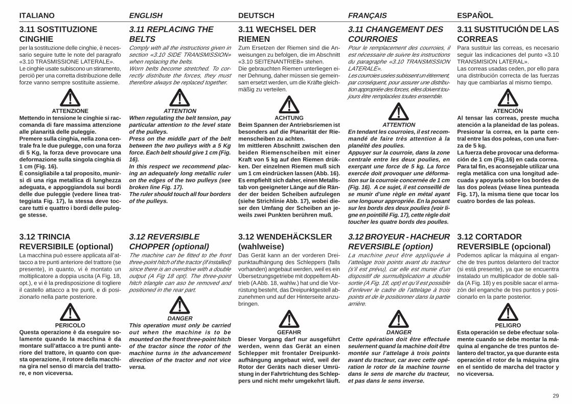
29
ITALIANO ENGLISH DEUTSCH ESPAÑOLFRANÇAIS
3.11 SOSTITUZIONECINGHIEper la sostituzione delle cinghie, è neces-sario seguire tutte le note del paragrafo«3.10 TRASMISSIONE LATERALE».Le cinghie usate subiscono un stiramento,perciò per una corretta distribuzione delleforze vanno sempre sostituite assieme.
ATTENZIONEMettendo in tensione le cinghie si rac-comanda di fare massima attenzionealle planarità delle puleggie.Premere sulla cinghia, nella zona cen-trale fra le due pulegge, con una forzadi 5 Kg, la forza deve provocare unadeformazione sulla singola cinghia di1 cm (Fig. 16).È consigliabile a tal proposito, munir-si di una riga metallica di lunghezzaadeguata, e appoggiandola sui bordidelle due puleggie (vedere linea trat-teggiata Fig. 17), la stessa deve toc-care tutti e quattro i bordi delle puleg-ge stesse.
3.12 TRINCIAREVERSIBILE (optional)La macchina può essere applicata all’at-tacco a tre punti anteriore del trattore (sepresente), in quanto, vi è montato unmoltiplicatore a doppia uscita (A Fig. 18,opt.), e vi è la predisposizione di togliereil castello attacco a tre punti, e di posi-zionarlo nella parte posteriore.
PERICOLOQuesta operazione è da eseguire so-lamente quando la macchina è damontare sull’attacco a tre punti ante-riore del trattore, in quanto con que-sta operazione, il rotore della macchi-na gira nel senso di marcia del tratto-re, e non viceversa.
3.11 REPLACING THEBELTSComply with all the instructions given insection «3.10 SIDE TRANSMISSION»when replacing the belts.Worn belts become stretched. To cor-rectly distribute the forces, they musttherefore always be replaced together.
ATTENTIONWhen regulating the belt tension, payparticular attention to the level stateof the pulleys.Press on the middle part of the beltbetween the two pulleys with a 5 Kgforce. Each belt should give 1 cm (Fig.16).In this respect we recommend plac-ing an adequately long metallic ruleron the edges of the two pulleys (seebroken line Fig. 17).The ruler should touch all four bordersof the pulleys.
3.12 REVERSIBLECHOPPER (optional)The machine can be fitted to the frontthree-point hitch of the tractor (if installed)since there is an overdrive with a doubleoutput (A Fig 18 opt). The three-pointhitch trlangle can aso be removed andpositioned in the rear part.
DANGERThis operation must only be carriedout when the machine is to bemounted on the front three-point hitchof the tractor since the rotor of themachine turns in the advancementdirection of the tractor and not viceversa.
3.11 WECHSEL DERRIEMENZum Ersetzen der Riemen sind die An-weisungen zu befolgen, die im Abschnitt«3.10 SEITENANTRIEB» stehen.Die gebrauchten Riemen unterliegen ei-ner Dehnung, daher müssen sie gemein-sam ersetzt werden, um die Kräfte gleich-mäßig zu verteilen.
ACHTUNGBeim Spannen der Antriebsriemen istbesonders auf die Planarität der Rie-menscheiben zu achten.Im mittleren Abschnitt zwischen denbeiden Riemenscheiben mit einerKraft von 5 kg auf den Riemen drük-ken. Der einzelnen Riemen muß sichum 1 cm eindrücken lassen (Abb. 16).Es empfiehlt sich daher, einen Metalls-tab von geeigneter Länge auf die Rän-der der beiden Scheiben aufzulegen(siehe Strichlinie Abb. 17), wobei die-ser den Umfang der Scheiben an je-weils zwei Punkten berühren muß.
3.12 WENDEHÄCKSLER(wahlweise)Das Gerät kann an der vorderen Drei-punktaufhängung des Schleppers (fallsvorhanden) angebaut werden, weil es einÜbersetzungsgetriebe mit doppeltem Ab-trieb (A Abb. 18, wahlw.) hat und die Vor-rüstung besteht, das Dreipunktgestell ab-zunehmen und auf der Hinterseite anzu-bringen.
GEFAHRDieser Vorgang darf nur ausgeführtwerden, wenn das Gerät an einenSchlepper mit frontaler Dreipunkt-aufhängung angebaut wird, weil derRotor der Geräts nach dieser Umrü-stung in der Fahrtrichtung des Schlep-pers und nicht mehr umgekehrt läuft.
3.11 CHANGEMENT DESCOURROIESPour le remplacement des courroies, ilest nécessaire de suivre les instructionsdu paragraphe «3.10 TRANSMISSIONLATERALE».Les courroies usées subissent un étirement,par conséquent, pour assurer une distribu-tion appropriée des forces, elles doivent tou-jours être remplacées toutes ensemble.
ATTENTIONEn tendant les courroies, il est recom-mandé de faire très attention à laplanéité des poulies.Appuyer sur la courroie, dans la zonecentrale entre les deux poulies, enexerçant une force de 5 kg. La forceexercée doit provoquer une déforma-tion sur la courroie concernée de 1 cm(Fig. 16). A ce sujet, il est conseillé dese munir d’une règle en métal ayantune longueur appropriée. En la posantsur les bords des deux poulies (voir li-gne en pointillé Fig. 17), cette règle doittoucher les quatre bords des poulles.
3.12 BROYEUR - HACHEURREVERSIBLE (option)La machine peut être appliquée àI’attelage trois points avant du tracteur(s’il est prévu), car elle est munie d’undispositif de surmultiplication a doublesortie (A Fig. 18, opt) et qu’il est possibled’enlever le cadre de l’attelage à troispoints et de le positionner dans la partiearrière.
DANGERCette opération doit être effectuéeseulernent quand la machine doit êtremontée sur l’attelage à trois pointsavant du tracteur, car avec cette opé-ration le rotor de la machine tournedans le sens de marche du tracteur,et pas dans le sens inverse.
3.11 SUSTITUCIÓN DE LASCORREASPara sustituir las correas, es necesarioseguir las indicaciones del punto «3.10TRANSMISION LATERAL».Las correas usadas ceden, por ello parauna distribución correcta de las fuerzashay que cambiarlas al mismo tiempo.
ATENCIÓNAl tensar las correas, preste muchaatención a la planeidad de las poleas.Presionar la correa, en la parte cen-tral entre las dos poleas, con una fuer-za de 5 kg.La fuerza debe provocar una deforma-ción de 1 cm (Fig.16) en cada correa.Para tal fin, es aconsejable utilizar unaregla metálica con una longitud ade-cuada y apoyarla sobre los bordes delas dos poleas (véase línea punteadaFig. 17), la misma tiene que tocar loscuatro bordes de las poleas.
3.12 CORTADORREVERSIBLE (opcional)Podemos aplicar la máquina al engan-che de tres puntos delantero del tractor(si está presente), ya que se encuentrainstalado un multiplicador de doble sali-da (A Fig. 18) y es posible sacar el arma-zón del enganche de tres puntos y posi-cionarlo en la parte posterior.
PELIGROEsta operación se debe efectuar sola-mente cuando se debe montar la má-quina al enganche de tres puntos de-lantero del tractor, ya que durante estaoperación el rotor de la máquina giraen el sentido de marcha del tractor yno viceversa.
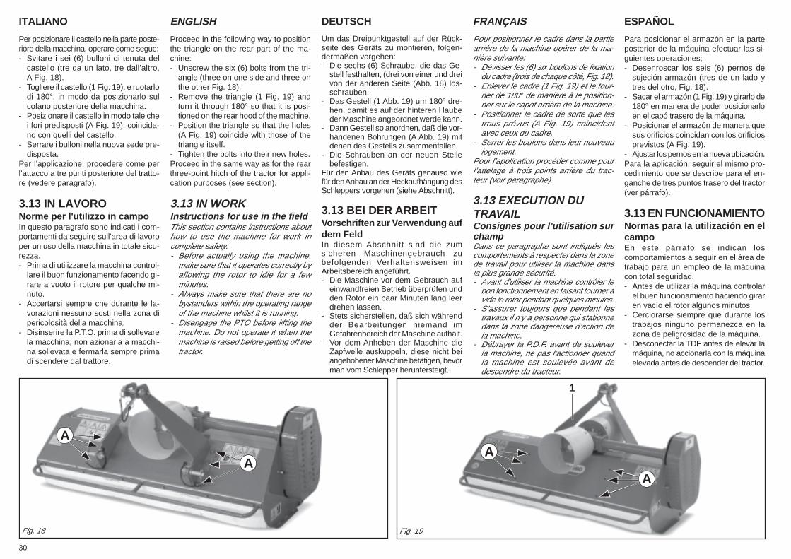
ITALIANO ENGLISH DEUTSCH ESPAÑOLFRANÇAIS
30
1
Per posizionare il castello nella parte poste-riore della macchina, operare come segue:- Svitare i sei (6) bulloni di tenuta del
castello (tre da un lato, tre dall’altro,A Fig. 18).
- Togliere il castello (1 Fig. 19), e ruotarlodi 180°, in modo da posizionarlo sulcofano posteriore della macchina.
- Posizionare il castello in modo tale chei fori predisposti (A Fig. 19), coincida-no con quelli del castello.
- Serrare i bulloni nella nuova sede pre-disposta.
Per l’applicazione, procedere come perl’attacco a tre punti posteriore del tratto-re (vedere paragrafo).
3.13 IN LAVORONorme per l'utilizzo in campoIn questo paragrafo sono indicati i com-portamenti da seguire sull'area di lavoroper un uso della macchina in totale sicu-rezza.- Prima di utilizzare la macchina control-
lare il buon funzionamento facendo gi-rare a vuoto il rotore per qualche mi-nuto.
- Accertarsi sempre che durante le la-vorazioni nessuno sosti nella zona dipericolosità della macchina.
- Disinserire la P.T.O. prima di sollevarela macchina, non azionarla a macchi-na sollevata e fermarla sempre primadi scendere dal trattore.
Proceed in the foilowing way to positionthe triangle on the rear part of the ma-chine:- Unscrew the six (6) bolts from the tri-
angle (three on one side and three onthe other Fig. 18).
- Remove the triangle (1 Fig. 19) andturn it through 180° so that it is posi-tioned on the rear hood of the machine.
- Position the triangle so that the holes(A Fig. 19) coincide wlth those of thetriangle itself.
- Tighten the bolts into their new holes.Proceed in the same way as for the rearthree-point hitch of the tractor for appli-cation purposes (see section).
3.13 IN WORKInstructions for use in the fieldThis section contains instructions abouthow to use the machine for work incomplete safety.- Before actually using the machine,
make sure that it operates correctly byallowing the rotor to idle for a fewminutes.
- Always make sure that there are nobystanders within the operating rangeof the machine whilst it is running.
- Disengage the PTO before lifting themachine. Do not operate it when themachine is raised before getting off thetractor.
Um das Dreipunktgestell auf der Rück-seite des Geräts zu montieren, folgen-dermaßen vorgehen:- Die sechs (6) Schraube, die das Ge-
stell festhalten, (drei von einer und dreivon der anderen Seite (Abb. 18) los-schrauben.
- Das Gestell (1 Abb. 19) um 180° dre-hen, damit es auf der hinteren Haubeder Maschine angeordnet werde kann.
- Dann Gestell so anordnen, daß die vor-handenen Bohrungen (A Abb. 19) mitdenen des Gestells zusammenfallen.
- Die Schrauben an der neuen Stellebefestigen.
Für den Anbau des Geräts genauso wiefür den Anbau an der Heckaufhängung desSchleppers vorgehen (siehe Abschnitt).
3.13 BEI DER ARBEITVorschriften zur Verwendung aufdem FeldIn diesem Abschnitt sind die zumsicheren Maschinengebrauch zubefolgenden Verhaltensweisen imArbeitsbereich angeführt.- Die Maschine vor dem Gebrauch auf
einwandfreien Betrieb überprüfen undden Rotor ein paar Minuten lang leerdrehen lassen.
- Stets sicherstellen, daß sich währendder Bearbeitungen niemand imGefahrenbereich der Maschine aufhält.
- Vor dem Anheben der Maschine dieZapfwelle auskuppeln, diese nicht beiangehobener Maschine betätigen, bevorman vom Schlepper heruntersteigt.
Pour positionner le cadre dans la partiearrière de la machine opérer de la ma-nière suivante:- Dévisser les (6) six boulons de fixation
du cadre (trois de chaque côté, Fig. 18).- Enlever le cadre (1 Fig. 19) et le tour-
ner de 180° de manière à le position-ner sur le capot arrière de la machine.
- Positionner le cadre de sorte que lestrous prévus (A Fig. 19) coincidentavec ceux du cadre.
- Serrer les boulons dans leur nouveaulogement.
Pour l’application procéder comme pourl’attelage à trois points arrière du trac-teur (voir paragraphe).
3.13 EXECUTION DUTRAVAILConsignes pour l’utilisation surchampDans ce paragraphe sont indiqués lescomportements à respecter dans la zonede travail pour utiliser la machine dansla plus grande sécurité.- Avant d’utiliser la machine contrôler le
bon fonctionnement en faisant tourner àvide le rotor pendant quelques minutes.
- S’assurer toujours que pendant lestravaux il n’y a personne qui stationnedans la zone dangereuse d’action dela machine.
- Débrayer la P.D.F. avant de souleverla machine, ne pas l’actionner quandla machine est soulevée avant dedescendre du tracteur.
Para posicionar el armazón en la parteposterior de la máquina efectuar las si-guientes operaciones;- Desenroscar los seis (6) pernos de
sujeción armazón (tres de un lado ytres del otro, Fig. 18).
- Sacar el armazón (1 Fig. 19) y girarlo de180° en manera de poder posicionarloen el capó trasero de la máquina.
- Posicionar el armazón de manera quesus orificios coincidan con los orificiosprevistos (A Fig. 19).
- Ajustar los pernos en la nueva ubicación.Para la aplicación, seguir el mismo pro-cedimiento que se describe para el en-ganche de tres puntos trasero del tractor(ver párrafo).
3.13 EN FUNCIONAMIENTONormas para la utilización en elcampoEn este párrafo se indican loscomportamientos a seguir en el área detrabajo para un empleo de la máquinacon total seguridad.- Antes de utilizar la máquina controlar
el buen funcionamiento haciendo giraren vacío el rotor algunos minutos.
- Cerciorarse siempre que durante lostrabajos ninguno permanezca en lazona de peligrosidad de la máquina.
- Desconectar la TDF antes de elevar lamáquina, no accionarla con la máquinaelevada antes de descender del tractor.
A
Fig. 19
A
Fig. 18
AA
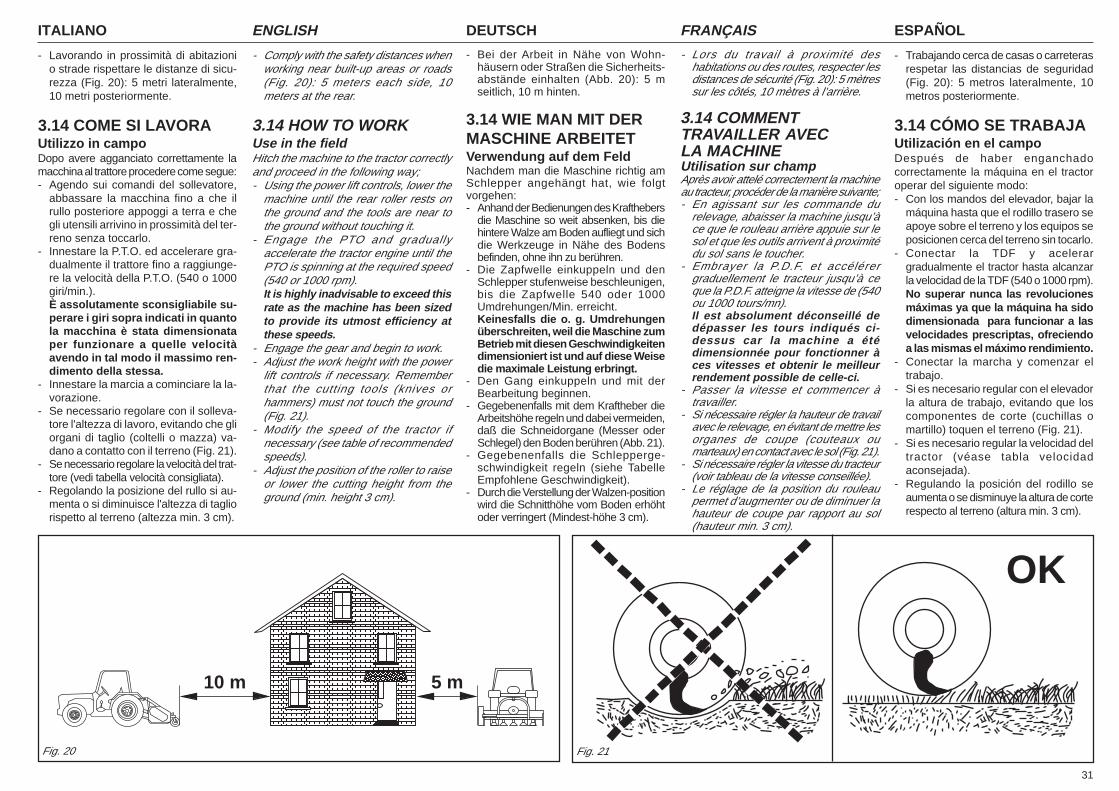
31
ITALIANO ENGLISH DEUTSCH ESPAÑOLFRANÇAIS
- Lavorando in prossimità di abitazionio strade rispettare le distanze di sicu-rezza (Fig. 20): 5 metri lateralmente,10 metri posteriormente.
3.14 COME SI LAVORAUtilizzo in campoDopo avere agganciato correttamente lamacchina al trattore procedere come segue:- Agendo sui comandi del sollevatore,
abbassare la macchina fino a che ilrullo posteriore appoggi a terra e chegli utensili arrivino in prossimità del ter-reno senza toccarlo.
- Innestare la P.T.O. ed accelerare gra-dualmente il trattore fino a raggiunge-re la velocità della P.T.O. (540 o 1000giri/min.).È assolutamente sconsigliabile su-perare i giri sopra indicati in quantola macchina è stata dimensionataper funzionare a quelle velocitàavendo in tal modo il massimo ren-dimento della stessa.
- Innestare la marcia a cominciare la la-vorazione.
- Se necessario regolare con il solleva-tore l'altezza di lavoro, evitando che gliorgani di taglio (coltelli o mazza) va-dano a contatto con il terreno (Fig. 21).
- Se necessario regolare la velocità del trat-tore (vedi tabella velocità consigliata).
- Regolando la posizione del rullo si au-menta o si diminuisce l'altezza di tagliorispetto al terreno (altezza min. 3 cm).
- Comply with the safety distances whenworking near built-up areas or roads(Fig. 20): 5 meters each side, 10meters at the rear.
3.14 HOW TO WORKUse in the fieldHitch the machine to the tractor correctlyand proceed in the following way;- Using the power lift controls, lower the
machine until the rear roller rests onthe ground and the tools are near tothe ground without touching it.
- Engage the PTO and graduallyaccelerate the tractor engine until thePTO is spinning at the required speed(540 or 1000 rpm).It is highly inadvisable to exceed thisrate as the machine has been sizedto provide its utmost efficiency atthese speeds.
- Engage the gear and begin to work.- Adjust the work height with the power
lift controls if necessary. Rememberthat the cutting tools (knives orhammers) must not touch the ground(Fig. 21).
- Modify the speed of the tractor ifnecessary (see table of recommendedspeeds).
- Adjust the position of the roller to raiseor lower the cutting height from theground (min. height 3 cm).
- Bei der Arbeit in Nähe von Wohn-häusern oder Straßen die Sicherheits-abstände einhalten (Abb. 20): 5 mseitlich, 10 m hinten.
3.14 WIE MAN MIT DERMASCHINE ARBEITETVerwendung auf dem FeldNachdem man die Maschine richtig amSchlepper angehängt hat, wie folgtvorgehen:- Anhand der Bedienungen des Krafthebers
die Maschine so weit absenken, bis diehintere Walze am Boden aufliegt und sichdie Werkzeuge in Nähe des Bodensbefinden, ohne ihn zu berühren.
- Die Zapfwelle einkuppeln und denSchlepper stufenweise beschleunigen,bis die Zapfwelle 540 oder 1000Umdrehungen/Min. erreicht.Keinesfalls die o. g. Umdrehungenüberschreiten, weil die Maschine zumBetrieb mit diesen Geschwindigkeitendimensioniert ist und auf diese Weisedie maximale Leistung erbringt.
- Den Gang einkuppeln und mit derBearbeitung beginnen.
- Gegebenenfalls mit dem Kraftheber dieArbeitshöhe regeln und dabei vermeiden,daß die Schneidorgane (Messer oderSchlegel) den Boden berühren (Abb. 21).
- Gegebenenfalls die Schlepperge-schwindigkeit regeln (siehe TabelleEmpfohlene Geschwindigkeit).
- Durch die Verstellung der Walzen-positionwird die Schnitthöhe vom Boden erhöhtoder verringert (Mindest-höhe 3 cm).
- Lors du travail à proximité deshabitations ou des routes, respecter lesdistances de sécurité (Fig. 20): 5 mètressur les côtés, 10 mètres à l’arrière.
3.14 COMMENTTRAVAILLER AVECLA MACHINEUtilisation sur champAprès avoir attelé correctement la machineau tracteur, procéder de la manière suivante;- En agissant sur les commande du
relevage, abaisser la machine jusqu’àce que le rouleau arrière appuie sur lesol et que les outils arrivent à proximitédu sol sans le toucher.
- Embrayer la P.D.F. et accélérergraduellement le tracteur jusqu’à ceque la P.D.F. atteigne la vitesse de (540ou 1000 tours/mn).Il est absolument déconseillé dedépasser les tours indiqués ci-dessus car la machine a étédimensionnée pour fonctionner àces vitesses et obtenir le meilleurrendement possible de celle-ci.
- Passer la vitesse et commencer àtravailler.
- Si nécessaire régler la hauteur de travailavec le relevage, en évitant de mettre lesorganes de coupe (couteaux oumarteaux) en contact avec le sol (Fig. 21).
- Si nécessaire régler la vitesse du tracteur(voir tableau de la vitesse conseillée).
- Le réglage de la position du rouleaupermet d’augmenter ou de diminuer lahauteur de coupe par rapport au sol(hauteur min. 3 cm).
- Trabajando cerca de casas o carreterasrespetar las distancias de seguridad(Fig. 20): 5 metros lateralmente, 10metros posteriormente.
3.14 CÓMO SE TRABAJAUtilización en el campoDespués de haber enganchadocorrectamente la máquina en el tractoroperar del siguiente modo:- Con los mandos del elevador, bajar la
máquina hasta que el rodillo trasero seapoye sobre el terreno y los equipos seposicionen cerca del terreno sin tocarlo.
- Conectar la TDF y acelerargradualmente el tractor hasta alcanzarla velocidad de la TDF (540 o 1000 rpm).No superar nunca las revolucionesmáximas ya que la máquina ha sidodimensionada para funcionar a lasvelocidades prescriptas, ofreciendoa las mismas el máximo rendimiento.
- Conectar la marcha y comenzar eltrabajo.
- Si es necesario regular con el elevadorla altura de trabajo, evitando que loscomponentes de corte (cuchillas omartillo) toquen el terreno (Fig. 21).
- Si es necesario regular la velocidad deltractor (véase tabla velocidadaconsejada).
- Regulando la posición del rodillo seaumenta o se disminuye la altura de corterespecto al terreno (altura min. 3 cm).
Fig. 21Fig. 20
10 m 5 m
OK
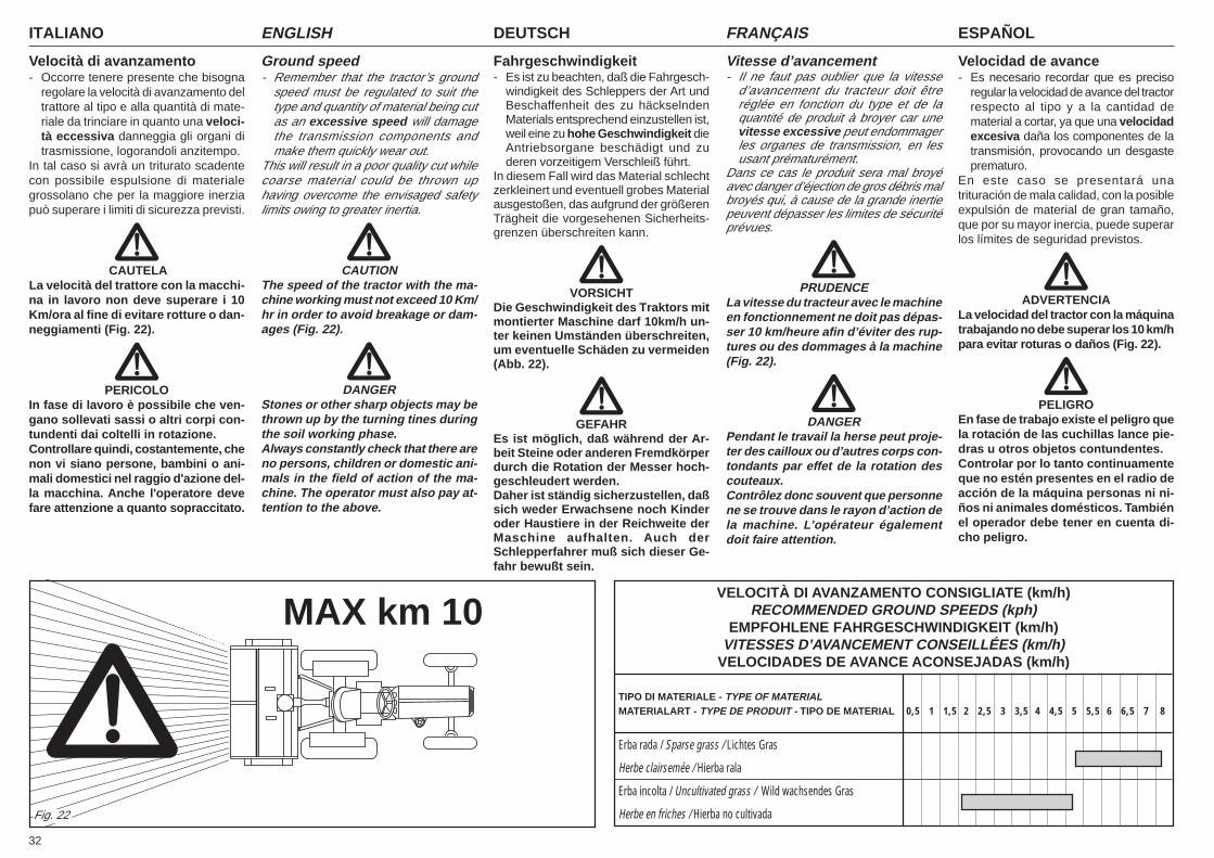
ITALIANO ENGLISH DEUTSCH ESPAÑOLFRANÇAIS
32
Velocità di avanzamento- Occorre tenere presente che bisogna
regolare la velocità di avanzamento deltrattore al tipo e alla quantità di mate-riale da trinciare in quanto una veloci-tà eccessiva danneggia gli organi ditrasmissione, logorandoli anzitempo.
In tal caso si avrà un triturato scadentecon possibile espulsione di materialegrossolano che per la maggiore inerziapuò superare i limiti di sicurezza previsti.
CAUTELALa velocità del trattore con la macchi-na in lavoro non deve superare i 10Km/ora al fine di evitare rotture o dan-neggiamenti (Fig. 22).
PERICOLOIn fase di lavoro è possibile che ven-gano sollevati sassi o altri corpi con-tundenti dai coltelli in rotazione.Controllare quindi, costantemente, chenon vi siano persone, bambini o ani-mali domestici nel raggio d'azione del-la macchina. Anche l'operatore devefare attenzione a quanto sopraccitato.
Ground speed- Remember that the tractor’s ground
speed must be regulated to suit thetype and quantity of material being cutas an excessive speed will damagethe transmission components andmake them quickly wear out.
This will result in a poor quality cut whilecoarse material could be thrown uphaving overcome the envisaged safetylimits owing to greater inertia.
CAUTIONThe speed of the tractor with the ma-chine working must not exceed 10 Km/hr in order to avoid breakage or dam-ages (Fig. 22).
DANGERStones or other sharp objects may bethrown up by the turning tines duringthe soil working phase.Always constantly check that there areno persons, children or domestic ani-mals in the field of action of the ma-chine. The operator must also pay at-tention to the above.
Vitesse d’avancement- Il ne faut pas oublier que la vitesse
d’avancement du tracteur doit êtreréglée en fonction du type et de laquantité de produit à broyer car unevitesse excessive peut endommagerles organes de transmission, en lesusant prématurément.
Dans ce cas le produit sera mal broyéavec danger d’éjection de gros débris malbroyés qui, à cause de la grande inertiepeuvent dépasser les limites de sécuritéprévues.
PRUDENCELa vitesse du tracteur avec le machineen fonctionnement ne doit pas dépas-ser 10 km/heure afin d’éviter des rup-tures ou des dommages à la machine(Fig. 22).
DANGERPendant le travail la herse peut proje-ter des cailloux ou d’autres corps con-tondants par effet de la rotation descouteaux.Contrôlez donc souvent que personnene se trouve dans le rayon d’action dela machine. L’opérateur égalementdoit faire attention.
Fahrgeschwindigkeit- Es ist zu beachten, daß die Fahrgesch-
windigkeit des Schleppers der Art undBeschaffenheit des zu häckselndenMaterials entsprechend einzustellen ist,weil eine zu hohe Geschwindigkeit dieAntriebsorgane beschädigt und zuderen vorzeitigem Verschleiß führt.
In diesem Fall wird das Material schlechtzerkleinert und eventuell grobes Materialausgestoßen, das aufgrund der größerenTrägheit die vorgesehenen Sicherheits-grenzen überschreiten kann.
VORSICHTDie Geschwindigkeit des Traktors mitmontierter Maschine darf 10km/h un-ter keinen Umständen überschreiten,um eventuelle Schäden zu vermeiden(Abb. 22).
GEFAHREs ist möglich, daß während der Ar-beit Steine oder anderen Fremdkörperdurch die Rotation der Messer hoch-geschleudert werden.Daher ist ständig sicherzustellen, daßsich weder Erwachsene noch Kinderoder Haustiere in der Reichweite derMaschine aufhalten. Auch derSchlepperfahrer muß sich dieser Ge-fahr bewußt sein.
Velocidad de avance- Es necesario recordar que es preciso
regular la velocidad de avance del tractorrespecto al tipo y a la cantidad dematerial a cortar, ya que una velocidadexcesiva daña los componentes de latransmisión, provocando un desgasteprematuro.
En este caso se presentará unatrituración de mala calidad, con la posibleexpulsión de material de gran tamaño,que por su mayor inercia, puede superarlos límites de seguridad previstos.
ADVERTENCIALa velocidad del tractor con la máquinatrabajando no debe superar los 10 km/hpara evitar roturas o daños (Fig. 22).
PELIGROEn fase de trabajo existe el peligro quela rotación de las cuchillas lance pie-dras u otros objetos contundentes.Controlar por lo tanto continuamenteque no estén presentes en el radio deacción de la máquina personas ni ni-ños ni animales domésticos. Tambiénel operador debe tener en cuenta di-cho peligro.
MAX km 10
Fig. 22
VELOCITÀ DI AVANZAMENTO CONSIGLIATE (km/h)RECOMMENDED GROUND SPEEDS (kph)
EMPFOHLENE FAHRGESCHWINDIGKEIT (km/h)VITESSES D’AVANCEMENT CONSEILLÉES (km/h)
VELOCIDADES DE AVANCE ACONSEJADAS (km/h)
TIPO DI MATERIALE - TYPE OF MATERIALMATERIALART - TYPE DE PRODUIT - TIPO DE MATERIAL 0,5 1 1,5 2 2,5 3 3,5 4 4,5 5 5,5 6 6,5 7 8
Erba rada / Sparse grass / Lichtes Gras
Herbe clairsemée / Hierba rala
Erba incolta / Uncultivated grass / Wild wachsendes Gras
Herbe en friches / Hierba no cultivada
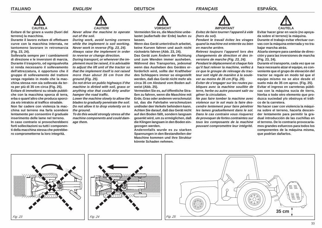
33
ITALIANO ENGLISH DEUTSCH ESPAÑOLFRANÇAIS
CAUTELAEvitare di far girare a vuoto (fuori delterreno) la macchina.Durante il lavoro evitare di effettuarecurve con la macchina interrata, netantomeno lavorare in retromarcia(Fig. 23, 24).Sollevarla sempre per i cambiamentidi direzione e le inversioni di marcia.Durante il trasporto, od ogniqualvoltasi renda necessario il sollevamentodell'attrezzatura, è opportuno che ilgruppo di sollevamento del trattorevenga regolato in modo che la mac-china stessa non sia sollevata da ter-ra per più di 35 cm circa (Fig. 25).Evitare di immettersi su strade pubbli-che con la macchina sporca di terra,erba o quant’altro che produca sporci-zia e/o intralcio al traffico stradale.Non far cadere con violenza la mac-china sul terreno ma farla scenderelentamente per consentire il gradualeinserimento delle lame nel terreno.In caso contrario si provocherebberoforti sollecitazioni su tutti i componen-ti della macchina stessa che potrebbe-ro comprometterne la loro integrità.
CAUTIONNever allow the machine to operateout of the soil.During work, avoid turning cornerswhile the implement is soil working.Never work in reverse (Fig. 23, 24).Always raise the implement in orderto reverse or change direction.During transport, or whenever the im-plement must be raised, it is advisableto adjust the lift unit of the tractor sothat the implement itself is not raisedmore than about 35 cm from theground (Fig. 25).Do not drive on public highways if themachine is dirtied with soil, grass oranything else that could dirty and/orhamper the road traffic.Lower the machine slowly to allow theblades to gradually penetrate the soil.Do not allow it to drop violently on tothe ground.To do this would strongly stress all themachine components and could dam-age them.
VORSICHTVermeiden Sie es, die Maschine unbe-lastet (außerhalb der Erde) laufen zulassen.Wenn das Gerät unterirdisch arbeitet,keine Kurven fahren und auch nichtrückwärts fahren (Abb. 23, 24).Das Gerät zum Ändern der Richtungund zum Wenden immer ausheben.Während des Transportes, jedesmalwenn das Ausheben des Gerätes er-forderlich wird, sollte der Kraftheberdes Schleppers immer so eingestelltwerden, daß das Gerät nicht mehr alscirca 35 cm Abstand vom Boden auf-weist (Abb. 25).Vermeiden Sie es, auf öffentliche Stra-ßen zu fahren, wenn die Maschine mitErde, Gras oder anderem verschmutztist, das die Fahrbahn verschmutzenund/oder den Verkehr behindern kann.Achten Sie darauf, daß das Gerät nichtauf den Boden fällt, sondern langsamgesenkt wird, um zu ermöglichen, daßdie Klingen langsam in den Boden ein-gezogen werden.Anderenfalls wurde es zu starkenSpannungen in den Bestandteilen derMaschine kommen und ihre Strukturkönnte Schaden nehmen.
IMPORTANTEvitez de faire tourner l’appareil à vide(hors du sol).Pendant le travail évitez les viragesquand la machine est enterrée ou bienen marche arrière.Relevez toujours l’appareil lors deschangements de direction et des in-versions de marche (Fig. 23, 24).Pendant le déplacement et chaque foisqu’il faut relever la machine, veillez àce que le groupe de relevage du trac-teur soit réglé de manière à la soule-ver au moins de 35 cm (Fig. 25).Eviter de s’engager sur les routes pu-bliques avec la machine souillée deterre, herbe ou autre pouvant salir ougêner la circulation.Ne pas faire tomber la machine avecviolence sur le sol mais la faire des-cendre lentement pour faire pénétrerles lames graduellement dans le sol.Dans le cas contraire vous risquerezde provoquer de fortes contraintes surtous les composants de la machinepouvant compromettre leur intégrité.
CAUTELAEvitar hacer girar en vacío (no apoya-da sobre el terreno) la máquina.Durante el trabajo evitar efectuar cur-vas con la máquina enterrada y no tra-bajar marcha atrás.Alzarla siempre para cambiar de direc-ción y para las inversiones de marcha(Fig. 23, 24).Durante el transporte, cada vez que sehace necesario alzar el equipo, es con-veniente que el grupo de elevación deltractor se regule en modo tal que elequipo mismo no se alce desde elsuelo más de 35 cm aprox. (Fig. 25).Evitar el ingreso en carreteras públi-cas con la máquina sucia de tierra,hierba o todo otro elemento que pro-duzca suciedad y/o obstruya el tráfi-co de la carretera.No hacer caer con violencia la máqui-na sobre el terreno, hacerla descen-der lentamente para permitir la gra-dual introducción de las cuchillas enel terreno. De lo contrario provocaría-mos grandes esfuerzos para todos loscomponentes de la máquina misma,que podrían dañarlos.
Fig. 23 Fig. 24 Fig. 2535 cm
12345678901234567890123456789012345678901234567890123456789012345678901234567890123456789012345678901234567890123456789012345678901234567890123456789012345678901234567890
12345678901234567890123456789012123456789012345671234567890123456789012345678901212345678901234567123456789012345678901234567890121234567890123456712345678901234567890123456789012123456789012345671234567890123456789012345678901212345678901234567123456789012345678901234567890121234567890123456712345678901234567890123456789012123456789012345671234567890123456789012345678901212345678901234567123456789012345678901234567890121234567890123456712345678901234567890123456789012123456789012345671234567890123456789012345678901212345678901234567123456789012345678901234567890121234567890123456712345678901234567890123456789012123456789012345671234567890123456789012345678901212345678901234567123451234512345
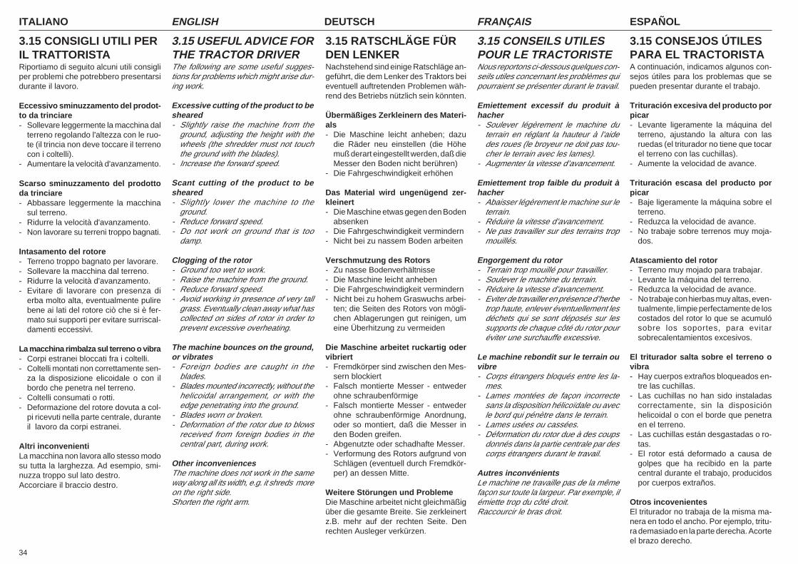
ITALIANO ENGLISH DEUTSCH ESPAÑOLFRANÇAIS
34
3.15 CONSIGLI UTILI PERIL TRATTORISTARiportiamo di seguito alcuni utili consigliper problemi che potrebbero presentarsidurante il lavoro.
Eccessivo sminuzzamento del prodot-to da trinciare- Sollevare leggermente la macchina dal
terreno regolando l'altezza con le ruo-te (il trincia non deve toccare il terrenocon i coltelli).
- Aumentare la velocità d'avanzamento.
Scarso sminuzzamento del prodottoda trinciare- Abbassare leggermente la macchina
sul terreno.- Ridurre la velocità d'avanzamento.- Non lavorare su terreni troppo bagnati.
Intasamento del rotore- Terreno troppo bagnato per lavorare.- Sollevare la macchina dal terreno.- Ridurre la velocità d'avanzamento.- Evitare di lavorare con presenza di
erba molto alta, eventualmente pulirebene ai lati del rotore ciò che si è fer-mato sui supporti per evitare surriscal-damenti eccessivi.
La macchina rimbalza sul terreno o vibra- Corpi estranei bloccati fra i coltelli.- Coltelli montati non correttamente sen-
za la disposizione elicoidale o con ilbordo che penetra nel terreno.
- Coltelli consumati o rotti.- Deformazione del rotore dovuta a col-
pi ricevuti nella parte centrale, duranteil lavoro da corpi estranei.
Altri inconvenientiLa macchina non lavora allo stesso modosu tutta la larghezza. Ad esempio, smi-nuzza troppo sul lato destro.Accorciare il braccio destro.
3.15 USEFUL ADVICE FORTHE TRACTOR DRIVERThe following are some useful sugges-tions for problems which might arise dur-ing work.
Excessive cutting of the product to besheared- Slightly raise the machine from the
ground, adjusting the height with thewheels (the shredder must not touchthe ground with the blades).
- Increase the forward speed.
Scant cutting of the product to besheared- Slightly lower the machine to the
ground.- Reduce forward speed.- Do not work on ground that is too
damp.
Clogging of the rotor- Ground too wet to work.- Raise the machine from the ground.- Reduce forward speed.- Avoid working in presence of very tall
grass. Eventually clean away what hascollected on sides of rotor in order toprevent excessive overheating.
The machine bounces on the ground,or vibrates- Foreign bodies are caught in the
blades.- Blades mounted incorrectly, without the
helicoidal arrangement, or with theedge penetrating into the ground.
- Blades worn or broken.- Deformation of the rotor due to blows
received from foreign bodies in thecentral part, during work.
Other inconveniencesThe machine does not work in the sameway along all its width, e.g. it shreds moreon the right side.Shorten the right arm.
3.15 RATSCHLÄGE FÜRDEN LENKERNachstehend sind einige Ratschläge an-geführt, die dem Lenker des Traktors beieventuell auftretenden Problemen wäh-rend des Betriebs nützlich sein könnten.
Übermäßiges Zerkleinern des Materi-als- Die Maschine leicht anheben; dazu
die Räder neu einstellen (die Höhemuß derart eingestellt werden, daß dieMesser den Boden nicht berühren)
- Die Fahrgeschwindigkeit erhöhen
Das Material wird ungenügend zer-kleinert- Die Maschine etwas gegen den Boden
absenken- Die Fahrgeschwindigkeit vermindern- Nicht bei zu nassem Boden arbeiten
Verschmutzung des Rotors- Zu nasse Bodenverhältnisse- Die Maschine leicht anheben- Die Fahrgeschwindigkeit vermindern- Nicht bei zu hohem Graswuchs arbei-
ten; die Seiten des Rotors von mögli-chen Ablagerungen gut reinigen, umeine Überhitzung zu vermeiden
Die Maschine arbeitet ruckartig odervibriert- Fremdkörper sind zwischen den Mes-
sern blockiert- Falsch montierte Messer - entweder
ohne schraubenförmige- Falsch montierte Messer - entweder
ohne schraubenförmige Anordnung,oder so montiert, daß die Messer inden Boden greifen.
- Abgenutzte oder schadhafte Messer.- Verformung des Rotors aufgrund von
Schlägen (eventuell durch Fremdkör-per) an dessen Mitte.
Weitere Störungen und ProblemeDie Maschine arbeitet nicht gleichmäßigüber die gesamte Breite. Sie zerkleinertz.B. mehr auf der rechten Seite. Denrechten Ausleger verkürzen.
3.15 CONSEILS UTILESPOUR LE TRACTORISTENous reportons ci-dessous quelques con-seils utiles concernant les problèmes quipourraient se présenter durant le travail.
Emiettement excessif du produit àhacher- Soulever légèrement le machine du
terrain en réglant la hauteur à l’aidedes roues (le broyeur ne doit pas tou-cher le terrain avec les lames).
- Augmenter la vitesse d’avancement.
Emiettement trop faible du produit àhacher- Abaisser légèrement le machine sur le
terrain.- Réduire la vitesse d’avancement.- Ne pas travailler sur des terrains trop
mouillés.
Engorgement du rotor- Terrain trop mouillé pour travailler.- Soulever le machine du terrain.- Réduire la vitesse d’avancement.- Eviter de travailler en présence d’herbe
trop haute, enlever éventuellement lesdéchets qui se sont déposés sur lessupports de chaque côté du rotor pouréviter une surchauffe excessive.
Le machine rebondit sur le terrain ouvibre- Corps étrangers bloqués entre les la-
mes.- Lames montées de façon incorrecte
sans la disposition hélicoïdale ou avecle bord qui pénètre dans le terrain.
- Lames usées ou cassées.- Déformation du rotor due à des coups
donnés dans la partie centrale par descorps étrangers durant le travail.
Autres inconvénientsLe machine ne travaille pas de la mêmefaçon sur toute la largeur. Par exemple, ilémiette trop du côté droit.Raccourcir le bras droit.
3.15 CONSEJOS ÚTILESPARA EL TRACTORISTAA continuación, indicamos algunos con-sejos útiles para los problemas que sepueden presentar durante el trabajo.
Trituración excesiva del producto porpicar- Levante ligeramente la máquina del
terreno, ajustando la altura con lasruedas (el triturador no tiene que tocarel terreno con las cuchillas).
- Aumente la velocidad de avance.
Trituración escasa del producto porpicar- Baje ligeramente la máquina sobre el
terreno.- Reduzca la velocidad de avance.- No trabaje sobre terrenos muy moja-
dos.
Atascamiento del rotor- Terreno muy mojado para trabajar.- Levante la máquina del terreno.- Reduzca la velocidad de avance.- No trabaje con hierbas muy altas, even-
tualmente, limpie perfectamente de loscostados del rotor lo que se acumulósobre los soportes, para evitarsobrecalentamientos excesivos.
El triturador salta sobre el terreno ovibra- Hay cuerpos extraños bloqueados en-
tre las cuchillas.- Las cuchillas no han sido instaladas
correctamente, sin la disposiciónhelicoidal o con el borde que penetraen el terreno.
- Las cuchillas están desgastadas o ro-tas.
- El rotor está deformado a causa degolpes que ha recibido en la partecentral durante el trabajo, producidospor cuerpos extraños.
Otros incovenientesEl triturador no trabaja de la misma ma-nera en todo el ancho. Por ejemplo, tritu-ra demasiado en la parte derecha. Acorteel brazo derecho.

35
ITALIANO ENGLISH DEUTSCH ESPAÑOLFRANÇAIS
Lavoro in collinaSe possibile procedere «salendo» nelsenso della pendenza.Se non è possibile evitare di lavorare lun-go i fianchi della collina, effettuare i pas-saggi dall'alto verso il basso per ridurrel'effetto terrazza.
Osservazioni praticheIl terreno lavorato dovrebbe trovarsi sem-pre alla destra del guidatore. Il sistemamigliore è di lavorare a striscie alternate.
3.16 PARCHEGGIO
AVVERTENZAAl fine di assicurare stabilità alla mac-china, quando viene sganciato dal trat-tore, seguire le seguenti indicazioni:- Alzare le ruote posteriori della macchina.- Abbassare la macchina fino a terra.- Assicurarsi che la macchina venga de-
positata su una superficie idonea.
Working on hillsWhen possible, proceed by moving up-wards in the direction of the slope.If it is not possible to avoid working alongthe sides of the hill, work from top to bot-tom to reduce the terracing effect.
Practical hintsThe worked ground must always be onthe right of the driver.The best system is to work in alternatingstrips.
3.16 PARKING
WARNINGIn order to ensure the stability of themachine, follow these instructionswhen it is unhooked from the tractor:- Raise the rear wheels of the machine.- Lower the machine to the ground.- Make sure that machine is parked on
a proper surface.
Travail en collineSi possible, travailler «en montant» dansle sens de la pente.Sinon, éviter de travailler le long desflancs de la colline, effectuer les passa-ges du haut vers le bas pour réduire l’effetterrasse.
Observations pratiquesLe terrain travaillé devrait toujours setrouver à la droite du conducteur.Le meilleur système est de travailler àbandes alternées.
3.16 STATIONNEMENT
ATTENTIONAfin de garantir la stabilité du machinequand il est détaché du tracteur, sui-vre les indications suivantes:- Lever les roues arrière du machine.- Abaisser le machine jusqu’au sol.- Il faut s’assurer que la machine soit
parquée sur une surface appropriée.
Arbeiten auf hügeligem BodenFalls möglich, sollte «ansteigend» gear-beitet werden. Kann ein Arbeiten entlangder Seiten eines Hügels nicht vermiedenwerden, so empfiehlt sich ein Arbeitenvon oben nach unten, um den Terrassen-effekt so weit als möglich zu vermeiden.
PraktischesDie zu bearbeitende Fläche sollte sichstets auf der rechten Seite des Lenkersbefinden. Am geeignetsten ist ein Ar-beitsvorgang in abwechselnden Streifen.
3.16 PARKEN
HINWEISUm die Stabilität der Maschine zu si-chern, sobald diese vom Traktor ab-geschlossen wird, ist auf Folgendeszu achten:- Die rückwärtigen Räder der Maschine
anheben.- Die Maschine auf den Boden absenken.- Bitte versichern Sie sich, daß die Ma-
schine auf Lager auf eine platte Flächebleibt.
Trabajo en colinasSi es posible, «suba» en el sentido de lapendiente. Si no es posible evitar trabajara lo largo de las laderas de la colina,efectúe pasajes desde arriba hacia abajopara reducir el efecto terraza.
Observaciones prácticasEl terreno elaborado siempre tiene queestar a la derecha del conductor. El mejorsistema es el de trabajar por hileras alter-nadas.
3.16 APARCAMIENTO
ADVERTENCIAPara asegurar la estabilidad de la má-quina cuando lo desenganche del trac-tor, siga las siguientes indicaciones:- Levante las ruedas traseras de la má-
quina.- Baje la máquina hasta el suelo.- Asegurarse que la maquina sea
aparcada sobre una superficie apro-priada.
4.0 MANUTENZIONESono di seguito elencate le varie opera-zioni di manutenzione da eseguirsi conperiodicità. Il minor costo di esercizio eduna lunga durata della macchina dipen-de, tra l'altro, dalla metodica e costanteosservanza di tali norme.
CAUTELAI tempi di intervento elencati in que-sto manuale hanno solo carattere in-formativo e sono relativi a condizioninormali di impiego, possono pertanto
4.0 MAINTENANCEThe various operations of periodic main-tenance are listed below.Lower operating costs and longer life forthe machine depend, among other things,on the methodical and constant obser-vation of these rules.
CAUTIONThe time-frames for intervention listedin this manual are only of an informa-tive nature and are relative to normalconditions of use.
4.0 WARTUNGNachstehend sind die in regelmäßigenAbständen auszuführenden Wartungs-arbeiten aufgelistet. Das Befolgen dieserHinweise gewährleistet unter anderemgeringere Betriebskosten, sowie längereLebensdauer der Maschine.
VORSICHTDie in vorliegender Gebrauchsanlei-tung angeführten Zeitabstände sindals rein informativ zu betrachten undbeziehen sich auf normale Betriebs-bedingungen.
4.0 ENTRETIENNous reportons ci-dessous les différen-tes opérations d’entretien à effectuer ré-gulièrement. L’observation méthodique etconstante de ces normes permet de ré-duire au maximum les frais d’entretien etd’avoir une plus longue durée de la ma-chine.
PRUDENCELes temps d’intervention ne sont re-portés dans ce manuel qu’à titre in-formatif et se réfèrent à des conditionsnormales d’emploi.
4.0 MANTENIMIENTOA continuación, indicamos las diferentesoperaciones de mantenimiento que tie-nen que efectuarse con periodicidad. Uncosto menor de trabajo y una larga dura-ción de la máquina dependen, entre otrascosas, de la observación metódica yconstante de dichas normas.
ADVERTENCIALos tiempos de intervención indica-dos en este manual tienen sólo la fun-ción de informar y se refieren a con-diciones normales de empleo, por lo
ITALIANO ENGLISH DEUTSCH ESPAÑOLFRANÇAIS
36
subire variazioni in relazione al gene-re di servizio, ambiente più o menopolveroso, fattori stagionali, ecc.Nel caso di condizioni più gravose diservizio, gli interventi di manutenzio-ne vanno logicamente incrementati.- Prima di iniettare il grasso lubrifi-
cante negli ingrassatori, è necessa-rio pulire con cura gli ingrassatoristessi per impedire che fango, pol-vere o corpi estranei si mescolinocon il grasso, facendo diminuire, oaddirittura annullare, l'effetto dellalubrificazione.
- Nell'eseguire il ripristino o il cambioolio, è necessario usare lo stessotipo di olio usato precedentemente.
AVVERTENZATenere sempre gli olii ed i grassi al difuori della portata dei bambini.Leggere sempre attentamente le av-vertenze e le precauzioni indicate suicontenitori. Evitare il contatto con lapelle. Dopo l'utilizzo lavarsi accurata-mente e a fondo. Trattare gli olii usatiin conformità con le leggi vigenti anti-inquinamento.
4.1 PRIME 8 ORELAVORATIVE- Dopo le prime 8 ore lavorative a cui la
macchina è stata sottoposta, effettua-re un accurato controllo dello stato ge-nerale della macchina stessa.In particolare, dopo aver controllato l'usu-ra dei coltelli, serrare a fondo ulteriormen-te le viti. In tale occasione è bene effet-tuare un controllo del serraggio delle vitie bulloni di tutta la macchina.
4.2 OGNI 8 ORELAVORATIVE- Ingrassare le crociere dell'albero
cardanico.- Ingrassare i cuscinetti del rotore (1
Fig. 26).- Verificare il serraggio dei bulloni di fis-
saggio dei coltelli.
Therefore they may undergo varia-tions in relation to the type of service,a more or less dusty environment,seasonal factors, etc.In case of more difficult service con-ditions, maintenance interventionswill logically increase.- Before injecting lubricating grease
into the lubricators, it is importantto thoroughly clean them in orderto prevent mud, dust or foreign bod-ies from mixing with the grease anddiminishing - or even annulling - theeffect of the lubrication.
- When adding, or changing, oil it isnecessary to use the same type ofoil used previously.
WARNINGAlways keep oil and grease away fromchildren.Always carefully read the warningsand precautions indicated on thecontainers.Avoid contact with theskin. After using, wash hands at lengthand thoroughly. Treat used oils in con-formity with the anti-pollution laws inforce.
4.1 FIRST 8 HOURSSERVICE- Carefully check the general condition
of the machine after the first 8 hoursservice.In particular, after having checked thetines for wear, tighten the screws. Atthat time, it is advisable to check thatall screws and bolts are correctlytorqued.
4.2 EVERY 8 WORKHOURS- Grease the cardan shaft cross journals.- Grease the bearings of the rotor (1
Fig. 26).- Check the tightness of the fastening
bolts of the blades.
Es könnte sich daher las nötig erwei-sen, diese Zeitabschnitte aufgrund derjeweiligen Anforderungen undBetriebsbedingungen (z.B.: saisonbe-dingte Umstände, mehr oder wenigstaubiges Arbeitsklima usw.) zu ver-längern oder zu verkürzen.- Bevor die Schmiervorrichtungen mit
Schmiermittel gefüllt werden, ist zukontrollieren, daß diese frei vonSchmutz- oder Staubablagerungensind, die sich anderenfalls mit demSchmiermittel vermischen und soden Effekt der Schmierung aufhe-ben könnten.
- Beim Ölwechsel oder beim Nachfüllenvon Schmieröl ist darauf zu achten, diegleiche Art von Öl zu benutzen.
HINWEISKinder sind von Schmierölen undSchmierfetten unbefó˛gt fernzuhalten.Beachten Sie stets die Hinweise undVorschriften auf den Verpackungen.Den Kontakt mit der Haut vermeiden.Nach Anwendung der Schmiermitteldie Hände sorgfältig reinigen. Die aus-gebrannten Öle gemäß der landes-gültigen Vorschriften in Sachen Um-weltschutz entsorgen.
4.1 ERSTE 8BETRIEBSSTUNDEN- Nach den ersten 8 Betriebsstunden ist
die Maschine einer sorgfältigen Kon-trolle hinsichtlich ihres Allgemein-zustandes zu unterziehen.Nach der Prüfung des Versch-leißzustandes der Messer sind insbeson-dere die Schrauben. Dabei sollten alleSchrauben und Schraubbolzen der Ma-schine auf festen Sitz geprüft werden.
4.2 ALLE 8BETRIEBSSTUNDEN- Die Kreuzstücke der Gelenkwelle
schmieren.- Die Lager des Rotors schmieren (1
Fig. 26).- Die Befestigungsbolzen der Messer
festziehen.
Ils peuvent donc subir des modifica-tions selon le type d’utilisation, le mi-lieu plus ou moins poussiéreux, lesagents atmosphériques, etc.Si les conditions de fonctionnementsont plus difficiles, les opérationsd’entretien doivent naturellement êtreplus fréquentes.- Avant d’injecter la graisse lubri-
fiante dans les graisseurs, il faut lesnettoyer soigneusement pour em-pêcher que la boue, la poussière oudes corps étrangers se mélangentà la graisse, en diminuant ou mêmeen annulant l’effet du graissage.
- Quand on rajoute de l’huile ouquand on la change, il faut toujoursutiliser le même type d’huile.
ATTENTIONTenir l’huile et la graisse hors de por-tée des enfants. Lire attentivement lemode d’emploi et les indications re-portés sur les bidons. Eviter le con-tact avec la peau. Après l’utilisation,se laver soigneusement et à fond. Re-cycler les huiles usées conformémentaux lois antipollution en vigueur.
4.1 APRES LES 8PREMIERES HEURESDE TRAVAIL- Après le 8 premières heures de travail
de la machine, contrôlez attentivementson état général.En particulier, après avoir contrôlél’usure des couteaux, serrez à fond lesvis. A cette occasion vérifiez égalementle serrage des vis et des boulons detoute la machine.
4.2 TOUTES LES 8HEURES DE TRAVAIL- Graissez les croisillons de l’arbre à
cardans.- Graisser les roulements du rotor (1
Fig. 26).- Contrôler le serrage des boulons de
fixation des lames.
tanto, pueden sufrir variaciones deacuerdo al tipo de trabajo, ambientemás o menos polvoroso, factoresestacionales, etc. En el caso de con-diciones más difíciles de trabajo, tie-ne que aumentar, lógicamente, lasoperaciones de mantenimiento.- Antes de inyectar la grasa lubrican-
te en los engrasadores, es necesa-rio limpiar cuidadosamente losengrasadores mismos, para que ellodo, polvo o cuerpos extraños nose mezclen con la grasa, disminu-yendo, o incluso anulando, el efec-to de la lubricación.
- Cuando agregue o cambie el acei-te, es necesario usar el mismo tipode aceite utilizado anteriormente.
ADVERTENCIASiempre mantenga los aceites y las gra-sas fuera del alcance de los niños. Leaatentamente las advertencias y las pre-cauciones indicadas en los envases.Evite el contacto con la piel. Tras el uso,lávese cuidadosamente y a fondo. Tra-te los aceites usados de acuerdo con laleyes vigentes contra la contaminación.
4.1 PRIMERAS 8 HORASDE TRABAJO- Después de las primeras 8 horas de
trabajo de la máquina, efectuar un cui-dadoso control general de la misma.En especial, después de controlar eldesgaste de las cuchillas, ajustar afondo los tornillos. En esta ocasión esaconsejable efectuar un control delajuste de todos los tornillos y bulonesde la máquina.
4.2 CADA 8 HORAS DETRABAJO- Engrasar las crucetas del árbol cardá-
nico.- Engrase los cojinetes de rotación (1
Fig. 26).- Controle que los pernos de sujeción
de las cuchillas estén biene apretados.
37
ITALIANO ENGLISH DEUTSCH ESPAÑOLFRANÇAIS
4.3 OGNI 50 ORELAVORATIVE- DOPO LE PRIME 50 ORE SOSTITUI-
RE L’OLIO NELLA SCATOLA CEN-TRALE.
- Verificare il livello olio nella scatola delmoltiplicatore, eventualmente ripristi-narlo fino all’altezza del foro di livello(5 Fig. 26).
4.4 OGNI 400 ORELAVORATIVE- Effettuare il cambio completo dell'olio
del moltiplicatore, scaricando com-pletamente l'olio dal tappo di scaricoposto sotto la scatola moltiplicatore(4 Fig. 26).
4.5 MESSA A RIPOSOA fine stagione, o nel caso si preveda unlungo periodo di riposo, è consigliabile:- Lavare la macchina soprattutto da con-
cimi e da prodotti chimici ed asciugarlo.- Controllarla accuratamente ed even-
tualmente sostituire le parti danneggia-te o usurate.
- Serrare a fondo tutte le viti e i bulloni, inparticolare quelli che fissano i coltelli.
- Effettuare un accurato ingrassaggio edinfine proteggere tutta l'attrezzaturacon un telo e sistemarla in un ambien-te asciutto.
Se queste operazioni vengono fatte concura, il vantaggio sarà solo dell'utilizzato-re in quanto alla ripresa del lavoro, trove-rà un'attrezzatura in perfette condizioni.
In caso di smantellamento della mac-china, attenersi alle relative leggi delpaese di utilizzo in particolare alle leg-gi sull'anti-inquinamento.
Si ricorda infine che la Ditta Costruttri-ce è sempre a disposizione per qualsi-asi necessità di assistenza e ricambi.
4.3 EVERY 50 HOURSOF WORK- CHANGE THE OIL IN THE CENTRAL
AFTER THE FIRST 50 HOURSSERVICE.
- Check the oil level in the overdrive box,filling it up, if necessary, to the notchon the indicator (5 Fig. 26).
4.4 EVERY 400 HOURS OFWORK- Carry out a complete oil change of the
overdrive, discharging all the oil fromthe discharge cap located below theoverdrive box (4 Fig. 26).
4.5 STORAGEProceed in the following way at the endof the season or if the harrow is to re-main unused for a long period of time:- Wash the harrow and dry it. Make sure
that all fertilizer and chemical productshave been removed.
- Carefully check the implement andreplace any damaged or worn parts.
- Fully tighten all screws and bolts, par-ticularly the ones that fix the tines.
- Thoroughly grease the implement andprotect it with a tarpaulin. The harrowshould be stored in a dry place.
If these operations are carefully carriedout, the user will find the implement in aperfect condition when it is requiredagain.
Comply with the laws in force in therelative countries, particularly the anti-pollution provisions, if the machinemust be dismantled.
Also remember that the Manufactureris always at your disposal for any tech-nical assistance and spare parts asmay be required.
4.3 ALLE 50BETRIEBSSTUNDEN- NACH DEN ERSTEN 50 BETRIEBS-
STUNDEN DAS ÖL IM ZENTRALENGEHÄUSE ERSETZEN.
- Den Ölstand im Übersetzungsgetriebe-gehäuse prüfen und eventuell bis zumFüllstrich auffüllen (5 Abb. 26).
4.4 ALLE 400BETRIEBSSTUNDEN- Das gesamte Öl des Übersetzungs-
getriebes wechseln. Das Öl vollkom-men über die Ablaßöffnung, die sichauf der Unterseite des Gehäuses be-findet, auslaufen lassen (4 Abb. 26).
4.5 RUHEPERIODENAm Ende der Saison oder, wenn eine län-gere Ruhepause vorgesehen ist, mußman wie folgt vorgehen:- Den Krümler gründlich reinigen, vor al-
lem Dünger- und/oder Chemikalien-reste gut entfernen, um ihn dann zutrocknen.
- Auf das Vorhandensein etwaiger Schä-den oder Verschleißstellen prüfen unddie schadhaften Teile ersetzen.
- Alle Schrauben und Schraubbolzenfest anziehen, vor allem diejenigen zurMesserbefestigung.
Wenn diese Arbeiten sorgfältig ausge-führt werden, wirkt sich das zum Vorteildes Benutzers aus, weil er das Gerät,wenn er es wiederbenutzen will, in einemeinwandfreien Zustand vorfindet.
Vergessen Sie nicht, daß der Herstel-ler für alle Fragen hinsichtlich Kun-dendienst und Ersatzteilen stets zurVerfügung steht.
Vergessen Sie nicht, daß die Herstel-lerfirma für alle Fragen hinsichtlichKundendienst und Ersatzteilen stetszur Verfügung steht.
4.3 TOUTES LES 50HEURES DE TRAVAIL- APRES LES 50 PREMIERES
HEURES VIDANGER L’HUILE DANSLE BOITIER CENTRAL.
- Contrôler le niveau d’huile dans le boî-tier du multiplicateur, au besoin rajou-ter de l’huile jusqu’au repère qui setrouve sur la jauge (5 Fig. 26).
4.4 TOUTES LES 400HEURES DE TRAVAIL- Changer complètement l’huile du mul-
tiplicateur, en évacuant l’huile par lebouchon de vidange qui se trouve sousle boîtier du multiplicateur (4 Fig. 26).
4.5 REMISSAGEA la fin de la saison ou lorsque vous pré-voyez une longue période d’inactivité,prenez les précautions suivantes:- Lavez l’appareil en enlevant surtout les
engrais et les produits chimiques, etséchez-le soigneusement.
- Contrôlez attentivement l’appareil:remplacez les parties usées ou en-dommagées.
- Serrez à fond toutes les vis et les bou-lons, en particulier celles des cou-teaux.
- Graissez soigneusement et protégezl’outil avec une bâche en plastique.Rangez-le dans un local sec.
Si ces opérations sont réalisées soigneu-sement, lors de la reprise des travauxl’utilisateur trouvera un outil en parfaitétat.
Dans le cas de mise à la décharge dela machine, respectez les lois du paysd’utilisation et notamment les lois con-tre la pollution de l’environnement.
Le Constructeur demeure à votre dis-position pour répondre à toute de-mande d’assistance et de pièces dé-tachées.
4.3 CADA 50 HORAS DETRABAJO- DESPUÉS DE LAS 50 HORAS
SUSTITUIR EL ACEITE EN LA CAJACENTRAL.
- Controle el nivel de aceite en la cajadel multiplicador, si es necesario, res-tablézcalo hasta la muesca del nivel(5 Fig. 26).
4.4 CADA 400 HORAS DETRABAJO- Cambie totalmente el aceite del multi-
plicador, descargándolo por el tapónde descarga que está colocado abajode la caja del multiplicador (4 Fig. 26).
4.5 PERIODOS DE REPOSOAl finalizar la estación o siempre que pre-vemos un período de inactividad prolon-gado aconsejamos:- Lavar la máquina, eliminando sobre
todo abonos y productos químicos;luego secarla.
- Controlarla cuidadosamente y even-tualmente sustituir las partes dañadaso gastadas.
- Ajustar a fondo todos los tornillos y losbulones, en particular aquellos que fi-jan las cuchillas.
- Efectuar un cuidadoso engrase y porúltimo proteger todo el equipo con unalona y guardarla en un ambiente seco.
Si realizamos cuidadosamente estasoperaciones redundará en ventaja delusuario, ya que encontrará, al recomen-zar el trabajo, los equipos en perfectascondiciones.
En caso de eliminación de la máquinaobservar las leyes del relativo pais, enparticular las leyes anticontamina-ción.
Recordamos por último que el Fabri-cante está siempre a sus órdenes paratoda necesidad de asistencia y re-puestos.
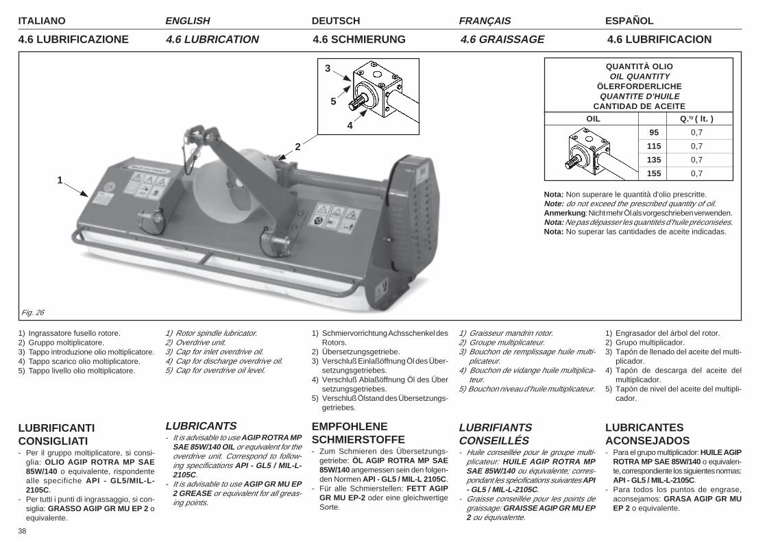
ITALIANO ENGLISH DEUTSCH ESPAÑOLFRANÇAIS
38
QUANTITÀ OLIOOIL QUANTITY
ÖLERFORDERLICHEQUANTITE D'HUILE
CANTIDAD DE ACEITE
OIL Q.ty ( lt. )
95 0,7
115 0,7
135 0,7
155 0,7
Nota: Non superare le quantità d'olio prescritte.Note: do not exceed the prescribed quantity of oil.Anmerkung: Nicht mehr Öl als vorgeschrieben verwenden.Nota: Ne pas dépasser les quantités d’huile préconisées.Nota: No superar las cantidades de aceite indicadas.
1) Ingrassatore fusello rotore.2) Gruppo moltiplicatore.3) Tappo introduzione olio moltiplicatore.4) Tappo scarico olio moltiplicatore.5) Tappo livello olio moltiplicatore.
LUBRIFICANTICONSIGLIATI- Per il gruppo moltiplicatore, si consi-
glia: OLIO AGIP ROTRA MP SAE85W/140 o equivalente, rispondentealle specifiche API - GL5/MIL-L-2105C.
- Per tutti i punti di ingrassaggio, si con-siglia: GRASSO AGIP GR MU EP 2 oequivalente.
1) Rotor spindle lubricator.2) Overdrive unit.3) Cap for inlet overdrive oil.4) Cap for discharge overdrive oil.5) Cap for overdrive oil level.
LUBRICANTS- It is advisable to use AGIP ROTRA MP
SAE 85W/140 OIL or equivalent for theoverdrive unit. Correspond to follow-ing specifications API - GL5 / MIL-L-2105C.
- It is advisable to use AGIP GR MU EP2 GREASE or equivalent for all greas-ing points.
1) Schmiervorrichtung Achsschenkel desRotors.
2) Übersetzungsgetriebe.3) Verschluß Einlaßöffnung Öl des Über-
setzungsgetriebes.4) Verschluß Ablaßöffnung Öl des Über
setzungsgetriebes.5) Verschluß Ölstand des Übersetzungs-
getriebes.
EMPFOHLENESCHMIERSTOFFE- Zum Schmieren des Übersetzungs-
getriebe: ÖL AGIP ROTRA MP SAE85W/140 angemessen sein den folgen-den Normen API - GL5 / MIL-L 2105C.
- Für alle Schmierstellen: FETT AGIPGR MU EP-2 oder eine gleichwertigeSorte.
1) Graisseur mandrin rotor.2) Groupe multiplicateur.3) Bouchon de remplissage huile multi-
plicateur.4) Bouchon de vidange huile multiplica-
teur.5) Bouchon niveau d’huile multiplicateur.
LUBRIFIANTSCONSEILLÉS- Huile conseillée pour le groupe multi-
plicateur: HUILE AGIP ROTRA MPSAE 85W/140 ou équivalente; corres-pondant les spécifications suivantes API- GL5 / MIL-L-2105C.
- Graisse conseillée pour les points degraissage: GRAISSE AGIP GR MU EP2 ou équivalente.
1) Engrasador del árbol del rotor.2) Grupo multiplicador.3) Tapón de llenado del aceite del multi-
plicador.4) Tapón de descarga del aceite del
multiplicador.5) Tapón de nivel del aceite del multipli-
cador.
LUBRICANTESACONSEJADOS- Para el grupo multiplicador: HUILE AGIP
ROTRA MP SAE 85W/140 o equivalen-te, correspondiente los siguientes normas:API - GL5 / MIL-L-2105C.
- Para todos los puntos de engrase,aconsejamos: GRASA AGIP GR MUEP 2 o equivalente.
4.6 LUBRIFICAZIONE 4.6 SCHMIERUNG 4.6 GRAISSAGE 4.6 LUBRIFICACION4.6 LUBRICATION
Fig. 26
1
2
4
5
3
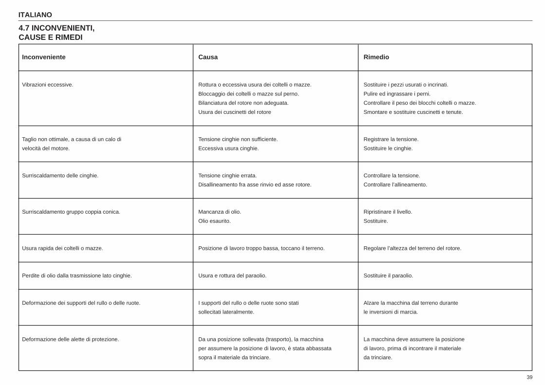
39
ITALIANO ENGLISH DEUTSCH ESPAÑOLFRANÇAIS
4.7 INCONVENIENTI,CAUSE E RIMEDI
Inconveniente Causa Rimedio
Vibrazioni eccessive. Rottura o eccessiva usura dei coltelli o mazze. Sostituire i pezzi usurati o incrinati.
Bloccaggio dei coltelli o mazze sul perno. Pulire ed ingrassare i perni.
Bilanciatura del rotore non adeguata. Controllare il peso dei blocchi coltelli o mazze.
Usura dei cuscinetti del rotore Smontare e sostituire cuscinetti e tenute.
Taglio non ottimale, a causa di un calo di Tensione cinghie non sufficiente. Registrare la tensione.
velocità del motore. Eccessiva usura cinghie. Sostituire le cinghie.
Surriscaldamento delle cinghie. Tensione cinghie errata. Controllare la tensione.
Disallineamento fra asse rinvio ed asse rotore. Controllare l’allineamento.
Surriscaldamento gruppo coppia conica. Mancanza di olio. Ripristinare il livello.
Olio esaurito. Sostituire.
Usura rapida dei coltelli o mazze. Posizione di lavoro troppo bassa, toccano il terreno. Regolare l’altezza del terreno del rotore.
Perdite di olio dalla trasmissione lato cinghie. Usura e rottura del paraolio. Sostituire il paraolio.
Deformazione dei supporti del rullo o delle ruote. I supporti del rullo o delle ruote sono stati Alzare la macchina dal terreno durante
sollecitati lateralmente. le inversioni di marcia.
Deformazione delle alette di protezione. Da una posizione sollevata (trasporto), la macchina La macchina deve assumere la posizione
per assumere la posizione di lavoro, è stata abbassata di lavoro, prima di incontrare il materiale
sopra il materiale da trinciare. da trinciare.

ITALIANO ENGLISH DEUTSCH ESPAÑOLFRANÇAIS
40
Störung Ursache Behebung
Übermäßiges Vibrieren der Maschine. Beschädigte oder abgenutzte Messer. Die abgenutzten oder beschädigten Teile ersetzen.Sperre der Messer auf den Bolzen. Die Bolzen reinigen und schmieren.Auswuchtung des Rotors nicht korrekt. Das Gewicht der Messerblöcke kontrollieren.Abgenutzte Lager des Rotors. Die Lager und Dichtungen abmontieren und auswechseln.
Schnitt nicht korrekt aufgrund eines Motorabfalls. Spannung der Antriebsriemen ungenügend. Die Spannung neu einstellen.Übermäßige Abnutzung der Riemen. Die Antriebsriemen auswechseln.
Überhitzung der Antriebsriemen. Falsche Spannung. Die Spannung kontrollieren.Falsche Ausrichtung der Rotorachse und der Rücklaufachse. Die Ausrichtung kontrollieren.
Überhitzung des Kegelmoments. Zu wenig Öl. Öl nachfüllen.Ausgebranntes Öl. Öl wechseln.
Zu schnelle Abnutzung der Messer. Zu niedrig eingestellt, berühren den Boden. Den Abstand des Rotors vom Boden vergrößern.Auslaufen des Öls aus dem Seitenantrieb. Abnutzung bzw. Beschädigung der Ölfangkappe. Die Ölfangkappe auswechseln.Verformung der Halterungen der Räder bzw. der Walzen. Die Halterungen wurden seitlich belastet. Die Maschine während eines Richtungswechseln
immer anheben.Verformung der Schutzblenden. Die Maschine wurde nach einer Beförderung zum Die Maschine muß in Betriebsposition gebracht werden,
Betrieb auf des zu bearbeitende Material abgesenkt bevor sie in Berührung mit dem zu bearbeitenden.Material kommt.
4.7 STÖRUNGEN, DERENURSACHEN UNDBEHEBUNG
Inconvenience Cause Remedy
Excessive vibration. Breakage or excessive wear of blades and hammers. Replace the worn or cracked pieces.Blades or hammers blocked on pin. Clean and grease the pins.Inadequate balancing of rotor. Check the weight of the of the blades/hammers blockWear of rotor bearings. Remove and replace bearings and seals.
Imperfect cut due to lowering of engine speed. Belt tension insufficient. Regulate tension.Belts excessively worn. Replace belts.
Overheating of belts. Incorrect tension of belts. Check tension.Transmission axis and rotor axis out of alignment. Check alignment.
Overheating of bevel gear pair. Lack of oil. Add oil to proper level.Oil depleted. Replace.
Rapid wearing of blades or hammers. Work position too low, blades touching ground. Adjust height of rotor from ground.Loss of oil from transmission, belt side. Wear and breakage of oil seal. Replace seal.Deformation of the supports of the roller or wheels. The supports of the roller and the wheels Raise the machine from the ground when in reverse gear.
have undergone side stress.Deformation of protective guards. In order to assume the work position, the machine The machine must be in the work position before touching
- from a raised position (transport) - has been the material to be shredded.lowered onto the material to be shredded.
4.7 INCONVENIENCES,CAUSES AND REMEDYS
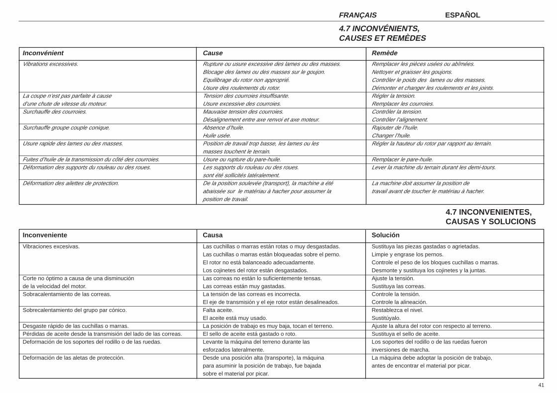
41
ITALIANO ENGLISH DEUTSCH ESPAÑOLFRANÇAIS
Inconvénient Cause Remède
Vibrations excessives. Rupture ou usure excessive des lames ou des masses. Remplacer les pièces usées ou abîmées.Blocage des lames ou des masses sur le goujon. Nettoyer et graisser les goujons.Equilibrage du rotor non approprié. Contrôler le poids des lames ou des masses.Usure des roulements du rotor. Démonter et changer les roulements et les joints.
La coupe n’est pas parfaite à cause Tension des courroies insuffisante. Régler la tension.d’une chute de vitesse du moteur. Usure excessive des courroies. Remplacer les courroies.Surchauffe des courroies. Mauvaise tension des courroies. Contrôler la tension.
Désalignement entre axe renvoi et axe moteur. Contrôler l’alignement.Surchauffe groupe couple conique. Absence d’huile. Rajouter de l’huile.
Huile usée. Changer l’huile.Usure rapide des lames ou des masses. Position de travail trop basse, les lames ou les Régler la hauteur du rotor par rapport au terrain.
masses touchent le terrain.Fuites d’huile de la transmission du côté des courroies. Usure ou rupture du pare-huile. Remplacer le pare-huile.Déformation des supports du rouleau ou des roues. Les supports du rouleau ou des roues. Lever la machine du terrain durant les demi-tours.
sont été sollicités latéralement.Déformation des ailettes de protection. De la position soulevée (transport), la machine a été La machine doit assumer la position de
abaissée sur le matériau à hacher pour assumer la travail avant de toucher le matériau à hacher.position de travail.
Inconveniente Causa Solución
Vibraciones excesivas. Las cuchillas o marras están rotas o muy desgastadas. Sustituya las piezas gastadas o agrietadas.Las cuchillas o marras están bloqueadas sobre el perno. Limpie y engrase los pernos.El rotor no está balanceado adecuadamente. Controle el peso de los bloques cuchillas o marras.Los cojinetes del rotor están desgastados. Desmonte y sustituya los cojinetes y la juntas.
Corte no óptimo a causa de una disminución Las correas no están lo suficientemente tensas. Ajuste la tensión.de la velocidad del motor. Las correas están muy gastadas. Sustituya las correas.Sobracalentamiento de las correas. La tensión de las correas es incorrecta. Controle la tensión.
El eje de transmisión y el eje rotor están desalineados. Controle la alineación.Sobrecalentamiento del grupo par cónico. Falta aceite. Restablezca el nivel.
El aceite está muy usado. Sustitúyalo.Desgaste rápido de las cuchillas o marras. La posición de trabajo es muy baja, tocan el terreno. Ajuste la altura del rotor con respecto al terreno.Pérdidas de aceite desde la transmisión del lado de las correas. El sello de aceite está gastado o roto. Sustituya el sello de aceite.Deformación de los soportes del rodillo o de las ruedas. Levante la máquina del terreno durante las Los soportes del rodillo o de las ruedas fueron
esforzados lateralmente. inversiones de marcha.Deformación de las aletas de protección. Desde una posición alta (transporte), la máquina La máquina debe adoptar la posición de trabajo,
para asuminir la posición de trabajo, fue bajada antes de encontrar el material por picar.sobre el material por picar.
4.7 INCONVÉNIENTS,CAUSES ET REMÈDES
4.7 INCONVENIENTES,CAUSAS Y SOLUCIONS
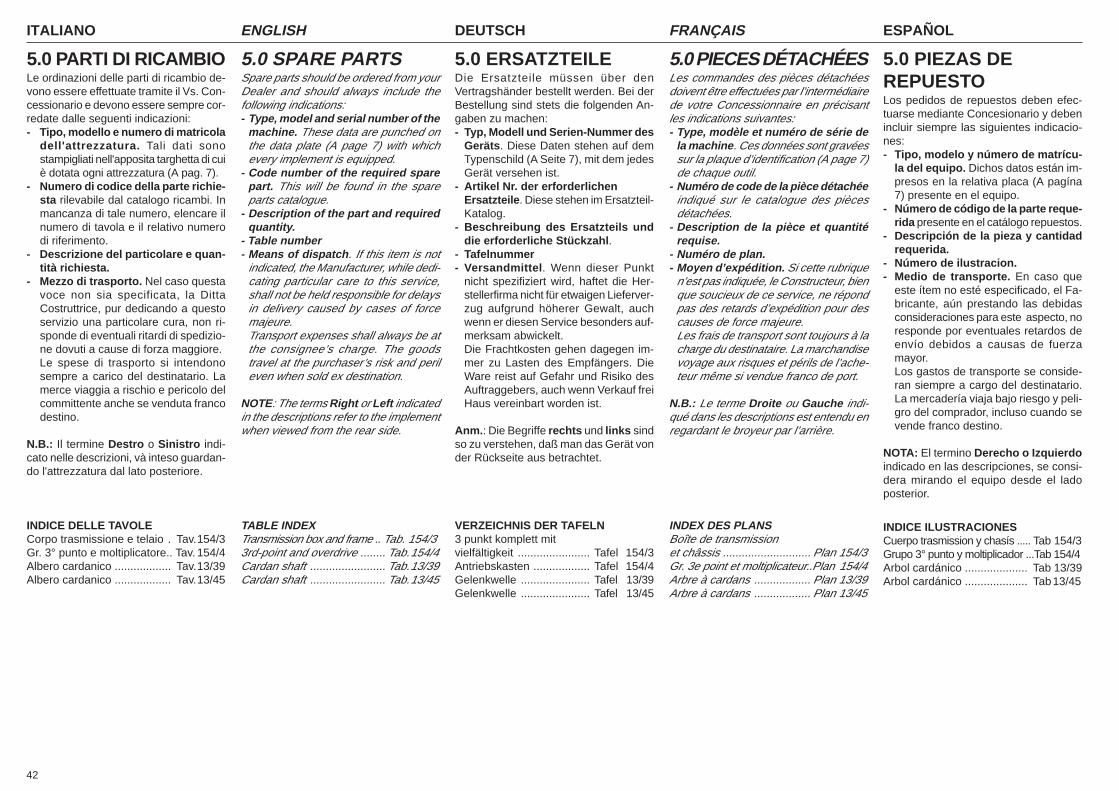
ITALIANO ENGLISH DEUTSCH ESPAÑOLFRANÇAIS
42
5.0 PARTI DI RICAMBIOLe ordinazioni delle parti di ricambio de-vono essere effettuate tramite il Vs. Con-cessionario e devono essere sempre cor-redate dalle seguenti indicazioni:- Tipo, modello e numero di matricola
dell'attrezzatura. Tali dati sonostampigliati nell'apposita targhetta di cuiè dotata ogni attrezzatura (A pag. 7).
- Numero di codice della parte richie-sta rilevabile dal catalogo ricambi. Inmancanza di tale numero, elencare ilnumero di tavola e il relativo numerodi riferimento.
- Descrizione del particolare e quan-tità richiesta.
- Mezzo di trasporto. Nel caso questavoce non sia specificata, la DittaCostruttrice, pur dedicando a questoservizio una particolare cura, non ri-sponde di eventuali ritardi di spedizio-ne dovuti a cause di forza maggiore.Le spese di trasporto si intendonosempre a carico del destinatario. Lamerce viaggia a rischio e pericolo delcommittente anche se venduta francodestino.
N.B.: Il termine Destro o Sinistro indi-cato nelle descrizioni, và inteso guardan-do l'attrezzatura dal lato posteriore.
INDICE DELLE TAVOLECorpo trasmissione e telaio . Tav.154/3Gr. 3° punto e moltiplicatore.. Tav. 154/4Albero cardanico .................. Tav.13/39Albero cardanico .................. Tav.13/45
5.0 SPARE PARTSSpare parts should be ordered from yourDealer and should always include thefollowing indications:- Type, model and serial number of the
machine. These data are punched onthe data plate (A page 7) with whichevery implement is equipped.
- Code number of the required sparepart. This will be found in the spareparts catalogue.
- Description of the part and requiredquantity.
- Table number- Means of dispatch. If this item is not
indicated, the Manufacturer, while dedi-cating particular care to this service,shall not be held responsible for delaysin delivery caused by cases of forcemajeure.Transport expenses shall always be atthe consignee’s charge. The goodstravel at the purchaser’s risk and perileven when sold ex destination.
NOTE: The terms Right or Left indicatedin the descriptions refer to the implementwhen viewed from the rear side.
TABLE INDEXTransmission box and frame .. Tab. 154/33rd-point and overdrive ........ Tab.154/4Cardan shaft ........................ Tab.13/39Cardan shaft ........................ Tab.13/45
5.0 ERSATZTEILEDie Ersatzteile müssen über denVertragshänder bestellt werden. Bei derBestellung sind stets die folgenden An-gaben zu machen:- Typ, Modell und Serien-Nummer des
Geräts. Diese Daten stehen auf demTypenschild (A Seite 7), mit dem jedesGerät versehen ist.
- Artikel Nr. der erforderlichenErsatzteile. Diese stehen im Ersatzteil-Katalog.
- Beschreibung des Ersatzteils unddie erforderliche Stückzahl.
- Tafelnummer- Versandmittel. Wenn dieser Punkt
nicht spezifiziert wird, haftet die Her-stellerfirma nicht für etwaigen Lieferver-zug aufgrund höherer Gewalt, auchwenn er diesen Service besonders auf-merksam abwickelt.Die Frachtkosten gehen dagegen im-mer zu Lasten des Empfängers. DieWare reist auf Gefahr und Risiko desAuftraggebers, auch wenn Verkauf freiHaus vereinbart worden ist.
Anm.: Die Begriffe rechts und links sindso zu verstehen, daß man das Gerät vonder Rückseite aus betrachtet.
VERZEICHNIS DER TAFELN3 punkt komplett mitvielfältigkeit ....................... Tafel 154/3Antriebskasten .................. Tafel 154/4Gelenkwelle ...................... Tafel 13/39Gelenkwelle ...................... Tafel 13/45
5.0 PIECES DÉTACHÉESLes commandes des pièces détachéesdoivent être effectuées par l’intermédiairede votre Concessionnaire en précisantles indications suivantes:- Type, modèle et numéro de série de
la machine. Ces données sont gravéessur la plaque d’identification (A page 7)de chaque outil.
- Numéro de code de la pièce détachéeindiqué sur le catalogue des piècesdétachées.
- Description de la pièce et quantitérequise.
- Numéro de plan.- Moyen d’expédition. Si cette rubrique
n’est pas indiquée, le Constructeur, bienque soucieux de ce service, ne répondpas des retards d’expédition pour descauses de force majeure.Les frais de transport sont toujours à lacharge du destinataire. La marchandisevoyage aux risques et périls de l’ache-teur même si vendue franco de port.
N.B.: Le terme Droite ou Gauche indi-qué dans les descriptions est entendu enregardant le broyeur par l’arrière.
INDEX DES PLANSBoîte de transmissionet châssis ............................ Plan 154/3Gr. 3e point et moltiplicateur..Plan 154/4Arbre à cardans .................. Plan 13/39Arbre à cardans .................. Plan 13/45
5.0 PIEZAS DEREPUESTOLos pedidos de repuestos deben efec-tuarse mediante Concesionario y debenincluir siempre las siguientes indicacio-nes:- Tipo, modelo y número de matrícu-
la del equipo. Dichos datos están im-presos en la relativa placa (A pagína7) presente en el equipo.
- Número de código de la parte reque-rida presente en el catálogo repuestos.
- Descripción de la pieza y cantidadrequerida.
- Número de ilustracion.- Medio de transporte. En caso que
este ítem no esté especificado, el Fa-bricante, aún prestando las debidasconsideraciones para este aspecto, noresponde por eventuales retardos deenvío debidos a causas de fuerzamayor.Los gastos de transporte se conside-ran siempre a cargo del destinatario.La mercadería viaja bajo riesgo y peli-gro del comprador, incluso cuando sevende franco destino.
NOTA: El termino Derecho o Izquierdoindicado en las descripciones, se consi-dera mirando el equipo desde el ladoposterior.
INDICE ILUSTRACIONESCuerpo trasmission y chasís ..... Tab 154/3Grupo 3° punto y moltiplicador ...Tab 154/4Arbol cardánico .................... Tab 13/39Arbol cardánico .................... Tab13/45

PARTI DI RICAMBIOSPARE PARTSERSATZTEILEPIECES DÉTACHÉESPIEZAS DE REPUESTO
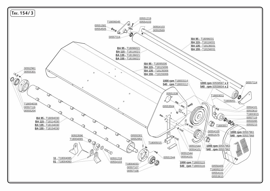
TAV. 154/3
BA 95 - T18095006BA 115 - T18115006BA 135 - T18135006BA 155 - T18155006
T180040340055711600555204
0055296100555301
T180040330055710700557108
00553596T18004065
0055121800554103
11 - T1800408501 - T18004060
BA 95 - T18094030BA 115 - T18114030BA 135 - T18134030BA 155 - T18154030
0055530100552951
T18005015
0055154400554101
0055410500551575
0055410100553610T18003015005571190055509500555215
T18003011
00557114
T18006051
BA 95 - T18096031BA 115 - T18116031BA 135 - T18136031BA 155 - T18156031BA 95 - T18096021
BA 115 - T18116021BA 135 - T18136021BA 155 - T18156021
T180060450055121900554103
00557114
00556405T18005210
0055410100553610
0055410300553569
00553504
1000 rpm 00557963540 rpm 00557962
0055154400554101
00551544
1000 rpm T18003115540 rpm T18003116
1000 rpm 00557961540 rpm 00557968
00551538
1000 rpm T18003114540 rpm T18003112 1000 rpm 00558587 x 2
540 rpm 00558604 x 2
0055158100554505
T18003017

CODICE DESCRIZIONE DESCRIPTION BENENNUNG DESCRIPTION DESCRIPCION TAV. 154/3T18003011 SUPPORTO TENDICATENA CHAIN STRETCHER SUPPORT KETTENSPANNERHALTER SUPPORT TENDEUR DE CHAINE SOPORTE TENSOR DE CADENAT18003015 PULEGGIA TENDICINGHIA BELT STRETCHER PULLEY RIEMENSPANSCHEIBE POULIE COURROIE ROLDANA DE CORREAT18003017 DISTANZIALE SPACER DISTANZSTUECK ENTRETOISE DISTANCIADORT18003112 PULEGGIA MOTRICE DP=225 DRIVING PULLEY ZIEHEN RIEMEN POULIE TIRANTE ROLDANA DE TIRART18003114 PULEGGIA MOTRICE DP=160 DRIVING PULLEY ZIEHEN RIEMEN POULIE TIRANTE ROLDANA DE TIRART18003115 PULEGGIA CONDOTTA DP=120 PULLEY SCHEIBE POULIE ROLDANAT18003116 PULEGGIA CONDOTTA DP=100 PULLEY SCHEIBE POULIE ROLDANAT18004033 SUPPORTO ROTORE SX ROTOR SUPPORT ROTORHALTER SUPPORT ROTOR SOPORTE ROTORT18004034 SUPPORTO ROTORE DX ROTOR SUPPORT ROTORHALTER SUPPORT ROTOR SOPORTE ROTORT18004060 COLTELLO “BA” BLADE “BA” MESSER “BA” COUTEAU “BA” CUCHILLO “BA”T18004065 ANELLO ATTACCO COLTELLI BLADE HOLDER RING MESSERHALTERRING BAGUE PORTE COUTEAUX ANILLO PORTA-AZADAST18004085 PALETTA BLADE MESSER MARTEAU-CUILLERE M11 BA CUCHILLAT18005015 CHIUSURA LATERALE REAR LATERAL PANEL HINTERE BLECH CAPOT ARRIERE LATERAL PLANCHA LATERALET18005210 CARTER LATERALE SIDE CARTER SEIT.GEHAEUSE CARTER CARTER LATERALT18006045 ASS.SUPPORTO RULLO DX RIGHT ROLLER SUPPORT RECHT WALZEHALTER SUPPORT ROULEAU DROITE SOPORTE RODILLO DERECHOT18006051 ASS.SUPPORTO RULLO SX LEFT ROLLER SUPPORT LINK WALZEHALTER SUPPORT ROULEAU GAUCHE SOPORTE RODILLO ISQUIERDOT18094030 ASSIEME ROTORE BA 95 BLADES HOLDER ROTOR BA 95 MESSERHALTERROTOR BA 95 ROTOR PORTE COUTEAUX BA 95 ROTOR PORTA-AZADAS BA 95T18095006 ASSIEME TELAIO BA 95 COMPLETE FRAME BA 95 KOMPL. RAHMEN BA 95 CHASSIS COMPL. BA 95 TELAR COMPL. BA 95T18096021 ASSIEME RULLO POSTER. 95 ROLLER BA 95 WALZE BA 95 ROULEAU BA 95 RODILLO BA 95T18096031 ANGOLARE RASCHIAF. 95 SOILSCAPER BA 95 ABSTREIFER BA 95 DECROTTOIR BA 95 RASQUETA BA 95T18114030 ASSIEME ROTORE BA 115 BLADES HOLDER ROTOR BA 115 MESSERHALTERROTOR BA 115 ROTOR PORTE COUTEAUX BA 115 ROTOR PORTA-AZADAS BA 115T18115006 ASSIEME TELAIO BA 115 COMPLETE FRAME BA 115 KOMPL. RAHMEN BA 115 CHASSIS COMPL. BA 115 TELAR COMPL. BA 115T18116021 ASSIEME RULLO POSTER. 115 ROLLER BA 115 WALZE BA 115 ROULEAU BA 115 RODILLO BA 115T18116031 ANGOLARE RASCHIAF. 115 SOILSCAPER BA 115 ABSTREIFER BA 115 DECROTTOIR BA 115 RASQUETA BA 115T18134030 ASSIEME ROTORE BA 135 BLADES HOLDER ROTOR BA 135 MESSERHALTERROTOR BA 135 ROTOR PORTE COUTEAUX BA 135 ROTOR PORTA-AZADAS BA 135T18135006 ASSIEME TELAIO BA 135 COMPLETE FRAME BA 135 KOMPL. RAHMEN BA 135 CHASSIS COMPL. BA 135 TELAR COMPL. BA 135T18136021 ASSIEME RULLO POSTER. 135 ROLLER BA 135 WALZE BA 135 ROULEAU BA 135 RODILLO BA 135T18136031 ANGOLARE RASCHIAF. 135 SOILSCAPER BA 135 ABSTREIFER BA 135 DECROTTOIR BA 135 RASQUETA BA 135T18154030 ASSIEME ROTORE BA 155 BLADES HOLDER ROTOR BA 155 MESSERHALTERROTOR BA 155 ROTOR PORTE COUTEAUX BA 155 ROTOR PORTA-AZADAS BA 155T18155006 ASSIEME TELAIO BA 155 COMPLETE FRAME BA 155 KOMPL. RAHMEN BA 155 CHASSIS COMPL. BA 155 TELAR COMPL. BA 155T18156021 ASSIEME RULLO POSTER.155 ROLLER BA 155 WALZE BA 155 ROULEAU BA 155 RODILLO BA 155T18156031 ANGOLARE RASCHIAF. 155 SOILSCAPER BA 155 ABSTREIFER BA 155 DECROTTOIR BA 155 RASQUETA BA 15500551218 >VITE M 8X1,25X 55 5737 10.9BR BOLT M8 X 1,25 X 55 SCHRAUBE M8 X 1,25 X 55 VIS M8 X 1,25 X 55 TORNILLO M8 X 1,25 X 5500551219 VITE TE.8G.M8X25 UNI 5739 BOLT M 8X25 SCHRAUBE M 8X25 VIS M 8X25 TORNILLO M 8X2500551538 VITE TE.8G.M10X1,25X70 UNI 5740 BOLT M 10X1,25X70 SCHRAUBE M 10X1,25X70 VIS M 10X1,25X70 TORNILLO M 10X1,25X7000551544 VITE TE.8G.M10X1,25X25 UNI 5740 BOLT M 10X1,25X25 SCHRAUBE M 10X1,25X25 VIS M 10X1,25X25 TORNILLO M 10X1,25X2500551575 VITE M12X1,25 X 25 5740 8.8 ZG BOLT M 12X1,25X25 SCHRAUBE M 12X1,25X25 VIS M 12X1,25X25 TORNILLO M 12X1,25X2500552952 VITE STEI M6X10 UNI 5927 BOLT M 6X10 SCHRAUBE M 6X10 VIS M 6X10 TORNILLO M 6X1000552961 TAPPO TIPO GPN 985 PLT GIAL PLUG VERSCHLUSSPFRPFEN BOUCHON FERMETURE TAPON CLAUSURA00553410 DADO AUTOFRENANTE M10X1,25 SELF LOCKING NUT M10X1,25 980V SELBSTSP.MUTT. M10X1,25 980-V ECROU AUTOBL. M10X1,25 980-V DADO AUTOBL. M10X1,25 980-V00553504 DADO E.6S.M10X1,25 UNI 5587 NUT M10X1,25 MUTTER M10X1,25 ECROU M10X1,25 DADO M10X1,2500553596 DADO AUT.A M 8X1,25 SELF LOCKING NUT M8X1,25 SELBSTSP.MUTT. M8X1,25 ECROU AUTOBL. M8X1,25 DADO AUTOBL. M8X1,2500553610 DADO AUTOBL. M10X1,25 UNI 7473 SELF LOCKING NUT M10X1,25 SELBSTSPERR.MUTTER M10X1,25 ECROU AUTOBL. M10X1,25 DADO AUTOBL. M10X1,2500554101 RONDELLA 10,5X21 ZPG WASHER 10,5X21 SCHEIBE 10,5X21 RONDELLE 10,5X21 ARANDELA 10,5X2100554103 RONDELLA PIANA D.8 UNI 6592 PLANE WASHER D.8 SCHEIBE D.8 RONDELLE D.8 ARANDELA D.800554105 RONDELLA PIANA D.12 UNI 6592 PLANE WASHER D.12 SCHEIBE D.12 RONDELLE D.12 ARANDELA D.1200555095 ANELLO SEEGER D.42 UNI 7437 SEEGER RING D.42 SEEGERRING D.42 BAGUE SEEGER D.42 ANILLO SEEGER D.4200555204 ANELLO SEEGER D.35 UNI 7435 SEEGER RING D.35 SEEGERRING D.35 BAGUE SEEGER D.35 ANILLO SEEGER D.3500555215 ANELLO SEEGER D.20 UNI7435 COMPRESSION RING D.20 RING D.20 ANNEAU RESSORT D.20 ANILLO D.2000555301 INGRASSATORE M6X1 DIRITTO A/1 GREASE NIPPLE M6X1 SCHMIERERBUCHSE M6X1 GRAISSEUR M6X1 ENGRASADOR M6X100556405 GUAINA BORDO CARTER SHEATH KABEL GAINE VAINA00557107 CUSCINETTO YSA 208-2FK BEARING YSA 208-2FK LAGER YSA 208-2FK ROULEMENT YSA 208-2FK COJINETE YSA 208-2FK00557108 BUSSOLA H2308 BEARING H2308 LAGER H2308 ROULEMENT H2308 COJINETE H230800557114 CUSCINETTO 1726204 2RS1 BEARING 1726204 2RS1 LAGER 1726204 2RS1 ROULEMENT 1726204 2RS1 COJINETE 1726204 2RS100557116 CUSCINETTO Y 1726207-2RS1 BEARING 1726207 2RS1 LAGER 1726207 2RS1 ROULEMENT 1726207 2RS1 COJINETE 1726207 2RS100557119 CUSCINETTO 6004 BEARING 6004 LAGER 6004 ROULEMENT 6004 COJINETE 600400557961 CALETTATORE AUTOB.DI=25 DE=55 SELF LOCKING KEYNG SELBSTPERR.VERKEILEN EMBOITAGE AUOBL. ENSAMBLADURA AUTOBL.00557962 CALETTATORE AUTOCENTR.30X55 KEYNG VERKEILEN EMBOITAGE ENSAMBLADURA00557963 CALETTATORE AUTOB.DI=30 DE=65 SELF LOCKING KEYNG SELBSTPERR.VERKEILEN EMBOITAGE AUOBL. ENSAMBLADURA AUTOBL.00557968 CALETTATORE AUTOCENTR. 25X65 SELF LOCKING KEYNG SELBSTPERR.VERKEILEN EMBOITAGE AUOBL. ENSAMBLADURA AUTOBL.00558587 CINGHIA BA BELT SCHAUBE COURROIE CORREA00558604 CINGHIA XPB LP=1043 BELT SCHAUBE COURROIE CORREA
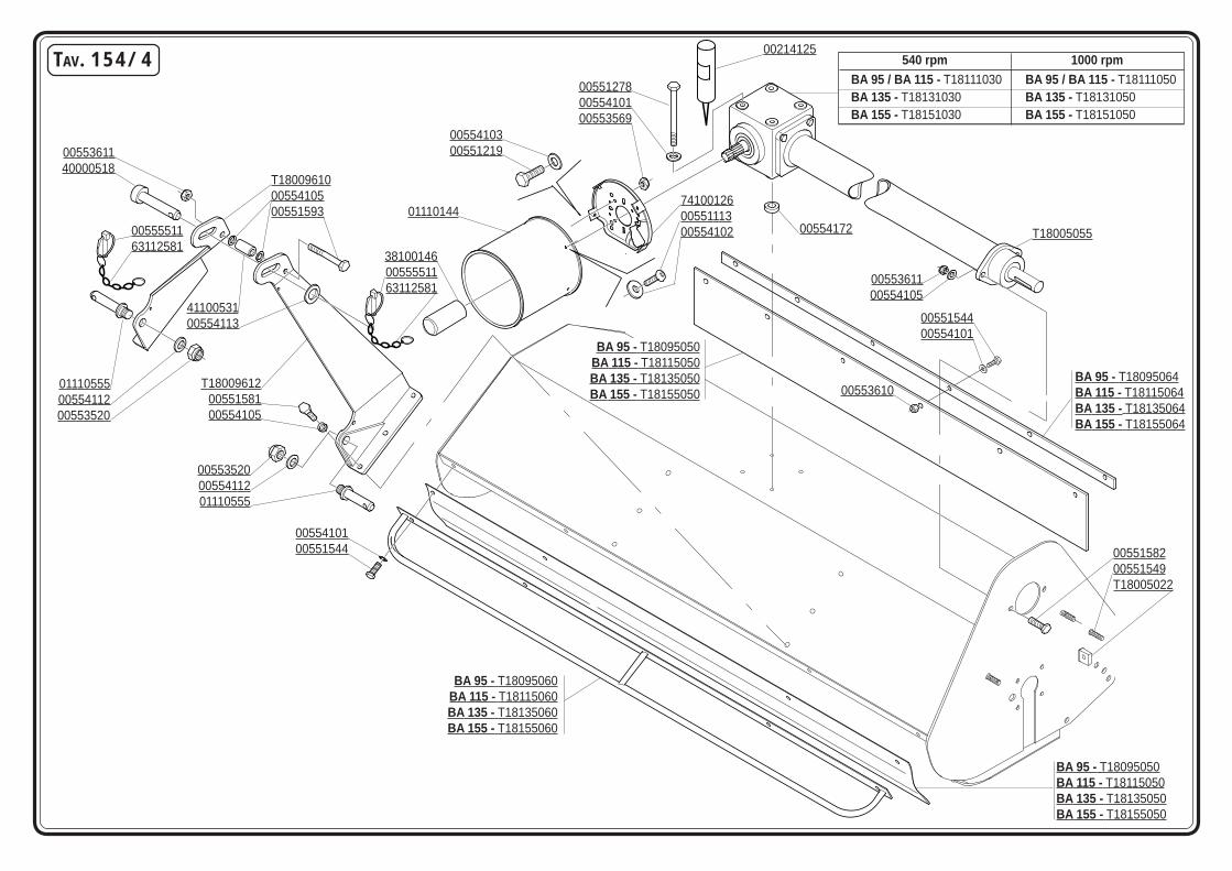
TAV. 154/4
T18005055
0055361100554105
0055158200551549T18005022
741001260055111300554102
0055410300551219
01110144
0055361140000518
381001460055551163112581
0055551163112581
T180096100055410500551593
011105550055411200553520
T180096120055158100554105
0055410100551544
BA 95 - T18095060BA 115 - T18115060BA 135 - T18135060BA 155 - T18155060
BA 95 - T18095050BA 115 - T18115050BA 135 - T18135050BA 155 - T18155050
BA 95 / BA 115 - T18111030 BA 95 / BA 115 - T18111050BA 135 - T18131030 BA 135 - T18131050BA 155 - T18151030 BA 155 - T18151050
005512780055410100553569
00554172
4110053100554113
005535200055411201110555
00553610
0055154400554101
BA 95 - T18095064BA 115 - T18115064BA 135 - T18135064BA 155 - T18155064
BA 95 - T18095050BA 115 - T18115050BA 135 - T18135050BA 155 - T18155050
00214125540 rpm 1000 rpm

CODICE DESCRIZIONE DESCRIPTION BENENNUNG DESCRIPTION DESCRIPCION TAV. 154/4T18005022 SUPP. REGISTRO TENDICINGHIA SUPPORT HALTER SUPPORT SOPORTET18005055 SUPPORTO PROLUNGA SUPPORT HALTER SUPPORT SOPORTET18009610 ASSIEME 3¢ PUNTO DX RH 3RD POINT 3¢ PUNKT RECHTS 3EME POINT DROITE 3¢ PUNTO DERECHOT18009612 ASSIEME 3¢ PUNTO SX LH 3RD POINT 3¢ PUNKT LINKS 3EME POINT GAUCHE 3¢ PUNTO ISQUIERDOT18095050 PROTEZIONE IN PVC BA 95 PROTECTION SCHUTZ PROTECTION PROTECCIONT18095060 ASSIEME PROTEZIONE ANTER. FRONT PROTECTION VORDERSCHUTZ PROTECTION AVANT PROTECCION ANTERIORT18095064 PIATTO FISSAGGIO PROT. GOMMA PLATE PLATTE PLAT PLACAT18111030 SCATOLA”BA”CON PROLUNGA L=530 GEARBOX WECHSELGETRIEBEGEHAEUSE BOITE DE VITESSE CAJA CAMBIOT18111050 SCAT.”BA”3 VIE PROLUNGA L=530 GEARBOX WECHSELGETRIEBEGEHAEUSE BOITE DE VITESSE CAJA CAMBIOT18115050 PROTEZIONE IN PVC BA 115 PROTECTION SCHUTZ PROTECTION PROTECCIONT18115060 ASSIEME PROTEZIONE ANTER. FRONT PROTECTION VORDERSCHUTZ PROTECTION AVANT PROTECCION ANTERIORT18115064 PIATTO FISSAGG. PROT. GOMMA PLATE PLATTE PLAT PLACAT18131030 SCATOLA”BA”- PROLUNGA L=615 GEARBOX WECHSELGETRIEBEGEHAEUSE BOITE DE VITESSE CAJA CAMBIOT18131050 SCATOLA 3 VIE PROLUNGA L=615 GEARBOX WECHSELGETRIEBEGEHAEUSE BOITE DE VITESSE CAJA CAMBIOT18135050 PROTEZIONE IN PVC BA 135 PROTECTION SCHUTZ PROTECTION PROTECCIONT18135060 ASSIEME PROTEZIONE ANTER. FRONT PROTECTION VORDERSCHUTZ PROTECTION AVANT PROTECCION ANTERIORT18135064 PIATTO FISSAG. PROT. GOMMA PLATE PLATTE PLAT PLACAT18151030 SCATOLA CON PROLUNGA L=715 GEARBOX WECHSELGETRIEBEGEHAEUSE BOITE DE VITESSE CAJA CAMBIOT18151050 SCATOLA CON PROLUNGA L=715 GEARBOX WECHSELGETRIEBEGEHAEUSE BOITE DE VITESSE CAJA CAMBIOT18155050 PROTEZIONE IN PVC BA 155 PROTECTION SCHUTZ PROTECTION PROTECCIONT18155060 ASSIEME PROTEZIONE ANTER. FRONT PROTECTION VORDERSCHUTZ PROTECTION AVANT PROTECCION ANTERIORT18155064 PIATTO FISSAG. PROT. GOMMA PLATE PLATTE PLAT PLACA00214125 LOCTITE 1X250 ML. TIPO.243 SEALING PACKAGE DICHTUNGSMASSE ANFERTIGUNG CONFECTION SIGILLANTE CONFECION SELADURA00551113 VITE TE.8G.M6X16 UNI 5739 BOLT M 6X16 SCHRAUBE M 6X16 VIS M 6X16 TORNILLO M 6X1600551219 VITE TE.8G.M8X25 UNI 5739 BOLT M 8X25 SCHRAUBE M 8X25 VIS M 8X25 TORNILLO M 8X2500551278 VITE M10X1,25X140 5738 8.8 ZG BOLT M 10X1,25X140 SCHRAUBE M 10X1,25X140 VIS M 10X1,25X140 TORNILLO M 10X1,20X14000551544 VITE TE.8G.M10X1,25X25 UNI 5740 BOLT M 10X1,25X25 SCHRAUBE M 10X1,25X25 VIS M 10X1,25X25 TORNILLO M 10X1,25X2500551548 VITE M10X1,25X 30 5740 8.8 ZG BOLT M 10X1,25X30 SCHRAUBE M 10X1,25X30 VIS M 10X1,25X30 TORNILLO M 10X1,25X3000551581 VITE TE.8G.M12X1,25X30 UNI 5740 BOLT M 12X1,25X30 SCHRAUBE M 12X1,25X30 VIS M 12X1,25X30 TORNILLO M 12X1,25X3000551582 VITE TE.8G.M12X1,25X35 UNI 5740 BOLT M 12X1,25X35 SCHRAUBE M 12X1,25X35 VIS M 12X1,25X35 TORNILLO M 12X1,25X3500551593 VITE TE.8G.M12X1,25X90 UNI 5738 BOLT M 12X1,25X90 SCHRAUBE M 12X1,25X90 VIS M 12X1,25X90 TORNILLO M 12X1,25X9000553520 DADO E.6S.M24X2 UNI 5588 NUT M24X2 MUTTER M24X2 ECROU M24X2 DADO M24X200553569 DADO AUT.M8X1,25 D982 8G ZG SELF LOCKING NUT M8X1,25 SELBSTSP.MUTT. M8X1,25 ECROU AUTOBL. M8X1,25 DADO AUTOBL. M8X1,2500553610 DADO AUTOBL. M10X1,25 UNI 7473 SELF LOCKING NUT M10X1,25 SELBSTSPERR.MUTTER M10X1,25 ECROU AUTOBL. M10X1,25 DADO AUTOBL. M10X1,2500553611 DADO AUTOBL. M12X1,25 UNI 7473 SELF LOCKING NUT M12X1,25 SELBSTSPERR.MUTTER M12X1,25 ECROU AUTOBL. M12X1,25 DADO AUTOBL. M12X1,2500554101 RONDELLA 10,5X21 ZPG WASHER 10,5X21 SCHEIBE 10,5X21 RONDELLE 10,5X21 ARANDELA 10,5X2100554102 RONDELLA PIANA D.6 UNI 6592 PLANE WASHER D.6 SCHEIBE D.6 RONDELLE D.6 ARANDELA D.600554103 RONDELLA PIANA D.8 UNI 6592 PLANE WASHER D.8 SCHEIBE D.8 RONDELLE D.8 ARANDELA D.800554105 RONDELLA PIANA D.12 UNI 6592 PLANE WASHER D.12 SCHEIBE D.12 RONDELLE D.12 ARANDELA D.1200554112 RONDELLA PIANA D.24 UNI 6592 PLANE WASHER D.24 SCHEIBE D.24 RONDELLE D.24 ARANDELA D.2400554113 RONDELLA PIANA D.20X34 UNI 6593 PLANE WASHER D. 20 SCHEIBE D.20 RONDELLE D. 20 ARANDELLA D.2000554172 ROS.M12 FASCIA LAR.DIN6340 ZG WASHER D. 12 SCHEIBE D.12 RONDELLE D.12 ARANDELA D.1200555511 COPIGLIA A SCATTO D.11 SPLIT PIN D.11 SPLINT D.11 GOUPILLE D.11 RODETE D.1101110144 PROTEZIONE CARDANO CARDAN PROTECTION GELENKWELLENSCHUTZ PROTECTION CARDAN PROTECCION CARDANICO01110555 PERNO ATTACCO D.22 LINKAGE PIN D.22 VERB.BOLZEN D.22 GOUJON ATTELAGE D.22 PERNO ATAQUE D.2238100146 MANICOTTO PROTEZIONE PDF P.T.O. PROTECTION ZAPFWELLENSCHUTZ P.T.O. MANCHON DE PROTECTION P.T.O. MANGUITO PROTECCION P.T.O.40000518 PERNO TERZO PUNTO PIN BOLZEN GOUJON PERNO41100531 BOCCOLA UNIONE TERZO PUNTO BUSH SPACER 3RD POINT DISTANZBUECHSE DREIPUNKT BOUSSOLE D’ENTRETROISE BRUJULA DISTANCIADOR63112581 CATENELLA CHAIN KETTE CHAINE CADENA74100126 SUPPORTO PROTEZIONE PROTECTION SUPPORT GELENKWELLENSCHUTZ HALTER SUPPORT PROTECTION CARDAN SOPORTE PROTECCION CARDANICO
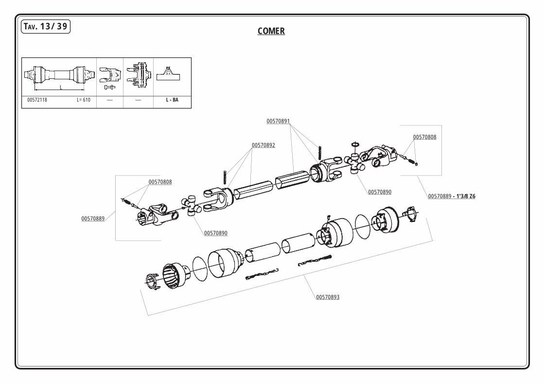
COMERTAV. 13/39
00572118 L= 610 — — L - BA
L
00570808
00570889
00570890
00570892
00570891
00570808
00570889 - 1'3/8 Z600570890
00570893

CODICE DESCRIZIONE DESCRIPTION BENENNUNG DESCRIPTION DESCRIPCION TAV. 13/3900570808 PULSANTE COMPLETO PUSHBUTTON ASSY DRUCKKNOPF KOMPL. POUSSOIR COMPL. PULSADOR COMPL.00570889 FORCELLA ATTACCO LINKAGE FORK GABELSTUECK FOURCHE ATTELAGE HORQUILLA ATAQUE00570890 CROCERA COMPLETA SPIDER ASSY GELENKKREUZ KOMPL. CROISIERE COMPL. CRUCETA COMPLETA00570891 FORCELLA CON TUBO ESTERNO FORK WITH EXTERNAL PIPE GABELST. + AUSSENROHR FOURCHE AVEC TUBE EXTERIEUR HORQUILLA + TUBO EXTERNO00570892 FORCELLA CON TUBO INTERNO FORK WITH INTERNAL PIPE GABELST. + AUSSENROHR FOURCHE AVEC TUBE INT. HORQUILLA + TUBO INT.00570893 PROTEZIONE COMPLETA PROTECTION ASSY KOMPL. SCHUTZ PROTECTION COMPL. PROTECCION COMPL.00572118 ALBERO CARDANICO COMPLETO UNIVERSAL P.T.O SHAFT GELENKWELLE ARBRE A CARDAN ARBOL CARDANICO
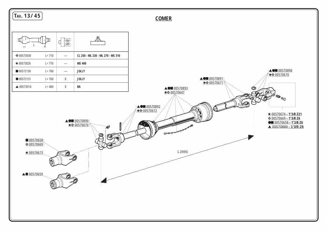
TAV. 13/45
L (min)
✜ 00573030 L= 710 — CL 250 - ML 230 - ML 270 - MS 310
✱ 00573026 L= 710 — MS 400
■ 00572130 L= 760 — JOLLY
● 00572131 L= 760 X JOLLY
▲ 00573014 L= 460 X BA
L
■ 00570658✜ 00570669
✱ 00570673
▲● 00570659
▲●■ 00570890✱✜ 00570670
▲●■ 00570892✱✜ 00570672
▲●■ 00570893✱✜ 00570647
▲●■ 00570891✱✜ 00570671
▲●■ 00570890✱✜ 00570670
✱ 00570674 - 1’3/8 Z21✜ 00570669 - 1’3/8 Z6●■ 00570658 - 1’3/8 Z6▲ 00570889 - 1’3/8 Z6
COMER

CODICE DESCRIZIONE DESCRIPTION BENENNUNG DESCRIPTION DESCRIPCION TAV. 13/4500570647 PROTEZIONE COMPLETA PROTECTION ASSY KOMPL. SCHUTZ PROTECTION COMPL. PROTECCION COMPL.00570658 FORCELLA ATTACCO LINKAGE FORK GABELSTUECK FOURCHE ATTELAGE HORQUILLA ATAQUE00570659 RUOTA LIBERA FREE WHEEL FREILAUF ROUE LIBRE RUEDA LIBRE00570669 FORCELLA ATTACCO LINKAGE FORK GABELSTUECK FOURCHE ATTELAGE HORQUILLA ATAQUE00570670 CROCIERA COMPLETA SPIDER ASSY GELENKKREUZ KOMPL. CROISIERE COMPL. CRUCETA COMPLETA00570671 FORCELLA CON TUBO ESTERNO FORK WITH EXTERNAL PIPE GABELST. + AUSSENROHR FOURCHE AVEC TUBE EXTERIEUR HORQUILLA + TUBO EXTERNO00570672 FORCELLA CON ALBERO FORK WITH SHAFT CUNA GABELST. + WELLE CUNA FOURCHE AVEC ARBRE CUNA HORQUILLA + ARBOL CUNA00570673 FORCELLA ATTACCO LINKAGE FORK GABELSTUECK FOURCHE ATTELAGE HORQUILLA ATAQUE00570674 FORCELLA ATTACCO LINKAGE FORK GABELSTUECK FOURCHE ATTELAGE HORQUILLA ATAQUE00570889 FORCELLA ATTACCO LINKAGE FORK GABELSTUECK FOURCHE ATTELAGE HORQUILLA ATAQUE00570890 CROCERA COMPLETA SPIDER ASSY GELENKKREUZ KOMPL. CROISIERE COMPL. CRUCETA COMPLETA00570891 FORCELLA CON TUBO ESTERNO FORK WITH EXTERNAL PIPE GABELST. + AUSSENROHR FOURCHE AVEC TUBE EXTERIEUR HORQUILLA + TUBO EXTERNO00570892 FORCELLA CON TUBO INTERNO FORK WITH INTERNAL PIPE GABELST. + AUSSENROHR FOURCHE AVEC TUBE INT. HORQUILLA + TUBO INT.00570893 PROTEZIONE COMPLETA PROTECTION ASSY KOMPL. SCHUTZ PROTECTION COMPL. PROTECCION COMPL.00572130 ALBERO CARDANICO COMPLETO UNIVERSAL P.T.O SHAFT GELENKWELLE ARBRE A CARDAN ARBOL CARDANICO00572131 ALBERO CARDANICO COMPLETO UNIVERSAL P.T.O SHAFT GELENKWELLE ARBRE A CARDAN ARBOL CARDANICO00573014 ALBERO CARDANICO COMPLETO UNIVERSAL P.T.O SHAFT GELENKWELLE ARBRE A CARDAN ARBOL CARDANICO00573026 ALBERO CARDANICO COMPLETO UNIVERSAL P.T.O SHAFT GELENKWELLE ARBRE A CARDAN ARBOL CARDANICO00573030 ALBERO CARDANICO COMPLETO UNIVERSAL P.T.O SHAFT GELENKWELLE ARBRE A CARDAN ARBOL CARDANICO
RICHIEDETE SEMPRE RICAMBI ORIGINALI MARCHIATI GARANZIA DI ASSOLUTA QUALITÀ!USE GENUINE PARTS ONLY, A GUARANTEE OF ABSOLUTE QUALITY!
BENUTZEN SIE NUR ORIGINALTEILE MIT DEM EINGEPRÄGTEN DIE GARANTIE FÜR ABSOLUTE QUALITÄTEXIGEZ LES PIECES DE RECHANGE ESTAMPILLES GARANTIE DE QUALITE ABSOLUE
UTILICEN REPUESTOS ORIGINALES GARANTIA Y FIABILIDAD
La garanzia MASCHIO sulle macchine ha valore solo se utilizzate Ricambi OriginaliMASCHIO Warranty will only cover machines that are fitted with genuine Maschio parts
Nur der Einsatz von MASCHIO Originalteilen sichert Ihnen die Garantie für Ihre MASCHIO-GeräteLes garanties ne s’appliquent que pour les machines équipées de pièces d’origine MASCHIO
MASCHIO garantíza sus maquinas solo en caso de que esten equipadas con recambios originales
ROTRA MPCLASSIFICAZIONE SAE 85W/140
GR MU EP2
Il grasso AGIP GR MU EP 2 soddisfa le seguenti specifiche:AGIP GR MU EP 2 grease complies with the following specifications:Das Feet AGIP GR MU EP 2 entspricht den folgenden Normen:La graisse AGIP GR MU EP 2 satisfait les spécifications suivantes:La grasa AGIP GR MU EP 2 satisfa los siguientes normas:
- DIN 51825 (KP2K)
L'olio AGIP ROTRA MP soddisfa le seguenti specifiche:AGIP ROTRA MP oil complies with the following specifications:Das Öl ROTRA MP entspricht den folgenden Normen:L'huile AGIP ROTRA MP satisfait les spécifications suivantes:L'aceite AGIP ROTRA MP satisfa los siguientes normas:
- API GL5- MIL-L-2105C
MASCHIO GASPARDO S.p.A.Via Marcello, 73I-35011 Campodarsego (Padova) ItalyTel. +39 049 9289810Fax +39 049 9289900http://www.maschionet.comE-mail: [email protected]
MASCHIO FRANCE S.a.r.l.1, rue de Merignan ZAF-45240 - La Ferte St. Aubin - FranceTel. +33 (0) 2.38.64.12.12Fax +33 (0) 2.38.64.66.79
MASCHIO DEUTSCHLAND GmbHÄußere Nürnberger Straße 5D-91177 ThalmässingDeutschlandTel. +49 (0) 9173 79000Fax +49 (0) 9173 790079
MASCHIO-GASPARDO IBERICA S.L.Calle Cabernet, n° 10Poligono Industrial Clot de MojaOlerdola - 08734 - BarcelonaTel. +34 93 81.99.058Fax +34 93 81.99.059
MASCHIO MIDDLE EASTP.O. Box 922388Amman, 11192 JordanTel. 962 6 5511384Fax 962 6 5538398E-mail: [email protected]
MASCHIO-GASPARDO USA, Inc.120 North Scott Park RoadEldridge, IA 52748 - USAPh. +1 563 - 285 9937Fax +1 563 - 285 9938
Top Related