


Sprachen
Seiten
Rechtliche

DE Montageanleitung RGB B
GB Installation manual RGB B
FR Instructions de montage RGB B
IT Istruzioni di montaggio RGB B
DK Monteringsvejledning RGB B
NL Montagehandleiding RGB B
ES Manual de montaje RGB B
PL Instrukcja montażu RGB B
HU Szerelési útmutató RGB B
CZ Návod k montáži RGB B
Inhaltsverzeichnis
DE 1. Zu dieser Anleitung................................................................................... 71.1 Inhalt dieser Anleitung..... . . . . . . . . . . . . . . . . . . . . . . . . . . . . . . . . . . . . . . . . . . . . . . . . . . . . . . . . . . . . . . . . . . . . . . . . . . 71.2 Verwendete Symbole.... . . . . . . . . . . . . . . . . . . . . . . . . . . . . . . . . . . . . . . . . . . . . . . . . . . . . . . . . . . . . . . . . . . . . . . . . . . . . . 71.3 An wen wendet sich diese Anleitung?.... . . . . . . . . . . . . . . . . . . . . . . . . . . . . . . . . . . . . . . . . . . . . . . . . . . . . . . 71.4 Lieferumfang.... . . . . . . . . . . . . . . . . . . . . . . . . . . . . . . . . . . . . . . . . . . . . . . . . . . . . . . . . . . . . . . . . . . . . . . . . . . . . . . . . . . . . . . . . 7
2. Sicherheit................................................................................................. 82.1 Bestimmungsgemäße Verwendung.... . . . . . . . . . . . . . . . . . . . . . . . . . . . . . . . . . . . . . . . . . . . . . . . . . . . . . . . . 82.2 Allgemeine Sicherheitshinweise... . . . . . . . . . . . . . . . . . . . . . . . . . . . . . . . . . . . . . . . . . . . . . . . . . . . . . . . . . . . . . . 8
3. Technische Angaben.................................................................................. 93.1 Übersicht und Abmessungen.... . . . . . . . . . . . . . . . . . . . . . . . . . . . . . . . . . . . . . . . . . . . . . . . . . . . . . . . . . . . . . . . . . . 93.2 Technische Daten.... . . . . . . . . . . . . . . . . . . . . . . . . . . . . . . . . . . . . . . . . . . . . . . . . . . . . . . . . . . . . . . . . . . . . . . . . . . . . . . . . . . 93.3 Schaltpläne..... . . . . . . . . . . . . . . . . . . . . . . . . . . . . . . . . . . . . . . . . . . . . . . . . . . . . . . . . . . . . . . . . . . . . . . . . . . . . . . . . . . . . . . . . . . 10
4. Vor der Installation.................................................................................... 114.1 Hinweise zum Montageort... . . . . . . . . . . . . . . . . . . . . . . . . . . . . . . . . . . . . . . . . . . . . . . . . . . . . . . . . . . . . . . . . . . . . . . 11
5. Montage.................................................................................................. 125.1 Montage RGB..... . . . . . . . . . . . . . . . . . . . . . . . . . . . . . . . . . . . . . . . . . . . . . . . . . . . . . . . . . . . . . . . . . . . . . . . . . . . . . . . . . . . . . . . 12
6. Installation............................................................................................... 136.1 Elektrischer Anschluss RGB.... . . . . . . . . . . . . . . . . . . . . . . . . . . . . . . . . . . . . . . . . . . . . . . . . . . . . . . . . . . . . . . . . . . . . . 13
7. Inbetriebnahme........................................................................................ 147.1 Konfiguration.... . . . . . . . . . . . . . . . . . . . . . . . . . . . . . . . . . . . . . . . . . . . . . . . . . . . . . . . . . . . . . . . . . . . . . . . . . . . . . . . . . . . . . . . 14
Table of contents
GB 1. Regarding the instructions......................................................................... 151.1 Content of this manual... . . . . . . . . . . . . . . . . . . . . . . . . . . . . . . . . . . . . . . . . . . . . . . . . . . . . . . . . . . . . . . . . . . . . . . . . . . . 151.2 Used symbols.... . . . . . . . . . . . . . . . . . . . . . . . . . . . . . . . . . . . . . . . . . . . . . . . . . . . . . . . . . . . . . . . . . . . . . . . . . . . . . . . . . . . . . . . . 151.3 For whom is this manual intended?.... . . . . . . . . . . . . . . . . . . . . . . . . . . . . . . . . . . . . . . . . . . . . . . . . . . . . . . . . . 151.4 Scope of Supply.... . . . . . . . . . . . . . . . . . . . . . . . . . . . . . . . . . . . . . . . . . . . . . . . . . . . . . . . . . . . . . . . . . . . . . . . . . . . . . . . . . . . . . 15
2. Safety...................................................................................................... 162.1 Usage according to purpose... . . . . . . . . . . . . . . . . . . . . . . . . . . . . . . . . . . . . . . . . . . . . . . . . . . . . . . . . . . . . . . . . . . . . 162.2 General safety instructions.... . . . . . . . . . . . . . . . . . . . . . . . . . . . . . . . . . . . . . . . . . . . . . . . . . . . . . . . . . . . . . . . . . . . . . 16
3. Technical Data.......................................................................................... 173.1 Overview and Dimensions.... . . . . . . . . . . . . . . . . . . . . . . . . . . . . . . . . . . . . . . . . . . . . . . . . . . . . . . . . . . . . . . . . . . . . . . 173.2 Technical Data.... . . . . . . . . . . . . . . . . . . . . . . . . . . . . . . . . . . . . . . . . . . . . . . . . . . . . . . . . . . . . . . . . . . . . . . . . . . . . . . . . . . . . . . 173.3 Circuit diagrams.... . . . . . . . . . . . . . . . . . . . . . . . . . . . . . . . . . . . . . . . . . . . . . . . . . . . . . . . . . . . . . . . . . . . . . . . . . . . . . . . . . . . . 18
4. Before installation..................................................................................... 194.1 Tips for the assembly location... . . . . . . . . . . . . . . . . . . . . . . . . . . . . . . . . . . . . . . . . . . . . . . . . . . . . . . . . . . . . . . . . . 19
5. Assembly.................................................................................................. 205.1 Assembly RGB.... . . . . . . . . . . . . . . . . . . . . . . . . . . . . . . . . . . . . . . . . . . . . . . . . . . . . . . . . . . . . . . . . . . . . . . . . . . . . . . . . . . . . . . . 20
6. Installation............................................................................................... 216.1 Electrical connection RGB.... . . . . . . . . . . . . . . . . . . . . . . . . . . . . . . . . . . . . . . . . . . . . . . . . . . . . . . . . . . . . . . . . . . . . . . . 21
7. Commissioning......................................................................................... 227.1 Configuration.... . . . . . . . . . . . . . . . . . . . . . . . . . . . . . . . . . . . . . . . . . . . . . . . . . . . . . . . . . . . . . . . . . . . . . . . . . . . . . . . . . . . . . . . 22
2 03.11
Sommaire
FR 1. Au sujet des présentes instructions............................................................. 231.1 Contenu des présentes instructions..... . . . . . . . . . . . . . . . . . . . . . . . . . . . . . . . . . . . . . . . . . . . . . . . . . . . . . . . . 231.2 Symboles utilisés.... . . . . . . . . . . . . . . . . . . . . . . . . . . . . . . . . . . . . . . . . . . . . . . . . . . . . . . . . . . . . . . . . . . . . . . . . . . . . . . . . . . . 231.3 A qui s'adresse ce manuel?... . . . . . . . . . . . . . . . . . . . . . . . . . . . . . . . . . . . . . . . . . . . . . . . . . . . . . . . . . . . . . . . . . . . . . . 231.4 Etendue de la livraison.... . . . . . . . . . . . . . . . . . . . . . . . . . . . . . . . . . . . . . . . . . . . . . . . . . . . . . . . . . . . . . . . . . . . . . . . . . . . 23
2. Sécurité.................................................................................................... 242.1 Utilisation conforme aux fins prévues... . . . . . . . . . . . . . . . . . . . . . . . . . . . . . . . . . . . . . . . . . . . . . . . . . . . . . . 242.2 Consignes générales de sécurité.... . . . . . . . . . . . . . . . . . . . . . . . . . . . . . . . . . . . . . . . . . . . . . . . . . . . . . . . . . . . . . . 24
3. Indications techniques............................................................................... 253.1 Aperçu et Dimensions.... . . . . . . . . . . . . . . . . . . . . . . . . . . . . . . . . . . . . . . . . . . . . . . . . . . . . . . . . . . . . . . . . . . . . . . . . . . . . 253.2 Caractéristiques techniques... . . . . . . . . . . . . . . . . . . . . . . . . . . . . . . . . . . . . . . . . . . . . . . . . . . . . . . . . . . . . . . . . . . . . 253.3 Schémas de câblage..... . . . . . . . . . . . . . . . . . . . . . . . . . . . . . . . . . . . . . . . . . . . . . . . . . . . . . . . . . . . . . . . . . . . . . . . . . . . . . . 26
4. Avant l'installation.................................................................................... 274.1 Recommandations concernant le lieu de montage.... . . . . . . . . . . . . . . . . . . . . . . . . . . . . . . . . . . . . 27
5. Montage.................................................................................................. 285.1 Montage RGB..... . . . . . . . . . . . . . . . . . . . . . . . . . . . . . . . . . . . . . . . . . . . . . . . . . . . . . . . . . . . . . . . . . . . . . . . . . . . . . . . . . . . . . . . 28
6. Installation............................................................................................... 296.1 Branchement électrique RGB.... . . . . . . . . . . . . . . . . . . . . . . . . . . . . . . . . . . . . . . . . . . . . . . . . . . . . . . . . . . . . . . . . . . 29
7. Mise en service.......................................................................................... 307.1 Configuration.... . . . . . . . . . . . . . . . . . . . . . . . . . . . . . . . . . . . . . . . . . . . . . . . . . . . . . . . . . . . . . . . . . . . . . . . . . . . . . . . . . . . . . . . 30
Indice
IT 1. Introduzione............................................................................................. 311.1 Contenuto.... . . . . . . . . . . . . . . . . . . . . . . . . . . . . . . . . . . . . . . . . . . . . . . . . . . . . . . . . . . . . . . . . . . . . . . . . . . . . . . . . . . . . . . . . . . . . 311.2 Simboli utilizzati.. . . . . . . . . . . . . . . . . . . . . . . . . . . . . . . . . . . . . . . . . . . . . . . . . . . . . . . . . . . . . . . . . . . . . . . . . . . . . . . . . . . . . . 311.3 A chi si rivolge questo manuale?... . . . . . . . . . . . . . . . . . . . . . . . . . . . . . . . . . . . . . . . . . . . . . . . . . . . . . . . . . . . . . . 311.4 Dotazione di fornitura..... . . . . . . . . . . . . . . . . . . . . . . . . . . . . . . . . . . . . . . . . . . . . . . . . . . . . . . . . . . . . . . . . . . . . . . . . . . . 31
2. Sicurezza.................................................................................................. 322.1 Utilizzo appropriato.... . . . . . . . . . . . . . . . . . . . . . . . . . . . . . . . . . . . . . . . . . . . . . . . . . . . . . . . . . . . . . . . . . . . . . . . . . . . . . . . 322.2 Norme di sicurezza generali... . . . . . . . . . . . . . . . . . . . . . . . . . . . . . . . . . . . . . . . . . . . . . . . . . . . . . . . . . . . . . . . . . . . . . 32
3. Dati tecnici............................................................................................... 333.1 Panoramica e dimensioni... . . . . . . . . . . . . . . . . . . . . . . . . . . . . . . . . . . . . . . . . . . . . . . . . . . . . . . . . . . . . . . . . . . . . . . . . 333.2 Dati tecnici.. . . . . . . . . . . . . . . . . . . . . . . . . . . . . . . . . . . . . . . . . . . . . . . . . . . . . . . . . . . . . . . . . . . . . . . . . . . . . . . . . . . . . . . . . . . . . . 333.3 Schemi elettrici.. . . . . . . . . . . . . . . . . . . . . . . . . . . . . . . . . . . . . . . . . . . . . . . . . . . . . . . . . . . . . . . . . . . . . . . . . . . . . . . . . . . . . . . . 34
4. Prima dell'installazione.............................................................................. 354.1 Avvertenze sul luogo di montaggio... . . . . . . . . . . . . . . . . . . . . . . . . . . . . . . . . . . . . . . . . . . . . . . . . . . . . . . . . . . 35
5. Montaggio................................................................................................ 365.1 Montaggio dell'unità ambiente RGB.... . . . . . . . . . . . . . . . . . . . . . . . . . . . . . . . . . . . . . . . . . . . . . . . . . . . . . . . . 36
6. Installazione............................................................................................. 376.1 Allacciamento elettrico RGB.... . . . . . . . . . . . . . . . . . . . . . . . . . . . . . . . . . . . . . . . . . . . . . . . . . . . . . . . . . . . . . . . . . . . 37
7. Messa in esercizio...................................................................................... 387.1 Configurazione... . . . . . . . . . . . . . . . . . . . . . . . . . . . . . . . . . . . . . . . . . . . . . . . . . . . . . . . . . . . . . . . . . . . . . . . . . . . . . . . . . . . . . . 38
03.11 3
Indholdsfortegnelse
DK 1. Om denne vejledning................................................................................ 391.1 Denne vejlednings indhold.... . . . . . . . . . . . . . . . . . . . . . . . . . . . . . . . . . . . . . . . . . . . . . . . . . . . . . . . . . . . . . . . . . . . . . 391.2 Anvendte symboler.... . . . . . . . . . . . . . . . . . . . . . . . . . . . . . . . . . . . . . . . . . . . . . . . . . . . . . . . . . . . . . . . . . . . . . . . . . . . . . . . . 391.3 Hvem henvender denne vejledning sig til?... . . . . . . . . . . . . . . . . . . . . . . . . . . . . . . . . . . . . . . . . . . . . . . . . 391.4 Leveringsomfang..... . . . . . . . . . . . . . . . . . . . . . . . . . . . . . . . . . . . . . . . . . . . . . . . . . . . . . . . . . . . . . . . . . . . . . . . . . . . . . . . . . . 39
2. Sikkerhed................................................................................................. 402.1 Forskriftsmæssig anvendelse.... . . . . . . . . . . . . . . . . . . . . . . . . . . . . . . . . . . . . . . . . . . . . . . . . . . . . . . . . . . . . . . . . . . 402.2 Generelle sikkerhedsinstruktioner.... . . . . . . . . . . . . . . . . . . . . . . . . . . . . . . . . . . . . . . . . . . . . . . . . . . . . . . . . . . . 40
3. Tekniske data........................................................................................... 413.1 Oversigt og Mål.... . . . . . . . . . . . . . . . . . . . . . . . . . . . . . . . . . . . . . . . . . . . . . . . . . . . . . . . . . . . . . . . . . . . . . . . . . . . . . . . . . . . . . 413.2 Tekniske data.... . . . . . . . . . . . . . . . . . . . . . . . . . . . . . . . . . . . . . . . . . . . . . . . . . . . . . . . . . . . . . . . . . . . . . . . . . . . . . . . . . . . . . . . . 413.3 El-diagrammer.... . . . . . . . . . . . . . . . . . . . . . . . . . . . . . . . . . . . . . . . . . . . . . . . . . . . . . . . . . . . . . . . . . . . . . . . . . . . . . . . . . . . . . . 42
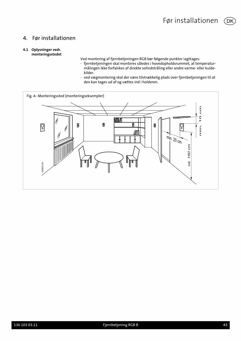
4. Før installationen...................................................................................... 434.1 Oplysninger vedr. monteringsstedet.... . . . . . . . . . . . . . . . . . . . . . . . . . . . . . . . . . . . . . . . . . . . . . . . . . . . . . . . . 43
5. Montering................................................................................................ 445.1 Montering RGB.... . . . . . . . . . . . . . . . . . . . . . . . . . . . . . . . . . . . . . . . . . . . . . . . . . . . . . . . . . . . . . . . . . . . . . . . . . . . . . . . . . . . . . 44
6. Installation............................................................................................... 456.1 Elektrisk tilslutning RGB.... . . . . . . . . . . . . . . . . . . . . . . . . . . . . . . . . . . . . . . . . . . . . . . . . . . . . . . . . . . . . . . . . . . . . . . . . . 45
7. Idrifttagning............................................................................................. 467.1 Konfiguration.... . . . . . . . . . . . . . . . . . . . . . . . . . . . . . . . . . . . . . . . . . . . . . . . . . . . . . . . . . . . . . . . . . . . . . . . . . . . . . . . . . . . . . . . 46
Inhoudsopgave
NL 1. Toelichting bij deze handleiding................................................................. 471.1 Inhoud van deze handleiding.... . . . . . . . . . . . . . . . . . . . . . . . . . . . . . . . . . . . . . . . . . . . . . . . . . . . . . . . . . . . . . . . . . . 471.2 Gebruikte symbolen.... . . . . . . . . . . . . . . . . . . . . . . . . . . . . . . . . . . . . . . . . . . . . . . . . . . . . . . . . . . . . . . . . . . . . . . . . . . . . . . 471.3 Tot wie richt zich deze handleiding?.... . . . . . . . . . . . . . . . . . . . . . . . . . . . . . . . . . . . . . . . . . . . . . . . . . . . . . . . . 471.4 Leveringspakket... . . . . . . . . . . . . . . . . . . . . . . . . . . . . . . . . . . . . . . . . . . . . . . . . . . . . . . . . . . . . . . . . . . . . . . . . . . . . . . . . . . . . . 47
2. Veiligheid................................................................................................. 482.1 Doelmatig gebruik.... . . . . . . . . . . . . . . . . . . . . . . . . . . . . . . . . . . . . . . . . . . . . . . . . . . . . . . . . . . . . . . . . . . . . . . . . . . . . . . . . . 482.2 Algemene veiligheidsvoorschriften... . . . . . . . . . . . . . . . . . . . . . . . . . . . . . . . . . . . . . . . . . . . . . . . . . . . . . . . . . . 48
3. Technische gegevens................................................................................. 493.1 Overzicht en Afmetingen.... . . . . . . . . . . . . . . . . . . . . . . . . . . . . . . . . . . . . . . . . . . . . . . . . . . . . . . . . . . . . . . . . . . . . . . . 493.2 Technische kenmerken.... . . . . . . . . . . . . . . . . . . . . . . . . . . . . . . . . . . . . . . . . . . . . . . . . . . . . . . . . . . . . . . . . . . . . . . . . . . 493.3 Bedradingschema’s... . . . . . . . . . . . . . . . . . . . . . . . . . . . . . . . . . . . . . . . . . . . . . . . . . . . . . . . . . . . . . . . . . . . . . . . . . . . . . . . . 50
4. Voorbereiding van de installatie................................................................. 514.1 Aanwijzingen betreffende de lokatie... . . . . . . . . . . . . . . . . . . . . . . . . . . . . . . . . . . . . . . . . . . . . . . . . . . . . . . . . 51
5. Montage.................................................................................................. 525.1 Montage RGB..... . . . . . . . . . . . . . . . . . . . . . . . . . . . . . . . . . . . . . . . . . . . . . . . . . . . . . . . . . . . . . . . . . . . . . . . . . . . . . . . . . . . . . . . 52
6. Installatie................................................................................................. 536.1 Elektrische aansluiting RGB.... . . . . . . . . . . . . . . . . . . . . . . . . . . . . . . . . . . . . . . . . . . . . . . . . . . . . . . . . . . . . . . . . . . . . 53
7. Inbedrijfsname......................................................................................... 547.1 Configuratie... . . . . . . . . . . . . . . . . . . . . . . . . . . . . . . . . . . . . . . . . . . . . . . . . . . . . . . . . . . . . . . . . . . . . . . . . . . . . . . . . . . . . . . . . . . 54
4 03.11
Índice
ES 1. Acerca de este manual............................................................................... 551.1 Contenido de este manual.... . . . . . . . . . . . . . . . . . . . . . . . . . . . . . . . . . . . . . . . . . . . . . . . . . . . . . . . . . . . . . . . . . . . . . . 551.2 Símbolos utilizados..... . . . . . . . . . . . . . . . . . . . . . . . . . . . . . . . . . . . . . . . . . . . . . . . . . . . . . . . . . . . . . . . . . . . . . . . . . . . . . . . 551.3 ¿A quién va dirigido este manual?... . . . . . . . . . . . . . . . . . . . . . . . . . . . . . . . . . . . . . . . . . . . . . . . . . . . . . . . . . . . . 551.4 Volumen de suministro.... . . . . . . . . . . . . . . . . . . . . . . . . . . . . . . . . . . . . . . . . . . . . . . . . . . . . . . . . . . . . . . . . . . . . . . . . . . 55
2. Seguridad................................................................................................. 562.1 Uso previsto.... . . . . . . . . . . . . . . . . . . . . . . . . . . . . . . . . . . . . . . . . . . . . . . . . . . . . . . . . . . . . . . . . . . . . . . . . . . . . . . . . . . . . . . . . . . 562.2 Instrucciones generales de seguridad... . . . . . . . . . . . . . . . . . . . . . . . . . . . . . . . . . . . . . . . . . . . . . . . . . . . . . . . 56
3. Características técnicas.............................................................................. 573.1 Resumen y dimensiones.... . . . . . . . . . . . . . . . . . . . . . . . . . . . . . . . . . . . . . . . . . . . . . . . . . . . . . . . . . . . . . . . . . . . . . . . . . 573.2 Características técnicas.... . . . . . . . . . . . . . . . . . . . . . . . . . . . . . . . . . . . . . . . . . . . . . . . . . . . . . . . . . . . . . . . . . . . . . . . . . . 573.3 Esquemas eléctricos.... . . . . . . . . . . . . . . . . . . . . . . . . . . . . . . . . . . . . . . . . . . . . . . . . . . . . . . . . . . . . . . . . . . . . . . . . . . . . . . . 58
4. Antes de la instalación............................................................................... 594.1 Indicaciones acerca del lugar de montaje... . . . . . . . . . . . . . . . . . . . . . . . . . . . . . . . . . . . . . . . . . . . . . . . . . . 59
5. Montaje................................................................................................... 605.1 Montaje RGB..... . . . . . . . . . . . . . . . . . . . . . . . . . . . . . . . . . . . . . . . . . . . . . . . . . . . . . . . . . . . . . . . . . . . . . . . . . . . . . . . . . . . . . . . . 60
6. Instalación................................................................................................ 616.1 Conexión eléctrica RGB.... . . . . . . . . . . . . . . . . . . . . . . . . . . . . . . . . . . . . . . . . . . . . . . . . . . . . . . . . . . . . . . . . . . . . . . . . . . 61
7. Puesta en servicio...................................................................................... 627.1 Configuración.... . . . . . . . . . . . . . . . . . . . . . . . . . . . . . . . . . . . . . . . . . . . . . . . . . . . . . . . . . . . . . . . . . . . . . . . . . . . . . . . . . . . . . . . 62
Spis treści
PL 1. Uwagi dotyczące niniejszej instrukcji montażu............................................ 631.1 Treść niniejszej instrukcji montażu.... . . . . . . . . . . . . . . . . . . . . . . . . . . . . . . . . . . . . . . . . . . . . . . . . . . . . . . . . . . 631.2 Zastosowane symbole... . . . . . . . . . . . . . . . . . . . . . . . . . . . . . . . . . . . . . . . . . . . . . . . . . . . . . . . . . . . . . . . . . . . . . . . . . . . . 631.3 Dla kogo przeznaczona jest niniejsza instrukcja obsługi?... . . . . . . . . . . . . . . . . . . . . . . . . . . . . 631.4 Zakres dostawy.... . . . . . . . . . . . . . . . . . . . . . . . . . . . . . . . . . . . . . . . . . . . . . . . . . . . . . . . . . . . . . . . . . . . . . . . . . . . . . . . . . . . . . 63
2. Bezpieczeństwo........................................................................................ 642.1 Zastosowanie zgodnie z przeznaczeniem..... . . . . . . . . . . . . . . . . . . . . . . . . . . . . . . . . . . . . . . . . . . . . . . . . 642.2 Ogólne wskazówki dotyczące bezpieczeństwa... . . . . . . . . . . . . . . . . . . . . . . . . . . . . . . . . . . . . . . . . . . 64
3. Dane techniczne........................................................................................ 653.1 Przegląd i wymiary... . . . . . . . . . . . . . . . . . . . . . . . . . . . . . . . . . . . . . . . . . . . . . . . . . . . . . . . . . . . . . . . . . . . . . . . . . . . . . . . . . 653.2 Dane techniczne..... . . . . . . . . . . . . . . . . . . . . . . . . . . . . . . . . . . . . . . . . . . . . . . . . . . . . . . . . . . . . . . . . . . . . . . . . . . . . . . . . . . . 653.3 Schemat połączeń elektrycznych.... . . . . . . . . . . . . . . . . . . . . . . . . . . . . . . . . . . . . . . . . . . . . . . . . . . . . . . . . . . . . . 66
4. Przed rozpoczęciem montażu..................................................................... 674.1 Wskazówki dotyczące miejsca zamontowania regulatora.... . . . . . . . . . . . . . . . . . . . . . . . . . . 67
5. Montaż.................................................................................................... 685.1 Montaż regulatora RGB..... . . . . . . . . . . . . . . . . . . . . . . . . . . . . . . . . . . . . . . . . . . . . . . . . . . . . . . . . . . . . . . . . . . . . . . . . . 68
6. Instalacja.................................................................................................. 696.1 Podłączenie elektryczne regulatora pokojowego RGB.... . . . . . . . . . . . . . . . . . . . . . . . . . . . . . . . . 69
7. Rozruch.................................................................................................... 707.1 Konfiguracja... . . . . . . . . . . . . . . . . . . . . . . . . . . . . . . . . . . . . . . . . . . . . . . . . . . . . . . . . . . . . . . . . . . . . . . . . . . . . . . . . . . . . . . . . . . 70
03.11 5
Tartalom
HU 1. Ehhez az útmutatóhoz............................................................................... 711.1 Ennek az útmutatónak a tartalma.... . . . . . . . . . . . . . . . . . . . . . . . . . . . . . . . . . . . . . . . . . . . . . . . . . . . . . . . . . . . 711.2 Alkalmazott szimbólumok..... . . . . . . . . . . . . . . . . . . . . . . . . . . . . . . . . . . . . . . . . . . . . . . . . . . . . . . . . . . . . . . . . . . . . . 711.3 Kinek szól ez az útmutató?.... . . . . . . . . . . . . . . . . . . . . . . . . . . . . . . . . . . . . . . . . . . . . . . . . . . . . . . . . . . . . . . . . . . . . . 711.4 Szállítási terjedelem.... . . . . . . . . . . . . . . . . . . . . . . . . . . . . . . . . . . . . . . . . . . . . . . . . . . . . . . . . . . . . . . . . . . . . . . . . . . . . . . 71
2. Biztonság................................................................................................. 722.1 Rendeltetésszerű használat... . . . . . . . . . . . . . . . . . . . . . . . . . . . . . . . . . . . . . . . . . . . . . . . . . . . . . . . . . . . . . . . . . . . . . 722.2 Általános biztonságtechnikai előírások.... . . . . . . . . . . . . . . . . . . . . . . . . . . . . . . . . . . . . . . . . . . . . . . . . . . . . 72
3. Műszaki adatok........................................................................................ 733.1 Áttekintés és méretek.... . . . . . . . . . . . . . . . . . . . . . . . . . . . . . . . . . . . . . . . . . . . . . . . . . . . . . . . . . . . . . . . . . . . . . . . . . . . . 733.2 Műszaki adatok.... . . . . . . . . . . . . . . . . . . . . . . . . . . . . . . . . . . . . . . . . . . . . . . . . . . . . . . . . . . . . . . . . . . . . . . . . . . . . . . . . . . . . . 733.3 Kapcsolási vázlatok..... . . . . . . . . . . . . . . . . . . . . . . . . . . . . . . . . . . . . . . . . . . . . . . . . . . . . . . . . . . . . . . . . . . . . . . . . . . . . . . . 74
4. A szerelés előtt.......................................................................................... 754.1 Előírások a telepítési helyhez.... . . . . . . . . . . . . . . . . . . . . . . . . . . . . . . . . . . . . . . . . . . . . . . . . . . . . . . . . . . . . . . . . . . 75
5. Szerelése.................................................................................................. 765.1 RGB szerelése.... . . . . . . . . . . . . . . . . . . . . . . . . . . . . . . . . . . . . . . . . . . . . . . . . . . . . . . . . . . . . . . . . . . . . . . . . . . . . . . . . . . . . . . . . 76
6. Szerelés.................................................................................................... 776.1 Az RGB elektromos bekötése... . . . . . . . . . . . . . . . . . . . . . . . . . . . . . . . . . . . . . . . . . . . . . . . . . . . . . . . . . . . . . . . . . . . 77
7. Üzembehelyezés....................................................................................... 787.1 Konfiguráció.... . . . . . . . . . . . . . . . . . . . . . . . . . . . . . . . . . . . . . . . . . . . . . . . . . . . . . . . . . . . . . . . . . . . . . . . . . . . . . . . . . . . . . . . . . 78
Obsah
CZ 1. Zu dieser Anleitung................................................................................... 791.1 Obsah tohoto návodu.... . . . . . . . . . . . . . . . . . . . . . . . . . . . . . . . . . . . . . . . . . . . . . . . . . . . . . . . . . . . . . . . . . . . . . . . . . . . . 791.2 Použité symboly.... . . . . . . . . . . . . . . . . . . . . . . . . . . . . . . . . . . . . . . . . . . . . . . . . . . . . . . . . . . . . . . . . . . . . . . . . . . . . . . . . . . . . 791.3 Komu je určený tento návod?... . . . . . . . . . . . . . . . . . . . . . . . . . . . . . . . . . . . . . . . . . . . . . . . . . . . . . . . . . . . . . . . . . . 791.4 Rozsah dodávky..... . . . . . . . . . . . . . . . . . . . . . . . . . . . . . . . . . . . . . . . . . . . . . . . . . . . . . . . . . . . . . . . . . . . . . . . . . . . . . . . . . . . . 79
2. Sicherheit................................................................................................. 802.1 Použití v souladu s určeným účelem.... . . . . . . . . . . . . . . . . . . . . . . . . . . . . . . . . . . . . . . . . . . . . . . . . . . . . . . . . 802.2 Všeobecné bezpečnostní pokyny.... . . . . . . . . . . . . . . . . . . . . . . . . . . . . . . . . . . . . . . . . . . . . . . . . . . . . . . . . . . . . . 80
3. Technische Angaben.................................................................................. 813.1 Přehled a rozměry..... . . . . . . . . . . . . . . . . . . . . . . . . . . . . . . . . . . . . . . . . . . . . . . . . . . . . . . . . . . . . . . . . . . . . . . . . . . . . . . . . . 813.2 Technická data.... . . . . . . . . . . . . . . . . . . . . . . . . . . . . . . . . . . . . . . . . . . . . . . . . . . . . . . . . . . . . . . . . . . . . . . . . . . . . . . . . . . . . . . 813.3 Schémata zapojení... . . . . . . . . . . . . . . . . . . . . . . . . . . . . . . . . . . . . . . . . . . . . . . . . . . . . . . . . . . . . . . . . . . . . . . . . . . . . . . . . . 82
4. Vor der Installation.................................................................................... 834.1 Pokyny k místu montáže.... . . . . . . . . . . . . . . . . . . . . . . . . . . . . . . . . . . . . . . . . . . . . . . . . . . . . . . . . . . . . . . . . . . . . . . . . 83
5. Montage.................................................................................................. 845.1 Montáž RGB..... . . . . . . . . . . . . . . . . . . . . . . . . . . . . . . . . . . . . . . . . . . . . . . . . . . . . . . . . . . . . . . . . . . . . . . . . . . . . . . . . . . . . . . . . . 84
6. Installation............................................................................................... 856.1 Elektrická přípojka RGB.... . . . . . . . . . . . . . . . . . . . . . . . . . . . . . . . . . . . . . . . . . . . . . . . . . . . . . . . . . . . . . . . . . . . . . . . . . . 85
7. Inbetriebnahme........................................................................................ 867.1 Konfigurace.... . . . . . . . . . . . . . . . . . . . . . . . . . . . . . . . . . . . . . . . . . . . . . . . . . . . . . . . . . . . . . . . . . . . . . . . . . . . . . . . . . . . . . . . . . . 86
6 03.11
1. Zu dieser Anleitung
Lesen Sie diese Anleitung vor der Montage des Zubehörs sorgfältig durch!
1.1 Inhalt dieser AnleitungInhalt dieser Anleitung ist die Montage und Einstellung des Raumgerätes RGB.
Beachten Sie außerdem die Montage- und Installationsanleitungen des verwende-ten Heizkessels.
1.2 Verwendete SymboleGefahr! Bei Nichtbeachtung der Warnung besteht Gefahr für Leib und Leben.
Stromschlaggefahr! Bei Nichtbeachtung der Warnung besteht Gefahr für Leib undLeben durch Elektrizität!
Achtung! Bei Nichtbeachtung der Warnung besteht Gefahr für die Umwelt unddas Gerät.
Hinweis/Tipp: Hier finden Sie Hintergrundinformationen und hilfreiche Tipps.
Verweis auf zusätzliche Informationen in anderen Unterlagen.
1.3 An wen wendet sich dieseAnleitung?
Diese Montageanleitung wendet sich an den Heizungsfachmann, der das Zubehörmontiert.
1.4 Lieferumfang
- Raumgerät RGB mit Wandhalter- Steckverbinder- Montageanleitung- Kurzanleitung
Zu dieser Anleitung
136 103 03.11 Raumgerät RGB B 7
DE
2. Sicherheit
Gefahr! Beachten Sie unbedingt die folgenden Sicherheitshinweise! Sie gefährdensonst sich selbst und andere.
2.1 BestimmungsgemäßeVerwendung
Das Raumgerät RGB B dient zur Fernbedienung aller Brötje-Heizkessel ab Serie C.Mit dem Raumgerät RGB können der Temperatursollwert und die Betriebsart desHeizkreises eingestellt werden.
Hinweis: Bei Betrieb des Raumgerätes RGB mit integrierten Systemreglern desTyps LMU ist darauf zu achten, dass das Raumgerät nur mit LMU 7-Reglern abSoftwareversion 1.04 verwendbar ist.
Ausführliche Informationen zur Programmierung des integrierten Systemreglersund Einstelltafeln mit den programmierbaren Parametern sind im Programmier-und Hydraulikhandbuch und im Installationshandbuch des Heizkessels enthalten.
2.2 AllgemeineSicherheitshinweise
Stromschlaggefahr! Alle mit der Installation verbundenen Elektroarbeiten dürfennur von einer elektrotechnisch ausgebildeten Fachkraft durchgeführt werden!
Achtung! Bei der Installation des Zubehörs besteht die Gefahr erheblicher Sach-schäden. Deshalb darf das Zubehör nur durch Fachunternehmen montiert unddurch Sachkundige der Erstellerfirmen erstmalig in Betrieb genommen werden!
Verwendetes Zubehör muss den Technischen Regeln entsprechen und vom Her-steller in Verbindung mit diesem Zubehör zugelassen sein.
Achtung! Es dürfen nur Original-Ersatzteile verwendet werden.
Eigenmächtige Umbauten und Veränderungen am Zubehör sind nicht gestattet,da sie Menschen gefährden und zu Schäden am Zubehör führen können. Bei Nicht-beachtung erlischt die Zulassung des Zubehörs.
Sicherheit
8 Raumgerät RGB B 136 103 03.11
DE

3. Technische Angaben
3.1 Übersicht und Abmessungen
Abb. 1: Übersicht und Abmessungen
96
1
2
3°C
4
47
96
91
C0
00
32
13
1 Betriebsarttaste Heizbetrieb 3 Drehknopf
2 Display 4 Präsenztaste
3.2 Technische Daten
Tab. 1: Technische Daten
Speisung Busspeisung über Systemregler (Anschluss FB)
Messbereich 0...50°C
Toleranz Raumtemperaturmessung
Bereich 15...25°C 0,8 K
Bereich 0...15°C bzw. 25...50°C 1K
Anschluss 2-adrig an FB
Gehäuseschutzart nach EN 60529 IP 20
Schutzklasse nach EN 60730 Schutzklasse III
Technische Angaben
136 103 03.11 Raumgerät RGB B 9
DE
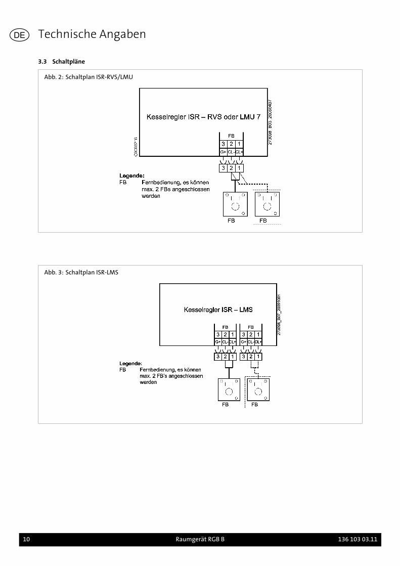
3.3 Schaltpläne
Abb. 2: Schaltplan ISR-RVS/LMU
Abb. 3: Schaltplan ISR-LMS
Technische Angaben
10 Raumgerät RGB B 136 103 03.11
DE
4. Vor der Installation
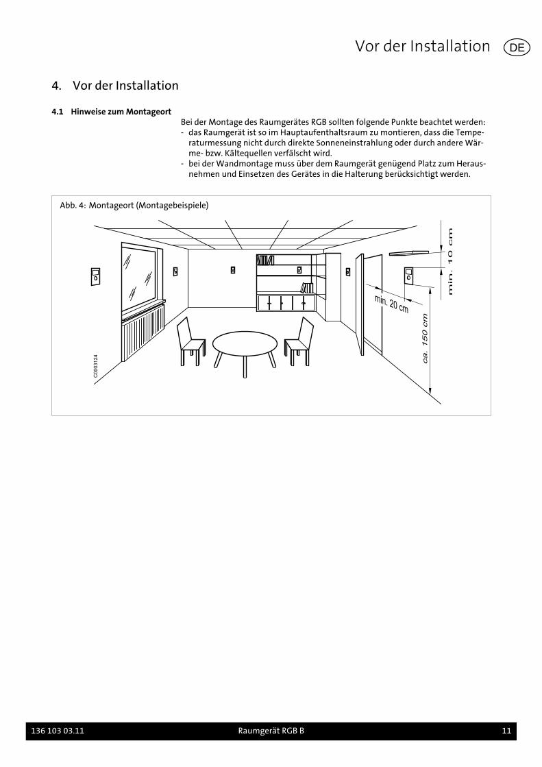
4.1 Hinweise zum MontageortBei der Montage des Raumgerätes RGB sollten folgende Punkte beachtet werden:- das Raumgerät ist so im Hauptaufenthaltsraum zu montieren, dass die Tempe-
raturmessung nicht durch direkte Sonneneinstrahlung oder durch andere Wär-me- bzw. Kältequellen verfälscht wird.
- bei der Wandmontage muss über dem Raumgerät genügend Platz zum Heraus-nehmen und Einsetzen des Gerätes in die Halterung berücksichtigt werden.
Abb. 4: Montageort (Montagebeispiele)
C0003124
Vor der Installation
136 103 03.11 Raumgerät RGB B 11
DE

5. Montage
5.1 Montage RGB
Abb. 5: Montage des Raumgerätes RGB
C0003221
1. Raumgerät vom Wandhalter lösen2. Wandhalter am gewünschten Montageort befestigen3. Anschlussleitungen gemäß Schaltplan anschließen4. Raumgerät am Wandhalter anbringen
Montage
12 Raumgerät RGB B 136 103 03.11
DE
6. Installation
6.1 Elektrischer Anschluss RGB- Anschlussleitungen vom RGB zum Heizkessel verlegen- Leitungen in den Zugentlastungen des Schaltfeldes festsetzen und gemäß
Schaltplan (Abb. 2) anschließen
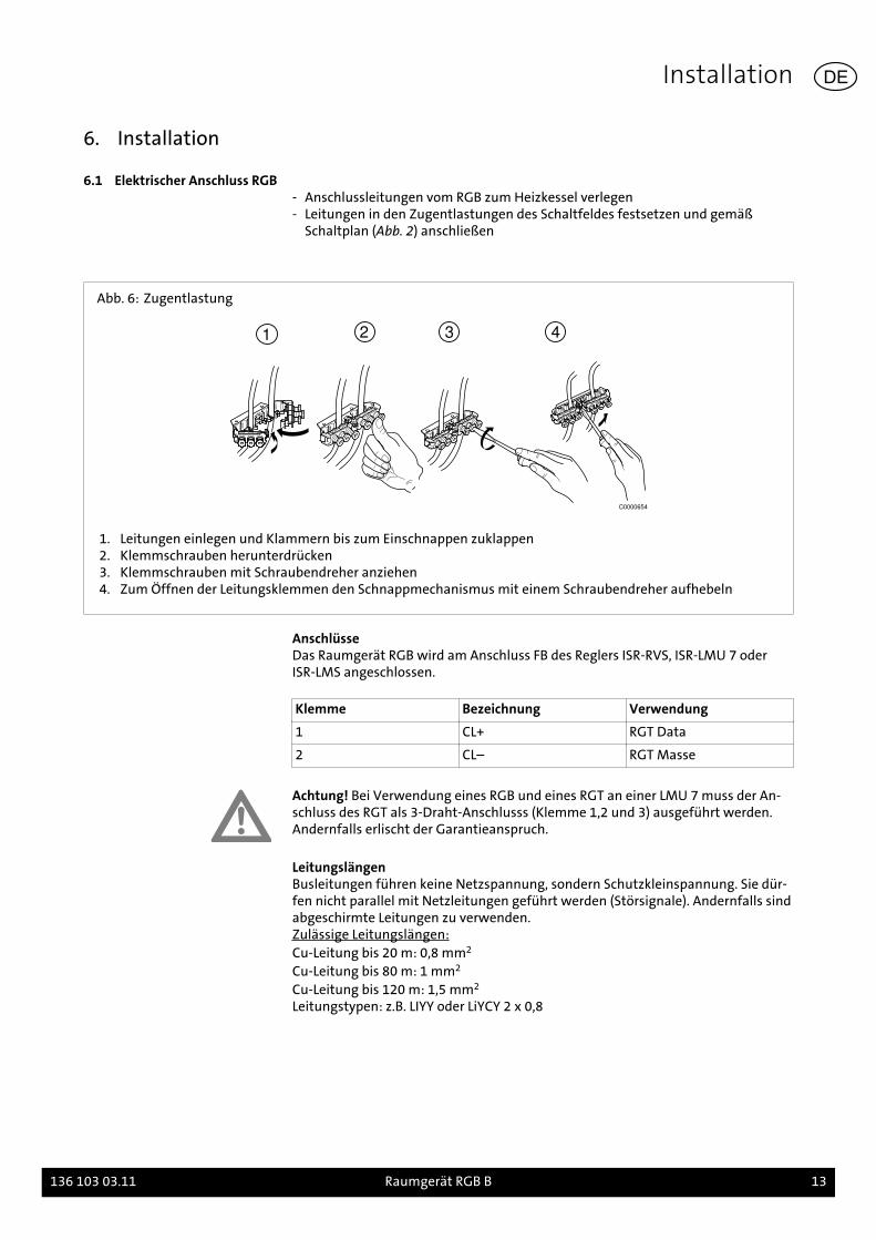
Abb. 6: Zugentlastung
1 2 3 4
C0000654
1. Leitungen einlegen und Klammern bis zum Einschnappen zuklappen2. Klemmschrauben herunterdrücken3. Klemmschrauben mit Schraubendreher anziehen4. Zum Öffnen der Leitungsklemmen den Schnappmechanismus mit einem Schraubendreher aufhebeln
AnschlüsseDas Raumgerät RGB wird am Anschluss FB des Reglers ISR-RVS, ISR-LMU 7 oderISR-LMS angeschlossen.
Klemme Bezeichnung Verwendung
1 CL+ RGT Data
2 CL– RGT Masse
Achtung! Bei Verwendung eines RGB und eines RGT an einer LMU 7 muss der An-schluss des RGT als 3-Draht-Anschlusss (Klemme 1,2 und 3) ausgeführt werden.Andernfalls erlischt der Garantieanspruch.
LeitungslängenBusleitungen führen keine Netzspannung, sondern Schutzkleinspannung. Sie dür-fen nicht parallel mit Netzleitungen geführt werden (Störsignale). Andernfalls sindabgeschirmte Leitungen zu verwenden.Zulässige Leitungslängen:Cu-Leitung bis 20 m: 0,8 mm2
Cu-Leitung bis 80 m: 1 mm2
Cu-Leitung bis 120 m: 1,5 mm2
Leitungstypen: z.B. LIYY oder LiYCY 2 x 0,8
Installation
136 103 03.11 Raumgerät RGB B 13
DE
7. Inbetriebnahme
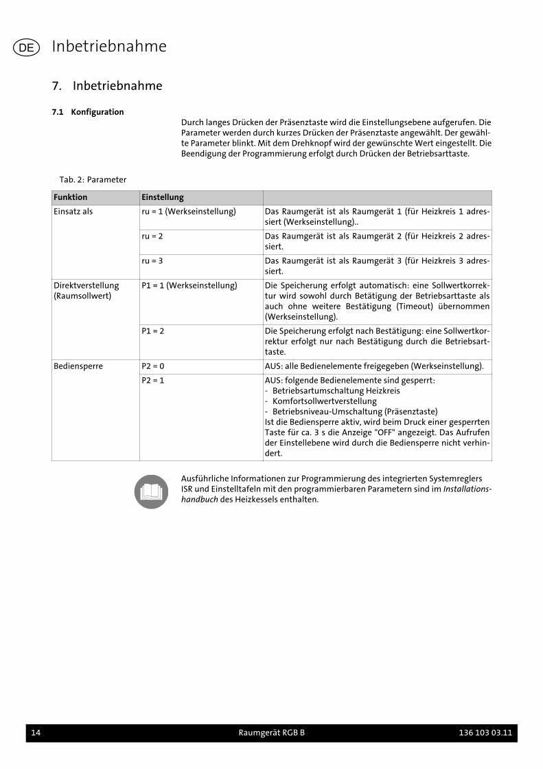
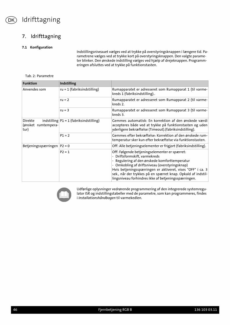
7.1 KonfigurationDurch langes Drücken der Präsenztaste wird die Einstellungsebene aufgerufen. DieParameter werden durch kurzes Drücken der Präsenztaste angewählt. Der gewähl-te Parameter blinkt. Mit dem Drehknopf wird der gewünschte Wert eingestellt. DieBeendigung der Programmierung erfolgt durch Drücken der Betriebsarttaste.
Tab. 2: Parameter
Funktion Einstellung
Einsatz als ru = 1 (Werkseinstellung) Das Raumgerät ist als Raumgerät 1 (für Heizkreis 1 adres-siert (Werkseinstellung)..
ru = 2 Das Raumgerät ist als Raumgerät 2 (für Heizkreis 2 adres-siert.
ru = 3 Das Raumgerät ist als Raumgerät 3 (für Heizkreis 3 adres-siert.
Direktverstellung(Raumsollwert)
P1 = 1 (Werkseinstellung) Die Speicherung erfolgt automatisch: eine Sollwertkorrek-tur wird sowohl durch Betätigung der Betriebsarttaste alsauch ohne weitere Bestätigung (Timeout) übernommen(Werkseinstellung).
P1 = 2 Die Speicherung erfolgt nach Bestätigung: eine Sollwertkor-rektur erfolgt nur nach Bestätigung durch die Betriebsart-taste.
Bediensperre P2 = 0 AUS: alle Bedienelemente freigegeben (Werkseinstellung).
P2 = 1 AUS: folgende Bedienelemente sind gesperrt:- Betriebsartumschaltung Heizkreis- Komfortsollwertverstellung- Betriebsniveau-Umschaltung (Präsenztaste)Ist die Bediensperre aktiv, wird beim Druck einer gesperrtenTaste für ca. 3 s die Anzeige "OFF" angezeigt. Das Aufrufender Einstellebene wird durch die Bediensperre nicht verhin-dert.
Ausführliche Informationen zur Programmierung des integrierten SystemreglersISR und Einstelltafeln mit den programmierbaren Parametern sind im Installations-handbuch des Heizkessels enthalten.
Inbetriebnahme
14 Raumgerät RGB B 136 103 03.11
DE
1. Regarding the instructions
Please read the instructions thoroughly before any modifications are made.
1.1 Content of this manualContent of this manual is the assembly and setting of the Room device RGB.
Moreover, take notice of the operation and maintenance manual of the appliedboiler.
1.2 Used symbolsDanger! Danger exists for body and life in case it is not observed.
Danger of electric shock! In case it is not observed, danger from electricity existsfor body and life!
Caution! If warning is not observed, danger exists for environment and the device.
Note/tip: Here, you can find background information and useful tips.
Reference to additional information in other documents.
1.3 For whom is this manualintended?
This installation manual is intended for the heating specialist, who installs the ac-cessory.
1.4 Scope of Supply
- Room device with wall bracket- Plug-in connector- Installation manual- Brief instruction
Regarding the instructions
136 103 03.11 Room device RGB B 15
GB

2. Safety
Danger! Observe the following safety information! Otherwise you are endangeringyourself and others.
2.1 Usage according to purposeRoom device RGB serves as distance control for boilers of Brötje (from series C).The nominal value of the room temperature and the operation mode of the hea-ting circuit can be set with the room device RGB.
Note: The room device RGB is connected to the integrated system control LMU ofthe boiler, the LMU control 7 shall have a software version not smaller than 1.04.
Detailed information for programming of the integrated system control and thesetting tables is given in the Programming and Hydraulics Manual and InstallationManual of the boiler.
2.2 General safety instructionsDanger of electric shock! All electrical work in connection with the installationmust only be carried out by a trained electrician!
Caution! A danger of significant damages to property exists during installation ofaccessory. Therefore, accessories must only be installed by specialist companiesand commissioned by specialists of the installing company!
Used accessories must comply with the technical rules and have been approved inconnection with these accessories by the manufacturer.
Only original spare parts must be used.
Unauthorised conversions and modifications of accessories are not permitted, asthis can endanger persons and lead to damage of the accessories. In case of notobserving this, the approval of the accessories becomes void.
Safety
16 Room device RGB B 136 103 03.11
GB
3. Technical Data
3.1 Overview and Dimensions
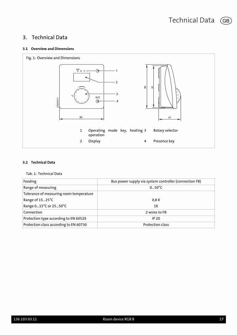
Fig. 1: Overview and Dimensions
96
1
2
3°C
4
47
96
91
C0
00
32
13
1 Operating mode key, heatingoperation
3 Rotary selector
2 Display 4 Presence key
3.2 Technical Data
Tab. 1: Technical Data
Feeding Bus power supply via system controller (connection FB)
Range of measuring 0...50°C
Tolerance of measuring room temperature
Range of 15...25°C 0,8 K
Range 0...15°C or 25...50°C 1K
Connection 2 wires to FB
Protection type according to EN 60529 IP 20
Protection class according to EN 60730 Protection class
Technical Data
136 103 03.11 Room device RGB B 17
GB
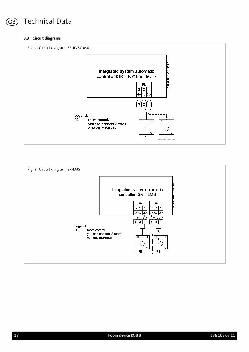
3.3 Circuit diagrams
Fig. 2: Circuit diagram ISR-RVS/LMU
Fig. 3: Circuit diagram ISR-LMS
Technical Data
18 Room device RGB B 136 103 03.11
GB
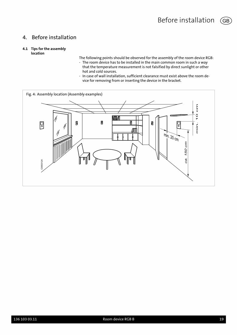
4. Before installation
4.1 Tips for the assemblylocation
The following points should be observed for the assembly of the room device RGB:- The room device has to be installed in the main common room in such a way
that the temperature measurement is not falsified by direct sunlight or otherhot and cold sources.
- In case of wall installation, sufficient clearance must exist above the room de-vice for removing from or inserting the device in the bracket.
Fig. 4: Assembly location (Assembly examples)
C0003124
Before installation
136 103 03.11 Room device RGB B 19
GB

5. Assembly
5.1 Assembly RGB
Fig. 5: Assembly of the room device RGB
C0003221
1. Remove room device from the wall bracket.2. Attach clamp at the requested place3. Connect conduits according to wiring diagram4. Install room device on the wall bracket
Assembly
20 Room device RGB B 136 103 03.11
GB
6. Installation
6.1 Electrical connection RGB- Route connecting lines from RGB to boiler.- The cables should be fixed in the starin relief clamp of the control panel and con-
nected according to the connection diagram.Fig. 2
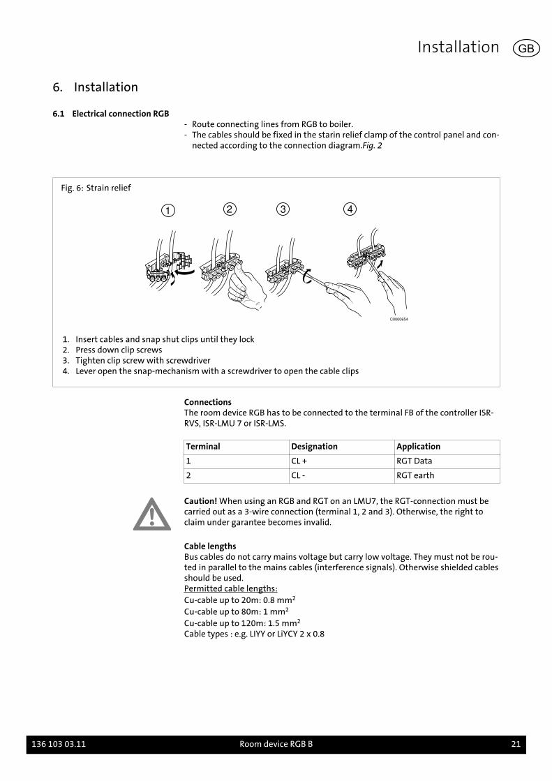
Fig. 6: Strain relief
1 2 3 4
C0000654
1. Insert cables and snap shut clips until they lock2. Press down clip screws3. Tighten clip screw with screwdriver4. Lever open the snap-mechanism with a screwdriver to open the cable clips
ConnectionsThe room device RGB has to be connected to the terminal FB of the controller ISR-RVS, ISR-LMU 7 or ISR-LMS.
Terminal Designation Application
1 CL + RGT Data
2 CL - RGT earth
Caution! When using an RGB and RGT on an LMU7, the RGT-connection must becarried out as a 3-wire connection (terminal 1, 2 and 3). Otherwise, the right toclaim under garantee becomes invalid.
Cable lengthsBus cables do not carry mains voltage but carry low voltage. They must not be rou-ted in parallel to the mains cables (interference signals). Otherwise shielded cablesshould be used.Permitted cable lengths:Cu-cable up to 20m: 0.8 mm2
Cu-cable up to 80m: 1 mm2
Cu-cable up to 120m: 1.5 mm2
Cable types : e.g. LIYY or LiYCY 2 x 0.8
Installation
136 103 03.11 Room device RGB B 21
GB
7. Commissioning
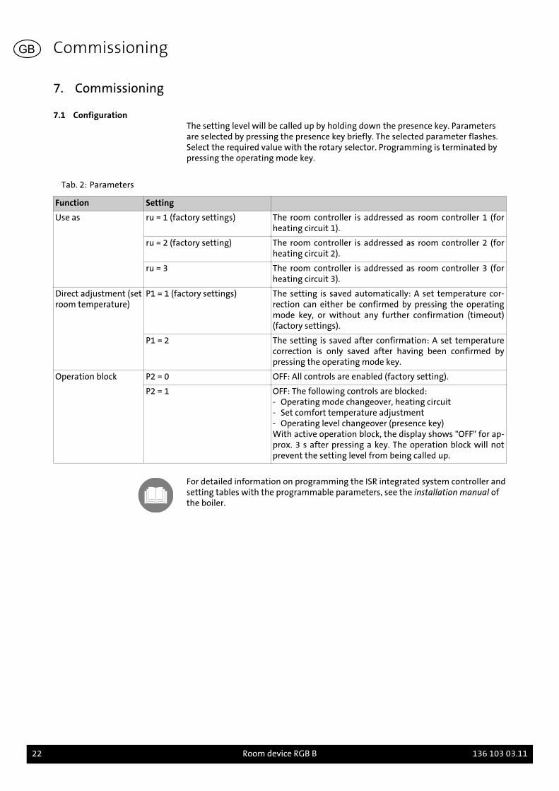
7.1 ConfigurationThe setting level will be called up by holding down the presence key. Parametersare selected by pressing the presence key briefly. The selected parameter flashes.Select the required value with the rotary selector. Programming is terminated bypressing the operating mode key.
Tab. 2: Parameters
Function Setting
Use as ru = 1 (factory settings) The room controller is addressed as room controller 1 (forheating circuit 1).
ru = 2 (factory setting) The room controller is addressed as room controller 2 (forheating circuit 2).
ru = 3 The room controller is addressed as room controller 3 (forheating circuit 3).
Direct adjustment (setroom temperature)
P1 = 1 (factory settings) The setting is saved automatically: A set temperature cor-rection can either be confirmed by pressing the operatingmode key, or without any further confirmation (timeout)(factory settings).
P1 = 2 The setting is saved after confirmation: A set temperaturecorrection is only saved after having been confirmed bypressing the operating mode key.
Operation block P2 = 0 OFF: All controls are enabled (factory setting).
P2 = 1 OFF: The following controls are blocked:- Operating mode changeover, heating circuit- Set comfort temperature adjustment- Operating level changeover (presence key)With active operation block, the display shows "OFF" for ap-prox. 3 s after pressing a key. The operation block will notprevent the setting level from being called up.
For detailed information on programming the ISR integrated system controller andsetting tables with the programmable parameters, see the installation manual ofthe boiler.
Commissioning
22 Room device RGB B 136 103 03.11
GB
1. Au sujet des présentes instructions
Veuillez lire attentivement les instructions avant le montage de accessoire!
1.1 Contenu des présentesinstructions
Contenu des présentes instructions le montage et le réglage du appareil ambiantRGB.
Veuillez également tenir compte des instructions d'installation et d´instructionsde montage de la chaudière.
1.2 Symboles utilisésDanger! La non-observation de l'avertissement entraîne un risque de blessures etde mort.
Risque de décharge électrique ! La non-observation de l'avertissement entraîne unrisque de blessures et de mort dû à l'électricité!
Attention! La non-observation de l'avertissement entraîne un risque pour l'envi-ronnement et l'appareil.
Consigne/conseil: Vous trouverez ici des informations annexes et des conseils pré-cieux.
Renvoi des informations complémentaires dans d'autres documents.
1.3 A qui s'adresse ce manuel?Ce manuel s'adresse au chauffagiste installant les accessoires.
1.4 Etendue de la livraison
- Appareil ambiant RGB avec support mural- Connecteur- Instructions de montage- Instructions succinctes
Au sujet des présentes instructions
136 103 03.11 Appareil ambiant RGB B 23
FR
2. Sécurité
Danger! Observez absolument les consignes de sécurité suivantes ! Dans le cascontraire, vous vous exposez, vous et des tiers, à des risques.
2.1 Utilisation conforme aux finsprévues
L'appareil ambiant RGB est prévu pour l'utilisation à distance de toutes les chau-dières Brötje de la série C. L'appareil ambiant RGB sert à régler la valeur théoriquede la température ambiante et le mode de service du circuit de chauffe.
Remarque: L'appareil ambiant ne fonctionne que avec des régulateurs integrésavec la version de software à partir de 1.04.
Des informations détaillées pour la programmation du régulateur du système in-tégré et des panneaux de réglage avec les paramètres programmables se trouventdans le Manuel de programmation et d'hydraulique ainsi que dans le Manuel d'in-stallation de la chaudière.
2.2 Consignes générales desécurité
Risque de décharge électrique ! Tous les travaux électriques liés à l'installation doi-vent uniquement être effectués par des électriciens agréés !
Attention! Lors du installation de l'accessoire, il y a risque de dommages considéra-bles pour le matériel. C'est pourquoi l'accessoire doit uniquement être monté pardes spécialistes et être mis pour la première fois en service par des experts !
Les accessoires utilisés doivent correspondre aux règles techniques et être autori-sés par le fabricant en combinaison avec cet accessoire.
Seules des pièces détachées d'originedoivent être utilisées.
Il est interdit de monter des éléments et de modifier l'accessoire sous risque d'ex-poser le personnel à des dangers et d'endommager l'accessoire. L'homologation del'accessoire expire en cas de non-observation.
Sécurité
24 Appareil ambiant RGB B 136 103 03.11
FR

3. Indications techniques
3.1 Aperçu et Dimensions
Fig 1: Aperçu et Dimensions
96
1
2
3°C
4
47
96
91
C0
00
32
13
1 Touche de mode de service mo-de de chauffe
3 Bouton rotatif
2 Display 4 Touche de présence
3.2 Caractéristiques techniques
Tab. 1: Caractéristiques techniques
Alimentation Alimentation par le régulateur integré (raccordement FB)
Plage de mesure 0...50°C
Tolerancemesurage température ambiant
Plage 15...25°C 0,8 K
Plage 0...15°C bzw. 25...50°C 1K
Raccord câble à 2 conducteurs à FB
Type de protection (jacquette) selon EN60529
IP 20
Classe de protection selon EN 60730 Classe de protection
Indications techniques
136 103 03.11 Appareil ambiant RGB B 25
FR
3.3 Schémas de câblage
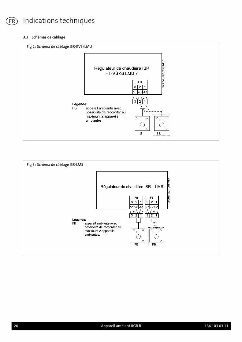
Fig 2: Schéma de câblage ISR-RVS/LMU
Fig 3: Schéma de câblage ISR-LMS
Indications techniques
26 Appareil ambiant RGB B 136 103 03.11
FR
4. Avant l'installation
4.1 Recommandationsconcernant le lieu demontage
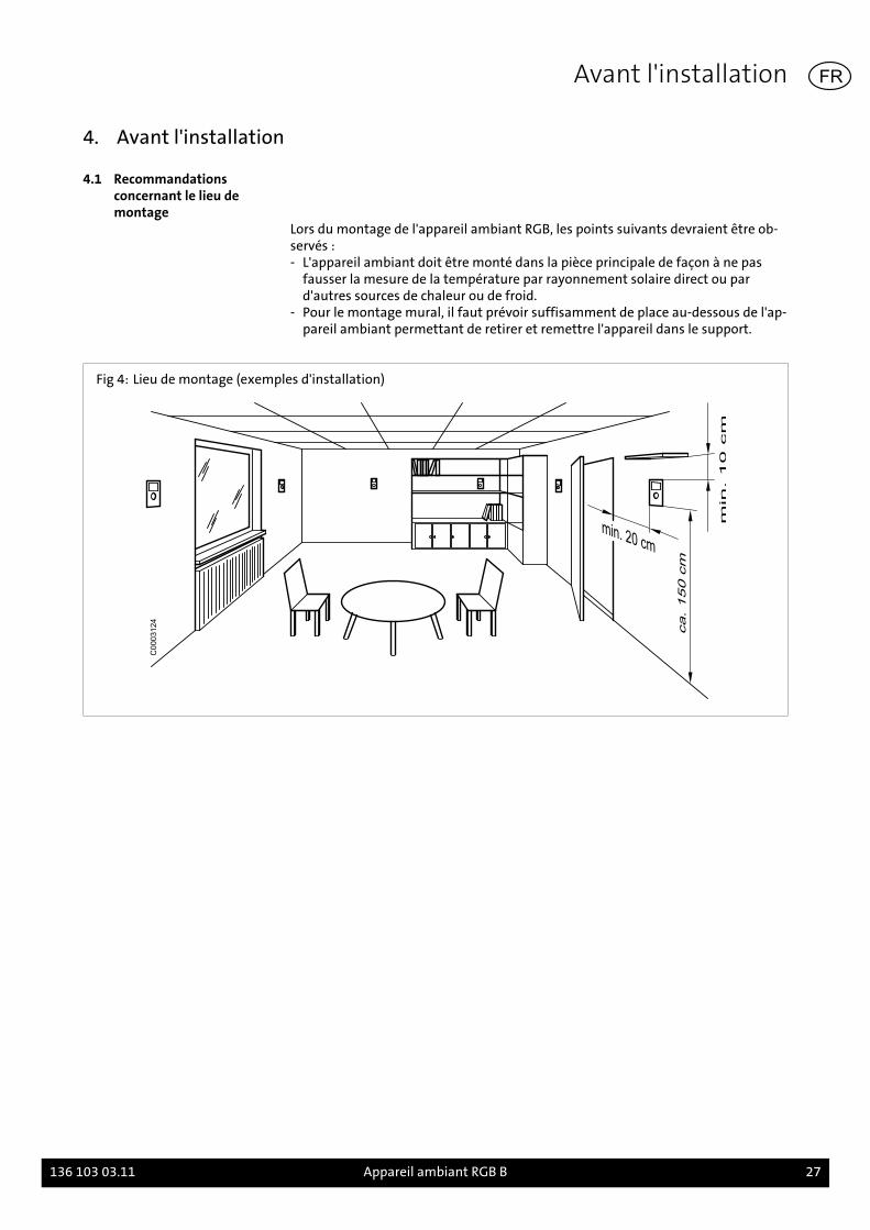
Lors du montage de l'appareil ambiant RGB, les points suivants devraient être ob-servés :- L'appareil ambiant doit être monté dans la pièce principale de façon à ne pas
fausser la mesure de la température par rayonnement solaire direct ou pard'autres sources de chaleur ou de froid.
- Pour le montage mural, il faut prévoir suffisamment de place au-dessous de l'ap-pareil ambiant permettant de retirer et remettre l'appareil dans le support.
Fig 4: Lieu de montage (exemples d'installation)
C0003124
Avant l'installation
136 103 03.11 Appareil ambiant RGB B 27
FR
5. Montage
5.1 Montage RGB
Fig 5: Montage de l'appareil ambiant RGB
C0003221
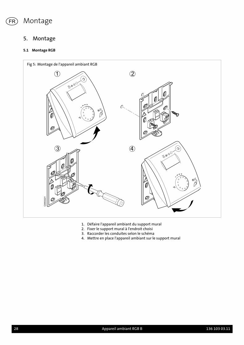
1. Défaire l'appareil ambiant du support mural2. Fixer le support mural à l'endroit choisi3. Raccorder les conduites selon le schéma4. Mettre en place l'appareil ambiant sur le support mural
Montage
28 Appareil ambiant RGB B 136 103 03.11
FR
6. Installation
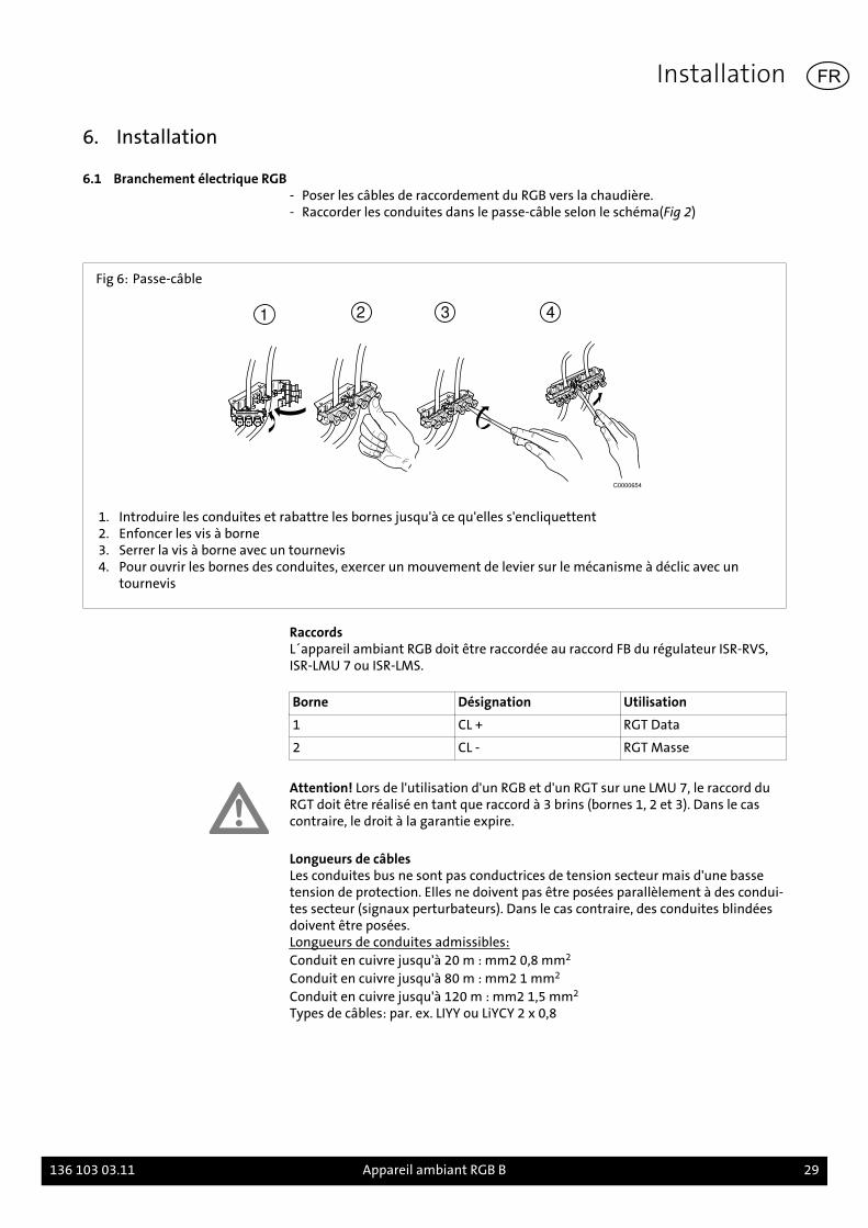
6.1 Branchement électrique RGB- Poser les câbles de raccordement du RGB vers la chaudière.- Raccorder les conduites dans le passe-câble selon le schéma(Fig 2)
Fig 6: Passe-câble
1 2 3 4
C0000654
1. Introduire les conduites et rabattre les bornes jusqu'à ce qu'elles s'encliquettent2. Enfoncer les vis à borne3. Serrer la vis à borne avec un tournevis4. Pour ouvrir les bornes des conduites, exercer un mouvement de levier sur le mécanisme à déclic avec un
tournevis
RaccordsL´appareil ambiant RGB doit être raccordée au raccord FB du régulateur ISR-RVS,ISR-LMU 7 ou ISR-LMS.
Borne Désignation Utilisation
1 CL + RGT Data
2 CL - RGT Masse
Attention! Lors de l'utilisation d'un RGB et d'un RGT sur une LMU 7, le raccord duRGT doit être réalisé en tant que raccord à 3 brins (bornes 1, 2 et 3). Dans le cascontraire, le droit à la garantie expire.
Longueurs de câblesLes conduites bus ne sont pas conductrices de tension secteur mais d'une bassetension de protection. Elles ne doivent pas être posées parallèlement à des condui-tes secteur (signaux perturbateurs). Dans le cas contraire, des conduites blindéesdoivent être posées.Longueurs de conduites admissibles:Conduit en cuivre jusqu'à 20 m : mm2 0,8 mm2
Conduit en cuivre jusqu'à 80 m : mm2 1 mm2
Conduit en cuivre jusqu'à 120 m : mm2 1,5 mm2
Types de câbles: par. ex. LIYY ou LiYCY 2 x 0,8
Installation
136 103 03.11 Appareil ambiant RGB B 29
FR
7. Mise en service
7.1 ConfigurationLe niveau de réglage est appelé en appuyant longtemps sur la touche de présence.Les paramètres sont sélectionnés en appuyant brièvement sur la touche de pré-sence. Le paramètre choisi clignote. Le bouton rotatif permet de régler la valeursouhaitée. Pour quitter la programmation, il suffit d'appuyer sur la touche de mo-de de service.
Tab. 2: Paramètres
Fonction Réglage
Utilisation ru = 1 (Réglage en sortie d'usi-ne)
L'appareil ambiant est adressé en tant que appareil d'ambi-ance (pour circuit de chauffe 1 (réglage en sortie d'usine)..
ru = 2 L'appareil ambiant est adressé en tant que appareil d'ambi-ance (pour circuit de chauffe 2 .
ru = 3 L'appareil ambiant est adressé en tant que appareil d'ambi-ance (pour circuit de chauffe 3 .
Réglage direct (valeurthéorique ambiante)
P1 = 1 (Réglage en sortie d'usi-ne)
La mémorisation se fait automatiquement : une correctionde valeur théorique se fait tant par actionnement de la tou-che de mode de service que sans autre confirmation (Time-out).(Réglage en sortie d'usine).
P1 = 2 La mémorisation se fait après confirmation: une correctionde valeur théorique se fait uniquement après confirmationpar une touche de mode de service.
Blocage commande P2 = 0 Arrêt: Tous les éléments de commande sont libérés (réglageeffectué en usine).
P2 = 1 Arrêt: Les éléments de commande suivants sont bloqués:- Commutation régime Circuit de chauffe- Réglage de la valeur de consigne confort- Commutation de niveau de service (touche de présence)Si le blocage de la commande est actif, l'affichage "OFF" ap-paraît pendant env. 3 s à l'actionnement d'une touche blo-quée. L'appel du niveau de réglage n'est pas empêché par leblocage de la commande.
Les informations détaillées sur la programmation du régulateur à système integréISR et les tableaux de réglage comprenant les paramètres programmables se trou-vent dans le manuel d'installation de la chaudière.
Mise en service
30 Appareil ambiant RGB B 136 103 03.11
FR
1. Introduzione
Leggere attentamente queste istruzioni prima di montare gli accessori!
1.1 ContenutoContenuto di queste istruzioni il montaggio e la regolazione dell'unità ambienteRGB.
Osservare inoltre le istruzioni di montaggio e installazione della caldaia utilizzata.
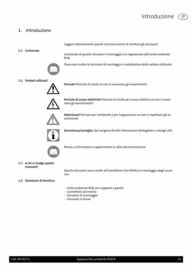
1.2 Simboli utilizzatiPericolo! Pericolo di morte se non si osservano gli avvertimenti.
Pericolo di scosse elettriche! Pericolo di morte per scossa elettrica se non si osser-vano gli avvertimenti!
Attenzione! Pericolo per l'ambiente e per l'apparecchio se non si rispettano gli av-vertimenti.
Avvertenza/consiglio: Qui vengono forniti informazioni dettagliate e consigli utili.
Rinvio a informazioni supplementari in altra documentazione.
1.3 A chi si rivolge questomanuale?
Queste istruzioni sono rivolte all'installatore che effettua il montaggio degli acces-sori.
1.4 Dotazione di fornitura
- Unità ambiente RGB con supporto a parete- Connettore ad innesto- Istruzioni di montaggio- Istruzioni in breve
Introduzione
136 103 03.11 Apparecchio ambiente RGB B 31
IT
2. Sicurezza
Pericolo! Osservare le seguenti avvertenze sulla sicurezza! In caso contrario mette-te in pericolo voi stessi e gli altri.
2.1 Utilizzo appropriatoL'unità ambiente RGB serve per telecomandare tutte le caldaie Brötje a partire dal-la serie delle caldaie C. Con l'apparecchio ambiente RGB si possono impostare il va-lore nominale temperatura ambiente e il tipo d'esercizio del circuito riscaldamen-to.
Avvertenza: Durante il funzionamento dell'unità ambiente RGB con regolatori disistema integrati del tipo LMU prestare attenzione che l'unità ambiente è utilizza-bile soltanto con regolatori LMU 7 con software dalla versione 1.04.
Le informazioni dettagliate relative alla programmazione del regolatore di sistemaintegrato RVS e le tavole impostazioni con i parametri programmabili sono conte-nute nel Manuale di programmazione e di idraulica e nel Manuale di montaggiodella caldaia.
2.2 Norme di sicurezza generaliPericolo di scosse elettriche! Tutti i lavori elettrici durante l'installazione devonoessere effettuati esclusivamente da un elettrotecnico competente!
Attenzione! Durante l'installazione degli accessori sussiste il pericolo di causaredanni materiali rilevanti. Pertanto gli accessori devono essere montati esclusiva-mente da ditte qualificate e la prima messa in funzione deve essere eseguita dapersonale competente delle ditte produttrici!
Gli accessori utilizzati devono soddisfare le regole tecniche ed essere omologati dalproduttore in abbinamento con l'apparecchio.
Devono essere utilizzati solo ricambi originali.
Non è consentito smontare e modificare arbitrariamente gli accessori, perché sipossono mettere in pericolo gli uomini e causare danni agli accessori. In caso dimancata osservanza decadono l'omologazione e la garanzia dell'accessorio.
Sicurezza
32 Apparecchio ambiente RGB B 136 103 03.11
IT
3. Dati tecnici
3.1 Panoramica e dimensioni
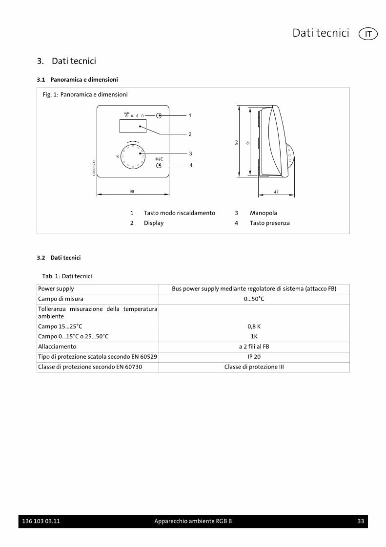
Fig. 1: Panoramica e dimensioni
96
1
2
3°C
4
47
96
91
C0
00
32
13
1 Tasto modo riscaldamento 3 Manopola
2 Display 4 Tasto presenza
3.2 Dati tecnici
Tab. 1: Dati tecnici
Power supply Bus power supply mediante regolatore di sistema (attacco FB)
Campo di misura 0...50°C
Tolleranza misurazione della temperaturaambiente
Campo 15...25°C 0,8 K
Campo 0...15°C o 25...50°C 1K
Allacciamento a 2 fili al FB
Tipo di protezione scatola secondo EN 60529 IP 20
Classe di protezione secondo EN 60730 Classe di protezione III
Dati tecnici
136 103 03.11 Apparecchio ambiente RGB B 33
IT

3.3 Schemi elettrici
Fig. 2: Schema elettrico ISR-RVS/LMU
Fig. 3: Schema elettrico ISR-LMS
Dati tecnici
34 Apparecchio ambiente RGB B 136 103 03.11
IT

4. Prima dell'installazione
4.1 Avvertenze sul luogo dimontaggio
Per il montaggio dell'unità ambiente RGB osservare i punti seguenti:- l'unità ambiente deve essere montata nel locale di soggiorno principale in modo
che la misurazione della temperatura non venga influenzata dall'irraggiamentodiretto del sole oppure da fonti di calore o di freddo.
- per il montaggio a parete prevedere sopra l'unità ambiente uno spazio sufficien-te per estrarre e inserire l'unità nell'apposito supporto.
Fig. 4: Luogo di montaggio (esempio di montaggio)
C0003124
Prima dell'installazione
136 103 03.11 Apparecchio ambiente RGB B 35
IT
5. Montaggio
5.1 Montaggio dell'unitàambiente RGB
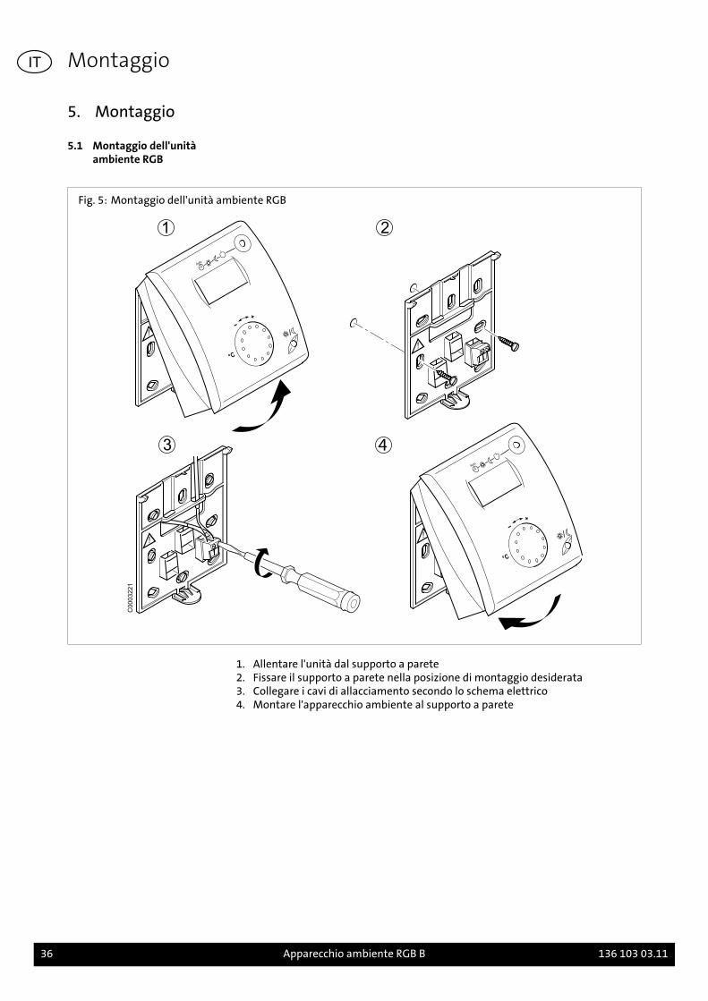
Fig. 5: Montaggio dell'unità ambiente RGB
C0003221
1. Allentare l'unità dal supporto a parete2. Fissare il supporto a parete nella posizione di montaggio desiderata3. Collegare i cavi di allacciamento secondo lo schema elettrico4. Montare l'apparecchio ambiente al supporto a parete
Montaggio
36 Apparecchio ambiente RGB B 136 103 03.11
IT
6. Installazione
6.1 Allacciamento elettrico RGB- Posare i cavi allacciamento dall'unità ambiente RGB alla caldaia.- Fissare i cavi nei pressacavi del quadro di comando e collegare secondo lo sche-
ma elettrico (Fig. 2)
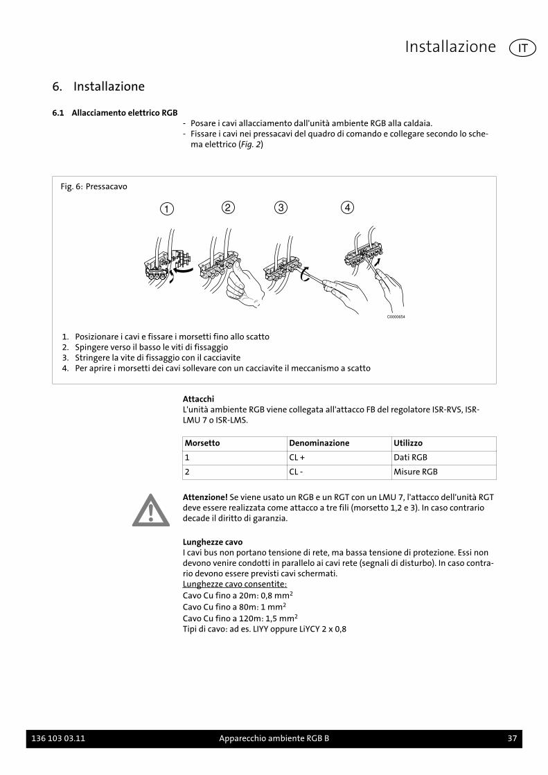
Fig. 6: Pressacavo
1 2 3 4
C0000654
1. Posizionare i cavi e fissare i morsetti fino allo scatto2. Spingere verso il basso le viti di fissaggio3. Stringere la vite di fissaggio con il cacciavite4. Per aprire i morsetti dei cavi sollevare con un cacciavite il meccanismo a scatto
AttacchiL'unità ambiente RGB viene collegata all'attacco FB del regolatore ISR-RVS, ISR-LMU 7 o ISR-LMS.
Morsetto Denominazione Utilizzo
1 CL + Dati RGB
2 CL - Misure RGB
Attenzione! Se viene usato un RGB e un RGT con un LMU 7, l'attacco dell'unità RGTdeve essere realizzata come attacco a tre fili (morsetto 1,2 e 3). In caso contrariodecade il diritto di garanzia.
Lunghezze cavoI cavi bus non portano tensione di rete, ma bassa tensione di protezione. Essi nondevono venire condotti in parallelo ai cavi rete (segnali di disturbo). In caso contra-rio devono essere previsti cavi schermati.Lunghezze cavo consentite:Cavo Cu fino a 20m: 0,8 mm2
Cavo Cu fino a 80m: 1 mm2
Cavo Cu fino a 120m: 1,5 mm2
Tipi di cavo: ad es. LIYY oppure LiYCY 2 x 0,8
Installazione
136 103 03.11 Apparecchio ambiente RGB B 37
IT
7. Messa in esercizio
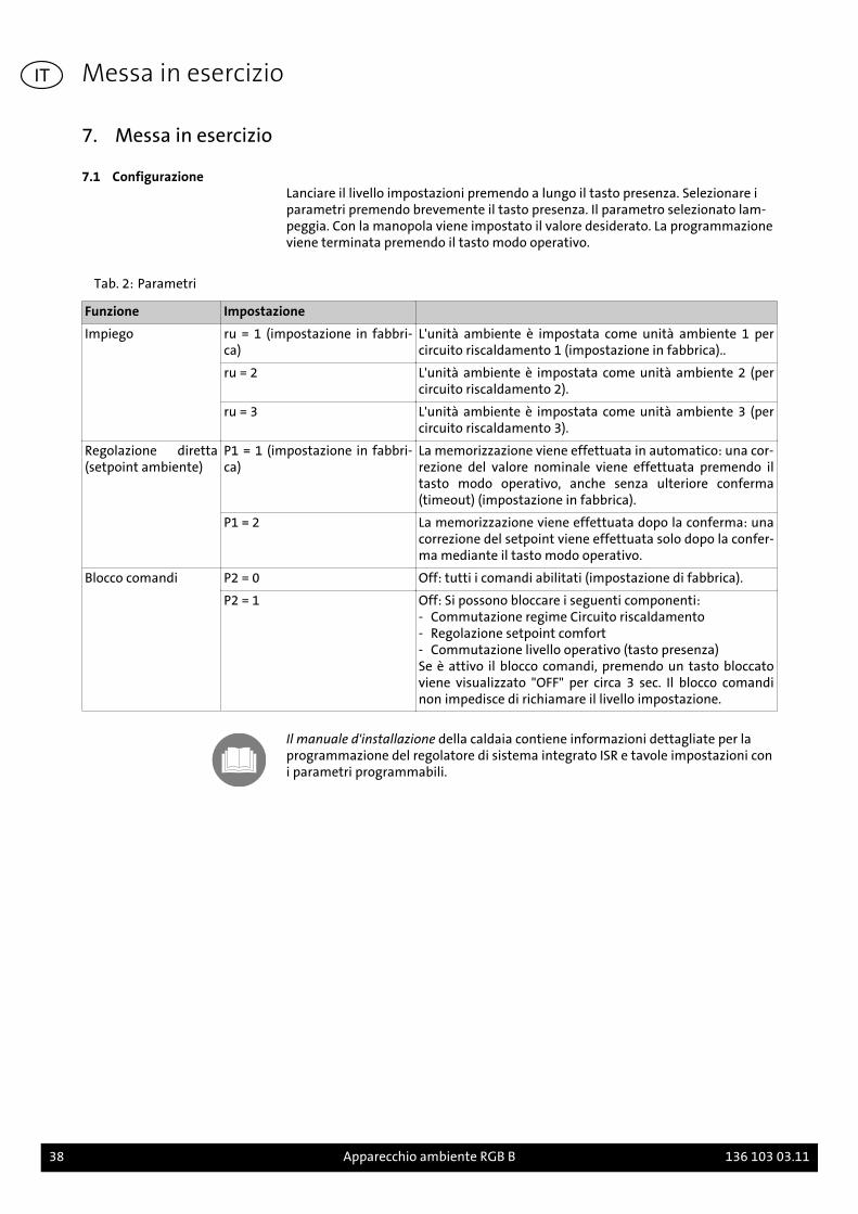
7.1 ConfigurazioneLanciare il livello impostazioni premendo a lungo il tasto presenza. Selezionare iparametri premendo brevemente il tasto presenza. Il parametro selezionato lam-peggia. Con la manopola viene impostato il valore desiderato. La programmazioneviene terminata premendo il tasto modo operativo.
Tab. 2: Parametri
Funzione Impostazione
Impiego ru = 1 (impostazione in fabbri-ca)
L'unità ambiente è impostata come unità ambiente 1 percircuito riscaldamento 1 (impostazione in fabbrica)..
ru = 2 L'unità ambiente è impostata come unità ambiente 2 (percircuito riscaldamento 2).
ru = 3 L'unità ambiente è impostata come unità ambiente 3 (percircuito riscaldamento 3).
Regolazione diretta(setpoint ambiente)
P1 = 1 (impostazione in fabbri-ca)
La memorizzazione viene effettuata in automatico: una cor-rezione del valore nominale viene effettuata premendo iltasto modo operativo, anche senza ulteriore conferma(timeout) (impostazione in fabbrica).
P1 = 2 La memorizzazione viene effettuata dopo la conferma: unacorrezione del setpoint viene effettuata solo dopo la confer-ma mediante il tasto modo operativo.
Blocco comandi P2 = 0 Off: tutti i comandi abilitati (impostazione di fabbrica).
P2 = 1 Off: Si possono bloccare i seguenti componenti:- Commutazione regime Circuito riscaldamento- Regolazione setpoint comfort- Commutazione livello operativo (tasto presenza)Se è attivo il blocco comandi, premendo un tasto bloccatoviene visualizzato "OFF" per circa 3 sec. Il blocco comandinon impedisce di richiamare il livello impostazione.
Il manuale d'installazione della caldaia contiene informazioni dettagliate per laprogrammazione del regolatore di sistema integrato ISR e tavole impostazioni coni parametri programmabili.
Messa in esercizio
38 Apparecchio ambiente RGB B 136 103 03.11
IT
1. Om denne vejledning
Læs denne vejledning grundigt før montering af tilbehør!
1.1 Denne vejlednings indholdDenne vejlednings indhold montering og indstilling af fjernbetjeningen RGB.
Overhold desuden monterings- og installationsvejledningen til den anvendte var-mekedel.
1.2 Anvendte symbolerFare! Hvis advarslen ikke respekteres, er der fare for liv og lemmer.
Fare for elektrisk stød! Hvis advarslen ikke respekteres, er der fare for liv og lem-mer på grund af elektricitet!
OBS! Hvis advarslen ikke respekteres, er der fare for miljø og apparat.
Bemærk/tip: Her kan findes baggrundsinformation og gode råd.
Henvisning til ekstra information i andre dokumenter.
1.3 Hvem henvender dennevejledning sig til?
Denne monteringsvejledning henvender sig til den VVS-installatør, der monterertilbehøret.
1.4 Leveringsomfang
- Fjernbetjening RGB med vægholder- Stikforbindelse- Monteringsvejledning- Kort vejledning
Om denne vejledning
136 103 03.11 Fjernbetjening RGB B 39
DK
2. Sikkerhed
Fare! Vær opmærksom på følgende sikkerhedsanvisninger! Du kan i modsat faldvære til fare for dig selv og andre.
2.1 Forskriftsmæssig anvendelseFjernbetjeningen RGB er beregnet til fjernbetjening af alle Brötjevarmekedler i se-rien C. Med fjernbetjeningen RGB kan man indstille den ønskede rumtemperaturog varmekredsens driftsart.
Bemærk: Ved anvendelse af fjernbetjening RGB med integrerede systemregulato-rer af type LMU skal man tage højde for, at fjernbetjeningen kun kan anvendesmed LMU 7-regulatorer med softwareversion 1.04 eller nyere.
Udførlige informationer til programmering af den integrerede systemregulator ogindstillingstabeller med de parametre, der kan programmeres, findes i Programm-erings- og hydraulikmanualenog i varmekedlens Installationshåndbog.
2.2 Generellesikkerhedsinstruktioner
Fare for elektrisk stød! Alt det med installationen forbundne el-arbejde må kunudføres af personer med en el-teknisk uddannelse!
OBS! Ved installation af tilbehøret er der fare for betydelige materielle skader. Der-for må tilbehøret kun monteres af fagfirmaer, og den første idrifttagning skal fore-tages af montørfirmaets faglærte personale!
Det anvendte udstyr skal opfylde de tekniske regler, og producenten skal have gi-vet tilladelse til dets anvendelse sammen med dette udstyr.
Der må kun anvendes originale reservedele
Egenhændig ombygning og ændring af tilbehør er ikke tilladt, da der ellers opstårfare for personulykker og beskadigelse af tilbehør. Ved manglende overholdelsebortfalder tilbehørets godkendelse.
Sikkerhed
40 Fjernbetjening RGB B 136 103 03.11
DK
3. Tekniske data
3.1 Oversigt og Mål
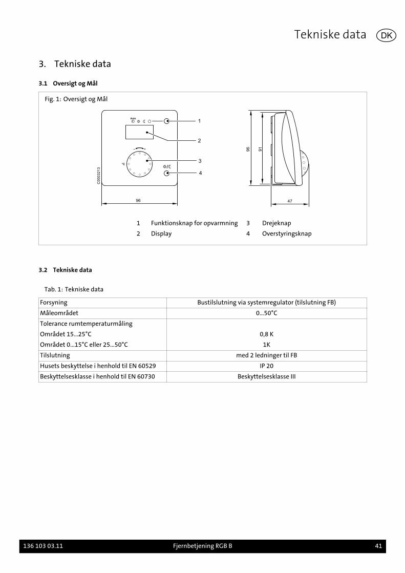
Fig. 1: Oversigt og Mål
96
1
2
3°C
4
47
96
91
C0
00
32
13
1 Funktionsknap for opvarmning 3 Drejeknap
2 Display 4 Overstyringsknap
3.2 Tekniske data
Tab. 1: Tekniske data
Forsyning Bustilslutning via systemregulator (tilslutning FB)
Måleområdet 0...50°C
Tolerance rumtemperaturmåling
Området 15...25°C 0,8 K
Området 0...15°C eller 25...50°C 1K
Tilslutning med 2 ledninger til FB
Husets beskyttelse i henhold til EN 60529 IP 20
Beskyttelsesklasse i henhold til EN 60730 Beskyttelsesklasse III
Tekniske data
136 103 03.11 Fjernbetjening RGB B 41
DK
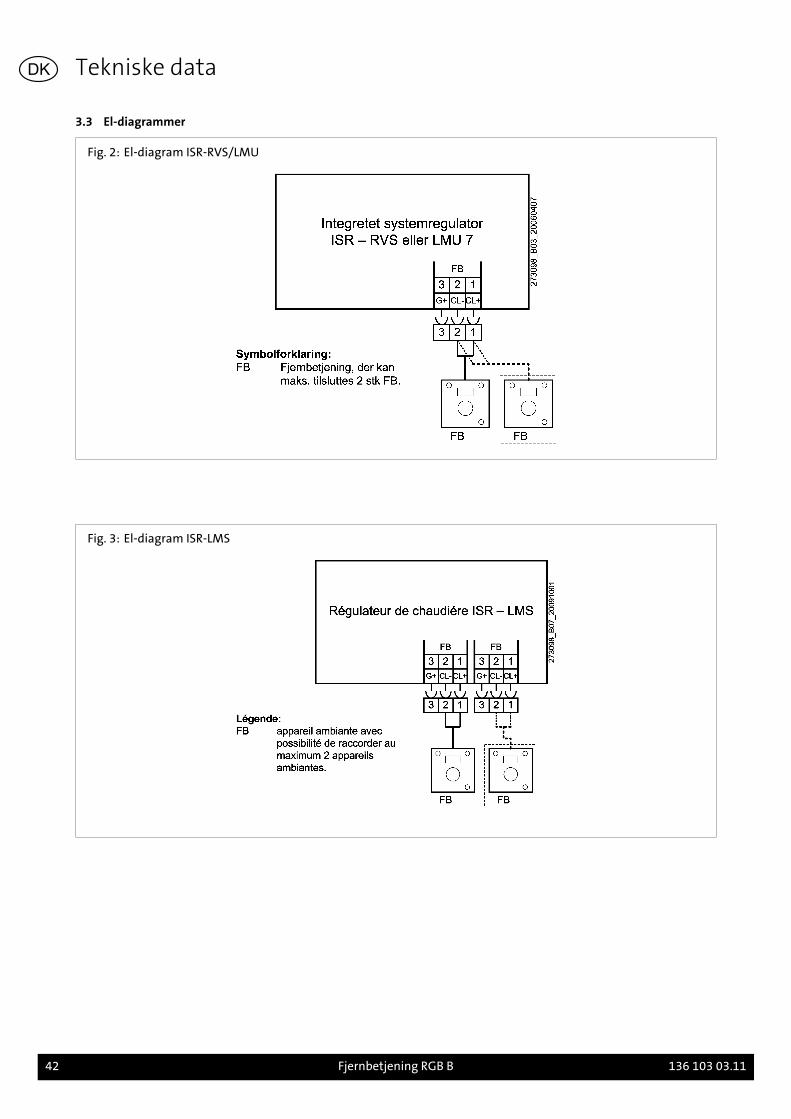
3.3 El-diagrammer
Fig. 2: El-diagram ISR-RVS/LMU
Fig. 3: El-diagram ISR-LMS
Tekniske data
42 Fjernbetjening RGB B 136 103 03.11
DK
4. Før installationen
4.1 Oplysninger vedr.monteringsstedet
Ved montering af fjernbetjeningen RGB bør følgende punkter iagttages:- fjernbetjeningen skal monteres således i hovedopholdsrummet, at temperatur-
målingen ikke forfalskes af direkte solindstråling eller andre varme- eller kulde-kilder.
- ved vægmontering skal der være tilstrækkelig plads over fjernbetjeningen til atden kan tages ud af og sættes ind i holderen.
Fig. 4: Monteringssted (monteringseksempler)
C0003124
Før installationen
136 103 03.11 Fjernbetjening RGB B 43
DK
5. Montering
5.1 Montering RGB
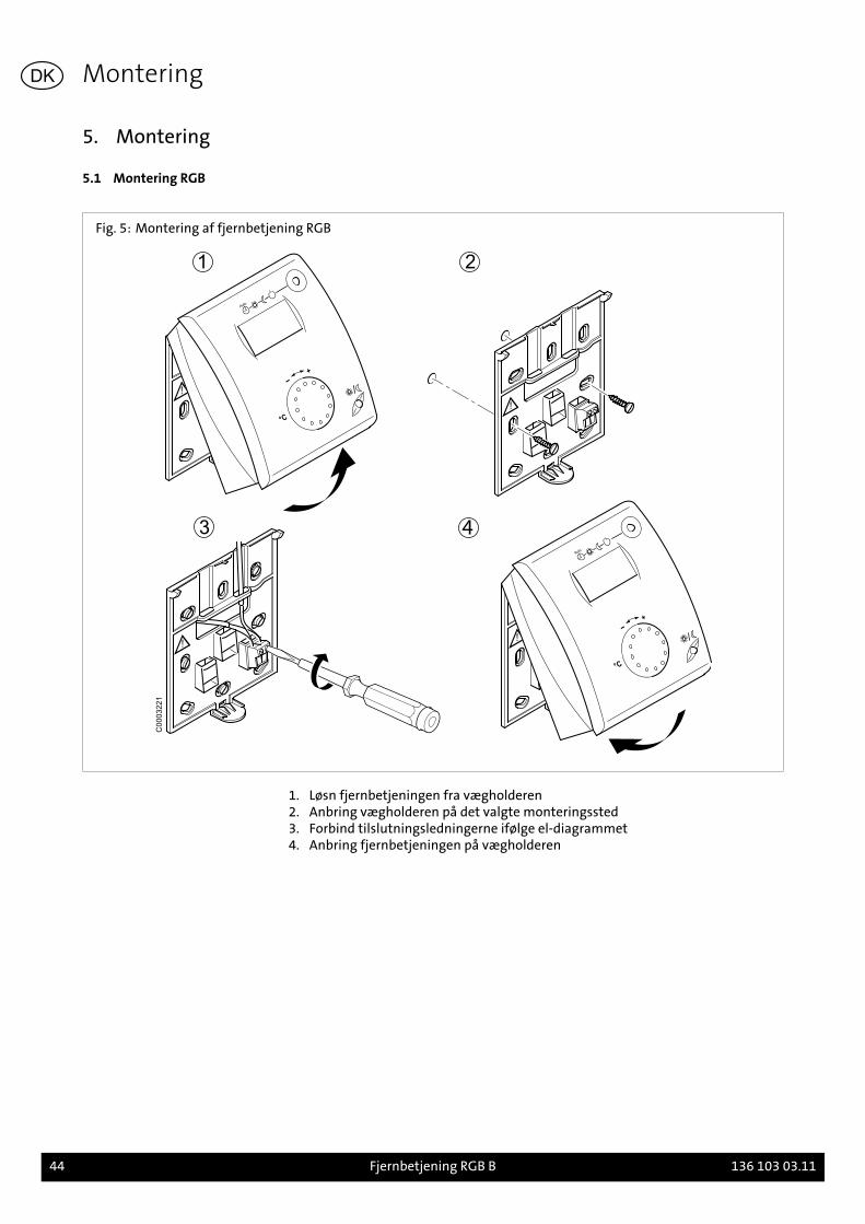
Fig. 5: Montering af fjernbetjening RGB
C0003221
1. Løsn fjernbetjeningen fra vægholderen2. Anbring vægholderen på det valgte monteringssted3. Forbind tilslutningsledningerne ifølge el-diagrammet4. Anbring fjernbetjeningen på vægholderen
Montering
44 Fjernbetjening RGB B 136 103 03.11
DK
6. Installation
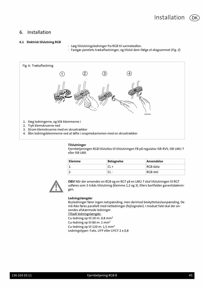
6.1 Elektrisk tilslutning RGB- Læg tilslutningsledninger fra RGB til varmekedlen.- Fastgør panelets trækaflastninger, og tilslut dem ifølge el-diagrammet (Fig. 2)
Fig. 6: Trækaflastning
1 2 3 4
C0000654
1. Ilæg ledningerne, og klik klemmerne i2. Tryk klemskruerne ned3. Stram klemskruerne med en skruetrækker4. Åbn ledningsklemmerne ved at løfte i snapmekanismen med en skruetrækker
TilslutningerFjernbetjeningen RGB tilsluttes til tilslutningen FB på regulator ISR-RVS, ISR-LMU 7eller ISR-LMS
Klemme Betegnelse Anvendelse
1 CL + RGB data
2 CL - RGB stel
OBS! Når der anvendes en RGB og en RGT på en LMU 7 skal tilslutningen til RGTudføres som 3-tråds-tilslutning (klemme 1,2 og 3). Ellers bortfalder garantidæknin-gen.
LedningslængderBusledninger fører ingen netspænding, men derimod beskyttelseslavspænding. Demå ikke føres parallelt med netledninger (fejlsignaler). I modsat fald skal der an-vendes afskærmede ledninger.Tilladt ledningslængde:Cu-ledning op til 20 m: 0,8 mm2
Cu-ledning op til 80 m: 1 mm2
Cu-ledning op til 120 m: 1,5 mm2
Ledningstyper: f.eks. LIYY eller LiYCY 2 x 0,8
Installation
136 103 03.11 Fjernbetjening RGB B 45
DK
7. Idrifttagning
7.1 KonfigurationIndstillingsniveauet vælges ved at trykke på overstyringsknappen i længere tid. Pa-rametrene vælges ved at trykke kort på overstyringsknappen. Den valgte parame-ter blinker. Den ønskede indstilling vælges ved hjælp af drejeknappen. Programm-eringen afsluttes ved at trykke på funktionstasten.
Tab. 2: Parametre
Funktion Indstilling
Anvendes som ru = 1 (fabriksindstilling) Rumapparatet er adresseret som Rumapparat 1 (til varme-kreds 1 (fabriksindstilling)..
ru = 2 Rumapparatet er adresseret som Rumapparat 2 (til varme-kreds 2.
ru = 3 Rumapparatet er adresseret som Rumapparat 3 (til varme-kreds 3.
Direkte indstilling(ønsket rumtempera-tur)
P1 = 1 (fabriksindstilling) Gemmes automatisk: En korrektion af den ønskede værdiaccepteres både ved at trykke på funktionstasten og udenyderligere bekræftelse (Timeout).(fabriksindstilling).
P1 = 2 Gemmes efter bekræftelse: Korrektion af den ønskede rum-temperatur sker kun efter bekræftelse via funktionstasten.
Betjeningsspærringen P2 = 0 Off: Alle betjeningselementer er frigjort (fabriksindstilling).
P2 = 1 Off: Følgende betjeningselementer er spærret:- Driftsformskift, varmekreds- Regulering af den ønskede komforttemperatur- Omkobling af driftsniveau (overstyringsknap)Hvis betjeningsspærringen er aktiveret, vises "OFF" i ca. 3sek., når der trykkes på en spærret knap. Opkald af indstil-lingsniveau forhindres ikke af betjeningsspærringen.
Udførlige oplysninger vedrørende programmering af den integrerede systemregu-lator ISR og indstillingstabeller med de parametre, som kan programmeres, findesi Installationshåndbogen til varmekedlen.
Idrifttagning
46 Fjernbetjening RGB B 136 103 03.11
DK
1. Toelichting bij deze handleiding
Lees deze handleiding voor de montage en instelling van de toebehoren zorgvul-dig!
1.1 Inhoud van deze handleidingInhoud van deze handleiding Is de montage en instelling van de ruimtevoeler RGB.
Respecteer ook de montage - en installatiehandleiding van de betrokken verwar-mingsketel.
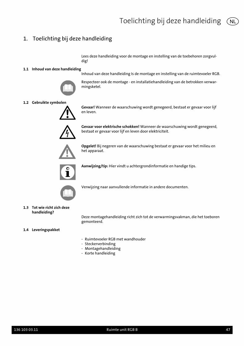
1.2 Gebruikte symbolenGevaar! Wanneer de waarschuwing wordt genegeerd, bestaat er gevaar voor lijfen leven.
Gevaar voor elektrische schokken! Wanneer de waarschuwing wordt genegeerd,bestaat er gevaar voor lijf en leven door elektriciteit.
Opgelet! Bij negeren van de waarschuwing bestaat er gevaar voor het milieu enhet apparaat.
Aanwijzing/tip: Hier vindt u achtergrondinformatie en handige tips.
Verwijzing naar aanvullende informatie in andere documenten.
1.3 Tot wie richt zich dezehandleiding?
Deze montagehandleiding richt zich tot de verwarmingsvakman, die het toeborengemonteerd.
1.4 Leveringspakket
- Ruimtevoeler RGB met wandhouder- Steckerverbinding- Montagehandleiding- Korte handleiding
Toelichting bij deze handleiding
136 103 03.11 Ruimte unit RGB B 47
NL
2. Veiligheid
Gevaar! Let in ieder geval op de volgende veiligheidsinstructies! U brengt anderszichzelf en anderen in gevaar.
2.1 Doelmatig gebruikDe ruimtevoeler RGB B dient voor de bediening van alle Brötje verwarmingsketelsvan de serie C. Met de ruimtevoeler RGB kan de gevraagde temperatuur en be-drijfstoestand van de verwarmingskringen worden ingesteld.
Opmerking: Bij gebruik van ruimtevoelers RGB met geïntegreerde systemmrele-laar van het type LMU, moet men er voor zorgen dat de omgevingsvoeler werktmet LMU 7-regeling en softwareversie 1.04.
Verdere informatie over de programmering van geïntegreerde systeemregelaarsen instellingen met programmeerbare prameters zijn terug te vinden in de pro-gramma - en hydraulische handboeken en de installatiehandleidingen van de ver-warmingsketels.
2.2 Algemeneveiligheidsvoorschriften
Gevaar voor elektrische schokken! De elektrische installatie en aansluitingen mo-gen slechts door een erkende elektricien uitgevoerd worden!
Opgelet! de installatie van toebehoren bestaat het gevaar voor ernstig en zwareschade aan het materiaal. Daarom mag de toebehoren, uitsluitend door gespecia-liseerde vakbedrijven worden gemonteerd en door vakkundige personen van deproducerende bedrijven voor het eerst in gebruik worden genomen!
Gebruikte accessoires moeten voldoen aan de technische regels en door de fabri-kant in verbinding met deze accessoires goedgekeurd zijn.
Enkel het gebruik van originele onderdelen is toegestaan.
Zelfondernomen modificaties en veranderingen aan het toebehoren zijn niet toe-gestaan, omdat deze mensen in gevaar brengen en tot schade kunnen leiden. Bijeen niet-naleven vervalt de goedkeuring van het toebehoren.
Veiligheid
48 Ruimte unit RGB B 136 103 03.11
NL

3. Technische gegevens
3.1 Overzicht en Afmetingen
Afb. 1: Overzicht en Afmetingen
96
1
2
3°C
4
47
96
91
C0
00
32
13
1 Bedrijfskeuzetoets verwarmings-bedrijf
3 Draaiknop
2 Display 4 Aanwezigheidstoets
3.2 Technische kenmerken
Tab. 1: Technische kenmerken
Voeding Busvoeding via systeemregelaar (aansluiting FB)
Meetbereik 0...50°C
Tolerantie ruimtetemperatuurmeting
Gebied 15...25°C 0,8 K
Gebied 0...15°C of 25...50°C 1K
Aansluiting 2-aderige aan FB
Beschermingsgraad volgens EN 60529 IP 20
Beschermingsklasse volgens EN 60730 Beschermingsklasse III
Technische gegevens
136 103 03.11 Ruimte unit RGB B 49
NL

3.3 Bedradingschema’s
Afb. 2: Bedradingschema ISR-RVS/LMU
Afb. 3: Bedradingschema ISR-LMS
Technische gegevens
50 Ruimte unit RGB B 136 103 03.11
NL
4. Voorbereiding van de installatie
4.1 Aanwijzingen betreffende delokatie
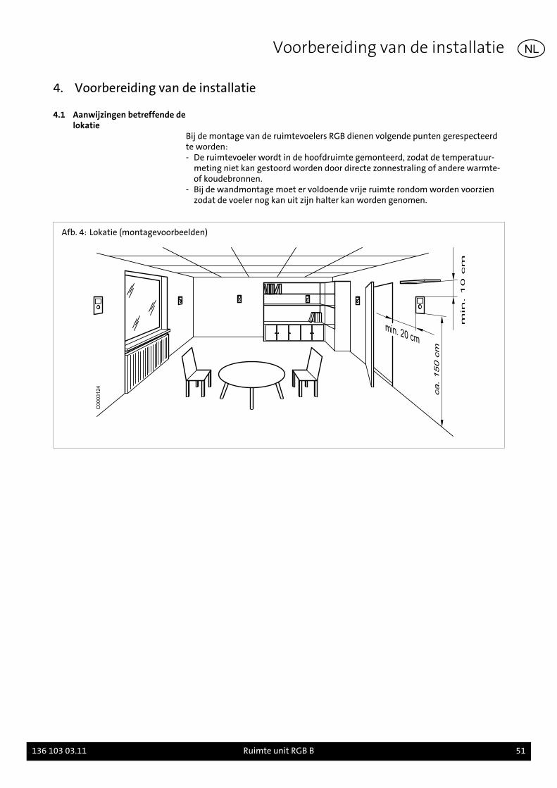
Bij de montage van de ruimtevoelers RGB dienen volgende punten gerespecteerdte worden:- De ruimtevoeler wordt in de hoofdruimte gemonteerd, zodat de temperatuur-
meting niet kan gestoord worden door directe zonnestraling of andere warmte-of koudebronnen.
- Bij de wandmontage moet er voldoende vrije ruimte rondom worden voorzienzodat de voeler nog kan uit zijn halter kan worden genomen.
Afb. 4: Lokatie (montagevoorbeelden)
C0003124
Voorbereiding van de installatie
136 103 03.11 Ruimte unit RGB B 51
NL
5. Montage
5.1 Montage RGB
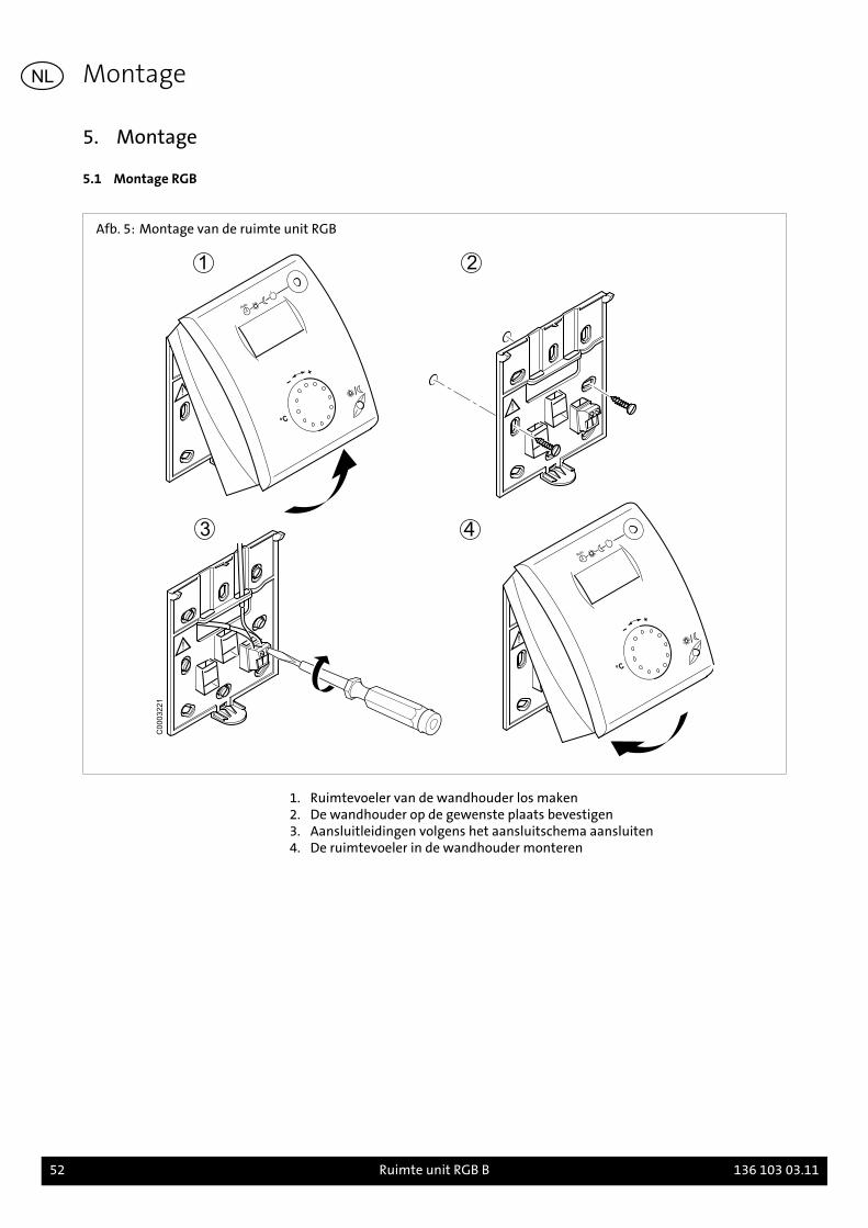
Afb. 5: Montage van de ruimte unit RGB
C0003221
1. Ruimtevoeler van de wandhouder los maken2. De wandhouder op de gewenste plaats bevestigen3. Aansluitleidingen volgens het aansluitschema aansluiten4. De ruimtevoeler in de wandhouder monteren
Montage
52 Ruimte unit RGB B 136 103 03.11
NL
6. Installatie
6.1 Elektrische aansluiting RGB- Aansluitleidingen van de RGB naar de verwarmingsketel brengen- Leidingen moeten in de trekontlastingen van het schakelveld vastgezet worden
en overeenkomstig het schakelschema aangesloten worden (Afb. 2)
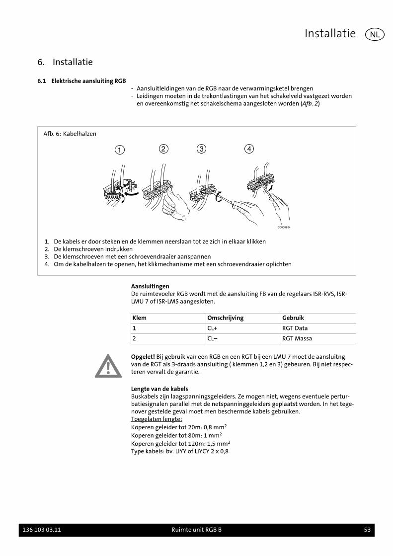
Afb. 6: Kabelhalzen
1 2 3 4
C0000654
1. De kabels er door steken en de klemmen neerslaan tot ze zich in elkaar klikken2. De klemschroeven indrukken3. De klemschroeven met een schroevendraaier aanspannen4. Om de kabelhalzen te openen, het klikmechanisme met een schroevendraaier oplichten
AansluitingenDe ruimtevoeler RGB wordt met de aansluiting FB van de regelaars ISR-RVS, ISR-LMU 7 of ISR-LMS aangesloten.
Klem Omschrijving Gebruik
1 CL+ RGT Data
2 CL– RGT Massa
Opgelet! Bij gebruik van een RGB en een RGT bij een LMU 7 moet de aansluitngvan de RGT als 3-draads aansluiting ( klemmen 1,2 en 3) gebeuren. Bij niet respec-teren vervalt de garantie.
Lengte van de kabelsBuskabels zijn laagspanningsgeleiders. Ze mogen niet, wegens eventuele pertur-batiesignalen parallel met de netspanninggeleiders geplaatst worden. In het tege-nover gestelde geval moet men beschermde kabels gebruiken.Toegelaten lengte:Koperen geleider tot 20m: 0,8 mm2
Koperen geleider tot 80m: 1 mm2
Koperen geleider tot 120m: 1,5 mm2
Type kabels: bv. LIYY of LiYCY 2 x 0,8
Installatie
136 103 03.11 Ruimte unit RGB B 53
NL
7. Inbedrijfsname
7.1 ConfiguratieDoor lang te drukken op de aanwezigheidstoets word het instelmenu opgeroepen.Deze parameters worden door kort op de aanwezigheidstoets te drukken opgero-pen. De aangeduide parameter knippert. Met de draaiknop wordt de gewenstewaarde ingesteld. De beëindiging van de programmering gebeurt door het druk-ken op de bedrijfstoestandtoets.
Tab. 2: Parameter
Functie Instelling
Inzet als ru = 1 (fabrieksinstelling) De ruimtevoeler is als omgeveingsvoeler 1 ( voor verwar-mingskring 1 geadresseerd) ( werkinstelling).
ru = 2 De ruimtevoeler is als omgevingsvoeler 2 ( voor verwar-mingskring 2 geadresseerdwerkinstelling).
ru = 3 De ruimtevoeler is als omgevingsvoeler 3 ( voor verwar-mingskring 3 geadresseerdwerkinstelling).
Directe verstelling(Gew wrde ruimte)
P1 = 1 (fabrieksinstelling) Het opslaan gebeurt automatisch: Een wijziging wordt be-vestigd door bevestiging met de bedrijfstoestandtoets ofdoor geen verdere bevestiging ( Timeout ) overgenomen( werkinstelling).
P1 = 2 Het opslaan gebeurt na bevestiging: Een afwijking gebeurtdoor een bevesting van de bedrijfstoestandtoets.
Bedienblokkering P2 = 0 Uit: alle bedienelementen vrijgegeven ( werkinstelling).
P2 = 1 Uit: Volgende bedienelement zijn geblokkeerd:- Bedrijfskeuzeomschakeling Verwarmings circuit- Gewenste wrde comfort verstelling- Bedrijfsniveau-omschakeling (Aanwezigheidstoets)Is de bedienblokkering actief, wordt bij een druk op de ge-blokkeerde toets gedurende 3 seconden de melding gege-ven "OFF". Het oproepen van instellingen wordt door de be-dienblokkering niet verhinderd.
Uitvoerige informatie over de programmering van geïntegreerde systemmregelaarISR en insteltabellen met programeerbare parameters zijn terug te vinden in deinstallatiehandleidingen van de verwarmingsketels.
Inbedrijfsname
54 Ruimte unit RGB B 136 103 03.11
NL
1. Acerca de este manual
Lea atentamente este manual antes de proceder al montaje del accesorio.
1.1 Contenido de este manualContenido de este manual de montaje y ajuste de la unidad ambiente RGB.
Consulte, además, los manuales de instalación y montaje de la caldera.
1.2 Símbolos utilizados¡Peligro! En caso de inobservancia existe peligro de muerte y de lesiones graves.
¡Peligro de descarga eléctrica! En caso de inobservancia existe peligro de muerte yde lesiones graves por electricidad.
¡Atención! En caso de inobservancia existe peligro para el medio ambiente y parael equipo.
Indicación/Consejo: Aquí encontrará información complementaria o consejos úti-les.
Referencias a información adicional en otros documentos.
1.3 ¿A quién va dirigido estemanual?
Este manual de montaje va dirigido al instalador del accesorio.
1.4 Volumen de suministro
- Unidad ambiente RGB con soporte mural- Conector- Manual de montaje- Instrucciones breves
Acerca de este manual
136 103 03.11 Unidad ambiente RGB B 55
ES
2. Seguridad
¡Peligro! Observe las siguientes instrucciones de seguridad para evitar peligros pa-ra usted mismo y para otras personas.
2.1 Uso previstoLa unidad ambiente RGB B sirve como mando a distancia de todas las calderasBrötje a partir de la serie C. La unidad ambiente RGB permite regular la temperatu-ra nominal del circuito de calefacción y seleccionar el modo de servicio del mismo.
Nota: En caso de utilizar la unidad ambiente RGB con reguladores de sistema in-tegrados del tipo LMU, debe observarse que la unidad sólo funciona con regulado-res LMU 7 a partir de la versión de software 1.04.
Para más información sobre la programación del regulador de sistema integrado ypara las tablas de ajuste con los parámetros programables consulte el Manual deprogramación e hidráulica y el Manual de instalación de la caldera.
2.2 Instrucciones generales deseguridad
¡Peligro de descarga eléctrica! Los trabajos eléctricos relacionados con la instalaci-ón sólo podrá realizarlos personal especializado.
¡Atención! Durante la instalación del accesorio existe el riesgo de que se produz-can importantes daños materiales. Por este motivo, se recomienda que el montajedel accesorio lo lleve a cabo una empresa especializada y que la primera puesta enservicio la realice personal experto de la empresa del fabricante.
Cualquier accesorio utilizado debe cumplir las reglas técnicas y estar autorizadopor el fabricante en combinación con este accesorio.
¡Atención! Sólo pueden emplearse piezas de recambio originales.
No está permitido realizar ningún tipo de modificaciones y cambios sin autorizaci-ón en los accesorios, ya que ponen en peligro a las personas y pueden provocar da-ños en los accesorios. En caso de no observar esta prohibición, la homologación delos accesorios queda inhabilitada.
Seguridad
56 Unidad ambiente RGB B 136 103 03.11
ES
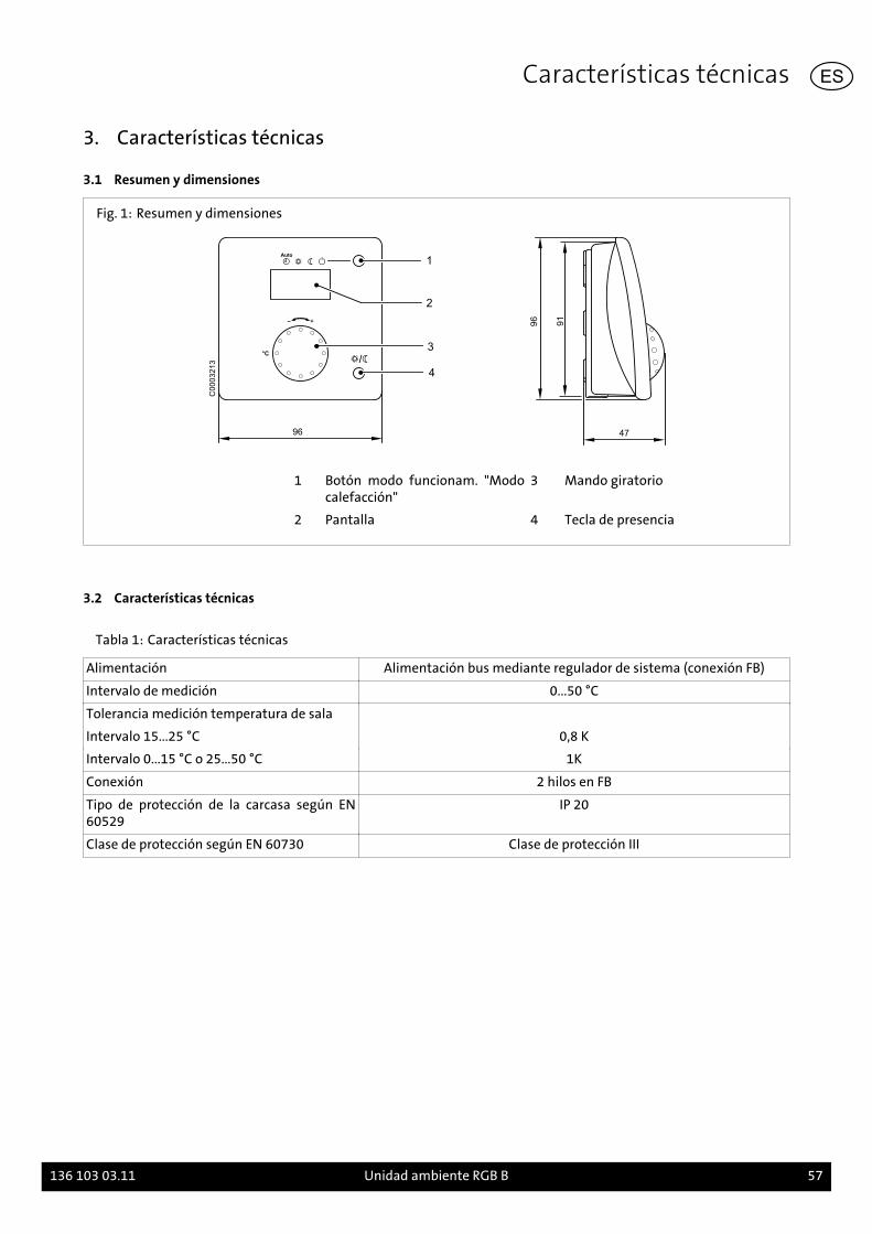
3. Características técnicas
3.1 Resumen y dimensiones
Fig. 1: Resumen y dimensiones
96
1
2
3°C
4
47
96
91
C0
00
32
13
1 Botón modo funcionam. "Modocalefacción"
3 Mando giratorio
2 Pantalla 4 Tecla de presencia
3.2 Características técnicas
Tabla 1: Características técnicas
Alimentación Alimentación bus mediante regulador de sistema (conexión FB)
Intervalo de medición 0...50 °C
Tolerancia medición temperatura de sala
Intervalo 15...25 °C 0,8 K
Intervalo 0...15 °C o 25...50 °C 1K
Conexión 2 hilos en FB
Tipo de protección de la carcasa según EN60529
IP 20
Clase de protección según EN 60730 Clase de protección III
Características técnicas
136 103 03.11 Unidad ambiente RGB B 57
ES
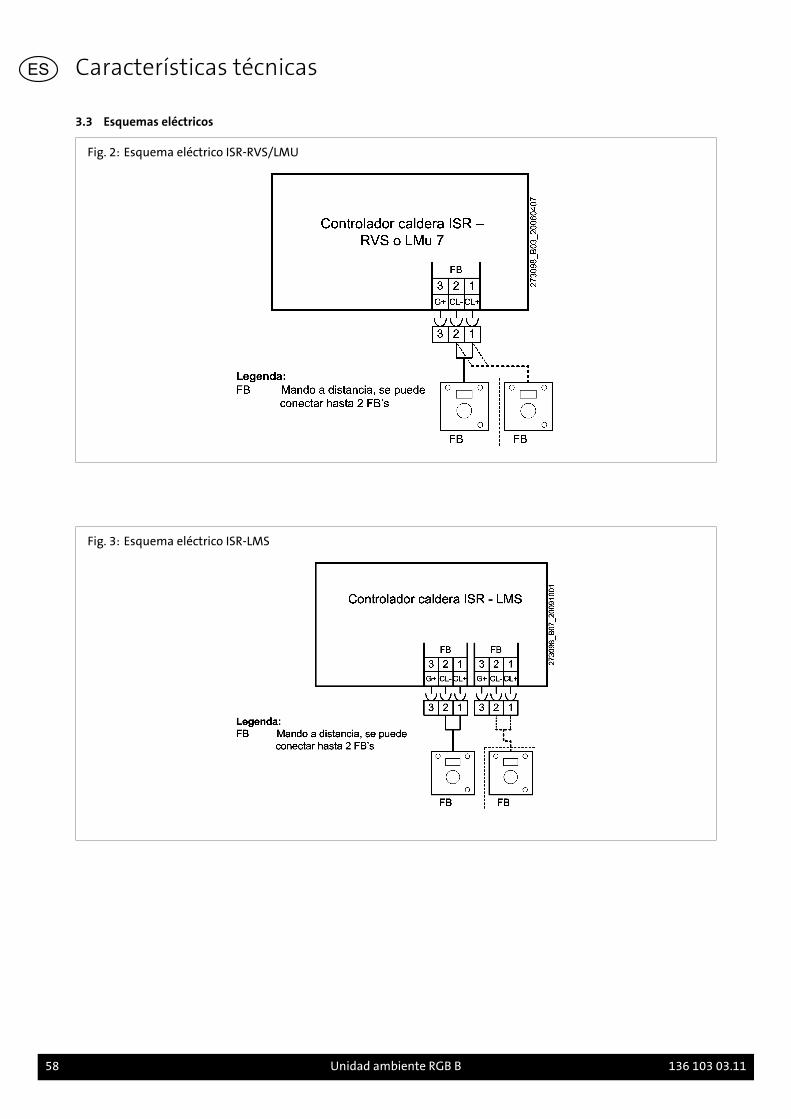
3.3 Esquemas eléctricos
Fig. 2: Esquema eléctrico ISR-RVS/LMU
Fig. 3: Esquema eléctrico ISR-LMS
Características técnicas
58 Unidad ambiente RGB B 136 103 03.11
ES
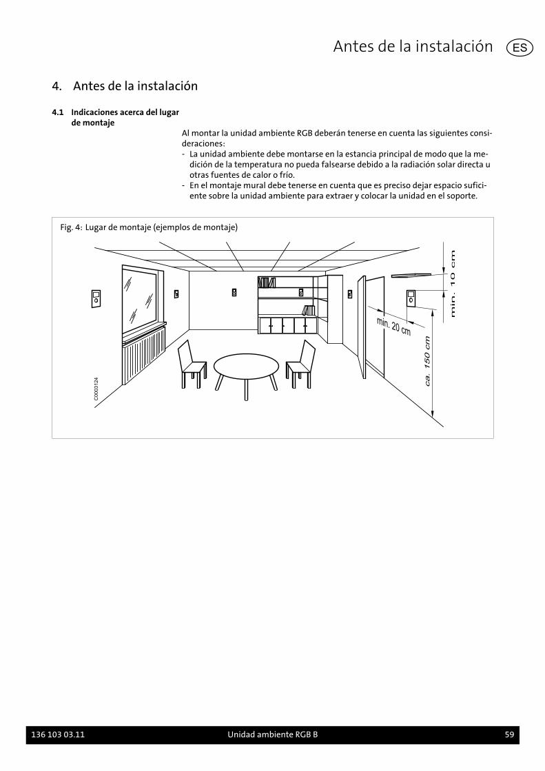
4. Antes de la instalación
4.1 Indicaciones acerca del lugarde montaje
Al montar la unidad ambiente RGB deberán tenerse en cuenta las siguientes consi-deraciones:- La unidad ambiente debe montarse en la estancia principal de modo que la me-
dición de la temperatura no pueda falsearse debido a la radiación solar directa uotras fuentes de calor o frío.
- En el montaje mural debe tenerse en cuenta que es preciso dejar espacio sufici-ente sobre la unidad ambiente para extraer y colocar la unidad en el soporte.
Fig. 4: Lugar de montaje (ejemplos de montaje)
C0003124
Antes de la instalación
136 103 03.11 Unidad ambiente RGB B 59
ES

5. Montaje
5.1 Montaje RGB
Fig. 5: Montaje de la unidad ambiente RGB
C0003221
1. Separar la unidad ambiente del soporte mural.2. Fijar el soporte mural en el lugar de montaje deseado.3. Conectar los cables de conexión de acuerdo con el esquema eléctrico.4. Fijar la unidad ambiente en el soporte mural.
Montaje
60 Unidad ambiente RGB B 136 103 03.11
ES
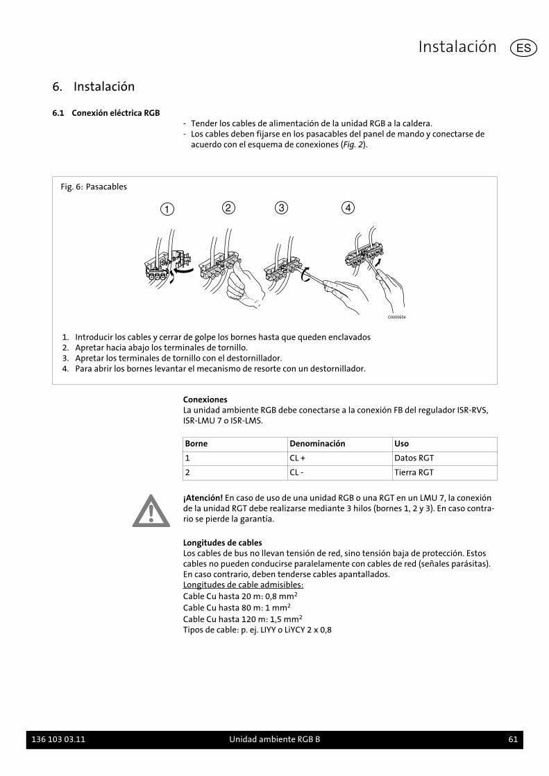
6. Instalación
6.1 Conexión eléctrica RGB- Tender los cables de alimentación de la unidad RGB a la caldera.- Los cables deben fijarse en los pasacables del panel de mando y conectarse de
acuerdo con el esquema de conexiones (Fig. 2).
Fig. 6: Pasacables
1 2 3 4
C0000654
1. Introducir los cables y cerrar de golpe los bornes hasta que queden enclavados2. Apretar hacia abajo los terminales de tornillo.3. Apretar los terminales de tornillo con el destornillador.4. Para abrir los bornes levantar el mecanismo de resorte con un destornillador.
ConexionesLa unidad ambiente RGB debe conectarse a la conexión FB del regulador ISR-RVS,ISR-LMU 7 o ISR-LMS.
Borne Denominación Uso
1 CL + Datos RGT
2 CL - Tierra RGT
¡Atención! En caso de uso de una unidad RGB o una RGT en un LMU 7, la conexiónde la unidad RGT debe realizarse mediante 3 hilos (bornes 1, 2 y 3). En caso contra-rio se pierde la garantía.
Longitudes de cablesLos cables de bus no llevan tensión de red, sino tensión baja de protección. Estoscables no pueden conducirse paralelamente con cables de red (señales parásitas).En caso contrario, deben tenderse cables apantallados.Longitudes de cable admisibles:Cable Cu hasta 20 m: 0,8 mm2
Cable Cu hasta 80 m: 1 mm2
Cable Cu hasta 120 m: 1,5 mm2
Tipos de cable: p. ej. LIYY o LiYCY 2 x 0,8
Instalación
136 103 03.11 Unidad ambiente RGB B 61
ES
7. Puesta en servicio
7.1 ConfiguraciónUna pulsación larga de la tecla de presencia abre el nivel de ajustes. Los parámet-ros se seleccionan mediante una pulsación breve de la tecla de presencia. El pará-metro seleccionado parpadea. El botón giratorio permite ajustar el valor deseado.Para finalizar la programación debe pulsarse la tecla de modo de servicio.
Tabla 2: Parámetro
Función Ajustes
Usado como ru = 1 (ajuste de fábrica) La unidad ambiente tiene la dirección de unidad ambiente 1(para el circuito de calefacción 1) (ajuste de fábrica).
ru = 2 La unidad ambiente tiene la dirección de unidad ambiente 2(para el circuito de calefacción 2).
ru = 3 La unidad ambiente tiene la dirección de unidad ambiente 3(para el circuito de calefacción 3).
Ajuste directo (valorde consigna de la sala)
P1 = 1 (ajuste de fábrica) El valor se guarda automáticamente: el sistema acepta elnuevo valor de consigna al pulsar la tecla de modo de servi-cio o también si no se pulsa ninguna tecla durante un tiem-po (timeout) (ajuste de fábrica).
P1 = 2 El valor se guarda después de confirmarlo: el sistema sólocorrige el valor de consigna tras confirmarlo mediante latecla de modo de servicio.
Bloqueo de mando P2 = 0 Off: todos los elementos de mando están desbloqueados(ajuste de fábrica).
P2 = 1 Off: Los siguientes elementos de mando están bloqueados:- Cambio modo de servicio circuito calefacción- Modificación del valor de consigna de confort- Cambio del nivel de servicio (tecla de presencia)Al pulsar una tecla bloqueada con el bloqueo activado, apa-recerá en pantalla durante unos 3 segundos el mensaje"OFF". El bloqueo de mando no impide abrir el nivel de ajus-te.
Para más información acerca de la programación del regulador de sistema integra-do ISR y las tablas de ajustes con los parámetros programables consulte el Manualde instalación de la caldera.
Puesta en servicio
62 Unidad ambiente RGB B 136 103 03.11
ES
1. Uwagi dotyczące niniejszej instrukcji montażu
Przed rozpoczęciem montażu elementów wyposażenia dodatkowego proszę star-annie zapoznać się z niniejszą instrukcją!
1.1 Treść niniejszej instrukcjimontażu
Treść niniejszej instrukcji jest sposób montażu i wprowadzania nastaw w regula-torze pokojowym RGB.
Ponadto należy stosować się do zaleceń instrukcji montażu i instalacji zastosowa-nego kotła grzewczego.
1.2 Zastosowane symboleNiebezpieczeństwo! W przypadku niezastosowania się do tego ostrzeżenia istniejezagrożenie dla zdrowia i życia.
Niebezpieczeństwo porażenia prądem! W przypadku braku zachowania odpo-wiedniej ostrożności istnieje niebezpieczeństwo uszkodzenia ciała i zagrożenie dlażycia!
Uwaga! W przypadku niezastosowania się do tego ostrzeżenia istnieje niebezpiec-zeństwo dla środowiska i uszkodzenia urządzenia.
Wskazówka: Dodatkowe informacje i przydatne wskazówki.
Odesłanie do dodatkowych informacji zawartych w innych dokumentach.
1.3 Dla kogo przeznaczona jestniniejsza instrukcja obsługi?
Niniejsza instrukcja montażu jest przeznaczona dla wykonawcy instalacji ogrzewa-nia montującego elementy wyposażenia dodatkowego.
1.4 Zakres dostawy
- Regulator RGB z kieszenią naścienną- wtyczka- Instrukcja montażu- skrócona instrukcja obsługi
Uwagi dotyczące niniejszej instrukcji montażu
136 103 03.11 Regulator pokojowy RGB B 63
PL
2. Bezpieczeństwo
Niebezpieczeństwo! Należy stosować się do poniższych wskazówek dotyczącychbezpieczeństwa! W przeciwnym razie stwarzają Państwo zagrożenie dla siebie i in-nych.
2.1 Zastosowanie zgodnie zprzeznaczeniem
Regulator RGB służy do zdalnej obsługi wszystkich kotłów grzewczych firmy Brötjepocząwszy od serii C. Za pomocą regulatora RGB można wprowadzać temperaturęzadaną w pomieszczeniu i wybierać tryb pracy obiegu c.o.
Wskazówka: Podczas eksploatacji regulatora RGB ze zintegrowanymi regulatoramisystemowymi typu LMU należy pamiętać o tym, że regulator pokojowy możewspółpracować tylko z regulatorami LMU 7 wyposażonymi w oprogramowanie wwersji od 1.04.
Szczegółowe informacje dotyczące programowania zintegrowanego regulatorasystemowego oraz tabele nastaw wraz z możliwymi do zaprogramowania para-metrami zawiera Podręcznik programowania i instalacji hydraulicznej oraz Pod-ręcznik instalacyjny kotła.
2.2 Ogólne wskazówkidotyczące bezpieczeństwa
Niebezpieczeństwo porażenie prądem! Wszelkie prace elektryczne związane z in-stalacją może wykonywać wyłącznie monter instalacji elektrotechnicznych!
Uwaga! Podczas montowania elementów wyposażenia dodatkowego istnieje nie-bezpieczeństwo spowodowania poważnych uszkodzeń. Z tego względu elementywyposażenie dodatkowego powinny być montowane tylko przez specjalistycznefirmy i uruchamiane po raz pierwszy przez specjalistów producentów!
Zastosowane elementy wyposażenia dodatkowego muszą spełniać wymagania re-guł techniki i być dopuszczone przez producenta do stosowania z tymi elementamiwyposażenia dodatkowego.
Stosować wyłącznie oryginalne części.
Wykonywanie we własnym zakresie zmiana konstrukcyjnych o dotyczących ele-mentów wyposażenia dodatkowego jest niedozwolone, ponieważ może to pro-wadzić do zagrożenia dla ludzi i uszkodzenia wyposażenia. W przypadku niezasto-sowania się do tego wymogu wygasa zezwolenie na stosowanie elementów wypo-sażenia dodatkowego.
Bezpieczeństwo
64 Regulator pokojowy RGB B 136 103 03.11
PL

3. Dane techniczne
3.1 Przegląd i wymiary
Rys. 1: Przegląd i wymiary
96
1
2
3°C
4
47
96
91
C0
00
32
13
1 przycisk wyboru trybu pracy 3 pokrętło
2 wyświetlacz 4 przycisk obecności
3.2 Dane techniczne
Tab. 1: Dane techniczne
Zasilania Zasianie magistrali przez regulator systemowy (przyłącze FB)
Zakres pomiarowy 0...50°C
Tolerancja pomiaru temperatury w pmieszc-zeniu
Zakres od 15°C do 25°C 0,8 K
Zakres od 0°C do 15°C lub od 25°C do 50°C 1K
Podłączenie 2-żyłowy do przyłącza FB
Stopień ochrony obudowy zgodnie z normąEN 60529
IP 20
Stopień ochrony zgodnie z normą EN 60730 stopień ochrony III
Dane techniczne
136 103 03.11 Regulator pokojowy RGB B 65
PL
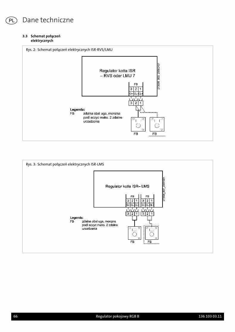
3.3 Schemat połączeńelektrycznych
Rys. 2: Schemat połączeń elektrycznych ISR-RVS/LMU
Rys. 3: Schemat połączeń elektrycznych ISR-LMS
Dane techniczne
66 Regulator pokojowy RGB B 136 103 03.11
PL
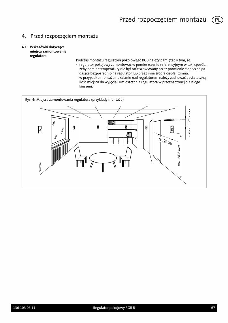
4. Przed rozpoczęciem montażu
4.1 Wskazówki dotyczącemiejsca zamontowaniaregulatora
Podczas montażu regulatora pokojowego RGB należy pamiętać o tym, że:- regulator pokojowy zamontować w pomieszczeniu referencyjnym w taki sposób,
żeby pomiar temperatury nie był zafałszowywany przez promienie słoneczne pa-dające bezpośrednio na regulator lub przez inne źródła ciepła i zimna.
- w przypadku montażu na ścianie nad regulatorem należy zachować dostatecznąilość miejsca do wyjęcia i umieszczenia regulatora w przeznaczonej dla niegokieszeni.
Rys. 4: Miejsce zamontowania regulatora (przykłady montażu)
C0003124
Przed rozpoczęciem montażu
136 103 03.11 Regulator pokojowy RGB B 67
PL
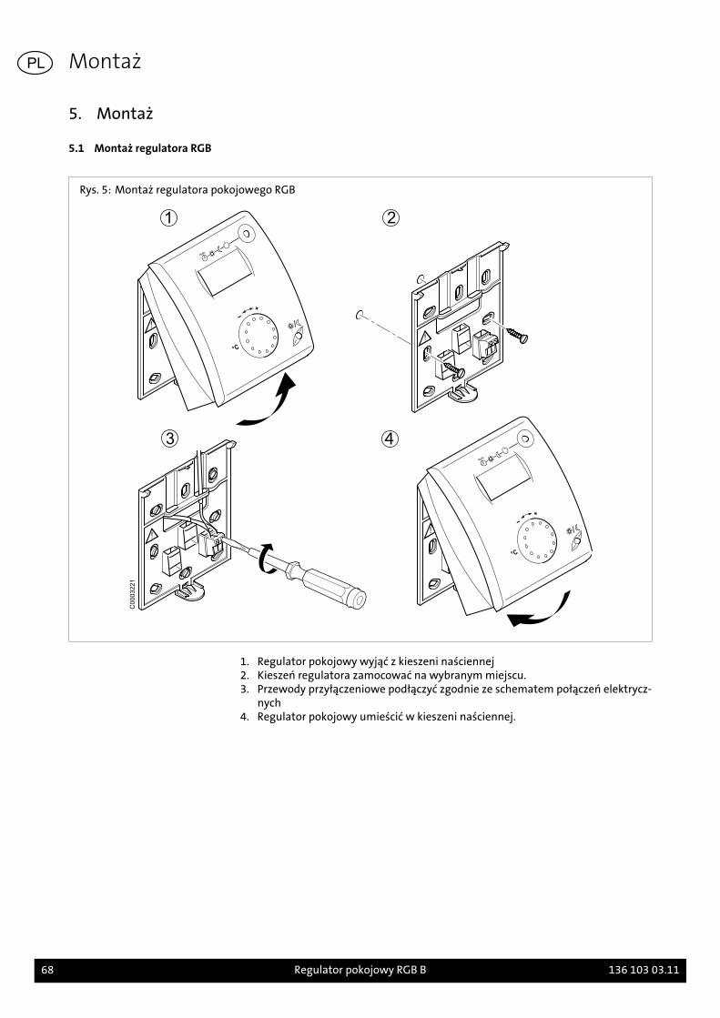
5. Montaż
5.1 Montaż regulatora RGB
Rys. 5: Montaż regulatora pokojowego RGB
C0003221
1. Regulator pokojowy wyjąć z kieszeni naściennej2. Kieszeń regulatora zamocować na wybranym miejscu.3. Przewody przyłączeniowe podłączyć zgodnie ze schematem połączeń elektrycz-
nych4. Regulator pokojowy umieścić w kieszeni naściennej.
Montaż
68 Regulator pokojowy RGB B 136 103 03.11
PL
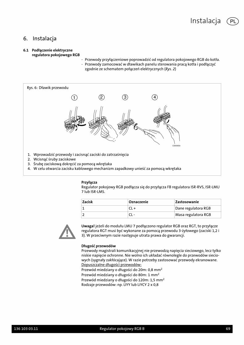
6. Instalacja
6.1 Podłączenie elektryczneregulatora pokojowego RGB
- Przewody przyłączeniowe poprowadzić od regulatora pokojowego RGB do kotła.- Przewody zamocować w dławikach panelu sterowania pracą kotła i podłączyć
zgodnie ze schematem połączeń elektrycznych (Rys. 2)
Rys. 6: Dławik przewodu
1 2 3 4
C0000654
1. Wprowadzić przewody i zacisnąć zaciski do zatrzaśnięcia2. Wcisnąć śruby zaciskowe3. Śrubę zaciskową dokręcić za pomocą wkrętaka4. W celu otwarcia zacisku kablowego mechanizm zapadkowy unieść za pomocą wkrętaka
PrzyłączaRegulator pokojowy RGB podłącza się do przyłącza FB regulatora ISR-RVS, ISR-LMU7 lub ISR-LMS.
Zacisk Oznaczenie Zastosowanie
1 CL + Dane regulatora RGB
2 CL - Masa regulatora RGB
Uwaga! jeżeli do modułu LMU 7 podłączono regulator RGB oraz RGT, to przyłączeregulatora RGT musi być wykonane za pomocą przewodu 3-żyłowego (zaciski 1,2 i3). W przeciwnym razie następuje utrata prawa do gwarancji.
Długość przewodówPrzewody magistrali komunikacyjnej nie przewodzą napięcia sieciowego, lecz tylkoniskie napięcie ochronne. Nie wolno ich układać równolegle do przewodów siecio-wych (sygnały zakłócające). W razie potrzeby zastosować przewody ekranowane.Dopuszczalne długości przewodów:Przewód miedziany o długości do 20m: 0,8 mm2
Przewód miedziany o długości do 80m: 1 mm2
Przewód miedziany o długości do 120m: 1,5 mm2
Rodzaje przewodów: np. LIYY lub LiYCY 2 x 0,8
Instalacja
136 103 03.11 Regulator pokojowy RGB B 69
PL
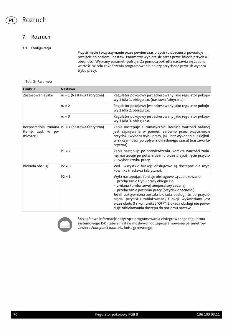
7. Rozruch
7.1 KonfiguracjaPrzyciśnięcie i przytrzymanie przez pewien czas przycisku obecności powodujeprzejście do poziomu nastaw. Parametry wybiera się przez przyciśnięcie przyciskuobecności. Wybrany parametr pulsuje. Za pomocą pokrętła nastawia się żądanąwartość. W celu zakończenia programowania należy przycisnąć przycisk wyborutrybu pracy.
Tab. 2: Parametr
Funkcja Nastawa
Zastosowanie jako ru = 1 (Nastawa fabryczna) Regulator pokojowy jest adresowany jako regulator pokojo-wy 1 (dla 1. obiegu c.o. (nastawa fabryczna).
ru = 2 Regulator pokojowy jest adresowany jako regulator pokojo-wy 2 (dla 2. obiegu c.o.
ru = 3 Regulator pokojowy jest adresowany jako regulator pokojo-wy 3 (dla 3. obiegu c.o.
Bezpośrednia zmiana(temp. zad. w po-mieszcz.)
P1 = 1 (nastawa fabryczna) Zapis następuje automatycznie: korekta wartości zadanejjest zapisywana w pamięci zarówno przez przyciśnięcieprzycisku wyboru trybu pracy, jak i bez wykonania jakiejkol-wiek czynności (po upływie określonego czasu) (nastawa fa-bryczna).
P1 = 2 Zapis następuje po potwierdzeniu: korekta wartości zada-nej następuje po potwierdzeniu przez przyciśnięcie przycis-ku wyboru trybu pracy.
Blokada obsługi P2 = 0 Wył.: wszystkie funkcje obsługowe są dostępne dla użyt-kownika (nastawa fabryczna).
P2 = 1 Wył.: następujące funkcje obsługowe są zablokowane:- przełączanie trybu pracy obiegu c.o.- zmiana komfortowej temperatury zadanej- przełączanie poziomu pracy (przycisk obecności)Jeżeli uaktywniona została blokada obsługi, to po przyciś-nięciu przycisku zablokowanej funkcji wyświetlany jestprzez około 3 s komunikat "OFF". Blokada obsługi nie powo-duje zablokowania dostępu do poziomu nastaw.
Szczegółowe informacje dotyczące programowania zintegrowanego regulatorasystemowego ISR i tabele nastaw możliwych do zaprogramowania parametrówzawiera Podręcznik montażu kotła grzewczego.
Rozruch
70 Regulator pokojowy RGB B 136 103 03.11
PL
1. Ehhez az útmutatóhoz
A tartozékok szerelése előtt figyelmesen olvassa el ezt az útmutatót!
1.1 Ennek az útmutatónak atartalma
Ennek az útmutatónak a tartalma az RGB szobatermosztát szerelése és beállítása.
Ezenkívül vegye figyelembe az alkalmazott kazán szerelési útmutatóit.
1.2 Alkalmazott szimbólumokVeszély! A figyelmeztetés be nem tartása esetén az emberi testet és életet veszélyfenyegeti!
Áramütés veszélye! A figyelmeztetés be nem tartása esetén az elektromosság ré-vén az emberi testet és életet veszély fenyegeti!
Figyelem! A figyelmeztetés be nem tartása esetén a környezetet és a készüléketveszély fenyegeti!
Utalás/tipp: Itt háttérinformációkat és hasznos tippeket talál.
Utalás más dokumentumokban lévő kiegészítő információkra..
1.3 Kinek szól ez az útmutató?Ez a szerelési útmutató annak a fűtésszerelőnek szól, aki a tartozékokat felszereli.
1.4 Szállítási terjedelem
- RGB szobatermosztát falitartóval- dugaszos összekötő- Szerelési útmutató- Rövid leírás
Ehhez az útmutatóhoz
136 103 03.11 RGB B helyiségtermosztát 71
HU
2. Biztonság
Veszély! Feltétlenül vegye figyelembe a következő biztonságtechnikai előírásokat!Egyébként veszélyezteti magát és másokat.
2.1 Rendeltetésszerű használatAz RGB szobatermosztát a C kazánsorozattól kezdve minden Brötje-kazán távkapc-solására szolgál. Az RGB szobatermosztáttal beállítható a hőmérséklet parancsoltértéke és a fűtési kör üzemmódja.
Figyelem: Az RGB szobatermosztátnak az LMU típusú beépített rendszerszabályo-zóval való üzeménél ügyelni kell arra, hogy a szobatermosztát csak az 1.04 szoft-ververzió fölötti LMU 7-szabályozókkal alkalmazható.
A beépített rendszerszabályozó programozására, és a programozható paramétere-ket tartalmazható beállítási táblázatokra vonatkozó részletes információkat a ka-zán programozási és hidraulikai kézikönyve és szerelési kézikönyve tartalmazza.
2.2 Általános biztonságtechnikaielőírások
Áramütés veszélye! Minden, a szereléssel összefüggő villanyszerelési munkát csakvillanyszerelő szakemberek végezhetnek!
Figyelem! A tartozékok szerelésénél jelentős anyagi károk veszélye áll fenn. Ezért atartozékokat csak szakvállalat szerelheti fel, és csak a gyártó cégek szakértői hel-yezhetik azokat első ízben üzembe!
Az alkalmazott tartozékok feleljenek meg a műszaki szabályoknak és azok alkal-mazását ezzel a tartozékkal kapcsolatban a gyártónak engedélyeznie kell.
Csak eredeti pótalkatrészek alkalmazhatók.
Az önhatalmú átszerelések és módosítások a tartozékon nincsenek megengedve,mivel azok veszélyeztetik az embereket, és a tartozék károsodásaihoz vezethetnek.Ennek figyelmen kívül hagyása esetén a tartozék engedélye megszűnik.
Biztonság
72 RGB B helyiségtermosztát 136 103 03.11
HU
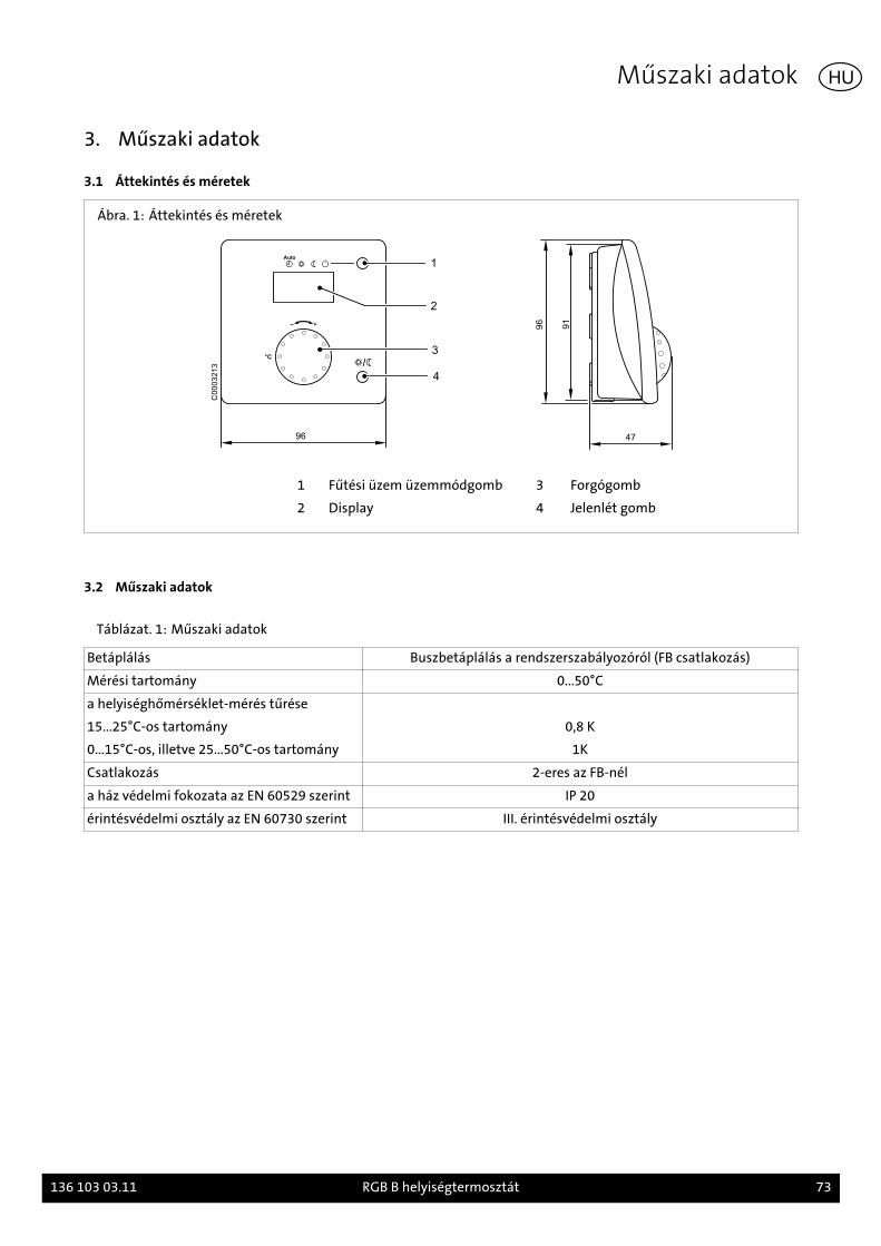
3. Műszaki adatok
3.1 Áttekintés és méretek
Ábra. 1: Áttekintés és méretek
96
1
2
3°C
4
47
96
91
C0
00
32
13
1 Fűtési üzem üzemmódgomb 3 Forgógomb
2 Display 4 Jelenlét gomb
3.2 Műszaki adatok
Táblázat. 1: Műszaki adatok
Betáplálás Buszbetáplálás a rendszerszabályozóról (FB csatlakozás)
Mérési tartomány 0...50°C
a helyiséghőmérséklet-mérés tűrése
15...25°C-os tartomány 0,8 K
0...15°C-os, illetve 25...50°C-os tartomány 1K
Csatlakozás 2-eres az FB-nél
a ház védelmi fokozata az EN 60529 szerint IP 20
érintésvédelmi osztály az EN 60730 szerint III. érintésvédelmi osztály
Műszaki adatok
136 103 03.11 RGB B helyiségtermosztát 73
HU

3.3 Kapcsolási vázlatok
Ábra. 2: Kapcsolási vázlat ISR-RVS/LMU
Ábra. 3: Kapcsolási vázlat ISR-LMS
Műszaki adatok
74 RGB B helyiségtermosztát 136 103 03.11
HU

4. A szerelés előtt
4.1 Előírások a telepítési helyhezAz RGB szobatermosztát szerelésénél a következő pontokra kell ügyelni:- A szobatermosztátot úgy kell felszerelni a mértékadó tartózkodási helyiségben,
hogy a hőmérsékletmérést közvetlen napsugárzás, vagy egyéb hő-, illetve hideg-forrás ne hamisítsa meg.
- A fali szerelésnél a szobatermosztát fölött elegendő helyet kell hagyni a készülékkivételéhez és betételéhez a tartóból, illertve a tartóba.
Ábra. 4: Telepítési hely (szerelési példák)
C0003124
A szerelés előtt
136 103 03.11 RGB B helyiségtermosztát 75
HU

5. Szerelése
5.1 RGB szerelése
Ábra. 5: RGB szobatermosztát szerelése
C0003221
1. A szobatermosztát oldása a falitartótól2. A falitartó rögzítése a kívánt telepítési helyen3. A csatlakozóvezetékek bekötése a kapcsolási vázlat szerint4. A szobatermosztát elhelyezése a falitartóban
Szerelése
76 RGB B helyiségtermosztát 136 103 03.11
HU
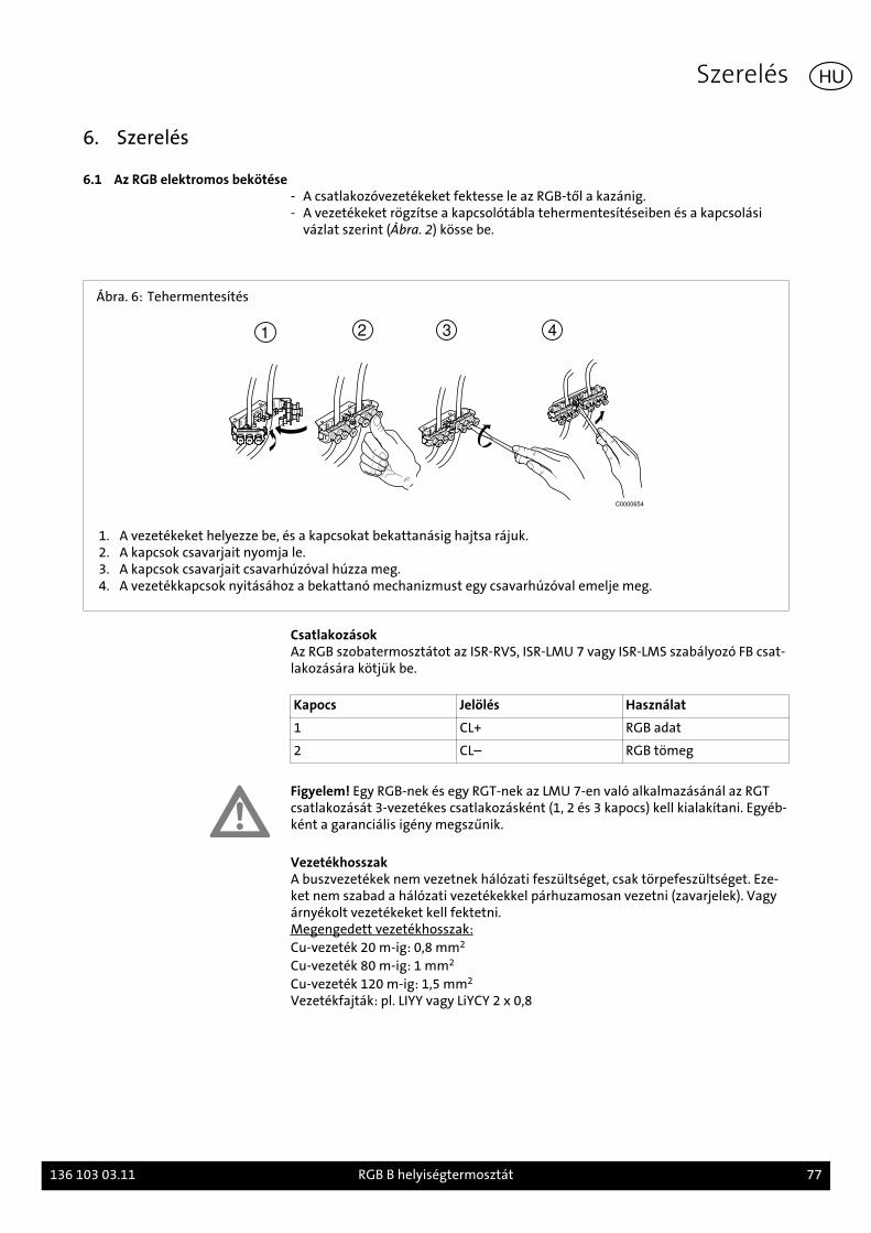
6. Szerelés
6.1 Az RGB elektromos bekötése- A csatlakozóvezetékeket fektesse le az RGB-től a kazánig.- A vezetékeket rögzítse a kapcsolótábla tehermentesítéseiben és a kapcsolási
vázlat szerint (Ábra. 2) kösse be.
Ábra. 6: Tehermentesítés
1 2 3 4
C0000654
1. A vezetékeket helyezze be, és a kapcsokat bekattanásig hajtsa rájuk.2. A kapcsok csavarjait nyomja le.3. A kapcsok csavarjait csavarhúzóval húzza meg.4. A vezetékkapcsok nyitásához a bekattanó mechanizmust egy csavarhúzóval emelje meg.
CsatlakozásokAz RGB szobatermosztátot az ISR-RVS, ISR-LMU 7 vagy ISR-LMS szabályozó FB csat-lakozására kötjük be.
Kapocs Jelölés Használat
1 CL+ RGB adat
2 CL– RGB tömeg
Figyelem! Egy RGB-nek és egy RGT-nek az LMU 7-en való alkalmazásánál az RGTcsatlakozását 3-vezetékes csatlakozásként (1, 2 és 3 kapocs) kell kialakítani. Egyéb-ként a garanciális igény megszűnik.
VezetékhosszakA buszvezetékek nem vezetnek hálózati feszültséget, csak törpefeszültséget. Eze-ket nem szabad a hálózati vezetékekkel párhuzamosan vezetni (zavarjelek). Vagyárnyékolt vezetékeket kell fektetni.Megengedett vezetékhosszak:Cu-vezeték 20 m-ig: 0,8 mm2
Cu-vezeték 80 m-ig: 1 mm2
Cu-vezeték 120 m-ig: 1,5 mm2
Vezetékfajták: pl. LIYY vagy LiYCY 2 x 0,8
Szerelés
136 103 03.11 RGB B helyiségtermosztát 77
HU
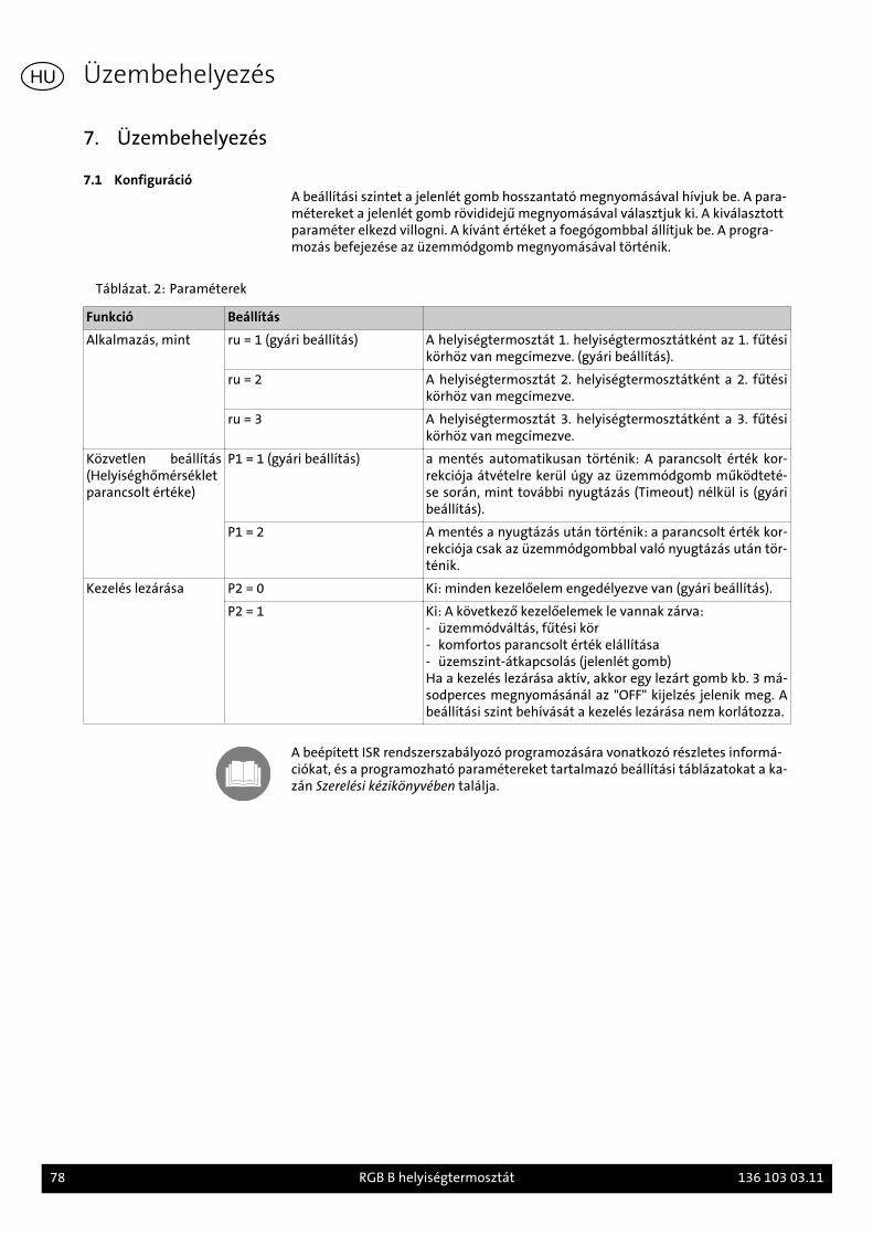
7. Üzembehelyezés
7.1 KonfigurációA beállítási szintet a jelenlét gomb hosszantató megnyomásával hívjuk be. A para-métereket a jelenlét gomb rövididejű megnyomásával választjuk ki. A kiválasztottparaméter elkezd villogni. A kívánt értéket a foegógombbal állítjuk be. A progra-mozás befejezése az üzemmódgomb megnyomásával történik.
Táblázat. 2: Paraméterek
Funkció Beállítás
Alkalmazás, mint ru = 1 (gyári beállítás) A helyiségtermosztát 1. helyiségtermosztátként az 1. fűtésikörhöz van megcímezve. (gyári beállítás).
ru = 2 A helyiségtermosztát 2. helyiségtermosztátként a 2. fűtésikörhöz van megcímezve.
ru = 3 A helyiségtermosztát 3. helyiségtermosztátként a 3. fűtésikörhöz van megcímezve.
Közvetlen beállítás(Helyiséghőmérsékletparancsolt értéke)
P1 = 1 (gyári beállítás) a mentés automatikusan történik: A parancsolt érték kor-rekciója átvételre kerül úgy az üzemmódgomb működteté-se során, mint további nyugtázás (Timeout) nélkül is (gyáribeállítás).
P1 = 2 A mentés a nyugtázás után történik: a parancsolt érték kor-rekciója csak az üzemmódgombbal való nyugtázás után tör-ténik.
Kezelés lezárása P2 = 0 Ki: minden kezelőelem engedélyezve van (gyári beállítás).
P2 = 1 Ki: A következő kezelőelemek le vannak zárva:- üzemmódváltás, fűtési kör- komfortos parancsolt érték elállítása- üzemszint-átkapcsolás (jelenlét gomb)Ha a kezelés lezárása aktív, akkor egy lezárt gomb kb. 3 má-sodperces megnyomásánál az "OFF" kijelzés jelenik meg. Abeállítási szint behívását a kezelés lezárása nem korlátozza.
A beépített ISR rendszerszabályozó programozására vonatkozó részletes informá-ciókat, és a programozható paramétereket tartalmazó beállítási táblázatokat a ka-zán Szerelési kézikönyvében találja.
Üzembehelyezés
78 RGB B helyiségtermosztát 136 103 03.11
HU
1. Zu dieser Anleitung
Před montáží příslušenství si tento návod pečlivě přečtěte.
1.1 Obsah tohoto návoduObsah tohoto návodu je montáž a nastavení jednotky dálkového ovládání v míst-nosti RGB.
Kromě toho respektujte návody k montáži a instalaci použitého topného kotle.
1.2 Použité symbolyNebezpečí! Při nerespektování výstrahy hrozí nebezpečí úrazu a nebezpečí ohrože-ní života.
Nebezpečí úrazu elektrickým proudem! Při nerespektování výstrahy hrozí nebez-pečí úrazu a nebezpečí ohrožení života při zásahu elektrickým proudem!
Pozor! Při nerespektování výstrahy hrozí nebezpečí pro životní prostředí a prozařízení.
Upozornění/tip: zde naleznete dodatečné informace a užitečné tipy.
Odkaz na dodatečné informace v jiných podkladech.
1.3 Komu je určený tentonávod?
Tento návod je určený pro montážního pracovníka / servisního technika, který in-staluje příslušenství.
1.4 Rozsah dodávky
- Jednotka dálkového ovládání v místnosti RGB s držákem na stěnu- Spojovací konektory- NÁVOD k montáži- Stručný návod
Zu dieser Anleitung
136 103 03.11 Jednotka dálkového ovládání v místnosti RGB B 79
CZ
2. Sicherheit
Nebezpečí! Bezpodmínečně respektujte a dodržujte následující bezpečnostní poky-ny! Jinak vystavíte ohrožení sebe i jiné.
2.1 Použití v souladu s určenýmúčelem
Jednotka dálkového ovládání v místnosti RGB je určena k dálkové obsluze a ovládá-ní všech topných kotlů řady C firmy Brötje. Jednotkou dálkového ovládání v míst-nosti RGB je možno nastavovat požadovanou hodnotu teploty v místnosti a režimprovozu topného kotle.
Upozornění: Při provozu jednotky dálkového ovládání v místnosti RGB s integrova-nými systémovými regulátory typu LMU je nutno dát pozor na to, že jednotka dál-kového ovládání v místnosti je použitelná pouze s regulátory LMU 7 od verze soft-ware 1.04.
Podrobné informace k programování integrovaného systémového regulátoru a kpanelům nastavení programovatelných parametrů jsou uvedeny v návodu progra-mování a hydrauliky a v návodu k instalaci topného kotle.
2.2 Všeobecné bezpečnostnípokyny
Nebezpečí úrazu elektrickým proudem! Všechny elektrikářské práce související sinstalací smí provádět pouze odborný pracovník s kvalifikací v oblasti elektro!
Pozor! Při instalaci příslušenství hrozí nebezpečí značných věcných škod. Proto smípříslušenství montovat pouze odborná servisní firma a první uvedení do provozusmějí provádět pouze specialisté montážních firem!
Použité příslušenství musí odpovídat technickým předpisům a schválení výrobcemusí být společně s tímto příslušenstvím.
Smějí se použít jen originální náhradní díly.
Svévolné přestavby, úpravy a změny příslušenství nejsou povoleny, protože mohouohrozit osoby a mohou mít za následek poškození příslušenství. Při nerespektováníztrácí schválení příslušenství svou platnost.
Sicherheit
80 Jednotka dálkového ovládání v místnosti RGB B 136 103 03.11
CZ
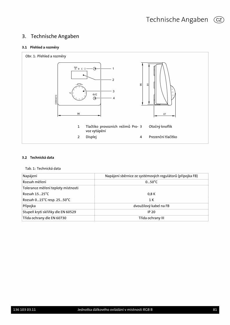
3. Technische Angaben
3.1 Přehled a rozměry
Obr. 1: Přehled a rozměry
96
1
2
3°C
4
47
96
91
C0
00
32
13
1 Tlačtíko provozních režimů Pro-voz vytápění
3 Otočný knoflík
2 Displej 4 Prezenční tlačítko
3.2 Technická data
Tab. 1: Technická data
Napájení Napájení sběrnice ze systémových regulátorů (přípojka FB)
Rozsah měření 0...50°C
Tolerance měření teploty místnosti
Rozsah 15...25°C 0,8 K
Rozsah 0...15°C resp. 25...50°C 1 K
Přípojka dvoužilový kabel na FB
Stupeň krytí skříňky dle EN 60529 IP 20
Třída ochrany dle EN 60730 Třída ochrany III
Technische Angaben
136 103 03.11 Jednotka dálkového ovládání v místnosti RGB B 81
CZ
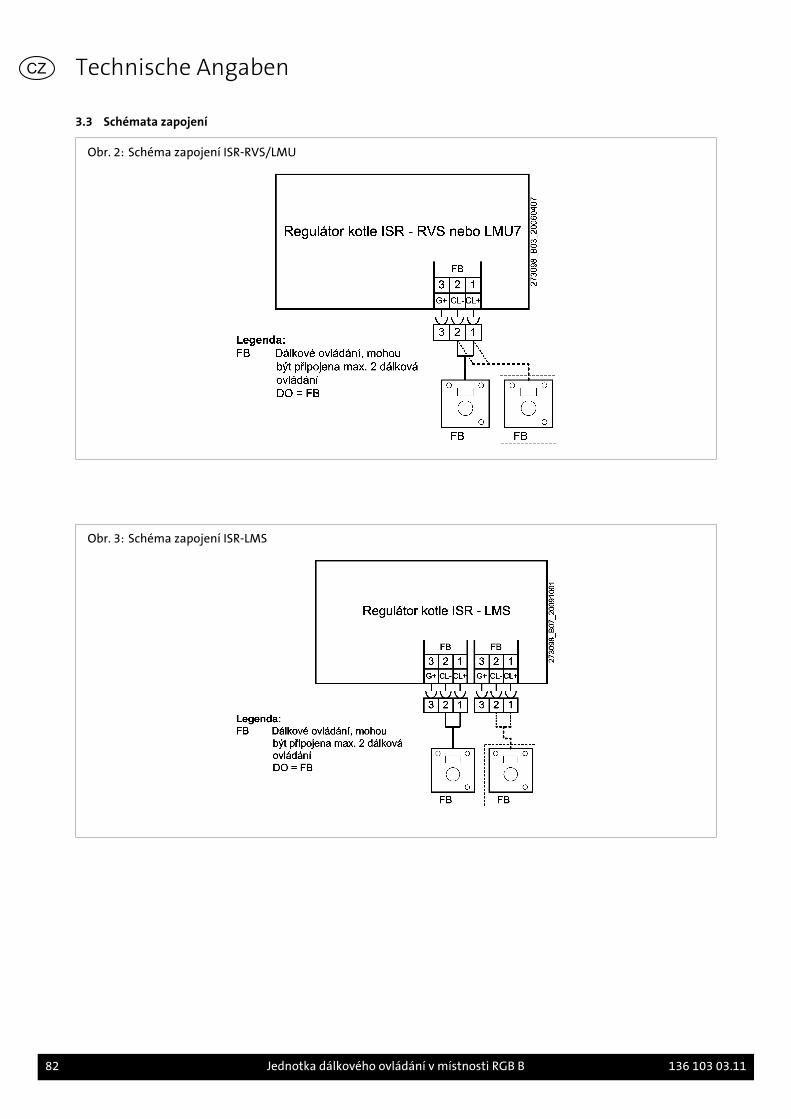
3.3 Schémata zapojení
Obr. 2: Schéma zapojení ISR-RVS/LMU
Obr. 3: Schéma zapojení ISR-LMS
Technische Angaben
82 Jednotka dálkového ovládání v místnosti RGB B 136 103 03.11
CZ
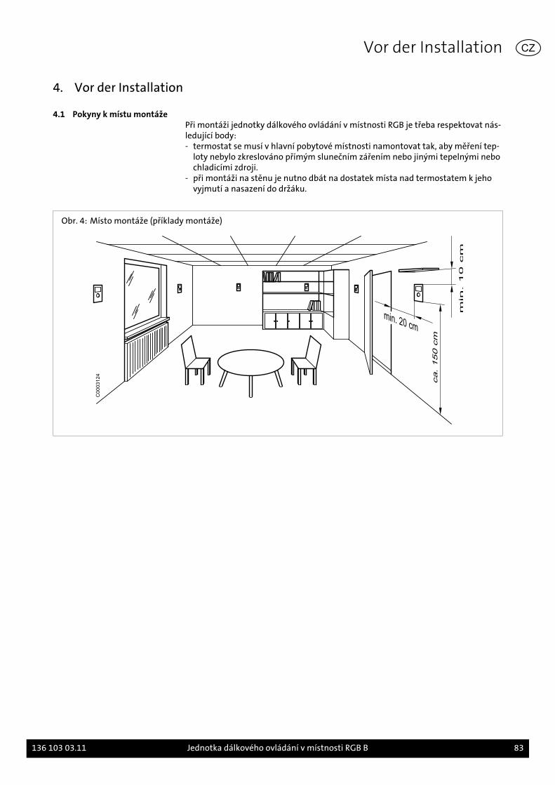
4. Vor der Installation
4.1 Pokyny k místu montážePři montáži jednotky dálkového ovládání v místnosti RGB je třeba respektovat nás-ledující body:- termostat se musí v hlavní pobytové místnosti namontovat tak, aby měření tep-
loty nebylo zkreslováno přímým slunečním zářením nebo jinými tepelnými nebochladicími zdroji.
- při montáži na stěnu je nutno dbát na dostatek místa nad termostatem k jehovyjmutí a nasazení do držáku.
Obr. 4: Místo montáže (příklady montáže)
C0003124
Vor der Installation
136 103 03.11 Jednotka dálkového ovládání v místnosti RGB B 83
CZ
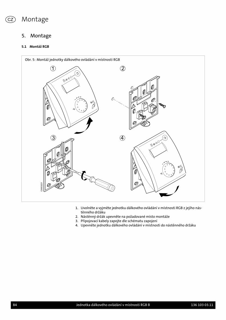
5. Montage
5.1 Montáž RGB
Obr. 5: Montáž jednotky dálkového ovládání v místnosti RGB
C0003221
1. Uvolněte a vyjměte jednotku dálkového ovládání v místnosti RGB z jejího nás-
těnného držáku2. Nástěnný držák upevněte na požadované místo montáže3. Připojovací kabely zapojte dle schématu zapojení4. Upevněte jednotku dálkového ovládání v místnosti do nástěnného držáku
Montage
84 Jednotka dálkového ovládání v místnosti RGB B 136 103 03.11
CZ
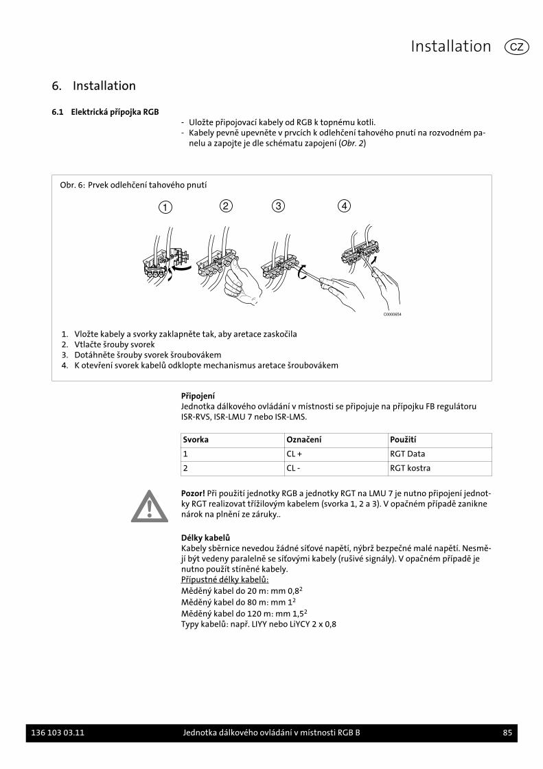
6. Installation
6.1 Elektrická přípojka RGB- Uložte připojovací kabely od RGB k topnému kotli.- Kabely pevně upevněte v prvcích k odlehčení tahového pnutí na rozvodném pa-
nelu a zapojte je dle schématu zapojení (Obr. 2)
Obr. 6: Prvek odlehčení tahového pnutí
1 2 3 4
C0000654
1. Vložte kabely a svorky zaklapněte tak, aby aretace zaskočila2. Vtlačte šrouby svorek3. Dotáhněte šrouby svorek šroubovákem4. K otevření svorek kabelů odklopte mechanismus aretace šroubovákem
PřipojeníJednotka dálkového ovládání v místnosti se připojuje na přípojku FB regulátoruISR-RVS, ISR-LMU 7 nebo ISR-LMS.
Svorka Označení Použití
1 CL + RGT Data
2 CL - RGT kostra
Pozor! Při použití jednotky RGB a jednotky RGT na LMU 7 je nutno připojení jednot-ky RGT realizovat třížilovým kabelem (svorka 1, 2 a 3). V opačném případě zaniknenárok na plnění ze záruky..
Délky kabelůKabely sběrnice nevedou žádné síťové napětí, nýbrž bezpečné malé napětí. Nesmě-jí být vedeny paralelně se síťovými kabely (rušivé signály). V opačném případě jenutno použít stíněné kabely.Přípustné délky kabelů:Měděný kabel do 20 m: mm 0,82
Měděný kabel do 80 m: mm 12
Měděný kabel do 120 m: mm 1,52
Typy kabelů: např. LIYY nebo LiYCY 2 x 0,8
Installation
136 103 03.11 Jednotka dálkového ovládání v místnosti RGB B 85
CZ
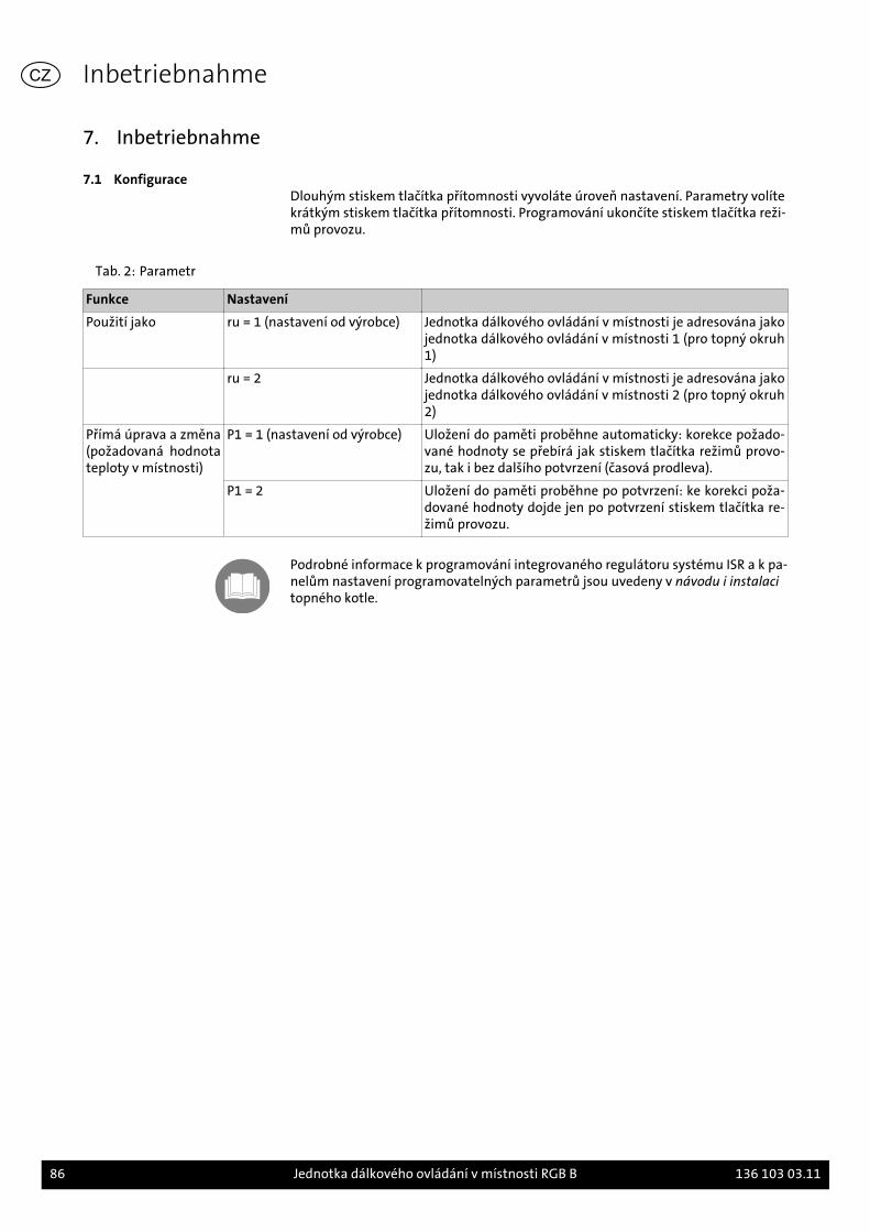
7. Inbetriebnahme
7.1 KonfiguraceDlouhým stiskem tlačítka přítomnosti vyvoláte úroveň nastavení. Parametry volítekrátkým stiskem tlačítka přítomnosti. Programování ukončíte stiskem tlačítka reži-mů provozu.
Tab. 2: Parametr
Funkce Nastavení
Použití jako ru = 1 (nastavení od výrobce) Jednotka dálkového ovládání v místnosti je adresována jakojednotka dálkového ovládání v místnosti 1 (pro topný okruh1)
ru = 2 Jednotka dálkového ovládání v místnosti je adresována jakojednotka dálkového ovládání v místnosti 2 (pro topný okruh2)
Přímá úprava a změna(požadovaná hodnotateploty v místnosti)
P1 = 1 (nastavení od výrobce) Uložení do paměti proběhne automaticky: korekce požado-vané hodnoty se přebírá jak stiskem tlačítka režimů provo-zu, tak i bez dalšího potvrzení (časová prodleva).
P1 = 2 Uložení do paměti proběhne po potvrzení: ke korekci poža-dované hodnoty dojde jen po potvrzení stiskem tlačítka re-žimů provozu.
Podrobné informace k programování integrovaného regulátoru systému ISR a k pa-nelům nastavení programovatelných parametrů jsou uvedeny v návodu i instalacitopného kotle.
Inbetriebnahme
86 Jednotka dálkového ovládání v místnosti RGB B 136 103 03.11
CZ
DE Index
AAbmessungen 9An wen wendet sich diese Anleitung 7
BBestimmungsgemäße Verwendung 8
EElektrischer Anschluss RGB 13
IInbetriebnahme 14Inhalt dieser Anleitung 7Installation 13
KKonfiguration 14
LLieferumfang 7
MMontage RGB 12Montagebeispiele 11Montageort 11
SSchaltplan
-Heizkesselregler ISR-LMS 10-Heizkesselregler ISR-RVS/LMU 10
Sicherheit allgemein 8
TTechnische Daten 9
ÜÜbersicht 9
VVerwendete Symbole 7
GB Index
AAssembly examples 19Assembly location 19Assembly RGB 20
CCommissioning 22Configuration 22Content of this manual 15
DDimensions 17
EElectrical connection RGB 21
FFor whom is this manual intended 15
IInstallation 21
OOverview 17
SSafety general 16Scope of Supply 15
TTechnical Data 17
03.11 87
UUsage according to purpose 16Used symbols 15
WWiring Diagram
-Integrated system control ISR-LMS 18-Integrated system control ISR-RVS/LMU 18
FR Index
AA qui s'adresse ce manuel 23Aperçu 25
BBranchement électrique RGB 29
CCaractéristiques techniques 25Configuration 30Contenu des présentes instructions 23
DDimensions 25
EEtendue de la livraison 23Exemples d'installation 27
IInstallation 29
LLieu de montage 27
MMise en service 30Montage RGB 28
SSchéma de câblage
-Régulateur ISR-LMS 26-Régulateur ISR-RVS/LMU 26
Sécurité en général 24Symboles utilisés 23
UUtilisation conforme aux fins prévues 24
IT Indice
AA chi si rivolge questo manuale 31Allacciamento elettrico RGB 37
CConfigurazione 38Contenuto di queste istruzion: 31
88 03.11
DDati tecnici 33Dimensioni 33Dotazione di fornitura 31
EEsempio di montaggio 35
IInstallazione 37
LLuogo di montaggio 35
MMessa in funzione 38Montaggio dell'unità ambinete RGB 36
PPanoramica 33
SSchema elettrico
-Regolatore per caldaia ISR-LMS 34-Regolatore per caldaia ISR-RVS/LMU 34
Sicurezza in generale 32Simboli utilizzati 31
UUtilizzo appropriato 32
DK Index
AAnvendte symboler 39
DDenne vejlednings indhold 39
EEl-diagram
-Varmekedelregulator ISR-LMS 42-Varmekedelregulator ISR-RVS/LMU 42
Elektrisk tilslutning RGB 45
FForskriftsmæssig anvendelse 40
HHvem henvender denne vejledning sig til 39
IIdriftsættelse 46Installation 45
KKonfiguration 46
LLeveringsomfang 39
MMål 41Montering RGB 44Monteringseksempler 43Monteringssted 43
OOversigt 41
SSikkerhed generelt 40
TTekniske data 41
03.11 89
NL Index
AAfmetingen 49
BBedradingschema
-Ketelregelaar ISR-LMS 50-Ketelregelaar ISR-RVS/LMU 50
CConfiguratie 54
DDoelmatig gebruik 48
EElektrische aansluiting RGB 53
GGebruikte symbolen 47
IInbedrijfsname 54Inhoud van deze handleiding 47Installatie 53
LLeveringspakket 47Lokatie 51
MMontage RGB 52Montagevoorbeelden 51
OOverzicht 49
TTechnische kenmerken 49Tot wie richt zich deze handleiding 47
VVeiligheid algemeen 48
ES Index
¿¿A quién va dirigido este manual? 55
CCaracterísticas técnicas 57Conexión eléctrica RGB 61Configuración 62
DDimensiones 57
EEjemplos de montaje 59El presente manual incluye las instrucciones 55Esquema eléctrico
-Regulador de caldera ISR-LMS 58-Regulador de caldera ISR-RVS/LMU 58
IInstalación 61
LLugar de montaje 59
MMontaje RGB 60
90 03.11
PPuesta en servicio 62
RResumen 57
SSeguridad general 56Símbolos utilizados 55
UUso previsto 56
VVolumen de suministro 55
PL Indeks
BBezpieczeństwo informacje ogólne 64
DDane techniczne 65Dla kogo przeznaczona jest niniejsza instrukcja obsłu-gi 63
IInstalacja 69
KKonfiguracja 70
MMiejsce zamontowania regulatora 67Montaż regulatora RGB 68
PPodłączenie elektryczne regulatora pokojowego RGB 69Przegląd 65Przykłady montażu 67
RRozruch 70
SSchemat połączeń elektrycznych
-Regulator kotła ISR-LMS 66-Regulator kotła ISR-RVS/LMU 66
TTreść niniejszej instrukcji 63
WWymiary 65
ZZakres dostawy 63Zastosowane symbole 63Zastosowanie zgodnie z przeznaczeniem 64
HU Index
03.11 91
AAlkalmazott szimbólumok 71
ÁÁttekintés 73
AAz RGB elektromos bekötése 77
BBiztonság általában 72
EEnnek az útmutatónak a tartalma 71
KKapcsolási vázlat
-ISR-RVS/LMU kazánszabályozó 74-SR-LMS kazánszabályozó 74
Kinek szól ez az útmutató 71Konfiguráció 78
MMéretek 73Műszaki adatok 73
RRendeltetésszerű használat 72RGB szerelése 76
SSzállítási terjedelem 71Szerelés 77Szerelési példák 75
TTelepítési hely 75
ÜÜzembehelyezés 78
CZ Index
BBezpečnost všeobecně 80
EElektrická přípojka RGB 85
IInstalace 85
KKomu je určený tento návod? 79Konfigurace 86
MMísto montáže 83Montáž RGB 84
OObsahem tohoto návodu 79
PPoužité symboly 79Použití v souladu s určeným účelem 80Přehled 81Příklady montáže 83
RRozměry 81Rozsah dodávky 79
SSchéma zapojení
-Regulátor topného kotle ISR-LMS 82-Regulátor topného kotle ISR-RVS/LMU 82
TTechnická data 81
UUvedení do provozu 86
92 03.11

Raum für Notizen / Space for notes / Notices / Appun-ti / Plads til notater / Nota's / Espacio para anotacio-
nes / Notatki / Feljegyzések / Místo pro poznámky:
03.11 93
Raum für Notizen / Space for notes / Notices / Appunti / Pladstil notater / Nota's / Espacio para anotaciones / Notatki / Fel-jegyzések / Místo pro poznámky:
94 03.11
Raum für Notizen / Space for notes / Notices / Appun-ti / Plads til notater / Nota's / Espacio para anotacio-
nes / Notatki / Feljegyzések / Místo pro poznámky:
03.11 95
August Brötje GmbH · Postfach 13 54 · 26171 RastedeTelefon 04402 80-0 · Telefx 04402 80-583 · www.broetje.de
Tech
nisc
he Ä
nder
unge
n un
d Ir
rtüm
er v
orbe
halt
en. M
aßan
gabe
n un
verb
indl
ich.
Top Related