


Sprachen
Seiten
Rechtliche

M O N T A G E A N L E I T U N G
MOUNTING INSTRUCT IONS
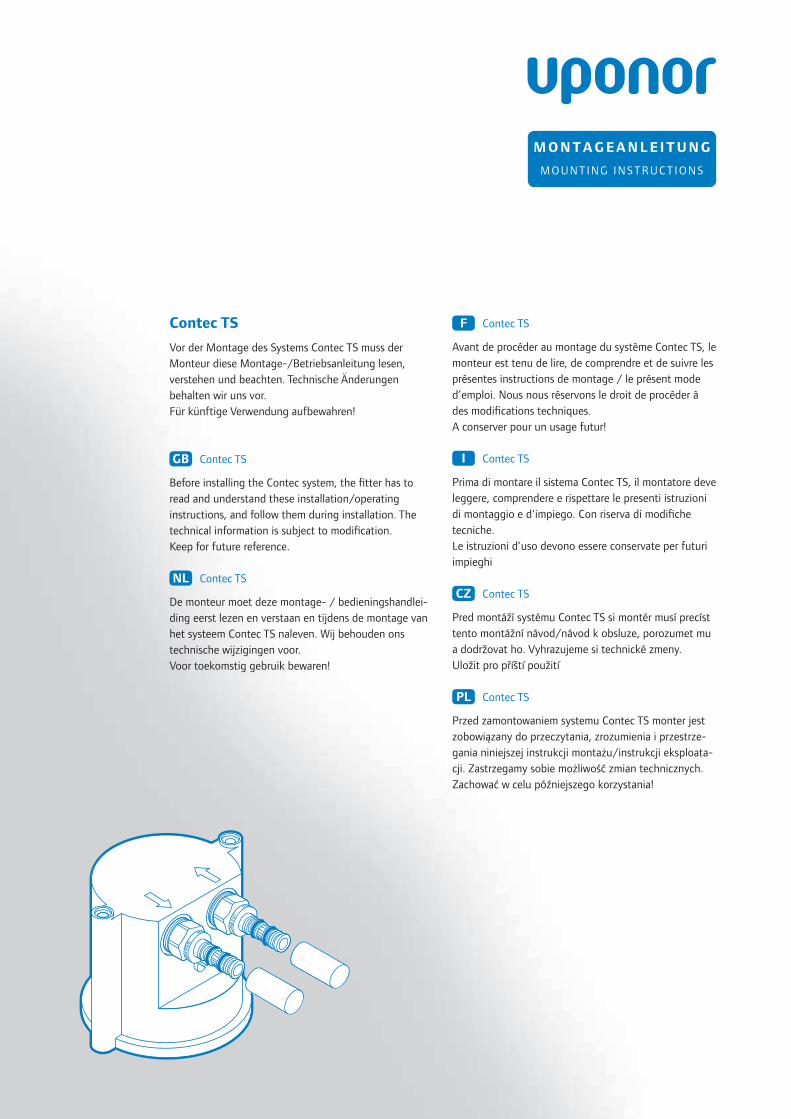
Contec TS
Vor der Montage des Systems Contec TS muss der
Monteur diese Montage-/Betriebsanleitung lesen,
verstehen und beachten. Technische Änderungen
behalten wir uns vor.
Für künftige Verwendung aufbewahren!
GB Contec TS
Before installing the Contec system, the fi tter has to
read and understand these installation/operating
instructions, and follow them during installation. The
technical information is subject to modifi cation.
Keep for future reference.
NL Contec TS
De monteur moet deze montage- / bedieningshandlei-
ding eerst lezen en verstaan en tijdens de montage van
het systeem Contec TS naleven. Wij behouden ons
technische wijzigingen voor.
Voor toekomstig gebruik bewaren!
F Contec TS
Avant de procéder au montage du système Contec TS, le
monteur est tenu de lire, de comprendre et de suivre les
présentes instructions de montage / le présent mode
d’emploi. Nous nous réservons le droit de procéder à
des modifi cations techniques.
A conserver pour un usage futur!
I Contec TS
Prima di montare il sistema Contec TS, il montatore deve
leggere, comprendere e rispettare le presenti istruzioni
di montaggio e d'impiego. Con riserva di modifi che
tecniche.
Le istruzioni d’uso devono essere conservate per futuri
impieghi
CZ Contec TS
Pred montáží systému Contec TS si montér musí precíst
tento montážní návod/návod k obsluze, porozumet mu
a dodržovat ho. Vyhrazujeme si technické zmeny.
Uložit pro příští použití
PL Contec TS
Przed zamontowaniem systemu Contec TS monter jest
zobowiązany do przeczytania, zrozumienia i przestrze-
gania niniejszej instrukcji montażu/instrukcji eksploata-
cji. Zastrzegamy sobie możliwość zmian technicznych.
Zachować w celu późniejszego korzystania!

2 1 0 3 0 1 8 3 4 / 2 0 0 8
InhaltContents • Inhoud • Contenu • Indice • Obsah • Treść
GB
1 Safety
1.1 Safety instructions and tips ••••••••••••••3
1.2 Designated application ••••••••••••••••••3
1.3 Authorized fi tters •••••••••••••••••••••3
2 Sample system, components •••••••••••••••6
3 Installation ••••••••••••••••••••••••••••••7
4 Pressure test •••••••••••••••••••••••••••11
5 After concreting and shuttering •••••••••••12
6 Installation adapter plug •••••••••••••••••14
D
1 Sicherheit
1.1 Sicherheitshinweise und Tipps ••••••••••••3
1.2 Bestimmungsgemäße Verwendung •••••••••3
1.3 Zugelassene Monteure ••••••••••••••••••3
2 Anlagenbeispiel, Komponenten ••••••••••••6
3 Montage ••••••••••••••••••••••••••••••••7
4 Druckprobe •••••••••••••••••••••••••••••11
5 Nach dem Betonieren und Ausschalen ••••••12
6 Einbau Adapterstecker •••••••••••••••••••14
NL
1 Veiligheid
1.1 Veiligheidsaanwijzingen en tips •••••••••••4
1.2 Doelmatig gebruik •••••••••••••••••••••4
1.3 Geautoriseerde monteurs ••••••••••••••••4
2 Installatievoorbeeld, componenten ••••••••••6
3 Montage ••••••••••••••••••••••••••••••••7
4 Druktest •••••••••••••••••••••••••••••••11
5 Na het betonneren en ontkisten •••••••••••12
6 Inbouw verloopstekker •••••••••••••••••••14
F
1 Sécurité
1.1 Utilisation conforme à la destination •••••••4
1.2 Indications de sécurité et conseils •••••••••4
1.3 Monteurs autorisés •••••••••••••••••••••4
2 Exemple d’installation, composants •••••••••6
3 Montage ••••••••••••••••••••••••••••••••7
4 Essai de pression ••••••••••••••••••••••••11
5 Après le bétonnage et le décoffrage •••••••12
6 Montage du connecteur adaptateur ••••••••14
I
1 Sicurezza
1.1 Indicazioni di sicurezza e consigli ••••••••••5
1.2 Impiego conforme alle disposizioni •••••••••5
1.3 Montatori autorizzati •••••••••••••••••••5
2 Esempio di impianto, componenti •••••••••••6
3 Montaggio ••••••••••••••••••••••••••••••7
4 Prova di pressione •••••••••••••••••••••••11
5 Dopo la gettata di calcestruzzo e il disarmo •12
6 Montaggio del connettore di adattamento ••14
CZ
1 Bezpecnost
1.1 Bezpecnostní pokyny a tipy ••••••••••••••5
1.2 Predpisové použití •••••••••••••••••••••5
1.3 Oprávnení montéri •••••••••••••••••••••5
2 Príklad použití, komponenty •••••••••••••••6
3 Montáž •••••••••••••••••••••••••••••••••7
4 Tlaková zkouœka •••••••••••••••••••••••11
5 Po betonáži a obednení ••••••••••••••••••12
6 Montáž konektoru adaptéru ••••••••••••••14
PL
1 Bezpieczeństwo
1.1 Uwagi dot. bezpieczeństwa i wskazówki •••••3
1.2 Stosowanie systemu zgodne z
przeznaczeniem •••••••••••••••••••••••3
1.3 Dopuszczeni monterzy ••••••••••••••••••3
2 Przykład instalacji, elementy •••••••••••••••6
3 Montaż •••••••••••••••••••••••••••••••••7
4 Próba ciśnieniowa •••••••••••••••••••••••11
5 Po zabetonowaniu i rozdeskowaniu ••••••••12
6 Montaż wtyczki adaptera •••••••••••••••••14
31 0 3 0 1 8 3 4 / 2 0 0 8
Herzlichen GlückwunschCongratulations • Hartelijk gefeliciteerd • Nos sincères félicitations • Congratulazioni
Srdečně blahopřejeme • Serdeczne gratulacje
D
Herzlichen Glückwunsch und vielen Dank, dass Sie sich
für den Contec TS Verteiler entschieden haben.
GB
Congratulations and thank you for purchasing a
Contec TS distributor.
NL
Gefeliciteerd en bedankt dat u voor de Contec TS
verdeler gekozen hebt.
F
Nos sincères félicitations et tous nos remerciements
d‘avoir porté votre choix sur le distributeur Contec TS
1 SicherheitSafety • Veiligheid • Sécurité • Sicurezza • Bezpečnost • Bezpieczeństwo
D
1.1 Sicherheitshinweise und Tipps
In dieser Montage-/Betriebsanleitung werden folgende
Symbole verwendet.
GB
1.1 Safety instructions and tips
In these mounting/operating instructions the following
symbols are used:
NL
1.1 Veiligheidsaanwijzingen en tips
In deze montage/bedieningshandleiding worden de
volgende symbolen gebruikt.
F
1.1 Indications de sécurité et conseils
Dans ces instructions de montage/ce mode d’emploi,
l’on utilise les symboles suivants.
I
1.1 Segnali di sicurezza
Nelle presenti istruzioni di montaggio e d’impiego
vengono utilizzati i seguenti simboli
CZ
1.1 Bezpečnostní pokyny a typy
V tomto montážním/provozním návodu jsou použity
následující symboly.
PL
1.1 Uwagi dot. bezpieczeństwa i wskazówki
W niniejszej instrukcji montażu i obsługi używane są
następujące symbole.
I
Congratulazioni e grazie per aver scelto il distributore
Contec TS!
CZ
Srdečně blahopřejeme a mnohokrát děkujeme, že jste se
rozhodl pro Contec TS rozdělovač .
PL
Serdeczne gratulacje i podziękowania za to, że zdecydo-
wali się państwo na zakup systemu suchej zabudowy
Contec TS dla ścian i podłogi.
4 1 0 3 0 1 8 3 4 / 2 0 0 8
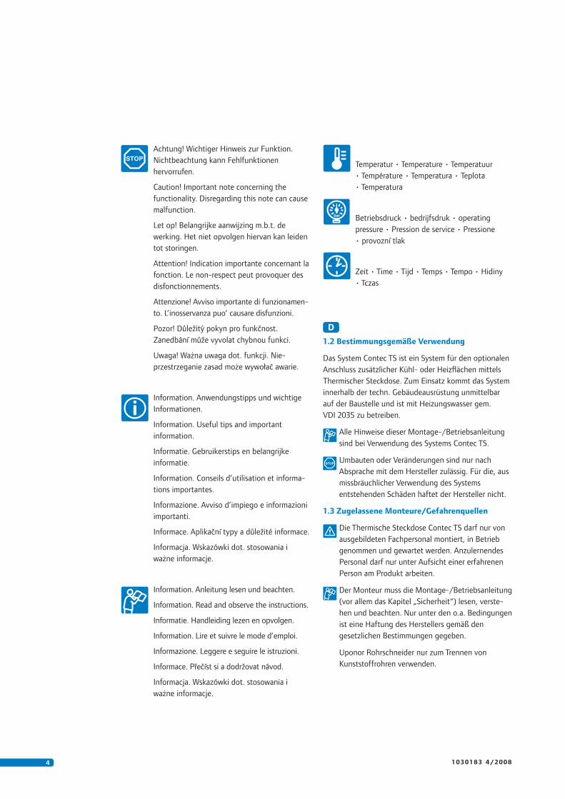
Achtung! Wichtiger Hinweis zur Funktion.
Nichtbeachtung kann Fehlfunktionen
hervorrufen.
Caution! Important note concerning the
functionality. Disregarding this note can cause
malfunction.
Let op! Belangrijke aanwijzing m.b.t. de
werking. Het niet opvolgen hiervan kan leiden
tot storingen.
Attention! Indication importante concernant la
fonction. Le non-respect peut provoquer des
disfonctionnements.
Attenzione! Avviso importante di funzionamen-
to. L’inosservanza puo’ causare disfunzioni.
Pozor! Důležitý pokyn pro funkčnost.
Zanedbání může vyvolat chybnou funkci.
Uwaga! Ważna uwaga dot. funkcji. Nie-
przestrzeganie zasad może wywołać awarie.
Information. Anwendungstipps und wichtige
Informationen.
Information. Useful tips and important
information.
Informatie. Gebruikerstips en belangrijke
informatie.
Information. Conseils d’utilisation et informa-
tions importantes.
Informazione. Avviso d’impiego e informazioni
importanti.
Informace. Aplikační typy a důležité informace.
Informacja. Wskazówki dot. stosowania i
ważne informacje.
Information. Anleitung lesen und beachten.
Information. Read and observe the instructions.
Informatie. Hand leiding lezen en opvolgen.
Information. Lire et suivre le mode d’emploi.
Informazione. Leggere e seguire le istruzioni.
Informace. Přečíst si a dodržovat návod.
Informacja. Wskazówki dot. stosowania i
ważne informacje.
Temperatur • Temperature • Temperatuur
• Température • Temperatura • Teplota
• Temperatura
Betriebsdruck • bedrijfsdruk • operating
pressure • Pression de service • Pressione
• provozní tlak
Zeit • Time • Tijd • Temps • Tempo • Hidiny
• Tczas
D
1.2 Bestimmungsgemäße Verwendung
Das System Contec TS ist ein System für den optionalen
Anschluss zusätzlicher Kühl- oder Heizfl ächen mittels
Thermischer Steckdose. Zum Einsatz kommt das System
innerhalb der techn. Gebäudeausrüstung unmittelbar
auf der Baustelle und ist mit Heizungswasser gem.
VDI 2035 zu betreiben.
Alle Hinweise dieser Montage-/Betriebsanleitung
sind bei Verwendung des Systems Contec TS.
Umbauten oder Veränderungen sind nur nach
Absprache mit dem Hersteller zulässig. Für die, aus
missbräuchlicher Verwendung des Systems
entstehenden Schäden haftet der Hersteller nicht.
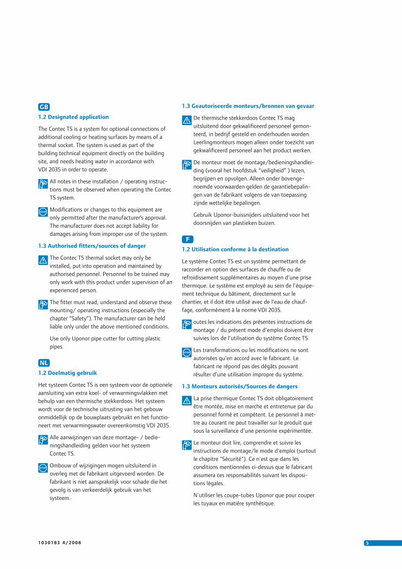
1.3 Zugelassene Monteure/Gefahrenquellen
Die Thermische Steckdose Contec TS darf nur von
ausgebildeten Fachpersonal montiert, in Betrieb
genommen und gewartet werden. Anzulernendes
Personal darf nur unter Aufsicht einer erfahrenen
Person am Produkt arbeiten.
Der Monteur muss die Montage-/Betriebsanleitung
(vor allem das Kapitel „Sicherheit“) lesen, verste-
hen und beachten. Nur unter den o.a. Bedingungen
ist eine Haftung des Herstellers gemäß den
gesetzlichen Bestimmungen gegeben.
Uponor Rohrschneider nur zum Trennen von
Kunststoffrohren verwenden.
51 0 3 0 1 8 3 4 / 2 0 0 8
GB
1.2 Designated application
The Contec TS is a system for optional connections of
additional cooling or heating surfaces by means of a
thermal socket. The system is used as part of the
building technical equipment directly on the building
site, and needs heating water in accordance with
VDI 2035 in order to operate.
All notes in these installation / operating instruc-
tions must be observed when operating the Contec
TS system.
Modifi cations or changes to this equipment are
only permitted after the manufacturer’s approval.
The manufacturer does not accept liability for
damages arising from improper use of the system.
1.3 Authorised fi tters/sources of danger
The Contec TS thermal socket may only be
installed, put into operation and maintained by
authorised personnel. Personnel to be trained may
only work with this product under supervision of an
experienced person.
The fi tter must read, understand and observe these
mounting/ operating instructions (especially the
chapter “Safety”). The manufacturer can be held
liable only under the above mentioned conditions.
Use only Uponor pipe cutter for cutting plastic
pipes.
NL
1.2 Doelmatig gebruik
Het systeem Contec TS is een systeem voor de optionele
aansluiting van extra koel- of verwarmingsvlakken met
behulp van een thermische stekkerdoos. Het systeem
wordt voor de technische uitrusting van het gebouw
onmiddellijk op de bouwplaats gebruikt en het functio-
neert met verwarmingswater overeenkomstig VDI 2035.
Alle aanwijzingen van deze montage- / bedie-
ningshandleiding gelden voor het systeem
Contec TS.
Ombouw of wijzigingen mogen uitsluitend in
overleg met de fabrikant uitgevoerd worden. De
fabrikant is niet aansprakelijk voor schade die het
gevolg is van verkeerdelijk gebruik van het
systeem.
1.3 Geautoriseerde monteurs/bronnen van gevaar
De thermische stekkerdoos Contec TS mag
uitsluitend door gekwalifi ceerd personeel gemon-
teerd, in bedrijf gesteld en onderhouden worden.
Leerlingmonteurs mogen alleen onder toezicht van
gekwalifi ceerd personeel aan het product werken.
De monteur moet de montage/bedieningshandlei-
ding (vooral het hoofdstuk “veiligheid” ) lezen,
begrijpen en opvolgen. Alleen onder bovenge-
noemde voorwaarden gelden de garantiebepalin-
gen van de fabrikant volgens de van toepassing
zijnde wettelijke bepalingen.
Gebruik Uponor-buissnijders uitsluitend voor het
doorsnijden van plastieken buizen.
F
1.2 Utilisation conforme à la destination
Le système Contec TS est un système permettant de
raccorder en option des surfaces de chauffe ou de
refroidissement supplémentaires au moyen d’une prise
thermique. Le système est employé au sein de l’équipe-
ment technique du bâtiment, directement sur le
chantier, et il doit être utilisé avec de l’eau de chauf-
fage, conformément à la norme VDI 2035.
outes les indications des présentes instructions de
montage / du présent mode d’emploi doivent être
suivies lors de l’utilisation du système Contec TS.
Les transformations ou les modifi cations ne sont
autorisées qu'en accord avec le fabricant. Le
fabricant ne répond pas des dégâts pouvant
résulter d’une utilisation impropre du système.
1.3 Monteurs autorisés/Sources de dangers
La prise thermique Contec TS doit obligatoirement
être montée, mise en marche et entretenue par du
personnel formé et compétent. Le personnel à met-
tre au courant ne peut travailler sur le produit que
sous la surveillance d'une personne expérimentée.
Le monteur doit lire, comprendre et suivre les
instructions de montage/le mode d'emploi (surtout
le chapitre "Sécurité"). Ce n'est que dans les
conditions mentionnées ci-dessus que le fabricant
assumera ces responsabilités suivant les disposi-
tions légales.
N'utiliser les coupe-tubes Uponor que pour couper
les tuyaux en matière synthétique.
6 1 0 3 0 1 8 3 4 / 2 0 0 8
I
1.2 Impiego conforme alle disposizioni
Il sistema Contec TS è un sistema predisposto per il
collegamento opzionale di superfi ci di raffreddamento o
riscaldamento supplementari mediante presa termica. Il
sistema può essere impiegato all'interno dell'impianto
tecnico dell'edifi cio montato direttamente in cantiere; il
sistema funziona con acqua di riscaldamento secondo la
norma VDI 2035.
Tutte le indicazioni delle presenti istruzioni di
montaggio e d'impiego si riferiscono all'utilizzo del
sistema Contec TS.
Le opere di ristrutturazione e le modifi che sono
consentite solo su accordo con il produttore. Il
produttore non fornisce alcuna garanzia per i danni
causati da un uso improprio del sistema.
1.3 Montatori autorizzati
La presa termica Contec TS deve essere installata,
messa in funzione e sottoposta a manutenzione
solo da personale specializzato adeguatamente
istruito. Il personale da formare deve lavorare sul
prodotto esclusivamente sotto la supervisione di un
esperto.
È necessario leggere, comprendere ed osservare le
presenti istruzioni di montaggio e d'impiego (in
particolare il capitolo "sicurezza"). Solo alle
condizioni sopraccitate viene garantita la responsa-
bilità del produttore in conformità con le disposizi-
oni legali.
Utilizzare il tagliatubi Uponor solo per separare tubi
di plastica.
CZ
1.2 Predpisové použití
Systém Contec TS je systém pro optimální pripojení
prídavných chladicích a výhrevných ploch pomocí
tepelné zásuvky. Systém se používá v rámci technického
vybavení budov bezprostredne na staveništi, musí
provozován s topnou vodou podle normy VDI 2035.
Všechny pokyny v tomto montážním návodu/návo-
du k obsluze platí pro použití systému Contec TS
Prestavby a zmeny jsou dovoleny pouze po dohode
s výrobcem. Za škody vzniklé nedovoleným
použitím systému výrobce nerucí.
PL
1.2 Stosowanie systemu zgodne z przeznaczeniem
System Contec TS jest systemem służącym do opcjonalnego
podłączenia dodatkowych powierzchni chłodzących /
grzejnych przy pomocy gniazda wtykowego odpornego
na wysoką temperaturę. System znajduje zastosowanie w
obrębie technicznego wyposażenia budynków,
bezpośrednio na placu budowy i musi być napędzany
wodą grzewczą, zgodnie z normą VDI 2035.
Należy przestrzegać wszystkich wskazówek
niniejszej instrukcji montażu/instrukcji eksploatacji
dla systemu TS.
Przebudowy lub inne zmiany są dopuszczalne
wyłącznie po uzgodnieniu z producentem. Za
szkody powstałe w wyniku niewłaściwego
stosowania systemu producent nie ponosi
odpowiedzialności.
1.3 Dopuszczeni monterzy/źródła zagrożeń
Gniazdo wtykowe odporne na wysoką temperaturę
Contec TS może być montowane, uruchamiane i
konserwowane tylko przez wykwalifi kowany
personel. Przyuczany personel może pracować przy
urządzeniu wyłącznie pod nadzorem doświadczonej
osoby.
Monter musi przeczytać, zrozumieć i przestrzegać
instrukcji montażu i obsługi (przede wszystkim
rozdział „bezpieczeństwo“). Tylko po spełnieniu
wyżej wymienionych warunków producent ponosi
odpwiedzialność cywilną zgodnie z ustawowymi
postanowieniami.
Obcinaka do rur Uponor należy używać wyłącznie do
rozcinania rur wykonanych z tworzywa sztucznego.
1.3 Oprávnení montéri/zdroje nebezpecí
Tepelnou zásuvku Contec TS smí montovat, uvádet
do provozu a provádet údržbu jen vyškolený
kvalifi kovaný personál. Zaucení pracovníci smí
pracovat na výrobku jen pod dohledem zkušené
osoby.
Montér si musí p√ecíst montážní návod/návod k
obsluze (p√edevším kapitolu "Bezpeπnost"),
porozumæt mu a dodržovat ho. Jen za výše
uvedených podmínek rucí výrobce podle zákon-
ných predpisu.
Trubkorez Uponor používejte jen k delení plasto-
vých trubek.
71 0 3 0 1 8 3 4 / 2 0 0 8
2 Anlagenbeispiel/KomponentenApplication examples/components • Toepassingsvoorbeelden/componenten • Exemples
d’applications/Composants • Esempi di applicazione/Componenti • Príklady použití/
komponenty • Przykład instalacji/elementy
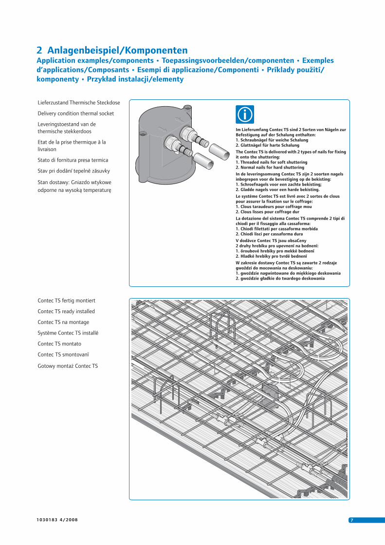
Lieferzustand Thermische Steckdose
Delivery condition thermal socket
Leveringstoestand van de
thermische stekkerdoos
Etat de la prise thermique à la
livraison
Stato di fornitura presa termica
Stav pri dodání tepelné zásuvky
Stan dostawy: Gniazdo wtykowe
odporne na wysoką temperaturę
Im Lieferumfang Contec TS sind 2 Sorten von Nägeln zurBefestigung auf der Schalung enthalten:1. Schraubnägel für weiche Schalung2. Glattnägel für harte Schalung
The Contec TS is delivered with 2 types of nails for fixingit onto the shuttering:1. Threaded nails for soft shuttering2. Normal nails for hard shuttering
In de leveringsomvang Contec TS zijn 2 soorten nagelsinbegrepen voor de bevestiging op de bekisting:1. Schroefnagels voor een zachte bekisting;2. Gladde nagels voor een harde bekisting.
Le système Contec TS est livré avec 2 sortes de clouspour assurer la fixation sur le coffrage:1. Clous taraudeurs pour coffrage mou2. Clous lisses pour coffrage dur
La dotazione del sistema Contec TS comprende 2 tipi dichiodi per il fissaggio alla cassaforma:1. Chiodi filettati per cassaforma morbida2. Chiodi lisci per cassaforma dura
V dodávce Contec TS jsou obsaĽeny2 druhy hrebíku pro upevnení na bednení:1. őroubové hrebíky pro mekké bednení2. Hladké hrebíky pro tvrdé bednení
W zakresie dostawy Contec TS są zawarte 2 rodzajegwoździ do mocowania na deskowaniu:1. gwoździe nagwintowane do miękkiego deskowania2. gwoździe gładkie do twardego deskowania
Contec TS fertig montiert
Contec TS ready installed
Contec TS na montage
Système Contec TS installé
Contec TS montato
Contec TS smontovanī
Gotowy montaż Contec TS
8 1 0 3 0 1 8 3 4 / 2 0 0 8
3 MontageInstallation • Montage • Montage • Montaggio • Montáž • Montaż
60 mm60 mm60 mm
120 mm120 mm120 mm
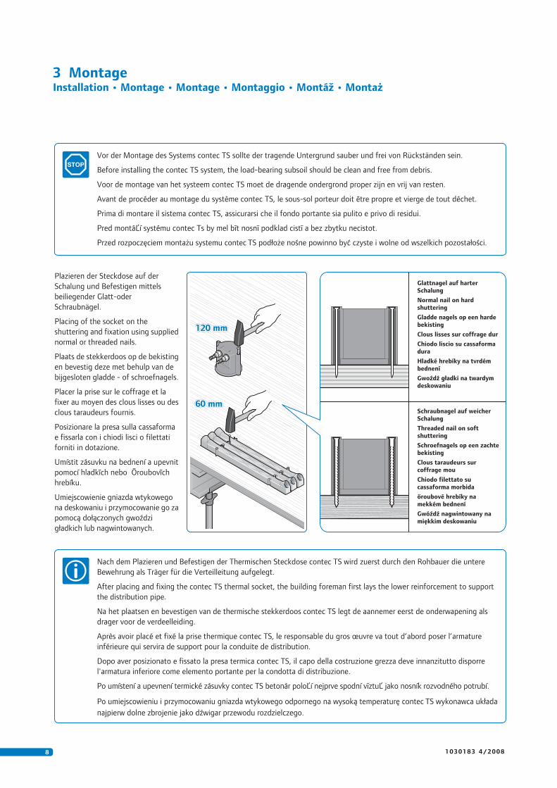
Plazieren der Steckdose auf der
Schalung und Befestigen mittels
beiliegender Glatt-oder
Schraubnägel.
Placing of the socket on the
shuttering and fixation using supplied
normal or threaded nails.
Plaats de stekkerdoos op de bekisting
en bevestig deze met behulp van de
bijgesloten gladde - of schroefnagels.
Placer la prise sur le coffrage et la
fixer au moyen des clous lisses ou des
clous taraudeurs fournis.
Posizionare la presa sulla cassaforma
e fissarla con i chiodi lisci o filettati
forniti in dotazione.
Umístit zásuvku na bednení a upevnit
pomocí hladkīch nebo Ōroubovīch
hrebíku.
Umiejscowienie gniazda wtykowego
na deskowaniu i przymocowanie go za
pomocą dołączonych gwoździ
gładkich lub nagwintowanych.
Vor der Montage des Systems contec TS sollte der tragende Untergrund sauber und frei von Rückständen sein.
Before installing the contec TS system, the load-bearing subsoil should be clean and free from debris.
Voor de montage van het systeem contec TS moet de dragende ondergrond proper zijn en vrij van resten.
Avant de procéder au montage du système contec TS, le sous-sol porteur doit être propre et vierge de tout déchet.
Prima di montare il sistema contec TS, assicurarsi che il fondo portante sia pulito e privo di residui.
Pred montáĽí systému contec Ts by mel bīt nosnī podklad cistī a bez zbytku necistot.
Przed rozpoczęciem montażu systemu contec TS podłoże nośne powinno być czyste i wolne od wszelkich pozostałości.
Schraubnagel auf weicherSchalung
Threaded nail on softshuttering
Schroefnagels op een zachtebekisting
Clous taraudeurs surcoffrage mou
Chiodo filettato sucassaforma morbida
őroubové hrebíky namekkém bednení
Gwóźdź nagwintowany namiękkim deskowaniu
Glattnagel auf harterSchalung
Normal nail on hardshuttering
Gladde nagels op een hardebekisting
Clous lisses sur coffrage dur
Chiodo liscio su cassaformadura
Hladké hrebíky na tvrdémbednení
Gwoźdź gładki na twardymdeskowaniu
Nach dem Plazieren und Befestigen der Thermischen Steckdose contec TS wird zuerst durch den Rohbauer die untere
Bewehrung als Träger für die Verteilleitung aufgelegt.
After placing and fixing the contec TS thermal socket, the building foreman first lays the lower reinforcement to support
the distribution pipe.
Na het plaatsen en bevestigen van de thermische stekkerdoos contec TS legt de aannemer eerst de onderwapening als
drager voor de verdeelleiding.
Après avoir placé et fixé la prise thermique contec TS, le responsable du gros œuvre va tout d’abord poser l’armature
inférieure qui servira de support pour la conduite de distribution.
Dopo aver posizionato e fissato la presa termica contec TS, il capo della costruzione grezza deve innanzitutto disporre
l'armatura inferiore come elemento portante per la condotta di distribuzione.
Po umístení a upevnení termické zásuvky contec TS betonár poloĽí nejprve spodní vīztuĽ jako nosník rozvodného potrubí.
Po umiejscowieniu i przymocowaniu gniazda wtykowego odpornego na wysoką temperaturę contec TS wykonawca układa
najpierw dolne zbrojenie jako dźwigar przewodu rozdzielczego.
91 0 3 0 1 8 3 4 / 2 0 0 8
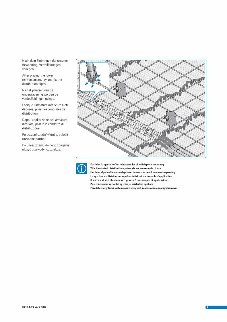
Nach dem Einbringen der unteren
Bewehrung, Verteilleitungen
verlegen.
After placing the lower
reinforcement, lay and fix the
distribution pipes.
Na het plaatsen van de
onderwapening worden de
verdeelleidingen gelegd.
Lorsque l’armature inférieure a été
déposée, poser les conduites de
distribution.
Dopo l'applicazione dell'armatura
inferiore, posare le condotte di
distribuzione.
Po osazení spodní vīztuĽe, poloĽit
rozvodné potrubí
Po umieszczeniu dolnego zbrojenia
ułożyć przewody rozdzielcze.
Das hier dargestellte Verteilsystem ist eine Beispielanwendung
This illustrated distribution system shows an example of use
Het hier afgebeelde verdeelsysteem is een voorbeeld van een toepassing
Le système de distribution représenté ici est un exemple d’application
Il sistema di distribuzione raffigurato è un esempio di applicazione
Zde znázornenī rozvodnī systém je príkladem aplikace
Przedstawiony tutaj system rozdzielczy jest zastosowaniem przykładowym
10 1 0 3 0 1 8 3 4 / 2 0 0 8
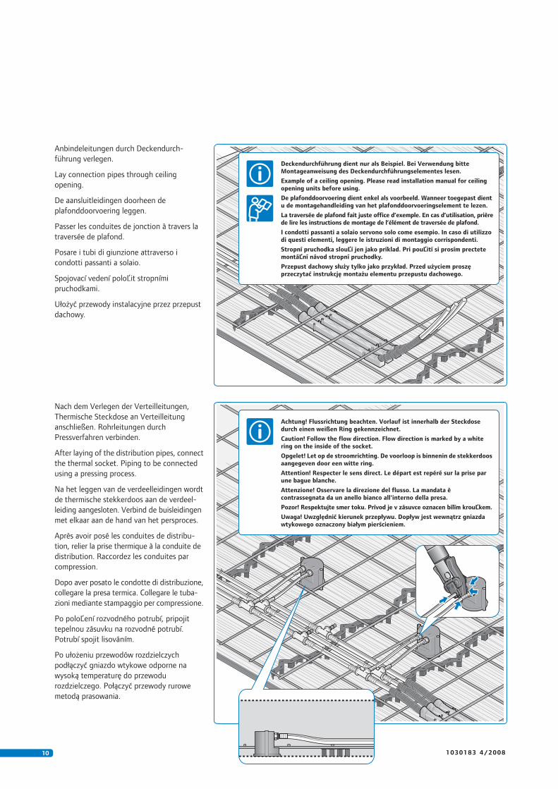
Anbindeleitungen durch Deckendurch-
führung verlegen.
Lay connection pipes through ceiling
opening.
De aansluitleidingen doorheen de
plafonddoorvoering leggen.
Passer les conduites de jonction à travers la
traversée de plafond.
Posare i tubi di giunzione attraverso i
condotti passanti a solaio.
Spojovací vedení poloĽit stropními
pruchodkami.
Ułożyć przewody instalacyjne przez przepust
dachowy.
Nach dem Verlegen der Verteilleitungen,
Thermische Steckdose an Verteilleitung
anschließen. Rohrleitungen durch
Pressverfahren verbinden.
After laying of the distribution pipes, connect
the thermal socket. Piping to be connected
using a pressing process.
Na het leggen van de verdeelleidingen wordt
de thermische stekkerdoos aan de verdeel-
leiding aangesloten. Verbind de buisleidingen
met elkaar aan de hand van het persproces.
Après avoir posé les conduites de distribu-
tion, relier la prise thermique à la conduite de
distribution. Raccordez les conduites par
compression.
Dopo aver posato le condotte di distribuzione,
collegare la presa termica. Collegare le tuba-
zioni mediante stampaggio per compressione.
Po poloĽení rozvodného potrubí, pripojit
tepelnou zásuvku na rozvodné potrubí.
Potrubí spojit lisováním.
Po ułożeniu przewodów rozdzielczych
podłączyć gniazdo wtykowe odporne na
wysoką temperaturę do przewodu
rozdzielczego. Połączyć przewody rurowe
metodą prasowania.
Deckendurchführung dient nur als Beispiel. Bei Verwendung bitteMontageanweisung des Deckendurchführungselementes lesen.
Example of a ceiling opening. Please read installation manual for ceilingopening units before using.
De plafonddoorvoering dient enkel als voorbeeld. Wanneer toegepast dientu de montagehandleiding van het plafonddoorvoeringselement te lezen.
La traversée de plafond fait juste office d’exemple. En cas d’utilisation, prièrede lire les instructions de montage de l’élément de traversée de plafond.
I condotti passanti a solaio servono solo come esempio. In caso di utilizzodi questi elementi, leggere le istruzioni di montaggio corrispondenti.
Stropní pruchodka slouĽí jen jako príklad. Pri pouĽití si prosím prectetemontáĽní návod stropní pruchodky.
Przepust dachowy służy tylko jako przykład. Przed użyciem proszęprzeczytać instrukcję montażu elementu przepustu dachowego.
Achtung! Flussrichtung beachten. Vorlauf ist innerhalb der Steckdosedurch einen weißen Ring gekennzeichnet.
Caution! Follow the flow direction. Flow direction is marked by a whitering on the inside of the socket.
Opgelet! Let op de stroomrichting. De voorloop is binnenin de stekkerdoosaangegeven door een witte ring.
Attention! Respecter le sens direct. Le départ est repéré sur la prise parune bague blanche.
Attenzione! Osservare la direzione del flusso. La mandata ècontrassegnata da un anello bianco all'interno della presa.
Pozor! Respektujte smer toku. Prívod je v zásuvce oznacen bílīm krouĽkem.
Uwaga! Uwzględnić kierunek przepływu. Dopływ jest wewnątrz gniazdawtykowego oznaczony białym pierścieniem.
111 0 3 0 1 8 3 4 / 2 0 0 8
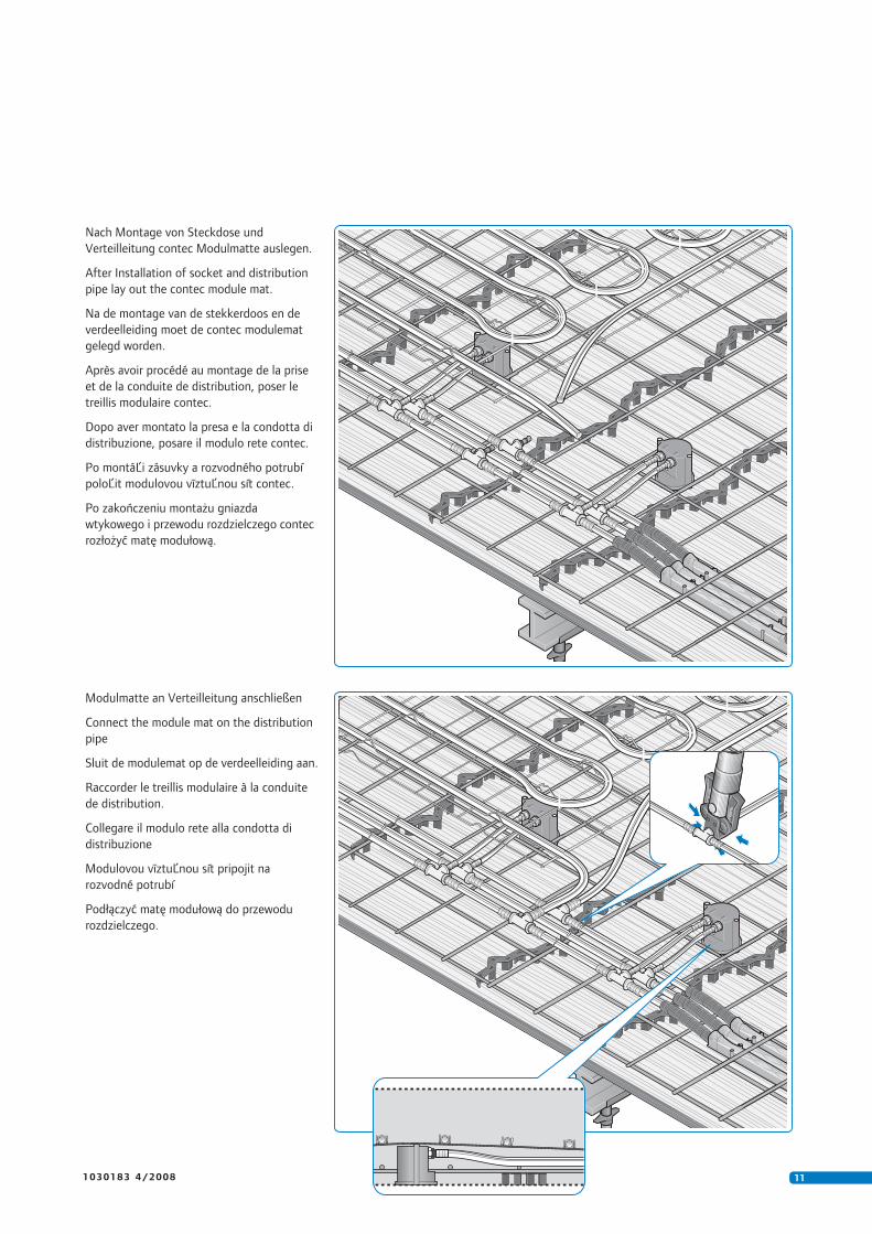
Nach Montage von Steckdose und
Verteilleitung contec Modulmatte auslegen.
After Installation of socket and distribution
pipe lay out the contec module mat.
Na de montage van de stekkerdoos en de
verdeelleiding moet de contec modulemat
gelegd worden.
Après avoir procédé au montage de la prise
et de la conduite de distribution, poser le
treillis modulaire contec.
Dopo aver montato la presa e la condotta di
distribuzione, posare il modulo rete contec.
Po montáĽi zásuvky a rozvodného potrubí
poloĽit modulovou vīztuĽnou sít contec.
Po zakończeniu montażu gniazda
wtykowego i przewodu rozdzielczego contec
rozłożyć matę modułową.
Modulmatte an Verteilleitung anschließen
Connect the module mat on the distribution
pipe
Sluit de modulemat op de verdeelleiding aan.
Raccorder le treillis modulaire à la conduite
de distribution.
Collegare il modulo rete alla condotta di
distribuzione
Modulovou vīztuĽnou sít pripojit na
rozvodné potrubí
Podłączyć matę modułową do przewodu
rozdzielczego.
12 1 0 3 0 1 8 3 4 / 2 0 0 8
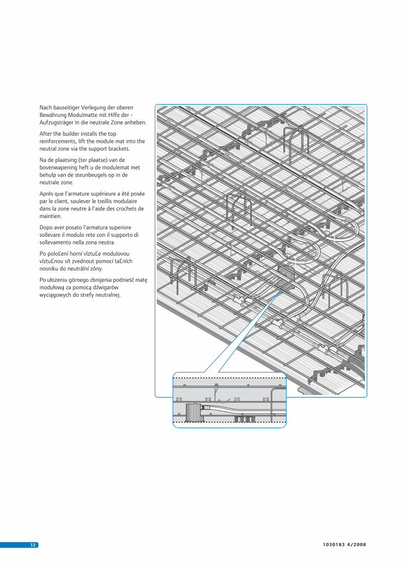
Nach bauseitiger Verlegung der oberen
Bewährung Modulmatte mit Hilfe der -
Aufzugsträger in die neutrale Zone anheben.
After the builder installs the top
reinforcements, lift the module mat into the
neutral zone via the support brackets.
Na de plaatsing (ter plaatse) van de
bovenwapening heft u de modulemat met
behulp van de steunbeugels op in de
neutrale zone.
Après que l’armature supérieure a été posée
par le client, soulever le treillis modulaire
dans la zone neutre à l’aide des crochets de
maintien.
Dopo aver posato l'armatura superiore
sollevare il modulo rete con il supporto di
sollevamento nella zona neutra.
Po poloĽení horní vīztuĽe modulovou
vīztuĽnou sít zvednout pomocí taĽnīch
nosníku do neutrální zóny.
Po ułożeniu górnego zbrojenia podnieść matę
modułową za pomocą dźwigarów
wyciągowych do strefy neutralnej.
131 0 3 0 1 8 3 4 / 2 0 0 8
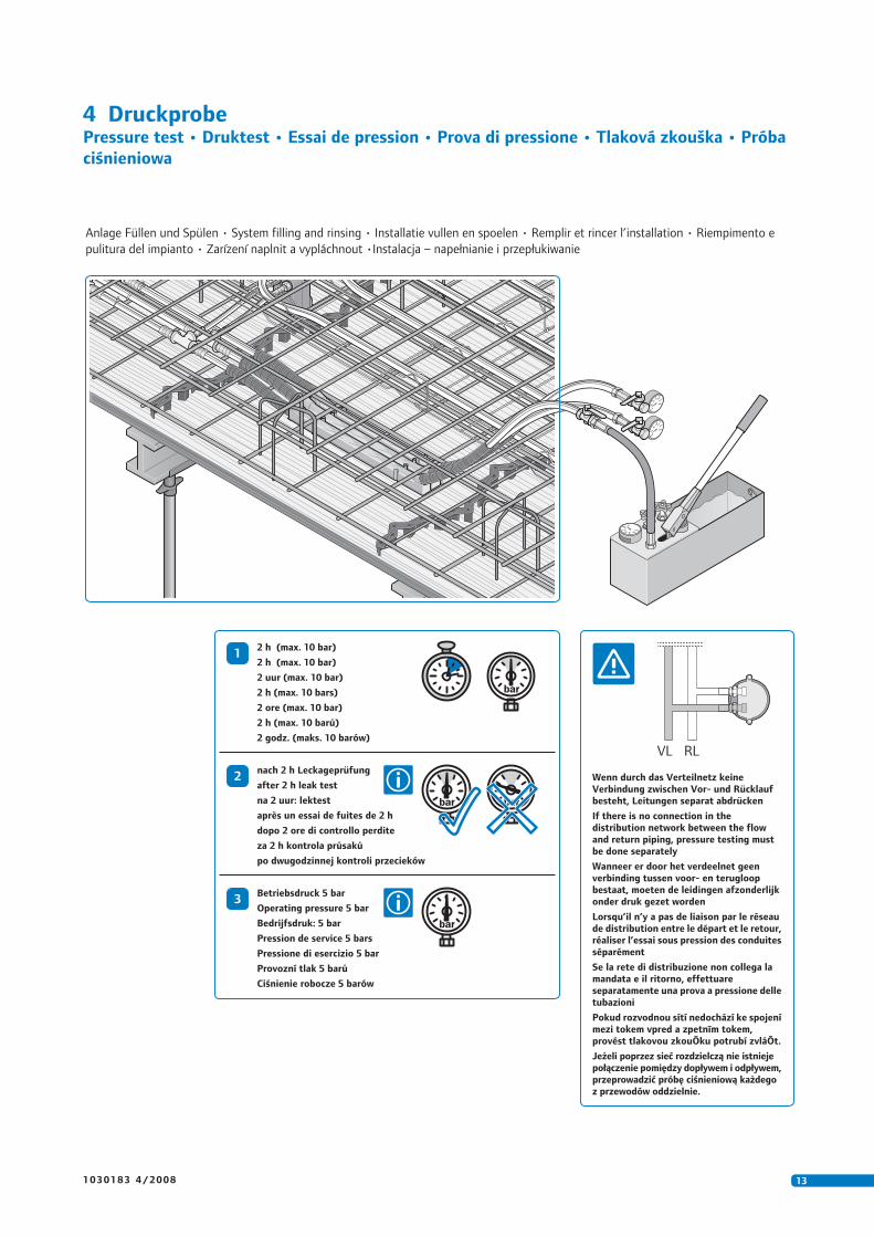
4 DruckprobePressure test • Druktest • Essai de pression • Prova di pressione • Tlaková zkouška • Próba
ciśnieniowa
1
Anlage Füllen und Spülen • System filling and rinsing • Installatie vullen en spoelen • Remplir et rincer l’installation • Riempimento e
pulitura del impianto • Zarízení naplnit a vypláchnout •Instalacja – napełnianie i przepłukiwanie
2 h (max. 10 bar)
2 h (max. 10 bar)
2 uur (max. 10 bar)
2 h (max. 10 bars)
2 ore (max. 10 bar)
2 h (max. 10 barů)
2 godz. (maks. 10 barów)
VL RL
Wenn durch das Verteilnetz keineVerbindung zwischen Vor- und Rücklaufbesteht, Leitungen separat abdrücken
If there is no connection in thedistribution network between the flowand return piping, pressure testing mustbe done separately
Wanneer er door het verdeelnet geenverbinding tussen voor- en terugloopbestaat, moeten de leidingen afzonderlijkonder druk gezet worden
Lorsqu’il n’y a pas de liaison par le réseaude distribution entre le départ et le retour,réaliser l’essai sous pression des conduitesséparément
Se la rete di distribuzione non collega lamandata e il ritorno, effettuareseparatamente una prova a pressione delletubazioni
Pokud rozvodnou sítí nedochází ke spojenímezi tokem vpred a zpetnīm tokem,provést tlakovou zkouŌku potrubí zvláŌt.
Jeżeli poprzez sieć rozdzielczą nie istniejepołączenie pomiędzy dopływem i odpływem,przeprowadzić próbę ciśnieniową każdegoz przewodów oddzielnie.
2nach 2 h Leckageprüfung
after 2 h leak test
na 2 uur: lektest
après un essai de fuites de 2 h
dopo 2 ore di controllo perdite
za 2 h kontrola průsaků
po dwugodzinnej kontroli przecieków
3Betriebsdruck 5 bar
Operating pressure 5 bar
Bedrijfsdruk: 5 bar
Pression de service 5 bars
Pressione di esercizio 5 bar
Provozní tlak 5 barů
Ciśnienie robocze 5 barów
14 1 0 3 0 1 8 3 4 / 2 0 0 8
5 Nach dem Betonieren und AusschalenAfter concreting and shuttering • Na het betonneren en ontkisten • Après le bétonnage
et le décoffrage • Dopo la gettata di calcestruzzo e il disarmo • Po betonáži a obednení
• Po zabetonowaniu i rozdeskowaniu
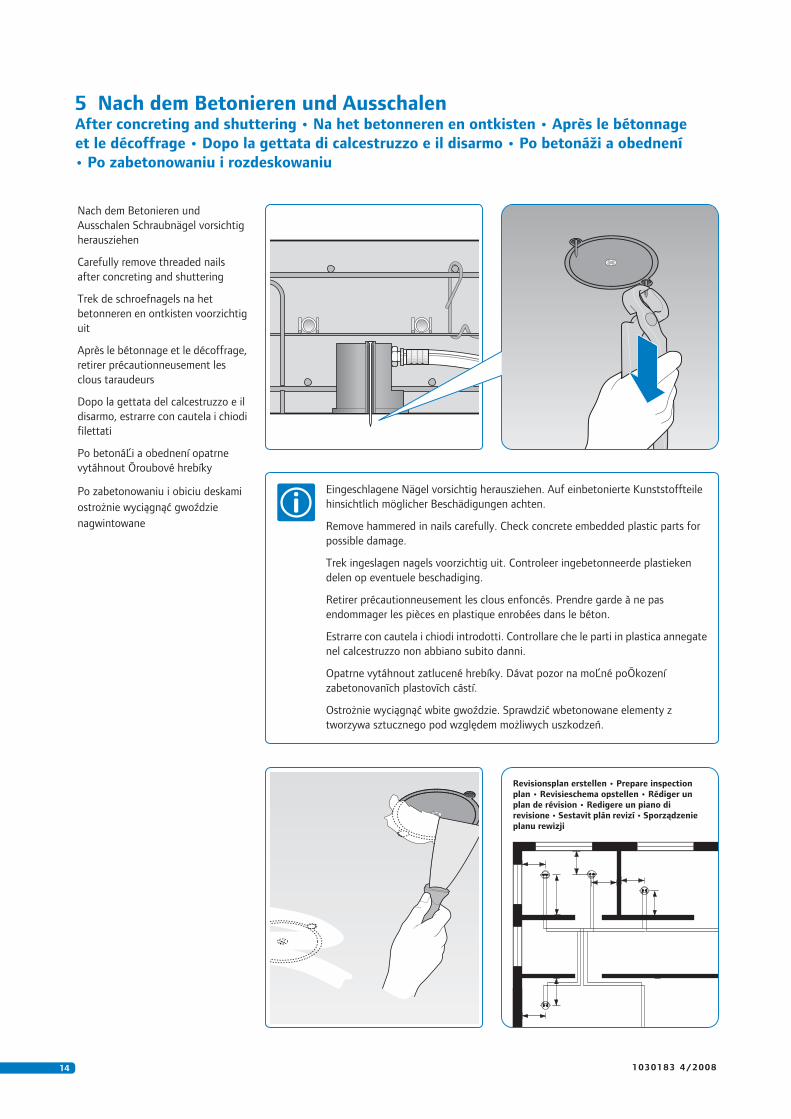
Nach dem Betonieren und
Ausschalen Schraubnägel vorsichtig
herausziehen
Carefully remove threaded nails
after concreting and shuttering
Trek de schroefnagels na het
betonneren en ontkisten voorzichtig
uit
Après le bétonnage et le décoffrage,
retirer précautionneusement les
clous taraudeurs
Dopo la gettata del calcestruzzo e il
disarmo, estrarre con cautela i chiodi
filettati
Po betonáĽi a obednení opatrne
vytáhnout Ōroubové hrebíky
Po zabetonowaniu i obiciu deskami
ostrożnie wyciągnąć gwoździe
nagwintowane
Eingeschlagene Nägel vorsichtig herausziehen. Auf einbetonierte Kunststoffteile
hinsichtlich möglicher Beschädigungen achten.
Remove hammered in nails carefully. Check concrete embedded plastic parts for
possible damage.
Trek ingeslagen nagels voorzichtig uit. Controleer ingebetonneerde plastieken
delen op eventuele beschadiging.
Retirer précautionneusement les clous enfoncés. Prendre garde à ne pas
endommager les pièces en plastique enrobées dans le béton.
Estrarre con cautela i chiodi introdotti. Controllare che le parti in plastica annegate
nel calcestruzzo non abbiano subito danni.
Opatrne vytáhnout zatlucené hrebíky. Dávat pozor na moĽné poŌkození
zabetonovanīch plastovīch cástí.
Ostrożnie wyciągnąć wbite gwoździe. Sprawdzić wbetonowane elementy z
tworzywa sztucznego pod względem możliwych uszkodzeń.
Revisionsplan erstellen • Prepare inspectionplan • Revisieschema opstellen • Rédiger unplan de révision • Redigere un piano direvisione • Sestavit plán revizí • Sporządzenieplanu rewizji
151 0 3 0 1 8 3 4 / 2 0 0 8
6 Einbau AdaptersteckerInstallation adapter plug • Inbouw verloopstekker • Montage du connecteur adaptateur
• Montaggio del connettore di adattamento • Montáž konektoru adaptéru • Montaż
wtyczki adaptera
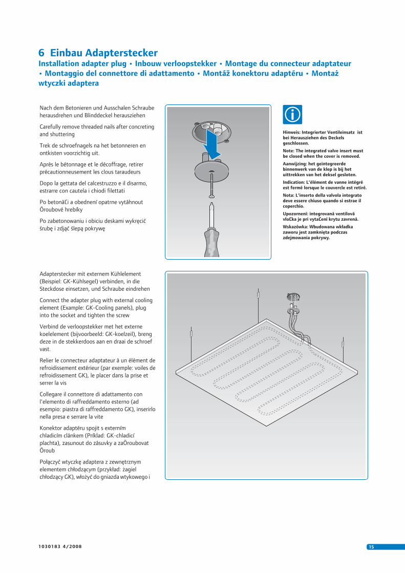
Adapterstecker mit externem Kühlelement
(Beispiel: GK-Kühlsegel) verbinden, in die
Steckdose einsetzen, und Schraube eindrehen
Connect the adapter plug with external cooling
element (Example: GK-Cooling panels), plug
into the socket and tighten the screw
Verbind de verloopstekker met het externe
koelelement (bijvoorbeeld: GK-koelzeil), breng
deze in de stekkerdoos aan en draai de schroef
vast.
Relier le connecteur adaptateur à un élément de
refroidissement extérieur (par exemple: voiles de
refroidissement GK), le placer dans la prise et
serrer la vis
Collegare il connettore di adattamento con
l'elemento di raffreddamento esterno (ad
esempio: piastra di raffreddamento GK), inserirlo
nella presa e serrare la vite
Konektor adaptéru spojit s externím
chladicím clánkem (Príklad: GK-chladicí
plachta), zasunout do zásuvky a zaŌroubovat
Ōroub
Połączyć wtyczkę adaptera z zewnętrznym
elementem chłodzącym (przykład: żagiel
chłodzący GK), włożyć do gniazda wtykowego i
Nach dem Betonieren und Ausschalen Schraube
herausdrehen und Blinddeckel herausziehen
Carefully remove threaded nails after concreting
and shuttering
Trek de schroefnagels na het betonneren en
ontkisten voorzichtig uit.
Après le bétonnage et le décoffrage, retirer
précautionneusement les clous taraudeurs
Dopo la gettata del calcestruzzo e il disarmo,
estrarre con cautela i chiodi filettati
Po betonáĽi a obednení opatrne vytáhnout
Ōroubové hrebíky
Po zabetonowaniu i obiciu deskami wykręcić
śrubę i zdjąć ślepą pokrywę
Hinweis: Integrierter Ventileinsatz istbei Herausziehen des Deckelsgeschlossen.
Note: The integrated valve insert mustbe closed when the cover is removed.
Aanwijzing: het geïntegreerdebinnenwerk van de klep is bij hetuittrekken van het deksel gesloten.
Indication: L’élément de vanne intégréest fermé lorsque le couvercle est retiré.
Nota: L'inserto della valvola integratodeve essere chiuso quando si estrae ilcoperchio.
Upozornení: integrovaná ventilovávloĽka je pri vytaĽení krytu zavrená.
Wskazówka: Wbudowana wkładkazaworu jest zamknięta podczaszdejmowania pokrywy.
VLVLVL RLRLRL
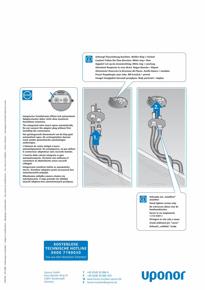
Integrierter Ventileinsatz öffnet sich automatisch.Adapterstecker daher nicht ohne montierteAnschlüsse einsetzen.
The integrated valve insert opens automatically.Do not connect the adapter plug without firstinstalling the connections.
Het geïntegreerde binnenwerk van de klep gaatautomatisch open. De verloopstekker daaromnooit zonder gemonteerde aansluitingenaanbrengen.
L’élément de vanne intégré s’ouvreautomatiquement. En conséquence, ne pas utiliserle connecteur adaptateur sans raccords montés.
L'inserto della valvola integrato si apreautomaticamente. Pertanto non utilizzare ilconnettore di adattamento senza raccordicollegati.
Integrovaná ventilová vloĽka se automatickyotevre. Konektor adaptéru proto nevsazovat beznamontovanīch prípojek.
Wbudowana wkładka zaworu otwiera sięautomatycznie. Z tego powodu nie wkładaćwtyczki adaptera bez zamontowanych przyłączy.
1.
2.
Achtung! Flussrichtung beachten. Weißer Ring = Vorlauf
Caution! Follow the flow direction. White ring = flow
Opgelet! Let op de stroomrichting. Witte ring = voorloop.
Attention! Respecter le sens direct. Bague blanche = Départ
Attenzione! Osservare la direzione del flusso. Anello bianco = mandata
Pozor! Respektujte smer toku. Bílī krouĽek = prívod
Uwaga! Uwzględnić kierunek przepływu. Biały pierścień = dopływ
Schraube nur „handfest“anziehen
Hand tighten screws only
De schroeven alleen met dehandvastdraaien.
Serrer la vis simplement« à la main »
Stringere la vite solo a mano
őroub utáhnout jen “rucne“
Dokręcić „solidnie“ śrubę
1 0 3 0 1 8 3 4 / 2 0 0 8
Uponor GmbHHans-Böckler-Ring 4122851 NorderstedtGermany1
030183 -
04/2008 –
Än
der
un
gen
vo
rbeh
alte
n •
Su
bje
ct t
o m
od
ifi c
atio
ns
• W
ijzig
ing
en v
oo
rbeh
ou
den
• S
ou
s ré
serv
e d
e m
od
ifi c
atio
ns
• C
on
ris
erva
di m
od
ifi c
he
• Z
měn
y vy
hra
zen
y • Z
astr
zeg
amy
mo
żliw
ość
do
kon
ania
zm
ian
T +49 (0)40 30 986-0F +49 (0)40 30 986-433W www.heizen-kuehlen.uponor.deE [email protected]
KOSTENLOSETECHNISCHE HOTLINE
0 8 0 0 7 7 8 0 0 3 0(nur aus dem deutschen Festnetz)
Top Related