
Sprachen
Seiten
Rechtliche

Montageanleitung
Mounting instructions
Instrucciones de montaje
Hochleistungsluftkühler
Forced convection unit air cooler
Evaporador cúbico de tiro forzado
Bitte beachten Sie die projektbezogenen Schaltpläne zum HVIS/T oder FHVI/T.
http://schaltplan.walterroller.de
Please pay attention to the project- specific winring diagrams of the HVIS/T or FHVI/T.
http://wiring.walterroller.com
Por favor, no confunda y diferencie los diagramas específicos de la serie HVIS/T y la serie FHVI/T.
1. Seitenteil 2. Ventilatorblech 3. Ventilator 4. Schutzgitter 5. Kondensatablauf 6. Tropfschale 7. Typenschild
1. Side panel 2. Fan panel 3. Fan 4. Protection grille 5. Condensate drain 6. Drain pan 7. Type plate
1. Panel lateral 2. Panel de ventiladores 3. Ventilador 4. Rejilla de protección 5. Tubo de desagüe para condensados 6. Bandeja 7. Placa de características
FHVI/ T
HVIS/ T
1
2
3
4
5
7
6
2
Inhaltsverzeichnis 1 Einleitung 3 2 Normen/ Richtlinien 3 3 Sicherheitssymbole 4 4 Anwendung 5 5 Lagerung 6 6 Transport 6 7 Auspacken 6 8 Geometrische Daten 7 9 Montage 11 10 Anschluss Kältemittel 12 11 Rohr Anschlüsse 13 12 Durchbrüche 14 13 Anschluss Sole 15 14 Kondensatablauf 15 15 Schwenkbare Ventilatoren 16 16 Textilschlauch 17 17 Defrost Damper 18 18 Defrost Dome 19 19 Nachleitrad 20 20 Elektroanschluss 21 21 Elektrische Anschlusswerte 22 22 Schaltschema 23 23 Ventilatoren 24 24 Ventilatoren EC 25 25 Abtauen 26 26 ST-Heizstäbe 27 27 Thermostat (Zub.) 28 28 SI Heizkabel (Zub.) 29 29 Ringheizung 30 30 Inbetriebnahme 31 31 Schalldaten 31 32 Reinigung 32 33 Wartungsintervalle 33 34 Entsorgung 33 35 Ersatzteilliste 34 36 Fehlersuche 35
Index
1 Introduction 3
2 Standards/ Directives 3
3 Safety symbols 4
4 Intended application 5
5 Storage 6
6 Transportation 6
7 Unpack 6
8 Geometric data 7
9 Mounting 11
10 Refrigerant connection 12
11 Connection diameters 13
12 Cut-outs 14
13 Brine connection 15
14 Condensate drain 15
15 Swivel mounted fans 16
16 Textile hose conneciton 17
17 Defrost Damper 18
18 Defrost Dome 19
19 Streamer 20
20 Electric connections 21
21 Electrical loads 22
22 Wiring diagram 23
23 Fans 24
24 Fans EC 25
25 Defrost 26
26 ST- heater rods 27
27 Thermostat (acc.) 28
28 SI- heater (acc.) 29
29 Fan collar heater 30
30 Start-up 31
31 Sound pressure levels 31
32 Cleaning 32
33 Service interval 33
34 Disposal 33
35 Spare parts 34
36 Trouble shooting 35
Ìndice 1 Introducción 3
2 Normas/ directivas 3
3 Símbolos de seguridad 4
4 Modos de empleo 5
5 Almacenamiento 6
6 Transporte 6
7 Desembalar 6
8 Geometría 7
9 Montaje 11
10 Conexiones de refrigerante 12
11 Diámetros de conexion 13
12 Pasos 14
13 Conexiones para glicol 15
14 Desagüe para condensados15
15 Ventiladores practicables 16
16 Manga textil 17
17 Defrost Damper 18
18 Defrost Dome 19
19 Guía dardo de aire 20
20 Conexiones eléctricas 21
21 Características eléctricas 22
22 Esquema eléctrico 23
23 Ventiladores 24
24 Ventiladores EC 25
25 Desescarche 26
26 ST- Resistencias 27
27 Termostato (acc.) 28
28 SI Resistencia (acc.) 29
29 Resistencia embocadura 30
30 Puesta en marcha 31
31 Datos sonoros 31
32 Limpieza 32
33 Revisión periódica 33
34 Fin del periodo útil 33
35 Piezas de repuesto 34
36 Diagnóstico de fallos 35
3
1 Einleitung Die deutsche Fassung der Montageanleitung ist das Original.
Alle Sicherheitstexte und Hinweise sind kursiv gesetzt.
Bewahren Sie diese Montageanleitung auf, sie ist Teil der Dokumentation der Kälteanlage.
Die jeweils aktuelle Fassung dieser Montageanleitung kann auf unserer Website http://inst.walterroller.de heruntergeladen werden.
2 Normen/ Richtlinien Die Normenreihe EN 378 "Kälteanlagen und Wärmepumpen - Sicherheitstechnische und umweltrelevante Anforderungen" dokumentiert die Anforderungen, die der Errichter sowie der Betreiber der Kälteanlage erfüllen müssen.
Die Luftkühler sind nach EN 378-2 Absatz 5.2.1 eine Rohrschlange mit Luft als Sekundärfluid, und entspricht den Anforderungen von EN 14276-2 mit Punkt 5.2.2.2 der EN 378.
Je nach Art der Errichtung der Kälteanlage ergeben sich unterschiedliche Anforderungen an die elektrische Absicherung. Eine der folgenden Normen muss zur Bewertung der sicherheitstechnischen Anforderung herangezogen werden:
o EN 60335-2-40,
o EN 60335-2-89
o oder EN 60204-1.
Die Luftkühler HVIS/T, FHVI/T stellen eine unvollständige Maschine nach Maschinenrichtlinie dar. Daher erhalten Sie keine CE Kennzeichnung. Das CE Zeichen auf Ventilatoren und Heizstäben bestätigt die Konformität dieser Komponenten mit den auf sie zutreffenden Richtlinien (z.B. Niederspannungsrichtlinie, ERP Richtlinie).
1 Introduction This mounting instruction is a translation of the german original Montageanleitung.
All safety information and advice is printed in italics.
Keep these instructions; they are part of the refrigerating plant.
You can download the latest revision of these mounting instructions on our website http://inst.walterroller.com.
2 Standards/ Directives The standard series EN 378 "Refrigerating systems and heat pumps- Safety and environmental requirements" documents the requirements, which the builder and the operator of the refrigeration plant have to comply.
Unit air coolers are coils with air as secondary fluid according to EN 378-2 paragraph 5.2.1. It fulfills the requirements of EN 14276-2 and paragraph. 5.2.2.2 of EN 378.
Depending on the type of refrigeration system there are different requirements for electric safety. One of the following standards has to be obeyed, when designing and installing the plant:
o EN 60335-2-40,
o EN 60335-2-89
o or EN 60204-1.
The air unit cooler HVIS/T and FHVI/T are an incomplete machine, according to the EC machinery directive. Because of that it isn't labeled with the CE sign. The CE sign visible on fans, heaters etc. shows that these components are in conformance with other directives (e.g. ERP directive, low- voltage directive).
1 Introducción Estas Instrucciones de Montaje han sido traducidas del original en Alemán Montageanleitung.
Las indicaciones e instrucciones de seguridad se han escrito en letra cursiva.
Conserve estas instrucciones, son parte de la información técnica de la instalación frigorífica.
Puede Vd. descargar la última edición de estas instrucciones de montaje en nuestra página web: http://inst.walterroller.com.
2 Normas/ directivas • La Normativa EN 378 "sistemas de refrigeración y bombas de calor-seguridad y requisitos ambientales" documenta los requisitos que deben cumplir el fabricante y el técnico de la instalación frigorífica.
• Los evaporadores son una batería frigorífica que utiliza el aire como fluido secundario, según la norma EN 378-2 párrafo 5.2.1. Cumple con los requisitos de la EN 14276-2 y el párrafo. 5.2.2.2 de la EN 378.
• Dependiendo del tipo de sistema de refrigeración existen diferentes Normas de seguridad eléctrica. Una de las siguientes Normas tiene que ser de obligado cumplimiento, en el diseño e instalación de la planta:
o EN 60335-2-40,
o EN 60335-2-89
o o la EN 60204-1.
•Los evaporadores HVIS/T y FHVI/T son una máquina incompleta, según la Directiva de maquinaria CE. Por eso no contiene el símbolo CE. La CE se muestra visible en los ventiladores, calentadores etc., y demuestra que estos componentes están en conformidad con otras directivas (por ejemplo, la Directiva BT, Directiva de baja tensión).
4
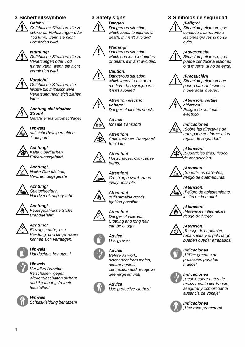
3 Sicherheitssymbole
Gefahr! Gefährliche Situation, die zu schweren Verletzungen oder Tod führt, wenn sie nicht vermieden wird.
Warnung! Gefährliche Situation, die zu Verletzungen oder Tod führen kann, wenn sie nicht vermieden wird.
Vorsicht! Gefährliche Situation, die leichte bis mittelschwere Verletzung nach sich ziehen kann.
Achtung elektrischer Strom! Gefahr eines Stromschlages .
Hinweis auf sicherheitsgerechten Transport!
Achtung! Kalte Oberflächen, Erfrierungsgefahr!
Achtung! Heiße Oberflächen, Verbrennungsgefahr!
Achtung! Quetschgefahr, Handverletzungsgefahr!
Achtung! Feuergefährliche Stoffe, Brandgefahr!
Achtung! Einzugsgefahr, lose Kleidung, und lange Haare können sich verfangen.
Hinweis Handschutz benutzen!
Hinweis Vor allen Arbeiten freischalten, gegen wiedereinschalten sichern und Spannungsfreiheit feststellen!
Hinweis Schutzkleidung benutzen!
3 Safety signs
Danger! Dangerous situation, which leads to injuries or death, if it isn't avoided.
Warning! Dangerous situation, which can lead to injuries or death, if it isn't avoided.
Caution! Dangerous situation, which leads to minor to medium- heavy injuries, if it isn't avoided.
Attention electric voltage! Danger of electric shock.
Advice for safe transport!
Attention! Cold surfaces. Danger of frost bite.
Attention! Hot surfaces. Can cause burns.
Attention! Crushing hazard. Hand injury possible.
Attention! of flammable goods. Ignition possible.
Attention! Danger of insertion. Clothing and long hair can be caught.
Advice Use gloves!
Advice Before all work, disconnect from mains, secure against connection and recognize deenergised unit!
Advice Use protective clothes!
3 Símbolos de seguridad
¡Peligro! Situación peligrosa, que conduce a la muerte o lesiones graves si no se evita.
¡Advertencia! Situación peligrosa, que puede conducir a lesiones o la muerte, si no se evita.
¡Precaución! Situación peligrosa que podría causar lesiones moderadas o leves.
¡Atención, voltaje eléctrico! Peligro de contacto eléctrico.
Indicaciones ¡Sobre las directivas de transporte conforme a las reglas de seguridad!
¡Atención! ¡Superficies frías, riesgo de congelación!
¡Atención! ¡Superficies calientes, riesgo de quemaduras!
¡Atención! ¡Peligro de aplastamiento, lesión en la mano!
¡Atención! ¡Materiales inflamables, riesgo de fuego!
¡Atención! ¡Riesgo de captación, ropa suelta y el pelo largo pueden quedar atrapados!
Indicaciones ¡Utilice guantes de protección para las manos!
Indicaciones ¡Desbloquear antes de realizar cualquier trabajo, asegurar y comprobar la ausencia de voltaje!
Indicaciones ¡Use ropa protectora!
5
4 Anwendung Bestimmungsgemäße Verwendung
Die bestimmungsgemäße Verwendung des Luftkühlers besteht im Abkühlen bzw. Erhitzen und Fördern von feuchter Luft. Ebenso umfasst die bestimmungsgemäße Verwendung des Luftkühlers das gegebenenfalls nötige Abtauen und das Ableiten des anfallenden Kondensates.
Die Montage und der Anschluss müssen nach dieser Anleitung erfolgen.
Die Luftkühler dürfen nur in technisch einwandfreiem Zustand, mit einer technisch einwandfreien Kälteanlage betrieben werden.
Zulässiger Betriebsdruck PS siehe Typenschild.
Die auf dem Typenschild angegebenen Umgebungstemperaturbereiche sind einzuhalten.
(Position des Typenschildes siehe Frontseite.)
Beachten Sie auch den gesonderten Temperatureinsatzbereich des Ventilators.
Folgende Luftverunreinigungen sind zu meiden:
o Abrasive (abtragende) Partikel.
o Stark korrosiv wirkende Verunreinigungen z.B. Salznebel.
o Hohe Staubbelastung z.B. Absaugung von Sägespänen.
o Brennbare Gase/ Partikel.
Der Kühler darf nicht in der Nähe von brennbaren Stoffen und Komponenten betrieben werden.
Der Kühler darf nicht in explosiver Atmosphäre betrieben werden.
Der Kühler darf keine sicherheitsrelevanten Aufgaben übernehmen.
Alle nicht bestimmungsgemäßen Verwendungen sind verboten!
4 Intended application
The intended application of the air cooler is the cooling or heating and blowing of humid air. A defrost operation and the drain of the condensate is intended application, too.
Mounting and connecting has to be done according to these instructions.
The unit air coolers may only be operated in excellent technical condition with a technical sound refrigerating plant.
Allowable operating pressure PS see type plate.
The ambient temperature ranges given on the type plate have to be maintained. (Position of the type plate see front page.)
Consider the different operating conditions of the fan.
The following pollutions of the air have to be avoided:
o Abrasive particles.
o Strong corrosive pollutions
e.g. salt spray mist.
o High dust loading, e.g.
exhaustion of saw dust.
o Flammable gases/ particles.
The cooler may not be run next to flammable materials or components.
The cooler may not be run in explosive ambient.
The cooler mustn’t take over security relevant duties.
Use for purpose other than designed for is forbidden.
4 Modos de empleo Uso previsto
Este aparato está indicado para funciones de refrigeración ó calefacción y regulación de la humedad del aire. El sistema de desescarche y la bandeja de condensados complementan las tareas derivadas de las funciones descritas.
El montaje y el conexionado se deben efectuar conforme a las instrucciones del manual de uso.
El evaporador se debe de encontrar en un estado de funcionamiento irreprochable, para su instalación en un sistema frigorífico.
Máxima presión de servicio admisible PS ver en la placa de características.
Los rangos de temperatura ambiente se indican en la placa de características. (Posición de la placa en la primera página.)
Comprobar las condiciones de funcionamiento del ventilador.
Se debe evitar aire conteniendo las siguientes sustancias contaminantes:
o Partículas abrasivas.
o Sustancias altamente corrosivas, por ejemplo ambientes salinos.
o Altas concentraciones de polvo, por ejemplo serrín.
o Gases o partículas inflamables.
Este evaporador no está preparado para funcionar con materias o componentes inflamables.
Este evaporador no está preparado para funcionar en ambientes explosivos.
Este evaporador no puede asumir tareas en condiciones de seguridades relevantes.
Todos los usos que no respeten los modos de empleo están prohibidos.
6
5 Lagerung Anlage bis zur Montage trocken und wettergeschützt in der Originalverpackung lagern.
Lagern Sie das Gerät maximal ein Jahr.
Lagertemperatur: -40 °C bis +80 °C.
Feuchtigkeit und Schmutz dürfen nicht in das Gerät eindringen.
6 Transport
Warnung! Das Gerät wiegt bis zu 881 kg. Herunterfallende Geräte können zu schweren Verletzungen oder Tod führen.
Zum Transport die Original-verpackung verwenden.
Nur an den vorgesehenen Transportvorrichtungen mit geeignetem Hebezeug transportieren.
Gewichte siehe Kapitel 9.
Anlage vorsichtig transportieren, Schläge und Stöße vermeiden.
Sichern Sie das Gerät gegen Verrutschen und herabfallen.
7 Auspacken
Achtung! Lamellen sind scharfkantig!
Hinweis Handschutz benutzen!
Überprüfen Sie die Verpa-ckung auf äußere Schäden.
Überprüfen Sie den Luftkühler auf Schäden. Montieren Sie keine beschädigten Geräte.
Stellen Sie das Gerät nicht auf den Schutzgittern der Ventil-atoren ab.
5 Storage The unit has to be warehoused dry and weather protected in the original packing until installation.
Store the unit maximum one year.
Storage temperature between -40°C and +80 °C.
Humidity and dust mustn't get into the unit.
6 Shipping
Warning! The unit weighs up to 881 kg.
Dropping units can lead to severe injuries or death.
Use the original packing for transport.
Move only with intended lifting devices using appropriate fixtures.
For weights see chapter 9.
Move the unit carefully avoiding jolts and impacts.
Secure the unit against slipping and dropping.
7 Unpacking
Attention! Fins are sharp- edged!
Advice Use gloves!
Check the packing for damages.
Check the air unit cooler for damages. Damaged units mustn't be mounted.
Don't put the unit with the fan guards on the ground.
5 Almacenamiento La unidad se debe almacenar en lugar seco y protegido de la intemperie, en su embalaje original hasta el montaje.
Se recomienda un periodo de estocaje máximo de 1 año.
Temperatura de almace-namiento: -40 °C hasta +80 °C.
Se debe evitar la entrada de polvo y humedad al interior del aparato.
6 Transporte
¡Advertencia! El aparato puede pesar hasta 881 kg. La caida del aparato puede causar lesiones graves o la muerte.
Para efectuar el transporte se debe utilizar el embalaje original.
Transportar únicamente con los medios adecuados y en los puntos de transporte previstos para este efecto.
Especificaciones de pesos: ver capítulo 9.
Transporte la unidad con prudencia, evitando choques y golpes. Asegure el aparato para evitar resbalones y caídas.
7 Desembalar
¡Atención! ¡Las aletas están afiladas!
Indicaciones ¡Utilice guantes de protección para las manos!
Compruebe la ausencia de daños en el embalaje.
Si el equipo está dañado, no se debe instalar.
No coja el aparato por las rejillas de los ventiladores.
7
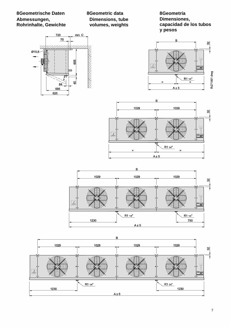
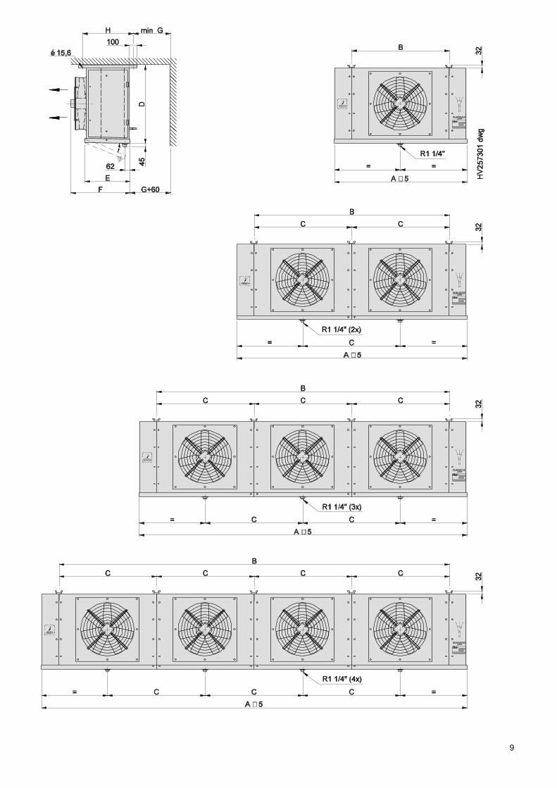
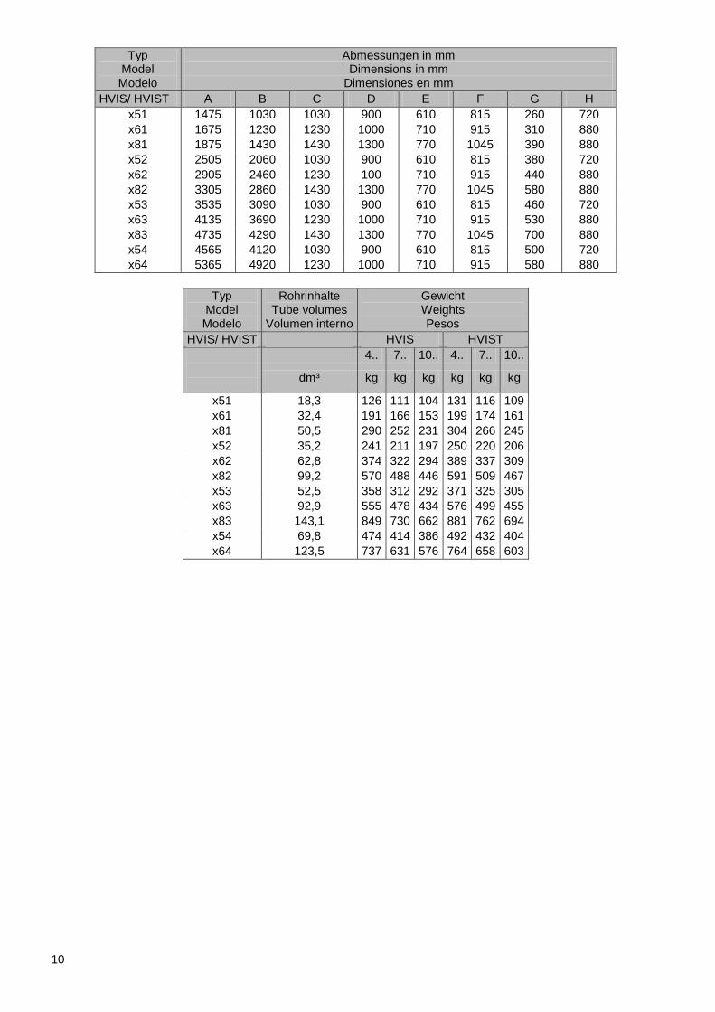
8 Geometrische Daten
Abmessungen, Rohrinhalte, Gewichte
8Geometric data
Dimensions, tube volumes, weights
8 Geometría
Dimensiones, capacidad de los tubos y pesos
8
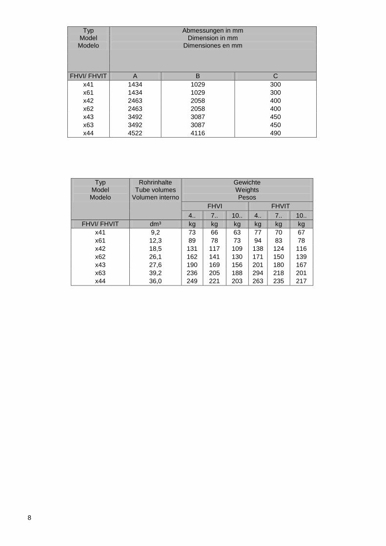
Typ Model Modelo
Abmessungen in mm Dimension in mm
Dimensiones en mm
FHVI/ FHVIT A B C
x41 1434 1029 300
x61 1434 1029 300
x42 2463 2058 400
x62 2463 2058 400
x43 3492 3087 450
x63 3492 3087 450
x44 4522 4116 490
Typ Model Modelo
Rohrinhalte Tube volumes
Volumen interno
Gewichte Weights Pesos
FHVI FHVIT
4.. 7.. 10.. 4.. 7.. 10..
FHVI/ FHVIT dm³ kg kg kg kg kg kg
x41 9,2 73 66 63 77 70 67
x61 12,3 89 78 73 94 83 78
x42 18,5 131 117 109 138 124 116
x62 26,1 162 141 130 171 150 139
x43 27,6 190 169 156 201 180 167
x63 39,2 236 205 188 294 218 201
x44 36,0 249 221 203 263 235 217
9
10
Typ Model Modelo
Abmessungen in mm Dimensions in mm
Dimensiones en mm
HVIS/ HVIST A B C D E F G H
x51 1475 1030 1030 900 610 815 260 720
x61 1675 1230 1230 1000 710 915 310 880
x81 1875 1430 1430 1300 770 1045 390 880
x52 2505 2060 1030 900 610 815 380 720
x62 2905 2460 1230 100 710 915 440 880
x82 3305 2860 1430 1300 770 1045 580 880
x53 3535 3090 1030 900 610 815 460 720
x63 4135 3690 1230 1000 710 915 530 880
x83 4735 4290 1430 1300 770 1045 700 880
x54 4565 4120 1030 900 610 815 500 720
x64 5365 4920 1230 1000 710 915 580 880
Typ Model Modelo
Rohrinhalte Tube volumes
Volumen interno
Gewicht Weights Pesos
HVIS/ HVIST HVIS HVIST
4.. 7.. 10.. 4.. 7.. 10..
dm³ kg kg kg kg kg kg
x51 18,3 126 111 104 131 116 109
x61 32,4 191 166 153 199 174 161
x81 50,5 290 252 231 304 266 245
x52 35,2 241 211 197 250 220 206
x62 62,8 374 322 294 389 337 309
x82 99,2 570 488 446 591 509 467
x53 52,5 358 312 292 371 325 305
x63 92,9 555 478 434 576 499 455
x83 143,1 849 730 662 881 762 694
x54 69,8 474 414 386 492 432 404
x64 123,5 737 631 576 764 658 603
11
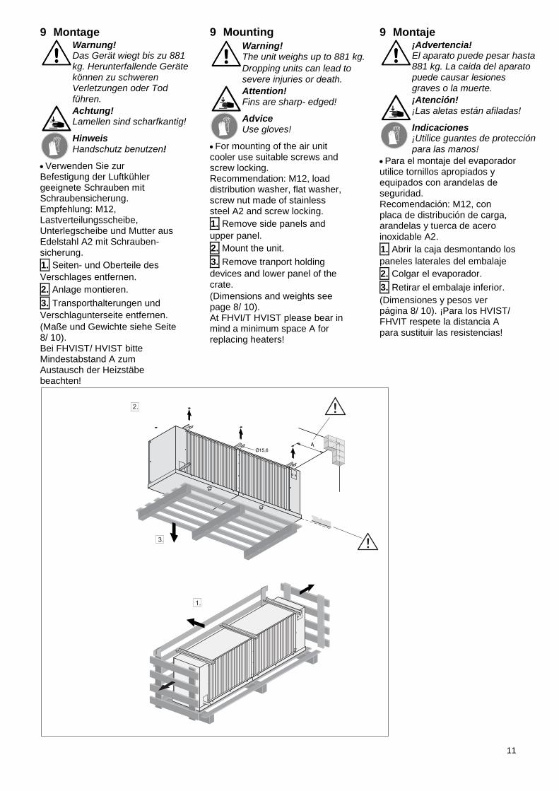
9 Montage
Warnung! Das Gerät wiegt bis zu 881 kg. Herunterfallende Geräte können zu schweren Verletzungen oder Tod führen.
Achtung! Lamellen sind scharfkantig!
Hinweis Handschutz benutzen!
Verwenden Sie zur Befestigung der Luftkühler geeignete Schrauben mit Schraubensicherung. Empfehlung: M12, Lastverteilungsscheibe, Unterlegscheibe und Mutter aus Edelstahl A2 mit Schrauben-sicherung.
1. Seiten- und Oberteile des
Verschlages entfernen.
2. Anlage montieren.
3. Transporthalterungen und
Verschlagunterseite entfernen.
(Maße und Gewichte siehe Seite 8/ 10). Bei FHVIST/ HVIST bitte Mindestabstand A zum Austausch der Heizstäbe beachten!
9 Mounting
Warning! The unit weighs up to 881 kg.
Dropping units can lead to
severe injuries or death.
Attention! Fins are sharp- edged!
Advice Use gloves!
For mounting of the air unit cooler use suitable screws and screw locking. Recommendation: M12, load distribution washer, flat washer, screw nut made of stainless steel A2 and screw locking.
1. Remove side panels and
upper panel.
2. Mount the unit.
3. Remove tranport holding
devices and lower panel of the crate.
(Dimensions and weights see page 8/ 10). At FHVI/T HVIST please bear in mind a minimum space A for replacing heaters!
9 Montaje
¡Advertencia! El aparato puede pesar hasta 881 kg. La caida del aparato puede causar lesiones graves o la muerte.
¡Atención! ¡Las aletas están afiladas!
Indicaciones ¡Utilice guantes de protección para las manos!
Para el montaje del evaporador utilice tornillos apropiados y equipados con arandelas de seguridad. Recomendación: M12, con placa de distribución de carga, arandelas y tuerca de acero inoxidable A2.
1. Abrir la caja desmontando los
paneles laterales del embalaje
2. Colgar el evaporador.
3. Retirar el embalaje inferior.
(Dimensiones y pesos ver página 8/ 10). ¡Para los HVIST/ FHVIT respete la distancia A para sustituir las resistencias!
12
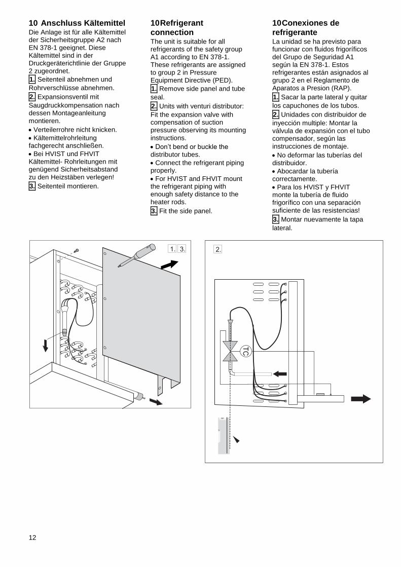
10 Anschluss Kältemittel Die Anlage ist für alle Kältemittel der Sicherheitsgruppe A2 nach EN 378-1 geeignet. Diese Kältemittel sind in der Druckgeräterichtlinie der Gruppe 2 zugeordnet.
1. Seitenteil abnehmen und
Rohrverschlüsse abnehmen.
2. Expansionsventil mit
Saugdruckkompensation nach dessen Montageanleitung montieren.
Verteilerrohre nicht knicken.
Kältemittelrohrleitung fachgerecht anschließen.
Bei HVIST und FHVIT Kältemittel- Rohrleitungen mit genügend Sicherheitsabstand zu den Heizstäben verlegen!
3. Seitenteil montieren.
10 Refrigerant connection The unit is suitable for all refrigerants of the safety group A1 according to EN 378-1. These refrigerants are assigned to group 2 in Pressure Equipment Directive (PED).
1. Remove side panel and tube
seal.
2. Units with venturi distributor:
Fit the expansion valve with compensation of suction pressure observing its mounting instructions.
Don’t bend or buckle the distributor tubes.
Connect the refrigerant piping properly.
For HVIST and FHVIT mount the refrigerant piping with enough safety distance to the heater rods.
3. Fit the side panel.
10 Conexiones de refrigerante La unidad se ha previsto para funcionar con fluidos frigoríficos del Grupo de Seguridad A1 según la EN 378-1. Estos refrigerantes están asignados al grupo 2 en el Reglamento de Aparatos a Presion (RAP).
1. Sacar la parte lateral y quitar
los capuchones de los tubos.
2. Unidades con distribuidor de
inyección multiple: Montar la válvula de expansión con el tubo compensador, según las instrucciones de montaje.
No deformar las tuberías del distribuidor.
Abocardar la tubería correctamente.
Para los HVIST y FHVIT monte la tubería de fluido frigorífico con una separación suficiente de las resistencias!
3. Montar nuevamente la tapa
lateral.
13
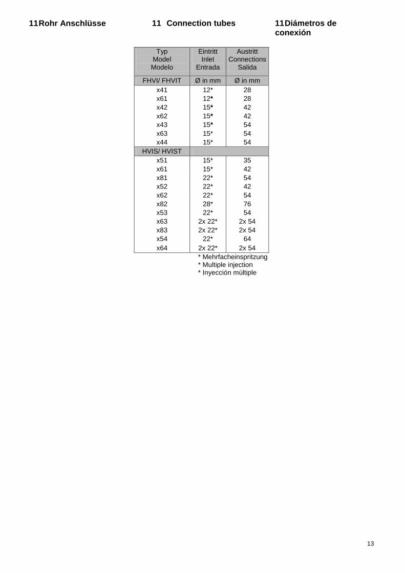
11 Rohr Anschlüsse 11 Connection tubes 11 Diámetros de conexión
Typ Model Modelo
Eintritt Inlet
Entrada
Austritt Connections
Salida
FHVI/ FHVIT Ø in mm Ø in mm
x41 12* 28
x61 12* 28
x42 15* 42
x62 15* 42
x43 15* 54
x63 15* 54
x44 15* 54
HVIS/ HVIST
x51 15* 35
x61 15* 42
x81 22* 54
x52 22* 42
x62 22* 54
x82 28* 76
x53 22* 54
x63 2x 22* 2x 54
x83 2x 22* 2x 54
x54 22* 64
x64 2x 22* 2x 54
* Mehrfacheinspritzung * Multiple injection * Inyección múltiple
14
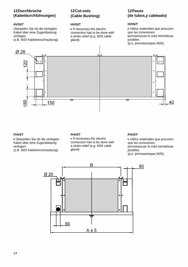
12 Durchbrüche
(Kabeldurchführungen)
HVIS/T
Überpüfen Sie ob die verlegten Kabel über eine Zugentlastung verfügen. (z.B. M20 Kabelverschraubung).
12 Cut-outs
(Cable Bushing)
HVIS/T
If necessary the electric connection has to be done with a strain-relief (e.g. M20 cable gland).
12 Pasos
(de tubos,y cableado)
HVIS/T
Utilice materiales que procuren que las conexiones permanezcan lo más herméticas posibles (p.e. prensaestopas M20).
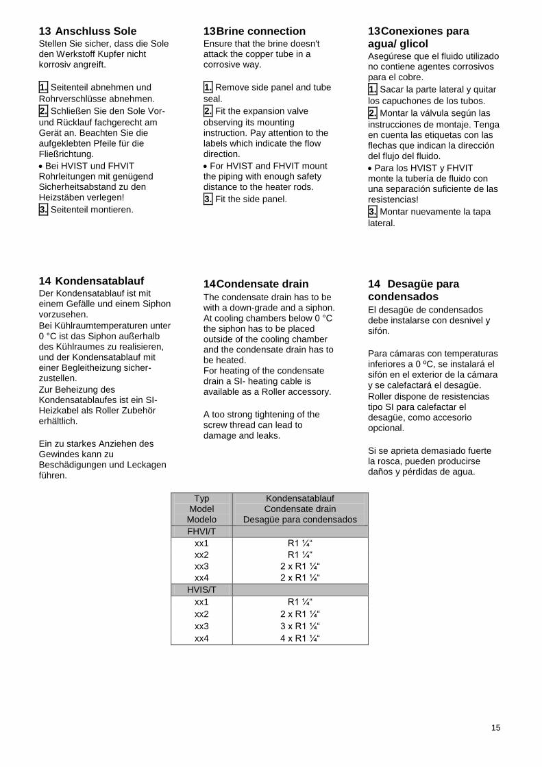
FHVI/T
Überpüfen Sie ob die verlegten Kabel über eine Zugentlastung verfügen. (z.B. M20 Kabelverschraubung).
FHVI/T
If necessary the electric connection has to be done with a strain-relief (e.g. M20 cable gland).
FHVI/T
Utilice materiales que procuren que las conexiones permanezcan lo más herméticas posibles (p.e. prensaestopas M20).
15
13 Anschluss Sole Stellen Sie sicher, dass die Sole den Werkstoff Kupfer nicht korrosiv angreift.
1. Seitenteil abnehmen und
Rohrverschlüsse abnehmen.
2. Schließen Sie den Sole Vor-
und Rücklauf fachgerecht am Gerät an. Beachten Sie die aufgeklebten Pfeile für die Fließrichtung.
Bei HVIST und FHVIT Rohrleitungen mit genügend Sicherheitsabstand zu den Heizstäben verlegen!
3. Seitenteil montieren.
13 Brine connection Ensure that the brine doesn't attack the copper tube in a corrosive way.
1. Remove side panel and tube
seal.
2. Fit the expansion valve
observing its mounting instruction. Pay attention to the labels which indicate the flow direction.
For HVIST and FHVIT mount the piping with enough safety distance to the heater rods.
3. Fit the side panel.
13 Conexiones para agua/ glicol Asegúrese que el fluido utilizado no contiene agentes corrosivos para el cobre.
1. Sacar la parte lateral y quitar
los capuchones de los tubos.
2. Montar la válvula según las
instrucciones de montaje. Tenga en cuenta las etiquetas con las flechas que indican la dirección del flujo del fluido.
Para los HVIST y FHVIT monte la tubería de fluido con una separación suficiente de las resistencias!
3. Montar nuevamente la tapa
lateral.
14 Kondensatablauf Der Kondensatablauf ist mit einem Gefälle und einem Siphon vorzusehen.
Bei Kühlraumtemperaturen unter 0 °C ist das Siphon außerhalb des Kühlraumes zu realisieren, und der Kondensatablauf mit einer Begleitheizung sicher-zustellen.
Zur Beheizung des Kondensatablaufes ist ein SI- Heizkabel als Roller Zubehör erhältlich.
Ein zu starkes Anziehen des Gewindes kann zu Beschädigungen und Leckagen führen.
14 Condensate drain The condensate drain has to be with a down-grade and a siphon. At cooling chambers below 0 °C the siphon has to be placed outside of the cooling chamber and the condensate drain has to be heated. For heating of the condensate drain a SI- heating cable is available as a Roller accessory.
A too strong tightening of the screw thread can lead to damage and leaks.
14 Desagüe para condensados El desagüe de condensados debe instalarse con desnivel y sifón.
Para cámaras con temperaturas inferiores a 0 ºC, se instalará el sifón en el exterior de la cámara y se calefactará el desagüe.
Roller dispone de resistencias tipo SI para calefactar el desagüe, como accesorio opcional.
Si se aprieta demasiado fuerte la rosca, pueden producirse daños y pérdidas de agua.
Typ Model Modelo
Kondensatablauf Condensate drain
Desagüe para condensados
FHVI/T
xx1 R1 ¼“
xx2 R1 ¼“
xx3 2 x R1 ¼“
xx4 2 x R1 ¼“
HVIS/T
xx1 R1 ¼“
xx2 2 x R1 ¼“
xx3 3 x R1 ¼“
xx4 4 x R1 ¼“
16
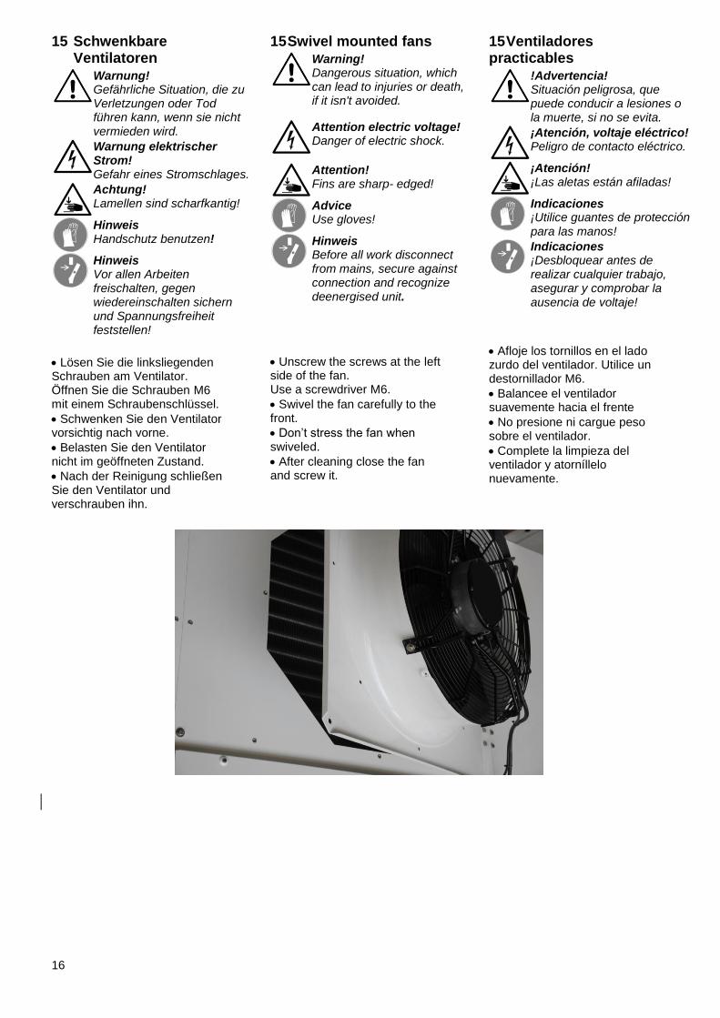
15 Schwenkbare Ventilatoren
Warnung! Gefährliche Situation, die zu Verletzungen oder Tod führen kann, wenn sie nicht vermieden wird.
Warnung elektrischer Strom! Gefahr eines Stromschlages.
Achtung! Lamellen sind scharfkantig!
Hinweis Handschutz benutzen!
Hinweis Vor allen Arbeiten freischalten, gegen wiedereinschalten sichern und Spannungsfreiheit feststellen!
Lösen Sie die linksliegenden Schrauben am Ventilator. Öffnen Sie die Schrauben M6 mit einem Schraubenschlüssel.
Schwenken Sie den Ventilator vorsichtig nach vorne.
Belasten Sie den Ventilator nicht im geöffneten Zustand.
Nach der Reinigung schließen Sie den Ventilator und verschrauben ihn.
15 Swivel mounted fans
Warning! Dangerous situation, which can lead to injuries or death, if it isn't avoided.
Attention electric voltage! Danger of electric shock.
Attention! Fins are sharp- edged!
Advice Use gloves!
Hinweis Before all work disconnect from mains, secure against connection and recognize deenergised unit.
Unscrew the screws at the left side of the fan. Use a screwdriver M6.
Swivel the fan carefully to the front.
Don’t stress the fan when swiveled.
After cleaning close the fan and screw it.
15 Ventiladores practicables
!Advertencia! Situación peligrosa, que puede conducir a lesiones o la muerte, si no se evita.
¡Atención, voltaje eléctrico! Peligro de contacto eléctrico.
¡Atención! ¡Las aletas están afiladas!
Indicaciones ¡Utilice guantes de protección para las manos!
Indicaciones ¡Desbloquear antes de realizar cualquier trabajo, asegurar y comprobar la ausencia de voltaje!
Afloje los tornillos en el lado zurdo del ventilador. Utilice un destornillador M6.
Balancee el ventilador suavemente hacia el frente
No presione ni cargue peso sobre el ventilador.
Complete la limpieza del ventilador y atorníllelo nuevamente.
17
16 Textilschlauch
Warnung! Gefährliche Situation, die zu Verletzungen oder Tod führen kann, wenn sie nicht vermieden wird.
Warnung elektrischer Strom! Gefahr eines Stromschlages.
Achtung! Lamellen sind scharfkantig!
Hinweis Handschutz benutzen!
Hinweis Vor allen Arbeiten freischalten, gegen wiedereinschalten sichern und Spannungsfreiheit feststellen!
Durch den Anschluss eines Textilschlauches entsteht ein zusätzlicher Druckverlust. Dies hat Auswirkungen auf die Leistungsfähigkeit des Luftkühlers. Bei Fragen zur Luftkühlerauslegung kontaktieren Sie bitte Walter Roller GmbH & Co.
Überpüfen Sie die Versorgungsleitungen des Ventilators. Diese müssen in den meisten Fällen neu verlegt werden.
Der Textilschlauch wird über das Schutzgitter des Ventilators gezogen und auf der Volldüse verspannt.
Siehe Kapitel 17 Defrost Damper.
16 Textile hose
Warning! Dangerous situation, which can lead to injuries or death, if it isn't avoided.
Attention electric voltage! Danger of electric shock.
Attention! Fins are sharp- edged!
Advice Use gloves!
Hinweis Before all work disconnect from mains, secure against connection and recognize deenergised unit.
Connecting a textile hose results in an additional pressure loss. This effects the capacity of the air cooler. If you have any questions please contact Walter Roller GmbH & Co.
Check the supply wires of the fan. In most cases they have to be rewired.
The textile hose connection is screwd with 4 sheet- metal screws.
Put the textile hose over the fan guard and tighten it on the fan frame.
See chapter 17 defrost damper.
16 Manga textil
!Advertencia! Situación peligrosa, que puede conducir a lesiones o la muerte, si no se evita.
¡Atención, voltaje eléctrico! Peligro de contacto eléctrico.
¡Atención! ¡Las aletas están afiladas!
Indicaciones ¡Utilice guantes de protección para las manos!
Indicaciones ¡Desbloquear antes de realizar cualquier trabajo, asegurar y comprobar la ausencia de voltaje!
La conexión de una manga textil al evaporador produce una pérdida de carga adicional. Esto influye en la capacidad del evaporador. Para preguntas sobre esta aplicación, contácte con Walter GmbH & Co.
Revise los cables de conexión de los ventiladores.
Seguramente deberá recolocarlos y reapretarlos.
Coloque la manga de forma que se despliegue sobre la rejilla del ventilador.
Ver capítulo 17 manga desescharche (Defrost Damper).
18
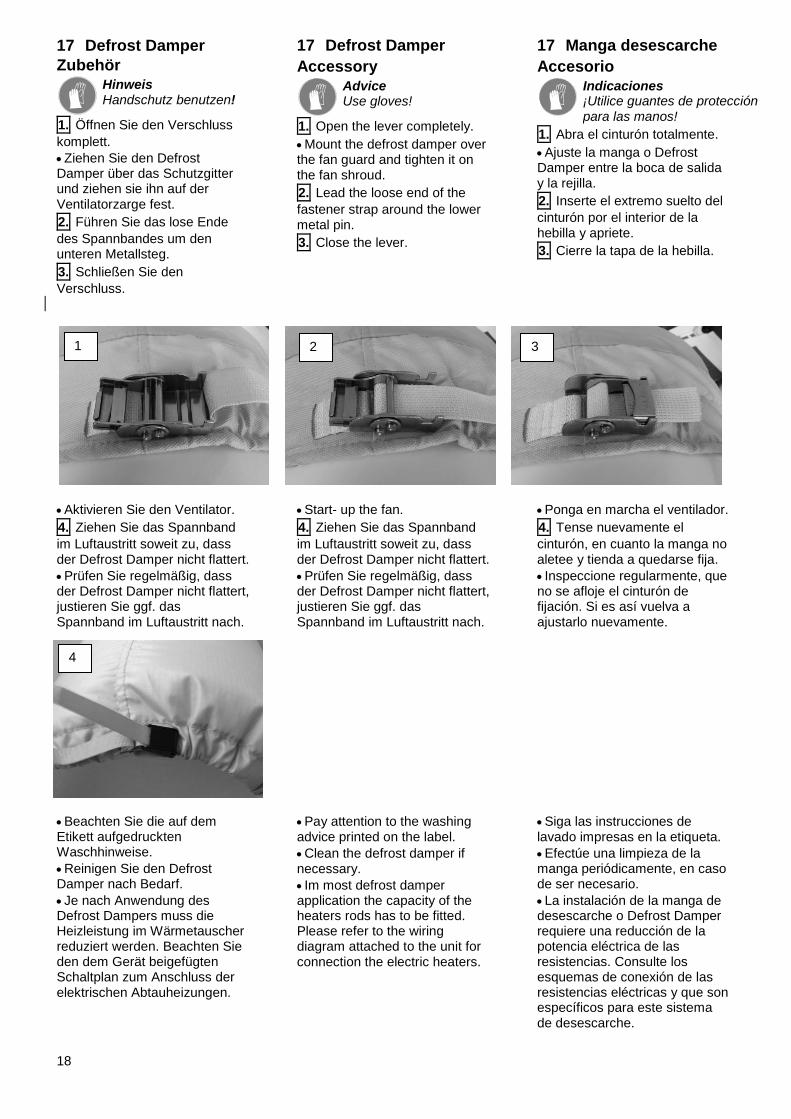
17 Defrost Damper
Zubehör
Hinweis Handschutz benutzen!
1. Öffnen Sie den Verschluss
komplett.
Ziehen Sie den Defrost Damper über das Schutzgitter und ziehen sie ihn auf der Ventilatorzarge fest.
2. Führen Sie das lose Ende
des Spannbandes um den unteren Metallsteg.
3. Schließen Sie den
Verschluss.
17 Defrost Damper
Accessory
Advice Use gloves!
1. Open the lever completely.
Mount the defrost damper over the fan guard and tighten it on the fan shroud.
2. Lead the loose end of the
fastener strap around the lower metal pin.
3. Close the lever.
17 Manga desescarche
Accesorio
Indicaciones ¡Utilice guantes de protección para las manos!
1. Abra el cinturón totalmente.
Ajuste la manga o Defrost Damper entre la boca de salida y la rejilla.
2. Inserte el extremo suelto del
cinturón por el interior de la hebilla y apriete.
3. Cierre la tapa de la hebilla.
Aktivieren Sie den Ventilator.
4. Ziehen Sie das Spannband
im Luftaustritt soweit zu, dass der Defrost Damper nicht flattert.
Prüfen Sie regelmäßig, dass der Defrost Damper nicht flattert, justieren Sie ggf. das Spannband im Luftaustritt nach.
Beachten Sie die auf dem Etikett aufgedruckten Waschhinweise.
Reinigen Sie den Defrost Damper nach Bedarf.
Je nach Anwendung des Defrost Dampers muss die Heizleistung im Wärmetauscher reduziert werden. Beachten Sie den dem Gerät beigefügten Schaltplan zum Anschluss der elektrischen Abtauheizungen.
Start- up the fan.
4. Ziehen Sie das Spannband
im Luftaustritt soweit zu, dass der Defrost Damper nicht flattert.
Prüfen Sie regelmäßig, dass der Defrost Damper nicht flattert, justieren Sie ggf. das Spannband im Luftaustritt nach.
Pay attention to the washing advice printed on the label.
Clean the defrost damper if necessary.
Im most defrost damper application the capacity of the heaters rods has to be fitted. Please refer to the wiring diagram attached to the unit for connection the electric heaters.
Ponga en marcha el ventilador.
4. Tense nuevamente el
cinturón, en cuanto la manga no aletee y tienda a quedarse fija.
Inspeccione regularmente, que no se afloje el cinturón de fijación. Si es así vuelva a ajustarlo nuevamente.
Siga las instrucciones de lavado impresas en la etiqueta.
Efectúe una limpieza de la manga periódicamente, en caso de ser necesario.
La instalación de la manga de desescarche o Defrost Damper requiere una reducción de la potencia eléctrica de las resistencias. Consulte los esquemas de conexión de las resistencias eléctricas y que son específicos para este sistema de desescarche.
1 2 3
4
19
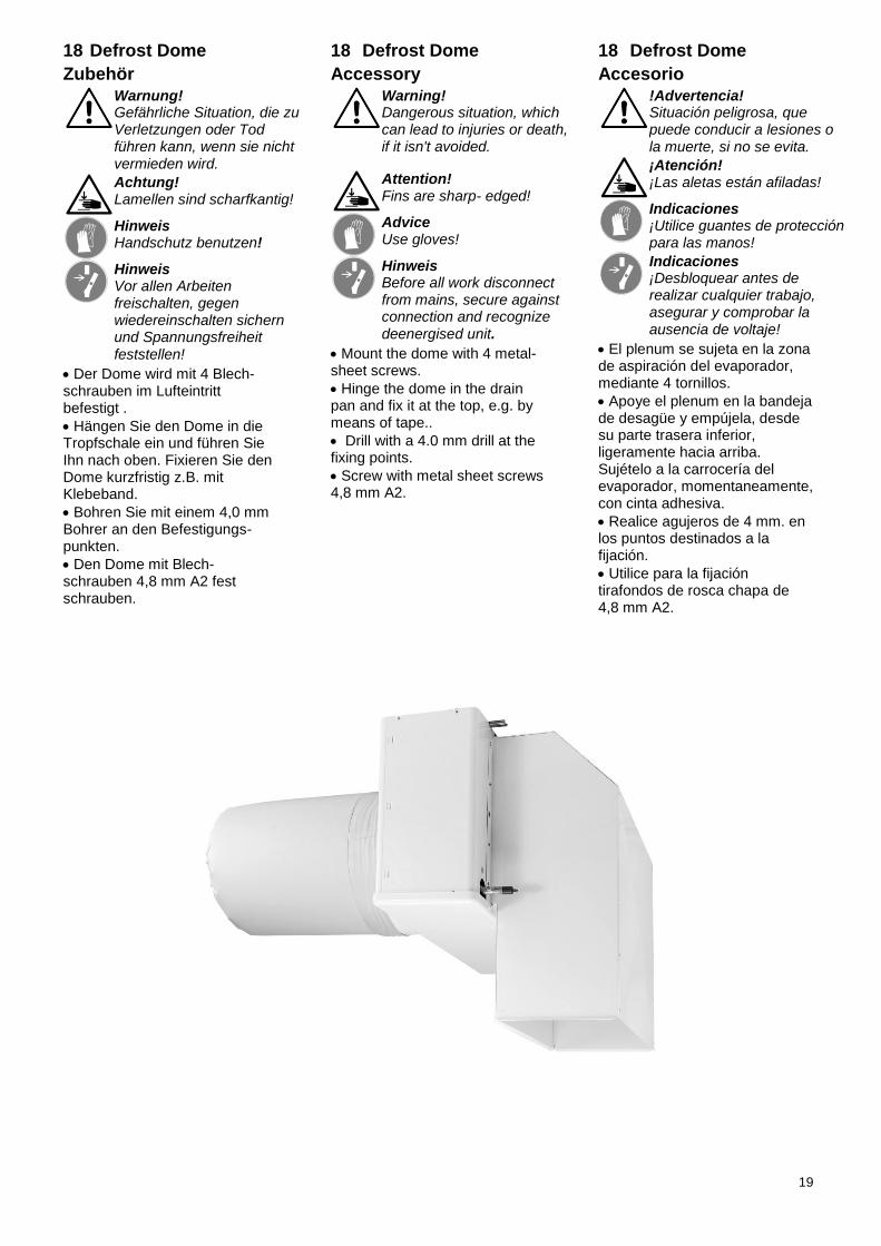
18 Defrost Dome
Zubehör
Warnung! Gefährliche Situation, die zu Verletzungen oder Tod führen kann, wenn sie nicht vermieden wird.
Achtung! Lamellen sind scharfkantig!
Hinweis Handschutz benutzen!
Hinweis Vor allen Arbeiten freischalten, gegen wiedereinschalten sichern und Spannungsfreiheit
feststellen!
Der Dome wird mit 4 Blech-schrauben im Lufteintritt befestigt .
Hängen Sie den Dome in die Tropfschale ein und führen Sie Ihn nach oben. Fixieren Sie den Dome kurzfristig z.B. mit Klebeband.
Bohren Sie mit einem 4,0 mm Bohrer an den Befestigungs-punkten.
Den Dome mit Blech-schrauben 4,8 mm A2 fest schrauben.
18 Defrost Dome
Accessory
Warning! Dangerous situation, which can lead to injuries or death, if it isn't avoided.
Attention! Fins are sharp- edged!
Advice Use gloves!
Hinweis Before all work disconnect from mains, secure against connection and recognize deenergised unit.
Mount the dome with 4 metal- sheet screws.
Hinge the dome in the drain pan and fix it at the top, e.g. by means of tape..
Drill with a 4.0 mm drill at the fixing points.
Screw with metal sheet screws 4,8 mm A2.
18 Defrost Dome
Accesorio
!Advertencia! Situación peligrosa, que puede conducir a lesiones o la muerte, si no se evita.
¡Atención! ¡Las aletas están afiladas!
Indicaciones ¡Utilice guantes de protección para las manos!
Indicaciones ¡Desbloquear antes de realizar cualquier trabajo, asegurar y comprobar la ausencia de voltaje!
El plenum se sujeta en la zona de aspiración del evaporador, mediante 4 tornillos.
Apoye el plenum en la bandeja de desagüe y empújela, desde su parte trasera inferior, ligeramente hacia arriba. Sujételo a la carrocería del evaporador, momentaneamente, con cinta adhesiva.
Realice agujeros de 4 mm. en los puntos destinados a la fijación.
Utilice para la fijación tirafondos de rosca chapa de 4,8 mm A2.
20
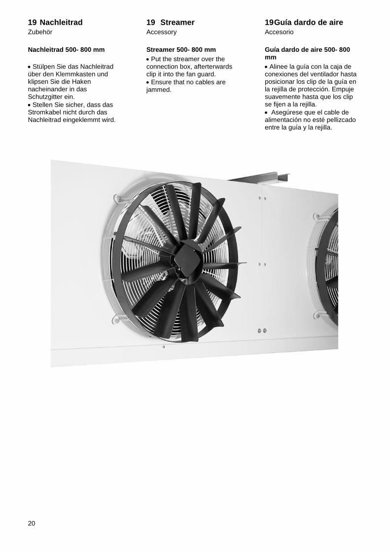
19 Nachleitrad Zubehör
Nachleitrad 500- 800 mm
Stülpen Sie das Nachleitrad über den Klemmkasten und klipsen Sie die Haken nacheinander in das Schutzgitter ein.
Stellen Sie sicher, dass das Stromkabel nicht durch das Nachleitrad eingeklemmt wird.
19 Streamer Accessory
Streamer 500- 800 mm
Put the streamer over the connection box, afterterwards clip it into the fan guard.
Ensure that no cables are jammed.
19 Guía dardo de aire Accesorio
Guía dardo de aire 500- 800 mm
Alinee la guía con la caja de conexiones del ventilador hasta posicionar los clip de la guía en la rejilla de protección. Empuje suavemente hasta que los clip se fijen a la rejilla.
Asegúrese que el cable de alimentación no esté pellizcado entre la guía y la rejilla.
21
20 Elektroanschluss
Warnung! Gefährliche Situation, die zu Verletzungen oder Tod führen kann, wenn sie nicht vermieden wird.
Achtung elektrischer Strom! Gefahr eines Stromschlages.
Hinweis Vor allen Arbeiten freischalten, gegen wiedereinschalten sichern und Spannungsfreiheit feststellen!
Der Elektroanschluss darf nur von einer Elektrofachkraft
durchgeführt werden.
Zuleitung mit genügend Sicherheitsabstand zum rotierenden Ventilator verlegen!
Bringen Sie immer zuerst einen Schutzleiter an.
Schließen Sie den Kühler nur an Stromkreise an, die mit einem allpolig trennenden Schalter abschaltbar sind.
Wir empfehlen Leitungsschutzschalter mit D- Charakteristik.
Verwenden Sie nur Leitungen, die den vorgeschriebenen Installationsvorschriften hinsichtlich Spannung, Strom, Isolationsmaterial, Belastbarkeit etc. entsprechen.
Lose Verbindungen und defekte Kabel sofort ersetzen.
Das Gerät erst 5 Minuten nach dem allpoligen Abschalten der Spannung öffnen.
Bei Arbeiten am Gerät auf eine Gummimatte stellen.
Vor Arbeiten am Gerät die Netzanschlüsse und PE kurzschließen.
20 Electric connection
Warning! Dangerous situation, which can lead to injuries or death, if it isn't avoided.
Attention electric voltage! Danger of electric shock.
Hinweis Before all work disconnect from mains, secure against connection and recognize deenergised unit.
The electric connection has to be done by an electrician.
Mount supply wire with enough
safety disctance to the fans.
Always mount the protective earth conductor first!
Mount the unit only to circuits that are equipped with circuit breaker.
We recommend circuit breakers type D.
Use only wires that are in conformity to installation rules in case of voltage, current, insulation materials, capacity, etc.
Replace loose connections and defective cables immediately.
Don’t open the unit till 5 minutes after switching off the power supply.
When working at the unit stand on a rubber mat.
Short circuit the conductors and PE before working on the unit.
20 Conexiones eléctricas
!Advertencia! Situación peligrosa, que puede conducir a lesiones o
la muerte, si no se evita.
¡Atención, voltaje eléctrico! Peligro de contacto eléctrico.
Indicaciones ¡Desbloquear antes de realizar cualquier trabajo, asegurar y comprobar la ausencia de voltaje!
La unidad deberá ser instalada sólo por personal técnico cualificado.
¡Realice el cableado adicional manteniendo suficiente distancia de seguridad a los ventiladores!
Instale siempre un cable conductor a tierra
La unidad se alimentará con una línea exclusiva equipada con interruptor de corte
Se recomienda interruptores de corte tipo D.
Utilice solamente mangueras eléctricas que cumplan la normativa eléctrica de voltaje, intensidad, aislamiento, capacidad, etc.
Reemplace inmediatamente las conexiones flojas o cables defectuosos.
No abra la unidad hasta que hayan transcurrido 5 minutos desde el corte del suministro eléctrico.
Para trabajar en el aparato, aislarse del suelo mediante una alfombrilla de goma.
Corte la tensión de alimentación mediante el interruptor correspondiente, antes de comenzar a trabajar en el aparato.
22
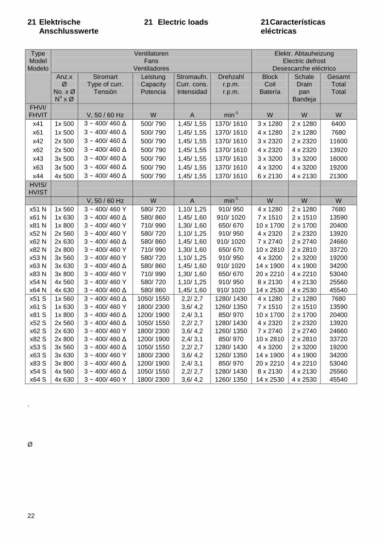
21 Elektrische Anschlusswerte
21 Electric loads 21 Características eléctricas
.
Ø
Type Model Modelo
Ventilatoren Fans
Ventiladores
Elektr. Abtauheizung Electric defrost
Desescarche eléctrico
Anz.x Ø
No. x Ø N
o x Ø
Stromart Type of curr.
Tensión
Leistung Capacity Potencia
Stromaufn. Curr. cons. Intensidad
Drehzahl r.p.m. r.p.m.
Block Coil
Batería
Schale Drain pan
Bandeja
Gesamt Total Total
FHVI/ FHVIT V, 50 / 60 Hz W A min
-1 W W W
x41 1x 500 3 ~ 400/ 460 Δ 500/ 790 1,45/ 1,55 1370/ 1610 3 x 1280 2 x 1280 6400
x61 1x 500 3 ~ 400/ 460 Δ 500/ 790 1,45/ 1,55 1370/ 1610 4 x 1280 2 x 1280 7680
x42 2x 500 3 ~ 400/ 460 Δ 500/ 790 1,45/ 1,55 1370/ 1610 3 x 2320 2 x 2320 11600
x62 2x 500 3 ~ 400/ 460 Δ 500/ 790 1,45/ 1,55 1370/ 1610 4 x 2320 4 x 2320 13920
x43 3x 500 3 ~ 400/ 460 Δ 500/ 790 1,45/ 1,55 1370/ 1610 3 x 3200 3 x 3200 16000
x63 3x 500 3 ~ 400/ 460 Δ 500/ 790 1,45/ 1,55 1370/ 1610 4 x 3200 4 x 3200 19200
x44 4x 500 3 ~ 400/ 460 Δ 500/ 790 1,45/ 1,55 1370/ 1610 6 x 2130 4 x 2130 21300
HVIS/ HVIST
V, 50 / 60 Hz W A min-1
W W W
x51 N 1x 560 3 ~ 400/ 460 Y 580/ 720 1,10/ 1,25 910/ 950 4 x 1280 2 x 1280 7680
x61 N 1x 630 3 ~ 400/ 460 Δ 580/ 860 1,45/ 1,60 910/ 1020 7 x 1510 2 x 1510 13590
x81 N 1x 800 3 ~ 400/ 460 Y 710/ 990 1,30/ 1,60 650/ 670 10 x 1700 2 x 1700 20400
x52 N 2x 560 3 ~ 400/ 460 Y 580/ 720 1,10/ 1,25 910/ 950 4 x 2320 2 x 2320 13920
x62 N 2x 630 3 ~ 400/ 460 Δ 580/ 860 1,45/ 1,60 910/ 1020 7 x 2740 2 x 2740 24660
x82 N 2x 800 3 ~ 400/ 460 Y 710/ 990 1,30/ 1,60 650/ 670 10 x 2810 2 x 2810 33720
x53 N 3x 560 3 ~ 400/ 460 Y 580/ 720 1,10/ 1,25 910/ 950 4 x 3200 2 x 3200 19200
x63 N 3x 630 3 ~ 400/ 460 Δ 580/ 860 1,45/ 1,60 910/ 1020 14 x 1900 4 x 1900 34200
x83 N 3x 800 3 ~ 400/ 460 Y 710/ 990 1,30/ 1,60 650/ 670 20 x 2210 4 x 2210 53040
x54 N 4x 560 3 ~ 400/ 460 Y 580/ 720 1,10/ 1,25 910/ 950 8 x 2130 4 x 2130 25560
x64 N 4x 630 3 ~ 400/ 460 Δ 580/ 860 1,45/ 1,60 910/ 1020 14 x 2530 4 x 2530 45540
x51 S 1x 560 3 ~ 400/ 460 Δ 1050/ 1550 2,2/ 2,7 1280/ 1430 4 x 1280 2 x 1280 7680
x61 S 1x 630 3 ~ 400/ 460 Y 1800/ 2300 3,6/ 4,2 1260/ 1350 7 x 1510 2 x 1510 13590
x81 S 1x 800 3 ~ 400/ 460 Δ 1200/ 1900 2,4/ 3,1 850/ 970 10 x 1700 2 x 1700 20400
x52 S 2x 560 3 ~ 400/ 460 Δ 1050/ 1550 2,2/ 2,7 1280/ 1430 4 x 2320 2 x 2320 13920
x62 S 2x 630 3 ~ 400/ 460 Y 1800/ 2300 3,6/ 4,2 1260/ 1350 7 x 2740 2 x 2740 24660
x82 S 2x 800 3 ~ 400/ 460 Δ 1200/ 1900 2,4/ 3,1 850/ 970 10 x 2810 2 x 2810 33720
x53 S 3x 560 3 ~ 400/ 460 Δ 1050/ 1550 2,2/ 2,7 1280/ 1430 4 x 3200 2 x 3200 19200
x63 S 3x 630 3 ~ 400/ 460 Y 1800/ 2300 3,6/ 4,2 1260/ 1350 14 x 1900 4 x 1900 34200
x83 S 3x 800 3 ~ 400/ 460 Δ 1200/ 1900 2,4/ 3,1 850/ 970 20 x 2210 4 x 2210 53040
x54 S 4x 560 3 ~ 400/ 460 Δ 1050/ 1550 2,2/ 2,7 1280/ 1430 8 x 2130 4 x 2130 25560
x64 S 4x 630 3 ~ 400/ 460 Y 1800/ 2300 3,6/ 4,2 1260/ 1350 14 x 2530 4 x 2530 45540
23
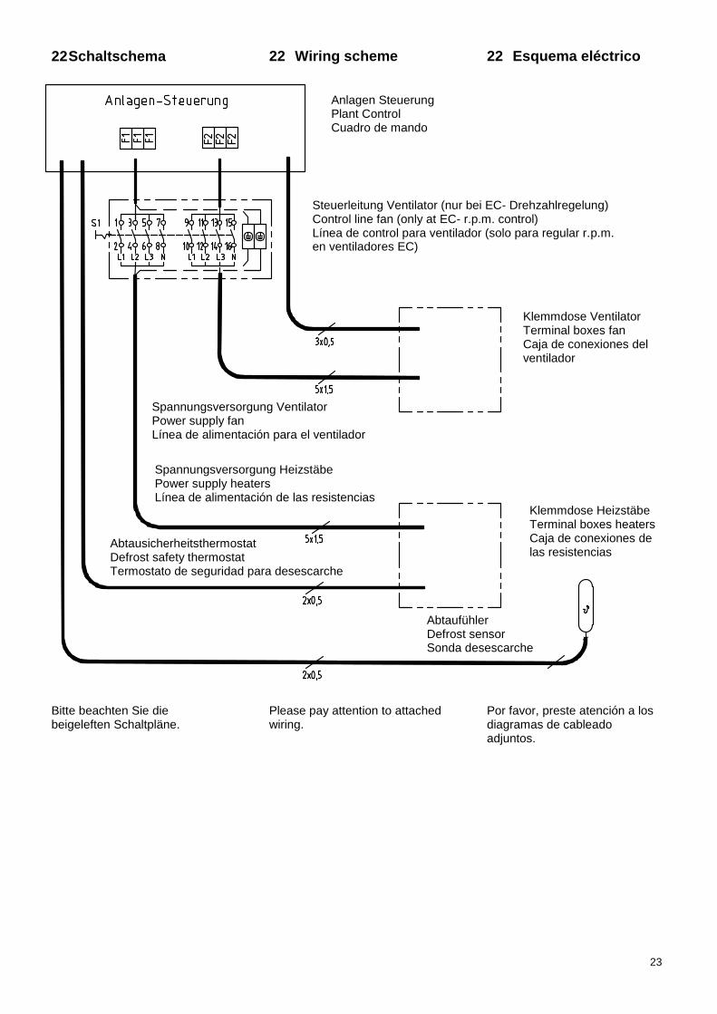
Spannungsversorgung Ventilator Power supply fan Línea de alimentación para el ventilador
Spannungsversorgung Heizstäbe Power supply heaters Línea de alimentación de las resistencias
22 Schaltschema 22 Wiring scheme 22 Esquema eléctrico
Bitte beachten Sie die beigeleften Schaltpläne.
Please pay attention to attached wiring.
Por favor, preste atención a los diagramas de cableado adjuntos.
Steuerleitung Ventilator (nur bei EC- Drehzahlregelung) Control line fan (only at EC- r.p.m. control) Línea de control para ventilador (solo para regular r.p.m. en ventiladores EC)
Abtausicherheitsthermostat Defrost safety thermostat Termostato de seguridad para desescarche
Abtaufühler Defrost sensor Sonda desescarche
Klemmdose Ventilator Terminal boxes fan Caja de conexiones del ventilador
Klemmdose Heizstäbe Terminal boxes heaters Caja de conexiones de las resistencias
Anlagen Steuerung Plant Control Cuadro de mando
24
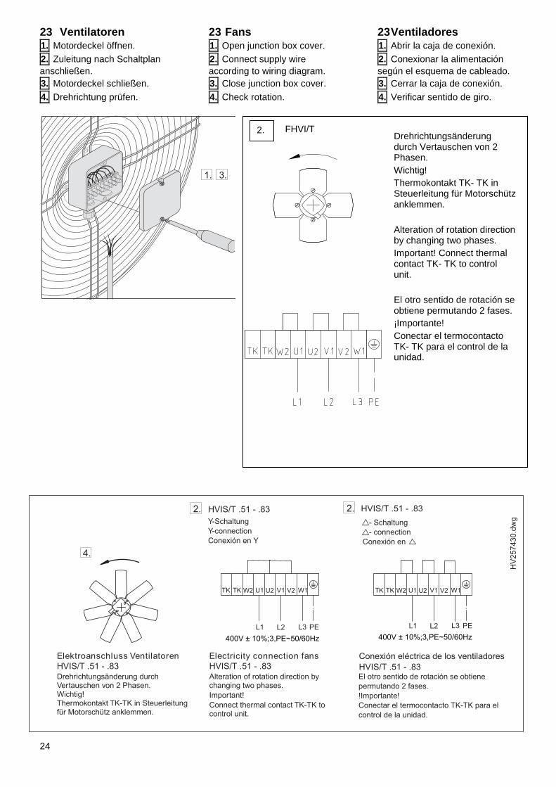
23 Ventilatoren 1. Motordeckel öffnen.
2. Zuleitung nach Schaltplan
anschließen.
3. Motordeckel schließen.
4. Drehrichtung prüfen.
23 Fans 1. Open junction box cover.
2. Connect supply wire
according to wiring diagram.
3. Close junction box cover.
4. Check rotation.
23 Ventiladores 1. Abrir la caja de conexión.
2. Conexionar la alimentación
según el esquema de cableado.
3. Cerrar la caja de conexión.
4. Verificar sentido de giro.
2. FHVI/T Drehrichtungsänderung durch Vertauschen von 2 Phasen.
Wichtig!
Thermokontakt TK- TK in Steuerleitung für Motorschütz anklemmen.
Alteration of rotation direction by changing two phases.
Important! Connect thermal contact TK- TK to control unit.
El otro sentido de rotación se obtiene permutando 2 fases.
¡Importante!
Conectar el termocontacto TK- TK para el control de la unidad.
25
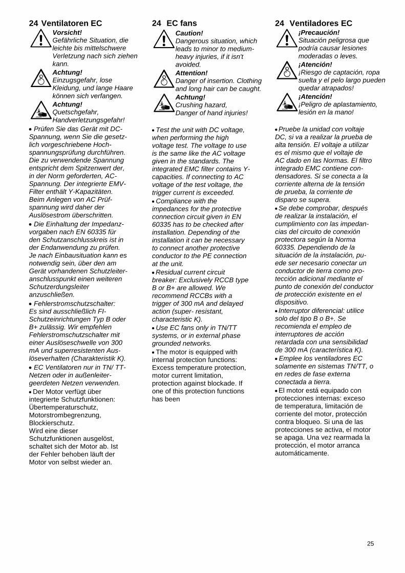
24 Ventilatoren EC
Vorsicht! Gefährliche Situation, die leichte bis mittelschwere Verletzung nach sich ziehen kann.
Achtung! Einzugsgefahr, lose Kleidung, und lange Haare können sich verfangen.
Achtung! Quetschgefahr, Handverletzungsgefahr!
Prüfen Sie das Gerät mit DC- Spannung, wenn Sie die gesetz-lich vorgeschriebene Hoch-spannungsprüfung durchführen. Die zu verwendende Spannung entspricht dem Spitzenwert der, in der Norm geforderten, AC- Spannung. Der integrierte EMV- Filter enthält Y-Kapazitäten. Beim Anlegen von AC Prüf-spannung wird daher der Auslösestrom überschritten.
Die Einhaltung der Impedanz-vorgaben nach EN 60335 für den Schutzanschlusskreis ist in der Endanwendung zu prüfen. Je nach Einbausituation kann es notwendig sein, über den am Gerät vorhandenen Schutzleiter-anschlusspunkt einen weiteren Schutzerdungsleiter anzuschließen.
Fehlerstromschutzschalter: Es sind ausschließlich FI- Schutzeinrichtungen Typ B oder B+ zulässig. Wir empfehlen Fehlerstromschutzschalter mit einer Auslöseschwelle von 300 mA und superresistenten Aus-löseverhalten (Charakteristik K).
EC Ventilatoren nur in TN/ TT- Netzen oder in außenleiter-geerdeten Netzen verwenden.
Der Motor verfügt über integrierte Schutzfunktionen: Übertemperaturschutz, Motorstrombegrenzung, Blockierschutz. Wird eine dieser Schutzfunktionen ausgelöst, schaltet sich der Motor ab. Ist der Fehler behoben läuft der Motor von selbst wieder an.
24 EC fans
Caution! Dangerous situation, which leads to minor to medium- heavy injuries, if it isn't avoided.
Attention! Danger of insertion. Clothing and long hair can be caught.
Achtung! Crushing hazard, Danger of hand injuries!
Test the unit with DC voltage, when performing the high voltage test. The voltage to use is the same like the AC voltage given in the standards. The integrated EMC filter contains Y- capacities. If connecting to AC voltage of the test voltage, the trigger current is exceeded.
Compliance with the impedances for the protective connection circuit given in EN 60335 has to be checked after installation. Depending of the installation it can be necessary to connect another protective conductor to the PE connection at the unit.
Residual current circuit breaker: Exclusively RCCB type B or B+ are allowed. We recommend RCCBs with a trigger of 300 mA and delayed action (super- resistant, characteristic K).
Use EC fans only in TN/TT systems, or in external phase grounded networks.
The motor is equipped with internal protection functions: Excess temperature protection, motor current limitation, protection against blockade. If one of this protection functions has been
24 Ventiladores EC
¡Precaución! Situación peligrosa que podría causar lesiones
moderadas o leves.
¡Atención! ¡Riesgo de captación, ropa suelta y el pelo largo pueden quedar atrapados!
¡Atención! ¡Peligro de aplastamiento, lesión en la mano!
Pruebe la unidad con voltaje DC, si va a realizar la prueba de alta tensión. El voltaje a utilizar es el mismo que el voltaje de AC dado en las Normas. El filtro integrado EMC contiene con-densadores. Si se conecta a la corriente alterna de la tensión de prueba, la corriente de disparo se supera.
Se debe comprobar, después de realizar la instalación, el cumplimiento con las impedan-cias del circuito de conexión protectora según la Norma 60335. Dependiendo de la situación de la instalación, pu-ede ser necesario conectar un conductor de tierra como pro-tección adicional mediante el punto de conexión del conductor de protección existente en el dispositivo.
Interruptor diferencial: utilice solo del tipo B o B+. Se recomienda el empleo de interruptores de acción retardada con una sensibilidad de 300 mA (característica K).
Emplee los ventiladores EC solamente en sistemas TN/TT, o en redes de fase externa
conectada a tierra.
El motor está equipado con protecciones internas: exceso de temperatura, limitación de corriente del motor, protección contra bloqueo. Si una de las protecciones se activa, el motor se apaga. Una vez rearmada la protección, el motor arranca automáticamente.
26
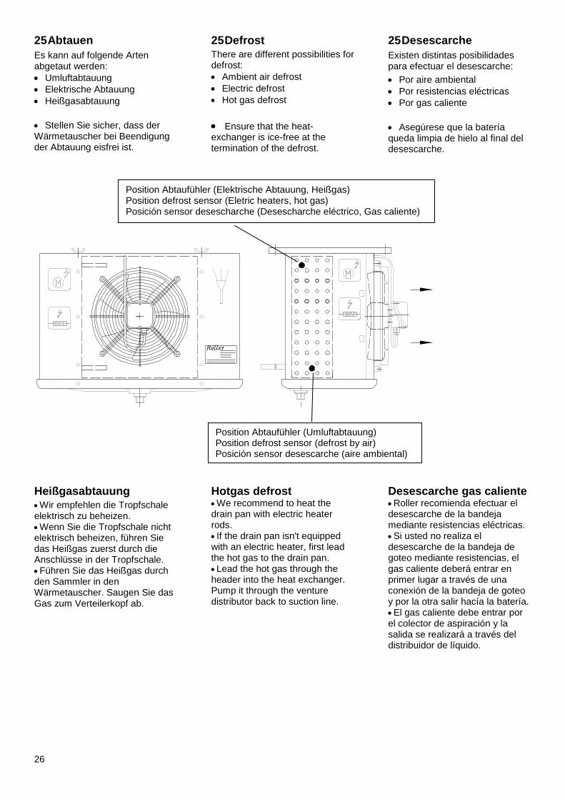
25 Abtauen
Es kann auf folgende Arten abgetaut werden:
Umluftabtauung
Elektrische Abtauung
Heißgasabtauung
Stellen Sie sicher, dass der Wärmetauscher bei Beendigung der Abtauung eisfrei ist.
25 Defrost There are different possibilities for defrost:
Ambient air defrost
Electric defrost
Hot gas defrost
Ensure that the heat- exchanger is ice-free at the termination of the defrost.
25 Desescarche
Existen distintas posibilidades para efectuar el desescarche:
Por aire ambiental
Por resistencias eléctricas
Por gas caliente
Asegúrese que la batería queda limpia de hielo al final del desescarche.
Heißgasabtauung Wir empfehlen die Tropfschale elektrisch zu beheizen. Wenn Sie die Tropfschale nicht elektrisch beheizen, führen Sie das Heißgas zuerst durch die Anschlüsse in der Tropfschale. Führen Sie das Heißgas durch den Sammler in den Wärmetauscher. Saugen Sie das Gas zum Verteilerkopf ab.
Hotgas defrost We recommend to heat the drain pan with electric heater rods. If the drain pan isn't equipped with an electric heater, first lead the hot gas to the drain pan. Lead the hot gas through the header into the heat exchanger. Pump it through the venture distributor back to suction line.
Desescarche gas caliente Roller recomienda efectuar el desescarche de la bandeja mediante resistencias eléctricas. Si usted no realiza el desescarche de la bandeja de goteo mediante resistencias, el gas caliente deberá entrar en primer lugar a través de una conexión de la bandeja de goteo y por la otra salir hacía la batería. El gas caliente debe entrar por el colector de aspiración y la salida se realizará a través del distribuidor de líquido.
Position Abtaufühler (Elektrische Abtauung, Heißgas) Position defrost sensor (Eletric heaters, hot gas) Posición sensor desescharche (Desescharche eléctrico, Gas caliente)
Position Abtaufühler (Umluftabtauung) Position defrost sensor (defrost by air) Posición sensor desescarche (aire ambiental)
27
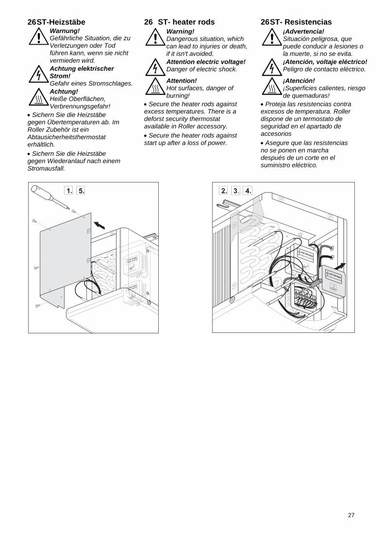
26 ST-Heizstäbe
Warnung! Gefährliche Situation, die zu Verletzungen oder Tod führen kann, wenn sie nicht vermieden wird.
Achtung elektrischer Strom! Gefahr eines Stromschlages.
Achtung! Heiße Oberflächen, Verbrennungsgefahr!
Sichern Sie die Heizstäbe gegen Übertemperaturen ab. Im Roller Zubehör ist ein Abtausicherheitsthermostat erhältlich.
Sichern Sie die Heizstäbe gegen Wiederanlauf nach einem Stromausfall.
26 ST- heater rods
Warning! Dangerous situation, which can lead to injuries or death, if it isn't avoided.
Attention electric voltage! Danger of electric shock.
Attention! Hot surfaces, danger of burning!
Secure the heater rods against excess temperatures. There is a deforst security thermostat available in Roller accessory.
Secure the heater rods against start up after a loss of power.
26 ST- Resistencias
¡Advertencia! Situación peligrosa, que puede conducir a lesiones o la muerte, si no se evita.
¡Atención, voltaje eléctrico! Peligro de contacto eléctrico.
¡Atención! ¡Superficies calientes, riesgo de quemaduras!
Proteja las resistencias contra excesos de temperatura. Roller dispone de un termostato de seguridad en el apartado de accesorios
Asegure que las resistencias no se ponen en marcha después de un corte en el suministro eléctrico.
28
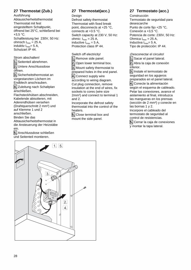
27 Thermostat (Zub.) Ausführung
Abtausicherheitsthermostat
Thermostat mit fest eingestelltem Schaltpunkt, öffnend bei 25°C, schließend bei +3,5 °C.
Schaltleistung bei 230V, 50 Hz: ohmsch Imax = 25 A, induktiv Imax= 5 A, Schutzart IP 44.
Strom abschalten!
1. Seitenteil abnehmen.
2. Untere Anschlussdose
öffnen.
3. Sicherheitsthermostat an
vorgestanzten Löchern im Endblech anschrauben.
4. Zuleitung nach Schaltplan
anschließen.
Flachsteckhülsen abschneiden, Kabelende abisolieren, mit Aderendhülsen versehen (Drahtquerschnitt 2 mm²) und auf Klemme 1 und 2 anschließen.
Binden Sie das Abtausicherheitsthermostat in die Ansteuerung der Heizstäbe ein.
5. Anschlussdose schließen
und Seitenteil montieren.
27 Thermostat(acc.)
Design
Defrost safety thermostat
Thermostat with fixed break point, disconnects at +25 °C, connects at +3.5 °C.
Switch capacity at 230 V, 50 Hz: ohmic: Imax = 25 A, inductive Imax = 5 A, Protection class IP 44.
Switch off electricity!
1. Remove side panel.
2. Open lower terminal box.
3. Mount safety thermostat to
prepared holes in the end panel.
4. Connect supply wire
according to wiring diagram.
Cut plug connection, remove insulation at the end of wires, fix sockets to cores (wire size 2mm²) and connect to terminal 1 and 2.
Incorporate the defrost safety thermostat into the control of the heaters.
5. Close terminal box and
mount the side panel.
27 Termostato (acc.)
Construcción
Termostato de seguridad para desescarche
Punto de corte fijo +25 °C, Conexión a +3,5 °C.
Potencia de corte: 230V, 50 Hz: Ohmica Imax = 25 A, Inductiva Imax= 5 A, Tipo de protección: IP 44.
¡Desconectar el circuito!
1. Sacar el panel lateral.
2. Abra la caja de conexión
inferior.
3. Instale el termostato de
seguridad en los agujeros preparados en el panel lateral.
4. Conecte la alimentación
según el esquema de cableado.
Pelar las conexiones, avance el aislamiento al final, introduzca las mangueras en los prensas (sección de 2 mm²) y conecte en las bornas 1 y 2.
Incorpore el cableado del termostato de seguridad al control de resistencias.
5. Cerrar la caja de conexiones
y montar la tapa lateral.
29
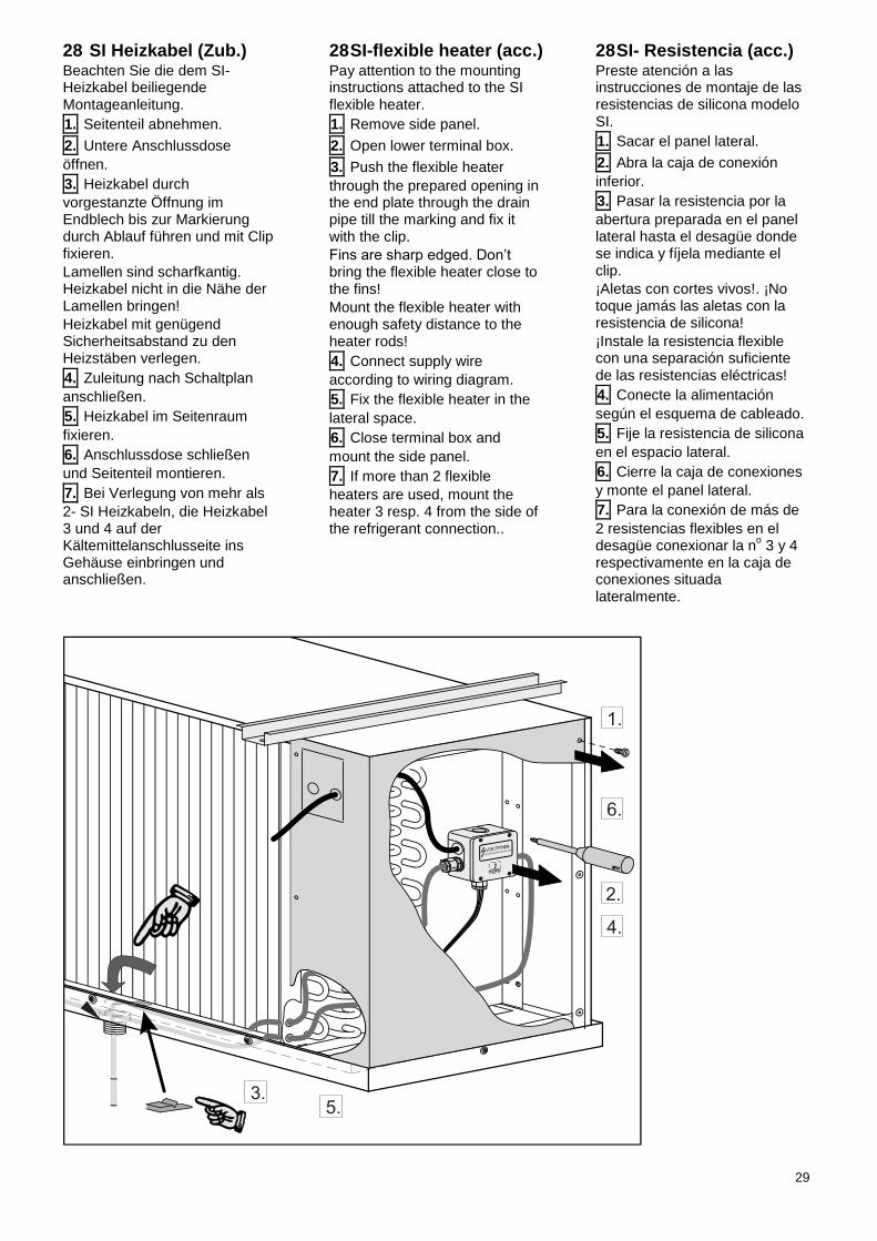
28 SI Heizkabel (Zub.) Beachten Sie die dem SI- Heizkabel beiliegende Montageanleitung.
1. Seitenteil abnehmen.
2. Untere Anschlussdose
öffnen.
3. Heizkabel durch
vorgestanzte Öffnung im Endblech bis zur Markierung durch Ablauf führen und mit Clip fixieren.
Lamellen sind scharfkantig. Heizkabel nicht in die Nähe der Lamellen bringen!
Heizkabel mit genügend Sicherheitsabstand zu den Heizstäben verlegen.
4. Zuleitung nach Schaltplan
anschließen.
5. Heizkabel im Seitenraum
fixieren.
6. Anschlussdose schließen
und Seitenteil montieren.
7. Bei Verlegung von mehr als
2- SI Heizkabeln, die Heizkabel 3 und 4 auf der Kältemittelanschlusseite ins Gehäuse einbringen und anschließen.
28 SI-flexible heater (acc.) Pay attention to the mounting instructions attached to the SI flexible heater.
1. Remove side panel.
2. Open lower terminal box.
3. Push the flexible heater
through the prepared opening in the end plate through the drain pipe till the marking and fix it with the clip.
Fins are sharp edged. Don’t bring the flexible heater close to the fins!
Mount the flexible heater with enough safety distance to the heater rods!
4. Connect supply wire
according to wiring diagram.
5. Fix the flexible heater in the
lateral space.
6. Close terminal box and
mount the side panel.
7. If more than 2 flexible
heaters are used, mount the heater 3 resp. 4 from the side of the refrigerant connection..
28 SI- Resistencia (acc.) Preste atención a las instrucciones de montaje de las resistencias de silicona modelo SI.
1. Sacar el panel lateral.
2. Abra la caja de conexión
inferior.
3. Pasar la resistencia por la
abertura preparada en el panel lateral hasta el desagüe donde se indica y fíjela mediante el clip.
¡Aletas con cortes vivos!. ¡No toque jamás las aletas con la resistencia de silicona!
¡Instale la resistencia flexible con una separación suficiente de las resistencias eléctricas!
4. Conecte la alimentación
según el esquema de cableado.
5. Fije la resistencia de silicona
en el espacio lateral.
6. Cierre la caja de conexiones
y monte el panel lateral.
7. Para la conexión de más de
2 resistencias flexibles en el desagüe conexionar la n
o 3 y 4
respectivamente en la caja de conexiones situada lateralmente.
30
29 Ringheizung ZH Zubehör FHVI/T
Warnung! Gefährliche Situation, die zu Verletzungen oder Tod führen kann, wenn sie nicht vermieden wird.
Achtung elektrischer Strom! Gefahr eines Stromschlages.
Achtung! Heiße Oberflächen, Verbrennungsgefahr!
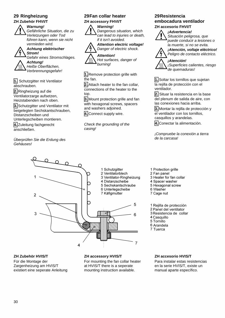
1. Schutzgitter mit Ventilator
abschrauben.
2. Ringheizung auf die
Ventilatorzarge aufsetzen, Heizstabenden nach oben.
3. Schutzgitter und Ventilator mit
beigelegten Sechskantschrauben, Distanzscheiben und Unterlegscheiben montieren.
4. Zuleitung fachgerecht
anschließen.
Überprüfen Sie die Erdung des Gehäuses!
29 Fan collar heater ZH accessory FHVI/T
Warning! Dangerous situation, which can lead to injuries or death, if it isn't avoided.
Attention electric voltage! Danger of electric shock.
Attention! Hot surfaces, danger of burning!
1. Remove protection grille with
the fan.
2. Attach heater to the fan collar,
connections of the heater to the top.
3. Mount protection grille and fan
with hexagonal screws, spacers and washers adjoined.
4. Connect supply wire.
Check the grounding of the casing!
29 Resistencia embocadura ventilador ZH accesorio FHVI/T
¡Advertencia! Situación peligrosa, que puede conducir a lesiones o la muerte, si no se evita.
¡Atención, voltaje eléctrico! Peligro de contacto eléctrico.
¡Atención! ¡Superficies calientes, riesgo de quemaduras!
1. Soltar los tornillos que sujetan
la rejilla de protección con el ventilador.
2. Situar la resistencia en la base
del plenum de salida de aire, con las conexiones hacia arriba.
3. Montar la rejilla de protección y
el ventilador con los tornillos, casquillos y arandelas.
4. Conectar la alimentación.
¡Compruebe la conexión a tierra de la carcasa!
ZH Zubehör HVIS/T
Für die Montage der Zargenheizung am HVIS/T existiert eine seperate Anleitung
ZH accessory HVIS/T
For mounting the fan collar heater at HVIS/T there is a seperate mounting instruction available.
ZH accesorio HVIS/T
Para instalar estas resistencias en la serie HVIS/T, existe un manual aparte específico.
31
30 Inbetriebnahme Der Elektroanschluss muss fachgerecht abgeschlossen sein.
Vergewissern Sie sich, dass alle Deckel und Seitenteile montiert sind.
Prüfen Sie die Befestigung des Schutzgitters.
Die Tropfschale muss auf beiden Seiten eingehängt und fest verschraubt sein.
Achtung!
Anlage darf nur in betriebssicheren Zustand in Betrieb genommen werden.
Anlage einschalten.
Überprüfung der Überhitzung des Kältemittels am Austritt.
Herstellerangaben des Expansionsventils beachten!
Einstellung des Expansionsventils auf die Überhitzung:
Δtsup = 0,5....................0,7 x DT1
DT1 ≥ 12 K DT1 ≥ 6 K
Δtsup Überhitzung des Kältemittels am Austritt.
DT1 Eintrittstemperaturdifferenz = Lufteintrittstemperatur - Verdampfungstemperatur am Austritt (Sättigungstemperatur).
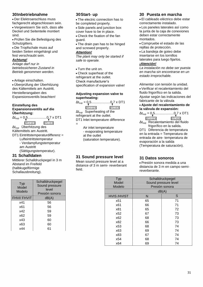
31 Schalldaten Mittlerer Schalldruckpegel in 3 m Abstand im Freifeld (halbkugelförmige Schallausbreitung).
30 Start- up The electric connection has to be completed properly.
Side panels and junction box cover have to be in place.
Check the fixation of the fan guard.
The drain pan has to be hinged and screwed properly.
Attention!
The plant may only be started if safe to operate.
Turn the unit on.
Check superheat of the refrigerant at the outlet.
Check manufacturer’s specification of expansion valve!
Adjusting expansion valve to superheating:
Δtsup = 0,5....................0,7 x DT1
DT1 ≥ 12 K DT1 ≥ 6 K
Δtsup Superheating of the refrigerant at the outlet.
DT1 Inlet temperature difference = Air inlet temperature - evaporating temperature at the outlet (saturation temperature).
31 Sound pressure level Mean sound pressure level at a distance of 3 m semi- reverberant field.
30 Puesta en marcha El cableado eléctrico debe estar correctamente instalado.
Los paneles laterales así como la junta de la caja de conexiones deben estar correctamente montados.
Compruebe el estado de las rejillas de protección.
La bandeja de goteo debe insertarse en los tornillos laterales para luego fijarlos.
¡Atención!
La instalación no debe ser puesta en marcha sin encontrarse en un estado irreprochable.
Alimentar con tensión la unidad.
Verificar el recalentamiento del fluido frigorífico en la salida.
Ajustar según las indicaciones del fabricante de la válvula
Ajuste del recalentamiento de la válvula de expansión:
Δtsup = 0,5....................0,7 x DT1
DT1 ≥ 12 K DT1 ≥ 6 K
Δtsup Recalentamiento del fluido frigorífico en la salida. DT1 Diferencia de temperatura en la entrada = Temperatura de entrada de aire- temperatura de evaporación a la salida (Temperatura de saturación).
31 Datos sonoros Presión sonora medida a una distancia de 3 m en campo semi- reverberante.
Typ Model Modelo
Schalldruckpegel Sound pressure
level Presión sonora
FHVI/ FHVIT dB(A)
x41 56
x61 56
x42 59
x62 59
x43 60
x63 60
x44 61
Typ Model Modelo
Schalldruckpegel Sound pressure level
Presión sonora
dB(A)
HVIS /HVIST N S
x51 65 71
x61 66 71
x81 65 72
x52 67 73
x62 68 73
x82 66 73
x53 68 74
x63 69 74
x83 67 74
x54 68 74
x64 69 74
32
32 Reinigung
Warnung! Gefährliche Situation, die zu Verletzungen oder Tod führen kann, wenn sie nicht vermieden wird.
Achtung! Handverletzungsgefahr! Lamellen sind scharfkantig.
Achtung elektrischer Strom! Gefahr eines Stromschlages.
Hinweis Vor allen Arbeiten freischalten, gegen wiedereinschalten sichern und Spannungsfreiheit feststellen!
Anlage darf nur von autorisiertem Fachpersonal gewartet werden.
Die Häufigkeit der Reinigung des Luftkühlers hängt vom Einsatzgebiet ab. Eine Reinigung sollte zumindest quartalsweise durchgeführt werden.
Reinigung des Ventilators:
Beschädigung des Ventilators bei Reinigung und damit einhergehende Fehlfunktionen sind möglich.
Reinigen Sie den Ventilator nicht mit einem Wasserstrahl oder Hochdruckreiniger.
Verwenden Sie keine säure-, laugen- und lösungsmittel-haltigen Reinigungsmittel.
Überprüfen Sie den Ventilator auf Unwucht.
Reinigung des Lamellenblockes:
Demontieren oder schwenken Sie die Ventilatoren zur Reinig-ung des Lamellenblockes ab oder demontieren Sie beide Tropfschalen ab.
Reinigen Sie das Gerät mit Wasser oder speziell für Kupfer- Aluminium Wärmetauscher freigegebenen Reinigungs-mitteln.
Verwenden Sie keinesfalls chlorhaltige Reinigungsmittel.
Achten Sie darauf, dass die Lamellen nicht verbogen werden.
Spülen Sie den Wärme-tauscher nach der Reinigung gründlich mit klarem Wasser ab.
32 Cleaning
Warning Dangerous situation, which leads to injuries or death, if it isn't avoided.
Attention! Hand injury possible. Fins are sharp-edged.
Attention electric voltage! Danger of electric shock.
Advice Prior to working on the unit, switch off the electricity and secure against unauthorized connecting.
Unit may only be serviced and repaired by authorized and skilled personnel.
The frequency of cleaning of the air cooler depends on its application. A cleaning should be done at least every three months.
Cleaning of the fan:
Damage to the fan and malfunction afterwards is possible.
Don’t clean the fan by means of a high pressure cleaner.
Don’t use purifier that contains acid, base or dilution.
Check the fan balance.
Cleaning of the coil block
Disassemble or swivel the fans to clean the coil block or demount the drain pans.
Clean the device by means of water or special copper aluminium heat exchanger purifier.
Never use chlorine containing purifiers.
Pay attention that the fins don’t get deformed.
Flush the heat exchanger well with water after cleaning it.
32 Limpieza
¡Advertencia! Situación peligrosa, que puede conducir a lesiones o la muerte, si no se evita.
¡Atención! ¡Peligro de aplastamiento, lesión en la mano!
¡Atención, voltaje eléctrico! Peligro de contacto eléctrico.
Indicaciones Desconecte la unidad antes de cada intervención, asegurándose que no se pueda conectar por personal no autorizado.
La unidad no debe ser instalada más que por personal autorizado.
La frecuencia de limpieza dependerá de la aplicación. Se recomienda al menos 1 vez cada tres meses.
Limpieza de los ventiladores:
Es posible un fallo en los ventiladores después de haber efectuado la limpieza.
No efectúe la limpieza de los ventiladores con agua o aire a presión.
No utilice limpiadores agresivos, con ácidos, bases ó disoluciones.
Compruebe el equilibrado del aspa del ventilador.
Limpieza de las aletas de la batería:
Desmontar o abrir mediante las bisagras los ventiladores para limpiar las aletas de la batería y desmontar ambas bandejas.
Limpiar la carrocería del aparato con agua ó con productos específicos para el cobre-aluminio.
No utilice detergentes con cloro.
Ponga especial atención en no doblar las aletas.
Aclare el intercambiador con agua, después de realizar la limpieza.
33
33 Wartungsintervalle Anlage darf nur von autorisiertem Fachpersonal gewartet und repariert werden.
Mindestens halbjährlich sind folgende Wartungstätigkeiten durchzuführen:
Befestigung der Anlage.
Befestigung des Ventilators.
Berührungsschutz
Elektroanschlüsse.
Befestigung des Schutzleiters.
Kondenswasserbohrung des Ventilators.
Kondensatablauf des Kühlers.
Dichtigkeit der Anlage.
Überhitzungseinstellung.
33 Service interval The unit may only be serviced and repaired by authorized and skilled personnel.
At least every 6 months the following services have to be done.
Check the:
Mounting of the unit.
Mounting of the fans.
Protection cover.
Electric connections.
Mounting of the protection conductor.
Condensate draining hole of the fan.
Condensate draining of the cooler
Leaks in the unit.
Adjustment of the superheat.
33 Revisión periódica
La unidad no debe ser instalada ni reparada más que por personal autorizado.
Se deben realizar las siguientes revisiones al menos cada 6 meses:
Fijación de la unidad
Fijación de los ventiladores.
Rejillas de protección.
Conexionado eléctrico.
Contactores y protectores térmicos.
Condensaciones en los ventiladores.
Desagüe del evaporador
Estanquidad de la unidad.
Ajuste del recalentamiento.
34 Entsorgung Bevor Sie den Luftkühler demontieren, entfernen Sie die Wärmetauscher enthaltenen Medien und führen sie der Wiederverwertung zu. Beachten Sie bei der Entsorgung des Gerätes alle relevanten, in ihrem Land geltenden Anforderungen und Bestimmungen.
34 Disposal Before dismounting the air cooler, remove all fluids inside the heat exchanger and dispose them in a correct way.
When disposing the device, please comply with all relevant requirements and regulations applicable in your country.
34 Fin del periodo útil del evaporador Cuando el aparato se deba sustituir por este motivo, recupere el refrigerante y el aceite y entréguelos a un gestor de residuos.
Cumpla con la normativa y las regulaciones para el reciclado y eliminación de residuos vigente en su país.
34
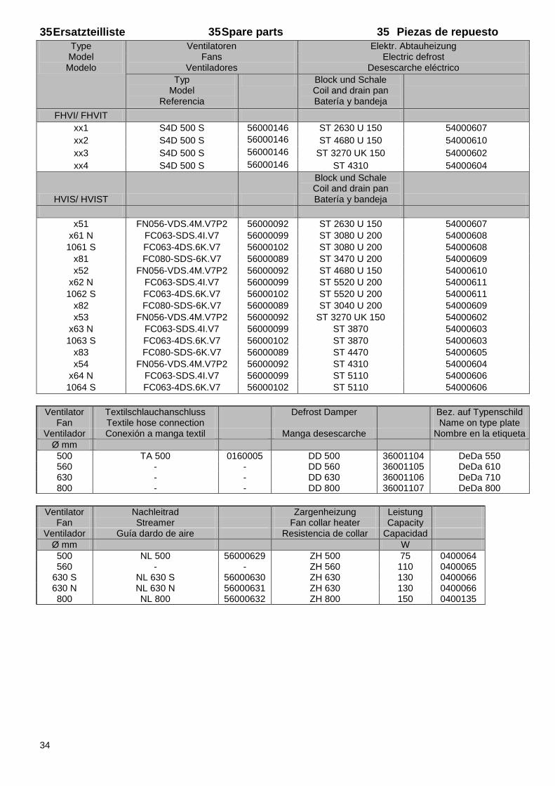
35 Ersatzteilliste 35 Spare parts 35 Piezas de repuesto
Type Model Modelo
Ventilatoren Fans
Ventiladores
Elektr. Abtauheizung Electric defrost
Desescarche eléctrico
Typ Model
Referencia
Block und Schale Coil and drain pan Batería y bandeja
FHVI/ FHVIT
xx1 S4D 500 S 56000146 ST 2630 U 150 54000607
xx2 S4D 500 S 56000146 ST 4680 U 150 54000610
xx3 S4D 500 S 56000146 ST 3270 UK 150 54000602
xx4 S4D 500 S 56000146 ST 4310 54000604
HVIS/ HVIST
Block und Schale Coil and drain pan Batería y bandeja
x51 FN056-VDS.4M.V7P2 56000092 ST 2630 U 150 54000607
x61 N FC063-SDS.4I.V7 56000099 ST 3080 U 200 54000608
1061 S FC063-4DS.6K.V7 56000102 ST 3080 U 200 54000608
x81 FC080-SDS-6K.V7 56000089 ST 3470 U 200 54000609
x52 FN056-VDS.4M.V7P2 56000092 ST 4680 U 150 54000610
x62 N FC063-SDS.4I.V7 56000099 ST 5520 U 200 54000611
1062 S FC063-4DS.6K.V7 56000102 ST 5520 U 200 54000611
x82 FC080-SDS-6K.V7 56000089 ST 3040 U 200 54000609
x53 FN056-VDS.4M.V7P2 56000092 ST 3270 UK 150 54000602
x63 N FC063-SDS.4I.V7 56000099 ST 3870 54000603
1063 S FC063-4DS.6K.V7 56000102 ST 3870 54000603
x83 FC080-SDS-6K.V7 56000089 ST 4470 54000605
x54 FN056-VDS.4M.V7P2 56000092 ST 4310 54000604
x64 N FC063-SDS.4I.V7 56000099 ST 5110 54000606
1064 S FC063-4DS.6K.V7 56000102 ST 5110 54000606
Ventilator Textilschlauchanschluss Defrost Damper
Bez. auf Typenschild Fan Textile hose connection
Name on type plate
Ventilador Conexión a manga textil Manga desescarche
Nombre en la etiqueta
Ø mm
500 TA 500 0160005 DD 500 36001104 DeDa 550 560 - - DD 560 36001105 DeDa 610 630 - - DD 630 36001106 DeDa 710 800 - - DD 800 36001107 DeDa 800
Ventilator Nachleitrad Zargenheizung Leistung Fan Streamer Fan collar heater Capacity
Ventilador Guía dardo de aire Resistencia de collar Capacidad
Ø mm
W
500 NL 500 56000629 ZH 500 75 0400064 560 - - ZH 560 110 0400065
630 S NL 630 S 56000630 ZH 630 130 0400066 630 N NL 630 N 56000631 ZH 630 130 0400066 800 NL 800 56000632 ZH 800 150 0400135
35
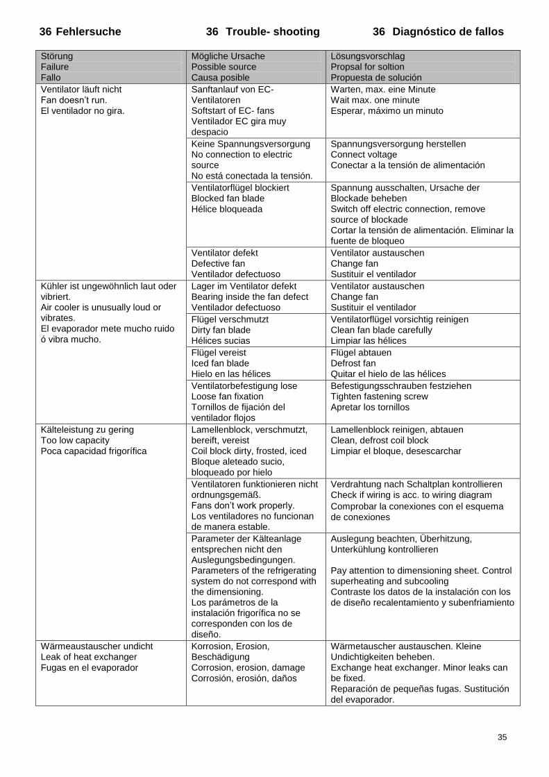
36 Fehlersuche 36 Trouble- shooting 36 Diagnóstico de fallos
Störung Failure Fallo
Mögliche Ursache Possible source Causa posible
Lösungsvorschlag Propsal for soltion Propuesta de solución
Ventilator läuft nicht Fan doesn’t run. El ventilador no gira.
Sanftanlauf von EC- Ventilatoren Softstart of EC- fans Ventilador EC gira muy despacio
Warten, max. eine Minute Wait max. one minute Esperar, máximo un minuto
Keine Spannungsversorgung No connection to electric source No está conectada la tensión.
Spannungsversorgung herstellen Connect voltage Conectar a la tensión de alimentación
Ventilatorflügel blockiert Blocked fan blade Hélice bloqueada
Spannung ausschalten, Ursache der Blockade beheben Switch off electric connection, remove source of blockade Cortar la tensión de alimentación. Eliminar la fuente de bloqueo
Ventilator defekt Defective fan Ventilador defectuoso
Ventilator austauschen Change fan Sustituir el ventilador
Kühler ist ungewöhnlich laut oder vibriert. Air cooler is unusually loud or vibrates. El evaporador mete mucho ruido ó vibra mucho.
Lager im Ventilator defekt Bearing inside the fan defect Ventilador defectuoso
Ventilator austauschen Change fan Sustituir el ventilador
Flügel verschmutzt Dirty fan blade Hélices sucias
Ventilatorflügel vorsichtig reinigen Clean fan blade carefully Limpiar las hélices
Flügel vereist Iced fan blade Hielo en las hélices
Flügel abtauen Defrost fan Quitar el hielo de las hélices
Ventilatorbefestigung lose Loose fan fixation Tornillos de fijación del ventilador flojos
Befestigungsschrauben festziehen Tighten fastening screw Apretar los tornillos
Kälteleistung zu gering Too low capacity Poca capacidad frigorífica
Lamellenblock, verschmutzt, bereift, vereist Coil block dirty, frosted, iced Bloque aleteado sucio, bloqueado por hielo
Lamellenblock reinigen, abtauen Clean, defrost coil block Limpiar el bloque, desescarchar
Ventilatoren funktionieren nicht ordnungsgemäß. Fans don’t work properly. Los ventiladores no funcionan de manera estable.
Verdrahtung nach Schaltplan kontrollieren Check if wiring is acc. to wiring diagram
Comprobar la conexiones con el esquema de conexiones
Parameter der Kälteanlage entsprechen nicht den Auslegungsbedingungen. Parameters of the refrigerating system do not correspond with the dimensioning. Los parámetros de la instalación frigorífica no se corresponden con los de diseño.
Auslegung beachten, Überhitzung, Unterkühlung kontrollieren Pay attention to dimensioning sheet. Control superheating and subcooling Contraste los datos de la instalación con los de diseño recalentamiento y subenfriamiento
Wärmeaustauscher undicht Leak of heat exchanger Fugas en el evaporador
Korrosion, Erosion, Beschädigung Corrosion, erosion, damage Corrosión, erosión, daños
Wärmetauscher austauschen. Kleine Undichtigkeiten beheben. Exchange heat exchanger. Minor leaks can be fixed. Reparación de pequeñas fugas. Sustitución del evaporador.
36
Technische Änderungen und Verbesserungen vorbehalten.
Subject to technical alterations and improvements.
Reservado el derecho de cambio y de mejoras técnicas.
Walter Roller GmbH & Co. Fabrik für Kälte- und Klimageräte Lindenstr. 27-31 D- 70839 Gerlingen Postfach 10 03 30 D- 70828 Gerlingen Telefon (0 71 56) 20 01- 0 Telefax (0 71 56) 20 01- 26 E-mail [email protected] http://www.walterroller.de
Walter Roller GmbH & Co. Fabrik für Kälte- und Klimageräte
12.2
016
88
000
212
02.2
013
88
000
161
02.2
013
88
000
161
02.2
013
88
000
161
Looking for another language?
Request your copy: [email protected]
Est- ce que vous cherchez la instruction de montage en
français?
Demandez votre copie: [email protected]
มองหาภาษาไทยสามารถขอส าเนา ได้ที ่: [email protected]
您需要中文版本?
请发电子邮件索求
Top Related