


Sprachen
Seiten
Rechtliche

MVA GmbH • Mess- und Verfahrenstechnik Lochhamer Schlag 6 • D-82166 Gräfelfing Fon: +49/89-85 83 69-0 • Fax: +49/89-85 83 69-70 [email protected] • www.mva-messvt.de
2
MVA GmbH Mess- und Verfahrenstechnik Lochhamer Schlag 6 • D-82166 Gräfelfing
Rückschlagklappen 932 Rev.01 0813 DD
Fon: +49/89-85 83 69 -0 • Fax: +49/89-85 83 69 -70 [email protected] • www.mva-messvt.de
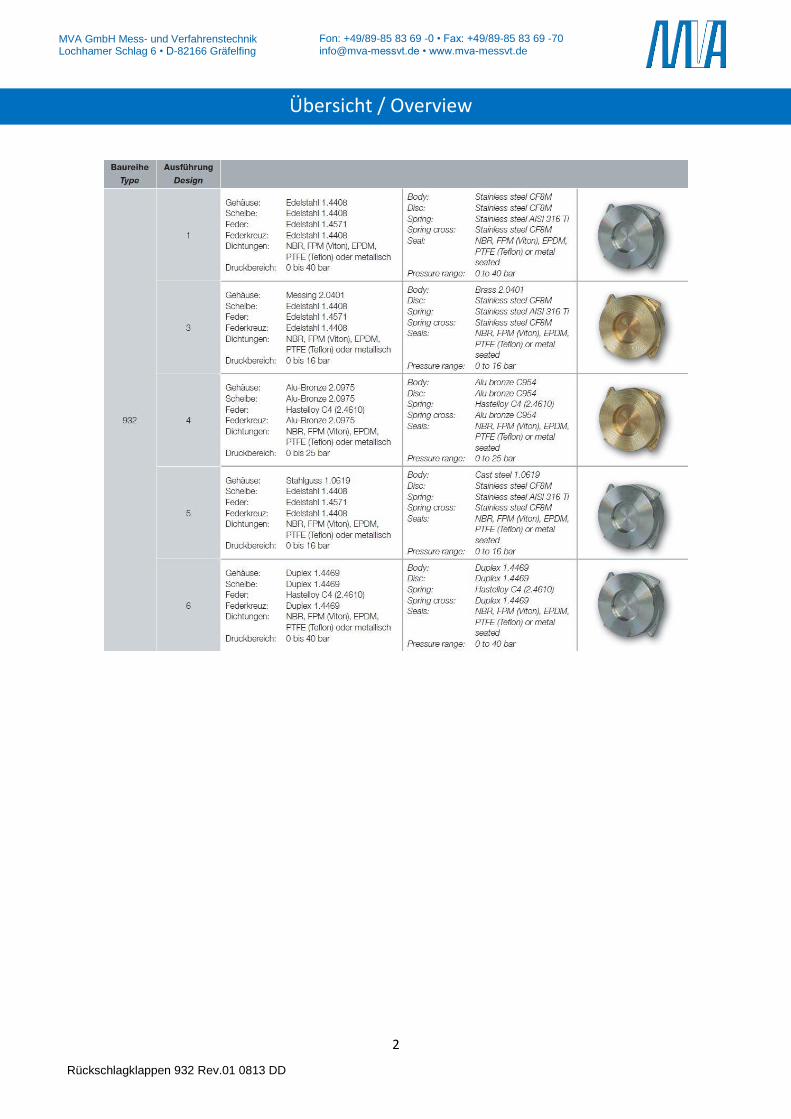
Übersicht / Overview
3
MVA GmbH Mess- und Verfahrenstechnik Lochhamer Schlag 6 • D-82166 Gräfelfing
Rückschlagklappen 932 Rev.01 0813 DD
Fon: +49/89-85 83 69 -0 • Fax: +49/89-85 83 69 -70 [email protected] • www.mva-messvt.de
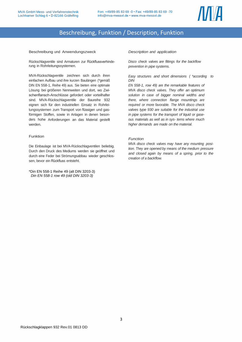
Beschreibung und Anwendungszweck
Rückschlagventile sind Armaturen zur Rückflussverhinde-rung in Rohrleitungssystemen.
MVA-Rückschlagventile zeichnen sich durch ihren
einfachen Aufbau und ihre kurzen Baulängen (*gemäß
DIN EN 558-1, Reihe 49) aus. Sie bieten eine optimale
Lösung bei größeren Nennweiten und dort, wo Zwi-
schenflansch-Anschlüsse gefordert oder vorteilhafter
sind. MVA-Rückschlagventile der Baureihe 932
eignen sich für den industriellen Einsatz in Rohrlei-
tungssystemen zum Transport von flüssigen und gas-
förmigen Stoffen, sowie in Anlagen in denen beson-
ders hohe Anforderungen an das Material gestellt
werden.
Funktion
Die Einbaulage ist bei MVA-Rückschlagventilen beliebig.
Durch den Druck des Mediums werden sie geöffnet und
durch eine Feder bei Strömungsabbau wieder geschlos-
sen, bevor ein Rückfluss entsteht.
Description and application
Disco check valves are fittings for the backflow
prevention in pipe systems.
Easy structures and short dimensions ( *according to DIN
EN 558-1, row 49) are the remarkable features of
MVA disco check valves. They offer an optimum
solution in case of bigger nominal widths and
there, where connection flange mountings are
required or more favorable. The MVA disco check
valves type 930 are suitable for the industrial use
in pipe systems for the transport of liquid or gase-
ous materials as well as in sys- tems where much
higher demands are made on the material.
Function
MVA disco check valves may have any mounting posi-
tion. They are opened by means of the medium pressure
and closed again by means of a spring, prior to the
creation of a backflow.
*Din EN 558-1 Reihe 49 (alt DIN 3203-3) Din EN 558-1 row 49 (old DIN 3203-3)
Beschreibung, Funktion / Description, Funktion
4
MVA GmbH Mess- und Verfahrenstechnik Lochhamer Schlag 6 • D-82166 Gräfelfing
Rückschlagklappen 932 Rev.01 0813 DD
Fon: +49/89-85 83 69 -0 • Fax: +49/89-85 83 69 -70 [email protected] • www.mva-messvt.de
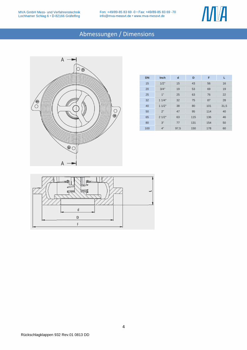
DN Inch d D F L
15 1/2" 15 43 56 16 20 3/4" 19 53 69 19 25 1" 25 63 76 22 32 1 1/4" 32 75 87 28 40 1 1/2" 38 80 101 31,5 50 2" 47 95 114 40 65 2 1/2" 63 115 136 46 80 3" 77 131 154 50 100 4" 97,5 150 178 60
Abmessungen / Dimensions
5
MVA GmbH Mess- und Verfahrenstechnik Lochhamer Schlag 6 • D-82166 Gräfelfing
Rückschlagklappen 932 Rev.01 0813 DD
Fon: +49/89-85 83 69 -0 • Fax: +49/89-85 83 69 -70 [email protected] • www.mva-messvt.de
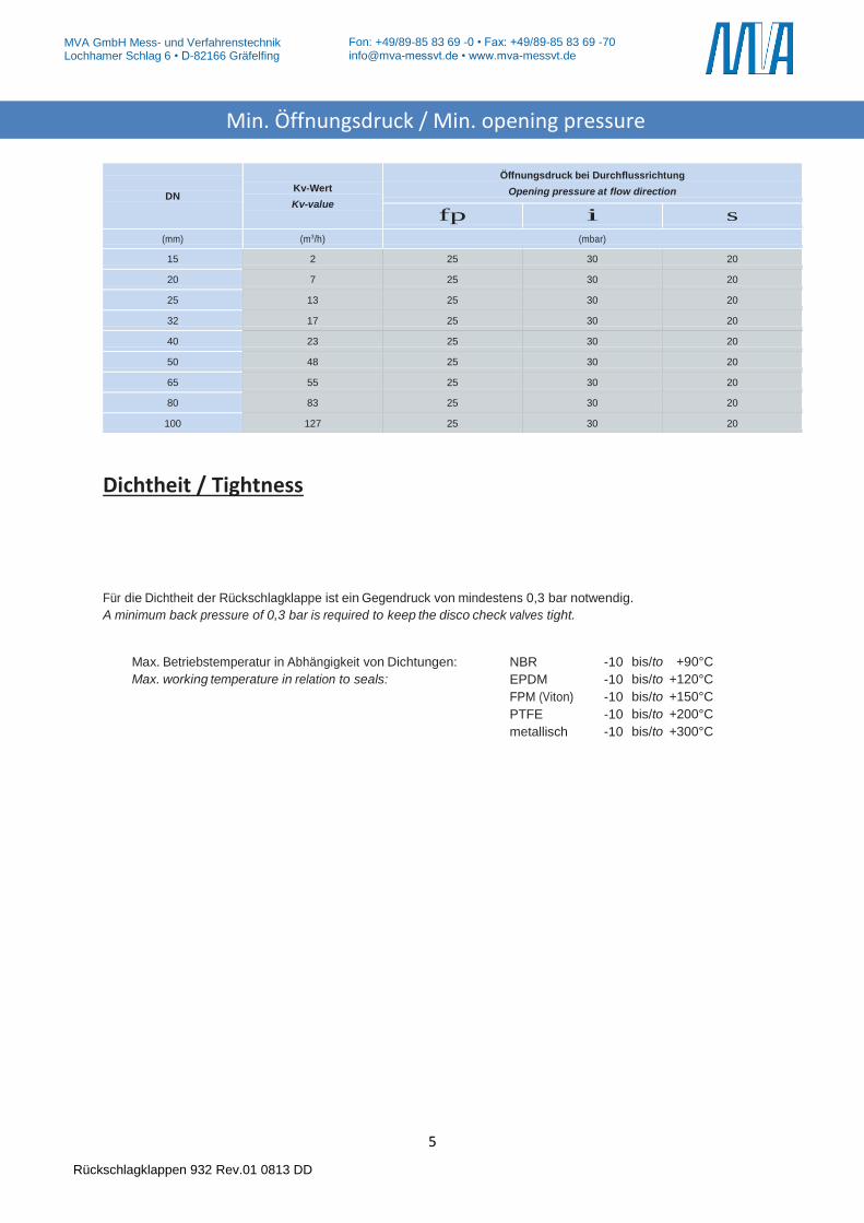
Dichtheit / Tightness
Für die Dichtheit der Rückschlagklappe ist ein Gegendruck von mindestens 0,3 bar notwendig.
A minimum back pressure of 0,3 bar is required to keep the disco check valves tight.
Max. Betriebstemperatur in Abhängigkeit von Dichtungen: NBR -10 bis/to +90°C Max. working temperature in relation to seals: EPDM -10 bis/to +120°C
FPM (Viton) -10 bis/to +150°C
PTFE -10 bis/to +200°C
metallisch -10 bis/to +300°C
DN
Kv-Wert
Kv-value
Öffnungsdruck bei Durchflussrichtung
Opening pressure at flow direction
fp i s
(mm) (m3/h) (mbar)
15 2 25 30 20
20 7 25 30 20
25 13 25 30 20
32 17 25 30 20
40 23 25 30 20
50 48 25 30 20
65 55 25 30 20
80 83 25 30 20
100 127 25 30 20
Min. Öffnungsdruck / Min. opening pressure
6
MVA GmbH Mess- und Verfahrenstechnik Lochhamer Schlag 6 • D-82166 Gräfelfing
Rückschlagklappen 932 Rev.01 0813 DD
Fon: +49/89-85 83 69 -0 • Fax: +49/89-85 83 69 -70 [email protected] • www.mva-messvt.de
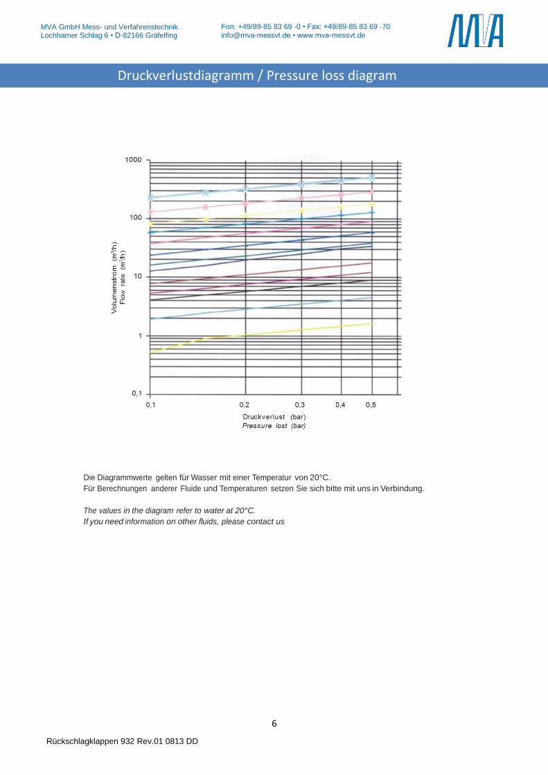
Die Diagrammwerte gelten für Wasser mit einer Temperatur von 20°C.
Für Berechnungen anderer Fluide und Temperaturen setzen Sie sich bitte mit uns in Verbindung.
The values in the diagram refer to water at 20°C.
If you need information on other fluids, please contact us
Druckverlustdiagramm / Pressure loss diagram
7
MVA GmbH Mess- und Verfahrenstechnik Lochhamer Schlag 6 • D-82166 Gräfelfing
Rückschlagklappen 932 Rev.01 0813 DD
Fon: +49/89-85 83 69 -0 • Fax: +49/89-85 83 69 -70 [email protected] • www.mva-messvt.de
1. Bestimmungsgemäße Verwendung
MVA-Rückschlagklappen sind ausschließlich dazu be-
stimmt, nach Einbau in ein Rohrleitungssystem Medien
innerhalb der zugelassenen Druck- und Temperaturgren-
zen einseitig abzusperren (s. Datenblatt). Sie dürfen nur
für Medien verwendet werden, gegen die das Material und
die Dichtungen der Rückschlagklappe beständig sind. Für
Medien mit Feststoffen sind sie ungeeignet
2. Sicherheitshinweise
Allgemeine Sicherheitshinweise
Für die Rückschlagklappen gelten dieselben Sicherheits-
vorschriften wie für das Rohrleitungssystem, in das sie
eingebaut werden.
Anforderungen an den Anwender
Für Rohrleitungssysteme, in denen unsere Rückschlag-
klappen eingebaut sind, ist der Planer/Installateur und der
Betreiber verantwortlich, dass
die Rückschlagklappe nur wie unter Punkt 1 verwen-
det wird
das Rohrleitungssystem fachgerecht verlegt ist und
dessen Funktion regelmäßig überprüft wird
nur fachlich qualifiziertes Personal die Rückschlag-
klappe einbaut, ausbaut und repariert. Das Personal
muss regel- mäßig in allen zutreffenden Vorschriften
für Arbeitssicherheit und Umweltschutz, insbesondere
für druckführende Leitungen unterwiesen werden.
dieses Personal die Betriebsanleitung kennt und die
darin enthaltenen Hinweise beachtet.
Besondere Arten von Gefahren
Vor dem Ausbau der Rückschlagklappe muss der Druck in
der Anlage komplett abgebaut sein, um ein unkontrolliertes
Austreten des Mediums zu vermeiden. Eventuell sich in
der Leitung befindliche Flüssigkeit ablassen. Die beim
Ausbau austretende Restflüssigkeit ist aufzufangen. Bei
gefährlichen Restflüssigkeiten oder Gasen notwendige
Schutzmaßnahmen treffen.
3. Lagerung und Transport
Lagerung:
Rückschlagklappen sind in der Originalverpackung zu
transportieren und an einem sauberen Ort zu lagern.
Rückschlagklappen enthalten Dichtelemente aus
organischen Werkstoffen, die auf Umwelteinflüsse
reagieren. Sie müssen daher auch möglichst kühl,
trocken und dunkel gelagert werden.
Die Stirnseiten der Rückschlagklappen dürfen me-
chanisch nicht beschädigt werden
1. Appropriate use in accordance to designed capabili-
ties
MVA disco check valves are designed to block media on
one side of the pipe within allowable pressure and temper-
ature limits (see data sheet) and to be installed in a pipe
system only. They are only to be used with media, which
the material and the seals are resistant to. They are not
suitable for media with solid components.
2. Safety advices
General safety advices
The safety advices for the pipe system, in which the valves
are to be mounted, are to be followed. The same applies to
the disco check valves.
Demands on the user
In pipe systems, where our disco check valves are to be
used, the planning/installing person and the operator are
responsible for the following issues:
The disco check valves is to be used according to the
regulation in p.1
The pipe system is to be installed correctly and its
operation is to be checked regularly
The disco check valves is to be mounted, removed
and repaired by qualified personnel only. The staff is
to be regularly instructed according to all relevant
regulations concerning working safety and environ-
mental protection, especially in the field of pipes un-
der pressure.
These staff members have to be informed about the
manual and the advices included.
Special risks
Before the disco check valve is being removed, pressure
has to be completely taken off the plant to avoid media
escaping from the pipe. Fluid being left in the pipe must be
drained off. Fluid, which has remained in the valve and
comes out during removal, is to be collected. If hazardous
fluids or gases are left in the valves, the safety measure-
ments required must be taken.
3. Storage and transport
Storage:
Disco check valves are to be transported in their
original packaging and to be stored in a clean loca-
tion.
Disco check valves include sealing elements consist-
ing of organic material, that reacts to environmental
effects. Therefore, they are to be stored in a place,
which is also to be kept as cool, dry and dark as pos-
sible.
The front and back sides of the disco check valves
must not be mechanically damaged.
Betriebsanleitung Rückschlagklappen / Perating instruction for disco check valves
8
MVA GmbH Mess- und Verfahrenstechnik Lochhamer Schlag 6 • D-82166 Gräfelfing
Rückschlagklappen 932 Rev.01 0813 DD
Fon: +49/89-85 83 69 -0 • Fax: +49/89-85 83 69 -70 [email protected] • www.mva-messvt.de
4. Einbauvorschriften, Inbetriebnahme
Beim Einbau der Rückschlagventile sind folgende Punkte zu beachten:
Die Rückschlagventile und O-Ringe vor dem Einbau auf eventuelle Beschädigungen prüfen. Die Beweglichkeit der Scheibe überprüfen. Beschädigte Teile dürfen nicht eingebaut werden.
Sicherstellen, dass nur Rückschlagventile eingebaut werden, deren Druckklasse, chemische Beständigkeit, Anschluß und Abmessungen den Einsatzbedingungen entsprechen.
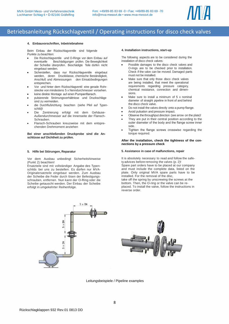
Vor und hinter dem Rückschlagventil eine gerade Rohr-strecke von mindestens 5 x Nenndurchmesser vorsehen.
keine direkte Montage auf einen Pumpenflansch.
pulsierende Strömungsverhältnisse und Druckschläge sind zu vermeiden.
die Durchflußrichtung beachten (siehe Pfeil auf Typen-schild)!
Die Zentrierung erfolgt mit dem Gehäuse-Außendurchmesser auf die Innenseite der Flansch-Schrauben.
Flansch-Schrauben kreuzweise mit dem entspre-chenden Drehmoment anziehen
Bei einer anschließenden Druckprobe sind die An-schlüsse auf Dichtheit zu prüfen. 5. Hilfe bei Störungen, Reparatur
Vor dem Ausbau unbedingt Sicherheitshinweise (Punkt 2) beachten! Ersatzteile sind mit vollständiger Angabe des Typen-schilds bei uns zu bestellen. Es dürfen nur MVA-Originalersatzteile eingebaut werden. Zum Ausbau der Scheibe die Feder durch lösen der Befestigungs-schrauben, entfernen. Nun kann der O-Ring oder die Scheibe getauscht werden. Der Einbau der Scheibe erfolgt in umgekehrter Reihenfolge.
4. Installation instructions, start-up
The following aspects are to be considered during the installation of disco check valves:
Possible damages to the disco check valves and O-rings are to be checked prior to installation. Check if the valve can be moved. Damaged parts must not be installed.
Make sure that only those disco check valves are being installed, that meet the operational requirements regarding pressure category, chemical resistance, connection and dimen-sions.
Make sure to install a minimum of 5 x nominal diameter of straight pipeline in front of and behind the disco check valve.
Do not install the valves directly onto a pump flange.
Avoid pulsation and pressure impact.
Observe the throughput direction (see arrow on the plate)!
They are put in their central position according to the outer diameter of the body and the flange screw inner side.
Tighten the flange screws crosswise regarding the torque required.
After the installation, check the tightness of the con-nections by a pressure check 5. Assistance in case of malfunctions, repair
It is absolutely necessary to read and follow the safe-ty advices before removing the valves (p. 2)! Spare part orders have to be placed at our company and must include the complete data, listed on the plate. Only original MVA spare parts have to be installed. For the removal of the disc, take off the spring by unscrewing the screws at the bottom. Then, the O-ring or the valve can be re-placed. To install the valve, follow the instructions in reverse order.
Leitungsbeispiele / Pipeline examples
Betriebsanleitung Rückschlagventil / Operating instructions for disco check valves
9
MVA GmbH Mess- und Verfahrenstechnik Lochhamer Schlag 6 • D-82166 Gräfelfing
Rückschlagklappen 932 Rev.01 0813 DD
Fon: +49/89-85 83 69 -0 • Fax: +49/89-85 83 69 -70 [email protected] • www.mva-messvt.de
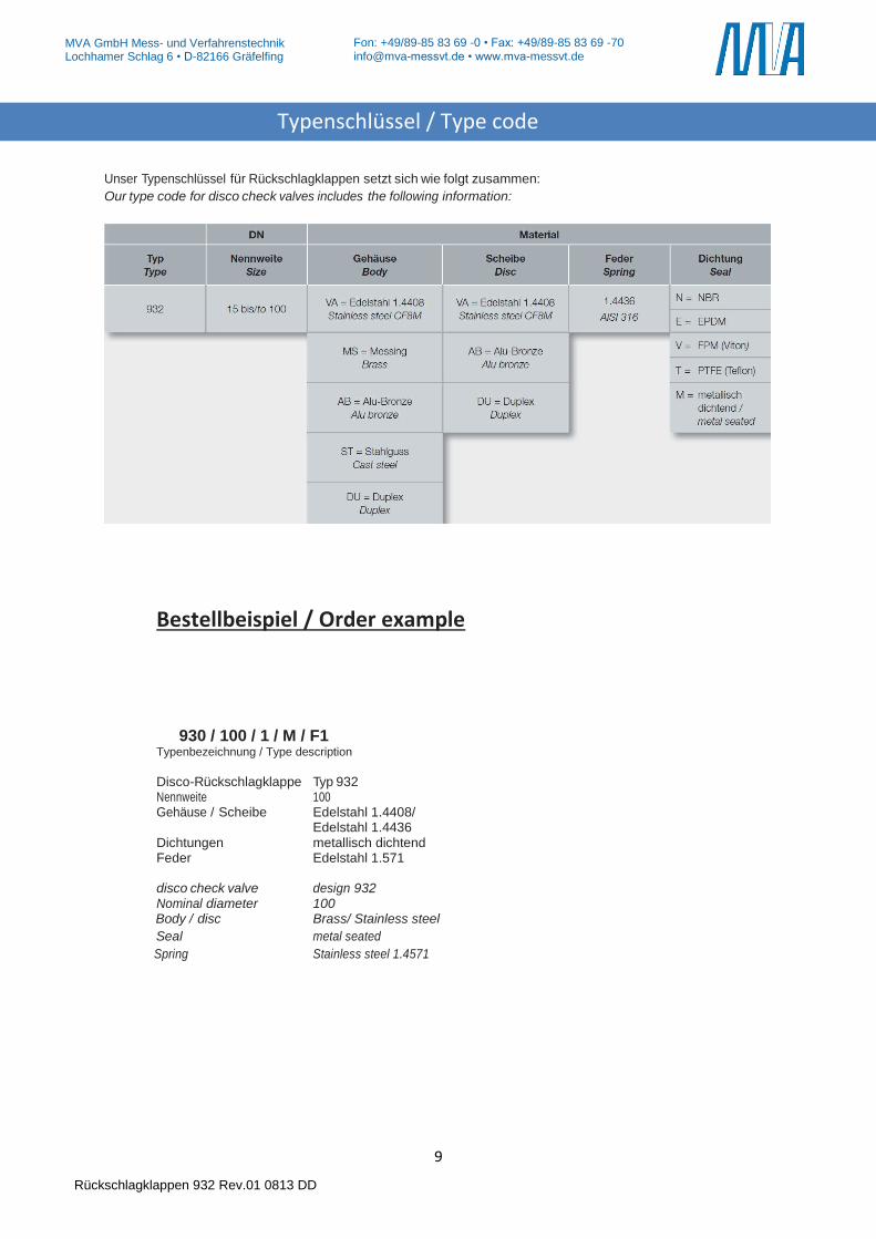
Unser Typenschlüssel für Rückschlagklappen setzt sich wie folgt zusammen:
Our type code for disco check valves includes the following information:
Bestellbeispiel / Order example 930 / 100 / 1 / M / F1 Typenbezeichnung / Type description
Disco-Rückschlagklappe Typ 932 Nennweite 100 Gehäuse / Scheibe Edelstahl 1.4408/ Edelstahl 1.4436 Dichtungen metallisch dichtend Feder Edelstahl 1.571 disco check valve design 932 Nominal diameter 100
Body / disc Brass/ Stainless steel
Seal metal seated
Spring Stainless steel 1.4571
Typenschlüssel / Type code
Top Related