


Sprachen
Seiten
Rechtliche


8/13/2019 UHR 5 Hydraulic Fracturing
http://slidepdf.com/reader/full/uhr-5-hydraulic-fracturing 1/21
Unconventional Hydrocarbon Resources
(PE 413)
Shale GasHydraulic Fracturing
Dr Bijaya K Behera Professor
School of Petroleum Technology
1

8/13/2019 UHR 5 Hydraulic Fracturing
http://slidepdf.com/reader/full/uhr-5-hydraulic-fracturing 2/21
Acknowledgement
Dhruva Dhankher
Ayush
Nitin Chaudhary
Harsh Vora
Sunil Kumar
Gaurav Tomar
Chanchal Chakrachhatri
Sharanya Gantla
Ayush Mishra
Swetha Gokavarapu
Yash Malani
Yashaswini Nallaparaju
Mayank Jhunjhunwala
Abbasi Soni
Mayank Sharma
B. Tech Petroleum Engineering, 2009 Batch
Pandit Deendayal Petroleum University, Gandhinagar

8/13/2019 UHR 5 Hydraulic Fracturing
http://slidepdf.com/reader/full/uhr-5-hydraulic-fracturing 3/21
3
What is Hydraulic Fracturing?
Hydraulic fracturing is the process of pumping a fluid into a
wellbore at an injection rate that is too high for theformation to accept in a radial flow pattern that exceeds thebreakdown pressure of the formation that is open to thewellbore.
Once the formation “breaks-down”, a crack or fracture is
formed, and the injected fluid begins moving down thefracture.
Fluid that does not contain any propping agent, often called“pad”, is injected to create a fracture that grows up, out and
down, and creates a fracture that is wide enough to accepta propping agent. The purpose of the propping agent is to“prop open” the fracture once the pumping operationceases.

8/13/2019 UHR 5 Hydraulic Fracturing
http://slidepdf.com/reader/full/uhr-5-hydraulic-fracturing 4/21
4
Rock formation properties
To begin with, we first of all need to find out thegeophysical and geo-mechanical properties of thetarget formation by :
1. log analysis
2. core analysis3. well testing
The important properties that we need to Know are :
1. Young’s modulus 4. Permeability2. Bulk modulus 5. Porosity
3. Poisson’s ratio 6. Saturation

8/13/2019 UHR 5 Hydraulic Fracturing
http://slidepdf.com/reader/full/uhr-5-hydraulic-fracturing 5/21
5
Hydraulic Fracturing Process
Steps of Hydraulic Fracturing Process
8/13/2019 UHR 5 Hydraulic Fracturing
http://slidepdf.com/reader/full/uhr-5-hydraulic-fracturing 6/21
6
FRACTURE LENGTH
Fracture length defines the extension of the fracture in the
formation.
The fracture length orientation depends on the poisons ratio of the
formation.
If the formation is bounded by other formations having higherpoisons ratio then the fracture length would be much longer than
the fracture width.
Calculation of fracture length
2-D Models
3-D Models
8/13/2019 UHR 5 Hydraulic Fracturing
http://slidepdf.com/reader/full/uhr-5-hydraulic-fracturing 7/21
7
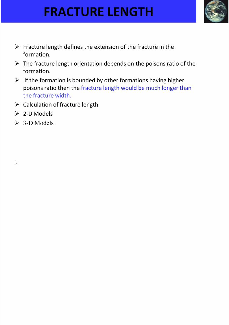
Where,
Xf = Productive fracture half length, E’= Plane strain modulus, Vi = Volume of fluid injected, hf = Fracture height,
b N = Nolte method intercept, pc = Closure pressure,
Rf = Radial fracture radius
Closure Stress/pressure: Closure stress/pressure is the pressure at which the
fracture effectively closes without proppant in place. The closure stress at a
given depth is the sum of overburden pressure and pore pressure.
PKN: Perkins&Kern, 1961 and Nordgren, 1972Model (PKN ) without leakoff test• KGD: Khristianovic and Zheltov, 1955; Geertsma and de Klerk, 1969
FRACTURE LENGTH

8/13/2019 UHR 5 Hydraulic Fracturing
http://slidepdf.com/reader/full/uhr-5-hydraulic-fracturing 8/21
8
FRACTURE CONDUCTIVITY
• Fracture conductivity is the product of fracture permeability and
propped fracture width left after the fracture has closed.
• Dimensionless fracture conductivity is a key design parameter in
well stimulation that compares the capacity of the fracture to
transmit fluids down the fracture and into the wellbore with the
ability of the formation to deliver fluid into the fracture.
• C fD=kf w/kFxf
x f is the fracture half-length,
k f is the fracture permeability, and
w is the fracture width
kF is the formation permeability
8/13/2019 UHR 5 Hydraulic Fracturing
http://slidepdf.com/reader/full/uhr-5-hydraulic-fracturing 9/21

8/13/2019 UHR 5 Hydraulic Fracturing
http://slidepdf.com/reader/full/uhr-5-hydraulic-fracturing 10/21
10
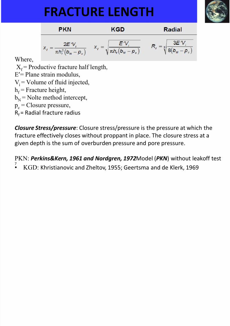
Water Based Fluid
• Economical, readily available, easily viscosified and yields increased Hydrostatic head
• Includes low viscosity “slick water” with low proppant conc. and high pump rates creatinghighly complex fractures in gas reservoirs.
• cross-linked fluid with increased mol. wt. resulting from tying together various polymermolecules into a structure through metal-chelate cross linkers is an advancement of water
based fluids.
Oil Based Fluids
• Mostly it is a reaction product of Aluminium Phosphate Ester and Base, typically NaAlO2
• Requires a great deal of technical capability and quality control
• Primary disadvantages are fire hazards and pumping friction
Alcohol Based Fluids
• Methanol and isopropanol provides low surface tension, miscibility with water andcompatibility with water sensitive formation
• Drawbacks are inherent danger to person breathing alcohol fumes and danger ofcombustion
TYPES OF FRACTURING FLUIDS

8/13/2019 UHR 5 Hydraulic Fracturing
http://slidepdf.com/reader/full/uhr-5-hydraulic-fracturing 11/21
11
TYPES OF FRACTURING FLUIDS
Emulsions Based Fluids
• Highly viscous solutions with good transport properties and fluid loss control
• Water external emulsion are easy to mix and pump and have tendency to achieve frictionreduction with polymers
• Oil external emulsions yields high friction pressure related to high oil viscosity and lack offriction reduction
Foam Based Fluids
• Simply a gas in liquid emulsion where gas bubbles provide high visco and excellentproppant transport capabilities
• Minimises the amount of fluid placed on the formation and improves fracturing fluidrecovery by inherent energy of gas
• Applications are in shallow, low pressure wells and water sensitive formations
New Generation Fluids
• VES base fluid uses surfactants in combination with inorganic salts creating orderedstructures which increases viscosity and elasticity
• Extension of VES fluid tech is VES foams which can be formed with N2 or CO2

8/13/2019 UHR 5 Hydraulic Fracturing
http://slidepdf.com/reader/full/uhr-5-hydraulic-fracturing 12/21
12
ADDITIVES USED IN FRACTURING FLUID
Sr. No. Additive Function
1 Polymers Used to viscosify the fluid.
2 Cross-linkers Used to change the viscous fluid to a
pseudo-plastic fluid.
3 Biocides Used to kill bacteria in the mix water.
4 Buffers Used to control the pH of the fracture
fluid.
5 Surfactants Used to lower the surface tension.
6 Fluid-Loss additives Used to minimize fluid leak-off into the
formation.
7 Stabilizers Used to keep the fluid viscous at high
temperature.
8 Breakers Used to break the polymers and crosslink
sites at low temperature.

8/13/2019 UHR 5 Hydraulic Fracturing
http://slidepdf.com/reader/full/uhr-5-hydraulic-fracturing 13/21
13
SELECTION OF FRACTURE FLUIDS
• Low leak-off rate.
• Ability to carry the propping agent.
• Low pumping friction loss.
• Easy to remove from the formation.
• Compatible with the natural formation fluids.
• Minimum damage to the formation permeability.
• Break back to a low viscosity fluid for clean up after
the treatment.
The properties that any Fracturing fluid should possess:
8/13/2019 UHR 5 Hydraulic Fracturing
http://slidepdf.com/reader/full/uhr-5-hydraulic-fracturing 14/21
14
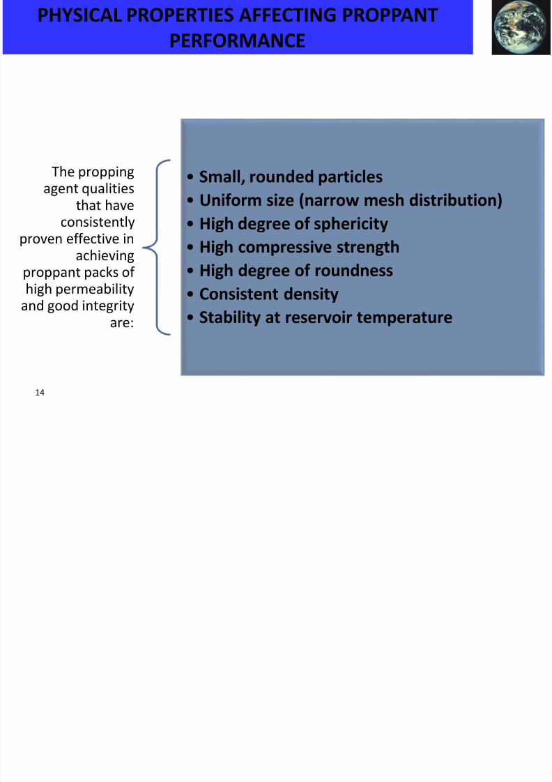
PHYSICAL PROPERTIES AFFECTING PROPPANT
PERFORMANCE
The propping
agent qualitiesthat haveconsistently
proven effective inachieving
proppant packs of
high permeabilityand good integrity
are:
• Small, rounded particles
• Uniform size (narrow mesh distribution)
• High degree of sphericity
• High compressive strength
• High degree of roundness
• Consistent density• Stability at reservoir temperature
8/13/2019 UHR 5 Hydraulic Fracturing
http://slidepdf.com/reader/full/uhr-5-hydraulic-fracturing 15/21
15
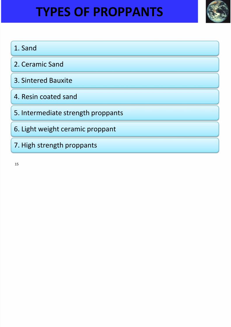
TYPES OF PROPPANTS
1. Sand
2. Ceramic Sand
3. Sintered Bauxite
4. Resin coated sand
5. Intermediate strength proppants
6. Light weight ceramic proppant
7. High strength proppants
8/13/2019 UHR 5 Hydraulic Fracturing
http://slidepdf.com/reader/full/uhr-5-hydraulic-fracturing 16/21
16
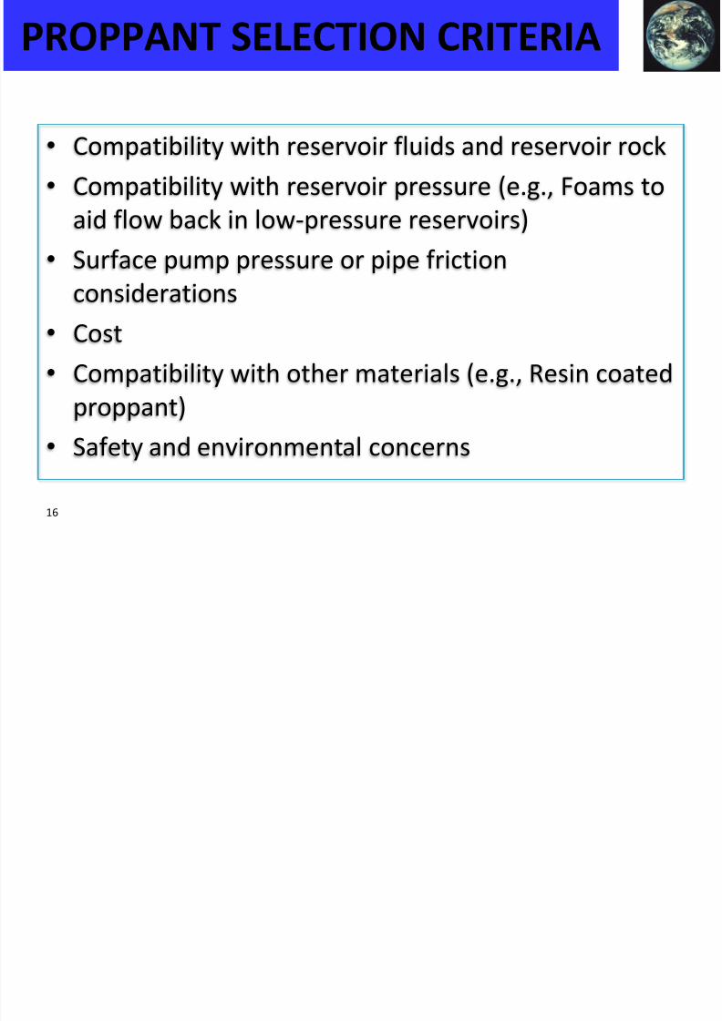
PROPPANT SELECTION CRITERIA
• Compatibility with reservoir fluids and reservoir rock
• Compatibility with reservoir pressure (e.g., Foams to
aid flow back in low-pressure reservoirs)
• Surface pump pressure or pipe frictionconsiderations
• Cost
•
Compatibility with other materials (e.g., Resin coatedproppant)
• Safety and environmental concerns
8/13/2019 UHR 5 Hydraulic Fracturing
http://slidepdf.com/reader/full/uhr-5-hydraulic-fracturing 17/21
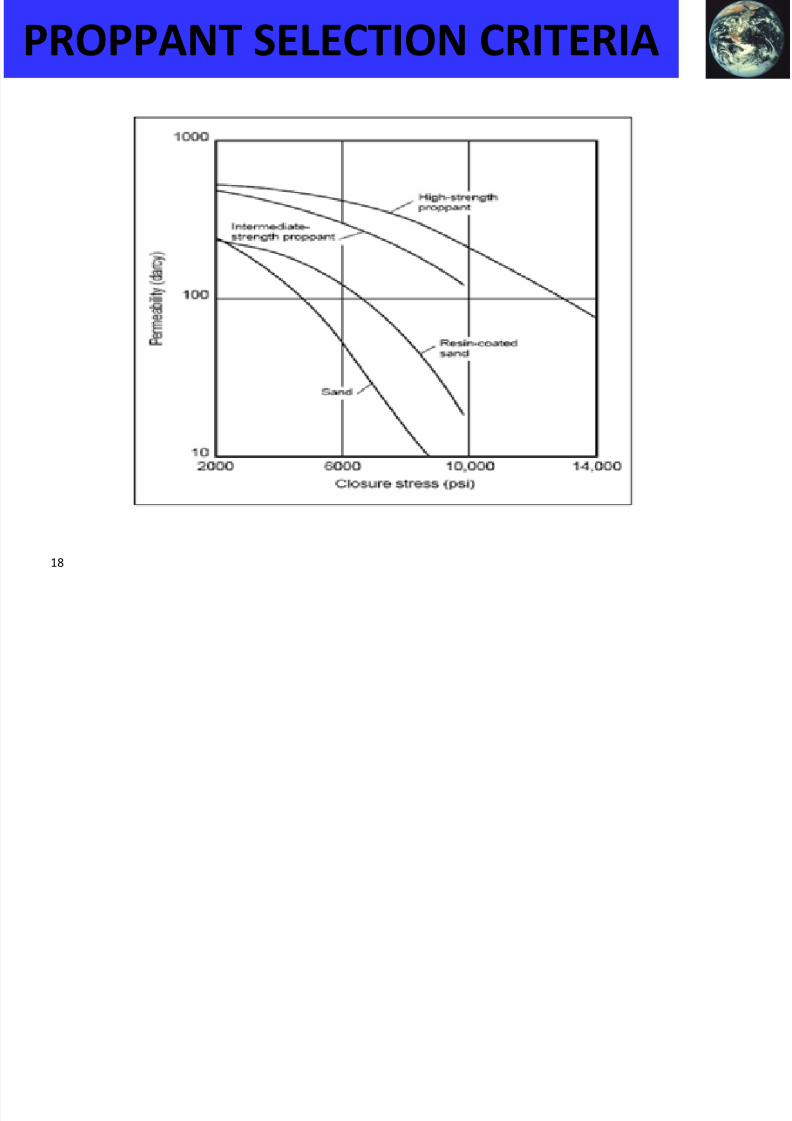
17
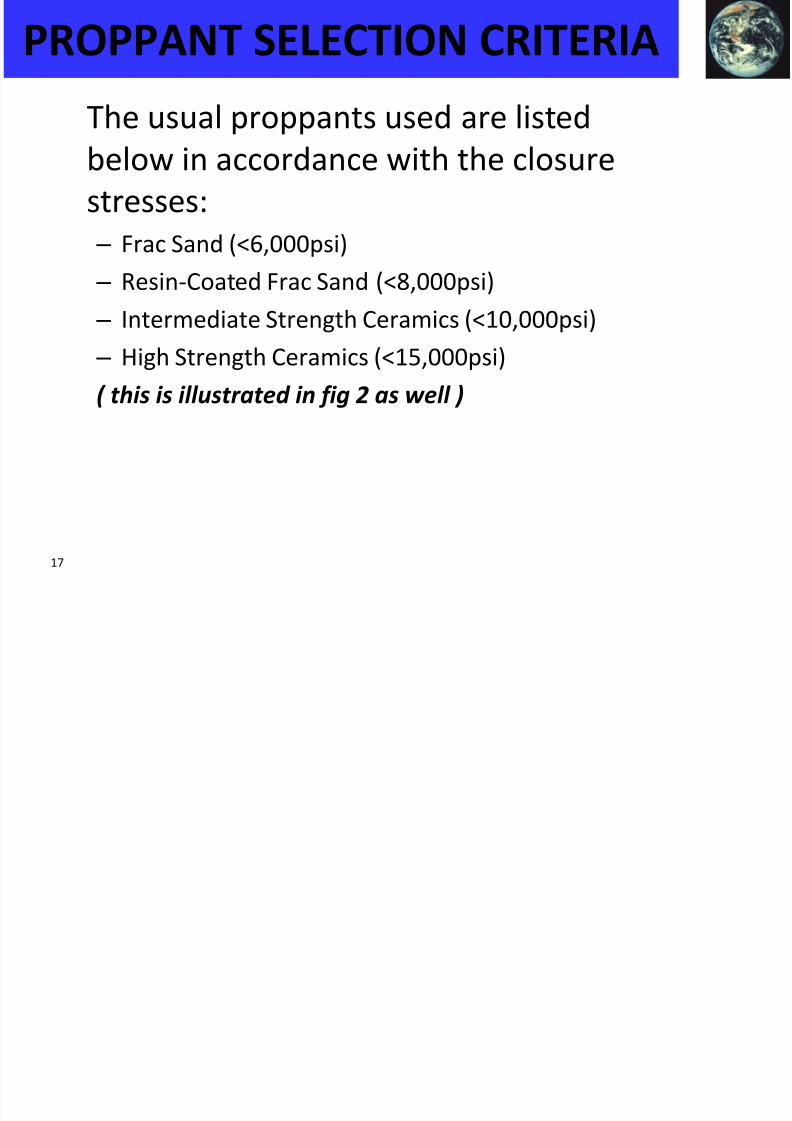
The usual proppants used are listed
below in accordance with the closure
stresses:
– Frac Sand (<6,000psi)
– Resin-Coated Frac Sand (<8,000psi)
– Intermediate Strength Ceramics (<10,000psi)
– High Strength Ceramics (<15,000psi)
( this is illustrated in fig 2 as well )
PROPPANT SELECTION CRITERIA
8/13/2019 UHR 5 Hydraulic Fracturing
http://slidepdf.com/reader/full/uhr-5-hydraulic-fracturing 18/21
18
PROPPANT SELECTION CRITERIA

8/13/2019 UHR 5 Hydraulic Fracturing
http://slidepdf.com/reader/full/uhr-5-hydraulic-fracturing 19/21
19
PROPPANT TRANSPORT
• Modes of proppant transport
– Simple settling
• Governed by Stoke’s law
Where,v fall is the settling rate in ft/s,
d prop is the average proppant particle diameter in in.,
μ is the fluidviscosity in cp, and
γ prop and γ fluid are the specific gravity of the proppant and the fluid, respectively
8/13/2019 UHR 5 Hydraulic Fracturing
http://slidepdf.com/reader/full/uhr-5-hydraulic-fracturing 20/21
20
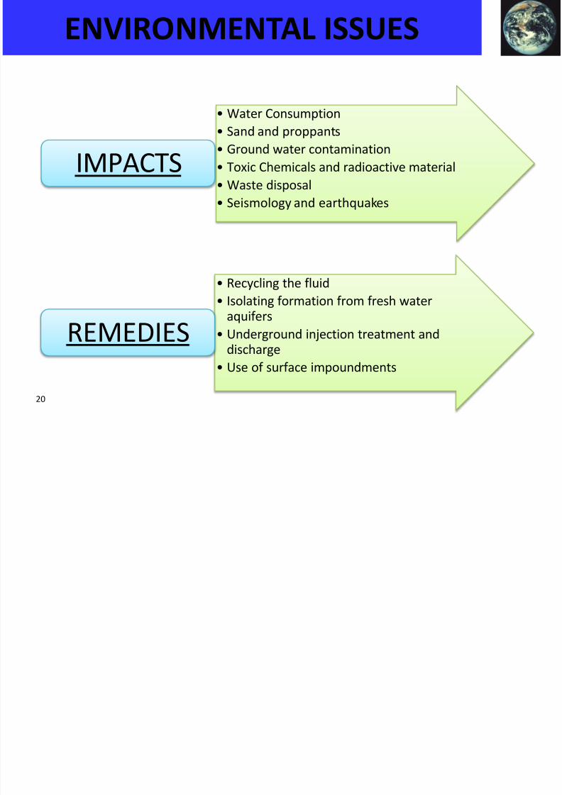
ENVIRONMENTAL ISSUES
• Water Consumption
• Sand and proppants
• Ground water contamination
• Toxic Chemicals and radioactive material
• Waste disposal
• Seismology and earthquakes
IMPACTS
• Recycling the fluid
• Isolating formation from fresh wateraquifers
• Underground injection treatment anddischarge
• Use of surface impoundments
REMEDIES

8/13/2019 UHR 5 Hydraulic Fracturing
http://slidepdf.com/reader/full/uhr-5-hydraulic-fracturing 21/21
TH NK YOU
Top Related