ELEKTRONISCHE BAUELEMENTE ELECTRONIC COMPONENTS · 2003-12-13 · tions and in electronic data...
32
ELEKTRONISCHE BAUELEMENTE ELECTRONIC COMPONENTS Drosseln, Festinduktivitäten Chokes, Fixed Value Inductors 2
Transcript of ELEKTRONISCHE BAUELEMENTE ELECTRONIC COMPONENTS · 2003-12-13 · tions and in electronic data...
ELEKTRONISCHE BAUELEMENTEELECTRONIC COMPONENTS
Drosseln, FestinduktivitätenChokes, Fixed Value Inductors 2
Drosseln, FestinduktivitätenChokes, Fixed Value Inductors2
2.02
Inhalt
AllgemeinesEinführung, MessbedingungenWerkstoffdaten, Ferrite
Drosseln mit radialen AnschlüssenSd 75Bs 75Sd 8Bs 11Sd 12 kSd 12Sd 14
Stabkerndrosseln Z...
Breitbanddrossel Zd 6
Drossel/Übertrager U 15
Stromkompensierte RingkerndrosselnR 18, R 25
Stromkompensierte RingkerndrosselnTL 21 - TL 25, TL 81 - TL 85
Übertrager mit RM-EP-E-Kernen
Contents
General InformationIntroduction, measuring conditions
Data of ferrite grades
Radial lead inductorsSd 75Bs 75Sd 8
Bs 11Sd 12
Sd 12 kSd 14
Free suspension chokes
Wide-band choke Zd 6
Choke/Transformer U 15
Common mode chokes R 18, R 25
Common mode chokesTL 21 - TL 25, TL 81 - TL 85
Transformers with RM-EP-E-cores
Seite/page
2.03 - 2.052.06
2.07 - 2.092.10 - 2.122.13 - 2.142.15 - 2.162.17 - 2.182.19 - 2.20
2.21
2.22
2.23
2.24
2.25 - 2.26
2.27 - 2.29
2.30 - 2.31
Drosseln, FestinduktivitätenChokes, Fixed Value Inductors2
2.03
Einführung
Mit unserer langjährigen Erfahrung auf demGebiet der induktiven Bauelemente, bieten wirheute ein breites Spektrum von Festinduktivitä-ten verschiedenster Ausführungsform: radialgegurtete Drosseln, auch abgeschirmt, mit engerToleranz als Schwingkreisinduktivität, Speicher-und Siebdrossel, nichtlineare Drosseln und Spu-len für die Oberflächenmontage.
Anwendung
Unsere Drosseln werden in allen Bereichen derFernmeldetechnik, der professionellen Nach-richtentechnik, der Medizintechnik sowie inelektronischen Datenverarbeitungsanlagen undVideotechnik eingesetzt. Sie eignen sich speziell zur Funkentstörung elektrischerMaschinen, Haushaltsgeräten, Kollektormoto-ren, elektrischer Kontakte usw. . In Hoch- undNiederfrequenzschaltungen dienen sie nebender Systementkopplung von Oszillator- und Verstärkerstufen zur Siebung und Entzerrungvon Gleichrichterschaltungen. Die Möglichkeitzur Auswahl verschiedener Ferritmaterialiengestattet es, viele Typen auch als Spulen hoherGüte für Resonanzkreise oder andere Selekti-onsmittel einzusetzen.
Introduction
Through many years of manufacturing inductivecomponents our experience has grown andtoday we can offer a wide spectrum of designs:bandoleered radial chokes, also screened versi-ons, with tight tolerance of inductance, storageand smoothing chokes, non-linear chokes, (withpermanent magnet) as well as RF coils for surface mounting.
Application
Our chokes are used in all ranges of radio, tele-vision and video products, in the professionaltelecommunication industry, in medical applica-tions and in electronic data processing. They areespecially suited for the suppression of radiointerference, generated by electrical machines,household applicances, commutator motors,electrical contacts, etc.. In high and low fre-quency circuits they are used for decoupling ofoscillator and amplifier stages, and for filteringand suppression of rectifier circuits. The choiceof suitable ferrite grade enables some types ofchokes to be used as high-Q inductors in tunedcircuits or filters.
Drosseln, FestinduktivitätenChokes, Fixed Value Inductors2
2.04
Aufbau
Im allgemeinen ist man bestrebt, bei einerbestimmten Induktivität einen möglichst niedri-gen Gleichstromwiderstand zu erzielen, um denSpannungsverlust klein zu halten und eine hoheStrombelastung zu ermöglichen. Daneben sindjedoch weitere Eigenschaften, wie Eigenreso-nanz, Leitfähigkeit des Materials bei Berührungmit Nachbarbauelementen oder magnetischeAussteuerbarkeit von Bedeutung. Für die Dros-seln haben wir daher das besonders gut isolie-rende Ferritmaterial F5 is, und mit höherer Per-meabilität das Material F1 is entwickelt. DieEigenschaften dieser Materialien haben sichauch für den Einsatz bei weiteren Typen als vor-teilhaft erwiesen. In Spulen hoher Güte sowiebei verschiedenen Dämpfungsperlen oder Breit-banddämpfungsdrosseln empfehlen wir den fürdas jeweilige Frequenzgebiet am besten geeig-neten Werkstoff. Auf den folgenden Seiten isteine Übersicht der gebräuchlichsten Werkstoffezusammengefasst.
Elektrische Daten und Messungen
Die Messung der Induktivität erfolgt mit mög-lichst niedrigem Messstrom bzw. Spannung, sodass magnetische Übersteuerung vermiedenwird. Die Frequenz soll niedrig sein. Sie wird jedoch nach unten begrenzt durch dengeforderten niedrigen Messstrom und das Auflösungsvermögen des Gerätes, z. B. Mess-brücke. Die Eigenresonanz der zu messendenInduktivität, die Grenzfrequenz des Kernmateri-als und die Stromverdrängung im Wickeldrahtsetzen andererseits der höchsten Messfrequenzdie Grenze.
Wenn nicht anders spezifiziert, empfehlen wir die in der IEC 1007 bzw. DIN EN 129000aufgeführten Messbedingungen.
Design
In general, the design purpose is to achieve acertain inductance value with a minimum DCresistance so that the voltage drop is low andpermissible current loading high. There are alsoother considerations: self-resonance, conductivi-ty of the material touching adjacent elements,current loading capability. For the chokes - wetherefore have developed grade F5 is ferrite withparticularly good insulating properties (resistivi-ty) and - with higher permeability - grade F1 is.The properties of these ferrite grades have beenfound very useful in other choke types as well.However, for high-Q inductors and for suppres-sion beads and wideband chokes we recom-mend usually the ferrite grade, best suited forthe envisaged frequency range. On the pagesthat follow, we show the most frequently usedgrades and their most important parameters.
Electrical data and measurements
The measurement of inductance must be carried out a very low current or voltage respec-tively to avoid magnetic overloading. The frequency should be as low as possible. Thetest-frequency is limited at the lower and by theresolution of the equipment (measuring bridge)and by the current flowing through the compo-nent. At the higher end the test-frequency islimited by the self resonant frequency of theinductor, by the upper frequency limit of thecore material and by skin effect in the case ofheavy wire.
If not otherwise specified, we recommend theIEC 1007 or DIN EN 129000 performed testconditions.
Drosseln, FestinduktivitätenChokes, Fixed Value Inductors2
2.05
Elektrische Daten und Messungen
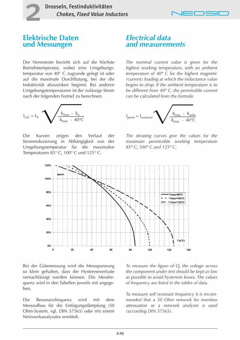
Der Nennstrom bezieht sich auf die höchsteBetriebstemperatur, wobei eine Umgebungs-temperatur von 40° C zugrunde gelegt ist oderauf die maximale Durchflutung, bei der dieInduktivität abzusinken beginnt. Bei anderenUmgebungstemperaturen ist der zulässige Stromnach der folgenden Formel zu berechnen.
Die Kurven zeigen den Verlauf der Stromreduzierung in Abhängigkeit von derUmgebungstemperatur für die maximalen Temperaturen 85° C, 100° C und 125° C.
Bei der Gütemessung wird die Messspannungso klein gehalten, dass die Hystereseverlustevernachlässigt werden können. Die Messfre-quenz wird in den Tabellen jeweils mit angege-ben.
Die Resonanzfrequenz wird mit dem Messaufbau für die Einfügungsdämpfung (50Ohm-System, vgl. DIN 57565) oder mit einemNetzwerkanalysator ermittelt.
Electrical data and measurements
The nominal current value is given for the highest working temperature, with an ambienttemperature of 40° C for the highest magnetic(current) loading at which the inductance valuebegins to drop. If the ambient temperature is tobe different from 40° C, the permissible currentcan be calculated from the formula:
The derating curves give the values for the maximum permissible working temperature 85° C, 100° C and 125° C.
To measure the figure of Q, the voltage acrossthe component under test should be kept as lowas possible to avoid hysteresis losses. The valuesof frequency are listed in the tables of data.
To measure self resonant frequency it is recom-mended that a 50 Ohm network for insertionattenuation or a network analyzer is used(according DIN 57565).
�max - �u
�max - 40°C Izul. = IN �� �max - �amb.
�max - 40°C Iperm = Inominal��
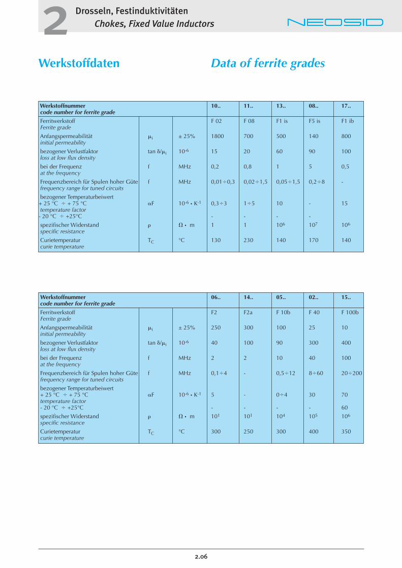
Werkstoffnummer 06.. 14.. 05.. 02.. 15..code number for ferrite grade
Ferritwerkstoff F2 F2a F 10b F 40 F 100bFerrite grade
Anfangspermeabilität �i ± 25% 250 300 100 25 10initial permeability
bezogener Verlustfaktor tan �/�i 10-6 40 100 90 300 400loss at low flux density
bei der Frequenz f MHz 2 2 10 40 100at the frequency
Frequenzbereich für Spulen hoher Güte f MHz 0,1�4 - 0,5�12 8�60 20�200frequency range for tuned circuits
bezogener Temperaturbeiwert + 25 °C � + 75 °C �F 10-6 � K-1 5 - 0�4 30 70temperature factor - 20 °C � +25°C - - - - 60
spezifischer Widerstand � � � m 101 101 104 105 106
specific resistance
Curietemperatur TC °C 300 250 300 400 350curie temperature
Werkstoffnummer 10.. 11.. 13.. 08.. 17..code number for ferrite grade
Ferritwerkstoff F 02 F 08 F1 is F5 is F1 ibFerrite grade
Anfangspermeabilität �i ± 25% 1800 700 500 140 800initial permeability
bezogener Verlustfaktor tan �/�i 10-6 15 20 60 90 100loss at low flux density
bei der Frequenz f MHz 0,2 0,8 1 5 0,5at the frequency
Frequenzbereich für Spulen hoher Güte f MHz 0,01�0,3 0,02�1,5 0,05�1,5 0,2�8 -frequency range for tuned circuits
bezogener Temperaturbeiwert + 25 °C � + 75 °C �F 10-6 � K-1 0,3�3 1�5 10 - 15temperature factor - 20 °C � +25°C - - - -
spezifischer Widerstand � � � m 1 1 106 107 106
specific resistance
Curietemperatur TC °C 130 230 140 170 140curie temperature
Drosseln, FestinduktivitätenChokes, Fixed Value Inductors2
2.06
Werkstoffdaten Data of ferrite grades
Drosseln, FestinduktivitätenChokes, Fixed Value Inductors2
Sd75/Nenninduktivität
Anwendung:Entkopplung in Schaltungen im HF- und NF-Bereich, Funkentstörung, Einsatz inselektiven Kreisen in der Nachrichtentechnik, Datenverarbeitungsanlagen,Videotechnik usw.
Daten: Abmessungen:7,5 x 4,6 x 10,5 mm
Induktivitätsbereich:0,1 �H � 68 mH
Toleranz:± 10% bis 8,2 �H± 5% ab 10 �Hengere Toleranz auf Anfrage
Betriebstemperaturbereich:-40°C bis +125°C
Lötbarkeit nach DIN IEC 68-2-20 Ta:235°C, 5 Sek.
Lötwärmebeständigkeit nach DIN IEC 68-2-20 Tb:260°C, 5 Sek.
Auszugsfestigkeit der DrähteDIN IEC 68-2-21 Ua1:10 N
Temperaturkoeffizient von -25°C bis +85°C:ca. 200 x 10-6/°K
zulässige Verlustleistungbei 40°:270 mW
Verpackung: gegurtet nach IEC 286/2
Verpackungseinheit:1000 Stück Ammopack
Sd75/Nominal inductance
Application:Decoupling of high and low frequency circuits, etc.We recommend these Chokes forapplication in telecommunication,video equipment and electronicdata processing systems.
Data:dimensions:7,5 x 4,6 x 10,5 mm
Inductance range:0,1 �H � 68 mH
Tolerance:± 10% < 8,2 �H± 5% > 10 �Htighter tolerances on request
Operating temperature range:-40°C to +125°C
Solderability as perDIN IEC 68-2-20 Ta:235°C, 5 sec.
Resistance to soldering heatDIN IEC 68-2-20 Tb:260°C, 5 sec.
Pulling strength of lead out wiresDIN IEC 68-2-21 Ua1:10 N
Temperature coefficient between-25°C to +85°C:app. 200 x 10-6/°K
Permissible power lossat �u = 40°:270 mW
Packaging:bandoleered as per IEC 286/2
Packaging size:1000 pieces ammopack
2.07
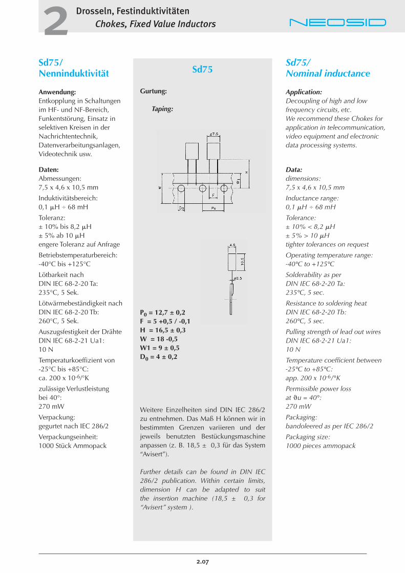
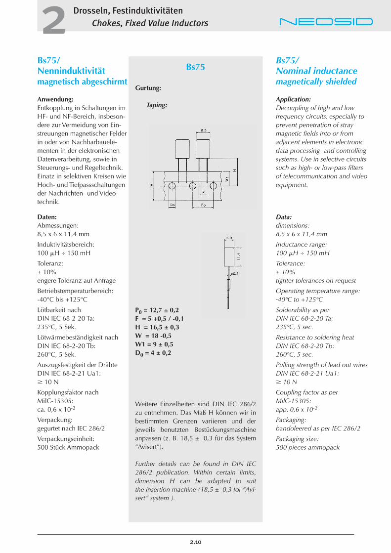
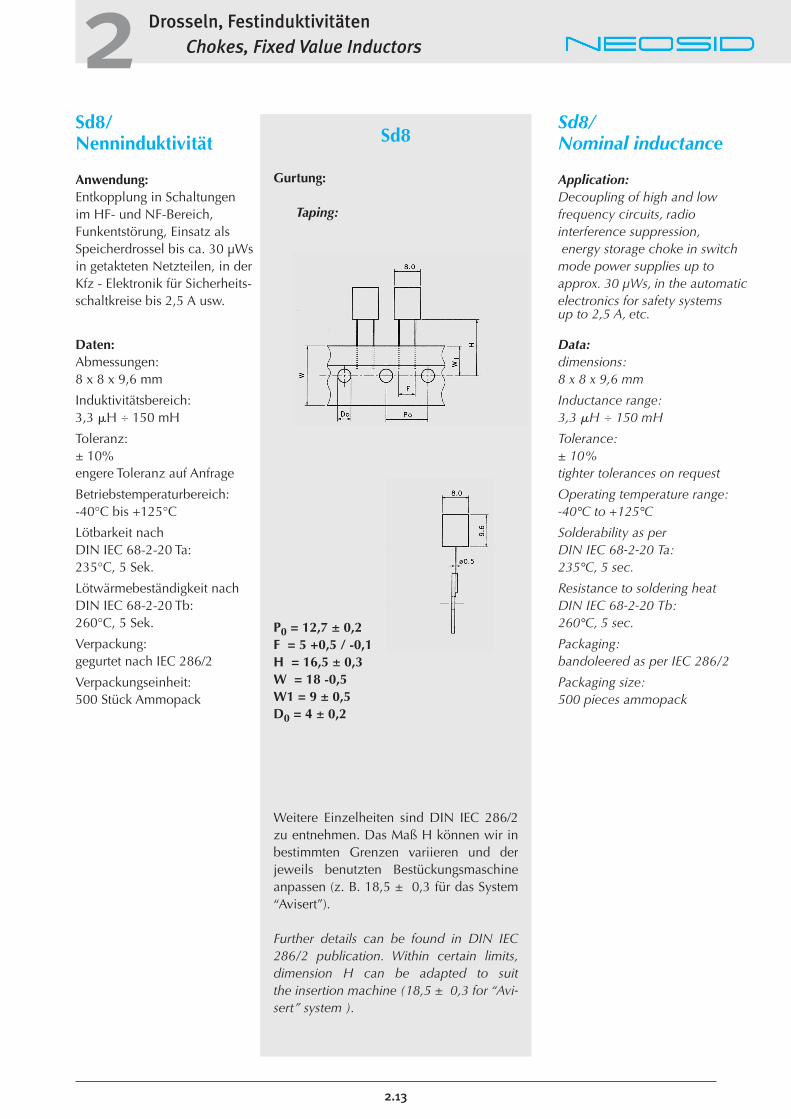
Sd75
Gurtung:
Taping:
P0 = 12,7 ± 0,2F = 5 +0,5 / -0,1H = 16,5 ± 0,3W = 18 -0,5W1 = 9 ± 0,5D0 = 4 ± 0,2
Weitere Einzelheiten sind DIN IEC 286/2zu entnehmen. Das Maß H können wir inbestimmten Grenzen variieren und derjeweils benutzten Bestückungsmaschineanpassen (z. B. 18,5 ± 0,3 für das System“Avisert”).
Further details can be found in DIN IEC286/2 publication. Within certain limits,dimension H can be adapted to suit the insertion machine (18,5 ± 0,3 for “Avisert” system ).
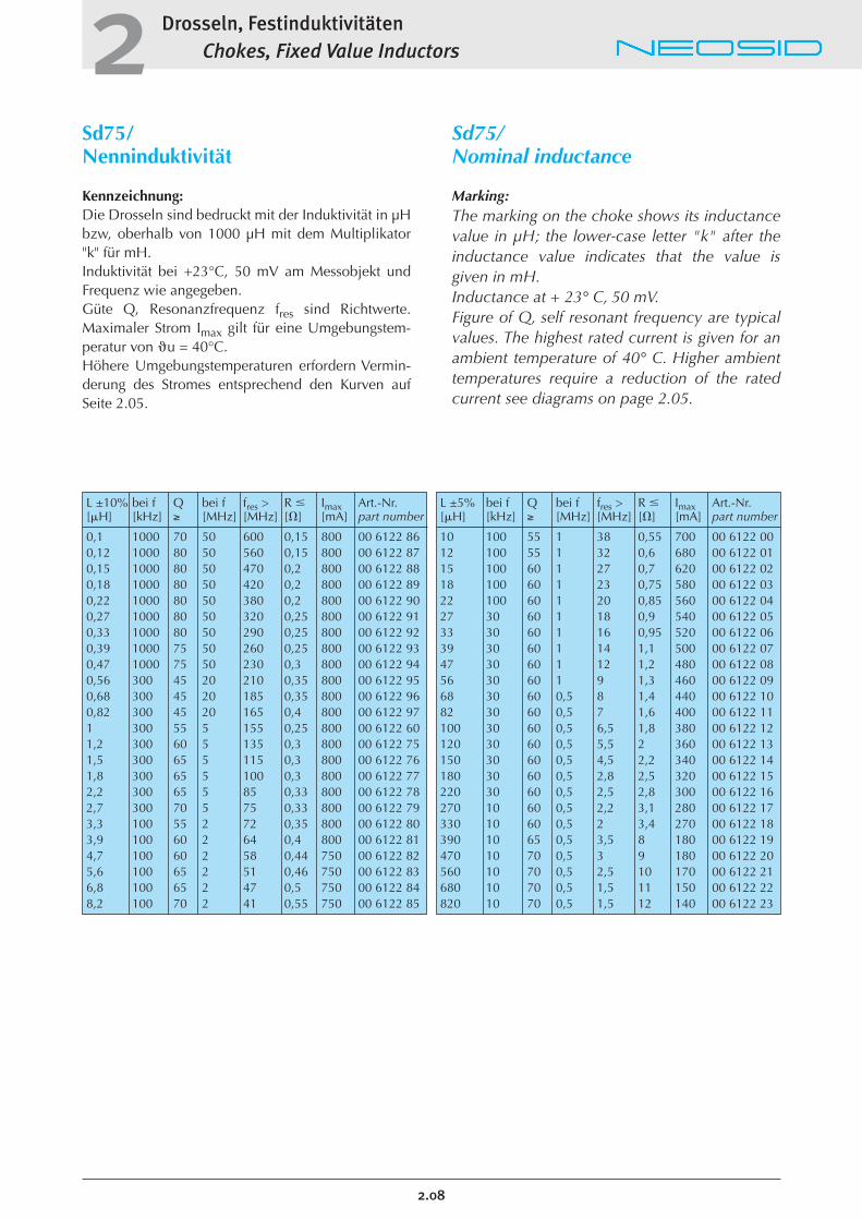
L ±5% bei f Q bei f fres > R � Imax Art.-Nr.[�H] [kHz] ≥ [MHz] [MHz] [�] [mA] part number
10 100 55 1 38 0,55 700 00 6122 0012 100 55 1 32 0,6 680 00 6122 0115 100 60 1 27 0,7 620 00 6122 0218 100 60 1 23 0,75 580 00 6122 0322 100 60 1 20 0,85 560 00 6122 0427 30 60 1 18 0,9 540 00 6122 0533 30 60 1 16 0,95 520 00 6122 0639 30 60 1 14 1,1 500 00 6122 0747 30 60 1 12 1,2 480 00 6122 0856 30 60 1 9 1,3 460 00 6122 0968 30 60 0,5 8 1,4 440 00 6122 1082 30 60 0,5 7 1,6 400 00 6122 11100 30 60 0,5 6,5 1,8 380 00 6122 12120 30 60 0,5 5,5 2 360 00 6122 13150 30 60 0,5 4,5 2,2 340 00 6122 14180 30 60 0,5 2,8 2,5 320 00 6122 15220 30 60 0,5 2,5 2,8 300 00 6122 16270 10 60 0,5 2,2 3,1 280 00 6122 17330 10 60 0,5 2 3,4 270 00 6122 18390 10 65 0,5 3,5 8 180 00 6122 19470 10 70 0,5 3 9 180 00 6122 20560 10 70 0,5 2,5 10 170 00 6122 21680 10 70 0,5 1,5 11 150 00 6122 22820 10 70 0,5 1,5 12 140 00 6122 23
L ±10% bei f Q bei f fres > R � Imax Art.-Nr.[�H] [kHz] ≥ [MHz] [MHz] [�] [mA] part number
0,1 1000 70 50 600 0,15 800 00 6122 860,12 1000 80 50 560 0,15 800 00 6122 870,15 1000 80 50 470 0,2 800 00 6122 880,18 1000 80 50 420 0,2 800 00 6122 890,22 1000 80 50 380 0,2 800 00 6122 900,27 1000 80 50 320 0,25 800 00 6122 910,33 1000 80 50 290 0,25 800 00 6122 920,39 1000 75 50 260 0,25 800 00 6122 930,47 1000 75 50 230 0,3 800 00 6122 940,56 300 45 20 210 0,35 800 00 6122 950,68 300 45 20 185 0,35 800 00 6122 960,82 300 45 20 165 0,4 800 00 6122 971 300 55 5 155 0,25 800 00 6122 601,2 300 60 5 135 0,3 800 00 6122 751,5 300 65 5 115 0,3 800 00 6122 761,8 300 65 5 100 0,3 800 00 6122 772,2 300 65 5 85 0,33 800 00 6122 782,7 300 70 5 75 0,33 800 00 6122 793,3 100 55 2 72 0,35 800 00 6122 803,9 100 60 2 64 0,4 800 00 6122 814,7 100 60 2 58 0,44 750 00 6122 825,6 100 65 2 51 0,46 750 00 6122 836,8 100 65 2 47 0,5 750 00 6122 848,2 100 70 2 41 0,55 750 00 6122 85
Drosseln, FestinduktivitätenChokes, Fixed Value Inductors2
2.08
Sd75/Nenninduktivität
Kennzeichnung:Die Drosseln sind bedruckt mit der Induktivität in µHbzw, oberhalb von 1000 µH mit dem Multiplikator"k" für mH. Induktivität bei +23°C, 50 mV am Messobjekt undFrequenz wie angegeben. Güte Q, Resonanzfrequenz fres sind Richtwerte.Maximaler Strom Imax gilt für eine Umgebungstem-peratur von �u = 40°C. Höhere Umgebungstemperaturen erfordern Vermin-derung des Stromes entsprechend den Kurven aufSeite 2.05.
Sd75/Nominal inductance
Marking:The marking on the choke shows its inductancevalue in µH; the lower-case letter "k" after theinductance value indicates that the value isgiven in mH.Inductance at + 23° C, 50 mV.Figure of Q, self resonant frequency are typicalvalues. The highest rated current is given for anambient temperature of 40° C. Higher ambienttemperatures require a reduction of the ratedcurrent see diagrams on page 2.05.
Drosseln, FestinduktivitätenChokes, Fixed Value Inductors2
2.09
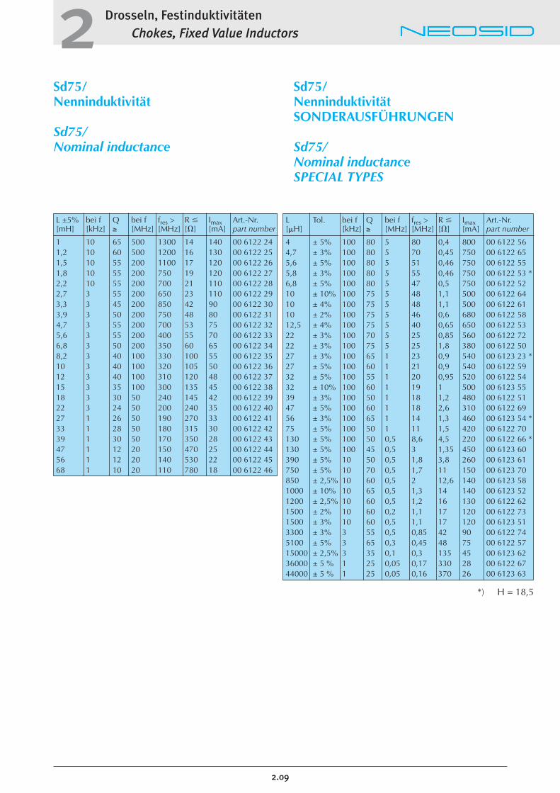
Sd75/Nenninduktivität
Sd75/Nominal inductance
Sd75/NenninduktivitätSONDERAUSFÜHRUNGEN
Sd75/Nominal inductanceSPECIAL TYPES
L ±5% bei f Q bei f fres > R � Imax Art.-Nr.[mH] [kHz] ≥ [MHz] [MHz] [�] [mA] part number
1 10 65 500 1300 14 140 00 6122 241,2 10 60 500 1200 16 130 00 6122 251,5 10 55 200 1100 17 120 00 6122 261,8 10 55 200 750 19 120 00 6122 272,2 10 55 200 700 21 110 00 6122 282,7 3 55 200 650 23 110 00 6122 293,3 3 45 200 850 42 90 00 6122 303,9 3 50 200 750 48 80 00 6122 314,7 3 55 200 700 53 75 00 6122 325,6 3 55 200 400 55 70 00 6122 336,8 3 50 200 350 60 65 00 6122 348,2 3 40 100 330 100 55 00 6122 3510 3 40 100 320 105 50 00 6122 3612 3 40 100 310 120 48 00 6122 3715 3 35 100 300 135 45 00 6122 3818 3 30 50 240 145 42 00 6122 3922 3 24 50 200 240 35 00 6122 4027 1 26 50 190 270 33 00 6122 4133 1 28 50 180 315 30 00 6122 4239 1 30 50 170 350 28 00 6122 4347 1 12 20 150 470 25 00 6122 4456 1 12 20 140 530 22 00 6122 4568 1 10 20 110 780 18 00 6122 46
L Tol. bei f Q bei f fres > R � Imax Art.-Nr.[�H] [kHz] ≥ [MHz] [MHz] [�] [mA] part number
4 ± 5% 100 80 5 80 0,4 800 00 6122 564,7 ± 3% 100 80 5 70 0,45 750 00 6122 655,6 ± 5% 100 80 5 51 0,46 750 00 6122 555,8 ± 3% 100 80 5 55 0,46 750 00 6122 53 *6,8 ± 5% 100 80 5 47 0,5 750 00 6122 5210 ± 10% 100 75 5 48 1,1 500 00 6122 6410 ± 4% 100 75 5 48 1,1 500 00 6122 6110 ± 2% 100 75 5 46 0,6 680 00 6122 5812,5 ± 4% 100 75 5 40 0,65 650 00 6122 5322 ± 3% 100 70 5 25 0,85 560 00 6122 7222 ± 3% 100 75 5 25 1,8 380 00 6122 5027 ± 3% 100 65 1 23 0,9 540 00 6123 23 *27 ± 5% 100 60 1 21 0,9 540 00 6122 5932 ± 5% 100 55 1 20 0,95 520 00 6122 5432 ± 10% 100 60 1 19 1 500 00 6123 5539 ± 3% 100 50 1 18 1,2 480 00 6122 5147 ± 5% 100 60 1 18 2,6 310 00 6122 6956 ± 3% 100 65 1 14 1,3 460 00 6123 54 *75 ± 5% 100 50 1 11 1,5 420 00 6122 70130 ± 5% 100 50 0,5 8,6 4,5 220 00 6122 66 *130 ± 5% 100 45 0,5 3 1,35 450 00 6123 60390 ± 5% 10 50 0,5 1,8 3,8 260 00 6123 61750 ± 5% 10 70 0,5 1,7 11 150 00 6123 70850 ± 2,5% 10 60 0,5 2 12,6 140 00 6123 581000 ± 10% 10 65 0,5 1,3 14 140 00 6123 521200 ± 2,5% 10 60 0,5 1,2 16 130 00 6122 621500 ± 2% 10 60 0,2 1,1 17 120 00 6122 731500 ± 3% 10 60 0,5 1,1 17 120 00 6123 513300 ± 3% 3 55 0,5 0,85 42 90 00 6122 745100 ± 5% 3 65 0,3 0,45 48 75 00 6122 5715000 ± 2,5% 3 35 0,1 0,3 135 45 00 6123 6236000 ± 5 % 1 25 0,05 0,17 330 28 00 6122 6744000 ± 5 % 1 25 0,05 0,16 370 26 00 6123 63
*) H = 18,5
Drosseln, FestinduktivitätenChokes, Fixed Value Inductors2
Bs75/Nenninduktivitätmagnetisch abgeschirmt
Anwendung:Entkopplung in Schaltungen imHF- und NF-Bereich, insbeson-dere zur Vermeidung von Ein-streuungen magnetischer Felderin oder von Nachbarbauele-menten in der elektronischenDatenverarbeitung, sowie inSteuerungs- und Regeltechnik.Einatz in selektiven Kreisen wieHoch- und Tiefpassschaltungender Nachrichten- und Video-technik.
Daten: Abmessungen:8,5 x 6 x 11,4 mm
Induktivitätsbereich:100 �H � 150 mH
Toleranz:± 10%engere Toleranz auf Anfrage
Betriebstemperaturbereich:-40°C bis +125°C
Lötbarkeit nach DIN IEC 68-2-20 Ta:235°C, 5 Sek.
Lötwärmebeständigkeit nach DIN IEC 68-2-20 Tb:260°C, 5 Sek.
Auszugsfestigkeit der DrähteDIN IEC 68-2-21 Ua1: 10 N
Kopplungsfaktor nachMilC-15305:ca. 0,6 x 10⁻²
Verpackung: gegurtet nach IEC 286/2
Verpackungseinheit:500 Stück Ammopack
Bs75/Nominal inductancemagnetically shielded
Application:Decoupling of high and low frequency circuits, especially toprevent penetration of straymagnetic fields into or from adjacent elements in electronicdata processing- and controllingsystems. Use in selective circuitssuch as high- or low-pass filters of telecommunication and videoequipment.
Data:dimensions:8,5 x 6 x 11,4 mm
Inductance range:100 �H � 150 mH
Tolerance:± 10%tighter tolerances on request
Operating temperature range:-40°C to +125°C
Solderability as perDIN IEC 68-2-20 Ta:235°C, 5 sec.
Resistance to soldering heatDIN IEC 68-2-20 Tb:260°C, 5 sec.
Pulling strength of lead out wiresDIN IEC 68-2-21 Ua1: 10 N
Coupling factor as perMilC-15305:app. 0,6 x 10⁻²
Packaging:bandoleered as per IEC 286/2
Packaging size:500 pieces ammopack
2.10
Bs75
Gurtung:
Taping:
P0 = 12,7 ± 0,2F = 5 +0,5 / -0,1H = 16,5 ± 0,3W = 18 -0,5W1 = 9 ± 0,5D0 = 4 ± 0,2
Weitere Einzelheiten sind DIN IEC 286/2zu entnehmen. Das Maß H können wir inbestimmten Grenzen variieren und derjeweils benutzten Bestückungsmaschineanpassen (z. B. 18,5 ± 0,3 für das System“Avisert”).
Further details can be found in DIN IEC286/2 publication. Within certain limits,dimension H can be adapted to suit the insertion machine (18,5 ± 0,3 for “Avi-sert” system ).
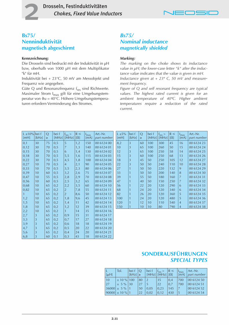
L ±5% bei f Q bei f fres > R � Imax Art.-Nr.[mH] [kHz] ≥ [MHz] [MHz] [�] [mA] part number
8,2 3 60 100 300 45 16 00 6124 2310 3 65 100 260 50 15 00 6124 2412 3 65 100 250 58 14 00 6124 2515 3 60 100 250 68 13 00 6124 2618 3 45 50 250 105 12 00 6124 2722 3 50 50 240 110 10 00 6124 2827 1 50 50 220 132 9 00 6124 2933 1 50 50 200 140 8 00 6124 3039 1 55 50 180 160 7 00 6124 3147 1 40 50 150 250 7 00 6124 3256 1 22 20 120 290 6 00 6124 3368 1 24 20 120 340 6 00 6124 3482 1 26 20 120 360 5 00 6124 35100 1 24 20 120 480 5 00 6124 36120 1 12 10 110 540 4 00 6124 37150 1 10 10 80 790 4 00 6124 38
L ±10% bei f Q bei f fres > R � Imax Art.-Nr.[mH] [kHz] ≥ [MHz] [MHz] [�] [mA] part number
0,1 30 75 0,5 5 1,2 150 00 6124 000,12 30 70 0,5 7 1,3 140 00 6124 010,15 30 70 0,5 6 1,4 130 00 6124 020,18 30 70 0,5 5,5 1,6 115 00 6124 030,22 30 70 0,5 4,5 1,8 100 00 6124 040,27 10 70 0,5 4 2,1 90 00 6124 050,33 10 70 0,5 3,5 2,3 80 00 6124 060,39 10 60 0,5 3,2 2,6 75 00 6124 070,47 10 55 0,5 2,8 2,9 70 00 6124 080,56 10 60 0,5 2,5 3,2 65 00 6124 090,68 10 65 0,2 2,2 3,5 60 00 6124 100,82 10 65 0,2 2 7,8 55 00 6124 111 10 65 0,2 2 8,6 50 00 6124 121,2 10 65 0,2 1,8 9,6 45 00 6124 131,5 10 65 0,2 1,4 11 42 00 6124 141,8 10 65 0,2 1,2 12 39 00 6124 152,2 10 65 0,2 1 14 35 00 6124 162,7 3 65 0,2 0,9 15 31 00 6124 173,3 3 65 0,2 0,7 17 27 00 6124 183,9 3 65 0,2 0,6 18 18 00 6124 194,7 3 65 0,2 0,5 20 22 00 6124 205,6 3 65 0,2 0,4 24 20 00 6124 216,8 3 60 0,1 0,3 43 18 00 6124 22
Drosseln, FestinduktivitätenChokes, Fixed Value Inductors2
2.11
Bs75/Nenninduktivitätmagnetisch abgeschirmt
Kennzeichnung:Die Drosseln sind bedruckt mit der Induktivität in µHbzw, oberhalb von 1000 µH mit dem Multiplikator"k" für mH. Induktivität bei + 23°C, 50 mV am Messobjekt undFrequenz wie angegeben. Güte Q und Resonanzfrequenz fres sind Richtwerte.Maximaler Strom Imax gilt für eine Umgebungstem-peratur von �u = 40°C. Höhere Umgebungstempera-turen erfordern Verminderung des Stromes.
Bs75/Nominal inductancemagnetically shielded
Marking:The marking on the choke shows its inductancevalue in µH; the lower-case letter "k" after the induc-tance value indicates that the value is given in mH.Inductance given at + 23° C, 50 mV and measure-ment frequency.Figure of Q and self resonant frequency are typicalvalues. The highest rated current is given for anambient temperature of 40°C. Higher ambient temperatures require a reduction of the rated current.
SONDERAUSFÜHRUNGENSPECIAL TYPES
L Tol. bei f Q bei f fres > R � Imax Art.-Nr.[�H] [kHz] ≥ [MHz] [MHz] [�] [mA] part number
10 ± 10 % 100 80 2 35 0,4 700 00 6124 5027 ± 5 % 30 27 5 22 0,7 700 00 6124 5136000 ± 5 % 1 50 0,05 0,23 145 7 00 6124 5290000 ± 10 % 1 22 0,02 0,12 430 5 00 6124 54
Drosseln, FestinduktivitätenChokes, Fixed Value Inductors2
2.12
Bs75/Nenninduktivitätmagnetisch abgeschirmt
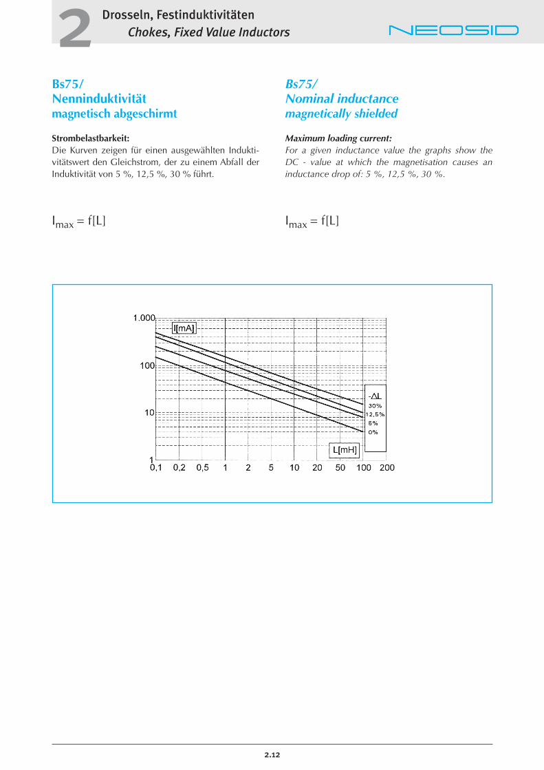
Strombelastbarkeit:Die Kurven zeigen für einen ausgewählten Indukti-vitätswert den Gleichstrom, der zu einem Abfall derInduktivität von 5 %, 12,5 %, 30 % führt.
Imax = f[L]
Bs75/Nominal inductancemagnetically shielded
Maximum loading current:For a given inductance value the graphs show the DC - value at which the magnetisation causes aninductance drop of: 5 %, 12,5 %, 30 %.
Imax = f[L]
Drosseln, FestinduktivitätenChokes, Fixed Value Inductors2
Sd8/Nenninduktivität
Anwendung:Entkopplung in Schaltungen im HF- und NF-Bereich, Funkentstörung, Einsatz alsSpeicherdrossel bis ca. 30 µWsin getakteten Netzteilen, in derKfz - Elektronik für Sicherheits-schaltkreise bis 2,5 A usw.
Daten: Abmessungen:8 x 8 x 9,6 mm
Induktivitätsbereich:3,3 �H � 150 mH
Toleranz:± 10%engere Toleranz auf Anfrage
Betriebstemperaturbereich:-40°C bis +125°C
Lötbarkeit nach DIN IEC 68-2-20 Ta:235°C, 5 Sek.
Lötwärmebeständigkeit nach DIN IEC 68-2-20 Tb:260°C, 5 Sek.
Verpackung: gegurtet nach IEC 286/2
Verpackungseinheit:500 Stück Ammopack
Sd8/Nominal inductance
Application:Decoupling of high and low frequency circuits, radiointerference suppression,energy storage choke in switchmode power supplies up toapprox. 30 µWs, in the automaticelectronics for safety systems up to 2,5 A, etc.
Data:dimensions:8 x 8 x 9,6 mm
Inductance range:3,3 �H � 150 mH
Tolerance:± 10%tighter tolerances on request
Operating temperature range:-40°C to +125°C
Solderability as perDIN IEC 68-2-20 Ta:235°C, 5 sec.
Resistance to soldering heatDIN IEC 68-2-20 Tb:260°C, 5 sec.
Packaging:bandoleered as per IEC 286/2
Packaging size:500 pieces ammopack
2.13
Sd8
Gurtung:
Taping:
P0 = 12,7 ± 0,2F = 5 +0,5 / -0,1H = 16,5 ± 0,3W = 18 -0,5W1 = 9 ± 0,5D0 = 4 ± 0,2
Weitere Einzelheiten sind DIN IEC 286/2zu entnehmen. Das Maß H können wir inbestimmten Grenzen variieren und derjeweils benutzten Bestückungsmaschineanpassen (z. B. 18,5 ± 0,3 für das System“Avisert”).
Further details can be found in DIN IEC286/2 publication. Within certain limits,dimension H can be adapted to suit the insertion machine (18,5 ± 0,3 for “Avi-sert” system ).
Drosseln, FestinduktivitätenChokes, Fixed Value Inductors2
2.14
Sd8/Nenninduktivität
Kennzeichnung:Die Drosseln sind bedruckt mit der Induktiviät in µHbzw, oberhalb von 1000 µH mit dem Multiplikator"k" für mH. Güte Q, Resonanzfrequenz fres sind Richtwerte.Maximaler Strom Imax bezieht sich auf einen Abfallder Induktivität um ca. 3% und gilt für eine Umgebungstemperatur von von 40°C. HöhereUmgebungstemperaturen erfordern Verminderungdes Stromes.
Sd8/Nominal inductance
Marking:The marking on the choke shows its inductancevalue in µH; the lower-case letter "k" after the inductance value indicates that the value is given in mH.Figure of Q, self resonant frequency are typicalvalues. The highest rated current is given for anambient temperature of 40° C. Higher ambient temperatures require a reduction of the rated current.
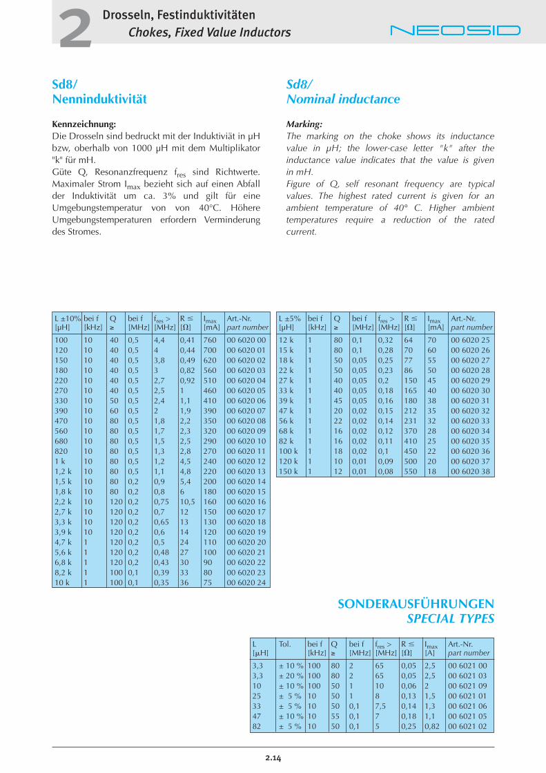
L ±5% bei f Q bei f fres > R � Imax Art.-Nr.[µH] [kHz] ≥ [MHz] [MHz] [�] [mA] part number
12 k 1 80 0,1 0,32 64 70 00 6020 2515 k 1 80 0,1 0,28 70 60 00 6020 2618 k 1 50 0,05 0,25 77 55 00 6020 2722 k 1 50 0,05 0,23 86 50 00 6020 2827 k 1 40 0,05 0,2 150 45 00 6020 2933 k 1 40 0,05 0,18 165 40 00 6020 3039 k 1 45 0,05 0,16 180 38 00 6020 3147 k 1 20 0,02 0,15 212 35 00 6020 3256 k 1 22 0,02 0,14 231 32 00 6020 3368 k 1 16 0,02 0,12 370 28 00 6020 3482 k 1 16 0,02 0,11 410 25 00 6020 35100 k 1 18 0,02 0,1 450 22 00 6020 36120 k 1 10 0,01 0,09 500 20 00 6020 37150 k 1 12 0,01 0,08 550 18 00 6020 38
L ±10% bei f Q bei f fres > R � Imax Art.-Nr.[µH] [kHz] ≥ [MHz] [MHz] [�] [mA] part number
100 10 40 0,5 4,4 0,41 760 00 6020 00120 10 40 0,5 4 0,44 700 00 6020 01150 10 40 0,5 3,8 0,49 620 00 6020 02180 10 40 0,5 3 0,82 560 00 6020 03220 10 40 0,5 2,7 0,92 510 00 6020 04270 10 40 0,5 2,5 1 460 00 6020 05330 10 50 0,5 2,4 1,1 410 00 6020 06390 10 60 0,5 2 1,9 390 00 6020 07470 10 80 0,5 1,8 2,2 350 00 6020 08560 10 80 0,5 1,7 2,3 320 00 6020 09680 10 80 0,5 1,5 2,5 290 00 6020 10820 10 80 0,5 1,3 2,8 270 00 6020 111 k 10 80 0,5 1,2 4,5 240 00 6020 121,2 k 10 80 0,5 1,1 4,8 220 00 6020 131,5 k 10 80 0,2 0,9 5,4 200 00 6020 141,8 k 10 80 0,2 0,8 6 180 00 6020 152,2 k 10 120 0,2 0,75 10,5 160 00 6020 162,7 k 10 120 0,2 0,7 12 150 00 6020 173,3 k 10 120 0,2 0,65 13 130 00 6020 183,9 k 10 120 0,2 0,6 14 120 00 6020 194,7 k 1 120 0,2 0,5 24 110 00 6020 205,6 k 1 120 0,2 0,48 27 100 00 6020 216,8 k 1 120 0,2 0,43 30 90 00 6020 228,2 k 1 100 0,1 0,39 33 80 00 6020 2310 k 1 100 0,1 0,35 36 75 00 6020 24
SONDERAUSFÜHRUNGENSPECIAL TYPES
L Tol. bei f Q bei f fres > R � Imax Art.-Nr.[�H] [kHz] ≥ [MHz] [MHz] [�] [A] part number
3,3 ± 10 % 100 80 2 65 0,05 2,5 00 6021 003,3 ± 20 % 100 80 2 65 0,05 2,5 00 6021 0310 ± 10 % 100 50 1 10 0,06 2 00 6021 0925 ± 5 % 10 50 1 8 0,13 1,5 00 6021 0133 ± 5 % 10 50 0,1 7,5 0,14 1,3 00 6021 0647 ± 10 % 10 55 0,1 7 0,18 1,1 00 6021 0582 ± 5 % 10 50 0,1 5 0,25 0,82 00 6021 02
Drosseln, FestinduktivitätenChokes, Fixed Value Inductors2
Bs11/Nenninduktivitätmagnetisch abgeschirmt
Anwendung:Entkopplung in Schaltungen im HF- und NF-Bereich, Funkentstörung, insbesonderezur Vermeidung von Einstreuungen magnetischerFelder in oder von Nachbar-bauelementen. Einsatz in derAudio- und Videotechnik sowiein anderen Schaltungen derNachrichtentechnik.
Aufbau:Drosseln Bs11 sind durch eineFerritkappe magnetisch abge-schirmt und mit einemGießharz vergossen.
Daten: Induktivitätsbereich:10 �H � 100 mH
Betriebstemperaturbereich:-25°C bis +50°C
Lötbarkeit nach DIN IEC 68-2-20 Ta:235°C, 5 Sek.
Lötwärmebeständigkeit nach DIN IEC 68-2-20 Tb:260°C, 5 Sek.
Verpackung: Palette
Verpackungseinheit:50 Stück/Lage
Bs11/Nominal inductancemagnetically shielded
Application:Decoupling of RF and LF circuits,especially to prevent penetration of stray magnetic fields into or fromadjacent components. The chokesBs 11 are designed for use in audioand video electronic equipment aswell as other electronic devices.
Design:Bs11 are magnetically screened bymeans of a ferrite cup core and arefiled with an epoxy resin.
Data:Inductance range:10 �H � 100 mH
Operating temperature range:-25°C to +50°C
Solderability as perDIN IEC 68-2-20 Ta:235°C, 5 sec.
Resistance to soldering heatDIN IEC 68-2-20 Tb:260°C, 5 sec.
Packaging:tray
Packaging size:50 pieces/layer
2.15
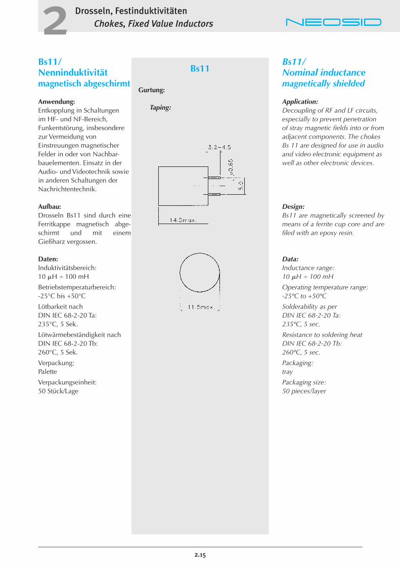
Bs11
Gurtung:
Taping:
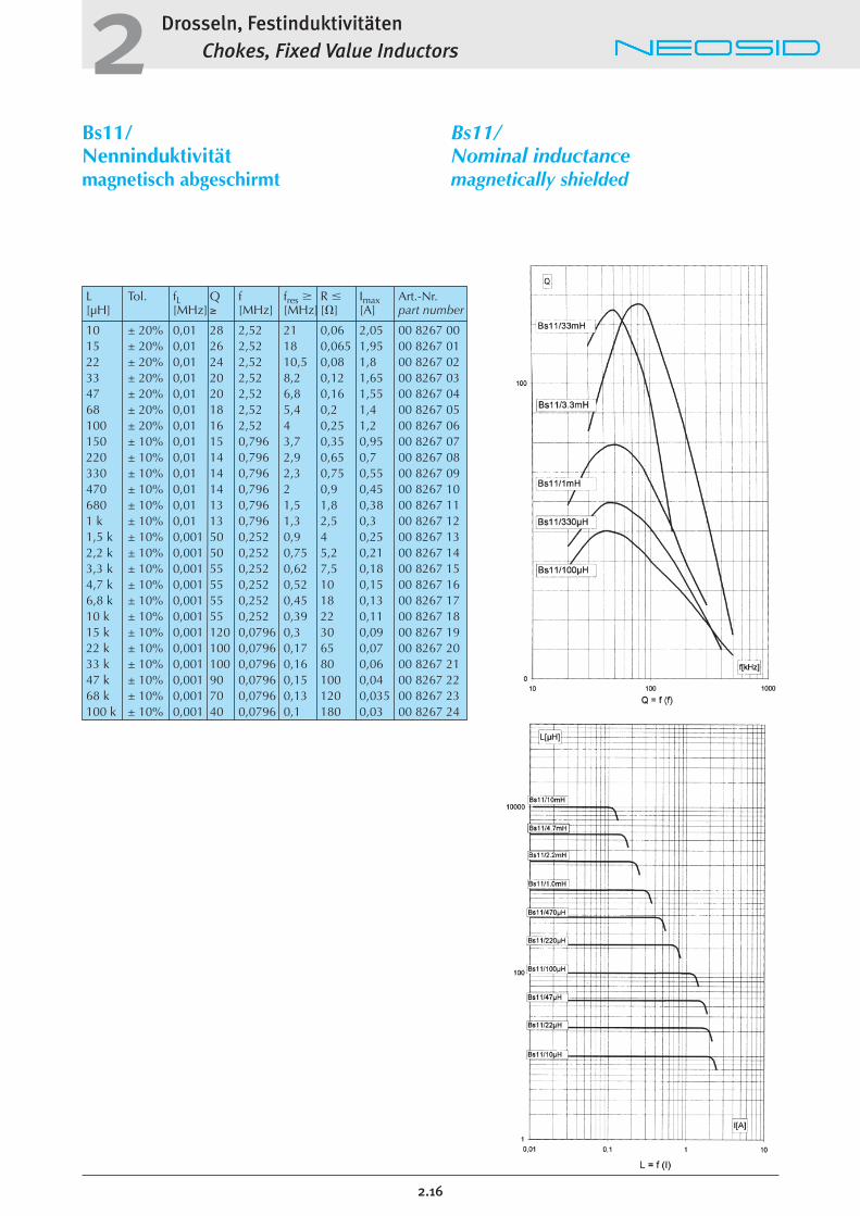
L Tol. fL Q f fres R � Imax Art.-Nr.[µH] [MHz] ≥ [MHz] [MHz] [�] [A] part number
10 ± 20% 0,01 28 2,52 21 0,06 2,05 00 8267 0015 ± 20% 0,01 26 2,52 18 0,065 1,95 00 8267 0122 ± 20% 0,01 24 2,52 10,5 0,08 1,8 00 8267 0233 ± 20% 0,01 20 2,52 8,2 0,12 1,65 00 8267 0347 ± 20% 0,01 20 2,52 6,8 0,16 1,55 00 8267 0468 ± 20% 0,01 18 2,52 5,4 0,2 1,4 00 8267 05100 ± 20% 0,01 16 2,52 4 0,25 1,2 00 8267 06150 ± 10% 0,01 15 0,796 3,7 0,35 0,95 00 8267 07220 ± 10% 0,01 14 0,796 2,9 0,65 0,7 00 8267 08330 ± 10% 0,01 14 0,796 2,3 0,75 0,55 00 8267 09470 ± 10% 0,01 14 0,796 2 0,9 0,45 00 8267 10680 ± 10% 0,01 13 0,796 1,5 1,8 0,38 00 8267 111 k ± 10% 0,01 13 0,796 1,3 2,5 0,3 00 8267 121,5 k ± 10% 0,001 50 0,252 0,9 4 0,25 00 8267 132,2 k ± 10% 0,001 50 0,252 0,75 5,2 0,21 00 8267 143,3 k ± 10% 0,001 55 0,252 0,62 7,5 0,18 00 8267 154,7 k ± 10% 0,001 55 0,252 0,52 10 0,15 00 8267 166,8 k ± 10% 0,001 55 0,252 0,45 18 0,13 00 8267 1710 k ± 10% 0,001 55 0,252 0,39 22 0,11 00 8267 1815 k ± 10% 0,001 120 0,0796 0,3 30 0,09 00 8267 1922 k ± 10% 0,001 100 0,0796 0,17 65 0,07 00 8267 2033 k ± 10% 0,001 100 0,0796 0,16 80 0,06 00 8267 2147 k ± 10% 0,001 90 0,0796 0,15 100 0,04 00 8267 2268 k ± 10% 0,001 70 0,0796 0,13 120 0,035 00 8267 23100 k ± 10% 0,001 40 0,0796 0,1 180 0,03 00 8267 24
Drosseln, FestinduktivitätenChokes, Fixed Value Inductors2
2.16
Bs11/Nenninduktivitätmagnetisch abgeschirmt
Bs11/Nominal inductancemagnetically shielded
Drosseln, FestinduktivitätenChokes, Fixed Value Inductors2
Sd12k/Nenninduktivität
Anwendung:Entkopplung in Schaltungen im NF-Bereich, Funkentstörung,Einsatz als Speicherdrossel bis ca. 180 µWs in getaktetenNetzteilen, in der Kfz-Elektronikfür Sicherheitsschaltkreise bis5,5 A usw..
Daten: Induktivitätsbereich:10 �H � 3,3 mH
Toleranz:± 10%engere Toleranz auf Anfrage
Betriebstemperaturbereich:-25°C bis +125°C
Lötbarkeit nach DIN IEC 68-2-20 Ta:235°C, 5 Sek.
Lötwärmebeständigkeit nach DIN IEC 68-2-20 Tb:260°C, 5 Sek.
zulässige Verlustleistungbei 40°:ca 1 W
Verpackung: Palette
Verpackungseinheit:50 Stück/Lage
Sd12k/Nominal inductance
Application:Decoupling of low frequency circuits, radio interference suppression, energy storage chokein switch mode power supplies upto app. 180 µWs, in the automotiveelectronics for safety systems up to5.5 A, etc..
Data:Inductance range:10 �H � 3,3 mH
Tolerance:± 10%tighter tolerances on request
Operating temperature range:-25°C to +125°C
Solderability as perDIN IEC 68-2-20 Ta:235°C, 5 sec.
Resistance to soldering heatDIN IEC 68-2-20 Tb:260°C, 5 sec.
Permissible power lossat �u = 40°:app. 1 W
Packaging:tray
Packaging size:50 pieces/layer
2.17
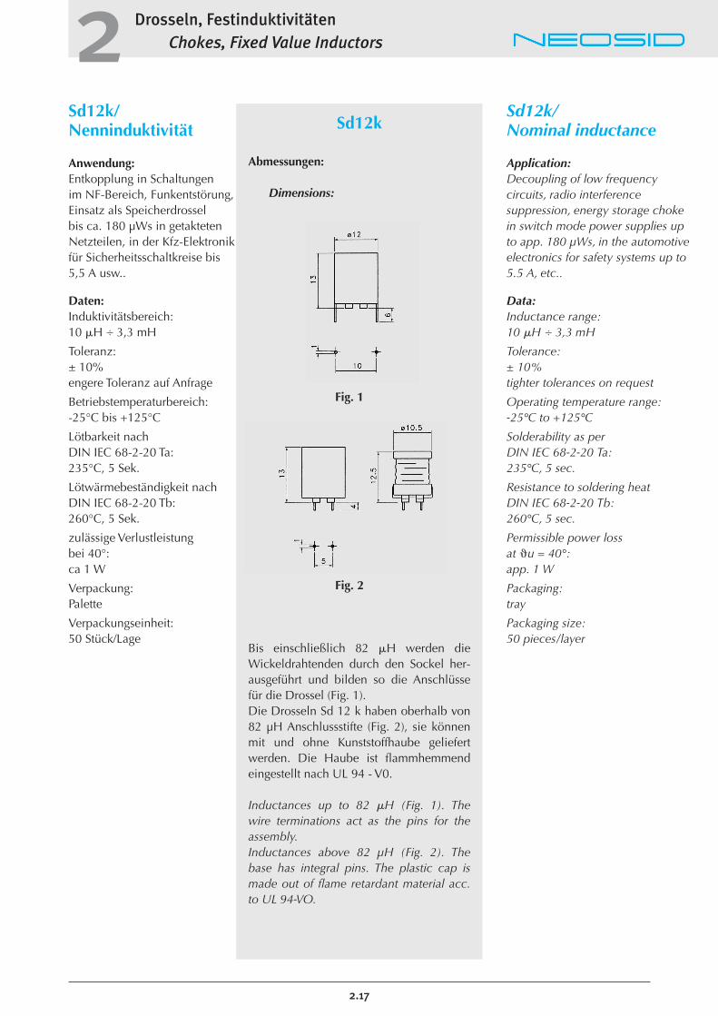
Sd12k
Abmessungen:
Dimensions:
Fig. 1
Fig. 2
Bis einschließlich 82 �H werden dieWickeldrahtenden durch den Sockel her-ausgeführt und bilden so die Anschlüssefür die Drossel (Fig. 1).Die Drosseln Sd 12 k haben oberhalb von82 µH Anschlussstifte (Fig. 2), sie könnenmit und ohne Kunststoffhaube geliefertwerden. Die Haube ist flammhemmendeingestellt nach UL 94 - V0.
Inductances up to 82 �H (Fig. 1). The wire terminations act as the pins for theassembly.Inductances above 82 µH (Fig. 2). Thebase has integral pins. The plastic cap ismade out of flame retardant material acc.to UL 94-VO.
Drosseln, FestinduktivitätenChokes, Fixed Value Inductors2
2.18
Sd12k/Nenninduktivität
Sd12k/Nominal inductance
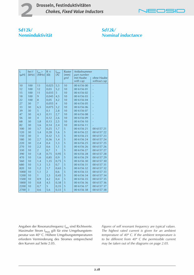
L bei f fres > R � Imax Raster Artikelnummer[�H] [kHz] [MHz] [�] [A] [mm] part number
grid mit Haube ohne Haubewith cap without cap
10 100 13 0,025 5,5 10 00 6156 00 -12 100 12 0,03 5,2 10 00 6156 01 -15 100 11 0,035 5 10 00 6156 02 -18 100 9 0,045 4,5 10 00 6156 03 -22 100 8 0,05 4,2 10 00 6156 04 -27 30 7 0,055 4 10 00 6156 05 -33 30 6,5 0,075 3,2 10 00 6156 06 -39 30 5 0,1 2,8 10 00 6156 07 -47 30 4,3 0,11 2,7 10 00 6156 08 -56 30 4 0,12 2,6 10 00 6156 09 -68 30 3,8 0,13 2,5 10 00 6156 10 -82 30 3,6 0,14 2,4 10 00 6156 11 -100 30 3,7 0,25 1,7 5 00 6156 21 00 6157 21120 30 3,4 0,28 1,6 5 00 6156 22 00 6157 22150 30 3 0,32 1,5 5 00 6156 23 00 6157 23180 30 2,7 0,36 1,4 5 00 6156 24 00 6157 24220 30 2,4 0,4 1,3 5 00 6156 25 00 6157 25270 10 2,2 0,6 1,1 5 00 6156 26 00 6157 26330 10 2 0,7 1 5 00 6156 27 00 6157 27390 10 1,8 0,75 0,95 5 00 6156 28 00 6157 28470 10 1,6 0,85 0,9 5 00 6156 29 00 6157 29560 10 1,4 1,35 0,75 5 00 6156 30 00 6157 30680 10 1,3 1,5 0,7 5 00 6156 31 00 6157 31820 10 1,2 1,7 0,65 5 00 6156 32 00 6157 321000 10 1,1 2 0,6 5 00 6156 33 00 6157 331200 10 1 3,5 0,45 5 00 6156 34 00 6157 341500 10 0,9 4,2 0,4 5 00 6156 35 00 6157 351800 10 0,8 4,5 0,38 5 00 6156 36 00 6157 362200 10 0,7 5 0,35 5 00 6156 37 00 6157 372700 3 0,6 5,6 0,33 5 00 6156 38 00 6157 38
Angaben der Resonanzfrequenz fres sind Richtwerte.Maximaler Strom Imax gilt für eine Umgebungstem-peratur von 40° C. Höhere Umgebungstemperaturenerfordern Verminderung des Stromes entsprechendden Kurven auf Seite 2.05.
Figures of self resonant frequency are typical values.The highest rated current is given for an ambienttemperature of 40° C. If the ambient temperature isto be different from 40° C the permissible currentmay be taken out of the diagrams on page 2.05.
Drosseln, FestinduktivitätenChokes, Fixed Value Inductors2
Sd12/Nenninduktivität
Anwendung:Entkopplung in Schaltungen im NF-Bereich, Funkentstörung,Einsatz als Speicherdrossel bis ca. 180 µWs in getaktetenNetzteilen, in der Kfz-Elektronikfür Sicherheitsschaltkreise bis 6 A usw..
Daten: Induktivitätsbereich:10 �H � 15 mH
Toleranz:± 10%engere Toleranz auf Anfrage
Betriebstemperaturbereich:-25°C bis +125°C
Lötbarkeit nach DIN IEC 68-2-20 Ta:235°C, 5 Sek.
Lötwärmebeständigkeit nach DIN IEC 68-2-20 Tb:260°C, 5 Sek.
Verpackung: Palette
Verpackungseinheit:50 Stück/Lage
Sd12/Nominal inductance
Application:Decoupling of high and low frequency circuits, etc. We recommend these Chokes forapplication in telecommunication,video equipment and electronicdata processing systems.
Data:Inductance range:10 �H � 15 mH
Tolerance:± 10%tighter tolerances on request
Operating temperature range:-25°C to +125°C
Solderability as perDIN IEC 68-2-20 Ta:235°C, 5 sec.
Resistance to soldering heatDIN IEC 68-2-20 Tb:260°C, 5 sec.
Packaging:tray
Packaging size:50 pieces/layer
2.19
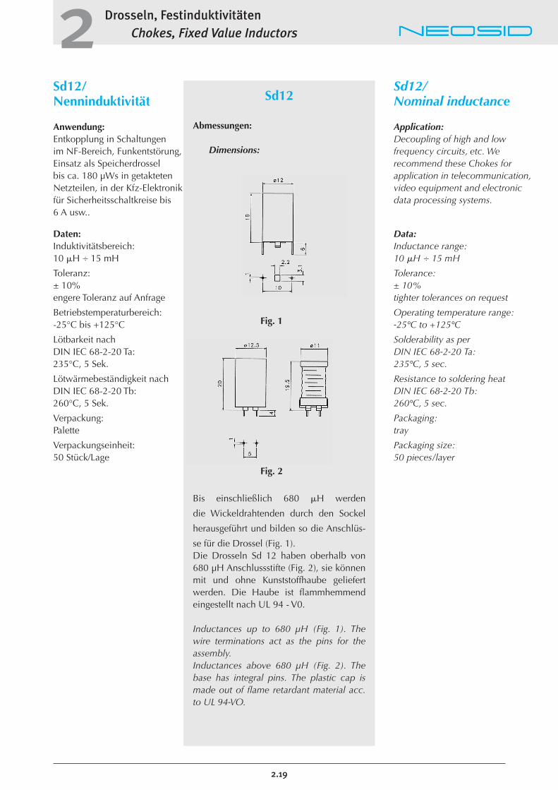
Sd12
Abmessungen:
Dimensions:
Fig. 1
Fig. 2
Bis einschließlich 680 �H werden
die Wickeldrahtenden durch den Sockel
herausgeführt und bilden so die Anschlüs-
se für die Drossel (Fig. 1).Die Drosseln Sd 12 haben oberhalb von680 µH Anschlussstifte (Fig. 2), sie könnenmit und ohne Kunststoffhaube geliefertwerden. Die Haube ist flammhemmendeingestellt nach UL 94 - V0.
Inductances up to 680 µH (Fig. 1). Thewire terminations act as the pins for theassembly.Inductances above 680 µH (Fig. 2). Thebase has integral pins. The plastic cap ismade out of flame retardant material acc.to UL 94-VO.
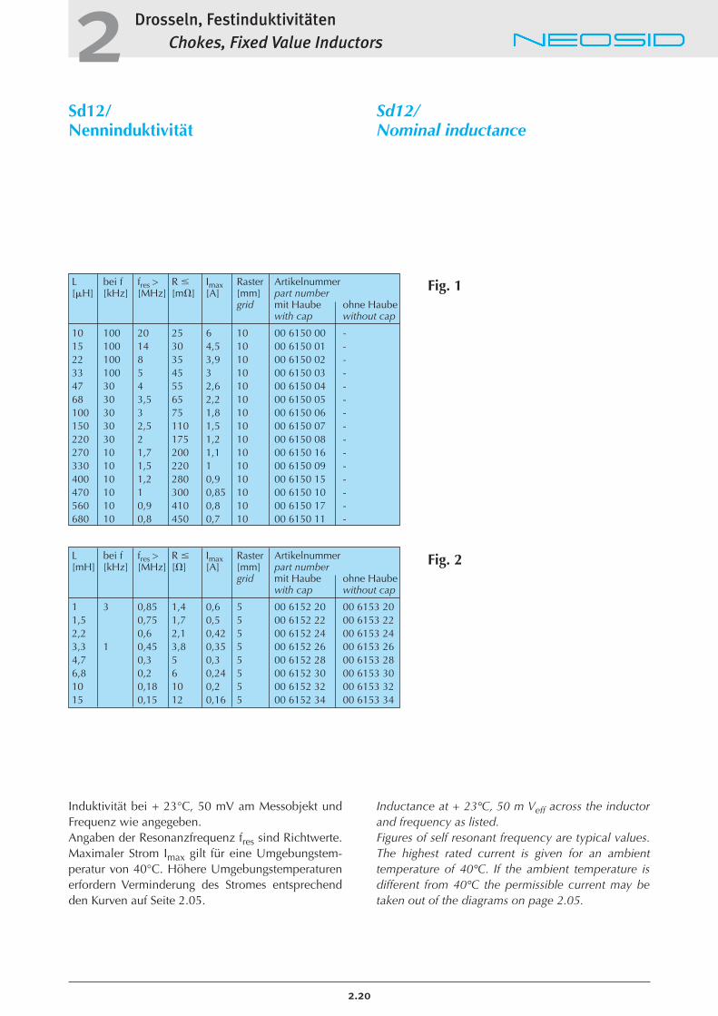
L bei f fres > R � Imax Raster Artikelnummer[�H] [kHz] [MHz] [m�] [A] [mm] part number
grid mit Haube ohne Haubewith cap without cap
10 100 20 25 6 10 00 6150 00 -15 100 14 30 4,5 10 00 6150 01 -22 100 8 35 3,9 10 00 6150 02 -33 100 5 45 3 10 00 6150 03 -47 30 4 55 2,6 10 00 6150 04 -68 30 3,5 65 2,2 10 00 6150 05 -100 30 3 75 1,8 10 00 6150 06 -150 30 2,5 110 1,5 10 00 6150 07 -220 30 2 175 1,2 10 00 6150 08 -270 10 1,7 200 1,1 10 00 6150 16 -330 10 1,5 220 1 10 00 6150 09 -400 10 1,2 280 0,9 10 00 6150 15 -470 10 1 300 0,85 10 00 6150 10 -560 10 0,9 410 0,8 10 00 6150 17 -680 10 0,8 450 0,7 10 00 6150 11 -
Drosseln, FestinduktivitätenChokes, Fixed Value Inductors2
2.20
Sd12/Nenninduktivität
Sd12/Nominal inductance
Fig. 1
Fig. 2
Induktivität bei + 23°C, 50 mV am Messobjekt undFrequenz wie angegeben.Angaben der Resonanzfrequenz fres sind Richtwerte.Maximaler Strom Imax gilt für eine Umgebungstem-peratur von 40°C. Höhere Umgebungstemperaturenerfordern Verminderung des Stromes entsprechendden Kurven auf Seite 2.05.
Inductance at + 23°C, 50 m Veff across the inductorand frequency as listed.Figures of self resonant frequency are typical values.The highest rated current is given for an ambienttemperature of 40°C. If the ambient temperature isdifferent from 40°C the permissible current may betaken out of the diagrams on page 2.05.
L bei f fres > R � Imax Raster Artikelnummer[mH] [kHz] [MHz] [�] [A] [mm] part number
grid mit Haube ohne Haubewith cap without cap
1 3 0,85 1,4 0,6 5 00 6152 20 00 6153 201,5 0,75 1,7 0,5 5 00 6152 22 00 6153 222,2 0,6 2,1 0,42 5 00 6152 24 00 6153 243,3 1 0,45 3,8 0,35 5 00 6152 26 00 6153 264,7 0,3 5 0,3 5 00 6152 28 00 6153 286,8 0,2 6 0,24 5 00 6152 30 00 6153 3010 0,18 10 0,2 5 00 6152 32 00 6153 3215 0,15 12 0,16 5 00 6152 34 00 6153 34
L ±10% bei f fres > R � Imax Art.-Nr.[�H] [kHz] [MHz] [m�] [mA] part number
4,7 1 30 11 12,5 00 6014 016,8 1 25 14 11 00 6014 0210 1 20 21 8,5 00 6014 0315 1 15 26 8 00 6014 0422 1 10 31 7,5 00 6014 0533 1 6,5 45 6 00 6014 0639 1 5 50 6 00 6014 0747 1 3,5 55 5,5 00 6014 0856 1 3 60 5 00 6014 0968 1 2,5 80 4,5 00 6014 10120 1 2 130 3,5 00 6014 30
Drosseln, FestinduktivitätenChokes, Fixed Value Inductors2
Sd14/Nenninduktivität
Anwendung:Entkopplung und Siebung inGleichrichterschaltungen, Funkentstörung, Einsatz alsSpeicherdrossel in getaktetenNetzteilen. Sie hat einen niedrigen Gleichstromwider-stand und kann mit hohen Strömen belastet werden.
Aufbau:In eine spulenkörperlose Wicklung ist ein Zylinderkernaus Ferrit F 2 eingeklebt. EineHaube aus Polycarbonatschützt die Drossel gegenmechanische Einflüsse undsorgt für eine hohe Spannungs-festigkeit gegenüber Nachbar-bauelementen.
Daten: Betriebstemperaturbereich:-40°C bis +125°C
Lötbarkeit nach DIN IEC 68-2-20 Ta:235°C, 5 Sek.
Lötwärmebeständigkeit nach DIN IEC 68-2-20 Tb:260°C, 5 Sek.
Auszugsfestigkeit der DrähteDIN IEC 68-2-21 Ua1:> 20 N
zulässige Verlustleistungbei 40°: ca. 1,8 W
Verpackung: Palette
Verpackungseinheit:50 Stück/Lage
Sd14/Nominal inductance
Application:Decoupling, filtering of rectifier circuits, radio interference suppression, energy storage chokein power supplies. For high currentload and low DC resistance.
Design:Free-mounting winding of EnCuwire with glued- in rod ferrite corein F 2 grade. A polycarbonatecover protects the choke againstmechanical damage and provideshigh voltage insulation to othercomponents
Data:Operating temperature range:-40°C to +125°C
Solderability as perDIN IEC 68-2-20 Ta:235°C, 5 sec.
Resistance to soldering heatDIN IEC 68-2-20 Tb:260°C, 5 sec.
Pulling strength of lead out wiresDIN IEC 68-2-21 Ua1:> 20 N
Permissible power lossat �u = 40°: app. 1,8 W
Packaging:tray
Packaging size:50 pieces/layer
2.21
Sd14
Abmessungen:
Dimensions
* Andere Anschlussdrahtlängen sind lieferbar.Chokes with other length of terminations are available too.
Induktivität bei +23°C, 50 mV am Messobjekt und Frequenz wie angegeben. Angaben der Resonanzfrequenz fres sindRichtwerte. Maximaler Strom Imax gilt füreine Umgebungstemperatur von 40°C.Höhere Umgebungstemperaturen erfor-dern Verminderung des Stromes entspre-chend den Kurven auf Seite 2.05.
Inductance at +23°C, 50 mVeff across theinductor and frequency as listed.Figures of self resonant frequency are typical values. The highest rated current is given for an ambient temperature of40°C. If the ambient temperature is different from 40°C the permissible current may be taken out of the diagramson page 2.05.
Bez. L Tol. bei f R � Imax d1 a l d Wickelsinn Art.-Nr.type [�H] ± % [kHz] [m�] [A] winding part no. Part number
rechts linksclockw. anticlockw.
Z 1,5 0,5 10 300 20 5 0,7 4,3 6,7 3 X 00 6064 00Z 1,5 0,7 10 300 20 4,2 0,4 4,8 6,7 3 X 00 6064 01Z 1,5 1 10 300 30 3,5 0,35 5,5 6,7 3 X 00 6064 02Z 1,5 1,5 10 300 20 2,6 0,45 7,8 9,8 3 X 00 6064 03Z 2,8s 2 20 300 30 3,8 0,4 5,2 11,5 4,6 X 00 6066 02Z 4 2,2 10 300 20 6 0,6 7 15 5,5 X 00 6081 15Z 2,7 2,4 20 300 10 4 0,71 14,4 16,5 4,5 X 00 6058 00Z 1,5 2,5 10 300 40 2,2 0,35 7,8 9,8 3 X 00 6064 04Z 1,5 3 10 300 50 2 0,3 7,3 9,8 3 X 00 6064 05Z 1,5 4 10 300 40 1,4 0,4 12 13,4 3 X 00 6064 06Z 4 4,7 10 300 20 5 0,56 9 20 5,3 X 00 6081 17Z 4 5,5 10 300 30 5 0,56 10,2 20 5,3 X 00 6081 18Z 1,5 5,6 10 300 50 1,2 0,35 11,2 13,4 3 X 00 6064 07Z 2,8 7 10 100 100 1,8 0,28 8 10 4 X 00 6066 12Z 4 8 10 100 30 3,9 0,6 14,8 20 5,5 X 00 6081 20Z 4 10 10 100 40 3,6 0,56 15 20 5,5 X 00 6081 00Z 4 15 10 30 60 3 0,45 14,2 20 5,5 X 00 6081 10Z 4 25 10 30 70 2,5 0,45 17,2 25 5,5 X 00 6081 30Z 4 28 10 30 80 1,7 0,45 18,7 25 5,5 X 00 6081 26
Drosseln, FestinduktivitätenChokes, Fixed Value Inductors2
Stabkerndrosseln Z.../Nenninduktivität
Anwendung:Stabkerndrosseln der Aus-führung Z werden zur Funkent-störung von Kleinmotoren undelektrischen Kontakten, sowiezur Entkopplung in elektroni-schen Schaltungen verwendet.
Free-suspension chokes Z.../Nominal inductance
Application:Free suspension chokes, type Z areused for small commutator motorsand electrical contacts, as well asin electronic circuits for electro-magnetic compatibility.
2.22
Z...
Abmessungen:
Dimensions
Fig. 1Wickelsinn links/Winding anticlockwise
Fig. 2Wickelsinn rechts/Winding clockwise
Drosseln anderer Ausführung auf Anfrage.Other versions on request.
Elektrische und mechanische Daten/Electrical and mechanical Data:

Drosseln, FestinduktivitätenChokes, Fixed Value Inductors2
Zd6/Breitbanddrossel
Anwendung:Drossel zur breitbandigen Entkopplung von Stromversor-gungen in Antennenverstärkernund anderen Schaltungen derHochfrequenztechnik.
Zd6/Wide-band choke
Application:Wide band chokes are recommended for the suppressionof radio interferences in powersupplies of antenna systems andother electronic devices.
2.23
Zd6
Aufbau: Z Windungszahl ArtikelnummerDesign: [�] No. of turns part number
25 MHz 100 MHz
600 800 2,5 00820512
700 600 3 00820513
400 600 2 00820511
300 500 2 x 1,5 00820510
L1 = L2 Streuinduktivität R1 = R2 Imax Art.-Nr.leakage inductance part number
[mH] [�H] [�] [A]
> 14,5 440 � 2 0,5 00 8201 10> 17,5 550 � 2 0,6 00 8201 11< 25 700 � 2 0,6 00 8201 12> 33 650 � 2 0,6 00 8201 13
Drosseln, FestinduktivitätenChokes, Fixed Value Inductors2
U15/Drossel, Übertrager
Daten: Betriebstemperaturbereich:-20°C bis +110°C
Lötbarkeit nach DIN IEC 68-2-20 Ta:235°C, 5 Sek.
Lötwärmebeständigkeit nach DIN IEC 68-2-20 Tb:260°C, 5 Sek.
Prüfspannung zwischen denWicklungen:1500 V DC, 2 Sek.
Prüfspannung zwischen Wicklungen und Kern:1500 V DC, 2 Sek.
U15/Choke, Transformer
Data:Operating temperature range:-20°C to +110°C
Solderability as perDIN IEC 68-2-20 Ta:235°C, 5 sec.
Resistance to soldering heatDIN IEC 68-2-20 Tb:260°C, 5 sec.
Test voltage betweenwindings:1500 V DC, 2 sec.
Test voltage betweenwindings and core:1500 V DC, 2 sec.°K
2.24
U15
Abmessungen:
Dimensions:
Fig. 1
Fig. 2 Fig. 3
L1 Tol. R Imax Artikelnummer[mH] ± % [�] [A] part number
1 10 � 0,8 1,5 00 8201 00
Übertrager U15/Transformer U15 (Fig. 2): Drossel U15/Choke U15 (Fig. 3):
Drosseln, FestinduktivitätenChokes, Fixed Value Inductors2
R18, R25/StromkompensierteRingkerndrosseln
Anwendung:Die stromkompensierten Drosseln eignen sich zur Netz-entkopplung von Messgeräten,Datenverarbeitungsanlagen,numerisch gesteuertenMaschinen, medizinischen Einrichtungen sowie Anlagen,in denen getaktete Netzteilebenutzt werden.
Aufbau:Die stromkompensierten Drosseln sind mit Ferritkernenaufgebaut, die zwei gleicharti-ge, voneinander isolierte Wicklungen tragen. Sie sind inGehäusen aus schwer entflammbarem Kunststoff mit vier Anschluss-Stiften eingegossen. Als Vergussmassedient ein Harz nach UL 94. Eshat eine gute Wärmeleitfähig-keit und gewährleistet damiteine hohe Strombelastbarkeitder Drossel.
Daten: Induktivitätsbereich:0,68 �H � 47 mH
Belastbarkeit:0,6 A � 6 A
Nennspannung:250 V, 50 Hz � 400 Hz
Prüfspannung:1500 V, 50 Hz, 2 Sek.
Spannungsfestigkeit derKunststoffhaube:2500 V, 50 Hz
R18, R25/Standard EncapsulatedLine Filters
Application:Standard encapsulated Line Filters are suitable for suppression of main interference of measuring instruments, data processing systems, numericallycontrolled machines, medicalequipment and installations operating with switches modepower supplies.
Design:Balanced chokes have two identical windings, isolated from each other, on a ferrite ring core. They are encapsulated in housings made of flame retarding plastics material and have four pins. The casting material is a resin accordingto UL 94 specification. Its goodthermal conductivity helps increasing the current load of the choke.
Data:Inductance range:0,68 �H � 47 mH
Loading:0,6 A � 6 A
Nominal voltage:250 V, 50 Hz � 400 Hz
Test voltage:1500 V, 50 Hz, 2 sec.
Electric strength of theplastic cap:2500 V, 50 Hz
2.25
R18, R25
Der Nennstrom in der Tabelle S. 2.26bezieht sich auf eine Umgebungstempera-tur von 40 °C. Bei höherer Umgebung-stemperatur muss der Strom reduziert werden, siehe Seite 2.05.
The value of nominal current is given foran ambient temperature of 40° C. If theambient temperature is higher, the currentmust be reduced, see page 2.05.
Type a b d l
R18.. 12,5 15 18 17R25 17,5 20 25 18
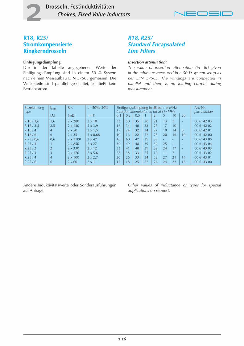
Bezeichnung Inom R < L +50%/-30% Einfügungsdämpfung in dB bei f in MHz Art.-Nr.type Insertion attenutation in dB at f in MHz part number
[A] [m�] [mH] 0,1 0,2 0,5 1 2 5 10 20
R 18 / 1,6 1,6 2 x 280 2 x 10 33 50 35 28 21 13 7 - 00 6142 03R 18 / 2,5 2,5 2 x 130 2 x 3,9 16 34 40 32 25 17 10 - 00 6142 02R 18 / 4 4 2 x 50 2 x 1,5 17 24 32 34 27 19 14 8 00 6142 01R 18 / 6 6 2 x 25 2 x 0,68 10 16 22 27 25 20 16 10 00 6142 00R 25 / 0,6 0,6 2 x 1100 2 x 47 48 60 47 39 33 - - - 00 6143 05R 25 / 1 1 2 x 850 2 x 27 39 49 48 39 32 25 - - 00 6143 04R 25 / 2 2 2 x 330 2 x 12 33 41 48 39 32 24 17 - 00 6143 03R 25 / 3 3 2 x 170 2 x 5,6 28 38 33 25 19 11 7 - 00 6143 02R 25 / 4 4 2 x 100 2 x 2,7 20 26 33 34 32 27 21 14 00 6143 01R 25 / 6 6 2 x 60 2 x 1 12 18 25 27 26 24 22 16 00 6143 00
Drosseln, FestinduktivitätenChokes, Fixed Value Inductors2
2.26
R18, R25/StromkompensierteRingkerndrosseln
Einfügungsdämpfung:Die in der Tabelle angegebenen Werte der Einfügungsdämpfung sind in einem 50 � Systemnach einem Messaufbau DIN 57565 gemessen. DieWickelteile sind parallel geschaltet, es fließt keinBetriebsstrom.
Andere Induktivitätswerte oder Sonderausführungenauf Anfrage.
R18, R25/Standard EncapsulatedLine Filters
Insertion attenuation:The value of insertion attenuation (in dB) given in the table are measured in a 50 � system setup asper DIN 57565. The windings are connected in parallel and there is no loading current during measurement.
Other values of inductance or types for special applications on request.
Drosseln, FestinduktivitätenChokes, Fixed Value Inductors2
TL21 � TL25TL81 � TL85StromkompensierteRingkerndrosseln
Aufbau:Eine kompakte Gehäuseformermöglicht eine Montage auf der Leiterplatte ohnezusätzliche Montagehilfe. Die Wahl zwischen horizontaler und vertikaler Ausführung erlaubt eine optimale Ausnutzung des verfügbaren Raumes.
Der größte Teil der Ringkerndrosseln erfüllt dieAnforderungen der VDE 0565,Teil II, Anwendungsklasse - 40° C � + 125° C (siehe Tabelle).
Daten: Induktivitätsbereich:0,4 mH � 47 mH
Belastbarkeit:0,3 A � 12 A
Nennspannung:250 V / AC
Prüfspannung:1500 V, 50 Hz, 2 Sek.
Spannungsfestigkeit derKunststoffhaube:2500 V, 50 Hz
TL21 � TL25TL81 � TL85Standard EncapsulatedLine Filters
Design:This compact encapsulated form which allows mounting onthe print circuit board withoutadditional mounting aids andthe choice between horizontaland vertical design gives anoptimum minding the availablespace.
Most of the toroidal chokescomply with the requirementsof VDE 0565, part II, applicationclass at - 40° C � + 125° C (see table).
Data:Inductance range:0,4 mH � 47 mH
Loading:0,3 A � 12 A
Nominal voltage:250 V / AC
Test voltage:1500 V, 50 Hz, 2 sec.
Electric strength of theplastic cap:2500 V, 50 Hz
2.27
TL21 � TL25TL81 � TL85
Abmessungen:
Dimensions:
Vertikale Ausführung/Vertical typeTL 21 � TL 25
Horizontale Ausführung/Horizontal typeTL 81 � TL 85
Type a b c d e l
TL21 10 5 13 18 2 20TL22 12,5 10 15,5 23 2 25TL23 15 12,5 18 27 2 29TL24 15 12,5 18 32 2 33,5TL25 17,5 12,5 20,5 32 3 36
Type a b c d e l
TL81 15 10 18 17 2 12,5TL82 20 12,5 24 22,5 2 15,5TL83 25 15 30 27 2 17,5TL84 30 20 33 32 2 17,5TL85 35 20 41 37 2 20,5
Drosseln, FestinduktivitätenChokes, Fixed Value Inductors2
2.28
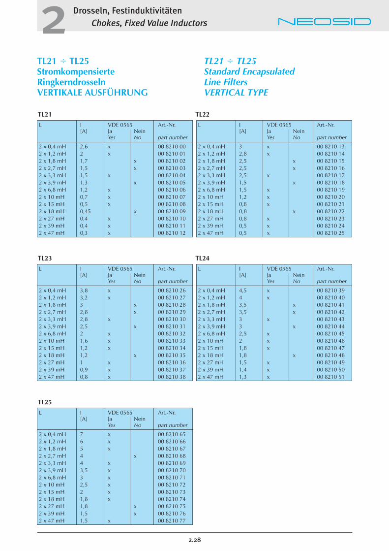
TL21 � TL25StromkompensierteRingkerndrosselnVERTIKALE AUSFÜHRUNG
TL21 � TL25Standard EncapsulatedLine FiltersVERTICAL TYPE
L I VDE 0565 Art.-Nr.[A] Ja Nein
Yes No part number
2 x 0,4 mH 2,6 x 00 8210 00 2 x 1,2 mH 2 x 00 8210 012 x 1,8 mH 1,7 x 00 8210 022 x 2,7 mH 1,5 x 00 8210 032 x 3,3 mH 1,5 x 00 8210 042 x 3,9 mH 1,3 x 00 8210 052 x 6,8 mH 1,2 x 00 8210 062 x 10 mH 0,7 x 00 8210 072 x 15 mH 0,5 x 00 8210 082 x 18 mH 0,45 x 00 8210 092 x 27 mH 0,4 x 00 8210 102 x 39 mH 0,4 x 00 8210 112 x 47 mH 0,3 x 00 8210 12
L I VDE 0565 Art.-Nr.[A] Ja Nein
Yes No part number
2 x 0,4 mH 3 x 00 8210 132 x 1,2 mH 2,8 x 00 8210 142 x 1,8 mH 2,5 x 00 8210 152 x 2,7 mH 2,5 x 00 8210 162 x 3,3 mH 2,5 x 00 8210 172 x 3,9 mH 1,5 x 00 8210 182 x 6,8 mH 1,5 x 00 8210 192 x 10 mH 1,2 x 00 8210 202 x 15 mH 0,8 x 00 8210 212 x 18 mH 0,8 x 00 8210 222 x 27 mH 0,8 x 00 8210 232 x 39 mH 0,5 x 00 8210 242 x 47 mH 0,5 x 00 8210 25
L I VDE 0565 Art.-Nr.[A] Ja Nein
Yes No part number
2 x 0,4 mH 3,8 x 00 8210 262 x 1,2 mH 3,2 x 00 8210 272 x 1,8 mH 3 x 00 8210 282 x 2,7 mH 2,8 x 00 8210 292 x 3,3 mH 2,8 x 00 8210 302 x 3,9 mH 2,5 x 00 8210 312 x 6,8 mH 2 x 00 8210 322 x 10 mH 1,6 x 00 8210 332 x 15 mH 1,2 x 00 8210 342 x 18 mH 1,2 x 00 8210 352 x 27 mH 1 x 00 8210 362 x 39 mH 0,9 x 00 8210 372 x 47 mH 0,8 x 00 8210 38
L I VDE 0565 Art.-Nr.[A] Ja Nein
Yes No part number
2 x 0,4 mH 7 x 00 8210 652 x 1,2 mH 6 x 00 8210 662 x 1,8 mH 5 x 00 8210 672 x 2,7 mH 4 x 00 8210 682 x 3,3 mH 4 x 00 8210 692 x 3,9 mH 3,5 x 00 8210 702 x 6,8 mH 3 x 00 8210 712 x 10 mH 2,5 x 00 8210 722 x 15 mH 2 x 00 8210 732 x 18 mH 1,8 x 00 8210 742 x 27 mH 1,8 x 00 8210 752 x 39 mH 1,5 x 00 8210 762 x 47 mH 1,5 x 00 8210 77
L I VDE 0565 Art.-Nr.[A] Ja Nein
Yes No part number
2 x 0,4 mH 4,5 x 00 8210 392 x 1,2 mH 4 x 00 8210 402 x 1,8 mH 3,5 x 00 8210 412 x 2,7 mH 3,5 x 00 8210 422 x 3,3 mH 3 x 00 8210 432 x 3,9 mH 3 x 00 8210 442 x 6,8 mH 2,5 x 00 8210 452 x 10 mH 2 x 00 8210 462 x 15 mH 1,8 x 00 8210 472 x 18 mH 1,8 x 00 8210 482 x 27 mH 1,5 x 00 8210 492 x 39 mH 1,4 x 00 8210 502 x 47 mH 1,3 x 00 8210 51
TL21 TL22
TL23 TL24
TL25
L I VDE 0565 Art.-Nr.[A] Ja Nein
Yes No part number
2 x 0,4 mH 3 x 00 8211 132 x 1,2 mH 2,8 x 00 8211 142 x 1,8 mH 2,5 x 00 8211 152 x 2,7 mH 2,5 x 00 8211 162 x 3,3 mH 2,5 x 00 8211 172 x 3,9 mH 1,5 x 00 8211 182 x 6,8 mH 1,5 x 00 8211 192 x 10 mH 1,2 x 00 8211 202 x 15 mH 0,8 x 00 8211 212 x 18 mH 0,8 x 00 8211 222 x 27 mH 0,8 x 00 8211 232 x 39 mH 0,5 x 00 8211 242 x 47 mH 0,5 x 00 8211 25
L I VDE 0565 Art.-Nr.[A] Ja Nein
Yes No part number
2 x 0,4 mH 2,6 x 00 8211 002 x 1,2 mH 2 x 00 8211 012 x 1,8 mH 1,7 x 00 8211 022 x 2,7 mH 1,5 x 00 8211 032 x 3,3 mH 1,5 x 00 8211 042 x 3,9 mH 1,3 x 00 8211 052 x 6,8 mH 1,2 x 00 8211 062 x 10 mH 0,7 x 00 8211 072 x 15 mH 0,5 x 00 8211 082 x 18 mH 0,4 x 00 8211 092 x 27 mH 0,4 x 00 8211 102 x 39 mH 0,4 x 00 8211 112 x 47 mH 0,3 x 00 8211 12
L I VDE 0565 Art.-Nr.[A] Ja Nein
Yes No part number
2 x 0,4 mH 12 x 00 8211 652 x 1,2 mH 10 x 00 8211 662 x 1,8 mH 10 x 00 8211 672 x 2,7 mH 8 x 00 8211 682 x 3,3 mH 6 x 00 8211 692 x 3,9 mH 6 x 00 8211 702 x 6,8 mH 4 x 00 8211 712 x 10 mH 3 x 00 8211 722 x 15 mH 2 x 00 8211 732 x 18 mH 2 x 00 8211 742 x 27 mH 1,8 x 00 8211 752 x 39 mH 1,7 x 00 8211 762 x 47 mH 1,5 x 00 8211 77
Drosseln, FestinduktivitätenChokes, Fixed Value Inductors2
2.29
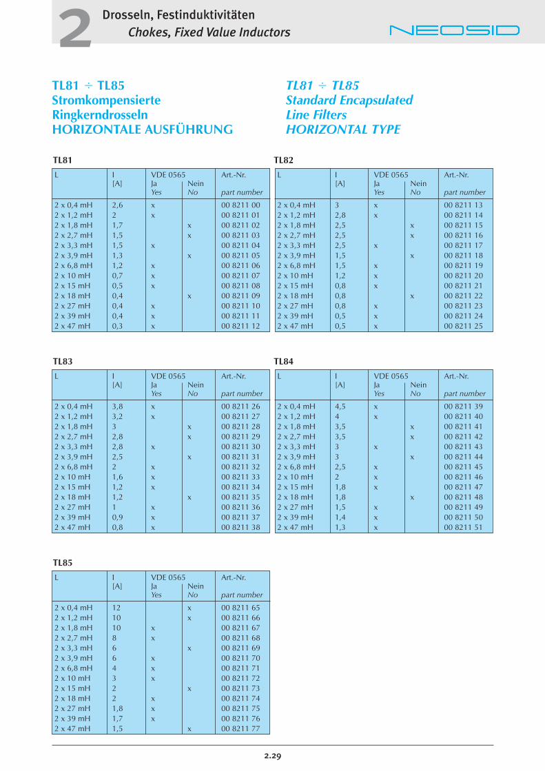
TL81 � TL85StromkompensierteRingkerndrosselnHORIZONTALE AUSFÜHRUNG
TL81 � TL85Standard EncapsulatedLine FiltersHORIZONTAL TYPE
L I VDE 0565 Art.-Nr.[A] Ja Nein
Yes No part number
2 x 0,4 mH 3,8 x 00 8211 262 x 1,2 mH 3,2 x 00 8211 272 x 1,8 mH 3 x 00 8211 282 x 2,7 mH 2,8 x 00 8211 292 x 3,3 mH 2,8 x 00 8211 302 x 3,9 mH 2,5 x 00 8211 312 x 6,8 mH 2 x 00 8211 322 x 10 mH 1,6 x 00 8211 332 x 15 mH 1,2 x 00 8211 342 x 18 mH 1,2 x 00 8211 352 x 27 mH 1 x 00 8211 362 x 39 mH 0,9 x 00 8211 372 x 47 mH 0,8 x 00 8211 38
L I VDE 0565 Art.-Nr.[A] Ja Nein
Yes No part number
2 x 0,4 mH 4,5 x 00 8211 392 x 1,2 mH 4 x 00 8211 402 x 1,8 mH 3,5 x 00 8211 412 x 2,7 mH 3,5 x 00 8211 422 x 3,3 mH 3 x 00 8211 432 x 3,9 mH 3 x 00 8211 442 x 6,8 mH 2,5 x 00 8211 452 x 10 mH 2 x 00 8211 462 x 15 mH 1,8 x 00 8211 472 x 18 mH 1,8 x 00 8211 482 x 27 mH 1,5 x 00 8211 492 x 39 mH 1,4 x 00 8211 502 x 47 mH 1,3 x 00 8211 51
TL81 TL82
TL83 TL84
TL85
Drosseln, FestinduktivitätenChokes, Fixed Value Inductors2
2.30
RM-EP-E-KernÜbertrager
Allgemeines:In unserem reichhaltigem Programm von Wickelgütern haben wir auch eine Vielzahl vonanwenderspezifischen Übertragern mit RM-, EP-, E-Kernen usw. An dieser Stelle beschreiben wir nureinige Beispiele.Bei Bedarf bitten wir um Ihre Anfrage. Je mehr Datenund Anforderungen wir von Ihrem gewünschten Produkt kennen, um so besser können wir Ihnen einoptimal dimensioniertes Bauelement zu einem günstigen Preis anbieten.
Anwendung:RM - Kernspulen und -Übertrager werden in Schaltungen der Hausleittechnik, der Steuer- undRegeltechnik, in Filterschaltungen und zur Spannungswandlung benutzt. Im Vordergrund derEigenschaften stehen hohe Stabilität und bei Kernenmit Luftspalt große Genauigkeit der Induktivitätsowie hohe Güte und gute magnetische Abschirmung. Aufbauten mit EP - Kernen sind gut abgeschirmt und besonders kompakt. Sicherheitsü-bertrager mit hohen Anforderungen an die Spannungsfestigkeit lassen sich einfach herstellenund mit Gießharz einkapseln (Zündübertrager,Impulstrafos). Auch bis zu hohen Frequenzen einsetzbare Speicherdrosseln - mit Luftspalt - sindmöglich. Die bekannten E - Kerne eignen sich zumAufbau von Impulstrafos, stromkompensierten Drosseln und Übertragern für Schaltnetzteile. Kernemit Luftspalt empfehlen wir für Speicherdrosseln, alsSchwingkreisinduktivität für Leuchtstofflampen undähnliche Anwendungen.
Lieferform:Auf leistungsfähigen Fertigungsautomaten stellen wirdiese Bauelemente nach den Kundenspezifikationenher. Wir können die Übertrager je nach Erfordernis mit UL - gelistetem, flammhemmend eingestelltem Gießharz einkapseln. Die Übertragerdurchlaufen eine lückenlose Qualitätskontrolle,deren Messwerte dokumentiert werden können. BeiSicherheitsübertragern wird eine entsprechendeHochspannungsprüfung durchgeführt.
RM-EP-E-coretransformers
General information:In our large variety of wound components you willfind o lot of custom designed transformers and coilswith RM - EP -, and E - cores. On the following pageswe describe a few of them examplarily.We kindly ask for your inquiries. Please use ourrequest forms on page 4.52.
Application:Coils and transformers constructed out of RM - coresare often used in rf - filters, centralized multi servicecontrol systems and dc / dc converters. The mostimportant properties are high stability, effective shielding and precision of inductance as well as highQ in the case of gapped RM-cores. EP-cores offer theadvantage of high compactness and excellentmagnetic shielding. They can be casted with a suitedresin to get a safety transformer meeting high require-ments of electric strength (for example ignition andpulse transformers). Energy storage chokes in the frequency range up to 1 MHz normally need gappedcores. We recommend for this application RM-,EP - and E - cores. The E - shaped cores are well suited for balanced chokes, pulse transformers, dc /dc power converters, tuned inductors for fluorescentlamps and so on.
Delivery:We manufacture these customized wound components on high effective production systems. Itis possible to encapsulate the transformer coils in UL- listed resin to meet special requirements for inflamability. We have installed a consistent qualityinspection and add our measuring reports, if required. For safety transformers a high tension test is made according to the required standards orspecifications.
Drosseln, FestinduktivitätenChokes, Fixed Value Inductors2
RM-EP-E-KernÜbertrager
RM-EP-E-coretransformers
2.31
RM 5 RM 6 EF 12,6
Daten von Ausführungsbeispielen:
Data of some exemplary types:
Wenn Sie Bedarf an speziellen Spulen oder Übertragern haben, fragen Sie uns bitte. Wir helfen Ihnen beider Lösung Ihrer Probleme und fertigen nach Ihren Spezifikationen.
If you have a need for special designed coils or transformers, please do not hesitate to contact us. We willsolve your problems and manufacture according to your specifications.
Bezeichnung n1 n2 n3 L1 L2 L3 fmin fmax Bemerkungen Artikelnummertype [mH] [mH] [mH] [kHz] remarks part number
RM 5 135 15 33 0,4 5 150 00 6535 00
RM 6 64 64 8 0,41 0,41 0,006 10 1000 abgleichbar/adjustable
RM 6 64 64 0,41 0,41 10 1000 abgleichbar/ 00 6536 01adjustable
RM 6 120 1,45 10 1000 abgleichbar/ 00 6536 02adjustable
RM 6 82 0,68 10 1000 abgleichbar/ 00 6536 03adjustable
EF 12,6 140 140 20 20 5 150 00 6540 00
n = Windungen / number of turns
Drosseln, FestinduktivitätenChokes, Fixed Value Inductors2
2.32
Notizen/Notices: