TUM · PDF fileHorst Degen-Hientz, KUGLER MAAG CIE Florian Deißenböck, TU...
82
TUM INSTITUT F ¨ UR INFORMATIK Tagungsband des 3. Workshops zur Software-Qualit¨ atsmodellierung und -bewertung Stefan Wagner, Manfred Broy, Florian Deissenboeck, Peter Liggesmeyer, J¨ urgen M¨ unch (Hrsg.) TUM-I1001 Februar 10 TECHNISCHE UNIVERSIT ¨ ATM ¨ UNCHEN
Transcript of TUM · PDF fileHorst Degen-Hientz, KUGLER MAAG CIE Florian Deißenböck, TU...

T U MI N S T I T U T F U R I N F O R M A T I K
Tagungsband des 3. Workshops zurSoftware-Qualitatsmodellierung und -bewertung
Stefan Wagner, Manfred Broy, Florian Deissenboeck, PeterLiggesmeyer, Jurgen Munch (Hrsg.)
TUM-I1001Februar 10
T E C H N I S C H E U N I V E R S I T A T M U N C H E N

TUM-INFO-02-I1001-0/1.-FIAlle Rechte vorbehaltenNachdruck auch auszugsweise verboten
c!2010
Druck: Institut fur Informatik derTechnischen Universitat Munchen
Vorwort
Qualität ist seit Beginn der kommerziellen Entwicklung von Software ein wichtiges Thema in Forschung und Praxis und diese Bedeutung verstärkt sich noch weiter. Heutige Entwicklungen stellen zusätzliche Anforderungen an verschiedenste Qualitätsaspekte dar. Beispielsweise führt die Durchdringung von kritischen Systemen, wie Flugzeugen oder Automobilen, zu immer höheren Sicherheitsanforderungen an Software. Der starke Anstieg der durchschnittlichen Code-Größen und die Langlebigkeit von Software-Systemen machen die Wartbarkeit zu einer wichtigen Eigenschaft. Die Beherrschung von Software-Qualität stellt somit ein wichtiges Ziel im Software Engineering dar. Diesem Ziel steht aber die Komplexität und Vielschichtigkeit von Qualität gegenüber. Es existiert eine große Zahl an unterschiedlichen Sichten und eine entsprechende Vielzahl an Herangehensweisen zu diesem Thema. Für die praktische Anwendung in der Software-Entwicklung stehen aufgrund dieser Vielfalt überwiegend nur Insellösungen zur Verfügung, die keine ganzheitliche Behandlung des Themas ermöglichen. Beispielsweise sind trotz der engen Verbindung Bewertungen von Zuverlässigkeit und Nutzbarkeit typischerweise nicht integriert. Ein verbreitetes Vorgehen zur Bewältigung dieser Probleme stellt die Verwendung von Qualitätsmodellen und daraus abgeleiteter bzw. damit in Beziehung gesetzter Bewertungen dar. Ein solches Vorgehen wird sowohl in der Forschung untersucht, als auch bereits in der Praxis angewendet. Es hat sich aber oft gezeigt, dass Standards, wie die ISO 9126, nicht direkt anwendbar sind und eigene Qualitätsmodelle für spezifische Situationen erstellt werden müssen. Dies resultiert in teilweise sehr unterschiedlichen Ansätzen zur Qualitätsmodellierung und -bewertung. Ziel dieses Workshops ist es, diese Ansätze vorzustellen und zu diskutieren. Hierbei bauen wir auf die Erfahrungen und Ergebnisse der ersten beiden Ausgaben des Workshops 2008 und 2009.
3. Workshop zur Software-Qualitätsmodellierung und -bewertung
1

Organisation Der Workshop SQMB ’10 wurde in Zusammenarbeit der Technische Universität München und des Fraunhofer IESE organisiert. Der Workshop fand im Zusammenhang mit der Konferenz SE 2010 in Paderborn statt. Organisatoren Stefan Wagner, Technische Universität München Manfred Broy, Technische Universität München Florian Deißenböck, Technische Universität München Peter Liggesmeyer, Fraunhofer IESE Jürgen Münch, Fraunhofer IESE Programmkomitee Klaus Beetz, Siemens Thomas Beil, Daimler Manfred Broy, TU München Horst Degen-Hientz, KUGLER MAAG CIE Florian Deißenböck, TU München Reiner Dumke, Universität Magdeburg Gregor Engels, Universität Paderborn Jürgen Knoblach, BMW Christian Körner, Siemens Peter Liggesmeyer, Fraunhofer IESE Oliver Mäckel, Siemens Jürgen Münch, Fraunhofer IESE
Dietmar Pfahl, Simula Research Laboratory Markus Pizka, itestra Reinhold Plösch, JKU Linz Ralf Reussner, Universität Karlsruhe Wilhelm Schäfer, Universität Paderborn Kurt Schneider, Universität Hannover Andy Schürr, TU Darmstadt Dirk Voelz, SAP Stefan Wagner, TU München Ernest Wallmüller, Qualität & Informatik Andreas Zeller, Universität des Saarlandes Rolf Ziegler, SAP
Externe Gutachter Oliver Sudmann
3. Workshop zur Software-Qualitätsmodellierung und -bewertung
2
From Code-based to Requirement-based Testing
Harry M. Sneed (MPA) ANECON GmbH, Vienna
Abstract: This presentation describes how software testing has evolved from testing programs against themselves – code-based testing – to testing programs against their design – model-based testing – to testing programs against their requirements – requirement-based testing. The basic premise has always been the same, namely that a test is a comparison of actual behavior with expected behavior. The problems have also remained constant and that is what to test and how to describe the expected system behavior. The speaker goes back to the very first test system – RXVP – developed to test the U.S. Ballistic Missile Defense System back in 1975. This system already contained many of the features of current testing systems including instrumentation, assertions, test scripts and execution path monitoring. The speaker then goes on to describe the experience with the first commercial software test laboratory set up in Budapest to test the Siemens Integrated Transport Steuerungssoftware – ITS. This testing project was a landmark project in many respects, a) the test was made on a fixed price basis, b) the test was value driven, and c) the test involved taking the software offshore to test. As such it was a precedent to today’s many offshore testing projects. The Budapest Test Laboratory is a good example of code-based testing. The module test cases were extracted from the code by analyzing the potential execution paths and their input data domain. A test case was generated for every path with the conditional data variables as input parameters. A certain class of errors was found but only 51% of the total errors that were finally reported. The errors in the interaction of the modules with each other and with the environment were only found later in system integration testing. As such this experience points out the limits of unit testing. This inspired the speaker to move on to model-based testing. Case tools were introduced to support users in developing a model of their system. The models of the 80’s were mainly based on structured module design and data flow, but there were other approaches as well such as data modeling with E/R diagrams, process modeling with Petri Nets and logic design with decision tables. These design documents were analyzed to extract test cases directed toward exercising all data flows, all conditions and all data entity relations. Later, in the 1990’s object technology emerged as the leading design approach. UML diagrams were then used to model a system. Testing technology followed suit by analyzing these diagrams to create test cases. The test cases then became use cases, object interactions, state transitions and activity diagram paths. The speaker gives several examples of model-based testing using UML. The current trend is toward requirement-based testing. Here the test cases are extracted from the requirement documents. The speaker explains how requirement texts are automatically analyzed to recognize potential test cases. These may be actions to be executed, object states to be confirmed and conditional rules to be verified. The presentation is rounded off by a review of the experience made with requirement-based testing and the expectations of the speaker concerning the future of software testing. The new solutions are faster and more elegant, yet the main problem remains unsolved and that is to find an infinite numbers of errors in a finite time.
3. Workshop zur Software-Qualitätsmodellierung und -bewertung
3

Goal-oriented Adaptation of Software Quality Models
Michael Kläs, Constanza Lampasona, Adam Trendowicz, Jürgen Münch
Fraunhofer Institute for Experimental Software Engineering Fraunhofer-Platz 1, 67663 Kaiserslautern, Germany
{michael.klaes,constanza.lampasona,adam.trendowicz,juergen muench}@iese fraunhofer.de
Abstract. Objectively measuring and evaluating software quality has become a fundamental task. Many models support software product quality stakeholders in dealing with software quality. In this contribution, we present an approach for adapting software quality models and the challenges that emerge in this re-gard. We propose an adaptation process based on the use of a core quality model and on the existence of a meta-model that provides an essential structure for the base and for the derived adapted models. We show different solution ideas for obtaining a correct adapted quality model and performing goal-oriented, efficient adaptation.
1 Introduction
Given the increasing pervasiveness of software in our society and its growing com-plexity, it is essential to produce high software quality. The importance of satisfying customers’ needs and keeping the software organization profitable have made the objective measurement and evaluation of software quality a fundamental task.
A myriad of software quality models (QMs) intend to support product quality stakeholders in dealing with software quality. Most of these models can be assigned to one of two strategies for modeling software quality [15], namely fixed-model ap-proaches and define-your-own-model approaches. The former usually specify a pre-scriptive set of quality characteristics or metrics, whereas the latter use methods to guide the experts in the derivation of customized QMs. The applicability of fixed models is generally limited to contexts similar to the one in which the model was developed, in contrast to define-your-own approaches, which require intensive expert effort. A third option is represented by the so-called balanced QMs, which are based upon the idea of adapting a core model for specific domains and specific purposes [15]. This adaptation should be as much reproducible as possible and should therefore be guided by a detailed process. The use of a base QM and its systematic customiza-tion may support cost-effective handling of organizational or project quality needs. Furthermore, the fact that software quality for all products would be relying on the same elementary structure represents another potential advantage.
The concept of balanced models plays a central role in the German research project QuaMoCo, in which the work presented in this paper has been conducted. The project aims at developing a software quality standard with a degree of detail that should allow its direct operational application. Besides, the quality standard should have the
3. Workshop zur Software-Qualitätsmodellierung und -bewertung
4
necessary flexibility to cover different technologies for software development. In this contribution, our objective is to present an approach for adapting QMs and the chal-lenges that emerge in this regard.
Existing software quality models are deficient when it comes to their adaptation to the needs of a specific organization or project in a reusable, reproducible manner. Adaptations of QMs are generally based on ISO9126 [14]. Some common modifica-tions are to define attributes [2] or to add quality characteristics for a very specific domain [17, 5].
The literature related to adaptation methods for software product QMs is rather meager. For adapting the ISO9126 QM to the domain of component-based software development, Andreou and Tziakouris [2] take into account the users: component developers, re-users, and end users. The outcome is a quality model especially for original software components. Calero et al. [7] used a general portal quality model for the creation of a special QM for eBanking: BPQM (eBanking Portal Quality Model). To achieve the specialization of the model, a survey was performed among domain experts. Unfortunately, these specific adaptations focus on the resulting adapted QMs and not on a reproducible customization process.
Other authors use define-your-own-model tools to refine their specific models. These customizations have a narrow focus and are difficult to transfer to other con-texts. Andersson and Eriksson [1], for example, present a process for the construction of a QM founded on a basic QM with existing metrics (SOLE quality model). They illustrate how to customize the model to the specific needs of an organization, includ-ing how to identify quality factors and mapping them to metrics. The SOLE quality model [10] has the factor-criteria-metric [16] structure. Bianchi et al. [6] used GQM to refine a specific model. They center their research on QM reuse, i.e., which changes can be requested when a quality model is reused, how to verify that despite the changes made in the reused quality model, it remains suitable for its goals, and what the side effects caused by changing the metrics are on the quality model. Horgan and Khaddaj [13] propose an approach for model refinement based on expert knowl-edge.
Franch and Carvallo [11] present a very general process to build an ISO9126 QM. It should be kept in mind that we are explicitly referring to software product quality and not to process quality. Nevertheless, for the refinement of our tailoring idea, we will consider concepts related to software process adaptation and study their transfer-ability to the customization of software product quality models.
2 Proposed Adaptation Approach
2.1 Adaptation Process Scope
In order to locate the adaptation of a QM within an organization’s structure and proc-esses, we use the Quality Improvement Paradigm (QIP) [4]. QIP defines an abstract six-step process for introducing and continuously improving a technology within an organization, where analogical cycles are applied at the organizational level and at the project level. We recommend embedding quality modeling and model application into
3. Workshop zur Software-Qualitätsmodellierung und -bewertung
5

these cycles (Fig. 1). At the organizational level, the performance of a QM is the subject of continuous improvement. At the project level, the QM is used to evaluate and improve software product quality.
Major QM adaptations should take place in step 3 (Choose Processes) at higher or-ganizational levels such as a whole organization, a business unit, a domain, or a pro-jects portfolio. At the project level, QM adaptation takes place in the analogical step (4.3) and should be limited to minor adjustments, e.g., driven by project-specific quality requirements, without changing the QM structure, in order to preserve con-formance of quality evaluations across software products created at the project level. Therefore, an adaption process has to support three logical activities: reducing, ex-tending, and adjusting a QM.1
2. Set Up GoalsDefine goals w.r.t. the quality of
software products;Define goals w.r.t. the performance
of the quality model
1. CharacterizeIdentify environment characteristics
and assumptions relevant for quality modeling
3. Choose ProcessesAdapt product quality model and
associated processes (e.g., product quality evaluation process).
Plan execution and analysis steps
4. ExecuteApply the quality model at the
project level5. AnalyzeAnalyze data on the perfomance of the quality model; identify causes of
deficiencies and improvement potentials
6. PackagePackage and communicate the
results of analysis and experiences; plan improvements of the quality
model (next QIP cycle)4.24.1 4.3
4.44.54.6
Fig. 1. Scope of the QM adaptation process
2.1 Requirements
Based on the requirements for the definition and application of QMs stated by practi-tioners and scientists within the QuaMoCo project, we condensed three major re-quirements with respect to the adaptation process: • (R1) Correctness – An adapted QM must be syntactically correct in that it remains
conformant to the underlying meta-model (MM) and to the defined consistency rules.
1 QIP refines the first step of the PDCA approach [9] (Plan) into three more detailed ones,
with the remaining three PDCA steps being used very similarly by the QIP [11]. For readers who may be more familiar with the PDCA approach, this means that the quality adaptation process can be thought of as a part of the first step within PDCA. Analogically, the DMAIC cycle [18] could be mapped to the concepts of QIP, and probably, step 3 of QIP would corre-spond to some activity in the Define step of DMAIC.
3. Workshop zur Software-Qualitätsmodellierung und -bewertung
6

• (R2) Goal Orientation – The adaption of a base model should be driven by organ-izational needs and capabilities. In particular, organization-specific and project-specific software quality objectives should be considered.
• (R3) Efficiency – This is concerned with the overhead (e.g., personnel, time, and budget) needed for adapting a QM. Acceptable overhead would differ depending on the organizational level (e.g., more overhead will be allowed for adapting a QM at the level of the whole organization, where such adaptation has a larger scope and is performed relatively rarely).
One major challenge of defining a QM adaptation process is to make it independent of a particular model, i.e., to define a set of adaptation rules that will be universally applicable to any model conformant with the QuaMoCo MM.
2.2 Solution Idea for R1 (Correctness)
Assuring syntactical correctness requires an MM describing the structure of the QM and some consistency rules that should be fulfilled by the QM in order to be compli-ant with the MM. We show the adaptation process on the QuaMoCo MM (Fig. 2) [8]. The two fundamental constructs in this MM are the Quality Aspect tree, which de-scribes and refines the quality characteristic of interest (e.g., maintainability is broken down into the sub-aspects analyzability, stability, changeability, and testability) and the Factors, which capture the product-related factors with the major influence on the Quality Aspects defined (e.g., complexity of source code). A Factor consists of an Entity Type (e.g., source code) and a Property that characterizes it (e.g., complexity). Both provide important information for defining appropriate Measures, with a Meas-ure referring to rules for determining the actual value of a Factor’s occurrence. Based on the Measures, an Impact Evaluation can be specified to determine the concrete impact of the Factor on the Quality Aspects (i.e., a rule mapping the measurement results to a specific value on the evaluation scale). The general tendency whether a factor improves or inhibits a specific Quality Aspect is defined and justified by the corresponding Impact (e.g., high complexity inhibits the analyzability of the product). In order to get an overall statement about the quality of interest, the evaluation results of different Impacts and of different subordinate Quality Aspects have to be combined according to rules defined by Quality Aspect Evaluations (e.g., analyzability and stability evaluations are combined into an overall maintainability statement). One approach for assuring the consistency of an adapted model would be to adapt the QM first, and then check its consistency based on the MM and consistency rules. Another approach for assuring consistency during the adaptation of a QM would be to define a limited set of basic operations that allow transforming a QM from one consistent state into a new consistent state. We propose a compromise between these two options: We allow intermediate inconsistencies and defining rules for a set of basic transforma-tions to highlight inconsistencies and to explain what has to be done to return the QM back to a consistent state. Such basic transformations can be DELete, ADD, or MOD-ify a specific model construct (see Table 1). For instance, if we want to add a new Measure for an existing Factor (i.e., ADD(Measure)), we have to check all Impact Evaluations defined for the Factor and include the Measure in the Impact Evaluation description.
3. Workshop zur Software-Qualitätsmodellierung und -bewertung
7

Table 1. Exemplary consistency rules for basic transformation operations
Construct DEL([Construct]) ADD([Construct]) MOD([Construct]) Measure Modify descriptions of all impact
evaluations that use the measure, in order to remove the deleted measure from the impact evaluation
For each factor to which the meas-ure added belongs, modify related impact evaluation descriptions in order to include the new measure
Check descriptions of all impact evaluations that use the measure, in order to align them with the modifi-cation of the measure (if required)
… … … …
2.3 Solution Idea for R2 (Goal Orientation)
We suggest describing the objective of the adapted QM using the GQM goal template [3]. The GQM goal template is a means for specifying a goal in a structured way. Our aim is not to derive a measurement plan using the GQM approach, but to use the GQM template to formulate the quality modeling goal with respect to which adapta-tion should be performed. The template describes the entities to be considered (Ob-ject), from which perspective we consider them (Viewpoint), the quality aspects of interest (Quality Focus), the adapted QM intention (Purpose), and the environmental characteristics influencing the QM (Context) (for an example goal, see Fig. 2).
+name+description
EntityType
+name+description
Property
+name+description
QualityAspect
+name+description
Measure
+descriptionImpactEvaluation
1
*
isA1*
partOf
+nameEntity MeasurementData ImpactEvaluationResult
+descriptionQualityAspectEvaluation
QAEvaluationResult
**
quantifies
1 *
characterizes
1 *
describes
* *
based on
* *
based on
* *
uses
11
evaluates
11
evaluates
QualitySpecification
Quality Model Application
+descriptionFactor
1*
+justification+effect
Impact
* 1
influences
1..* 1..*
impacts
1
*
type
Quality Evaluation
-name-description
QualityRequirement
1*
(1)
(2)
(3+4)
(5)
Quality Model DefinitonGQM Goal
Evaluate (1: Purpose) the source code(2: Object) from the perspective of a Manager (3: Viewpoint) with respect to its Maintainability (4: Quality Focus) for a product in the embedded domain, developed with C (5: Context).
1*
1
1
1
1
Fig. 2. Quality MM and area of goal-oriented QM adaptation A goal-oriented approach allows us to simplify the adaptation process such that each basic transformation is assigned elemental rules specifying which QM elements need to be adapted and how. For instance, the following goal-oriented rules can be defined for reducing the QM, i.e., removing all its parts that are not relevant for achieving the particular goal: (1) For the purpose of quality evaluation, all constructs defined by the MM are required. For the purpose of quality specification, we can remove irrelevant elements by applying the rule: DEL(Construct ∈ {Measure, Impact Evaluation, Qual-ityAspectEvaluation}). (2) All Factors in which the entity type does not correspond to the Object specified in the QM’s goal can be removed from the QM by applying the rule: DEL(EntityTypes ∉ instanceOf(Object)). For example, if we are interested in source code, this operation removes requirements- and design-related Factors from
3. Workshop zur Software-Qualitätsmodellierung und -bewertung
8

the QM. (3) The Viewpoint identifies relevant Impacts by scoping specific Quality Aspects. Impacts that are irrelevant regarding a particular Viewpoint can be re-moved, together with associated Impact Evaluations, by applying the rule: DEL(QualityAspects ∉ partOf(Viewpoint)). (4) If we are only interested in a specific Quality Aspect (e.g., maintainability, but not reliability), this would further reduce the relevant scope of the adapted QM: DEL(QualityAspects ∉ part of (QualityAspect)). (5) Finally, we have to remove all Measures that cannot be collected in our context, e.g., for C source code this could be object-oriented metrics: DEL(Measure m with m.applicableFor.language ∉ context.language).
2.4 Solution Idea for R3 (Efficiency)
To achieve efficient QM adaption, existing (MM-conformant) QMs should be reused as an adaptation base instead of building a QM from scratch. Further, a base model should cover diverse concrete content, because QM reduction can be more efficiently automated than QM extension. However, including only universally valid content in such a model would lead to a nearly empty model without reuse potential. Thus, the adaptation approach should allow identifying potential reuse candidates.
2.5 Connection of Solution Ideas
In an initial tailoring step, the quality model is reduced to the elements needed for the specific quality modeling goal (R2). We increase reduction efficiency by focusing on the key elements of the GQM goal and by automating the respective basic operations (R3). In further adaption steps, the model can be modified and extended with basic operations, while consistency is assured by associated consistency rules (R1).
3 Summary and Future Work
This paper explains the need for an adaption process for QMs, presents fundamental requirements identified, and sketches an approach that addresses these requirements. The consistency of the adapted QM is covered by the definition of basic operations and corresponding consistency rules; further, the approach explains how to integrate the relevant goals into the adaptation process and addresses the efficiency of adapta-tion through automation and reuse. The next steps will be the refinement of the ap-proach, i.e., the explicit description of a process into which the ideas presented here will be embedded. An empirical evaluation in an industrial environment is also planned, as is a tool for supporting the customization process. A special challenge is seen in the appropriate use of context information.
3. Workshop zur Software-Qualitätsmodellierung und -bewertung
9

4 Acknowledgements
Parts of this work have been funded by the BMBF project QuaMoCo (grant 01 IS 08 023 C). We gratefully acknowledge the contributions and input of Reinhold Plösch, Dominik Kirchler, and Jens Heidrich.
5 References
1. Andersson, T.; Eriksson, I. V. (1996): Modeling the quality needs of an organization’s software. In: HICSS ‘96: Proceedings of the 29th Hawaii International Conference on Sys-tem Sciences Volume 4: Organizational Systems and Technology. Washington, DC, USA: IEEE Computer Society, p. 139.
2. Andreou, A. S.; Tziakouris, M. (2007): A quality framework for developing and evaluat-ing original software components. In: Inf. Softw. Technol., vol. 49, no. 2, pp. 122–141.
3. Basili, V. R. (1992): Software Modeling and Measurement. The Goal/Question/Metric Paradigm. University of Maryland - Dept. of Computer Science: (Computer Science Technical Report Series). - NR CS-TR-2956. - NR UMIACS-TR-92-96.
4. Basili, V. R.; Caldiera, G.; Rombach, H. D. (2002): Experience Factory. In: Marciniak, John J. (Ed.): Encyclopedia of Software Engineering. 2nd Ed. New York: John Wiley & Sons, Vol. 1, pp. 511–519.
5. Behkamal, B.; Kahani, M.; Akbari, M. K. (2009): Customizing ISO 9126 quality model for evaluation of B2B applications. In: Inf. Softw. Technol., vol. 51, no. 3, pp. 599–609.
6. Bianchi, A.; Caivano, D.; Visaggio, G. (2002): Quality models reuse: experimentation on field. In: COMPSAC ‘02: Proceedings of the 26th International Computer Software and Applications Conference on Prolonging Software Life: Development and Redevelopment. Washington, DC, USA: IEEE Computer Society, pp. 535–540.
7. Calero, C.; Cachero, C.; Córdoba, J.; Moraga, M. (2007): PQM vs. BPQM: studying the tailoring of a general quality model to a specific domain. In: Advances in Conceptual Modeling – Foundations and Applications, pp. 192–201.
8. Deissenboeck, F. H. (2009): Quamoco Report: Quality meta model-WP1.3 v1.0 2009-08-17.
9. Deming, W. E. (1986): Out of the crisis. Massachusetts Institute of Technology, Cambrid-ge, Mass.
10. Eriksson, I.; Törn, A. (1991): A model for IS quality. In: Softw. Eng. J., vol. 6, no. 4, pp. 152-158.
11. Franch, X.; Carvallo, J. P. (2003): Using quality models in software package selection. In: IEEE Softw., vol. 20, no. 1, pp. 34–41.
12. Hamann, D. (2006): Towards an integrated approach for software process improvement. Combining software process assessment and software process modeling. Techn. Univ., Diss.--Kaiserslautern, 2005. Stuttgart: Fraunhofer-IRB-Verl. (PhD Theses in Experimental Software Engineering, 19).
13. Horgan, G.; Khaddaj, S. (2009): Use of an adaptable quality model approach in a produc-tion support environment. In: Journal of Systems and Software, vol. 82, no. 4, pp. 730–738.
14. ISO/IEC 9126-1:2001: Software Engineering - Product Quality - Part 1: Quality Model. 15. Klaes, M.; Muench, J. (2008): Balancing upfront definition and customization of quality
models. In: Software-Qualitaetsmodellierung und -bewertung SQMB'08, pp. 26–30.
3. Workshop zur Software-Qualitätsmodellierung und -bewertung
10

16. McCall, J. A.; Richards, P. K.; Walters, G. F. (1977): Factors in Software Quality. Con-cept and Definitions of Software Quality: Final Technical Report Springfield: National Technical Information Service (NTIS), Reportnr. RADC-TR-77-369 (I, II and III).
17. Sharma, A.; Kumar, R.; Grover, P. S. (2008): Estimation of quality for software compo-nents: an empirical approach. In: SIGSOFT Softw. Eng. Notes, vol. 33, no. 6, pp. 1–10.
18. Tayntor, C. B. (2002): Six Sigma Software Development. Boca Raton: Auerbach Publica-tions, 2002.
3. Workshop zur Software-Qualitätsmodellierung und -bewertung
11

Adapting Quality Models for Assessments – Concepts and Tool Support
Reinhold Plösch1, Harald Gruber1, Gustav Pomberger1, Christian Körner2
1 Johannes Kepler University Linz, Altenberger Straße 69,4040 Linz, Austria {reinhold.ploesch, harald.gruber, gustav.pomberger}@jku.at
2 Siemens AG, Corporate Technology – SE 1, Otto-Hahn-Ring 6, 81739 Munich, Germany
Abstract. Operational quality models, i.e., quality models that do not only structure and define quality by means of quality aspects but also contain a larger number of measures, facilitate quality measurement as the laborious task of defining measures can be omitted. An operational quality model often contains a large number of quality aspects and measures; therefore methodological support as well as tool support is necessary to adapt such a quality model to project-specific needs. Based on a general quality adaption framework we have developed a method for tailoring quality models. This method is supported by an accompanying tool. The application of the method and the tool in more than 40 projects proved the practicability of the approach. Nevertheless additional methodological support for deriving quality aspects or quality requirements from (business) goals would be desirable.
Keywords: ISO 9126, Adapting quality models, EMISQ method, SPQR tool
1 Introduction It's the ambitious goal of software engineers to develop good software. What
means “good”? Assessing a product, i.e., determining whether the product (software as well as any other consumer product) is good, has something to do with quality. The term quality may be considered from different viewpoints, leading to different interpretations and definitions. ISO 9126 [8], which follows the product-based and manufacturing-based approaches (as introduced in [4]), defines the term software quality as "the totality of characteristics of an entity that bear on its ability to satisfy stated and implied needs".
This definition gives us an idea about software quality but is too vague for any practical application. To allow measuring software quality, a systematic approach has to be used to derive measures from general properties of software. Quality models provide this in a systematic manner. There are a number of different quality models known in literature. One example of a general model is the so called factor-criteria-metrics-model (FCM-model) [1]. According to this quality model, the quality of software is described by identifying various quality attributes, often called factors or quality aspects. In order to make each factor measurable, it is necessary to refine factors into quality criteria. Factors represent a more user-oriented view, while quality
3. Workshop zur Software-Qualitätsmodellierung und -bewertung
12

criteria reflect a more software-oriented view. The refinement process takes place until quality indicators, i.e., measurable and assessable metrics, can be found for each quality criteria. There exist a number of specific quality models based on this general FCM-approach, e.g., the model defined by ISO 9126 [8], the FURPS model [5], the model defined by McCall [10], the quality model by Barry Boehm [2] or the SATC model [6].
The benefits of these approaches are well structured quality aspect hierarchies that facilitate reasoning about quality and ease finding measures for specific quality aspects. The model proposed by ISO 9126 defines a widely used quality model. Nevertheless, on the level of metrics (in terms of the FCM-model) ISO 9126 provides only some examples for metrics. These examples give good hints how to measure a quality aspect, but the set of measures provided is far from being comprehensive.
One important aspect of EMISQ ("Evaluation Method for Internal Software Quality") [11] was (and still is) the development of operational quality models. Operational in this context means providing a comprehensive set of measures for each quality attribute, with special attention on measures that can be provided automatically by static code analysis tools like PMD [15] or PC-Lint [14]. The current quality model provided by EMISQ contains more than 3,000 measures of 15 different tools. These measures are assigned to two quality models – one that is similar in structure to the ISO 9126 model and a second one that has its emphasis on technical topics and problems (e.g. memory issues, threading issues). This large number of measures makes it necessary to think about an adaptation process and a method as not all 3,000 measures can be applied for each project. Approaches like GQM [16, 17, 18] or SQUID [9] focus on building entire quality models from scratch and cannot be directly used for adaptation tasks, though the result of these approaches (especially the identified quality aspects) could of course be used as input for the tailoring process. Franch and Carvallo [3] propose a six step approach for building (adapting) a quality model based on the ISO 9126 quality model. Both, on the level of quality attributes and on the level of measures they allow the following principal operations:
• Delete-Operations: Remove quality attributes (or later measures) that are not suitable for the domain or the specific project.
• Add-Operations: Add quality attributes (or later measures) that were not included in the original (ISO 9126) quality model but that make sense in the context of the domain or project.
• Modify-Operations: Adapting of thresholds for measures.
Fig. 1 depicts the principal process for adapting the quality model. This general adaptation process needs to be refined in order to provide the necessary support for the adaptation. In our EMISQ method we provide more specific methodological support for this general adaption process (this is described in chapter 2). Chapter 3 describes how the tailoring approach provided by EMISQ is supported by our tool SPQR (“Software Project Quality Reporter”).
3. Workshop zur Software-Qualitätsmodellierung und -bewertung
13

Fig. 1. General adaptation process
2 Tailoring in the EMISQ Assessment Method Besides the quality model aspect, EMISQ is a methodology for systematically
assessing the internal software quality. The assessment model is based on the ISO 14598 [7] standard but extends it significantly. The major differences are:
• Instead of specifying a quality model and finding measures for each project we have developed a pre-defined quality model with measures integrated from various static code analysis tools. This quality model may be tailored for a particular project. The step "Establish rating levels for metrics" of the ISO standard can be excluded completely as its activities are already considered in our quality model.
• Contrary to the ISO standard the evaluation of the quality attributes does not occur automatically after the measures are collected but needs an expert. An aggregation model describes how to sum up quality ratings from the sub-attribute level to the top level.
• The method is substantially supported by a knowledge base, i.e., by a set of structured evaluation guidelines, that guides the evaluation team and provides extra material like checklists, tool configuration files, presentation material, and document templates.
• Furthermore, the evaluation team can use a tool called SPQR (Software Project Quality Reporter) that is aligned with the EMISQ-method. This would of course also be possible when applying ISO 14598, but currently SPQR is tightly focused on the EMISQ-method.
The EMISQ evaluation model consists of eight main activities that are each
divided up into 5 to 10 sub-activities. Fig. 2 depicts the main activities. The first activity – “Establish Purpose of Evaluation” – is a major preparing
activity for the adaptation process. The intention of this step is to identify and define the goals of the evaluation project, e.g., improving the maintainability of a software product or identifying stability and efficiency problems. It has to be found out whether these goals can be achieved by following the EMISQ method or whether additional measures (e.g. dynamic analysis of programs) have to be planned. The result of this activity is a signed project agreement and a set of the goals that have to be considered by the evaluation project.
The adaptation process is spread over three main activities (see Fig. 2). According to the defined goals, the types of products to be analyzed are selected (“Identify Types
3. Workshop zur Software-Qualitätsmodellierung und -bewertung
14

of Products”). The purpose of this activity is to identify those software artifacts that are objects of the assessment, e.g. products, packages or subsystems. During this step all technical issues for the selected software artifacts that are important for the evaluation are documented.
EstablishPurpose ofEvaluation
Identify Types of Products
Specify Quality Model Select Metrics
Produce Evaluation Plan
TakeMeasurements
Assess and Document
Results
Assure Reuse of Results
Objectives Adaptation
Planning, Assessment and Feedback
Fig. 2. EMISQ Process Overview. Activities with tailoring tasks are highlighted.
The core adaptation activities take place in the activities “Specify Quality Model” and “Select Metrics”.
The adaptation process in “Specify Quality Model” starts by trying to map the identified goals to quality aspects. In EMISQ we support two different quality aspect hierarchies – one following ISO 9126 (with some enhancements) and, as a second choice, one that is organized by technical topics (e.g. Memory topics, Timing topics, Object-oriented programming topics). The respective quality aspects are identified by analyzing the goals and trying to link them with aspects that are suitable to support goal achievement. The formulation of goals (e.g. “The code should be highly portable”) often gives hints for the selection of quality aspects, but obviously more support would be desirable here. Currently we are working on a better method support for this mapping.
Depending on the types of goals either management oriented quality aspects in the manner of ISO 9126 or technical topics will be selected. The EMISQ approach starts with fully developed operational quality aspect hierarchies and removes those quality aspects that cannot be justified by the identified goals. Our current quality model contains more than 3,000 measures from various static code analysis tools, which makes flexible support for the selection of quality aspects and measures absolutely necessary. Thus, according to the general adaption steps presented in chapter 1, we perform delete-operations on the level of quality aspects (measures are not yet considered). Sometimes a goal might impose a link on a general quality aspect like “Maintainability”. In such a case it has to be cross-checked, whether all sub quality aspects (e.g., “Readability”, Changeability”) are to be included or whether the goal was formulated too imprecise. Fig. 3 depicts the adaptation process.
As shown in Fig. 3 all measures associated with quality aspects are part of the tailored quality model at this stage of the adaptation process. Typically we do not apply add-operations (see chapter 1) on the level of quality aspects as we start with a fully developed quality model.
3. Workshop zur Software-Qualitätsmodellierung und -bewertung
15

Fig. 3. Tailoring (deleting) of quality aspects. Circles denote quality aspects,
squares denote measures. Quality aspects marked for deletion are indicated by dark grey color.
In the “Select metrics” activity the measures are adapted. In a first step, typically delete-operations (see chapter 1) are applied – with different selection criteria for deletion:
• Programming Language: Typically only measures of one programming language are used in a project. Nevertheless, depending on the complexity of a project, it could make sense to integrate measures of more than one programming language in the quality model, if different parts of the project are realized using different programming languages. In that case, the quality goals have to be invariant for these different parts.
• Static Code Analysis Tool: The selection of static code analysis tools is mainly driven by experience with tools in an organization and by software license conditions. Therefore those static code analysis tools are excluded that do not fit into the organization. Typically a static code analysis tool is focused on one programming language (e.g. PMD [15] provides support for the programming language Java, only). Nevertheless, there are some tools available (e.g. Sissy [16]) that provide multi programming language support. It therefore makes sense to decouple the selection of the programming language from the selection of the static code analysis tools.
• Importance: As a part of the quality model each measure has an associated importance attribute. The importance of a metric is defined for the relation between the measure and the quality aspect, i.e., if a measure is associated with more than one quality aspect, the importance might be different for each quality aspect. This importance attribute allows the selection of metrics in the range “very high” to “very low”. Usually, when starting a quality enhancement program based on static code analysis, only measures with “very high” importance are selected in order to keep the effort for quality enhancements low. Later in the project, additional metrics with lower importance might be added.
• Trustworthiness: Each measure in the quality model is attributed with a trustworthiness level (in percent). This number is derived by means of a special analysis technique, where we have manually inspected the results of static code analysis tools in order to find out so called false-positives, i.e., measure values that are misinterpreted as false while being correct. Details on the approach can be found in [13]. Depending on the importance of a quality
3. Workshop zur Software-Qualitätsmodellierung und -bewertung
16

aspect, one might select for instance metrics with a lower trustworthiness, too, if it is an important quality aspect, and on the other hand will concentrate on metrics with high trustworthiness only, if the quality aspect is of lesser importance.
• Key Metrics: Key metrics have been identified by a group of experts and denote metrics that are considered to be important regardless of the type of software product. This attribute therefore reflects the experience of experts. Typically, key metrics are important for at least one quality aspect and have at least an average trustworthiness level.
These criteria can be combined flexibly and therefore give the opportunity of a fine-grained selection of metrics for the project-specific quality model. Additionally, individual metrics may be separately deleted from the quality model.
We also provide add-operations for measures, i.e. depending on the goals it might be useful to add measures. Adding measures takes place when measures of tools should be used that are not yet part of our operational quality model. Additionally, some tools allow the specification of additional metrics, e.g., by using a special query engine (PMD [15] is an example of a tool that allows this). Finally, metrics that cannot be retrieved automatically but only by means of code inspections or code walkthroughs can be added.
Fig. 4. Adaptation of metrics – deleting and adding metrics. Starting with the
quality model tailored by quality aspects (see Fig. 3) we delete metrics (marked dark grey) and add metrics (marked light grey).
In a last step, modify-operations are applied onto measures. This basically means that thresholds for metrics are adjusted according to the goals of the project – quality aspects that are considered to be very important will have stricter thresholds for the associated metrics than quality aspects that are of less importance.
Typically we apply this adapted quality model on the project in order to fine-tune the selection of measures. This is essential as there are always project situations were some measures – that are reasonable in principal – cannot be used for the project, as they are in conflict with established and documented programming practices of the project. So, we typically apply additional delete-operations on metrics after a first measurement task before finishing the adaptation process.
3 Tool Support for the Tailoring Process Tool Support for EMISQ is provided by the Software Project Quality Reporter
(SPQR) [12] which is implemented as set of Eclipse plug-ins. SPQR is capable of
3. Workshop zur Software-Qualitätsmodellierung und -bewertung
17

importing data from various static code analysis tools for associating this data with the quality model. Flexible filtering and browsing facilities allow detailed inspection of the data by quality experts and provide integrated access to the source code under investigation. Furthermore the tool provides support for documenting quality measures and for documenting the ratings of the quality experts. Finally the tool allows exporting a preliminary code quality report as Microsoft Word document. This is the core functionality needed by quality experts. In addition, plug-ins are available to maintain the central quality model and to tailor this quality model to the specific needs of each evaluation project. In this chapter we present the tailoring capabilities in more detail.
(1)
(3)
(4)
(5)
(2)
(6)
Fig. 5. Adapting quality models with SPQR – Overview
The tailoring process starts with a fully operational quality model. The main user interface for adapting this quality model is depicted in Fig. 5. The following numbers refer to the numbers in the image above.
(1) By default the ISO 9126 quality hierarchy (QM-Quality Model) as well as the defect oriented classification (Technical Issue Classification) are available. If the defined goals for a project clearly focus on one view only, the unnecessary view can be excluded quickly (by the particular checkbox) .
(2) For each quality aspect hierarchy those aspects that are not needed in a project can be excluded (see Fig. 6, where the aspects Portability and Security are deleted from the quality model).
(3) The deletion of metrics from the quality model can be done by different criteria – either by means of analysis tools, programming languages or additional properties.
3. Workshop zur Software-Qualitätsmodellierung und -bewertung
18

(4) For the current project the tools FindBugs and PMD are used. The other static code analysis tools (and therefore the measures associated with them) are excluded from the quality model.
(5) Deleting metrics for specific programming languages is done in a similar way as deleting tools (see (4)).
(6) The deletion of metrics can also be done via the properties trustworthiness and importance as well as by considering key metrics as described in chapter 3 (see Fig. 7).
Pressing the ok-Button (see Fig. 5) generates a tailored quality model. The quality model editor (there is no figure for this in this paper) can be used to manually add new metrics and to modify the thresholds of metrics and therefore fully support add and modify operations as presented in chapters 1 and 2 on the level of measures.
Fig. 6. Deleting quality aspects
Fig. 7. Deleting measures by properties
At the end of the adaptation process an adapted quality model is available. SPQR generates the appropriate tool configuration data – depending on the measures and tools included in this adapted quality model.
3. Workshop zur Software-Qualitätsmodellierung und -bewertung
19

4 Experience and Further Works The tailoring process described in this paper was applied to more than 40
evaluation projects worldwide with success. The principal idea of starting with an operational quality model proved to be good. Typically, gathering of goals and mapping these goals to quality aspects is done by means of one or two workshops. The workshop is used to identify business and quality goals and to map them to quality attributes, i.e., to gain a common understanding of the relation between goals and quality attributes. The fine-tuning of the quality model on the level of metrics is typically driven by the importance of a quality attribute and by the availability of tool support (or the license costs for them). A comparable quality model (i.e., with comparable accuracy) built from scratch would require considerable more effort (in the projects we have in mind this would mean another addition 2 person weeks at least). Additionally, having an operational model facilitates the communication as examples for measures of a quality aspect can be shown – this often clarifies problems or ambiguities in the definition of a quality aspect and therefore leads to more accurate quality models. In all projects the tailoring of the quality model takes place by means of analysis tools, as there is often experience available with specific tools, or organizations want to start with open source tools, only. Trustworthiness levels or importance of metrics are hardly used in projects, while the selection of key metrics is typically done when starting with quality management.
On the method level additional support is needed for deriving quality aspects from (business) goals. Currently, there is hardly any method support available which means that only highly experienced quality experts can adapt the quality model.
References 1. Balzert H.: Lehrbuch der Software-Technik – Software Management; Software-
Qualitätssicherung, Unternehmensmodelierung, Spektrum Akademischer Verlag, 1998 2. Boehm B., Brown J.R., Kaspar H., Lipow M., MacLeod G.J., Merrit M.J., "Characteristics
of Software Quality", 1978 3. Franch X., Carvallo J.P..: Using Quality Models in Software Package Selection, IEEE
Software, Vol. 20, No 1, IEEE Computer Society Press, 2003 4. Garvin D.A.: "What does Product Quality Really Mean?, in: Sloan Management Review,
1984, pp 25-43 5. Grady R.B., Caswell D.L.: "Software Metrics: Establishing a Company-Wide Program",
Prentice Hall, 1987 6. Hyatt L., Rosenberg L.: "A Software Quality Model and Metrics for Identifying project
Risks and Assessing Software Quality", Proceedings of 8th Annual Software Technology Conference, Utah, April 1996
7. ISO/IEC 14598: Information Technology – Software Product Evaluation; ISO/IEC, 1999 8. ISO/IEC 9126-1:2001: Software engineering - Product quality - Part 1: Quality model
(2001) 9. Kitchenham B., Linkman S., Pasquini A., Nanni V.: The SQUID approach to defining a
quality model., Software Quality Journal, Vol (6), No 3, September 1997, Springer Netherlands, 1997
10. McCall J.A., Richards P.K., Walters G.F.: "Factors in Software Quality", Rome Air Development Center, 1977
11. Plösch R., Gruber H., Hentschel A., Körner Ch., Pomberger G., Schiffer S., Saft M., Storck S.: The EMISQ Method - Expert Based Evaluation of Internal Software Quality,
3. Workshop zur Software-Qualitätsmodellierung und -bewertung
20

Proceedings of 3rd IEEE Systems and Software Week, March 3-8, 2007, Baltimore, USA, IEEE Computer Society Press, 2007
12. Plösch R., Gruber H., Pomberger G., Saft M., Schiffer S.: Tool Support for Expert-Centred Code Assessments, Proceedings of the IEEE International Conference on Software Testing, Verification, and Validation (ICST 2008), April 9-11, 2008, Lillehammer, Norwegen, IEEE Computer Society Press, 2008
13. Plösch R., Mayr A., Pomberger G., Saft M.: An Approach for a Method and a Tool Supporting the Evaluation of the Quality of Static Code Analysis Tools, Proceedings of SQMB 2009 Workshop, held in conjunction with SE 2009 conference, March 3rd 2009, Kaiserslautern, Germany, published as Technical Report TUM-I0917 of the Technical University Munich, July 2009
14. Product information about PC-Lint can be obtained via http://www.gimpel.com 15. Product information about PMD can be obtained via http://pmd.sourceforge.net 16. Product information about SISSy can be obtained via http://sissy fzi.de 17. Rombach H.D., Basili V.R.: Quantitative Software-Qualitätssicherung; In: Informatik
Spektrum, Band 10, Heft 3, Juni 1987, S 145-158 18. Solingen R., Berghout E.: The Goal/Question/Metric Method; McGraw Hill Verlag,
Berkeley, 1999 19. Solingen R.: The Goal/Question/Metric Approach; In: Encyclopedia of software
Engineering, two-volume set, 2002
3. Workshop zur Software-Qualitätsmodellierung und -bewertung
21
Architecture-Driven Derivation of Performance Metrics
Frank Brüseke, Yavuz Sancar, Gregor Engels
s-lab - Software Quality Lab, Warburger Str. 100,
33098 Paderborn, Germany
{fbrueseke, ysancar, engels}@s-lab.uni-paderborn.de
Abstract. To assess the software quality using a quality model, metrics must be
selected for the particular project. While quality models as ISO 9126 define me-
trics, they are too vague and must be mapped to the particular project by speci-
fying where to apply which metrics in the particular system. Especially, for the
quality attribute performance finding the right metrics is difficult, as one must
find the metrics that will uncover performance problems. Performance analysis
tries to find the root cause of performance problems using measurements. Thus,
it enforces an internal perspective on a software system, including a view on the
software architecture, to find appropriate metrics. Existing approaches are ei-
ther not intended or not specialized enough to find appropriate metrics for per-
formance analysis regarding the software architecture. Our goal is to supply
such a specialized approach. In this paper, we introduce a first step of such an
approach. We construct a set of performance metrics based on a special perfor-
mance architecture model. We use this model to identify locations where we
can apply performance metrics. We plan to select metrics from the resulting set
in our specialized approach for finding appropriate performance metrics.
1 Introduction
Quality models are traditionally used to clarify the quality requirements for software
systems. They are also used to validate if these quality requirements are met by the
software system. For example, ISO 9126 [1] is such a quality model that defines
software qualities by detailing them using quality attributes and metrics.
The metrics defined in ISO 9126 are too vague to use in a particular project [2].
The metrics defined there must be mapped to the particular project by specifying what
needs to be measured where in regard to the particular software system.
In this paper, we present a method detailing the quality attribute performance. We
define performance the same way that efficiency is defined in ISO 9126. This method
is used as part of a performance analysis (PA) approach. PA deals with finding the
root cause of performance problems. So, we are interested in an internal perspective
regarding the quality attribute performance that allows us to locate the problem in the
structure of the software system. A performance problem’s cause can be effectively
found using measurements. Agarwala and Schwan [3] have identified requirements
for performance measurement. On one hand, they state that one has to collect mea-
3. Workshop zur Software-Qualitätsmodellierung und -bewertung
22

surements in the entire software system. On the other hand, they demand measure-
ments with fine granularity. They argue that both requirements are necessary to effec-
tively analyze performance. Measuring in the entire system with fine granularity
means to carefully choose metrics. Choosing an insufficient number of metrics or the
wrong metrics can lead to situations where performance problems cannot be analyzed
and choosing too many metrics can lead to perturbation of the software.
The software architecture defines the entire software system and its most important
entities. Regarding the software architecture ensures that no part of the system is
forgotten and it naturally hints at where metrics can be applied. Moreover, we can
also enable measurement at the granularity that the software architecture is specified
in. So, we need an internal perspective on software systems that defines metrics based
on the software architecture and fulfills the given requirements.
While choosing metrics is a crucial task in PA, most PA methods do not describe
how to do this (e.g. [4], [5]). Focke [6] has proposed to use the Goal-Question-Metric
paradigm (GQM) [7] to build a detailed internal quality model for PA. GQM is too
abstract to help to choose the right metrics specifically for PA. Moreover, Focke does
not regard the software architecture when applying GQM.
Our research goal is to supply an approach that enables choosing the right metrics
for PA. The first step to do so is to know which set of metrics we can choose from.
The next step is to choose performance metrics appropriate for PA from the set found
in the first step. How to derive such a set of metrics is described in this paper.
This set of metrics has to fulfill certain requirements. As we want to choose from it
later on, the set must at least have a certain size. First, it must comprise metrics re-
garding time behavior as well as resource utilization (cf. ISO 9126 [1]). It must also
be big enough, such that it covers the whole system to be analyzed. Lastly, it must
allow tracking down time behavior problems to at least component granularity. This
means that the set of metrics must comprise at least one time behavior metric for each
component and subsystem, and at least one resource usage metric for each host.
We propose a method to construct a set of metrics in an architecture-aware fashion.
Our method may already be applied at an early stage of development in which the
implementation is not yet complete. The process of finding the set of metrics is illu-
strated in Fig. 1. In the first step, one must extract a special model of the system ar-
chitecture, called Performance Architecture Model (PerArMo), from existing archi-
tecture descriptions given in the specification. This model has to include all compo-
nents as specified. Moreover, we must also extract from the design specification
which hardware the components run on. Including deployment aspects in the model
enables us to argue about resource usage. We propose to use a combination of UML
component and deployment diagram for the PerArMo. The deployment part of the
diagram enables us to also model hosts and execution environments, such as comput-
ers, operating systems and middleware.
The PerArMo may need to be refined (cf. step 2 in Fig. 1) to also include compo-
nents and metrics that the specification does not talk about explicitly. These compo-
nents are technical components that are not mentioned due to the high level of ab-
straction of the specification. For example, the TCP/IP stacks are usually not men-
tioned when specifying remote interfaces between components.
3. Workshop zur Software-Qualitätsmodellierung und -bewertung
23

The fully refined PerArMo offers a complete overview of the measurement loca-
tions (MLs) of the software system. An ML is an identifiable entity in hardware or
software where we can make measurements. For instance, a ML is a host, a device
driver, a middleware system, a component, a framework, or a class. We create an
empty list of metrics for each ML identified in the PerArMo (cf. step 3 in Fig. 1).
Lastly, we derive metrics (cf. step 4.1 in Fig. 1) for each ML. This technique to
find metrics can be complemented with experiences from previous projects (cf. step
4.2 in Fig. 1) where performance measurement took place, and with market analysis
of measurement tools as well as literature research (cf. step 4.3 in Fig. 1). The metrics
found in these activities enhance the set of metrics resulting from the process de-
scribed above.
In this paper we will describe the process illustrated in Fig. 1 in detail. In Chap-
ter 2, we detail how to build an initial PerArMo from the specification. When the
model is refined as described in Chapter 3 it includes all MLs. In Chapter 4, we dem-
onstrate how to derive metrics. While all this is explained we demonstrate the steps
using a running example introduced in Chapter 2. Chapter 5 discusses related work in
the area of methodologies to find (performance) metrics and in the area of architecture
models. Chapter 6 concludes the paper and gives an outlook on future work in the
area of finding metrics using this method.
2 Building the initial performance-architecture model
To create the PerArMo, we must identify the subsystems and components of the ana-
lyzed system and their internal structure down to sub-component level. We must also
find out how the components are meant to be deployed. The first step of our method
(cf. Fig. 1) is that we study the specification to construct this PerArMo. We can also
interview the developers if the specification is unclear or (still) incomplete.
The PerArMo constructed in this step must cover all functional components (in-
cluding subsystems and sub-components). These components need to form a con-
nected graph. The components must either be coupled by provided and required inter-
faces or by interface forwarding from component to sub-component. It must cover
how these components are to be distributed between the physical nodes and in which
Performacearchitecture
model
Comp 1 Comp 2
Comp 3
ML #1
ReqSpec
AnalysisSpec
DesignSpec
3.
ML #2
ML #n
3. identify measurement locations
4.2
… 4.3
4. find metrics4.1
4.1
4.1
1. extract model
literature
meas tools
1.
2. Refine model
previous projects
Fig. 1. Metric derivation process
3. Workshop zur Software-Qualitätsmodellierung und -bewertung
24

execution environments they will be running. This first model is to be refined in the
next step of our process.
The PerArMo is an UML component diagram that also covers certain elements of
the UML deployment diagram. The component diagram models the different compo-
nents and their connection with each other using provided and required interfaces [8].
The deployment diagram usually assigns artifacts realizing certain components to
nodes, i.e. host computers [8]. However, we propose to include nodes and execution
environments directly into the component diagram. In this combined model, nodes
and execution environments can encapsulate other execution environments and com-
ponents. This combined diagram is still syntactically correct UML [8]. So, any devel-
oper with sufficient UML-experience can construct a PerArMo.
In the following, we will apply our method to the Java Petstore 2.0 for JEE 5 [9] as
an example. This application implements a web shop where you can sell and buy pets.
When creating an entry to sell a pet you need to enter a captcha to secure the pet store
against bots. When buying pets you can use a geographic search that can find pets
offered in your neighborhood.
The pet store is based on the JEE platform and therefore is executed on a JEE ap-
plication server (such as JBoss, Glassfish etc.). The web shop also uses a relational
database to store its data. Throughout this paper, we will assume that the web shop
runs on one host and that the database is running on another host.
A PerArMo for the Java Petstore is shown in Fig. 2. The component diagram part
of the PerArMo shown in Fig. 2 gives us an overview of the main functional units of
the software. This information can be used to derive MLs as we can measure in any of
those components and in all of the interfaces.
Including deployment information into the PerArMo adds a technical dimension to
the model (see Fig. 2). This information is used to include resource usage metrics, as
CPU usage, and environmental information, such as process id. As we can see that the
components “Captcha”, “Geodata”, “Petstore” and “OR-Mapper” run on one host we
know that they are potentially competing for the resources offered by that host. We
now also have a clue how the interfaces are technically realized in the software archi-
tecture as we can see them crossing the boundaries of execution environments and
Application Server Host
<<execution environment>>Java Virtual Machine (JVM)
Database Host
DBMS
<<execution environment>>Application Server
Petstore
CaptchaGeodata
OR-Mapper
Map service
Geo coding service
Fig. 2. Architecture model implicitly covering measurement locations
3. Workshop zur Software-Qualitätsmodellierung und -bewertung
25

hosts. This information is important for refining the PerArMo.
3 Refining the performance-architecture model
The PerArMo in Fig. 2 is not yet complete and needs to be refined (cf. step 2 in
Fig. 1). There may be components that have not been modeled as they are not men-
tioned in the specification. This can happen in two circumstances. First, an interface
may abstract away technical details in the specification. That is, it implicitly defines
multiple MLs. Second, an execution environment or host may include a technical
component that influences the performance.
In the first case, we need to find the implicit MLs by examining all interfaces in the
PerArMo that are crossing execution environment or host boundaries. We refine such
an interface by introducing an intermediate component connecting the source and
target component. We repeat this until there is at least one component for this inter-
face in any execution environment or host the source or target component is encapsu-
lated in. When an interface goes from one host to another we add two components on
either side, regardless of encapsulation. For example, the interface between OR-
Mapper and the DMBS crosses host boundaries. Hence, we add network driver com-
ponents on either side. Moreover, we insert the JDBC framework on the JVM-level of
the application server. Now, we have sufficiently detailed the interface according to
the introduced conditions. In Fig. 3 these MLs are added as components and interfac-
es in between the two components OR-Mapper and DBMS.
In the second case, we examine every execution environment and host. We check
if the particular execution environment or host executes performance-relevant servic-
es that are needed to execute our system. Often these services manage resources, for
example the garbage collector of the JVM (see Fig. 4) and the memory manager of
the application server host. These technical components do not need to be connected
to any functional component.
The refined PerArMo implicitly specifies all MLs. Each entity in the PerArMo can
serve as a ML. We allocate an empty list of metrics for each component, interface,
Application Server Host
Network driver
Database Host
DBMS Network driver
<<execution environment>>Java Virtual Machine (JVM)
<<execution environment>>Application Server
OR-Mapper JDBC
Fig. 3. Example for an explicitly modeled implicit measurement location
3. Workshop zur Software-Qualitätsmodellierung und -bewertung
26

execution environment and host in the PerArMo (cf. step 3 in Fig. 1). Please note that
the interface and socket notation of component diagrams is an abbreviation for two
linked interfaces in UML's abstract syntax. This way, we also get the two perspectives
that we can measure an interface from. In our example, we can measure the interface
between the Petstore and the OR-Mapper from either the perspective of the Petstore
or from the perspective of the OR-Mapper (cf. Fig. 2).
4 Finding metrics
Next, we find possible metrics for the MLs we have identified so far (cf. step 4 in
Fig. 1). A metric consists first and foremost of the measurement procedure, and se-
condly of the data type, unit and scale of the measurements.
The main technique to find metrics is to directly derive metrics from each ML (cf.
step 4.1 in Fig. 1). To derive a metric we need to know its unit and the environmental
information it refers to. First, write down which units can be measured in this ML.
For example, in the ML “network device” (cf. Fig. 3) we can measure the units
second, byte, and packet. The list of units must include a time unit. Next, combine
each pair of units with each other using the division operator. We get combinations
like bytes/second. Using such a combination as well as its reciprocal to construct
metrics usually does not make sense. Decide for the combination or its reciprocal. For
example, we rather choose the combination “bytes/packet” than “packets/byte”, be-
cause it results in integer values.
While the units given as an example are physical, more abstract MLs offer more
abstract units. Important sources for units are the input and output entities. For exam-
ple, the unit “captcha” can be measured as output of the component “Captcha” (cf.
Fig. 2). This unit can also be combined to the unit “captcha/sec”.
Next, we have to look for environmental information found in MLs. Environmental
information is information that has no performance relevance, but helps to categorize
the performance measurements. Environmental information also often does not
change during one run of the software. Examples for such environmental information
that can be found in the ML network driver are: local IP-address, maximum transmis-
sion unit (MTU), link speed and duplex mode. Environmental information should
only be measured if it relates to some performance information.
Now, we detail the units further and relate them to the environmental information.
There are two questions that can help us with this task:
Application Server Host<<execution environment>> Java Virtual Machine (JVM)
Memory Manager
Garbage Collector
Fig. 4. Example for technical services in operating system and JVM
3. Workshop zur Software-Qualitätsmodellierung und -bewertung
27

─ Can the unit of measurement be broken into parts? What information, i.e. units
of measurement or environmental information, can be found in the part?
─ Which environmental information (or other measurements) relates to the unit of
measurement?
The first question applies mostly to units of measurement that have a higher ab-
straction level, such as packet and captcha. For example the unit packet has a header
that can tell us where it comes from and where it is going to. The second question can
be useful for any unit of measurement. To answer this question, one needs to relate
the unit of measurement to environmental information found in this ML and related
MLs. Related MLs are components and interfaces linked to this ML using an associa-
tion and execution environments and hosts that encapsulate this ML.
The information obtained with the questions is helpful to construct metrics. We
combine a unit or combination of units with environmental information. This way, we
construct a first idea of a metric. For example, we may be interested in the throughput
(unit KB/sec) of JDBC packets originating from the application server process (envi-
ronmental information packet type and packet source).
All the metrics we found for a ML can then be documented in a table. Table 1 is an
example how this could look like for the ML network driver. This table comprises the
name of the described ML together with the ML it was implicitly defined in. Then,
there follows a list of metrics detailed with the metric’s name, unit of measurement
and measurement information (i.e. what is measured).
A complementary technique to find metrics is to analyze which metrics have been
used in past projects (cf. step 4.2 in Fig. 1). We need to consider projects that have
used similar technologies realizing the system to be developed.
Another complementary technique to find metrics is to analyze the measurement
tools on the market and the literature (cf. step 4.3 in Fig. 1). For many of the mea-
surement tools it is possible to find out which metrics they can apply in which envi-
ronments. Additionally, one can evaluate metrics defined in the literature, e.g. ISO
9126 [1]. The metrics that have been found using the two complementary techniques
Table 1. Metrics associated with a specific measurement location
Measurement Location “Network Driver on Application Host OS”
implicit in “Interface from OR-Mapper to DMBS”
Performance metrics Name Unit Measurement information
JDBC through-
put (outgoing)
KB/s Sum of the size of packets per second, where the packets are sent to
the port and host given in the JDBC URL from the application server process.
JDBC through-
put (incoming)
KB/s Sum of the size of packets per second, where the packets are sent
from the host given in the JDBC URL to the application server
process
Overall throughput
KB/s Sum of the size all packets passing through the network adapter per second
Split packets packets/sec Number of packets that need to be sent as multiple packets over the
wire as their size exceeded the MTU
Average packet size
KB Average size of packets, where the packets are sent to the destination port and host given in the JDBC URL and originating form the
application server process
3. Workshop zur Software-Qualitätsmodellierung und -bewertung
28

must be mapped to the MLs. If we can map the found metrics to one or more of the
MLs, we include it in the table for the matching MLs. All the tables constructed for
each of the MLs represent the set of metrics that is the result of our method.
5 Related Work
Related work can be found in two areas. First, there is related work on how to find
(performance) metrics. This includes the area of PA. Second, there are other means of
architecture modeling that also cover performance aspects.
5.1 Performance analysis and finding metrics
Most common approaches for PA do not talk about how to find metrics.
DeRose et. al [4] introduce a basic PA cycle that consists of the following five steps:
1) instrumentation; 2) measurement; 3) analysis; 4) presentation; and 5) optimization.
They do not cover how the metrics are found that are applied to the system by instru-
mentation and measurement.
Schlimm et. al [5] also introduce a PA approach. They recommend using certain
tool classes for PA in their approach. They assume that one can find any performance
problem with these tools and do not choose metrics.
Smith and Williams [10] also propose a process for PA in their book. It starts off
with the step “Prepare test plans”. In this step, one has to define which measurements
should be taken with which tools, but it is not stated how metrics can be derived.
In performance engineering ([10], [11]) performance models are constructed to
predict how good the performance will be, given the software design. The perfor-
mance models mainly determine the performance metrics that are used. Performance
models, such as execution graphs or the UML profile for schedulability, performance
and time (UML SPT) [12], produce results when the models are solved. These results
can also be interpreted as measurements taken on the basis of metrics. In performance
engineering, real measurements obtained by executing the system are only used to
verify and calibrate the performance models. The selected set of metrics is not suffi-
cient to serve PA purposes, as they focus on categories (cf. [5]) of performance prob-
lems where using design alternatives may solve the problem.
Siddiqui and Woodside [13] suggest using performance budgets. They use the, so
called, resource demand budgets to specify which performance constraints an element
in a Use Case Map (UCM) must fulfill. They complete the UCM with elements, such
as middleware, that have been abstracted away in the original model. These comple-
tions are very similar to our consideration of implicit ML. However, UCMs are not
suited to choose metrics as they do not cover the interface specification of compo-
nents and do not distinguish between hardware and software.
The Goal-Question-Metric paradigm [7] is a generic method for choosing metrics.
As it is generic it can naturally give no support how to choose appropriate metrics
specifically for PA. The method introduced in this paper can complement GQM when
it is applied for PA, as shown by Focke [6].
3. Workshop zur Software-Qualitätsmodellierung und -bewertung
29

5.2 Architecture Models
The UML offers several profiles for modeling performance information. UML
SPT [12] allows us to annotate dynamic models with performance characteristics.
UML SPT does not affect structural models and hence does not give us more oppor-
tunities than pure UML in terms of architecture modeling.
The UML QoS/FT profile [14] allows us to create quality models. These quality
models contain quality characteristics (i.e. metrics) and constraints (i.e. indicators).
The constraints can then be attached to arbitrary UML elements using annotations.
This way, one can bring together software architecture and performance requirements.
The notation using annotations is, however, not very readable for big sets of metrics,
like the ones we are constructing here.
The Palladio Component Model (PCM) [11] comprises a set of diagrams that can
be used for component-based software development. It is specifically designed to
allow performance engineering. In the PCM method, component designers model
their component with its provided and required interfaces. The system architect com-
bines them using an allocation diagram and the system deployer assigns those assem-
bled components to nodes. So, the information about the software architecture is scat-
tered among three different diagrams. This scattered way of modeling is not suited for
the (partly) manual derivation of metrics from the software architecture.
6 Conclusions and Outlook
In this paper, we have introduced a method to systematically derive a set of software
performance metrics from the software architecture. The derived set of metrics in-
cludes all relevant metrics according to the requirements (cf. Chapter 1). But, we do
not state here how to choose metrics relevant for a particular situation where PA is
needed. This is subject of further research.
To find the set of metrics, one constructs a PerArMo from the specification includ-
ing all functional components in the system. The model is then enhanced by adding
technical components. We assume that all relevant components (functional or tech-
nical) are either specified or known to the developers and therefore regarded in the
PerArMo. We add components that reflect the complexity of interfaces crossing ex-
ecution environment or host boundaries and also service components that are included
in hosts or execution environments. Then, we find metrics for each ML, i.e. for each
component, interface, execution environment and host. We derive metrics by finding
and combining the units and environmental information that can be measured in a
particular ML.
All metrics found with this method form the resulting set of metrics. This set of
metrics gives us a complete overview (assuming the PerArMo is complete) of the
time behavior of the software on component granularity. As the interfaces model
input/output behavior of components and we enforce to regard a time unit in every
ML, we find all metrics necessary to characterize time behavior for each component.
However, metrics for resource usage are only included in the resulting set of metrics
3. Workshop zur Software-Qualitätsmodellierung und -bewertung
30
if one considers units specifying resource saturation in the particular MLs.
The PerArMo is a combination of UML component and deployment diagram. This
diagram allows us to see the information about functional coupling and technical
deployment of those functions in one place. This makes the diagram the ideal basis
for performance metric derivation. Regarding the technical aspects of deployment
enables us to find metrics considering resource utilization on any modeled host or
execution environment.
We are planning to improve the PerArMo, such that it includes information about
metrics and still remains readable. Moreover, we want to implement tool support for
creating PerArMos and deriving metrics from the architecture. In this context, we are
planning to evaluate our method and compare it to other approaches. The tool might
integrate a database of environmental information and metrics for the reuse of MLs.
References
1. International Organization for Standardization: Software engineering - product quality -
Part 1: Quality Model, ISO/IEC 9126-1 (2001).
2. Becker, S.: Performance-Related Metrics in the ISO 9126 Standard. Dependability Me-
trics. pp. 204-206 Springer (2008).
3. Agarwala, S., Schwan, K.: SysProf: Online Distributed Behavior Diagnosis through Fine-
grain System Monitoring. 26th IEEE International Conference on Distributed Computing
Systems, 2006. ICDCS 2006. (2006).
4. DeRose, L., Pantano, M., Reed, D., Vetter, J.: Performance Issues in Parallel Processing
Systems. Performance Evaluation: Origins and Directions. pp. 141–159 (2000).
5. Schlimm, N., Novakovic, M., Spielmann, R., Knierim, T.: Performance-Analyse und -
Optimierung in der Softwareentwicklung, Informatik-Spektrum, vol. 30, 2007, pp. 251-
258.
6. Focke, T., Hasselbring, W., Rohr, M., Schute, J.: Ein Vorgehensmodell für Performance-
Monitoring von Informationssystemlandschaften, EMISA Forum, vol. 27, Jan. 2007, pp.
26-31.
7. Basili, V., Caldiera, G., Rombach, H.D.: Goal Question Metric Paradigm. Encyclopedia
of Software Engineering. pp. 528–532 John Wiley & Sons, Inc. (1994).
8. Object Management Group, Inc.: UML superstructure specification, Version 2.2 (2009).
9. Sun Microsystems Inc.: petstore: Java Pet Store Reference Application,
https://petstore.dev.java net/, Dec. 2009.
10. Smith, C.U., Williams, L.G.: Performance Solutions: A Practical Guide to Creating Res-
ponsive, Scalable Software, Addison-Wesley Professional (2001).
11. Becker, S., Koziolek, H., Reussner, R.: Model-Based performance prediction with the
palladio component model. Proceedings of the 6th international workshop on Software
and performance. pp. 54-65 ACM, Buenes Aires, Argentina (2007).
12. Object Management Group, Inc.: UML(TM) Profile for Schedulability, Performance, and
Time Specification, Version 1.1 (2005).
13. Siddiqui, K.H., Woodside, C.M.: Performance aware software development (PASD) using
resource demand budgets. Proceedings of the 3rd international workshop on Software and
performance. pp. 275-285 ACM, Rome, Italy (2002).
14. Object Management Group, Inc.: UML(TM) Profile for Modeling Quality of Service and
Fault Tolerance Characteristics and Mechanisms Specification, Version 1.1.
3. Workshop zur Software-Qualitätsmodellierung und -bewertung
31

3MQM: A Maturity Model for Model-based Quality Management
Michael Kläs, Adam Trendowicz, Jens Heidrich, Ove Armbrust
Fraunhofer Institute for Experimental Software Engineering, Fraunhofer-Platz 1, 67663 Kaiserslautern, Germany
{michael.klaes, adam.trendowicz, jens.heidrich, ove.armbrust}@iese.fraunhofer.de
Abstract. Managing product quality during the development, operation, and maintenance of software-intensive systems is a challenging task. Although many organizations use quality models to define, control, measure, or improve different quality aspects of their development artifacts, only very little guidance is available on how to assess the maturity of an organization with respect to model-based quality management (MQM). Thus, it is difficult for an organiza-tion to improve its usage of quality models. Existing process maturity models such as CMMI or SPICE are too generic to provide specific guidance for the improvement of MQM. This paper presents a Maturity Model for Model-based Quality Management (3MQM) as a first step towards better support for deter-mining the maturity of current MQM and for identifying improvement possi-bilities with respect to MQM. The model can be applied to provide an inte-grated overview of the maturity of an organization with respect to the usage of quality models. Keywords: Software Quality, Quality Management, Quality Model, Maturity Model, Process Assessment Method.
1 Introduction & Related Work
Nowadays, software practitioners are faced with the challenging task of managing the quality of software-intensive systems in a predictable and controllable way. Accord-ing to a study [9] conducted in the context of the German QuaMoCo project [8], many organizations rely on quality models for specifying, controlling, measuring, or im-proving different quality aspects of their development artifacts. The maturity of their quality management process is crucial for coming up with appropriate models that actually work in practice. This includes, for instance, the definition of quality models, their adaptation for specific projects, their maintenance over time, and their introduc-tion into the respective organization. ISO/IEC 9126 [1] defines a quality model for software products that is widely used as a basis for developing company-specific quality models. Recently, the ISO started developing the ISO/IEC 25000 series [2] of standards to replace ISO/IEC 9126 and the corresponding quality evaluation standard ISO/IEC 14598 [3]. There are many aspects involved in setting up a successful model-based quality management system (MQM), some of which are addressed by
3. Workshop zur Software-Qualitätsmodellierung und -bewertung
32

these standards. However, very little guidance is available on how to assess the capa-bility of an organization regarding all those aspects and evaluate its maturity with respect to MQM. Thus, it is difficult for an organization to establish a clear path for improving and optimizing its usage of quality models.
With respect to software processes in general, however, a number of improvement approaches exist. Model-based approaches such as ISO/IEC 15504 (SPICE) [4] or CMMI [5] compare an organization’s processes or methods to a reference model containing well-known and widely accepted best practices. Typically, the elements of such a reference model are associated with different levels that are supposed to reflect an organization’s different capability or maturity levels. Therefore, this type of model is called capability or maturity model. An assessment or appraisal determines to which degree an organization complies with the demands of the respective model and is typically performed by comparing the actually used processes against the require-ments for these processes as stated in the reference model. Such assessments may serve to evaluate an organization with respect to its process maturity, or to identify improvement options for an organization’s processes.
One well-known capability model is described in ISO/IEC 15504, often referred to as SPICE. It defines requirements for performing process assessments and provides an exemplar assessment model that complies with these requirements. In fact, SPICE is often used synonymously with this exemplar model, which we will also do throughout the remainder of this paper. SPICE defines process areas like project man-agement or software construction, which encapsulate the most important activities (base practices) and expected outcomes for each process area. In addition to that, generic practices are instantiated for every process area, e.g., concerning management of the respective activities or unifying activities across the whole organization. A process area is evaluated on a scale from 0 to 5, reflecting the organization’s capabil-ity with respect to, for example, project management.
The CMMI model provides similar features and adds an organizational maturity level, which is assumed to reflect the respective organization’s process maturity in a single value. In order to reach a certain maturity level, an organization must hence reach minimum capability levels for defined process areas. Capability/maturity mod-els such as SPICE and CMMI have continuously become more popular, and their concepts of which are hence being transferred to other, specialized models, such as TPI for test process improvement [6]. However, for model-based quality manage-ment, no such transfer exists.
The basic idea illustrated in this paper is to make use of the standard framework for process assessments as defined in ISO/IEC 15504 for creating a comprehensive capa-bility model for selected MQM process areas and an overall maturity model for model-based quality management (3MQM) that introduces relevant quality practices for MQM process areas and capability levels. 3MQM will support companies in sys-tematically improving their capability regarding selected MQM process areas and their overall MQM maturity.
The paper is structured as follows: Section 2 introduces the basic ideas for our ca-pability and maturity model for MQM. Section 3 summarizes the basic approach and discusses future work in this area.
3. Workshop zur Software-Qualitätsmodellierung und -bewertung
33

2 Maturity Model for Model-Based Quality Management
The model we propose defines process areas (PAs), which are used to evaluate an organization’s capability with respect to MQM and to guide improvement activities. Capability level (CL) definitions based on quality practices (QPs) support this evalua-tion. We further propose a mapping of CL profiles to maturity levels (ML) describing an organization’s overall maturity with respect to MQM.
2.1 Process Areas
Since we propose an MQM maturity model for software organizations, we focus in our proposal on primary software-related life cycle processes, including software verification & validation. In alignment to the SPICE standard, the engineering PAs are separated into software requirements analysis, design, and construction. We did not include software integration as a distinct area because usually no explicit MQM takes place in this PA. For the sake of simplicity, we further combined the SPICE PAs of software testing, joint reviews, verification, and validation into the single PA veri-fication and validation. Our selection of PAs is currently driven by the artifacts to which MQM is applied. That is to say, we address the processes producing these artifacts. PAs such as product evaluation or quality assurance that benefit from or are in charge of specific MQM aspects, but do not produce such artifacts, are not in-cluded. In order to underline and assure the alignment of MQM in specific PAs with the global quality goals addressing the product as a whole, we included an additional PA named global quality management. In order to illustrate the need of such a PA, we can think, for example, about a global quality goal like “fast system responds time for queries” that may be broken down and supported by corresponding goals in the design PA (“high performance architecture”) and the construction PA (“efficient algo-rithms”). Fig. 1 displays the proposed process areas. Although the initial MQM ma-turity model focuses on primary life cycle processes, it may also be applied to soft-ware during operation and maintenance phases. Operation is addressed by the global quality management PA, which focuses on the software in operation. The use of qual-ity models in maintenance and development is similar; therefore, the developed PAs are expected to also be applicable to product maintenance phases.
Fig. 1. Proposed process areas for model-based quality management
3. Workshop zur Software-Qualitätsmodellierung und -bewertung
34

2.2 Capability Levels
We propose choosing the CLs based on a set of typical application purposes for qual-ity models. Such purposes may be to specify, measure and monitor, evaluate and control, manage, or measure and predict the quality of a software-intensive product [7]. Since these purposes form a partial order with respect to an organization’s quality modeling capabilities, they can be utilized to define corresponding CLs:
• CL0: Incomplete – Concepts of MQM are not implemented, or fail to achieve their purposes.
• CL1: Specifying – On a project level, a common understanding of quality is speci-fied in the specific process area and linked to higher level goals. Guidelines de-scribe strategies for archiving this quality.
• CL2: Monitoring – The understanding of quality is operationalized and measured in the process area at appropriate points in time. The trends in measurement data are analyzed.
• CL3: Controlling – A common understanding of quality is defined in the process area on an organizational level. Collected measurement data are evaluated in order to control quality.
• CL4: Managing – Impacts on quality are known for the specific area process and are actively managed in case of measured quality deviations.
• CL5: Predicting – The quality in the specific process area is predictable because the quantitative impact of the most important influence factors on quality is known. Therefore, quality in the specific process area can be planned quantitatively.
These capability levels define a natural order of improvement: the more sophisticated the purpose, the higher the associated CL. For instance, we cannot measure and moni-tor quality without first specifying it; we cannot control quality (i.e., provide targets or thresholds) without quantifying it; and so on.
2.3 Maturity Levels
In order to evaluate an organization’s overall maturity with respect to model-based quality management, we propose a mapping of the CLs to an ML. The major benefit of such a mapping is that it shows directions for improvement during the introduction and refinement of MQM in a company. Similar to CMMI, we propose five MLs:
• ML1: Initial – Every organization is on ML 1.
• ML2: Monitoring – In the organization, projects are actively monitoring product quality in the process areas software requirements analysis and software construc-tion.
• ML3: Controlling – The organization is consistently controlling quality for soft-ware requirements analysis, software construction, and the complete product (global quality).
3. Workshop zur Software-Qualitätsmodellierung und -bewertung
35

• ML4: Managing – The organization is consistently controlling quality for the com-plete product (global quality) and for every process area for MQM, and, in addi-tion, considers influence factors for actively managing the most important process areas
• ML5: Predicting – The organization is consistently managing quality for the com-plete product (global quality) and for every process area, and ,in addition, quantita-tively controls influence factors for the most important process areas.
Table 1 depicts the construction of organizational MLs based on the CLs: In order to reach ML2, an organization must achieve CL2 at least for the process areas software requirements analysis and software construction. Likewise, in order to reach ML3, an organization must achieve CL3 at least for the process areas software requirements analysis, software construction, and global quality.
Table 1. Maturity level mapping to process area capability levels
Process Area
Requirements Design Construction V&V Global Quality
1 - - - - - 2 2 - 2 - 2 3 3 - 3 - 3 4 3* 3* 3* 3* 3*
Mat
urity
Lev
el
5 4+ 4+ 4+ 4+ 4+ *: All process areas must achieve at least CL 3, plus at least one process area must reach CL 4. +: All process areas must achieve at least CL 4, plus at least one process area must reach CL 5.
2.4 Example: Software Construction Quality Practices
In this paragraph, we provide an example definition of quality practices (QP) for MQM capability levels for the software construction process area (i.e., we focus on the quality of the software code). In this initial version of our maturity model, we do not (yet) distinguish base and generic practices as, for example, SPICE does. Please note that the term “establish” within a QP implies the existence of four sub-practices, which state that the process outputs must be (1) defined, (2) introduced, i.e., commu-nicated to all relevant stakeholders, (3) applied, i.e., application should be ensured by appropriate control mechanisms and trainings, and (4) maintained, i.e., necessary changes must be implemented and their effects on other process outputs must be traced and resolved. We will not repeat these sub-practices for the remainder of this paper.
1 – Specifying
QP1.1: Establish quality goals with respect to software code. Code quality goals are goals related to the quality of software code, for ex-ample, low complexity or little code cloning.
3. Workshop zur Software-Qualitätsmodellierung und -bewertung
36

QP1.2: Establish an integrated code quality model that is derived from code quality goals by qualitatively refining them (horizontal goal alignment). Integrated means that all quality goals are considered in one model. How-ever, the model may be comprised of several sub-models.
QP1.3: Establish links between code quality goals and global quality goals (vertical goal alignment). Global quality goals can be goals for the overall software-intensive system.
QP1.4: Establish coding guidelines based on the code quality model. Coding guidelines provide constructive strategies for reaching the code quality goals.
2 – Monitoring
QP2.1: Establish measures for quantifying quality goals defined in the code quality model. Goal-oriented measurement assures that collected measurement data con-tributes to at least one quality goal.
3 – Controlling
QP3.1: Establish quantitative evaluation criteria for each code quality goal. An evaluation criterion consists of a defined procedure that maps measure-ment values to an evaluation scale. Usually, for this purpose a baseline or threshold values are used to evaluate goal achievement.
QP3.2: Establish rules for aggregating evaluation results. Aggregation rules may allow for defining an overall evaluation for code quality comprising all related aspects and goals.
QP3.3: Establish an organization-wide code quality model. All code quality goals across the organization should be integrated into a unified model.
QP3.4: Establish a standard method for adapting organization-wide code quality models. An adaptation method is required for adapting the organizational code qual-ity model to the particular context, e.g., a particular software development project.
4 – Managing
QP4.1: Establish a qualitative link between variation factors and their influences on code quality goals. Variation factors include environmental characteristics (e.g., related to pro-ject context, resources, personnel, or processes) that have an impact on the achievement of the code quality goals. Qualitative refers to the type of im-pact, that is, whether it has a positive or negative impact on achieving a spe-cific quality goal.
3. Workshop zur Software-Qualitätsmodellierung und -bewertung
37

5 – Predicting
QP5.1: Establish a quantitative link between variation factors and the quality goals they have an impact on. Quantitative relationship refers to a functional relationship between quality goals and the values of related variation and context factors, for instance, related to project context, resources, personnel, or processes.
3 Summary and Future Work
Improving the maturity of an organization regarding its quality management activities is crucial for staying competitive in a highly dynamic business environment in which product quality is one central differentiator between competitors. Model-based quality management (MQM) is becoming more and more popular because it supports an organization in making product quality measureable and therewith controllable. The intention of the maturity model for model-based quality management (3MQM) pro-posed in this paper is to help organizations in systematically building up a clear path towards improving their MQM capability of selected process areas and their overall MQM maturity.
The basic idea of 3MQM is to create an ISO/IEC 15504-compatible model for de-termining the capability of MQM process areas, and to define a corresponding matur-ity model. Initially, we distinguish four process areas addressing different phases of the software development life cycle and one process area integrating quality manage-ment on a global level, i.e., encompassing the complete product. A number of quality practices are used to describe capability levels for the process areas, covering typical application purposes of quality models. Based on the capability levels, an organiza-tion-specific maturity level can be determined. The capability levels together with the maturity level show an organization how and where to make systematic improve-ments with respect to model-based quality management.
Our next step will be to complete the 3MQM approach. This especially includes a more detailed definition of all quality practices for all capability levels and process areas. It is also important to note that the selection of process areas is probably not final and may be extended in the future. One possible candidate from SPICE’s sup-porting life cycle processes that may be included in the final model is, for instance, “documentation”. Furthermore, the approach will be evaluated in industrial case stud-ies as part of the public German research project QuaMoCo. The goal of the QuaMoCo project is to define an operationalized tailor-made product quality model for different domains and organizations. The evaluation will monitor the capability levels of selected process areas and the overall MQM maturity of an organization after different stages of the QuaMoCo quality model have been introduced. Another interesting research topic will be to explicitly align the quality goals within quality models with an organization’s overall business goals and strategies.
3. Workshop zur Software-Qualitätsmodellierung und -bewertung
38

Acknowledgments
Parts of this work have been funded by the BMBF project “QuaMoCo – Software-Qualität: Flexible Modellierung und integriertes Controlling” (grant 01 IS 08 023 C).
References
1. International Organization for Standardization, “ISO/IEC 9126 International Standard, Software engineering – Product quality, Part 1: Quality model,” ISO/IEC, Geneva, Switzerland 2001.
2. International Organization for Standardization, “ISO/IEC 25000 Software product Quality Requirements and Evaluation (SQuaRE): Guide to SQuaRE,” ISO/IEC, Ge-neva, Switzerland 2005
3. International Organization for Standardization, “ISO/IEC 14598 International Stan-dard, Software product evaluation - Part 1: General overview”, ISO/IEC, Geneva, Switzerland 1999.
4. International Organization for Standardization, “ISO/IEC 15504:2004, Information technology - Process assessment,” ISO/IEC, Geneva, Switzerland 2006.
5. “CMMI for Development, Version 1.2”, CMU/SEI-2006-TR-008, Carnegie Mellon University, 2006.
6. Sogeti, “Test Process Improvement,” http://www.sogeti.de/tpi-test-process-improvement html, last visited 2009-11-11.
7. Klaes, M., Heidrich, J., Muench, J., Trendowicz, A., “CQML Scheme: A Classifica-tion Scheme for Comprehensive Quality Model Landscapes,” Proceedings of the 35th EUROMICRO Conference Software Engineering and Advanced Applications, IEEE Computer Society, pp. 243-250, 2009.
8. “Software-Qualität: Flexible Modellierung und integriertes Controlling (QuaMoCo)”, Website: http://www.quamoco.de, last visited 2009-11-14.
9. Wagner, S., Lochmann, K., Winter, S., Goeb, A., Klaes, M., “Quality Models in Prac-tice. A Preliminary Analysis,” Proceedings of 3rd International Symposium on Em-pirical Software Engineering and Measurement, IEEE Computer Society, 2009.
3. Workshop zur Software-Qualitätsmodellierung und -bewertung
39

Categorization of Software Quality Patterns?
Klaus Lochmann1, Stefan Wagner1, Andreas Goeb2, Dominik Kirchler2
1 Technische Universitat Munchen 2 SAP ResearchGarching, Germany Darmstadt, Germany
{lochmann, wagnerst}@in.tum.de {andreas.goeb, dominik.kirchler}@sap.com
Abstract. In software systems recurring patterns are often observedand have been collected and documented in different forms, as for ex-ample in development guidelines. These well-known patterns are utilizedto support design decisions or to automatically detect flaws in softwaresystems. For the most part, these patterns are related to software qual-ity issues and can also be be referred to as software quality patterns.These quality patterns have to be communicated to the various rolescontributing to the development of software, e.g., to software architectsor developers. Hence, a comprehensive scheme to categorize the varioustypes of patterns is needed to support effective communication. The cat-egories should be shaped so that each category can be communicated toa single organizational role in a company. Since each pattern refers to aspecific concept of the software system, a categorization based on sys-tem modeling concepts is used. The presented categorization scheme isgrounded on activity-based quality models that are already used to col-lect different patterns related to the quality of software systems. Based ontwo case studies the applicability of the categorization scheme is shown.Real-world models were categorized using the scheme and the resultingdistribution of entities within the different classes is discussed.
1 Introduction
In practical software engineering, a major challenge is to develop software ofhigh quality. Professional developers use proven best practices and experiencesto tackle it. In order to pass these best practices to inexperienced developersthey document recurring patterns. Sources for such patterns are, for example,coding guidelines, style guides, bug patterns, and architectural patterns. Styleguides for source code improve its readability by applying a consistent format.Bug patterns are used to detect and classify defects in software.
The term quality pattern as used by Houdek and Kempter [1] describes astructured way to document and reuse quality-related experience. The authorsdefine a framework based on Goal/Question/Metric-Approach that contains anabstract, a problem statement in a specified context as well as a solution. Ourunderstanding of the term quality pattern is more general. All product-related
? This work has partially been supported by the German Federal Ministry of Educationand Research (BMBF) in the project QuaMoCo (01 IS 08023B/D).
3. Workshop zur Software-Qualitätsmodellierung und -bewertung
40

patterns occuring in software that are related to quality are seen as qualitypatterns by us. The exact definition of the term is based on quality models andwill be given in section 2.
Patterns and their relation to quality attributes of a system are representedin quality models. The first quality model that distinguishes between qualityattributes and quality-influencing properties of a system is that of Dromey [2].In this paper the approach of Deissenboeck et al. [3], which extends Dromey’sideas, is used because it sets development activities in relation to propertiesof the system. These properties are essentially describing quality patterns. Inrecent work, such quality models are used to define how to achieve quality in asoftware system [4,5]. All these quality models focus on software product qualityby defining concepts related to the software product itself as opposed to process-related concepts.
Problem. To efficiently communicate the information contained in quality modelsa categorization is needed that supports their communication. Many existingquality models provide a categorization according to quality attributes. Yet,especially for communicating the patterns to different audiences and roles, thiscategorization is not optimal, because it does not divide the quality patternsalongside the needs of these organizational roles. Furthermore, quality models inpractice tend to be large, containing hundereds of patterns. The handling andcommunicating of such models posed additional challenges.
Contribution. In this paper we propose an approach for classifying quality pat-terns according to abstraction levels of the system they are referring to. Eachabstraction level is concerned with different concepts that are relevant for differ-ent development steps. Since the different development steps are performed bydifferent roles within a company, corresponding quality patterns can be commu-nicated to these roles.
2 Activity-Based Quality Models
Quality models have been used to describe the concept of software quality fordecades [6,7]. Several authors argue that facts describing the system have to beseparated from quality aspects. Dromey [2], for example, introduces a qualitymodel that distinguishes between quality-carrying properties and quality at-tributes.
Entity
Attribute
Activity
1
*
1 *Fact
*1
1*
Impact
* *
Fig. 1: Meta-Model: Activity-Based Quality Model
3. Workshop zur Software-Qualitätsmodellierung und -bewertung
41

Existing quality models often use high-level “-ilities” for defining quality on avery coarse level, which is reported to be hard to operationalize [3]. To overcomethis shortcoming, activity-based quality models (ABQM) were proposed [8]. Theidea there is to break down quality in detailed facts and their influence on activ-ities performed on the system. An example for a fact would be “unambigousnessof source code”, which has an influence on the activity “code reading”.
An ABQM is based on a defined meta-model (see Fig. 1) whose elements aredescribed in the following. The beforementioned facts are modeled as a compo-sition of entities and attributes. The entities describe a hierarchically structureddecomposition of the system and corresponding documents. Entities can be tech-nical concepts of programming languages such as source code expressions but alsomore abstract concepts such as inheritance structure. An entity that is character-ized by an Attribute is called Fact, e.g., [Source Code | UNAMBIGUOUSNESS] denotesunambiguous source code. Also the activities are organized in a hierarchy. A top-level activity maintenance has sub-activities such as code reading, modification, andtesting. The impacts define a relationsship between facts and activities. They de-scribe which fact has an influence on an activity. For denoting the previous exam-
ple, the following notation is used: [Source Code | UNAMBIGOUSNESS]+−→ [Code Reading].
ABQMs have been used for modeling maintainability [3], usability [9], andsecurity [4]. In these case studies existing knowledge in form of guidelines, check-lists, standards, etc. has been modeled as an ABQM. The occuring patternsfound in these documents are modeled as facts in the ABQM, whereby the im-pact on activities gives a justification for the relevance of the fact.
3 Categorization of Entities
Due to the fact the entities of the ABQM are referring to very different conceptsand abstraction levels of a system and the fact that real quality models are verylarge (e.g., 142 entities in [3]), the task of communicating the significant partsof the model to the appropriate people at the right phase during developmentis challenging. Since the activities are more related to the concerns of stake-holders, they are not suited as a means for categorization regarding roles in acompany. A software architect, for example, has to take both maintainabilityand performance issues into regard.
In the following we propose an approach to structure the entities in a waythat is suitable for the goals described above. The most general way of catego-rization is to distinguish between entities referring to the software system itself,and those referring to documents secondarily produced, like documentation (seeFig. 2a). Although ABQMs are also used to model non-system entities, like thedevelopment environment or pocess characteristics, we focus on product relatedentities, because they make up a strong majority of entites in our case studies.We distinguish between system documentation that describes the inner structureand working of the system, and the user documentation like operator manualsetc. Since all entities referring to the software system in some way represent a
3. Workshop zur Software-Qualitätsmodellierung und -bewertung
42

model of it, we will use existing concepts from existing modeling techniques tostructure them.
According to Schatz et al. [10] we distinguish between horizontal and ver-tical abstraction (see Fig. 2b). Horizontal abstraction introduces a separationof concerns with the distinction between structure, behavior, and data. Verticalabstraction introduces levels of abstraction, whereby the lower the level of ab-straction, the more details are visible. An example for levels of abstraction areblack-box description, white-box description, and the technical implementationof a system.
For each abstraction level research has been conducted and sophisticatedmodels are available that we exploit here. Broy et al. [11] describe the architec-ture of embedded software-intensive systems on different levels of abstraction.In this work we use the concepts depicted in Fig. 2b and described as follows.
Black-box level On this level of abstraction the inner working of the system isomitted. Therefore, only the interface of the system to its environment and theuser-visible behavior are described.
– Structural Concepts describe the structure of the system. Since, on the black-box level the internal structure is not visible, only externally visible structureis described here.
– Behavioral Concepts describe the behavior of the system as seen at the sys-tem boundary by its environment or rather the user.
– Interface/Data Concepts define the syntactic interface of the system and thedata types that are used by it.
White-box level On this level of abstraction the system is described as a whitebox, i.e., the internal components of the system are visible. This level is alsocalled logical architecture.
– Structural Concepts on this level are the components the system consists of,and the way in which the components are connected to each other.
(a)
Entities
Software System
Documentation
Horizontal Abstraction
Vertical Abstraction
System Documentation
User Documentation
(b)
Black-Box Level
Implementation Level
White-Box Level
Str
uc
ture
Be
ha
vio
r
Da
ta/I
fac
e.
Vert
ical
Abs
trac
tion
Horizontal Abstraction
Fig. 2: Categorization of Entities
3. Workshop zur Software-Qualitätsmodellierung und -bewertung
43

– Behavioral Concepts on this level define the behavior of each component.
– Interface/Data Concepts describe the interfaces of the components.
Implementation level On this level, the actual implementation of the system isdescribed. It consists of both software and hardware elements.
– Structural Concepts describe the structure of the software, e.g., the source-code, configuration files, and hardware, e.g., CPUs, memory, and bus sys-tems.
– Behavioral Concepts describe the behavior of the elements on this level.These can be timing constraints of the hardware but also behavioral conceptsof the programming language as for example pointers and garbage collection.
– Data Concepts describe the data structures used on the source code andhardware level.
4 Case Study: TUM Maintainability Model
At Technische Universitat Munchen (TUM) an ABQM for maintainability wasdeveloped in multiple case studies [3,8]. This quality model was used for thegeneration of guidelines as well as for the evaluation of the results of static codeanalysis tools. The model consists of 152 entities, 205 facts, and 30 activities.It has to be noted, that some entities are used for structuring and are actuallynot referring to system concepts at all. These entities typically have no factsassociated with them and were omitted in the analysis. There were 10 entitiesof this kind.
Example In Tab. 1 examples of the TUM maintainability model are shown. Inthe first row of the table the fact [Distribution | EXISTENCE] is defined. This fact justexpresses whether there are distributed parts within the system or not. Becauseit relates to the concept that the system consists of different components, it wascategorized as “white-box / structure”.
Another example is that of the third row: [Recursion | EXISTENCE]. The exis-tence of recursive function calls is clearly related to the implementation level,and because it refers to the behavior of the code, it was categorized as “imple-mentation / behavior”.
These two examples clearly show that the categorization is suitable for thecommunication of facts. The white-box facts, which would be communicated tosoftware architects, contain information on architectural issues (in this case, dis-tribution). The implementation facts, which would be used for coding-guidelines,would express rules for developers, in this case the use of recursive functionswould be forbidden.
Discussion In Tab. 2 the results of the categorization are visualized. It can beseen that most of the entities are situated on the implementation level. However,this result is not surprising taking into account that the model was built using
3. Workshop zur Software-Qualitätsmodellierung und -bewertung
44

Table 1: Examples of the TUM maintainability modelEntity Attributes and Description Category
distribution existence: “Does the system have dis-tributed parts?”
White-box / Structure
boolean expressionaccessibility : “Within a boolean expres-
sion, no assignments shouldbe made.”
Impl. / Structure
completeness: “Boolean expressions haveto be completely bracketed.”
recursion existence: “Are there recursive func-tion calls?”
Impl. / Behavior
runtime-checks existence: “Does the language provideruntime checks, e.g. for ar-ray bounds?”
Impl. / Behavior
design-decisionsexistence: “Are design-decisions docu-
mented?”Documentation / System
completeness: “Is the documentation ofdesign-decisions complete?”
Table 2: Categorization of TUM maintainability model(a) Software system entities
Structure Behavior Data / Iface
Black-Box 1 0 0White-Box 3 1 0Implementation 89 11 9
(b) Documentation entities
Type #
User Documentation 0System Documentation 28
coding guidelines and static code analysis tools. These sources of informationtypically refer to the source code and not to high-level concepts of softwaresystems. It has to be noted that also architectural issues are hardly presentin this model. The entities categorized as system documentation, however, areavailable in a significant number.
5 Case Study: SAP Security Requirements
In this case study, the SAP Product Standard [12] for security was examinedwith respect to the defined categorization scheme. In a first step, all the qual-ity requirements contained in the Product Standard were transferred into theproposed ABQM structure. In total, 205 different requirements were analyzedand modeled. To model the activity hierarchy, we used the scheme proposed byWagner et al. [4]. The constructed entity types were categorized according to thedefinitions above. The total number of categorized entities was 121. The resultsare shown in Tab. 3. Note that more than one requirement may refer to a specific
3. Workshop zur Software-Qualitätsmodellierung und -bewertung
45
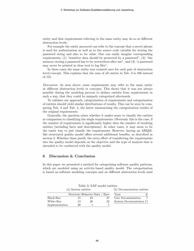
entity and that requirements referring to the same entity may do so at differentabstraction levels.
For example the entity password can refer to the concept that a secret phraseis used for authorization as well as to the source code variable for storing thepassword string and also to its value. One can easily imagine correspondingrequirements: (1) “sensitive data should be protected by a password”, (2) “thememory storing a password has to be overwritten after use”, and (3) “a passwordmay never be printed in clear text to log files”.
In these cases the same entity was counted once for each pair of abstractionlevel/concept. This explains that the sum of all entries in Tab. 3 is 166 insteadof 121.
Discussion As seen above, some requirements may refer to the same entityat different abstraction levels or concepts. This shows that it was not alwayspossible during the modeling process to deduce entities from requirements insuch a way, that they could be uniquely categorized afterwards.
To validate our approach, categorization of requirements and categorizationof entities should yield similar distributions of results. This can be seen by com-paring Tab. 3 and Tab. 4, the latter summarizing the categorization results ofthe original requirements.
Generally, the question arises whether it makes sense to classify the entitiesin comparison to classifying the single requirements. Obviously this is the case, ifthe number of requirements is significantly higher then the number of resultingentities (including facts and descriptions). In other cases, it may seem to bethe easier way to just classify the requirements. However, having an ABQM-like structured quality model offers several additional benefits, as described insection 2. Whether these justify the extra effort of transferring the requirementsinto the quality model depends on the objective and the type of analysis that isintended to be conducted with the quality model.
6 Discussion & Conclusion
In this paper we presented a method for categorizing software quality patterns,which are modeled using an activity-based quality model. The categorizationis based on software modeling concepts and on different abstraction levels used
Table 3: SAP model entities(a) System entities
Structure Behavior Data / Iface
Black-Box 15 23 27White-Box 13 26 22Implementation 20 1 1
(b) Documentation entities
Type #
User Documentation 7System Documentation 11
3. Workshop zur Software-Qualitätsmodellierung und -bewertung
46

Table 4: SAP requirements
(a) System requirements
Structure Behavior Data / Iface
Black-Box 16 36 32White-Box 16 37 24Implementation 22 1 1
(b) Documentation require-ments
Type #
User Documentation 7System Documentation 13
herein. The patterns of the different categories could be suited for communicatingthe patterns to different organizational roles or to designate responsible personsfor eliciting and maintaining the patterns.
The categorization scheme was evaluated in two case studies. The first casestudy relied on an already existing model that was constructed using codingguidelines and evaluation rules of static code analysis tools. In the second casestudy a real-world requirements list was modeled and then categorized.
These case studies showed that the categorization scheme is applicable toreal-world models. In the second case study we can see that the number ofentities in each category is quite evenly distributed with the tendency that higherabstraction levels are more present. Thus we conclude that the categorizationscheme does actually define categories that are present in real documents.
By comparing the two case studies, we can see that the nature of the mod-els is strongly reflected in the distribution of the category sizes. In the secondcase study a generic requirements list was modeled that contained very differentrequirements. This is reflected by the equal distribution of the category sizes.However, in the first case study coding guidelines and metrics of static code anal-ysis tools were modeled, which resulted in entities that were mostly categorizedas referring to implementation structure.
Moreover, the categorization of the model promoted a deeper understandingof the model itself. During the categorization the modeler had to think about theexact meaning of the entities. In the quality model that meaning was often notexplicitly documented. Therefore, during the categorization it was discoveredthat some entities were used ambiguously in the quality model. This deficiencywas then corrected by splitting the entity in two entities, in order to reflectthe two different meanings. In summary, the categorization also contributed toenhance the quality of the quality model itself.
A possible problem during categorization is the decision where to place spe-cific concepts. Since all concepts are eventually implemented as source code,there appears the general tendency to classify all as implementation level. Thecategorization scheme must be applied in such a way that the patterns are clas-sified at the highest possible abstraction level. If a pattern describes user-visiblefunctionality, it has to be classified as black-box, even though the functionalityitself is implemented in source code. If a pattern describes an implementationdetail of one specific programming language, it is clearly related to the imple-
3. Workshop zur Software-Qualitätsmodellierung und -bewertung
47

mentation level, because users and even software architects are not concernedwith this detail.
In our future research we will focus on how the categorization scheme canbe used to improve both communication and maintenance of software qualitypatterns. For the communication, it is possible to communicate the entities ofdifferent abstraction levels to different organizational roles. Implementation pat-terns are typically relevant for developers and can be used to generate guidelines,while the white-box patterns handle architectural issues and are therefore rele-vant for software architects. An adequately classified quality model can be usedto integrate quality knowledge into the tools that are central to these organiza-tional roles, e.g. the programming environment for the developer. Furthermore,the categorization scheme could be used to find adequate roles to maintain ex-isting software quality patterns. Black-box patterns are mainly concerned withhigh-level concepts, which are primarily elicited and handled in requirementsengineering. For the maintenance of adequate white-box patterns software ar-chitects are most probably the right group, while implementation patterns haveto be developed by experts of programming languages. In future research theseapplications of the categorization scheme have to be empirically evaluated in casestudies to prove their feasibility and usefulness. In addition, this evauation maylead to a refinement of the categorization granularity, should we find evidencethat a higher level of detail will raise its practical value.
References
1. Houdek, F., Kempter, H.: Quality patterns—an approach to packaging software en-gineering experience. In: SSR ’97: Proceedings of the 1997 symposium on Softwarereusability, New York, NY, USA, ACM (1997) 81–88
2. Dromey, G.R.: A model for software product quality. IEEE Transactions onSoftware Engineering 21(2) (1995) 146–162
3. Deissenboeck, F., Stefan Wagner, Pizka, M., Teuchert, S., Girard, J.F.: An activity-based quality model for maintainability. In: Proceedings of the 23rd InternationalConference on Software Maintenance (ICSM 2007), IEEE Computer Society (2007)
4. Wagner, S., Mendez Fernandez, D., Islam, S., Lochmann, K.: A security require-ments approach for web systems. In: Workshop Quality Assessment in Web (QAW2009). (2009)
5. Wagner, S., Deissenboeck, F., Winter, S.: Managing quality requirements usingactivity-based quality models. In: Proc. 6th International Workshop on Softwarequality (WoSQ’08), ACM Press (2008) 29–34
6. Boehm, W.B.: Characteristics of Software Quality. North-Holland (1978)7. McCall, A.J., Richards, K.P., Walters, F.G.: Factors in Software Quality. NTIS
(1977)8. Broy, M., Deissenboeck, F., Pizka, M.: Demystifying maintainability. In: Proceed-
ings of the 4th Workshop on Software Quality, ACM Press (2006)9. Winter, S., Wagner, S., Deissenboeck, F.: A comprehensive model of usability. In:
Proceedings of Engineering Interactive Systems. LNCS, Springer (2007)10. Schatz, B., Pretschner, A., Huber, F., Philipps, J.: Model-based development of
embedded systems. In: Proc. Workshop on Advances in Object-Oriented Informa-tion Systems. LNCS. Springer-Verlag (2002) 331–336
3. Workshop zur Software-Qualitätsmodellierung und -bewertung
48

11. Broy, M., Feilkas, M., Grunbauer, J., Gruler, A., Harhurin, A., Hartmann, J.,Penzenstadler, B., Schatz, B., Wild, D.: Umfassendes Architekturmodell fur dasEngineering eingebetteter Software-intensiver Systeme. Technical Report TUM-I0816, TU Munchen (2008)
12. Wroblewski, M.: Compliance testing of non-functional requirements at SAP. In:Quality Engineered Software and Testing Conference (QUEST’08). (2008)
3. Workshop zur Software-Qualitätsmodellierung und -bewertung
49

Teststufenspezifische Qualitätsattribute für die Qualitätsbewertung von nichtfunktionalen
Anforderungen
Yavuz Sancar1 , Frank Brüseke1, Gregor Engels1,
1 Software Quality Lab (s-lab), Universität Paderborn, Warburger Str.100
33100 Paderborn, Germany {ysancar, fbrueseke, engels}@s-lab.upb.de
Abstract. Die Bewertbarkeit einer Software nach ihren geforderten Qualitätsattributen kann erfolgskritisch sein. Die übliche Beschreibung der Qualitätsattribute, wie wir sie aus der Standardliteratur kennen, ist jedoch aus Testersicht zu allgemein, um sie für jede Teststufe ohne Weiteres anwenden zu können. Dies gilt insbesondere auch für die nichtfunktionalen Anforderungen. Somit ist es schwierig, für jede Teststufe Aussagen über die Softwarequalität in Hinblick auf die funktionalen und nichtfunktionalen Qualitätsattribute zu treffen. Wir stellen einen Ansatz für die Qualitätsbewertung durch teststufenspezifische Betrachtung der Qualitätsattribute vor.
Keywords: quality assessment, quality models, test metrics, test management
1 Qualität und Testen
Während der Entwicklung von Softwaresystemen müssen unterschiedliche Qualitätsattribute wie Zeitverhalten und Fehlertoleranz berücksichtigt werden [1]. Eine klare Vorstellung über die im Produkt zu berücksichtigenden Qualitätsattribute zu erlangen, ist eine wichtige Aufgabe. Denn die Produktqualität kann die Folgekosten der Software maßgeblich beeinflussen und ein entscheidender Wettbewerbsvorteil sein [2].
Das Testen beschreibt eine analytische Maßnahme zur Kontrolle und Sicherung der geforderten Softwarequalität, die durch entsprechende Anforderungen beschrieben wird. Es hat die Aufgabe Fehler zu finden und das Vertrauen in die Software zu steigern [3]. Es ermöglicht, die Frage nach dem Erfüllungsgrad der geforderten Qualitätsattribute zu beantworten. In der Praxis wird das Testen durch aufeinander aufbauende Stufen realisiert. In jeder dieser Teststufen wird dabei ein Testprozess durchlaufen, um letztlich eine Bewertung der Software hinsichtlich der erreichten Qualitätsattribute zu ermöglichen. Unserer Beobachtung nach werden Qualitätsanforderungen wie Effizienz und Sicherheit häufig deswegen vernachlässigt, weil deren Bedeutung und Bewertung in den unterschiedlichen Teststufen, besonders in den unteren Teststufen wie dem Komponenten- oder Integrationstest, nicht
3. Workshop zur Software-Qualitätsmodellierung und -bewertung
50

eindeutig ist. Hierzu ist aus unserer Erfahrung, die wir im s-lab durch unsere Industrieprojekte gesammelt haben, die Erkenntnis wichtig, dass die Prüfung der für die Software geforderten Qualitätsattribute je nach Teststufe und Testumgebung völlig unterschiedliche Testziele, Testmetriken und Akzeptanzkriterien erfordern kann.
In diesem Papier stellen wir einen Ansatz für die Bewertung der Qualitätsattribute durch ihre teststufenspezifische Betrachtung vor und zeigen Nutzungsmöglichkeiten des Ansatzes auf.
2 Teststufenspezifische Bewertung von Qualitätsattributen
Das stufenweise Testen wie es beispielsweise das V-Modell [6] vorsieht, wird dazu eingesetzt, möglichst frühzeitig Aussagen über die Qualität zu ermöglichen (Abbildung 1). Die Messung der Qualitätsattribute im Produkt beantwortet letztlich die Frage, ob die geforderten Qualitätsattribute im Produkt vorhanden sind. Nun muss für jedes geforderte Qualitätsattribut geklärt werden, wie es in der jeweiligen Teststufe gemessen und bewertet werden kann.
2.1 Problem und Anforderung an die Lösung
Die übliche Beschreibung der Qualitätsattribute in einem Qualitätsmodell, wie wir sie aus der Standardliteratur kennen, bezieht sich auf die Qualitätseigenschaften, die das gesamte Produkt erfüllen muss [1][4][5]. Aus Testersicht sind diese Vorgaben zu allgemein, da sie sich auf das vollständig integrierte System beziehen und damit bestenfalls für den Abnahmetest oder Systemtest angewendet werden können. Die Bedeutung der Qualitätsattribute für die anderen Teststufen ist nicht offensichtlich. Dies ist jedoch für eine systematische Testplanung der Teststufen essentiell. Ist die Bedeutung eines Qualitätsattributs für eine Teststufe nicht klar formuliert, so besteht die Gefahr falsche oder fehlende Testziele abzuleiten. Auch die auf diesen Testzielen aufbauenden Schritte des Testprozesses, wie zum Beispiel das Ableiten der Testfälle, produzieren sonst unzureichende Ergebnisse. Um dem entgegenzuwirken ist es notwendig in der „Testplanung & Steuerung“ des Testprozesses, die für die Software allgemein geforderten Qualitätsattribute zu konkretisieren. Dabei wird die Bedeutung dieser Qualitätsattribute gemeinsam mit ihren Akzeptanzkriterien für jede Teststufe festgelegt. Auf diese Weise entsteht ein detailliertes Qualitätsmodell für jede Teststufe. Diese Detaillierungsnotwendigkeit wird in Abbildung 1 anhand der gestrichelten Linien beispielhaft dargestellt.
3. Workshop zur Software-Qualitätsmodellierung und -bewertung
51
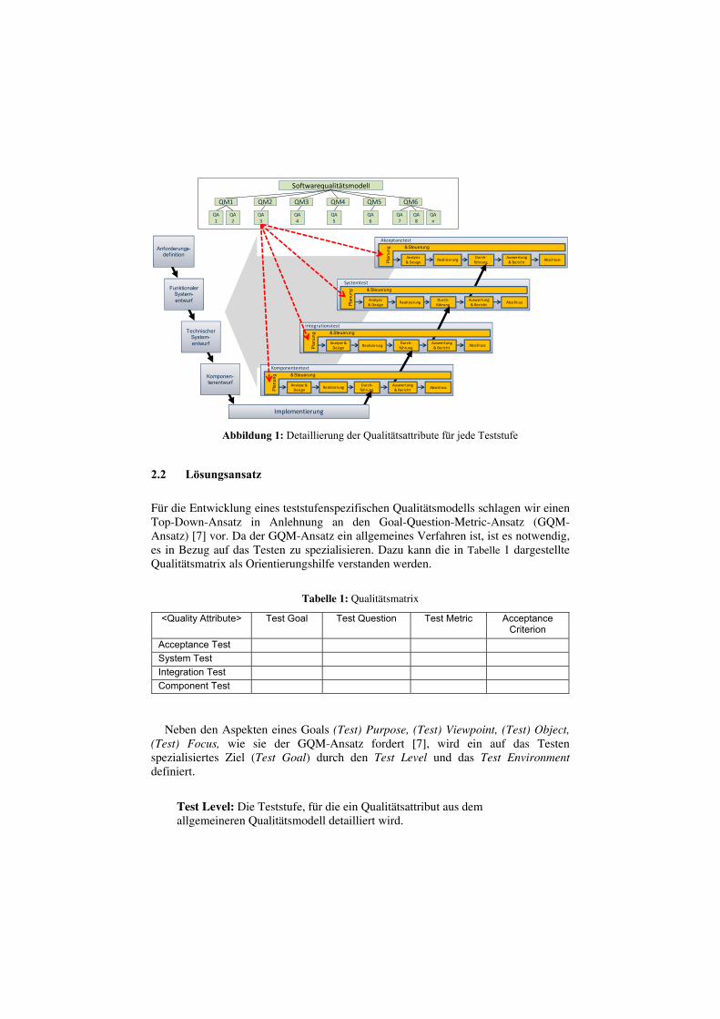
Plan
ung & Steuerung
Akzeptanztest
AbschlussAnalysis & Design
RealisierungDurch‐führung
Auswertung& Bericht
Plan
ung & Steuerung
Systemtest
AbschlussAnalysis & Design
RealisierungDurch‐führung
Auswertung& Bericht
Plan
ung & Steuerung
Integrationstest
AbschlussAnalyse & Design Realisierung
Durch‐führung
Auswertung& Bericht
Anforderungs-definition
Funktionaler System-entwurf
Technischer System-entwurf
Komponen-tenentwurf
Plan
ung & Steuerung
Komponententest
AbschlussAnalyse & Design
Realisierung Durch‐führung
Auswertung& Bericht
Implementierung
Softwarequalitätsmodell
QM1 QM2 QM3 QM4 QM5 QM6
QA2
QA1
QA3
QA4
QA5
QA6
QA7
QA8
QAn
2.2 Lösungsansatz
Für die Entwicklung eines teststufenspezifischen Qualitätsmodells schlagen wir einen Top-Down-Ansatz in Anlehnung an den Goal-Question-Metric-Ansatz (GQM-Ansatz) [7] vor. Da der GQM-Ansatz ein allgemeines Verfahren ist, ist es notwendig, es in Bezug auf das Testen zu spezialisieren. Dazu kann die in Tabelle 1 dargestellte Qualitätsmatrix als Orientierungshilfe verstanden werden.
Tabelle 1: Qualitätsmatrix
<Quality Attribute> Test Goal Test Question Test Metric Acceptance Criterion
Acceptance Test System Test Integration Test Component Test
Neben den Aspekten eines Goals (Test) Purpose, (Test) Viewpoint, (Test) Object, (Test) Focus, wie sie der GQM-Ansatz fordert [7], wird ein auf das Testen spezialisiertes Ziel (Test Goal) durch den Test Level und das Test Environment definiert.
Test Level: Die Teststufe, für die ein Qualitätsattribut aus dem allgemeineren Qualitätsmodell detailliert wird.
Abbildung 1: Detaillierung der Qualitätsattribute für jede Teststufe
wagnerst
Text Box
52

Test Environment: Die Testumgebung, in der die Einhaltung des Qualitätsattributes überprüft werden soll. Test Focus: Das assoziierte Qualitätsattribut aus dem allgemeinen Qualitätsmodell, nach dem die Testobjekte getestet werden sollen (z.B.: Antwortzeit). Test Viewpoint: Die Sichtweise wird ebenfalls durch die Teststufe bestimmt. Beispielsweise wird im Komponententest aus Sicht des Entwicklers getestet. Test Objects: Eine Auswahl von Testobjekten (z.B.: Klassen oder Methoden), die im Hinblick auf den Test Focus getestet werden sollen; gegebenenfalls (nach Risiko) priorisiert. Test Purpose: Der Zweck wird durch die Teststufe bestimmt. Z.B.: Der Zweck des Komponententests ist es, Fehler zu finden und das Vertrauen in die kleinsten Einheiten zu steigern, für die noch eine eigene Spezifikation existiert (z.B.: Klassen oder Methoden); individuell und unabhängig von anderen Einheiten des Systems.
Die Definition eines Goals nach dem GQM-Ansatz ist der erste Schritt in der Entwicklung eines Qualitätsmodells [4]. Analog dazu ist die Definition eines Test Goals für eine Teststufe der erste Schritt in der Entwicklung eines teststufenspezifischen Qualitätsmodells. Im nächsten Schritt werden die Test Goals mit quantifizierbaren Testfragen (Test Question) weiter verfeinert. Die konkreten Test Questions müssen individuell formuliert werden.
Da der Zweck des Testens jedoch durch die Fehlerfindung und die Steigerung des Vertrauens vorgegeben ist, können im Bereich des Testens die Test Question auch in zwei Kategorien unterteilt werden: Test Result und Test Quality. Welche Fehler ausgewertet werden sollen, werden in der Test Result-Kategorie erfragt. Die Test Quality-Kategorie soll eine angemessene Qualität der Tests gewährleisten. Damit wird direkt das Vertrauen in die eigenen Testaktivitäten und indirekt das Vertrauen in die Software gesteigert. Für jede der genannten Kategorien muss mindestens eine Frage formuliert werden.
Schließlich werden den Test Questions Test Metrics und entsprechende Acceptance Criteria zugeordnet, die sich für die Beantwortung der Fragen eignen. Mit der Durchführung dieser vier Schritte wird eine Zeile der oben genannten Qualitätsmatrix gefüllt. Das Füllen der Qualitätsmatrix zeigen wir im Folgenden an den Beispielen für den Abnahme- und Komponententest (s. Abschnitt 2.3 bzw. Abschnitt 2.4). Das betrachtete Qualitätsattribut sei „Zeitverhalten“ („Time behavior“).
Entsprechend den hier gezeigten Beispielen muss dieses Vorgehen für alle geforderten Qualitätsattribute eines Softwaresystems und jeweils für alle geplanten Teststufen in der Testphase „Testplanung" durchgeführt werden.
3. Workshop zur Software-Qualitätsmodellierung und -bewertung
53

2.3 Beispiel: Abnahmetest (Acceptance Test)
Das Test Goal für den Abnahmetest („TB_CT_TG“) wäre nach den in Abschnitt 2.1 definierten Aspekten somit:
„Im Abnahmetest müssen in der produktivnahen Testumgebung Win7ENG1DB2 in Hinblick auf das Zeitverhalten aus Sicht des Benutzers Fehler in dem vollständig integrierten System gefunden und das Vertrauen in das gesamte System gesteigert werden.“
Die Beantwortung der folgenden Fragen ist in diesem Beispiel von Interesse:
1) Test Result-Kategorie: Wie hoch ist die mittlere Zeitdauer bis zu einer Fehlerwirkung in Hinblick auf das Zeitverhalten? (TB_AT_TQTR1)
2) Test Quality- Kategorie: Wie hoch ist die Überdeckung der Geschäftsvorfälle mit Priorität „sehr hoch“, die nach Zeitverhalten getestet werden sollten. (TB_AT_TQTR2)
Als Metriken und Akzeptanzkriterien zur Beantwortung der Fragen eignen sich
die folgenden Metriken:
Zu 1) TB_AT_TMTR1: „Mean time to failure“ (MTTF) als durchschnittliche Betriebsstunden im Abnahmetest bis zum Auftritt einer Fehlerwirkung, die das Zeitverhalten des gesamten Softwaresystems betrifft.
Das Acceptance Criterion sei TB_AT_AC_TR1> 48 Stunden.
Zu 2) TB_AT_TMTR2:
Das Acceptance Criterion sei TB_AT_AC_TR2= 1.
Damit haben wir die Zeile für den Akzeptanztest der Qualitätsmatrix gefüllt (siehe Tabelle 2). Aus Gründen der Übersichtlichkeit wurden nur die Kennungen der Inhalte eingetragen.
Tabelle 2: Qualitätsmatrix für Time behavior – Acceptance Test
<Time behavior> Test Goal Test Question Test Metric Acceptance Criterion
Acceptance Test TB_AT_TG TB_AT_TQTR1 TB_AT_TMTR1 TB_AT_AC_TR1 TB_AT_TQTR2 TB_AT_TMTR2 TB_AT_AC_TR2
Anzahl der Geschäftsvorfälle mit Priorität „sehr hoch“, die nach Zeitverhalten getestet wurden Gesamtanzahl der Geschäftsvorfälle mit Priorität „sehr hoch“, die nach Zeitverhalten getestet werden
3. Workshop zur Software-Qualitätsmodellierung und -bewertung
54

2.4 Beispiel: Komponententest (Component)
Das Test Goal für den Komponententest („TB_CT_TG“) wäre nach den in Abschnitt 2.1 definierten Aspekten wie folgt:
„Im Komponententest müssen in der Testumgebung ECLPSE3D1Oracle in Hinblick auf das Zeitverhalten aus Sicht des Entwicklers Fehler in den Komponenten networkScanner, activityControl, wakeUPStatus gefunden und das Vertrauen in diese Komponenten unabhängig von den anderen Einheiten gesteigert werden.“
Folgende Fragen werden für den Komponententest gestellt:
1) Test Result-Kategorie: Wie hoch ist die Anzahl der Fehlerwirkungen in Hinblick auf das Zeitverhalten? (TB_CT_TQTR1)
2) Test Quality- Kategorie: Wie hoch ist die Überdeckung der Komponenten mit Priorität „hoch“, die nach Zeitverhalten getestet werden sollten. (TB_CT_TQTR2)
Als Metriken und Akzeptanzkriterien zur Beantwortung der Fragen eignen sich
die folgenden Metriken:
Zu 1) TB_CT_TMTR1: Gewichtete Gesamtanzahl der Fehlerwirkungen, die mit
der Durchführung einer Testfallmenge und der dadurch erreichten Überdeckung gefunden wurden.
Das Acceptance Criterion sei TB_CT_AC_TR1<= 3 Fehlerwirkungen.
Zu 2) TB_CT_TMTR2:
Das Acceptance Criterion sei TB_CT_AC_TR2<= 0,75.
Damit haben wir die Zeile für den Komponententest der Qualitätsmatrix ebenfalls gefüllt (siehe Tabelle 3).
Tabelle 3: Qualitätsmatrix für Time behavior – Acceptance Test and Component Test
<Time behavior> Test Goal Test Question Test Metric Acceptance Criterion
Acceptance Test TB_AT_TG TB_AT_TQTR1
TB_AT_TMTR1
TB_AT_AC_TR1
TB_AT_TQTR2 TB_AT_TMTR2 TB_AT_AC_TR2
Component Test TB_CT_TG TB_CT_TQTR1
TB_CT_TMTR1
TB_CT_AC_TR1
TB_CT_TQTR2 TB_CT_TMTR2 TB_CT_AC_TR2
Anzahl der Komponenten mit Priorität „hoch“, die nach Zeitverhalten getestet wurden Gesamtanzahl der Komponenten Priorität „hoch“, die nach Zeitverhalten getestet werden müssen
3. Workshop zur Software-Qualitätsmodellierung und -bewertung
55

3 Zusammenfassung und Ausblick
Eine Beurteilung der Softwarequalität in den Teststufen, wie Komponenten- und Integrationstest, erfordert die teststufenspezifische Betrachtung der geforderten Qualitätsattribute für diese Teststufen. In diesem Beitrag wurde ein Verfahren vorgestellt, das dieser Forderung durch eine Spezialisierung des GQM-Ansatzes von Basili [7] nachkommt. Dabei werden bei der Definition von Zielen und Fragen die Besonderheiten des Testens wie Teststufen (Test Level) und Testumgebungen (Test Environment) bzw. die Testergebnisse (Test Result) und die zugrundeliegende Testqualität (Test Quality) berücksichtigt. Auf die Weise wird ein detaillierteres Qualitätsmodell für jede Teststufe erstellt. Durch die klaren Zielvorgaben dieses Qualitätsmodells wird die Testplanung, insbesondere die Auswahl der richtigen Metriken systematisiert und die frühe Beurteilung der Softwarequalität vereinfacht. Da häufig die nichtfunktionalen Anforderungen vernachlässigt werden [8][9][10][11], profitiert besonders die Bewertung der nichtfunktionalen Anforderungen durch dieses Verfahren.
In einem weiteren Papier werden wir vorstellen, wie in der Testphase “Testauswertung“ die Entscheidung getroffen wird, ob ein Test Goal erreicht worden ist. Dazu werden wir das Vorgehen für die Messung der Test Metric, den Abgleich der ermittelten Kennzahlen mit den Acceptance Criteria und die Beantwortung der Test Questions beleuchten. Im Zuge dessen werden wir auch die Auswirkungen der Test Goals auf die Testfallerstellung und die Testaufwandsberechnung betrachten.
Es ist geplant, dieses Vorgehen in die Teststrategiebestimmung während der
Testplanung und in die Teststeuerung zu integrieren. Die Praxistauglichkeit werden wir in einem Anwendungsgebiet für Informationssysteme evaluieren.
References
1. International Organization for Standardization: Software engineering - product quality - Part 1: Quality Model, ISO/IEC 9126-1, 2001.
2. Wagner, S., Broy, M., Deißenböck, F., Kläs M., Liggesmeyer P., Münch J. and. Streit J: Softwarequalitätsmodelle – Praxisempfehlungen und Forschungsagenda. Informatik-Spektrum, 2009.
3. Spillner, A., Linz, T.: Basiswissen Softwaretest. dpunkt.verlag, 2005. – ISBN 3–89864–358–1.
4. Balzert, H.: Lehrbuch der Software-Technik. Bd. 1. Zweite Auflage. Berlin Heidelberg: Spektrum Akademischer Verlag, 2001.
5. Bøegh, J.: A New Standard for Quality Requirements. IEEE Software 25, 2. 57-63, 2008 6. Dröschel, W., Inkrementelle und objektorientierte Vorgehensweisen mit dem V-Modell 97.
München: Oldenbourg, 1998. 7. Basili, V., Caldiera, G., Rombach, H.D.: Goal Question Metric Paradigm. Encyclopedia of
Software Engineering. pp. 528–532 John Wiley & Sons, Inc., 1994.
3. Workshop zur Software-Qualitätsmodellierung und -bewertung
56

8. Wagner, S., Deißenböck, F., Winter S.: Managing quality requirements using activity-based quality models. WoSQ '08: Proceedings of the 6th international workshop on Software quality. ACM, 2008.
9. Matoussi A., Laleau R.: A Survey of Non-Functional Requirements in Software Development Process. Technical report LACL, University of Paris-Est 2008.
10. Chung L., Non-functional requirements in software engineering. Boston, Mass.: Kluwer Acad. Publ., 2000.
11. van Lamsweerde A., Goal-oriented requirements enginering: a roundtrip from research to practice. In International Requirements Engineering 2008 (RE '08). 16th IEEE, 2008, pp. 4–7.
3. Workshop zur Software-Qualitätsmodellierung und -bewertung
57

Using a software blood count in custom software
development projects: an experience report
Markus Großmann
Capgemini sd&m AG, Löffelstr. 46, 70597 Stuttgart, Germany
Abstract. Capgemini sd&m develops quality models and tools for controlling
the software product quality and has been applying them in their custom
software development projects since a couple of years. The latest version of the
quality model is the so called “software blood count” [1], which was
implemented in the Capgemini sd&m Software Cockpit. This tool was rolled
out to the company at the start of 2009 and is now actively used in over twelve
software development projects. This paper gives a first summary of the
experiences we made in 2009 concerning the usage of the software blood count
in practice. We experienced that projects didn’t use it to define a custom quality
model. The main reasons were that quality requirements are typically not clear
enough and measuring overall software quality showed as being too complex to
do it within one single evaluation process. Instead projects picked only few
indicators of the software blood count and integrated the measurements as
integral parts of their quality assurance processes. The selection was motivated
by quality risks projects wanted to control. We could identify typical
measurement-based quality assurance techniques based on the software blood
count: automatic code reviews, architecture management and test monitoring.
Further work has to be done to elaborate those techniques and provide out-of-
the-box-solutions. Besides that we also perceived that there are problems with
adequate measurement tool support. Many programming languages are not
covered by those tools and even if they are, the tools have usually shortcomings
when used in a large scale project context. This is a problem because automatic
code reviews showed to be the most significant technique.
1 Introduction
The economic crisis has reached the IT: time and cost pressure have dramatically
increased. Although the price level is sinking, a sinking of the quality level is usually
not accepted. Getting proves for a sufficient quality level gets increasingly important
– both for customers and software vendors. German software companies have to
justify their higher prices compared to Indian pure player. They argue that they
deliver better software quality and have a longer experience in software craftsmanship
[2]. Unfortunately there are currently no established quality standards that could help
to prove this.
Besides that, other evolutions in the area of commercial software development
induce further challenges in software quality assurance: SOA is popular and Cloud
3. Workshop zur Software-Qualitätsmodellierung und -bewertung
58

Computing describes a new supplement, consumption and delivery model for IT
services. Software becomes larger, more complex and more distributed. Application
management and the factor “maintainability” are of great importance since most
development effort is still spent on existing software. This all demands effective
quality assurance methods that manage the growing quality needs.
Therefore Capgemini sd&m has developed several constructive and analytical
quality assurance techniques in the past and has been using them in their software
projects. Among them is a tool called “software cockpit” that was initially developed
together with a research partner [3].
This tool and the contained quality model were developed further in cooperation
with a handful of pilot projects at Capgemini sd&m. At the beginning of 2009 the
software cockpit was released as general available product inside of Capgemini
sd&m. It contained a new quality model called the “software blood count”, i.e. a
collection of software product metrics relevant to quality assessment (see fig. 1.). The
software blood count was also equipped with interpretation aids for the metrics,
recommendations on quality requirements and possible mitigations in case of detected
quality risks. This was an improved quality model approach based on experiences
with the first version of the software cockpit [1].
Fig. 1. The Capgemini sd&m software blood count
The software cockpit was rolled out to and used actively in twelve custom software
development projects in 2009. The sizes of these projects were equally distributed
from small projects (smaller than 100 KLOC1) up to large scale projects (larger than
1,000 KLOC). All projects used Java technology, target industries were mainly the
automotive sector, but also logistics, public sector and travel.
The software cockpit was intentionally delivered without detailed process or
quality evaluation guidelines. This should encourage a pragmatic use of the tool and
provide better insights about the really necessary application scenarios in practice by
showing the processes that evolve or are affected by the usage. In the following we
1 KLOC = Kilo Lines of Code
3. Workshop zur Software-Qualitätsmodellierung und -bewertung
59

outline the experiences we made about the usage of the software blood count
approach in practice. The experiences where mainly collected by interviews with the
project leaders and the technical architects of the projects and by providing support
for the setup and application of the software cockpit.
2 Usage of the software blood count as a quality model
Software Quality models are a means to define and describe software quality. They
shall help to specify the quality of a software product in a way that it can be used in a
number of scenarios, e.g. to assess the quality of the software product, to improve the
quality of the software product, and so on.
The software cockpit allows building a custom quality model. It provides a toolset
that measures the metrics of the software blood count and can be extended by custom
metrics. If offers the possibility to define checks and thresholds that help to verify the
conformance to quality requirements. Additionally it provides quality requirements
suggestions and detection patterns that form a basic quality model. The question now
is whether the projects used the software blood count as a quality model: to define
quality, to measure quality aspects, to carry out quality evaluations, etc.
2.1 Projects didn’t use the software blood count to define software quality
Most of the projects didn’t have a clear set of measurement goals when starting
with the software cockpit; there were only two projects that knew in advance what
they wanted to measure. One project got a list of over 200 static code analysis rules
from the customer that they had to check. The requirement was that the next release
source code mustn’t contain more code anomalies for each rule than for the last
release. The other project wanted to measure a set of custom size metrics (number of
application services, number of interfaces, etc.). Both are far away from being a
definition for the overall software quality of the project. All in all the projects had too
few explicit non-functional requirements to justify the creation of a comprehensive
quality model. This had several reasons.
One reason was that the customers usually asked for a fixed price offer based on a
rough concept or an announcement. In many cases non-functional requirements are
not known exactly at this point of time so they are left out or are described only very
general. Measurable definitions have the characteristic that they are “hard” – either
the customer or the software vendor can insist on them. Opinions differ whether this
is an advantage or a drawback, though, in many cases people refrain from making
clear upfront decisions. However, it is universally agreed that those requirements
should be specified that have a strong influence on the price. High demands are
expensive – that has to be visible.
Another reason was that quality modelling was perceived as taking too much time
and as being too complex. Every requirement would have to be reconciled with the
customer and there is the fear that it isn’t clear where to start and where to end here.
Non-functional requirements are often taken as granted by the customer, they are
considered as self-evident hygiene factors (e.g., passwords must not be saved in clear
3. Workshop zur Software-Qualitätsmodellierung und -bewertung
60

text). There is the trust that programmers know what they do and you don’t have to
specify every single rule of software craftsmanship. So projects often do without
additional controlling activities, especially because the measurement of quality
requirements often isn’t simple (e.g., do the programmers write understandable code
comments).
Conclusion: Software quality definitions are difficult in custom development
software projects, mainly because sustainable and comprehensive quality
requirements are missing or too lately known in the project. Controlling the basic
rules of software craftsmanship is often seen as overhead – especially in qualified
teams. So although the software blood count simplifies the definition and
measurement of quality requirements, this wasn’t really used in practice. Unless there
are clear goal definitions, by management or by the customer, projects will spend only
very low effort on quality definition.
2.2 Different opinions concerning quality requirement threshold guidelines
The software cockpit provides a set of basic quality requirement suggestions
together with thresholds (e.g., unit tests shouldn’t fail). Projects could decide whether
they adopt some of those requirements. We experienced that the projects divided into
two fractions here, nearly equally divided.
The one fraction completely denied any kind of threshold because they feared that
thresholds may have an unwanted influence on the software development process.
They saw the risk that people concentrate on tuning metrics instead of improving
software quality or the effectiveness of the development process. They advocate
trusting the programmer and didn’t want to encourage a “work-to-rule” working
atmosphere. They compared it with traffic where studies showed that too many traffic
signs do not prevent but rather promote road accidents.
The other fraction was open for guidelines and thresholds that demand self-evident
qualities of software craftsmanship. It should be on hand to see where programmers
even fail the simplest rules and it should be possible to demand or guarantee a
minimum quality standard – especially at code handover situations. We noticed that
especially members of highly distributed projects represented this fraction.
Conclusion: The acceptance of quality guidelines seems to depend on the project
situation, especially the team organization and the team qualification. Projects with a
highly qualified team often do without controlling the ABC of software development.
Whereas teams that haven’t been working together consider proposals as helpful that
define a minimum quality standard for specific characteristics of software
craftsmanship.
2.3 Projects focused on specific quality indicators
We perceived that each project used only a small custom subset of the software
blood count. We had no project that measured all of the 16 available indicators; they
rather did cherry-picking. Projects chose only those indicators where they wanted to
establish a controlling activity for a specific quality aspect. Measurement with the
3. Workshop zur Software-Qualitätsmodellierung und -bewertung
61

software cockpit was thought as a supplement to existing quality assurance methods
like, e.g., functional testing or code reviews. It was not considered necessary to
establish a controlling for all kinds of quality aspects. Instead projects selected those
measurements that were considered important in the project, that represented a vital
quality risk or that were not covered by other measures. The projects justified this
with lean management and pragmatic thinking. The following table lists each metric
and how many projects used it2.
Used by projects (percentage)
Classes count 100 %
Number of statements (NCSS) 100 %
Code comment density 100 %
Number and result of unit tests 100 %
Rule violations count 92 %
Code anomalies count 92 %
Code anomaly density 92 %
Code coverage 50 %
Average component dependency (ACD) 42 %
Relative ACD 42 %
Illegal dependencies count 42 %
Cycles count 42 %
Defects count 25 %
Defect density 25 %
Frequency of changes 17 %
Review effort 0 %
Table 1. Metrics of the software blood, sorted by usage rate
Projects enriched their software development process with activities that used
software measurement for analytical quality assurance. It is interesting that we could
identify similarities between projects here. All of the observed activities could be
categorized into three different process bundles – we call them measurement-based
quality assurance techniques. We will depict those in the next chapter.
Furthermore we often got the feedback that though the number of metrics is
manageable it is still difficult to figure out the application context of each metric. The
scope of the software blood count is quite large and the catalogue of detection
patterns is too unclear if you want to filter for a specific quality aspect or to find out
which indicators are essential in your specific project context. It was also
cumbersome for the projects that metrics where not embedded within activities
respectively process descriptions. So people had to invent their own usage techniques.
However, this was our intention and we now got a clearer picture about software
development process integration for software measurement.
2 Please note that not all metrics of the software blood count were implemented in the rolled out
software cockpit release.
3. Workshop zur Software-Qualitätsmodellierung und -bewertung
62

Conclusion: It seems to make sense to modularize the software blood count in
order to support a focused quality view of a software development project. A
modularized structure would also simplify the understanding and clarify the
application areas of the software blood count. Projects needn’t have to deal with a
universal quality evaluation method, but can select those techniques that are important
– or demanded by the customer – in their project context.
3 Measurement-based quality assurance techniques
We experienced that several metrics of the software blood count were always used
together in similar application contexts throughout the projects. This chapter gives a
brief description of the identified techniques in order to get the idea, describe the main
motivation and list the used metrics.
Used by projects
(percentage)
Automatic Code Reviews 92 %
Architecture Management 42 %
Test Monitoring 50 %
Table 2. Percentage of projects using measurement-based quality assurance techniques
3.1 Automatic Code Reviews
All except one project integrated static code analysis tools into their automated
build process. That means they added Findbugs, PMD and Checkstyle in order to
search for bug patterns in the source code or to do code style validations. Most
projects had their own configuration for these tools, only two projects used the
templates that came with the software cockpit. The measured metrics of the software
blood count were number of code anomalies, code anomaly density, number of rule
violations.
Users drew an analogy between this technique and a virus scanner. The motivation
of this technique was to control the conformance to an agreed coding style and to find
possible defects. They let the static code analysis tools go over the source code like a
virus scanner and analyzed the reported code anomalies. Here it was essential to
choose a good configuration of the static code analysis tools so that false alarms were
minimized.
This technique should also help to increase the effectiveness of manual code
reviews, because the entry criteria for a manual code review were that the code
conformed to the coding style and that no severe code anomalies were in the code. So
that manual code reviews weren’t bothered with trivial mistakes and negligences.
Projects also used automatic code reviews to find suspicious places in the code where
improvements or a manual code review would be sensible. One project for example
3. Workshop zur Software-Qualitätsmodellierung und -bewertung
63

regularly performed a so called “quality day” where the data of the static code
analysis served as input data for code improvements and refactorings.
3.2 Architecture Management
Projects that used this technique created a SonarJ3 logical architecture model for
their software system. The motivation was to find deviations between the intended
architecture and the real architecture in the source code. Additionally some
dependency metrics were calculated. This should help to prevent software erosion i.e.
the continuous decay of the internal structure of the software system. Software
erosion is a big problem for changeability and maintainability of the software.
Architecture management is described in [4]. The measured metrics of the software
blood count were number of illegal dependencies, number of cycles, relative average
component dependency (rACD), average component dependency (ACD).
3.3 Test Monitoring
Test monitoring looks after the effectiveness of the tests, especially the automated
test suite. It checks whether the tests are running successfully and how high the test
coverage is. A test suite that isn’t maintained looses its significance. Low test
coverage could mean that tests are insufficient. The measured metrics of the software
blood count were number of tests, test results and code coverage.
3.4 Software Performance Monitoring
The software performance metrics of the software blood count have been
implemented late in 2009, so that no project was able to use them. However we had
some requests of projects that wanted to do Software Performance Monitoring, i.e. a
regular check of business transaction response times.
4 Further Lessons Learned
This chapter contains a brief summary of other significant experiences we made.
4.1 Measurement tools have shortcomings in a large scale project context
We ran into several technical problems especially when setting up measurement
tools for large scale projects with a huge code base. Setup for small and medium size
projects took usually only about 5 person days whereas setup for the same tools for
3 http://www hello2morrow.com/products/sonarj
3. Workshop zur Software-Qualitätsmodellierung und -bewertung
64

large scale projects took about 20 person days. The reason is that the measurement
tools showed technical shortcomings when used in a large scale project context.
One example: we used Cobertura4 for measuring code coverage. The Maven plugin
for Cobertura showed problems when used with the Maven inheritance feature, which
is quite common in large scale projects. The Cobertura Maven plugin also doesn’t
automatically calculate code coverage for multiple projects – also a feature that is
widely used in large scale projects. The build process of large scale projects has
usually many steps (e.g., deployment on servers), which isn’t good supported by the
Cobertura code instrumenting feature. Other code coverage tools like EMMA5 and
even the commercial tool Clover6 also showed more or less technical problems in a
large scale project context.
4.2 No adequate measurement tool support for several programming languages
We learned that the application of measurement or quality models is hampered by
a lack of measurement tool support.
Java is maybe the programming language that has the best support of static code
analysis tools. A lot of them are even Open Source. However, we observed that even
if you use Java technology, there is a lot of “code” that is not considered by static
code analyzers: e.g. code from scripting languages (e.g., JavaScript), template
languages (e.g., Java Server Faces), proprietary configuration files (e.g., Spring,
Hibernate), etc. So these are blind spots when measuring e.g. code coverage, code
size or code anomalies.
We also tried to implement the software blood count for ABAP, but had difficulties
at extracting the measurement data from the ABAP workbench because adequate
interfaces were missing. So this was a situation where measurement tools were
available but their data couldn’t be used by external programs.
Finally there are a lot of programming languages where there are no or only very
little measurement tools available – especially open source tools. For example there is
still a lot of Cobol software, but hardly any measurement tools for this programming
language. We think that this problem will not become smaller in future but rather
increase since the growing significance of (graphical) Model Driven Design
languages and Domain specific languages. This is a problem, especially because
Automatic Code Reviews showed as the technique with the highest significance.
4.3 Out-of-the-box solutions are preferred
The time and effort needed for setting up and operating the measurement of the
software blood count was the main acceptance criteria. Projects preferred out-of-the-
box solutions, even if they provide less flexibility. It is essential to have measurement
completely automated.
4 http://cobertura.sourceforge net/ 5 http://emma.sourceforge net/ 6 http://www.atlassian.com/software/clover/
3. Workshop zur Software-Qualitätsmodellierung und -bewertung
65

5 Conclusions and Outlook
We rolled out the software blood count with only little process guidelines. It
showed that not only one but many different quality evaluation processes evolved –
the measurement-based quality assurance techniques. Each technique didn’t use the
full software blood count but only fractions of it. The next steps will now be to further
elaborate those techniques and modularize the software blood count according to
them. The goal is to provide out-of-the-box solutions that can be quickly applied in
practice. Tool support matters, so these solutions should be equipped with sufficient
howtos and recipes that especially describe the snares and caveats when applying
measurement tools in a large scale project context.
Further work can be done to explore new measurement-based quality assurance
techniques, particularly those that use metrics which are currently not part of the
software blood count. It will also be interesting to do research on the effectiveness of
each method: how good do they help to evaluate which quality aspects? How many
defects can be found earlier than as usual?
Finally the main challenge will be to integrate all of these techniques into an
overall quality model or an overall quality standard. From our current point of view
and due to our experiences it is more likely that an overall quality standard will be an
aggregation of “mini” quality standards than a homogenous way to calculate quality
aspects from measurement results.
References
[1] M. Großmann: Towards an applicable software quality model for individual software
projects, in S. Wagner, M. Broy, F. Deissenboeck, P. Liggesmeyer, J. Münch (Hrsg.)
Tagungsband 2. Workshop zur Software-Qualitätsmodellierung und -bewertung (SQMB
'09) (2009)
[2] „Software - Made in Germany", Study of the IMWF Institut für Management- und
Wirtschaftsforschung on behalf of the Beratungs- und Softwarehauses PPI AG (2009).
[3] M. Bennicke, F. Steinbrückner, M. Radicke, J.-P. Richter: Das sd&m Software Cockpit:
Architektur und Erfahrungen, in R. Koschke, O. Herzog, K.-H. Rödiger, M. Ronthaler
(Hrsg.): INFORMATIK 2007, Beiträge der 37. Jahrestagung der Gesellschaft für Informatik
e.V. (GI), Lecture Notes in Informatics (LNI), GI Proceedings 110, Band 2, pp. 254—260
(2007)
[4] A. v. Zitzewitz: Erosion vorbeugen, JavaMagazin, (2), (2007)
3. Workshop zur Software-Qualitätsmodellierung und -bewertung
66

Maintainability Index Revisited: Adaption andEvaluation for Bosch Automotive Software
Jochen Quante, Thomas Grundler, Andreas Thums
Robert Bosch GmbHCorporate Sector Research and Advance Engineering Software
P.O. Box 30 02 40, 70442 Stuttgart, Germany
Abstract. Assessing maintainability or other software quality attributesautomatically has been in focus of research and practice for a long time.One well-known example is the Maintainability Index by Oman andHagemeister [1, 2]. Their results were promising – however, there alsohas been a lot of critics about the approach. This paper reports on theadaption and evaluation of this approach on Bosch automotive software.
1 Introduction: The Maintainability Index
The Maintainability Index (MI) as introduced by Oman and Hagemeister isbased on the idea of correlating software product metrics with expert opinions onmaintainability [1, 2]. It uses principal components analysis (PCA) on softwaremetrics plus a polynomial regression analysis to build a predictor model. Theunderlying assumption is that software product metrics measure properties thathave something to do with maintainability, which appears reasonable.
Embedded software is different from classical IT software [3]. Therefore, itis interesting to see whether the approach is applicable to this kind of soft-ware. Furthermore, we want to report about the acceptance and usefulness ofthe approach in industry. Our goal in using the MI is to provide a means toidentify components with low maintainability, such that those can be targetedand improved systematically.
2 Applying the Method to Bosch Software
To evaluate the approach, we selected two subsystems from a Diesel engine con-trol software and let a number of experts judge their maintainability. The latterwas done using a questionnaire that covered different aspects of maintainability.Then we took a set of standard software product metrics as provided by theQA-C tool1. When applying PCA on this data, the result was that most metricsended up in one cluster along with the lines of code metric. Also, this clusterrepresents the major share of information.
1 http://www.programmingresearch.com/QAC_MAIN.html
3. Workshop zur Software-Qualitätsmodellierung und -bewertung
67

Using regression analysis, the following formula resulted as the maintainabil-ity index when calibrated with subsystem A:
M = 266.04−0.07 ·XLN −0.29 ·LCT −3.87 ·CAL−5, 27 ·LOP −36, 48 ·MIF
where XLN is the number of executable lines of code, LCT is the number oflocal variables declared, CAL is the number of distinct function calls, LOP isthe number of logical operators, and MIF is the maximum nesting of controlstructures.
We also evaluated a set of advanced non-standard metrics, such as dataflow complexity and cognitive complexity. However, they did not result in anynew clusters in the PCA, which means that they are strongly correlated to theother (simpler) metrics. Another observation is that the metrics from the HISrecommendations2 are mostly located in distinct clusters, which indicates thatthey really check for different aspects.
Fig. 1. Maintainability index results for the modules of subsystem B. Maintainabil-ity values greater zero indicate “good” maintainability, values lower than zero “bad”maintainability. The X axis enumerates the different modules.
The formula was evaluated on a second subsystem B. Figure 1 shows themaintainability index values for the different modules of this subsystem. Mostof the modules get a positive rating, whereas a few modules have large negativevalues and thus a strong indication of bad maintainability. Those are the modulesthat one should first regard when looking for maintainability improvement. Thequestion is whether the indicated modules are really those that are also ratedas being of low maintainability (LM) by the experts. We found that 50% of
2 HIS is an initiative of German vehicle manufacturers that focuses on improvingsoftware quality. Among other things, they have defined recommended ranges forcertain software metrics that apply for automotive software [4].
3. Workshop zur Software-Qualitätsmodellierung und -bewertung
68

the modules belong to the LM category (precision), and that 83% of the LMmodules are contained in this set (recall). This means that the index is really aquite useful indicator: It highlights only a few of the modules, and every secondof these modules has in fact potential for improvement.
3 Experience and Discussion
On first sight, at 50%, the precision of our MI may not seem quite high. However,the feedback from our business units is that this level of precision is “goodenough” in practice: They are happy to get some hint where to look first whenaiming at maintainability improvement. The index does not need to be perfect– which would mean 100% precision and 100% recall. The HIS metric rangerecommendations already are a guideline for good software quality, but do nothave maintainability in focus. Another practical advantage is that assessing theMI is quite “cheap”: The required metrics are already there. It is therefore easy toroll out the MI and to integrate it into the software development process. Theseare factors that should not be underestimated for industrial application. Apartfrom the practical relevance, applicability and acceptance aspects, we found anumber of other noteworthy issues in our studies on which we will elaborate inthe following.
Code size and maintainability. One major finding is that the length of afunction or module (XLOC) alone is already a strong indicator for maintainabil-ity. In most cases, the functions that were indicated by the MI were in fact thosethat were very long. Long functions were also rated to have low maintainabilityby the experts. This means it would be a good heuristic to sort the functions bytheir size to find the problematic ones. Furthermore, the majority of the met-rics is correlated to XLOC, which makes this approach even more appealing.However, when evaluated on the same subsystem B, we found that the XLOCcriterion alone also results in a precision of 50%, but in a recall of only 43%.This means that the additional terms in the MI help to improve recall, and thisimprovement comes at quite low cost.
Comparability. Another finding concerns different programming styles.Different organizational units may use different programming guidelines andimplementation styles, which makes results hard to transfer from one system toanother. This means that the MI has to be calibrated for each unit individually.There cannot be a single universal or even company-wide maintainability index.Comparing maintainability between different systems is therefore infeasible.
Individual differences. Also, different experts judged about the samemodule in quite inconsistent ways. For example, the same module was rated“good” by one expert and “very bad” by another. Of course, this is not a goodbasis for maintainability assessment: How can an automatism assess maintain-ability when even the experts do not agree? This means that the “perfect index”is not realizable by any maintainability assessment approach: Different peopleregard different constructs as being hard to understand; what is complex for oneperson may be easy for another, and vice versa.
3. Workshop zur Software-Qualitätsmodellierung und -bewertung
69
Variance and preprocessor. Our software has a very high variance. Tocope with that, the product line approach is applied, which means that commonparts are shared and variant parts are separated using different mechanisms. Onewidespread variant mechanism is the use of C preprocessor conditions. In ouranalyses, we used QA-C metrics, which work on preprocessed code. However,it turned out that variants sometimes contain less than 50% of the entire codebase, which means that we ignored most of the code that a programmer has todeal with. Maintainability therefore should be assessed on the source code levelinstead of the preprocessed code level. Unfortunately, metrics on the unprepro-cessed source code level often have to rely on heuristics and may therefore bemore imprecise input data. This approach yet has to be evaluated.
Root-cause analysis. One point that is generally criticized about the MIis that it does not allow root-cause analysis. This means that the index tells youthat your code is bad – but it does not tell you why or how to make it better.One approach to tackle this problem is to integrate bad smell pattern detection.
Outliers. Also, the MI ignores outliers, which may contain valuable hintsabout maintainability problems in practice. In a case study we performed, anapproach solely based on outliers delivered quite good results for assessing main-tainability. Similar to the MI, XLOC is an important factor here, but othermetrics that are significantly higher (or lower) than the average also becomean influencing factor. If precision shall be improved, it could be a good idea toinclude outliers into the index.
4 Summary and Outlook
As pointed out above, the MI in its current form is already quite valuable forindustrial purposes. However, it can be further improved by raising precision andadding root-cause analysis capabilities. We plan to improve the index by usinga combined metrics – including source-level metrics – and “bad smell patterns”approach. The different indicators will then be combined using a quality model.Outliers can be integrated into this model as well. This approach will allowroot-cause analysis and will be more independent from the experts’ assessment.
References
1. Oman, P.W., Hagemeister, J.R.: Constructing and testing of polynomials predictingsoftware maintainability. Journal of Systems and Software 24(3) (1994)
2. Coleman, D., Ash, D., Lowther, B., Oman, P.: Using metrics to evaluate softwaresystem maintainability. IEEE Computer 27(8) (1994) 44–49
3. Schulte-Coerne, V., Thums, A., Quante, J.: Challenges in reengineering automo-tive software. In: Proc. of 13th Conf. on Software Maintenance and Reengineering(CSMR). (2009) 315–316
4. Kuder, H.: HIS Source Code Metriken (April 2008) available at http://portal.
automotive-his.de/images/pdf/SoftwareTest/his-sc-metriken.1.3.1.pdf.
3. Workshop zur Software-Qualitätsmodellierung und -bewertung
70

The ArchMapper Approach to ArchitecturalConformance Checks: An Eclipse-based Tool forStyle-oriented Architecture to Code Mappings
Simon Giesecke1 and Michael Gottschalk2 and Wilhelm Hasselbring3
1 Simon GieseckeBTC Business Technology Consulting AG
Kurfürstendamm 3310719 Berlin
[email protected] Michael Gottschalk
freiheit.com technologies GmbHStraßenbahnring 2220251 Hamburg
[email protected] Wilhelm Hasselbring
Christian-Albrechts-Universität zu KielDepartment of Computer Science
24098 [email protected]
Abstract. The ArchMapper approach allows performing two activitiesin the software development process efficiently: checking the conformanceof the code to the intended architecture as specified by an architecturaldescription, and generating code skeletons and architecture-related con-figuration files from the architectural description. Both directions exploitinformation based on the architectural style of the software system. Anarchitectural style may be as simple as the style of layered architectures,or it may correspond to a specific middleware platform, which allowsmore specific analyses and generation. We have applied the approach tothe style of the Spring MVC framework, where several architectural prop-erties can be checked, and the Spring configuration file for the applicationmay be automatically generated from the architectural description.
1 Introduction
An important aspect in ensuring the evolvability of a software system is itsconceptual integrity. Conceptual integrity is guaranteed on the architectural levelby the adherence to a consistent architectural style. In practise, the adherenceto an architectural style can only be ensured in the long term when tool supportfor checking the conformance of the implementation to the architecture and itsstyle is available. This is particularly true in the context of distributed softwaredevelopment. Tool support requires that the architectural style can be formalised
3. Workshop zur Software-Qualitätsmodellierung und -bewertung
71

in some way, which is not possible for all properties that can be associated withan architectural style. Strict approaches focus on declarative properties of anarchitectural style which require knowledge of a complex formalism in practicallyrelevant cases (see, e.g., [1]). It is often easier, though less rigorous, to specifyarchitectural rules by implementing checks for them imperatively. This does notrequire an evaluation engine for declaratively specified rules. The ArchMapperapproach is such an approach. In this paper, we focus on using the ArchMapperapproach to perform style-based architectural conformance checks as describedbefore. However, the ArchMapper approach supports another activity, style-based code generation.
In the following, we begin by describing the conceptual foundations of theapproach (Section 2). Then, we describe the architecture of the ArchMapper toolthat implements the approach (Section 3). In Section 4, we describe an evaluationof the approach and the tool in a case study using a real-world system. Section 5discusses related work, while Section 6 concludes the paper and provides thoughtson future work.
2 Concept
2.1 Foundations
Software Architecture and Architectural Views Currently, there is noconsensus on the meaning of the term “software architecture” yet, so we brieflyintroduce our understanding. We distinguish the general term “software archi-tecture” and subordinate “architectural views” (other authors and related ap-proaches implicitly or explicitly equate “software architecture” with a specific“architectural view”, e.g. [2]). This understanding is based on the definitions inthe ISO 42010 Standard [3] for software architecture description, which definessoftware architecture as “the fundamental organization of a system embodied inits components, their relationships to each other and to the environment andthe principles guiding its design and evolution”.
The architecture of a software system can be described from different view-points that may decompose the system into different kinds of elements, eachof which is called an architectural view. The most important viewpoints [4]are the module viewpoint, which describes the structure of the code in termsof modules (in Java, e.g., these are usually identified with packages), and thecomponent-and-connector viewpoint that describes the basic runtime structureof the system. When designing new software systems, it is convenient to usea straightforward mapping of components and connectors to modules, whichmeans that certain modules are used exclusively by their corresponding compo-nents. However, library modules will typically be used by multiple components.When the software system is run on a runtime component platform, componentsmay explicitly correspond to artefacts: For example, OSGi bundles (or Eclipseplug-ins) are components in this sense.
3. Workshop zur Software-Qualitätsmodellierung und -bewertung
72

Architectural Styles Architectural styles can be defined for any architec-tural view, but they are most commonly used together with the component-and-connector view. Well-known examples are several variants of the pipe-and-filterstyle and of layered styles. For this architectural view, the following definitiondescribes the seminal understanding of architectural styles: “An architecturalstyle determines the vocabulary of components and connectors that can be usedin instances of that style, together with a set of constraints on how they canbe combined” [5]. An “instance” of a style is an architectural description of aconcrete software system that conforms to the vocabulary and constraints of thestyle.
2.2 Style-oriented Architecture to Code Mappings
Our mapping approach is based on architectural descriptions in the component-and-connector view. The code however, is naturally organised in the moduleview. Therefore, the definition of the architecture-to-code-mapping implicitlyinvolves a mapping between these architectural views.
Architectural information inherently goes beyond the information that isnaturally contained in the source code. Any code-to-architecture conformancechecking approach uses an architectural description and a mapping from theelements architectural description (e.g. components) to the elements of the code(e.g. source files, packages, and classes). A (generic) conformance checker usesthe architectural description, the mapping and the source code to create a listof violations (if any exist). This basic approach is extended by the ArchMapperapproach. An overview of its elements is shown in Figure 1.
In the ArchMapper approach, the architectural information consists of twotypes of artefacts: style descriptions, which are reusable for all software systemsthat are built on top of the same platform4, and architectural descriptions, whichcorrespond to a specific software system. In our evaluation, we use an academicArchitectural Description Language (ADL) called Acme for describing styles andarchitectures. While this ADL is not well-known among software practitioners,it is easy to learn since it can be said to be a minimal language that has therequired modelling features, i.e. the constructs necessary for modelling stylesand instances of styles5.
Acme has the additional benefit that a modelling tool is available, which isintegrated with Eclipse and allows checking the architecture for conformancewith the style, which means that these rules do not need to be checked di-rectly in the code. However, there remain constraints imposed by a specific stylethat need to be checked in the code, e.g. constraints that refer to constituents
4 An architectural style is a model of the platform from the component-and-connectorarchitectural view. A platform is a specific mode of use of a set of middlewareproducts. We distinguish platform and product since complex middleware productscan be used in a variety of ways that incur architectural differences.
5 We have shown that using the UML for this purpose is possible, but unfortunatelyawkward if implemented rigorously [6].
3. Workshop zur Software-Qualitätsmodellierung und -bewertung
73

MidArch Style Description
(Acme)
Architecture Description
(Acme)
Style-specific Mapping
(XML)
Architecture-specific Mapping
(XML)
Generic Conformance
Checker
Style-specific Conformance
Checker
references references
conforms to
Source Code(Java)
Platform-specific
Configuration Files
Rule Violations
Fig. 1. ArchMapper Approach to Style-specific Architecture Conformance Checks
(e.g. methods) of the target elements of the mapping (e.g. classes). Therefore,the code-to-architecture conformance check can be improved by exploiting theknowledge that a software system should adhere to a specified architectural style.
This knowledge is used in two ways:– A style-specific mapping. It describes rules for mapping style-dependent el-
ements of an architectural description to the code. It is interpreted by thegeneric conformance checker that is used for style-independent mappings aswell.
– A style-specific conformance checker. This may be used to check proper-ties that cannot be easily expressed in the form of rules that the genericconformance checker interprets.
It is important to note that both the style-specific mapping and the style-specificconformance checker are specified or implemented independently from a specificsoftware system. They can be reused and be applied to any system that is spec-ified to adhere to the same style.
The properties checked by the generic conformance checker are the following:Communicational integrity: For each dependency between elements in the
code, an allowed dependency must be specified for the respective componentsin the architectural description.
Missing elements: Each component must be implemented by at least one codeelement, and every code element must be associated with a component.
3. Workshop zur Software-Qualitätsmodellierung und -bewertung
74

3 Architecture
3.1 Foundations
Eclipse Static Analysis Tools The Eclipse Static Analysis Tools are partof the Eclipse Test and Performance Tools Platform. They provide a language-neutral framework and GUI for implementing and running static code analyses.A static analysis can be easily defined by implementing a Rule interface anddefining an extension to an extension point supplied by the Static Analysis Tools.
3.2 Architecture of the ArchMapper Tool
Fig. 2. Architecture of the ArchMapper Tool
Figure 2 shows an overview of the architecture of the ArchMapper tool6.For the sake of simplicity, the diagram shows dependencies for the case of Java.However, the architecture can be easily adapted to other languages supportedby IDEs based on the Eclipse Workbench IDE, such as C++. In the current Javasetup, the ArchMapper tool extends both the Eclipse Java Development Tools(JDT) and the Static Analysis Tools. There is a core ArchMapper componentwhich implements the generic code generator and conformance checker as wellas the user interface. It uses an internal representation of the architectural de-scription, which is supplied by ADL-specific plug-ins. Currently, only the Acmeplug-in is implemented, but UML support could be easily added as indicated6 Available for download at http://archmapper.sourceforge.net/
3. Workshop zur Software-Qualitätsmodellierung und -bewertung
75

in the figure. Style-specific code generators and conformance checkers are alsoadded via the Eclipse plug-in infrastructure, as it is currently done with theSpringStyleMapper plug-in.
3.3 ArchMapper Tool Features
In addition to the style-based architectural conformance check, the ArchMappertool checks the following properties on the architectural level:Average Component Dependency: The Average Component Dependency met-
ric [7] is calculated and shown as a warning, independently from its value.Dependency cycles: Components that are part of a dependency cycle are
identified.
4 Evaluation
The ArchMapper tool has been evaluated using a relevant middleware-orientedarchitectural style of the Spring Model/View/Controller framework7 and a real-world software system that has been in use at a postal service company.
4.1 Spring Web-MVC Architectural Style and Style-specificMapping
Fig. 3. Screenshot:Conformance check rules specific to the Spring Web-MVC style
7 http://static.springsource.org/spring/docs/2.0.x/reference/mvc.html
3. Workshop zur Software-Qualitätsmodellierung und -bewertung
76

Figure 3 shows the conformance check rules that have been defined specif-ically for the Spring MidArch Style, which is a specialisation of the general-purpose Model-View-Controller style.
One of the architectural rules is the “No computation in Model classes” rule.It is an architectural rule, since it governs the global interaction structure withinthe application. It may be stated on the architectural level, however it cannot bechecked on the architectural level, but only using the implementation. In termsof the implementation elements, it means that classes within a Model componentmay only offer simple getter and setter methods.
The source code generation feature is used to generate the Spring XML con-figuration file from the architectural description.
4.2 Application to the Architecture of an Existing Software System
The ArchMapper tool identified several violations of architectural rules thathave apparently not been noticed before. First, there are violations of the “Nocomputation in Model classes” rule, which has been violated 40 times in theoriginal implementation that was checked using ArchMapper. Additional viola-tions of architectural rules that have been uncovered by ArchMapper include alarge number of violations of the generic architectural rule of communicationalintegrity, for example direct accesses from classes of the controller component todatabase classes. In addition, violations of the rules “No outgoing connectionsin Model components” and “No static methods” have been detected. While theviolations of the communicational integrity rule could have been detected witha generic architectural conformance checking tool, the other architectural rulescould not have been stated easily without the unique style-based approach un-derlying ArchMapper, and hence the detection of their violation would not havebeen possible.
5 Related Work
5.1 Academic Approaches
There are several academic approaches to architectural conformance checking,but few that consider the relevance of style-specific checks. First, representa-tive for those approaches that do not consider architectural styles, we discussthe ArchJava approach. Second, we discuss the approach supported by the toolArchitectureChecker.
ArchJava Architectural information can be either provided as additional anno-tations that are part of the source code files, or it can be provided as a separateartefact. ArchJava [8] uses the former approach, while we chose the latter ap-proach, which has several benefits:
– The software architecture has a different lifecycle than the code, since it isinitially created before any code is written. Thus, it can be used for codegeneration. In addition, it is changed much less often than the code.
3. Workshop zur Software-Qualitätsmodellierung und -bewertung
77

– A separate software architecture description can be easily used as architec-tural documentation. If the architectural information is distributed over alarge number of source code files, relationships between different fragmentsare difficult to understand.
– Notations that are commonly used for architecture descriptions, e.g. theUML or specialised architecture description languages, often are graphicaland are not designed to be intermixed with source code. A language forannotating source code would require an additional learning effort.
– The mapping between architecture and code is made explicit. It can bespecified by rules and exceptions to these rules.
ArchitectureChecker In [9], another style-based approach to checking archi-tectural conformance is presented. It is based on a declarative description of thearchitectural style. In difference to the approach presented here, it only uses thedescription of the style and a representation of the architecture derived from thesource code, i.e. a module view. It does not use an explicit model of the expectedarchitecture. It is not explicitly stated whether the architectural style refers tothe component-and-connector view or to the module view. A tool implementingthe approach also exists (ArchitectureChecker), but is not described in detail inthe paper.
5.2 Industrial Tools
There exist some industrial tools that allow to perform architecture conformancechecks. However, none of these tools supports the notion of an architecturalstyle natively. Furthermore, they are not based on an independent architecturaldescriptions from the component-and-connector viewpoint, but rather operateon code-based architectural elements and their dependencies.
SonarJ8 supports the definition of matrix-like structures of architectural el-ements and implicitly defines a kind of basic architectural style that limits legaldependencies between the architectural elements. It is limited to software sys-tems implemented in Java.
Sotograph9 is a tool with an academic background [10] which has been ex-tended towards an industrial-strength tool. It is implicitly based on a sort oflayered architectural style.
The CAST Application Intelligence Platform10 also provides some capabili-ties for specifying and checking architectural rules.
6 Conclusions and Outlook
Compared to other approaches, ArchMapper has several unique properties:8 http://www.hello2morrow.com/products/sonarj9 http://www.hello2morrow.com/products/sotograph
10 http://www.castsoftware.com/Product/Application-Intelligence-Platform.aspx
3. Workshop zur Software-Qualitätsmodellierung und -bewertung
78

– ArchMapper is the only tool that is based on an architecture that can easilyaccommodate arbitrary architectural description notations, since we separatethe architecture description language from the mapping approach.
– ArchMapper is one of only two existing approaches to exploit style informa-tion in the mapping.Our approach is more general, since the tool used by [11] is restricted tolayered architectures.
– ArchMapper is the only approach that is designed to produce architecturalrules and style-specific mappings across independently developed softwaresystems, since the architectural styles and style-specifics mapping aspectsare bound to the middleware product and platform that is used to build thesoftware system.
– ArchMapper is integrated with a popular IDE (Eclipse) and provides in-formation on architectural violations directly side-by-side with the sourcecode.
– ArchMapper is the only approach that allows the addition of a style-specificconformance checker, and is furthermore integrated with a code generationfeature, which has not been detailed in this paper.
– While the implementation is currently only available for Java as the imple-mentation language, its architecture allows it to be easily be adapted to otherimplementation languages that are supported by the Eclipse Static AnalysisTools.
There are still some limitations to the approach, for which remedies could beprovided by future work:
– When using Acme as an ADL, it is not possible to explicitly specify thedirection of communication links. These are implicitly determined by thesemantics of the defined ports. This could be relieved by using a differentADL for architecture specification, such as the UML-based modelling ap-proach presented in [6].
– The mapping between the component-and-connector view and the moduleview does not yet accommodate for modules that are not associated withexactly one component, which is usually the case for any library module. Oneway to handle this is to define library pseudo-components for each librarymodule. A component type for library components can be supplied by aspecific architectural style. Style-specific rules are that library componentsmay not access any non-library components. Among the library components,communication restrictions may also be explicitly defined. The mapping oflibrary components to their source code may be reused for any softwaresystem using the libraries.
– While it is quite easy to adapt the tool to an implementation language otherthan Java, the application to multi-language software systems would requirean additional effort to make the specification of the architecture-to-codemapping convenient.
3. Workshop zur Software-Qualitätsmodellierung und -bewertung
79
References
1. Pahl, C., Giesecke, S., Hasselbring, W.: Ontology-based modelling of architecturalstyles. Information & Software Technology 51 (2009) 1739–1749
2. Kazman, R., Bass, L., Webb, M., Abowd, G.: SAAM: a method for analyzingthe properties of software architectures. In: ICSE ’94: Proceedings of the 16thinternational conference on Software engineering, Los Alamitos, CA, USA, IEEEComputer Society Press (1994) 81–90
3. ISO: Recommended Practice for Architectural Description of Software-IntensiveSystems. (2006) IEEE Standard 1471-2000, ISO/IEC Standard 42010 (formerlyISO/IEC DIS 25961).
4. Clements, P., Garlan, D., Bass, L., Stafford, J., Nord, R., Ivers, J., Little, R.: Doc-umenting Software Architectures: Views and Beyond. Pearson Education (2002)
5. Garlan, D., Shaw, M.: An introduction to software architecture. In Ambriola, V.,Tortora, G., eds.: Advances in Software Engineering and Knowledge Engineering,Singapore, World Scientific Publishing Company (1993) 1–39
6. Giesecke, S., Marwede, F., Rohr, M., Hasselbring, W.: A Style-based ArchitectureModelling Approach for UML 2 Component Diagrams. In: Proceedings of the 11thIASTED International Conference Software Engineering and Applications (SEA2007), Cambridge, MA, USA, Anaheim, CA, USA, ACTA Press (2007) 530–538
7. Beck, C., Stuhr, O.: Stan – strukturanalyse für java. JavaSpektrum (2008) 44–498. Aldrich, J., Chambers, C., Notkin, D.: ArchJava: connecting software architecture
to implementation. In: Proceedings of the 24th international conference on Softwareengineering, ACM Press (2002) 187–197
9. Becker-Pechau, P.: Stilbasierte architekturprüfung. In Fischer, S., Mähle, E.,Reischuk, R., eds.: Informatik 2009. Volume P-154 of Lecture Notes in Informatics.,Bonn, Germany, Gesellschaft für Informatik e.V. (GI) (2009) 3264–3275
10. Bischofberger, W.R., Kühl, J., Löffler, S.: Sotograph - a pragmatic approach tosource code architecture conformance checking. In Oquendo, F., Warboys, B.,Morrison, R., eds.: Software Architecture, First European Workshop, EWSA 2004,St Andrews, UK, May 21-22, 2004, Proceedings. Volume 3047 of Lecture Notes inComputer Science., Springer (2004) 1–9
11. Becker-Pechau, P., Karstens, B., Lilienthal, C.: Automatisierte softwareüberprü-fung auf der basis von architekturregeln. In Biel, B., Book, M., Gruhn, V., eds.:Software Engineering 2006, Fachtagung des GI-Fachbereichs Softwaretechnik, 28.-31.3.2006 in Leipzig. Volume 79 of LNI., GI (2006) 27–37
3. Workshop zur Software-Qualitätsmodellierung und -bewertung
80