Ex STM 295-3G/D
24
// Ex STM 295-3G/D Montage- und Anschlussanleitung / Sicherheitszuhaltung Mounting and wiring instructions / Solenoid interlock Instructions de montage et de câblage / Dispositif d' interverrouillage de sécurité Istruzioni di montaggio e collegamento / Elettroserratura di sicurezza Instruções de montagem e instalação / Chave de segurança com bloqueio Инструкция по монтажу и подключению / Реле защитной блокировки steute Technologies GmbH & Co. KG Brückenstraße 91, 32584 Löhne, Germany, www.steute.com 1 / 24 Deutsch (Originalbetriebsanleitung) Nutzung der Montage- und Anschlussanleitung Zielgruppe: autorisiertes Fachpersonal. Sämtliche in dieser Montageanleitung beschriebenen Handhabungen dürfen nur durch ausgebildetes und vom Anlagenbetreiber autorisier- tes Fachpersonal durchgeführt werden. 1. Montage- und Anschlussanleitung lesen und verstehen. 2. Geltende Vorschriften über Arbeitssicherheit und Unfallverhütung einhalten. 3. Gerät installieren und in Betrieb nehmen. Auswahl und Einbau der Geräte sowie ihre steuerungstechnische Ein- bindung sind an eine qualifizierte Kenntnis der einschlägigen Gesetze und normativen Anforderungen durch den Maschinenhersteller geknüpft. Im Zweifelsfall ist die deutsche Sprachversion dieser Anleitung maßgeblich. Lieferumfang 1 Gerät, 1 Montage- und Anschlussanleitung, Kartonage. Sicherheitshinweise = In diesem Dokument wird das Warndreieck zu- sammen mit einem Signalwort verwendet, um auf gefährliche Situationen hinzuweisen. Die Signalwörter haben folgende Bedeutungen: HINWEIS zeigt eine Situation an, die einen Sachschaden zur Folge haben könnte. VORSICHT zeigt eine Situation an, die eine geringfügige oder mäßige Ver- letzung zur Folge haben könnte. WARNUNG zeigt eine Situation an, die den Tod oder eine schwere Verlet- zung zur Folge haben könnte. GEFAHR zeigt eine Situation an, die eine schwere Verletzung oder den Tod zur Folge hat. Bestimmungsgemäßer Gebrauch = GEFAHR Zweckentfremdete Verwendung und explosions- fähige Einsatzumgebung. Explosionsgefahr! Ver- brennungsgefahr! Darf nicht in Kategorien 1 und 2/ Zonen 0 und 1 und Zonen 20 und 21 eingesetzt wer- den. Nur in zulässigen Kategorien/Zonen einsetzen. Gerät nur entsprechend der in dieser Montage- und Anschlussanleitung festgelegten Betriebsbedin- gungen verwenden. Gerät nur entsprechend dem in dieser Montage- und Anschlussanleitung genann- ten Einsatzzweck verwenden. Das Gerät entspricht den Europäischen Normen für den Explosions- schutz EN 60079-0, -1, -7, -18 und -31. Es ist für den Einsatz in explo- sionsgefährdeten Bereichen der Zonen 2 und 22 nach EN 60079-14 vorgesehen. Die Anforderungen der EN 60079-14, z.B. in Bezug auf Staubablagerungen und Temperaturgrenzen, einhalten. Die Sicher- heitszuhaltungen Ex STM 295-3G/D stellen sicher, dass bewegliche Schutzeinrichtungen wie Gitter, Hauben oder Türen im Zusammenwir- ken mit dem steuerungstechnischen Teil einer Maschine, wie sicheren Zeitgliedern oder Stillstandswächtern, nicht geöffnet werden können, bis gefahrbringende Zustände (z.B. Nachlaufbewegungen) beendet sind. Es sind zwei Versionen lieferbar: 1. Ruhestromprinzip: Zuhalten durch Feder, Entriegeln durch Span- nung am Elektromagneten. 2. Arbeitstromprinzip: Zuhalten durch Spannung am Elektromagneten, Entriegeln durch Feder. Diese Version darf nur nach sorgfältiger Ri- sikoanalyse eingesetzt werden, da bei Spannungsausfall sofort freigeschaltet wird. Installation, Montage, Demontage = GEFAHR Spannungsführende Teile und explosionsfähige At- mosphäre. Stromschlaggefahr! Explosionsgefahr! Verbrennungsgefahr! Anschluss und Abklemmen nur durch qualifiziertes und autorisiertes Fachper- sonal. Anschluss und Abklemmen nur in nicht- explosionsfähiger Umgebung. Wenn keine extern vorgeordnete Sicherung mit einem Schaltvermö- gen von min. 1.500 A verwendet wird, ist der maximal mögliche Kurz- schlussstrom der speisenden Quelle auf das Ausschaltvermögen der internen Sicherung von 50 A zu begrenzen. Eindrähtige Leitungen min. 5 mm abisolieren, mehrdrähtige Leitungen min. 5 mm abisolie- ren und mit 5 mm langen Aderendhülsen versehen. Die Sicherheitszu- haltung und den Betätiger auf einer ebenen Fläche befestigen. Die Si- cherheitszuhaltung Ex STM 295-3G/D muss mit 3 Schrauben befestigt werden; dafür sind 3 Befestigungsmöglichkeiten vorgesehen. Der elektrische Anschluss darf nur von autorisiertem Fachpersonal durch- geführt werden. Dieses hat insbesondere darauf zu achten, dass die Zugänglichkeit von Betätigungselementen oder Ersatzbetätigern wegen der Manipulationsgefahr unterbunden wird. Bei der Montage darauf achten, dass ein Verschieben des Geräts nicht möglich ist. Dies gilt auch im Fehlerfall. Den Betätiger gegen unbefugtes Lösen si- chern, z.B. mit Einweg-Sicherheitsschrauben. Bei anderer Befesti- gung, z.B. Nieten oder Schweißen, darauf achten, dass sich die Ein- tauchtiefe des codierten Betätigungsbügels nicht ändert. Eine be- triebsmäßige Nutzung der Hilfsentriegelung ist durch geeignete Maß- nahmen zu unterbinden. Bei der Montage von Betätiger und Schalter die Anforderungen nach EN ISO 14119, insbesondere die Punkte 5.1 bis 5.4, berücksichtigen! Beachten Sie die Hinweise der Normen EN ISO 12100 und EN ISO 14120.
Transcript of Ex STM 295-3G/D

// Ex STM 295-3G/DMontage- und Anschlussanleitung / SicherheitszuhaltungMounting and wiring instructions / Solenoid interlockInstructions de montage et de câblage / Dispositif d' interverrouillage de sécuritéIstruzioni di montaggio e collegamento / Elettroserratura di sicurezzaInstruções de montagem e instalação / Chave de segurança com bloqueioИнструкция по монтажу и подключению / Реле защитной блокировки
steu
te T
echn
olog
ies
Gm
bH &
Co.
KG
Brü
cken
stra
ße 9
1, 3
2584
Löh
ne, G
erm
any,
ww
w.s
teut
e.co
m
1 / 24
Deutsch (Originalbetriebsanleitung)
Nutzung der Montage- und AnschlussanleitungZielgruppe: autorisiertes Fachpersonal.Sämtliche in dieser Montageanleitung beschriebenen Handhabungen dürfen nur durch ausgebildetes und vom Anlagenbetreiber autorisier-tes Fachpersonal durchgeführt werden. 1. Montage- und Anschlussanleitung lesen und verstehen.2. Geltende Vorschriften über Arbeitssicherheit und Unfallverhütung
einhalten.3. Gerät installieren und in Betrieb nehmen.Auswahl und Einbau der Geräte sowie ihre steuerungstechnische Ein- bindung sind an eine qualifizierte Kenntnis der einschlägigen Gesetze und normativen Anforderungen durch den Maschinenhersteller geknüpft. Im Zweifelsfall ist die deutsche Sprachversion dieser Anleitung maßgeblich.
Lieferumfang 1 Gerät, 1 Montage- und Anschlussanleitung, Kartonage.
Sicherheitshinweise
= In diesem Dokument wird das Warndreieck zu-sammen mit einem Signalwort verwendet, um auf gefährliche Situationen hinzuweisen.
Die Signalwörter haben folgende Bedeutungen:
HINWEISzeigt eine Situation an, die einen Sachschaden zur Folge haben könnte.
VORSICHTzeigt eine Situation an, die eine geringfügige oder mäßige Ver-letzung zur Folge haben könnte.
WARNUNGzeigt eine Situation an, die den Tod oder eine schwere Verlet-zung zur Folge haben könnte.
GEFAHRzeigt eine Situation an, die eine schwere Verletzung oder den Tod zur Folge hat.
Bestimmungsgemäßer Gebrauch
= GEFAHRZweckentfremdete Verwendung und explosions- fähige Einsatzumgebung. Explosionsgefahr! Ver-brennungsgefahr! Darf nicht in Kategorien 1 und 2/Zonen 0 und 1 und Zonen 20 und 21 eingesetzt wer-den. Nur in zulässigen Kategorien/Zonen einsetzen. Gerät nur entsprechend der in dieser Montage- und Anschlussanleitung festgelegten Betriebsbedin-gungen verwenden. Gerät nur entsprechend dem in dieser Montage- und Anschlussanleitung genann-ten Einsatzzweck verwenden.
Das Gerät entspricht den Europäischen Normen für den Explosions-schutz EN 60079-0, -1, -7, -18 und -31. Es ist für den Einsatz in explo-sionsgefährdeten Bereichen der Zonen 2 und 22 nach EN 60079-14 vorgesehen. Die Anforderungen der EN 60079-14, z.B. in Bezug auf Staubablagerungen und Temperaturgrenzen, einhalten. Die Sicher-heitszuhaltungen Ex STM 295-3G/D stellen sicher, dass bewegliche Schutzeinrichtungen wie Gitter, Hauben oder Türen im Zusammenwir-ken mit dem steuerungstechnischen Teil einer Maschine, wie sicheren Zeitgliedern oder Stillstandswächtern, nicht geöffnet werden können, bis gefahrbringende Zustände (z.B. Nachlaufbewegungen) beendet sind. Es sind zwei Versionen lieferbar:1. Ruhestromprinzip: Zuhalten durch Feder, Entriegeln durch Span-
nung am Elektromagneten. 2. Arbeitstromprinzip: Zuhalten durch Spannung am Elektromagneten,
Entriegeln durch Feder. Diese Version darf nur nach sorgfältiger Ri-sikoanalyse eingesetzt werden, da bei Spannungsausfall sofort freigeschaltet wird.
Installation, Montage, Demontage
= GEFAHRSpannungsführende Teile und explosionsfähige At-mosphäre. Stromschlaggefahr! Explosionsgefahr! Verbrennungsgefahr! Anschluss und Abklemmen nur durch qualifiziertes und autorisiertes Fachper-sonal. Anschluss und Abklemmen nur in nicht- explosionsfähiger Umgebung.
Wenn keine extern vorgeordnete Sicherung mit einem Schaltvermö-gen von min. 1.500 A verwendet wird, ist der maximal mögliche Kurz-schlussstrom der speisenden Quelle auf das Ausschaltvermögen der internen Sicherung von 50 A zu begrenzen. Eindrähtige Leitungen min. 5 mm abisolieren, mehrdrähtige Leitungen min. 5 mm abisolie-ren und mit 5 mm langen Aderendhülsen versehen. Die Sicherheitszu-haltung und den Betätiger auf einer ebenen Fläche befestigen. Die Si-cherheitszuhaltung Ex STM 295-3G/D muss mit 3 Schrauben befestigt werden; dafür sind 3 Befestigungsmöglichkeiten vorgesehen. Der elektrische Anschluss darf nur von autorisiertem Fachpersonal durch-geführt werden. Dieses hat insbesondere darauf zu achten, dass die Zugänglichkeit von Betätigungselementen oder Ersatzbetätigern wegen der Manipulationsgefahr unterbunden wird. Bei der Montage darauf achten, dass ein Verschieben des Geräts nicht möglich ist. Dies gilt auch im Fehlerfall. Den Betätiger gegen unbefugtes Lösen si-chern, z.B. mit Einweg-Sicherheitsschrauben. Bei anderer Befesti-gung, z.B. Nieten oder Schweißen, darauf achten, dass sich die Ein-tauchtiefe des codierten Betätigungsbügels nicht ändert. Eine be-triebsmäßige Nutzung der Hilfsentriegelung ist durch geeignete Maß-nahmen zu unterbinden. Bei der Montage von Betätiger und Schalter die Anforderungen nach EN ISO 14119, insbesondere die Punkte 5.1 bis 5.4, berücksichtigen! Beachten Sie die Hinweise der Normen EN ISO 12100 und EN ISO 14120.

// Ex STM 295-3G/DMontage- und Anschlussanleitung / SicherheitszuhaltungMounting and wiring instructions / Solenoid interlockInstructions de montage et de câblage / Dispositif d' interverrouillage de sécuritéIstruzioni di montaggio e collegamento / Elettroserratura di sicurezzaInstruções de montagem e instalação / Chave de segurança com bloqueioИнструкция по монтажу и подключению / Реле защитной блокировки
steu
te T
echn
olog
ies
Gm
bH &
Co.
KG
Brü
cken
stra
ße 9
1, 3
2584
Löh
ne, G
erm
any,
ww
w.s
teut
e.co
m
2 / 24
Verwendung und Betrieb
= GEFAHRSpannungsführende Teile. Stromschlaggefahr! Schutzabdeckung über Kontaktanschlüssen muss unversehrt sein.
= GEFAHRBei Überlastung der Kontakte zu hohe Betriebs- temperaturen. Explosionsgefahr! Verbrennungs-gefahr! Für Kurzschlussschutz entsprechende Sicherungsgröße verwenden.
- Gerät nur innerhalb der zulässigen elektrischen Belastungsgrenzen betreiben (siehe Technische Daten).
- Gerät nur innerhalb der zulässigen Umgebungstemperaturbereiche verwenden (siehe Typenschild und Technische Daten).
Reinigung
= GEFAHRSpannungsführende Teile. Stromschlaggefahr! Bei Reinigung: Schutzart IP67 beachten.
- Zur Vermeidung elektrostatischer Aufladung darf das Gerät in explosionsgefährdeten Bereichen nur mit einem feuchten Tuch gereinigt werden.
- Bei feuchter Reinigung: Wasser oder milde, nicht-scheuernde, nicht-kratzende Reinigungsmittel verwenden.
- Keine aggressiven Reinigungs- oder Lösungsmittel verwenden.
Instandhaltung, Wartung, Reparatur
= GEFAHRSpannungsführende Teile. Stromschlaggefahr! Beschädigte und defekte Geräte nicht reparieren, sondern ersetzen.
= GEFAHRExplosionsfähige Atmosphäre. Explosionsgefahr! Verbrennungsgefahr! Maximale Schaltspiele beachten.
= GEFAHRExplosionsfähige Atmosphäre. Explosionsgefahr! Verbrennungsgefahr! Umbauten und Veränderun-gen am Gerät unterlassen.
Deutsch (Originalbetriebsanleitung)= GEFAHR
Spannungsführende Teile. Stromschlaggefahr! Explosionsgefahr! Gerät nur in spannungsfreiem Zustand öffnen.
Bei sorgfältiger Montage, unter der Beachtung der oben beschriebe-nen Hinweise, ist nur eine geringe Wartung notwendig. Wir empfehlen eine regelmäßige Wartung wie folgt:1. Prüfen der Schaltfunktion.2. Prüfen des Schalters und Betätigers auf festen Sitz.3. Überprüfung der Ausrichtung von Sicherheitszuhaltung
und Betätiger. 4. Entfernen von Schmutz.5. Deckel ordnungsgemäß verschrauben und verschließen,
Anzugsmoment 0,5 … 0,6 Nm.
Entsorgung- Nationale, lokale und gesetzliche Bestimmungen zur
Entsorgung beachten.- Materialien getrennt dem Recycling zuführen.
Hinweise Das Gerät darf nicht als mechanischer Anschlag verwendet werden. Die Gebrauchslage ist beliebig. Sie sollte so gewählt werden, dass kein grober Schmutz in die benutzte Öffnung eindringen kann. Die nicht be-nutzten Öffnungen nach der Montage mit den Schlitzverschlüssen ver-schließen. Umbauten und Veränderungen am Gerät sind nicht gestat-tet. Für das Errichten von elektrischen Betriebsmitteln in explosions-gefährdeten Bereichen gilt die EN 60079-14. Zu beachten sind zudem die ATEX-Prüfbescheinigung und die darin enthaltenen besonderen Bedingungen. Die hier beschriebenen Produkte wurden entwickelt, um als Teil einer Gesamtanlage oder Maschine sicherheitsgerichtete Funktionen zu übernehmen. Ein komplettes sicherheitsgerichtetes System enthält in der Regel Sensoren, Auswerteeinheiten, Meldegerä-te und Konzepte für sichere Abschaltungen. Hierzu ist auch eine Vali-dierung nach EN ISO 13849-2 bzw. nach EN 62061 erforderlich. Des-weiteren kann der Performance-Level nach EN ISO 13849-1 bzw. SIL-CL-Level nach EN 62061 durch Verkettung von mehreren Sicherheits-bauteilen und anderen sicherheitsgerichteten Geräten, z.B. Reihen-schaltung von Sensoren, niedriger ausfallen als die Einzellevel. Es liegt im Verantwortungsbereich des Herstellers einer Anlage oder Ma-schine, die korrekte Gesamtfunktion sicherzustellen. Technische Änderungen vorbehalten.
Use of the mounting and wiring instructionsTarget group: authorised and qualified staff. All actions described in these instructions may only be performed by qualified persons who have been trained and authorised by the operating company. 1. Read and understand these mounting and wiring instructions.2. Comply with the valid occupational safety and accident prevention
regulations.
English

// Ex STM 295-3G/DMontage- und Anschlussanleitung / SicherheitszuhaltungMounting and wiring instructions / Solenoid interlockInstructions de montage et de câblage / Dispositif d' interverrouillage de sécuritéIstruzioni di montaggio e collegamento / Elettroserratura di sicurezzaInstruções de montagem e instalação / Chave de segurança com bloqueioИнструкция по монтажу и подключению / Реле защитной блокировки
steu
te T
echn
olog
ies
Gm
bH &
Co.
KG
Brü
cken
stra
ße 9
1, 3
2584
Löh
ne, G
erm
any,
ww
w.s
teut
e.co
m
3 / 24
English
3. Install and operate the device.Selection and installation of devices and their integration in control systems demand qualified knowledge of all the relevant laws, as well as the normative requirements of the machine manufacturer.In case of doubt, the German language version of these instructions shall prevail.
Scope of delivery 1 device, 1 mounting and wiring instructions, carton.
Safety information
= In this document, the warning triangle is used together with a signal word to indicate a hazardous situation.
The signal words have the following meanings:
NOTICEindicates a situation which may result in material damage.
CAUTIONindicates a situation which may result in minor or moderate injury.
WARNINGindicates a situation which may result in serious injury or death.
DANGERindicates a situation which will result in serious injury or death.
Intended use
= DANGERMisuse and explosive environment. Explosion hazard! Risk of burns! Not for use in categories 1 and 2/zones 0 and 1 and zones 20 and 21. Use only in permitted categories/zones. Use device only in accordance with the operating conditions defined in the mounting and wiring instructions. Use device only in accordance with the intended purpose de-fined in the mounting and wiring instructions.
The device complies with the European standards for explosion protec-tion EN 60079-0, -1, -7, -18 and -31. It is intended for use in hazardous areas of zones 2 and 22 according to EN 60079-14. Comply with the re-quirements of EN 60079-14, e.g. with regard to dust deposits and tem-perature limits. The Ex STM 295-3G/D solenoid interlocks secure that movable protective guards such as fences, doors or covers in combina-tion with the control circuitry of a machine, such as safety timers or standstill monitors, cannot be opened until dangerous situations (e.g. over-run movements) have been terminated. There are two versions available: 1. Spring-to-lock principle: lock by spring, unlock by power supply of
electromagnet.
2. Power-to-lock principle: lock by power supply of electromagnet, un-lock by spring. This version may only be applied after careful risk analysis because in case of power failure, immediate access is given.
Installation, mounting, dismantling
= DANGERLive parts and explosive atmosphere. Electric shock hazard! Explosion hazard! Risk of burns! Connecting and disconnecting only to be performed by qualified and authorised personnel. Connecting and disconnecting only in non-explosive environment.
If no external fuse with min. 1,500 A switching capacity is connected, the maximum possible short-circuit current of the supply source must be limited to a switch-off capacity of the internal fuse to 50 A. Single-wires must be stripped at least 5 mm, multi-wires must be stripped at least 5 mm and equipped with 5 mm long conductor fer-rules. Mount the solenoid interlock and actuator on an even surface. The solenoid interlock Ex STM 295-3G/D has to be fixed with 3 screws for which 3 fixing holes are provided. The electrical connection may only be carried out by authorised personnel. They must take care that the accessibilty of actuators or spare actuators is prevented because of the danger of manipulation. Ensure that the device cannot be moved from its position. Ensure this in case of failure, too. For protection against manipulation use oneway safety screws. With other fastening, e.g. riveting or welding, ensure that the immersion depth of the coded actuating bracket does not change. Operational use of the auxiliary unlocking device must be eliminated by appropriate measures. When mounting the actuator and switch, observe the requirements of EN ISO 14119, especially the sections 5.1 to 5.4! Observe the instructions in the standards EN ISO 12100 and EN ISO 14120.
Application and operation
= DANGERLive parts. Electric shock hazard! Protective cover over contacts must be intact.
= DANGERIn case of overloaded contacts too high operation temperatures. Explosion hazard! Risk of burns! For short-circuit protection use appropriate fuse size.
- Use device only within the permitted electrical load limits (see technical data).
- Use device only within the permitted ambient temperature range (see product label and technical data).

// Ex STM 295-3G/DMontage- und Anschlussanleitung / SicherheitszuhaltungMounting and wiring instructions / Solenoid interlockInstructions de montage et de câblage / Dispositif d' interverrouillage de sécuritéIstruzioni di montaggio e collegamento / Elettroserratura di sicurezzaInstruções de montagem e instalação / Chave de segurança com bloqueioИнструкция по монтажу и подключению / Реле защитной блокировки
steu
te T
echn
olog
ies
Gm
bH &
Co.
KG
Brü
cken
stra
ße 9
1, 3
2584
Löh
ne, G
erm
any,
ww
w.s
teut
e.co
m
4 / 24
English
Cleaning
= DANGERLive parts. Electric shock hazard! When cleaning: observe degree of protection IP67.
- Use a damp cloth to clean devices in explosive areas. This prevents electrostatic charge.
- In case of damp cleaning: use water or mild, non-scratching, non-chafing cleaners.
- Do not use aggressive cleaners or solvents.
Service, maintenance, repair
= DANGERLive parts. Electric shock hazard! Do not repair de-fective or damaged devices. Replace them.
= DANGERExplosive atmosphere. Explosion hazard! Risk of burns! Observe maximum switching cycles.
= DANGERExplosive atmosphere. Explosion hazard! Risk of burns! Do not rebuild or modify the device in any way.
= DANGERLive parts. Electric shock hazard! Explosion haz-ard! Open device only while it is in zero potential state.
With careful mounting as described above, only minor maintenance is necessary. We recommend a routine maintenance as follows:1. Check switching function.2. Check for tight installation of the switch and actuator.3. Check for alignment of solenoid interlock and actuator. 4. Remove all dirt.5. Screw and close cover correctly, tightening torque 0.5 … 0.6 Nm.
Disposal- Observe national, local and legal regulations concerning disposal.- Recycle each material separately.
N.B.Do not use the device as a mechanical endstop. Any mounting position is possible. It should be selected in such a way that no coarse dirt can fall into the used slot. The unused slots should be protected with the optional slotcaps. Reconstruction and alterations at the device - which
Français
Utilisation des instructions de montage et de câblageGroupe cible: personnel autorisé et compétent.Toutes les manipulations décrites dans cette notice d‘installation ne doivent être effectuées que par du personnel formé et autorisé par la société exploitante. 1. Lire et comprendre les instructions de montage et de câblage.2. Respecter les règles de sécurité et de prévention des accidents en
vigueur.3. Installer l’appareil et le mettre en service.La sélection et l'installation des appareils et leurs intégrations dans les systèmes de commande exigent une connaissance approfondie de toutes les lois pertinentes, ainsi que des exigences normatives du fabricant de la machine.En cas de doute, la version allemande fait référence.
Volume de livraison1 appareil, 1 instruction de montage et de câblage, carton.
Instructions de sécurité
= Dans ce document, le triangle de présignalisa-tion est utilisé avec un mot-clé pour signaler les situations dangereuses.
Les mots-clés ont les significations suivantes:
NOTICEindique une situation qui pour-rait entraîner un dommage matériel.
ATTENTIONindique une situation qui pour-rait entraîner une blessure légère ou gravité modérée.
MISE EN GARDEindique une situation qui pour-rait entraîner la mort ou une blessure grave.
DANGERindique une situation qui en-traîne une blessure grave ou la mort.
might affect the explosion protection - are not allowed. Furthermore, EN 60079-14 has to be applied for the installation of electrical equip-ment in explosive areas. The described products were developed in order to assume safety functions as part of an entire plant or machine. A complete safety system normally covers sensors, monitoring mod-ules, indicator switches and concepts for safe disconnection. There-fore, a validation according to EN ISO 13849-2 or EN 62061 is neces-sary. Furthermore, the Performance Level according to EN ISO 13849-1 and SIL CL Level according to EN 62061 can be lower than the single level because of the combination of several safety components and other safety-related devices, e.g. by serial connection of sensors. It is the responsibility of the manufacturer of a plant or machine to guaran-tee the correct general function. Subject to technical modifications.

// Ex STM 295-3G/DMontage- und Anschlussanleitung / SicherheitszuhaltungMounting and wiring instructions / Solenoid interlockInstructions de montage et de câblage / Dispositif d' interverrouillage de sécuritéIstruzioni di montaggio e collegamento / Elettroserratura di sicurezzaInstruções de montagem e instalação / Chave de segurança com bloqueioИнструкция по монтажу и подключению / Реле защитной блокировки
steu
te T
echn
olog
ies
Gm
bH &
Co.
KG
Brü
cken
stra
ße 9
1, 3
2584
Löh
ne, G
erm
any,
ww
w.s
teut
e.co
m
5 / 24
Français terverrouillage de sécurité et l'actionneur sur une surface plane. Le dispositif d' interverrouillage de sécurité Ex STM 295-3G/D peut être fixé par 3 vis, trois points de fixation sont prévus à cet effet. Seuls des électriciens compétents peuvent effectuer le raccordement électrique. Lors du montage, prévoir un positionnement mécanique approprié de manière à empêcher toute possibilité de fraude par un autre action-neur ou actionneur de rechange. Observer pour le montage qu'une fois l’appareil mis en place, il n'est plus possible de le déplacer, même en cas de défaillance. Fixer l'actionneur pour éviter un desserrage non autorisé, par ex. avec des vis de sécurité indémontables. Pour d'autres fixations, par ex. rivage ou soudage, observer que la profondeur d'in-sertion de l'actionneur codé ne change pas. Une utilisation abusive du déverrouillage de secours doit être em pêchée en fonctionnement nor-mal. Lors du montage de l'actionneur et de l'interrupteur, respecter les exigences selon EN ISO 14119, en particulier les points 5.1 à 5.4! Respecter également les indications des normes EN ISO 12100 et EN ISO 14120.
Utilisation et opération
= DANGERPièces sous tension. Risque d’électrocution! Le capuchon de protection sur les contacts doit être intact.
= DANGERLors de surcharge des contacts, les températures de service sont trop élevées. Risque d’explosion! Risque de brûlure! Pour la protection contre les courts-circuits, utilisez la taille de fusible appropriée.
- N’utiliser l’appareil que dans les limites des charges électriques au-torísées (voir données techniques).
- N’utiliser l’appareil que dans la plage de température ambiante au-torisée (voir plaque d’identification et données techniques).
Nettoyage
= DANGERPièces sous tension. Risque d’électrocution! Pour le nettoyage: Respecter la classe de protection IP67.
- Pour éviter une charge électrostatique, l’appareil ne doit être nettoyé qu’avec un chiffon humide dans des environnements potentiellement explosifs.
- Pour un nettoyage humide: utiliser de l’eau ou un nettoyant doux, non abrasif, qui ne raye pas.
- Ne pas utiliser de nettoyants ou solvants agressifs.
Utilisation conforme
= DANGERD’utilisations non conformes et un environnement potentiellement explosif. Risque d'explosion! Risque de brûlure! Ne doit pas être utilisé dans la catégories 1 et 2/zones 0 et 1 et zones 20 et 21. Utiliser uniquement dans les catégories/zones au-torisées. N’utiliser l’appareil qu’en conformité avec les conditions de fonctionnement stipulées dans ces instructions de montage et de câblage. Utiliser uniquement en conformité avec les applications sti-pulées dans ces instructions de montage et de câblage.
L’appareil répond aux normes Européennes pour la protection contre les explosions EN 60079-0, -1, -7, -18 et -31. Il est prévu pour l'utilisa-tion en environnements à risque d'explosion des zones 2 et 22 selon EN 60079-14. Observer les exigences de EN 60079-14, par ex. en rap-port avec les dépôts de poussières et limites de températures. Les dispositifs d' interverrouillage de sécurité Ex STM 295-3G/D empêche l’ouverture de protecteurs coulis sants, pivotants et amovibles (tels que grilles, capots ou portes), sur machines et installations dangereuses, jusqu’à l’arrêt des mouvements dangereux (mouvements d’inertie, par exemple), en association avec d’autres composants de sécurité de type minuteries ou détecteurs de vitesse nulle, par exemple. Il empêche également l’ouverture intempestive durant les cycles de fonctionne-ment et contribue ainsi à une productivité en toute sécurité. Deux modèles sont disponibles: 1. Ouverture sous-tension: verrouillage par effet ressort, déverrouil-
lage par présence de tension sur l’electro-aimant.2. Ouverture hors-tension: verrouillage par présence de tension sur
l’electro-aimant, déverrouillage par effet ressort. Ce modèle ne doit être utilisé qu’après une analyse minutieuse des risques, car en cas de panne de courant l'activation est immédiate.
Installation, montage, démontage
= DANGERPièces sous tension et atmosphère potentiellement explosive. Risque d’électrocution! Risque d'explo-sion! Risque de brûlure! Raccordement et débran-chement que par du personnel qualifié et autorisé. Raccordement et débranchement uniquement dans un environnement non explosif.
Si aucun fusible extérieur de puissance minimum 1.500 A n’est utili-sé, il convient de limiter le courant de court-circuit de l’alimentation sur le fusible interne à 50 A. Les conducteurs mono-brin sont à dénu-der à 5 mm, les conducteurs multibrins sont à dénuder à 5 mm et à équiper avec des embouts de longueur 5 mm. Fixer le dispositif d' in-
// Ex STM 295-3G/DMontage- und Anschlussanleitung / SicherheitszuhaltungMounting and wiring instructions / Solenoid interlockInstructions de montage et de câblage / Dispositif d' interverrouillage de sécuritéIstruzioni di montaggio e collegamento / Elettroserratura di sicurezzaInstruções de montagem e instalação / Chave de segurança com bloqueioИнструкция по монтажу и подключению / Реле защитной блокировки
steu
te T
echn
olog
ies
Gm
bH &
Co.
KG
Brü
cken
stra
ße 9
1, 3
2584
Löh
ne, G
erm
any,
ww
w.s
teut
e.co
m
6 / 24
Utilizzo delle istruzioni di montaggio e collegamentoGruppo target: personale autorizzato e qualificato.Tutte le azioni descritte nelle presenti istruzioni possono essere ese-guite esclusivamente da personale qualificato, addestrato e autorizza-to dall’azienda di gestione.1. Leggere e comprendere le presenti istruzioni di montaggio e colle-
gamento.2. Rispettare le norme vigenti in materia di sicurezza sul lavoro e pre-
venzione dagli infortuni.3. Installare e mettere in funzione il dispositivo.La scelta e l’installazione dei dispositivi e la loro integrazione nei siste-mi di controllo richiedono una conoscenza specifica di tutte le relative leggi e dei requisiti normativi del costruttore della macchina.In caso di dubbi, fa fede la versione in lingua tedesca di queste istruzioni.
Volume di consegna1 dispositivo, 1 istruzioni di montaggio e collegamento, imballo.
Informazioni di sicurezza
= In questo documento, il triangolo di emergenza viene utilizzato insieme a una parola di segna-lazione per indicare una situazione pericolosa.
Le parole di segnalazione hanno i seguenti significati:
AVVISOindica una situazione che può causare danni materiali.
ATTENZIONEindica una situazione che può causare lesioni lievi o moderate.
AVVERTIMENTOindica una situazione che può causare lesioni gravi o morte.
PERICOLOindica una situazione che causa lesioni gravi o morte.
Italiano
Maintenance, entretien, réparation
= DANGERPièces sous tension. Risque d‘électrocution! Ne pas réparer les appareils endommagés ou défec-tueux, mais les remplacer.
= DANGERAtmosphère potentiellement explosive. Risque d’explosion! Risque de brûlure! Observer les fré-quences de commutation maximales.
= DANGERAtmosphère potentiellement explosive. Risque d’explosion! Risque de brûlure! S’abstenir de faire des modifications ou changements de l’appareil.
= DANGERPièces sous tension. Risque d‘électrocution! Risque d’explosion! N’ouvrir l’appareil qu’en état hors tension.
Avec une installation soignée et en respectant les indications décrites ci-dessus, seul un entretien minimal est nécessaire:1. Contrôler la fonction de commutation.2. Contrôler que l'interrupteur et l'actionneur sont fixés solidement.3. Vérifier les alignements du dispositif d'interverrouillage de sécurité
et de l'actionneur.4. Enlever les salissures.5. Bien refermer et visser le couvercle, couple de serrage
0,5 ... 0,6 Nm.
Elimination des déchets- Observer les dispositions nationales, locales et légales pour
l‘élimination.- Trier les déchets pour le recyclage.
RemarquesL’appareil ne peut pas servir de butée mécanique. La position de mon-tage est indifférente. Toutefois, elle doit être choisie de manière à em-pêcher la pénétration de salissures grossières dans l’ou verture utili-sée. Les ouvertures non utilisées doivent être obturées après montage à l’aide d’obturateurs/cache-entrée. Des transformations et modifica-tions de l'appareil ne sont pas autorisées. L'installation d'équipements électriques dans des atmosphères potentiellement explosives est sou-mise à la norme EN 60079-14. Il faut également observer le certificat d'essai ATEX et les conditions particulières qui y figurent. Les produits décrits dans ces instructions de montage ont été développés pour ef-fectuer des fonctions de sécurité comme élément d’une machine ou
Français installation complète. Un système de sécurité se compose générale-ment de multiples capteurs, modules de sécurité, dispositifs de signa-lisation et concepts assurant un déclenchement sûr. Pour ce faire, une validation selon EN ISO 13849-2 ou selon EN 62061 est nécessaire. De plus, le niveau de perfomance PL selon EN ISO 13849-1 ou niveau d’intégrité de sécurité SIL selon EN 62061 peut être inférieur au ni-veau des composant de sécurité pris individuellement, dans le cas d’une mise-en-série, par exemple. Le constructeur d’une machine ou installation doit assurer le fonctionnement de l’ensemble. Sous ré-serve de modi fications techniques.

// Ex STM 295-3G/DMontage- und Anschlussanleitung / SicherheitszuhaltungMounting and wiring instructions / Solenoid interlockInstructions de montage et de câblage / Dispositif d' interverrouillage de sécuritéIstruzioni di montaggio e collegamento / Elettroserratura di sicurezzaInstruções de montagem e instalação / Chave de segurança com bloqueioИнструкция по монтажу и подключению / Реле защитной блокировки
steu
te T
echn
olog
ies
Gm
bH &
Co.
KG
Brü
cken
stra
ße 9
1, 3
2584
Löh
ne, G
erm
any,
ww
w.s
teut
e.co
m
7 / 24
Italiano azionamento, nonché all’uso di azionatori alternativi per il rischio di manipolazione. Durante il montaggio, assicurarsi che il finecorsa non possa essere spostato, anche in caso di guasto. Fissare l’azionatore garantendo l’impossibilità di essere rimosso, per es. con viti unidire-zionali. Per altri tipi di fissaggio, ad esempio rivettatura o saldatura, assicurarsi che la profondità di inserimento della staffa di azionamen-to codificata non sia variata. L’utilizzo dello sblocco ausiliare ai fini del comune esercizio operativo dev’essere impedito mediante delle idonee misure protettive. Nel montaggio di azionatore e interruttore, osser-vare i requisiti della normativa EN ISO 14119, in particolare i punti 5.1 a 5.4! Rispettare le istruzioni secondo le normative EN ISO 12100 e EN ISO 14120.
Uso e funzionamento
= PERICOLOComponenti sotto tensione. Pericolo di scossa elettrica! La copertura protettiva sui contatti deve essere intatta.
= PERICOLOIn caso di sovraccarico dei contatti, temperature di esercizio troppo elevate. Pericolo di esplosione! Ri-schio di ustione! Per la protezione da cortocircuito, utilizzare un fusibile di dimensioni appropriate.
- Utilizzare il dispositivo soltanto entro i limiti di carico elettrico con-sentiti (vedere i dati tecnici).
- Utilizzare il dispositivo soltanto entro il range di temperature con-sentito (vedere l’etichetta del prodotto e i dati tecnici).
Pulizia
= PERICOLOComponenti sotto tensione. Pericolo di scossa elettrica! Durante la pulizia: rispettare il grado di protezione IP67.
- Utilizzare un panno umido per pulire dispositivi in aree esplosive. In questo modo si impedisce la carica elettrostatica.
- Per la pulizia a umido: utilizzare acqua oppure detergenti delicati, non abrasivi, non graffianti.
- Non utilizzare detergenti o solventi aggressivi.
Assistenza, manutenzione, riparazione
= PERICOLOComponenti sotto tensione. Pericolo di scossa elet-trica! Non tentare di riparare dispositivi difettosi e danneggiati. Sostituirli.
Destinazione d‘uso
= PERICOLOUso improprio ed ambiente esplosivo. Pericolo di esplosione! Rischio di ustione! Non deve essere utilizzato in categorie 1 e 2/zone 0 e 1 e zone 20 e 21. Utilizzare esclusivamente nelle categorie/zone consentite. Utilizzare il dispositivo soltanto in conformità con le condizioni operative definite nelle istruzioni di montaggio e collegamento. Utilizzare il dispositivo soltanto ai fini definiti nelle istruzioni di montaggio e collegamento.
Il dispositivo è conforme agli standard europei per la protezione dalle esplosioni EN 60079-0, -1, -7, -18 e -31. È destinato all'uso in aree pe-ricolose delle zone 2 e 22 secondo EN 60079-14. Rispettare i requisiti della EN 60079-14, ad es. per quanto riguarda i depositi di polvere e i limiti di temperatura. Le elettroserrature di sicurezza Ex STM 295- 3G/D intervengono in combinazione con l’unità di comando di una mac-china, come ad es. temporizzatori o controllori d’arresto, affinché di-spositivi di protezione mobili come grate, coperchi o porte di sicurezza non possano essere aperti sino a quando le condizioni di pericolo non siano terminate (per es. movimenti di oltrecorsa). Sono disponibili due versioni: 1. Principio di corrente di riposo: Ritenuta mediante molla, sblocco
mediante tensione sull’elettromagnete. 2. Principio di corrente di lavoro: Ritenuta mediante tensione sull’elet-
tromagnete, sblocco mediante molla. Questa versione può essere impiegata soltanto dopo un’attenta analisi del rischio, dato che nel caso mancasse la tensione viene sbloccato immediatamente.
Installazione, montaggio, smontaggio
= PERICOLOComponenti sotto tensione ed atmosfere esplosive. Pericolo di scossa elettrica! Pericolo di esplosione! Rischio di ustione! Connessione e disconnessione soltanto da parte di personale qualificato ed auto-rizzato. Connessione e disconnessione soltanto in ambienti non esplosivi.
Se non si predispone a monte un fusibile esterno con capacità di com-mutazione di min. 1.500 A, è necessario limitare la massima corrente di corto circuito dalla fonte di alimentazione sulla capacità di spegni-mento del fusibile interno a 50 A. Isolare cavi a un conduttore almeno a 5 mm, isolare cavi con più conduttori almeno a 5 mm e dotare cavi con capicorda con lunghezza minima di 5 mm. Montare l’elettroserra-tura di sicurezza e l’azionatore su una superficie piana. L’elettroserra-tura di sicurezza Ex STM 295-3G/D deve essere fissata con 3 viti attra-verso i fori predisposti. Garantire che il collegamento elettrico venga effettuato esclusivamente da personale tecnico autorizzato, il quale dovrà prestare molta attenzione ad impedire l’accesso agli elementi di

// Ex STM 295-3G/DMontage- und Anschlussanleitung / SicherheitszuhaltungMounting and wiring instructions / Solenoid interlockInstructions de montage et de câblage / Dispositif d' interverrouillage de sécuritéIstruzioni di montaggio e collegamento / Elettroserratura di sicurezzaInstruções de montagem e instalação / Chave de segurança com bloqueioИнструкция по монтажу и подключению / Реле защитной блокировки
steu
te T
echn
olog
ies
Gm
bH &
Co.
KG
Brü
cken
stra
ße 9
1, 3
2584
Löh
ne, G
erm
any,
ww
w.s
teut
e.co
m
8 / 24
Italiano
= PERICOLOAtmosfera esplosiva. Pericolo di esplosione! Ri-schio di ustione! Osservare il massimo di cicli di commutazione.
= PERICOLOAtmosfera esplosiva. Pericolo di esplosione! Ri-schio di ustione! Non trasformare o modificare il dispositivo.
= PERICOLOComponenti sotto tensione. Pericolo di scossa elet-trica! Pericolo di esplosione! Aprire il dispositivo soltanto quando è in stato a potenziale zero.
Con un montaggio attento come sopra descritto, si necessiterà di poche operazioni di manutenzione. Suggeriamo una manutenzione regolare seguendo i seguenti passi:1. Verificare la funzione di commutazione.2. Verificare che l’interruttore e l’azionatore codificato siano
ben fissati.3. Direzione azionatore – controllare elettroserratura di sicurezza.4. Rimuovere tutta la sporcizia.5. Avvitare e serrare correttamente il coperchio, coppia di serraggio
0,5 … 0,6 Nm.
Smaltimento- Osservare le norme nazionali, locali e legali per lo smaltimento.- Riciclare ciascun materiale separatamente.
IndicazioniNon usare il dispositivo come mezzo meccanico di arresto. Ogni posi-zione di montaggio è possibile. Dovrebbe essere scelta in un modo tale che il materiale di scarto non possa cadere all’interno della fessura in uso. Le fessure non utilizzate dovrebbero essere protette con dei co-prifessura opzionali. Non sono consentite alterazioni e modifiche al di-spositivo, che compromettano la protezione antideflagrante. Per la co-struzione di apparecchiature elettriche in aree a rischio di esplosione si applica la EN 60079-14. Occorre inoltre osservare il certificato di prova ATEX e le particolari condizioni in esso contenute. I prodotti de-scritti sono stati sviluppati con l’intento di svolgere funzioni di sicurez-za come una parte di un intero impianto o macchinario. Di norma un completo sistema di sicurezza comprende sensori, unità di valorizza-zione, apparecchi di segnalazione nonché sistemi per uno spegnimen-to sicuro. A tal fine è richiesta anche una convalida secondo EN ISO 13849-2 oppure EN 62061. IInoltre, il Performance Level secondo EN ISO 13849-1 e SIL CL Level secondo EN 62061 può essere inferiore ri-spetto al singolo livello, a causa della combinazione di diversi compo-nenti di sicurezza ed altri dispositivi di sicurezza, come ad esempio il collegamento in serie di sensori. Il produttore di un impianto o mac-chinario si assume la responsabilità della sua corretta funzione globa-le. Soggetta a modifiche tecniche.
Português
Utilização das instruções de montagem e instalaçãoPúblico alvo: pessoal autorizado e qualificado.Todas as ações descritas neste manual somente podem ser realizadas por pessoal qualificado, os quais tenham sido treinados e autorizados pela empresa. 1. Ler e compreender estas instruções de montagem e instalação.2. Seguir as normas e regulamentos válidos para segurança ocupacio-
nal e prevenção de acidentes.3. Instalar e operar o dispositivo.Seleção e instalação dos dispositivos e sua intregração no sistema de controle demanda conhecimento qualificado de todas as leis relevan-tes, assim como dos requerimentos norminativos do fabricante da máquina.No caso de dúvidas, prevalecerá a versão em alemão dessas instruções.
Escopo de entrega1 dispositivo, 1 instruções de montagem e instalação, caixa em papelão.
Informações de segurança
= Neste documento, o triângulo de advertência é usado com uma palavra para indicação de situação perigosa.
As palavras possuem os seguintes significados:
AVISOindica uma situação que pode resultar em danos materiais.
CUIDADOindica uma situação que pode resultar em lesão mínima ou moderada.
ATENÇÃOindica uma situação que pode resultar em lesão grave ou morte.
PERIGOindica uma situação que resul-tará em lesão grave ou morte.
Uso pretendido
= PERIGOMá utilização e ambiente explosivo. Perigo de explosão! Risco de queimaduras! Não deve ser utilizado na categorias 1 e 2/zonas 0 e 1 e zonas 20 e 21. Use apenas em categorias/zonas permitidas. Use o dispositivo apenas nas condições opera-cionais definidas nas instruções de montagem e instalação. Use o dispositivo apenas na finalidade pretendida definida nas instruções de montagem e instalação.
O dispositivo está em conformidade com as normas européias para proteção contra explosão EN 60079-0, -1, -7, -18 e -31. O dispositivo destina-se para utilização em áreas classificadas como zona 2 e 22 de

// Ex STM 295-3G/DMontage- und Anschlussanleitung / SicherheitszuhaltungMounting and wiring instructions / Solenoid interlockInstructions de montage et de câblage / Dispositif d' interverrouillage de sécuritéIstruzioni di montaggio e collegamento / Elettroserratura di sicurezzaInstruções de montagem e instalação / Chave de segurança com bloqueioИнструкция по монтажу и подключению / Реле защитной блокировки
steu
te T
echn
olog
ies
Gm
bH &
Co.
KG
Brü
cken
stra
ße 9
1, 3
2584
Löh
ne, G
erm
any,
ww
w.s
teut
e.co
m
9 / 24
Português
acordo com a EN 60079-14. Atende aos requisitos da EN 60079-14, por ex. no que diz respeito a acumulo de poeira e limites de temperatura. As chaves de segurança com bloqueio Ex STM 295-3G/D em ação con-comitante com as funções de comando como: temporizadores ou sen-sores controladores de paralisação de movimentos, que integram o sistema de segurança de uma máquina, garantem o travamento dos equipamentos de segurança, tais como de: grades, portas ou barreiras até que tenham sido concluídas todas as movimentações que gerem riscos de acidentes (ex.: inércia dos movimentos de avanços, etc.). Duas versões são disponibilizadas: 1. Operando pelo princípio do bloqueio por mola: mantendo fechado
através de mola e desbloqueando aplicando a corrente elétrica no eletro-ímã.
2. Operando pelo princípio do travamento por corrente elétrica: man-tendo fechado através da energia elétrica aplicada no eletro-íma e desbloqueando através da mola. Esta versão só pode ser aplicada depois de uma criteriosa avaliação dos riscos envolvidos, uma vez que, ocorrendo uma queda de tensão a função de liberação do sis-tema é atuada imediatamente.
Instalação, montagem, desmontagem
= PERIGOPartes vivas e atmosfera explosiva. Risco de cho-que elétrico! Perigo de explosão! Risco de queima-duras! Conexão e desconexão apenas por pessoal qualificado e autorizado. Conexão e desconexão apenas em ambiente não explosivo.
Quando a instalação do solenóide não for precedida por um fusí-vel com capacidade protetiva mínima de 1.500 A, a corrente de curto cir-cuito da fonte alimentadora deverá ter sua capacidade de atuação restringida à capacidade do fusível interno de até 50 A. Os cabos de uma e mais veias deverão ser isolados numa extensão mínima de 5 mm e ser providos de buchas aderentes com 5 mm. Montar a chave de segurança com bloqueio e atuador em uma superfície plana. As chaves de segurança com bloqueio Ex STM 295-3G/D deverão ser fixa-das com 3 parafusos e para tanto foram previstas 3 possibilidades de fixação. A ligação elétrica somente poderá ser executada por profis-sionais devidamente qualificados e credenciados. Esta providência tem como objetivo, primordial, evitar que o acesso aos elementos de atua-ção ou aos atuadores secundários sejam inibidos em função dos riscos de manipulação. Assegure-se de que o dispositivo não possa ser des-locado, mesmo em caso da ocorrência de falha. Para proteção contra manipulação não autorizada, use, por exemplo, parafusos de seguran-ça unidirecionais. Com outra fixação, por ex. rebites ou solda, assegu-re-se de que a profundidade do suporte de acionamento codificado não seja alterado. A implementação de providências apropriadas deverá evitar a utilização de desbloqueadores auxiliares. Quando da monta-gem do atuador e da chave, observar os requerimentos da norma EN ISO 14119, especialmente os parágrafos 5.1 até 5.4! Observar as instruções nas normas EN ISO 12100 e EN ISO 14120.
Aplicação e operação
= PERIGOPartes vivas. Risco de choque elétrico! A tampa protetora sobre os contatos deve estar intacta.
= PERIGOEm caso de sobrecarga dos contatos podem ocor-rer temperaturas de operação muito altas. Perigo de explosão! Risco de queimaduras! Para proteção contra curto-circuito, utilize fusível apropriado.
- Use o dispositivo somente dentro dos limites de carga elétrica auto-rizada (ver dados técnicos).
- Use o dispositivo somente dentro do intervalo de temperatura am-biente permitido (ver rótulo do produto e dados técnicos).
Limpeza
= PERIGOPartes vivas. Risco de choque elétrico! Durante a limpeza: observar o grau de proteção IP67.
- Use um pano úmido para limpar dispositivos em áreas explosivas. Isto previne contra carga eletrostática.
- Em caso de limpeza úmida: Use água e produtos de limpeza não abrasivos.
- Não utilize produtos de limpeza agressivos e solventes.
Serviço, manutenção, reparo
= PERIGOPartes vivas. Risco de choque elétrico! A Não repa-re dispositivos com defeito e danos. Substitua.
= PERIGOAtmosferas explosivas. Perigo de explosão! Risco de queimaduras! Observe ciclos máximos de comutação.
= PERIGOAtmosferas explosivas. Perigo de explosão! Risco de queimaduras! Não reconstruir ou alterar o dispositivo.
= PERIGOPartes vivas. Risco de choque elétrico! Perigo de explosão! Abra o dispositivo somente desenergizado.

// Ex STM 295-3G/DMontage- und Anschlussanleitung / SicherheitszuhaltungMounting and wiring instructions / Solenoid interlockInstructions de montage et de câblage / Dispositif d' interverrouillage de sécuritéIstruzioni di montaggio e collegamento / Elettroserratura di sicurezzaInstruções de montagem e instalação / Chave de segurança com bloqueioИнструкция по монтажу и подключению / Реле защитной блокировки
steu
te T
echn
olog
ies
Gm
bH &
Co.
KG
Brü
cken
stra
ße 9
1, 3
2584
Löh
ne, G
erm
any,
ww
w.s
teut
e.co
m
10 / 24
Português
Com a montagem feita de maneira cuidadosa como descrito acima, apenas pequenas manutenções serão necessárias. Recomendamos a manutenção de rotina da seguinte forma:1. Verifique a função de chaveamento.2. Verifique o aperto da instalação da chave e do atuador.3. Verifique o alinhamento da chave solenóide e do atuador.4. Remover toda sujeira.5. Fechar e apertar corretamente os parafusos da tampa, torque de
fixação 0,5 ... 0,6 Nm.
Descarte- Observe as disposições legais locais a referente ao descarte.- Separar materiais recicláveis.
Observações O dispositivo não pode ser utilizado como batente mecânico. O posicio-namento de uso é livre. Recomenda-se escolher a posição de maneira que seja impedida a penetração de sujeira mais grossa pela abertura. As aberturas não utilizadas durante a montagem deverão ser fechadas com os fechos de fendas de código. Modificações e alterações no dis-positivo – as quais possa afetar a proteção contra explosão – não são permitidas. Além disso, a EN 60079-14 (ABNT NBR IEC 60079-14) tem que ser aplicada para a instalação de equipamentos elétricos em at-mosferas explosivas. Além disso, o certificado de conformidade ATEX tem que ser observado. Os produtos aqui descritos foram desenvolvi-dos para assumir as funções de segurança, parcial e/ou total de um equipamento/instalação ou máquina. Um completo sistema de segu-rança normalmente abrange os sensores, módulos de monitoramento e chaves indicadoras para um desconexão segura. Além disso, é ne-cessária validação conforme EN ISO 13849-2 ou EN 62061. Além disto o Performance Level conforme EN ISO 13849-1 ou SIL CL Level con-forme EN 62061 pode ser reduzido quando encadeados diversos com-ponentes de segurança ou outros dispositivos relacionados a segu-rança, como por exemplo conectando diversos sensores em série. É de responsabilidade do fabricante da instalação ou máquina assegurar perfeito funcionamento da totalidade das funções. Sujeito a alterações técnicas.
Русский
Использование Инструкции по монтажу и подключениюЦелевая группа: специально уполномоченный персонал.Все операции, описанные в данном руководстве по монтажу, долж-ны выполняться только квалифицированным персоналом, уполно-моченным эксплуатационником оборудования. 1. Прочитать и понять Инструкция по монтажу и подключению.2. Соблюдать действующие предписания по технике безопасности и
предотвращению несчастных случаев.3. Установка и ввод устройства в эксплуатацию.Выбор и установка устройств, а также их интеграция в системы управления связаны с квалифицированными знаниями соответ-ствующих законов и нормативных требований производителя оборудования.
В случае сомнения версия на немецком языке является определяющей.
Комплект поставки1 устройство, 1 инструкция по монтажу и подключению, картонаж.
Указания по безопасности
= В этом документе используется предупрежда-ющий треугольник вместе с сигнальным сло-вом, чтобы указывать на опасные ситуации.
Сигнальные слова имеют следующие значения:
УВЕДОМЛЕНИЕпоказывает ситуацию, след-ствием которой может быть материальный ущерб.
ВНИМАНИЕ показывает ситуацию, след-ствием которой может быть небольшая или умеренная травма.
ПРЕДУПРЕЖДЕНИЕпоказывает ситуацию, след-ствием которой может быть смерть или тяжелая травма.
ОПАСНОСТЬпоказывает ситуацию, след-ствием которой является тяже-лая травма или смерть.
Использование по назначению
= ОПАСНОСТЬНенадлежащее использование и взрывоопасная среда применения. Опасность взрыва! Опас-ность ожогов! Не допускается использование в категории 1 и 2/зон 0 и 1 и зон 20 и 21. Исполь-зовать только в допущенных категориях/зонах. Устройство использовать только в соответствии с заданными в этом Инструкцие по монтажу и под-ключению условиями эксплуатации. Устройство использовать только в соответствии с названным в этом Инструкцие по монтажу и подключению целью применения.
Устройство соответствует европейским нормам взрывозащиты EN 60079-0, -1, -7, -18 и -31. Оно предусмотрено для использования во взрывоопасных зонах 2 и 22 в соответствии с EN 60079-14. Со-блюдать требования норм EN 60079-14, например в части отложе-ния пыли и ограничения температур. Реле защитной блокировки Ex STM 295-3G/D во вза и мо действии с бло ком упра вле ния машины блокируют подвижные защитные устройст ва, такие как решетки, кожуха или двери, чтобы они не открывались до тех пор, по ка опас-ное состояние машины (на при мер, движение по инерции) не завершилось. Поставляются две вер сии устройства: 1. Принцип механической блокировки: бло ки ров ка пружиной, раз-
блокирование подачей напряжения на электромагнит. 2. Принцип электрической блокировки: блокировка по да чей напря-
жения на электромагнит, раз блокирование пружиной. Раз реша-ется применять эту версию только после тщательного ана лиза рисков, т.к. при обесточивании сразу разблокируется.

// Ex STM 295-3G/DMontage- und Anschlussanleitung / SicherheitszuhaltungMounting and wiring instructions / Solenoid interlockInstructions de montage et de câblage / Dispositif d' interverrouillage de sécuritéIstruzioni di montaggio e collegamento / Elettroserratura di sicurezzaInstruções de montagem e instalação / Chave de segurança com bloqueioИнструкция по монтажу и подключению / Реле защитной блокировки
steu
te T
echn
olog
ies
Gm
bH &
Co.
KG
Brü
cken
stra
ße 9
1, 3
2584
Löh
ne, G
erm
any,
ww
w.s
teut
e.co
m
11 / 24
Русский
Инсталляция, монтаж, демонтаж
= ОПАСНОСТЬНаходящиеся под напряжением части и взрыво-опасная атмосфера. Опасность поражения элек-трическим током! Опасность взрыва! Опасность ожогов! Подключение и отсоединение от клемм только квалифицированным и специально упол-номоченным персоналом. Подключение и отсо-единение от клемм только не во взрывоопасной окружающей среде.
Если не используется внешняя защита с мощностью коммутации не менее 1.500 А, необходимо ограничить максимальный ток ко-роткого замыкания питающего источника мощностью отключения внутрен ней защиты в 50 А. Снять изоляцию у одножильных прово-дов на 5 мм, у многожильных на 5 мм и одеть наконечники 5 мм. Реле защитной блокировки и привод крепятся на плоской повер х-ности. Реле защитной блокировки Ex STM 295-3G/D должно кре-питься 3 болтами, для этого предусмотрены 3 возможности крепле-ния. Электрические соединения, должны осуществляться только спе- циально уполномоченным персоналом. Необходимо обратить особое внимание на то, чтобы доступ к элементам привода или резервным приводам в связи с опасностью манипуляций был заблокирован. При монтаже обратить внимание на то, чтобы сдвиг устройства был не-возможен. Это действует также и на случай ошибки. Привод защи-тить от несанкционированного снятия, например при помощи одно-разовых защитных винтов. При другом креплении, например заклеп-ками или сваркой, обратить внимание на то, чтобы глубина погруже-ния скобы закодированного привода не менялась. При монтаже при-вода и выключателя соблюдать требования EN ISO 14119, особенно пунктов 5.1 до 5.4! Обратите внимание на указания норм EN ISO 12100 и EN ISO 14120.
Применение и эксплуатация
= ОПАСНОСТЬНаходящиеся под напряжением части. Опасность поражения электрическим током! Защитный кожух поверх контактов подключения должен быть неповрежденным.
= ОПАСНОСТЬПри перегрузке контактов слишком высокая ра-бочая температура. Опасность взрыва! Опасность ожогов! Для защиты от короткого замыкания использовать соответствующий номинал предохранителя.
- Устройство эксплуатировать только в рамках допустимых электри-ческих нагрузок (см. Технические данные).
- Устройство эксплуатировать только в пределах допустимых темпе-ратур окружающей среды (см. шильдик типа и Технические данные).
Очистка
= ОПАСНОСТЬНаходящиеся под напряжением части. Опасность поражения электрическим током! При очистке: соблюдать вид защиты IP67.
- Во избежание образования электростатического заряда разреша-ется очищать устройство в взрывоопасных зонах только при помо-щи влажной салфетки.
- При влажной очистке: использовать воду или мягкие, не абразив-ные и не царапающие чистящие средства.
- Не использовать агрессивные чистящие средства или растворители.
Уход, обслуживание, ремонт
= ОПАСНОСТЬНаходящиеся под напряжением части. Опасность поражения электрическим током! Поврежденные или дефектные устройства не ремонтировать, а заменять на новые.
= ОПАСНОСТЬВзрывоопасные атмосферы. Опасность взрыва! Опасность ожогов! Учитывать максимальное ко-личество циклов включения.
= ОПАСНОСТЬВзрывоопасные атмосферы. Опасность взрыва! Опасность ожогов! Переделки и изменения в устройстве недопустимы.
= ОПАСНОСТЬНаходящиеся под напряжением части. Опасность поражения электрическим током! Опасность взрыва! Открывать устройство только в обесто-ченном состоянии.
При тщательном монтаже и соблюдении вышеописанных указаний необходимо только небольшое техническое обслуживание. Мы ре-комендуем регулярное техническое обслуживание как указано:1. Проверка функции включения.2. Проверка привода на прочность крепления.3. Юстировка привода - проверка блокирования.4. Удаление грязи.5. Крышку закрыть и закрутить надлежащим образом, момент
затяжки 0,5 … 0,6 Нм.

// Ex STM 295-3G/DMontage- und Anschlussanleitung / SicherheitszuhaltungMounting and wiring instructions / Solenoid interlockInstructions de montage et de câblage / Dispositif d' interverrouillage de sécuritéIstruzioni di montaggio e collegamento / Elettroserratura di sicurezzaInstruções de montagem e instalação / Chave de segurança com bloqueioИнструкция по монтажу и подключению / Реле защитной блокировки
steu
te T
echn
olog
ies
Gm
bH &
Co.
KG
Brü
cken
stra
ße 9
1, 3
2584
Löh
ne, G
erm
any,
ww
w.s
teut
e.co
m
12 / 24
Русский
Утилизация- Соблюдать национальные, локальные и нормативные требования
по утилизации.- Материалы отдавать в утилизацию раздельно.
Замечания Не используйте устройство в качестве механического стопора. Раз-личные монтажные позиции возможны. Оно должно быть выбрано так, чтобы в исполь зованное отверстие не попадала крупная грязь. Неиспользованные отверстия закрыть после монтажа шлицевыми заглушками. Переделки и изменения в устройстве, которые могут ухудшить его взрывозащиту недопустимы. Для установки электроо-борудования во взрывоопасных областях действуют требования EN 60079-14. Также следует обратить внимание на свидетельства о проверке ATEX и содержащиеся в них особые условия. Описанные здесь продукты были разработаны так, чтобы в качестве составной части целой установки или машины взять на себя выполнение функций безопасности. Полная система безопасности обычно вклю-чает в себя датчики, контрольные модули, инициирующие выклю-чатели и возможности для безопасного разъединения. Для этого необходима проверка на соответствие нормам EN ISO 13849-2 либо EN 62061. Кроме того в результате последовательного включения в цепь нескольких модулей безопасности и других ориентированных на безопасность приборов, например последовательное включе-ние датчиков, уровень Performance Level по EN ISO 13849-1 либо SIL CL Level по EN 62061 может оказаться ниже уровня отдельного прибора. Обеспечение корректной общей работы входит в круг обя-занностей изготовителя установки или машины. Возможны техни-ческие изменения.
MontageabstandMounting distanceDistance de montageDistanza di montaggioDistância de montagem Монтажный отступ
// Ex STM 295-3G/DMontage- und Anschlussanleitung / SicherheitszuhaltungMounting and wiring instructions / Solenoid interlockInstructions de montage et de câblage / Dispositif d' interverrouillage de sécuritéIstruzioni di montaggio e collegamento / Elettroserratura di sicurezzaInstruções de montagem e instalação / Chave de segurança com bloqueioИнструкция по монтажу и подключению / Реле защитной блокировки
steu
te T
echn
olog
ies
Gm
bH &
Co.
KG
Brü
cken
stra
ße 9
1, 3
2584
Löh
ne, G
erm
any,
ww
w.s
teut
e.co
m
13 / 24
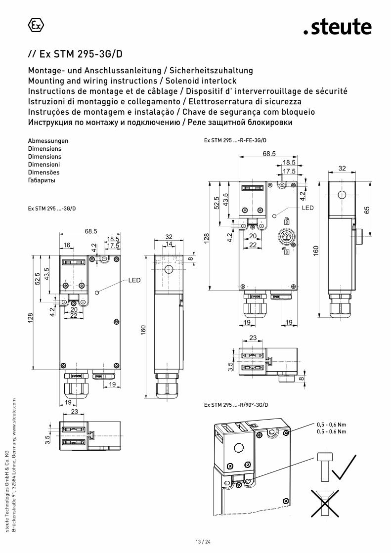
LED
Ex STM 295 ...-R-FE-3G/D
Ex STM 295 ...-R/90°-3G/D
AbmessungenDimensionsDimensionsDimensioniDimensões Габариты
2220
68.518.517.516
3214
19
19
23
LED
Ex STM 295 ...-3G/D
0,5 - 0,6 Nm0.5 - 0.6 Nm

// Ex STM 295-3G/DMontage- und Anschlussanleitung / SicherheitszuhaltungMounting and wiring instructions / Solenoid interlockInstructions de montage et de câblage / Dispositif d' interverrouillage de sécuritéIstruzioni di montaggio e collegamento / Elettroserratura di sicurezzaInstruções de montagem e instalação / Chave de segurança com bloqueioИнструкция по монтажу и подключению / Реле защитной блокировки
steu
te T
echn
olog
ies
Gm
bH &
Co.
KG
Brü
cken
stra
ße 9
1, 3
2584
Löh
ne, G
erm
any,
ww
w.s
teut
e.co
m
14 / 24
AbmessungenDimensionsDimensionsDimensioniDimensões Габариты
BetätigerActuatorActionneurAzionatoreAtuadorПривод a b x
STM 295-B1 350 mm 700 mm 11 mm
STM 295-B5 350 mm 700 mm 13,5 mm 13.5 mm
STM 295-B6 100 mm 100 mm 13 mm
BetätigungsradienActuating radiiRayons d'actionnementRaggi di azionamento Angulos de atuação Радиусы привода в действие
x
a
xb
Die dargestellten Schaltsymbole beziehen sich auf die Grundstel-lung der geschlossenen Tür und den stromlosen Zustand.Contact symbols are shown for the guard in closed position and current-free state.Interrupteurs représentés contacts au repos, protecteur fermé et au repos sans courant.I simboli dei contatti si riferiscono alla posizione di base della porta chiusa in assenza di corrente.Os diagramas dos contatos se referem à posição básica, proteção de fechamento em estado desenergizado sem energia.Представленные условные обозначения относятся к закрытому рабочему положения двери и обесточенному состоянию.
KontakteContactsContactsContattiContatosКонтакты
STM 295-B1 STM 295-B5
STM 295-B6
22
20
30
1
3
5,5
1126,5
2,5
4,2
22
2030
1
3
5,5
1126,5
4,2
2,5
13,5
37,5
5,5

// Ex STM 295-3G/DMontage- und Anschlussanleitung / SicherheitszuhaltungMounting and wiring instructions / Solenoid interlockInstructions de montage et de câblage / Dispositif d' interverrouillage de sécuritéIstruzioni di montaggio e collegamento / Elettroserratura di sicurezzaInstruções de montagem e instalação / Chave de segurança com bloqueioИнструкция по монтажу и подключению / Реле защитной блокировки
steu
te T
echn
olog
ies
Gm
bH &
Co.
KG
Brü
cken
stra
ße 9
1, 3
2584
Löh
ne, G
erm
any,
ww
w.s
teut
e.co
m
15 / 24
Ex STM 295 1Ö1S/2Ö-R-FE-3G/D
Ex STM 295 1Ö1S/1Ö1S-R-3G/DEx STM 295 1Ö1S/1Ö1S-R/90°-3G/DEx STM 295 1Ö1S/1Ö1S-R-FE-3G/DEx STM 295 1Ö1S/1Ö1S-R/90°-FE-3G/D
Ex STM 295 2Ö/1Ö1S-R-FE-3G/DEx STM 295 2Ö/1Ö1S-R/90°-FE-3G/D
Ex STM 295 2Ö1S/2Ö1S-R-3G/DEx STM 295 2Ö1S/2Ö1S-R-FE-3G/D
RuhestromprinzipSpring-to-lock principleOuverture sous-tensionPrincipio di corrente di riposoPrincípio de bloqueio por molaПринцип механической блокировки
KontakteContactsContactsContattiContatosКонтакты
A zwangsöffnend P betätigt Q unbetätigt positive break actuated not actuated ouverture positive actionné pas actionné apertura obbligata azionato non azionato ruptura forçada atuado desativado положительный размыкаемый включено не включено
LegendeLegendLégendeLeggendaLegendaОбозначения
// Ex STM 295-3G/DMontage- und Anschlussanleitung / SicherheitszuhaltungMounting and wiring instructions / Solenoid interlockInstructions de montage et de câblage / Dispositif d' interverrouillage de sécuritéIstruzioni di montaggio e collegamento / Elettroserratura di sicurezzaInstruções de montagem e instalação / Chave de segurança com bloqueioИнструкция по монтажу и подключению / Реле защитной блокировки
steu
te T
echn
olog
ies
Gm
bH &
Co.
KG
Brü
cken
stra
ße 9
1, 3
2584
Löh
ne, G
erm
any,
ww
w.s
teut
e.co
m
16 / 24
KontakteContactsContactsContattiContatosКонтакты
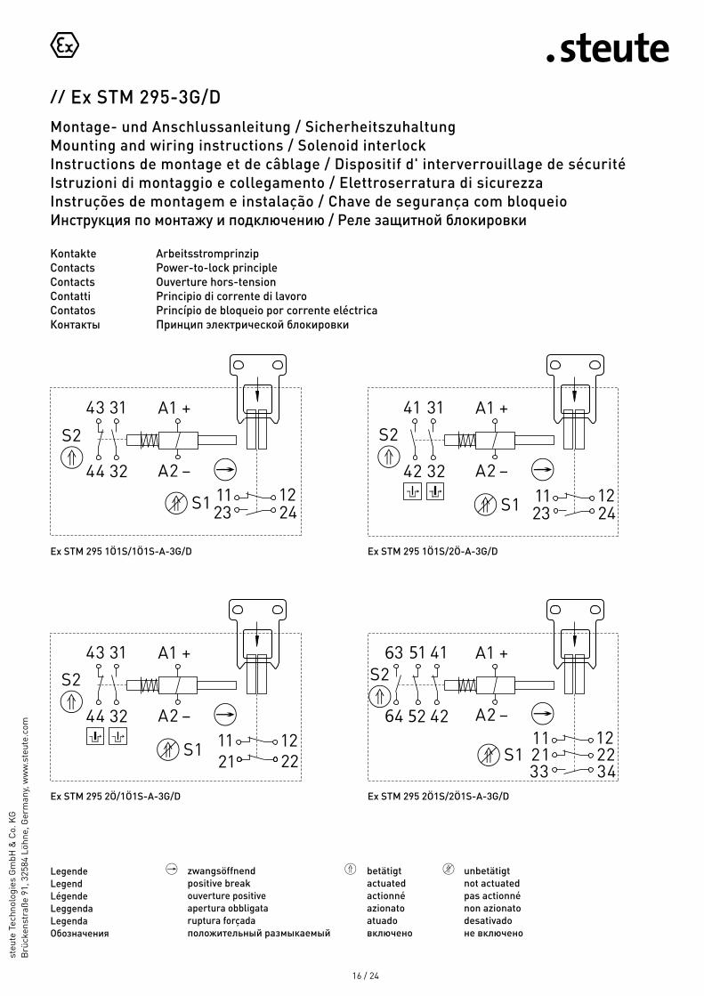
ArbeitsstromprinzipPower-to-lock principleOuverture hors-tensionPrincipio di corrente di lavoroPrincípio de bloqueio por corrente eléctricaПринцип электрической блокировки
Ex STM 295 2Ö/1Ö1S-A-3G/D
Ex STM 295 1Ö1S/1Ö1S-A-3G/D Ex STM 295 1Ö1S/2Ö-A-3G/D
Ex STM 295 2Ö1S/2Ö1S-A-3G/D
A zwangsöffnend P betätigt Q unbetätigt positive break actuated not actuated ouverture positive actionné pas actionné apertura obbligata azionato non azionato ruptura forçada atuado desativado положительный размыкаемый включено не включено
LegendeLegendLégendeLeggendaLegendaОбозначения

// Ex STM 295-3G/DMontage- und Anschlussanleitung / SicherheitszuhaltungMounting and wiring instructions / Solenoid interlockInstructions de montage et de câblage / Dispositif d' interverrouillage de sécuritéIstruzioni di montaggio e collegamento / Elettroserratura di sicurezzaInstruções de montagem e instalação / Chave de segurança com bloqueioИнструкция по монтажу и подключению / Реле защитной блокировки
steu
te T
echn
olog
ies
Gm
bH &
Co.
KG
Brü
cken
stra
ße 9
1, 3
2584
Löh
ne, G
erm
any,
ww
w.s
teut
e.co
m
17 / 24
Deutsch (Originalbetriebsanleitung)
Technische DatenAngewandte Normen EN 60947-5-1; EN 60079-0, -1, -7, -18, -31; EN ISO 13849-1; EN ISO 14119Gehäuse glasfaserverstärkter, schlagfester Thermo- plast, selbstverlöschend UL 94-V0, schutzisoliertFestgelegtes Objekt Betätiger STM 295-B1, -B5 oder -B6 Schaltertyp Bauart 2Kodierungsstufe geringe KodierungSchutzart IP67 nach IEC/EN 60529Anzugsmoment Deckelschrauben: 0,5 … 0,6 Nm; Schalteinsätze: M3 Schraubanschlussklemmen min. 0,6 Nm; Hubmagnet: M3,5 Schraubanschlussklemmen min. 0,8 NmSchaltsystem Schleichschaltung, Öffner zwangsöffnend ASchaltelemente 2 Öffner/2 Schließer, 3 Öffner/1 Schließer oder 4 Öffner/2 Schließer Anschlussart M3 SchraubanschlussklemmenAnschlussquerschnitt min. 0,2 mm2 (AWG 24), max. 1,5 mm2 (AWG 16)Leitungseinführung 2 x M20x1,5; nur Ex-geprüfte und -beschei- nigte Kabeleinführungen min. Schutzart IP67 und zulässigem Umgebungstemperatur- bereich verwendenB10d (10% Nennlast) 1 MillionTM max. 20 JahreUimp 4 kVUi 250 VGebrauchskategorie AC-15; DC-13Schaltvermögen Freigabe-/Meldekontakte: 3 A / 250 V (AC-15) * 0,25 A / 230 V (DC-13) *
1,5 A / 250 V (AC-15) * 0,25 A / 230 V (DC-13) * Gleichstrom-Hubmagnet: 0,08 A / 24 V DC +-10% / -15%Kurzschlussschutz 3 A / 1,5 A gG/gN-Sicherung * Gleichstrom-Hubmagnet: 2 A (träge)Zuhaltekraft F 1.000 NSchalthäufigkeit max. 1.200/hLeistungsaufnahme max. 47 W (0,25 s)Mechan. Lebensdauer >500.000 SchaltspieleTemperaturklasse T4Umgebungstemperatur T4 = -20 °C ... +55 °CEx-Kennzeichnung L II 3G Ex dc ec mc IIC T4 Gc L II 3D Ex tc IIIC T100°C DcKennzeichnung Ô
* Je nach Ausführung, siehe Geräteetikett.
English
Technical dataApplied standards EN 60947-5-1; EN 60079-0, -1, -7, -18, -31; EN ISO 13849-1; EN ISO 14119Enclosure fibreglass-reinforced, shockproof thermo- plastic, self-extinguishing UL 94-V0, protective insulationDefined object actuator STM 295-B1, -B5 or -B6Switch type type 2Coding level low codingDegree of protection IP67 to IEC/EN 60529Tightening torque cover screws: 0.5 … 0.6 Nm; switch inserts: M3 screw connection terminals min. 0.6 Nm; solenoid: M3.5 screw connection terminals min. 0.8 NmSwitching system slow action, positive break NC contacts ASwitching elements 2 NC/2 NO, 3 NC/1 NO or 4 NC/2 NOConnection M3 screw connection terminalsCable cross-section min. 0.2 mm2 (AWG 24), max. 1.5 mm2 (AWG 16)Cable entry 2 x M20x1.5; use only Ex approved and certified cable glands min. degree of protection IP67 and admissible ambient temperature range B10d (10% nominal load) 1 millionTM max. 20 yearsUimp 4 kVUi 250 VUtilisation category AC-15; DC-13Switching capacity enabling/signalling contacts: 3 A / 250 V (AC-15) * 0.25 A / 230 V (DC-13) *
1.5 A / 250 V (AC-15) * 0.25 A / 230 V (DC-13) * direct-current solenoid: 0.08 A / 24 V DC +-10% / -15%Short-circuit protection 3 A / 1.5 A gG/gN fuse * direct-current solenoid: 2 A (slow-blow)Holding force F 1,000 NOperation cycles max. 1,200/hPower consumption max. 47 W (0.25 s)Mechanical life >500,000 operationsTemperature class T4Ambient temperature T4 = -20°C ... +55°CEx marking L II 3G Ex dc ec mc IIC T4 Gc L II 3D Ex tc IIIC T100°C DcDesignation Ô
* Depending on the variant, see product label.

// Ex STM 295-3G/DMontage- und Anschlussanleitung / SicherheitszuhaltungMounting and wiring instructions / Solenoid interlockInstructions de montage et de câblage / Dispositif d' interverrouillage de sécuritéIstruzioni di montaggio e collegamento / Elettroserratura di sicurezzaInstruções de montagem e instalação / Chave de segurança com bloqueioИнструкция по монтажу и подключению / Реле защитной блокировки
steu
te T
echn
olog
ies
Gm
bH &
Co.
KG
Brü
cken
stra
ße 9
1, 3
2584
Löh
ne, G
erm
any,
ww
w.s
teut
e.co
m
18 / 24
Français
Données techniquesNormes appliquées EN 60947-5-1; EN 60079-0, -1, -7, -18, -31; EN ISO 13849-1; EN ISO 14119Boîtier thermoplastique renforcé de fibres de verre, résilient, auto-extinguible UL94-V0, double isolationObject défini actionneur STM 295-B1, -B5 ou -B6Type d'interrupteur type de construction 2Niveau de codage codage faibleEtanchéité IP67 selon IEC/EN 60529Couple de serrage vis de couvercle: 0,5 … 0,6 Nm; inserts de commutation: bornes à vis M3 min. 0,6 Nm; aimant de levage: bornes à vis M3,5 min. 0,8 NmSystème de commutation action dépendante, contact NF à ouverture positive AEléments de commutation 2 NF/2 NO, 3 NF/1 NO ou 4 NF/2 NORaccordement bornes à vis M3Diamètre du câble de raccordement min. 0,2 mm2 (AWG 24), max. 1,5 mm2 (AWG16)Entrée de câble 2 x M20x1,5; utiliser uniquement des entrées de câble certifiées Ex, avec étanchéité min. IP67 et tenue en température B10d (10% charge nominal) 1 millionTM max. 20 ansUimp 4 kVUi 250 VCatégorie d’utilisation AC-15; DC-13Capacité de commutation contacts de validation/signalisation: 3 A / 250 V (AC-15) * 0,25 A / 230 V (DC-13) *
1,5 A / 250 V (AC-15) * 0,25 A / 230 V (DC-13) * aimant de levage à courant continu: 0,08 A / 24 V DC +-10% / -15%Protection contre les courts-circuits fusible 3 A / 1,5 A gG/gN * aimant de levage à courant continu: 2 A (lent)Force de retenue F 1.000 NFréquence de manoeuvre max. 1.200/hPuissance consommée max. 47 W (0,25 s)Durée de vie mécanique >500.000 manoeuvres
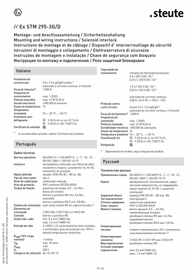
Italiano
Dati tecniciNorme applicate EN 60947-5-1; EN 60079-0, -1, -7, -18, -31; EN ISO 13849-1; EN ISO 14119Custodia termoplastica rinforzata con fibre di vetro, antiurto, autoestinguente UL94-V0, isolamento protettivo Azionamento azionatore STM 295-B1, -B5 oppure -B6Tipo di interruttore tipo 2Livello di codifica codifica bassaGrado di protezione IP67 secondo IEC/EN 60529Coppia di serraggio viti del coperchio: 0,5 … 0,6 Nm; inserti di commutazione: morsetti a vite M3 min. 0,6 Nm; solenoide: morsetti a vite M3,5 min. 0,8 NmSistema di commutazione commutazione lenta, contatto NC ad apertura obbligata AElementi di commutazione 2 NC/2 NA, 3 NC/1 NA oppure 4 NC/2 NACollegamento morsetti a vite M3Sezione di collegamento min. 0,2 mm2 (AWG 24), max. 1,5 mm2 (AWG 16)Passacavo 2 x M20x1,5; utilizzare solo ingressi cavo col- laudati e certificati Ex, grado di protezione min. IP67 e adatti a temperatura ambientale B10d (10% carico nominale) 1 milioneTM max. 20 anniUimp 4 kVUi 250 VCategoria d'impiego AC-15; DC-13Capacità di commutazione contatti di libero e di segnalazione: 3 A / 250 V (AC-15) * 0,25 A / 230 V (DC-13) *
1,5 A / 250 V (AC-15) * 0,25 A / 230 V (DC-13) * solenoide a corrente continua: 0,08 A / 24 V DC +-10% / -15%
Classe de température T4Température ambiante T4 = -20 °C ... +55 °CProtection anti- déflagrante L II 3G Ex dc ec mc IIC T4 Gc L II 3D Ex tc IIIC T100°C DcMarquage Ô
* Dépendant de la variante, voir l'étiquette de l'appareil.
// Ex STM 295-3G/DMontage- und Anschlussanleitung / SicherheitszuhaltungMounting and wiring instructions / Solenoid interlockInstructions de montage et de câblage / Dispositif d' interverrouillage de sécuritéIstruzioni di montaggio e collegamento / Elettroserratura di sicurezzaInstruções de montagem e instalação / Chave de segurança com bloqueioИнструкция по монтажу и подключению / Реле защитной блокировки
steu
te T
echn
olog
ies
Gm
bH &
Co.
KG
Brü
cken
stra
ße 9
1, 3
2584
Löh
ne, G
erm
any,
ww
w.s
teut
e.co
m
19 / 24
Português
Dados técnicosNormas aplicáveis EN 60947-5-1; EN 60079-0, -1, -7, -18, -31; EN ISO 13849-1; EN ISO 14119Invólucro termoplástico reforçado com fibras de vidro, resistente a impacto, autoextintor UL 94-V0, isolamento de proteçãoObjeto definido atuador STM 295-B1, -B5 ou -B6Tipo de interruptor tipo 2Nível de codificação codificação reduzidaGrau de proteção IP67 conforme IEC/EN 60529Torque de fixação parafusos da tampa: 0,5 … 0,6 Nm; blocos de contato: bornes a parafuso M3 mín. 0,6 Nm; solenóide: bornes a parafuso M3,5 mín. 0,8 NmSistema de comutação ação lenta,contato NF de ruptura forçada AElementos de comutação 2 NF/2 NA, 3 NF/1 NA ou 4 NF/2 NAConexão bornes a parafuso M3 Seção máx. cabo mín. 0,2 mm2 (AWG 24), máx. 1,5 mm2 (AWG 16)Entrada de cabo 2 x M20 x 1,5; exclusivamente dutos testados e certificados, grau de proteção mín. IP67 e admita temperaturas ambientes B10d (10% carga nominal) 1 milhãoTM máx. 20 anosUimp 4 kVUi 250 VCategoria de utilização AC-15; DC-13
Русский
Технические данныеПримененные нормы EN 60947-5-1; EN 60079-0, -1, -7, -18, -31; EN ISO 13849-1; EN ISO 14119Корпус армированный стекловолокном, ударо- прочный термопластик, не поддержива- ющий горение UL 94-V0, с защитной изоляциейЗаданный объект привод STM 295-B1, -B5 или -B6Тип выключателя конструкция 2Степень кодировки невысокая кодировкаКласс защиты IP67 по IEC/EN 60529Момент затяжки винты крышки: 0,5 … 0,6 Нм; коммутирующие вставки: резьбовые клеммы M3 мин. 0,6 Нм; подъёмный магнит: резьбовые клеммы M3,5 мин. 0,8 НмКоммутирующая система плавное переключение, НЗ с положитель- ным размыкаемым контактом AКоммутирующие элементы 2 НЗ/2 НP, 3 НЗ/1 НP или 4 НЗ/2 НP Вид подключения резьбовые клеммы M3Сечение проводов подключения мин. 0,2 мм2 (AWG 24), мaкc. 1,5 мм2 (AWG 16)
Protezione da cortocircuito 3 A / 1,5 A gG/gN fusibile * solenoide a corrente continua: 2 A (lento)Forza di ritenuta F 1.000 NFrequenza di commutazioni max. 1.200/hPotenza assorbita max. 47 W (0,25 s)Durata meccanica >500.000 di manovreClasse di temperatura T4Temperatura circostante T4 = -20 °C ... +55 °CProtezione anti- deflagrante L II 3G Ex dc ec mc IIC T4 Gc L II 3D Ex tc IIIC T100°C DcCertificato di collaudo Ô
* A seconda della variante, vedere l’etichetta del prodotto.
Italiano Capacidade de chaveamento contatos de liberação/sinalização: 3 A / 250 V (AC-15) * 0,25 A / 230 V (DC-13) *
1,5 A / 250 V (AC-15) * 0,25 A / 230 V (DC-13) * solenoide de corrente contínua: 0,08 A / 24 V DC +-10% / -15%Proteção contra curto-circuito fusível 3 A / 1,5 A gG/gN * solenoide de corrente contínua: 2 A (lento)Força de fechamento F 1.000 NFrequéncia de comutação máx. 1.200/hPotência instalada máx. 47 W (0,25 s)Durabilidade mecânica >500.000 de operaçõesClasse da temperatura T4Temperatura ambiente T4 = -20 °C ... + 55 °CClassificação Ex L II 3G Ex dc ec mc IIC T4 Gc L II 3D Ex tc IIIC T100°C DcDesignação Ô
* Dependendo do modelo, veja a etiqueta do produto.

// Ex STM 295-3G/DMontage- und Anschlussanleitung / SicherheitszuhaltungMounting and wiring instructions / Solenoid interlockInstructions de montage et de câblage / Dispositif d' interverrouillage de sécuritéIstruzioni di montaggio e collegamento / Elettroserratura di sicurezzaInstruções de montagem e instalação / Chave de segurança com bloqueioИнструкция по монтажу и подключению / Реле защитной блокировки
steu
te T
echn
olog
ies
Gm
bH &
Co.
KG
Brü
cken
stra
ße 9
1, 3
2584
Löh
ne, G
erm
any,
ww
w.s
teut
e.co
m
20 / 24
Русский
Kабельный ввод 2 x M20x1,5; применять только прове рен - ный и сертифицированный на взрывозащи- ту кабельный ввод с мин. классом защиты IP67 и допустимой температурой окружаю- щей среды B10d (10% номиналь- ной нагрузки) 1 миллионTM макс. 20 лeтUimp 4 kVUi 250 VКатегории использования AC-15; DC-13Допустимая коммутационная разблокирующих/сигнальных контактов: 3 A / 250 V (AC-15) * 0,25 A / 230 V (DC-13) *
1,5 A / 250 V (AC-15) * 0,25 A / 230 V (DC-13) * подъёмный магнит постоянного тока: 0,08 A / 24 V DC +-10% / -15%Защита от короткого замыкания 3 A / 1,5 A gG/gN предохранитель * подъёмный магнит постоянного тока: 2 A (инерционная)Сила удержания F 1.000 НЧастота коммутации макс. 1.200/часПотребляемая мощность мaкc. 47 W (0,25 сек)Механ. долговечность >500.000 циклы коммутацииТемпературный класс T4Температура окру- жающей среды T4 = -20 °C ... +55 °CВзрывная защищенность L II 3G Ex dc ec mc IIC T4 Gc L II 3D Ex tc IIIC T100°C DcMаркировка Ô
* В зависимости от варианта, см. ярлык устройства.

// Ex STM 295-3G/DMontage- und Anschlussanleitung / SicherheitszuhaltungMounting and wiring instructions / Solenoid interlockInstructions de montage et de câblage / Dispositif d' interverrouillage de sécuritéIstruzioni di montaggio e collegamento / Elettroserratura di sicurezzaInstruções de montagem e instalação / Chave de segurança com bloqueioИнструкция по монтажу и подключению / Реле защитной блокировки
steu
te T
echn
olog
ies
Gm
bH &
Co.
KG
Brü
cken
stra
ße 9
1, 3
2584
Löh
ne, G
erm
any,
ww
w.s
teut
e.co
m
21 / 24
Herstellungsdatum 012321 => Montag KW 23 / 2021Production date Monday CW 23 / 2021Date de fabrication lundi semaine 23 / 2021Data di produzione lunedi settimana 23 / 2021Data de fabricação segunda semana 23 / 2021Дата изготовления понедельник календарная неделя 23 / 2021
01 Montag Monday lundi lunedi segunda понедельник
02 Dienstag Tuesday mardi martedì terça вторник
03 Mittwoch Wednesday mercredi mercoledì quarta среда
04 Donnerstag Thursday jeudi giovedì quinta четверг
05 Freitag Friday vendredi venerdì sexta пятница

// Ex STM 295-3G/DMontage- und Anschlussanleitung / SicherheitszuhaltungMounting and wiring instructions / Solenoid interlockInstructions de montage et de câblage / Dispositif d' interverrouillage de sécuritéIstruzioni di montaggio e collegamento / Elettroserratura di sicurezzaInstruções de montagem e instalação / Chave de segurança com bloqueioИнструкция по монтажу и подключению / Реле защитной блокировки
steu
te T
echn
olog
ies
Gm
bH &
Co.
KG
Brü
cken
stra
ße 9
1, 3
2584
Löh
ne, G
erm
any,
ww
w.s
teut
e.co
m
22 / 24
Als Hersteller trägt die Firma steute Technologies die alleinige Verantwortung für die Ausstellung dieser Konformitätserklärung /As manufacturer, steute Technologies is solely responsible for issuing this Declaration of Conformity.
Art und Bezeichnung der Betriebsmittel / Ex Sicherheitszuhaltung, Typen Ex STM 295 … -3G/DType and name of equipment: Ex solenoid interlock, types Ex STM 295 … -3G/D
Hiermit erklären wir, dass die oben aufgeführten elektrischen Betriebsmittel aufgrund der Konzipierung und Bauart den grundlegenden Sicherheits- und Gesundheitsanforderungen nach Anhang II der Richtlinie 2014/34/EU entsprechen. /We hereby declare that, due to its design and construction, the above mentioned electrical equipment satisfies the requirements of directive 2014/34/EU in respect to basic safety and health requirements according to Annex II.
Angewandte EU-Richtlinie /Applied EU directive
Harmonisierte Normen / Harmonised standards
Neueste harmonisierte Normen /Latest harmonised standards
2014/34/EU Explosionsschutzrichtlinie / 2014/34/EU Explosion Protection Directive
EN IEC 60079-0:2018, EN 60079-1:2014, EN 60079-7:2015, EN 60079-18:2015, EN 60079-31:2014
Weitere angewandte EU-Richtlinien /Additionally applied EU directives
Harmonisierte Normen / Harmonised standards
Anmerkungen /Comments
2006 / 42 / EG Maschinenrichtlinie / 2006 / 42 / EC Machinery Directive
EN 60947-5-1:2017;EN ISO 14119:2013
2014 / 30 / EU EMV-Richtlinie /2014 / 30 / EU EMC Directive
EN 60947-5-1:2017;EN 61000-6-1:2007,EN 61000-6-2:2005;EN 55011:2016 + A1:2017
2011 / 65 / EU RoHS-Richtlinie /2011 / 65 / EU RoHS Directive
EN IEC 63000:2018
Rechtsverbindliche Unterschrift, Marc Stanesby (Geschäftsführer) /Legally binding signature, Marc Stanesby (Managing Director)
Rechtsverbindliche Unterschrift, Rechtsverbindliche Unterschrift, Rechtsverbindliche Unterschrift, Rechtsverbindliche Unterschrift, Rechtsverbindliche Unterschrift, Rechtsverbindliche Unterschrift, Rechtsverbindliche Unterschrift, Rechtsverbindliche Unterschrift, Rechtsverbindliche Unterschrift, Rechtsverbindliche Unterschrift, Rechtsverbindliche Unterschrift, Rechtsverbindliche Unterschrift, Rechtsverbindliche Unterschrift, Rechtsverbindliche Unterschrift, Rechtsverbindliche Unterschrift, Rechtsverbindliche Unterschrift, Rechtsverbindliche Unterschrift, Rechtsverbindliche Unterschrift, Rechtsverbindliche Unterschrift, Rechtsverbindliche Unterschrift, Rechtsverbindliche Unterschrift, Rechtsverbindliche Unterschrift, Rechtsverbindliche Unterschrift, Rechtsverbindliche Unterschrift, Rechtsverbindliche Unterschrift, Rechtsverbindliche Unterschrift, Rechtsverbindliche Unterschrift, Rechtsverbindliche Unterschrift, Rechtsverbindliche Unterschrift, Rechtsverbindliche Unterschrift, Rechtsverbindliche Unterschrift, Rechtsverbindliche Unterschrift, Rechtsverbindliche Unterschrift, Rechtsverbindliche Unterschrift, Rechtsverbindliche Unterschrift, Rechtsverbindliche Unterschrift, Rechtsverbindliche Unterschrift, Rechtsverbindliche Unterschrift, Rechtsverbindliche Unterschrift, Rechtsverbindliche Unterschrift, Rechtsverbindliche Unterschrift, Marc Stanesby (Geschäftsführer) Marc Stanesby (Geschäftsführer) Marc Stanesby (Geschäftsführer) Marc Stanesby (Geschäftsführer) Marc Stanesby (Geschäftsführer) Marc Stanesby (Geschäftsführer) Marc Stanesby (Geschäftsführer) Marc Stanesby (Geschäftsführer) Marc Stanesby (Geschäftsführer) Marc Stanesby (Geschäftsführer) Marc Stanesby (Geschäftsführer) Marc Stanesby (Geschäftsführer) Marc Stanesby (Geschäftsführer) Marc Stanesby (Geschäftsführer) Marc Stanesby (Geschäftsführer) Marc Stanesby (Geschäftsführer) Marc Stanesby (Geschäftsführer) Marc Stanesby (Geschäftsführer) Marc Stanesby (Geschäftsführer) Marc Stanesby (Geschäftsführer) Marc Stanesby (Geschäftsführer) Marc Stanesby (Geschäftsführer) Marc Stanesby (Geschäftsführer) Marc Stanesby (Geschäftsführer) Marc Stanesby (Geschäftsführer) Marc Stanesby (Geschäftsführer) Marc Stanesby (Geschäftsführer) Marc Stanesby (Geschäftsführer) Marc Stanesby (Geschäftsführer) Marc Stanesby (Geschäftsführer) Marc Stanesby (Geschäftsführer) Marc Stanesby (Geschäftsführer) Marc Stanesby (Geschäftsführer) ///
EG-Baumusterprüfung / EU-type examination:
Ex-Kennzeichnung /Ex marking
Neueste Ex-Kennzeichnung /Latest Ex marking
L II 3G Ex dc ec mc IIC T4 GcL II 3D Ex tc IIIC T100°C Dc
Verantwortlich technische Dokumentation / Responsible for technical documentation:
Marc Stanesby (Geschäftsführer)Marc Stanesby (Managing Director)
steute Technologies GmbH & Co KG, Brückenstr. 91, 32584 Löhne, Germany
Löhne, 14. Januar 2021 / January 14, 2021 Ort und Datum der Ausstellung / Place and date of issue
EU-KONFORMITÄTSERKLÄRUNG EU DECLARATION OF CONFORMITY
gemäß der Explosionsschutz-Richtlinie 2014 / 34 / EUaccording to Explosion Protection Directive 2014 / 34/ EU

// Ex STM 295-3G/DMontage- und Anschlussanleitung / SicherheitszuhaltungMounting and wiring instructions / Solenoid interlockInstructions de montage et de câblage / Dispositif d' interverrouillage de sécuritéIstruzioni di montaggio e collegamento / Elettroserratura di sicurezzaInstruções de montagem e instalação / Chave de segurança com bloqueioИнструкция по монтажу и подключению / Реле защитной блокировки
steu
te T
echn
olog
ies
Gm
bH &
Co.
KG
Brü
cken
stra
ße 9
1, 3
2584
Löh
ne, G
erm
any,
ww
w.s
teut
e.co
m
23 / 24
Als Hersteller trägt die Firma steute Technologies die alleinige Verantwortung für die Ausstellung dieser Konformitätserklärung /As manufacturer, steute Technologies is solely responsible for issuing this Declaration of Conformity.
Art und Bezeichnung der Betriebsmittel / Ex Sicherheitszuhaltung, Typen Ex STM 295 … -3G/DType and name of equipment: Ex solenoid interlock, types Ex STM 295 … -3G/D
Hiermit erklären wir, dass die oben aufgeführten elektrischen Betriebsmittel aufgrund der Konzipierung und Bauart den grundlegenden Sicherheits- und Gesundheitsanforderungen nach Anhang II der Richtlinie Equipment and Protective Systems Intended for use in Potentially Explosive Atmospheres Regulations 2016 entsprechen. /We hereby declare that, due to its design and construction, the above mentioned electrical equipment satisfies the requirements of directive Equipment and Protective Systems Intended for use in Potentially Explosive Atmospheres Regulations 2016 in respect to basic safety and health requirements according to Annex II.
Relevante UK-Richtlinie /Relevant UK directive
Angewandte harmonisierte Normen /Applied harmonised/designated standards
Anmerkungen /Comments
2014/34/EU Explosionsschutzrichtlinie /2014/34/EU Explosion Protection Directive
EN IEC 60079-0:2018, EN 60079-1:2014, EN 60079-7:2015, EN 60079-18:2015, EN 60079-31:2014
Weitere angewandte EU-Richtlinien /Additionally applied EU directives
Harmonisierte Normen /Harmonised/Designated standards
Anmerkungen /Comments
Supply of Machinery (Safety) Regulations 2008
EN 60947-5-1:2017;EN ISO 14119:2013
Electromagnetic Compatibility Regulations 2016
EN 60947-5-1:2017;EN 61000-6-1:2007,EN 61000-6-2:2005;EN 55011:2016 + A1:2017
The Restriction of the Use of Certain Hazardous Substances in Electrical and Electronic Equipment Regulations 2012
EN IEC 63000:2018
Rechtsverbindliche Unterschrift, Marc Stanesby (Geschäftsführer) /Legally binding signature, Marc Stanesby (Managing Director)
EG-Baumusterprüfung /EU-type examination:
Ex-Kennzeichnung /Ex marking
Neueste Ex-Kennzeichnung /Latest Ex marking
L II 3G Ex dc ec mc IIC T4 GcL II 3D Ex tc IIIC T100°C Dc
Verantwortlich technische Dokumentation / Responsible for technical documentation:
Marc Stanesby (Geschäftsführer)Marc Stanesby (Managing Director)
steute Technologies GmbH & Co KG, Brückenstr. 91, 32584 Löhne, Germany
Löhne, 21. September 2021 / 21 September, 2021Ort und Datum der Ausstellung / Place and date of issue
UK-KONFORMITÄTSERKLÄRUNG UK DECLARATION OF CONFORMITY
gemäß der Equipment and Protective Systems Intended for use in Potentially Explosive Atmospheres Regulations 2016according to Equipment and Protective Systems Intended for use in Potentially Explosive Atmospheres Regulations 2016
steu
te T
echn
olog
ies
Gm
bH &
Co.
KG
Brü
cken
stra
ße 9
1, 3
2584
Löh
ne, G
erm
any,
ww
w.s
teut
e.co
m
24 / 24
Zusatzinformation zu Montage- und AnschlussanleitungenAdditional information on mounting and wiring instructionsInformation complémentaire aux instructions de montage et de câblageUlteriori informazioni sulle istruzioni di collegamento e montaggioInformação adicional para as instruções de montagemДополнительная информация по монтажу и инструкциям по подключению
[bg] При поискване Вие ще получите тази асамблея, а също и връзката ръчно майчиния си език.
[cs] Na požádání obdržíte tento návod na montáž a připojení také v jazyce vaší země.
[da] På anmodning kan De også rekvirere denne montage- og tils-lutningsvejledning på deres eget sprog.
[de] Auf Anfrage erhalten Sie diese Montage- und Anschlussanlei-tung auch in Ihrer Landessprache.
[el] Εφόσον το ζητήσετε λαμβάνετε αυτές τις οδηγίες τοποθέτησης και σύνδεσης και στην γλώσσα της χώρας σας.
[en] This mounting and wiring instruction is also available in your national language on request.
[es] Estas instrucciones de montaje y conexionado se pueden soli-citar en su idioma.
[et] Soovi korral on see installimis- ja ühendusjuhend saadaval ka teie riigikeeles.
[fi] Pyydettäessä asennus- ja kytkentäohjeet on saatavana myös sinun omalla äidinkielellä.
[fr] Ces instructions de montage et de câblage sont disponibles sur demande, dans votre langue nationale.
[ga] Arna iarraidh sin gheobhaidh tú na treoracha tionóil agus na treorach seo i do theanga féin.
[hr] Na zahtjev ćete dobiti ova uputstva za montažu i priključenje i na svom jeziku.
[hu] Egyeztetés után, kérésére, ezt a szerelési- és csatlakoztatási leírást, biztosítjuk az ön anyanyelvén is.
[it] Questa istruzione di collegamento e montaggio e’inoltre dispo-nibile nella vostra lingua su richiesta.
[lt] Jei jums reikėtų šios įdiegimo ir pajungimo instrukcijos valsty-bine kalba, teiraukitės pardavėjo.
[lv] Šo montāžas un pieslēgšanas instrukciju pēc pieprasījuma varat saņemt arī savas valsts valodā.
[mt] Dan il-manwal dwar il-muntaġġ u konnessjonijiet huwa dispo-nibbli wkoll fil-lingwa tiegħek.
[nl] Op aanvraag kunt u deze montage- en installatiehandleiding ook in uw taal verkrijgen.
[pl] Niniejsza instrukcja montażu i podłączenia jest dostępna na życzenie w języku polskim.
[pt] Instruções de ligação e montagem podem ser disponibilizadas em outros idiomas também - consulte-nos.
[ro] La cererea dumneavoastră, vă trimitem instrucţiunile de folosi-re şi instrucţiunile de montaj şi în limba romana.
[sk] Na vyžiadanie obdržíte tento návod na montáž a pripojenie takisto v jazyku vašej krajiny.
[sl] Na zahtevo boste dobili ta navodila za montažo in priklop tudi v vašem domačem jeziku.
[sv] Den här monterings- och elinstallation instruktionen finns även tillgänglig på ditt nationella språk efter förfrågan.
Importer for United KingdomforTop Automation & Energy Control UK LtdMalvern Hills Science ParkGeraldine RoadWR14 3SZ Malvern, WorcestershireUnited Kingdomwww.4top.co.uk
01.2
6.05
18 /
118
38 7
7 / 0
9.20
21 /
1417
81.In
dex
j / 5
00 w
d