2922 Einstiegsseite Seidel Tensile Surface Structure · 2015-01-22 · Tensile Surface Structures A...
14
S S S a a a m m m p p p l l l e e e C C C h h h a a a p p p t t t e e e r r r Tensile Surface Structures A Practical Guide to Cable and Membrane Construction Editor: Michael Seidel Copyright © 2009 Ernst & Sohn, Berlin ISBN: 978-3-433-02922-0 Wilhelm Ernst & Sohn Verlag für Architektur und technische Wissenschaften GmbH & Co. KG Rotherstraße 21, 10245 Berlin Deutschland www.ernst-und-sohn.de
Transcript of 2922 Einstiegsseite Seidel Tensile Surface Structure · 2015-01-22 · Tensile Surface Structures A...
SSSaaammmpppllleee CCChhhaaapppttteeerrr Tensile Surface Structures A Practical Guide to Cable and Membrane Construction Editor: Michael Seidel Copyright © 2009 Ernst & Sohn, Berlin ISBN: 978-3-433-02922-0
Wilhelm Ernst & Sohn Verlag für Architektur und technische Wissenschaften GmbH & Co. KG Rotherstraße 21, 10245 Berlin Deutschland www.ernst-und-sohn.de
59
2.4.3.2 Erection criteriaIn addition to the determination of the strip layout favour-able for the deformation behaviour according to structural and topological criteria and production limitations like strip width, cutting waste and seamed joints, the division of a membrane surface into strips is also subject to limitations regarding erection. It becomes particularly clear during the tensioning process, how important the material used, its cut-ting patterns, the shape of the surface and the type of edg-ing are for the erection. This particularly makes the tension-ing scheme, which can have a considerable eff ect on the overall project costs, economically signifi cant in the erection process.
Tensioning travel, tensioning direction – cut-out pattern direction In order to make a membrane suffi ciently load-bearing, it has to be biaxially tensioned in the relevant curve and fi xed. The calculated share of compensation must be pulled out of the material through the edging and its corners.
The cost of implementing a tensioning procedure is deter-mined mainly by the arrangement of the individual panels. Apart from the optical appearance of the seams and the structural conditions in a membrane surface, all erection measures, like the dimensioning and installation of the ten-sioning equipment, measures to stabilise the primary con-struction and the arrangement of scaff olding, depend on the orientation of the strips.
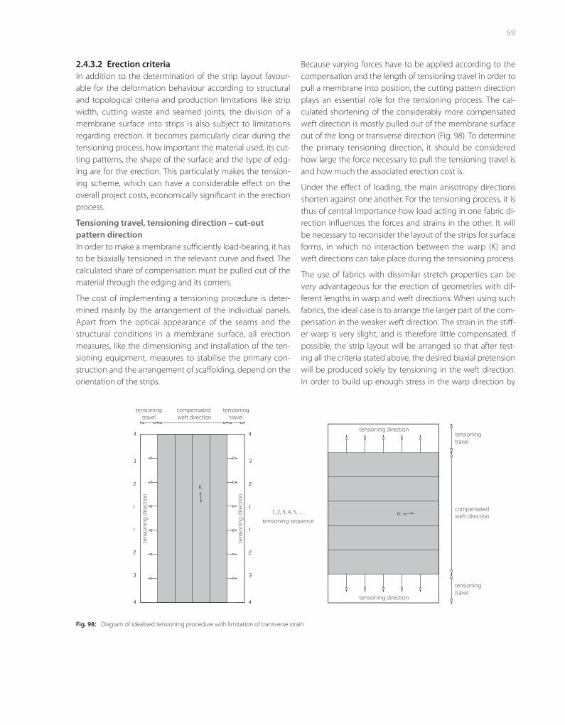
Because varying forces have to be applied according to the compensation and the length of tensioning travel in order to pull a membrane into position, the cutting pattern direction plays an essential role for the tensioning process. The cal-culated shortening of the considerably more compensated weft direction is mostly pulled out of the membrane surface out of the long or transverse direction (Fig. 98). To determine the primary tensioning direction, it should be considered how large the force necessary to pull the tensioning travel is and how much the associated erection cost is.
Under the eff ect of loading, the main anisotropy directions shorten against one another. For the tensioning process, it is thus of central importance how load acting in one fabric di-rection infl uences the forces and strains in the other. It will be necessary to reconsider the layout of the strips for surface forms, in which no interaction between the warp (K) and weft directions can take place during the tensioning process.
The use of fabrics with dissimilar stretch properties can be very advantageous for the erection of geometries with dif-ferent lengths in warp and weft directions. When using such fabrics, the ideal case is to arrange the larger part of the com-pensation in the weaker weft direction. The strain in the stiff -er warp is very slight, and is therefore little compensated. If possible, the strip layout will be arranged so that after test-ing all the criteria stated above, the desired biaxial pretension will be produced solely by tensioning in the weft direction. In order to build up enough stress in the warp direction by
Fig. 98: Diagram of idealised tensioning procedure with limitation of transverse strain
tensioningtravel
compensated weft direction
tensioningtravel
tens
ioni
ng d
irect
ion
tens
ioni
ng d
irect
ion
1, 2, 3, 4, 5, …tensioning sequence
tensioning direction
tensioning direction
tensioningtravel
compensatedweft direction
tensioningtravel
60
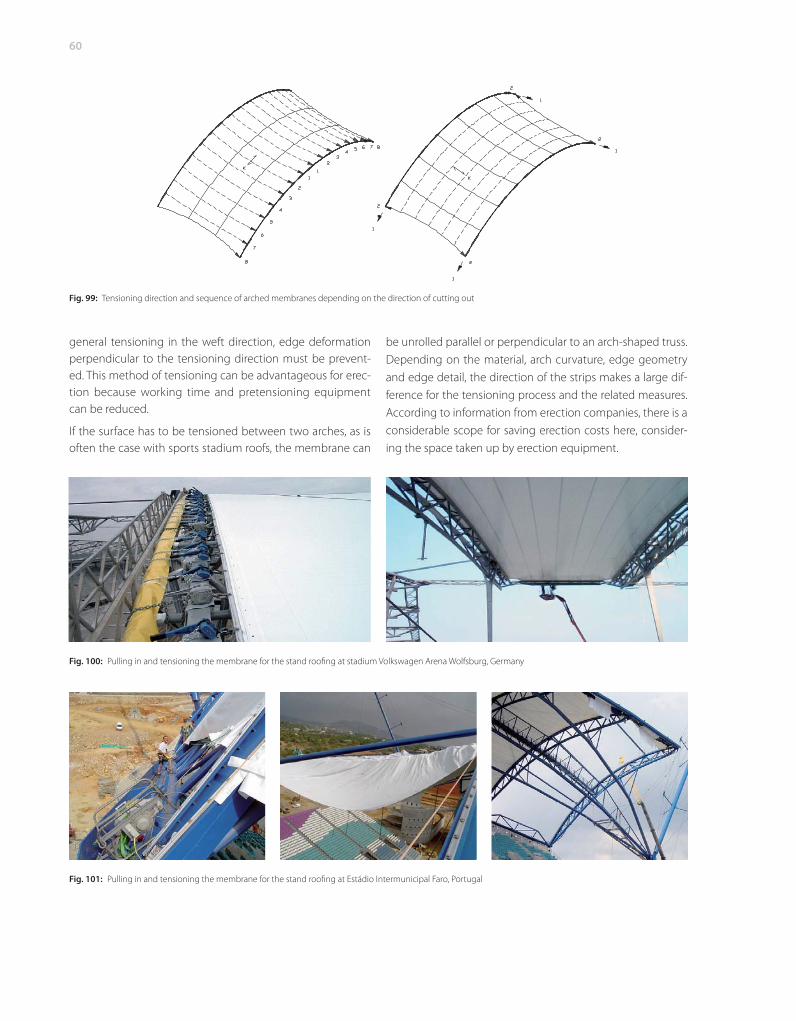
general tensioning in the weft direction, edge deformation perpendicular to the tensioning direction must be prevent-ed. This method of tensioning can be advantageous for erec-tion because working time and pretensioning equipment can be reduced.
If the surface has to be tensioned between two arches, as is often the case with sports stadium roofs, the membrane can
be unrolled parallel or perpendicular to an arch-shaped truss. Depending on the material, arch curvature, edge geometry and edge detail, the direction of the strips makes a large dif-ference for the tensioning process and the related measures. According to information from erection companies, there is a considerable scope for saving erection costs here, consider-ing the space taken up by erection equipment.
Fig. 99: Tensioning direction and sequence of arched membranes depending on the direction of cutting out
Fig. 100: Pulling in and tensioning the membrane for the stand roofi ng at stadium Volkswagen Arena Wolfsburg, Germany
Fig. 101: Pulling in and tensioning the membrane for the stand roofi ng at Estádio Intermunicipal Faro, Portugal
61
If a membrane surface unrolled parallel to the arch truss is compared with one unrolled perpendicular to it, then it can be noticed that when tensioning the strips perpendicular to the arch truss (left in Fig. 99), the pretension has to be ap-plied at more points than with the variant (right in Fig. 99). This requires more work and equipment.
Apart from setting up and operating the erection equipment at the location where the force is applied, this extra work is often caused by the type of edge detail.
If the use of single clamping plate edge elements cannot be avoided because of structural requirements, then the forces must be applied starting from the centre and the edge ele-ments installed singly, adjusted and fi xed (Fig. 100).
If the warp direction is perpendicular to the arch truss and the surface has the right curvature and has a keder rail edge detail, then the surface can be pulled through the rail and tensioned quickly and easily (Fig. 101).
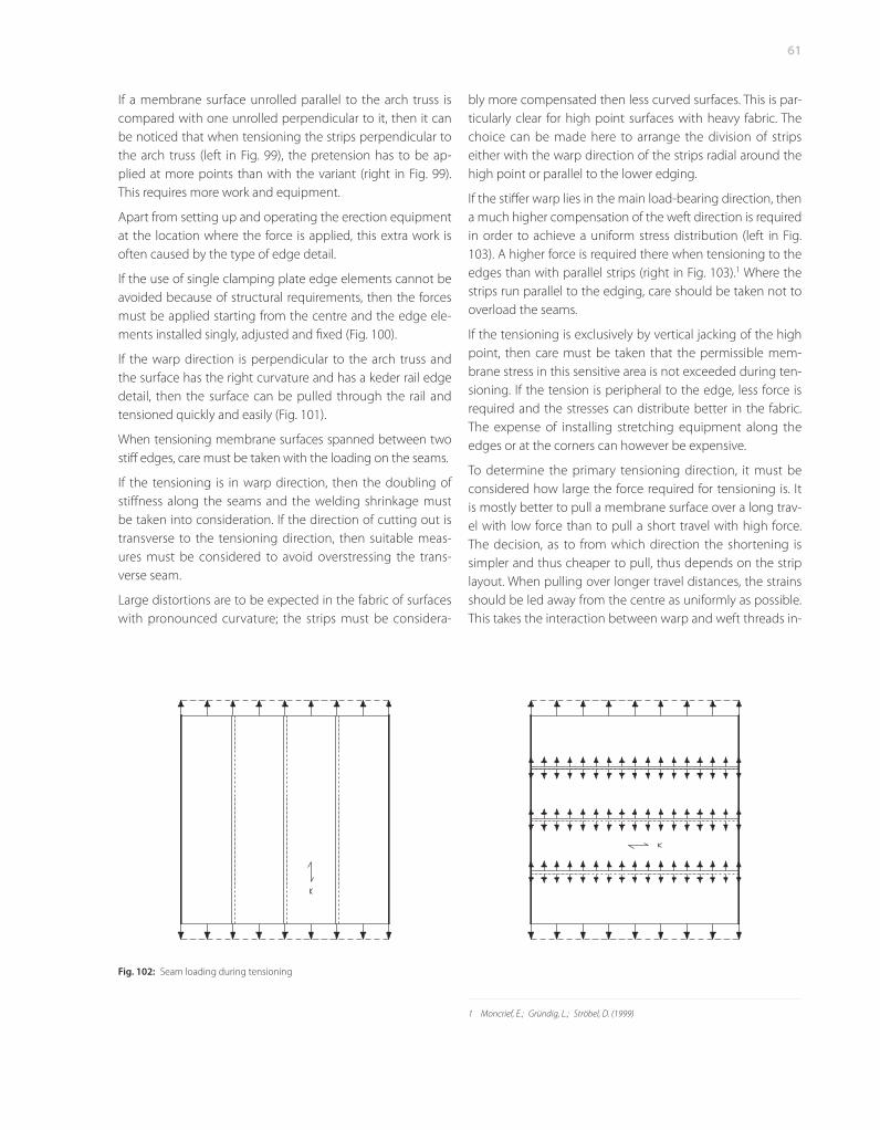
When tensioning membrane surfaces spanned between two stiff edges, care must be taken with the loading on the seams.
If the tensioning is in warp direction, then the doubling of stiff ness along the seams and the welding shrinkage must be taken into consideration. If the direction of cutting out is transverse to the tensioning direction, then suitable meas-ures must be considered to avoid overstressing the trans-verse seam.
Large distortions are to be expected in the fabric of surfaces with pronounced curvature; the strips must be considera-
Fig. 102: Seam loading during tensioning
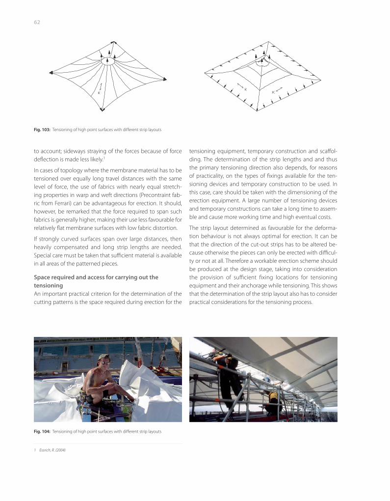
bly more compensated then less curved surfaces. This is par-ticularly clear for high point surfaces with heavy fabric. The choice can be made here to arrange the division of strips either with the warp direction of the strips radial around the high point or parallel to the lower edging.
If the stiff er warp lies in the main load-bearing direction, then a much higher compensation of the weft direction is required in order to achieve a uniform stress distribution (left in Fig. 103). A higher force is required there when tensioning to the edges than with parallel strips (right in Fig. 103).1 Where the strips run parallel to the edging, care should be taken not to overload the seams.
If the tensioning is exclusively by vertical jacking of the high point, then care must be taken that the permissible mem-brane stress in this sensitive area is not exceeded during ten-sioning. If the tension is peripheral to the edge, less force is required and the stresses can distribute better in the fabric. The expense of installing stretching equipment along the edges or at the corners can however be expensive.
To determine the primary tensioning direction, it must be considered how large the force required for tensioning is. It is mostly better to pull a membrane surface over a long trav-el with low force than to pull a short travel with high force. The decision, as to from which direction the shortening is simpler and thus cheaper to pull, thus depends on the strip layout. When pulling over longer travel distances, the strains should be led away from the centre as uniformly as possible. This takes the interaction between warp and weft threads in-
1 Moncrief, E.; Gründig, L.; Ströbel, D. (1999)
62
to account; sideways straying of the forces because of force defl ection is made less likely.1
In cases of topology where the membrane material has to be tensioned over equally long travel distances with the same level of force, the use of fabrics with nearly equal stretch-ing properties in warp and weft directions (Precontraint fab-ric from Ferrari) can be advantageous for erection. It should, however, be remarked that the force required to span such fabrics is generally higher, making their use less favourable for relatively fl at membrane surfaces with low fabric distortion.
If strongly curved surfaces span over large distances, then heavily compensated and long strip lengths are needed. Special care must be taken that suffi cient material is available in all areas of the patterned pieces.
Space required and access for carrying out the tensioning An important practical criterion for the determination of the cutting patterns is the space required during erection for the
1 Essrich, R. (2004)
tensioning equipment, temporary construction and scaff ol-ding. The determination of the strip lengths and and thus the primary tensioning direction also depends, for reasons of practicality, on the types of fi xings available for the ten-sioning devices and temporary construction to be used. In this case, care should be taken with the dimensioning of the erection equipment. A large number of tensioning devices and temporary constructions can take a long time to assem-ble and cause more working time and high eventual costs.
The strip layout determined as favourable for the deforma-tion behaviour is not always optimal for erection. It can be that the direction of the cut-out strips has to be altered be-cause otherwise the pieces can only be erected with diffi cul-ty or not at all. Therefore a workable erection scheme should be produced at the design stage, taking into consideration the provision of suffi cient fi xing locations for tensioning equipment and their anchorage while tensioning. This shows that the determination of the strip layout also has to con sider practical considerations for the tensioning process.
Fig. 103: Tensioning of high point surfaces with diff erent strip layouts
Fig. 104: Tensioning of high point surfaces with diff erent strip layouts
2.4.4 Cutting out the piecesCutting out denotes the division of one or more textile sur-faces (layers) according to dimensions or cutting out from pattern drawings as part of fabrication.1
The patterning and design are normally carried out by the engineer. Surface areas, edge details and seams are deter-mined in discussion with the architect. The cutting out of the pieces and the joining, packaging and delivery are undertak-en by the fabricator.
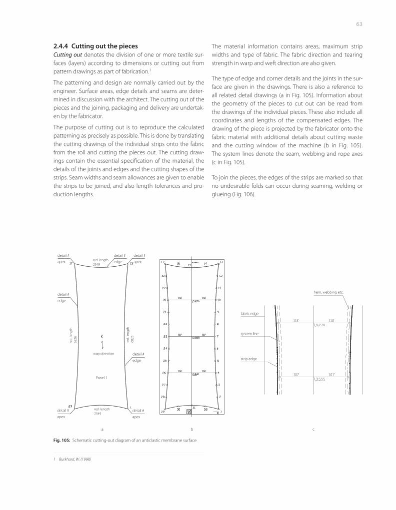
The purpose of cutting out is to reproduce the calculated patterning as precisely as possible. This is done by translating the cutting drawings of the individual strips onto the fabric from the roll and cutting the pieces out. The cutting draw-ings contain the essential specifi cation of the material, the details of the joints and edges and the cutting shapes of the strips. Seam widths and seam allowances are given to enable the strips to be joined, and also length tolerances and pro-duction lengths.
1 Burkhard, W. (1998)
63
fabric edge
system line
strip edge
hem, webbing etc.
Fig. 105: Schematic cutting-out diagram of an anticlastic membrane surface
detail #
apex
detail #
edge
detail #
edge
detail #
edge
detail #
apex
detail #
apex
detail #
apex
red. length2549
red. length2549
red.
leng
th68
26
red.
leng
th68
26
warp direction
Panel 1
a b c
The material information contains areas, maximum strip widths and type of fabric. The fabric direction and tearing strength in warp and weft direction are also given.
The type of edge and corner details and the joints in the sur-face are given in the drawings. There is also a reference to all related detail drawings (a in Fig. 105). Information about the geometry of the pieces to cut out can be read from the drawings of the individual pieces. These also include all coordinates and lengths of the compensated edges. The drawing of the piece is projected by the fabricator onto the fabric material with additional details about cutting waste and the cutting window of the machine (b in Fig. 105). The system lines denote the seam, webbing and rope axes (c in Fig. 105).
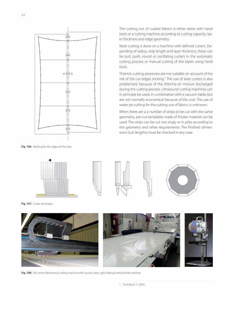
To join the pieces, the edges of the strips are marked so that no undesirable folds can occur during seaming, welding or glueing (Fig. 106).
64
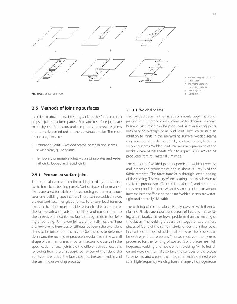
The cutting out of coated fabrics is either done with hand tools or a cutting machine according to cutting capacity, lay-er thickness and edge geometry.
Most cutting is done on a machine with defi ned cutters. De-pending of radius, strip length and layer thickness, these can be pull, push, round or oscillating cutters in the automatic cutting process or manual cutting of the layers using hand tools.
Thermic cutting processes are not suitable on account of the risk of the cut edges sticking.1 The use of laser cutters is also problematic because of the chlorine-air mixture discharged during the cutting process. Ultrasound cutting machines can in principle be used, in combination with a vacuum table, but are not normally economical because of the cost. The use of water jet cutting for the cutting out of fabrics is unknown.
When there are a a number of strips to be cut with the same geometry, pre-cut templates made of thicker material can be used. The strips can be cut out singly or in piles according to the geometry and other requirements. The fi nished dimen-sions (cut lengths) must be checked in any case.
1 Steckelbach, C. (2005)
Fig. 106: Marking for the edges of the strip
Fig. 107: Cutter tip shapes
Fig. 108: left, centre: Mechanical cutting machine with round cutter; right: Manual vertical knife machine
65
2.5 Methods of jointing surfaces
In order to obtain a load-bearing surface, the fabric cut into strips is joined to form panels. Permanent surface joints are made by the fabricator, and temporary or reusable joints are normally carried out on the construction site. The most important joints are:
Permanent joints – welded seams, combination seams, sewn seams, glued seams
Temporary or reusable joints – clamping plates and keder rail joints, looped and laced joints
2.5.1 Permanent surface joints
The material cut out from the roll is joined by the fabrica-tor to form load-bearing panels. Various types of permanent joints are used for fabric strips according to material, struc-tural and building specifi cation. These can be welded, sewn, welded and sewn, or glued joints. To ensure load transfer, joints in the fabric must be able to transfer the forces out of the load-bearing threads in the fabric and transfer them to the threads of the conjoined fabric through mechanical join-ing or bonding. Permanent joints are normally fl exible. There are, however, diff erences of stiff ness between the two fabric strips to be joined and the seam. Obstructions to deforma-tion along the seam joint produce irregularities in the overall shape of the membrane. Important factors to observe in the specifi cation of such joints are the diff erent thread locations following from the anisotropic behaviour of the fabric, the adhesion strength of the fabric coating, the seam widths and the seaming or welding process.
•
•
2.5.1.1 Welded seams
The welded seam is the most commonly used means of jointing in membrane construction. Welded seams in mem-brane construction can be produced as overlapping joints with varying overlaps or as butt joints with cover strip. In addition to joints in the membrane surface, welded seams may also be edge sleeve details, reinforcements, keder or webbing seams. Welded joints are normally produced at the works, where partial sheets of up to approx. 5,000 m2 can be produced from roll material 5 m wide.
The strength of welded joints depends on welding process and processing temperature and is about 60 – 95 % of the fabric strength. The force transfer is through shear loading of the coating. The quality of the coating and its adhesion to the fabric produce an eff ect similar to form-fi t and determine the strength of the joint. Welded seams produce an abrupt increase in the stiff ness at the seam. Welded seams are water-tight and normally UV-stable.
The welding of coated fabrics is only possible with thermo-plastics. Plastics are poor conductors of heat, so the weld-ing of thin fabrics makes fewer problems than the welding of thick layers. The welding process joins together two or more pieces of fabric of the same material under the infl uence of heat without the use of additional adhesive. The process can be with or without pressure. The two most commonly used processes for the jointing of coated fabric pieces are high frequency welding and hot element welding. While hot el-ement welding thermally softens the surfaces of the pieces to be joined and presses them together with a defi ned pres-sure, high-frequency welding forms a largely homogeneous
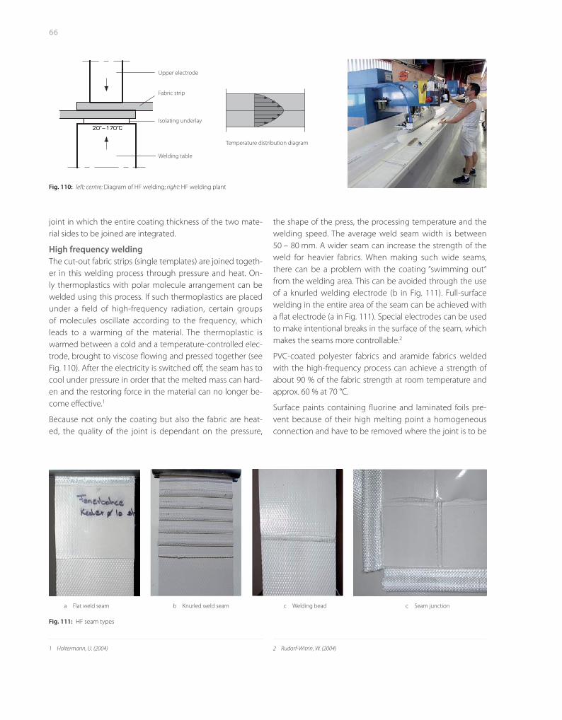
Fig. 109: Surface joint types
a overlapping welded seamb sewn seamc lapped sewn seam d clamping plate joint e looped joint f laced joint
a b c
d e f
66
joint in which the entire coating thickness of the two mate-rial sides to be joined are integrated.
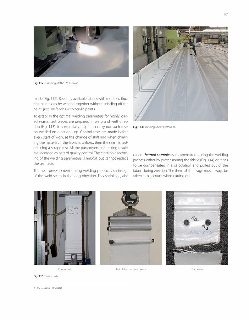
High frequency weldingThe cut-out fabric strips (single templates) are joined togeth-er in this welding process through pressure and heat. On-ly thermoplastics with polar molecule arrangement can be welded using this process. If such thermoplastics are placed under a fi eld of high-frequency radiation, certain groups of molecules oscillate according to the frequency, which leads to a warming of the material. The thermoplastic is warmed between a cold and a temperature-controlled elec-trode, brought to viscose fl owing and pressed together (see Fig. 110). After the electricity is switched off , the seam has to cool under pressure in order that the melted mass can hard-en and the restoring force in the material can no longer be-come eff ective.1
Because not only the coating but also the fabric are heat-ed, the quality of the joint is dependant on the pressure,
1 Holtermann, U. (2004)
the shape of the press, the processing temperature and the welding speed. The average weld seam width is between 50 – 80 mm. A wider seam can increase the strength of the weld for heavier fabrics. When making such wide seams, there can be a problem with the coating “swimming out“ from the welding area. This can be avoided through the use of a knurled welding electrode (b in Fig. 111). Full-surface welding in the entire area of the seam can be achieved with a fl at electrode (a in Fig. 111). Special electrodes can be used to make intentional breaks in the surface of the seam, which makes the seams more controllable.2
PVC-coated polyester fabrics and aramide fabrics welded with the high-frequency process can achieve a strength of about 90 % of the fabric strength at room temperature and approx. 60 % at 70 °C.
Surface paints containing fl uorine and laminated foils pre-vent because of their high melting point a homogeneous connection and have to be removed where the joint is to be
2 Rudorf-Witrin, W. (2004)
Fig. 110: left; centre: Diagram of HF welding; right: HF welding plant
Fig. 111: HF seam types
a Flat weld seam b Knurled weld seam c Welding bead c Seam junction
Welding table
Isolating underlay
Fabric strip
Upper electrode
Temperature distribution diagram
67
made (Fig. 112). Recently available fabrics with modifi ed fl uo-rine paints can be welded together without grinding off the paint, just like fabrics with acrylic paints.
To establish the optimal welding parameters for highly load-ed seams, test pieces are prepared in warp and weft direc-tion (Fig. 113). It is especially helpful to carry out such tests on welded-on erection lugs. Control tests are made before every start of work, at the change of shift and when chang-ing the material. If the fabric is welded, then the seam is test-ed using a scrape test. All the parameters and testing results are recorded as part of quality control. The electronic record-ing of the welding parameters is helpful, but cannot replace the tear tests.1
The heat development during welding produces shrinkage of the weld seam in the long direction. This shrinkage, also
1 Rudorf-Witrin, W. (2004)
called thermal crumple, is compensated during the welding process either by pretensioning the fabric (Fig. 114) or it has to be compensated in a calculation and pulled out of the fabric during erection. The thermal shrinkage must always be taken into account when cutting out.
Fig. 112: Grinding off the PVDF paint
Fig. 113: Seam tests
Control test Test of the completed seam Torn seam
Fig. 114: Welding under pretension
68
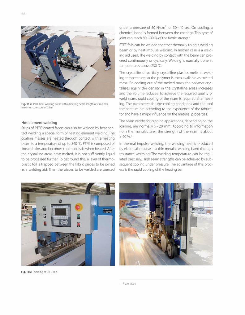
Hot element weldingStrips of PTFE-coated fabric can also be welded by heat con-tact welding, a special form of heating element welding. The coating masses are heated through contact with a heating beam to a temperature of up to 340 °C. PTFE is composed of linear chains and becomes thermoplastic when heated. After the crystalline areas have melted, it is not suffi ciently liquid to be processed further. To get round this, a layer of thermo-plastic foil is trapped between the fabric pieces to be joined as a welding aid. Then the pieces to be welded are pressed
under a pressure of 50 N/cm2 for 30 – 40 sec. On cooling, a chemical bond is formed between the coatings. This type of joint can reach 80 – 90 % of the fabric strength.
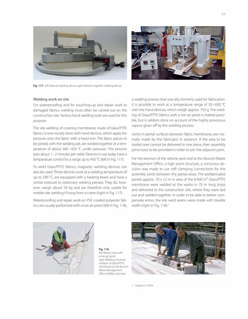
ETFE foils can be welded together thermally using a welding beam or by heat impulse welding. In neither case is a weld-ing aid used. The welding by contact with the beam can pro-ceed continuously or cyclically. Welding is normally done at temperatures above 230 °C.
The crystallite of partially crystalline plastics melts at weld-ing temperature, so the polymer is then available as melted mass. On cooling out of the melted mass, the polymer crys-tallises again, the density in the crystalline areas increases and the volume reduces. To achieve the required quality of weld seam, rapid cooling of the seam is required after heat-ing. The parameters for the cooling conditions and the tool temperature are according to the experience of the fabrica-tor and have a major infl uence on the material properties.
The seam widths for cushion applications, depending on the loading, are normally 5 – 20 mm. According to information from the manufacturer, the strength of the seam is about > 90 %.1
In thermal impulse welding, the welding heat is produced by electrical impulse in a thin metallic welding band through resistance warming. The welding temperature can be regu-lated precisely. High seam strengths can be achieved by sub-sequent cooling under pressure. The advantage of this proc-ess is the rapid cooling of the heating bar.
1 Fitz, H. (2004)
Fig. 115: PTFE heat welding press with a heating beam length of 2 m and a maximum pressure of 7 bar
Fig. 116: Welding of ETFE foils
69
Welding work on siteFor waterproofi ng and for touching-up and repair work to damaged fabrics, welding must often be carried out on the construction site. Various hand welding tools are used for this purpose.
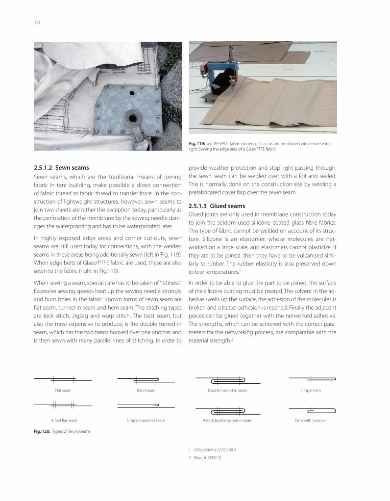
The site welding of covering membranes made of Glass/PTFE fabrics is now mostly done with hand devices, which apply the pressure onto the fabric with a hand iron. The fabric pieces to be joined, with the welding aid, are welded together at a tem-perature of about 360 – 420 °C under pressure. This process lasts about 1 – 2 minutes per weld. Devices in use today have a temperature control for a range up to 450 °C (left in Fig. 117).
To weld Glass/PTFE fabrics, magnetic welding devices can also be used. These devices work at a welding temperature of up to 390 °C, are equipped with a heating beam and have a similar pressure to stationary welding presses. They do, how-ever, weigh about 50 kg and are therefore only usable for mobile site welding if hung from a crane (right in Fig. 117).
Waterproofi ng and repair work on PVC-coated polyester fab-rics are usually performed with a hot-air pistol (left in Fig. 118),
a welding process that was also formerly used for fabrication. It is possible to work at a temperature range of 50 – 600 °C with the hand devices, which weigh approx. 750 g. The weld-ing of Glass/PTFE fabrics with a hot air pistol is indeed possi-ble, but is seldom done on account of the highly poisonous vapour given off by the welding process.
Joints in partial surfaces between fabric membranes are nor-mally made by the fabricator in advance. If the area to be roofed over cannot be delivered in one piece, then assembly joints have to be provided in order to join the adjacent parts.
For the erection of the vehicle park roof at the Munich Waste Management Offi ce, a high point structure, a conscious de-cision was made to use stiff clamping connections for the assembly joints between the partial areas. The prefabricated panels approx. 10 x 12 m in area of the 8.400 m2 Glass/ PTFE membrane were welded at the works in 70 m long strips and delivered to the construction site, where they were laid out and welded together. In order to be able to better com-pensate errors, the site weld seams were made with double width (right in Fig. 118).1
1 Göppert, K. (2003)
Fig. 117: left: Manual welding device; right: Mobile magnetic welding device
Fig. 118: left: Repair work with a hot air pistol; right: Welding of partial surfaces of Glass/PTFE membrane at the Munich Waste Management Offi ce (AWM), Germany
70
2.5.1.2 Sewn seamsSewn seams, which are the traditional means of joining fabric in tent building, make possible a direct connection of fabric thread to fabric thread to transfer force. In the con-struction of lightweight structures, however, sewn seams to join two sheets are rather the exception today, particularly as the perforation of the membrane by the sewing needle dam-ages the waterproofi ng and has to be waterproofed later.
In highly exposed edge areas and corner cut-outs, sewn seams are still used today for connections, with the welded seams in these areas being additionally sewn (left in Fig. 119). When edge belts of Glass/PTFE fabric are used, these are also sewn to the fabric (right in Fig.119).
When sewing a seam, special care has to be taken of “tidiness“. Excessive sewing speeds heat up the sewing needle strongly and burn holes in the fabric. Known forms of sewn seam are fl at seam, turned-in seam and hem seam. The stitching types are lock stitch, zigzag and warp stitch. The best seam, but also the most expensive to produce, is the double turned-in seam, which has the two hems hooked over one another and is then sewn with many parallel lines of stitching. In order to
provide weather protection and stop light passing through, the sewn seam can be welded over with a foil and sealed. This is normally done on the construction site by welding a prefabricated cover fl ap over the sewn seam.
2.5.1.3 Glued seamsGlued joints are only used in membrane construction today to join the seldom-used silicone-coated glass fi bre fabrics. This type of fabric cannot be welded on account of its struc-ture. Silicone is an elastomer, whose molecules are net-worked on a large scale, and elastomers cannot plasticize. If they are to be joined, then they have to be vulcanised simi-larly to rubber. The rubber elasticity is also preserved down to low temperatures.1
In order to be able to glue the part to be joined, the surface of the silicone coating must be treated. The solvent in the ad-hesive swells up the surface, the adhesion of the molecules is broken and a better adhesion is reached. Finally the adjacent pieces can be glued together with the networked adhesive. The strengths, which can be achieved with the correct para-meters for the networking process, are comparable with the material strength.2
1 DVS guideline 2225 (1991)
2 Blum, R. (2002-2)
Fig. 119: left: PES/PVC fabric corners of a circus tent reinforced with sewn seams; right: Sewing the edge area of a Glass/PTFE fabric
Fig. 120: Types of sewn seams
Flat seam Blind seam Double turned-in seam Simple hem
4-fold fl at seam Simple turned-in seam 4-fold double turned-in seam Hem with turnover
Bo
ok
Re
com
me
nd
ati
on
Seidel, M.
Tensile Surface Structures. A Practical Guide to Cable and Membrane Construction Materials, Design, Assembly and Erection Tensile surface structures are the visual expression of an intensive rethinking of the topic of building envelopes by designers. Advances in design methods, materials, construction elements and assembly and erection planning in the field of lightweight construction are enabling ever more exacting applications of tensile structures with envelope and structural functions, especially in roofing over large clear spans without internal support. However, the particular mechanical characteristics of the materials
used in the construction of textile structures demand consideration of the question of "buildability". This book provides answers by discussing the fundamental influence of material manufacture and assembly in deciding the most suitable type of building or structure and its detailing in the design process. The fundamentals of material composition, manufacturing process, patterning and the behaviour of flexible structural systems are all explained here, as well as their use as structural and connection elements, and special attention is given to the erection of wide-span lightweight structures. The erection equipment is described, as well as the lifting and tensioning process and the construction methods used to erect the characteristic types of tensile structures, illustrated with a selection of example projects. XI, 229 pages with approx 368 figures 196 in color. Hardcover. Published)
⌦Link Online-Order ⌦Fax-Answer +49(0)30 47031 240 Quantity Order-No. Title Unit price
978-3-433-02922-0 Tensile Surface Structures. A Practical Guide to Cable and Membrane Construction
€ 139,-
904852 Publishing Index Verlag Ernst & Sohn for free
2091 Journal BAUTECHNIK 1 sample copy for free
Delivery and Invoice address: private business Company
Contact person Telephone
UST-ID Nr./VAT-ID No. Fax
Street//No. E-Mail
Land - Zip code location
Date/Signature *In EU countries the local VAT is effective for books and journals. Postage will be charged. Whilst every effort is made to ensure that the contents of this leaflet are accurate, all information is subject to change without notice. Our standard terms and delivery conditions apply. Prices are subject to change without notice. Date of Information: 01.04.09 (homepage_Leseprobe)
(
Wilhelm Ernst & Sohn Verlag für Architektur und technische Wissenschaften GmbH & Co. KG Rotherstraße 21 10245 Berlin Deutschland www.ernst-und-sohn.de


![Link to VoR: Angewandte · 2018. 11. 29. · (cytoplasmic-facing) leaflet of the cell membrane.[2] The exposure of PS on the cell surface is a common marker of cell death[3] and one](https://static.fdokument.com/doc/165x107/60db9de11ce58475ca4e6eb0/link-to-vor-angewandte-2018-11-29-cytoplasmic-facing-leaflet-of-the-cell.jpg)