
4794 35 BA - img.elit.czimg.elit.cz/rgcmedia/s/171/167/7927cbed015d48f4856fa0f8c0831dc9.pdf3...
64
Betriebsanleitung Universal-Werkzeug-Sortiment für Motoreinstellung an: Operating Instructions Universal Engine Timing Tool Set for: Návod pro obsluhu Univerzální sada pro nastavení rozvodů značek: AUDI, SEAT, SKODA, VOLKSWAGEN, OPEL, VAUXHALL, FORD, CITROËN, PEUGEOT, RENAULT 4794/35 HAZET-WERK HÖCHSTE TECHNOLOGIE IN DER WERKZEUGFERTIGUNG SEIT 1868 HIGHEST TECHNOLOGY IN TOOL MANUFACTURE SINCE 1868 223258
Transcript of 4794 35 BA - img.elit.czimg.elit.cz/rgcmedia/s/171/167/7927cbed015d48f4856fa0f8c0831dc9.pdf3...

Betriebsanleitung Universal-Werkzeug-Sortiment für Motoreinstellung an:Operating Instructions Universal Engine Timing Tool Set for:Návod pro obsluhu Univerzální sada pro nastavení rozvodů značek:
AUDI, SEAT, SKODA, VOLKSWAGEN, OPEL, VAUXHALL, FORD, CITROËN, PEUGEOT, RENAULT
4794/35
HAZET-WERKHÖCHSTE TECHNOLOGIE IN DER WERKZEUGFERTIGUNG SEIT 1868HIGHEST TECHNOLOGY IN TOOL MANUFACTURE SINCE 1868
2232
58
2
Arbeiten an Motoren dürfen nur von Fachleuten ausgeführt werden.
Immer persönliche Schutzausrüstung tragen.
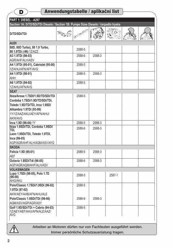
DPART 1: DIESEL - A297Section 1A: D/TD/SDi/TDi Diesels / Section 1B: Pumpe Düse Diesels / čerpadlo tryska
D/TD/SDi/TDi
AUDI80D, 80D Turbo), 80 1.9 Turbo,80 1.9TDi (-96) 1Z/AZZ 2588-5
A3 1.9TDi (98-03) 2588-6 2588-3AGR/AHF/ALH/ASVA4 1.9TDi (95-01), Cabriolet (95-00) 2588-51Z/AHU/AFN/AFF/AVGA4 1.9TDi (98-01) 2588-5 2588-3AHHA6 1.9TDi (94-02) 2588-51Z/AHU/AFN/AVGSEATIbiza/Arosa 1.7SDI/1.9D/TD/SDi/TDi 2588-5Cordoba 1.7SDi/1.9D/TD/SDi/TDi,Toledo 1.9D/TD/TDi, Inca 1.9SDiAlhambra 1.9TDi (93-99)1Y/1Z/AAZ/AKU/AEY/AFN/AHU/AKW/AVGInca 1.9D (96-04) 1Y 2588-5 2588-3Ibiza 1.9SDi/TDi, Cordoba 1.9SDi/TDi, 2588-6 2588-3Leon 1.9SDi/TDi, Toledo 1.9TDI,Inca (99-05)AGP/AGR/AHF/ALH/AQM/ASV/AYQSKODAFelicia 1.9D (95-01) 2588-5 2588-3AEF Octavia 1.9SDi/Tdi (96-05) 2588-6 2588-3AGP/AGR/AQM/AHF/ALH/ASVVOLKSWAGENLupo 1.7SDi (98-05), Polo 1.7D (96-00) 2588-5 2587-1AHG/AKUPolo/Classic 1.7SDi/1.9SDi (96-02) 2588-51.9TDi (97-02) AKW/AEY/AHB/AFN/AHU/ALEPolo/Classic 1.9SDi/TDi (99-06) 2588-6 2588-3AQM/ASV/AGP/AGR/ASYGolf 1.9D/SDi/TDi + Cabrio (94-03) 2588-51Z/AEY/AEF/AHU/AFN/ALE/AAZ/AVG
Anwendungstabelle / aplikační list
3
Arbeiten an Motoren dürfen nur von Fachleuten ausgeführt werden.
Immer persönliche Schutzausrüstung tragen.
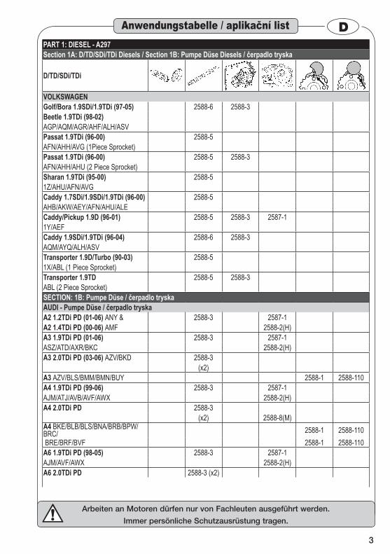
DAnwendungstabelle / aplikační listPART 1: DIESEL - A297Section 1A: D/TD/SDi/TDi Diesels / Section 1B: Pumpe Düse Diesels / čerpadlo tryska
D/TD/SDi/TDi
VOLKSWAGENGolf/Bora 1.9SDi/1.9TDi (97-05) 2588-6 2588-3Beetle 1.9TDi (98-02)AGP/AQM/AGR/AHF/ALH/ASVPassat 1.9TDi (96-00) 2588-5AFN/AHH/AVG (1Piece Sprocket)Passat 1.9TDi (96-00) 2588-5 2588-3AFN/AHH/AHU (2 Piece Sprocket)Sharan 1.9TDi (95-00) 2588-51Z/AHU/AFN/AVGCaddy 1.7SDi/1.9SDi/1.9TDi (96-00) 2588-5AHB/AKW/AEY/AFN/AHU/ALECaddy/Pickup 1.9D (96-01) 2588-5 2588-3 2587-11Y/AEFCaddy 1.9SDi/1.9TDi (96-04) 2588-6 2588-3AQM/AYQ/ALH/ASVTransporter 1.9D/Turbo (90-03) 2588-51X/ABL (1 Piece Sprocket)Transporter 1.9TD 2588-5 2588-3ABL (2 Piece Sprocket)SECTION: 1B: Pumpe Düse / čerpadlo tryskaAUDI - Pumpe Düse / čerpadlo tryskaA2 1.2TDi PD (01-06) ANY & 2588-3 2587-1A2 1.4TDi PD (00-06) AMF 2588-2(H)A3 1.9TDi PD (01-06) 2588-3 2587-1ASZ/ATD/AXR/BKC 2588-2(H)A3 2.0TDi PD (03-06) AZV/BKD 2588-3
(x2)A3 AZV/BLS/BMM/BMN/BUY 2588-1 2588-110A4 1.9TDi PD (99-06) 2588-3 2587-1AJM/ATJ/AVB/AVF/AWX 2588-2(H)A4 2.0TDi PD 2588-3
(x2) 2588-8(M)A4 BKE/BLB/BLS/BNA/BRB/BPW/BRC/ 2588-1 2588-110 BRE/BRF/BVF 2588-1 2588-110A6 1.9TDi PD (98-05) 2588-3 2587-1AJM/AVF/AWX 2588-2(H)A6 2.0TDi PD 2588-3 (x2)
4
Arbeiten an Motoren dürfen nur von Fachleuten ausgeführt werden.
Immer persönliche Schutzausrüstung tragen.
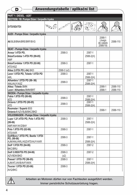
DPART 1: DIESEL - A297SECTION: 1B: Pumpe Düse / čerpadlo tryska
D/TD/SDi/TDi
AUDI - Pumpe Düse / čerpadlo tryska
A6 BLB/BNA/BRE/BRF/BVG2588-1 (Juego
de calado 2588/19)
2588-110
SEAT - Pumpe Düse / čerpadlo tryskaArosa 1.4TDi PD, 2588-3 2587-1Ibiza/Cordoba 1.4TDi PD (99-05) 2588-2(H)AMFIbiza/Cordoba 1.9TDi PD (02-06) 2588-3 2587-1ATD/ASZAltea 2.0TDi PD (-04) BKD 2588-3 )x2)Leon 1.9TDi PD, Toledo 1.9TDi PD 2588-3 2587-1ARL 2588-2(H)Alhambra 1.9TDi PD (99- 06)ANU/AUY/ASZ 2588-3 2587-1
2588-2(H)Altea / Toledo BMNLeon / Alhambra BMM/BRT
2588-12588-1
2588-1102588-110
SKODA - Pumpe Düse / čerpadlo tryskaFabia 1.9TDi PD (00-06)ATD 2588-3 2587-1
2588-2(H)Octavia 1.9TDi PD (00-05)ATD 2588-3 2587-1
2588-2(H)Roomster / Superb BSSOctavia II AZV/BJB/BKC/BKD 2588-1 2588-110
VOLKSWAGEN - Pumpe Düse / čerpadlo tryskaLupo 1.2/1.4TDi PD, Polo 1.4TDi PD 2588-3 2587-1(99-06) 2588-2(H)AMF/ANY/AYZ/BAYPolo 1.9TDi PD (02-06) 2588-3 2587-1ATD/AXRGolf/Bora 1.9TDi PD, Beetle 1.9TDi PD, (99-06) 2588-3 2587-1AJM/ANU/ARL/ASZ/ATD/AUY/AXR 2588-2(H)Golf 1.9TDI PD (04-06) 2588-3 2587-2BKC/BRUGolf 2.0SDI/TDi PD (04-06) 2588-3 2587-2AZV/BDK/BKD (x2)Passat 1.9TDi PD (96-05) 2588-3 2587-1AJM/ATJ/AVB/AVF/AWX 2588-2(H)Touran 1.9TDi PD (03-06) 2588-3AVQ/BKC
Anwendungstabelle / aplikační list
5
Arbeiten an Motoren dürfen nur von Fachleuten ausgeführt werden.
Immer persönliche Schutzausrüstung tragen.
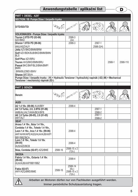
DPART 1: DIESEL - A297SECTION: 1B: Pumpe Düse / čerpadlo tryska
D/TD/SDi/TDi
VOLKSWAGEN - Pumpe Düse / čerpadlo tryskaTouran 2.0TDi PD (03-06) AZV/BKD
2588-3 (2x)
Sharan 1.9TDi PD (99-06) 2588-3 2587-1ANU/ASZ/AUY 2588-2(H)Jetta AZV/BKD/BMM/BRMGolf AZV/BDK/BJB/BKD/BMM/BMN/BLSGolf Plus AZV/BRUTouran AVQ/BKD/BMN/BRUPassat BKC/BKP/BLS/BMA/BMP/BMR/ BRM/BUZ/BEV/BWVSharan BRT/BVH
2588-1 2588-110
Pumpe Düse / čerpadlo tryska - (H) = Hydraulic Tensioner / hydraulický napínák (-02) (M) = Mechanical Tensioner / mechanický napínák (02-)
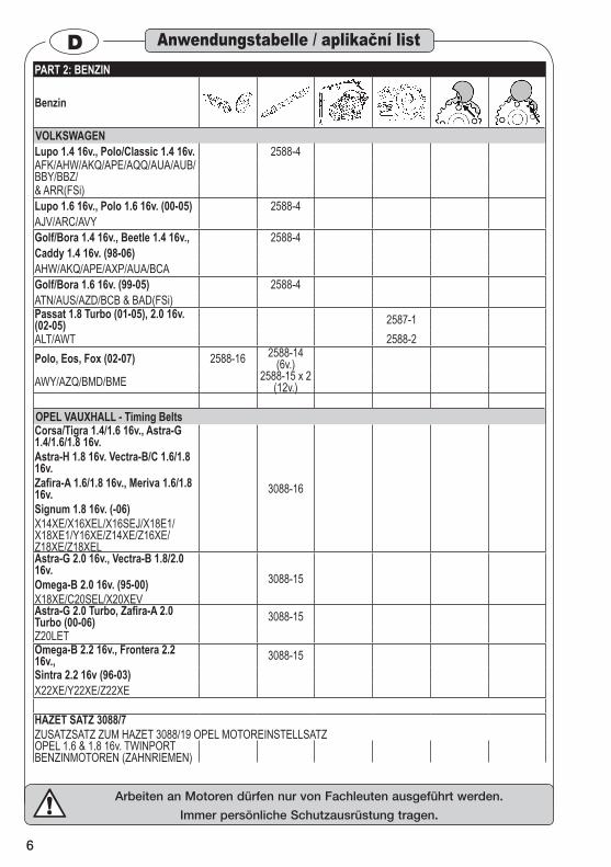
PART 2: BENZIN
Benzin
AUDIA2 1.4 16v. (00-06) AUA/BBY 2588-4A4 1.8 Turbo, 2.0, 2.0FSi (01-06)AMB/AVJ/ALT/AWA/BEX/BFB
2587-12588-2
A6 1.8 Turbo (00-05), 2.0 (01-05) AWT/ALT
2587-12588-2
SEATArosa 1.4 16v., Ibiza 1.4 16v.,Cordoba 1.4 16v., Toledo 1.4 16v.,Leon 1.4 16v., Inca 1.4 16v. (99-06)AKF/AHW/APE/AQQ/AUA/AUB/AXP/BBY/BBZ/BCA
2588-4
Leon 1.6 16v., Toledo 1.6 16v. (00-05)AUS/AZD/BCB
2588-4
Ibiza, Cordoba (02-07) AZQ/BME 2588-16 2588-15 x 2 (12v.)
SKODAFabria 1.4 16v., Octavia 1.4 16v. (99-06) 2588-4AUA/AUB/AXP/BBY/BBZ
Fabia (02-07) AWY/AZQ/BMD/BME 2588-16
2588-14 (6v.)
2588-15 x 2 (12v.)
Anwendungstabelle / aplikační list
6
Arbeiten an Motoren dürfen nur von Fachleuten ausgeführt werden.
Immer persönliche Schutzausrüstung tragen.
DPART 2: BENZIN
Benzin
VOLKSWAGENLupo 1.4 16v., Polo/Classic 1.4 16v. 2588-4AFK/AHW/AKQ/APE/AQQ/AUA/AUB/BBY/BBZ/& ARR(FSi)Lupo 1.6 16v., Polo 1.6 16v. (00-05) 2588-4AJV/ARC/AVYGolf/Bora 1.4 16v., Beetle 1.4 16v., 2588-4Caddy 1.4 16v. (98-06) AHW/AKQ/APE/AXP/AUA/BCAGolf/Bora 1.6 16v. (99-05) 2588-4ATN/AUS/AZD/BCB & BAD(FSi)Passat 1.8 Turbo (01-05), 2.0 16v. (02-05) 2587-1ALT/AWT 2588-2Polo, Eos, Fox (02-07) 2588-16 2588-14
(6v.)AWY/AZQ/BMD/BME 2588-15 x 2
(12v.)
OPEL VAUXHALL - Timing BeltsCorsa/Tigra 1.4/1.6 16v., Astra-G 1.4/1.6/1.8 16v.Astra-H 1.8 16v. Vectra-B/C 1.6/1.8 16v.Zafira-A 1.6/1.8 16v., Meriva 1.6/1.8 16v.Signum 1.8 16v. (-06)X14XE/X16XEL/X16SEJ/X18E1/X18XE1/Y16XE/Z14XE/Z16XE/Z18XE/Z18XEL
3088-16
Astra-G 2.0 16v., Vectra-B 1.8/2.0 16v.Omega-B 2.0 16v. (95-00)X18XE/C20SEL/X20XEV
3088-15
Astra-G 2.0 Turbo, Zafira-A 2.0 Turbo (00-06) 3088-15Z20LETOmega-B 2.2 16v., Frontera 2.2 16v., 3088-15Sintra 2.2 16v (96-03) X22XE/Y22XE/Z22XE
HAZET SATZ 3088/7ZUSATZSATZ ZUM HAZET 3088/19 OPEL MOTOREINSTELLSATZOPEL 1.6 & 1.8 16v. TWINPORT BENZINMOTOREN (ZAHNRIEMEN)
Anwendungstabelle / aplikační list
7
Arbeiten an Motoren dürfen nur von Fachleuten ausgeführt werden.
Immer persönliche Schutzausrüstung tragen.
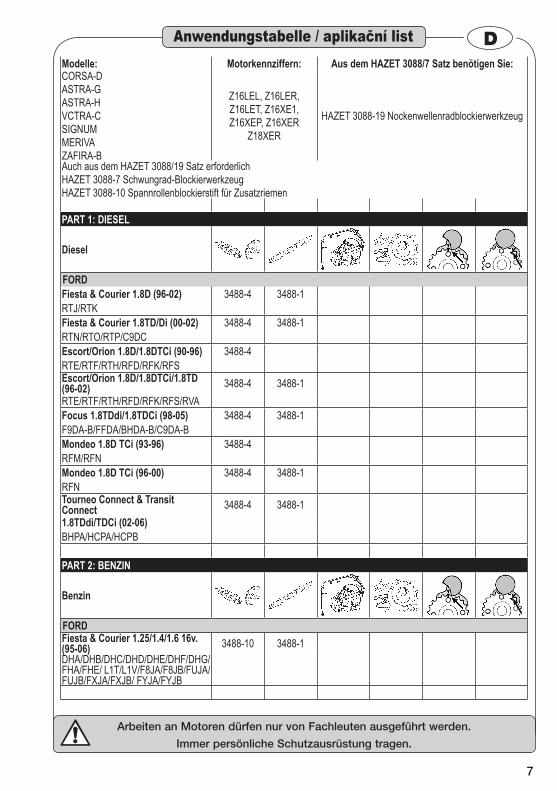
DModelle: Motorkennziffern: Aus dem HAZET 3088/7 Satz benötigen Sie:CORSA-DASTRA-GASTRA-HVCTRA-CSIGNUMMERIVAZAFIRA-B
Z16LEL, Z16LER,Z16LET, Z16XE1,Z16XEP, Z16XER
Z18XER
HAZET 3088-19 Nockenwellenradblockierwerkzeug
Auch aus dem HAZET 3088/19 Satz erforderlichHAZET 3088-7 Schwungrad-BlockierwerkzeugHAZET 3088-10 Spannrollenblockierstift für Zusatzriemen
PART 1: DIESEL
Diesel
FORDFiesta & Courier 1.8D (96-02) 3488-4 3488-1RTJ/RTKFiesta & Courier 1.8TD/Di (00-02) 3488-4 3488-1RTN/RTO/RTP/C9DCEscort/Orion 1.8D/1.8DTCi (90-96) 3488-4RTE/RTF/RTH/RFD/RFK/RFSEscort/Orion 1.8D/1.8DTCi/1.8TD (96-02) 3488-4 3488-1RTE/RTF/RTH/RFD/RFK/RFS/RVAFocus 1.8TDdi/1.8TDCi (98-05) 3488-4 3488-1F9DA-B/FFDA/BHDA-B/C9DA-BMondeo 1.8D TCi (93-96) 3488-4RFM/RFNMondeo 1.8D TCi (96-00) 3488-4 3488-1RFNTourneo Connect & Transit Connect 3488-4 3488-11.8TDdi/TDCi (02-06)BHPA/HCPA/HCPB
PART 2: BENZIN
Benzin
FORDFiesta & Courier 1.25/1.4/1.6 16v. (95-06) 3488-10 3488-1DHA/DHB/DHC/DHD/DHE/DHF/DHG/FHA/FHE/ L1T/L1V/F8JA/F8JB/FUJA/FUJB/FXJA/FXJB/ FYJA/FYJB
Anwendungstabelle / aplikační list
8
Arbeiten an Motoren dürfen nur von Fachleuten ausgeführt werden.
Immer persönliche Schutzausrüstung tragen.
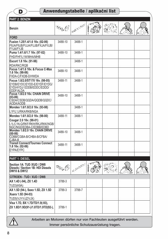
DPART 2: BENZIN
Benzin
FORDFusion 1.25/1.4/1.6 16v. (02-06) 3488-10 3488-1F8JA/F8JB/FUJA/FUJB/FXJA/FXJB/FYJA/FYJBPuma 1.4/1.6/1.7 16v. (97-02) 3488-10 3488-1FHD/FHF/L1W/MHA/MHBEscort 1.8 16v. (91-98) 3488-1RDA/RKC/RQBFocus 1.4/1.6 16v. & Focus C-Max 1.6 16v. (98-06) 3488-10 3488-1FXDA-C/FXDB-D/HWDAFocus 1.8/2.0/ST170 16v. (98-05) 3488-11 3488-1EYDB/EYDC/EYDD-E/EYDF/EYDG/EYDI/4YDJ/ EDDB/EDDC/EDDD/EDDF/ALDAFocus 1.8/2.0 16v. CHAIN DRIVE (03-06) 3488-10 3488-1CSDA/CSDB/QQDA/QQDB/QQDC/AODA/AODBMondeo 1.6/1.8/2.0 16v. (93-98) 3488-1L1F/L1J/RKA/RKB/NGAMondeo 1.6/1.8/2.0 16v. (98-00) 3488-11 3488-1Cougar 2.0 16v. (98-01)L1L/L1N-Q/RKF/RKH/RKJ/RKK/NGB/NGC/NGD/EDBA-C/EDBB/EDBDMondeo 1.8/2.0 16v. CHAIN DRIVE (00-06) 3488-10 3488-1CDBB/CGBA-B/CHBA-B/CFBA/CJBA-BTransit Connect/Tourneo Connect 1.8 16v. (02-06) 3488-11 3488-1EYPA/EYPC
PART 1: DIESELSection 1A: TUD /XUD / DW8 Diesels / Section 1B: HDi Diesels DW10 & DW12CITROEN - TUD / XUD / DW8AX 1.4D (-94), ZX 1.4D 3788-3TUD3(K9A)AX 1.5D (94-), Saxo 1.5D, ZX 1.5D 3788-3 3788-7Xsara 1.5D (94-03)TUD5(VJY/VJZ/VJX)Visa 1.7D, BX 1.7D/TD/1.9(-93),ZX 1.8D/1.9D(91-)/1.8TD/1.9TD(92-), 3788-1
Anwendungstabelle / aplikační list

9
Arbeiten an Motoren dürfen nur von Fachleuten ausgeführt werden.
Immer persönliche Schutzausrüstung tragen.
DPART 1: DIESELSection 1A: TUD /XUD / DW8 Diesels / Section 1B: HDi Diesels DW10 & DW12CITROEN - TUD / XUD / DW8Xsara 1.8D/1.9D/TD, Xantia 1.9D/TD(93-), Synergie/Evasion 1.9TD, C15D 1.8D, Berlingo 1.8D/1.9D, Dispatch 1.9D/TD, Relay/Jumper 1.9D/TDXUD7(A9A)/XUD7TE/XUD9AY(DJY)/XUD9A+AU(D9B)/XUD9TE+TFY(DHX)/XUD9TFL(D8B)XUD9UTF(D8C)/XUD9BTF(DHX)
3788-1
Xsara 1.9D, Berlingo 1.9D, C15 1.9D, Dispatch/Jumpy 1.9D (98-06)DW8B(WJY)/DW8(WJZ)
3788-1 3788-5
Xantia 2.1TD(95-), XM 2.1/TD, XM2.2D, Synergie/Evasion 2.1TD, Dispatch/Jumpy 2.1DTXUD11A/XUD11ATE/XUD11BTE(P8A/P8B/P9A/PHZ)
3788-1 3788-10
XM 2.5TD, Relay/Jumper 2.5D/TD(94-), Relay/Jumper 2.5TDi DIRECT INJECTIONDKATE(THY)/DJ5(T9A)/DJ5T(T8A-THZ)/DJ5TED(THX)
3788-1 3788-9 3788-4 3788-10
PEUGEOT - TUD / XUD / DW8106 1.4D(-94) 3788-3TUD3(K9A)106 1.5D (94-03) 3788-3 3788-7 3788-4TUD5(VJY/VJZVJX) 3788-5205 1.8D/TD/1.9D, 305 1.8D/1.9D(-89), 306 1.9D/TD(93-), 309 1.8D/TD/1.9D(-93), 405 1.8TD/1.9D/TD(92-), 406 1.9TD, 806 1.9TD, J5/Talbot Express 1.9D(-94), Partner 1.8D/1.9D, Expert 1.9D/TD, Boxer 1.9D/TDXUD7(A9A)/XUD7TE / XUD9AY(DJY) / XUD9A+AU(D9B) / XUD9TE+TFY(DHX) / XUD9TFL(D8B) / XUD9UTF(D8C) / XUD9BTF(DHX)
3788-1
206 1.9D, 306 1.9D, 3788-1 3788-5Expert 1.9D, Partner 1.9D (98-06)WJZ(DW8)/WJY(DW8B)406 2.1TD(95-) 3788-1 3788-10605 2/1D/TD, 806 2.1TDXUD11A/XUD11ATE/XUD11BTE(P8A/P8B/P9A/PHZ)
Anwendungstabelle / aplikační list
10
Arbeiten an Motoren dürfen nur von Fachleuten ausgeführt werden.
Immer persönliche Schutzausrüstung tragen.
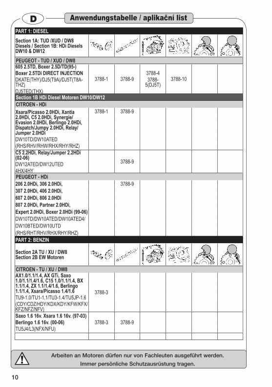
DPART 1: DIESELSection 1A: TUD /XUD / DW8 Diesels / Section 1B: HDi Diesels DW10 & DW12PEUGEOT - TUD / XUD / DW8605 2.5TD, Boxer 2.5D/TD(95-)Boxer 2.5TDi DIRECT INJECTIONDKATE(THY)/DJ5(T9A)/DJ5T(T8A-THZ)DJ5TED(THX)
3788-1 3788-93788-43788-
5(DJ5T)3788-10
Section 1B HDi Diesel Motoren DW10/DW12CITROEN - HDiXsara/Picasso 2.0HDi, Xantia 2.0HDi, C5 2.0HDi, Synergie/Evasion 2.0HDi, Berlingo 2.0HDi, Dispatch/Jumpy 2.0HDi, Relay/Jumper 2.0HDiDW10TD/DW10ATED(RHS/RHV/RHW/RHX/RHY/RHZ)
3788-1 3788-9
C5 2.2HDi, Relay/Jumper 2.2HDi (02-06)DW12ATED/DW12UTED4HX/4HY
3788-9
PEUGEOT - HDi206 2.0HDi, 306 2.0HDi, 3788-9307 2.0HDi, 406 2.0HDi,607 2.0HDi, 806 2.0HDi807 2.0HDi, Partner 2.0HDi,Expert 2.0HDi, Boxer 2.0HDi (99-06)DW10TD/DW10ATED/DW10ATED4/DW10BTED/DW10UTD (RHS/RHT/RHV/RHX/RHY/RHZ)PART 2: BENZIN
Section 2A TU / XU / DW8 Section 2B EW Motoren
CITROEN - TU / XU / DW8AX1.0/1.1/1.4, AX GTi, Saxo 1.0/1.1/1.4/1.6, C15 1.0/1.1/1.4, BX 1.1/1.4, ZX 1.1/1.4/1.6, Berlingo 1.1/1.4, Xsara/Picasso 1.4/1.6TU9-1.0/TU1-1.1/TU3-1.4/TU5JP-1.6(CDY/CDZ/HDY/KDX/KDY/KFW/KFX/KFZ/NFZ/NFV)
3788-3
Saxo 1.6 16v. Xsara 1.6 16v. (97-03)Berlingo 1.6 16v. (00-06)TU5J4/L3(NFX/NFU)
3788-3 3788-9
Anwendungstabelle / aplikační list
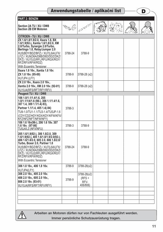
11
Arbeiten an Motoren dürfen nur von Fachleuten ausgeführt werden.
Immer persönliche Schutzausrüstung tragen.
DPART 2: BENZIN
Section 2A TU / XU / DW8 Section 2B EW Motoren
CITROEN - TU / XU / DW8ZX 1.6/1.8/1.9/2.0, Xsara 1.8, BX 1.6/1.9(92-), Xantia 1.6/1.8/2.0, XM 2.0/Turbo, Synergie 2.0/Turbo, Berlingo 1.8, Relay/Jumper 2.0XU5(BDY/BDZ/BFZ) / XU7(L6A/LFX/LFZ) / XU9(D6A/D6B/D6D/DDZ/DKZ/DFZ) / XU10J2(RFL/RFU/RGX/RGY/RFZ/RFX/RFW/RDZ)With Eccentric Tensioner
3788-24 3788-9
Xsara 1.8 16v., Xantia 1.8 16v.ZX 1.8 16v. (95-00)XU7JP4 (LFY)
3788-9 3788-28 (x2)
ZX 2.0 16v., Xsara 2.0 16v.,Xantia 2.0 16v., XM 2.0 16v. (92-01)XU10J4(RFS/RFT/RFY/RFV)
3788-9 3788-28 (x2)
Peugeot TU / XU / DW8106 1.0/1.1/1.4/1.6, 205 1.0/1.1/1/4/1.6 (98-), 306 1.1/1.4/1.6, 307 1.4, 309 1.1/1.4(-93), Partner 1.1/1.4, 405 1.4(-94)TU9-1.0/TU1-1.1/TU3-1.4/TU5JP-1.6(CDY/CDZ/HDY/KDX/KDY/KFW/KFX/KFZ/NFZ/NFT/NFW/NFY)
3788-3
106 1.6 16v(96-), 206 1.6 18v. 307 1.6 16v. (97-06) TU5J4/L3 (NFX/NFU)
3788-3 3788-9
205 1.6/1.9(92-), 306 1.8/2.0, 309 1.6/1.9(92-), 405 1.6/1.8/1.9/2.0(92-), 406 1.6/1.8/2.0, 605 2.0, 806 1.8/2.0/Turbo, Boxer 2.0, Partner 1.8XU5(BDY/BDZ/BFZ) / XU7(L6A/LFX/LFZ) / XU9(D6A/D6B/D6D/DDZ/DKZ/DFZ) / XU10J2(RFL/RFU/RGX/RGY/RFZ/RFX/RFW/RDZ)With Eccentric Tensioner
3788-24 3788-9
306 1.8 16v., 406 1.8 16v. 3788-9 3788-28(x2)XU7JP4(LFY)306 2.0 16v., 405 2.0 16v. 406 2.0 16v., 605 2.0 16v.,806 2.0 16v. (93-01)XU10J4(RFS/RFT/RFV/RFY)
3788-93788-28(x2)
(RFS + RFV-
406/806)
Anwendungstabelle / aplikační list
12
Arbeiten an Motoren dürfen nur von Fachleuten ausgeführt werden.
Immer persönliche Schutzausrüstung tragen.
DPART 2: BENZIN
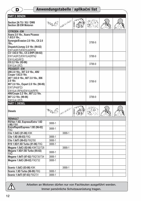
Section 2A TU / XU / DW8 Section 2B EW Motoren
CITROEN - EW Xsara 2.0 16v., Xsara Picasso 1.8/2.0 16v., Synergie/Evasion 2.0 16v., C8 2.0 16v.,Dispatch/Jumpy 2.0 16v. (99-02)EW7J4(6FZ)/EW10J4(RFN)
3788-9
C5 1.8/2.0 16v., C5 2.0HPi (00-02)EW7J4(6FZ)/EW10J4(RFN)/EW10J4D(RFZ)
3788-9
C8 2.2 16v. (02-06)EW12J4 (3FZ) 3788-9PEUGEOT - EW 206 2.0 16v., 307 2.0 16v., 406/Coupe 1.8/2.0 16v.407 1.8/2.0 16v., 607 2.0 16v., 806 2.0 16v.807 2.0 16v., Expert 2.0 16v. (98-06) EW7JP4(6FZ)/EW10J4 (RFN)/EW10J4(RFR)
3788-9
406/Coupe 2.2 16v., 607 2.2 16v.807 2.2 16v. (99-06)EW12J4 (3FZ)
3788-9
PART 1: DIESEL
Diesels
RENAULTR5/Van 1.6D, Express/Extra 1.6D (-96) F8M 3888-1Extra/Rapid/Express 1.9D (96-02) F8Q 3888-1Clio 1.5dCi (01-06) K9K 3888-1Clio 1.9D (90-03) F8Q 3888-1Clio 1.9dTi (99-03) F9Q780 3888-1R19 1.9D/1.9D Turbo (91-96) F8Q 3888-1Megane 1.5dCi (02-06) K9K722/728 3888-1Megane 1.9D/1.9D Turbo (95-02) F8Q 3888-1Megane 1.9dTi (97-02) F9Q730/734 3888-1Megane 1.9dCi (99-02) F9Q732 3888-1
Scenic 1.5dCi (03-06) K9K 3888-1Scenic 1.9D Turbo (96-99) F8Q 3888-1Scenic 1.9dTi (97-03) F9Q731 3888-1
Anwendungstabelle / aplikační list
13
Arbeiten an Motoren dürfen nur von Fachleuten ausgeführt werden.
Immer persönliche Schutzausrüstung tragen.
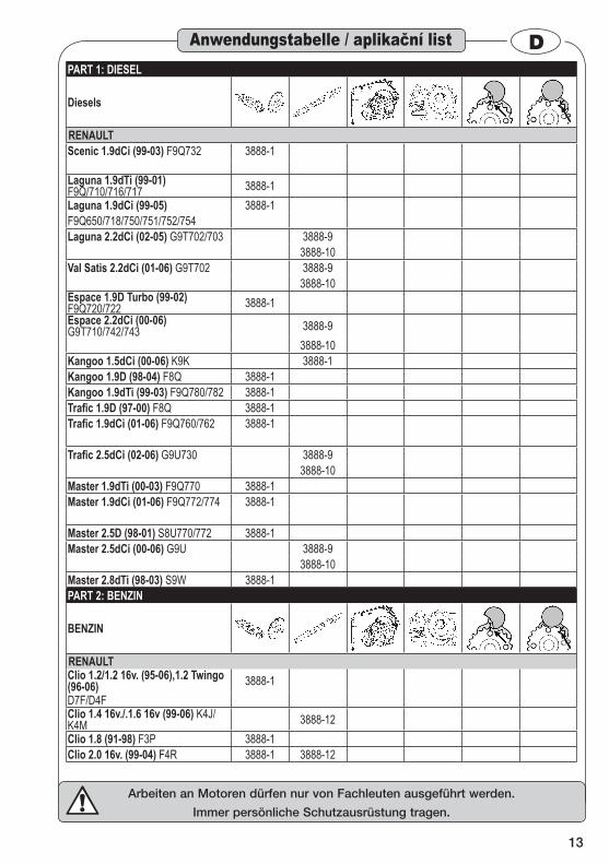
DPART 1: DIESEL
Diesels
RENAULTScenic 1.9dCi (99-03) F9Q732 3888-1
Laguna 1.9dTi (99-01) F9Q/710/716/717 3888-1Laguna 1.9dCi (99-05) 3888-1F9Q650/718/750/751/752/754Laguna 2.2dCi (02-05) G9T702/703 3888-9
3888-10Val Satis 2.2dCi (01-06) G9T702 3888-9
3888-10Espace 1.9D Turbo (99-02) F9Q720/722 3888-1Espace 2.2dCi (00-06) G9T710/742/743 3888-9
3888-10Kangoo 1.5dCi (00-06) K9K 3888-1Kangoo 1.9D (98-04) F8Q 3888-1Kangoo 1.9dTi (99-03) F9Q780/782 3888-1Trafic 1.9D (97-00) F8Q 3888-1Trafic 1.9dCi (01-06) F9Q760/762 3888-1
Trafic 2.5dCi (02-06) G9U730 3888-93888-10
Master 1.9dTi (00-03) F9Q770 3888-1Master 1.9dCi (01-06) F9Q772/774 3888-1
Master 2.5D (98-01) S8U770/772 3888-1Master 2.5dCi (00-06) G9U 3888-9
3888-10Master 2.8dTi (98-03) S9W 3888-1PART 2: BENZIN
BENZIN
RENAULTClio 1.2/1.2 16v. (95-06),1.2 Twingo (96-06) 3888-1D7F/D4FClio 1.4 16v./.1.6 16v (99-06) K4J/K4M 3888-12Clio 1.8 (91-98) F3P 3888-1Clio 2.0 16v. (99-04) F4R 3888-1 3888-12
Anwendungstabelle / aplikační list

14
Arbeiten an Motoren dürfen nur von Fachleuten ausgeführt werden.
Immer persönliche Schutzausrüstung tragen.
DPART 2: BENZIN
BENZIN
RENAULTR19 1.8 (92-96) F3P 3888-1Megane 1.4 16v./.1.6 16v (99-06) K4J/K4M 3888-12Megane/Scenic 2.0 (95-99) F3R/F7R 3888-1Megane/Scenic 2.0 16v. (99-03) F4R 3888-1 3888-12Laguna 1.6 16v. (98-05) K4M 3888-12Laguna 1.8 (94-98)/ 2.0 (98-01) F3P/F3R 3888-1Laguna 1.8 16v.(98-05)/ 2.0 16v. (99-05) F4P/F4R 3888-1 3888-12Espace 2.0 (96-99) F3R 3888-1Espace 2.0 16v. (98-06)/ 2.0 Turbo(02-06) F4R/t 3888-1 3888-12Kangoo1.2 (98-06)/1.2 16v. (01-06) D7F/D4F 3888-1
Kit 4794/5Universal Sprocket Locking KitTiming Belt Replacement Applications 4794-1 “Multi-Lock” Engine Timing/Sprocket Locking Device for Twin Camshaft, Quad Cam and Diesel Injection Pump Sprockets
Anwendungstabelle / aplikační list
2588/19 / 2588/9 VW-VEHICLE MANUFACTURER‘S TOOL CROSS REFERENCE HAZET No. Anzahl Audi / VW VAG SEAT SKODA2587-1 1 VAG3387 U-30009A2588-1 1 T100502588-2 1 T100082588-3 2 T20102 VAG3359 U-40074 MP-1-3012588-4 1 T10074/ T100162588-5 1 VAG2065A U-20006/ U-40021 MP-1-3002588-6 1 T10098A T20038 MP-1-3122588-14 1 T101202588-15 2 T101232588-16 1 T101212588-110 1 T101003088/19 / 3088/7 OPEL - VEHICLE MANUFACTURER‘S TOOL CROSS REFERENCEHAZET No. Anzahl OPEL3088-15 1 KM-8533088-16 1 KM-8523088-19 1 KM-6340

15
Arbeiten an Motoren dürfen nur von Fachleuten ausgeführt werden.
Immer persönliche Schutzausrüstung tragen.
DAnwendungstabelle / aplikační list3488/17 FORD - VEHICLE MANUFACTURER‘S TOOL CROSS REFERENCEHAZET No. Anzahl FORD3488-1 1 21-162B 303-3763488-4 1 21-104 303-1933488-10 1 21-210 303-5073488-11 1 21-163 303-574 303-620 303-5743788/37 PSA - VEHICLE MANUFACTURER‘S TOOL CROSS REFERENCEHAZET No. Anzahl CITROEN PEUGEOT3788-1 1 7014-TJ / 7099-TM 0153N / 0153ZY / 9767,343788-3 1 4507-TA 0132Q / 0132QZ / 9767,273788-4 1 5711-TB 0178B3788-5 1 5711-TC 0178C / 0188-H / 0188-Y3788-7 1 4527-TS2 0132AB3788-9 1 4533-TAC1 / 5711-TA / 7014-TN 0132AJ1 / 0153G / 0178A / 0188-M /
9766,98 / 0189-J3788-10 1 5711-TE 0178E / 0132R / 0153AA3788-24 1 7018-TY / 7004-TG3788-28 2 9041-TZ 0153AB3888/19 RENAULT - VEHICLE MANUFACTURER‘S TOOL CROSS REFERENCEHAZET No. Anzahl RENAULT3888-1 1 Mot861 Mot10543888-9 1 Mot15373888-10 1 Mot15343888-12 1 Mot14964794/5HAZET No. Anzahl4794-1 1
16
Arbeiten an Motoren dürfen nur von Fachleuten ausgeführt werden.
Immer persönliche Schutzausrüstung tragen.
DSehr geehrter Kunde, Sie haben gut gewählt, denn vor Ihnen liegt ein HAZET-Qualitäts- Produkt, das Ihren Arbeitsablauf optimieren wird.
Allgemeine Informationen 1. Bitte stellen Sie sicher, dass der Benutzer die-• ses Werkzeugs die vorliegende Betriebsanlei-tung vor der ersten Inbetriebnahme gründlich durchgelesen und verstanden hat.Diese Betriebsanleitung enthält wichtige Hin-• weise, die zum sicheren und störungsfreien Betrieb Ihres HAZET-Werkzeuges erforderlich sind. Zum bestimmungsgemäßen Gebrauch des • Werkzeuges gehört die vollständige Beachtung aller Sicherheitshinweise und Informationen in dieser Betriebsanleitung. Bewahren Sie deshalb diese Betriebsanleitung • immer bei Ihrem HAZET-Werkzeug auf. Dieses Werkzeug wurde für bestimmte Anwen-• dungen entwickelt. HAZET weist ausdrücklich darauf hin, dass dieses Werkzeug nicht verän-dert und/oder in einer Weise eingesetzt werden darf, die nicht seinem vorgesehenen Verwen-dungszweck entspricht. Für Verletzungen und Schäden, die aus un-• sachgemäßer und zweckentfremdeter An-wendung bzw. Zuwiderhandlung gegen die Sicherheitsvorschriften resultieren, übernimmt HAZET keine Haftung oder Gewährleistung. Darüber hinaus sind die für den Einsatzbereich • des Werkzeugs geltenden Unfallverhütungs-vorschriften und allgemeinen Sicherheitsbe-stimmungen einzuhalten.
Symbolerklärung2. ACHTUNG: Schenken Sie diesen Symbolen
höchste Aufmerksamkeit! Betriebsanleitung lesen!
Der Betreiber ist verpflichtet die Be-triebsanleitung zu beachten und alle Anwender des Werkzeugs gemäß der Betriebsanleitung zu unterweisen.
HINWEIS!Dieses Symbol kennzeichnet Hinwei-se, die Ihnen die Handhabung erleich-tern.
WARNUNG! Dieses Symbol kennzeichnet wichtige Beschreibungen, gefährliche Bedin-gungen, Sicherheitsgefahren bzw. Si-cherheitshinweise. ACHTUNG!Dieses Symbol kennzeichnet Hinwei-se, deren Nichtbeachtung Beschädi-gungen, Fehlfunktionen und/- oder den Ausfall des Werkzeuges zur Folge haben.
KURBELWELLE/SCHWUNGSCHEIBE Dieses Bild kennzeichnet das Werk-zeug, dass zur Fixierung der Kurbel-welle/Schwungscheibe an dem ange-gebenen Fahrzeug zur Anwendung kommen soll.
NOCKENWELLE ➪
Dieses Bild kennzeichnet das Werk-zeug, dass zur Fixierung der Nocken-welle an dem angegebenen Fahrzeug zur Anwendung kommen soll.
EINSPRITZPUMPE Dieses Bild kennzeichnet das Werk-zeug, dass zur Fixierung der Diesel-Einspritzpumpe an dem angegebenen Fahrzeug zur Anwendung kommen soll.
ZAHNRIEMEN-SPANNROLLE Dieses Bild kennzeichnet das Werk-zeug, dass zur Betätigung der Zahn-riemen-Spannrolle an dem angegebe-nen Fahrzeug zur Anwendung kommen soll.
SCHLOSSTRÄGER Dieses Bild kennzeichnet das Werk-zeug, dass zum Aus- und Einbau des Schlossträgers an dem angegebenen Fahrzeug zur Anwendung kommen soll.
Zu Ihrer Information

17
Arbeiten an Motoren dürfen nur von Fachleuten ausgeführt werden.
Immer persönliche Schutzausrüstung tragen.
DHaftung und Gewährleistung 3.
Jede über die bestimmungsgemäße Verwendung hinausgehende und/- oder andersartige Verwendung des Werkzeuges ist untersagt und gilt als nicht bestimmungsgemäß.
Ansprüche jeglicher Art gegen den Hersteller • und/oder seine Bevollmächtigten wegen Schä-den aus nicht bestimmungsgemäßer Verwen-dung des Werkzeuges sind ausgeschlossen. Für alle Schäden bei nicht bestimmungsgemä-• ßer Verwendung haftet allein der Betreiber.
Ersatzteile 4. Nur Original-Ersatzteile des Herstellers ver-• wenden. Falsche oder fehlerhafte Ersatzteile können zu • Beschädigungen, Fehlfunktionen oder Total-ausfall des Werkzeuges führen.Bei Verwendung nicht freigegebener Ersatz-• teile erlöschen sämtliche Garantie-, Service-, Schadenersatz- und Haftpflichtansprüche ge-gen den Hersteller oder seine Beauftragten, Händler und Vertreter.
Entsorgung 5. Zur Aussonderung, reinigen und unter Beach-• tung geltender Arbeits- und Umweltvorschrif-ten zerlegen. Bestandteile der Wiederverwer-tung zuführen. Metallische Materialreste verschrotten. • Die Verringerung von Umweltbelastungen und • die Bewahrung der Umwelt, stehen im Mittel-punkt unserer Aktivitäten!
Zu Ihrer Information
18
Arbeiten an Motoren dürfen nur von Fachleuten ausgeführt werden.
Immer persönliche Schutzausrüstung tragen.
DDieser Abschnitt gibt einen Überblick über alle wichtigen Sicherheitsaspekte für den optimalen Schutz des Perso-nals sowie den sicheren und störungs-
freien Betrieb des Werkzeuges. Zusätzlich bein-halten die einzelnen Kapitel konkrete, mit Symbolen gekennzeichnete Sicherheitshinweise zur Abwendung unmittelbarer Gefahren.
Allgemeines 1. Das Werkzeug ist zum Zeitpunkt sei-ner Entwicklung und Fertigung nach geltenden, anerkannten Regeln der Technik gebaut und gilt als betriebssi-
cher. Es können vom Werkzeug jedoch Gefahren ausgehen, wenn es von nicht fachgerecht ausge-bildetem Personal, unsachgemäß oder nicht be-stimmungsgemäß, verwendet wird. Jede Person, die mit Arbeiten am oder mit dem Werkzeug be-auftragt ist, muss daher die Betriebsanleitung vor Beginn der Arbeiten gelesen und verstanden ha-ben.
Veränderungen jeglicher Art sowie An- oder • Umbauten am Werkzeug sind untersagt. Angegebene Einstellwerte oder -bereiche sind • unbedingt einzuhalten.
Verantwortung des Betreibers 2. Betriebsanleitung stets in unmittelbarer Nähe • des Werkzeugs aufbewahren. Dieses Werkzeug darf nur von Fachleuten ein-• gesetzt werden. Werkzeug nur in technisch einwandfreiem und • betriebssicherem Zustand betreiben. Sicherheitseinrichtungen immer frei erreichbar • vorhalten und regelmäßig prüfen. Neben den Arbeitssicherheits-Hinweisen in • dieser Betriebsanleitung sind die für den Ein-satzbereich des Werkzeuges allgemeingültigen Sicherheits-, Unfallverhütungs- und Umwelt-schutzvorschriften zu beachten und einzuhal-ten.
Diese Anweisung gibt lediglich Hin-weise. Stellen Sie immer sicher, dass Sie die geeigneten Servicean-weisungen des Fahrzeugherstellers
oder ein entsprechendes Handbuch besitzen, aus dem Sie die korrekten Daten für die vor-schriftsgemäße Durchführung der Arbeit ent-nehmen können.
Bestimmungsgemäße 3. Verwendung
Die Betriebssicherheit ist nur bei be-stimmungsgemäßer Verwendung ent-sprechend der Angaben in der Be-triebsanleitung gewährleistet. Neben
den Arbeitssicherheits- Hinweisen in dieser Be-triebsanleitung sind die für den Einsatzbereich des Werkzeuges allgemein gültigen Sicherheits-, Unfallverhütungsund Umweltschutz-Vorschriften zu beachten und einzuhalten.
Das HAZET-Werkzeug ist für den Zahnriemen-• Wechsel bei Diesel- und Benzinmotoren an bestimmt. Der unsachgemäße Gebrauch der enthaltenen • Werkzeuge oder der Gebrauch nicht entspre-chend der Sicherheitshinweise kann zu schwe-ren Verletzungen oder zum Tode führen. Jede über die bestimmungsgemäße Verwen-• dung hinausgehende und/oder andersartige Verwendung des Werkzeuges ist untersagt und gilt als nicht bestimmungsgemäß. Ansprüche jeglicher Art gegen den Herstel-• ler und/oder seine Bevollmächtigten, wegen Schäden aus nicht bestimmungsgemäßer Ver-wendung des Werkzeuges, sind ausgeschlos-sen. Für alle Schäden, bei nicht bestimmungsge-• mäßer Verwendung, haftet allein der Betreiber.
Aufbewahrung / Lagerung 4. Das Werkzeug ist unter folgenden Be-dingungen zu lagern und aufzube-wahren:
Werkzeug trocken und staubfrei lagern. • Werkzeug keinen Flüssigkeiten und/oder ag-• gressiven Substanzen aussetzen. Werkzeug nicht im Freien aufbewahren. • Werkzeug für Kinder unzugänglich aufbewah-• ren. Lagertemperatur -10°C bis +40°C. • Relative Luftfeuchtigkeit max. 60%. •
Zu Ihrer Sicherheit
19
Arbeiten an Motoren dürfen nur von Fachleuten ausgeführt werden.
Immer persönliche Schutzausrüstung tragen.
DGefahren die vom Gerät 5. ausgehen
Vor jeder Benutzung sind die HAZET Werkzeuge zur Motoreinstellung auf ihre volle Funktionsfähigkeit und Be-schädigung zu prüfen. Ist die Funkti-
onsfähigkeit nach dem Ergebnis dieser Prüfung nicht gewährleistet oder werden Schäden festge-stellt, darf das Werkzeug nicht verwendet werden. Ist die volle Funktionsfähigkeit nicht gegeben und das Werkzeug wird dennoch verwendet, besteht die Gefahr von erheblichen Körper-, Gesundheits- und Sachschäden. Defektes Werkzeug kann schwere Verletzungen verursachen.Zum Schutz vor Schaden sind folgende grund-sätzliche Sicherheitsmaßnahmen zu beachten:ACHTUNG:
Die falsche Steuerzeiten-Einstellung kann zu Kontakt zwischen Kolben und Ventilen führen und dadurch ei-nen Motorschaden verursachen.
Stellen Sie daher immer sicher, dass Sie die richtigen Werkzeuge verwenden und die Vor-gaben des Fahrzeugherstellers befolgen.
Vor Beginn der Arbeit den Minuspol der Batte-• rie abklemmen.
HINWEIS: Vor dem Abklemmen der Batterie si-cherstellen, dass der Kfz-Besitzer den Code für das Autoradio kennt.
Jedes „aufgebockte“ oder über den Boden • angehobene Fahrzeug, muss mit Achsböcken, Rampen etc. angemessen abgestützt werden. Tragen Sie enganliegende Arbeitsschutzklei-• dung und Schutzbrille. Motoren haben drehen-de Komponenten, die sich in loser Kleidung, Schmuckstücken etc. verfangen können. Sie sind immer für die von Ihnen benutzten • Werkzeuge verantwortlich. Lassen Sie niemals Werkzeuge im oder am Motor liegen, wenn dieser gedreht wird oder wenn die Arbeit be-endet ist. Lose Teile können weggeschleudert werden und Personen in der Umgebung verlet-zen oder töten, Gegenstände können beschä-digt werden. Die Fixierdorne, Arretierstifte/-vorrichtung nicht • zum Blockieren der Kurbelwelle, beim Lösen oder Anziehen der Kurbelwellenschraube, ver-wenden.
Nicht den Zahnriemen zum Blockieren des No-• ckenwellenrades benutzen, um Verschraubun-gen zu lösen. Zahnriemen nicht knicken, umdrehen oder mit • einem Radius unter 25 mm biegen. Zum Anbringen des Zahnriemens keine Hebel • verwenden und keine Gewalt anwenden. Spannrolle, Umlenkrolle(n) und Wasserpumpe • auf freien Lauf prüfen. Motor auf Dichtigkeit prüfen ggf. Undichtigkei-• ten beseitigen. Bei Ersatz des Zahnriemens nur neue Zahnrie-• men mit richtiger Zahnung verwenden. Zahnriemenspannung richtig einstellen (Her-• stellerangaben beachten). Vorgeschriebene Anzugsdrehmomente einhal-• ten (Herstellerangaben beachten). Die durch Pfeil angegebene Drehrichtung des • Zahnriemens beachten. Gebrauchte Zahnriemen nicht wiederverwen-• den, immer neue Zahnriemen einsetzen. Bei Anzeichen von Verschleiß wie Reibstellen, • Rissen, oder Beschädigungen sowie starker Verschmutzung (z.B. durch Öl) Zahnriemen ersetzen. Bei Schäden am Zahnriemen Ursache suchen • und beseitigen. Keine Lösungsmittel, wie Verdünnung, Benzin • etc. zum Reinigen von Zahnriemen verwenden. Im Zweifelsfall den Zahnriemen auswechseln. Den Zahnriemen zum Inspizieren nicht umdre-• hen. Den Motor, außer bei speziellen Vorgaben • durch den Hersteller, nur in normaler Drehrich-tung drehen. Verwenden Sie nur vom Hersteller empfohlene • Teile, Befestigungen und Zubehör. Reparaturen nur von autorisierten Personen • durchführen lassen. Die Werkzeuge nur an Orten verwenden, die • durch geltende Verordnungen für Arbeitsberei-che bestimmt und vorgeschrieben werden. Aus Sicherheitsgründen sind Veränderungen • an HAZET-Werkzeugen untersagt. Die Vor-nahme von Veränderungen am Werkzeug führt zum sofortigen Haftungsausschluß.
Zu Ihrer Sicherheit
20
Arbeiten an Motoren dürfen nur von Fachleuten ausgeführt werden.
Immer persönliche Schutzausrüstung tragen.
DVor Inbetriebnahme 1.
Die Benutzung, Inspektion und War-tung von Werkzeugen muss immer ent-sprechend den lokalen, staatlichen, Landes- oder Bundesbestimmungen erfolgen.
Vor Beginn der Arbeiten Motor von der Strom-• versorgung trennen. Lesen Sie die Betriebsan-leitung für den Motor und ggf. für montierte Ag-gregate und Geräte (z.B. Radio, etc) ebenfalls gründlich durch.
WICHTIG Einstellungen wie Radio-Code sichern.
ACHTUNG Aufgebockte Fahrzeuge gegen Absturz sichern.
WICHTIG Nur geeignete Ersatzteile verwenden.
Inbetriebnahme2. DIESELMOTOREN 3.1.
Standardeinspritzsystem • Dieselmotoren D / TD / SDi / TDi
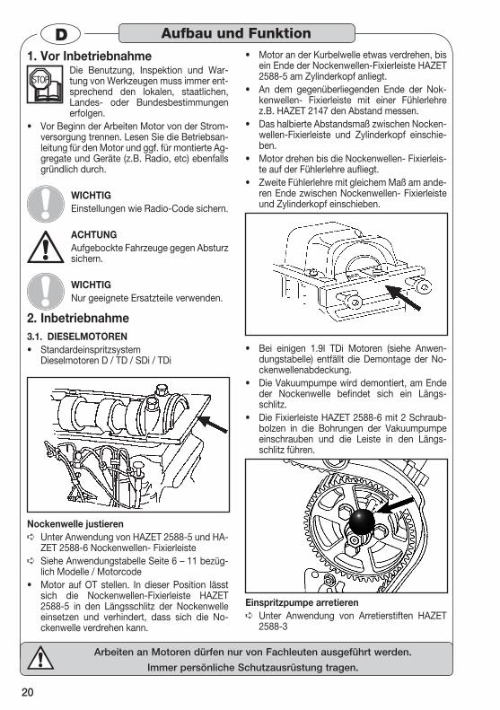
Nockenwelle justierenUnter Anwendung von HAZET 2588-5 und HA- ➪ZET 2588-6 Nockenwellen- FixierleisteSiehe Anwendungstabelle Seite 6 – 11 bezüg- ➪lich Modelle / Motorcode Motor auf OT stellen. In dieser Position lässt • sich die Nockenwellen-Fixierleiste HAZET 2588-5 in den Längsschlitz der Nockenwelle einsetzen und verhindert, dass sich die No-ckenwelle verdrehen kann.
Motor an der Kurbelwelle etwas verdrehen, bis • ein Ende der Nockenwellen-Fixierleiste HAZET 2588-5 am Zylinderkopf anliegt. An dem gegenüberliegenden Ende der Nok-• kenwellen- Fixierleiste mit einer Fühlerlehre z.B. HAZET 2147 den Abstand messen. Das halbierte Abstandsmaß zwischen Nocken-• wellen-Fixierleiste und Zylinderkopf einschie-ben. Motor drehen bis die Nockenwellen- Fixierleis-• te auf der Fühlerlehre aufliegt. Zweite Fühlerlehre mit gleichem Maß am ande-• ren Ende zwischen Nockenwellen- Fixierleiste und Zylinderkopf einschieben.
Bei einigen 1.9l TDi Motoren (siehe Anwen-• dungstabelle) entfällt die Demontage der No-ckenwellenabdeckung. Die Vakuumpumpe wird demontiert, am Ende • der Nockenwelle befindet sich ein Längs-schlitz. Die Fixierleiste HAZET 2588-6 mit 2 Schraub-• bolzen in die Bohrungen der Vakuumpumpe einschrauben und die Leiste in den Längs-schlitz führen.
Einspritzpumpe arretierenUnter Anwendung von Arretierstiften HAZET ➪2588-3
Aufbau und Funktion
21
Arbeiten an Motoren dürfen nur von Fachleuten ausgeführt werden.
Immer persönliche Schutzausrüstung tragen.
DSiehe Anwendungstabelle Seite 6 – 11 bezüg- ➪lich Modelle /Motorcode Die Einspritzpumpen-Arretierstifte werden • durch Bezugsbohrungen in den Zahnriemenrä-dern in Bohrungen am Motor eingesetzt. 2588-3 Absteckstift wird benutzt, wenn 2- teili-• ge Zahnriemenräder montiert sind. Diese Zahn-riemenräder sind mit 3 Schrauben gesichert. Die Absteckstifte werden durch den Träger in eine Bezugsbohrung im Motor eingesetzt.
Zahnriemen-Einstellung / Zahnriemen- Span-nung
Siehe Anwendungstabelle Seite 6 – 11 bezüg- ➪lich Modelle /Motorcode
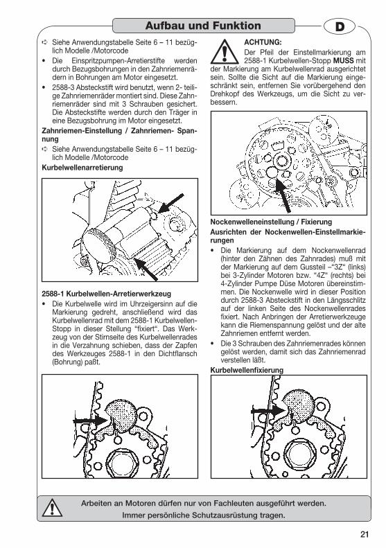
Kurbelwellenarretierung
2588-1 Kurbelwellen-Arretierwerkzeug Die Kurbelwelle wird im Uhrzeigersinn auf die • Markierung gedreht, anschließend wird das Kurbelwellenrad mit dem 2588-1 Kurbelwellen-Stopp in dieser Stellung “fixiert“. Das Werk-zeug von der Stirnseite des Kurbelwellenrades in die Verzahnung schieben, dass der Zapfen des Werkzeuges 2588-1 in den Dichtflansch (Bohrung) paßt.
ACHTUNG:Der Pfeil der Einstellmarkierung am 2588-1 Kurbelwellen-Stopp MUSS mit
der Markierung am Kurbelwellenrad ausgerichtet sein. Sollte die Sicht auf die Markierung einge-schränkt sein, entfernen Sie vorübergehend den Drehkopf des Werkzeugs, um die Sicht zu ver-bessern.
Nockenwelleneinstellung / Fixierung Ausrichten der Nockenwellen-Einstellmarkie-rungen
Die Markierung auf dem Nockenwellenrad • (hinter den Zähnen des Zahnrades) muß mit der Markierung auf dem Gussteil –“3Z“ (links) bei 3-Zylinder Motoren bzw. “4Z“ (rechts) bei 4-Zylinder Pumpe Düse Motoren übereinstim-men. Die Nockenwelle wird in dieser Position durch 2588-3 Absteckstift in den Längsschlitz auf der linken Seite des Nockenwellenrades fixiert. Nach Anbringen der Arretierwerkzeuge kann die Riemenspannung gelöst und der alte Zahnriemen entfernt werden. Die 3 Schrauben des Zahnriemenrades können • gelöst werden, damit sich das Zahnriemenrad verstellen läßt.
Kurbelwellenfixierung
Aufbau und Funktion
22
Arbeiten an Motoren dürfen nur von Fachleuten ausgeführt werden.
Immer persönliche Schutzausrüstung tragen.
DKurbelwellen-Stopp Arretierwerkzeug 2588-1
Siehe Pumpe Düse 1.2l,1.4l, und 1.9l TDi / PD ➪Abschnitt.
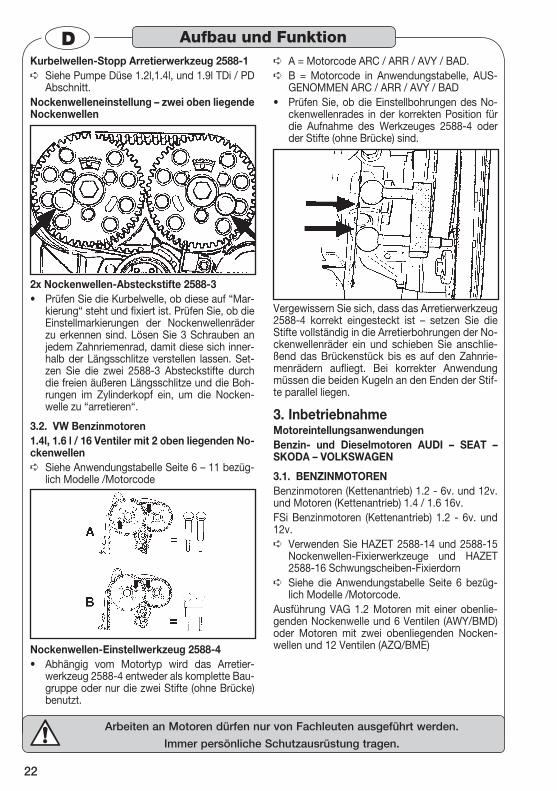
Nockenwelleneinstellung – zwei oben liegende Nockenwellen
2x Nockenwellen-Absteckstifte 2588-3 Prüfen Sie die Kurbelwelle, ob diese auf “Mar-• kierung“ steht und fixiert ist. Prüfen Sie, ob die Einstellmarkierungen der Nockenwellenräder zu erkennen sind. Lösen Sie 3 Schrauben an jedem Zahnriemenrad, damit diese sich inner-halb der Längsschlitze verstellen lassen. Set-zen Sie die zwei 2588-3 Absteckstifte durch die freien äußeren Längsschlitze und die Boh-rungen im Zylinderkopf ein, um die Nocken-welle zu “arretieren“.
VW Benzinmotoren 3.2. 1.4l, 1.6 l / 16 Ventiler mit 2 oben liegenden No-ckenwellen
Siehe Anwendungstabelle Seite 6 – 11 bezüg- ➪lich Modelle /Motorcode
Nockenwellen-Einstellwerkzeug 2588-4 Abhängig vom Motortyp wird das Arretier-• werkzeug 2588-4 entweder als komplette Bau-gruppe oder nur die zwei Stifte (ohne Brücke) benutzt.
A = Motorcode ARC / ARR / AVY / BAD. ➪
B = Motorcode in Anwendungstabelle, AUS- ➪GENOMMEN ARC / ARR / AVY / BAD Prüfen Sie, ob die Einstellbohrungen des No-• ckenwellenrades in der korrekten Position für die Aufnahme des Werkzeuges 2588-4 oder der Stifte (ohne Brücke) sind.
Vergewissern Sie sich, dass das Arretierwerkzeug 2588-4 korrekt eingesteckt ist – setzen Sie die Stifte vollständig in die Arretierbohrungen der No-ckenwellenräder ein und schieben Sie anschlie-ßend das Brückenstück bis es auf den Zahnrie-menrädern aufliegt. Bei korrekter Anwendung müssen die beiden Kugeln an den Enden der Stif-te parallel liegen.
Inbetriebnahme 3. Motoreintellungsanwendungen Benzin- und Dieselmotoren AUDI – SEAT – SKODA – VOLKSWAGEN
BENZINMOTOREN 3.1. Benzinmotoren (Kettenantrieb) 1.2 - 6v. und 12v. und Motoren (Kettenantrieb) 1.4 / 1.6 16v. FSi Benzinmotoren (Kettenantrieb) 1.2 - 6v. und 12v.
Verwenden Sie HAZET 2588-14 und 2588-15 ➪Nockenwellen-Fixierwerkzeuge und HAZET 2588-16 Schwungscheiben-Fixierdorn Siehe die Anwendungstabelle Seite 6 bezüg- ➪lich Modelle /Motorcode.
Ausführung VAG 1.2 Motoren mit einer obenlie-genden Nockenwelle und 6 Ventilen (AWY/BMD) oder Motoren mit zwei obenliegenden Nocken-wellen und 12 Ventilen (AZQ/BME)
Aufbau und Funktion
23
Arbeiten an Motoren dürfen nur von Fachleuten ausgeführt werden.
Immer persönliche Schutzausrüstung tragen.
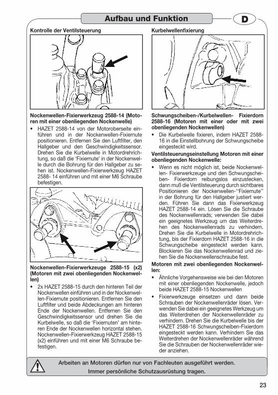
DKontrolle der Ventilsteuerung
Nockenwellen-Fixierwerkzeug 2588-14 (Moto-ren mit einer obenliegenden Nockenwelle)
HAZET 2588-14 von der Motoroberseite ein-• führen und in der Nockenwellen-Fixiernute positionieren. Entfernen Sie den Luftfilter, den Hallgeber und den Geschwindigkeitssensor. Drehen Sie die Kurbelwelle in Motordrehrich-tung, so daß die ‘Fixiernute’ in der Nockenwel-le durch die Bohrung für den Hallgeber zu se-hen ist. Nockenwellen-Fixierwerkzeug HAZET 2588- 14 einführen und mit einer M6 Schraube befestigen.
Nockenwellen-Fixierwerkzeuge 2588-15 (x2) (Motoren mit zwei obenliegenden Nockenwel-len)
2x HAZET 2588-15 durch den hinteren Teil der • Nockenwellen einführen und in der Nockenwel-len-Fixiernute positionieren. Entfernen Sie den Luftfilter und beide Abdeckungen am hinteren Ende der Nockenwellen. Entfernen Sie den Geschwindigkeitssensor und drehen Sie die Kurbelwelle, so daß die ‘Fixiernuten’ am hinte-ren Ende der Nockenwellen horizontal stehen. Nockenwellen-Fixierwerkzeug HAZET 2588-15 (x2) einführen und mit einer M6 Schraube be-festigen.
Kurbelwellenfixierung
Schwungscheiben-/Kurbelwellen- Fixierdorn 2588-16 (Motoren mit einer oder mit zwei obenliegenden Nockenwellen)
Die Kurbelwelle fixieren, indem HAZET 2588-• 16 in die Einstellbohrung der Schwungscheibe eingesteckt wird.
Ventilsteuerungseinstellung Motoren mit einer obenliegenden Nockenwelle:
Wenn es nicht möglich ist, beide Nockenwel-• len- Fixierwerkzeuge und den Schwungschei-ben- Fixierdorn reibungslos einzustecken, dann muß die Ventilsteuerung durch sichtbares Positionieren der Nockenwellen-‘‘Fixiernute’’ in der Bohrung für den Hallgeber justiert wer-den. Führen Sie dann das Fixierwerkzeug HAZET 2588-14 ein. Lösen Sie die Schraube des Nockenwellenrads; verwenden Sie dabei ein geeignetes Werkzeug um das Weiterdre-hen des Nockenwellenrads zu verhindern. Drehen Sie die Kurbelwelle in Motordrehrich-tung, bis der Fixierdorn HAZET 2588-16 in die Schwungscheibe eingesteckt werden kann. Blockieren Sie das Nockenwellenrad und zie-hen Sie die Nockenwellenschraube fest.
Motoren mit zwei obenliegenden Nockenwel-len:
Ähnliche Vorgehensweise wie bei den Motoren • mit einer obenliegenden Nockenwelle, jedoch beide HAZET 2588-15 NockenwellenFixierwerkzeuge einsetzen und dann beide • Schrauben der Nockenwellenräder lösen. Ver-wenden Sie dabei ein geeignetes Werkzeug um das Weiterdrehen der Nockenwellenräder zu verhindern. Drehen Sie die Kurbelwelle bis der HAZET 2588-16 Schwungscheiben-Fixierdorn eingesteckt werden kann. Verhindern Sie das Weiterdrehen der Nockenwellenräder während Sie die Schrauben der Nockenwellenräder wie-der anziehen.
Aufbau und Funktion
24
Arbeiten an Motoren dürfen nur von Fachleuten ausgeführt werden.
Immer persönliche Schutzausrüstung tragen.
D
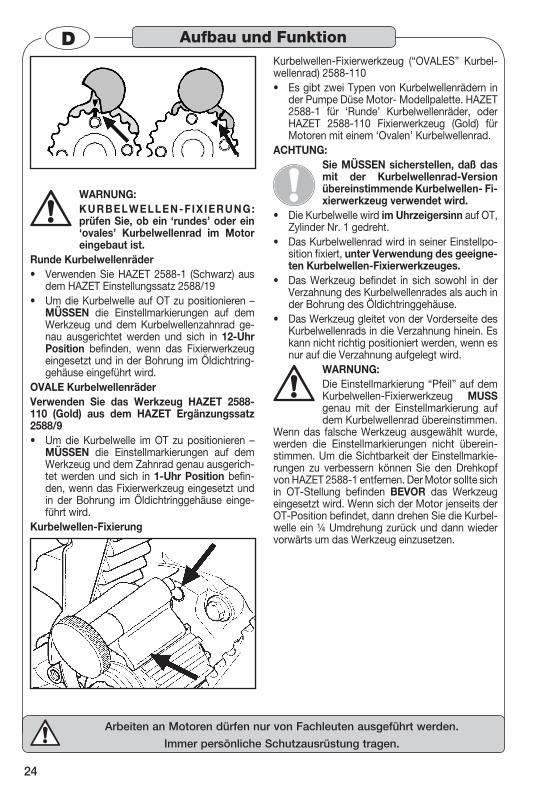
WARNUNG: KURBELWELLEN-FIX IERUNG: prüfen Sie, ob ein ‘rundes’ oder ein ‘ovales’ Kurbelwellenrad im Motor eingebaut ist.
Runde Kurbelwellenräder Verwenden Sie HAZET 2588-1 (Schwarz) aus • dem HAZET Einstellungssatz 2588/19 Um die Kurbelwelle auf OT zu positionieren – • MÜSSEN die Einstellmarkierungen auf dem Werkzeug und dem Kurbelwellenzahnrad ge-nau ausgerichtet werden und sich in 12-Uhr Position befinden, wenn das Fixierwerkzeug eingesetzt und in der Bohrung im Öldichtring-gehäuse eingeführt wird.
OVALE Kurbelwellenräder Verwenden Sie das Werkzeug HAZET 2588- 110 (Gold) aus dem HAZET Ergänzungssatz 2588/9
Um die Kurbelwelle im OT zu positionieren – • MÜSSEN die Einstellmarkierungen auf dem Werkzeug und dem Zahnrad genau ausgerich-tet werden und sich in 1-Uhr Position befin-den, wenn das Fixierwerkzeug eingesetzt und in der Bohrung im Öldichtringgehäuse einge-führt wird.
Kurbelwellen-Fixierung
Kurbelwellen-Fixierwerkzeug (“OVALES” Kurbel-wellenrad) 2588-110
Es gibt zwei Typen von Kurbelwellenrädern in • der Pumpe Düse Motor- Modellpalette. HAZET 2588-1 für ‘Runde’ Kurbelwellenräder, oder HAZET 2588-110 Fixierwerkzeug (Gold) für Motoren mit einem ‘Ovalen’ Kurbelwellenrad.
ACHTUNG:Sie MÜSSEN sicherstellen, daß das mit der Kurbelwellenrad-Version übereinstimmende Kurbelwellen- Fi-xierwerkzeug verwendet wird.
Die Kurbelwelle wird • im Uhrzeigersinn auf OT, Zylinder Nr. 1 gedreht.Das Kurbelwellenrad wird in seiner Einstellpo-• sition fixiert, unter Verwendung des geeigne-ten Kurbelwellen-Fixierwerkzeuges.Das Werkzeug befindet in sich sowohl in der • Verzahnung des Kurbelwellenrades als auch in der Bohrung des Öldichtringgehäuse.Das Werkzeug gleitet von der Vorderseite des • Kurbelwellenrads in die Verzahnung hinein. Es kann nicht richtig positioniert werden, wenn es nur auf die Verzahnung aufgelegt wird.
WARNUNG: Die Einstellmarkierung “Pfeil” auf dem Kurbelwellen-Fixierwerkzeug MUSS genau mit der Einstellmarkierung auf dem Kurbelwellenrad übereinstimmen.
Wenn das falsche Werkzeug ausgewählt wurde, werden die Einstellmarkierungen nicht überein-stimmen. Um die Sichtbarkeit der Einstellmarkie-rungen zu verbessern können Sie den Drehkopf von HAZET 2588-1 entfernen. Der Motor sollte sich in OT-Stellung befinden BEVOR das Werkzeug eingesetzt wird. Wenn sich der Motor jenseits der OT-Position befindet, dann drehen Sie die Kurbel-welle ein ¼ Umdrehung zurück und dann wieder vorwärts um das Werkzeug einzusetzen.
Aufbau und Funktion
25
Arbeiten an Motoren dürfen nur von Fachleuten ausgeführt werden.
Immer persönliche Schutzausrüstung tragen.
DZahnriemenwechsel 4.
1.6, 1.8, 2.0 Motoren mit zwei oben liegenden Nockenwellen
Siehe Anwendungstabelle bezüglich Modelle / ➪Motorcode.
Nockenwellen-Fixierwerkzeuge 3088-15 (gelb) und 3088-16 (blau) HINWEIS
Diese Werkzeuge sind zwecks Motor-Benutzungsidentifizierung farblich ko-diert.
Vor Modelljahr 1999 basierte der 1.8 16 V EcoTec Motor auf dem 2.0 16 V. Für diese Motoren wird das Fixierwerkzeug 3088-15 (gelb) eingesetzt. Ab Modelljahr 1999 basiert der 1.8 16 V Motor auf dem 1.6 16 V, für diese Motoren wir das Fixier-werkzeug 3088-16 (blau) eingesetzt. Diese Werk-zeuge werden zwischen den beiden Nockenwel-lenrädern fest in die Verzahnung eingesetzt. Dies fixiert die Nockenwellenräder und verhindert, dass sie sich aus ihrer Position drehen, wenn der Zahnriemen entfernt wird. Die Nockenwellen-Einstellmarkierungen MÜSSEN vor Einsetzen des Fixierwerkzeugs ausgerichtet sein. HINWEIS
OPEL Nockenwellen Einstellmarkie-rungen variieren je nach Motormodell in ihrer Lage. Sie können zum Beispiel
oben (3 A) oder mittig (3 B) liegen. Hersteller-Angaben/-Hinweise beachten.
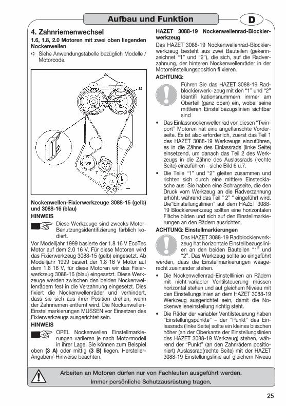
HAZET 3088-19 Nockenwellenrad-Blockier-werkzeugDas HAZET 3088-19 Nockenwellenrad-Blockier-werkzeug besteht aus zwei Bauteilen (gekenn-zeichnet “1” und “2”), die sich, auf die Radver-zahnung, der hinteren Nockenwellenräder in der Motoreinstellungsposition fi xieren.ACHTUNG:
Führen Sie das HAZET 3088-19 Rad-blockierwerk- zeug mit den “1” und “2” Identifi kationsnummern immer am Oberteil (ganz oben) ein, wobei seine mittleren Einstellbezugslinien sichtbar sind
Das Einlassnockenwellenrad von diesen “Twin-• port” Motoren hat eine angeflanschte Vorder-seite. Es ist also erforderlich, zuerst das Teil 1 des HAZET 3088-19 Werkzeugs einzuführen, es in die Zähne des Einlassrads (linke Seite) einsetzend, um danach das Teil 2 des Werk-zeugs in die Zähne des Auslassrads (rechte Seite) einzuführen - siehe Bild 6 u.7.Die Teile “1” und “2” gleiten zusammen und • richten sich durch eine mittlere Einsteckla-sche aus. Sie haben eine Schrägseite, die den Druck vom Werkzeug an die Radverzahnung erhöht, während das Teil “ 2” “ eingeführt wird. Die“Einstellungslinien” auf dem HAZET 3088-19 Blockierwerkzeug sollten eine horizontalen Fläche bilden und sich auf den Einstellmarkie-rungen an den Rädern ausrichten.
ACHTUNG: EinstellmarkierungenDas HAZET 3088-19 Radblockierwerk-zeug hat horizontale Einstellbezugslini-en an den beiden Bauteilen “1” und “2”. Das Werkzeug sollte so eingeführt
werden, dass die Einstellmarkierungen waage-recht zueinander stehen.
Die Nockenwellenrad-Einstelllinien an Rädern • mit nicht-variabler Ventilsteuerung müssen horizontal stehen und auf gleichem Niveau mit den Einstellungslinien an dem HAZET 3088-19 Werkzeug ausgerichtet sein, damit die No-ckenwelleneinstellung richtig steht.Die Räder der variabler Ventilsteuerung haben • “Einstellungspunkte” – der “Punkt” des Ein-lassrads (linke Seite) sollte ein kleines bisschen höher (an der Oberkante der Einstellungslinien des HAZET 3088-19 Werkzeug) stehen, wäh-rend der “Punkt” (an den Zahnrädern positio-niert) Auslassrad(rechte Seite) mit der HAZET 3088-19 Einstellungslinie auf gleichem Niveau
Aufbau und Funktion
26
Arbeiten an Motoren dürfen nur von Fachleuten ausgeführt werden.
Immer persönliche Schutzausrüstung tragen.
Dstehen sollte, so dass die Nockenwellenein-stellung richtig steht.
Inbetriebnahme 5. Zahnriemenwechsel Diesel / Benzinmotoren an FORD
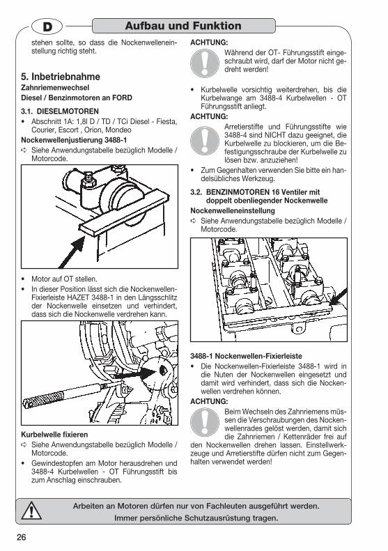
DIESELMOTOREN 3.1. Abschnitt 1A: 1,8l D / TD / TCi Diesel - Fiesta, • Courier, Escort , Orion, Mondeo
Nockenwellenjustierung 3488-1Siehe Anwendungstabelle bezüglich Modelle / ➪Motorcode.
Motor auf OT stellen. • In dieser Position lässt sich die Nockenwellen-• Fixierleiste HAZET 3488-1 in den Längsschlitz der Nockenwelle einsetzen und verhindert, dass sich die Nockenwelle verdrehen kann.
Kurbelwelle fixierenSiehe Anwendungstabelle bezüglich Modelle / ➪Motorcode. Gewindestopfen am Motor herausdrehen und • 3488-4 Kurbelwellen - OT Führungsstift bis zum Anschlag einschrauben.
ACHTUNG:Während der OT- Führungsstift einge-schraubt wird, darf der Motor nicht ge-dreht werden!
Kurbelwelle vorsichtig weiterdrehen, bis die • Kurbelwange am 3488-4 Kurbelwellen - OT Führungsstift anliegt.
ACHTUNG:Arretierstifte und Führungsstifte wie 3488-4 sind NICHT dazu geeignet, die Kurbelwelle zu blockieren, um die Be-festigungsschraube der Kurbelwelle zu lösen bzw. anzuziehen!
Zum Gegenhalten verwenden Sie bitte ein han-• delsübliches Werkzeug.
BENZINMOTOREN 16 Ventiler mit 3.2. doppelt obenliegender Nockenwelle
NockenwelleneinstellungSiehe Anwendungstabelle bezüglich Modelle / ➪Motorcode.
3488-1 Nockenwellen-Fixierleiste Die Nockenwellen-Fixierleiste 3488-1 wird in • die Nuten der Nockenwellen eingesetzt und damit wird verhindert, dass sich die Nocken-wellen verdrehen können.
ACHTUNG:Beim Wechseln des Zahnriemens müs-sen die Verschraubungen des Nocken-wellenrades gelöst werden, damit sich die Zahnriemen / Kettenräder frei auf
den Nockenwellen drehen lassen. Einstellwerk-zeuge und Arretierstifte dürfen nicht zum Gegen-halten verwendet werden!
Aufbau und Funktion
27
Arbeiten an Motoren dürfen nur von Fachleuten ausgeführt werden.
Immer persönliche Schutzausrüstung tragen.
D
Fixieren der KurbelwelleSiehe Anwendungstabelle bezüglich Modelle / ➪Motorcode. 3488-10, 3488-11
Kurbelwellen- Arretierstifte Zahnriemenan-trieb:
1,25l, 1,4l, 1,6l Fiesta, Courier, Fusion, Puma, • Focus – verwenden Sie den Arretierstift 3488-10. 1,6l Mondeo; 1,8l, 2,0l Focus, Mondeo, Cou-• gar, Connect – verwenden Sie den Arretierstift 3488-11.
Kettenradantrieb: 1,8l, 2,0l – wird der Arretierstift 3488-10 benö-• tigt. Verschraubung am Motor herausdrehen und • 3488-10 Arretierstift bis zum Anschlag ein-schrauben. Kurbelwelle vorsichtig weiterdre-hen bis die Kurbelwange am Arretierstift 3488-10 anliegt.
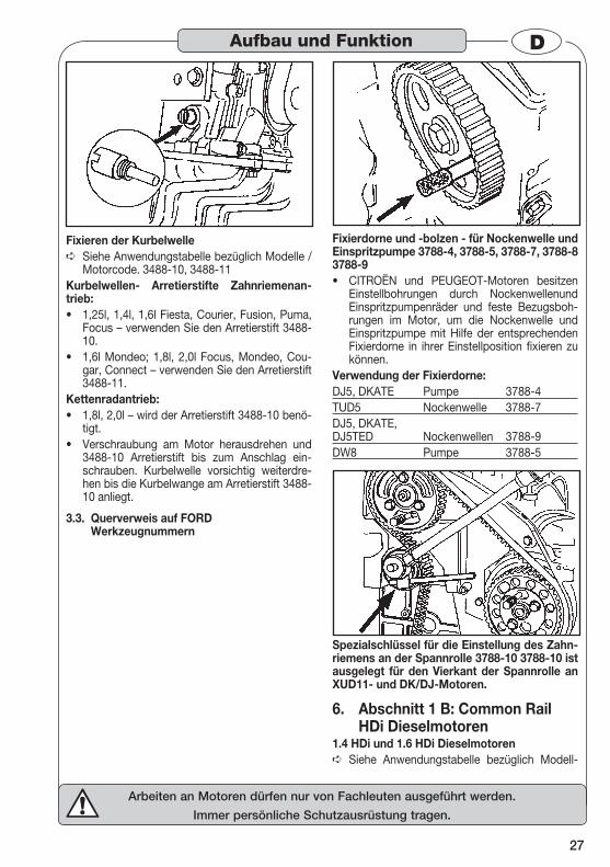
Querverweis auf FORD 3.3. Werkzeugnummern
Fixierdorne und -bolzen - für Nockenwelle und Einspritzpumpe 3788-4, 3788-5, 3788-7, 3788-8 3788-9
CITROËN und PEUGEOT-Motoren besitzen • Einstellbohrungen durch Nockenwellenund Einspritzpumpenräder und feste Bezugsboh-rungen im Motor, um die Nockenwelle und Einspritzpumpe mit Hilfe der entsprechenden Fixierdorne in ihrer Einstellposition fixieren zu können.
Verwendung der Fixierdorne: DJ5, DKATE Pumpe 3788-4 TUD5 Nockenwelle 3788-7 DJ5, DKATE, DJ5TED Nockenwellen 3788-9 DW8 Pumpe 3788-5
Spezialschlüssel für die Einstellung des Zahn-riemens an der Spannrolle 3788-10 3788-10 ist ausgelegt für den Vierkant der Spannrolle an XUD11- und DK/DJ-Motoren.
Abschnitt 1 B: Common Rail 6. HDi Dieselmotoren
1.4 HDi und 1.6 HDi DieselmotorenSiehe Anwendungstabelle bezüglich Modell- ➪
Aufbau und Funktion

28
Arbeiten an Motoren dürfen nur von Fachleuten ausgeführt werden.
Immer persönliche Schutzausrüstung tragen.
Dbenutzung / Motorcode Fixierdorn 3788-9 wird zum Fixieren der No-• ckenwelle bei allen 2.0 HDi und 2.2 HDi Mo-toren benutzt.
Benzinmotoren 7. Abschnitt 2A: TU / XU Motoren Fixierdorne Kurbelwellen-/Schwungscheiben-OT
Siehe Anwendungstabelle bezüglich Modell- ➪benutzung / Motorcode
Kurbelwellen-/Schwungscheiben-OTFixier-dorne 3788-3, 3788-9
CITROËN und PEUGEOT TU/XU Benzinmoto-• ren haben Einstellbohrungen durch Kurbelwel-lenriemenscheibe und Schwungscheibe sowie feste Bezugsbohrungen im Motorblock, durch die die Kurbelwelle, unter Verwendung der kor-rekt bemessenen Fixierdorne, in ihrer Stellung fixiert wird.
Verwendung der Fixierdorne:TU1, TU3, TU5, TU9, TU5J4 3788-3XU7, X10J4 3788-9Fixierdorne für Motoren mit einer oder zwei oben liegenden Nockenwellen
Siehe Anwendungstabelle bezüglich Modell- ➪benutzung / Motorcode
Arretierstifte 3788-9 3788-28 (x2) Für CITROËN und PEUGEOT Motoren mit einer • oder zwei oben liegenden Nockenwellen (TU und XU), werden die Fixierdorne in Kombina-tion verwendet, um die Steuerzeiteneinstellung während des Zahnriemenwechsels zu fixieren. Die Fixierdorne werden durch Zugangsbohrun-gen in jedem der Nockenwellenräder in feste Bezugsbohrungen dahinter eingesetzt.
Verwendung der Fixierdorne: XU5, TU9, XU10 3788-9XU7JP4, XU10JP4 3788-28 (x2)
Spannrollen-Fixierdorn 3788-9 Setzen Sie den Fixierdorn 3788-9 in den Spann-• rollenträger ein und lösen Sie die Spannrollen-verschraubung. Drehen Sie die Spannrolle im Uhrzeigersinn, bis der Zeiger den Fixierdorn berührt, ziehen Sie die Mutter wieder an und entfernen Sie den Fixierdorn.
Aufbau und Funktion
29
Arbeiten an Motoren dürfen nur von Fachleuten ausgeführt werden.
Immer persönliche Schutzausrüstung tragen.
DInbetriebnahme 8.
Zahnriemenwechsel RENAULT Diesel / Benzinmotoren
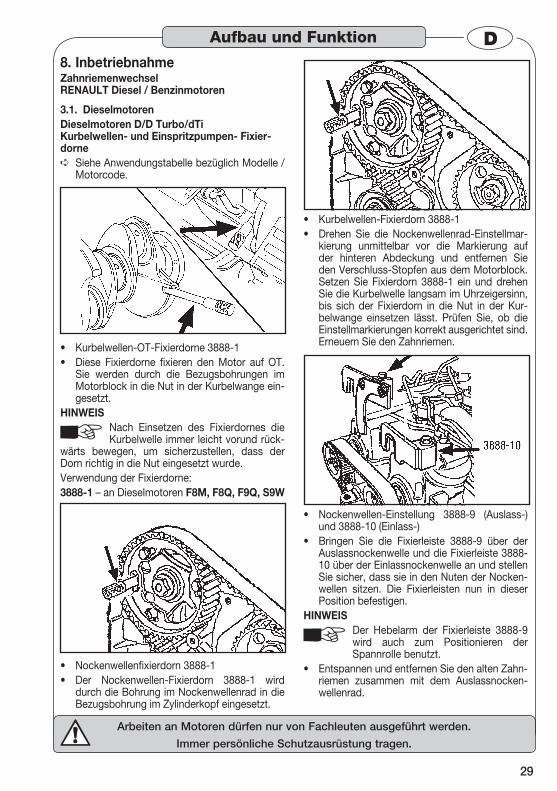
Dieselmotoren 3.1. Dieselmotoren D/D Turbo/dTi Kurbelwellen- und Einspritzpumpen- Fixier-dorne
Siehe Anwendungstabelle bezüglich Modelle / ➪Motorcode.
Kurbelwellen-OT-Fixierdorne 3888-1 • Diese Fixierdorne fixieren den Motor auf OT. • Sie werden durch die Bezugsbohrungen im Motorblock in die Nut in der Kurbelwange ein-gesetzt.
HINWEISNach Einsetzen des Fixierdornes die Kurbelwelle immer leicht vorund rück-
wärts bewegen, um sicherzustellen, dass der Dorn richtig in die Nut eingesetzt wurde. Verwendung der Fixierdorne:3888-1 – an Dieselmotoren F8M, F8Q, F9Q, S9W
Nockenwellenfixierdorn 3888-1 • Der Nockenwellen-Fixierdorn 3888-1 wird • durch die Bohrung im Nockenwellenrad in die Bezugsbohrung im Zylinderkopf eingesetzt.
Kurbelwellen-Fixierdorn 3888-1 • Drehen Sie die Nockenwellenrad-Einstellmar-• kierung unmittelbar vor die Markierung auf der hinteren Abdeckung und entfernen Sie den Verschluss-Stopfen aus dem Motorblock. Setzen Sie Fixierdorn 3888-1 ein und drehen Sie die Kurbelwelle langsam im Uhrzeigersinn, bis sich der Fixierdorn in die Nut in der Kur-belwange einsetzen lässt. Prüfen Sie, ob die Einstellmarkierungen korrekt ausgerichtet sind. Erneuern Sie den Zahnriemen.
Nockenwellen-Einstellung 3888-9 (Auslass-) • und 3888-10 (Einlass-) Bringen Sie die Fixierleiste 3888-9 über der • Auslassnockenwelle und die Fixierleiste 3888-10 über der Einlassnockenwelle an und stellen Sie sicher, dass sie in den Nuten der Nocken-wellen sitzen. Die Fixierleisten nun in dieser Position befestigen.
HINWEISDer Hebelarm der Fixierleiste 3888-9 wird auch zum Positionieren der Spannrolle benutzt.
Entspannen und entfernen Sie den alten Zahn-• riemen zusammen mit dem Auslassnocken-wellenrad.
Aufbau und Funktion
30
Arbeiten an Motoren dürfen nur von Fachleuten ausgeführt werden.
Immer persönliche Schutzausrüstung tragen.
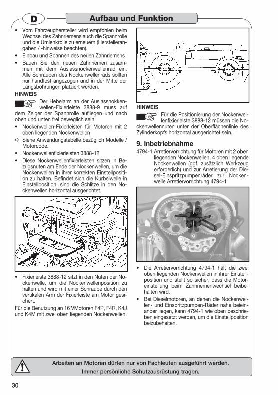
DVom Fahrzeughersteller wird empfohlen beim • Wechsel des Zahnriemens auch die Spannrolle und die Umlenkrolle zu erneuern (Herstelleran-gaben / -hinweise beachten). Einbau und Spannen des neuen Zahnriemens • Bauen Sie den neuen Zahnriemen zusam-• men mit dem Auslassnockenwellenrad ein. Alle Schrauben des Nockenwellenrads sollten nur handfest angezogen und in der Mitte der Längsbohrungen platziert werden.
HINWEISDer Hebelarm an der Auslassnokken-wellen-Fixierleiste 3888-9 muss auf
dem Zeiger der Spannrolle aufliegen und nach oben und unten frei beweglich sein.
Nockenwellen-Fixierleisten für Motoren mit 2 • oben liegenden NockenwellenSiehe Anwendungstabelle bezüglich Modelle / ➪Motorcode. Nockenwellenfixierleisten 3888-12 • Diese Nockenwellenfixierleisten sitzen in Be-• zugsnuten am Ende der Nockenwellen, um die Nockenwellen in ihrer korrekten Einstellpositi-on zu halten. Befindet sich die Kurbelwelle in Einstellposition, sind die Schlitze in den No-ckenwellen horizontal ausgerichtet.
Fixierleiste 3888-12 sitzt in den Nuten der No-• ckenwelle, um die Nockenwellenposition zu halten und wird mit einer Schraube durch den vertikalen Arm der Fixierleiste am Motor gesi-chert.
Für die Benutzung an 16 VMotoren F4P, F4R, K4J und K4M mit zwei oben liegenden Nockenwellen.
HINWEISFür die Positionierung der Nockenwel-lenfixierleiste 3888-12 müssen die No-
ckenwellennuten unter der Oberflächenlinie des Zylinderkopfs horizontal ausgerichtet sein.
Inbetriebnahme 9. 4794-1 Arretiervorrichtung für Motoren mit 2 oben
liegenden Nockenwellen, 4 oben liegende Nockenwellen (ggf. zusätzlich Werkzeug erforderlich) und zur Arretierung der Die-sel-Einspritzpumpenräder zur Nocken-welle Arretiervorrichtung 4794-1
Die Arretiervorrichtung 4794-1 hält die zwei • oben liegenden Nockenwellen in ihrer Einstell-position und stellt so sicher, dass die Motor-einstellung beim Zahnriemenwechsel beibe-halten wird. Bei Dieselmotoren, an denen die Nockenwel-• len- und Einspritzpumpen-Räder nahe beiein-ander liegen, kann 4794-1 wie oben beschrie-ben eingesetzt werden, um die Einstellposition beizubehalten.
Aufbau und Funktion
31
Arbeiten an Motoren dürfen nur von Fachleuten ausgeführt werden.
Immer persönliche Schutzausrüstung tragen.
D
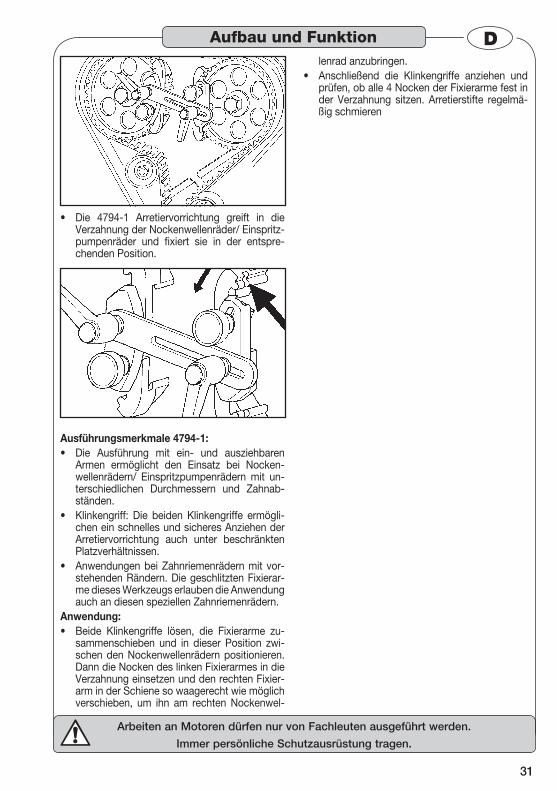
Die 4794-1 Arretiervorrichtung greift in die • Verzahnung der Nockenwellenräder/ Einspritz-pumpenräder und fixiert sie in der entspre-chenden Position.
Ausführungsmerkmale 4794-1: Die Ausführung mit ein- und ausziehbaren • Armen ermöglicht den Einsatz bei Nocken-wellenrädern/ Einspritzpumpenrädern mit un-terschiedlichen Durchmessern und Zahnab-ständen. Klinkengriff: Die beiden Klinkengriffe ermögli-• chen ein schnelles und sicheres Anziehen der Arretiervorrichtung auch unter beschränkten Platzverhältnissen. Anwendungen bei Zahnriemenrädern mit vor-• stehenden Rändern. Die geschlitzten Fixierar-me dieses Werkzeugs erlauben die Anwendung auch an diesen speziellen Zahnriemenrädern.
Anwendung: Beide Klinkengriffe lösen, die Fixierarme zu-• sammenschieben und in dieser Position zwi-schen den Nockenwellenrädern positionieren. Dann die Nocken des linken Fixierarmes in die Verzahnung einsetzen und den rechten Fixier-arm in der Schiene so waagerecht wie möglich verschieben, um ihn am rechten Nockenwel-
lenrad anzubringen. Anschließend die Klinkengriffe anziehen und • prüfen, ob alle 4 Nocken der Fixierarme fest in der Verzahnung sitzen. Arretierstifte regelmä-ßig schmieren
Aufbau und Funktion
32
Maintenance work on engines must be carried out only by experienced mechanics.
Always wear personal protective equipment.
USA GB
Dear Customer, You have made a good choice. This HAZET tool in front of you is a high-quality product that will make your work easier.
General Information 1. Please make sure that the user of these tools • carefully reads these operating instructions and fully understands all information given be-fore they are used.These operating instructions contain important • advice that is necessary for a safe and trouble-free operation of your HAZET Tools.For effective use of the tools as intended, it is • essential that all safety and other information in these operating instructions is adhered to. For this reason, always keep these operating • instructions together with your HAZET Engine Timing Tool Set.This tool set has been designed exclusively for • specific applications. HAZET emphasizes that any modification to the tool set and/or use on an application not detailed to its intended ap-plication are strictly forbidden.HAZET will not be liable for any injuries to per-• sons or damage to property originating from improper application, misuse of the tools or a disregard of the safety instructions.Furthermore, the general safety regulations • and regulations for the prevention of accidents valid for the application area of these tools must be observed and respected.
Explanation of Symbols2. ATTENTION: Please pay attention to these
symbols! Read the Operating Instructions!
The user/owner of this tool set is obli-ged to observe the operating instruc-tions and should ensure all users of this tool set use it according to the in-formation given in this manual.
NOTICE!This symbol marks advice which is helpful when using the tools.
CAUTION! This symbol marks important specifi-cations, dangerous conditions, safety risks and safety advice.
ATTENTION!This symbol marks advice which if disregarded results in damage, mal-function and/or functional failure of the tools.
CRANKSHAFT / FLYWHEEL
This figure marks the tool which has to be used to lock the crankshaft/ fly-wheel on the indicated vehicle.
CAMSHAFT This figure marks the tool which has to be used to lock the camshaft on the indicated vehicle.
INJECTION PUMPThis figure marks the tool which has to be used to lock the diesel injection pump on the indicated vehicle.
TENSIONER ROLLERThis figure marks the tool which has to be used to operate the tensioner roller on the indicated vehicle.
FRONT PANEL This figure marks the tool which has to be used to mount/dismount the front panel on the indicated vehicle.
For Your Information
33
Maintenance work on engines must be carried out only by experienced mechanics.
Always wear personal protective equipment.
GBUSALiability and Warranty3.
Any deviation from the intended use and/or any misapplication of the tools is not allowed and will be considered as improper use.
Any claims against the manufacturer and/or its • authorized agents because of damage caused by improper use of the tools are void.Any personal injury or material losses caused • by improper use of the tools are the sole res-ponsibility of the operator and user.
Spare Parts 4. Only use the manufacturer’s original spare • parts.Unsuitable or defective spare parts may cause • damage, malfunction or total failure of the tools.The use of non approved spare parts will void • all warranty, service and liability claims as well as all claims for compensation against the ma-nufacturer or its agents, distributors and sales representatives.
Disposal 5. For disposal, clean tools and disassemble • them according to the regulations for work safety and environmental protection. Com-ponents can be recycled.Metal components can be scrapped.• The reduction of the pollution as well as the • protection of the environment are the central points of our activities.
For Your Information

34
Maintenance work on engines must be carried out only by experienced mechanics.
Always wear personal protective equipment.
USA GBThis paragraph gives an overview of im-portant security advice to help to ensu-re the optimal protection of the person-nel as well as the safe and trouble-free
operation of the tool set. Additionally, the different chapters contain security advice that is marked with symbols in order to avert immediate danger. Furthermore, all stickers and labels on the tool set must be observed and must be kept legible.
General Aspects 1. This tool set was developed and manu-factured according to the technical norms and standards valid at the time and is considered to be operationally
reliable. Nevertheless, the tools can present a dan-ger when they are not used as intended or in an in-appropriate way by non-qualified personnel. Please make sure that any person using this tool or carry-ing out maintenance work carefully reads these operating instructions and fully understands all in-formation given, before using the tools.
Any modification of the tools is strictly forbid-• den.All indications concerning setting values and • setting ranges must be observed.
User’s / Owner’s Liability2. Keep the operating instructions together with • the tool set at all times.This tool set is intended exclusively for use by • experienced mechanics.The tool set must only be used if it is in good • working order.All safety equipment must always be within re-• ach and should be checked regularly.All safety equipment, e.g. fire extinguisher etc., • must always be within reach and should be che-cked regularly.
In addition to the safety advice given in these operating instructions, the general safety regulations, regulati-ons for the prevention of accidents
and regulations for environmental protection being valid for the application area of this tool set have to be observed and respected. These instructions are provided as a guide only. Al-ways ensure you possess and can make refe-rence to the vehicle manufacturer’s appropriate service instructions, or a suitable proprietary manual, to establish the current procedure and data.
Appropriate Usage3. Operational reliability can only be en-sured, if the tool set is used as inten-ded and in compliance with the indi-cations given in the operating
instructions. In addition to the safety advice given in these operating instructions, the general safety regulations, regulations for the prevention of acci-dents and regulations for environmental protec-tion being valid for the application area of this tool set have to be observed and respected.
This HAZET Tool Set is intended for the re-• placement of timing belts on diesel and petrol engines.The improper use of the tools or the disregard • of the safety advice may cause severe injury or death.Any deviation from the intended use and/or • any misapplication of the tool set is not allowed and will be considered as improper use.Any claims against the manufacturer and/or its • authorized agents because of damage caused by improper use of the tool set will be void.Any personal injury or material losses caused • by improper use are the sole responsibility of the operator and user.
Storage 4.
The tool set has be stored according the following conditions:
Keep tool set in a dry and dust-free place.• Do not expose the tool set to liquids or aggres-• sive substances.Do not store the tool set outdoors.• Keep tool set out of reach of children• Storage temperature: -10°C to +40°C• Relative air humidity: max. 60%•
For Your Safety

35
Maintenance work on engines must be carried out only by experienced mechanics.
Always wear personal protective equipment.
GBUSADangers emanating from the 1. Tool Set
Before each use, check the HAZET En-gine Timing Tool Set for full functional efficiency. Do not use the Tool Set if its functional efficiency cannot be ensu-
red or if damage is detected. If the Tool Set is used, when it is not in full working order, you risk severe injuries to persons and damage to proper-ty. Defective tools may cause severe injury.In order to avoid injury or damage, it is essential that the following fundamental safety guidelines will be observed:ATTENTION:
Incorrect or out of phase camshaft timing can result in contact between valves and pistons causing damage to the engine. Always ensure the
correct tools are used and that the vehicle manufacturer’s procedures are adhered to.
Before starting to work, disconnect the • battery’s negative terminal.
NOTICE: Before disconnecting the battery, en-sure that the vehicle owner has a re-cord of the car radio code.
Any vehicle “jacked up” or raised above • ground must be adequately supported with axle stands, ramps etc.Wear protective clothing, safety eye protection. • Engines have rotating components, so avoid wearing loose clothing, jewellery etc. which can get caught up in the engine moving parts.Always account for tools being used. Do not • leave them in or near the engine when turning the engine over, or when the job is finished. Parts that are not fixed can be hurled around and may cause severe injury or death to per-sons in the work area. Objects may be dama-ged.Do not use the locking pins for locking the the • crankshaft when tightening or releasing the crankshaft bolt.The timing belt must not be used for locking • the camshaft sprocket when slackening the nuts.Do not forcibly twist a new belt or bend it • through a radius of less than 25 mm.Never lever or force the timing belt onto the • sprockets.
Check free running of tensioner roller, guide • roller(s) and water pump.Check engine for leakages, if detected elimi-• nate them.Replace old timing belts with a new one and • ensure that it has the correct teeth profile.Ensure timing belt tension is correctly adjus-• ted (adhere to vehicle manufacturer’s instruc-tions).Observe torque specifications (adhere to ve-• hicle manufacturer’s instructions)Pay regard to the timing belt’s direction of rota-• tion which is indicated by an arrow.Do not reuse used timing belts. Always fit a • new one.In case of any appearance of wear as wear • points, cracks or damages as well as soiling (e.g. by oil) , replace timing belt .If the timing belt shows damage, find out origin • and remedy deficiencies.Do not use solvents or cleaning fluids like thin-• ner or benzine on belts, sprockets etc.Do not twist, bend or reverse the timing belt • for inspection.The engine must only be turned in the normal • direction of rotation, unless otherwise noted by the vehicle manufacturer.Only use parts, supports and accessories • which are recommended by the manufacturer.Repair work must be carried out exclusively by • authorized persons.Only use the tools within the prescribed places, • and governed under the current regulations re-lating to the working environment.For safety reasons any modification of HAZET • tools is strictly forbidden. Any modification of the tools will result in immediate exlcusion from warranty and liability.
For Your Safety
36
Maintenance work on engines must be carried out only by experienced mechanics.
Always wear personal protective equipment.
USA GBPrior to Operation1.
Always ensure tools are used, inspec-ted and maintained in compliance with the respective local, state, national or federal regulations.
Before starting to work, disconnect enginge • from power supply. Carefully read operating instructions for the engine and if necessary for the other equipment assemblies and devices (e.g. radio etc.)
ATTENTION Ensure that the radio code is recor-ded.
CAUTION Jacked up vehicles must be secured adequately.
ATTENTION Only use appropriate spare parts.
Operation2. DIESEL ENGINES 3.2.
Diesel Engines with Standard Injection Sys-• tems D / TD / SDi / TDi
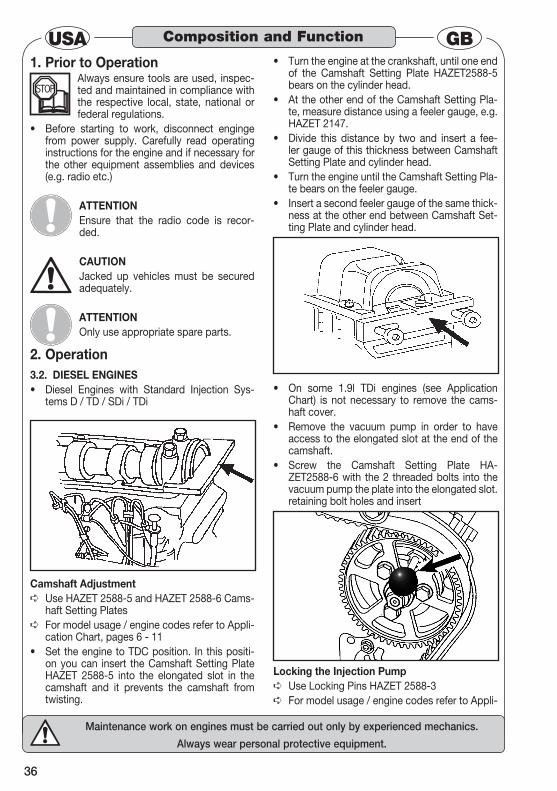
Camshaft AdjustmentUse HAZET 2588-5 and HAZET 2588-6 Cams- ➪haft Setting PlatesFor model usage / engine codes refer to Appli- ➪cation Chart, pages 6 - 11Set the engine to TDC position. In this positi-• on you can insert the Camshaft Setting Plate HAZET 2588-5 into the elongated slot in the camshaft and it prevents the camshaft from twisting.
Turn the engine at the crankshaft, until one end • of the Camshaft Setting Plate HAZET2588-5 bears on the cylinder head.At the other end of the Camshaft Setting Pla-• te, measure distance using a feeler gauge, e.g. HAZET 2147.Divide this distance by two and insert a fee-• ler gauge of this thickness between Camshaft Setting Plate and cylinder head.Turn the engine until the Camshaft Setting Pla-• te bears on the feeler gauge.Insert a second feeler gauge of the same thick-• ness at the other end between Camshaft Set-ting Plate and cylinder head.
On some 1.9l TDi engines (see Application • Chart) is not necessary to remove the cams-haft cover.Remove the vacuum pump in order to have • access to the elongated slot at the end of the camshaft.Screw the Camshaft Setting Plate HA-• ZET2588-6 with the 2 threaded bolts into the vacuum pump the plate into the elongated slot.retaining bolt holes and insert
Locking the Injection PumpUse Locking Pins HAZET 2588-3 ➪
For model usage / engine codes refer to Appli- ➪
Composition and Function
37
Maintenance work on engines must be carried out only by experienced mechanics.
Always wear personal protective equipment.
GBUSAcation Chart, pages 6 - 11The injection pump locking pins are designed • to pass through the datum holes in the timing belt fixed holes on the engine.sprockets and into theLocking Pin 2588-3 is used when 2-part injec-• tion pump sprockets are fitted. These injection pump sprockets are fixed with 3 screws. The locking pin is inserted through the sprocket carrier into a datum hole in the engine.
Timing Belt Adjustment / Timing Belt Tensio-ning
For model usage / engine codes refer to Appli- ➪cation Chart, pages 6 - 11
CRANKSHAFT LOCKING
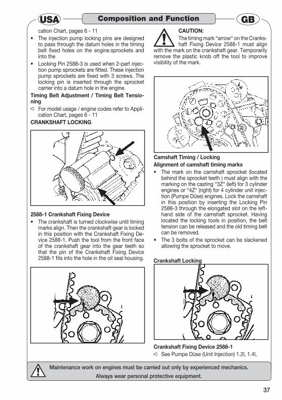
2588-1 Crankshaft Fixing DeviceThe crankshaft is turned clockwise until timing • marks align. Then the crankshaft gear is locked in this position with the Crankshaft Fixing De-vice 2588-1. Push the tool from the front face of the crankshaft gear into the gear teeth so that the pin of the Crankshaft Fixing Device 2588-1 fits into the hole in the oil seal housing.
CAUTION:The timing mark “arrow“ on the Cranks-haft Fixing Device 2588-1 must align
with the mark on the crankshaft gear. Temporarily remove the plastic knob off the tool to improve visibility of the mark.
Camshaft Timing / LockingAlignment of camshaft timing marks
The mark on the camshaft sprocket (located • behind the sprocket teeth ) must align with the marking on the casting “3Z“ (left) for 3 cylinder engines or “4Z“ (right) for 4 cylinder unit injec-tion (Pumpe Düse) engines. Lock the camshaft in this position by inserting the Locking Pin 2588-3 through the elongated slot on the left-hand side of the camshaft sprocket. Having located the locking tools in position, the belt tension can be released and the old timing belt can be removed.The 3 bolts of the sprocket can be slackened • allowing the sprocket to move.
Crankshaft Locking
Crankshaft Fixing Device 2588-1See Pumpe Düse (Unit Injection) 1.2l, 1.4l, ➪
Composition and Function
38
Maintenance work on engines must be carried out only by experienced mechanics.
Always wear personal protective equipment.
USA GBCamshaft Timing – Twin Cams
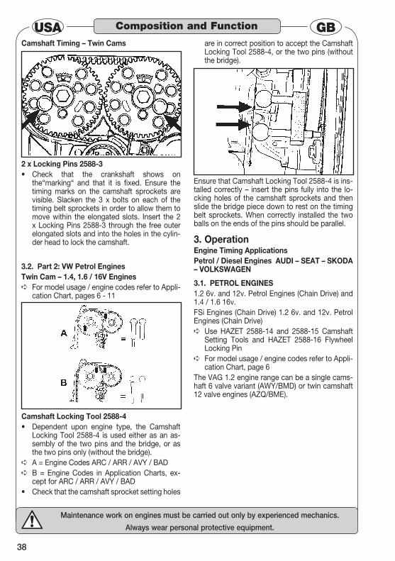
2 x Locking Pins 2588-3Check that the crankshaft shows on • the“marking“ and that it is fixed. Ensure the timing marks on the camshaft sprockets are visible. Slacken the 3 x bolts on each of the timing belt sprockets in order to allow them to move within the elongated slots. Insert the 2 x Locking Pins 2588-3 through the free outer elongated slots and into the holes in the cylin-der head to lock the camshaft.
3.2. Part 2: VW Petrol EnginesTwin Cam – 1.4, 1.6 / 16V Engines
For model usage / engine codes refer to Appli- ➪cation Chart, pages 6 - 11
Camshaft Locking Tool 2588-4Dependent upon engine type, the Camshaft • Locking Tool 2588-4 is used either as an as-sembly of the two pins and the bridge, or as the two pins only (without the bridge).A = Engine Codes ARC / ARR / AVY / BAD ➪
B = Engine Codes in Application Charts, ex- ➪cept for ARC / ARR / AVY / BADCheck that the camshaft sprocket setting holes •
are in correct position to accept the Camshaft Locking Tool 2588-4, or the two pins (without the bridge).
Ensure that Camshaft Locking Tool 2588-4 is ins-talled correctly – insert the pins fully into the lo-cking holes of the camshaft sprockets and then slide the bridge piece down to rest on the timing belt sprockets. When correctly installed the two balls on the ends of the pins should be parallel.
Operation3. Engine Timing ApplicationsPetrol / Diesel Engines AUDI – SEAT – SKODA – VOLKSWAGEN
3.1. PETROL ENGINES1.2 6v. and 12v. Petrol Engines (Chain Drive) and 1.4 / 1.6 16v.FSi Engines (Chain Drive) 1.2 6v. and 12v. Petrol Engines (Chain Drive)
Use HAZET 2588-14 and 2588-15 Camshaft ➪Setting Tools and HAZET 2588-16 Flywheel Locking PinFor model usage / engine codes refer to Appli- ➪cation Chart, page 6
The VAG 1.2 engine range can be a single cams-haft 6 valve variant (AWY/BMD) or twin camshaft 12 valve engines (AZQ/BME).
Composition and Function
39
Maintenance work on engines must be carried out only by experienced mechanics.
Always wear personal protective equipment.
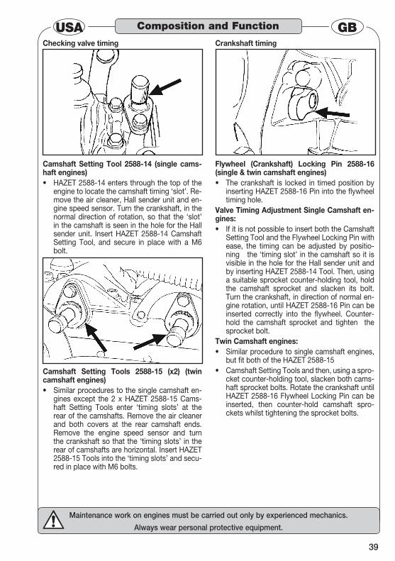
GBUSAChecking valve timing
Camshaft Setting Tool 2588-14 (single cams-haft engines)
HAZET 2588-14 enters through the top of the • engine to locate the camshaft timing ‘slot’. Re-move the air cleaner, Hall sender unit and en-gine speed sensor. Turn the crankshaft, in the normal direction of rotation, so that the ‘slot’ in the camshaft is seen in the hole for the Hall sender unit. Insert HAZET 2588-14 Camshaft Setting Tool, and secure in place with a M6 bolt.
Camshaft Setting Tools 2588-15 (x2) (twin camshaft engines)
Similar procedures to the single camshaft en-• gines except the 2 x HAZET 2588-15 Cams-haft Setting Tools enter ‘timing slots’ at the rear of the camshafts. Remove the air cleaner and both covers at the rear camshaft ends. Remove the engine speed sensor and turn the crankshaft so that the ‘timing slots’ in the rear of camshafts are horizontal. Insert HAZET 2588-15 Tools into the ‘timing slots’ and secu-red in place with M6 bolts.
Crankshaft timing
Flywheel (Crankshaft) Locking Pin 2588-16 (single & twin camshaft engines)
The crankshaft is locked in timed position by • inserting HAZET 2588-16 Pin into the flywheel timing hole.
Valve Timing Adjustment Single Camshaft en-gines:
If it is not possible to insert both the Camshaft • Setting Tool and the Flywheel Locking Pin with ease, the timing can be adjusted by positio-ning the ‘timing slot’ in the camshaft so it is visible in the hole for the Hall sender unit and by inserting HAZET 2588-14 Tool. Then, using a suitable sprocket counter-holding tool, hold the camshaft sprocket and slacken its bolt. Turn the crankshaft, in direction of normal en-gine rotation, until HAZET 2588-16 Pin can be inserted correctly into the flywheel. Counter-hold the camshaft sprocket and tighten the sprocket bolt.
Twin Camshaft engines:Similar procedure to single camshaft engines, • but fit both of the HAZET 2588-15Camshaft Setting Tools and then, using a spro-• cket counter-holding tool, slacken both cams-haft sprocket bolts. Rotate the crankshaft until HAZET 2588-16 Flywheel Locking Pin can be inserted, then counter-hold camshaft spro-ckets whilst tightening the sprocket bolts.
Composition and Function
40
Maintenance work on engines must be carried out only by experienced mechanics.
Always wear personal protective equipment.
USA GB
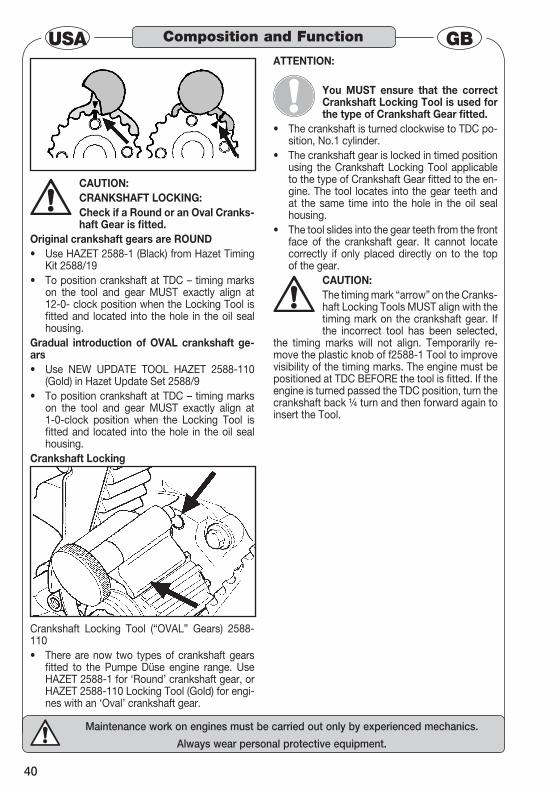
CAUTION:CRANKSHAFT LOCKING:Check if a Round or an Oval Cranks-haft Gear is fitted.
Original crankshaft gears are ROUNDUse HAZET 2588-1 (Black) from Hazet Timing • Kit 2588/19To position crankshaft at TDC – timing marks • on the tool and gear MUST exactly align at 12-0- clock position when the Locking Tool is fitted and located into the hole in the oil seal housing.
Gradual introduction of OVAL crankshaft ge-ars
Use NEW UPDATE TOOL HAZET 2588-110 • (Gold) in Hazet Update Set 2588/9To position crankshaft at TDC – timing marks • on the tool and gear MUST exactly align at 1-0-clock position when the Locking Tool is fitted and located into the hole in the oil seal housing.
Crankshaft Locking
Crankshaft Locking Tool (“OVAL” Gears) 2588-110
There are now two types of crankshaft gears • fitted to the Pumpe Düse engine range. Use HAZET 2588-1 for ‘Round’ crankshaft gear, or HAZET 2588-110 Locking Tool (Gold) for engi-nes with an ‘Oval’ crankshaft gear.
ATTENTION:
You MUST ensure that the correct Crankshaft Locking Tool is used for the type of Crankshaft Gear fitted.
The crankshaft is turned clockwise to TDC po-• sition, No.1 cylinder.The crankshaft gear is locked in timed position • using the Crankshaft Locking Tool applicable to the type of Crankshaft Gear fitted to the en-gine. The tool locates into the gear teeth and at the same time into the hole in the oil seal housing.The tool slides into the gear teeth from the front • face of the crankshaft gear. It cannot locate correctly if only placed directly on to the top of the gear.
CAUTION: The timing mark “arrow” on the Cranks-haft Locking Tools MUST align with the timing mark on the crankshaft gear. If the incorrect tool has been selected,
the timing marks will not align. Temporarily re-move the plastic knob of f2588-1 Tool to improve visibility of the timing marks. The engine must be positioned at TDC BEFORE the tool is fitted. If the engine is turned passed the TDC position, turn the crankshaft back ¼ turn and then forward again to insert the Tool.
Composition and Function

41
Maintenance work on engines must be carried out only by experienced mechanics.
Always wear personal protective equipment.
GBUSATiming Belt Replacement4.
1.6, 1.8, 2.0 EnginesFor model usage / engine codes refer to Appli- ➪cation Chart, pages 6-7.
Camshaft Locking Tools 3088-15 (Yellow) and 3088-16 (Blue)NOTE:
These tools are colour-coded for engi-ne use identification.Prior to model year 1999 the 1.8 16V
EcoTec engine was based on the 2.0 16V and uses Locking Tool 3088-15 (Yellow). From model year 1999 the 1.8 16V is based on the 1.6 16V and uses Locking Tool 3088-16 (Blue). These tools are inserted between the two camshaft sprockets, lo-cating firmly into the gear teeth of the sprockets. This action locks the sprockets to prevent them from turning out of their timed position, when timing belt is removed. Camshaft timing marks must align before inserting locking tool. NOTE OPEL:
Camshaft timing marks vary in position according to the model of engine. For example, they can be at the top (3 A),
or centered (3 B). Check service information care-fully. HAZET 3088-19 Camshaft Sprocket Locking Tool.The HAZET 3088-19 Camshaft Sprocket Locking
Tool comprises two parts (marked “1” and “2”), •
which ‘lock’ the camshaft sprockets in timed position by locating in to the sprocket teeth.
ATTENTION: Always insert HAZET 3088-19 Spro-cket Locking Tool with the identifying numbers “1” and “2” on top (upper-most) and with its central timing mark lines visible.
The inlet camshaft sprocket of these “Twin-• port” engines has a fl anged front face and therefore it is necessary to insert Part 1 of the HAZET 3088-19 Tool fi rst, fi tting it into the teeth of the inlet (left-hand) sprocket, followed by fi tting Part “2” of the Tool in to the teeth of the exhaust (right-hand) sprocket.Parts “1” and “2” slide together and align via • a central tongue, and have an angled face, which increases the pressure of the Tool in to the sprocket teeth, as Part “ 2” “ is inserted. The “timing lines” on HAZET 3088-19 Locking Tool should be in a horizontal plane and align to the timing marks on the sprockets.
ATTENTION: Sprocket Timing marksHAZET 3088-19 Sprocket Locking Tool has horizontal timing mark lines on both Parts “1” and “2”. The Tool should be inserted so that the timing marks are horizontally level to each other.
The camshaft sprocket timing lines on non-VVT • sprockets must be horizontal and level and ali-gned to the timing lines on the HAZET 3088-19 Tool for camshaft timing to be correct.VVT camshaft sprockets have “timing spots” – • the inlet (left-hand) sprocket “spot” should be very slightly higher (on the upper edge of the HAZET 3088-19 Tool’s timing line), whereas the exhaust (right-hand) sprocket “spot” (loca-ted on the sprocket tooth), should be level with the HAZET 3088-19 timing line, for camshaft timing to be correct.
Composition and Function
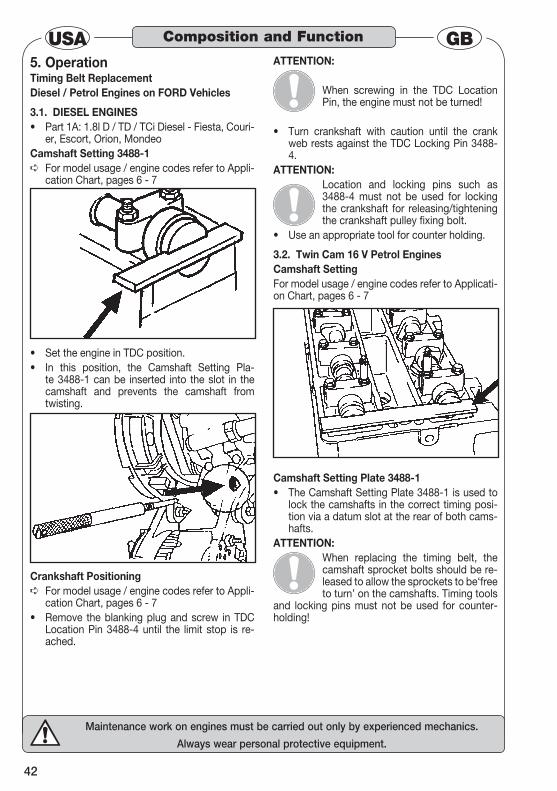
42
Maintenance work on engines must be carried out only by experienced mechanics.
Always wear personal protective equipment.
USA GBOperation5.
Timing Belt ReplacementDiesel / Petrol Engines on FORD Vehicles
3.1. DIESEL ENGINESPart 1A: 1.8l D / TD / TCi Diesel - Fiesta, Couri-• er, Escort, Orion, Mondeo
Camshaft Setting 3488-1For model usage / engine codes refer to Appli- ➪cation Chart, pages 6 - 7
Set the engine in TDC position.• In this position, the Camshaft Setting Pla-• te 3488-1 can be inserted into the slot in the camshaft and prevents the camshaft from twisting.
Crankshaft PositioningFor model usage / engine codes refer to Appli- ➪cation Chart, pages 6 - 7Remove the blanking plug and screw in TDC • Location Pin 3488-4 until the limit stop is re-ached.
ATTENTION:
When screwing in the TDC Location Pin, the engine must not be turned!
Turn crankshaft with caution until the crank • web rests against the TDC Locking Pin 3488-4.
ATTENTION:Location and locking pins such as 3488-4 must not be used for locking the crankshaft for releasing/tightening the crankshaft pulley fixing bolt.
Use an appropriate tool for counter holding.•
3.2. Twin Cam 16 V Petrol EnginesCamshaft SettingFor model usage / engine codes refer to Applicati-on Chart, pages 6 - 7
Camshaft Setting Plate 3488-1The Camshaft Setting Plate 3488-1 is used to • lock the camshafts in the correct timing posi-tion via a datum slot at the rear of both cams-hafts.
ATTENTION:When replacing the timing belt, the camshaft sprocket bolts should be re-leased to allow the sprockets to be‘free to turn’ on the camshafts. Timing tools
and locking pins must not be used for counter-holding!
Composition and Function
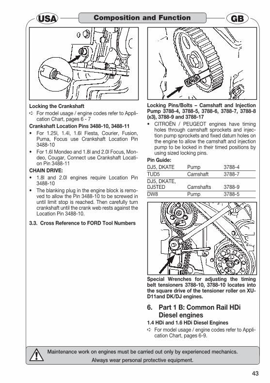
43
Maintenance work on engines must be carried out only by experienced mechanics.
Always wear personal protective equipment.
GBUSA
Locking the CrankshaftFor model usage / engine codes refer to Appli- ➪cation Chart, pages 6 - 7
Crankshaft Location Pins 3488-10, 3488-11For 1.25l, 1.4l, 1.6l Fiesta, Courier, Fusion, • Puma, Focus use Crankshaft Location Pin 3488-10For 1.6l Mondeo and 1.8l and 2.0l Focus, Mon-• deo, Cougar, Connect use Crankshaft Locati-on Pin 3488-11
CHAIN DRIVE:1.8l and 2.0l engines require Location Pin • 3488-10The blanking plug in the engine block is remo-• ved to allow the Pin 3488-10 to be screwed in until limit stop is reached. Then carefully turn crankshaft until the crank web rests against the Location Pin 3488-10.
Cross Reference to FORD Tool Numbers3.3.
Locking Pins/Bolts – Camshaft and Injection Pump 3788-4, 3788-5, 3788-6, 3788-7, 3788-8 (x3), 3788-9 and 3788-17
CITROËN / PEUGEOT engines have timing • holes through camshaft sprockets and injec-tion pump sprockets and fixed datum holes on the engine to allow the camshaft and injection pump to be locked in their timed positions by using sized locking pins.
Pin Guide:DJ5, DKATE Pump 3788-4TUD5 Camshaft 3788-7DJ5, DKATE, DJ5TED Camshafts 3788-9DW8 Pump 3788-5
Special Wrenches for adjusting the timing belt tensioners 3788-10, 3788-10 locates into the square drive of the tensioner roller on XU-D11and DK/DJ engines.
Part 1 B: Common Rail HDi 6. Diesel engines
1.4 HDi and 1.6 HDi Diesel EnginesFor model usage / engine codes refer to Appli- ➪cation Chart, pages 6-9.
Composition and Function
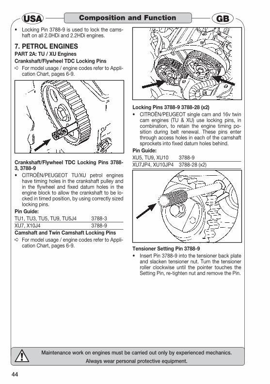
44
Maintenance work on engines must be carried out only by experienced mechanics.
Always wear personal protective equipment.
USA GBLocking Pin 3788-9 is used to lock the cams-• haft on all 2.0HDi and 2.2HDi engines.
PETROL ENGINES7. PART 2A: TU / XU EnginesCrankshaft/Flywheel TDC Locking Pins
For model usage / engine codes refer to Appli- ➪cation Chart, pages 6-9.
Crankshaft/Flywheel TDC Locking Pins 3788-3, 3788-9
CITROËN/PEUGEOT TU/XU petrol engines • have timing holes in the crankshaft pulley and in the flywheel and fixed datum holes in the engine block to allow the crankshaft to be lo-cked in timed position, by using correctly sized locking pins.
Pin Guide:TU1, TU3, TU5, TU9, TU5J4 3788-3XU7, X10J4 3788-9Camshaft and Twin Camshaft Locking Pins
For model usage / engine codes refer to Appli- ➪cation Chart, pages 6-9.
Locking Pins 3788-9 3788-28 (x2)CITROËN/PEUGEOT single cam and 16v twin • cam engines (TU & XU) use locking pins, in combination, to retain the engine timing po-sition during belt renewal. These pins enter through access holes in each of the camshaft sprockets into fixed datum holes behind.
Pin Guide:XU5, TU9, XU10 3788-9XU7JP4, XU10JP4 3788-28 (x2)
Tensioner Setting Pin 3788-9Insert Pin 3788-9 into the tensioner back plate • and slacken tensioner nut. Turn the tensioner roller clockwise until the pointer touches the Setting Pin, re-tighten nut and remove the Pin.
Composition and Function
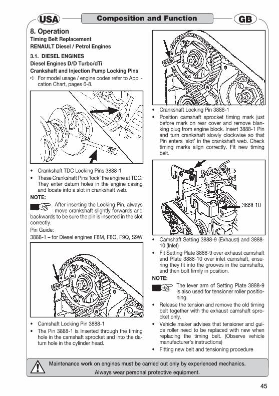
45
Maintenance work on engines must be carried out only by experienced mechanics.
Always wear personal protective equipment.
GBUSAOperation8.
Timing Belt ReplacementRENAULT Diesel / Petrol Engines
3.1. DIESEL ENGINESDiesel Engines D/D Turbo/dTiCrankshaft and Injection Pump Locking Pins
For model usage / engine codes refer to Appli- ➪cation Chart, pages 6-8.
Crankshaft TDC Locking Pins 3888-1• These Crankshaft Pins ‘lock’ the engine at TDC. • They enter datum holes in the engine casing and locate into a slot in crankshaft web.
NOTE:After inserting the Locking Pin, always move crankshaft slightly forwards and
backwards to be sure the pin is inserted in the slot correctly.Pin Guide:3888-1 – for Diesel engines F8M, F8Q, F9Q, S9W
Camshaft Locking Pin 3888-1• The Pin 3888-1 is Inserted through the timing • hole in the camshaft sprocket and into the da-tum hole in the cylinder head.
Crankshaft Locking Pin 3888-1• Position camshaft sprocket timing mark just • before mark on rear cover and remove blan-king plug from engine block. Insert 3888-1 Pin and turn crankshaft slowly clockwise so that Pin enters ‘slot’ in the crankshaft web. Check timing marks align correctly. Fit new timing belt.
Camshaft Setting 3888-9 (Exhaust) and 3888-• 10 (Inlet)Fit Setting Plate 3888-9 over exhaust camshaft • and Plate 3888-10 over inlet camshaft, ensu-ring they fit into the grooves in the camshafts, and then bolt firmly in position.
NOTE:The lever arm of Setting Plate 3888-9 is also used for tensioner roller positio-ning.
Release the tension and remove the old timing • belt together with the exhaust camshaft spro-cket only.Vehicle maker advises that tensioner and gui-• de roller need to be replaced with new when replacing the timing belt. (Observe vehicle manufacturer’s instructions)Fitting new belt and tensioning procedure•
Composition and Function
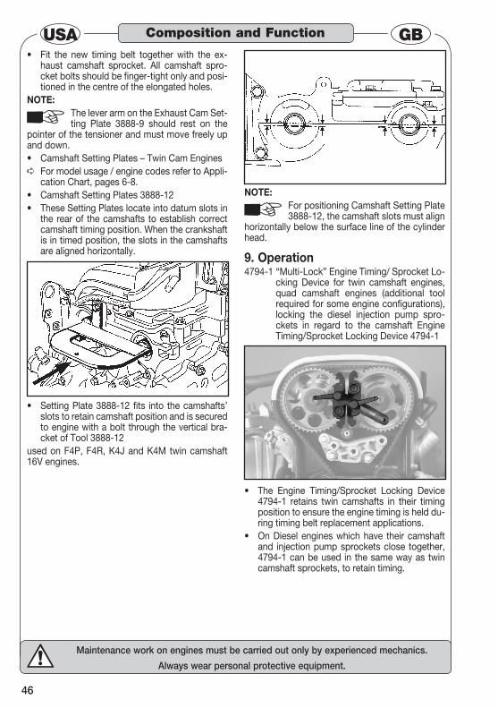
46
Maintenance work on engines must be carried out only by experienced mechanics.
Always wear personal protective equipment.
USA GBFit the new timing belt together with the ex-• haust camshaft sprocket. All camshaft spro-cket bolts should be finger-tight only and posi-tioned in the centre of the elongated holes.
NOTE:The lever arm on the Exhaust Cam Set-ting Plate 3888-9 should rest on the
pointer of the tensioner and must move freely up and down.
Camshaft Setting Plates – Twin Cam Engines• For model usage / engine codes refer to Appli- ➪cation Chart, pages 6-8.Camshaft Setting Plates 3888-12• These Setting Plates locate into datum slots in • the rear of the camshafts to establish correct camshaft timing position. When the crankshaft is in timed position, the slots in the camshafts are aligned horizontally.
Setting Plate 3888-12 fits into the camshafts’ • slots to retain camshaft position and is secured to engine with a bolt through the vertical bra-cket of Tool 3888-12
used on F4P, F4R, K4J and K4M twin camshaft 16V engines.
NOTE:For positioning Camshaft Setting Plate 3888-12, the camshaft slots must align
horizontally below the surface line of the cylinder head.
Operation9. 4794-1 “Multi-Lock” Engine Timing/ Sprocket Lo-
cking Device for twin camshaft engines, quad camshaft engines (additional tool required for some engine configurations), locking the diesel injection pump spro-ckets in regard to the camshaft Engine Timing/Sprocket Locking Device 4794-1
The Engine Timing/Sprocket Locking Device • 4794-1 retains twin camshafts in their timing position to ensure the engine timing is held du-ring timing belt replacement applications.On Diesel engines which have their camshaft • and injection pump sprockets close together, 4794-1 can be used in the same way as twin camshaft sprockets, to retain timing.
Composition and Function
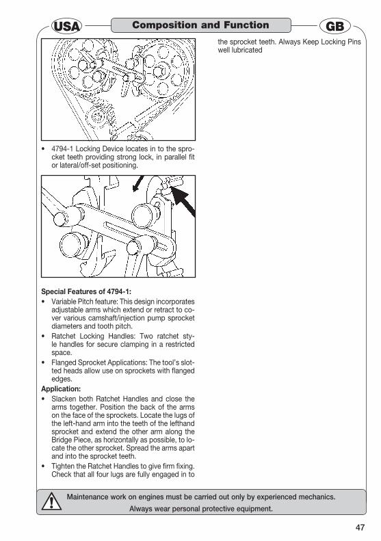
47
Maintenance work on engines must be carried out only by experienced mechanics.
Always wear personal protective equipment.
GBUSA
4794-1 Locking Device locates in to the spro-• cket teeth providing strong lock, in parallel fit or lateral/off-set positioning.
Special Features of 4794-1:Variable Pitch feature: This design incorporates • adjustable arms which extend or retract to co-ver various camshaft/injection pump sprocket diameters and tooth pitch.Ratchet Locking Handles: Two ratchet sty-• le handles for secure clamping in a restricted space.Flanged Sprocket Applications: The tool’s slot-• ted heads allow use on sprockets with flanged edges.
Application:Slacken both Ratchet Handles and close the • arms together. Position the back of the arms on the face of the sprockets. Locate the lugs of the left-hand arm into the teeth of the lefthand sprocket and extend the other arm along the Bridge Piece, as horizontally as possible, to lo-cate the other sprocket. Spread the arms apart and into the sprocket teeth.Tighten the Ratchet Handles to give firm fixing. • Check that all four lugs are fully engaged in to
the sprocket teeth. Always Keep Locking Pins well lubricated
Composition and Function

48
Pracovní úkony mohou vykonávat pouze vyškolení pracovníci, na základě pracovních postupů stanovených výrobcem vozu.Při práci vždy používejte ochranné pomůcky.
CZVážený zákazníku, zvolili jste dobře, protože před vámi leží kva-litní produkt HAZET, který dokáže optimalizovat vaše pracovní pos-tupy.
Všeobecné informace 1. Zajistěte prosím, aby si uživatel tohoto nářadí • důkladně pročetl a pochopil předložený pro-vozní návod před prvním uváděním nářadí do provozu.Tento provozní návod obsahuje důležité pokyny, • které jsou nutné pro bezpečný a bezporuchový provoz vašeho nářadí HAZET. Do použití nářadí odpovídající určení patří • kompletní dodržování všech bezpečnostních pokynů a informací v tomto provozním návodu. Uložte si proto tento provozní návod vždy u • vašeho nářadí HAZET. Toto nářadí bylo vyvinuto pro určené použití. • Firma HAZET výslovně poukazuje na to, že toto nářadí se nesmí upravovat a/nebo používat způsobem, který neodpovídá určenému účelu použití. Firma HAZET nepřebírá žádné ručení nebo • záruku za zranění nebo poškození vyplývající z neodborného a účelu neodpovídajícího použití popř. v důsledku nedodržení bezpečnostních předpisů. Kromě toho je pro oblast použití nářadí nut-• né dodržovat platné bezpečnostní předpisy a všeobecná bezpečnostní ustanovení.
Vysvětlení symbolů2. POZOR: Věnujte tomuto symbolu nejvyšší po-
zornost! Přečtěte si provozní návod!
Provozovatel je povinen dbát na tento provozní návod a poučit všechny uživatele nářadí podle tohoto provoz-ního návodu.
POKYN!Tento symbol označuje pokyny, které vám usnadní použití.
VAROVÁNÍ! Tento symbol označuje důležité popi-sy, podmínky ohrožení, bezpečnostní rizika popř. bezpečnostní pokyny.
POZOR!Tento symbol označuje pokyny, jejichž nedodržení může mít za následek poškození, chybnou funkci a/nebo zničení nářadí.
KLIKOVÁ HŘÍDEL/SETRVAČNÍK
Tento obrázek označuje nářadí, které se má použít u udaného vozidla pro zajištění klikové hřídele/setrvačníku.
VAČKOVÁ HŘÍDEL Tento obrázek označuje nářadí, které se má použít u udaného vozidla pro zajištění vačkové hřídele.
VSTŘIKOVACÍ ČERPADLO Tento obrázek označuje nářadí, které se má použít u udaného vozidla pro zajištění vstřikovacího čerpadla vznětového motoru.
NAPÍNACÍ KLADKA OZUBENÉHO ŘEMENUTento obrázek označuje nářadí, které se má použít u udaného vozidla pro ovládání napínací kladky ozubeného řemenu.
DRŽÁK ZÁMKU Tento obrázek označuje nářadí, které se má použít u udaného vozidla pro demontáž a montáž držáku zámkuk.
Pro vaši informaci
49
Pracovní úkony mohou vykonávat pouze vyškolení pracovníci, na základě pracovních postupů stanovených výrobcem vozu.Při práci vždy používejte ochranné pomůcky.
CZRučení a záruka3.
Jakékoliv použití přesahující použití odpovídající účelu a/nebo jakékoliv jiné použití je zakázáno a platí jako neodpovídající účelu.
Vyloučeny jsou nároky jakéhokoliv druhu vůči • výrobci a/nebo zplnomocněným osobám v důsledku škod vyplývajících z použití neodpo-vídajícího účelu. Za veškeré škody způsobené použitím neodpo-• vídajícím účelu ručí pouze provozovatel.
Náhradní díly 4. Používat se smějí pouze originální náhradní • díly výrobce. Špatné nebo chybné náhradní díly mohou vést • k poškození, chybné funkci nebo k celkovému zničení nářadí. Při použití neuvolněných náhradních dílů zani-• kají veškeré nároky na záruku, servis, náhrad škod a povinné ručení vůči výrobci a pověřeným stranám, prodejcům a zástupcům.
Likvidace 5. Pro vyřazení z provozu je nutné zařízení vyčistit • a rozebrat je při dodržení platných pracovních předpisů a předpisů pro ochranu životního prostředí. Díly je nutné předat do systému re-cyklování.Kovové zbytky materiálu je nutné sešrotovat. • Pro snižování zatěžování životního prostředí a • ekologické chování stojí vždy ve středu pozor-nosti našich aktivit!
Pro vaši informaci

50
Pracovní úkony mohou vykonávat pouze vyškolení pracovníci, na základě pracovních postupů stanovených výrobcem vozu.Při práci vždy používejte ochranné pomůcky.
CZTento odstavec udává přehled o všech důležitých bezpečnostních aspektech pro optimální ochranu personálu a o bezpečném a bezporuchovém provo-
zu nářadí. Jednotlivé kapitoly kromě toho přídavně obsahují konkrétní bezpečnostní pokyny pro odv-rácení bezprostředního ohrožení, které jsou označeny příslušnými symboly.
Všeobecné 1. Nářadí je konstruováno v okamžiku svého vývoje a výroby podle platných a uznávaných pravidel techniky a je provozně bezpečné. Z nářadí však
může vyplývat určité ohrožení, pokud je používáno neodborně, nevyškoleným personálem nebo po-kud je používáno v rozporu s určením. Každá oso-ba pověřená prací s tímto nářadím nebo na tomto nářadí si proto musí přečíst před začátkem práce tento provozní návod a pochopit jej.
Zakázány jsou změny jakéhokoliv druhu a jaké-• koliv nástavby a přestavby zařízení. Bezpodmínečně je nutné dodržovat udané nas-• tavovací hodnoty nebo rozsahy.
Zodpovědnost provozovatele 2. Provozní návod je vždy nutné uložit v • bezprostřední blízkosti nářadí. Toto nářadí smí používat pouze odborníci. • Nářadí se smí provozovat pouze v technicky • bezchybném a provozně bezpečném stavu. Bezpečnostní zařízení je vždy nutné udržovat • tak, aby byla volně dosažitelná a tato zařízení je nutné pravidelně kontrolovat. Vedle pokynů pro bezpečnost práce udaných • v tomto provozním návodu je nutné dbát a dodržovat také pro oblast použití všeobecně platné bezpečnostní předpisy, předpisy pre-vence úrazů a ekologické předpisy.
Tento návod udává pouze některé pokyny. Vždy zajistěte, aby byly k dispozici vhodné servisní pokyny výrobce vozidla nebo příslušná
příručka, ze které by bylo možné převzít správ-ná data pro předpisové provedení práce.
Použití odpovídající účelu Použití 3. Provozní bezpečnost je zaručena pou-ze při použití odpovídajícím účelu dle údajů v provozním návodu. Vedle pokynů pro provozní bezpečnost v
tomto provozním návodu je nutné vždy dbát a dodržovat pro oblast použití nářadí platné všeobecné bezpečnostní předpisy, předpisy pro prevenci úrazů a předpisy pro ochranu životního prostředí.
Nářadí HAZET je určeno pro výměnu ozu-• bených řemenů u vznětových a zážehových motorů. Při neodborném použití tohoto nářadí nebo • při použití neodpovídajícím bezpečnostním pokynům může dojít k závažným zraněním nebo ke smrtelným úrazům. Jakékoliv použití přesahující určený účel a/• nebo jiné použití nářadí je zakázáno a platí jako neodpovídající určení. Vyloučeny jsou nároky jakéhokoliv druhu vůči • výrobci a/nebo zplnomocněným zástupcům v důsledku poškození vzniklých z použití neod-povídajícího účelu. Za veškeré škody vzniklé účelu neodpovída-• jícím použitím ručí pouze provozovatel.
Uložení / skladování 4.
Nářadí je nutné uložit a skladovat za následujících podmínek:
Nářadí skladovat na suchém místě bez • prachu. Nářadí se nesmí vystavit žádným kapalinám a/• nebo agresivním látkám. Nářadí se nesmí ukládat na volném prostran-• ství. Nářadí nesmí být přístupné dětem. • Skladovací teplota -10°C až +40°C. • Relativní vlhkost vzduchu max. 60 %. •
Pro vaši bezpečnost
51
Pracovní úkony mohou vykonávat pouze vyškolení pracovníci, na základě pracovních postupů stanovených výrobcem vozu.Při práci vždy používejte ochranné pomůcky.
CZRizika vyplývající ze zařízení 1.
Před každým použitím je nutné u nářadí HAZET pro nastavování motoru překontrolovat jeho kompletní funkce-schopnost a poškození. Pokud není
zaručena funkceschopnost na základě výsledků této kontroly, nebo když se zjistí poškození nářadí, tak se nářadí nesmí použít. Pokud není zaručena kompletní funkceschopnost a nářadí se přesto použije, vzniká riziko závažného zranění, poškození zdraví a věcných škod. Vadné nářadí může způsobit těžká zranění. Pro ochranu před poškozením je nutné dbát na následující základní bezpečnostní opatření:POZOR:
Chybné nastavení rozvodů může vést ke kontaktu mezi pístem a ven-tily a tím k poškození motoru. Proto vždy zajistěte, aby se použilo správ-
né nářadí a postupovalo se podle pokynů výrobce vozidla.
Před zahájením práce odpojit mínusový pól • akumulátoru.
POKYN: Před odpojením akumulátoru zajistěte, aby majitel vozidla věděl kód svého au-torádia.
Každé „podepřené“ nebo nad zem zvednuté • vozidlo musí být přiměřeně zajištěno nápravo-vými stojánky, rampami atd. Při práci noste vždy přiléhavý pracovní oděv a • používejte ochranné brýle. Motory mají točící se komponenty, které by mohly zachytit volné díly oděvu, šperky atd. Vždy jste zodpovědni za vámi používané • nářadí. Nenechávejte nikdy nářadí v motoru nebo ležet na motoru když je motor v pohybu, nebo když se ukončí práce. Volné díly by mohly být vymrštěny a mohly by zranit nebo usmrtit osoby v okolí, nebo by mohlo dojít k poškození okolních předmětů. Zajišťovací trny, aretační kolíky/přípravky • nepoužívejte k blokování klikové hřídele při povolování nebo utahování šroubu klikové hřídele. Nepoužívejte ozubený řemen k blokování • řemenice vačkové hřídele, když se uvolňuje šroubení. Ozubený řemen nesmíte zlomit, otočit a ohýbat • v poloměru pod 25 mm. Pro nasazování ozubeného řemenu nikdy •
nepoužívat páky a násilí. U napínacích kladek, vodících kladek a vodního • čerpadla vždy překontrolovat jejich volný chod. U motoru překontrolovat těsnost a případně od-• stranit netěsnosti. Při výměně ozubeného řemenu použít vždy • pouze nový ozubený řemen se správným ozu-bením. Správně nastavit napnutí ozubeného řemenu • (dodržovat údaje výrobce). Dodržet předepsané utahovací momenty • (dodržovat údaje výrobce). Dbát na směr otáčení ozubeného řemenu • udaný šipkou. Použité ozubené řemeny nikdy znovu • nepoužívat, vždy použít nový ozubený řemen. Ozubený řemen vyměnit při jakémkoliv znaku • opotřebení jako jsou prodřená místa, trhliny nebo poškození a silné znečištění (např. ole-jem). Při poškození ozubeného řemenu zjistit příčinu • a tuto odstranit. Pro čištění ozubeného řemenu nepoužívat • žádná rozpouštědla jako jsou ředidla, benzín atd. V případě pochybností vyměnit ozubený řemen. Ozubený řemen za účelem kontroly neotáčet. • Motorem otáčet pouze v normálním směru • otáčení, pokud opačné otáčení není předepsáno výrobcem. Použijte pouze výrobcem doporučené díly, • upevnění a příslušenství. Opravy nechat provádět pouze autorizovaným • osobám. Nářadí používat pouze v těch místech, které • je určeno a předepsáno platnými předpisy pro pracovní oblast. Z bezpečnostních důvodů je zakázáno provádět • jakékoliv změny u nářadí HAZET. Provedení úprav nářadí vede k okamžitému ukončení ručení.
Pro vaši bezpečnost
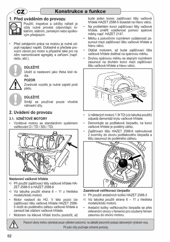
52
Pracovní úkony mohou vykonávat pouze vyškolení pracovníci, na základě pracovních postupů stanovených výrobcem vozu.Při práci vždy používejte ochranné pomůcky.
CZPřed uváděním do provozu 1.
Použití, inspekce a údržby nářadí je vždy nutné provést odpovídajíc lo-kálním, státním, zemským nebo spolko-vým předpisům.
Před zahájením práce na motoru je nutné od-• pojit napájecí napětí. Důkladně si přečtete pro-vozní návod pro motor a případně také pro na něm namontované agregáty a zařízení (např. rádio, atd.).
DŮLEŽITÉ Uložit si nastavení jako třeba kód rá-dia. POZOR Zvednuté vozidlo je nutné zajistit proti pádu.
DŮLEŽITÉ Smějí se používat pouze vhodné náhradní díly.
Uvádeni do provozu 2. VZNĚTOVÉ MOTORY 3.1.
Vznětové motory se standardním systémem • vstřikování D / TD / SDi / TDi
Nastavení vačkové hřídele Při použití zajišťovací lišty vačkové hřídele HA- ➪ZET 2588-5 a HAZET 2588-6 Viz tabulka použití strana 6 – 11 z hlediska ➪modelů/kódů motorů Motor nastavit do HÚ. V této pozici lze • zajišťovací lištu vačkové hřídele HAZET 2588-5 vložit do podélného zářezu vačkové hřídele a zamezit tak otáčení vačkové hřídele. Motorem na klikové hřídeli trochu pootočit, až •
bude jeden konec zajišťovací lišty vačkové hřídele HAZET 2588-5 dosedat na hlavu válců. Na protilehlém konci zajišťovací lišty vačkové • hřídele změřit vzádlenost pomocí spárové měrky např. HAZET 2147. Měrku s polovičním rozměrem vzdálenosti za-• sunout mezi zajišťovací lištu vačkové hřídele a hlavu válců. Otáčet motorem, až bude zajišťovací lišta • vačkové hřídele doléhat na spárovou měrku. Druhou spárovou měrku se stejným rozměrem • zasunout na druhém konci mezi zajišťovací lištu vačkové hřídele a hlavu válců.
U některých motorů 1.9l TDi (viz tabulka použití) • odpadá demontáž krytu vačkové hřídele. Demontujte se podtlakové čerpadlo, na konci • vačkové hřídele je podélný zářez. Zajišťovací lištu HAZET 2588-6 našroubovat • 2 svorníky do otvoru podtlakového čerpadla a lištu zasunout do podélného zářezu.
Zaaretovat vstřikovací čerpadloPři použití aretačních kolíků HAZET 2588-3 ➪
Viz tabulka použití strana 6 – 11 z hlediska ➪modelů/kódů motorů Aretační kolíky vstřikovacího čerpadla se přes • referenční otvory v řemenici pro ozubený řemen zasunou do otvorů motoru.
Konstrukce a funkce

53
Pracovní úkony mohou vykonávat pouze vyškolení pracovníci, na základě pracovních postupů stanovených výrobcem vozu.Při práci vždy používejte ochranné pomůcky.
CZVymezovací kolík 2588-3 se použije, pokud • je montována 2dílná řemenice ozubených řemenů. Tyto řemenice ozubených řemenů jsou zajištěny 3 šrouby. Vymezovací kolíky se vkládají přes držák do referenčních otvorů v motoru.
Nastavení ozubeného řemenu / napnutí ozube-ného řemenu
Viz tabulka použití strana 6 – 11 z hlediska ➪modelů/kódů motorů
Aretace klikové hřídele
Nářadí pro aretaci klikové hřídele 2588-1Kliková hřídel se otáčí ve směru hodinových • ručiček na značku, potom se v této poloze „zafi-xuje“ řemenice klikové hřídele pomocí zarážky klikové hřídele 2588-1. Nářadí se zasune z čelní strany řemenice klikové hřídele do ozu-bení, aby čep nářadí 2588-1 zapadal do těsnicí příruby (otvor).
POZOR:Šipka nastavovací značky na zarážce klikové hřídele 2588-1 MUSÍ být nas-
tavena na značku na řemenici klikové hřídele. Pokud je omezen výhled na značky, demontujte přechodně otočnou hlavici nářadí pro zlepšení vi-
ditelnosti.
Nastavení vačkové hřídele / fixace Seřízení vačkové hřídele-nastavovací značky
Značka na kole vačkové hřídele (za zuby ozu-• beného kola) musí souhlasit se značkou na od-litku –“3Z“ (vlevo) u 3válcových motorů popř. “4Z“ (vpravo) u 4válcových motorů se systé-mem čerpadlo-tryska. Vačková hřídel je v této pozici fixována vymezovacím kolíkem 2588-3 v podélném zářezu na levé straně kola vačkové hřídele. Po nasazení aretačního nářadí lze uvolnit napnutí řemenu a demontovat starý ozubený řemen. Nyní lze uvolnit 3 šrouby řemenice ozubené-• ho řemenu, aby bylo možné přestavit řemenici ozubeného řemenu.
Zajištění klikové hřídele
Aretační nářadí pro zajištění klikové hřídele 2588-1
Viz čerpadlo-trysko 1.2l,1.4l a 1.9l TDi / sekce ➪čerpadlo-tryska.
Nastavení vačkové hřídele – dvě nahoře umístěné vačkové hřídele
Konstrukce a funkce
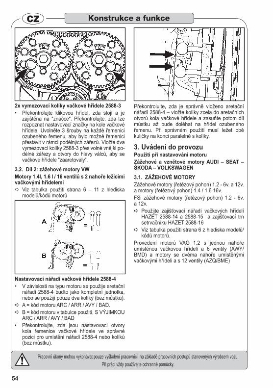
54
Pracovní úkony mohou vykonávat pouze vyškolení pracovníci, na základě pracovních postupů stanovených výrobcem vozu.Při práci vždy používejte ochranné pomůcky.
CZ
2x vymezovací kolíky vačkové hřídele 2588-3 Překontrolujte klikovou hřídel, zda stojí a je • zajištěna na “značce“. Překontrolujte, zda lze rozpoznat nastavovací značky na kole vačkové hřídele. Uvolněte 3 šrouby na každé řemenici ozubeného řemenu, aby bylo možné řemenici přestavit v rámci podélných zářezů. Vložte dva vymezovací kolíky 2588-3 přes volné vnější po-délné zářezy a otvory do hlavy válců, aby se vačkové hřídele “zaaretovaly“.
Díl 2: zážehové motory VW3.2. Motory 1.4l, 1.6 l / 16 ventilů s 2 nahoře ležícími vačkovými hřídelemi
Viz tabulka použití strana 6 – 11 z hlediska ➪modelů/kódů motorů
Nastavovací nářadí vačkové hřídele 2588-4 V závislosti na typu motoru se použije aretační • nářadí 2588-4 buďto jako kompletní jednotka, nebo se použijí pouze dva kolíky (bez můstku).A = kód motoru ARC / ARR / AVY / BAD. ➪
B = kód motoru v tabulce použití, S VÝJIMKOU ➪ARC / ARR / AVY / BAD Překontrolujte, zda jsou nastavovací otvory • kola řemenice vačkové hřídele ve správné pozici pro umístění nářadí 2588-4 nebo kolíků (bez můstku).
Překontrolujte, zda je správně vloženo aretační nářadí 2588-4 – vložte kolíky zcela do aretačních otvorů kola vačkové hřídele a zasuňte potom díl můstku až bude doléhat na hřídel ozubeného řemenu. Při správném použití musí ležet obě kuličky na konci paralelně s kolíky.
Uvádeni do provozu 3. Použití při nastavování motoruZážehové a vznětové motory AUDI – SEAT – ŠKODA – VOLKSWAGEN 3.1. ZÁŽEHOVÉ MOTORYZážehové motory (řetězový pohon) 1.2 - 6v. a 12v. a motory (řetězový pohon) 1.4 / 1.6 16v. FSi zážehové motory (řetězový pohon) 1.2 - 6v. a 12v.
Použijte zajišťovací nářadí vačkových hřídelí ➪HAZET 2588-14 a 2588-15 a zajišťovací trn setrvačníku HAZET 2588-16 Viz tabulka použití strana 6 z hlediska modelů/ ➪kódů motorů.
Provedení motorů VAG 1.2 s jednou nahoře umístěnou vačkovou hřídelí a 6 ventily (AWY/BMD) a motory se dvěma nahoře umístěnými vačkovými hřídeli a s 12 ventily (AZQ/BME)
Konstrukce a funkce
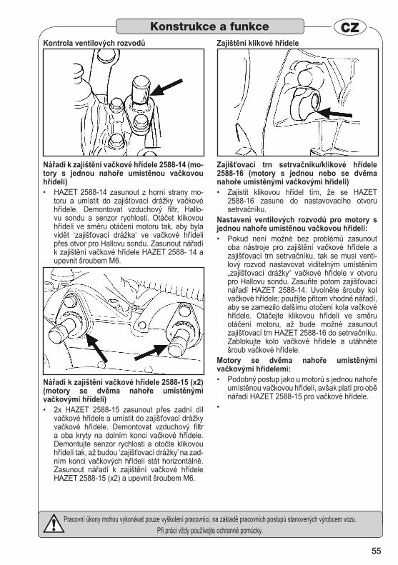
55
Pracovní úkony mohou vykonávat pouze vyškolení pracovníci, na základě pracovních postupů stanovených výrobcem vozu.Při práci vždy používejte ochranné pomůcky.
CZKontrola ventilových rozvodů
Nářadí k zajištění vačkové hřídele 2588-14 (mo-tory s jednou nahoře umístěnou vačkovou hřídelí)
HAZET 2588-14 zasunout z horní strany mo-• toru a umístit do zajišťovací drážky vačkové hřídele. Demontovat vzduchový filtr, Hallo-vu sondu a senzor rychlosti. Otáčet klikovou hřídelí ve směru otáčení motoru tak, aby byla vidět ‘zajišťovací drážka‘ ve vačkové hřídeli přes otvor pro Hallovu sondu. Zasunout nářadí k zajištění vačkové hřídele HAZET 2588- 14 a upevnit šroubem M6.
Nářadí k zajištění vačkové hřídele 2588-15 (x2) (motory se dvěma nahoře umístěnými vačkovými hřídeli)
2x HAZET 2588-15 zasunout přes zadní díl • vačkové hřídele a umístit do zajišťovací drážky vačkové hřídele. Demontovat vzduchový filtr a oba kryty na dolním konci vačkové hřídele. Demontujte senzor rychlosti a otočte klikovou hřídelí tak, až budou ‘zajišťovací drážky’ na zad-ním konci vačkových hřídelí stát horizontálně. Zasunout nářadí k zajištění vačkové hřídele HAZET 2588-15 (x2) a upevnit šroubem M6.
Zajištění klikové hřídele
Zajišťovací trn setrvačníku/klikové hřídele 2588-16 (motory s jednou nebo se dvěma nahoře umístěnými vačkovými hřídeli)
Zajistit klikovou hřídel tím, že se HAZET • 2588-16 zasune do nastavovacího otvoru setrvačníku.
Nastavení ventilových rozvodů pro motory s jednou nahoře umístěnou vačkovou hřídelí:
Pokud není možné bez problémů zasunout • oba nástroje pro zajištění vačkové hřídele a zajišťovací trn setrvačníku, tak se musí venti-lový rozvod nastavovat viditelným umístěním „zajišťovací drážky“ vačkové hřídele v otvoru pro Hallovu sondu. Zasuňte potom zajišťovací nářadí HAZET 2588-14. Uvolněte šrouby kol vačkové hřídele; použijte přitom vhodné nářadí, aby se zamezilo dalšímu otočení kola vačkové hřídele. Otáčejte klikovou hřídelí ve směru otáčení motoru, až bude možné zasunout zajišťovací trn HAZET 2588-16 do setrvačníku. Zablokujte kolo vačkové hřídele a utáhněte šroub vačkové hřídele.
Motory se dvěma nahoře umístěnými vačkovými hřídelemi:
Podobný postup jako u motorů s jednou nahoře • umístěnou vačkovou hřídelí, avšak platí pro obě nářadí HAZET 2588-15 pro vačkové hřídele.
•
Konstrukce a funkce
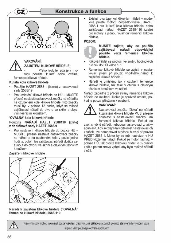
56
Pracovní úkony mohou vykonávat pouze vyškolení pracovníci, na základě pracovních postupů stanovených výrobcem vozu.Při práci vždy používejte ochranné pomůcky.
CZVložit zajišťovací nářadí a potom uvolnit oba • šrouby kol vačkových hřídelí. Použijte k tomu vhodné nářadí, aby se zamezilo pootočení kol vačkové hřídele. Pootočit klikovou hřídelí, až bude možné zasunout zajišťovací trn setrvačníku HAZET 2588-16. Je nutné zamezit pootočení kol vačkových hřídelí během utaho-vání šroubů kol vačkových hřídelí.
VAROVÁNÍ: ZAJIŠTĚNÍ KLIKOVÉ HŘÍDELE:
Překontrolujte, zda je v mo-• toru použita ‘kulatá’ nebo ‘oválná’
řemenice klikové hřídele. Kulatá kola klikové hřídele
Použijte HAZET 2588-1 (černá) z nastavovací • sady 2588/19 Pro umístění klikové hřídele do HÚ – MUSÍTE • přesně nastavit nastavovací značky na nářadí a na ozubeném kole klikové hřídele, tyto značky musí být v poloze 12 hodin, když se vkládá zajišťovací nářadí do otvoru ve skříni s olejo-vým těsnicím kroužkem.
‘OVÁLNÁ’ kola klikové hřídele Použijte NÁŘADÍ HAZET 2588110 (zlaté) z doplňkové sady HAZET 2588/9
Pro nastavení klikové hřídele do pozice HÚ – • MUSÍTE přesně nastavit nastavovací značky na nářadí a na ozubeném kole v pozici jedna hodina, potom lze zajišťovací nářadí vložit a za-sunout do otvoru ve skříni s olejovým těsnicím kroužkem.
Zajišťení klikové hřídele
Nářadí k zajištění klikové hřídele (“OVÁLNÁ” řemenice klikové hřídele) 2588-110
Existují dva typy kol klikových hřídelí v mode-• lové paletě motorů čerpadlo-tryska. HAZET 2588-1 pro ‘kulatá’ kola klikové hřídele, nebo zajišťovací nářadí HAZET 2588-110 (zlaté) pro motory s jednou ‘oválnou’ řemenicí klikové hřídele.
POZOR:MUSÍTE zajistit, aby se použilo zajišťovací nářadí odpovídající použité verzi řemenice klikové hřídele.
Kliková hřídel se pootočí ve směru hodinových • ručiček do HÚ válce č. 1.Řemenice klikové hřídele se zajistí v nasta-• vovací pozici při použití vhodného nářadí k zajištění klikové hřídele.Nářadí je umístěno jak v ozubení řemenice • klikové hřídele, tak také v otvoru s olejovým těsnicím kroužkem ve skříni.
Nářadí zapadne z přední strany řemenice klikové hřídele do ozubení. Nelze je správně umístit, po-kud je pouze přiloženo k ozubení.
VAROVÁNÍ: Nastavovací značka “šipka” na nářadí k zajištění klikové hřídele MUSÍ přesně souhlasit s nastavovací značkou na řemenici klikové hřídele. Pokud se
zvolí chybné nářadí, nebudou nastavovací značky souhlasit. Aby se zlepšila viditelnost nastavovacích značek, lze demontovat otočnou hlavici přípravku HAZET 2588-1. Motor by se měl nacházet v HÚ PŘED vložením nářadí. Pokud se motor nachází v poloze HÚ, tak otočte klikovou hřídelí o ¼ otáčky zpět a potom znovu vpřed, aby bylo možné nářadí vložit.
Konstrukce a funkce
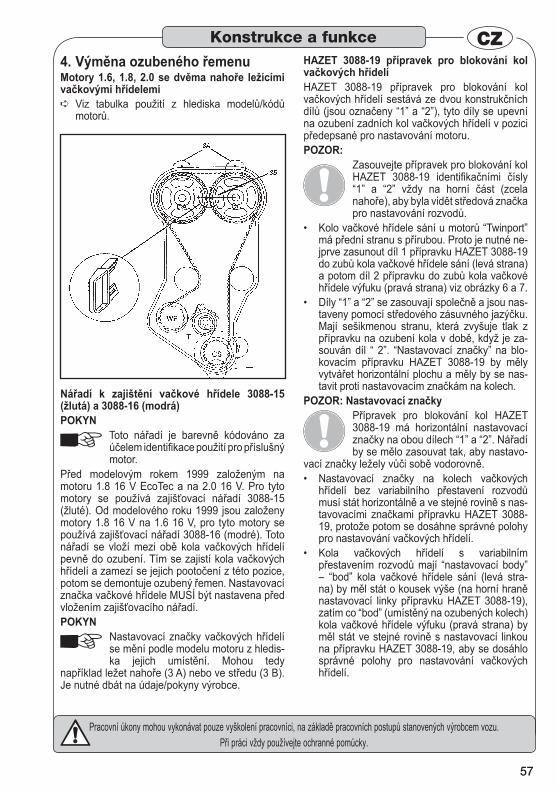
57
Pracovní úkony mohou vykonávat pouze vyškolení pracovníci, na základě pracovních postupů stanovených výrobcem vozu.Při práci vždy používejte ochranné pomůcky.
CZVýměna ozubeného řemenu 4.
Motory 1.6, 1.8, 2.0 se dvěma nahoře ležícími vačkovými hřídelemi
Viz tabulka použití z hlediska modelů/kódů ➪motorů.
Nářadí k zajištění vačkové hřídele 3088-15 (žlutá) a 3088-16 (modrá) POKYN
Toto nářadí je barevně kódováno za účelem identifikace použití pro příslušný motor.
Před modelovým rokem 1999 založeným na motoru 1.8 16 V EcoTec a na 2.0 16 V. Pro tyto motory se používá zajišťovací nářadí 3088-15 (žluté). Od modelového roku 1999 jsou založeny motory 1.8 16 V na 1.6 16 V, pro tyto motory se používá zajišťovací nářadí 3088-16 (modré). Toto nářadí se vloží mezi obě kola vačkových hřídelí pevně do ozubení. Tím se zajistí kola vačkových hřídelí a zamezí se jejich pootočení z této pozice, potom se demontuje ozubený řemen. Nastavovací značka vačkové hřídele MUSÍ být nastavena před vložením zajišťovacího nářadí. POKYN
Nastavovací značky vačkových hřídelí se mění podle modelu motoru z hledis-ka jejich umístění. Mohou tedy
například ležet nahoře (3 A) nebo ve středu (3 B). Je nutné dbát na údaje/pokyny výrobce.
HAZET 3088-19 přípravek pro blokování kol vačkových hřídelíHAZET 3088-19 přípravek pro blokování kol vačkových hřídelí sestává ze dvou konstrukčních dílů (jsou označeny “1” a “2”), tyto díly se upevní na ozubení zadních kol vačkových hřídelí v pozici předepsané pro nastavování motoru.POZOR:
Zasouvejte přípravek pro blokování kol HAZET 3088-19 identifikačními čísly “1” a “2” vždy na horní část (zcela nahoře), aby byla vidět středová značka pro nastavování rozvodů.
Kolo vačkové hřídele sání u motorů “Twinport” • má přední stranu s přírubou. Proto je nutné ne-jprve zasunout díl 1 přípravku HAZET 3088-19 do zubů kola vačkové hřídele sání (levá strana) a potom díl 2 přípravku do zubů kola vačkové hřídele výfuku (pravá strana) viz obrázky 6 a 7.Díly “1” a “2” se zasouvají společně a jsou nas-• taveny pomocí středového zásuvného jazýčku. Mají sešikmenou stranu, která zvyšuje tlak z přípravku na ozubení kola v době, když je za-souván díl “ 2”. “Nastavovací značky” na blo-kovacím přípravku HAZET 3088-19 by měly vytvářet horizontální plochu a měly by se nas-tavit proti nastavovacím značkám na kolech.
POZOR: Nastavovací značkyPřípravek pro blokování kol HAZET 3088-19 má horizontální nastavovací značky na obou dílech “1” a “2”. Nářadí by se mělo zasouvat tak, aby nastavo-
vací značky ležely vůči sobě vodorovně.Nastavovací značky na kolech vačkových • hřídelí bez variabilního přestavení rozvodů musí stát horizontálně a ve stejné rovině s nas-tavovacími značkami přípravku HAZET 3088-19, protože potom se dosáhne správné polohy pro nastavování vačkových hřídelí. Kola vačkových hřídelí s variabilním • přestavením rozvodů mají “nastavovací body” – “bod” kola vačkové hřídele sání (levá stra-na) by měl stát o kousek výše (na horní hraně nastavovací linky přípravku HAZET 3088-19), zatím co “bod” (umístěný na ozubených kolech) kola vačkové hřídele výfuku (pravá strana) by měl stát ve stejné rovině s nastavovací linkou na přípravku HAZET 3088-19, aby se dosáhlo správné polohy pro nastavování vačkových hřídelí.
Konstrukce a funkce

58
Pracovní úkony mohou vykonávat pouze vyškolení pracovníci, na základě pracovních postupů stanovených výrobcem vozu.Při práci vždy používejte ochranné pomůcky.
CZUvádění do provozu 5.
Výměna ozubeného řemenu Vznětové/zážehové motory u FORD 3.1. VZNĚTOVÉ MOTORY
Odstavec 1A: 1,8l D / TD / TCi vznětové Fiesta, • Courier, Escort , Orion, Mondeo
Nastavení vačkové hřídele 3488-1Viz tabulka použití z hlediska modelů/kódů ➪motorů.
Motor nastavit do HÚ. • V této pozici lze zajišťovací lištu vačkové • hřídele HAZET 3488-1 vložit do podélného zářezu vačkové hřídele a zamezit tak otáčení vačkové hřídele.
Zajištění klikové hřídele Viz tabulka použití z hlediska modelů/kódů ➪motorů. Vyšroubovat závitovou zátku na motoru a až • na doraz zašroubovat vodící kolík pro klikovou hřídel v HÚ 3488-4
POZOR:
Při zašroubování vodícího kolíku pro HÚ se motorem nesmí otáčet!
Klikovou hřídelí opatrně otočit dále, až rame-• no kliky dosedne na vodící kolík klikové hřídele v HÚ 3488-4.
POZOR:Aretační kolíky a vodicí kolíky jako 3488-4 NEJSOU vhodné pro blokování klikové hřídele, pro uvolňování popř. utahování upevňovacích šroubů kliko-vé hřídele!
Pro přidržení použijte prosím běžné obchodní • nářadí.
3.2. ZÁŽEHOVÉ MOTORY se 16 ventily s dvojitou nahoře umístěnou vačkovou hřídelí
Nastavení vačkové hřídeleViz tabulka použití z hlediska modelů/kódů motorů.
Zajišťovací lišta vačkové hřídele 3488-1Zajišťovací lišta vačkové hřídele 3488-1 se • vloží do drážek vačkové hřídele a tím se zame-zí otáčení vačkové hřídele.
POZOR:Při výměně ozubeného řemenu je nut-né uvolnit šroubení kola vačkové hřídele, aby bylo možné volně na vačkové hřídeli otáčet řetězovým ko-
lem s ozubeným řemenem. Nastavovací nářadí a aretační kolíky se nesmějí používat pro přidržení při utahování!
Konstrukce a funkce

59
Pracovní úkony mohou vykonávat pouze vyškolení pracovníci, na základě pracovních postupů stanovených výrobcem vozu.Při práci vždy používejte ochranné pomůcky.
CZ
Zajištění klikové hřídeleViz tabulka použití z hlediska modelů/kódů ➪motorů.
Aretační kolík klikové hřídele pro pohon ozu-beného řemenu 3488-10, 3488-11:
1,25l, 1,4l, 1,6l Fiesta, Courier, Fusion, Puma, • Focus – použijte aretační kolík 3488-10. 1,6l Mondeo; 1,8l, 2,0l Focus, Mondeo, Cougar, • Connect – použijte aretační kolík 3488-11.
Pohon řetězového kola: 1,8l, 2,0l – bude potřebný aretační kolík 3488-• 10. Vyšroubovat šroubení na motoru a zašroubovat • až na doraz aretační kolík 3488-10. Klikovou hřídelí opatrně dále pootočit, až rameno kliky dolehne na aretační kolík 3488-10.
3.3. Odkazy na čísla nářadí FORD
Zajišťovací trny a čepy pro vačkovou hřídel a vstřikovací čerpadlo 3788-4, 3788-5, 3788-7, 3788-8 3788-9
Motory CITROËN a PEUGEOT mají nasta-• vovací otvory přes kola vačkových hřídelí a vstřikovacích čerpadel a pevné otvory v motoru. Tak lze vačkové hřídele a vstřikovací čerpadlo zajistit pomocí příslušných zajišťovacích trnů v nastavovací pozici.
Použití zajišťovacích trnů: DJ5, DKATE čerpadlo 3788-4TUD5 vačkové hřídele 3788-7 DJ5, DKATE, DJ5TED vačkové hřídele 3788-9DW8 čerpadlo 3788-5
Speciální klíč pro nastavení ozubeného řemenu na napínací kladce 3788-10 3788-10 je konst-ruován pro čtyřhran napínací kladky u motorů XUD11 a DK/DJ.
Odstavec 1 B: Common Rail HDi 6. Vznětové motory
Vznětové motory 1.4 HDi a 1.6 HDi Viz tabulka použití z hlediska modelů / kód mo- ➪toru Zajišťovací trn 3788-9 se používá pro zajištění •
Konstrukce a funkce
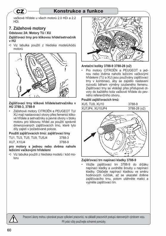
60
Pracovní úkony mohou vykonávat pouze vyškolení pracovníci, na základě pracovních postupů stanovených výrobcem vozu.Při práci vždy používejte ochranné pomůcky.
CZvačkové hřídele u všech motorů 2.0 HDi a 2.2 HDi.
Zážehové motory 7. Odstavec 2A: Motory TU / XU Zajišťovací trny pro klikovou hřídel/setrvačník v HÚ
Viz tabulka použití z hlediska modelů/kódů ➪motorů
Zajišťovací trny klikové hřídele/setrvačníku v HÚ 3788-3, 3788-9
Zážehové motory CITROËN a PEUGEOT TU/• XU mají nastavovací otvory přes řemenici kliko-vé hřídele a setrvačníku a pevné otvory v bloku motoru pro klikovou hřídel za použití správně dimenzovaných zajišťovacích trnů, které tyto díly zajistí v požadované poloze.
Použití zajišťovacích trnů: zajišťovací trny TU1, TU3, TU5, TU9, TU5J4 3788-3XU7, X10J4 3788-9pro motory s jednou nebo dvěma nahoře ležícími vačkovými hřídelemi
Viz tabulka použití z hlediska modelů / kód mo- ➪toru
Aretační kolíky 3788-9 3788-28 (x2) Pro motory CITROËN a PEUGEOT s jed-• nou nebo dvěma nahoře ležícími vačkovými hřídelemi (TU a XU) jsou používány zajišťovací trny v kombinaci, aby se zajistilo nastavení rozvodů během výměny ozubeného řemenu. Zajišťovací trny se vkládají přes přístupové ot-vory do každého kola vačkové hřídele do pev-ného referenčního otvoru.
Použití zajišťovacích trnů:XU5, TU9, XU10 3788-9XU7JP4, XU10JP4 3788-28 (x2)
Zajišťovací trn napínací kladky 3788-9 Vložte zajišťovací trn 3788-9 do držáku • napínací kladky a uvolněte šrouby u napínací kladky. Otáčejte napínací kladkou ve směru hodinových ručiček, až se ukazatel dotkne zajišťovacího trnu, potom utáhněte matici a vyjměte zajišťovací trn.
Konstrukce a funkce
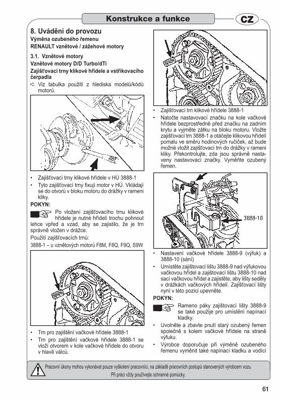
61
Pracovní úkony mohou vykonávat pouze vyškolení pracovníci, na základě pracovních postupů stanovených výrobcem vozu.Při práci vždy používejte ochranné pomůcky.
CZUvádění do provozu 8.
Výměna ozubeného řemenu RENAULT vznětové / zážehové motory
Vznětové motory 3.1. Vznětové motory D/D Turbo/dTi Zajišťovací trny klikové hřídele a vstřikovacího čerpadla
Viz tabulka použití z hlediska modelů/kódů ➪motorů.
Zajišťovací trny klikové hřídele v HÚ 3888-1 • Tyto zajišťovací trny fixují motor v HÚ. Vkládají • se do otvorů v bloku motoru do drážky v rameni kliky.
POKYN:Po vložení zajišťovacího trnu klikové hřídele je nutné hřídelí trochu pohnout
lehce vpřed a vzad, aby se zajistilo, že je trn správně vložen v drážce.Použití zajišťovacích trnů:3888-1 – u vznětových motorů F8M, F8Q, F9Q, S9W
Trn pro zajištění vačkové hřídele 3888-1 • Trn pro zajištění vačkové hřídele 3888-1 se • vloží otvorem v kole vačkové hřídele do otvoru v hlavě válců.
Zajišťovací trn klikové hřídele 3888-1 • Natočte nastavovací značku na kole vačkové • hřídele bezprostředně před značku na zadním krytu a vyjměte zátku na bloku motoru. Vložte zajišťovací trn 3888-1 a otáčejte klikovou hřídelí pomalu ve směru hodinových ručiček, až bude možné vložit zajišťovací trn do drážky v rameni kliky. Překontrolujte, zda jsou správně nasta-veny nastavovací značky. Vyměňte ozubený řemen.
Nastavení vačkové hřídele 3888-9 (výfuk) a • 3888-10 (sání) Umístěte zajištovací lištu 3888-9 nad výfukovou • vačkovou hřídel a zajištovací lištu 3888-10 nad sací vačkovou hřídel a zajistěte, aby lišty seděly v drážkách vačkových hřídelí. Zajišťovací lišty nyní v této pozici upevněte.
POKYN:Rameno páky zajištovací lišty 3888-9 se také použije pro umístění napínací kladky.
Uvolněte a zbavte pnutí starý ozubený řemen • společně s kolem vačkové hřídele na straně výfuku. Výrobce doporučuje při výměně ozubeného • řemenu vyměnit také napínací kladku a vodící
Konstrukce a funkce
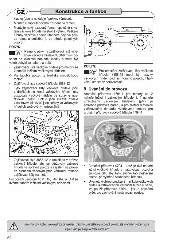
62
Pracovní úkony mohou vykonávat pouze vyškolení pracovníci, na základě pracovních postupů stanovených výrobcem vozu.Při práci vždy používejte ochranné pomůcky.
CZkladku (dbejte na údaje / pokyny výrobce). Montáž a napnutí nového ozubeného řemenu • Montujte nový ozubený řemen společně s ko-• lem vačkové hřídele na straně výfuku. Veškeré šrouby vačkové hřídele utáhněte nejprve pou-ze rukou a umístěte je ve středu podélných otvorů.
POKYN:Rameno páky na zajištovací liště výfu-kové vačkové hřídele 3888-9 musí do-
sedat na ukazatel napínací kladky a musí být volně pohyblivé nahoru a dolů.
Zajišťovací lišta vačkové hřídele pro motory se • 2 nahoře ležícími vačkovými hřídelemiViz tabulka použití z hlediska modelů/kódů ➪motorů. Zajišťovací lišty vačkové hřídele 3888-12 • Tyto zajišťovací lišty vačkové hřídele jsou • v drážkách na konci vačkových hřídelí, aby udržovaly vačkové hřídele ve správné nas-tavovací pozici. Pokud jsou klikové hřídele v nastavovací pozici, jsou zářezy ve vačkových hřídelích směrovány horizontálně.
Zajištovací lišta 3888-12 je umístěna v drážce • vačkové hřídele, aby se udržovaly vačkové hřídele ve správné poloze a zajištění se prove-de šroubem vedeným přes vertikální rameno zajištovací lišty na motor.
Pro použití u motorů 16 V F4P, F4R, K4J a K4M se dvěma nahoře ležícími vačkovými hřídelemi.
POKYN:Pro umístění zajišťovací lišty vačkové hřídele 3888-12 musí být drážky
vačkových hřídelí pod linií horního povrchu hlavy válců umístěny horizontálně.
Uvádění do provozu 9. Aretační přípravek 4794-1 pro motory se 2 nahoře ležícími vačkovými hřídelemi, 4 nahoře umístěnými vačkovými hřídelemi (příp. je potřebné přídavné nářadí) a pro aretaci řemenice vstřikovacího čerpadla vznětového motoru pro aretační přípravek vačkové hřídele 4794-1.
Aretační přípravek 4794-1 udržuje dvě nahoře • ležící vačkové hřídele v nastavovací pozici a zajišťuje tak, aby bylo zachováno nastavení motoru při výměně ozubeného řemenu. U vznětových motorů, které mají kola vačkových • hřídelí a vstřikovacích čerpadel blízko u sebe, lze použít přípravek 4794-1, jak je popsáno výše, pro zachování nastavovací pozice.
Konstrukce a funkce
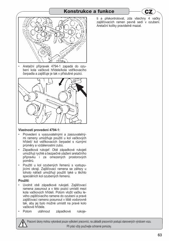
63
Pracovní úkony mohou vykonávat pouze vyškolení pracovníci, na základě pracovních postupů stanovených výrobcem vozu.Při práci vždy používejte ochranné pomůcky.
CZ
Aretační přípravek 4794-1 zapadá do ozu-• bení kola vačkové hřídele/kola vstřikovacího čerpadla a zajišťuje je tak v příslušné pozici.
Vlastnosti provedení 4794-1: Provedení s vysouvatelnými a zasouvatelný-• mi rameny umožňuje použití u kol vačkových hřídelí/ kol vstřikovacích čerpadel s různými průměry a vzdálenostmi zubů. Západková rukojeť: Obě západkové rukojeti • umožňují rychlé a bezpečné utažení aretačního přípravku i za omezených prostorových poměrů. Použití u kol ozubených řemenů s vystupu-• jícími okraji. Zajišťovací ramena se zářezy u tohoto nářadí umožňují použití také u těchto speciálních kol ozubených řemenů.
Použití: Uvolnit obě západkové rukojeti. Zajišťovací • ramena zasunout a v této pozici umístit mezi kola vačkových hřídelí. Potom vložit vačku le-vého zajišťovacího ramene do ozubení a pravé zajišťovací rameno posunout v liště vodorovně tak, aby jej bylo možné umístit na pravé kolo vačkové hřídele. Potom utáhnout západkové rukoje-•
ti a překontrolovat, zda všechny 4 vačky zajišťovacích ramen pevně sedí v ozubení. Aretační kolíky pravidelně mazat.
Konstrukce a funkce

223
258
I.05.
2010
/0.5
mpw
/MC
HAZET-WERK • Hermann Zerver GmbH & Co. KG} 10 04 61 • D-42804 Remscheid • Germany
[ +49 (0) 21 91 / 7 92-0 • ^ hazet.de • ] [email protected] \ +49 (0) 21 91 / 7 92-375 (Deutschland) -400 (International)