
abschn14
18
Section 14 Steering Gears, Rudder Propeller Units, Lateral Thrust Units, Winches, Hydraulic Control Systems, Fire Door Control Systems and Stabilizers A. Steering Gears 1. General 1.1 Scope The requirements contained in A. apply to the steering gear including all the equipment used to operate the rudder, the steering station and all transmission ele- ments from the steering station to the steering gear. For the rudder and manoeuvring arrangement, see Chapter 1 – Hull Structures, Section 14. The requirements set out in SOLAS Chapter II-1, Regulation 29 and 30 in their most actual version are integral part of this rule and are to be applied in their full extent. 1.2 Documents for approval Assembly and general drawings of all steering gears, diagrams of the hydraulic and electrical equipment together with detail drawings of all important load- transmitting components are to be submitted to GL in triplicate for approval. The drawings and other documents are to contain all the information relating to materials, working pres- sures, pump delivery rates, drive motor ratings, etc. necessary to enable the documentation to be checked. 2. Materials 2.1 Approved materials 2.1.1 As a rule, important load-transmitting com- ponents of the steering gear are to be made of steel or cast steel complying with the Rules II – Materials and Welding, Part 1 – Metallic Materials. With the consent of GL, cast iron may be used for certain components. Pressure vessels in general are to be made of steel, cast steel or nodular cast iron (with a predominantly ferritic matrix). For welded structures, the Rules II – Materials and Welding, Part 3 – Welding are to be observed. 2.1.2 Casings with integrated journal and guide bearings on ships with a nozzle rudder and ice class are not to be made of grey cast iro n. 2.1.3 The pipes of hydraulic steering gears are to be made of seamless or longitudinally welded steel tubes. The use of cold-drawn, unannealed tubes is not permitted. At points where they are exposed to damage, copper pipes for control lines are to be provided with protec- tive shielding and are to be safeguarded against hard- ening due to vibration by the use of suitable fasten- ings. 2.1.4 High-pressure hose assemblies may be used for short pipe connections subject to compliance with Section 11, U., if this is necessary due to vibrations or flexibly mounted units. 2.1.5 The materials used for pressurized compo- nents including the seals are to be suitable for the hydraulic oil in use. 2.2 Testing of materials 2.2.1 The materials of important force-transmitting components of the steering gear as well as of the pres- surized casings of hydraulic steering gears are to be tested under the supervision of GL in accordance with the Rules II – Materials and Welding, Part 1 – Metal- lic Materials. For pressurized oil pipes the requirements according to Section 11, Table 11.3 are to be observed. For welded pressurized casings, the Rules II – Materi- als and Welding, Part 3 – Welding are to be consid- ered. 2.2.2 In the case of small hand-operated main steering gears and small manually operated auxiliary steering gear GL may dispense with testing the mate- rials of individual components such as axiometer gear shafts, etc. 3. Design and equipment 3.1 Number of steering gears Every ship is to be equipped with at least one main and one auxiliary steering gear. Both steering gears are to be independent of each other and, wherever possible, act separately upon the rudder stock. GL may agree to components being used jointly by the main and auxiliary steering gear. I - Part 1 GL 2008 Section 14 Steering Gears, Rudder Propeller Units, Lateral Thrust Units, Winches, Hydraulic Control Systems, Fire Door Control Systems and Stabilizers Chapter 2 Page 14–1 A
Transcript of abschn14
7262019 abschn14
httpslidepdfcomreaderfullabschn14 118
Section 14
Steering Gears Rudder Propeller Units Lateral Thrust Units WinchesHydraulic Control Systems Fire Door Control Systems and Stabilizers
A Steering Gears
1 General
11 Scope
The requirements contained in A apply to the steeringgear including all the equipment used to operate the
rudder the steering station and all transmission ele-ments from the steering station to the steering gearFor the rudder and manoeuvring arrangement seeChapter 1 ndash Hull Structures Section 14
The requirements set out in SOLAS Chapter II-1Regulation 29 and 30 in their most actual version areintegral part of this rule and are to be applied in theirfull extent
12 Documents for approval
Assembly and general drawings of all steering gears
diagrams of the hydraulic and electrical equipmenttogether with detail drawings of all important load-transmitting components are to be submitted to GL intriplicate for approval
The drawings and other documents are to contain allthe information relating to materials working pres-sures pump delivery rates drive motor ratings etcnecessary to enable the documentation to be checked
2 Materials
21 Approved materials
211 As a rule important load-transmitting com-ponents of the steering gear are to be made of steel orcast steel complying with the Rules II ndash Materials andWelding Part 1 ndash Metallic Materials
With the consent of GL cast iron may be used forcertain components
Pressure vessels in general are to be made of steelcast steel or nodular cast iron (with a predominantlyferritic matrix)
For welded structures the Rules II ndash Materials andWelding Part 3 ndash Welding are to be observed
212 Casings with integrated journal and guidebearings on ships with a nozzle rudder and ice classare not to be made of grey cast iron
213 The pipes of hydraulic steering gears are tobe made of seamless or longitudinally welded steeltubes The use of cold-drawn unannealed tubes is notpermitted
At points where they are exposed to damage copperpipes for control lines are to be provided with protec-tive shielding and are to be safeguarded against hard-
ening due to vibration by the use of suitable fasten-ings
214 High-pressure hose assemblies may be usedfor short pipe connections subject to compliance withSection 11 U if this is necessary due to vibrations orflexibly mounted units
215 The materials used for pressurized compo-nents including the seals are to be suitable for thehydraulic oil in use
22 Testing of materials
221 The materials of important force-transmittingcomponents of the steering gear as well as of the pres-surized casings of hydraulic steering gears are to betested under the supervision of GL in accordance withthe Rules II ndash Materials and Welding Part 1 ndash Metal-lic Materials
For pressurized oil pipes the requirements accordingto Section 11 Table 113 are to be observed
For welded pressurized casings the Rules II ndash Materi-als and Welding Part 3 ndash Welding are to be consid-ered
222 In the case of small hand-operated mainsteering gears and small manually operated auxiliarysteering gear GL may dispense with testing the mate-rials of individual components such as axiometer gearshafts etc
3 Design and equipment
31 Number of steering gears
Every ship is to be equipped with at least one mainand one auxiliary steering gear Both steering gearsare to be independent of each other and whereverpossible act separately upon the rudder stock GLmay agree to components being used jointly by themain and auxiliary steering gear
I - Part 1GL 2008
Section 14 Steering Gears Rudder Propeller Units Lateral Thrust UnitsWinches Hydraulic Control Systems Fire Door Control Systemsand Stabilizers
Chapter 2Page 14ndash1
A
7262019 abschn14
httpslidepdfcomreaderfullabschn14 218
32 Main steering gear
321 Main steering gears are with the rudder fullyimmersed in calm water to be capable of putting therudder from 35deg port to 35deg starboard and vice versa at
the ships speed for which the rudder has been de-signed in accordance with Chapter 1 ndash Hull StructuresSection 14 The time required to put the rudder from35deg port to 30deg starboard or vice versa is not to exceed28 seconds
The main steering gear is to be as a rule poweroper-ated
In every tanker chemical tanker or gas carrier of10 000 GT and upwards and in every other ship of70 000 GT and upwards the main steering gear is tocomprise two or more identical power units
322 Manual operation is acceptable for rudderstock diameters up to 120 mm calculated for torsionalloads in accordance with Chapter 1 ndash Hull StructuresSection 14 C1 Not more than 25 turns of the hand-wheel are to be necessary to put the rudder from onehard over position to the other Taking account of theefficiency of the system the force required to operatethe handwheel is generally not to exceed 200 N
33 Auxiliary steering gear
331 Auxiliary steering gears are with the rudderfully immersed in calm water to be capable of puttingthe rudder from 15deg port to 15deg starboard or vice versa
within 60 seconds at 50 of the ships maximumspeed subject to a minimum of seven knots Hydrau-lically operated auxiliary steering gears are to be fittedwith their own piping system independent of that ofthe main steering gear The pipe or hose connectionsof steering gears are to be capable of being shut offdirectly at the pressurized casings
332 Manual operation of auxiliary steering gearsystems is permitted up to a theoretical stock diameterof 230 mm referring to steel with a minimum nominalupper yield stress ReH = 235 Nmm2
34 Power unit
341 Where power operated hydraulic main steer-ing gears are equipped with two or more identicalpower units no auxiliary steering gear need be in-stalled provided that the following conditions arefulfilled
3411 On passenger ships requirements 321 and41 are to be complied with while any one of thepower units is out of operation
3412 On cargo ships the power units are to bedesigned in a way that requirements 321 and 41 are
complied with while operating with all power unitsThe main steering gear of tankers chemical tankers orgas carriers of 10 000 GT and upwards is to compriseeither
ndash two independent and separate power actuatingsystems (power units(s) hydraulic pipes poweractuator) each capable of meeting the require-ments as set out in 321 and 41 or
ndash at least two identical power actuating systemswhich acting simultaneously in normal opera-tion are to be capable of meeting the require-ments as set out in 321 and 41
3413 In the event of failure of a single componentof the main steering gear including the piping exclud-ing the rudder tiller or similar components as well asthe cylinders rotary vanes and casing means are to beprovided for quickly regaining control of one steeringsystem
For tankers chemical tankers or gas carriers of10 000 GT and upwards steering capability is to be
regained within 45 sec after a single failure
3414 In the event of a loss of hydraulic oil it is to be possible to isolate the damaged system in such away that the second control system remains fully op-erable
35 Rudder angle limitation
The rudder angle in normal service is to be limited bydevices fitted to the steering gear (eg limit switches)to a rudder angle of 35 deg on both sides Deviationsfrom this requirement are permitted only with theconsent of GL
36 End position limitation
For the limitation by means of stoppers of the endpositions of tillers and quadrants see Chapter 1 ndash HullStructures Section 14 G
In the case of hydraulic steering gears without an endposition limitation of the tiller and similar compo-nents a mechanical end position limiting device is tobe fitted within the rudder actuator
37 Locking equipment
Steering gear systems are to be equipped with a lock-ing system effective in all rudder positions see alsoChapter 1 ndash Hull Structures Section 14 G
Where hydraulic plants are fitted with shut-offs di-rectly at the cylinders or rotary vane casings speciallocking equipment may be dispensed with
For steering gears with cylinder units which may beindependently operated these shut-off devices do nothave to be fitted directly on the cylinders
38 Overload protection
381 Power-operated steering gear systems are tobe equipped with overload protection (slip couplingrelief valves) to ensure that the driving torque is lim-ited to the maximum permissible value
Chapter 2Page 14ndash2
Section 14 Steering Gears Rudder Propeller Units Lateral Thrust UnitsWinches Hydraulic Control Systems Fire Door ControlSystems and Stabilizers
I - Part 1GL 2008
A
7262019 abschn14
httpslidepdfcomreaderfullabschn14 318
The overload protection device is to be secured toprevent re-adjustment by unauthorized persons Meansare to be provided for checking the setting while inservice
The pressurized casings of hydraulic steering gearswhich also fulfil the function of the locking equipmentmentioned in 37 are to be fitted with relief valvesunless they are so designed that the pressure generatedwhen the elastic-limit torque is applied to the rudderstock cannot cause rupture deformation or other dam-age of the pressurized casing
382 Relief valves have to be provided for protect-ing any part of the hydraulic system which can beisolated and in which pressure can be generated fromthe power source or from external forces
The relief valves are to be set to a pressure value equal
or higher than the maximum working pressure butlower than the design pressure of the steering gear(definition of maximum working pressure and designpressure in accordance to 41)
The minimum discharge capacity of the relief valve(s)are not to be less than 11 times the total capacity ofthe pumps which can deliver through it (them)
With this setting any higher peak pressure in the sys-tem than 11 times the setting pressure of the valves isto be prohibited
39 Controls
391 Control of the main and auxiliary steeringgears is to be exercised from a steering station on thebridge Controls are to be mutually independent and sodesigned that the rudder cannot move unintentionally
392 Means are also to be provided for exercisingcontrol from the steering gear compartment Thetransmission system is to be independent of that serv-ing the main steering station
393 Suitable equipment is to be installed to pro-vide means of communication between the bridge allsteering stations and the steering gear compartment
394 Failures of single control components (egcontrol system for variable displacement pump or flowcontrol valve) which may lead to loss of steering areto cause an audible and visible alarm on the navigatingbridge if loss of steering cannot be prevented by othermeasures
310 Rudder angle indication
3101 The rudder position is to be clearly indicatedon the bridge and at all steering stations Where thesteering gear is operated electrically or hydraulicallythe rudder angle is to be indicated by a device (rudderposition indicator) which is actuated either by therudder stock itself or by parts which are mechanicallyconnected to it In case of time-dependent control ofthe main and auxiliary steering gear the midship posi-
tion of the rudder is to be indicated on the bridge bysome additional means (signal lamp or similar) Ingeneral this indicator is still to be fitted even if thesecond control system is a manually operated hydrau-lic system See also Chapter 3 ndash Electrical Installa-
tions Section 9 C
3102 The actual rudder position is also to be indi-cated at the steering gear itself
An additional rudder angle indicator fitted at the mainengine control station is recommended
311 Piping
3111 The pipes of hydraulic steering gear systemsare to be installed in such a way as to ensure maxi-mum protection while remaining readily accessible
Pipes are to be installed at a sufficient distance fromthe ships shell As far as possible pipes should notpass through cargo spaces
Connections to other hydraulic systems are not permit-ted
3112 For the design and dimensions of pipesvalves fittings pressure vessels etc see Section 8 andSection 11 A B C D and U
312 Oil level indicators filters
3121 Tanks within the hydraulic system are to beequipped with oil level indicators
3122 The lowest permissible oil level is to bemonitored Audible and visual alarms are to be pro-vided for the navigating bridge and in the machineryspace or machinery control room The alarm on thenavigating bridge is to be an individual alarm
3123 Arrangements are to be provided to maintainthe cleanliness of the hydraulic fluid taking into con-sideration the type and design of the hydraulic system
313 Storage tank
In hydraulic operated steering gear systems an addi-
tional permanently installed storage tank is to be fittedwhich has a capacity sufficient to refill at least one ofthe control systems including the service tank
This storage tank is to be permanently connected bypipes to the control systems so that the latter can berefilled from a position inside the steering gear com-partment
314 Arrangement
Steering gears are to be installed in a way to be acces-sible at any time and to be easily maintainable
315 Electrical equipmentFor the electrical equipment the rules in Chapter 3 ndashElectrical Installations Section 7 A have to be ob-served
I - Part 1GL 2008
Section 14 Steering Gears Rudder Propeller Units Lateral Thrust UnitsWinches Hydraulic Control Systems Fire Door Control Systemsand Stabilizers
Chapter 2Page 14ndash3
A
7262019 abschn14
httpslidepdfcomreaderfullabschn14 418
316 Seating
Seating of the steering gear has to be applied accord-ing to GL Rules VI ndash Additional Rules and Guide-lines Part 4 ndash Diesel Engines Chapter 3 ndash Guidelines
for the Seating of Propulsion Plants and AuxiliaryMachinery In case of seating on cast resin the forcesaccording to the elastic limit torque of the rudder shaftas well as the rudder bearing forces have to be trans-mitted to the shiprsquos structure by welded stoppers
4 Power and dimensioning
41 Power of steering gears
The power of the steering gear has to comply with therequirements set out in 32 and 33 see also SOLAS Chapter II-1 Part C Reg 29
The maximum effective torque for which the steeringgear is to be equipped is not to be less than
r
3
t
maxk
24
D
M
⎟⎟ ⎠
⎞⎜⎜⎝
⎛
= [Nm] (1)
Dt = theoretical rudder stock diameter [mm] de-
rived from the required hydrodynamic rudder
torque for the ahead running condition in ac-
cordance with the Rules Chapter 1 ndash Hull
Structures Section 14 C1 and Section 15
B9 and D37
The working torque of the steering gear is to be larger
than the hydrodynamic torque QR of the rudder ac-
cording to Chapter 1 - Hull Structures Section 14
B12 B22 B23 and cover the friction moments of
the related bearing arrangement
The corresponding maximum working pressure is themaximum expected pressure in the system when thesteering gear is operated to comply with the powerrequirements as mentioned above
Frictional losses in the steering gear including pipinghave to be considered within the determination of themaximum working pressure
The design pressure pc for calculation to determine thescantlings of piping and other steering gear compo-nents subjected to internal hydraulic pressure is to beat least 125 times the maximum working pressure asdefined above and has not to be less than the setting ofthe relief valves as described under 382
In the case of multi-surface rudders controlled by acommon steering gear the relevant diameter is to bedetermined by applying the formula
3 32t
31tti DDD ++=
k r = material characteristic
e
eHr
R
235k ⎟
⎟ ⎠
⎞⎜⎜⎝
⎛ = (2)
e = 075 2eHmm
N
235Rwhere gt
= 102eH
mm
N235Rwhere le
ReH = yield strength of rudder stock material
[Nmm2]
The applied value for ReH is not to be greater
than 07 Rm or 450 Nmm2 whichever is less
Rm = tensile strength [Nmm2]
42 Design of transmission components
421 The design calculations for those parts of thesteering gear which are not protected against overloadare to be based on the elastic-limit torque of the rudderstock
The elastic-limit torque to be used is
r
3
Fk
24
D
2M⎟⎟ ⎠
⎞⎜⎜⎝
⎛
sdot= [Nm] (3)
D = minimum actual rudder stock diameter [mm]
The value used for the actual diameter need
not be larger than 1145 sdot Dt
The stresses in the components of the steering geardetermined in this way are not to exceed the yieldstrength of the materials used The design of parts ofthe steering gear with overload protection is to bebased on the loads corresponding to the responsethreshold of the overload protection
422 Tiller and rotary vane hubs made of materialwith a tensile strength of up to 500 Nmmsup2 have tosatisfy the following conditions in the area where the
force is applied see Figure 141
Height of hub H ge 10 sdot D [mm]
Outside diameter Da ge 18 sdot D [mm]
sD
Da
H
Fig 141 Hub dimensions
Chapter 2Page 14ndash4
Section 14 Steering Gears Rudder Propeller Units Lateral Thrust UnitsWinches Hydraulic Control Systems Fire Door ControlSystems and Stabilizers
I - Part 1GL 2008
A
7262019 abschn14
httpslidepdfcomreaderfullabschn14 518
In special cases the outside diameter may be reduced to
Da = 17 sdot D [mm]
but the height of the hub must then be at least
H = 114 sdot D [mm]
423 Where materials with a tensile strengthgreater than 500 Nmm2 are used the section of thehub may be reduced by 10
424 Where the force is transmitted by clampedor tapered connections the elastic-limit torque maybe transmitted by a combination of frictional andpositive locking mechanism using adequately pre-tensioned bolts and a key
For the elastic limit torque according to formula (3)the thread root diameter of the bolts can be deter-
mined by applying the following formula
eHrk
Rk z
1D769d
sdotsdotsdotge [mm] (4)
D = actual rudder stock diameter [mm] Thevalue used for the actual diameter need not
be larger than 1145 sdot Dt
z = total number of bolts [ndash]
ReH = yield strength of the bolt material [Nmmsup2]
425 Split hubs of clamped joints are to be joinedtogether with at least four bolts
The key is not to be located at the joint in the clamp
426 Where the oil injection method is used to
joint the rudder tiller or rotary vanes to the rudder
stock methods of calculation appropriate to elasticitytheory are to be applied Calculations are to be based
on the elastic-limit torque allowing for a coefficient
of friction micro o = 015 for steel and micro o = 012 for nodu-
lar cast iron The von Mises equivalent stress calcu-
lated from the specific pressure p and the correspond-
ing tangential load based on the dimensions of the
shrunk joint is not to exceed 80 of the yieldstrength of the materials used
427 Where circumferential tension componentsare used to connect the rudder tiller or rotary vanes to
the rudder stock calculations are to be based on two
and a half times the maximum torque (but not more
than the elastic limit torque) allowing for a coeffi-
cient of friction of micro o = 012 The von Mises equiva-
lent stress calculated from the contact pressure p andthe corresponding tangential load based on the di-
mensions of the shrunk-on connection is not to ex-
ceed 80 of the yield strength of the materials used
When more than one circumferential tension compo-nents are used the torque capacity of the connection is
to be determined by adding the torques of the sole ten-sion components and applying a reduction factor of 09
5 Tests in the manufacturers works
51 Testing of power units
The power units are required to undergo tests on a
test stand in the manufacturers works
511 For diesel engines see Section 2
512 For electric motors see Chapter 3 ndash Electri-cal Installations Section 21
513 For hydraulic pumps and motors see VI ndashAdditional Rules and Guidelines Part 6 ndash PumpsCompressors Fittings Chapter 1 ndash Guidelines forDesign Construction and Testing of Pumps are to beapplied analogously Where the drive power is 50 kWor more this testing is to be carried out in the pres-ence of a GL Surveyor
52 Pressure and tightness tests
Pressure components are to undergo a pressure test
The test pressure is pp
pp = 15 sdot pc (5)
pc = design pressure for which a component orpiping system is designed with its mechani-cal characteristics [bar] For pressures above200 bar the test pressure need not exceedp + 100 bar
For pressure testing of pipes their valves and fittingssee Section 11 B4 and U5
Tightness tests are to be performed on components towhich this is appropriate
53 Final inspection and operational test
Following testing of the individual components andafter completion of assembly the steering gear isrequired to undergo final inspection and an opera-tional test Among other things the overload protec-tion is to be adjusted at this time
6 Shipboard trialsThe operational efficiency of the steering gear is tobe proved during the sea trials For this purpose theZ manoeuvre corresponding to 321 and 331 is tobe executed as a minimum requirement
B Rudder Propeller Units
1 General
11 Scope
The requirements of B are valid for the rudder pro-peller as main drive the ships manoeuvring stationand all transmission elements from the manoeuvringstation to the rudder propeller
I - Part 1GL 2008
Section 14 Steering Gears Rudder Propeller Units Lateral Thrust UnitsWinches Hydraulic Control Systems Fire Door Control Systemsand Stabilizers
Chapter 2Page 14ndash5
B
7262019 abschn14
httpslidepdfcomreaderfullabschn14 618
12 Documents for approval
Assembly and sectional drawings as well as partdrawings of the gears and propellers giving all thedata necessary for the examination are to be submit-
ted in triplicate to GL for approval
2 Materials
21 Approved materials
The selection of materials is subject as and whereapplicable to the provisions of A21 and to those ofSections 4 5 and 6
22 Testing of materials
All important components of the rudder propeller
involved in the transmission of torques and bendingmoments are to be tested under the supervision of GLin accordance with the Rules II ndash Materials andWelding Part 1 ndash Metallic Materials
3 Design and equipment
31 Number of rudder propellers
Each ship is to have at least two rudder propellersBoth units are to be capable of being operated inde-pendently of the other
32 Locking devicesEach rudder propeller is to be provided with a lock-ing device to prevent the unintentional rotation of thepropeller and the slewing mechanism of the unitwhich is out of operation at a time The locking de-vice is to be designed to securely lock the non-operated unit while operating the ship with the maxi-mum power of the remaining rudder propeller unitshowever at a ship speed of at least 7 kn
33 Control
331 Both the drive and the slewing mechanism
of each rudder propeller are to be controlled from amanoeuvring station on the navigating bridge
The controls are to be mutually independent and sodesigned that the rudder propeller cannot be turnedunintentionally
An additional combined control for all rudder propel-lers is permitted
Means have to be provided fulfilling the same pur-pose as the steering angle limitation in A35 Thesemay be dispensed with in cases where no danger forthe ship is caused by unintentional slewing of theunits at full power and ship speed to any angle
332 The failure of a single element within thecontrol and hydraulic system of one unit is not to leadto the failure of the other units
333 An auxiliary steering device is to be pro-vided for each rudder propeller In case of a failure ofthe main steering system the auxiliary steering deviceis at least to be capable of moving the rudder propel-ler to midship position
334 Where the hydraulic systems of more thanone rudder propeller are combined it is to be possiblein case of a loss of hydraulic oil to isolate the dam-aged system in such a way that the other controlsystems remain fully operational
34 Position indicators
341 The position of each rudder propeller is to beclearly discernible on the navigating bridge and ateach manoeuvring station
342 The actual position is also to be discernibleat the rudder propeller itself
35 Pipes
The pipes of hydraulic control systems are subject tothe provisions of A311 wherever relevant
36 Oil level indicators filters
Oil level indicators and filters are subject to the pro-visions of A312 wherever relevant
37 Lubrication
371 The lubricating oil supply is to be ensuredby a main pump and an independent standby pump
372 In the case of separate lubricating systems inwhich the main lubricating oil pumps can be replacedwith the means available on board the standby pumpmay be replaced by a complete spare pump Thisspare pump is to be carried on board and is to beready for mounting
4 Dimensioning
41 Gears
For the design of gears see Section 5
The slewing gears are in general to be designed asspur or bevel gears
42 Shaft line
For the dimensioning of the propeller shaft betweenpropeller and gear wheel see Section 4 For the di-mensioning of the remaining part of this shaft and allother gear shafts see Section 5
43 Propellers
For the design of propellers see Section 6
Chapter 2Page 14ndash6
Section 14 Steering Gears Rudder Propeller Units Lateral Thrust UnitsWinches Hydraulic Control Systems Fire Door ControlSystems and Stabilizers
I - Part 1GL 2008
B
7262019 abschn14
httpslidepdfcomreaderfullabschn14 718
44 Support pipe
The design of the support pipe and its attachment tothe ships hull is to take account of the loads due tothe propeller and nozzle thrust including the dynamic
components
45 Pipes
For arrangement and design of pipes valves fittingsand pressure vessels see Section 8 and Section 11A B C D U
5 Tests in the manufacturers works
51 Testing of power units
A51 applies wherever relevant
52 Pressure and tightness test
A52 applies wherever relevant
53 Final inspection and operational test
531 After inspection of the individual compo-nents and completion of assembly rudder propellersare to undergo a final inspection and operational testThe final inspection is to be combined with a trial runlasting several hours under part or full-load condi-
tions A check of the tooth clearance and of the toothcontact pattern is to be carried out
532 When no suitable test bed is available for theoperational and load testing of large rudder propel-lers the tests mentioned in 531 can be carried out onthe occasion of the dock test
533 Limitations on the scope of the test requireGLs consent
6 Testing on board
61 The faultless operation smooth running andbearing temperatures of the gears and control systemare to be checked during the sea trials under allsteaming conditions
After the conclusion of the sea trials the toothing isto be examined through the inspection openings andthe contact pattern is to be checked The tooth contactpattern is to be assessed on the basis of the referencevalues for the percentage area of contact given inSection 5 Table 56
62 The scope of the check on contact patternfollowing the sea trials may be limited with the Sur-veyors agreement provided that the checks on con-tact pattern called for in 531 and 532 have beensatisfactory
C Lateral Thrust Units
1 General
11 ScopeThe requirements contained in C apply to the lateralthrust unit the control station and all the transmissionelements from the control station to the lateral thrustunit
12 Documents for approval
Assembly and sectional drawings for lateral thrustunits with an input power of 100 kW and more to-gether with detail drawings of the gear mechanismand propellers containing all the data necessary forchecking are each to be submitted to GL in triplicatefor approval For propellers this only applies to aninput power exceeding 500 kW
2 Materials
Materials are subject as appropriate to the provi-sions of Sections 4 and 5
Section 6 applies analogously to the materials and thematerial testing of propellers
3 Dimensioning and design
The design of the relevant components of lateralthrust units is to be in accordance with Sections 4 and5 that of the propellers with Section 6
The pipe connections of hydraulic drive systems aresubject to the applicable requirements contained inA213 and A214
Lateral thrust units are to be capable of being oper-ated independently of other connected systems
Windmilling of the propeller during sea passages hasto be taken into account as an additional load caseOtherwise effective countermeasures have to be in-troduced to avoid windmilling eg a shaft brake
In the propeller area the thruster tunnel is to be pro-
tected against damages caused by cavitation erosionby effective measures such as stainless steel plating
For the electrical part of lateral thrust units seeChapter 3 ndash Electrical Installations Section 7 B
4 Tests in the manufacturers works
A5 is applicable as appropriate
For hydraulic pumps and motors with a drive powerof 100 kW or more the tests are to be conducted inthe presence of a GL Surveyor
For lateral thrust units with an input power of lessthan 100 kW final inspection and function tests maybe carried out by the manufacturer who will thenissue the relevant Manufacturer Inspection Certifi-cate
I - Part 1GL 2008
Section 14 Steering Gears Rudder Propeller Units Lateral Thrust UnitsWinches Hydraulic Control Systems Fire Door Control Systemsand Stabilizers
Chapter 2Page 14ndash7
C
7262019 abschn14
httpslidepdfcomreaderfullabschn14 818
5 Shipboard trials
Testing is to be carried out during sea trials duringwhich the operating times are to be established
D Windlasses
1 General
11 Scope
The requirements contained in D apply to boweranchor windlasses stern anchor windlasses com-bined anchor and mooring winches and chain stop-pers For anchors and chains see Chapter 1 ndash HullStructures Section 18
12 Documents for approval
121 For each type of anchor windlass and chainstopper general and sectional drawings circuit dia-grams of the hydraulic electrical and steam systemsand detail drawings of the main shaft cable lifterbrake stopper bar chain pulley and axle are to besubmitted in triplicate for approval
One copy of a description of the anchor windlassincluding the proposed overload protection and othersafety devices is likewise to be submitted
122 Where an anchor windlass is to be approvedfor several strengths and types of chain cable thecalculation relating to the maximum braking torque isto be submitted and proof furnished of the power andhauling-in speed in accordance with 41 correspond-ing to all the relevant types of anchor and chain ca-ble
123 One copy of the strength calculation forbolts chocks and stoppers securing the windlass tothe deck is likewise to be submitted This calculationis to consider forces acting on the windlass caused bythe loads specified in 42 and 43
2 Materials
21 Approved materials
211 The provisions contained in A21 are to beapplied as appropriate to the choice of materials
212 Cable lifters and chain pulleys are generallyto be made of cast steel Nodular cast iron is permit-ted for stud link chain cables of
up to 50 mm diameter for grade K 1
up to 42 mm diameter for grade K 2
up to 35 mm diameter for grade K 3
In special cases nodular cast iron may also be usedfor larger chain diameters by arrangement with GL
Grey cast iron is permitted for stud link chain cablesof
up to 30 mm diameter for grade K 1
up to 25 mm diameter for grade K 2
up to 21 mm diameter for grade K 3
22 Testing of materials
221 The materials for forged rolled and castparts which are stressed by the pull of the chain whenthe cable lifter is disengaged (main shaft cable lifterbrake bands brake spindles brake bolts tensionstraps stopper bar chain pulley and axle) are to betested under the supervision of GL in accordancewith the Rules II ndash Materials and Welding Part 1 ndashMetallic Materials
In the case of anchor windlasses for chains up to 14 mm in diameter an Manufacturer Inspection Certifi-cate issued by the producer may be accepted as proof
222 In the case of hydraulic systems the materialused for pipes (see Section 11 Table 113) as well asfor pressure vessels is also to be tested
3 Design and equipment
31 Type of drive
311 Windlasses are normally to be driven by an
engine which is independent of other deck machin-ery The piping systems of hydraulic and steam-driven windlass engines may be connected to otherhydraulic or steam systems provided that this is per-missible for the latter The windlasses are howeverto be capable of being operated independently ofother connected systems
312 Manual operation as the main driving powercan be allowed for anchors weighing up to 250 kg
313 In the case of hydraulic drives with a pipingsystem connected to other hydraulic systems a secondpump unit is recommended
314 In the case of windlasses with two cablelifters both cable lifters are to be engageable simulta-neously
32 Reversing mechanism
Power-driven windlasses are to be reversible Onwindlasses for ships with a Range of Service ratingup to RSA (50) and on those powered by internalcombustion engines a reversing mechanism may bedispensed with
33 Overload protectionFor the protection of the mechanical parts in theevent of the windlass jamming an overload protec-tion (eg slip coupling relief valve) is to be fitted to
Chapter 2Page 14ndash8
Section 14 Steering Gears Rudder Propeller Units Lateral Thrust UnitsWinches Hydraulic Control Systems Fire Door ControlSystems and Stabilizers
I - Part 1GL 2008
D
7262019 abschn14
httpslidepdfcomreaderfullabschn14 918
limit the maximum torque of the drive engine (cf412) The setting of the overload protection is to bespecified (eg in the operating instructions)
34 Couplings
Windlasses are to be fitted with disengageable cou-plings between the cable lifter and the drive shaft In
an emergency hydraulic or electrically operated cou-plings are to be capable of being disengaged by hand
35 Braking equipment
Windlasses are to be fitted with cable lifter brakeswhich are capable of holding a load in accordancewith 423 with the cable lifter disengaged In addi-tion where the gear mechanism is not of self-lockingtype a device (eg gearing brake lowering brake oilhydraulic brake) is to be fitted to prevent paying out
of the chain should the power unit fail while the cablelifter is engaged
36 Pipes
For the design and dimensions of pipes valves fit-tings pressure vessels etc see Section 8 and Section11 A B C D and U
37 Cable lifters
Cable lifters are to have at least five snugs
38 Windlass as warping winch
Combined windlasses and warping or mooring win-ches are not to be subjected to excessive loads even
when the maximum pull is exerted on the warping rope
39 Electrical equipment
For the electrical equipment the rules of Chapter 3 ndashElectrical Installations Section 7 E2 have to beobserved
310 Hydraulic equipment
For oil level indicators see A3121 For filters seeF322
4 Power and dimensioning
41 Driving power
411 Depending on the grade of the chain cable
and anchor depth windlasses must be capable of exert-ing the following nominal pull Z at a mean speed of at least 015 ms
Z = d2 (f + 0218 sdot (h ndash 100)) [N]
d = diameter of anchor chain [mm]
h = anchor depth [m]
f = nominal pull factor [ndash]
Grade K 1 K 2 K3
f 375 425 475
The calculation of nominal pull is to be based on aminimum anchor depth of 100 m
The pull of stern windlasses with an anchor rope canbe determined by reference to the anchor weight and
the diameter of the corresponding chain cable
412 The nominal output of the power units is tobe such hat the conditions specified in 411 can bemet for 30 minutes without interruption In additionthe power units are to be capable of developing amaximum torque equal to a maximum pull Zmax of
Zmax = 15 sdot Z [N]
at a reduced speed for at least two minutes
413 At the maximum torque specified in 412 ashort-time overload of up to 20 is allowed in the
case of internal combustion engines
414 An additional reduction gear stage may befitted in order to achieve the maximum torque
415 With manually operated windlasses steps are
to be taken to ensure that the anchor can be hoisted at a
mean speed of 0033 ms with the pull specified in
411 This is to be achieved without exceeding a man-ual force of 150 N applied to a crank radius of about 350 mm with the hand crank turned at about 30 rpm
42 Dimensioning of load-transmitting com-
ponents and chain stoppers
421 The basis for the design of the load-transmitting components of windlasses and chainstoppers are the anchors and chain cables specified inChapter 1 ndash Hull Structures Section 18
422 The cable lifter brake is to be so designedthat the anchor and chain can be safely stopped whilepaying out the chain cable
423 The dimensional design of those parts of the
windlass which are subjected to the chain pull when
the cable lifter is disengaged (cable lifter main shaft braking equipment bedframe and deck fastening) is to
be based on a theoretical pull equal to 80 of the
nominal breaking load specified in the GL Rules II ndash
Materials and Welding Part 1 ndash Metallic Materials for
the chain in question The design of the main shaft is to
take account of the braking forces and the cable lifter
brake is not to slip when subjected to this load
424 The theoretical pull may be reduced to 45 of the nominal breaking load for the chain providedthat a chain stopper approved by GL is fitted
425 The design of all other windlass components is
to be based upon a force acting on the cable lifter pitch
circle and equal to the maximum pull specified in 412
426 At the theoretical pull specified in 423 and424 the force exerted on the brake handwheel is notto exceed 500 N
I - Part 1GL 2008
Section 14 Steering Gears Rudder Propeller Units Lateral Thrust UnitsWinches Hydraulic Control Systems Fire Door Control Systemsand Stabilizers
Chapter 2Page 14ndash9
D
7262019 abschn14
httpslidepdfcomreaderfullabschn14 1018
427 The dimensional design of chain stoppers isto be based on a theoretical pull equal to 80 of thenominal breaking load of the chain
428 The total stresses applied to components are
to be below the minimum yield point of the materialsused
429 The foundations and pedestals of windlassesand chain stoppers are governed by Chapter 1 ndash HullStructures Section 10 B5
43 Strength requirements to resist green seaforces
431 For ships of length 80 m or more where theheight of the exposed deck in way of the item is lessthan 01L or 22 m above the summer load waterlinewhichever is the lesser the attachment of the wind-lass located within the forward quarter length of theship has to resist the green sea forces
The following pressures and associated areas are tobe applied (Fig 142)
ndash 200 kNm2 normal to the shaft axis and awayfrom the forward perpendicular over the pro- jected area in this direction
ndash 150 kNm2 parallel to the shaft axis and actingboth inboard and outboard separately over themultiple of f times the projected area in this di-rection
f = 1 + BH but not greater than 25
B = width of windlass measured parallel to theshaft axis [m]
H = overall height of the windlass [m]
Where mooring winches are integral with the anchorwindlass they are to be considered as part of thewindlass
432 Forces in the bolts chocks and stoppers
securing the windlass to the deck caused by greensea forces specified in 431 are to be calculated
The windlass is supported by N bolt groups eachcontaining one or more bolts (Fig 143)
The axial forces Ri in bolt group (or bolt) i positive
in tension is to be obtained from
Rxi = Px sdot h sdot xi sdot Ai Ix [kN]
Ryi = Py sdot h sdot yi sdot Ai Iy [kN]
Ri = Rxi + Ryi ndash Rsi [kN]
Px = force acting normal to the shaft axis [kN]Py = force acting parallel to the shaft axis either
inboard or outboard whichever gives the
greater force in bolt group i [kN]
h = shaft height above the windlass mounting [cm]
xi yi = x and y coordinates of bolt group i from the
centroid of all N bolt groups positive in the
direction opposite to that of the applied force
[cm]
Ai = cross sectional area of all bolts in group i
[cm2]
Ix = Σ Ai xi2 for N bolt groups [cm4]
Iy = Σ Ai yi2 for N bolt groups [cm4]
Rsi = static reaction at bolt group i due to weight
of windlass [kN]
Fig 142 Direction of forces and weight
Chapter 2Page 14ndash10
Section 14 Steering Gears Rudder Propeller Units Lateral Thrust UnitsWinches Hydraulic Control Systems Fire Door ControlSystems and Stabilizers
I - Part 1GL 2008
D
7262019 abschn14
httpslidepdfcomreaderfullabschn14 1118
Fig 143 Sign convention
433 Shear forces Fxi and Fyi applied to the boltgroup i and the resultant combined force are to beobtained from
Fxi = x wP m
N
minusαsdot [kN]
Fyi =y wP m
N
minusαsdot [kN]
Fi = ( )2 2
xi yiF F+ [kN]
α = coefficient of friction to be taken equal to 05
mw = weight-force of windlass [kN]
N = number of bolt groups
Axial tensile and compressive forces and lateral forcescalculated in 431 432 and 433 are also to be con-sidered in the design of the supporting structure
434 Tensile axial stresses in the individual boltsin each bolt group i are to be calculated The horizon-tal forces Fxi and Fyi are normally to be reacted by
shear chocks
Where fitted bolts are designed to support these shear forces in one or both directions the von Mises equiva-lent stresses in the individual bolts are to be calculated and compared to the stress under proof load
Where pourable resins are incorporated in the holdingdown arrangement due account is to be taken in thecalculations
The safety factor against bolt proof strength is to benot less than 20
5 Tests in the manufacturers works
51 Testing of driving engines
A51 is applicable as appropriate
52 Pressure and tightness tests
A52 is applicable as appropriate
53 Final inspection and operational testing
531 Following manufacture windlasses are re-quired to undergo final inspection and operationaltesting at the maximum pull The hauling-in speed is
to be verified with continuous application of thenominal pull During the tests particular attention is tobe given to the testing and where necessary setting ofbraking and safety equipment
In the case of anchor windlasses for chains gt 14 mmin diameter this test is to be performed in the presenceof the GL Surveyor
In the case of anchor windlasses for chains le 14 mmdiameter the Manufacturers Inspection Certificatewill be accepted
532 Where the manufacturing works does nothave adequate facilities the aforementioned testsincluding the adjustment of the overload protectioncan be carried out on board ship In these cases func-tional testing in the manufacturers works is to beperformed under no-load conditions
533 Following manufacture chain stoppers arerequired to undergo final inspection and operationaltesting in the presence of the GL Surveyor
6 Shipboard trials
The anchor equipment is to be tested during sea trialsAs a minimum requirement this test is required todemonstrate that the conditions specified in 314 and422 can be fulfilled
I - Part 1GL 2008
Section 14 Steering Gears Rudder Propeller Units Lateral Thrust UnitsWinches Hydraulic Control Systems Fire Door Control Systemsand Stabilizers
Chapter 2Page 14ndash11
D
7262019 abschn14
httpslidepdfcomreaderfullabschn14 1218
E Winches
1 Towing winches
The design and testing of towing winches are to com-ply with Chapter 1 ndash Hull Structures Section 25 C5
2 Winches for cargo handling gear and otherlifting equipment
The design and testing of these winches are to complywith VI ndash Additional Rules and Guidelines Part 2 ndashLoading Gear Chapter 2 ndash Guidelines for the Con-struction and Survey of Lifting Appliances
3 Lifeboat winches
The design and testing of life boat winches are to com-ply with VI ndash Additional Rules and Guidelines Part 2 ndash
Loading Gear Chapter 1 ndash Guidelines for Life-Saving
Launching Appliances
4 Winches for special equipment
The GL Guidelines VI ndash Additional Rules and Guide-lines Part 2 ndash Loading Gear Chapter 2 ndash Guidelinesfor the Construction and Survey of Lifting Appliancesare to be applied as appropriate to winches for spe-cial equipment such as ramps hoisting gear and hatchcovers
F Hydraulic Systems
1 General
11 Scope
The requirements contained in F apply to hydraulicsystems used for example to operate hatch coversclosing appliances in the ships shell and bulkheads
and hoists The requirements are to be applied inanalogous manner to the ships other hydraulic sys-tems except where covered by the requirements ofSection 11
12 Documents for approval
The diagram of the hydraulic system together withdrawings of the cylinders containing all the data nec-essary for assessing the system eg operating datadescriptions materials used etc are to be submittedin triplicate for approval
13 Dimensional design
For the design of pressure vessels see Section 8 forthe dimensions of pipes and hose assemblies seeSection 11
2 Materials
21 Approved materials
211 Components fulfilling a major function in thepower transmission system normally are to be made ofsteel or cast steel in accordance with the Rules II ndashMaterials and Welding Part 1 ndash Metallic MaterialsThe use of other materials is subject to special agree-ment with GL
Cylinders are preferably to be made of steel cast steelor nodular cast iron (with a predominantly ferriticmatrix)
212 Pipes are to be made of seamless or longitu-dinally welded steel tubes
213 The pressure-loaded walls of valves fittingspumps motors etc are subject to the requirements ofSection 11 B
22 Testing of materials
The following components are to be tested under su-pervision of GL in accordance with the Rules II ndashMaterials and Welding Part 1 ndash Metallic Materials
a) Pressure pipes with DN gt 50 (see Section 11
Table 113)
b) Cylinders where the product of the pressuretimes the diameter
pezul Di gt 20000
pezul = maximum allowable working pressure[bar]
Di = inside diameter of tube [mm]
c) For testing the materials of hydraulic accumula-tors see Section 8 B
Testing of materials by GL may be dispensed with inthe case of cylinders for secondary applications pro-vided that evidence in the form of a Manufacturer TestReport (eg to EN 10204- 23) is supplied
3 Hydraulic operating equipment for hatchcovers
31 Design and construction
311 Hydraulic operating equipment for hatchcovers may be served either by one common powerstation for all hatch covers or by several power sta-tions individually assigned to a single hatch coverWhere a common power station is used at least twopump units are to be fitted Where the systems aresupplied individually change-over valves or fittings
are required so that operation can be maintainedshould one pump unit fail
312 Movement of hatch covers is not to be initi-ated merely by the starting of the pumps Special con-
Chapter 2Page 14ndash12
Section 14 Steering Gears Rudder Propeller Units Lateral Thrust UnitsWinches Hydraulic Control Systems Fire Door ControlSystems and Stabilizers
I - Part 1GL 2008
F
7262019 abschn14
httpslidepdfcomreaderfullabschn14 1318
trol stations are to be provided for controlling theopening and closing of hatch covers The controls areto be so designed that as soon as they are releasedmovement of the hatch covers stops immediately
The hatches should normally be visible from the con-trol stations Should this in exceptional cases beimpossible opening and closing of the hatches is to besignalled by an audible alarm In addition the controlstations must then be equipped with indicators formonitoring the movement of the hatch covers
At the control stations the controls governing theopening and closing operations are to be appropriatelymarked
313 Suitable equipment is to be fitted in or im-mediately adjacent to each power unit (cylinder orsimilar) used to operate hatch covers to enable the
hatches to be closed slowly in the event of a powerfailure respectively due to a pipe rupture
32 Pipes
321 Pipes are to be installed and secured in such away as to protect them from damage while enablingthem to be properly maintained from outside
Pipes may be led through tanks in pipe tunnels onlyThe laying of such pipes through cargo spaces is to berestricted to the essential minimum The piping systemis to be fitted with relief valves to limit the pressure to
the maximum allowable working pressure
322 The piping system is to be fitted with filtersfor cleaning the hydraulic fluid
Equipment is to be provided to enable the hydraulicsystem to be vented
323 The accumulator space of the hydraulic ac-cumulator is to have permanent access to the reliefvalve of the connected system The gas chamber of theaccumulator may be filled only with inert gases Gasand operating medium are to be separated by accumu-lator bags diaphragms or similar
324 Connection between the hydraulic systemused for hatch cover operation and other hydraulicsystems is permitted only with the consent of GL
325 For oil level indicators see A3121
326 The hydraulic fluids must be suitable for theintended ambient and service temperatures
33 Hose assemblies
The construction of hose assemblies is to conform to
Section 11 U The requirement that hose assembliesshould be of flame-resistant construction may be setaside for hose lines in spaces not subject to a fire haz-ard and in systems not important to the safety of theship
34 Emergency operation
It is recommended that devices be fitted which areindependent of the main system and which enablehatch covers to be opened and closed in the event of
failure of the main system Such devices may forexample take the form of loose rings enabling hatchcovers to be moved by cargo winches warpingwinches etc
4 Hydraulically operated closing appliancesin the ships shell
41 Scope
The following requirements apply to the powerequipment of hydraulically operated closing appli-ances in the ships shell such as shell and landing
doors which are normally not operated while at seaFor the design and arrangement of the closures seeChapter 1 ndash Hull Structures Section 6 H
42 Design
421 The movement of shell doors etc may not beinitiated merely by the starting of the pumps at thepower station
422 Local control inaccessible to unauthorizedpersons is to be provided for every closing appliancein the ships shell As soon as the controls (push-buttons levers or similar) are released movement of
the appliance is to stop immediately
423 Closing appliances in the ships shell nor-mally are to be visible from the control stations If themovement cannot be observed audible alarms are tobe fitted In addition the control stations are then to beequipped with indicators enabling the execution of themovement to be monitored
424 Closing appliances in the ships shell are to be
fitted with devices which prevent them from moving
into their end positions at excessive speed Such de-vices are not to cause the power unit to be switched off
As far as is required mechanical means are to beprovided for locking closing appliances in the openposition
425 Every power unit driving horizontally hingedor vertically operated closing appliances is to be fittedwith throttle valves or similar devices to prevent sud-den dropping of the closing appliance
426 It is recommended that the driving power beshared between at least two mutually independentpump sets
43 Pipes hose assemblies
32 and 33 are to be applied in analogous manner tothe pipes and hose lines of hydraulically operatedclosing appliances in the ships shell
I - Part 1GL 2008
Section 14 Steering Gears Rudder Propeller Units Lateral Thrust UnitsWinches Hydraulic Control Systems Fire Door Control Systemsand Stabilizers
Chapter 2Page 14ndash13
F
7262019 abschn14
httpslidepdfcomreaderfullabschn14 1418
5 Bulkhead closures
51 General
511 Scope
5111 The following requirements apply to thepower equipment of hydraulically-operated watertightbulkhead doors on passenger and cargo vessels
5112 For details of the number design and ar-rangement of bulkhead doors see Chapter 1 ndash HullStructures Sections 11 26 and 28
The SOLAS regulations Chapter II-1 Regulations 1516 and 259 are not affected by these provisions
512 Design
Bulkhead doors are to be power-driven sliding doorsmoving horizontally Other designs require the ap-proval of GL and the provision of additional safetymeasures where necessary
513 Piping
5131 Wherever applicable the requirements forpipes in hydraulic bulkhead closing systems are gov-erned by the Rules in 32 with the restriction that theuse of flexible hose assemblies is not permitted
5132 The hydraulic fluids must be suitable for theintended ambient and service temperatures
514 Drive unit
5141 A selector switch with the switch positionslocal control and close all doors is to be providedat the central control station on the bridge
Under normal conditions this switch is to be set tolocal control
In the local control position the doors may be lo-cally opened and closed without automatic closure
In the close all doors position all doors are closedautomatically They may be reopened by means of thelocal control device but are to close again automati-
cally as soon as the local door controls are released
It is not to be possible to open the closed doors fromthe bridge
5142 Closed or open bulkhead doors are not to beset in motion automatically in the event of a powerfailure
5143 The control system is to be designed in such away that an individual fault inside the control systemincluding the piping does not have any adverse effecton the operation of other bulkhead doors
5144 The controls for the power drive are to be lo-cated at least 16 m above the floor on both sides of the
bulkhead close to the door The controls are to be in-stalled in such a way that a person passing through the
door is able to hold both controls in the open position
The controls are to return to their original positionautomatically when released
5145 The direction of movement of the controls isto be clearly marked and is to be the same as the direc-
tion of movement of the door
5146 In the event that an individual element failsinside the control system for the power drive includ-ing the piping but excluding the closing cylinders onthe door or similar components the operational abilityof the manually-operated control system is not to beimpaired
5147 The movement of the power driven bulkheaddoors may not be initiated simply by switching on thedrive units but only by actuating additional devices
5148 The control and monitoring equipment for the
drive units is to be housed in the central control stationon the bridge
515 Manual control
Each door is to have a manual control system which isindependent of the power drive
516 Indicators
Visual indicators to show whether each bulkhead dooris fully open or closed are to be installed at the centralcontrol station on the bridge
517 Electrical equipment
For details of electrical equipment see Chapter 3 ndashElectrical Installations Sections 9 and 14 D
52 Passenger vessels
In addition to 51 the following requirements are to betaken into consideration in the case of passenger ves-sels
521 Design and location
5211 Bulkhead doors together with the powerplants and including the piping electric cables andcontrol instruments must have a minimum distance of
02 times B from the perpendiculars which interset thehull contour line when the ship is at load draught(B = beam)
5212 The bulkhead doors are to be capable of be-ing closed securely using the power drive as well asusing the manual control even when the ship has apermanent heel of 15deg
5213 The force required to close a door is to becalculated based on a static water pressure of at least
1 m above the door coaming
5214 All power driven doors are to be capable ofbeing closed simultaneously from the bridge with theship upright in not more than 60 seconds
Chapter 2Page 14ndash14
Section 14 Steering Gears Rudder Propeller Units Lateral Thrust UnitsWinches Hydraulic Control Systems Fire Door ControlSystems and Stabilizers
I - Part 1GL 2008
F
7262019 abschn14
httpslidepdfcomreaderfullabschn14 1518
5215 The closing speed of each individual doormust have a uniform rate Their closing time withpower operation and with the ship upright may be notmore than 40 seconds and not less than 20 secondsfrom the start of the motion with the door completely
open until it is closed
5216 Power operated bulkhead closing systemsmay be fitted as an option with a central hydraulicdrive for all doors or with mutually independent hy-draulic or electric drives for each individual door
5217 The bulkhead closing system is not to beconnected to other systems
522 Central hydraulic system - power drives
5221 Two mutually independent power pump unitsare to be installed if possible above the bulkhead or
freeboard deck and outside the machinery spaces
5222 Each pump unit is to be capable of closing allconnected bulkhead doors simultaneously
5223 The hydraulic system is to incorporate accu-mulators with sufficient capacity to operate all con-nected doors three times ie close open and recloseat the minimum permitted accumulator pressure
523 Individual hydraulic drive
5231 An independent power pump unit is to befitted to each door for opening and closing the door
5232 An accumulator is also to be provided withsufficient capacity to operate the door three times ieclose open and reclose at the minimum permittedaccumulator pressure
524 Individual electric drive
5241 An independent electric drive unit is to befitted to each door for opening and closing the door
5242 In the event of a failure of either the mainpower supply or the emergency power supply thedrive unit is still to be capable of operating the door
three times ie close open and reclose
525 Manual control
5251 Manual control is to be capable of beingoperated at the door from both sides of the bulkheadas well as from an easily accessible control stationlocated above the bulkhead or freeboard decks andoutside the machinery space
5252 The controls at the door are to allow the doorto be opened and closed
5253 The control above the deck is to allow the
door to be closed
5254 The fully open door is to be capable of beingclosed using manual control within 90 seconds withthe ship upright
5255 A means of communication is to be providedbetween the control stations for remote manual driveabove the bulkhead of freeboard decks and the centralcontrol station on the bridge
526 Indicators
The indicators described in 516 are to be installed atthe operating stations for manual control above thebulkhead or freeboard deck for each door
527 Alarms
5271 While all the doors are being closed from thebridge an audible alarm is to sound at each door Thisalarm is to start at least 5 seconds - but not more than10 seconds - before the door starts moving and is tocontinue right throughout the door movement
5272 When the door is being closed by remotecontrol using the manual control above the bulkheador freeboard deck it is sufficient for the alarm tosound only while the door is actually moving
5273 The installation of an additional intermittentvisual alarm may be required in the passenger areasand in areas where there is a high level of backgroundnoise
5274 With a central hydraulic system the mini-mum permitted oil level in the service tank is to besignalled by means of an independent audible andvisual alarm at the central control station on the
bridge
5275 The alarm described in 5274 is also to beprovided to signal the minimum permitted accumula-tor pressure of the central hydraulic system
5276 A decentralized hydraulic system which hasindividual drive units on each door the minimumpermitted accumulator pressure is to be signalled bymeans of a group alarm at the central control stationon the bridge
Visual indicators are also to be fitted at the operatingstations for each individual door
53 Cargo vessels
In addition to the specifications laid down in 51 thefollowing requirements are to be observed for cargovessels
531 Manual control
5311 The manual control is to be capable of beingoperated at the door from both sides of the bulkhead
5312 The controls are to allow the door to beopened and closed
532 Alarms
Whilst all the doors are being closed from the bridgean audible alarm is to be sounded all the time they arein motion
I - Part 1GL 2008
Section 14 Steering Gears Rudder Propeller Units Lateral Thrust UnitsWinches Hydraulic Control Systems Fire Door Control Systemsand Stabilizers
Chapter 2Page 14ndash15
F
7262019 abschn14
httpslidepdfcomreaderfullabschn14 1618
6 Hoists
61 Definition
For the purposes of these requirements hoists include
hydraulically operated appliances such as wheelhousehoists lifts lifting platforms and similar equipment
62 Design
621 Hoists may be supplied either by a combinedpower station or individually by several power stationsfor each single lifting appliances
In the case of a combined power supply and hydraulicdrives whose piping system is connected to otherhydraulic systems a second pump unit is to be fitted
622 The movement of hoists is not to be capable
of being initiated merely by starting the pumps Themovement of hoists is to be controlled from specialoperating stations The controls are to be so arrangedthat as soon as they are released the movement of thehoist ceases immediately
623 Local controls inaccessible to unauthorizedpersons are to be fitted The movement of hoists nor-mally is to be visible from the operating stations If themovement cannot be observed audible andor visualwarning devices are to be fitted In addition the oper-ating stations are then to be equipped with indicatorsfor monitoring the movement of the hoist
624 Devices are to be fitted which prevent thehoist from reaching its end position at excessivespeed These devices are not to cause the power unit tobe switched off As far as is necessary mechanicalmeans are to be provided for locking the hoist in itsend positions
If the locking devices cannot be observed from theoperating station a visual indicator is to be installed atthe operating station to show the locking status
625 313 is to be applied in analogous manner tothose devices which if the power unit fails or a pipe
ruptures ensure that the hoist is slowly lowered
63 Pipes hose assemblies
32 and 33 apply in analogous manner to the pipesand hose lines of hydraulically operated hoists
7 Tests in the manufacturers works
71 Testing of power units
The power units are required to undergo testing on atest bed Manufacturer Test Report for this testing areto be presented at the final inspection of the hydraulic
system
72 Pressure and tightness tests
A52 is applicable in analogous manner
8 Shipboard trials
After installation the equipment is to undergo anoperational test
The operational test of watertight doors has to includethe emergency operating system and determination ofthe closing times
G Fire Door Control Systems
1 General
11 Scope
The requirements of G apply to power operated firedoor control systems on passenger vessels TheseRules meet the requirements for the control systems offire doors laid down in Chapter II-2 Regulation 94 ofSOLAS 74 as amended The following requirementsmay be applied as appropriate to other fire door con-trol systems
12 Documents for approval
The electric and pneumatic diagram together withdrawings of the cylinders containing all the data nec-essary for assessing the system eg operating datadescriptions materials used etc are to be submittedin triplicate for approval
13 Dimensional design
For the design of pressure vessels see Section 8 forthe dimensions of pipes see Section 11
2 Materials
21 Approved materials
Cylinders are to be made of corrosion resistant materials
Stainless steel or copper is to be used for pipes
The use of other materials requires the special agree-ment of GL
The use of hose assemblies is not permittedInsulation material has to be of an approved type
The quality properties of all critical components foroperation and safety is to conform to recognized rulesand standards
22 Material testing
Suitable proof of the quality properties of the materi-als used is to be furnished For parts under pressureCertificates according to Table 113 for all other partsManufacturer Test Reports are required
GLs Surveyor reserves the right to order supplemen-
tary tests of his own to be carried out where he con-siders that the circumstances justify this
See Section 8 B for details on the material testing ofcompressed air accumulators
Chapter 2Page 14ndash16
Section 14 Steering Gears Rudder Propeller Units Lateral Thrust UnitsWinches Hydraulic Control Systems Fire Door ControlSystems and Stabilizers
I - Part 1GL 2008
G
7262019 abschn14
httpslidepdfcomreaderfullabschn14 1718
3 Design
31 Each door is to be capable of being openedand closed by a single person from both sides of thebulkhead
32 Fire doors are to be capable of closing auto-matically even against a permanent heeling angle ofthe ship of 35deg
33 The closing time of hinged doors with theship upright may be no more than 40 seconds and noless than 10 seconds from the start of the movement ofthe door when fully open to its closed position foreach individual door
The closing speed of sliding doors is to be steady andwith the ship upright may be no more than 02 ms
and no less than 01 ms
Measures are to be taken to ensure that any persons in
the door areas are protected from any excessive danger
34 All doors are to be capable of being closedfrom the central control station either jointly or ingroups It also is to be possible to initiate closure ateach individual door The closing switch is to take theform of a locking switch
35 Visual indicators are to be installed at thecentral control station to show that each fire door isfully closed
36 Power driven doors leading from specialareas (eg car decks railway decks) in accordancewith Chapter II-2 Regulation 346 of SOLAS 74 asamended or from comparable spaces to control sta-tions stairwells and also to accommodation and ser-vice spaces and which are closed when the ship is atsea do not need to be equipped with indicators asdescribed in 35 and alarms as described in 312
37 Operating agents for the control system are tobe installed next to each door on both sides of thebulkhead and by their operation a door which has been
closed from the central control station can be re-opened The controls are to return to their originalposition when released thereby causing the door toclose again
In an emergency it is to be possible to use the controlsto interrupt immediately the opening of the door andbring about its immediate closure
A combination of the controls with the door handlemay be permitted
The controls are to be designed in such a way that anopen door can be closed locally In addition each dooris to be capable of being locked locally in such a waythat it cannot longer be opened by remote control
38 The control unit at the door is to be equippedwith a device which will vent the pneumatic system or
cut off the electric energy of the door control systemsimultaneously shutting off the main supply line andthereby allowing emergency operation by hand
39 The door is to close automatically should thecentral power supply fail The doors may not reopenautomatically when the central supply is restored
Accumulator systems are to be located in the immedi-ate vicinity of the door being sufficient to allow thedoor to be completely opened and closed at least tenmore times with the ship upright using the localcontrols
310 Measures are to be taken to ensure that thedoor can still be operated by hand in the event of fail-ure of the energy supply
311 Should the central energy supply fail in thelocal control area of a door the capability of the otherdoors to function may not be adversely affected
312 Doors which are closed from the central con-trol station are to be fitted with an audible alarm Oncethe door close command has been given this alarm isto start at least 5 seconds but not more than10 seconds before the door starts to move and con-tinue sounding until the door is completely closed
313 Fire doors are to be fitted with safety stripssuch that a closing door reopens as soon as contact ismade with them Following contact with the safetystrip the opening travel of the door is to be no morethan 1 m
314 Local door controls including all compo-nents are to be accessible for maintenance and ad- justment
315 The control system is to be of approved de-sign Their capability to operate in the event of fire is
to be proven in accordance with the FTP-Code 1 andunder supervision of GL
The control system is to conform to the following
minimum requirements
3151 The door still is to be capable of being oper-ated safely for 60 minutes at a minimum ambienttemperature of 200 degC by means of the central energysupply
3152 The central energy supply for the other doorsnot affected by fire may not be impaired
3153 At ambient temperatures in excess of 300 degCthe central energy supply is to be shut off automati-cally and the local control system is to be de-energized The residual energy is still to be sufficient
to close an open door completely during this process
1 IMO Res MSC 61(67)
I - Part 1GL 2008
Section 14 Steering Gears Rudder Propeller Units Lateral Thrust UnitsWinches Hydraulic Control Systems Fire Door Control Systemsand Stabilizers
Chapter 2Page 14ndash17
G
7262019 abschn14
httpslidepdfcomreaderfullabschn14 1818
The shut-off device is to be capable of shutting off theenergy supply for one hour with a temperature varia-tion corresponding to the standardized time-tempera-ture curve given in Section II-2 Regulation 3 of SO-LAS 74 as amended
316 The pneumatic system is to be protectedagainst overpressure
317 Drainage and venting facilities are to be pro-vided
318 Air filtering and drying facilities are to beprovided
319 For details of the electrical equipment cfChapter 3 ndash Electrical Installations Section 14 D
4 Tests in the manufacturers works
The complete control system is to be subjected to atype approval test In addition the required construc-tion according to 2 and 3 and the operability have tobe proven for the complete drive
5 Shipboard trials
After installation the systems are to be subjected to anoperating test which also includes emergency opera-tion and the verification of closing times
H Stabilizers
1 General
11 Scope
The requirements contained in H apply to stabilizerdrive units necessary for the operation and safety ofthe ship
12 Documents for approval
Assembly and general drawings together with dia-grams of the hydraulic and electrical equipment con-taining all the data necessary for checking are to besubmitted in triplicate for approval
2 Design
A213 and A214 are applicable in analogous man-ner to the pipe connections of hydraulic drive units
3 Pressure and tightness test
A52 is applicable in analogous manner
4 Shipboard trials
The operational efficiency of the stabilizer equipmentis to be demonstrated during the sea trials
Chapter 2Page 14ndash18
Section 14 Steering Gears Rudder Propeller Units Lateral Thrust UnitsWinches Hydraulic Control Systems Fire Door ControlSystems and Stabilizers
I - Part 1GL 2008
H
7262019 abschn14
httpslidepdfcomreaderfullabschn14 318
The overload protection device is to be secured toprevent re-adjustment by unauthorized persons Meansare to be provided for checking the setting while inservice
The pressurized casings of hydraulic steering gearswhich also fulfil the function of the locking equipmentmentioned in 37 are to be fitted with relief valvesunless they are so designed that the pressure generatedwhen the elastic-limit torque is applied to the rudderstock cannot cause rupture deformation or other dam-age of the pressurized casing
382 Relief valves have to be provided for protect-ing any part of the hydraulic system which can beisolated and in which pressure can be generated fromthe power source or from external forces
The relief valves are to be set to a pressure value equal
or higher than the maximum working pressure butlower than the design pressure of the steering gear(definition of maximum working pressure and designpressure in accordance to 41)
The minimum discharge capacity of the relief valve(s)are not to be less than 11 times the total capacity ofthe pumps which can deliver through it (them)
With this setting any higher peak pressure in the sys-tem than 11 times the setting pressure of the valves isto be prohibited
39 Controls
391 Control of the main and auxiliary steeringgears is to be exercised from a steering station on thebridge Controls are to be mutually independent and sodesigned that the rudder cannot move unintentionally
392 Means are also to be provided for exercisingcontrol from the steering gear compartment Thetransmission system is to be independent of that serv-ing the main steering station
393 Suitable equipment is to be installed to pro-vide means of communication between the bridge allsteering stations and the steering gear compartment
394 Failures of single control components (egcontrol system for variable displacement pump or flowcontrol valve) which may lead to loss of steering areto cause an audible and visible alarm on the navigatingbridge if loss of steering cannot be prevented by othermeasures
310 Rudder angle indication
3101 The rudder position is to be clearly indicatedon the bridge and at all steering stations Where thesteering gear is operated electrically or hydraulicallythe rudder angle is to be indicated by a device (rudderposition indicator) which is actuated either by therudder stock itself or by parts which are mechanicallyconnected to it In case of time-dependent control ofthe main and auxiliary steering gear the midship posi-
tion of the rudder is to be indicated on the bridge bysome additional means (signal lamp or similar) Ingeneral this indicator is still to be fitted even if thesecond control system is a manually operated hydrau-lic system See also Chapter 3 ndash Electrical Installa-
tions Section 9 C
3102 The actual rudder position is also to be indi-cated at the steering gear itself
An additional rudder angle indicator fitted at the mainengine control station is recommended
311 Piping
3111 The pipes of hydraulic steering gear systemsare to be installed in such a way as to ensure maxi-mum protection while remaining readily accessible
Pipes are to be installed at a sufficient distance fromthe ships shell As far as possible pipes should notpass through cargo spaces
Connections to other hydraulic systems are not permit-ted
3112 For the design and dimensions of pipesvalves fittings pressure vessels etc see Section 8 andSection 11 A B C D and U
312 Oil level indicators filters
3121 Tanks within the hydraulic system are to beequipped with oil level indicators
3122 The lowest permissible oil level is to bemonitored Audible and visual alarms are to be pro-vided for the navigating bridge and in the machineryspace or machinery control room The alarm on thenavigating bridge is to be an individual alarm
3123 Arrangements are to be provided to maintainthe cleanliness of the hydraulic fluid taking into con-sideration the type and design of the hydraulic system
313 Storage tank
In hydraulic operated steering gear systems an addi-
tional permanently installed storage tank is to be fittedwhich has a capacity sufficient to refill at least one ofthe control systems including the service tank
This storage tank is to be permanently connected bypipes to the control systems so that the latter can berefilled from a position inside the steering gear com-partment
314 Arrangement
Steering gears are to be installed in a way to be acces-sible at any time and to be easily maintainable
315 Electrical equipmentFor the electrical equipment the rules in Chapter 3 ndashElectrical Installations Section 7 A have to be ob-served
I - Part 1GL 2008
Section 14 Steering Gears Rudder Propeller Units Lateral Thrust UnitsWinches Hydraulic Control Systems Fire Door Control Systemsand Stabilizers
Chapter 2Page 14ndash3
A
7262019 abschn14
httpslidepdfcomreaderfullabschn14 418
316 Seating
Seating of the steering gear has to be applied accord-ing to GL Rules VI ndash Additional Rules and Guide-lines Part 4 ndash Diesel Engines Chapter 3 ndash Guidelines
for the Seating of Propulsion Plants and AuxiliaryMachinery In case of seating on cast resin the forcesaccording to the elastic limit torque of the rudder shaftas well as the rudder bearing forces have to be trans-mitted to the shiprsquos structure by welded stoppers
4 Power and dimensioning
41 Power of steering gears
The power of the steering gear has to comply with therequirements set out in 32 and 33 see also SOLAS Chapter II-1 Part C Reg 29
The maximum effective torque for which the steeringgear is to be equipped is not to be less than
r
3
t
maxk
24
D
M
⎟⎟ ⎠
⎞⎜⎜⎝
⎛
= [Nm] (1)
Dt = theoretical rudder stock diameter [mm] de-
rived from the required hydrodynamic rudder
torque for the ahead running condition in ac-
cordance with the Rules Chapter 1 ndash Hull
Structures Section 14 C1 and Section 15
B9 and D37
The working torque of the steering gear is to be larger
than the hydrodynamic torque QR of the rudder ac-
cording to Chapter 1 - Hull Structures Section 14
B12 B22 B23 and cover the friction moments of
the related bearing arrangement
The corresponding maximum working pressure is themaximum expected pressure in the system when thesteering gear is operated to comply with the powerrequirements as mentioned above
Frictional losses in the steering gear including pipinghave to be considered within the determination of themaximum working pressure
The design pressure pc for calculation to determine thescantlings of piping and other steering gear compo-nents subjected to internal hydraulic pressure is to beat least 125 times the maximum working pressure asdefined above and has not to be less than the setting ofthe relief valves as described under 382
In the case of multi-surface rudders controlled by acommon steering gear the relevant diameter is to bedetermined by applying the formula
3 32t
31tti DDD ++=
k r = material characteristic
e
eHr
R
235k ⎟
⎟ ⎠
⎞⎜⎜⎝
⎛ = (2)
e = 075 2eHmm
N
235Rwhere gt
= 102eH
mm
N235Rwhere le
ReH = yield strength of rudder stock material
[Nmm2]
The applied value for ReH is not to be greater
than 07 Rm or 450 Nmm2 whichever is less
Rm = tensile strength [Nmm2]
42 Design of transmission components
421 The design calculations for those parts of thesteering gear which are not protected against overloadare to be based on the elastic-limit torque of the rudderstock
The elastic-limit torque to be used is
r
3
Fk
24
D
2M⎟⎟ ⎠
⎞⎜⎜⎝
⎛
sdot= [Nm] (3)
D = minimum actual rudder stock diameter [mm]
The value used for the actual diameter need
not be larger than 1145 sdot Dt
The stresses in the components of the steering geardetermined in this way are not to exceed the yieldstrength of the materials used The design of parts ofthe steering gear with overload protection is to bebased on the loads corresponding to the responsethreshold of the overload protection
422 Tiller and rotary vane hubs made of materialwith a tensile strength of up to 500 Nmmsup2 have tosatisfy the following conditions in the area where the
force is applied see Figure 141
Height of hub H ge 10 sdot D [mm]
Outside diameter Da ge 18 sdot D [mm]
sD
Da
H
Fig 141 Hub dimensions
Chapter 2Page 14ndash4
Section 14 Steering Gears Rudder Propeller Units Lateral Thrust UnitsWinches Hydraulic Control Systems Fire Door ControlSystems and Stabilizers
I - Part 1GL 2008
A
7262019 abschn14
httpslidepdfcomreaderfullabschn14 518
In special cases the outside diameter may be reduced to
Da = 17 sdot D [mm]
but the height of the hub must then be at least
H = 114 sdot D [mm]
423 Where materials with a tensile strengthgreater than 500 Nmm2 are used the section of thehub may be reduced by 10
424 Where the force is transmitted by clampedor tapered connections the elastic-limit torque maybe transmitted by a combination of frictional andpositive locking mechanism using adequately pre-tensioned bolts and a key
For the elastic limit torque according to formula (3)the thread root diameter of the bolts can be deter-
mined by applying the following formula
eHrk
Rk z
1D769d
sdotsdotsdotge [mm] (4)
D = actual rudder stock diameter [mm] Thevalue used for the actual diameter need not
be larger than 1145 sdot Dt
z = total number of bolts [ndash]
ReH = yield strength of the bolt material [Nmmsup2]
425 Split hubs of clamped joints are to be joinedtogether with at least four bolts
The key is not to be located at the joint in the clamp
426 Where the oil injection method is used to
joint the rudder tiller or rotary vanes to the rudder
stock methods of calculation appropriate to elasticitytheory are to be applied Calculations are to be based
on the elastic-limit torque allowing for a coefficient
of friction micro o = 015 for steel and micro o = 012 for nodu-
lar cast iron The von Mises equivalent stress calcu-
lated from the specific pressure p and the correspond-
ing tangential load based on the dimensions of the
shrunk joint is not to exceed 80 of the yieldstrength of the materials used
427 Where circumferential tension componentsare used to connect the rudder tiller or rotary vanes to
the rudder stock calculations are to be based on two
and a half times the maximum torque (but not more
than the elastic limit torque) allowing for a coeffi-
cient of friction of micro o = 012 The von Mises equiva-
lent stress calculated from the contact pressure p andthe corresponding tangential load based on the di-
mensions of the shrunk-on connection is not to ex-
ceed 80 of the yield strength of the materials used
When more than one circumferential tension compo-nents are used the torque capacity of the connection is
to be determined by adding the torques of the sole ten-sion components and applying a reduction factor of 09
5 Tests in the manufacturers works
51 Testing of power units
The power units are required to undergo tests on a
test stand in the manufacturers works
511 For diesel engines see Section 2
512 For electric motors see Chapter 3 ndash Electri-cal Installations Section 21
513 For hydraulic pumps and motors see VI ndashAdditional Rules and Guidelines Part 6 ndash PumpsCompressors Fittings Chapter 1 ndash Guidelines forDesign Construction and Testing of Pumps are to beapplied analogously Where the drive power is 50 kWor more this testing is to be carried out in the pres-ence of a GL Surveyor
52 Pressure and tightness tests
Pressure components are to undergo a pressure test
The test pressure is pp
pp = 15 sdot pc (5)
pc = design pressure for which a component orpiping system is designed with its mechani-cal characteristics [bar] For pressures above200 bar the test pressure need not exceedp + 100 bar
For pressure testing of pipes their valves and fittingssee Section 11 B4 and U5
Tightness tests are to be performed on components towhich this is appropriate
53 Final inspection and operational test
Following testing of the individual components andafter completion of assembly the steering gear isrequired to undergo final inspection and an opera-tional test Among other things the overload protec-tion is to be adjusted at this time
6 Shipboard trialsThe operational efficiency of the steering gear is tobe proved during the sea trials For this purpose theZ manoeuvre corresponding to 321 and 331 is tobe executed as a minimum requirement
B Rudder Propeller Units
1 General
11 Scope
The requirements of B are valid for the rudder pro-peller as main drive the ships manoeuvring stationand all transmission elements from the manoeuvringstation to the rudder propeller
I - Part 1GL 2008
Section 14 Steering Gears Rudder Propeller Units Lateral Thrust UnitsWinches Hydraulic Control Systems Fire Door Control Systemsand Stabilizers
Chapter 2Page 14ndash5
B
7262019 abschn14
httpslidepdfcomreaderfullabschn14 618
12 Documents for approval
Assembly and sectional drawings as well as partdrawings of the gears and propellers giving all thedata necessary for the examination are to be submit-
ted in triplicate to GL for approval
2 Materials
21 Approved materials
The selection of materials is subject as and whereapplicable to the provisions of A21 and to those ofSections 4 5 and 6
22 Testing of materials
All important components of the rudder propeller
involved in the transmission of torques and bendingmoments are to be tested under the supervision of GLin accordance with the Rules II ndash Materials andWelding Part 1 ndash Metallic Materials
3 Design and equipment
31 Number of rudder propellers
Each ship is to have at least two rudder propellersBoth units are to be capable of being operated inde-pendently of the other
32 Locking devicesEach rudder propeller is to be provided with a lock-ing device to prevent the unintentional rotation of thepropeller and the slewing mechanism of the unitwhich is out of operation at a time The locking de-vice is to be designed to securely lock the non-operated unit while operating the ship with the maxi-mum power of the remaining rudder propeller unitshowever at a ship speed of at least 7 kn
33 Control
331 Both the drive and the slewing mechanism
of each rudder propeller are to be controlled from amanoeuvring station on the navigating bridge
The controls are to be mutually independent and sodesigned that the rudder propeller cannot be turnedunintentionally
An additional combined control for all rudder propel-lers is permitted
Means have to be provided fulfilling the same pur-pose as the steering angle limitation in A35 Thesemay be dispensed with in cases where no danger forthe ship is caused by unintentional slewing of theunits at full power and ship speed to any angle
332 The failure of a single element within thecontrol and hydraulic system of one unit is not to leadto the failure of the other units
333 An auxiliary steering device is to be pro-vided for each rudder propeller In case of a failure ofthe main steering system the auxiliary steering deviceis at least to be capable of moving the rudder propel-ler to midship position
334 Where the hydraulic systems of more thanone rudder propeller are combined it is to be possiblein case of a loss of hydraulic oil to isolate the dam-aged system in such a way that the other controlsystems remain fully operational
34 Position indicators
341 The position of each rudder propeller is to beclearly discernible on the navigating bridge and ateach manoeuvring station
342 The actual position is also to be discernibleat the rudder propeller itself
35 Pipes
The pipes of hydraulic control systems are subject tothe provisions of A311 wherever relevant
36 Oil level indicators filters
Oil level indicators and filters are subject to the pro-visions of A312 wherever relevant
37 Lubrication
371 The lubricating oil supply is to be ensuredby a main pump and an independent standby pump
372 In the case of separate lubricating systems inwhich the main lubricating oil pumps can be replacedwith the means available on board the standby pumpmay be replaced by a complete spare pump Thisspare pump is to be carried on board and is to beready for mounting
4 Dimensioning
41 Gears
For the design of gears see Section 5
The slewing gears are in general to be designed asspur or bevel gears
42 Shaft line
For the dimensioning of the propeller shaft betweenpropeller and gear wheel see Section 4 For the di-mensioning of the remaining part of this shaft and allother gear shafts see Section 5
43 Propellers
For the design of propellers see Section 6
Chapter 2Page 14ndash6
Section 14 Steering Gears Rudder Propeller Units Lateral Thrust UnitsWinches Hydraulic Control Systems Fire Door ControlSystems and Stabilizers
I - Part 1GL 2008
B
7262019 abschn14
httpslidepdfcomreaderfullabschn14 718
44 Support pipe
The design of the support pipe and its attachment tothe ships hull is to take account of the loads due tothe propeller and nozzle thrust including the dynamic
components
45 Pipes
For arrangement and design of pipes valves fittingsand pressure vessels see Section 8 and Section 11A B C D U
5 Tests in the manufacturers works
51 Testing of power units
A51 applies wherever relevant
52 Pressure and tightness test
A52 applies wherever relevant
53 Final inspection and operational test
531 After inspection of the individual compo-nents and completion of assembly rudder propellersare to undergo a final inspection and operational testThe final inspection is to be combined with a trial runlasting several hours under part or full-load condi-
tions A check of the tooth clearance and of the toothcontact pattern is to be carried out
532 When no suitable test bed is available for theoperational and load testing of large rudder propel-lers the tests mentioned in 531 can be carried out onthe occasion of the dock test
533 Limitations on the scope of the test requireGLs consent
6 Testing on board
61 The faultless operation smooth running andbearing temperatures of the gears and control systemare to be checked during the sea trials under allsteaming conditions
After the conclusion of the sea trials the toothing isto be examined through the inspection openings andthe contact pattern is to be checked The tooth contactpattern is to be assessed on the basis of the referencevalues for the percentage area of contact given inSection 5 Table 56
62 The scope of the check on contact patternfollowing the sea trials may be limited with the Sur-veyors agreement provided that the checks on con-tact pattern called for in 531 and 532 have beensatisfactory
C Lateral Thrust Units
1 General
11 ScopeThe requirements contained in C apply to the lateralthrust unit the control station and all the transmissionelements from the control station to the lateral thrustunit
12 Documents for approval
Assembly and sectional drawings for lateral thrustunits with an input power of 100 kW and more to-gether with detail drawings of the gear mechanismand propellers containing all the data necessary forchecking are each to be submitted to GL in triplicatefor approval For propellers this only applies to aninput power exceeding 500 kW
2 Materials
Materials are subject as appropriate to the provi-sions of Sections 4 and 5
Section 6 applies analogously to the materials and thematerial testing of propellers
3 Dimensioning and design
The design of the relevant components of lateralthrust units is to be in accordance with Sections 4 and5 that of the propellers with Section 6
The pipe connections of hydraulic drive systems aresubject to the applicable requirements contained inA213 and A214
Lateral thrust units are to be capable of being oper-ated independently of other connected systems
Windmilling of the propeller during sea passages hasto be taken into account as an additional load caseOtherwise effective countermeasures have to be in-troduced to avoid windmilling eg a shaft brake
In the propeller area the thruster tunnel is to be pro-
tected against damages caused by cavitation erosionby effective measures such as stainless steel plating
For the electrical part of lateral thrust units seeChapter 3 ndash Electrical Installations Section 7 B
4 Tests in the manufacturers works
A5 is applicable as appropriate
For hydraulic pumps and motors with a drive powerof 100 kW or more the tests are to be conducted inthe presence of a GL Surveyor
For lateral thrust units with an input power of lessthan 100 kW final inspection and function tests maybe carried out by the manufacturer who will thenissue the relevant Manufacturer Inspection Certifi-cate
I - Part 1GL 2008
Section 14 Steering Gears Rudder Propeller Units Lateral Thrust UnitsWinches Hydraulic Control Systems Fire Door Control Systemsand Stabilizers
Chapter 2Page 14ndash7
C
7262019 abschn14
httpslidepdfcomreaderfullabschn14 818
5 Shipboard trials
Testing is to be carried out during sea trials duringwhich the operating times are to be established
D Windlasses
1 General
11 Scope
The requirements contained in D apply to boweranchor windlasses stern anchor windlasses com-bined anchor and mooring winches and chain stop-pers For anchors and chains see Chapter 1 ndash HullStructures Section 18
12 Documents for approval
121 For each type of anchor windlass and chainstopper general and sectional drawings circuit dia-grams of the hydraulic electrical and steam systemsand detail drawings of the main shaft cable lifterbrake stopper bar chain pulley and axle are to besubmitted in triplicate for approval
One copy of a description of the anchor windlassincluding the proposed overload protection and othersafety devices is likewise to be submitted
122 Where an anchor windlass is to be approvedfor several strengths and types of chain cable thecalculation relating to the maximum braking torque isto be submitted and proof furnished of the power andhauling-in speed in accordance with 41 correspond-ing to all the relevant types of anchor and chain ca-ble
123 One copy of the strength calculation forbolts chocks and stoppers securing the windlass tothe deck is likewise to be submitted This calculationis to consider forces acting on the windlass caused bythe loads specified in 42 and 43
2 Materials
21 Approved materials
211 The provisions contained in A21 are to beapplied as appropriate to the choice of materials
212 Cable lifters and chain pulleys are generallyto be made of cast steel Nodular cast iron is permit-ted for stud link chain cables of
up to 50 mm diameter for grade K 1
up to 42 mm diameter for grade K 2
up to 35 mm diameter for grade K 3
In special cases nodular cast iron may also be usedfor larger chain diameters by arrangement with GL
Grey cast iron is permitted for stud link chain cablesof
up to 30 mm diameter for grade K 1
up to 25 mm diameter for grade K 2
up to 21 mm diameter for grade K 3
22 Testing of materials
221 The materials for forged rolled and castparts which are stressed by the pull of the chain whenthe cable lifter is disengaged (main shaft cable lifterbrake bands brake spindles brake bolts tensionstraps stopper bar chain pulley and axle) are to betested under the supervision of GL in accordancewith the Rules II ndash Materials and Welding Part 1 ndashMetallic Materials
In the case of anchor windlasses for chains up to 14 mm in diameter an Manufacturer Inspection Certifi-cate issued by the producer may be accepted as proof
222 In the case of hydraulic systems the materialused for pipes (see Section 11 Table 113) as well asfor pressure vessels is also to be tested
3 Design and equipment
31 Type of drive
311 Windlasses are normally to be driven by an
engine which is independent of other deck machin-ery The piping systems of hydraulic and steam-driven windlass engines may be connected to otherhydraulic or steam systems provided that this is per-missible for the latter The windlasses are howeverto be capable of being operated independently ofother connected systems
312 Manual operation as the main driving powercan be allowed for anchors weighing up to 250 kg
313 In the case of hydraulic drives with a pipingsystem connected to other hydraulic systems a secondpump unit is recommended
314 In the case of windlasses with two cablelifters both cable lifters are to be engageable simulta-neously
32 Reversing mechanism
Power-driven windlasses are to be reversible Onwindlasses for ships with a Range of Service ratingup to RSA (50) and on those powered by internalcombustion engines a reversing mechanism may bedispensed with
33 Overload protectionFor the protection of the mechanical parts in theevent of the windlass jamming an overload protec-tion (eg slip coupling relief valve) is to be fitted to
Chapter 2Page 14ndash8
Section 14 Steering Gears Rudder Propeller Units Lateral Thrust UnitsWinches Hydraulic Control Systems Fire Door ControlSystems and Stabilizers
I - Part 1GL 2008
D
7262019 abschn14
httpslidepdfcomreaderfullabschn14 918
limit the maximum torque of the drive engine (cf412) The setting of the overload protection is to bespecified (eg in the operating instructions)
34 Couplings
Windlasses are to be fitted with disengageable cou-plings between the cable lifter and the drive shaft In
an emergency hydraulic or electrically operated cou-plings are to be capable of being disengaged by hand
35 Braking equipment
Windlasses are to be fitted with cable lifter brakeswhich are capable of holding a load in accordancewith 423 with the cable lifter disengaged In addi-tion where the gear mechanism is not of self-lockingtype a device (eg gearing brake lowering brake oilhydraulic brake) is to be fitted to prevent paying out
of the chain should the power unit fail while the cablelifter is engaged
36 Pipes
For the design and dimensions of pipes valves fit-tings pressure vessels etc see Section 8 and Section11 A B C D and U
37 Cable lifters
Cable lifters are to have at least five snugs
38 Windlass as warping winch
Combined windlasses and warping or mooring win-ches are not to be subjected to excessive loads even
when the maximum pull is exerted on the warping rope
39 Electrical equipment
For the electrical equipment the rules of Chapter 3 ndashElectrical Installations Section 7 E2 have to beobserved
310 Hydraulic equipment
For oil level indicators see A3121 For filters seeF322
4 Power and dimensioning
41 Driving power
411 Depending on the grade of the chain cable
and anchor depth windlasses must be capable of exert-ing the following nominal pull Z at a mean speed of at least 015 ms
Z = d2 (f + 0218 sdot (h ndash 100)) [N]
d = diameter of anchor chain [mm]
h = anchor depth [m]
f = nominal pull factor [ndash]
Grade K 1 K 2 K3
f 375 425 475
The calculation of nominal pull is to be based on aminimum anchor depth of 100 m
The pull of stern windlasses with an anchor rope canbe determined by reference to the anchor weight and
the diameter of the corresponding chain cable
412 The nominal output of the power units is tobe such hat the conditions specified in 411 can bemet for 30 minutes without interruption In additionthe power units are to be capable of developing amaximum torque equal to a maximum pull Zmax of
Zmax = 15 sdot Z [N]
at a reduced speed for at least two minutes
413 At the maximum torque specified in 412 ashort-time overload of up to 20 is allowed in the
case of internal combustion engines
414 An additional reduction gear stage may befitted in order to achieve the maximum torque
415 With manually operated windlasses steps are
to be taken to ensure that the anchor can be hoisted at a
mean speed of 0033 ms with the pull specified in
411 This is to be achieved without exceeding a man-ual force of 150 N applied to a crank radius of about 350 mm with the hand crank turned at about 30 rpm
42 Dimensioning of load-transmitting com-
ponents and chain stoppers
421 The basis for the design of the load-transmitting components of windlasses and chainstoppers are the anchors and chain cables specified inChapter 1 ndash Hull Structures Section 18
422 The cable lifter brake is to be so designedthat the anchor and chain can be safely stopped whilepaying out the chain cable
423 The dimensional design of those parts of the
windlass which are subjected to the chain pull when
the cable lifter is disengaged (cable lifter main shaft braking equipment bedframe and deck fastening) is to
be based on a theoretical pull equal to 80 of the
nominal breaking load specified in the GL Rules II ndash
Materials and Welding Part 1 ndash Metallic Materials for
the chain in question The design of the main shaft is to
take account of the braking forces and the cable lifter
brake is not to slip when subjected to this load
424 The theoretical pull may be reduced to 45 of the nominal breaking load for the chain providedthat a chain stopper approved by GL is fitted
425 The design of all other windlass components is
to be based upon a force acting on the cable lifter pitch
circle and equal to the maximum pull specified in 412
426 At the theoretical pull specified in 423 and424 the force exerted on the brake handwheel is notto exceed 500 N
I - Part 1GL 2008
Section 14 Steering Gears Rudder Propeller Units Lateral Thrust UnitsWinches Hydraulic Control Systems Fire Door Control Systemsand Stabilizers
Chapter 2Page 14ndash9
D
7262019 abschn14
httpslidepdfcomreaderfullabschn14 1018
427 The dimensional design of chain stoppers isto be based on a theoretical pull equal to 80 of thenominal breaking load of the chain
428 The total stresses applied to components are
to be below the minimum yield point of the materialsused
429 The foundations and pedestals of windlassesand chain stoppers are governed by Chapter 1 ndash HullStructures Section 10 B5
43 Strength requirements to resist green seaforces
431 For ships of length 80 m or more where theheight of the exposed deck in way of the item is lessthan 01L or 22 m above the summer load waterlinewhichever is the lesser the attachment of the wind-lass located within the forward quarter length of theship has to resist the green sea forces
The following pressures and associated areas are tobe applied (Fig 142)
ndash 200 kNm2 normal to the shaft axis and awayfrom the forward perpendicular over the pro- jected area in this direction
ndash 150 kNm2 parallel to the shaft axis and actingboth inboard and outboard separately over themultiple of f times the projected area in this di-rection
f = 1 + BH but not greater than 25
B = width of windlass measured parallel to theshaft axis [m]
H = overall height of the windlass [m]
Where mooring winches are integral with the anchorwindlass they are to be considered as part of thewindlass
432 Forces in the bolts chocks and stoppers
securing the windlass to the deck caused by greensea forces specified in 431 are to be calculated
The windlass is supported by N bolt groups eachcontaining one or more bolts (Fig 143)
The axial forces Ri in bolt group (or bolt) i positive
in tension is to be obtained from
Rxi = Px sdot h sdot xi sdot Ai Ix [kN]
Ryi = Py sdot h sdot yi sdot Ai Iy [kN]
Ri = Rxi + Ryi ndash Rsi [kN]
Px = force acting normal to the shaft axis [kN]Py = force acting parallel to the shaft axis either
inboard or outboard whichever gives the
greater force in bolt group i [kN]
h = shaft height above the windlass mounting [cm]
xi yi = x and y coordinates of bolt group i from the
centroid of all N bolt groups positive in the
direction opposite to that of the applied force
[cm]
Ai = cross sectional area of all bolts in group i
[cm2]
Ix = Σ Ai xi2 for N bolt groups [cm4]
Iy = Σ Ai yi2 for N bolt groups [cm4]
Rsi = static reaction at bolt group i due to weight
of windlass [kN]
Fig 142 Direction of forces and weight
Chapter 2Page 14ndash10
Section 14 Steering Gears Rudder Propeller Units Lateral Thrust UnitsWinches Hydraulic Control Systems Fire Door ControlSystems and Stabilizers
I - Part 1GL 2008
D
7262019 abschn14
httpslidepdfcomreaderfullabschn14 1118
Fig 143 Sign convention
433 Shear forces Fxi and Fyi applied to the boltgroup i and the resultant combined force are to beobtained from
Fxi = x wP m
N
minusαsdot [kN]
Fyi =y wP m
N
minusαsdot [kN]
Fi = ( )2 2
xi yiF F+ [kN]
α = coefficient of friction to be taken equal to 05
mw = weight-force of windlass [kN]
N = number of bolt groups
Axial tensile and compressive forces and lateral forcescalculated in 431 432 and 433 are also to be con-sidered in the design of the supporting structure
434 Tensile axial stresses in the individual boltsin each bolt group i are to be calculated The horizon-tal forces Fxi and Fyi are normally to be reacted by
shear chocks
Where fitted bolts are designed to support these shear forces in one or both directions the von Mises equiva-lent stresses in the individual bolts are to be calculated and compared to the stress under proof load
Where pourable resins are incorporated in the holdingdown arrangement due account is to be taken in thecalculations
The safety factor against bolt proof strength is to benot less than 20
5 Tests in the manufacturers works
51 Testing of driving engines
A51 is applicable as appropriate
52 Pressure and tightness tests
A52 is applicable as appropriate
53 Final inspection and operational testing
531 Following manufacture windlasses are re-quired to undergo final inspection and operationaltesting at the maximum pull The hauling-in speed is
to be verified with continuous application of thenominal pull During the tests particular attention is tobe given to the testing and where necessary setting ofbraking and safety equipment
In the case of anchor windlasses for chains gt 14 mmin diameter this test is to be performed in the presenceof the GL Surveyor
In the case of anchor windlasses for chains le 14 mmdiameter the Manufacturers Inspection Certificatewill be accepted
532 Where the manufacturing works does nothave adequate facilities the aforementioned testsincluding the adjustment of the overload protectioncan be carried out on board ship In these cases func-tional testing in the manufacturers works is to beperformed under no-load conditions
533 Following manufacture chain stoppers arerequired to undergo final inspection and operationaltesting in the presence of the GL Surveyor
6 Shipboard trials
The anchor equipment is to be tested during sea trialsAs a minimum requirement this test is required todemonstrate that the conditions specified in 314 and422 can be fulfilled
I - Part 1GL 2008
Section 14 Steering Gears Rudder Propeller Units Lateral Thrust UnitsWinches Hydraulic Control Systems Fire Door Control Systemsand Stabilizers
Chapter 2Page 14ndash11
D
7262019 abschn14
httpslidepdfcomreaderfullabschn14 1218
E Winches
1 Towing winches
The design and testing of towing winches are to com-ply with Chapter 1 ndash Hull Structures Section 25 C5
2 Winches for cargo handling gear and otherlifting equipment
The design and testing of these winches are to complywith VI ndash Additional Rules and Guidelines Part 2 ndashLoading Gear Chapter 2 ndash Guidelines for the Con-struction and Survey of Lifting Appliances
3 Lifeboat winches
The design and testing of life boat winches are to com-ply with VI ndash Additional Rules and Guidelines Part 2 ndash
Loading Gear Chapter 1 ndash Guidelines for Life-Saving
Launching Appliances
4 Winches for special equipment
The GL Guidelines VI ndash Additional Rules and Guide-lines Part 2 ndash Loading Gear Chapter 2 ndash Guidelinesfor the Construction and Survey of Lifting Appliancesare to be applied as appropriate to winches for spe-cial equipment such as ramps hoisting gear and hatchcovers
F Hydraulic Systems
1 General
11 Scope
The requirements contained in F apply to hydraulicsystems used for example to operate hatch coversclosing appliances in the ships shell and bulkheads
and hoists The requirements are to be applied inanalogous manner to the ships other hydraulic sys-tems except where covered by the requirements ofSection 11
12 Documents for approval
The diagram of the hydraulic system together withdrawings of the cylinders containing all the data nec-essary for assessing the system eg operating datadescriptions materials used etc are to be submittedin triplicate for approval
13 Dimensional design
For the design of pressure vessels see Section 8 forthe dimensions of pipes and hose assemblies seeSection 11
2 Materials
21 Approved materials
211 Components fulfilling a major function in thepower transmission system normally are to be made ofsteel or cast steel in accordance with the Rules II ndashMaterials and Welding Part 1 ndash Metallic MaterialsThe use of other materials is subject to special agree-ment with GL
Cylinders are preferably to be made of steel cast steelor nodular cast iron (with a predominantly ferriticmatrix)
212 Pipes are to be made of seamless or longitu-dinally welded steel tubes
213 The pressure-loaded walls of valves fittingspumps motors etc are subject to the requirements ofSection 11 B
22 Testing of materials
The following components are to be tested under su-pervision of GL in accordance with the Rules II ndashMaterials and Welding Part 1 ndash Metallic Materials
a) Pressure pipes with DN gt 50 (see Section 11
Table 113)
b) Cylinders where the product of the pressuretimes the diameter
pezul Di gt 20000
pezul = maximum allowable working pressure[bar]
Di = inside diameter of tube [mm]
c) For testing the materials of hydraulic accumula-tors see Section 8 B
Testing of materials by GL may be dispensed with inthe case of cylinders for secondary applications pro-vided that evidence in the form of a Manufacturer TestReport (eg to EN 10204- 23) is supplied
3 Hydraulic operating equipment for hatchcovers
31 Design and construction
311 Hydraulic operating equipment for hatchcovers may be served either by one common powerstation for all hatch covers or by several power sta-tions individually assigned to a single hatch coverWhere a common power station is used at least twopump units are to be fitted Where the systems aresupplied individually change-over valves or fittings
are required so that operation can be maintainedshould one pump unit fail
312 Movement of hatch covers is not to be initi-ated merely by the starting of the pumps Special con-
Chapter 2Page 14ndash12
Section 14 Steering Gears Rudder Propeller Units Lateral Thrust UnitsWinches Hydraulic Control Systems Fire Door ControlSystems and Stabilizers
I - Part 1GL 2008
F
7262019 abschn14
httpslidepdfcomreaderfullabschn14 1318
trol stations are to be provided for controlling theopening and closing of hatch covers The controls areto be so designed that as soon as they are releasedmovement of the hatch covers stops immediately
The hatches should normally be visible from the con-trol stations Should this in exceptional cases beimpossible opening and closing of the hatches is to besignalled by an audible alarm In addition the controlstations must then be equipped with indicators formonitoring the movement of the hatch covers
At the control stations the controls governing theopening and closing operations are to be appropriatelymarked
313 Suitable equipment is to be fitted in or im-mediately adjacent to each power unit (cylinder orsimilar) used to operate hatch covers to enable the
hatches to be closed slowly in the event of a powerfailure respectively due to a pipe rupture
32 Pipes
321 Pipes are to be installed and secured in such away as to protect them from damage while enablingthem to be properly maintained from outside
Pipes may be led through tanks in pipe tunnels onlyThe laying of such pipes through cargo spaces is to berestricted to the essential minimum The piping systemis to be fitted with relief valves to limit the pressure to
the maximum allowable working pressure
322 The piping system is to be fitted with filtersfor cleaning the hydraulic fluid
Equipment is to be provided to enable the hydraulicsystem to be vented
323 The accumulator space of the hydraulic ac-cumulator is to have permanent access to the reliefvalve of the connected system The gas chamber of theaccumulator may be filled only with inert gases Gasand operating medium are to be separated by accumu-lator bags diaphragms or similar
324 Connection between the hydraulic systemused for hatch cover operation and other hydraulicsystems is permitted only with the consent of GL
325 For oil level indicators see A3121
326 The hydraulic fluids must be suitable for theintended ambient and service temperatures
33 Hose assemblies
The construction of hose assemblies is to conform to
Section 11 U The requirement that hose assembliesshould be of flame-resistant construction may be setaside for hose lines in spaces not subject to a fire haz-ard and in systems not important to the safety of theship
34 Emergency operation
It is recommended that devices be fitted which areindependent of the main system and which enablehatch covers to be opened and closed in the event of
failure of the main system Such devices may forexample take the form of loose rings enabling hatchcovers to be moved by cargo winches warpingwinches etc
4 Hydraulically operated closing appliancesin the ships shell
41 Scope
The following requirements apply to the powerequipment of hydraulically operated closing appli-ances in the ships shell such as shell and landing
doors which are normally not operated while at seaFor the design and arrangement of the closures seeChapter 1 ndash Hull Structures Section 6 H
42 Design
421 The movement of shell doors etc may not beinitiated merely by the starting of the pumps at thepower station
422 Local control inaccessible to unauthorizedpersons is to be provided for every closing appliancein the ships shell As soon as the controls (push-buttons levers or similar) are released movement of
the appliance is to stop immediately
423 Closing appliances in the ships shell nor-mally are to be visible from the control stations If themovement cannot be observed audible alarms are tobe fitted In addition the control stations are then to beequipped with indicators enabling the execution of themovement to be monitored
424 Closing appliances in the ships shell are to be
fitted with devices which prevent them from moving
into their end positions at excessive speed Such de-vices are not to cause the power unit to be switched off
As far as is required mechanical means are to beprovided for locking closing appliances in the openposition
425 Every power unit driving horizontally hingedor vertically operated closing appliances is to be fittedwith throttle valves or similar devices to prevent sud-den dropping of the closing appliance
426 It is recommended that the driving power beshared between at least two mutually independentpump sets
43 Pipes hose assemblies
32 and 33 are to be applied in analogous manner tothe pipes and hose lines of hydraulically operatedclosing appliances in the ships shell
I - Part 1GL 2008
Section 14 Steering Gears Rudder Propeller Units Lateral Thrust UnitsWinches Hydraulic Control Systems Fire Door Control Systemsand Stabilizers
Chapter 2Page 14ndash13
F
7262019 abschn14
httpslidepdfcomreaderfullabschn14 1418
5 Bulkhead closures
51 General
511 Scope
5111 The following requirements apply to thepower equipment of hydraulically-operated watertightbulkhead doors on passenger and cargo vessels
5112 For details of the number design and ar-rangement of bulkhead doors see Chapter 1 ndash HullStructures Sections 11 26 and 28
The SOLAS regulations Chapter II-1 Regulations 1516 and 259 are not affected by these provisions
512 Design
Bulkhead doors are to be power-driven sliding doorsmoving horizontally Other designs require the ap-proval of GL and the provision of additional safetymeasures where necessary
513 Piping
5131 Wherever applicable the requirements forpipes in hydraulic bulkhead closing systems are gov-erned by the Rules in 32 with the restriction that theuse of flexible hose assemblies is not permitted
5132 The hydraulic fluids must be suitable for theintended ambient and service temperatures
514 Drive unit
5141 A selector switch with the switch positionslocal control and close all doors is to be providedat the central control station on the bridge
Under normal conditions this switch is to be set tolocal control
In the local control position the doors may be lo-cally opened and closed without automatic closure
In the close all doors position all doors are closedautomatically They may be reopened by means of thelocal control device but are to close again automati-
cally as soon as the local door controls are released
It is not to be possible to open the closed doors fromthe bridge
5142 Closed or open bulkhead doors are not to beset in motion automatically in the event of a powerfailure
5143 The control system is to be designed in such away that an individual fault inside the control systemincluding the piping does not have any adverse effecton the operation of other bulkhead doors
5144 The controls for the power drive are to be lo-cated at least 16 m above the floor on both sides of the
bulkhead close to the door The controls are to be in-stalled in such a way that a person passing through the
door is able to hold both controls in the open position
The controls are to return to their original positionautomatically when released
5145 The direction of movement of the controls isto be clearly marked and is to be the same as the direc-
tion of movement of the door
5146 In the event that an individual element failsinside the control system for the power drive includ-ing the piping but excluding the closing cylinders onthe door or similar components the operational abilityof the manually-operated control system is not to beimpaired
5147 The movement of the power driven bulkheaddoors may not be initiated simply by switching on thedrive units but only by actuating additional devices
5148 The control and monitoring equipment for the
drive units is to be housed in the central control stationon the bridge
515 Manual control
Each door is to have a manual control system which isindependent of the power drive
516 Indicators
Visual indicators to show whether each bulkhead dooris fully open or closed are to be installed at the centralcontrol station on the bridge
517 Electrical equipment
For details of electrical equipment see Chapter 3 ndashElectrical Installations Sections 9 and 14 D
52 Passenger vessels
In addition to 51 the following requirements are to betaken into consideration in the case of passenger ves-sels
521 Design and location
5211 Bulkhead doors together with the powerplants and including the piping electric cables andcontrol instruments must have a minimum distance of
02 times B from the perpendiculars which interset thehull contour line when the ship is at load draught(B = beam)
5212 The bulkhead doors are to be capable of be-ing closed securely using the power drive as well asusing the manual control even when the ship has apermanent heel of 15deg
5213 The force required to close a door is to becalculated based on a static water pressure of at least
1 m above the door coaming
5214 All power driven doors are to be capable ofbeing closed simultaneously from the bridge with theship upright in not more than 60 seconds
Chapter 2Page 14ndash14
Section 14 Steering Gears Rudder Propeller Units Lateral Thrust UnitsWinches Hydraulic Control Systems Fire Door ControlSystems and Stabilizers
I - Part 1GL 2008
F
7262019 abschn14
httpslidepdfcomreaderfullabschn14 1518
5215 The closing speed of each individual doormust have a uniform rate Their closing time withpower operation and with the ship upright may be notmore than 40 seconds and not less than 20 secondsfrom the start of the motion with the door completely
open until it is closed
5216 Power operated bulkhead closing systemsmay be fitted as an option with a central hydraulicdrive for all doors or with mutually independent hy-draulic or electric drives for each individual door
5217 The bulkhead closing system is not to beconnected to other systems
522 Central hydraulic system - power drives
5221 Two mutually independent power pump unitsare to be installed if possible above the bulkhead or
freeboard deck and outside the machinery spaces
5222 Each pump unit is to be capable of closing allconnected bulkhead doors simultaneously
5223 The hydraulic system is to incorporate accu-mulators with sufficient capacity to operate all con-nected doors three times ie close open and recloseat the minimum permitted accumulator pressure
523 Individual hydraulic drive
5231 An independent power pump unit is to befitted to each door for opening and closing the door
5232 An accumulator is also to be provided withsufficient capacity to operate the door three times ieclose open and reclose at the minimum permittedaccumulator pressure
524 Individual electric drive
5241 An independent electric drive unit is to befitted to each door for opening and closing the door
5242 In the event of a failure of either the mainpower supply or the emergency power supply thedrive unit is still to be capable of operating the door
three times ie close open and reclose
525 Manual control
5251 Manual control is to be capable of beingoperated at the door from both sides of the bulkheadas well as from an easily accessible control stationlocated above the bulkhead or freeboard decks andoutside the machinery space
5252 The controls at the door are to allow the doorto be opened and closed
5253 The control above the deck is to allow the
door to be closed
5254 The fully open door is to be capable of beingclosed using manual control within 90 seconds withthe ship upright
5255 A means of communication is to be providedbetween the control stations for remote manual driveabove the bulkhead of freeboard decks and the centralcontrol station on the bridge
526 Indicators
The indicators described in 516 are to be installed atthe operating stations for manual control above thebulkhead or freeboard deck for each door
527 Alarms
5271 While all the doors are being closed from thebridge an audible alarm is to sound at each door Thisalarm is to start at least 5 seconds - but not more than10 seconds - before the door starts moving and is tocontinue right throughout the door movement
5272 When the door is being closed by remotecontrol using the manual control above the bulkheador freeboard deck it is sufficient for the alarm tosound only while the door is actually moving
5273 The installation of an additional intermittentvisual alarm may be required in the passenger areasand in areas where there is a high level of backgroundnoise
5274 With a central hydraulic system the mini-mum permitted oil level in the service tank is to besignalled by means of an independent audible andvisual alarm at the central control station on the
bridge
5275 The alarm described in 5274 is also to beprovided to signal the minimum permitted accumula-tor pressure of the central hydraulic system
5276 A decentralized hydraulic system which hasindividual drive units on each door the minimumpermitted accumulator pressure is to be signalled bymeans of a group alarm at the central control stationon the bridge
Visual indicators are also to be fitted at the operatingstations for each individual door
53 Cargo vessels
In addition to the specifications laid down in 51 thefollowing requirements are to be observed for cargovessels
531 Manual control
5311 The manual control is to be capable of beingoperated at the door from both sides of the bulkhead
5312 The controls are to allow the door to beopened and closed
532 Alarms
Whilst all the doors are being closed from the bridgean audible alarm is to be sounded all the time they arein motion
I - Part 1GL 2008
Section 14 Steering Gears Rudder Propeller Units Lateral Thrust UnitsWinches Hydraulic Control Systems Fire Door Control Systemsand Stabilizers
Chapter 2Page 14ndash15
F
7262019 abschn14
httpslidepdfcomreaderfullabschn14 1618
6 Hoists
61 Definition
For the purposes of these requirements hoists include
hydraulically operated appliances such as wheelhousehoists lifts lifting platforms and similar equipment
62 Design
621 Hoists may be supplied either by a combinedpower station or individually by several power stationsfor each single lifting appliances
In the case of a combined power supply and hydraulicdrives whose piping system is connected to otherhydraulic systems a second pump unit is to be fitted
622 The movement of hoists is not to be capable
of being initiated merely by starting the pumps Themovement of hoists is to be controlled from specialoperating stations The controls are to be so arrangedthat as soon as they are released the movement of thehoist ceases immediately
623 Local controls inaccessible to unauthorizedpersons are to be fitted The movement of hoists nor-mally is to be visible from the operating stations If themovement cannot be observed audible andor visualwarning devices are to be fitted In addition the oper-ating stations are then to be equipped with indicatorsfor monitoring the movement of the hoist
624 Devices are to be fitted which prevent thehoist from reaching its end position at excessivespeed These devices are not to cause the power unit tobe switched off As far as is necessary mechanicalmeans are to be provided for locking the hoist in itsend positions
If the locking devices cannot be observed from theoperating station a visual indicator is to be installed atthe operating station to show the locking status
625 313 is to be applied in analogous manner tothose devices which if the power unit fails or a pipe
ruptures ensure that the hoist is slowly lowered
63 Pipes hose assemblies
32 and 33 apply in analogous manner to the pipesand hose lines of hydraulically operated hoists
7 Tests in the manufacturers works
71 Testing of power units
The power units are required to undergo testing on atest bed Manufacturer Test Report for this testing areto be presented at the final inspection of the hydraulic
system
72 Pressure and tightness tests
A52 is applicable in analogous manner
8 Shipboard trials
After installation the equipment is to undergo anoperational test
The operational test of watertight doors has to includethe emergency operating system and determination ofthe closing times
G Fire Door Control Systems
1 General
11 Scope
The requirements of G apply to power operated firedoor control systems on passenger vessels TheseRules meet the requirements for the control systems offire doors laid down in Chapter II-2 Regulation 94 ofSOLAS 74 as amended The following requirementsmay be applied as appropriate to other fire door con-trol systems
12 Documents for approval
The electric and pneumatic diagram together withdrawings of the cylinders containing all the data nec-essary for assessing the system eg operating datadescriptions materials used etc are to be submittedin triplicate for approval
13 Dimensional design
For the design of pressure vessels see Section 8 forthe dimensions of pipes see Section 11
2 Materials
21 Approved materials
Cylinders are to be made of corrosion resistant materials
Stainless steel or copper is to be used for pipes
The use of other materials requires the special agree-ment of GL
The use of hose assemblies is not permittedInsulation material has to be of an approved type
The quality properties of all critical components foroperation and safety is to conform to recognized rulesand standards
22 Material testing
Suitable proof of the quality properties of the materi-als used is to be furnished For parts under pressureCertificates according to Table 113 for all other partsManufacturer Test Reports are required
GLs Surveyor reserves the right to order supplemen-
tary tests of his own to be carried out where he con-siders that the circumstances justify this
See Section 8 B for details on the material testing ofcompressed air accumulators
Chapter 2Page 14ndash16
Section 14 Steering Gears Rudder Propeller Units Lateral Thrust UnitsWinches Hydraulic Control Systems Fire Door ControlSystems and Stabilizers
I - Part 1GL 2008
G
7262019 abschn14
httpslidepdfcomreaderfullabschn14 1718
3 Design
31 Each door is to be capable of being openedand closed by a single person from both sides of thebulkhead
32 Fire doors are to be capable of closing auto-matically even against a permanent heeling angle ofthe ship of 35deg
33 The closing time of hinged doors with theship upright may be no more than 40 seconds and noless than 10 seconds from the start of the movement ofthe door when fully open to its closed position foreach individual door
The closing speed of sliding doors is to be steady andwith the ship upright may be no more than 02 ms
and no less than 01 ms
Measures are to be taken to ensure that any persons in
the door areas are protected from any excessive danger
34 All doors are to be capable of being closedfrom the central control station either jointly or ingroups It also is to be possible to initiate closure ateach individual door The closing switch is to take theform of a locking switch
35 Visual indicators are to be installed at thecentral control station to show that each fire door isfully closed
36 Power driven doors leading from specialareas (eg car decks railway decks) in accordancewith Chapter II-2 Regulation 346 of SOLAS 74 asamended or from comparable spaces to control sta-tions stairwells and also to accommodation and ser-vice spaces and which are closed when the ship is atsea do not need to be equipped with indicators asdescribed in 35 and alarms as described in 312
37 Operating agents for the control system are tobe installed next to each door on both sides of thebulkhead and by their operation a door which has been
closed from the central control station can be re-opened The controls are to return to their originalposition when released thereby causing the door toclose again
In an emergency it is to be possible to use the controlsto interrupt immediately the opening of the door andbring about its immediate closure
A combination of the controls with the door handlemay be permitted
The controls are to be designed in such a way that anopen door can be closed locally In addition each dooris to be capable of being locked locally in such a waythat it cannot longer be opened by remote control
38 The control unit at the door is to be equippedwith a device which will vent the pneumatic system or
cut off the electric energy of the door control systemsimultaneously shutting off the main supply line andthereby allowing emergency operation by hand
39 The door is to close automatically should thecentral power supply fail The doors may not reopenautomatically when the central supply is restored
Accumulator systems are to be located in the immedi-ate vicinity of the door being sufficient to allow thedoor to be completely opened and closed at least tenmore times with the ship upright using the localcontrols
310 Measures are to be taken to ensure that thedoor can still be operated by hand in the event of fail-ure of the energy supply
311 Should the central energy supply fail in thelocal control area of a door the capability of the otherdoors to function may not be adversely affected
312 Doors which are closed from the central con-trol station are to be fitted with an audible alarm Oncethe door close command has been given this alarm isto start at least 5 seconds but not more than10 seconds before the door starts to move and con-tinue sounding until the door is completely closed
313 Fire doors are to be fitted with safety stripssuch that a closing door reopens as soon as contact ismade with them Following contact with the safetystrip the opening travel of the door is to be no morethan 1 m
314 Local door controls including all compo-nents are to be accessible for maintenance and ad- justment
315 The control system is to be of approved de-sign Their capability to operate in the event of fire is
to be proven in accordance with the FTP-Code 1 andunder supervision of GL
The control system is to conform to the following
minimum requirements
3151 The door still is to be capable of being oper-ated safely for 60 minutes at a minimum ambienttemperature of 200 degC by means of the central energysupply
3152 The central energy supply for the other doorsnot affected by fire may not be impaired
3153 At ambient temperatures in excess of 300 degCthe central energy supply is to be shut off automati-cally and the local control system is to be de-energized The residual energy is still to be sufficient
to close an open door completely during this process
1 IMO Res MSC 61(67)
I - Part 1GL 2008
Section 14 Steering Gears Rudder Propeller Units Lateral Thrust UnitsWinches Hydraulic Control Systems Fire Door Control Systemsand Stabilizers
Chapter 2Page 14ndash17
G
7262019 abschn14
httpslidepdfcomreaderfullabschn14 1818
The shut-off device is to be capable of shutting off theenergy supply for one hour with a temperature varia-tion corresponding to the standardized time-tempera-ture curve given in Section II-2 Regulation 3 of SO-LAS 74 as amended
316 The pneumatic system is to be protectedagainst overpressure
317 Drainage and venting facilities are to be pro-vided
318 Air filtering and drying facilities are to beprovided
319 For details of the electrical equipment cfChapter 3 ndash Electrical Installations Section 14 D
4 Tests in the manufacturers works
The complete control system is to be subjected to atype approval test In addition the required construc-tion according to 2 and 3 and the operability have tobe proven for the complete drive
5 Shipboard trials
After installation the systems are to be subjected to anoperating test which also includes emergency opera-tion and the verification of closing times
H Stabilizers
1 General
11 Scope
The requirements contained in H apply to stabilizerdrive units necessary for the operation and safety ofthe ship
12 Documents for approval
Assembly and general drawings together with dia-grams of the hydraulic and electrical equipment con-taining all the data necessary for checking are to besubmitted in triplicate for approval
2 Design
A213 and A214 are applicable in analogous man-ner to the pipe connections of hydraulic drive units
3 Pressure and tightness test
A52 is applicable in analogous manner
4 Shipboard trials
The operational efficiency of the stabilizer equipmentis to be demonstrated during the sea trials
Chapter 2Page 14ndash18
Section 14 Steering Gears Rudder Propeller Units Lateral Thrust UnitsWinches Hydraulic Control Systems Fire Door ControlSystems and Stabilizers
I - Part 1GL 2008
H
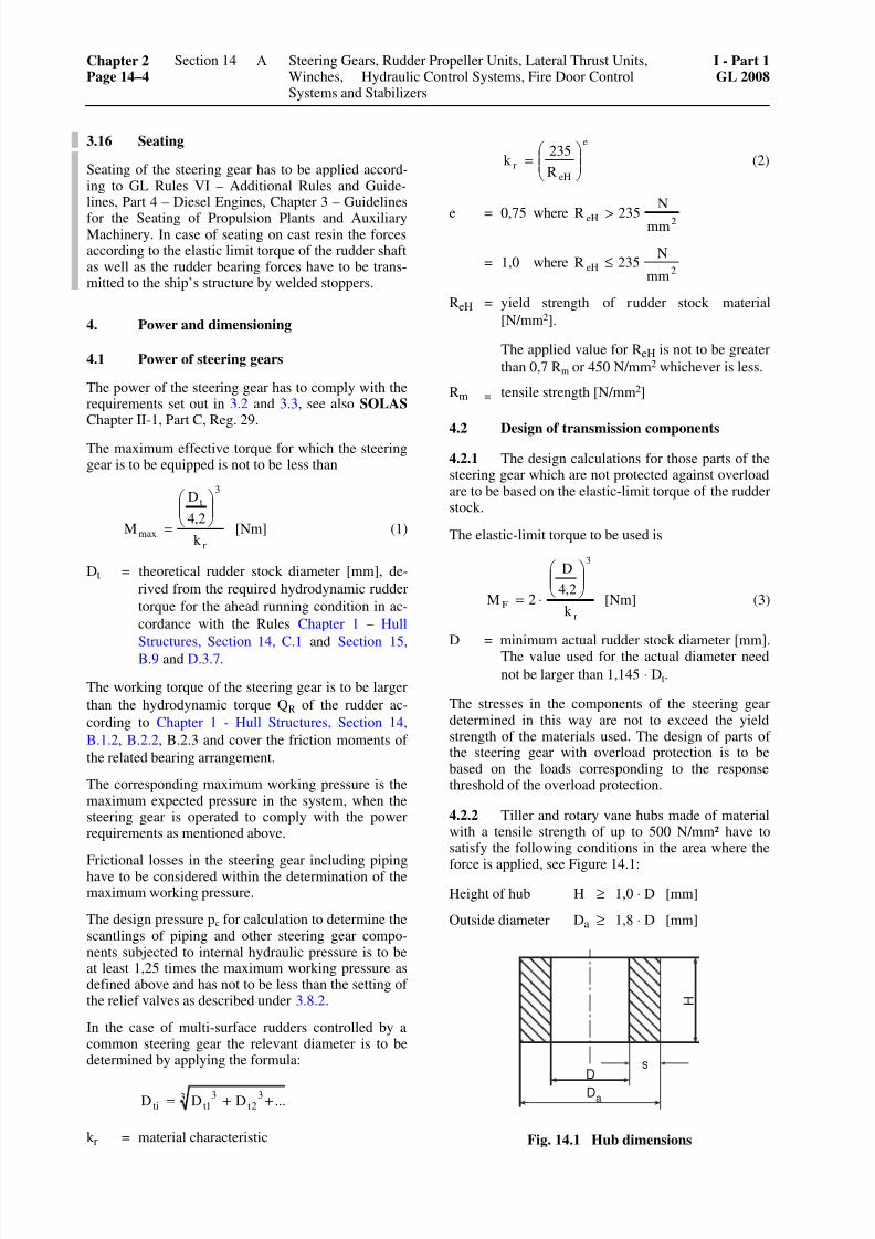
7262019 abschn14
httpslidepdfcomreaderfullabschn14 418
316 Seating
Seating of the steering gear has to be applied accord-ing to GL Rules VI ndash Additional Rules and Guide-lines Part 4 ndash Diesel Engines Chapter 3 ndash Guidelines
for the Seating of Propulsion Plants and AuxiliaryMachinery In case of seating on cast resin the forcesaccording to the elastic limit torque of the rudder shaftas well as the rudder bearing forces have to be trans-mitted to the shiprsquos structure by welded stoppers
4 Power and dimensioning
41 Power of steering gears
The power of the steering gear has to comply with therequirements set out in 32 and 33 see also SOLAS Chapter II-1 Part C Reg 29
The maximum effective torque for which the steeringgear is to be equipped is not to be less than
r
3
t
maxk
24
D
M
⎟⎟ ⎠
⎞⎜⎜⎝
⎛
= [Nm] (1)
Dt = theoretical rudder stock diameter [mm] de-
rived from the required hydrodynamic rudder
torque for the ahead running condition in ac-
cordance with the Rules Chapter 1 ndash Hull
Structures Section 14 C1 and Section 15
B9 and D37
The working torque of the steering gear is to be larger
than the hydrodynamic torque QR of the rudder ac-
cording to Chapter 1 - Hull Structures Section 14
B12 B22 B23 and cover the friction moments of
the related bearing arrangement
The corresponding maximum working pressure is themaximum expected pressure in the system when thesteering gear is operated to comply with the powerrequirements as mentioned above
Frictional losses in the steering gear including pipinghave to be considered within the determination of themaximum working pressure
The design pressure pc for calculation to determine thescantlings of piping and other steering gear compo-nents subjected to internal hydraulic pressure is to beat least 125 times the maximum working pressure asdefined above and has not to be less than the setting ofthe relief valves as described under 382
In the case of multi-surface rudders controlled by acommon steering gear the relevant diameter is to bedetermined by applying the formula
3 32t
31tti DDD ++=
k r = material characteristic
e
eHr
R
235k ⎟
⎟ ⎠
⎞⎜⎜⎝
⎛ = (2)
e = 075 2eHmm
N
235Rwhere gt
= 102eH
mm
N235Rwhere le
ReH = yield strength of rudder stock material
[Nmm2]
The applied value for ReH is not to be greater
than 07 Rm or 450 Nmm2 whichever is less
Rm = tensile strength [Nmm2]
42 Design of transmission components
421 The design calculations for those parts of thesteering gear which are not protected against overloadare to be based on the elastic-limit torque of the rudderstock
The elastic-limit torque to be used is
r
3
Fk
24
D
2M⎟⎟ ⎠
⎞⎜⎜⎝
⎛
sdot= [Nm] (3)
D = minimum actual rudder stock diameter [mm]
The value used for the actual diameter need
not be larger than 1145 sdot Dt
The stresses in the components of the steering geardetermined in this way are not to exceed the yieldstrength of the materials used The design of parts ofthe steering gear with overload protection is to bebased on the loads corresponding to the responsethreshold of the overload protection
422 Tiller and rotary vane hubs made of materialwith a tensile strength of up to 500 Nmmsup2 have tosatisfy the following conditions in the area where the
force is applied see Figure 141
Height of hub H ge 10 sdot D [mm]
Outside diameter Da ge 18 sdot D [mm]
sD
Da
H
Fig 141 Hub dimensions
Chapter 2Page 14ndash4
Section 14 Steering Gears Rudder Propeller Units Lateral Thrust UnitsWinches Hydraulic Control Systems Fire Door ControlSystems and Stabilizers
I - Part 1GL 2008
A
7262019 abschn14
httpslidepdfcomreaderfullabschn14 518
In special cases the outside diameter may be reduced to
Da = 17 sdot D [mm]
but the height of the hub must then be at least
H = 114 sdot D [mm]
423 Where materials with a tensile strengthgreater than 500 Nmm2 are used the section of thehub may be reduced by 10
424 Where the force is transmitted by clampedor tapered connections the elastic-limit torque maybe transmitted by a combination of frictional andpositive locking mechanism using adequately pre-tensioned bolts and a key
For the elastic limit torque according to formula (3)the thread root diameter of the bolts can be deter-
mined by applying the following formula
eHrk
Rk z
1D769d
sdotsdotsdotge [mm] (4)
D = actual rudder stock diameter [mm] Thevalue used for the actual diameter need not
be larger than 1145 sdot Dt
z = total number of bolts [ndash]
ReH = yield strength of the bolt material [Nmmsup2]
425 Split hubs of clamped joints are to be joinedtogether with at least four bolts
The key is not to be located at the joint in the clamp
426 Where the oil injection method is used to
joint the rudder tiller or rotary vanes to the rudder
stock methods of calculation appropriate to elasticitytheory are to be applied Calculations are to be based
on the elastic-limit torque allowing for a coefficient
of friction micro o = 015 for steel and micro o = 012 for nodu-
lar cast iron The von Mises equivalent stress calcu-
lated from the specific pressure p and the correspond-
ing tangential load based on the dimensions of the
shrunk joint is not to exceed 80 of the yieldstrength of the materials used
427 Where circumferential tension componentsare used to connect the rudder tiller or rotary vanes to
the rudder stock calculations are to be based on two
and a half times the maximum torque (but not more
than the elastic limit torque) allowing for a coeffi-
cient of friction of micro o = 012 The von Mises equiva-
lent stress calculated from the contact pressure p andthe corresponding tangential load based on the di-
mensions of the shrunk-on connection is not to ex-
ceed 80 of the yield strength of the materials used
When more than one circumferential tension compo-nents are used the torque capacity of the connection is
to be determined by adding the torques of the sole ten-sion components and applying a reduction factor of 09
5 Tests in the manufacturers works
51 Testing of power units
The power units are required to undergo tests on a
test stand in the manufacturers works
511 For diesel engines see Section 2
512 For electric motors see Chapter 3 ndash Electri-cal Installations Section 21
513 For hydraulic pumps and motors see VI ndashAdditional Rules and Guidelines Part 6 ndash PumpsCompressors Fittings Chapter 1 ndash Guidelines forDesign Construction and Testing of Pumps are to beapplied analogously Where the drive power is 50 kWor more this testing is to be carried out in the pres-ence of a GL Surveyor
52 Pressure and tightness tests
Pressure components are to undergo a pressure test
The test pressure is pp
pp = 15 sdot pc (5)
pc = design pressure for which a component orpiping system is designed with its mechani-cal characteristics [bar] For pressures above200 bar the test pressure need not exceedp + 100 bar
For pressure testing of pipes their valves and fittingssee Section 11 B4 and U5
Tightness tests are to be performed on components towhich this is appropriate
53 Final inspection and operational test
Following testing of the individual components andafter completion of assembly the steering gear isrequired to undergo final inspection and an opera-tional test Among other things the overload protec-tion is to be adjusted at this time
6 Shipboard trialsThe operational efficiency of the steering gear is tobe proved during the sea trials For this purpose theZ manoeuvre corresponding to 321 and 331 is tobe executed as a minimum requirement
B Rudder Propeller Units
1 General
11 Scope
The requirements of B are valid for the rudder pro-peller as main drive the ships manoeuvring stationand all transmission elements from the manoeuvringstation to the rudder propeller
I - Part 1GL 2008
Section 14 Steering Gears Rudder Propeller Units Lateral Thrust UnitsWinches Hydraulic Control Systems Fire Door Control Systemsand Stabilizers
Chapter 2Page 14ndash5
B
7262019 abschn14
httpslidepdfcomreaderfullabschn14 618
12 Documents for approval
Assembly and sectional drawings as well as partdrawings of the gears and propellers giving all thedata necessary for the examination are to be submit-
ted in triplicate to GL for approval
2 Materials
21 Approved materials
The selection of materials is subject as and whereapplicable to the provisions of A21 and to those ofSections 4 5 and 6
22 Testing of materials
All important components of the rudder propeller
involved in the transmission of torques and bendingmoments are to be tested under the supervision of GLin accordance with the Rules II ndash Materials andWelding Part 1 ndash Metallic Materials
3 Design and equipment
31 Number of rudder propellers
Each ship is to have at least two rudder propellersBoth units are to be capable of being operated inde-pendently of the other
32 Locking devicesEach rudder propeller is to be provided with a lock-ing device to prevent the unintentional rotation of thepropeller and the slewing mechanism of the unitwhich is out of operation at a time The locking de-vice is to be designed to securely lock the non-operated unit while operating the ship with the maxi-mum power of the remaining rudder propeller unitshowever at a ship speed of at least 7 kn
33 Control
331 Both the drive and the slewing mechanism
of each rudder propeller are to be controlled from amanoeuvring station on the navigating bridge
The controls are to be mutually independent and sodesigned that the rudder propeller cannot be turnedunintentionally
An additional combined control for all rudder propel-lers is permitted
Means have to be provided fulfilling the same pur-pose as the steering angle limitation in A35 Thesemay be dispensed with in cases where no danger forthe ship is caused by unintentional slewing of theunits at full power and ship speed to any angle
332 The failure of a single element within thecontrol and hydraulic system of one unit is not to leadto the failure of the other units
333 An auxiliary steering device is to be pro-vided for each rudder propeller In case of a failure ofthe main steering system the auxiliary steering deviceis at least to be capable of moving the rudder propel-ler to midship position
334 Where the hydraulic systems of more thanone rudder propeller are combined it is to be possiblein case of a loss of hydraulic oil to isolate the dam-aged system in such a way that the other controlsystems remain fully operational
34 Position indicators
341 The position of each rudder propeller is to beclearly discernible on the navigating bridge and ateach manoeuvring station
342 The actual position is also to be discernibleat the rudder propeller itself
35 Pipes
The pipes of hydraulic control systems are subject tothe provisions of A311 wherever relevant
36 Oil level indicators filters
Oil level indicators and filters are subject to the pro-visions of A312 wherever relevant
37 Lubrication
371 The lubricating oil supply is to be ensuredby a main pump and an independent standby pump
372 In the case of separate lubricating systems inwhich the main lubricating oil pumps can be replacedwith the means available on board the standby pumpmay be replaced by a complete spare pump Thisspare pump is to be carried on board and is to beready for mounting
4 Dimensioning
41 Gears
For the design of gears see Section 5
The slewing gears are in general to be designed asspur or bevel gears
42 Shaft line
For the dimensioning of the propeller shaft betweenpropeller and gear wheel see Section 4 For the di-mensioning of the remaining part of this shaft and allother gear shafts see Section 5
43 Propellers
For the design of propellers see Section 6
Chapter 2Page 14ndash6
Section 14 Steering Gears Rudder Propeller Units Lateral Thrust UnitsWinches Hydraulic Control Systems Fire Door ControlSystems and Stabilizers
I - Part 1GL 2008
B
7262019 abschn14
httpslidepdfcomreaderfullabschn14 718
44 Support pipe
The design of the support pipe and its attachment tothe ships hull is to take account of the loads due tothe propeller and nozzle thrust including the dynamic
components
45 Pipes
For arrangement and design of pipes valves fittingsand pressure vessels see Section 8 and Section 11A B C D U
5 Tests in the manufacturers works
51 Testing of power units
A51 applies wherever relevant
52 Pressure and tightness test
A52 applies wherever relevant
53 Final inspection and operational test
531 After inspection of the individual compo-nents and completion of assembly rudder propellersare to undergo a final inspection and operational testThe final inspection is to be combined with a trial runlasting several hours under part or full-load condi-
tions A check of the tooth clearance and of the toothcontact pattern is to be carried out
532 When no suitable test bed is available for theoperational and load testing of large rudder propel-lers the tests mentioned in 531 can be carried out onthe occasion of the dock test
533 Limitations on the scope of the test requireGLs consent
6 Testing on board
61 The faultless operation smooth running andbearing temperatures of the gears and control systemare to be checked during the sea trials under allsteaming conditions
After the conclusion of the sea trials the toothing isto be examined through the inspection openings andthe contact pattern is to be checked The tooth contactpattern is to be assessed on the basis of the referencevalues for the percentage area of contact given inSection 5 Table 56
62 The scope of the check on contact patternfollowing the sea trials may be limited with the Sur-veyors agreement provided that the checks on con-tact pattern called for in 531 and 532 have beensatisfactory
C Lateral Thrust Units
1 General
11 ScopeThe requirements contained in C apply to the lateralthrust unit the control station and all the transmissionelements from the control station to the lateral thrustunit
12 Documents for approval
Assembly and sectional drawings for lateral thrustunits with an input power of 100 kW and more to-gether with detail drawings of the gear mechanismand propellers containing all the data necessary forchecking are each to be submitted to GL in triplicatefor approval For propellers this only applies to aninput power exceeding 500 kW
2 Materials
Materials are subject as appropriate to the provi-sions of Sections 4 and 5
Section 6 applies analogously to the materials and thematerial testing of propellers
3 Dimensioning and design
The design of the relevant components of lateralthrust units is to be in accordance with Sections 4 and5 that of the propellers with Section 6
The pipe connections of hydraulic drive systems aresubject to the applicable requirements contained inA213 and A214
Lateral thrust units are to be capable of being oper-ated independently of other connected systems
Windmilling of the propeller during sea passages hasto be taken into account as an additional load caseOtherwise effective countermeasures have to be in-troduced to avoid windmilling eg a shaft brake
In the propeller area the thruster tunnel is to be pro-
tected against damages caused by cavitation erosionby effective measures such as stainless steel plating
For the electrical part of lateral thrust units seeChapter 3 ndash Electrical Installations Section 7 B
4 Tests in the manufacturers works
A5 is applicable as appropriate
For hydraulic pumps and motors with a drive powerof 100 kW or more the tests are to be conducted inthe presence of a GL Surveyor
For lateral thrust units with an input power of lessthan 100 kW final inspection and function tests maybe carried out by the manufacturer who will thenissue the relevant Manufacturer Inspection Certifi-cate
I - Part 1GL 2008
Section 14 Steering Gears Rudder Propeller Units Lateral Thrust UnitsWinches Hydraulic Control Systems Fire Door Control Systemsand Stabilizers
Chapter 2Page 14ndash7
C
7262019 abschn14
httpslidepdfcomreaderfullabschn14 818
5 Shipboard trials
Testing is to be carried out during sea trials duringwhich the operating times are to be established
D Windlasses
1 General
11 Scope
The requirements contained in D apply to boweranchor windlasses stern anchor windlasses com-bined anchor and mooring winches and chain stop-pers For anchors and chains see Chapter 1 ndash HullStructures Section 18
12 Documents for approval
121 For each type of anchor windlass and chainstopper general and sectional drawings circuit dia-grams of the hydraulic electrical and steam systemsand detail drawings of the main shaft cable lifterbrake stopper bar chain pulley and axle are to besubmitted in triplicate for approval
One copy of a description of the anchor windlassincluding the proposed overload protection and othersafety devices is likewise to be submitted
122 Where an anchor windlass is to be approvedfor several strengths and types of chain cable thecalculation relating to the maximum braking torque isto be submitted and proof furnished of the power andhauling-in speed in accordance with 41 correspond-ing to all the relevant types of anchor and chain ca-ble
123 One copy of the strength calculation forbolts chocks and stoppers securing the windlass tothe deck is likewise to be submitted This calculationis to consider forces acting on the windlass caused bythe loads specified in 42 and 43
2 Materials
21 Approved materials
211 The provisions contained in A21 are to beapplied as appropriate to the choice of materials
212 Cable lifters and chain pulleys are generallyto be made of cast steel Nodular cast iron is permit-ted for stud link chain cables of
up to 50 mm diameter for grade K 1
up to 42 mm diameter for grade K 2
up to 35 mm diameter for grade K 3
In special cases nodular cast iron may also be usedfor larger chain diameters by arrangement with GL
Grey cast iron is permitted for stud link chain cablesof
up to 30 mm diameter for grade K 1
up to 25 mm diameter for grade K 2
up to 21 mm diameter for grade K 3
22 Testing of materials
221 The materials for forged rolled and castparts which are stressed by the pull of the chain whenthe cable lifter is disengaged (main shaft cable lifterbrake bands brake spindles brake bolts tensionstraps stopper bar chain pulley and axle) are to betested under the supervision of GL in accordancewith the Rules II ndash Materials and Welding Part 1 ndashMetallic Materials
In the case of anchor windlasses for chains up to 14 mm in diameter an Manufacturer Inspection Certifi-cate issued by the producer may be accepted as proof
222 In the case of hydraulic systems the materialused for pipes (see Section 11 Table 113) as well asfor pressure vessels is also to be tested
3 Design and equipment
31 Type of drive
311 Windlasses are normally to be driven by an
engine which is independent of other deck machin-ery The piping systems of hydraulic and steam-driven windlass engines may be connected to otherhydraulic or steam systems provided that this is per-missible for the latter The windlasses are howeverto be capable of being operated independently ofother connected systems
312 Manual operation as the main driving powercan be allowed for anchors weighing up to 250 kg
313 In the case of hydraulic drives with a pipingsystem connected to other hydraulic systems a secondpump unit is recommended
314 In the case of windlasses with two cablelifters both cable lifters are to be engageable simulta-neously
32 Reversing mechanism
Power-driven windlasses are to be reversible Onwindlasses for ships with a Range of Service ratingup to RSA (50) and on those powered by internalcombustion engines a reversing mechanism may bedispensed with
33 Overload protectionFor the protection of the mechanical parts in theevent of the windlass jamming an overload protec-tion (eg slip coupling relief valve) is to be fitted to
Chapter 2Page 14ndash8
Section 14 Steering Gears Rudder Propeller Units Lateral Thrust UnitsWinches Hydraulic Control Systems Fire Door ControlSystems and Stabilizers
I - Part 1GL 2008
D
7262019 abschn14
httpslidepdfcomreaderfullabschn14 918
limit the maximum torque of the drive engine (cf412) The setting of the overload protection is to bespecified (eg in the operating instructions)
34 Couplings
Windlasses are to be fitted with disengageable cou-plings between the cable lifter and the drive shaft In
an emergency hydraulic or electrically operated cou-plings are to be capable of being disengaged by hand
35 Braking equipment
Windlasses are to be fitted with cable lifter brakeswhich are capable of holding a load in accordancewith 423 with the cable lifter disengaged In addi-tion where the gear mechanism is not of self-lockingtype a device (eg gearing brake lowering brake oilhydraulic brake) is to be fitted to prevent paying out
of the chain should the power unit fail while the cablelifter is engaged
36 Pipes
For the design and dimensions of pipes valves fit-tings pressure vessels etc see Section 8 and Section11 A B C D and U
37 Cable lifters
Cable lifters are to have at least five snugs
38 Windlass as warping winch
Combined windlasses and warping or mooring win-ches are not to be subjected to excessive loads even
when the maximum pull is exerted on the warping rope
39 Electrical equipment
For the electrical equipment the rules of Chapter 3 ndashElectrical Installations Section 7 E2 have to beobserved
310 Hydraulic equipment
For oil level indicators see A3121 For filters seeF322
4 Power and dimensioning
41 Driving power
411 Depending on the grade of the chain cable
and anchor depth windlasses must be capable of exert-ing the following nominal pull Z at a mean speed of at least 015 ms
Z = d2 (f + 0218 sdot (h ndash 100)) [N]
d = diameter of anchor chain [mm]
h = anchor depth [m]
f = nominal pull factor [ndash]
Grade K 1 K 2 K3
f 375 425 475
The calculation of nominal pull is to be based on aminimum anchor depth of 100 m
The pull of stern windlasses with an anchor rope canbe determined by reference to the anchor weight and
the diameter of the corresponding chain cable
412 The nominal output of the power units is tobe such hat the conditions specified in 411 can bemet for 30 minutes without interruption In additionthe power units are to be capable of developing amaximum torque equal to a maximum pull Zmax of
Zmax = 15 sdot Z [N]
at a reduced speed for at least two minutes
413 At the maximum torque specified in 412 ashort-time overload of up to 20 is allowed in the
case of internal combustion engines
414 An additional reduction gear stage may befitted in order to achieve the maximum torque
415 With manually operated windlasses steps are
to be taken to ensure that the anchor can be hoisted at a
mean speed of 0033 ms with the pull specified in
411 This is to be achieved without exceeding a man-ual force of 150 N applied to a crank radius of about 350 mm with the hand crank turned at about 30 rpm
42 Dimensioning of load-transmitting com-
ponents and chain stoppers
421 The basis for the design of the load-transmitting components of windlasses and chainstoppers are the anchors and chain cables specified inChapter 1 ndash Hull Structures Section 18
422 The cable lifter brake is to be so designedthat the anchor and chain can be safely stopped whilepaying out the chain cable
423 The dimensional design of those parts of the
windlass which are subjected to the chain pull when
the cable lifter is disengaged (cable lifter main shaft braking equipment bedframe and deck fastening) is to
be based on a theoretical pull equal to 80 of the
nominal breaking load specified in the GL Rules II ndash
Materials and Welding Part 1 ndash Metallic Materials for
the chain in question The design of the main shaft is to
take account of the braking forces and the cable lifter
brake is not to slip when subjected to this load
424 The theoretical pull may be reduced to 45 of the nominal breaking load for the chain providedthat a chain stopper approved by GL is fitted
425 The design of all other windlass components is
to be based upon a force acting on the cable lifter pitch
circle and equal to the maximum pull specified in 412
426 At the theoretical pull specified in 423 and424 the force exerted on the brake handwheel is notto exceed 500 N
I - Part 1GL 2008
Section 14 Steering Gears Rudder Propeller Units Lateral Thrust UnitsWinches Hydraulic Control Systems Fire Door Control Systemsand Stabilizers
Chapter 2Page 14ndash9
D
7262019 abschn14
httpslidepdfcomreaderfullabschn14 1018
427 The dimensional design of chain stoppers isto be based on a theoretical pull equal to 80 of thenominal breaking load of the chain
428 The total stresses applied to components are
to be below the minimum yield point of the materialsused
429 The foundations and pedestals of windlassesand chain stoppers are governed by Chapter 1 ndash HullStructures Section 10 B5
43 Strength requirements to resist green seaforces
431 For ships of length 80 m or more where theheight of the exposed deck in way of the item is lessthan 01L or 22 m above the summer load waterlinewhichever is the lesser the attachment of the wind-lass located within the forward quarter length of theship has to resist the green sea forces
The following pressures and associated areas are tobe applied (Fig 142)
ndash 200 kNm2 normal to the shaft axis and awayfrom the forward perpendicular over the pro- jected area in this direction
ndash 150 kNm2 parallel to the shaft axis and actingboth inboard and outboard separately over themultiple of f times the projected area in this di-rection
f = 1 + BH but not greater than 25
B = width of windlass measured parallel to theshaft axis [m]
H = overall height of the windlass [m]
Where mooring winches are integral with the anchorwindlass they are to be considered as part of thewindlass
432 Forces in the bolts chocks and stoppers
securing the windlass to the deck caused by greensea forces specified in 431 are to be calculated
The windlass is supported by N bolt groups eachcontaining one or more bolts (Fig 143)
The axial forces Ri in bolt group (or bolt) i positive
in tension is to be obtained from
Rxi = Px sdot h sdot xi sdot Ai Ix [kN]
Ryi = Py sdot h sdot yi sdot Ai Iy [kN]
Ri = Rxi + Ryi ndash Rsi [kN]
Px = force acting normal to the shaft axis [kN]Py = force acting parallel to the shaft axis either
inboard or outboard whichever gives the
greater force in bolt group i [kN]
h = shaft height above the windlass mounting [cm]
xi yi = x and y coordinates of bolt group i from the
centroid of all N bolt groups positive in the
direction opposite to that of the applied force
[cm]
Ai = cross sectional area of all bolts in group i
[cm2]
Ix = Σ Ai xi2 for N bolt groups [cm4]
Iy = Σ Ai yi2 for N bolt groups [cm4]
Rsi = static reaction at bolt group i due to weight
of windlass [kN]
Fig 142 Direction of forces and weight
Chapter 2Page 14ndash10
Section 14 Steering Gears Rudder Propeller Units Lateral Thrust UnitsWinches Hydraulic Control Systems Fire Door ControlSystems and Stabilizers
I - Part 1GL 2008
D
7262019 abschn14
httpslidepdfcomreaderfullabschn14 1118
Fig 143 Sign convention
433 Shear forces Fxi and Fyi applied to the boltgroup i and the resultant combined force are to beobtained from
Fxi = x wP m
N
minusαsdot [kN]
Fyi =y wP m
N
minusαsdot [kN]
Fi = ( )2 2
xi yiF F+ [kN]
α = coefficient of friction to be taken equal to 05
mw = weight-force of windlass [kN]
N = number of bolt groups
Axial tensile and compressive forces and lateral forcescalculated in 431 432 and 433 are also to be con-sidered in the design of the supporting structure
434 Tensile axial stresses in the individual boltsin each bolt group i are to be calculated The horizon-tal forces Fxi and Fyi are normally to be reacted by
shear chocks
Where fitted bolts are designed to support these shear forces in one or both directions the von Mises equiva-lent stresses in the individual bolts are to be calculated and compared to the stress under proof load
Where pourable resins are incorporated in the holdingdown arrangement due account is to be taken in thecalculations
The safety factor against bolt proof strength is to benot less than 20
5 Tests in the manufacturers works
51 Testing of driving engines
A51 is applicable as appropriate
52 Pressure and tightness tests
A52 is applicable as appropriate
53 Final inspection and operational testing
531 Following manufacture windlasses are re-quired to undergo final inspection and operationaltesting at the maximum pull The hauling-in speed is
to be verified with continuous application of thenominal pull During the tests particular attention is tobe given to the testing and where necessary setting ofbraking and safety equipment
In the case of anchor windlasses for chains gt 14 mmin diameter this test is to be performed in the presenceof the GL Surveyor
In the case of anchor windlasses for chains le 14 mmdiameter the Manufacturers Inspection Certificatewill be accepted
532 Where the manufacturing works does nothave adequate facilities the aforementioned testsincluding the adjustment of the overload protectioncan be carried out on board ship In these cases func-tional testing in the manufacturers works is to beperformed under no-load conditions
533 Following manufacture chain stoppers arerequired to undergo final inspection and operationaltesting in the presence of the GL Surveyor
6 Shipboard trials
The anchor equipment is to be tested during sea trialsAs a minimum requirement this test is required todemonstrate that the conditions specified in 314 and422 can be fulfilled
I - Part 1GL 2008
Section 14 Steering Gears Rudder Propeller Units Lateral Thrust UnitsWinches Hydraulic Control Systems Fire Door Control Systemsand Stabilizers
Chapter 2Page 14ndash11
D
7262019 abschn14
httpslidepdfcomreaderfullabschn14 1218
E Winches
1 Towing winches
The design and testing of towing winches are to com-ply with Chapter 1 ndash Hull Structures Section 25 C5
2 Winches for cargo handling gear and otherlifting equipment
The design and testing of these winches are to complywith VI ndash Additional Rules and Guidelines Part 2 ndashLoading Gear Chapter 2 ndash Guidelines for the Con-struction and Survey of Lifting Appliances
3 Lifeboat winches
The design and testing of life boat winches are to com-ply with VI ndash Additional Rules and Guidelines Part 2 ndash
Loading Gear Chapter 1 ndash Guidelines for Life-Saving
Launching Appliances
4 Winches for special equipment
The GL Guidelines VI ndash Additional Rules and Guide-lines Part 2 ndash Loading Gear Chapter 2 ndash Guidelinesfor the Construction and Survey of Lifting Appliancesare to be applied as appropriate to winches for spe-cial equipment such as ramps hoisting gear and hatchcovers
F Hydraulic Systems
1 General
11 Scope
The requirements contained in F apply to hydraulicsystems used for example to operate hatch coversclosing appliances in the ships shell and bulkheads
and hoists The requirements are to be applied inanalogous manner to the ships other hydraulic sys-tems except where covered by the requirements ofSection 11
12 Documents for approval
The diagram of the hydraulic system together withdrawings of the cylinders containing all the data nec-essary for assessing the system eg operating datadescriptions materials used etc are to be submittedin triplicate for approval
13 Dimensional design
For the design of pressure vessels see Section 8 forthe dimensions of pipes and hose assemblies seeSection 11
2 Materials
21 Approved materials
211 Components fulfilling a major function in thepower transmission system normally are to be made ofsteel or cast steel in accordance with the Rules II ndashMaterials and Welding Part 1 ndash Metallic MaterialsThe use of other materials is subject to special agree-ment with GL
Cylinders are preferably to be made of steel cast steelor nodular cast iron (with a predominantly ferriticmatrix)
212 Pipes are to be made of seamless or longitu-dinally welded steel tubes
213 The pressure-loaded walls of valves fittingspumps motors etc are subject to the requirements ofSection 11 B
22 Testing of materials
The following components are to be tested under su-pervision of GL in accordance with the Rules II ndashMaterials and Welding Part 1 ndash Metallic Materials
a) Pressure pipes with DN gt 50 (see Section 11
Table 113)
b) Cylinders where the product of the pressuretimes the diameter
pezul Di gt 20000
pezul = maximum allowable working pressure[bar]
Di = inside diameter of tube [mm]
c) For testing the materials of hydraulic accumula-tors see Section 8 B
Testing of materials by GL may be dispensed with inthe case of cylinders for secondary applications pro-vided that evidence in the form of a Manufacturer TestReport (eg to EN 10204- 23) is supplied
3 Hydraulic operating equipment for hatchcovers
31 Design and construction
311 Hydraulic operating equipment for hatchcovers may be served either by one common powerstation for all hatch covers or by several power sta-tions individually assigned to a single hatch coverWhere a common power station is used at least twopump units are to be fitted Where the systems aresupplied individually change-over valves or fittings
are required so that operation can be maintainedshould one pump unit fail
312 Movement of hatch covers is not to be initi-ated merely by the starting of the pumps Special con-
Chapter 2Page 14ndash12
Section 14 Steering Gears Rudder Propeller Units Lateral Thrust UnitsWinches Hydraulic Control Systems Fire Door ControlSystems and Stabilizers
I - Part 1GL 2008
F
7262019 abschn14
httpslidepdfcomreaderfullabschn14 1318
trol stations are to be provided for controlling theopening and closing of hatch covers The controls areto be so designed that as soon as they are releasedmovement of the hatch covers stops immediately
The hatches should normally be visible from the con-trol stations Should this in exceptional cases beimpossible opening and closing of the hatches is to besignalled by an audible alarm In addition the controlstations must then be equipped with indicators formonitoring the movement of the hatch covers
At the control stations the controls governing theopening and closing operations are to be appropriatelymarked
313 Suitable equipment is to be fitted in or im-mediately adjacent to each power unit (cylinder orsimilar) used to operate hatch covers to enable the
hatches to be closed slowly in the event of a powerfailure respectively due to a pipe rupture
32 Pipes
321 Pipes are to be installed and secured in such away as to protect them from damage while enablingthem to be properly maintained from outside
Pipes may be led through tanks in pipe tunnels onlyThe laying of such pipes through cargo spaces is to berestricted to the essential minimum The piping systemis to be fitted with relief valves to limit the pressure to
the maximum allowable working pressure
322 The piping system is to be fitted with filtersfor cleaning the hydraulic fluid
Equipment is to be provided to enable the hydraulicsystem to be vented
323 The accumulator space of the hydraulic ac-cumulator is to have permanent access to the reliefvalve of the connected system The gas chamber of theaccumulator may be filled only with inert gases Gasand operating medium are to be separated by accumu-lator bags diaphragms or similar
324 Connection between the hydraulic systemused for hatch cover operation and other hydraulicsystems is permitted only with the consent of GL
325 For oil level indicators see A3121
326 The hydraulic fluids must be suitable for theintended ambient and service temperatures
33 Hose assemblies
The construction of hose assemblies is to conform to
Section 11 U The requirement that hose assembliesshould be of flame-resistant construction may be setaside for hose lines in spaces not subject to a fire haz-ard and in systems not important to the safety of theship
34 Emergency operation
It is recommended that devices be fitted which areindependent of the main system and which enablehatch covers to be opened and closed in the event of
failure of the main system Such devices may forexample take the form of loose rings enabling hatchcovers to be moved by cargo winches warpingwinches etc
4 Hydraulically operated closing appliancesin the ships shell
41 Scope
The following requirements apply to the powerequipment of hydraulically operated closing appli-ances in the ships shell such as shell and landing
doors which are normally not operated while at seaFor the design and arrangement of the closures seeChapter 1 ndash Hull Structures Section 6 H
42 Design
421 The movement of shell doors etc may not beinitiated merely by the starting of the pumps at thepower station
422 Local control inaccessible to unauthorizedpersons is to be provided for every closing appliancein the ships shell As soon as the controls (push-buttons levers or similar) are released movement of
the appliance is to stop immediately
423 Closing appliances in the ships shell nor-mally are to be visible from the control stations If themovement cannot be observed audible alarms are tobe fitted In addition the control stations are then to beequipped with indicators enabling the execution of themovement to be monitored
424 Closing appliances in the ships shell are to be
fitted with devices which prevent them from moving
into their end positions at excessive speed Such de-vices are not to cause the power unit to be switched off
As far as is required mechanical means are to beprovided for locking closing appliances in the openposition
425 Every power unit driving horizontally hingedor vertically operated closing appliances is to be fittedwith throttle valves or similar devices to prevent sud-den dropping of the closing appliance
426 It is recommended that the driving power beshared between at least two mutually independentpump sets
43 Pipes hose assemblies
32 and 33 are to be applied in analogous manner tothe pipes and hose lines of hydraulically operatedclosing appliances in the ships shell
I - Part 1GL 2008
Section 14 Steering Gears Rudder Propeller Units Lateral Thrust UnitsWinches Hydraulic Control Systems Fire Door Control Systemsand Stabilizers
Chapter 2Page 14ndash13
F
7262019 abschn14
httpslidepdfcomreaderfullabschn14 1418
5 Bulkhead closures
51 General
511 Scope
5111 The following requirements apply to thepower equipment of hydraulically-operated watertightbulkhead doors on passenger and cargo vessels
5112 For details of the number design and ar-rangement of bulkhead doors see Chapter 1 ndash HullStructures Sections 11 26 and 28
The SOLAS regulations Chapter II-1 Regulations 1516 and 259 are not affected by these provisions
512 Design
Bulkhead doors are to be power-driven sliding doorsmoving horizontally Other designs require the ap-proval of GL and the provision of additional safetymeasures where necessary
513 Piping
5131 Wherever applicable the requirements forpipes in hydraulic bulkhead closing systems are gov-erned by the Rules in 32 with the restriction that theuse of flexible hose assemblies is not permitted
5132 The hydraulic fluids must be suitable for theintended ambient and service temperatures
514 Drive unit
5141 A selector switch with the switch positionslocal control and close all doors is to be providedat the central control station on the bridge
Under normal conditions this switch is to be set tolocal control
In the local control position the doors may be lo-cally opened and closed without automatic closure
In the close all doors position all doors are closedautomatically They may be reopened by means of thelocal control device but are to close again automati-
cally as soon as the local door controls are released
It is not to be possible to open the closed doors fromthe bridge
5142 Closed or open bulkhead doors are not to beset in motion automatically in the event of a powerfailure
5143 The control system is to be designed in such away that an individual fault inside the control systemincluding the piping does not have any adverse effecton the operation of other bulkhead doors
5144 The controls for the power drive are to be lo-cated at least 16 m above the floor on both sides of the
bulkhead close to the door The controls are to be in-stalled in such a way that a person passing through the
door is able to hold both controls in the open position
The controls are to return to their original positionautomatically when released
5145 The direction of movement of the controls isto be clearly marked and is to be the same as the direc-
tion of movement of the door
5146 In the event that an individual element failsinside the control system for the power drive includ-ing the piping but excluding the closing cylinders onthe door or similar components the operational abilityof the manually-operated control system is not to beimpaired
5147 The movement of the power driven bulkheaddoors may not be initiated simply by switching on thedrive units but only by actuating additional devices
5148 The control and monitoring equipment for the
drive units is to be housed in the central control stationon the bridge
515 Manual control
Each door is to have a manual control system which isindependent of the power drive
516 Indicators
Visual indicators to show whether each bulkhead dooris fully open or closed are to be installed at the centralcontrol station on the bridge
517 Electrical equipment
For details of electrical equipment see Chapter 3 ndashElectrical Installations Sections 9 and 14 D
52 Passenger vessels
In addition to 51 the following requirements are to betaken into consideration in the case of passenger ves-sels
521 Design and location
5211 Bulkhead doors together with the powerplants and including the piping electric cables andcontrol instruments must have a minimum distance of
02 times B from the perpendiculars which interset thehull contour line when the ship is at load draught(B = beam)
5212 The bulkhead doors are to be capable of be-ing closed securely using the power drive as well asusing the manual control even when the ship has apermanent heel of 15deg
5213 The force required to close a door is to becalculated based on a static water pressure of at least
1 m above the door coaming
5214 All power driven doors are to be capable ofbeing closed simultaneously from the bridge with theship upright in not more than 60 seconds
Chapter 2Page 14ndash14
Section 14 Steering Gears Rudder Propeller Units Lateral Thrust UnitsWinches Hydraulic Control Systems Fire Door ControlSystems and Stabilizers
I - Part 1GL 2008
F
7262019 abschn14
httpslidepdfcomreaderfullabschn14 1518
5215 The closing speed of each individual doormust have a uniform rate Their closing time withpower operation and with the ship upright may be notmore than 40 seconds and not less than 20 secondsfrom the start of the motion with the door completely
open until it is closed
5216 Power operated bulkhead closing systemsmay be fitted as an option with a central hydraulicdrive for all doors or with mutually independent hy-draulic or electric drives for each individual door
5217 The bulkhead closing system is not to beconnected to other systems
522 Central hydraulic system - power drives
5221 Two mutually independent power pump unitsare to be installed if possible above the bulkhead or
freeboard deck and outside the machinery spaces
5222 Each pump unit is to be capable of closing allconnected bulkhead doors simultaneously
5223 The hydraulic system is to incorporate accu-mulators with sufficient capacity to operate all con-nected doors three times ie close open and recloseat the minimum permitted accumulator pressure
523 Individual hydraulic drive
5231 An independent power pump unit is to befitted to each door for opening and closing the door
5232 An accumulator is also to be provided withsufficient capacity to operate the door three times ieclose open and reclose at the minimum permittedaccumulator pressure
524 Individual electric drive
5241 An independent electric drive unit is to befitted to each door for opening and closing the door
5242 In the event of a failure of either the mainpower supply or the emergency power supply thedrive unit is still to be capable of operating the door
three times ie close open and reclose
525 Manual control
5251 Manual control is to be capable of beingoperated at the door from both sides of the bulkheadas well as from an easily accessible control stationlocated above the bulkhead or freeboard decks andoutside the machinery space
5252 The controls at the door are to allow the doorto be opened and closed
5253 The control above the deck is to allow the
door to be closed
5254 The fully open door is to be capable of beingclosed using manual control within 90 seconds withthe ship upright
5255 A means of communication is to be providedbetween the control stations for remote manual driveabove the bulkhead of freeboard decks and the centralcontrol station on the bridge
526 Indicators
The indicators described in 516 are to be installed atthe operating stations for manual control above thebulkhead or freeboard deck for each door
527 Alarms
5271 While all the doors are being closed from thebridge an audible alarm is to sound at each door Thisalarm is to start at least 5 seconds - but not more than10 seconds - before the door starts moving and is tocontinue right throughout the door movement
5272 When the door is being closed by remotecontrol using the manual control above the bulkheador freeboard deck it is sufficient for the alarm tosound only while the door is actually moving
5273 The installation of an additional intermittentvisual alarm may be required in the passenger areasand in areas where there is a high level of backgroundnoise
5274 With a central hydraulic system the mini-mum permitted oil level in the service tank is to besignalled by means of an independent audible andvisual alarm at the central control station on the
bridge
5275 The alarm described in 5274 is also to beprovided to signal the minimum permitted accumula-tor pressure of the central hydraulic system
5276 A decentralized hydraulic system which hasindividual drive units on each door the minimumpermitted accumulator pressure is to be signalled bymeans of a group alarm at the central control stationon the bridge
Visual indicators are also to be fitted at the operatingstations for each individual door
53 Cargo vessels
In addition to the specifications laid down in 51 thefollowing requirements are to be observed for cargovessels
531 Manual control
5311 The manual control is to be capable of beingoperated at the door from both sides of the bulkhead
5312 The controls are to allow the door to beopened and closed
532 Alarms
Whilst all the doors are being closed from the bridgean audible alarm is to be sounded all the time they arein motion
I - Part 1GL 2008
Section 14 Steering Gears Rudder Propeller Units Lateral Thrust UnitsWinches Hydraulic Control Systems Fire Door Control Systemsand Stabilizers
Chapter 2Page 14ndash15
F
7262019 abschn14
httpslidepdfcomreaderfullabschn14 1618
6 Hoists
61 Definition
For the purposes of these requirements hoists include
hydraulically operated appliances such as wheelhousehoists lifts lifting platforms and similar equipment
62 Design
621 Hoists may be supplied either by a combinedpower station or individually by several power stationsfor each single lifting appliances
In the case of a combined power supply and hydraulicdrives whose piping system is connected to otherhydraulic systems a second pump unit is to be fitted
622 The movement of hoists is not to be capable
of being initiated merely by starting the pumps Themovement of hoists is to be controlled from specialoperating stations The controls are to be so arrangedthat as soon as they are released the movement of thehoist ceases immediately
623 Local controls inaccessible to unauthorizedpersons are to be fitted The movement of hoists nor-mally is to be visible from the operating stations If themovement cannot be observed audible andor visualwarning devices are to be fitted In addition the oper-ating stations are then to be equipped with indicatorsfor monitoring the movement of the hoist
624 Devices are to be fitted which prevent thehoist from reaching its end position at excessivespeed These devices are not to cause the power unit tobe switched off As far as is necessary mechanicalmeans are to be provided for locking the hoist in itsend positions
If the locking devices cannot be observed from theoperating station a visual indicator is to be installed atthe operating station to show the locking status
625 313 is to be applied in analogous manner tothose devices which if the power unit fails or a pipe
ruptures ensure that the hoist is slowly lowered
63 Pipes hose assemblies
32 and 33 apply in analogous manner to the pipesand hose lines of hydraulically operated hoists
7 Tests in the manufacturers works
71 Testing of power units
The power units are required to undergo testing on atest bed Manufacturer Test Report for this testing areto be presented at the final inspection of the hydraulic
system
72 Pressure and tightness tests
A52 is applicable in analogous manner
8 Shipboard trials
After installation the equipment is to undergo anoperational test
The operational test of watertight doors has to includethe emergency operating system and determination ofthe closing times
G Fire Door Control Systems
1 General
11 Scope
The requirements of G apply to power operated firedoor control systems on passenger vessels TheseRules meet the requirements for the control systems offire doors laid down in Chapter II-2 Regulation 94 ofSOLAS 74 as amended The following requirementsmay be applied as appropriate to other fire door con-trol systems
12 Documents for approval
The electric and pneumatic diagram together withdrawings of the cylinders containing all the data nec-essary for assessing the system eg operating datadescriptions materials used etc are to be submittedin triplicate for approval
13 Dimensional design
For the design of pressure vessels see Section 8 forthe dimensions of pipes see Section 11
2 Materials
21 Approved materials
Cylinders are to be made of corrosion resistant materials
Stainless steel or copper is to be used for pipes
The use of other materials requires the special agree-ment of GL
The use of hose assemblies is not permittedInsulation material has to be of an approved type
The quality properties of all critical components foroperation and safety is to conform to recognized rulesand standards
22 Material testing
Suitable proof of the quality properties of the materi-als used is to be furnished For parts under pressureCertificates according to Table 113 for all other partsManufacturer Test Reports are required
GLs Surveyor reserves the right to order supplemen-
tary tests of his own to be carried out where he con-siders that the circumstances justify this
See Section 8 B for details on the material testing ofcompressed air accumulators
Chapter 2Page 14ndash16
Section 14 Steering Gears Rudder Propeller Units Lateral Thrust UnitsWinches Hydraulic Control Systems Fire Door ControlSystems and Stabilizers
I - Part 1GL 2008
G
7262019 abschn14
httpslidepdfcomreaderfullabschn14 1718
3 Design
31 Each door is to be capable of being openedand closed by a single person from both sides of thebulkhead
32 Fire doors are to be capable of closing auto-matically even against a permanent heeling angle ofthe ship of 35deg
33 The closing time of hinged doors with theship upright may be no more than 40 seconds and noless than 10 seconds from the start of the movement ofthe door when fully open to its closed position foreach individual door
The closing speed of sliding doors is to be steady andwith the ship upright may be no more than 02 ms
and no less than 01 ms
Measures are to be taken to ensure that any persons in
the door areas are protected from any excessive danger
34 All doors are to be capable of being closedfrom the central control station either jointly or ingroups It also is to be possible to initiate closure ateach individual door The closing switch is to take theform of a locking switch
35 Visual indicators are to be installed at thecentral control station to show that each fire door isfully closed
36 Power driven doors leading from specialareas (eg car decks railway decks) in accordancewith Chapter II-2 Regulation 346 of SOLAS 74 asamended or from comparable spaces to control sta-tions stairwells and also to accommodation and ser-vice spaces and which are closed when the ship is atsea do not need to be equipped with indicators asdescribed in 35 and alarms as described in 312
37 Operating agents for the control system are tobe installed next to each door on both sides of thebulkhead and by their operation a door which has been
closed from the central control station can be re-opened The controls are to return to their originalposition when released thereby causing the door toclose again
In an emergency it is to be possible to use the controlsto interrupt immediately the opening of the door andbring about its immediate closure
A combination of the controls with the door handlemay be permitted
The controls are to be designed in such a way that anopen door can be closed locally In addition each dooris to be capable of being locked locally in such a waythat it cannot longer be opened by remote control
38 The control unit at the door is to be equippedwith a device which will vent the pneumatic system or
cut off the electric energy of the door control systemsimultaneously shutting off the main supply line andthereby allowing emergency operation by hand
39 The door is to close automatically should thecentral power supply fail The doors may not reopenautomatically when the central supply is restored
Accumulator systems are to be located in the immedi-ate vicinity of the door being sufficient to allow thedoor to be completely opened and closed at least tenmore times with the ship upright using the localcontrols
310 Measures are to be taken to ensure that thedoor can still be operated by hand in the event of fail-ure of the energy supply
311 Should the central energy supply fail in thelocal control area of a door the capability of the otherdoors to function may not be adversely affected
312 Doors which are closed from the central con-trol station are to be fitted with an audible alarm Oncethe door close command has been given this alarm isto start at least 5 seconds but not more than10 seconds before the door starts to move and con-tinue sounding until the door is completely closed
313 Fire doors are to be fitted with safety stripssuch that a closing door reopens as soon as contact ismade with them Following contact with the safetystrip the opening travel of the door is to be no morethan 1 m
314 Local door controls including all compo-nents are to be accessible for maintenance and ad- justment
315 The control system is to be of approved de-sign Their capability to operate in the event of fire is
to be proven in accordance with the FTP-Code 1 andunder supervision of GL
The control system is to conform to the following
minimum requirements
3151 The door still is to be capable of being oper-ated safely for 60 minutes at a minimum ambienttemperature of 200 degC by means of the central energysupply
3152 The central energy supply for the other doorsnot affected by fire may not be impaired
3153 At ambient temperatures in excess of 300 degCthe central energy supply is to be shut off automati-cally and the local control system is to be de-energized The residual energy is still to be sufficient
to close an open door completely during this process
1 IMO Res MSC 61(67)
I - Part 1GL 2008
Section 14 Steering Gears Rudder Propeller Units Lateral Thrust UnitsWinches Hydraulic Control Systems Fire Door Control Systemsand Stabilizers
Chapter 2Page 14ndash17
G
7262019 abschn14
httpslidepdfcomreaderfullabschn14 1818
The shut-off device is to be capable of shutting off theenergy supply for one hour with a temperature varia-tion corresponding to the standardized time-tempera-ture curve given in Section II-2 Regulation 3 of SO-LAS 74 as amended
316 The pneumatic system is to be protectedagainst overpressure
317 Drainage and venting facilities are to be pro-vided
318 Air filtering and drying facilities are to beprovided
319 For details of the electrical equipment cfChapter 3 ndash Electrical Installations Section 14 D
4 Tests in the manufacturers works
The complete control system is to be subjected to atype approval test In addition the required construc-tion according to 2 and 3 and the operability have tobe proven for the complete drive
5 Shipboard trials
After installation the systems are to be subjected to anoperating test which also includes emergency opera-tion and the verification of closing times
H Stabilizers
1 General
11 Scope
The requirements contained in H apply to stabilizerdrive units necessary for the operation and safety ofthe ship
12 Documents for approval
Assembly and general drawings together with dia-grams of the hydraulic and electrical equipment con-taining all the data necessary for checking are to besubmitted in triplicate for approval
2 Design
A213 and A214 are applicable in analogous man-ner to the pipe connections of hydraulic drive units
3 Pressure and tightness test
A52 is applicable in analogous manner
4 Shipboard trials
The operational efficiency of the stabilizer equipmentis to be demonstrated during the sea trials
Chapter 2Page 14ndash18
Section 14 Steering Gears Rudder Propeller Units Lateral Thrust UnitsWinches Hydraulic Control Systems Fire Door ControlSystems and Stabilizers
I - Part 1GL 2008
H
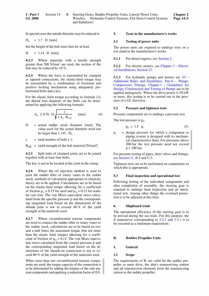
7262019 abschn14
httpslidepdfcomreaderfullabschn14 518
In special cases the outside diameter may be reduced to
Da = 17 sdot D [mm]
but the height of the hub must then be at least
H = 114 sdot D [mm]
423 Where materials with a tensile strengthgreater than 500 Nmm2 are used the section of thehub may be reduced by 10
424 Where the force is transmitted by clampedor tapered connections the elastic-limit torque maybe transmitted by a combination of frictional andpositive locking mechanism using adequately pre-tensioned bolts and a key
For the elastic limit torque according to formula (3)the thread root diameter of the bolts can be deter-
mined by applying the following formula
eHrk
Rk z
1D769d
sdotsdotsdotge [mm] (4)
D = actual rudder stock diameter [mm] Thevalue used for the actual diameter need not
be larger than 1145 sdot Dt
z = total number of bolts [ndash]
ReH = yield strength of the bolt material [Nmmsup2]
425 Split hubs of clamped joints are to be joinedtogether with at least four bolts
The key is not to be located at the joint in the clamp
426 Where the oil injection method is used to
joint the rudder tiller or rotary vanes to the rudder
stock methods of calculation appropriate to elasticitytheory are to be applied Calculations are to be based
on the elastic-limit torque allowing for a coefficient
of friction micro o = 015 for steel and micro o = 012 for nodu-
lar cast iron The von Mises equivalent stress calcu-
lated from the specific pressure p and the correspond-
ing tangential load based on the dimensions of the
shrunk joint is not to exceed 80 of the yieldstrength of the materials used
427 Where circumferential tension componentsare used to connect the rudder tiller or rotary vanes to
the rudder stock calculations are to be based on two
and a half times the maximum torque (but not more
than the elastic limit torque) allowing for a coeffi-
cient of friction of micro o = 012 The von Mises equiva-
lent stress calculated from the contact pressure p andthe corresponding tangential load based on the di-
mensions of the shrunk-on connection is not to ex-
ceed 80 of the yield strength of the materials used
When more than one circumferential tension compo-nents are used the torque capacity of the connection is
to be determined by adding the torques of the sole ten-sion components and applying a reduction factor of 09
5 Tests in the manufacturers works
51 Testing of power units
The power units are required to undergo tests on a
test stand in the manufacturers works
511 For diesel engines see Section 2
512 For electric motors see Chapter 3 ndash Electri-cal Installations Section 21
513 For hydraulic pumps and motors see VI ndashAdditional Rules and Guidelines Part 6 ndash PumpsCompressors Fittings Chapter 1 ndash Guidelines forDesign Construction and Testing of Pumps are to beapplied analogously Where the drive power is 50 kWor more this testing is to be carried out in the pres-ence of a GL Surveyor
52 Pressure and tightness tests
Pressure components are to undergo a pressure test
The test pressure is pp
pp = 15 sdot pc (5)
pc = design pressure for which a component orpiping system is designed with its mechani-cal characteristics [bar] For pressures above200 bar the test pressure need not exceedp + 100 bar
For pressure testing of pipes their valves and fittingssee Section 11 B4 and U5
Tightness tests are to be performed on components towhich this is appropriate
53 Final inspection and operational test
Following testing of the individual components andafter completion of assembly the steering gear isrequired to undergo final inspection and an opera-tional test Among other things the overload protec-tion is to be adjusted at this time
6 Shipboard trialsThe operational efficiency of the steering gear is tobe proved during the sea trials For this purpose theZ manoeuvre corresponding to 321 and 331 is tobe executed as a minimum requirement
B Rudder Propeller Units
1 General
11 Scope
The requirements of B are valid for the rudder pro-peller as main drive the ships manoeuvring stationand all transmission elements from the manoeuvringstation to the rudder propeller
I - Part 1GL 2008
Section 14 Steering Gears Rudder Propeller Units Lateral Thrust UnitsWinches Hydraulic Control Systems Fire Door Control Systemsand Stabilizers
Chapter 2Page 14ndash5
B
7262019 abschn14
httpslidepdfcomreaderfullabschn14 618
12 Documents for approval
Assembly and sectional drawings as well as partdrawings of the gears and propellers giving all thedata necessary for the examination are to be submit-
ted in triplicate to GL for approval
2 Materials
21 Approved materials
The selection of materials is subject as and whereapplicable to the provisions of A21 and to those ofSections 4 5 and 6
22 Testing of materials
All important components of the rudder propeller
involved in the transmission of torques and bendingmoments are to be tested under the supervision of GLin accordance with the Rules II ndash Materials andWelding Part 1 ndash Metallic Materials
3 Design and equipment
31 Number of rudder propellers
Each ship is to have at least two rudder propellersBoth units are to be capable of being operated inde-pendently of the other
32 Locking devicesEach rudder propeller is to be provided with a lock-ing device to prevent the unintentional rotation of thepropeller and the slewing mechanism of the unitwhich is out of operation at a time The locking de-vice is to be designed to securely lock the non-operated unit while operating the ship with the maxi-mum power of the remaining rudder propeller unitshowever at a ship speed of at least 7 kn
33 Control
331 Both the drive and the slewing mechanism
of each rudder propeller are to be controlled from amanoeuvring station on the navigating bridge
The controls are to be mutually independent and sodesigned that the rudder propeller cannot be turnedunintentionally
An additional combined control for all rudder propel-lers is permitted
Means have to be provided fulfilling the same pur-pose as the steering angle limitation in A35 Thesemay be dispensed with in cases where no danger forthe ship is caused by unintentional slewing of theunits at full power and ship speed to any angle
332 The failure of a single element within thecontrol and hydraulic system of one unit is not to leadto the failure of the other units
333 An auxiliary steering device is to be pro-vided for each rudder propeller In case of a failure ofthe main steering system the auxiliary steering deviceis at least to be capable of moving the rudder propel-ler to midship position
334 Where the hydraulic systems of more thanone rudder propeller are combined it is to be possiblein case of a loss of hydraulic oil to isolate the dam-aged system in such a way that the other controlsystems remain fully operational
34 Position indicators
341 The position of each rudder propeller is to beclearly discernible on the navigating bridge and ateach manoeuvring station
342 The actual position is also to be discernibleat the rudder propeller itself
35 Pipes
The pipes of hydraulic control systems are subject tothe provisions of A311 wherever relevant
36 Oil level indicators filters
Oil level indicators and filters are subject to the pro-visions of A312 wherever relevant
37 Lubrication
371 The lubricating oil supply is to be ensuredby a main pump and an independent standby pump
372 In the case of separate lubricating systems inwhich the main lubricating oil pumps can be replacedwith the means available on board the standby pumpmay be replaced by a complete spare pump Thisspare pump is to be carried on board and is to beready for mounting
4 Dimensioning
41 Gears
For the design of gears see Section 5
The slewing gears are in general to be designed asspur or bevel gears
42 Shaft line
For the dimensioning of the propeller shaft betweenpropeller and gear wheel see Section 4 For the di-mensioning of the remaining part of this shaft and allother gear shafts see Section 5
43 Propellers
For the design of propellers see Section 6
Chapter 2Page 14ndash6
Section 14 Steering Gears Rudder Propeller Units Lateral Thrust UnitsWinches Hydraulic Control Systems Fire Door ControlSystems and Stabilizers
I - Part 1GL 2008
B
7262019 abschn14
httpslidepdfcomreaderfullabschn14 718
44 Support pipe
The design of the support pipe and its attachment tothe ships hull is to take account of the loads due tothe propeller and nozzle thrust including the dynamic
components
45 Pipes
For arrangement and design of pipes valves fittingsand pressure vessels see Section 8 and Section 11A B C D U
5 Tests in the manufacturers works
51 Testing of power units
A51 applies wherever relevant
52 Pressure and tightness test
A52 applies wherever relevant
53 Final inspection and operational test
531 After inspection of the individual compo-nents and completion of assembly rudder propellersare to undergo a final inspection and operational testThe final inspection is to be combined with a trial runlasting several hours under part or full-load condi-
tions A check of the tooth clearance and of the toothcontact pattern is to be carried out
532 When no suitable test bed is available for theoperational and load testing of large rudder propel-lers the tests mentioned in 531 can be carried out onthe occasion of the dock test
533 Limitations on the scope of the test requireGLs consent
6 Testing on board
61 The faultless operation smooth running andbearing temperatures of the gears and control systemare to be checked during the sea trials under allsteaming conditions
After the conclusion of the sea trials the toothing isto be examined through the inspection openings andthe contact pattern is to be checked The tooth contactpattern is to be assessed on the basis of the referencevalues for the percentage area of contact given inSection 5 Table 56
62 The scope of the check on contact patternfollowing the sea trials may be limited with the Sur-veyors agreement provided that the checks on con-tact pattern called for in 531 and 532 have beensatisfactory
C Lateral Thrust Units
1 General
11 ScopeThe requirements contained in C apply to the lateralthrust unit the control station and all the transmissionelements from the control station to the lateral thrustunit
12 Documents for approval
Assembly and sectional drawings for lateral thrustunits with an input power of 100 kW and more to-gether with detail drawings of the gear mechanismand propellers containing all the data necessary forchecking are each to be submitted to GL in triplicatefor approval For propellers this only applies to aninput power exceeding 500 kW
2 Materials
Materials are subject as appropriate to the provi-sions of Sections 4 and 5
Section 6 applies analogously to the materials and thematerial testing of propellers
3 Dimensioning and design
The design of the relevant components of lateralthrust units is to be in accordance with Sections 4 and5 that of the propellers with Section 6
The pipe connections of hydraulic drive systems aresubject to the applicable requirements contained inA213 and A214
Lateral thrust units are to be capable of being oper-ated independently of other connected systems
Windmilling of the propeller during sea passages hasto be taken into account as an additional load caseOtherwise effective countermeasures have to be in-troduced to avoid windmilling eg a shaft brake
In the propeller area the thruster tunnel is to be pro-
tected against damages caused by cavitation erosionby effective measures such as stainless steel plating
For the electrical part of lateral thrust units seeChapter 3 ndash Electrical Installations Section 7 B
4 Tests in the manufacturers works
A5 is applicable as appropriate
For hydraulic pumps and motors with a drive powerof 100 kW or more the tests are to be conducted inthe presence of a GL Surveyor
For lateral thrust units with an input power of lessthan 100 kW final inspection and function tests maybe carried out by the manufacturer who will thenissue the relevant Manufacturer Inspection Certifi-cate
I - Part 1GL 2008
Section 14 Steering Gears Rudder Propeller Units Lateral Thrust UnitsWinches Hydraulic Control Systems Fire Door Control Systemsand Stabilizers
Chapter 2Page 14ndash7
C
7262019 abschn14
httpslidepdfcomreaderfullabschn14 818
5 Shipboard trials
Testing is to be carried out during sea trials duringwhich the operating times are to be established
D Windlasses
1 General
11 Scope
The requirements contained in D apply to boweranchor windlasses stern anchor windlasses com-bined anchor and mooring winches and chain stop-pers For anchors and chains see Chapter 1 ndash HullStructures Section 18
12 Documents for approval
121 For each type of anchor windlass and chainstopper general and sectional drawings circuit dia-grams of the hydraulic electrical and steam systemsand detail drawings of the main shaft cable lifterbrake stopper bar chain pulley and axle are to besubmitted in triplicate for approval
One copy of a description of the anchor windlassincluding the proposed overload protection and othersafety devices is likewise to be submitted
122 Where an anchor windlass is to be approvedfor several strengths and types of chain cable thecalculation relating to the maximum braking torque isto be submitted and proof furnished of the power andhauling-in speed in accordance with 41 correspond-ing to all the relevant types of anchor and chain ca-ble
123 One copy of the strength calculation forbolts chocks and stoppers securing the windlass tothe deck is likewise to be submitted This calculationis to consider forces acting on the windlass caused bythe loads specified in 42 and 43
2 Materials
21 Approved materials
211 The provisions contained in A21 are to beapplied as appropriate to the choice of materials
212 Cable lifters and chain pulleys are generallyto be made of cast steel Nodular cast iron is permit-ted for stud link chain cables of
up to 50 mm diameter for grade K 1
up to 42 mm diameter for grade K 2
up to 35 mm diameter for grade K 3
In special cases nodular cast iron may also be usedfor larger chain diameters by arrangement with GL
Grey cast iron is permitted for stud link chain cablesof
up to 30 mm diameter for grade K 1
up to 25 mm diameter for grade K 2
up to 21 mm diameter for grade K 3
22 Testing of materials
221 The materials for forged rolled and castparts which are stressed by the pull of the chain whenthe cable lifter is disengaged (main shaft cable lifterbrake bands brake spindles brake bolts tensionstraps stopper bar chain pulley and axle) are to betested under the supervision of GL in accordancewith the Rules II ndash Materials and Welding Part 1 ndashMetallic Materials
In the case of anchor windlasses for chains up to 14 mm in diameter an Manufacturer Inspection Certifi-cate issued by the producer may be accepted as proof
222 In the case of hydraulic systems the materialused for pipes (see Section 11 Table 113) as well asfor pressure vessels is also to be tested
3 Design and equipment
31 Type of drive
311 Windlasses are normally to be driven by an
engine which is independent of other deck machin-ery The piping systems of hydraulic and steam-driven windlass engines may be connected to otherhydraulic or steam systems provided that this is per-missible for the latter The windlasses are howeverto be capable of being operated independently ofother connected systems
312 Manual operation as the main driving powercan be allowed for anchors weighing up to 250 kg
313 In the case of hydraulic drives with a pipingsystem connected to other hydraulic systems a secondpump unit is recommended
314 In the case of windlasses with two cablelifters both cable lifters are to be engageable simulta-neously
32 Reversing mechanism
Power-driven windlasses are to be reversible Onwindlasses for ships with a Range of Service ratingup to RSA (50) and on those powered by internalcombustion engines a reversing mechanism may bedispensed with
33 Overload protectionFor the protection of the mechanical parts in theevent of the windlass jamming an overload protec-tion (eg slip coupling relief valve) is to be fitted to
Chapter 2Page 14ndash8
Section 14 Steering Gears Rudder Propeller Units Lateral Thrust UnitsWinches Hydraulic Control Systems Fire Door ControlSystems and Stabilizers
I - Part 1GL 2008
D
7262019 abschn14
httpslidepdfcomreaderfullabschn14 918
limit the maximum torque of the drive engine (cf412) The setting of the overload protection is to bespecified (eg in the operating instructions)
34 Couplings
Windlasses are to be fitted with disengageable cou-plings between the cable lifter and the drive shaft In
an emergency hydraulic or electrically operated cou-plings are to be capable of being disengaged by hand
35 Braking equipment
Windlasses are to be fitted with cable lifter brakeswhich are capable of holding a load in accordancewith 423 with the cable lifter disengaged In addi-tion where the gear mechanism is not of self-lockingtype a device (eg gearing brake lowering brake oilhydraulic brake) is to be fitted to prevent paying out
of the chain should the power unit fail while the cablelifter is engaged
36 Pipes
For the design and dimensions of pipes valves fit-tings pressure vessels etc see Section 8 and Section11 A B C D and U
37 Cable lifters
Cable lifters are to have at least five snugs
38 Windlass as warping winch
Combined windlasses and warping or mooring win-ches are not to be subjected to excessive loads even
when the maximum pull is exerted on the warping rope
39 Electrical equipment
For the electrical equipment the rules of Chapter 3 ndashElectrical Installations Section 7 E2 have to beobserved
310 Hydraulic equipment
For oil level indicators see A3121 For filters seeF322
4 Power and dimensioning
41 Driving power
411 Depending on the grade of the chain cable
and anchor depth windlasses must be capable of exert-ing the following nominal pull Z at a mean speed of at least 015 ms
Z = d2 (f + 0218 sdot (h ndash 100)) [N]
d = diameter of anchor chain [mm]
h = anchor depth [m]
f = nominal pull factor [ndash]
Grade K 1 K 2 K3
f 375 425 475
The calculation of nominal pull is to be based on aminimum anchor depth of 100 m
The pull of stern windlasses with an anchor rope canbe determined by reference to the anchor weight and
the diameter of the corresponding chain cable
412 The nominal output of the power units is tobe such hat the conditions specified in 411 can bemet for 30 minutes without interruption In additionthe power units are to be capable of developing amaximum torque equal to a maximum pull Zmax of
Zmax = 15 sdot Z [N]
at a reduced speed for at least two minutes
413 At the maximum torque specified in 412 ashort-time overload of up to 20 is allowed in the
case of internal combustion engines
414 An additional reduction gear stage may befitted in order to achieve the maximum torque
415 With manually operated windlasses steps are
to be taken to ensure that the anchor can be hoisted at a
mean speed of 0033 ms with the pull specified in
411 This is to be achieved without exceeding a man-ual force of 150 N applied to a crank radius of about 350 mm with the hand crank turned at about 30 rpm
42 Dimensioning of load-transmitting com-
ponents and chain stoppers
421 The basis for the design of the load-transmitting components of windlasses and chainstoppers are the anchors and chain cables specified inChapter 1 ndash Hull Structures Section 18
422 The cable lifter brake is to be so designedthat the anchor and chain can be safely stopped whilepaying out the chain cable
423 The dimensional design of those parts of the
windlass which are subjected to the chain pull when
the cable lifter is disengaged (cable lifter main shaft braking equipment bedframe and deck fastening) is to
be based on a theoretical pull equal to 80 of the
nominal breaking load specified in the GL Rules II ndash
Materials and Welding Part 1 ndash Metallic Materials for
the chain in question The design of the main shaft is to
take account of the braking forces and the cable lifter
brake is not to slip when subjected to this load
424 The theoretical pull may be reduced to 45 of the nominal breaking load for the chain providedthat a chain stopper approved by GL is fitted
425 The design of all other windlass components is
to be based upon a force acting on the cable lifter pitch
circle and equal to the maximum pull specified in 412
426 At the theoretical pull specified in 423 and424 the force exerted on the brake handwheel is notto exceed 500 N
I - Part 1GL 2008
Section 14 Steering Gears Rudder Propeller Units Lateral Thrust UnitsWinches Hydraulic Control Systems Fire Door Control Systemsand Stabilizers
Chapter 2Page 14ndash9
D
7262019 abschn14
httpslidepdfcomreaderfullabschn14 1018
427 The dimensional design of chain stoppers isto be based on a theoretical pull equal to 80 of thenominal breaking load of the chain
428 The total stresses applied to components are
to be below the minimum yield point of the materialsused
429 The foundations and pedestals of windlassesand chain stoppers are governed by Chapter 1 ndash HullStructures Section 10 B5
43 Strength requirements to resist green seaforces
431 For ships of length 80 m or more where theheight of the exposed deck in way of the item is lessthan 01L or 22 m above the summer load waterlinewhichever is the lesser the attachment of the wind-lass located within the forward quarter length of theship has to resist the green sea forces
The following pressures and associated areas are tobe applied (Fig 142)
ndash 200 kNm2 normal to the shaft axis and awayfrom the forward perpendicular over the pro- jected area in this direction
ndash 150 kNm2 parallel to the shaft axis and actingboth inboard and outboard separately over themultiple of f times the projected area in this di-rection
f = 1 + BH but not greater than 25
B = width of windlass measured parallel to theshaft axis [m]
H = overall height of the windlass [m]
Where mooring winches are integral with the anchorwindlass they are to be considered as part of thewindlass
432 Forces in the bolts chocks and stoppers
securing the windlass to the deck caused by greensea forces specified in 431 are to be calculated
The windlass is supported by N bolt groups eachcontaining one or more bolts (Fig 143)
The axial forces Ri in bolt group (or bolt) i positive
in tension is to be obtained from
Rxi = Px sdot h sdot xi sdot Ai Ix [kN]
Ryi = Py sdot h sdot yi sdot Ai Iy [kN]
Ri = Rxi + Ryi ndash Rsi [kN]
Px = force acting normal to the shaft axis [kN]Py = force acting parallel to the shaft axis either
inboard or outboard whichever gives the
greater force in bolt group i [kN]
h = shaft height above the windlass mounting [cm]
xi yi = x and y coordinates of bolt group i from the
centroid of all N bolt groups positive in the
direction opposite to that of the applied force
[cm]
Ai = cross sectional area of all bolts in group i
[cm2]
Ix = Σ Ai xi2 for N bolt groups [cm4]
Iy = Σ Ai yi2 for N bolt groups [cm4]
Rsi = static reaction at bolt group i due to weight
of windlass [kN]
Fig 142 Direction of forces and weight
Chapter 2Page 14ndash10
Section 14 Steering Gears Rudder Propeller Units Lateral Thrust UnitsWinches Hydraulic Control Systems Fire Door ControlSystems and Stabilizers
I - Part 1GL 2008
D
7262019 abschn14
httpslidepdfcomreaderfullabschn14 1118
Fig 143 Sign convention
433 Shear forces Fxi and Fyi applied to the boltgroup i and the resultant combined force are to beobtained from
Fxi = x wP m
N
minusαsdot [kN]
Fyi =y wP m
N
minusαsdot [kN]
Fi = ( )2 2
xi yiF F+ [kN]
α = coefficient of friction to be taken equal to 05
mw = weight-force of windlass [kN]
N = number of bolt groups
Axial tensile and compressive forces and lateral forcescalculated in 431 432 and 433 are also to be con-sidered in the design of the supporting structure
434 Tensile axial stresses in the individual boltsin each bolt group i are to be calculated The horizon-tal forces Fxi and Fyi are normally to be reacted by
shear chocks
Where fitted bolts are designed to support these shear forces in one or both directions the von Mises equiva-lent stresses in the individual bolts are to be calculated and compared to the stress under proof load
Where pourable resins are incorporated in the holdingdown arrangement due account is to be taken in thecalculations
The safety factor against bolt proof strength is to benot less than 20
5 Tests in the manufacturers works
51 Testing of driving engines
A51 is applicable as appropriate
52 Pressure and tightness tests
A52 is applicable as appropriate
53 Final inspection and operational testing
531 Following manufacture windlasses are re-quired to undergo final inspection and operationaltesting at the maximum pull The hauling-in speed is
to be verified with continuous application of thenominal pull During the tests particular attention is tobe given to the testing and where necessary setting ofbraking and safety equipment
In the case of anchor windlasses for chains gt 14 mmin diameter this test is to be performed in the presenceof the GL Surveyor
In the case of anchor windlasses for chains le 14 mmdiameter the Manufacturers Inspection Certificatewill be accepted
532 Where the manufacturing works does nothave adequate facilities the aforementioned testsincluding the adjustment of the overload protectioncan be carried out on board ship In these cases func-tional testing in the manufacturers works is to beperformed under no-load conditions
533 Following manufacture chain stoppers arerequired to undergo final inspection and operationaltesting in the presence of the GL Surveyor
6 Shipboard trials
The anchor equipment is to be tested during sea trialsAs a minimum requirement this test is required todemonstrate that the conditions specified in 314 and422 can be fulfilled
I - Part 1GL 2008
Section 14 Steering Gears Rudder Propeller Units Lateral Thrust UnitsWinches Hydraulic Control Systems Fire Door Control Systemsand Stabilizers
Chapter 2Page 14ndash11
D
7262019 abschn14
httpslidepdfcomreaderfullabschn14 1218
E Winches
1 Towing winches
The design and testing of towing winches are to com-ply with Chapter 1 ndash Hull Structures Section 25 C5
2 Winches for cargo handling gear and otherlifting equipment
The design and testing of these winches are to complywith VI ndash Additional Rules and Guidelines Part 2 ndashLoading Gear Chapter 2 ndash Guidelines for the Con-struction and Survey of Lifting Appliances
3 Lifeboat winches
The design and testing of life boat winches are to com-ply with VI ndash Additional Rules and Guidelines Part 2 ndash
Loading Gear Chapter 1 ndash Guidelines for Life-Saving
Launching Appliances
4 Winches for special equipment
The GL Guidelines VI ndash Additional Rules and Guide-lines Part 2 ndash Loading Gear Chapter 2 ndash Guidelinesfor the Construction and Survey of Lifting Appliancesare to be applied as appropriate to winches for spe-cial equipment such as ramps hoisting gear and hatchcovers
F Hydraulic Systems
1 General
11 Scope
The requirements contained in F apply to hydraulicsystems used for example to operate hatch coversclosing appliances in the ships shell and bulkheads
and hoists The requirements are to be applied inanalogous manner to the ships other hydraulic sys-tems except where covered by the requirements ofSection 11
12 Documents for approval
The diagram of the hydraulic system together withdrawings of the cylinders containing all the data nec-essary for assessing the system eg operating datadescriptions materials used etc are to be submittedin triplicate for approval
13 Dimensional design
For the design of pressure vessels see Section 8 forthe dimensions of pipes and hose assemblies seeSection 11
2 Materials
21 Approved materials
211 Components fulfilling a major function in thepower transmission system normally are to be made ofsteel or cast steel in accordance with the Rules II ndashMaterials and Welding Part 1 ndash Metallic MaterialsThe use of other materials is subject to special agree-ment with GL
Cylinders are preferably to be made of steel cast steelor nodular cast iron (with a predominantly ferriticmatrix)
212 Pipes are to be made of seamless or longitu-dinally welded steel tubes
213 The pressure-loaded walls of valves fittingspumps motors etc are subject to the requirements ofSection 11 B
22 Testing of materials
The following components are to be tested under su-pervision of GL in accordance with the Rules II ndashMaterials and Welding Part 1 ndash Metallic Materials
a) Pressure pipes with DN gt 50 (see Section 11
Table 113)
b) Cylinders where the product of the pressuretimes the diameter
pezul Di gt 20000
pezul = maximum allowable working pressure[bar]
Di = inside diameter of tube [mm]
c) For testing the materials of hydraulic accumula-tors see Section 8 B
Testing of materials by GL may be dispensed with inthe case of cylinders for secondary applications pro-vided that evidence in the form of a Manufacturer TestReport (eg to EN 10204- 23) is supplied
3 Hydraulic operating equipment for hatchcovers
31 Design and construction
311 Hydraulic operating equipment for hatchcovers may be served either by one common powerstation for all hatch covers or by several power sta-tions individually assigned to a single hatch coverWhere a common power station is used at least twopump units are to be fitted Where the systems aresupplied individually change-over valves or fittings
are required so that operation can be maintainedshould one pump unit fail
312 Movement of hatch covers is not to be initi-ated merely by the starting of the pumps Special con-
Chapter 2Page 14ndash12
Section 14 Steering Gears Rudder Propeller Units Lateral Thrust UnitsWinches Hydraulic Control Systems Fire Door ControlSystems and Stabilizers
I - Part 1GL 2008
F
7262019 abschn14
httpslidepdfcomreaderfullabschn14 1318
trol stations are to be provided for controlling theopening and closing of hatch covers The controls areto be so designed that as soon as they are releasedmovement of the hatch covers stops immediately
The hatches should normally be visible from the con-trol stations Should this in exceptional cases beimpossible opening and closing of the hatches is to besignalled by an audible alarm In addition the controlstations must then be equipped with indicators formonitoring the movement of the hatch covers
At the control stations the controls governing theopening and closing operations are to be appropriatelymarked
313 Suitable equipment is to be fitted in or im-mediately adjacent to each power unit (cylinder orsimilar) used to operate hatch covers to enable the
hatches to be closed slowly in the event of a powerfailure respectively due to a pipe rupture
32 Pipes
321 Pipes are to be installed and secured in such away as to protect them from damage while enablingthem to be properly maintained from outside
Pipes may be led through tanks in pipe tunnels onlyThe laying of such pipes through cargo spaces is to berestricted to the essential minimum The piping systemis to be fitted with relief valves to limit the pressure to
the maximum allowable working pressure
322 The piping system is to be fitted with filtersfor cleaning the hydraulic fluid
Equipment is to be provided to enable the hydraulicsystem to be vented
323 The accumulator space of the hydraulic ac-cumulator is to have permanent access to the reliefvalve of the connected system The gas chamber of theaccumulator may be filled only with inert gases Gasand operating medium are to be separated by accumu-lator bags diaphragms or similar
324 Connection between the hydraulic systemused for hatch cover operation and other hydraulicsystems is permitted only with the consent of GL
325 For oil level indicators see A3121
326 The hydraulic fluids must be suitable for theintended ambient and service temperatures
33 Hose assemblies
The construction of hose assemblies is to conform to
Section 11 U The requirement that hose assembliesshould be of flame-resistant construction may be setaside for hose lines in spaces not subject to a fire haz-ard and in systems not important to the safety of theship
34 Emergency operation
It is recommended that devices be fitted which areindependent of the main system and which enablehatch covers to be opened and closed in the event of
failure of the main system Such devices may forexample take the form of loose rings enabling hatchcovers to be moved by cargo winches warpingwinches etc
4 Hydraulically operated closing appliancesin the ships shell
41 Scope
The following requirements apply to the powerequipment of hydraulically operated closing appli-ances in the ships shell such as shell and landing
doors which are normally not operated while at seaFor the design and arrangement of the closures seeChapter 1 ndash Hull Structures Section 6 H
42 Design
421 The movement of shell doors etc may not beinitiated merely by the starting of the pumps at thepower station
422 Local control inaccessible to unauthorizedpersons is to be provided for every closing appliancein the ships shell As soon as the controls (push-buttons levers or similar) are released movement of
the appliance is to stop immediately
423 Closing appliances in the ships shell nor-mally are to be visible from the control stations If themovement cannot be observed audible alarms are tobe fitted In addition the control stations are then to beequipped with indicators enabling the execution of themovement to be monitored
424 Closing appliances in the ships shell are to be
fitted with devices which prevent them from moving
into their end positions at excessive speed Such de-vices are not to cause the power unit to be switched off
As far as is required mechanical means are to beprovided for locking closing appliances in the openposition
425 Every power unit driving horizontally hingedor vertically operated closing appliances is to be fittedwith throttle valves or similar devices to prevent sud-den dropping of the closing appliance
426 It is recommended that the driving power beshared between at least two mutually independentpump sets
43 Pipes hose assemblies
32 and 33 are to be applied in analogous manner tothe pipes and hose lines of hydraulically operatedclosing appliances in the ships shell
I - Part 1GL 2008
Section 14 Steering Gears Rudder Propeller Units Lateral Thrust UnitsWinches Hydraulic Control Systems Fire Door Control Systemsand Stabilizers
Chapter 2Page 14ndash13
F
7262019 abschn14
httpslidepdfcomreaderfullabschn14 1418
5 Bulkhead closures
51 General
511 Scope
5111 The following requirements apply to thepower equipment of hydraulically-operated watertightbulkhead doors on passenger and cargo vessels
5112 For details of the number design and ar-rangement of bulkhead doors see Chapter 1 ndash HullStructures Sections 11 26 and 28
The SOLAS regulations Chapter II-1 Regulations 1516 and 259 are not affected by these provisions
512 Design
Bulkhead doors are to be power-driven sliding doorsmoving horizontally Other designs require the ap-proval of GL and the provision of additional safetymeasures where necessary
513 Piping
5131 Wherever applicable the requirements forpipes in hydraulic bulkhead closing systems are gov-erned by the Rules in 32 with the restriction that theuse of flexible hose assemblies is not permitted
5132 The hydraulic fluids must be suitable for theintended ambient and service temperatures
514 Drive unit
5141 A selector switch with the switch positionslocal control and close all doors is to be providedat the central control station on the bridge
Under normal conditions this switch is to be set tolocal control
In the local control position the doors may be lo-cally opened and closed without automatic closure
In the close all doors position all doors are closedautomatically They may be reopened by means of thelocal control device but are to close again automati-
cally as soon as the local door controls are released
It is not to be possible to open the closed doors fromthe bridge
5142 Closed or open bulkhead doors are not to beset in motion automatically in the event of a powerfailure
5143 The control system is to be designed in such away that an individual fault inside the control systemincluding the piping does not have any adverse effecton the operation of other bulkhead doors
5144 The controls for the power drive are to be lo-cated at least 16 m above the floor on both sides of the
bulkhead close to the door The controls are to be in-stalled in such a way that a person passing through the
door is able to hold both controls in the open position
The controls are to return to their original positionautomatically when released
5145 The direction of movement of the controls isto be clearly marked and is to be the same as the direc-
tion of movement of the door
5146 In the event that an individual element failsinside the control system for the power drive includ-ing the piping but excluding the closing cylinders onthe door or similar components the operational abilityof the manually-operated control system is not to beimpaired
5147 The movement of the power driven bulkheaddoors may not be initiated simply by switching on thedrive units but only by actuating additional devices
5148 The control and monitoring equipment for the
drive units is to be housed in the central control stationon the bridge
515 Manual control
Each door is to have a manual control system which isindependent of the power drive
516 Indicators
Visual indicators to show whether each bulkhead dooris fully open or closed are to be installed at the centralcontrol station on the bridge
517 Electrical equipment
For details of electrical equipment see Chapter 3 ndashElectrical Installations Sections 9 and 14 D
52 Passenger vessels
In addition to 51 the following requirements are to betaken into consideration in the case of passenger ves-sels
521 Design and location
5211 Bulkhead doors together with the powerplants and including the piping electric cables andcontrol instruments must have a minimum distance of
02 times B from the perpendiculars which interset thehull contour line when the ship is at load draught(B = beam)
5212 The bulkhead doors are to be capable of be-ing closed securely using the power drive as well asusing the manual control even when the ship has apermanent heel of 15deg
5213 The force required to close a door is to becalculated based on a static water pressure of at least
1 m above the door coaming
5214 All power driven doors are to be capable ofbeing closed simultaneously from the bridge with theship upright in not more than 60 seconds
Chapter 2Page 14ndash14
Section 14 Steering Gears Rudder Propeller Units Lateral Thrust UnitsWinches Hydraulic Control Systems Fire Door ControlSystems and Stabilizers
I - Part 1GL 2008
F
7262019 abschn14
httpslidepdfcomreaderfullabschn14 1518
5215 The closing speed of each individual doormust have a uniform rate Their closing time withpower operation and with the ship upright may be notmore than 40 seconds and not less than 20 secondsfrom the start of the motion with the door completely
open until it is closed
5216 Power operated bulkhead closing systemsmay be fitted as an option with a central hydraulicdrive for all doors or with mutually independent hy-draulic or electric drives for each individual door
5217 The bulkhead closing system is not to beconnected to other systems
522 Central hydraulic system - power drives
5221 Two mutually independent power pump unitsare to be installed if possible above the bulkhead or
freeboard deck and outside the machinery spaces
5222 Each pump unit is to be capable of closing allconnected bulkhead doors simultaneously
5223 The hydraulic system is to incorporate accu-mulators with sufficient capacity to operate all con-nected doors three times ie close open and recloseat the minimum permitted accumulator pressure
523 Individual hydraulic drive
5231 An independent power pump unit is to befitted to each door for opening and closing the door
5232 An accumulator is also to be provided withsufficient capacity to operate the door three times ieclose open and reclose at the minimum permittedaccumulator pressure
524 Individual electric drive
5241 An independent electric drive unit is to befitted to each door for opening and closing the door
5242 In the event of a failure of either the mainpower supply or the emergency power supply thedrive unit is still to be capable of operating the door
three times ie close open and reclose
525 Manual control
5251 Manual control is to be capable of beingoperated at the door from both sides of the bulkheadas well as from an easily accessible control stationlocated above the bulkhead or freeboard decks andoutside the machinery space
5252 The controls at the door are to allow the doorto be opened and closed
5253 The control above the deck is to allow the
door to be closed
5254 The fully open door is to be capable of beingclosed using manual control within 90 seconds withthe ship upright
5255 A means of communication is to be providedbetween the control stations for remote manual driveabove the bulkhead of freeboard decks and the centralcontrol station on the bridge
526 Indicators
The indicators described in 516 are to be installed atthe operating stations for manual control above thebulkhead or freeboard deck for each door
527 Alarms
5271 While all the doors are being closed from thebridge an audible alarm is to sound at each door Thisalarm is to start at least 5 seconds - but not more than10 seconds - before the door starts moving and is tocontinue right throughout the door movement
5272 When the door is being closed by remotecontrol using the manual control above the bulkheador freeboard deck it is sufficient for the alarm tosound only while the door is actually moving
5273 The installation of an additional intermittentvisual alarm may be required in the passenger areasand in areas where there is a high level of backgroundnoise
5274 With a central hydraulic system the mini-mum permitted oil level in the service tank is to besignalled by means of an independent audible andvisual alarm at the central control station on the
bridge
5275 The alarm described in 5274 is also to beprovided to signal the minimum permitted accumula-tor pressure of the central hydraulic system
5276 A decentralized hydraulic system which hasindividual drive units on each door the minimumpermitted accumulator pressure is to be signalled bymeans of a group alarm at the central control stationon the bridge
Visual indicators are also to be fitted at the operatingstations for each individual door
53 Cargo vessels
In addition to the specifications laid down in 51 thefollowing requirements are to be observed for cargovessels
531 Manual control
5311 The manual control is to be capable of beingoperated at the door from both sides of the bulkhead
5312 The controls are to allow the door to beopened and closed
532 Alarms
Whilst all the doors are being closed from the bridgean audible alarm is to be sounded all the time they arein motion
I - Part 1GL 2008
Section 14 Steering Gears Rudder Propeller Units Lateral Thrust UnitsWinches Hydraulic Control Systems Fire Door Control Systemsand Stabilizers
Chapter 2Page 14ndash15
F
7262019 abschn14
httpslidepdfcomreaderfullabschn14 1618
6 Hoists
61 Definition
For the purposes of these requirements hoists include
hydraulically operated appliances such as wheelhousehoists lifts lifting platforms and similar equipment
62 Design
621 Hoists may be supplied either by a combinedpower station or individually by several power stationsfor each single lifting appliances
In the case of a combined power supply and hydraulicdrives whose piping system is connected to otherhydraulic systems a second pump unit is to be fitted
622 The movement of hoists is not to be capable
of being initiated merely by starting the pumps Themovement of hoists is to be controlled from specialoperating stations The controls are to be so arrangedthat as soon as they are released the movement of thehoist ceases immediately
623 Local controls inaccessible to unauthorizedpersons are to be fitted The movement of hoists nor-mally is to be visible from the operating stations If themovement cannot be observed audible andor visualwarning devices are to be fitted In addition the oper-ating stations are then to be equipped with indicatorsfor monitoring the movement of the hoist
624 Devices are to be fitted which prevent thehoist from reaching its end position at excessivespeed These devices are not to cause the power unit tobe switched off As far as is necessary mechanicalmeans are to be provided for locking the hoist in itsend positions
If the locking devices cannot be observed from theoperating station a visual indicator is to be installed atthe operating station to show the locking status
625 313 is to be applied in analogous manner tothose devices which if the power unit fails or a pipe
ruptures ensure that the hoist is slowly lowered
63 Pipes hose assemblies
32 and 33 apply in analogous manner to the pipesand hose lines of hydraulically operated hoists
7 Tests in the manufacturers works
71 Testing of power units
The power units are required to undergo testing on atest bed Manufacturer Test Report for this testing areto be presented at the final inspection of the hydraulic
system
72 Pressure and tightness tests
A52 is applicable in analogous manner
8 Shipboard trials
After installation the equipment is to undergo anoperational test
The operational test of watertight doors has to includethe emergency operating system and determination ofthe closing times
G Fire Door Control Systems
1 General
11 Scope
The requirements of G apply to power operated firedoor control systems on passenger vessels TheseRules meet the requirements for the control systems offire doors laid down in Chapter II-2 Regulation 94 ofSOLAS 74 as amended The following requirementsmay be applied as appropriate to other fire door con-trol systems
12 Documents for approval
The electric and pneumatic diagram together withdrawings of the cylinders containing all the data nec-essary for assessing the system eg operating datadescriptions materials used etc are to be submittedin triplicate for approval
13 Dimensional design
For the design of pressure vessels see Section 8 forthe dimensions of pipes see Section 11
2 Materials
21 Approved materials
Cylinders are to be made of corrosion resistant materials
Stainless steel or copper is to be used for pipes
The use of other materials requires the special agree-ment of GL
The use of hose assemblies is not permittedInsulation material has to be of an approved type
The quality properties of all critical components foroperation and safety is to conform to recognized rulesand standards
22 Material testing
Suitable proof of the quality properties of the materi-als used is to be furnished For parts under pressureCertificates according to Table 113 for all other partsManufacturer Test Reports are required
GLs Surveyor reserves the right to order supplemen-
tary tests of his own to be carried out where he con-siders that the circumstances justify this
See Section 8 B for details on the material testing ofcompressed air accumulators
Chapter 2Page 14ndash16
Section 14 Steering Gears Rudder Propeller Units Lateral Thrust UnitsWinches Hydraulic Control Systems Fire Door ControlSystems and Stabilizers
I - Part 1GL 2008
G
7262019 abschn14
httpslidepdfcomreaderfullabschn14 1718
3 Design
31 Each door is to be capable of being openedand closed by a single person from both sides of thebulkhead
32 Fire doors are to be capable of closing auto-matically even against a permanent heeling angle ofthe ship of 35deg
33 The closing time of hinged doors with theship upright may be no more than 40 seconds and noless than 10 seconds from the start of the movement ofthe door when fully open to its closed position foreach individual door
The closing speed of sliding doors is to be steady andwith the ship upright may be no more than 02 ms
and no less than 01 ms
Measures are to be taken to ensure that any persons in
the door areas are protected from any excessive danger
34 All doors are to be capable of being closedfrom the central control station either jointly or ingroups It also is to be possible to initiate closure ateach individual door The closing switch is to take theform of a locking switch
35 Visual indicators are to be installed at thecentral control station to show that each fire door isfully closed
36 Power driven doors leading from specialareas (eg car decks railway decks) in accordancewith Chapter II-2 Regulation 346 of SOLAS 74 asamended or from comparable spaces to control sta-tions stairwells and also to accommodation and ser-vice spaces and which are closed when the ship is atsea do not need to be equipped with indicators asdescribed in 35 and alarms as described in 312
37 Operating agents for the control system are tobe installed next to each door on both sides of thebulkhead and by their operation a door which has been
closed from the central control station can be re-opened The controls are to return to their originalposition when released thereby causing the door toclose again
In an emergency it is to be possible to use the controlsto interrupt immediately the opening of the door andbring about its immediate closure
A combination of the controls with the door handlemay be permitted
The controls are to be designed in such a way that anopen door can be closed locally In addition each dooris to be capable of being locked locally in such a waythat it cannot longer be opened by remote control
38 The control unit at the door is to be equippedwith a device which will vent the pneumatic system or
cut off the electric energy of the door control systemsimultaneously shutting off the main supply line andthereby allowing emergency operation by hand
39 The door is to close automatically should thecentral power supply fail The doors may not reopenautomatically when the central supply is restored
Accumulator systems are to be located in the immedi-ate vicinity of the door being sufficient to allow thedoor to be completely opened and closed at least tenmore times with the ship upright using the localcontrols
310 Measures are to be taken to ensure that thedoor can still be operated by hand in the event of fail-ure of the energy supply
311 Should the central energy supply fail in thelocal control area of a door the capability of the otherdoors to function may not be adversely affected
312 Doors which are closed from the central con-trol station are to be fitted with an audible alarm Oncethe door close command has been given this alarm isto start at least 5 seconds but not more than10 seconds before the door starts to move and con-tinue sounding until the door is completely closed
313 Fire doors are to be fitted with safety stripssuch that a closing door reopens as soon as contact ismade with them Following contact with the safetystrip the opening travel of the door is to be no morethan 1 m
314 Local door controls including all compo-nents are to be accessible for maintenance and ad- justment
315 The control system is to be of approved de-sign Their capability to operate in the event of fire is
to be proven in accordance with the FTP-Code 1 andunder supervision of GL
The control system is to conform to the following
minimum requirements
3151 The door still is to be capable of being oper-ated safely for 60 minutes at a minimum ambienttemperature of 200 degC by means of the central energysupply
3152 The central energy supply for the other doorsnot affected by fire may not be impaired
3153 At ambient temperatures in excess of 300 degCthe central energy supply is to be shut off automati-cally and the local control system is to be de-energized The residual energy is still to be sufficient
to close an open door completely during this process
1 IMO Res MSC 61(67)
I - Part 1GL 2008
Section 14 Steering Gears Rudder Propeller Units Lateral Thrust UnitsWinches Hydraulic Control Systems Fire Door Control Systemsand Stabilizers
Chapter 2Page 14ndash17
G
7262019 abschn14
httpslidepdfcomreaderfullabschn14 1818
The shut-off device is to be capable of shutting off theenergy supply for one hour with a temperature varia-tion corresponding to the standardized time-tempera-ture curve given in Section II-2 Regulation 3 of SO-LAS 74 as amended
316 The pneumatic system is to be protectedagainst overpressure
317 Drainage and venting facilities are to be pro-vided
318 Air filtering and drying facilities are to beprovided
319 For details of the electrical equipment cfChapter 3 ndash Electrical Installations Section 14 D
4 Tests in the manufacturers works
The complete control system is to be subjected to atype approval test In addition the required construc-tion according to 2 and 3 and the operability have tobe proven for the complete drive
5 Shipboard trials
After installation the systems are to be subjected to anoperating test which also includes emergency opera-tion and the verification of closing times
H Stabilizers
1 General
11 Scope
The requirements contained in H apply to stabilizerdrive units necessary for the operation and safety ofthe ship
12 Documents for approval
Assembly and general drawings together with dia-grams of the hydraulic and electrical equipment con-taining all the data necessary for checking are to besubmitted in triplicate for approval
2 Design
A213 and A214 are applicable in analogous man-ner to the pipe connections of hydraulic drive units
3 Pressure and tightness test
A52 is applicable in analogous manner
4 Shipboard trials
The operational efficiency of the stabilizer equipmentis to be demonstrated during the sea trials
Chapter 2Page 14ndash18
Section 14 Steering Gears Rudder Propeller Units Lateral Thrust UnitsWinches Hydraulic Control Systems Fire Door ControlSystems and Stabilizers
I - Part 1GL 2008
H
7262019 abschn14
httpslidepdfcomreaderfullabschn14 918
limit the maximum torque of the drive engine (cf412) The setting of the overload protection is to bespecified (eg in the operating instructions)
34 Couplings
Windlasses are to be fitted with disengageable cou-plings between the cable lifter and the drive shaft In
an emergency hydraulic or electrically operated cou-plings are to be capable of being disengaged by hand
35 Braking equipment
Windlasses are to be fitted with cable lifter brakeswhich are capable of holding a load in accordancewith 423 with the cable lifter disengaged In addi-tion where the gear mechanism is not of self-lockingtype a device (eg gearing brake lowering brake oilhydraulic brake) is to be fitted to prevent paying out
of the chain should the power unit fail while the cablelifter is engaged
36 Pipes
For the design and dimensions of pipes valves fit-tings pressure vessels etc see Section 8 and Section11 A B C D and U
37 Cable lifters
Cable lifters are to have at least five snugs
38 Windlass as warping winch
Combined windlasses and warping or mooring win-ches are not to be subjected to excessive loads even
when the maximum pull is exerted on the warping rope
39 Electrical equipment
For the electrical equipment the rules of Chapter 3 ndashElectrical Installations Section 7 E2 have to beobserved
310 Hydraulic equipment
For oil level indicators see A3121 For filters seeF322
4 Power and dimensioning
41 Driving power
411 Depending on the grade of the chain cable
and anchor depth windlasses must be capable of exert-ing the following nominal pull Z at a mean speed of at least 015 ms
Z = d2 (f + 0218 sdot (h ndash 100)) [N]
d = diameter of anchor chain [mm]
h = anchor depth [m]
f = nominal pull factor [ndash]
Grade K 1 K 2 K3
f 375 425 475
The calculation of nominal pull is to be based on aminimum anchor depth of 100 m
The pull of stern windlasses with an anchor rope canbe determined by reference to the anchor weight and
the diameter of the corresponding chain cable
412 The nominal output of the power units is tobe such hat the conditions specified in 411 can bemet for 30 minutes without interruption In additionthe power units are to be capable of developing amaximum torque equal to a maximum pull Zmax of
Zmax = 15 sdot Z [N]
at a reduced speed for at least two minutes
413 At the maximum torque specified in 412 ashort-time overload of up to 20 is allowed in the
case of internal combustion engines
414 An additional reduction gear stage may befitted in order to achieve the maximum torque
415 With manually operated windlasses steps are
to be taken to ensure that the anchor can be hoisted at a
mean speed of 0033 ms with the pull specified in
411 This is to be achieved without exceeding a man-ual force of 150 N applied to a crank radius of about 350 mm with the hand crank turned at about 30 rpm
42 Dimensioning of load-transmitting com-
ponents and chain stoppers
421 The basis for the design of the load-transmitting components of windlasses and chainstoppers are the anchors and chain cables specified inChapter 1 ndash Hull Structures Section 18
422 The cable lifter brake is to be so designedthat the anchor and chain can be safely stopped whilepaying out the chain cable
423 The dimensional design of those parts of the
windlass which are subjected to the chain pull when
the cable lifter is disengaged (cable lifter main shaft braking equipment bedframe and deck fastening) is to
be based on a theoretical pull equal to 80 of the
nominal breaking load specified in the GL Rules II ndash
Materials and Welding Part 1 ndash Metallic Materials for
the chain in question The design of the main shaft is to
take account of the braking forces and the cable lifter
brake is not to slip when subjected to this load
424 The theoretical pull may be reduced to 45 of the nominal breaking load for the chain providedthat a chain stopper approved by GL is fitted
425 The design of all other windlass components is
to be based upon a force acting on the cable lifter pitch
circle and equal to the maximum pull specified in 412
426 At the theoretical pull specified in 423 and424 the force exerted on the brake handwheel is notto exceed 500 N
I - Part 1GL 2008
Section 14 Steering Gears Rudder Propeller Units Lateral Thrust UnitsWinches Hydraulic Control Systems Fire Door Control Systemsand Stabilizers
Chapter 2Page 14ndash9
D
7262019 abschn14
httpslidepdfcomreaderfullabschn14 1018
427 The dimensional design of chain stoppers isto be based on a theoretical pull equal to 80 of thenominal breaking load of the chain
428 The total stresses applied to components are
to be below the minimum yield point of the materialsused
429 The foundations and pedestals of windlassesand chain stoppers are governed by Chapter 1 ndash HullStructures Section 10 B5
43 Strength requirements to resist green seaforces
431 For ships of length 80 m or more where theheight of the exposed deck in way of the item is lessthan 01L or 22 m above the summer load waterlinewhichever is the lesser the attachment of the wind-lass located within the forward quarter length of theship has to resist the green sea forces
The following pressures and associated areas are tobe applied (Fig 142)
ndash 200 kNm2 normal to the shaft axis and awayfrom the forward perpendicular over the pro- jected area in this direction
ndash 150 kNm2 parallel to the shaft axis and actingboth inboard and outboard separately over themultiple of f times the projected area in this di-rection
f = 1 + BH but not greater than 25
B = width of windlass measured parallel to theshaft axis [m]
H = overall height of the windlass [m]
Where mooring winches are integral with the anchorwindlass they are to be considered as part of thewindlass
432 Forces in the bolts chocks and stoppers
securing the windlass to the deck caused by greensea forces specified in 431 are to be calculated
The windlass is supported by N bolt groups eachcontaining one or more bolts (Fig 143)
The axial forces Ri in bolt group (or bolt) i positive
in tension is to be obtained from
Rxi = Px sdot h sdot xi sdot Ai Ix [kN]
Ryi = Py sdot h sdot yi sdot Ai Iy [kN]
Ri = Rxi + Ryi ndash Rsi [kN]
Px = force acting normal to the shaft axis [kN]Py = force acting parallel to the shaft axis either
inboard or outboard whichever gives the
greater force in bolt group i [kN]
h = shaft height above the windlass mounting [cm]
xi yi = x and y coordinates of bolt group i from the
centroid of all N bolt groups positive in the
direction opposite to that of the applied force
[cm]
Ai = cross sectional area of all bolts in group i
[cm2]
Ix = Σ Ai xi2 for N bolt groups [cm4]
Iy = Σ Ai yi2 for N bolt groups [cm4]
Rsi = static reaction at bolt group i due to weight
of windlass [kN]
Fig 142 Direction of forces and weight
Chapter 2Page 14ndash10
Section 14 Steering Gears Rudder Propeller Units Lateral Thrust UnitsWinches Hydraulic Control Systems Fire Door ControlSystems and Stabilizers
I - Part 1GL 2008
D
7262019 abschn14
httpslidepdfcomreaderfullabschn14 1118
Fig 143 Sign convention
433 Shear forces Fxi and Fyi applied to the boltgroup i and the resultant combined force are to beobtained from
Fxi = x wP m
N
minusαsdot [kN]
Fyi =y wP m
N
minusαsdot [kN]
Fi = ( )2 2
xi yiF F+ [kN]
α = coefficient of friction to be taken equal to 05
mw = weight-force of windlass [kN]
N = number of bolt groups
Axial tensile and compressive forces and lateral forcescalculated in 431 432 and 433 are also to be con-sidered in the design of the supporting structure
434 Tensile axial stresses in the individual boltsin each bolt group i are to be calculated The horizon-tal forces Fxi and Fyi are normally to be reacted by
shear chocks
Where fitted bolts are designed to support these shear forces in one or both directions the von Mises equiva-lent stresses in the individual bolts are to be calculated and compared to the stress under proof load
Where pourable resins are incorporated in the holdingdown arrangement due account is to be taken in thecalculations
The safety factor against bolt proof strength is to benot less than 20
5 Tests in the manufacturers works
51 Testing of driving engines
A51 is applicable as appropriate
52 Pressure and tightness tests
A52 is applicable as appropriate
53 Final inspection and operational testing
531 Following manufacture windlasses are re-quired to undergo final inspection and operationaltesting at the maximum pull The hauling-in speed is
to be verified with continuous application of thenominal pull During the tests particular attention is tobe given to the testing and where necessary setting ofbraking and safety equipment
In the case of anchor windlasses for chains gt 14 mmin diameter this test is to be performed in the presenceof the GL Surveyor
In the case of anchor windlasses for chains le 14 mmdiameter the Manufacturers Inspection Certificatewill be accepted
532 Where the manufacturing works does nothave adequate facilities the aforementioned testsincluding the adjustment of the overload protectioncan be carried out on board ship In these cases func-tional testing in the manufacturers works is to beperformed under no-load conditions
533 Following manufacture chain stoppers arerequired to undergo final inspection and operationaltesting in the presence of the GL Surveyor
6 Shipboard trials
The anchor equipment is to be tested during sea trialsAs a minimum requirement this test is required todemonstrate that the conditions specified in 314 and422 can be fulfilled
I - Part 1GL 2008
Section 14 Steering Gears Rudder Propeller Units Lateral Thrust UnitsWinches Hydraulic Control Systems Fire Door Control Systemsand Stabilizers
Chapter 2Page 14ndash11
D
7262019 abschn14
httpslidepdfcomreaderfullabschn14 1218
E Winches
1 Towing winches
The design and testing of towing winches are to com-ply with Chapter 1 ndash Hull Structures Section 25 C5
2 Winches for cargo handling gear and otherlifting equipment
The design and testing of these winches are to complywith VI ndash Additional Rules and Guidelines Part 2 ndashLoading Gear Chapter 2 ndash Guidelines for the Con-struction and Survey of Lifting Appliances
3 Lifeboat winches
The design and testing of life boat winches are to com-ply with VI ndash Additional Rules and Guidelines Part 2 ndash
Loading Gear Chapter 1 ndash Guidelines for Life-Saving
Launching Appliances
4 Winches for special equipment
The GL Guidelines VI ndash Additional Rules and Guide-lines Part 2 ndash Loading Gear Chapter 2 ndash Guidelinesfor the Construction and Survey of Lifting Appliancesare to be applied as appropriate to winches for spe-cial equipment such as ramps hoisting gear and hatchcovers
F Hydraulic Systems
1 General
11 Scope
The requirements contained in F apply to hydraulicsystems used for example to operate hatch coversclosing appliances in the ships shell and bulkheads
and hoists The requirements are to be applied inanalogous manner to the ships other hydraulic sys-tems except where covered by the requirements ofSection 11
12 Documents for approval
The diagram of the hydraulic system together withdrawings of the cylinders containing all the data nec-essary for assessing the system eg operating datadescriptions materials used etc are to be submittedin triplicate for approval
13 Dimensional design
For the design of pressure vessels see Section 8 forthe dimensions of pipes and hose assemblies seeSection 11
2 Materials
21 Approved materials
211 Components fulfilling a major function in thepower transmission system normally are to be made ofsteel or cast steel in accordance with the Rules II ndashMaterials and Welding Part 1 ndash Metallic MaterialsThe use of other materials is subject to special agree-ment with GL
Cylinders are preferably to be made of steel cast steelor nodular cast iron (with a predominantly ferriticmatrix)
212 Pipes are to be made of seamless or longitu-dinally welded steel tubes
213 The pressure-loaded walls of valves fittingspumps motors etc are subject to the requirements ofSection 11 B
22 Testing of materials
The following components are to be tested under su-pervision of GL in accordance with the Rules II ndashMaterials and Welding Part 1 ndash Metallic Materials
a) Pressure pipes with DN gt 50 (see Section 11
Table 113)
b) Cylinders where the product of the pressuretimes the diameter
pezul Di gt 20000
pezul = maximum allowable working pressure[bar]
Di = inside diameter of tube [mm]
c) For testing the materials of hydraulic accumula-tors see Section 8 B
Testing of materials by GL may be dispensed with inthe case of cylinders for secondary applications pro-vided that evidence in the form of a Manufacturer TestReport (eg to EN 10204- 23) is supplied
3 Hydraulic operating equipment for hatchcovers
31 Design and construction
311 Hydraulic operating equipment for hatchcovers may be served either by one common powerstation for all hatch covers or by several power sta-tions individually assigned to a single hatch coverWhere a common power station is used at least twopump units are to be fitted Where the systems aresupplied individually change-over valves or fittings
are required so that operation can be maintainedshould one pump unit fail
312 Movement of hatch covers is not to be initi-ated merely by the starting of the pumps Special con-
Chapter 2Page 14ndash12
Section 14 Steering Gears Rudder Propeller Units Lateral Thrust UnitsWinches Hydraulic Control Systems Fire Door ControlSystems and Stabilizers
I - Part 1GL 2008
F
7262019 abschn14
httpslidepdfcomreaderfullabschn14 1318
trol stations are to be provided for controlling theopening and closing of hatch covers The controls areto be so designed that as soon as they are releasedmovement of the hatch covers stops immediately
The hatches should normally be visible from the con-trol stations Should this in exceptional cases beimpossible opening and closing of the hatches is to besignalled by an audible alarm In addition the controlstations must then be equipped with indicators formonitoring the movement of the hatch covers
At the control stations the controls governing theopening and closing operations are to be appropriatelymarked
313 Suitable equipment is to be fitted in or im-mediately adjacent to each power unit (cylinder orsimilar) used to operate hatch covers to enable the
hatches to be closed slowly in the event of a powerfailure respectively due to a pipe rupture
32 Pipes
321 Pipes are to be installed and secured in such away as to protect them from damage while enablingthem to be properly maintained from outside
Pipes may be led through tanks in pipe tunnels onlyThe laying of such pipes through cargo spaces is to berestricted to the essential minimum The piping systemis to be fitted with relief valves to limit the pressure to
the maximum allowable working pressure
322 The piping system is to be fitted with filtersfor cleaning the hydraulic fluid
Equipment is to be provided to enable the hydraulicsystem to be vented
323 The accumulator space of the hydraulic ac-cumulator is to have permanent access to the reliefvalve of the connected system The gas chamber of theaccumulator may be filled only with inert gases Gasand operating medium are to be separated by accumu-lator bags diaphragms or similar
324 Connection between the hydraulic systemused for hatch cover operation and other hydraulicsystems is permitted only with the consent of GL
325 For oil level indicators see A3121
326 The hydraulic fluids must be suitable for theintended ambient and service temperatures
33 Hose assemblies
The construction of hose assemblies is to conform to
Section 11 U The requirement that hose assembliesshould be of flame-resistant construction may be setaside for hose lines in spaces not subject to a fire haz-ard and in systems not important to the safety of theship
34 Emergency operation
It is recommended that devices be fitted which areindependent of the main system and which enablehatch covers to be opened and closed in the event of
failure of the main system Such devices may forexample take the form of loose rings enabling hatchcovers to be moved by cargo winches warpingwinches etc
4 Hydraulically operated closing appliancesin the ships shell
41 Scope
The following requirements apply to the powerequipment of hydraulically operated closing appli-ances in the ships shell such as shell and landing
doors which are normally not operated while at seaFor the design and arrangement of the closures seeChapter 1 ndash Hull Structures Section 6 H
42 Design
421 The movement of shell doors etc may not beinitiated merely by the starting of the pumps at thepower station
422 Local control inaccessible to unauthorizedpersons is to be provided for every closing appliancein the ships shell As soon as the controls (push-buttons levers or similar) are released movement of
the appliance is to stop immediately
423 Closing appliances in the ships shell nor-mally are to be visible from the control stations If themovement cannot be observed audible alarms are tobe fitted In addition the control stations are then to beequipped with indicators enabling the execution of themovement to be monitored
424 Closing appliances in the ships shell are to be
fitted with devices which prevent them from moving
into their end positions at excessive speed Such de-vices are not to cause the power unit to be switched off
As far as is required mechanical means are to beprovided for locking closing appliances in the openposition
425 Every power unit driving horizontally hingedor vertically operated closing appliances is to be fittedwith throttle valves or similar devices to prevent sud-den dropping of the closing appliance
426 It is recommended that the driving power beshared between at least two mutually independentpump sets
43 Pipes hose assemblies
32 and 33 are to be applied in analogous manner tothe pipes and hose lines of hydraulically operatedclosing appliances in the ships shell
I - Part 1GL 2008
Section 14 Steering Gears Rudder Propeller Units Lateral Thrust UnitsWinches Hydraulic Control Systems Fire Door Control Systemsand Stabilizers
Chapter 2Page 14ndash13
F
7262019 abschn14
httpslidepdfcomreaderfullabschn14 1418
5 Bulkhead closures
51 General
511 Scope
5111 The following requirements apply to thepower equipment of hydraulically-operated watertightbulkhead doors on passenger and cargo vessels
5112 For details of the number design and ar-rangement of bulkhead doors see Chapter 1 ndash HullStructures Sections 11 26 and 28
The SOLAS regulations Chapter II-1 Regulations 1516 and 259 are not affected by these provisions
512 Design
Bulkhead doors are to be power-driven sliding doorsmoving horizontally Other designs require the ap-proval of GL and the provision of additional safetymeasures where necessary
513 Piping
5131 Wherever applicable the requirements forpipes in hydraulic bulkhead closing systems are gov-erned by the Rules in 32 with the restriction that theuse of flexible hose assemblies is not permitted
5132 The hydraulic fluids must be suitable for theintended ambient and service temperatures
514 Drive unit
5141 A selector switch with the switch positionslocal control and close all doors is to be providedat the central control station on the bridge
Under normal conditions this switch is to be set tolocal control
In the local control position the doors may be lo-cally opened and closed without automatic closure
In the close all doors position all doors are closedautomatically They may be reopened by means of thelocal control device but are to close again automati-
cally as soon as the local door controls are released
It is not to be possible to open the closed doors fromthe bridge
5142 Closed or open bulkhead doors are not to beset in motion automatically in the event of a powerfailure
5143 The control system is to be designed in such away that an individual fault inside the control systemincluding the piping does not have any adverse effecton the operation of other bulkhead doors
5144 The controls for the power drive are to be lo-cated at least 16 m above the floor on both sides of the
bulkhead close to the door The controls are to be in-stalled in such a way that a person passing through the
door is able to hold both controls in the open position
The controls are to return to their original positionautomatically when released
5145 The direction of movement of the controls isto be clearly marked and is to be the same as the direc-
tion of movement of the door
5146 In the event that an individual element failsinside the control system for the power drive includ-ing the piping but excluding the closing cylinders onthe door or similar components the operational abilityof the manually-operated control system is not to beimpaired
5147 The movement of the power driven bulkheaddoors may not be initiated simply by switching on thedrive units but only by actuating additional devices
5148 The control and monitoring equipment for the
drive units is to be housed in the central control stationon the bridge
515 Manual control
Each door is to have a manual control system which isindependent of the power drive
516 Indicators
Visual indicators to show whether each bulkhead dooris fully open or closed are to be installed at the centralcontrol station on the bridge
517 Electrical equipment
For details of electrical equipment see Chapter 3 ndashElectrical Installations Sections 9 and 14 D
52 Passenger vessels
In addition to 51 the following requirements are to betaken into consideration in the case of passenger ves-sels
521 Design and location
5211 Bulkhead doors together with the powerplants and including the piping electric cables andcontrol instruments must have a minimum distance of
02 times B from the perpendiculars which interset thehull contour line when the ship is at load draught(B = beam)
5212 The bulkhead doors are to be capable of be-ing closed securely using the power drive as well asusing the manual control even when the ship has apermanent heel of 15deg
5213 The force required to close a door is to becalculated based on a static water pressure of at least
1 m above the door coaming
5214 All power driven doors are to be capable ofbeing closed simultaneously from the bridge with theship upright in not more than 60 seconds
Chapter 2Page 14ndash14
Section 14 Steering Gears Rudder Propeller Units Lateral Thrust UnitsWinches Hydraulic Control Systems Fire Door ControlSystems and Stabilizers
I - Part 1GL 2008
F
7262019 abschn14
httpslidepdfcomreaderfullabschn14 1518
5215 The closing speed of each individual doormust have a uniform rate Their closing time withpower operation and with the ship upright may be notmore than 40 seconds and not less than 20 secondsfrom the start of the motion with the door completely
open until it is closed
5216 Power operated bulkhead closing systemsmay be fitted as an option with a central hydraulicdrive for all doors or with mutually independent hy-draulic or electric drives for each individual door
5217 The bulkhead closing system is not to beconnected to other systems
522 Central hydraulic system - power drives
5221 Two mutually independent power pump unitsare to be installed if possible above the bulkhead or
freeboard deck and outside the machinery spaces
5222 Each pump unit is to be capable of closing allconnected bulkhead doors simultaneously
5223 The hydraulic system is to incorporate accu-mulators with sufficient capacity to operate all con-nected doors three times ie close open and recloseat the minimum permitted accumulator pressure
523 Individual hydraulic drive
5231 An independent power pump unit is to befitted to each door for opening and closing the door
5232 An accumulator is also to be provided withsufficient capacity to operate the door three times ieclose open and reclose at the minimum permittedaccumulator pressure
524 Individual electric drive
5241 An independent electric drive unit is to befitted to each door for opening and closing the door
5242 In the event of a failure of either the mainpower supply or the emergency power supply thedrive unit is still to be capable of operating the door
three times ie close open and reclose
525 Manual control
5251 Manual control is to be capable of beingoperated at the door from both sides of the bulkheadas well as from an easily accessible control stationlocated above the bulkhead or freeboard decks andoutside the machinery space
5252 The controls at the door are to allow the doorto be opened and closed
5253 The control above the deck is to allow the
door to be closed
5254 The fully open door is to be capable of beingclosed using manual control within 90 seconds withthe ship upright
5255 A means of communication is to be providedbetween the control stations for remote manual driveabove the bulkhead of freeboard decks and the centralcontrol station on the bridge
526 Indicators
The indicators described in 516 are to be installed atthe operating stations for manual control above thebulkhead or freeboard deck for each door
527 Alarms
5271 While all the doors are being closed from thebridge an audible alarm is to sound at each door Thisalarm is to start at least 5 seconds - but not more than10 seconds - before the door starts moving and is tocontinue right throughout the door movement
5272 When the door is being closed by remotecontrol using the manual control above the bulkheador freeboard deck it is sufficient for the alarm tosound only while the door is actually moving
5273 The installation of an additional intermittentvisual alarm may be required in the passenger areasand in areas where there is a high level of backgroundnoise
5274 With a central hydraulic system the mini-mum permitted oil level in the service tank is to besignalled by means of an independent audible andvisual alarm at the central control station on the
bridge
5275 The alarm described in 5274 is also to beprovided to signal the minimum permitted accumula-tor pressure of the central hydraulic system
5276 A decentralized hydraulic system which hasindividual drive units on each door the minimumpermitted accumulator pressure is to be signalled bymeans of a group alarm at the central control stationon the bridge
Visual indicators are also to be fitted at the operatingstations for each individual door
53 Cargo vessels
In addition to the specifications laid down in 51 thefollowing requirements are to be observed for cargovessels
531 Manual control
5311 The manual control is to be capable of beingoperated at the door from both sides of the bulkhead
5312 The controls are to allow the door to beopened and closed
532 Alarms
Whilst all the doors are being closed from the bridgean audible alarm is to be sounded all the time they arein motion
I - Part 1GL 2008
Section 14 Steering Gears Rudder Propeller Units Lateral Thrust UnitsWinches Hydraulic Control Systems Fire Door Control Systemsand Stabilizers
Chapter 2Page 14ndash15
F
7262019 abschn14
httpslidepdfcomreaderfullabschn14 1618
6 Hoists
61 Definition
For the purposes of these requirements hoists include
hydraulically operated appliances such as wheelhousehoists lifts lifting platforms and similar equipment
62 Design
621 Hoists may be supplied either by a combinedpower station or individually by several power stationsfor each single lifting appliances
In the case of a combined power supply and hydraulicdrives whose piping system is connected to otherhydraulic systems a second pump unit is to be fitted
622 The movement of hoists is not to be capable
of being initiated merely by starting the pumps Themovement of hoists is to be controlled from specialoperating stations The controls are to be so arrangedthat as soon as they are released the movement of thehoist ceases immediately
623 Local controls inaccessible to unauthorizedpersons are to be fitted The movement of hoists nor-mally is to be visible from the operating stations If themovement cannot be observed audible andor visualwarning devices are to be fitted In addition the oper-ating stations are then to be equipped with indicatorsfor monitoring the movement of the hoist
624 Devices are to be fitted which prevent thehoist from reaching its end position at excessivespeed These devices are not to cause the power unit tobe switched off As far as is necessary mechanicalmeans are to be provided for locking the hoist in itsend positions
If the locking devices cannot be observed from theoperating station a visual indicator is to be installed atthe operating station to show the locking status
625 313 is to be applied in analogous manner tothose devices which if the power unit fails or a pipe
ruptures ensure that the hoist is slowly lowered
63 Pipes hose assemblies
32 and 33 apply in analogous manner to the pipesand hose lines of hydraulically operated hoists
7 Tests in the manufacturers works
71 Testing of power units
The power units are required to undergo testing on atest bed Manufacturer Test Report for this testing areto be presented at the final inspection of the hydraulic
system
72 Pressure and tightness tests
A52 is applicable in analogous manner
8 Shipboard trials
After installation the equipment is to undergo anoperational test
The operational test of watertight doors has to includethe emergency operating system and determination ofthe closing times
G Fire Door Control Systems
1 General
11 Scope
The requirements of G apply to power operated firedoor control systems on passenger vessels TheseRules meet the requirements for the control systems offire doors laid down in Chapter II-2 Regulation 94 ofSOLAS 74 as amended The following requirementsmay be applied as appropriate to other fire door con-trol systems
12 Documents for approval
The electric and pneumatic diagram together withdrawings of the cylinders containing all the data nec-essary for assessing the system eg operating datadescriptions materials used etc are to be submittedin triplicate for approval
13 Dimensional design
For the design of pressure vessels see Section 8 forthe dimensions of pipes see Section 11
2 Materials
21 Approved materials
Cylinders are to be made of corrosion resistant materials
Stainless steel or copper is to be used for pipes
The use of other materials requires the special agree-ment of GL
The use of hose assemblies is not permittedInsulation material has to be of an approved type
The quality properties of all critical components foroperation and safety is to conform to recognized rulesand standards
22 Material testing
Suitable proof of the quality properties of the materi-als used is to be furnished For parts under pressureCertificates according to Table 113 for all other partsManufacturer Test Reports are required
GLs Surveyor reserves the right to order supplemen-
tary tests of his own to be carried out where he con-siders that the circumstances justify this
See Section 8 B for details on the material testing ofcompressed air accumulators
Chapter 2Page 14ndash16
Section 14 Steering Gears Rudder Propeller Units Lateral Thrust UnitsWinches Hydraulic Control Systems Fire Door ControlSystems and Stabilizers
I - Part 1GL 2008
G
7262019 abschn14
httpslidepdfcomreaderfullabschn14 1718
3 Design
31 Each door is to be capable of being openedand closed by a single person from both sides of thebulkhead
32 Fire doors are to be capable of closing auto-matically even against a permanent heeling angle ofthe ship of 35deg
33 The closing time of hinged doors with theship upright may be no more than 40 seconds and noless than 10 seconds from the start of the movement ofthe door when fully open to its closed position foreach individual door
The closing speed of sliding doors is to be steady andwith the ship upright may be no more than 02 ms
and no less than 01 ms
Measures are to be taken to ensure that any persons in
the door areas are protected from any excessive danger
34 All doors are to be capable of being closedfrom the central control station either jointly or ingroups It also is to be possible to initiate closure ateach individual door The closing switch is to take theform of a locking switch
35 Visual indicators are to be installed at thecentral control station to show that each fire door isfully closed
36 Power driven doors leading from specialareas (eg car decks railway decks) in accordancewith Chapter II-2 Regulation 346 of SOLAS 74 asamended or from comparable spaces to control sta-tions stairwells and also to accommodation and ser-vice spaces and which are closed when the ship is atsea do not need to be equipped with indicators asdescribed in 35 and alarms as described in 312
37 Operating agents for the control system are tobe installed next to each door on both sides of thebulkhead and by their operation a door which has been
closed from the central control station can be re-opened The controls are to return to their originalposition when released thereby causing the door toclose again
In an emergency it is to be possible to use the controlsto interrupt immediately the opening of the door andbring about its immediate closure
A combination of the controls with the door handlemay be permitted
The controls are to be designed in such a way that anopen door can be closed locally In addition each dooris to be capable of being locked locally in such a waythat it cannot longer be opened by remote control
38 The control unit at the door is to be equippedwith a device which will vent the pneumatic system or
cut off the electric energy of the door control systemsimultaneously shutting off the main supply line andthereby allowing emergency operation by hand
39 The door is to close automatically should thecentral power supply fail The doors may not reopenautomatically when the central supply is restored
Accumulator systems are to be located in the immedi-ate vicinity of the door being sufficient to allow thedoor to be completely opened and closed at least tenmore times with the ship upright using the localcontrols
310 Measures are to be taken to ensure that thedoor can still be operated by hand in the event of fail-ure of the energy supply
311 Should the central energy supply fail in thelocal control area of a door the capability of the otherdoors to function may not be adversely affected
312 Doors which are closed from the central con-trol station are to be fitted with an audible alarm Oncethe door close command has been given this alarm isto start at least 5 seconds but not more than10 seconds before the door starts to move and con-tinue sounding until the door is completely closed
313 Fire doors are to be fitted with safety stripssuch that a closing door reopens as soon as contact ismade with them Following contact with the safetystrip the opening travel of the door is to be no morethan 1 m
314 Local door controls including all compo-nents are to be accessible for maintenance and ad- justment
315 The control system is to be of approved de-sign Their capability to operate in the event of fire is
to be proven in accordance with the FTP-Code 1 andunder supervision of GL
The control system is to conform to the following
minimum requirements
3151 The door still is to be capable of being oper-ated safely for 60 minutes at a minimum ambienttemperature of 200 degC by means of the central energysupply
3152 The central energy supply for the other doorsnot affected by fire may not be impaired
3153 At ambient temperatures in excess of 300 degCthe central energy supply is to be shut off automati-cally and the local control system is to be de-energized The residual energy is still to be sufficient
to close an open door completely during this process
1 IMO Res MSC 61(67)
I - Part 1GL 2008
Section 14 Steering Gears Rudder Propeller Units Lateral Thrust UnitsWinches Hydraulic Control Systems Fire Door Control Systemsand Stabilizers
Chapter 2Page 14ndash17
G
7262019 abschn14
httpslidepdfcomreaderfullabschn14 1818
The shut-off device is to be capable of shutting off theenergy supply for one hour with a temperature varia-tion corresponding to the standardized time-tempera-ture curve given in Section II-2 Regulation 3 of SO-LAS 74 as amended
316 The pneumatic system is to be protectedagainst overpressure
317 Drainage and venting facilities are to be pro-vided
318 Air filtering and drying facilities are to beprovided
319 For details of the electrical equipment cfChapter 3 ndash Electrical Installations Section 14 D
4 Tests in the manufacturers works
The complete control system is to be subjected to atype approval test In addition the required construc-tion according to 2 and 3 and the operability have tobe proven for the complete drive
5 Shipboard trials
After installation the systems are to be subjected to anoperating test which also includes emergency opera-tion and the verification of closing times
H Stabilizers
1 General
11 Scope
The requirements contained in H apply to stabilizerdrive units necessary for the operation and safety ofthe ship
12 Documents for approval
Assembly and general drawings together with dia-grams of the hydraulic and electrical equipment con-taining all the data necessary for checking are to besubmitted in triplicate for approval
2 Design
A213 and A214 are applicable in analogous man-ner to the pipe connections of hydraulic drive units
3 Pressure and tightness test
A52 is applicable in analogous manner
4 Shipboard trials
The operational efficiency of the stabilizer equipmentis to be demonstrated during the sea trials
Chapter 2Page 14ndash18
Section 14 Steering Gears Rudder Propeller Units Lateral Thrust UnitsWinches Hydraulic Control Systems Fire Door ControlSystems and Stabilizers
I - Part 1GL 2008
H
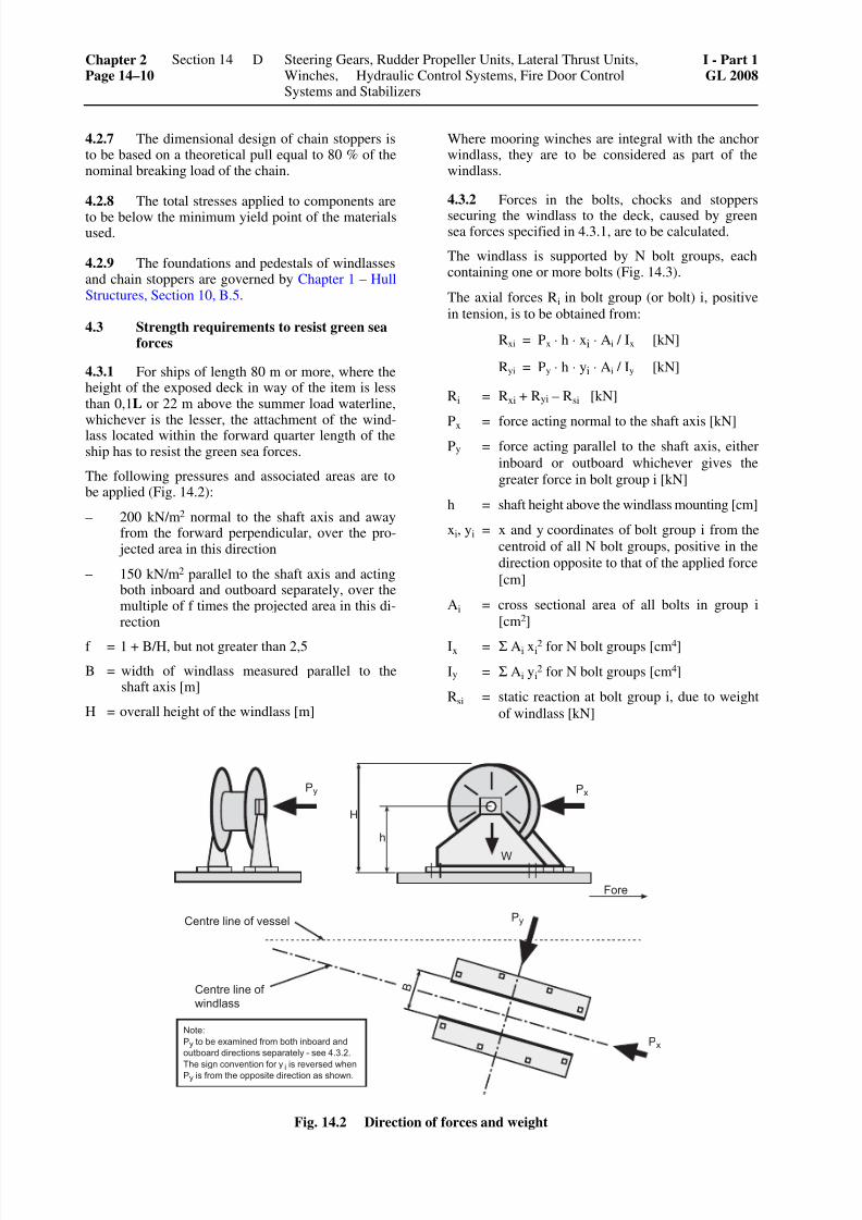
7262019 abschn14
httpslidepdfcomreaderfullabschn14 1018
427 The dimensional design of chain stoppers isto be based on a theoretical pull equal to 80 of thenominal breaking load of the chain
428 The total stresses applied to components are
to be below the minimum yield point of the materialsused
429 The foundations and pedestals of windlassesand chain stoppers are governed by Chapter 1 ndash HullStructures Section 10 B5
43 Strength requirements to resist green seaforces
431 For ships of length 80 m or more where theheight of the exposed deck in way of the item is lessthan 01L or 22 m above the summer load waterlinewhichever is the lesser the attachment of the wind-lass located within the forward quarter length of theship has to resist the green sea forces
The following pressures and associated areas are tobe applied (Fig 142)
ndash 200 kNm2 normal to the shaft axis and awayfrom the forward perpendicular over the pro- jected area in this direction
ndash 150 kNm2 parallel to the shaft axis and actingboth inboard and outboard separately over themultiple of f times the projected area in this di-rection
f = 1 + BH but not greater than 25
B = width of windlass measured parallel to theshaft axis [m]
H = overall height of the windlass [m]
Where mooring winches are integral with the anchorwindlass they are to be considered as part of thewindlass
432 Forces in the bolts chocks and stoppers
securing the windlass to the deck caused by greensea forces specified in 431 are to be calculated
The windlass is supported by N bolt groups eachcontaining one or more bolts (Fig 143)
The axial forces Ri in bolt group (or bolt) i positive
in tension is to be obtained from
Rxi = Px sdot h sdot xi sdot Ai Ix [kN]
Ryi = Py sdot h sdot yi sdot Ai Iy [kN]
Ri = Rxi + Ryi ndash Rsi [kN]
Px = force acting normal to the shaft axis [kN]Py = force acting parallel to the shaft axis either
inboard or outboard whichever gives the
greater force in bolt group i [kN]
h = shaft height above the windlass mounting [cm]
xi yi = x and y coordinates of bolt group i from the
centroid of all N bolt groups positive in the
direction opposite to that of the applied force
[cm]
Ai = cross sectional area of all bolts in group i
[cm2]
Ix = Σ Ai xi2 for N bolt groups [cm4]
Iy = Σ Ai yi2 for N bolt groups [cm4]
Rsi = static reaction at bolt group i due to weight
of windlass [kN]
Fig 142 Direction of forces and weight
Chapter 2Page 14ndash10
Section 14 Steering Gears Rudder Propeller Units Lateral Thrust UnitsWinches Hydraulic Control Systems Fire Door ControlSystems and Stabilizers
I - Part 1GL 2008
D
7262019 abschn14
httpslidepdfcomreaderfullabschn14 1118
Fig 143 Sign convention
433 Shear forces Fxi and Fyi applied to the boltgroup i and the resultant combined force are to beobtained from
Fxi = x wP m
N
minusαsdot [kN]
Fyi =y wP m
N
minusαsdot [kN]
Fi = ( )2 2
xi yiF F+ [kN]
α = coefficient of friction to be taken equal to 05
mw = weight-force of windlass [kN]
N = number of bolt groups
Axial tensile and compressive forces and lateral forcescalculated in 431 432 and 433 are also to be con-sidered in the design of the supporting structure
434 Tensile axial stresses in the individual boltsin each bolt group i are to be calculated The horizon-tal forces Fxi and Fyi are normally to be reacted by
shear chocks
Where fitted bolts are designed to support these shear forces in one or both directions the von Mises equiva-lent stresses in the individual bolts are to be calculated and compared to the stress under proof load
Where pourable resins are incorporated in the holdingdown arrangement due account is to be taken in thecalculations
The safety factor against bolt proof strength is to benot less than 20
5 Tests in the manufacturers works
51 Testing of driving engines
A51 is applicable as appropriate
52 Pressure and tightness tests
A52 is applicable as appropriate
53 Final inspection and operational testing
531 Following manufacture windlasses are re-quired to undergo final inspection and operationaltesting at the maximum pull The hauling-in speed is
to be verified with continuous application of thenominal pull During the tests particular attention is tobe given to the testing and where necessary setting ofbraking and safety equipment
In the case of anchor windlasses for chains gt 14 mmin diameter this test is to be performed in the presenceof the GL Surveyor
In the case of anchor windlasses for chains le 14 mmdiameter the Manufacturers Inspection Certificatewill be accepted
532 Where the manufacturing works does nothave adequate facilities the aforementioned testsincluding the adjustment of the overload protectioncan be carried out on board ship In these cases func-tional testing in the manufacturers works is to beperformed under no-load conditions
533 Following manufacture chain stoppers arerequired to undergo final inspection and operationaltesting in the presence of the GL Surveyor
6 Shipboard trials
The anchor equipment is to be tested during sea trialsAs a minimum requirement this test is required todemonstrate that the conditions specified in 314 and422 can be fulfilled
I - Part 1GL 2008
Section 14 Steering Gears Rudder Propeller Units Lateral Thrust UnitsWinches Hydraulic Control Systems Fire Door Control Systemsand Stabilizers
Chapter 2Page 14ndash11
D
7262019 abschn14
httpslidepdfcomreaderfullabschn14 1218
E Winches
1 Towing winches
The design and testing of towing winches are to com-ply with Chapter 1 ndash Hull Structures Section 25 C5
2 Winches for cargo handling gear and otherlifting equipment
The design and testing of these winches are to complywith VI ndash Additional Rules and Guidelines Part 2 ndashLoading Gear Chapter 2 ndash Guidelines for the Con-struction and Survey of Lifting Appliances
3 Lifeboat winches
The design and testing of life boat winches are to com-ply with VI ndash Additional Rules and Guidelines Part 2 ndash
Loading Gear Chapter 1 ndash Guidelines for Life-Saving
Launching Appliances
4 Winches for special equipment
The GL Guidelines VI ndash Additional Rules and Guide-lines Part 2 ndash Loading Gear Chapter 2 ndash Guidelinesfor the Construction and Survey of Lifting Appliancesare to be applied as appropriate to winches for spe-cial equipment such as ramps hoisting gear and hatchcovers
F Hydraulic Systems
1 General
11 Scope
The requirements contained in F apply to hydraulicsystems used for example to operate hatch coversclosing appliances in the ships shell and bulkheads
and hoists The requirements are to be applied inanalogous manner to the ships other hydraulic sys-tems except where covered by the requirements ofSection 11
12 Documents for approval
The diagram of the hydraulic system together withdrawings of the cylinders containing all the data nec-essary for assessing the system eg operating datadescriptions materials used etc are to be submittedin triplicate for approval
13 Dimensional design
For the design of pressure vessels see Section 8 forthe dimensions of pipes and hose assemblies seeSection 11
2 Materials
21 Approved materials
211 Components fulfilling a major function in thepower transmission system normally are to be made ofsteel or cast steel in accordance with the Rules II ndashMaterials and Welding Part 1 ndash Metallic MaterialsThe use of other materials is subject to special agree-ment with GL
Cylinders are preferably to be made of steel cast steelor nodular cast iron (with a predominantly ferriticmatrix)
212 Pipes are to be made of seamless or longitu-dinally welded steel tubes
213 The pressure-loaded walls of valves fittingspumps motors etc are subject to the requirements ofSection 11 B
22 Testing of materials
The following components are to be tested under su-pervision of GL in accordance with the Rules II ndashMaterials and Welding Part 1 ndash Metallic Materials
a) Pressure pipes with DN gt 50 (see Section 11
Table 113)
b) Cylinders where the product of the pressuretimes the diameter
pezul Di gt 20000
pezul = maximum allowable working pressure[bar]
Di = inside diameter of tube [mm]
c) For testing the materials of hydraulic accumula-tors see Section 8 B
Testing of materials by GL may be dispensed with inthe case of cylinders for secondary applications pro-vided that evidence in the form of a Manufacturer TestReport (eg to EN 10204- 23) is supplied
3 Hydraulic operating equipment for hatchcovers
31 Design and construction
311 Hydraulic operating equipment for hatchcovers may be served either by one common powerstation for all hatch covers or by several power sta-tions individually assigned to a single hatch coverWhere a common power station is used at least twopump units are to be fitted Where the systems aresupplied individually change-over valves or fittings
are required so that operation can be maintainedshould one pump unit fail
312 Movement of hatch covers is not to be initi-ated merely by the starting of the pumps Special con-
Chapter 2Page 14ndash12
Section 14 Steering Gears Rudder Propeller Units Lateral Thrust UnitsWinches Hydraulic Control Systems Fire Door ControlSystems and Stabilizers
I - Part 1GL 2008
F
7262019 abschn14
httpslidepdfcomreaderfullabschn14 1318
trol stations are to be provided for controlling theopening and closing of hatch covers The controls areto be so designed that as soon as they are releasedmovement of the hatch covers stops immediately
The hatches should normally be visible from the con-trol stations Should this in exceptional cases beimpossible opening and closing of the hatches is to besignalled by an audible alarm In addition the controlstations must then be equipped with indicators formonitoring the movement of the hatch covers
At the control stations the controls governing theopening and closing operations are to be appropriatelymarked
313 Suitable equipment is to be fitted in or im-mediately adjacent to each power unit (cylinder orsimilar) used to operate hatch covers to enable the
hatches to be closed slowly in the event of a powerfailure respectively due to a pipe rupture
32 Pipes
321 Pipes are to be installed and secured in such away as to protect them from damage while enablingthem to be properly maintained from outside
Pipes may be led through tanks in pipe tunnels onlyThe laying of such pipes through cargo spaces is to berestricted to the essential minimum The piping systemis to be fitted with relief valves to limit the pressure to
the maximum allowable working pressure
322 The piping system is to be fitted with filtersfor cleaning the hydraulic fluid
Equipment is to be provided to enable the hydraulicsystem to be vented
323 The accumulator space of the hydraulic ac-cumulator is to have permanent access to the reliefvalve of the connected system The gas chamber of theaccumulator may be filled only with inert gases Gasand operating medium are to be separated by accumu-lator bags diaphragms or similar
324 Connection between the hydraulic systemused for hatch cover operation and other hydraulicsystems is permitted only with the consent of GL
325 For oil level indicators see A3121
326 The hydraulic fluids must be suitable for theintended ambient and service temperatures
33 Hose assemblies
The construction of hose assemblies is to conform to
Section 11 U The requirement that hose assembliesshould be of flame-resistant construction may be setaside for hose lines in spaces not subject to a fire haz-ard and in systems not important to the safety of theship
34 Emergency operation
It is recommended that devices be fitted which areindependent of the main system and which enablehatch covers to be opened and closed in the event of
failure of the main system Such devices may forexample take the form of loose rings enabling hatchcovers to be moved by cargo winches warpingwinches etc
4 Hydraulically operated closing appliancesin the ships shell
41 Scope
The following requirements apply to the powerequipment of hydraulically operated closing appli-ances in the ships shell such as shell and landing
doors which are normally not operated while at seaFor the design and arrangement of the closures seeChapter 1 ndash Hull Structures Section 6 H
42 Design
421 The movement of shell doors etc may not beinitiated merely by the starting of the pumps at thepower station
422 Local control inaccessible to unauthorizedpersons is to be provided for every closing appliancein the ships shell As soon as the controls (push-buttons levers or similar) are released movement of
the appliance is to stop immediately
423 Closing appliances in the ships shell nor-mally are to be visible from the control stations If themovement cannot be observed audible alarms are tobe fitted In addition the control stations are then to beequipped with indicators enabling the execution of themovement to be monitored
424 Closing appliances in the ships shell are to be
fitted with devices which prevent them from moving
into their end positions at excessive speed Such de-vices are not to cause the power unit to be switched off
As far as is required mechanical means are to beprovided for locking closing appliances in the openposition
425 Every power unit driving horizontally hingedor vertically operated closing appliances is to be fittedwith throttle valves or similar devices to prevent sud-den dropping of the closing appliance
426 It is recommended that the driving power beshared between at least two mutually independentpump sets
43 Pipes hose assemblies
32 and 33 are to be applied in analogous manner tothe pipes and hose lines of hydraulically operatedclosing appliances in the ships shell
I - Part 1GL 2008
Section 14 Steering Gears Rudder Propeller Units Lateral Thrust UnitsWinches Hydraulic Control Systems Fire Door Control Systemsand Stabilizers
Chapter 2Page 14ndash13
F
7262019 abschn14
httpslidepdfcomreaderfullabschn14 1418
5 Bulkhead closures
51 General
511 Scope
5111 The following requirements apply to thepower equipment of hydraulically-operated watertightbulkhead doors on passenger and cargo vessels
5112 For details of the number design and ar-rangement of bulkhead doors see Chapter 1 ndash HullStructures Sections 11 26 and 28
The SOLAS regulations Chapter II-1 Regulations 1516 and 259 are not affected by these provisions
512 Design
Bulkhead doors are to be power-driven sliding doorsmoving horizontally Other designs require the ap-proval of GL and the provision of additional safetymeasures where necessary
513 Piping
5131 Wherever applicable the requirements forpipes in hydraulic bulkhead closing systems are gov-erned by the Rules in 32 with the restriction that theuse of flexible hose assemblies is not permitted
5132 The hydraulic fluids must be suitable for theintended ambient and service temperatures
514 Drive unit
5141 A selector switch with the switch positionslocal control and close all doors is to be providedat the central control station on the bridge
Under normal conditions this switch is to be set tolocal control
In the local control position the doors may be lo-cally opened and closed without automatic closure
In the close all doors position all doors are closedautomatically They may be reopened by means of thelocal control device but are to close again automati-
cally as soon as the local door controls are released
It is not to be possible to open the closed doors fromthe bridge
5142 Closed or open bulkhead doors are not to beset in motion automatically in the event of a powerfailure
5143 The control system is to be designed in such away that an individual fault inside the control systemincluding the piping does not have any adverse effecton the operation of other bulkhead doors
5144 The controls for the power drive are to be lo-cated at least 16 m above the floor on both sides of the
bulkhead close to the door The controls are to be in-stalled in such a way that a person passing through the
door is able to hold both controls in the open position
The controls are to return to their original positionautomatically when released
5145 The direction of movement of the controls isto be clearly marked and is to be the same as the direc-
tion of movement of the door
5146 In the event that an individual element failsinside the control system for the power drive includ-ing the piping but excluding the closing cylinders onthe door or similar components the operational abilityof the manually-operated control system is not to beimpaired
5147 The movement of the power driven bulkheaddoors may not be initiated simply by switching on thedrive units but only by actuating additional devices
5148 The control and monitoring equipment for the
drive units is to be housed in the central control stationon the bridge
515 Manual control
Each door is to have a manual control system which isindependent of the power drive
516 Indicators
Visual indicators to show whether each bulkhead dooris fully open or closed are to be installed at the centralcontrol station on the bridge
517 Electrical equipment
For details of electrical equipment see Chapter 3 ndashElectrical Installations Sections 9 and 14 D
52 Passenger vessels
In addition to 51 the following requirements are to betaken into consideration in the case of passenger ves-sels
521 Design and location
5211 Bulkhead doors together with the powerplants and including the piping electric cables andcontrol instruments must have a minimum distance of
02 times B from the perpendiculars which interset thehull contour line when the ship is at load draught(B = beam)
5212 The bulkhead doors are to be capable of be-ing closed securely using the power drive as well asusing the manual control even when the ship has apermanent heel of 15deg
5213 The force required to close a door is to becalculated based on a static water pressure of at least
1 m above the door coaming
5214 All power driven doors are to be capable ofbeing closed simultaneously from the bridge with theship upright in not more than 60 seconds
Chapter 2Page 14ndash14
Section 14 Steering Gears Rudder Propeller Units Lateral Thrust UnitsWinches Hydraulic Control Systems Fire Door ControlSystems and Stabilizers
I - Part 1GL 2008
F
7262019 abschn14
httpslidepdfcomreaderfullabschn14 1518
5215 The closing speed of each individual doormust have a uniform rate Their closing time withpower operation and with the ship upright may be notmore than 40 seconds and not less than 20 secondsfrom the start of the motion with the door completely
open until it is closed
5216 Power operated bulkhead closing systemsmay be fitted as an option with a central hydraulicdrive for all doors or with mutually independent hy-draulic or electric drives for each individual door
5217 The bulkhead closing system is not to beconnected to other systems
522 Central hydraulic system - power drives
5221 Two mutually independent power pump unitsare to be installed if possible above the bulkhead or
freeboard deck and outside the machinery spaces
5222 Each pump unit is to be capable of closing allconnected bulkhead doors simultaneously
5223 The hydraulic system is to incorporate accu-mulators with sufficient capacity to operate all con-nected doors three times ie close open and recloseat the minimum permitted accumulator pressure
523 Individual hydraulic drive
5231 An independent power pump unit is to befitted to each door for opening and closing the door
5232 An accumulator is also to be provided withsufficient capacity to operate the door three times ieclose open and reclose at the minimum permittedaccumulator pressure
524 Individual electric drive
5241 An independent electric drive unit is to befitted to each door for opening and closing the door
5242 In the event of a failure of either the mainpower supply or the emergency power supply thedrive unit is still to be capable of operating the door
three times ie close open and reclose
525 Manual control
5251 Manual control is to be capable of beingoperated at the door from both sides of the bulkheadas well as from an easily accessible control stationlocated above the bulkhead or freeboard decks andoutside the machinery space
5252 The controls at the door are to allow the doorto be opened and closed
5253 The control above the deck is to allow the
door to be closed
5254 The fully open door is to be capable of beingclosed using manual control within 90 seconds withthe ship upright
5255 A means of communication is to be providedbetween the control stations for remote manual driveabove the bulkhead of freeboard decks and the centralcontrol station on the bridge
526 Indicators
The indicators described in 516 are to be installed atthe operating stations for manual control above thebulkhead or freeboard deck for each door
527 Alarms
5271 While all the doors are being closed from thebridge an audible alarm is to sound at each door Thisalarm is to start at least 5 seconds - but not more than10 seconds - before the door starts moving and is tocontinue right throughout the door movement
5272 When the door is being closed by remotecontrol using the manual control above the bulkheador freeboard deck it is sufficient for the alarm tosound only while the door is actually moving
5273 The installation of an additional intermittentvisual alarm may be required in the passenger areasand in areas where there is a high level of backgroundnoise
5274 With a central hydraulic system the mini-mum permitted oil level in the service tank is to besignalled by means of an independent audible andvisual alarm at the central control station on the
bridge
5275 The alarm described in 5274 is also to beprovided to signal the minimum permitted accumula-tor pressure of the central hydraulic system
5276 A decentralized hydraulic system which hasindividual drive units on each door the minimumpermitted accumulator pressure is to be signalled bymeans of a group alarm at the central control stationon the bridge
Visual indicators are also to be fitted at the operatingstations for each individual door
53 Cargo vessels
In addition to the specifications laid down in 51 thefollowing requirements are to be observed for cargovessels
531 Manual control
5311 The manual control is to be capable of beingoperated at the door from both sides of the bulkhead
5312 The controls are to allow the door to beopened and closed
532 Alarms
Whilst all the doors are being closed from the bridgean audible alarm is to be sounded all the time they arein motion
I - Part 1GL 2008
Section 14 Steering Gears Rudder Propeller Units Lateral Thrust UnitsWinches Hydraulic Control Systems Fire Door Control Systemsand Stabilizers
Chapter 2Page 14ndash15
F
7262019 abschn14
httpslidepdfcomreaderfullabschn14 1618
6 Hoists
61 Definition
For the purposes of these requirements hoists include
hydraulically operated appliances such as wheelhousehoists lifts lifting platforms and similar equipment
62 Design
621 Hoists may be supplied either by a combinedpower station or individually by several power stationsfor each single lifting appliances
In the case of a combined power supply and hydraulicdrives whose piping system is connected to otherhydraulic systems a second pump unit is to be fitted
622 The movement of hoists is not to be capable
of being initiated merely by starting the pumps Themovement of hoists is to be controlled from specialoperating stations The controls are to be so arrangedthat as soon as they are released the movement of thehoist ceases immediately
623 Local controls inaccessible to unauthorizedpersons are to be fitted The movement of hoists nor-mally is to be visible from the operating stations If themovement cannot be observed audible andor visualwarning devices are to be fitted In addition the oper-ating stations are then to be equipped with indicatorsfor monitoring the movement of the hoist
624 Devices are to be fitted which prevent thehoist from reaching its end position at excessivespeed These devices are not to cause the power unit tobe switched off As far as is necessary mechanicalmeans are to be provided for locking the hoist in itsend positions
If the locking devices cannot be observed from theoperating station a visual indicator is to be installed atthe operating station to show the locking status
625 313 is to be applied in analogous manner tothose devices which if the power unit fails or a pipe
ruptures ensure that the hoist is slowly lowered
63 Pipes hose assemblies
32 and 33 apply in analogous manner to the pipesand hose lines of hydraulically operated hoists
7 Tests in the manufacturers works
71 Testing of power units
The power units are required to undergo testing on atest bed Manufacturer Test Report for this testing areto be presented at the final inspection of the hydraulic
system
72 Pressure and tightness tests
A52 is applicable in analogous manner
8 Shipboard trials
After installation the equipment is to undergo anoperational test
The operational test of watertight doors has to includethe emergency operating system and determination ofthe closing times
G Fire Door Control Systems
1 General
11 Scope
The requirements of G apply to power operated firedoor control systems on passenger vessels TheseRules meet the requirements for the control systems offire doors laid down in Chapter II-2 Regulation 94 ofSOLAS 74 as amended The following requirementsmay be applied as appropriate to other fire door con-trol systems
12 Documents for approval
The electric and pneumatic diagram together withdrawings of the cylinders containing all the data nec-essary for assessing the system eg operating datadescriptions materials used etc are to be submittedin triplicate for approval
13 Dimensional design
For the design of pressure vessels see Section 8 forthe dimensions of pipes see Section 11
2 Materials
21 Approved materials
Cylinders are to be made of corrosion resistant materials
Stainless steel or copper is to be used for pipes
The use of other materials requires the special agree-ment of GL
The use of hose assemblies is not permittedInsulation material has to be of an approved type
The quality properties of all critical components foroperation and safety is to conform to recognized rulesand standards
22 Material testing
Suitable proof of the quality properties of the materi-als used is to be furnished For parts under pressureCertificates according to Table 113 for all other partsManufacturer Test Reports are required
GLs Surveyor reserves the right to order supplemen-
tary tests of his own to be carried out where he con-siders that the circumstances justify this
See Section 8 B for details on the material testing ofcompressed air accumulators
Chapter 2Page 14ndash16
Section 14 Steering Gears Rudder Propeller Units Lateral Thrust UnitsWinches Hydraulic Control Systems Fire Door ControlSystems and Stabilizers
I - Part 1GL 2008
G
7262019 abschn14
httpslidepdfcomreaderfullabschn14 1718
3 Design
31 Each door is to be capable of being openedand closed by a single person from both sides of thebulkhead
32 Fire doors are to be capable of closing auto-matically even against a permanent heeling angle ofthe ship of 35deg
33 The closing time of hinged doors with theship upright may be no more than 40 seconds and noless than 10 seconds from the start of the movement ofthe door when fully open to its closed position foreach individual door
The closing speed of sliding doors is to be steady andwith the ship upright may be no more than 02 ms
and no less than 01 ms
Measures are to be taken to ensure that any persons in
the door areas are protected from any excessive danger
34 All doors are to be capable of being closedfrom the central control station either jointly or ingroups It also is to be possible to initiate closure ateach individual door The closing switch is to take theform of a locking switch
35 Visual indicators are to be installed at thecentral control station to show that each fire door isfully closed
36 Power driven doors leading from specialareas (eg car decks railway decks) in accordancewith Chapter II-2 Regulation 346 of SOLAS 74 asamended or from comparable spaces to control sta-tions stairwells and also to accommodation and ser-vice spaces and which are closed when the ship is atsea do not need to be equipped with indicators asdescribed in 35 and alarms as described in 312
37 Operating agents for the control system are tobe installed next to each door on both sides of thebulkhead and by their operation a door which has been
closed from the central control station can be re-opened The controls are to return to their originalposition when released thereby causing the door toclose again
In an emergency it is to be possible to use the controlsto interrupt immediately the opening of the door andbring about its immediate closure
A combination of the controls with the door handlemay be permitted
The controls are to be designed in such a way that anopen door can be closed locally In addition each dooris to be capable of being locked locally in such a waythat it cannot longer be opened by remote control
38 The control unit at the door is to be equippedwith a device which will vent the pneumatic system or
cut off the electric energy of the door control systemsimultaneously shutting off the main supply line andthereby allowing emergency operation by hand
39 The door is to close automatically should thecentral power supply fail The doors may not reopenautomatically when the central supply is restored
Accumulator systems are to be located in the immedi-ate vicinity of the door being sufficient to allow thedoor to be completely opened and closed at least tenmore times with the ship upright using the localcontrols
310 Measures are to be taken to ensure that thedoor can still be operated by hand in the event of fail-ure of the energy supply
311 Should the central energy supply fail in thelocal control area of a door the capability of the otherdoors to function may not be adversely affected
312 Doors which are closed from the central con-trol station are to be fitted with an audible alarm Oncethe door close command has been given this alarm isto start at least 5 seconds but not more than10 seconds before the door starts to move and con-tinue sounding until the door is completely closed
313 Fire doors are to be fitted with safety stripssuch that a closing door reopens as soon as contact ismade with them Following contact with the safetystrip the opening travel of the door is to be no morethan 1 m
314 Local door controls including all compo-nents are to be accessible for maintenance and ad- justment
315 The control system is to be of approved de-sign Their capability to operate in the event of fire is
to be proven in accordance with the FTP-Code 1 andunder supervision of GL
The control system is to conform to the following
minimum requirements
3151 The door still is to be capable of being oper-ated safely for 60 minutes at a minimum ambienttemperature of 200 degC by means of the central energysupply
3152 The central energy supply for the other doorsnot affected by fire may not be impaired
3153 At ambient temperatures in excess of 300 degCthe central energy supply is to be shut off automati-cally and the local control system is to be de-energized The residual energy is still to be sufficient
to close an open door completely during this process
1 IMO Res MSC 61(67)
I - Part 1GL 2008
Section 14 Steering Gears Rudder Propeller Units Lateral Thrust UnitsWinches Hydraulic Control Systems Fire Door Control Systemsand Stabilizers
Chapter 2Page 14ndash17
G
7262019 abschn14
httpslidepdfcomreaderfullabschn14 1818
The shut-off device is to be capable of shutting off theenergy supply for one hour with a temperature varia-tion corresponding to the standardized time-tempera-ture curve given in Section II-2 Regulation 3 of SO-LAS 74 as amended
316 The pneumatic system is to be protectedagainst overpressure
317 Drainage and venting facilities are to be pro-vided
318 Air filtering and drying facilities are to beprovided
319 For details of the electrical equipment cfChapter 3 ndash Electrical Installations Section 14 D
4 Tests in the manufacturers works
The complete control system is to be subjected to atype approval test In addition the required construc-tion according to 2 and 3 and the operability have tobe proven for the complete drive
5 Shipboard trials
After installation the systems are to be subjected to anoperating test which also includes emergency opera-tion and the verification of closing times
H Stabilizers
1 General
11 Scope
The requirements contained in H apply to stabilizerdrive units necessary for the operation and safety ofthe ship
12 Documents for approval
Assembly and general drawings together with dia-grams of the hydraulic and electrical equipment con-taining all the data necessary for checking are to besubmitted in triplicate for approval
2 Design
A213 and A214 are applicable in analogous man-ner to the pipe connections of hydraulic drive units
3 Pressure and tightness test
A52 is applicable in analogous manner
4 Shipboard trials
The operational efficiency of the stabilizer equipmentis to be demonstrated during the sea trials
Chapter 2Page 14ndash18
Section 14 Steering Gears Rudder Propeller Units Lateral Thrust UnitsWinches Hydraulic Control Systems Fire Door ControlSystems and Stabilizers
I - Part 1GL 2008
H
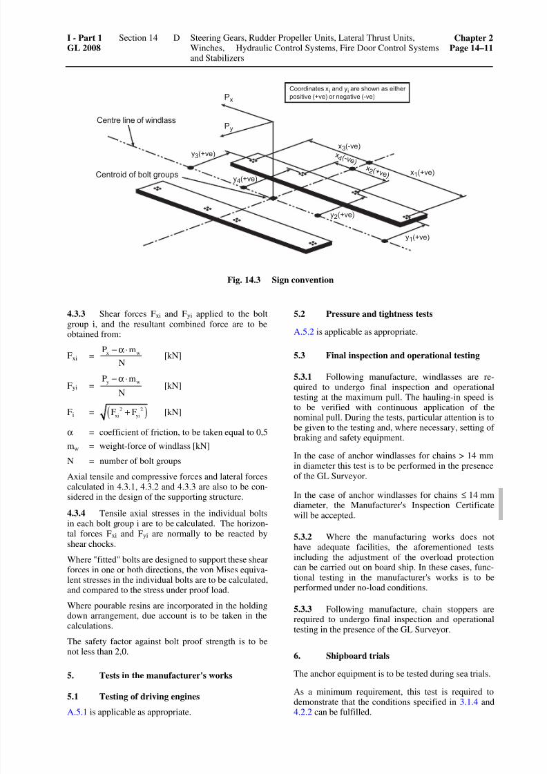
7262019 abschn14
httpslidepdfcomreaderfullabschn14 1118
Fig 143 Sign convention
433 Shear forces Fxi and Fyi applied to the boltgroup i and the resultant combined force are to beobtained from
Fxi = x wP m
N
minusαsdot [kN]
Fyi =y wP m
N
minusαsdot [kN]
Fi = ( )2 2
xi yiF F+ [kN]
α = coefficient of friction to be taken equal to 05
mw = weight-force of windlass [kN]
N = number of bolt groups
Axial tensile and compressive forces and lateral forcescalculated in 431 432 and 433 are also to be con-sidered in the design of the supporting structure
434 Tensile axial stresses in the individual boltsin each bolt group i are to be calculated The horizon-tal forces Fxi and Fyi are normally to be reacted by
shear chocks
Where fitted bolts are designed to support these shear forces in one or both directions the von Mises equiva-lent stresses in the individual bolts are to be calculated and compared to the stress under proof load
Where pourable resins are incorporated in the holdingdown arrangement due account is to be taken in thecalculations
The safety factor against bolt proof strength is to benot less than 20
5 Tests in the manufacturers works
51 Testing of driving engines
A51 is applicable as appropriate
52 Pressure and tightness tests
A52 is applicable as appropriate
53 Final inspection and operational testing
531 Following manufacture windlasses are re-quired to undergo final inspection and operationaltesting at the maximum pull The hauling-in speed is
to be verified with continuous application of thenominal pull During the tests particular attention is tobe given to the testing and where necessary setting ofbraking and safety equipment
In the case of anchor windlasses for chains gt 14 mmin diameter this test is to be performed in the presenceof the GL Surveyor
In the case of anchor windlasses for chains le 14 mmdiameter the Manufacturers Inspection Certificatewill be accepted
532 Where the manufacturing works does nothave adequate facilities the aforementioned testsincluding the adjustment of the overload protectioncan be carried out on board ship In these cases func-tional testing in the manufacturers works is to beperformed under no-load conditions
533 Following manufacture chain stoppers arerequired to undergo final inspection and operationaltesting in the presence of the GL Surveyor
6 Shipboard trials
The anchor equipment is to be tested during sea trialsAs a minimum requirement this test is required todemonstrate that the conditions specified in 314 and422 can be fulfilled
I - Part 1GL 2008
Section 14 Steering Gears Rudder Propeller Units Lateral Thrust UnitsWinches Hydraulic Control Systems Fire Door Control Systemsand Stabilizers
Chapter 2Page 14ndash11
D
7262019 abschn14
httpslidepdfcomreaderfullabschn14 1218
E Winches
1 Towing winches
The design and testing of towing winches are to com-ply with Chapter 1 ndash Hull Structures Section 25 C5
2 Winches for cargo handling gear and otherlifting equipment
The design and testing of these winches are to complywith VI ndash Additional Rules and Guidelines Part 2 ndashLoading Gear Chapter 2 ndash Guidelines for the Con-struction and Survey of Lifting Appliances
3 Lifeboat winches
The design and testing of life boat winches are to com-ply with VI ndash Additional Rules and Guidelines Part 2 ndash
Loading Gear Chapter 1 ndash Guidelines for Life-Saving
Launching Appliances
4 Winches for special equipment
The GL Guidelines VI ndash Additional Rules and Guide-lines Part 2 ndash Loading Gear Chapter 2 ndash Guidelinesfor the Construction and Survey of Lifting Appliancesare to be applied as appropriate to winches for spe-cial equipment such as ramps hoisting gear and hatchcovers
F Hydraulic Systems
1 General
11 Scope
The requirements contained in F apply to hydraulicsystems used for example to operate hatch coversclosing appliances in the ships shell and bulkheads
and hoists The requirements are to be applied inanalogous manner to the ships other hydraulic sys-tems except where covered by the requirements ofSection 11
12 Documents for approval
The diagram of the hydraulic system together withdrawings of the cylinders containing all the data nec-essary for assessing the system eg operating datadescriptions materials used etc are to be submittedin triplicate for approval
13 Dimensional design
For the design of pressure vessels see Section 8 forthe dimensions of pipes and hose assemblies seeSection 11
2 Materials
21 Approved materials
211 Components fulfilling a major function in thepower transmission system normally are to be made ofsteel or cast steel in accordance with the Rules II ndashMaterials and Welding Part 1 ndash Metallic MaterialsThe use of other materials is subject to special agree-ment with GL
Cylinders are preferably to be made of steel cast steelor nodular cast iron (with a predominantly ferriticmatrix)
212 Pipes are to be made of seamless or longitu-dinally welded steel tubes
213 The pressure-loaded walls of valves fittingspumps motors etc are subject to the requirements ofSection 11 B
22 Testing of materials
The following components are to be tested under su-pervision of GL in accordance with the Rules II ndashMaterials and Welding Part 1 ndash Metallic Materials
a) Pressure pipes with DN gt 50 (see Section 11
Table 113)
b) Cylinders where the product of the pressuretimes the diameter
pezul Di gt 20000
pezul = maximum allowable working pressure[bar]
Di = inside diameter of tube [mm]
c) For testing the materials of hydraulic accumula-tors see Section 8 B
Testing of materials by GL may be dispensed with inthe case of cylinders for secondary applications pro-vided that evidence in the form of a Manufacturer TestReport (eg to EN 10204- 23) is supplied
3 Hydraulic operating equipment for hatchcovers
31 Design and construction
311 Hydraulic operating equipment for hatchcovers may be served either by one common powerstation for all hatch covers or by several power sta-tions individually assigned to a single hatch coverWhere a common power station is used at least twopump units are to be fitted Where the systems aresupplied individually change-over valves or fittings
are required so that operation can be maintainedshould one pump unit fail
312 Movement of hatch covers is not to be initi-ated merely by the starting of the pumps Special con-
Chapter 2Page 14ndash12
Section 14 Steering Gears Rudder Propeller Units Lateral Thrust UnitsWinches Hydraulic Control Systems Fire Door ControlSystems and Stabilizers
I - Part 1GL 2008
F
7262019 abschn14
httpslidepdfcomreaderfullabschn14 1318
trol stations are to be provided for controlling theopening and closing of hatch covers The controls areto be so designed that as soon as they are releasedmovement of the hatch covers stops immediately
The hatches should normally be visible from the con-trol stations Should this in exceptional cases beimpossible opening and closing of the hatches is to besignalled by an audible alarm In addition the controlstations must then be equipped with indicators formonitoring the movement of the hatch covers
At the control stations the controls governing theopening and closing operations are to be appropriatelymarked
313 Suitable equipment is to be fitted in or im-mediately adjacent to each power unit (cylinder orsimilar) used to operate hatch covers to enable the
hatches to be closed slowly in the event of a powerfailure respectively due to a pipe rupture
32 Pipes
321 Pipes are to be installed and secured in such away as to protect them from damage while enablingthem to be properly maintained from outside
Pipes may be led through tanks in pipe tunnels onlyThe laying of such pipes through cargo spaces is to berestricted to the essential minimum The piping systemis to be fitted with relief valves to limit the pressure to
the maximum allowable working pressure
322 The piping system is to be fitted with filtersfor cleaning the hydraulic fluid
Equipment is to be provided to enable the hydraulicsystem to be vented
323 The accumulator space of the hydraulic ac-cumulator is to have permanent access to the reliefvalve of the connected system The gas chamber of theaccumulator may be filled only with inert gases Gasand operating medium are to be separated by accumu-lator bags diaphragms or similar
324 Connection between the hydraulic systemused for hatch cover operation and other hydraulicsystems is permitted only with the consent of GL
325 For oil level indicators see A3121
326 The hydraulic fluids must be suitable for theintended ambient and service temperatures
33 Hose assemblies
The construction of hose assemblies is to conform to
Section 11 U The requirement that hose assembliesshould be of flame-resistant construction may be setaside for hose lines in spaces not subject to a fire haz-ard and in systems not important to the safety of theship
34 Emergency operation
It is recommended that devices be fitted which areindependent of the main system and which enablehatch covers to be opened and closed in the event of
failure of the main system Such devices may forexample take the form of loose rings enabling hatchcovers to be moved by cargo winches warpingwinches etc
4 Hydraulically operated closing appliancesin the ships shell
41 Scope
The following requirements apply to the powerequipment of hydraulically operated closing appli-ances in the ships shell such as shell and landing
doors which are normally not operated while at seaFor the design and arrangement of the closures seeChapter 1 ndash Hull Structures Section 6 H
42 Design
421 The movement of shell doors etc may not beinitiated merely by the starting of the pumps at thepower station
422 Local control inaccessible to unauthorizedpersons is to be provided for every closing appliancein the ships shell As soon as the controls (push-buttons levers or similar) are released movement of
the appliance is to stop immediately
423 Closing appliances in the ships shell nor-mally are to be visible from the control stations If themovement cannot be observed audible alarms are tobe fitted In addition the control stations are then to beequipped with indicators enabling the execution of themovement to be monitored
424 Closing appliances in the ships shell are to be
fitted with devices which prevent them from moving
into their end positions at excessive speed Such de-vices are not to cause the power unit to be switched off
As far as is required mechanical means are to beprovided for locking closing appliances in the openposition
425 Every power unit driving horizontally hingedor vertically operated closing appliances is to be fittedwith throttle valves or similar devices to prevent sud-den dropping of the closing appliance
426 It is recommended that the driving power beshared between at least two mutually independentpump sets
43 Pipes hose assemblies
32 and 33 are to be applied in analogous manner tothe pipes and hose lines of hydraulically operatedclosing appliances in the ships shell
I - Part 1GL 2008
Section 14 Steering Gears Rudder Propeller Units Lateral Thrust UnitsWinches Hydraulic Control Systems Fire Door Control Systemsand Stabilizers
Chapter 2Page 14ndash13
F
7262019 abschn14
httpslidepdfcomreaderfullabschn14 1418
5 Bulkhead closures
51 General
511 Scope
5111 The following requirements apply to thepower equipment of hydraulically-operated watertightbulkhead doors on passenger and cargo vessels
5112 For details of the number design and ar-rangement of bulkhead doors see Chapter 1 ndash HullStructures Sections 11 26 and 28
The SOLAS regulations Chapter II-1 Regulations 1516 and 259 are not affected by these provisions
512 Design
Bulkhead doors are to be power-driven sliding doorsmoving horizontally Other designs require the ap-proval of GL and the provision of additional safetymeasures where necessary
513 Piping
5131 Wherever applicable the requirements forpipes in hydraulic bulkhead closing systems are gov-erned by the Rules in 32 with the restriction that theuse of flexible hose assemblies is not permitted
5132 The hydraulic fluids must be suitable for theintended ambient and service temperatures
514 Drive unit
5141 A selector switch with the switch positionslocal control and close all doors is to be providedat the central control station on the bridge
Under normal conditions this switch is to be set tolocal control
In the local control position the doors may be lo-cally opened and closed without automatic closure
In the close all doors position all doors are closedautomatically They may be reopened by means of thelocal control device but are to close again automati-
cally as soon as the local door controls are released
It is not to be possible to open the closed doors fromthe bridge
5142 Closed or open bulkhead doors are not to beset in motion automatically in the event of a powerfailure
5143 The control system is to be designed in such away that an individual fault inside the control systemincluding the piping does not have any adverse effecton the operation of other bulkhead doors
5144 The controls for the power drive are to be lo-cated at least 16 m above the floor on both sides of the
bulkhead close to the door The controls are to be in-stalled in such a way that a person passing through the
door is able to hold both controls in the open position
The controls are to return to their original positionautomatically when released
5145 The direction of movement of the controls isto be clearly marked and is to be the same as the direc-
tion of movement of the door
5146 In the event that an individual element failsinside the control system for the power drive includ-ing the piping but excluding the closing cylinders onthe door or similar components the operational abilityof the manually-operated control system is not to beimpaired
5147 The movement of the power driven bulkheaddoors may not be initiated simply by switching on thedrive units but only by actuating additional devices
5148 The control and monitoring equipment for the
drive units is to be housed in the central control stationon the bridge
515 Manual control
Each door is to have a manual control system which isindependent of the power drive
516 Indicators
Visual indicators to show whether each bulkhead dooris fully open or closed are to be installed at the centralcontrol station on the bridge
517 Electrical equipment
For details of electrical equipment see Chapter 3 ndashElectrical Installations Sections 9 and 14 D
52 Passenger vessels
In addition to 51 the following requirements are to betaken into consideration in the case of passenger ves-sels
521 Design and location
5211 Bulkhead doors together with the powerplants and including the piping electric cables andcontrol instruments must have a minimum distance of
02 times B from the perpendiculars which interset thehull contour line when the ship is at load draught(B = beam)
5212 The bulkhead doors are to be capable of be-ing closed securely using the power drive as well asusing the manual control even when the ship has apermanent heel of 15deg
5213 The force required to close a door is to becalculated based on a static water pressure of at least
1 m above the door coaming
5214 All power driven doors are to be capable ofbeing closed simultaneously from the bridge with theship upright in not more than 60 seconds
Chapter 2Page 14ndash14
Section 14 Steering Gears Rudder Propeller Units Lateral Thrust UnitsWinches Hydraulic Control Systems Fire Door ControlSystems and Stabilizers
I - Part 1GL 2008
F
7262019 abschn14
httpslidepdfcomreaderfullabschn14 1518
5215 The closing speed of each individual doormust have a uniform rate Their closing time withpower operation and with the ship upright may be notmore than 40 seconds and not less than 20 secondsfrom the start of the motion with the door completely
open until it is closed
5216 Power operated bulkhead closing systemsmay be fitted as an option with a central hydraulicdrive for all doors or with mutually independent hy-draulic or electric drives for each individual door
5217 The bulkhead closing system is not to beconnected to other systems
522 Central hydraulic system - power drives
5221 Two mutually independent power pump unitsare to be installed if possible above the bulkhead or
freeboard deck and outside the machinery spaces
5222 Each pump unit is to be capable of closing allconnected bulkhead doors simultaneously
5223 The hydraulic system is to incorporate accu-mulators with sufficient capacity to operate all con-nected doors three times ie close open and recloseat the minimum permitted accumulator pressure
523 Individual hydraulic drive
5231 An independent power pump unit is to befitted to each door for opening and closing the door
5232 An accumulator is also to be provided withsufficient capacity to operate the door three times ieclose open and reclose at the minimum permittedaccumulator pressure
524 Individual electric drive
5241 An independent electric drive unit is to befitted to each door for opening and closing the door
5242 In the event of a failure of either the mainpower supply or the emergency power supply thedrive unit is still to be capable of operating the door
three times ie close open and reclose
525 Manual control
5251 Manual control is to be capable of beingoperated at the door from both sides of the bulkheadas well as from an easily accessible control stationlocated above the bulkhead or freeboard decks andoutside the machinery space
5252 The controls at the door are to allow the doorto be opened and closed
5253 The control above the deck is to allow the
door to be closed
5254 The fully open door is to be capable of beingclosed using manual control within 90 seconds withthe ship upright
5255 A means of communication is to be providedbetween the control stations for remote manual driveabove the bulkhead of freeboard decks and the centralcontrol station on the bridge
526 Indicators
The indicators described in 516 are to be installed atthe operating stations for manual control above thebulkhead or freeboard deck for each door
527 Alarms
5271 While all the doors are being closed from thebridge an audible alarm is to sound at each door Thisalarm is to start at least 5 seconds - but not more than10 seconds - before the door starts moving and is tocontinue right throughout the door movement
5272 When the door is being closed by remotecontrol using the manual control above the bulkheador freeboard deck it is sufficient for the alarm tosound only while the door is actually moving
5273 The installation of an additional intermittentvisual alarm may be required in the passenger areasand in areas where there is a high level of backgroundnoise
5274 With a central hydraulic system the mini-mum permitted oil level in the service tank is to besignalled by means of an independent audible andvisual alarm at the central control station on the
bridge
5275 The alarm described in 5274 is also to beprovided to signal the minimum permitted accumula-tor pressure of the central hydraulic system
5276 A decentralized hydraulic system which hasindividual drive units on each door the minimumpermitted accumulator pressure is to be signalled bymeans of a group alarm at the central control stationon the bridge
Visual indicators are also to be fitted at the operatingstations for each individual door
53 Cargo vessels
In addition to the specifications laid down in 51 thefollowing requirements are to be observed for cargovessels
531 Manual control
5311 The manual control is to be capable of beingoperated at the door from both sides of the bulkhead
5312 The controls are to allow the door to beopened and closed
532 Alarms
Whilst all the doors are being closed from the bridgean audible alarm is to be sounded all the time they arein motion
I - Part 1GL 2008
Section 14 Steering Gears Rudder Propeller Units Lateral Thrust UnitsWinches Hydraulic Control Systems Fire Door Control Systemsand Stabilizers
Chapter 2Page 14ndash15
F
7262019 abschn14
httpslidepdfcomreaderfullabschn14 1618
6 Hoists
61 Definition
For the purposes of these requirements hoists include
hydraulically operated appliances such as wheelhousehoists lifts lifting platforms and similar equipment
62 Design
621 Hoists may be supplied either by a combinedpower station or individually by several power stationsfor each single lifting appliances
In the case of a combined power supply and hydraulicdrives whose piping system is connected to otherhydraulic systems a second pump unit is to be fitted
622 The movement of hoists is not to be capable
of being initiated merely by starting the pumps Themovement of hoists is to be controlled from specialoperating stations The controls are to be so arrangedthat as soon as they are released the movement of thehoist ceases immediately
623 Local controls inaccessible to unauthorizedpersons are to be fitted The movement of hoists nor-mally is to be visible from the operating stations If themovement cannot be observed audible andor visualwarning devices are to be fitted In addition the oper-ating stations are then to be equipped with indicatorsfor monitoring the movement of the hoist
624 Devices are to be fitted which prevent thehoist from reaching its end position at excessivespeed These devices are not to cause the power unit tobe switched off As far as is necessary mechanicalmeans are to be provided for locking the hoist in itsend positions
If the locking devices cannot be observed from theoperating station a visual indicator is to be installed atthe operating station to show the locking status
625 313 is to be applied in analogous manner tothose devices which if the power unit fails or a pipe
ruptures ensure that the hoist is slowly lowered
63 Pipes hose assemblies
32 and 33 apply in analogous manner to the pipesand hose lines of hydraulically operated hoists
7 Tests in the manufacturers works
71 Testing of power units
The power units are required to undergo testing on atest bed Manufacturer Test Report for this testing areto be presented at the final inspection of the hydraulic
system
72 Pressure and tightness tests
A52 is applicable in analogous manner
8 Shipboard trials
After installation the equipment is to undergo anoperational test
The operational test of watertight doors has to includethe emergency operating system and determination ofthe closing times
G Fire Door Control Systems
1 General
11 Scope
The requirements of G apply to power operated firedoor control systems on passenger vessels TheseRules meet the requirements for the control systems offire doors laid down in Chapter II-2 Regulation 94 ofSOLAS 74 as amended The following requirementsmay be applied as appropriate to other fire door con-trol systems
12 Documents for approval
The electric and pneumatic diagram together withdrawings of the cylinders containing all the data nec-essary for assessing the system eg operating datadescriptions materials used etc are to be submittedin triplicate for approval
13 Dimensional design
For the design of pressure vessels see Section 8 forthe dimensions of pipes see Section 11
2 Materials
21 Approved materials
Cylinders are to be made of corrosion resistant materials
Stainless steel or copper is to be used for pipes
The use of other materials requires the special agree-ment of GL
The use of hose assemblies is not permittedInsulation material has to be of an approved type
The quality properties of all critical components foroperation and safety is to conform to recognized rulesand standards
22 Material testing
Suitable proof of the quality properties of the materi-als used is to be furnished For parts under pressureCertificates according to Table 113 for all other partsManufacturer Test Reports are required
GLs Surveyor reserves the right to order supplemen-
tary tests of his own to be carried out where he con-siders that the circumstances justify this
See Section 8 B for details on the material testing ofcompressed air accumulators
Chapter 2Page 14ndash16
Section 14 Steering Gears Rudder Propeller Units Lateral Thrust UnitsWinches Hydraulic Control Systems Fire Door ControlSystems and Stabilizers
I - Part 1GL 2008
G
7262019 abschn14
httpslidepdfcomreaderfullabschn14 1718
3 Design
31 Each door is to be capable of being openedand closed by a single person from both sides of thebulkhead
32 Fire doors are to be capable of closing auto-matically even against a permanent heeling angle ofthe ship of 35deg
33 The closing time of hinged doors with theship upright may be no more than 40 seconds and noless than 10 seconds from the start of the movement ofthe door when fully open to its closed position foreach individual door
The closing speed of sliding doors is to be steady andwith the ship upright may be no more than 02 ms
and no less than 01 ms
Measures are to be taken to ensure that any persons in
the door areas are protected from any excessive danger
34 All doors are to be capable of being closedfrom the central control station either jointly or ingroups It also is to be possible to initiate closure ateach individual door The closing switch is to take theform of a locking switch
35 Visual indicators are to be installed at thecentral control station to show that each fire door isfully closed
36 Power driven doors leading from specialareas (eg car decks railway decks) in accordancewith Chapter II-2 Regulation 346 of SOLAS 74 asamended or from comparable spaces to control sta-tions stairwells and also to accommodation and ser-vice spaces and which are closed when the ship is atsea do not need to be equipped with indicators asdescribed in 35 and alarms as described in 312
37 Operating agents for the control system are tobe installed next to each door on both sides of thebulkhead and by their operation a door which has been
closed from the central control station can be re-opened The controls are to return to their originalposition when released thereby causing the door toclose again
In an emergency it is to be possible to use the controlsto interrupt immediately the opening of the door andbring about its immediate closure
A combination of the controls with the door handlemay be permitted
The controls are to be designed in such a way that anopen door can be closed locally In addition each dooris to be capable of being locked locally in such a waythat it cannot longer be opened by remote control
38 The control unit at the door is to be equippedwith a device which will vent the pneumatic system or
cut off the electric energy of the door control systemsimultaneously shutting off the main supply line andthereby allowing emergency operation by hand
39 The door is to close automatically should thecentral power supply fail The doors may not reopenautomatically when the central supply is restored
Accumulator systems are to be located in the immedi-ate vicinity of the door being sufficient to allow thedoor to be completely opened and closed at least tenmore times with the ship upright using the localcontrols
310 Measures are to be taken to ensure that thedoor can still be operated by hand in the event of fail-ure of the energy supply
311 Should the central energy supply fail in thelocal control area of a door the capability of the otherdoors to function may not be adversely affected
312 Doors which are closed from the central con-trol station are to be fitted with an audible alarm Oncethe door close command has been given this alarm isto start at least 5 seconds but not more than10 seconds before the door starts to move and con-tinue sounding until the door is completely closed
313 Fire doors are to be fitted with safety stripssuch that a closing door reopens as soon as contact ismade with them Following contact with the safetystrip the opening travel of the door is to be no morethan 1 m
314 Local door controls including all compo-nents are to be accessible for maintenance and ad- justment
315 The control system is to be of approved de-sign Their capability to operate in the event of fire is
to be proven in accordance with the FTP-Code 1 andunder supervision of GL
The control system is to conform to the following
minimum requirements
3151 The door still is to be capable of being oper-ated safely for 60 minutes at a minimum ambienttemperature of 200 degC by means of the central energysupply
3152 The central energy supply for the other doorsnot affected by fire may not be impaired
3153 At ambient temperatures in excess of 300 degCthe central energy supply is to be shut off automati-cally and the local control system is to be de-energized The residual energy is still to be sufficient
to close an open door completely during this process
1 IMO Res MSC 61(67)
I - Part 1GL 2008
Section 14 Steering Gears Rudder Propeller Units Lateral Thrust UnitsWinches Hydraulic Control Systems Fire Door Control Systemsand Stabilizers
Chapter 2Page 14ndash17
G
7262019 abschn14
httpslidepdfcomreaderfullabschn14 1818
The shut-off device is to be capable of shutting off theenergy supply for one hour with a temperature varia-tion corresponding to the standardized time-tempera-ture curve given in Section II-2 Regulation 3 of SO-LAS 74 as amended
316 The pneumatic system is to be protectedagainst overpressure
317 Drainage and venting facilities are to be pro-vided
318 Air filtering and drying facilities are to beprovided
319 For details of the electrical equipment cfChapter 3 ndash Electrical Installations Section 14 D
4 Tests in the manufacturers works
The complete control system is to be subjected to atype approval test In addition the required construc-tion according to 2 and 3 and the operability have tobe proven for the complete drive
5 Shipboard trials
After installation the systems are to be subjected to anoperating test which also includes emergency opera-tion and the verification of closing times
H Stabilizers
1 General
11 Scope
The requirements contained in H apply to stabilizerdrive units necessary for the operation and safety ofthe ship
12 Documents for approval
Assembly and general drawings together with dia-grams of the hydraulic and electrical equipment con-taining all the data necessary for checking are to besubmitted in triplicate for approval
2 Design
A213 and A214 are applicable in analogous man-ner to the pipe connections of hydraulic drive units
3 Pressure and tightness test
A52 is applicable in analogous manner
4 Shipboard trials
The operational efficiency of the stabilizer equipmentis to be demonstrated during the sea trials
Chapter 2Page 14ndash18
Section 14 Steering Gears Rudder Propeller Units Lateral Thrust UnitsWinches Hydraulic Control Systems Fire Door ControlSystems and Stabilizers
I - Part 1GL 2008
H
7262019 abschn14
httpslidepdfcomreaderfullabschn14 1818
The shut-off device is to be capable of shutting off theenergy supply for one hour with a temperature varia-tion corresponding to the standardized time-tempera-ture curve given in Section II-2 Regulation 3 of SO-LAS 74 as amended
316 The pneumatic system is to be protectedagainst overpressure
317 Drainage and venting facilities are to be pro-vided
318 Air filtering and drying facilities are to beprovided
319 For details of the electrical equipment cfChapter 3 ndash Electrical Installations Section 14 D
4 Tests in the manufacturers works
The complete control system is to be subjected to atype approval test In addition the required construc-tion according to 2 and 3 and the operability have tobe proven for the complete drive
5 Shipboard trials
After installation the systems are to be subjected to anoperating test which also includes emergency opera-tion and the verification of closing times
H Stabilizers
1 General
11 Scope
The requirements contained in H apply to stabilizerdrive units necessary for the operation and safety ofthe ship
12 Documents for approval
Assembly and general drawings together with dia-grams of the hydraulic and electrical equipment con-taining all the data necessary for checking are to besubmitted in triplicate for approval
2 Design
A213 and A214 are applicable in analogous man-ner to the pipe connections of hydraulic drive units
3 Pressure and tightness test
A52 is applicable in analogous manner
4 Shipboard trials
The operational efficiency of the stabilizer equipmentis to be demonstrated during the sea trials
Chapter 2Page 14ndash18
Section 14 Steering Gears Rudder Propeller Units Lateral Thrust UnitsWinches Hydraulic Control Systems Fire Door ControlSystems and Stabilizers
I - Part 1GL 2008
H