Alpha IP - BSM 24001 - markus.romarkus.ro/new/wp-content/uploads/2017/04/BSM-instructiuni.pdf · 5...
34
DEU ENG 1 Alpha IP BSM 24001 Alpha IP BSM 24001 133420.1651 Bedienungsanleitung
Transcript of Alpha IP - BSM 24001 - markus.romarkus.ro/new/wp-content/uploads/2017/04/BSM-instructiuni.pdf · 5...
DEU ENG1
Alpha IP BSM 24001
Alpha IPBSM 24001
133420.1651
Bedienungsanleitung
DEU ENG2
Alpha IP BSM 24001
Inhalt
1 Zu dieser Anleitung .......................................... 31.1 Gültigkeit, Aufbewahrung und Weitergabe der Anleitung 31.2 Symbole 3
2 Sicherheit ......................................................... 42.1 Personelle Voraussetzungen 42.2 Bestimmungsgemäße Verwendung 42.3 Sicherheitshinweise 5
3 Funktion ........................................................... 6
4 Geräteübersicht ................................................ 74.1 Technische Daten 7
5 Adapter für Markenschalter ................................... 8
6 Inbetriebnahme .............................................. 116.1 Montage 116.2 Gerät anlernen 13
7 Bedienung ...................................................... 14
8 Anzeigen ........................................................ 158.1 Statusanzeigen 158.2 Fehleranzeigen 15
9 Reinigen ......................................................... 16
10 Werkseinstellungen herstellen ....................... 16
11 Außerbetriebnahme ....................................... 17
12 Entsorgen ....................................................... 17
DEU ENG3
Zu dieser AnleitungAlpha IP BSM 24001
1 Zu dieser Anleitung
1.1 Gültigkeit, Aufbewahrung und Weitergabe der Anleitung
Diese Anleitung gilt für den Alpha IP Schalt-Mess-Aktor – Markenschal-ter (BSM 24001). Sie enthält Informationen, die für die Inbetriebnahme und Bedienung notwendig sind. Bevor mit dem Gerät gearbeitet wird, ist diese Anleitung vollständig und gründlich zu lesen. Die Anleitung ist aufzubewahren und an nachfolgende Benutzer weiterzugeben.
Diese Anleitung sowie zusätzliche Alpha IP Systeminformationen sind stets aktuell unter www.alphaip.de zu finden.
Systeminformationen, Funktionen und Bedienschritte aus der Anleitung des Alpha IP Access Point (HAP 2001) sind zu berücksichtigen.
1.2 Symbole
Folgende Symbole werden in dieser Anleitung verwendet:
Gefahrzeichen: Weist auf eine Gefahr mit möglichem Personenschaden hin
Hinweis: Kennzeichnet eine wichtige oder nützliche Information
Ö Voraussetzung 9 Ergebnis, das aus einer Handlung erfolgt
• Aufzählung ohne feste Reihenfolge1., 2. Anweisung mit fester Reihenfolge
DEU ENG4
SicherheitAlpha IP BSM 24001
2 Sicherheit
2.1 Personelle Voraussetzungen
Die Elektroinstallation ist nach den aktuellen nationalen Bestimmungen sowie den Vorschriften des örtlichen EVUs auszuführen. Diese Anleitung setzt Fachkenntnisse voraus, die einem staatlich anerkannten Ausbildungs-abschluss in einem der folgenden Berufe entsprechen:• Anlagenmechaniker/in für Sanitär-, Heizungs- und Klimatechnik• Elektroanlagenmonteur/in oder• Elektroniker/inentsprechend den in der Bundesrepublik Deutschland amtlich bekannt-gemachten Berufsbezeichnungen sowie den vergleichbaren Berufsab-schlüssen im europäischen Gemeinschaftsrecht.
2.2 Bestimmungsgemäße Verwendung
Der Alpha IP Schalt-Mess-Aktor – Markenschalter (BSM 24001) ist eine Systemkomponente des Alpha IP Systems und dient• der ortsfesten Installation in wohnungsähnlichen Umgebungen,• der Schaltung angeschlossener elektronischer Verbraucher,• der Messung des Energieverbrauchs und -kosten von angeschlosse-
nen Verbrauchern,• der Verbindung und Kommunikation weiterer Alpha IP Komponen-
ten.
Jegliche andere Verwendung, Änderungen und Umbauten sind ausdrück-lich untersagt. Eine nicht bestimmungsgemäße Verwendung führt zu Gefahren, für die der Hersteller nicht haftet und zum Gewährleistungs- und Haftungsausschluss.
DEU ENG5
SicherheitAlpha IP BSM 24001
2.3 Sicherheitshinweise
Zur Vermeidung von Unfällen mit Personen- und Sachschäden sind alle Sicherheitshinweise in dieser Anleitung zu beachten. Für Personen- und Sachschäden, die durch unsachgemäße Handhabung oder Nichtbeach-ten der Gefahrenhinweise verursacht werden, wird keine Haftung über-nommen. In solchen Fällen erlischt jeder Gewährleistungsanspruch. Für Folgeschäden wird keine Haftung übernommen.• Das Montieren, Anschließen und Öffnen des Gerätes ist nur von ei-
ner autorisierten Fachkraft zulässig.• Das Gerät nur in technisch einwandfreiem Zustand verwenden.• Die Leistungsgrenzen des Gerätes und dessen Umgebungsbedingun-
gen einhalten.• Das Gerät darf nicht zum Freischalten verwendet werden.• Das Gerät nur in ortsfesten Installationen verwenden.• Das Gerät nicht bei von außen erkennbaren Schäden, z. B. am Ge-
häuse, an Bedienelementen oder an den Anschlussbuchsen, verwen-den.
• Das Gerät nur in trockener sowie staubfreier Umgebung betreiben.• Das Gerät keinem Einfluss von Feuchtigkeit, Vibrationen, ständiger
Sonnen- oder anderer Wärmeeinstrahlung, Kälte oder mechanischen Belastungen aussetzen.
• Sicherstellen, dass keine Kinder mit dem Produkt oder der Verpa-ckung spielen. Gegebenenfalls Kinder beaufsichtigen.
• Das Verpackungsmaterial nicht achtlos liegen lassen. Plastikfolien/ -tüten, Styroporteile etc. können für Kinder zu einem gefährlichen Spielzeug werden.
DEU ENG6
FunktionAlpha IP BSM 24001
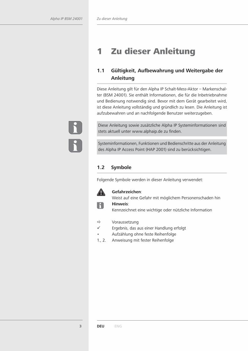
3 FunktionDer Alpha IP Schalt-Mess-Aktor für Markenschalter eignet sich für die Montage in einer Unterputzdose. Einmal installiert schaltet er ange-schlossene Verbraucher (z. B. Leuchten) ein bzw. aus und misst ihren Energieverbrauch.Der Schalt-Mess-Aktor für Markenschalter ermöglicht eine komfortable Steuerung angeschlossener Verbraucher über die Alpha IP App. Über die Bedienoberfläche wird der Energieverbrauch angeschlossener Verbrau-cher sowie die Energiekosten dargestellt.
Die Adapter für verschiedene Schalterserien ermöglichen einen kosten-sparenden Austausch von Schaltern gängiger Hersteller gegen eine intel-ligente Alpha IP Installation. Durch die Nutzung von Bauteilen der bereits vorhandenen bzw. vorgesehenen Schalterserien und Verkabelungen wird der Installationsaufwand auf ein Minimum reduziert. Das Design bzw. Farben und Oberflächen von bereits installierten Schalterserien bleibt unverändert, da vorhandene Rahmen und Wippen weiter genutztwerden können.
Die Kommunikation mit anderen Komponenten erfolgt über das Home-matic (HmIP) Funkprotokoll. Die Funk-Übertragung wird auf einem nicht exklusiven Übertragungsweg realisiert, weshalb Störungen nicht ausge-schlossen werden können. Störeinflüsse können z. B. hervorgerufen wer-den durch Schaltvorgänge, Elektromotoren oder defekte Elektrogeräte.
Die Reichweite in Gebäuden kann stark von der im Außenbereich (Frei-feld) abweichen.
DEU ENG7
GeräteübersichtAlpha IP BSM 24001
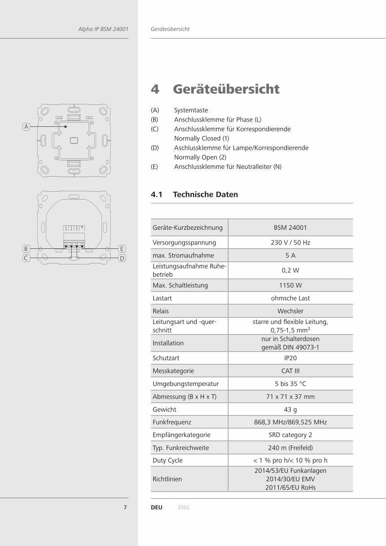
4 Geräteübersicht(A) Systemtaste(B) Anschlussklemme für Phase (L)(C) Anschlussklemme für Korrespondierende Normally Closed (1)(D) Aschlussklemme für Lampe/Korrespondierende Normally Open (2)(E) Anschlussklemme für Neutralleiter (N)
4.1 Technische Daten
Geräte-Kurzbezeichnung BSM 24001
Versorgungsspannung 230 V / 50 Hz
max. Stromaufnahme 5 A
Leistungsaufnahme Ruhe-betrieb
0,2 W
Max. Schaltleistung 1150 W
Lastart ohmsche Last
Relais Wechsler
Leitungsart und -quer-schnitt
starre und flexible Leitung,0,75-1,5 mm²
Installationnur in Schalterdosengemäß DIN 49073-1
Schutzart IP20
Messkategorie CAT III
Umgebungstemperatur 5 bis 35 °C
Abmessung (B x H x T) 71 x 71 x 37 mm
Gewicht 43 g
Funkfrequenz 868,3 MHz/869,525 MHz
Empfängerkategorie SRD category 2
Typ. Funkreichweite 240 m (Freifeld)
Duty Cycle < 1 % pro h/< 10 % pro h
Richtlinien2014/53/EU Funkanlagen
2014/30/EU EMV2011/65/EU RoHs
A
DEB
C
DEU ENG8
Adapter für MarkenschalterAlpha IP BSM 24001
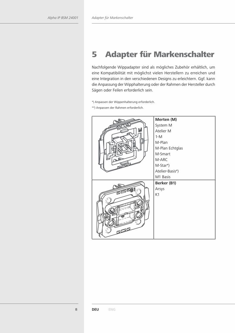
5 Adapter für MarkenschalterNachfolgende Wippadapter sind als mögliches Zubehör erhältlich, um eine Kompatibilität mit möglichst vielen Herstellern zu erreichen und eine Integration in den verschiedenen Designs zu erleichtern. Ggf. kann die Anpassung der Wipphalterung oder der Rahmen der Hersteller durch Sägen oder Feilen erforderlich sein.
*) Anpassen der Wippenhalterung erforderlich.
**) Anpassen der Rahmen erforderlich.
Merten (M)System MAtelier M1-MM-PlanM-Plan EchtglasM-SmartM-ARCM-Star*)Atelier-Basis*)M1 BasisBerker (B1)ArsysK1

DEU ENG9
Adapter für MarkenschalterAlpha IP BSM 24001
Berker (B2)S1Modul 2B1B3B7Q1
Busch-Jaeger (BJ)Duro 2000® SI/SI LinearReflex SI/SI Linearcarat®future® linearsolo®Busch® axcent, alpha
Jung (J1)*)LS 990LS designLS plusCD 500CD universalCD plus
Jung (J2)*)A 500A creationA plusAS 500AS universal

DEU ENG10
Adapter für MarkenschalterAlpha IP BSM 24001
Kopp (K)*) **)AlaskaAthenisAmbienteEuropaParis (Objekt HK 05)MilanoRivo
Gira (GD)Standard
Gira 55 (G)System 55Standard 55E2EventEspirit
düwi / Popp (D)**)ArchitasteArcadaTrendStandard Quadro (Plus2000)EverLuxe (Forever)ProLuxe (Quadro)PrimaLuxe
DEU ENG11
InbetriebnahmeAlpha IP BSM 24001
6 Inbetriebnahme
6.1 Montage
WARNUNGLebensgefahr durch anliegende elektrische Spannung!
¾ Das Montieren und Anschließen des Gerätes ist nur von einer autori-sierten Fachkraft zulässig.
¾ Vor der Montage und Installation die Netzspannung ausschalten und gegen Wiedereinschalten sichern
¾ Das Gerät darf nur mit Adapter und einer zugehörigen, montierten Schalterabdeckung betrieben werden. Die Schalterabdeckung nur für die Konfiguration entfernen.
Die Verschaltung einer Einzelraumregelung hängt von individuellen Fakto-ren ab und muss sorgsam vom Installateur geplant und realisiert werden.Für die Steck-/Klemmanschlüsse sind nachfolgende Querschnitte ver-wendbar:• starre Leitung: 0,75 – 1,5 mm²• flexible Leitung: 0,75 – 1,5 mm²• Leitungsenden 8 mm abisoliert
Die Installation darf nur in handelsüblichen Schalterdosen (Gerätedosen) gemäß DIN 49073-1 erfolgen.
Geräte mit elektronischen Netzteilen (z. B. Fernseher oder Hoch-volt-LED-Leuchtmittel) stellen keine ohmschen Lasten dar. Sie können Einschaltströme von über 100 A erzeugen. Schalten solcher Verbraucher führt zu vorzeitigem Verschleiß des Aktors. In solchen Fällen wird die Verwendung von Einschaltstrombegrenzern an den Schaltausgängen empfohlen.
Der Stromkreis, an dem das Gerät und die Last angeschlossen werden, muss mit einem Leitungsschutzschalter gemäß EN60898-1 (Auslösecha-rakteristik B oder C, max. 16 A Nennstrom, min. 6 kA Abschaltvermö-gen, Energiebegrenzungsklasse 3) abgesichert sein. Installationsvor-schriften lt. VDE 0100 bzw. HD384 oder IEC 60364 müssen beachtet werden. Der Leitungsschutzschalter muss für den Benutzer leicht er-reichbar und als Trennvorrichtung für das Gerät gekennzeichnet sein.
DEU ENG12
InbetriebnahmeAlpha IP BSM 24001
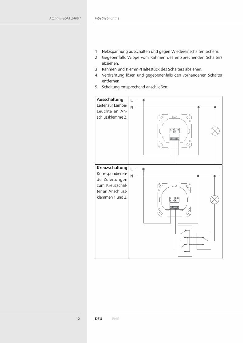
1. Netzspannung ausschalten und gegen Wiedereinschalten sichern.2. Gegebenfalls Wippe vom Rahmen des entsprechenden Schalters
abziehen.3. Rahmen und Klemm-/Haltestück des Schalters abziehen.4. Verdrahtung lösen und gegebenenfalls den vorhandenen Schalter
entfernen.5. Schaltung entsprechend anschließen:
AusschaltungLeiter zur Lampe/Leuchte an An-schlussklemme 2.
KreuzschaltungKorrespondieren-de Zuleitungen zum Kreuzschal-ter an Anschluss-klemmen 1 und 2.
DEU ENG13
InbetriebnahmeAlpha IP BSM 24001
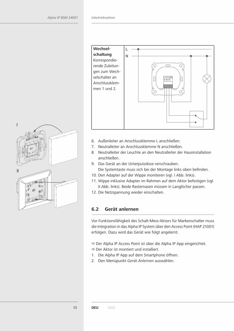
Wechsel- schaltungKorrespondie-rende Zuleitun-gen zum Wech-selschalter an Anschlussklem-men 1 und 2.
6. Außenleiter an Anschlussklemme L anschließen.7. Neutralleiter an Anschlussklemme N anschließen.8. Neutralleiter der Leuchte an den Neutralleiter der Hausinstallation
anschließen.9. Das Gerät an der Unterputzdose verschrauben.
Die Systemtaste muss sich bei der Montage links oben befinden.10. Den Adapter auf der Wippe moniteren (vgl. I Abb. links).11. Wippe inklusive Adapter im Rahmen auf dem Aktor befestigen (vgl.
II Abb. links). Beide Rasternasen müssen in Langlöcher passen.12. Die Netzspannung wieder einschalten.
6.2 Gerät anlernen
Vor Funktionsfähigkeit des Schalt-Mess-Aktors für Markenschalter muss die Integration in das Alpha IP System über den Access Point (HAP 21001) erfolgen. Dazu wird das Gerät wie folgt angelernt.
ÖDer Alpha IP Access Point ist über die Alpha IP App eingerichtet. ÖDer Aktor ist montiert und installiert.
1. Die Alpha IP App auf dem Smartphone öffnen.2. Den Menüpunkt Gerät Anlernen auswählen.
I
II
DEU ENG14
BedienungAlpha IP BSM 24001
Nach der Installation ist der Anlernmodus für 3 Minuten aktiv. Der Anlernmodus ist manuell über das Entfernen der Wippe und kurzes Drücken der Systemtaste aktivierbar.
3. Das Gerät erscheint automatisch in der App.4. Zur Bestätigung des Anlernvorgangs die letzten vier Ziffern der Ge-
rätenummer (SGTIN) in der App eingeben oder den beiliegenden QR-Code Scannen. Die Gerätenummer befindet sich auf dem Gerät.
Nach einem erfolgreichen Anlernvorgang leuchtet die LED grün. Leuch-tet die LED rot, den Vorgang wiederholen.
5. Den Anweisungen in der Alpha IP App folgen.
7 BedienungNach dem Anlernen und der Montage des Gerätes erfolgt die Konfigu-ration über die Alpha IP App.
DEU ENG15
AnzeigenAlpha IP BSM 24001
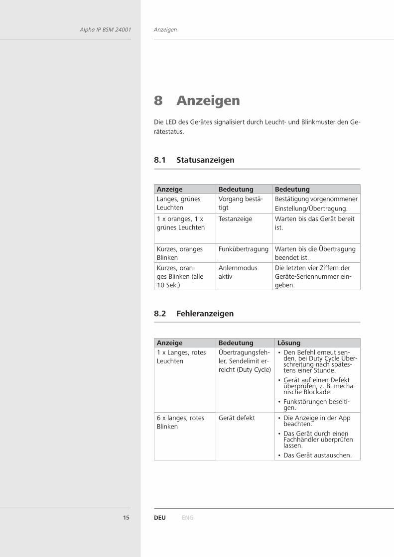
8 AnzeigenDie LED des Gerätes signalisiert durch Leucht- und Blinkmuster den Ge-rätestatus.
8.1 Statusanzeigen
Anzeige Bedeutung BedeutungLanges, grünes Leuchten
Vorgang bestä-tigt
Bestätigung vorgenommener Einstellung/Übertragung.
1 x oranges, 1 x grünes Leuchten
Testanzeige Warten bis das Gerät bereit ist.
Kurzes, oranges Blinken
Funkübertragung Warten bis die Übertragung beendet ist.
Kurzes, oran-ges Blinken (alle 10 Sek.)
Anlernmodus aktiv
Die letzten vier Ziffern der Geräte-Seriennummer ein-geben.
8.2 Fehleranzeigen
Anzeige Bedeutung Lösung1 x Langes, rotes Leuchten
Übertragungsfeh-ler, Sendelimit er-reicht (Duty Cycle)
• Den Befehl erneut sen-den, bei Duty Cycle Über-schreitung nach spätes-tens einer Stunde.
• Gerät auf einen Defekt überprüfen, z. B. mecha-nische Blockade.
• Funkstörungen beseiti-gen.
6 x langes, rotes Blinken
Gerät defekt • Die Anzeige in der App beachten.
• Das Gerät durch einen Fachhändler überprüfen lassen.
• Das Gerät austauschen.
DEU ENG16
Werkseinstellungen herstellenAlpha IP BSM 24001
9 ReinigenDas Gerät ist wartungsfrei.
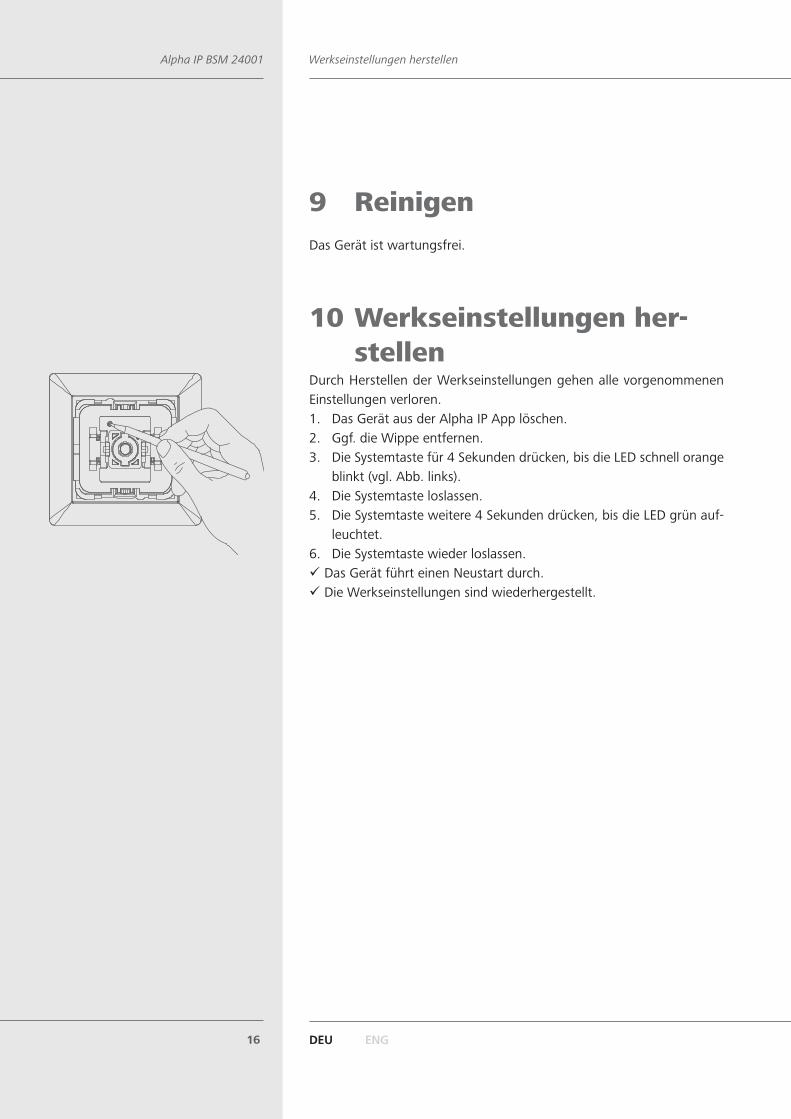
10 Werkseinstellungen her-stellen
Durch Herstellen der Werkseinstellungen gehen alle vorgenommenen Einstellungen verloren. 1. Das Gerät aus der Alpha IP App löschen.2. Ggf. die Wippe entfernen.3. Die Systemtaste für 4 Sekunden drücken, bis die LED schnell orange
blinkt (vgl. Abb. links).4. Die Systemtaste loslassen.5. Die Systemtaste weitere 4 Sekunden drücken, bis die LED grün auf-
leuchtet.6. Die Systemtaste wieder loslassen.
9 Das Gerät führt einen Neustart durch. 9 Die Werkseinstellungen sind wiederhergestellt.
DEU ENG17
EntsorgenAlpha IP BSM 24001
11 AußerbetriebnahmeWARNUNGLebensgefahr durch anliegende elektrische Spannung!
¾ Die Außerbetriebnahme des Gerätes ist nur von einer autorisierten Fachkraft zulässig.
¾ Vor der Außerbetriebnahme Netzspannung ausschalten und gegen Wiedereinschalten sichern
1. Das Gerät aus der Alpha IP App löschen.2. Netzspannung ausschalten und gegen Wiedereinschalten sichern.3. Alle bestehenden Kabel lösen.4. Das Gerät demontieren und ordnungsgemäß entsorgen.
12 EntsorgenDas Gerät nicht im Hausmüll entsorgen! Elektronische Geräte sind ent-sprechend der Richtlinie über Elektro- und Elektronik-Altgeräte über die örtlichen Sammelstellen für Elektronik-Altgeräte zu entsorgen.
Dieses Handbuch ist urheberrechtlich geschützt. Alle Rechte vorbehalten. Es darf weder ganz
noch teilweise ohne vorheriges Einverständnis des Herstellers kopiert, reproduziert, gekürzt
oder in irgendeiner Form übertragen werden, weder mechanisch noch elektronisch. © 2016

DEU ENG18
Alpha IP BSM 24001
Alpha IPBSM 24001
133420.1651
Instruction manual
DEU ENG19
Alpha IP BSM 24001
Contents
1 About these instructions ................................ 201.1 Validity, storage and forwarding of the instructions 201.2 Symbols 20
2 Safety ............................................................. 212.1 Personnel-related preconditions 212.2 Intended use 212.3 Safety notes 21
3 Function ......................................................... 23
4 Device overview ............................................. 244.1 Technical Data 24
5 Adapters for brand switches ......................... 25
6 Commissioning ............................................... 286.1 Installation 286.2 Teach-in of the device 30
7 Operation ....................................................... 31
8 Displays .......................................................... 328.1 Status displays 328.2 Error indications 32
9 Cleaning ......................................................... 33
10 Resetting factory settings .............................. 33
11 Decommissioning ........................................... 34
12 Disposal ......................................................... 34
DEU ENG20
About these instructionsAlpha IP BSM 24001
1 About these instructions
1.1 Validity, storage and forwarding of the instruc-tions
These instructions apply to the Alpha IP Switch Actuator and Meter– brand switches (BSM 24001). These instructions include information necessary for commissioning and operating. These instructions must be read completely and thoroughly before commencing any work with the device. These instructions must be kept and handed over to future users.
These instructions as well as constantly up-to-date additional Alpha IP system information can be found under www.alphaip.de.
System information, functions and operating steps from the Alpha IP Access Point (HAP 2001) instructions must be followed.
1.2 Symbols
The following symbols are used in this manual:
Hazard symbol: Indicates a hazard with possible personal damage
Note: Identifies important or useful information
Ö Preconditions 9 Result from an action
• List without fixed order1., 2. List with fixed order
DEU ENG21
SafetyAlpha IP BSM 24001
2 Safety
2.1 Personnel-related preconditions
The electrical installations must be performed according to the current national VDE regulations as well as according to the regulations of your local electric power utility company. These instructions require special knowledge corresponding to an officially acknowledged degree in one of the following professions:• Systems Mechanic for sanitary, heating and air condition technology• Electrical Equipment Installer or• Electronics Engineeraccording to the profession designations officially announced in the Fed-eral Republic of Germany, as well as according to comparable professions within the European Community Law.
2.2 Intended use
The Alpha IP Switch Actuator and Meter – brand switches (BSM 24001) is a component of the Alpha IP System and serves• for a fixed installation in environments of residential use,• for switching connected electronic consumers,• for measuring energy consumption and energy cost of connected
consumers,• for the connection of further Alpha IP components and the commu-
nication with these.
Every other use, modification and conversion is expressively forbidden. Improper use leads to dangers the manufacturer cannot be held liable for and will exempt guarantees and liabilities.
2.3 Safety notes
All safety notes in these instructions must be observed in order to avoid accidents causing personal damage or property damage. No liability is assumed for personal damage and property damage caused by improper use or non-observance of the danger notes. In such cases any warranty claim is invalid. There is no liability for consequential damages.
DEU ENG22
SafetyAlpha IP BSM 24001
• Only an authorised electrician may install, connect and open the de-vice.
• Only use the device if it is in flawless state.• Observe the performance limits of the device and its environmental
conditions.• The device must not be used for disconnection.• Only use the device in stationary installations.• Do not use the device in case of visible external damage, e. g. at the
casing, at operating elements or at the connection sockets.• Only operate the device in a dry and dust-free environment.• Do not expose the device to the influence of humidity, vibration,
continuous solar radiation or other types of radiation, coldness or mechanical load.
• Ensure that children do not play with this device or its packaging. Children must be monitored if necessary.
• Do not throw packaging material carelessly away. Plastic foils, bags, styrofoam parts etc. may become a dangerous plaything in the hands of children.
DEU ENG23
FunctionAlpha IP BSM 24001
3 FunctionThe Alpha IP Switch Actuator and Meter for brand switches is suitable for installation in a flush-type box. Once installed, it switches connected consumers (e. g. lamps) and measures their energy consumption.The switch actuator and meter for brand switches allows a comfortable control of connected consumers via the Alpha IP app. The energy con-sumption and the energy cost of connected consumers is displayed on the user interface.
The adaptors for different switch series allow a cost-saving exchange of switches made by popular manufacturers against an intelligent Alpha IP installation. Installation efforts are kept to a minimum because compo-nents of the already existing or scheduled switch series and cables can be used. The design resp. the colours and surfaces of already installed switch series remains unchanged, because existing frames and rockers can be continued to be used.
Communication with other components is performed via the Homematic (HmIP) radio protocol. Radio transmission is realised on a non-exclusive transmission path; thus, interference cannot be completely excluded. Interference can be caused e. g. by switching processes, electric motors or defective electric appliances.
The range inside buildings can be strongly different from the range in open air.

DEU ENG24
Device overviewAlpha IP BSM 24001
4 Device overview(A) System key(B) Connection terminal for phase (L)(C) Connection terminal for corresponding supply lines Normally Closed (1)(D) Connection terminal for lamp/corresponding supply lines Normally Open (2)(E) Connection terminal for neutral conductor (N)
4.1 Technical Data
Short designation of the device
BSM 24001
Supply voltage 230 V / 50 Hz
Max. power consumption 5 A
Standby power consumption
0.2 W
Max. switching power 1150 W
Load type resistive load
Relay changeover contact
Line type and line section rigid and flexible line, 0.75-1.5 mm²
Installationonly in switchboxes according to DIN
49073-1
Protection type IP20
Measurement category CAT III
Ambient temperature 5 to 35 °C
Dimensions (W x H x D) 71 x 71 x 37 mm
Weight 43 g
Radio frequency 868.3 MHz/869.525 MHz
Receiver category SRD category 2
Typical radio range 240 m (in open air)
Duty cycle < 1 % per h/< 10 % per h
Guidelines2014/53/EU Radio installations
2014/30/EU EMC2011/65/EU RoHs
A
DEB
C
DEU ENG25
Adapters for brand switches Alpha IP BSM 24001
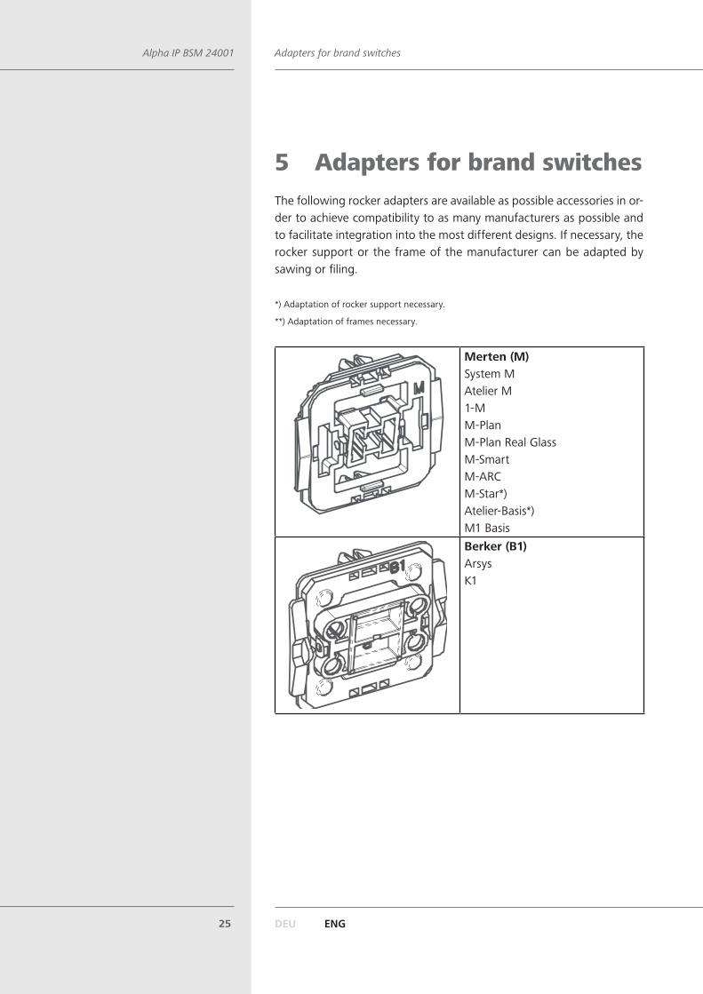
5 Adapters for brand switches The following rocker adapters are available as possible accessories in or-der to achieve compatibility to as many manufacturers as possible and to facilitate integration into the most different designs. If necessary, the rocker support or the frame of the manufacturer can be adapted by sawing or filing.
*) Adaptation of rocker support necessary.
**) Adaptation of frames necessary.
Merten (M)System MAtelier M1-MM-PlanM-Plan Real GlassM-SmartM-ARCM-Star*)Atelier-Basis*)M1 BasisBerker (B1)ArsysK1
DEU ENG26
Adapters for brand switches Alpha IP BSM 24001
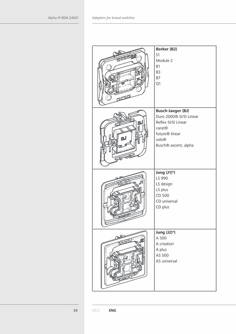
Berker (B2)S1Module 2B1B3B7Q1
Busch-Jaeger (BJ)Duro 2000® SI/SI LinearReflex SI/SI Linearcarat®future® linearsolo®Busch® axcent, alpha
Jung (J1)*)LS 990LS designLS plusCD 500CD universalCD plus
Jung (J2)*)A 500A creationA plusAS 500AS universal
DEU ENG27
Adapters for brand switches Alpha IP BSM 24001
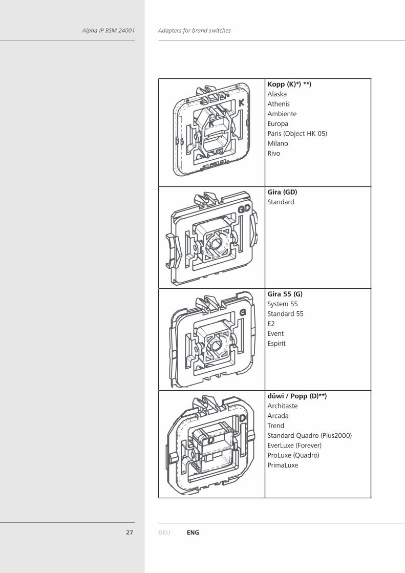
Kopp (K)*) **)AlaskaAthenisAmbienteEuropaParis (Object HK 05)MilanoRivo
Gira (GD)Standard
Gira 55 (G)System 55Standard 55E2EventEspirit
düwi / Popp (D)**)ArchitasteArcadaTrendStandard Quadro (Plus2000)EverLuxe (Forever)ProLuxe (Quadro)PrimaLuxe
DEU ENG28
CommissioningAlpha IP BSM 24001
6 Commissioning
6.1 Installation
WARNINGElectrical voltage! Danger to life!
¾ Only an authorised electrician may install and connect the device. ¾ Always disconnect from the mains network and secure against unin-tended activation before mounting and installation.
¾ The device must only be operated with an adapter and a correspond-ing and installed switch cover. Only remove the switch cover for con-figuration purposes.
The wiring of a room-by-room temperature control system depends on several factors and must be planned and carried through carefully by the installer.The following cross-sections are applicable for the plug-in/clamping connections:• rigid wire: 0.75 – 1.5 mm²• flexible wire: 0.75 – 1.5 mm²• 8 mm insulation stripped off the wire
Installation must only be performed in industrially available switchbox-es (mounting boxes) according to DIN 49073-1.
Devices with electronic power supply units (e. g. TV sets or high voltage LED lamps) do not represent ohmic loads. They can generate inrush currents of up to 100 A. The switching of such consumers leads to a premature wear of the actuator. In such cases, the use of inrush current limiters at the switching outputs is recommended.
The circuit the device and the load are connected to must be safeguard-ed with a circuit breaker according to EN60898-1 (triggering character-istic B or C, max. 16 A nominal current, min. 6 kA breaking capacity, energy limiting class 3). Installation guidelines according to VDE 0100 resp. HD384 or IEC 60364 must be observed. The circuit breaker must be easily accessible to the user, and must be identified as disconnect device for the unit.
DEU ENG29
CommissioningAlpha IP BSM 24001
1. Disconnect from the mains network and secure against unintended activation.
2. If necessary pull off the rocker from the frame of the respective switch.3. Pull off the frame and the clamping/support piece from the switch.4. Loosen the cabling and remove the existing switch if necessary.5. Connect the wiring as follows:
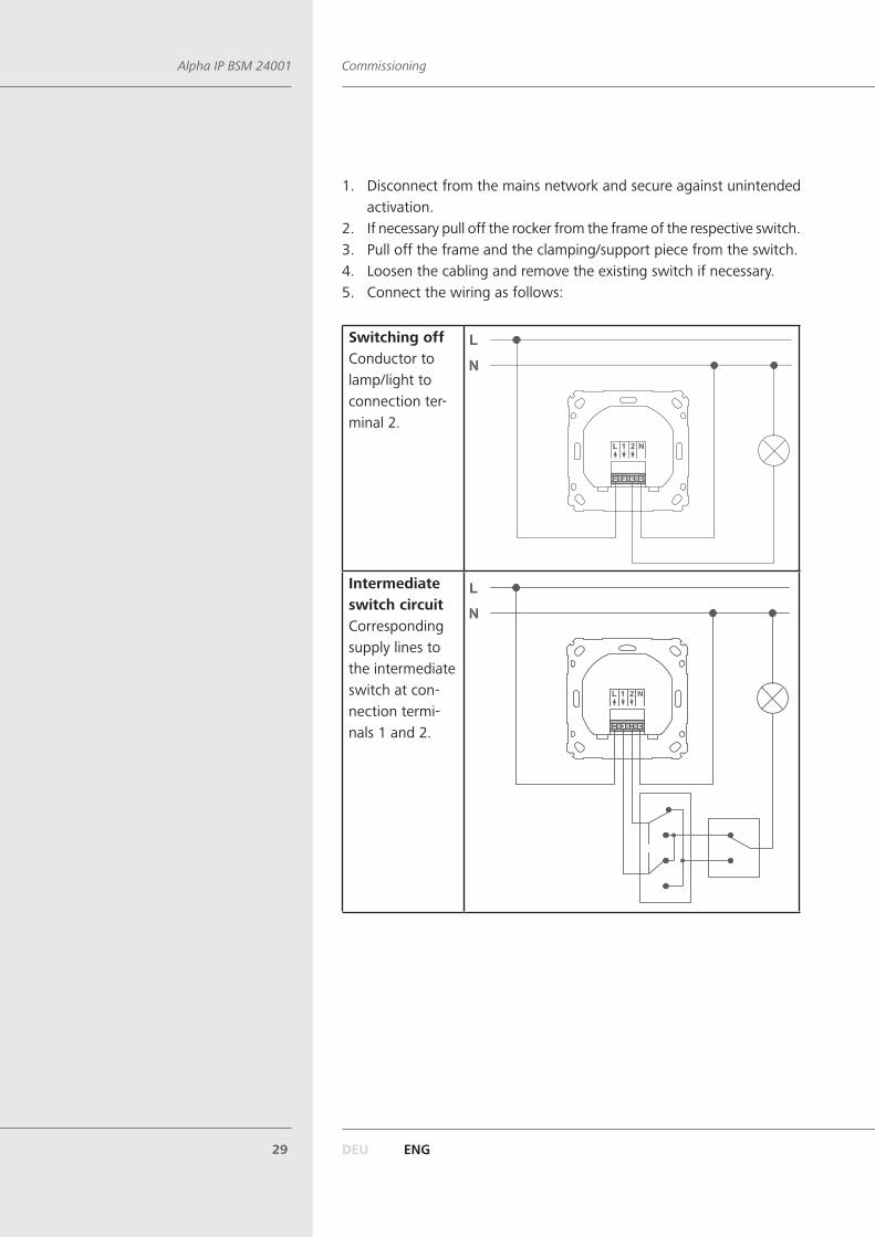
Switching offConductor to lamp/light to connection ter-minal 2.
Intermediate switch circuitCorresponding supply lines to the intermediate switch at con-nection termi-nals 1 and 2.
DEU ENG30
CommissioningAlpha IP BSM 24001
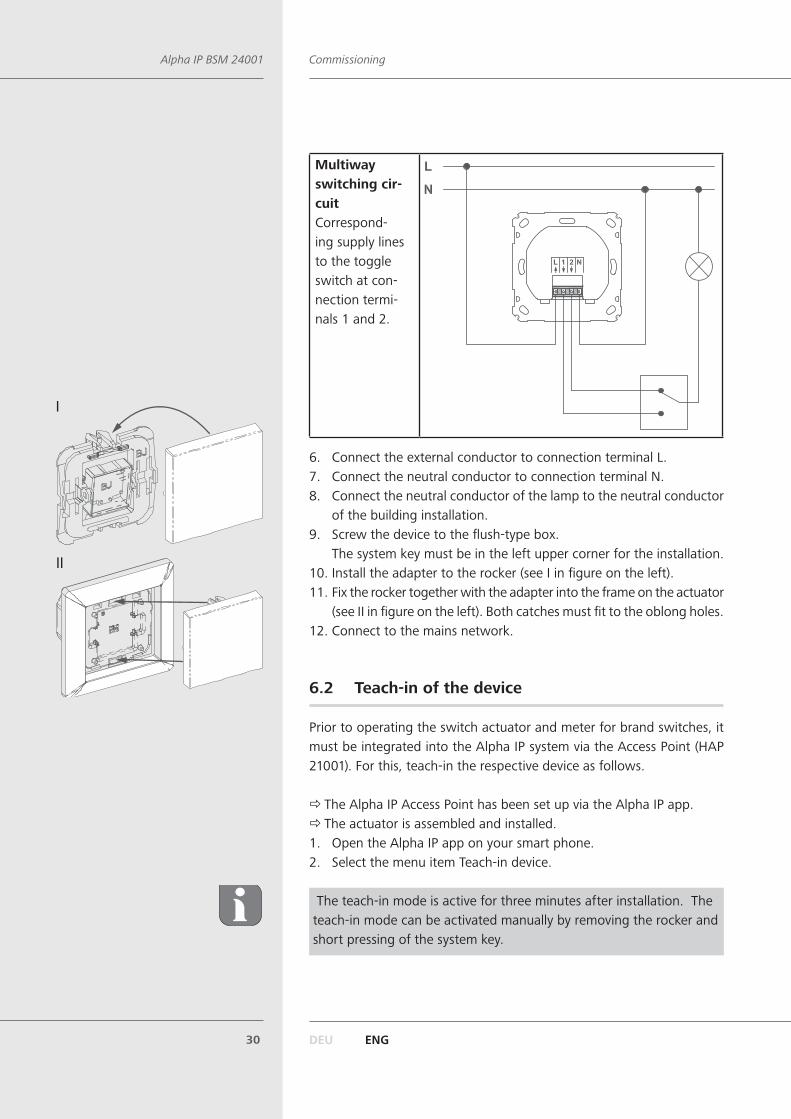
Multiway switching cir-cuitCorrespond-ing supply lines to the toggle switch at con-nection termi-nals 1 and 2.
6. Connect the external conductor to connection terminal L.7. Connect the neutral conductor to connection terminal N.8. Connect the neutral conductor of the lamp to the neutral conductor
of the building installation.9. Screw the device to the flush-type box.
The system key must be in the left upper corner for the installation.10. Install the adapter to the rocker (see I in figure on the left).11. Fix the rocker together with the adapter into the frame on the actuator
(see II in figure on the left). Both catches must fit to the oblong holes.12. Connect to the mains network.
6.2 Teach-in of the device
Prior to operating the switch actuator and meter for brand switches, it must be integrated into the Alpha IP system via the Access Point (HAP 21001). For this, teach-in the respective device as follows.
Ö The Alpha IP Access Point has been set up via the Alpha IP app. Ö The actuator is assembled and installed.
1. Open the Alpha IP app on your smart phone.2. Select the menu item Teach-in device.
The teach-in mode is active for three minutes after installation. The teach-in mode can be activated manually by removing the rocker and short pressing of the system key.
I
II

DEU ENG31
OperationAlpha IP BSM 24001
3. The device will be displayed automatically in the app.4. For confirmation of the teach-in process, enter the last four digits of
the device number (SGTIN) in the app or scan the supplied QR code. The device number can be found on the back side of the device.
The LED will light up in green after a successful teach-in process. The process must be repeated if the LED lights up in red.
5. Follow the directions of the Alpha IP app.
7 OperationAfter the teaching-in and the installation of the device, the configuration is performed via the Alpha IP app.
DEU ENG32
DisplaysAlpha IP BSM 24001
8 DisplaysThe LED of the device signalises the device status by means of light and flashing patterns.
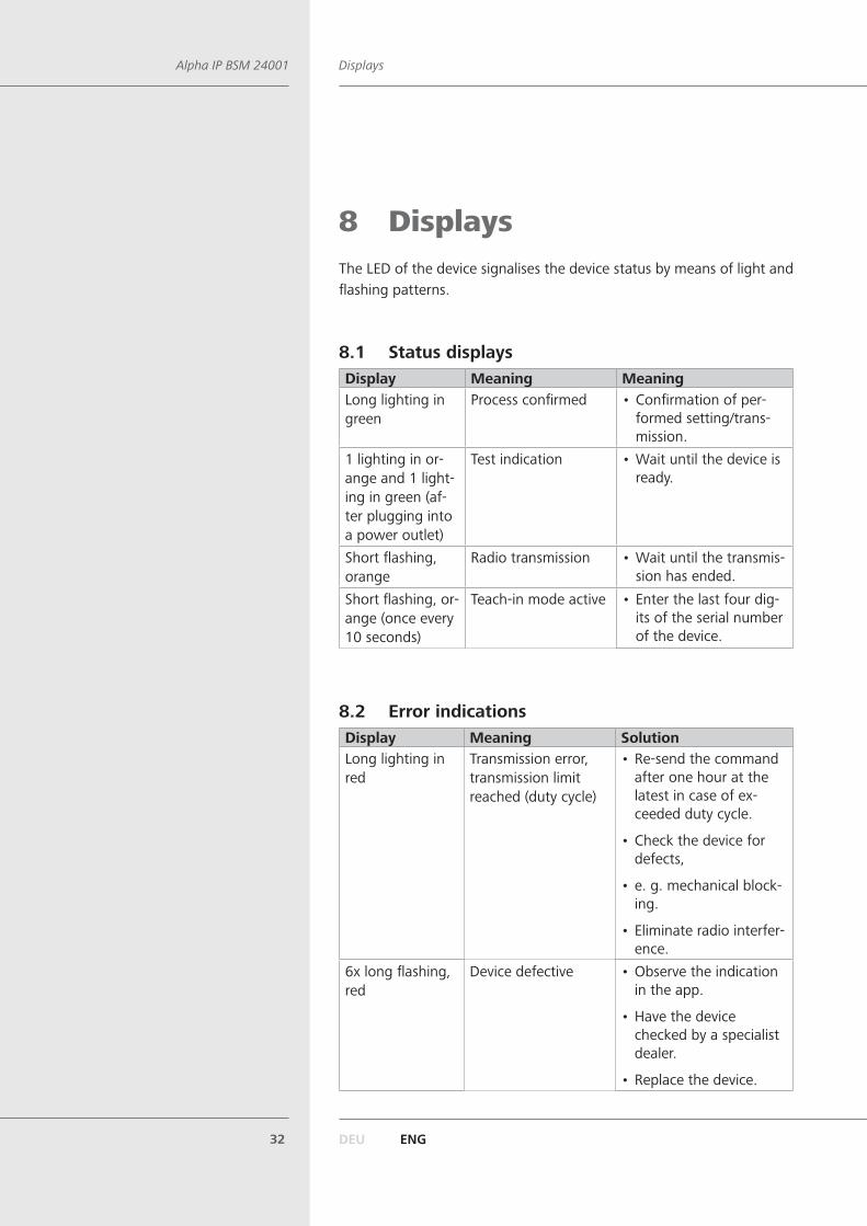
8.1 Status displaysDisplay Meaning MeaningLong lighting in green
Process confirmed • Confirmation of per-formed setting/trans-mission.
1 lighting in or-ange and 1 light-ing in green (af-ter plugging into a power outlet)
Test indication • Wait until the device is ready.
Short flashing, orange
Radio transmission • Wait until the transmis-sion has ended.
Short flashing, or-ange (once every 10 seconds)
Teach-in mode active • Enter the last four dig-its of the serial number of the device.
8.2 Error indicationsDisplay Meaning SolutionLong lighting in red
Transmission error, transmission limit reached (duty cycle)
• Re-send the command after one hour at the latest in case of ex-ceeded duty cycle.
• Check the device for defects,
• e. g. mechanical block-ing.
• Eliminate radio interfer-ence.
6x long flashing, red
Device defective • Observe the indication in the app.
• Have the device checked by a specialist dealer.
• Replace the device.
DEU ENG33
Resetting factory settingsAlpha IP BSM 24001
9 CleaningThe device is maintenance-free.
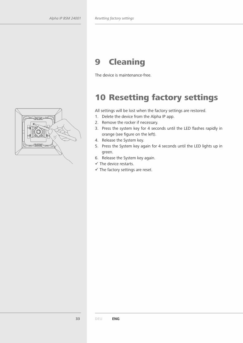
10 Resetting factory settingsAll settings will be lost when the factory settings are restored. 1. Delete the device from the Alpha IP app.2. Remove the rocker if necessary.3. Press the system key for 4 seconds until the LED flashes rapidly in
orange (see figure on the left).4. Release the System key.5. Press the System key again for 4 seconds until the LED lights up in
green.6. Release the System key again.
9 The device restarts. 9 The factory settings are reset.
DEU ENG34
DisposalAlpha IP BSM 24001
This manual is protected by copyright. All rights reserved. It may not be copied, reproduced,
abbreviated or transmitted, neither in whole nor in parts, in any form, neither mechanically
nor electronically, without the previous consent of the manufacturer. © 2016
11 DecommissioningWARNINGElectrical voltage! Danger to life!
¾ Only an authorised electrician may decommission the device. ¾ Prior to decommissioning, disconnect from the mains voltage and se-cure against unintended activation.
1. Delete the device from the Alpha IP app.2. Disconnect from the mains network and secure against unintended
activation.3. Loosen all connected cables.4. Uninstall the device and dispose of properly.
12 DisposalDo not dispose of the device with domestic waste!Electronic devices/products must be disposed of according to the Direc-tive for Waste Electrical and Electronic Equipment at the local collection points for waste electronic equipment.