An exploration of moving walkways as a transport system in ... · Abstract Moving walkways (MW)...
20
An exploration of moving walkways as a transport system in urban centers Riccardo Scarinci 1 riccardo.scarinci@epfl.ch Farzaneh Bahrami 2 farzaneh.bahrami@epfl.ch Andr´ e Ourednik 3 andre.ourednik@epfl.ch Michel Bierlaire 1 michel.bierlaire@epfl.ch Report TRANSP-OR 160810 Transport and Mobility Laboratory TRANSP-OR School of Architecture, Civil and Environmental Engineering ENAC ´ Ecole Polytechnique F´ ed´ erale de Lausanne EPFL transp-or.epfl.ch 01 August 2016 1 ´ Ecole Polytechnique F´ ed´ erale de Lausanne EPFL, School of Architecture, Civil and Envi- ronmental Engineering ENAC, Transport and Mobility Laboratory TRANSP-OR, Switzerland, transp-or.epfl.ch 2 ´ Ecole Polytechnique F´ ed´ erale de Lausanne EPFL, School of Architecture, Civil and Envi- ronmental Engineering ENAC, Laboratory of Urbanism LAB-U, Switzerland, lab-u.epfl.ch 3 ´ Ecole Polytechnique F´ ed´ erale de Lausanne EPFL, School of Architecture, Civil and Envi- ronmental Engineering ENAC, Laboratory Chˆ oros, Switzerland, choros.epfl.ch
Transcript of An exploration of moving walkways as a transport system in ... · Abstract Moving walkways (MW)...
An exploration of moving walkways as a transportsystem in urban centers
Riccardo Scarinci 1 [email protected] Bahrami 2 [email protected] Ourednik 3 [email protected] Bierlaire 1 [email protected]
Report TRANSP-OR 160810Transport and Mobility Laboratory TRANSP-OR
School of Architecture, Civil and Environmental Engineering ENACEcole Polytechnique Federale de Lausanne EPFL
transp-or.epfl.ch
01 August 2016
1 Ecole Polytechnique Federale de Lausanne EPFL, School of Architecture, Civil and Envi-ronmental Engineering ENAC, Transport and Mobility Laboratory TRANSP-OR, Switzerland,transp-or.epfl.ch
2 Ecole Polytechnique Federale de Lausanne EPFL, School of Architecture, Civil and Envi-ronmental Engineering ENAC, Laboratory of Urbanism LAB-U, Switzerland, lab-u.epfl.ch
3 Ecole Polytechnique Federale de Lausanne EPFL, School of Architecture, Civil and Envi-
ronmental Engineering ENAC, Laboratory Choros, Switzerland, choros.epfl.ch

Abstract
Moving walkways (MW) have been imagined as a possible means of transport since thelate 19th century, and this system has fascinated urban planners and engineers ever since.Contrary to what has been imagined, moving walkways are only used in transportationhub corridors, and not as a main transport mode in city centers. Today however, MWs arereceiving increasing attention as a possible solution to congestion and pollution, as well asa catalyst for soft mobility. This paper explores the role of moving walkways as a transportsystem. We review historical MWs, current installations and future possibilities, usingdifferent perspectives, from geography to urban planning to transport engineering. Wediscuss the way in which MWs influence how people inhabit the urban space, and wereview this system in the context of history of urban planning. Then, we describe atechnological development called accelerating moving walkways (AMW), i.e. MWs ableto reach a higher speed than traditional ones. We develop an optimization frameworkto design a network of AMWs, and we apply it to a real case study. The results of thenetwork design are a reference useful to discuss the feasibility of the system starting froman engineering perspective. We conclude that the use of MWs can facilitate the flexibilityand spontaneity typical of pedestrian movements, and this system could be integrated inthe mix of urban transport modes in city centers.
1 Introduction
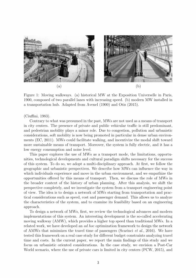
Moving walkways (MW), also known as moving sidewalks, have been imagined as a systemcapable of facilitating pedestrian movements on specific routes, or even as the primarytransport mode in city centers. This concept is present in the history of transportationsince the late 19th century, and it has fascinated science-fiction writers, urban plannersand engineers ever since. The use of impossibly fast (more than 100 km/h) and massivemoving walkways as the main transport system of future megalopolis was described inseveral science-fiction novels such as A Story of the Days To Come (Wells, 1897), TheRoads Must Roll (Heinlein, 1940) and The Caves of Steel (Asimov, 1954). In the sameperiod, real implementations of moving walkways were presented in exhibition events suchas the World’s Columbian Exposition, Chicago, USA, 1893 (Badger, 1979), ExpositionUniverselle, Paris, France, 1900 (Avenel, 1900) and 42nd street, New York, USA, 1923(NYPL, 1923). These MWs were composed of parallel lanes, each of them moving ata higher speed, reaching the maximum speed of 9 km/h. The users could access themlaterally everywhere and reach the high-speed lane jumping from one belt to the adjacentone, see Figure 1(a).
Nowadays, MWs consist of one lane only, and the lateral access is not allowed forsafety reasons, see Figure 1(b). In addition, the maximum speed is limited to 3 km/hto avoid discomfort. They are used on individual routes with high demand, usually inlarge transportation hubs such as airports and metro stations. In a few cases, MWsare installed in cities, for example, the Central-Mid-Levels escalator and walkway systemin Hong Kong (Cullinane, 2002), the Mechanical Ramps in Vitoria-Gasteiz (Helzel andTaylor, 2011), or in hilly urban environments to facilitate the access to elevated areas,for instance, Medellin, Colombia (Nakamichi and Nakamura, 2014) and Perugia, Italy
2
(a) (b)
Figure 1: Moving walkways. (a) historical MW at the Exposition Universelle in Paris,1900, composed of two parallel lanes with increasing speed. (b) modern MW installed ina transportation hub. Adapted from Avenel (1900) and Otis (2015).
(Ciuffini, 1983).Contrary to what was presumed in the past, MWs are not used as a means of transport
in city centers. The presence of private and public vehicular traffic is still predominant,and pedestrian mobility plays a minor role. Due to congestion, pollution and urbanisticconsiderations, soft mobility is now being promoted in particular in dense urban environ-ments (EC, 2011). MWs could facilitate walking, and incentivize the modal shift towardmore sustainable means of transport. Moreover, the system is fully electric, and it has alow energy consumption and noise level.
This paper explores the use of MWs as a transport mode, the limitations, opportu-nities, technological developments and cultural paradigm shifts necessary for the successof this system. To do so, we adopt a multi-disciplinary approach. At first, we follow thegeographic and urbanistic perspectives. We describe how MWs can influence the way inwhich individuals experience and move in the urban environment, and we empathize theopportunities offered by this means of transport. Then, we discuss the role of MWs inthe broader context of the history of urban planning. After this analysis, we shift theperspective completely, and we investigate the system from a transport engineering pointof view. The idea is to design a network of MWs starting from transportation and prac-tical considerations such as speed, cost and passenger demand. This allows us to analyzethe characteristics of the system, and to examine its feasibility based on an engineeringapproach.
To design a network of MWs, first, we review the technological advances and modernimplementations of this system. An interesting development is the so-called acceleratingmoving walkway (AMW), which provides a higher top speed than traditional MWs. In arelated work, we have developed an ad hoc optimization framework to design the networkof AMWs that minimizes the travel time of passengers (Scarinci et al., 2016). We havetested this framework on a real case study for different budget constraints analyzing traveltime and costs. In the current paper, we report the main findings of this study and wefocus on urbanistic oriented considerations. In the case study, we envision a Post-CarWorld scenario, where the use of private cars is limited in city centers (PCW, 2015), and
3
the entire passenger demand is satisfied by AMWs or walking.The paper is structured as follows. Section 2 discusses the signification of MWs for the
individuals moving through the space and the existential implications on the inhabitingspace. In Section 3, we look at the re-consideration of MWs in the 20th century, followingthe critiques of the car and the attempts to seek futuristic mobility alternatives. Section 4reviews the technical characteristics of accelerating moving walkways, as well as currentinstallations. Section 5 investigates the possibility to use AMWs as an urban transportmode by designing a network of AMWs on a real case study. The main conclusions arereported in Section 6
2 The moving walkway as a new way of inhabiting
the urban space
The private car is often regarded as a means of transport offering a great freedom ofmovement, seen as a major quality of this mode of transport. In fact, the use of thecar implies accepting inhabiting the space in a tunnel perspective. The car limits thepossible spatial behavior of its driver to a movement forward, and its interaction with theimmediate environment to occasional honking or headlight flashing (Ourednik, 2008).Especially in the urban context, it is by no means easy to park a car and to leave itin order to engage into more complex ways of inhabiting the space (Heidegger, 1954;Bollnow, 1967).
As opposed to the coerced freedom of the car, pedestrian movements are characterizedby flexibility and spontaneity, providing opportunities for interactions. However, thisflexibility is only efficient in the context of dense and diverse urban centers, where suchopportunities, whether they consist of people or places, are close to each other. Theexperience of density itself, however, is also closely related to the speed of movementsthrough a given environment (Ourednik, 2010). Even in an urban setting, the numberof reachable elements remains limited by the speed of pedestrian movements. As theaverage topographic distances between objects of interest grow, only speed of movementscan restore an experience of density. Conversely, this also means that urban density,understood as an interaction potential, can be augmented by accelerating the pedestrianmovements. Being capable to reach more things, people and places, signifies having morechoice of action. It opens up individual’s existential perspectives: which is the verypurpose of any city. The collateral effect of this acceleration, however, is cutting theindividual off the immediate environment of his/her movements. A compromise thus hasto be found between speed and the potential of local interactions.
Open vehicles, such as bikes or segways, constitute an answer to this problem. Anotheroriginal answer is given by MWs, especially when these are organized into a network wherethe individuals can choose the direction at each crossroads. The technical implicationsof the construction of such a network are by no means trivial and are discussed in thefollowing of the present paper.
4

3 The moving walkway in the broader context of the
history of urban planning
The ecological consciousness, oil crisis and the spatial consequences of decades of carurbanism generated, during the 1960s and 1970s, an urge to seek alternatives systems tocar mobility. With the conviction that “people will use automobiles as long as nothingbetter is available” (Gruen, 1964) a series of explorations started proposing new innovativepossibilities for the future that will give even more delight and convenience to the user.Given the considerable amount of studies and experiments on mechanical means of movingpeople prior to the mass motorization era, up to 1920s, urban projects in this periodreemployed many of the historical schemes and examples to develop the future withthe objective of reducing the role of the private car. Among many transport systemsimagined, such as mini-rails, self-driven mini taxis, automatic people movers, and othernon-stop moving systems, MWs were a promising recurrent scheme. Applied mostlywithin transportation hubs and shopping malls, it was also imagined to be a viabletransport means for intra-city movements, especially within the new developments.
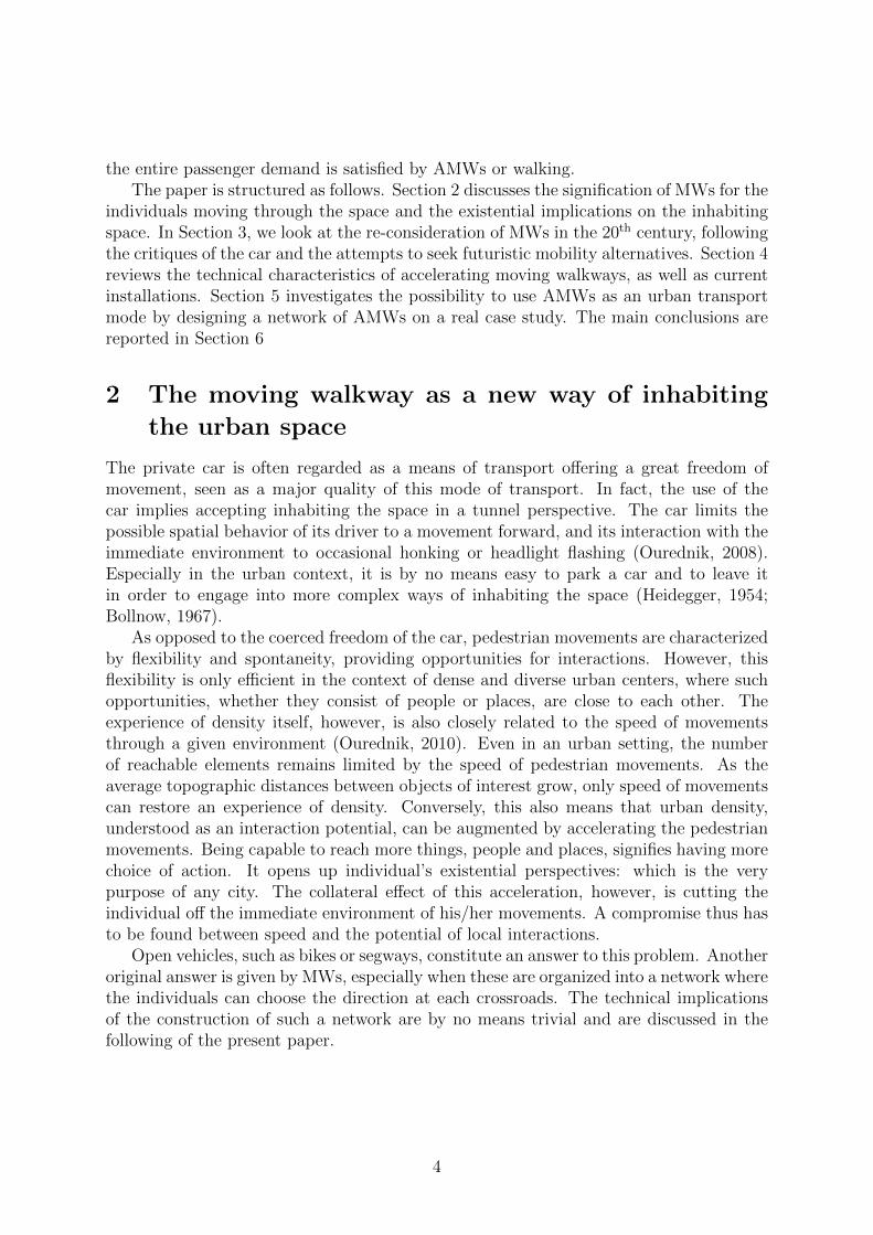
MWs, also called pedestrian conveyors in the literature, were thought not only as anaid to pedestrian movements but also capable to provide a new experience, with a viewover the city at a different speed, not necessarily faster than that of pedestrians. In aninventory of transport systems proposed by Richards (1966, 1976) the average speed ofpedestrians (4.8 km/h) was interestingly higher than that of pedestrian conveyor (3km/h).However, given the fact that they could be walked on, the speed as an advantage wasnot excluded. Such effortless, immobile walk of the pedestrian conveyors offered anothervision of the city without regrets for the car. As described by Rouillard (2013), the city islike a permanent Exposition Universelle. Richards (1976), in his exploratory surveys intothe future, also introduces the idea of high-speed conveyors, called Speedaway, with theaverage speed of 12-16 km/h. The Speedaway was intended to run above London Bridge,one of the densest corridors of movement in London, see Figure 2. The proposal usedtwin high-speed conveyors, operating within an air-conditioned enclosure and connectedat either end with elevated pedestrian decks linked with the underground stations closeby. The system was above all considered as a complement to both existing and futuremodes of transport. The critical challenge however, was the spatial arrangement, theinsertion of the system within the existing width of streets. Therefore in many cases itwas imagined as an elevated level, following examples like the London Pedways project(Hebbert, 1993). This project planned and partly implemented a network of elevatedwalkways throughout the city, re-proposing the traditional idea of separating pedestriansfrom motorized or wheeled traffic.
It is not irrelevant, proposes Rouillard (2013), to link the very concrete and persistentideas and sketches of moving walkways and other innovative moving systems, with themore utopian imaginaries of the time, which were focused on the idea of augmentedpedestrian and ecstatic mobility. For example, Cook (1999) proposes a combination ofcushion and vehicle called the Cushicle. It was a sort of mobile structure in two parts:a chassis with appliances and personalized apparatuses and an inflatable envelope. Likea car, the Cushicle was envisioned as eventually becoming part of an urban system ofpersonalized enclosures, though it was conceived as usable in any environment. From the
5
(a) (b)
(c)
Figure 2: Speedaway system. (a) Plan showing the Speedaway system crossing theThames connecting existing underground stations on the north bank with new develop-ments on the south bank. (b) Interior view along the system. (c) Speedaway runningabove a car-free shopping street. Adapted from Richards (1976).
6

Cushicle to ideas of individual air travel, they were all struggles to achieve new paradigmsin transport in cities, hoping that, as Buchanan (1963) put it, “we are not at the endof our ingenuity for that matter”. Contrary to many of its contemporary ideas, movingwalkways were actually applied in real contexts, and nowadays are installed in severalenvironments.
4 Review of accelerating moving walkway
The main limitation of MWs is the low speed, and since the 1960s, technical solutions ableto achieve higher speeds have been investigated (Kusumaningtyas, 2009). Some of thesesolutions were developed between the 1970s and early 1980s, and the first prototypes ofaccelerating moving walkways (AMW) were made. The successful prototypes were builtand tested in the late 1990s and early 2000s.
Since then, AMWs have received increasing attention from researchers. Gonzalez Ale-many and Cuello (2003), Ikizawa et al. (2001), Saeki (1996) and Shirakihara (1997) studythe technological aspects of the system. Abe et al. (2001) propose a different design ableto cover inclined and even curved paths. The integration of this innovative system withthe urban infrastructure is studied by Rockwood and Garmire (2015). Kusumaningtyaset al., in several research papers focused on AMWs, make a comprehensive investiga-tion of the system from a technical and transportation perspective (Kusumaningtyas andLodewijks, 2008; Kusumaningtyas, 2009; Kusumaningtyas and Lodewijks, 2013).
In the following, we present the AMW characteristics, the different AMW types andtwo installation examples.
4.1 Technical characteristics
AMWs are divided into three sections: acceleration, constant speed, and deceleration.The acceleration section, as the name suggests, has an acceleration between 0.14 m/s2
and 0.43 m/s2, depending on the installations (Dembart, 2003; Gonzalez Alemany et al.,2007; Kusumaningtyas and Lodewijks, 2008, 2013). In this section, the speed increasesfrom the entry speed between 2.1 km/h and 2.7 km/h (Donoghue, 1981; Fruin, 1992) tothe top speed. Real implementations of AMWs show that the top speed can be up to12 km/h (Kusumaningtyas, 2009). The constant speed section has zero acceleration, andpassengers can walk. Thus, the walking speed is added to the top speed of the AMW.The walking speed depends on factors such as the age, gender and trip purpose of theindividuals. However, as a reference, Young (1999) shows that the walking speed on MWsis on average 3.7 km/h. The final section is the deceleration section. Here, the speeddecreases to an exit speed equal to the entry speed for a safe disembarking.
AMWs have a constant width along the entire length. The typical width of theinternal space usable by passengers is between 0.8 and 1.6 meters, and, considering therequired lateral installation, the corridor width ranges between 1.2 meters and 2.3 meters(Kusumaningtyas, 2009). The length is limited by the technology, and it ranges between120 meters and 350 meters (Abe et al., 2001; Lechner, 2011).
The capacity of an AMW, expressed in passengers per hour (pax/h) per direction,depends on the entry speed and the width. Typical installations have capacities ranging
7
from 4,500 pax/h to 7,500 pax/h (Kusumaningtyas and Lodewijks, 2008). The capitalcost of AMW, including the surrounding structure, is between 34.8 million EUR/km and54.4 million EUR/km, and the operational cost ranges from 0.08 EUR/pax-km to 0.42EUR/pax-km, with a typical value of 0.13 EUR/pax-km (Kusumaningtyas, 2009).
AMWs present a limited energy consumption of approximately 0.11 MJ/pax-km.They are fully electric, thus, reduce local emission of greenhouse gases. In addition,the system has a low noise level close to 54 dB(A) (ThyssenKrupp, 2004).
In comparison with other urban means of transport such as buses and light rail metroservices, AMWs have a competitive speed, operational cost and capacity with the ad-vantage of a limited corridor width. However, AMWs present a greater capital cost,especially in comparison with busses (Kusumaningtyas and Lodewijks, 2008). Bussesand light rails have higher top speeds than AMWs, however, the discontinuous natureof these systems decreases the average speed. Busses have an average speed between 15km/h and 20 km/h, while light rail can reach speeds up to 45 km/h (Brand and Preston,2003; KFH Group, 2013). AMWs can have maximum speeds up to 15-17 km/h thanksto the possibility of pedestrians to walk on the constant speed section. This speed iscompetitive with private cars during peak hours, which travel at an average speed of 15km/h (Christidis and Rivas, 2012). AMWs are designed for a high traffic demand, andthey have a maximum capacity larger than buses which is between 1,000 pax/h and 4,500pax/h, but lower than light rail services, which can serve up to 30,000 passengers per hour(Brand and Preston, 2003; KFH Group, 2013). Moreover, AMWs require a limited spacefor installation in comparison with the other means of transport. This is an advantagefor the integration of the system in the urban environment. Busses and light rails havecorridors width between 2.5 meters and 4.2 meters per direction, more than double theminimum width of an AMW (KFH Group, 2013). While the operational cost is similaramong all means of transport, AMWs present the high capital cost. This cost is compa-rable with the one of light rails, but much higher than the bus cost, which maximum isaround 6.7 million EUR/km (Kusumaningtyas and Lodewijks, 2008). AMWs consumeless energy than busses and light rails, which consumption ranges from 0.30 MJ/pax-kmto 2.50 MJ/pax-km. Also the noise level is lower than the other means of transport thatare between 60 dB(A) and 84 db(A) (Brand and Preston, 2003).
In order to study a network of AMWs and not only AMW on individual paths, weneed to make hypotheses on the behavior of the system at junctions. Passengers havetwo options at intersections. Either the AMW where they are travelling spans over theintersection allowing them to travel at the top speed, or they disembark and re-embarkthe next one. We refer to AMWs that span over several roads without decelerating atintersections as expressways. Given the absence of MW junctions in real installations,we take inspiration from existing embarking/disembarking and intersection systems fromother technologies, and we propose hypothetical designs. Inspiration is given by reviewingsolutions implemented for conveyor belts used for goods (Alspaugh, 2008), and real lifeimplementations and futuristic ideas of intersections for pedestrian and vehicular trafficsuch as cross intersection, rotating platform, circular walkway (DfT, 2011). We envisageseveral designs, from a simple approach where everyone is slowed down, to a complexintersection with multiple expressways at different levels, see Figure 3. The intersectiondesign itself and the necessary technology is not part of the present study. We refer to
8

(a) (b)
Figure 3: Possible intersection designs: (a) single-layer intersection and (b) multiple-layerintersection with expressways. Adapted from Rojanawisut (2015).
Rojanawisut (2015) for a review of possible intersections. We only assume the presenceof expressways able to span across intersections without conflicting with other AMWs.
4.2 Types of accelerating moving walkways
Based on the method used to achieve acceleration and deceleration, AMWs can be cat-egorized into four types: in-line belts, sliding parallelograms, accelerating/deceleratingrollers and sliding pallets.
In-line belts
A number of short MWs with slightly different speeds are placed one after another, end toend. The in-line belts have increasing speeds at each entrance, such that they acceleratepassengers to a high-speed MW in the middle section. Approaching the exit, anotherseries of short MWs with decreasing speeds decelerates passengers, see Figure 4(a). Thismechanism was used in the Loderway system (Loder, 1998), which was tested for publicuse in Brisbane Airport, Melbourne Airport and Degraves Street Subway in Melbourne,Australia. A similar system, named Speedmove, was also built by Fujitec (Kazuo et al.,2003).
Sliding parallelograms
A series of parallelograms form a continuous tread way. At the entrance, the paral-lelograms are aligned along the long side, and they move at a low speed for a shortdistance. Then, while continuing to move forward, each parallelogram begins to rotateprogressively sideways with regard to the parallelogram behind it. The result of theforward moving and the sideway rotation creates an acceleration zone, see Figure 4(b).The parallelograms stop rotating once they reach the target top speed. The method is
9
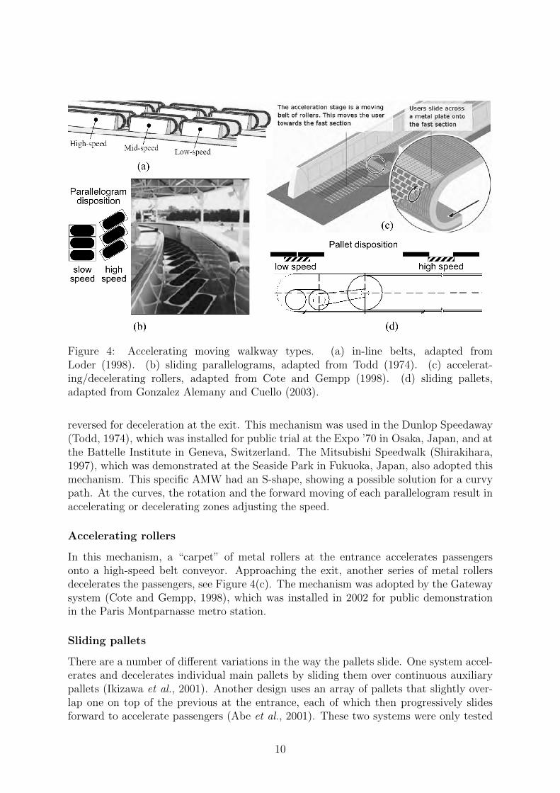
Figure 4: Accelerating moving walkway types. (a) in-line belts, adapted fromLoder (1998). (b) sliding parallelograms, adapted from Todd (1974). (c) accelerat-ing/decelerating rollers, adapted from Cote and Gempp (1998). (d) sliding pallets,adapted from Gonzalez Alemany and Cuello (2003).
reversed for deceleration at the exit. This mechanism was used in the Dunlop Speedaway(Todd, 1974), which was installed for public trial at the Expo ’70 in Osaka, Japan, and atthe Battelle Institute in Geneva, Switzerland. The Mitsubishi Speedwalk (Shirakihara,1997), which was demonstrated at the Seaside Park in Fukuoka, Japan, also adopted thismechanism. This specific AMW had an S-shape, showing a possible solution for a curvypath. At the curves, the rotation and the forward moving of each parallelogram result inaccelerating or decelerating zones adjusting the speed.
Accelerating rollers
In this mechanism, a “carpet” of metal rollers at the entrance accelerates passengersonto a high-speed belt conveyor. Approaching the exit, another series of metal rollersdecelerates the passengers, see Figure 4(c). The mechanism was adopted by the Gatewaysystem (Cote and Gempp, 1998), which was installed in 2002 for public demonstrationin the Paris Montparnasse metro station.
Sliding pallets
There are a number of different variations in the way the pallets slide. One system accel-erates and decelerates individual main pallets by sliding them over continuous auxiliarypallets (Ikizawa et al., 2001). Another design uses an array of pallets that slightly over-lap one on top of the previous at the entrance, each of which then progressively slidesforward to accelerate passengers (Abe et al., 2001). These two systems were only tested
10
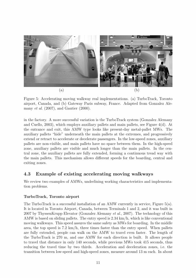
(a) (b)
Figure 5: Accelerating moving walkway real implementations. (a) TurboTrack, Torontoairport, Canada, and (b) Gateway Paris subway, France. Adapted from Gonzalez Ale-many et al. (2007), and Gautier (2000).
in the factory. A more successful variation is the TurboTrack system (Gonzalez Alemanyand Cuello, 2003), which employs auxiliary pallets and main pallets, see Figure 4(d). Atthe entrance and exit, this AMW type looks like present-day metal-pallet MWs. Theauxiliary pallets “hide” underneath the main pallets at the extremes, and progressivelyextend or retract to accelerate or decelerate passengers. In the low-speed zones, auxiliarypallets are non-visible, and main pallets have no space between them. In the high-speedzone, auxiliary pallets are visible and much longer than the main pallets. In the cen-tral zone, the auxiliary pallets are fully extended, forming a continuous tread way withthe main pallets. This mechanism allows different speeds for the boarding, central andexiting zones.
4.3 Example of existing accelerating moving walkways
We review two examples of AMWs, underlining working characteristics and implementa-tion problems.
TurboTrack, Toronto airport
The TurboTrack is a successful installation of an AMW currently in service, Figure 5(a).It is located in Toronto Airport, Canada, between Terminals 1 and 2, and it was built in2007 by ThyssenKrupp Elevator (Gonzalez Alemany et al., 2007). The technology of thisAMW is based on sliding pallets. The entry speed is 2.34 km/h, which is like conventionalmoving walkways. This speed assures the same safety as MWs for boarding. In the middlearea, the top speed is 7.2 km/h, three times faster than the entry speed. When palletsare fully extended, people can walk on the AMW to travel even faster. The length ofthe TurboTrack is 270 m, and one AMW for each direction is built. It allows peopleto travel that distance in only 140 seconds, while previous MWs took 415 seconds, thusreducing the travel time by two thirds. Acceleration and deceleration zones, i.e. thetransition between low-speed and high-speed zones, measure around 13 m each. In about
11

10 seconds, the AMW reaches the top speed. This implies an acceleration of 0.14 m/s2.The TurboTrack has a width of 1.2 m, which is the most common width used for MWsas well. It allows two columns of passengers, which permit the overtaking of standingpassengers. The system has a capacity close to 7,000 passenger per hour, as calculatedusing the empirical equation defined by CEN (1998).
Gateway, Paris subway
The one-lane Gateway AMW in Paris, France, at Montparnasse station, was inauguratedin July 2002 (Gautier, 2000), Figure 5(b). It was built to connect the subway station to thetrain station. The acceleration/deceleration rollers were subject to frequent maintenancedue to breakdowns. The technology used for the acceleration section was considered notsafe from many users, and it led to numerous passenger falls. Due to the presence ofone lane only, it was perceived that the direction of travel was often in the wrong way.When tests were made before the Gateway opened for the public, the initial top speedwas set to 10.8 km/h. However, it was reduced to 9 km/h due to safety problems. Asthe entire system speed and acceleration profile are interdependent, the entry speed wasalso reduced proportionally from 2.7 km/h to 2.2 km/h. The main problems were on theacceleration and deceleration zones. The most problematic issues were not the maximumspeed in the constant speed section, but the acceleration itself. Initially, the accelerationwas fixed to 0.43 m/s2 (for high-speed of 10.8 km/h), however due to many problemsrelated to feelings of unbalance or even falls, the value of 0.28 m/s2 was chosen. Theacceleration and deceleration parts measured about 10m, and, as the TurboTrack, theGateway width is 1.2 meters and the capacity is close to 7,000 passenger per hour.
5 Network design of a transport system based on
accelerating moving walkways
In this section, we study the use of AMWs at a large scale. First, we describe theoptimization framework developed for this scope, and then we apply it to a real casestudy.
The network design aims to identify the set of AMWs that could best satisfy thepassenger demand minimizing the total travel time in the city. A street network ofinterconnected roads, an operational budget and an origin-destination demand are theinputs of this problem. The result defines for each road, if it is equipped with an AMW,and if so, the speed profile and capacity of the installed walkway. To identify the solution,we evaluate only the travel time and the operational costs to run the system on anhourly basis. Other factors such as accessibility, comfort and construction costs are notconsidered.
To solve this problem, first, we formulate the system mathematically based on thecharacteristics previously reviewed, then we use an algorithm with a structure similar tothe ones used in the field of road network design (Yang and Bell, 1998; Farahani et al.,2013). This structure has two main tasks: traffic assignment and network update. In ourcase, we start with an initial network equipped with all feasible AMWs, which we itera-tively transform by removing AMW lanes on selected roads until the operational budget
12

RoadsPrimary
Intersections
Gate
(a) (b)
SecondaryLocal
Intersection
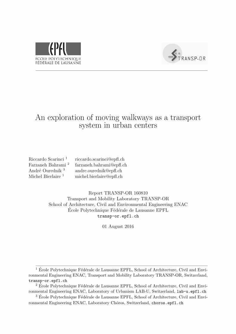
Figure 6: Case study road network: (a) original road network and (b) simplified roadnetwork.
limit is reached. We refer to Scarinci et al. (2016) for the details on the optimizationframework.
We apply the optimization algorithm to a real case study. The city of Geneva, Switzer-land, presents a suitable traffic demand and road network.The traffic demand is repre-sented by an OD matrix with twenty-six zones, seven of which in the city centers (DGT,2015). It has 117,349 trips during the morning peak-hour. The city roads are classifiedinto three categories: primary, secondary, and local roads (SITG, 2015), see Figure 6(a).We decide to evaluate the installation of AMWs on the primary roads only for their spa-tial characteristics. Primary roads present a larger road section adapted to car mobilitythat provides more space available for the insertion of the AMW system. In addition,primary roads present a reduced intensity of use by pedestrians compared to secondaryand local ones in favor of vehicular traffic. Moreover, having a higher speed is also moredesired in primary roads compared to small local roads with dense and intense publicspaces where “pausability” and spontaneity of movements are their constitutive values.Thus, the choice of big arteries is made to minimize a fundamental drawback of MWinfrastructure (like many other infrastructures), that is the creations of edges (barriers)and the reduction of the network permeability and thus spontaneity of flows. Gates areplaced around the study area through which incoming and outgoing traffic can flow. Fig-ure 6(b) shows the simplified road network, composed of 47 links, 37 intersections and10 gates for a total length of 32 km.
The optimal network design of AMWs is returned by the optimization framework.To investigate how this AMW network modifies when the budget decreases, the optimalAMW network is computed for a maximum budget of 125,000 EUR. Notice that thebudget constraints the operational cost to run the system during the morning peak-
13

hour. Then, this budget is gradually reduced to 100,000 EUR, 75,000 EUR and 50,000EUR. Although empirical data are used, we have no ambition of designing a ready-to-usenetwork. The goal is to have possible designs of AMW networks based on transportationconsiderations, i.e. travel demand and travel time, on a case study, and to draw usefulinformation for discussing the feasibility of this system.
The resulting networks are presented in Figure 7, where the origin and destinationnode for each AMW are connected by a straight line. This allows a clear identification ofexpressways, otherwise overlapping with individual AMWs on the same road. In all cases,the networks are composed by one lane AMW for each direction, and they are almostexactly symmetric. This means that AMWs would be installed in both directions on theequipped links. We remind that one lane is 1.2 meters wide, and it has a capacity close to7,000 passengers per hour. In comparison, a one lane urban road has the minimum widthbetween 2.5 to 3.5 meters and a capacity ranging from 750 to 1,800 vehicles per hourdepending on the intersection downstream (DfT, 2011). This means that it is possible toinstall two AMW lanes, one per direction, in a single vehicular traffic lane. For example,on a standard two ways street, it could be possible to preserve one lane for the AMWsystem (both directions) and to modify the viability to the remaining transport modes toone-way. Alternatively, AMWs could be installed instead of on-street parking slots at theroad side. This could allow the integration of AMWs while maintaining the traditionalmobility.
The main disadvantage of the system is the high capital cost. For this reason, itsapplication can be imagined in city centers with a high transport demand and a limitedspace. AMWs could be a substitute for other means of transport able to free valuablespaces for other purpose.
6 Conclusions
In this paper, we explore the possible use of moving walkways as a transport system. Weuse different perspectives, from geography to urban planning to transport engineering,and we analyze the system in different historical periods. We draw the final conclusionsstarting from the latest perspective and the possible future development.
The results of the optimization framework allow us to analyze the use of AMWs ata network level, and to provide useful considerations to delineate the system feasibility.Given the high capacity of the system and the limited space required, AMWs are suitablefor dense city centers with a high passenger demand. The travel time between two givenpoints remains the main criterion of this technical solution, aimed at intra-urban com-muters primarily. However, the solution also allows us to imagine a possible city withoutcars, dominated by pedestrian mobility. The resulting network cannot be considered aready-to-use design of the AMW system. However, it is a valid starting point for dis-cussions with town planners to evaluate the potential of AMWs as a possible transportmode in urban areas.
The AMW system allows pedestrian movements to and from small local roads withpublic spaces where “pausability” and spontaneity of movements are needed. This ispossible thanks to the network structure of the system. The presence of multiple nodesfor accessing/exiting the AMW system makes it permeable. The pedestrians leaving this
14

(a) (b)
(c) (d)
194 AMWs125,000 EUR
44 AMWs100,000 EUR
28 AMWs75,000 EUR
15 AMWs50,000 EUR
Figure 7: Case study results. Road network arcs equipped with AMWs for differentoperational budgets.
15
system of AMWs are directly liberated from the means of transport, i.e. they do not haveto park the mobility device nor return back to it at the end of a journey. The experienceof movement and the exposure to the surrounding environment is greater than in theclosed space of a car. Interacting with other passengers during travel on the AMW is asin a public tramway or bus. This system could be a catalyst for a mobility paradigm shift.Nowadays, the transport system of the future is immagined being dominated by driver-less vehicles. However, AMWs, liberating the passengers by the vehicles, could incentivea future system composed by “vehicle-less” drivers, instead of “driver-less” vehicles. Withthis inversion of the paradigm, the individuals, and not the vehicles, are at the center ofthe mobility system.
Running in an ongoing fashion, moreover, the system does not force individuals towait at public transport stops and generates, thus, a feeling of continuous flow similarto the pedestrian experience of the space. This happens also at intersections, thanks tothe connections between AMWs and the presence of expressways, that allows a directcrossing of the junction. The continuous flow system lowers also the level of frustrationexperienced by drivers stuck in traffic jams and by pedestrians facing red lights on a roadcrossing. Thus, while allowing a gain in speed, the system does not prevent from takingadvantage of the urban space. It might possibly contribute to liberate our cities fromtheir twitchy rhythm imposed by car traffic into a space of continuous and unconstrainedflow of social interactions. Replacing the car traffic, it should boost a more dense andvivid public space. In addition, the combined effects of promoting walking, fully electricsystem, low energy and space consumption could lead to a reduction of greenhouse gasemission and a more sustainable transport system.
The main limitations of the system are the architectural barriers that it creates insidethe city center, the high capital cost, the acceptance of the system by the users andits accessibility. These aspects should be evaluated in further research, and the systemfeasibility defined more accurately.
Acknowledgment
This research is part of the project Post-Car World (PCW, 2015) with the goal of ex-ploring the future of mobility through the role of the car, funded by the Swiss NationalScience Foundation (SNSF, 2015). We thank Guillaume Lopez, Bastien Rojanawisut,Raphael Luthi for their contributions on this research.
References
Abe, Y., Beniya, Y., Masuda, H., 2001. Accelerating Moving Walkway“ACCEL-LINER”.Bridges 10, 55.
Alspaugh, A., 2008. Bulk Material Handling by Conveyor Belt 7. Society for Mining,Metallurgy, and Exploration.
Asimov, I., 1954. Caves of Steel. Random House Publishing Group.
16
Avenel, H., 1900. Histoire de la presse francaise, depuis 1789 jusqu’a nos jours, rapportau ministere du commerce: exposition universelle de 1900. E. Flammarion.
Badger, R., 1979. The great American fair: The world’s Columbian exposition & Amer-ican culture. Taylor Trade Publications.
Bollnow, O., 1967. Lived-Space, in Lawrence, Nathaniel and O’Connor, Daniel (eds.)Readings in Existential Phenomenology .
Brand, C., Preston, J., 2003. Which technology for urban public transport?, in: Proceed-ings of the Institution of Civil Engineers-Transport, pp. 201–210.
Buchanan, C., 1963. Traffic in towns: a study of the long-term problems of traffic inurban areas. Penguin Books.
CEN, 1998. NEN-EN 115:1998 safety rules for the construction and installation of esca-lators and passenger conveyors. Technical Report. Comite Europeen de Normalisation.
Christidis, P., Rivas, J.N.I., 2012. Measuring road congestion. Technical Report. Euro-pean Union. Institute for Prospective and Technological Studies, Joint Research Centre.
Ciuffini, F., 1983. Escalators to facilitate pedestrian movement in Perugia. Casabella 47,28–28.
Cook, P., 1999. Archigram. Princeton Architectural Press.
Cote, A., Gempp, A., 1998. The High Speed Passenger Conveyor Reflections on Comfort,in: 6th International Conference on Automated People Movers (APMs).
Cullinane, S., 2002. The relationship between car ownership and public transport provi-sion: a case study of Hong Kong. Transport Policy 9, 29–39.
Dembart, L., 2003. International Traveler/Update: In Paris, The Concorde of All Side-walks. Technical Report. International Herald Tribune.
DfT, 2011. Design manual for roads and bridges. Department of Transport, Great Britain.
DGT, 2015. Direction generale des transports. URL: http://ge.ch/mobilite/.
Donoghue, E.A., 1981. Handbook on A17.1: Safety Code for Elevator and Escalators.Technical Report. The American Society of Mechanical Engineers.
EC, 2011. White paper Roadmap to a Single European Transport Area - Towards acompetitive and resource efficient transport system - The Impact Assessment. TechnicalReport. European Commission.
Farahani, R.Z., Miandoabchi, E., Szeto, W.Y., Rashidi, H., 2013. A review of urbantransportation network design problems. European Journal of Operational Research229, 281–302.
Fruin, J., 1992. Designing for pedestrians. volume HS-011 999. Public TransportationUnited States.
17

Gautier, F., 2000. Gateway: the high-speed walkway, in: Rail Transit Conference, 2000.
Gonzalez Alemany, M., Soffritti, M., Behrend, M., Eisele, T., 2007. TurboTrack: makinglong distances shorter. ThyssenKrupp techforum , 68–75.
Gonzalez Alemany, M.A., Cuello, M.A., 2003. Accelerating walkway. Technical Report.ThyssenKrupp techforum.
Gruen, V., 1964. The Heart of our Cities: The Urban Crisis, Diagnosis and Cure. NewYork: Simon and Schuster.
Hebbert, M., 1993. The City of London walkway experiment. Journal of the AmericanPlanning Association 59, 433–450.
Heidegger, M., 1954. Bauen wohnen denken. Vortrge und Aufstze 151.
Heinlein, R.A., 1940. The Roads Must Roll. The Science Fiction Hall of Fame, VolumeOne, 1929-1964.
Helzel, M., Taylor, I., 2011. PUBLIC SPACES-Stainless Steel in the Urban Environment.Building Series 16.
Ikizawa, K., Nagai, H., ichiro Aoe, S., Sato, T., Okuno, R., Yanagisawa, T., 2001. Devel-opment of an accelerating walkway. NKK Technical Review 84, 66–70.
Kazuo, A., Kenro, M., Masakuni, H., Katsumi, Y., Tomoyoshi, K., 2003. Feature andprospect of accelerating moving walks. Technical Report.
KFH Group, 2013. Transit Capacity and Quality of Service Manual. Technical Report.Kittelson & Assoc, Inc Parsons Brinckerhoff, Inc KFH Group, Inc Texas A&M Trans-portation Institute Arup. Transportation Research Board, Washington.
Kusumaningtyas, I., 2009. Mind Your Step: Exploring aspects in the application of longaccelerating moving walkways. Ph.D. thesis. Delft University of Technology. Mechanical,Maritime and Materials Engineering. Marine and Transport Technology.
Kusumaningtyas, I., Lodewijks, G., 2008. Accelerating Moving Walkway: A review ofthe characteristics and potential application. Transportation research part A: policyand practice 42, 591–609.
Kusumaningtyas, I., Lodewijks, G., 2013. On the application of accelerating moving walk-ways to support passenger processes in Amsterdam Airport Schiphol. TransportationPlanning and Technology 36, 617–635.
Lechner, N., 2011. Plumbing, Electricity, Acoustics: Sustainable Design Methods forArchitecture. Plumbing, Electricity, Acoustics: Sustainable Design Methods for Archi-tecture, Wiley.
Loder, J., 1998. The in-line accelerating moving walkway. Elevator World 46, 94–97.
18
Nakamichi, K., Nakamura, F., 2014. Current state of the modern urban transport systemin Medellin, Colombia. Journal of the City Planning Institute of Japan 49.
NYPL, 1923. Belt Conveyor Moving Platform New York Diagram Passengers Transport.New York Public Library digital collection.
Otis, 2015. The online architecture and design exhibition. ArchiEXPO.
Ourednik, A., 2008. Conatus et le miel de Jean-Baptiste. Pour un recit hu-main de l’automobilite. EspacesTemps.net. URL: http://www.espacestemps.net/
document6273.html.
Ourednik, A., 2010. L’habitant et la cohabitation dans les modeles de l’espace habite.Ph.D. thesis. Ecole Polytechnique Federale de Lausanne EPFL.
PCW, 2015. Post-Car World: A Trans-Disciplinary Multi-Dimensional Stimulation. URL:http://postcarworld.epfl.ch.
Richards, B., 1966. New movement in cities. London; New York: Littlehampton BookServices Ltd.
Richards, B., 1976. Moving in Cities. Westview Press.
Rockwood, D., Garmire, D., 2015. A new transportation system for efficient and sus-tainable cities: Development of a next generation variable speed moving walkway.Sustainable Cities and Society 14, 209–214.
Rojanawisut, B., 2015. Optimisation of the network design of a futuristic transport systembased on accelerated moving walkways. Master Thesis. Ecole Polytechnique Federale deLausanne EPFL, Section of Mathematics.
Rouillard, D., 2013. La marche le marketing du corps. Marche et espace urbain del’Antiquite a nos jours. Le Maire, Judith, Christophe Loir, and Anne Desprechins.Editions Mardaga , 149–166.
Saeki, H., 1996. Mitsubishi-Speedwalk: Development of accelerating moving walk, in:Colloque international sur les transports collectifs automatiques, pp. 571–581.
Scarinci, R., Markov, I., Bierlaire, M., 2016. Network design of a transport system basedon accelerating moving walkways, in: Ninth Triennial Symposium on TransportationAnalysis TRISTAN IX.
Shirakihara, T., 1997. Speedwalk - an Accelerating Moving Walkway, in: Proceedings ofthe 1997 6th International Conference on Automated People Movers, April 9-12 April,pp. 624–633.
SITG, 2015. Systeme d’information du territoire a Geneve. URL: http://ge.ch/sitg/.
SNSF, 2015. Swiss National Science Foundation. URL: http://www.snf.ch/.
19

ThyssenKrupp, 2004. Questions and answers: How loud are escalators or walkways?Technical Report. ThyssenKrupp Fahrtreppen GmbH.
Todd, J., 1974. Dunlop S-type Speedway: A high-speed passenger conveyor. Transporta-tion Research Record 522, 65–75.
Wells, H.G., 1897. A Story of the Days to Come. Horizon Publishing Group.
Yang, H., Bell, M.G.H., 1998. Models and algorithms for road network design: a reviewand some new developments. Transport Reviews 18, 257–278.
Young, S.B., 1999. Evaluation of pedestrian walking speeds in airport terminals. Trans-portation Research Record: Journal of the Transportation Research Board 1674, 20–26.
20