
Assessment and modelling of switching technologies for470146/FULLTEXT01.pdf · Assessment and...
74
Transcript of Assessment and modelling of switching technologies for470146/FULLTEXT01.pdf · Assessment and...


Assessment and modelling of switching technologies for
application in HVDC-circuit breakers
Institute for High Voltage Engineering
Rheinisch–Westfälischen Technischen Hochschule Aachen
Master Thesis
by
Johan Lund
Examiner: Prof. Göran Engdahl, KTH
Univ.–Prof. Dr.–Ing. Armin Schnettler, RWTH
Supervisor: Dipl.–Ing. Daniel Eichhoff
Date of submission: 2010-11-22


Abstract
A key element for future DC-grids is a DC circuit breaker that in case of a shortcircuit fault reliably can turn off a short circuit current. AC circuit breakers arewell known components that has been in use for a long time in AC-grids. TheAC circuit breaker is designed to interrupt the current at its natural current zerocrossings. In DC grids such does not exists, therefore AC breakers can not bedirectly applied in DC grids. Different concepts and technologies to solve thisproblem is available. In this work three different DC-Circuit breaker topologiesthat show good potential in the medium voltage range has been modeled namely
• Resonance Hybrid DC Circuit Breaker
• Active Turn-off Hybrid DC Circuit Breaker
• Snubbered Hybrid DC Breaker
The three different breaker concepts has been analyzed and compared for theirability to limit short circuit current. The comparison shows that the SnubberedDC Circuit breaker has the best short circuit current limiting performance. Themaximum short circuit current during the turn-off process is 20 % lower than forthe other two DC breaker topologies which shows the aproximately the same shortcircuit current limiting performance.
iii

iv

Contents
1 Introduction 11.1 Motivation . . . . . . . . . . . . . . . . . . . . . . . . . . . . . . 1
1.2 State of science . . . . . . . . . . . . . . . . . . . . . . . . . . . 2
1.3 Objectives . . . . . . . . . . . . . . . . . . . . . . . . . . . . . . 3
2 Fundamentals and Basics 52.1 Model of a DC-grid and switching of DC . . . . . . . . . . . . . 5
2.1.1 Model of a DC-grid . . . . . . . . . . . . . . . . . . . . . 5
2.1.2 Requirements on DC Breakers . . . . . . . . . . . . . . . 7
2.2 Detection of short circuit current . . . . . . . . . . . . . . . . . . 10
2.3 Mechanical Breaker Models . . . . . . . . . . . . . . . . . . . . 10
2.3.1 Mechanical drive . . . . . . . . . . . . . . . . . . . . . . 11
2.3.2 Ultra fast switch, (UFS) . . . . . . . . . . . . . . . . . . 11
2.3.3 Vacuum circuit breaker, VCB . . . . . . . . . . . . . . . 14
3 DC Breaker models 173.1 Resonance Hybrid DC Circuit Breaker (RHCB) . . . . . . . . . . 17
3.1.1 Functional principle . . . . . . . . . . . . . . . . . . . . 17
3.1.2 Dimensioning of the resonance circuit . . . . . . . . . . . 19
3.2 Active Turn-off Hybrid DC Circuit Breaker (ATHCB) . . . . . . 21
3.3 Snubbered Hybrid DC Circuit Breaker (SHCB) . . . . . . . . . . 24
3.3.1 Functional principle . . . . . . . . . . . . . . . . . . . . 24
3.3.2 Dimensioning of Snubber Capacitance . . . . . . . . . . . 27
3.3.3 Current commutation onto the snubber capacitor . . . . . 31
v
vi CONTENTS
4 Breaker models Analysis 354.1 Resonance Hybrid DC Circuit Breaker . . . . . . . . . . . . . . . 36
4.1.1 Influence DC breaker parameters . . . . . . . . . . . . . . 364.1.2 Influence of grid parameters . . . . . . . . . . . . . . . . 39
4.2 Active Turn-off Hybrid DC Circuit Breaker . . . . . . . . . . . . 404.2.1 Influence of DC breaker parameters . . . . . . . . . . . . 414.2.2 Influence of grid parameters . . . . . . . . . . . . . . . . 45
4.3 Snubbered Hybrid DC Circuit Breaker . . . . . . . . . . . . . . . 474.3.1 Influence of DC breaker parameters . . . . . . . . . . . . 474.3.2 Influence of grid parameters . . . . . . . . . . . . . . . . 53
5 Comparison and Discussion 555.1 Optimized breaker models . . . . . . . . . . . . . . . . . . . . . 55
5.1.1 Resonance Hybrid DC Circuit Breaker . . . . . . . . . . . 555.1.2 Active Turn-off Hybrid Circuit Breaker . . . . . . . . . . 565.1.3 Snubbered Hybrid DC Circuit Breaker . . . . . . . . . . . 57
5.2 Economical comparison . . . . . . . . . . . . . . . . . . . . . . . 575.3 Comparison of the breaker models . . . . . . . . . . . . . . . . . 585.4 Influence of grid parameters . . . . . . . . . . . . . . . . . . . . 59
6 Conclusion and Outlook 616.1 Outlook . . . . . . . . . . . . . . . . . . . . . . . . . . . . . . . 62
Literatur 64

Chapter 1
Introduction
1.1 Motivation
The use of a DC transmission system for electrical power has significant advan-tages over an AC transmission system. Due to the lack of reactive power in aDC-grid, the reactive power loss is zero and most important no limitations of thetransmission length occurs. This advantage has already been recognized for trans-mission over long distances in point to point HVDC transmission.However there are still components missing before a multi terminal DC grid canbe realized. The two most important are electrical transformers/converters tochange the voltage in different parts of the system and DC circuit breakers. Thecircuit breakers are used to disconnect lines or loads in normal operations to allowfor a flexible power flow in the grid. Their main task is, however, to disconnectfaulty equipment from the grid.It could be argued that since DC grids are mainly fed by converters which canturn of the current in the matter of µs these could be used to turn off fault cur-rents. This could be done in a point to point DC transmission, however for a multiterminal grid the complete system would shut down every time a fault occurs andis therefore not an option. Therefore the development of DC circuit breakers is ofutmost importance for the realization of future DC-grids.
1

2 CHAPTER 1. INTRODUCTION
1.2 State of science
Circuit breakers for AC systems are designed to break the current at the naturalzero crossings of the current, since no such exist in DC application they cannot beapplied in a DC grid. Various solutions are available to solve this problem. In thiswork, the focus is on DC breakers in the medium voltage range.Semiconducting devices has the ability to interrupt current in the kA range in thetime scale of µs. However, they have high on-state losses. By combining an ordi-nary mechanical breaker with a semiconducting device so that in the normal casethe current is carried by the mechanical breaker and in case of a fault the currentis interrupted by the semiconducting device would therefore be an attractive so-lution. Two different circuit layouts has been analyzed for this concept, one withan active turn off semiconducting device, another with a capacitance in serial witha thyristor. These types of breakers are in literature often referred to as HybridCircuit Breakers.In the Resonance Hybrid DC Circuit Breaker a pre-charged resonance circuit isconnected in parallel to an AC circuit breaker. To control the resonance circuita thyristor is is connected in parallel. To interrupt the grid current the resonancecircuit is fired and artificial zero crossings of the current through the AC circuitbreaker is created. The AC circuit breaker can then interrupt the current at theresulting current zero crossing.A working prototype of a Hybrid Circuit Breaker with active turn-off semicon-ductors has been constructed by [Mey06]. A number of papers can be foundabout the Resonance Circuit Breaker [Gel00], [Kun03], [Alf08]. In [Mey07] animprovement of the Hybrid Circuit Breaker from [Mey06] is discussed consistingof a capacitance and a thyristor instead of an active turn-off semiconducting de-vice. This topology shows great potential. However, a prototype has not yet beenconstructed.

1.3. OBJECTIVES 3
1.3 Objectives
The objective of this thesis is by literature research identify suitable technologiesfor DC Circuit Breakers and compare these regarding technological and econom-ical aspects.For this purpose a model for each breaker should be build using the simulationtool Matlab Simulink with the add-on SimPowerSystems to simulate the transientconditions under short circuit current interruption.

4 CHAPTER 1. INTRODUCTION
Chapter 2
Fundamentals and Basics
2.1 Model of a DC-grid and switching of DC
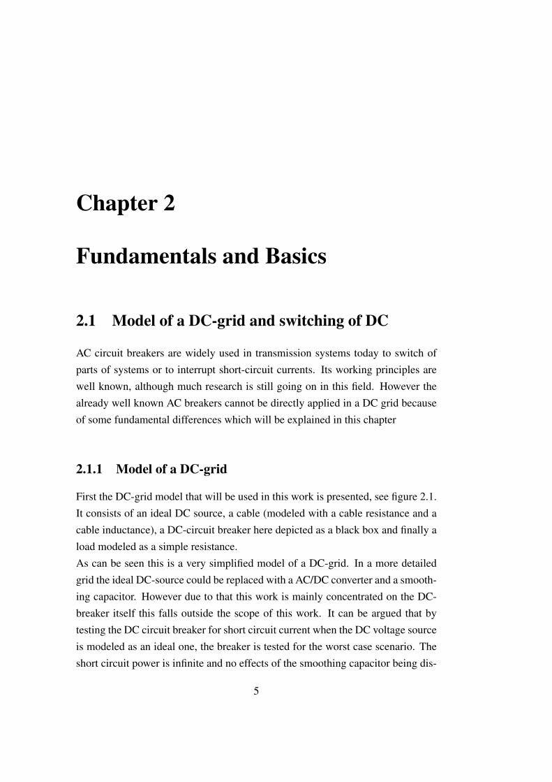
AC circuit breakers are widely used in transmission systems today to switch ofparts of systems or to interrupt short-circuit currents. Its working principles arewell known, although much research is still going on in this field. However thealready well known AC breakers cannot be directly applied in a DC grid becauseof some fundamental differences which will be explained in this chapter
2.1.1 Model of a DC-grid
First the DC-grid model that will be used in this work is presented, see figure 2.1.It consists of an ideal DC source, a cable (modeled with a cable resistance and acable inductance), a DC-circuit breaker here depicted as a black box and finally aload modeled as a simple resistance.As can be seen this is a very simplified model of a DC-grid. In a more detailedgrid the ideal DC-source could be replaced with a AC/DC converter and a smooth-ing capacitor. However due to that this work is mainly concentrated on the DC-breaker itself this falls outside the scope of this work. It can be argued that bytesting the DC circuit breaker for short circuit current when the DC voltage sourceis modeled as an ideal one, the breaker is tested for the worst case scenario. Theshort circuit power is infinite and no effects of the smoothing capacitor being dis-
5

6 CHAPTER 2. FUNDAMENTALS AND BASICS
VGrid
LGrid
Load
DC Circuit Breaker
RGridIGrid
Figure 2.1: Simplified model of a DC-grid
charged would be visible. The values adapted for the simplified DC-grid in figure2.1 is given in table 2.1.
Power level PGrid 40 MWGrid voltage VGrid 20 kVLoad resistance RLoad 10 ΩGrid current IGrid 2 kAGrid inductance L′Grid 300µH/kmGrid resistance R′Grid 10 mΩ/kmLength of cable lCable 10 km
Table 2.1: DC-grid parameters
Since no standard voltage levels for DC-grids yet is defined, the voltage and powerlevel is based on probable levels for future medium power DC-grids. Voltagelevels found in literature, [Mar07], [Ste01], [Mey05] , [Mey07] varies between7 kV and 20 kV. The power level found in litterature, [Mar07], [Ste01], [Mey05], [Mey07], is set between 14 MW and 80 MW. For this work the voltage level20 kV is chosen. By choosing 40 MW as the power level, the nominal current iscalculated to 2 kA.The cable parameters are based on typical values given by [Mey05], the cablelength is chosen to 10 km.

2.1. MODEL OF A DC-GRID AND SWITCHING OF DC 7
2.1.2 Requirements on DC Breakers
AC circuit breakers are mainly mechanical systems that separates two movingcontacts to get an isolating distance in between. Due to the inductive nature ofmost power grids the current through the breaker won’t stop flowing when thecontacts starts to open but will continue to flow in the form of an arc betweenthe contacts. The plasma that occurs between the contacts due to the burning arc,has an extremely high temperature and low resistance which leads to an almostunhampered current flow.In AC grids the current is interrupted by the mechanical system of the breakerat the natural zero crossings of the current which occur once every half periodof the grid frequency. In a DC system there are no natural zero crossing of thecurrent. DC circuit breaker therefore need additional circuitry to compensate forthis. Mainly two different principles can be distinguished.In the hybrid circuit breaker concept the breaker is divided into different parts eachmade to perform a specific task. During normal operation the current is carriedby a mechanical breaker which has low on-state losses. However the mechanicalbreaker is not able to break the current due to lack of current zero crossing. There-fore another part is needed to turn off the fault current. At last the energy storedin the grid inductance has to be dissipated in order to bring the current to zero.Different hybrid breaker topologies use different components to perform the tasksexplained.A difference between AC- and DC-grids is the response to a sudden short circuit.In figure 2.2 the equivalent DC-grid is shown with a short circuit fault at the load.
Before the DC circuit breaker opens, the full grid voltage will fall over the gridresistance and the grid inductance.
VGrid = RGrid · isc + LGrid ·discdt
(2.1)
This equation is solved for the short circuit current
isc(t) =VGridRGrid
· (1− e−t·RgridLGrid ) (2.2)

8 CHAPTER 2. FUNDAMENTALS AND BASICS
VGrid
LGrid
DC Circuit Breaker
RGridIsc
Figure 2.2: Short circuit fault of the load
In figure 2.3 the current in the case of an sudden short circuit fault is shown. Fromtime t = 0 s to time t = 100 ms the nominal current is flowing, thereafter theshort circuit fault at the load occurs and the grid current starts to increase. Alsothe magnetization of the grid inductance will hereby increase.
0 50 100 150 200 250 300 350 400−50
0
50
100
150
200
250
Time [ms]
Cur
rent
[kA
]
Figure 2.3: Sudden short circuit fault

2.1. MODEL OF A DC-GRID AND SWITCHING OF DC 9
In the steady state only the cable resistance is limiting the amplitude of the shortcircuit current. Due to the low resistance in the grid, the current will rise to about200 kA. However, since the voltage source in figure 2.2 corresponds to a generatoror a smaller grid which has a limited short circuit power, therefore the current willfor sure not rise to this huge value. It can be seen in figure 2.3 that after only10 ms after the fault the short circuit current is already at around 60 kA. The steeprate of rise of the short circuit current is due to the limited inductance in a DCgrid. In a DC grid the only inductive element is the cables, compared to ACgrids which usually consists of large generators and transformers both with largeinternal inductances. An important requirement on a DC breaker is therefore tobe fast acting since the longer it takes for the breaker to react on a short circuitcurrent, the higher the short-circuit current rises.To stop the current increase a negative current slope is needed. From figure 2.1the voltage over the grid inductance can be written as equation 2.3. To make itmore clear the cable resistance has here been neglected.
VLgrid = VGrid − VBreaker = LGrid ·diBreaker
dt(2.3)
From equation 2.3 it can be realized that once the breaker voltage, VBreaker, be-comes greater than the grid voltage, Vgrid, the current slope will turn negative andthe grid inductance starts to demagnetize.Since the burning arc voltage of the mechanical breaker is not nearly as high asthe grid voltage (10...20 V, according to [Ste01], [Hol01]) an important demandfor a DC breaker is therefore to be able to create a countervoltage which is biggerthan the grid voltage in order to demagnetize the grid inductance, and bringing theshort circuit current to zero.In AC systems were the current is switched of at the natural zero crossings of thecurrent were the grid inductance is demagnetized this is not an issue.The summarized requirements on a DC breaker is therefore:
• Compensation for lack of natural zero crossings of the current
• Fast acting, due to high short circuit current slope

10 CHAPTER 2. FUNDAMENTALS AND BASICS
• Ability to create a countervoltage greater than the grid voltage to demagne-tize the grid inductance and force the current to zero.
2.2 Detection of short circuit current
The detection of fault circuit current is made by a detection system that triggerswhen the current reaches a preset value. This preset value needs to be chosenhigher than the nominal current so that the detection system does not trigger onload changes. According to the work of [Mey07] and [Mar07] the detection levelis chosen to:
IDet = 1.5 · IN (2.4)
Since the logical circuit of the detection system has a certain delay, a detectiontime, tDet needs to be introduced. From [Ste01], and [Mey07] this detection timeis in the range of 60µs. Also due to delay in the electrodynamical drive for themechanical breaker a mechanical delay time, tmd is introduced which is in therange of (100...180)µs depending on type of breaker. The total delay is
tDel = tDet + tmd (2.5)
2.3 Mechanical Breaker Models
Two different types of mechanical breakers are used in this work, the ordinaryVacuum Circuit Breaker (VCB) and a fast basic switch, the Ultra Fast Switch(UFS), [Ste01], [Hol01]. The key parameters for the mechanical breaker is currentcarrying capability, burning arc voltage and dielectric recovery. The influence ofthese parameters on the required breaker drive mechanism will be discussed.

2.3. MECHANICAL BREAKER MODELS 11
2.3.1 Mechanical drive
Opening of the mechanical breaker is made with an electrodynamic drive. Thedetails of this drive falls out of the scope of this work. However the most importantdetails are shortly discussed.The mechanical delay time tmd of an electrodynamic drive is in the time from thatthe drive is given an open command until the contacts starts moving. For a VCBthe mechanical delay is in the range of 180µs according to [Mey06] and for theUFS 100µs [Ste01].For the mechanical breaker a high opening velocity is necessary. Accordingto [Hol01], [Ste01], [Mey05] the opening speed of the Ultra fast switch is con-sidered to be constant. The opening velocity of the mechanical breaker is mainlyinfluenced by the drive energy, it’s efficiency and the mechanical inertia of themoving contact. By considering a given drive, the opening velocity is only depen-dent on the mass of the moving contact.For the Ultra Fast switch, opening velocities up to 30 m/s has been realized [Hol01],[Ste01]. For a Vacuum Circuit breaker 10 m/s has been realized by [Mey06].As the current carrying capability of the switch is proportional to the dimensionsof the moving part, higher current carrying capability means higher mass of themoving part and in order to have the same opening speed a higher drive energy isneeded.
2.3.2 Ultra fast switch, (UFS)
The Ultrafast switch explained in this subsection is based on the work of [Ste01]and [Hol01]. It was developed for the use as the mechanical part in an AC hybridfault current limiting system. Since the hybrid breaker concept is also applicablefor interrupting of DC current this breaker type is considered in this work.Due to that in a hybrid breaker topology the current is interrupted by a semi-conducting device, no arc quenching system is needed for the UFS. The UFS istherefore designed with the assumption that an arc only occurs for a very shorttime, tarc ≤ 135µs [Hol01].
12 CHAPTER 2. FUNDAMENTALS AND BASICS
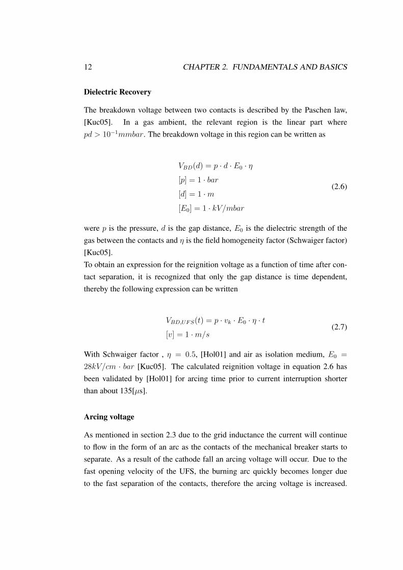
Dielectric Recovery
The breakdown voltage between two contacts is described by the Paschen law,[Kuc05]. In a gas ambient, the relevant region is the linear part wherepd > 10−1mmbar. The breakdown voltage in this region can be written as
VBD(d) = p · d · E0 · η
[p] = 1 · bar
[d] = 1 ·m
[E0] = 1 · kV/mbar
(2.6)
were p is the pressure, d is the gap distance, E0 is the dielectric strength of thegas between the contacts and η is the field homogeneity factor (Schwaiger factor)[Kuc05].To obtain an expression for the reignition voltage as a function of time after con-tact separation, it is recognized that only the gap distance is time dependent,thereby the following expression can be written
VBD,UFS(t) = p · vk · E0 · η · t
[v] = 1 ·m/s(2.7)
With Schwaiger factor , η = 0.5, [Hol01] and air as isolation medium, E0 =
28kV/cm · bar [Kuc05]. The calculated reignition voltage in equation 2.6 hasbeen validated by [Hol01] for arcing time prior to current interruption shorterthan about 135[µs].
Arcing voltage
As mentioned in section 2.3 due to the grid inductance the current will continueto flow in the form of an arc as the contacts of the mechanical breaker starts toseparate. As a result of the cathode fall an arcing voltage will occur. Due to thefast opening velocity of the UFS, the burning arc quickly becomes longer dueto the fast separation of the contacts, therefore the arcing voltage is increased.

2.3. MECHANICAL BREAKER MODELS 13
The following values and equations is based on the work of [Ste01] and [Hol01].The initial arcing voltage, V0, which occurs directly after contact separation isin the range of 10...20 V. The increase of the burning arc voltage due to contactseparation is described by the second term in equation 2.8
Varc = V0 + v2k · kv · t
were
kv = 100 Vs/m2
(2.8)
kv is an adapted constant derived from experiments [Ste01]. The initial burningarc voltage is chosen as the middle value of the given interval.
V0 = 15 V (2.9)
Influence of multiple serial breaks
By applying many breaks in series the voltage over each individual break is re-duced as explained by figure 2.4. Grading capacitors are connected in parallel toeach break to make sure that the voltage is equally distributed over the gaps.
Break 1 Break 2 Break n
CGrade CGrade CGrade
UBreaker
Ubreaker/nkUbreaker/nk Ubreaker/nk
Figure 2.4: Effect of multiple serial breaks
By opening all breaks simultaneously the voltage over each break will be 1nk
timeslower resulting in that the total breakdown voltage will be nk times higher. Equa-tion 2.7 is therefore multiplied by the number of serial breaks nk

14 CHAPTER 2. FUNDAMENTALS AND BASICS
VBD,UFS(t) = nk · p · vk · E0 · η · t (2.10)
It should be mentioned that it is very important that the breaks are simultaneouslyopened and with the same velocity. If opening of one break should be delayedor made with a slower velocity, a dielectric breakdown is likely to occur. Bycombining the serial breaks into one moving piece which is driven by a commondrive, this could be avoided.Since the arcing voltage is independent from the breaker voltage the arcing voltageof each individual break will add to a total arcing voltage, equation 2.8 is thereforemultiplied by the number of serial breaks, nk
Varc = nk · (V0 + v2k · kv · t) (2.11)
To have the same current carrying capability each break needs to have the samedimensions and therefore the same mass. Therefore by putting more breaks inseries the drive energy needs to be increased. For a UFS able to carry the nominalcurrent and with the velocity 20 m/s a maximum number of serial breaks is set to3, [Ste01].
2.3.3 Vacuum circuit breaker, VCB
The vacuum circuit breaker is well known and is widely used in medium voltageAC-grids to interrupt fault currents. The vacuum circuit breaker is designed tobreak the fault current at the natural zero crossings of the current. In DC gridsthere are no natural zero crossings of the current, therefore additional circuitry isneeded as explained in section 2.1.2 In an AC system for the current to be suc-cessfully interrupted, two criteria needs to be fulfilled, the current slope approach-ing current zero must not be to high and the VCB must be able to withstand thetransient recovery voltage which occurs after the current interruption. The firstcriteria is fulfilled if the turn off capability of the VCB is sufficient. To withstandthe transient recovery voltage, the dielectric recovery of the VCB after currentinterruption needs to be fast enough.
2.3. MECHANICAL BREAKER MODELS 15
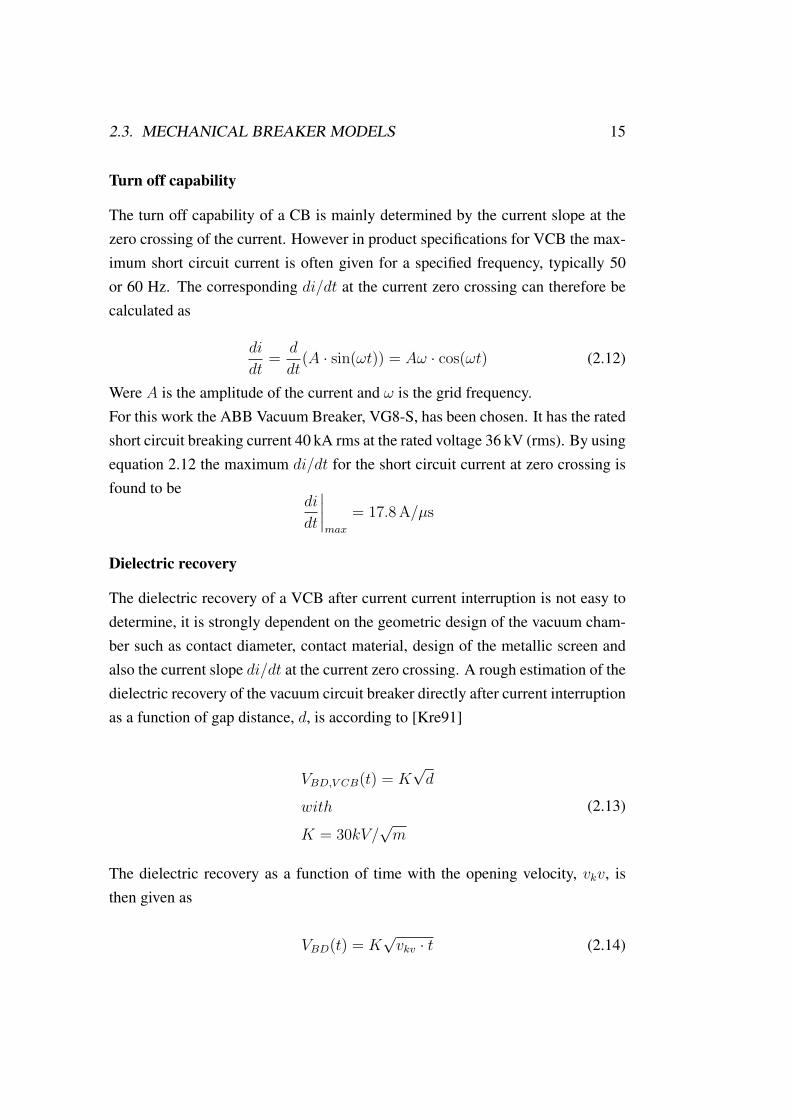
Turn off capability
The turn off capability of a CB is mainly determined by the current slope at thezero crossing of the current. However in product specifications for VCB the max-imum short circuit current is often given for a specified frequency, typically 50or 60 Hz. The corresponding di/dt at the current zero crossing can therefore becalculated as
di
dt=
d
dt(A · sin(ωt)) = Aω · cos(ωt) (2.12)
Were A is the amplitude of the current and ω is the grid frequency.For this work the ABB Vacuum Breaker, VG8-S, has been chosen. It has the ratedshort circuit breaking current 40 kA rms at the rated voltage 36 kV (rms). By usingequation 2.12 the maximum di/dt for the short circuit current at zero crossing isfound to be
di
dt
∣∣∣∣max
= 17.8 A/µs
Dielectric recovery
The dielectric recovery of a VCB after current current interruption is not easy todetermine, it is strongly dependent on the geometric design of the vacuum cham-ber such as contact diameter, contact material, design of the metallic screen andalso the current slope di/dt at the current zero crossing. A rough estimation of thedielectric recovery of the vacuum circuit breaker directly after current interruptionas a function of gap distance, d, is according to [Kre91]
VBD,V CB(t) = K√d
with
K = 30kV/√m
(2.13)
The dielectric recovery as a function of time with the opening velocity, vkv, isthen given as
VBD(t) = K√vkv · t (2.14)
16 CHAPTER 2. FUNDAMENTALS AND BASICS
Arcing voltage of VCB
Since the opening velocity of the VCB is slower than in the UFS, the effect ofprolonging of the arc as explained in subsection 2.3.2 is not visible. The initialarcing voltage, V0, of the VCB which occurs directly after contact separation is inthe order of 10...20 V, [Sla08], [Mey06]. Since the opening velocity of the VCB ismuch lower compared to the UFS, the effect of prolonging of the arc is neglected.The initial arcing voltage is chosen to the middle of the given interval.
Varc,V CB = V0 = 15 V (2.15)
Influence of multiple serial breaks
As already explained in subsection 2.3.2 by putting many breaks in series, thevoltage over each break is decreased with a factor of 1/nk, with nk as the numberof serial breaks. The total dielectric recovery is therefore increased with the factornk.
VBD(t) = nk ·K√vkv · t (2.16)
By the use of multiple serial breaks the arcing voltage of each break will add toeach other [Sla08]. The total arcing voltage is therefore increased with the factornk
Varc,V CB = nk · V0 (2.17)
Since the current slope at zero crossing of the current is not affected by the numberof serial breaks, the turn off capability of the VCB is not influenced of the numberof breaks in series. Each break therefore needs to have the same turn off capabilityas in the case of just one break.

Chapter 3
DC Breaker Models
In this chapter three different DC circuit breaker concepts chosen for this workwill be presented. The Active Turn-off Hybrid DC Breaker and the SnubberedDC Circuit Breaker concepts has been chosen with respect to the work of [Mey05]who has made a systematical comparison between different DC breaker topolo-gies. The already build and functional Resonance Hybrid Circuit Breaker, [Mey06],[Kun03] is also discussed.
3.1 Resonance Hybrid DC Circuit Breaker (RHCB)
In a DC grid there is no natural zero crossings of the current, which as explained insubsection 2.1.2 makes the use of an ordinary AC breaker impossible. However byconnecting a resonance circuit in parallel to a mechanical breaker, artificial zerocrossings of the current can be obtained. An ordinary circuit breaker can then beused in a similar way as in an AC grid.
3.1.1 Functional principle
The equivalent circuit of the Resonance Hybrid Circuit Breaker is shown in figure3.1 It consists of a mechanical breaker, a resonance circuit and a varistor. Atnominal operation the current is carried by the mechanical breaker, the thyristoris blocking the current in branch B and no current flows in branch C due to thevaristor. The capacitanceCRes is pre-charged to a given value, Vpre, who’s polarity
17

18 CHAPTER 3. DC BREAKER MODELS
Lσ,A
Varistor
Lσ,C
Lσ,B
iMech
iRes
iVar
SMech
A
B
C
iBreaker
CRes LRes Thyristor
Figure 3.1: Equivalent circuit diagram of the Resonance Hybrid DC CircuitBreaker
is chosen so that the first discharge of the capacitor results in a current that hasthe opposite polarity to that of the grid current. In case of short circuit fault, thecurrent through the breaker will increase according to figure 2.2, when the currenthas reached a given value it is interpreted as a fault current (section 2.2). An opensignal is then given to the mechanical breaker and the thyristor is fired. The pre-charged capacitor CRes and the inductance LRes together creates a countercurrent,iRes, which flows through the mechanical breaker in the opposite direction to theshort circuit current, iBreaker. If the amplitude of the countercurrent is larger thanthe short circuit current artificial crossings of current zero is created as shown infigure 3.2.Due to the dielectric recovery of the mechanical breaker the grid current is notinterrupted at the first current zero crossing as the gap distance between the con-tacts is not long enough. However, by the second crossing of current zero thegap distance between the contacts is longer and therefore the dielectric strength ishigher.Since the mechanical breaker in this topology has to be able to break the current atthe zero crossings of the current, the Ultra Fast Switch cannot be used due to it’slack of an arc quenching capability. The mechanical breaker therefore is chosento a Vacuum Circuit Breaker.

3.1. RESONANCE HYBRID DC CIRCUIT BREAKER (RHCB) 19
0 0.5 1 1.5 2 2.5 3 3.5 4 4.5
−4
−2
0
2
4
6
8
10
12
Time [ms]
Cur
rent
[kA
]
iBreaker
iMech
iRes
iVar
Figure 3.2: Current during turn off process of the Resonance Hybrid Circuit DCBreaker
After the current is interrupted, the whole grid current flows through branch B andcharges the capacitance. When the capacitance voltage is as high as the varistorprotection voltage, the varistor starts conducting and the current is commutatedto branch C. When the current in branch B becomes zero the thyristor preventsthe current from changing direction and magnetize the grid inductance further. Asthe varistor voltage is higher than the grid voltage the grid inductance becomesreverse biased and starts demagnetizing, as seen by equation 2.3.
3.1.2 Dimensioning of the resonance circuit
In order to create artificial current zero crossings the countercurrent amplitudeiRes|max from the resonance circuit has to be higher than the short circuit current.Also for the mechanical breaker to be able to interrupt the short circuit current,the current slope, diRes
dt
∣∣max
, at the current zero crossing should not be higher thanthe turn off capability of the breaker. In figure 3.3 the simplified equivalent circuitfor the resonance circuit is depicted, were the on-state losses and voltage drop ofthe thyristor has been neglected.
20 CHAPTER 3. DC BREAKER MODELS
Thyristor
iRes
CRes LRes
VCres VLres
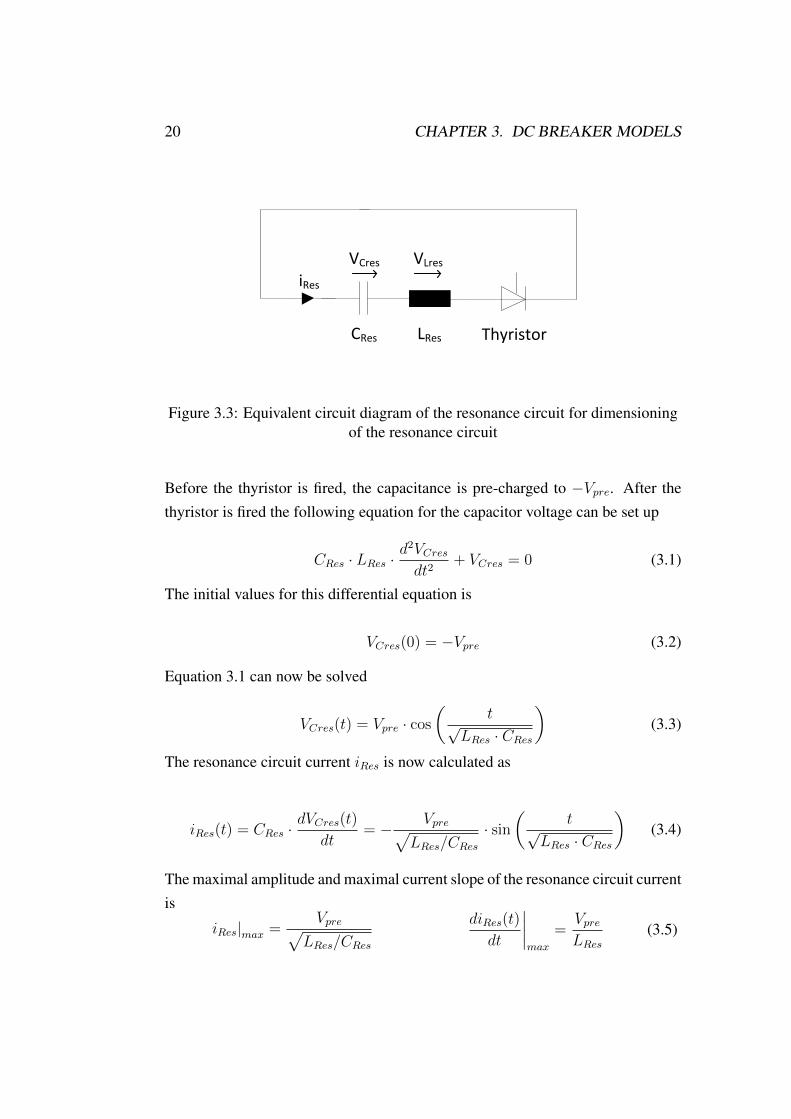
Figure 3.3: Equivalent circuit diagram of the resonance circuit for dimensioningof the resonance circuit
Before the thyristor is fired, the capacitance is pre-charged to −Vpre. After thethyristor is fired the following equation for the capacitor voltage can be set up
CRes · LRes ·d2VCresdt2
+ VCres = 0 (3.1)
The initial values for this differential equation is
VCres(0) = −Vpre (3.2)
Equation 3.1 can now be solved
VCres(t) = Vpre · cos
(t√
LRes · CRes
)(3.3)
The resonance circuit current iRes is now calculated as
iRes(t) = CRes ·dVCres(t)
dt= − Vpre√
LRes/CRes· sin
(t√
LRes · CRes
)(3.4)
The maximal amplitude and maximal current slope of the resonance circuit currentis
iRes|max =Vpre√
LRes/CRes
diRes(t)
dt
∣∣∣∣max
=VpreLRes
(3.5)

3.2. ACTIVE TURN-OFF HYBRID DC CIRCUIT BREAKER (ATHCB) 21
Equations 3.5 is solved for CRes and LRes
LRes =Vpre
diRes(t)dt
∣∣∣max
CRes =iRes|2max
VPre · diRes(t)dt
∣∣∣max
(3.6)
By choosing values for Vpre, iRes|max and diRes
dt
∣∣max
the corresponding values forCRes and LRes can be calculated.
3.2 Active Turn-off Hybrid DC Circuit Breaker (ATHCB)
The Active Turn-off Hybrid DC Circuit Breaker is based on the hybrid breakerconcept explained in subsection 2.1.2. A mechanical circuit breaker as used inAC-grids cannot be used to break a DC current because the lack of zero crossingof the current. However semiconducting devices have the ability to break currentsin kA range within a few µs, [Mey06]. The drawback with semiconducting de-vices is however large on-state losses, which is not the case with a mechanicalbreaker. These two devices are combined so that the nominal current is carriedby the mechanical breaker and in case of fault, the current is interrupted by thesemiconducting device.In figure 3.4 the equivalent circuit diagram of the ATHCB is shown. It consists ofdifferent branches each made to perform a certain task. At nominal operation thesemiconducting device is blocking current from flowing through branch B. As thevaristor protection voltage is set higher than the grid voltage no current is flowingthrough branch C either. The full current in nominal operation is therefore carriedby the mechanical breaker which has much lower losses than the semiconductingdevice.The semiconducting device needs to be of active turn-off type. Mainly two dif-ferent components is available today, the Isolated Gate Bipolar Transistor, IGBT,and the Integrated Gate-Commutated Thyristor, IGCT. The IGBT has higher on-state losses than the IGCT but has lower switching losses [Moh03], though nohigh switching frequency is needed for this application, the IGCT is chosen as thesemiconducting device in this work.

22 CHAPTER 3. DC BREAKER MODELS
Lσ,A
Varistor
Lσ,C
Lσ,B
iMech
iIGCT
iVar
SMech
A
B
C
iBreaker
IGCT
Figure 3.4: Equivalent circuit diagram of the Active Turn-off Hybrid DC CircuitBreaker
In case of a short circuit fault the current will start to rise according to section2.1.2. When the current reaches a threshold value a signal is given to the mechan-ical breaker to open and to the IGCT to start conducting. Due to the stray induc-tances (Lσ) in branch A and B, it will take the current some time to commutatefrom branch A to branch B, during which a burning arc occurs inside the mechan-ical breaker. The value of the burning arc voltage and the stray inductances inbranch A and B will decide the duration of the commutationprocess from branchA to branch B.When the current is fully commutated to branch B, the semiconductor device canbe given a command to block the current. Due to that the semiconductor deviceswill turn off the current fast (a matter of µs), the di
dtat the grid inductance will be
high leading to a voltage peak over the semiconductor. To prevent the semicon-ductor to break from this voltage peak, a voltage limiting device, i.e a varistor isconnected in parallel to the IGCT.Almost directly after the IGCT has opened the voltage over the breaker will rise tothe varistor protection voltage which will start conducting the current. Since thevaristor protection voltage is higher than the grid voltage, the voltage over the gridinductance will turn negative and the grid inductance will start to demagnetize, seeequation 2.3.
3.2. ACTIVE TURN-OFF HYBRID DC CIRCUIT BREAKER (ATHCB) 23
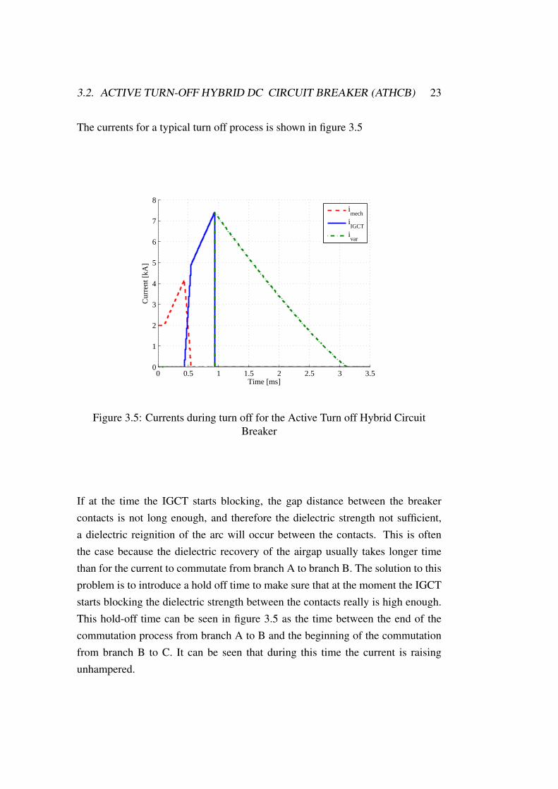
The currents for a typical turn off process is shown in figure 3.5
0 0.5 1 1.5 2 2.5 3 3.50
1
2
3
4
5
6
7
8
Time [ms]
Cur
rent
[kA
]
imech
iIGCT
ivar
Figure 3.5: Currents during turn off for the Active Turn off Hybrid CircuitBreaker
If at the time the IGCT starts blocking, the gap distance between the breakercontacts is not long enough, and therefore the dielectric strength not sufficient,a dielectric reignition of the arc will occur between the contacts. This is oftenthe case because the dielectric recovery of the airgap usually takes longer timethan for the current to commutate from branch A to branch B. The solution to thisproblem is to introduce a hold off time to make sure that at the moment the IGCTstarts blocking the dielectric strength between the contacts really is high enough.This hold-off time can be seen in figure 3.5 as the time between the end of thecommutation process from branch A to B and the beginning of the commutationfrom branch B to C. It can be seen that during this time the current is raisingunhampered.

24 CHAPTER 3. DC BREAKER MODELS
3.3 Snubbered Hybrid DC Circuit Breaker (SHCB)
The snubbered Hybrid circuit breaker concept explained in this section is mainlybased on the work of [Mey07]. The concept is an improvement of the already ex-plained ATHCB. During nominal operation the current is carried by a mechanicalbreaker which has low on-state losses. The parallel path is what differs the SHCBfrom the ATHCB, instead of using an active turn-off device such as an IGCT, acapacitance and a thyristor is used.
3.3.1 Functional principle
As the ATHCB the SHCB consists of three parallel branches each with its owntask. Its equivalent circuit diagram is showed in figure 3.6
Lσ,A
Varistor
Lσ,C
Lσ,B
iMech
iCsnubb
iVar
SMech
A
B
C
iBreaker
CSnubber Thyristor
Figure 3.6: Equivalent Circuit Diagram of the Snubbered Hybrid circuit Breaker
The functional principle of the SHCB is close to that of the ATHB. In the nominalcase the current is carried by the mechanical switch which has low on-state losses.The thyristor in branch B is blocking the current until its given a fire signal. Thevaristor in path C is also not conducting any current at nominal operation, thou itsprotection level is higher than the nominal grid voltage.When a short circuit failure occurs the current starts to rise as explained in section2.1.2. Once the short circuit current has reached the detection level a signal is

3.3. SNUBBERED HYBRID DC CIRCUIT BREAKER (SHCB) 25
given to the mechanical breaker to open and a fire signal is given to the thyristor.The current now starts to commutate onto branch B. Due to the stray inductances(Lσ1 and Lσ2) the current commutation from branch A to branch B takes sometime during which a burning arc occurs between the contacts of the opening me-chanical breaker.Up until this point the process is identical to that of the ATHCB. For the momentit is assumed that the current fully commutates to branch B, however this needscareful consideration and is explained in section 3.3.3. As the current starts tocommutate into path B the snubber capacitor starts getting charged. The resultingvoltage over the snubber capacitor will start to increase according to equation 3.7
dUCsnubberdt
=iCsnubbCCsnubber
(3.7)
This is the main idea with this topology; as the voltage recovery of the mechan-ical breaker increases with time as the mechanical breaker opens as explained insection 2.3. By choosing the size of the capacitor the voltage rate of rise over themechanical breaker can be chosen so that the dielectric strength of the breaker atall times is higher than the voltage over the snubber capacitor and therefore alsoover the mechanical breaker. By doing this a dielectric reignition of the gap dis-tance inside the mechanical breaker can be avoided. How the snubber capacitanceis dimensioned is explained in subsection 3.3.2.Since the capacitor is connected in parallel to the mechanical breaker, the voltageover the capacitor will be the same as over the mechanical breaker (assuming thatLσ is 0 and the on-state thyristor voltage drop is equal to zero). From equation2.3 it follows that as the snubber capacitance is charged the resulting voltage overthe grid inductance will decrease. Once the voltage over the snubber capacitorbecomes greater than the grid voltage, the voltage over the grid inductance willturns negative and the grid inductance starts to demagnetize. The short circuitcurrent then starts to decrease.When the voltage over the snubber capacitance becomes as high as the protectionlevel of the varistor, the varistor starts conducting and the current is commutatedto branch C.In figure 3.7, the currents and voltages for a typical turn off process is shown.

26 CHAPTER 3. DC BREAKER MODELS
0 1 2 3 4
−10
0
10
20
30
40
Time [ms]
Vol
tage
[kV
]
iBreaker
VCsnubb
VLgrid
VBreaker
(a) Voltages
0 1 2 3 40
1
2
3
4
5
6
Time [ms]
Cur
rent
[kA
]
iMech
iCsnubb
iVar
(b) Currents
Figure 3.7: Turn off process of the Snubbered Hybrid Circuit Breaker

3.3. SNUBBERED HYBRID DC CIRCUIT BREAKER (SHCB) 27
Since the snubber capacitor and the grid inductance together create a resonancecircuit the current in branch B needs to be stopped from changing its sign, oth-erwise the stored energy in the snubber capacitor would remagnetize the grid in-ductance leading to an oscillation between the snubber capacitance and the gridinductance. This is done by the thyristor which blocks the current from flowingin negative direction. A result of this is that at the end of the turn off process thecapacitor will be charged to the protection level of the varistor. After the turn offprocess the capacitor needs to be discharged before the SHCB is ready to operateagain.
3.3.2 Dimensioning of Snubber Capacitance
Since the dielectric recovery of a mechanical breaker increases with time, thesnubber capacitance should be dimensioned so that the voltage slope over the me-chanical breaker is lower than the dielectric recovery of the mechanical breaker.In this section the required size of the snubber capacitor in order to have a spec-ified voltage slope during charging of the capacitor is calculated as a function ofthe grid parameters. The following calculations is based on the work of [Mey05].During charging of the capacitance, the circuit breaker can be explained by theequivalent circuit diagram in figure 3.8. In the following calculations the grid
VGrid
LGrid
RGridIGrid
Lσ,B
v(t)
CSnubber Triac
Figure 3.8: Equivalent circuit diagram for the determination of CSnubber
resistance, RGrid can be neglected, thou its influence on these calculations are

28 CHAPTER 3. DC BREAKER MODELS
considered to be small and the its presence will severely complicate the calcu-lations. The stray inductance in branch B, (Lσ,B) is much smaller than the gridinductance and is therefore also neglected in the following calculations. From thecircuit diagram in figure 3.8, the equation for the snubber capacitor voltage duringthe turn off process, v(t) can be written as:
Vgrid = LGrid · Csnubber ·d2
dt2· v(t) + v(t) (3.8)
This is a second order differential equation (two energy storage devices present),and therefore two initial values needs to be stated. At time t = 0 the snubber ca-pacitance is assumed to have the precharged voltage, Upre. This precharge voltageis used as a commutation help for the short circuit current to commutate onto thesnubber capacitor, see subsection 3.3.3.The second initial value is the initial voltage slope, dv(t)
dt
∣∣∣t=0
, which is proportionalto the current at the beginning of the turn-off process. Here another simplificationneeds to be made. The current will be assumed to commutate from branch A tobranch B instantaneously after the mechanical breaker is given its opening com-mand. With this simplification the initial current that flows through branch B canbe calculated as the sum of the detection current and the current increase duringthe detection time of the short circuit detection system as explained in 2.2. Thetwo initial conditions is given in equation 3.9.
v(t)|t=0 = Vpre
dv(t)
dt
∣∣∣∣t=0
=IDet + tDet·VGrid
LGrid
CSnubber
(3.9)
With these initial values, equation 3.8 is solved for the voltage over snubber ca-pacitor, v(t)
v(t) =IDet · LGrid + tDet · VGrid√
Lgrid · CSnubber· sin
(t√
LGrid · CSnubber
)− cos
(t√
LGrid · CSnubber
)· VGrid + VGrid + Upre
(3.10)

3.3. SNUBBERED HYBRID DC CIRCUIT BREAKER (SHCB) 29
By differentiating equation 3.10 with respect to time the equation for the voltageslope as a function of time is obtained:
dv(t)
dt=IDet · LGrid + tDet · VGrid√
Lgrid · CSnubber· cos
(t√
LGrid · CSnubber
)+ sin
(t√
LGrid · CSnubber
)· VGrid
(3.11)
To find the maximum voltage slope, first this equation is once again differentiatedover time, set equal to zero, and solved for time. Now the time when the maximumvoltage slope occurs can be expressed. This time is then put into equation 3.11 andthe maximum voltage slope dv
dt
∣∣max
can be expressed. As the last step the equationfor dv
dt
∣∣max
is solved for the snubber capacitance. More detailed calculations canbe found in [Mey07]. The result of this is the equation for dimensioning of thesnubber capacitance.
CSnubber ≥
√V 4Grid + 4 · dv
dt
∣∣2max· A
2 · dvdt
∣∣2max· LGrid
+V 2Grid
2 · dvdt
∣∣2max· LGrid
were
A = L2Grid · I2Det + 2 · LGrid · IDet · tDet · VGrid + t2Det · V 2
Grid
(3.12)
The dimensioning of the snubber capacitance is not only dependent on the gridparameters (such as nominal voltage, current and grid inductance), it is also de-pendent on the fault current detection parameters such as the detection time, tDet,and detection level of the current IDet.By increasing the nominal grid voltage, the grid current or the detection currenta larger capacitance is needed. By increasing any of these parameters, a highercurrent would flow through the capacitor which if kept constant would be chargedquicker. To keep the voltage slope constant this needs to be compensated with ahigher capacitance.For the grid inductance the opposite dependency can be seen, a lower grid induc-tance would lead to a higher required capacitance. This is realized from equation

30 CHAPTER 3. DC BREAKER MODELS
2.3, a lower LGrid will lead to a higher didt
and therefore the current will rise to ahigher value.In figure 3.9 the dielectric recovery voltage of a VCB and an UFS is shown to-gether with the voltage over the mechanical breaker (i.e the voltage over the snub-ber capacitor). As already mentioned to avoid a dielectric breakdown during theopening of the breaker the dielectric strength of the mechanical breaker needs tobe higher than the voltage over the mechanical breaker.
0.3 0.4 0.5 0.6 0.7 0.8 0.9 1−10
0
10
20
30
40
50
time [ms]
volta
ge [k
V]
V
Csnubb
VBD, UFS
VBD, VCB
Figure 3.9: Dielectric recovery of a VCB and an UFS and snubber capacitorvoltage
For the Ultra Fast Switch, the dielectric recovery is a linear function with respectto time, the maximum voltage slope, dv
dt
∣∣max
is therefore directly calculated fromequation 2.10.For the Vacuum Circuit Breaker the dielectric recovery is proportional to thesquare root of time. However, by recognizing that the voltage over the mechanicalbreaker never rises over the varistor protection voltage, Vvar, the maximum volt-age slope, dv
dt
∣∣max
, for the Vacuum Circuit Breaker can be calculated with equation2.16.
dv
dt
∣∣∣∣max
= (nk ·K)2 · vkvVvar
(3.13)

3.3. SNUBBERED HYBRID DC CIRCUIT BREAKER (SHCB) 31
3.3.3 Current commutation onto the snubber capacitor
To successfully commutate the current from branch A onto branch B, the voltageover branch B needs to be lower than the arcingvoltage during the commutationprocess. The voltage over branch B is determined by the equivalent impedanceand the current in branch B,
Varc > iCsnubber · ZB (3.14)
The impedance ZB is determined by the stray inductances LσA and LσB and thesnubber capacitor. Larger stray inductance and lower capacitance therefore leadsto a more difficult current commutation.From [Hol01] it is shown that in order to commutate a current of some kA, witha burning arc voltage of (10...20) V and stray inductances in the order of a few0.1µ H onto a parallel capacitance, the capacitance would need to be in the orderof (1...10) mF.From equation 3.7 it is understood that the higher snubber capacitance the lowersnubber capacitor voltage slope. With this, by taking a look at equation 2.3 it canbe realized that the faster the voltage over the snubber capacitance increases, thefaster will the grid inductance start to demagnetize and the lower the maximumcurrent through the breaker will be. The result of this is that to keep the maximumshort circuit current low the snubber capacitance should be kept as low as possible.The minimum allowed value for the snubber capacitance is set by equation 3.12.As already pointed out in section 3.3.1, this minimal value is to keep the voltageslope of the capacitor lower than the dielectric recovery voltage of the mechanicalbreaker.With a ultrafast switch with 5-20 m/s switching speed or a vacuum circuit breakerwith 1-3 m/s and the grid parameters shown in table 2.1 the minimal snubbercapacitance calculated from equation 3.12 is several 1...100µF . This is clearlylower than the (1...10) mF which is the minimal allowed capacitance at which acurrent of around 4 kA can be commutated onto.To increase the commutation ability the stray inductances (Lσ,A and Lσ,B in figure3.6) must be kept as low as possible or the burning arc voltage should be increased.

32 CHAPTER 3. DC BREAKER MODELS
By applying many breaks in series as explained in subsection 2.3.2 the burningarc voltages for each break will add to each other and the total burning arc voltagewill be increased, see section 2.3.2.
0.42 0.44 0.46 0.48 0.5 0.520
50
100
150
200
250
300
time [ms]
volta
ge [
V],
cur
rent
[10
0A]
Arcing voltageV
Csnubb
Imech
Isnubb
(a) Successful commutation
0.42 0.44 0.46 0.48 0.5 0.52 0.540
50
100
150
200
250
300
time [ms]vo
ltage
[V
], c
urre
nt [
100A
]
Arcing voltageV
Csnubb
Imech
Isnubb
(b) Failed commutation
Figure 3.10: Current commutation from branch A to branch B for SHCB
Figure 3.10 shows a successful and a failed commutation of the current onto acapacitance of 375µF. In the successful case 16 serial breaks is simulated. Infigure 3.10(a) it can be seen that the burning arc voltage is greater than the voltageover the snubber capacitor during the entire commutation process and thereforethe current fully commutates onto the snubber capacitance and the burning arc isquenched. In figure 3.10(b), 15 serial breaks is simulated. The capacitor voltagetherefore becomes greater than the total burning arc voltage and the current is notcommutated onto the snubber capacitance. The arc therefore continues to burnand the current increases unhampered according to figure 2.3.To commutate the current onto a snubber capacitance of 375µF, 16 serial breaksare needed to commutate the current. As explained in subsection 2.3.2, the practi-cal limit is 3 serial breaks due to the drive mechanism of the mechanical breaker.To build a mechanical breaker with 16 serial breaks which all has to be able tocarry the nominal current is not realistic. Therefore other means to help the cur-rent commutation onto the snubber capacitance needs to be considered.One solution is to use a bigger snubber capacitance in order to make the equivalentimpedance in branch B lower. Simulations show that by using 3 breaks in seriesthe snubber capacitance needs to be at least 12 mF which is much higher than the

3.3. SNUBBERED HYBRID DC CIRCUIT BREAKER (SHCB) 33
minimum allowed snubber capacitance calculated from equation 3.12. The maxi-mum short circuit current therefore rises to about 32 kA. Therefore this method isalso not realistic.
0.42 0.44 0.46 0.48 0.5 0.52 0.54−250
−200
−150
−100
−50
0
50
100
Time [ms]
Vol
tage
[V],
Cur
rent
* 1
00[A
]
Varc
VCsnubb
Imech
Isnubb
(a) Successful commutation
0.42 0.44 0.46 0.48 0.5 0.52 0.54−250
−200
−150
−100
−50
0
50
100
Time [ms]
Vol
tage
[V],
Cur
rent
* 1
00[A
]
Varc
VCsnubb
Imech
Isnubb
(b) Failed commutation
Figure 3.11: Current commutation from branch A to branch B with negativelypre-charged snubber capacitance for SHCB
Another solution is to negatively pre-charge the snubber capacitance with a volt-age Vpre. By doing this the voltage over Branch B will have a negative value oncethe thyristor is fired. Figure 3.11 shows a successful and a failed commutationprocess with a negatively pre-charged capacitance. Once again for the currentcommutation to succeed the voltage over the snubber capacitor needs to be lowerthan the burning arc voltage during the full commutation process. In the success-ful case (figure 3.11(a)) the pre-charged voltage is -202 V and in the nonsuccessfulcase (figure 3.11(a)) the pre-charged voltage is -190 V. With this method, the cur-rent is commutated onto the minimal allowed snubber capacitance calculated fromequation 3.12, therefore the maximum short circuit current is as low as possible.To commutate the current onto a lower capacitance the pre-charge voltage needsto be increased due to that the voltage slope over a smaller capacitance will behigher.

34 CHAPTER 3. DC BREAKER MODELS

Chapter 4
Breaker models Analysis
For the different DC breaker topologies the most important parameter is the maxi-mum short circuit current during the turn-off process since this parameter decidesthe current level that all equipment in the system needs to be protected against.The influence of different parameters is analyzed to understand how the differentbreaker topologies can be optimized. For the analysis the nominal values in table4.1 are adapted. The analysis has been carried with the simulation tool SimPow-erSystems in Matlab Simulink.
Grid parametersGrid voltage VGrid 20 kVLoad resistance RLoad 10 ΩGrid current IGrid 2 kAGrid inductance L′Grid 300µH/kmGrid resistance R′Grid 10 mΩ/kmLength of cable lCable 10 km
Current detection parametersDetection current IDet 3 kADelay time time tDel 180µs
Breaker parametersVaristor voltage VV ar 30 kVStray inductance LσA = LσB = LσC 0.5µH
Table 4.1: Nominal values for the analysis of the different DC breaker topologies
35

36 CHAPTER 4. BREAKER MODELS ANALYSIS
4.1 Resonance Hybrid DC Circuit Breaker
In the Resonant Hybrid DC Circuit Breaker the maximum short circuit current isdecided by how fast after the detection of fault current an artificial current zerocrossing occurs at the mechanical breaker. Since at the current zero crossingsthe burning arc needs to be extinguished by the mechanical breaker, the UltraFast Switch cannot be used due to its lack of arc quenching ability. Therefore aVacuum Circuit Breaker is chosen as the mechanical breaker.The time to artificial current zero crossing is decided by the values of the induc-tance LRes and capacitance CRes of the resonance circuit in branch B. These com-ponents are dimensioned under consideration of two parameters. The maximumcurrent slope diRes(t)
dt
∣∣∣max
should be limited to the maximum turn off capability ofthe mechanical breaker, see section 2.3.3, and the resulting countercurrent ampli-tude iRes|max should be greater than the short circuit current.
4.1.1 Influence DC breaker parameters
From section 3.1.2 the parameters that decides the resonance circuit is the re-quired countercurrent amplitude iRes|max, the current slope at the zero crossing ofthe current diRes(t)
dt
∣∣∣max
and the pre-charge voltage Vpre. The countercurrent ampli-tude is determined by the short circuit current detection system and the maximumcurrent slope is given by the turn off capability of the VCB. The pre-charge volt-age however, can be chosen freely.The moment the current is interrupted by the VCB the dielectric strength of theVCB must be high enough to avoid a dielectric reignition of the arc. From equa-tion 2.16, the dielectric recovery is dependent on the opening velocity vkv, there-fore a minimal opening velocity is required to avoid a dielectric reignition of thearc.Figure 4.1 shows the maximum short circuit current during the turn off processand minimum opening velocity as a function of the pre-charge voltage with thenominal circuit parameters in table 4.1 adapted.Figure 4.1(a) shows that with increased pre-charge voltage the maximum shortcurrent is decreased. This is explained with the help of figure 4.2 which shows the

4.1. RESONANCE HYBRID DC CIRCUIT BREAKER 37
5 10 15 20 25 30 35 40
6
6.2
6.4
6.6
6.8
7
7.2
7.4
Vpre
[kV]
I sc,m
ax [
kA]
(a) Pre-charge voltage
5 10 15 20 25 30 35 401
1.2
1.4
1.6
1.8
2
2.2
2.4
VPre
[kV]
v kv [
m/s
]
(b) Opening velocity
Figure 4.1: Pre-charge voltage and required opening velocity vs maximum shortcircuit current during the turn off process for the RHCB
turn off process of the RHCB with two different pre-charge voltages. The voltageover the grid inductance is calculated by VGrid − VBreaker. When the currentis interrupted by the VCB in the second current zero crossing , the resonancecircuit capacitance voltage VCres shows a positive value. Thou the breaker voltageVBreaker is equal to the resonance capacitor voltage, VCres (Voltage drop over LRescan be neglected; compare VBreaker and VCres in figure 4.2), the voltage over thegrid inductance is decreased with the resonance capacitor voltage.With increased pre-charge voltage the size of the capacitance is decreased (seeequation 3.6) and therefore the resonance capacitor is charged faster. Therefore atthe time the VCB breaks the current, the voltage over the capacitor is higher. Thisleads to a higher instantaneous decrease of the voltage over the grid inductance.The time until the voltage over the grid inductance becomes zero and it startsdemagnetizing is therefore shorter.This is also why a higher opening velocity is needed for higher pre-charge voltageas showed in figure 4.1(b). At the time the VCB interrupts the current the voltageover the VCB is the resonance capacitor voltage. As mentioned with higher pre-charge voltage the lower resonance capacitance and the higher voltage increase.Therefore the VCB has to withstand a higher voltage after the current has beeninterrupted at the second current zero crossing. This sets a higher demand for thedielectric recovery of the VCB e.g the opening velocity needs to be increased, seeequation 2.17.

38 CHAPTER 4. BREAKER MODELS ANALYSIS
0 0.25 0.5 0.75 1 1.25 1.5 1.75 2−12−10−8−6−4−2
02468
1012141618202224
Time [ms]
Vol
tage
*2[
kV],
Cur
rent
[kA
]
iBreaker
iMech
VLgrid
VCres
VBreaker
(a) Vpre = 10 kV
0 0.25 0.5 0.75 1 1.25 1.5 1.75 2−12−10−8−6−4−2
02468
1012141618202224
Time [ms]
Vol
tage
*2[
kV],
Cur
rent
[kA
]
iBreaker
iMech
VLgrid
VCres
VBreaker
(b) Vpre = 20 kV
Figure 4.2: Turn off process with different pre-charge voltage
Influence of stray inductance
Since the resonance circuit of the RHCB already consists of an inductance LResthis inductance should be dimensioned with respect to the stray inductances sothat the resulting inductance is the inductance which is wanted. By doing this thestray inductance will have no influence.

4.1. RESONANCE HYBRID DC CIRCUIT BREAKER 39
4.1.2 Influence of grid parameters
Influence of fault current detection system
By setting the detection current for the fault current detection system to a highervalue, the short circuit current reaches a higher value before the current is inter-preted as a fault. In order to create artificial current zero crossings of the current,the countercurrent amplitude should be increased. In figure 4.3 the maximumshort circuit current during the turn off process is plotted as function of the factorIGrid/IDet.
1.5 2 2.5 3 3.5 46
7
8
9
10
11
12
IDet
/IGrid
I sc,m
ax [
kA]
Figure 4.3: maximum short circuit current during the turn off process as functionof fault current detection level for RHCB
Influence of cable length
The cable length is directly proportional to the grid inductance in figure 2.1. Withshorter cable length the short circuit current rate of rise is increased, see equation2.3. This results in that at the time the fault current is detected by the fault cur-rent detection system the current has risen to a higher value, therefore a greatercountercurrent amplitude is needed in order to create artificial zero crossings of
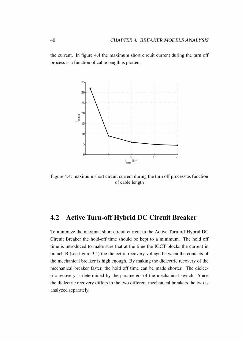
40 CHAPTER 4. BREAKER MODELS ANALYSIS
the current. In figure 4.4 the maximum short circuit current during the turn offprocess is a function of cable length is plotted.
0 5 10 15 200
5
10
15
20
25
30
35
lcable
[km]
I sc,m
ax
Figure 4.4: maximum short circuit current during the turn off process as functionof cable length
4.2 Active Turn-off Hybrid DC Circuit Breaker
To minimize the maximal short circuit current in the Active Turn-off Hybrid DCCircuit Breaker the hold-off time should be kept to a minimum. The hold offtime is introduced to make sure that at the time the IGCT blocks the current inbranch B (see figure 3.4) the dielectric recovery voltage between the contacts ofthe mechanical breaker is high enough. By making the dielectric recovery of themechanical breaker faster, the hold off time can be made shorter. The dielec-tric recovery is determined by the parameters of the mechanical switch. Sincethe dielectric recovery differs in the two different mechanical breakers the two isanalyzed separately.

4.2. ACTIVE TURN-OFF HYBRID DC CIRCUIT BREAKER 41
4.2.1 Influence of DC breaker parameters
Influence of mechanical breaker parameters for the UFS
The dielectric recovery voltage of an Ultra Fast Switch as a function of time aftercontact opening is given in equation 2.10. By choosing air as switching mediumthe dielectric recovery is only dependent on the number of serial breaks nk, gaspressure, p and opening velocity, vk. In figure 4.5 these three parameters arecombined into one parameter called the switch design factor,ks
ks = nk · p · vk (4.1)
By choosing a higher switch design factor the dielectric strength of the UFS isincreased faster and the hold off time can be made shorter. Figure 4.5 shows themaximum short circuit current during the turn off process as a function of theswitch design factor.
0 50 100 1504
5
6
7
8
9
10
11
12
13
14
15
I sc,m
ax [
kA]
ks
Figure 4.5: maximum short circuit current during the turn off process for theATHCB as function of switch design factor of the UFS
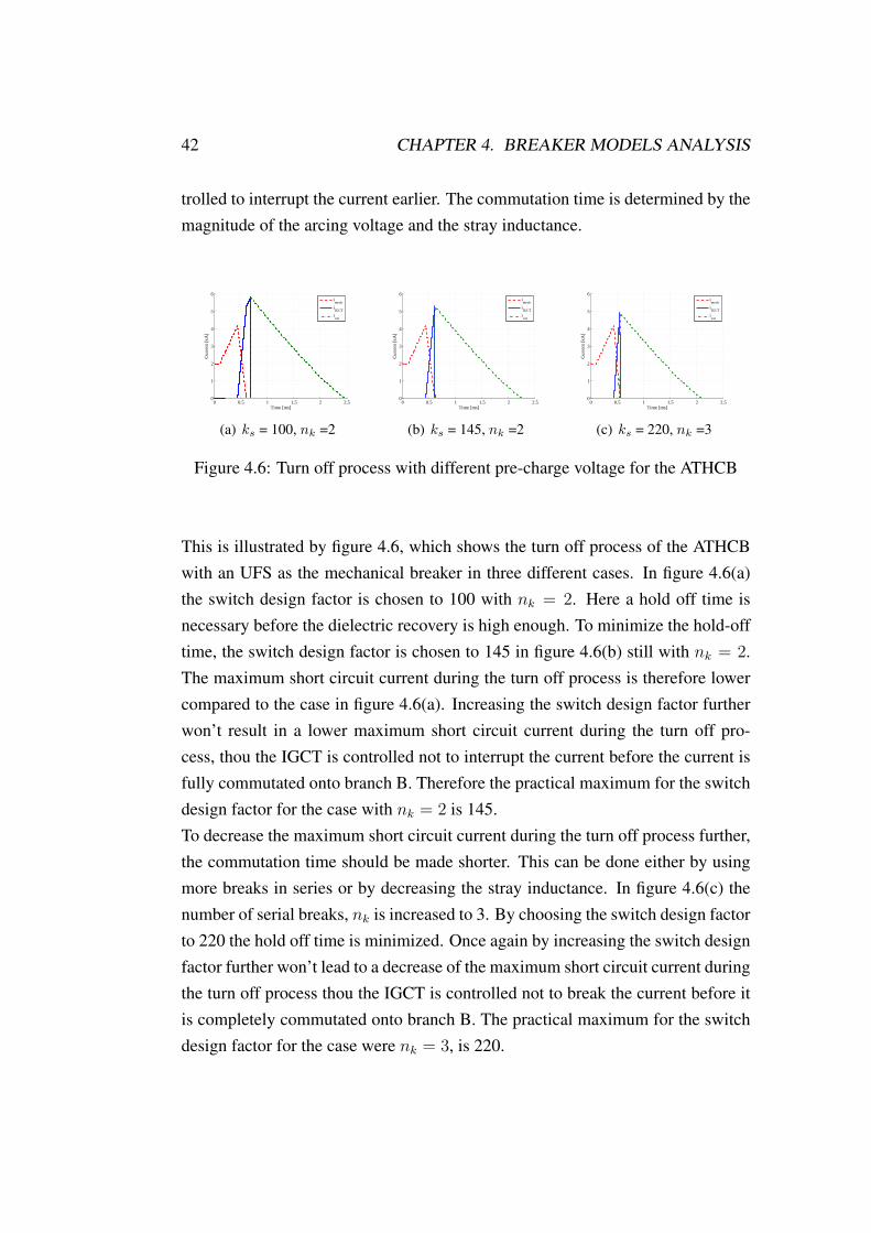
The IGCT is controlled not to break the current before the short circuit current isfully commutated onto branch B. This sets a practical maximum for the dielec-tric recovery of the mechanical breaker, were a faster dielectric recovery won’tlead to a smaller maximum short circuit current during the turn off process. Bymaking the commutation time (i.e the arcing time) shorter the IGCT can be con-
42 CHAPTER 4. BREAKER MODELS ANALYSIS
trolled to interrupt the current earlier. The commutation time is determined by themagnitude of the arcing voltage and the stray inductance.
0 0.5 1 1.5 2 2.50
1
2
3
4
5
6
Time [ms]
Cur
rent
[kA
]
imech
iIGCT
ivar
(a) ks = 100, nk =2
0 0.5 1 1.5 2 2.50
1
2
3
4
5
6
Time [ms]
Cur
rent
[kA
]
imech
iIGCT
ivar
(b) ks = 145, nk =2
0 0.5 1 1.5 2 2.50
1
2
3
4
5
6
Time [ms]
Cur
rent
[kA
]
imech
iIGCT
ivar
(c) ks = 220, nk =3
Figure 4.6: Turn off process with different pre-charge voltage for the ATHCB
This is illustrated by figure 4.6, which shows the turn off process of the ATHCBwith an UFS as the mechanical breaker in three different cases. In figure 4.6(a)the switch design factor is chosen to 100 with nk = 2. Here a hold off time isnecessary before the dielectric recovery is high enough. To minimize the hold-offtime, the switch design factor is chosen to 145 in figure 4.6(b) still with nk = 2.The maximum short circuit current during the turn off process is therefore lowercompared to the case in figure 4.6(a). Increasing the switch design factor furtherwon’t result in a lower maximum short circuit current during the turn off pro-cess, thou the IGCT is controlled not to interrupt the current before the current isfully commutated onto branch B. Therefore the practical maximum for the switchdesign factor for the case with nk = 2 is 145.To decrease the maximum short circuit current during the turn off process further,the commutation time should be made shorter. This can be done either by usingmore breaks in series or by decreasing the stray inductance. In figure 4.6(c) thenumber of serial breaks, nk is increased to 3. By choosing the switch design factorto 220 the hold off time is minimized. Once again by increasing the switch designfactor further won’t lead to a decrease of the maximum short circuit current duringthe turn off process thou the IGCT is controlled not to break the current before itis completely commutated onto branch B. The practical maximum for the switchdesign factor for the case were nk = 3, is 220.

4.2. ACTIVE TURN-OFF HYBRID DC CIRCUIT BREAKER 43
As mentioned earlier the commutation time is also dependent on the stray induc-tance Lσ. Figure 4.7 shows the practical maximum for the switch design factor asa function of stray inductance and number of serial breaks.
0.4 0.6 0.8 1 1.2 1.4 1.6 1.80
50
100
150
200
250
300
350
k s
Stray inductance [µH]
n
k=1
nk=2
nk=3
Figure 4.7: Practical maximum for the switch design factor of the UFS asfunction of number of serial breaks and stray inductance for the ATHCB
Influence of mechanical breaker parameters for the VCB
For the vacuum circuit breaker the dielectric recovery is given by equation 3.13which is dependent on the opening velocity and the number of breaks in seriessquared. In figure 4.8 the opening velocity and number of series breaks are plottedagainst the maximum short circuit current during the turn off process. It is realizedthat by increasing the number of serial breaks the opening velocity of VCB canbe severely decreased, this is due to that the dielectric recovery is proportional tothe number of serial brakes squared, see equation 3.13.The IGCT is controlled not to break the current before the current is fully com-mutated onto branch B. This sets a practical maximum for the dielectric recoverywere by increasing the dielectric recovery further won’t result in a lower maxi-mum short circuit current during the turn off process. To decrease the maximal

44 CHAPTER 4. BREAKER MODELS ANALYSIS
0 1 2 3 4 5 6 74
5
6
7
8
9
10
11
12
13
14
15
I sc,m
ax [
kA]
vkv
[m/s]
n
k=1
nk=2
nk=3
Figure 4.8: maximum short circuit current during the turn off process for theATHCB as function of opening velocity, vkv, of the VCB and number of serial
breaks, nk
short circuit current further the commutation time should be decreased. This canbe done either by increasing the number of serial breaks or to decrease the strayinductance. In figure 4.9 the influence of stray inductance and number of serialbreaks vs the maximum practical opening velocity of the VCB is plotted.
0.4 0.6 0.8 1 1.2 1.4 1.6 1.80
0.5
1
1.5
2
2.5
3
3.5
4
4.5
5
v vk [m
/s]
Stray inductance [µH]
n
k=1
nk=2
nk=3
Figure 4.9: Practical maximum opening velocity for the VCB as function ofnumber of serial breaks and stray inductance for the ATHCB

4.2. ACTIVE TURN-OFF HYBRID DC CIRCUIT BREAKER 45
In figure 4.9 it is seen that due to that the dielectric recovery is proportional to thenumber of breaks squared (see equation 3.13), by putting more breaks in series inorder to get a lower commutation time a lower practical maximum of the openingvelocity is obtained.
4.2.2 Influence of grid parameters
Influence of fault current detection system
By increasing the detection current for the fault current detection system the faultcurrent rises to a higher value before it is recognized as a fault. This additionalcurrent leads to an increase of the maximum short circuit current during the turnoff process. In figure 4.10 the maximum short circuit current during the turn offprocess as function of the detection level is plotted
1.5 2 2.5 3 3.5 45
5.5
6
6.5
7
7.5
8
8.5
9
9.5
10
10.5
I sc,m
ax [
kA]
IGrid
/IDet
Figure 4.10: maximum short circuit current during the turn off process asfunction of fault current detection level for ATHCB

46 CHAPTER 4. BREAKER MODELS ANALYSIS
Influence of cable length
By decreasing the length of the cable the cable parameters LGrid and Rgrid infigure 2.1 is reduced. By decreasing the grid inductance the short circuit currentrate of rise is increased according to equation 2.1. Therefore at the time the cur-rent detection system has recognized the short circuit current a greater currentflows through the DC breaker, also since the current continues to rise during thecommutation process, when the current has finally commutated it has reached ahigher value. In figure 4.11, the maximum short circuit current during the turn offprocess as a function of cable length is plotted.
0 5 10 15 200
5
10
15
20
25
30
35
lcable
I sc,m
ax
Figure 4.11: maximum short circuit current during the turn off process asfunction of cable length

4.3. SNUBBERED HYBRID DC CIRCUIT BREAKER 47
4.3 Snubbered Hybrid DC Circuit Breaker
The most significant parameters influencing the maximum short circuit currentduring the turn off process in the Snubbered Hybrid Circuit Breaker is the size ofthe snubber capacitance. The higher the capacitance the higher the short maxi-mum short circuit current during the turn off process, see subsection 3.3.3. Theminimum required capacitance is determined by the dielectric recovery of themechanical breaker. First the influence of the mechanical parameters of the twodifferent mechanical breakers are analyzed, then the influence of extra high pre-charge voltage are analyzed. Also the influence of the stray inductance is ana-lyzed. Thereafter the influence of the grid parameters are analyzed.
4.3.1 Influence of DC breaker parameters
Influence of mechanical breaker parameters for the UFS
By choosing the grid and breaker parameters as in table 4.1 the size of the snubbercapacitance from equation 3.7 is only dependent on the maximum allowed voltageslope over the mechanical breaker, dv
dt|max. Equation 2.10 describes the dielectric
recovery for an Ultra Fast Switch, which is a linear function of time. If the gasbetween the contacts is chosen as air and the Schwaiger factor of the contacts isconsidered constant, the steepness of the dielectric recovery is determined by theopening velocity, the pressure of the gas and the number of serial breaks. Thesethree parameters are combined into one parameter called the switch design factor.
ks = nk · p · vk (4.2)
For the current to commutate onto branch B the snubber capacitance needs to benegatively pre-charged, see subsection 3.3.3. The magnitude of the pre-chargevoltage is however dependent on the arcing voltage. From equation 2.11 it isseen that the burning arc voltage is influenced by number of serial breaks nk andopening velocity vkThe second term of equation 2.11 describes the voltage increase due to the pro-longing of the arc. The maximum arcing voltage increase is determined by theopening velocity vk and the arcing time tarc. The arcing time is higher for small

48 CHAPTER 4. BREAKER MODELS ANALYSIS
values of the switch design factor (smaller ks factor results in a higher capaci-tance, equation 3.7 and therefore longer commutation time). Simulations showthat for a switch design factor of 10 the arcing time tarc is 40µs, with an openingvelocity of 20 m/s and nk = 1 this gives an additional voltage of 0.6 V. As the in-stantaneous burning arc voltage, V0 is in the range (10...20) V, the 0.6 V extra dueto prolonging of the airgap falls well within this range. The effect on the arcingvoltage of prolonged arc is therefore neglected.The first term in equation 2.11 can not be neglected. As explained in section 3.3.3the pre-charge voltage needs to be higher than the arcing voltage during the fullcommutation process for the current to commutate onto the snubber capacitance.By using multiple serial breaks the arcing voltage is increased, the pre-chargevoltage can thereby be decreased with the corresponding voltage increase, that isV0 · nk.
0 20 40 60 80 100 120 1400123456789
101112131415
Vol
tage
⋅ 100
[V],
Cap
acita
nce
*10[
µF
], C
urre
nt [k
A]
ks
isc,max
Vpre
CSnubber
Figure 4.12: maximum short circuit current during the turn off process, requiredsnubber capacitance and required pre-charge voltage for the SHCB as function of
the switch design factor of the UFS
In figure 4.12 the simulated maximum short circuit current during the turn offprocess is plotted against the switch design factor and the minimal required pre-

4.3. SNUBBERED HYBRID DC CIRCUIT BREAKER 49
charge voltage for the current to commutate onto the snubber capacitor. The re-quired size of the snubber capacitance calculated from equation 3.12 is also plot-ted.
Influence of mechanical breaker parameters for the VCB
The maximum allowed voltage slope over a VCB to guarantee that the dielectricstrength is sufficient is calculated from equation 3.13. The parameters influencingthe dielectric recovery are the opening velocity, vk, and number of serial breaksnk.Due to lower opening velocity of the VCB than for the UFS, the effect of pro-longing of the airgap is even smaller than for the UFS, see subsection 4.3.1 and istherefore neglected here as well.In figure 4.13 maximum short circuit current during the turn off process as func-tion of opening velocity and number of serial breaks for the VCB is plotted.
0 1 2 3 4 5 6 74
5
6
7
8
9
10
11
12
13
14
15
i sc,m
ax
vkv
[m/s]
n
k=1
nk=2
nk=3
Figure 4.13: maximum short circuit current during the turn off process of theSHCB as function of opening velocity and number of serial breaks for the VCB
In figure 4.14 the required snubber capacitance and pre-charge voltage for theSHCB as function of the opening velocity of the VCB are plotted.

50 CHAPTER 4. BREAKER MODELS ANALYSIS
0 1 2 3 4 5 6 70
10
20
30
40
50
60
70
80
90
100
110
120
130
140
150
Vol
tage
⋅ 10
[V],
Cap
acita
nce[
µF
]
vkv
[m/s]
V
pre
CSnubber
Figure 4.14: Required snubber capacitance and pre-charge voltage for the SHCBas function of opening velocity of the VCB
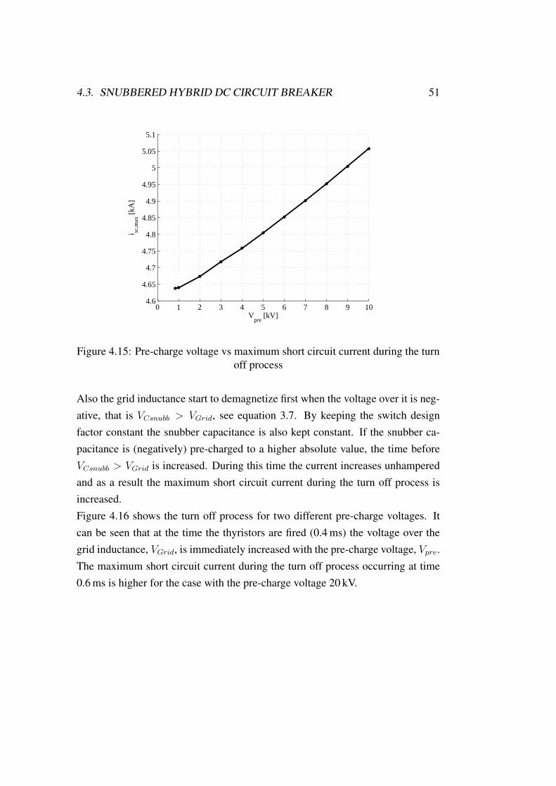
Influence of pre-charge voltage
In the subsection above the minimal required pre-charge voltage of the snubbercapacitance in order to commutate the current onto the snubber capacitor is plottedfor different values of the switch design factor. In this subsection the influence ofan increased pre-charge voltage is analyzed. In figure 4.15 the maximum shortcircuit current during the turn off process versus the pre-charge voltage is plottedwith the switch design factor held constant at 100 bar ·m/s.By increasing the pre-charge voltage the maximum short circuit current duringthe turn off process is increased. This can be understood by taking a look at thevoltage over the grid inductance, see equation 2.3. At the instant the thyristoris fired the voltage VBreaker will be the pre-charge voltage. Since the pre-chargevoltage is negative the resulting voltage over the grid inductance will be the sum ofthe grid voltage and the pre-charged voltage. The pre-charge voltage will thereforemagnetize the grid inductance even more and as a result the current slope, diBreaker
dt
is increased.
4.3. SNUBBERED HYBRID DC CIRCUIT BREAKER 51
0 1 2 3 4 5 6 7 8 9 104.6
4.65
4.7
4.75
4.8
4.85
4.9
4.95
5
5.05
5.1
i sc,m
ax [
kA]
Vpre
[kV]
Figure 4.15: Pre-charge voltage vs maximum short circuit current during the turnoff process
Also the grid inductance start to demagnetize first when the voltage over it is neg-ative, that is VCsnubb > VGrid, see equation 3.7. By keeping the switch designfactor constant the snubber capacitance is also kept constant. If the snubber ca-pacitance is (negatively) pre-charged to a higher absolute value, the time beforeVCsnubb > VGrid is increased. During this time the current increases unhamperedand as a result the maximum short circuit current during the turn off process isincreased.Figure 4.16 shows the turn off process for two different pre-charge voltages. Itcan be seen that at the time the thyristors are fired (0.4 ms) the voltage over thegrid inductance, VGrid, is immediately increased with the pre-charge voltage, Vpre.The maximum short circuit current during the turn off process occurring at time0.6 ms is higher for the case with the pre-charge voltage 20 kV.

52 CHAPTER 4. BREAKER MODELS ANALYSIS
0 0.2 0.4 0.6 0.8 1 1.2 1.4 1.6 1.8 2 2.2 2.4 2.6
−20
−15
−10
−5
0
5
10
15
20
25
30
35
40
45
Time [ms]
Vol
tage
[kV
], C
urre
nt [k
A]
iBreaker
VCsnubb
VLgrid
VBreaker
(a) Vpre = 840 V
0 0.2 0.4 0.6 0.8 1 1.2 1.4 1.6 1.8 2 2.2 2.4 2.6
−20
−15
−10
−5
0
5
10
15
20
25
30
35
40
45
Time [ms]
Vol
tage
[kV
], C
urre
nt [k
A]
iBreaker
VCsnubb
VLgrid
VBreaker
(b) Vpre = 20 kV
Figure 4.16: Turn off process with different pre-charge voltage

4.3. SNUBBERED HYBRID DC CIRCUIT BREAKER 53
Influence of stray inductance
Next the stray inductances of the SHCB, see figure 3.6, is varied and its influenceon the maximum short circuit current during the turn off process is analyzed.
0 0.5 1 1.5 2 2.5 3
4.62
4.64
4.66
4.68
4.7
4.72
4.74
i sc,m
ax [k
A]
Lσ [µH]
(a) maximum short circuit current dur-ing the turn off process
0 0.5 1 1.5 2 2.5 3400
600
800
1000
1200
1400
1600
1800
2000
Vpr
e [V]
Lσ [µH]
(b) Required pre-charge voltage
Figure 4.17: maximum short circuit current during the turn off process andrequired pre-charge voltage as function of stray inductance for the SHCB
By increasing the stray inductances the equivalent impedance in branch B, ZBincreases. Therefore in order to commutate the short circuit current onto branchB a higher pre-charge voltage of the snubber capacitor is required. The smallincrease in the maximum short circuit current during the turn off process is dueto the fact that a higher pre-charge voltage results in an increase of the maximumshort circuit current during the turn off process as explained in subsection 4.3.1.
4.3.2 Influence of grid parameters
Influence of fault current detection system
With higher detection current, see section 2.2, the short circuit current reachesa higher value before the fault current detection system reacts and mechanicalbreaker is opened. In subsection 3.3.3 it is explained that in order to commutatea higher current onto the snubber capacitor, the pre-charge voltage needs to beincreased. Figure 4.18(a) shows the increase in maximum short circuit currentduring the turn off process as a function of the detection level. Figure 4.18(b)shows the minimal required pre-charge voltage in order to commutate the currentonto the snubber capacitor.

54 CHAPTER 4. BREAKER MODELS ANALYSIS
1.5 2 2.5 3 3.5 44
5
6
7
8
9
10
i sc,m
ax [
kA]
IGrid
/IDet
(a) maximum short circuit current dur-ing the turn off process
1.5 2 2.5 3 3.5 4800
900
1000
1100
1200
1300
1400
Vpr
e [V
]
IGrid
/IDet
(b) Required pre-charge voltage
Figure 4.18: maximum short circuit current during the turn off process andrequired pre-charge voltage as function of fault current detection level for SHCB
Influence of cable length
With decreased length of the cable in figure 2.1 the grid inductance is also reduced.From equation 3.12 it follows that by decreasing the grid inductance the snubbercapacitance is increased, therefore the snubber capacitance voltage slope becomeslower. As a result the time before the voltage over the snubber capacitance be-comes higher than the grid voltage and the grid inductance start demagnetizing isincreased, see equation 2.3. Since a higher current needs to be commutated ontothe snubber capacitance In figure 4.19 the maximum short circuit current duringthe turn off process as function of the cable length is plotted.
0 5 10 15 202
4
6
8
10
12
14
16
18
20
lcable
I sc,m
ax
(a) maximum short circuit current dur-ing the turn off process
0 5 10 15 20600
800
1000
1200
1400
1600
1800
lcable
Vpr
e
(b) Required pre-charge voltage
Figure 4.19: maximum short circuit current during the turn off process andrequired pre-charge voltage as function of cable length

Chapter 5
Comparison and Discussion
The different breaker models are here compared under technical and economicalaspects. The most important technical parameter the breakers are to limit the max-imum short circuit current during the turn off process and the blocking voltage.The blocking voltage is decided by the protection voltage of the varistor. Themaximum short circuit current during the turn off process during is determinedby the breaker topologies. To compare the different breakers in a fair way, theyshould be optimized for the same operation case.
5.1 Optimized breaker models
5.1.1 Resonance Hybrid DC Circuit Breaker
In figure 4.1 the pre-charge voltage of the resonance capacitor and the requiredopening velocity is plotted against the maximum short circuit current during theturn off process during the turn off process. To limit the maximal short circuitcurrent the pre-charge voltage should be increased, however by increasing thepre-charge voltage a higher opening velocity is necessary and therefore the costof the mechanical drive for the VCB increases. Also higher energy ratings areneeded for the resonance capacitor and the resonance inductance, this also affectsthe cost in a negative way. The pre-charge voltage should therefore be chosenin the range were a further increase of the pre-charge voltage does not resultsin major benefit in form of a decreased maximal short circuit current during the
55
56 CHAPTER 5. COMPARISON AND DISCUSSION
turn-off process. From figure 4.1(a) this voltage is chosen as UPre = 20 kV. Fromfigure 4.1(b) the minimum required opening velocity to avoid dielectric reignitionis vkv = 1.95 m/s. For the RHCB the mechanical breaker is responsible of turningof the current at the artificially created zero crossings of the current created by theresonance circuit. Therefore the mechanical breaker has to be chosen as a VCB.With the opening speed and pre-charge voltage chosen as explained above maxi-mum short circuit current during the turn off process for the RHCB is.
Isc,max,RHCB = 6.0 kA
5.1.2 Active Turn-off Hybrid Circuit Breaker
Since the current is not turned off by the mechanical breaker in the ATHCB anUltra Fast switch can be used as the mechanical breaker. Also the use of a VCBas the mechanical switch is analyzed.In figure 4.5 the maximum short circuit current during the turn off process as afunction of the switch design factor of the UFS is plotted. The switch designfactor is chosen to the value were a further increase does not lead to a significantdecrease of the maximum short circuit current during the turn off process. Fromfigure 4.7 in order to chose the switch design factor to 100, 2 serial breaks isneeded with the stray inductance chosen according to table 4.1.From figure 4.1 the maximum short circuit current during the turn off process asfunction of number of serial breaks and opening velocity of the VCB is shown. Ifthe number of serial breaks is chosen as 1, the opening velocity were a further in-crease does not lead to a significant decrease of the maximum short circuit currentduring the turn off process is 4.67 m/s. However from figure 4.9 it is seen that themaximum practical opening velocity for the ATHCB with just one break and thestray inductance 0.6µ H is 3.3 m/s. Therefore the number of serial breaks shouldbe increased to 2. From figure 4.9 with nk = 2 the opening velocity were a furtherincrease does not lead to a significant decrease is 1.2 m/s.With the parameters chosen as the values given for the two different mechanicalbreakers the maximum short circuit current during the turn off process is
5.2. ECONOMICAL COMPARISON 57
Isc,max,ATHCB = 5.8 kA
5.1.3 Snubbered Hybrid DC Circuit Breaker
For the snubbered DC breaker the current is not interrupted by the mechanicalbreaker itself, therefore either the UFS or VCB can be used as the mechanicalbreaker. Figure 4.12 shows the maximum short circuit current during the turn offprocess as function of the switch design factor of the UFS. By choosing the switchdesign factor to 100 it can be seen that by increasing it further does not lead toa significantly decrease of the maximum short circuit current during the turn offprocess. From figure 4.13 with the number of serial breaks set to 1, the openingvelocity of the VCB were a further increase does not lead to a significant decreaseof the maximum short circuit current during the turn off process is 4.67 m/s.Also for the current to commutate onto the snubber capacitance the pre-chargevoltage should be chosen to 840 V, according to the graph in figure 4.12.For the given values for the two different mechanical breakers the maximal shortcircuit current is
Isc,max,SHCB = 4.7 kA
5.2 Economical comparison
In [Mey05] and [Mey07] an economical comparison between different DC breakerconcepts has been carried out. The cost of the ATHCB and the SHCB has beenanalyzed in this work. The result of this analysis is that for a grid voltage of20 kV the cost for the ATHCB is approximately the double of the SHCB. This ismainly due to the fact that active turn off devices are needed in the ATHCB whilein the SHCB the cheaper and more robust thyristor can be used. However theanalysis of the SHCB is made without consideration of the current commutationprocess from branch A to branch B (see figure 3.6). As was shown in subsection3.3.3 in order to commutate the current onto the snubber capacitance it has to be
58 CHAPTER 5. COMPARISON AND DISCUSSION
negatively pre-charged. Therefore the cost of keeping the snubber capacitance atall times pre-charged to a specific value has to be taken into account.For the RHCB the only component that has to be added in comparison to theSHCB is the resonance inductance. Also the resonance circuit capacitance hasto be kept pre-charged just like the snubber capacitor in the SHCB, however to ahigher voltage.
5.3 Comparison of the breaker models
The analysis of the maximum short circuit current during the turn off process ofthe different topologies under equal operation conditions show that the SnubberedHybrid DC Circuit breaker has the best short circuit current limitation capability.The maximum short circuit current during the turn off process is about 21 % lowerthan for the Resonance Hybrid Circuit Breaker and about 20 % lower than for theActive Turn-off DC Circuit Breaker.With the switch design factor 100 of the UFS or the opening velocity 4.67 m/s forthe VCB and the grid parameters given in 4.1 the maximum short circuit currentduring the turn off process is limited to 4.7 kA. The number of serial breaks, nk,opening velocity, vk and gas pressure, p, can be chosen according to the definitionof the switch design factor, see equation 4.2.The voltage blocking capability is the same for the three models, thou a varistorconnected in parallel limits the over voltage to the protection level of the varis-tor. The economical comparison of the breaker topologies performed in [Mey05],[Mey07] shows that the SHCB also is the most cost efficient of the three breakers.Two different mechanical breakers has been analyzed in this work, the VacuumCircuit Breaker and the Ultra Fast Switch . Due to the faster dielectric recovery ofvacuum the required opening velocity of the VCB is lower than for the UFS. Witha lower opening velocity the requirements on the drive system for the mechanicalbreaker is decreased. However to compare the requirements on the drive systemsfor the two breakers more parameters than the opening velocity needs to be takeninto account. The Vacuum Circuit Breaker is build to withstand an electrical arcfor up to 100 ms [Sla08]. The Ultra Fast Switch is designed with the assumptionthat an arc only occurs for a very short time, approx up to 150µ s [Hol01]. There-
5.4. INFLUENCE OF GRID PARAMETERS 59
fore the Ultrafast switch can be build with less material and moving parts whichwould decrease the requirements on the drive system. To decide which mechani-cal breaker that sets the lowest requirement on the drive system is therefore hardto say.
5.4 Influence of grid parameters
From the analysis of the grid parameters in sections 4.1.2, 4.2.2 and 4.3.2 it is clearthat the breaker performance is highly dependent on parameters such as detectionlevel and delay time of the short circuit current detection system. The influence ofhigher detection current on the short circuit current limitation for the different isapproximately the same. This make sense as by increasing the current detectionlevel for the different breakers gives an extra offset of the current that needs to beinterrupted. From the analysis of varied cable length it is realized that by reducedcable length, the grid inductance is reduced. With reduced grid inductance theshort circuit current rate of rise is increased. As can be seen in the analysis thisleads to an increased value of the maximum short circuit current during the turnoff process. Therefore the performance of the breaker is highly dependent on werein the DC-grid it is installed.

60 CHAPTER 5. COMPARISON AND DISCUSSION

Chapter 6
Conclusion and Outlook
DC-grids have have many advantages over AC-grids. The most important is thelack of reactive power in DC-grids, therefore no reactive losses appears. Alsono restrictions for power transmissions over long distances occurs. However theprotection of DC-grids is more complicated than AC-grids. In AC circuit breakersthe current is interrupted at the natural zero crossings of the current. In DC-gridsno current zero crossings exist. Different solutions to this problems exists and hasbeen evaluated in this work.Three different concepts has been identified and analyzed in this work. By con-necting a pre-charged resonance circuit in parallel to a mechanical breaker arti-ficial current zero crossings can be created through the mechanical breaker. Themechanical breaker can then be used as in the case of an AC gridIn the Active turn off Hybrid DC circuit breaker an active turn-off semiconductingdevice capable of interrupting currents in the kA range in the matter of µs iscombined with a mechanical breaker that has low on-state losses so that the currentin normal operation flows through the mechanical breaker. To interrupt the currentthe mechanical breaker is open, and the semiconducting device is turned on. Thecurrent commutates over to the semiconducting device. When the current is fullycommutated the current is turned off by the active semiconducting device.A developed version of the Active turn off DC Circuit Breaker is the SnubberHybrid DC Circuit breaker from [Mey05]. Instead of the active turn off semicon-ducting device a snubber capacitor and a thyristor is used in the parallel branch.
61

62 CHAPTER 6. CONCLUSION AND OUTLOOK
The voltage rate of rise over the mechanical breaker can therefore be controlled tobe lower than the dielectric recovery of the mechanical breaker.The three breaker topologies has been tested and analyzed under the same gridparameters. The most important parameter is the short circuit current limitingcapability. The results show that the maximum short circuit current during theturn off process is approximately 20 % lower for the Snubbered Hybrid DC CircuitBreaker compared to the other two concepts which shows approximately the samecurrent limiting capability.An economical analysis in [Mey05] shows that the snubbered mechanical circuitbreaker is also the most cost efficient solution of the three.
6.1 Outlook
The Snubbered Hybrid DC Breaker modeled in this thesis shows great potentialas use as a short circuit current interrupter in a future DC-grid.To extend the model that has been made in this work the dielectric recovery ofthe two types of mechanical circuit breaker should be deeper analyzed. The di-electric recovery directly after current interruption is dependent of many differentparameters and is therefore best made by practical experiments.Also the drive system of the mechanical breaker should be analyzed to gain moreinformation on how the use of multiple serial breaks and opening velocity affectsthe drive system and the required drive energy. Since a number of different drivesystems exist a comparison between them should be carried out to find the mostpromising solution.

Bibliography
[Alf08] D. Alferov, A. Budovsky, D. Evsin, V. Invanov, V. Sidorov &V. Yagnov. DC Vacuum circuit-breaker. Troitsk Institute forInnovation and Fusion Research (TRINTU), 2008.
[Gel00] Peter Gelder & J.A. Ferreira. Zero volt switching Hybrid DC
Circuit Breakers. Delft University of Technology, 2000.
[Hol01] Walter Holaus. Ultrafast switches - Basic elements for future
medium voltage switchgear. Hartung Gorre Verlag, 2001.
[Kre91] Frederik Hendrik Kreuger. Industrial High Voltage. Delft Uni-versity Press, 1991.
[Kuc05] Andreas Kuchler. Hochspannungstechnik. Springer-VerlagBerlin Heidelberg, 2005.
[Kun03] Jurgen Kunhardt & Ulrich Kahnt. Verfahren zur Abschaltung
von Gleichstromen und Gleichstrom-Schnellschaleinrichtung fur
Bahnversorgsystemen. Eropean patent office, (EP 1 480 241 B1),2003.
[Mar07] Olof Martander. DC-grids for windfarms. 2007.
[Mey05] Christoph Meyer, Maurice Kowal & Rik W.De Doncker. Cir-
cuit Breaker Concepts for Future High-Power DC-Applications.2005.
63
64 BIBLIOGRAPHY
[Mey06] Jean-Marc Meyer & Alfred Rufer. A DC Hybrid Circuit
Breaker With Ultra-Fast Contact Opening and Integrated Gate-
Commutated Thyristors. 2006.
[Mey07] Christoph Meyer. Key Components for Future Offshore DC
Grids. Shaker Verlag GmbH, 2007.
[Moh03] Ned Mohan, Tore M. Undeland & William P. Robbins. Power
Electronics. Springer-Verlag Berlin Heidelberg, 2003.
[Sla08] Paul G. Slade. The Vacuum Interrupter. Taylor and Francisgroup, LLC, 2008.
[Ste01] Michael Steurer. Ein hybrides Schaltsystem für Mittelspannung
zur strombegrenzenden Kurzschlussunterbrechung. 2001.