ATheoretical Study on the Growth of Large Sodium Vapor ...
83
KfK 3173 EUR 7053e Mai 1981 A Theoretical Study on the Growth of Large Sodium Vapor Bubbles in Liquid Sodium F. Casadei Institut für Neutronenphysik und Reaktortechnik Projekt Schneller Brüter Kernforschungszentrum Karlsruhe
Transcript of ATheoretical Study on the Growth of Large Sodium Vapor ...

KfK 3173EUR 7053e
Mai 1981
ATheoretical Study on theGrowth of Large Sodium Vapor
Bubbles in Liquid Sodium
F. Casadei
Institut für Neutronenphysik und ReaktortechnikProjekt Schneller Brüter
Kernforschungszentrum Karlsruhe


KERNFORSCHUNGS ZENTRUM KARLSRUHE
~nstitut für Neutronenphysik und Reaktortechnik
Projekt Schneller Brüter
KfK 3173
EUR 7053e
.A Theoretical Study on the Growth of Large Sodium Vapor
BubQle~ in Liquid Sodium
F. Casadeit
~working with an Euratom grant at the Institut für Neutronen
physik und Reaktortechrimk, Karlsruhe
Kernforschungszentrum Karlsruhe, GmbH., Karlsruhe

Als Manuskript vervielfältigtFür diesen Bericht behalten wir uns alle Rechte vor
Kernforschungszentrum Karlsruhe GmbH
ISSN 0303-4003
-1-
Contents
Abstract
Zusammenfassung
List of Symbols
List of Figures
List of Tables
1. Introduction
1.1 Description of the problem
1.2 Previous work
1.3 Present model and assumptions
1.4 Differences between the present model and the previous approaches.
2. Governing equations using the Plesset-Zwick solution
2.1 Continuity equation for the liquid
2.2 Equation of motion for the liquid
2.3 Energy equation for the liquid
2.4 Equation of mass transfer at the interface
2.5 Equations of energy transfer at the interface
2.6 Vapor source description
2.7 Continuity equation for the vapor
2.8 Energy equation for the vapor
2.9 Final form of the differential equations
3. Governing equations using the Theofanous _approach
3.1 Energy equation for the liquid
3.2 Equation of energy transfer at the interface
3.3 Final form of the differential equations
4. Numerical solution of the differential equations obtained using
the Plesset-Zwick formulae
4.1 Method of numerical solution
4.2 Use of the Plesset-Zwick formula
4.3 Derivatives of the physical properties
4.4 Vapor source treatment
4.5 Initial conditions and va lues of the parameters
5. Results
Acknowledgement
References
Figures
-2-

-3-
Abstract
The growth of a large sodium vapor HCDA bubble in a finite pool of
cold sodium is modelled. During the growth the bubble is supplied
with hot vapor coming from the core region through an orifice.
Nonequilibrium at the phase interface is allowed, and the effect of
noncondensable fission gases is parametrically studi~d.
Results are presented in graphical form for the case of a typical
300 MW fast breeder reactor. An increase of the quantity of non
condensable fission gases is showed to cause a slight increase of
the growth velocity, and a much greater increase of the vapor tem
perature and decrease of the liquid interface temperature, as
expected.
~heoretische Untersuchungen über das Wachstum von großen Natriumdampf
blasen in flüssigem Natrium
Zusammenfassung
In dieser Arbeit wird das Wachstum einer großen HCDA-Natriumdampfblase
im kalten flüssigen Natrium theoretisch untersucht. Während des Wachs
tums wird die Blase mit heißem Natriumdampf aus dem Kern gespeist.
Temperaturdifferenzen an der Blasenoberfläche werden berücksichtigt
und der Effekt von unkondensierbaren gasförmigen Spaltprodukten
wird parametrisch untersu9ht. Es werden Ergebnisse für einen typsichen
300 MW-Schnellen Brüter dargestellt. Eine Zunahme der Konzentration
derunkondensierbaren Gase verursacht eine geringe Zunahme der Wachs
tumsgeschwindigkeit und eine viel größere Zunahme der Dampf temperatur
und Abnahme der Temperatur des flüssigen Natriums an der Blasenober
fläche.

-4-
Latin symbols:
a
A
b
B
c
C
EI
f
F,F'h
""hev
~~ ,
L,liq.~~
hL,vap
t vI
K
M
MevM
coMin
n
p
coefficient
expression (3.22)
coefficient
expression (2.58)
Condensation-evaporation Coefficient (-); coefficient (-)
expression (3.21)
coefficients
specific heat 'at constant pressure(J/kg. k)
specific heat at ',constant volume (J/kg. k)
liquid thermal diffusivity (m2/sec)
energy per unit surface (J/m2 )
energy per unit surface (J/m2 )
function
function
enthalpy (J), time step (sec)
specific vaporization enthalpy at T=TL
(J/kg)
specific enthalpy of saturated liquid at T=TL(J/kg)
specific enthalpy of saturated vapor at T=TL (J/kg)
specific enthalpy of vapor at T=T , p=p (J/kg)v vPlesset-Zwick integral
thermal conductivity (J/sec.m,k)
expressions (4.10) used in Runge-Kutta integration'
mass(kg)2
evaporated mass (kg/m )2condensed mass (kg/m )
mass flow rate introduced from the source into the bubble
(kg/sec)
Sodium molar weight (kg/mol)
expenent
pressure (N/m2 )
R
R'
RgRLS
t
T
U
AV
vwx
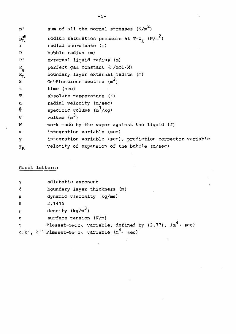
-5-
sum of all the normal stresses (N/rn2 )
2sodiumsaturation pressure at T=TL (N/rn )
radial coordinate (rn)
bubble radius (rn)
external liquid radius (rn)
perfect gas constant (J /rnol' J()
boundary layer external radius (rn)
Orifice cross section (rn2)
time (sec)
absolute ternperature (R)
radial velocity (rn/sec)
specific volurne (rn3/kg)
volurne (rn3 )
work made by the vapor against the liquid (J)
integration variable (sec)
integration variable (sec), prediction corrector variable
velocity of expansion of the bubble (rn/sec)
Greek letters:
y
0
~
TI
p
cr
T
1;,~',l;; , ,
adiabatic exponent
boundary layer thickness (rn)
dynarnic viscosity (kg/ms)
3.14153density (kg/rn )
surface tension (N/rn)4Plesset-Zwick variable, defined by (2.77), ,(rn • sec)
Plesset-~wick variable ~m4. sec)

-6-
Superscripts:
*time derivative (1,s)
saturated conditions .
specific quanti tli' (1/kgj
Subscripts:
c
co
crit
ev
i
in
I
L
lin
m
R
v
vI
o2
00
of cover gas
condensation
critical
evaporation
in the vapor source
introduced from the source to the bubble
of liquid
of liquid, at the interface
linearized
index
at radius r=R
of vapor
from vapor to liquid
initial
final
at infinity

-7~
List of Figures:
Fig. 1
Fig. 2
Fig. 3
Fig. 4 :
Fig. 5+14:
Fig.15';'24:
Fig. 25729:
Fig. 30734:
Schematic representation of the used model
Temperature distribution in the Theofanous approach
Integration of the Plesset-Zwick equation over the
last interval
Variation of the orifice cross-section
Comparisanof the results of the three calculations in
the first 270 ms.
Comparison of the results of the three calculations
in the first 3 ms.
Results of calculation with c=0.1 in the first 1.5 S.
Results of calculation with c=0.01 in the first 2.4 s.
List of Tables:
Table 1
Table 2
Table.3
Table 4
Table 5
Summary of the governing equations using the Plffiset
Zwick solution
Summary of the governing equations using the Theofanous
solution.
Initial conditions
Values of the parameters
Results of calculations


-9-
1. Introduction
1.1 Description of the proE~~
The dynamics of the expansion of large bubbles of hot sodium vapor
in a pool of relatively cold liquid sodiurr. plays an important
role in under$tanding the effects of an hypothetical core-disruptive
accident (HCDA) in Liquid Metal Fast Breeding Reactors (LMFBR-s).
As a result of fuel-coolant interaction in an HCDA, a large bubble
would be formed by the discharge of a mixture of hot sodium vapor,
liquid sodium, highly dispersed fuel and fission gases, from the
core region into the relatively cold liquid sodium pool placed
above the core.
An isentropic expansion of the bbbble down to the equilibrium
pressure, taking into account the compression of the cover gas
volume, wo,uld be a rather simple but too conservative estimate,
i. e .overestimate ., of the work performed by the bubble.
The work potential of the accident is much mitigated, if heat
transfer to the cold liquid pool, mainly due to condensation of
hot sodium vapor at the bubble surface, is taken into account.
On the other hand, this mitigating effect could be seriously
reduced by the presence of the noncondensable fission gases, which
tend to accumulate near the condensation surfaces, inhibiting the
heat transfer.
Other mechanisms , such as cold liquid sodium entrainment in the
bubble, the presence of relatively cold structures in the pool etc 1can influence the bubble expansion as weIl, generally, but not
always, in the sense of mitigating the work potential. They have
not been. considered in the present approach.
1.2 PreviOQs work
The literature on bubble dynamics that we have examined, can be
roughly divided into two major classes, the first dealing with
boiling and growth of small bubbles in superheated liquids, the
second with expansion and collapse at large bubbles surrounded by

-10-
relatively cold liquid, mainly for HCDA simulation.
To the first class belong classical papers like those of PIesset
and Zwick /1,11,12/,of Birkhoff and Margulies /15/,of Theofanous
and Fauske /3/, of Bornhorst and Hatsopoulos /13, 14/. More
recently,studies have been performed by Dalle Donne and Ferranti
/16/, Brook and Mills /5/ and Prosperetti and Plesset/17/.
To the second class belong the paper o~ Reynolds ar.d Kennedy/18/
who examined the condensation of a large sodium vapor bubble
obtained by adiabatic expansion of the products of a typical
HCDA, while it rises in the liquid sodium pool, assuming a constant
condensation heat transfer coefficient. The condensation process
was found to be governed by transient conduction in the liquid
and a significant fraction of the sodium vapor was concluded
to cqndense before the bubble reaches the pool surface. A subse
quent paper of Theofan:1US and Fauske /19/ once more analyzed
the condensation of a rising bubble, but taking into account the
effect of noncondensables and solving the problem of transient mass
diffusicn in the vapor space in conjunction with the transient
heat conduction and convection in the liquid phase. The presence
of noncondensables was found to seriously delay the condensation
process.
The paper by Özijik and Kress /20/ treats the problem of the con
densation of the rising bubble in a way similar to the previous
work /19/, i.e. including the effect of fission gases, but a
turbulent boundary layer is assumed, rather than transfer by mode
cu~ar diffusion in the vapor phase. The reason of this modification
is that a diffusion model may underestimate the condensation rates
if strong internal convection motionsare present.
Finally Reyn"olds and Berthoud /4/ have analyzed both theoretically
and experimentally the expansion and collapse of large two phase
(water vapor and liquid water) bubbles in a pool of cold liquid
water. The effect of noncondensables was not included.
An early instability of the bbbble surface was observed. During
this phase conduction-limited heat transfer is shown to be too
slow to account for the experimental results, while it describes

-11-
weIl the bubble expansion and collapse as soon as the bubble surface
becomes stable. The heat and masstransfer, in the absence of non
condensable gases, significanty mitigates the mechanical work.
1.3 Present model and assumptions
The present ~odel describes the expansion and collapse of a large
sodium vapor bubble in a finite pool of relatively cold liquid
sodium. During its growth the bubble is supplied with hot sodium
vapor coming from the core region. The core region is modelIed with
a superheated vapor source at constant pressure and temperature,
connected with the bubble through an orifice. The discharqe of hob
sodium'vapor through the orifice is governed by~he .pressure
difference between core region and bubble. The geometry of
the problemis spherical (see Fig. 1).
Thetemperature and the pressure of the'vapor in the bUbble are
considered to be uniform. The mass of liquid contained in the pool
is finite. The presence of the cover volume is also modelIed by
means of an external spherical gas shell which may be compressed
by the motion of the liquid.
The reactor tank is considered to be rigid and is modelIed by an
external rigid boundary.
The initial conditions are as folIows: the bubble has an initial
radius of 0.1 m., is filled with sodmum saturated vapor at atmos
pheric pressure, i.e. at about 1154K, and the sodium pool, containing
110 m3
of liquid, has an initial uniform temperature of BOOK.
The initial temperature at the interface is also BOOK. A 70 m3
cover
gas volume surrounds the liquid. The volumes and temperatures chosen
are typical of a 300 MW fast breeder reactor.
The hot sodium vapor in the core region has a constant pressure of
5 bar and a constant temperature of 1700K. The orifice connecting
the bubble with the source starts to open linearly at t=o and is
completely open after 1 msec. Orifice parameters are so chosen that
a maximum mass injection rate of 100 kg/sec of hot vapor from the
core is reached. Nonequilibrium betweerl the sodium vapor in the
bubble and the liquid at the interface is described by the model,
since the temperature of the vapor is different from the temperature
of the liquid at the wall.

-12-
The effect of noncondensable fission gases on the expansion
and collapse of the bubble is modelled by introducing con
densation and evaporation coefficients, a technique used
in many previous works /3,4,5/. A parametric study is made
varying the value of the coefficients according to experimental
data.•
The interphase heat transfer problem is solved together with
the heat conduction in the liquid and the liquid motion problem.
Two distinct models are presented, the difference beeing only
in the description of the heat conduction in the liquid.
The first model uses the Plesset-Zwick /1/ solution for the
heat diffusion across a spherical boundary with radial motion.
The second uses the Theofanous-Fauske /3/ technique of solving
the energy equation for the liq~id by postulatinga thin second order
thermal boundary layer in the liquid.
Only the results obtained by the first method are shown in the ~resent
report • Calculations were made also using th~ second approach.
The results of these are not presertted her~as they are in full
agreement with the prevtous ones.
The presence of liquid sodium, of fuel particles and fuel vapor
in the bubble, the entrainment of liquid drops from the pool, the
presence of cold structures and the instability of the bubble sur
face are neglected at the present stage of themodel ..Rising of the bubble in the pool is also neglected, since the ex-
pansion characteristic times are much smaller than the time re
quired to rise in the pool.
-13-
1.4 Diff~!ences between th~_present. model and the previous approaches
The main differences between the present model and the previous
approa.ches 'can be resurned as follows:
a) instead of considering a. constant-radius rising bubble, as in
/18, 19, 20/ we investigate the expansion phase of the bubble.
b) we simulate the flow of hot sodium vapor from the core during
the expansion~ instead of modelling a flashing water source
like in /4/.
2. ~rn~ng equa~ions using the Plesset-Zwick solution
2.1 Continuity ~9uation for the liguid
Let us consider an incofupressible fluid, for which:
(2.1)
The continuity equation in spherical coordinates and in presence
of a spherical symrnetry is then:
(2.2)

-14-
Expanding the derivative oregets:
(2. 3)
emd from (2.3):
(2.4) 'iJ~ (42~~) = ,2M- .
~~ A..(2.5) _=,_.att.& tt~
which will be used in the following sectiöns.
Eq, (2.2) can also be rewritten as:( 2 • 6 ) 'l.&M, = ~ 2 R ·i~~7) .M- = R2 R/~~.
2.2 Equation of motion for the liquid:
The equation of motion of a viscous, incompressible fluid
(Navier-Stokes' equation) /9/ in spherical coordinates and in
presence of a spherical symmetry is
(2.8)
where
.A--!-t
(2.9)
represents the sum of all the normal stresses, and is given by the
static pressure plus the n"orroal friction stresses.
From Eq. (2.4) one gets:
(2.10)
(It~ : ) - l.AL) d - == O.- - e
)LI. ~~ Je,
and from Eq. (2.5), (2.9) ..
'd Jt>' 9,. + .A1.f'"t,.u..
(2.11) - - - ---r .'()"L '3'"t. JE,.

-15-
Using Eq. {2.3}, (2.10), {2.11} , Eq. {2.8} becomes:
{2.12}
From Eq. {2.7} one gets then:
{2.13} (•• 2 • .2)RR +2R.R .
Substituting now Eq. (2. 7) , ( 2. 1 3) in (2. 12) one obtains the equat.ion
of metion of the liquid in the final form:
(2.14)A--~
__ e
This equation is now integrated with respect to the radial
coordinate r from the bubble radius R tO,a general radius r 2 .
With the assumption {2.1} and assuming that the viscosity of
the liquid is also constant:
(2.15)
the integration yü.üds:
{2.16}

-16-
The pressure PR of the liquid at the bubble boundary can be expressed
by:
(2.17)
Now we havp to distinguish between two different cases: in the first
case, considering the expansion of a vapor bubble in a very large
pool of liquid, as it can be in the case of bubble growth in super
heated liquid, we have to set:
(2.18)
and eq. t2 .16), using (2.17), reduces to:
(2.19)•• .3. 2. 4 rot.RR+2""R + ft.
•R.-R
In the second case, considering the expansion of a large vapor
bubble in a finite liquid pool, see Fig.(1):, we have to consider
the external radius R' of the liquid pool and to set P2 eq~al
to the pressure of the cover gas, i.e.:
(2~20)Je,! CI R·..f.t = -re .
For (2.1), the exterm.al liquid radius R' can be given as a function
of R by:
(2.21)
-17-
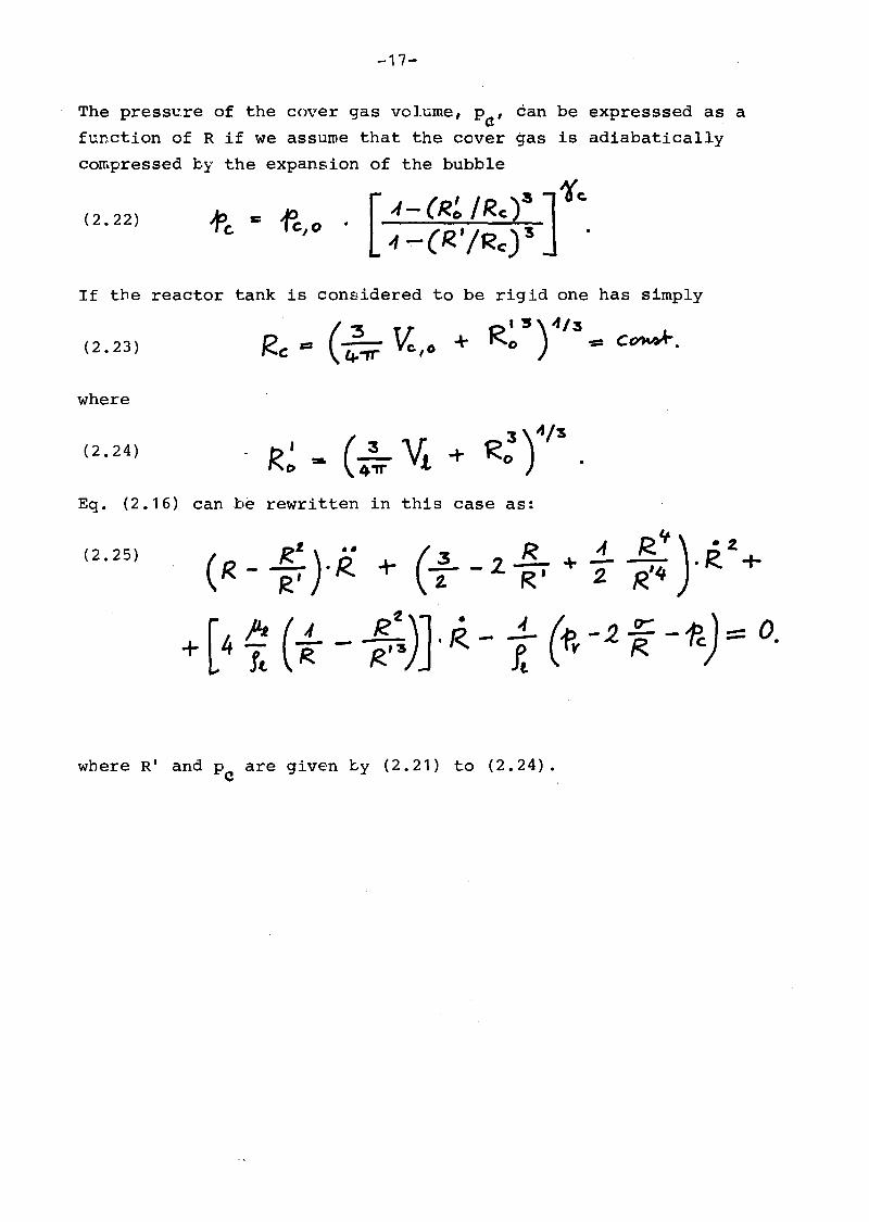
The presse,re of the cover gas volllme, Pa' can be expresssed as a
function of R if we assurne that the cover gas is adiabatically
compressed
(2.22)
by the expansion of the bubble
. [4-(R~ /Rc)$ J1c:.oft: '" fc,o " _ eR.'IRe) '5 •
(2.23)
If the reactor tank 1s considered to be rigid one has simply
D == (.2- ~ 0 + R: S)4/
3~ C~.
I'oC lf.-rr '
where
(2.24)
Eq. (2.16) can be rewritten in this case as:
(2.25)
where R' and Pe are given ~y (2.21) to (2.24).

-18-
2.3 ~sy equation for the liquid
The problem of the heat diffusion across a spherical boundary
witr. radial motion has been analytically solved in successive
approximc3.tions b'y Plesset and Zwick /1/ .The approximation
procedure converges rapidly, provided the temperature varia
tions are appreciable only in a thin layer adjacent to the
spterical boundary. Here the zero-order solution is used,
without higher-order ccr~ections.
The explici t solution for the liquid tempe·rature at the boundary
is given in the zero order as a functi.on of the temperature
at infinity and of the temperature gradient at the spherical
boundary: ~
(2.26) TL Ct) = T _ (~)-f/2.j ('~T/d'L) R • J. 'I11 I 00 -rr R2. (I'[' _ä-)-t/~ 0 ·
o
where
(2.27)
Substituting (2.27) into (2.26) one gets also:
t:(2.28)
T;. (t) Ta> _(~rt «1 ()() . (0 T /dlt-) R.- . clx-{lt:R"(~)' ~ fit
0

-19-
2.4 Equation of ma~ss transfer at the inteEface
The mass transport across a:-phase interface has been described
in previious work /2/. The relationships used here are:
(2.29)
where
=•.... MtL'I
relationships are similecr to those used in previous literature
4, 5/. The coefficients c , c represent the ratio ofco evactual mass transfer t~ the value deEived frcm the ~netic
(2.30)
(2.31)
The
/3.,the
-f'vYTv '
l (TL) .
ff:
theory. Here a parametric study is made where these coefficients
are varied between 1 and 0.01, a range which encompasses the
large scatter of experimental datafrom the literature /3/.
2.5 Equations of· eneEgy transfer at the interface
The net rate of heat transfer at the interface is given by:
(2.3~)
•E~t --
•Mev
• 1\*M~" · ~ LV·,
This expression is used only in the energy balance for the
vapor phase. The net rate of energy transmitted to the liquid
phase is given by
(2.33)• A A .. )Mev . (j,v - .e.L,t -
• 1\
Mt.V • ~.1v

-.20-
-
which is slightly different from (2.32), due to the fact that the
solution (2.26) given by Plesset and Zwick /1/ neglects the
variation of mass of the liquid.
The heat transfer equation at the phase boundary (2.33) is then
coupled with the heat diffusion solution in the liquid (2.26) ,(2.27)
by taking for the temperature gradient at the boundary:• I
E. \".t
KJ.,(2.34)
2.6 Vapor source description
The bubble is irnagined to be connected with a vapor source through
an orifice. The source contains sodium vapor at high pressure and
tempera~ure and 1s assumed to be so large that
(2.35).fi. = CD"H S t .
Ti ::= GO"I~t:.
,although: a finite quantity of vapor flows from the source into the
bubble. The critical pressure for the flow through the orifice is
defined by:
(2.36) •
where
(2.37)e"i,Cv/t
•
The mass flow rate through the orifice is regulated by the downstrearn
pressure, which is the pressure in the bubble. The maximum velocity
in the orifice is the critical velocity. If the pressure in the bubble
is
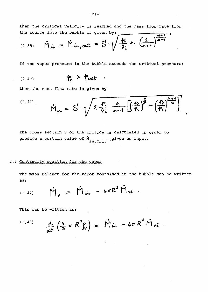
(2.38)
-21-
•M~(2.39)
then the critical velocity is reached and the mass flow rate from
the source into the bubble is given by: ------------~~~-,M+'"
~ (~~~)~
If the vapor pressure in the bubble exceeds the criticalpressure:
(2.40)
then the mass flow rate is given by
(2.41)
M~ ~ S·•
The cross section S of the orifice is calculated in order to
produce a certain value of M . ,given as input.ü'l,crit
2~7 continuity equation forthe vapor
The mass balance for the vapor contained in the bubble can be written
as:
(2.42)
•M~
This can be written as:
(2.43) •M~

-22-
R-:5Performing the derivative and rearranging:
• M~~ + Mvt - -41l"RZ =0.(2.44)
The derivative of the vapor density is now expressed by
(2.45)
Replacing (2.45) in (2.44) one gets finally:
(2.46)
where ~ is given by (2.29) to (2.31) and A is given byV1 'in
( 2 • 38) to (2. 41)
2.8 Bnergy equation for the vapor
The energy balance for the vapor contained in the bubble can be
written as:
(2.47)• . . ~ .
E~ - W- - 41fT? tvt. .
The work made by the vapor against the liquid is given by
(2.48)
while the energy introduced by the vapor coming from the source is
(2.49)•E~ ::;
• A
M~ · i..:.
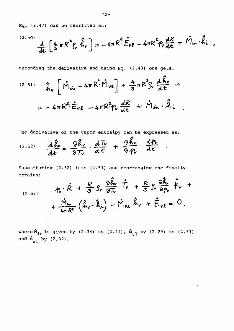
-23-
Eq. (2.47) can be rewritten as:
expanding thederivative and using Eq. (2.43) one gets:
(2.51)
The derivative of the vapor enthalpy can be expressed as:
'dt., '"" J,Tv '1.e.v . ,,{.~'"(2.52) tie.., .- + -
~t;== tA,.t: ?f>viM: '3Tv
substituting (2.52) into (2.51) and rearranging one finally
obtains:A ~ .
R 9f,v •R d~l" 1>• r; -t
"fv· R. + 3 fv ~7;. + -:3 Iv af'v v(2.53)
• ~ 1) · ~•
M~ (~v- ;., - M~.l.·~v + Ev.t == 0-+ •
4wR2.
whereMin is given by (2.38) to (2.41), Mvl by (2.29) to (2.31)
and Evl
by (2.32).

-24-
2.9 Final form of the differential equations
The problem of the bubble growth is completely described by the
following equations:
a) Equation of motion for the liquid, Eq. (2.25)
b) Continuityequation for the vapor, Eq. (2.46)
c) Energy equation for the vapor, Eq. (2.53)
d) Energy equation solution ,for the liquid, Eq. (2.28)
The first three equations form the system of differential equations
to be solved, simultaneously with the fourth expression which gives
the liquid temperature at the interface.
The first equation, Eq. (2.25) ,is of the second order, andcanbe
splitted into two equations of the first order. Let us define:
(2.54)
•~R == R
Eq. (2.25) becomes, using (2.54) and rearranging:
(2.55)
From Eq. (2.46), using(2.54), one gets
(2.56)R--.:3 •

-25-
Substituting (2.56) in Eq. (2.53), using (2.54) and rearranging
0ne gets finally:
(2.57)
where
• A:: -
B
(2.58)
dfv)'01V ..
Equations (2.54), (2.55), (2.57), (2.56) together with the solution
(~.26) of the energy equation of the liquid form the. system of five
differential equations in the five unknown functions R, Y~, ~, Pv'
TL' which has to be solved.
In Table 1 all the eqaations and the formulas necessary for the
solution of the problem are listed.
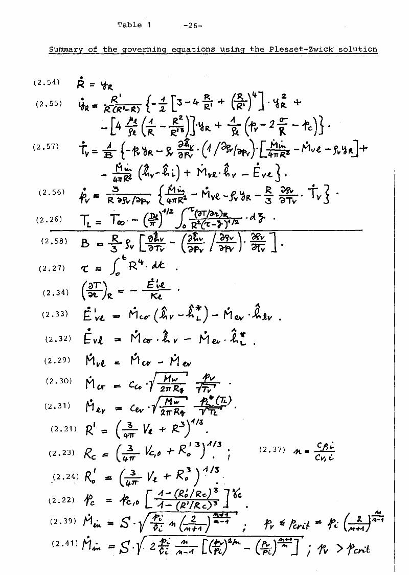
Table 1 -26-
Surmnary of the governing equations using the Plesset.... Zwick· solution
(2.57)
(2.26)
Cf,L..Jf\..-
Cv, i.(2.37)
(2.58) ß .. -f S'v n~ -(~~: /~). ~].(b Lt
(2.27) 'C = )0 R .~ .
(.E.) = _ E~ .( 2 • 34 ) ~ R. Kot
• I • ~ t"*") · 6( 2 • 3 3 ) E vt. =:r MCD'" ( AV - ~ L - M Q.v •~1v
• • 1 • "" ....(2.32) f vt = Mev· ~ V - M tN • ~ L. •
( 2 • 29) Mvt Co Mer - M(V
(2.30) MGI" ... Ce.. .( I2~R~' ~~• .~ fL·(1i.)
(2.31 ) M.e.v -== Cev·1~ -~ .
( 2 • 21) R' -::: (4-;' V.t + R...3).fI~ •
(3 ~ R ' 3) A13 .
( 2 • 23 ) Re := t:;:iT c, f) +-" .,
_(2. 24) R~ = (4-;' V.t + R.3
) -1 /~ .
[4- (RJ/Rc.)"& ]~
(2.22) ~ = .fe/o "":1- (R'IR.c.)3 .
(2. 39) M~ = S. -r.!:i.. '" / 2 ) f!f I. je)'».} =P. (~-f:;;V -"..: CA-.+-t ,./ v tCl"Lr "I L ;;;:;:;;]
•(2. 41 )M~ =S. 2. ,1!; M [lb)f./ttL ('")~J . M >Ä:' .1Ci. t1t-4 tri. - Pi I 'IV I c""'~

-27-
3. Governing equatio~s using the Theofanöus·~]:'oaCh.
3.1 Energy equation for the liquid
The equations of continuity for the liquid Eq. (2.2), of motion
for the liquid Eq. (2.19) or Eq. (2.25), of mass transfer at
the interface Eq. (2.29) to (2.31), of energy tr~nsfer at the
interface Eq. (2.32) and (2.33)., the continuity equation for the
vapor Eq. (2.46)and the energy equation for the vapor Eq. (2.531
remain unchanged.
Instead of using the approximate-solution of Plesset-Zwick Eq. (2.26)
the energy equation for the liquid is solved simultaneously with
the other equations, although with some simplifications /3/.
The energy equation for a fluid in spherical coordinates and in
presence of a spherical syrnrnetry is:
(3. 1 )
Let us assurne now that the temperature of the liquid is everywhere
constant and equal to T , except in a thermal boundary layer00
(3.2)
near the phase interface
(3.3)
If we now consider the integral of Eq. (3.1) over the boundary
layer, we obtain:

-28-
Instead of solving {3.3) directly, the following approximate
procedure is used: it is assumed that the temperature distribution
in the liquid can be approached by a second-order distribution of
the form
(3 .4)T (If.)::' a. IE.%...... b~ + C
TC?) ~ T(1O
.}
Now the coefficients, a,b,c, are determined using the following
boundary conditions (see Fig. 2)
(3.5)
T (RL) = TCD •
t~: )RL =0.
Substituting Eq. (3.4) in (3.5) we get:
TL - T ooa. = (RL. - R)t(3.6)
b = -2 (TL.- T00~ • RL .(RL - R)
(TL-Tao) 'Z.
T~ ...... . RL .C - (R
L_R)2--

-29-
Substitution of (3.6) in (3.4) and rearrangement gives:
(3. 7)
.I
~)' RL .
Using the temperature distribution Eq. (3.7) the various terms
appearing in Eq. (3.3) are calculated:
)(1. .t..)~T 'C}TIIO tRL-~ ~t 't) I-r- -r \ + 0 ( .... _T,\ (RL-R RL-It)R... ~(RL-~) (R ...-R)
(3 s;l- =- + -~''''- '.j "'" 'L "'.j 3 •. '1'>t :>t RL- R ~ (RL - R)
(3.9 )'OT-OlL
We consider for sirnplicity the case:
(3.11)
and substitute the expressions (3.8) to (3.10) in Eq. (3.3), using
also the continuity equation for the liquid in the form (2.6), and
get:
(3.12)

-3n-
Performing the integration and after some rearrangement one gets:
(3.13)(R..-K.) (R~+ 3Rl-R. +bR~)~ + (r..-T..)(3R~+Ij.R..R+3RZ)~L+
e+1[r;.-T...)(R~ +3RL R_j~'L) f '" (,OlHT..-rOD)(R:_R) .
At this point we perform achange of variable, intoducing the
boundary layer thickness:
(3.14)
and Eq. (3.13) becomes finally:
J(40//"+ [;Rl +[!jff +- (r..-Ta.)C20 RI'+,tSj ::- +(3.15)
+ (Ti.-To.)(o10R2+1o~1 +36) ji ., '0.D~ (TL.-r.) f .
3.2 Equation of energy transfer at the interface
In order to couple the heat diffusion problem in the liquid with
the interphase energy transfer, Eq. (2.34) is used as a boundary
condi,ticin for the energy equation for the llquid.
Substituting the postulated temperat~distribution Eq. (3.7) in
Eq. (2.34),using also Eq. (3.9) and (3.14) one has:
(3.16)-2,
Ti. - Tt10
t--

-31-
Now we differentiate Eq. (3.16) with respect to time assuming for
simplicity
(3.17)
and, using also Eq. (2.33), (2.30), (2.31) (3.11), we obtain:
(3.18)
3.3 Final form of the differential equations
The problem of the bubble growth is completely described by the
following equations:
a) Equation of the motion for the liquid, Eq. (2.25)
b) Continuity equation for the vapor, Eq. (2.46)
c) Energy equation for the vapor, Eq. (2.53)
d) Energy equation for the liquid, Eq. (3.15)
e) Equation of energy transfer at the interface, Eq. (3.18)
Equations a), b), c) are treated exactly the same way as in § 2.9
obtaining Equations (2.54), (2.55), (2.56), (2.57) and (2.58).
Then we use Eq. (3.15) and (2.54) to obtain:
(3.19)

-32-
•Substituting Eq. (3.19) in Eq. (3.18) and solving for ~ one gets
finally:
(3.20)
where
Equations (2-54), (2.55), (2.57), (2.56), (3.20), (3.19) formthe
system of six differential equations in the six unknown functions
R, YR
, Tv " Pv' 0, TL' which has to be solved. In Table 2 all
the equations and the fonnulae,necessary for the solution of the
problem are listed.
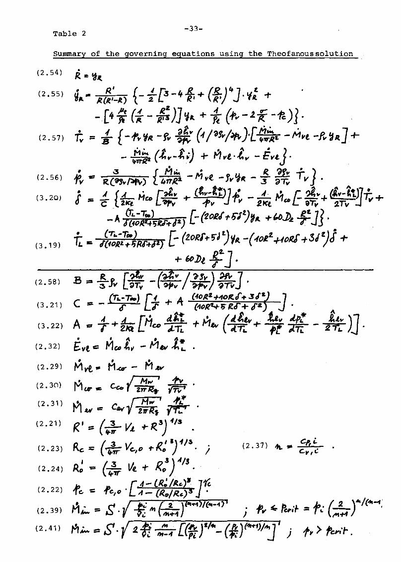
Table 2-33-
Summary of the governing equations using the Theofanouss61ution
(2.54)
(2.55)
(2.57)
(2.56)
(3.20)
(3.19)
(2.58 )
(3.21)
(3.22 )
(2.32)
(2.29)
(2.30)
(2.31)
(2.21)
(2.23)
(2.24)
(2.22)
(2.39)
(2.41)
l.t" )11- 2TL, ~.
(2.37) "", .. Cp,i.c." t:
-34-
4. Numerical solution of the differential equations obtained using
the Plesset-Zwick formulae
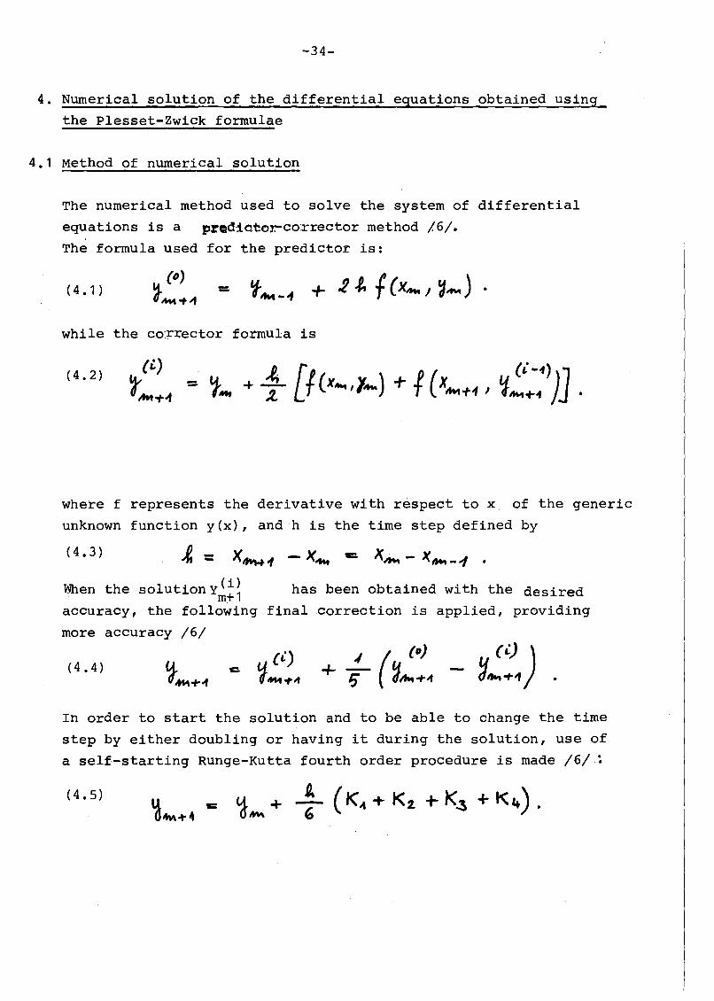
4.1 Method of numerical solution
The numerical method used to solve the system of differential
equations is a procUotor.-co:rrector method /6/.
The formula used for the predictor is:
(4. 1 )
while the co:rrector formula is
(4.2)
where f represents the derivative with respect to x. of the generic
unknown function y(x), andh is the time step defined by
(4.3) x~ - X. /IItIt -1 .
When the solutiOny(i)1 has been obtained with the desiredm+accuracy, the following final correction is applied, providing
more accuracy /6/
(4.4)./ ( (0)
+ Ii ~Iht+"
In order to start the solution and to be able to change the time
step by either doubling or having it during the solution, use of
a self-starting Runge-Kutta fourth order procedure is made /6/ ~
(4.5)

-35-
where
(4.6)
(4.7)
4.2 Use of the Plesset~Zwick formula
The plesset-Zwick formula (2.26) is solved iteratively at each
step of the numerical integration. An iterative solution is
necessary since the integral appearing at the right handside is
a function of TL(t). starting values for the ite~ative procedure
are calculated by second order or first order interpolation
formulae using values of TL at the preceding time steps.
A diffdculty arises in the numericalcalculation of the integral
appearing in (2.26h because the integral becomes infinite at the
right boundary of the domain of integration. An approximated solution
is öbtained by replacing the curve
F(7) = (tJT/t)'t.)R.tJ1f<2(,.)
by a second order curve fp,;) fitting the values. of F (1;) at the last
three points of the integration domain, t", ~' andr 'respectively
(see Fd.g. 3 )
(4.8)
where
(4.9)
C.J = '" [ F('r:)- F(~" _ Fei') - F{~b) 7or 'C - ~ 't:- ?" " -}" J'
C" ~ - ('Z'- ~'j c + F(";') - F(~") ., 'd 'iI" 1'-'}"
C3
'" - fL. c, - r CL -r F (~) .
-36-
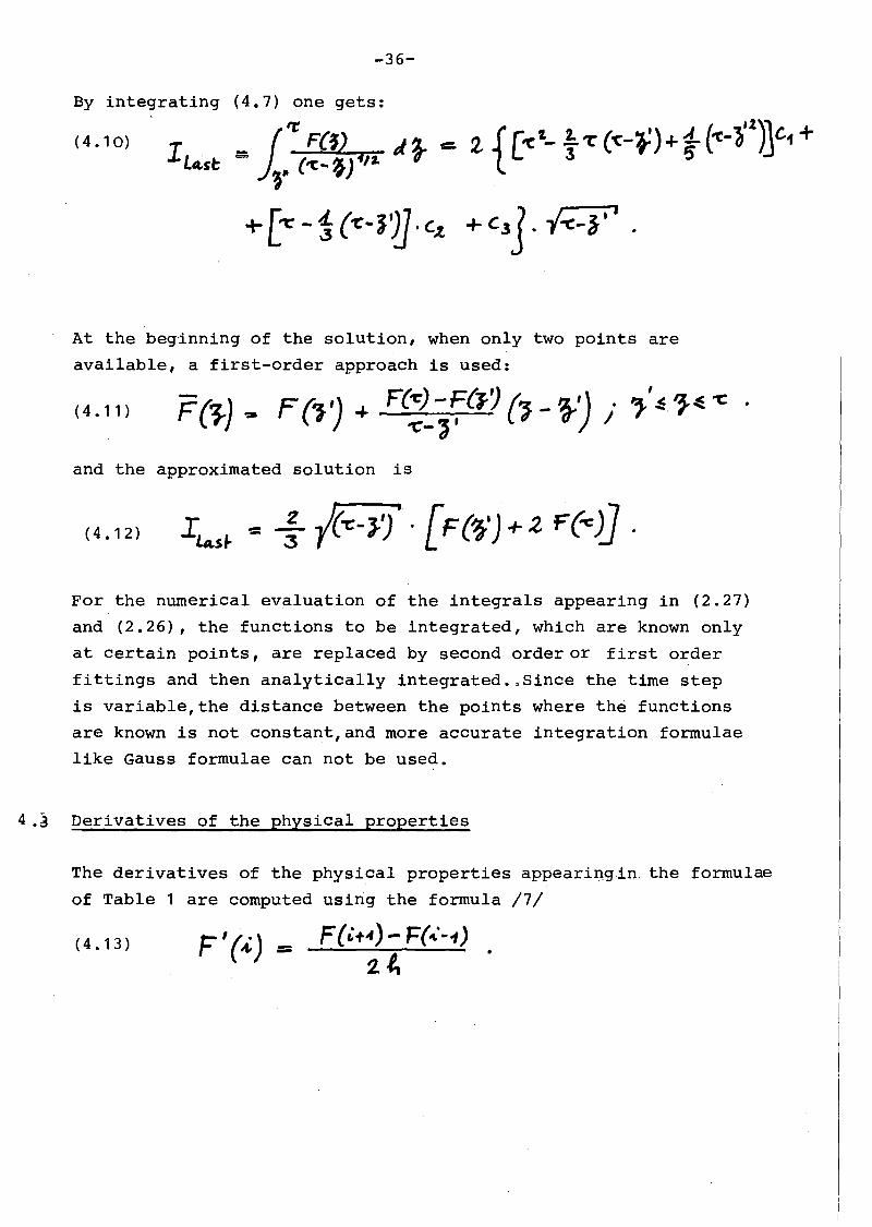
By integrating (4.7) one gets:
(4.10)IL4.S~
_ fit' F(~) J ~ t: 2 {['(;1._ fT (~-~)"'1- (-c-~'1)JC1 +e... )~" ('Ca, ,j"/2. T
+ [oe -1 (-r:- J?]. C.t + c3]. -{-C-f" .
At the beginning of the solution, when only two points are
available, a first-order approach is used:
(4.11)
and the approximated solution is
(4.12)
For the nurnerical evaluation of the integrals appearing in (2.27)
and (2.26), the functions to be integrated, which are known only
at certain points, are replaced by second order or first order
fittings and then analytically integrated.,Since the time step
is variable,the distance between the points where the functions
are known is not constant,and more accurate integration formulae
like Gauss formulae can not be used.
4.J Derivatives of the physical properties
The derivatives of the physical properties appeariDgin the formulae
of Table 1 are computed using the forrnula /7/
(4.13) F'{i) = F(i+if) - F(...··.,)2.~

-37-
4.4 Vapor source treatment
In order to improve the rapidity of convergence of the solution,
the equation (2.41) is replaced by the linearized formula
(4.14)
in the domain
(4.15)
where
(4.16)
•M~
The cross section S of the orifice is varied ac~ording to Fig. 4
and the value S is computed in order to give a certain chosen"max•Value M. 't of themass flow rate •.ln., crl
4.5 Initial cond~ti6ns and values of the parameters
We present solutions of the set of equations listed in Table 1,
obtained with the initial conditions listed in Table 3:
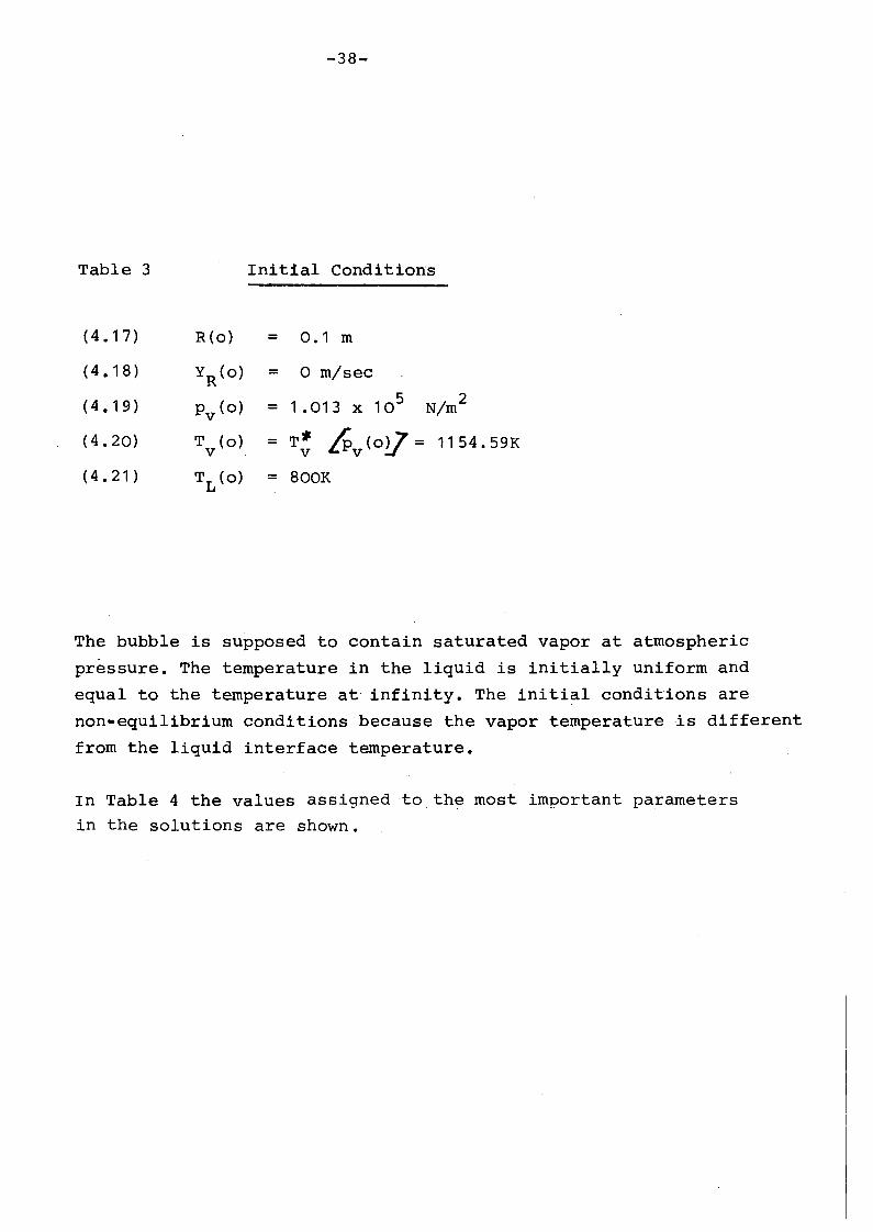
Table 3
-38-
Initial Conditions
(4.17) R(o) = 0.1 m
(4.18) YR
(0) = o rn/sec
(4.19) Pv (0)5
N/m2= 1 .013 x 10
(4.20) T (0) = T- 6 v (oV = 1154.59Kv - v
(4.21) TL(O) = 800K
The bubble is supposed to contain saturated vapor at atmospheric
pressure. The temperature in the liquid is initially uniform and
equal to the temperature at infinity. The initial conditions are
non-equilibrium conditions because the vapor temperature is different
from the liquid interface temperature.
In Table 4 the values assigned to the most important parameters
in the solutions are shown.

-39-
Table '4
Va lues of the parameters:
T. = 1700K1.
105 2Pi = 5. x N/m
R = 8314. -J!moi .K'g
MW
= 23. kg/mol-3,U l = 0.227 x 10 kg/m' sec
825.8 kg/m3Pl =
a = 0.154 N/m
cp,l = 1259.7 J/ kg.,K
Kl = 65.6 J/sec. m., K
Too = 800K- a
Poo = Pv,O 2 -Ro
v l = 110 m3
3v = 70 mc,o
Pc,o = Poo
Yc = 1 .667
The orifice connecting the bubble with the source starts to open
linearly at time t=O and is completely open after 1 msec. Orifice
parameters are so chosen that a maximum mass rate fram the core to
the bubble of 100 kg/sec of hot sodium vapor is reached.
To compute the physical properties of sodium such as enthalpies,
saturation pressure etc, use has been made of MAPLIB-routines
/8, 10/

for the cases ':
a) c = c = c = 0.1ev co
b) c = c = c = 0.01ev coc) c = C = c = 1 •ev co
The initial conditions
-4n-
5. Results
The results of three different solutions ofthe set of equations
obtained with the Plesset-Zwick approach (Table 1) are presented,
and the values of the other parameters were
exactly the same in the three cases presente~ and have been listed
in Table 3 and Table 4 respectively.
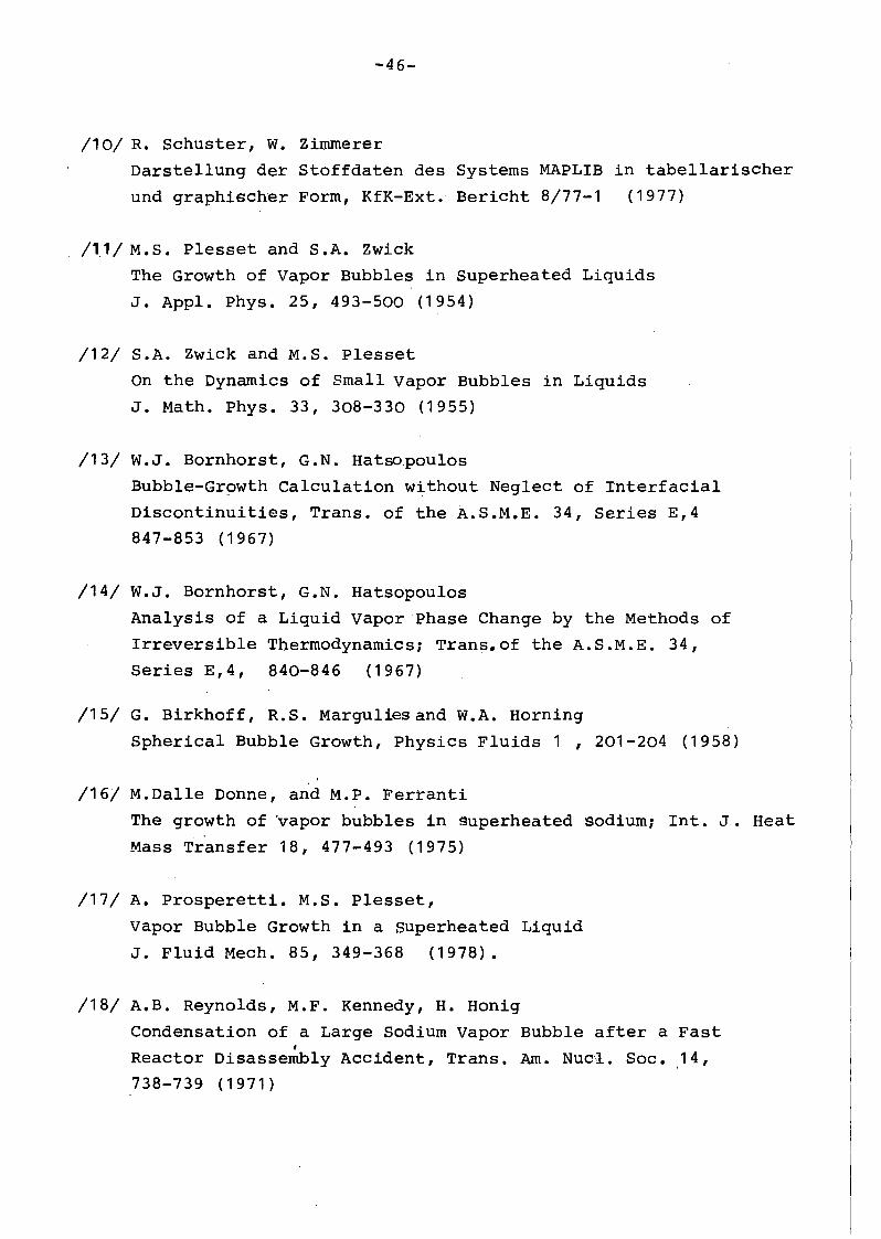
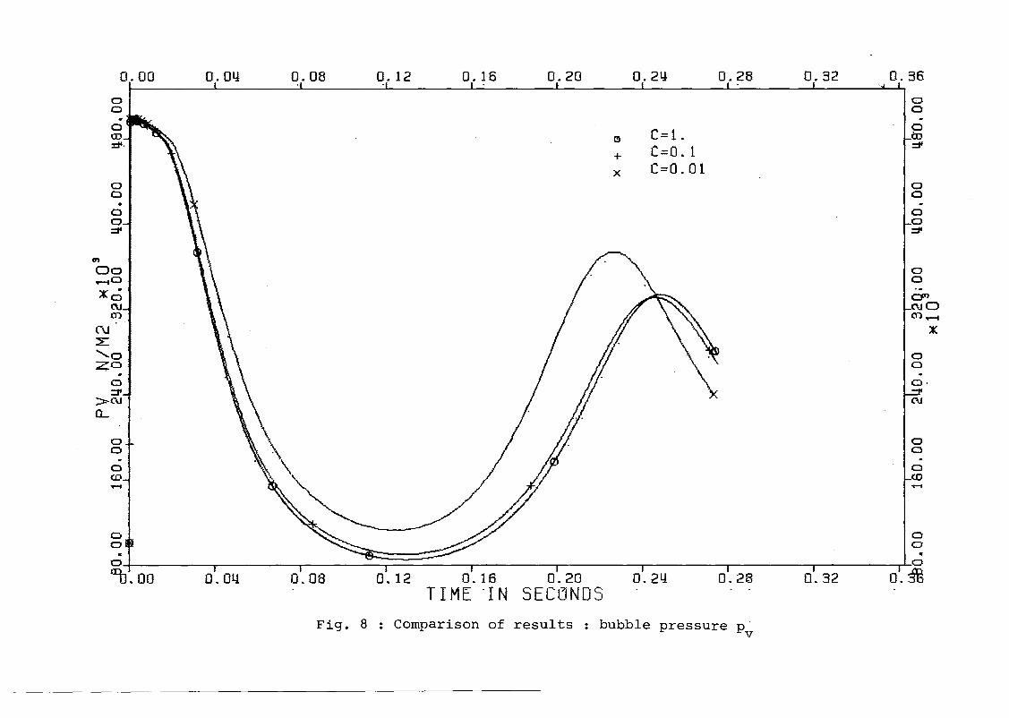
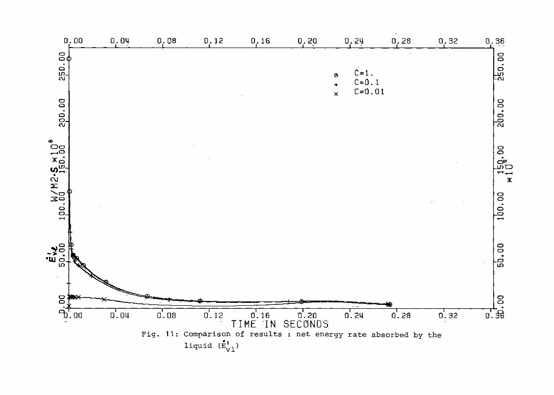
Figures 5 to14 show a comparison of the results of the three cases
in the first 270 msec.
A decrease in the value of the coefficients c,as it would be in
presence of noncondensable gases which tend to accumulate near the
bubble wall, cause~ a slight increase of the growth velocity and
a much greater increase of the vapor temperature, as expected. The
liquid interface temperature, on the other hand,is much decreased .
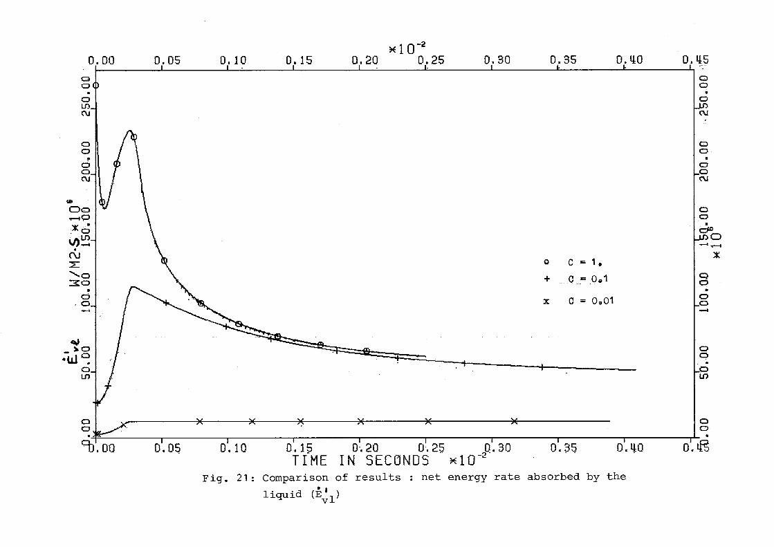
Figures 15 to 24 show the same curves in the initial region
(about 0 ~ 3 msec).
The calculations for cases a) and b) have been extended up to 1. 5scec
and 2.4 sec, respectively.
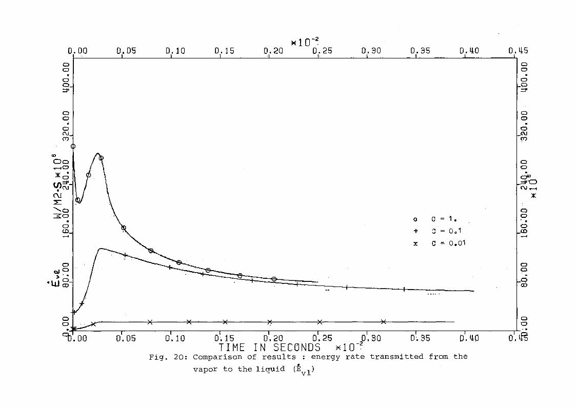
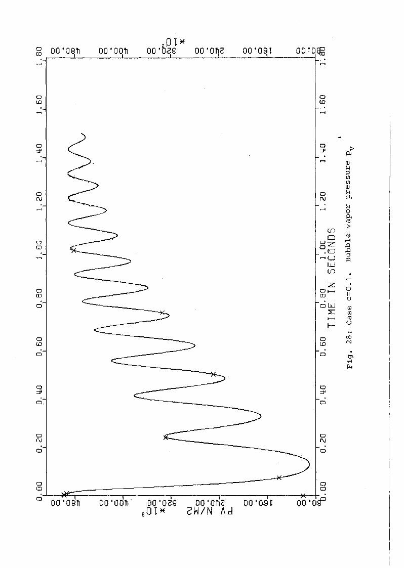
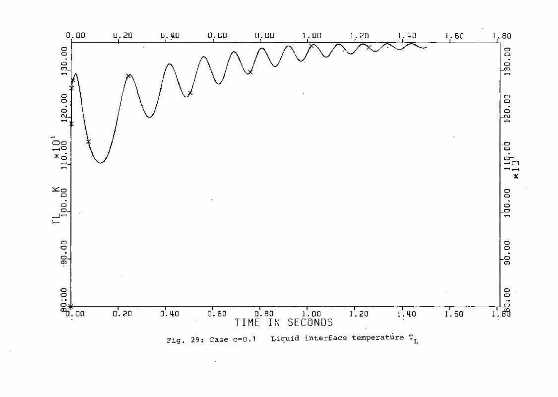
Figures 25 to 29 show' theresults for case a) and Figures 30 to 34
show the results for case b) .
Oscillations are mainly due to the presence of the cover gas volume.
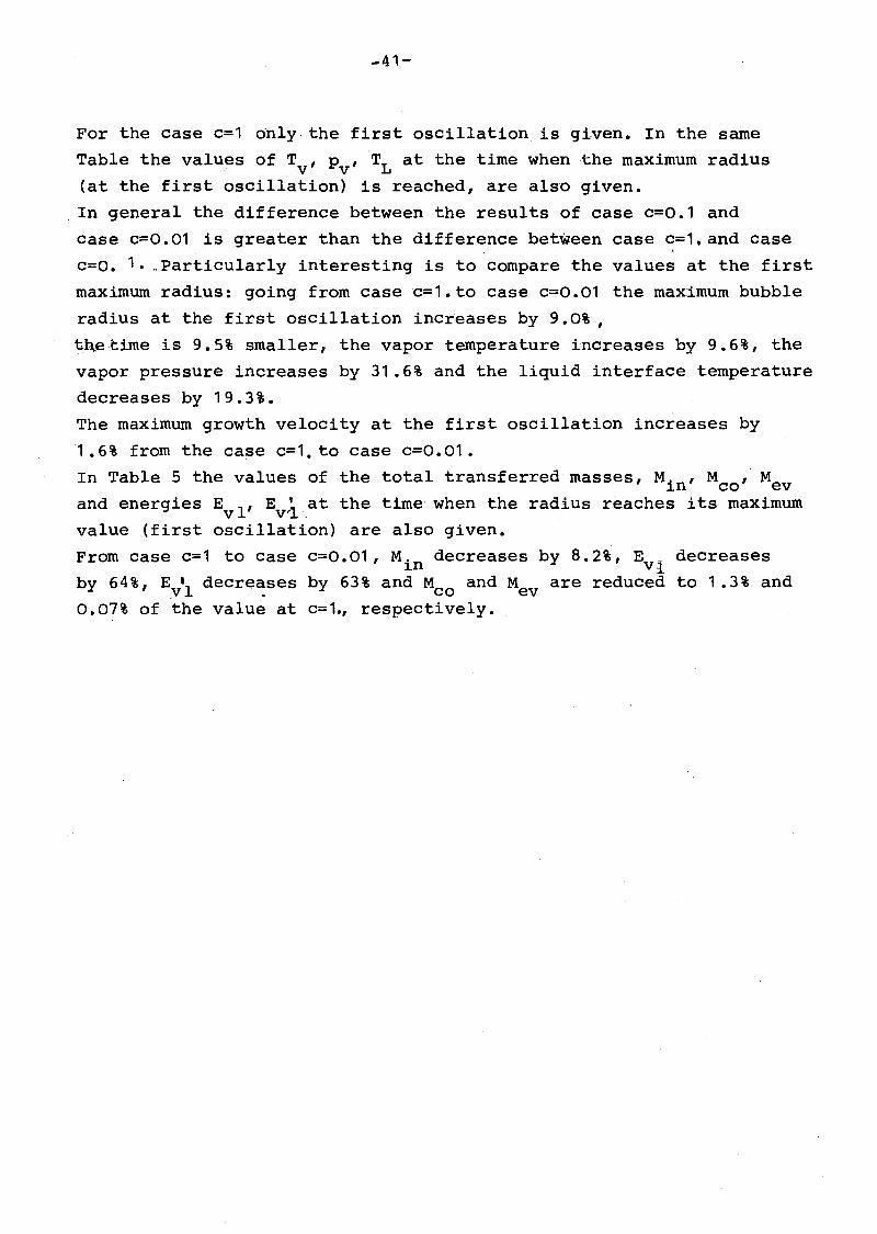
In Table 5 some results are listed for thethree cases presented. The
values of the maximum' radius, growth velocity, vapor temperature,
vapor pressure, liquid interface temperature and introduced mass flow
rate are given for the first threee oscillations of the bubble.
-41-
For the case c=1 onlythe first oscillation is given. In the same
Table the values of T , P ,TL at the time whenthe maximum radiusv v(at the first oscillation) is reached, are also given.
In general the difference between the results of case c=0.1 and
case c=0.01 is greater than the difference between case c=1.and case
c=o. 1. ,Particularly interesting is to comparethe values at the first
maximum radius: going from case c=1.to case c=0.01 the maximum bubble
radius at the first oscillation increases by 9.0%,
t.h..etime is 9.5% smaller, the vapor temperature increases by 9.6%, the
vapor pressure increases by 31.6% and the liquid interface temperature
decreases by 19.3~.
The maximum growth velocity at the first oscillation increases by
'1 .6% from the case c=1. to case c=0.01.
In Table 5 the values of the total transferredmasses, M'n' M ,Me1. co vand energies Ev1 ' Evri,at the time' when the radius reaches its maximum
value (first oscillation) are also given.
From case c=1 to Case c=0.01, M, decreases by 8.2%, E _ decreases1.n vlby 64%, E
Yldecre~ses by 63% and Mco and Mev are reduced to 1 .3% and
0.07% of the value at c=1., respectively.
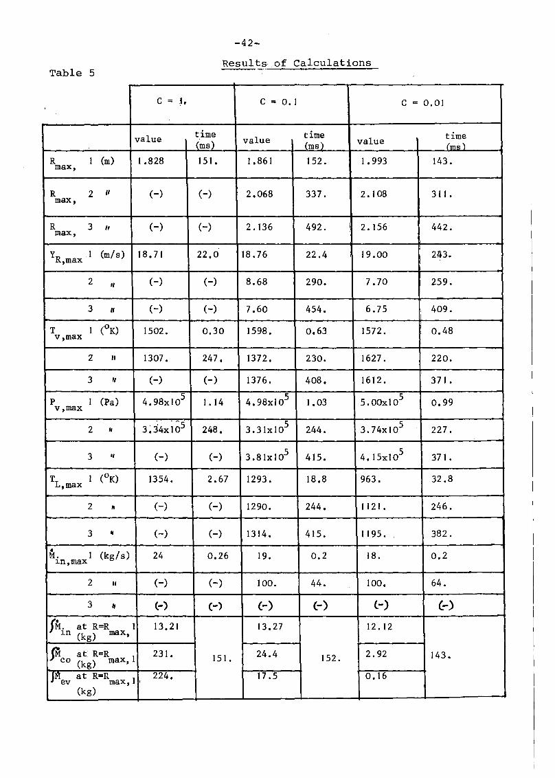
Table 5
-42-
Results.of Calculations
C = ~. C = 0.1 C = 0.01
value timevalue time time
(ms) (ms) value (ms)
R I (m) 1.828 151. 1.861 152. 1.993 143.max,
R 2 " (-) (-) 2.068 337. 2. 108 311.max,
R 3 11 (-) (-) 2.136 492. I 2. 156 442.max,
y I (m/s) 18.71 22.0 18.76 22.4 I 19.00 243.R,max
2 11 (-) (-) 8.68 290. 7.70 259.
3 " (-) (-) 7.60 454. 6.75 409.
T I (oK) 1502. 0.30 1598. 0.63 1572 • I 0.48;v,max
2 247.I
11 1307. 1372. 230. 1627. 220.
3 11 (-) (-) 1376. 408. 1612. 371.
P I (Pa) 5I. 14 5 1.03 5 0.994.98x10 4.98x10 5.00xlOv,max
2 3J4xlö5 248. 5 244. 5 227." 3.31x10 3.74x10
3 " (-) (-) 5 415. 5 371.3.81x10 4.15xlO
T I (oK) 1354. 2.67 1293. 18.8 963. 32.8L,max
2 " (-) (-) 1290. 244. 1121. 246.
3 ., (-) (-) 1314. 415. 1195 . 382.
• I (kg/s) 24M. 0.26 19. 0.2 18. 0.2~n,max
2 " (-) (-) 100. 44. 100. 64.
3 I, (-) (-) (-) (-) (-) (-)
{M. at R=R I 13.21 13.27 12.12~n (kg) max,
IM at R=R 231. 151. 24.4 152. 2.92 143.co (kg) max, I
I jr-11
at R=R . 224. 17.5 0.16ev max, I I
(kg)
continued (tab. 5)
-43-
fE lat R=R' 7 3::73x107 73.86 xlO 1.39x10
vI (J) max, I
J" R=R I 7 7 7Evi at 3.21x10 3.06x10 1.20xlO
(J)max,
T at R=R 1 1154.00 151. 1235. ' 152. 1265. 143,v (K) max,
5 ,5p at R=R 1 0.919x10 0.986x10 1.209x10
v max,(Pa) I
i
TL at R=R 1 1141. I 117. 920.max,i
(k)

-44-
Acknowledgement
The author wishes to thank Dr. M. Dalle Donne, who suggested
the work, for the advice and the helpful discussions.

-45-
References
/1/ M.S. Plesset, S.A. Zwick
A Nonsteady Heat Diffusion Problem with Spherical Symmetry,
Jo Appl. Phys. 23, 95-98 (1952)
/2/ R.W. Schrage
A Theoretical Study of Interphase Mass Transfer,
Columbia University Press, New York (1953)
/3/ To Theofanous,Lo Biasi, H.S. Isbin, H. Fauske
A Theoretical Study on Bubble Growth in,Cbnstant andTime
dependent Pressure F ields', Chem 0 Eng. Sci. 24 (3),
885-897 (1969)
/4/ AoB. Reynolds and G. Berthoud
Expansion and Collapse of Large Two-Phase Bubbles
99th ASME Wint. Anno Mtg o (1978) , Proceedings
/5/ A.J. Brook and DoS. Mills
NABUB: a non-saturated model of coolant boiling in a fast reactor
sub-assembly, TRG Report 2733(R), UKAEA (1975)
/6/ D.D. Mc Crakeil, W.S. Dorn
Numerical Methods and ,FORTR~N Programming
J.Wiley and Sons (1964).
/7/ J.M.MC. Cormick, M.G. Salvadori,
Numerical Methods in FORTRAN
Premtice Hall (1964)
/8/ U. Schumann
MAPLIB:Ein Programmsystem zur Bereitstellung von Stoffdaten für
Rechenprogramme : KfK-Bericht Nr. 1253 (1970)
/9/ S. Goldstein (ed)
Modern Developments in Fluid Dynamics , Vol 10 CIClJrendon Press,
Oxford (1952).
-46-
/10/ R. Schuster, W. Zimmerer
Darstellung der Stoffdaten des Systems MAPLIB in tabellarischer
und graphischer Form, KfK-Ext. Bericht 8/77-1 (1977)
/1.1/ M.S. Plesset and S.A. zwick
The Growth of Vapor Bubbles in Superheated Liquids
J. Appl. Phys. 25, 493-500 (1954)
/12/ S.A. Zwick and M.S. Plesset
On the Dynamics of Small Vapor Bubbles in Liquids
J. Math. Phys. 33, 308-330 (1955)
/13/ W. J. Bornhorst, G. N. HatSO.poulos
Bubble-Growth Calculation without Neglect of Interfacial
Discontinuities, Trans. of the A.S.M.E. 34, Series E,4
847-853 (1967)
/14/ W.J. Bornhorst, G.N. Hatsopoulos
Analysis of a Liquid vapor Phase Change by the Methods of
Irreversible Thermodynamics; Trans.of the A.S.M.E. 34,
Series E,4, 840-846 (1967)
/15/ G. Birkhoff, R.S. Marguliesand W.A. Horning
Spherical Bubble Growth, Physics Fluids 1 , 201-204 (1958)
/16/ M.Dalle Donne, and M.P. Ferranti
The growth of 'vapor bubbles in Superheated Sodium; Int. J. Heat
Mass Transfer 18, 477-493 (1975)
/17/ A. Prosperetti. M.S. Plesset,
Vapor Bubble Growth in a superheated Liquid
J. Fluid Mech. 85, 349-368 (1978).
/18/ A.B. Reynolds, M.F. Kennedy, H. Honig
Condensation of a Large SodiumVapor Bubble after a Fast,Reactor Disassembly Accident, Trans. Am. Nuc-l. Soc. 14,
738-739 (1971)

-47-
/19/ T.G. Theofanous, H.K. Fauske
The Effeet of Noncondensables on the Rate of Sodium Vapor
Condensation from a Single-Rising HCDA Bubble; Nuel. Teehn.19
132~139 (1973)
/20/ M.N. özi~ik, T.S. Kress,
Effeets of InternalCirculation veloeity and Noneondensable
Gas on Vapor Condensation from a Rising Bubble; Nuel. Sei. and
Engn. 66, 397-405 (1978)

rigid tank
cover gas
L--ProC~ liquid sodium
sodium vapor
orifice
Core region
Fig.1 :Schematic representation of
the used model
T
Tv 1---------........
o
Fig. 2: Temperature distribution in the
Theofanous approach
r

o
F
~CD
II
t
Fig.3: Integration of the PLesset-Zwick
equation over the last interval
S
Smax
o to t, t
Fig. 4:Variation of the orifice cross section

0.00
oo·(\J
oCD
.....
o(\J
::!:.....:
a:oco·o
o::r·o
oo
0.0l! 0.08 0.12 O. 16 0.20
Cl)
+x
0.2l!
C= 1.t=O·VC=~l
0.28 0.32 0.~6
oq
(\J
o(0
~
o(\J
~
oco.o
o=I'.o
oo
chI. 00 01.01! 0
1• 08 0
1• 12 0
1• 16 0
1.20 0
1• 21! 0!.28 0!.32 0
1.'~
TIME IN SECCJNDSFig. 5 Comparison of results : bubble radius R

0.320.280.240.20O. 160.12G,080.04 0.36I . , I , , ! I , I ".
0.00
ao
CI(3
CIo
CIo
·(\JI
·.lD......
·.(r)......
C=1C=O.lC=O.Ol
G
+x
oo·lD~
·r- I IfI I I I I I I I. I I I~
0.00 0.04 0.08 0.12 0.16 0.20 0~24 0.28 0.32 0.36TI ME IN SECIJNOS
·(r)~
oo
ao
ao
·(\J,
UO~ ,,\ ~~WO~Wm
"La:
>-~1 \ /1 / ~~
Fig. 6 Comparison of results : bubble growth velocity YR

0.00 0.04 0.08 O. 12 O. 16 0.20 0.24 0.28 0.32 0.36
0 0Cl 0
· " .Cl 0(D (D~ ......
0 0Cl 0· ·0 0
lJ)~ ......
..00 0....... 0 0
%0 ·c:r:::r 0...... "':'"' .......~
~OJ \~ ! ~ l;" 0
0(I")
>~
r-
0 00 0
· ·0 Cl(\J C\J...... ......
0 00 0
· ·0 Cl-< -<
'0.00 0.014 0.08 O. 12 O. 16 0.20 0.214 0.28 0.32 O.~TI ME" IN SECeJN05
P'ig. 7 : Comparison of results : bubble vapor temperature Tv
0.00
oo·o
ID:d'.
oo·o
o::jf
0')
00.-40
Xorutn
C\l::E""-0=40
·o::J'
>ruQ...
oo·o
(lJ......
oo
0.014 0.08 O. 12 0.16 0.20
(!)
+x
0.21.1
C=1.C=O.lC=O.Ol
0.28 0.32 0.36I . I :4 I
I00
·0,CD::jf
00
·0,0::jf
00..onruOtn~
X
00
·O·::I'ru
00
·0(lJ......
oo
-~ ~~ L-~ I I I I J I I l,.gu.OO 0.04 0.08 0.12 0.16 0.20 0.21.1 0.28 0.32 O.~b
T I ME .IN SECGNOS
Fig. 8 Cornparison of results : bubble pressure Pv

Clo•
,0Ci)
0.28 0.32 0.36II
00
·0(1").....
00
·0,(\J.....
00
·er""';0.....~
:«:
00
·Cl,0.....
0.21.!0.20O. 16O. 120.080.01.!
oo
·o/J) .
~oo
oo
·Cl(l")......
oo
·o(\J......
0.00
·Clo
-l~
I'-
00~a
:«:0~
......
oo
oo
~. L~~ j I I I I I j i j ..co
u.OO 0.04 0.08 0.12 0.16 0.20 0.21.! 0.28 0.32 O.~b
TIME IN SECCJNDS
Fig. 9 : comparison of results liauid interface temperature TL

0" 00
oo·o
o:::t'
oo·o
C\I(T)
CD
00..-1 0
XcV):it.C\I
(\J
L"-03:0
·oCD
'"""'
0.01.! 0.08 O. 12 0.16 0.20
(!)
+x
0.21.!
C= l.t=O.lC=O.Ol
0.28 0.32 0.36I I
I00
·00:::t'
00
·0C\I(T)
00·CJD
::1'0C\I~
X
00
·0CD
'"""'
~o.1.&.1 0
·oco
oo·.0co
~ ~ r~ 2'( ~. S I I S _I ( I ~ _ .' I ~ I I I ~~.DO D.OI.! 0.08 0.12 0.16 0.20 D.21.! 0.28 0.32 0.36
TIME IN SECClNDSFig. 10: Comparison of res,ults : energy rate transmitted from the
. .vapor to the li~uid (E
v1)
0.00
oo.oLn(\J
oo.oo(\J
Ul
00~O
;(0Ln
(1)......•
C\J:E'03::0
oo.....
O.Ol! 0.08 O. 12 O. 16 0.20
Cl
+x
0.2l!
C=l.C=O.lC=O.Ol
0.28 0.32 0.36- -.L,I ••
Iooo.Ln
-(\J
oo.o.0(\J
oo
c:JD·0
.....~
;(
ooo.0.....
o~O-> •
-tU 0U)
oo..0U)
~~ ~ lo~ ~,I e I , L ~ ,.. -, I I':
~.OO 0.04 0.08 0.12 0.16 0.20 0.24 0.28 0.32 0.36T I ME '1 N SECGNDS
Fig. 11: Comparison of results : net energy rate absorbed by the
liquid (E~l)

0.00 0.04 0.08 0.12 0.16 0.20 0.24 0.28 0.32 0.36
oo·o
o~
oo·o(0
oo..oo~
oo.o(0
~:~ 11 ~:~
z
.~:~ 11 ~:oo·oru
oo
0.04 0.08 0.12 0.16 0.20TIME IN SECCJNDS
0.24 0.28 0.32
oo.oru
oo
0.36
•Fig. 12: Comparison of results : introduced mass rate Hi:h
UJ oO'o'e(11
o
OO'OOe OO'OSt 00·' 00 t 00·05 00 'qgo
N01
o
N01
o
ro ro :>N N
Q)
· ·Ä0 0 Q)
4J...... co...... 0 lo-l
...... 00. Ul
::::J'. 11 11 11 ::::J' Ul
N UUU N co
· S0 0 'd
Q)€I + X 4J
co(f) lo-l
0 00 Oz PIN co
~o :>· Q)0 ou
W(f) Ul
4JZ M
UJ (0 ....... ;jUl,..., ...... Q)· lo-l
0 oW::E: 4--l....... 0
~ l=:0
r\l N Ul.r-i,..., ,...,lo-l· co
0 0 c..5u
ro ro C"1
0 0 ....· .
0 0 b'l.r-ir...
::::J' ::::J'0 0
·0 0
o 0o 0o...l-~!::=oe------....----......----.....,.-----r---_---.::I~"
OU'OSe DO'OOe oO'OSt oO'OOt oo·os2WS/~~3W•

oo·.0(D
oo.o(D
0.00 0.01.1 0.08 O. 12 O. 16 0.20 0.21.1 0.28 0.32 0.36I I
;j (!) C=1. l;+ C=O.lx C=O.Ol
0 00 0. ·0 0ru ru(T') m
0 00 0
(\J • ·LO Cl
(f)~ oC\JC\J 0
"-t:)
GOJ \ ~ ~;.~~
~ie 0:::;::::-. I I ~: L~Q..; ( i i I I I I I '...0.
o U. 00 0.04 0.08 0.12 0.113 0.20 0.21.1 0.28 0'.32 O• .:mT I ME IN SECCjNOS
•Fig. 14: Comparison of results : condensed mass rate Hco

0.00 0.05 0.10 0.15* 10-2
0.20 0.25 0.30 0.35 O. l.W 0.1.l5
(0(T)
......
(0(T)
•......
=t'0
0 C = 1. I"':+ C = 0.1
x C = 0 0 01I
(0
aJ..0.15 Q.20 0".25 0".30 0.35 0".1.l0 0". tf5TIME IN SECCJNDS * 10-2
0.100.05
(0(1)
::a' ."e......
I• I I J I i I I I
9r.00 I ,
3~ / ~~-I0..--l
.~~~ / ~~.0...... ..--l
:f
~3J l3a::
Fig. 15: Comparison of results : bubble radius R

0.00 0.05 0.10 0.15* 10-2
0.20 0.25 0.30 0.35 0.1l0 0.1l5
81 18~~ ~~
~~ l~
ua~~ ~~WO
(f)-,co:E
0::
>-~~ ~ ~~
§I __~ - ~ I§~-,e I~ -_.. .- - " v - I. r-~
+ C = 0 0 1
x C = 0001
81 18
=rOI• OO 0
1.05 0
1• 10 0
1• 15 0',20 0
1• 25 O~, 30 0
1• 35 0
1, 110 0'.' ~5
TIMEIN 5EC{J NOS . ~ 10 -~ . . .
Fig. 16: Comparison of results bubble growth velocitv y- R

~ 10-2
0.00 0.05 0.10 0.15 0.20 0.25 0.30 0.35 0.4:0 0.l!50 0CJ CJ. ·CJ CJC1;J C1;J.... ....
0 0CJ CJ. ·CJ CJlJ") lJ").... - --'
..Da Cl~CJ CJ)K .• •
CJ er::j' ::j'0.... --'~
)K
~:j I l~> ....I-
;JI l;0 c = t.
~I+ C = 001
l~x C = 0001
I I I I I II I I~-0.,00 0.05 0.10 O. 15 0.20 0.25 0.30 0.35 0.4:0 Q.TIME IN SEC(jNOS * 10-2
Fig. 17: Cornparison of results : bubble vapor ternperature Tv

oo.o0_:::::fl
lI'J
00~o
~o.. C\J_
(T)
(\J
L......... 020..
o:::t'_
>ru0:..
I>
0.35I .
O.Y:OI
oo·o
~co:::::fl
Clo·o
f-o:::::fl
oo
•cF~C\JO
(I") ..-f
~
oo
!'
~ru
+ C = 0 0 1
x C = 0.01
oq
•o(0_......
~ o c = 1 0
oq·.0
~(O......
ooo01).00
J(l.(l~
I
0.10I0.1~
TIMEI I I
0.20 0.25 0.30IN SECONDS ~ 10-2
.
I0.3!;i
IQ. 4:1J
CIo
oI ,.p;:l.
0.4:~
Fig. 18: Comparison of results : bubble pressure Pv

0.00 0.05 0.10 0.15* 10-2
0.20 0.25 0.30 0.35 0.l!0 O. l!_5
oCl
oCl
oo
Clo- ,~O..... .--t
::t:
bo-.o,0~
·,0(7)
·o,(0.....
·o,N.....
O.l!O
o 0==1.
x 0 == 0.01
+ 0 == Og 1
D.35
I ..
..... ~'J ,.,
0.15 0~20 0.25 0~30
TtME IN 5ECGNDS MI0~
)( ""*
D.Q5 0.101""""- i i I I i i .0, ( 0'. tP5
g I ~ e ~ ~ 6 ., ~ . .'<1 .. ! I I r 1°
1
~
·o(0.....
·om
oo
·oru.....
oo
oo
~oo'.oo
-J .....r-
00:"""'0):.
o..........
Fig. 19: Cornparison of results : liquid interface ternperature TL
0.00oo.oo:3'
oo
,;
oru(T)
0.05 0.10 0.15xl O-~
0.20 0.25 0.30 0.35 O.I.lO 0.1.l5oo·oo::r
o<:)
·oC\I~
U)
00.....-10
)I(~U)::j'.('\J
(\J
::E""'-03:0.
o(0......
oQ,lo:) ..
·W ~
oo
0.05 0.10
Fig. 20:
0 C = 1.
+ C = 0 0 1
x C = 0.01
0~15 0.20 0~25 0.30 0~35 D.110TIMEIN SEC 0NOS ~ 10 -~ .
Comparison of results : energy rate transmitted from the•vapor to the liquid (Evl )
oo·c:JD::j''O('\J .....-I
)I(
Clo·o(0......
oo·q
co
oo
O".Iß
oo
oo·,0
Ln
0.4:0o.~~
0.30 0.35 0.4:0 0.4:5I ~ ~ I .~-
I00
•0lJ)(\J
00·0,0(\J
00
•i:::JDlJ)0-...-I
C ::; 1 e Ig::t:
0
+ C ::: Og1•
x C ::; 0001 10,0-
* 10-2
0.20 0.25O. 15
0.15 O~20 0~25 0.30TfME IN SECDNDS - Kl0~·
0.10
0.10
o.o~
0.05
r , J I I I I I l-I 0'. tß
~
oo
oo
·oLn(\J
·oo
oo
0.00
•oo(\J
ce00...-10X·~ 0. "Ln\/}-.(\j
L'-0~O
Cll,J_~O
euJ c:oLn
Fig. 21: Comparison of results : net energy rate absorbed by the
liquid (E~l)

0.00
CJo·U1_
ru .
CJo·0_~
~
p
0.051
0.10I .
0.15·1
* 10-2
0.20' 0.25I· I·
0.30·1
0.35I
0.1.1:0I
CJ-9.
f-U1ru
oo.
...0ru
0
~~(f)o'- .C)U1
C = 1 0
........0
~
Z+ C = 00 1
~~~CJ
C = 0001·~9
x·0......
~~J .~ ~~:r=oe 1-
E9 I
f
e
:,: @) I
~1......
"= l~: :')(
I I I I I Itß9).00 0.05 0.10 Q.15 0.20 0.25 0.30 0.35 Q.I.I:O 0'.TIME IN SECllNDS * 10-2
Fig. 22: Comparison of results•
introduced mass rate M.lD

0.00
oo·oLn_(\J
oo·°0_(\J
o(\Je:::E O(f)U), ......l:)
~WO
.::L G·°0_......
(
0.05I
0.10I
""-
0.15I
-e
* 1O-~0.20 0.25
I I
-0.30
I0.35
I
o C==1 0
+ C==001
x C == 0 0 01
0.4:0·1
0.4:5I
oo·CI
~Ln(\J
od·C)
1-0(\J
oCl·Cl
~IJ)......
oo·Cl~o......
~~ l .~
0.Jt I I I I I lO° I.0ä.: 1 )(. =7 )( 1)( I )( ~ r: 1)( I I I •u.oO 0.05 0.10 0.15 0.20 0.25 0.30 0.35 0.4:0 O.f5
TIMEIN SEC Cl NOS * 10 -2 .
•Fig. 23: Cornparison of results : evaporated rnass rate Mev

0.00 0.05 0.10 0.15* 10-2
0.20 . 0.25 0.30 0.35 0.4:0 0.4:5oo·oo::::f'
oo·o,0::::f'
oo·o(\J(I")
oo·Cl,ru(I")
o(\j~::E0(J)~,(\J
l:)
~UO
.:L0·oCD....
o C = 1.
+ C = 0" 1
x C = 0.01
oq·o.::t'(\J
oCl
•o,CD......
ClCI
- .o.ßO.tto0.35..,0.30
~ 10-'"0.20 0.25
IN SEC(JNDSO.l!:?TIME
0.100.05
oo
~f ~
Fig. 24: Comparisop of results•
condensed mass rate Mco

oCO 00 'i::: 09' t Oi::: ' t 08'0 Ofl'O 00 'eg
..... '
otel'
otel
.....
0 0=I' ~
..... .....
J):;
Ul
0 0 ~•.-1
f\J ('\J 'D..... ..... cU
~
Q)r-i
(f) ..00 ..0
0 Oz ~
0 o 'S)o:l
• r-..... ..... I:...JW .-(D
.011
Z u0 o~ Q)co co Ul. · cU0 oW ux:
~
I-Lf)
N
0 o· tJ'ltel tel •.-1. · rz..0 0·
o
o('\J
o
o=1"
Cl
o('\J
·o
gl----r-----~-.--=======:====~:::::==~~(_lgo 00 •i::: 09 • t OZ ' t 09" 0 On •0 00 'cf
W 8

0.00 0.20 0.4:0 0.60 0.80 1. 00 1. 20 1. 4:0 1.60 1.S0
Clo
Clo
·(\J
I
Clo
oo
·(1')
·co
oCl
oo
·(D~
·,(T)~~
·(D~
·(T)
Clo
Clo·(\J
I . -
~-1 ~I V. V I V I I I I I ,l~b·0.00 0~20 0.4:0 0.60 0.80 1.00 1.20 1.4:0 ].60 1.8
TIME IN SECDNDS
L'oWOUleÖ"-L
~~t \ 1\ 1\ 1\ I\n
Fig. 26: Case c=O.1 Bubble growth velocity YR

0.00 0.20 0.4:0 0.60 0.80 1. 00 1. 20 1. 4:0 1. 60 1. 80
0 00 0
· ·0 0CD CD....... ......
0 00 0
· ·0 0Lf)...... ......
~
~s00...-l0
:t:: o=t'......
)K
:~J \ f\ /\ 1\ 1\ 1\ I~/VVV~ l;I \j Vr-
V V V0 00 0
· ·0 0(\J (\J....... ......
0 00 0
· ·0 0..... -lJ.OO D.20 0.4:0 0.60 0.80 1. 00 1. 20 1. 4:0 1. 60 1.BO
TIME IN SECGNDS
Fig. 27: Case c=O.1 Bubble vapor temperature Tv
o Do'oeno.:J
CI!JJ
OO'OOn,,0 I ~
oo't~s OO'O~2 OO'09t 00 ~ ot§.....
......
0 0~:;jl :;jl
0<T'""'i ...... Q)
lo-4;:jUlUlQ)
0 0 lo-4(\J (\J 0<
...... ...... lo-400<cu~
CD0 Q)
CI Oz rl..0Cl
~D ..0;:j...... ..... u~
WCD
.....Z .
CI o I-t 0o.:J o:::l 11. · 0
Cl ClW Q)~ UlI-t cuI- u
CI 0 co!JJ l.D N
a a .0'
•..-1
Ji.l
, ,
CI ------ 0:;jl :;jl
·Cl, 0
CI(\.1.Cl
CICl
o(\J
·Cl
oa
'~--:~..,.-----.----------,.----~------.------4~+ .Cl oo'oell OO'OOn' oo'o~s oo'o~z OO'O.9t oo·o€p
&;0 I ~ cW/N I\d
0.00 0.20I !
00
·0(T)~
00
·0(\J~
..00,....,0
;(ö.....~
:::Co0
·00
-J~
I-
00·0Cf)
0.1.10 0.60 0.80 1. 00 1. 20 1. 1.10 1. 60 1. 80"/
I00
·Cl(T)~
00
·0·01~
·00
·er..... 0-,....,
::t:
00
·00-oo·.0Cf)
oo
oo
~i L~(0..; I I I I I I I I '..co.
u. 00 O. 20 O. 1.10 O. 60 O. 80 1 . 00 1 ". 20 1 . 4:0 1 . 60 1 . öU
TIME IN SECClNOSFig. 29: Case c=O.1 Liquid interface temperature TL

CI(D
CIC'\J.i(')
CIIX)
C'\J
00'( 09 ' ~ 08'0 0'11'0 OO'~
,0C\J
·cn
'='co
er.CI '=' (j)::t' A< ::::t'
~! •..-1
C'\J i r·J 'Cl
! cuH
Irf) Q)
i 0 ...-lCI '='z ..0
..0D Dio ~
C'\J l N C..) ~
i I.JJ
f (/1 ..-0.
) Z. 0CI 01--1 11(D
~!.D U
· Q).-. ,.....l.JJ(j)
:E cuI-NI U1- ..
? 0CI '=' C"'1
C'\J ? N .Öl.-. ;? ,.....
•..-1
~
<CI C' 0IX) ? ro
·CI
2CI
CI ~ 0::t' c:::__ ::::t'
·CI
~CI
CI ~ 0-----Cl _._-- Cl
·Cl I I I00 ,tfl00'( 09 ' ~ Oe • ~ 08'0' 0'11'0
~~ lj

CIuJ OO·Et OO'S OO'E
I.:JrJ
11")
orum
r.J
CIo.r\J
0llJ
rufl::
:>i
:>i+J
0 •..-1~ 0, 0l"'J r-l
Q)
~
Cf) Q)r-l
0 ,.Q0 ,.QoZ
~.0 ll:ll"\J C_)
W(f)
.--0,
z· 011o t--I 0l.O. Q)..... w Ul
::e::: !'Cl...--t U
I-.--
0('I")
ru ,tJ'l..... •..-1~
CJ
I:J::1'
.,..,----.----..c:::::-,._--.--_.~
._.-._-----._-~+-
ollJ
o
o~
o
(jC)
~---*---'I-----+
OO'S 00"2- OO"L-o
8.-\
IOO'S]::!S/W
)(
oc:::::::::::............~_~-..._. ."..~--"'~'----"--'
__-t---------J-o--..-::::;::;..----~-~~-'--- ...------.-
~=--iOO·SL OO'Et
I.:Joo

0.00 O.I!O 0.80 1. 20 1. 60 2.00 2.1!0 2.80 3.20 3.60
;~0CI
I·CI
CD......
I
;i I f ~ A •
0CI
·CI
......
;:~\ I \jV ~ VVVV'JV
~O...... T""'"t
:t::
:;J \I l;...-
0 V 0CI CI. ·CI Cl("<.1 (\j
...... .......
0 0CI CI. ·0 CI...... ......'0.00 O.I!O 0.80 1. 20 1. 60 2.00 2. LW 2.80 3.20 3.50
TIME IN SECONDSFig. 32: Case c=O.01. Bubble vapor temperature Tv

GS OO'08tJ OO'OOtJ~O 1~
oo~bc€ OO'OnZ 00'09t OO·O.~
01 ·in
Clf\l
·rn
oN
·m
Cl 0OJ CO
· ·r\l ("\.1 :>~"l.
Q).l-l;j
q 0 lJ)
::t' ::t' lJ)Q)· · l-lru· N P.;
l-l0
(f) ~
0 cUCl Oz :>0
~EJ Q)·roJ Ne) r-I..0
W ..0Cf) ;j
~
zCl o I-l
..--tD (Cl 0
•· 0,..... .-.W11
~ u.......1-- Q)
lJ)
cUCl CI Uf\l N
...... .-. MC'l.t:Tl
•..-l~
Cl0:1
o
Cl::.t'
·o
------~-----::::::> .re:=:
-------_..->ce
oco·o
o::t'
·o
CIo·
00· oEP
~~-------_.--
Clo...L-~::;::::::===:===;::::======;::.=--~--_r-
o 00' 08tJ 00.' odtJ 00 •O~€ 00 'Ohe 00' 09 t€Ol~ 2W/N Ad

~~)( )( )(
::t::
oo
oo
oo
oo
oo
·om
·oru......
~
o(TJ......
·o.0......
-~O......~
.3.603.202.802.4:02.001. 601. 200.800.00 0.4:0I I
00
·0(TJ......
00
·0ru......
...Po..-1 0
~ä..........
~o0
·00
-.J ......~
00
·0m
01 100 1 '0
~I L~~3fC I ( I I I I I I I ~
u.OO 0.4:0 0.80 1~20 1.60 2.00 2.4:0 2.80 3.20 3.bUTIME IN SECONDS
Fig. 34: Case c=O.01. Liquid interface temperature TL