Austrian Infantry Rifled Musket - ACWSAacwsa.org/Documents/LorenzManualTranslation.pdf ·...
72
The Imperial Royal Austrian Infantry – Rifled Musket Standard Operating Procedures for Officers Vienna, 1857
Transcript of Austrian Infantry Rifled Musket - ACWSAacwsa.org/Documents/LorenzManualTranslation.pdf ·...

The Imperial Royal
Austrian
Infantry – Rifled
Musket
Standard Operating Procedures
for Officers
Vienna, 1857

Translators Forward: This is a translation of “Das kaiserlich ˶ königliche österreichische Infanterie –
Feuergewehr. Auf die hohen Vorschriften basirt und zum Gebrauche für den Officeier”,
or in English: “The Imperial Royal Austrian Infantry - Rifled Musket Standard Operating
Procedures for Officers” for the Model 1854 Lorenz rifled musket.
Both my American Civil War Shooting Assn. (ACWSA) team and reenacting
group portray the 2nd Wisconsin Volunteer Infantry, who used these rifled muskets
during the Civil War. I jumped at the chance to buy the first one I ever saw offered, but
have been frustrated that I couldn’t find a lot of documentation in English about them.
When S & S Firearms (www.ssfirearms.com) started offering reprinted copies of
this manual in its original tongue, I immediately purchased a copy, but only translated a
few passages of it until recently.
Translating this book was challenging. It’s written in an Austrian dialect of
German, using an obsolete script called Fraktur. With no Optical Character Recognition
software for Fraktur available, the books entire contents was retyped into modern script,
then translated from German into English using Google Translate.
Converting measurements was also challenging. All measurements in the book
use the Austro-Hungarian system predating the metric system, and while the names of
the units (e.g., Schritte, Linien, Punct, etc.) commonly appear throughout German
speaking Europe, the actual distance they measured varied depending on where you
were, even within the borders of the Austro-Hungarian Empire.
Highlights:
The table on page 45 is useful to all musket shooters, not just Lorenz owners.
It lists common problems, the probable defect(s), and what needs to be done
to fix it.
The original page numbers have retained to ease referencing back to the
original document.
All measurements have been converted, but the original measurements
appear alongside of them in case you want to apply your own conversion
factors.
Acknowledgements: Thanks go to fellow North-South Skirmish Assn (N-SSA) member
Jonathan Klein for his help translating the first couple pages, proofing some of the first
section, and helping with paragraphs 81-83 on the ‘Guard Ammunition’. My daughter,
Amy proofed the entire manual. I especially want to thank N-SSA member Don Dixon
for confirming with authority our suspicions on the guard ammunition, providing the
measurement specifications used in Vienna, Austria when these rifled muskets were
made, answering my questions during the translation and extensive proofing.
Gary Van Kauwenbergh, [email protected]
Last updated: December 21, 2014
Content
Text
Number Paragraph Page
Section I. The Construction of the Rifle
1 1 Main parts of the Rifle 2
2 2 Barrel 2
23 3 Lock 10
45 4 Stock 20
57 5 Mountings 23
58 6 Ramrod 23
59 7 Bayonet 24
Section II. Accessories, Tools and Other Aids
63 8 Accessories 25
67 9 Tools 26
68 10 Other Aids 26
Section III. Ammunition
71 11 Service ammunition 28
80 12 Blank ammunition 30
81 13 Guard ammunition 30
Section IV. Discharging the Rifle
84 14 Shooting guard and blank ammunition 31
87 15 Shooting service ammunition 31

Text
Number Paragraph Page
Section V.
On The Treatment of the Rifle by the Soldier
91 16 General Rules 32
96 17 Disassembly and reassembly of the rifle 33
105 18 General Cleaning 35
122 19 Cleaning the barrel after firing 38
127 20 Cleaning of the rifle after being in the rain 39
Section VI.
Inspections
130 21 Inspection of the rifle by soldiers 40
136 22 Inspection of the rifle by the Sergeant 41
146 23 All deficiencies to be recognized by the
Company Officers and a directory of the
Prescribed inspections of the rifle 43
Section VII.
156 24 Dynamics of the powder and ball during
Ignition, The trajectory of the fired projectile
and requirements for aiming using the front
and rear sights. 50
Annex
No. 1. Rules concerning sealing of the barrel by
lowering the hammer on the nipple and
placing the tompion in the muzzle 65
2. Packing equipment per Regulations 65
3. Directory of equipment, accessories
and Cleaning supplies 66
4. Dimensions - Comparative Table 67
Introduction
Parts of the Infantry and Pioneer Corps are armed with the same rifled-muskets.
The guns have wrought iron barrels and are constructed according to a system
by which the closely-fitting lead ball is loaded directly onto a powder charge, so that
when fired the shot compresses along the longitudinal axis, increasing the diameter of
the ball, pressing it into the rifling, whose direction it must follow. But, this rifling doesn’t
run parallel with the bore axis, rather it circumscribes a long twist, so the fired bullet in
the course of its progress takes on a spinning motion along its own longitudinal access
which it maintains for a distance outside of the muzzle along its flight path.
This type of rotation is essential for an accurate shot, to compensate for the
detrimental effects of air resistance that a fired bullet encounters along its intended flight
path.
Since the rifles of the infantry itself, as well as those of the Jäger and other
troops are constructed according to the same system, they all use the same munitions.
The same bullet is suitable for all foot soldiers.
Firing is controlled by a percussion lock, and the ignition medium is a copper
percussion cap.
All the rifles have the same rifling and construction, but there are two different
rear sights. Two-thirds of the line infantry unit will have rifles with fixed sights, and the
other third of the unit, along with its Sergeants, will have rear sights that are adjustable
from 246-737 yards (300-900 Schritte). Regardless of the rear sight used for aiming, all
the infantry rifles have similar construction.
1

2
The only difference between the rifles with one-piece rear sights that the majority
of the soldiers use and the ones carried by 1/3 of the unit and its Sergeants, is the
adjustable rear sight mounted on the barrel which can be flipped up.
The adjustable rear sight is still by comparison not excessively high, barely more
than an additional half inch (half Zoll) above the barrel circumference. Once flipped up
it can be used for more distant targets, out to as far as 737.5 Yards (900 Schritte),
because the initial bullet speed is very fast, namely over 1224 feet (1180 Fuß) per
second.
The bullet leaves the muzzle with a velocity of 1224 fps (1180 Fuß) and would
continue its flight at its initial speed if not for air resistance. The bullet will progressively
slow from its initial speed with each moment of continued flight duration.
However, that speed and the gun’s accuracy can only be obtained when the
bullet is properly and consistently loaded into the barrel. Loading, as well as firing
requires a great deal of care and attention.
Soldiers must be well trained with their weapons, knowledgeable on how to use
them properly, and motivated to maintain them at all times.
Section I.
Construction of the Rifle
§1
Main components.
1. The main components of the rifle are:
1. The Barrel, 3. The Stock, 5. The Ramrod, and
2. The Lock, 4. The Furniture, 6. The Bayonet.
§2.
Barrel.
2. The barrel is a 37.33 inch (36 Zoll) long, cylindrically drilled iron tube whose
walls are thinner in front, but are thicker in back, where the ignited powder exerts the
most pressure.

3
Barrel Axis.
3. The hollow, cylindrical bore of the barrel, .5473
inch (6 Linien, 4 Puncte) in diameter, and the center line, or
barrel axis line, is a line drawn in its center running entire
length of barrel.
Rifling.
The barrel’s bore is not smooth, but cut with 4
furrows, called the grooves.

4
Lands.
4. The four remaining ridges between the grooves in the barrel are called Lands.
The inside of the barrel is thus divided into eight equal parts, four lands and four
grooves opposing each other.
The grooves are cut .0072 inch (1 punct) into the bore. The Lands and Grooves
each measure 1/8 of the bore circumference, travelling in the direction of the rifling.
The rifling serves as a guide for bullets passing through the bore by pressing the
lead into the grooves on the barrel wall and forcing the projectile to follow the direction
of the lands.
Twist.
5. Lands are cut like a long screw along the bore in a spiral, twisting to the right
almost a half turn along the barrels length. An imaginary length of 82.966 inches (80
Zoll) would be needed to complete a full rotation.
Accordingly, the rifling is described as a 35/80 or 0.44 twist, with an angle of 88
degrees and 47 minutes to the bore axis.
Because our rifling only completes about a half turn in the length of the barrel, it
is called a half-twist barrel. The rifling has the correct twist necessary to stabilize the
bullet along its longitudinal axis, which is important to overcome the detrimental effects
of wind resistance, and therefore to produce accurate shots
Compression.
6. The projectile compresses slightly in the breech when the powder ignites,
increasing its circumference, and it is very important that the bullet expands into the
.089 inch (1 linien) deep rifling within 5.185 or 6.222 inches (5 or 6 Zoll) of the chamber.
[The enlarged chamber section is called the Fall.]

5
When beginning to load a cartridge some resistance will be felt from the muzzle
down to the level of the rear sights. Then the bullet will go down far easier from there
down into the breech [The enlarged chamber section is called the Fall.].
Muzzle.
7. The upper opening through which the charge is loaded into the barrel, and
from which the loaded bullet flies, is called the muzzle.
Caliber.
8. The width of the muzzle, and that of the entire bore is called the gun’s caliber
and measures .54734 inch (6 Linien, 4 Puncte), except however, at the bottom or the
bore, where the dimension increases by .0072 inch (1 Puncte). [The enlarged chamber
section is called the Fall.]
Breech.
9. The outside barrel is shaped in the form of an octagon from its lower end up to
around the rear sight, however, only five sides are ground flat, and the part inside the
barrel channel of the stock remains rounded.
This heavier rear part of the barrel, in which the ball is seated and where the
combustion of the powder takes place, is called the chamber.
The external barrel diameter is 1.0803 inch (1 Zoll, 6 Puncte) at the breech,
.7922 inch (9 linien, 2 Puncte) in the middle, and only .07418 inch (8 Linien, 7 Puncte)
at the muzzle. Thus the barrel is .3385 (3 Linien, 11 Puncte) thicker at the breech than it
is at the muzzle.
The barrel weighs 4.1376 pounds (3 Pfund, 11 Loth), and the entire rifle, without
the .0928 pound (24 Loth) bayonet, weighs 9.4352 pounds (7 Pfund, 20 Loth).
Nipple Seat and Ignition Channel.
10. At the very bottom of the iron of the barrel is the nipple-seat, which is
attached as one piece to the barrel, and includes the ignition channel that measures
.1296 inch (1 Linie, 6 Puncte). This leads on one end to the chamber, and at the other
end, to a female threaded opening designed to accept the nipple.

6
The Nipple contains the touch-hole; it has a conical shape to receive the
percussion cap atop a quadrangular Square that is used to screw the nipple in and out.
Beneath the quadrangles is the Nipple disk and below that emerge the screw threads.
The Nipple is inclined at a 52 degree angle from the barrel, and it takes 4 ½ turns
to tighten the disk against the nipple-seat.
Ignition Channel.
11. The touchhole of the nipple widens into a
funnel shape as it reaches the fire channel, as it is
.0432 inches (6 Puncte) wide, and on the top surface of
the nipple, which is called the contact face, is bored
cylindrically.
12. The nipple is replaceable and if it breaks, or
becomes enlarged from the wear of escaping gas, it
must be changed.
Breechplug.
13. The breech plug forms the rear closure on
the bore. It has a very flat face, which cuts into the bore
to where the ignition channel intersects the chamber. - It
extends behind the breech – and has a hole drilled
where needed to accept the tang screw.
Sight Reticle and Blade.
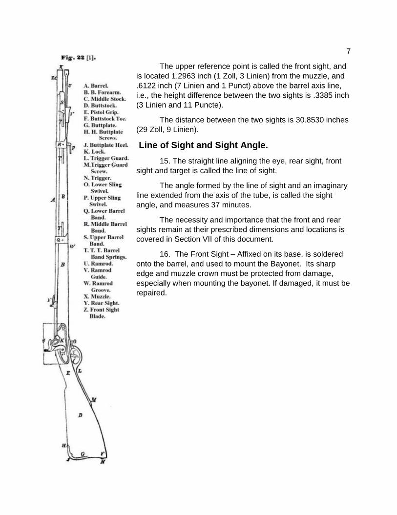
14. Above the barrel are attached two reference
points used to aim the firearm that must lie at the same
level and direction as the axis of the bore.
The one closest to the eye, i.e., the rear sight, is
5.1854 inches (5 Zoll) from the rear end of the barrel,
where it has a diameter of 1.0227 inch (11 Linien, 10
Puncte). The notch of the rear sight should be .9507 inch (11 Linien) above the axis of
the bore.
7
The upper reference point is called the front sight, and
is located 1.2963 inch (1 Zoll, 3 Linien) from the muzzle, and
.6122 inch (7 Linien and 1 Punct) above the barrel axis line,
i.e., the height difference between the two sights is .3385 inch
(3 Linien and 11 Puncte).
The distance between the two sights is 30.8530 inches
(29 Zoll, 9 Linien).
Line of Sight and Sight Angle.
15. The straight line aligning the eye, rear sight, front
sight and target is called the line of sight.
The angle formed by the line of sight and an imaginary
line extended from the axis of the tube, is called the sight
angle, and measures 37 minutes.
The necessity and importance that the front and rear
sights remain at their prescribed dimensions and locations is
covered in Section VII of this document.
16. The Front Sight – Affixed on its base, is soldered
onto the barrel, and used to mount the Bayonet. Its sharp
edge and muzzle crown must be protected from damage,
especially when mounting the bayonet. If damaged, it must be
repaired.

8
17. There are two different rear sights; a fixed sight used by two thirds of the unit,
and an adjustable sight with apertures for long-distance shooting for one third of the unit
and the non-commissioned officers.
18. Both rear sights are mounted in slots atop the outer barrel wall. While the
front sight is fixed, either rear sight can be moved from side to side. Once the gun is
zeroed in the correct position to shoot in a straight line, the rear sight is staked in place.
The soldier must observe and ensure the sight always remains in that position in the
slot. A bumped sight is easily recognizable by its position in its slot, and must be
immediately shown by the soldier to the noncommissioned officer so it can be corrected
immediately, by carefully and gently tapping the side of the sight. If the sight moves
easily without significant resistance or even merely by the touch of a finger, it must be
reported so the situation can be remedied.

9
Apertures.
19. The notch on the bottom of the long-range sight is used for aiming at targets
up to 245.8 yards (300 Schritten); the sight leaf is raised for aiming up to 737.5 yards
(900 Schritten). The placement of the openings have been deliberately calculated, and
are called apertures. The notch must be in its original, unaltered, sharply cut shape.
These apertures are on a spring leaf that is held in place on a flange by two screws
which folds up and down on a pin through the base which also stops the movement of
flange when erect.
20. The method for aiming through the various rear sights is as follows:
Sight pictures for both rifle sights in general: At 122.9 yards (150 Schritten) with
the front sight on the abdomen of the opponent; 163.9 yards (200 Schritten) with the
front sight on the chest; and 245.8 yards (300 Schritten) with the full front sight on the
chest.
With the long range sight erected: 327.8 yards (400 Schritten) through the
opening and Aperture No. 4-5 with a fine front sight at the abdomen; 409.7 yards (500
Schritten), using the same aperture with a full front sight at the head; 491.7 yards (600
Schritten) through the opening and the Aperture No. 6-7 with a fine front sight at the
abdomen; and 573.3 yards (700 Schritten) with a full front sight at the head. 655.6
yards (800 Schritten) through the No. 8-9 notch on the top edge of the sight leaf with a
fine front sight at the abdomen and 737.5 yards (900 Schritten) with a full front sight at
the head.
So at 327.8, 491.7, and 655.6 yards (400, 600, 800 Schritten) through the
corresponding numbered apertures with fine front sight at the abdomen, and at 409.7,
573.3, and 737.5 yards (500, 700, 900 Schritten) with the full front sight at the head.
21. The rules and regulations, "Aim and Hitting" and "target shooting" are
included in Austrian Army regulations.
22. Finally, it is noted that all diligence and effort must be made to maintain the
rifle in standard, as-issued condition by the soldiers in its cleaning and maintenance,
and the non-commission officer in his inspections. Both will be discussed further in the
following sections.

10
§3.
The Lock.
23. The lock is an artificial mechanism made to crush a percussion cap, which in
turn ignites the powder charge. It must be carefully treated and maintained to operate
properly. It delivers a short and strong impact directly onto the nipple to make the
spark, which is called the percussion.
24. That lock is embedded into the stock where dust or moisture cannot
penetrate its inner mechanism. It is secured by two carriage bolts to the stock that must
be firmly tightened.
25. The lock consists of two main parts which are connected.

11
Locking and Percussion Device.
The main components of the lock mechanism
are located inside - and the percussion device, i.e., the
hammer, on the outside.
26. The lock plate includes a thicker iron part,
called the bolster that has a cutout where the barrels
nipple-seat rests.
Lock Mechanism.
27. The locking mechanism consists of: 1. The
main-spring. 2. The tumbler. 3. The bridle. 4. The sear,
and 5. The sear-spring.
Mainspring.
28. The mainspring is the moving force in the lock
mechanism. It is bent over double and is fixed in place
by a lobe and a pin in the plate. The former is located at
the upper end of the short arm, the latter at the bend
between the long and short arms. Both arms are
movable and the longer arm has a round shape, called
the horn, at its end and affect the firing pin spring with a
force of 16.1 to 17.3 pounds (13 to 14 Pfunden) on the
tumbler.
After it is put in place, it must be protected as
not to unnecessarily weaken its strength because a
weak main spring no longer functions and causes
problems. The long arm must also move freely, i.e., it
must not touch the lock plate along its length when
moving and rub against it. Rubbing is usually indicated
by shiny streak left on the inside of the lock plate.
When noted this deficiency should be reported and
fixed.

12
Tumbler.
29. The Tumbler controls the spring tension of the outer Percussion mechanism,
namely the hammer.
It has two co-rotating axles, one on each side, and on
its interior axis has a lobe that is divided into four unequal
segments. The axles are called the Tumbler-axis, the one
that fits into the lock plate is called the arbor and the other
side that fits into the bridle is called the pivot. The tumbler
rotates on its axis between two parallel walls - the lock plate
and bridle - and this rotation must be free and not wobble; if
the bridle is too tight it will not move freely - and if the holes
in the lock plate or bridle are too large, or the bridle not
tightened enough, it will wobble.
The square is located on the arbor, where the
hammer is attached and held in place with the hammer
screw.
Lobes.
The four sections on the outside edge of the tumbler
are called the lobes.
Tumbler Horn.
The mainspring makes contact with the Horn, and
rubs against it when the hammer is cocked. While the short arm of the mainspring is
fixed, the long arm is tensioned when it is raised and released when the long arm is
forced down again.
The mainspring must not go beyond the horn as clamping against the body of the
tumbler would inhibit the proper expression of power.
Safety Notch.
The second lobe contains the safety notch, which is cut very deeply at an oblique
angle.

13
Firing Notch.
The third lobe contains the firing [Full Cock] notch, which is cut in the direction of
the center of the tumbler, and is only deep enough so the end of the sear can rest in it.
Finally, the fourth remaining piece is called the tail lobe, and has no particular
importance.
The friction of the tumbler rotation between the bridle
and lock plate is minimized as much as possible by the
chamfered surfaces around the axles, which alone rub while
the remaining parts of the tumbler walls are free.
Bridle.
30. The bridle shroud forms one of the bearings for the
tumbler axle and holds the tumbler pin. It is attached to the
lock plate by the two screws. Through their rear is a hole for
the sear screw, which acts as a fulcrum for the sear.
These three screws must always be fully tightened, yet
allow the tumbler and sear to move normally.
Over tightening the screws would clamp the tumbler,
which would be a major problem.
Sear.
31. The sear is a double-sided lever which has a hole for the
sear screw, which serves as a pivot point. The sear serves
the purpose of holding the hammer in the half and full cock
positions through its engagement with the tumbler. Like the
tumbler, it fits between the lock plate and bridle and also has
a chamfers on both sides to reduce friction.
14
The sear nose engages the tumbler notches, while the much longer trailing arm and the
right angle bend of the sear rod pin, are used to transfer pressure from the trigger when
you want to fire.
Sear Spring.
32. The sear nose is held in the tumbler notches by pressure against it from the
sear spring. It cannot jump out at random and resists pressure from the trigger blade.
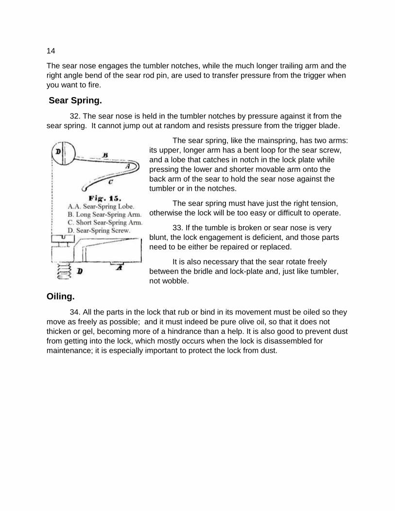
The sear spring, like the mainspring, has two arms:
its upper, longer arm has a bent loop for the sear screw,
and a lobe that catches in notch in the lock plate while
pressing the lower and shorter movable arm onto the
back arm of the sear to hold the sear nose against the
tumbler or in the notches.
The sear spring must have just the right tension,
otherwise the lock will be too easy or difficult to operate.
33. If the tumble is broken or sear nose is very
blunt, the lock engagement is deficient, and those parts
need to be either be repaired or replaced.
It is also necessary that the sear rotate freely
between the bridle and lock-plate and, just like tumbler,
not wobble.
Oiling.
34. All the parts in the lock that rub or bind in its movement must be oiled so they
move as freely as possible; and it must indeed be pure olive oil, so that it does not
thicken or gel, becoming more of a hindrance than a help. It is also good to prevent dust
from getting into the lock, which mostly occurs when the lock is disassembled for
maintenance; it is especially important to protect the lock from dust.

15
Oiling is usually done with the lock still assembled, by putting a very small drop of
oil on the following points:
1. On the tumbler, where the mainspring horn loop rubs.
2. On the two middle [Full and Half Cock] notches, where the catches rub the
sear nose.
3. On the back of the sear spring, where the lobe goes into the lock plate
4. On tumbler pin pivot in the bridle - and
5. On the tumbler arbor between the hammer and lock plate.
Lock Disassembly.
35. The lock should never be disassembled by soldiers, and only removed with
permission of the Noncommissioned Officers during inspections or special cleanings.
Also if a bayonet needs disassembly, or in the rare cases when it is necessary to
separate the hammer and tumbler, it will be done by the Noncommissioned Officer,
under the supervision of a gunsmith.
If a Noncommissioned Officer is charged with the disassembling a lock, he first
separates it from the stock by unscrewing the two lock screws and then carefully
removes the lock from the stock. He then proceeds as follows:
1. Cock the hammer and clamp the mainspring;
2. Release the hammer and remove the mainspring;
3. To remove the Bridle, release the tab on the sear spring, then unscrew the
sear spring screw all the way and remove it and the sear spring.
5. Unscrew the bridle screws and take out the bridle.
Lock Reassembly.
36. In contrast, the lock is reassembled in reverse order:
1. Install the bridle shroud and bridal screws.
2. Insert the sear spring screw and spring.
16
3. With the thumb of the left hand clamping the sear spring and sear screw
together, complete final tightening of the screw.
4. Install the mainspring, then cock the hammer to tighten the tension on it.
5. Let the hammer down to increase the spring tension by holding the lock in the
left hand with the curved forefinger of the right hand on the hammer head and pressing
the sear arm with the thumb.
Screws.
37. All screws should be tightened to the end of their threads, but no torque is to
be applied, which would eventually destroy the threads, i.e., a stripped lock, and cause
the mechanism to bind. Likewise, leaving the screws loose will cause the gradual
expansion of all thread holes and a sloppy mechanism, ultimately causing hammer
malfunctions.
Screwdriver and Spring Vise Application.
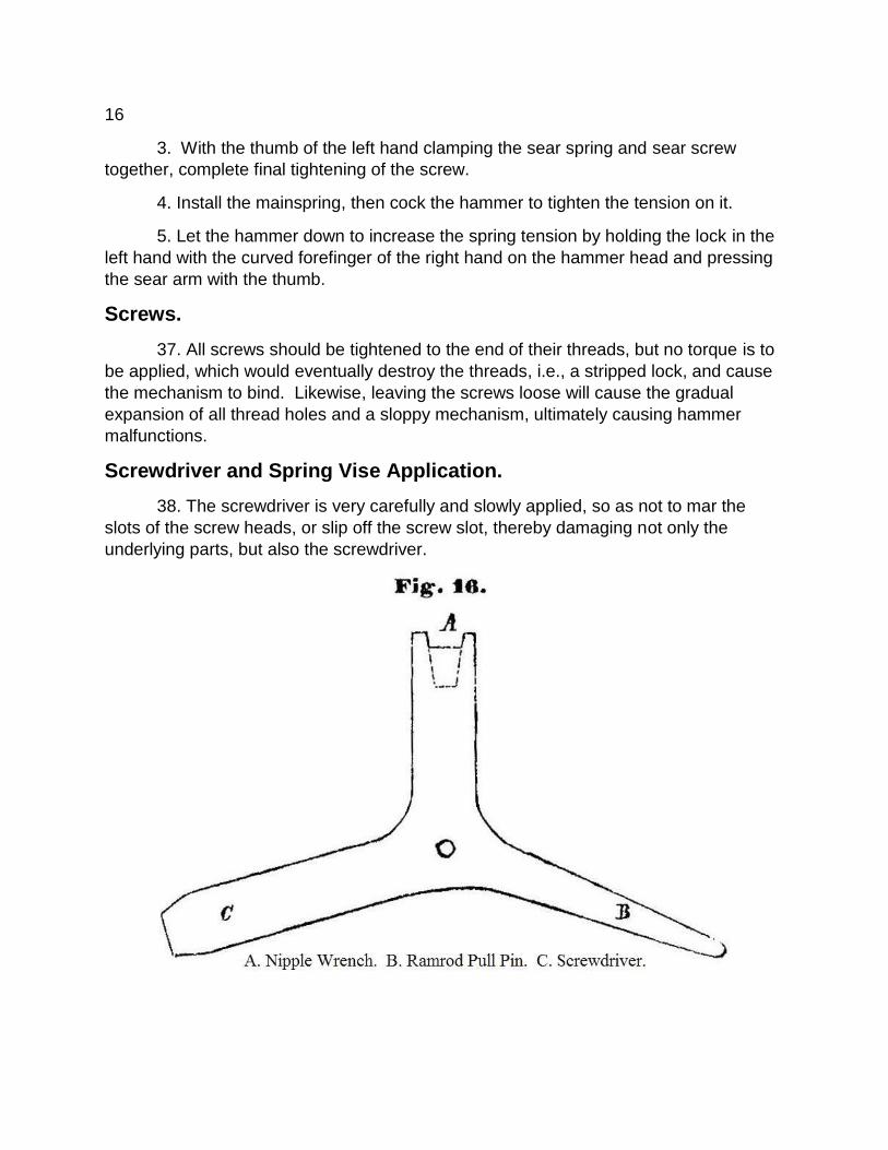
38. The screwdriver is very carefully and slowly applied, so as not to mar the
slots of the screw heads, or slip off the screw slot, thereby damaging not only the
underlying parts, but also the screwdriver.

17
When using the screwdriver, it should always be inserted perpendicular into the
slot of the screw head and gently held there by the thumb of the left hand. If holding the
gun cannot be achieved by hand a stable surface should be
used that is well lit and dust free so as not to soil the greased
iron parts, defeating the purpose of oiling as earlier described
in this manual.
Finally, when using the mainspring with the vise, it
should be applied vertically with the spring arms positioned
perfectly between the jaws to prevent them from jumping out of
the clamp.
The Percussion Device, the Hammer.
39. The hammer consists of the head with a face that is
located within the cavity on its front; and the hammer comb,
whose surface is roughened with cross-cuts; and finally at the
other end of the hammer is the disc, which is affixed to the
squares of the tumbler, connecting it to the hammer.

18
When the lock is dismounted from the stock, the bolster on the lock plate
prevents the released hammer from rotating further.
The hammer has to rotate without any interference at full force to the percussion
cap to properly ignite it every time.
Therefore, for the full impact the hammer should exert on percussion cap against
the nipple face, it is absolutely necessary that it is firmly seated on the squares of the
tumbler.
Any looseness must remedied immediately, because unless the hammer falls
down squarely on the face of nipple, and this is not perfectly uniform, this by itself could
cause misfires of the percussion caps.
Furthermore, whether or not the hammer has a staggering gait still needs to be
checked, to confirm it is an extension of the tumbler notches through the lock plate and
Bridle, and if not it also requires repair. These two evils - the hammer wobbling on the
square and a staggering gait – are both caused by not tightening the Bridle shroud - are
generally regarded as the unilateral cause of problems with the hammer striking the
surface on the percussion cap. The hammer itself is high in iron and shaped such that it
does not bend easily.

19
Lock mechanism
40. The lock mechanism, or the effect of the locking mechanism, on the one
hand, releases tension from mainspring spreading open, transferring their power from
the long compressed arms onto the tumbler, while cocking the hammer compresses
both mainspring arms clamping them against each other, rotating the tumbler horn
upward. Therefore, while outside the hammer is hurling forward, inside the immutable
connection is turning the tumbler back.
41. On the other hand, the pressure exerted by the sear spring drives the sear
into the recessed notches of the tumbler, expressing a ratcheting effect that arrests the
reverse rotation or slipping of the tumbler. The cocked hammer will be held in place as
the sear spring presses the sear into the tumbler notches. The trigger releases the sear
spring pressure when back pressure from the trigger blade, pressing up on the sear
arm, frees the nose from the notch that is preventing it from following their spring
tension.
42. The sear nose can be easily raised from the full cock notch, namely, when
the hammer is cocked and pressure by the trigger blade transferred to the nose of the
sear, the release of the hammer requires very little trigger pressure because of the way
it’s made. A hard trigger pull may mean the lock needs lubrication; if not, it must be
reported immediately to remedy the situation.
43. If the hammer is not fully cocked, but only pulled back as far as the safety
notch - where it cannot strike the percussion cap - the mainspring tension is significantly
weaker, because the spring is far less compressed.
The sear releasing from this notch arbitrarily, or even by mistakenly pulling the
trigger, is totally prevented by the notch being cut very deeply and at much more
oblique angle; therefore, it is also called the safety notch.

20
44. Finally, for tumbler assembly to be operating
correctly, the sear nose needs to drop into the tumbler
notches, without hindrance or hesitation before it absorbs
the tension from the mainspring. An indicator of a properly
working tumbler assembly is the crisp sounding snap of the
sear nose dropping into the tumbler notches when the
hammer is cocked. Where this is not noted, there is a
problem that needs to be reported and repair authorized.
§4.
The Stock.
15. The stock connects of the lock to the barrel,
providing a means to use of the rifle.
It is made from kiln dried red beech wood, nearly
reaches the muzzle, and has to accommodate the barrel,
the lock and the other components of the rifle - some of
which are inletted.
46. The stock is divided along its length into four
main sections. They are: 1. The Forearm. 2. The Bed for
the lock. 3. The Pistol Grip, and 4. The Butt.
Forearm and its Furniture.
47. The forearm extends from the upper end of the
stock nearest the muzzle to the lock. Running almost its
entire length is a semi-circular cutout, which is specifically
called the barrel channel.
21
On the reverse side of the stock, concurrent with the bed for the lock are holes
drilled for the lock side screws. These holes are reinforced with a side plate.
Since the wood between the lock side screws and the side plate - as well as that
which surrounds the cut at the lower part barrel channel - can be very thin, particular
caution is needed to protect this part of the stock.
48. The barrel is held in the barrel channel by three iron bands: of which the
upper band sits at the muzzle end, and has a funnel provided for easier insertion of the
ramrod; the middle barrel band has a sling swivel; and the lower band binds up the
exposed ramrod channel, which is internally bored from that point to the iron ramrod
striker plate.
Each of the three bands is held in place by a band spring inset into the stock.
The Stock Bed and its Furniture.
49. The bed of the stock is designed to hold the lock section. The stock must
enclose the lock mechanism perfectly, and the various cuts within it need adequate
clearances, so no internal parts in the lock rub on the wood, which would of course only
inhibit it working. Additionally, for precisely for this reason, the hammer shank cannot
leave streaks - when this occurs there is usually binding.
Side Plate.
50. On the side stock opposite the lock plate, a single plate to holds and supports
the two lock screws is inletted into surface.
Trigger Plate.
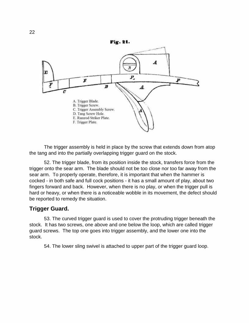
51. Furthermore, the Trigger Assembly is located in the bed, below the lock, with
its loosely mounted trigger blade. It consists of the finger pad and the trigger blade,
which are connected by a trigger screw that anchors it and serves as the rotation point
for transforming the leverage along the trigger blade. At the front end of the Assembly
is the striker plate upon which the supplied ramrod rests.
22
The trigger assembly is held in place by the screw that extends down from atop
the tang and into the partially overlapping trigger guard on the stock.
52. The trigger blade, from its position inside the stock, transfers force from the
trigger onto the sear arm. The blade should not be too close nor too far away from the
sear arm. To properly operate, therefore, it is important that when the hammer is
cocked - in both safe and full cock positions - it has a small amount of play, about two
fingers forward and back. However, when there is no play, or when the trigger pull is
hard or heavy, or when there is a noticeable wobble in its movement, the defect should
be reported to remedy the situation.
Trigger Guard.
53. The curved trigger guard is used to cover the protruding trigger beneath the
stock. It has two screws, one above and one below the loop, which are called trigger
guard screws. The top one goes into trigger assembly, and the lower one into the
stock.
54. The lower sling swivel is attached to upper part of the trigger guard loop.
23
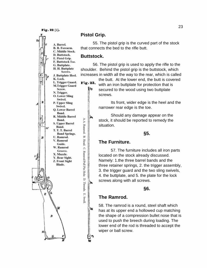
Pistol Grip.
55. The pistol grip is the curved part of the stock
that connects the bed to the rifle butt.
Buttstock.
56. The pistol grip is used to apply the rifle to the
shoulder. Behind the pistol grip is the buttstock, which
increases in width all the way to the rear, which is called
the butt. At the lower end, the butt is covered
with an iron buttplate for protection that is
secured to the wood using two buttplate
screws.
Its front, wider edge is the heel and the
narrower rear edge is the toe.
Should any damage appear on the
stock, it should be reported to remedy the
situation.
§5.
The Furniture.
57. The furniture includes all iron parts
located on the stock already discussed.
Namely: 1.the three barrel bands and the
three retainer springs, 2. the trigger assembly,
3. the trigger guard and the two sling swivels,
4. the buttplate, and 5. the plate for the lock
screws along with all screws.
§6.
The Ramrod.
58. The ramrod is a round, steel shaft which
has at its upper end a hollowed cup matching
the shape of a compression bullet nose that is
used to push the breech during loading. The
lower end of the rod is threaded to accept the
wiper or ball screw.

24
However, in order make getting a handhold easier, the pulling pin of the projectile
to the screwdriver is inserted through the hole drilled through the lower part of the
ramrod Head, which serves as a handle.
The steel shaft has an enlarged reinforcement below the Ramrod Head - the
swell – which somewhat aids situating it into the rifling.
§7.
The Bayonet.
59. The bayonet consists of a straight, 18.6 inch (18 Zoll) long steel blade
connected to a socket by a curved neck. It has two ribs and characterized as four-
bladed.
The socket is used to fix the Bayonet onto the barrel, where it is locked down
with a rotating locking ring.
60. Thus, the socket of the bayonet is planted on the barrel muzzle with the front
sight inserted into the cut-outs of the bridge, stud mortise, and corresponding opening of
the locking ring, then tightened after fixing by twisting the ring.
61. Caution should be exercised when fixing the bayonet. An examination of the
number of work orders submitted show that fixing bayonets too roughly ruins the edges
of the front sight blades.
62. The locking ring must remain reasonably loose on its rotational surfaces so it,
and the screw mounted there, should be oiled to prevent any rust that would cause
excessive friction.

25
Section II. Accessories, Tools and Other Aids
§8.
The Accessories, Wiper, Screwdriver, Pull Pin.
63. Each rifle comes with an iron wiper, into which an iron worm is screwed, as
well as a combination tool with a screwdriver, ramrod pulling pin and nipple wrench.
64. Caution must be used when using the combination tool on the nipples and
screws. See text number 38.
65. Every man with a musket must be issued these items, and a number of
worms will be distributed in each Company.
Ball-Screw.
The ball-screw consists of the drill and guide sleeve. The latter is lowered into the

26
rifling, guiding the drill to the highest part and center of the compression bullet, and
holding it there during drilling to prevent damage to the rifling.
Mainspring Vise. 66. Finally, each Sergeant has a main spring vise and knows how to use it to
disassemble and reassemble the lock.
§9.
The Cleaning Kit.
67. Every soldier and Sergeant is required to have a
cleaning kit for their rifle consisting of: 1. Some linen cloth. 2.
Two 5.2 by 3.1 inch (5 by 3 Zoll) cloth rags – one saturated with
pure tallow for metal parts and the other with olive oil for the
wooden stock. 3. One 9.3 by 3.1 inch (9 by 3 Zoll) flannel rag for
the bore enriched with pure tallow, 4. A small rifle brush, 5. Some
small feathers and 6. A small glass vial with pure olive oil.
§10.
Other Aids.
Tompion. 68. A tompion, a 2.1 inch (2 Zoll) long wooden cylinder whose diameter is slightly
smaller than the rifle caliber, seals the muzzle from moisture and dust on marches, in
the barracks, and wherever else needed. It has large lead plate on the upper end, and
three to four layers of pure tallow cloth held in place with a nail on the bottom

27
that completely fill the grooves when inserted into the bore. The clearance between the
wooden cylinder and the barrel walls, together with the impregnated cloth strips must be
periodically checked, especially if it gets wet or soiled, because this moisture or dirt
would inevitably cause rust.
Inspecting rifles in storage for this is particularly important.
Practice Cartridge. 69. During every loading exercise, a cloth-covered practice Cartridge must be
inserted into the chamber to protect the breech plug face and the ramrod threads. It is
1.55 inch (1.5 Zoll) long and the same diameter as the ball diameter. Inside the cloth is
a lead weight.
The practice cartridge must be kept completely clean and dry, even a small
amount of rust on it can cause big problems.
70. A reserve nipple is also part of the accessories, along with two nipple picks
which are carried in the cartridge pouch.
Note.
Be diligently mindful of the condition of the rifle, the accessories, tools and other
aids.
In addition, each man must bear the prescribed ammunition and Company
Supply must stock a reasonable number of wooden mop sticks. (See No. 119)

28
Section III. Ammunition.
§11.
Service ammunition. 71. Service ammunition cartridges contain: gun powder, the Compression bullet,
and percussion caps.
Gunpowder. 72. The gunpowder is a granular mixture of 80 parts of saltpeter, 12 parts sulfur
and parts 14 charcoal. One charge has 62.15 Grains (55 Gran) of gunpowder.
Compression Bullet. 73. The compression bullet is a lead projectile weighing an average of 452
Grains (400 Gran). Like round balls, it can be cast in molds, but it is now cut and
swaged with new machines. It consists of two
sections: Namely the upper nose and the cylinder.
This design provides two parallel grooves around
its axis length for the compression of the projectile
beyond its original size.
74. The diameter of the compression bullet
is .5401 inch (6 Linien 3 Puncte), i.e., smaller than
the rifle caliber by a Punct, which gives it
clearance. The bullet nose is an ogive, .5617 inch
(6 Linien, 6 Puncte), and the Cylinder is .4321 inch
(5 Linien) high, which gives a total height of .9939
inch (11 Linien, 6 Puncte). The two rings are
separated by .0864 inch (1 linien) wide gaps that
are .1296 inch (1.5 Linien) deep.
When fired, the high pressure of the expanding powder gases compress the bullet,
squeezing out all clearance between it and the lands and grooves, sending it out of the
barrel with the full pressure exerted behind the bullet and no pressure escaping
between the bullet and rifling.

29
The compression bullet forms to the spiral shape of the rifling, and follows the rotating
spiral grooves down the barrel axis, maintaining its rotation in the air after leaving the
bore throughout its trajectory to the target.
Cartridge. 75. The cartridge consists of a closed sleeve of paper
containing the gunpowder and ovoid body of the compression
bullet. Around the whole sleeve with the projectile with the bullet
nose inside, is a wrapping of solid straw paper closed on the end
beneath the bullet.
The closed end of the cartridge and surroundings is immersed in
mutton tallow, and the other end is folded longitudinally to close
the powder tube. This folded part is where the cartridge is torn
when you want to load it.
76. The lubrication fills the rifling when loading the
cartridge, coats the barrel, softens the residue of burnt powder -
the so-called fouling - and facilitates the loading; but mainly
allows for smoother ramming of the ball into the bore.
Percussion Caps. 77. The percussion cap is made of copper in the shape of
a hat with an explosive preparation pressed inside that is
protected from moisture and preserved with a coating of shellac.
The hat has four splits around its opening and each of the four
30
splits are bent at right angles, forming a shape that is easy to feel. The splits help
prevent splintering of the percussion cap during shooting.
78. Soldiers receive 8 percussion caps in each package of 6 cartridges, so there
are 2 extra caps in each package. Immediately after opening the cartridge package, the
8 caps should be put into the cap pouch located on the cartridge bag strap.
79. Fired percussion caps are thrown away, while unfired caps are kept and must
be stored according to regulations.
§12.
Blank Ammunition. 80. Blank cartridges have a paper spacer instead of a compression bullet.
The blank cartridge is a cylinder of rolled writing paper containing 56.5 Grains (50
Gran) of old musket gunpowder and a 1/20 arc plug made from gray graft paper. Like
the service cartridge, the plug is located in the lower part of the cartridge, covered by
the powder charge.
§13.
Guard Ammunition. 81. Guard ammunition differs from the usual service ammunition in that you load
a bare compression bullet, which is slightly smaller in diameter, onto the powder charge
so you can unload the rifle by pointing its muzzle slightly downward without using the
ball-screw or other implements.
Lead Ball. 82. When lead balls are loaded they are held in place with wadding.
83. Everyone must be provided with tompions to keep the bores clean, dry and
prevent rust in their chambers.

31
Section IV. Unloading the Rifle
§14.
84. Percussion caps are removed before unloading.
Guard Ammunition. 85. Guard ammunition is removed from the barrel using the ball screw on the
ramrod and, together with the guide sleeve, it is twisted into the bullet loaded in the
chamber, then pulled out.
With the bullet removed, the rifle is tilted muzzle-down, and the gunpowder
shaken out immediately, ensuring the crown never touches a stone or hard object.
Blank Ammunition. 86. Blank ammunition is unloaded similar to the Guard ammunition.
Service ammunition. 87. A service cartridge is usually shot into the ground. Unloading by pulling them
out of barrel should be avoided when possible.
88. When it is necessary to pull out a loaded cartridge, the guide sleeve of the
drill is first lowered into the bore, brought against the bullet and drilled slowly. With the
drill sufficiently engaged, the ball is lifted slowly and carefully, together with the guide
sleeve from the bore.
Violently jerking the ramrod and pulling the ball-screw from the bullet must be
avoided because the projectile would compress and become more difficult to extract
from the bore.
89. After removal of the bullet, the gunpowder is unloaded as previously
mentioned.
32
90. The balls drawn under such circumstances must be kept for future re-use.
Notes. For all unloading, use only the ball-screw and never the wiper, because of its
smaller diameter in the bore.
Section V. On The Treatment of Rifles by the Soldier
§16.
General Rules. 91. The rifle must be treated with great care and always maintained in top
condition.
92. Rust is the biggest enemy for the rifle and must be avoided at all costs. It is
easier to prevent than to cure once it occurs. Correspondingly, any uncleanness should
be avoided.
93. Every soldier must be familiar with the condition of his rifle. He must know it
completely, and so he can immediately detect and report any problems and repair the
situation.
94. Repairs are nearly always done by the unit’s armorer. Work by anyone other
than a gunsmith is prohibited.
95. The procedure to report a perceived defect for repair by a gunsmith is known;
men should be reminded they can neither be slow in reporting faults nor miss
inspections by the battalion weapons officer.
Repair List. A defective rifle is submitted by the Company with a repair list pinched between
the hammer and nipple on which the gun number and the perceived defects are noted.
Repair Journal. An entry is then made in the repair journal with the following sections: 1. Gun
number, 2. Assigned user’s last name, 3. Problem,

33
4. Repair, 5. Inspection Following Repair, 6. Acquisition by the Company, and 7. Notes.
Numbers 1 and 2 are filled in by the Company; 3 and 5 by the visiting inspector;
and 4 by the gunsmith repairing the defect; and finally 6 by both company armorer
accepting repaired rifle and the Officer of the Day.
The recently-repaired gun is tested by the Weapons Officer. If it is acceptable,
the Journal is updated. If unacceptable, the visiting inspector reexamines it and either
finds it acceptable or reassigns it for repair and only then is the Journal updated. The
repaired rifle and repair list is returned to the Officer of the Day of the Company that it
came from, and the journal is updated.
§17. 96. Men must understand how to disassemble the rifle properly. To thoroughly
clean the rifle and all of its parts, gun disassembly is in five steps, in the following order:
Rifle Disassembly. 97. 1. Remove sling.
2. Remove lock screws.
3. Remove the tang screw.
4. Remove the three barrel bands in order.
5. Remove the barrel with the hammer at half-cock.
98. If only the barrel needs to be detached, the lock does not need to be
removed.
99. When removing barrel bands, you can protect the finish of the barrel and
stock by using a fitted piece of hardwood.

34
The barrel bands are tight, so coating the snug parts with tallow will help remove
them, but excessive force should never be used. Gouging the wood at a tight spot will
only make it tighter.
There are always two locations where the barrel band and stock come into direct
contact. The wood and front half of the barrel bands are designed to be tight at those
points.
Knocking on the back of the barrel bands is hazardous for the stock and should
never be done.
100. The removal of the barrel from the stock must be done very gingerly and
carefully. The right hand holds both the stock and barrel towards the breech with the
nipple pointing down, while the left hand supports the rifle beneath in the middle of the
tube, ready to immediately catch the freed barrel. The barrel is then rotated with the
nipple moving towards the ground, which separates the barrel into the left hand, while
the right hand holds the stock.
101. Finally, in rare cases where a local inspector directs or the need arises to
remove the trigger guard, trigger assembly, or the butt plate, the appropriate screws are
slowly twisted out and the parts gently separated. These parts should usually be
cleaned on the stock.
Reassembling the Rifle. 102. Reassemble the rifle in reverse order of disassembly, namely;
1. Replace the barrel with the hammer at half-cock.
2. Slide the three barrel bands onto the stock.

35
3. Put the hammer down.
4. Replace the tang screw.
5. Replace the sling.
103. Inserting the barrel into the channel of the stock must be done carefully.
104. The process specified in No. 99 must be also be followed when replacing
the barrel bands. Cleaning and lubricating the inner walls should never be skipped, and
the tang screw must be well cleaned, the shaft greased and the threads oiled.
§18.
Cleaning. 105. Before and after each use, the rifle is thoroughly wiped inside and out with a
dry linen cloth. In foul weather the metal parts will sweat when brought into a warm
place from a colder temperature. The beaded moisture on the metal parts is
condensation. Wiping is be useless while there is a considerable temperature difference
because moisture continues to condensate on the metal. The temperature difference
equalizes quickly and soon the condensation evaporates by itself, and the rifle is then
ready for wiping.
Special Cleaning. 106. Prevention of rust on all metal parts is easily avoided with grease. But once
rust has occurred somewhere, it must be immediately saturated with oil and repeatedly
wiped with a cloth wound on a wooden stick; this method will soften and remove the rust
quickly.
107. The use of any abrasives, such as lime, or polish is strictly prohibited.
3*

36
The Stock. 108. The stock is to be kept unaltered, neither painted nor varnished, and only
occasionally preserved with a coat of olive oil, especially in high summer and during
prolonged wet weather. It is moistened with olive oil, then rubbed with a cloth rag, until
it has a matte gloss.
Metal Parts. 109. Metal parts are wiped with a linen cloth inside and out along with the
bayonet, ramrod, lock and accoutrements. When that is not adequate, they are cleaned
with the gun brush, then coated with grease.
110. The same is true of the iron parts of the accessories and other aids, and
also bayonet and scabbard fittings.
Touch hole. 111. The touch hole in the nipple is cleaned with a feather and, if necessary, with
a pick.
Excessive oil should be avoided, because it could interfere with the detonation of
percussion caps and gunpowder inevitably causing a misfire.
Lock. 112. Cleaning the lock is usually performed without dismantling it. As previously
stated, if a special cleaning of the individual parts is needed, the lock will be dismantled
only by the sergeant, who alone has the required main spring vise.
113. Ordinary cleaning of the lock is done with items the men already have. All
surfaces and intricacies of the mechanism are cleaned with the rifle brush, dried and
then wiped with grease.
114. The sergeant sees to the oiling of all parts listed in No. 34.
115. If for whatever reason, the lock has been disassembled by the sergeant, the
men should clean all the component parts before he reassembles it.

37
The pivot points on the bridle screws and the threads should be moderately oiled.
116. When reassembling the lock, the screws should be double-checked for
tightness.
Trigger Blade.
117. If, as noted in No. 101, the trigger assembly is removed, before reinstalling it
should be cleaned and a small drop of oil put on the pivot point.
Bore.
118. For cleaning the rifle’s bore, the wiper is screwed onto the ramrod without
the guide sleeve, and used with a thick, dry linen cloth as necessary for cleaning the
rifling.
119. A cloth should be placed on the crown of the barrel so the ramrod does not
touch and wear away the rifling at the bore.
Ramrod Guide.
When using implements on the ramrod, it is safest to prepare a two inch long
cylindrical sleeve of cloth or leather ahead of time which is inserted into the bore and
held there, with the rest of the gun in the left hand. This ramrod guide is put onto the
ramrod, against the head, before threading on the wiper and wrapping the cloth. It
remains on the ramrod until use of the implements are completed.
The parts of the crown and bore covered by the guide cannot be forgotten, and
must be cleaned once it is removed.
Wooden Cleaning Rods. Wooden cleaning rods should be used whenever practicable – especially in
garrison.
38
They are preferred because they do not damage the rifling and are easier to use.
This rod is a long, wooden stick of somewhat smaller diameter of the rifle bore
with multiple slots on one or both ends, like those on the iron wiper, to hold the wrapped
cleaning cloths.
120. The slots on the wiper and wooden cleaning rods should cleaned each time
the cleaning cloths are replaced, so as to prevent spreading grime from the muzzle to
the breech.
After cleaning, use the same rod to lightly coat the bore twice using a greased
flannel cloth.
121. It is very important to clean and grease rifles stored in magazines.
§19.
Cleaning the Barrel after Firing. 122. After firing, the rifle must be cleaned and oiled. The barrel remains mounted
in the stock and hammer cocked away from the nipple.
123. To wash out the barrel, close nipple ignition hole with the index finger of one
hand and fill the bore with warm water to the level of the rear sight. Then close the bore
with the palm of the other hand and swing and shake the rifle with both ends closed until
the water drains completely clear.
After the water is clear, fully drain the barrel with the muzzle down and then wipe
it completely dry.

39
124. The procedure to dry the bore is covered in the Nos. 118-120. Moist linen
rags should be switched with dry ones.
Pumping the wiper or cleaning rod must be done quickly to produce a powerful
airflow and promote drying. This procedure must be continued while the barrel is warm
and until the linen rag is completely dry.
125. Quickly wiping the barrel while it is warm forces considerable air pressure
through the flash and the touch-holes that is sufficient to dry both completely.
126. Once the drying procedure is done, the greased flannel rag is used as
previously discussed, and musket cleaning is complete.
§20.
Cleaning after the gun was exposed to persistent rain. 127. After exposure to persistent rain, wipe, dry and treat the bore just as
described in Nos. 124-126.
128. Then disassemble the rifle as described in No. 97 and very carefully clean
and oil beneath the barrel along with the furniture on the stock and the ramrod.
During this cleaning, the stock should dry without sun or heat, then the barrel
channel wiped with the grease cloth and the entire stock coated with olive oil.
129. After everything is treated, the rifle is reassembled.

40
Section VI. Inspections.
§21.
By the men. 130. A well-trained soldier will be able to quickly and accurately detect and report
key problems with the rifle.
131. He must, therefore, examine his gun before each use, namely that 1. The
gun is unloaded, 2. The ignition channel is clear, 3. The sights are not askew, 4. The
lock is operating properly and 5. The trigger pull is light enough.
Barrel and Touch hole. 132. To inspect the barrel and ignition channel, put the hammer at the half-cock,
and with the mouth over the muzzle draw air. The free and unhindered flow of air
through the bore indicates there is no problem. If on the other hand, there is a
noticeable obstacle or resistance, and a quick cleaning with a pick or feather does not
correct it, the sergeant should be notified that something needs to be done.
Rear Sight. 133. The correct position of the rear sight can be easily recognized. When it is
out of place, the deficiency must be reported immediately. The correct position of the
rear sight is so important that the greatest caution and supervision is necessary. The
sighting notches provide the sight picture and must always be kept thoroughly clean, as
even small particles can block the aim. It is best to hold the edges of the sight when
wiping with a cloth.
Lock. 134. A clean and unrestricted lock does not bind when the hammer is slowly
cocked from the rest position to full cock or when discharged slowly with the thumb
counter-balancing the tension by putting pressure on the hammer tail. The hammer has
to fall without the least resistance and the spring tension must not vary.

41
When cocking, the sear makes a crisp snapping sound as it falls into the notches.
Rough hammer movement, uneven or weak spring tension, or hammer wobble on the
square end of the tumbler arbor needs to be repaired.
Trigger Tension. 135. Finally, trigger tension is tested by moving it slightly back and forth with two
fingers in the three positions of the hammer. There should be no swaying and either no
or only slight binding of the trigger on its axis (the screw in the trigger assembly). This
should be reported to remedy the situation.
This type of testing the lock and trigger tolerances is called timing.
§22.
By the Sergeant. 136. The sergeant is required and obligated to lead his team by example in
maintenance and knowledge of its weapons, and to rigorously supervise them in
following all the rules.
137. His knowledge of the lock construction must be especially accurate
because, as previously mentioned, he and he alone is entrusted with the mainspring
vise.
138. Besides the tests of the rifle already mentioned, one might like to examine
the interior of the bore further.
139. For this examination, he must be provided with a Cleanliness Rod and
Inspection Plate.
Cleanliness Rod. 140. The Cleanliness Rod is similar in shape to the wooden mop stick, and is
used wrapped with a clean linen wiping cloth to check the cleanliness and dryness of
the inside of the barrel.
Mirrored Inspection Disc. 141. The Mirror Inspection Disc is a shiny polished steel plate the diameter of the
bullet which is lowered into the bore to the breech, and acts like a mirror to illuminate
the rifling in the bore.

42
It is used by holding the rifle up to the light so the beams reflect back into the
eye, and the entire bore is lit showing any damages (such as scaling, pits, unnatural
prominences, etc.) and even uncleanness.
Understandably, these types of bore defects will be obvious.
142. The sergeant uses these aids frequently to examine the bores, especially
when cleaning is performed before and after target shooting, or a rifle is taken out of
storage.
Rifles temporarily stored in magazines undergo this inspection, in addition to
cleaning the bores and applying fresh lubrication.
143. The sergeant especially must acquire the skills needed to check that the
lock timing on the rifles he supervises is always in perfect condition, and to know and be
able to show his team correct procedures when they are unsure or overlooked.
144. It is also understood that he must acquire a certain degree of confidence
and skill using the screwdriver and main spring vise so he can dismantle the lock when
needed.
Nipple Replacement. 145. When a man has a defective nipple, he reports it so it can be repaired. In
emergencies however, if no officer is present and he is convinced the nipple is no
longer serviceable or the escaping pressure is so powerful that hammer blows back, he
may replace it himself with the reserve nipple. Replaced nipples must be checked to
insure they are completely tightened.

43
§23.
Inspections by the Company Officer. 146. Each officer must be a secondary source of the knowledge, care and
assessment of weapons, serve as a role model and teacher for their skillful use and
marksmanship, and be able to successfully train their unit on the needed practical rules,
finer points and related concepts.
147. He therefore has to use the greatest care in the training of his unit and the
monitoring their weapons.
148. The rifles are inspected by him before and after each prolonged use. This
inspection goes into far more detail than the men’s and non-commissioned officers’
encompassed. It usually covers the following Points:
149. 1. Inspection of cleanliness and lubrication of all external metal parts, the
stock, Bayonets and all accessories and other aids.
2. General external visual inspection, whether on barrel, ignition hole, together
with the nipple, front and rear sights; the stock, especially on the ramrod channel
through the barrel bands and around the lock opening; the ramrod and the condition of
its threads; and that mounted bayonets are neither too loose nor tight, and have no thin
walls on their sockets or locking rings.
3. Inspection of the bore using the Mirrored Inspection Disc.
4. Examination of the lock timing and trigger tension.
Further Inspection.
150. For further inspection, he performs the following steps:
The rifle with its hammer down, is propped up on left hip so it is facing away at an
oblique angle, with the palm of the left hand down on top of the hammer
The index finger of the left hand pulls the trigger all the way back and
simultaneously
The right hand on the trigger guard with its thumb on the hammer tail. He now

44
feels for any defects in the lock gear and hammer assembly by pulling the trigger
repeatedly and slowly moving the hammer back and forth.
151. A rough, heavy or hard lock mechanism has either an internal or external
problem.
Inside it may either need oil, or the sear spring could be rubbing on the plate, or
the tumbler could be binding (i.e., the tumbler no free rotational movement between the
plate and bridle), or finally, the Lock could be too tight and is rubbing against the wood.
Outside, the hammer could be rubbing on the end of bridle screws or a lower lock
screw that’s protruding too far.
152. The mainspring must provide strong and uniform tension.
153. After this test, the officer proceeds to investigate the trigger tension and lock
timing. That is, the hammer is slowly moved to both notches on the tumbler with the
sear tip making a crisp sound when freely falling into the positions. The trigger should
move freely into both notches as discussed. A broken or defective sear spring, the
bridle screws drawn too tight, not having enough oil, or binding against the wood can be
detected by this test.
Simultaneously with this test, the amount of play of the hammer on tumbler arbor
square is measured by moving it a trifle while cocked.
154. Now inspect the trigger blade: it should not bind or wobble, and should have
the same amount of movement on its pivot point both resting and cocked,
155. And finally: the trigger pull should be neither too light nor too heavy with the
sear coming from it’s from its notch smoothly.
If the spring tension, tolerances, timing and trigger blade motion are correct, the
lock is in good working order.

45
Overview
of the
Main Defects Which Occur in the Various Inspections.
Inspection. Deficiency* Remedy.
Inspection by the men. 1. Whether the barrel is unobstructed, and 2. The nipple touch hole is clear, checked by sucking air through the muzzle.
Either the ignition channel or nipple hole is clogged.
Air is drawn with the mouth on the muzzle – Clear the barrel with the ramrod and, if necessary, touch hole with a pick and cleaning feather.
3. Whether the rear sight is askew.
A problem is indicated by a misalignment of the chisel marks on the rear sight and the barrel.
Should be reported to and corrected by a sergeant even if only slightly moved.
4. Whether the lock operates smoothly and is properly timed.
1. Rough, hard or uneven hammer movement - where even a creak is sometimes heard. 2. Wobbling or slack movement of the hammer on the tumbler. 3. Weak tension from a broken or weakened sear spring. 4. No crisp sound when the sear drops into the tumbler notches.
Must be reported.
5. Whether the trigger blade in all three positions of the hammer has proper movement. (Cocking Continued)
1. The trigger blade binds when pulled. 2 The trigger moves up and down.
Must be reported,
* Any broken component part should be reported as a defect, even if not listed.
46
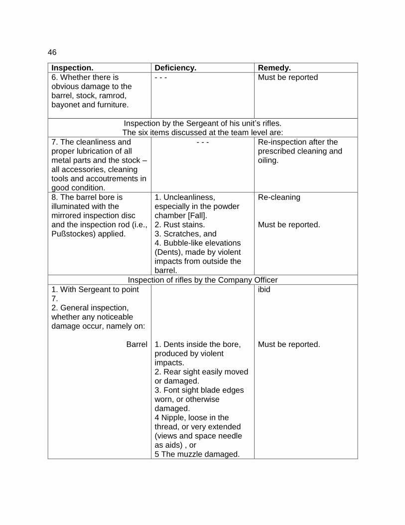
Inspection. Deficiency. Remedy.
6. Whether there is obvious damage to the barrel, stock, ramrod, bayonet and furniture.
- - - Must be reported
Inspection by the Sergeant of his unit’s rifles. The six items discussed at the team level are:
7. The cleanliness and proper lubrication of all metal parts and the stock – all accessories, cleaning tools and accoutrements in good condition.
- - - Re-inspection after the prescribed cleaning and oiling.
8. The barrel bore is illuminated with the mirrored inspection disc and the inspection rod (i.e., Pußstockes) applied.
1. Uncleanliness, especially in the powder chamber [Fall]. 2. Rust stains. 3. Scratches, and 4. Bubble-like elevations (Dents), made by violent impacts from outside the barrel.
Re-cleaning Must be reported.
Inspection of rifles by the Company Officer
1. With Sergeant to point 7. 2. General inspection, whether any noticeable damage occur, namely on:
Barrel
1. Dents inside the bore, produced by violent impacts. 2. Rear sight easily moved or damaged. 3. Font sight blade edges worn, or otherwise damaged. 4 Nipple, loose in the thread, or very extended (views and space needle as aids) , or 5 The muzzle damaged.
ibid Must be reported.

47
Stock
Ramrod
Bayonet
1. Split or missing wood, especially along the ramrod channel causes barrel jump and near the lock over-tightened tang screws.
Must be reported.
1. Bent shaft, 2. Spoiled thread, or 3. Break beginning near the cup.
1. A break starting along the blade, 2. Bent neck, whereby the blade is tilted, 3. Dented socket, at one of the mouth or on the open cutout (in the groove), 4. Tight or loose locking ring and screw wear, or 5. The bayonet cannot be completely seated, but clasp on the upper barrel is loose.
3. Lighting the bore with the mirrored inspection discs.
Points 1-4 with the subordinate officer.
Must be reported.
5. Dark black or gray iron splinters, 6. Black appearing deep locations, such as small holes and pits, 7. Obvious bending of the barrel, sometimes detected by direct light rays rather than reflected light.
Must be reported.
4. Examination of the lock and trigger assembly by swapping margins.
The following defects cannot be rectified with a quick oiling and shall be reported to remedy the situation.
Problem: 1. Mainspring operates freely and hammer can be cocked, but Mainspring brings the hammer down slowly when trigger is pulled.
Defect: 1. Tight mainspring tension with weak hammer impact.
Cause of the Defect: Mainspring either broken or too weak (disassemble lock).

48
2. Rough and hard hammer transition
1. Friction on the back of the hammer disc from bridle screw extending too far from the lock plate. (Disassemble lock).
2. Lack of oiling or accumulated grime, 3. The lock parts are binding on the wood inside the lock cavity, indicated by wear marks on the wood and indentations. These sites are usually: a) where the long arm on the main spring engages horn of the tumbler, b) where tumbler is positioned, c) where the sear and bridle is positioned, d) where the sear rod pin end rubs on the wood of the rear wall of the lock cavity, e) where the side of the sear binds against the inside of the lock plate, 4. the wear disc of the tumbler is too low or missing altogether, or the bridle screws clamp the tumbler,
3. Bumpy Hammer Movement.
1. The end of the main spring does not rest evenly on the tumbler horn. 2. The tumbler horn surface is wavy rather than flat, causing the main spring to bounce as it moves across it. 3. The main spring is too long, and presses against the tumbler wear disc.
4. Uneven Hammer Movement.
Sear and bridle screws are not completely tightened, causing wobble along the axis of the tumbler and hammer rotation.
5. Hammer wobbles on the square end of the tumbler.
The hammer screw is removed, and the hammer is pressed and back and forth to clearly reveal slack between the hammer shaft and the four sides of the hammer hole.
2. Sear arm and spring are weak
The sear barely falls into the tumbler notches with a dull or nearly inaudible sound.
1. Increased friction caused by lack of oiling or accumulated grime, 2. The sear is too long or the end of sear arm binds against the wood,

49
The sear tip falls into the notches with a distinctive snap and the hammer wiggles in both notches.
(Lock take-down) 3. The trigger has little play while against sear arm, and consequently cannot budge during its movement. It may be binding against the wood in the lock cavity. 4. The sear spring is too weak, or its short arm too long, not pressing on forearm of the sear, but merely rotating on the sear screws and exerts little or no tension.
Hammer does not lock in the full cock notch when drawn back.
The hammer cannot fully cock due to a lack of oil.
1. The mainspring horn is at full tension but wedged on the lock plate bolster, so it cannot be cocked. 2. The long arm of the mainspring, and especially the horn, is stuck on and movement inhibited by the lock plate bolster.
Little or no trigger-play in full and half cock.
1. The trigger is either stuck or difficult to move back and forth.
1. The upper part of the trigger blade is too close to the sear arm. 2. The upper part of the trigger blade is clamped in the cutout of the trigger housing. 3. It is too tight at the rotation points, and therefore has no free movement, which could be caused by accumulated grime, rust or lack of oil.
2. Uneven gait or tottering movement of the trigger blade in the trigger assembly at the trigger screw.
Enlargement or elongation of the trigger-screw hole, causing a stutter when squeezing the trigger on the dismounted trigger assembly.
Lock operates slowly when released.
1. The lock is difficult to operate.
1. Lack of lubrication. 2. Too deep, crooked or non-square cuts on the tumbler or sear. 3. Incorrect spring tensions, namely sear spring too strong, and main spring too weak. 4. No trigger-play.
2. Lock releases too easily.
1. Full cock notch too shallow. 2. Sear spring too weak.
3. Lock releases from the half-cock.
1. Broken half-cock notch. 2. Blunted or broken sear end.

50
Section VII
Powder Strength, Ball Effectiveness, Trajectory, the Need for
Establishing the Sight Picture, Rear Sight and Front Sight Blade.
§24.
157. The force that drives the bullet from the barrel to the intended target is
generated by the ignition of the gunpowder.
Ignited gunpowder is transformed into two products quite different from each
other: fouling and gas.
The gas is the product used as a propelling force during the ignition - partly
evaporating as smoke, but also partly remaining as residue on the barrel walls referred
to by the term “fouling”.
158. Gunpowder is made from a blend of 80 parts of saltpeter, 12 sulfur and 14
charcoal that is thoroughly pulverized, mixed, granulated and then polished.
The saltpeter is a compound of two substances, while sulfur and charcoal are
basic ingredients.
To generate the gas, one of the products in the gunpowder’s saltpeter is
transformed during the ignition of the charcoal while the other is being ripped from the
sulfur, which also forms a residue. The sulfur is a mediator, so to speak, during the
burning that transforms the powder into the two completely new products of gas and
fouling.
159. The powder residue or fouling, is unfortunately an unavoidable by-product of
gun powder combustion. It hardens and adheres to the bore walls, gradually
accumulating, drying and becoming fixed at high temperatures, and can only

51
be removed by very careful softening and washing with water.
Consequently, if the fouling does not stay soft in the bore from the lubrication, partly
from the cartridge case just fired and from the one just loaded, the continued
accumulation of fouling from additional shooting will eventually reach the point where a
cartridge can no longer be loaded into the chamber.
160. If the gunpowder is ignited (i.e., converted into the two known products), it
produces gas occupying a much larger volume than the powder charge. Typically,
every 1.13 grains (1 Gran) powder produces nearly 1.03 cubic inches (1 Zoll) of gas and
a .56 grains (.5 Gran) of fouling. Using this rule the gas volume of our gunpowder
charge can be assumed to be between 51.6 and 62.2 cubic inches (50 and 60 cubic
Zoll), but the heat of ignition increases it far more, and because it is compressed into
such a small space behind the ball, it exerts a intense high pressure yielding a muzzle
velocity of over 1037 feet (1000 Fuß) per second.
161. This kind of gas is highly resilient, and when confined in a small space
wants to expand to its natural volume, like a forcibly compressed coil spring. In this
effort to reach its natural volume, the struggle between the artificial and the natural
compression, now manifests itself by exerting pressure on all sides, with the greatest
pressure to expand while in the smaller, more compressed space.
Therefore, if the walls of the confined space are not strong enough to contain the
compressed gas within them, it will break through them at the weakest part, violently
expanding to its natural volume.
4*

52
This is the standing principle for each powder ignition.
162. When blasting, with either a whole or partial explosive charge, the intention
is to form a breakthrough point.
When shooting on the other hand, the barrel walls and the rear closure - the guns
breechplug - does not yield, applying all the pressure from the powder charge onto the
projectile as the breakthrough point, driving it violently away from the gasses and out of
the barrel.
The more effective the bore, the more hermetically the bullet adheres to the
rifling, sealing the gas from escaping so the entire process is concentrated behind it
while travelling through the barrel.
163. The bullet must travel smoothly and consistently through the bore and its
accelerating speed should be disturbed or inhibited as little as possible. The inside of
the barrel should be smooth and unadulterated like a mirror. It is critical that the sides
of the lands and grooves not form sharp angles and edges, and the bore has no cracks,
pits, rough spots, rust or other impurities in it.
164. Understandably, to shoot a heavier or lighter projectile at closer or further
distances, it requires a larger or smaller powder charge and the strength of the barrel
must be able to contain the pressure of the gas so as not to damage the rifle.
165. The gas of an ignited powder charge exerts equal pressure on all sides.
The lateral pressure will produce the same sideways movement through a uniform and
cylindrical shaped bore in a rifle that is not defective.
53
However, when the gas pressure breaks out in two directions, it can be quite different.
Two projectiles of equal weights surrounding a powder charge in the middle of a
tube open at both ends would both be flung the same distance when fired. However, a
difference would show up immediately if the balls used were different or unequal
weights.
For the sake of this experiment, assume one projectile is 145 times heavier than
the other and so tight in the bore that moves very little when the powder ignites, and the
gas pressure only results in the heavy ball firmly stuck in the bore. The pressure exerted
against the heavier projectile moves it only slightly, but will drive other lighter projectile
out of the barrel.
When the whole gun is together, the firmly mounted breech plug acts like the
heavier projectile against the lighter one.
166. The recoil corresponds to the infantry rifle – where the weight of the rifle to
that of the projectile, is about 145 to 1 – resulting in a recoil of 59.4 pounds (48
Pfunden).
167. The force of the ignition recoils backward while the driving the projectile
forward. How great the recoil depends on the amount of pressure, but this effect is
obvious from the aforementioned observations of the nature of the ignited gunpowder in
confined spaces.
168. The effect a bullet has when it impacts a target depends on two factors: the
projectile speed and its weight.

54
It is said that bullet momentum equals its speed times its weight. The higher the
numbers of these two factors the greater the impact. Logically, a ball weighing 452
grains (400 Gran) travelling at 12445 Feet (1000 Fuß) per second, will penetrate
materials significantly deeper than one weighing only 113 Grains (100 Gran) travelling
207 Feet (200 Fuß) per second. Likewise, less penetration will result if the
aforementioned bullet weighing 452 Grains (400 Gran) is travelling only 519 Feet (500
Fuß) per second when it hits, instead of 12445 Feet (1000 Fuß) per second.
169. Our Compression bullet, weighing 452 Grains (400 Gran), penetrates 5.2-
6.2 Inches (5-6 Zoll) of wood at a distance of 492 Yards (600 Schritten).
170. The velocity at which a bullet leaves the barrel, called the muzzle velocity,
decreases during its flight through the atmosphere until it finally stops altogether. This
slowing of the bullet speed is attributable to air resistance dragging against the forward
movement of the bullet.
The trajectory must be charted for a clearer understanding of this phenomenon,
as an illustration of the projectile’s material characteristics, while it moves progressively
slower and slower through the atmosphere until finally stopping.
So if our compressive ball has traveled about 328 yards (950 Fuß) during the first
second of its flight, it will travel less in the second, and even smaller distances during
each of the subsequent seconds.
171. A fired bullet, therefore, travels straight along its original path at a
decreasing rate of speed until it surrenders all its momentum to the surrounding air and
stops.

55
The moment the bullet leaves the barrel, another force acts on it that detracts from its
straight trajectory. This influence disturbing the intended flight is gravity.
172. Gravity is the well-known phenomenon where all objects drop to earth when
released.
173. This falling or sinking always occurs in a vertical line, i.e., in the direction of
the center point of our planet. At the same though, its relation to the bullet speed is
exactly the opposite while flying through the air. Namely, while bullet velocity decreases
with each moment of flight, the speed with which a bullet drops due to gravity
progressively increases.
174. The specific laws predicting this increasing rate of fall are known. Each
bullet will drop 15.6 feet (15 Fuß) in the first second, 62.2 (60 Fuß) in the second, 140
(135 Fuß) in the third, and 249 feet (240 Fuß) in the fourth. However, these numbers
are somewhat counteracted by the effects of air resistance.
175. Thus, to chart a fired bullet and these two forces acting on it, make a
horizontal line 950 units long, then from the end point a vertical line 15 units down to
show the drop from gravity, and finally a new line between the initial point and end point.
This new line between the two main points represent the trajectory of the bullet which
travels 328 yards (950 Fuß) horizontally and drops 15.6 feet (15 Fuß) vertically during
the first second of its flight.

56
Continuing to chart the subsequent seconds using the same method for flight, in which
the speed decreases but the drop increases to the 4, 9 16 and 25 units, results in a line
that increasingly dips downward.
Now, these figures are charted, and the trajectory over a period of several seconds can
be seen.
176. The trajectory of the flight path is thus determined by three factors, namely: the
pressure of the gas from the burning powder, the resistance of the air, and gravity.
Combining the first two together give projectile speed, and the third demonstrates the
effects of the phenomenon of gravity.
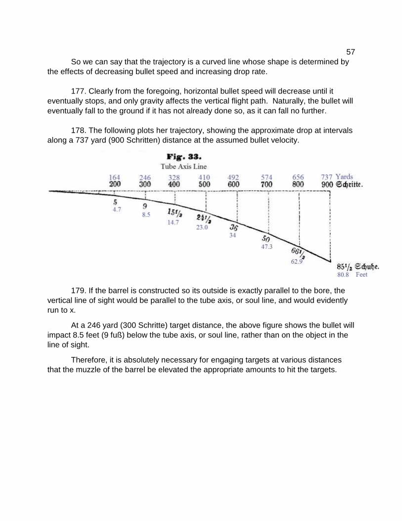
57
So we can say that the trajectory is a curved line whose shape is determined by
the effects of decreasing bullet speed and increasing drop rate.
177. Clearly from the foregoing, horizontal bullet speed will decrease until it
eventually stops, and only gravity affects the vertical flight path. Naturally, the bullet will
eventually fall to the ground if it has not already done so, as it can fall no further.
178. The following plots her trajectory, showing the approximate drop at intervals
along a 737 yard (900 Schritten) distance at the assumed bullet velocity.
179. If the barrel is constructed so its outside is exactly parallel to the bore, the
vertical line of sight would be parallel to the tube axis, or soul line, and would evidently
run to x.
At a 246 yard (300 Schritte) target distance, the above figure shows the bullet will
impact 8.5 feet (9 fuß) below the tube axis, or soul line, rather than on the object in the
line of sight.
Therefore, it is absolutely necessary for engaging targets at various distances
that the muzzle of the barrel be elevated the appropriate amounts to hit the targets.

58
Figures 34 and 35 vividly illustrate the appropriate elevations needed for each distance.
The respective amounts of elevation above the horizontal line-of-sight for striking
targets can be seen.

With the measurement of the bullet drop from the barrel axis line at the appropriate
target range, one can graph the trajectory, arcing at three fifths its distance.
59
Yards Schritt
At 164 200 Strike Distance 10.4 to 12.4 inches (10 to 12 Zoll)
“ 246 300 “ “ 1.6 to 2.1 feet (1 ½ to 2 Fuß)
“ 328 400 “ “ 3.1 to 4.1 feet (3 to 4 Fuß)
“ 410 500 “ “ 5.1 to 6.2 feet (5 to 6 Fuß)
“ 492 600 “ “ 8.3 to 10.34 feet (8 to 10 Fuß)
“ 737 900 “ “ 18.7 to 20.7 feet (18 to 20 Fuß)
If the infantry rifle is fired with the barrel oriented horizontally 5.18 feet (5 Fuß)
above flat ground, the bullet strikes the ground 164 yards (200 Schritten) away.
180. Understandably, it would be impractical if the gun sights were parallel to the
tube axis. For aiming and shooting, as a rule, rifles should be issued sighted in for a 5.2
inch (5 Zoll) drop at 164 yards (200 Schritte), 9.3 inches (9 Zoll) at 246 (300 Schritte),
16 inches (15.5 Zoll) at 328 (400 Schritte), etc., up to 88.7 inches (85.5 Zoll) at 737
yards (900 Schritte).
Targets further away are beyond the maximum range of the sights.
181. The solution to this very difficult and almost impractical problem is to raise
the aiming line beyond the limits of the rear sight notch along the barrel axis a
proportional amount to obtain the required elevation.
The outside of the barrel is not cylindrically-shaped like its bore; the breech is
thicker than the muzzle. The shape of the barrel is therefore not exactly cylindrical, but
in the form of a cone whose base is the breech and muzzle is the top.
The angle that the barrel axis makes with the sight line is called the sight angle,
which is also called the angle of elevation if the sight line is horizontal, indicating the
elevation of the tube axis over the horizon.

60
182. Clearly the more the rear sight is raised above the axis of the tube, the
higher the front sight rises, which increases the barrels angle of elevation. The front
sight is fixed above the barrel at a constant height, and raising to meet the rear sight will
increase the sight angle.
Thus the way to increase the angle of sight is to elevate the rear sight, increasing
the height difference between the front and rear sights as much as needed when
aiming, to compensate for the bullet drop from the tube axis line along the trajectory.
183. The front sight, which is the second alignment point seen by the eye through
the rear sight reticle when aiming directly at a target, is positioned directly atop the
barrel. The higher it is mounted on the barrel, the closer it parallels the direction of the
tube axis line.
The front sight is usually .612 inch (7 linien and 1 Punct) above the tube axis line
in contrast to the rear sight reticle which is an additional .338 inch (3 Linien and 11
Puncte) higher. Consequently, the bullet crosses the line of sight at 3.787 feet (4
Schuhen and 11 Linien) in front of the muzzle when shooting.
Therefore, the most elevation is produced when the front sight is high in the rear
sight reticle and conversely, the least elevation when it is positioned lowest in the
reticle.

61
184. When finding the correct sight picture for all distances with a rifle, it must
use the same powder charge and projectile weight cannot vary, because any deviations
will cause a change in the point of impact.
185. The infantry rifle’s front sight is not adjustable and is fixed on the barrel near
the muzzle. For ranges beyond 246 yards (300 Schritten), the long distance rear sight
has a leaf with three notches cut into it, each of which is used for two different ranges by
moving the front sight higher or lower in the notch as described above.
Use as much of the front sight blade as needed. Less blade if you are shooting
high and more if shooting low. When the front sight blade is placed low in the notch, you
can raise it as much as thought necessary until it fills the entire notch. Also, when
shooting too high you would lower the sight blade in the notch to lower the barrel
elevation and reduce the range.
When aiming with the full front sight the barrel is more elevated and higher points
of impact result, however, if a shot misses or is lost, using less front sight or a lower
notch may be precisely what is needed.

62
Incidentally, the second most common reason shots miss, when aiming through
the same sight, is targeting the abdomen with a fine sight alignment rather than aiming
at the head with a full sight alignment.
186. Ultimately, regarding accurate shooting, it is an absolute necessity that the
line of sight through the horizontal plane – must align exactly parallel with the barrel’s
axis. Figure 38 clearly shows a view of alignment from above the barrel.
` Displacement of the rear sight reticle to the left of the barrel axis line results in
deviations to the right, and conversely, a displacement to the right results in deviations
to the left.

63
Therefore, when sighting in the rifle to shoot straight, the direction the rear sight
must be moved is counter to direction of the deviation.
187. Finally summarizing all the observations and theories, we see:
1. The momentum of a bullet is measured by its weight multiplied by its velocity.
2. Bullet speed decreases with every moment in the trajectory.
3. The amount of drop, on the other hand, increases with each moment the bullet
is in the air.
4. Faster bullets reach greater distances in shorter periods of time. A bullet with
a slower velocity fired at the same range drops more because it takes longer to reach
that distance. The larger the drop, the more the breech needs to be depressed - so the
faster the bullet velocity the smaller the amount of compensation is needed.
5. The force of a bullets impact is the result of both the projectile weight and its
velocity, so you can obtain the same impact with a light projectile travelling at a faster
speed as a heavy projectile moving slowly.
Clearly, a military rifle that shoots a faster, lighter bullet - and therefore has a
lower trajectory - is preferable to one that has the same effect but shoots a slower,
heavier bullet with a higher trajectory.

64
Appendix
1. Standard operating procedure for the treatment of infantry weapons requires
that the hammer (page 17) will rest against the nipple whenever the rifle is stored or
unloaded. Whenever it is unloaded, or during peace-time marches, the muzzle will be
sealed with the tompion.
2. Per the current Regulation Circular of the Army High Command dated 25
January, 1856, Section 2, No. 28, the rifle accessories and equipment are packed as
follows:
a) In the large compartment of the cartridge pouch store:
The combination tool.
b) In the small compartment of the same:
1. The mirrored metal disc.
2. The wiper, worm, ball-screw with its guide-sleeve, along with the spare
nipple wrapped in a linen cloth,
3. The oil bottles wrapped in the cloth and grease in a double-folded piece
of cloth,
4. The tompion.
c) Under the cartridge pouch lid:
Two nipple picks with chain fasteners in two leather sleeves.
d) In the knapsack:
The remaining items.

65
3. Directory
Of the required equipment, tools and other supplies belonging with arms.
Equipment:
For each rifle: A wiper, together with its spacer iron.
A Combination tool – screwdriver, ramrod pulling pin
and nipple wrench.
A spare nipple
Two nipple picks.
For some members
of the unit: A ball-screw, together with its guide sleeve.
Cleaning Supplies
For each gun:
Linen cloths.
Two cloths - 5.2”x3.1” (5x3 Zoll) impregnated with
clean grease.
A canvas or flannel (fat lobes) 9.3”x3.1”(9x3 Zoll}
saturated with oil.
A rifle brush.
Some small feathers.
A glass bottle with pure olive oil (wrapped in the
fitting sleeve described at No. 119).
Aids:
For each rifle: A Tompion.
An exercise cartridge to practice loading [See No. 69]
A lead bullet
A lead Guard bullet. [See No. 85]
For some
members of
the unit: Wooden mop sticks.
For the Sergeant:
A mainspring vise
A wooden cleaning rod
A polished steel inspection mirror.