
Baugröße / Size Seite / Page - atlantagmbhatlantagmbh.com/wp-content/uploads/2016/03/Kap-A.pdf ·...
24
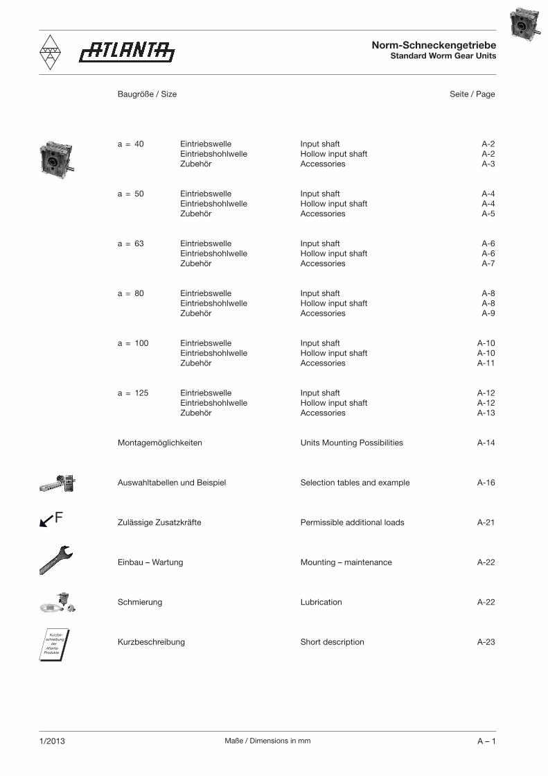
Maße / Dimensions in mm A – 1 1/2013 Norm-Schneckengetriebe Standard Worm Gear Units Baugröße / Size Seite / Page a = 40 Eintriebswelle Input shaft A-2 Eintriebshohlwelle Hollow input shaft A-2 Zubehör Accessories A-3 a = 50 Eintriebswelle Input shaft A-4 Eintriebshohlwelle Hollow input shaft A-4 Zubehör Accessories A-5 a = 63 Eintriebswelle Input shaft A-6 Eintriebshohlwelle Hollow input shaft A-6 Zubehör Accessories A-7 a = 80 Eintriebswelle Input shaft A-8 Eintriebshohlwelle Hollow input shaft A-8 Zubehör Accessories A-9 a = 100 Eintriebswelle Input shaft A-10 Eintriebshohlwelle Hollow input shaft A-10 Zubehör Accessories A-11 a = 125 Eintriebswelle Input shaft A-12 Eintriebshohlwelle Hollow input shaft A-12 Zubehör Accessories A-13 Montagemöglichkeiten Units Mounting Possibilities A-14 Auswahltabellen und Beispiel Selection tables and example A-16 Zulässige Zusatzkräfte Permissible additional loads A-21 Einbau – Wartung Mounting – maintenance A-22 Schmierung Lubrication A-22 Kurzbeschreibung Short description A-23 F Kurzbe- schreibung der Atlanta- Produkte
-
Upload
nguyenthuy -
Category
Documents
-
view
222 -
download
4
Transcript of Baugröße / Size Seite / Page - atlantagmbhatlantagmbh.com/wp-content/uploads/2016/03/Kap-A.pdf ·...
Maße / Dimensions in mm A – 11/2013
Norm-SchneckengetriebeStandard Worm Gear Units
Baugröße / Size Seite / Page
a = 40 Eintriebswelle Input shaft A-2 Eintriebshohlwelle Hollow input shaft A-2 Zubehör Accessories A-3
a = 50 Eintriebswelle Input shaft A-4 Eintriebshohlwelle Hollow input shaft A-4 Zubehör Accessories A-5
a = 63 Eintriebswelle Input shaft A-6 Eintriebshohlwelle Hollow input shaft A-6 Zubehör Accessories A-7
a = 80 Eintriebswelle Input shaft A-8 Eintriebshohlwelle Hollow input shaft A-8 Zubehör Accessories A-9
a = 100 Eintriebswelle Input shaft A-10 Eintriebshohlwelle Hollow input shaft A-10 Zubehör Accessories A-11
a = 125 Eintriebswelle Input shaft A-12 Eintriebshohlwelle Hollow input shaft A-12 Zubehör Accessories A-13
Montagemöglichkeiten Units Mounting Possibilities A-14
Auswahltabellen und Beispiel Selection tables and example A-16
Zulässige Zusatzkräfte Permissible additional loads A-21
Einbau – Wartung Mounting – maintenance A-22
Schmierung Lubrication A-22
Kurzbeschreibung Short description A-23
F
Kurzbe-schreibung
der Atlanta-
Produkte
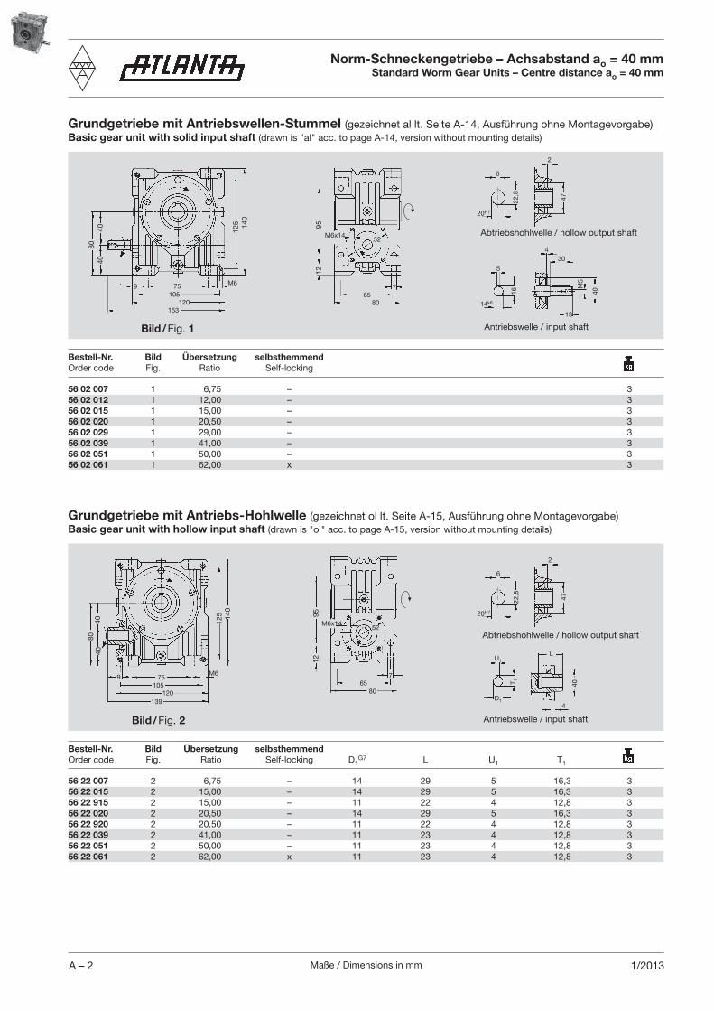
Maße / Dimensions in mmA – 2 1/2013
56 02 007 1 6,75 – 356 02 012 1 12,00 – 356 02 015 1 15,00 – 356 02 020 1 20,50 – 356 02 029 1 29,00 – 356 02 039 1 41,00 – 356 02 051 1 50,00 – 356 02 061 1 62,00 x 3
Grundgetriebe mit Antriebswellen-Stummel (gezeichnet al lt. Seite A-14, Ausführung ohne Montagevorgabe)Basic gear unit with solid input shaft (drawn is "al" acc. to page A-14, version without mounting details)
Bestell-Nr. Bild Übersetzung selbsthemmend Order code Fig. Ratio Self-locking
75
120153
105
4040
80
M69
140
125
40
304
M5
13
5
16
14k6
22,8
6
20H7
2
47
Abtriebshohlwelle / hollow output shaft
Antriebswelle / input shaftBild / Fig. 1
Bestell-Nr. Bild Übersetzung selbsthemmend Order code Fig. Ratio Self-locking D1
G7 L U1 T1
56 22 007 2 6,75 – 14 29 5 16,3 356 22 015 2 15,00 – 14 29 5 16,3 356 22 915 2 15,00 – 11 22 4 12,8 356 22 020 2 20,50 – 14 29 5 16,3 356 22 920 2 20,50 – 11 22 4 12,8 356 22 039 2 41,00 – 11 23 4 12,8 356 22 051 2 50,00 – 11 23 4 12,8 356 22 061 2 62,00 x 11 23 4 12,8 3
6
22,8
20H7
247
D1
T 1
U1L
40
4
Bild / Fig. 2
9512
8040
40
140
125
M69
139120
10575
9512
52
80
765
M6x14
M6x1452
765
80
Norm-Schneckengetriebe – Achsabstand ao = 40 mmStandard Worm Gear Units – Centre distance ao = 40 mm
Abtriebshohlwelle / hollow output shaft
Antriebswelle / input shaft
Grundgetriebe mit Antriebs-Hohlwelle (gezeichnet ol lt. Seite A-15, Ausführung ohne Montagevorgabe)Basic gear unit with hollow input shaft (drawn is "ol" acc. to page A-15, version without mounting details)
Maße / Dimensions in mm A – 31/2013
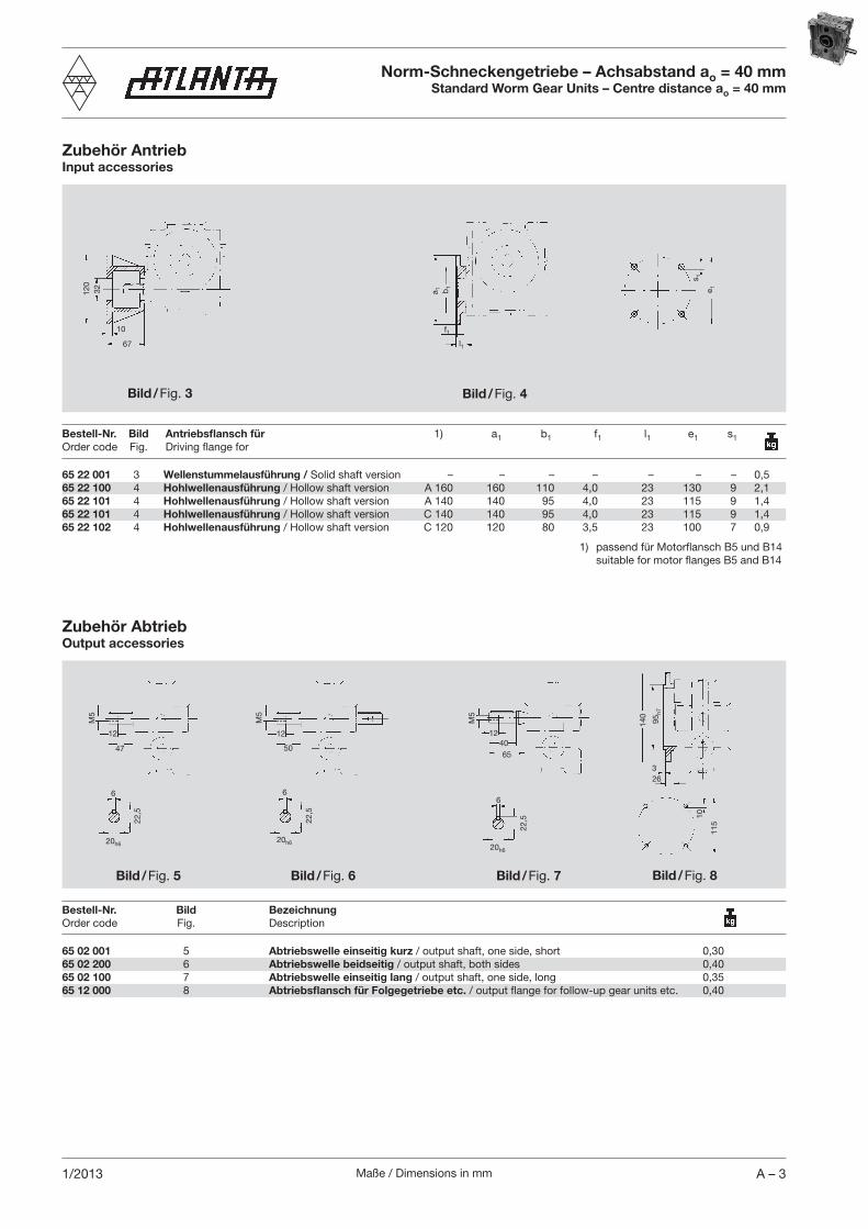
Zubehör AntriebInput accessories
67
10
32120
65 22 001 3 Wellenstummelausführung / Solid shaft version – – – – – – – 0,565 22 100 4 Hohlwellenausführung / Hollow shaft version A 160 160 110 4,0 23 130 9 2,165 22 101 4 Hohlwellenausführung / Hollow shaft version A 140 140 95 4,0 23 115 9 1,465 22 101 4 Hohlwellenausführung / Hollow shaft version C 140 140 95 4,0 23 115 9 1,465 22 102 4 Hohlwellenausführung / Hollow shaft version C 120 120 80 3,5 23 100 7 0,9
Bestell-Nr. Bild Antriebsflansch für 1) a1 b1 f1 l1 e1 s1Order code Fig. Driving flange for
1) passend für Motorflansch B5 und B14 suitable for motor flanges B5 and B14
Bild / Fig. 3
a 1 b1
f1
l1
Bild / Fig. 4
s 1
e 1
M5
12
47
22,5
6
20h6
M5
12
50
6
22,5
20h6
M5
124065
20h6
22,5
6
140
95h7
10
115
Zubehör AbtriebOutput accessories
Bestell-Nr. Bild Bezeichnung Order code Fig. Description
65 02 001 5 Abtriebswelle einseitig kurz / output shaft, one side, short 0,3065 02 200 6 Abtriebswelle beidseitig / output shaft, both sides 0,4065 02 100 7 Abtriebswelle einseitig lang / output shaft, one side, long 0,3565 12 000 8 Abtriebsflansch für Folgegetriebe etc. / output flange for follow-up gear units etc. 0,40
Bild / Fig. 8Bild / Fig. 6 Bild / Fig. 7Bild / Fig. 5
326
Norm-Schneckengetriebe – Achsabstand ao = 40 mmStandard Worm Gear Units – Centre distance ao = 40 mm
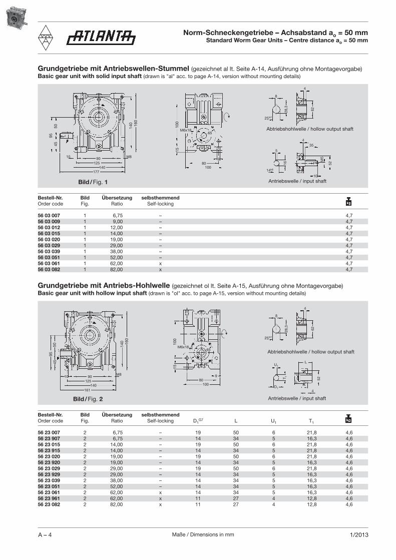
Maße / Dimensions in mmA – 4 1/2013
56 03 007 1 6,75 – 4,756 03 009 1 9,00 – 4,756 03 012 1 12,00 – 4,756 03 015 1 14,00 – 4,756 03 020 1 19,00 – 4,756 03 029 1 29,00 – 4,756 03 039 1 38,00 – 4,756 03 051 1 52,00 – 4,756 03 061 1 62,00 x 4,756 03 082 1 82,00 x 4,7
Bestell-Nr. Bild Übersetzung selbsthemmend Order code Fig. Ratio Self-locking
15
90
140177
125
5045
95
M8
52
354
M5
10
5
16
14k6
28,3
8
25H7
4
62
10
Bestell-Nr. Bild Übersetzung selbsthemmend Order code Fig. Ratio Self-locking D1
G7 L U1 T1
56 23 007 2 6,75 – 19 50 6 21,8 4,656 23 907 2 6,75 – 14 34 5 16,3 4,656 23 015 2 14,00 – 19 50 6 21,8 4,656 23 915 2 14,00 – 14 34 5 21,8 4,656 23 020 2 19,00 – 19 50 6 21,8 4,656 23 920 2 19,00 – 14 34 5 16,3 4,656 23 029 2 29,00 – 19 50 6 21,8 4,656 23 929 2 29,00 – 14 34 5 16,3 4,656 23 039 2 38,00 – 14 34 5 16,3 4,656 23 051 2 52,00 – 14 34 5 16,3 4,656 23 061 2 62,00 x 14 34 5 16,3 4,656 23 961 2 62,00 x 11 27 4 12,8 4,656 23 082 2 82,00 x 11 27 4 12,8 4,6
15
8
28,3
25H7
462
D1
T 1
U1L
52
4
9550
45
160
M810
161140
12590
140 16
0
80
65
9
M6x18
100
100
M6x18
980
100
100
140
65
Norm-Schneckengetriebe – Achsabstand ao = 50 mmStandard Worm Gear Units – Centre distance ao = 50 mm
Grundgetriebe mit Antriebswellen-Stummel (gezeichnet al lt. Seite A-14, Ausführung ohne Montagevorgabe)Basic gear unit with solid input shaft (drawn is "al" acc. to page A-14, version without mounting details)
Grundgetriebe mit Antriebs-Hohlwelle (gezeichnet ol lt. Seite A-15, Ausführung ohne Montagevorgabe)Basic gear unit with hollow input shaft (drawn is "ol" acc. to page A-15, version without mounting details)
Abtriebshohlwelle / hollow output shaft
Antriebswelle / input shaftBild / Fig. 1
Bild / Fig. 2
Abtriebshohlwelle / hollow output shaft
Antriebswelle / input shaft
Maße / Dimensions in mm A – 51/2013
65 23 001 3 Wellenstummelausführung / Solid shaft version – – – – – – – 0,565 23 100 4 Hohlwellenausführung / Hollow shaft version A 200 200 130 4,0 25 165 11 3,765 23 101 4 Hohlwellenausführung / Hollow shaft version A 160 160 110 4,0 25 130 9 2,365 23 101 4 Hohlwellenausführung / Hollow shaft version C 160 160 110 4,0 25 130 9 2,365 23 102 4 Hohlwellenausführung / Hollow shaft version A 140 140 95 3,5 25 115 9 1,665 23 102 4 Hohlwellenausführung / Hollow shaft version C 140 140 95 3,5 25 115 9 1,6
Bestell-Nr. Bild Antriebsflansch für 1) a1 b1 f1 l1 e1 s1Order code Fig. Driving flange for
1) passend für Motorflansch B5 und B14 suitable for motor flanges B5 and B14
67
10
32120
a 1 b1
f1
l1
s 1
e 1
M8
18
71
8
28
25h6
M8
186085
25h6
28
8
253,5
160
110 h
7
130
10
Bestell-Nr. Bild Bezeichnung Modul ZähneOrder code Fig. Description Module Teeth m z l3 b d d2 dk
20 28 332 5a Abtriebsritzelwelle geradverzahnt / output pinion shaft, straight teeth 2 32 53 25 64,00 38 68,0 1,2520 28 321 5a Abtriebsritzelwelle geradverzahnt / output pinion shaft, straight teeth 3 21 55 30 63,00 38 69,0 1,3320 29 330 5a Abtriebsritzelwelle schrägverz. li. / output pinion shaft, helical teeth, LH 2 30 53 25 63,66 38 67,7 1,2520 29 320 5a Abtriebsritzelwelle schrägverz. li. / output pinion shaft, helical teeth, LH 3 20 55 30 63,66 38 69,7 1,3365 03 001 5b Abtriebswelle einseitig kurz / output shaft, one side, short 0,6065 03 200 6 Abtriebswelle beidseitig / output shaft, both sides 0,8065 03 100 7 Abtriebswelle einseitig lang / output shaft, one side, long 0,7065 13 000 8 Abtriebsflansch für Folgegetriebe etc. / output flange for follow-up gear units etc. 0,60
M8
18
67
28
8
25h6
d2
bl3
d dk
Norm-Schneckengetriebe – Achsabstand ao = 50 mmStandard Worm Gear Units – Centre distance ao = 50 mm
Zubehör AntriebInput accessories
Zubehör AbtriebOutput accessories
Bild / Fig. 3 Bild / Fig. 4
Bild / Fig. 8Bild / Fig. 5b Bild / Fig. 7Bild / Fig. 5a Bild / Fig. 6

Maße / Dimensions in mmA – 6 1/2013
56 04 007 1 6,75 – 7,256 04 009 1 9,25 – 7,256 04 015 1 14,50 – 7,256 04 020 1 19,50 – 7,256 04 029 1 29,00 – 7,256 04 039 1 39,00 – 7,256 04 051 1 51,00 – 7,256 04 061 1 61,00 x 7,256 04 082 1 82,00 x 7,2
Bestell-Nr. Bild Übersetzung selbsthemmend Order code Fig. Ratio Self-locking
18
170212
145
6352
M10
195
175
62
405
M5
14
5
18
16k6
31,3
8
28H7
6
62
12
125
115
110
Bestell-Nr. Bild Übersetzung selbsthemmend Order code Fig. Ratio Self-locking D1
G7 L U1 T1
8
31,3
28H7
662
D1
T 1
U1L
62
5
56 24 007 2 6,75 – 24 58 8 27,3 7,256 24 907 2 6,75 – 19 45 6 21,8 7,256 24 015 2 14,50 – 24 58 8 27,3 7,256 24 915 2 14,50 – 19 45 6 21,8 7,256 24 020 2 19,50 – 24 58 8 27,3 7,256 24 920 2 19,50 – 19 45 6 21,8 7,256 24 039 2 39,00 – 19 45 6 21,8 7,256 24 939 2 39,00 – 14 35 5 16,3 7,256 24 051 2 51,00 – 19 45 6 21,8 7,256 24 951 2 51,00 – 14 35 5 16,3 7,256 24 061 2 61,00 x 14 35 5 16,3 7,256 24 082 2 82,00 x 14 35 5 16,3 7,2
6352
195
175
M1012
190170
145110
115
1812
5
95
11
M8x17
120
80
M8x1780
95120
11
Norm-Schneckengetriebe – Achsabstand ao = 63 mmStandard Worm Gear Units – Centre distance ao = 63 mm
Grundgetriebe mit Antriebswellen-Stummel (gezeichnet al lt. Seite A-14, Ausführung ohne Montagevorgabe)Basic gear unit with solid input shaft (drawn is "al" acc. to page A-14, version without mounting details)
Grundgetriebe mit Antriebs-Hohlwelle (gezeichnet ol lt. Seite A-15, Ausführung ohne Montagevorgabe)Basic gear unit with hollow input shaft (drawn is "ol" acc. to page A-15, version without mounting details)
Abtriebshohlwelle / hollow output shaft
Antriebswelle / input shaftBild / Fig. 1
Bild / Fig. 2
Abtriebshohlwelle / hollow output shaft
Antriebswelle / input shaft
Maße / Dimensions in mm A – 71/2013
65 24 001 3 Wellenstummelausführung / Solid shaft version – – – – – – – 0,7565 24 100 4 Hohlwellenausführung / Hollow shaft version A 200 200 130 4,0 25 165 11 3,765 24 100 4 Hohlwellenausführung / Hollow shaft version C 200 200 130 4,0 25 165 11 3,765 24 101 4 Hohlwellenausführung / Hollow shaft version A 160 160 110 4,0 25 130 9 2,365 24 101 4 Hohlwellenausführung / Hollow shaft version C 160 160 110 4,0 25 130 9 2,365 24 102 4 Hohlwellenausführung / Hollow shaft version C 140 140 95 3,5 25 115 9 1,6
Bestell-Nr. Bild Antriebsflansch für 1) a1 b1 f1 l1 e1 s1Order code Fig. Driving flange for
1) passend für Motorflansch B5 und B14 suitable for motor flanges B5 and B14
75
10
40140
a 1 b1
f1
l1M
8
18
71
8
31
28h6
M8
186090
28h6
31
8
303,5
200
130 h
7
165
13
M8
18
67
31
8
28h6
d2
bl3
d dk
20 28 432 5a Abtriebsritzelwelle geradverzahnt / output pinion shaft, straight teeth 2 32 57,5 25 64,00 42 68,0 1,5020 28 421 5a Abtriebsritzelwelle geradverzahnt / output pinion shaft, straight teeth 3 21 60,0 30 63,00 42 69,0 1,6020 28 417 5a Abtriebsritzelwelle geradverzahnt / output pinion shaft, straight teeth 4 17 65,0 40 68,00 42 76,0 2,0020 29 430 5a Abtriebsritzelwelle schrägverz. li. / output pinion shaft, helical teeth, LH 2 30 57,5 25 63,66 42 67,7 1,5020 29 420 5a Abtriebsritzelwelle schrägverz. li. / output pinion shaft, helical teeth, LH 3 20 60,0 30 63,66 42 69,7 1,6020 29 415 5a Abtriebsritzelwelle schrägverz. li. / output pinion shaft, helical teeth, LH 4 15 65,0 40 63,66 42 71,7 1,8565 04 000 5b Abtriebswelle einseitig kurz / output shaft, one side, short 0,8065 04 200 6 Abtriebswelle beidseitig / output shaft, both sides 1,2065 04 100 7 Abtriebswelle einseitig lang / output shaft, one side, long 1,0065 14 000 8 Abtriebsflansch für Folgegetriebe etc. / output flange for follow-up gear units etc. 1,20
s 1
e 1
Norm-Schneckengetriebe – Achsabstand ao = 63 mmStandard Worm Gear Units – Centre distance ao = 63 mm
Zubehör AntriebInput accessories
Zubehör AbtriebOutput accessories
Bild / Fig. 3 Bild / Fig. 4
Bild / Fig. 8Bild / Fig. 5b Bild / Fig. 7Bild / Fig. 5a Bild / Fig. 6
Bestell-Nr. Bild Bezeichnung Modul ZähneOrder code Fig. Description Module Teeth m z l3 b d d2 dk
Es können auch die Abtriebswellen Best.-Nr. 65 04 040 und 65 04 140 mit Wellendurchmesser 30h6 aus unserem Servo-Katalog eingesetzt werden.Our output shaft, Order code 65 04 040 and 65 04 140, with shaft diameter Ø 30h6, shown in our servo catalogue, can also be used.
Maße / Dimensions in mmA – 8 1/2013
56 05 007 1 6,75 – 13,656 05 009 1 9,25 – 13,656 05 015 1 14,50 – 13,656 05 020 1 19,50 – 13,656 05 039 1 40,00 – 13,656 05 051 1 53,00 – 13,656 05 061 1 62,00 x 13,656 05 082 1 82,00 x 13,6
Bestell-Nr. Bild Übersetzung selbsthemmend Order code Fig. Ratio Self-locking
205258
175
8065
72
504
M8
20
6
22k6
39,3
10
36H7
5
72
145
13512,5 M12
225 24
5
24,5
Bestell-Nr. Bild Übersetzung selbsthemmend Order code Fig. Ratio Self-locking D1
G7 L U1 T1
20
10
39,3
36H7
572
D1
T 1
U1 L
72
4
170
56 25 007 2 6,75 – 28 64 8 31,3 13,656 25 907 2 6,75 – 24 59 8 27,3 13,656 25 015 2 14,50 – 24 59 8 27,3 13,656 25 020 2 19,50 – 24 59 8 27,3 13,656 25 039 2 40,00 – 24 59 8 27,3 13,656 25 939 2 40,00 – 19 43 6 21,8 13,656 25 051 2 53,00 – 24 59 8 27,3 13,656 25 951 2 53,00 – 19 43 6 21,8 13,656 25 061 2 62,00 x 19 43 6 21,8 13,656 25 082 2 82,00 x 19 43 6 21,8 13,6
8065
224205
175135
145
12,5 M12
225 24
5
115
13
140
100M10x20
170
20
M10x20100
13
115140
Norm-Schneckengetriebe – Achsabstand ao = 80 mmStandard Worm Gear Units – Centre distance ao = 80 mm
Grundgetriebe mit Antriebswellen-Stummel (gezeichnet al lt. Seite A-14, Ausführung ohne Montagevorgabe)Basic gear unit with solid input shaft (drawn is "al" acc. to page A-14, version without mounting details)
Grundgetriebe mit Antriebs-Hohlwelle (gezeichnet ol lt. Seite A-15, Ausführung ohne Montagevorgabe)Basic gear unit with hollow input shaft (drawn is "ol" acc. to page A-15, version without mounting details)
Abtriebshohlwelle / hollow output shaft
Antriebswelle / input shaftBild / Fig. 1
Bild / Fig. 2
Abtriebshohlwelle / hollow output shaft
Antriebswelle / input shaft
Maße / Dimensions in mm A – 91/2013
65 25 001 3 Wellenstummelausführung / Solid shaft version – – – – – – – 1,2565 25 100 4 Hohlwellenausführung / Hollow shaft version A 250 250 180 4,5 27 215 14 6,265 25 101 4 Hohlwellenausführung / Hollow shaft version A 200 200 130 4,0 25 165 11 3,765 25 101 4 Hohlwellenausführung / Hollow shaft version C 200 200 130 4,0 25 165 11 3,765 25 102 2) 4 Hohlwellenausführung / Hollow shaft version C 160 160 110 4,0 25 130 9 1,0
Bestell-Nr. Bild Antriebsflansch für 1) a1 b1 f1 l1 e1 s1Order code Fig. Driving flange for
12
50160
a 1 b1
f1
l1
s 1
e 1
106M
12
93
10
39
36h6
M12
36h6
39
10
364
250
180 h
7
215
15
M12
89
39
10
36h6
d2
bl3
d dk
26 26
10670
26
20 28 521 5a Abtriebsritzelwelle geradverzahnt / output pinion shaft, straight teeth 3 21 62 30 63,00 48 69,0 1,8020 28 517 5a Abtriebsritzelwelle geradverzahnt / output pinion shaft, straight teeth 4 17 67 40 68,00 48 76,0 2,6520 29 520 5a Abtriebsritzelwelle schrägverz. li. / output pinion shaft, helical teeth, LH 3 20 62 30 63,66 48 69,7 1,8020 29 515 5a Abtriebsritzelwelle schrägverz. li. / output pinion shaft, helical teeth, LH 4 15 67 40 63,66 48 71,7 2,5065 05 000 5b Abtriebswelle einseitig kurz / output shaft, one side, short 1,7065 05 200 6 Abtriebswelle beidseitig / output shaft, both sides 2,4065 05 100 7 Abtriebswelle einseitig lang / output shaft, one side, long 1,9065 15 000 8 Abtriebsflansch für Folgegetriebe etc. / output flange for follow-up gear units etc. 1,80
Norm-Schneckengetriebe – Achsabstand ao = 80 mmStandard Worm Gear Units – Centre distance ao = 80 mm
Zubehör AntriebInput accessories
Zubehör AbtriebOutput accessories
Bild / Fig. 3 Bild / Fig. 4
Bild / Fig. 8Bild / Fig. 5b Bild / Fig. 7Bild / Fig. 5a Bild / Fig. 6
1) passend für Motorflansch B5 und B14 / suitable for motor flanges B5 and B142) Ausführung und Abstützung gegen Gehäuse / design with support against housing
Bestell-Nr. Bild Bezeichnung Modul ZähneOrder code Fig. Description Module Teeth m z l3 b d d2 dk
Es können auch die Abtriebswellen Best.-Nr. 65 05 040 und 65 05 140 mit Wellendurchmesser 35h6 aus unserem Servo-Katalog eingesetzt werden.Our output shaft, Order code 65 05 040 and 65 05 140, with shaft diameter Ø 35h6, shown in our servo catalogue, can also be used.
Maße / Dimensions in mmA – 10 1/2013
56 06 007 1 6,75 – 2056 06 009 1 9,25 – 2056 06 015 1 14,50 – 2056 06 020 1 19,50 – 2056 06 029 1 29,00 – 2056 06 039 1 39,00 – 2056 06 051 1 52,00 – 2056 06 061 1 62,00 x 2056 06 082 1 82,00 x 20
Bestell-Nr. Bild Übersetzung selbsthemmend Order code Fig. Ratio Self-locking
250314
225
70
80
606,5
M8
20
8
25k6
51,8
14
48H7
8
170
18014 M12
265 29
0
100
28
100
Bestell-Nr. Bild Übersetzung selbsthemmend Order code Fig. Ratio Self-locking D1
G7 L U1 T1
14
51,8
48H7
8
D1
T 1
U1L
80
6,5
56 26 007 2 6,75 – 28 65 8 31,3 2056 26 015 2 14,50 – 28 65 8 31,3 2056 26 915 2 14,50 – 24 55 8 27,3 2056 26 020 2 19,50 – 28 65 8 31,3 2056 26 920 2 19,50 – 24 55 8 27,3 2056 26 039 2 39,00 – 24 55 8 27,3 2056 26 051 2 52,00 – 24 55 8 27,3 20 56 26 061 2 62,00 x 24 55 8 27,3 2056 26 961 2 62,00 x 19 43 6 21,8 2056 26 082 2 82,00 x 24 55 8 27,3 2056 26 982 2 82,00 x 19 43 8 21,8 20
100
70
250225180
170
14 M12
265 29
0
100
272
13
135
M12x26
210
22
160
120
135
120
13
160
2221
0
M12x26
Norm-Schneckengetriebe – Achsabstand ao = 100 mmStandard Worm Gear Units – Centre distance ao = 100 mm
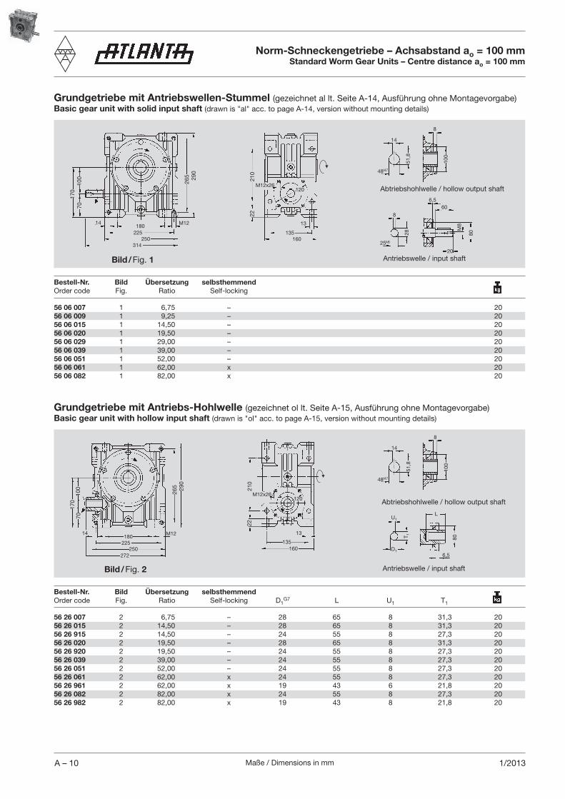
Grundgetriebe mit Antriebswellen-Stummel (gezeichnet al lt. Seite A-14, Ausführung ohne Montagevorgabe)Basic gear unit with solid input shaft (drawn is "al" acc. to page A-14, version without mounting details)
Grundgetriebe mit Antriebs-Hohlwelle (gezeichnet ol lt. Seite A-15, Ausführung ohne Montagevorgabe)Basic gear unit with hollow input shaft (drawn is "ol" acc. to page A-15, version without mounting details)
Abtriebshohlwelle / hollow output shaft
Antriebswelle / input shaftBild / Fig. 1
Bild / Fig. 2
Abtriebshohlwelle / hollow output shaft
Antriebswelle / input shaft
Maße / Dimensions in mm A – 111/2013
65 26 001 3 Wellenstummelausführung / Solid shaft version – – – – – – – 2,365 26 101 2) 4 Hohlwellenausführung / Hollow shaft version A 200 200 130 4,0 27 165 11 1,565 26 101 2) 4 Hohlwellenausführung / Hollow shaft version C 200 200 130 4,0 27 165 11 1,565 26 102 2) 4 Hohlwellenausführung / Hollow shaft version C 160 160 110 4,0 27 130 9 1,2
Bestell-Nr. Bild Antriebsflansch für 1) a1 b1 f1 l1 e1 s1Order code Fig. Driving flange for
14
60200
a 1 b1
f1
l1
s 1
e 1
131M
12
26
115
14
51,5
48h6
M12
48h6
51,5
14
4
300
230 h
7
265
15
M12
26
110
51,5
14
48h6
d2
bl3
d dk
36
110146
26
20 28 613 3) 5a Abtriebsritzelwelle geradverzahnt / output pinion shaft, straight teeth 5 13 20 28 617 5a Abtriebsritzelwelle geradverzahnt / output pinion shaft, straight teeth 4 17 72 40 68,00 57 76,0 4,0020 28 630 5a Abtriebsritzelwelle geradverzahnt / output pinion shaft, straight teeth 4 30 72 40 120,00 57 128,0 6,4020 29 612 4) 5a Abtriebsritzelwelle schrägverz. li. / output pinion shaft, helical teeth, LH 5 12 20 29 615 5a Abtriebsritzelwelle schrägverz. li. / output pinion shaft, helical teeth, LH 4 15 72 40 63,66 57 71,7 3,9020 29 630 5a Abtriebsritzelwelle schrägverz. li. / output pinion shaft, helical teeth, LH 4 30 72 40 127,32 57 135,3 6,9065 06 001 5b Abtriebswelle einseitig kurz / output shaft, one side, short 3,7065 06 200 6 Abtriebswelle beidseitig / output shaft, both sides 5,5065 06 100 7 Abtriebswelle einseitig lang / output shaft, one side, long 4,2065 16 000 8 Abtriebsflansch für Folgegetriebe etc. / output flange for follow-up gear units etc. 3,00
Norm-Schneckengetriebe – Achsabstand ao = 100 mmStandard Worm Gear Units – Centre distance ao = 100 mm
Zubehör AntriebInput accessories
Zubehör AbtriebOutput accessories
Bild / Fig. 3 Bild / Fig. 4
Bild / Fig. 8Bild / Fig. 5b Bild / Fig. 7Bild / Fig. 5a Bild / Fig. 6
1) passend für Motorflansch B5 und B14 / suitable for motor flanges B5 and B142) Ausführung und Abstützung gegen Gehäuse / design with support against housing
Bestell-Nr. Bild Bezeichnung Modul ZähneOrder code Fig. Description Module Teeth m z l3 b d d2 dk
3) mit Profilverschiebungsfaktor x = +0,5 / with profile modification factor x = +0,54) mit Profilverschiebungsfaktor x = +0,434 / with profile modification factor x = +0,434
Es können auch die Abtriebswellen Best.-Nr. 65 06 040 und 65 06 140 mit Wellendurchmesser 45h6 aus unserem Servo-Katalog eingesetzt werden.Our output shaft, Order code 65 06 040 and 65 06 140, with shaft diameter Ø 45h6, shown in our servo catalogue, can also be used.
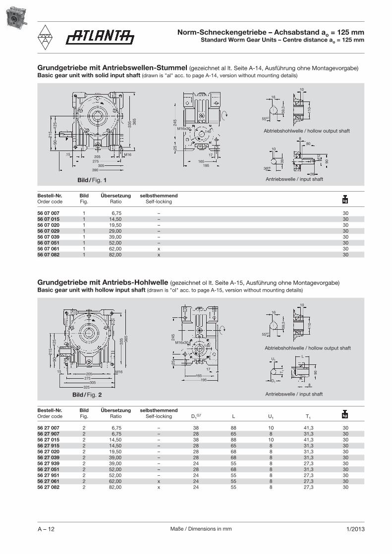
Maße / Dimensions in mmA – 12 1/2013
56 07 007 1 6,75 – 3056 07 015 1 14,50 – 3056 07 020 1 19,50 – 3056 07 029 1 29,00 – 3056 07 039 1 39,00 – 3056 07 051 1 52,00 – 3056 07 061 1 62,00 x 3056 07 082 1 82,00 x 30
Bestell-Nr. Bild Übersetzung selbsthemmend Order code Fig. Ratio Self-locking
305390
275
90
90
808
M12
26
10
36k6
59,3
16
55H7
10
215
20515 M16
335 36
5
125
39
110
Bestell-Nr. Bild Übersetzung selbsthemmend Order code Fig. Ratio Self-locking D1
G7 L U1 T1
16
59,3
55H7
10
D1
T 1
U1L
90
8
56 27 007 2 6,75 – 38 88 10 41,3 3056 27 907 2 6,75 – 28 65 8 31,3 3056 27 015 2 14,50 – 38 88 10 41,3 3056 27 915 2 14,50 – 28 65 8 31,3 3056 27 020 2 19,50 – 28 68 8 31,3 3056 27 039 2 39,00 – 28 68 8 31,3 3056 27 939 2 39,00 – 24 55 8 27,3 3056 27 051 2 52,00 – 28 68 8 31,3 3056 27 951 2 52,00 – 24 55 8 27,3 3056 27 061 2 62,00 x 24 55 8 27,3 3056 27 082 2 82,00 x 24 55 8 27,3 30
110
90
325305
275205
215
15 M16
335 36
5
125
140
195
17
165
M16x30
2524
5
140M16x30
165195
17
245
25
Norm-Schneckengetriebe – Achsabstand ao = 125 mmStandard Worm Gear Units – Centre distance ao = 125 mm
Grundgetriebe mit Antriebswellen-Stummel (gezeichnet al lt. Seite A-14, Ausführung ohne Montagevorgabe)Basic gear unit with solid input shaft (drawn is "al" acc. to page A-14, version without mounting details)
Grundgetriebe mit Antriebs-Hohlwelle (gezeichnet ol lt. Seite A-15, Ausführung ohne Montagevorgabe)Basic gear unit with hollow input shaft (drawn is "ol" acc. to page A-15, version without mounting details)
Abtriebshohlwelle / hollow output shaft
Antriebswelle / input shaftBild / Fig. 1
Bild / Fig. 2
Abtriebshohlwelle / hollow output shaft
Antriebswelle / input shaft

Maße / Dimensions in mm A – 131/2013
65 27 001 3 Wellenstummelausführung / Solid shaft version – – – – – – – 2,565 27 101 4 Hohlwellenausführung / Hollow shaft version A 250 250 180 4,5 27 215 14 6,365 27 102 2) 4 Hohlwellenausführung / Hollow shaft version A 200 200 130 4,0 27 165 11 1,865 27 102 2) 4 Hohlwellenausführung / Hollow shaft version C 200 200 130 4,0 27 165 11 1,8
Bestell-Nr. Bild Antriebsflansch für 1) a1 b1 f1 l1 e1 s1Order code Fig. Driving flange for
1) passend für Motorflansch B5 und B14 / suitable for motor flanges B5 and B142) Ausführung und Abstützung gegen Gehäuse / design with support against housing
14
80200
a 1 b1
f1
l1
s 1
e 1
149
Bestell-Nr. Bild Bezeichnung Order code Fig. Description
65 07 001 5 Abtriebswelle einseitig kurz / output shaft, one side, short 5,4065 07 200 6 Abtriebswelle beidseitig / output shaft, both sides 7,9065 17 000 8 Abtriebsflansch für Folgegetriebe etc. / output flange for follow-up gear units etc. 5,00
M12
110
59
16
55h6
M12
115
16
59
55h6
M12
55h6
59
16
350
250 h
7
18
545
26
154110
300
2626
Norm-Schneckengetriebe – Achsabstand ao = 125 mmStandard Worm Gear Units – Centre distance ao = 125 mm
Zubehör AntriebInput accessories
Zubehör AbtriebOutput accessories
Bild / Fig. 3 Bild / Fig. 4
Bild / Fig. 8Bild / Fig. 6 Bild / Fig. 7Bild / Fig. 5
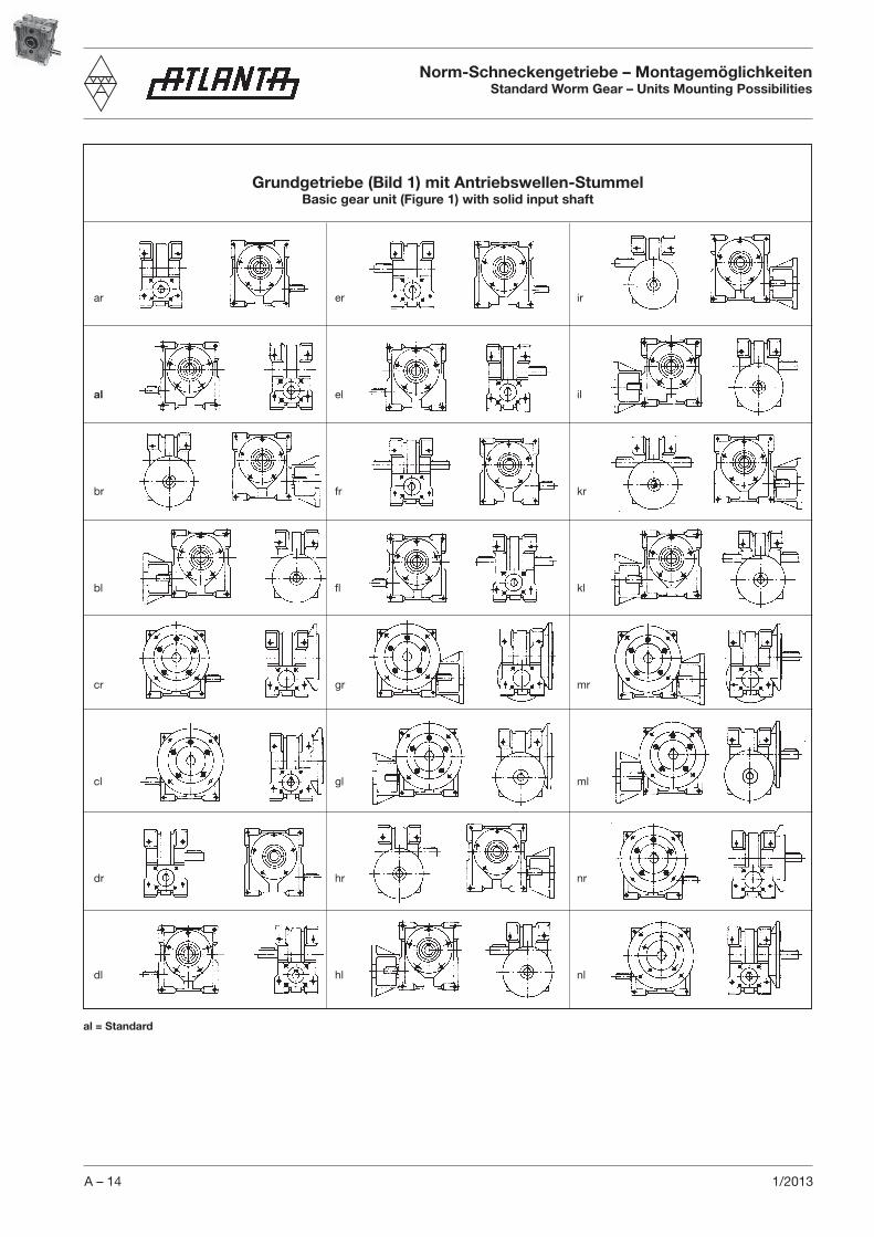
A – 14 1/2013
Norm-Schneckengetriebe – MontagemöglichkeitenStandard Worm Gear – Units Mounting Possibilities
ar
al
br
bl
cr
cl
dr
dl
er
el
fr
fl
gr
gl
hr
hl
ir
il
kr
kl
mr
ml
nr
nl
Grundgetriebe (Bild 1) mit Antriebswellen-StummelBasic gear unit (Figure 1) with solid input shaft
al = Standard
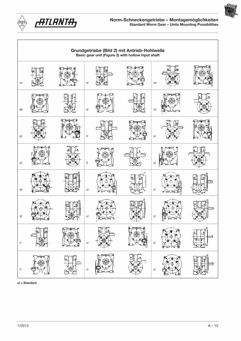
A – 151/2013
or
ol
pr
pl
qr
ql
rr
rl
sr
sl
tr
tl
ur
ul
vr
vl
wr
wl
xr
xl
yr
yl
zr
zl
Grundgetriebe (Bild 2) mit Antrieb-HohlwelleBasic gear unit (Figure 2) with hollow input shaft
Norm-Schneckengetriebe – MontagemöglichkeitenStandard Worm Gear – Units Mounting Possibilities
ol = Standard
Maße / Dimensions in mmA – 16 1/2013
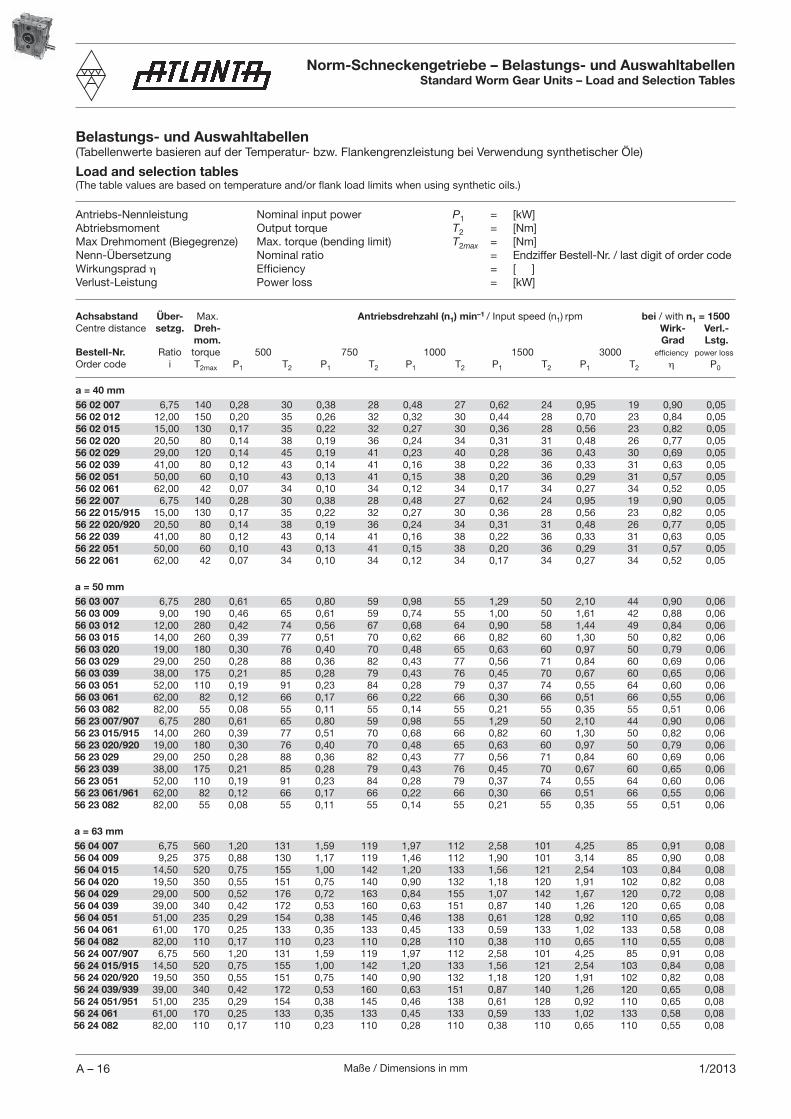
Belastungs- und Auswahltabellen(Tabellenwerte basieren auf der Temperatur- bzw. Flankengrenzleistung bei Verwendung synthetischer Öle)
Load and selection tables(The table values are based on temperature and/or flank load limits when using synthetic oils.)
Antriebs-Nennleistung Nominal input power P1 = [kW] Abtriebsmoment Output torque T2 = [Nm] Max Drehmoment (Biegegrenze) Max. torque (bending limit) T2max = [Nm] Nenn-Übersetzung Nominal ratio = Endziffer Bestell-Nr. / last digit of order codeWirkungsprad η Efficiency = [ ]Verlust-Leistung Power loss = [kW]
Achsabstand Über- Max. Antriebsdrehzahl (n1) min–1 / Input speed (n1) rpm bei / with n1 = 1500Centre distance setzg. Dreh- Wirk- Verl.- mom. Grad Lstg.Bestell-Nr. Ratio torque 500 750 1000 1500 3000 efficiency power loss
Order code i T2max P1 T2 P1 T2 P1 T2 P1 T2 P1 T2 η P0
a = 40 mm56 02 007 6,75 140 0,28 30 0,38 28 0,48 27 0,62 24 0,95 19 0,90 0,0556 02 012 12,00 150 0,20 35 0,26 32 0,32 30 0,44 28 0,70 23 0,84 0,0556 02 015 15,00 130 0,17 35 0,22 32 0,27 30 0,36 28 0,56 23 0,82 0,0556 02 020 20,50 80 0,14 38 0,19 36 0,24 34 0,31 31 0,48 26 0,77 0,0556 02 029 29,00 120 0,14 45 0,19 41 0,23 40 0,28 36 0,43 30 0,69 0,0556 02 039 41,00 80 0,12 43 0,14 41 0,16 38 0,22 36 0,33 31 0,63 0,0556 02 051 50,00 60 0,10 43 0,13 41 0,15 38 0,20 36 0,29 31 0,57 0,0556 02 061 62,00 42 0,07 34 0,10 34 0,12 34 0,17 34 0,27 34 0,52 0,0556 22 007 6,75 140 0,28 30 0,38 28 0,48 27 0,62 24 0,95 19 0,90 0,0556 22 015/915 15,00 130 0,17 35 0,22 32 0,27 30 0,36 28 0,56 23 0,82 0,0556 22 020/920 20,50 80 0,14 38 0,19 36 0,24 34 0,31 31 0,48 26 0,77 0,0556 22 039 41,00 80 0,12 43 0,14 41 0,16 38 0,22 36 0,33 31 0,63 0,0556 22 051 50,00 60 0,10 43 0,13 41 0,15 38 0,20 36 0,29 31 0,57 0,0556 22 061 62,00 42 0,07 34 0,10 34 0,12 34 0,17 34 0,27 34 0,52 0,05
a = 50 mm56 03 007 6,75 280 0,61 65 0,80 59 0,98 55 1,29 50 2,10 44 0,90 0,0656 03 009 9,00 190 0,46 65 0,61 59 0,74 55 1,00 50 1,61 42 0,88 0,0656 03 012 12,00 280 0,42 74 0,56 67 0,68 64 0,90 58 1,44 49 0,84 0,0656 03 015 14,00 260 0,39 77 0,51 70 0,62 66 0,82 60 1,30 50 0,82 0,0656 03 020 19,00 180 0,30 76 0,40 70 0,48 65 0,63 60 0,97 50 0,79 0,0656 03 029 29,00 250 0,28 88 0,36 82 0,43 77 0,56 71 0,84 60 0,69 0,0656 03 039 38,00 175 0,21 85 0,28 79 0,43 76 0,45 70 0,67 60 0,65 0,0656 03 051 52,00 110 0,19 91 0,23 84 0,28 79 0,37 74 0,55 64 0,60 0,0656 03 061 62,00 82 0,12 66 0,17 66 0,22 66 0,30 66 0,51 66 0,55 0,0656 03 082 82,00 55 0,08 55 0,11 55 0,14 55 0,21 55 0,35 55 0,51 0,0656 23 007/907 6,75 280 0,61 65 0,80 59 0,98 55 1,29 50 2,10 44 0,90 0,0656 23 015/915 14,00 260 0,39 77 0,51 70 0,68 66 0,82 60 1,30 50 0,82 0,0656 23 020/920 19,00 180 0,30 76 0,40 70 0,48 65 0,63 60 0,97 50 0,79 0,0656 23 029 29,00 250 0,28 88 0,36 82 0,43 77 0,56 71 0,84 60 0,69 0,0656 23 039 38,00 175 0,21 85 0,28 79 0,43 76 0,45 70 0,67 60 0,65 0,0656 23 051 52,00 110 0,19 91 0,23 84 0,28 79 0,37 74 0,55 64 0,60 0,0656 23 061/961 62,00 82 0,12 66 0,17 66 0,22 66 0,30 66 0,51 66 0,55 0,0656 23 082 82,00 55 0,08 55 0,11 55 0,14 55 0,21 55 0,35 55 0,51 0,06
a = 63 mm56 04 007 6,75 560 1,20 131 1,59 119 1,97 112 2,58 101 4,25 85 0,91 0,0856 04 009 9,25 375 0,88 130 1,17 119 1,46 112 1,90 101 3,14 85 0,90 0,0856 04 015 14,50 520 0,75 155 1,00 142 1,20 133 1,56 121 2,54 103 0,84 0,0856 04 020 19,50 350 0,55 151 0,75 140 0,90 132 1,18 120 1,91 102 0,82 0,0856 04 029 29,00 500 0,52 176 0,72 163 0,84 155 1,07 142 1,67 120 0,72 0,0856 04 039 39,00 340 0,42 172 0,53 160 0,63 151 0,87 140 1,26 120 0,65 0,0856 04 051 51,00 235 0,29 154 0,38 145 0,46 138 0,61 128 0,92 110 0,65 0,0856 04 061 61,00 170 0,25 133 0,35 133 0,45 133 0,59 133 1,02 133 0,58 0,0856 04 082 82,00 110 0,17 110 0,23 110 0,28 110 0,38 110 0,65 110 0,55 0,0856 24 007/907 6,75 560 1,20 131 1,59 119 1,97 112 2,58 101 4,25 85 0,91 0,0856 24 015/915 14,50 520 0,75 155 1,00 142 1,20 133 1,56 121 2,54 103 0,84 0,0856 24 020/920 19,50 350 0,55 151 0,75 140 0,90 132 1,18 120 1,91 102 0,82 0,0856 24 039/939 39,00 340 0,42 172 0,53 160 0,63 151 0,87 140 1,26 120 0,65 0,0856 24 051/951 51,00 235 0,29 154 0,38 145 0,46 138 0,61 128 0,92 110 0,65 0,0856 24 061 61,00 170 0,25 133 0,35 133 0,45 133 0,59 133 1,02 133 0,58 0,0856 24 082 82,00 110 0,17 110 0,23 110 0,28 110 0,38 110 0,65 110 0,55 0,08
Norm-Schneckengetriebe – Belastungs- und AuswahltabellenStandard Worm Gear Units – Load and Selection Tables

Maße / Dimensions in mm A – 171/2013
a = 80 mm56 05 007 6,75 1170 2,43 269 3,24 245 3,93 228 5,26 208 8,75 175 0,92 0,1056 05 009 9,25 775 1,71 257 2,29 235 2,83 220 3,73 200 6,24 169 0,91 0,1056 05 015 14,50 1060 1,51 317 1,99 290 2,37 272 3,12 248 5,14 211 0,86 0,1056 05 020 19,50 710 1,07 300 1,43 277 1,75 260 2,28 238 3,80 203 0,84 0,1056 05 039 40,00 690 0,73 340 1,00 318 1,17 300 1,42 278 2,44 239 0,77 0,1056 05 051 53,00 460 0,52 298 0,67 280 0,82 266 1,03 247 1,56 214 0,71 0,1056 05 061 62,00 340 0,55 314 0,76 314 0,98 314 1,28 314 2,05 275 0,62 0,1056 05 082 82,00 230 0,32 230 0,45 230 0,56 230 0,75 230 1,32 230 0,59 0,1056 25 007/907 6,75 1170 2,43 269 3,24 245 3,93 228 5,26 208 8,75 175 0,92 0,1056 25 015 14,50 1060 1,51 317 1,99 290 2,37 272 3,12 248 5,14 211 0,86 0,1056 25 020 19,50 710 1,07 300 1,43 277 1,75 260 2,28 238 3,80 203 0,84 0,1056 25 039/939 40,00 690 0,73 340 1,00 318 1,17 300 1,42 278 2,44 239 0,77 0,1056 25 051/951 53,00 460 0,52 298 0,67 280 0,82 266 1,03 247 1,56 214 0,71 0,1056 25 061 62,00 340 0,55 314 0,76 314 0,98 314 1,28 314 2,05 275 0,62 0,1056 25 082 82,00 230 0,32 230 0,45 230 0,56 230 0,75 230 1,32 230 0,59 0,10
a = 100 mm56 06 007 6,75 2170 4,50 500 6,00 460 7,40 430 9,95 390 16,30 330 0,92 0,1356 06 009 9,25 1560 3,30 500 4,50 460 5,40 430 7,25 390 12,50 330 0,92 0,1356 06 015 14,50 2030 2,80 620 3,75 570 4,50 530 6,00 485 9,90 410 0,87 0,1356 06 020 19,50 1400 2,10 590 2,85 540 3,40 510 5,65 470 7,45 400 0,88 0,1356 06 029 29,00 2000 1,85 680 2,45 630 3,00 600 3,90 550 6,20 470 0,75 0,1356 06 039 39,00 1380 1,25 575 1,60 540 1,90 510 2,50 470 4,00 400 0,76 0,1356 06 051 52,00 910 1,00 600 1,30 565 1,60 540 2,10 500 3,30 430 0,72 0,1356 06 061 62,00 580 0,97 580 1,35 580 1,55 550 1,95 510 3,20 450 0,66 0,1356 06 082 82,00 450 0,60 450 0,81 450 1,04 450 1,40 450 2,50 450 0,62 0,1356 26 007 6,75 2170 4,50 500 6,00 460 7,40 430 9,95 390 16,30 330 0,92 0,1356 26 015/915 14,50 2030 2,80 620 3,75 570 4,50 530 6,00 485 9,90 410 0,87 0,1356 26 020/920 19,50 1400 2,10 590 2,85 540 3,40 510 5,65 470 7,45 400 0,88 0,1356 26 039 39,00 1380 1,25 575 1,60 540 1,90 510 2,50 470 4,00 400 0,76 0,1356 26 051 52,00 910 1,00 600 1,30 565 1,60 540 2,10 500 3,30 430 0,72 0,1356 26 061/961 62,00 580 0,97 580 1,35 580 1,55 550 1,95 510 3,20 450 0,66 0,1356 26 082/982 82,00 450 0,60 450 0,81 450 1,04 450 1,40 450 2,50 450 0,62 0,13
a = 125 mm56 07 007 6,75 2450 8,80 990 11,70 900 14,25 840 19,30 765 31,50 645 1) 0,93 0,1656 07 015 14,50 4000 5,60 1200 7,50 1110 9,00 1040 12,00 950 19,50 800 0,88 0,1656 07 020 19,50 3000 4,00 1150 5,50 1060 6,50 1000 8,60 910 14,00 775 0,87 0,1656 07 029 29,00 4000 3,70 1380 4,75 1280 5,70 1200 7,60 1110 12,50 910 0,79 0,1656 07 039 39,00 2650 2,60 1290 3,40 1210 4,20 1150 5,50 1060 8,90 910 0,78 0,1656 07 051 52,00 1800 1,80 1130 2,40 1055 2,90 1015 3,80 940 6,80 815 0,74 0,1656 07 061 62,00 1300 2,03 1300 2,85 1300 3,30 1240 4,30 1160 6,80 1010 0,68 0,1656 07 082 82,00 860 1,10 860 1,53 860 1,80 860 2,50 860 4,65 860 0,66 0,1656 27 007/907 6,75 2450 8,80 990 11,70 900 14,25 840 19,30 765 31,50 6451) 0,93 0,1656 27 015/915 14,50 4000 5,60 1200 7,50 1110 9,00 1040 12,00 950 19,50 800 0,88 0,1656 27 020 19,50 3000 4,00 1150 5,50 1060 6,50 1000 8,60 910 14,00 775 0,87 0,1656 27 039/939 39,00 2650 2,60 1290 3,40 1210 4,20 1150 5,50 1060 8,90 910 0,78 0,1656 27 051/951 52,00 1800 1,80 1130 2,40 1055 2,90 1015 3,80 940 6,80 815 0,74 0,1656 27 061 62,00 1300 2,03 1300 2,85 1300 3,30 1240 4,30 1160 6,80 1010 0,68 0,1656 27 082 82,00 860 1,10 860 1,53 860 1,80 860 2,50 860 4,65 860 0,66 0,16
(Tabellenwerte basieren auf der Temperatur- bzw. Flankengrenzleistung bei Verwendung synthetischer Öle)(The values given in the table are based on temperature and/or flank load limits when using synthetic oils.)
Achsabstand Über- Max. Antriebsdrehzahl (n1) min–1 / Input speed (n1) rpm bei / with n1 = 1500Centre distance setzg. Dreh- Wirk- Verl.- mom. Grad Lstg.Bestell-Nr. Ratio torque 500 750 1000 1500 3000 efficiency power loss
Order code i T2max P1 T2 P1 T2 P1 T2 P1 T2 P1 T2 η P0
Norm-Schneckengetriebe – Belastungs- und AuswahltabellenStandard Worm Gear Units – Load and Selection Tables
1) max. Eintriebsdrehzahl von 2800 min-1 / max. input speed of 2800 min-1

Maße / Dimensions in mmA – 18 1/2013
Norm-Schneckengetriebe – Belastungstabellen und FormelnStandard Worm Gear Units – Load Tables and Formulas
Allgemeines
Für die Werte der Belastungstabelle wurde ein gleichmäßiger, stoßfreier Betrieb zugrunde gelegt. Da die Anwendungsfälle in der Praxis sehr verschieden sind, ist es erforderlich, die jewei-ligen Verhältnisse durch entsprechende Faktoren S, KA und bB zu be rücksichtigen (siehe nachstehend). Der Unter schied zwischen Ölsumpftemperatur und Umge bungstem peratur soll bei Dauerbetrieb 70 °C nicht überschreiten. Als Maximum für Ölsumpf gelten 110 °C.
Das zulässige Schneckenrad-Drehmoment beträgt:
T2zul. = [Nm]
Die erforderliche Antriebsleistung der Schnecken welle beträgt:
P1erf. = + P0 [kW]
T2Tabelle
KA · S · bB
T2erf. · n2
9550 · η
Sicherheitsbeiwert SDer Sicherheitsbeiwert ist nach Erfahrung zu berücksichtigen (S ≈ 1,1 ÷ 1,4).
Belastungsfaktor KA für äußere, dynamische Zusatzkräfte
Antrieb Belastungsart der anzutreibenden Maschine gleich- mittlere starke förmig Stöße Stöße
gleichförmig 1,00 1,25 1,75leichte Stöße 1,25 1,50 2,00mittlere Stöße 1,50 1,75 2,25
Betriebsdauerfaktor bB
Betriebsdauer 4–8 Std. 8–12 Std. über 12 Std.
Betriebsdauerfaktor 1,0 1,2 1,35
General
The values given in the load table are based on uniform, smooth operation. Since, in practice, the applications are very diverse, it is important to consider the actual conditions and use appropriate factors KA, S and bB (see below). For continuous operation the difference between oil sump tem-perature and ambient temperature should not exceed 70° C. The maximum oil sump temperature is 110° C.
The permissible worm wheel torque is:
T2perm. = [Nm]
The required driving power at the worm shaft is:
P1req. = + P0 [kW]
T2Tabelle
KA · S · bB
T2req. · n2
9550 · η
Safety coefficient SThe safety coefficient should be allowed for according to experience (S ≈ 1,1 ÷ 1,4).
Load factor KA for additional external dynamic loads
Drive Type of load from the machine to be driven uniform medium heavy shocks shocks
uniform 1,00 1,25 1,75light shocks 1,25 1,50 2,00medium shocks 1,50 1,75 2,25
Operating time factor bB
Operating time 4–8 h 8–12 h more than 12 h
Operating time factor 1,0 1,2 1,35

Maße / Dimensions in mm A – 191/2013
Formeln zur Leistungs- und Drehmomentermittlung:
a = [m/s²]
Fu = m · g + m · a (für Hubachse) [N]
Fu = m · g · µ + m · a (für Fahrachse) [N]
T2erf. = [Nm]
n2 = · 60000 [min-1]
iGetr. =
T2zul. = [Nm]
Bedingung T2zul. > T2erf. muss erfüllt sein P1erf. = + P0 [kW]
Formelzeichena = Beschleunigung bzw. Verzögerung (m/s²) bB = Betriebsdauerfaktord = Ritzel Teilkreisdurchmesser (mm)g = Erdbeschleunigung (9,81m /s²)m = Masse (kg)n1 = Getriebeeintriebsdrehzahl (min-1)n2 = Getriebeabtriebsdrehzahl (min-1)tb = Beschleunigungszeit (s)i = Unter- bzw. Übersetzungsverhältnis (--)ν = Fahr- bzw. Hubgeschwindigkeit (m/s)Fu = Umfangskraft am Ritzel (N)KA = Belastungsfaktor (--)P0 = Verlustleistung bei 1500 U/min (kW)P1 = Getriebe Eintriebsleistung (kW)S = Sicherheitsbeiwert (--)T2 = Getriebe Abtriebsdrehmoment (Nm)η = Getriebe Wirkungsgrad (--)µ = Reibwert (--)π = 3,14159
νtb
Fu · d
2000
νd · πn1
n2
T2Tabelle
KA · S · bB
T2erf. · n2
9550 · η
Norm-Schneckengetriebe – Formeln und AuswahlbeispielStandard Worm Gear Units – Formulas and Selection Example
Formulas for determining performances and torques:
a = [m/s²]
Fu = m · g + m · a (for lifting axle) [N]
Fu = m · g · µ + m · a (for driving axle) [N]
T2req. = [Nm]
n2 = · 60000 [min-1]
igear =
T2perm.= [Nm]
The condition T2perm. > T2req. must be fulfilled P1req. = + P0 [kW]
Formelzeichena = Acceleration/deceleration (m/s²) bB = Operating time factord = Pitch diameter of pinion (mm)g = Acceleration due to gravity (9,81m /s²)m = Mass (kg)n1 = Gear input rpm (min-1)n2 = Gear output rpm (min-1)tb = Acceleration time (sec)i = Gear ratio (--)ν = Travelling/lifting speed (m/s)Fu = Peripheral load at the pinion (N)KA = Load factor (--)P0 = Power loss at 1500 rpm (kW)P1 = Gear input power (kW)S = Safety coefficient (--)T2 = Gear output torque (Nm)η = Gear efficiency (--)µ = Coefficient of friction (--)π = 3,14159
νtb
Fu · d
2000
νd · πn1
n2
T2table
KA · S · bB
T2req. · n2
9550 · η
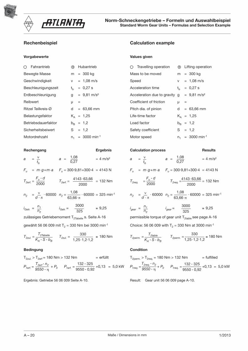
Maße / Dimensions in mmA – 20 1/2013
Rechenbeispiel
Vorgabewerte
Fahrantrieb Hubantrieb
Bewegte Masse m = 300 kg
Geschwindigkeit v = 1,08 m/s
Beschleunigungszeit tb = 0,27 s
Erdbeschleunigung g = 9,81 m/s²
Reibwert µ =
Ritzel Teilkreis-Ø d = 63,66 mm
Belastungsfaktor KA = 1,25
Betriebsdauerfaktor bB = 1,2
Sicherheitsbeiwert S = 1,2
Motordrehzahl n1 = 3000 min-1
Rechengang Ergebnis
a = a = = 4 m/s²
Fu = m·g+m·a Fu = 300·9,81+300·4 = 4143 N
T2erf. = T2erf. = = 132 Nm
n2 = · 60000 n2 = · 60000 = 325 min-1
iGetr. = iGetr. = ≅ 9,25
zulässiges Getriebemoment T2Tabelle s. Seite A-16
gewählt 56 06 009 mit T2 = 330 Nm bei 3000 min-1
T2zul. = T2zul. = ≅ 180 Nm
Bedingung
T2zul. > T2erf = 180 Nm > 132 Nm = erfüllt
P1erf. = + P0 P1erf. = +0,13 = 5,0 kW
x
νtb
1,080,27
T2Tabelle
KA · S · bB
330
1,25·1,2·1,2
Fu · d
20004143·63,66
2000
νd · π
3000
325n1n2
1,08
63,66 ·π
Ergebnis: Getriebe 56 06 009 Seite A-10.
T2erf · n2
9550 · η
132 · 325
9550 · 0,92
Norm-Schneckengetriebe – Formeln und AuswahlbeispielStandard Worm Gear Units – Formulas and Selection Example
Calculation example
Values given
Travelling operation Lifting operation
Mass to be moved m = 300 kg
Speed v = 1,08 m/s
Acceleration time tb = 0,27 s
Acceleration due to gravity g = 9,81 m/s²
Coefficient of friction µ =
Pitch dia. of pinion d = 63,66 mm
Life-time factor KA = 1,25
Load factor bB = 1,2
Safety coefficient S = 1,2
Motor speed n1 = 3000 min-1
Calculation process Results
a = a = = 4 m/s²
Fu = m·g+m·a Fu = 300·9,81+300·4 = 4143 N
T2req. = T2req. = = 132 Nm
n2 = · 60000 n2 = · 60000 = 325 min-1
igear = igear = ≅ 9,25
permissible torque of gear unit T2table see page A-16
Choice: 56 06 009 with T2 = 330 Nm at 3000 min-1
T2perm. = T2perm. = ≅ 180 Nm
Condition
T2perm. > T2req. = 180 Nm > 132 Nm = fulfilled
P1req. = + P0 P1req. = +0,13 = 5,0 kW
x
νtb
1,080,27
T2table
KA · S · bB
330
1,25·1,2·1,2
Fu · d
20004143·63,66
2000
νd · π
3000
325n1n2
1,08
63,66 ·π
Result: Gear unit 56 06 009 page A-10.
T2req. · n2
9550 · η132 · 325
9550 · 0,92
Maße / Dimensions in mm A – 211/2013
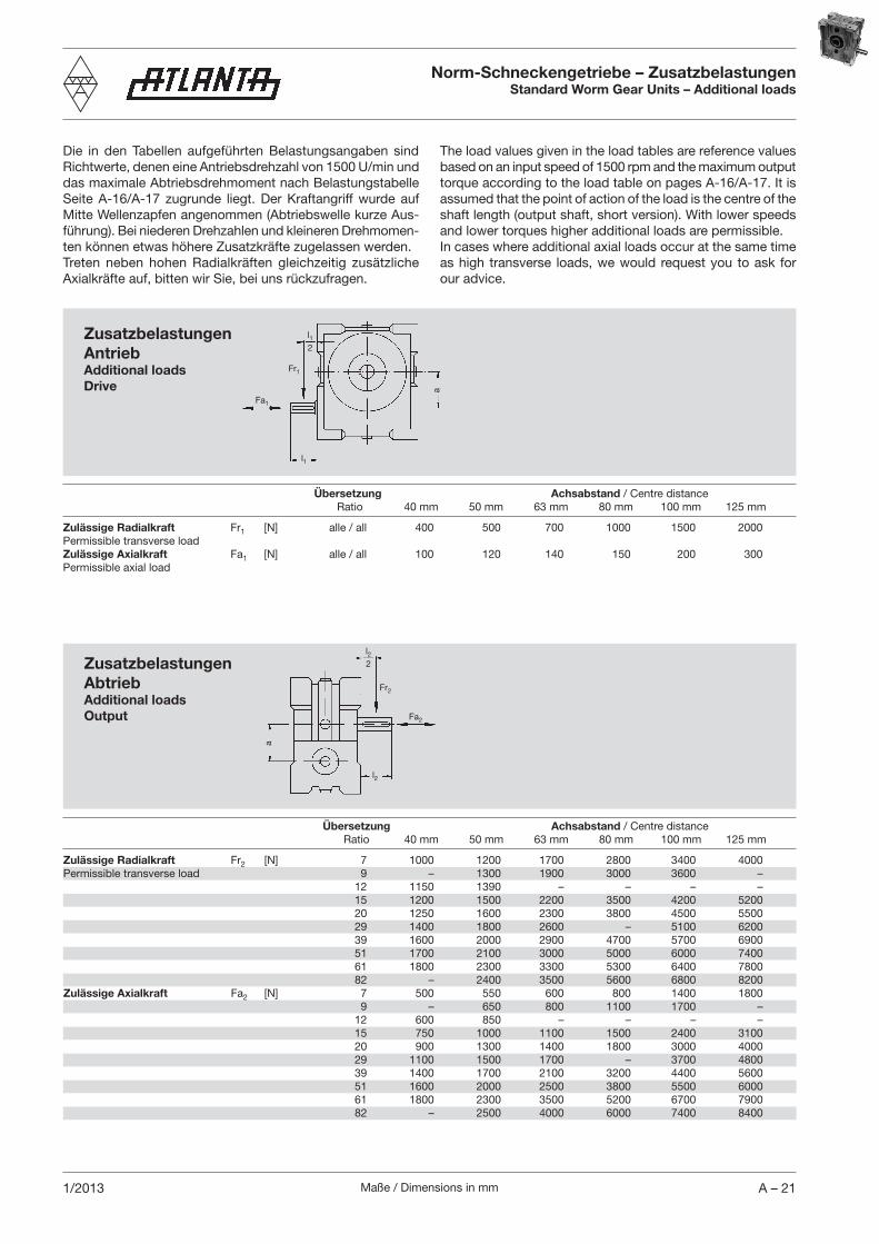
Norm-Schneckengetriebe – ZusatzbelastungenStandard Worm Gear Units – Additional loads
Die in den Tabellen aufgeführten Belastungsangaben sind Richtwerte, denen eine Antriebsdrehzahl von 1500 U/min und das maximale Abtriebsdrehmoment nach Belastungstabelle Seite A-16/A-17 zugrunde liegt. Der Kraftangriff wurde auf Mitte Wellenzapfen angenommen (Abtriebswelle kurze Aus-führung). Bei niederen Drehzahlen und kleineren Drehmo men-ten können etwas höhere Zusatzkräfte zugelassen werden. Treten neben hohen Radialkräften gleichzeitig zusätzliche Axialkräfte auf, bitten wir Sie, bei uns rückzufragen.
Zusatzbelastungen AntriebAdditional loadsDrive
Fr1
l12
a
l1
Fa1
Übersetzung Achsabstand / Centre distance Ratio 40 mm 50 mm 63 mm 80 mm 100 mm 125 mm
Zulässige Radialkraft Fr1 [N] alle / all 400 500 700 1000 1500 2000Permissible transverse loadZulässige Axialkraft Fa1 [N] alle / all 100 120 140 150 200 300Permissible axial load
Zusatzbelastungen AbtriebAdditional loadsOutput Fa2
a
Fr2
l22
l2
Übersetzung Achsabstand / Centre distance Ratio 40 mm 50 mm 63 mm 80 mm 100 mm 125 mm
Zulässige Radialkraft Fr2 [N] 7 1000 1200 1700 2800 3400 4000Permissible transverse load 9 – 1300 1900 3000 3600 – 12 1150 1390 – – – – 15 1200 1500 2200 3500 4200 5200 20 1250 1600 2300 3800 4500 5500 29 1400 1800 2600 – 5100 6200 39 1600 2000 2900 4700 5700 6900 51 1700 2100 3000 5000 6000 7400 61 1800 2300 3300 5300 6400 7800 82 – 2400 3500 5600 6800 8200Zulässige Axialkraft Fa2 [N] 7 500 550 600 800 1400 1800 9 – 650 800 1100 1700 – 12 600 850 – – – – 15 750 1000 1100 1500 2400 3100 20 900 1300 1400 1800 3000 4000 29 1100 1500 1700 – 3700 4800 39 1400 1700 2100 3200 4400 5600 51 1600 2000 2500 3800 5500 6000 61 1800 2300 3500 5200 6700 7900 82 – 2500 4000 6000 7400 8400
The load values given in the load tables are reference values based on an input speed of 1500 rpm and the maximum output torque according to the load table on pages A-16/A-17. It is assumed that the point of action of the load is the centre of the shaft length (output shaft, short version). With lower speeds and lower torques higher additional loads are permissible. In cases where additional axial loads occur at the same time as high transverse loads, we would request you to ask for our advice.

Maße / Dimensions in mmA – 22 1/2013
E
S
A
S
A
EE
S
A
E
S
A
EinbaulagenMounting positions
Ölmenge [L] bei allen Einbaulagen (jeweils an der Ölstandsschraube kontrollieren!)Oil quantity [L] for the various mounting positions (to be checked at the oil level plug!).
SchneckengetriebeEinbauATLANTA-Norm-Schneckengetriebe lassen sich durch die Vielzahl ihrer Befestigungs- und Gewindebohrungen in allen Einbaula gen ohne weitere Vorbereitungsarbeiten direkt mon-tieren. Immer sind gut zugängliche Schrauben für Entlüftung und Öleinfül lung , Ölablass und Ölstand vorhanden. Die Auslieferung erfolgt mit Ölfüllung nach Bild 4. Eine Ent-lüftungsschraube wird separat mitgeliefert und muss bei Inbetrieb nahme gegen die entsprechende Verschlussschraube ausgetauscht werden.
ÖlwechselDie Schmierung erfolgt durch handelsübliches synthetisches Getriebeöl (Basis Polyglykol), nicht mischbar mit Mineralölen. Unter normalen Bedingungen ist das Getriebe wartungsfrei (Lebensdauerschmierung). Bei Dauerbelastung im oberen Bereich der angegebenen Leistungen empfiehlt sich ein Öl-wechsel im 2jährigen Turnus.
SchmierstoffWir empfehlen folgenden synthetischen Ge triebe schmier stoff: Klübersynth GH 6 - 220, Bestell-Nr. 65 90 010 (1 Liter)
alternativ: SHELL Tivela S 220, BP Enersyn SG-XP 220, ARAL Degol GS 220
Bild /Fig. 1 Bild /Fig. 2 Bild /Fig. 3 Bild /Fig. 4
Norm-Schneckengetriebe – Einbau – Schmierung – WartungStandard Worm Gear Units – Mounting - Lubrication - Maintenance
L L L LAchs- 40 0,10 0,14 0,16 0,17abstand 50 0,15 0,18 0,20 0,20Centre 63 0,30 0,40 0,40 0,40distance 80 0,50 0,70 0,80 0,80[mm] 100 1,00 1,40 1,70 1,70 125 1,70 2,60 3,10 3,20
Worm gear unitsMountingDue to the great number of attachment and threaded holes provided, ATLANTA standard worm gear units can be directly installed in any desired mounting position without any prepa-ratory work being required. There are always sufficient easily accessible plugs for venting and oil filling , oil draining and oil level check . The gear units are supplied with an oil filling as shown in Fig.4. A vent screw is supplied separately and must be installed in replacement of the corresponding screw plug before putting the unit into operation.
Oil changeStandard synthetic gear oil (polyglycol basis) which must not be mixed with mineral oil is used for lubrication. Under normal operating conditions the gear unit is maintenance-free (lubrica-ted for life). If, however, the gear unit is continuously operated under loads within the upper range of the rated capacities, we recommed an oil change every two years.
LubricantWe recommend the following synthetic gear lubricant:Klübersynth GH 6 - 220, Order code: 65 90 010 (1 litre)
alternative: SHELL Tivela S 220, BP Enersyn SG-XP 220, ARAL Degol GS 220
Maße / Dimensions in mm A – 231/2013
Norm-Schneckengetriebe – Einbau – Schmierung – WartungStandard Worm Gear Units – Mounting - Lubrication - Maintenance
KurzbeschreibungDas ATLANTA-Norm-Schneckengetriebe wurde für den Einsatz mit Drehstrom- und Servomotoren entwickelt. Es zeichnet sich durch sein allseitig bearbeitetes Gehäuse aus, wodurch eine Ge-triebemontage in beliebiger Lage ermöglicht wird. Das verrippte Leichtmetallgehäuse ermöglicht eine optimale Wärmeabfuhr. So-lide Lager und eine gute Steifigkeit ermöglichen die Übertragung hoher Momente und Zusatzkräfte. Das Getriebe ist probegelaufen,
auf Dichtheit geprüft und somit betriebsbereit. Die Entlüftung- ,
Ablass- und Ölstandsschrauben sind je nach Einsatz des Getriebes untereinander austauschbar.Das ATLANTA-Norm-Schneckengetriebe darf ausschließlich zur Drehzahl- und Drehmomentwandlung im Maschinen- und Anla-genbau unter atmosphärischen Bedingungen verwendet werden. Die zulässige Eingangsdrehzahl und das Abtriebsdrehmoment dürfen nicht überschritten werden. Die Auslegungsrichtlinien nach Atlanta-Katalog müssen berücksichtigt werden. Beim Einsatz in explosionsgefährdeten Bereichen müssen die mit
gekennzeichneten Hinweise aus der BWS 109-10 beachtet werden, diese wurden anhand der Zündgefahrbewertung KGA 112 erstellt. Lagerung, Montagevorbereitung, Montageanleitung, Betrieb und Wartung der Getriebe, sind ebenfalls nach BWS 109-10 zu befolgen.ATLANTA übernimmt keinerlei Haftung für Schäden am Antrieb oder daraus resultierenden Folgeschäden bei Nicht-einhaltung dieser Anleitung.
Selbsthemmung von SchneckengetriebenVoraussetzung für Selbsthemmung ist ein kleiner Verzahnungs-Steigungswinkel an der Schnecke und damit ein Wirkungsgrad bei treibender Schnecke η ≤ 0,5. Es gibt Einsatzbereiche, da ein Schneckengetriebe keine Selbsthemmung haben darf, aber auch solche, wo die Selbsthemmung sogar laut Vorschrift gefordert wird. Je nach Einsatzfall, unterscheidet man zwischen statischer und dynamischer Selbsthemmung.Statisch selbsthemmend ist ein Schneckengetriebe, wenn ein Anlaufen aus dem Stillstand bei treibendem Schneckenrad nicht möglich ist. Bei ATLANTA-Radsätzen und -Getrieben ist dies der Fall, wenn der Steigungswinkel < 5° ist. Je größer der sta-tische Wirkungsgrad, umso geringer wird die Selbsthemmung. Bei hohem Drehmoment am Abtrieb, können Erschütterungen, Vibrationen oder Schwingungen die Selbsthemmung aufheben. Eine selbsthemmende Verzahnung kann daher eine Bremse oder Rücklaufsperre nicht ersetzen.Dynamisch selbsthemmend ist ein Schneckengetriebe, wenn beim laufenden Getriebe und treibendem Schneckenrad das Getriebe zum Stillstand kommt. Das Gewicht am Abtrieb kann ohne den Einfluss einer Bremse mit Verzögerung gehalten und gestoppt werden. Um eine Überbeanspruchung des Schnecken-triebes zu verhindern, ist ferner darauf zu achten, dass bei sehr großer kinetischer Energie nach dem Abschalten des Antriebes eine ausreichende Auslaufzeit zur Verfügung steht. Wenn eine totale Selbsthemmung des Getriebes verlangt wird, muss ein Bremsmotor zum Einsatz kommen wenn es um die Sicherheit des Anwendungssystems geht. Bei treibendem Schneckenrad neigen selbsthemmende Schneckengetriebe zum Rattern. Dieses Phänomen tritt beim Abwärtsfahren oder Absenken einer Last auf. Die Stärke des Ratterns ist vom gesamten Antriebsspiel, der Größe der Last, der Reibung und der Verstellgeschwindigkeit abhängig. Rattern wirkt sich sehr unangenehm aus, weil neben dem ruckartigen Ablauf auch Körperschall induziert wird, der sich in Strukturschwingungen umsetzt. Dem entgegen zu wirken, muss das Spiel in allen Mechanismen minimiert werden, obgleich das Phänomen ursächlich nicht abgestellt werden kannt.
Short descriptionATLANTA Standard Worm-Gear Units have been designed for use with three-phase motors and servo motors. Their housings are machined on all sides which allows installation in any position desired. Their ribbed housings ensure optimal heat dissipation. Robust bearings and appropriate rigidity allow the transmission of high torques and additional forces. The gear units are supplied test-run, tested for tightness, and consequently ready for opera-
tion. The vent , drain , and oil level plugs are interchange-able as required for the respective mounting of the gear unit.ATLANTA Standard Worm Gear Units may only be used for the conversion of rotary speeds and torques in machinery and equip-ment under atmospheric conditions. The permissible input speed and output torque must not be exceeded. The layout criteria specified in the catalogue must be observed. When used in areas with explosion hazard the instructions marked
with in the operation and maintenance manual BWS 109-10 must be observed. These instructions are based on the ignition danger rating KGA 112.The instructions contained in BWS 109-10 concerning storage, preparation of installation, installation, operation and maintenance of the gear units must also be observed. ATLANTA will not assume any liability for damage to the transmis-sion or any resulting consequential damage if these instructions are not observed.
Self-locking property of worm gear unitsSelf-locking is only possible when the pitch angle of the worm is small and the efficiency is consequently η ≤ 0.5 with driving worm. There are applications where a worm gear unit may not be self-locking, but also applications where according to the specifica-tions worm gear units are required to be self-locking.Depending on the individual application they may be either stati-cally self-locking or dynamically self-locking. A worm gear unit is statically self-locking when starting from standstill is impossible with driving worm-wheel. With the ATLANTA-gear sets and gear units this is the case when the pitch angle is < 5°. The bigger the static efficiency, the lower the self-locking capacity. With high torques at the input the self-locking capacity can be offset by shocks, vibrations, or oscillations. Therefore the self-locking gears cannot replace a brake or backstop.
A worm gear unit is dynamically self-locking if the gear unit comes to a standstill with operating gear unit and driving worm-wheel. The weight at the output can be held and stopped with a delay without the action of a brake.In order to avoid overloading of the worm-gear in the case of high kinetic energy it must furthermore be ensured that sufficient deceleration time is provided after switching off the input. In cases where complete self-locking of the gear unit is required, it is necessary to provide a braking motor to ensure the safety of the system. With a driving worm-wheel the self-locking worm-gear units tend to clatter. This phenomenon occurs when lowering a load. The intensity of the clattering noise depends upon the total play of the driving system, the size of the load, the friction, and the operating speed. Clattering has a very unpleasant effect because, besides the jerky operation, sound conducted through solids is induced which is converted into structural vibrations. In order to counteract this effect the play in all mechanisms must be minimized even though the cause of the phenomenon itself can not be avoided.