Bedienungsanleitung Instruction Manual - steiner-defense.com · STEINER is one of the largest...
15
Bedienungsanleitung Instrucon Manual
Transcript of Bedienungsanleitung Instruction Manual - steiner-defense.com · STEINER is one of the largest...

BedienungsanleitungInstruction Manual

Bedienungsanleitung . . . . . . . . . . . . . . . . . . . . . . . . . . . 2
User manual . . . . . . . . . . . . . . . . . . . . . . . . . . . . . . . . . 14
EINFÜHRUNGSTEINER zählt weltweit zu den größten Herstellern hoch-wertiger optischer Geräte. STEINER-Produkte entsprechen höchsten Standards an Genauigkeit und Technologie. Die Zielfernrohre wurden in enger Zusammenarbeit mit inter-nationalen Waffenexperten speziell für die strengen An-forderungen militärischer Missionen rund um den Globus entwickelt. Sie wurden unter härtesten Einsatzbedingun-gen von Spezialkräften im Feld getestet und haben sich in Gefechten bereits vielfach bewährt. Die Zielfernrohre von STEINER setzen neue Maßstäbe hinsichtlich Leistung, Qua-lität und Zuverlässigkeit. Sie sind für militärische Einsätze sowie für behördliche Einsatzzwecke optimal geeignet. STEINER-Zielfernrohre der neuesten Generation sind optional mit der Intelligent Firing Solution (IFS) ausgestattet. Die IFS stellt jederzeit alle relevanten Informationen in Echtzeit zur Verfügung. Der integrierte Ballistikrechner mit Umweltsensorik (Temperatur, Luftdruck, Inklination, Winddrift) bestimmt den Einschlagpunkt des Geschosses in Echtzeit. Zusätzlich verfügt das Display über eine Verkantungsanzeige und informiert im Sehfeld über die aktuellen Turmstellungen.Die Anzeige kann an die Bedürfnisse des Benutzers individuell angepasst werden. Mit Hilfe einer App für mobile Endgeräte kann jede Information frei platziert oder bei Bedarf deaktiviert werden. Dazu sind die Zielfernrohre mit IFS mit einer Bluetooth- Schnittstelle ausgestattet.
Im Lieferumfang sind jeweils die Schutzkappen und ein Innen-sechskantschlüssel enthalten. Diese Bedienungsanleitung enthält alle Informationen zum Gebrauch und zur Pflege der Zielfernrohre.Hinweise im Text auf Abbildungen und Bildpositionen sind in Klammern gesetzt. Beispiel: (3/4) bedeutet Abb. 3, Position 4.Die Bezeichnungen "rechts" und "links" im Text beziehen sich stets auf die Schussrichtung.Das Aussehen der Zielfernrohre kann je nach verwendetem Modell von den Darstellungen in dieser Bedienungsanleitung abweichen.Wichtige Anweisungen, die den sicheren Umgang mit dem Zielfernrohr betreffen, sind durch die Kennzeichnungen VORSICHT, ACHTUNG oder HINWEIS besonders hervorgeho-ben.
VORSICHT: Diese Hinweise beachten, um eine Gefährdung des Schützen zu vermeiden.
ACHTUNG: Diese Hinweise beachten, um eine Beschädi-gung des Zielfernrohrs zu vermeiden.
SICHERHEITSHINWEISE VORSICHT: Um Augenverletzungen zu vermeiden, mit
dem Zielfernrohr nicht direkt in die Sonne oder in helle Lichtquellen blicken.
ACHTUNG: Zielfernrohr ausschließlich vom Hersteller re-parieren lassen.
INHALTEinführung ........................................................................ 2Sicherheitshinweise .......................................................... 3Beschreibung und Bedienelemente ................................. 4Montage ............................................................................ 6Bedienung ......................................................................... 6Pflege und Wartung .......................................................... 8Entsorgung ........................................................................ 9Service und Reparatur ...................................................... 9Zubehör ............................................................................. 9Technische Daten ............................................................ 10Zielfernrohr Abmessungen ............................................. 12
2 3

BESCHREIBUNG UND BEDIENELEMENTEDer Dioptrieneinstellring (1/1 bzw. 2/1) dient zur individu-ellen Einstellung der Schärfe des Absehens.Der Stellring für Vergrößerung (1/2 bzw. 2/2) dient der Vergrö-ßerung des Ziels. Die Absehenbeleuchtung erhöht die Sichtbarkeit der Strichplatte bei ungünstigen Lichtverhältnissen. Die Be-leuchtungsstärke wird mit dem Stellring (1/3 bzw. 2/3) eingestellt. Der Stellring für die Beleuchtung ist in 11 Stu-fen unterteilt. Zwischen jeder Stufe befindet sich eine "Aus"-Stellung, mit der die Beleuchtung abgeschaltet wird. Die Stufen 1 bis 4 sind für die Verwendung mit Vorsatz-geräten (z. B. Restlichtverstärker) vorgesehen. Die Stufen 5 und 6 sind für den Einsatz ohne Vorsatzgeräte in der Nacht geeignet. Die Stufen 7 bis 11 sind für den Einsatz bei Tages-licht konzipiert. In den Stellungen "0" ist die Beleuchtung vollständig ausgeschaltet. Für die Beleuchtung wird eine 3-Volt-Lithium-Batterie (siehe technische Daten) benötigt. Die Batterie befindet sich unter dem Stellring für die Abse-henbeleuchtung.
Abb. 1 Zielfernrohr der Serie M8Xi
1 Dioptrieneinstellring2 Stellring für Vergrößerung3 Stellring für Absehenbeleuchtung4 Skalenring für Höheneinstellung5 Skalenring für Seiteneinstellung6 Haptische Anzeige
Zum Ausgleichen der Parallaxe dient bei den Zielfernroh-ren M7Xi der Stellring (2/7). Die Zielfernrohre M8Xi sind bei 100 m parallaxenfrei fest eingestellt.Die Skalenringe für Höhen- und Seiteneinstellung (1/4 und 1/5 bzw. 2/4 und 2/5) sind so kalibriert, dass ein Click 0,1 mrad (= 1 cm auf 100 m) entspricht. Für die Höhenverstellung stehen 270 Clicks (M7Xi / M8Xi), für die Seitenverstellung jeweils 60 Clicks nach rechts und nach links zur Verfügung. Die Einstellungen sind durch fühl- und hörbare Clicks wahrnehmbar. Mechanische An-schläge an beiden Enden der Einstellbereiche dienen als Bezugspunkte. Als haptische Anzeige (1/6 bzw. 2/6) dient ein Stift, der nach der ersten vollen Umdrehung des Skalenrings für Höheneinstellung (1/4 bzw. 2/4) aus dem Gehäuse austritt. Damit ist eine fühlbare Kontrolle der Höhenverstellung möglich.
Abb. 2 Zielfernrohr der Serie M7Xi
1 Dioptrieneinstellring2 Stellring für Vergrößerung3 Stellring für Absehenbeleuchtung4 Skalenring für Höheneinstellung5 Skalenring für Seiteneinstellung6 Haptische Anzeige7 Stellring für Parallaxen- und Fokuseinstellung
4 5

MONTAGEDie Montage des Zielfernrohrs an der Waffe erfolgt mit 34-mm-Ringen. Empfohlen werden hochwertige, robuste Ringe und Schienen aus Stahl. Für Schüsse auf sehr weit entfernte Ziele, bei denen der gesamte Höhenverstellbe-reich (26 mrad bzw. 27 mrad) ausgenutzt werden muss, wird eine Montage mit einer Vorneigung von 45 MOA (13,1 mrad) empfohlen. Anweisungen des Herstellers zur Montage beachten.
MONTIEREN UND EINSCHIESSEN
Beispiel Montage & Einschießen M7Xi und M8Xi
Montage 0 MOA auf der Waffe, Schiene geneigt 30 MOA:
• Zielfernrohr montieren (Drehmoment des Montagen-herstellers beachten!)
• Einschießen auf 100 m (0 bei ca. 48 Klicks zu finden)
• Türme mechanisch auf 0 stellen (siehe Seite 8, Punkt 2 (5/1 und 5/2))
• Danach ist das Zielfernrohr einsatzfähig
Beispiel Montage & Einschießen M7Xi IFS(Abbildungen siehe IFS Bedienungsanleitung)
Montage 0 MOA auf der Waffe, Schiene geneigt 30 MOA:
• IFS montieren (Drehmoment des Montagenherstellers beachten!)
• Einschießen auf 100 m (0 bei ca. 48 Klicks zu finden)
• Türme mechanisch auf 0 stellen (siehe Seite 8, Punkt 2 (5/1 und 5/2))
• Batterie einlegen
• IFS einschalten
• Ein-/Ausschalttaste kurz drücken, um Nullstellung der Türme elektronisch zu bestätigen
• Danach Daten der Munition (Mündungsgeschwindigkeit, Ballistikdaten, etc.) über die Steiner IFS App program-mieren.
• Danach ist die IFS einsatzfähig
Steiner-Optik empfiehlt die Verwendung einer Montage mit einer Vorneigung von 40 MOA (116 MIL), um den ma-ximalen Stellweg der Höhenseinstellung zu gewährleiten!
BEDIENUNG
Bildschärfe und Vergrößerung einstellen
VORSICHT: Das Zielfernrohr nicht auf die Sonne oder helle Lichtquellen richten.
1. Zielfernrohr zum Himmel oder auf eine helle Wand rich-ten und hineinblicken. Wenn die Strichplatte scharf und schwarz erscheint, ist keine weitere Einstellung erfor-derlich.
2. Bei Bedarf Dioptrieneinstellring drehen, bis die Strich-platte scharf und schwarz erscheint.
3. Mit dem Stellring für Vergrößerung in der ersten Bildebene des Absehens auf die gewünschte Größe ein-stellen.
Seiten- und Höhenabweichung einstellen - Justie-ren der Nullstellung
Die Nullstellung der Höhen- und der Seiteneinstellung kann jeweils individuell justiert werden.1. Zielfernrohr auf gewünschte Entfernung (z. B. 100 m)
justieren.
2. Die beiden Einstellschrauben (3/1 und 3/2) am Skalen-ring für die Höheneinstellung mit dem mitgelieferten Innensechskantschlüssel eine halbe Umdrehung lösen.
Der Skalenring ist nun ohne Rasterung drehbar. ACHTUNG: Die Einstellschrauben nicht weiter lösen.
Der Turm kann sonst versehentlich demontiert werden.
3. Skalenring auf "0" drehen.
4. Einstellschrauben festziehen.
5. Die beiden Einstell-schrauben (3/3 und 3/4) am Skalenring für die Sei-teneinstellung mit dem mitgelieferten Innen-sechskantschlüssel eine halbe Umdrehung lösen. Der Skalenring ist nun ohne Rasterung drehbar.
Abb. 3
ACHTUNG: Die Einstellschrauben nicht weiter lösen. Der Turm kann sonst versehentlich demontiert werden.
6. Skalenring auf "0" drehen.
7. Einstellschrauben festziehen.
6 7

Batterie der Absehenbeleuchtung wechseln
1. Deckel (6/1) abschrauben.
2. Batterie entnehmen und durch neue Batterie (sie-he technische Daten) er-setzen.
3. Deckel (6/1) aufschrau-ben.
Abb. 6
PFLEGE UND WARTUNGDas Zielfernrohr ist bis auf die äußerliche Pflege und das Erneuern der Batterien wartungsfrei.
ACHTUNG Die Linsen des Zielfernrohrs können bei un-sachgemäßer Reinigung beschädigt werden.
Zielfernrohr so halten, dass lose Schmutzpartikel von den Linsen abfallen können.Anhaftende Schmutzpartikel mit weichem Pinsel vorsichtig von den Linsen entfernen und dabei die gelösten Schmutz-partikel von den Linsen wegpusten.Bei stärkeren Verschmutzungen Linsen mit klarem Was-ser oder einem Linsenreinigungsmittel besprühen und Schmutz mit einem Linsenreinigungstuch entfernen.
ENTSORGUNGDas Zielfernrohr enthält elektrische bzw. elektronische Komponenten und darf nicht im Hausmüll entsorgt werden. Nationale Bestimmungen beachten.
SERVICE UND REPARATUR ACHTUNG: Zielfernrohr ausschließlich vom Hersteller
reparieren lassen.
STEINER Optik GmbHDr.-Hans-Frisch-Str. 9D-95448 BayreuthGermanyInternational: www.steiner.deUSA: www.steiner-optics.comDefense: www.steiner-defense.com
Absehenbeleuchtung einstellen
1. Mit dem Stellring für Absehenbeleuchtung gewünschte Beleuch-tungsstärke einstellen.
2. Zum Ausschalten der Absehenbeleuchtung den Stellring in die Stellung (4/1) zwischen dem eingestellten und dem nächsten Wert drehen.
Abb. 4
Parallaxe und Fokus einstellen
1. Stellring (5/2) drehen, bis die Zahl, die unge-fähr der Entfernung des Ziels entspricht, auf einer Linie mit der Be-zugsmarkierung (5/1) liegt. Wenn die Entfer-nung nicht bekannt ist, Stellring drehen, bis das Ziel scharf zu sehen ist.
Abb. 5
HINWEIS: Der auf der Skala des Stellrings eingestellte Wert gibt nicht die tatsächliche Entfernung wieder. Es handelt sich bei diesen Werten um Richtwerte, die je nach Auge variieren können.
Das Zielfernrohr ist parallaxenfrei eingestellt, wenn das Auge seitlich oder nach oben bzw. nach unten bewegt wer-den kann, ohne dass sich die Strichplatte in Bezug auf das Ziel bewegt.
ZUBEHÖRNur STEINER-Original-Zubehör verwenden. STEINER bietet eine große Auswahl an Zubehörteilen an. Zielfernrohre mit 50-mm- und 56-mm-Objektiven ermöglichen das Anbrin-gen von Antireflexvorrichtungen, Sonnenblenden, Filtern und anderem Zubehör.
8 9

M7Xi4-28x56 mm
M7Xi4-28x56 mm IFS
Vergrößerung min./max.
4-28 x 4-28 x
Objektivmaße 56 mm 56 mm
Vergrößerungswechsel 7 x 7 x
Austrittspupille 9,2 – 2,0 mm 9,2 – 2,0 mm
Augenabstand 87 mm – 82 mm 87 mm – 82 mm
Sehfeld auf 100 m 9,0 – 1,42 m 9,0 – 1,42 m
Dämmerungszahl 14,92 – 39,6 14,92 – 39,6
Batterie CR 2032 CR 2032; AA 1,5 V
Dioptrienausgleich +2 bis -2 Dioptrien +2 bis -2 Dioptrien
Rohrdurchmesser 34 mm 34 mm
Einstellung der Fokusebene
erste Bildebene erste Bildebene
Absehen (Strichplatte)
MSR 2 / TReMoR 3/ G2B
MSR 2 / TReMoR 3/ G2B
Beleuchtung 11 Beleuchtungs-stufen (7 Nacht & 4 Tag)
11 Beleuchtungs-stufen (7 Nacht & 4 Tag)
Druckwasserdicht bis 20 m bis 20 m
Stoßfest bis zu 900 G bis zu 900 G
100 % beschlagfrei ja (Stickstoff-Füllung)
ja (Stickstoff-Füllung)
Betriebstemperatur -46 °C bis +63 °C -32 °C bis +49 °C
Lagertemperatur -46 °C bis +63 °C -40 °C bis +49 °C
Gewicht 950 g 1150 g
Länge (bei 0 Dioptrien)
≤ 387 mm ≤ 393 mm
Höhenverstellungs-schritt
1 cm (0,10 mrad) 1 cm (0,10 mrad)
Höhenverstellbereich bei 100 m
270 cm 270 cm
Seitenverstellschritte 1 cm (0,10 mrad) 1 cm (0,10 mrad)
Seitenverstellbereich bei 100 m
+/- 60 cm +/- 60 cm
Parallaxenausgleich (Fokus)
50 m bis unendlich 50 m bis unendlich
Batterie für IFS - Energizer Ultimate Lithium AA (Be-triebszeit: 8 h bei 20 °C)
TECHNISCHE DATEN
M8Xi1-8x24 mm
Vergrößerung min./max.
1-8 x
Objektivmaße 24 mm
Vergrößerungswechsel 8 x
Austrittspupille 9,2 – 3,1 mm
Augenabstand 87 mm – 82 mm
Sehfeld auf 100 m 34,2 – 4,8 m
Dämmerungszahl 5,14 – 13,86
Batterie CR 2032
Dioptrienausgleich +2 bis -2 Dioptrien
Rohrdurchmesser 34 mm
Einstellung der Fokusebene
zweite Bildebene
Absehen (Strichplatte)
DMR8i
Beleuchtung 11 Beleuchtungs-stufen (7 Nacht & 4 Tag)
Druckwasserdicht bis 20 m
Stoßfest bis zu 900 G
100 % beschlagfrei ja (Stickstoff-Füllung)
Betriebstemperatur -46 °C bis +63 °C
Lagertemperatur -46 °C bis +63°C
Gewicht 650 g
Länge (bei 0 Dioptrien)
≤ 271 mm
Höhenverstellungs-schritt
1 cm (0,10 mrad)
Höhenverstellbereich bei 100 m
260 cm
Seitenverstellschritte 1 cm (0,10 mrad)
Seitenverstellbereich bei 100 m
+/- 60 cm
Parallaxenausgleich (Fokus)
fix bei 100 m
Batterie für IFS -
10 11

ZIELFERNROHR ABMESSUNGEN
M7Xi4-28x56 mm
M7Xi4-28x56 mm
IFS
mm mm
A Optimaler Augenabstand hoch – niedrig
87- 82 87- 82
B Durchmesser Objektiv Ende 62 62
C Freier Objektivdurchmesser 56 56
D Durchmesser Okular-Ende 45 45
E Abmessung Zielfernrohr 387 393
F Abmessung Zielfernrohr 129 129
G Abmessung Zielfernrohr 46 46
H Abmessung Zielfernrohr 65 65
I Abmessung Zielfernrohr 102 109
J Abmessung Zielfernrohr 154 154
M8Xi1-8x24 mm
mm
A Optimaler Augenabstand hoch – niedrig
87- 82
B Durchmesser Objektiv Ende 34
C Freier Objektivdurchmesser 24
D Durchmesser Okular-Ende 45
E Abmessung Zielfernrohr 260
F Abmessung Zielfernrohr 51
G Abmessung Zielfernrohr 65
H Abmessung Zielfernrohr 102
12 13

INTRODUCTIONSTEINER is one of the largest manufacturers of high-quality optics in the world. STEINER products meet the highest standards in precision and technology. The riflescopes were developed in cooperation with international weapons experts for the particularly strict requirements of military missions all around the globe. They have been tested in harshest operating conditions by special forces in the field and proven highly successful in combat. The riflescopes from STEINER set new standards in terms of performance, quality, and reliability. They are perfectly suitable both for military missions and official operational purposes. The latest generation of STEINER riflescopes are available with Intelligent Firing Solution (IFS). The IFS provides all relevant data in real time at any given time. The integrat-ed ballistics calculator with environmental sensor system (temperature, atmospheric pressure, inclination, wind drift) determines the projectile's point of impact. The display pro-vides information about leveling and the current turret set-ting in the field of view.The display can be customized to user needs. All the dis-played information can be easily added, moved or deacti-vated if needed with a smart phone or mobile app. To do so, the riflescopes with IFS are equipped with a Bluetooth interface.
CONTENTSIntroduction .................................................................... 14Safety instructions .......................................................... 15Description and controls ................................................. 16Mounting ........................................................................ 18Operation ........................................................................ 18Care and maintenance .................................................... 20Disposal ........................................................................... 21Service and repair ........................................................... 21Accessories...................................................................... 21Technical data ................................................................. 22Riflescope dimensions .................................................... 24
The scope includes the protective lens covers and an Allen wrench. This user manual contains all the information you need for the use and care of the riflescopes.Any references in the text to figures and item numbers in the images are indicated in parentheses. Example: (3/4) means fig. 3, item 4.The definitions "on the right" and "on the left" in the text are always related to the direction of fire.The appearance of the riflescopes may differ from the illustrations in the present user manual depending on the model in use.Important instructions concerning safe handling of the riflescope are emphasized by the warning signs CAUTION, IMPORTANT, or NOTE.
CAUTION: Observe these notes to avoid a hazardous situation for the shooter.
IMPORTANT: Observe these notes to avoid any damage to the riflescope.
SAFETY INSTRUCTIONS CAUTION: To avoid eye injury, do not look directly at
the sun or bright light sources through the riflescope.
IMPORTANT: The riflescope may only be repaired by the manufacturer.
14 15

On the M7Xi riflescopes, the adjustment ring (2/7) is used to correct the parallax. The M8Xi riflescopes are adjusted to be parallax free at 100 m.The adjustment scale rings for elevation and windage (1/4 and 1/5 or 2/4 and 2/5) are calibrated such that one click represents 0.1 mrad (= 1 cm over 100 m). 270 clicks (M7Xi / M8Xi)) are available for elevation adjustment, and 60 clicks both to the right and to the left for windage ad-justment. The adjustment can be felt and heard with audi-ble clicks. Mechanical stops at both ends of the adjustment range serve as reference points. A pin coming out of the housing after the first full turn of the adjustment scale ring for elevation (1/4 or 2/4) serves as Second rotation indicator (1/6 or 2/6). In this way, a per-ceptible control of the elevation adjustment is possible.
Illustration 2 Riflescope of the series M7Xi
1 Diopter adjustment ring2 Magnification adjustment ring3 Reticle illumination adjustment ring4 Adjustment scale ring for elevation5 Adjustment scale ring for windage6 Second rotation indicator7 Adjustment ring for parallax and focus
DESCRIPTION AND CONTROLSThe diopter adjustment ring (1/1 or 2/1) is used to adjust the individual reticle focus.The magnification adjustment ring (1/2 or 2/2) is used to magnify the target. The reticle illumination enhances the visibility of the reticle in adverse light conditions. The intensity of the illumina-tion is adjusted with the adjustment ring (1/3 or 2/3). The adjustment ring for the illumination has 11 levels. Between each level, there is an "OFF" position, where the illumina-tion is switched off. Levels 1 to 4 are intended for the use with attachments (e.g. image intensifiers). Levels 5 and 6 are suitable for application without attachments during the night. Levels 7 to 11 have been planned for use during daylight. In positions "0", the illumination is completely switched off. A 3-volt lithium battery (refer to technical data) is required for the illumination. The battery is located underneath the reticle illumination adjustment ring.
Illustration 1 Riflescope of the series M8Xi
1 Diopter adjustment ring2 Magnification adjustment ring3 Reticle illumination adjustment ring4 Adjustment scale ring for elevation5 Adjustment scale ring for windage6 Second rotation indicator
16 17

MOUNTINGMounting the riflescope on the weapon requires 34-mm rings. High-quality, rugged rings and bases made from steel are recommended. For shots aimed at very distant targets, where the entire elevation adjustment range (26 mrad or 27 mrad) must be used, mounting with a forward tilt of 45 MOA (13.1 mrad) is recommended. Observe the manufacturer's mounting instructions.
MOUNTING AND ZEROING INThis riflescope is shipped from the factory with the opti-cal center (knob at ‘0’ position) set below center. Without tapered bases the initial sight-in will likely produce an in-itial point of impact considerably high. For best results, Steiner recommends a 40 MOA canted base.
Instructions for mounting & zeroing M7Xi and M8Xi
Mount 0 MOA on the weapon, rail inclined 30 MOA:
• Mount the riflescope (check the torque of the mount manufacturer)
• Zero in at 100 m (0 at approx. 48 clicks)
• Set the turrets mechanically to –0 (see page 8, point 2 (5/1 and 5/2)).
• The scope is then ready for use
Instructions for mounting & zeroing M7Xi IFS (see IFS manual for illustrations)
Mount 0 MOA on the weapon, rail inclined 30 MOA
• Mount IFS (check torque of mount manufacturer)
• Zero in at 100 m (0 at approx. 48 clicks)
• Set the turrets mechanically to 0 (see page 8, point 2 (5/1 and 5/2)).
• Insert battery
• Switch on IFS
• Briefly press the on/off button to electronically confirm the zero position of the turrets.
• Then program ammunition data (muzzle velocity, balli-stics data, etc.) via the Steiner IFS App.
• The IFS is now ready for use
OPERATION
Adjusting image sharpness and magnification
CAUTION: Do not point riflescope at the sun or at bright light sources.
1. Point riflescope toward the sky or at a bright wall and look through it. If the reticle appears sharp and black, no further adjustment is required.
2. If necessary, turn diopter adjustment ring until the reticle appears sharp and black.
3. Adjust the desired size in the first image plane of the reticle with the magnification adjustment ring.
Adjusting windage and elevation deviation - ad-justment of zero position
The zero position and the elevation and windage adjust-ment can be customized.1. Sight-in the riflescope at the desired distance (e.g. 100 m).
2. Release the two adjustment screws (3/1 and 3/2) on the adjustment scale ring for elevation half a turn with the included Allen wrench.
The scale ring can now be turned without click stops. IMPORTANT: Do not release the adjustment screws
any further. Otherwise, the turret may be accidentally removed.
3. Turn scale ring to "0".
4. Tighten the adjustment screws.
5. Release the two adjust-ment screws (3/3 and 3/4) on the adjustment scale ring for windage half a turn with the in-cluded Allen wrench. The scale ring can now be turned without click stops.
Illustration 3
IMPORTANT: Do not release the adjustment screws any further. Otherwise, the turret may be accidentally removed.
6. Turn scale ring to "0".
7. Tighten the adjustment screws.
18 19

Replacing battery of the reticle illumination
1. Unscrew cap (6/1).
2. Take battery out and re-place with new battery (refer to technical data).
3. Screw cap (6/1) on.
Illustration 6
CARE AND MAINTENANCEExcept for external care and replacement of the batteries, the riflescope is maintenance-free.
IMPORTANT The lenses of the riflescope may be damaged if they are cleaned improperly.
Hold riflescope such that any loose dirt particles can fall off the lenses.Carefully brush away with a soft brush any dirt particles adhering to the lenses and, while doing so, blow the detached dirt particles away from the lenses.In the event of heavy soiling, spray clear water or a lens cleaner onto the lenses and remove dirt with lens cleaning wipes.
DISPOSALThe riflescope contains electrical and/or electronic components and must not be disposed of along with other household waste. Observe the national regulations.
SERVICE AND REPAIR IMPORTANT: The riflescope may only be repaired by
the manufacturer.
STEINER Optik GmbHDr.-Hans-Frisch-Str. 995448 BayreuthGermanyInternational: www.steiner.deUSA: www.steiner-optics.comDefense: www.steiner-defense.com
Adjusting reticle illumination
1. Adjust the desired illu-mination level with the reticle illumination ad-justment ring.
2. Turn the adjustment ring to the position (4/1) between the ad-justed and the next val-ue to switch the reticle illumination off.
Illustration 4
Adjusting parallax and focus
1. Turn adjustment ring (5/2) until the num-ber that approximately matches the distance to the target is aligned with the reference mark (5/1). If the dis-tance is not known, turn adjustment ring until the target appears sharp.
Illustration 5
NOTE: The value adjusted on the scale of the adjust-ment ring does not match the actual distance. These values are approximate values, that may vary depend-ing on the eye.
The riflescope is adjusted to be parallax-free if you can move the eye to the sides, up and/or down, without any movement of the reticle in relation to the target.
ACCESSORIESOnly use original STEINER accessories. STEINER offers a wide selection of accessories. Riflescopes with 50-mm and 56-mm objective lenses are suitable for the attachment of anti-reflective devices, sun shields, filters, and other acces-sories.
20 21

M7Xi4-28x56 mm
M7Xi4-28x56 mm IFS
Magnification min./max.
4-28 x 4-28 x
Objective lens dimensions 56 mm 56 mm
Magnification change 7 x 7 x
Exit pupil 9.2 – 2.0 mm 9.2 – 2.0 mm
Interpupillary distance 87 mm – 82 mm 87 mm – 82 mm
Field of view over 100 m 9.0 – 1.42 m 9.0 – 1.42 m
Twilight factor 14.92 – 39.6 14.92 – 39.6
Battery CR 2032 CR 2032; AA 1.5 V
Diopter compensation +2 to -2 diopters +2 to -2 diopters
Tube diameter 34 mm 34 mm
Adjustment of the focal plane
first image plane first image plane
Reticle MSR 2 / TReMoR 3/ G2B
MSR 2 / TReMoR 3/ G2B
Illumination 11 illumination levels (7 night & 4 day)
11 illumination levels (7 night & 4 day)
Water tight to a depth of up to 20 m up to 20 m
Shock resistant up to 900 G up to 900 G
100 % non-fogging yes (nitrogen filling)
yes (nitrogen filling)
Operating temperature -46 °C to +63 °C -32 °C to +49 °C
Storage temperature -46 °C to +63 °C -40 °C to +49 °C
Weight 950 g 1150 g
Length (at 0 diopters)
≤ 387 mm ≤ 393 mm
Elevation adjustment increment
1 cm (0.10 mrad) 1 cm (0.10 mrad)
Elevation adjustment range for 100 m
270 cm 270 cm
Windage adjustment increments
1 cm (0.10 mrad) 1 cm (0.10 mrad)
Windage adjustment range for 100 m
+/- 60 cm +/- 60 cm
Parallax compensation (focus)
50 m to infinity 50 m to infinity
Battery for IFS - Energizer Ultimate Lithium AA (oper-ation time: 8 h at 20 °C)
TECHNICAL DATA
M8Xi1-8x24 mm
Magnification min./max.
1-8 x
Objective lens dimensions 24 mm
Magnification change 8 x
Exit pupil 9.2 – 3.1 mm
Interpupillary distance 87 mm – 82 mm
Field of view over 100 m 34.2 – 4.8 m
Twilight factor 5.14 – 13.86
Battery CR 2032
Diopter compensation +2 to -2 diopters
Tube diameter 34 mm
Adjustment of the focal plane
second image plane
Reticle DMR8i
Illumination 11 illumination levels (7 night & 4 day)
Water tight to a depth of up to 20 m
Shock resistant up to 900 G
100 % non-fogging yes (nitrogen filling)
Operating temperature -46 °C to +63 °C
Storage temperature -46 °C to +63°C
Weight 650 g
Length (at 0 diopters)
≤ 271 mm
Elevation adjustment increment
1 cm (0.10 mrad)
Elevation adjustment range for 100 m
260 cm
Windage adjustment increments
1 cm (0.10 mrad)
Windage adjustment range for 100 m
+/- 60 cm
Parallax compensation (focus)
fixed for 100 m
Battery for IFS -
22 23
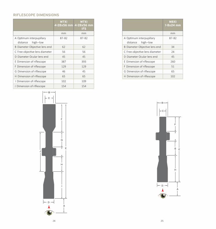
RIFLESCOPE DIMENSIONS
M7Xi4-28x56 mm
M7Xi4-28x56 mm
IFS
mm mm
A Optimum interpupillary distance high – low
87- 82 87- 82
B Diameter Objective lens end 62 62
C Free objective lens diameter 56 56
D Diameter Ocular lens end 45 45
E Dimension of riflescope 387 393
F Dimension of riflescope 129 129
G Dimension of riflescope 46 45
H Dimension of riflescope 65 65
I Dimension of riflescope 102 109
J Dimension of riflescope 154 154
M8Xi1-8x24 mm
mm
A Optimum interpupillary distance high – low
87- 82
B Diameter Objective lens end 34
C Free objective lens diameter 24
D Diameter Ocular lens end 45
E Dimension of riflescope 260
F Dimension of riflescope 51
G Dimension of riflescope 65
H Dimension of riflescope 102
24 25

NOTIZEN / NOTES
26 27

STEINER-OPTIK is a Beretta Holding company
STEINER-OPTIK GMBHDr.-Hans-Frisch-Str. 9
D-95448 BayreuthGermany
International: www.steiner.deUSA: www.steiner-optics.com
Defense: www.steiner-defense.comIte
m N
umbe
r V00
0057
5