Bedienungsanleitung Steinel Bewegungsmelder HF 3360 ... · A - ÖVE-EN 1, h - SEV 1000) 3 HF 3360...
20
Hier klicken und günstig bestellen! Zum PKE Webshop Steinel Bewegungsmelder HF 3360, COM1 Aufputz eckig Artikel-Nr.: Hersteller Artikel-Nr.: Hersteller: 146-800 011734 Steinel
Transcript of Bedienungsanleitung Steinel Bewegungsmelder HF 3360 ... · A - ÖVE-EN 1, h - SEV 1000) 3 HF 3360...
Hier klicken und günstig bestellen!
Zum PKE Webshop
Steinel Bewegungsmelder HF 3360, COM1Aufputz eckig
Artikel-Nr.:
Hersteller Artikel-Nr.:
Hersteller:
146-800
011734
Steinel
D STEINEL Vertrieb GmbH Dieselstraße 80-84 · 33442 Herzebrock-Clarholz Tel: +49/5245/448-188 · Fax: +49/5245/448-197 · www.steinel.de
A Steinel Austria GmbH Hirschstettner Strasse 19/A/2/2 · A-1220 Wien Tel.: +43/1/2023470 · Fax: +43/1/2020189 · [email protected]
CH PUAG AG Oberebenestrasse 51 · CH-5620 Bremgarten Tel.: +41/56/6488888 · Fax: +41/56/6488880 · [email protected]
GB STEINEL U.K. LTD. 25, Manasty Road · Axis Park · Orton Southgate GB-Peterborough Cambs PE2 6UP Tel.: +44/1733/366-700 · Fax: +44/1733/366-701 [email protected]
IRL Socket Tool Company Ltd Unit 714 Northwest Business Park Kilshane Drive · Ballycoolin Dublin 15 Tel.: 00353 1 8809120 · Fax: 00353 1 8612061 [email protected]
F STEINEL FRANCE SAS ACTICENTRE - CRT 2 · Rue des Famards - Bât. M - Lot 3 F-59818 Lesquin Cedex · Tél.: +33/3/20 30 34 00 Fax: +33/3/20 30 34 20 · [email protected]
NL Van Spijk B.V. Postbus 2 · 5688 HP OIRSCHOT · De Scheper 402 5688 HP OIRSCHOT · Tel. +31 499 571810 Fax. +31 499 575795 · [email protected] · www.vanspijk.nl
B VSA Belgium Hagelberg 29 · B-2440 Geel Tel.: +32/14/256050 ·Fax: +32/14/256059 [email protected] · www.vsabelgium.be
L Minusines S.A. 8, rue de Hogenberg · L-1022 Luxembourg Tél. : (00 352) 49 58 58 1 · Fax : (00 352) 49 58 66/67 www.minusines.lu
E SAET-94 S.L. C/ Trepadella, n° 10 · Pol. Ind. Castellbisbal Sud E-08755 Castellbisbal (Barcelona) Tel.: +34/93/772 28 49 · Fax: +34/93/772 01 80 [email protected]
I STEINEL Italia S.r.l. Largo Donegani 2 · I-20121 Milano Tel.: +39/02/96457231 · Fax: +39/02/96459295 [email protected] · www.steinel.it
P Pronodis - Soluções Tecnológicas, Lda. Zona Industrial Vila Verde Sul, Rua D, n.º 11 P-3770-305 Oliveira do Bairro Tel.: +351 234 484 031 · Fax: +351 234 484 033 [email protected] · www.pronodis.pt
S KARL H STRÖM AB Verktygsvägen 4 · S-55302 Jönköping Tel.: +46/36/31 42 40 · Fax: +46/36/31 42 49 · www.khs.se
DK Roliba A/S Hvidkærvej 52 · DK-5250 Odense SV Tel.: +45 6593 0357 · Fax: +45 6593 2757 · www.roliba.dk
FI Oy Hedtec Ab Lauttasaarentie 50 · FI-00200 Helsinki Tel.: +358/207 638 000 · Fax: +358/9/673 813 [email protected] · www.hedtec.fi/valaistus
N Vilan AS Olaf Helsetsvei 8 · N-0694 Oslo Tel.: +47/22725000 · [email protected] · www.vilan.no
GR PANOS Lingonis + Sons O. E. Aristofanous 8 Str. · GR-10554 Athens Tel.: +30/210/3212021 · Fax: +30/210/3218630 [email protected]
PL „LŁ“ Spółka z ograniczoną odpowiedzialnością sp.k. Byków, ul. Wrocławska 43 · PL-55-095 Mirków Tel.: +48 71 3980818 · Fax: +48 71 3980819 [email protected]
CZ ELNAS s.r.o. Oblekovice 394 · CZ-67181 Znojmo · Tel.: +420/515/220126 Fax: +420/515/244347 · [email protected] · www.elnas.cz
TR SAOS Teknoloji Elektrik Sanayi ve Ticaret Limited Şirketi Halil Rıfat Paşa mahallesi Yüzerhavuz Sokak PERPA Ticaret Merkezi A Blok · Kat 5 No.313 · Şişli / İSTANBUL Tel.: +90 212 220 09 20 · Fax: +90 212 220 09 21 [email protected] · www.saosteknoloji.com.tr
H DINOCOOP Kft Radvány u. 24 · H-1118 Budapest Tel.: +36/1/3193064 · Fax: +36/1/3193066 [email protected]
LT KVARCAS Neries krantine 32 · LT-48463, Kaunas Tel.: +370/37/408030 · Fax: +370/37/408031 · [email protected]
EST Fortronic AS Tööstuse tee 10 · EST-61715, Tõrvandi, Tartumaa Tel.: +372/7/475208 · Fax: +372/7/367229 [email protected] · www.fortronic.ee
SLO ELEKTRO – PROJEKT PLUS D.O.O. Suha pri Predosljah 12 · SLO-4000 Kranj PE GRENC 2 · 4220 Škofja Loka Tel.: 00386-4-2521645 · GSM: 00386-40-856555 [email protected] · www.priporocam.si
SK NECO SK, a.s. Ružová ul. 111 · SK-01901 Ilava Tel.: +421/42/4 45 67 10 · Fax: +421/42/4 45 67 11 [email protected] · www.neco.sk
RO Steinel Distribution SRL Parc Industrial Metrom · RO - 500269 Brasov · Str. Carpatilor nr. 60 Tel.: +40(0)268 53 00 00 · Fax: +40(0)268 53 11 11 www.steinel.ro
HR Daljinsko upravljanje d.o.o. Bedricha Smetane 10 · HR-10000 Zagreb t/ 00385 1 388 66 77 · f/ 00385 1 388 02 47 [email protected] · www.daljinsko-upravljanje.hr
LV Ambergs SIA Brivibas gatve 195-16 · LV-1039 Riga Tel.: 00371 67550740 · Fax: 00371 67552850 · www.ambergs.lv
BG ТАШЕВ-ГАЛВИНГ ООД Бул. Климент Охридски № 68 · 1756 София, България Тел.: +359 2 700 45 45 4 · Факс: +359 2 439 21 12 [email protected] · www.tashev-galving.com
RUS Best - Snab ул.1812 года, дом 12 · 121127 Москва · Россия Tel: +7 (495) 280-35-53 · [email protected] · www.steinel.su
CN STEINEL China Representative Office · Shanghai Rm. 25 A, Huadu Mansion No. 838 · Zhangyang Road Shanghai 200122 Tel: +86 21 5820 4486 · Fax: +86 21 5820 4212 [email protected] · [email protected] · www.steinel.cn
06/2016 SENSOREN Version „J“
1100
5103
8 0
9/20
16_J
Te
chni
sche
Änd
erun
gen
vorb
ehal
ten.
/ S
ubje
ct to
tech
nica
l mod
ifica
tion
with
out n
otic
e.
D
0000
0000
0
07/2
013
Te
chni
sche
Änd
erun
gen
vorb
ehal
ten.
RU
SC
NB
GLV
LTE
ST
HR
SLO
RO
PL
SK
CZ
HT
RG
RN
FIN
DK
SP
EI
NL
FG
BD
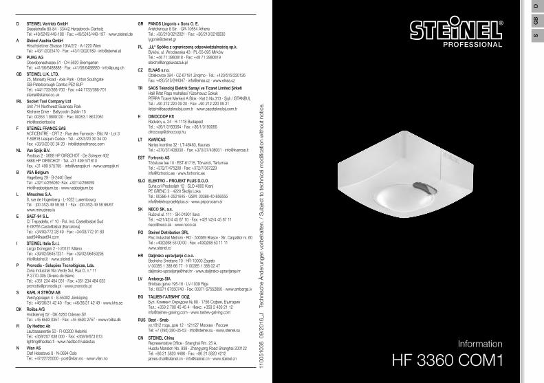
HF 3360 COM1Information
STL-6995-16_BDAL-3000er.indd 2 01.08.16 14:57
S
GB
2 3
...
D � � � � � � � � � � 12GB � � � � � � � � � 20F � � � � � � � � � � 28
Textteil beachten!Follow written instructions!Iaktta texten!
4 5
a
b
c
d
6 7
8 9
10 11
12 13
D
1� Zu diesem Dokument
– Bitte sorgfältig lesen und aufbewahren! – Urheberrechtlich geschützt.
Nachdruck, auch auszugsweise, nur mit unserer Genehmigung. – Änderungen, die dem technischen Fortschritt dienen, vorbehalten.
Symbolerklärung
! Warnung vor Gefahren!
...Verweis auf Textstellen im Dokument�
2� Allgemeine Sicherheitshinweise
Vor allen Arbeiten am Sensor die Spannungszufuhr unterbrechen!
• Bei der Montage muss die anzuschließende elektrische Leitung spannungsfrei sein. Daher als erstes Strom abschalten und Spannungsfreiheit mit einem Spannungs-prüfer überprüfen.
• Bei der Installation des Sensors handelt es sich um eine Arbeit an der Netzspan-nung. Sie muss daher fachgerecht nach den landesüblichen Installationsvorschrif-ten und Anschlussbedingungen durchgeführt werden. ( - VDE 0100, A - ÖVE-EN 1, h - SEV 1000)
3� HF 3360 COM1
Bestimmungsgemäßer Gebrauch – Sensor zur Decken- und Wandmontage im Innenbereich geeignet
Der HF 3360 COM1 ist ein aktiver Bewegungsmelder. Er reagiert temperaturunab-hängig auf kleinste Bewegungen. Der integrierte HF-Sensor sendet hochfrequente elektromagnetische Wellen (5,8 GHz) aus und empfängt deren Echo. Bei der kleinsten Bewegung im Erfassungsbereich, wird die Echoveränderung vom Sensor wahrge-nommen. Ein Microprozessor löst dann den Schaltbefehl "Licht einschalten" aus. Eine Erfassung durch Türen, Glasscheiben oder dünne Wände ist möglich.
!
Alle Funktionseinstellungen können optional über die Fernbedienungen RC5, RC8 sowie die Smart Remote vorgenommen werden. (➔ "7� Zubehör")
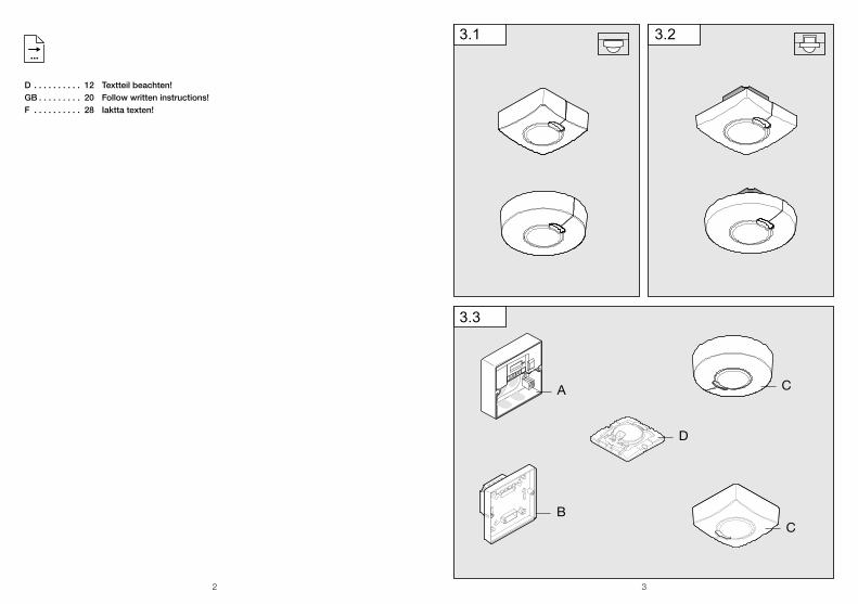
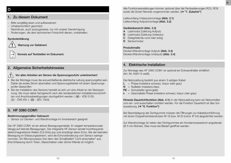
Lieferumfang Unterputzmontage (Abb� 3�1)Lieferumfang Aufputzmontage (Abb� 3�2)
Geräteübersicht (Abb� 3�3)A Lastmodul Zuleitung AufputzB Lastmodul Zuleitung UnterptuzC Designblende rund oder eckigD Sensormodul
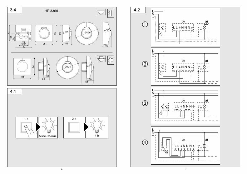
ProduktmaßeDecken/Wandmontage Aufputz (Abb� 3�4)Decken/Wandmontage Unterputz (Abb� 3�4)
4� Elektrische Installation
Zur Montage des HF 3360 COM1 ist optional ein Eckwandhalter erhältlich. (Art.-Nr. 648114 weiß).
Die Netzzuleitung besteht aus einem 3-adrigen Kabel:L = Phase (meistens schwarz, braun oder grau)N = Nullleiter (meistens blau)PE = Schutzleiter (grün/gelb) = Geschaltete Phase (meistens schwarz, braun oder grau)
Hinweis Dauerlichtfunktion (Abb� 4�1): In der Netzzuleitung kann ein Netzschalter zum ein- und ausschalten montiert werden. Für die Funktion Dauerlicht ist dies Vor-aussetzung. (➔ "6� Funktion")
Bei Beschädigung der Dichtgummis müssen die Öffnungen zur Kabeldurchführung mit einem Doppelmembranstutzen M 16 bzw. M 20 (mind. IP 54) abgedichtet werden.
Zur Wandmontage ist neben den Dichtgummies ein Kondenzwasserloch angedeutet (Ø 5 mm Bohrer). Dies muss bei Bedarf geöffnet werden.
D
14 15
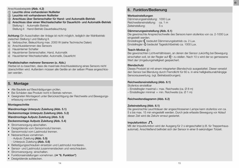
Anschlussbeispiele (Abb� 4�2)a Leuchte ohne vorhandenen Nullleiterb Leuchte mit vorhandenem Nullleiterc Anschluss über Serienschalter für Hand- und Automatik-Betriebd Anschluss über einen Wechselschalter für Dauerlicht- und Automatik-Betrieb Stellung I: Automatik-Betrieb Stellung II: Hand-Betrieb Dauerbeleuchtung
Achtung: Ein Ausschalten der Anlage ist nicht möglich, lediglich der Wahlbetrieb zwischen Stellung I und Stellung II.a) Verbraucher, Beleuchtung max. 2000 W (siehe Technische Daten)b) Anschlussklemmen des Sensorsc) Hausinterner Schalterd) Hausinterner Serienschalter, Hand, Automatike) Hausinterner Wechselschalter, Automatik, Dauerlicht
Parallelschalten mehrerer Sensoren (o� Abb�)Hierbei ist zu beachten, dass die maximale Anschlussleistung eines Sensors nicht überschritten wird. Außerdem müssen alle Geräte an der selben Phase angeschlos-sen werden.
5� Montage
• Alle Bauteile auf Beschädigungen prüfen.• Bei Schäden das Produkt nicht in Betrieb nehmen.• Geeigneten Montageort unter Berücksichtigung der Reichweite und Bewegungs-
erfassung vornehmen.
Montageschritte
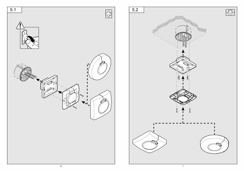
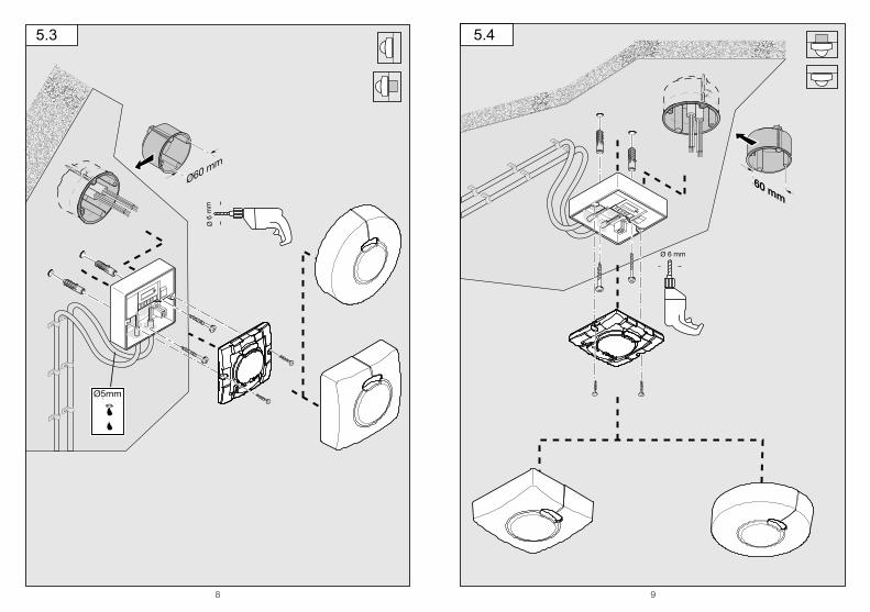
Wandmontage Unterputz Zuleitung (Abb� 5�1)Deckenmontage Unterputz Zuleitung (Abb� 5�2)Wandmontage Aufputz Zuleitung (Abb� 5�3)Deckenmontage Aufputz Zuleitung (Abb� 5�4) • Stromversorgung abschalten.• Designblende vom Sensormodul trennen.• Sensormodul vom Lastmodul trennen.• Netzanschluss vornehmen.
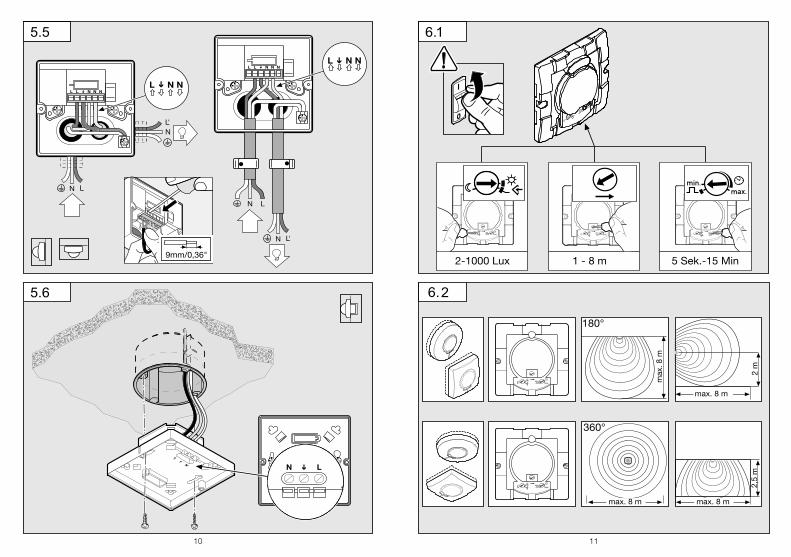
- Aufputz Zuleitung (Abb� 5�5) - Unterputz Zuleitung (Abb� 5�6)
• Befestigungsschrauben einsetzen und Lastmodul montieren.• Sensor- und Lastmodul zusammenstecken und verschrauben.• Stromversorgung einschalten.• Funktionseinstellungen vornehmen. (➔ "6� Funktion")• Designblende aufstecken.
6� Funktion/Bedienung
WerkseinstellungenDämmerungseinstellung: 1000 LuxReichweiteneinstellung: ca. 1 mZeiteinstellung: 5 s
Dämmerungseinstellung (Abb� 6�1)Die gewünschte Ansprechschwelle des Sensors kann stufenlos von ca. 2-1000 Lux eingestellt werden. Einstellregler bedeutet Dämmerungsbetrieb ca. 2 Lux. Einstellregler bedeutet Tageslichtbetrieb ca. 1000 Lux.
Teach-Modus Bei gewünschten Lichtverhältnissen, an denen der Sensor zukünftig bei Bewegung einschalten soll, ist der Regler auf zu stellen. Nach 10 s wird der so gemessene Wert der Umgebungshelligkeit gespeichert.
BlendschutzDieses Produkt ist mit einem integrierten Blendschutz ausgestattet. Dieser versetzt den Sensor bei Blendung durch Fremdlicht für 60 s. in eine helligkeitsunabhängige Sensorauswertung. (vgl. Betriebsstörungen).
Reichweiteneinstellung (Abb� 6�1)Stufenlos einstellbar– Einstellregler maximal = max. Reichweite (ca. Ø 8 m)– Einstellregler minimal = min. Reichweite (ca. Ø 1 m)
Reichweitendiagramm (Abb� 6�2)
Zeiteinstellung (Abb� 6�1)Die gewünschte Leuchtdauer der angeschlossenen Lampe kann stufenlos von ca. 5 s bis max. 15 min eingestellt werden. Durch jede erfasste Bewegung vor Ablauf dieser Zeit wird die Zeituhr erneut gestartet.
Impulsfunktion Mit der Impulsfunktion wird der Ausgang für 2 s eingeschaltet (z.B. für Treppenhaus-automat). Anschließend befindet sich der Sensor in einer 8-sekündigen Totzeit.
D
16 17
Dauerlichtfunktion (Abb� 4�1)Wird ein Netzschalter in die Netzzuleitung montiert, sind neben dem einfachen Ein- und Ausschalten folgende Funktionen möglich:Wichtig: Das mehrmalige Betätigen des Schalters sollte schnell hintereinander erfolgen (im Bereich 0,5-1 s). Sensorbetrieb 1) Licht einschalten (wenn Leuchte AUS): Schalter 1 x AUS und AN.
Sensor bleibt für die eingestellte Zeit an.2) Licht ausschalten (wenn Leuchte AN): Schalter 1 x AUS und AN.
Sensor geht aus bzw. in den Sensorbetrieb über.
Dauerlichtbetrieb1) Dauerlicht einschalten:
Schalter 2 x AUS und AN. Der Sensor wird für 4 Stunden auf Dauerlicht gestellt (rote LED leuchtet hinter der Linse). Anschließend geht er automatisch wieder in den Sensorbetrieb über (rote LED aus).
2) Dauerlicht ausschalten: Schalter 1 x AUS und AN. Sensor geht aus bzw. in den Sensorbetrieb über.
7� Zubehör (optional)
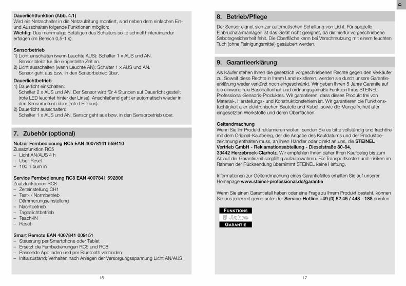
Nutzer Fernbedienung RC5 EAN 40078141 559410Zusatzfunktion RC5 – Licht AN/AUS 4 h – User-Reset – 100 h burn in
Service Fernbedienung RC8 EAN 4007841 592806Zuatzfunktionen RC8 – Zeiteinstellung CH1 – Test- / Normbetrieb – Dämmerungseinstellung – Nachtbetrieb – Tageslichtbetrieb – Teach-IN – Reset
Smart Remote EAN 4007841 009151 – Steuerung per Smartphone oder Tablet – Ersetzt die Fernbedienungen RC5 und RC8 – Passende App laden und per Bluetooth verbinden – Initialzustand; Verhalten nach Anlegen der Versorgungsspannung Licht AN/AUS
8� Betrieb/Pflege
Der Sensor eignet sich zur automatischen Schaltung von Licht. Für spezielle Einbruchalarmanlagen ist das Gerät nicht geeignet, da die hierfür vorgeschriebene Sabotagesicherheit fehlt. Die Oberfläche kann bei Verschmutzung mit einem feuchten Tuch (ohne Reinigungsmittel) gesäubert werden.
9� Garantieerklärung
Als Käufer stehen Ihnen die gesetzlich vorgeschriebenen Rechte gegen den Verkäufer zu. Soweit diese Rechte in Ihrem Land existieren, werden sie durch unsere Garantie-erklärung weder verkürzt noch eingeschränkt. Wir geben Ihnen 5 Jahre Garantie auf die einwandfreie Beschaffenheit und ordnungsgemäße Funktion Ihres STEINEL- Professional-Sensorik-Produktes. Wir garantieren, dass dieses Produkt frei von Material-, Herstellungs- und Konstruktionsfehlern ist. Wir garantieren die Funktions-tüchtigkeit aller elektronischen Bauteile und Kabel, sowie die Mangelfreiheit aller eingesetzten Werkstoffe und deren Oberflächen.
GeltendmachungWenn Sie Ihr Produkt reklamieren wollen, senden Sie es bitte vollständig und frachtfrei mit dem Original-Kaufbeleg, der die Angabe des Kaufdatums und der Produktbe-zeichnung enthalten muss, an Ihren Händler oder direkt an uns, die STEINEL Vertrieb GmbH - Reklamationsabteilung - Dieselstraße 80-84, 33442 Herzebrock-Clarholz. Wir empfehlen Ihnen daher Ihren Kaufbeleg bis zum Ablauf der Garantiezeit sorgfältig aufzubewahren. Für Transportkosten und -risiken im Rahmen der Rücksendung übernimmt STEINEL keine Haftung.
Informationen zur Geltendmachung eines Garantiefalles erhalten Sie auf unserer Homepage www�steinel-professional�de/garantie
Wenn Sie einen Garantiefall haben oder eine Frage zu Ihrem Produkt besteht, können Sie uns jederzeit gerne unter der Service-Hotline +49 (0) 52 45 / 448 - 188 anrufen.
D
18 19
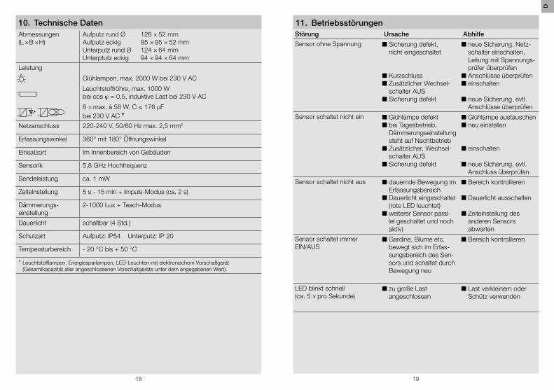
Abmessungen(L × B × H)
Aufputz rund ØAufputz eckigUnterputz rund ØUnterptutz eckig
126 × 52 mm95 × 95 × 52 mm124 × 64 mm94 × 94 × 64 mm
Leistung
Glühlampen, max. 2000 W bei 230 V AC
Leuchtstoffröhre, max. 1000 W bei cos j = 0,5, induktive Last bei 230 V AC
8 × max. à 58 W, C ≤ 176 µF bei 230 V AC *
Netzanschluss 220-240 V, 50/60 Hz max. 2,5 mm2
Erfassungswinkel 360° mit 180° Öffnungswinkel
Einsatzort Im Innenbereich von Gebäuden
Sensorik 5,8 GHz Hochfrequenz
Sendeleistung ca. 1 mW
Zeiteinstellung 5 s - 15 min + Impuls-Modus (ca. 2 s)
Dämmerungs-einstellung
2-1000 Lux + Teach-Modus
Dauerlicht schaltbar (4 Std.)
Schutzart Aufputz: IP54 Unterputz: IP 20
Temperaturbereich - 20 °C bis + 50 °C
* Leuchtstofflampen, Energiesparlampen, LED-Leuchten mit elektronischem Vorschaltgerät (Gesamtkapazität aller angeschlossenen Vorschaltgeräte unter dem angegebenen Wert).
Störung Ursache Abhilfe
Sensor ohne Spannung n Sicherung defekt, nicht eingeschaltet
n Kurzschlussn Zusätzlicher Wechsel-
schalter AUSn Sicherung defekt
n neue Sicherung, Netz-schalter einschalten, Leitung mit Spannungs-prüfer überprüfen
n Anschlüsse überprüfenn einschalten
n neue Sicherung, evtl. Anschlüsse überprüfen
Sensor schaltet nicht ein n Glühlampe defektn bei Tagesbetrieb,
Dämmerungseinstellung steht auf Nachtbetrieb
n Zusätzlicher, Wechsel-schalter AUS
n Sicherung defekt
n Glühlampe austauschenn neu einstellen
n einschalten
n neue Sicherung, evtl. Anschluss überprüfen
Sensor schaltet nicht aus n dauernde Bewegung im Erfassungsbereich
n Dauerlicht eingeschaltet (rote LED leuchtet)
n weiterer Sensor paral-lel geschaltet und noch aktiv)
n Bereich kontrollieren
n Dauerlicht ausschalten
n Zeiteinstellung des anderen Sensors abwarten
Sensor schaltet immer EIN/AUS
n Gardine, Blume etc. bewegt sich im Erfas-sungsbereich des Sen-sors und schaltet durch Bewegung neu
n Bereich kontrollieren
LED blinkt schnell(ca. 5 × pro Sekunde)
n zu große Last angeschlossen
n Last verkleinern oder Schütz verwenden
11� Betriebsstörungen10� Technische Daten
D
20 21
GB
1� About this document
– Please read carefully and keep in a safe place. – Under copyright.
Reproduction either in whole or in part only with our consent. – Subject to change in the interest of technical progress.
Symbols
! Hazard warning!
...Reference to other information in the document�
2� General safety precautions
Disconnect the power supply before attempting any work on the sensor�
• During installation, the electric power cable to be connected must not be live. Therefore, switch off the power first and use a voltage tester to make sure the wiring is off-circuit.
• Installing the sensor involves work on the mains power supply. This work must therefore be carried out professionally in accordance with national wiring regula-tions and electrical operating conditions. ( - VDE 0100, A - ÖVE-EN 1, h - SEV 1000)
3� HF 3360 COM1
Proper use – Sensor suitable for indoor wall and ceiling-mounting
The HF 3360 COM1 is an active motion detector. It responds to the slightest movement regardless of temperature. The integrated HF sensor emits high-frequency electromagnetic waves (5.8 GHz) and receives their echo. In response to the slightest movement in the detection zone, the change in echo is perceived by the sensor. A microprocessor then issues the switch command "switch light ON". Detection is possible through doors, panes of glass or thin walls.
Optionally, all function settings can be made via the RC5, RC8 remote controls as well as the Smart Remote. (➔ "7� Accessories")
!
Package contents for concealed installation (Fig� 3�1)Package contents for surface-mounted installation (Fig� 3�2)
Product components (Fig� 3�3)A Load module, power supply lead, surface-mountedB Load module, power supply lead, concealed installationC Designer trim, round or squareD Sensor module
Product dimensionsCeiling / wall mounting / surface wiring (Fig� 3�4)Ceiling / wall mounting / concealed wiring (Fig� 3�4)
4� Electrical installation
An optional corner wall mount is available for mounting the HF 3360 COM1. (Prod. No. 648114 white).
The supply lead consist of three wires:L = phase conductor (usually black, brown or grey)N = neutral conductor (usually blue)PE = protective-earth conductor (green/yellow) = switched phase conductor (usually black, brown or grey)
Note on manual override function (Fig� 4�1): A power switch for switching ON and OFF can be installed in the mains supply lead. This is a prerequisite for the manual override function. (➔ "6� Function")
If the rubber seal is damaged, the cable entry openings must be sealed with an M16 or M20 (at least IP54) double seal cable gland.
For mounting on the wall, a condensation water drainage hole (Ø 5 mm drill bit) is marked next to the rubber seal. This must be opened if necessary.
Connection examples (Fig� 4�2)a Light without neutral conductorb Light with neutral conductorc Connection by means of two-circuit single-interruption switch for manual
and automatic operationd Connection via two-way switch for manual override and automatic
operation Setting I: Automatic operation Setting II: Manual operation, light permanently ON
GB
22 23
Note: The system cannot be switched OFF, it is only possible to select operation via setting I or II.a) Load, lighting max. 2000 W (refer to Technical specifications)b) Sensor connection terminalsc) Indoor switchd) Indoor two-circuit single-interruption switch, manual, automatice) Indoor two-way switch, automatic, light permanently ON
Connecting several sensors in parallel (not illustrated)In this case, it is important not to exceed a sensor's maximum connected rating. In addition, all units must be connected to the same phase.
5� Mounting
• Check all components for damage.• Do not use the product if it is damaged.• Select an appropriate mounting location, taking the reach and
motion detection into consideration.
Installation procedure
Wall-mounting, concealed power supply lead (Fig� 5�1)Ceiling mounting, concealed power supply lead (Fig� 5�2)Wall-mounting, surface-mounted power supply lead (Fig� 5�3)Ceiling mounting, surface-mounted power supply lead (Fig� 5�4)• Switch OFF power supply.• Detach designer trim from sensor module.• Disconnect sensor module from the load module.• Connect to mains power supply.
- Surface-mounted power supply lead. (Fig� 5�5) - Concealed power supply lead. (Fig� 5�6)
• Insert fastening screw and mount load module.• Fit sensor and load module together and screw into place.• Switch ON power supply.• Set functions. (➔ "6� Function")• Fit decorative trim panel.
6� Function / operation
Factory settingsTwilight level: 1000 luxReach adjustment: approx. 1 mTime setting: 5 s
Twilight setting (Fig� 6�1)The chosen sensor response threshold is infinitely adjustable from approx. 2-1000 lux. Control dial set to = twilight mode at approx. 2 lux. Control dial set to = daylight operation, approx. 1000 lux.
Teach mode The control must be set to at the level of light at which you want the sensor to respond to movement from now on. The level of ambient brightness measured in this way will be saved after 10 seconds.
Dazzle guardThis product is equipped with an integrated dazzle guard. If blinded by extraneous light, this puts the sensor into a brightness-related evaluation mode for 60 s. (see Troubleshooting).
Reach setting (Fig� 6�1)Infinitely adjustable– Control dial set to maximum = max. reach (approx. Ø 8 m)– Control dial set to minimum = min. reach (approx. Ø 1 m)
Reach diagram (Fig� 6�2)
Time setting (Fig� 6�1)The time you want the connected lamp to stay ON for is infinitely adjustable from approx. 5 sec to a maximum of 15 min. Any movement detected before this time elapses will restart the timer.
Pulse function The pulse function activates the output for 2 s (e.g. for staircase lighting time switch-es). The sensor will then be in a dead time for 8 seconds.
Manual override function (Fig� 4�1)If a mains switch is installed in the mains supply lead, the following functions are available in addition to simply switching ON and OFF:Important: The switch should be actuated in rapid succession (in the 0.5 - 1 s range).
Sensor mode 1) Switch light ON (when light is OFF): switch ON and OFF once.
Sensor stays ON for the period selected.2) Switch light OFF (when light is ON): switch ON and OFF once.
Sensor goes out or switches to sensor mode.
GB
24 25
Manual override1) Activate manual override:
Switch ON and OFF twice. The sensor is set to stay ON for 4 hours (red LED lights up behind the lens). Then it returns automatically to sensor mode (red LED off).
2) Deactivate manual override: Switch ON and OFF once. Sensor goes out or switches to sensor mode.
7� Accessories (optional)
User remote control RC5 EAN 40078141 559410Additional functions, RC5 – Light ON/OFF 4 h – User reset – 100 h burn in
Service remote control RC8 EAN 4007841 592806Additional functions, RC8 – Time setting CH1 – Test / normal mode – Twilight setting – Night-time operation – Daylight operation – Teach-IN – Reset
Smart Remote EAN 4007841 009151 – Control via smartphone or tablet – Replaces remote controls RC5 and RC8 – Download the appropriate app and connect via Bluetooth – Initial state; behaviour after applying the light ON/OFF supply voltage
8� Operation / maintenance
The Sensor is suitable for switching on a light automatically. The unit is not suitable for burglar alarm systems as it is not tamperproof in the manner prescribed for such systems. The surface can be cleaned with a damp cloth (without detergents) if dirty.
9� Declaration of Warranty
As purchaser, you are entitled to your statutory rights against the vendor. If these rights exist in your country, they are neither curtailed nor restricted by our Warranty Declaration. We guarantee that your STEINEL Professional sensor product will remain in perfect condition and proper working order for a period of 5 years. We guarantee that this product is free from material-, manufacturing- and design flaws. In addition, we guarantee that all electronic components and cables function in the proper man-ner and that all materials used and their surfaces are without defects.
Making ClaimsIf you wish to make a claim, please send your product complete and carriage paid with the original receipt of purchase, which must show the date of purchase and product designation, either to your retailer or contact us at STEINEL (UK) Limited, 25 Manasty Road, Axis Park, Orton Southgate, Peterborough, PE2 6UP, for a re-turns number. For this reason, we recommend that you keep your receipt of purchase in a safe place until the warranty period expires. STEINEL shall assume no liability for the costs or risks involved in returning a product.
For information on making claims under the terms of the warranty, please go to www�steinel-professional�de/garantie
If you have a warranty claim or would like to ask any question regarding your product, you are welcome to call us at any time on our Service Hotline 01733 366700.
GB
26 27
Dimensions(L × W × H)
Surface-mounted installation, round ØSurface-mounted installation, squareConcealed installation, round ØConcealed installation, square
126 × 52 mm95 × 95 × 52 mm124 × 64 mm94 × 94 × 64 mm
Output
Incandescent lamps, max. 2000 W at 230 V AC
Fluorescent lamps, max. 1000 Wat cos j = 0.5, inductive load at 230 V AC
8 x max. 58 W each, C ≤ 176 µF at 230 V AC *
Mains power supply 220-240 V, 50 / 60 Hz max. 2.5 mm2
Angle of coverage 360° with 180° angle of aperture
Application inside buildings
Sensor system 5.8 GHz high frequency
Transmitter power approx. 1 mW
Time setting 5 s - 15 min + pulse mode (approx. 2 s)
Twilight setting 2 – 1000 lux + teach mode
Manual override (permanent light)
selectable (4 h)
IP rating Surface-mounted: IP54 Concealed: IP20
Temperature range - 20°C to + 50°C
* Fluorescent lamps, low-energy lamps, LED lights with electronic ballast (total capacity of all ballasts connected below the level stated).
Malfunction Cause Remedy
No power at the sensor n Fuse faulty, not switched ON
n Short circuitn Additional two-way
switch OFFn Fuse faulty
n Replace fuse, turn ON power switch, check lead with voltage tester
n Check connectionsn Switch ON
n Fit new fuse, check connections if neces-sary
Sensor will not switch ON n Bulb faultyn Twilight setting
set to night-time mode during daytime oper-ation
n Additional two-way switch OFF
n Fuse faulty
n Change bulbn Adjust setting
n Switch ON
n Fit new fuse, check connection if necessary
Sensor will not switch OFF n Continuous movement in the detection zone
n Manual override activat-ed (red LED lights up)
n Another sensor is par-allel-connected and still active
n Check zone
n Deactivate manual override
n Wait for time setting of the other sensor to elapse
Sensor keeps switching ON/OFF
n Curtains, plants etc. moving in the sensor's detection zone causing the sensor to respond
n Check zone
LED flashes rapidly(approx. 5 × per second)
n Load connected is too high
n Reduce load or use contactor
11� Troubleshooting10� Technical specifications GB
28 29
S
1� Om detta dokument
– Läs noga igenom dokumentet och förvara det väl! – Upphovsrättsligt skyddat.
Eftertryck, även delar av texten, bara med vårt samtycke. – Ändringar som görs pga den tekniska utvecklingen, förbehålles.
Symbolförklaring
! Varning för fara!
...Hänvisning till textställen i dokumentet�
2� Allmänna säkerhetsanvisningar
Bryt spänningen före alla arbeten på sensorn!
• Under monteringen måste den elektriska ledningen som skall anslutas vara spänningsfri. Bryt strömmen och kontrollera med spänningsprovare att alla parter är spänningsfria.
• Eftersom sensorn installeras till nätspänningen. måste arbetet utföras på ett fackmannamässigt sätt enligt gällande installationsföreskrifter och anslutningskrav i respektive land. ( - VDE 0100, A - ÖVE-EN 1, h - SEV 1000)
3� HF 3360 COM1
Ändamålsenlig användning – Sensor för tak- och väggmontage inomhus
HF 3360 COM1 är en aktiv rörelsevakt. Den reagerar på minsta rörelse oberoende av temperaturen. Den integrerade HF-sensorn sänder högfrekventa elektromagne-tiska vågor (5,8 GHz) och mottar deras eko. Vid minsta rörelse i bevakningsområdet registreras ekoförändringen av sensorn. En mikroprocessor utlöser då kommandot "tänd ljuset“. Detekteringen fungerar också genom dörrar, glas eller tunna väggar.
!
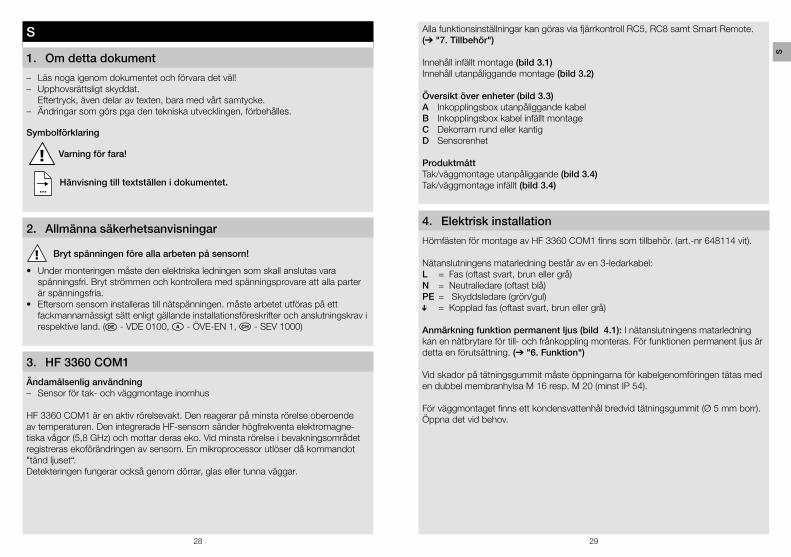
Alla funktionsinställningar kan göras via fjärrkontroll RC5, RC8 samt Smart Remote. (➔ "7� Tillbehör")
Innehåll infällt montage (bild 3�1)Innehåll utanpåliggande montage (bild 3�2)
Översikt över enheter (bild 3�3)A Inkopplingsbox utanpåliggande kabelB Inkopplingsbox kabel infällt montageC Dekorram rund eller kantigD Sensorenhet
ProduktmåttTak/väggmontage utanpåliggande (bild 3�4)Tak/väggmontage infällt (bild 3�4)
4� Elektrisk installation
Hörnfästen för montage av HF 3360 COM1 finns som tillbehör. (art.-nr 648114 vit).
Nätanslutningens matarledning består av en 3-ledarkabel:L = Fas (oftast svart, brun eller grå)N = Neutralledare (oftast blå)PE = Skyddsledare (grön/gul) = Kopplad fas (oftast svart, brun eller grå)
Anmärkning funktion permanent ljus (bild 4�1): I nätanslutningens matarledning kan en nätbrytare för till- och frånkoppling monteras. För funktionen permanent ljus är detta en förutsättning. (➔ "6� Funktion")
Vid skador på tätningsgummit måste öppningarna för kabelgenomföringen tätas med en dubbel membranhylsa M 16 resp. M 20 (minst IP 54).
För väggmontaget finns ett kondensvattenhål bredvid tätningsgummit (Ø 5 mm borr). Öppna det vid behov.
S
30 31
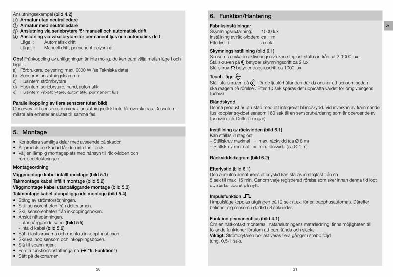
Anslutningsexempel (bild 4�2)a Armatur utan neutralledareb Armatur med neutralledarec Anslutning via seriebrytare för manuell och automatisk driftd Anslutning via växelbrytare för permanent ljus och automatisk drift Läge I: Automatisk drift Läge II: Manuell drift, permanent belysning
Obs! Frånkoppling av anläggningen är inte möjlig, du kan bara välja mellan läge I och läge II.a) Förbrukare, belysning max. 2000 W (se Tekniska data)b) Sensorns anslutningsklämmorc) Husintern strömbrytared) Husintern seriebrytare, hand, automatike) Husintern växelbrytare, automatik, permanent ljus
Parallellkoppling av flera sensorer (utan bild)Observera att sensorns maximala anslutningseffekt inte får överskridas. Dessutom måste alla enheter anslutas till samma fas.
5� Montage
• Kontrollera samtliga delar med avseende på skador.• Är produkten skadad får den inte tas i bruk.• Välj en lämplig montageplats med hänsyn till räckvidden och
rörelsedetekteringen.
Montageordning
Väggmontage kabel infällt montage (bild 5�1)Takmontage kabel infällt montage (bild 5�2)Väggmontage kabel utanpåliggande montage (bild 5�3)Takmontage kabel utanpåliggande montage (bild 5�4)• Stäng av strömförsörjningen.• Skilj sensorenheten från dekorramen.• Skilj sensorenheten från inkopplingsboxen.• Anslut nätspänningen.
- utanpåliggande kabel (bild 5�5) - infälld kabel (bild 5�6)
• Sätt i fästskruvarna och montera inkopplingsboxen.• Skruva ihop sensorn och inkopplingsboxen.• Slå till spänningen.• Företa funktionsinställningarna. (➔ "6� Funktion")• Sätt på dekorramen.
6� Funktion/Hantering
FabriksinställningarSkymningsinställning: 1000 luxInställning av räckvidden: ca 1 mEfterlystid: 5 sek
Skymningsinställning (bild 6�1)Sensorns önskade aktiveringsnivå kan steglöst ställas in från ca 2-1000 lux. Ställskruven på betyder skymningsdrift ca 2 lux. Ställskruv betyder dagsljusdrift ca 1000 lux.
Teach-läge Ställ ställskruven på för de ljusförhållanden där du önskar att sensorn sedan ska reagera på rörelser. Efter 10 sek sparas det uppmätta värdet för omgivningens ljusnivå.
BländskyddDenna produkt är utrustad med ett integrerat bländskydd. Vid inverkan av främmande ljus kopplar skyddet sensorn i 60 sek till en sensorutvärdering som är oberoende av ljusnivån. (jfr. Driftstörningar).
Inställning av räckvidden (bild 6�1)Kan ställas in steglöst– Ställskruv maximal = max. räckvidd (ca Ø 8 m)– Ställskruv minimal = min. räckvidd (ca Ø 1 m)
Räckviddsdiagram (bild 6�2)
Efterlystid (bild 6�1)Den anslutna armaturens efterlystid kan ställas in steglöst från ca 5 sek till max. 15 min. Genom varje registrerad rörelse som sker innan denna tid löpt ut, startar tiduret på nytt.
Impulsfunktion I impulsläge kopplas utgången på i 2 sek (t.ex. för en trapphusautomat). Därefter befinner sig sensorn i dödtid i 8 sekunder.
Funktion permanentljus (bild 4�1)Om en nätkontakt monteras i nätanslutningens matarledning, finns möjligheten till följande funktioner förutom att bara tända och släcka:Viktigt: Strömbrytaren bör aktiveras flera gånger i snabb följd (ung. 0,5-1 sek).
S
32 33
Sensordrift1) Tända ljuset (om armaturen FRÅN): brytare 1 × FRÅN och TILL.
Sensorn förblir aktiverad under inställd tid.2) Släcka ljuset (om armaturen TILL): brytare 1 × FRÅN och TILL.
Sensorn avaktiveras resp. går över i sensordrift.
Permanentljus1) Tillkoppla permanent ljus:
brytare 2 × FRÅN och TILL. Sensorn ställs på permanent ljus i 4 timmar (röd LED lyser bakom linsen). Därefter återgår sensorn automatiskt till sensordrift igen (röd LED Från)
2) Frånkoppla permanent ljus: brytare 1 × FRÅN och TILL. Sensorn avaktiveras resp. går över i sensordrift.
7� Tillbehör (tillval)
Fjärrkontroll RC5 EAN 40078141 559410Extra funktion RC5 – Ljuset TÄNDS/SLÄCKS 4 h – User-Reset – 100 h burn in
Servicefjärrkontroll RC8 EAN 4007841 592806Extra funktioner RC8 – Efterlystid CH1 – Testläge / Normalläge – Skymningsinställning – Nattdrift – Dagsljusdrift – Teach-IN – Reset
Smart Remote EAN 4007841 009151 – Styrning via smartphone eller surfplatta – Ersätter fjärrkontrollerna RC5 och RC8 – Ladda ner den passande appen och anslut via Bluetooth – Initialtillstånd; beteende efter inkoppling av matarspänningen ljus TILL/FRÅN
8� Drift/Skötsel
Sensorn lämpar sig för automatisk koppling av ljus. Den är inte avsedd för profes-sionella tjuvlarm, eftersom den inte uppfyller de krav som ställs mot åverkan och sabotage. Ytan kan rengöras med en fuktig trasa (utan rengöringsmedel).
9� Garantiförklaring
Som köpare har du rätt till gällande garantirättigheter enligt konsumentlagen alt. ALEM 09. Dessa rättigheter varken förkortas eller begränsas genom vår garantiförkla-ring. Utöver den rättsliga garanti-fristen, ger vi 5 års garanti på att din STEINEL- Professional-Sensor-produkt är i oklanderligt skick och fungerar korrekt. Vi garanterar, att denna produkt är helt utan material-, produktions- eller konstruk-tionsfel. Vi garanterar, att alla elektroniska element och kablar är fullt funktionsdugliga samt att allt använt råmaterial jämte dess ytor, är helt utan brister.
ReklamationOm du vill reklamera din produkt, så kontakter du inköpsstället dvs din återförsäljare. Om återförsäljaren av olika anledningar ej kan kontaktas kan du vända dig direkt till Steinels generalagent i Sverige; Karl H Ström AB, Verktygsvägen 4, 553 02 Jönköping, 036 - 314240. Vi rekommenderar att du sparar kvittot väl tills garantitiden har gått ut. För transportkostnader och -risker vid retursändningar lämnar STEINEL ingen garanti.
Ytterligare uppgifter om produkter samt kontakt hittar du på vår hemsida. www�steinel�se
Om du har frågor beträffande produkten eller frågor om garantins omfattning, kan du alltid nå oss på 036 – 314240.
S
34 35
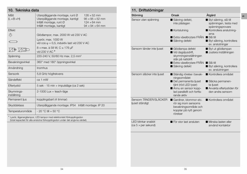
Mått(L × B × H)
Utanpåliggande montage, runt ØUtanpåliggande montage, kantigtInfällt montage, runt ØInfällt montage, kantigt
126 × 52 mm95 × 95 × 52 mm124 × 64 mm94 × 94 × 64 mm
Effekt
Glödlampor, max. 2000 W vid 230 V AC
Lysrör, max. 1000 W vid cos j = 0,5, induktiv last vid 230 V AC
8 × max. à 58 W, C ≤ 176 µF vid 230 V AC *
Spänning 220-240 V, 50/60 Hz max. 2,5 mm2
Bevakningsvinkel 360° med 180° öppningsvinkel
Användning Inomhus
Sensorik 5,8 GHz högfrekvens
Sändeffekt ca 1 mW
Efterlystid 5 sek - 15 min + impulsläge (ca 2 sek)
Skymnings-inställning
2-1000 Lux + teach-läge
Permanent ljus kopplingsbart (4 timmar)
Skyddsklass Utanpåliggande montage: IP54 Infällt montage: IP 20
Temperaturområde - 20 °C till + 50 °C
* Lysrör, lågenergilampor, LED-lampor med elektroniskt förkopplingsdon (total kapacitet för alla anslutna förkopplingsdon under det angivna värdet).
Störning Orsak Åtgärd
Sensor utan spänning n Säkring defekt, inte påslagen
n Kortslutning
n Extra växelbrytare FRÅNn Säkring defekt
n Byt säkring, slå till spänningen, testa med spänningsprovare
n Kontrollera anslutning-arna
n Slå tilln Byt säkring, kontrollera
ev. anslutningar
Sensorn tänder inte ljuset n Glödlampa defektn Vid dagsljusdrift,
skymningsinställningen står på nattdrift
n Extra växelbrytare FRÅNn Säkring defekt
n Byt ut glödlampann Justera inställningen
n Slå tilln Byt säkring, kontrollera
ev. anslutningen
Sensorn släcker inte ljuset n Ständig rörelse i bevak-ningsområdet
n Det permanenta ljuset tänt (röd LED lyser)
n Ännu en sensor kopp-lad parallellt och fortfa-rande aktiv
n Kontrollera området
n Släcka permanen-ta ljuset
n Avvakta efterlystiden för den andra sensorn
Sensorn TÄNDER/SLÄCKER ljuset ständigt
n Gardiner, blommor etc. rör sig inom sensorns bevakningsområde och kopplar på nytt genom rörelser
n Kontrollera området
LED blinkar snabbt(ca 5 × per sekund)
n För stor last ansluten n Minska lasten eller använd kontaktor
11� Driftstörningar10� Tekniska data
S

Hier klicken und günstig bestellen!
Zum PKE Webshop
PK Elektronik Vertriebs GmbHAm Erlengraben 276275 Ettlingen
Fon: +49(0)7243-60595-0Fax: +49(0)7243-60595-25
E-Mail: [email protected]: www.pkelektronik.com
![Hochfrequenz- Chirurgie - · PDF file8 I HF-Chirurgie HF-Chirurgie I 9 Anschlusskabel für die HF-Chirurgie Anschlusskabel für die HF-Chirurgie Geräteseite Länge [m] Stück/VE Artikel-Nr](https://static.fdokument.com/doc/165x107/5a789cba7f8b9ae91b8cdb80/hochfrequenz-chirurgie-i-hf-chirurgie-hf-chirurgie-i-9-anschlusskabel-fr-die.jpg)