
Betriebsanleitung Erweiterungs-Modul M-Bus für A2xx-Geräte ...
24
1 Betriebsanleitung Erweiterungs-Modul M-Bus für A2xx-Geräte EMMOD206 EMMOD206 Bdfe 169 335 01.13 Camille Bauer AG Aargauerstrasse 7 CH-5610 Wohlen/Switzerland Telefon +41 56 618 21 11 Telefax +41 56 618 35 35 [email protected] www.camillebauer.com Sicherheitshinweise Die Installation und Inbetriebnahme darf nur durch geschul- tes Personal erfolgen. Überprüfen Sie vor der Inbetriebnahme, dass: – die maximalen Werte aller Anschlüsse nicht überschritten werden, siehe Kapitel «Technische Daten», – die Anschlussleitungen nicht beschädigt und bei der Verdrahtung span- nungsfrei sind. Das Gerät muss ausser Betrieb gesetzt werden, wenn ein gefahrloser Be- trieb (z.B. sichtbare Beschädigungen) nicht mehr möglich ist. Dabei sind alle Anschlüsse abzuschalten. Das Gerät ist an unser Werk bzw. an eine durch uns autorisierte Servicestelle zu schicken. Leiterplatte und Kontakte nicht berühren! Elektrostatische Aufladung kann elektronische Bauteile zuerstören. Bei einem Eingriff in das Gerät erlischt der Garantieanspruch. Inhaltsverzeichnis 1. Kurzbeschreibung ........................................................................................ 2 2. Lieferumfang ................................................................................................ 2 3. Technische Daten ......................................................................................... 2 4. Blockschema ................................................................................................ 2 5. Montage/Demontage ................................................................................... 2 6. Anschlüsse am Gerät ................................................................................... 3 7. Anzeige- und Bedienelemente ..................................................................... 3 8. Programmierung ........................................................................................... 4 9. M-Bus Spezifikation ..................................................................................... 6 10. M-Bus Protokoll ........................................................................................... 6 11. Umschaltung auf Modbus ............................................................................ 8 12. Konformitätserklärung .................................................................................. 8 Geräte dürfen nur fachgerecht entsorgt werden!
Transcript of Betriebsanleitung Erweiterungs-Modul M-Bus für A2xx-Geräte ...

1
BetriebsanleitungErweiterungs-ModulM-Bus für A2xx-Geräte
EMMOD206
EMMOD206 Bdfe 169 335 01.13
Camille Bauer AG
Aargauerstrasse 7
CH-5610 Wohlen/Switzerland
Telefon +41 56 618 21 11
Telefax +41 56 618 35 35
www.camillebauer.com
Sicherheitshinweise
Die Installation und Inbetriebnahme darf nur durch geschul-
tes Personal erfolgen.
Überprüfen Sie vor der Inbetriebnahme, dass:
– die maximalen Werte aller Anschlüsse nicht überschritten werden, siehe
Kapitel «Technische Daten»,
– die Anschlussleitungen nicht beschädigt und bei der Verdrahtung span-
nungsfrei sind.
Das Gerät muss ausser Betrieb gesetzt werden, wenn ein gefahrloser Be-
trieb (z.B. sichtbare Beschädigungen) nicht mehr möglich ist. Dabei sind
alle Anschlüsse abzuschalten. Das Gerät ist an unser Werk bzw. an eine
durch uns autorisierte Servicestelle zu schicken.
Leiterplatte und Kontakte nicht berühren! Elektrostatische
Aufladung kann elektronische Bauteile zuerstören.
Bei einem Eingriff in das Gerät erlischt der Garantieanspruch.
Inhaltsverzeichnis
1. Kurzbeschreibung ........................................................................................2
2. Lieferumfang ................................................................................................2
3. Technische Daten .........................................................................................2
4. Blockschema ................................................................................................2
5. Montage/Demontage ...................................................................................2
6. Anschlüsse am Gerät ...................................................................................3
7. Anzeige- und Bedienelemente .....................................................................3
8. Programmierung ...........................................................................................4
9. M-Bus Spezifikation .....................................................................................6
10. M-Bus Protokoll ...........................................................................................6
11. Umschaltung auf Modbus ............................................................................8
12. Konformitätserklärung ..................................................................................8
Geräte dürfen nur fachgerecht
entsorgt werden!
2
1. KurzbeschreibungDas Erweiterungs-Modul EMMOD206 ergänzt die Funktio-
nalität sowie Flexibilität eines Grundgerätes A2xx und er-
möglicht die Abfrage von Momentanwerten und Zählerwer-
ten via M-Bus Schnittstelle. Zusätzlich steht ein Digitalein-
gang für die Synchronisation der Intervalle für die Bestim-
mung der Mittelwertgrössen oder für die Tarifumschaltung
der Energiezähler zur Verfügung.
Die Auswahl der zu übertragenden Messwerte und weitere
Einstellungen sind über die Tastatur des Grundgerätes mög-
lich. Vorübergehend kann die Schnittstelle von M-Bus Pro-
tokoll auf Modbus-Protokoll umgeschaltet werden, um eine
bequeme Konfiguration der Messfunktionalität des Grund-
gerätes A2xx über die Software A200plus zu ermöglichen.
Das Modul ist ohne Eingriff in das Grundgerät nachrüstbar.
Dazu müssen die Grundgeräte A210, A220, A230 und A230s
aber mit der Firmware-Version V5.0 oder höher ausgerüstet
sein.
2. Lieferumfang1 Erweiterungs-Modul EMMOD206
4 Kunststoff-Spreiznieten
1 Betriebsanleitung deutsch/französisch/englisch
Je 1 Zusatzschild Eingang und Ausgang/Hilfsenergie
3. Technische DatenHilfsenergie
Das EMMOD206 wird vom Grundgerät A2xx versorgt. Die
Leistungsaufnahme des Grundgerätes steigt um ca. 0.1W
bei aufgestecktem Modul.
Umgebungsbedingungen
Betriebstemperatur: – 10 bis + 55 °C
Lagertemperatur: – 25 bis + 70 °C
Relative Feuchtigkeit
im Jahresmittel: ≤75%
Betriebshöhe: 2000 m max.
Nur in Innenräumen zu verwenden
Kommunikation M-Bus
Schnittstelle, Protokoll: M-Bus
Baudrate: 300…38 400 Baud, einstellbar über
Tastatur des Grundgerätes A2xx,
Autobaud nicht unterstützt.
Primäradresse: 0...250, einstellbar über Tastatur
des Grundgerät A2xx
Sekundäradresse / ID: Ist fest und wird im Werk vorgege-
ben
ID1…ID4 Entspricht der auf
dem Typenschild
aufgedruckten
8-stelligen Serienummer
(Laufnummer)
MAN1, MAN2 A3, 1D (GMC)
GEN 210 (bei A210 und A220),
230 (bei A230 und A230s)
MED 02 (Electricity)
Messwertabbildung: Mode 1, LSB first
Mode 2 nicht unterstützt
Konfigurationsdaten: Nichtflüchtige Speicherung im
Grundgerät.
ID-Nummer vom Modul geliefert.
Kollisionerkennung: keine
Lastfaktor Bus: 0.7 (Ruhestrom ca. 1.1 mA)
Anschlüsse steckbare Schraubklemmen
0.5...1.5 mm2 (Litze) oder
0.5...2.5 mm2 (Draht)
Digitaleingang
Funktion: Synchrontakt für Mittelwertgrössen
oder Umschaltung Hoch-/Nieder-
tarif für Energiezähler
Polarität: Beliebig
Anschluss extern: max. 230 V AC oder DC
Ruhezustand: Uin<12 V AC/DC, Hochtarif
LED „IN“ dunkel
Aktivzustand: Uin>17 V AC/DC, Niedertarif
LED „IN“ leuchtet
Stromaufnahme: < 4 mA bei 15 V DC
< 2 mA bei 250 V DC
Reaktionszeit: 150 ms
Galvanische Trennung: via Optokoppler
Sicherheit nach EN 61010-1
Basisisolation zwischen Klemmen und Buchsenleiste
Bemessungsspannung: 300 V
Messkategorie: CATIII
Verschmutzungsgrad: 2
Prüfspannungen: 50 Hz / 1 min
2200 V: M-Bus zu Grundgerät und
Digitaleingang zu Grundgerät,
3700 V: M-Bus gegen Digitaleingang
Abmessungen (L x B x H) 86 x 38 x 20 mm
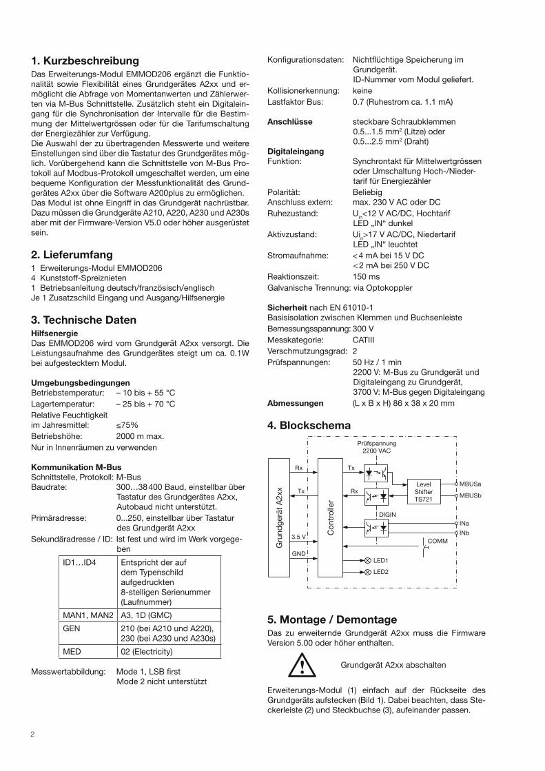
4. Blockschema
Prüfspannung
Gru
nd
gerä
t A
2xx
Co
ntr
olle
r
2200 VAC
MBUSa
MBUSb
INa
Tx
Rx
Rx
Tx
3.5 V
GND
INb
COMM
Level
Shifter
TS721
LED1
DIGIN
LED2
5. Montage / DemontageDas zu erweiternde Grundgerät A2xx muss die Firmware
Version 5.00 oder höher enthalten.
Grundgerät A2xx abschalten
Erweiterungs-Modul (1) einfach auf der Rückseite des
Grundgeräts aufstecken (Bild 1). Dabei beachten, dass Ste-
ckerleiste (2) und Steckbuchse (3), aufeinander passen.

3
Achtung!
Leiterplatte und Kontakte nicht berühren.
Elektrostatische Aufladung kann
elektronische Bauteile beschädigen.
(1)
(2)
(4)
(3)
Zur mechanischen Sicherung die vier mitgelieferten Kunst-
stoff-Spreiznieten (5) in die dafür vorgesehenen Löcher (4)
eindrücken (Bild 2).
(5)(4)
Die Zusatzschilder Eingang und Ausgang/Hilfsenergie nach
Bild 3 aufkleben.
Bild 3
Zum Demontieren den gerändelten Kopf (6) der Kunststoff-
Spreiznieten mit den Fingern herausziehen (Bild 4). Das
Erweiterungs-Modul (1) lässt sich jetzt abnehmen.
(6) (1)
Bild 1
Bild 2
Bild 4
6. Anschlüsse am Gerät
30 31 32 33 34
No. 1
Nr. Signal
30 INa Eingang Tarifumschaltung
(polaritätsunabhängig)31 INb
32 ––– darf nicht angeschlossen werden
33 M-BUS-A Busanschluss M-BUS
(polaritätsunabhängig)34 M-BUS-B
Achtung: Klemmenstecker nicht verwechseln!
7. Anzeige- und Bedienelemente
LED1
links
Tx
PWR
Kommunikation:
Helligkeit Bedeutung
mittel Ruhe, interne
Kommunikation OK
Impuls
dunkel
M-BUS Telegramm
empfangen
Impuls hell M-BUS Telegramm
gesendet
Blinkend
1s/1s
Umgeschaltet auf
Modbus Protokoll
dunkel Interne Kommunikation
gestört
LED2
rechts
IN Digitaleingang:
Helligkeit Bedeutung
dunkel Signal inaktiv, Hochtarif
mittel Signal aktiv, Niedertarif
hell nicht verwendet
Taste
Die Taste COMM dient zur temporären Umschaltung von M-
BUS auf MODBUS Protokoll, wobei der pysikalische Layer
von M-Bus beibehalten bleibt.
4
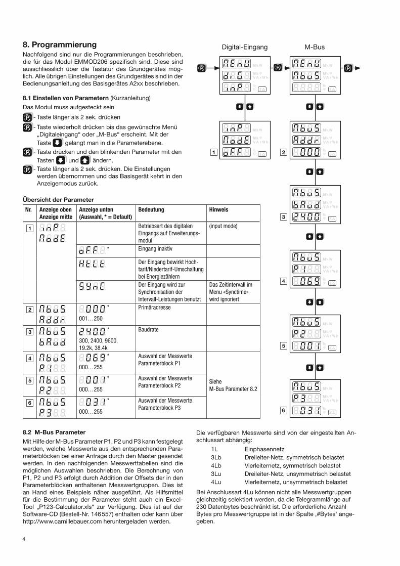
8. ProgrammierungNachfolgend sind nur die Programmierungen beschrieben,
die für das Modul EMMOD206 spezifisch sind. Diese sind
ausschliesslich über die Tastatur des Grundgerätes mög-
lich. Alle übrigen Einstellungen des Grundgerätes sind in der
Bedienungsanleitung des Basisgerätes A2xx beschrieben.
8.1 Einstellen von Parametern (Kurzanleitung)
Das Modul muss aufgesteckt sein
P - Taste länger als 2 sek. drücken
P - Taste wiederholt drücken bis das gewünschte Menü
„Digitaleingang“ oder „M-Bus“ erscheint. Mit der
Taste gelangt man in die Parameterebene.
P - Taste drücken und den blinkenden Parameter mit den
Tasten und ändern.
P - Taste länger als 2 sek. drücken. Die Einstellungen
werden übernommen und das Basisgerät kehrt in den
Anzeigemodus zurück.
Übersicht der Parameter
Nr. Anzeige oben
Anzeige mitte
Anzeige unten
(Auswahl, * = Default)
Bedeutung Hinweis
Betriebsart des digitalen
Eingangs auf Erweiterungs-
modul
(input mode)
* Eingang inaktiv
Der Eingang bewirkt Hoch-
tarif/Niedertarif-Umschaltung
bei Energiezählern
Der Eingang wird zur
Synchronisation der
Intervall-Leistungen benutzt
Das Zeitintervall im
Menu «Synctime»
wird ignoriert
*
001…250
Primäradresse
*
300, 2400, 9600,
19.2k, 38.4k
Baudrate
*
000…255
Auswahl der Messwerte
Parameterblock P1
Siehe
M-Bus Parameter 8.2
*
000…255
Auswahl der Messwerte
Parameterblock P2
*
000…255
Auswahl der Messwerte
Parameterblock P3
P P
Digital-Eingang M-Bus
P
8.2 M-Bus Parameter
Mit Hilfe der M-Bus Parameter P1, P2 und P3 kann festgelegt
werden, welche Messwerte aus den entsprechenden Para-
meterblöcken bei einer Anfrage durch den Master gesendet
werden. In den nachfolgenden Messwerttabellen sind die
möglichen Auswahlen beschrieben. Die Berechnung von
P1, P2 und P3 erfolgt durch Addition der Offsets der in den
Parameterblöcken enthaltenen Messwertgruppen. Dies ist
an Hand eines Beispiels näher ausgeführt. Als Hilfsmittel
für die Bestimmung der Parameter steht auch ein Excel-
Tool „P123-Calculator.xls“ zur Verfügung. Dies ist auf der
Software-CD (Bestell-Nr. 146 557) enthalten oder kann über
http://www.camillebauer.com heruntergeladen werden.
Die verfügbaren Messwerte sind von der eingestellten An-
schlussart abhängig:
1L Einphasennetz
3Lb Dreileiter-Netz, symmetrisch belastet
4Lb Vierleiternetz, symmetrisch belastet
3Lu Dreileiter-Netz, unsymmetrisch belastet
4Lu Vierleiternetz, unsymmetrisch belastet
Bei Anschlussart 4Lu können nicht alle Messwertgruppen
gleichzeitig selektiert werden, da die Telegrammlänge auf
230 Datenbytes beschränkt ist. Die erforderliche Anzahl
Bytes pro Messwertgruppe ist in der Spalte ‚#Bytes‘ ange-
geben.
5
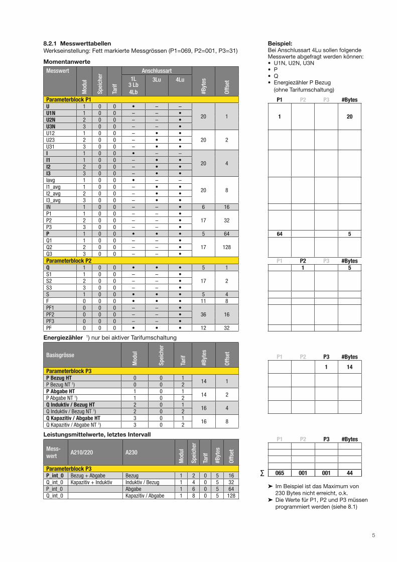
8.2.1 Messwerttabellen
Werkseinstellung: Fett markierte Messgrössen (P1=069, P2=001, P3=31)
Momentanwerte
Messwert
Mod
ul
Sp
eich
er
Tari
f
Anschlussart
#B
ytes
Off
set1L
3 Lb
4Lb
3Lu 4Lu
Parameterblock P1U 1 0 0 • – –
20 1U1N 1 0 0 – – •U2N 2 0 0 – – •U3N 3 0 0 – – •U12 1 0 0 – • •
20 2U23 2 0 0 – • •U31 3 0 0 – • •I 1 0 0 • – –
20 4I1 1 0 0 – • •I2 2 0 0 – • •I3 3 0 0 – • •Iavg 1 0 0 • – –
20 8I1_avg 1 0 0 – • •I2_avg 2 0 0 – • •I3_avg 3 0 0 – • •IN 1 0 0 – – • 6 16P1 1 0 0 – – •
17 32P2 2 0 0 – – •P3 3 0 0 – – •P 1 0 0 • • • 5 64Q1 1 0 0 – – •
17 128Q2 2 0 0 – – •Q3 3 0 0 – – •
Parameterblock P2Q 1 0 0 • • • 5 1S1 1 0 0 – – •
17 2S2 2 0 0 – – •S3 3 0 0 – – •S 1 0 0 • • • 5 4F 0 0 0 • • • 11 8PF1 0 0 0 – – •
36 16PF2 0 0 0 – – •PF3 0 0 0 – – •PF 0 0 0 • • • 12 32
Energiezähler 1) nur bei aktiver Tarifumschaltung
Basisgrösse
Mod
ul
Sp
eich
er
Tari
f
#B
ytes
Off
set
Parameterblock P3P Bezug HT 0 0 1
14 1P Bezug NT 1) 0 0 2P Abgabe HT 1 0 1
14 2P Abgabe NT 1) 1 0 2Q Induktiv / Bezug HT 2 0 1
16 4Q Induktiv / Bezug NT 1) 2 0 2Q Kapazitiv / Abgabe HT 3 0 1
16 8Q Kapazitiv / Abgabe NT 1) 3 0 2
Leistungsmittelwerte, letztes Intervall
Mess-
wertA210/220 A230
Mod
ul
Sp
eich
er
Tari
f
#B
ytes
Off
set
Parameterblock P3P_int_0 Bezug + Abgabe Bezug 1 2 0 5 16Q_int_0 Kapazitiv + Induktiv Induktiv / Bezug 1 4 0 5 32P_int_0 Abgabe 1 6 0 5 64Q_int_0 Kapazitiv / Abgabe 1 8 0 5 128
Beispiel:Bei Anschlussart 4Lu sollen folgende Messwerte abgefragt werden können:• U1N, U2N, U3N• P• Q• Energiezähler P Bezug
(ohne Tarifumschaltung)
P1 P2 P3 #Bytes
1 20
64 5
P1 P2 P3 #Bytes1 5
P1 P2 P3 #Bytes
1 14
P1 P2 P3 #Bytes
065 001 001 44
➤ Im Beispiel ist das Maximum von
230 Bytes nicht erreicht, o.k.
➤ Die Werte für P1, P2 und P3 müssen
programmiert werden (siehe 8.1)
∑

6
8.2.2 Datenformat
Alle übertragenen Messwerte sind Primärwerte. Momentanwerte werden als 16-Bit Integer und Energiezähler als 32-Bit Inte-
ger dargestellt. Die zugehörigen Einheiten und Dezimalstellen verändern sich mit der Einstellung der Wandler am Grundgerät
und werden normgerecht im Datentelegramm mitgeliefert.
Die Messwerte für Frequenz F [Hz] und Powerfaktor PF [ ] sind in der Norm nicht eingepflegt. Daher werden diese Daten, wie
es die Norm empfiehlt, als ASCII-String übermittelt.
Die grösste verfügbare Energieeinheit für M-BUS ist MWh. Je nach Einstellung der Wandlerverhältnisse entstehen aber
grössere Einheiten bis GWh. In diesem Fall wird das Fehlerflag in DIF gesetzt und der Anwender muss selbst für die richtige
Interpretation der Energieeinheit sorgen.
8.2.3 Datenpunkte und Zuordnung
Die Reihenfolge der Übertragung von Messwerten entspricht immer den Tabellenzeilen, also die Spannungen zuerst und die
Leistungsmittelwerte zuletzt. Messwerte, die für die gewählte Anschlussart nicht gültig sind, werden nicht übermittelt.
Die „Datenpunkte“ werden im Master üblicherweise in der Reihenfolge des Eintreffens zugeordnet. Es empfiehlt sich daher
zuerst alle Einstellungen am Grundgerät vorzunehmen, bevor die Auswertung der Daten eingerichtet wird.
Zur besseren Unterscheidung von Messwerten mit gleicher Einheit können die übermittelten Zusatzinformationen in den
Spalten Modul, Speicher und Tarif verwendet werden.
Nur die mit „•“ markierten Momentanwerte sind bei der entsprechenden Anschlussart verfügbar.
9. M-Bus Spezifi kationAusführliche Informationen zu M-Bus sind über die Webpage http://www.m-bus.com und die Norm EN1434-3 verfügbar.
Die Verkabelung erfolgt beim M-Bus durch ein Adernpaar eines Standard-Telefonkabels (z.B. JY(St)Y 2 x 2 x 0.8 mm). Die
Polarität spielt dabei keine Rolle. Es ist aber zu beachten, dass Pegelwandler welche für den Anschluss an den PC verwendet
werden, oft nicht galvanisch getrennt sind und der Bus mit Spannungen bis 40 V arbeitet.
Für eine Standardkonfiguration, mit Baudraten zwischen 300 und 9600 Baud und maximal 250 Slaves, beträgt die maximale
Entfernung zwischen Master und Slave 350 m. Die maximale Entfernung erhöht sich, wenn man eine niedrigere Baudrate
wählt oder wenn man die Anzahl der Slaves vermindert.
10. M-Bus-Protokoll
10.1 Adressierung
Das EMMOD206 unterstützt sowohl die Primär- als auch die Sekundäradressierung.
Für die Primär adressierung muss über die Tastatur jedem am Bus angeschlossen Gerät eine eigene Adresse im Bereich von
1...250 eingestellt werden. Die Anfragen des Masters beinhalten dann diese Adresse und der Slave antwortet bei Überein-
stimmung.
Bei der Sekundäradressierung benutzt der Master die Primäradresse 253 (Broadcast, Selection) und übermittelt dazu die ge-
wünschte Identifikation bestehend aus 8 Byte (4 Serie-Nummer + 2 Manufacturer + 1 Generation + 1 Medium). Weil die Serie-
nummer beim EMMOD206 garantiert einmalig ist, können keine Doppeladressierungen auftreten und es ist keine Adress-
einstellung am Gerät nötig. Alle nachfolgenden Abfragen mit Primäradresse 253 werden vom selektierten Gerät beantwortet,
bis eine andere Selektion festgestellt wird. Mit Hilfe der Wildcards F bzw. FF werden ID-Elemente ausgeblendet, womit der
Master die Suche nach neuen Geräten effizient durchführen kann.
10.2 Unterstützte Dialoge
10.2.1 Reset SND_NKE / ACK
➤ Anfrage vom Master
SND_NKE
10 40 FF 3F 16 Der Master veranlasst alle Slaves durch Verwendung der Broadcast-Adresse (FF=255) zu einem Kommunikations-Reset
mit Bestätigung durch ACK.
➤ Antwort des Slaves
ACK
E5
10.2.2 Datenabfrage mit Primäradressierung REQ_UD2 / RSP_UD
➤ Anfrage vom Master
REQ_UD2
10 7B 03 7E 16Der Master verlangt vom Slave Nr. 3 die Daten.

7
➤ Antwort des Slaves mit Adresse 003, Gerät A230, 4-Leiter ungleichbelastet, Tarifumschaltung aktiv,
P1=069, P2=001, P3=255:
RSP_UD
68 Start
91 LEN = 91 = 145 Bytes
91 LEN
68 Start
08 C = 08
03 Adresse = 003
72 CI = 72
78 56 34 12 Serie-Nummer = 12345678
A3 1D Manufacturer = GMC
E6 Generation = E6 = 230 = Grundgerät A230
02 Medium = Electricity
02 TC = Transmit Counter = 02 (wird nur durch Power-Up zurückgesetzt)
00 Status = 00 = kein Fehler
00 00 SIG1, SIG2 = 00 = unbenutzt
82 40 FD 48 60 03 1: U1N = 86.4 V
82 80 40 FD 48 BF 03 2: U2N = 95.9 V
82 C0 40 FD 48 20 04 3: U3N = 105.6 V
82 40 FD 59 BD 03 4: I1 = 957 mA
82 80 40 FD 59 1F 04 5: I2 = 1055 mA
82 C0 40 FD 59 7E 04 6: I3 = 1150 mA
82 40 2B E0 00 7: P = 224 W
82 40 2B 36 FF 8: Q = -202 W(VA)
84 10 04 94 28 00 00 9: P Bezug HT = 103.88 kWh
84 20 04 98 3A 00 00 10: P Bezug NT = 150.00 kWh
84 50 04 BF 4E 00 00 11: P Abgabe HT = 201.59 kWh
84 60 04 A8 61 00 00 12: P Abgabe NT= 250.0 kWh
84 90 40 04 8B 75 00 00 13: Q Induktiv HT = 300.91 kWh (kVarh)
84 A0 40 04 B8 88 00 00 14: Q Induktiv NT = 350.00 kWh (kVarh)
84 D0 40 04 2D 9D 00 00 15: Q Kapazitiv HT = 402.37 kWh (kVarh)
84 E0 40 04 C8 AF 00 00 16: Q Kapazitiv NT = 450.00 kWh (kVarh)
82 41 2B E0 00 17: P_int_0 Bezug = 224 W
82 42 2B 00 00 18: Q_int_0 Induktiv = 0 W (Var)
82 43 2B 00 00 19: P_int_0 Abgabe = 0 W 82 44 2B CA 00 20: Q_int_0 Kapazitiv= 202 W (Var)
42 Prüfsumme
16 Stopp
10.2.3 Datenabfrage mit Sekundäradressierung SND_UD / ACK
➤ Selektion durch Master
SND_UD
68 Start Long Frame
0B LEN = 0B = 11 Bytes
0B LEN
68 Start
73 C
FD A = FD = 253 = Broadcast für Sekundäradressierung
52 CI = Selection
78 56 34 12 ID1..4 Serie-Nummer 12345678
FF FF MAN1, MAN2 wird wegen Wildcard nicht beachtet
FF GEN wird wegen Wildcard nicht beachtet
FF MED wird wegen Wildcard nicht beachtet
D2 SC Prüfsumme
16 Stop
➤ Antwort des Slaves
ACK E5
➤ Anfrage vom Master REQ_UD2
10 7B FD 78 16 Der Master verlangt vom selektierten Slave die Daten und verwendet die Primäradresse FD=253.
➤ Antwort des Slaves (mit beliebiger Primäradresse)
RSP_UD
Der Inhalt des Antworttelegramms ist identisch zu dem unter 10.2.2 beschriebenen.
8
11. Umschaltung auf ModbusGrundsätzlich lassen sich über ein EMMOD206 mit M-Bus Kommandos keine Einstellungen vornehmen. Die zahlreichen
Einstellungen im Grundgerät, wie Wandlerfaktoren usw., lassen sich aber trotzdem komfortabel über den M-Bus Anschluss
des EMMOD206 durchführen:
1. PC via M-Bus Pegelwandler an EMMOD206 anschliessen.
2. Software A200plus starten.
3. Via Optionen > Kommunikations-Schnittstelle > Schnittstellen-Typ „RS-232 Schnittstelle“ einstellen und benutztes
Comm-Port wählen.
4. Taste COMM auf dem EMMOD206 während ca. 5 Sekunden drücken bis die LED1 im 1s/1s Takt blinkt. Damit ist das
Protokoll von M-Bus auf Modbus umgeschaltet.
Nun lassen sich, wie mit einem Modbus-Modul EMMOD201, alle Messwerte auslesen und Konfigurationen des Grundge-
rätes einstellen.
Bei erneutem Drücken der Taste COMM oder nach 10 Minuten ohne Modbus-Datenverkehr wird wieder auf M-BUS Proto-
koll zurückgeschaltet.
Falls mehrere Geräte gleichzeitig am Bus angeschlossen sind, ist darauf zu achten, dass nur eines gleichzeitig auf Modbus
umgeschaltet wird.
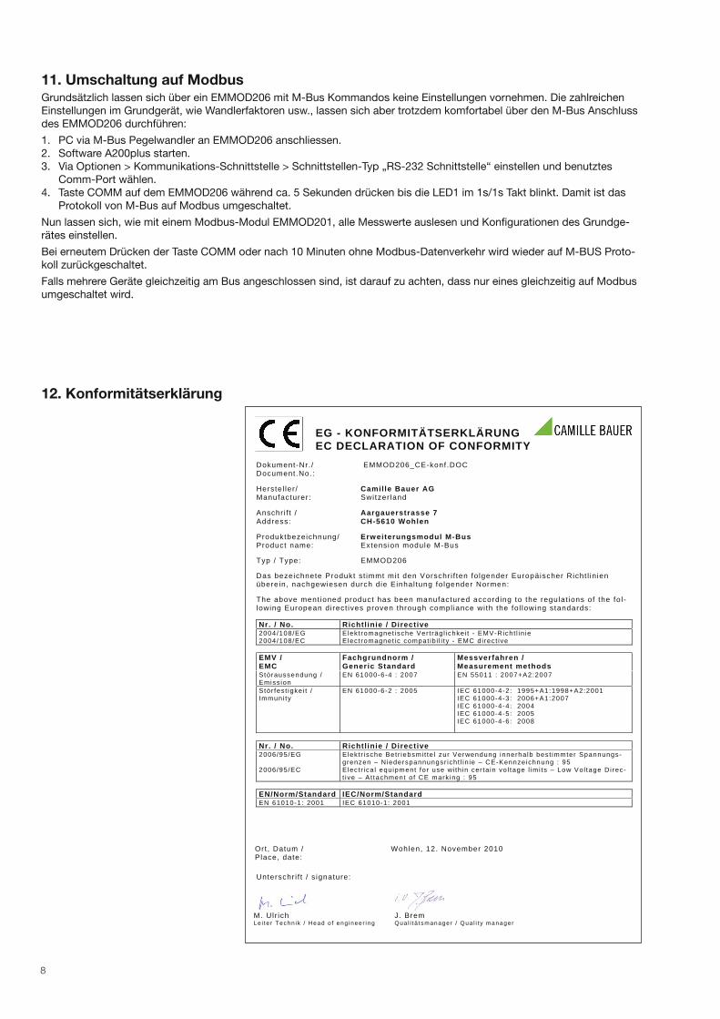
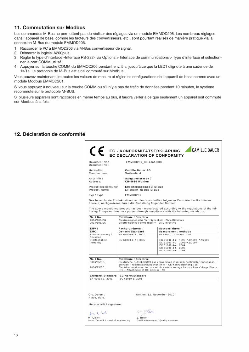
12. Konformitätserklärung
EG - KONFORMITÄTSERKLÄRUNGEC DECLARATION OF CONFORMITY
Dokument-Nr. / EMMOD206_CE-konf.DOC Document.No.:
Herstel ler / Camille Bauer AGManufacturer: Switzer land
Anschr i f t / Aargauerstrasse 7 Address: CH-5610 Wohlen
Produktbezeichnung/ Erweiterungsmodul M-BusProduct name: Extension module M-Bus
Typ / Type: EMMOD206
Das bezeichnete Produkt st immt mit den Vorschr i f ten fo lgender Europäischer Richt l in ienüberein, nachgewiesen durch die Einhal tung fo lgender Normen:
The above ment ioned product has been manufactured according to the regulat ions of the fo l -lowing European direct ives proven through compl iance wi th the fo l lowing standards: Nr. / No. Richtl inie / Directive 2004/108/EG2004/108/EC
Elekt romagnet ische Ver t räg l ichke i t - EMV-Richt l in ie E lect romagnet ic compat ib i l i ty - EMC d i rect ive
EMV / EMC
Fachgrundnorm / Generic Standard
Messverfahren / Measurement methods
Störaussendung / Emiss ion
EN 61000-6-4 : 2007 EN 55011 : 2007+A2:2007
Stör fes t igke i t / Immuni ty
EN 61000-6-2 : 2005 IEC 61000-4-2: 1995+A1:1998+A2:2001 IEC 61000-4-3: 2006+A1:2007 IEC 61000-4-4: 2004 IEC 61000-4-5: 2005 IEC 61000-4-6: 2008
Nr. / No. Richtl inie / Directive 2006/95/EG
2006/95/EC
Elekt r ische Bet r iebsmi t te l zur Verwendung innerha lb best immter Spannungs-grenzen – Niederspannungsr icht l in ie – CE-Kennzeichnung : 95 Elect r ica l equipment for use wi th in cer ta in vo l tage l imi ts – Low Vol tage Di rec-t ive – At tachment o f CE mark ing : 95
EN/Norm/Standard IEC/Norm/Standard EN 61010-1: 2001 IEC 61010-1: 2001
Ort , Datum / Place, date:
Wohlen, 12. November 2010
Unterschr i f t / s ignature:
M. Ulr ich J. Brem Le i te r Techn ik / Head o f eng ineer ing Qua l i t ä t smanager / Qua l i t y manager
9
Mode d’emploiModule d’extensionM-Bus pour appareils A2xx
EMMOD206
EMMOD206 Bdfe 169 335 01.13
Camille Bauer AG
Aargauerstrasse 7
CH-5610 Wohlen/Suisse
Téléphone +41 56 618 21 11
Téléfax +41 56 618 35 35
www.camillebauer.com
Consignes de sécurité
Seul du personnel dûment formé est autorisé à réaliser l’ins-
tallation et la mise en service.
Avant la mise en service, vérifiez les points suivants:
– les valeurs maximales de toutes les connexions ne doivent pas être
dépassées, voir le chapitre Caractéristiques techniques.
– les câbles de raccordement ne doivent pas être endommagés et doivent
être sans tension au moment du câblage.
Il faut mettre l’appareil hors service lorsque son fonctionnement n’est plus
possible sans danger (dommages visibles p. ex..). Il faut alors débrancher
tous les raccordements. Il faut renvoyer l’appareil à notre entreprise ou à
un centre de service agréé par nous.
Ne pas toucher la carte de circuit imprimé ni les contacts! Les
charges électrostatiques peuvent détruire les composants
électroniques.
Toute revendication en garantie est exclue en cas d’intervention dans
l’appareil.
Sommaire
1 Présentation rapide ....................................................................................10
2 Equipement standard .................................................................................10
3 Caractéristiques techniques .......................................................................10
4 Schéma fonctionnel ....................................................................................10
5 Montage / démontage ................................................................................10
6 Connexions sur l’appareil ...........................................................................11
7 Organes d’affichage et de commande .......................................................11
8 Programmation ...........................................................................................12
9 Spécification M-Bus ...................................................................................14
10 Protocole M-Bus ........................................................................................14
11 Commutation sur Modbus .........................................................................16
12 Déclaration de conformité ..........................................................................16
Les appareils doivent être
recyclés dans les règles!
10
1. Présentation rapideLe module d’extension EMMOD206 complète les fonction-
nalités d’un appareil de base A2xx ainsi que sa flexibilité. Il
permet de consulter des valeurs instantanées et des valeurs
de compteurs par le biais de l’interface M-Bus. Une entrée
numérique est disponible en supplément pour la synchronisa-
tion des intervalles de mesure servant à définir les grandeurs
moyennes ou au basculement de tarif du compteur d’énergie.
Le clavier de l’appareil de base est utilisé pour sélection-
ner les valeurs de mesure à transmettre et effectuer des
réglages. A titre passager, l’interface du protocole M-Bus
peut être commutée sur le protocole Modbus afin de per-
mettre une configuration pratique de la fonction de me-
sure de l’appareil de base A2xx via le logiciel A200plus.
Il est possible de post-équiper le module sans intervenir
dans l’appareil de base. Les appareils de base A210, A220,
A230 et A230s doivent dans ce cas être équipés de la ver-
sion V5.0 ou supérieure du firmware.
2. Equipement standard1 module d’extension EMMOD206
4 rivets aveugles à fentes en matière plastique
1 mode d’emploi allemand/français/anglais
1 étiquette supplémentaire pour entrée et pour
sortie/énergie auxiliaire
3. Caractéristiques techniquesEnergie auxiliaire
Le module EMMOD206 est alimenté par l’appareil de base
A2xx. La puissance absorbée de l’appareil de base aug-
mente d’environ 0,1 W lorsque le module est connecté.
Conditions ambiantes
Température de service: – 10 à + 55 °C
Température de stockage: – 25 à + 70 °C
Humidité relative en
moyenne annuelle: ≤75%
Altitude de service: 2000 m max.
A n’utiliser qu’à l’intérieur
Communication M-Bus
Interface, protocole: M-Bus
Vitesse de transmission: 300…38 400 bauds, se règle
via le clavier de l’appareil de
base A2xx, Autobaud n’est
pas pris en charge
Adresse primaire: 0...250, se règle via le clavier
de l’appareil de base A2xx
Adresse secondaire / ID: fixe et réglée en usine
ID1…ID4 correspond au numéro de
série à 8 chiffres imprimé
sur la plaque signalétique
(n° courant)
MAN1, MAN2 A3, 1D (GMC)
GEN 210 (pour A210 et A220),
230 (pour A230 et A230s),
MED 02 (électricité)
Représentation de la
valeur de mesure: mode 1, LSB first
mode 2, pas pris en charge
Données de configuration: mémorisation non volatile dans
l’appareil de base
numéro ID fourni par le
module.
Détection anticollision: aucune
Facteur de charge bus: 0,7 (courant de repos 1,1 mA
env.)
Connexions bornes à vis enfichables
0,5…1,5 mm2 (toron) ou
0,5…2,5 mm2 (fil)
Entrée numérique
Fonction: cadence synchronisée pour
grandeurs moyennes ou com-
mutation tarifs heures pleines/
creuses des compteurs
d’énergie
Polarité: au choix
Connexion externe: max. 230 V CA ou CC
Repos: Uin<12 V CA/CC, tarif heures
pleines
LED «IN» sombre
Etat activé: Uin<17 V CA/CC, tarif heures
creuses
LED «IN» allumée
Courant consommé: < 4 mA sous 15 V CC
< 2 mA sous 250 V CC
Temps de réponse: 150 ms
Séparation galvanique: par optocoupleur
Sécurité conforme à EN 61010-1
Isolation de base entre bornes et connecteur à douille
Tension assignée: 300 V
Catégorie de mesure: CATIII
Degré de pollution: 2
Tensions d’essai: 50 Hz / 1 min
2200 V: M-Bus vers appareil
de base et
entrée numérique vers appareil
de base,
3700 V: M-Bus par rapport
entrée numérique
Dimensions (L x l x H) 86 x 38 x 20 mm
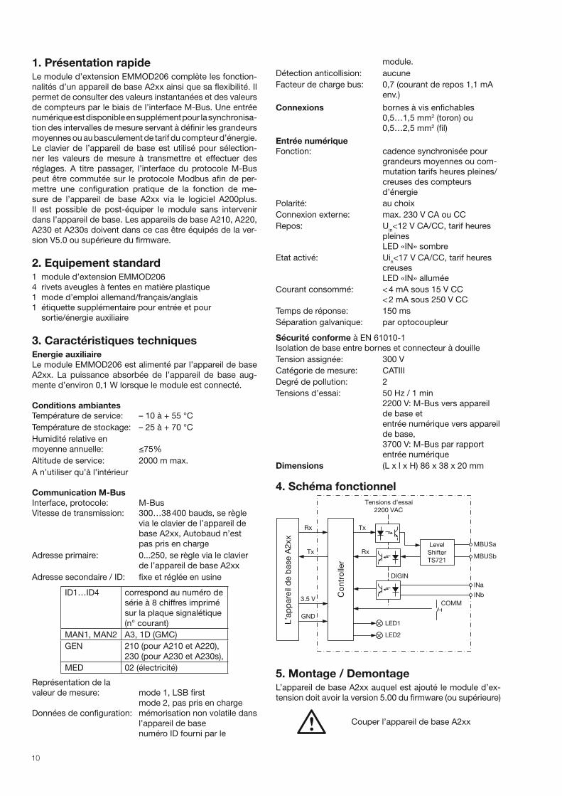
4. Schéma fonctionnel
Tensions d’essai
L’a
pp
are
il d
e b
ase A
2xx
Co
ntr
olle
r
2200 VAC
MBUSa
MBUSb
INa
Tx
Rx
Rx
Tx
3.5 V
GND
INb
COMM
Level
Shifter
TS721
LED1
DIGIN
LED2
5. Montage / DemontageL’appareil de base A2xx auquel est ajouté le module d’ex-
tension doit avoir la version 5.00 du firmware (ou supérieure)
Couper l’appareil de base A2xx

11
Enficher tout simplement le module d’extension (1) au dos
de l’appareil de base (figure 1). Veillez à ce que le connec-
teur (2) et la prise femelle (3) soient adaptés l’un à l’autre.
Attention!
Ne pas toucher la carte de circuit imprimé
ni les contacts! Les charges électrosta-
tiques peuvent détruire les composants
électroniques.
(1)
(2)
(4)
(3)
Pour réaliser le blocage mécanique, enfoncer les quatre
rivets aveugles à fentes en matière plastique (5) fournis
dans les trous (4) prévus à cet effet (figure 2).
(5)(4)
Coller les étiquettes supplémentaires Entrée et Sortie/éner-
gie auxiliaire comme le montre la figure 3.
Figure 3
Retirer la tête moletée (6) des rivets aveugles à fentes avec
les doigts pour le démontage (figure 4). Il est possible main-
tenant de sortie le module d’extension (1).
(6) (1)
Figure 1
Figure 2
Figure 4
6. Connexions sur l’appareil
30 31 32 33 34
No. 1
N° Signal
30 INa entrée basculement de tarif
(indépendant de la polarité)31 INb
32 ––– ne doit pas être connecté
33 M-BUS-A connexion de bus M-BUS
(indépendant de la polarité)34 M-BUS-B
Attention! Ne pas inverser les connecteurs de borne!
7. Organes d’affi chage et de commande
LED1
gauche
Tx
PWR
Communication
luminosité signification
moyenne repos, communication
interne OK
impulsion
sombre
réception d'un télé-
gramme M-BUS
impulsion
claire
envoi d'un télégramme
M-BUS
clignotant
1s/1s
commutation sur
protocole Modbus
sombre communication interne
perturbée
LED2
droite
IN entrée numérique
luminosité signification
sombre signal inactif, tarif heures
pleines
moyenne signal actif, tarif heures
creuses
claire inutilisée
Touche
La touche COMM sert à commuter temporairement du pro-
tocole M-BUS au protocole MODBUS, la couche physique
de M-Bus étant conservée.
12
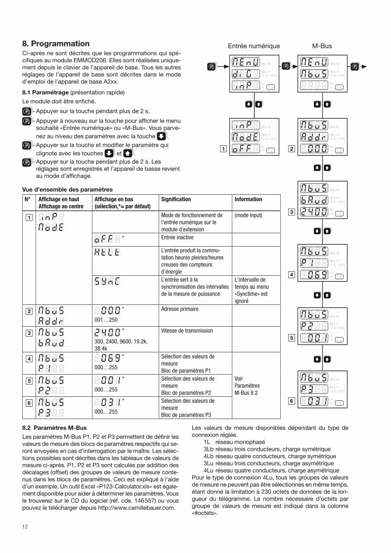
8. ProgrammationCi-après ne sont décrites que les programmations qui spé-
cifiques au module EMMOD206. Elles sont réalisées unique-
ment depuis le clavier de l’appareil de base. Tous les autres
réglages de l’appareil de base sont décrites dans le mode
d’emploi de l’appareil de base A2xx.
8.1 Paramétrage (présentation rapide)
Le module doit être enfiché.
P - Appuyer sur la touche pendant plus de 2 s.
P - Appuyer à nouveau sur la touche pour afficher le menu
souhaité «Entrée numérique» ou «M-Bus». Vous parve-
nez au niveau des paramètres avec la touche .
P - Appuyer sur la touche et modifier le paramètre qui
clignote avec les touches et .
P - Appuyer sur la touche pendant plus de 2 s. Les
réglages sont enregistrés et l’appareil de basse revient
au mode d’affichage.
Vue d’ensemble des paramètres
N° Affichage en haut
Affichage au centre
Affichage en bas
(sélection,*= par défaut)
Signification Information
Mode de fonctionnement de
l’entrée numérique sur le
module d’extension
(mode input)
* Entrée inactive
L’entrée produit la commu-
tation heures pleines/heures
creuses des compteurs
d’énergie
L’entrée sert à la
synchronisation des intervalles
de la mesure de puissance
L'intervalle de
temps au menu
«Synctime» est
ignoré
*
001…250
Adresse primaire
*
300, 2400, 9600, 19.2k,
38.4k
Vitesse de transmission
*
000…255
Sélection des valeurs de
mesure
Bloc de paramètres P1
Voir
Paramètres
M-Bus 8.2
*
000…255
Sélection des valeurs de
mesure
Bloc de paramètres P2
*
000…255
Sélection des valeurs de
mesure
Bloc de paramètres P3
P P
Entrée numérique M-Bus
P
8.2 Paramètres M-Bus
Les paramètres M-Bus P1, P2 et P3 permettent de définir les
valeurs de mesure des blocs de paramètres respectifs qui se-
ront envoyées en cas d’interrogation par le maître. Les sélec-
tions possibles sont décrites dans les tableaux de valeurs de
mesure ci-après. P1, P2 et P3 sont calculés par addition des
décalages (offset) des groupes de valeurs de mesure conte-
nus dans les blocs de paramètres. Ceci est expliqué à l’aide
d’un exemple. Un outil Excel «P123-Calculator.xls» est égale-
ment disponible pour aider à déterminer les paramètres. Vous
le trouverez sur le CD du logiciel (réf. cde. 146 557) ou vous
pouvez le télécharger depuis http://www.camillebauer.com.
Les valeurs de mesure disponibles dépendant du type de
connexion réglée.
1L réseau monophasé
3Lb réseau trois conducteurs, charge symétrique
4Lb réseau quatre conducteurs, charge symétrique
3Lu réseau trois conducteurs, charge asymétrique
4Lu réseau quatre conducteurs, charge asymétrique
Pour le type de connexion 4Lu, tous les groupes de valeurs
de mesure ne peuvent pas être sélectionnés en même temps,
étant donné la limitation à 230 octets de données de la lon-
gueur du télégramme. Le nombre nécessaire d’octets par
groupe de valeurs de mesure est indiqué dans la colonne
«#octets».
13
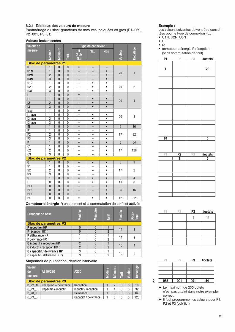
8.2.1 Tableaux des valeurs de mesure
Paramétrage d’usine: grandeurs de mesures indiquées en gras (P1=069,
P2=001, P3=31)
Valeurs instantanées
Valeur de
mesureM
odu
le
Mém
oire
Tari
f
Type de connexion
#oc
tets
Déc
alag
e
1L3 Lb
4Lb
3Lu 4Lu
Bloc de paramètres P1U 1 0 0 • – –
20 1U1N 1 0 0 – – •U2N 2 0 0 – – •U3N 3 0 0 – – •U12 1 0 0 – • •
20 2U23 2 0 0 – • •U31 3 0 0 – • •I 1 0 0 • – –
20 4I1 1 0 0 – • •I2 2 0 0 – • •I3 3 0 0 – • •Iavg 1 0 0 • – –
20 8I1_avg 1 0 0 – • •I2_avg 2 0 0 – • •I3_avg 3 0 0 – • •IN 1 0 0 – – • 6 16P1 1 0 0 – – •
17 32P2 2 0 0 – – •P3 3 0 0 – – •P 1 0 0 • • • 5 64Q1 1 0 0 – – •
17 128Q2 2 0 0 – – •Q3 3 0 0 – – •
Bloc de paramètres P2Q 1 0 0 • • • 5 1S1 1 0 0 – – •
17 2S2 2 0 0 – – •S3 3 0 0 – – •S 1 0 0 • • • 5 4F 0 0 0 • • • 11 8PF1 0 0 0 – – •
36 16PF2 0 0 0 – – •PF3 0 0 0 – – •PF 0 0 0 • • • 12 32
Compteur d’énergie 1) uniquement si la commutation de tarif est activée
Grandeur de base
Mod
ule
Mém
oire
Tari
f
#oc
tets
Déc
a-
lag
e
Bloc de paramètres P3P réception HP 0 0 1
14 1P réception HC 1) 0 0 2P délivrance HP 1 0 1
14 2P délivrance HC 1) 1 0 2Q inductif / réception HP 2 0 1
16 4Q inductif / réception HC 1) 2 0 2Q capacitif / délivrance HP 3 0 1
16 8Q capacitif / délivrance HC 1) 3 0 2
Moyennes de puissance, dernier intervalle
Valeur
de
mesure
A210/220 A230
Mod
ule
Mém
oire
Tari
f
#oc
tets
Déc
alag
e
Bloc de paramètres P3P_int_0 Réception + délivrance Réception 1 2 0 5 16Q_int_0 Capacitif + inductif Inductif / réception 1 4 0 5 32P_int_0 Délivrance 1 6 0 5 64
Q_int_0 Capacitif / délivrance 1 8 0 5 128
Exemple :Les valeurs suivantes doivent être consul-tées pour le type de connexion 4Lu:• U1N, U2N, U3N• P• Q• compteur d’énergie P réception
(sans commutation de tarif)
P1 P2 P3 #octets
1 20
64 5
P1 P2 P3 #octets1 5
P1 P2 P3 #octets
1 14
P1 P2 P3 #octets
065 001 001 44
➤ Le maximum de 230 octets
n’est pas atteint dans notre exemple,
correct.
➤ Il faut programmer les valeurs pour P1,
P2 et P3 (voir 8.1)
∑
14
8.2.2 Format des données
Toutes les valeurs de mesure transmises sont des valeurs primaires. Les valeurs instantanées sont représentées sous forme
de nombres entiers 16 bits et les compteurs d’énergie sous forme de nombres entiers 32 bits. Les unités et les virgules
décimales correspondantes se modifient avec le réglage du convertisseur sur l’appareil de base et sont fournies dans le
télégramme de données conformément à la norme.
Les valeurs de mesure de fréquence F [Hz] et du facteur de puissance PF [ ] ne sont pas traitées dans la norme. Ces données
sont donc transmises sous forme de chaîne ASCII comme la norme le recommande.
La plus grande unité d‘énergie disponible pour M-Bus est le MWh. Selon le réglage des rapports de transformation, des unités
plus grandes peuvent cependant être générées, jusqu’au GWh. Dans ce cas, l’indicateur d’erreur est réglé sur DIF et c’est à
l’opérateur de choisir la bonne interprétation pour l’unité d‘énergie.
8.2.3 Points de données et affectation
L’ordre de la transmission des valeurs de mesure correspond toujours aux lignes du tableau : les tensions en premier et les
moyennes de puissance en dernier. Les valeurs de mesure qui ne s’appliquent pas au type de connexion sélectionné ne sont
pas transmises.
Les «points de données» sont généralement affectés dans le maître dans l’ordre de leur arrivée. Il est donc recommandé de
réaliser tous les réglages sur l’appareil de base dans un premier temps avant de mettre l’évaluation des données au point.
Pour mieux différencier les valeurs de mesure ayant la même unité, vous pouvez utiliser les informations supplémentaires
transmises des colonnes Module, Mémoire et Tarif.
Ne sont disponibles pour le type de connexion respectif que les valeurs instantanées signalées par « • ».
9. Spécifi cation M-BusDes informations détaillées sur M-Bus sont disponibles sur le site Internet http://www.m-bus.com et dans la norme EN1434-3.
Le câblage est réalisé, dans le cas de M-Bus, avec une paire de brins d’un câble téléphonique standard (par ex. JY(St)Y 2 x
2 x 0.8 mm). La polarité ne joue aucun rôle. Il faut cependant noter que les convertisseurs de signal utilisés pour la connexion
au PC sont rarement dotés d’une séparation galvanique et que le bus fonctionne avec des tensions jusqu’à 40 V.
Pour une configuration standard avec des vitesses de transmission comprises entre 300 et 9 600 bauds et 250 esclaves
maximum, la distance maximale entre maître et esclave est de 350 m. Cette distance maximale augmente si une vitesse de
transmission plus lente est choisie ou si le nombre d’esclaves est réduit.
10. Protocole M-Bus
10.1 Adressage
Le module EMMOD206 prend en charge á la fois l’adressage primaire et l’adressage secondaire.
Pour l’adressage primaire, il faut régler une adresse comprise dans la plage de 1 à 250 à l’aide du clavier pour chacun des ap-
pareils raccordés au bus. Les interrogations du maître contiennent cette adresse et l’esclave répond en cas de concordance.
Pour l’adressage secondaire, le maître utilise l’adresse primaire 253 (Broadcast, Selection) et transmet en plus l’identification
souhaitée qui comprend 8 octets (4 numéro de série + 2 fabricant + 1 génération + 1 support). Comme il est garanti que
le numéro de série pour le module EMMOD206 est unique, des doubles adressages ne peuvent se produire et il n’est pas
nécessaire de régler une adresse sur l’appareil. L’appareil sélectionné répondra à toutes les interrogations qui suivront avec
l’adresse primaire 253 jusqu’à ce qu’il constate une autre sélection. Les jokers F ou FF servent à masquer des ID d’éléments,
ce qui permet au maître de rechercher efficacement de nouveaux appareils.
10.2 Dialogues pris en charge
10.2.1 Reset SND_NKE / ACK
➤ interrogation au maître
SND_NKE
10 40 FF 3F 16 Le maître assigne tous les esclaves à un reset de communication avec confirmation par ACK en utilisant l’adresse broad-
cast (FF=255).
➤ réponse de l’esclave
ACK
E5
10.2.2 Interrogation de données avec adressage primaire REQ_UD2 / RSP_UD
➤ interrogation au maître
REQ_UD2
10 7B 03 7E 16Le maître demande les données à l’esclave n° 3.
15
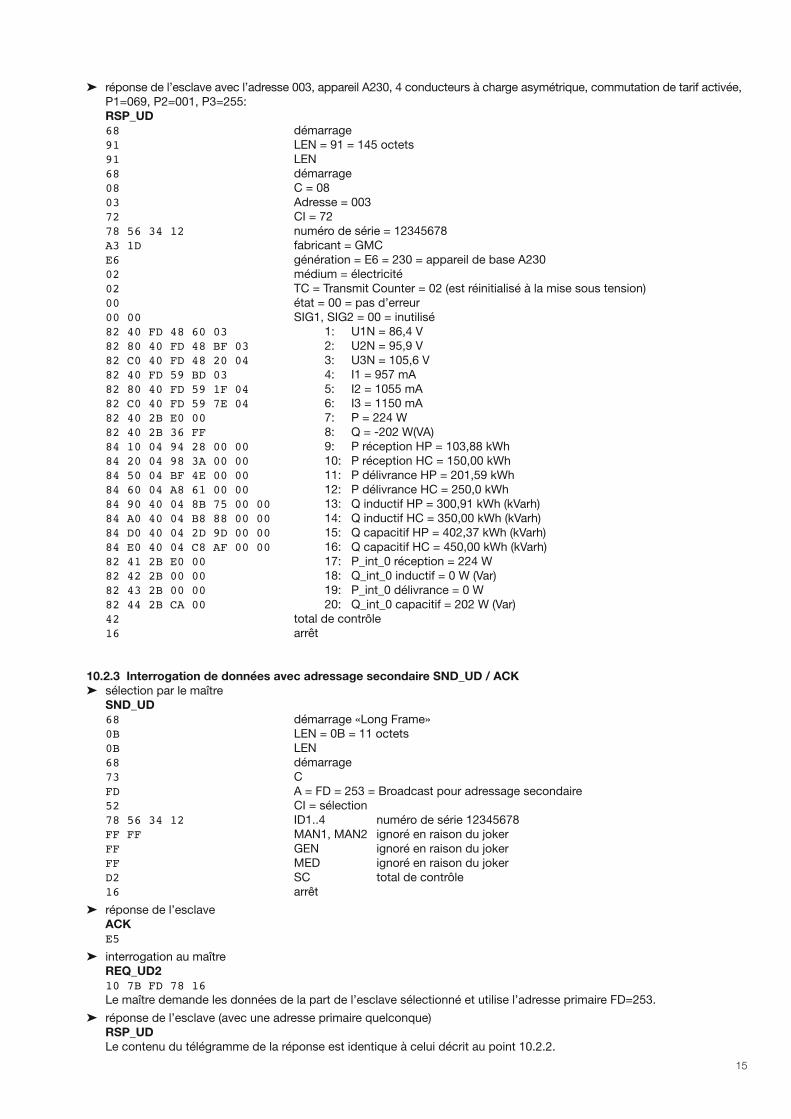
➤ réponse de l’esclave avec l’adresse 003, appareil A230, 4 conducteurs à charge asymétrique, commutation de tarif activée,
P1=069, P2=001, P3=255:
RSP_UD
68 démarrage
91 LEN = 91 = 145 octets
91 LEN
68 démarrage
08 C = 08
03 Adresse = 003
72 CI = 72
78 56 34 12 numéro de série = 12345678
A3 1D fabricant = GMC
E6 génération = E6 = 230 = appareil de base A230
02 médium = électricité
02 TC = Transmit Counter = 02 (est réinitialisé à la mise sous tension)
00 état = 00 = pas d’erreur
00 00 SIG1, SIG2 = 00 = inutilisé
82 40 FD 48 60 03 1: U1N = 86,4 V
82 80 40 FD 48 BF 03 2: U2N = 95,9 V
82 C0 40 FD 48 20 04 3: U3N = 105,6 V
82 40 FD 59 BD 03 4: I1 = 957 mA
82 80 40 FD 59 1F 04 5: I2 = 1055 mA
82 C0 40 FD 59 7E 04 6: I3 = 1150 mA
82 40 2B E0 00 7: P = 224 W
82 40 2B 36 FF 8: Q = -202 W(VA)
84 10 04 94 28 00 00 9: P réception HP = 103,88 kWh
84 20 04 98 3A 00 00 10: P réception HC = 150,00 kWh
84 50 04 BF 4E 00 00 11: P délivrance HP = 201,59 kWh
84 60 04 A8 61 00 00 12: P délivrance HC = 250,0 kWh
84 90 40 04 8B 75 00 00 13: Q inductif HP = 300,91 kWh (kVarh)
84 A0 40 04 B8 88 00 00 14: Q inductif HC = 350,00 kWh (kVarh)
84 D0 40 04 2D 9D 00 00 15: Q capacitif HP = 402,37 kWh (kVarh)
84 E0 40 04 C8 AF 00 00 16: Q capacitif HC = 450,00 kWh (kVarh)
82 41 2B E0 00 17: P_int_0 réception = 224 W
82 42 2B 00 00 18: Q_int_0 inductif = 0 W (Var)
82 43 2B 00 00 19: P_int_0 délivrance = 0 W 82 44 2B CA 00 20: Q_int_0 capacitif = 202 W (Var)
42 total de contrôle
16 arrêt
10.2.3 Interrogation de données avec adressage secondaire SND_UD / ACK
➤ sélection par le maître
SND_UD
68 démarrage «Long Frame»
0B LEN = 0B = 11 octets
0B LEN
68 démarrage
73 C
FD A = FD = 253 = Broadcast pour adressage secondaire
52 CI = sélection
78 56 34 12 ID1..4 numéro de série 12345678
FF FF MAN1, MAN2 ignoré en raison du joker
FF GEN ignoré en raison du joker
FF MED ignoré en raison du joker
D2 SC total de contrôle
16 arrêt
➤ réponse de l’esclave
ACK E5
➤ interrogation au maître
REQ_UD2
10 7B FD 78 16 Le maître demande les données de la part de l’esclave sélectionné et utilise l’adresse primaire FD=253.
➤ réponse de l’esclave (avec une adresse primaire quelconque)
RSP_UD
Le contenu du télégramme de la réponse est identique à celui décrit au point 10.2.2.
16
11. Commutation sur ModbusLes commandes M-Bus ne permettent pas de réaliser des réglages via un module EMMOD206. Les nombreux réglages
dans l’appareil de base, comme les facteurs des convertisseurs, etc., sont pourtant réalisés de manière pratique via la
connexion M-Bus du module EMMOD206.
1. Raccorder le PC à EMMOD206 via M-Bus convertisseur de signal.
2. Démarrer le logiciel A200plus.
3. Régler le type d’interface «Interface RS-232» via Options > Interface de communications > Type d’interface et sélection-
ner le port COMM utilisé.
4. Appuyer sur la touche COMM du EMMOD206 pendant env. 5 s, jusqu’à ce que la LED1 clignote à une cadence de
1s/1s. Le protocole de M-Bus est ainsi commuté sur Modbus.
Vous pouvez maintenant lire toutes les valeurs de mesure et régler les configurations de l’appareil de base comme avec un
module Modbus EMMOD201.
Si vous appuyez à nouveau sur la touche COMM ou s’il n’y a pas de trafic de données pendant 10 minutes, le système
recommute sur le protocole M-BUS.
Si plusieurs appareils sont raccordés en même temps au bus, il faudra veiller à ce que seulement un appareil soit commuté
sur Modbus à la fois.
12. Déclaration de conformité
EG - KONFORMITÄTSERKLÄRUNGEC DECLARATION OF CONFORMITY
Dokument-Nr. / EMMOD206_CE-konf.DOC Document.No.:
Herstel ler / Camille Bauer AGManufacturer: Switzer land
Anschr i f t / Aargauerstrasse 7 Address: CH-5610 Wohlen
Produktbezeichnung/ Erweiterungsmodul M-BusProduct name: Extension module M-Bus
Typ / Type: EMMOD206
Das bezeichnete Produkt st immt mit den Vorschr i f ten fo lgender Europäischer Richt l in ienüberein, nachgewiesen durch die Einhal tung fo lgender Normen:
The above ment ioned product has been manufactured according to the regulat ions of the fo l -lowing European direct ives proven through compl iance wi th the fo l lowing standards: Nr. / No. Richtl inie / Directive 2004/108/EG2004/108/EC
Elekt romagnet ische Ver t räg l ichke i t - EMV-Richt l in ie E lect romagnet ic compat ib i l i ty - EMC d i rect ive
EMV / EMC
Fachgrundnorm / Generic Standard
Messverfahren / Measurement methods
Störaussendung / Emiss ion
EN 61000-6-4 : 2007 EN 55011 : 2007+A2:2007
Stör fes t igke i t / Immuni ty
EN 61000-6-2 : 2005 IEC 61000-4-2: 1995+A1:1998+A2:2001 IEC 61000-4-3: 2006+A1:2007 IEC 61000-4-4: 2004 IEC 61000-4-5: 2005 IEC 61000-4-6: 2008
Nr. / No. Richtl inie / Directive 2006/95/EG
2006/95/EC
Elekt r ische Bet r iebsmi t te l zur Verwendung innerha lb best immter Spannungs-grenzen – Niederspannungsr icht l in ie – CE-Kennzeichnung : 95 Elect r ica l equipment for use wi th in cer ta in vo l tage l imi ts – Low Vol tage Di rec-t ive – At tachment o f CE mark ing : 95
EN/Norm/Standard IEC/Norm/Standard EN 61010-1: 2001 IEC 61010-1: 2001
Ort , Datum / Place, date:
Wohlen, 12. November 2010
Unterschr i f t / s ignature:
M. Ulr ich J. Brem Le i te r Techn ik / Head o f eng ineer ing Qua l i t ä t smanager / Qua l i t y manager
17
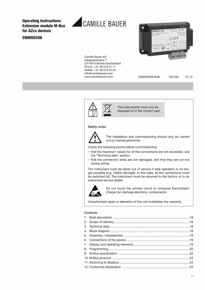
Operating InstructionsExtension module M-Busfor A2xx devices
EMMOD206
EMMOD206 Bdfe 169 335 01.13
Camille Bauer AG
Aargauerstrasse 7
CH-5610 Wohlen/Switzerland
Phone +41 56 618 21 11
Telefax +41 56 618 35 35
www.camillebauer.com
Safety notes
The installation and commissioning should only be carried
out by trained personnel.
Check the following points before commissioning:
– that the maximum values for all the connections are not exceeded, see
the “Technical data” section,
– that the connection wires are not damaged, and that they are not live
during wiring.
The instrument must be taken out of service if safe operation is no lon-
ger possible (e.g. visible damage). In this case, all the connections must
be switched off. The instrument must be returned to the factory or to an
authorized service dealer.
Do not touch the printed circuit or contacts! Electrostatic
charge can damage electronic components.
Unauthorized repair or alteration of the unit invalidates the warranty.
Contents
1. Brief description .........................................................................................18
2. Scope of delivery ........................................................................................18
3. Technical data ............................................................................................18
4. Block diagram ............................................................................................18
5. Assembly / disassembly .............................................................................18
6. Connections of the device..........................................................................19
7. Display and operating elements .................................................................19
8. Programming ..............................................................................................20
9. M-Bus specification ...................................................................................22
10. M-Bus protocol ..........................................................................................22
11. Switching to Modbus .................................................................................24
12. Conformity declaration ..............................................................................24
The instruments must only be
disposed of in the correct way!
18
1. Brief descriptionThe extension module EMMOD206 supplements the func-
tionality and flexibility of the basic device A2xx and allows
reading instantaneous values and metering contents via M-
Bus interface. In addition a digital input is provided to syn-
chronize the intervals for the mean-values calculation or to
switch the tariff of the energy meters.
The selection of the measurements to transfer and further
settings can be performed via the keys of the basic unit. The
interface can be temporarily switched from M-Bus protocol
to Modbus protocol to allow a comfortable configuration of
the measurement functionality of the basic device A2xx by
means of the A200plus software.
The module can be retrofitted without tampering with the
basic unit. But to do so, the basic units A210, A220, A230
and A230s must be equipped with firmware version V5.0 or
higher.
2. Scope of delivery1 Extension module EMMOD206
4 Plastic rivets
1 Operating instruction German/French/English
Additional label each for input and output/power supply
3. Technical dataPower supply
The EMMOD206 is powered by the A2xx basic unit. The
power consumption of the basic unit is increased by approx.
0.1 W when the EMMOD206 is connected.
Environmental conditions
Operating
temperature: – 10 up to + 55 °C
Storage temperature: – 25 up to + 70 °C
Relative humidity of
annual mean: ≤ 75%
Altitude: 2000 m max.
Indoor use statement!
Communication M-Bus
Interface, protocol: M-Bus
Baud rate: 300…38 400 baud, adjustable via
the keys of the basic unit A2xx,
auto baud is not supported.
Primary address: 0...250, adjustable via the keys of
the basic unit A2xx
Secondary
address / ID: Is fixed and factory predefined
ID1…ID4 Corresponds to the
8-digit serial number
(sequential number) given
on the nameplate.
MAN1, MAN2 A3, 1D (GMC)
GEN 210 (for A210 and A220),
230 (for A230 and A230s)
MED 02 (Electricity)
Measurement image: Mode 1, LSB first
Mode 2 not supported
Configuration data: non-volatile storage in the basic
unit.
ID number provided by module.
Collision detection: none
Load factor bus: 0.7 (standby current approx. 1.1 mA)
Connections Pluggable screw terminals
0.5…1.5 mm2 (multiwire) or
0.5...2.5 mm2 (single wire)
Digital input
Function Synchronization of mean-values
or switching of high/low tariff for
energy meters
Polarity: Any
External connection: max. 230 V AC or DC
Passive state: Uin<12 V AC/DC, high tariff
LED „IN“ off
Active state: Uin>17 V AC/DC, low tariff
LED „IN“ on
Power consumption: < 4 mA at 15 V DC
< 2 mA at 250 V DC
Response time: 150 ms
Galvanic isolation: via optocoupler
Safety according EN 61010-1
Basic insulation between terminals and socket board
Rated voltage: 300 V
Measurement
category: CATIII
Pollution degree: 2
Test voltages: 50 Hz / 1 min
2200 V: M-Bus versus basic unit
and digital input versus basic unit
3700 V: M-Bus versus digital input
Dimensions (L x W x D) 86 x 38 x 20 mm
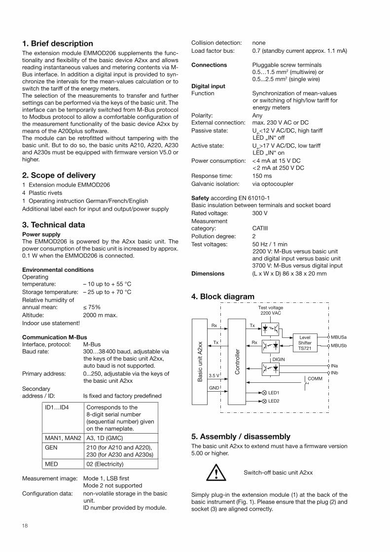
4. Block diagram
Test voltage
Basic
un
it A
2xx
Co
ntr
olle
r
2200 VAC
MBUSa
MBUSb
INa
Tx
Rx
Rx
Tx
3.5 V
GND
INb
COMM
Level
Shifter
TS721
LED1
DIGIN
LED2
5. Assembly / disassemblyThe basic unit A2xx to extend must have a firmware version
5.00 or higher.
Switch-off basic unit A2xx
Simply plug-in the extension module (1) at the back of the
basic instrument (Fig. 1). Please ensure that the plug (2) and
socket (3) are aligned correctly.

19
Note!
Do not touch the printed circuit or contacts!
Electrostatic charge can damage electronic
components.
(1)
(2)
(4)
(3)
To fix the module mechanically, insert the four plastic clips
supplied (5) in the fixing holes (4) (Fig. 2).
(5)(4)
Affix the additional label: inputs and outputs/power supply
as in Fig. 3.
Fig. 3
To release the module, pull out the plastic clips by the
knurled knob (6) with the fingers (Fig. 4). The extension
module (1) can now be removed.
(6) (1)
Fig. 1
Fig. 2
Fig. 4
6. Connections of the device
30 31 32 33 34
No. 1
No. Signal Connection
30 INa Digital input
(polarity independent)31 INb
32 ––– Not to be connected
33 M-BUS-A Bus connection M-BUS
(polarity independent)34 M-BUS-B
Attention: Do not confuse the plug-in terminals !
7. Display and operating elements
LED1
left
Tx
PWR
Communication:
Brightness Meaning
medium No activity, internal
communication OK
pulsed
dark
M-BUS telegram
received
pulsed light M-BUS telegram sent
flashing
1s/1s
Switched to Modbus
protocol
dark Internal communication
disturbed
LED2
right
IN Digital input:
Brightness Meaning
dark Signal inactive,
high tariff
medium Signal active, low tariff
light Not used
Key
The key COMM serves to temporarily switch from M-Bus
to Modbus protocol, in which the physical layer of M-Bus
remains untouched.
20
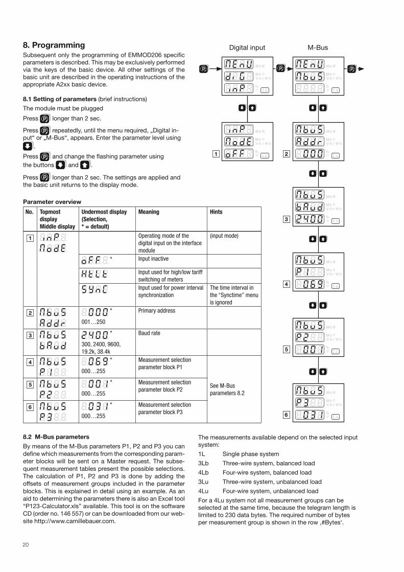
8. ProgrammingSubsequent only the programming of EMMOD206 specific
parameters is described. This may be exclusively performed
via the keys of the basic device. All other settings of the
basic unit are described in the operating instructions of the
appropriate A2xx basic device.
8.1 Setting of parameters (brief instructions)
The module must be plugged
Press P longer than 2 sec.
Press P repeatedly, until the menu required, „Digital in-
put“ or „M-Bus“, appears. Enter the parameter level using
.
Press P and change the flashing parameter using
the buttons and .
Press P longer than 2 sec. The settings are applied and
the basic unit returns to the display mode.
Parameter overview
No. Topmost
display
Middle display
Undermost display
(Selection,
* = default)
Meaning Hints
Operating mode of the
digital input on the interface
module
(input mode)
* Input inactive
Input used for high/low tariff
switching of meters
Input used for power interval
synchronization
The time interval in
the “Synctime” menu
is ignored
*
001…250
Primary address
*
300, 2400, 9600,
19.2k, 38.4k
Baud rate
*
000…255
Measurement selection
parameter block P1
See M-Bus
parameters 8.2
*
000…255
Measurement selection
parameter block P2
*
000…255
Measurement selection
parameter block P3
P P
Digital input M-Bus
P
8.2 M-Bus parameters
By means of the M-Bus parameters P1, P2 and P3 you can
define which measurements from the corresponding param-
eter blocks will be sent on a Master request. The subse-
quent measurement tables present the possible selections.
The calculation of P1, P2 and P3 is done by adding the
offsets of measurement groups included in the parameter
blocks. This is explained in detail using an example. As an
aid to determining the parameters there is also an Excel tool
“P123-Calculator.xls” available. This tool is on the software
CD (order no. 146 557) or can be downloaded from our web-
site http://www.camillebauer.com.
The measurements available depend on the selected input
system:
1L Single phase system
3Lb Three-wire system, balanced load
4Lb Four-wire system, balanced load
3Lu Three-wire system, unbalanced load
4Lu Four-wire system, unbalanced load
For a 4Lu system not all measurement groups can be
selected at the same time, because the telegram length is
limited to 230 data bytes. The required number of bytes
per measurement group is shown in the row ‚#Bytes‘.
21
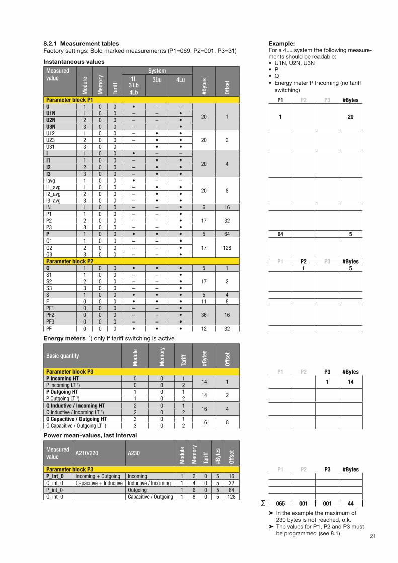
8.2.1 Measurement tables
Factory settings: Bold marked measurements (P1=069, P2=001, P3=31)
Instantaneous values
Measured
valueM
odu
le
Mem
ory
Tari
ff
System
#B
ytes
Off
set1L
3 Lb
4Lb
3Lu 4Lu
Parameter block P1U 1 0 0 • – –
20 1U1N 1 0 0 – – •U2N 2 0 0 – – •U3N 3 0 0 – – •U12 1 0 0 – • •
20 2U23 2 0 0 – • •U31 3 0 0 – • •I 1 0 0 • – –
20 4I1 1 0 0 – • •I2 2 0 0 – • •I3 3 0 0 – • •Iavg 1 0 0 • – –
20 8I1_avg 1 0 0 – • •I2_avg 2 0 0 – • •I3_avg 3 0 0 – • •IN 1 0 0 – – • 6 16P1 1 0 0 – – •
17 32P2 2 0 0 – – •P3 3 0 0 – – •P 1 0 0 • • • 5 64Q1 1 0 0 – – •
17 128Q2 2 0 0 – – •Q3 3 0 0 – – •
Parameter block P2Q 1 0 0 • • • 5 1S1 1 0 0 – – •
17 2S2 2 0 0 – – •S3 3 0 0 – – •S 1 0 0 • • • 5 4F 0 0 0 • • • 11 8PF1 0 0 0 – – •
36 16PF2 0 0 0 – – •PF3 0 0 0 – – •PF 0 0 0 • • • 12 32
Energy meters 1) only if tariff switching is active
Basic quantity
Mod
ule
Mem
ory
Tari
ff
#B
ytes
Off
set
Parameter block P3P Incoming HT 0 0 1
14 1P Incoming LT 1) 0 0 2P Outgoing HT 1 0 1
14 2P Outgoing LT 1) 1 0 2Q Inductive / Incoming HT 2 0 1
16 4Q Inductive / Incoming LT 1) 2 0 2Q Capacitive / Outgoing HT 3 0 1
16 8Q Capacitive / Outgoing LT 1) 3 0 2
Power mean-values, last interval
Measured
valueA210/220 A230
Mod
ule
Mem
ory
Tari
ff
#B
ytes
Off
set
Parameter block P3P_int_0 Incoming + Outgoing Incoming 1 2 0 5 16Q_int_0 Capacitive + Inductive Inductive / Incoming 1 4 0 5 32P_int_0 Outgoing 1 6 0 5 64Q_int_0 Capacitive / Outgoing 1 8 0 5 128
Example:For a 4Lu system the following measure-ments should be readable:• U1N, U2N, U3N• P• Q• Energy meter P Incoming (no tariff
switching)
P1 P2 P3 #Bytes
1 20
64 5
P1 P2 P3 #Bytes1 5
P1 P2 P3 #Bytes
1 14
P1 P2 P3 #Bytes
065 001 001 44
➤ In the example the maximum of
230 bytes is not reached, o.k.
➤ The values for P1, P2 and P3 must
be programmed (see 8.1)
∑
22
8.2.2 Data format
All transferred measurements are primary values. Instantaneous values are represented as 16-bit integer numbers and energy
meters as 32-bit integer numbers. The corresponding units and decimal point positions are changing in accordance with the
transformer ratios of the basic unit and will be delivered in the data telegram in conformance with the standard.
The measurements for frequency F [Hz] and power factor PF [ ] are not described in the standard. Therefore these data is
transferred as ASCII string, as suggested by the standard.
The largest available energy unit for M-Bus is MWh. But depending on the settings of the transformer ratios, larger unit up to
GWh may occur. In such a case the error flag in DIF is set and the user has to take care himself for a correct interpretation.
8.2.3 Data points and assignments
The transfer sequence of the measurements always corresponds to the table lines, voltages first and power mean-values last.
Measurements which are invalid for the selected system will not be transferred.
On master side normally the „data points“ will be assigned in the received sequence. Therefore it‘s recommended to perform
all settings of the basic unit first before arranging the data analysis in the master.
For a better distinction of measurements with the same unit, the additionally sent information in the rows Module, Memory
and Tariff can be used.
Only the instantaneous values marked with a „•“ are available in the corresponding system.
9. M-Bus specifi cationDetailed information about M-Bus is available via the webpage http://www.m-bus.com and the standard EN1434-3.
Wiring for M-Bus is performed via a pair of wires of a standard phone cable (e.g. JY(St)Y 2 x 2 x 0.8 mm). The polarity does
not matter. However, it should be noted that level converters used for PC connection often are not galvanically isolated, but
the bus works with voltages up to 40 V.
For a standard configuration, with baud rates between 300 and 9600 baud and a maximum of 250 slaves, the maximum di-
stance between master and slave is 350 m (approx. 1150 ft). The maximum distance increases if a lower baud rate is selected
or if the number of slaves is decreased.
10. M-Bus protocol
10.1 Addressing
The EMMOD206 supports both primary and secondary addressing.
For the primary addressing you have to assign via the keys a unique address in the range 1...250 to each device connected
to the bus. The requests from the master will then contain this address and the slave responds if there is a match.
For the secondary addressing the master uses the primary address 253 (Broadcast, Selection) and in addition transmits the
desired identification consisting of 8 bytes (4 serial number + 2 manufacturer + 1 generation + 1 medium). Because the serial
number of the EMMOD206 is guaranteed to be unique, no double addressing can occur and no address setting on the device
is necessary. All subsequent requests with primary address 253 will then be answered by the selected device until a new
selection is detected. Using the wildcards F resp. FF ID elements will be masked, by which the master is able to perform an
efficient search for new devices.
10.2 Supported dialogs
10.2.1 Reset SND_NKE / ACK
➤ Request from master
SND_NKE
10 40 FF 3F 16 By using the broadcast address (FF=255) the master causes all slaves to perform a communication reset with acknow-
ledge by ACK.
➤ Answer of the slave
ACK
E5
10.2.2 Data request using primary addressing REQ_UD2 / RSP_UD
➤ Request from master
REQ_UD2
10 7B 03 7E 16 The master requests data from slave no. 3.
23
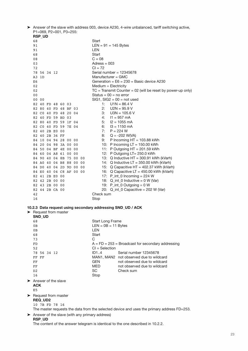
➤ Answer of the slave with address 003, device A230, 4-wire unbalanced, tariff switching active,
P1=069, P2=001, P3=255:
RSP_UD
68 Start
91 LEN = 91 = 145 Bytes
91 LEN
68 Start
08 C = 08
03 Adress = 003
72 CI = 72
78 56 34 12 Serial number = 12345678
A3 1D Manufacturer = GMC
E6 Generation = E6 = 230 = Basic device A230
02 Medium = Electricity
02 TC = Transmit Counter = 02 (will be reset by power-up only)
00 Status = 00 = no error
00 00 SIG1, SIG2 = 00 = not used
82 40 FD 48 60 03 1: U1N = 86.4 V
82 80 40 FD 48 BF 03 2: U2N = 95.9 V
82 C0 40 FD 48 20 04 3: U3N = 105.6 V
82 40 FD 59 BD 03 4: I1 = 957 mA
82 80 40 FD 59 1F 04 5: I2 = 1055 mA
82 C0 40 FD 59 7E 04 6: I3 = 1150 mA
82 40 2B E0 00 7: P = 224 W
82 40 2B 36 FF 8: Q = -202 W(VA)
84 10 04 94 28 00 00 9: P Incoming HT = 103.88 kWh
84 20 04 98 3A 00 00 10: P Incoming LT = 150.00 kWh
84 50 04 BF 4E 00 00 11: P Outgoing HT = 201.59 kWh
84 60 04 A8 61 00 00 12: P Outgoing LT= 250.0 kWh
84 90 40 04 8B 75 00 00 13: Q Inductive HT = 300.91 kWh (kVarh)
84 A0 40 04 B8 88 00 00 14: Q Inductive LT = 350.00 kWh (kVarh)
84 D0 40 04 2D 9D 00 00 15: Q Capacitive HT = 402.37 kWh (kVarh)
84 E0 40 04 C8 AF 00 00 16: Q Capacitive LT = 450.00 kWh (kVarh)
82 41 2B E0 00 17: P_int_0 Incoming = 224 W
82 42 2B 00 00 18: Q_int_0 Inductive = 0 W (Var)
82 43 2B 00 00 19: P_int_0 Outgoing = 0 W 82 44 2B CA 00 20: Q_int_0 Capacitive = 202 W (Var)
42 Check sum
16 Stop
10.2.3 Data request using secondary addressing SND_UD / ACK
➤ Request from master
SND_UD
68 Start Long Frame
0B LEN = 0B = 11 Bytes
0B LEN
68 Start
73 C
FD A = FD = 253 = Broadcast for secondary addressing
52 CI = Selection
78 56 34 12 ID1..4 Serial number 12345678
FF FF MAN1, MAN2 not observed due to wildcard
FF GEN not observed due to wildcard
FF MED not observed due to wildcard
D2 SC Check sum
16 Stop
➤ Answer of the slave
ACK E5
➤ Request from master
REQ_UD2
10 7B FD 78 16 The master requests the data from the selected device and uses the primary address FD=253.
➤ Answer of the slave (with any primary address)
RSP_UD
The content of the answer telegram is identical to the one described in 10.2.2.
24
11. Switching to ModbusVia the EMMOD206 no settings can be performed using M-Bus commands. Nevertheless, the numerous settings of the
basic unit, such as transformer ratios etc., can be performed comfortable via the M-Bus connector of the EMMOD206:
1. Connect the PC to the EMMOD206 via M-Bus level converter.
2. Start the A200plus software.
3. Via Options > Communication interface > interface type select „RS-232 interface“ and the used COM port.
4. Press the key COMM on the EMMOD206 for approx. 5 sec. until LED1 starts flashing in a 1s/1s cycle. Therewith the
protocol is switched from M-Bus to Modbus.
Now all measurements can be read and the configuration of the basic unit adjusted, as it would be possible with a Modbus
module EMMOD 201.
By pressing the key COMM once more or after 10 minutes without Modbus data traffic the protocol is switched back to
M-Bus.
If there is more than one device connected to the bus you have to pay attention, that only one device is switched to Mod-
bus at the same time.
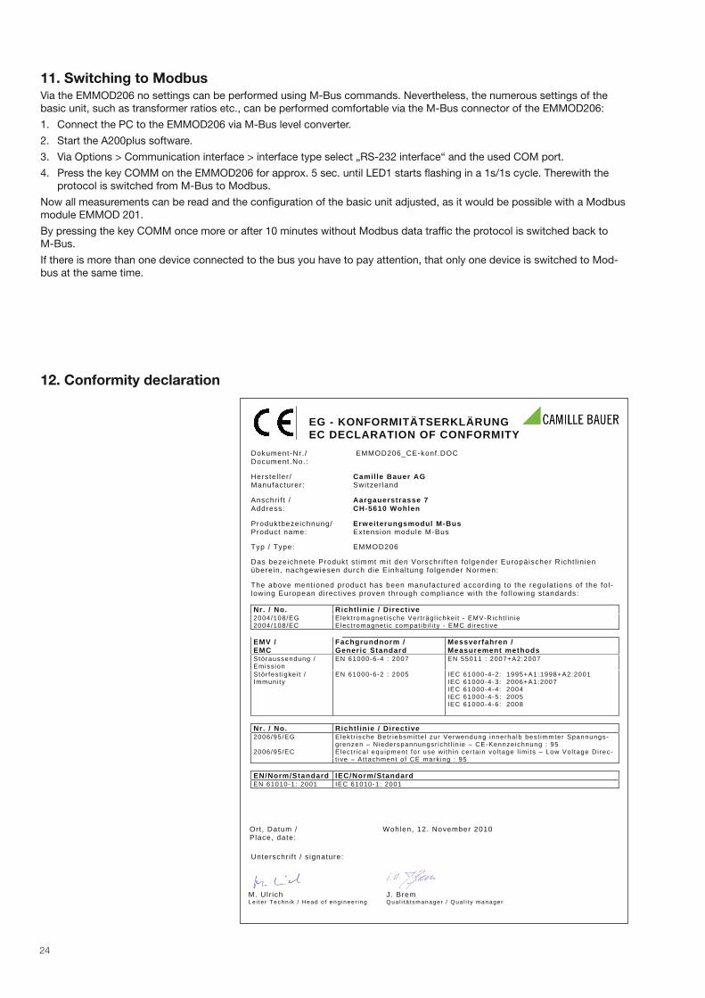
12. Conformity declaration
EG - KONFORMITÄTSERKLÄRUNGEC DECLARATION OF CONFORMITY
Dokument-Nr. / EMMOD206_CE-konf.DOC Document.No.:
Herstel ler / Camille Bauer AGManufacturer: Switzer land
Anschr i f t / Aargauerstrasse 7 Address: CH-5610 Wohlen
Produktbezeichnung/ Erweiterungsmodul M-BusProduct name: Extension module M-Bus
Typ / Type: EMMOD206
Das bezeichnete Produkt st immt mit den Vorschr i f ten fo lgender Europäischer Richt l in ienüberein, nachgewiesen durch die Einhal tung fo lgender Normen:
The above ment ioned product has been manufactured according to the regulat ions of the fo l -lowing European direct ives proven through compl iance wi th the fo l lowing standards: Nr. / No. Richtl inie / Directive 2004/108/EG2004/108/EC
Elekt romagnet ische Ver t räg l ichke i t - EMV-Richt l in ie E lect romagnet ic compat ib i l i ty - EMC d i rect ive
EMV / EMC
Fachgrundnorm / Generic Standard
Messverfahren / Measurement methods
Störaussendung / Emiss ion
EN 61000-6-4 : 2007 EN 55011 : 2007+A2:2007
Stör fes t igke i t / Immuni ty
EN 61000-6-2 : 2005 IEC 61000-4-2: 1995+A1:1998+A2:2001 IEC 61000-4-3: 2006+A1:2007 IEC 61000-4-4: 2004 IEC 61000-4-5: 2005 IEC 61000-4-6: 2008
Nr. / No. Richtl inie / Directive 2006/95/EG
2006/95/EC
Elekt r ische Bet r iebsmi t te l zur Verwendung innerha lb best immter Spannungs-grenzen – Niederspannungsr icht l in ie – CE-Kennzeichnung : 95 Elect r ica l equipment for use wi th in cer ta in vo l tage l imi ts – Low Vol tage Di rec-t ive – At tachment o f CE mark ing : 95
EN/Norm/Standard IEC/Norm/Standard EN 61010-1: 2001 IEC 61010-1: 2001
Ort , Datum / Place, date:
Wohlen, 12. November 2010
Unterschr i f t / s ignature:
M. Ulr ich J. Brem Le i te r Techn ik / Head o f eng ineer ing Qua l i t ä t smanager / Qua l i t y manager