C-0065 THLZ-PLV-FF 09-09 - Comefri - Home€¦ · ai fini di un sistematico incremento delle...
48
THLZ FF DOUBLE INLET CENTRIFUGAL FANS WITH GLASS REINFORCED POLYAMID WHEEL ZWEISEITIGSAUGENDE RADIALVENTILATOREN MIT LAUFRAD AUS GLASFASERVERSTÄRKTEM POLYAMID VENTILATEURS CENTRIFUGES DOUBLE ASPIRATION AVEC TURBINE EN FIBRE DE VERRE DE POLYAMIDE RENFORCÉ VENTILATORI CENTRIFUGHI A DOPPIA ASPIRAZIONE CON GIRANTE IN POLIAMMIDE RINFORZATA
Transcript of C-0065 THLZ-PLV-FF 09-09 - Comefri - Home€¦ · ai fini di un sistematico incremento delle...
THLZ FF
DOUBLE INLET CENTRIFUGAL FANS WITH GLASS REINFORCED POLYAMID WHEEL
ZWEISEITIGSAUGENDE RADIALVENTILATOREN MIT LAUFRAD AUS GLASFASERVERSTÄRKTEM POLYAMID
VENTILATEURS CENTRIFUGES DOUBLE ASPIRATION AVEC TURBINE EN FIBRE DE VERRE DE POLYAMIDE RENFORCÉ
VENTILATORI CENTRIFUGHI A DOPPIA ASPIRAZIONE CON GIRANTE IN POLIAMMIDE RINFORZATA
DOUBLE INLET CENTRIFUGAL FANS WITH GLASS REINFORCED POLYAMID WHEEL – THLZ FF ZWEISEITIGSAUGENDE RADIALVENTILATOREN MIT LAUFRAD AUS GLASFASERVERSTÄRKTEM POLYAMID – THLZ FF VENTILATEURS CENTRIFUGES DOUBLE ASPIRATION AVEC TURBINE EN FIBRE DE VERRE DE POLYAMIDE RENFORCÉ – THLZ FF
VENTILATORI CENTRIFUGHI A DOPPIA ASPIRAZIONE CON GIRANTE IN POLIAMMIDE RINFORZATA – THLZ FF
C-0065 Septemper 2009
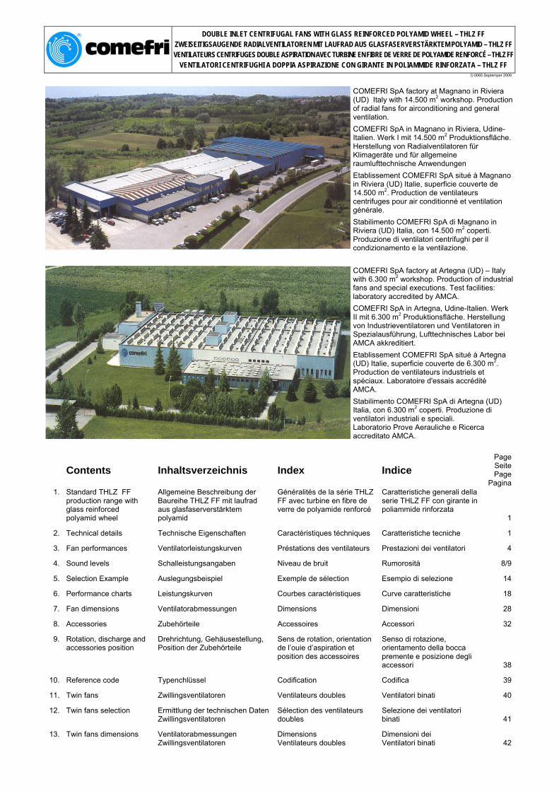
COMEFRI SpA factory at Magnano in Riviera (UD) Italy with 14.500 m2 workshop. Production of radial fans for airconditioning and general ventilation.
COMEFRI SpA in Magnano in Riviera, Udine-Italien. Werk I mit 14.500 m2 Produktionsfläche. Herstellung von Radialventilatoren für Klimageräte und für allgemeine raumlufttechnische Anwendungen
Etablissement COMEFRI SpA situé à Magnano in Riviera (UD) Italie, superficie couverte de 14.500 m2. Production de ventilateurs centrifuges pour air conditionné et ventilation générale.
Stabilimento COMEFRI SpA di Magnano in Riviera (UD) Italia, con 14.500 m2 coperti. Produzione di ventilatori centrifughi per il condizionamento e la ventilazione.
COMEFRI SpA factory at Artegna (UD) – Italy with 6.300 m2 workshop. Production of industrial fans and special executions. Test facilities: laboratory accredited by AMCA.
COMEFRI SpA in Artegna, Udine-Italien. Werk II mit 6.300 m2 Produktionsfläche. Herstellung von Industrieventilatoren und Ventilatoren in Spezialausführung, Lufttechnisches Labor bei AMCA akkreditiert.
Etablissement COMEFRI SpA situé à Artegna (UD) Italie, superficie couverte de 6.300 m2. Production de ventilateurs industriels et spéciaux. Laboratoire d'essais accrédité AMCA.
Stabilimento COMEFRI SpA di Artegna (UD) Italia, con 6.300 m2 coperti. Produzione di ventilatori industriali e speciali. Laboratorio Prove Aerauliche e Ricerca accreditato AMCA.
Contents Inhaltsverzeichnis Index Indice PageSeitePage
Pagina1. Standard THLZ FF
production range with glass reinforced polyamid wheel
Allgemeine Beschreibung der Baureihe THLZ FF mit laufrad aus glasfaserverstärktem polyamid
Généralités de la série THLZ FF avec turbine en fibre de verre de polyamide renforcé
Caratteristiche generali della serie THLZ FF con girante in poliammide rinforzata
1
2. Technical details Technische Eigenschaften Caractéristiques téchniques Caratteristiche tecniche 1
3. Fan performances Ventilatorleistungskurven Préstations des ventilateurs Prestazioni dei ventilatori 4
4. Sound levels Schalleistungsangaben Niveau de bruit Rumorosità 8/9
5. Selection Example Auslegungsbeispiel Exemple de sélection Esempio di selezione 14
6. Performance charts Leistungskurven Courbes caractéristiques Curve caratteristiche 18
7. Fan dimensions Ventilatorabmessungen Dimensions Dimensioni 28
8. Accessories Zubehörteile Accessoires Accessori 32
9. Rotation, discharge and accessories position
Drehrichtung, Gehäusestellung, Position der Zubehörteile
Sens de rotation, orientation de l’ouie d’aspiration et position des accessoires
Senso di rotazione, orientamento della bocca premente e posizione degli accessori 38
10. Reference code Typenchlüssel Codification Codifica 39
11. Twin fans Zwillingsventilatoren Ventilateurs doubles Ventilatori binati 40
12. Twin fans selection Ermittlung der technischen Daten
Zwillingsventilatoren Sélection des ventilateurs doubles
Selezione dei ventilatori binati 41
13. Twin fans dimensions Ventilatorabmessungen
Zwillingsventilatoren Dimensions Ventilateurs doubles
Dimensioni dei Ventilatori binati 42

DOUBLE INLET CENTRIFUGAL FANS WITH GLASS REINFORCED POLYAMID WHEEL – THLZ FF ZWEISEITIGSAUGENDE RADIALVENTILATOREN MIT LAUFRAD AUS GLASFASERVERSTÄRKTEM POLYAMID – THLZ FF VENTILATEURS CENTRIFUGES DOUBLE ASPIRATION AVEC TURBINE EN FIBRE DE VERRE DE POLYAMIDE RENFORCÉ – THLZ FF
VENTILATORI CENTRIFUGHI A DOPPIA ASPIRAZIONE CON GIRANTE IN POLIAMMIDE RINFORZATA – THLZ FF
C-0065 Septemper 2009
1. Standard THLZ FF production range
1. Allgemeine Beschreibung der Baureihe THLZ FF
1. Généralités de la série THLZ FF
1. Caratteristiche generali della serie THLZ FF
Comefri's THLZ double-inlet-double-width centrifugal fans with glass reinforced polyamid wheels series cover a size range from 180 to 450. All fans within the range have the following characteristics: • optimally engineered for HVAC applications; • high quality, compact design; • high efficiency, low power consumption; • quiet operation; • fan performances fully tested and certified in Comefri's own state-of-the-art laboratory in accordance with DIN, ISO, BS and AMCA standards. • Performance data according to DIN 24166, accuracy Class 1.
Die zweiseitig saugende Comefri Radialventilatorbaureihe THLZ FF mit laufrad aus glasfaserverstärktem polyamid wird in den Baugrößen 180 bis 450 hergestellt. Alle Ventilatoren dieser Baureihe verfügen über folgende Eigenschaften: • Optimierte Kennlinie für die Klimatechnik; • Hohe Qualität, kompakte Bauweise; • Hohen Wirkungsgrad, niedrige Leistungsaufnahme; • Geräuscharmen Betrieb; • Leistungsdaten wurden im Comefri Labor nach DIN, ISO, BS, AMCA Standard gemessen. • Ventilatordaten nach DIN 24166, Genauigkeitsklasse1
Les ventilateurs centrifuges double aspiration de la série THLZ FF avec turbine en fibre de verre de polyamide renforcé avec aubes courbées vers l’arrìre et sont construits de la taille 180 à la taille 450. Tous les ventilateurs de cette gamme ont les carac-téristiques suivantes: • particuliérement adaptes pour la climatisation; • niveau de qualité élevé, dimensions compactes; • niveau de rendement élevé, fiable puissance absorbée; • silencieux; • préstations garanties par d'essais effectués auprés du laboratoire Comefri, selon les normes DIN,ISO, BS et AMCA; • courbes selon les normes DIN 24166, Classe de précision 1.
I ventilatori centrifughi a doppia aspirazione della serie THLZ FF hanno le giranti in poliammide rinforzata con pale profilate e sono costruiti nelle grandezze dalla 180 alla 450. Tutti i ventilatori compresi in questa gamma hanno le seguenti caratteristiche: • particolarmente adatti per la climatizzazione; • alta qualità, dimensioni compatte; • alto rendimento, bassa potenza assorbita; • silenziosità; • prestazioni garantite da prove eseguite presso il laboratorio Comefri, secondo le norme DIN, ISO, BS e AMCA; • curve caratteristiche secondo le norme DIN 24166, Classe di precisione 1.
2. Technical details 2.1. Forefinger ®
2. Technische Eigenschaften 2.1. Forefinger ®
2. Caractéristiques téchniques 2.1. Forefinger ®
2. Caratteristiche tecniche 2.1. Forefinger ®
Es handelt sich um eine Innovation, entwickelt im Comefri eigenen Labor für Lufttechnik und Akustik.(*) (Bild 1). Die Hauptaufgabe besteht darin, die internen Verluste des Ventilators
Il s’agit d’un dispositif innovateur étudié et développé par le laboratoire aéraulique et acoustique de Comefri (*) (Fig.1). Son but est de mieux répartir et exploiter le circuit de la volute. En effet, comme nous
(im Gehäuse) zu reduzieren. Diese sind, wie allgemein bekannt, die wichtigste Ursache für Verluste eines Ventilators und beeinflussen den Wirkungsgrad negativ bei Gleichzeitigem Anstieg des
Fig.1
le signalons, nous
constatons que ce phénomène est la principale
cause des pertes d’un ventilateur,
ce qui conduit à un
affaiblissement du rendement
et une augmentation
sensible du
It is an innovative device fully developed and engineered by the Aeraulic and Acoustic Test Lab of Comefri (*) (Fig.1). The principle is to exploit the air swirls, always present inside a fan housing. As well known, the recirculation of the air streams inside the fan housing is a major source of losses, decreasing the fan efficiency and increasing fan’s noise. This device, called Forefinger ®, is actively readdressing this air recirculation to the outlet, with a systematic enhancement of the performances, both aeraulic and acoustic.
(*) Patent pending by Comefri
Lärmpegel. Mittels des neuen Patent Forefinger ® werden diese Verluste drastisch reduziert und somit die Leistungsdaten des Ventilators und auch die Akustik nachhaltig verbessert.
(*) zum Patent angemeldet
niveau sonore. Ce dispositif appelé Forefinger ®, agit activement sur le mouvement de l’air, ce qui d’une manière systématique permet d’accroître les performances aéraulique et acoustique.
(*) Titulaire de la relative demande du brevet
Si tratta di un dispositivo innovativo progettato e sviluppato dal Laboratorio Prove Aerauliche ed Acustiche della Comefri (*) (Fig.1). Il suo scopo è quello di ripartire e sfruttare i ricircoli d’aria presenti all’interno della coclea. Essi infatti, come noto, essendo la principale causa delle perdite di un ventilatore, ne condizionano negativamente il rendimento e ne aumentano sensibilmente la rumorosità. Il dispositivo, denominato Forefinger ®, di fatto è in grado di “intervenire attivamente” su tali ricircoli ai fini di un sistematico incremento delle prestazioni sia Aerauliche che Acustiche.
(*) Titolare della relativa domanda di brevetto
1

DOUBLE INLET CENTRIFUGAL FANS WITH GLASS REINFORCED POLYAMID WHEEL – THLZ FF ZWEISEITIGSAUGENDE RADIALVENTILATOREN MIT LAUFRAD AUS GLASFASERVERSTÄRKTEM POLYAMID – THLZ FF VENTILATEURS CENTRIFUGES DOUBLE ASPIRATION AVEC TURBINE EN FIBRE DE VERRE DE POLYAMIDE RENFORCÉ – THLZ FF
VENTILATORI CENTRIFUGHI A DOPPIA ASPIRAZIONE CON GIRANTE IN POLIAMMIDE RINFORZATA – THLZ FF
C-0065 Septemper 2009
2.2. Housing 2.2. Gehäuse 2.2. Volute 2.2. Coclea
All fan housings are manufactured in galvanised steel sheet (Fig.3) from size 180 to 450 and are constructed using the Pittsbourgh seam method (Fig.2), which ensures a high quality air tight seal as well as a structurally reinforced housing. The design of the inlets is of vital importance for the fan performances and sound levels. They have been accurately engineered to guarantee an optimal airflow path towards the wheel and thus very high performance levels. The inlet cones are manufactured in sheet, steel as well, painted and bolted on the housing sideplates. A series of standard holes are located on the sideplates to allow the fitting of frames or feet. These holes are positioned in such a way that several standard accessories can be applied.
Die Ventilatorgehäuse der Baugrößen 180 bis 450, bestehen aus verzinktem Stahlblech (Bild 3); Seitenteile und Gehäusemantel sind durch den bewährten Pittsbourgh Falz miteinander verbunden (Bild 2), d.h. die vier übereinanderliegenden Materiallagen wirken versteifend. Die Einströmdüsen sind strömungsgünstig geformt und sorgen sorgen für eine optimale Beaufschlagung des Laufrades. Sie bestehen aus lackiertem Stahlblech und werden mit dem Gehäuse verschraubt. In den Gehäuseseitenteilen ermöglichen eingestanzte Löcher und Muttern eine einwandfreie Befestigung der Zubehörteile
Les volutes des ventilateurs de la taille 180 à la taille 450 sont construites avec tôle d'acier galvanisé (Fig.3) et sont agrafées avec la méthode Pittsbourgh (Fig.2), qui assure qualité élevée, une parfaite étanchéité et une forte structure. Etant donné que le profil du pavilion est d'importance fondamentale pour les préstations des ventilateurs et pour leur bruit, il a été étudié afin d'obtenir un flux d'air optimal et permettre par conséquence I'obtention d'un rendement tres élevé. Les pavilions sont construits en tôle d'acier peints et sont fixés aux fiasques de la volute. Une série des alésages standards est prédisposée sur les fiasques de façon à permettre le fixage des nombreux accessoires standards.
Le coclee dei ventilatori dalla grandezza 180 alla 450 sono costruite con lamiera d'acciaio zincato (Fig.3) e sono graffate con il metodo Pittsbourgh (Fig.2), il quale assicura alta qualità, perfetta tenuta e robustezza. Poichè il profilo del boccaglio di ingresso è di fondamentale importanza per le prestazioni dei ventilatori e per la loro rumorosità, esso è stato progettato in modo da garantire un flusso ottimale in aspirazione e di permettere quindi I'ottenimento di un rendimento molto elevato. I boccagli sono costruiti in lamiera d'acciaio, verniciati e sono fissati alle fiancate della coclea. Una serie di fori standard è predisposta sulle fiancate in modo da permettere il fissaggio dei telai. Altri fori permettono il fissaggio di numerosi accessori standard.
2.3. Impeller 2.3. Laufrad 2.3. Turbine 2.3. Girante
This high performance impeller is manufactured in glass reinforced polyamid, with backward curved, true profiled shaped blades (Fig.4), and are balanced, both statically and dynamically, to an accuracy grade of G = 6,3 in accordance to DIN ISO 1940-1 (VDI 2060). The impellers are secured to the shaft through an aluminium hub. Hub bore is precision machined and incorporates a keyway and locking screw.
Die Hochleistungslaufräder sind aus glasfaserverstärktem Polyamid, mit rückwärtsgekrümmten Schaufeln hergestellt (Bild 4). Sie sind statisch und dynamisch in Gütestufe G=6,3 ausgewuchtet, gemäß VDI 2060 (DIN ISO 1940-1). Die Laufräder sind mit der Welle durch eine Nabe verbunden. Die Nabenbohrungen sind mit einer Passfedernut und einer Befestigungsschraube ausgerüstet.
Ces turbines à rendement élevé sont construites en polyamide renforcé et sont les aubes courbées vers I'arriére (Fig.4). Elles sont equilibrées statiquement et dynamiquement avec un degré de tolérance G=6,3 selon les normes DIN ISO 1940-1 (VDI 2060). Les turbines sont fixées a I'arbre à I'aide de moyeux munis de clavette et vis de blocage.
Queste giranti ad alto rendimento sono costruite in poliammide rinforzata, con pale curvate all'indietro (Fig.4). Esse sono bilanciate staticamente e dinamicamente con un grado tolleranza G = 6,3 secondo le norme DIN ISO 1940-1 (VDI 2060). Le giranti sono calettate all'albero tramite mozzi muniti di linguetta e vite di serraggio.
Fig.2
Fig.3
Fig.4
2
DOUBLE INLET CENTRIFUGAL FANS WITH GLASS REINFORCED POLYAMID WHEEL – THLZ FF ZWEISEITIGSAUGENDE RADIALVENTILATOREN MIT LAUFRAD AUS GLASFASERVERSTÄRKTEM POLYAMID – THLZ FF VENTILATEURS CENTRIFUGES DOUBLE ASPIRATION AVEC TURBINE EN FIBRE DE VERRE DE POLYAMIDE RENFORCÉ – THLZ FF
VENTILATORI CENTRIFUGHI A DOPPIA ASPIRAZIONE CON GIRANTE IN POLIAMMIDE RINFORZATA – THLZ FF
C-0065 Septemper 2009
2.4. Shafts 2.4. Wellen 2.4. Arbres 2.4. Alberi
All shafts are designed with a high safety factor and with the first critical speed well beyond to the maximum fan speed. Made in hardened steel, they are precision ground and polished. Shafts are provided with keyways for the wheel hub and for belt pulleys that can be fitted on either shaft ends. All shafts are coated with protective paint for added protection prior to shipping.
Alle Wellen sind mit einem hohen Sicherheitsfaktor berechnet. Dabei liegt die maximal zulässige Drehzahl weit unter der ersten kritischen Drehzahl. Die geschliffenen Wellen sind aus hochwertigem Stahl hergestellt. Die Verbindung von Laufrad/Welle und Keilriemenscheibe/Welle erfolgt mittels Nut und Feder. Alle Wellen werden mit Rostschutzlack geschützt.
Tous les arbres sont dimensionnés avec un coefficient de sécurité élevé. La vitesse maximale admise est bien inférieure à la vitesse critique. Ils sont construits en acier au carbone, usinés et réctifiés. Les arbres ont une clavette en correspondence au moyeu de la turbine et une autre clavette à chaque extémité, de façon que la poulie puisse être montée indifféremment d'une côté ou de I'autre. Tous les arbres sont couverts avec une peinture protective.
Tutti gli alberi sono dimensionati con un elevato coefficiente di sicurezza ed una velocità critica largamente superiore alla massima velocità di funzionamento consentita. Sono costruiti in acciaio al carbonio, torniti e rettificati. Gli alberi hanno una sede linguetta in corrispondenza del mozzo della girante ed un'altra ad ogni estremità. Tutti gli alberi sono rivestiti con una vernice protettiva.
2.5. Bearings 2.5. Lager 2.5. Paliers 2.5. Cuscinetti
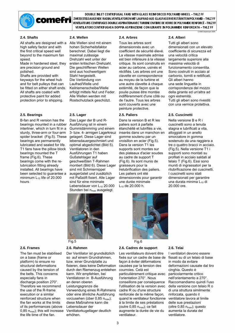
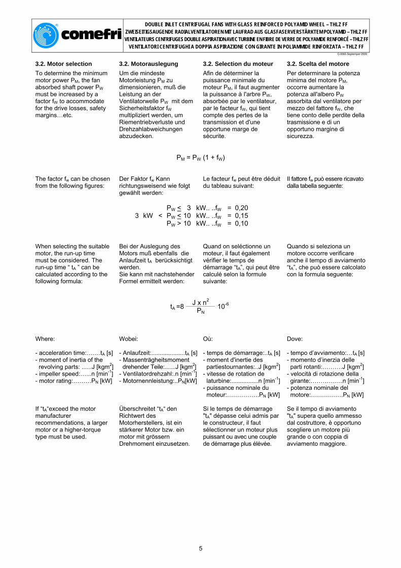
B-fan and R version has the bearings mounted in a rubber interliner, which in turn fit in a sturdy, three-arm or four-arm spider bracket (Fig.5). These bearings are permanently lubricated and sealed for life. T1 fans have the pillow block bearings mounted the T frame (Fig.6). These bearings come with the re-lubrication fitting already installed. All bearings have been selected to guarantee a minimum L10 life of 20.000 hours.
Das Lager der B und R-Ausführung ist in einem Gummidämmring und einem 3- bzw. 4- armigen Lagerkreuz gelagert. Diese Lager sind lebensdauergeschmiert und optimal abgedichtet (Bild 5). Ventilatoren in den Ausführungen T1 haben Gußstehlager auf geschweißten T-Rahmen montiert (Bild 6). Diese Lager sind mit Schmiernippel ausgerüstet und zusätzlich mit Paßstift fixiert. Alle Lager sind für eine minimale Lebensdauer von L10 20.000 Stunden bei nmax ausgelegt.
Dans la version B et R les paliers sont à parfaite étanchéité et lubrifiés a vie, inserés dans un manchon en gomme soutenu par un croisillon en acier (Fig.5). Dans la version T1 les supports sont montes sur des plateaux d'acier soudes au cadre de support T (Fig.6). Ils sont munis de graisseurs pour la lrelubrification des paliers. Les paliers ont été dimensionnés pour garantir une durée minimale L10 de 20.000 h.
Nella versione B e R i cuscinetti sono a tenuta stagna e lubrificati a vita, alloggiati in un anello smorzatore in gomma sostenuto da una raggiera a tre o quattro bracci in acciaio. (Fig.5). Nella versione T1 i supporti sono montati su profilati in acciaio saldati al telaio T (Fig.6). Essi sono muniti di ingrassatori per la rilubrificazione dei cuscinetti. I cuscinetti sono stati dimensionati per garantire una durata minima L10 di 20.000 ore.
Fig.5 Fig.6
2.6. Frames 2.6. Rahmen 2.6. Cadres de support 2.6. Telai
The fan must be stabilised on a base (frame or platform) to ensure no structural deformations caused by the tension of the belts. This concerns especially fans in discharge position 270°. Therefore we recommend the use of the R-frame execution or a similar reinforced structure when the fan works at the limits of its performances (above 0,85 nmax); this will increase the life time of the fan.
Der Ventilator ist grundsätzlich so auf einem Grundrahmen, bzw. einer Grundplatte zu fixieren, dass keine Deformation durch den Riemenzug entstehen kann. Wir empfehlen, bei Ventilatoren in B-Ausführung an deren oberen Leistungsgrenze die Verwendung eines R-Rahmens oder eine ähnliche Ausführung vorzusehen (über 0,85 nmax); diese Maßnahme kann die Lebensdauer der Ventilatorkugellager deutlich erhöhen.
Les ventilateurs doivent être fixés sur un cadre de base de façon à éviter déformations causées par la tension des courroies. Celà est particulièrement critique avec I'orientation 270°. Nous conseillons par conséquence I'utilisation de la version avec cadre R ou d'une structure renforcée de la même façon, quand le ventilateur fonctionne à la limite de ses préstations (outre 0,85 nmax); ce fait augmente la durée de vie du ventilateur.
I ventilatori devono essere fissati su di un telaio di base in modo da evitare deformazioni causate dal tiro cinghia. Questo è particolarmente critico nell'orientamento a 270°. Raccomandiamo quindi I'uso della versione con telaio R o di una struttura similmente rinforzata, quando il ventilatore lavora al limite delle sue prestazioni (oltre 0,85 nmax); questo aumenta la durata del ventilatore.
3

DOUBLE INLET CENTRIFUGAL FANS WITH GLASS REINFORCED POLYAMID WHEEL – THLZ FF ZWEISEITIGSAUGENDE RADIALVENTILATOREN MIT LAUFRAD AUS GLASFASERVERSTÄRKTEM POLYAMID – THLZ FF VENTILATEURS CENTRIFUGES DOUBLE ASPIRATION AVEC TURBINE EN FIBRE DE VERRE DE POLYAMIDE RENFORCÉ – THLZ FF
VENTILATORI CENTRIFUGHI A DOPPIA ASPIRAZIONE CON GIRANTE IN POLIAMMIDE RINFORZATA – THLZ FF
C-0065 Septemper 2009
3. Fan performances 3. Ventilator Leistungskurven
3. Prestations 3. Prestazioni
3.1. Performance data 3.1. Leistungsdaten 3.1. Diagrammes 3.1. Diagrammi
Comefri’s laboratory has measured the data included in the performance chart section with modern, state-of-the-art testing instruments. • The performances were measured for an installation type B, i.e. free inlet and ducted outlet configuration, • All curves to a density of ρ = 1,2 kg/m3, • Outlet velocity “c” and dynamic pressure “pdyn“refer to the flange cross section area at the fan outlet, • Performance data according to DIN 24166 Class 1 (R, B fan versions from size 250 to 450, and fan version T1 sizes 355, 400 and 450) and Class 2 (B, R fan versions sizes 180, 200 and 225 and T1 version from size 180 to 315).
Performance test rig according to DIN 24163 / BS 848 Part 1 / ISO 5801 / AMCA 210 - fig.14.
Im Comefri-Labor wurden die Leistungsdaten mit modernster Technik aufgenommen. • Die Ermittlung der Kennlinien erfolgte mit druckseitigem Kanalanschluss, freiansaugend • Alle Leistungsdiagramme beziehen sich auf eine Luftdichte von ρ = 1,2 kg/m3, • Die Ausblasgeschwindigkeit “c“ und der dynamische Druck “pdyn“beziehen sich auf den Ausblasflanschquerschnitt, • Ventilatoredaten nach DIN 24166 in Genauigkeitsklasse 1. (R, B Ventilatorausführungen von Baugröße 250 bis 450 und Ventilatorausführungen T1 Baugröße 355, 400 und 450) und Klasse 2 (B, R Ventilatorausführungen Baugröße 180, 200 und 225 und T1 Ausführungen von Baugröße 180 bis 315)
Prüfstandaufbau nach DIN 24163/ BS 848 Part 1 / ISO 5801 / AMCA 210 - fig.14.
Les données représentées sur les courbes de sélection ont été élaborées avec des mésure effectuées selon les plus modernes méthodologiesdans le Laboratoire Comefri. • Les préstations font réference à une installation de type B, avec aspirations libres et refoulement canalisé, • Toutes les courbes font reference a une densite d'air de ρ = 1,2 kg/m3, • La vitesse de sortie “c” et la pression dynamique “pdyn” font réference à la section de la bride du refoulement, • Courbeses selon les normes DIN 24166 Classe 1 (ventilateurs en exécution B et R, de dimension 250 à 450, et en exécution T1 pour les dimensions 355, 400 et 450) et Classe 2 (ventilateurs en exécution B et R des dimensions 180, 200 et 225 et en exécution T1 de 180 à 315).
Banc d'essai selon les normes DIN 24163 / BS 848 Part 1 / ISO 5801 / AMCA 210 - fig.14.
I dati riportati nelle curve di selezione sono stati ricavati da misure eseguite con le più moderne metodologie nel laboratorio Comefri. • Le prestazioni sono riferite ad un'installazione di tipo B, con bocche aspiranti libere e bocca di mandata canalizzata,• Tutte le curve sono riferite ad una densità dell'aria di ρ = 1,2 kg/m3, • La velocità di uscita “c” e la pressione dinamica “pdyn” sono riferite alla sezione della flangia della bocca premente • Curve caratteristiche secondo le norme DIN 24166, Classe 1 (ventilatori in esecuzione B ed R dalla grandezza 250 alla 450, in esecuzione T1 le grandezze 355, 400 e 450) e Classe 2 (ventilatori in esecuzione B ed R grandezze 180, 200 e 225 e in esecuzione T1 dalla 180 alla 315).
Banco prova secondo le norme DIN 24163 / BS 848 Part 1 / ISO 5801 / AMCA 210 - fig.14.
1. Fan / Ventilator / Ventilateur / Ventilatore 2. Outlet duct / Ausblaskanal / Canal de refoulement / Canale di mandata 3. Electric motor drive / Elektrischer Antrieb / Moteur éléctrique /
Motore elettrico 4. Torquemeter / Drehmomentaufnehmer / Torsiomètre / Torsiometro 5. Tachometer / Drehzahlmesser / Tachymètre / Tachimetro
Differential pressure gauge / Differenzdruckmesser / Manomètre différentiel / Manometro differenziale
6. Temperature probe / Temperaturaufnahme / Sonde thermométrique / Sonda termometrica
7. Test chamber / Prüfkammer / Salle d'essai / Camera di prova 8. Flow straightener / Strömungsgleichrichter / Redresseur de flux /
Raddrizzatore di flusso 9. Damper / Drossel / Registre de réglage / Serranda di regolazione
10. Normalized inlet / Einlauf-Normdüse / Pavillon normalisé / Boccaglio normalizzato
The performance curves inclu-de the following information:
Die Leistungskurven zeigen folgende Informationen:
Les diagrammes comprennent les données suivantes:
I diagrammi comprendono i dati seguenti:
Total pressure Gesamtdruckdifferenz Pression totale Pressione totale ∆ptot [ Pa ] Dynamic pressure Dynamischer Druck Pression dynamique Pressione dinamica pdyn [ Pa ] Volume air flow Volumenstrom Débit Portata V° [ m3/h ] Absorbed power on fan shaft
Aufgenommene Leistung an der Welle
Puissance absorbée à l'arbre du ventilateur
Potenza assorbita all'albero del ventilatore Pw [ kW ]
Fan speed Ventilatordrehzahl Vitesse de rotation du ventilateur Velocità di rotazione del ventilatore n [ min-1 ] Total Efficiency Gesamtwirkungsgrad Rendement totat Rendimento totate ηt [ % ] Outlet velocity Ausblasgeschwindigkeit Vitesse de sortie de I’air Velocità di uscita dell'aria c [ m/s ] Sound Power Level Schalleistungspegel Niveau de puissance sonore Livello di Potenza Sonora LwA4/7 [ dB(A) ]
4
DOUBLE INLET CENTRIFUGAL FANS WITH GLASS REINFORCED POLYAMID WHEEL – THLZ FF ZWEISEITIGSAUGENDE RADIALVENTILATOREN MIT LAUFRAD AUS GLASFASERVERSTÄRKTEM POLYAMID – THLZ FF VENTILATEURS CENTRIFUGES DOUBLE ASPIRATION AVEC TURBINE EN FIBRE DE VERRE DE POLYAMIDE RENFORCÉ – THLZ FF
VENTILATORI CENTRIFUGHI A DOPPIA ASPIRAZIONE CON GIRANTE IN POLIAMMIDE RINFORZATA – THLZ FF
C-0065 Septemper 2009
3.2. Motor selection 3.2. Motorauslegung 3.2. Selection du moteur 3.2. Scelta del motore
To determine the minimum motor power PM, the fan absorbed shaft power PW must be increased by a factor fW to accommodate for the drive losses, safety margins…etc.
Um die mindeste Motorleistung PM zu dimensionieren, muß die Leistung an der Ventilatorwelle PW mit dem Sicherheitsfaktor fW multipliziert werden, um Riementriebverluste und Drehzahlabweichungen abzudecken.
Afin de déterminer la puissance minimale du moteur PM, il faut augmenter la puissance à I'arbre PW, absorbée par le ventilateur, par le facteur fW, qui tient compte des pertes de la transmission et d'une opportune marge de sécurite.
Per determinare la potenza minima del motore PM, occorre aumentare la potenza all'albero PW assorbita dal ventilatore per mezzo del fattore fW, che tiene conto delle perdite della trasmissione e di un opportuno margine di sicurezza.
PM = PW (1 + fW)
The factor fw can be chosen from the following figures:
Der Faktor fw Kann richtungsweisend wie folgt gewählt werden:
Le facteur fw peut être déduit du tableau suivant:
II fattore fw può essere ricavato dalla tabella seguente:
3
kW
<
PW <PW <PW >
31010
kW..kW..kW..
..fW
..fW
..fW
===
0,20 0,15 0,10
When selecting the suitable motor, the run-up time must be considered. The run-up time “ tA ” can be calculated according to the following formula:
Bei der Auslegung des Motors muß ebenfalls die Anlaufzeit tA berücksichtigt werden. Sie kann mit nachstehender Formel ermittelt werden:
Quand on seléctionne un moteur, il faut également vérifier le temps de démarrage “tA”, qui peut être calculé selon la formule suivante:
Quando si seleziona un motore occorre verificare anche il tempo di avviamento “tA”, che può essere calcolato con la formula seguente:
J x n2 tA =8 PN 10-6
Where: - acceleration time:…….tA [s] - moment of inertia of the revolving parts: ......J [kgm2] - impeller speed:…...n [min-1] - motor rating:………PN [kW]
Wobei: - Anlaufzeit:....................tA [s]- Massenträgheitsmoment drehender Teile:.......J [kgm2] - Ventilatordrehzahl:.n [min-1] - Motornennleistung:..PN[kW]
Où: - temps de démarrage:..tA [s] - moment d'inertie des partiestournantes:..J [kgm2] - vitesse de rotation de laturbine:................n [min-1] - puissance nominale du moteur:…………….PN [kW]
Dove: - tempo d’avviamento:…tA [s] - momento d’inerzia delle parti rotanti:……….J [kgm2] - velocità di rotazione della girante:…………….n [min-1] - potenza nominale del motore:…………….PN [kW]
If “tA“exceed the motor manufacturer recommendations, a larger motor or a higher-torque type must be used.
Überschreitet “tA“ den Richtwert des Motorherstellers, ist ein stärkerer Motor bzw. ein motor mit grössern Drehmoment einzusetzen.
Si le temps de démarrage "tA" dépasse celui admis par le constructeur, il faut sélectionner un moteur plus puissant ou avec une couple de démarrage plus élévée.
Se il tempo di avviamento "tA" supera quello ammesso dal costruttore, è opportuno scegliere un motore più grande o con coppia di avviamento maggiore.
5
DOUBLE INLET CENTRIFUGAL FANS WITH GLASS REINFORCED POLYAMID WHEEL – THLZ FF ZWEISEITIGSAUGENDE RADIALVENTILATOREN MIT LAUFRAD AUS GLASFASERVERSTÄRKTEM POLYAMID – THLZ FF VENTILATEURS CENTRIFUGES DOUBLE ASPIRATION AVEC TURBINE EN FIBRE DE VERRE DE POLYAMIDE RENFORCÉ – THLZ FF
VENTILATORI CENTRIFUGHI A DOPPIA ASPIRAZIONE CON GIRANTE IN POLIAMMIDE RINFORZATA – THLZ FF
C-0065 Septemper 2009
3.3. Correction of performance data referred to free outlet (Installation type A)
3.3. Korrektur der Leistungsdaten bei Anordnung-A (Installationstyp-A)
3.3. Correction des prestations dans le cas de refoulement libre (installation type A)
3.3. Correzione delle prestazioni nel caso di bocca premente libera (Installazione di tipo A)
As all data present in the fan performance charts refer to the free inlet-ducted outlet configuration, correction to those data must be applied when a free outlet installation type A is requested. The static pressure in free inlet-ducted outlet condition is:
Die in den Leistungskennlinien angegebenen Daten beziehen sich auf die Anordnung freiansaugend mit druckseitigem Kanalanschluss. Bei freiausblasender Installationtyp-A müßt die stat. Druck korrigiert werden. Der statische Druck, freiansaugend bei druckseitigem Kanalanschluss, wird wie folgt berechnet:
Tous les diagrammes de sélection font réference à la configuration avec aspiration libre – refoulement canalisé; afin d'avoir la pression statique, quand le refoulement est libre (installation type A), il faut introduire une correction, selon la suivante procédure: La pression statique avec aspiration libre-refoulement canalisé est:
Tutti i diagrammi di selezione sono riferiti alla configurazione con bocca aspirante libera–bocca premente canalizzata; per conoscere la pressione statica con bocca premente libera (installazione tipo A), occorre introdurre una correzione, secondo la procedura seguente: La pressione statica con bocca aspirante libera-bocca premente canalizzata è:
∆pfst = ∆ptot -pdyn
In free discharge condition the static pressure ∆pfa, for a given fan speed, can be obtained as:
Bei freiausblasendem Ventilator wird der statische Druck ∆pfa wie folgt berechnet:
La pression statique avec refoulement libre est:
La pressione statica con bocca premente libera è:
∆pfa = ∆ptot -pdyn − kfa x pdyn = ∆pfst - kfa x pdyn
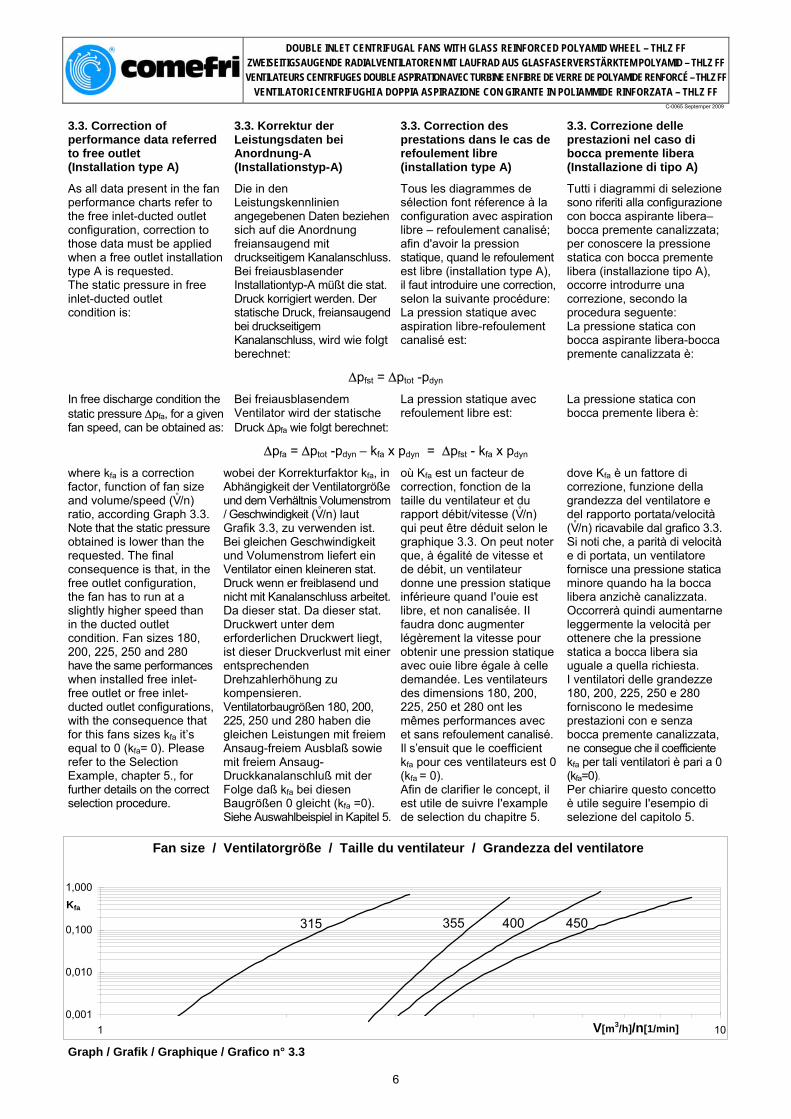
where kfa is a correction factor, function of fan size and volume/speed (V° /n) ratio, according Graph 3.3. Note that the static pressure obtained is lower than the requested. The final consequence is that, in the free outlet configuration, the fan has to run at a slightly higher speed than in the ducted outlet condition. Fan sizes 180, 200, 225, 250 and 280 have the same performances when installed free inlet-free outlet or free inlet-ducted outlet configurations, with the consequence that for this fans sizes kfa it’s equal to 0 (kfa= 0). Please refer to the Selection Example, chapter 5., for further details on the correct selection procedure.
wobei der Korrekturfaktor kfa, in Abhängigkeit der Ventilatorgröße und dem Verhältnis Volumenstrom / Geschwindigkeit (V° /n) laut Grafik 3.3, zu verwenden ist. Bei gleichen Geschwindigkeit und Volumenstrom liefert ein Ventilator einen kleineren stat. Druck wenn er freiblasend und nicht mit Kanalanschluss arbeitet. Da dieser stat. Da dieser stat. Druckwert unter dem erforderlichen Druckwert liegt, ist dieser Druckverlust mit einer entsprechenden Drehzahlerhöhung zu kompensieren. Ventilatorbaugrößen 180, 200, 225, 250 und 280 haben die gleichen Leistungen mit freiem Ansaug-freiem Ausblaß sowie mit freiem Ansaug-Druckkanalanschluß mit der Folge daß kfa bei diesen Baugrößen 0 gleicht (kfa =0). Siehe Auswahlbeispiel in KapiteI 5.
où Kfa est un facteur de correction, fonction de la taille du ventilateur et du rapport débit/vitesse (V° /n) qui peut être déduit selon le graphique 3.3. On peut noter que, à égalité de vitesse et de débit, un ventilateur donne une pression statique inférieure quand I'ouie est libre, et non canalisée. II faudra donc augmenter légèrement la vitesse pour obtenir une pression statique avec ouie libre égale à celle demandée. Les ventilateurs des dimensions 180, 200, 225, 250 et 280 ont les mêmes performances avec et sans refoulement canalisé. Il s’ensuit que le coefficient kfa pour ces ventilateurs est 0 (kfa = 0). Afin de clarifier le concept, il est utile de suivre I'example de selection du chapitre 5.
dove Kfa è un fattore di correzione, funzione della grandezza del ventilatore e del rapporto portata/velocità (V° /n) ricavabile dal grafico 3.3. Si noti che, a parità di velocità e di portata, un ventilatore fornisce una pressione statica minore quando ha la bocca libera anzichè canalizzata. Occorrerà quindi aumentarne leggermente la velocità per ottenere che la pressione statica a bocca libera sia uguale a quella richiesta. I ventilatori delle grandezze 180, 200, 225, 250 e 280 forniscono le medesime prestazioni con e senza bocca premente canalizzata, ne consegue che il coefficiente kfa per tali ventilatori è pari a 0 (kfa=0). Per chiarire questo concetto è utile seguire I'esempio di selezione del capitolo 5.
Fan size / Ventilatorgröße / Taille du ventilateur / Grandezza del ventilatore
0,001
0,010
0,100
1,000
1 10V[m3/h]/n[1/min]
Kfa
450400355315
Graph / Grafik / Graphique / Grafico n° 3.3
6
DOUBLE INLET CENTRIFUGAL FANS WITH GLASS REINFORCED POLYAMID WHEEL – THLZ FF ZWEISEITIGSAUGENDE RADIALVENTILATOREN MIT LAUFRAD AUS GLASFASERVERSTÄRKTEM POLYAMID – THLZ FF VENTILATEURS CENTRIFUGES DOUBLE ASPIRATION AVEC TURBINE EN FIBRE DE VERRE DE POLYAMIDE RENFORCÉ – THLZ FF
VENTILATORI CENTRIFUGHI A DOPPIA ASPIRAZIONE CON GIRANTE IN POLIAMMIDE RINFORZATA – THLZ FF
C-0065 Septemper 2009
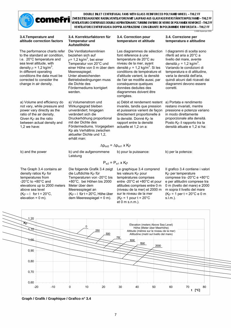
3.4.Temperature and altitude correction factors
3.4. Korrekturfaktoren für Temperatur und Aufstellhöhe
3.4. Correction pour temperature et altitude
3.4. Correzione per temperatura e altitudine
The performance charts refer to the standard air condition, i.e. 20°C temperature and sea level altitude, with density ρ = 1,2 kg/m3. In different operating conditions the data must be corrected to consider the change in air density.
Die Ventilatorkennlinien beziehen sich auf ρ= 1,2 kg/m3, bei einer Temperatur von 20°C und einer Höhe von 0 m über dem Meeresspiegel. Unter abweichenden Betriebsbedingungen muss die Dichte des Fördermediums korrigiert werden.
Les diagrammes de sélection font réference à une temperature de 20°C au niveau de la mer, ayant densité ρ = 1,2 kg/m3. Si les conditions de température et d'altitude varient, la densité de I'air se modifie aussi, par conséquence quelques données deduites des diagrammes doivent être corrigées.
I diagrammi di scelta sono riferiti ad aria a 20°C a livello del mare, avente densità ρ = 1,2 kg/m3. Variando le condizioni di temperatura e di altitudine, varia la densità dell'aria, quindi alcuni dati ricavati dai diagrammi devono essere corretti.
a) Volume and efficiency do not vary, while pressure and power vary directly as the ratio of the air density. Given Kρ as the ratio between actual density and 1,2 we have:
a) Volumenstrom und Wirkungsgrad bleiben unverändert; hingegen verändert sich die Druckerhöhung proportional mit der Dichte des Fördermediums. Vorgegeben Kp als Verhältnis zwischen aktueller Dichte und 1,2, erhält man:
a) Débit et rendement restent invariés, tandis que pression et puissance varient de façon directement proportionelle à la densité. Donné Kρ le rapport entre la densité actuelle et 1,2 on a:
a) Portata e rendimento restano invariati, mentre pressione e potenza variano in modo direttamente proporzionale alla densità. Posto Kρ il rapporto tra la densità attuale e 1,2 si ha:
∆ptot2 = ∆ptot1 x Kρ
b) and the power b) und die aufgenommene Leistung
b) pour la puissance: b) per la potenza:
Pw2 = Pw1 x Kρ
The Graph 3.4 contains air density ratios Kρ for temperatures from -20°C to +80°C and elevations up to 2000 meters above sea level (Kρ = 1 for t = 20°C, elevation = 0 m).
Die folgende Grafik 3.4 zeigt die Luftdichte Kρ für Temperaturen von -20°C bis +80°C, bei Höhen bis 2000 Meter über dem Meeresspiegel an (Kρ = 1 für t = 20°C, Höhe über dem Meeresspiegel = 0 m).
Le graphique 3.4 comprend les valeurs Kρ pour températures comprises entre -20°C et +80°C et pour altitudes comprises entre 0 m (niveau de la mer) et 2000 m sur le niveau de la mer (Kρ = 1 pour t = 20°C et 0 m s.n.m.).
II grafico 3.4 contiene i valori Kρ per temperature comprese tra -20°C e +80°C e per altitudini comprese tra 0 m (livello del mare) e 2000 m sopra il livello del mare (Kρ = 1 per t = 20°C e 0 m s.l.m.).
0,60
0,70
0,80
0,90
1,00
1,10
1,20
-20 -10 0 10 20 30 40 50 60 70 80t [°C]
KρHöhe (Meter über Meerhöhe)
Elevation [meters Above Sea Level]0
20001500
1000750
500250
Graph / Grafik / Graphique / Grafico n° 3.4
7
Elevation (meters Above Sea Level) Höhe (Meter über Meerhöhe)
Altitude (mètres sur le niveau de la mer) Altitudine (metri sul livello del mare)
DOUBLE INLET CENTRIFUGAL FANS WITH GLASS REINFORCED POLYAMID WHEEL – THLZ FF ZWEISEITIGSAUGENDE RADIALVENTILATOREN MIT LAUFRAD AUS GLASFASERVERSTÄRKTEM POLYAMID – THLZ FF VENTILATEURS CENTRIFUGES DOUBLE ASPIRATION AVEC TURBINE EN FIBRE DE VERRE DE POLYAMIDE RENFORCÉ – THLZ FF
VENTILATORI CENTRIFUGHI A DOPPIA ASPIRAZIONE CON GIRANTE IN POLIAMMIDE RINFORZATA – THLZ FF
C-0065 Septemper 2009
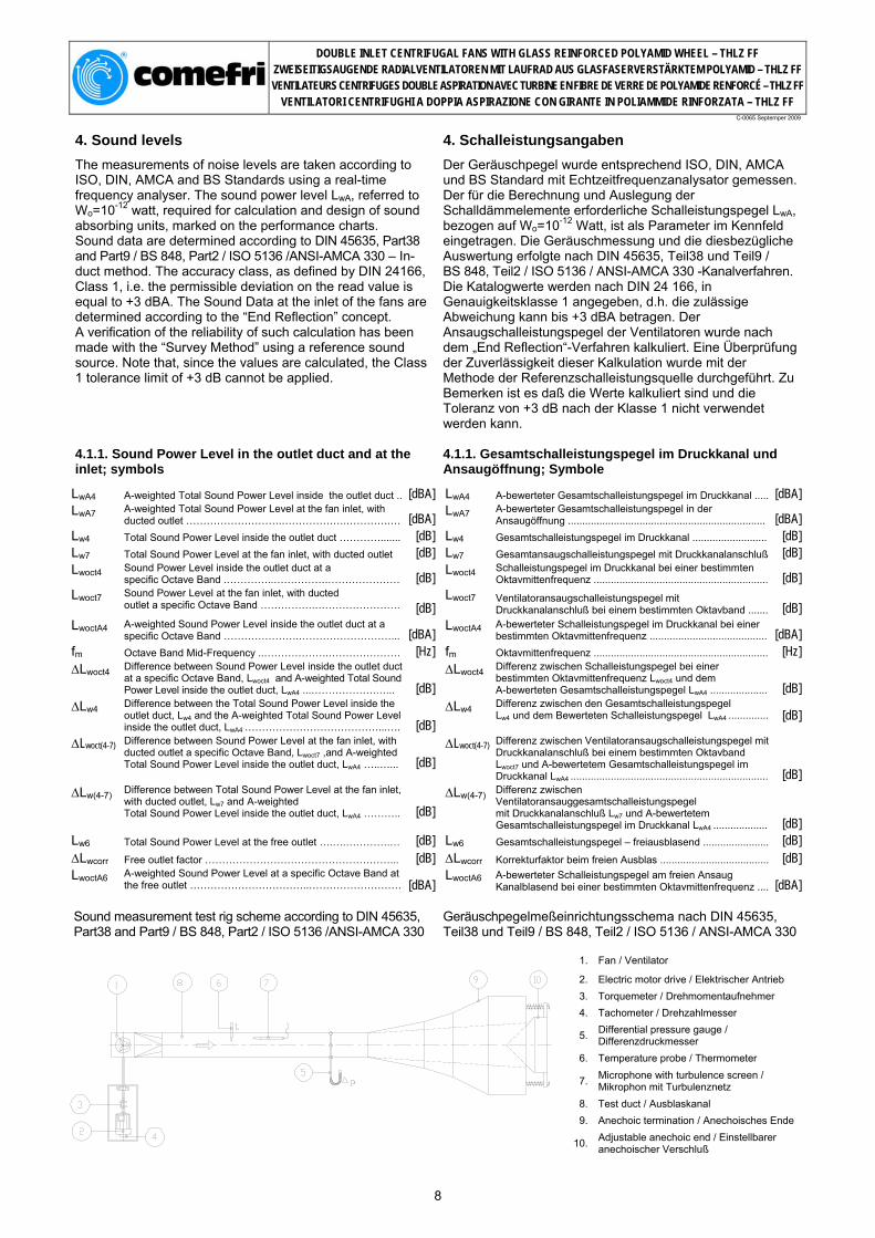
4. Sound levels 4. Schalleistungsangaben
The measurements of noise levels are taken according to ISO, DIN, AMCA and BS Standards using a real-time frequency analyser. The sound power level LwA, referred to Wo=10-12 watt, required for calculation and design of sound absorbing units, marked on the performance charts. Sound data are determined according to DIN 45635, Part38 and Part9 / BS 848, Part2 / ISO 5136 /ANSI-AMCA 330 – In-duct method. The accuracy class, as defined by DIN 24166, Class 1, i.e. the permissible deviation on the read value is equal to +3 dBA. The Sound Data at the inlet of the fans are determined according to the “End Reflection” concept. A verification of the reliability of such calculation has been made with the “Survey Method” using a reference sound source. Note that, since the values are calculated, the Class 1 tolerance limit of +3 dB cannot be applied.
Der Geräuschpegel wurde entsprechend ISO, DIN, AMCA und BS Standard mit Echtzeitfrequenzanalysator gemessen. Der für die Berechnung und Auslegung der Schalldämmelemente erforderliche Schalleistungspegel LwA, bezogen auf Wo=10-12 Watt, ist als Parameter im Kennfeld eingetragen. Die Geräuschmessung und die diesbezügliche Auswertung erfolgte nach DIN 45635, Teil38 und Teil9 / BS 848, Teil2 / ISO 5136 / ANSI-AMCA 330 -Kanalverfahren. Die Katalogwerte werden nach DIN 24 166, in Genauigkeitsklasse 1 angegeben, d.h. die zulässige Abweichung kann bis +3 dBA betragen. Der Ansaugschalleistungspegel der Ventilatoren wurde nach dem „End Reflection“-Verfahren kalkuliert. Eine Überprüfung der Zuverlässigkeit dieser Kalkulation wurde mit der Methode der Referenzschalleistungsquelle durchgeführt. Zu Bemerken ist es daß die Werte kalkuliert sind und die Toleranz von +3 dB nach der Klasse 1 nicht verwendet werden kann.
4.1.1. Sound Power Level in the outlet duct and at the inlet; symbols
4.1.1. Gesamtschalleistungspegel im Druckkanal und Ansaugöffnung; Symbole
LwA4 A-weighted Total Sound Power Level inside the outlet duct .. [dBA] LwA4 A-bewerteter Gesamtschalleistungspegel im Druckkanal ..... [dBA] LwA7 A-weighted Total Sound Power Level at the fan inlet, with
ducted outlet ……………………….……………….………….… [dBA] LwA7 A-bewerteter Gesamtschalleistungspegel in der Ansaugöffnung ..................................................................... [dBA]
Lw4 Total Sound Power Level inside the outlet duct …………....... [dB] Lw4 Gesamtschalleistungspegel im Druckkanal .......................... [dB] Lw7 Total Sound Power Level at the fan inlet, with ducted outlet [dB] Lw7 Gesamtansaugschalleistungspegel mit Druckkanalanschluß [dB] Lwoct4 Sound Power Level inside the outlet duct at a
specific Octave Band .…………..…………….………………… [dB] Lwoct4 Schalleistungspegel im Druckkanal bei einer bestimmten Oktavmittenfrequenz ............................................................. [dB]
Lwoct7 Sound Power Level at the fan inlet, with ducted outlet a specific Octave Band …………….…………………….
[dB]
Lwoct7 Ventilatoransaugschalleistungspegel mit Druckkanalanschluß bei einem bestimmten Oktavband ....... [dB]
LwoctA4 A-weighted Sound Power Level inside the outlet duct at a specific Octave Band ………………….………………………... [dBA] LwoctA4 A-bewerteter Schalleistungspegel im Druckkanal bei einer
bestimmten Oktavmittenfrequenz ......................................... [dBA]fm Octave Band Mid-Frequency ..……………….………………… [Hz] fm Oktavmittenfrequenz ............................................................. [Hz] ∆Lwoct4 Difference between Sound Power Level inside the outlet duct
at a specific Octave Band, Lwoct4 and A-weighted Total Sound Power Level inside the outlet duct, LwA4 ...……………….…... [dB]
∆Lwoct4 Differenz zwischen Schalleistungspegel bei einer bestimmten Oktavmittenfrequenz Lwoct4 und dem A-bewerteten Gesamtschalleistungspegel LwA4 ....................
[dB] ∆Lw4 Difference between the Total Sound Power Level inside the
outlet duct, Lw4 and the A-weighted Total Sound Power Level inside the outlet duct, LwA4 …………………………………...….
[dB]
∆Lw4 Differenz zwischen den Gesamtschalleistungspegel Lw4 und dem Bewerteten Schalleistungspegel LwA4 .............. [dB]
∆Lwoct(4-7) Difference between Sound Power Level at the fan inlet, with ducted outlet a specific Octave Band, Lwoct7 ,and A-weighted Total Sound Power Level inside the outlet duct, LwA4 …..…...
[dB] ∆Lwoct(4-7) Differenz zwischen Ventilatoransaugschalleistungspegel mit
Druckkanalanschluß bei einem bestimmten Oktavband Lwoct7 und A-bewertetem Gesamtschalleistungspegel im Druckkanal LwA4 .....................................................................
[dB]
∆Lw(4-7) Difference between Total Sound Power Level at the fan inlet, with ducted outlet, Lw7 and A-weighted Total Sound Power Level inside the outlet duct, LwA4 ………..
[dB] ∆Lw(4-7) Differenz zwischen
Ventilatoransauggesamtschalleistungspegel mit Druckkanalanschluß Lw7 und A-bewertetem Gesamtschalleistungspegel im Druckkanal LwA4 ...................
[dB]
Lw6 Total Sound Power Level at the free outlet ….….………….… [dB] Lw6 Gesamtschalleistungspegel – freiausblasend ....................... [dB] ∆Lwcorr Free outlet factor ………………………………………………... [dB] ∆Lwcorr Korrekturfaktor beim freien Ausblas ...................................... [dB] LwoctA6 A-weighted Sound Power Level at a specific Octave Band at
the free outlet ……………………………..………………………
[dBA] LwoctA6 A-bewerteter Schalleistungspegel am freien Ansaug
Kanalblasend bei einer bestimmten Oktavmittenfrequenz .... [dBA]
Sound measurement test rig scheme according to DIN 45635, Part38 and Part9 / BS 848, Part2 / ISO 5136 /ANSI-AMCA 330
Geräuschpegelmeßeinrichtungsschema nach DIN 45635, Teil38 und Teil9 / BS 848, Teil2 / ISO 5136 / ANSI-AMCA 330
1. Fan / Ventilator
2. Electric motor drive / Elektrischer Antrieb 3. Torquemeter / Drehmomentaufnehmer 4. Tachometer / Drehzahlmesser
5. Differential pressure gauge / Differenzdruckmesser
6. Temperature probe / Thermometer
7. Microphone with turbulence screen / Mikrophon mit Turbulenznetz
8. Test duct / Ausblaskanal 9. Anechoic termination / Anechoisches Ende
10. Adjustable anechoic end / Einstellbarer anechoischer Verschluß
8

DOUBLE INLET CENTRIFUGAL FANS WITH GLASS REINFORCED POLYAMID WHEEL – THLZ FF ZWEISEITIGSAUGENDE RADIALVENTILATOREN MIT LAUFRAD AUS GLASFASERVERSTÄRKTEM POLYAMID – THLZ FF VENTILATEURS CENTRIFUGES DOUBLE ASPIRATION AVEC TURBINE EN FIBRE DE VERRE DE POLYAMIDE RENFORCÉ – THLZ FF
VENTILATORI CENTRIFUGHI A DOPPIA ASPIRAZIONE CON GIRANTE IN POLIAMMIDE RINFORZATA – THLZ FF
C-0065 Septemper 2009
4. Niveau de bruit 4. Rumorosità
Les mesures de niveau de bruit ont été éffectuées selon les normes ISO, DIN, AMCA und BS avec un analyseur de fréquence en temps réel. Sur les courbes est reporté le Niveau de Puissance Sonore réferé à Wo = 10-12 watt, nécéssaire pour le calcul dans les différentes applications et pour le dimensionnement d'éventuels silencieux. Les valeurs de la Puissance Sonore ont été déterminées selon les normes DIN 45635, Part 38 et Part9 / BS 848, Part2 / ISO 5136 / ANSI-AMCA 330 - méthode en canal; la classe de précision, comme définie par les normes DIN 24 166, pour ce qui concerne les valeurs de bruit réportées sur les catalogues, est Classe 1 et admet une tolérance sur les valeurs indiquées de + 3dBA. Le niveau de puissance sonore à l’aspiration a été calculé en utilisant l’idée de l’«End Reflection». On a fait un contrôle de crédibilité de ce calcul avec la méthode de la source sonore de référence. Il faut tenir compte que, puisqu’il s’agit de valeurs calculés, ce n’est pas possible d’appliquer la tolérance de +3 dB, fixée par la Classe 1.
La misura della rumorosità è stata eseguita secondo le norme ISO, DIN, BS, UNI ed ANSI-AMCA, per mezzo di un analizzatore di frequenza in tempo reale. Sulle curve caratteristiche è riportato il Livello di Potenza Sonora riferito a Wo = 10-12 watt, necessario per il calcolo nelle varie applicazioni e per il dimensionamento di eventuali silenziatori. I Livelli di Potenza Sonora sono stati determinati secondo le norme DIN 45635, Part 38 e Part9 / BS 848, Part2 / ISO 5136 / ANSI-AMCA 330 -metodo in canale; la classe di precisione, come definita dalle norme DIN 24 166, per quanto riguarda i valori di rumorosità riportati sui cataloghi, è Classe 1, con una tolleranza sui valori indicati di + 3 dBA. I Livelli di Potenza Sonora all’aspirazione, sono stati calcolati utilizzando il concetto della “End Reflection”. Una verifica della attendibilità di tale calcolazione è stata fatta con il metodo della sorgente sonora di riferimento. Si tenga presente che, essendo valori calcolati, ad essi non si può applicare la tolleranza di +3 dB, stabilita dalla Classe 1.
4.1.1. Niveau de Puissance Sonore en canal de refoulement et en aspiration; symboles
4.1.1. Livelli di Potenza Sonora nel canale di mandata ed alla aspirazione; simboli
LwA4 Niveau de Puissance Sonore Totale en canal de refoulement, pondéré en échelle A …………………..….…… [dBA] LwA4 Livello di Potenza Sonora Totale nel canale di mandata,
ponderato in scala A …………………………………………... [dBA] LwA7 Niveau de Puissance Sonore Totale à l'aspiration en canal
de refoulement canalisée, pondéré en échelle A …………… [dBA] LwA7 Livello di Potenza Sonora Totale all'aspirazione con mandata canalizzata, ponderato in scala A ………….……..
[dBA] Lw4 Niveau de Puissance Sonore Totale en canal de refoulement [dB] Lw4 Livello di Potenza Sonora Totale nel canale di mandata [dB] Lw7 Le niveau de puissance sonore totale à l’aspiration canalisée [dB] Lw7 Livello di Potenza Sonora Totale all’aspirazione con
mandata canalizzata ….……………………………………….. [dB] Lwoct4 Niveau de Puissance Sonore en canal de refoulement en
Bande d'Octave ……………………………………………..…… [dB] Lwoct4 Livello di Potenza Sonora nel canale di mandata in Banda d'Ottava ………………………………………………… [dB]
Lwoct7 Niveau de puissance sonore à l’aspiration par bande d’octave canalisée ……………………………………………… [dB] Lwoct7 Livello di Potenza Sonora all’aspirazione in Banda d'Ottava
con mandata canalizzata ……………………………...……… [dB] LwoctA4 Niveau de Puissance Sonore en canal de refoulement en Bande
d'Octave, pondéré en échelle A ………………………..………… [dBA] LwoctA4 Livello di Potenza Sonora nel canale di mandata in Banda d'Ottava, ponderato in scala A ……………………..………… [dBA]
fm Fréquence centrale de Bande d'Octave ………………….…... [Hz] fm Frequenza centrale di Banda d'Ottava ………...……….…… [Hz] ∆Lwoct4 Différence entre le Niveau de Puissance Sonore en canal de
refoulement en Bande d'Octave, Lwoct4 et le Niveau de Puissance Sonore Totale en canal de refoulement, pondéré en échelle A, LwA4 ………………………………………………...
[dB]
∆Lwoct4 Differenza tra il Livello di Potenza Sonora nel canale di mandata in Banda d'Ottava, Lwoct4 ed il Livello di Potenza Sonora Totale nel canale di mandata ponderato in scala A, LwA4 …………………………………………....……....
[dB] ∆Lw4 Différence entre le Niveau de Puissance Sonore Totale en
canal de refoulement, Lw4 et le Niveau de Puissance Sonore Totale en canal de refoulement, pondéré en échelle A, LwA4 ..
[dB] ∆Lw4 Differenza tra il Livello di Potenza Sonora Totale nel canale
di mandata, Lw4 ed il Livello di Potenza Sonora Totale nel canale di mandata ponderato in scala A, LwA4 ………………
[dB]
∆Lwoct(4-7) La différence entre le niveau de puissance sonore en bande d’octave à l’aspiration Lwoct7 et le niveau de puissance sonore dans le canal au refoulement, pondérée en échelle A, LwA4 ….
[dB]
∆Lwoct(4-7) Differenza tra il Livello di Potenza Sonora in Banda di Ottava alla aspirazione, Lwoct7 ed il Livello di Potenza Sonora nel canale di mandata, ponderato in scala A, LwA4...
[dB]
∆Lw(4-7) La différence entre le niveau de puissance sonore totale à l’aspiration canalisée, Lw7 et le niveau de puissance sonore totale dans le canal au refoulement pondérée en échelle A, LwA4 ...………………………………………………………………
[dB]
∆Lw(4-7) Differenza tra il Livello di Potenza Sonora Totale alla aspirazione con mandata canalizzata, Lw7 ed il Livello di Potenza Sonora Totale nel canale di mandata ponderato in scala A, LwA4 …………………………………………………….
[dB] Lw6 Niveau de Puissance Sonore Totale avec refoulement libre [dB] Lw6 Livello di Potenza Sonora Totale con bocca di mandata libera [dB] ∆Lwcorr Niveau de Puissance Sonore Totale avec refoulement libre .. [dB] ∆Lwcorr Fattore di correzione per bocca di mandata libera ………....
[dB] LwoctA6 Niveau de Puissance Sonore avec refoulement libre en
Bande d’Octave, pondéré en échelle A ……………………..... [dBA] LwoctA6 Livello di potenza sonora con bocca di mandata libera in Banda d’Ottava, ponderato in scala A ………………………. [dBA]
Schéma Banc d’essai bruit selon normes DIN 45635, Part38 et Part9 / BS 848, Part2 / ISO 5136 / ANSI-AMCA 330
Schema banco prova rumore secondo norme DIN 45635 Part38 e Part9 / BS 848 Part2 / ISO 5136 / ANSI-AMCA 330
1. Ventilateur / Ventilatore 2. Moteur éléctrique / Motore elettrico 3. Torsiomètre / Torsiometro 4. Compte-tours / Contagiri 5. Manomètre différentiel / Manometro
differenziale 6. Sonde thermométrique / Sonda
termometrica 7. Microphone avec écran anti-turbulence /
Microfono con schermo antiturbolenza 8. Canal d'essai / Canale di prova 9. Terminal anecoique / Terminale anecoico
10. Fermeture conique réglable/ Chiusura anecoica regolabile
9

DOUBLE INLET CENTRIFUGAL FANS WITH GLASS REINFORCED POLYAMID WHEEL – THLZ FF ZWEISEITIGSAUGENDE RADIALVENTILATOREN MIT LAUFRAD AUS GLASFASERVERSTÄRKTEM POLYAMID – THLZ FF VENTILATEURS CENTRIFUGES DOUBLE ASPIRATION AVEC TURBINE EN FIBRE DE VERRE DE POLYAMIDE RENFORCÉ – THLZ FF
VENTILATORI CENTRIFUGHI A DOPPIA ASPIRAZIONE CON GIRANTE IN POLIAMMIDE RINFORZATA – THLZ FF
C-0065 Septemper 2009
4.1.2. Sound Power Level in the outlet duct and at the inlet; formulae and calculations
4.1.2. Schalleistungspegel im Druckkanal und an der Ansaugöffnung; Formeln und Rechnung
4.1.2. Niveaux de Puissance Sonore en canal de refoulement e à l'aspiration; formules et calculations
4.1.2. Livelli di Potenza Sonora nel canale di mandata ed all’aspirazione; formule e calcolazioni
1. The A-weighted Total Sound Power Level LwA4 inside the outlet duct can be read on the Performance Chart, for a given fan performance. 2. The Sound Power Level Lwoct4, at a specific Octave Band Mid-Frequency, inside the outlet duct, can be determined from following formula:
1. Der A-bewertete Gesamtschalleistungspegel LwA4 im Druckkanal kann aus dem Diagramm, bei einer vorgegebenen Ventilatorleistung, abgelesen werden. 2. Der Schalleistungspegel Lwoct4, bei einer bestimmten Oktavmittenfrequenz im Druckkanal, kann nach folgender Formel errechnet werden:
1. On lit ou valeur LwA4 du Niveau de Puissance Sonore pondéré en échelle A, sur les diagrammes en correspondance des prestations requises. 2. Le Niveau de Puissance Sonore en Bande d'Octave Lwoct4, dans le canal de refoulement, peut être calculé par la formule suivante:
1. Si legge il valore LwA4 del Livello di Potenza Sonora ponderato in scala A, sui diagrammi in corrispondenza delle prestazioni richieste 2. Il Livello di Potenza Sonora in Bande d’Ottava Lwoct4, all’interno del canale di mandata, può essere calcolato con la formula seguente:
Lwoct4 = LwA4 + ∆Lwoct4
3. The Total Sound Power Level inside the outlet duct can be obtained from the following formula:
3. Der Gesamtschalleistungspegel Lw4 im Druckkanal wird wie folgt errechnet:
3. Le Niveau de Puissance Sonore Totale dans le canal de refoulement peut être calculé par la formule suivante:
3. Il Livello di Potenza Sonora Totale all’interno del canale di mandata può essere calcolato con la formula seguente:
Lw4 = LwA4 + ∆Lw4
The values for ∆Lwoct4 and ∆Lw4 are given in the Sound Data Tables section 4.3.
Die Werte für ∆LwoctA4 und ∆Lw4 können aus der Schallpegeltabelle, (4.3) entnommen werden.
Les valeurs de ∆LwoctA4 et ∆Lw4 sont reportées dans le paragraphe 4.3.
I valori di ∆Lwoct4 e ∆Lw4 sono riportati nelle tabelle del paragrafo 4.3.
4. The Sound Power Level Lwoct7 at a specific Octave Band Mid-Frequency, at the inlet, can be determined from the following formula:
Der Schalleistungspegel Lwoct7, bei einer bestimmten Oktavmittenfrequenz an der Ansaugöffnung, kann nach folgender Formel errechnet werden:
Le Niveau de Puissance Sonore en Bande d'Octave Lwoct7, à l'aspiration, peut être calculé par la formule suivante:
4. Il Livello di Potenza Sonora in Bande d’Ottava Lwoct7 all’aspirazione, può essere calcolato con la formula seguente:
Lwoct7 = LwA4 + ∆Lwoct(4-7)
5. The Total Sound Power Level at the fan inlet can be obtained from the following formula:
Der Gesamtschalleistungspegel an der Ansaugöffnung wird wie folgt errechnet:
Le Niveau de Puissance Sonore Totale à l'aspiration peut être calculé par la formule suivante:
5. Il Livello di Potenza Sonora Totale all’aspirazione, può essere calcolato con la formula seguente:
Lw7 = LwA4 + ∆Lw(4-7)
The values for ∆Lwoct7 and ∆Lw7 are given in Sound Data Tables section 4.3.
Die Werte für ∆Lwoct7 und ∆Lw7 können aus der Schallpegeltabelle, (4.3) entnommen werden.
Les valeurs de ∆Lwoct7 et ∆Lw7 sont reportées dans le paragraphe 4.3.
I valori di ∆Lwoct7 e ∆Lw7 sono riportati nelle tabelle del paragrafo 4.3
10

DOUBLE INLET CENTRIFUGAL FANS WITH GLASS REINFORCED POLYAMID WHEEL – THLZ FF ZWEISEITIGSAUGENDE RADIALVENTILATOREN MIT LAUFRAD AUS GLASFASERVERSTÄRKTEM POLYAMID – THLZ FF VENTILATEURS CENTRIFUGES DOUBLE ASPIRATION AVEC TURBINE EN FIBRE DE VERRE DE POLYAMIDE RENFORCÉ – THLZ FF
VENTILATORI CENTRIFUGHI A DOPPIA ASPIRAZIONE CON GIRANTE IN POLIAMMIDE RINFORZATA – THLZ FF
C-0065 Septemper 2009
4.2. Total Sound Power Level at the free outlet, Lw6
4.2. Gesamt- schalleistungspegel - freiausblasend - Lw6
4.2. Niveau de Puissance Sonore Totale avec aspiration libre, Lw6
4.2. Livello di Potenza Sonora Totale con bocca libera, Lw6
The Total Sound Power Level, outside the termination of the outlet duct, can be calculated with approximation using of the "End Reflection" concept : part of the sound power generated by the fan at the discharge is reflected back into the duct when there is an abrupt termination. The value Lw6, at the outlet in a free discharge condition, can be considered approximately equal to the: Total Sound Power Level outside the termination of the outlet duct. The octave band values can be obtained subtracting, octave by octave, from the Lwoct4 values the reflected back portion of the sound power. The following table gives the correction factors ∆Lwcorr, for each fan size, that has to be applied to the corresponding Lwoct4 value.
Der Gesamtschalleistungspegel - freiausblasend - kann näherungsweise nach dem End- Reflection-Verfahren berechnet werden. Bei abrupter Querschnittsveränderung wird ein gewisser Anteil des Ventilatorgeräusches im Meßkanal reflektiert. Bei freiausblasendem Einsatz entspricht der Lw6 Wert in etwa dem Gesamtschallpegel. Die Werte über dem Oktavband erhält man durch Subtraktion der anteiligen Korrekturwerten ∆Lwcorr von den Lwoct4 - Werten. Näheres siehe im Berechnungsbeispiel.
Le Niveau de Puissance Sonore Totale, à l'extérieur du conduit de refoulement, peut être déterminé an première approximation, en utilisant le concept de la "End Reflection", selon lequel une partie du son produit par le ventilateur ne sort pas du refoulement, mais vient réfléchi eà l'arrière.La valeur Lw6, à l'éxterieur de l’ouie libre (non canalisée), peut être considérée approximativement égale au Niveau de Puissance Sonore Totale à la sortie du canal de refoulement. Le bruit en Bande d'Octave, à la sortie du conduit de refoulement ou avec ouie libre, peut être déterminé en deduisant à Lwoct4, pour chaque Bande d'Octave, la partie du bruit refléchi. Le tableau suivant donne les valeurs ∆Lwcorr, qui doivent être ajoutées pour chaque taille à la correspondante valeur de Lwoct4.
Il Livello di Potenza Sonora Totale, all'esterno del canale di mandata, può essere determinato in prima approssimazione usando il concetto della "End Reflection", secondo cui parte del suono prodotto dal ventilatore non esce dalla bocca del canale, ma viene riflesso all'indietro. Il valore Lw6, all'esterno della bocca di mandata libera (non canalizzata), può essere ritenuto approssimativamente uguale al Livello di Potenza Sonora Totale all'uscita dal canale di mandata. La rumorosità in Bande d'Ottava, all'uscita del canale di mandata o con bocca libera, può essere determinata sottraendo a Lwoct4, per ogni Banda d'Ottava, la parte di rumore riflesso. La tabella seguente riporta i valori ∆Lwcorr, che devono essere applicati, per ogni grandezza, al corrispondente valore di Lwoct4.
Size/ Baugröße / Taille / Grandezza
180 200 225 250 280 315 355 400 450
63 [Hz] -13 -12 -12 -11 -10 -10 -10 -9 -8
125 [Hz] -8 -7,5 -7,5 -7 -7 -5,5 -5 -5 -4
250 [Hz] -4 -3,5 -3 -3 -3 -2 -2 -2 -2 ∆L w
corr
500 [Hz] -1 -1 -1 0 0 0 0 0 0
Graph / Grafik / Graphique / Grafico n° 4.2
Please refer to the Selection Example for the detailed procedure to follow. Note that, as Lw6 is an estimated value, the Class 1 tolerance limit of +3 dBA cannot be applied. Finally, please consider that the low frequencies (125 Hz and below) are strongly affected by vibrations (drive alignment, pulley unbalance, etc) and by ducts not properly acoustically insulated from the fan; the final effect is the generation of additional low frequency noise.
Im Auslegungsbeispiel ist das zu folgende Verfahren im Detail beschrieben. Der Lw6 - Wert ist nur ein Näherungswert, für den die Genauigkeitsklasse 1 nicht zutrifft. Desweiteren entstehen im Bereich bis 125 Hz zusätzliche Geräusche durch Vibration von Antrieb, Unwucht, usw. welche sich negativ auswirken können.
Dans l’exemple de sélection la procédure à suivre est décrit au détail. Il faut prendre en compte que, étant Lw6 une valeur calculée, on ne peut pas lui appliquer la tolérance de + 3 dBA, établie par la Classe 1. On considére en outre que le bruit en basse fréquence (125 Hz et inférieur), est fortement influencé par les vibrations (alignement de la transmission, deséquilibrage des poulies etc.) et par les canalisations non suffisamment isolées acoustiquement; par conséquent il est possible d’avoir une augmentation du niveau de bruit aux basses fréquences.
Nell’esempio di selezione è riportata nel dettaglio la procedura da seguire. Si tenga presente che, essendo Lw6 un valore calcolato, ad esso non si può applicare la tolleranza di +3 dBA, stabilita dalla Classe 1. Si consideri inoltre che la rumorosità, alle basse frequenze (125 Hz ed inferiori), è fortemente influenzata dalle vibrazioni (allineamento della trasmissione, sbilanciamento delle pulegge, ecc.) e da canalizzazioni non sufficientemente isolate acusticamente; l'effetto finale può portare ad un incremento della rumorosità alle basse frequenze.
11

DOUBLE INLET CENTRIFUGAL FANS WITH GLASS REINFORCED POLYAMID WHEEL – THLZ FF ZWEISEITIGSAUGENDE RADIALVENTILATOREN MIT LAUFRAD AUS GLASFASERVERSTÄRKTEM POLYAMID – THLZ FF VENTILATEURS CENTRIFUGES DOUBLE ASPIRATION AVEC TURBINE EN FIBRE DE VERRE DE POLYAMIDE RENFORCÉ – THLZ FF
VENTILATORI CENTRIFUGHI A DOPPIA ASPIRAZIONE CON GIRANTE IN POLIAMMIDE RINFORZATA – THLZ FF
C-0065 Septemper 2009
4.3. Sound data tables 4.3. Schallpegeltabelle 4.3. Donnés sur le niveau sonore 4.3. Dati di rumorosità
∆LWoct4 ∆LWoct7 Fan model and size Ventilator-Baugröße Taille du ventilateur
Grandezza del ventilatore
Volume flow range Volumenstrom
Interval du debit Intervallo di portata
Speed range Drehzahl
Interval de vitesse Intervallo di velocità
∆LW 4 63 125 250 500 1000 2000 4000 8000
∆LW (4-7)63 125 250 500 1000 2000 4000 8000
RPM < 2500 11,8 9 7 1 -4 -4 -9 -14 -22 3,0 -3 -5 -3 -6 -6 -9 -14 -22 2501 <RPM< 4500 10,4 8 4 1 -4 -5 -11 -14 -22 1,5 -7 -7 -5 -5 -6 -11 -14 -22 Area 1 RPM > 4501 9,9 7 4 1 -5 -4 -9 -12 -22 0,5 -7 -7 -8 -9 -6 -9 -12 -22
RPM < 2500 8,7 5 3 1 -3 -4 -10 -14 -23 3,9 -6 -3 -1 -5 -4 -8 -14 -23 2501 <RPM< 4500 6,8 2 1 0 -4 -4 -10 -14 -23 1,3 -10 -8 -5 -5 -5 -10 -14 -23 Area 2 RPM > 4501 6,8 2 0 1 -5 -4 -9 -13 -23 -0,5 -10 -10 -9 -9 -6 -9 -13 -23
RPM < 2500 9,5 7 2 0 -3 -4 -6 -10 -21 4,3 -3 -4 -2 -4 -4 -6 -10 -21 2501 <RPM< 4500 7,0 3 0 0 -3 -5 -8 -12 -21 2,7 -8 -6 -3 -4 -5 -8 -12 -21
THLZ 180 FF
Area 3 RPM > 4501 7,2 3 1 0 -4 -5 -8 -9 -20 1,0 -8 -8 -7 -7 -6 -8 -9 -20
∆LWoct4 ∆LWoct7 Fan model and size
Ventilator-Baugröße Taille du ventilateur
Grandezza del ventilatore
Volume flow range Volumenstrom
Interval du debit Intervallo di portata
Speed range Drehzahl
Interval de vitesse Intervallo di velocità
∆LW 4 63 125 250 500 1000 2000 4000 8000
∆LW (4-7)63 125 250 500 1000 2000 4000 8000
RPM < 2500 12,5 11 4 2 -3 -5 -8 -13 -22 3,9 -4 -3 -3 -3 -5 -8 -13 -22 2501 <RPM< 4500 11,6 10 4 0 -3 -5 -10 -17 -22 3,0 -6 -3 -5 -3 -5 -10 -17 -22 Area 1 RPM > 4501 7,4 4 1 -2 -4 -3 -8 -13 -20 1,3 -12 -9 -7 -6 -3 -8 -13 -20
RPM < 2500 10,5 7 6 1 -4 -5 -8 -14 -24 1,3 -9 -5 -6 -6 -7 -8 -14 -24 2501 <RPM< 4500 9,6 8 0 -1 -3 -4 -8 -14 -22 1,1 -9 -5 -7 -6 -7 -8 -14 -22 Area 2 RPM > 4501 7,3 4 2 -3 -7 -5 -7 -12 -20 -0,4 -12 -8 -8 -8 -8 -8 -13 -20
RPM < 2500 8,5 4 4 0 -4 -4 -8 -14 -25 4,0 -6 -2 -3 -4 -3 -8 -12 -23 2501 <RPM< 4500 8,1 5 1 -1 -3 -3 -6 -13 -21 2,1 -9 -5 -5 -5 -5 -8 -13 -21
THLZ 200 FF
Area 3 RPM > 4501 6,2 2 0 -6 -7 -2 -5 -7 -20 -0,1 -12 -10 -10 -10 -6 -7 -8 -21
∆LWoct4 ∆LWoct7 Fan model and size
Ventilator-Baugröße Taille du ventilateur
Grandezza del ventilatore
Volume flow range Volumenstrom
Interval du debit Intervallo di portata
Speed range Drehzahl
Interval de vitesse Intervallo di velocità
∆LW 4 63 125 250 500 1000 2000 4000 8000
∆LW (4-7)63 125 250 500 1000 2000 4000 8000
RPM < 2500 14,0 12 8 3 -3 -6 -12 -18 -28 5,0 -2 -1 0 -4 -6 -12 -18 -28 2501 <RPM< 4500 9,3 6 4 0 -3 -4 -9 -16 -25 2,6 -6 -5 -5 -4 -4 -9 -16 -25 Area 1 RPM > 4501 8,5 4 4 0 -3 -4 -11 -16 -25 1,5 -10 -6 -6 -4 -5 -11 -16 -25
RPM < 2500 8,8 6 3 -2 -3 -4 -9 -15 -27 1,5 -6 -6 -7 -5 -6 -9 -15 -27 2501 <RPM< 4500 6,0 2 0 -4 -4 -4 -8 -13 -21 -0,1 -10 -9 -8 -7 -7 -8 -15 -21 Area 2 RPM > 4501 4,1 -1 -3 -5 -6 -4 -6 -13 -21 -0,7 -15 -12 -9 -8 -6 -8 -13 -21
RPM < 2500 8,7 6 2 -1 -3 -4 -8 -13 -25 3,1 -5 -7 -3 -4 -4 -8 -13 -25 2501 <RPM< 4500 6,8 3 1 -3 -4 -4 -8 -12 -18 1,7 -7 -7 -6 -5 -5 -9 -13 -19
THLZ 225 FF
Area 3 RPM > 4501 4,5 0 -2 -6 -7 -4 -6 -10 -18 -0,3 -11 -9 -9 -9 -6 -8 -12 -20
∆LWoct4 ∆LWoct7 Fan model and size
Ventilator-Baugröße Taille du ventilateur
Grandezza del ventilatore
Volume flow range Volumenstrom
Interval du debit Intervallo di portata
Speed range Drehzahl
Interval de vitesse Intervallo di velocità
∆LW 4 63 125 250 500 1000 2000 4000 8000
∆LW (4-7)63 125 250 500 1000 2000 4000 8000
RPM < 1800 11,1 8 6 1 0 -5 -10 -16 -23 6,5 0 1 -2 0 -4 -9 -15 -22 1801 <RPM< 2700 13,7 11 8 5 0 -4 -10 -16 -23 7,1 0 1 1 0 -3 -9 -15 -22 Area 1 RPM > 2701 11,4 8 6 3 0 -4 -10 -16 -23 5,7 -3 -3 -1 1 -3 -9 -15 -22
RPM < 1800 9,5 7 3 -1 -2 -5 -7 -14 -21 6,0 -1 -1 -1 -2 -2 -6 -13 -20 1801 <RPM< 2700 9,6 7 3 0 -2 -5 -7 -14 -21 4,2 -3 -4 -4 -2 -4 -6 -13 -20 Area 2 RPM > 2701 9,1 6 3 0 -2 -5 -7 -14 -21 3,0 -4 -6 -4 -3 -6 -9 -13 -20
RPM < 1800 8,9 6 3 -1 -4 -6 -6 -9 -19 5,2 -3 -3 -3 -2 -3 -3 -8 -18 1801 <RPM< 2700 9,0 6 3 0 -4 -6 -6 -9 -19 3,2 -5 -6 -5 -4 -5 -5 -8 -18
THLZ 250 FF
Area 3 RPM > 2701 7,1 3 2 -3 -4 -6 -6 -9 -19 2,7 -8 -6 -6 -4 -5 -5 -8 -18
∆LWoct4 ∆LWoct7 Fan model and size
Ventilator-Baugröße Taille du ventilateur
Grandezza del ventilatore
Volume flow range Volumenstrom
Interval du debit Intervallo di portata
Speed range Drehzahl
Interval de vitesse Intervallo di velocità
∆LW 4 63 125 250 500 1000 2000 4000 8000
∆LW (4-7)63 125 250 500 1000 2000 4000 8000
RPM < 1800 12,4 10 7 2 -3 -6 -10 -18 -25 6,2 0 0 0 -1 -6 -10 -18 -25 1801 <RPM< 2700 13,8 12 7 3 -1 -6 -10 -18 -25 5,6 0 -2 -1 -1 -6 -10 -18 -25 Area 1 RPM > 2701 9,5 7 2 0 -1 -6 -8 -15 -21 3,4 -7 -4 -4 -2 -5 -7 -14 -20
RPM < 1800 12,4 10 7 1 -1 -5 -9 -18 -24 7,0 0 0 0 0 -1 -7 -12 -19 1801 <RPM< 2700 12,2 10 6 1 0 -5 -9 -18 -24 6,2 -2 -3 0 1 -3 -7 -16 -22 Area 2 RPM > 2701 7,2 4 1 -4 -3 -5 -6 -14 -21 4,1 -7 -5 -4 -1 -3 -5 -13 -19
RPM < 1800 9,1 6 3 0 -3 -6 -5 -16 -21 7,3 2 0 1 -2 -4 -3 -14 -19 1801 <RPM< 2700 9,6 6 4 0 -2 -3 -4 -16 -24 6,2 -1 -2 -1 -1 -2 -3 -15 -23
THLZ 280 FF
Area 3 RPM > 2701 6,8 4 -2 -4 -3 -3 -7 -12 -19 3,7 -6 -4 -4 -3 -3 -7 -12 -19
12

DOUBLE INLET CENTRIFUGAL FANS WITH GLASS REINFORCED POLYAMID WHEEL – THLZ FF ZWEISEITIGSAUGENDE RADIALVENTILATOREN MIT LAUFRAD AUS GLASFASERVERSTÄRKTEM POLYAMID – THLZ FF VENTILATEURS CENTRIFUGES DOUBLE ASPIRATION AVEC TURBINE EN FIBRE DE VERRE DE POLYAMIDE RENFORCÉ – THLZ FF
VENTILATORI CENTRIFUGHI A DOPPIA ASPIRAZIONE CON GIRANTE IN POLIAMMIDE RINFORZATA – THLZ FF
C-0065 Septemper 2009
∆LWoct4 ∆LWoct7 Fan model and size Ventilator-Baugröße Taille du ventilateur
Grandezza del ventilatore
Volume flow range Volumenstrom
Interval du debit Intervallo di portata
Speed range Drehzahl
Interval de vitesse Intervallo di velocità
∆LW 4 63 125 250 500 1000 2000 4000 8000
∆LW (4-7)63 125 250 500 1000 2000 4000 8000
RPM < 1500 14,1 13 5 3 -3 -7 -11 -18 -27 6,8 2 -1 1 -2 -4 -10 -17 -23 1501 <RPM< 2500 14,9 13 9 3 -3 -4 -11 -18 -24 6,4 0 0 1 -3 -3 -10 -17 -23 Area 1 RPM > 2501 12,2 9 8 2 -3 -6 -11 -20 -28 5,4 -3 0 0 -3 -5 -10 -19 -27
RPM < 1500 11,7 9 6 3 -4 -6 -10 -18 -27 5,9 0 0 0 -5 -4 -8 -16 -25 1501 <RPM< 2500 12,1 9 7 4 -4 -6 -10 -18 -27 5,8 -1 0 0 -4 -4 -8 -16 -25 Area 2 RPM > 2501 9,0 6 4 -3 -4 -5 -8 -17 -25 4,5 -4 -2 -4 -2 -3 -6 -15 -23
RPM < 1500 8,9 5 4 0 -3 -6 -5 -17 -25 6,2 0 -1 0 -2 -5 -4 -16 -24 1501 <RPM< 2500 9,6 7 2 0 -2 -3 -5 -17 -21 6,3 -1 -2 0 -1 -2 -4 -16 -20
THLZ 315 FF
Area 3 RPM > 2501 8,0 4 3 -5 -3 -3 -3 -14 -21 4,8 -6 -3 -5 -2 -2 -2 -13 -20
∆LWoct4 ∆LWoct7 Fan model and size Ventilator-Baugröße Taille du ventilateur
Grandezza del ventilatore
Volume flow range Volumenstrom
Interval du debit Intervallo di portata
Speed range Drehzahl
Interval de vitesse Intervallo di velocità
∆LW 4 63 125 250 500 1000 2000 4000 8000
∆LW (4-7)63 125 250 500 1000 2000 4000 8000
RPM < 1500 13,6 12 6 3 -3 -6 -12 -16 -21 7,3 4 -1 1 -3 -6 -12 -16 -21 1501 <RPM< 2500 12,1 9 7 4 -4 -7 -10 -15 -24 6,4 0 0 2 -4 -7 -10 -15 -24 Area 1 RPM > 2501 9,5 6 4 1 -2 -5 -10 -17 -23 4,2 -5 -2 -2 -2 -5 -10 -17 -23
RPM < 1500 10,5 8 4 2 -4 -6 -9 -15 -24 6,2 0 -2 1 -2 -4 -8 -14 -23 1501 <RPM< 2500 9,9 7 4 2 -5 -6 -9 -13 -22 6,2 0 0 0 -3 -4 -8 -12 -21 Area 2 RPM > 2501 6,8 3 0 -3 -2 -4 -8 -14 -20 3,8 -7 -5 -5 -1 -3 -7 -13 -19
RPM < 1500 7,0 3 0 0 -4 -4 -8 -14 -22 5,3 -2 -3 0 -3 -3 -7 -13 -21 1501 <RPM< 2500 7,8 5 0 -1 -4 -4 -7 -13 -19 5,8 -1 -3 -1 -2 -2 -5 -11 -17
THLZ 355 FF
Area 3 RPM > 2501 5,2 1 -3 -5 -3 -4 -6 -14 -21 3,4 -7 -6 -6 -2 -3 -5 -13 -20
∆LWoct4 ∆LWoct7 Fan model and size Ventilator-Baugröße Taille du ventilateur
Grandezza del ventilatore
Volume flow range Volumenstrom
Interval du debit Intervallo di portata
Speed range Drehzahl
Interval de vitesse Intervallo di velocità
∆LW 4 63 125 250 500 1000 2000 4000 8000
∆LW (4-7)63 125 250 500 1000 2000 4000 8000
RPM < 1500 11,4 9 5 3 -4 -5 -10 -15 -21 7,1 1 1 2 -4 -4 -9 -14 -20 1501 <RPM< 2500 12,9 11 5 5 -5 -4 -12 -18 -25 7,5 2 0 3 -4 -3 -11 -17 -24 Area 1 RPM > 2501 12,0 10 5 2 -3 -5 -11 -17 -24 6,0 0 -1 0 -2 -4 -10 -16 -23
RPM < 1500 10,7 9 3 0 -4 -4 -11 -15 -19 6,0 0 -1 0 -3 -3 -10 -14 -18 1501 <RPM< 2500 10,7 9 0 3 -5 -5 -11 -16 -23 5,9 1 -3 1 -5 -4 -10 -15 -22 Area 2 RPM > 2501 8,2 6 -1 -1 -3 -4 -9 -15 -22 4,0 -4 -4 -3 -3 -3 -8 -14 -21
RPM < 1500 6,6 4 -3 -2 -6 -4 -6 -15 -23 3,8 -4 -5 -3 -5 -3 -5 -14 -22 1501 <RPM< 2500 9,3 7 0 0 -5 -1 -4 -15 -23 5,6 -1 -3 -1 -5 -1 -4 -15 -23
THLZ 400 FF
Area 3 RPM > 2501 9,3 7 0 -1 -1 -2 -6 -14 -20 5,9 -1 -3 -2 -1 -1 -5 -13 -19
∆LWoct4 ∆LWoct7 Fan model and size Ventilator-Baugröße Taille du ventilateur
Grandezza del ventilatore
Volume flow range Volumenstrom
Interval du debit Intervallo di portata
Speed range Drehzahl
Interval de vitesse Intervallo di velocità
∆LW 4 63 125 250 500 1000 2000 4000 8000
∆LW (4-7)63 125 250 500 1000 2000 4000 8000
RPM < 1500 14,1 12 9 1 -3 -6 -10 -16 -25 8,8 5 4 0 -3 -6 -10 -16 -25 1501 <RPM< 2300 12,1 9 7 4 -5 -6 -13 -17 -24 7,2 1 2 2 -4 -5 -12 -16 -23 Area 1 RPM > 2301 11,5 8 7 3 -3 -5 -12 -17 -24 6,0 0 1 -1 -3 -5 -12 -17 -24
RPM < 1500 10,5 7 6 1 -4 -5 -9 -15 -24 7,9 1 4 1 -3 -4 -8 -14 -23 1501 <RPM< 2300 9,1 6 2 2 -3 -4 -10 -15 -22 6,9 0 -1 2 -1 -3 -9 -14 -21 Area 2 RPM > 2301 7,5 3 1 1 -4 -3 -9 -14 -21 5,7 -3 -2 1 -3 -2 -8 -13 -20
RPM < 1500 9,2 6 4 -1 -4 -3 -9 -15 -25 7,0 1 2 -1 -3 -2 -8 -14 -24 1501 <RPM< 2300 7,5 4 0 1 -5 -4 -8 -16 -23 5,6 -1 -2 0 -3 -3 -7 -15 -22
THLZ 450 FF
Area 3 RPM > 2301 7,1 3 0 0 -5 -3 -7 -12 -19 5,0 -3 -2 -2 -4 -2 -6 -11 -18
13

DOUBLE INLET CENTRIFUGAL FANS WITH GLASS REINFORCED POLYAMID WHEEL – THLZ FF ZWEISEITIGSAUGENDE RADIALVENTILATOREN MIT LAUFRAD AUS GLASFASERVERSTÄRKTEM POLYAMID – THLZ FF VENTILATEURS CENTRIFUGES DOUBLE ASPIRATION AVEC TURBINE EN FIBRE DE VERRE DE POLYAMIDE RENFORCÉ – THLZ FF
VENTILATORI CENTRIFUGHI A DOPPIA ASPIRAZIONE CON GIRANTE IN POLIAMMIDE RINFORZATA – THLZ FF
C-0065 Septemper 2009
2562
5,07
10,5
77
11,3
80,5%
5. Selection Example 5. Auslegungsbeispiel 5. Exemple de sélection 5. Esempio di selezione
THLZ 400 FF B R T1 Fan Max RPM / Max zul. Ventilatordrehzahl / Vitesse de rotation maximale / Massima velocità di rotazione [min-1] 2850
Fan Max power / Max zul. Ventilatorwellenleistung / Puissance absorbée maximale / Potenza massima assorbita [kW] 7,5
Fan weight / Ventilatorgewicht / Poids du ventilateur / Peso del ventilatore [kg] 30,5 37 46 Wheel diameter / Laufraddurchmesser / Diamètre nominale de la turbine / Diametro nominale della girante [mm] 400
Wheel No. Blades / Schaufelanzahl / Nombre d'aubes / N° di pale z 8 Wheel Moment of Inertia / Laufrad Massenträgheitsmoment / Moment d'inertie de la turbine / Momento d’inerzia della girante [kg m2] 0,15
Wheel weight / Laufradgewicht / Poids de la turbine / Peso della girante [kg] 7
Fan curves plotted for air density:1,2 Kg/m3
Free inlet-Ducted outlet. LWA4;7 : A-weighted Sound Power Level inside the fan outlet duct and at fan inlet.
Ventilatorkennlinie bei ρ Luft:1,2 kg/m3
Freiansaugend mit Druckanal. LWA4;7 : A-bewertete Schalleistungpegel im Ausblaskanal und an der Ansaugseite.
Les diagrammese font réference à de l’air ayant une densité de 1,2 kg/m3 en aspiration libre et refoulement canalisé. LWA4;7 : niveau de puissance sonore pondéré en échelle A, respectivement dans le canal de refoulement et dans l’aspiration.
I diagrammi sono riferiti ad aria con densità di 1,2 Kg/m3 con bocca di aspirazione libera e bocca di mandata canalizzata. LWA4;7 : livello di potenza sonora ponderato in scala A, rispettivamente all’interno del canale di mandata e alla bocca di aspirazione.
14
DOUBLE INLET CENTRIFUGAL FANS WITH GLASS REINFORCED POLYAMID WHEEL – THLZ FF ZWEISEITIGSAUGENDE RADIALVENTILATOREN MIT LAUFRAD AUS GLASFASERVERSTÄRKTEM POLYAMID – THLZ FF VENTILATEURS CENTRIFUGES DOUBLE ASPIRATION AVEC TURBINE EN FIBRE DE VERRE DE POLYAMIDE RENFORCÉ – THLZ FF
VENTILATORI CENTRIFUGHI A DOPPIA ASPIRAZIONE CON GIRANTE IN POLIAMMIDE RINFORZATA – THLZ FF
C-0065 Septemper 2009
Fan selection for the following operating parameters:
Gegeben: Sélection du ventilateur pour les suivants paramètres de fonctionnement:
Selezione di un ventilatore per i seguenti parametri di funzionamento:
V° . ∆ptot
ρ t
====
10500 m3/h; 1400 Pa; 1,2 kg/m3; 20 °C;
A) Ducted outlet
Fan selected model and size is THLZ 400 FF R:
A) Mit Druckkanalanschluss
Gewählt: THLZ 400 FF R Leistungsangaben laut Ventilatordiagramm:
A) Canalisé
Le ventilateur sélectionné est le THLZ 400 FF R ayant les suivantes caractéristiques:
A) Canalizzato
Il ventilatore selezionato è il THLZ 400 FF R, avente le caratteristiche seguenti:
nnmaxpdyn
ηtPw
LwA4 = LwA7
======
2562 min-1; 2850 min-1; 77 Pa; 80,5 % 5,07 kW; 92 dB(A);
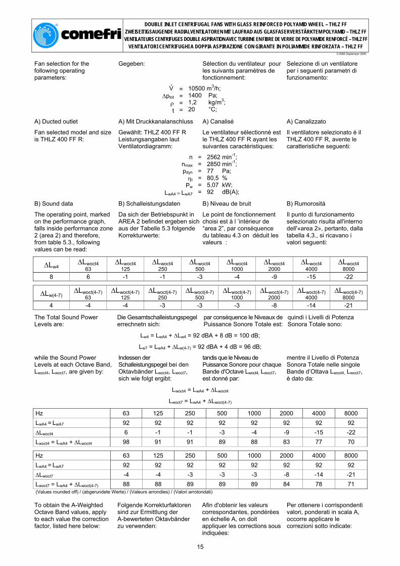
B) Sound data
The operating point, marked on the performance graph, falls inside performance zone 2 (area 2) and therefore, from table 5.3., following values can be read:
B) Schalleistungsdaten
Da sich der Betriebspunkt in AREA 2 befindet ergeben sich aus der Tabelle 5.3 folgende Korrekturwerte:
B) Niveau de bruit
Le point de fonctionnement choisi est à l ’intérieur de “area 2”, par conséquence du tableau 4.3 on déduit les valeurs :
B) Rumorosità
Il punto di funzionamento selezionato risulta all'interno dell'«area 2», pertanto, dalla tabella 4.3., si ricavano i valori seguenti:
∆Lw4 ∆Lwoct4 63
∆Lwoct4 125
∆Lwoct4 250
∆Lwoct4 500
∆Lwoct4 1000
∆Lwoct4 2000
∆Lwoct4 4000
∆Lwoct4 8000
8 6 -1 -1 -3 -4 -9 -15 -22
∆Lw(4-7) ∆Lwoct(4-7) 63
∆Lwoct(4-7) 125
∆Lwoct(4-7) 250
∆Lwoct(4-7) 500
∆Lwoct(4-7) 1000
∆Lwoct(4-7) 2000
∆Lwoct(4-7) 4000
∆Lwoct(4-7) 8000
4 -4 -4 -3 -3 -3 -8 -14 -21
The Total Sound Power Levels are:
Die Gesamtschalleistungspegel errechnetn sich:
par conséquence le Niveaux de Puissance Sonore Totale est:
quindi i Livelli di Potenza Sonora Totale sono:
Lw4 = LwA4 + ∆Lw4 = 92 dBA + 8 dB = 100 dB;
Lw7 = LwA4 + ∆Lw(4-7) = 92 dBA + 4 dB = 96 dB;
while the Sound Power Levels at each Octave Band, Lwoct4, Lwoct7, are given by:
Indessen der Schalleistungspegel bei den Oktavbänder Lwoct4, Lwoct7, sich wie folgt ergibt:
tandis que le Niveau de Puissance Sonore pour chaque Bande d'Octave Lwoct4, Lwoct7, est donné par:
mentre il Livello di Potenza Sonora Totale nelle singole Bande d’Ottava Lwoct4, Lwoct7, è dato da:
Lwoct4 = LwA4 + ∆Lwoct4
Lwoct7 = LwA4 + ∆Lwoct(4-7)
Hz 63 125 250 500 1000 2000 4000 8000 LwA4 = LwA7 92 92 92 92 92 92 92 92 ∆Lwoct4 6 -1 -1 -3 -4 -9 -15 -22 Lwoct4 = LwA4 + ∆Lwoct4 98 91 91 89 88 83 77 70
Hz 63 125 250 500 1000 2000 4000 8000 LwA4 = LwA7 92 92 92 92 92 92 92 92 ∆Lwoct7 -4 -4 -3 -3 -3 -8 -14 -21 Lwoct7 = LwA4 + ∆Lwoct(4-7) 88 88 89 89 89 84 78 71 (Values rounded off) / (abgerundete Werte) / (Valeurs arrondies) / (Valori arrotondati)
To obtain the A-Weighted Octave Band values, apply to each value the correction factor, listed here below:
Folgende Korrekturfaktoren sind zur Ermittlung der A-bewerteten Oktavbänder zu verwenden:
Afin d'obtenir les valeurs correspondantes, pondérées en échelle A, on doit appliquer les corrections sous indiquées:
Per ottenere i corrispondenti valori, ponderati in scala A, occorre applicare le correzioni sotto indicate:
15

DOUBLE INLET CENTRIFUGAL FANS WITH GLASS REINFORCED POLYAMID WHEEL – THLZ FF ZWEISEITIGSAUGENDE RADIALVENTILATOREN MIT LAUFRAD AUS GLASFASERVERSTÄRKTEM POLYAMID – THLZ FF VENTILATEURS CENTRIFUGES DOUBLE ASPIRATION AVEC TURBINE EN FIBRE DE VERRE DE POLYAMIDE RENFORCÉ – THLZ FF
VENTILATORI CENTRIFUGHI A DOPPIA ASPIRAZIONE CON GIRANTE IN POLIAMMIDE RINFORZATA – THLZ FF
C-0065 Septemper 2009
Octave Band Mid Frequency Oktavband Mittefrequenz Fréquence moyenne de la Bande d'Octave Frequenza media della Banda d'Ottava
63 Hz 125 Hz 250 Hz 500 Hz 1000 Hz 2000 Hz 4000 Hz 8000 Hz
A-Weighting Korrekturwerte Correction pour l'échelle A Correzione per la Scala A
-26 -16 -9 -3 0 +1 +1 -1
(Values rounded off) / (abgerundete Werte) / (Valeurs arrondies) / (Valori arrotondati)
LwoctA4 and LwoctA7, A-weighted values, are consequently:
Die LwoctA4 und LwoctA7 Werte (A-gewichtet) ergeben sich wie folgt:
Les valeurs LwoctA4 et LwoctA7, pondérées en échelle A, seront donc les suivantes:
I valori LwoctA4 e LwoctA7, ponderati in scala A, saranno quindi seguenti:
Octave Band Mid Frequency Oktavband Mittefrequenz Fréquence moyenne de la Bande d'Octave Frequenza media della Banda d'Ottava
63 Hz 125 Hz 250 Hz 500 Hz 1000 Hz 2000 Hz 4000 Hz 8000 Hz
Lwoct4 98 91 91 89 88 83 77 70 A-Weighting Korrekturwerte Correction pour l'échelle A Correzione per la Scala A
-26 -16 -9 -3 0 +1 +1 -1
LwoctA4 72 75 82 86 88 84 78 69 (Values rounded off) / (abgerundete Werte) / (Valeurs arrondies) / (Valori arrotondati)
Octave Band Mid Frequency Oktavband Mittefrequenz Fréquence moyenne de la Bande d'Octave Frequenza media della Banda d'Ottava
63 Hz 125 Hz 250 Hz 500 Hz 1000 Hz 2000 Hz 4000 Hz 8000 Hz
Lwoct7 88 88 89 89 89 84 78 71 A-Weighting Korrekturwerte Correction pour l'échelle A Correzione per la Scala A
-26 -16 -9 -3 0 +1 +1 -1
LwoctA7 62 72 80 86 89 85 79 70 (Values rounded off) / (abgerundete Werte) / (Valeurs arrondies) / (Valori arrotondati)
C) Free outlet selection
If the same fan has to be selected in a free-outlet configuration (type A installation) a correction factor Kfa must be introduced, as explained at section 3.3. As V° /n = 10500 / 2562 = 4,1 from the relevant graph 3.3 the value of Kfa is 0,016. With ducted outlet configuration the static pressure ∆pfst is:
C) Ohne Druckkanalanschluss
Entsprechend dem Paragraph 3.3, ist bei der Anordnung A, der Korrekturfaktor Kfa zu verwenden. Da V° /n = 10500 / 2562 = 4,1 aus der Grafik 3.3 wird der Korrekturfaktor Kfa = 0,016 ermittelt. Bei Kanalanschluss beträgt der statische Druck
C) Refoulement libre
Si le même ventilateur du cas précédent avait le refoulement libre, au lieu de canalisé, il faudrait introduire le facteur Kfa, comme indiqué dans le paragraphe 3.3. La valeur correspondante de V° /n = 10500 / 2562 = 4,1 se retrouve sur le graphique 3.3 la valeur de Kfa égale à 0,016. Avec le refoulement canalisé la pression statique ∆pfst est :
C) Bocca di mandata libera
Se lo stesso ventilatore del caso precedente avesse la bocca di mandata libera, anzichè canalizzata, occorrerebbe introdurre il fattore Kfa, come indicato nel paragrafo 3.3. In corrispondenza di V° /n = 10500 / 2562 = 4,1 si ricava dal grafico 3.3 il valore di Kfa uguale a 0,016. Con la bocca di mandata canalizzata la pressione statica ∆pfst è:
∆pfst = ∆ptot - pdyn = 1400 - 77 = 1323 Pa
While the static pressure with free outlet, ∆pfa, is:
Indessen bei freiausblasender Installation der statische Druck ∆pfa
La pression statique avec ouie canalisée ∆pfa, est:
La pressione statica con bocca premente libera ∆pfa, sarà quindi:
∆pfa = ∆ptot - pdyn - Kfa x pdyn = ∆pfst - Kfa x pdyn = 1323 - 0,016 x 77 = 1321 Pa
As consequence, to obtain the requested static pressure with a free outlet configuration, the fan must be selected at a higher value than the nominal pressure:
d.h. bei freiausblasender Installation ist deshalb die Ventilatorauswahl bei einem höheren Druck als dem Nominaldruck zu tätigen:
Pour obtenir la même pression statique avec le même débit du cas précédent, il faudra sélectionner le ventilateur avec une pression totale supérieure, c'est-à-dire:
Per ottenere la medesima pressione statica con la stessa portata del caso precedente, occorrerà quindi selezionare il ventilatore con una pressione totale maggiore, ossia:
∆’ptot = ∆ptot + Kfa x pdyn = 1400 + 2 = 1402 Pa
16
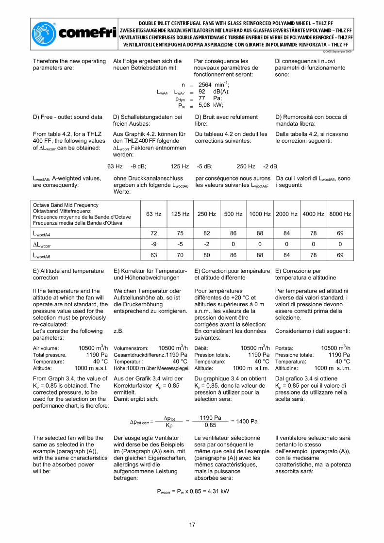
DOUBLE INLET CENTRIFUGAL FANS WITH GLASS REINFORCED POLYAMID WHEEL – THLZ FF ZWEISEITIGSAUGENDE RADIALVENTILATOREN MIT LAUFRAD AUS GLASFASERVERSTÄRKTEM POLYAMID – THLZ FF VENTILATEURS CENTRIFUGES DOUBLE ASPIRATION AVEC TURBINE EN FIBRE DE VERRE DE POLYAMIDE RENFORCÉ – THLZ FF
VENTILATORI CENTRIFUGHI A DOPPIA ASPIRAZIONE CON GIRANTE IN POLIAMMIDE RINFORZATA – THLZ FF
C-0065 Septemper 2009
Therefore the new operating parameters are:
Als Folge ergeben sich die neuen Betriebsdaten mit:
Par conséquence les nouveaux paramètres de fonctionnement seront:
Di conseguenza i nuovi parametri di funzionamento sono:
nLwA4 = LwA7
pdyn Pw
= = = =
2564 min-1; 92 dB(A); 77 Pa; 5,08 kW;
D) Free - outlet sound data
From table 4.2, for a THLZ 400 FF, the following values of ∆Lwcorr can be obtained:
D) Schalleistungsdaten bei freien Ausbas:
Aus Graphik 4.2. können für den THLZ 400 FF folgende ∆Lwcorr Faktoren entnommen werden:
D) Bruit avec refulement libre:
Du tableau 4.2 on deduit les corrections suivantes:
D) Rumorosità con bocca di mandata libera:
Dalla tabella 4.2, si ricavano le correzioni seguenti:
63 Hz -9 dB; 125 Hz -5 dB; 250 Hz -2 dB
LwoctA6, A-weighted values, are consequently:
ohne Druckkanalanschluss ergeben sich folgende LwoctA6 Werte:
par conséquence nous aurons les valeurs suivantes LwoctA6:
Da cui i valori di LwoctA6, sono i seguenti:
Octave Band Mid Frequency Oktavband Mittefrequenz Fréquence moyenne de la Bande d'Octave Frequenza media della Banda d'Ottava
63 Hz 125 Hz 250 Hz 500 Hz 1000 Hz 2000 Hz 4000 Hz 8000 Hz
LwoctA4 72 75 82 86 88 84 78 69
∆Lwcorr -9 -5 -2 0 0 0 0 0
LwoctA6 63 70 80 86 88 84 78 69
E) Altitude and temperature correction If the temperature and the altitude at which the fan will operate are not standard, the pressure value used for the selection must be previously re-calculated: Let’s consider the following parameters:
Air volume: 10500 m3/h Total pressure: 1190 Pa Temperature: 40 °C Altitude: 1000 m a.s.l.
From Graph 3.4, the value of Kρ = 0,85 is obtained. The corrected pressure, to be used for the selection on the performance chart, is therefore:
E) Korrektur für Temperatur- und Höhenabweichungen Weichen Temperatur oder Aufstellunshöhe ab, so ist die Druckerhöhung entsprechend zu korrigieren. z.B.
Volumenstrom: 10500 m3/h Gesamtdruckdifferenz:1190 Pa Temperatur : 40 °C Höhe:1000 m über Meeresspiegel.
Aus der Grafik 3.4 wird der Korrekturfaktor Kρ = 0,85 ermittelt. Damit ergibt sich:
E) Correction pour température et altitude différente Pour températures différentes de +20 °C et altitudes supérieures à 0 m s.n.m., les valeurs de la pression doivent être corrigées avant la sélection: En considérant les données suivantes:
Débit: 10500 m3/h Pression totale: 1190 Pa Température: 40 °C Altitude: 1000 m s.l.m.
Du graphique 3.4 on obtient Kρ = 0,85, donc la valeur de pression à utilizer pour la sélection sera:
E) Correzione per temperatura e altitudine Per temperature ed altitudini diverse dai valori standard, i valori di pressione devono essere corretti prima della selezione. Consideriamo i dati seguenti:
Portata: 10500 m3/hPressione totale: 1190 Pa Temperatura: 40 °C Altitudine: 1000 m s.l.m.
Dal grafico 3.4 si ottiene Kρ = 0,85 per cui il valore di pressione da utilizzare nella scelta sarà:
∆ptot 1190 Pa
∆ptot corr = Kρ = 0,85 = 1400 Pa
The selected fan will be the same as selected in the example (paragraph (A)), with the same characteristics but the absorbed power will be:
Der ausgelegte Ventilator wird derselbe des Beispiels im (Paragraph (A)) sein, mit den gleichen Eigenschaften, allerdings wird die aufgenommene Leistung betragen:
Le ventilateur sélectionné sera par conséquent le même que celui de l’exemple (paragraphe (A)) avec les mêmes caractéristiques, mais la puissance absorbée sera:
Il ventilatore selezionato sarà pertanto lo stesso dell'esempio (paragrafo (A)), con le medesime caratteristiche, ma la potenza assorbita sarà:
Pwcorr = Pw x 0,85 = 4,31 kW
17

DOUBLE INLET CENTRIFUGAL FANS WITH GLASS REINFORCED POLYAMID WHEEL – THLZ FF ZWEISEITIGSAUGENDE RADIALVENTILATOREN MIT LAUFRAD AUS GLASFASERVERSTÄRKTEM POLYAMID – THLZ FF VENTILATEURS CENTRIFUGES DOUBLE ASPIRATION AVEC TURBINE EN FIBRE DE VERRE DE POLYAMIDE RENFORCÉ – THLZ FF
VENTILATORI CENTRIFUGHI A DOPPIA ASPIRAZIONE CON GIRANTE IN POLIAMMIDE RINFORZATA – THLZ FF
C-0065 Septemper 2009
6. Performance charts 6. Leistungskurven 6. Courbes caractéristiques 6. Curve caratteristiche
6.1. THLZ 180 FF………………………………………………………………………………………...……..…. 19
6.2. THLZ 200 FF……………………………………………………………………………………...……..……. 20
6.3. THLZ 225 FF………………………………………………………………………………………...……..…. 21
6.4. THLZ 250 FF………………………………………………………………………………………...……..…. 22
6.5. THLZ 280 FF…………………………………………………………………………………...……..………. 23
6.6. THLZ 315 FF…………………………………………………………………..………………………...……. 24
6.7. THLZ 355 FF…………………………………………………………………...…………………..…………. 25
6.8. THLZ 400 FF……………………………………………………………………...…………………..………. 26
6.9. THLZ 450 FF………………………………………………...………………………………………..………. 27
18
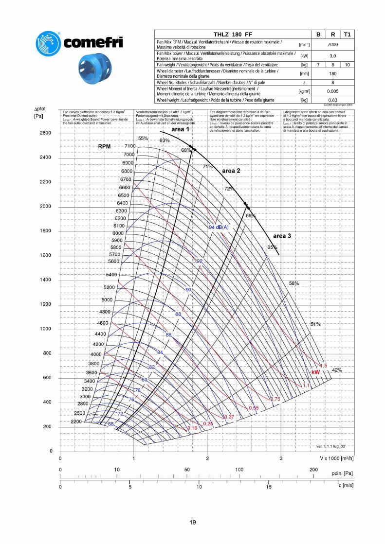
THLZ 180 FF B R T1
Fan Max RPM / Max zul. Ventilatordrehzahl / Vitesse de rotation maximale / Massima velocità di rotazione [min-1] 7000
Fan Max power / Max zul. Ventilatorwellenleistung / Puissance absorbée maximale / Potenza massima assorbita [kW] 3,0
Fan weight / Ventilatorgewicht / Poids du ventilateur / Peso del ventilatore [kg] 7 8 10 Wheel diameter / Laufraddurchmesser / Diamètre nominale de la turbine / Diametro nominale della girante [mm] 180
Wheel No. Blades / Schaufelanzahl / Nombre d'aubes / N° di pale z 8 Wheel Moment of Inertia / Laufrad Massenträgheitsmoment / Moment d'inertie de la turbine / Momento d’inerzia della girante [kg m2] 0,005
Wheel weight / Laufradgewicht / Poids de la turbine / Peso della girante [kg] 0,83 C-0065 Septemper 2009
Fan curves plotted for air density:1,2 Kg/m3
Free inlet-Ducted outlet. LWA4;7 : A-weighted Sound Power Level inside the fan outlet duct and at fan inlet.
Ventilatorkennlinie bei ρ Luft:1,2 kg/m3
Freiansaugend mit Druckanal. LWA4;7 : A-bewertete Schalleistungpegel im Ausblaskanal und an der Ansaugseite.
Les diagrammese font réference à de l’air ayant une densité de 1,2 kg/m3 en aspiration libre et refoulement canalisé. LWA4;7 : niveau de puissance sonore pondéré en échelle A, respectivement dans le canal de refoulement et dans l’aspiration.
I diagrammi sono riferiti ad aria con densità di 1,2 Kg/m3 con bocca di aspirazione libera e bocca di mandata canalizzata. LWA4;7 : livello di potenza sonora ponderato in scala A, rispettivamente all’interno del canale di mandata e alla bocca di aspirazione.
19
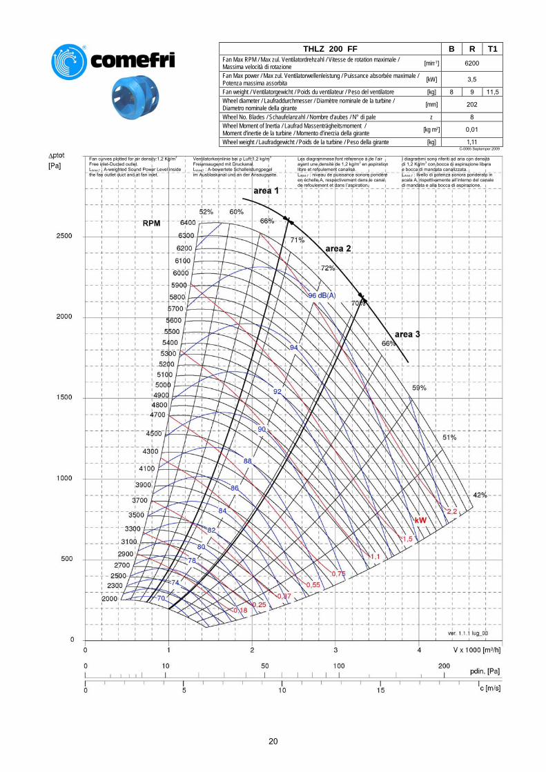
THLZ 200 FF B R T1
Fan Max RPM / Max zul. Ventilatordrehzahl / Vitesse de rotation maximale / Massima velocità di rotazione [min-1] 6200
Fan Max power / Max zul. Ventilatorwellenleistung / Puissance absorbée maximale / Potenza massima assorbita [kW] 3,5
Fan weight / Ventilatorgewicht / Poids du ventilateur / Peso del ventilatore [kg] 8 9 11,5 Wheel diameter / Laufraddurchmesser / Diamètre nominale de la turbine / Diametro nominale della girante [mm] 202
Wheel No. Blades / Schaufelanzahl / Nombre d'aubes / N° di pale z 8 Wheel Moment of Inertia / Laufrad Massenträgheitsmoment / Moment d'inertie de la turbine / Momento d’inerzia della girante [kg m2] 0,01
Wheel weight / Laufradgewicht / Poids de la turbine / Peso della girante [kg] 1,11 C-0065 Septemper 2009
Fan curves plotted for air density:1,2 Kg/m3
Free inlet-Ducted outlet. LWA4;7 : A-weighted Sound Power Level inside the fan outlet duct and at fan inlet.
Ventilatorkennlinie bei ρ Luft:1,2 kg/m3
Freiansaugend mit Druckanal. LWA4;7 : A-bewertete Schalleistungpegel im Ausblaskanal und an der Ansaugseite.
Les diagrammese font réference à de l’air ayant une densité de 1,2 kg/m3 en aspiration libre et refoulement canalisé. LWA4;7 : niveau de puissance sonore pondéré en échelle A, respectivement dans le canal de refoulement et dans l’aspiration.
I diagrammi sono riferiti ad aria con densità di 1,2 Kg/m3 con bocca di aspirazione libera e bocca di mandata canalizzata. LWA4;7 : livello di potenza sonora ponderato in scala A, rispettivamente all’interno del canale di mandata e alla bocca di aspirazione.
20
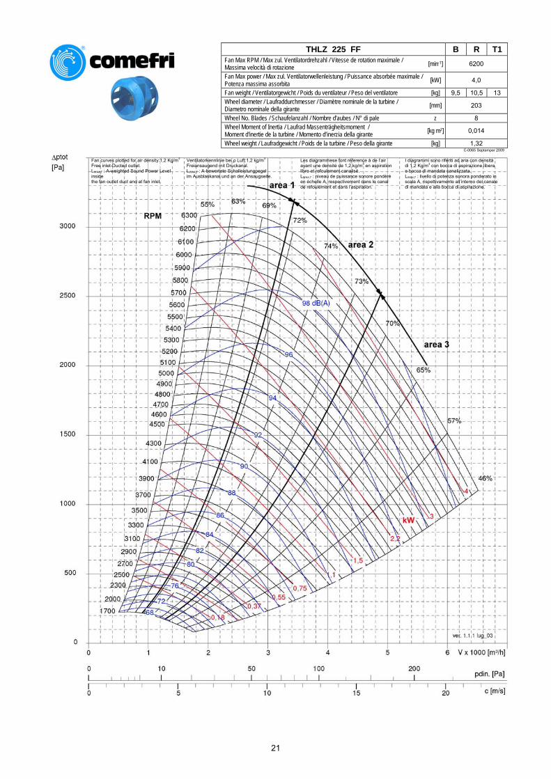
THLZ 225 FF B R T1
Fan Max RPM / Max zul. Ventilatordrehzahl / Vitesse de rotation maximale / Massima velocità di rotazione [min-1] 6200
Fan Max power / Max zul. Ventilatorwellenleistung / Puissance absorbée maximale / Potenza massima assorbita [kW] 4,0
Fan weight / Ventilatorgewicht / Poids du ventilateur / Peso del ventilatore [kg] 9,5 10,5 13 Wheel diameter / Laufraddurchmesser / Diamètre nominale de la turbine / Diametro nominale della girante [mm] 203
Wheel No. Blades / Schaufelanzahl / Nombre d'aubes / N° di pale z 8 Wheel Moment of Inertia / Laufrad Massenträgheitsmoment / Moment d'inertie de la turbine / Momento d’inerzia della girante [kg m2] 0,014
Wheel weight / Laufradgewicht / Poids de la turbine / Peso della girante [kg] 1,32 C-0065 Septemper 2009
Fan curves plotted for air density:1,2 Kg/m3
Free inlet-Ducted outlet. LWA4;7 : A-weighted Sound Power Level inside the fan outlet duct and at fan inlet.
Ventilatorkennlinie bei ρ Luft:1,2 kg/m3
Freiansaugend mit Druckanal. LWA4;7 : A-bewertete Schalleistungpegel im Ausblaskanal und an der Ansaugseite.
Les diagrammese font réference à de l’air ayant une densité de 1,2 kg/m3 en aspiration libre et refoulement canalisé. LWA4;7 : niveau de puissance sonore pondéré en échelle A, respectivement dans le canal de refoulement et dans l’aspiration.
I diagrammi sono riferiti ad aria con densità di 1,2 Kg/m3 con bocca di aspirazione libera e bocca di mandata canalizzata. LWA4;7 : livello di potenza sonora ponderato in scala A, rispettivamente all’interno del canale di mandata e alla bocca di aspirazione.
21

THLZ 250 FF B R T1
Fan Max RPM / Max zul. Ventilatordrehzahl / Vitesse de rotation maximale / Massima velocità di rotazione [min-1] 5800
Fan Max power / Max zul. Ventilatorwellenleistung / Puissance absorbée maximale / Potenza massima assorbita [kW] 5,0
Fan weight / Ventilatorgewicht / Poids du ventilateur / Peso del ventilatore [kg] 11 12 15,5 Wheel diameter / Laufraddurchmesser / Diamètre nominale de la turbine / Diametro nominale della girante [mm] 250
Wheel No. Blades / Schaufelanzahl / Nombre d'aubes / N° di pale z 8 Wheel Moment of Inertia / Laufrad Massenträgheitsmoment / Moment d'inertie de la turbine / Momento d’inerzia della girante [kg m2] 0,02
Wheel weight / Laufradgewicht / Poids de la turbine / Peso della girante [kg] 1,63 C-0065 Septemper 2009
Fan curves plotted for air density:1,2 Kg/m3
Free inlet-Ducted outlet. LWA4;7 : A-weighted Sound Power Level inside the fan outlet duct and at fan inlet.
Ventilatorkennlinie bei ρ Luft:1,2 kg/m3
Freiansaugend mit Druckanal. LWA4;7 : A-bewertete Schalleistungpegel im Ausblaskanal und an der Ansaugseite.
Les diagrammese font réference à de l’air ayant une densité de 1,2 kg/m3 en aspiration libre et refoulement canalisé. LWA4;7 : niveau de puissance sonore pondéré en échelle A, respectivement dans le canal de refoulement et dans l’aspiration.
I diagrammi sono riferiti ad aria con densità di 1,2 Kg/m3 con bocca di aspirazione libera e bocca di mandata canalizzata. LWA4;7 : livello di potenza sonora ponderato in scala A, rispettivamente all’interno del canale di mandata e alla bocca di aspirazione.
22

THLZ 280 FF B R T1
Fan Max RPM / Max zul. Ventilatordrehzahl / Vitesse de rotation maximale / Massima velocità di rotazione [min-1] 4700
Fan Max power / Max zul. Ventilatorwellenleistung / Puissance absorbée maximale / Potenza massima assorbita [kW] 5,2
Fan weight / Ventilatorgewicht / Poids du ventilateur / Peso del ventilatore [kg] 15 17 21 Wheel diameter / Laufraddurchmesser / Diamètre nominale de la turbine / Diametro nominale della girante [mm] 282
Wheel No. Blades / Schaufelanzahl / Nombre d'aubes / N° di pale z 8 Wheel Moment of Inertia / Laufrad Massenträgheitsmoment / Moment d'inertie de la turbine / Momento d’inerzia della girante [kg m2] 0,034
Wheel weight / Laufradgewicht / Poids de la turbine / Peso della girante [kg] 2,42 C-0065 Septemper 2009
Fan curves plotted for air density:1,2 Kg/m3
Free inlet-Ducted outlet. LWA4;7 : A-weighted Sound Power Level inside the fan outlet duct and at fan inlet.
Ventilatorkennlinie bei ρ Luft:1,2 kg/m3
Freiansaugend mit Druckanal. LWA4;7 : A-bewertete Schalleistungpegel im Ausblaskanal und an der Ansaugseite.
Les diagrammese font réference à de l’air ayant une densité de 1,2 kg/m3 en aspiration libre et refoulement canalisé. LWA4;7 : niveau de puissance sonore pondéré en échelle A, respectivement dans le canal de refoulement et dans l’aspiration.
I diagrammi sono riferiti ad aria con densità di 1,2 Kg/m3 con bocca di aspirazione libera e bocca di mandata canalizzata. LWA4;7 : livello di potenza sonora ponderato in scala A, rispettivamente all’interno del canale di mandata e alla bocca di aspirazione.
23

THLZ 315 FF B R T1
Fan Max RPM / Max zul. Ventilatordrehzahl / Vitesse de rotation maximale / Massima velocità di rotazione [min-1] 3700
Fan Max power / Max zul. Ventilatorwellenleistung / Puissance absorbée maximale / Potenza massima assorbita [kW] 5,6
Fan weight / Ventilatorgewicht / Poids du ventilateur / Peso del ventilatore [kg] 19 22 27 Wheel diameter / Laufraddurchmesser / Diamètre nominale de la turbine / Diametro nominale della girante [mm] 315
Wheel No. Blades / Schaufelanzahl / Nombre d'aubes / N° di pale z 8 Wheel Moment of Inertia / Laufrad Massenträgheitsmoment / Moment d'inertie de la turbine / Momento d’inerzia della girante [kg m2] 0,05
Wheel weight / Laufradgewicht / Poids de la turbine / Peso della girante [kg] 3,37 C-0065 Septemper 2009
Fan curves plotted for air density:1,2 Kg/m3
Free inlet-Ducted outlet. LWA4;7 : A-weighted Sound Power Level inside the fan outlet duct and at fan inlet.
Ventilatorkennlinie bei ρ Luft:1,2 kg/m3
Freiansaugend mit Druckanal. LWA4;7 : A-bewertete Schalleistungpegel im Ausblaskanal und an der Ansaugseite.
Les diagrammese font réference à de l’air ayant une densité de 1,2 kg/m3 en aspiration libre et refoulement canalisé. LWA4;7 : niveau de puissance sonore pondéré en échelle A, respectivement dans le canal de refoulement et dans l’aspiration.
I diagrammi sono riferiti ad aria con densità di 1,2 Kg/m3 con bocca di aspirazione libera e bocca di mandata canalizzata. LWA4;7 : livello di potenza sonora ponderato in scala A, rispettivamente all’interno del canale di mandata e alla bocca di aspirazione.
24
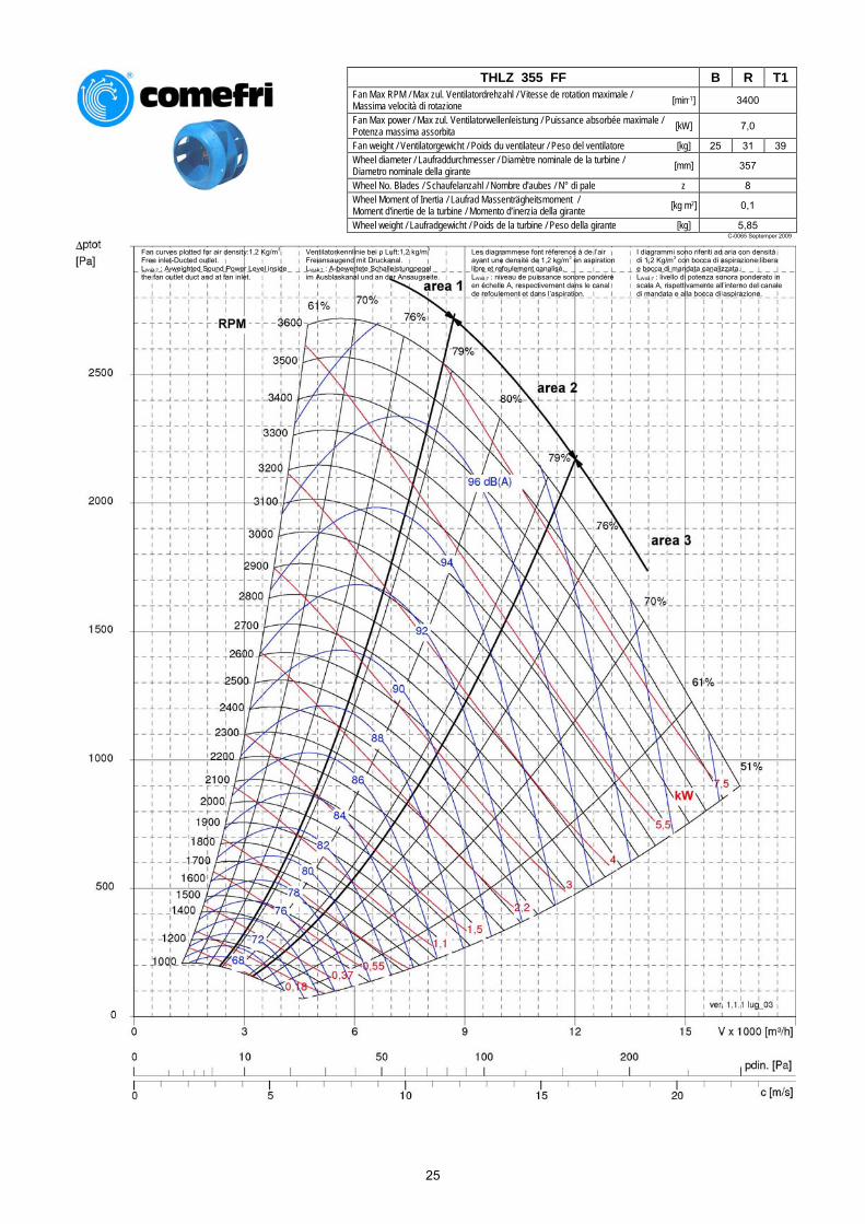
THLZ 355 FF B R T1
Fan Max RPM / Max zul. Ventilatordrehzahl / Vitesse de rotation maximale / Massima velocità di rotazione [min-1] 3400
Fan Max power / Max zul. Ventilatorwellenleistung / Puissance absorbée maximale / Potenza massima assorbita [kW] 7,0
Fan weight / Ventilatorgewicht / Poids du ventilateur / Peso del ventilatore [kg] 25 31 39 Wheel diameter / Laufraddurchmesser / Diamètre nominale de la turbine / Diametro nominale della girante [mm] 357
Wheel No. Blades / Schaufelanzahl / Nombre d'aubes / N° di pale z 8 Wheel Moment of Inertia / Laufrad Massenträgheitsmoment / Moment d'inertie de la turbine / Momento d’inerzia della girante [kg m2] 0,1
Wheel weight / Laufradgewicht / Poids de la turbine / Peso della girante [kg] 5,85 C-0065 Septemper 2009
Fan curves plotted for air density:1,2 Kg/m3
Free inlet-Ducted outlet. LWA4;7 : A-weighted Sound Power Level inside the fan outlet duct and at fan inlet.
Ventilatorkennlinie bei ρ Luft:1,2 kg/m3
Freiansaugend mit Druckanal. LWA4;7 : A-bewertete Schalleistungpegel im Ausblaskanal und an der Ansaugseite.
Les diagrammese font réference à de l’air ayant une densité de 1,2 kg/m3 en aspiration libre et refoulement canalisé. LWA4;7 : niveau de puissance sonore pondéré en échelle A, respectivement dans le canal de refoulement et dans l’aspiration.
I diagrammi sono riferiti ad aria con densità di 1,2 Kg/m3 con bocca di aspirazione libera e bocca di mandata canalizzata. LWA4;7 : livello di potenza sonora ponderato in scala A, rispettivamente all’interno del canale di mandata e alla bocca di aspirazione.
25
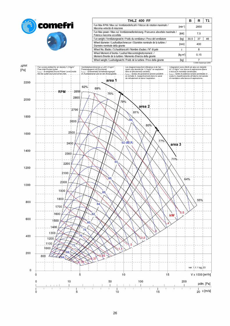
THLZ 400 FF B R T1
Fan Max RPM / Max zul. Ventilatordrehzahl / Vitesse de rotation maximale / Massima velocità di rotazione [min-1] 2850
Fan Max power / Max zul. Ventilatorwellenleistung / Puissance absorbée maximale / Potenza massima assorbita [kW] 7,5
Fan weight / Ventilatorgewicht / Poids du ventilateur / Peso del ventilatore [kg] 30,5 37 46 Wheel diameter / Laufraddurchmesser / Diamètre nominale de la turbine / Diametro nominale della girante [mm] 400
Wheel No. Blades / Schaufelanzahl / Nombre d'aubes / N° di pale z 8 Wheel Moment of Inertia / Laufrad Massenträgheitsmoment / Moment d'inertie de la turbine / Momento d’inerzia della girante [kg m2] 0,15
Wheel weight / Laufradgewicht / Poids de la turbine / Peso della girante [kg] 7 C-0065 Septemper 2009
Fan curves plotted for air density:1,2 Kg/m3
Free inlet-Ducted outlet. LWA4;7 : A-weighted Sound Power Level inside the fan outlet duct and at fan inlet.
Ventilatorkennlinie bei ρ Luft:1,2 kg/m3
Freiansaugend mit Druckanal. LWA4;7 : A-bewertete Schalleistungpegel im Ausblaskanal und an der Ansaugseite.
Les diagrammese font réference à de l’air ayant une densité de 1,2 kg/m3 en aspiration libre et refoulement canalisé. LWA4;7 : niveau de puissance sonore pondéré en échelle A, respectivement dans le canal de refoulement et dans l’aspiration.
I diagrammi sono riferiti ad aria con densità di 1,2 Kg/m3 con bocca di aspirazione libera e bocca di mandata canalizzata. LWA4;7 : livello di potenza sonora ponderato in scala A, rispettivamente all’interno del canale di mandata e alla bocca di aspirazione.
26
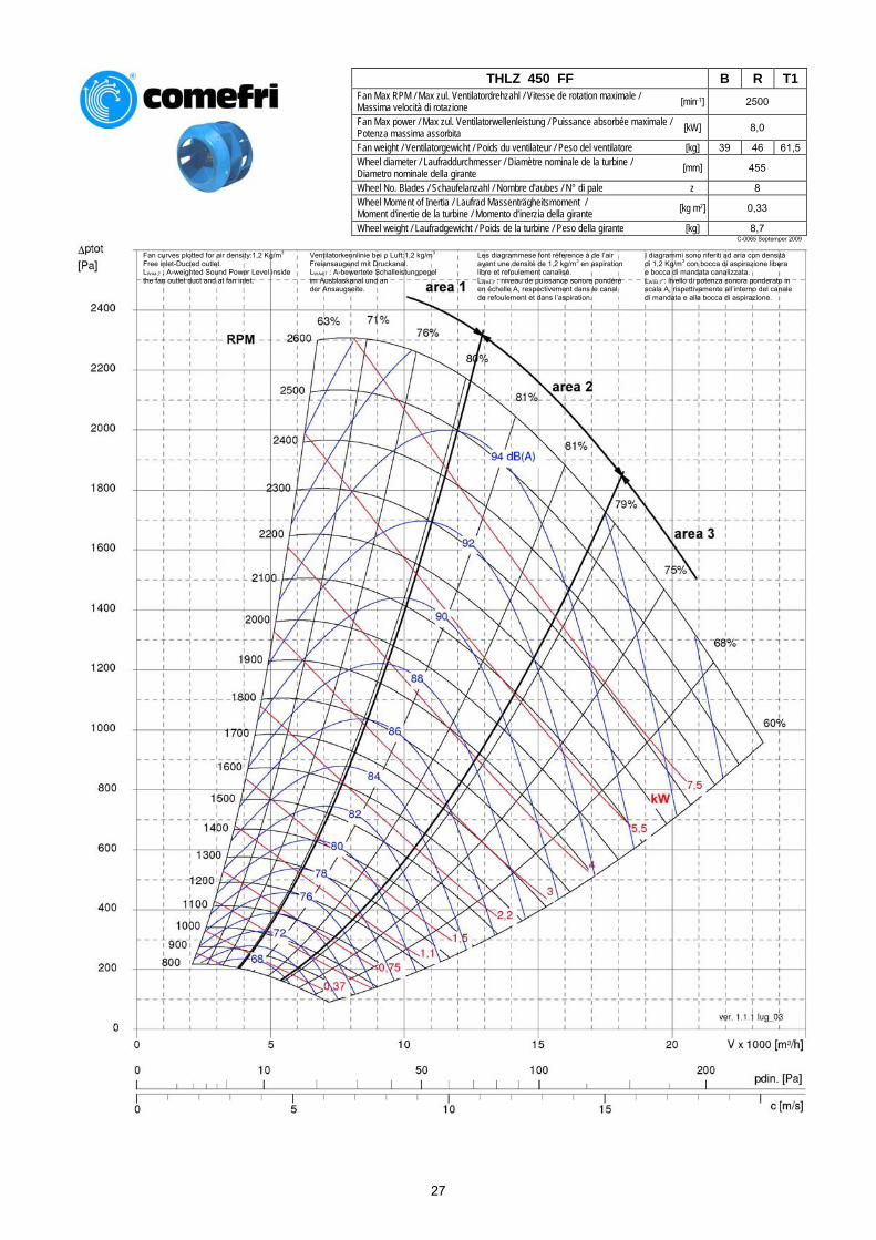
THLZ 450 FF B R T1
Fan Max RPM / Max zul. Ventilatordrehzahl / Vitesse de rotation maximale / Massima velocità di rotazione [min-1] 2500
Fan Max power / Max zul. Ventilatorwellenleistung / Puissance absorbée maximale / Potenza massima assorbita [kW] 8,0
Fan weight / Ventilatorgewicht / Poids du ventilateur / Peso del ventilatore [kg] 39 46 61,5 Wheel diameter / Laufraddurchmesser / Diamètre nominale de la turbine / Diametro nominale della girante [mm] 455
Wheel No. Blades / Schaufelanzahl / Nombre d'aubes / N° di pale z 8 Wheel Moment of Inertia / Laufrad Massenträgheitsmoment / Moment d'inertie de la turbine / Momento d’inerzia della girante [kg m2] 0,33
Wheel weight / Laufradgewicht / Poids de la turbine / Peso della girante [kg] 8,7 C-0065 Septemper 2009
Fan curves plotted for air density:1,2 Kg/m3
Free inlet-Ducted outlet. LWA4;7 : A-weighted Sound Power Level inside the fan outlet duct and at fan inlet.
Ventilatorkennlinie bei ρ Luft:1,2 kg/m3
Freiansaugend mit Druckanal. LWA4;7 : A-bewertete Schalleistungpegel im Ausblaskanal und an der Ansaugseite.
Les diagrammese font réference à de l’air ayant une densité de 1,2 kg/m3 en aspiration libre et refoulement canalisé. LWA4;7 : niveau de puissance sonore pondéré en échelle A, respectivement dans le canal de refoulement et dans l’aspiration.
I diagrammi sono riferiti ad aria con densità di 1,2 Kg/m3 con bocca di aspirazione libera e bocca di mandata canalizzata. LWA4;7 : livello di potenza sonora ponderato in scala A, rispettivamente all’interno del canale di mandata e alla bocca di aspirazione.
27

DOUBLE INLET CENTRIFUGAL FANS WITH GLASS REINFORCED POLYAMID WHEEL – THLZ FF ZWEISEITIGSAUGENDE RADIALVENTILATOREN MIT LAUFRAD AUS GLASFASERVERSTÄRKTEM POLYAMID – THLZ FF VENTILATEURS CENTRIFUGES DOUBLE ASPIRATION AVEC TURBINE EN FIBRE DE VERRE DE POLYAMIDE RENFORCÉ – THLZ FF
VENTILATORI CENTRIFUGHI A DOPPIA ASPIRAZIONE CON GIRANTE IN POLIAMMIDE RINFORZATA – THLZ FF
C-0065 Septemper 2009
7. Fan dimensions 7. Ventilatorabmessungen 7. Dimensions 7. Dimensioni
7.1. THLZ 180 FF ÷ 450 FF B
Ø w
a b c φ d e f g h j l m n n1 o THLZ 180 FF 328 313 153 20 229 133 22.5 6 195 90 317 279 279 254 THLZ 200 FF 364 342 164 20 256 148 22.5 6 216 112 348 306 306 281 THLZ 225 FF 409 380 180 20 288 166 22.5 6 243 112 384 338 338 313 THLZ 250 FF 454 417 195 20 322 184 22.5 6 270 112 422 372 372 347 THLZ 280 FF 509 464 215 25 361 207 28 8 302 140 467 421 411 391 THLZ 315 FF 573 516 236 25 404 233 28 8 341 140 516 464 454 434 THLZ 355 FF 646 576 261 30 453 262 33 8 384 177,5 581 533 503 493 THLZ 400 FF 726 645 291 30 507 296 33 8 432 177,5 649 587 557 547 THLZ 450 FF 818 722 322 35 569 332 38 10 486 225 729 649 619 609
p q q1 r s s1 t u v z x y φ w z1 THLZ 180 FF 375 359 357 180 73 259 164 7 30 5 164 224 7 2 THLZ 200 FF 405 397 393 224 74 286 184 5 30 5 181 245 7 2 THLZ 225 FF 435 440 440 224 74 318 204 5 30 5 197 274 7 3 THLZ 250 FF 470 480 483 224 74 352 227 6 30 5 210 299 7 3 THLZ 280 FF 540 535 535 280 90 391 252 4 40 5 233 328 10.5 3 THLZ 315 FF 585 600 600 280 90 434 280 5 40 5 258 367 10.5 4 THLZ 355 FF 655 657 672 355 101 483 319 7 40 10 273 410 10.5 4 THLZ 400 FF 709 733 757 355 101 537 358 7 40 10 301 461 10.5 5 THLZ 450 FF 810 823 850 450 121 599 407 11 50 10 337 519 12 6
28
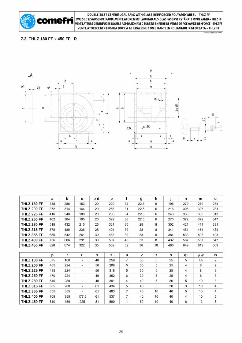
DOUBLE INLET CENTRIFUGAL FANS WITH GLASS REINFORCED POLYAMID WHEEL – THLZ FF ZWEISEITIGSAUGENDE RADIALVENTILATOREN MIT LAUFRAD AUS GLASFASERVERSTÄRKTEM POLYAMID – THLZ FF VENTILATEURS CENTRIFUGES DOUBLE ASPIRATION AVEC TURBINE EN FIBRE DE VERRE DE POLYAMIDE RENFORCÉ – THLZ FF
VENTILATORI CENTRIFUGHI A DOPPIA ASPIRAZIONE CON GIRANTE IN POLIAMMIDE RINFORZATA – THLZ FF
C-0065 Septemper 2009
7.2. THLZ 180 FF ÷ 450 FF R
Ø w
a b c φ d e f g h j n n1 o THLZ 180 FF 338 286 153 20 229 34 22.5 6 195 279 279 254 THLZ 200 FF 372 314 164 20 256 31 22.5 6 216 306 306 281 THLZ 225 FF 416 348 180 20 288 34 22.5 6 243 338 338 313 THLZ 250 FF 462 384 195 20 322 36 22.5 6 270 372 372 347 THLZ 280 FF 518 432 215 25 361 35 28 8 302 421 411 391 THLZ 315 FF 578 480 236 25 404 39 28 8 341 464 454 434 THLZ 355 FF 655 542 261 30 453 39 33 8 384 533 503 493 THLZ 400 FF 736 606 291 30 507 45 33 8 432 587 557 547 THLZ 450 FF 828 674 322 35 569 52 38 10 486 649 619 609
p r r1 s s1 u v z x q1 φ w z1 THLZ 180 FF 375 180 - 48 259 7 30 5 25 5 7,5 2 THLZ 200 FF 405 224 - 50 286 5 30 5 25 4 8 2 THLZ 225 FF 435 224 - 50 318 5 30 5 25 4 8 3 THLZ 250 FF 470 224 - 49 352 6 30 5 25 4 8 3 THLZ 280 FF 540 280 - 40 391 4 40 5 30 5 10 3 THLZ 315 FF 585 280 - 61 434 5 40 5 30 3 10 4 THLZ 355 FF 655 355 - 61 483 7 40 10 40 5 10 4 THLZ 400 FF 709 355 177,5 61 537 7 40 10 40 4 10 5 THLZ 450 FF 810 450 225 81 599 11 50 10 40 6 12 6
29
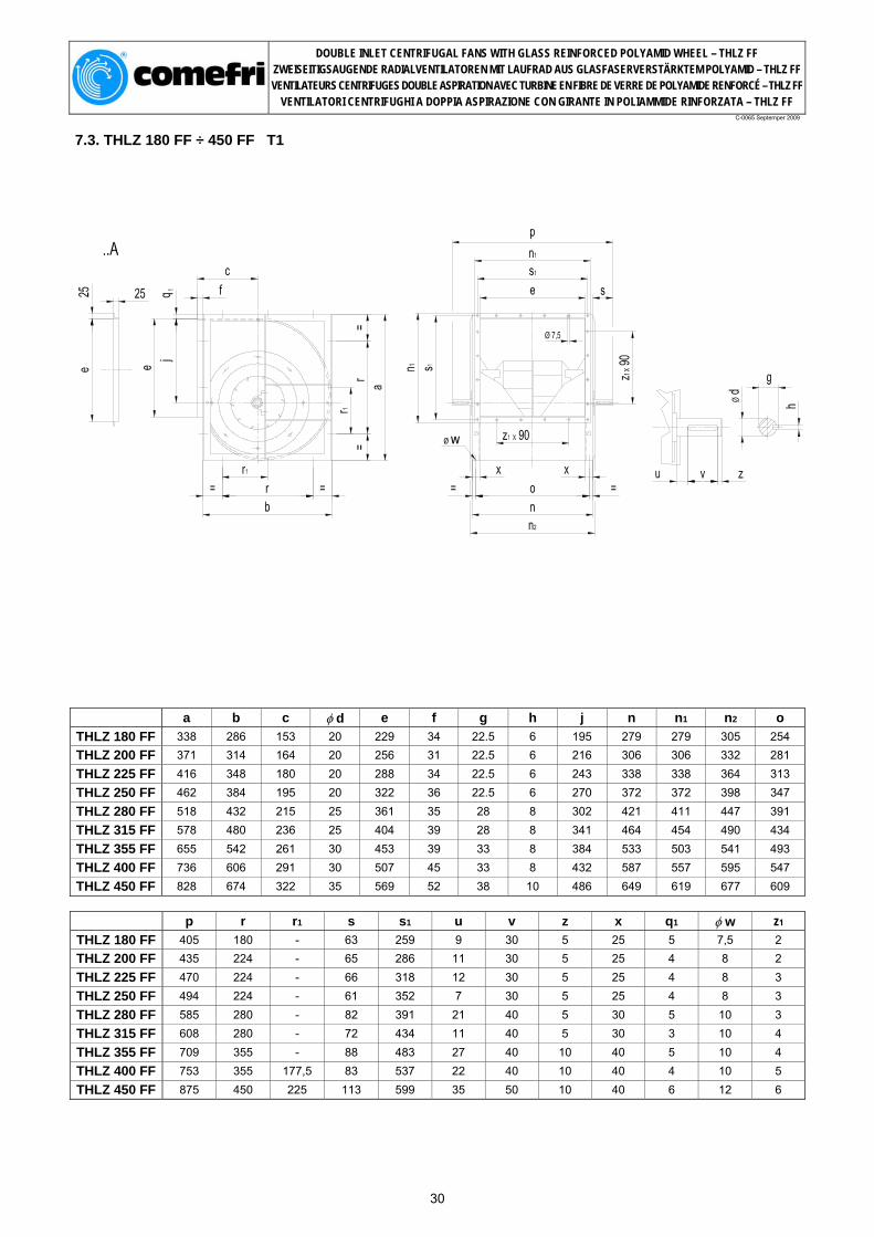
DOUBLE INLET CENTRIFUGAL FANS WITH GLASS REINFORCED POLYAMID WHEEL – THLZ FF ZWEISEITIGSAUGENDE RADIALVENTILATOREN MIT LAUFRAD AUS GLASFASERVERSTÄRKTEM POLYAMID – THLZ FF VENTILATEURS CENTRIFUGES DOUBLE ASPIRATION AVEC TURBINE EN FIBRE DE VERRE DE POLYAMIDE RENFORCÉ – THLZ FF
VENTILATORI CENTRIFUGHI A DOPPIA ASPIRAZIONE CON GIRANTE IN POLIAMMIDE RINFORZATA – THLZ FF
C-0065 Septemper 2009
7.3. THLZ 180 FF ÷ 450 FF T1
Ø w
a b c φ d e f g h j n n1 n2 o
THLZ 180 FF 338 286 153 20 229 34 22.5 6 195 279 279 305 254 THLZ 200 FF 371 314 164 20 256 31 22.5 6 216 306 306 332 281 THLZ 225 FF 416 348 180 20 288 34 22.5 6 243 338 338 364 313 THLZ 250 FF 462 384 195 20 322 36 22.5 6 270 372 372 398 347 THLZ 280 FF 518 432 215 25 361 35 28 8 302 421 411 447 391 THLZ 315 FF 578 480 236 25 404 39 28 8 341 464 454 490 434 THLZ 355 FF 655 542 261 30 453 39 33 8 384 533 503 541 493 THLZ 400 FF 736 606 291 30 507 45 33 8 432 587 557 595 547 THLZ 450 FF 828 674 322 35 569 52 38 10 486 649 619 677 609
p r r1 s s1 u v z x q1 φ w z1 THLZ 180 FF 405 180 - 63 259 9 30 5 25 5 7,5 2 THLZ 200 FF 435 224 - 65 286 11 30 5 25 4 8 2 THLZ 225 FF 470 224 - 66 318 12 30 5 25 4 8 3 THLZ 250 FF 494 224 - 61 352 7 30 5 25 4 8 3 THLZ 280 FF 585 280 - 82 391 21 40 5 30 5 10 3 THLZ 315 FF 608 280 - 72 434 11 40 5 30 3 10 4 THLZ 355 FF 709 355 - 88 483 27 40 10 40 5 10 4 THLZ 400 FF 753 355 177,5 83 537 22 40 10 40 4 10 5 THLZ 450 FF 875 450 225 113 599 35 50 10 40 6 12 6
30
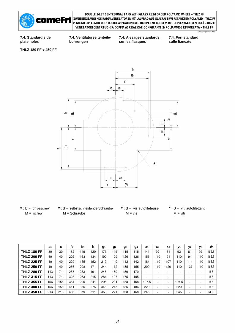
DOUBLE INLET CENTRIFUGAL FANS WITH GLASS REINFORCED POLYAMID WHEEL – THLZ FF ZWEISEITIGSAUGENDE RADIALVENTILATOREN MIT LAUFRAD AUS GLASFASERVERSTÄRKTEM POLYAMID – THLZ FF VENTILATEURS CENTRIFUGES DOUBLE ASPIRATION AVEC TURBINE EN FIBRE DE VERRE DE POLYAMIDE RENFORCÉ – THLZ FF
VENTILATORI CENTRIFUGHI A DOPPIA ASPIRAZIONE CON GIRANTE IN POLIAMMIDE RINFORZATA – THLZ FF
C-0065 Septemper 2009
7.4. Standard side plate holes THLZ 180 FF ÷ 450 FF
7.4. Ventilatorseitenteile- bohrungen
7.4. Alesages standards sur les flasques
7.4. Fori standard sulle fiancate
*
* : B = drivescrew M = screw
* : B = selbstschneidende Schraube M = Schraube
* : B = vis autofileteuse M = vis
* : B = viti autofilettanti M = viti
a1 c f1 f2 f3 g1 g2 g3 g4 x1 x2 x3 y1 y2 y3 THLZ 180 FF 30 30 182 149 120 175 115 115 115 141 92 81 92 81 92 B 6,3 THLZ 200 FF 40 40 202 163 134 190 129 126 126 155 110 91 110 94 110 B 6,3 THLZ 225 FF 40 40 229 185 152 219 149 142 142 184 110 107 110 114 110 B 6,3 THLZ 250 FF 40 40 256 208 171 244 172 155 155 209 110 120 110 137 110 B 6,3 THLZ 280 FF 113 71 287 233 191 245 169 150 170 - - - - - - B 8 THLZ 315 FF 113 71 323 263 215 284 197 175 195 - - - - - - B 8 THLZ 355 FF 156 156 364 295 241 295 204 158 158 197,5 - - 197,5 - - B 8 THLZ 400 FF 156 156 411 336 275 346 243 186 186 220 - - 220 - - B 8 THLZ 450 FF 213 213 466 379 311 350 271 168 168 245 - - 245 - - M 10
31
DOUBLE INLET CENTRIFUGAL FANS WITH GLASS REINFORCED POLYAMID WHEEL – THLZ FF ZWEISEITIGSAUGENDE RADIALVENTILATOREN MIT LAUFRAD AUS GLASFASERVERSTÄRKTEM POLYAMID – THLZ FF VENTILATEURS CENTRIFUGES DOUBLE ASPIRATION AVEC TURBINE EN FIBRE DE VERRE DE POLYAMIDE RENFORCÉ – THLZ FF
VENTILATORI CENTRIFUGHI A DOPPIA ASPIRAZIONE CON GIRANTE IN POLIAMMIDE RINFORZATA – THLZ FF
C-0065 Septemper 2009
8. Accessories Zubehörteile Accessoires Accessori Page Seite Page
Pagina
8.1. Mounting Feet Füsse Pieds support Piedi di sostegno F ……….… 33
8.2. Fan mounting frames Rechteckrahmen Cadre Telaio R R ………… 33
8.3. Outlet flange Ausblasflansch Bride de refoulement Flangia premente A ………… 33
8.4. Flexible outlet connection
Elastischer Ausblasstutzen
Manchette souple au refoulement
Giunto antivibrante premente
AEL …...… 33
8.5. Drain plug Kondensatablaufstutzen Purge volute Tappo scarico condensa K ..……….. 34
8.6. Inspection door Inspektionsklappe Porte de visite Portina d’ispezione I ………….. 34
8.7. Outlet guard Ausblasschutzgitter Grillage au refoulement Rete di protezione premente
AS ……….. 34
8.8. Inlet guard Ansaugschutzgitter Grillage à l'aspiration Rete di protezione aspirante
ZS ……….. 34
8.9. Belt guard Keilriemenschutzgitter Carter de protection transmission
Carter di protezione trasmissione
RIS …….... 35
8.10. Shaft guard Wellenschutz Protection à l'arbre Carter di protezione albero
WES …….. 35
8.11. Anti vibration mountings
Schwingungsdämpfer Supports amortisseurs Supporti antivibranti DAG, DAM 35
8.12. Motor base plate Motorspannschlitten Base support moteur Base portamotore SY ……..… 35
8.13. Standard baseframe Standard-Grundrahmen Châssis standard Basamento standard GR …….… 36
8.14. Airflow measuring device
Volumenstrom – Meßeinrichtung
Dispositif pour la mesure du débit
Dispositivo per la misurazione della portata
…………… 36
32

DOUBLE INLET CENTRIFUGAL FANS WITH GLASS REINFORCED POLYAMID WHEEL – THLZ FF ZWEISEITIGSAUGENDE RADIALVENTILATOREN MIT LAUFRAD AUS GLASFASERVERSTÄRKTEM POLYAMID – THLZ FF VENTILATEURS CENTRIFUGES DOUBLE ASPIRATION AVEC TURBINE EN FIBRE DE VERRE DE POLYAMIDE RENFORCÉ – THLZ FF
VENTILATORI CENTRIFUGHI A DOPPIA ASPIRAZIONE CON GIRANTE IN POLIAMMIDE RINFORZATA – THLZ FF
C-0065 Septemper 2009
8.1. Mounting Feet ..F 8.1. Füsse ..F 8.1. Pieds de support ..F 8.1. Piedi di sostegno ..F
Standard feet are manufactured in galvanized steel sheet. They are supplied as a separate item, with the necessary fixing screws. For dimensions see page 28.
Standard-Füsse werden aus verzinktem Stahlblech hergestellt und separat mit den entsprechenden Befestigungschrauben geliefert. Abmessungen siehe seite 28.
Les supports F sont réalisés en tôle d'acier galvanisé et sont fournis séparément avec les vis de fixation nécessaires. Les dimensions se trouvent à la page 28.
I sostegni F sono realizzati in lamiera zincata e sono forniti separatamente con le necessarie viti di fissaggio. Le dimensioni si trovano a pagina 28.
8.2. Fan mounting frames..R
8.2. Rechteckrahmen ..R 8.2. Cadres ..R 8.2. Telai ..R
They are manufactured in galvanized steel sheet. They can be supplied as a separate item, with the necessary fixing screws, or already fitted on fan. For dimensions see page 29.
Rechteckrahmen R sind aus verzinktem Stahlblech hergestellt. Sie sind entweder lose mit Befestigungschraubenoder montiert lieferbar. Abmessungen, siehe seite 29.
Ceux-ci sont construits en acier galvanisé et peuvent être fournis déjà montés au ventilateur ou séparément avec la visserie nécessaire. Les dimensions se trouvent à la page 29.
Essi sono costruiti in acciaio zincato e possono essere forniti sia separatamente, con le viti necessarie per il fissaggio, oppure già montati sul ventilatore. Le dimensioni si trovano a pagina 29.
8.3. Outlet flange ..A 8.3. Ausblasflansch ..A 8.3. Bride au refoulement..A 8.3. Flangia premente ..A
It can be supplied separately or fitted on customer’s requirement. Manufactured in galvanised steel, ist dimensions and drillings are given in the fan dimension tables.
Der Ausblasflansch kann lose oder am Ventilator montiert geliefert werden. Hergestellt aus verzinktem Stahlblech; Abmessungen und Bohrungen können aus der Ventilatortabelle entnommen werden.
La bride peut être fournie séparément ou fixée au ventilateur. Contruite en acier galvanisé, elle a les dimensions et les trous qui sont reportés sur les dessins d'encombrement des ventilateurs.
Può essere fornita separatamente o fissata al ventilatore. Costruita in acciaio zincato, ha le dimensioni e le forature riportate sui disegni d’ingombro dei ventilatori.
8.4. Flexible outlet connection ..AEL
8.4. Elastischer Ausblasstutzen ..AEL
8.4. Manchette souple au refoulement ..AEL
8.4. Giunto antivibrante premente ..AEL
The flexible connection for the outlet is manufactured with a polyester / PVC fabric and two matching flanges, made in galvanised steel sheet. The “L” dimension, valid for all fan sizes, is equal to 155 mm. Special flexible connections can be manufactured on request.
Der elastische Ausblasstutzen besteht aus zwei Ausblasflanschen mit dazwischen liegendem Polyester /PVC Band. Die Einbaulänge ”L”, beträgt ca. 155 mm einheitlich für alle Baugrössen. Spezielle Ausführungen auf Anfrage.
Elle est construite par une bande en polyester / PVC fixée à deux brides d'acier galvanisé. La dimension "L"est égale pour toutes les tailles est mesure 155 mm, lorsque la manchette est toute étendue. Manchettes souples spéciales peuvent être fournies sur demande.
È costituito da una fascia in Poliestere / PVC fissata a due flange di acciaio zincato. La quota “L ” è uguale per tutte le grandezze e vale 155 mm con il giunto totalmente esteso. Giunti antivibranti speciali possono essere forniti su richiesta.
33

DOUBLE INLET CENTRIFUGAL FANS WITH GLASS REINFORCED POLYAMID WHEEL – THLZ FF ZWEISEITIGSAUGENDE RADIALVENTILATOREN MIT LAUFRAD AUS GLASFASERVERSTÄRKTEM POLYAMID – THLZ FF VENTILATEURS CENTRIFUGES DOUBLE ASPIRATION AVEC TURBINE EN FIBRE DE VERRE DE POLYAMIDE RENFORCÉ – THLZ FF
VENTILATORI CENTRIFUGHI A DOPPIA ASPIRAZIONE CON GIRANTE IN POLIAMMIDE RINFORZATA – THLZ FF
C-0065 Septemper 2009
8.5. Drain plug ..K 8.5. Kondensat- ablaufstutzen ..K
8.5. Purge volute ..K 8.5. Tappo scarico condensa ..K
Usually fitted at the lowest part of the fan to facilitate drain of condensation.
Die Positionierung des Kondensatablaufstutzen erfolgt an der tiefsten Stelle des Ventilatorgehäuses oder gemäß entsprechender Kundenspezifikation.
Elle est fixée sur la partie inférieure de la volute pour permettre un écoulement facile des condensats.
È fissato nella parte inferiore della cassa in modo da permettere un facile drenaggio della condensa.
8.6. Inspection door ..I 8.6. Inspektionsklappe ..I 8.6. Porte de visite ..I 8.6. Portina d’ispezione ..I
Can be fitted to the fan casing and consists of a galvanised steel plate fixed by quick release screws. A synthetic gasket prevents leakage. Position of the inspection door must be clearly stated in the order.
Die Inspektionsklappe aus verzinktem Stahlblech wird mit einer synthetischen Dichtung versehen, und mit dem Gehäuse verschraubt. Die lage der Inspektionsklappe muß bei der Auftragserteilung eindeutig angegeben werden.
Elle est construite en acier galvanisé et est fixée avec des vis à la volute. Une garniture assure une tenue parfaite. La position de la porte de visite doit être clairement indiquée au moment de la commande.
È costruita in acciaio zincato ed è fissata mediante viti alla cassa. Una guarnizione garantisce una perfetta tenuta. La posizione della portina d’ispezione deve essere chiaramente indicata al momento dell’ordine.
a b THLZ 180 FF ÷ 280 FF 170 190
THLZ 315 FF ÷ 450 FF 220 240
8.7. Outlet guard..AS 8.7. Ausblasschutzgitter
..AS 8.7. Grillage au refoulement..AS
8.7. Rete di protezione in mandata ..AS
Industrial safety regulations specify that reliable guards must be provided for rotating machine elements. Inlet protections are available, in full accordance to ISO EN ISO 13857:2008, European safety regulations.
Schutzvorschriften für rotierende Maschinen verlangen eine entsprechende Schutzvorrichtung. Das Ausblasschutzgitter AS wird nach EN ISO 13857:2008 gefertigt.
Il est construit selon la norme EN ISO 13857:2008, concernant la sécurité pour l'utilisation des machines tournantes.
È costruita secondo le norme EN ISO 13857:2008, sulla sicurezza nell’uso delle macchine rotanti.
8.8. Inlet guard ..ZS
8.8. Ansaugschutzgitter ..ZS
8.8. Grillage à l'aspiration ..ZS
8.8. Rete di protezione aspirante..ZS
Industrial safety regulations specify that reliable guards must be provided for rotating machine elements. Outlet protections are available, according to EN ISO 13857:2008
Schutzvorschriften für rotierende Maschinen verlangen eine entsprechende Schutzvorrichtung. Das Ansaugschutzgitter AS wird nach EN ISO 13857:2008 gefertigt.
Il est construit selon la norme EN ISO 13857:2008, concernant la sécurité pour l'utilisation des machines tournantes.
È costruita secondo le norme EN ISO 13857:2008, sulla sicurezza nell’uso delle macchine rotanti.
34

DOUBLE INLET CENTRIFUGAL FANS WITH GLASS REINFORCED POLYAMID WHEEL – THLZ FF ZWEISEITIGSAUGENDE RADIALVENTILATOREN MIT LAUFRAD AUS GLASFASERVERSTÄRKTEM POLYAMID – THLZ FF VENTILATEURS CENTRIFUGES DOUBLE ASPIRATION AVEC TURBINE EN FIBRE DE VERRE DE POLYAMIDE RENFORCÉ – THLZ FF
VENTILATORI CENTRIFUGHI A DOPPIA ASPIRAZIONE CON GIRANTE IN POLIAMMIDE RINFORZATA – THLZ FF
C-0065 Septemper 2009
8.9. Belt guard ..RIS
8.9. Keilriemen- schutzgitter ..RIS
8.9. Carter protection courroies..RIS
8.9. Carter protezione cinghie ..RIS
The belt guard is manufactured in a corrosion proof steel wire mesh, in full accordance with EN ISO 13857:2008. Dimensions denoted with “a”, “b” and “c” depend on the corresponding pulley diameters and number of belts. Upon request, access for rpm measurement can be provided.
Das Keilriemenschutzgitter besteht aus verzinktem Stahlgitter nach EN ISO 13857:2008. Die Abmessungen “a”, “b” und “c” hängen von der Antriebsauslegung ab. Auf Anfrage ist eine Drehzahlmeßöffnung lieferbar.
Il est construit en fil d'acier galvanisé et respecte les normes EN ISO 13857:2008. Les dimensions "a" "b" et "c" dépendent des diamètres et du nombre de gorge des poulies montées. Sur demande on peut fournir une sonde de prise de la vitesse de rotation.
È costruito in filo d’acciaio zincato e rispetta le norme EN ISO 13857:2008. Le dimensioni “a ” “b ” e “c ” dipendono dai diametri e dal numero di gole delle pulegge montate. Si può fornire a richiesta un accesso per la misura della velocità di rotazione.
8.10. Shaft guard ..WES
8.10. Wellenschutz ..WES
8.10. Protection à l'arbre ..WES
8.10. Carter protezione albero ..WES
A wire meshed shaft guard is available, for both B/R and T versions.
Der Wellenschutz aus Stahlgitter ist für alle Ventilatorausführungen lieferbar.
Il est construit en grillage et est disponible pour toutes les versions.
È costruito in rete ed è disponibile per tutte le versioni.
8.11. Anti vibration mountings, rubber type ..DAG and Anti vibration mountings, spring type ..DAM
8.11.Gummischwin-gungsdämpfer Typ ..DAG und Federschwingun- gsdämpfer Typ ..DAM
8.11. Supports amortisseurs, en caoutchouc ..DAG et à essort d'acier ..DAM
8.11. Supporti antivibranti,in gomma ..DAG e a molla ..DAM
The anti-vibration mountings are normally delivered separately, together with the necessary bolts and nuts to fix the mountings to the baseframe. They are selected taking into consideration the total weight of the fan, belt drive, motor and all the ordered accessories. On request, and to suit special applications, spring type mountings can be ordered and supplied.
Es können Gummischwingungsdämpfer (DAG) oder Federschwingungsdämpfer (DAM) verwendet werden. Die Schwingungsdämpfer werden mit den entsprechenden Schrauben und Muttern separat geliefert. Die Auslegung erfolgt nach dem Gesamtgewicht und der Drehzahl des Ventilators.
Les supports amortisseurs sont normalement fournis séparément et avec les vis nécessaires pour la fixation au châssis. Ils sont sélectionnés tenant compte de la masse totale supportée (ventilateur, moteur, transmission, accessoires, etc). Sur demande Pour Application spéciale on peut fournir des types de supports particuliers.
I supporti antivibranti sono normalmente forniti separatamente e con le viti necessarie per il fissaggio al basamento. Sono selezionati tenendo conto della massa totale sopportata (ventilatore, motore, trasmissione, accessori, ecc.). A richiesta e per applicazioni speciali si possono fornire tipi di supporti particolari.
DAM DAG
8.12. Motor base plates ..SY 8.12. Motorspannschlitten
..SY 8.12. Base support moteur ..SY
8.12. Base portamotore ..SY
Two sizes of base plates are available, for motor sizes from 63 to 132 included.
Motorspannschlitten sind für Motorbaugrößen von 63 bis 132 lieferbar.
Deux modèles de base support moteur sont disponibles pour les moteurs de la taille 63 à la taille 132 comprise.
Due modelli di base portamotore sono disponibili per i motori dalla grandezza 63 alla grandezza 132 compresa.
35

DOUBLE INLET CENTRIFUGAL FANS WITH GLASS REINFORCED POLYAMID WHEEL – THLZ FF ZWEISEITIGSAUGENDE RADIALVENTILATOREN MIT LAUFRAD AUS GLASFASERVERSTÄRKTEM POLYAMID – THLZ FF VENTILATEURS CENTRIFUGES DOUBLE ASPIRATION AVEC TURBINE EN FIBRE DE VERRE DE POLYAMIDE RENFORCÉ – THLZ FF
VENTILATORI CENTRIFUGHI A DOPPIA ASPIRAZIONE CON GIRANTE IN POLIAMMIDE RINFORZATA – THLZ FF
C-0065 Septemper 2009
8.13. Standard baseframe ..GR
8.13. Standard-Grundrahmen ..GR
8.13. Châssis standards ..GR
8.13. Basamenti standard ..GR
Made of carbon steel, welded “C” profile, and painted.
Aus U-Profil geschweißt und lackiert.
Ils sont construits en profilé à “C” d'acier et peints.
Sono costruiti in profilati a “C” d’acciaio verniciato.
8.14. Airflow measuring device
8.14. Volumenstrom – Meßeinrichtung
8.14. Dispositif pour la mesure du débit
8.14. Dispositivo per la misurazione della portata
Die Ventilatoren TLHZ FF können mit einer Einrichtung zur Volumenstrombestimmung und -überwachung ausgestattet werden (Abweichung 5-10% unter normalen Betriebsbedingungen). Um die Genauigkeit zu gewährleisten, wurden in unserem Labor für jeden Ventilator der TLHZ FF -Reihe entsprechende Kalibrierfaktoren ermittelt. Die Volumenstrom-Meßeinrichtung besteht aus zwei oder mehreren Meßstellen in jeder Einströmdüse, die durch eine Ringleitung (Innendurchmesser 3-5 mm) verbunden sind. Als der Ventilator in ein Gerät eingebaut wird, muß der Differenzdruck zwischen Gerät –Ansaug und Ringleitung gemessen werden (siehe Schema auf Seite 37) Dieser Differenzdruck wird wie folgt zur Ermittlung des
Les ventilateurs peuvent être équipés avec un dispositif pour la mesure et le contrôle du débit en conditions normales d’utilisation, avec une marge d’erreur maximum de lecture entre le 5 et le 10%. Afin de garantir ce degré de précision sur l’indication du débit, le mesureur a été calibré pour chaque taille de la série TLHZ FF dans le Laboratoire d’Essais Aérauliques Comefri. Le système consiste à placer deux ou plusieurs prises statiques de pression sur les pavillons d’aspiration connectés entre elles par un circuit anulaire,c’est-à-dire un tube avec diamètre interne entre 3 et 5 mm fixé aux pavillons par des attaches prévues à cet effet. Quand le ventilateur est installé dans une unité la différence de pression qui doit être mesurée est entre l’aspiration de l’unité et la prise anulaire prévue sur les pavillons (voir schéma à page 37). La différence de
The TLHZ FF fans can be fitted with a device for measuring and controlling the air volume, with a tolerance of 5 to 10%, (normal operating conditions). The measuring device accuracy is guaranteed by an extensive series of tests performed in our state of art test laboratory, for the whole fan range dimensions. The device consist of two or more static pressure measuring points, mounted directly into both inlet cones. The measuring points are manifolded together via a flexible pipe ring. Therefore only a single pipe connection to the pressure measuring device is required.. When the fan is installed in an AHU, the pressure differential to be measured is between the suction chamber of the AHU (where the fan is installed) and the flow measuring device (see drawing page.37). This pressure difference can be converted into the volume flow by the following formula: Volumenstromes
verwendet: pression statique
obtenue est la ∆p à utiliser pour la définition du débit.
I ventilatori possono essere dotati di un dispositivo per la misurazione ed il controllo della portata che nelle condizioni normali di impiego comporta un errore massimo di lettura compreso tra il 5 e il 10 %. Per garantire il grado di precisione nella indicazione della portata, il misuratore è stato calibrato nel Laboratorio Prove Aerauliche Comefri per ogni ventilatore della serie TLHZ FF. Il sistema consiste di due o più prese statiche di pressione realizzate su entrambi i boccagli di aspirazione collegati tra loro mediante un circuito anulare con apposito attacco per il tubo di diametro interno compreso tra i 3 edi 5 mm. Quando il ventilatore è inserito in una unità, la differenza di pressione che deve essere misurata è tra l’aspirazione dell’unità e la presa anulare predisposta sui boccagli (vedi schema pag.37). La differenza di pressione statica così ottenuta è la ∆p da utilizzarsi nella espressione della portata.
Airflow Volumenstrom Débit Portata V° [ m3/h ]
Calibration factor depending on fan size
Kalibrierfaktor abhängig von dem Ventilatorgröße
Facteurs de calibrage relatifs à la taille du ventilateur
Fattore di calibrazione dipendente dalla grandezza del ventilatore
K(*)
Air density Luftdichte Densité d’air Densità dell’aria ρ [ kg/m3 ] Differential pressure Differenzdruck Différence de pression Differenza di pressione ∆p [ Pa ]
(*) Our maintenance manual details the relevant calibration factor (K)
(*) K-Werte befinden sich auf der Gebrauch- und Wartungsanleitung
(*) Les valeurs de K sont sur le manuel d’utilisation et d’entreten
(*) I valori di K sono riportati sul manuale di uso e manutenzione
The device with the measuring ring (Fig. 10) can be used with the Electronic Cometer (Fig.11).
The pressure measuring device must be ordered with the fan, as it must be factory installed.
Das System mit der Ringleitung (Bild 10) dagegen dem Electronic Cometer (Bild.11).
Die Ventilatoren müssen mit der bereits installierten Meßeinrichtung bestellt werden
Fig.11
Le deuxième système à circuit annulaire (Fig.10), peut être jumelé au Cometer Eléctronique (Fig.11).
Les ventilateurs doivent être demandés avec système de mesuration installé, au moment de la commande
Il sistema a circuito anulare (Fig.10), può essere abbinato all’ Electronic Cometer (Fig.11).
I ventilatori devono essere richiesti all’atto dell’ordine con il sistema di misurazione installato.
36
( ) p 2 V ∆ ⋅ ρ
= K ⋅
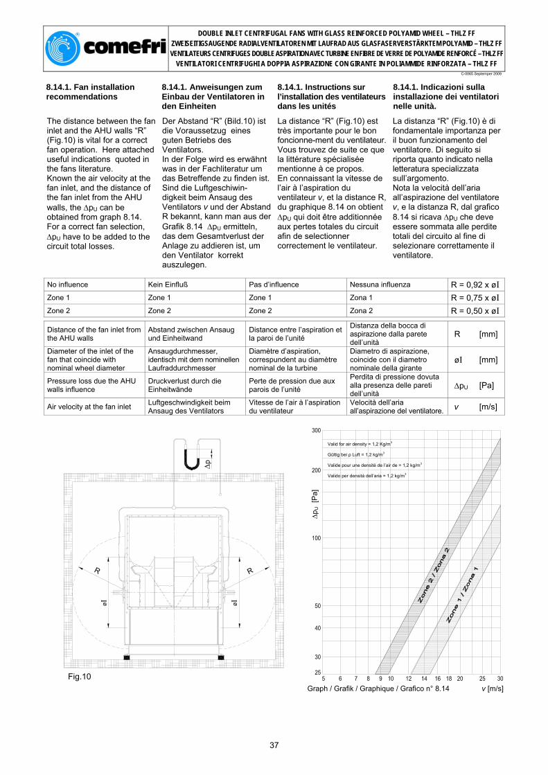
DOUBLE INLET CENTRIFUGAL FANS WITH GLASS REINFORCED POLYAMID WHEEL – THLZ FF ZWEISEITIGSAUGENDE RADIALVENTILATOREN MIT LAUFRAD AUS GLASFASERVERSTÄRKTEM POLYAMID – THLZ FF VENTILATEURS CENTRIFUGES DOUBLE ASPIRATION AVEC TURBINE EN FIBRE DE VERRE DE POLYAMIDE RENFORCÉ – THLZ FF
VENTILATORI CENTRIFUGHI A DOPPIA ASPIRAZIONE CON GIRANTE IN POLIAMMIDE RINFORZATA – THLZ FF
C-0065 Septemper 2009
8.14.1. Fan installation recommendations
8.14.1. Anweisungen zum Einbau der Ventilatoren in den Einheiten
8.14.1. Instructions sur l’installation des ventilateurs dans les unités
8.14.1. Indicazioni sulla installazione dei ventilatori nelle unità.
The distance between the fan inlet and the AHU walls “R” (Fig.10) is vital for a correct fan operation. Here attached useful indications quoted in the fans literature. Known the air velocity at the fan inlet, and the distance of the fan inlet from the AHU walls, the ∆pU can be obtained from graph 8.14. For a correct fan selection, ∆pU have to be added to the circuit total losses.
Der Abstand “R” (Bild.10) ist die Voraussetzug eines guten Betriebs des Ventilators. In der Folge wird es erwähnt was in der Fachliteratur um das Betreffende zu finden ist.Sind die Luftgeschiwin- digkeit beim Ansaug des Ventilators v und der Abstand R bekannt, kann man aus der Grafik 8.14 ∆pU ermitteln, das dem Gesamtverlust der Anlage zu addieren ist, um den Ventilator korrekt auszulegen.
La distance “R” (Fig.10) est très importante pour le bon foncionne-ment du ventilateur. Vous trouvez de suite ce que la littérature spécialisée mentionne à ce propos. En connaissant la vitesse de l’air à l’aspiration du ventilateur v, et la distance R, du graphique 8.14 on obtient ∆pU qui doit être additionnée aux pertes totales du circuit afin de selectionner correctement le ventilateur.
La distanza “R” (Fig.10) è di fondamentale importanza per il buon funzionamento del ventilatore. Di seguito si riporta quanto indicato nella letteratura specializzata sull’argomento. Nota la velocità dell’aria all’aspirazione del ventilatore v, e la distanza R, dal grafico 8.14 si ricava ∆pU che deve essere sommata alle perdite totali del circuito al fine di selezionare correttamente il ventilatore.
No influence Kein Einfluß Pas d’influence Nessuna influenza R = 0,92 x øI Zone 1 Zone 1 Zone 1 Zona 1 R = 0,75 x øI Zone 2 Zone 2 Zone 2 Zona 2 R = 0,50 x øI
Distance of the fan inlet from the AHU walls
Abstand zwischen Ansaug und Einheitwand
Distance entre l’aspiration et la paroi de l’unité
Distanza della bocca di aspirazione dalla parete dell’unità
R [mm]
Diameter of the inlet of the fan that coincide with nominal wheel diameter
Ansaugdurchmesser, identisch mit dem nominellen Laufraddurchmesser
Diamètre d’aspiration, correspundent au diamètre nominal de la turbine
Diametro di aspirazione, coincide con il diametro nominale della girante
øI [mm]
Pressure loss due the AHU walls influence
Druckverlust durch die Einheitwände
Perte de pression due aux parois de l’unité
Perdita di pressione dovuta alla presenza delle pareti dell’unità
∆pU [Pa]
Air velocity at the fan inlet Luftgeschwindigkeit beim Ansaug des Ventilators
Vitesse de l’air à l’aspiration du ventilateur
Velocità dell’aria all’aspirazione del ventilatore. v [m/s]
∆p
R
øI
R
øI
Fig.10 Graph / Grafik / Graphique / Grafico n° 8.14 v [m/s]
37
Valid for air density = 1,2 Kg/m3 Gültig bei ρ Luft = 1,2 kg/m3 Valide pour une densité de l’air de = 1,2 kg/m3 Valido per densità dell’aria = 1,2 kg/m3
∆pU [
Pa]

DOUBLE INLET CENTRIFUGAL FANS WITH GLASS REINFORCED POLYAMID WHEEL – THLZ FF ZWEISEITIGSAUGENDE RADIALVENTILATOREN MIT LAUFRAD AUS GLASFASERVERSTÄRKTEM POLYAMID – THLZ FF VENTILATEURS CENTRIFUGES DOUBLE ASPIRATION AVEC TURBINE EN FIBRE DE VERRE DE POLYAMIDE RENFORCÉ – THLZ FF
VENTILATORI CENTRIFUGHI A DOPPIA ASPIRAZIONE CON GIRANTE IN POLIAMMIDE RINFORZATA – THLZ FF
C-0065 Septemper 2009
9. Rotation, discharge and accessories position
9. Drehrichtung, Gehäusestellung, Position der Zubehörteile
9. Sens de rotation, orientation de l'ouie d'aspiration et position des accessoires
9. Senso di rotazione, orientamento della bocca premente e posizione degli accessori
9.1. Rotation and Discharge Position
9.1. Drehrichtung, Gehäusestellung
9.1. Sens de rotation et position de l'ouie d'aspiration
9.1. Senso di rotazione e posizione della bocca premente
The fan direction of rotation, when seen from drive side is: a) clockwise, if indicated with the symbol RD, or b) counter-clockwise if indicated with the symbol LG The fan discharge position is indicated firstly by the rotation symbol (RD or LG) and, secondly by the angle with respect to the reference line perpendicular to the mounting surface (e.g. RD 90)
Die Drehrichtung des Ventilators – von der Antriebsseite aus betrachtet-wird: a) “im Uhrzeigersinn“ mit RD (rechtsdrehend) und b) “gegen den Uhrzeigersinn“ mit LG (linksdrehend) angegeben. Unter der Gehäusestellung des Ventilators versteht man die Position der Ausblasöffnung. Diese wird zuerst mit dem Symbol für die Drehrichtung (RD oder LG) und danach mit der Position der Ausblasöffnung angegeben.
Le sens de rotation du ventilateur, quand on le regarde du côté transmission, peut être: a) horaire ou droit et marqué avec le sigle RD b) anti horaire ou gauche et on l'indique avec le sigle LG La position de l'ouie ou au refoulement est indiquée par le sigle de la rotation (RD ou LG), suivi de l'angle d'inclination en degrés par rapport à la ligne verticale passant par l'axe de rotation (ex.RD 90)
Il senso di rotazione del ventilatore, quando lo si guarda dal Iato trasmissione, può essere: a) orario, o destro, e si indica con la sigla RD b) antiorario, o sinistro, e si indica con la sigla LG. La posizione della bocca premente o di mandata è indicata dalla sigla della rotazione (RD o LG), seguita dall'angolo d'inclinazione in gradi rispetto alla linea verticale passante per l'asse di rotazione (es. RD 90).
9.2. Accessories Position 9.2. Position der
Zubehörteile 9.2. Position des accessoires
9.2. Posizione degli accessori
The position is indicated, gives the rotation RD or LG, by the angle measured in degrees, with respect to the reference perpendicular line to the mounting surface.
Die Position der Zubehörteile wird mit dem dazugehörigen Drehrichtungssymbol RD oder LG bezeichnet und der Winkelangabe.
La position des accessoires est donnée par l'angle mesuré en degré par rapport à la verticale, vers droite pour les ventilateurs RD et vers gauche pour les ventilateurs LG.
La loro posizione è data dall'angolo misurato in gradi rispetto alla verticale, verso destra per i ventilatori RD e verso sinistra per i ventilatori LG.
10.3. Example: Fan LG 0 Drain plug 180 Inspection door 135
10.3. Beispiel: Ventilator LG 0 Kondensatablaufstutzen 180 Inspektionsklappe 135
10.3. Exemple: Ventilateur LG 0 Purge volute 180 Porte de visite 135
10.3. Esempio: Ventilatore LG 0 Tappo di scarico 180 Portina d'ispezione 135
38
RD – CLOCKWISE / RECHTSDREHEND / HORARIE / ORARIO
LG – COUNTER CLOCKWISE / LINKSDREHEND / ANTI-HORARIE / ANTIORARIO
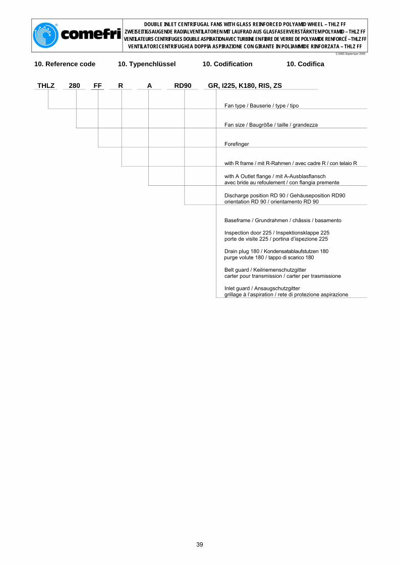
DOUBLE INLET CENTRIFUGAL FANS WITH GLASS REINFORCED POLYAMID WHEEL – THLZ FF ZWEISEITIGSAUGENDE RADIALVENTILATOREN MIT LAUFRAD AUS GLASFASERVERSTÄRKTEM POLYAMID – THLZ FF VENTILATEURS CENTRIFUGES DOUBLE ASPIRATION AVEC TURBINE EN FIBRE DE VERRE DE POLYAMIDE RENFORCÉ – THLZ FF
VENTILATORI CENTRIFUGHI A DOPPIA ASPIRAZIONE CON GIRANTE IN POLIAMMIDE RINFORZATA – THLZ FF
C-0065 Septemper 2009
10. Reference code 10. Typenchlüssel 10. Codification 10. Codifica THLZ 280 FF R A RD90 GR, I225, K180, RIS, ZS
Fan type / Bauserie / type / tipo
Fan size / Baugröße / taille / grandezza
Forefinger
with R frame / mit R-Rahmen / avec cadre R / con telaio R
with A Outlet flange / mit A-Ausblasflansch avec bride au refoulement / con flangia premente
Discharge position RD 90 / Gehäuseposition RD90 orientation RD 90 / orientamento RD 90
Baseframe / Grundrahmen / châssis / basamento Inspection door 225 / Inspektionsklappe 225 porte de visite 225 / portina d’ispezione 225 Drain plug 180 / Kondensatablaufstutzen 180 purge volute 180 / tappo di scarico 180 Belt guard / Keilriemenschutzgitter carter pour transmission / carter per trasmissione Inlet guard / Ansaugschutzgitter grillage à l’aspiration / rete di protezione aspirazione
39
DOUBLE INLET CENTRIFUGAL FANS WITH GLASS REINFORCED POLYAMID WHEEL – THLZ FF ZWEISEITIGSAUGENDE RADIALVENTILATOREN MIT LAUFRAD AUS GLASFASERVERSTÄRKTEM POLYAMID – THLZ FF VENTILATEURS CENTRIFUGES DOUBLE ASPIRATION AVEC TURBINE EN FIBRE DE VERRE DE POLYAMIDE RENFORCÉ – THLZ FF
VENTILATORI CENTRIFUGHI A DOPPIA ASPIRAZIONE CON GIRANTE IN POLIAMMIDE RINFORZATA – THLZ FF
C-0065 Septemper 2009
11. Twin fans 11. Zwillingsventilatoren 11. Ventilateurs doubles 11. Ventilatori binati
The Twin Fans THLZ-BL, THLZ-BP, THLZ-BT are manufactured with the same components used for the backward curved THLZ fans and are available from size 180 to size 450. Main characteristics are:
• optimally engineered for HVAC applications; • high quality, compact design; • high efficiency, low power consumption; • quiet operation;
Die THLZ-BL, THLZ-BP, THLZ-BT Zwillingsventilatoren werden mit den gleichen Komponenten der THLZ -Baureihe gefertigt und sind ab Größe 180 bis 450 erhältlich. Die wichtigsten Eigenschaften sind:
• Optimierte Kennlinie für die Klimatechnik; • Hohe Qualität, kompakte Bauweise; • Hoher Wirkungsgrad, niedrige Leistungsaufnahme; • Geräuscharmer Betrieb;
Les ventilateurs doubles THLZ-BL, THLZ-BP, THLZ-BT sont construits avec les mêmes composants utilisés pour les ventilateurs THLZ et sont disponibles de la taille 180 à la taille 450. Les caractéristiques principales sont:
• particuliérement adaptes pour la climatisation; • niveau de qualité élevé, dimensions compactes; • niveau de rendement élevé, faible puissance absorbée; • silencieux;
I ventilatori binati THLZ-BL, THLZ-BP, THLZ-BT sono costruiti con gli stessi componenti utilizzati per la serie THLZ e sono disponibili dalla grandezza 180 alla 450. Le principali caratteristiche sono:
• particolarmente adatti per la climatizzazione; • alta qualità, dimensioni compatte; • alto rendimento, bassa potenza assorbita; • silenziosità;
11.1. Available standard executions
11.1 Erhältliche Standard- Ausführungen
11.1. Versions standard disponibles
11.1. Esecuzioni standard disponibili
THLZ-BL 180 to 450 Comefri's THLZ-BL Twin Fans are manufactured with two THLZ B fans on a common shaft, supported with three bearings. Three stiffeners which join the fan’s scroll, guarantee structural rigidity. Mounting feets could be supplied as an option.
THLZ-BL 180 ÷ 450 Die Comefri THLZ-BL Zwillings_ ventilatoren werden aus zwei THLZ B Ventilatoren, mit einer einzigen durchgehenden Welle mit drei Lageraufnahmen hergestellt. Die zwei Gehäuse-Rückwände werden mit drei verzinkten und gebogenen Blechtraversen verbunden, um die notwendige Stabilität der Struktur zu gewährleisten. Die Füsse können als Zubehör geliefert werden.
THLZ-BL 180 ÷ 450 Les ventilateurs doubles Comefri doubles THLZ-BL sont construits avec deux ventilateurs THLZ B standards sur un seul arbre, supporté par trois roulements. Trois traverses en tôle d’acier galvanisée unissent les deux dos des volutes garantissant la nécessaire structurale. Les pieds peuvent être fournis comme accessoires.
THLZ-BL 180 ÷ 450 I ventilatori Comefri binati THLZ-BL sono costruiti utilizzando due ventilatori THLZ B con un albero unico, supportato da tre cuscinetti. Tre traverse in lamiera zincata e piegata uniscono i due dorsi delle coclee, garantendo la necessaria robustezza strutturale. I piedi di sostegno possono essere forniti come accessori.
THLZ-BP 180 to 450 Comefri's THLZ-BP Twin Fans are manufactured using two THLZ R fans with a common shaft with three bearings. Fan frames in galvanized steel with 4 angular stiffeners joining the frames.
THLZ-BP 180 ÷ 450 Die Comefri THLZ-BP Zwillings_ ventilatoren werden aus zwei THLZ Ventilatoren in der R-Ausführung, mit einer einzigen durchgehenden Welle, und mit drei Lageraufnahmen hergestellt. Die R-Rahmen der beiden Ventilatoren sind mit vier verzinkten und gebogenen Blechtraversen verbunden.
THLZ-BP 180 ÷ 450 Les ventilateurs doubles Comefri THLZ-BP sont construits avec deux ventilateurs THLZ R avec un seul arbre supporté par trois roulements. Les cadres R des deux ventilateurs sont relié par quatres traverses en tôle d’acier galvanisé et pliées.
THLZ-BP 180 ÷ 450 I ventilatori Comefri binati THLZ-BP sono costruiti utilizzando due ventilatori THLZ R con un albero unico, supportato da tre cuscinetti. I riquadri R dei due ventilatori sono collegati da quattro traverse in lamiera zincata e piegata.
THLZ-BT 180 to 450 Comefri's THLZ-BT Twin Fans they consist in two THLZ T1 with a common shaft supported by three pillow-block, bearings. The frames are connected together with four angle steel stiffeners.
THLZ-BT 180 ÷ 450 Die Comefri THLZ-BT Zwillings_ ventilatoren werden aus zwei THLZ T1 Ventilatoren in der T1 Ausführung, mit einer einzigen durchgehenden Welle, und mit drei Gußstehlageraufnahmen hergestellt. Die Rahmen der beiden Ventilatoren werden mit Stahltraversen verbunden.
THLZ-BT 180 ÷ 450 Les ventilateurs doubles Comefri THLZ-BT sont construits avec deux ventilateurs THLZ T1 et un seul arbre supporté par trois roulements montés sur des supports en fonte. Les cadres latéraux des deux ventilateurs sont reliés par quatre traverses en profil d’acier.
THLZ-BT 180 ÷ 450 I ventilatori Comefri binati THLZ-BT sono costruiti utilizzando due ventilatori THLZ T1 con un albero unico supportato da tre cuscinetti montati su sopporti ritti in ghisa. I telai dei due ventilatori sono collegati da quattro traverse in profilato d’acciaio.
40

DOUBLE INLET CENTRIFUGAL FANS WITH GLASS REINFORCED POLYAMID WHEEL – THLZ FF ZWEISEITIGSAUGENDE RADIALVENTILATOREN MIT LAUFRAD AUS GLASFASERVERSTÄRKTEM POLYAMID – THLZ FF VENTILATEURS CENTRIFUGES DOUBLE ASPIRATION AVEC TURBINE EN FIBRE DE VERRE DE POLYAMIDE RENFORCÉ – THLZ FF
VENTILATORI CENTRIFUGHI A DOPPIA ASPIRAZIONE CON GIRANTE IN POLIAMMIDE RINFORZATA – THLZ FF
C-0065 Septemper 2009
12. Twin fans selection 12. Ermittlung der technischen Daten der Zwillingsventilatoren
12. Sélection des ventilateurs doubles
12. Selezione dei ventilatori binati
The parameters for a selection are:
Die technischen Daten Zwillingsventilatoren ergeben sich aus:
Les paramètres pour la sélection des ventilateurs sont:
I parametri per la selezione dei binati sono:
Twin Fan Static Pressure Statischen Druck des Zwillingsventilators
Pression statique du ventilateur double Pressione statica del binato ∆pstat TF [ Pa ]
Twin Fan Air Volume Flow Volumen des Zwillingsventilators Débit de l’air du ventilateur double Portata del binato V° TF [ m3/h ] Absorbed Power at Twin Fan Shaft
Aufgenomme Leistung an der Welle des Zwillingsventilators
Puissance absorbée à l’arbre du ventilateur double
Potenza assorbita all’albero del binato Pw TF [ kW ]
Rotational Speed of Twin Fan Shaft
Umdrehungsgeschwindigkeit der Welle des Zwillingsventilators
Vitesse de rotation de l’arbre du ventilateur double
Velocità di rotazione dell’albero del binato nTF [ min-1 ]
Twin Fan A-weighted Total Sound Power Level at the fan inlet, with ducted outlet
A-bewerteter Gesamtschalleistungspegel in der Ansaugöffnung des Zwillingsventilators
Niveau de Puissance Sonore Totale à l'aspiration en canal de refoulement du ventilateur double canalisée, pondéré en échelle A
Livello di Potenza Sonora Totale all'aspirazione del binato con mandata canalizzata, ponderato in scala A
LwA7 TF [ dB(A) ]
Twin Fan A-weighted Total Sound Power Level inside the outlet duct
A-bewerteter Gesamtschalleistungspegel im Druckkanal des Zwillingsventilators
Niveau de Puissance Sonore Totale en canal de refoulement du ventilateur double, pondéré en échelle A
Livello di Potenza Sonora Totale nel canale di mandata del binato, ponderato in scala A
LwA4 TF [ dB(A) ]
Select the THLZ-BL, THLZ-BP, THLZ-BT Twin Fan using the THLZ fan’s selection charts. The Air Volume Flow and Static Pressure to be used in the THLZ charts are: ∆pstat = ∆pstat TF V° . = V° TF / 1,9
Zur Auswertung der THLZ-BL, THLZ-BP, THLZ-BT-Zwillingsventilatoren sind die Kennlinien der THLZ-Ventilatoren zu verwenden. Nachfolgend das Volumen und der statische Druck, welche aus den THLZ-Kennlinie zu verwenden sind: ∆pstat = ∆pstat TF V° . = V° TF / 1,9
Sélectionner le ventilateur double THLZ-BL, THLZ-BP, THLZ-BT en utilisant la courbe de sélection du ventilateur THLZ. Le débit d’air et la Pression Statique qui doivent être utilisés pour la courbe des THLZ sont: ∆pstat = ∆pstat TF V° . = V° TF / 1,9
Scegliere i binati THLZ-BL, THLZ-BP, THLZ-BT utilizzando le curve caratteristiche dei ventilatori THLZ. La portata e la pressione statica da utilizzare sulle curve THLZ saranno: ∆pstat = ∆pstat TF V° . = V° TF / 1,9
From the performance chart: Aus den Kennlinien: A partir de la courbe de
prestation: Dalle curve caratteristiche:
Single Fan THLZ Absorbed Power Aufgenommene Leistung des einzelnen THLZ-Ventilators
Puissance absorbée ventilateur simple THLZ
Potenza assorbita dal singolo ventilatore THLZ Pw [ kW ]
THLZ Fan Speed Umdrehungsgeschwindigkeit der Welle des THLZ Vitesse ventilateur THLZ Velocità di rotazione dell’albero n [ min-1 ]
A-weighted Sound Power Level inside the fan outlet duct and at fan inlet
A-bewertete Schalleistungpegel im Ausblaskanal und an der Ansaugseite
Niveau de puissance sonore pondéré en échelle A, respectivement dans le canal de refoulement et dans l’aspiration
Livello di potenza sonora ponderato in scala A, rispettivamente all’interno del canale di mandata e alla bocca di aspirazione
LwA4;7 [ dB(A) ]
Absorbed Power at Twin Fan Shaft
Aufgenommen Leistung an der Welle des Zwillingsventilators
Puissance absorbée à l’arbre du ventilateur double
Potenza assorbita all’albero del binato Pw TF = 2,1 x Pw
Rotational Speed of Twin Fan Shaft
Umdrehungsgeschwindigkeit der Welle des Zwillingsventilators
Vitesse de rotation de l’arbre du ventilateur double
Velocità di rotazione dell’albero del binato nTF = n
Twin Fan A-weighted Total Sound Power Level at the inlets, with ducted outlet
A-bewerteter Gesamtschalleistungspegel in der Ansaugöffnung des Zwillingsventilators
Niveau de Puissance Sonore Totale à l'aspiration en canal de refoulement du ventilateur double canalisée, pondéré en échelle A
Livello di Potenza Sonora Totale all'aspirazione del binato con mandate canalizzate, ponderato in scala A
LwA7 TF = LwA4;7 + 4
Twin Fan A-weighted Total Sound Power Level inside the outlet ducts
A-bewerteter Gesamtschalleistungspegel im Druckkanal des Zwillingsventilators
Niveau de Puissance Sonore Totale en canal de refoulement du ventilateur double, pondéré en échelle A
Livello di Potenza Sonora Totale nei canali di mandata, ponderato in scala A
LwA4 TF = LwA4;7 + 1
The values of the Twin Maximum Absorbed Power and Maximum Speed are listed on the following pages, beside the dimensional tables.
Die Werte der maximal aufgennmmenen Leistung und der maximalen Undrehungsgeschwindigkeit der Zwillingsventilatoren-Welle sind auf den nachfolgenden Seiten angegeben, neben den Abmessungstabellen.
Les valeurs max. pour les ventilateurs doubles de la puissance absorbée et de la vitesse de rotation sont indiquées à la page suivante, à côté de la table des dimensions.
I valori di massima potenza assorbita, e di massima velocità di rotazione dei binati sono indicati nelle pagine seguenti, accanto alle tabelle dimensionali.
41

DOUBLE INLET CENTRIFUGAL FANS WITH GLASS REINFORCED POLYAMID WHEEL – THLZ FF ZWEISEITIGSAUGENDE RADIALVENTILATOREN MIT LAUFRAD AUS GLASFASERVERSTÄRKTEM POLYAMID – THLZ FF VENTILATEURS CENTRIFUGES DOUBLE ASPIRATION AVEC TURBINE EN FIBRE DE VERRE DE POLYAMIDE RENFORCÉ – THLZ FF
VENTILATORI CENTRIFUGHI A DOPPIA ASPIRAZIONE CON GIRANTE IN POLIAMMIDE RINFORZATA – THLZ FF
C-0065 Septemper 2009
13. Twin fans dimensions
13. Ventilatorabmessungen Zwillingsventilatoren
13. Dimensions Ventilateurs doubles
13. Dimensioni Ventilatori binati
13.1. THLZ-BL 180 ÷ 450
Ø w Ø w
a b c ød e f g h k k1 k2 j l m n n1 o
THLZ-BL 180 328 313 153 20 229 133 22.5 6 154 180 20 195 90 317 689 279 254 THLZ-BL 200 364 342 164 20 256 148 22.5 6 175 200 20 216 112 348 763 306 281 THLZ-BL 225 409 380 180 20 288 166 22.5 6 200 225 20 243 112 384 852 338 313 THLZ-BL 250 454 417 195 20 322 184 22.5 6 225 250 30 270 112 422 945 372 347 THLZ-BL 280 509 464 215 25 361 207 28 8 250 280 30 302 140 467 1062 411 391 THLZ-BL 315 573 516 236 25 404 233 28 8 285 315 30 341 140 516 1183 454 434 THLZ-BL 355 646 576 261 30 453 262 33 8 315 355 30 384 177,5 581 1344 503 493 THLZ-BL 400 726 645 291 30 507 296 33 8 360 400 40 432 177,5 649 1494 557 547 THLZ-BL 450 818 722 322 35 569 332 38 10 410 450 40 486 225 729 1668 619 609
p q q1 r s s1 t u v z x y φ w z1 max RPM
max kW
THLZ-BL 180 784 359 357 180 47 259 164 7 30 5 164 224 7 2 3800 1,5 THLZ-BL 200 860 397 393 224 48,5 286 184 5 30 5 181 245 7 2 3100 1,5 THLZ-BL 225 949 440 440 224 48,5 318 204 5 30 5 197 274 7 3 2600 1,5 THLZ-BL 250 1045 480 483 224 50 352 227 6 30 5 210 299 7 3 2300 2,5 THLZ-BL 280 1181 535 535 280 59 391 252 4 40 5 233 328 10.5 3 2300 2,5 THLZ-BL 315 1305 600 600 280 91 434 280 5 40 5 258 367 10,5 4 1800 3,5 THLZ-BL 355 1465 657 672 355 61 483 319 7 40 10 273 410 10,5 4 1800 4 THLZ-BL 400 1617 733 757 355 61 537 358 7 40 10 301 461 10,5 5 1400 4 THLZ-BL 450 1828 823 850 450 79 599 407 11 50 10 337 519 12 6 1400 5
42

DOUBLE INLET CENTRIFUGAL FANS WITH GLASS REINFORCED POLYAMID WHEEL – THLZ FF ZWEISEITIGSAUGENDE RADIALVENTILATOREN MIT LAUFRAD AUS GLASFASERVERSTÄRKTEM POLYAMID – THLZ FF VENTILATEURS CENTRIFUGES DOUBLE ASPIRATION AVEC TURBINE EN FIBRE DE VERRE DE POLYAMIDE RENFORCÉ – THLZ FF
VENTILATORI CENTRIFUGHI A DOPPIA ASPIRAZIONE CON GIRANTE IN POLIAMMIDE RINFORZATA – THLZ FF
C-0065 Septemper 2009
13.2. THLZ-BP 180 ÷ 450
Ø w
a b c ød e f g h k k1 j n n1 o
THLZ-BP 180 338 286 153 20 229 34 22.5 6 154 180 195 689 279 254 THLZ-BP 200 372 314 164 20 256 31 22.5 6 175 200 216 763 306 281 THLZ-BP 225 416 348 180 20 288 34 22.5 6 200 225 243 852 338 313 THLZ-BP 250 462 384 195 20 322 36 22.5 6 225 250 270 945 372 347 THLZ-BP 280 518 432 215 25 361 35 28 8 250 280 302 1062 411 391 THLZ-BP 315 578 480 236 25 404 39 28 8 285 315 341 1183 454 434 THLZ-BP 355 655 542 261 30 453 39 33 8 315 355 384 1344 503 493 THLZ-BP 400 736 606 291 30 507 45 33 8 360 400 432 1494 557 547 THLZ-BP 450 828 674 322 35 569 52 38 10 410 450 486 1668 619 609
p r r1 s s1 u v z x q1 φ w z1 max RPM
max kW
THLZ-BP 180 784 180 - 47 259 7 30 5 25 4 7,5 2 3800 3 THLZ-BP 200 860 224 - 48,5 286 5 30 5 25 4 8 2 3100 3 THLZ-BP 225 949 224 - 48,5 318 5 30 5 25 4 8 3 2600 3 THLZ-BP 250 1045 224 - 50 352 6 30 5 25 4 8 3 2300 4 THLZ-BP 280 1181 280 - 59 391 4 40 5 30 5 10 3 2300 4 THLZ-BP 315 1305 280 140 60 434 5 40 5 30 4 10 4 1800 5 THLZ-BP 355 1465 355 177,5 61 483 7 40 10 40 6 10 4 1800 5 THLZ-BP 400 1617 355 177,5 61 537 7 40 10 40 6 10 5 1400 5 THLZ-BP 450 1828 450 225 79 599 11 50 10 40 7 12 6 1400 6
43

DOUBLE INLET CENTRIFUGAL FANS WITH GLASS REINFORCED POLYAMID WHEEL – THLZ FF ZWEISEITIGSAUGENDE RADIALVENTILATOREN MIT LAUFRAD AUS GLASFASERVERSTÄRKTEM POLYAMID – THLZ FF VENTILATEURS CENTRIFUGES DOUBLE ASPIRATION AVEC TURBINE EN FIBRE DE VERRE DE POLYAMIDE RENFORCÉ – THLZ FF
VENTILATORI CENTRIFUGHI A DOPPIA ASPIRAZIONE CON GIRANTE IN POLIAMMIDE RINFORZATA – THLZ FF
C-0065 Septemper 2009
13.3. THLZ-BT 180 ÷ 450
Ø w
a b c ød e f g h k k1 j n n1 n2 o
THLZ-BT 180 338 286 153 20 229 34 22.5 6 154 180 195 689 279 715 254 THLZ-BT 200 371 314 164 20 256 31 22.5 6 175 200 216 763 306 789 281 THLZ-BT 225 416 348 180 20 288 34 22.5 6 200 225 243 852 338 878 313 THLZ-BT 250 462 384 195 20 322 36 22.5 6 225 250 270 945 372 971 347 THLZ-BT 280 518 432 215 25 361 35 28 8 250 280 302 1062 411 1028 391 THLZ-BT 315 578 480 236 25 404 39 28 8 285 315 341 1183 454 1211 434 THLZ-BT 355 655 542 261 30 453 39 33 8 315 355 384 1344 503 1350 493 THLZ-BT 400 736 606 291 35 507 45 38 10 360 400 432 1494 557 1503 547 THLZ-BT 450 828 674 322 40 569 52 43 12 410 450 486 1668 619 1697 609
p r r1 s s1 u v z x q1 φ w z1 xt max RPM
max kW
THLZ-BT 180 814 180 - 62,5 259 9 30 5 25 4 7,5 2x90 3800 3 THLZ-BT 200 891 224 - 64 286 11 30 5 25 4 8 2x90 3100 3,5 THLZ-BT 225 983 224 - 65 318 12 30 5 25 4 8 3x90 2600 4 THLZ-BT 250 1066 224 - 60 352 7 30 5 25 4 8 3x90 2400 5 THLZ-BT 280 1226 280 - 82 391 21 40 5 30 5 10 3x90 2500 5,2 THLZ-BT 315 1327 280 140 71 434 11 40 5 30 5 10 4x90 1850 5,6 THLZ-BT 355 1517 355 177,5 87 483 27 40 10 40 6 10 4x90 1850 7 THLZ-BT 400 1655 355 177,5 82 537 22 50 10 40 6 10 5x90 1850 7,5 THLZ-BT 450 1900 450 225 112 599 35 70 10 40 7 12 6x90 1725 8
44

DOUBLE INLET CENTRIFUGAL FANS WITH GLASS REINFORCED POLYAMID WHEEL – THLZ FF ZWEISEITIGSAUGENDE RADIALVENTILATOREN MIT LAUFRAD AUS GLASFASERVERSTÄRKTEM POLYAMID – THLZ FF VENTILATEURS CENTRIFUGES DOUBLE ASPIRATION AVEC TURBINE EN FIBRE DE VERRE DE POLYAMIDE RENFORCÉ – THLZ FF
VENTILATORI CENTRIFUGHI A DOPPIA ASPIRAZIONE CON GIRANTE IN POLIAMMIDE RINFORZATA – THLZ FF
C-0065 Septemper 2009
.................................................................................................................................................................
.................................................................................................................................................................
.................................................................................................................................................................
.................................................................................................................................................................
.................................................................................................................................................................
.................................................................................................................................................................
.................................................................................................................................................................
.................................................................................................................................................................
.................................................................................................................................................................
.................................................................................................................................................................
.................................................................................................................................................................
.................................................................................................................................................................
.................................................................................................................................................................
.................................................................................................................................................................
.................................................................................................................................................................
.................................................................................................................................................................
.................................................................................................................................................................
.................................................................................................................................................................
.................................................................................................................................................................
.................................................................................................................................................................
.................................................................................................................................................................
.................................................................................................................................................................
.................................................................................................................................................................
.................................................................................................................................................................
.................................................................................................................................................................
.................................................................................................................................................................
.................................................................................................................................................................
.................................................................................................................................................................
.................................................................................................................................................................
.................................................................................................................................................................
.................................................................................................................................................................
.................................................................................................................................................................
.................................................................................................................................................................
.................................................................................................................................................................
.................................................................................................................................................................
45

COMEFRI reserves the right to make any dimensional design changes which are part of their improvement programme. Necessary corrections are updated on our AEOLUS PLUS selection program.
COMEFRI behält sich sämtliche Änderungen vor, die dem technischen Fortschritt dienen. Notwendige Korrekturen der Katalogdaten werden in unserem Auswahlprogramm AEOLUS PLUS berücksichtigt.
Comefri se réserve la possibilité d’apporter des modifications de dimensions sans aucun préavis ceci parce que ces informations font parties d’un programme interne de dévelopment du produit. Les éventuelles variations et/ou corrections seront ajournés dans notre programme de sélection AEOLUS PLUS.
La COMEFRI si riserva la possibilità di apportare modifiche dimensionali senza alcun preavviso ciò in quanto parte di un programma interno di sviluppo del prodotto. Le eventuali variazioni e/o correzioni saranno aggiornate nel nostro programma di selezione AEOLUS PLUS.
Comefri SpA
Via Buja, 3 I-33010 Magnano in Riviera (UD) Italy Tel. +39-0432-798811 Fax +39-0432-783378 www.comefri.com E-mail: [email protected]
Comefri USA, Inc Comefri Gmbh Comefri France S.A.
330 BilI Bryan Boulevard Hopkinsville, KY 42240 USA Tel. +1-270-881-1444 Fax + 1-270-889-0309 www.comefriusa.com E-mail: [email protected]
Landshuter str.55 84030 Ergolding Germany Tel. +49-871-43070-0 Fax +49-871-43070-40 www.comefri.de E-mail: [email protected]
10, Rue des Frères Lumière 69740 Genas France Tel. +33-4-72 79 03 80 Fax +33-4-78 90 69 73 www.comefri.com E-mail: [email protected]
Comefri UK Ltd Comefri Nordisk ApS Comefri China Ind. Co. Ltd.
Carters Lane, 8 Kiln Farm Milton Keynes, MK11 3 ER Great Britain Tel. +44-1908-56 94 69 Fax +44-1908-56 75 66 www.comefri.com E-mail: [email protected]
Mileparken, 18 DK 2740 Skovlunde Denmark Tel. +45-44-92 76 00 Fax +45-44-92 55 33 www.comefri.com E-mail: [email protected]
Suite 1201, North Tower, New World Times Center, 2191 Guangyuan Rd. (E.) Guangzhou. P.R.C. Tel: +86 20 8773 1890/1891 Fax: +86 8773 1893 http://www.comefrichina.com E-mail: [email protected]
Cat. C-0065 September 2009