Calibration Setup for Stereo DVS · Calibration Setup for Stereo DVS ... l b2g p BH #H2gmb2`gBMi2`7...
21
Calibration Setup for Stereo DVS eingereichtes Projektpraktikum von Laurenz Altenm¨ uller Andreas Plieninger Lehrstuhl f¨ ur STEUERUNGS- und REGELUNGSTECHNIK Technische Universit¨ at M¨ unchen Prof. J. Conradt Betreuer: Ph.D. Viviane Ghaderi and M.Sc. Lukas Everding Beginn: 19.10.2015 Abgabe: 18.01.2016
Transcript of Calibration Setup for Stereo DVS · Calibration Setup for Stereo DVS ... l b2g p BH #H2gmb2`gBMi2`7...
Calibration Setup forStereo DVS
eingereichtesProjektpraktikum
von
Laurenz AltenmullerAndreas Plieninger
Lehrstuhl furSTEUERUNGS- und REGELUNGSTECHNIK
Technische Universitat Munchen
Prof. J. Conradt
Betreuer: Ph.D. Viviane Ghaderi and M.Sc. Lukas EverdingBeginn: 19.10.2015Abgabe: 18.01.2016


TECHNISCHE UNIVERSITAT MUNCHEN
NEUROWISSENSCHAFTLICHE SYSTEMTHEORIEPROF. DR. JORG CONRADT
2015-10-01
P R A C T I C A L C O U R S E
Calibration Setup for Stereo DVS
Problem description:
In our lab, we use so called dynamic vision sensors[1]. The working principle of these recently inventedsensors is very different from the one of conventional cameras and mimics the functionality of biologicaleyes. We want to make use of the advantages of the DVS in a stereo setup, i.e. extract depth from thevision fields of two parallel DVS like the brain does with your eyes. But while the brain knows the exactorientation of your eyes towards each other, in a machine vision setup, the precise orientation of thevision sensors is not known. In this project, we would like you to develop a system for the calibrationof two DVS, i.e. identifying the geometrical and intrinsic camera parameters, as well as rectifyingdistortion of the optical lenses. You will need to build a setup consisting of blinking LEDs with veryprecisely known positions in space and develop a method to automatically extract the parameter valuesfrom the vision stream of two DVS.
Tasks:
• Get familiar with dynamic vision sensors and multi-camera geometry• Design a system for measuring the intrinsic camera parameters and geometry of a stereo setup• Rectify lens distortion• Evaluate the quality of calibration and rectification
Supervisor: Viviane Ghaderi, Lukas Everding
(Jorg Conradt)Professor
Bibliography:
[1] Lichtsteiner, P., Posch, C. and Delbruck, T. A 128 times; 128 120 dB 15 us Latency AsynchronousTemporal Contrast Vision Sensor IEEE Journal of Solid-State Circuits Feb. 2008 p. 566-576

Documentation / ReportPart of this project was contributed within the scope of a practical course at the TUM NST. Thisdocument is the final project report.
The following sections will give a precise overview of the project goal, problems and insights which wegained while developing a solution.
Table of ContentsProject Summary
Project GoalInitial PlanKey ChallengesSummary of ResultsFuture Work
What is an eDVS?Software Setup
Existing Software as Starting PointeDVS Driver for ROSComputation Graph of Software Nodes
Calibration ModelCalibration Walkthrough
Using the Calibration DataCalibration Tweaks
ResultsIntrinsic and Extrinsic Camera Parameters3D ReconstructionBenchmarkLearnings
Suggested Improvements for eDVS Ros DriverTools
Store Detected PatternsPlayback Stored PatternsPlot Patterns with Matplotlib
Project Summary
Project GoalIn order to extract depth information from a stereo camera setup, most methods require some

information about their positioning towards each other. The geometrical and intrinsic cameraparameters as well as the rectification matrix are necessary to calculate world coordinates from imagefeatures. A number of tools and a lot of literature on this topic exists and is in widespread use theresearch community and industry. The calibration procedure for conventional cameras is highlystandardized. Dynamic Vision Sensors are a promising new type of sensor that works with events instead of frames.Like traditional cameras, the mounted lens needs to be calibrated to achieve exact depth information.However, because of the difference in information representation between the two kinds of sensors,conventional calibration procedures like checkerboard corner detection cannot be applied. This researchproject aims to develop a method that facilitates extracting the parameters from a vision stream of astereo eDVS camera setup.
Initial PlanIn the beginning of the project, the core thought of our plan was the following: Get as fast as possibleto a working calibration setup and then iterate on this initial setup. Therefore, we have chosen to useexisting software and methods to calibrate a camera. In details, the road map included:
Plum Bob camera model (as in OpenCV library): Simplest method, which is in use for normalcameras with usual lenses (not fish-eye lenses) and should therefore also work for an eDVSAssumption of one planar stereo pair with overlapping field of view as it is the most commonsetup and simplifies the calibration methodImplement eDVS driver for ROS in order to profit from existing image processing tools and to runstand alone (open source and e.g. without Matlab)Use available user interface of ROS (ros rqt) to make calibration run more user friendlyUse existing LED board for calibration: Provides wider viewing angles and better frequencytracking than an animated image displayed on a computer monitor. Benchmark mathematical model using reprojectionBenchmark stereo setup using ground-truth data and a calibration rig
Key ChallengesThe issues in our project confirmed our approach to focus on a simple working calibration setup in thebeginning. A summary of the main obstacles are listed below:
eDVS Driver:The available protocol of the event stream does not provide a reliable method to find thebeginning of packets. Especially the "E1" type, which we used at first, often lead to wrongpacket beginnings and therefore corrupted data.The hardware supports to set biases. But even with the help of our supervisors, we could notimplement a working version. The camera freezes as soon as biases are read or changed.Under-documented protocol, rough or not available drivers made our own modificationsnecessary and error prone.
LED Board:Reflections at the corner of the LED board had negative influence on the pattern detection.The original software of the board did not fit our purpose: Several different blinking

frequencies and too many blinking LEDs at once (80) made detection overly complicated oreven impossible.Movements of the board or cameras during the calibration process introduced blur over time.Missing documentation of the LED board firmware made changes very challenging and timeconsuming.
Pattern detection issues:The key challenge was to reliably detect the LED pattern in the event stream. Many factors,like movements, too many LED points, reflections, dark light, noise, limited optics and lowsensor resolution made this task very complicated to master.Even with a more reliable detection method, sometimes the patterns are spurious or evenwrong. Consequentially, we introduced an optional manual step to exclude wrong patternsfrom the calibration step.
Varying intrinsic camera parameters: The sometimes substantial differences in the intrinsicparameters of two cameras lead to problems in the stereo rectification: It impeded to correctlyidentify a plausible rectification matrix. Therefore, the 3D reconstruction is sometimes verychallenging.
Summary of ResultsOur proposed method does successfully calibrate, undistort and rectify mono or stereo setups.
In our evaluation, we found that quality issues persists: A repeated calibration of one camera using thesame setup led to varying intrinsic camera parameters. Especially the focal length and the principalpoint of view varied more than 15%.
Future WorkWe achieved all of the project goals. Still, there are many areas to improve our presented solution. Wepropose two main points:
Repeatable identification of intrinsic camera parameters: Investigate main influence onvarying performance and results (e.g. limitations of camera model, noisy data)Provide additional calibration guidance: As an example, add an assistant, which guides theuser through the calibration process (e.g. connect cameras, automatically estimate quality ofavailable patterns).
What is an eDVS?An eDVS (embedded Dynamic Vision Sensor) produces an event stream. Compared to a usual frame-based camera, the eDVS produces an event every time a pixel changes. This key difference enables forexample very fast feedback cycles (<5ms). The used so-called silicon retina chips are developed by theThe Institute of Neuroinformatics Zürich, which also provides further information. In our project weused the miniaturized eDVS.
Software SetupExisting Software as Starting Point

Existing Software as Starting PointCamera calibration and rectification is already done routinely for "normal", frame-based cameras.Therefore, there exist many tools to tackle the task. One of them is the open-source computer visionlibrary OpenCV. Based on this library, the open source Robot Operating System (ROS) provides apackage, called Camera Calibration. It helps to facilitate the calibration process of „monocular orstereo cameras using a checkerboard calibration target“ . Unfortunately, it is only for frame-basedcameras. For that reason, the Robotics and Perception Group of Zurich published another open-sourcepackage for ROS called rpg_dvs_ros. The software tries to use existing parts of thecamera_calibration package and OpenCV again.
Instead of trying to reinvent the wheel again, we think the best approach is to build upon provenexisting software. Therefore, this project uses the rpg_dvs_ros package as starting point. We forkedthe original repository in order to implement and add our new features.
eDVS Driver for ROSThe rpg_dvs_ros package (DVS_ROS) expects a rostopic input stream of the format dvs::EventArray . The eDVS on the other hand provides the event stream using its own customprotocol. The used communication channel is an emulated serial device over UART. Further detailsprovides the IniLabs eDVS guide as well as the Silicon Retina Wiki of the INI Zurich. After connectingthe eDVS camera over USB to a Linux computer, an emulated serial device usually called /dev/ttyUSB0 will be created (since udev 2.5, you can also access a device using its persistent name /dev/serial/byid/usbFTDI_Dual_RS232HSif00port0 ). Using the console, one can send andreceive commands on the interface, for example as illustrated below:
#set interface speed to 4Mbit, no IO processing (> no EOF)
$ stty F /dev/ttyUSB0 4000000 raw
#start background process to see camera output
$ cat /dev/ttyUSB0 &
#send reset command to the camera
$ echo 'R' > /dev/ttyUSB0
#set event mode to 1 and start sending events
$ echo ne '!E1\nE+\n' > /dev/ttyUSB0
#display help of available commands
$ echo '??' > /dev/ttyUSB0
#answer could be:
EDVS128_LPC2106, V2.2: Apr 22 2015, 17:16:20 (TIMESYNC)
System Clock: 64MHz / 1us event time resolution
Supported Commands:
E+/ enable/disable event sending
!Ex specify event data format, ??E to list options
!ET[=x] set/reset the event timestamp
!ET[M0,M+] active synchronized time master mode; 0:stop, +:run
!ETS active synchronized time slave mode
!Bx=y set bias register x[0..11] to value y[0..0xFFFFFF]
!BF send bias settings to DVS
1
!BDx select and flush default bias set (default: set 0)
?Bx get bias register x current value
0,1,2 LED off/on/blinking
!S=x set baudrate to x
!S[0,1,2] UART echo mode (none, cmdreply, all)
R reset board
P enter reprogramming mode
?? display help
??E
!E0 2 bytes per event binary 0yyyyyyy.pxxxxxxx (default)
!E1 1..3 bytes timestamp (7bits each), time difference (1us resolution)
!E2 4 bytes per event (as above followed by 16bit timestamp 1us res)
!E3 5 bytes per event (as above followed by 24bit timestamp 1us res)
!E4 6 bytes per event (as above followed by 32bit timestamp 1us res)
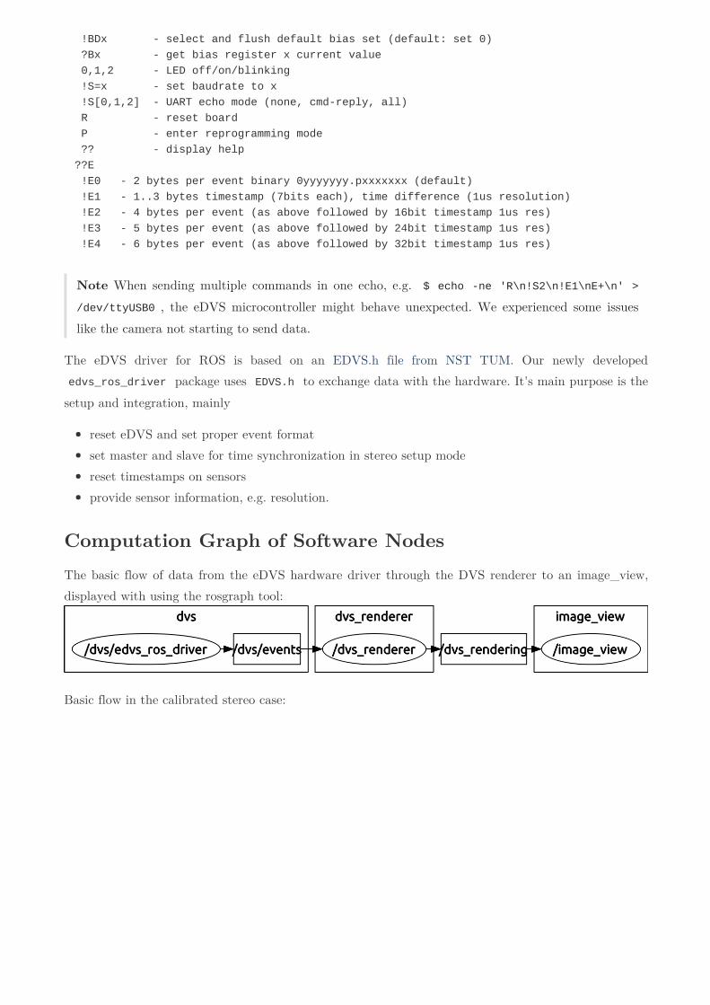
Note When sending multiple commands in one echo, e.g. $ echo ne 'R\n!S2\n!E1\nE+\n' >/dev/ttyUSB0 , the eDVS microcontroller might behave unexpected. We experienced some issueslike the camera not starting to send data.
The eDVS driver for ROS is based on an EDVS.h file from NST TUM. Our newly developed edvs_ros_driver package uses EDVS.h to exchange data with the hardware. It's main purpose is thesetup and integration, mainly
reset eDVS and set proper event formatset master and slave for time synchronization in stereo setup modereset timestamps on sensorsprovide sensor information, e.g. resolution.
Computation Graph of Software NodesThe basic flow of data from the eDVS hardware driver through the DVS renderer to an image_view,displayed with using the rosgraph tool:
Basic flow in the calibrated stereo case:
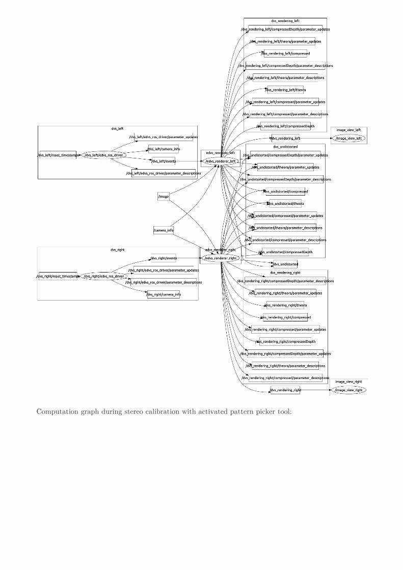
Computation graph during stereo calibration with activated pattern picker tool:
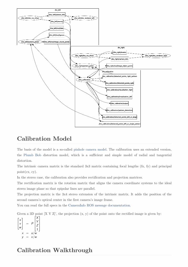
Calibration ModelThe basis of the model is a so-called pinhole camera model. The calibration uses an extended version,the Plumb Bob distortion model, which is a sufficient and simple model of radial and tangentialdistortion. The intrinsic camera matrix is the standard 3x3 matrix containing focal lengths (fx, fy) and principalpoint(cx, cy). In the stereo case, the calibration also provides rectification and projection matrices. The rectification matrix is the rotation matrix that aligns the camera coordinate systems to the idealstereo image plane so that epipolar lines are parallel. The projection matrix is the 3x4 stereo extension of the intrinsic matrix. It adds the position of thesecond camera's optical center in the first camera's image frame. You can read the full specs in the CameraInfo ROS message documentation.
Given a 3D point [X Y Z]', the projection (x, y) of the point onto the rectified image is given by:
Calibration Walkthrough
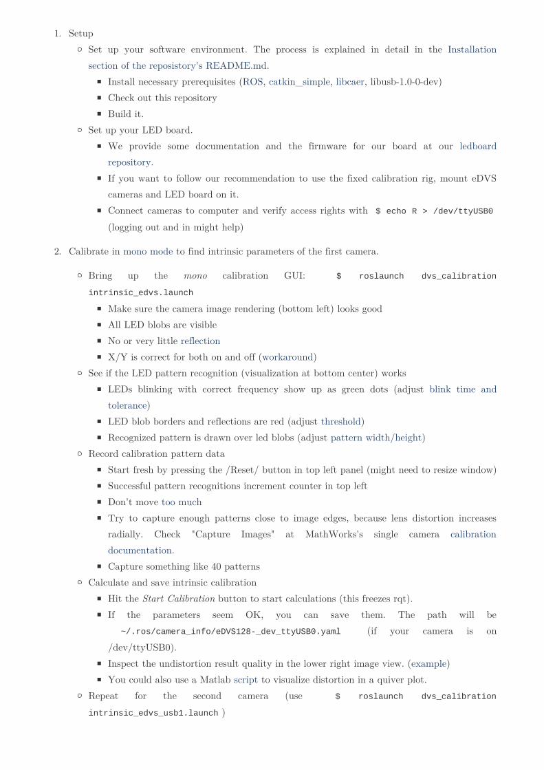
1. SetupSet up your software environment. The process is explained in detail in the Installationsection of the reposistory's README.md.
Install necessary prerequisites (ROS, catkin_simple, libcaer, libusb-1.0-0-dev)Check out this repositoryBuild it.
Set up your LED board.We provide some documentation and the firmware for our board at our ledboardrepository.If you want to follow our recommendation to use the fixed calibration rig, mount eDVScameras and LED board on it.Connect cameras to computer and verify access rights with $ echo R > /dev/ttyUSB0 (logging out and in might help)
2. Calibrate in mono mode to find intrinsic parameters of the first camera.
Bring up the mono calibration GUI: $ roslaunch dvs_calibration
intrinsic_edvs.launch
Make sure the camera image rendering (bottom left) looks goodAll LED blobs are visibleNo or very little reflectionX/Y is correct for both on and off (workaround)
See if the LED pattern recognition (visualization at bottom center) worksLEDs blinking with correct frequency show up as green dots (adjust blink time andtolerance)LED blob borders and reflections are red (adjust threshold)Recognized pattern is drawn over led blobs (adjust pattern width/height)
Record calibration pattern dataStart fresh by pressing the /Reset/ button in top left panel (might need to resize window)Successful pattern recognitions increment counter in top leftDon't move too muchTry to capture enough patterns close to image edges, because lens distortion increasesradially. Check "Capture Images" at MathWorks's single camera calibrationdocumentation.Capture something like 40 patterns
Calculate and save intrinsic calibrationHit the Start Calibration button to start calculations (this freezes rqt).If the parameters seem OK, you can save them. The path will be ~/.ros/camera_info/eDVS128_dev_ttyUSB0.yaml (if your camera is on/dev/ttyUSB0).Inspect the undistortion result quality in the lower right image view. (example)You could also use a Matlab script to visualize distortion in a quiver plot.
Repeat for the second camera (use $ roslaunch dvs_calibration
intrinsic_edvs_usb1.launch )

Screenshot of mono calibration:
Calibrate in stereo modeMake sure you have intrinsic parameters for the left and right camera in ~/.ros/camera_info/eDVS128_dev_ttyUSB0.yaml and ~/.ros/camera_info/eDVS128
_dev_ttyUSB1.yaml , respectively.Start the stereo calibration GUI: $ roslaunch dvs_calibration stereo_edvs.launch Record patterns as you did in mono mode (Patterns are stored if they appear in both camerassimultaneously)Start Calibration and Save Calibration (The .yaml files will be overwritten)
Using the Calibration Data
In ROS
If camera calibration has been completed beforehand, it is easy and straightforward to use thecalibration in ROS. First, make sure the precomputed calibration files are where ROS'scamera_info_manager expects them. This is usually ~/.ros/camera_info/eDVS128
_dev_ttyUSB0.yaml . The camera_info_manager ROS package, which is part of ROS's image_pipelinestack, will then be able to use the calibration automatically. The image_pipeline is designed to process complete frames of pixel-images. Thus, we need thedvs_renderer to generate an image from an accumulation of eDVS events.
Usage:
Start eDVS event output: $ roslaunch edvs_ros_driver edvsstereo.launch Render images and display stages of image_pipelines stereo processing: $ roslaunch
edvs_ros_driver stereodisplay.launch
Elsewhere

The calibration data can easily be used in other environments. The following example generates aMatlab cameraParameters object:
cp = cameraParameters( ...
'IntrinsicMatrix', [164.0138, 0, 80.1241; 0, 164.8755, 44.2025; 0, 0, 1], ...
'RadialDistortion', [0.2875, 0.1980], ...
'TangentialDistortion', [0.0038, 0.0081]);
Calibration TweaksSee Calibration Details and Parameters.
Use the tool that displays last detectionUse the tool that asks for approval every time a pattern is detected
Results
Intrinsic and Extrinsic Camera ParametersExample of an original image vs. undistorted image:
Original(distorted image)
Result(undistored image)
Visualization of eDVS lens distortion using our Matlab script.

60 40 20 0 20 40 60
60
40
20
0
20
40
60
3D ReconstructionWith successful pattern capture capabilities, 3D point reconstruction can be attempted. The plot belowshows the camera positions as detected during calibration in red. Three 3x4 LED board patterns indifferent distances are visualized in green, orange and blue. The plot was created with a Python script.
Benchmark
Mathematical Model Benchmark
After a model is calculated, one can check, how good the model fits with the provided LED points. Theused LED points will be projected to the world model and then reprojected from the model to the

image. The euclidean distance of the real input image point and the reprojected point will be used to aserror. The reprojection error provided after the calibration is the root mean square over all these errors.For example, an reprojection error of 3.0 would indicate, that, on average, each projected point is 3pxaway from the original point.
Where can I find the reprojection error in the interface? The value is displayed in a textfield in the calibration interface, after the calibration has successfully finished.
A small reprojection error does not imply a good world model. It can only describe, how good theprovided calibration points can fit into one common model. Therefore, a lot of more points might evenincrease this error, as every new point can add noise.
Benchmark using Ground Truth
One goal was to create an benchmark for the calibration and rectification result. Our requirementswere to be reproducible and easy to perform. It should provide ground truth and according calculateddepth data. This enables to calculate the 3D reprojection error.
One approach to providing ground truth is using an marker based infrared optical tracking system.While such a system is available at the NST chair, the anticipated time for setting up andunderstanding the system did not seem to be worthwhile given the introduced spatial noise in groundtruth and increased complexity of the experimental setup.
Instead, we propose to use a laser-cut high density fiberboard construction to reproducibly andaccurately move the LED board. The eDVS stereo setup is mounted on the construction. The boardmoves on a Z-axis rail, where it snaps in at fixed positions. When both eDVS sensors capture the samefeature (e.g. the blinking pattern), we can triangulate the feature's 3D positions with the help of theprerecorded camera calibration data being evaluated. The distance (delta) we can calculate betweenthese 3D positions is compared to the Ground-truth distances which can easily measured or deducedfrom the rig's design files. Using this method guarantees that the ground-truth data is the same for every run, even when themounting position of the eDVS varies in the order of some millimeters.
Learnings
LED Board with too many blinking LEDs
At the beginning we experimented with an LED board with 80 LEDs (200Hz), which produced toomany events. We discovered, that the eDVS can not cope with so many events (even at 4MBit datarate). On the other hand, the DVS (not eDVS) has no problem with that many events. In ourexperience the DVS usually reports about five times as many events from the same scene.
With a lot of additional light (to surpress noise) and 10.0s transition map aggregation time, even thefull board could be detected in the end. The big number of points makes the calculation of theprincipal point more accurate. However it is very difficult to get all LEDs to be detected without toomuch noise.

Reflection from LED Board
Reflectioninfluence
LEDs near to the border of the board reflected too strongly, which had a negative influence on patterndetection. We experimented with some textile to absorb the reflections. The result was surprisinglygood. Yet, for our final solution, we disable the LEDs at the border to achieve the same detectionquality without depending on covers.
Movements during Calibration Process
Our first calibration experiments used one of the following setups: (1) The eDVS was moved around toproduce events of a fixed LED board from different point of views. (2) The eDVS was fixed, while theLED board was moved around in its field of view. Both approaches resulted in some issues: The subpixel accuracy calculation of the LED's center was disturbed by the moving scene. This is because thesensor does not produce frames, but a constant stream of events. The transition map of the eventsaccumulated during one time frame hence included a visible trail of LED point movements, asillustrated in the figure below. The time frame (and thus led trail length) can not be decreased, or

noise will prevent pattern detection. Therefore the estimation of the LED blob's center position is notexact. This lead to suboptimal calibration results.
Moving eDVS(trail)
Fixed eDVS(no trail)
Our solution is to use both (1) a statically mounted camera and (2) a fixed led board. As both partsare physically not moving, we prevent the influence of pixel trails and achieve better results. In orderto collect image points of blinking LEDs over the whole sensor area, the board's software incrementallyshifts the illumination pattern every 10 seconds. The following picture shows the board at thebeginning and after some seconds.
t=0s t=12s
In our animation of pattern recognition you can observe how (1) the pattern shifts over the board and(2) how pixel coordinates of the same pattern points vary relatively little (about +- 0.3px max),because no movement is introduced.
Wrong Buffering rejects Events
The buffer in the original eDVS.h read all available bytes on the serial interface. Sometimes, the buffer

ended in the middle of an event package. Then, it rejected the package, because it was incomplete. Oursolution was to always read at least six bytes from the serial before we try to process it.
Original eDVS.h without Timestamps
The original eDVS.h did not provide timestamps. Hence, we implemented this functionality ourselves.As we learned later, there is an improved version available at edvstools.
Shifted X and Y Coordinates for On-Events
Sometimes the sensor image shows shifted x and y values for on-events. The reason so far is notcompletely clear. We used the following quick-fix (while the calibration interface was running) in aseparate terminal:
#press hardware reset button on eDVS
#send reset command
$ echo ne 'R\n!' > /dev/ttyUSB0
#sometimes send reset event again, if it was not working
#(you can check if the calibration interface still shows an image)
#after the rest, it should not show any events anymore
$ echo ne 'R\n!' > /dev/ttyUSB0
#set event mode to 1 and start sending events again
$ echo ne '!E1\nE+\n' > /dev/ttyUSB0
#now your events should be displayed correctly
Later, we switched to the "E2" timestamp format and used a Boost circular buffer for processing. Thisensured that no events were split and lost. This also removed the sporadic x/y shifts and mysteriousnoise at image borders (it seems that a few timestamp bytes were interpreted as X or Y some time).
Suggested Improvements for eDVS Ros DriverThere already exists an improved version of the basic EDVS.h file, which was the starting point for theROS driver. This early EDVS.h is very limited in functionality. Further efforts regarding the eDVScalibration topic should consider switching to the most recent version of the library (edvstools).
Tools
Store Detected PatternsIn order to analyze, which points where detected, one can record the result from e.g. these topics:
/dvs_calibration/detected_points_left_or_single/dvs_calibration/detected_points_left_or_single_pattern
Here a short example, how to e.g. record and view the data:
#first source resources
source devel/setup.bash
#run the calibration interface
roslaunch dvs_calibration intrinsic_edvs.launch
#now, on e.g. other terminal
#this will display only the transition maps with detected points
rosrun image_view image_view
image:=/dvs_calibration/detected_points_left_or_single_pattern &
#this will show the detected points messages
rostopic echo /dvs_calibration/detected_points_left_or_single &
#this will record both of them in a file
rosbag record /dvs_calibration/detected_points_left_or_single_pattern
/dvs_calibration/detected_points_left_or_single
Playback Stored PatternsFor playback of the recorded data, run:
roscore &
#this will show the detected points messages
rostopic echo /dvs_calibration/detected_points_left_or_single &
#play in an endless loop the file
rosbag play l 20151214151738.bag
#or step through the file: press p in the command window or
#space to pause playback
#rosbag play pause 20151214151738.bag
Plot Patterns with Matplotlibfirst, convert rosbag file to csv
rostopic echo b 20151222005333.bag p /dvs_right/out/image_object_points >
stereoright.csv
rostopic echo b 20151222005333.bag p /dvs_left/out/image_object_points >
stereoleft.csv
then, plot it using a small python script
python utils/plot.py stereoright.csv
#or try two or more files at once
python utils/plot.py stereoright.csv stereoleft.csv
for 3d recordings, you can also use
python utils/plot3d.py ../ttyUSB0.yaml ../ttyUSB1.yaml pointsleft.csv points
right.csv
#or, if like usually, yaml with calibration info is stored in home file
python utils/plot3d.py ~/.ros/camera_info/eDVS128_dev_ttyUSB0.yaml
~/.ros/camera_info/eDVS128_dev_ttyUSB1.yaml pointsleft.csv pointsright.csv
We hereby certify that this advanced seminar has been composed by ourselves, anddescribes our own work, unless otherwise acknowledged in the text. All referencesand verbatim extracts have been quoted, and all sources of information have beenspecifically acknowledged.


![2017 Vortrag Band DVS BV Köln [Kompatibilitätsmodus]€¦ · 3 Vortrag Kleben DVS BV Köln, 02.02.2017 DVS BV Köln, 2017 Jan 2016 Quelle: TC-Kleben Anforderungen an den Klebstoff](https://static.fdokument.com/doc/165x107/5eab324140d5bb1519535115/2017-vortrag-band-dvs-bv-kln-kompatibilittsmodus-3-vortrag-kleben-dvs-bv-kln.jpg)