Commissioning instruction Siedle Scope / Scope cordless ... · Ausgabe der gesamten Dokumen ......
64
S 851-0 SZM 851-0 SGM 650-0 Commissioning instruction Siedle Scope Scope cordless handset Smart Gateway Mini Siedle App
Transcript of Commissioning instruction Siedle Scope / Scope cordless ... · Ausgabe der gesamten Dokumen ......
S 851-0SZM 851-0SGM 650-0
Commissioning instructionSiedle ScopeScope cordless handsetSmart Gateway MiniSiedle App
2
DEErgänzend zu diesem Dokument finden Sie die jeweils aktuelle Ausgabe der gesamten Dokumentation im Downloadbereich unter www.siedle.com
ENIn addition to this document, you will find the current valid issue of the entire documentation in the download area under www.siedle.com
FREn complément de ce document, vous trouverez l’édition actuelle de l’ensemble de la documentation dans la zone de téléchargement, à l’adresse www.siedle.com
ITIn integrazione al presente documento, l’edizione aggiornata dell’intera documentazione è scaricabile dall’area Download del sito www.siedle.com
NLAanvullend op dit document vindt u altijd de actuele uitgave van de gehele documentatie in het downloadbereik onder www.siedle.com
DKSom et supplement til dette dokument kan du altid finde den sidste nye udgave af hele dokumentationen på downloadsiden under www.siedle.com
SESom komplettering till detta dokument finns alltid den aktuella utgåvan av hela dokumentationen i nedladdningszonen under www.siedle.com
ESDe forma complementaria a este documento encontrará la correspondiente versión actual de toda la documentación en el área de descargas de www.siedle.com
PLZawsze aktualne wydanie całej dokumentacji, stanowiące uzupełnienie niniejszego dokumentu, można znaleźć w naszej strefie pobierania pod adresem www.siedle.com
NOSom supplement til dette dokumentet finner du den til enhver tid aktuelle utgaven av den totale dokumentasjonen i nedlastingsområdet under www.siedle.com
3
English
Contents
One for all 4
Safety remarks
Reading the product information and commissioning instructions 5
Medical devices/facilities 5
Protect your property! 6
Legal notes 6
Contact with liquids 6
Servicing 6
Preparation
Stepbystep through the commissioning process 7
Fulfilling commissioning requirements 7
System overview 8
Providing the accessories required for commissioning 9
Providing the system documentation 9
Checking the scope of supply for completeness 10
Charging the cordless handset 11
Charging cradle for the Scope cordless handset 11
Assembling and connecting the base station 12
Status LED at the base station 12
Preparing the PC/laptop 13
Configuring the In-Home bus system
Programming 15
Manual programming 17
Programming – Plug+Play 18
Programming with PC 20
Configuring Siedle Scope
Configuring Siedle Scope 21
Key assignment tab 22
Additional functions tab 23
App tab 24
Exporting the XML configuration file 25
Configuring the base station/Smart Gateway Mini
General information 26
Log in as administrator 27
Update the system 29
Changing the password 31
Change the network settings 33
Setting the date and time 34
Import the InHome bus configuration into the base station. 35
Change PIN 36
Telephony settings 37
Register Siedle App to Siedle Server 39
Secure with the Siedle server 39
Functions 40
Operating requirements 40
Registering mobile end devices with the Siedle app 40
Ports needed for operation on the Siedle server 41
Registering the first mobile end device with the Siedle app 42
Deleting registration(s) 45
Resetting an incorrect registration 46
Log out 48
Changing the password (User) 49
Log out 51
Factory setting 52
Handsets – Getting started
Switching on the cordless handset 53
Registering the cordless handset at the base station 53
Start screen 54
Display navigation 54
Registering the cordless handset at the base station 55
Log in with an already registered cordless handset 56
Log in via the browserbased user interface of the base station 57
Deregister handset 58
Setting the language 58
Setting the date and time 59
Final assignments
Complete function check 61
Simplified EU Declaration of Conformity 61
Index 62
4
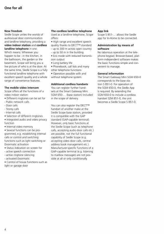
New freedomSiedle Scope unites the worlds of audiovisual door communication and landline telephony, providing a video indoor station and cordless landline telephone in one.Which means: Wherever you happen to be in the kitchen, in the bathroom, the garden or the basement, Scope will bring you a live picture of who is at the door. At the same time, Siedle Scope is a fully functional landline telephone with excellent speech quality and a whole range of convenience features.
The mobile video intercom Scope offers all the functions of a video indoor station:• Different ringtones can be set for Public network calls Door calls Storey calls Internal calls• Selection of different ringtones• Integrated audio and video privacy function• Internal video memory• Several functions can be programmed, e.g. establishing internal calls or control and switching functions such as light switching or Doormatic activation• Status indication on screen for active speech connection active ringtone silencing activated Doormatic• Control of house functions such as light or garage door
The cordless landline telephone Used as a landline telephone, Scope offers:• High range and excellent speech quality thanks to DECT™ standard: up to 300 m across open country up to 50 m in the building• Eco mode with reduced transmission output• Long battery life• Phonebook, call lists and many other telephone functions• Operation possible with and without telephone system.
Additional cordless handsets You can register further handsets at the Smart Gateway Mini SGM 650… (base station) included in the scope of delivery.
You can also register the DECT™ handset of another make at the Siedle Scope base station, provided it is compatible with the GAP standard (GAPcapable terminal). However, only basic functions at the Siedle Scope (such as telephone calls, accepting audio door calls etc.) are possible, not the full functional capability of Siedle Scope (e.g. accepting video door calls, central address book management etc.). Manufacturerspecific functions of a GAPcapable terminal (e.g. listening to mailbox messages) are not possible at all or only conditionally.
App link Scope S 851… allows the Siedle app for InHome to be connected.
Administration by means of software No laborious operation at the telephone keypad. Browserbased, platformindependent software makes the basic functions simple and convenient to manage.
General information The Smart Gateway Mini SGM 6500 corresponds to the base station S 8510. For operation of the SGM 6500, the Siedle App is required. By extending the SGM 6500 to include a cordless handset SZM 8510, the unit becomes a Siedle Scope S 8510.
One for all
5
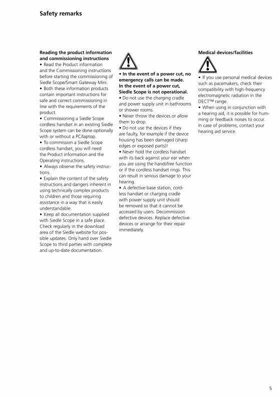
Reading the product information and commissioning instructions • Read the Product information and the Commissioning instructions before starting the commissioning of Siedle Scope/Smart Gateway Mini.• Both these information products contain important instructions for safe and correct commissioning in line with the requirements of the product.• Commissioning a Siedle Scope cordless handset in an existing Siedle Scope system can be done optionally with or without a PC/laptop.• To commission a Siedle Scope cordless handset, you will need the Product information and the Operating instructions.• Always observe the safety instructions.• Explain the content of the safety instructions and dangers inherent in using technically complex products to children and those requiring assistance in a way that is easily understandable.• Keep all documentation supplied with Siedle Scope in a safe place. Check regularly in the download area of the Siedle website for possible updates. Only hand over Siedle Scope to third parties with complete and uptodate documentation.
Safety remarks
• In the event of a power cut, no emergency calls can be made.In the event of a power cut, Siedle Scope is not operational.• Do not use the charging cradle and power supply unit in bathrooms or shower rooms.• Never throw the devices or allow them to drop.• Do not use the devices if they are faulty, for example if the device housing has been damaged (sharp edges or exposed parts)!• Never hold the cordless handset with its back against your ear when you are using the handsfree function or if the cordless handset rings. This can result in serious damage to your hearing.• A defective base station, cordless handset or charging cradle with power supply unit should be removed so that it cannot be accessed by users. Decommission defective devices. Replace defective devices or arrange for their repair immediately.
Medical devices/facilities
• If you use personal medical devices such as pacemakers, check their compatibility with highfrequency electromagnetic radiation in the DECT™ range.• When using in conjunction with a hearing aid, it is possible for humming or feedback noises to occur. In case of problems, contact your hearing aid service.
6
Safety remarks
Contact with liquids • In case of intensive contact with or contamination by liquids (such as water damage due to burst pipes, dropping the cordless handset into the bath), follow points 1 to 4 and contact your service partner without delay.• If the base station, cordless handset, charging cradle or power supply unit has come into contact with fluid, please carry out the following steps:
1 In case of devices with power supply unit: Switch off the socket fuse and take the power supply unit out of the socket. If applicable, contact an electrical expert in order to check the electrical installation.2 In the case of cordless handsets: Switch off the device immediately, take out the battery and leave the battery compartment open.3 Using your own judgement, position the device in a way that best allows fluid to drain away.4 Pat the device dry using an absorbent cloth.5 Allow the device to dry out for at least 72 hours in a warm, dry location (do not use an oven/microwave or similar).6 Only recommission the device when it is completely dried out and free of contamination from the fluid.
Legal notes • Systems with video cameras which are operated within the European Union and are aimed at a publicly accessible area or part of one, and film and record this, are subject to the EU General Data Protection Regulation (EU GDPR) as of May 25, 2018. It is the sole responsibility of the operator to operate such systems in accordance with data protection regulations.• Photographs of individuals taken without their knowledge may not be published or stored in publicly accessible video memory facilities.• Individuals who have been photographed without their knowledge are entitled to request that pictures be deleted based on the right of persons to their own likeness. Never store pictures of persons you do not know in social networks or send them by email to others/public groups. This will infringe their personal rights.• If stored images are used as part of private / criminal law proceedings or in a police investigation, this requires prior clarification with a lawyer or the responsible police authority.
Servicing Statutory warranty conditions apply.If the device requires servicing, contact your specialist dealer or electrical installer.
Customer service in the Furtwangen factory +49 7723 63434
Protect your property! • Lock front doors or apartment doors during the daytime if there is nobody home. Unlocked doors allow thieves/burglars to gain easy access to your property.• The Scope cordless handset must be kept with the same care and security awareness as a house key, as it can also open your front door from the outside.• Ensure that it does not fall into unauthorized hands!• The Siedle app can be used from any location as a door release. Keep smartphones/tablets on which the Siedle app is activated safe from theft. Protect these devices against unauthorized usage with a code / password. Always use the latest protection mechanisms available for your mobile phone.• Never hand over a smartphone/tablet with an operable Siedle app to a third person! If you are no longer using a smartphone/tablet, whether it be temporarily or permanently (repair, sale, exchange), uninstall the Siedle app from the device.
7
Step-by-step through the commissioning process The following commissioning steps are described over the following pages:1 Fulfil the commissioning requirements.2 Provide the accessories required for commissioning.3 Provide the system documentation.4 Check the scope of supply for completeness.5 Charge the cordless handset.6 Assemble and connect the base station.7 Prepare the PC/laptop.8 Configure the InHome bus system.9 Configure Siedle Scope.10 Configure the base station/Smart Gateway Mini.11 Configure and commission the cordless handset(s) / Siedle app(s) for InHome.12 Complete function check.
Preparation
Fulfilling commissioning requirements • The data from the door intercom with Siedle Scope is transmitted via the Siedle InHome bus. Programming is described in the In-Home-Bus: Video system manual.• In their asdelivered status, the devices are initially unprogrammed. After initially switching on the bus video line rectifier, each of the connected devices in the line is assigned its own unique address.• Once installation is complete, a mutual “teachin” process between all the devices must be performed to ensure that functions are correctly executed (e.g. the bus telephone rings as soon as the call button is pressed).• Using bus programming software BPS 650… from V2.14 the entire function of an InHome system can be programmed using a Windows PC. For connection of the PC to the InHome installation, the programming interface PRI 602… USB and the bus power supply accessory ZBVG 650… are required. The ZBVG 650… is plugged once within a system and once in a BNG/BVNG 650… The PRI 602… USB can be permanently installed in a system or can be plugged in via an 8pin Western junction box. The software BPS 650… is provided together with the PRI 602… USB. Current updates for the BPS 650… software are available in the download area under www.siedle.com. For more information on how to commission the system using the Bus programming software BPS 650… refer to the software online help.Installation, commissioning and programming are described in the system manual (enclosed with line rectifiers BNG/BVNG 650…).
• Using the full functional capability of Siedle Scope, Smart Gateway Mini and the Siedle app for Smart Gateway Mini within the intercom requires programming with the programming software.• If manual or Plug+Play programming is carried out, only selected functions can be programmed.• Detailed information is available in the InHomeBus: Video system manual in the chapter Programming > Overview of functions.
Conditions:• The door intercom system has been correctly installed/assembled as described in the InHomeBus: Video system manual, and has been prepared with a programming interface for programming using a PC/laptop.• The position of all devices has been documented.• All required button assignments/functions for the individual devices have been documented.• A PC/laptop with installed BPS programming software in the latest version is available for commissioning.• The scope of delivery S 8510/SGM 6500/SZM 8510 is available.• Network information is available.• The person commissioning the system has a basic grounding in network technology.
8
Preparation
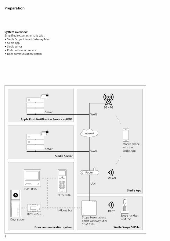
DECT
WLAN
LAN
BVPC 850-...
BFCV 850-...
BVNG 650-...
Router
3G / 4G
WAN
Apple Push Notification Service – APNS
WAN
Door communication system Siedle Scope S 851-...
In-Home bus
Scope base station /Smart Gateway MiniSGM 650-...
Scope handsetSZM 851-...
Siedle�App
Mobile phone with the Siedle App
Door station
Siedle Server
Server
Internet
Server
System overview Simplified system schematic with:• Siedle Scope / Smart Gateway Mini• Siedle app• Siedle server• Push notification service• Door communication system
9
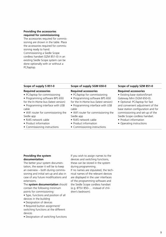
Scope of supply S 851-0 Scope of supply SGM 650-0 Scope of supply SZM 851-0
Required accessories• PC/laptop for commissioning• Programming software BPS 650 for the InHome bus (latest version)• Programming interface with USB cable• WiFi router for commissioning the Siedle app• RJ45 network cable• Product information• Commissioning instructions
Required accessories• PC/laptop for commissioning• Programming software BPS 650 for the InHome bus (latest version)• Programming interface with USB cable• WiFi router for commissioning the Siedle app• RJ45 network cable• Product information• Commissioning instructions
Required accessories• Existing base station/Smart Gateway Mini (SGM 6500).• Optional: PC/laptop for fast and convenient adjustment of the base station configuration and for commissioning and setup of the Siedle Scope cordless handset.• Product information• Operating instructions
Providing the accessories required for commissioning The accessories required for commissioning are shown in the table. Place the accessories required for commissioning ready to hand.Commissioning a Siedle Scope cordless handset (SZM 8510) in an existing Siedle Scope system can be done optionally with or without a PC/laptop.
Providing the system documentation The better your system documentation, the easier it will be to keep an overview – both during commissioning and initial setup and also in case of any future modifications and extensions.The system documentation should contain the following minimum points for commissioning:• Type, functions and position of all devices in the building• Designation of devices• Required button assignment/switching functions at the different devices• Designation of switching functions
If you wish to assign names to the devices and switching functions, these can be stored in the system during programming. If no names are stipulated, the technical names of the relevant devices are displayed in the user interfaces of the programming software and the Siedle Scope cordless handset (e.g. BTSV 850… instead of children’s bedroom).
10
Preparation
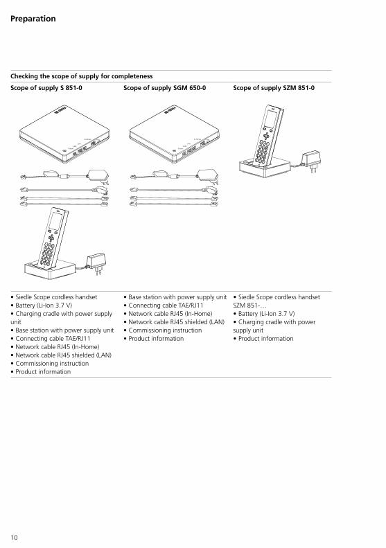
Checking the scope of supply for completeness
Scope of supply S 851-0 Scope of supply SGM 650-0 Scope of supply SZM 851-0
Power
Line
In-Home Prog.
LANPower
Line
In-Home Prog.
LAN
• Siedle Scope cordless handset• Battery (LiIon 3.7 V)• Charging cradle with power supply unit• Base station with power supply unit• Connecting cable TAE/RJ11• Network cable RJ45 (InHome)• Network cable RJ45 shielded (LAN)• Commissioning instruction• Product information
• Base station with power supply unit• Connecting cable TAE/RJ11• Network cable RJ45 (InHome)• Network cable RJ45 shielded (LAN)• Commissioning instruction• Product information
• Siedle Scope cordless handset SZM 851…• Battery (LiIon 3.7 V)• Charging cradle with power supply unit• Product information
11
Charging the cordless handset Use only the original Siedle rechargeable battery in the cordless handset.The charging and operating times depend on the degree of usage of Siedle Scope and on the capacity and age of the battery.
Charging times:• Recommended initial charge: at least 3 hours• Minimum charge prior to commissioning: at least 30 minutes• Standard charge: at least 3 hours
Operating times:• Standby operation: appr. 100 hours• Talk time: appr. 5 hours
The battery is precharged in the asdelivered status. The battery may become discharged during storage and transport. The cordless handset must be fully charged before first use (see the “battery charge status” display symbol).
Procedure:1 Check the scope of supply for completeness.2 Take the following components from the scope of supply:• Product information S 851-0• Commissioning instructions S 851-0• Siedle Scope cordless handset with battery (LiIon 3.7 V)• Charging cradle with power supply unit3 Connect the charging cradle to the power mains.4 Place the cordless handset in the charging cradle.
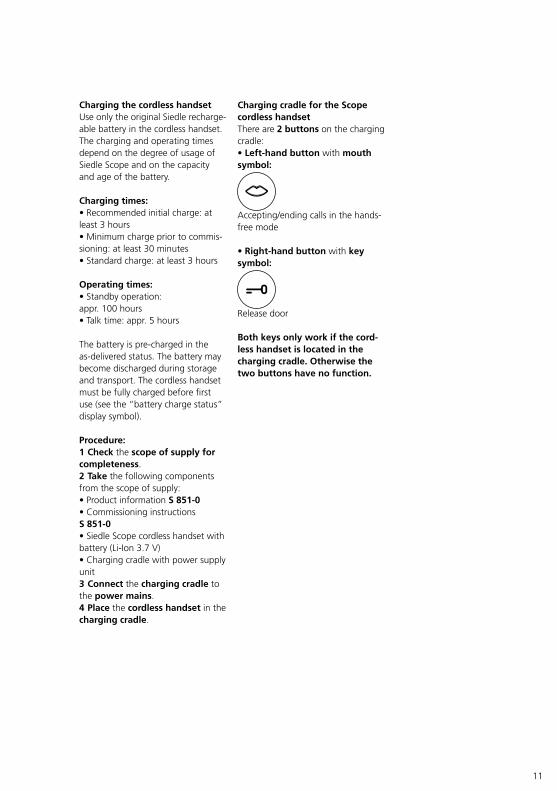
Charging cradle for the Scope cordless handset There are 2 buttons on the charging cradle:• Left-hand button with mouth symbol:
Accepting/ending calls in the handsfree mode
• Right-hand button with key symbol:
Release door
Both keys only work if the cord-less handset is located in the charging cradle. Otherwise the two buttons have no function.
12
Power
Line
In-Home Prog.
LAN
Power
Line
In-Home Prog.
LAN
Preparation
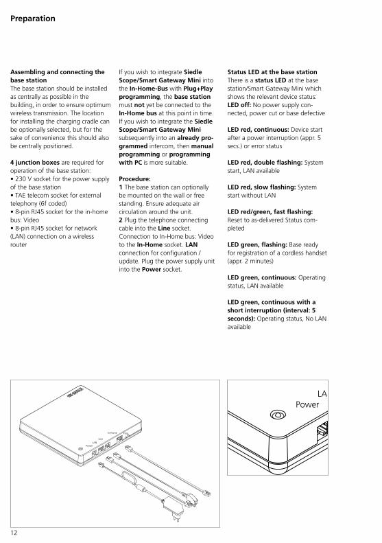
Assembling and connecting the base station The base station should be installed as centrally as possible in the building, in order to ensure optimum wireless transmission. The location for installing the charging cradle can be optionally selected, but for the sake of convenience this should also be centrally positioned.
4 junction boxes are required for operation of the base station:• 230 V socket for the power supply of the base station• TAE telecom socket for external telephony (6f coded)• 8pin RJ45 socket for the inhome bus: Video• 8pin RJ45 socket for network (LAN) connection on a wireless router
Status LED at the base station There is a status LED at the base station/Smart Gateway Mini which shows the relevant device status:LED off: No power supply connected, power cut or base defective
LED red, continuous: Device start after a power interruption (appr. 5 secs.) or error status
LED red, double flashing: System start, LAN available
LED red, slow flashing: System start without LAN
LED red/green, fast flashing: Reset to asdelivered Status completed
LED green, flashing: Base ready for registration of a cordless handset (appr. 2 minutes)
LED green, continuous: Operating status, LAN available
LED green, continuous with a short interruption (interval: 5 seconds): Operating status, No LAN available
If you wish to integrate Siedle Scope/Smart Gateway Mini into the In-Home-Bus with Plug+Play programming, the base station must not yet be connected to the In-Home bus at this point in time.If you wish to integrate the Siedle Scope/Smart Gateway Mini subsequently into an already pro-grammed intercom, then manual programming or programming with PC is more suitable.
Procedure:1 The base station can optionally be mounted on the wall or free standing. Ensure adequate air circulation around the unit.2 Plug the telephone connecting cable into the Line socket. Connection to InHome bus: Video to the In-Home socket. LAN connection for configuration / update. Plug the power supply unit into the Power socket.
13
Preparing the PC/laptop
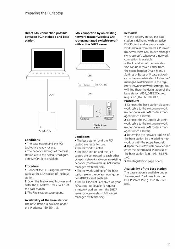
Direct LAN connection possible between PC/Notebook and base station.
LAN
SGM 650-...
Conditions:• The base station and the PC/Laptop are ready for use.• The network settings of the base station are in the default configuration (DHCP client enabled).
Procedure:1 Connect the PC using the network cable at the LAN socket of the base station.2 Open the Firefox web browser and enter the IP address 169.254.1.1 of the base station.3 The Registration page opens.
Availability of the base station:The base station is available under the IP address 169.254.1.1.
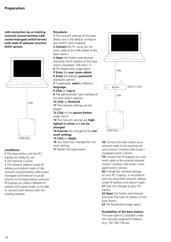
LAN connection by an existing network (router/wireless LAN router/managed switch/server) with active DHCP server.
DECT
LAN
Router
LAN
Siedle Scope S 851-...
SGM 650-... SZM 851-...
DHCP = ON
Conditions:• The base station and the PC/Laptop are ready for use.• The network is active.• The base station and the PC/Laptop are connected to each other by each network cable on an existing network (router/wireless LAN router/managed switch/server).• The network settings of the base station are in the default configuration (DHCP client enabled).• The DHCP client is enabled on your PC/Laptop, to be able to request a network address from the DHCP server (router/wireless LAN router/managed switch/server).
Remarks:• In the delivery status, the base station is delivered with an active DHCP client and requests a network address from the DHCP server (router/wireless LAN router/managed switch/server), whenever a network connection is available.• The IP address of the base station can be received either from the scope handset (Main Menu > Settings > Status > IP base station) or by the router/wireless LAN router/managed switch/server in the register Network/Network settings. You will find there the designation of the base station s851_D4E32Cxxxxxx (e.g. s851_D4E32C0000C1).Procedure:1 Connect the base station via a network cable to the existing network (router / wireless LAN router / managed switch / server).2 Connect the PC/Laptop via a network cable to the existing network (router / wireless LAN router / managed switch / server).3 Determine the network address of the base station by the existing network or with the scope handset.4 Open the Firefox web browser and enter the determined IP address of the base station (e.g. 192.168.178.xxx).5 The Registration page opens.
Availability of the base station:The base station is available under the assigned IP address from the DHCP server IP (e.g. 192.168.178.xxx).
14
Preparation
LAN connection by an existing network (router/wireless LAN router/managed switch/server) with static IP adresses (inactive DHCP server).
LAN
SGM 650-...
Conditions:• The base station and the PC/Laptop are ready for use.• The network is active.• The network address range (IP address and subnet mask) of the network (router/wireless LAN router/managed switch/server) must be known.For the base station and your PC/Laptop you need a different IP address and subnet mask, to be able to connect both devices with the existing network.
Procedure:1 The network settings of the base station are in the default configuration (DHCP client enabled).2 Connect the PC using the network cable at the LAN socket of the base station.3 Open the Firefox web browser and enter the IP address of the base station (Standard: 169.254.1.1).4 The Registration page opens.5 Enter the user name admin.6 Enter the relevant password (standard: admin).7 If applicable, select a different language.8 Click on Log in.9 The administrator user interface of the base station appears.10 Click on Network.11 The network settings are displayed.12 Click on the square button under DHCP.13 The network settings are high-lighted in white and can be changed.14 Execute the changes at the net-work settings.15 Click on Apply.16 You have now changed the network settings.17 Restart the base station.
LAN
Router
LAN
SGM 650-...
DHCP = OFF
18 Connect the base station via a network cable to the existing network (router / wireless LAN router / managed switch / server).19 Connect the PC/Laptop via a network cable to the existing network (router / wireless LAN router / managed switch / server).20 Change the network settings on your PC / Laptop, in accordance with the prescribed network address range (IP address and subnet mask).21 Save the changes to your PC/Laptop.22 Open the Firefox web browser and enter the static IP address of the base station.23 The Registration page opens.
Availability of the base station:The base station is available under the manually assigned IP address (e.g. 192.168.178.xxx).
15
Configuring the In-Home bus system
Important remarks prior to programming • The entire installation must have been completed. When programming using the Plug+Play method, the housing of the bus indoor devices must not yet be closed. The Siedle Scope base station must not be connected to the InHome bus.• Before starting programming, all buttons should be inscribed to allow them to be assigned to the relevant bus indoor devices. • It is only ever possible to activate one door loudspeaker in the programming mode. • If an already programmed call button is pressed for longer than 3 seconds in the programming mode at the activated door loudspeaker, after one second a warningtone is sounded, and after 3 seconds the confirmation tone. After this, the call button is deleted if there was no bus indoor device active. However, if there is a bus indoor device active at this moment, the button is overwritten with the new address. • All BNG/BVNG 650… units must be connected to mains voltage of 230 V AC. • In multiple line systems with several BNG/BVNG 650… units, actuating the Prog. mode button at one BNG/BVNG 650… switches all other connected BNG/BVNG 650… units to the programming mode. • In multiple line systems, at each BNG/BVNG 650… a different address must be set. The number “0” cannot be used as an address! • In multiple line systems bus power supply accessory ZBVG 650… must be additionally plugged into one BNG/BVNG 650… The bus video line rectifier accessory ZBVNG 650… must be pIugged into each BVNG 650…
Programming In order to use the door intercom system, at least one door call must be programmed in the InHome bus.The data from the door intercom with Siedle Scope is transmitted via the Siedle InHome bus. Programming is described in the In-Home-Bus: Video system manual.In addition to the basic functions, you can program additional functions using the programming soft-ware BPS 650… . For connecting the PC to the In-Home bus: Video, a programming interface PRI 602… USB and a ZBVG 650… plugin card are required.The configuration performed must be saved using the BPS 650… in the form of an XML file and then transmitted to the base station. Information on importing the configuration into the base station is provided on/from page 35.
The InHome bus can be programmed in three ways:
1 Programming – manualFor more information, see page 17.
2 Programming – Plug+PlayFor more information, see page 18.
3 Programming – with PCFor more information, see page 20.
16
Configuring the In-Home bus system
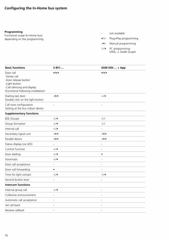
Programming Functional scope (InHome bus) depending on the programming.
not available
•// Plug+Play programming
/•/ Manual programming
//• PC programming(XML > Siedle Scope)
Basic functions S 851-… SGM 650-… + App
Door callStorey callDoor release buttonLight buttonCall silencing and display(Functional following installation)
•/•/• •/•/•
Dialling last doorDouble click on the light button
/•/• //•
Call tone configurationSetting at the bus indoor device
Supplementary functions
BSE Groups //• //
Group formation //• //
Internal call //•
Secondary signal unit /•/• /•/•
Parallel device /•/• /•/•
Status display (via LED)
Control function //•
Door dialling //• •
Doormatic //•
Door call acceptance
Door call forwarding •
Time for light contact //• //•
Second button level
Intercom functions
Internal group call //•
Collective announcement
Automatic call acceptance
Set callback
Receive callback
17
In-Home
Prog.
4 Sek.
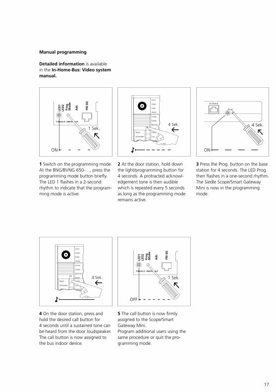
5 The call button is now firmly assigned to the Scope/Smart Gateway Mini.Program additional users using the same procedure or quit the programming mode.
3 Press the Prog. button on the base station for 4 seconds. The LED Prog. then flashes in a onesecond rhythm. The Siedle Scope/Smart Gateway Mini is now in the programming mode.
2 At the door station, hold down the light/programming button for 4 seconds. A protracted acknowledgement tone is then audible which is repeated every 5 seconds as long as the programming mode remains active.
1 Switch on the programming mode. At the BNG/BVNG 650…, press the programming mode button briefly. The LED 1 flashes in a 2second rhythm to indicate that the programming mode is active.
4 On the door station, press and hold the desired call button for 4 seconds until a sustained tone can be heard from the door loudspeaker. The call button is now assigned to the bus indoor device.
Manual programming
Detailed information is available in the In-Home-Bus: Video system manual.
18
Configuring the In-Home bus system
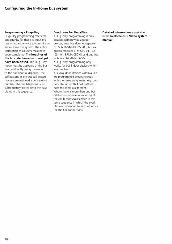
Programming – Plug+Play Plug+Play programming offers the opportunity for those without programming experience to commission an InHome bus system. The entire installation of all users must have been completed. The housings of the bus telephones must not yet have been closed. The Plug+Play mode must be activated at the bus line rectifier. By being connected to the bus door loudspeaker, the call buttons at the bus call button module are assigned a consecutive number. The bus telephones are subsequently locked onto the base plates in this sequence.
Conditions for Plug+Play:• Plug+playprogramming is only possible with new bus indoor devices, new bus door loudspeaker BTLM 65004/BTLE 05003, bus call button modules BTM 65001, 02, 03, 04, BRMA 05001 and bus line rectifiers BNG/BVNG 650…• Plug+playprogramming only works for bus indoor devices within any one line.• Several door stations within a line are programmed simultaneously with the same assignment, e.g. two door stations with 4 call buttons have the same assignment.Where there is more than one bus call button module, numbering of the call buttons takes place in the same sequence in which the modules are connected to each other via the IN/OUT connections.
Detailed information is available in the In-Home-Bus: Video system manual.
19
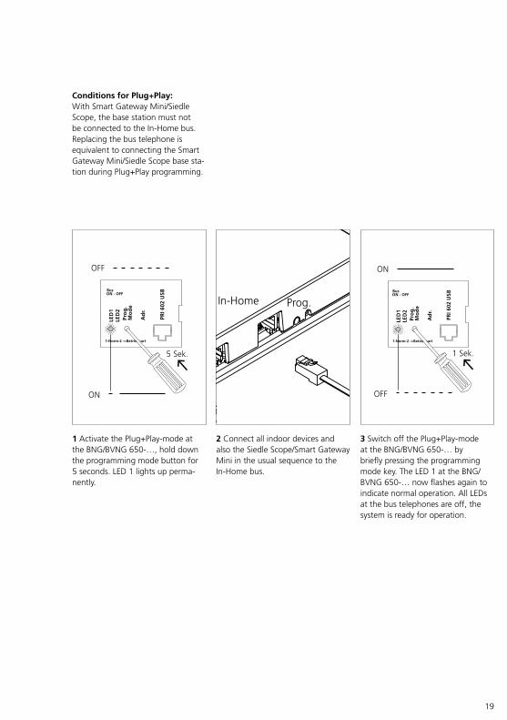
Conditions for Plug+Play:With Smart Gateway Mini/Siedle Scope, the base station must not be connected to the InHome bus. Replacing the bus telephone is equivalent to connecting the Smart Gateway Mini/Siedle Scope base station during Plug+Play programming.
1 Activate the Plug+Playmode at the BNG/BVNG 650…, hold down the programming mode button for 5 seconds. LED 1 lights up permanently.
3 Switch off the Plug+Playmode at the BNG/BVNG 650… by briefly pressing the programming mode key. The LED 1 at the BNG/BVNG 650… now flashes again to indicate normal operation. All LEDs at the bus telephones are off, the system is ready for operation.
Power
Line
In-Home Prog.
LAN
2 Connect all indoor devices and also the Siedle Scope/Smart Gateway Mini in the usual sequence to the InHome bus.
20
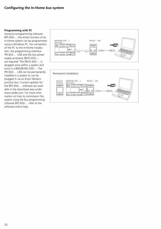
Programming with PC Using bus programming software BPS 650… the entire function of an InHome system can be programmed using a Windows PC. For connection of the PC to the InHome installation, the programming interface PRI 602… USB and the bus power supply accessory ZBVG 650… are required. The ZBVG 650… is plugged once within a system and once in a BNG/BVNG 650… The PRI 602… USB can be permanently installed in a system or can be plugged in via an 8pin Western junction box. Current updates for the BPS 650… software are available in the download area under www.siedle.com. For more information on how to commission the system using the Bus programming software BPS 650… refer to the software online help.
Permanent installation
Configuring the In-Home bus system
21
Configuring Siedle Scope
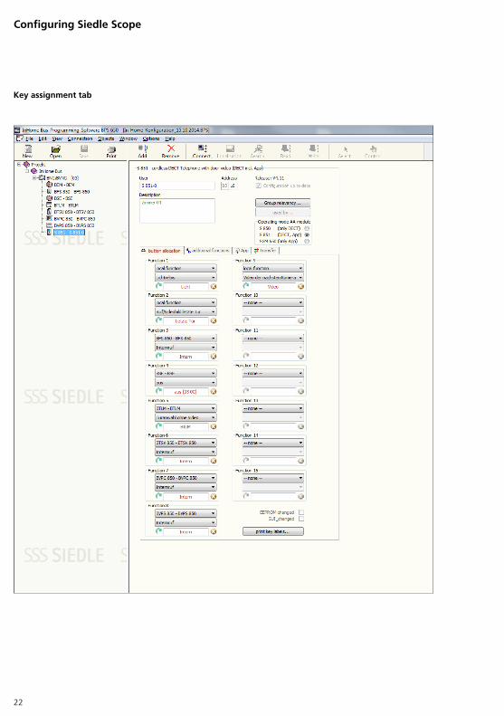
Configuring Siedle Scope Name: Name of the InHome bus component which is shown at devices with displays (e.g. S 8510)Description: Information field for device documentation in the programGroup assignment: Information about programmed group assignmentOperating mode AA module: Operating mode of Siedle Scope/Smart Gateway Mini (standard S 8510: DECT™, App)
Key assignment tab:Function 1–15: Assign functions and change inscriptions. The inscriptions are shown in the device displays. The functional scope is dependent on the components contained in the InHome bus.
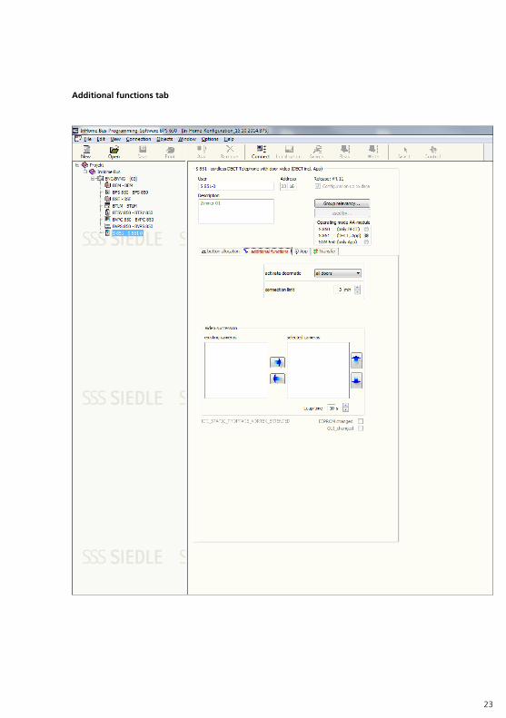
Additional functions tab:Activate Doormatic for: Selection of the door/doors for which the door release is automatically actuated following a door call.Maximum call duration: Duration of maximum call length for a door call (1–10 minutes)
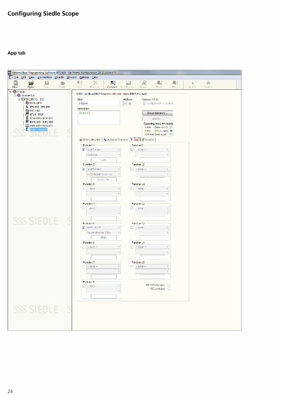
App tab:Function 1–15: Selectable functional scope for the app. The functional scope is dependent on the components contained in the InHome bus and the functional scope of the app.
Transfer tab:Transferring files to the web front end – GUI configuration: Save the Siedle Scope configuration as an XML file in order to allow this to be transferred to the base station/Smart Gateway Mini.
Procedure:1 Connect the PC/laptop to the programming interface using a USB cable.2 Start the programming soft-ware BPS 650… (latest version).3 Click on Connect, to establish an active connection to the InHome bus.4 Click on Search in order to export the system. The Find In-Home devices window opens.5 Click on Find all and add. A con-firmation dialogue opens.6 Confirm the dialogue Do you also want to enter the config-uration of all In-Home devices? with Yes.7 The In-Home bus system is com-pletely exported. The duration of the process depends on the number of installed components/terminals. After terminating the process, you will see a device structure at the lefthand side of the BPS software which contains all the devices detected in the InHome bus. If the list is not complete, check the installation for possible faults and repeat the process.8 Click on the individual com-ponents/terminals in the device structure in order to configure them. The relevant configuration possibility is located on the right of the displayed device structure. In the event of a change the relevant device symbol lights up red.9 Configure the Siedle Scope/Smart Gateway Mini.10 Save the system configuration on the PC/laptop so that this does not have to be exported again at a later date. You can carry out and save changes in the configuration and then transfer them later to the In-Home bus system.11 Click on Write when the configuration has been carried out and saved. A confirmation dialogue opens.12 Click on Select all in the confirmation dialogue Write configura-tion data to In-Home devices. All list entries are selected.
13 Click on Write configuration. The duration of the process depends on the number of installed components/terminals and is displayed in the dialogue below.14 After completed transfer of the InHome bus configuration, the confirmation message All selected devices successfully written appears. Confirm the message by clicking OK.15 Now export the InHome bus configuration as an XML configura-tion file for the base station.16 Click on Disconnect to disconnect the active connection to the InHome bus.17 End the programming soft-ware.
Programming with PC and bus programming software BPS 650… in the latest version.For detailed information go to the help function of the programming software.
22
Configuring Siedle Scope
Key assignment tab
23
Additional functions tab
24
Configuring Siedle Scope
App tab
25
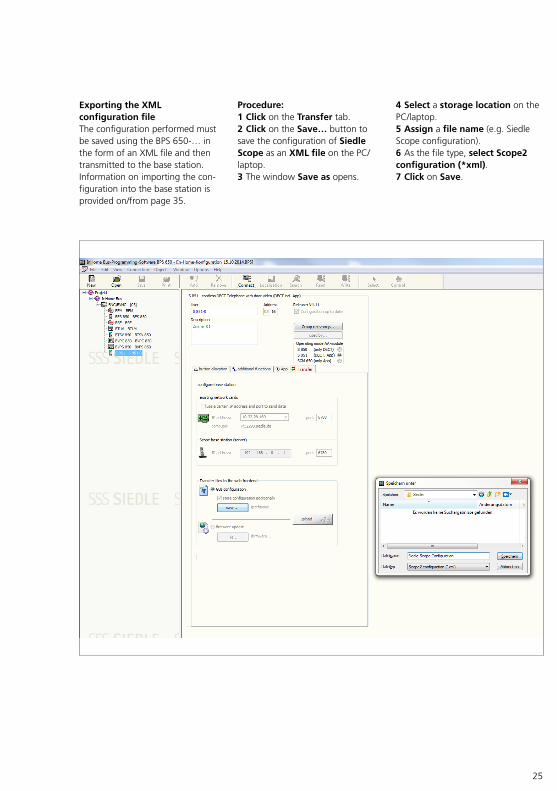
Procedure:1 Click on the Transfer tab.2 Click on the Save… button to save the configuration of Siedle Scope as an XML file on the PC/laptop.3 The window Save as opens.
4 Select a storage location on the PC/laptop.5 Assign a file name (e.g. Siedle Scope configuration).6 As the file type, select Scope2 configuration (*xml).7 Click on Save.
Exporting the XML configuration file The configuration performed must be saved using the BPS 650… in the form of an XML file and then transmitted to the base station. Information on importing the configuration into the base station is provided on/from page 35.
26
Configuring the base station/Smart Gateway Mini
General information The base station can be configured in the following ways:Direct LAN connection possible between PC/Notebook and base station > Partial configuration possible. No system update possible as no internet connection exists.LAN connection via an existing network (WiFi router) with internet connection > Complete configuration of the base station possible. The IP address of the base station must be determined in the menu of the WiFi router.
If you use a different web browser to the Mozilla Firefox, display errors can occur.
Procedure:1 Log in as administrator2 Update the system3 Change the password4 Change the network settings5 Setting the date and time6 Import the InHome bus configuration into the base station.7 Change PIN8 Telephony settings9 Register Siedle App to Siedle Server10 Log out
27
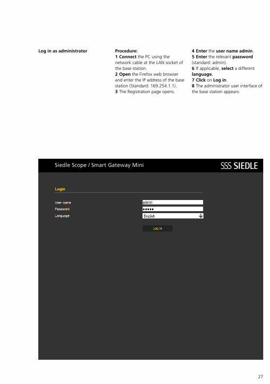
Log in as administrator Procedure:1 Connect the PC using the network cable at the LAN socket of the base station.2 Open the Firefox web browser and enter the IP address of the base station (Standard: 169.254.1.1).3 The Registration page opens.
4 Enter the user name admin.5 Enter the relevant password (standard: admin).6 If applicable, select a different language.7 Click on Log in.8 The administrator user interface of the base station appears.
28
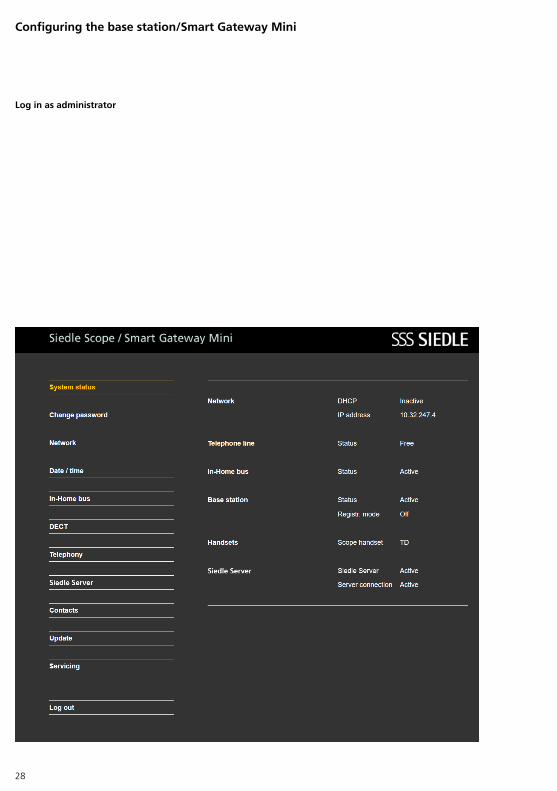
Configuring the base station/Smart Gateway Mini
Log in as administrator
29
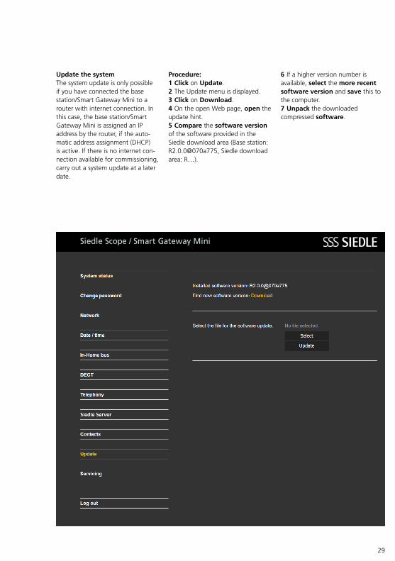
Update the system The system update is only possible if you have connected the base station/Smart Gateway Mini to a router with internet connection. In this case, the base station/Smart Gateway Mini is assigned an IP address by the router, if the automatic address assignment (DHCP) is active. If there is no internet connection available for commissioning, carry out a system update at a later date.
Procedure:1 Click on Update.2 The Update menu is displayed.3 Click on Download.4 On the open Web page, open the update hint.5 Compare the software version of the software provided in the Siedle download area (Base station: R2.0.0@070a775, Siedle download area: R…).
6 If a higher version number is available, select the more recent software version and save this to the computer.7 Unpack the downloaded compressed software.
30
Configuring the base station/Smart Gateway Mini
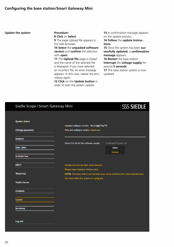
Update the system Procedure:8 Click on Select.9 The page Upload file appears in the web browser.10 Select the unpacked software version and confirm the selection with open.11 The Upload file page is closed and the name of the selected file is displayed. If you have selected an incorrect file, an error message appears. In this case, repeat the procedure again.12 Click on the Update button in order to start the system update.
13 A confirmation message appears on the update process.14 Follow the update instruc-tions.15 Once the system has been suc-cessfully updated, a confirmation message appears.16 Restart the base station: Interrupt the voltage supply for around 5 seconds.17 The base station system is now updated.
31
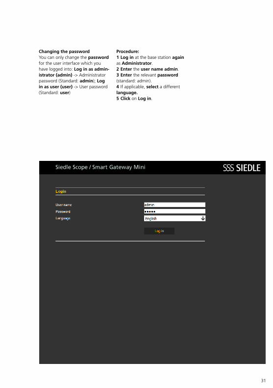
Procedure:1 Log in at the base station again as Administrator.2 Enter the user name admin.3 Enter the relevant password (standard: admin).4 If applicable, select a different language.5 Click on Log in.
Changing the password You can only change the password for the user interface which you have logged into: Log in as admin-istrator (admin) > Administrator password (Standard: admin); Log in as user (user) > User password (Standard: user)
32
Configuring the base station/Smart Gateway Mini
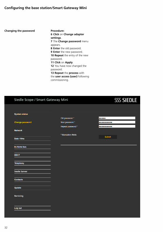
Changing the password Procedure:6 Click on Change adapter settings.7 The Change password menu appears.8 Enter the old password.9 Enter the new password.10 Repeat the entry of the new password.11 Click on Apply.12 You have now changed the password.13 Repeat the process with the user access (user) following commissioning.
33
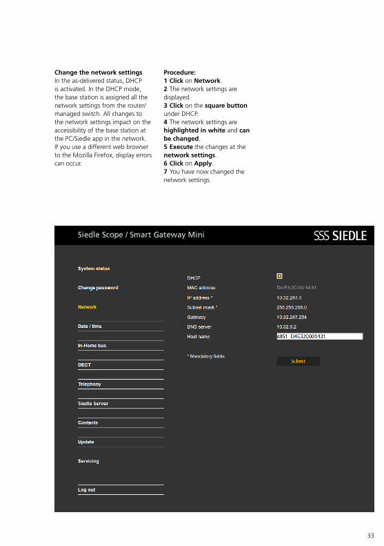
Change the network settings In the asdelivered status, DHCP is activated. In the DHCP mode, the base station is assigned all the network settings from the router/managed switch. All changes to the network settings impact on the accessibility of the base station at the PC/Siedle app in the network.If you use a different web browser to the Mozilla Firefox, display errors can occur.
Procedure:1 Click on Network.2 The network settings are displayed.3 Click on the square button under DHCP.4 The network settings are highlighted in white and can be changed.5 Execute the changes at the network settings.6 Click on Apply.7 You have now changed the network settings.
34
Configuring the base station/Smart Gateway Mini
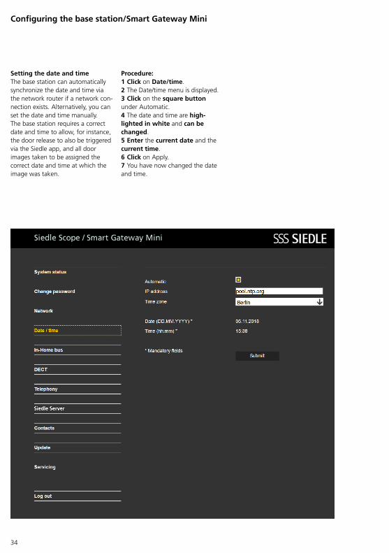
Setting the date and time The base station can automatically synchronize the date and time via the network router if a network connection exists. Alternatively, you can set the date and time manually.The base station requires a correct date and time to allow, for instance, the door release to also be triggered via the Siedle app, and all door images taken to be assigned the correct date and time at which the image was taken.
Procedure:1 Click on Date/time.2 The Date/time menu is displayed.3 Click on the square button under Automatic.4 The date and time are high-lighted in white and can be changed.5 Enter the current date and the current time.6 Click on Apply.7 You have now changed the date and time.
35
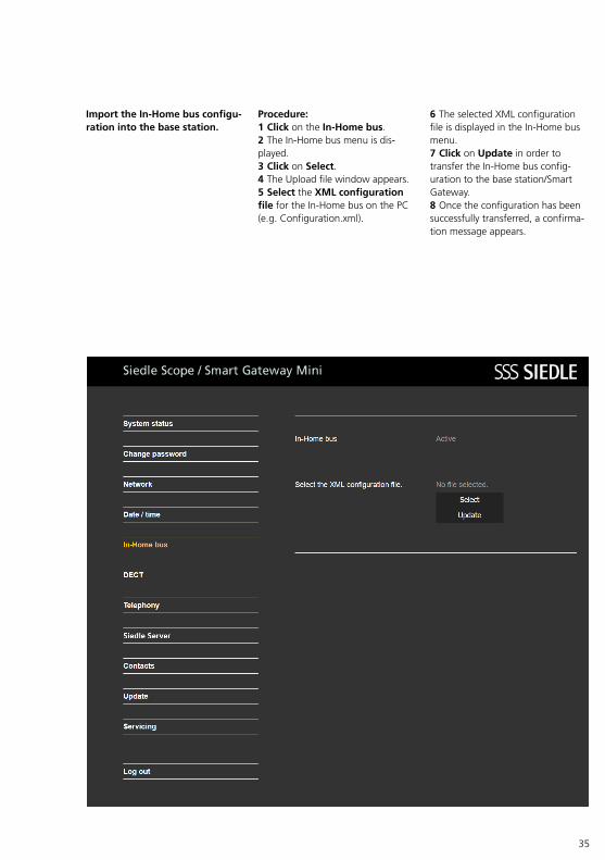
Import the In-Home bus configu-ration into the base station.
Procedure:1 Click on the In-Home bus.2 The InHome bus menu is displayed.3 Click on Select.4 The Upload file window appears.5 Select the XML configuration file for the InHome bus on the PC (e.g. Configuration.xml).
6 The selected XML configuration file is displayed in the InHome bus menu.7 Click on Update in order to transfer the InHome bus configuration to the base station/Smart Gateway.8 Once the configuration has been successfully transferred, a confirmation message appears.
36
Configuring the base station/Smart Gateway Mini
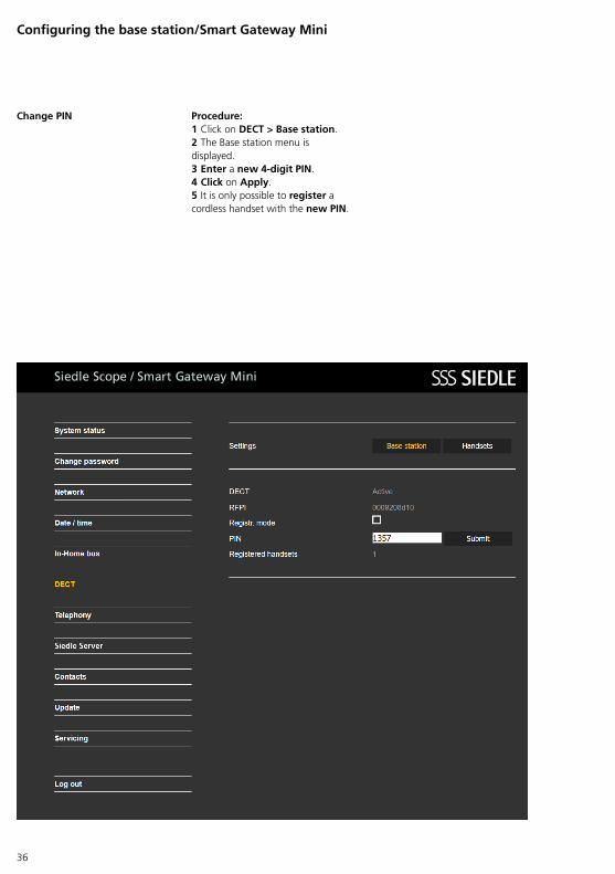
Change PIN Procedure:1 Click on DECT > Base station.2 The Base station menu is displayed.3 Enter a new 4-digit PIN.4 Click on Apply.5 It is only possible to register a cordless handset with the new PIN.
37
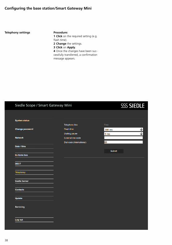
Telephony settings If the base station/Smart Gateway Mini is connected to a telephone system, you may have to carry out different settings in the base station/Smart Gateway Mini in order to enable smooth operation at the telephone system.The following settings can be changed in the Telephony menu:Flash time (300 ms): Precisely timed line interruption in an existing call when initiating the flash to allow a telephony function to be accessed (e.g. to confer)
Dialling pause (0 ms): Precisely timed dialling interruption between the external line digit and the telephone number which is technically required to allow an external call via a telephone system.
External line digit: Predialled number (e.g. 0), in order to allow an external call (public network call) to be carried out in telephone systems. The external line digit is dependent on the upstream telephone system.
Dialling code (International) (00): Replaces the plus symbol in front of an international dialling code (e.g. +49) by the numbers entered here (e.g. 0049). This permits shorter notation for international telephone numbers in the phonebook or faster direct dial using the keypad.
In the flash time and dialling pause settings, you can select the technically required value from predefined lists. Under the external line digit and dialling code (international) settings, you can carry out changes directly via the keypad.
Please note that incorrect settings in the Telephony menu can result in your not being able to make any external phone calls! If the base station is directly linked to the landline connection, no settings need to be carried out here.
38
Configuring the base station/Smart Gateway Mini
Telephony settings Procedure:1 Click on the required setting (e.g. flash time).2 Change the settings.3 Click on Apply.4 Once the changes have been successfully transferred, a confirmation message appears.
39
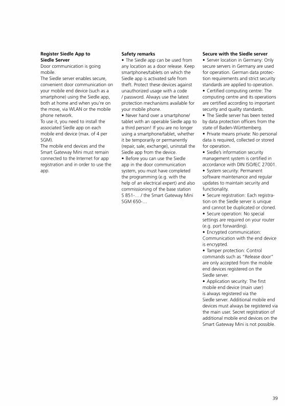
Register Siedle App to Siedle Server Door communication is going mobile.The Siedle server enables secure, convenient door communication on your mobile end device (such as a smartphone) using the Siedle app, both at home and when you’re on the move, via WLAN or the mobile phone network.To use it, you need to install the associated Siedle app on each mobile end device (max. of 4 per SGM).The mobile end devices and the Smart Gateway Mini must remain connected to the Internet for app registration and in order to use the app.
Secure with the Siedle server • Server location in Germany: Only secure servers in Germany are used for operation. German data protection requirements and strict security standards are applied to operation.• Certified computing centre: The computing centre and its operations are certified according to important security and quality standards.• The Siedle server has been tested by data protection officers from the state of BadenWürttemberg.• Private means private: No personal data is required, collected or stored for operation.• Siedle’s information security management system is certified in accordance with DIN ISO/IEC 27001.• System security: Permanent software maintenance and regular updates to maintain security and functionality.• Secure registration: Each registration on the Siedle server is unique and cannot be duplicated or cloned.• Secure operation: No special settings are required on your router (e.g. port forwarding).• Encrypted communication: Communication with the end device is encrypted.• Tamper protection: Control commands such as “Release door” are only accepted from the mobile end devices registered on the Siedle server.• Application security: The first mobile end device (main user) is always registered via the Siedle server. Additional mobile end devices must always be registered via the main user. Secret registration of additional mobile end devices on the Smart Gateway Mini is not possible.
Safety remarks • The Siedle app can be used from any location as a door release. Keep smartphones/tablets on which the Siedle app is activated safe from theft. Protect these devices against unauthorized usage with a code / password. Always use the latest protection mechanisms available for your mobile phone.• Never hand over a smartphone/tablet with an operable Siedle app to a third person! If you are no longer using a smartphone/tablet, whether it be temporarily or permanently (repair, sale, exchange), uninstall the Siedle app from the device. • Before you can use the Siedle app in the door communication system, you must have completed the programming (e.g. with the help of an electrical expert) and also commissioning of the base station S 851… / the Smart Gateway Mini SGM 650…
40
Registering mobile end devices with the Siedle app The first mobile end device is logged on via the Smart Gateway Mini and becomes the only main user.You can register up to 3 more mobile end devices via the main user.In the “Registration” submenu on the Siedle app, the names of all registered mobile end devices are shown to the main user.Tip: Give each mobile end device a unique name (e.g. iPhone [Name]) before registering it on the Siedle server so that you can tell them apart on the main user. On iOS you can change the name via the menu path: Settings > General > About > Name.
Operating requirements • Latest software status on the Smart Gateway Mini (www.siedle.com).• Mobile end device with operating system iOS 10 or higher.• Latest version of the Siedle app.• Functional camera on the mobile end device (for scanning the QR code during the registration process).• The Smart Gateway Mini must synchronise its time via the Internet (via the router).• The time zone in the Smart Gateway Mini must be set to match that of the operating location.• For operation on the Siedle server, the Smart Gateway Mini in the local network can be operated either with a static IP address or via DHCP.• Connection to the Internet (Smart Gateway Mini and each mobile end device) with 1 Mbps transfer speed each (upload/download).• The ports needed for operation must not be explicitly blocked in the router or must be explicitly permitted if necessary (depending on the type of firewall in the router). Generally, no special approval settings are needed for standard routers for private use.• Optional: It is advisable to use different device names so you can distinguish between the mobile end devices.
Configuring the base station/Smart Gateway Mini
Functions The Siedle app turns a smartphone/tablet into a mobile upgrade of an InHome door intercom from Siedle. The app has been specially developed for the requirements of door communication. Its functions correspond to those of a Siedle indoor station. It receives the door call, provides a live video image, establishes a speech connection and opens the door. Naturally with all the benefits of builtin security and every convenience, for instance a video memory. The video image is immediately available. The speech quality fulfils Siedle’s stringent standards, and the door is opened by pressing the familiar key symbol with a fingertip.
The Siedle app is the mobile complement to a door intercom system and does not replace an indoor device. For this reason, Siedle recommends including a wired indoor station in your system planning alongside the app.
For operation of this Siedle app, the Smart Gateway Mini (Siedle Scope) is required in connection with the InHome bus installation system. For more information, refer to the website.
Functions: Audio and video door communication Door release, light switching Secure door release function Handsfree function Incall volume adjustment possible Microphone muting Different ringtones Manual door dialling Automatic video memory function Auto login Switchover between landscape and portrait format for video (iPhone) Switchover between landscape and portrait format for the entire app (iPad)
41
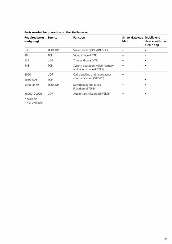
Ports needed for operation on the Siedle server
Required ports (outgoing)
Service Function Smart Gateway Mini
Mobile end device with the Siedle app
53 TCP/UDP Server access (DNS/DNSSEC) • •
80 TCP Video image (HTTP) • –
123 UDP Time and date (NTP) • •
443 TCP System operation, video memory and video image (HTTPS)
• •
5060 UDP Call signalling and negotiating communication (SIP/SIPS)
• –
5060–5061 TCP – •
3478–3479 TCP/UDP Determining the public IP address (STUN)
• •
10000–20000 UDP Audio transmission (RTP/SRTP) • •
• available– Not available
42
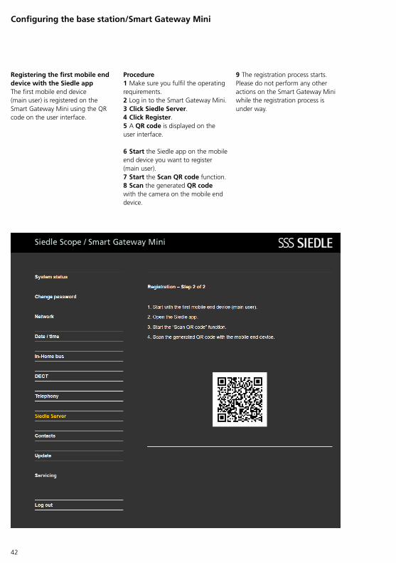
Registering the first mobile end device with the Siedle app The first mobile end device (main user) is registered on the Smart Gateway Mini using the QR code on the user interface.
Procedure1 Make sure you fulfil the operating requirements.2 Log in to the Smart Gateway Mini.3 Click Siedle Server.4 Click Register.5 A QR code is displayed on the user interface.
6 Start the Siedle app on the mobile end device you want to register (main user).7 Start the Scan QR code function.8 Scan the generated QR code with the camera on the mobile end device.
9 The registration process starts. Please do not perform any other actions on the Smart Gateway Mini while the registration process is under way.
Configuring the base station/Smart Gateway Mini
43
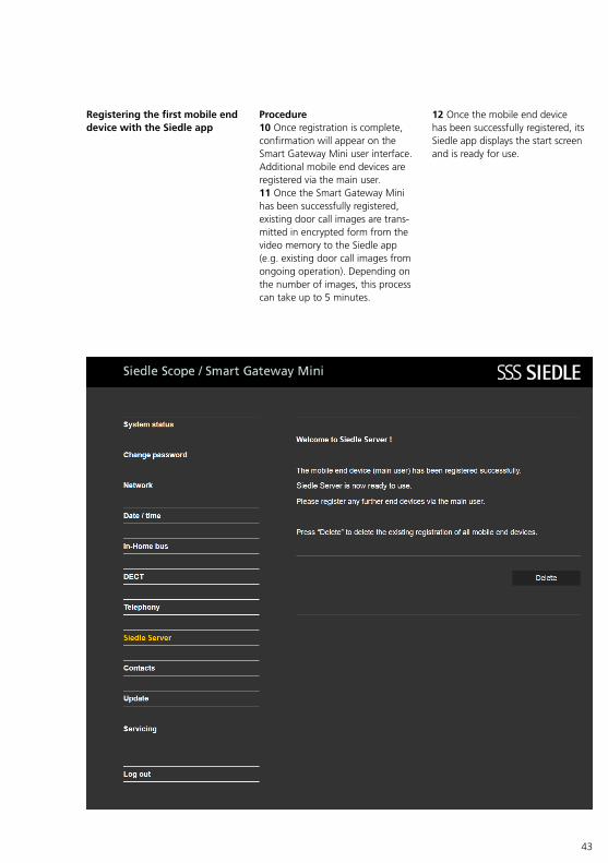
Registering the first mobile end device with the Siedle app
Procedure10 Once registration is complete, confirmation will appear on the Smart Gateway Mini user interface. Additional mobile end devices are registered via the main user.11 Once the Smart Gateway Mini has been successfully registered, existing door call images are transmitted in encrypted form from the video memory to the Siedle app (e.g. existing door call images from ongoing operation). Depending on the number of images, this process can take up to 5 minutes.
12 Once the mobile end device has been successfully registered, its Siedle app displays the start screen and is ready for use.
44
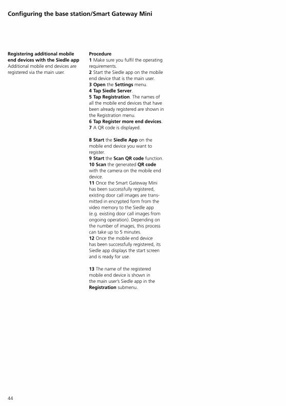
Registering additional mobile end devices with the Siedle app Additional mobile end devices are registered via the main user.
Procedure1 Make sure you fulfil the operating requirements.2 Start the Siedle app on the mobile end device that is the main user.3 Open the Settings menu.4 Tap Siedle Server.5 Tap Registration. The names of all the mobile end devices that have been already registered are shown in the Registration menu.6 Tap Register more end devices.7 A QR code is displayed.
8 Start the Siedle App on the mobile end device you want to register.9 Start the Scan QR code function.10 Scan the generated QR code with the camera on the mobile end device.11 Once the Smart Gateway Mini has been successfully registered, existing door call images are transmitted in encrypted form from the video memory to the Siedle app (e.g. existing door call images from ongoing operation). Depending on the number of images, this process can take up to 5 minutes.12 Once the mobile end device has been successfully registered, its Siedle app displays the start screen and is ready for use.
13 The name of the registered mobile end device is shown in the main user’s Siedle app in the Registration submenu.
Configuring the base station/Smart Gateway Mini
45
Deleting registration(s) Registration on the Siedle server can be deleted as follows:• Separately and individually per mobile end device, if all registrations for the mobile end devices are deleted, then the Smart Gateway Mini registration is automatically deleted too.• Centrally and completely via the Smart Gateway Mini: All registrations are deleted in one go.
Deleting registrations for mobile end devices The registrations for individual mobile end devices can be deleted directly via the Siedle app on the relevant mobile end device.If a main user is deleted, a new main user must be selected if there are several registered mobile end devices.
Procedure1 Open the Siedle App on the mobile end device for which you want to delete the registration.2 Open the Settings menu.3 Tap Delete registration.4 Confirm the security prompt.5 If necessary, select another main user, if there are several registered mobile end devices and you have deleted the registration of the former main user.
NoteIf there are no more mobile end devices registered on the Siedle server, the Smart Gateway Mini registration will be completely deleted and the server connection will be terminated. For technical reasons, this can take several minutes.
Deleting a registration on the Siedle Server via the Smart Gateway Mini The registration on the Siedle server can be completely deleted via the Smart Gateway Mini.
Procedure1 Log in to the Smart Gateway Mini.2 Click Siedle Server.3 Click Delete.4 The system will start to delete the existing registration. Please do not perform any other actions on the Smart Gateway Mini while the deletion process is under way.5 Once the registration has been successfully deleted, the display on the user interface switches back to registration mode.
46
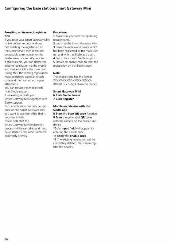
Resetting an incorrect registra-tion If you reset your Smart Gateway Mini to the default settings without first deleting the registration on the Siedle server, then it will not be possible to reregister on the Siedle server for security reasons.If still available, you can delete the existing registration via the mobile end device which is the main user.Failing this, the existing registration must be deleted using an enable code and then carried out again afterwards.You can obtain the enable code from Siedle support.If necessary, activate your Smart Gateway Mini together with Siedle support.Each enable code can only be used once on the Smart Gateway Mini you want to activate. After that it becomes invalid.Please note that the Smart Gateway Mini registration process will be cancelled and must be restarted if the code is entered incorrectly 3 times.
Procedure1 Make sure you fulfil the operating requirements.2 Log in to the Smart Gateway Mini.3 Have the mobile end device which has been registered as the main user to hand with the Siedle app open.4 Get in touch with Siedle support.5 Obtain an enable code to reset the registration on the Siedle server.
NoteThe enable code has the format XXXXXXXXXXXXXXXXXXXXXXXXX (5 x 5digit character blocks).
Smart Gateway Mini6 Click Siedle Server.7 Click Register.
Mobile end device with the Siedle app8 Start the Scan QR code function.9 Scan the generated QR code with the camera on the mobile end device.10 An input field will appear for entering the enable code.11 Enter the enable code.12 The existing registration will be completely deleted. You can reregister the devices.
Configuring the base station/Smart Gateway Mini
47
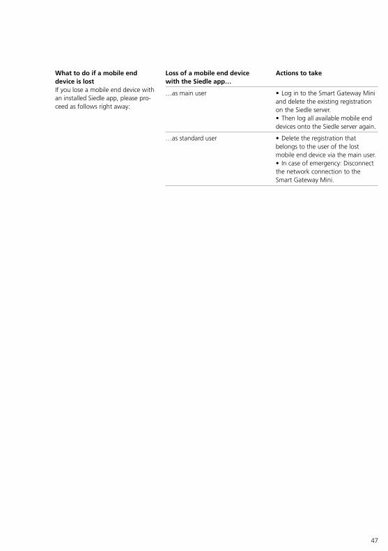
What to do if a mobile end device is lost If you lose a mobile end device with an installed Siedle app, please proceed as follows right away:
Loss of a mobile end device with the Siedle app…
Actions to take
…as main user • Log in to the Smart Gateway Mini and delete the existing registration on the Siedle server. • Then log all available mobile end devices onto the Siedle server again.
…as standard user • Delete the registration that belongs to the user of the lost mobile end device via the main user.• In case of emergency: Disconnect the network connection to the Smart Gateway Mini.
48
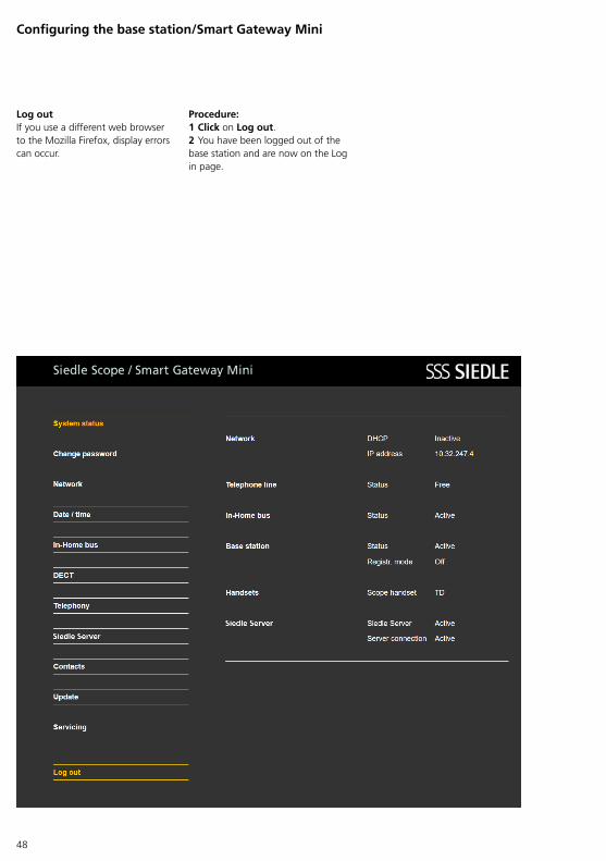
Procedure:1 Click on Log out.2 You have been logged out of the base station and are now on the Log in page.
Log out If you use a different web browser to the Mozilla Firefox, display errors can occur.
Configuring the base station/Smart Gateway Mini

49
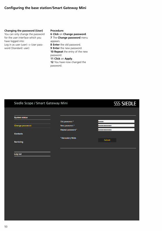
Changing the password (User) You can only change the password for the user interface which you have logged into:Log in as user (user) > User password (Standard: user)
Procedure:1 Log in at the base station again as user.2 Enter the user name user.3 Enter the relevant password (standard: user).4 If applicable, select a different language.5 Click on Log in.
50
Configuring the base station/Smart Gateway Mini
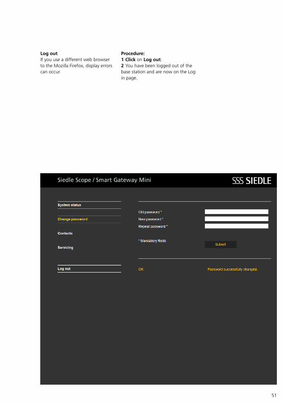
Procedure:6 Click on Change password.7 The Change password menu appears.8 Enter the old password.9 Enter the new password.10 Repeat the entry of the new password.11 Click on Apply.12 You have now changed the password.
Changing the password (User)You can only change the password for the user interface which you have logged into:Log in as user (user) > User password (Standard: user)
51
Procedure:1 Click on Log out.2 You have been logged out of the base station and are now on the Log in page.
Log out If you use a different web browser to the Mozilla Firefox, display errors can occur.
52
Power
Line
In-Home Prog.
LAN
Configuring the base station/Smart Gateway Mini
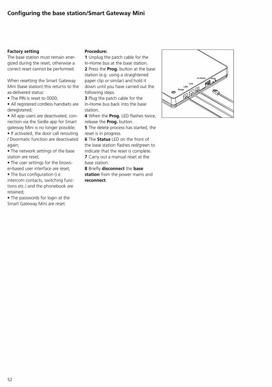
Factory setting The base station must remain energized during the reset, otherwise a correct reset cannot be performed.
When resetting the Smart Gateway Mini (base station) this returns to the asdelivered status:• The PIN is reset to 0000;• All registered cordless handsets are deregistered;• All app users are deactivated, connection via the Siedle app for Smart gateway Mini is no longer possible;• If activated, the door call rerouting / Doormatic function are deactivated again;• The network settings of the base station are reset;• The user settings for the browserbased user interface are reset;• The bus configuration (i.e. intercom contacts, switching functions etc.) and the phonebook are retained;• The passwords for login at the Smart Gateway Mini are reset.
Procedure:1 Unplug the patch cable for the InHome bus at the base station.2 Press the Prog. button at the base station (e.g. using a straightened paper clip or similar) and hold it down until you have carried out the following steps.3 Plug the patch cable for the InHome bus back into the base station.4 When the Prog. LED flashes twice, release the Prog. button.5 The delete process has started, the reset is in progress.6 The Status LED on the front of the base station flashes red/green to indicate that the reset is complete.7 Carry out a manual reset at the base station.8 Briefly disconnect the base station from the power mains and reconnect.
Power
Line
In-Home Prog.
LAN
53
Handsets – Getting started
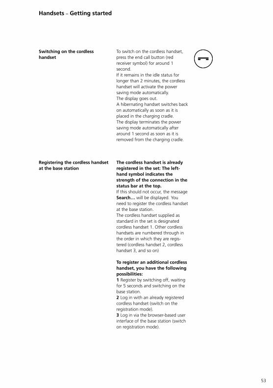
The cordless handset is already registered in the set: The left-hand symbol indicates the strength of the connection in the status bar at the top.If this should not occur, the message Search… will be displayed. You need to register the cordless handset at the base station.The cordless handset supplied as standard in the set is designated cordless handset 1. Other cordless handsets are numbered through in the order in which they are registered (cordless handset 2, cordless handset 3, and so on)
To register an additional cordless handset, you have the following possibilities:1 Register by switching off, waiting for 5 seconds and switching on the base station.2 Log in with an already registered cordless handset (switch on the registration mode).3 Log in via the browserbased user interface of the base station (switch on registration mode).
To switch on the cordless handset, press the end call button (red receiver symbol) for around 1 second.If it remains in the idle status for longer than 2 minutes, the cordless handset will activate the power saving mode automatically.The display goes out.A hibernating handset switches back on automatically as soon as it is placed in the charging cradle. The display terminates the power saving mode automatically after around 1 second as soon as it is removed from the charging cradle.
Registering the cordless handset at the base station
Switching on the cordless handset
54
Handsets – Getting started
Start screen Display navigation
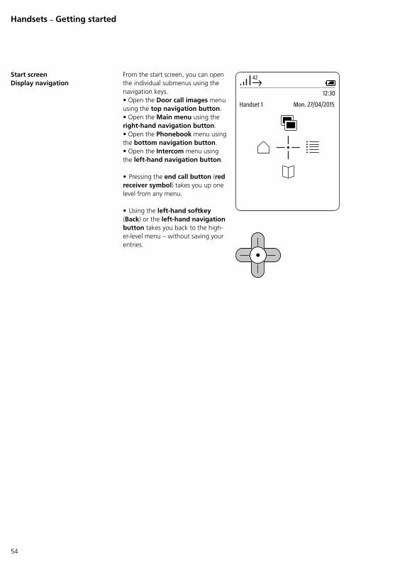
From the start screen, you can open the individual submenus using the navigation keys.• Open the Door call images menu using the top navigation button.• Open the Main menu using the right-hand navigation button.• Open the Phonebook menu using the bottom navigation button.• Open the Intercom menu using the left-hand navigation button.
• Pressing the end call button (red receiver symbol) takes you up one level from any menu.
• Using the left-hand softkey (Back) or the left-hand navigation button takes you back to the higherlevel menu – without saving your entries.
42
Handset 1 Mon. 27/04/2015
12:30
55
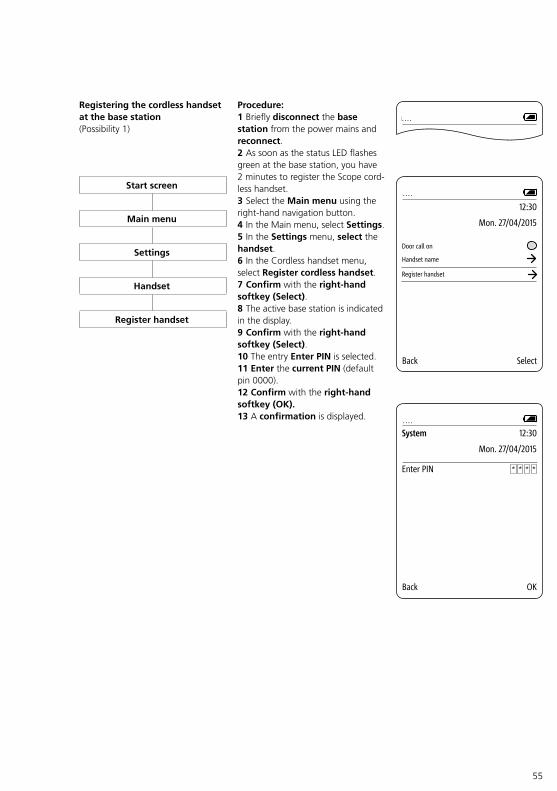
Registering the cordless handset at the base station (Possibility 1)
Procedure:1 Briefly disconnect the base station from the power mains and reconnect.2 As soon as the status LED flashes green at the base station, you have 2 minutes to register the Scope cordless handset.3 Select the Main menu using the righthand navigation button.4 In the Main menu, select Settings.5 In the Settings menu, select the handset.6 In the Cordless handset menu, select Register cordless handset.7 Confirm with the right-hand softkey (Select).8 The active base station is indicated in the display.9 Confirm with the right-hand softkey (Select).10 The entry Enter PIN is selected.11 Enter the current PIN (default pin 0000).12 Confirm with the right-hand softkey (OK).13 A confirmation is displayed.
42
System
Mon. 27/04/2015
12:30
Back OK
Enter PIN * * **
....
....
42
Mon. 27/04/2015
12:30
Back Select
Handset name
Door call on
Register handset
....Start screen
Main menu
Settings
Handset
Register handset
56
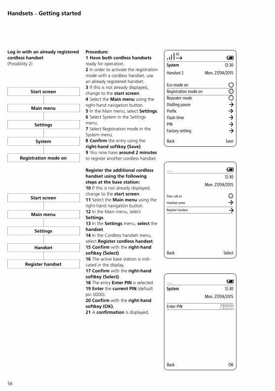
Log in with an already registered cordless handset (Possibility 2)
Procedure:1 Have both cordless handsets ready for operation.2 In order to activate the registration mode with a cordless handset, use an already registered handset.3 If this is not already displayed, change to the start screen.4 Select the Main menu using the righthand navigation button.5 In the Main menu, select Settings.6 Select System in the Settings menu.7 Select Registration mode in the System menu.8 Confirm the entry using the right-hand softkey (Save).9 You now have around 2 minutes to register another cordless handset.
Register the additional cordless handset using the following steps at the base station:10 If this is not already displayed, change to the start screen.11 Select the Main menu using the righthand navigation button.12 In the Main menu, select Settings.13 In the Settings menu, select the handset.14 In the Cordless handset menu, select Register cordless handset.15 Confirm with the right-hand softkey (Select).16 The active base station is indicated in the display.17 Confirm with the right-hand softkey (Select).18 The entry Enter PIN is selected.19 Enter the current PIN (default pin 0000).20 Confirm with the right-hand softkey (OK).21 A confirmation is displayed.
42
System
Handset 2 Mon. 27/04/2015
12:30
Back Save
Registration mode onRepeater mode
Eco mode on
Dialling pausePrefixFlash timePINFactory setting
42
System
Mon. 27/04/2015
12:30
Back OK
Enter PIN * * **
....
Start screen
Main menu
Settings
System
Registration mode on
42
Mon. 27/04/2015
12:30
Back Select
Handset name
Door call on
Register handset
....
Start screen
Main menu
Settings
Handset
Register handset
Handsets – Getting started
57
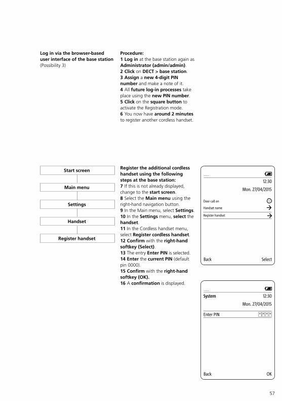
Log in via the browser-based user interface of the base station (Possibility 3)
Procedure:1 Log in at the base station again as Administrator (admin/admin).2 Click on DECT > base station.3 Assign a new 4-digit PIN number and make a note of it.4 All future log-in processes take place using the new PIN number.5 Click on the square button to activate the Registration mode.6 You now have around 2 minutes to register another cordless handset.
Register the additional cordless handset using the following steps at the base station:7 If this is not already displayed, change to the start screen.8 Select the Main menu using the righthand navigation button.9 In the Main menu, select Settings.10 In the Settings menu, select the handset.11 In the Cordless handset menu, select Register cordless handset.12 Confirm with the right-hand softkey (Select).13 The entry Enter PIN is selected.14 Enter the current PIN (default pin 0000).15 Confirm with the right-hand softkey (OK).16 A confirmation is displayed. 42
System
Mon. 27/04/2015
12:30
Back OK
Enter PIN * * **
....
42
Mon. 27/04/2015
12:30
Back Select
Handset name
Door call on
Register handset
....Start screen
Main menu
Settings
Handset
Register handset
58
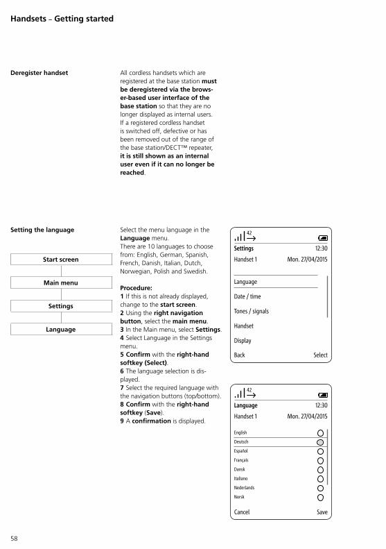
Setting the language Select the menu language in the Language menu. There are 10 languages to choose from: English, German, Spanish, French, Danish, Italian, Dutch, Norwegian, Polish and Swedish.
Procedure:1 If this is not already displayed, change to the start screen.2 Using the right navigation button, select the main menu.3 In the Main menu, select Settings.4 Select Language in the Settings menu.5 Confirm with the right-hand softkey (Select).6 The language selection is displayed.7 Select the required language with the navigation buttons (top/bottom).8 Confirm with the right-hand softkey (Save).9 A confirmation is displayed.
42
Settings
Handset 1 Mon. 27/04/2015
12:30
Back Select
Language
Date / time
Tones / signals
Handset
Display
Deregister handset All cordless handsets which are registered at the base station must be deregistered via the brows-er-based user interface of the base station so that they are no longer displayed as internal users. If a registered cordless handset is switched off, defective or has been removed out of the range of the base station/DECT™ repeater, it is still shown as an internal user even if it can no longer be reached.
42
Language
Handset 1 Mon. 27/04/2015
12:30
Cancel Save
Deutsch
Español
English
Français
Dansk
Italiano
Nederlands
Norsk
Start screen
Main menu
Settings
Language
Handsets – Getting started
59
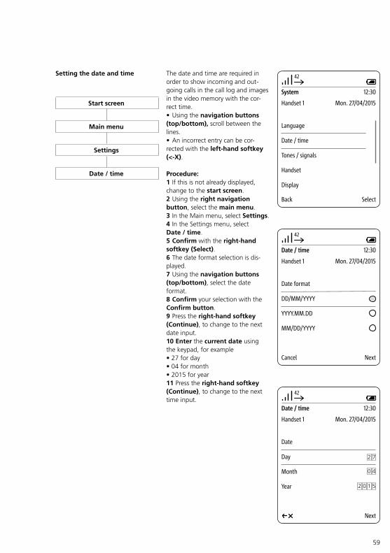
Setting the date and time The date and time are required in order to show incoming and outgoing calls in the call log and images in the video memory with the correct time.• Using the navigation buttons (top/bottom), scroll between the lines.• An incorrect entry can be corrected with the left-hand softkey (<-X).
Procedure:1 If this is not already displayed, change to the start screen.2 Using the right navigation button, select the main menu.3 In the Main menu, select Settings.4 In the Settings menu, select Date / time.5 Confirm with the right-hand softkey (Select).6 The date format selection is displayed.7 Using the navigation buttons (top/bottom), select the date format.8 Confirm your selection with the Confirm button.9 Press the right-hand softkey (Continue), to change to the next date input.10 Enter the current date using the keypad, for example• 27 for day• 04 for month• 2015 for year11 Press the right-hand softkey (Continue), to change to the next time input.
42
System
Handset 1 Mon. 27/04/2015
12:30
Back Select
Language
Date / time
Tones / signals
Handset
Display
42
Date / time
Handset 1 Mon. 27/04/2015
12:30
Next
Date
Day
Month
Year
2 7
2 0 51
40
42
Date / time
Handset 1 Mon. 27/04/2015
12:30
Cancel Next
Date format
DD/MM/YYYY
YYYY.MM.DD
MM/DD/YYYY
Start screen
Main menu
Settings
Date / time
60
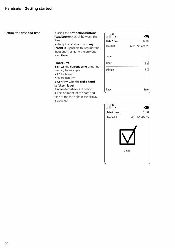
• Using the navigation buttons (top/bottom), scroll between the lines.• Using the left-hand softkey (back), it is possible to interrupt the input and change to the previous view Date.
Procedure:1 Enter the current time using the keypad, for example• 12 for hours• 30 for minutes2 Confirm with the right-hand softkey (Save).3 A confirmation is displayed.4 The indication of the date and time at the top right in the display is updated.
42
Date / time
Handset 1 Mon. 27/04/2015
12:30
Save
Time
Minute 03
42
Saved
Date / time
Handset 1 Mon. 27/04/2015
12:30
21Hour
Back
Handsets – Getting started
Setting the date and time
61
Final assignments
Complete function check Damit Sie die Türsprechanlage nutzen können, müssen im InHomeBus zumindest die Grundfunktionen „Türruf“, „Tür öffnen“ und „Tür anwählen“ programmiert werden.
The data from the door intercom with Siedle Scope is transmitted via the Siedle InHome bus. Programming is described in the In-Home-Bus: Video system manual.
Procedure:Carry out a complete function check of Siedle Scope and the intercom system. For operation of the cordless handset, use the operating instructions supplied on the data carrier.
Check at least the following points with Siedle Scope:• Conducting an external telephone call• Conducting an internal telephone call to other cordless handsets• Accepting a door call with video image transmission• Light switching• Triggering a door release• Calling a door• Calling indoor devices• Accepting calls from indoor devices• Extended switching functions (if available)• Doormatic function• Door call forwarding
Check at least the following points with the Siedle app:• Accepting a door call with video image transmission• Light switching• Triggering a door release• Calling the last door• Calling selected doors individually
Simplified EU Declaration of Conformity
Hereby,S. Siedle & Söhne Telefon- u. Telegrafenwerke OHG declares that the radio equipment type• S 8510• SZM 8510• SGM 8510is in compliance with Directive 2014/53/EU.The full text of the EU declaration of conformity is available at the following internet address:https://www.siedle.comPath: International > Home > Service > Download > Electricians and the wholesale trade > Certificates, lighting data > Declaration of conformity > S
Remarks This device is produced in different country variants/country variant combinations. Countryspecific technical connection conditions have been observed.Every country variant/country variant combination is exclusively designed for operation at the analogue telephone connection in the network of the specific country/countries.
62
Index
Additional cordless handsets 4
Administration by means of software 4
App link 4
Assembling and connecting the base station 12
Basic functions 16
Change PIN 36
Change the network settings 33
Changing the password 31, 49
Charging cradle for the Scope cordless handset 11
Charging the cordless handset 11
Checking the scope of supply for completeness 10
Complete function check 61
Configuring Siedle Scope 21
Configuring the base station/Smart Gateway Mini 26
Configuring the InHome bus system 15
Contact with liquids 6
Contents 3
Deleting registration(s) 45
Deregister handset 58
Display navigation 40
Factory setting 52
Final assignments 61
Fulfilling commissioning requirements 7
Functions 40
General information 4, 26
Import the InHome bus configuration into the base station. 35
Intercom functions 16
Legal notes 6
Log in as administrator 27
Log out 48, 51
Manual programming 17
Medical devices/facilities 5
Operating requirements 40
Ports needed for operation on the Siedle server 41
Preparation 7
Preparing the PC/laptop 13
Programming 15, 18, 20
Protect your property! 6
Providing the accessories required for commissioning 9
Providing the system documentation 9
Reading the product information and commissioning instructions 5
Register Siedle App to Siedle Server 39
Registering additional mobile end devices with the Siedle app 44
Registering mobile end devices with the Siedle app 40
Registering the cordless handset at the base station 53
Registering the first mobile end device with the Siedle app 42
Resetting an incorrect registration 46
Safety remarks 5
Secure with the Siedle server 39
Servicing 6
Setting the date and time 34, 59
Setting the language 58
Simplified EU Declaration of Conformity 61
Start screen 54
Status LED at the base station 12
Stepbystep through the commissioning process 7
Supplementary functions 16
Switching on the cordless handset 53
System overview 8
Telephony settings 37
The cordless landline telephone 47
The mobile video intercom 54
Update the system 29
What to do if a mobile end device is lost 47

63

S. Siedle & SöhneTelefon- und Telegrafenwerke OHG
Postfach 115578113 FurtwangenBregstraße 178120 Furtwangen
Telefon +49 7723 63-0Telefax +49 7723 [email protected]
© 2014/11.18Printed in GermanyBest. Nr. 210008823-01