Continuous granulation with a twin-screw extruder · Impact of the extruder setup on continuous...
112
CONTINUOUS GRANULATION WITH A TWIN-SCREW EXTRUDER Inaugural-Dissertation zur Erlangung des Doktorgrades der Mathematisch-Naturwissenschaftlichen Fakultät der Heinrich-Heine-Universität Düsseldorf vorgelegt von Dejan Djuric aus Lemgo Juni 2008
-
Upload
trinhduong -
Category
Documents
-
view
235 -
download
3
Transcript of Continuous granulation with a twin-screw extruder · Impact of the extruder setup on continuous...
CONTINUOUS GRANULATION WITH A TWIN-SCREW EXTRUDER
Inaugural-Dissertation
zur Erlangung des Doktorgrades der
Mathematisch-Naturwissenschaftlichen Fakultät der Heinrich-Heine-Universität Düsseldorf
vorgelegt von Dejan Djuric aus Lemgo
Juni 2008
Aus dem Institut für pharmazeutische Technologie und Biopharmazie der Heinrich-Heine-Universität Düsseldorf Gedruckt mit der Genehmigung der Mathematisch-Naturwissenschaftlichen Fakultät der Heinrich-Heine-Universität Düsseldorf Referent: Prof. Dr. P. Kleinebudde Koreferent: Prof. Dr. J. Breitkreutz
Tag der mündlichen Prüfung: 27.6.2008
I
Contents Contents…………………………………………………………………………………………. I List of abbreviations…………………………………………………………………………… V A Introduction...............................................................................................................1
1. Granulation ...........................................................................................................1 1.1 Definition and impact .....................................................................................1 1.2 Batch versus continuous granulation processes............................................1 1.3 Continuous granulation methods ...................................................................2
2. Twin screw extruder..............................................................................................3 2.1 State of the art ...............................................................................................3 2.2 Screw configuration .......................................................................................4
2.2.1 Impact.....................................................................................................4 2.2.2 Conveying elements ...............................................................................4 2.2.3 Kneading elements.................................................................................5 2.2.4 Combing mixer elements........................................................................6
3. Mixing behaviour of screw elements.....................................................................7 3.1 General aspects.............................................................................................7 3.2 Distributive mixing..........................................................................................7 3.3 Dispersive mixing...........................................................................................8
4. Leistritz Micro GL 27 / 28D ...................................................................................8 5. APV MP 19 TC 25.................................................................................................9
B Aim of this study .....................................................................................................10 C Results and Discussion ..........................................................................................11
1. Impact of the extruder setup on continuous granulation with a twin-screw extruder......................................................................................................................11
1.1 Impact of screw elements on lactose granules at 2kg/h input rate...............11 1.1.1 Introduction...........................................................................................11 1.1.2 Experimental setup...............................................................................11 1.1.3 Particle size distribution of granules .....................................................11 1.1.4 Granule porosity ...................................................................................14 1.1.5 Granule friability....................................................................................16 1.1.6 Granule flowability ................................................................................17 1.1.7 Scanning electron microscopy..............................................................19 1.1.8 Tablet tensile strength ..........................................................................20 1.1.9 Summary ..............................................................................................22
1.2 Impact of screw elements on mannitol granules at 2kg/h input rate ............23 1.2.1 Introduction...........................................................................................23 1.2.2 Experimental setup...............................................................................23 1.2.3 Particle size distribution of granules .....................................................23 1.2.4 Granule porosity ...................................................................................25 1.2.5 Granule friability....................................................................................26

II
1.2.6 Granule flowability ............................................................................... 28 1.2.7 Tablet tensile strength.......................................................................... 29 1.2.8 Summary ............................................................................................. 30
1.3 Impact of screw elements on dicalcium phosphate granules at 2kg/h input rate .................................................................................................................... 31
1.3.1 Introduction .......................................................................................... 31 1.3.2 Experimental setup .............................................................................. 31 1.3.3 Particle size distribution of granules .................................................... 31 1.3.4 Granule porosity .................................................................................. 32 1.3.5 Granule friability................................................................................... 33 1.3.6 Granule flowability ............................................................................... 34 1.3.7 Tablet tensile strength.......................................................................... 35 1.3.8 Summary ............................................................................................. 36
1.4 Impact of screw elements on lactose granules at 6kg/h input rate.............. 37 1.4.1 Introduction .......................................................................................... 37 1.4.2 Experimental setup .............................................................................. 37 1.4.3 Particle size distribution of granules .................................................... 37 1.4.4 Granule porosity .................................................................................. 38 1.4.5 Granule friability................................................................................... 40 1.4.6 Granule flowability ............................................................................... 41 1.4.7 Tablet tensile strength.......................................................................... 42 1.4.8 Summary ............................................................................................. 43
1.5 Impact of screw elements on dicalcium phosphate granules at 6kg/h input rate .................................................................................................................... 44
1.5.1 Introduction .......................................................................................... 44 1.5.2 Experimental setup .............................................................................. 44 1.5.3 Particle size distribution of granules .................................................... 44 1.5.4 Granule porosity .................................................................................. 46 1.5.5 Granule friability................................................................................... 47 1.5.6 Granule flowability ............................................................................... 49 1.5.7 Tablet tensile strength.......................................................................... 49 1.5.8 Summary ............................................................................................. 50
1.6 Influence of process parameters on granulation of mannitol....................... 51 1.6.1 Introduction .......................................................................................... 51 1.6.2 Experimental setup .............................................................................. 51 1.6.3 Particle size distribution ....................................................................... 52 1.6.4 Granule friability................................................................................... 55 1.6.5 Summary ............................................................................................. 56
1.7 Summary .................................................................................................... 57 2. Mixing behaviour of screw elements .................................................................. 58
2.1 Distributive mixing....................................................................................... 58 2.1.1 Introduction .......................................................................................... 58
III
2.1.2 Experimental setup...............................................................................58 2.1.3 Water content of granules during granulation with two powder feeders59 2.1.4 Theophylline content of granules during granulation with two powder feeders .............................................................................................................60
2.2 Dispersive mixing.........................................................................................62 2.2.1 Introduction...........................................................................................62 2.2.2 Experimental setup...............................................................................62 2.2.3 Dispersive effect on dicalcium phosphate ............................................63
2.3 Summary .....................................................................................................64 3. Comparison of twin-screw extruders for continuous granulation.........................65
3.1 Introduction..................................................................................................65 3.2 Experimental setup ......................................................................................65 3.3 Granulation of dicalcium phosphate.............................................................66
3.3.1 Particle size distribution of granules .....................................................66 3.3.2 Granule friability....................................................................................70 3.3.3 Granule flowability ................................................................................71 3.3.4 Tablet tensile strength ..........................................................................71
3.4 Granulation of lactose..................................................................................73 3.4.1 Particle size distribution of granules .....................................................73 3.4.2 Granule friability....................................................................................74 3.4.3 Granule flowability ................................................................................74 3.4.4 Tablet tensile strength ..........................................................................75 3.4.5 Summary ..............................................................................................76
D Summary ................................................................................................................77 E Zusammenfassung der Arbeit ................................................................................79 F Experimental part ...................................................................................................81
1. Materials .............................................................................................................81 1.1 Active pharmaceutical ingredient .................................................................81 1.2 Binders and Fillers .......................................................................................81 1.3 Other substances.........................................................................................82
2. Methods ..............................................................................................................82 2.1 General methods .........................................................................................82
2.1.1 Design of experiments..........................................................................82 2.1.2 Sample preparation ..............................................................................82
2.2 Manufacturing methods ...............................................................................82 2.2.1 Extruder setup for evaluation of the screw impact ................................82 2.2.2 Extruder setup for evaluation of distributive mixing of screw elements.84 2.2.3 Extruder setup for evaluation of dispersive mixing of screw elements..84 2.2.4 Extruder setup for granulation of mannitol ............................................85 2.2.5 Extruder setup for the comparison of two extruders .............................85 2.2.6 Determination of free chamber volume fraction ....................................87 2.2.7 Blending of powders .............................................................................87
IV
2.2.8 Drying and storage of granules............................................................ 87 2.2.9 Compression of granules ..................................................................... 87
2.3 Characterisation methods ........................................................................... 88 2.3.1 Sieve analysis...................................................................................... 88 2.3.2 Granule friability determination with an air jet sieve............................. 88 2.3.3 Helium density of granules................................................................... 89 2.3.4 Mercury density of granules................................................................. 89 2.3.5 Granule porosity .................................................................................. 89 2.3.6 Ring shear cell tester ........................................................................... 89 2.3.7 Loss on drying ..................................................................................... 91 2.3.8 Water content of granules.................................................................... 91 2.3.9 Scanning electron microscopy ............................................................. 91 2.3.10 Microscopic analysis of tablets ............................................................ 91 2.3.11 Laser diffraction ................................................................................... 92 2.3.12 UV spectroscopy.................................................................................. 92 2.3.13 Tensile strength of tablets.................................................................... 92 2.3.14 Tablet porosity ..................................................................................... 92
G Bibliography........................................................................................................... 94 H Annex .................................................................................................................. 100
V
List of abbreviations Abbreviation Meaning ang Advance angle [°] API Active pharmaceutical ingredient BF Breaking force [N] CI Confidence interval cyl Index cylinder D Diameter [m] DOE Design of experiments d50 Median particle size [µm] dos Powder feed rate [kg/h] ε Porosity [%] ffc Flowability function Fr Froude number g Gravitational constant [m/s²] GFA Code - conveying element GFM Code - combing mixer element h Tablet thickness [mm] He Index helium Hg Index mercury ID Inside diameter KB Code - kneading block L Length [m] ln Natural logarithm LOD Loss on drying [%] N Number of revolutions [rpm] OD Outside diameter p Probability value PAT Process Analytical Technology Ph. Eur. Pharmacopoeia Europaea Q² Predictibility Radj² Adjusted coefficient of determination ρ Density [g/cm³] s Standard deviation scr Screw speed [rpm] SEM Scanning electron microscopy σ1 Consolidation stress σc Unconfined yield strength TS Tensile strength [MPa] USP United States Pharmacopoeia Vol Volume [m³] wat Water content [%]

1
A Introduction
1. Granulation
1.1 Definition and impact Granules are by definition agglomerates made of primary particles. They are widely used in different industries. Different methods for the production of granules can be found for pharmaceutical purposes. On the one hand there are the wet granulation methods where solvents or binder solutions are used to agglomerate powders. Wet granulation methodologies are the fluid bed granulation, high shear granulation or the spray drying processes. On the other hand there are the dry granulation methods, using mechanical pressure for agglomeration, e.g. roller compaction and slugging. Meltable substances enable particle size enlargement for melt granulation processes, which can be performed e.g. in high shear mixers. In all these processes powder particles are enlarged up to granules with a particle size range from 0.1 to 2.0mm (Kristensen and Schaefer 1987). Nowadays granules are usually used as intermediates for compression of tablets, the most often dosage form, or for filling of capsules. Originally granules were administered in sachets as a multiple unit dosage form. Granules offer several advantages in comparison to pharmaceutical powders. In some cases they are as well necessary for the production of a solid dosage form: a prerequisite for the tablet production are good flowing properties which are improved with larger particle size (Rumpf 1958, Guerin et al. 1999). Thus free-flowing granules assure a good dosing accuracy during a tablet compression or capsule filling process (Gabaude et al. 2001). Another advantage is the increase in bulk density after an agglomeration step which enables a better control of drug content uniformity at low drug concentrations and avoids demixing or segregation processes (Faure et al. 2001). Furthermore granulation leads also to a reduction in dusting, an especially important fact for the production of high potent drugs (Augsburger and Vuppala 1997).
1.2 Batch versus continuous granulation processes In the pharmaceutical industry the production of granules is still mostly based on a batch concept (Leuenberger 2001). Continuous process forms are considered to be feasible for only large volume productions and too inflexible for product changes which can occur daily (Vervaet and Remon 2005). However in the chemical and food industry continuous processes are well established for decades. They also offer several advantages for the pharmaceutical manufacturer. First of all costs can be reduced by replacing and combining process steps, e.g. to combine a blending and an agglomeration device in a continuous granulator. Thus equipment, space and staff can be saved. Scale-up challenges can be met by elongating the process time and increase the production capacity without a change of the equipment. Furthermore continuous

2
processes are easier to automise (Lindberg 1988). Since process monitoring should accompany the whole production run, continuous processes are especially interesting for Process Analytical Technology (PAT) purposes. There are already tendencies to include PAT into the approval procedure for a drug, which may offer also a possibility to simplify the approval process.
1.3 Continuous granulation methods A continuous granulator should be able to combine at least two process steps in one machine. Ideally powders are homogeneously blended and agglomerated during passage of a continuous granulator. Further process steps as drying can be added (Ghebre-Sellasie et al. 2002). So far there are some applications in the pharmaceutical field for the continuous production of granules. Vervaet and Remon (2005) gave an overview of the current process methodologies. Roller compaction is a widely used method as it does not require an additional drying step (Kleinebudde 2004). This enables robust processes using small equipment. Agglomeration depends mainly on the compactibility of the used substances, thus high amounts of fines are often produced. This drawback can be met by using excipients with smaller particle sizes and thus reduce amount of fines in the final granules (Herting 2007). Continuous fluid bed agglomeration, a wet granulation technique, is mainly used in the chemical and food industry. Although pharmaceutical applications are already described (Leuenberger 2001), they are still quite rare since primarily large volume products can be run on such a system. Spray drying can be considered as a continuous granulation process, although materials obtained using this technique usually consist of non-agglomerated single particles or loosely bound agglomerates respectively showing poor flow properties. Therefore this process is combined with a following fluid bed agglomeration step leading to larger and free-flowing agglomerates. This results in a sophisticated process form, which is especially capable of large volume products. In comparison high instant granulation seems to be more applicable for pharmaceutical wet granulation purposes. It affords a large volume production for different substances with a short residence time (Vervaet et al. 1994, Lindberg 1988). In this context, twin-screw granulation can be seen as the latest process form for continuous wet granulation. Twin-screw extruders are supplied with powder by an additional dosing system. The powder is conveyed, agglomerated (after addition of a granulation liquid) and discharged at the end of the extruder. Extruders are available with counter- and co-rotating screws. They can be distinguished by their screw length and their screw diameter which is usually expressed with the dimensionless length to diameter (L/D) ratio. Furthermore an important attribute is the ratio of outside (OD) and inside diameter (ID) of the screws which describes the free volume that is offered for the material (Steiner 2003). The outer diameter refers the diameter of each screw for a twin-screw machine. The inside diameter is the OD less the depth of the flight.
3
2. Twin screw extruder
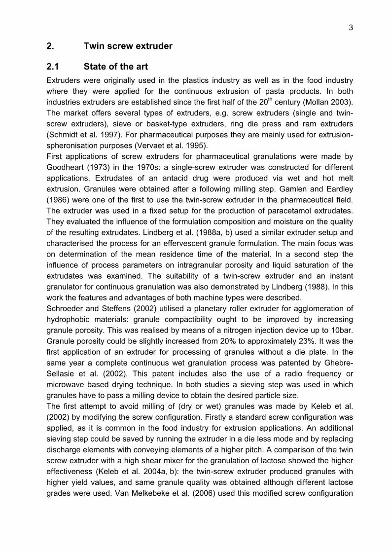
2.1 State of the art Extruders were originally used in the plastics industry as well as in the food industry where they were applied for the continuous extrusion of pasta products. In both industries extruders are established since the first half of the 20th century (Mollan 2003). The market offers several types of extruders, e.g. screw extruders (single and twin-screw extruders), sieve or basket-type extruders, ring die press and ram extruders (Schmidt et al. 1997). For pharmaceutical purposes they are mainly used for extrusion-spheronisation purposes (Vervaet et al. 1995). First applications of screw extruders for pharmaceutical granulations were made by Goodheart (1973) in the 1970s: a single-screw extruder was constructed for different applications. Extrudates of an antacid drug were produced via wet and hot melt extrusion. Granules were obtained after a following milling step. Gamlen and Eardley (1986) were one of the first to use the twin-screw extruder in the pharmaceutical field. The extruder was used in a fixed setup for the production of paracetamol extrudates. They evaluated the influence of the formulation composition and moisture on the quality of the resulting extrudates. Lindberg et al. (1988a, b) used a similar extruder setup and characterised the process for an effervescent granule formulation. The main focus was on determination of the mean residence time of the material. In a second step the influence of process parameters on intragranular porosity and liquid saturation of the extrudates was examined. The suitability of a twin-screw extruder and an instant granulator for continuous granulation was also demonstrated by Lindberg (1988). In this work the features and advantages of both machine types were described. Schroeder and Steffens (2002) utilised a planetary roller extruder for agglomeration of hydrophobic materials: granule compactibility ought to be improved by increasing granule porosity. This was realised by means of a nitrogen injection device up to 10bar. Granule porosity could be slightly increased from 20% to approximately 23%. It was the first application of an extruder for processing of granules without a die plate. In the same year a complete continuous wet granulation process was patented by Ghebre-Sellasie et al. (2002). This patent includes also the use of a radio frequency or microwave based drying technique. In both studies a sieving step was used in which granules have to pass a milling device to obtain the desired particle size. The first attempt to avoid milling of (dry or wet) granules was made by Keleb et al. (2002) by modifying the screw configuration. Firstly a standard screw configuration was applied, as it is common in the food industry for extrusion applications. An additional sieving step could be saved by running the extruder in a die less mode and by replacing discharge elements with conveying elements of a higher pitch. A comparison of the twin screw extruder with a high shear mixer for the granulation of lactose showed the higher effectiveness (Keleb et al. 2004a, b): the twin-screw extruder produced granules with higher yield values, and same granule quality was obtained although different lactose grades were used. Van Melkebeke et al. (2006) used this modified screw configuration

4
also for melt granulation purposes: polyethylene glycols as binders were used for the development of a veterinary drinking water formulation with immediate drug release. A current study dealt with the validation of a continuous granulation process (Van Melkebeke et al. 2008). The effect of modifying the screw configuration by changing the number and configuration of mixing zones was investigated. The process was identified as robust since mixing efficiency remained good irrespective of the applied modification.
2.2 Screw configuration
2.2.1 Impact Usually the screws of a twin-screw extruder are built up modularly. A series of unit operations can ideally be combined in a downstream process. This is already done in the plastics industry where it is a common approach to change and vary the screw configuration until the desired product is reached. A unit operation is realised by a discrete element or a combination of screw elements, e.g. feeding-, conveying-, mixing- or retaining functions are possible. The classical twin-screw element shapes are well described in literature. Erdmenger (1949, 1951) introduced the conveying and kneading elements for intermeshing co- and counter rotating twin-screw extruders. Up to now several other element types were introduced, which are mainly used in the plastics industry. Kohlgrüber (2007) made an overview of the available patents concerning screw element geometry. Screw elements are primarily defined by their number of flights. In this work always two flighted elements were used, i.e. conveying- and kneading elements, as classical screw elements, and the newer combing mixer elements were applied (Fig. 1-3, all by courtesy of Leistritz Extrusionstechnik GmbH).
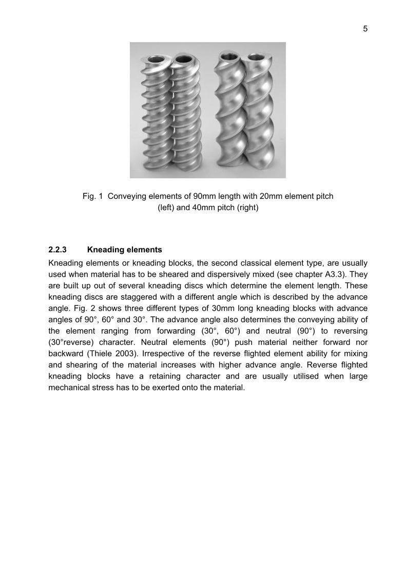
2.2.2 Conveying elements Classical conveying or forwarding elements are always inserted at cylinder openings, e.g. at barrel holes to convey material away from the feed opening or to discharge processed material at the end of the extruder (Thiele 2003). They also serve as drivers to provide forwarding pressure to supply material into kneading and mixing elements. Additionally they assure the self centering of the two screws in the extruder barrels. They can be distinguished by their number of flights, element length and the element pitch. Conveying properties improve with increasing element pitch since more volume is offered for the material and thus more material is conveyed with each revolution. For extrusion purposes the ability to pressurise the die improves with decreasing element pitch. The market also offers reverse flighted conveying elements which are used for retaining purposes. This type was not applied in the current work. In Fig. 1 two examples of the tested conveying elements are shown. The difference is the element pitch: on the left hand side a 20mm pitch element is shown which is typically used to pressurise the die. A standard conveying element with 40mm pitch is shown on the right hand side. It is usually employed for feeding and conveying tasks.
5
Fig. 1 Conveying elements of 90mm length with 20mm element pitch (left) and 40mm pitch (right)
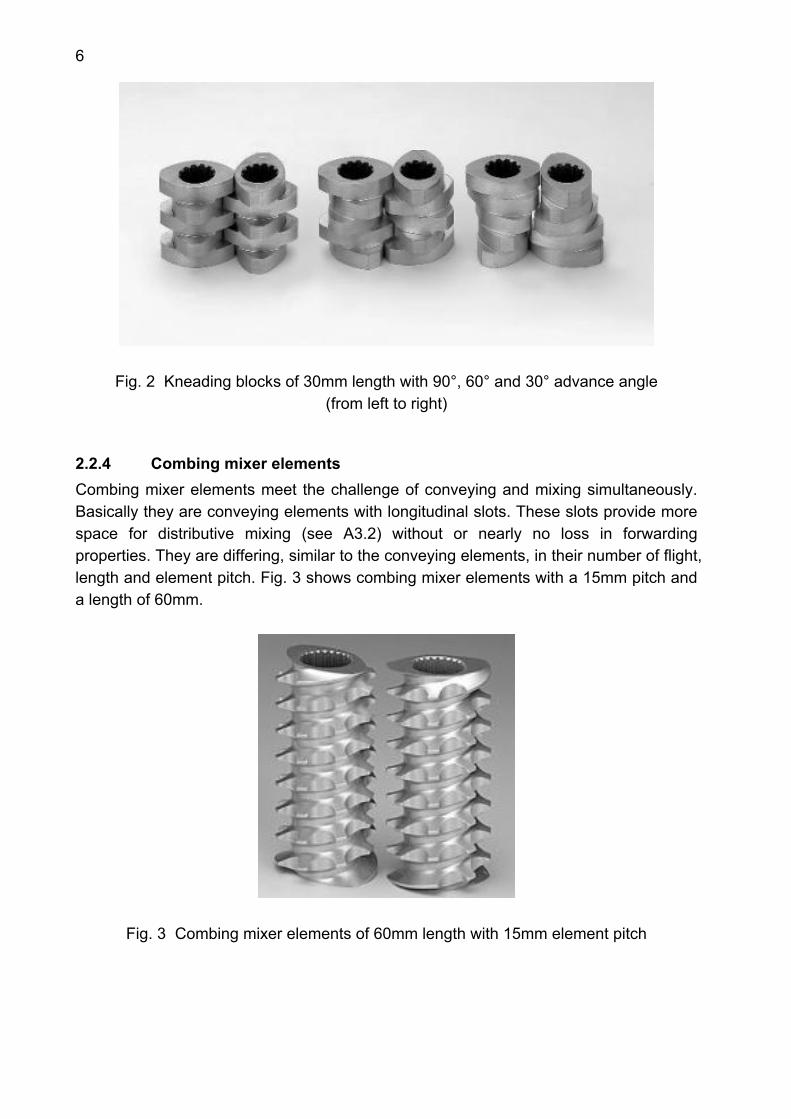
2.2.3 Kneading elements Kneading elements or kneading blocks, the second classical element type, are usually used when material has to be sheared and dispersively mixed (see chapter A3.3). They are built up out of several kneading discs which determine the element length. These kneading discs are staggered with a different angle which is described by the advance angle. Fig. 2 shows three different types of 30mm long kneading blocks with advance angles of 90°, 60° and 30°. The advance angle also determines the conveying ability of the element ranging from forwarding (30°, 60°) and neutral (90°) to reversing (30°reverse) character. Neutral elements (90°) push material neither forward nor backward (Thiele 2003). Irrespective of the reverse flighted element ability for mixing and shearing of the material increases with higher advance angle. Reverse flighted kneading blocks have a retaining character and are usually utilised when large mechanical stress has to be exerted onto the material.
6
Fig. 2 Kneading blocks of 30mm length with 90°, 60° and 30° advance angle (from left to right)
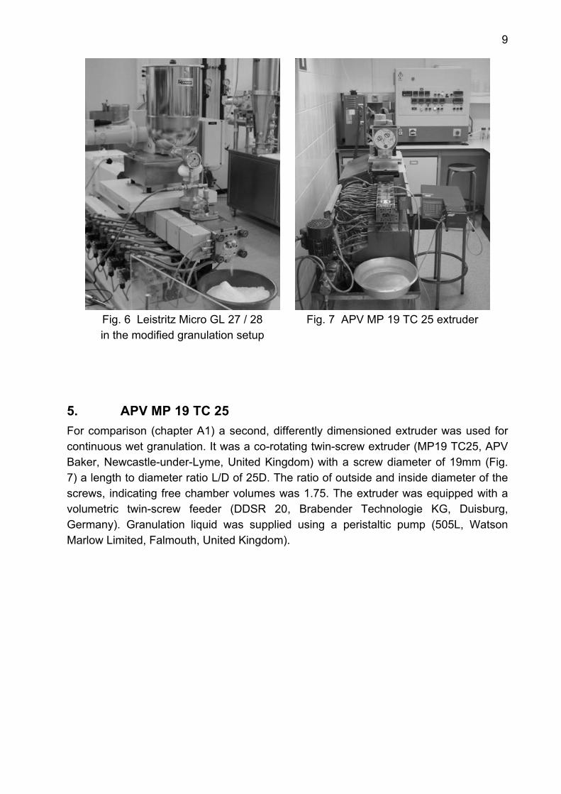
2.2.4 Combing mixer elements Combing mixer elements meet the challenge of conveying and mixing simultaneously. Basically they are conveying elements with longitudinal slots. These slots provide more space for distributive mixing (see A3.2) without or nearly no loss in forwarding properties. They are differing, similar to the conveying elements, in their number of flight, length and element pitch. Fig. 3 shows combing mixer elements with a 15mm pitch and a length of 60mm.
Fig. 3 Combing mixer elements of 60mm length with 15mm element pitch

7
3. Mixing behaviour of screw elements
3.1 General aspects Twin-screw extruders are in general effective mixing machines (Thiele 2003). The transported mass is bounded between screws and barrel walls. Thus short, local mass-transfer distances enable an accurate distribution of small formulation components. Besides this more general attribute of an extruder, mixing can be designed with a more dispensing or/and destructive character by using definite screw elements.
3.2 Distributive mixing Distributive mixing is one type of mixing behaviour that can be realised using a twin-screw extruder. Fig. 4 shows the basic model for distributive mixing. Distributive mixers tend to divide and recombine the material without disturbing the individual morphological components. For this task more space is required, i.e. higher free volumes within the extruder cylinder must be provided by the screw elements. A typical screw element with only distributive mixing properties is the combing mixer element. Other screw elements are also effective distributive mixers, e.g. kneading elements. In addition they provide enough shear stress for dispersive mixing. Usually a screw element possesses both mixing properties. The offered free volume and thus the mechanical stress determine which mixing property is dominating.
0 mixing division
1 mixing division
2 mixing divisions
3 mixing divisions
4 mixing divisions
Filling excipient API
Fig. 4 Distributive mixing model, modified according to Thiele (2003)

8
3.3 Dispersive mixing In contrast to distributive mixing elements, dispersive mixers tend to capture material domains in pressure traps that cause the material to become sheared and elongated. This leads to a reduction of morphological components. A certain shear rate must be overcome to induce this process. With either a high number or long dispersive mixing section shear rate and thus dispersive effect can be increased (Thiele 2003) (Fig. 5).
Fig. 5 Dispersive mixing model (Thiele 2003)
4. Leistritz Micro GL 27 / 28D Continuous wet granulation was performed using a co-rotating twin-screw extruder (Leistritz Micro GL 27 / 28D, Leistritz Extrusionstechnik GmbH, Nuremberg, Germany) with a screw diameter of 27mm and a OD/ID ratio of 1.4 (Fig. 6). Originally the extruder had a length to diameter ratio of 28D to facilitate extrusion processes with various requirements. For agglomeration purposes a considerably shorter extruder design is required. Since the cylinder barrels are modularly built up, a shorter screw length was assembled for the evaluation of the granulation process (see F2.2.1ff). During processing powder was dosed by a gravimetrical twin-screw feeder (K-CL-KT 20, K-Tron Soder, Niederlenz, Switzerland). Granulation liquid was supplied by a membrane pump (Cerex EP-31, Bran and Luebbe, Norderstedt, Germany) in combination with a flow through metering device (Corimass MFC 081/K, Krohne, Duisburg, Germany).
9
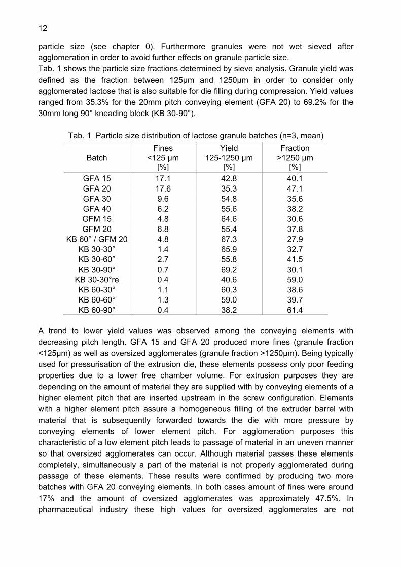
Fig. 6 Leistritz Micro GL 27 / 28 in the modified granulation setup
Fig. 7 APV MP 19 TC 25 extruder
5. APV MP 19 TC 25 For comparison (chapter A1) a second, differently dimensioned extruder was used for continuous wet granulation. It was a co-rotating twin-screw extruder (MP19 TC25, APV Baker, Newcastle-under-Lyme, United Kingdom) with a screw diameter of 19mm (Fig. 7) a length to diameter ratio L/D of 25D. The ratio of outside and inside diameter of the screws, indicating free chamber volumes was 1.75. The extruder was equipped with a volumetric twin-screw feeder (DDSR 20, Brabender Technologie KG, Duisburg, Germany). Granulation liquid was supplied using a peristaltic pump (505L, Watson Marlow Limited, Falmouth, United Kingdom).

10
B Aim of this study Continuous granulation is favourable in pharmaceutical industry as it offers more advantages than batch processes: improved process efficiency, reductions of costs and time as well as an optimal and flexible use of equipment. Due to a modular setup twin-screw extruders are especially qualified for such applications. They are established in the plastics industry since the 1950s, where as a common approach the extruder setup is changed and adjusted until a product with the desired properties is achieved. The aim of the present study was to investigate systematically the impact of discrete screw elements on granule properties and further tablets. On the one hand simple granule formulations were chosen for this purpose to exclude other influence factors. On the other hand different formulations were chosen to show screw impact on several substances. As water-soluble fillers lactose (brittle substance) and mannitol (ductile substance) were agglomerated. Furthermore dicalcium phosphate, as water-insoluble filler with brittle deformation behaviour was agglomerated with an additional binder. Higher material throughputs had to show that agglomeration behaviour of discrete screw elements is first of all a general element attribute. A design of experiments should evaluate the influence of process parameters on the wet granulation of mannitol. Material throughput, water content and screw speed were expected to have an influence on granule properties. 3 different screw configurations were applied for this design of experiments. In order to test the feasibility of a twin-screw extruder for a continuous processing with two or more powder dosing units distributive mixing behaviour of different screw elements had to be tested. Furthermore dispersive mixing properties had to be determined for different screw configurations. Finally comparison of two differently sized twin-screw extruders had to prove whether a granule formulation can be transferred between two machines. A design of experiments with two different granule formulations should explore if process parameters have the same influence on both extruders.

11
C Results and Discussion
1. Impact of the extruder setup on continuous granulation with a twin-screw extruder
1.1 Impact of screw elements on lactose granules at 2kg/h input rate
1.1.1 Introduction The standard approach in the pharmaceutical industry is to vary formulation parameters until the desired product is reached. To establish a new process understanding and to exploit the opportunities the extruder offers, the first step is to determine the effects of discrete screw elements on the granulation process. Data and experiences from the extrusion field are useful as an initial point. However they cannot be used directly since an agglomeration process is run without a die. Furthermore screw element behaviour is expected to be different for granulation purposes than for extrusion applications. Therefore new experiences are required for the agglomeration behaviour of screw elements. Robust formulations were chosen in order to eliminate formulation impacts. As the most common water-soluble filler α-lactose monohydrate (Granulac 200), a brittle substance, was agglomerated using the Leistritz twin-screw extruder. As a single component formulation, α-lactose monohydrate proved already to be suitable for twin-screw granulation (Keleb 2002). However a systematic evaluation of the element influence on lactose granules and further tablets is still missing in literature. Thus the purpose of this study was to investigate the impact of discrete screw elements on the granulation process of water-soluble lactose.
1.1.2 Experimental setup The extruder setup described in chapter F2.2.1 was used for granulation of lactose. Not the entire screw length of the extruder was used. Instead granulation was performed using a screw length of 12.22D as it enabled already a sufficient agglomeration of lactose. Powder feed rate was set at 2kg/h and 0.18kg/h demineralised water was pumped into the extruder as granulation liquid. In total 14 different screw configurations were tested at 100rpm screw speed for agglomeration of lactose at low powder feed rates.
1.1.3 Particle size distribution of granules The particle size distributions of granule batches were determined to evaluate primarily the effects of different screw elements on granule size (chapter F2.3.1). Therefore the water content was kept constant for all experiments to avoid its large impact on granule
12
particle size (see chapter 0). Furthermore granules were not wet sieved after agglomeration in order to avoid further effects on granule particle size. Tab. 1 shows the particle size fractions determined by sieve analysis. Granule yield was defined as the fraction between 125µm and 1250µm in order to consider only agglomerated lactose that is also suitable for die filling during compression. Yield values ranged from 35.3% for the 20mm pitch conveying element (GFA 20) to 69.2% for the 30mm long 90° kneading block (KB 30-90°).
Tab. 1 Particle size distribution of lactose granule batches (n=3, mean)
Batch Fines
<125 µm [%]
Yield 125-1250 µm
[%]
Fraction >1250 µm
[%] GFA 15 17.1 42.8 40.1 GFA 20 17.6 35.3 47.1 GFA 30 9.6 54.8 35.6 GFA 40 6.2 55.6 38.2 GFM 15 4.8 64.6 30.6 GFM 20 6.8 55.4 37.8
KB 60° / GFM 20 4.8 67.3 27.9 KB 30-30° 1.4 65.9 32.7 KB 30-60° 2.7 55.8 41.5 KB 30-90° 0.7 69.2 30.1
KB 30-30°re 0.4 40.6 59.0 KB 60-30° 1.1 60.3 38.6 KB 60-60° 1.3 59.0 39.7 KB 60-90° 0.4 38.2 61.4
A trend to lower yield values was observed among the conveying elements with decreasing pitch length. GFA 15 and GFA 20 produced more fines (granule fraction <125µm) as well as oversized agglomerates (granule fraction >1250µm). Being typically used for pressurisation of the extrusion die, these elements possess only poor feeding properties due to a lower free chamber volume. For extrusion purposes they are depending on the amount of material they are supplied with by conveying elements of a higher element pitch that are inserted upstream in the screw configuration. Elements with a higher element pitch assure a homogeneous filling of the extruder barrel with material that is subsequently forwarded towards the die with more pressure by conveying elements of lower element pitch. For agglomeration purposes this characteristic of a low element pitch leads to passage of material in an uneven manner so that oversized agglomerates can occur. Although material passes these elements completely, simultaneously a part of the material is not properly agglomerated during passage of these elements. These results were confirmed by producing two more batches with GFA 20 conveying elements. In both cases amount of fines were around 17% and the amount of oversized agglomerates was approximately 47.5%. In pharmaceutical industry these high values for oversized agglomerates are not

13
acceptable. However in a production process oversized agglomerates would be dissipated by an additional wet sieving step leading to granules with the desired particle size. Thus yield values would only be influenced by amounts of fines. This uneven agglomeration manner of low element pitch conveying elements is also reflected in their distributive mixing ability (chapter C2.1). The highest deviations in water and theophylline content were found for granules prepared with a 15mm pitch conveying element as a result of its poor mixing property. Increasing the element pitch of a conveying element enlarges the free chamber volume which provides a more homogeneous filling of the extruder cylinder within this element section. This leads to lower amounts of fines since material is more densified without creating too oversized agglomerates. Thus 40mm pitch conveying elements achieved the highest yield value among the conveying elements. Combing mixer elements produced higher yields compared to conveying elements of the same element pitch. The longitudinal slots enlarge the free chamber volume and improve the filling of the barrel chamber which reduced the amount of not agglomerated material. In addition the longitudinal slots decreased the amount of oversized agglomerates. The edges of these slots are able to cut material and to recombine it with other domains (Thiele 2003). Thus oversized agglomerates are broken down into smaller agglomerates. This attribute is widely used for melt extrusion purposes where combing mixer elements homogeneously dispense the melt and assure a good distributive mixing.
0
20
40
60
80
100
0 500 1000 1500 2000 2500 3000 3500
Particle size [µm]
cum
ulat
ive
unde
rsiz
e fra
ctio
n [%
]
GFA 15GFA 20GFA 30GFA 40GFM 15GFM 20KB 60°/GFM 20
Fig. 8 Cumulative undersize curves of granules prepared with conveying,
combing mixer elements and a kneading/mixing element combination (n=3, mean)
The use of kneading elements resulted in almost complete agglomeration of lactose in all cases. The lowest yield value was achieved with a long section of 90° kneading blocks. The non-forwarding character of the 90° advance angle increased the material residence time within the kneading section. This induced high mechanical stress and

14
produced many oversized agglomerates. A similar behaviour was observed for the reverse fligthed 30° kneading block (KB 30-30°re). Its retaining character highly densified the material and produced high amounts of oversized agglomerates. The highest yield could be achieved with a 30mm long 90° kneading block. Despite the non-conveying character of the 90° advance angle, large agglomerates could be dissipated increasing granule yield. The combination of a 30mm long 60° kneading block and a combing mixer element with 20mm element pitch led to the second highest yield value and to the lowest amount of oversized agglomerates. The 60° kneading block enabled an almost complete agglomeration of the lactose with low amount of fines. The following combing mixer element dissipated oversized agglomerates and increased efficiently granule yield. Thus the combination of a kneading block and a combing mixer element proved to be the most successful screw configuration in achieving a high granule yield with the lowest amount of oversized agglomerates. An additional wet sieving step would then assure always high yield values with low amounts of not agglomerated material. Fig. 8 and Fig. 9 show the cumulative undersize curves resulting from the sieving analysis.
0
20
40
60
80
100
0 500 1000 1500 2000 2500 3000 3500
Particle size [µm]
cum
ulat
ive
unde
rsiz
e fra
ctio
n [%
]
KB 30-30°KB 30-60°KB 30-90°KB 30-30°reKB 60-30°KB 60-60°KB 60-90°
Fig. 9 Cumulative undersize curves of granules prepared with kneading blocks
of 30 and 60mm length (n=3, mean)
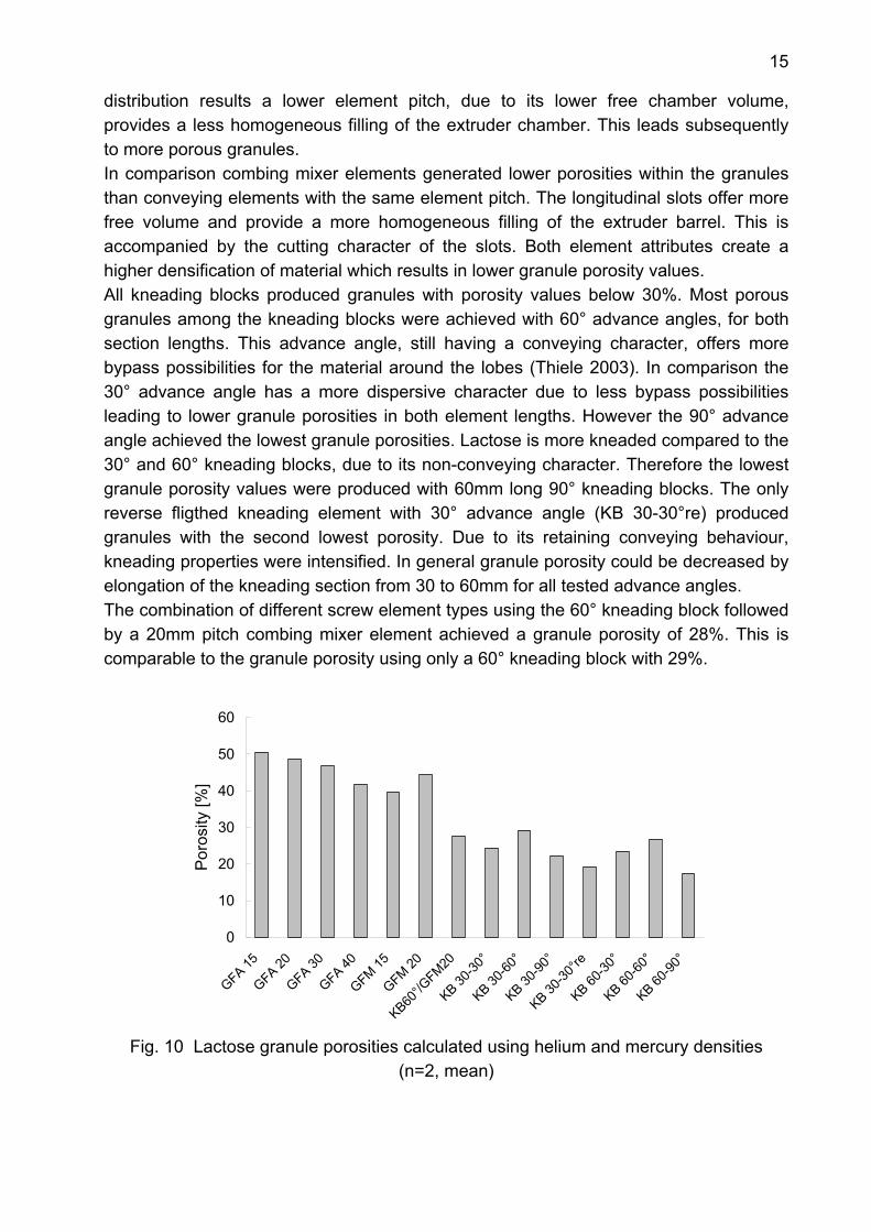
1.1.4 Granule porosity Granule porosity, as an important granule quality parameter, was expected to be influenced by the setup of different screw configurations. Fig. 10 displays the result of the helium and mercury density measurements (chapter F2.3.3ff.). Granule porosity values ranged from 17 % for the 60mm long 90° (KB 60-90°) kneading block up to 51% for the 15mm pitch conveying element (GFA 15). The conveying elements produced granules with the highest porosities from 44 to 51%. With decreasing element pitch conveying elements tended to produce higher porosities. Similar to the particle size
15
distribution results a lower element pitch, due to its lower free chamber volume, provides a less homogeneous filling of the extruder chamber. This leads subsequently to more porous granules. In comparison combing mixer elements generated lower porosities within the granules than conveying elements with the same element pitch. The longitudinal slots offer more free volume and provide a more homogeneous filling of the extruder barrel. This is accompanied by the cutting character of the slots. Both element attributes create a higher densification of material which results in lower granule porosity values. All kneading blocks produced granules with porosity values below 30%. Most porous granules among the kneading blocks were achieved with 60° advance angles, for both section lengths. This advance angle, still having a conveying character, offers more bypass possibilities for the material around the lobes (Thiele 2003). In comparison the 30° advance angle has a more dispersive character due to less bypass possibilities leading to lower granule porosities in both element lengths. However the 90° advance angle achieved the lowest granule porosities. Lactose is more kneaded compared to the 30° and 60° kneading blocks, due to its non-conveying character. Therefore the lowest granule porosity values were produced with 60mm long 90° kneading blocks. The only reverse fligthed kneading element with 30° advance angle (KB 30-30°re) produced granules with the second lowest porosity. Due to its retaining conveying behaviour, kneading properties were intensified. In general granule porosity could be decreased by elongation of the kneading section from 30 to 60mm for all tested advance angles. The combination of different screw element types using the 60° kneading block followed by a 20mm pitch combing mixer element achieved a granule porosity of 28%. This is comparable to the granule porosity using only a 60° kneading block with 29%.
0
10
20
30
40
50
60
GFA 15
GFA 20
GFA 30
GFA 40
GFM 15
GFM 20
KB60°/G
FM20
KB 30-30
°
KB 30-60
°
KB 30-90
°
KB 30-30
°re
KB 60-30
°
KB 60-60
°
KB 60-90
°
Por
osity
[%]
Fig. 10 Lactose granule porosities calculated using helium and mercury densities
(n=2, mean)
16
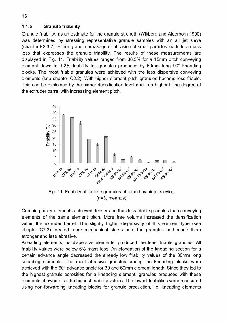
1.1.5 Granule friability Granule friability, as an estimate for the granule strength (Wikberg and Alderborn 1990) was determined by stressing representative granule samples with an air jet sieve (chapter F2.3.2). Either granule breakage or abrasion of small particles leads to a mass loss that expresses the granule friability. The results of these measurements are displayed in Fig. 11. Friability values ranged from 38.5% for a 15mm pitch conveying element down to 1.2% friability for granules produced by 60mm long 90° kneading blocks. The most friable granules were achieved with the less dispersive conveying elements (see chapter C2.2). With higher element pitch granules became less friable. This can be explained by the higher densification level due to a higher filling degree of the extruder barrel with increasing element pitch.
05
1015202530354045
GFA 15
GFA 20
GFA 30
GFA 40
GFM 15
GFM 20
KB60°/G
FM20
KB 30-30
°
KB 30-60
°
KB 30-90
°
KB 30-30
°re
KB 60-30
°
KB 60-60
°
KB 60-90
°
Fria
bilit
y [%
]
Fig. 11 Friabilty of lactose granules obtained by air jet sieving
(n=3, mean±s) Combing mixer elements achieved denser and thus less friable granules than conveying elements of the same element pitch. More free volume increased the densification within the extruder barrel. The slightly higher dispersivity of this element type (see chapter C2.2) created more mechanical stress onto the granules and made them stronger and less abrasive. Kneading elements, as dispersive elements, produced the least friable granules. All friability values were below 6% mass loss. An elongation of the kneading section for a certain advance angle decreased the already low friability values of the 30mm long kneading elements. The most abrasive granules among the kneading blocks were achieved with the 60° advance angle for 30 and 60mm element length. Since they led to the highest granule porosities for a kneading element, granules produced with these elements showed also the highest friability values. The lowest friabilities were measured using non-forwarding kneading blocks for granule production, i.e. kneading elements
17
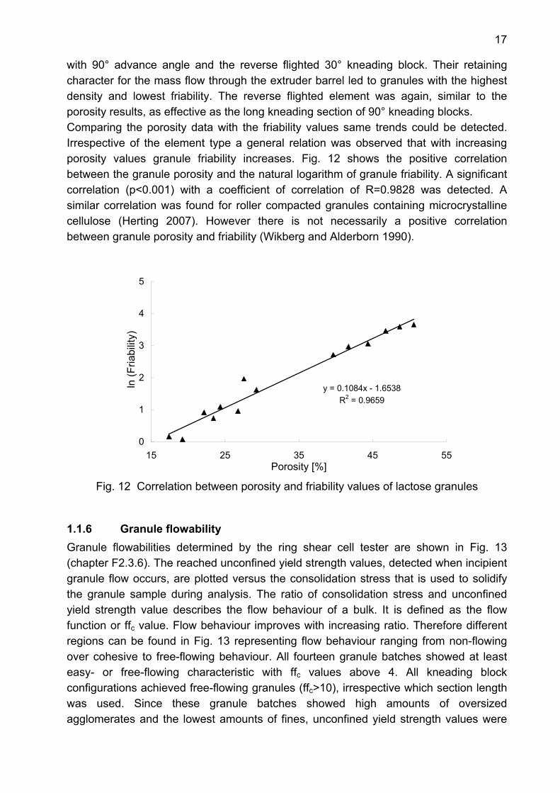
with 90° advance angle and the reverse flighted 30° kneading block. Their retaining character for the mass flow through the extruder barrel led to granules with the highest density and lowest friability. The reverse flighted element was again, similar to the porosity results, as effective as the long kneading section of 90° kneading blocks. Comparing the porosity data with the friability values same trends could be detected. Irrespective of the element type a general relation was observed that with increasing porosity values granule friability increases. Fig. 12 shows the positive correlation between the granule porosity and the natural logarithm of granule friability. A significant correlation (p<0.001) with a coefficient of correlation of R=0.9828 was detected. A similar correlation was found for roller compacted granules containing microcrystalline cellulose (Herting 2007). However there is not necessarily a positive correlation between granule porosity and friability (Wikberg and Alderborn 1990).
y = 0.1084x - 1.6538R2 = 0.9659
0
1
2
3
4
5
15 25 35 45 55Porosity [%]
ln (F
riabi
lity)
Fig. 12 Correlation between porosity and friability values of lactose granules
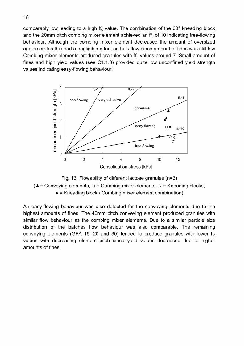
1.1.6 Granule flowability Granule flowabilities determined by the ring shear cell tester are shown in Fig. 13 (chapter F2.3.6). The reached unconfined yield strength values, detected when incipient granule flow occurs, are plotted versus the consolidation stress that is used to solidify the granule sample during analysis. The ratio of consolidation stress and unconfined yield strength value describes the flow behaviour of a bulk. It is defined as the flow function or ffc value. Flow behaviour improves with increasing ratio. Therefore different regions can be found in Fig. 13 representing flow behaviour ranging from non-flowing over cohesive to free-flowing behaviour. All fourteen granule batches showed at least easy- or free-flowing characteristic with ffc values above 4. All kneading block configurations achieved free-flowing granules (ffc>10), irrespective which section length was used. Since these granule batches showed high amounts of oversized agglomerates and the lowest amounts of fines, unconfined yield strength values were
18
comparably low leading to a high ffc value. The combination of the 60° kneading block and the 20mm pitch combing mixer element achieved an ffc of 10 indicating free-flowing behaviour. Although the combing mixer element decreased the amount of oversized agglomerates this had a negligible effect on bulk flow since amount of fines was still low. Combing mixer elements produced granules with ffc values around 7. Small amount of fines and high yield values (see C1.1.3) provided quite low unconfined yield strength values indicating easy-flowing behaviour.
0
1
2
3
4
0 2 4 6 8 10 12
Consolidation stress [kPa]
unco
nfin
ed y
ield
stre
ngth
[kP
a]
ffree-flowing
easy-flowing
cohesive
very cohesivenon flowing
ffc=1 ffc=2
ffc=4
ffc=10
Fig. 13 Flowability of different lactose granules (n=3)
(▲= Conveying elements, □ = Combing mixer elements, ○ = Kneading blocks, ● = Kneading block / Combing mixer element combination)
An easy-flowing behaviour was also detected for the conveying elements due to the highest amounts of fines. The 40mm pitch conveying element produced granules with similar flow behaviour as the combing mixer elements. Due to a similar particle size distribution of the batches flow behaviour was also comparable. The remaining conveying elements (GFA 15, 20 and 30) tended to produce granules with lower ffc
values with decreasing element pitch since yield values decreased due to higher amounts of fines.
19
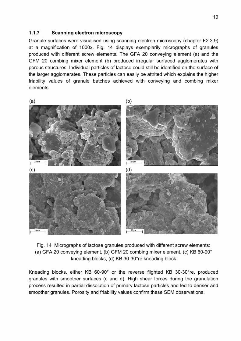
1.1.7 Scanning electron microscopy Granule surfaces were visualised using scanning electron microscopy (chapter F2.3.9) at a magnification of 1000x. Fig. 14 displays exemplarily micrographs of granules produced with different screw elements. The GFA 20 conveying element (a) and the GFM 20 combing mixer element (b) produced irregular surfaced agglomerates with porous structures. Individual particles of lactose could still be identified on the surface of the larger agglomerates. These particles can easily be attrited which explains the higher friability values of granule batches achieved with conveying and combing mixer elements. (a) (b)
(c)
(d)
Fig. 14 Micrographs of lactose granules produced with different screw elements: (a) GFA 20 conveying element, (b) GFM 20 combing mixer element, (c) KB 60-90°
kneading blocks, (d) KB 30-30°re kneading block Kneading blocks, either KB 60-90° or the reverse flighted KB 30-30°re, produced granules with smoother surfaces (c and d). High shear forces during the granulation process resulted in partial dissolution of primary lactose particles and led to denser and smoother granules. Porosity and friability values confirm these SEM observations.

20
1.1.8 Tablet tensile strength The different granule batches were compressed in order to evaluate impacts of screw configuration on tablet properties. Tablet tensile strength values (chapter F2.3.13) are plotted in consideration to their tablet porosity (Fig. 15). The four selected configurations represent the different element groups tested and the element combination of 60° kneading block and GFM 20 combing mixer elements. Water content was determined by Karl Fischer (chapter F2.3.8) before compression of granules, since granule moisture influences tablet strength (Riepma et al. 1992). According to the results all granule batches contained around 5.5% water indicating the lactose monohydrate form.
0.0
0.5
1.0
1.5
2.0
2.5
10 15 20 25
Tablet porosity [%]
Tens
ile s
treng
th [M
Pa] GFA 20
GFM 20KB60°/GFM20KB 60-90
Fig. 15 Tensile strength of lactose tablets for different screw configurations
(n=10, mean±s)
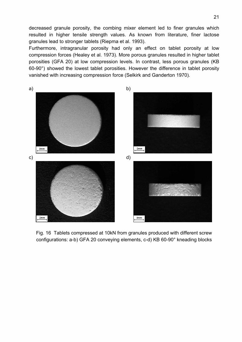
Granules with a high porosity value, e.g. produced with a GFA 20 conveying element, resulted in tablets with a very smooth surface (Fig. 16). Granule shape could not be detected after compression of tablets. Similar observations were already made for mannitol granules (Juppo 1996). In comparison, denser and less porous granules, e.g. produced by KB 60-90° kneading blocks, were more resistant towards deformation during compression. Original shape of granules was still noticeable on the surface of the tablets, indicating a higher intergranular porosity in comparison to the latter tablets (Fig. 16). These tablets showed low tensile strength values, due to large pores on the tablet surface which were the first to induce breakage (Riepma et al. 1993, Zuurman et al. 1994, Herting 2007). Combing mixer elements produced granules with a moderate porosity. Consequently, tablets compressed out of these granules showed moderate tensile strengths ranging between the values of conveying elements and kneading blocks. Granules prepared with a combination of kneading block and combing mixer element resulted in tablets with median tensile strength values. Although a kneading block
21
decreased granule porosity, the combing mixer element led to finer granules which resulted in higher tensile strength values. As known from literature, finer lactose granules lead to stronger tablets (Riepma et al. 1993). Furthermore, intragranular porosity had only an effect on tablet porosity at low compression forces (Healey et al. 1973). More porous granules resulted in higher tablet porosities (GFA 20) at low compression levels. In contrast, less porous granules (KB 60-90°) showed the lowest tablet porosities. However the difference in tablet porosity vanished with increasing compression force (Selkirk and Ganderton 1970). a)
b)
c)
d)
Fig. 16 Tablets compressed at 10kN from granules produced with different screw configurations: a-b) GFA 20 conveying elements, c-d) KB 60-90° kneading blocks
22
1.1.9 Summary Lactose was agglomerated with 14 different screw configurations at constant water content. The use of different element types significantly influenced granule properties and had also an effect on tablet characteristics. Different particle size distributions of granule batches were feasible: conveying elements produced the highest amounts of fines, whereas kneading blocks led to almost complete agglomeration of lactose powder. The highest yield value was achieved with an element combination of a kneading block and a combing mixer element (KB 60° / GFM 20). Granule porosity and granule friability were both affected by element type. With higher shear forces granule porosity and friability decreased. A linear correlation was detected between porosity and the natural logarithm of granule friability. Flowing behaviour of granules was mainly dependent on the particle size distribution as a consequence of the choice of a discrete element. All granule batches showed easy- or free-flowing behaviour respectively. Granule properties had also an effect on tablet characteristics: higher granule porosity led to tablets with higher tensile strength values and smoother surfaces. Consequently the combination of kneading block and combing mixer element proved to be the screw configuration of choice combining the advantages of kneading blocks and conveying elements: the highest yield value was accompanied with median granule porosity and thus tablet tensile strength value. Flowability of these granules was comparable to the free-flowing granule batches produced with kneading blocks without their large amounts of oversized agglomerates.
23
1.2 Impact of screw elements on mannitol granules at 2kg/h input rate
1.2.1 Introduction A second water-soluble excipient was agglomerated in order to prove that screw element impact is a general element characteristic. Mannitol powder, as a ductile substance, was taken for this purpose. Its use increased since it replaced lactose as an additive due to lactose intolerance. Owing to the poor flowability of mannitol powder, it is often agglomerated (Westermarck et al. 1998).
1.2.2 Experimental setup The screw configurations used for granulation of mannitol are described in chapter F2.2.1. In total 13 different screw configurations were tested at 100rpm screw speed. Powder feed rate was set at 2kg/h and 0.24kg/h demineralised water was pumped into the extruder as granulation liquid.
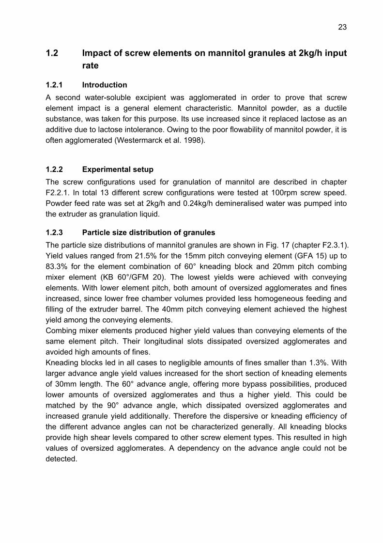
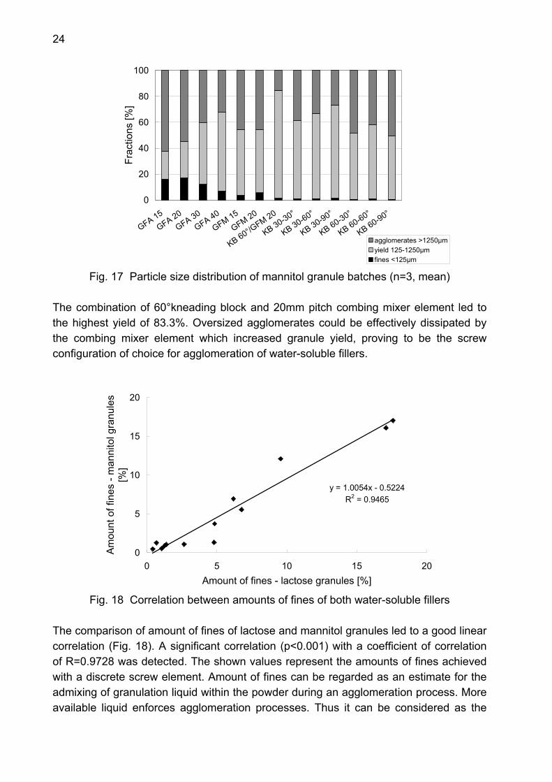
1.2.3 Particle size distribution of granules The particle size distributions of mannitol granules are shown in Fig. 17 (chapter F2.3.1). Yield values ranged from 21.5% for the 15mm pitch conveying element (GFA 15) up to 83.3% for the element combination of 60° kneading block and 20mm pitch combing mixer element (KB 60°/GFM 20). The lowest yields were achieved with conveying elements. With lower element pitch, both amount of oversized agglomerates and fines increased, since lower free chamber volumes provided less homogeneous feeding and filling of the extruder barrel. The 40mm pitch conveying element achieved the highest yield among the conveying elements. Combing mixer elements produced higher yield values than conveying elements of the same element pitch. Their longitudinal slots dissipated oversized agglomerates and avoided high amounts of fines. Kneading blocks led in all cases to negligible amounts of fines smaller than 1.3%. With larger advance angle yield values increased for the short section of kneading elements of 30mm length. The 60° advance angle, offering more bypass possibilities, produced lower amounts of oversized agglomerates and thus a higher yield. This could be matched by the 90° advance angle, which dissipated oversized agglomerates and increased granule yield additionally. Therefore the dispersive or kneading efficiency of the different advance angles can not be characterized generally. All kneading blocks provide high shear levels compared to other screw element types. This resulted in high values of oversized agglomerates. A dependency on the advance angle could not be detected.
24
0
20
40
60
80
100
GFA 15GFA 20
GFA 30GFA 40
GFM 15
GFM 20
KB 60°/GFM 20
KB 30-30°
KB 30-60°
KB 30-90°
KB 60-30°
KB 60-60°
KB 60-90°
Frac
tions
[%]
agglomerates >1250µmyield 125-1250µmfines <125µm
Fig. 17 Particle size distribution of mannitol granule batches (n=3, mean) The combination of 60°kneading block and 20mm pitch combing mixer element led to the highest yield of 83.3%. Oversized agglomerates could be effectively dissipated by the combing mixer element which increased granule yield, proving to be the screw configuration of choice for agglomeration of water-soluble fillers.
y = 1.0054x - 0.5224R2 = 0.9465
0
5
10
15
20
0 5 10 15 20Amount of fines - lactose granules [%]
Amou
nt o
f fin
es -
man
nito
l gra
nule
s [%
]
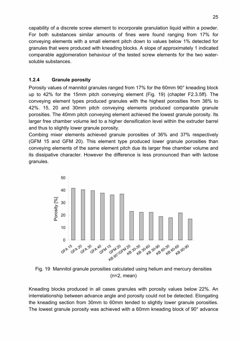
Fig. 18 Correlation between amounts of fines of both water-soluble fillers
The comparison of amount of fines of lactose and mannitol granules led to a good linear correlation (Fig. 18). A significant correlation (p<0.001) with a coefficient of correlation of R=0.9728 was detected. The shown values represent the amounts of fines achieved with a discrete screw element. Amount of fines can be regarded as an estimate for the admixing of granulation liquid within the powder during an agglomeration process. More available liquid enforces agglomeration processes. Thus it can be considered as the
25
capability of a discrete screw element to incorporate granulation liquid within a powder. For both substances similar amounts of fines were found ranging from 17% for conveying elements with a small element pitch down to values below 1% detected for granules that were produced with kneading blocks. A slope of approximately 1 indicated comparable agglomeration behaviour of the tested screw elements for the two water-soluble substances.
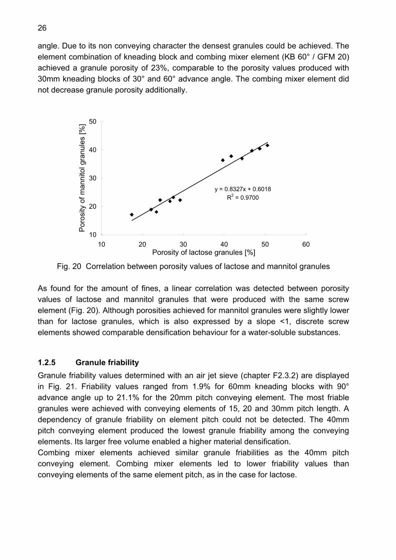
1.2.4 Granule porosity Porosity values of mannitol granules ranged from 17% for the 60mm 90° kneading block up to 42% for the 15mm pitch conveying element (Fig. 19) (chapter F2.3.5ff). The conveying element types produced granules with the highest porosities from 38% to 42%. 15, 20 and 30mm pitch conveying elements produced comparable granule porosities. The 40mm pitch conveying element achieved the lowest granule porosity. Its larger free chamber volume led to a higher densification level within the extruder barrel and thus to slightly lower granule porosity. Combing mixer elements achieved granule porosities of 36% and 37% respectively (GFM 15 and GFM 20). This element type produced lower granule porosities than conveying elements of the same element pitch due its larger free chamber volume and its dissipative character. However the difference is less pronounced than with lactose granules.
0
10
20
30
40
50
GFA 15GFA 20
GFA 30GFA 40
GFM 15
GFM 20
KB 60°/GFM 20
KB 30-30
KB 30-60
KB 30-90
KB 60-30
KB 60-60
KB 60-90
Por
osity
[%]
Fig. 19 Mannitol granule porosities calculated using helium and mercury densities
(n=2, mean) Kneading blocks produced in all cases granules with porosity values below 22%. An interrelationship between advance angle and porosity could not be detected. Elongating the kneading section from 30mm to 60mm tended to slightly lower granule porosities. The lowest granule porosity was achieved with a 60mm kneading block of 90° advance
26
angle. Due to its non conveying character the densest granules could be achieved. The element combination of kneading block and combing mixer element (KB 60° / GFM 20) achieved a granule porosity of 23%, comparable to the porosity values produced with 30mm kneading blocks of 30° and 60° advance angle. The combing mixer element did not decrease granule porosity additionally.
y = 0.8327x + 0.6018R2 = 0.9700
10
20
30
40
50
10 20 30 40 50 60Porosity of lactose granules [%]
Por
osity
of m
anni
tol g
ranu
les
[%]
Fig. 20 Correlation between porosity values of lactose and mannitol granules
As found for the amount of fines, a linear correlation was detected between porosity values of lactose and mannitol granules that were produced with the same screw element (Fig. 20). Although porosities achieved for mannitol granules were slightly lower than for lactose granules, which is also expressed by a slope <1, discrete screw elements showed comparable densification behaviour for a water-soluble substances.
1.2.5 Granule friability Granule friability values determined with an air jet sieve (chapter F2.3.2) are displayed in Fig. 21. Friability values ranged from 1.9% for 60mm kneading blocks with 90° advance angle up to 21.1% for the 20mm pitch conveying element. The most friable granules were achieved with conveying elements of 15, 20 and 30mm pitch length. A dependency of granule friability on element pitch could not be detected. The 40mm pitch conveying element produced the lowest granule friability among the conveying elements. Its larger free volume enabled a higher material densification. Combing mixer elements achieved similar granule friabilities as the 40mm pitch conveying element. Combing mixer elements led to lower friability values than conveying elements of the same element pitch, as in the case for lactose.

27
0
5
10
15
20
25
GFA 15GFA 20
GFA 30GFA 40
GFM 15
GFM 20
KB 60°/GFM 20
KB 30-30
KB 30-60
KB 30-90
KB 60-30
KB 60-60
KB 60-90
Fria
bilit
y [%
]
Fig. 21 Friability of mannitol granules obtained by air jet sieving
(n=3, mean±s) All kneading blocks and the element combination of kneading block and a combing mixer element produced granules with friability values below 5%. An elongation of the kneading section did not reduce granule friability additionally.
y = 0.5045x + 1.579R2 = 0.9634
0
10
20
30
0 10 20 30 40 50Friability of lactose granules [%]
Fria
bilit
y of
man
nito
l gra
nule
s [%
]
Fig. 22 Correlation between friability values of lactose and mannitol granules
A comparison of friability values of lactose and mannitol granules showed a linear correlation (Fig. 22). Lactose granules were almost twice abrasive than mannitol granules which is also expressed by a slope of approximately 0.5. In addition to the porosity data (Fig. 20) these results confirm similar densification behaviour for discrete screw elements when agglomerating water-soluble substances.
28
y = 0.0897x - 0.7706R2 = 0.9614
0
1
2
3
4
15 20 25 30 35 40 45Porosity [%]
ln (F
riabi
lity)
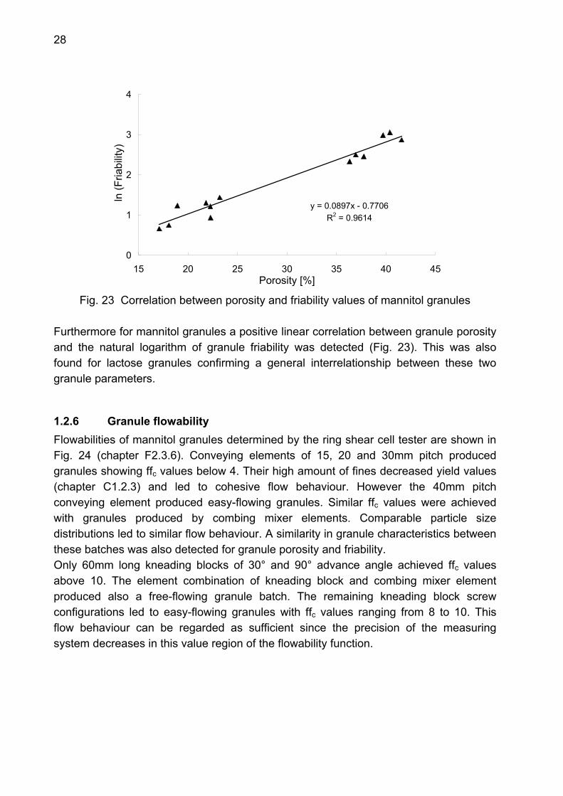
Fig. 23 Correlation between porosity and friability values of mannitol granules
Furthermore for mannitol granules a positive linear correlation between granule porosity and the natural logarithm of granule friability was detected (Fig. 23). This was also found for lactose granules confirming a general interrelationship between these two granule parameters.
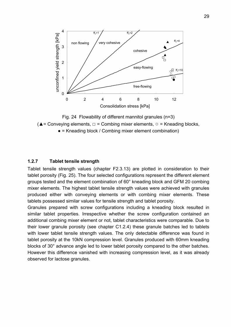
1.2.6 Granule flowability Flowabilities of mannitol granules determined by the ring shear cell tester are shown in Fig. 24 (chapter F2.3.6). Conveying elements of 15, 20 and 30mm pitch produced granules showing ffc values below 4. Their high amount of fines decreased yield values (chapter C1.2.3) and led to cohesive flow behaviour. However the 40mm pitch conveying element produced easy-flowing granules. Similar ffc values were achieved with granules produced by combing mixer elements. Comparable particle size distributions led to similar flow behaviour. A similarity in granule characteristics between these batches was also detected for granule porosity and friability. Only 60mm long kneading blocks of 30° and 90° advance angle achieved ffc values above 10. The element combination of kneading block and combing mixer element produced also a free-flowing granule batch. The remaining kneading block screw configurations led to easy-flowing granules with ffc values ranging from 8 to 10. This flow behaviour can be regarded as sufficient since the precision of the measuring system decreases in this value region of the flowability function.
29
0
1
2
3
4
0 2 4 6 8 10 12
Consolidation stress [kPa]
unco
nfin
ed y
ield
stre
ngth
[kP
a]
ffree-flowing
easy-flowing
cohesive
very cohesivenon flowing
ffc=1 ffc=2
ffc=4
ffc=10
Fig. 24 Flowability of different mannitol granules (n=3)
(▲= Conveying elements, □ = Combing mixer elements, ○ = Kneading blocks, ● = Kneading block / Combing mixer element combination)
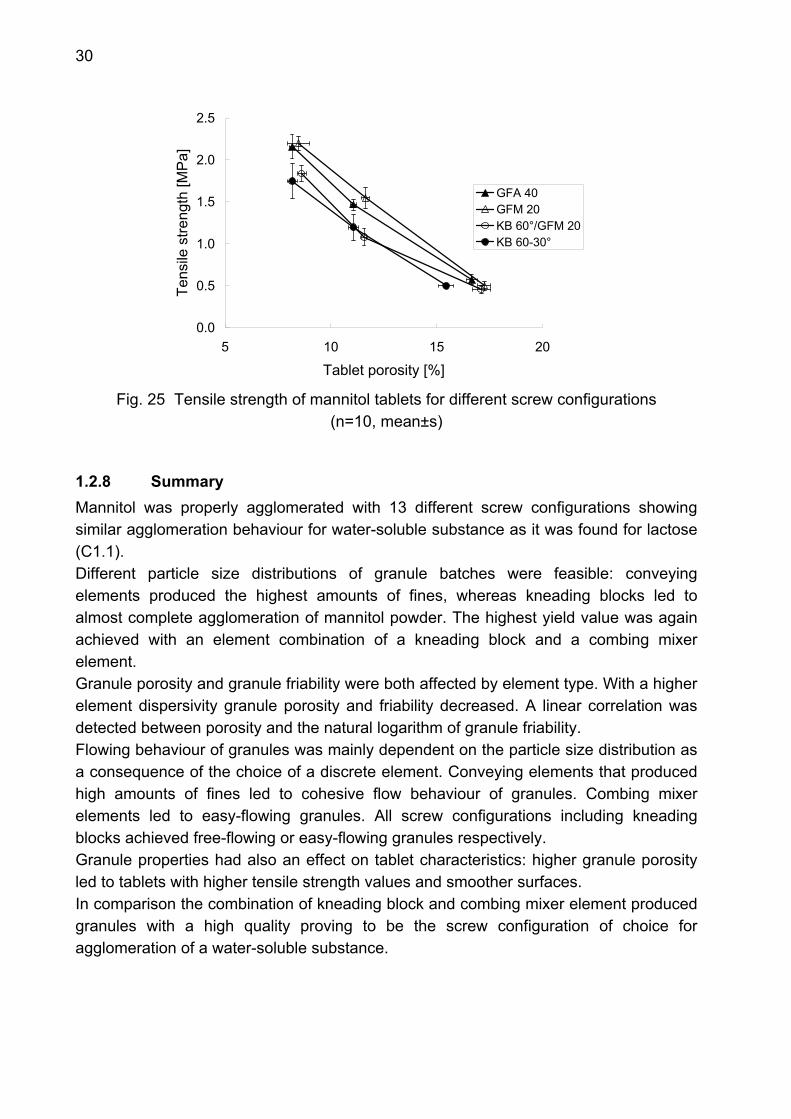
1.2.7 Tablet tensile strength Tablet tensile strength values (chapter F2.3.13) are plotted in consideration to their tablet porosity (Fig. 25). The four selected configurations represent the different element groups tested and the element combination of 60° kneading block and GFM 20 combing mixer elements. The highest tablet tensile strength values were achieved with granules produced either with conveying elements or with combing mixer elements. These tablets possessed similar values for tensile strength and tablet porosity. Granules prepared with screw configurations including a kneading block resulted in similar tablet properties. Irrespective whether the screw configuration contained an additional combing mixer element or not, tablet characteristics were comparable. Due to their lower granule porosity (see chapter C1.2.4) these granule batches led to tablets with lower tablet tensile strength values. The only detectable difference was found in tablet porosity at the 10kN compression level. Granules produced with 60mm kneading blocks of 30° advance angle led to lower tablet porosity compared to the other batches. However this difference vanished with increasing compression level, as it was already observed for lactose granules.
30
0.0
0.5
1.0
1.5
2.0
2.5
5 10 15 20
Tablet porosity [%]
Tens
ile s
treng
th [M
Pa]
GFA 40GFM 20KB 60°/GFM 20KB 60-30°
Fig. 25 Tensile strength of mannitol tablets for different screw configurations
(n=10, mean±s)
1.2.8 Summary Mannitol was properly agglomerated with 13 different screw configurations showing similar agglomeration behaviour for water-soluble substance as it was found for lactose (C1.1). Different particle size distributions of granule batches were feasible: conveying elements produced the highest amounts of fines, whereas kneading blocks led to almost complete agglomeration of mannitol powder. The highest yield value was again achieved with an element combination of a kneading block and a combing mixer element. Granule porosity and granule friability were both affected by element type. With a higher element dispersivity granule porosity and friability decreased. A linear correlation was detected between porosity and the natural logarithm of granule friability. Flowing behaviour of granules was mainly dependent on the particle size distribution as a consequence of the choice of a discrete element. Conveying elements that produced high amounts of fines led to cohesive flow behaviour of granules. Combing mixer elements led to easy-flowing granules. All screw configurations including kneading blocks achieved free-flowing or easy-flowing granules respectively. Granule properties had also an effect on tablet characteristics: higher granule porosity led to tablets with higher tensile strength values and smoother surfaces. In comparison the combination of kneading block and combing mixer element produced granules with a high quality proving to be the screw configuration of choice for agglomeration of a water-soluble substance.
31
1.3 Impact of screw elements on dicalcium phosphate granules at 2kg/h input rate
1.3.1 Introduction Dicalcium phosphate, as a brittle substance, was chosen to evaluate screw configuration impact also on water-insoluble materials. Povidone was added as an additional binder to enable agglomeration of the cohesive dicalcium phosphate.
1.3.2 Experimental setup The screw configurations used for granulation of dicalcium phosphate and povidone are described in chapter F2.2.1. Powder feed rate was set at 2kg/h and 0.24kg/h demineralised water was pumped into the extruder as granulation liquid. In total 5 different screw configurations were tested at 100rpm screw speed. These screw configurations were chosen since they represent the three different screw element types.
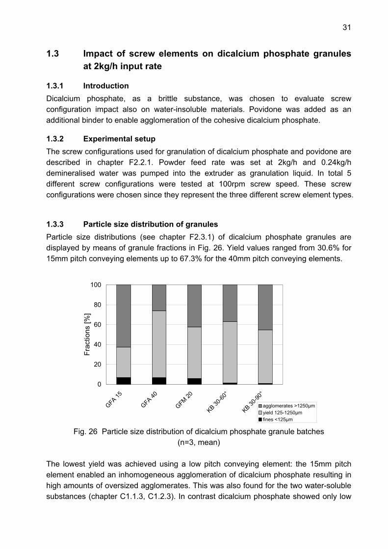
1.3.3 Particle size distribution of granules Particle size distributions (see chapter F2.3.1) of dicalcium phosphate granules are displayed by means of granule fractions in Fig. 26. Yield values ranged from 30.6% for 15mm pitch conveying elements up to 67.3% for the 40mm pitch conveying elements.
0
20
40
60
80
100
GFA 15
GFA 40
GFM 20
KB 30-60
°
KB 30-90
°
Frac
tions
[%]
agglomerates >1250µmyield 125-1250µmfines <125µm
Fig. 26 Particle size distribution of dicalcium phosphate granule batches (n=3, mean)
The lowest yield was achieved using a low pitch conveying element: the 15mm pitch element enabled an inhomogeneous agglomeration of dicalcium phosphate resulting in high amounts of oversized agglomerates. This was also found for the two water-soluble substances (chapter C1.1.3, C1.2.3). In contrast dicalcium phosphate showed only low
32
amounts of fines. This can be observed for all applied screw configurations agglomerating dicalcium phosphate since povidone, as an effective binder (Becker et al. 1997) avoided high amounts of fines. The combing mixer element and the two tested kneading blocks led to similar particle size distributions. Amounts of oversized agglomerates and granule yield were comparable. In case of the two kneading blocks of 60° and 90° advance angle amounts of fines were negligible. In contrast to the results for lactose and mannitol the 90° advance angle did not lead to a high yield value. A dissipative character of this discrete kneading block could not be detected any more, as it was observed for the water-soluble substances. Since kneading blocks squeeze and retain material higher liquid saturation levels are achieved in these element sections and coarser granules result (Kristensen et al. 1984). Furthermore dicalcium phosphate forms relatively strong agglomerates when sufficient liquid binder is present to provide the plasticity of the agglomerates (Holm et al. 1984).
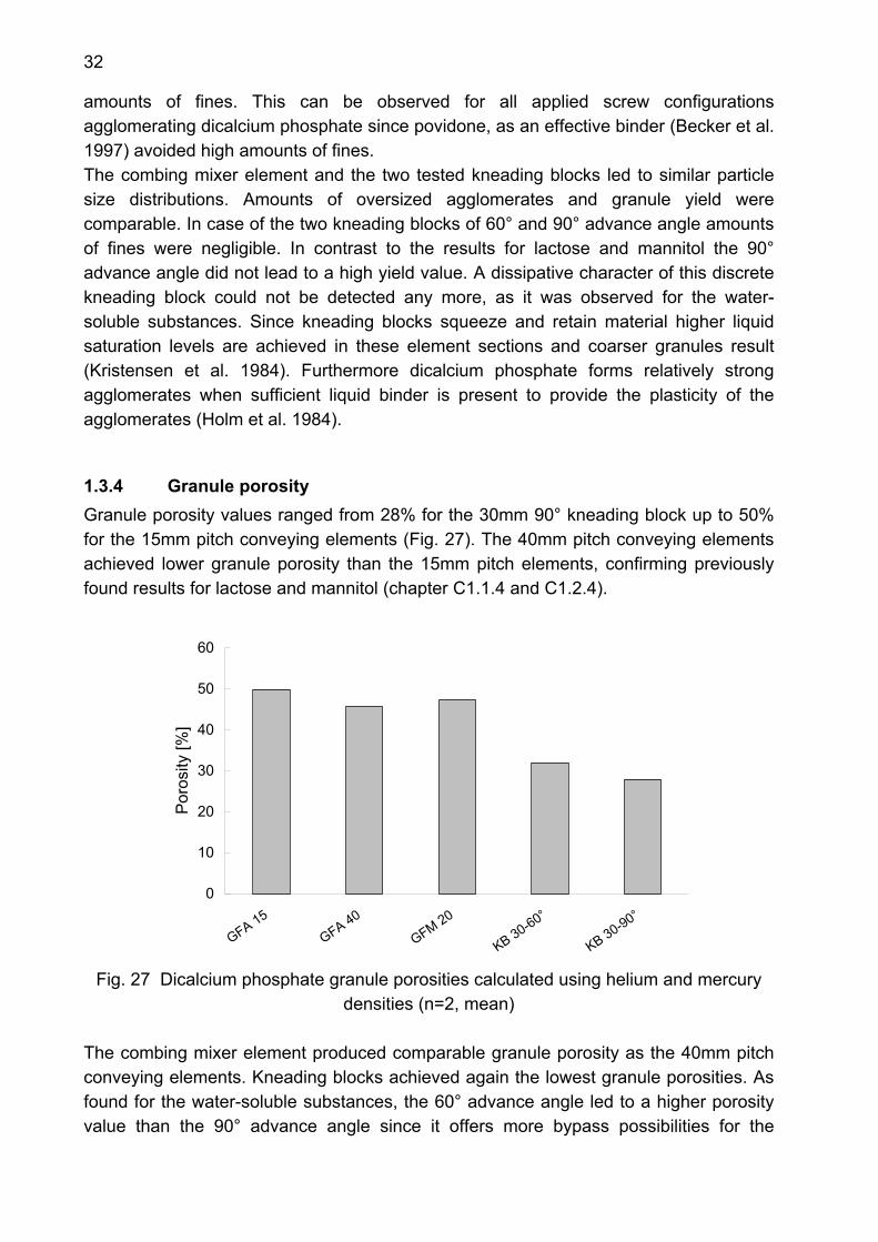
1.3.4 Granule porosity Granule porosity values ranged from 28% for the 30mm 90° kneading block up to 50% for the 15mm pitch conveying elements (Fig. 27). The 40mm pitch conveying elements achieved lower granule porosity than the 15mm pitch elements, confirming previously found results for lactose and mannitol (chapter C1.1.4 and C1.2.4).
0
10
20
30
40
50
60
GFA 15GFA 40
GFM 20
KB 30-60°
KB 30-90°
Por
osity
[%]
Fig. 27 Dicalcium phosphate granule porosities calculated using helium and mercury
densities (n=2, mean) The combing mixer element produced comparable granule porosity as the 40mm pitch conveying elements. Kneading blocks achieved again the lowest granule porosities. As found for the water-soluble substances, the 60° advance angle led to a higher porosity value than the 90° advance angle since it offers more bypass possibilities for the
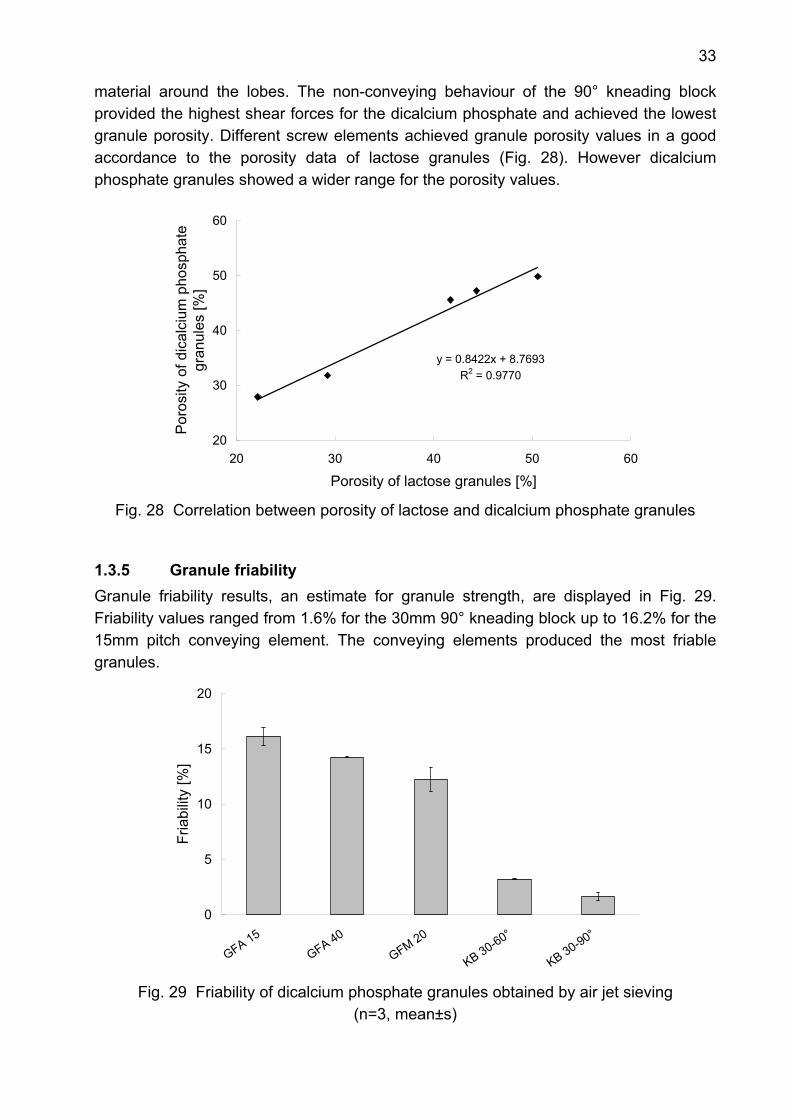
33
material around the lobes. The non-conveying behaviour of the 90° kneading block provided the highest shear forces for the dicalcium phosphate and achieved the lowest granule porosity. Different screw elements achieved granule porosity values in a good accordance to the porosity data of lactose granules (Fig. 28). However dicalcium phosphate granules showed a wider range for the porosity values.
y = 0.8422x + 8.7693R2 = 0.9770
20
30
40
50
60
20 30 40 50 60
Porosity of lactose granules [%]
Por
osity
of d
ical
cium
pho
spha
te
gran
ules
[%]
Fig. 28 Correlation between porosity of lactose and dicalcium phosphate granules
1.3.5 Granule friability Granule friability results, an estimate for granule strength, are displayed in Fig. 29. Friability values ranged from 1.6% for the 30mm 90° kneading block up to 16.2% for the 15mm pitch conveying element. The conveying elements produced the most friable granules.
0
5
10
15
20
GFA 15GFA 40
GFM 20
KB 30-60°
KB 30-90°
Fria
bilit
y [%
]
Fig. 29 Friability of dicalcium phosphate granules obtained by air jet sieving
(n=3, mean±s)
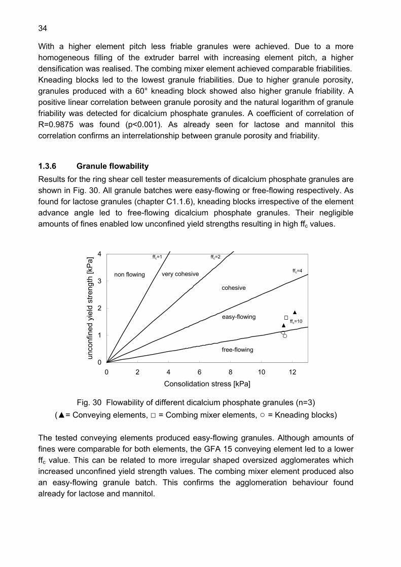
34
With a higher element pitch less friable granules were achieved. Due to a more homogeneous filling of the extruder barrel with increasing element pitch, a higher densification was realised. The combing mixer element achieved comparable friabilities. Kneading blocks led to the lowest granule friabilities. Due to higher granule porosity, granules produced with a 60° kneading block showed also higher granule friability. A positive linear correlation between granule porosity and the natural logarithm of granule friability was detected for dicalcium phosphate granules. A coefficient of correlation of R=0.9875 was found (p<0.001). As already seen for lactose and mannitol this correlation confirms an interrelationship between granule porosity and friability.
1.3.6 Granule flowability Results for the ring shear cell tester measurements of dicalcium phosphate granules are shown in Fig. 30. All granule batches were easy-flowing or free-flowing respectively. As found for lactose granules (chapter C1.1.6), kneading blocks irrespective of the element advance angle led to free-flowing dicalcium phosphate granules. Their negligible amounts of fines enabled low unconfined yield strengths resulting in high ffc values.
0
1
2
3
4
0 2 4 6 8 10 12
Consolidation stress [kPa]
unco
nfin
ed y
ield
stre
ngth
[kP
a]
ffree-flowing
easy-flowing
cohesive
very cohesivenon flowing
ffc=1 ffc=2
ffc=4
ffc=10
Fig. 30 Flowability of different dicalcium phosphate granules (n=3)
(▲= Conveying elements, □ = Combing mixer elements, ○ = Kneading blocks)
The tested conveying elements produced easy-flowing granules. Although amounts of fines were comparable for both elements, the GFA 15 conveying element led to a lower ffc value. This can be related to more irregular shaped oversized agglomerates which increased unconfined yield strength values. The combing mixer element produced also an easy-flowing granule batch. This confirms the agglomeration behaviour found already for lactose and mannitol.
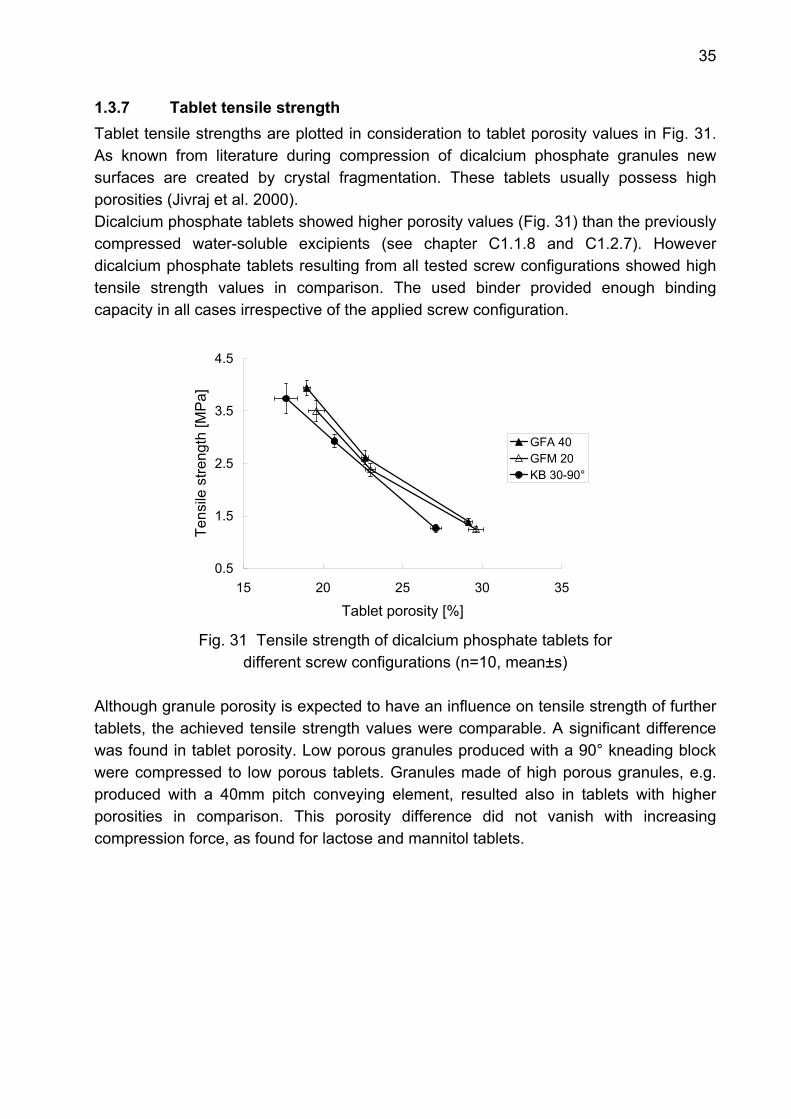
35
1.3.7 Tablet tensile strength Tablet tensile strengths are plotted in consideration to tablet porosity values in Fig. 31. As known from literature during compression of dicalcium phosphate granules new surfaces are created by crystal fragmentation. These tablets usually possess high porosities (Jivraj et al. 2000). Dicalcium phosphate tablets showed higher porosity values (Fig. 31) than the previously compressed water-soluble excipients (see chapter C1.1.8 and C1.2.7). However dicalcium phosphate tablets resulting from all tested screw configurations showed high tensile strength values in comparison. The used binder provided enough binding capacity in all cases irrespective of the applied screw configuration.
0.5
1.5
2.5
3.5
4.5
15 20 25 30 35
Tablet porosity [%]
Tens
ile s
treng
th [M
Pa]
GFA 40GFM 20KB 30-90°
Fig. 31 Tensile strength of dicalcium phosphate tablets for
different screw configurations (n=10, mean±s)
Although granule porosity is expected to have an influence on tensile strength of further tablets, the achieved tensile strength values were comparable. A significant difference was found in tablet porosity. Low porous granules produced with a 90° kneading block were compressed to low porous tablets. Granules made of high porous granules, e.g. produced with a 40mm pitch conveying element, resulted also in tablets with higher porosities in comparison. This porosity difference did not vanish with increasing compression force, as found for lactose and mannitol tablets.
36
1.3.8 Summary The tested screw configurations enabled a proper agglomeration of cohesive dicalcium phosphate. Although the water-insoluble material possessed different physical characteristics than the tested water-soluble substances (C1.1 and C1.2), screw elements showed similar agglomeration behaviour. Due to the use of povidone as an additional binder, lower amounts of fines were detected than in the case of lactose and mannitol. However conveying elements produced the highest amounts of fines, whereas kneading blocks led to almost complete agglomeration of dicalcium phosphate powder. Granule porosity and granule friability were both affected by element type. With a higher element dispersivity granule porosity and friability decreased. A linear correlation was detected between porosity and the natural logarithm of granule friability. All screw configurations achieved free-flowing or easy-flowing granules respectively. Tablet properties were less influenced by screw configuration compared to the water-soluble materials. Brittle deformation and the additional binder enabled high tensile strength values in all cases.
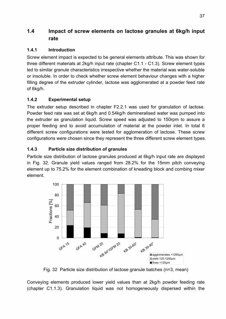
37
1.4 Impact of screw elements on lactose granules at 6kg/h input rate
1.4.1 Introduction Screw element impact is expected to be general elements attribute. This was shown for three different materials at 2kg/h input rate (chapter C1.1 - C1.3). Screw element types led to similar granule characteristics irrespective whether the material was water-soluble or insoluble. In order to check whether screw element behaviour changes with a higher filling degree of the extruder cylinder, lactose was agglomerated at a powder feed rate of 6kg/h.
1.4.2 Experimental setup The extruder setup described in chapter F2.2.1 was used for granulation of lactose. Powder feed rate was set at 6kg/h and 0.54kg/h demineralised water was pumped into the extruder as granulation liquid. Screw speed was adjusted to 150rpm to assure a proper feeding and to avoid accumulation of material at the powder inlet. In total 6 different screw configurations were tested for agglomeration of lactose. These screw configurations were chosen since they represent the three different screw element types.
1.4.3 Particle size distribution of granules Particle size distribution of lactose granules produced at 6kg/h input rate are displayed in Fig. 32. Granule yield values ranged from 28.2% for the 15mm pitch conveying element up to 75.2% for the element combination of kneading block and combing mixer element.
0
20
40
60
80
100
GFA 15GFA 40
GFM 20
KB 60°/GFM 20
KB 30-60°
KB 30-90°
Frac
tions
[%]
agglomerates >1250µmyield 125-1250µmfines <125µm
Fig. 32 Particle size distribution of lactose granule batches (n=3, mean) Conveying elements produced lower yield values than at 2kg/h powder feeding rate (chapter C1.1.3). Granulation liquid was not homogeneously dispersed within the

38
lactose powder which led to higher amounts of fines and oversized agglomerates simultaneously. However this effect was more pronounced for the 15mm pitch conveying element confirming the results at a lower input rate. The combing mixer element achieved slightly higher values for amounts of fines and oversized agglomerates compared to lower powder feed rates. Its agglomeration behaviour was comparable as it was found for low powder feed rates. Kneading blocks produced negligible amounts of fines. The 60° kneading block produced slightly more oversized agglomerates (+5%) than at the low powder feeding rate. Its advance angle still offered enough bypass possibilities for the material around the lobes to avoid excess oversized agglomerates. In contrast, the 90° kneading block produced two times more oversized agglomerates compared to the lower filling degree. Its non forwarding character retained material and enlarged the filling degree additionally within this element section leading to increased formation of oversized agglomerates. Dissipative attributes of the 90° advance angle could not be detected any more. The element combination of kneading block and combing mixer element produced higher amount of fines with increasing powder feeding rate. Granule yield was also increased due to a lower amount of oversized agglomerates. The dissipative character of the combing mixer element effectively decreased oversized agglomerates. The combination of these two elements proved again to be the screw configuration of choice for a water-soluble material.
1.4.4 Granule porosity Porosity values for lactose granules produced at 6kg/h powder feed rate ranged from 18% for the 30mm 90° kneading block up to 50% for the 15mm pitch conveying element (Fig. 33).
0
10
20
30
40
50
60
GFA 15 GFA 40
GFM 20
KB 60°/GFM 20
KB 30-60°
KB 30-90°
Por
osity
[%]
Fig. 33 Lactose granule porosities calculated using helium and mercury densities
(n=2, mean)

39
The two tested conveying elements produced similar porosity values. In comparison to the values at a low powder feed rate (chapter C1.1.4) the 15mm pitch conveying element produced the same granule porosity. However the 40mm pitch element achieved a higher porosity than found in the previous experiments. This can be related to a less homogeneous dispersion of granulation liquid within the lactose resulting in more porous granules. This effect was also observed for the combing mixer element. With a higher filling degree, more porous granules were produced.
y = 1.0869x - 2.0949R2 = 0.8979
15
25
35
45
55
15 25 35 45 55Granule porosity at 2kg/h [%]
Gra
nule
por
osity
at 6
kg/h
[%]
Fig. 34 Correlation between granule porosities achieved at different powder feed rates
Kneading blocks produced as expected the lowest granule porosities. The 60° kneading block did not change its agglomeration behaviour. However the kneading block with 90° advance angle could achieve a lower porosity than at a low powder feeding rate. Due to its neutral conveying attribute, lactose was more retained. This effect was supported by the higher filling degree of the cylinder leading to a granule porosity level that was achieved with 60mm 90° kneading blocks in the previous experiments. The combination of kneading block and combing mixer element led to higher granule porosity compared to the results at a lower powder feed rate. The attained value was even higher than for the discrete 60° kneading block. A comparison of the porosity data of discrete screw elements at 2 and 6kg/h powder feed rate respectively showed a linear correlation (Fig. 34) indicating similar granule porosities at both feed rates.
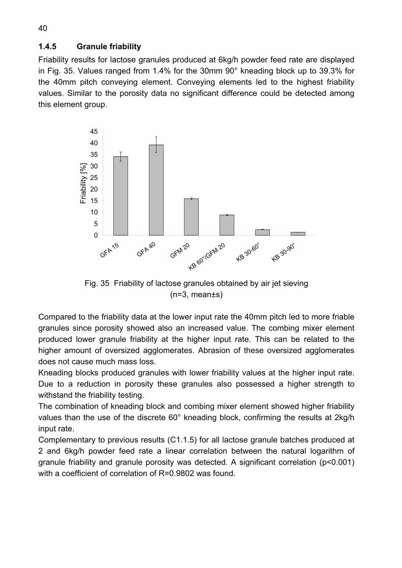
40
1.4.5 Granule friability Friability results for lactose granules produced at 6kg/h powder feed rate are displayed in Fig. 35. Values ranged from 1.4% for the 30mm 90° kneading block up to 39.3% for the 40mm pitch conveying element. Conveying elements led to the highest friability values. Similar to the porosity data no significant difference could be detected among this element group.
0
5
10
15
20
25
30
35
40
45
GFA 15 GFA 40
GFM 20
KB 60°/GFM 20
KB 30-60°
KB 30-90°
Fria
bilit
y [%
]
Fig. 35 Friability of lactose granules obtained by air jet sieving
(n=3, mean±s) Compared to the friability data at the lower input rate the 40mm pitch led to more friable granules since porosity showed also an increased value. The combing mixer element produced lower granule friability at the higher input rate. This can be related to the higher amount of oversized agglomerates. Abrasion of these oversized agglomerates does not cause much mass loss. Kneading blocks produced granules with lower friability values at the higher input rate. Due to a reduction in porosity these granules also possessed a higher strength to withstand the friability testing. The combination of kneading block and combing mixer element showed higher friability values than the use of the discrete 60° kneading block, confirming the results at 2kg/h input rate. Complementary to previous results (C1.1.5) for all lactose granule batches produced at 2 and 6kg/h powder feed rate a linear correlation between the natural logarithm of granule friability and granule porosity was detected. A significant correlation (p<0.001) with a coefficient of correlation of R=0.9802 was found.
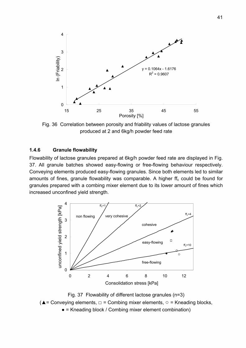
41
y = 0.1064x - 1.6176R2 = 0.9607
0
1
2
3
4
15 25 35 45 55Porosity [%]
ln (F
riabi
lity)
Fig. 36 Correlation between porosity and friability values of lactose granules
produced at 2 and 6kg/h powder feed rate
1.4.6 Granule flowability Flowability of lactose granules prepared at 6kg/h powder feed rate are displayed in Fig. 37. All granule batches showed easy-flowing or free-flowing behaviour respectively. Conveying elements produced easy-flowing granules. Since both elements led to similar amounts of fines, granule flowability was comparable. A higher ffc could be found for granules prepared with a combing mixer element due to its lower amount of fines which increased unconfined yield strength.
0
1
2
3
4
0 2 4 6 8 10 12
Consolidation stress [kPa]
unco
nfin
ed y
ield
stre
ngth
[kP
a]
f
free-flowing
easy-flowing
cohesive
very cohesivenon flowing
ffc=1 ffc=2
ffc=4
ffc=10
Fig. 37 Flowability of different lactose granules (n=3)
(▲= Conveying elements, □ = Combing mixer elements, ○ = Kneading blocks, ● = Kneading block / Combing mixer element combination)
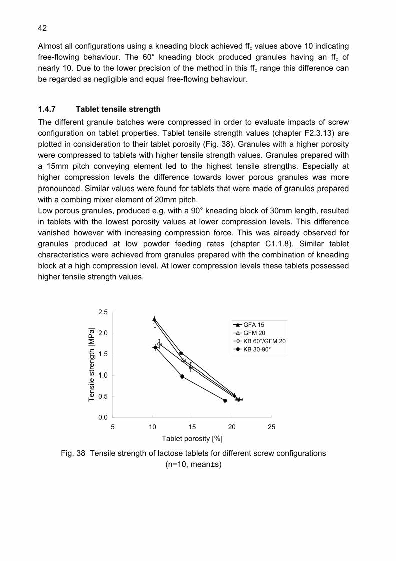
42
Almost all configurations using a kneading block achieved ffc values above 10 indicating free-flowing behaviour. The 60° kneading block produced granules having an ffc of nearly 10. Due to the lower precision of the method in this ffc range this difference can be regarded as negligible and equal free-flowing behaviour.
1.4.7 Tablet tensile strength The different granule batches were compressed in order to evaluate impacts of screw configuration on tablet properties. Tablet tensile strength values (chapter F2.3.13) are plotted in consideration to their tablet porosity (Fig. 38). Granules with a higher porosity were compressed to tablets with higher tensile strength values. Granules prepared with a 15mm pitch conveying element led to the highest tensile strengths. Especially at higher compression levels the difference towards lower porous granules was more pronounced. Similar values were found for tablets that were made of granules prepared with a combing mixer element of 20mm pitch. Low porous granules, produced e.g. with a 90° kneading block of 30mm length, resulted in tablets with the lowest porosity values at lower compression levels. This difference vanished however with increasing compression force. This was already observed for granules produced at low powder feeding rates (chapter C1.1.8). Similar tablet characteristics were achieved from granules prepared with the combination of kneading block at a high compression level. At lower compression levels these tablets possessed higher tensile strength values.
0.0
0.5
1.0
1.5
2.0
2.5
5 10 15 20 25
Tablet porosity [%]
Tens
ile s
treng
th [M
Pa]
GFA 15GFM 20KB 60°/GFM 20KB 30-90°
Fig. 38 Tensile strength of lactose tablets for different screw configurations
(n=10, mean±s)
43
1.4.8 Summary Lactose granules were properly agglomerated at an increased powder feed rate. Granule and tablet properties were slightly different compared to granules processed at a low powder feed rate. Conveying elements produced lower granule yield values due to higher amounts of fines and oversized agglomerates. Kneading blocks, especially the non forwarding 90° kneading block, led to increased amounts of oversized agglomerates. A higher filling degree of the extruder cylinder and the squeezing character of these elements produced coarser granules than at low powder feed rates. The highest yield was again achieved with the element combination of 60° kneading block and combing mixer element. Granule porosity and granule friability tended to higher values for conveying and combing mixer elements. Differences in granule porosity among the conveying elements vanished. A linear correlation was still detected between porosity and the natural logarithm of granule friability. Flowing behaviour of granules did not change with a higher powder feed rate. All produced granules showed still easy- or free-flowing behaviour. The influence of granule porosity on the tensile strength of tablets was less pronounced than found at a lower powder feed rate.

44
1.5 Impact of screw elements on dicalcium phosphate granules at 6kg/h input rate
1.5.1 Introduction Screw element impact is expected to be general elements’ attribute. This was shown for three different materials at 2kg/h input rate (chapter C1.1 - C1.3). Screw element types led to similar granule characteristics irrespective whether the material was water-soluble or insoluble. In order to check whether screw element behaviour changes with a higher filling degree of the extruder cylinder, dicalcium phosphate was agglomerated at a powder feeding rate of 6kg/h.
1.5.2 Experimental setup The extruder setup described in chapter F2.2.1 was used for granulation of dicalcium phosphate and povidone. Powder feed rate was set at 6kg/h and 0.72kg/h demineralised water was pumped into the extruder as granulation liquid. Screw speed was adjusted to 150rpm to assure a proper feeding and to avoid accumulation of material at the powder inlet. In total 6 different screw configurations were tested for agglomeration of dicalcium phosphate representing three different screw element types. In addition to chapter C1.3 the element combination of 60° kneading block and 20mm pitch combing mixer element was also used for agglomeration.
1.5.3 Particle size distribution of granules Particle size distribution of dicalcium phosphate granules produced at 6kg/h input rate are displayed in Fig. 39. Granule yield values ranged from 6.0% for the 90° kneading block of 30mm length up to 60.5% for 40mm pitch conveying element. Compared to the particle size distribution results achieved at 2kg/h powder feeding rate the 40mm pitch conveying element produced a higher amount of agglomerates and fines. Thus a lower yield value was detected. This was already observed for the granulation of lactose at 6kg/h powder feed rate. Granulation liquid was less homogeneously dispersed within the dicalcium phosphate powder which led to higher amounts of fines and oversized agglomerates simultaneously. In contrast to the previously found lactose results, granulation of dicalcium phosphate using the 15mm pitch conveying element led to similar particle size distributions at both powder feed rates. The 20mm pitch combing mixer element achieved slightly lower amounts of fines and a small increase in amount of oversized agglomerates. Granule yield produced with this element was comparable to the value at lower powder feed rate. Kneading blocks showed negligible amount of fines. These values were even lower than at low powder feed rates. Whereas granule yield remained the same for the use of the 60° kneading block, the 90° kneading block produced almost only oversized agglomerates (Fig. 40). Its non forwarding character, retained dicalcium phosphate and
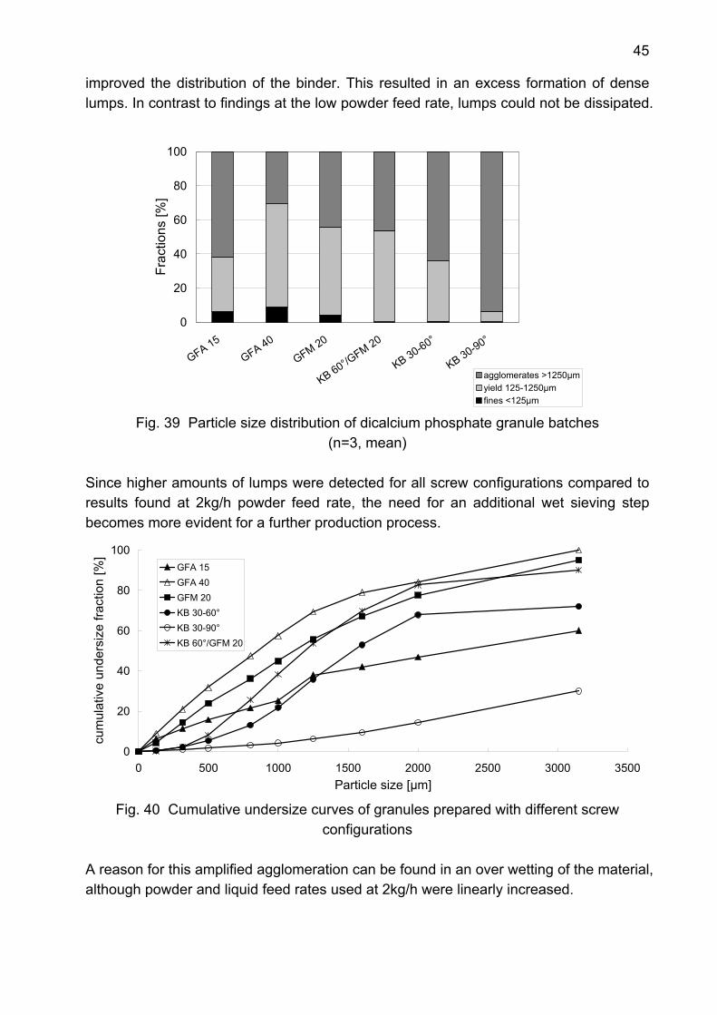
45
improved the distribution of the binder. This resulted in an excess formation of dense lumps. In contrast to findings at the low powder feed rate, lumps could not be dissipated.
0
20
40
60
80
100
GFA 15GFA 40
GFM 20
KB 60°/GFM 20
KB 30-60°
KB 30-90°
Frac
tions
[%]
agglomerates >1250µmyield 125-1250µmfines <125µm
Fig. 39 Particle size distribution of dicalcium phosphate granule batches (n=3, mean)
Since higher amounts of lumps were detected for all screw configurations compared to results found at 2kg/h powder feed rate, the need for an additional wet sieving step becomes more evident for a further production process.
0
20
40
60
80
100
0 500 1000 1500 2000 2500 3000 3500Particle size [µm]
cum
ulat
ive
unde
rsiz
e fra
ctio
n [%
]
GFA 15GFA 40GFM 20KB 30-60°KB 30-90°KB 60°/GFM 20
Fig. 40 Cumulative undersize curves of granules prepared with different screw
configurations A reason for this amplified agglomeration can be found in an over wetting of the material, although powder and liquid feed rates used at 2kg/h were linearly increased.
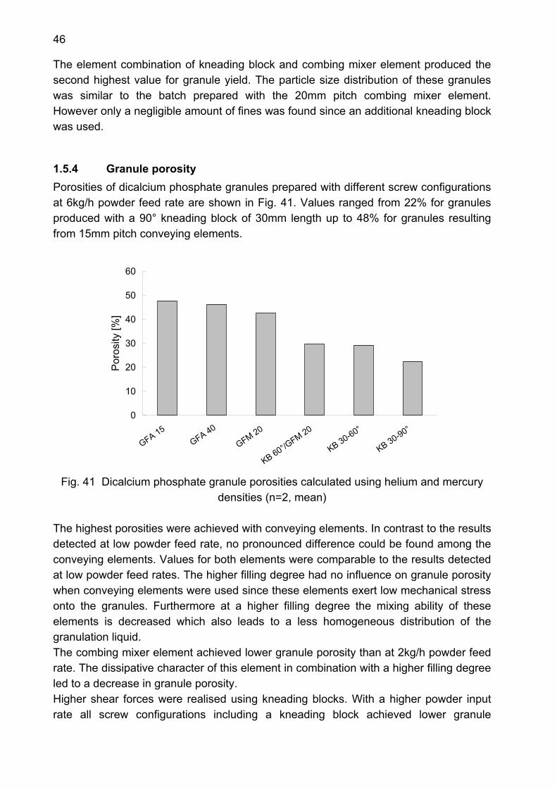
46
The element combination of kneading block and combing mixer element produced the second highest value for granule yield. The particle size distribution of these granules was similar to the batch prepared with the 20mm pitch combing mixer element. However only a negligible amount of fines was found since an additional kneading block was used.
1.5.4 Granule porosity Porosities of dicalcium phosphate granules prepared with different screw configurations at 6kg/h powder feed rate are shown in Fig. 41. Values ranged from 22% for granules produced with a 90° kneading block of 30mm length up to 48% for granules resulting from 15mm pitch conveying elements.
0
10
20
30
40
50
60
GFA 15 GFA 40
GFM 20
KB 60°/GFM 20
KB 30-60°
KB 30-90°
Por
osity
[%]
Fig. 41 Dicalcium phosphate granule porosities calculated using helium and mercury
densities (n=2, mean) The highest porosities were achieved with conveying elements. In contrast to the results detected at low powder feed rate, no pronounced difference could be found among the conveying elements. Values for both elements were comparable to the results detected at low powder feed rates. The higher filling degree had no influence on granule porosity when conveying elements were used since these elements exert low mechanical stress onto the granules. Furthermore at a higher filling degree the mixing ability of these elements is decreased which also leads to a less homogeneous distribution of the granulation liquid. The combing mixer element achieved lower granule porosity than at 2kg/h powder feed rate. The dissipative character of this element in combination with a higher filling degree led to a decrease in granule porosity. Higher shear forces were realised using kneading blocks. With a higher powder input rate all screw configurations including a kneading block achieved lower granule
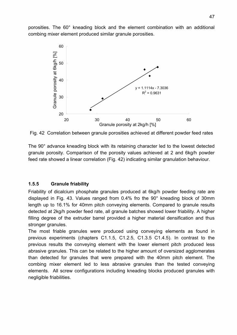
47
porosities. The 60° kneading block and the element combination with an additional combing mixer element produced similar granule porosities.
y = 1.1114x - 7.3036R2 = 0.9631
20
30
40
50
60
20 30 40 50 60Granule porosity at 2kg/h [%]
Gra
nule
por
osity
at 6
kg/h
[%]
Fig. 42 Correlation between granule porosities achieved at different powder feed rates
The 90° advance kneading block with its retaining character led to the lowest detected granule porosity. Comparison of the porosity values achieved at 2 and 6kg/h powder feed rate showed a linear correlation (Fig. 42) indicating similar granulation behaviour.
1.5.5 Granule friability Friability of dicalcium phosphate granules produced at 6kg/h powder feeding rate are displayed in Fig. 43. Values ranged from 0.4% fro the 90° kneading block of 30mm length up to 16.1% for 40mm pitch conveying elements. Compared to granule results detected at 2kg/h powder feed rate, all granule batches showed lower friability. A higher filling degree of the extruder barrel provided a higher material densification and thus stronger granules. The most friable granules were produced using conveying elements as found in previous experiments (chapters C1.1.5, C1.2.5, C1.3.5 C1.4.5). In contrast to the previous results the conveying element with the lower element pitch produced less abrasive granules. This can be related to the higher amount of oversized agglomerates than detected for granules that were prepared with the 40mm pitch element. The combing mixer element led to less abrasive granules than the tested conveying elements. All screw configurations including kneading blocks produced granules with negligible friabilities.
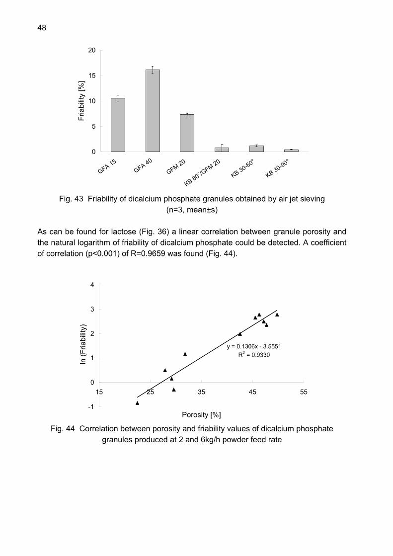
48
0
5
10
15
20
GFA 15 GFA 40
GFM 20
KB 60°/GFM 20
KB 30-60°
KB 30-90°
Fria
bilit
y [%
]
Fig. 43 Friability of dicalcium phosphate granules obtained by air jet sieving
(n=3, mean±s)
As can be found for lactose (Fig. 36) a linear correlation between granule porosity and the natural logarithm of friability of dicalcium phosphate could be detected. A coefficient of correlation (p<0.001) of R=0.9659 was found (Fig. 44).
y = 0.1306x - 3.5551R2 = 0.9330
-1
0
1
2
3
4
15 25 35 45 55
Porosity [%]
ln (F
riabi
lity)
Fig. 44 Correlation between porosity and friability values of dicalcium phosphate
granules produced at 2 and 6kg/h powder feed rate
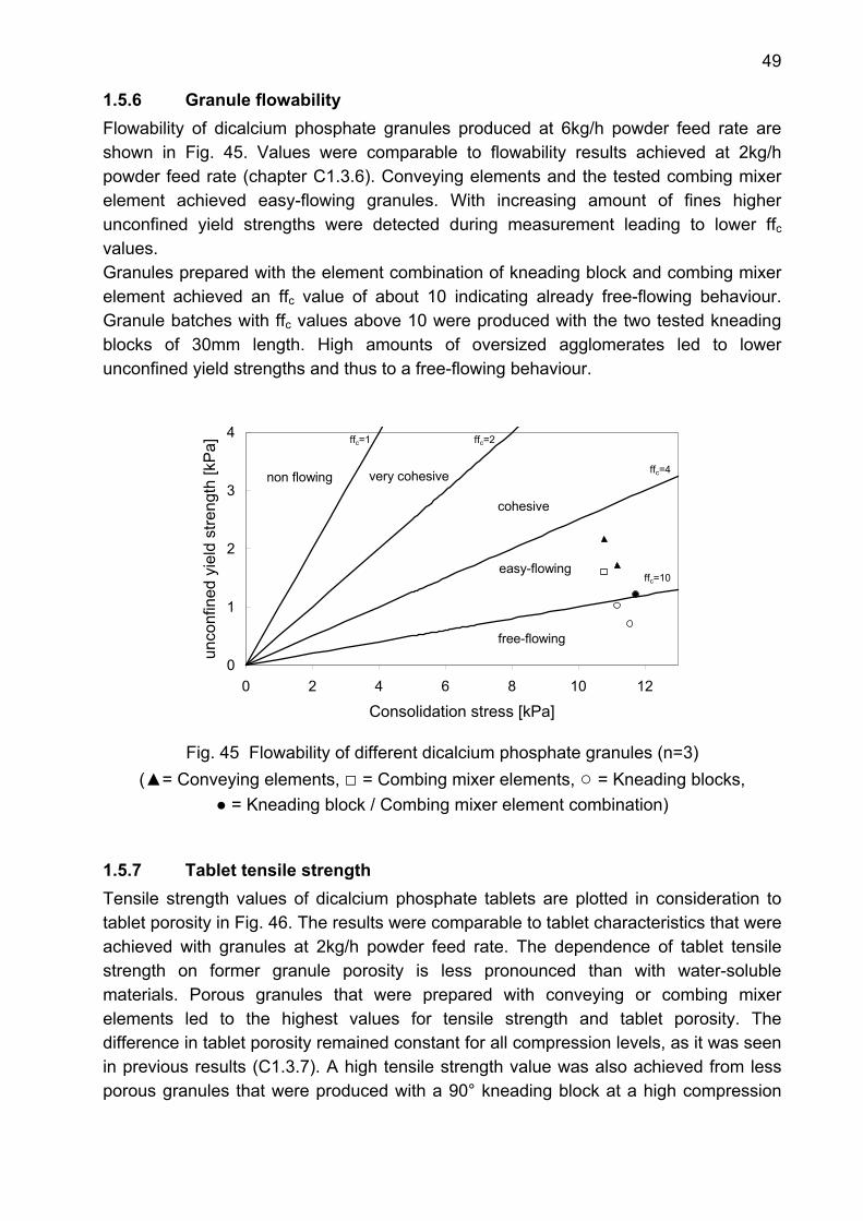
49
1.5.6 Granule flowability Flowability of dicalcium phosphate granules produced at 6kg/h powder feed rate are shown in Fig. 45. Values were comparable to flowability results achieved at 2kg/h powder feed rate (chapter C1.3.6). Conveying elements and the tested combing mixer element achieved easy-flowing granules. With increasing amount of fines higher unconfined yield strengths were detected during measurement leading to lower ffc values. Granules prepared with the element combination of kneading block and combing mixer element achieved an ffc value of about 10 indicating already free-flowing behaviour. Granule batches with ffc values above 10 were produced with the two tested kneading blocks of 30mm length. High amounts of oversized agglomerates led to lower unconfined yield strengths and thus to a free-flowing behaviour.
0
1
2
3
4
0 2 4 6 8 10 12
Consolidation stress [kPa]
unco
nfin
ed y
ield
stre
ngth
[kP
a]
f
free-flowing
easy-flowing
cohesive
very cohesivenon flowing
ffc=1 ffc=2
ffc=4
ffc=10
Fig. 45 Flowability of different dicalcium phosphate granules (n=3)
(▲= Conveying elements, □ = Combing mixer elements, ○ = Kneading blocks, ● = Kneading block / Combing mixer element combination)
1.5.7 Tablet tensile strength Tensile strength values of dicalcium phosphate tablets are plotted in consideration to tablet porosity in Fig. 46. The results were comparable to tablet characteristics that were achieved with granules at 2kg/h powder feed rate. The dependence of tablet tensile strength on former granule porosity is less pronounced than with water-soluble materials. Porous granules that were prepared with conveying or combing mixer elements led to the highest values for tensile strength and tablet porosity. The difference in tablet porosity remained constant for all compression levels, as it was seen in previous results (C1.3.7). A high tensile strength value was also achieved from less porous granules that were produced with a 90° kneading block at a high compression
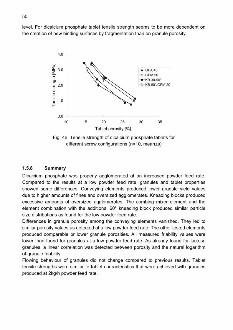
50
level. For dicalcium phosphate tablet tensile strength seems to be more dependent on the creation of new binding surfaces by fragmentation than on granule porosity.
0.0
1.0
2.0
3.0
4.0
10 15 20 25 30 35
Tablet porosity [%]
Tens
ile s
treng
th [M
Pa]
GFA 40GFM 20KB 30-90°KB 60°/GFM 20
Fig. 46 Tensile strength of dicalcium phosphate tablets for
different screw configurations (n=10, mean±s)
1.5.8 Summary Dicalcium phosphate was properly agglomerated at an increased powder feed rate. Compared to the results at a low powder feed rate, granules and tablet properties showed some differences. Conveying elements produced lower granule yield values due to higher amounts of fines and oversized agglomerates. Kneading blocks produced excessive amounts of oversized agglomerates. The combing mixer element and the element combination with the additional 60° kneading block produced similar particle size distributions as found for the low powder feed rate. Differences in granule porosity among the conveying elements vanished. They led to similar porosity values as detected at a low powder feed rate. The other tested elements produced comparable or lower granule porosities. All measured friability values were lower than found for granules at a low powder feed rate. As already found for lactose granules, a linear correlation was detected between porosity and the natural logarithm of granule friability. Flowing behaviour of granules did not change compared to previous results. Tablet tensile strengths were similar to tablet characteristics that were achieved with granules produced at 2kg/h powder feed rate.
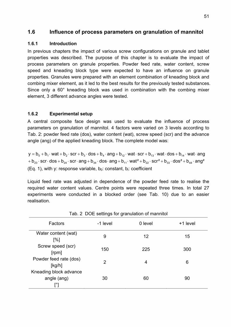
51
1.6 Influence of process parameters on granulation of mannitol
1.6.1 Introduction In previous chapters the impact of various screw configurations on granule and tablet properties was described. The purpose of this chapter is to evaluate the impact of process parameters on granule properties. Powder feed rate, water content, screw speed and kneading block type were expected to have an influence on granule properties. Granules were prepared with an element combination of kneading block and combing mixer element, as it led to the best results for the previously tested substances. Since only a 60° kneading block was used in combination with the combing mixer element, 3 different advance angles were tested.
1.6.2 Experimental setup A central composite face design was used to evaluate the influence of process parameters on granulation of mannitol. 4 factors were varied on 3 levels according to Tab. 2: powder feed rate (dos), water content (wat), screw speed (scr) and the advance angle (ang) of the applied kneading block. The complete model was:
²angb²dosb²scrb²watbangdosbangscrbdosscrbangwatbdoswatbscrwatbangbdosbscrbwatbby
44332211342423
14131243210
⋅+⋅+⋅+⋅+⋅⋅+⋅⋅+⋅⋅+
⋅⋅+⋅⋅+⋅⋅+⋅+⋅+⋅+⋅+=
(Eq. 1), with y: response variable, b0: constant, bi: coefficient Liquid feed rate was adjusted in dependence of the powder feed rate to realise the required water content values. Centre points were repeated three times. In total 27 experiments were conducted in a blocked order (see Tab. 10) due to an easier realisation.
Tab. 2 DOE settings for granulation of mannitol
Factors -1 level 0 level +1 level
Water content (wat) [%]
9 12 15
Screw speed (scr) [rpm]
150 225 300
Powder feed rate (dos) [kg/h]
2 4 6
Kneading block advance angle (ang)
[°] 30 60 90
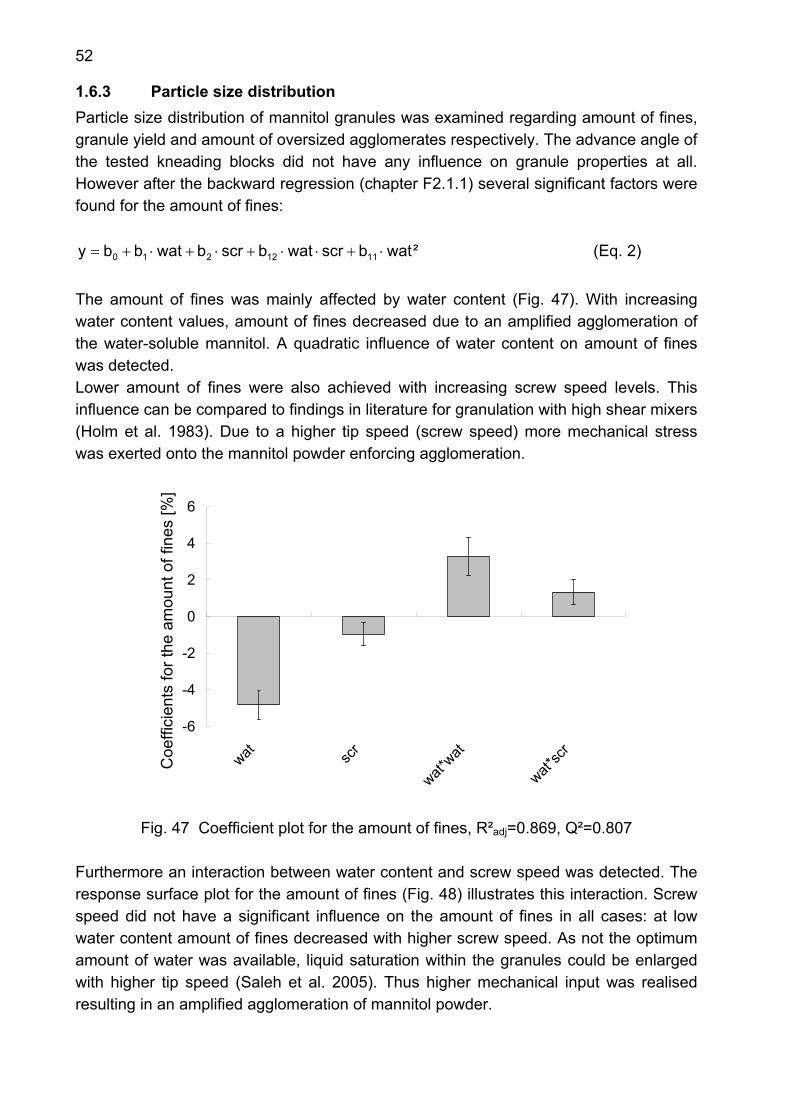
52
1.6.3 Particle size distribution Particle size distribution of mannitol granules was examined regarding amount of fines, granule yield and amount of oversized agglomerates respectively. The advance angle of the tested kneading blocks did not have any influence on granule properties at all. However after the backward regression (chapter F2.1.1) several significant factors were found for the amount of fines:
²watbscrwatbscrbwatbby 1112210 ⋅+⋅⋅+⋅+⋅+= (Eq. 2) The amount of fines was mainly affected by water content (Fig. 47). With increasing water content values, amount of fines decreased due to an amplified agglomeration of the water-soluble mannitol. A quadratic influence of water content on amount of fines was detected. Lower amount of fines were also achieved with increasing screw speed levels. This influence can be compared to findings in literature for granulation with high shear mixers (Holm et al. 1983). Due to a higher tip speed (screw speed) more mechanical stress was exerted onto the mannitol powder enforcing agglomeration.
-6
-4
-2
0
2
4
6
wat scr
wat*wat
wat*sc
r
Coe
ffici
ents
for t
he a
mou
nt o
f fin
es [%
]
Fig. 47 Coefficient plot for the amount of fines, R²adj=0.869, Q²=0.807
Furthermore an interaction between water content and screw speed was detected. The response surface plot for the amount of fines (Fig. 48) illustrates this interaction. Screw speed did not have a significant influence on the amount of fines in all cases: at low water content amount of fines decreased with higher screw speed. As not the optimum amount of water was available, liquid saturation within the granules could be enlarged with higher tip speed (Saleh et al. 2005). Thus higher mechanical input was realised resulting in an amplified agglomeration of mannitol powder.
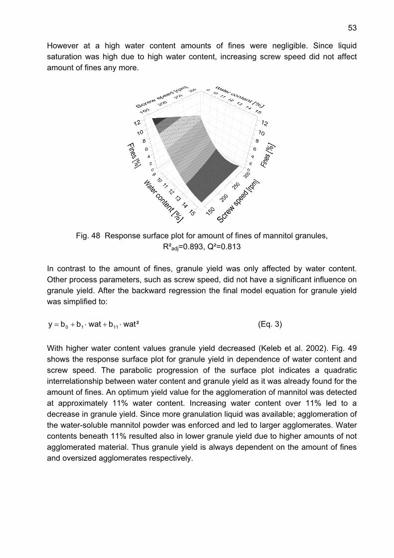
53
However at a high water content amounts of fines were negligible. Since liquid saturation was high due to high water content, increasing screw speed did not affect amount of fines any more.
Fig. 48 Response surface plot for amount of fines of mannitol granules,
R²adj=0.893, Q²=0.813 In contrast to the amount of fines, granule yield was only affected by water content. Other process parameters, such as screw speed, did not have a significant influence on granule yield. After the backward regression the final model equation for granule yield was simplified to:
²watbwatbby 1110 ⋅+⋅+= (Eq. 3) With higher water content values granule yield decreased (Keleb et al. 2002). Fig. 49 shows the response surface plot for granule yield in dependence of water content and screw speed. The parabolic progression of the surface plot indicates a quadratic interrelationship between water content and granule yield as it was already found for the amount of fines. An optimum yield value for the agglomeration of mannitol was detected at approximately 11% water content. Increasing water content over 11% led to a decrease in granule yield. Since more granulation liquid was available; agglomeration of the water-soluble mannitol powder was enforced and led to larger agglomerates. Water contents beneath 11% resulted also in lower granule yield due to higher amounts of not agglomerated material. Thus granule yield is always dependent on the amount of fines and oversized agglomerates respectively.
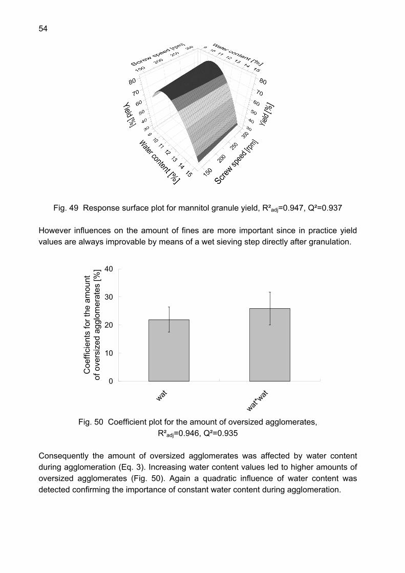
54
Fig. 49 Response surface plot for mannitol granule yield, R²adj=0.947, Q²=0.937
However influences on the amount of fines are more important since in practice yield values are always improvable by means of a wet sieving step directly after granulation.
0
10
20
30
40
wat
wat*wat
Coe
ffici
ents
for t
he a
mou
nt
of o
vers
ized
agg
lom
erat
es [%
]
Fig. 50 Coefficient plot for the amount of oversized agglomerates,
R²adj=0.946, Q²=0.935
Consequently the amount of oversized agglomerates was affected by water content during agglomeration (Eq. 3). Increasing water content values led to higher amounts of oversized agglomerates (Fig. 50). Again a quadratic influence of water content was detected confirming the importance of constant water content during agglomeration.
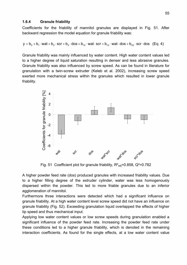
55
1.6.4 Granule friability Coefficients for the friability of mannitol granules are displayed in Fig. 51. After backward regression the model equation for granule friability was:
dosscrbdoswatbscrwatbdosbscrbwatbby 2313123210 ⋅⋅+⋅⋅+⋅⋅+⋅+⋅+⋅+= (Eq. 4) Granule friability was mainly influenced by water content. High water content values led to a higher degree of liquid saturation resulting in denser and less abrasive granules. Granule friability was also influenced by screw speed. As can be found in literature for granulation with a twin-screw extruder (Keleb et al. 2002), increasing screw speed exerted more mechanical stress within the granules which resulted in lower granule friability.
-6
-4
-2
0
2
4
wat scr
dos
wat*sc
r
wat*do
s
scr*d
os
Coe
ffici
ents
for g
ranu
le fr
iabi
lity
[%]
Fig. 51 Coefficient plot for granule friability, R²adj=0.858, Q²=0.782
A higher powder feed rate (dos) produced granules with increased friability values. Due to a higher filling degree of the extruder cylinder, water was less homogenously dispersed within the powder. This led to more friable granules due to an inferior agglomeration of mannitol. Furthermore three interactions were detected which had a significant influence on granule friability. At a high water content level screw speed did not have an influence on granule friability (Fig. 52). Exceeding granulation liquid overlapped the effects of higher tip speed and thus mechanical input. Applying low water content values or low screw speeds during granulation enabled a significant influence of the powder feed rate. Increasing the powder feed rate under these conditions led to a higher granule friability, which is denoted in the remaining interaction coefficients. As found for the single effects, at a low water content value
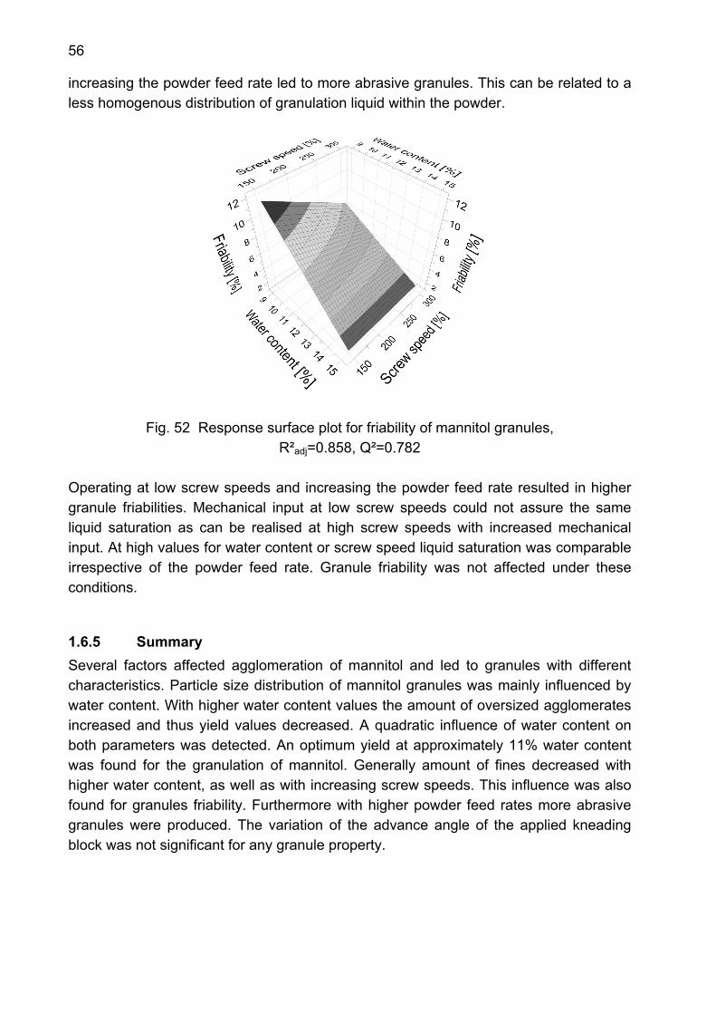
56
increasing the powder feed rate led to more abrasive granules. This can be related to a less homogenous distribution of granulation liquid within the powder.
Fig. 52 Response surface plot for friability of mannitol granules, R²adj=0.858, Q²=0.782
Operating at low screw speeds and increasing the powder feed rate resulted in higher granule friabilities. Mechanical input at low screw speeds could not assure the same liquid saturation as can be realised at high screw speeds with increased mechanical input. At high values for water content or screw speed liquid saturation was comparable irrespective of the powder feed rate. Granule friability was not affected under these conditions.
1.6.5 Summary Several factors affected agglomeration of mannitol and led to granules with different characteristics. Particle size distribution of mannitol granules was mainly influenced by water content. With higher water content values the amount of oversized agglomerates increased and thus yield values decreased. A quadratic influence of water content on both parameters was detected. An optimum yield at approximately 11% water content was found for the granulation of mannitol. Generally amount of fines decreased with higher water content, as well as with increasing screw speeds. This influence was also found for granules friability. Furthermore with higher powder feed rates more abrasive granules were produced. The variation of the advance angle of the applied kneading block was not significant for any granule property.
57
1.7 Summary Agglomeration using a twin-screw extruder was influenced by different variables. Screw configuration had a major impact on granulation behaviour. The tested screw configurations led to similar granule characteristics irrespective whether a water-soluble or insoluble substance was agglomerated. Differences depending on element pitch were detected. Conveying elements generally produced easy-flowing granules with the highest amounts of fines. Due to high porosity values, these granules showed the highest friability. Tablets compressed of these granule batches possessed the highest tensile strength values. Combing mixer elements produced also easy-flowing granules with less amounts of fines and lower porosity compared to conveying elements of the element pitch. Compression of these granules resulted in tablets with median tensile strength values. Kneading blocks achieved almost a complete agglomeration of all tested substances. Agglomeration behaviour usually depended on the advance angle of a discrete kneading block. These free-flowing granules possessed the lowest porosities and thus the lowest friabilities. Tablets resulting from kneading block granules showed the lowest tensile strength values. The element combination of kneading block and combing mixer element combined the advantages of these two element groups. Free-flowing granules with negligible amounts of fines were produced. These granule batches showed the highest yield values and low values for granule porosity and friability. Agglomeration behaviour of the tested screw configurations was comparable for 2kg/h and 6kg/h powder feed rate respectively. Granule characteristics resulting from the three different element groups remained the same. Process parameters had also an influence on granule characteristics. They were evaluated by means of a central composite face design agglomerating mannitol powder. Water content mainly influenced granule characteristics. Amounts of fines and and granule friability decreased with higher water content as well as with increasing screw speeds. More abrasive granules resulted with increasing powder feed rate.

58
2. Mixing behaviour of screw elements
2.1 Distributive mixing
2.1.1 Introduction For continuous granulation a homogenous powder blend must be achieved during processing, i.e. during passage of the extruder. A pre-blending step as known for batch processes is not possible. Distributive mixing is one type of mixing behaviour that can be realised using a twin-screw extruder (chapter A3.2). Distributive mixers tend to divide and recombine the material without disturbing the individual morphological components. The efficiency of distributive mixing depends on the number of particle re-orientations that is provided by the screw element geometry (Vainio et al. 1995). For polymer extrusion purposes the distributive mixing efficiency was already investigated (Vainio et al. 1995, Van Zuilichem et al. 1999). Kneading blocks and reverse flighted elements showed the best distributive mixing properties. Mixing efficiency was also tested for wet granulation with a twin-screw extruder (Van Melkebeke et al. 2008). Good mixing efficiency was detected irrespective of the tracer addition method and applied screw configuration. However a differently sized extruder was used (see chapter A5) for the latter study and only small variations in screw configuration could be realised. A systematic evaluation of the distributive mixing ability of different screw elements with two powder feeders for API and filler respectively is still missing. Since a homogeneous agglomeration of water-soluble powder is only possible when constant water contents are applied (chapter C1.6), distributive mixing should assure constant water contents in the resulting granules. Furthermore the API content was expected to be affected by different distributive mixing abilities of the used screw elements. However preliminary experiments showed comparable material residence time values around 30 seconds irrespective of the applied screw configuration (chapter F2.2.2).
2.1.2 Experimental setup To evaluate the distributive mixing ability of discrete screw elements, granulation was performed with two powder feeders (chapter F2.2.2). Two feeding ratios, 50:50 and 70:30 (m/m), for API and filler were applied. Lactose was dosed with 2kg/h and 2.77kg/h respectively. Theophylline was fed at 2kg/h and 1.23kg/h. Consequently different water contents were required for a proper agglomeration. For the 50:50 feeding ratio 0.54kg/h water was dosed and 0.36kg/h for the 70:30 ratio respectively. 6 different screw configurations were tested for granulation at 100rpm screw speed. After an equilibration time 10 granule samples were taken each minute (sample mass approximately 1g) for determination of water (chapter F2.3.7) and theophylline content respectively (chapter F2.3.12).

59
2.1.3 Water content of granules during granulation with two powder feeders Water content of granule samples in function of process time is displayed in Fig. 53 and Fig. 54. Considering only the added granulation liquid, water contents of 13.5% (50:50) and 9.0% (70:30) would result. However the detected values are the sum of initial water content of the two substances and the added granulation liquid. The largest fluctuation in water content showed granules produced with a 15mm pitch conveying element at both feeding ratios. The fluctuations in water content can be used to explain the results for the particle size distribution in previous experiments (chapter C1.1.3). The 15mm pitch conveying element produced lactose granules with high amount of fines and oversized agglomerates simultaneously. For other substances the same agglomeration behaviour was observed (chapter C1.2.3 and C1.3.3).
17
18
19
20
21
22
0 2 4 6 8 10 12
Time [min]
Wat
er c
onte
nt [%
]
GFA 15GFA 40GFM 20KB 30-60°KB 30-90°KB 60°/ GFM 20
Fig. 53 Water content of granule samples for feeding ratio 50:50 (lactose:theophylline)
This was primarily related to its low free chamber volume which provided a less homogenous distribution of water within the granules. Another explanation for this agglomeration behaviour is the fluctuation in water content.
Tab. 3 Water content values of granule samples for both feeding ratios (n=3) Water content (mean±s) [%]
Batch 50:50 70:30 GFA 15 19.5 ± 1.1 14.0 ± 0.7 GFA 40 20.0 ± 0.3 13.1 ± 0.2 GFM 20 20.1 ± 0.3 13.3 ± 0.2
KB 30-60° 20.1 ± 0.3 13.2 ± 0.2 KB 30-90° 19.9 ± 0.2 12.9 ± 0.2
KB 60°/ GFM 20 20.2 ± 0.3 13.4 ± 0.3

60
With increasing water content agglomeration is enforced leading to oversized agglomerates. As soon as water content is decreasing again, material is less agglomerated resulting in higher amounts of fines.
12
13
14
15
16
0 2 4 6 8 10 12
Time [min]
Wat
er c
onte
nt [%
]GFA 15GFA 40GFM 20KB 30-60°KB 30-90°KB 60°/ GFM 20
Fig. 54 Water content of granule samples for feeding ratio 70:30
(lactose:theophylline) The 40mm pitch elements did not lead to such fluctuating water content values. The other tested elements achieved similar variations in granule water content as the 40mm pitch conveying element (Tab. 3). A difference due to element type could not be detected.
2.1.4 Theophylline content of granules during granulation with two powder feeders
Theophylline content of granule samples is shown in function of process time in Fig. 55. All mean values were above 50% theophylline content (Tab. 4), although powder feeders were set in order to achieve 50% API content (chapter F2.2.2). A better control of the powder feeders was not possible since feeding data was not continuously recorded for both feeders.
Tab. 4 Theophylline content values of granule samples for both feeding ratios (n=3) Theophylline content (mean±s) [%]
Batch 50:50 70:30 GFA 15 53.6 ± 1.4 30.6 ± 2.8 GFA 40 53.6 ± 0.8 31.8 ± 1.4 GFM 20 53.6 ± 1.0 31.5 ± 0.4
KB 30-60° 54.0 ± 1.4 31.5 ± 0.5 KB 30-90° 53.4 ± 1.1 31.7 ± 0.2
KB 60°/ GFM 20 53.3 ± 1.9 31.4 ± 0.5
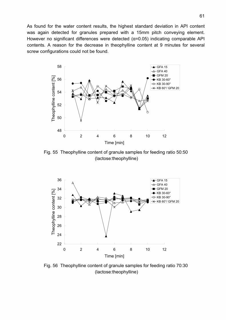
61
As found for the water content results, the highest standard deviation in API content was again detected for granules prepared with a 15mm pitch conveying element. However no significant differences were detected (α=0.05) indicating comparable API contents. A reason for the decrease in theophylline content at 9 minutes for several screw configurations could not be found.
48
50
52
54
56
58
0 2 4 6 8 10 12
Time [min]
Theo
phyl
line
cont
ent [
%]
GFA 15GFA 40GFM 20KB 30-60°KB 30-90°KB 60°/ GFM 20
Fig. 55 Theophylline content of granule samples for feeding ratio 50:50
(lactose:theophylline)
22
24
26
28
30
32
34
36
0 2 4 6 8 10 12
Time [min]
Theo
phyl
line
cont
ent [
%]
GFA 15GFA 40GFM 20KB 30-60°KB 30-90°KB 60°/ GFM 20
Fig. 56 Theophylline content of granule samples for feeding ratio 70:30
(lactose:theophylline)
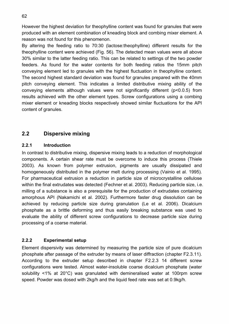
62
However the highest deviation for theophylline content was found for granules that were produced with an element combination of kneading block and combing mixer element. A reason was not found for this phenomenon. By altering the feeding ratio to 70:30 (lactose:theophylline) different results for the theophylline content were achieved (Fig. 56). The detected mean values were all above 30% similar to the latter feeding ratio. This can be related to settings of the two powder feeders. As found for the water contents for both feeding ratios the 15mm pitch conveying element led to granules with the highest fluctuation in theophylline content. The second highest standard deviation was found for granules prepared with the 40mm pitch conveying element. This indicates a limited distributive mixing ability of the conveying elements although values were not significantly different (p<0.0.5) from results achieved with the other element types. Screw configurations using a combing mixer element or kneading blocks respectively showed similar fluctuations for the API content of granules.
2.2 Dispersive mixing
2.2.1 Introduction In contrast to distributive mixing, dispersive mixing leads to a reduction of morphological components. A certain shear rate must be overcome to induce this process (Thiele 2003). As known from polymer extrusion, pigments are usually dissipated and homogeneously distributed in the polymer melt during processing (Vainio et al. 1995). For pharmaceutical extrusion a reduction in particle size of microcrystalline cellulose within the final extrudates was detected (Fechner et al. 2003). Reducing particle size, i.e. milling of a substance is also a prerequisite for the production of extrudates containing amorphous API (Nakamichi et al. 2002). Furthermore faster drug dissolution can be achieved by reducing particle size during granulation (Le et al. 2006). Dicalcium phosphate as a brittle deforming and thus easily breaking substance was used to evaluate the ability of different screw configurations to decrease particle size during processing of a coarse material.
2.2.2 Experimental setup Element dispersivity was determined by measuring the particle size of pure dicalcium phosphate after passage of the extruder by means of laser diffraction (chapter F2.3.11). According to the extruder setup described in chapter F2.2.3 14 different screw configurations were tested. Almost water-insoluble coarse dicalcium phosphate (water solubility <1% at 20°C) was granulated with demineralised water at 100rpm screw speed. Powder was dosed with 2kg/h and the liquid feed rate was set at 0.9kg/h.
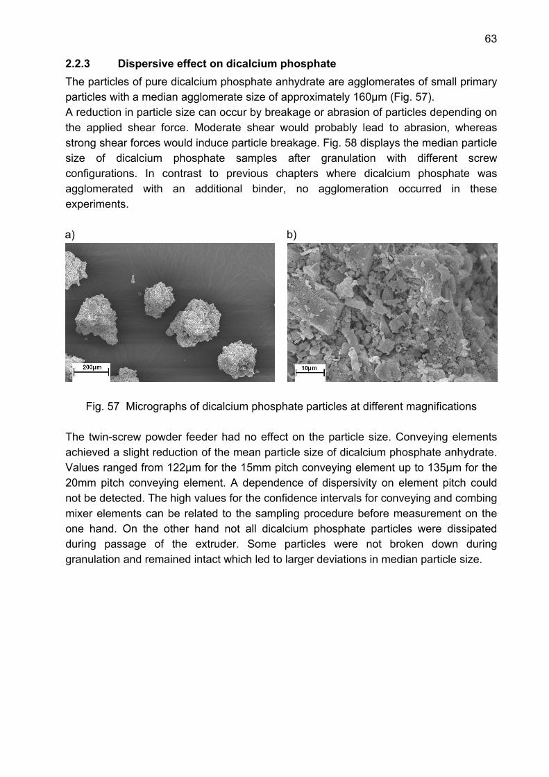
63
2.2.3 Dispersive effect on dicalcium phosphate The particles of pure dicalcium phosphate anhydrate are agglomerates of small primary particles with a median agglomerate size of approximately 160µm (Fig. 57). A reduction in particle size can occur by breakage or abrasion of particles depending on the applied shear force. Moderate shear would probably lead to abrasion, whereas strong shear forces would induce particle breakage. Fig. 58 displays the median particle size of dicalcium phosphate samples after granulation with different screw configurations. In contrast to previous chapters where dicalcium phosphate was agglomerated with an additional binder, no agglomeration occurred in these experiments. a)
b)
Fig. 57 Micrographs of dicalcium phosphate particles at different magnifications
The twin-screw powder feeder had no effect on the particle size. Conveying elements achieved a slight reduction of the mean particle size of dicalcium phosphate anhydrate. Values ranged from 122µm for the 15mm pitch conveying element up to 135µm for the 20mm pitch conveying element. A dependence of dispersivity on element pitch could not be detected. The high values for the confidence intervals for conveying and combing mixer elements can be related to the sampling procedure before measurement on the one hand. On the other hand not all dicalcium phosphate particles were dissipated during passage of the extruder. Some particles were not broken down during granulation and remained intact which led to larger deviations in median particle size.
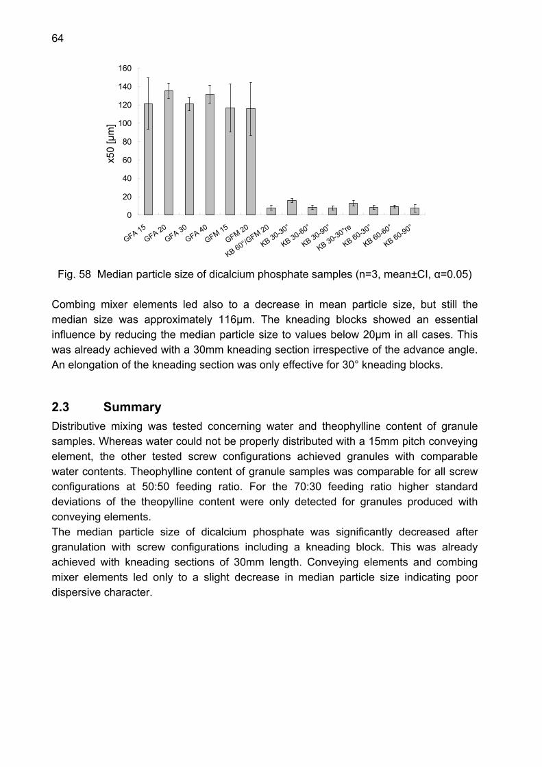
64
0
20
40
60
80
100
120
140
160
GFA 15GFA 20
GFA 30GFA 40
GFM 15
GFM 20
KB 60°/GFM 20
KB 30-30°
KB 30-60°
KB 30-90°
KB 30-30°re
KB 60-30°
KB 60-60°
KB 60-90°
x50
[µm
]
Fig. 58 Median particle size of dicalcium phosphate samples (n=3, mean±CI, α=0.05)
Combing mixer elements led also to a decrease in mean particle size, but still the median size was approximately 116µm. The kneading blocks showed an essential influence by reducing the median particle size to values below 20µm in all cases. This was already achieved with a 30mm kneading section irrespective of the advance angle. An elongation of the kneading section was only effective for 30° kneading blocks.
2.3 Summary Distributive mixing was tested concerning water and theophylline content of granule samples. Whereas water could not be properly distributed with a 15mm pitch conveying element, the other tested screw configurations achieved granules with comparable water contents. Theophylline content of granule samples was comparable for all screw configurations at 50:50 feeding ratio. For the 70:30 feeding ratio higher standard deviations of the theopylline content were only detected for granules produced with conveying elements. The median particle size of dicalcium phosphate was significantly decreased after granulation with screw configurations including a kneading block. This was already achieved with kneading sections of 30mm length. Conveying elements and combing mixer elements led only to a slight decrease in median particle size indicating poor dispersive character.
65
3. Comparison of twin-screw extruders for continuous granulation
3.1 Introduction Influences of extruder setup concerning screw configuration and process settings on granule attributes were described in previous chapters. In other studies similar work was conducted using a twin-screw extruder of a different size and manufacturer (Keleb 2004, Van Melkebeke et al. 2006, 2008). A comparison of different twin-screw extruders is still missing in literature. Therefore the purpose of this study was to compare two continuous granulators: a statistical design of experiments was run on two twin-screw extruders, namely an APV Baker extruder with 19 mm screw diameter and a Leistritz Micro with 27 mm screw diameter (chapter A4-A5). For a systematic investigation of process variables, materials of different physical properties have to be considered (Holm et al. 1983). Water-soluble and water-insoluble granules were processed. Since the large impact of water content was already observed (chapter C1.6), experiments were run with the same water content on both machines. Thus two factors were chosen for investigation: total input rate (sum of powder and liquid throughput) and screw speed.
3.2 Experimental setup Two formulations were processed: lactose and dicalcium phosphate were granulated with 7.5% and 11% (w/w) demineralised water, respectively. PVP, dissolved in the granulation liquid, was added as binder (2.5%, dry mass, m/m). A 12-run full factorial design was used on both extruders to evaluate 2 factors on 3 levels: total input rate (dos) was set at 2, 4 and 6 kg/h and screw speed (scr) was varied from 150rpm over 225rpm to 300 rpm. Three replicates of the centre point (0 level: i.e. 4 kg/h and 225 rpm) were performed. For evaluation of the results the extruder type was included as a qualitative factor (ext), using -1 as coded value for the APV extruder and +1 for the Leistritz extruder. The complete model equation was:
extscrbextdosbscrdosbextbscrbdosbby 2313123210 ⋅⋅+⋅⋅+⋅⋅+⋅+⋅+⋅+= (Eq. 5)
With y: response variable, b0: constant, bi: coefficient The different factor settings of the trials and results for particle size distribution and friability of dicalcium phosphate and lactose granules are shown in Tab. 11 and Tab. 12 respectively. All factor level combinations were carried out in a randomized order.
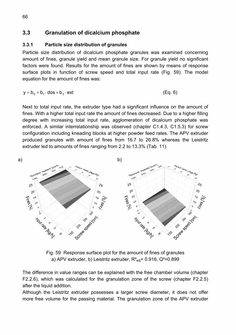
66
3.3 Granulation of dicalcium phosphate
3.3.1 Particle size distribution of granules Particle size distribution of dicalcium phosphate granules was examined concerning amount of fines, granule yield and mean granule size. For granule yield no significant factors were found. Results for the amount of fines are shown by means of response surface plots in function of screw speed and total input rate (Fig. 59). The model equation for the amount of fines was:
extbdosbby 310 ⋅+⋅+= (Eq. 6) Next to total input rate, the extruder type had a significant influence on the amount of fines. With a higher total input rate the amount of fines decreased. Due to a higher filling degree with increasing total input rate, agglomeration of dicalcium phosphate was enforced. A similar interrelationship was observed (chapter C1.4.3, C1.5.3) for screw configuration including kneading blocks at higher powder feed rates. The APV extruder produced granules with amount of fines from 16.7 to 26.8% whereas the Leistritz extruder led to amounts of fines ranging from 2.2 to 13.3% (Tab. 11).
a)
b)
Fig. 59 Response surface plot for the amount of fines of granules a) APV extruder, b) Leistritz extruder, R²adj= 0.916, Q²=0.899
The difference in value ranges can be explained with the free chamber volume (chapter F2.2.6), which was calculated for the granulation zone of the screw (chapter F2.2.5) after the liquid addition. Although the Leistritz extruder possesses a larger screw diameter, it does not offer more free volume for the passing material. The granulation zone of the APV extruder
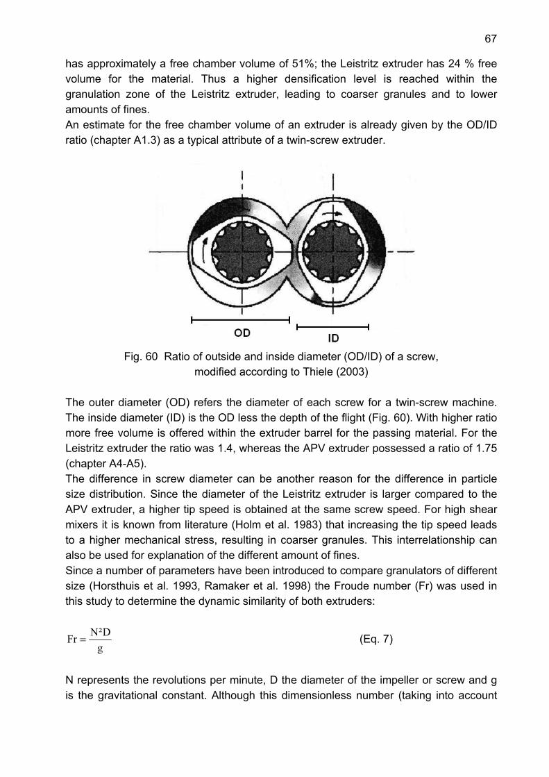
67
has approximately a free chamber volume of 51%; the Leistritz extruder has 24 % free volume for the material. Thus a higher densification level is reached within the granulation zone of the Leistritz extruder, leading to coarser granules and to lower amounts of fines. An estimate for the free chamber volume of an extruder is already given by the OD/ID ratio (chapter A1.3) as a typical attribute of a twin-screw extruder.
Fig. 60 Ratio of outside and inside diameter (OD/ID) of a screw,
modified according to Thiele (2003) The outer diameter (OD) refers the diameter of each screw for a twin-screw machine. The inside diameter (ID) is the OD less the depth of the flight (Fig. 60). With higher ratio more free volume is offered within the extruder barrel for the passing material. For the Leistritz extruder the ratio was 1.4, whereas the APV extruder possessed a ratio of 1.75 (chapter A4-A5). The difference in screw diameter can be another reason for the difference in particle size distribution. Since the diameter of the Leistritz extruder is larger compared to the APV extruder, a higher tip speed is obtained at the same screw speed. For high shear mixers it is known from literature (Holm et al. 1983) that increasing the tip speed leads to a higher mechanical stress, resulting in coarser granules. This interrelationship can also be used for explanation of the different amount of fines. Since a number of parameters have been introduced to compare granulators of different size (Horsthuis et al. 1993, Ramaker et al. 1998) the Froude number (Fr) was used in this study to determine the dynamic similarity of both extruders:
gD²NFr = (Eq. 7)
N represents the revolutions per minute, D the diameter of the impeller or screw and g is the gravitational constant. Although this dimensionless number (taking into account

68
centrifugal force to the gravitational force was initially used to compare different types of high shear granulators, its application was extended to granulation using an extruder. The Froude-numbers found for both extruders (Tab. 5) were lower than for high shear granulators due to different machine design.
Tab. 5 Froude number and tip speed values calculated for both extruders
Froude number Tip speed [m/s] Screw speed [rpm] APV Leistritz APV Leistritz 150 0.012 0.017 0.15 0.21 225 0.027 0.039 0.22 0.32 300 0.048 0.069 0.30 0.42
Although Froude-numbers were low, a difference was detected at all screw speed settings. The Leistritz extruder resulted in higher Froude numbers indicating higher centrifugal forces during agglomeration, due to higher tip speed values which induce larger mechanical stress onto the granules during processing. The median particle size (d50) of dicalcium phosphate granules was significantly influenced by total input rate (dos), extruder type (ext) and an interaction between the total input rate and the extruder type (Eq. 8).
extdosbextbscrbdosbby 133210 ⋅⋅+⋅+⋅+⋅+= (Eq. 8)
This relation becomes more evident using the interaction plot (Fig. 61) where the scaled and centred values for median granule size are shown in function of total input rate. Whereas the Leistritz extruder produced much larger granules with increasing total input rate, only a limited effect was observed in case of the APV extruder. The different behaviour of the two extruders can be explained by their difference in free chamber volume. The higher free chamber volume of the APV extruder allowed increasing the total input rate with little effect on the median granule size. In contrast the Leistritz extruder did not show this flexibility.

69
Fig. 61 Interaction plot for median particle size of dicalcium phosphate granules,
●= APV extruder , ▲= Leistritz extruder, R²adj=0.832, Q²=0.790 Particle size distributions of the centre points confirmed the results for the median particle size: granules produced by the Leistritz extruder were coarser than granules achieved with the APV extruder (Fig. 62). The full lines depict the particle size distributions for the APV extruder (n=4) and the Leistritz extruder (n=3). The dotted line represents a deviating run for the Leistritz extruder, which was not included in the calculation of the mean. A reason for this deviation could not be found.
0
20
40
60
80
100
0 500 1000 1500 2000 2500 3000 3500Particle size [µm]
cum
ulat
ive
unde
rsiz
e fra
ctio
n [%
]
Fig. 62 Cumulative curves of the centre points of dicalcium phosphate granules,
●= APV extruder (n=4, mean±s); ▲= Leistritz extruder (n=3, mean±s), dotted line represents deviating run of Leistritz experiment
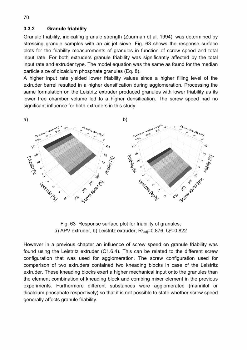
70
3.3.2 Granule friability Granule friability, indicating granule strength (Zuurman et al. 1994), was determined by stressing granule samples with an air jet sieve. Fig. 63 shows the response surface plots for the friability measurements of granules in function of screw speed and total input rate. For both extruders granule friability was significantly affected by the total input rate and extruder type. The model equation was the same as found for the median particle size of dicalcium phosphate granules (Eq. 8). A higher input rate yielded lower friability values since a higher filling level of the extruder barrel resulted in a higher densification during agglomeration. Processing the same formulation on the Leistritz extruder produced granules with lower friability as its lower free chamber volume led to a higher densification. The screw speed had no significant influence for both extruders in this study. a)
b)
Fig. 63 Response surface plot for friability of granules,
a) APV extruder, b) Leistritz extruder, R²adj=0.876, Q²=0.822
However in a previous chapter an influence of screw speed on granule friability was found using the Leistritz extruder (C1.6.4). This can be related to the different screw configuration that was used for agglomeration. The screw configuration used for comparison of two extruders contained two kneading blocks in case of the Leistritz extruder. These kneading blocks exert a higher mechanical input onto the granules than the element combination of kneading block and combing mixer element in the previous experiments. Furthermore different substances were agglomerated (mannitol or dicalcium phosphate respectively) so that it is not possible to state whether screw speed generally affects granule friability.
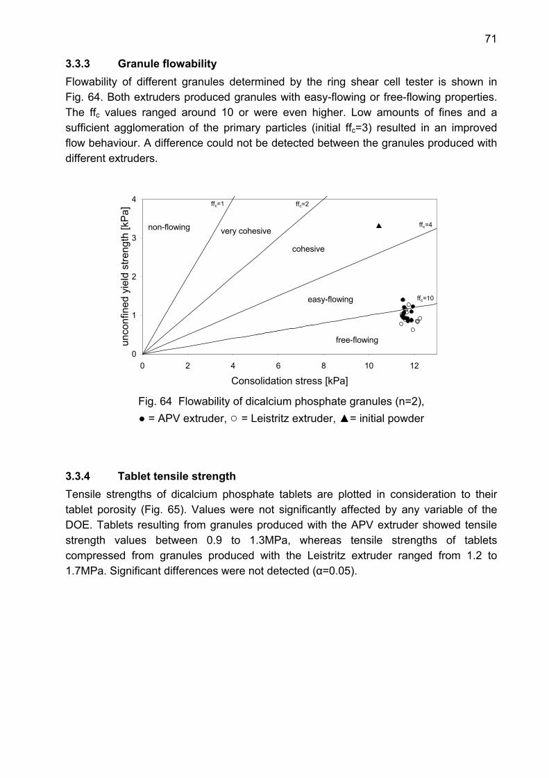
71
3.3.3 Granule flowability Flowability of different granules determined by the ring shear cell tester is shown in Fig. 64. Both extruders produced granules with easy-flowing or free-flowing properties. The ffc values ranged around 10 or were even higher. Low amounts of fines and a sufficient agglomeration of the primary particles (initial ffc=3) resulted in an improved flow behaviour. A difference could not be detected between the granules produced with different extruders.
0
1
2
3
4
0 2 4 6 8 10 12
Consolidation stress [kPa]
unco
nfin
ed y
ield
stre
ngth
[kP
a]
non-flowing very cohesive
cohesive
easy-flowing
free-flowing
ffc=1 ffc=2
ffc=4
ffc=10
Fig. 64 Flowability of dicalcium phosphate granules (n=2), ● = APV extruder, ○ = Leistritz extruder, ▲= initial powder
3.3.4 Tablet tensile strength Tensile strengths of dicalcium phosphate tablets are plotted in consideration to their tablet porosity (Fig. 65). Values were not significantly affected by any variable of the DOE. Tablets resulting from granules produced with the APV extruder showed tensile strength values between 0.9 to 1.3MPa, whereas tensile strengths of tablets compressed from granules produced with the Leistritz extruder ranged from 1.2 to 1.7MPa. Significant differences were not detected (α=0.05).
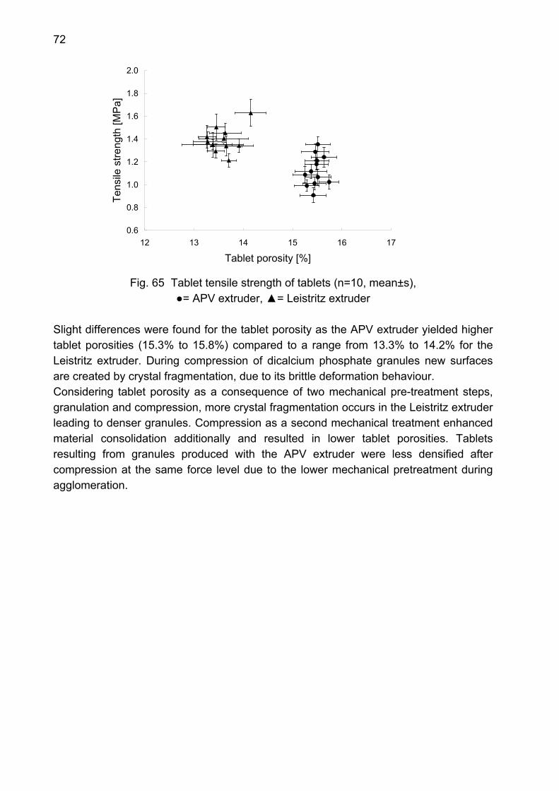
72
0.6
0.8
1.0
1.2
1.4
1.6
1.8
2.0
12 13 14 15 16 17
Tablet porosity [%]
Tens
ile s
treng
th [M
Pa]
Fig. 65 Tablet tensile strength of tablets (n=10, mean±s),
●= APV extruder, ▲= Leistritz extruder
Slight differences were found for the tablet porosity as the APV extruder yielded higher tablet porosities (15.3% to 15.8%) compared to a range from 13.3% to 14.2% for the Leistritz extruder. During compression of dicalcium phosphate granules new surfaces are created by crystal fragmentation, due to its brittle deformation behaviour. Considering tablet porosity as a consequence of two mechanical pre-treatment steps, granulation and compression, more crystal fragmentation occurs in the Leistritz extruder leading to denser granules. Compression as a second mechanical treatment enhanced material consolidation additionally and resulted in lower tablet porosities. Tablets resulting from granules produced with the APV extruder were less densified after compression at the same force level due to the lower mechanical pretreatment during agglomeration.

73
3.4 Granulation of lactose
3.4.1 Particle size distribution of granules Particle size distribution of lactose granules was examined concerning amount of fines, granule yield and the mean granule size. For amount of fines and granule yield no significant factors were found. The amount of oversized agglomerates was significantly influenced by extruder type and total input rate (Fig. 66). Consequently the model equation for the amount of oversized agglomerates was:
extbdosbby 310 ⋅+⋅+= (Eq. 9) In comparison negligible amounts of oversized agglomerates were produced with the APV extruder ranging from 0.2% to 2.2%. Lactose was properly agglomerated without creation of excessive lumps. In case of the Leistritz extruder a higher densification inside the barrel of the Leistritz extruder led to a larger fraction of oversized agglomerates in the range of 2.0% to 3.6%. For both extruders a higher total input rate resulted in an increase of amount of oversized agglomerates. With a higher filling degree agglomeration of lactose powder was enforced within the extruder barrel. a) b)
Fig. 66 Response surface plot for oversized agglomerates of lactose granules,
a) APV extruder, b) Leistritz extruder, R²adj=0.866, Q²=0.818 The cumulative distribution curves of the centre points are displayed in Fig. 67 for both extruders. Differences were less pronounced than with dicalcium phosphate granules, since lactose is less sensitive towards shear forces (Holm et al. 1984). However, the Leistritz extruder produced larger granules.
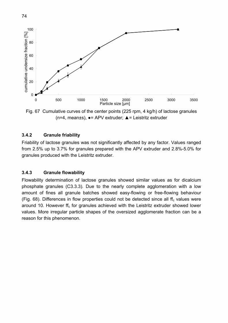
74
0
20
40
60
80
100
0 500 1000 1500 2000 2500 3000 3500Particle size [µm]
cum
ulat
ive
unde
rsiz
e fra
ctio
n [%
]
Fig. 67 Cumulative curves of the center points (225 rpm, 4 kg/h) of lactose granules
(n=4, mean±s), ●= APV extruder; ▲= Leistritz extruder
3.4.2 Granule friability Friability of lactose granules was not significantly affected by any factor. Values ranged from 2.5% up to 3.7% for granules prepared with the APV extruder and 2.8%-5.0% for granules produced with the Leistritz extruder.
3.4.3 Granule flowability Flowability determination of lactose granules showed similar values as for dicalcium phosphate granules (C3.3.3). Due to the nearly complete agglomeration with a low amount of fines all granule batches showed easy-flowing or free-flowing behaviour (Fig. 68). Differences in flow properties could not be detected since all ffc values were around 10. However ffc for granules achieved with the Leistritz extruder showed lower values. More irregular particle shapes of the oversized agglomerate fraction can be a reason for this phenomenon.
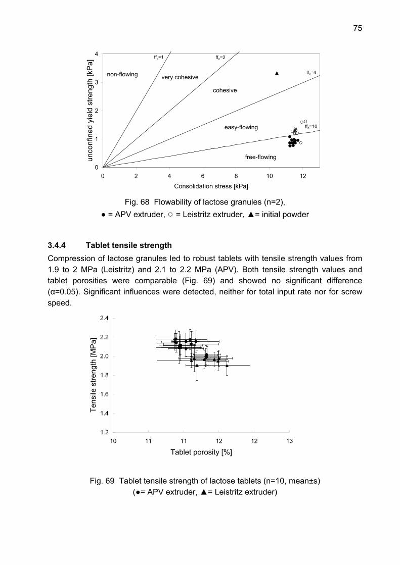
75
0
1
2
3
4
0 2 4 6 8 10 12
Consolidation stress [kPa]
unco
nfin
ed y
ield
stre
ngth
[kP
a]
non-flowing very cohesive
cohesive
easy-flowing
free-flowing
ffc=1 ffc=2
ffc=4
ffc=10
Fig. 68 Flowability of lactose granules (n=2),
● = APV extruder, ○ = Leistritz extruder, ▲= initial powder
3.4.4 Tablet tensile strength Compression of lactose granules led to robust tablets with tensile strength values from 1.9 to 2 MPa (Leistritz) and 2.1 to 2.2 MPa (APV). Both tensile strength values and tablet porosities were comparable (Fig. 69) and showed no significant difference (α=0.05). Significant influences were detected, neither for total input rate nor for screw speed.
1.2
1.4
1.6
1.8
2.0
2.2
2.4
10 11 11 12 12 13
Tablet porosity [%]
Tens
ile s
treng
th [M
Pa]
Fig. 69 Tablet tensile strength of lactose tablets (n=10, mean±s) (●= APV extruder, ▲= Leistritz extruder)
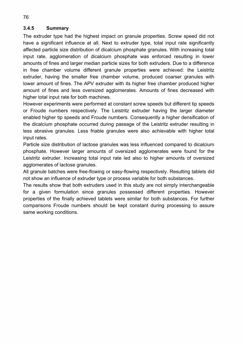
76
3.4.5 Summary The extruder type had the highest impact on granule properties. Screw speed did not have a significant influence at all. Next to extruder type, total input rate significantly affected particle size distribution of dicalcium phosphate granules. With increasing total input rate, agglomeration of dicalcium phosphate was enforced resulting in lower amounts of fines and larger median particle sizes for both extruders. Due to a difference in free chamber volume different granule properties were achieved: the Leistritz extruder, having the smaller free chamber volume, produced coarser granules with lower amount of fines. The APV extruder with its higher free chamber produced higher amount of fines and less oversized agglomerates. Amounts of fines decreased with higher total input rate for both machines. However experiments were performed at constant screw speeds but different tip speeds or Froude numbers respectively. The Leistritz extruder having the larger diameter enabled higher tip speeds and Froude numbers. Consequently a higher densification of the dicalcium phosphate occurred during passage of the Leistritz extruder resulting in less abrasive granules. Less friable granules were also achievable with higher total input rates. Particle size distribution of lactose granules was less influenced compared to dicalcium phosphate. However larger amounts of oversized agglomerates were found for the Leistritz extruder. Increasing total input rate led also to higher amounts of oversized agglomerates of lactose granules. All granule batches were free-flowing or easy-flowing respectively. Resulting tablets did not show an influence of extruder type or process variable for both substances. The results show that both extruders used in this study are not simply interchangeable for a given formulation since granules possessed different properties. However properties of the finally achieved tablets were similar for both substances. For further comparisons Froude numbers should be kept constant during processing to assure same working conditions.
77
D Summary The feasibility of a twin-screw extruder for a continuous wet granulation process was investigated. On the one hand the impact of different screw configurations and process parameters on granule and tablet properties was evaluated. On the other hand mixing properties of several screw configurations were tested with respect to a continuous process including mixing and granulation in one process step. Furthermore a comparison of differently sized twin-screw extruders was performed to evaluate differences and similarities between both machines. Screw configuration had a major impact on granulation behaviour. The tested screw configurations led to similar granule characteristics irrespective whether lactose or mannitol, as water-soluble substances, or dicalcium phosphate, as a water-insoluble substance, was agglomerated. Conveying elements generally produced easy-flowing granules with the highest amounts of fines, porosity values and thus highest granule friabilities. Combing mixer elements also produced easy-flowing granules with less amounts of fines and lower porosity. Kneading blocks achieved free-flowing granules with negligible amounts of fines and the lowest porosities. In general increasing granule porosity led to higher tensile strengths of tablets. Finally the element combination of kneading block and combing mixer element proved to be the screw configuration of choice for all substances. Agglomeration behaviour of the tested screw configurations was comparable for 2kg/h and 6kg/h powder feed rate respectively, providing the possibility of a simple increase in material output regarding a possible scale-up. Process parameters also had an influence on granule characteristics. Amounts of fines and granule friability decreased with higher water content as well as with increasing screw speeds. More abrasive granules resulted with increasing powder feed rate. Distributive mixing was tested concerning water and API content of granule samples. Almost all tested screw elements, except the 15mm pitch conveying element, showed good distributive properties. Dispersive mixing was achieved by the use of kneading blocks. Conveying elements and combing mixer elements showed hardly any dispersive properties. Comparison of two differently sized twin-screw extruders showed that the extruder type had a high influence on properties of lactose or dicalcium phosphate granules. Next to extruder type, total input rate significantly affected granule particle size distribution, whereas screw speed did not have a significant influence in these experiments. An increasing total input rate amplified agglomeration of water-soluble and water-insoluble substances resulting in lower amounts of fines and coarser granules. Due to a difference in free chamber volume for the passing material, different granule properties were achieved: the larger extruder produced coarser granules with lower amount of
78
fines due to a higher mechanical input realised by a smaller free chamber volume. The smaller sized extruder led to granules with higher amount of fines and less oversized agglomerates due to less mechanical input. However, both extruders produced easy- or free-flowing granules. For both substances the resulting tablets did not show an influence of extruder type or process variable. The results proved that both extruders are not simply replaceable for a given formulation since the resulting granules possessed different properties. However continuous granulation using a twin-screw extruder proved to be a robust process.
79
E Zusammenfassung der Arbeit Die Machbarkeit einer kontinuierlichen Feuchtgranulation mit Hilfe eines Zweischneckenextruders wurde untersucht. Dabei wurde der Einfluss der Schneckenkonfiguration und verschiedener Prozessparameter auf die resultierenden Granulate und Tabletten erörtert. Ferner wurde die Mischfähigkeit ausgesuchter Schneckenkonfigurationen getestet im Hinblick auf einen kontinuierlichen Granulationsprozess, bei dem Mischen und Agglomerieren in einem Schritt stattfinden kann. Der Vergleich zweier unterschiedlich dimensionierter Extruder diente zur Erörterung der Gemeinsamkeiten und Unterschiede der beiden Maschinen hinsichtlich ihrer möglichen Austauschbarkeit. Der Aufbau der Schneckenkonfiguration hatte einen maßgeblichen Einfluss auf das Granulierverhalten. Es wurden sowohl Krustengranulate aus Lactose oder Mannitol, als auch ein Klebstoffgranulat aus Dicalciumphosphat hergestellt. Die untersuchten Schneckenkonfigurationen führten stoffunabhängig jeweils zu vergleichbaren Granulateigenschaften. Förderlelemente produzierten grundsätzlich leicht fließende Granulate mit den höchsten Werten an Feinanteil, Granulatporosität als auch Granulatfriabillität. Mit Mischförderlementen waren ebenfalls leicht fließende Granulate herstellbar, die jedoch niedrigere Feinanteile und Granulatporositäten aufwiesen. Knetblöcke erzielten stets niedrigporöse, frei fließende Granulate mit vernachlässigbaren Feinanteilswerten. Im Allgemeinen führten höhere Granulatporositäten nach der Tablettierung zu festeren Tabletten. Schließlich erzielte die Elementkombination aus Knetblock und Mischförderelement bei allen Substanzen optimale Ergebnisse. Das Agglomerationsverhalten der Schneckenkonfigurationen war auch nach Erhöhung der Durchsatzmenge von 2kg/h auf 6kg/h vergleichbar und stellt somit eine einfache Möglichkeit eines möglichen Scale-up Verfahrens dar. Die Eigenschaften der hergestellten Granulate wurden auch von verschiedenen Prozessparametern beeinflusst. Granulate mit höheren Feinanteilen und Friabilitäten konnten mit einer Erhöhung der Feuchte beziehungsweise einer Erhöhung der Schneckendrehzahl erzielt werden. Höhere Materialdurchsätze hatten weniger abriebsfeste Granulate zur Folge. Distributives Mischen wurde an Hand der Granulatfeuchte und des Wirkstoffgehaltes von Granulatproben untersucht. Bis auf das Förderelement mit einer 15mm Steigung zeigten alle getesteten Elemente ein gutes distributives Mischverhaltenf. Dispersives Mischen wurde durch den Einsatz von Knetblöcken ermöglicht. Förder- und Mischförderlemente waren kaum dispersiv mischend.
80
Der Vergleich unterschiedlicher Extruder zeigte einen hauptsächlichen Einfluss des Extrudertyps auf die Eigenschaften von Lactose- und Dicalciumphosphat Granulaten. Ferner beeinflusste die Materialdurchsatzrate die Partikelgrößenverteilung der resultierenden Granulate. Eine steigende Durchsatzrate führte zu einer höheren mechanischen Beanspruchung der Granulate, was sich in niedrigeren Feinanteilen und insgesamt gröberen Krusten- und Klebstoffgranulaten widerspiegelte. Die Schneckendrehzahl zeigte im Rahmen dieser Untersuchungen keinen signifikanten Einfluss. Auf Grund des Unterschieds im freien Kammervolumen der beiden Extruder resultierten unterschiedliche Granulateigenschaften. Der größere Extruder erzielte gröbere Granulate mit niedrigen Feinanteilswerten. Dies lässt sich auf eine höhere mechanische Beanspruchung während des Granulierens zurückführen als Folge eines kleineren freien Kammervolumens. Der kleinere Extruder, mit einem höheren freien Kammervolumen ausgestattet, produzierte feinere Granulate mit höheren Feinanteilen die auch weniger abriebsfest waren. Beide Extruder erzielten jedoch leicht- bzw. frei fließende Granulate. Tabletten zeigten bei beiden Substanzen keinen Einfluss der untersuchten Variablen. Zusammenfassend lässt sich sagen, dass ein einfacher Austausch der beiden Extruder bei einer bestehenden Formulierung nicht möglich ist, da sie zu unterschiedlichen Granulateigenschaften führten. Jedoch haben die Versuche bewiesen, dass es sich bei der kontinuierlichen Granulation mit Zweischneckenextrudern um einen sehr robusten und viel versprechenden Prozess handelt.
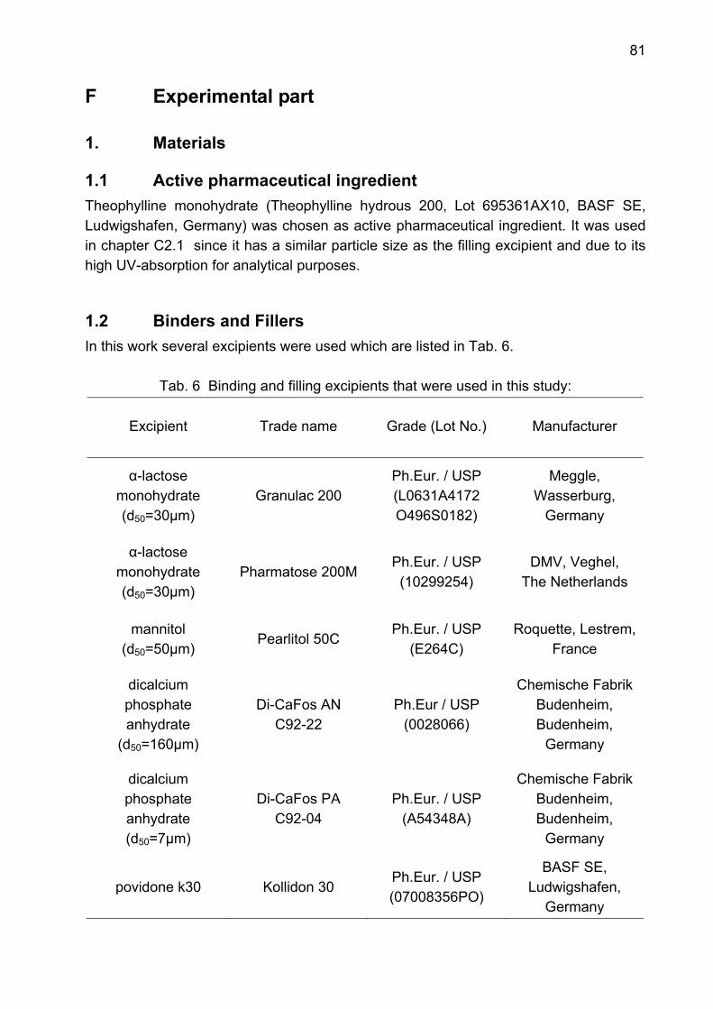
81
F Experimental part
1. Materials
1.1 Active pharmaceutical ingredient Theophylline monohydrate (Theophylline hydrous 200, Lot 695361AX10, BASF SE, Ludwigshafen, Germany) was chosen as active pharmaceutical ingredient. It was used in chapter C2.1 since it has a similar particle size as the filling excipient and due to its high UV-absorption for analytical purposes.
1.2 Binders and Fillers In this work several excipients were used which are listed in Tab. 6.
Tab. 6 Binding and filling excipients that were used in this study:
Excipient Trade name Grade (Lot No.)
Manufacturer
α-lactose monohydrate (d50=30µm)
Granulac 200
Ph.Eur. / USP (L0631A4172 O496S0182)
Meggle, Wasserburg,
Germany
α-lactose monohydrate (d50=30µm)
Pharmatose 200M
Ph.Eur. / USP (10299254)
DMV, Veghel, The Netherlands
mannitol (d50=50µm)
Pearlitol 50C
Ph.Eur. / USP (E264C)
Roquette, Lestrem, France
dicalcium phosphate anhydrate
(d50=160µm)
Di-CaFos AN
C92-22
Ph.Eur / USP (0028066)
Chemische Fabrik Budenheim, Budenheim,
Germany
dicalcium phosphate anhydrate (d50=7µm)
Di-CaFos PA C92-04
Ph.Eur. / USP (A54348A)
Chemische Fabrik Budenheim, Budenheim,
Germany
povidone k30 Kollidon 30 Ph.Eur. / USP (07008356PO)
BASF SE, Ludwigshafen,
Germany
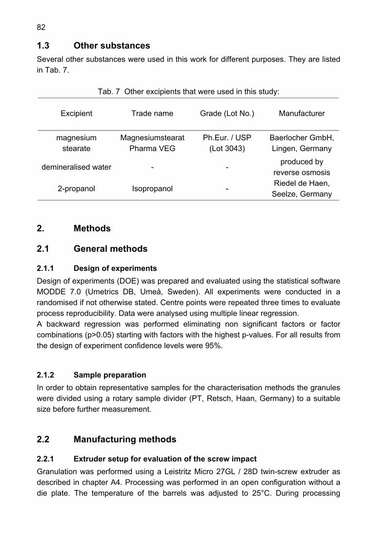
82
1.3 Other substances Several other substances were used in this work for different purposes. They are listed in Tab. 7.
Tab. 7 Other excipients that were used in this study:
Excipient Trade name Grade (Lot No.)
Manufacturer
magnesium stearate
Magnesiumstearat Pharma VEG
Ph.Eur. / USP (Lot 3043)
Baerlocher GmbH, Lingen, Germany
demineralised water - - produced by
reverse osmosis
2-propanol Isopropanol - Riedel de Haen, Seelze, Germany
2. Methods
2.1 General methods
2.1.1 Design of experiments Design of experiments (DOE) was prepared and evaluated using the statistical software MODDE 7.0 (Umetrics DB, Umeå, Sweden). All experiments were conducted in a randomised if not otherwise stated. Centre points were repeated three times to evaluate process reproducibility. Data were analysed using multiple linear regression. A backward regression was performed eliminating non significant factors or factor combinations (p>0.05) starting with factors with the highest p-values. For all results from the design of experiment confidence levels were 95%.
2.1.2 Sample preparation In order to obtain representative samples for the characterisation methods the granules were divided using a rotary sample divider (PT, Retsch, Haan, Germany) to a suitable size before further measurement.
2.2 Manufacturing methods
2.2.1 Extruder setup for evaluation of the screw impact Granulation was performed using a Leistritz Micro 27GL / 28D twin-screw extruder as described in chapter A4. Processing was performed in an open configuration without a die plate. The temperature of the barrels was adjusted to 25°C. During processing
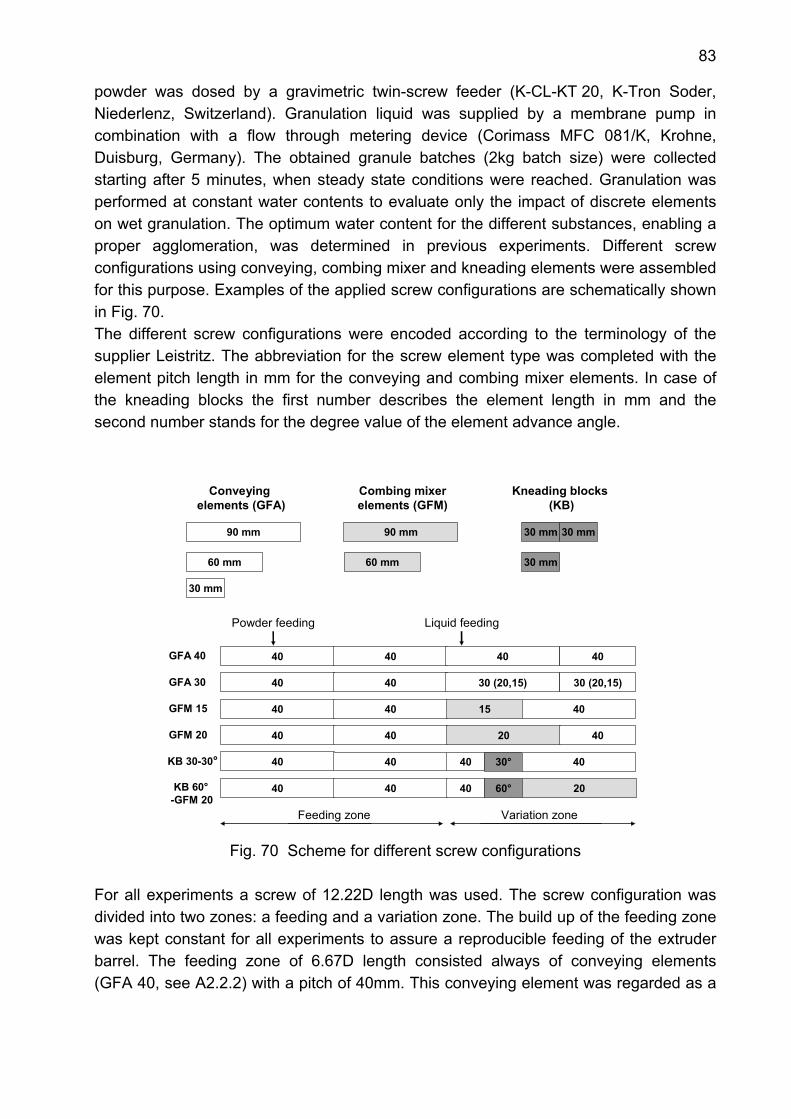
83
powder was dosed by a gravimetric twin-screw feeder (K-CL-KT 20, K-Tron Soder, Niederlenz, Switzerland). Granulation liquid was supplied by a membrane pump in combination with a flow through metering device (Corimass MFC 081/K, Krohne, Duisburg, Germany). The obtained granule batches (2kg batch size) were collected starting after 5 minutes, when steady state conditions were reached. Granulation was performed at constant water contents to evaluate only the impact of discrete elements on wet granulation. The optimum water content for the different substances, enabling a proper agglomeration, was determined in previous experiments. Different screw configurations using conveying, combing mixer and kneading elements were assembled for this purpose. Examples of the applied screw configurations are schematically shown in Fig. 70. The different screw configurations were encoded according to the terminology of the supplier Leistritz. The abbreviation for the screw element type was completed with the element pitch length in mm for the conveying and combing mixer elements. In case of the kneading blocks the first number describes the element length in mm and the second number stands for the degree value of the element advance angle.
GFA 40
GFA 30
KB 30-30°
Conveyingelements (GFA)
Kneading blocks(KB)
Combing mixerelements (GFM)
GFM 20
40 40 40 60°KB 60°-GFM 20
GFM 15
60 mm
40 40
40 40
40 40
40 40
40 40
40
30 mm
15
40
30 (20,15)
40
30 (20,15)
40
20
30° 40
40
90 mm 90 mm
60 mm
30 mm 30 mm
30 mm
Powder feeding Liquid feeding
Feeding zone Variation zone
20
Fig. 70 Scheme for different screw configurations
For all experiments a screw of 12.22D length was used. The screw configuration was divided into two zones: a feeding and a variation zone. The build up of the feeding zone was kept constant for all experiments to assure a reproducible feeding of the extruder barrel. The feeding zone of 6.67D length consisted always of conveying elements (GFA 40, see A2.2.2) with a pitch of 40mm. This conveying element was regarded as a
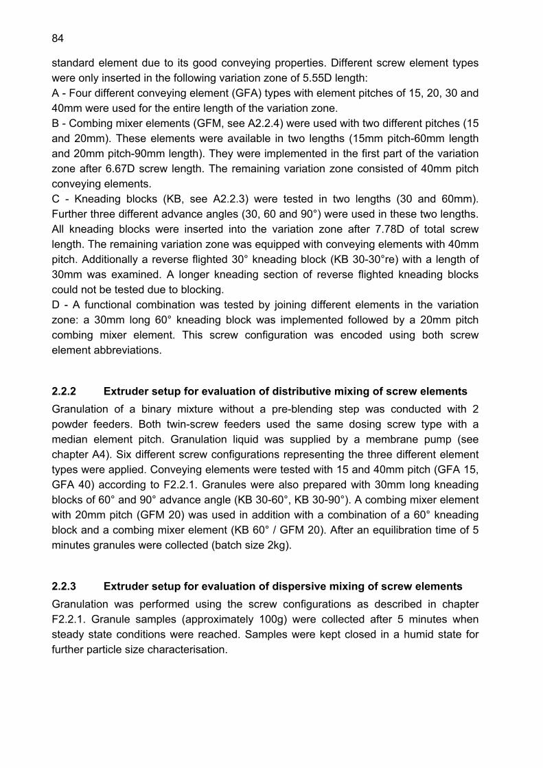
84
standard element due to its good conveying properties. Different screw element types were only inserted in the following variation zone of 5.55D length: A - Four different conveying element (GFA) types with element pitches of 15, 20, 30 and 40mm were used for the entire length of the variation zone. B - Combing mixer elements (GFM, see A2.2.4) were used with two different pitches (15 and 20mm). These elements were available in two lengths (15mm pitch-60mm length and 20mm pitch-90mm length). They were implemented in the first part of the variation zone after 6.67D screw length. The remaining variation zone consisted of 40mm pitch conveying elements. C - Kneading blocks (KB, see A2.2.3) were tested in two lengths (30 and 60mm). Further three different advance angles (30, 60 and 90°) were used in these two lengths. All kneading blocks were inserted into the variation zone after 7.78D of total screw length. The remaining variation zone was equipped with conveying elements with 40mm pitch. Additionally a reverse flighted 30° kneading block (KB 30-30°re) with a length of 30mm was examined. A longer kneading section of reverse flighted kneading blocks could not be tested due to blocking. D - A functional combination was tested by joining different elements in the variation zone: a 30mm long 60° kneading block was implemented followed by a 20mm pitch combing mixer element. This screw configuration was encoded using both screw element abbreviations.
2.2.2 Extruder setup for evaluation of distributive mixing of screw elements Granulation of a binary mixture without a pre-blending step was conducted with 2 powder feeders. Both twin-screw feeders used the same dosing screw type with a median element pitch. Granulation liquid was supplied by a membrane pump (see chapter A4). Six different screw configurations representing the three different element types were applied. Conveying elements were tested with 15 and 40mm pitch (GFA 15, GFA 40) according to F2.2.1. Granules were also prepared with 30mm long kneading blocks of 60° and 90° advance angle (KB 30-60°, KB 30-90°). A combing mixer element with 20mm pitch (GFM 20) was used in addition with a combination of a 60° kneading block and a combing mixer element (KB 60° / GFM 20). After an equilibration time of 5 minutes granules were collected (batch size 2kg).
2.2.3 Extruder setup for evaluation of dispersive mixing of screw elements Granulation was performed using the screw configurations as described in chapter F2.2.1. Granule samples (approximately 100g) were collected after 5 minutes when steady state conditions were reached. Samples were kept closed in a humid state for further particle size characterisation.
85
2.2.4 Extruder setup for granulation of mannitol A design of experiments was prepared to evaluate the impact of process parameters on granulation of mannitol. The granulation setup was generally adapted from chapter F2.2.1. Values for the powder and liquid feeding are displayed in Tab. 8 corresponding to 9, 12 and 15% humidity.
Tab. 8 Feeding rates for granulation of mannitol Liquid feed rate[kg/h] Powder feed rate
[kg/h] 9% humidity 12% humidity 15% humidity 2 0.18 0.24 0.30 4 0.36 0.48 0.60 6 0.54 0.72 0.90
Another variable of the DOE was the advance angle of the applied kneading block. The screw setup was altered according to the KB 60°/ GFM 20 screw configuration (Fig. 71). The advance angle of the 30mm long kneading block was varied on three levels using the 30° kneading block (-1 level), the 60° kneading block (0 level) and the 90° kneading block (+1 level). In total three different screw configurations were tested. The obtained granule batches (2kg batch size) were collected starting after 5 minutes, when steady state conditions were reached.
40 40 40 90° 20
40 40 40 60° 20
40 40 40 30° 20
Feeding zone Variation zone
Conveyingelements (GFA)
Kneading blocks(KB)
Combing mixerelements (GFM)
30 mm
90 mm 90 mm 30 mm
Powder feeding Liquid feeding
KB 60°-GFM 20KB 90°
-GFM 20
KB 30°-GFM 20
Fig. 71 Screw configuration scheme for the granulation of mannitol
2.2.5 Extruder setup for the comparison of two extruders A Leistritz Micro 27GL/28D co-rotating twin-screw extruder was used with a gravimetric powder feeding system as described in chapter F2.2.1 in an open configuration without a die plate. Contrary to the former setup granulation liquid was supplied by a peristaltic pump (504U, Watson Marlow Limited, Falmouth, United Kingdom) in combination with a
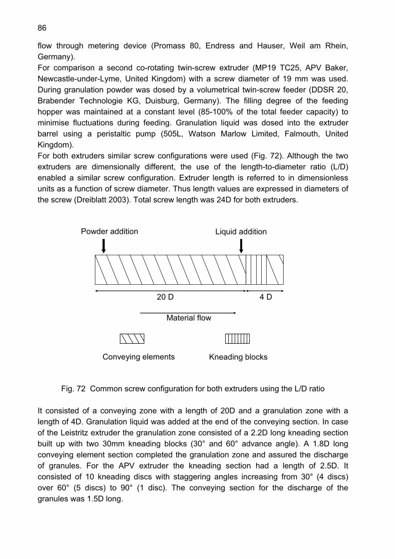
86
flow through metering device (Promass 80, Endress and Hauser, Weil am Rhein, Germany). For comparison a second co-rotating twin-screw extruder (MP19 TC25, APV Baker, Newcastle-under-Lyme, United Kingdom) with a screw diameter of 19 mm was used. During granulation powder was dosed by a volumetrical twin-screw feeder (DDSR 20, Brabender Technologie KG, Duisburg, Germany). The filling degree of the feeding hopper was maintained at a constant level (85-100% of the total feeder capacity) to minimise fluctuations during feeding. Granulation liquid was dosed into the extruder barrel using a peristaltic pump (505L, Watson Marlow Limited, Falmouth, United Kingdom). For both extruders similar screw configurations were used (Fig. 72). Although the two extruders are dimensionally different, the use of the length-to-diameter ratio (L/D) enabled a similar screw configuration. Extruder length is referred to in dimensionless units as a function of screw diameter. Thus length values are expressed in diameters of the screw (Dreiblatt 2003). Total screw length was 24D for both extruders.
4 D 20 D
Material flow
Kneading blocksConveying elements
Liquid additionPowder addition
Fig. 72 Common screw configuration for both extruders using the L/D ratio It consisted of a conveying zone with a length of 20D and a granulation zone with a length of 4D. Granulation liquid was added at the end of the conveying section. In case of the Leistritz extruder the granulation zone consisted of a 2.2D long kneading section built up with two 30mm kneading blocks (30° and 60° advance angle). A 1.8D long conveying element section completed the granulation zone and assured the discharge of granules. For the APV extruder the kneading section had a length of 2.5D. It consisted of 10 kneading discs with staggering angles increasing from 30° (4 discs) over 60° (5 discs) to 90° (1 disc). The conveying section for the discharge of the granules was 1.5D long.
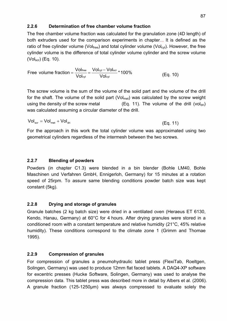
87
2.2.6 Determination of free chamber volume fraction The free chamber volume fraction was calculated for the granulation zone (4D length) of both extruders used for the comparison experiments in chapter... It is defined as the ratio of free cylinder volume (Volfree) and total cylinder volume (Volcyl). However, the free cylinder volume is the difference of total cylinder volume cylinder and the screw volume (Volscr) (Eq. 10).
%100*Vol
VolVolVolVolfraction volume Free
cyl
scrcyl
cyl
free −== (Eq. 10)
The screw volume is the sum of the volume of the solid part and the volume of the drill for the shaft. The volume of the solid part (Volmet) was calculated by the screw weight using the density of the screw metal (Eq. 11). The volume of the drill (voldri) was calculated assuming a circular diameter of the drill.
drimetscr VolVolVol += (Eq. 11) For the approach in this work the total cylinder volume was approximated using two geometrical cylinders regardless of the intermesh between the two screws.
2.2.7 Blending of powders Powders (in chapter C1.3) were blended in a bin blender (Bohle LM40, Bohle Maschinen und Verfahren GmbH, Ennigerloh, Germany) for 15 minutes at a rotation speed of 25rpm. To assure same blending conditions powder batch size was kept constant (5kg).
2.2.8 Drying and storage of granules Granule batches (2 kg batch size) were dried in a ventilated oven (Heraeus ET 6130, Kendo, Hanau, Germany) at 60°C for 4 hours. After drying granules were stored in a conditioned room with a constant temperature and relative humidity (21°C, 45% relative humidity). These conditions correspond to the climate zone 1 (Grimm and Thomae 1995).
2.2.9 Compression of granules For compression of granules a pneumohydraulic tablet press (FlexiTab, Roeltgen, Solingen, Germany) was used to produce 12mm flat faced tablets. A DAQ4-XP software for excentric presses (Hucke Software, Solingen, Germany) was used to analyse the compression data. This tablet press was described more in detail by Albers et al. (2006). A granule fraction (125-1250µm) was always compressed to evaluate solely the
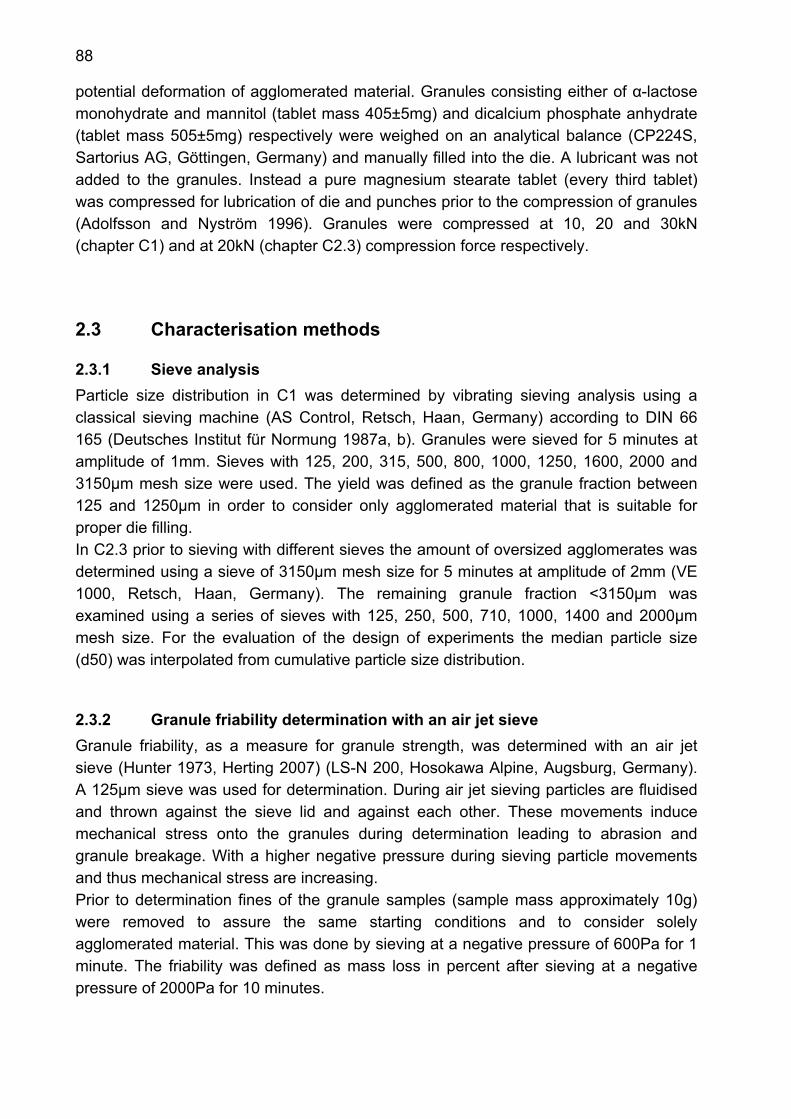
88
potential deformation of agglomerated material. Granules consisting either of α-lactose monohydrate and mannitol (tablet mass 405±5mg) and dicalcium phosphate anhydrate (tablet mass 505±5mg) respectively were weighed on an analytical balance (CP224S, Sartorius AG, Göttingen, Germany) and manually filled into the die. A lubricant was not added to the granules. Instead a pure magnesium stearate tablet (every third tablet) was compressed for lubrication of die and punches prior to the compression of granules (Adolfsson and Nyström 1996). Granules were compressed at 10, 20 and 30kN (chapter C1) and at 20kN (chapter C2.3) compression force respectively.
2.3 Characterisation methods
2.3.1 Sieve analysis Particle size distribution in C1 was determined by vibrating sieving analysis using a classical sieving machine (AS Control, Retsch, Haan, Germany) according to DIN 66 165 (Deutsches Institut für Normung 1987a, b). Granules were sieved for 5 minutes at amplitude of 1mm. Sieves with 125, 200, 315, 500, 800, 1000, 1250, 1600, 2000 and 3150µm mesh size were used. The yield was defined as the granule fraction between 125 and 1250µm in order to consider only agglomerated material that is suitable for proper die filling. In C2.3 prior to sieving with different sieves the amount of oversized agglomerates was determined using a sieve of 3150µm mesh size for 5 minutes at amplitude of 2mm (VE 1000, Retsch, Haan, Germany). The remaining granule fraction <3150µm was examined using a series of sieves with 125, 250, 500, 710, 1000, 1400 and 2000µm mesh size. For the evaluation of the design of experiments the median particle size (d50) was interpolated from cumulative particle size distribution.
2.3.2 Granule friability determination with an air jet sieve Granule friability, as a measure for granule strength, was determined with an air jet sieve (Hunter 1973, Herting 2007) (LS-N 200, Hosokawa Alpine, Augsburg, Germany). A 125µm sieve was used for determination. During air jet sieving particles are fluidised and thrown against the sieve lid and against each other. These movements induce mechanical stress onto the granules during determination leading to abrasion and granule breakage. With a higher negative pressure during sieving particle movements and thus mechanical stress are increasing. Prior to determination fines of the granule samples (sample mass approximately 10g) were removed to assure the same starting conditions and to consider solely agglomerated material. This was done by sieving at a negative pressure of 600Pa for 1 minute. The friability was defined as mass loss in percent after sieving at a negative pressure of 2000Pa for 10 minutes.
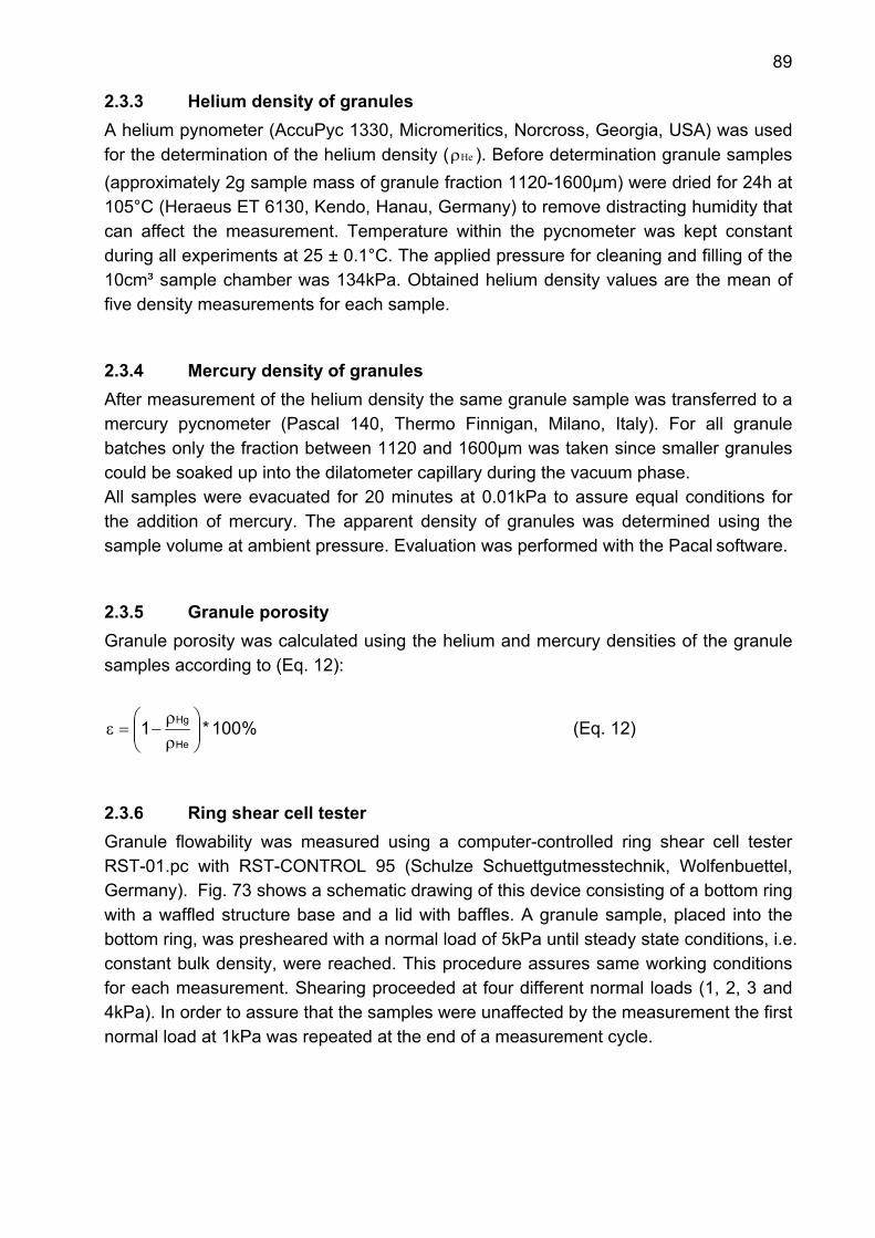
89
2.3.3 Helium density of granules A helium pynometer (AccuPyc 1330, Micromeritics, Norcross, Georgia, USA) was used for the determination of the helium density ( Heρ ). Before determination granule samples (approximately 2g sample mass of granule fraction 1120-1600µm) were dried for 24h at 105°C (Heraeus ET 6130, Kendo, Hanau, Germany) to remove distracting humidity that can affect the measurement. Temperature within the pycnometer was kept constant during all experiments at 25 ± 0.1°C. The applied pressure for cleaning and filling of the 10cm³ sample chamber was 134kPa. Obtained helium density values are the mean of five density measurements for each sample.
2.3.4 Mercury density of granules After measurement of the helium density the same granule sample was transferred to a mercury pycnometer (Pascal 140, Thermo Finnigan, Milano, Italy). For all granule batches only the fraction between 1120 and 1600µm was taken since smaller granules could be soaked up into the dilatometer capillary during the vacuum phase. All samples were evacuated for 20 minutes at 0.01kPa to assure equal conditions for the addition of mercury. The apparent density of granules was determined using the sample volume at ambient pressure. Evaluation was performed with the Pacal software.
2.3.5 Granule porosity Granule porosity was calculated using the helium and mercury densities of the granule samples according to (Eq. 12):
%100*1He
Hg
⎟⎟⎠
⎞⎜⎜⎝
⎛ρρ
−=ε (Eq. 12)
2.3.6 Ring shear cell tester Granule flowability was measured using a computer-controlled ring shear cell tester RST-01.pc with RST-CONTROL 95 (Schulze Schuettgutmesstechnik, Wolfenbuettel, Germany). Fig. 73 shows a schematic drawing of this device consisting of a bottom ring with a waffled structure base and a lid with baffles. A granule sample, placed into the bottom ring, was presheared with a normal load of 5kPa until steady state conditions, i.e. constant bulk density, were reached. This procedure assures same working conditions for each measurement. Shearing proceeded at four different normal loads (1, 2, 3 and 4kPa). In order to assure that the samples were unaffected by the measurement the first normal load at 1kPa was repeated at the end of a measurement cycle.
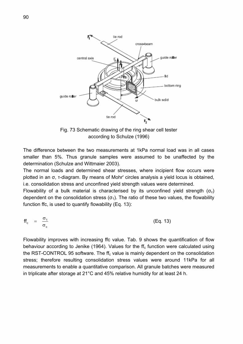
90
Fig. 73 Schematic drawing of the ring shear cell tester
according to Schulze (1996) The difference between the two measurements at 1kPa normal load was in all cases smaller than 5%. Thus granule samples were assumed to be unaffected by the determination (Schulze and Wittmaier 2003). The normal loads and determined shear stresses, where incipient flow occurs were plotted in an σ, τ-diagram. By means of Mohr' circles analysis a yield locus is obtained, i.e. consolidation stress and unconfined yield strength values were determined. Flowability of a bulk material is characterised by its unconfined yield strength (σc) dependent on the consolidation stress (σ1). The ratio of these two values, the flowability function ffc, is used to quantify flowability (Eq. 13):
c
1cff
σσ
= (Eq. 13)
Flowability improves with increasing ffc value. Tab. 9 shows the quantification of flow behaviour according to Jenike (1964). Values for the ffc function were calculated using the RST-CONTROL 95 software. The ffc value is mainly dependent on the consolidation stress; therefore resulting consolidation stress values were around 11kPa for all measurements to enable a quantitative comparison. All granule batches were measured in triplicate after storage at 21°C and 45% relative humidity for at least 24 h.
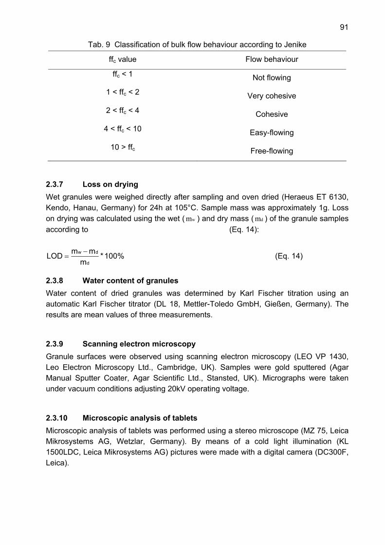
91
Tab. 9 Classification of bulk flow behaviour according to Jenike
ffc value Flow behaviour
ffc < 1
Not flowing
1 < ffc < 2
Very cohesive
2 < ffc < 4
Cohesive
4 < ffc < 10
Easy-flowing
10 > ffc
Free-flowing
2.3.7 Loss on drying Wet granules were weighed directly after sampling and oven dried (Heraeus ET 6130, Kendo, Hanau, Germany) for 24h at 105°C. Sample mass was approximately 1g. Loss on drying was calculated using the wet ( wm ) and dry mass ( dm ) of the granule samples according to (Eq. 14):
%100*m
mmLODd
dw −= (Eq. 14)
2.3.8 Water content of granules Water content of dried granules was determined by Karl Fischer titration using an automatic Karl Fischer titrator (DL 18, Mettler-Toledo GmbH, Gießen, Germany). The results are mean values of three measurements.
2.3.9 Scanning electron microscopy Granule surfaces were observed using scanning electron microscopy (LEO VP 1430, Leo Electron Microscopy Ltd., Cambridge, UK). Samples were gold sputtered (Agar Manual Sputter Coater, Agar Scientific Ltd., Stansted, UK). Micrographs were taken under vacuum conditions adjusting 20kV operating voltage.
2.3.10 Microscopic analysis of tablets Microscopic analysis of tablets was performed using a stereo microscope (MZ 75, Leica Mikrosystems AG, Wetzlar, Germany). By means of a cold light illumination (KL 1500LDC, Leica Mikrosystems AG) pictures were made with a digital camera (DC300F, Leica).
92
2.3.11 Laser diffraction Laser diffraction was used to evaluate the dispersive effect of screw elements on particle size of dicalcium phosphate. Particle size was determined before and after passage of the extruder using a laser diffraction system (Helos / KF-Magic, Sympatec GmbH, Clausthal-Zellerfeld, Germany). A wet dispersion method using a 50mL Helos-Cuvette system (Sympatec GmbH) was conducted using lens R4 (measurement range: 0.5-350µm). Granule samples were dispersed in 2-propanol in the cuvette and mixed at 1900rpm for 1 minute before each measurement. This procedure assured a homogeneous dispersion of the particles within the 2-propanol. Dicalcium phosphate is not soluble in 2-propanol. Granules were added to the measuring system until an optical concentration of approximately 5-10% was reached. Measurements were performed in triplicate.
2.3.12 UV spectroscopy UV spectroscopy (Lambda 2, Perkin Elmer, Überlingen, Germany) was used for the detection of theophylline at a wavelength of 272nm. Calibration of the UV/VIS- photometer was performed using 9 solutions (n=3) in the range from 0.19 to 2.50mg/100mL theophylline content. Theophylline content was calculated (R²=1) according to:
[Theophylline] [mg/100mL] =5099.0
0065.0Absorption − (Eq. 15)
Granule samples were weighed (CP224S, Sartorius AG, Göttingen, Germany) and dissolved in 1L of demineralised water for detection in triplicate.
2.3.13 Tensile strength of tablets Tablet breaking force (BF) was measured with a radial strength tester (HT-1, Sotax, Basel, Switzerland) at a constant speed of 1mm/s. Tablets were stored at 21°C and 45% relative humidity for 48h prior to characterisation. The breaking force (BF) of ten tablets was used for calculation of the mean tablet tensile strength (TS) where d represents the tablet diameter and h the tablet thickness (Eq. 16) (Fell and Newton 1970).
h*D*BF*2TS
π= (Eq. 16)
2.3.14 Tablet porosity Tablet diameter and thickness were measured with an electronic micrometer screw (Mitutoyo, Tokyo, Japan). Tablet porosity was calculated using tablet mass, determined

93
with an analytical balance (CP224S, Sartorius AG, Göttingen, Germany) and the helium density of the former granules.

94
G Bibliography Adolfsson, A. and Nyström, C. Tablet strength, porosity, elasticity and solid state structure of tablets compressed at high loads. Int J Pharm (1996) 95 -106.
Albers, J., Knop, K., Kleinebudde, P. Brand-to-brand and batch-to-batch uniformity of microcrystalline cellulose in direct tableting with a pneumohydraulic tablet press. Pharm Ind 68 (2006) 1420 -1428.
Augsburger, L.L., Vuppala, M.K. Theory of granulation. In: Parikh, D.M. (Ed.). Handbook of pharmaceutical granulation technology. Marcel Dekker: New York 1997. 7 - 25.
Becker, D., Rigassi, T., Bauer Brandl, A. Effectiveness of binders in wet granulation: a comparison using model formulations of different tabletability. Drug Dev Ind Pharm 23 (1997) 791 - 808.
Deutsches Institut für Normung. DIN 66 165 Teil 1: Partikelgrößenanalyse - Siebanalyse - Grundlagen. Beuth Verlag: Berlin 1987a.
Deutsches Institut für Normung. DIN 66 165 Teil 2: Partikelgrößenanalyse - Siebanalyse - Durchführung. Beuth Verlag: Berlin 1987b.
Dreiblatt, A. Process design. In: Ghebre-Sellasie, I., Martin, C. (Eds.). Pharmaceutical extrusion technology. Marcel Dekker: New York 2003. 153 - 169.
Erdmenger, R. Vorrichtung zum kontinuierlichen Mischen. Patent D - 815641 (1949).
Erdmenger, R. Misch- und Knetvorrichtung. Patent D - 813154 (1951).
Faure, A., York, P., Rowe, R.C. Process control and scale-up of pharmaceutical wet granulation processes: a review. Eur J Pharm Biopharm 52 (2001) 269 - 277.
Fechner, P.M., Wartewig, S., Futing, M., Heilmann, A., Neubert, R.H.H., Kleinebudde, P. Properties of microcrystalline cellulose and powder cellulose after extrusion/spheronization as studied by Fourier transform Raman spectroscopy and environmental scanning electron microscopy. AAPS PharmSciTech 5 (2003).
Fell, J.T., Newton, J.M. Determination of tablet strength by diametral-compression test. J Pharm Sci 59 (1970) 688 - 691.
95
Gabaude, C.M.D., Gautier, J.C., Saudemon, P. Validation of a new pertinent packing coefficient to estimate flow properties of pharmaceutical powders at a very early development stage, by comparison with mercury intrusion and classical flowability methods. J Mater Sci 36 (2001) 1763 - 1773.
Gamlen, M.J., Eardley, C. Continuous extrusion using a Baker Perkins MP50 (multipurpose) extruder. Drug Dev Ind Pharm 12 (1986) 1701 - 1713.
Ghebre-Sellasie, I., Plains, M., Mollan, M. J., Pathak, N., Lodaya, M., Fessehaie, M. Continuous production of pharmaceutical granulation. US Patent 6,499, 984 B1 (2002).
Goodheart, F.W., Draper, J.R., Ninger, F.C. Design and use of a laboratory extruder for pharmaceutical granulations. J Pharm Sci 62 (1973) 133 - 136.
Grimm, W., Thomae, K., International harmonization of stability tests for pharmaceuticals. The ICH tripartite guideline for stability testing of new drug substances and products. Eur J Pharm Biopharm 41 (1995) 194 - 196.
Guerin, E., Tchoreloff, P., Leclerc, B., Tanguy, D., Deleuil, M., Couarraze, G., Rheological characterization of pharmaceutical powders using tap testing, shear cell and mercury porosimeter. Int J Pharm 189 (1999) 91 - 103.
Healey, J.N.C., Humphreys-Jones, J.F., Walters, V. The effects of granule porosity and strength on the porosity, air permeability and tensile strength of tablets. J Pharm Pharmacol Suppl 25 (1973) 110 P.
Herting, M. G. Einfluss der Partikelgröße auf die Walzenkompaktierung und Tablettierung. PhD Thesis. Heinrich-Heine-University Duesseldorf (2007).
Herting, M.G., Kleinebudde, P. 2007. Roll compaction/dry granulation: effect of raw material particle size on granule and tablet properties. Int J Pharm 338 (2007) 110 - 118.
Holm, P., Jungersen, O., Schaefer, T., Kristensen, H.G. Granulation in high speed mixers. Part 1: effects of process variables during kneading. Pharm Ind 45 (1983) 806 - 811.
Holm, P., Jungersen, O., Schaefer, T., Kristensen, H.G. Granulation in high speed mixers. Part 2: effects of process variables during kneading. Pharm Ind 46 (1984) 97 - 100.
96
Horsthuis, G.J.B., Vanlaarhoven, J.A.H., Vanrooij, R.C.B.M., Vromans, H. Studies on upscaling parameters of the Gral high shear granulation process. Int J Pharm 92 (1993) 143 - 150.
Hunter, B.M. A friability test for granules. J Pharm Pharmacol Suppl 25 (1973) 111P.
Jenike, A. W. Storage and flow of solids. Bulletin of the University of Utah No 123 (1964). Engineering Experiment Station, University of Utah, Salt Lake City.
Jivraj, M., Martini, L.G., Thomson, C.M. An overview of the different excipients useful for the direct compression of tablets. PSTT 3 (2000) 58 - 63.
Juppo, A.M. Porosity parameters of lactose, glucose and mannitol tablets obtained by mercury porosimetry. Int J Pharm 129 (1996) 1 - 12.
Keleb, E.I., Vermeire, A., Vervaet, C., Remon, J.P. Continuous twin screw extrusion for the wet granulation of lactose. Int J Pharm 239 (2002) 69 - 80.
Keleb, E.I. Continuous agglomeration processes using a twin-screw extruder. PhD Thesis. Ghent University (2004).
Keleb, E.I., Vermeire, A., Vervaet, C., Remon, J.P. Twin-screw granulation as a simple and efficient tool for continuous wet granulation. Int J Pharm 273 (2004a) 183 - 194.
Keleb, E.I., Vermeire ,A., Vervaet ,C., Remon, J.P. Extrusion granulation and high shear granulation of different grades of lactose and highly dosed drugs: a comparative study. Drug Dev Ind Pharm 30 (2004b) 679 - 691.
Kleinebudde, P. Roll compaction/dry granulation: pharmaceutical applications. Eur J Pharm Biopharm 58 (2004) 317 - 326.
Kohlgrüber, K. Übersicht patentierter Schneckenelemente. In: Der gleichläufige Zweischneckenextruder. Carl Hanser Verlag: Munich 2007. 249 - 270.
Kristensen, H.G., Holm, P., Jaegerskou, A., Schaefer, T. Granulation in high speed mixers. Part 4: effect of liquid saturation on the agglomeration. Pharm Ind 46 (1984) 763 - 766.
Kristensen, H.G., Schaefer, T. Granulation - a review of pharmaceutical wet-granulation. Drug Dev Ind Pharm 13 (1987) 803 - 872.
97
Le, V.N., Leterme, P., Gayot, A., Flament, M.P. Influence of granulation and compaction on the particle size of ibuprofen-development of a size analysis method. Int J Pharm 321 (2006) 72-77.
Leuenberger, H. New trends in the production of pharmaceutical granules: batch versus continuous processing. Eur J Pharm Biopharm 52 (2001) 289 - 296.
Lindberg,N.O. Some experience of continuous granulation. Acta Pharm Suec 25 (1988) 239 - 246.
Lindberg, N.O., Myrenas, M., Tufvesson, C., Olbjer, L. Extrusion of an effervescent granulation with a twin screw extruder, Baker Perkins MPF 50D - determination of mean residence time. Drug Dev Ind Pharm 14 (1988) 649 - 655.
Lindberg, N.O., Tufvesson, C., Holm, P., Olbjer, L. Extrusion of an effervescent granulation with a twin screw extruder, Baker Perkins MPF 50-D - influence on intragranular porosity and liquid saturation. Drug Dev Ind Pharm 14 (1988) 1791 - 1798.
Mollan, M. Historical overview. In: Ghebre-Sellasie, I., Martin, C. (Eds.). Pharmaceutical extrusion technology. Marcel Dekker: New York 2003. 1 - 18.
Nakamichi, K., Nakano, T., Yasuura, H., Izumi, S., Kawashima, Y. The role of the kneading paddle and the effects of screw revolution speed and water content on the preparation of solid dispersions using a twin-screw extruder. Int J Pharm 241 (2002) 203 - 211.
Ramaker, J.S., Jelgersma, M.A., Vonk, P., Kossen, N.W.F. Scale-down of a high-shear pelletisation process: flow profile and growth kinetics. Int J Pharm 166 (1998) 89 - 97.
Riepma, K.A., Dekker, B.G., Lerk, C.F. The effect of moisture sorption on the strength and internal surface area of lactose tablets. Int J Pharm 87 (1992) 149 -159.
Riepma, K.A., Vromans, H., Zuurman, K., Lerk, C.F. The effect of dry granulation on the consolidation and compaction of crystalline lactose. Int J Pharm 97 (1993) 29 - 38.
Rumpf, H. Grundlagen und Methoden des Granulierens. Chem Ing Tech 3 (1958) 144 - 158.
98
Saleh, K., Vialatte, L., Guigon, P. Wet granulation in a batch high shear mixer. Chem Eng Sci 60 (2005) 3763 - 3775.
Schmidt, C., Lindner, H., Kleinebudde, P. Comparison between a twin-screw extruder and a rotary ring die press .I. Influence of formulation variables. Eur J Pharm Biopharm 44 (1997) 169 - 176.
Schroeder, R., Steffens, K.J. A new system for continuous wet granulation. Pharm Ind 64 (2002) 283 - 288.
Schulze, D. Flowability and time consolidation measurements using a ring shear tester. Powder handling and processing 8 (1996) 221 - 226.
Schulze, D., Wittmaier, A. Flow properties of highly dispersed powders at very small consolidation stresses. Chem Eng Technol 26 (2003) 133 - 137.
Selkirk, A.B., Ganderton, D. The influence of wet and dry granulation methods on pore structure of lactose tablets. J Pharm Pharmacol 22 (1970) 86 - 94.
Steiner, R. Extruder design. In: Ghebre-Sellasie, I., Martin, C. (Eds.). Pharmaceutical extrusion technology. Marcel Dekker: New York 2003. 19 - 37.
Thiele, W. Twin-screw extrusion and screw design for pharmaceutical applications. In: Ghebre-Sellasie, I., Martin, C. (Eds.). Pharmaceutical extrusion technology. Marcel Dekker: New York 2003. 69 - 99.
Vainio, T.P., Harlin, A., Seppala, J.V. Screw optimization of a co-rotating twin-screw extruder for a binary immiscible blend. Pol Eng Sci 35 (1995) 225 - 232.
Van Melkebeke, B., Vermeulen, B., Vervaet, C., Remon, J.P. Melt granulation using a twin-screw extruder: a case study. Int J Pharm 326 (2006) 89 - 93.
Van Melkebeke, B., Vervaet, C., Remon, J.P. Validation of a continuous granulation process using a twin-screw extruder. Int J Pharm 356 (2008) 224 - 230.
Van Zuilichem, D.J., Kuiper, E., Stolp, W., Jager, T. Mixing effects of constituting elements of mixing screws in single and twin screw extruders. Powder Technol 106 (1999) 147 - 159.
99
Vervaet, C., Vermeersch, H., Khotz, M.S., Massart, L., Remon, J.P. Parameters influencing granule quality using a continuous granulator. Int J Pharm 106 (1994) 157 - 160.
Vervaet, C., Baert, L., Remon, J.P. Extrusion-spheronisation a literature review. Int J Pharm 116 (1995) 131 - 146.
Vervaet, C., Remon, J.P. Continuous granulation in the pharmaceutical industry. Chem Eng Sci 60 (2005) 3949 - 3957.
Westermarck, S., Juppo, A.M., Kervinen, L., Yliruusi, J. Pore structure and surface area of mannitol powder, granules and tablets determined with mercury porosimetry and nitrogen adsorption. Eur J Pharm Biopharm 46 (1998) 61 - 68.
Wikberg, M., Alderborn, A. Compression characteristics of granulated materials II. Evaluation of granule fragmentation during compression by tablet permeability and porosity measurements. Int J Pharm 62 (1990) 229 - 241.
Zuurman, K., Riepma, K.A., Bolhuis, G.K., Vromans, H., Lerk, C.F. The relationship between bulk density and compactibility of lactose granulations. Int J Pharm 102 (1994) 1 - 9.
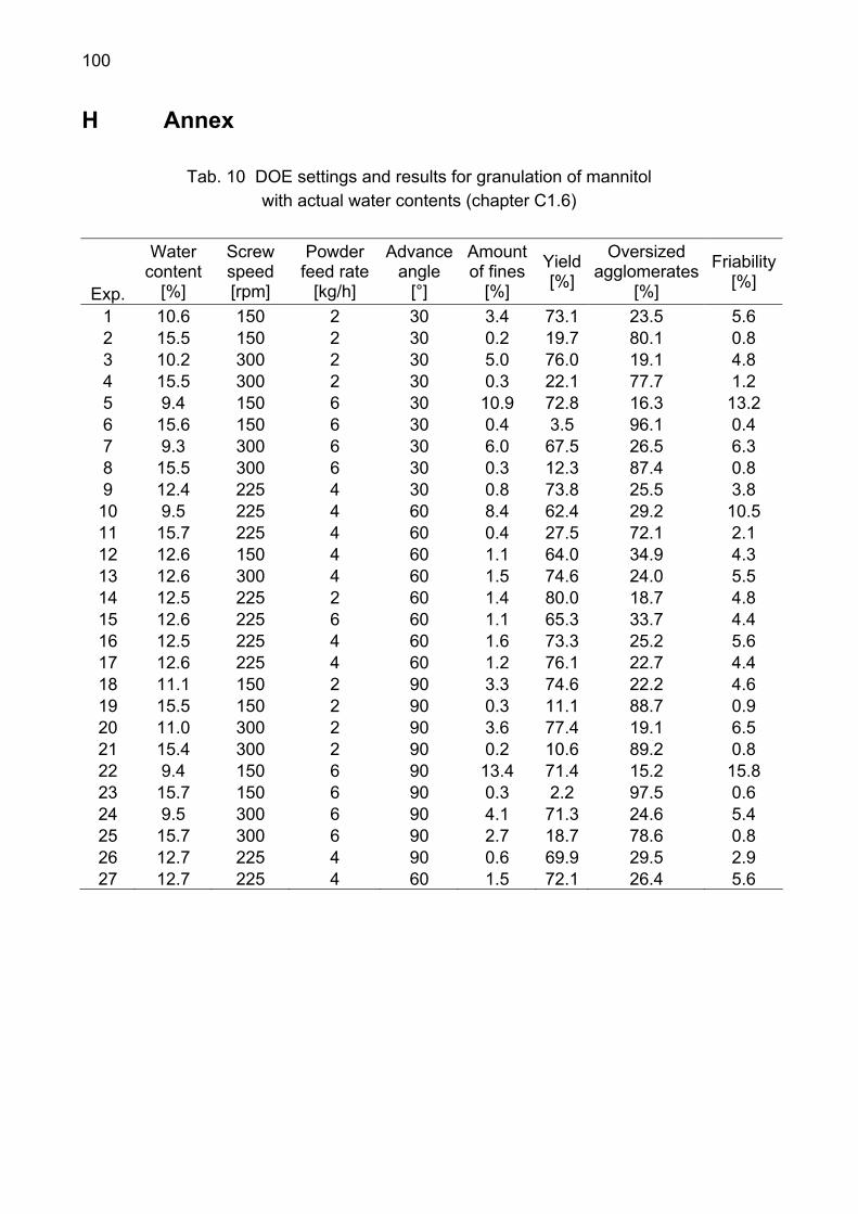
100
H Annex
Tab. 10 DOE settings and results for granulation of mannitol with actual water contents (chapter C1.6)
Exp.
Water content
[%]
Screw speed [rpm]
Powder feed rate
[kg/h]
Advance angle
[°]
Amount of fines
[%]
Yield [%]
Oversized agglomerates
[%]
Friability [%]
1 10.6 150 2 30 3.4 73.1 23.5 5.6 2 15.5 150 2 30 0.2 19.7 80.1 0.8 3 10.2 300 2 30 5.0 76.0 19.1 4.8 4 15.5 300 2 30 0.3 22.1 77.7 1.2 5 9.4 150 6 30 10.9 72.8 16.3 13.2 6 15.6 150 6 30 0.4 3.5 96.1 0.4 7 9.3 300 6 30 6.0 67.5 26.5 6.3 8 15.5 300 6 30 0.3 12.3 87.4 0.8 9 12.4 225 4 30 0.8 73.8 25.5 3.8 10 9.5 225 4 60 8.4 62.4 29.2 10.5 11 15.7 225 4 60 0.4 27.5 72.1 2.1 12 12.6 150 4 60 1.1 64.0 34.9 4.3 13 12.6 300 4 60 1.5 74.6 24.0 5.5 14 12.5 225 2 60 1.4 80.0 18.7 4.8 15 12.6 225 6 60 1.1 65.3 33.7 4.4 16 12.5 225 4 60 1.6 73.3 25.2 5.6 17 12.6 225 4 60 1.2 76.1 22.7 4.4 18 11.1 150 2 90 3.3 74.6 22.2 4.6 19 15.5 150 2 90 0.3 11.1 88.7 0.9 20 11.0 300 2 90 3.6 77.4 19.1 6.5 21 15.4 300 2 90 0.2 10.6 89.2 0.8 22 9.4 150 6 90 13.4 71.4 15.2 15.8 23 15.7 150 6 90 0.3 2.2 97.5 0.6 24 9.5 300 6 90 4.1 71.3 24.6 5.4 25 15.7 300 6 90 2.7 18.7 78.6 0.8 26 12.7 225 4 90 0.6 69.9 29.5 2.9 27 12.7 225 4 60 1.5 72.1 26.4 5.6
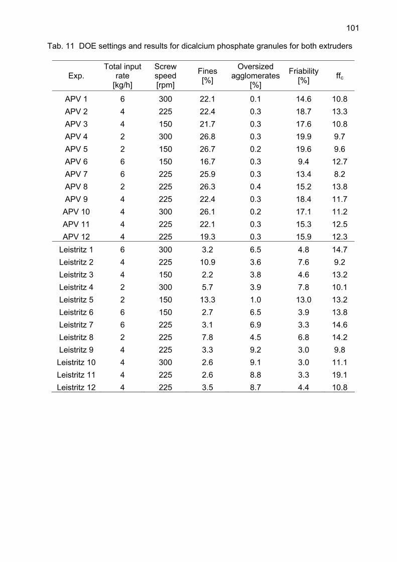
101
Tab. 11 DOE settings and results for dicalcium phosphate granules for both extruders
Exp. Total input
rate [kg/h]
Screw speed [rpm]
Fines [%]
Oversized agglomerates
[%]
Friability [%] ffc
APV 1 6 300 22.1 0.1 14.6 10.8 APV 2 4 225 22.4 0.3 18.7 13.3 APV 3 4 150 21.7 0.3 17.6 10.8 APV 4 2 300 26.8 0.3 19.9 9.7 APV 5 2 150 26.7 0.2 19.6 9.6 APV 6 6 150 16.7 0.3 9.4 12.7 APV 7 6 225 25.9 0.3 13.4 8.2 APV 8 2 225 26.3 0.4 15.2 13.8 APV 9 4 225 22.4 0.3 18.4 11.7
APV 10 4 300 26.1 0.2 17.1 11.2 APV 11 4 225 22.1 0.3 15.3 12.5 APV 12 4 225 19.3 0.3 15.9 12.3
Leistritz 1 6 300 3.2 6.5 4.8 14.7 Leistritz 2 4 225 10.9 3.6 7.6 9.2 Leistritz 3 4 150 2.2 3.8 4.6 13.2 Leistritz 4 2 300 5.7 3.9 7.8 10.1 Leistritz 5 2 150 13.3 1.0 13.0 13.2 Leistritz 6 6 150 2.7 6.5 3.9 13.8 Leistritz 7 6 225 3.1 6.9 3.3 14.6 Leistritz 8 2 225 7.8 4.5 6.8 14.2 Leistritz 9 4 225 3.3 9.2 3.0 9.8
Leistritz 10 4 300 2.6 9.1 3.0 11.1 Leistritz 11 4 225 2.6 8.8 3.3 19.1 Leistritz 12 4 225 3.5 8.7 4.4 10.8
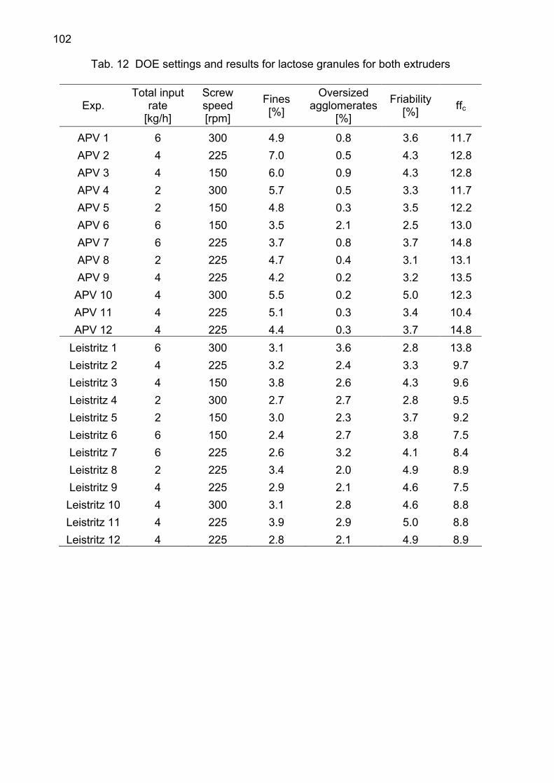
102
Tab. 12 DOE settings and results for lactose granules for both extruders
Exp. Total input
rate [kg/h]
Screw speed [rpm]
Fines [%]
Oversized agglomerates
[%]
Friability [%] ffc
APV 1 6 300 4.9 0.8 3.6 11.7 APV 2 4 225 7.0 0.5 4.3 12.8 APV 3 4 150 6.0 0.9 4.3 12.8 APV 4 2 300 5.7 0.5 3.3 11.7 APV 5 2 150 4.8 0.3 3.5 12.2 APV 6 6 150 3.5 2.1 2.5 13.0 APV 7 6 225 3.7 0.8 3.7 14.8 APV 8 2 225 4.7 0.4 3.1 13.1 APV 9 4 225 4.2 0.2 3.2 13.5
APV 10 4 300 5.5 0.2 5.0 12.3 APV 11 4 225 5.1 0.3 3.4 10.4 APV 12 4 225 4.4 0.3 3.7 14.8
Leistritz 1 6 300 3.1 3.6 2.8 13.8 Leistritz 2 4 225 3.2 2.4 3.3 9.7 Leistritz 3 4 150 3.8 2.6 4.3 9.6 Leistritz 4 2 300 2.7 2.7 2.8 9.5 Leistritz 5 2 150 3.0 2.3 3.7 9.2 Leistritz 6 6 150 2.4 2.7 3.8 7.5 Leistritz 7 6 225 2.6 3.2 4.1 8.4 Leistritz 8 2 225 3.4 2.0 4.9 8.9 Leistritz 9 4 225 2.9 2.1 4.6 7.5
Leistritz 10 4 300 3.1 2.8 4.6 8.8 Leistritz 11 4 225 3.9 2.9 5.0 8.8 Leistritz 12 4 225 2.8 2.1 4.9 8.9
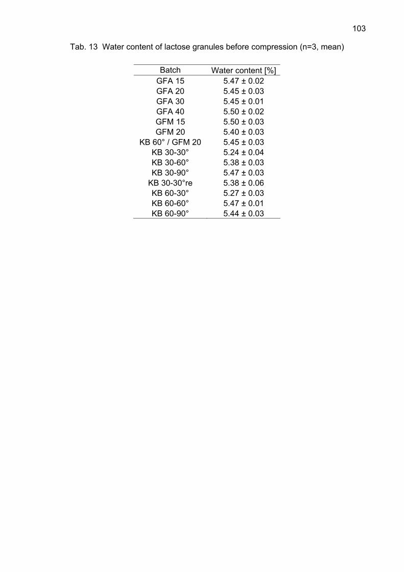
103
Tab. 13 Water content of lactose granules before compression (n=3, mean)
Batch Water content [%]GFA 15 5.47 ± 0.02 GFA 20 5.45 ± 0.03 GFA 30 5.45 ± 0.01 GFA 40 5.50 ± 0.02 GFM 15 5.50 ± 0.03 GFM 20 5.40 ± 0.03
KB 60° / GFM 20 5.45 ± 0.03 KB 30-30° 5.24 ± 0.04 KB 30-60° 5.38 ± 0.03 KB 30-90° 5.47 ± 0.03
KB 30-30°re 5.38 ± 0.06 KB 60-30° 5.27 ± 0.03 KB 60-60° 5.47 ± 0.01 KB 60-90° 5.44 ± 0.03

104
Danksagung Ich danke Herrn Professor Kleinebudde für die freundliche Aufnahme in seinen Arbeitskreis, die Überlassung des interessanten und aktuellen Themas und die sehr gute Betreuung während meiner Promotionszeit. Herrn Professor Breitkreutz danke ich für die Übernahme des Koreferats und für die vielen Hilfestellungen und Anregungen. I am very grateful to Professor Remon and Professor Vervaet who enabled the cooperation between Duesseldorf and Ghent. Thank you for your advices, suggestions and support. I thank Barbara Van Melkebeke for the excellent cooperation in the last years and many hours of discussion. Her support and cooperation assisted me in the completion of this work. Ich möchte der Firma Leistritz Extrusionstechnik danken für die zahlreichen Bereitstellungen von Schneckenelementen. Ich danke Frau Karin Mathée und Frau Dorothee Eikeler für die Analysen die sie für mich durchgeführt haben. Herrn Stefan Stich danke ich für die Unterstützung und die vielen Spezialanfertigungen im Rahmen meiner Arbeit. Herrn Markus Thommes danke ich für die Einführung am Extruder und die vielen Hilfen und Anregungen während der gesamten Zeit. Ich bin allen Kolleginnen und Kollegen dankbar für die schöne Zeit am Institut! Es hat mir sehr viel Freude bereitet mit Euch zusammenzuarbeiten und die Zeit wird mir in bester Erinnerung bleiben! Ganz besonders möchte ich meiner Familie danken, die stets hinter mir stand und die dies hier erst ermöglicht hat. Hvala za sve. Ovo je za vas…