CTEU-PN 1) Pin-Belegung - festo.com · system abhängig. Die grundsätzliche Vorgehensweise und die...
12
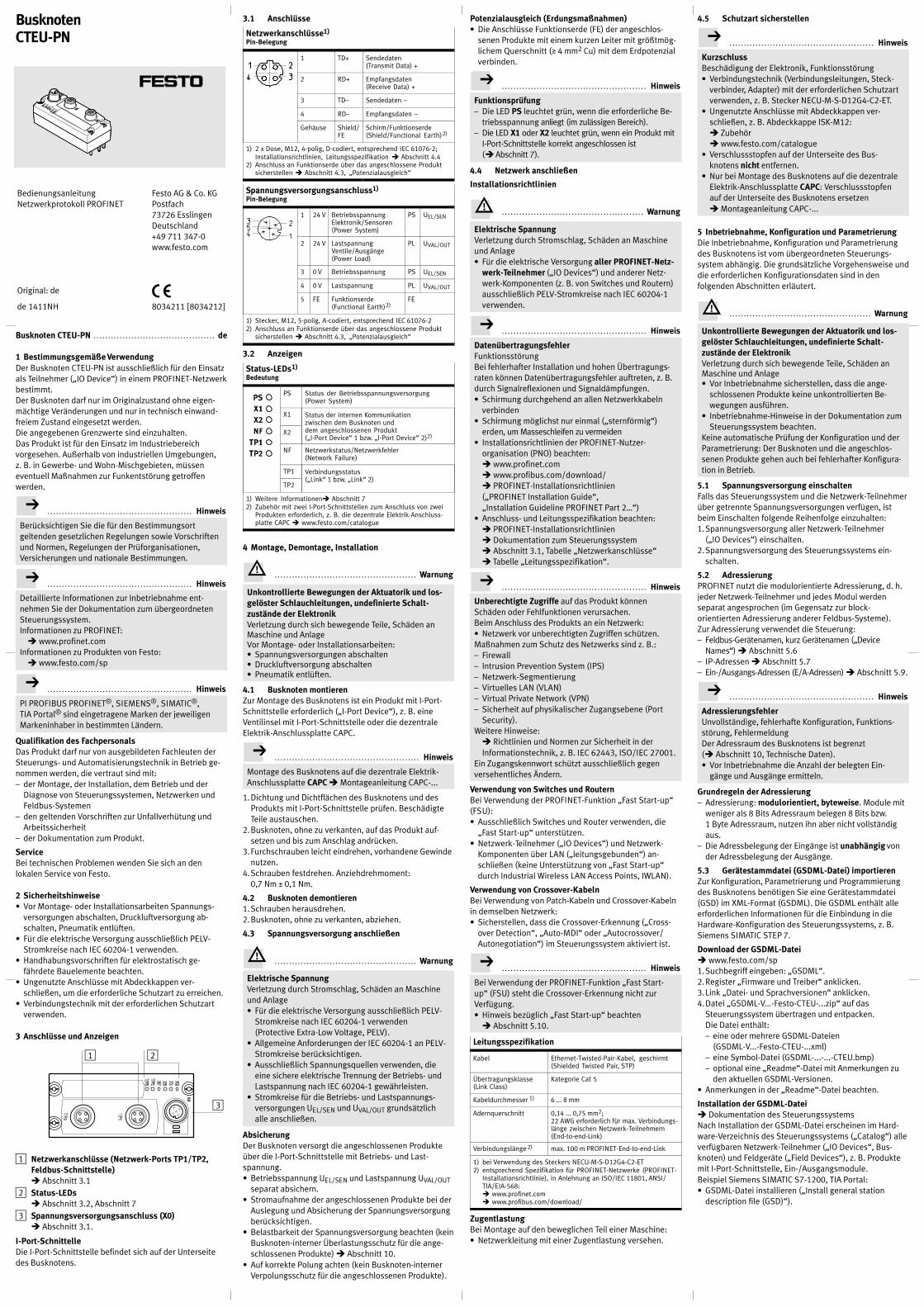
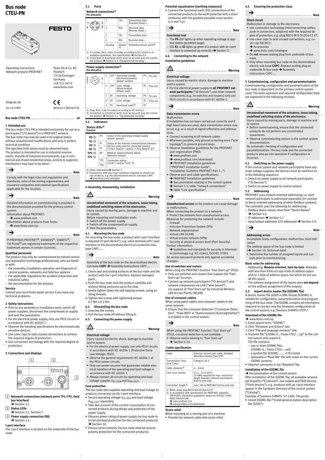
Busknoten CTEU-PN de .......................................... 1 Bestimmungsgemäße Verwendung Der Busknoten CTEU-PN ist ausschließlich für den Einsatz als Teilnehmer („IO Device“) in einem PROFINET-Netzwerk bestimmt. Der Busknoten darf nur im Originalzustand ohne eigen- mächtige Veränderungen und nur in technisch einwand- freiem Zustand eingesetzt werden. Die angegebenen Grenzwerte sind einzuhalten. Das Produkt ist für den Einsatz im Industriebereich vorgesehen. Außerhalb von industriellen Umgebungen, z. B. in Gewerbe- und Wohn-Mischgebieten, müssen eventuell Maßnahmen zur Funkentstörung getroffen werden. Hinweis .................................................. Berücksichtigen Sie die für den Bestimmungsort geltenden gesetzlichen Regelungen sowie Vorschriften und Normen, Regelungen der Prüforganisationen, Versicherungen und nationale Bestimmungen. Hinweis .................................................. Detaillierte Informationen zur Inbetriebnahme ent- nehmen Sie der Dokumentation zum übergeordneten Steuerungssystem. Informationen zu PROFINET: è www.profinet.com Informationen zu Produkten von Festo: è www.festo.com/sp Hinweis .................................................. PI PROFIBUS PROFINET ® , SIEMENS ® , SIMATIC ® , TIA Portal ® sind eingetragene Marken der jeweiligen Markeninhaber in bestimmten Ländern. Qualifikation des Fachpersonals Das Produkt darf nur von ausgebildeten Fachleuten der Steuerungs- und Automatisierungstechnik in Betrieb ge- nommen werden, die vertraut sind mit: – der Montage, der Installation, dem Betrieb und der Diagnose von Steuerungssystemen, Netzwerken und Feldbus-Systemen – den geltenden Vorschriften zur Unfallverhütung und Arbeitssicherheit – der Dokumentation zum Produkt. Service Bei technischen Problemen wenden Sie sich an den lokalen Service von Festo. 2 Sicherheitshinweise ʼn Vor Montage- oder Installationsarbeiten Spannungs- versorgungen abschalten, Druckluftversorgung ab- schalten, Pneumatik entlüften. ʼn Für die elektrische Versorgung ausschließlich PELV- Stromkreise nach IEC 60204-1 verwenden. ʼn Handhabungsvorschriften für elektrostatisch ge- fährdete Bauelemente beachten. ʼn Ungenutzte Anschlüsse mit Abdeckkappen ver- schließen, um die erforderliche Schutzart zu erreichen. ʼn Verbindungstechnik mit der erforderlichen Schutzart verwenden. 3 Anschlüsse und Anzeigen 2 3 1 1 Netzwerkanschlüsse (Netzwerk-Ports TP1/TP2, Feldbus-Schnittstelle) è Abschnitt 3.1 2 Status-LEDs è Abschnitt 3.2, Abschnitt 7 3 Spannungsversorgungsanschluss (X0) è Abschnitt 3.1. I-Port-Schnittelle Die I-Port-Schnittstelle befindet sich auf der Unterseite des Busknotens. 3.1 Anschlüsse Netzwerkanschlüsse 1) Pin-Belegung 1 TD+ Sendedaten (Transmit Data) + 2 RD+ Empfangsdaten (Receive Data) + 3 TD– Sendedaten – 4 RD– Empfangsdaten – Gehäuse Shield/ FE Schirm/Funktionserde (Shield/Functional Earth) 2) 1) 2 x Dose, M12, 4-polig, D-codiert, entsprechend IEC 61076-2; Installationsrichtlinien, Leitungsspezifikation è Abschnitt 4.4 2) Anschluss an Funktionserde über das angeschlossene Produkt sicherstellen è Abschnitt 4.3, „Potenzialausgleich“ Spannungsversorgungsanschluss 1) Pin-Belegung 1 24 V Betriebsspannung Elektronik/Sensoren (Power System) PS U EL/SEN 2 24 V Lastspannung Ventile/Ausgänge (Power Load) PL U VAL/OUT 3 0 V Betriebsspannung PS U EL/SEN 4 0 V Lastspannung PL U VAL/OUT 5 FE Funktionserde (Functional Earth) 2) FE 1) Stecker, M12, 5-polig, A-codiert, entsprechend IEC 61076-2 2) Anschluss an Funktionserde über das angeschlossene Produkt sicherstellen è Abschnitt 4.3, „Potenzialausgleich“ 3.2 Anzeigen Status-LEDs 1) Bedeutung PS Status der Betriebsspannungsversorgung (Power System) X1 Status der internen Kommunikation zwischen dem Busknoten und dem angeschlossenen Produkt („I-Port Device“ 1 bzw. „I-Port Device“ 2) 2) X2 NF Netzwerkstatus/Netzwerkfehler (Network Failure) TP1 Verbindungsstatus („Link“ 1 bzw. „Link“ 2) TP2 1) Weitere Informationenè Abschnitt 7 2) Zubehör mit zwei I-Port-Schnittstellen zum Anschluss von zwei Produkten erforderlich, z. B. die dezentrale Elektrik-Anschluss- platte CAPC è www.festo.com/catalogue 4 Montage, Demontage, Installation Warnung ................................................. Unkontrollierte Bewegungen der Aktuatorik und los- gelöster Schlauchleitungen, undefinierte Schalt- zustände der Elektronik Verletzung durch sich bewegende Teile, Schäden an Maschine und Anlage Vor Montage- oder Installationsarbeiten: ʼn Spannungsversorgungen abschalten ʼn Druckluftversorgung abschalten ʼn Pneumatik entlüften. 4.1 Busknoten montieren Zur Montage des Busknotens ist ein Produkt mit I-Port- Schnittstelle erforderlich („I-Port Device“), z. B. eine Ventilinsel mit I-Port-Schnittstelle oder die dezentrale Elektrik-Anschlussplatte CAPC. Hinweis .................................................. Montage des Busknotens auf die dezentrale Elektrik- Anschlussplatte CAPC è Montageanleitung CAPC-... 1. Dichtung und Dichtflächen des Busknotens und des Produkts mit I-Port-Schnittstelle prüfen. Beschädigte Teile austauschen. 2. Busknoten, ohne zu verkanten, auf das Produkt auf- setzen und bis zum Anschlag andrücken. 3. Furchschrauben leicht eindrehen, vorhandene Gewinde nutzen. 4. Schrauben festdrehen. Anziehdrehmoment: 0,7 Nm ± 0,1 Nm. 4.2 Busknoten demontieren 1. Schrauben herausdrehen. 2. Busknoten, ohne zu verkanten, abziehen. 4.3 Spannungsversorgung anschließen Warnung ................................................. Elektrische Spannung Verletzung durch Stromschlag, Schäden an Maschine und Anlage ʼn Für die elektrische Versorgung ausschließlich PELV- Stromkreise nach IEC舁60204-1 verwenden (Protective Extra-Low Voltage, PELV). ʼn Allgemeine Anforderungen der IEC舁60204-1 an PELV- Stromkreise berücksichtigen. ʼn Ausschließlich Spannungsquellen verwenden舂 , die eine sichere elektrische Trennung der Betriebs- und Lastspannung nach IEC舁60204-1 gewährleisten. ʼn Stromkreise für die Betriebs- und Lastspannungs- versorgungen U EL/SEN und U VAL/OUT grundsätzlich alle anschließen. Absicherung Der Busknoten versorgt die angeschlossenen Produkte über die I-Port-Schnittstelle mit Betriebs- und Last- spannung. ʼn Betriebsspannung U EL/SEN und Lastspannung U VAL/OUT separat absichern. ʼn Stromaufnahme der angeschlossenen Produkte bei der Auslegung und Absicherung der Spannungsversorgung berücksichtigen. ʼn Belastbarkeit der Spannungsversorgung beachten (kein Busknoten-interner Überlastungsschutz für die ange- schlossenen Produkte) è Abschnitt 10. ʼn Auf korrekte Polung achten (kein Busknoten-interner Verpolungsschutz für die angeschlossenen Produkte). Potenzialausgleich (Erdungsmaßnahmen) ʼn Die Anschlüsse Funktionserde (FE) der angeschlos- senen Produkte mit einem kurzen Leiter mit größtmög- lichem Querschnitt ( 4 mm 2 Cu) mit dem Erdpotenzial verbinden. Hinweis .................................................. Funktionsprüfung – Die LED PS leuchtet grün, wenn die erforderliche Be- triebsspannung anliegt (im zulässigen Bereich). – Die LED X1 oder X2 leuchtet grün, wenn ein Produkt mit I-Port-Schnittstelle korrekt angeschlossen ist (èAbschnitt 7). 4.4 Netzwerk anschließen Installationsrichtlinien Warnung ................................................. Elektrische Spannung Verletzung durch Stromschlag, Schäden an Maschine und Anlage ʼn Für die elektrische Versorgung aller PROFINET-Netz- werk-Teilnehmer („IO Devices“) und anderer Netz- werk-Komponenten (z. B. von Switches und Routern) ausschließlich PELV-Stromkreise nach IEC舁60204-1 verwenden. Hinweis .................................................. Datenübertragungsfehler Funktionsstörung Bei fehlerhafter Installation und hohen Übertragungs- raten können Datenübertragungsfehler auftreten, z. B. durch Signalreflexionen und Signaldämpfungen. ʼn Schirmung durchgehend an allen Netzwerkkabeln verbinden ʼn Schirmung möglichst nur einmal („sternförmig“) erden, um Masseschleifen zu vermeiden ʼn Installationsrichtlinien der PROFINET-Nutzer- organisation (PNO) beachten: è www.profinet.com è www.profibus.com/download/ è PROFINET-Installationsrichtlinien („PROFINET Installation Guide“, „Installation Guideline PROFINET Part 2…“) ʼn Anschluss- und Leitungsspezifikation beachten: è PROFINET-Installationsrichtlinien è Dokumentation zum Steuerungssystem è Abschnitt 3.1, Tabelle „Netzwerkanschlüsse“ è Tabelle „Leitungsspezifikation“. Hinweis .................................................. Unberechtigte Zugriffe auf das Produkt können Schäden oder Fehlfunktionen verursachen. Beim Anschluss des Produkts an ein Netzwerk: ʼn Netzwerk vor unberechtigten Zugriffen schützen. Maßnahmen zum Schutz des Netzwerks sind z. B.: – Firewall – Intrusion Prevention System (IPS) – Netzwerk-Segmentierung – Virtuelles LAN (VLAN) – Virtual Private Network (VPN) – Sicherheit auf physikalischer Zugangsebene (Port Security). Weitere Hinweise: è Richtlinien und Normen zur Sicherheit in der Informationstechnik, z. B. IEC 62443, ISO/IEC 27001. Ein Zugangskennwort schützt ausschließlich gegen versehentliches Ändern. Verwendung von Switches und Routern Bei Verwendung der PROFINET-Funktion „Fast Start-up“ (FSU): ʼn Ausschließlich Switches und Router verwenden, die „Fast Start-up“ unterstützen. ʼn Netzwerk-Teilnehmer („IO Devices“) und Netzwerk- Komponenten über LAN („leitungsgebunden“) an- schließen (keine Unterstützung von „Fast Start-up“ durch Industrial Wireless LAN Access Points, IWLAN). Verwendung von Crossover-Kabeln Bei Verwendung von Patch-Kabeln und Crossover-Kabeln in demselben Netzwerk: ʼn Sicherstellen, dass die Crossover-Erkennung („Cross- over Detection“, „Auto-MDI“ oder „Autocrossover/ Autonegotiation“) im Steuerungssystem aktiviert ist. Hinweis .................................................. Bei Verwendung der PROFINET-Funktion „Fast Start- up“ (FSU) steht die Crossover-Erkennung nicht zur Verfügung. ʼn Hinweis bezüglich „Fast Start-up“ beachten è Abschnitt 5.10. Leitungsspezifikation Kabel Ethernet-Twisted-Pair-Kabel, geschirmt (Shielded Twisted Pair, STP) Über tragungsklasse (Link Class) Kategorie Cat 5 Kabeldurchmesser 1) 6 ... 8 mm Adernquerschnitt 0,14 ... 0,75 mm 2 ; 22 AWG erforderlich für max. Verbindungs- länge zwischen Netzwerk-Teilnehmern (End-to-end-Link) Verbindungslänge 2) max. 100 m PROFINET-End-to-end-Link 1) bei Verwendung des Steckers NECU-M-S-D12G4-C2-ET 2) entsprechend Spezifikation für PROFINET-Netzwerke (PROFINET- Installationsrichtlinie), in Anlehnung an ISO/IEC 11801, ANSI/ TIA/EIA-568: è www.profinet.com è www.profibus.com/download/ Zugentlastung Bei Montage auf den beweglichen Teil einer Maschine: ʼn Netzwerkleitung mit einer Zugentlastung versehen. 4.5 Schutzart sicherstellen Hinweis .................................................. Kurzschluss Beschädigung der Elektronik, Funktionsstörung ʼn Verbindungstechnik (Verbindungsleitungen, Steck- verbinder, Adapter) mit der erforderlichen Schutzart verwenden, z. B. Stecker NECU-M-S-D12G4-C2-ET. ʼn Ungenutzte Anschlüsse mit Abdeckkappen ver- schließen, z. B. Abdeckkappe ISK-M12: è Zubehör è www.festo.com/catalogue ʼn Verschlussstopfen auf der Unterseite des Bus- knotens nicht entfernen. ʼn Nur bei Montage des Busknotens auf die dezentrale Elektrik-Anschlussplatte CAPC: Verschlussstopfen auf der Unterseite des Busknotens ersetzen è Montageanleitung CAPC-... 5 Inbetriebnahme, Konfiguration und Parametrierung Die Inbetriebnahme, Konfiguration und Parametrierung des Busknotens ist vom übergeordneten Steuerungs- system abhängig. Die grundsätzliche Vorgehensweise und die erforderlichen Konfigurationsdaten sind in den folgenden Abschnitten erläutert. Warnung ................................................. Unkontrollierte Bewegungen der Aktuatorik und los- gelöster Schlauchleitungen, undefinierte Schalt- zustände der Elektronik Verletzung durch sich bewegende Teile, Schäden an Maschine und Anlage ʼn Vor Inbetriebnahme sicherstellen, dass die ange- schlossenen Produkte keine unkontrollierten Be- wegungen ausführen. ʼn Inbetriebnahme-Hinweise in der Dokumentation zum Steuerungssystem beachten. Keine automatische Prüfung der Konfiguration und der Parametrierung: Der Busknoten und die angeschlos- senen Produkte gehen auch bei fehlerhafter Konfigura- tion in Betrieb. 5.1 Spannungsversorgung einschalten Falls das Steuerungssystem und die Netzwerk-Teilnehmer über getrennte Spannungsversorgungen verfügen, ist beim Einschalten folgende Reihenfolge einzuhalten: 1.Spannungsversorgung aller Netzwerk-Teilnehmer („IO Devices“) einschalten. 2. Spannungsversorgung des Steuerungssystems ein- schalten. 5.2 Adressierung PROFINET nutzt die modulorientierte Adressierung, d. h. jeder Netzwerk-Teilnehmer und jedes Modul werden separat angesprochen (im Gegensatz zur block- orientierten Adressierung anderer Feldbus-Systeme). Zur Adressierung verwendet die Steuerung: – Feldbus-Gerätenamen, kurz Gerätenamen („Device Names“) è Abschnitt 5.6 – IP-Adressen è Abschnitt 5.7 – Ein-/Ausgangs-Adressen (E/A-Adressen) è Abschnitt 5.9. Hinweis .................................................. Adressierungsfehler Unvollständige, fehlerhafte Konfiguration, Funktions- störung, Fehlermeldung Der Adressraum des Busknotens ist begrenzt (è Abschnitt 10, Technische Daten). ʼn Vor Inbetriebnahme die Anzahl der belegten Ein- gänge und Ausgänge ermitteln. Grundregeln der Adressierung – Adressierung: modulorientiert, byteweise. Module mit weniger als 8 Bits Adressraum belegen 8 Bits bzw. 1 Byte Adressraum, nutzen ihn aber nicht vollständig aus. – Die Adressbelegung der Eingänge ist unabhängig von der Adressbelegung der Ausgänge. 5.3 Gerätestammdatei (GSDML-Datei) importieren Zur Konfiguration, Parametrierung und Programmierung des Busknotens benötigen Sie eine Gerätestammdatei (GSD) im XML-Format (GSDML). Die GSDML enthält alle erforderlichen Informationen für die Einbindung in die Hardware-Konfiguration des Steuerungssystems, z. B. Siemens SIMATIC STEP 7. Download der GSDML-Datei è www.festo.com/sp 1. Suchbegriff eingeben: „GSDML“. 2.Register „Firmware und Treiber“ anklicken. 3. Link „Datei- und Sprachversionen“ anklicken. 4.Datei „GSDML-V...-Festo-CTEU-...zip“ auf das Steuerungssystem übertragen und entpacken. Die Datei enthält: – eine oder mehrere GSDML-Dateien (GSDML-V...-Festo-CTEU-...xml) – eine Symbol-Datei (GSDML-...-...-CTEU.bmp) – optional eine „Readme“-Datei mit Anmerkungen zu den aktuellen GSDML-Versionen. ʼn Anmerkungen in der „Readme“-Datei beachten. Installation der GSDML-Datei è Dokumentation des Steuerungssystems Nach Installation der GSDML-Datei erscheinen im Hard- ware-Verzeichnis des Steuerungssystems („Catalog“) alle verfügbaren Netzwerk-Teilnehmer („IO Devices“, Bus- knoten) und Feldgeräte („Field Devices“), z. B. Produkte mit I-Port-Schnittstelle, Ein-/Ausgangsmodule. Beispiel Siemens SIMATIC S7-1200, TIA Portal: ʼn GSDML-Datei installieren („Install general station description file (GSD)“). Bedienungsanleitung Netzwerkprotokoll PROFINET Original: de Festo AG & Co. KG Postfach 73726 Esslingen Deutschland +49 711 347-0 www.festo.com de 1411NH 8034211 [8034212] Busknoten CTEU-PN
Transcript of CTEU-PN 1) Pin-Belegung - festo.com · system abhängig. Die grundsätzliche Vorgehensweise und die...
Busknoten CTEU-PN de. . . . . . . . . . . . . . . . . . . . . . . . . . . . . . . . . . . . . . . . . .
1 Bestimmungsgemäße VerwendungDer Busknoten CTEU-PN ist ausschließlich für den Einsatzals Teilnehmer („IO Device“) in einem PROFINET-Netzwerkbestimmt.Der Busknoten darf nur im Originalzustand ohne eigenmächtige Veränderungen und nur in technisch einwandfreiem Zustand eingesetzt werden.Die angegebenen Grenzwerte sind einzuhalten.Das Produkt ist für den Einsatz im Industriebereichvorgesehen. Außerhalb von industriellen Umgebungen,z. B. in Gewerbe- und Wohn-Mischgebieten, müsseneventuell Maßnahmen zur Funkentstörung getroffenwerden.
Hinweis. . . . . . . . . . . . . . . . . . . . . . . . . . . . . . . . . . . . . . . . . . . . . . . . . .
Berücksichtigen Sie die für den Bestimmungsortgeltenden gesetzlichen Regelungen sowie Vorschriftenund Normen, Regelungen der Prüforganisationen,Versicherungen und nationale Bestimmungen.
Hinweis. . . . . . . . . . . . . . . . . . . . . . . . . . . . . . . . . . . . . . . . . . . . . . . . . .
Detaillierte Informationen zur Inbetriebnahme entnehmen Sie der Dokumentation zum übergeordnetenSteuerungssystem.Informationen zu PROFINET:� www.profinet.com
Informationen zu Produkten von Festo:� www.festo.com/sp
Hinweis. . . . . . . . . . . . . . . . . . . . . . . . . . . . . . . . . . . . . . . . . . . . . . . . . .
PI PROFIBUS PROFINET®, SIEMENS®, SIMATIC®,TIA Portal® sind eingetragene Marken der jeweiligenMarkeninhaber in bestimmten Ländern.
Qualifikation des FachpersonalsDas Produkt darf nur von ausgebildeten Fachleuten derSteuerungs- und Automatisierungstechnik in Betrieb genommen werden, die vertraut sind mit:– der Montage, der Installation, dem Betrieb und der
Diagnose von Steuerungssystemen, Netzwerken undFeldbus-Systemen
– den geltenden Vorschriften zur Unfallverhütung undArbeitssicherheit
– der Dokumentation zum Produkt.
ServiceBei technischen Problemen wenden Sie sich an denlokalen Service von Festo.
2 Sicherheitshinweise� Vor Montage- oder Installationsarbeiten Spannungs
versorgungen abschalten, Druckluftversorgung abschalten, Pneumatik entlüften.
� Für die elektrische Versorgung ausschließlich PELV-Stromkreise nach IEC 60204-1 verwenden.
� Handhabungsvorschriften für elektrostatisch gefährdete Bauelemente beachten.
� Ungenutzte Anschlüsse mit Abdeckkappen verschließen, um die erforderliche Schutzart zu erreichen.
� Verbindungstechnik mit der erforderlichen Schutzartverwenden.
3 Anschlüsse und Anzeigen
2
3
1
1 Netzwerkanschlüsse (Netzwerk-Ports TP1/TP2,Feldbus-Schnittstelle)� Abschnitt 3.1
2 Status-LEDs� Abschnitt 3.2, Abschnitt 7
3 Spannungsversorgungsanschluss (X0)� Abschnitt 3.1.
I-Port-SchnittelleDie I-Port-Schnittstelle befindet sich auf der Unterseitedes Busknotens.
3.1 Anschlüsse
Netzwerkanschlüsse1)
Pin-Belegung
1 TD+ Sendedaten(Transmit Data) +
2 RD+ Empfangsdaten(Receive Data) +
3 TD– Sendedaten –
4 RD– Empfangsdaten –
Gehäuse Shield/FE
Schirm/Funktionserde(Shield/Functional Earth)2)
1) 2 x Dose, M12, 4-polig, D-codiert, entsprechend IEC 61076-2;Installationsrichtlinien, Leitungsspezifikation � Abschnitt 4.4
2) Anschluss an Funktionserde über das angeschlossene Produktsicherstellen � Abschnitt 4.3, „Potenzialausgleich“
Spannungsversorgungsanschluss1)
Pin-Belegung
1 24 V BetriebsspannungElektronik/Sensoren(Power System)
PS UEL/SEN
2 24 V LastspannungVentile/Ausgänge(Power Load)
PL UVAL/OUT
3 0 V Betriebsspannung PS UEL/SEN
4 0 V Lastspannung PL UVAL/OUT
5 FE Funktionserde(Functional Earth)2)
FE
1) Stecker, M12, 5-polig, A-codiert, entsprechend IEC 61076-22) Anschluss an Funktionserde über das angeschlossene Produkt
sicherstellen � Abschnitt 4.3, „Potenzialausgleich“
3.2 Anzeigen
Status-LEDs1)
Bedeutung
PS Status der Betriebsspannungsversorgung(Power System)
X1 Status der internen Kommunikationzwischen dem Busknoten unddem angeschlossenen Produkt(„I-Port Device“ 1 bzw. „I-Port Device“ 2)2)
X2
NF Netzwerkstatus/Netzwerkfehler(Network Failure)
TP1 Verbindungsstatus(„Link“ 1 bzw. „Link“ 2)
TP2
1) Weitere Informationen� Abschnitt 72) Zubehör mit zwei I-Port-Schnittstellen zum Anschluss von zwei
Produkten erforderlich, z. B. die dezentrale Elektrik-Anschlussplatte CAPC � www.festo.com/catalogue
4 Montage, Demontage, Installation
Warnung. . . . . . . . . . . . . . . . . . . . . . . . . . . . . . . . . . . . . . . . . . . . . . . . .
Unkontrollierte Bewegungen der Aktuatorik und losgelöster Schlauchleitungen, undefinierte Schaltzustände der ElektronikVerletzung durch sich bewegende Teile, Schäden anMaschine und AnlageVor Montage- oder Installationsarbeiten:� Spannungsversorgungen abschalten� Druckluftversorgung abschalten� Pneumatik entlüften.
4.1 Busknoten montierenZur Montage des Busknotens ist ein Produkt mit I-Port-Schnittstelle erforderlich („I-Port Device“), z. B. eineVentilinsel mit I-Port-Schnittstelle oder die dezentraleElektrik-Anschlussplatte CAPC.
Hinweis. . . . . . . . . . . . . . . . . . . . . . . . . . . . . . . . . . . . . . . . . . . . . . . . . .
Montage des Busknotens auf die dezentrale Elektrik-Anschlussplatte CAPC � Montageanleitung CAPC-...
1.Dichtung und Dichtflächen des Busknotens und desProdukts mit I-Port-Schnittstelle prüfen. BeschädigteTeile austauschen.
2.Busknoten, ohne zu verkanten, auf das Produkt aufsetzen und bis zum Anschlag andrücken.
3.Furchschrauben leicht eindrehen, vorhandene Gewindenutzen.
4.Schrauben festdrehen. Anziehdrehmoment:0,7 Nm ± 0,1 Nm.
4.2 Busknoten demontieren1.Schrauben herausdrehen.2.Busknoten, ohne zu verkanten, abziehen.
4.3 Spannungsversorgung anschließen
Warnung. . . . . . . . . . . . . . . . . . . . . . . . . . . . . . . . . . . . . . . . . . . . . . . . .
Elektrische SpannungVerletzung durch Stromschlag, Schäden an Maschineund Anlage� Für die elektrische Versorgung ausschließlich PELV-
Stromkreise nach IEC�60204-1 verwenden(Protective Extra-Low Voltage, PELV).
� Allgemeine Anforderungen der IEC�60204-1 an PELV-Stromkreise berücksichtigen.
� Ausschließlich Spannungsquellen verwenden�, dieeine sichere elektrische Trennung der Betriebs- undLastspannung nach IEC�60204-1 gewährleisten.
� Stromkreise für die Betriebs- und Lastspannungsversorgungen UEL/SEN und UVAL/OUT grundsätzlichalle anschließen.
AbsicherungDer Busknoten versorgt die angeschlossenen Produkteüber die I-Port-Schnittstelle mit Betriebs- und Lastspannung.� Betriebsspannung UEL/SEN und Lastspannung UVAL/OUT
separat absichern.� Stromaufnahme der angeschlossenen Produkte bei der
Auslegung und Absicherung der Spannungsversorgungberücksichtigen.
� Belastbarkeit der Spannungsversorgung beachten (keinBusknoten-interner Überlastungsschutz für die angeschlossenen Produkte) � Abschnitt 10.
� Auf korrekte Polung achten (kein Busknoten-internerVerpolungsschutz für die angeschlossenen Produkte).
Potenzialausgleich (Erdungsmaßnahmen)� Die Anschlüsse Funktionserde (FE) der angeschlos
senen Produkte mit einem kurzen Leiter mit größtmöglichem Querschnitt (� 4 mm2 Cu) mit dem Erdpotenzialverbinden.
Hinweis. . . . . . . . . . . . . . . . . . . . . . . . . . . . . . . . . . . . . . . . . . . . . . . . . .
Funktionsprüfung– Die LED PS leuchtet grün, wenn die erforderliche Be
triebsspannung anliegt (im zulässigen Bereich).– Die LED X1 oder X2 leuchtet grün, wenn ein Produkt mit
I-Port-Schnittstelle korrekt angeschlossen ist(� Abschnitt 7).
4.4 Netzwerk anschließen
Installationsrichtlinien
Warnung. . . . . . . . . . . . . . . . . . . . . . . . . . . . . . . . . . . . . . . . . . . . . . . . .
Elektrische SpannungVerletzung durch Stromschlag, Schäden an Maschineund Anlage� Für die elektrische Versorgung aller PROFINET-Netz
werk-Teilnehmer („IO Devices“) und anderer Netzwerk-Komponenten (z. B. von Switches und Routern)ausschließlich PELV-Stromkreise nach IEC�60204-1verwenden.
Hinweis. . . . . . . . . . . . . . . . . . . . . . . . . . . . . . . . . . . . . . . . . . . . . . . . . .
DatenübertragungsfehlerFunktionsstörungBei fehlerhafter Installation und hohen Übertragungsraten können Datenübertragungsfehler auftreten, z. B.durch Signalreflexionen und Signaldämpfungen.� Schirmung durchgehend an allen Netzwerkkabeln
verbinden� Schirmung möglichst nur einmal („sternförmig“)
erden, um Masseschleifen zu vermeiden� Installationsrichtlinien der PROFINET-Nutzer
organisation (PNO) beachten:� www.profinet.com� www.profibus.com/download/� PROFINET-Installationsrichtlinien(„PROFINET Installation Guide“,„Installation Guideline PROFINET Part 2…“)
� Anschluss- und Leitungsspezifikation beachten:� PROFINET-Installationsrichtlinien� Dokumentation zum Steuerungssystem� Abschnitt 3.1, Tabelle „Netzwerkanschlüsse“� Tabelle „Leitungsspezifikation“.
Hinweis. . . . . . . . . . . . . . . . . . . . . . . . . . . . . . . . . . . . . . . . . . . . . . . . . .
Unberechtigte Zugriffe auf das Produkt könnenSchäden oder Fehlfunktionen verursachen.Beim Anschluss des Produkts an ein Netzwerk:� Netzwerk vor unberechtigten Zugriffen schützen.Maßnahmen zum Schutz des Netzwerks sind z. B.:– Firewall– Intrusion Prevention System (IPS)– Netzwerk-Segmentierung– Virtuelles LAN (VLAN)– Virtual Private Network (VPN)– Sicherheit auf physikalischer Zugangsebene (Port
Security).Weitere Hinweise:� Richtlinien und Normen zur Sicherheit in derInformationstechnik, z. B. IEC 62443, ISO/IEC 27001.
Ein Zugangskennwort schützt ausschließlich gegenversehentliches Ändern.
Verwendung von Switches und RouternBei Verwendung der PROFINET-Funktion „Fast Start-up“(FSU):� Ausschließlich Switches und Router verwenden, die
„Fast Start-up“ unterstützen.� Netzwerk-Teilnehmer („IO Devices“) und Netzwerk-
Komponenten über LAN („leitungsgebunden“) anschließen (keine Unterstützung von „Fast Start-up“durch Industrial Wireless LAN Access Points, IWLAN).
Verwendung von Crossover-KabelnBei Verwendung von Patch-Kabeln und Crossover-Kabelnin demselben Netzwerk:� Sicherstellen, dass die Crossover-Erkennung („Cross
over Detection“, „Auto-MDI“ oder „Autocrossover/Autonegotiation“) im Steuerungssystem aktiviert ist.
Hinweis. . . . . . . . . . . . . . . . . . . . . . . . . . . . . . . . . . . . . . . . . . . . . . . . . .
Bei Verwendung der PROFINET-Funktion „Fast Start-up“ (FSU) steht die Crossover-Erkennung nicht zurVerfügung.� Hinweis bezüglich „Fast Start-up“ beachten� Abschnitt 5.10.
Leitungsspezifikation
Kabel Ethernet-Twisted-Pair-Kabel, geschirmt(Shielded Twisted Pair, STP)
Übertragungsklasse(Link Class)
Kategorie Cat 5
Kabeldurchmesser 1) 6 ... 8 mm
Adernquerschnitt 0,14 ... 0,75 mm2;22 AWG erforderlich für max. Verbindungslänge zwischen Netzwerk-Teilnehmern(End-to-end-Link)
Verbindungslänge 2) max. 100 m PROFINET-End-to-end-Link
1) bei Verwendung des Steckers NECUMSD12G4C2ET2) entsprechend Spezifikation für PROFINET-Netzwerke (PROFINET-
Installationsrichtlinie), in Anlehnung an ISO/IEC 11801, ANSI/TIA/EIA-568:� www.profinet.com� www.profibus.com/download/
ZugentlastungBei Montage auf den beweglichen Teil einer Maschine:� Netzwerkleitung mit einer Zugentlastung versehen.
4.5 Schutzart sicherstellen
Hinweis. . . . . . . . . . . . . . . . . . . . . . . . . . . . . . . . . . . . . . . . . . . . . . . . . .
KurzschlussBeschädigung der Elektronik, Funktionsstörung� Verbindungstechnik (Verbindungsleitungen, Steck
verbinder, Adapter) mit der erforderlichen Schutzartverwenden, z. B. Stecker NECU-M-S-D12G4-C2-ET.
� Ungenutzte Anschlüsse mit Abdeckkappen verschließen, z. B. Abdeckkappe ISK-M12:� Zubehör� www.festo.com/catalogue
� Verschlussstopfen auf der Unterseite des Busknotens nicht entfernen.
� Nur bei Montage des Busknotens auf die dezentraleElektrik-Anschlussplatte CAPC: Verschlussstopfenauf der Unterseite des Busknotens ersetzen� Montageanleitung CAPC-...
5 Inbetriebnahme, Konfiguration und ParametrierungDie Inbetriebnahme, Konfiguration und Parametrierungdes Busknotens ist vom übergeordneten Steuerungssystem abhängig. Die grundsätzliche Vorgehensweise unddie erforderlichen Konfigurationsdaten sind in denfolgenden Abschnitten erläutert.
Warnung. . . . . . . . . . . . . . . . . . . . . . . . . . . . . . . . . . . . . . . . . . . . . . . . .
Unkontrollierte Bewegungen der Aktuatorik und losgelöster Schlauchleitungen, undefinierte Schaltzustände der ElektronikVerletzung durch sich bewegende Teile, Schäden anMaschine und Anlage� Vor Inbetriebnahme sicherstellen, dass die ange
schlossenen Produkte keine unkontrollierten Bewegungen ausführen.
� Inbetriebnahme-Hinweise in der Dokumentation zumSteuerungssystem beachten.
Keine automatische Prüfung der Konfiguration und derParametrierung: Der Busknoten und die angeschlossenen Produkte gehen auch bei fehlerhafter Konfiguration in Betrieb.
5.1 Spannungsversorgung einschaltenFalls das Steuerungssystem und die Netzwerk-Teilnehmerüber getrennte Spannungsversorgungen verfügen, istbeim Einschalten folgende Reihenfolge einzuhalten:1.Spannungsversorgung aller Netzwerk-Teilnehmer
(„IO Devices“) einschalten.2.Spannungsversorgung des Steuerungssystems ein
schalten.
5.2 AdressierungPROFINET nutzt die modulorientierte Adressierung, d. h.jeder Netzwerk-Teilnehmer und jedes Modul werdenseparat angesprochen (im Gegensatz zur blockorientierten Adressierung anderer Feldbus-Systeme).Zur Adressierung verwendet die Steuerung:– Feldbus-Gerätenamen, kurz Gerätenamen („Device
Names“) � Abschnitt 5.6– IP-Adressen � Abschnitt 5.7– Ein-/Ausgangs-Adressen (E/A-Adressen) � Abschnitt 5.9.
Hinweis. . . . . . . . . . . . . . . . . . . . . . . . . . . . . . . . . . . . . . . . . . . . . . . . . .
AdressierungsfehlerUnvollständige, fehlerhafte Konfiguration, Funktionsstörung, FehlermeldungDer Adressraum des Busknotens ist begrenzt(� Abschnitt 10, Technische Daten).� Vor Inbetriebnahme die Anzahl der belegten Ein
gänge und Ausgänge ermitteln.
Grundregeln der Adressierung– Adressierung: modulorientiert, byteweise. Module mit
weniger als 8 Bits Adressraum belegen 8 Bits bzw.1 Byte Adressraum, nutzen ihn aber nicht vollständigaus.
– Die Adressbelegung der Eingänge ist unabhängig vonder Adressbelegung der Ausgänge.
5.3 Gerätestammdatei (GSDML-Datei) importierenZur Konfiguration, Parametrierung und Programmierungdes Busknotens benötigen Sie eine Gerätestammdatei(GSD) im XML-Format (GSDML). Die GSDML enthält alleerforderlichen Informationen für die Einbindung in dieHardware-Konfiguration des Steuerungssystems, z. B.Siemens SIMATIC STEP 7.
Download der GSDML-Datei� www.festo.com/sp1.Suchbegriff eingeben: „GSDML“.2.Register „Firmware und Treiber“ anklicken.3.Link „Datei- und Sprachversionen“ anklicken.4.Datei „GSDML-V...-Festo-CTEU-...zip“ auf das
Steuerungssystem übertragen und entpacken.Die Datei enthält:– eine oder mehrere GSDML-Dateien
(GSDML-V...-Festo-CTEU-...xml)– eine Symbol-Datei (GSDML-...-...-CTEU.bmp)– optional eine „Readme“-Datei mit Anmerkungen zu
den aktuellen GSDML-Versionen.� Anmerkungen in der „Readme“-Datei beachten.
Installation der GSDML-Datei� Dokumentation des SteuerungssystemsNach Installation der GSDML-Datei erscheinen im Hardware-Verzeichnis des Steuerungssystems („Catalog“) alleverfügbaren Netzwerk-Teilnehmer („IO Devices“, Busknoten) und Feldgeräte („Field Devices“), z. B. Produktemit I-Port-Schnittstelle, Ein-/Ausgangsmodule.Beispiel Siemens SIMATIC S7-1200, TIA Portal:� GSDML-Datei installieren („Install general station
description file (GSD)“).
BedienungsanleitungNetzwerkprotokoll PROFINET
Original: de
Festo AG & Co. KGPostfach73726 EsslingenDeutschland+49 711 347-0www.festo.com
de 1411NH 8034211 [8034212]
BusknotenCTEU-PN

5.4 Steuerungssystem einrichten,Automatisierungsprojekt erstellen
� Dokumentation des SteuerungssystemsBeispiel Siemens SIMATIC S7-1200, TIA Portal:1.Geräte- und Netzwerk-Ansicht öffnen:
Ansicht („View“) � Doppelklick auf „Geräte und Netzwerk“ („Devices & networks“).
2.Netzwerk-Ansicht („Network view“) öffnen.3.Hardware-Katalog („Catalog“) öffnen.4.Verzeichnis „Systemsteuerung“ („PLC“) öffnen.5.Systemsteuerung (SPS/„CPU“) in die Netzwerk-Ansicht
ziehen.
5.5 PROFINET-Station („Station“) einfügen� Dokumentation des SteuerungssystemsBeispiel Siemens SIMATIC S7-1200, TIA Portal:1.Geräte- und Netzwerk-Ansicht öffnen („Devices &
networks“ � Abschnitt 5.4).2.Netzwerk-Ansicht („Network view“) öffnen.3.Hardware-Katalog („Catalog“) öffnen.4.Verzeichnis „Weitere Feldgeräte“ („Other field
devices“) öffnen:� „PROFINET IO“ � „Valves“ � „Festo AG & Co. KG“� „Festo CTEU-PN“.
5.Das Symbol der PROFINET-Station, d. h. des Busknotens CTEU-PN, auswählen und in die Netzwerk-Ansicht ziehen.
6.Verbindungs-Ansicht öffnen: "Connections".7.Den Busknoten CTEU-PN mit dem Steuerungssystem
verbinden:Busknoten-Symbol anklicken, Taste gedrückt haltenund Mauszeiger bis zum Symbol der Systemsteuerungziehen.
8.Verbindung auswählen: "Connections" � "PROFINETIO-System".
5.6 Gerätenamen („Device Name“) zuweisen� Dokumentation des SteuerungssystemsÜber den Gerätenamen können Sie den Busknoten unddas angeschlossene Produkt („I-Port Device“) direktadressieren, z. B. in Ihrem Automatisierungsprogramm.
5.7 IP-Adresse zuweisen oder ändern� Dokumentation des SteuerungssystemsIm Regelfall übernimmt das Steuerungssystem die Zuweisung einer IP-Adresse.
Hinweis. . . . . . . . . . . . . . . . . . . . . . . . . . . . . . . . . . . . . . . . . . . . . . . . . .
� Bei der Vergabe der IP-Adresse grundsätzlicheAdressierungsregeln beachten, z. B. bezüglich derVerwendung von privaten oder öffentlichen Adressbereichen.
� IP-Adresse auf Verwendbarkeit im Automatisierungsnetzwerk prüfen.
� Sicherstellen, dass IP-Adressen nicht doppeltverwendet werden.
5.8 Feldgeräte („I-Port Devices“) konfigurieren� Dokumentation des SteuerungssystemsBeispiel Siemens SIMATIC S7-1200, TIA Portal:1.Geräte- und Netzwerk-Ansicht öffnen („Devices &
networks“ � Abschnitt 5.4).2.Geräte-Ansicht („Device view“) öffnen.3.Hardware-Katalog („Catalog“) öffnen.4.Verzeichnis „Weitere Feldgeräte“ („Other field
devices“) öffnen.5.Feldgeräte konfigurieren:
Die Symbole der angeschlossenen Produkte („I-PortDevices“) in die Geräte-Übersicht ("Device overview")ziehen.
5.9 Anfangsadressen der Ein-/Ausgänge ändern,Diagnoseadressen ändern
� Dokumentation des SteuerungssystemsIm Regelfall übernimmt das Steuerungssystem die Zuweisung der Ein-/Ausgangsadressen und der Diagnoseadressen.
5.10 PROFINET-Funktion „Schneller Hochlauf“ („FastStart-up“, FSU) einrichten
� Dokumentation des Steuerungssystems
Hinweis. . . . . . . . . . . . . . . . . . . . . . . . . . . . . . . . . . . . . . . . . . . . . . . . . .
Bei Verwendung der PROFINET-Funktion „Fast Start-up“ (FSU) steht die Crossover-Erkennung („CrossoverDetection“, „Auto-MDI“ oder „Autocrossover/Autonegotiation“) nicht zur Verfügung:� Crossover-Erkennung deaktivieren:
– in der Hardware-Konfiguration aller Netzwerk-Teilnehmer
– in der Hardware-Konfiguration des Netzwerk-Nachbars („Partner-Port“).
Die Deaktivierung der Crossover-Erkennung ändert diePin-Belegung des weiterführenden Netzwerkanschlusses TP2 auf „Crossover“.� Verbindungsleitung in Abhängigkeit von der Pin-
Belegung des Netzwerkanschlusses des an TP2 angeschlossenen Produkts wählen:– Crossover-Kabel bei gleicher Belegung der Ports– Patch-Kabel bei unterschiedlicher Belegung der
Ports.
Beispiel Siemens SIMATIC S7-1200, TIA Portal:1.Geräteübersicht („Device overview“) aufrufen:
Fenster „Projektnavigation“ („Project navigation“)� Geräte („Devices“) � Gerätesicht („Device view“)� Geräteübersicht („Device overview“) � Baugruppe(„Module“) � „CTEU-PN“.
2.Baugruppe „PN-IO Interface“ anklicken.3.Schnittstellen-Optionen aufrufen:
Fenster „PN-IO Interface [Module]“ � Eigenschaften(„Properties“) � Allgemein („General“) � ErweiterteOptionen („Advanced options“) � Schnittstellen-Optionen („Interface options“).
4.Schnittstellen-Option „Priorisierter Hochlauf“(„Prioritized start-up“) aktivieren (Häkchen setzen).
5.Port-Optionen aufrufen:Fenster „PN-IO Interface [Module]“ � Eigenschaften(„Properties“) � Allgemein („General“) � ErweiterteOptionen („Advanced options“) � „Port 1 [X1 P1 R]“bzw. „Port 2 [X1 P2 R]“ � Port-Optionen („Portoptions“).
6.Unter „Verbindung“ („Connection“) die Crossover-Erkennung („Autonegotiation“) der Netzwerkanschlüsse (Netzwerk-Ports) TP1 und TP2 deaktivieren.
5.11 Parametrierung einstellen� Dokumentation des SteuerungssystemsSie können das Verhalten der angeschlossenen Produktedurch Parametrieren individuell einstellen („Modul-Parametrierung“), z. B. Eingangsentprellzeit, Signalverlängerungszeit, Produktüberwachung (Weiterleitungvon Diagnosemeldungen), Einstellungen für den Fehlerfall(„Fail-state“-Modus). Die Parametrierung ist für „I-PortDevice“ 1 (X1) und „I-Port Device“ 2 (X2) separat einstellbar.
Parameter1) Bedeutung
Port-Einstellungen2)
Beispiel „Universal Gerät 256DIO“ („Universal device 256DIO“)
Tool Change Mode Werkzeugwechsel-Modus:– „Tool Change Mode“ aktiviert:
Im Prozessdatenabbild sind die Adressräume für Ein- und Ausgangsdaten festzugeordnet (adressiert) – unabhängigvom angeschlossenen Produkt („I-PortDevice“), dadurch sind die angeschlossenen Produkte (z. B. Werkzeuge) ohneKonfigurationsänderung austauschbar.
– „Tool Change Mode“ deaktiviert:Das beim Start-up erfasste „I-PortDevice“ wird in die PROFINET-Konfiguration übernommen. Die Zuordnung(Adressierung) der Ein- und Ausgangsdaten im Prozessdatenabbild ist vomangeschlossenen Produkt abhängig.
Alle Diagnosemeldungen unterdrücken
keine Weiterleitung von Diagnosemeldungen über das Netzwerk („Suppressall diagnostics messages“)
Diagnosemeldung„fehlende Lastspannung“ unterdrücken
keine Weiterleitung der Diagnosemeldung„fehlende Lastspannung“3) über das Netzwerk4) („Suppress missing load voltagediagnostics messages“)
Fail-state Der „Fail-state“-Modus regelt das Verhaltendes Busknotens und der angeschlossenProdukte bei Kommunikationsfehlern:– Ausgänge zurücksetzen („Outputs
reset“): Die Ausgänge werden zurückgesetzt.
– Ausgänge „Hold last state“ („OutputsHold last state“): Die Ausgänge behalten den letzten Zustand bei.
Die gewählte Einstellung gilt für alle Ausgänge.Die Einstellung „Fail-state“ gilt auch für denBetriebszustand „Leerlauf“ („Idle state“):– Der „Idle state“ wird nach Aufforderung
durch das Steuerungssystem eingenommen. Das Steuerungssystem befindetsich dabei im „Stopp-Modus“.
– Eingangsdaten werden im „Idle state“weiterhin übertragen.
I-Port-Device-Parameter 2)
Beispiel „Universal Gerät 256DIO“ („Universal device 256DIO“)
Byte 0 ... Byte 7 Tunnelung von produktspezifischen Parametern � Dokumentation zum angeschlossenen Produkt
1) Siemens SIMATIC S7-1200, TIA Portal: Baugruppenparameter2) Die verfügbaren Parameter sind vom angeschlossenen Produkt
abhängig.3) Überwachung auf Unterspannung der Lastspannungsversorgung
Ausgänge/Ventile UOUT/VAL („Undervoltage UOUT/VAL“)4) Diagnosemeldungen „fehlende Lastspannung“ werden nur dann
erzeugt, wenn das angeschlossene Produkt die Lastspannungüberwacht und den Status an den Busknoten meldet.
Hinweis. . . . . . . . . . . . . . . . . . . . . . . . . . . . . . . . . . . . . . . . . . . . . . . . . .
Funktionsprüfung– Die LED NF ist aus (bei fehlerfreier Kommunikation
zwischen Steuerungssystem und Busknoten).– Die LED TP1 oder TP2 leuchtet grün (� Abschnitt 7).– Siemens SIMATIC S7-1200, TIA Portal: In den Spalten
„E-Adresse“ („I address“) bzw. „A-Adresse“(„O address“) befinden sich Adresseinträge (Startadressen der Ein-/Ausgänge).
– Verfügbarkeit der Netzwerk-Teilnehmer prüfen:Menü "Online" � "Accessible devices" � Auflistung der verfügbaren Netzwerk-Teilnehmer aufVollständigkeit prüfen ("Accessible devices in targetsubnet").
6 „Identification and Maintenance“� Dokumentation des SteuerungssystemsDie Funktion „Identification and Maintenance“ (I&M)bietet einen einheitlichen, herstellerunabhängigen Zugriffauf produktspezifische Informationen.
Hinweis. . . . . . . . . . . . . . . . . . . . . . . . . . . . . . . . . . . . . . . . . . . . . . . . . .
Manuell aktualisierte I&M-Angaben, z. B. der Firmware-und Software-Stand des Busknotens, können von denAngaben auf der Produktbeschriftung abweichen.
7 Diagnose
PS – Status der Betriebsspannungsversorgung(Power System)
LED-Anzeige
Zustand und Bedeutung
LED leuchtet grün:– normaler Betriebszustand– Betriebsspannung liegt an
(im zulässigen Bereich)– Lastspannung liegt an (im zulässigen Bereich)1)
LED blinkt grün (Blinkfrequenz: 1 Hz)– Betriebsspannung liegt unterhalb
der erforderlichen Spannung– Lastspannung liegt unterhalb
der erforderlichen Spannung1)
– Kurzschluss am I-Port1)
LED ist aus:– Betriebsspannung liegt nicht an– Betriebsspannung liegt unterhalb der für Diagnose
funktionen mindestens erforderlichen Spannung
1) Die Anzeige bezieht sich nur dann auf den Status der Lastspannung, wenn das angeschlossene Produkt die Lastspannungüberwacht und den Status an den Busknoten meldet.
X1 und X2 – Status der internen Kommunikationzwischen dem Busknoten und dem angeschlossenenProdukt („I-Port Device“ 1 bzw. „I-Port Device“ 2)1)
LED-Anzeige
Zustand und Bedeutung
LED leuchtet grün:– normaler Betriebszustand– „I-Port Device“ 1 bzw. 2 ist korrekt angeschlossen– Betriebs- und Lastspannung liegen an (im zulässigen
Bereich) 2)
LED blinkt grün:– Diagnose-Zustand– Unterspannung an System- oder Zusatzeinspeisung– Verbindung zwischen dem Busknoten und „I-Port
Device“ ist in Ordnung
LED leuchtet rot:– „I-Port Device“ ist korrekt angeschlossen, die interne
Kommunikation ist jedoch gestört– nach Inbetriebnahme falsches „I-Port Device“ ange
schlossen (von der Hardware-Konfiguration imSteuerungssystem abweichendes „I-Port Device“oder nicht I-Port-kompatibles Produkt)
LED blinkt rot:– bei Inbetriebnahme falsches „I-Port Device“ ange
schlossen (nicht I-Port kompatibles Produkt)– wenn nur LED X1 rot blinkt: Fehler im Busknoten– wenn X1 und X2 gleichzeitig rot blinken: kein Produkt
am Busknoten angeschlossen (mindestens ein „I-PortDevice“ ist erforderlich)
LED ist aus:– kein Produkt am Busknoten angeschlossen
1) Zubehör mit zwei I-Port-Schnittstellen zum Anschluss von zweiProdukten erforderlich
2) Die Anzeige bezieht sich nur dann auf den Status der Lastspannung, wenn das angeschlossene Produkt die Lastspannungüberwacht und den Status an den Busknoten meldet.
NF – Netzwerkstatus/Netzwerkfehler (Network Failure)
LED-Anzeige
Zustand und Bedeutung
LED blinkt rot:– Kommunikationsfehler– Kommunikation zwischen Steuerungssystem und
Busknoten ist gestört oder unterbrochen
LED ist aus:– normaler Betriebszustand– Kommunikation zwischen Steuerungssystem und
Busknoten ist in Ordnung
TP1/TP2 – Verbindungsstatus („Link“ 1 bzw. „Link“ 2)
LED-Anzeige
Zustand und Bedeutung
LED leuchtet grün:– normaler Betriebszustand– Netzwerk-Verbindung ist in Ordnung
Beide LEDs, TP1 und TP2, blinken grün:– zur Ortung des angeschlossenen Produkts
(„Modulor tung“), z. B. bei der Hardware-Konfiguration im Steuerungssytem oder zur Fehlersuche
LED ist aus:– kein Netzwerk angeschlossen
8 InstandhaltungKeine speziellen Maßnahmen.
9 Glossar
Begriff/Abkürzung Bedeutung
FSU PROFINET-Funktion „Schneller Hochlauf“(„Fast Start-up“), auch als „PriorisierterHochlauf“ („Prioritized Start-up“) oder„Schneller Wiederanlauf“ bezeichnet; Betriebsar t des Busknotens, gewährleisteteinen schnellen Hochlauf (Wiederanlauf )der Netzwerk-Teilnehmer („IO Devices“)
PROFIenergy PROFIenergy ermöglicht Energiemanagement-Einstellungen
PROFINET Auf Industrial Ethernet basierendes Netzwerk- und Feldbus-System für den Datenaustausch zwischen einem übergeordneten Steuerungssystem (Industrie-PC,SPS oder „IO Controller“), Netzwerk-Teilnehmern („IO Decives“) und Feldgeräten(„Field Devices“), z. B. Ventilinseln oderAntrieben� www.profinet.com� www.profibus.com/download/� PROFINET-Systembeschreibung,Technologie und Anwendung („PROFINETSystem Description, Technology andApplication“)
SPS Speicherprogrammierbare Steuerung,auch als Systemsteuerung oder kurzSteuerung bezeichnet („ProgrammableLogic Controller“, PLC)
10 Technische Daten
Hinweis. . . . . . . . . . . . . . . . . . . . . . . . . . . . . . . . . . . . . . . . . . . . . . . . . .
Technische Daten der angeschlossenen Produkte entnehmen Sie der Dokumentation zum Produkt.
Elektrische Eigenschaften
Schutzar t durch Gehäuse(nach IEC 60529/EN 60529)
IP65/IP671)2)
Schutz gegen elektrischen Schlag(Schutz gegen direktes undindirektes Berühren nachIEC 60204-1/EN 60204-1)
durch die Verwendung vonPELV-Stromkreisen(Protective Extra-Low Voltage)
TrennungNetzwerkanschlüsse zurBetriebsspannungsversorgungUEL/SEN
galvanisch getrennt, durch Trafo(bis 500 V)
Elektromagnetische Verträglichkeit (EMV)3)
– Störaussendung– Störfestigkeit
siehe Konformitätserklärung� www.festo.com
1) Voraussetzung: Busknoten komplett montiert, Steckverbinder imgesteckten Zustand oder mit Abdeckkappe versehen
2) Angeschlossene Produkte erfüllen möglicherweise nur einegeringere Schutzart.
3) Das Produkt ist für den Einsatz im Industriebereich vorgesehen.Außerhalb von industriellen Umgebungen, z. B. in Gewerbe- undWohn-Mischgebieten, müssen eventuell Maßnahmen zur Funkentstörung getroffen werden.
Allgemeine mechanische Eigenschaften
Schwing- und Schockfestigkeit(nach IEC 60068)1)
– Schwingung (Teil 2-6)– Schock (Teil 2-27)– Dauerschock (Teil 2-27)
Schärfegrad (SG)1) bei Wand-oder Hutschienenmontage– Wand: SG2; Hutschiene: SG1– Wand: SG2; Hutschiene: SG1– Wand und Hutschiene: SG1
Temperaturbereich 2)
– Lagerung/Transport– Betrieb
–20 … +70 °C–5 … +50 °C
Korrosionsschutz Das Produkt ist vorgesehen zurAnwendung im Innenraum mitindustrieüblicher Atmosphäre,Kondensation vermeiden.
Werkstoffe– Gehäuse– Lichtleiter– Gewindehülse M12– Gewindebuchse M3– Dichtungen– Schrauben
RoHS-konformPolyamid, verstärktPolycarbonatMessing, galvanisch vernickeltMessingNitrilkautschukStahl, verzinkt
Abmessungen– Breite– Länge– Höhe
40 mm91 mm50 mm
Gewicht (Busknoten ohneLeitungen und Unterbau)
94 g
1) Erläuterung der Schärfegrade � Tabelle „Erläuterung zuSchwingung und Schock – Schärfegrad“
2) Angeschlossene Produkte erfüllen möglicherweise nur einengeringeren Temperaturbereich.
Spannungsversorgung
Betriebsspannung für Busknoten und angeschlossene Produkte1)
– Nennwert– Toleranzbereich
24 V DC18 … 30 V DC2)
Lastspannung für Busknoten und angeschlossene Produkte1)
– Toleranzbereich 18 … 30 V DC2)
Eigenstromaufnahme bei Nennbetriebsspannung 24 V DCaus BetriebsspannungsversorgungElektronik/Sensoren (UEL/SEN)
typ. 80 mA(interne Elektronik)
Belastbarkeit der Betriebs- und Lastspannungsversorgungen 1)3)
– Busknoten auf dem angeschlossenenProdukt (z. B. Ventilinsel)
– Busknoten auf der dezentralen Elektrik-Anschlussplatte CAPC
max. 4 A
max. 2 Apro „I-Port Device“4)
Netzausfallüberbrückung 10 ms
1) Für die Betriebs- und Lastspannungsversorgungen sind separate,externe Sicherungen erforderlich (kein Busknoten-internerÜberlastungs- und Verpolungsschutz für die angeschlossenenProdukte).
2) Der Toleranzbereich ist abhängig von den angeschlossenenProdukten.
3) Gesamtbelastbarkeit der Betriebs- und Lastspannungsversorgungen PS und PL (Summenstrom), maximal zulässige Stromaufnahme des Busknotens und der angeschlossenen Produkte
4) Gesamtbelastbarkeit der Betriebs- und Lastspannungsversorgungen PS und PL (Summenstrom), maximal zulässige Stromaufnahme pro „I-Port Device“
Netzwerk-spezifische Eigenschaften
Netzwerkprotokoll PROFINET IO:– auf der Basis von Industrial Ethernet– in Anlehnung an das Standard-Ether
net-Protokoll (IEEE 802.3)
Unterstützte Protokoll-Eigenschaften undProtokoll-Funktionen(Auswahl)
– Zyklischer Datenaustausch „inEchtzeit“, ohne Taktsynchronität (Real-Time, RT) oder mit Taktsynchronität(Isochronous Real Time, IRT)1)
– Link Layer Discovery Protocol (LLDP)– Simple Network Management Protocol
(SNMP)– Fast Start-up (FSU)– PROFIenergy– Shared Device– Media Redundancy Protocol (MRP)
SystemspezifischeFunktionen
– Diagnose-Informationen (System-Diagnose, Unterspannung, Kommunikationsfehler)
– Webserver (Status des Busknotens undder angeschlossenen Produkte,Seriennummer, Konfiguration)
Spezifikation Auswahl an Richtlinien und Normen mitBezug auf PROFINET:– PROFINET-Installationsrichtlinien
(„PROFINET Installation Guide“,„Installation GuidelinePROFINET Part 2…“)
– IEC 61158– IEC 61784– IEC 61918Weitere Informationen:� www.profinet.com� www.profibus.com/download/
Übertragungstechnologie
Switched Fast Ethernet;Ausführung 100BaseTX nach IEEE 802.3
Übertragungsrate 100 Mbit/s
Netzwerkanschlüsse 2 x Dose, M12, D-codiert, 4-polig
Crossover-Erkennung,Autonegotiation
Auto-MDI
Max. AdressvolumenEingänge/Ausgänge
64 Bytes E, 64 Bytes A,Betriebsar t-unabhängig
1) IRT ist nur über LAN verfügbar
Erläuterung zu Schwingung und Schock – Schärfegrad
Belastung Schwingung
Frequenzbereich[Hz]
Beschleunigung[m/s2]
Auslenkung[mm]
SG1 SG2 SG1 SG2 SG1 SG2
2 … 8 2 … 8 – – ±3,5 ±3,5
8 … 27 8 … 27 10 10 – –
27 … 58 27 … 60 – – ±0,15 ±0,35
58 … 160 60 … 160 20 50 – –
160 … 200 160 … 200 10 10 – –
Belastung SchockBeschleunigung[m/s2]
Dauer[ms]
Schocksje Richtung
SG1 SG2 SG1 SG2 SG1 SG2
±150 ±300 11 11 5 5
Belastung DauerschockBeschleunigung[m/s2]
Dauer[ms]
Schocksje Richtung
±150 6 1000
Bus node CTEU-PN en. . . . . . . . . . . . . . . . . . . . . . . . . . . .
1 Intended useThe bus node CTEU-PN is intended exclusively for use as aparticipant (“I/O device”) in a PROFINET network.The bus node may only be used in its original statuswithout unauthorised modifications and only in perfecttechnical condition.The specified limit values must be observed here.The product is intended for use in industrial environments. Outside of industrial environments, e.g. in commercial and mixed-residential areas, actions to suppressinterference may have to be taken.
Note. . . . . . . . . . . . . . . . . . . . . . . . . . . . . . . . . . .
Comply with the legal rules and regulations andstandards, rules of the testing organisations andinsurance companies and national specificationsapplicable for the location.
Note. . . . . . . . . . . . . . . . . . . . . . . . . . . . . . . . . . .
Detailed information on commissioning is provided inthe documentation provided for the primary controlsystem.Information about PROFINET:� www.profinet.com
Information about products from Festo:� www.festo.com/sp
Note. . . . . . . . . . . . . . . . . . . . . . . . . . . . . . . . . . .
PI PROFIBUS PROFINET®, SIEMENS®, SIMATIC®,TIA Portal® are registered trademarks of the respectivetrademark owners in certain countries.
Qualified personnelThe product may only be commissioned by trained controland automation technology professionals, who are familiar with:– the assembly, installation, operation and diagnosis of
control systems, networks and field bus systems– the applicable regulations for accident prevention and
industrial safety– the documentation for the product.
ServiceConsult your local Festo repair service if you have anytechnical problems.
2 Safety instructions� Prior to any assembly or installation work, switch off
power supplies, disconnect the compressed air supplyand vent the pneumatics.
� For the electrical power supply, only use PELV circuits inaccordance with IEC 60204-1.
� Observe the handling specifications for electrostaticallysensitive devices.
� Use cover caps to seal unused connections to achievethe required degree of protection.
� Use connection technology with the required degree ofprotection.
3 Connections and displays
2
3
1
1 Netzwork connections (network ports TP1/TP2, fieldbus interface)� Section 3.1
2 Status LEDs� Section 3.2, Section 7
3 Power supply connection (X0)� Section 3.1.
I-port interfaceThe I-port interface is located on the underside of the busnode.
3.1 Ports
Network connections1)
Pin allocation
1 TD+ Transmitted data(Transmit Data) +
2 RD+ Received data(Receive Data) +
3 TD– Transmitted data –
4 RD– Received data –
housing Shield/FE
Shield/functional earth2)
1) 2 x socket, M12, 4-pin, D-coded, according to IEC 61076-2; installation guidelines, line specification � Section 4.4
2) Connection to functional earth must be secured over the connected product � Section 4.3, “Equipotential bonding”
Power supply connection1)
Pin allocation
1 24V Operating voltageElectronics/sensors(power system)
PS UEL/SEN
2 24V Load voltageValves/outputs(Power Load)
PL UVAL/OUT
3 0V Operating voltage PS UEL/SEN
4 0V Load voltage PL UVAL/OUT
5 FE Functional earth2) FE
1) Plug, M12, 5-pin, A-coded, according to IEC 61076-22) Connection to functional earth must be secured over the connec
ted product � Section 4.3, “Equipotential bonding”
3.2 Indicators
Status LEDs1)
Function
PS Status of the operating voltage supply(power system)
X1 Status of the internal communication betweenthe bus node and the connected product(“I-Port Device” 1 and/or “I-Port Device” 2)2)X2
NF Network status/network failure(Network Failure)
TP1 Connection status(“Link” 1 and/or “Link” 2)
TP2
1) Other information� Section 72) Accessories with two I-port interfaces required to connect up
two products, e.g. the decentralised electric sub-base CAPC�www.festo.com/catalogue
4 Assembly, disassembly, installation
Warning. . . . . . . . . . . . . . . . . . . . . . . . . . . . . . . .
Uncontrolled movement of the actuators, loose tubing,undefined switching states of the electronics.Injury caused by moving parts, damage to machine andto system.Before mounting and installation work:� Switch off the power supply� Switch off the compressed air supply.� Vent the pneumatics.
4.1 Mounting the bus nodeFor mounting the bus node, a product with I-port interfaceis required (“I-port device”), e.g. valve terminal with I-portinterface or the decentralised electrical connection box,type CAPC-... .
Note. . . . . . . . . . . . . . . . . . . . . . . . . . . . . . . . . . .
Assembly of the bus node on the decentralised electricsub-base CAPC � Assembly instructions CAPC-...
1.Check seal and sealing surfaces of the bus node and theproduct with the I-port interface. Replace damagedparts.
2.Push the bus node onto the product carefully andwithout tilting and press up to the stop.
3.Gently tighten down the self-tapping screws, using existing threads.
4.Tighten the screws with tightening torque:0.7 Nm ± 0.1 Nm.
4.2 Dismantling the bus node1.Unscrew the screws.2.Pull the bus node off without tilting it.
4.3 Connecting the power supply
Warning. . . . . . . . . . . . . . . . . . . . . . . . . . . . . . . .
Electrical voltageInjury caused by electric shock, damage to machineand to system.� For the electrical power supply, use only PELV circuits
in accordance with IEC�60204-1 (Protective Extra-Low Voltage, PELV).
� Observe the general requirements IEC�60204-1 ofthe PELV power circuits.
� Only use power sources that guarantee reliable electrical isolation of the operating and load voltage inaccordance with IEC�60204-1.
� Always connect all circuits for operating and loadvoltage supplies UEL/SEN and UVAL/OUT.
Fuse protectionThe bus node also supplies operating and load voltage toproducts connected via the I-port interface.� Secure operating voltage UEL/SEN and load voltage
UVAL/OUT separately.� Take due account of the current consumption of con
nected products during design and protection of thepower supply.
� Observe power rating of power supply (no bus node-internal overload protection for the connected products)� Section 10.
� Ensure correct polarity (no bus node-internal reversepolarity protection for the connected products).
Potential equalisation (earthing measures)� Connect the functional earth (FE) connections of the
connected products to the earth potential with a shortconductor with the greatest possible cross section(� 4 mm2 Cu).
Note. . . . . . . . . . . . . . . . . . . . . . . . . . . . . . . . . . .
Functional test– The PS LED lights up when operating voltage is app
lied (within permitted range).– LED X1 or X2 lights up green if a product with an I-port
interface is connected up correctly (� Section 7).
4.4 Connecting to the network
Installation guidelines
Warning. . . . . . . . . . . . . . . . . . . . . . . . . . . . . . . .
Electrical voltageInjury caused by electric shock, damage to machineand to system.� For the electrical power supply to all PROFINET net
work participants (“IO Devices”) and other networkcomponents (e.g. on switches and routers) only usePELV circuits in accordance with IEC�60204-1.
Note. . . . . . . . . . . . . . . . . . . . . . . . . . . . . . . . . . .
Data transmission errorsMalfunction:If installation has not been carried out correctly and ifhigh baud rates are used, data transmission errors mayoccur, e.g. as a result of signal reflections and attenuations.� Connect screening to all network cables� Wherever possible, only ground screening once (“star
topology”) to prevent ground loops� Observe installation guidelines for the PROFINET
user organisation (PNO):� www.profinet.com� www.profibus.com/download/� PROFINET installation guidelines(“PROFINET Installation Guide”,“Installation Guideline PROFINET Part 2…”)
� Observe port and cable specifications:� PROFINET installation guidelines� Documentation relating to the control system� Section 3.1, table “network connections”� Table “Line specification”.
Note. . . . . . . . . . . . . . . . . . . . . . . . . . . . . . . . . . .
Unauthorised access to the product can cause damageor malfunctions.When connecting the product to a network:� Protect the network from unauthorised access.Measures for protecting the network include:– Firewall– Intrusion Prevention System (IPS)– Network segmentation– Virtual LAN (VLAN)– Virtual private network (VPN)– Security at physical access level (Port Security).Further information:� Guidelines and standards for security in information technology, e.g. IEC 62443, ISO/IEC 27001.
An access password protects only against accidentalchanges.
Use of switches and routersWhen using the PROFINET function “Fast Start-up” (FSU):� Only use switches and routers that support the “Fast
Start-up” function.� Connect up network participants (“IO devices”) and
network components via LAN (“wire-bound”)(no support of “Fast Start-up” by Industrial WirelessLAN Access Points, IWLAN).
Use of crossover cablesWhen using patch cables and crossover cables in thesame network:� Ensure that the crossover detection (“Crossover Detec
tion”, “Auto-MDI” or “Autocrossover/Autonegotiation”)is enabled in the control system.
Note. . . . . . . . . . . . . . . . . . . . . . . . . . . . . . . . . . .
When using the PROFINET function “Fast Start-up”(FSU), crossover detection is not available.� Observe notice relating to “Fast Start-up”� Section 5.10.
Cable specification
Cable Ethernet twisted pair cable, shielded(Shielded Twisted Pair, STP)
Transmission class(Link Class)
Category Cat 5
Cable diameter1) 6 ... 8 mm
Core cross section 0.14 ... 0.75 mm2;22 AWG required for max. connectionlength between network participants(End-to-end-Link)
Connection length2) max. 100 m PROFINET-End-to-end-Link
1) When using plug NECUMSD12G4C2ET2) In accordance with specification for PROFINET networks
(PROFINET installation guideline), based on ISO/IEC 11801,ANSI/TIA/EIA-568:� www.profinet.com� www.profibus.com/download/
Strain reliefWhen mounting on a moving part of a machine:� Provide the network cable with strain relief.
4.5 Ensuring the protection class
Note. . . . . . . . . . . . . . . . . . . . . . . . . . . . . . . . . . .
Short circuitMalfunction or damage to the electronics� Use connection technology (interconnecting cables,
push-in connectors, adapters) with the required degree of protection, e.g. plug NECU-M-S-D12G4-C2-ET.
� Use cover caps to seal unused connections, e.g. cover cap ISK-M12:� Accessories� www.festo.com/catalogue
� Do not remove sealing plug from underside of busnode.
� Only when mounting bus node on the decentralisedelectric sub-base CAPC: Replace sealing plug onunderside fo bus node � Assemblyinstructions CAPC-...
5 Commissioning, configuration and parameterisationCommissioning, configuration and parametrisation of thebus node is dependent on the primary control systemused. The basic approach and required configuration dataare explained in the following sections.
Warning. . . . . . . . . . . . . . . . . . . . . . . . . . . . . . . .
Uncontrolled movement of the actuators, loose tubing,undefined switching states of the electronics.Injury caused by moving parts, damage to machine andto system.� Before commissioning, ensure that the connected
products do not perform any uncontrolledmovements.
� Observe commissioning notices in the control systemdocumentation.
No automatic checking of configuration andparameterisation: The bus node and the connectedproducts also go into operation if configuration isincorrect.
5.1 Switching on the power supplyIf the control system and network participants have separate voltage supplies, the devices must be switched onin the following sequence:1.Switch on power supply to all network participants
(“IO Devices”).2.Switch on power supply to control system.
5.2 AddressingPROFINET uses module-oriented addressing, i.e. eachnetwork participant is addressed separately (in contrastto block-oriented addressing of other fieldbus systems).The controller uses the following for addressing:– Fieldbus device names, short form “Device Names”� Section 5.6
– IP addresses � Section 5.7– Input/output addresses (I/O addresses) � Section 5.9.
Note. . . . . . . . . . . . . . . . . . . . . . . . . . . . . . . . . . .
Addressing errorsIncomplete faulty configuration, malfunction, fault indicationThe address space of the bus node is limited(� Section 10, Technical data).� Determine the number of assigned inputs and out
puts prior to commissioning.
Basic rules for addressing– Addressing: Module-oriented, byte-by-byte. Modules
with less than 8 bits occupy 8 bits of address spaceand/or 1 byte of address space, but which do not useall this space.
– The address assignment of the inputs does not dependon the address assignment of the outputs.
5.3 Import device master file (GSDML file)A device master file (GSD) in XML format (GSDML) isneeded for configuration, parameterisation and programming of the bus node. The GSDML contains all informationrequired to connect into the hardware configuration ofthe control system, e.g. Siemens SIMATIC STEP 7.
Download of the GSDML file� www.festo.com/sp1.Enter search term: “GSDML”.2.Click “Firmware and drivers” tab.3.Click “File and language versions” link.4.Transmit file “GSDML-V...-Festo-CTEU-...zip” to the con
trol system and unpack it.The file contains:– one or more GSDML files
(GSDML-V...-Festo-CTEU-...xml)– a symbol file (GSDML-...-...-CTEU.bmp)– optionally a “Read Me” file with notes on the current
GSDML versions.� Observe comments in the “Readme” file.
Installation of the GSDML file� Documentation of the control systemAfter installation of the GSDML file, all available networkparticipants (“IO devices”, bus nodes) and field devices(“Field devices”), e.g. products with an I-port interfaceappear in the hardware directory of the control system(“Catalog”).Example of Siemens SIMATIC S7-1200, TIA portal:� Install GSDML file (“Install general station description
file (GSD)”).
Operating instructionsNetwork protocol PROFINET
Original: de
Festo AG & Co. KGPostfach73726 EsslingenGermany+49 711 347-0www.festo.com
en 1411NH 8034211 [8034212]
Bus nodeCTEU-PN

5.4 Setting up control system, creating automationproject
� Documentation of the control systemExample of Siemens SIMATIC S7-1200, TIA portal:1.Open device and network view:
View � Double click “Devices & networks”.2.Open “Network view”.3.Open hardware catalog (“Catalog”).4.Open “System control” (“PLC”) directory.5.Drag system control (PCL/“CPU”) into the network view.
5.5 Insert PROFINET station (“Station”)� Documentation of the control systemExample of Siemens SIMATIC S7-1200, TIA portal:1.Open “Devices & networks” view � Section 5.4).2.Open “Network view”.3.Open hardware catalog (“Catalog”).4.Open “Other field devices” directory:� “PROFINET IO” � “Valves” � “Festo AG & Co. KG”� “Festo CTEU-PN”.
5.Select the symbol for the PROFINET station, i.e. of busnode CTEU-PN and drag it into the network view.
6.Open “Connections” view.7.Connect bus node CTEU-PN to the control system:
Click bus node symbol, press and hold down button anddrag mouse pointer to system control symbol.
8.Select connection: “Connections” � “PROFINET IOsystem”.
5.6 Assigning a “Device Name”� Documentation of the control systemWith the device name, you can address the bus node andthe connected product (“I-port device”) directly, e.g. inyour automation program.
5.7 Assigning or changing IP address� Documentation of the control systemIn most cases, the control system handles the assignmentof an IP address.
Note. . . . . . . . . . . . . . . . . . . . . . . . . . . . . . . . . . .
� Observe the basic addressing rules for the allocationof the IP address, e.g. with respect to the use ofprivate or public address ranges.
� Check that the IP address can be used in the automation network.
� Ensure that there is no duplication of IP addresses inuse.
5.8 Configuring field devices (“I-port devices;)� Documentation of the control systemExample of Siemens SIMATIC S7-1200, TIA portal:1.Open “Devices & networks” view � Section 5.4).2.Open “Device view”.3.Open hardware catalog (“Catalog”).4.Open “Other field devices” directory.5.Configure field devices:
Drag the symbols for the connected products (“I-portdevices”) into the “Device overview”.
5.9 Changing start addresses of inputs/outputs� Documentation of the control systemIn most cases, the control system handles the assignmentof the input/output addresses and the diagnosis addresses.
5.10 Setting up PROFINET “Fast Start-up” function� Documentation of the control system
Note. . . . . . . . . . . . . . . . . . . . . . . . . . . . . . . . . . .
When using the PROFINET “Fast Start-up” function(FSU), “Crossover Detection”, “Auto-MDI” and“Autocrossover/Autonegotiation” are not available.� Crossover detection - disable:
– in the hardware configuration of all networkparticipants
– in the hardware configuration of the networkneighbor (“Partner Port”).
Deactivation of the crossover detection changeschanges the pin allocation of the next network port TP2to “crossover”.� Select interconnecting cable dependent on pin
assignment of network connection of productconnected to TP2:– Crossover cables with identical assignment of
ports– Patch cables with different assignment of ports.
Example of Siemens SIMATIC S7-1200, TIA portal:1.Call up “Device overview” :
Open “Project navigation” window � Devices� Device view � Device overview � Module� CTEU-PN.
2.Click “PN-IO Interface” module.3.Call up interface options:
Window for “PN-IO Interface [Module]” � Properties� General � Advanced options � Interface options.
4.Enable interface option “Prioritized start-up (tickboxes).
5.Call up port options:Window “PN-IO Interface [Module]” � Properties� General � Advanced options � “Port 1 [X1 P1 R]”and/or “Port 2 [X1 P2 R]” � Port options.
6.Under “Connection”, disable crossover detection(“Autonegotiation”) on network ports TP1 and TP2.
5.11 Set parameterisation� Documentation of the control systemYou can set the characteristics of connected productsindividually using parameterisation (“Module parameterisation”), e.g. input debounce time, signal extensiontime, product monitoring, (forwarding of diagnostic messages), settings for error situations (“Fail-state” mode).Parameterisation for “I-port device” 1 (X1) and “I-portdevice” 2 (X2) can be set separately.
Parameter1) Function
Port settings2)
Example “Universal device 256DIO”
Tool Change Mode Tool change mode:– “Tool Change Mode” enabled:
The process data image rigidly assignsaddress spaces for input and outputdata (addressed) – regardless of whichproduct is connected (“I-port device”),meaning that the connected products(e.g. tools) can be interchanged withoutthe need for any configuration changes.
– “Tool Change Mode” disabled:The “I-port device” detected at start-upis adopted by the PROFINET configuration. The assignment (addressing) of input and output data in the process dataimage depends on the connectedproduct.
Suppress all diagnostic messages
No forwarding of diagnostic messages viathe network
Suppressdiagnostic message“No load voltage”
No forwarding of diagnostic message“No load voltage”3) via the network4)
(“Suppress missing load voltage diagnosticmessages”)
Fail-state The “Fail-state” mode governs the characteristics of the bus node and the connectedproducts in the event of any communication errors arising:– Reset outputs (“Outputs reset”): The
outputs are reset.– Outputs “Hold last state” (“Outputs
Hold last state”): The outputs hold theirlast state.
The selected setting applies to all outputs.The “Fail-state” setting also applies to the“Idle state” operating state:– The “Idle state” is adopted by the con
trol system on request. At this point, thecontrol system is in “Stop mode”.
– Input data continue to be transmittedwhile the system is in “Idle state”.
I-port device parameter2)
Example “Universal device 256DIO”
Byte 0 ... Byte 7 Tunneling of product-specific parameters� Documentation about the connectedproduct
1) Siemens SIMATIC S7-1200, TIA portal: Module parameter(s)2) The available parameters depend on the connected product.3) Monitoring for undervoltage of load voltage power supply to
outputs/valves UOUT/VAL (“Undervoltage UOUT/VAL”)4) Diagnostic messages “No load voltage” are only generated once,
whenever the connected product is monitoring load voltage andreports this status to the bus node.
Note. . . . . . . . . . . . . . . . . . . . . . . . . . . . . . . . . . .
Functional test– The LED NF is OFF (subject to fault-free communica
tion between control system and bus node).– The LED TP1 or TP2 lights up green (� Section 7).– Siemens SIMATIC S7-1200, TIA portal: In the
columns for “I address” and “O address”respectively, the address entries are located (startaddresses for the inputs/outputs).
– Check availability of the network participants:Menu “online” � “Accessible devices” � Check listing of available network participants for completeness (“Accessible devices in target subnet”).
6 “Identification and Maintenance”� Documentation of the control systemThe “Identification and Maintenance” (I&M) function offers uniform, manufacturer-independent access toproduct-specific information.
Note. . . . . . . . . . . . . . . . . . . . . . . . . . . . . . . . . . .
Manually updated I&M details, e.g. about the firmwareand software state of the bus node can differ from thedetails on the product nomenclature.
7 Diagnostics
PS – Status of the operating voltage supply(power system)
LEDdisplay
Status and significance
LED illuminated green:– normal operating status– Operating voltage is ON (within permitted range)– Load voltage is ON (within permitted range)1)
LED flashes green (flashing frequency: 1 Hz)– Operating voltage is below the required voltage– Load voltage is below the required level1)
– Short circuit at the I-port1)
LED is off:– Operating voltage not present– Operating voltage is below the voltage required for
diagnostic functions
1) This display only relates to the status of the load voltage if thethe connected product is monitoring the load voltage andreports its status to the bus node.
X1 and X2 – Status of internal communication betweenthe bus node and the connected product(“I-port device” 1 or “I-port device” 2)1)
LEDdisplay
Status and significance
LED illuminated green:– normal operating status– “I-port device” 1 or 2 is connected up correctly– Operating and load voltage are connected (within
permitted range)2)
LED flashing green:– Status of diagnostics– Undervoltage at system or additional power supply– Connection between the bus node and the “I-port
device” is OK
LED illuminated red:– “I-port device” is connected up correctly, but the
internal communication is in a fault state– After start-up, wrong “I-port device” is connected up
(not the “I-port device” specified in the controlsystem hardware configuration, or a product notcompatible with I-port)
LED flashing red:– During commissioning, incorrect I-port device
connected (non-I-port-compatible device)– If only LED X1 flashes red: error in the bus node– If X1 and X2 flash red simultaneously: no product
connected to the bus node (at least one I-port deviceis required)
LED is off:– No product connected to the bus node
1) Accessory with two I-port interfaces required to connect up twoproducts
2) This display only relates to the status of the load voltage if thethe connected product is monitoring the load voltage andreports its status to the bus node.
NF – Network status/network failure
LEDdisplay
Status and significance
LED flashing red:– Communication error– Communication between control system and bus
node is malfunctioning or interrupted.
LED is off:– normal operating status– Communication between control system and bus
node is OK
TP1/TP2 – Connection status (“Link” 1 or “Link” 2)
LEDdisplay
Status and significance
LED illuminated green:– normal operating status– Network connection is OK
Both LEDs, TP1 and TP2 flash green:– To locate the connected product (“module location”),
e.g. during hardware configuration of control systemor for troubleshooting
LED is off:– No network connected
8 MaintenanceNo specific measures
9 Glossary
Term/abbreviation Function
FSU PROFINET function “Fast Start-up” alsoknown as “Prioritized Start-up” or “Fastreboot”; operating mode of bus node,assures fast rebooting of networkparticipants (“IO devices”)
PROFIenergy PROFIenergy facilitates energymanagement settings
PROFINET Network and field bus system based onIndustrial Ethernet for data interchangebetween a primary control system(industry PC, PCL or “IO controller”),network participants (“IO devices”) andfield devices (“Field Devices”), e.g. valveterminals or drives� www.profinet.com� www.profibus.com/download/� PROFINET System Description,Technology and Application
PLC Programmable logic controller, alsoreferred to as system controller orcontroller for short (PLC)
10 Technical data
Note. . . . . . . . . . . . . . . . . . . . . . . . . . . . . . . . . . .
Technical data for the connected products can be obtained from the product documentation.
Electrical properties
Protection class through housing(in accordance withIEC/EN 60529/EN 60529)
IP65/IP671)2)
Protection against electric shock(protection against direct andindirect contact toIEC 60204-1/EN 60204-1)
through the use of PELV circuits(Protected Extra-Low Voltage)
SeparationNetwork connections foroperating voltage power supplyUEL/SEN
Galvanically separated throughtransformer (up to 500 V)
Electromagnetic compatibility(EMC)3)
– Emitted interference– Resistance to interference
See declaration of conformity� www.festo.com
1) Requirement: Bus node mounted completely, plug connector inthe plugged-in status or provided with cover cap.
2) Connected products may only satisfy a lower degree ofprotection.
3) The product is intended for use in an industrial environment.Outside of industrial environments, e.g. in commercial andmixed-residential areas, actions to suppress interference mayhave to be taken.
General mechanical attributes
Vibration and shock resistance(in accordance withIEC/EN 60068)1)
– Vibration (part 2-6)– Shock (part 2-27)– Continuous shock (part 2-27)
Severity level (SL)1) for wall orH-rail mounting
– Wall: SG2; H-rail: SG1– Wall: SG2; H-rail: SG1– Wall and H-rail: SG1
Temperature range2)
– Storage/transpor t– Operation
–20 … +70 °C–5 … +50 °C
Corrosion protection The product is intended forindoor application in typicalindustrial atmosphere: Avoidcondensation.
Materials– housing– fibre-optic cable– Threaded sleeve M12– Threaded bush M3– Seals– Screws
RoHS-compliantReinforced polyamidePolycarbonateBrass, galvanically nickel-platedbrass,Nitrile rubberGalvanised steel
Dimensions– Width– Length– Height
40 mm91 mm50 mm
Weight (bus node without cablesand sub-assembly)
94 g
1) Explanation of the severity level � Table “Explanation onvibration and shock – severity level”
2) Connected products may only satisfy a less extensivetemperature range.
Power supply
Operating voltage for bus node andconnected products1)
– Nennwert– tolerance range
24 V DC18 … 30 V DC2)
Load voltage for bus node and connectedproducts1)
– Tolerance range 18 … 30 V DC2)
Intrinsic current consumption at nominaloperating voltage 24 V DCfrom operating voltage supply forelectronics/sensors (UEL/SEN)
Typically 80 mA(internal electronics)
Power rating of operating and load voltagepower supplies1)3)
– Bus node on the connected product(e.g. valve terminal)
– Bus node on the decentralised electricsub-base CAPC
max. 4 A
max. 2 Aper “I-port device”4)
Power failure buffering 10 ms
1) Separate and external fuses are required for the operating andload voltage power supplies (no bus node-internal overload andpolarity reversal protection for the connected products).
2) The tolerance range is dependent on the connected products.3) Total power rating of operating and load voltage power supplies
PS and PL (residual current), maximum permitted currentconsumption of bus node and connected products
4) Total power rating of operating and load voltage power suppliesPS and PL (residual current), maximum permitted currentconsumption for each “I-port device”
Network-specific characteristics
Network protocol PROFINET IO:– based on Industrial Ethernet– based on the standard Ethernet
protocol (IEEE 802.3)
Suppor ted protocolcharacteristics andprotocol functions(selection)
– Cyclical data exchange “in real time”,without cycle synchronicity (Real-Time,RT) or with cycle synchronicity(Isochronous Real Time, IRT)1)
– Link Layer Discovery Protocol (LLDP)– Simple Network Management Protocol
(SNMP)– Fast Start-up (FSU)– PROFIenergy– Shared device– Media Redundancy Protocol (MRP)
System-specificfunctions
– Diagnosis information (systemdiagnosis, undervoltage,communication errors)
– Web server (status of bus node andconnected products, serial number,configuration)
Specification Selection of directives and normsregarding PROFINET:– PROFINET installation guidelines
(“PROFINET Installation Guide”,“Installation Guideline PROFINETPart 2…”).
– IEC 61158– IEC 61784– IEC 61918For additional information:� www.profinet.com� www.profibus.com/download/
Transmissiontechnology
Switched Fast EtherCat;Version 100BaseTX acc. to IEEE 802.3
Transmission rate 100 Mbit/s
Network connections 2 x socket, M12, D-coded, 4-pin
Crossover detection,auto-negotiation
Auto-MDI
Max. address volumeinputs/outputs
64 bytes E, 64 bytes A,independent of operating mode
1) IRT is only available via LAN
Explanation on vibration and shock – severity level
Vibration load
Frequency range[Hz]
Acceleration[m/s2]
Displacement[mm]
SL1 SL2 SL1 SL2 SL1 SL2
2 … 8 2 … 8 – – ±3.5 ±3.5
8 … 27 8 … 27 10 10 – –
27 … 58 27 … 60 – – ±0.15 ±0.35
58 … 160 60 … 160 20 50 – –
160 … 200 160 … 200 10 10 – –
Shock loadAcceleration[m/s2]
Duration[ms]
Shocks perdirection
SL1 SL2 SL1 SL2 SL1 SL2
±150 ±300 11 11 5 5
Continuous shock loadAcceleration[m/s2]
Duration[ms]
Shocks perdirection
±150 6 1000
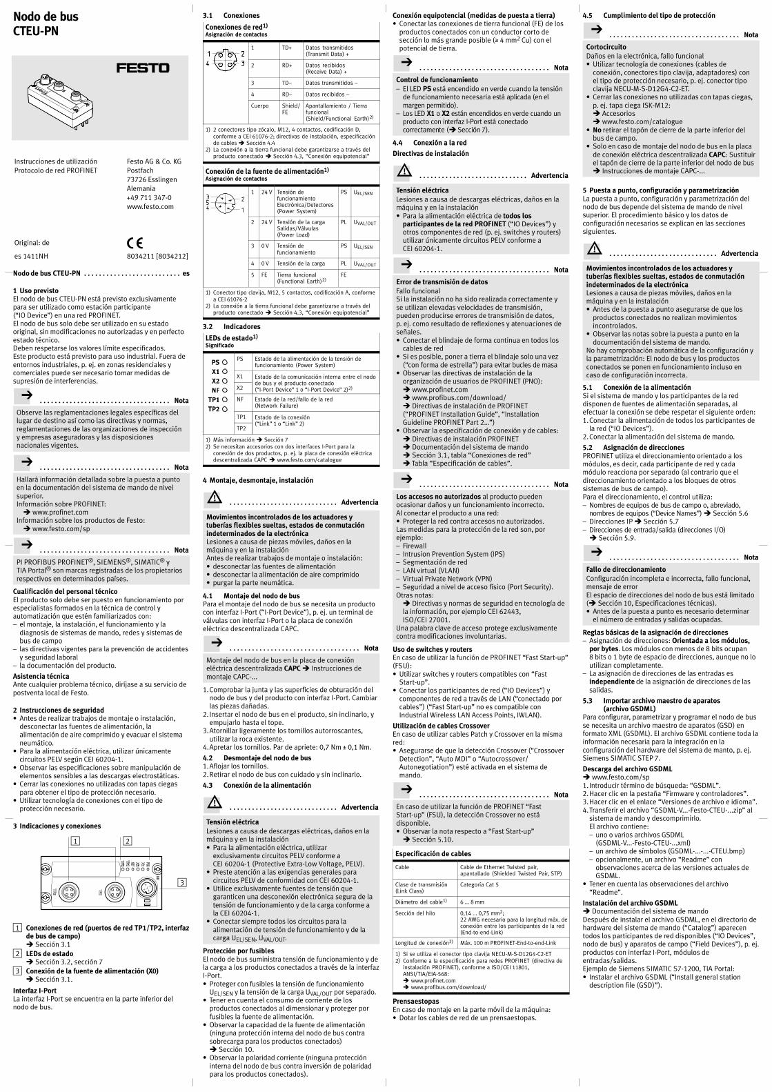
Nodo de bus CTEU-PN es. . . . . . . . . . . . . . . . . . . . . . . . . .
1 Uso previstoEl nodo de bus CTEU-PN está previsto exclusivamentepara ser utilizado como estación participante(“IO Device”) en una red PROFINET.El nodo de bus solo debe ser utilizado en su estadooriginal, sin modificaciones no autorizadas y en perfectoestado técnico.Deben respetarse los valores límite especificados.Este producto está previsto para uso industrial. Fuera deentornos industriales, p. ej. en zonas residenciales ycomerciales puede ser necesario tomar medidas desupresión de interferencias.
Nota. . . . . . . . . . . . . . . . . . . . . . . . . . . . . . . . . . .
Observe las reglamentaciones legales específicas dellugar de destino así como las directivas y normas,reglamentaciones de las organizaciones de inspeccióny empresas aseguradoras y las disposicionesnacionales vigentes.
Nota. . . . . . . . . . . . . . . . . . . . . . . . . . . . . . . . . . .
Hallará información detallada sobre la puesta a puntoen la documentación del sistema de mando de nivelsuperior.Información sobre PROFINET:� www.profinet.com
Información sobre los productos de Festo:� www.festo.com/sp
Nota. . . . . . . . . . . . . . . . . . . . . . . . . . . . . . . . . . .
PI PROFIBUS PROFINET®, SIEMENS®, SIMATIC® yTIA Portal® son marcas registradas de los propietariosrespectivos en determinados países.
Cualificación del personal técnicoEl producto solo debe ser puesto en funcionamiento porespecialistas formados en la técnica de control yautomatización que estén familiarizados con:– el montaje, la instalación, el funcionamiento y la
diagnosis de sistemas de mando, redes y sistemas debus de campo
– las directivas vigentes para la prevención de accidentesy seguridad laboral
– la documentación del producto.
Asistencia técnicaAnte cualquier problema técnico, diríjase a su servicio depostventa local de Festo.
2 Instrucciones de seguridad� Antes de realizar trabajos de montaje o instalación,
desconectar las fuentes de alimentación, laalimentación de aire comprimido y evacuar el sistemaneumático.
� Para la alimentación eléctrica, utilizar únicamentecircuitos PELV según CEI 60204-1.
� Observar las especificaciones sobre manipulación deelementos sensibles a las descargas electrostáticas.
� Cerrar las conexiones no utilizadas con tapas ciegaspara obtener el tipo de protección necesario.
� Utilizar tecnología de conexiones con el tipo deprotección necesario.
3 Indicaciones y conexiones
2
3
1
1 Conexiones de red (puertos de red TP1/TP2, interfazde bus de campo)� Sección 3.1
2 LEDs de estado� Sección 3.2, sección 7
3 Conexión de la fuente de alimentación (X0)� Sección 3.1.
Interfaz I-PortLa interfaz I-Port se encuentra en la parte inferior delnodo de bus.
3.1 Conexiones
Conexiones de red1)
Asignación de contactos
1 TD+ Datos transmitidos(Transmit Data) +
2 RD+ Datos recibidos(Receive Data) +
3 TD– Datos transmitidos –
4 RD– Datos recibidos –
Cuerpo Shield/FE
Apantallamiento / Tierrafuncional(Shield/Functional Earth)2)
1) 2 conectores tipo zócalo, M12, 4 contactos, codificación D,conforme a CEI 61076-2; directivas de instalación, especificaciónde cables � Sección 4.4
2) La conexión a la tierra funcional debe garantizarse a través delproducto conectado � Sección 4.3, “Conexión equipotencial”
Conexión de la fuente de alimentación1)
Asignación de contactos
1 24 V Tensión defuncionamientoElectrónica/Detectores(Power System)
PS UEL/SEN
2 24 V Tensión de la cargaSalidas/Válvulas(Power Load)
PL UVAL/OUT
3 0 V Tensión defuncionamiento
PS UEL/SEN
4 0 V Tensión de la carga PL UVAL/OUT
5 FE Tierra funcional(Functional Earth)2)
FE
1) Conector tipo clavija, M12, 5 contactos, codificación A, conformea CEI 61076-2
2) La conexión a la tierra funcional debe garantizarse a través delproducto conectado � Sección 4.3, “Conexión equipotencial”
3.2 Indicadores
LEDs de estado1)
Significado
PS Estado de la alimentación de la tensión defuncionamiento (Power System)
X1 Estado de la comunicación interna entre el nodode bus y el producto conectado(“I-Port Device” 1 o “I-Port Device” 2)2)X2
NF Estado de la red/fallo de la red(Network Failure)
TP1 Estado de la conexión(“Link” 1 o “Link” 2)
TP2
1) Más información � Sección 72) Se necesitan accesorios con dos interfaces I-Port para la
conexión de dos productos, p. ej. la placa de conexión eléctricadescentralizada CAPC � www.festo.com/catalogue
4 Montaje, desmontaje, instalación
Advertencia. . . . . . . . . . . . . . . . . . . . . . . . . . . . .
Movimientos incontrolados de los actuadores ytuberías flexibles sueltas, estados de conmutaciónindeterminados de la electrónicaLesiones a causa de piezas móviles, daños en lamáquina y en la instalaciónAntes de realizar trabajos de montaje o instalación:� desconectar las fuentes de alimentación� desconectar la alimentación de aire comprimido� purgar la parte neumática.
4.1 Montaje del nodo de busPara el montaje del nodo de bus se necesita un productocon interfaz I-Port (“I-Port Device”), p. ej. un terminal deválvulas con interfaz I-Port o la placa de conexióneléctrica descentralizada CAPC.
Nota. . . . . . . . . . . . . . . . . . . . . . . . . . . . . . . . . . .
Montaje del nodo de bus en la placa de conexióneléctrica descentralizada CAPC � Instrucciones demontaje CAPC-...
1.Comprobar la junta y las superficies de obturación delnodo de bus y del producto con interfaz I-Port. Cambiarlas piezas dañadas.
2. Insertar el nodo de bus en el producto, sin inclinarlo, yempujarlo hasta el tope.
3.Atornillar ligeramente los tornillos autorroscantes,utilizar la roca existente.
4.Apretar los tornillos. Par de apriete: 0,7 Nm ± 0,1 Nm.
4.2 Desmontaje del nodo de bus1.Aflojar los tornillos.2.Retirar el nodo de bus con cuidado y sin inclinarlo.
4.3 Conexión de la alimentación
Advertencia. . . . . . . . . . . . . . . . . . . . . . . . . . . . .
Tensión eléctricaLesiones a causa de descargas eléctricas, daños en lamáquina y en la instalación� Para la alimentación eléctrica, utilizar
exclusivamente circuitos PELV conforme aCEI�60204-1 (Protective Extra-Low Voltage, PELV).
� Preste atención a las exigencias generales paracircuitos PELV de conformidad con CEI�60204-1.
� Utilice exclusivamente fuentes de tensión quegaranticen una desconexión electrónica segura de latensión de funcionamiento y de la carga conforme ala CEI�60204-1.
� Conectar siempre todos los circuitos para laalimentación de tensión de funcionamiento y de lacarga UEL/SEN, UVAL/OUT.
Protección por fusiblesEl nodo de bus suministra tensión de funcionamiento y dela carga a los productos conectados a través de la interfazI-Port.� Proteger con fusibles la tensión de funcionamiento
UEL/SEN y la tensión de la carga UVAL/OUT por separado.� Tener en cuenta el consumo de corriente de los
productos conectados al dimensionar y proteger porfusibles la fuente de alimentación.
� Observar la capacidad de la fuente de alimentación(ninguna protección interna del nodo de bus contrasobrecarga para los productos conectados)� Sección 10.
� Observar la polaridad corriente (ninguna proteccióninterna del nodo de bus contra inversión de polaridadpara los productos conectados).
Conexión equipotencial (medidas de puesta a tierra)� Conectar las conexiones de tierra funcional (FE) de los
productos conectados con un conductor corto desección lo más grande posible (� 4 mm2 Cu) con elpotencial de tierra.
Nota. . . . . . . . . . . . . . . . . . . . . . . . . . . . . . . . . . .
Control de funcionamiento– El LED PS está encendido en verde cuando la tensión
de funcionamiento necesaria está aplicada (en elmargen permitido).
– Los LED X1 o X2 están encendidos en verde cuando unproducto con interfaz I-Port está conectadocorrectamente (� Sección 7).
4.4 Conexión a la red
Directivas de instalación
Advertencia. . . . . . . . . . . . . . . . . . . . . . . . . . . . .
Tensión eléctricaLesiones a causa de descargas eléctricas, daños en lamáquina y en la instalación� Para la alimentación eléctrica de todos los
participantes de la red PROFINET (“IO Devices”) yotros componentes de red (p. ej. switches y routers)utilizar únicamente circuitos PELV conforme aCEI�60204-1.
Nota. . . . . . . . . . . . . . . . . . . . . . . . . . . . . . . . . . .
Error de transmisión de datosFallo funcionalSi la instalación no ha sido realizada correctamente yse utilizan elevadas velocidades de transmisión,pueden producirse errores de transmisión de datos,p. ej. como resultado de reflexiones y atenuaciones deseñales.� Conectar el blindaje de forma continua en todos los
cables de red� Si es posible, poner a tierra el blindaje solo una vez
(“con forma de estrella”) para evitar bucles de masa� Observar las directivas de instalación de la
organización de usuarios de PROFINET (PNO):� www.profinet.com� www.profibus.com/download/� Directivas de instalación de PROFINET(“PROFINET Installation Guide”, “InstallationGuideline PROFINET Part 2…”)
� Observar la especificación de conexión y de cables:� Directivas de instalación PROFINET� Documentación del sistema de mando� Sección 3.1, tabla “Conexiones de red”� Tabla “Especificación de cables”.
Nota. . . . . . . . . . . . . . . . . . . . . . . . . . . . . . . . . . .
Los accesos no autorizados al producto puedenocasionar daños y un funcionamiento incorrecto.Al conectar el producto a una red:� Proteger la red contra accesos no autorizados.Las medidas para la protección de la red son, porejemplo:– Firewall– Intrusion Prevention System (IPS)– Segmentación de red– LAN virtual (VLAN)– Virtual Private Network (VPN)– Seguridad a nivel de acceso físico (Port Security).Otras notas:� Directivas y normas de seguridad en tecnología dela información, por ejemplo CEI 62443,ISO/CEI 27001.
Una palabra clave de acceso protege exclusivamentecontra modificaciones involuntarias.
Uso de switches y routersEn caso de utilizar la función de PROFINET “Fast Start-up”(FSU):� Utilizar switches y routers compatibles con “Fast
Start-up”.� Conectar los participantes de red (“IO Devices”) y
componentes de red a través de LAN (“conectado porcables”) (“Fast Start-up” no es compatible conIndustrial Wireless LAN Access Points, IWLAN).
Utilización de cables CrossoverEn caso de utilizar cables Patch y Crossover en la mismared:� Asegurarse de que la detección Crossover (“Crossover
Detection”, “Auto MDI” o “Autocrossover/Autonegotiation”) esté activada en el sistema demando.
Nota. . . . . . . . . . . . . . . . . . . . . . . . . . . . . . . . . . .
En caso de utilizar la función de PROFINET “FastStart-up” (FSU), la detección Crossover no estádisponible.� Observar la nota respecto a “Fast Start-up”� Sección 5.10.
Especificación de cables
Cable Cable de Ethernet Twisted pair,apantallado (Shielded Twisted Pair, STP)
Clase de transmisión(Link Class)
Categoría Cat 5
Diámetro del cable1) 6 ... 8 mm
Sección del hilo 0,14 ... 0,75 mm2;22 AWG necesario para la longitud máx. deconexión entre los participantes de la red(End-to-end-Link)
Longitud de conexión2) Máx. 100 m PROFINET-End-to-end-Link
1) Si se utiliza el conector tipo clavija NECUMSD12G4C2ET2) Conforme a la especificación para redes PROFINET (directiva de
instalación PROFINET), conforme a ISO/CEI 11801,ANSI/TIA/EIA-568:� www.profinet.com� www.profibus.com/download/
PrensaestopasEn caso de montaje en la parte móvil de la máquina:� Dotar los cables de red de un prensaestopas.
4.5 Cumplimiento del tipo de protección
Nota. . . . . . . . . . . . . . . . . . . . . . . . . . . . . . . . . . .
CortocircuitoDaños en la electrónica, fallo funcional� Utilizar tecnología de conexiones (cables de
conexión, conectores tipo clavija, adaptadores) conel tipo de protección necesario, p. ej. conector tipoclavija NECU-M-S-D12G4-C2-ET.
� Cerrar las conexiones no utilizadas con tapas ciegas,p. ej. tapa ciega ISK-M12:� Accesorios� www.festo.com/catalogue
� No retirar el tapón de cierre de la parte inferior delbus de campo.
� Solo en caso de montaje del nodo de bus en la placade conexión eléctrica descentralizada CAPC: Sustituirel tapón de cierre de la parte inferior del nodo de bus� Instrucciones de montaje CAPC-...
5 Puesta a punto, configuración y parametrizaciónLa puesta a punto, configuración y parametrización delnodo de bus depende del sistema de mando de nivelsuperior. El procedimiento básico y los datos deconfiguración necesarios se explican en las seccionessiguientes.
Advertencia. . . . . . . . . . . . . . . . . . . . . . . . . . . . .
Movimientos incontrolados de los actuadores ytuberías flexibles sueltas, estados de conmutaciónindeterminados de la electrónicaLesiones a causa de piezas móviles, daños en lamáquina y en la instalación� Antes de la puesta a punto asegurarse de que los
productos conectados no realizan movimientosincontrolados.
� Observar las notas sobre la puesta a punto en ladocumentación del sistema de mando.
No hay comprobación automática de la configuración yla parametrización: El nodo de bus y los productosconectados se ponen en funcionamiento incluso encaso de configuración incorrecta.
5.1 Conexión de la alimentaciónSi el sistema de mando y los participantes de la reddisponen de fuentes de alimentación separadas, alefectuar la conexión se debe respetar el siguiente orden:1.Conectar la alimentación de todos los participantes de
la red (“IO Devices”).2.Conectar la alimentación del sistema de mando.
5.2 Asignación de direccionesPROFINET utiliza el direccionamiento orientado a losmódulos, es decir, cada participante de red y cadamódulo reacciona por separado (al contrario que eldireccionamiento orientado a los bloques de otrossistemas de bus de campo).Para el direccionamiento, el control utiliza:– Nombres de equipos de bus de campo o, abreviado,
nombres de equipos (“Device Names”) � Sección 5.6– Direcciones IP � Sección 5.7– Direcciones de entrada/salida (direcciones I/O)� Sección 5.9.
Nota. . . . . . . . . . . . . . . . . . . . . . . . . . . . . . . . . . .
Fallo de direccionamientoConfiguración incompleta e incorrecta, fallo funcional,mensaje de errorEl espacio de direcciones del nodo de bus está limitado(� Sección 10, Especificaciones técnicas).� Antes de la puesta a punto es necesario determinar
el número de entradas y salidas ocupadas.
Reglas básicas de la asignación de direcciones– Asignación de direcciones: Orientada a los módulos,
por bytes. Los módulos con menos de 8 bits ocupan8 bits o 1 byte de espacio de direcciones, aunque no loutilizan completamente.
– La asignación de direcciones de las entradas esindependiente de la asignación de direcciones de lassalidas.
5.3 Importar archivo maestro de aparatos(archivo GSDML)
Para configurar, parametrizar y programar el nodo de busse necesita un archivo maestro de aparatos (GSD) enformato XML (GSDML). El archivo GSDML contiene toda lainformación necesaria para la integración en laconfiguración del hardware del sistema de manto, p. ej.Siemens SIMATIC STEP 7.
Descarga del archivo GSDML� www.festo.com/sp1.Introducir término de búsqueda: “GSDML”.2.Hacer clic en la pestaña “Firmware y controladores”.3.Hacer clic en el enlace “Versiones de archivo e idioma”.4.Transferir el archivo “GSDML-V...-Festo-CTEU-...zip” al
sistema de mando y descomprimirlo.El archivo contiene:– uno o varios archivos GSDML
(GSDML-V...-Festo-CTEU-...xml)– un archivo de símbolos (GSDML-...-...-CTEU.bmp)– opcionalmente, un archivo “Readme” con
observaciones acerca de las versiones actuales deGSDML.
� Tener en cuenta las observaciones del archivo“Readme”.
Instalación del archivo GSDML� Documentación del sistema de mandoDespués de instalar el archivo GSDML, en el directorio dehardware del sistema de mando (“Catalog”) aparecentodos los participantes de red disponibles (“IO Devices”,nodo de bus) y aparatos de campo (“Field Devices”), p. ej.productos con interfaz I-Port, módulos deentradas/salidas.Ejemplo de Siemens SIMATIC S7-1200, TIA Portal:� Instalar el archivo GSDML (“Install general station
description file (GSD)”).
Instrucciones de utilizaciónProtocolo de red PROFINET
Original: de
Festo AG & Co. KGPostfach73726 EsslingenAlemania+49 711 347-0www.festo.com
es 1411NH 8034211 [8034212]
Nodo de busCTEU-PN

5.4 Configuración del sistema de mando, creación deproyecto de automatización
� Documentación del sistema de mandoEjemplo de Siemens SIMATIC S7-1200, TIA Portal:1.Abrir vista de equipos y redes:
Vista (“View”) � Doble clic en “Equipos y redes”(“Devices & networks”).
2.Abrir vista de equipos y redes (“Network view”).3.Abrir catálogo de hardware (“Catalog”).4.Abrir el directorio “Sistema de mando” (“PLC”).5.Arrastrar el sistema de mando (SPS/“CPU”) a la vista
de red.
5.5 Incorporación de la estación PROFINET(“Station”)
� Documentación del sistema de mandoEjemplo de Siemens SIMATIC S7-1200, TIA Portal:1.Abrir vista de equipos y redes (“Devices & networks”� Sección 5.4).
2.Abrir vista de equipos y redes (“Network view”).3.Abrir catálogo de hardware (“Catalog”).4.Abrir el directorio “Otros equipos de campo” (“Other
field devices”):� “PROFINET IO” � “Valves” � “Festo AG & Co. KG”� “Festo CTEU-PN”.
5.Seleccionar el símbolo de la estación PROFINET, esdecir, del nodo de bus CTEU-PN, y arrastrarlo a la vistade redes.
6.Abrir la vista de conexiones: “Connections”.7.Conectar el nodo de bus CTEU-PN con el sistema de
mando:Hacer clic en el símbolo del nodo de bus, mantener elbotón pulsado y arrastrar el puntero del ratón hasta elsímbolo del sistema de mando.
8.Seleccionar la conexión: “Connections” � “PROFINETIO-System”.
5.6 Asignación de nombre de equipo (“Device Name”)� Documentación del sistema de mandoA través del nombre de equipo puede direccionar el nodode bus y el producto conectado (“I-Port Device”)directamente, p. ej. en su programa de automatización.
5.7 Asignación o modificación de la dirección IP� Documentación del sistema de mandoEn general el sistema de mando se encarga de laasignación de una dirección IP.
Nota. . . . . . . . . . . . . . . . . . . . . . . . . . . . . . . . . . .
� Al asignar la dirección IP deben observarse lasnormas principales de direccionamiento, p. ej. en loreferente a la utilización de espacios dedireccionamiento privados o públicos.
� Comprobar la aplicabilidad de la dirección IP en lared de automatización.
� Asegurarse de que las direcciones IP no se utilicendos veces.
5.8 Configuración de los equipos de campo (“I-PortDevices”)
� Documentación del sistema de mandoEjemplo de Siemens SIMATIC S7-1200, TIA Portal:1.Abrir vista de equipos y redes (“Devices & networks”� Sección 5.4).
2.Abrir vista de equipos (“Device view”).3.Abrir catálogo de hardware (“Catalog”).4.Abrir directorio “Otros equipos de campo” (“Other field
devices”).5.Configurar los equipos de campo:
Arrastrar los símbolos de los productos conectados(“I-Port Devices”) a la vista general de equipos (“Deviceoverview”).
5.9 Modificación de las direcciones iniciales de lasentradas/salidas, modificación de las direccionesde diagnosis
� Documentación del sistema de mandoEn general el sistema de mando se encarga de laasignación de las direcciones de entrada/salida y de lasdirecciones de diagnosis.
5.10 Configuración de la función PROFINET “Arranquerápido” (“Fast Start-up”, FSU)
� Documentación del sistema de mando
Nota. . . . . . . . . . . . . . . . . . . . . . . . . . . . . . . . . . .
En caso de utilizar la función de PROFINET “FastStart-up” (FSU), la detección Crossover (“CrossoverDetection”, “Auto MDI” o“Autocrossover/Autonegotiation”) no está disponible:� Desactivar la detección Crossover:
– en la configuración de hardware de todos losparticipantes de la red
– en la configuración de hardware de la redadyacente (“Partner-Port”).
La desactivación de la detección Crossover cambia laasignación de contactos de la conexión de red de salidaTP2 a “Crossover”.� Seleccionar el cable de conexión en función de la
asignación de contactos de la conexión de red delproducto conectado a TP2:– cable Crossover cuando la asignación de puertos
es igual– cable Patch cuando la asignación de puertos es
distinta.
Ejemplo de Siemens SIMATIC S7-1200, TIA Portal:1.Abrir vista general de equipos (“Device overview”):
Ventana “Navegación del proyecto” (“Projectnavigation”) � Equipos (“Devices”) � Vista deequipos (“Device view”) � Vista general de equipos(“Device overview”) � Módulos (“Module”)� “CTEU-PN”.
2.Hacer clic en el módulo “PN-IO Interface”.3.Abrir opciones de interfaces:
Ventana “PN-IO Interface [Module]” � Propiedades(“Properties”) � General (“General”) � Opcionesavanzadas (“Advanced options”) � Opciones deinterfaz (“Interface options”).
4.Activar la opción de interfaz “Arranque priorizado”(“Prioritized start-up”) (activar casilla).
5.Abrir opciones de puerto:Ventana “PN-IO Interface [Module]” � Propiedades(“Properties”) � General (“General”) � Opcionesavanzadas (“Advanced options”) � “Port 1 [X1 P1 R]” o“Port 2 [X1 P2 R]” � Opciones de puertos (“Portoptions”).
6.En “Conexión” (“Connection”), desactivar la detecciónCrossover (“Autonegotiation”) de las conexiones de red(puertos de red) TP1 y TP2.
5.11 Ajuste de la parametrización� Documentación del sistema de mandoEl comportamiento de los productos conectados sepuede ajustar individualmente mediante parametrización(“parametrización de módulo”), p. ej. tiempo decorrección, tiempo de prolongación de señal, supervisiónde la producción (transmisión de mensajes de diagnosis),ajustes para el caso de error (modo “Fail state”). Laparametrización puede configurarse por separado para“I-Port Device” 1 (X1) y “I-Port Device” 2 (X2).
Parámetro1) Significado
Ajustes de puerto2)
Ejemplo “Equipo universal 256DIO” (“Universal device 256DIO”)
Tool Change Mode Modo de cambio de herramienta:– “Tool Change Mode” activado:
En la imagen de datos de proceso losespacios de direcciones para los datosde entrada y de salida están asignados(direccionados) de forma fija,independientemente del productoconectado (“I-Port Device”); estopermite intercambiar los productosconectados (p. ej. herramientas) sinmodificación de la configuración.
– “Tool Change Mode” desactivado:El “I-Port Device” registrado durante elarranque se acepta en la configuraciónde PROFINET. La asignación(direccionamiento) de los datos deentrada y de salida en la imagen dedatos de proceso depende del productoconectado.
Suprimir todos losmensajes dediagnosis
No hay transmisión de mensajes dediagnosis a través de la red (“Suppress alldiagnostics messages”)
Suprimir mensajede diagnosis “faltatensión de la carga”
No hay transmisión del mensaje dediagnosis “falta tensión de la carga”3) através de la red4) (“Suppress missing loadvoltage diagnostics messages”)
Fail state El modo “Fail state” regula elcompor tamiento del nodo de bus y de losproductos conectados en caso de error decomunicación:– Restablecer salidas (“Outputs reset”):
Las salidas se restablecen.– Salidas “Hold last state” (“Outputs Hold
last state”): Las salidas conservan elúltimo estado.
El ajuste seleccionado es válido para todaslas salidas.El ajuste “Fail-state” también es válidopara el estado operativo “marcha sincarga” (“Idle state”):– El “Idle state” es adoptado por el
sistema de mando cuando se solicita. Elsistema de mando se encuentra en el“modo de parada”.
– Los datos de entrada se continúantransmitiendo en el “Idle state”.
Parámetros del I-Port Device2)
Ejemplo “Equipo universal 256DIO” (“Universal device 256DIO”)
Byte 0 a byte 7 Tunelado de parámetros específicos delproducto � Documentación del productoconectado
1) Siemens SIMATIC S7-1200, TIA Portal: Parámetros de módulos2) Los parámetros disponibles dependen del producto conectado.3) Supervisión de subtensión de la alimentación de la tensión de
carga de salidas/válvulas UOUT/VAL (“Undervoltage UOUT/VAL”)4) Los mensajes de diagnosis “falta tensión de la carga” solo se
generan cuando el producto conectado supervisa la tensión dela carga y comunica el estado al nodo de bus.
Nota. . . . . . . . . . . . . . . . . . . . . . . . . . . . . . . . . . .
Control de funcionamiento– El LED NF está apagado (en caso de comunicación sin
errores entre el sistema de mando y el nodo de bus).– El LED TP1 o TP2 se enciende en verde (� Sección 7).– Siemens SIMATIC S7-1200, TIA Portal: En las
columnas “Dirección I” (“I address”) o “Dirección O”(“O address”) hay registros de direcciones(direcciones iniciales de las entradas/salidas).
– Comprobar la disponibilidad de los participantes dela red:Menú “Online” � “Accessible devices”� Comprobar que la lista de participantes de la redesté completa (“Accessible devices in targetsubnet”).
6 “Identification and Maintenance”� Documentación del sistema de mandoLa función “Identification and Maintenance” (I&M) ofreceun acceso uniforme, independiente del fabricante, a lainformación específica del producto.
Nota. . . . . . . . . . . . . . . . . . . . . . . . . . . . . . . . . . .
Las especificaciones de I&M actualizadas, p. ej. de laversión del firmware y del software del nodo de buspueden diferir de las especificaciones de la inscripciónen el producto.
7 Diagnosis
PS – Estado de la alimentación de la tensión defuncionamiento (Power System)
Indicador LED
Estado y significado
LED encendido en verde:– estado operativo normal– hay tensión de funcionamiento
(en el margen permitido)– hay tensión de la carga (en el margen permitido)1)
LED intermitente en verde (frecuencia de intermitencia:1 Hz)– la tensión de funcionamiento está por debajo de la
tensión necesaria– la tensión de la carga está por debajo de la tensión
necesaria 1)
– Cortocircuito en el I-Port1)
LED apagado:– no hay tensión de funcionamiento– la tensión de funcionamiento está por debajo de la
tensión necesaria mínima para las funciones dediagnosis
1) La indicación se refiere en este caso solamente al estado de latensión de la carga, cuando el producto conectado supervisa latensión de la carga y comunica el estado al nodo de bus.
X1 y X2 – Estado de la comunicación interna el nodo debus y el producto conectado (“I-Port Device” 1 o“I-Port Device” 2)1)
Indicador LED
Estado y significado
LED encendido en verde:– estado operativo normal– “I-Port Device” 1 o 2 está conectado correctamente– hay tensión de funcionamiento y de la carga (dentro
del margen permitido)2)
LED intermitente en verde:– estado de diagnosis– subtensión en la alimentación adicional o del
sistema– la conexión entre el nodo de bus y el “I-Port Device”
es correcta
LED encendido en rojo:– el “I-Port Device” está conectado correctamente,
pero la comunicación interna falla– tras la puesta a punto se ha conectado un “I-Port
Device” (“I-Port Device” distinto a la configuraciónde hardware en el sistema de mando o producto nocompatible con I-Port)
LED intermitente en rojo:– durante la puesta a punto se ha conectado un “I-Port
Device” equivocado (producto no compatible conI-Port)
– si solo está intermitente en rojo el LED X1: Error en elnodo de bus
– si X1 y X2 están intermitentes en rojosimultáneamente: No se ha conectado ningúnproducto al nodo de bus (se requiere por lo menosun “I-Port Device”)
LED apagado:– no se ha conectado ningún producto al nodo de bus
1) Se necesitan accesorios con dos interfaces I-Port para la conexión de dos productos
2) La indicación se refiere en este caso solamente al estado de latensión de la carga, cuando el producto conectado supervisa latensión de la carga y comunica el estado al nodo de bus.
NF – Estado de la red/fallo de la red (Network Failure)
Indicador LED
Estado y significado
LED intermitente en rojo:– error de comunicación– fallo o interrupción de la comunicación entre el
sistema de mando y el nodo de bus
LED apagado:– estado operativo normal– comunicación correcta entre el sistema de mando y
el nodo de bus
TP1/TP2 – Estado de conexión (“Link” 1 o “Link” 2)
Indicador LED
Estado y significado
LED encendido en verde:– estado operativo normal– la conexión de red es correcta
Ambos LEDs, TP1 y TP2, intermitentes en verde:– para la localización del producto conectado
(“localización de módulo”), p. ej. en la configuraciónde hardware en el sistema de mando o para labúsqueda de errores
LED apagado:– no hay ninguna red conectada
8 MantenimientoNo se requieren medidas especiales.
9 Glosario
Término/abreviatura
Significado
FSU Función PROFINET “Arranque rápido”(“Fast Start-up”), también denominada“Arranque prioritario” (“PrioritizedStart-up”) o “Rearranque rápido”; modooperativo del nodo de bus, garantiza unarranque rápido (rearranque) de losparticipantes de la red (“IO Devices”)
PROFIenergy PROFIenergy permite realizar ajustes degestión energética
PROFINET Red basada en Industrial Ethernet usistemas de bus de campo para elintercambio de datos entre un sistema demando de nivel superior (PC industrial,PLC o “IO Controller”), participantes de lared (“IO Devices”) y equipos de campo(“Field Devices”), p. ej. terminales deválvulas o actuadores� www.profinet.com� www.profibus.com/download/� Descripción del sistema PROFINET,Tecnología y aplicación (“PROFINETSystem Description, Technology andApplication”)
PLC Control lógico programable, tambiéndenominado sistema de mando o,abreviado, control (“Programmable LogicController”, PLC)
10 Especificaciones técnicas
Nota. . . . . . . . . . . . . . . . . . . . . . . . . . . . . . . . . . .
Consulte las especificaciones técnicas de los productosconectados en la documentación del producto respectivo.
Características eléctricas
Tipo de protección a través de lacarcasa (conforme aCEI 60529/EN 60529)
IP65/IP671)2)
Protección contra descargaseléctricas (protección contracontacto directo o indirectosegún CEI 60204-1/EN 60204-1)
mediante el uso de circuitos PELV(Protective Extra-Low Voltage)
Separaciónde las conexiones de red para laalimentación de la tensión defuncionamiento UEL/SEN
Aislamiento galvánico, mediantetransformador (hasta 500 V)
Compatibilidad electromagnética(EMC)3)
– Emisión de interferencias– Resistencia a interferencias
Véase la declaración deconformidad � www.festo.com
1) Condición previa: Nodo de bus completamente montado,conector enchufable insertado o dotado de tapa ciega
2) Los productos conectados posiblemente solo cumplen un tipode protección bajo.
3) El producto está previsto para el uso industrial. Fuera deentornos industriales, p. ej. en zonas residenciales y comercialespuede ser necesario tomar medidas de supresión deinterferencias.
Características mecánicas generales
Resistencia a vibraciones eimpactos (según CEI/EN 60068)1)
– Vibraciones (parte 2-6)– Impactos (parte 2-27)– Impacto continuo (parte 2-27)
Grado de severidad (SG)1) paramontaje en pared o en perfil DIN– Pared: SG2, perfil DIN: SG1– Pared: SG2, perfil DIN: SG1– Pared y perfil DIN: SG 1
Margen de temperatura2)
– Almacenamiento/transpor te– Funcionamiento
–20 … +70 °C–5 … +50 °C
Protección contra la corrosión El producto está previsto para laaplicación en interiores enentornos industriales, evitar lacondensación.
Materiales
– Carcasa– Conductor de luz– Casquillo roscado M12– Casquillo roscado M3– Juntas– Tornillos
Conformidad con la directiva2002/95/CE (RoHS)Poliamida reforzadaPolicarbonatolatón, niquelado galvánicamentelatónNBRAcero, galvanizado
Dimensiones– Ancho– Largo– Alto
Ancho de 40 mm91 mm50 mm
Peso (nodo de bus sin cables nisubestructura)
94 g
1) Explicación de los grados de severidad � Tabla “Explicaciónsobre vibración y choque – Grado de severidad”
2) Los productos conectados posiblemente solo cumplen unmargen de temperatura pequeño.
Fuente de alimentación
Tensión de funcionamiento para nodo de busy equipos conectados1)
– Valor nominal– Margen de tolerancia
24 V DC18 … 30 V DC2)
Tensión de la carga para nodo de bus yproductos conectados1)
– Margen de tolerancia 18 … 30 V DC2)
Consumo propio en caso de tensión nominalde funcionamiento 24 V DCde la alimentación de la tensión de funcionamiento para electrónica/sensores (UEL/SEN)
Típ. 80 mA(electrónica interna)
Capacidad de las alimentaciones de la tensiónde funcionamiento y de la carga1)3)
– Nodo de bus en el aparato conectado(p. ej. terminal de válvulas)
– Nodo de bus en la placa de conexióneléctrica descentralizada CAPC
Máx. 4 A
Máx. 2 APor cada “I-PortDevice”4)
Puenteo en cortes de red 10 ms
1) Para las alimentaciones de la tensión de funcionamiento y de lacarga se requieren fusibles externos separados (ningunaprotección contra sobrecarga e inversión de polaridad interna delnodo de bus para los productos conectados).
2) El margen de tolerancia depende de los módulos conectados.3) Capacidad total de las alimentaciones de la tensión de
funcionamiento y de la carga PS y PL (corriente total), consumode corriente máximo admisible del nodo de bus y de losproductos conectados
4) Capacidad total de las alimentaciones de la tensión defuncionamiento y de la carga PS y PL (corriente total), consumode corriente máximo admisible por cada “I-Port Device”
Características específicas de red
Protocolo de red PROFINET IO:– basado en Industrial Ethernet– conforme al protocolo Ethernet
estándar (IEEE 802.3)
Características deprotocolo y funcionesde protocolocompatibles (selección)
– Intercambio cíclico de datos “entiempo real”, sin sincronización deciclo (Real Time, RT) o consincronización de ciclo (IsochronousReal Time, IRT)1)
– Link Layer Discovery Protocol (LLDP)– Simple Network Management Protocol
(SNMP)– Fast Start-up (FSU)– PROFIenergy– Shared Device– Media Redundancy Protocol (MRP)
Funciones específicasdel sistema
– Información de diagnosis (diagnosisdel sistema, subtensión, error decomunicación)
– Servidor de red (estado del nodo debus y de los productos conectados,número de serie, configuración)
Especificación Selección de directivas y normas respectoa PROFINET:– Directivas de instalación de PROFINET
(“PROFINET Installation Guide”,“Installation Guideline PROFINETPart 2…”)
– CEI 61158– CEI 61784– CEI 61918Más información:� www.profinet.com� www.profibus.com/download/
Tecnología detransmisión
Switched Fast Ethernet;Ejecución 100BaseTX según IEEE 802.3
Velocidad detransmisión
100 Mbit/s
Conexiones de red 2 conectores tipo zócalo M12,codificación D, 4 contactos
Detección Crossover,Autonegotiation
Auto-MDI
Volumen máx. dedirecciones deentradas/salidas
64 bytes I, 64 bytes O,independiente del modo operativo
1) IRT solo está disponible a través de LAN
Explicación de vibraciones e impactos – Grado deseveridad
Carga de vibracionesGama de frecuencias[Hz]
Aceleración[m/s2]
Desviación[mm]
SG1 SG2 SG1 SG2 SG1 SG2
2 … 8 2 … 8 – – ±3,5 ±3,5
8 … 27 8 … 27 10 10 – –
27 … 58 27 … 60 – – ±0,15 ±0,35
58 … 160 60 … 160 20 50 – –
160 … 200 160 … 200 10 10 – –
Carga de impactosAceleración[m/s2]
Duración[ms]
Impactos encada sentido
SG1 SG2 SG1 SG2 SG1 SG2
±150 ±300 11 11 5 5
Carga impacto continuoAceleración[m/s2]
Duración[ms]
Impactos encada sentido
±150 6 1000
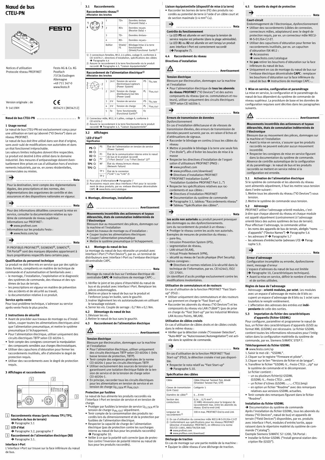
Nœud de bus CTEU-PN fr. . . . . . . . . . . . . . . . . . . . . . . . .
1 Usage normalLe nœud de bus CTEU-PN est exclusivement conçu pourune utilisation en tant qu'abonné (“IO Device”) dans unréseau PROFINET.Le nœud de bus doit être utilisé dans son état d'origine,sans avoir subi de modifications non autorisées et dansun état fonctionnel irréprochable.Les valeurs limites indiquées doivent être respectées.Le produit est destiné à être utilisé dans le domaineindustriel. Des mesures d'antiparasitage doivent éventuellement être prises en cas d'utilisation hors d'environnements industriels, par ex. en zones résidentielles,commerciales ou mixtes.
Nota. . . . . . . . . . . . . . . . . . . . . . . . . . . . . . . . . . .
Pour la destination, tenir compte des réglementationslégales, des prescriptions et des normes, desréglementations des organismes de contrôle et desassurances et des dispositions nationales en vigueur.
Nota. . . . . . . . . . . . . . . . . . . . . . . . . . . . . . . . . . .
Pour des informations détaillées concernant la mise enservice, consulter la documentation relative au système de commande de niveau supérieur.Informations sur PROFINET :� www.profinet.com
Informations sur les produits Festo :� www.festo.com/sp
Nota. . . . . . . . . . . . . . . . . . . . . . . . . . . . . . . . . . .
PI PROFIBUS PROFINET®, SIEMENS®, SIMATIC®,TIA Portal® sont des marques déposées appartenant àleurs propriétaires respectifs dans certains pays.
Qualification du personnel techniqueLe produit ne doit être mis en service que par des spécialistes formés, compétents en matière de technique decommande et d'automatisation et familiarisés avec :– le montage, l'installation, l'exploitation et le diagnostic
des systèmes de commande, des réseaux et des systèmes de bus de terrain,
– les prescriptions en vigueur en matière de préventiondes accidents et de sécurité au travail,
– la documentation relative à ce produit.
Service après-ventePour tout problème technique, s'adresser au serviceaprès-vente Festo le plus proche.
2 Instructions de sécurité� Avant de procéder aux travaux de montage ou d'instal
lation, couper toutes les alimentations électriques ainsique l'alimentation pneumatique, et mettre le systèmepneumatique à l'échappement.
� Pour l'alimentation électrique, utiliser uniquement descircuits électriques TBTP selon CEI 60204-1.
� Tenir compte des consignes concernant la manipulationdes composants sensibles aux charges électrostatiques.
� Utiliser des capuchons d'obturation pour fermer lesraccordements inutilisés, afin d'atteindre le degré deprotection requis.
� Utiliser des raccordements avec le degré de protectionrequis.
3 Affichages et raccordements
2
3
1
1 Raccordements réseau (ports réseau TP1/TP2,interface du bus de terrain)� Paragraphe 3.1
2 LED d'état� Paragraphe 3.2, paragraphe 7
3 Raccordement de l'alimentation électrique (X0)� Paragraphe 3.1.
Interface I-PortL'interface I-Port sur trouve sur la face inférieure du nœudde bus.
3.1 Raccordements
Raccordements réseau1)
Affectation des broches
1 TD+ Données émises(Transmit Data) +
2 RD+ Données reçues(Receive Data) +
3 TD– Données émises–
4 RD– Données reçues–
Boîtier Shield/FE
Blindage/mise à la terrefonctionnelle(Shield/Functional Earth)2)
1) 2 connecteurs femelles, M12, à 4 pôles, codage D, conformes àCEI 61076-2 ; directives d'installation, spécifications des câbles� Paragraphe 4.4
2) Assurer le raccordement à la terre fonctionnelle via le produitraccordé � Paragraphe 4.3, “Liaison équipotentielle”
Raccordement de l’alimentation électrique1)
Affectation des broches
1 24 V Tension de serviceélectronique/capteurs(Power System)
PS UEL/SEN
2 24 V Tension de chargedistributeurs/sor ties(Power Load)
PL UVAL/OUT
3 0 V Tension de service PS UEL/SEN
4 0 V Tension de charge PL UVAL/OUT
5 Fe Terre fonctionnelle(Functional Earth)2)
Fe
1) Connecteur mâle, M12, à 5 pôles, codage A, conforme àCEI 61076-2
2) Assurer le raccordement à la terre fonctionnelle via le produitraccordé � Paragraphe 4.3, “Liaison équipotentielle”
3.2 Affichages
LED d'état1)
Signification
PS État de l'alimentation en tension de service(Power System)
X1 État de la communication interne entre le nœudde bus et le produit raccordé(“I-Port Device” 1 ou “I-Port Device” 2)2)X2
NF État du réseau/erreurs réseau(Network Failure)
TP 1 État de la connexion(“Link” 1 ou “Link” 2)
TP 2
1) Pour plus d'informations� Paragraphe 72) Accessoires requis avec deux interfaces I-Port pour le raccorde
ment de deux produits, par ex. embase électrique décentraliséeCAPC � www.festo.com/catalogue
4 Montage, démontage, installation
Avertissement. . . . . . . . . . . . . . . . . . . . . . . . . . .
Mouvements incontrôlés des actionneurs et tuyauxdébranchés, états de commutation indéterminés del'électroniqueBlessure due au mouvement des pièces, dommages surla machine et l'installationAvant les travaux de montage ou d'installation :� Couper toutes les alimentations électriques� Couper l'alimentation pneumatique� Mettre le système pneumatique à l'échappement.
4.1 Montage du nœud de busLe montage du nœud de bus nécessite un produit avecinterface I-Port (“I-Port Device”), par ex. un terminal dedistributeurs avec interface I-Port ou l'embase électriquedécentralisée CAPC.
Nota. . . . . . . . . . . . . . . . . . . . . . . . . . . . . . . . . . .
Montage du nœud de bus sur l'embase électrique décentralisée CAPC � Instructions de montage CAPC-...
1.Vérifier le joint et les plans d'étanchéité du nœud debus et du produit avec interface I-Port. Remplacer lespièces endommagées.
2.Mettre en place le nœud de bus sur le produit etl'enfoncer jusqu'en butée, sans le gauchir.
3. Insérer légèrement les vis autotaraudeuses en utilisantle taraudage existant.
4.Serrer les vis. Couple de serrage : 0,7 Nm ± 0,1 Nm.
4.2 Démontage du nœud de bus1.Dévisser les vis.2.Retirer le nœud de bus sans le gauchir.
4.3 Raccordement de l’alimentation électrique
Avertissement. . . . . . . . . . . . . . . . . . . . . . . . . . .
Tension électriqueBlessure par électrocution, dommages sur la machineet l'installation� Pour l'alimentation électrique, utiliser uniquement
des circuits électriques TBTP selon CEI�60204-1 (trèsbasse tension de protection, TBTP).
� Tenir compte des exigences générales de la normeCEI�60204-1 pour les circuits électriques TBTP.
� Utiliser exclusivement des sources de tension quigarantissent une isolation électrique fiable de la tension de service et de la tension de charge selonCEI�60204-1.
� En principe, raccorder tous les circuits électriquespour les alimentations en tension de service et entension de charge UEL/SEN et UVAL/OUT.
Protection par fusiblesLe nœud de bus alimente les produits raccordés vial'interface I-Port en tension de service et en tension decharge.� Protéger par fusibles la tension de service UEL/SEN et la
tension de charge UVAL/OUT séparément.� Tenir compte de la consommation des produits rac
cordés lors du dimensionnement et de la protection parfusibles de l'alimentation électrique.
� Respecter la capacité de charge de l'alimentationélectrique (pas de protection contre les surchargesinterne au nœud de bus pour les produits raccordés)� Paragraphe 10.
� Veiller à ce que la polarité soit correcte (pas de protection contre l'inversion de polarité interne au nœud debus pour les produits raccordés).
Liaison équipotentielle (dispositif de mise à la terre)� Raccorder les bornes de terre (FE) des produits rac
cordés au potentiel de terre à l'aide d'un câble court etde section maximale (� 4 mm2 Cu).
Nota. . . . . . . . . . . . . . . . . . . . . . . . . . . . . . . . . . .
Contrôle du fonctionnement– La LED PS est allumée en vert lorsque la tension de
service requise est présente (dans la plage admissible).– La LED X1 ou X2 est allumée en vert lorsqu'un produit
avec interface I-Port est correctement raccordé(� Paragraphe 7).
4.4 Raccordement du réseau
Directives d'installation
Avertissement. . . . . . . . . . . . . . . . . . . . . . . . . . .
Tension électriqueBlessure par électrocution, dommages sur la machineet l'installation� Pour l'alimentation électrique de tous les abonnés
du réseau PROFINET (“IO Devices”) et des autrescomposants du réseau (par ex. commutateurs et routeurs), utiliser uniquement des circuits électriquesTBTP selon CEI�60204-1.
Nota. . . . . . . . . . . . . . . . . . . . . . . . . . . . . . . . . . .
Erreurs de transmission de donnéesDysfonctionnementEn cas d'installation défectueuse et de vitesses detransmission élevées, des erreurs de transmission dedonnées peuvent survenir, par ex. en raison d'échos etd'atténuations de signaux.� Raccorder le blindage en continu à tous les câbles du
réseau� Mettre si possible le blindage à la terre une seule fois
(“en étoile”), afin d'éviter les boucles de mise à lamasse
� Respecter les directives d'installation de l'organisation d'utilisateurs PROFINET (PNO) :� www.profinet.com� www.profibus.com/download/� Directives d'installation PROFINET(“PROFINET Installation Guide”,“Installation Guideline PROFINET Part 2…”)
� Respecter les spécifications relatives aux raccordements et aux câbles :� Directives d'installation PROFINET� Documentation du système de commande� Paragraphe 3.1, tableau “Raccordements réseau”� Tableau “Spécification des câbles”.
Nota. . . . . . . . . . . . . . . . . . . . . . . . . . . . . . . . . . .
Les accès non autorisés au produit peuvent provoquerdes dommages ou des dysfonctionnements.Lors du raccordement du produit à un réseau :� Protéger le réseau contre les accès non autorisés.Exemples de mesures de protection du réseau :– pare-feu,– Intrusion Prevention System (IPS),– segmentation de réseau,– LAN virtuel (VLAN),– Virtual Private Network (VPN),– sécurité au niveau de l'accès physique (Port Security).Autres consignes :� Directives et normes relatives à la sécurité dans latechnique de l'information, par ex. CEI 62443, ISO/CEI 27001.
Un identifiant d'accès protège exclusivement contre lesmodifications involontaires.
Utilisation de commutateurs et de routeursEn cas d'utilisation de la fonction PROFINET “Fast Start-up” (FSU) :� Utiliser uniquement des commutateurs et des routeurs
qui prennent en charge le “Fast Start-up”.� Raccorder les abonnés du réseau (“IO Devices”) et les
composants du réseau via LAN (“câblé”) (pas de priseen charge du “Fast Start-up” par les Industrial WirelessLAN Access Points, IWLAN).
Utilisation de câbles croisésEn cas d'utilisation de câbles droits et de câbles croisésdans le même réseau :� Vérifier que la détection croisée (“Crossover Detection”,
“Auto-MDI” ou “Autocrossover/Autonegotiation”) est activée dans le système de commande.
Nota. . . . . . . . . . . . . . . . . . . . . . . . . . . . . . . . . . .
En cas d'utilisation de la fonction PROFINET “FastStart-up” (FSU), la détection croisée n'est pas disponible.� Respecter le nota relatif au “Fast Start-up”� Paragraphe 5.10.
Spécification des câbles
Câble Câble Ethernet Twisted Pair, blindé(Shielded Twisted Pair, STP)
Classe de transmission(Link Class)
Catégorie 5
Diamètre de câble1) 6 ... 8 mm
Section desconducteurs
0,14 ... 0,75 mm2 ;22 AWG nécessaire pour la longueur deraccordement max. entre les abonnés duréseau (End-to-end-Link)
Longueur deraccordement 2)
100 m max. PROFINET-End-to-end-Link
1) En cas d'utilisation du connecteur mâle NECUMSD12G4C2ET2) Conformément aux spécifications pour les réseaux PROFINET
(directive d'installation PROFINET), en référence à la normeISO/CEI 11801, ANSI/TIA/EIA-568:� www.profinet.com� www.profibus.com/download/
Décharge de tractionEn cas de montage sur une partie mobile de la machine :� Équiper le câble réseau d'une décharge de traction.
4.5 Garantie du degré de protection
Nota. . . . . . . . . . . . . . . . . . . . . . . . . . . . . . . . . . .
Court-circuitEndommagement de l'électronique, dysfonctionnement� Utiliser des raccordements (câbles de connexion,
connecteurs mâles, adaptateurs) avec le degré deprotection requis, par ex. un connecteur mâle NECU-M-S-D12G4-C2-ET.
� Utiliser des capuchons d'obturation pour fermer lesraccordements inutilisés, par ex. un capuchond'obturation ISK-M12 :� Accessoires� www.festo.com/catalogue
� Ne pas retirer les bouchons d'obturation sur la faceinférieure du nœud de bus.
� Uniquement en cas de montage du nœud de bus surl'embase électrique décentralisée CAPC : remplacerles bouchons d'obturation sur la face inférieure dunœud de bus � Instructions de montage CAPC-...
5 Mise en service, configuration et paramétrageLa mise en service, la configuration et le paramétrage dunœud de bus dépendent du système de commande deniveau supérieur. La procédure de base et les données deconfiguration requises sont décrites dans les paragraphessuivants.
Avertissement. . . . . . . . . . . . . . . . . . . . . . . . . . .
Mouvements incontrôlés des actionneurs et tuyauxdébranchés, états de commutation indéterminés del'électroniqueBlessure due au mouvement des pièces, dommages surla machine et l'installation� Avant la mise en service, s'assurer que les produits
raccordés ne peuvent exécuter aucun mouvementincontrôlé.
� Respecter les consignes de mise en service figurantdans la documentation du système de commande.
Absence de contrôle automatique de la configurationet du paramétrage : le nœud de bus et les produitsraccordés se mettent en service même si laconfiguration est erronée.
5.1 Activation de l'alimentation électriqueSi le système de commande et les abonnés du réseausont alimentés séparément, il faut les mettre sous tensiondans l'ordre suivant :1.Mettre tous les abonnés du réseau (“IO Devices”) sous
tension.2.Mettre le système de commande sous tension.
5.2 AdressagePROFINET utilise l'adressage orienté modules, c'est-à-dire que chaque abonné du réseau et chaque moduleest appelé séparément (contrairement à l'adressageorienté blocs des autres systèmes de bus de terrain).Pour effectuer l'adressage, la commande utilise– les noms des appareils de bus de terrain, abrégés “noms
d'appareils” (“Device Names”) � Paragraphe 5.6– les adresses IP � Paragraphe 5.7– les adresses d'entrée/sortie (adresses I/O) � Parag
raphe 5.9.
Nota. . . . . . . . . . . . . . . . . . . . . . . . . . . . . . . . . . .
Erreur d'adressageConfiguration incomplète ou erronée, dysfonctionnement, message d'erreurL'espace d'adresses du nœud de bus est limitée(� Paragraphe 10, Caractéristiques techniques).� Avant la mise en service, définir le nombre d'entrées
et de sorties utilisées.
Règles de base de l'adressage– Adressage : orienté modules, par octet. Les modules
avec un espace d'adressage de moins de 8 bits occupent un espace d'adressage de 8 bits ou 1 octet sanstoutefois le remplir entièrement.
– L'affectation des adresses des entrées est indépendante de celle des sorties.
5.3 Importation du fichier des caractéristiquesd'appareils (fichier GSDML)
Pour configurer, paramétrer et programmer le nœud debus, un fichier des caractéristiques d'appareils (GSD) auformat XML (GSDML) est nécessaire. Le fichier GSDMLcontient toutes les informations nécessaires pour l'intégration dans la configuraiton matérielle du système decommande, par ex. Siemens SIMATIC STEP 7.
Téléchargement du fichier GSDML� www.festo.com/sp1.Saisir le mot-clé : “GSDML”.2.Cliquer sur le registre “Firmware et pilote”.3.Cliquer sur le lien “Versions de fichier et de langue”.4.Transférer le fichier “GSDML-V...-Festo-CTEU-...zip” sur
le système de commande et le décompresser.Le fichier contient :– un ou plusieurs fichier(s) GSDML
(GSDML-V...-Festo-CTEU-...xml)– un fichier d'icônes (GSDML-...-...-CTEU.bmp)– en option un fichier “Readme” avec des remarques
relatives aux versions GSDML actuelles.� Tenir compte des remarques figurant dans le fichier
“Readme”.
Installation du fichier GSDML� Documentation du système de commandeAprès l'installation du fichier GSDML, tous les abonnés duréseau (“IO Devices”, nœud de bus) et appareils deterrain (“Field Devices”) disponibles, par ex. produitsavec interface I-Port, modules d'entrée/sortie, apparaissent dans le répertoire matériel du système de commande (“Catalog”).Exemple Siemens SIMATIC S7-1200, TIA Portal :� Installer le fichier GSDML (“Install general station des
cription file (GSD)”).
Notices d'utilisationProtocole réseau PROFINET
Version originale : de
Festo AG & Co. KGPostfach73726 EsslingenAllemagne+49 711 347-0www.festo.fr
fr 1411NH 8034211 [8034212]
Nœud de busCTEU-PN
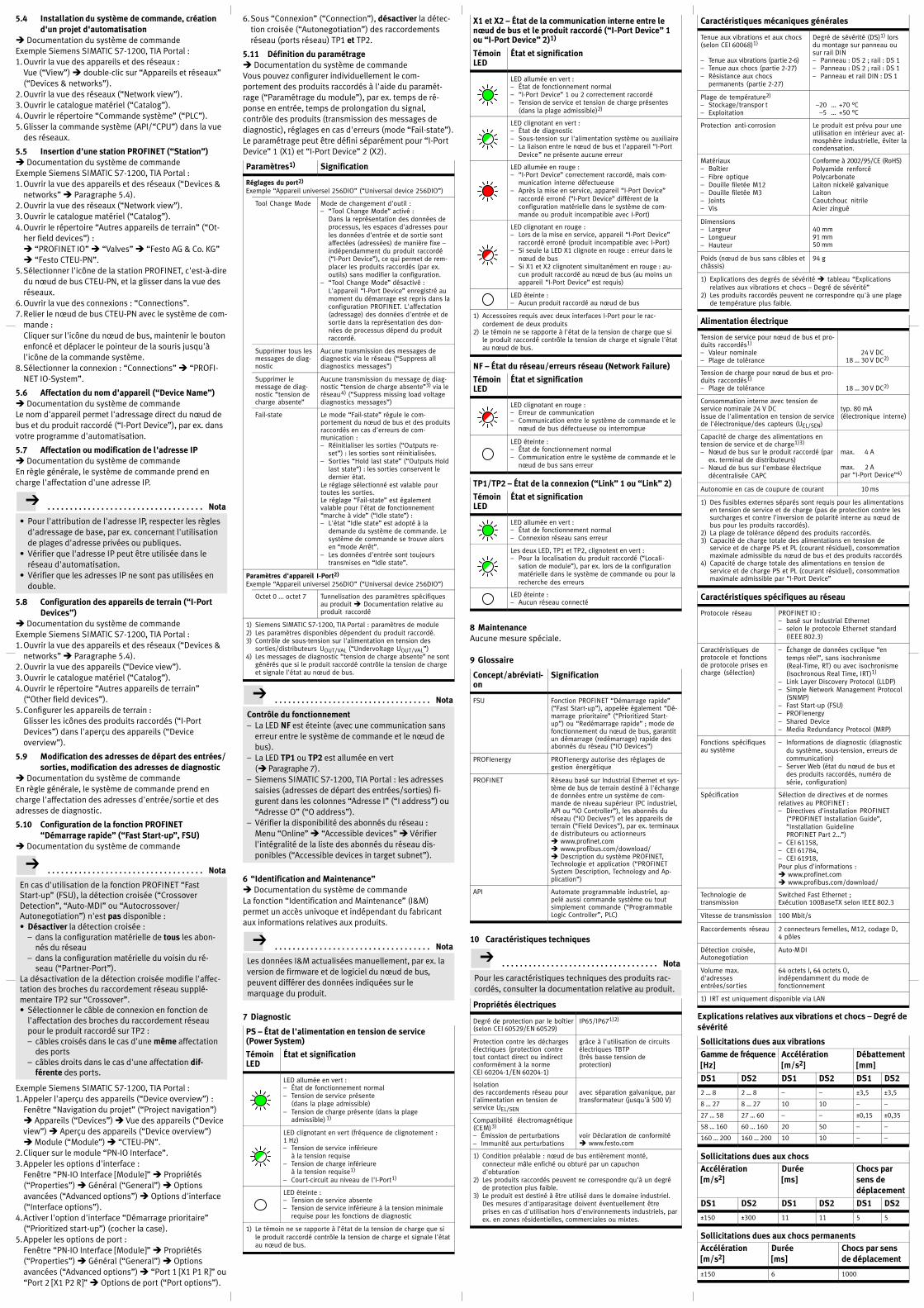
5.4 Installation du système de commande, créationd'un projet d'automatisation
� Documentation du système de commandeExemple Siemens SIMATIC S7-1200, TIA Portal :1.Ouvrir la vue des appareils et des réseaux :
Vue (“View”) � double-clic sur “Appareils et réseaux”(“Devices & networks”).
2.Ouvrir la vue des réseaux (“Network view”).3.Ouvrir le catalogue matériel (“Catalog”).4.Ouvrir le répertoire “Commande système” (“PLC”).5.Glisser la commande système (API/“CPU”) dans la vue
des réseaux.
5.5 Insertion d'une station PROFINET (“Station”)� Documentation du système de commandeExemple Siemens SIMATIC S7-1200, TIA Portal :1.Ouvrir la vue des appareils et des réseaux (“Devices &
networks” � Paragraphe 5.4).2.Ouvrir la vue des réseaux (“Network view”).3.Ouvrir le catalogue matériel (“Catalog”).4.Ouvrir le répertoire “Autres appareils de terrain” (“Ot
her field devices”) :� “PROFINET IO” � “Valves” � “Festo AG & Co. KG”� “Festo CTEU-PN”.
5.Sélectionner l'icône de la station PROFINET, c'est-à-diredu nœud de bus CTEU-PN, et la glisser dans la vue desréseaux.
6.Ouvrir la vue des connexions : “Connections”.7.Relier le nœud de bus CTEU-PN avec le système de com
mande :Cliquer sur l'icône du nœud de bus, maintenir le boutonenfoncé et déplacer le pointeur de la souris jusqu'àl'icône de la commande système.
8.Sélectionner la connexion : “Connections” � “PROFINET IO-System”.
5.6 Affectation du nom d'appareil (“Device Name”)� Documentation du système de commandeLe nom d'appareil permet l'adressage direct du nœud debus et du produit raccordé (“I-Port Device”), par ex. dansvotre programme d'automatisation.
5.7 Affectation ou modification de l'adresse IP� Documentation du système de commandeEn règle générale, le système de commande prend encharge l'affectation d'une adresse IP.
Nota. . . . . . . . . . . . . . . . . . . . . . . . . . . . . . . . . . .
� Pour l'attribution de l'adresse IP, respecter les règlesd'adressage de base, par ex. concernant l'utilisationde plages d'adresse privées ou publiques.
� Vérifier que l'adresse IP peut être utilisée dans leréseau d'automatisation.
� Vérifier que les adresses IP ne sont pas utilisées endouble.
5.8 Configuration des appareils de terrain (“I-PortDevices”)
� Documentation du système de commandeExemple Siemens SIMATIC S7-1200, TIA Portal :1.Ouvrir la vue des appareils et des réseaux (“Devices &
networks” � Paragraphe 5.4).2.Ouvrir la vue des appareils (“Device view”).3.Ouvrir le catalogue matériel (“Catalog”).4.Ouvrir le répertoire “Autres appareils de terrain”
(“Other field devices”).5.Configurer les appareils de terrain :
Glisser les icônes des produits raccordés (“I-PortDevices”) dans l'aperçu des appareils (“Deviceoverview”).
5.9 Modification des adresses de départ des entrées/sorties, modification des adresses de diagnostic
� Documentation du système de commandeEn règle générale, le système de commande prend encharge l'affectation des adresses d'entrée/sortie et desadresses de diagnostic.
5.10 Configuration de la fonction PROFINET“Démarrage rapide” (“Fast Start-up”, FSU)
� Documentation du système de commande
Nota. . . . . . . . . . . . . . . . . . . . . . . . . . . . . . . . . . .
En cas d'utilisation de la fonction PROFINET “FastStart-up” (FSU), la détection croisée (“CrossoverDetection”, “Auto-MDI” ou “Autocrossover/Autonegotiation”) n'est pas disponible :� Désactiver la détection croisée :
– dans la configuration matérielle de tous les abonnés du réseau
– dans la configuration matérielle du voisin du réseau (“Partner-Port”).
La désactivation de la détection croisée modifie l'affectation des broches du raccordement réseau supplémentaire TP2 sur “Crossover”.� Sélectionner le câble de connexion en fonction de
l'affectation des broches du raccordement réseaupour le produit raccordé sur TP2 :– câbles croisés dans le cas d'une même affectation
des ports– câbles droits dans le cas d'une affectation dif
férente des ports.
Exemple Siemens SIMATIC S7-1200, TIA Portal :1.Appeler l'aperçu des appareils (“Device overview”) :
Fenêtre “Navigation du projet” (“Project navigation”)� Appareils (“Devices”) � Vue des appareils (“Deviceview”) � Aperçu des appareils (“Device overview”)� Module (“Module”) � “CTEU-PN”.
2.Cliquer sur le module “PN-IO Interface”.3.Appeler les options d'interface :
Fenêtre “PN-IO Interface [Module]” � Propriétés(“Properties”) � Général (“General”) � Optionsavancées (“Advanced options”) � Options d'interface(“Interface options”).
4.Activer l'option d'interface “Démarrage prioritaire”(“Prioritized start-up”) (cocher la case).
5.Appeler les options de port :Fenêtre “PN-IO Interface [Module]” � Propriétés(“Properties”) � Général (“General”) � Optionsavancées (“Advanced options”) � “Port 1 [X1 P1 R]” ou“Port 2 [X1 P2 R]” � Options de port (“Port options”).
6.Sous “Connexion” (“Connection”), désactiver la détection croisée (“Autonegotiation”) des raccordementsréseau (ports réseau) TP1 et TP2.
5.11 Définition du paramétrage� Documentation du système de commandeVous pouvez configurer individuellement le comportement des produits raccordés à l'aide du paramétrage (“Paramétrage du module”), par ex. temps de réponse en entrée, temps de prolongation du signal,contrôle des produits (transmission des messages dediagnostic), réglages en cas d'erreurs (mode “Fail-state”).Le paramétrage peut être défini séparément pour “I-PortDevice” 1 (X1) et “I-Port Device” 2 (X2).
Paramètres1) Signification
Réglages du port2)
Exemple “Appareil universel 256DIO” (“Universal device 256DIO”)
Tool Change Mode Mode de changement d'outil :– “Tool Change Mode” activé :
Dans la représentation des données deprocessus, les espaces d'adresses pourles données d'entrée et de sortie sontaffectées (adressées) de manière fixe –indépendamment du produit raccordé(“I-Port Device”), ce qui permet de remplacer les produits raccordés (par ex.outils) sans modifier la configuration.
– “Tool Change Mode” désactivé :L'appareil “I-Port Device” enregistré aumoment du démarrage est repris dans laconfiguration PROFINET. L'affectation(adressage) des données d'entrée et desortie dans la représentation des données de processus dépend du produitraccordé.
Supprimer tous lesmessages de diagnostic
Aucune transmission des messages dediagnostic via le réseau (“Suppress alldiagnostics messages”)
Supprimer lemessage de diagnostic “tension decharge absente”
Aucune transmission du message de diagnostic “tension de charge absente”3) via leréseau4) (“Suppress missing load voltagediagnostics messages”)
Fail-state Le mode “Fail-state” régule le comportement du nœud de bus et des produitsraccordés en cas d'erreurs de communication :– Réinitialiser les sorties (“Outputs re
set”) : les sorties sont réinitialisées.– Sorties “Hold last state” (“Outputs Hold
last state”) : les sorties conservent ledernier état.
Le réglage sélectionné est valable pourtoutes les sorties.Le réglage “Fail-state” est égalementvalable pour l'état de fonctionnement“marche à vide” (“Idle state”) :– L'état “Idle state” est adopté à la
demande du système de commande. Lesystème de commande se trouve alorsen “mode Arrêt”.
– Les données d'entrée sont toujourstransmises en “Idle state”.
Paramètres d'appareil I-Port2)
Exemple “Appareil universel 256DIO” (“Universal device 256DIO”)
Octet 0 ... octet 7 Tunnelisation des paramètres spécifiquesau produit � Documentation relative auproduit raccordé
1) Siemens SIMATIC S7-1200, TIA Portal : paramètres de module2) Les paramètres disponibles dépendent du produit raccordé.3) Contrôle de sous-tension sur l'alimentation en tension des
sorties/distributeurs UOUT/VAL (“Undervoltage UOUT/VAL”)4) Les messages de diagnostic “tension de charge absente” ne sont
générés que si le produit raccordé contrôle la tension de chargeet signale l'état au nœud de bus.
Nota. . . . . . . . . . . . . . . . . . . . . . . . . . . . . . . . . . .
Contrôle du fonctionnement– La LED NF est éteinte (avec une communication sans
erreur entre le système de commande et le nœud debus).
– La LED TP1 ou TP2 est allumée en vert(� Paragraphe 7).
– Siemens SIMATIC S7-1200, TIA Portal : les adressessaisies (adresses de départ des entrées/sorties) figurent dans les colonnes “Adresse I” (“I address”) ou“Adresse O” (“O address”).
– Vérifier la disponibilité des abonnés du réseau :Menu “Online” � “Accessible devices” � Vérifierl'intégralité de la liste des abonnés du réseau disponibles (“Accessible devices in target subnet”).
6 “Identification and Maintenance”� Documentation du système de commandeLa fonction “Identification and Maintenance” (I&M)permet un accès univoque et indépendant du fabricantaux informations relatives aux produits.
Nota. . . . . . . . . . . . . . . . . . . . . . . . . . . . . . . . . . .
Les données I&M actualisées manuellement, par ex. laversion de firmware et de logiciel du nœud de bus,peuvent différer des données indiquées sur lemarquage du produit.
7 Diagnostic
PS – État de l'alimentation en tension de service(Power System)
TémoinLED
État et signification
LED allumée en vert :– État de fonctionnement normal– Tension de service présente
(dans la plage admissible)– Tension de charge présente (dans la plage
admissible) 1)
LED clignotant en vert (fréquence de clignotement :1 Hz)– Tension de service inférieure
à la tension requise– Tension de charge inférieure
à la tension requise1)
– Court-circuit au niveau de l'I-Port1)
LED éteinte :– Tension de service absente– Tension de service inférieure à la tension minimale
requise pour les fonctions de diagnostic
1) Le témoin ne se rapporte à l'état de la tension de charge que sile produit raccordé contrôle la tension de charge et signale l'étatau nœud de bus.
X1 et X2 – État de la communication interne entre lenœud de bus et le produit raccordé (“I-Port Device” 1ou “I-Port Device” 2)1)
TémoinLED
État et signification
LED allumée en vert :– État de fonctionnement normal– “I-Port Device” 1 ou 2 correctement raccordé– Tension de service et tension de charge présentes
(dans la plage admissible)2)
LED clignotant en vert :– État de diagnostic– Sous-tension sur l'alimentation système ou auxiliaire– La liaison entre le nœud de bus et l'appareil “I-Port
Device” ne présente aucune erreur
LED allumée en rouge :– “I-Port Device” correctement raccordé, mais com
munication interne défectueuse– Après la mise en service, appareil “I-Port Device”
raccordé erroné (“I-Port Device” différent de laconfiguration matérielle dans le système de commande ou produit incompatible avec I-Port)
LED clignotant en rouge :– Lors de la mise en service, appareil “I-Port Device”
raccordé erroné (produit incompatible avec I-Port)– Si seule la LED X1 clignote en rouge : erreur dans le
nœud de bus– Si X1 et X2 clignotent simultanément en rouge : au
cun produit raccordé au nœud de bus (au moins unappareil “I-Port Device” est requis)
LED éteinte :– Aucun produit raccordé au nœud de bus
1) Accessoires requis avec deux interfaces I-Port pour le raccordement de deux produits
2) Le témoin ne se rapporte à l'état de la tension de charge que sile produit raccordé contrôle la tension de charge et signale l'étatau nœud de bus.
NF – État du réseau/erreurs réseau (Network Failure)
TémoinLED
État et signification
LED clignotant en rouge :– Erreur de communication– Communication entre le système de commande et le
nœud de bus défectueuse ou interrompue
LED éteinte :– État de fonctionnement normal– Communication entre le système de commande et le
nœud de bus sans erreur
TP1/TP2 – État de la connexion (“Link” 1 ou “Link” 2)
TémoinLED
État et signification
LED allumée en vert :– État de fonctionnement normal– Connexion réseau sans erreur
Les deux LED, TP1 et TP2, clignotent en vert :– Pour la localisation du produit raccordé (“Locali
sation de module”), par ex. lors de la configurationmatérielle dans le système de commande ou pour larecherche des erreurs
LED éteinte :– Aucun réseau connecté
8 MaintenanceAucune mesure spéciale.
9 Glossaire
Concept/abréviation
Signification
FSU Fonction PROFINET “Démarrage rapide”(“Fast Start-up”), appelée également “Démarrage prioritaire” (“Prioritized Start-up”) ou “Redémarrage rapide” ; mode defonctionnement du nœud de bus, garantitun démarrage (redémarrage) rapide desabonnés du réseau (“IO Devices”)
PROFIenergy PROFIenergy autorise des réglages degestion énergétique
PROFINET Réseau basé sur Industrial Ethernet et système de bus de terrain destiné à l'échangede données entre un système de commande de niveau supérieur (PC industriel,API ou “IO Controller”), les abonnés duréseau (“IO Decives”) et les appareils deterrain (“Field Devices”), par ex. terminauxde distributeurs ou actionneurs� www.profinet.com� www.profibus.com/download/� Description du système PROFINET,Technologie et application (“PROFINETSystem Description, Technology and Application”)
API Automate programmable industriel, appelé aussi commande système ou toutsimplement commande (“ProgrammableLogic Controller”, PLC)
10 Caractéristiques techniques
Nota. . . . . . . . . . . . . . . . . . . . . . . . . . . . . . . . . . .
Pour les caractéristiques techniques des produits raccordés, consulter la documentation relative au produit.
Propriétés électriques
Degré de protection par le boîtier(selon CEI 60529/EN 60529)
IP65/IP671)2)
Protection contre les déchargesélectriques (protection contretout contact direct ou indirectconformément à la normeCEI 60204-1/EN 60204-1)
grâce à l'utilisation de circuitsélectriques TBTP(très basse tension deprotection)
Isolationdes raccordements réseau pourl'alimentation en tension deservice UEL/SEN
avec séparation galvanique, partransformateur (jusqu'à 500 V)
Compatibilité électromagnétique(CEM)3)
– Émission de perturbations– Immunité aux perturbations
voir Déclaration de conformité� www.festo.com
1) Condition préalable : nœud de bus entièrement monté,connecteur mâle enfiché ou obturé par un capuchond'obturation
2) Les produits raccordés peuvent ne correspondre qu'à un degréde protection plus faible.
3) Le produit est destiné à être utilisé dans le domaine industriel.Des mesures d'antiparasitage doivent éventuellement êtreprises en cas d'utilisation hors d'environnements industriels, parex. en zones résidentielles, commerciales ou mixtes.
Caractéristiques mécaniques générales
Tenue aux vibrations et aux chocs(selon CEI 60068)1)
– Tenue aux vibrations (partie 2-6)– Tenue aux chocs (partie 2-27)– Résistance aux chocs
permanents (partie 2-27)
Degré de sévérité (DS)1) lorsdu montage sur panneau ousur rail DIN– Panneau : DS 2 ; rail : DS 1– Panneau : DS 2 ; rail : DS 1– Panneau et rail DIN : DS 1
Plage de température2)
– Stockage/transpor t– Exploitation
–20 … +70 °C–5 … +50 °C
Protection anti-corrosion Le produit est prévu pour uneutilisation en intérieur avec atmosphère industrielle, éviter lacondensation.
Matériaux– Boîtier– Fibre optique– Douille filetée M12– Douille filetée M3– Joints– Vis
Conforme à 2002/95/CE (RoHS)Polyamide renforcéPolycarbonateLaiton nickelé galvaniqueLaitonCaoutchouc nitrileAcier zingué
Dimensions– Largeur– Longueur– Hauteur
40 mm91 mm50 mm
Poids (nœud de bus sans câbles etchâssis)
94 g
1) Explications des degrés de sévérité � tableau “Explicationsrelatives aux vibrations et chocs – Degré de sévérité”
2) Les produits raccordés peuvent ne correspondre qu'à une plagede température plus faible.
Alimentation électrique
Tension de service pour nœud de bus et produits raccordés1)
– Valeur nominale– Plage de tolérance
24 V DC18 … 30 V DC2)
Tension de charge pour nœud de bus et produits raccordés1)
– Plage de tolérance 18 … 30 V DC2)
Consommation interne avec tension deservice nominale 24 V DCissue de l'alimentation en tension de servicede l'électronique/des capteurs (UEL/SEN)
typ. 80 mA(électronique interne)
Capacité de charge des alimentations entension de service et de charge1)3)
– Nœud de bus sur le produit raccordé (parex. terminal de distributeurs)
– Nœud de bus sur l'embase électriquedécentralisée CAPC
max. 4 A
max. 2 Apar “I-Port Device”4)
Autonomie en cas de coupure de courant 10 ms
1) Des fusibles externes séparés sont requis pour les alimentationsen tension de service et de charge (pas de protection contre lessurcharges et contre l'inversion de polarité interne au nœud debus pour les produits raccordés).
2) La plage de tolérance dépend des produits raccordés.3) Capacité de charge totale des alimentations en tension de
service et de charge PS et PL (courant résiduel), consommationmaximale admissible du nœud de bus et des produits raccordés
4) Capacité de charge totale des alimentations en tension deservice et de charge PS et PL (courant résiduel), consommationmaximale admissible par “I-Port Device”
Caractéristiques spécifiques au réseau
Protocole réseau PROFINET IO :– basé sur Industrial Ethernet– selon le protocole Ethernet standard
(IEEE 802.3)
Caractéristiques deprotocole et fonctionsde protocole prises encharge (sélection)
– Échange de données cyclique “entemps réel”, sans isochronisme(Real-Time, RT) ou avec isochronisme(Isochronous Real Time, IRT)1)
– Link Layer Discovery Protocol (LLDP)– Simple Network Management Protocol
(SNMP)– Fast Start-up (FSU)– PROFIenergy– Shared Device– Media Redundancy Protocol (MRP)
Fonctions spécifiquesau système
– Informations de diagnostic (diagnosticdu système, sous-tension, erreurs decommunication)
– Server Web (état du nœud de bus etdes produits raccordés, numéro desérie, configuration)
Spécification Sélection de directives et de normesrelatives au PROFINET :– Directives d'installation PROFINET
(“PROFINET Installation Guide”,“Installation GuidelinePROFINET Part 2…”)
– CEI 61158,– CEI 61784,– CEI 61918,Pour plus d'informations :� www.profinet.com� www.profibus.com/download/
Technologie detransmission
Switched Fast Ethernet ;Exécution 100BaseTX selon IEEE 802.3
Vitesse de transmission 100 Mbit/s
Raccordements réseau 2 connecteurs femelles, M12, codage D,4 pôles
Détection croisée,Autonegotiation
Auto-MDI
Volume max.d'adressesentrées/sor ties
64 octets I, 64 octets O,indépendamment du mode defonctionnement
1) IRT est uniquement disponible via LAN
Explications relatives aux vibrations et chocs – Degré desévérité
Sollicitations dues aux vibrations
Gamme de fréquence[Hz]
Accélération[m/s2]
Débattement[mm]
DS1 DS2 DS1 DS2 DS1 DS2
2 … 8 2 … 8 – – ±3,5 ±3,5
8 … 27 8 … 27 10 10 – –
27 … 58 27 … 60 – – ±0,15 ±0,35
58 … 160 60 … 160 20 50 – –
160 … 200 160 … 200 10 10 – –
Sollicitations dues aux chocsAccélération[m/s2]
Durée[ms]
Chocs parsens dedéplacement
DS1 DS2 DS1 DS2 DS1 DS2
±150 ±300 11 11 5 5
Sollicitations dues aux chocs permanentsAccélération[m/s2]
Durée[ms]
Chocs par sensde déplacement
±150 6 1000
Nodo bus CTEU-PN it. . . . . . . . . . . . . . . . . . . . . . . . . . . .
1 Impiego conformeIl nodo bus CTEU PN è destinato esclusivamente all'utilizzo come utente (“IO Device”) in una rete PROFINET.L'uso del nodo bus è consentito solo se si trova nello stato originale e non ha subito modifiche non autorizzate esolo in uno stato tecnicamente perfetto.È necessario attenersi ai valori limite.Il prodotto è realizzato per l’impiego nel settore industriale. Al di fuori di ambienti industriali, ad esempio inzone polifunzionali professionali e abitative, occorre adottare eventualmente misure per la soppressione di radiodisturbi.
Attenzione. . . . . . . . . . . . . . . . . . . . . . . . . . . . . .
Osservare le disposizioni legali valide per il luogo didestinazione del prodotto nonché le prescrizioni e lenorme, i regolamenti delle organizzazioni di controllo edelle compagnie di assicurazione e le normativenazionali.
Attenzione. . . . . . . . . . . . . . . . . . . . . . . . . . . . . .
Per informazioni dettagliate sulla messa in servizioconsultare la documentazione relativa al sistema dicomando principale.Informazioni su PROFINET:� www.profinet.com
Informazioni sui prodotti di Festo:� www.festo.com/sp
Attenzione. . . . . . . . . . . . . . . . . . . . . . . . . . . . . .
PI PROFIBUS PROFINET®, SIEMENS®, SIMATIC®,TIA Portal® sono marchi registrati dei singoli proprietari in determinati paesi.
Qualifica del personale specializzatoIl prodotto può essere messo in esercizio solo da espertiqualificati nella tecnica dell'automazione e di comando,che abbiano familiarità con:– il montaggio, l'installazione, l'esercizio e la diagnosi di
sistemi di comando, reti e sistemi Fieldbus– le disposizioni vigenti sulla prevenzione degli infortuni e
la sicurezza del lavoro e– la documentazione del prodotto.
Servizio assistenzaIn caso di problemi tecnici rivolgersi al servizio di assistenza locale Festo.
2 Avvertenze di sicurezza� Prima dei lavori di montaggio o di installazione, disinse
rire le alimentazioni di tensione, l'alimentazione dell'aria compressa e disaerare il sistema pneumatico.
� Per l'alimentazione elettrica utilizzare esclusivamentecircuiti elettrici PELV secondo IEC 60204-1.
� Attenersi alle disposizioni per la manipolazione deglielementi sensibili alle cariche elettrostatiche.
� Chiudere le connessioni inutilizzate con calotte dicopertura per ottenere il grado di protezione necessario.
� Utilizzare la tecnica di collegamento con il grado di protezione necessario.
3 Collegamenti e indicatori
2
3
1
1 Connessioni di rete (porte rete TP1/TP2, interfacciaFieldbus)� Sezione 3.1
2 LED di stato� Sezione 3.2, Sezione 7
3 Attacco alimentazione di tensione (X0)� Sezione 3.1.
Interfaccia I-PortL'interfaccia I-Port si trova sulla parte inferiore del nodobus.
3.1 Connessioni
Connessioni di rete1)
Occupazione dei pin
1 TD+ Dati di trasmissione(Transmit Data) +
2 RD+ Dati di ricezione(Receive Data) +
3 TD– Dati di trasmissione –
4 RD– Dati di ricezione –
Corpo Shield/FE
Schermo/terra funzionale(Shield/Functional Earth)2)
1) 2 connettori femmina, M12, 4 poli, codifica D, secondoIEC 61076-2; direttive di installazione, specifica cavi� Sezione 4.4
2) Garantire la connessione per messa a terra tramite l'apparecchiocollegato � Sezione 4.3, “Compensazione del potenziale”
Attacco alimentazione di tensione1)
Occupazione dei pin
1 24 V Tensione d'esercizioElettronica/sensori(Power System)
PS UEL/SEN
2 24 V Tensione di caricoValvole/uscite(Power Load)
PL UVAL/OUT
3 0 V Tensione d'esercizio PS UEL/SEN
4 0 V Tensione di carico PL UVAL/OUT
5 FE Messa a terra(Functional Earth)2)
FE
1) Connettore, M12, 5 poli, codifica A, secondo IEC 61076-22) Garantire la connessione per messa a terra tramite l'apparecchio
collegato � Sezione 4.3, “Compensazione del potenziale”
3.2 Indicatori
LED di stato1)
Significato
PS Stato dell'alimentazione di tensione(Power System)
X1 Stato della comunicazione interna tra il nodobus e il prodotto collegato(“I-Port Device” 1 e/o “I-Port Device” 2)2)X2
NF Stato di rete/errore di rete(Network Failure)
TP1 Stato della connessione(“Link” 1 e/o “Link” 2)
TP2
1) Altre informazioni � Sezione 72) Accessorio con due interfacce I-Port per il collegamento di due
prodotti necessario, ad esempio la sottobase elettricadecentrata CAPC � www.festo.com/catalogue
4 Montaggio, smontaggio, installazione
Allarme. . . . . . . . . . . . . . . . . . . . . . . . . . . . . . . .
Movimenti incontrollati di attuatori, tubi flessibiliscollegati e stati di commutazione non definiti deicomponenti elettroniciLesione a causa di parti in movimento, danni alla macchina e all'impiantoPrima dei lavori di montaggio e di installazione:� Disinserire le alimentazioni di tensione� Scollegare l'alimentazione pneumatica� Scaricare il sistema pneumatico.
4.1 Montare il nodo busPer il montaggio del nodo bus è necessario un prodottocon interfaccia I-Port (“I-Port Device”), ad esempioun'unità di valvole con interfaccia I-Port oppure la sottobase elettrica decentrata CAPC.
Attenzione. . . . . . . . . . . . . . . . . . . . . . . . . . . . . .
Montaggio del nodo bus nella sottobase elettrica decentrata CAPC � Istruzioni di montaggio CAPC-...
1.Controllare la guarnizione e le superfici di tenuta delnodo bus e del prodotto con l'interfaccia I-Port. Sostituire le parti danneggiate.
2. Inserire il nodo bus nel prodotto senza inclinarlo e finoalla battuta.
3.Avvitare leggermente le viti autofilettanti, utilizzare ilfiletto esistente.
4.Serrare le viti. Coppia di serraggio: 0,7 Nm ± 0,1 Nm.
4.2 Smontare il nodo bus1.Svitare le viti.2.Smontare il nodo bus senza piegarlo.
4.3 Collegare l’alimentazione della tensione
Allarme. . . . . . . . . . . . . . . . . . . . . . . . . . . . . . . .
Tensione elettricaLesione dovuta a scossa elettrica, danni alla macchinae all'impianto� Per l'alimentazione elettrica utilizzare esclusivamen
te circuiti elettrici PELV secondo IEC�60204-1 (Protective Extra-Low Voltage, PELV).
� Osservare i requisiti generali della normaIEC�60204-1 per i circuiti elettrici PELV.
� Utilizzare solo sorgenti di tensione in grado di garantire un sezionamento elettrico sicuro della tensioned'esercizio e di carico secondo IEC�60204-1.
� Collegare di principio tutti i circuiti elettrici per l'alimentazione della tensione di esercizio e di caricoUEL/SEN e UVAL/OUT.
ProtezioneIl nodo bus alimenta con tensione di esercizio e di carico iprodotti collegati mediante l'interfaccia I-Port.� Mettere in sicurezza la tensione di esercizio UEL/SEN e la
tensione di carico UVAL/OUT separatamente.� Considerare l'assorbimento di corrente dei prodotti
collegati in fase di configurazione e protezione dell'alimentazione di tensione.
� Considerare il carico ammissibile dell'alimentazione ditensione (nessun nodo bus-protezione da sovraccaricointerna per i prodotti collegati) � Sezione 10.
� Fare attenzione alla polarità corretta (nessun nodo bus-protezione contro l'inversione di polarità interna per iprodotti collegati).
Compensazione del potenziale (misure di messa a terra)� Collegare i collegamenti massa di funzione (FE) dei pro
dotti collegati con un cavo corto a sezione il più elevatapossibile (� 4 mm2 Cu) con il potenziale verso terra.
Attenzione. . . . . . . . . . . . . . . . . . . . . . . . . . . . . .
Controllo del funzionamento– Il LED PS è illuminato in verde se è presente la
tensione di esercizio necessaria (nel campo ammesso).– Il LED X1 o X2 è illuminato in verde, se un prodotto con
interfaccia I-Port è collegato correttamente(� Sezione 7).
4.4 Collegare rete
Direttive per l'installazione
Allarme. . . . . . . . . . . . . . . . . . . . . . . . . . . . . . . .
Tensione elettricaLesione dovuta a scossa elettrica, danni alla macchinae all'impianto� Per l'alimentazione elettrica di tutte le utenze di rete
(“IO Devices”) e altri componenti di rete (ad esempiodi switch e router) utilizzare esclusivamente circuitielettrici PELV secondo IEC�60204-1.
Attenzione. . . . . . . . . . . . . . . . . . . . . . . . . . . . . .
Errori di trasmissione datiAnomalia di funzionamentoErrori di installazione e velocità di trasmissione elevatepossono dare luogo a errori di trasmissione dati dovutiad esempio a fenomeni di riflessione e attenuazionedei segnali.� Collegare la schermatura ininterrottamente a tutti i
cavi di rete� Collegare a terra la schermatura solo una volta (“giunto
a stella”) per evitare la formazione di loop di terra� Rispettare le direttive di installazione dell'organizza
zione utente PROFINET (PNO):� www.profinet.com� www.profibus.com/download/� Direttive d'installazione PROFINET(“PROFINET Installation Guide”,“Installation Guideline PROFINET Part 2…”)
� Rispettare la specifica di collegamento e la specificacavi:� Direttive di installazione PROFINET� Documentazione relativa al sistema di comando� Sezione 3.1, tabella “Connessioni di rete”� Tabelle “Specifica cavi”.
Attenzione. . . . . . . . . . . . . . . . . . . . . . . . . . . . . .
Accessi non autorizzati al prodotto possono causaredanni o malfunzionamenti.In caso di allacciamento del prodotto a una rete:� Proteggere la rete da accessi non autorizzati.Misure per la protezione della rete sono, ad es.:– Firewall– Intrusion Prevention System (IPS)– Segmentazione di rete– LAN virtuale (VLAN)– Virtual Private Network (VPN)– Sicurezza a livello di accesso fisico (Port Security).Altre note:� Direttive e norme per la sicurezza nella tecnologiadelle informazioni, ad esempio IEC 62443,ISO/IEC 27001.
Una password di accesso protegge esclusivamente damodifiche involontarie.
Utilizzo di switch e routerIn caso di utilizzo della funzione PROFINET “Fast Start-up”(FSU):� Utilizzare solo switch e router che supportano “Fast
Start-up”.� Collegare utenze di rete (“IO Devices”) e componenti di
rete mediante LAN (nessun supporto di “Fast Start-up”mediante Industrial Wireless LAN Access Points,IWLAN).
Utilizzo di cavi CrossoverIn caso di utilizzo di cavi Patch e cavi Crossover nella stessa rete:� Assicurarsi che il riconoscimento Crossover (“Crossover
Detection”, “Auto-MDI” o “Autocrossover/Autonegotiation”) nel sistema di comando sia attivato.
Attenzione. . . . . . . . . . . . . . . . . . . . . . . . . . . . . .
In caso di utilizzo della funzione PROFINET “Fast Start-up”(FSU) il riconoscimento Crossover non è disponibile.� In merito alla funzione “Fast Start-up” osservare an
che la relativa nota � Sezione 5.10.
Specifica cavi
Cavo Cavo Twisted Pair Ethernet schermato(Shielded Twisted Pair STP)
Classe di trasmissione(Link Class)
Categoria Cat 5
Diametro del cavo1) 6 ... 8 mm
Sezione conduttori 0,14 ... 0,75 mm2;22 AWG necessari per lunghezza dicollegamento max tra utenze di rete(End-to-end-Link)
Lunghezza dicollegamento 2)
max. 100 m PROFINET-End-to-end-Link
1) in caso di utilizzo del connettore NECUMSD12G4C2ET2) secondo la specifica per reti PROFINET (direttiva di installazione
PROFINET), in appoggio a ISO/IEC 11801, ANSI/TIA/EIA-568:� www.profinet.com� www.profibus.com/download/
Dado antistrappoIn caso di montaggio su un componente mobile di unamacchina:� Dotare la linea di rete di uno scarico della trazione.
4.5 Garantire il grado di protezione
Attenzione. . . . . . . . . . . . . . . . . . . . . . . . . . . . . .
Corto circuitoDanneggiamento dell'elettronica, anomalia difunzionamento� Utilizzare la tecnica di collegamento (cavi di
collegamento, adattatori) con il grado di protezionenecessario, ad esempio connettoriNECU-M-S-D12G4-C2-ET.
� Chiudere le connessioni inutilizzate con calotte dicopertura, ad esempio calotta di copertura ISK-M12:� Accessori� www.festo.com/catalogue
� Non eliminare i perni di chiusura sul lato inferiore delnodo del bus.
� Solo in caso di montaggio del nodo bus nellasottobase elettrica decentrata CAPC: sostituire pernidi chiusura sul lato inferiore del nodo bus� Istruzioni di montaggio CAPC-...
5 Messa in servizio, configurazione e parametrizzazioneLa messa in servizio, la configurazione e la parametrizzazione del nodo bus dipendono dal sistema di comandoprincipale. La procedura fondamentale e i dati di configurazione necessari sono illustrati nelle sezioni successive.
Allarme. . . . . . . . . . . . . . . . . . . . . . . . . . . . . . . .
Movimenti incontrollati di attuatori, tubi flessibiliscollegati e stati di commutazione non definiti deicomponenti elettroniciLesione a causa di parti in movimento, danni alla macchina e all'impianto� Prima della messa in servizio assicurarsi che i prodot
ti collegati non eseguano movimenti incontrollati.� Osservare le istruzioni sulla messa in servizio nella
documentazione relativa al sistema di comando.Nessun controllo automatico della configurazione edella parametrizzazione: il nodo bus e i prodotti collegati funzionano anche in caso di configurazione errata.
5.1 Inserzione dell’alimentazione di tensioneQualora sia prevista l'alimentazione separata del sistemadi comando e delle utenze di rete, allora osservare la seguente sequenza di inserzione:1. Inserire l'alimentazione di tensione di tutte le utenze di
rete (“IO Devices”).2. Inserire l'alimentazione di tensione del sistema di
comando.
5.2 IndirizzamentoPROFINET utilizza l'indirizzamento in funzione del modulo,cioè ogni utenza di rete e ogni modulo viene indirizzato/aseparatamente (contrariamente all'indirizzamento orientato al blocco di altri sistemi Fieldbus).Per l'indirizzamento il comando utilizza:– Nomi dell'unità Fieldbus, brevemente “nomi unità” (“Devi
ce Names”) � Sezione 5.6– Indirizzi IP � Sezione 5.7– Indirizzi ingresso/uscita (indirizzi I/O) � Sezione 5.9.
Attenzione. . . . . . . . . . . . . . . . . . . . . . . . . . . . . .
Errori di indirizzamentoConfigurazione incompleta, errata, anomalia di funzionamento, messaggio d'erroreIl volume indirizzi del nodo bus è limitato(� Sezione 10, Dati tecnici).� Prima della messa in servizio determinare il numero
degli ingressi e delle uscite occupati.
Fondamenti di indirizzamento– Indirizzamento: orientato al modulo, in byte. I moduli
con meno di 8 bit occupano un volume indirizzi a 8 bit o1 byte, però non lo utilizzano completamente.
– L'occupazione di indirizzi per gli ingressi è indipendentedall'occupazione di indirizzi per le uscite.
5.3 Importare archivio permanente dell'unità(file GSDML)
È necessario un archivio permanente (GSD) in formatoXML (GSDML) per poter configurare, parametrizzare eprogrammare il nodo bus. Il GSDML contiene tutte le informazioni necessarie per l'integrazione nella configurazione hardware del sistema di comando, ad es. SiemensSIMATIC STEP 7.
Download del file GSDML� www.festo.com/sp1.Inserire il termine di ricerca: “GSDML”.2.Fare clic sul registro “Firmware e driver”.3.Fare clic sul link “File e versioni lingua”.4.Trasmettere il file “GSDML-V...-Festo-CTEU-...zip” al
sistema di comando e decomprimerlo.Il file contiene:– uno o più file GSDML (GSDML-V...-Festo-CTEU-...xml)– un file simbolo (GSDML-...-...-CTEU.bmp)– come opzione un file “Readme” con osservazioni sul
le versioni GSDML aggiornate.� Attenersi alle osservazioni nel file “Readme”.
Installazione del file GSDML� Documentazione del sistema di comandoDopo l'installazione del file GSDML nella directory Hardware del sistema di comando (“Catalog”) compaiono tutte le utenze di rete disponibili (“IO Devices”, nodi bus) ele unità Field (“Field Devices”), ad esempio prodotti coninterfaccia I-Port, moduli di ingresso e di uscita.Esempio Siemens SIMATIC S7-1200, TIA Portal:� Installare file GSDM (“Install general station description
file (GSD)”).
Istruzioni per l'usoProtocollo di rete PROFINET
Originale: de
Festo AG & Co. KGPostfach73726 EsslingenGermania+49 711 347-0www.festo.it
it 1411NH 8034211 [8034212]
Nodo busCTEU-PN
5.4 Preparare sistema di comando, creare progetto diautomazione
� Documentazione del sistema di comandoEsempio Siemens SIMATIC S7-1200, TIA Portal:1.Aprire vista Unità e Rete:
Vista (“View”) � Fare doppio clic su “Unità e rete”(“Devices & networks”).
2.Aprire vista Rete (“Network view”).3.Aprire Catalogo hardware (“Catalog”).4.Aprire directory “Controllo di sistema” (“PLC”).5.Trascinare controllo di sistema (SPS/“CPU”) nella vista
Rete.
5.5 Inserire stazione PROFINET (“Station”)� Documentazione del sistema di comandoEsempio Siemens SIMATIC S7-1200, TIA Portal:1.Aprire vista Unità e Rete (“Devices & networks”� Sezione 5.4).
2.Aprire vista Rete (“Network view”).3.Aprire Catalogo hardware (“Catalog”).4.Aprire directory “Altre unità Field” (“Other field
devices”):� “PROFINET IO” � “Valves” � “Festo AG & Co. KG”� “Festo CTEU-PN”.
5.Selezionare il simbolo della stazione PROFINET, cioè ilnodo bus CTEU-PN e trascinarlo nella vista Rete.
6.Aprire vista Connessioni: “Connections”.7.Collegare il nodo bus CTEU-PN con il sistema di coman
do:Fare clic sul nome bus, tenere premuto il tasto e trascinare il puntatore del mouse fino al simbolo del sistemadi comando.
8.Selezionare connessione: “Connections” � “PROFINETIO-System”.
5.6 Assegnare nome dell'unità (“Device Name”)� Documentazione del sistema di comandoMediante il nome unità è possibile indirizzare direttamente il nodo bus e il prodotto collegato (“I-Port Device”), adesempio nel proprio programma di automazione.
5.7 Assegnare o modificare indirizzo IP� Documentazione del sistema di comandoIn genere il sistema di comando rileva l'assegnazione diun indirizzo IP.
Attenzione. . . . . . . . . . . . . . . . . . . . . . . . . . . . . .
� Al momento di assegnare l'indirizzo IP osservare leregole di indirizzamento fondamentali, ad es. riguardo all'impiego di campi di indirizzi privati o pubblici.
� Controllare se l'indirizzo IP può essere utilizzato nellarete di automazione.
� Assicurarsi che gli indirizzi IP non vengano utilizzatidue volte.
5.8 Configurare unità Field (“I-Port Devices”)� Documentazione del sistema di comandoEsempio Siemens SIMATIC S7-1200, TIA Portal:1.Aprire vista Unità e Rete (“Devices & networks”� Sezione 5.4).
2.Aprire vista Unità (“Device view”).3.Aprire catalogo hardware (“Catalog”).4.Aprire directory “Altre unità Field” (“Other field devi
ces”).5.Configurare unità Field:
Trascinare i simboli dei prodotti collegati (“I-Port Devices”) nella panoramica delle unità (“Device overview”).
5.9 Modificare gli indirizzi iniziali degli ingressi/delle uscite, modificare indirizzi diagnosi
� Documentazione del sistema di comandoIn genere il sistema di comando rileva l'assegnazionedegli indirizzi ingressi/uscite e degli indirizzi di diagnosi.
5.10 Preparare funzione PROFINET “Accelerazionerapida” (“Fast Start-up”, FSU)
� Documentazione del sistema di comando
Attenzione. . . . . . . . . . . . . . . . . . . . . . . . . . . . . .
In caso di utilizzo della funzione PROFINET “Fast Start-up” (FSU) il riconoscimento Crossover (“Crossover Detection” ,“Auto-MDI” o “Autocrossover/Autonegotiation”) non è disponibile:� Disattivare riconoscimento Crossover:
– nella configurazione hardware di tutte le utenze direte
– nella configurazione hardware del partner di rete(“Partner-Port”).
La disattivazione dell'identificativo Crossover modifical'occupazione dei pin della connessione di rete in uscitaTP2 su “Crossover”.� Selezionare cavo di collegamento in base all'occupa
zione dei pin del prodotto collegato a TP2:– cavi Crossover con stessa occupazione delle porte– cavi Patch con occupazione diversa delle porte.
Esempio Siemens SIMATIC S7-1200, TIA Portal:1.Richiamare panoramica unità (“Device overview”):
Finestra “Navigazione progetto“ (“Project navigation”)� Unità (“Devices”) � Vista Unità (“Device view”)� Panoramica unità (“Device overview”) � Modulo(“Module”) � “CTEU-PN”.
2.Fare clic sul modulo “PN-IO Interface”.3.Richiamare opzioni interfaccia:
Finestra “PN-IO Interface [Module]” � Caratteristiche(“Properties”) � Generale (“General”) � Opzioniampliate (“Advanced Options”) � Opzioni interfaccia(“Interface options”).
4.Attivare l'opzione interfaccia “Accelerazione priorizzata” (“Prioritized Start-up”) (impostare spunta).
5.Richiamare opzioni porta:Finestra “PN-IO Interface [Module]” � Caratteristiche(“Properties”) � Generale (“General”) � Opzioni ampliate (“Advanced options”) � “Porta 1 [X1 P1 R]” e/o“Porta 2 [X1 P2 R]” � Opzioni porta (“Port options”).
6. In “Connessione” (“Connection”) disattivare il riconoscimento Crossover (“Autonegotiation”) delle connessioni di rete (Porte di rete) TP1 e TP2.
5.11 Impostare parametrizzazione� Documentazione del sistema di comandoIl comportamento dei prodotti collegati può essere impostato individualmente mediante parametri (“Parametrizzazione modulo”), ad es. tempo di correzione in ingresso,tempo di estensione del segnale, monitoraggio prodotto(inoltro di segnalazioni diagnostiche), impostazioni per ilcaso di errore (modalità “Fail-state”). La parametrizzazione è impostabile separatamente per “I-Port Device” 1(X1) e “I-Port Device” 2 (X2).
Parametri1) Significato
Impostazioni porta2)
Esempio “Unità universale 256DIO” (“Universal device 256DIO”)
Tool Change Mode Modalità Cambio tool:– “Tool Change Mode“ attivata”:
nella rappresentazione dei dati delprocesso gli spazi di indirizzamento perdati di ingresso e di uscita sonoattribuiti (indirizzati) in modo fissoindipendentemente dal prodottocollegato (“I-Port Device”), i prodotticollegati (ad es. attrezzi) possonoessere scambiati senza modifica dellaconfigurazione.
– “Tool Change Mode” disattivata:L'“I-Port Device” viene trasmesso nellaconfigurazione PROFINET. L'attribuzione(indirizzamento) dei dati di ingresso euscita nella rappresentazione dati delprocesso dipende dal prodottocollegato.
Sopprimere tutte lesegnalazionidiagnostiche
Nessuna trasmissione di segnalazionidiagnostica mediante la rete (“Suppress alldiagnostics messages”)
Sopprimeresegnalazionediagnostica“Tensione di caricomancante”
Nessuna trasmissione della segnalazionediagnostica “Tensione di caricomancante”3) mediante la rete4) (“Suppressmissing load voltage diagnosticsmessages”)
Fail-state La modalità “Fail-state” regola ilcompor tamento del nodo bus e deiprodotti collegati con errori dicomunicazione:– Resettare uscite (“Outputs reset”): le
uscite vengono resettate.– Uscite “Hold last state” (“Outputs Hold
last state”): le uscite mantengonol'ultimo stato.
L'impostazione selezionata vale per tutte leuscite.L'impostazione “Fail-state” è valida ancheper lo stato di esercizio “Funzionamento avuoto” (“Idle state”):– Si passa all'“Idle state” su richiesta del
sistema di comando. Il sistema dicontrollo si trova in “modalità Stop”.
– I dati di ingresso vengono quinditrasmessi in “Idle state”.
Parametri I-Port-Device2)
Esempio “Unità universale 256DIO” (“Universal device 256DIO”)
Byte 0 ... Byte 7 Tunneling di parametri specifici delprodotto � Documentazione relativa alprodotto collegato
1) Esempio Siemens SIMATIC S7-1200, TIA Portal: parametri modulo2) I parametri disponibili dipendono dal prodotto collegato.3) Monitoraggio dell'eccessivo calo della tensione dell'alimenta
zione della tensione di carico di uscite/valvole UOUT/VAL (“Undervoltage UOUT/VAL”)
4) Le segnalazioni diagnostiche “Tensione di carico mancante”vengono generate soltanto se il prodotto collegato monitora latensione di carico e notifica lo stato al nodo bus.
Attenzione. . . . . . . . . . . . . . . . . . . . . . . . . . . . . .
Controllo del funzionamento– Il LED NF è spento (in caso di corretta comunicazione
tra sistema di comando e nodo bus).– Il LED TP1 o TP2 è illuminato in verde (� Sezione 7).– Siemens SIMATIC S7-1200, TIA Portal: nelle colonne
“Indirizzo I” (“I address”) e/o “Indirizzo O”(“O address”) si trovano gli inserimenti indirizzo(Indirizzi iniziali di ingressi/uscite).
– Controllare disponibilità delle utenze di rete:Menu “Online” � “Accessible devices”� Controllarecompletezza delle utenze di rete disponibili(“Accessible devices in target subnet”).
6 “Identification and Maintenance”� Documentazione del sistema di comandoLa funzione “Identification & Maintenance” (I&M) permette un accesso unitario indipendente dal produttore a informazioni online relative al prodotto.
Attenzione. . . . . . . . . . . . . . . . . . . . . . . . . . . . . .
I dati I&M aggiornati manualmente, ad esempio lo stato di firmware e software del nodo bus possono esserediversi dai dati riportati sul prodotto.
7 Diagnosi
PS – Stato dell'alimentazione di tensione(Power System)
Indicatore LED
Stato e significato
Il LED emette una luce verde fissa:– condizioni d'esercizio normali– tensione d'esercizio applicata
(nel campo ammesso)– tensione di carico applicata (nel campo ammesso)1)
LED verde lampeggiante (frequenza intermittente: 1 Hz)– La tensione d'esercizio è al di sotto
della tensione necessaria– La tensione di carico è al di sotto
della tensione necessaria 1)
– Corto circuito alla porta I1)
Il LED è spento:– Tensione d’esercizio non applicata– Tensione d'esercizio al di sotto della tensione
necessaria minima per le funzioni di diagnosi
1) L'indicatore si riferisce soltanto allo stato della tensione dicarico, se il prodotto collegato monitora la tensione di carico enotifica lo stato al nodo bus.
X1 e X2 – Stato della comunicazione interna tra il nodobus e il prodotto collegato (“I-Port Device” 1 e/o“I-Port Device” 2)1)
Indicatore LED
Stato e significato
Il LED emette una luce verde fissa:– condizioni d'esercizio normali– “I-Port Device” 1 e/o 2 collegato correttamente– tensione di esercizio e di carico applicate (in campo
ammesso)2)
LED verde lampeggiante:– stato diagnosi– sottotensione all'alimentazione del sistema o
supplementare– connessione tra nodo bus e“I-Port Device” corretta
Il LED mette una luce rossa fissa:– “I-Port Device” collegato correttamente, tuttavia la
comunicazione interna è difettosa– dopo la messa in servizio collegato “I-Port Device”
sbagliato (“I-Port Device” diverso dallaconfigurazione hardware nel sistema di comandooppure prodotto non compatibile con I-Port)
LED rosso lampeggiante:– durante la messa in servizio è stato collegato “I-Port
Device” sbagliato (prodotto non compatibile conI-Port)
– se lampeggia in rosso solo il LED X1: errore nel nodobus
– se X1 e X2 lampeggiano in rossocontemporaneamente: nessun prodotto collegato alnodo bus (necessario almeno un “I-Port Device”)
Il LED è spento:– nessun prodotto collegato al nodo bus
1) Accessorio con due interfacce I-Port per il collegamento di dueprodotti necessario
2) L'indicatore si riferisce soltanto allo stato della tensione dicarico, se il prodotto collegato monitora la tensione di carico enotifica lo stato al nodo bus.
NF – stato di rete/errore di rete (Network Failure)
Indicatore LED
Stato e significato
LED rosso lampeggiante:– errore di comunicazione– comunicazione tra sistema di comando e nodo bus
disturbata o interrotta
Il LED è spento:– condizioni d'esercizio normali– comunicazione tra sistema di comando e nodo bus
corretta
TP1/TP2 – Stato connessione (“Link” 1 e/o “Link” 2)
Indicatore LED
Stato e significato
Il LED emette una luce verde fissa:– condizioni d'esercizio normali– connessione alla rete corretta
Entrambi i LED, TP1 e TP2, lampeggiano in verde:– per localizzare il prodotto collegato (“Localizzazione
modulo”), ad esempio nella configurazione hardwarenel sistema di comando o per la ricerca di errori
Il LED è spento:– nessuna rete collegata
8 ManutenzioneNessuna misura speciale.
9 Glossario
Termine/Abbreviazione
Significato
FSU La funzione PROFINET “Accelerazionerapida” (“Fast Start-up”) chiamata anche“Accelerazione priorizzata” (“PrioritizedStart-up”) o “Riavvio rapido”; modooperativo del nodo bus, garantisceun'accelerazione rapida (riavvio) delleutenze di rete (“IO Devices”)
PROFIenergy PROFIenergy permette impostazioni per lagestione dell'energia
PROFINET Rete che si basa su Industrial Ethernet esistema Fieldbus per lo scambio di dati traun sistema di comando principale (IPC,PLC o “Controller IO”), utenze di rete(“IO Devices”) e unità Field (“FieldDevices”), ad esempio unità di valvole oattuatori� www.profinet.com� www.profibus.com/download/� Descrizione del sistema PROFINET,Tecnologia e applicazione (“PROFINETSystem Description, Technology andApplication”)
PLC Comando a logica programmabile,chiamato anche sistema di comando obrevemente controller (“ProgrammableLogic Controller”, PLC)
10 Dati tecnici
Attenzione. . . . . . . . . . . . . . . . . . . . . . . . . . . . . .
Per i dati tecnici dei prodotti collegati consultare ladocumentazione del prodotto.
Caratteristiche elettriche
Grado di protezione mediante ilcorpo(secondo IEC 60529/EN 60529)
IP65/IP671)2)
Protezione contro le scosseelettriche (protezione contro ilcontatto diretto e indirettosecondoIEC 60204-1/EN 60204-1)
mediante l'impiego di circuitielettrici PELV(Protective Extra-Low Voltage)
SeparazioneConnessioni di rete perl'alimentazione di tensioned'esercizio UEL/SEN
a isolamento galvanico mediantetrasformatore (fino a 500 V)
Compatibilità elettromagnetica(EMV)3)
– Emissione di interferenze– Immunità alle interferenze
vedi dichiarazione di conformità� www.festo.com
1) Presupposto: nodo bus completamente montato, connettoriinnestati oppure con le connessioni chiuse con le calotte dicopertura
2) I prodotti collegati soddisfano eventualmente solo un grado diprotezione limitato.
3) Il prodotto è realizzato per l’impiego nel settore industriale. Al difuori di ambienti industriali, ad esempio in zone polifunzionaliprofessionali e abitative, occorre adottare eventualmente misure per la soppressione di radiodisturbi.
Proprietà generali meccaniche
Resistenza alle vibrazioni eagli urti (secondo IEC 60068)1)
– Vibrazioni (parte 2-6)– Urti (parte 2-27)– Urti ripetuti (parte 2-27)
Grado di precisione (SG)1) conmontaggio a parete o su guida– Parete: SG2; guide profilate: SG1– Parete: SG2; guide profilate: SG1– Parete e guide profilate: SG1
Intervallo di temperatura2)
– stoccaggio/traspor to– durante il funzionamento
–20 … +70 °C–5 … +50 °C
Resistenza alla corrosione Il prodotto è previsto per l'applicazione in locali interni con atmosfereindustrial, evitare condensa.
Materiali– Corpo– Cavo ottico– Bussola filettata M12– Boccola filettata M3– Guarnizioni– Viti
Conforme RoHSPoliammide, rinforzataPolicarbonatoOttone nichelato galvanicamenteOttonePerbunanAcciaio zincato
Dimensioni– Larghezza– Lunghezza– Altezza
40 mm91 mm50 mm
Peso (nodo bus senza cavo esottostruttura)
94 g
1) Spiegazione dei gradi di precisione� Tabella “Spiegazionerelativa a vibrazioni e urti - grado di precisione”
2) I prodotti collegati soddisfano eventualmente solo un intervallodi temperatura ridotto.
Alimentazione di tensione
Tensione d'esercizio per nodo bus e prodotticollegati 1)
– Valore nominale– Margine di tolleranza
24 V DC18 … 30 V DC2)
Tensione di carico per nodo bus e prodotticollegati 1)
– Margine di tolleranza 18 … 30 V DC2)
Assorbimento elettrico interno con tensioned'esercizio nominale 24 V DCdall'alimentazione della tensione diesercizio elettronica/sensori (UEL/SEN)
tip. 80 mA(componentielettronici interni)
Carico ammissibile delle alimentazioni dellatensione di esercizio e della tensione dicarico1)3)
– Nodo bus nel prodotto collegato (ad es.unità di valvole)
– Nodo bus nella sottobase elettrica CAPC
Max. 4 A
Max. 2 Aper ogni “I-PortDevice”4)
Autonomia in caso di caduta di corrente 10 ms
1) Per le alimentazioni di tensioni d'esercizio e di carico sononecessari fusibili esterni separati (nessun nodo bus-protezioneinterna contro sovraccarico e inversione di polarità per i prodotticollegati).
2) L'intervallo di tolleranza dipende dai prodotti collegati.3) Carico ammissibile totale delle alimentazioni della tensione di
esercizio e della tensione di carico PS e PL (corrente totale),assorbimento massimo ammesso del nodo bus e dei prodotticollegati
4) Carico ammissibile totale delle alimentazioni della tensione diesercizio e della tensione di carico PS e PL (corrente totale),assorbimento massimo ammesso per ogni “I-Port Device”
Caratteristiche specifiche della rete
Protocollo di rete PROFINET IO:– sulla base dell'Industrial Ethernet– in appoggio al protocollo Ethernet
standard (IEEE 802.3)
Caratteristiche efunzioni del protocollosupportate (selezione)
– Scambio dati ciclico “in tempo reale”,senza modalità isocrona (Real-Time,RT) o con modalità isocrona (Isochronous Real Time, IRT)1)
– Link Layer Discovery Protocol (LLDP)– Simple Network Management Protocol
(SNMP)– Fast Start-up (FSU)– PROFIenergy– Shared Device– Media Redundancy Protocol (MRP)
Funzioni specifiche delsistema
– Informazioni diagnosi (diagnosi di sistema, eccessivo calo della tensione,errori di comunicazione)
– Server Web (stato del nodo bus e deiprodotti collegati, numero di serie, configurazione)
Specifiche Selezione di direttive e norme conriferimento a PROFINET:– direttive di installazione PROFI
NET(“PROFINET Installation Guide”,“Installation Guideline PROFINET Part 2…”)
– IEC 61158– IEC 61784– IEC 61918Ulteriori informazioni:� www.profinet.com� www.profibus.com/download/
Tecnologia ditrasmissione
Switched Fast Ethernet;Esecuzione 100BaseTX secondoIEEE 802.3
Velocità di trasmissione 100 Mbit/s
Connessioni di rete 2 connettori femmina, M12, codifica D,4 poli
RiconoscimentoCrossover,Autonegotiation
Auto MDI
Volumi indirizzo max.ingressi/uscite
64 byte E, 64 byte A,indipendente da modo operativo
1) IRT disponibile solo mediante LAN
Spiegazione relativa a vibrazioni e urti - grado di precisione
Carico oscillazioni
Intervallo di frequenza[Hz]
Accelerazione[m/s2]
Disassamento[mm]
SG1 SG2 SG1 SG2 SG1 SG2
2 … 8 2 … 8 – – ±3,5 ±3,5
8 … 27 8 … 27 10 10 – –
27 … 58 27 … 60 – – ±0,15 ±0,35
58 … 160 60 … 160 20 50 – –
160 … 200 160 … 200 10 10 – –
Carico urtiAccelerazione[m/s2]
Durata[ms]
Urti per ognidirezione
SG1 SG2 SG1 SG2 SG1 SG2
±150 ±300 11 11 5 5
Carico urti continuiAccelerazione[m/s2]
Durata[ms]
Urti per ognidirezione
±150 6 1000
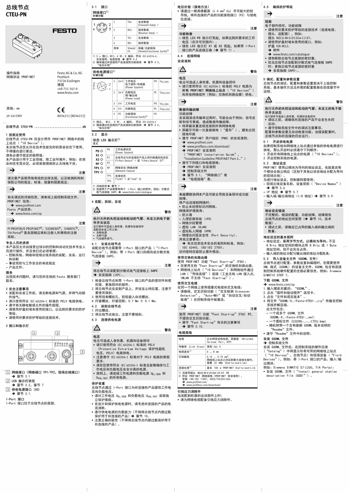
���� CTEU-PN zh. . . . . . . . . . . . . . . . . . . . . . . . . . . .
1 ����
���� CTEU-PN ����� PROFINET ���
��� (“IO Device”)。
������� ������������,
����� 。
����������。
������ ����。������,��:��
�������,������ ! �"!"。
�..................................
�##���$%&$'$�,�(%&'(�
�))*��、*+、�+�,-��。
�..................................
%.,-./�/,�00�112233�。
PROFINET �/:
� www.profinet.comFesto ���/:
� www.festo.com/sp
�..................................
PI PROFIBUS PROFINET®,SIEMENS®,SIMATIC®,
TIA Portal® 45,46�*#7�89%#7
�*。
���� ��
����� 5:;6<712��=>�����
?��@�,A���8��BC:
� 1223、��9D��23�:、E�、;�
�<F
� �G= ���EH%&��
� ��3�。
��
I9��>�J,��K8�$ Festo ?�@A
B2。
2 �����
� �:�E���L,�.F"C�DC,AMD=@
�ND。
� �O�E� IEC 60204-1 *+ PELV "F�"。
� ��%.G"PQ��@��H。
� ��RISTJ�:U,�KV8LM R
N1。
� ��8LM RN1O:��。
3 �����
2
3
1
1 ���(��� TP1/TP2,�����)
� +� 3.1
2 LED ��� !
� +� 3.2,+� 7
3 ""#� (X0)
� +� 3.1.
I-Port �
I-Port :U� ����W@。
3.1 �
���1)
$%�&
1 TD+ XPYZ(Transmit Data) +
2 RD+ :[YZ(Receive Data) +
3 TD– XPYZ –
4 RD– :[YZ –
\! Shield/FE
]Q/^�:$(Shield/Functional Earth)2)
1) 2 x _U、M12、4 R、D ST、E� IEC 61076-2;E�+`、"U�V � +� 4.4
2) W�X68O:��O:V^�:$ � +� 4.3,“"�Y"”
""#�1)
$%�&
1 24 V ��"a"b@�/#Qc(Power System)
PS UEL/SEN
2 24 V Z["a\/]I^(Power Load)
PL UVAL/OUT
3 0 V ��"a PS UEL/SEN
4 0 V Z["a PL UVAL/OUT
5 FE ^�:$(Functional Earth)2)
FE
1) _d、 M12、 5 R、 A ST、 E� IEC 61076-22) W�X68O:��O:V^�:$ � +� 4.3,
“"�Y"”
3.2 '�
! LED ���1)
(�
PS ��"C�(Power System)
X1 �����8O:��$_e@X��(“I-Port Device” 1 f “I-Port Device” 2)2)
X2
NF ��/�G`(Network Failure)
TP1 O:�(“Link” 1 ( “Link” 2)
TP2
1) ./�/� +� 72) O:%&��aLg%& I-Port :Ub�,��:hij"DO:c CAPC � www.festo.com/catalogue
4 )&、*�、�)
+,..................................
-.�� /01��2� 34、5�� "67
�8� !;�@�kdl�e'm,'c��nop�:fE���$L:� .F"C� .FDC� D=@�ND。
4.1 �)����
�:����aLg I-Port :U�� (“I-Port
Device”),��:g I-Port :U\qfhij"
DO:c CAPC。
�..................................
M�����:Vhij"DO:c� CAPC
� E�rs CAPC-...
1.%f�����g I-Port :U��tS��t
Sg。�uop@�。
2.M����E�V���,Avh!i�j,##
Lw*x。
3.�9%kly,mmz{�|k,。
4.}nk,。}n~o:0.7 Nm ± 0.1 Nm。
4.2 *�����
1.}Ik,。
2.M�����I,##L*x。
4.3 9�""#
+,..................................
"�
"�kdl�e'm,'c��nop
� �O�E� IEC�60204-1 *+ PELV
(Protective Extra-Low Voltage �R�p6
"a,PELV)"F�"。
� ##�� IEC�60204-1 *+� PELV "F��
LM。
� �K��E� IEC�60204-1 *+���W���
�"a�Z["aEHhq"C。
� �`�,�O:��"C�Z["C UEL/SEN �
UVAL/OUT 8%"F。
�:);
����X6 I-Port :U88O:������"
a�Z["a。
� ����"a UEL/SEN �Z["a UVAL/OUT ��r
s�R��。
� �����R�""CJ,�tu8O:��"
vwx。
� ���""CZ[��(M����e@6[
�R� 8O:��)� +� 10。
� ##yW��(M����e@6[�R�
8O:��)。
"�<�(�=>?)
� �X69z�{�g (� 4 mm2 Cu) �k��|��,M8O:��^�:$:U (FE) �$"
�O:。
�..................................
�@AB
� }~ LED PS r��:�,��KV8LM��
"a(� k��e)。
� }~ LED r�� X1 f X2 :�,��g I-Port
:U��O:yW(� +� 7)。
4.4 9���
�)��
+,..................................
"�
"�kdl�e'm,'c��nop
� �O�E� IEC�60204-1 *+ PELV "F8
CD PROFINET ����E� (“IO Devices”)
�w����(��:;u'�F5c)�"。
�..................................
FG�HIJ
^�G`
E���f#]�6�J,k�<5 ��:���
������,dlYZ#]G`。
� M]Q�jO�O:V8%�"U
� ]Q�k�9��::$(“��”),��I9
:$�F
� �� PROFINET ���� (PNO) E�+`:
� www.profinet.com� www.profibus.com/download/� PROFINET E�+`
(“PROFINET Installation Guide”,
“Installation Guideline PROFINET Part 2…”)
� ����:U�"U�V:
� PROFINET E�+`
� 12233�
� +� 3.1,“�:U”�
� “"U�V”�。
�..................................
5KLMNO���k�<���nopf^�
G`。
M��O:V�J:
� !J����>�。
��R��%:
� ��
� {= �23 (IPS)
� �h���
� �� LAN (VLAN)
� ����� (VPN)
� ���>�EH� (Port Security)。
w�##��:
� %.�/��EH+`�*+,��:
IEC 62443,ISO/IEC 27001。
�>tT�� !#�? 。
��PQ�RST
� PROFINET ^�“Fast Start-up”(FSU):
� ����“Fast Start-up”;u'�F5c。
� ����� (“IO Devices”) ����X6
LAN(“��O:”)O:(�� � LAN :{�,
IWLAN ��“Fast Start-up”)。
���"U
��9&���_�j"U�;�"U:
� �W�,;���^�(“;�%& Crossover
Detection”,“Auto-MDI”f“�=;�/�=
%&”)�1223����。
�..................................
� PROFINET ^�“Fast Start-up”(FSU) J,
��;���^�。
� ��“Fast Start-up”%.##��
� +� 5.10.
"U�V
"U � �¡��"U,]Q¢ (ShieldedTwisted Pair,STP)
#] (Link Class) � Cat 5
"U�£1) 6 ... 8 mm
¡��g 0.14 ... 0.75 mm2;�����$_KV¤�O:¢¥J,aL 22 AWG (End-to-end-Link)
O:¢¥2) ¤¢ 100 m PROFINET End-to-end-Link
1) ¦�_d NECUMSD12G4C2ET J2) E� PROFINET ��V(PROFINET E�+`),
JZ ISO/IEC 11801,ANSI/TIA/EIA-568:� www.profinet.com� www.profibus.com/download/
W�X�YZ�
¦�:V'c;=@��J:
� �8�"U:n§�6�w��。
4.5 [�\:]^
�..................................
_R
"b@�op,^�G`
� ��8LM RN1O:��(O:"U、
_d、£:c),��:
_d NECU-M-S-D12G4-C2-ET。� ��RISTJ�:U,��:
RI ISK-M12:� b�
� www.festo.com/catalogue� ��¤�����W@tS�。
� �¦�����:Vhij"DO:c CAPC
J:�u����W@tS�
� E�rs CAPC-...
5 `a、&;�!Fb;
����,-、:j�0Y�j�¨ �112
23。©�@�ª$(8a:jYZ�«�+��
¥¬。
+,..................................
-.�� /01��2� 34、5�� "67
�8� !;�@�kdl�e'm,'c��nop
� ,-$L,�W�8O:��<X¦1
;=。
� ��12233��,-##��。
:j�0Y�j �=%f^�:¦��:jJ,
�����8O:K<;�。
5.1 8c""#
��1223������X6®r�""C��
�",§Q¯°J������¨±:
1.¯°8%�����"C (“IO Devices”)。
2.¯°1223"C。
5.2 =db�
PROFINET ��©²8�³$´��,Xµ4¥ª
&©²<rs¶6(�� w��²�$´h:8�³
9D��)。
8��$´��,12c`a�:
� 9D���n·«,�n¬«(“Device Names”)
� +� 5.6
� IP $´ � +� 5.7
� ]{^/]I^$´(I/O $´)� +� 5.9.
�..................................
=db�ef
�¸、��:j,^�G`,G`¹º
����$´_;�(� +� 10,��
YZ)。
� ,-$L,�W�»¼�]{^�]I^
Y®。
=db� gh��
� $´��:ij�>k,"lm#n$。¯
8 Bits $´_©²¼� 8 Bits f 1 Byte
$´_,[<�H¼�。
� ]{^$´h:�]I^$´h:o�。
5.3 n&bp'q� (GSDML q�)
������:j、0Y�j�SHJ,KaL�
XML Vj (GSDML) �n]3�。GSDML ½¾%O:
V1223°�:jH@�L�/,��:Siemens
SIMATIC STEP 7。
*r GSDML q�
� www.festo.com/sp1.]{¿±.²³:“GSDML”。
2.��“À��=H±”´�Á。
3.��“3��µ¶·�”。
4.M3�“GSDML-V...-Festo-CTEU- ...zip”#]h12
23A¸a¹。
º3�½¾:
� 9&fÂ& GSDML 3�
(GSDML-V...-Festo-CTEU- ...xml)� 9&Ã*3� (GSDML-...-...-CTEU.bmp)� »'bg9&¾%¤Ä GSDML ·�¥¬
“Readme”3�。
� ��“Readme”3��¥¬。
�) GSDML q�
� 12233�
E� GSDML 3�«,�1223°�¼Å
(“Catalog”) �MÆ�8%k������
(“IO Devices”,����)�9D�n (“Field
Devices”),��:g I-Port :U��、]{/]
I©²。
��:Siemens SIMATIC S7-1200,TIA Portal:
� E� GSDML 3�(“Install general station
description file (GSD)”)。
@�rs�ǽ PROFINET
�·:de
Festo AG & Co. KGPostfach73726 EsslingenÈ,
+49 711 347-0www.festo.com
zh 1411NH 8034211 [8034212]
����CTEU-PN
5.4 b;0+st,,uv�6�w
� 12233�
��:Siemens SIMATIC S7-1200,TIA Portal:
1.ɯ�n��¾Ã:
¾Ã (“View”) � ¡�“�n��”
(“Devices & networks”)。
2.ɯ�¾Ã (“Network view”)。
3.ɯ°�¼Å (“Catalog”)。
4.ɯ“2312c”(“PLC”) ¼Å。
5.M2312c (PLC/“CPU”) Ê{�¾Ã。
5.5 x7 PROFINET E� (“Station”)
� 12233�
��:Siemens SIMATIC S7-1200,TIA Portal:
1.ɯ�n��¾Ã(“Devices & networks”
� +� 5.4)。
2.ɯ�¾Ã (“Network view”)。
3.ɯ°�¼Å (“Catalog”)。
4.ɯ“w�9D�n”(“Other field devices”)
¼Å:
� “PROFINET IO”� “Valves”� “Festo AG
& Co. KG”� “Festo CTEU-PN”。
5.´Ë PROFINET ��Ã*,Ì���� CTEU-PN
Ã*,AMwÊ{�¾Ã。
6.ɯO:¾Ã:“Connections”。
7.O:���� CTEU-PN �1223:
������Ã*,��vav²,AMÍ*Êh2
312cÃ*。
8.´ËO::“Connections”� “PROFINET
IO-System”。
5.6 �&bp9y (“Device Name”)
� 12233�
X6�n·«,Kk��:������8O:��
(“I-Port Device”) ��$´��,��:�K�
=>H±�。
5.7 �&z;{ IP =d
� 12233�
X�1223<6�h: IP $´。
�..................................
� �� IP $´J,���©�$´���`,
��:&�f)Î$´���。
� %f IP $´��=>��k��。
� W�¿Ï� IP $´。
5.8 &;��bp (“I-Port Devices”)
� 12233�
��:Siemens SIMATIC S7-1200,TIA Portal:
1.ɯ�n��¾Ã(“Devices & networks”
� +� 5.4)。
2.ɯ�n¾Ã (“Device view”)。
3.ɯ°�¼Å (“Catalog”)。
4.ɯ“w�9D�n”(“Other field devices”)
¼Å。
5.:j9D�n
M8O:�� (“I-Port Devices”) Ã*Ê{
�nÀÁ (“Device overview”)。
5.9 ;{H&�/H>�?|=d,;{}~=d
� 12233�
X�1223<6�h:]{^/]I^$´$´(
<F$´。
5.10 b;“Fast Start-up”PROFINET �@
(“Fast Start-up”,FSU)
� 12233�
�..................................
�“Fast Start-up”(FSU) PROFINET ^�J,
@��;���^� (“Crossover Detection”,
“Auto-MDI”f“Autocrossover/
Autonegotiation”):
� �;���^�:
� �CD�����°�:j�
� ��ÂÐ (“Partner-Port”) °�:
j�。
Ã�;���^�^�,M«��:U TP2
RÄh:? 8“Crossover”。
� zZ TP2 �8O:���:URÄh
:,´ËO:"U:
� ^Uh:�BJ,� Crossover ¢"U
� ^Uh:@BJ,� Patch "U。
��:Siemens SIMATIC S7-1200,TIA Portal:
1.,��nÀÁ (“Device overview”):
ÅU“�¼�Æ”(“Project navigation”)
� �n (“Devices”) � �n¾Ã (“Device
view”) � �nÀÁ (“Device overview”)
� �� (“Module”) � “CTEU-PN”。
2.����“PN-IO Interface”。
3.,I:U´�:
ÅU“PN-IO Interface [Module]”� ÇÑ
(“Properties”) � ÀL (“General”)
� ÒÓ´� (“Advanced options”)
� :U´� (“Interface options”)。
4.��(ÉÈ):U´�“{Ô°=”(“Prioritized
start-up”)。
5.,I^U´�:
ÅU“PN-IO Interface [Module]”� ÇÑ
(“Properties”) � ÀL (“General”)
� ÒÓ´� (“Advanced options”)
� “Port 1 [X1 P1 R]”f“Port 2 [X1 P2 R]”
� ^U´� (“Port options”)。
6.�“O:”� (“Connection”) ��:U
(�^U)TP1 � TP2 ;���^�
(“Autonegotiation”)。
5.11 b;!F
� 12233�
Kk�X60Y�j,¸8O:����(“©²
0Y�j”),��:]{^ÕÖJ_、��×¢J
_、��É1(ÊX<F�/)、�jG`ØÙ
(“Fail-state”-Modus)。“I-Port Device”1 (X1)
�“I-Port Device”2 (X2) k�rs��0Y�j。
!F1) (�
�b;2)
��:“X��n 256DIO”(“Universal device 256DIO”)
Tool Change Mode ���u©j:� ��“Tool Change Mode”:�6HYZÚ|�,»À�h:]{�]IYZ$´_(��$´)–�8O:�� (“I-Port Device”) .,Ûº a? :jÌk�u8O:��(��:��)。
� Ã�“Tool Change Mode”:°=J%&V“I-Port Device”M6�V PROFINET :j�。�HYZÃË�]{�]IYZh:($´��)�¨ 8O:��。
Ü�8%<F�/ X6�ÊX<F�/ (“Suppressall diagnostics messages”)
Ü�<F�/“Z["aÌ”
X6�4) ÊX<F�/“Z["aÌ”3) (“Suppress missing loadvoltage diagnostics messages”)
Fail-state “Fail-state”©j��}�����8O:���X�I9G`J¶6:� Ï�]I^ (“Outputs reset”):]I^Ï�。
� ]I^“Hold last state”(“Outputs Hold last state”):]I^��¤«�。
´��j£� 8%]I^。“Fail-state”�jX£� “Ê”;�� (“Idle state”):� “Idle state”kX61223�M���j。1223ºJÝ “�'©j”。
� ]{YZ�“Idle state”�Í�#]。
I-Port bp!F2)
��:“X��n 256DIO”(“Universal device 256DIO”)
Byte 0 ... Byte 7 ����0YÎÞ � 8O:��3�
1) Siemens SIMATIC S7-1200,TIA Portal: ��0Y2) k�0Y�¨ 8O:��。3) É1]I^/\Z["aÏa UOUT/VAL (“Undervoltage
UOUT/VAL”)4) ¦8O:��É1Z["aA³����¹º�J,ß<
�¦<F�/“Z["aÌ”。
�..................................
�@AB
� LED NF r��.Ð(¦1223�����$_
G`X�J)。
� }~ LED TP1 f TP2 r��:�
(� +� 7)。
� Siemens SIMATIC S7-1200,TIA Portal:
�“]{^$´”(“I address”)
f“]I^$´”(“O address”) ��¾%$´
ÑÅ(]{^f]I^�à$´)。
� %&�����k��:
Ò®“��”� “Accessible devices”
� %fk���������¸�
(“Accessible devices in target subnet”)。
6 “Identification and Maintenance”
� 12233�
“Identification and Maintenance”(I&M) ^��
;2d��239�>���!�/。
�..................................
á=�Ä I&M ¥¬,��:����À��Ó�
�,k�<���*Ô¥¬%8âã。
7 }~
PS – �H"� !(Power System)
LED���
!�(�
}~ LED r��:�:� y�;��� ��"ay�(Ý � ��e)� Z["ay�(Ý � ��e) 1)
}~ LED r��ÕÖ(ÕÖ×�:1 Hz)� ��"a6 8a"a� Z["a6 8a"a 1)
� I-Port |F1)
LED r��ØÙ:� ��"ay�� ��"a6 <F^�8a¤6"a
1) ¦8O:��É1Z["aA³����¹º�J,ß<Æ�4.Z["a�。
X1 und X2 – �����C9� J�K� Q7�V ! (“I-Port Device” 1z“I-Port Device” 2)1)
LED���
!�(�
}~ LED r��:�:� y�;��� “I-Port Device”1 ( 2 »yWO:� ��"a�Z["ay�(Ý � ��e) 2)
}~ LED r��ÕÖ:� <F�� 23"CfÚä"CÏa� �����“I-Port Device”$_O:y�
Û~ LED r��:�:� “I-Port Device”»O:yW,[e@X�å�G`。
� ,-«O:}��“I-Port Device”�n(�1223�°�:j9�“I-PortDevice”�nfÜ I-Port æç��)
Û~ LED r��ÕÖ:� ,-JO:}��“I-Port Device”�n
(Ü I-Port æç��)� ���Û~ LED X1 r��ÕÖ:����e@G`
� ��Û~ X1 � X2 r���JÕÖ:��JO:����(hèaLO:9é“I-Port Device”�n)
LED r��ØÙ:� ��JO:����
1) O:%&��aLg%& I-Port :Ub�2) ¦8O:��É1Z["aA³����¹º�J,ß<Æ�4.Z["a�。
NF – �� !/��IJ (Network Failure)
LED���
!�(�
Û~ LED r��ÕÖ:� X�G`� 1223�����$_X�G`f�F
LED r��ØÙ:� y�;��� 1223�����$_X�y�
TP1/TP2 – 9� !(“Link”1 z“Link”2)
LED���
!�(�
}~ LED r��:�:� y�;��� �O:y�
%&}~ LED TP1 � TP2 r��ÕÖ:� 8}��8O:��(“©²��”),��:1223�°�:jfG`fêJ
LED r��ØÙ:� JO:�
8 �;
aÇÝ��。
9 ���
��/�W (�
FSU “ëÞ°=”(“Fast Start-up”)PROFINET ^�,X«8“{Ô°=(“Prioritized Start-up”) f“ëÞ¿Ä°=”;������©j,W�ëÞ°=(¿Ä°=)�����(“IO Devices”)
PROFIenergy PROFIenergy �����C���j
PROFINET © ��� ���9D��23,� �11223(�� PC、PLCf“IO Controller”)、�����(“IO Decives”)�9D�n(“Field Devices”),��:\qf=c$_YZ;u� www.profinet.com� www.profibus.com/download/� PROFINET 23¥¬�,��(6�(“PROFINET System Description,Technology and Application”)。
PLC kSHßà12c,X«82312cf¬«812c (“Programmable LogicController”,PLC)
10 ��FG
�..................................
8O:����YZ,�00��3�。
"3��
\! RN1(E� IEC 60529/EN 60529)
IP65/IP67 1)2)
"� R(JZ IEC 60204-1/EN 60204-1���:�_::á�R)
X6� PELV "F(Protective Extra-LowVoltage)
âq��"C UEL/SEN �:U X6ìac"vâq
(¤� 500 V)
"ãæç� (EMV)3)
� X�!"� í!"�
0ä9��î¬� www.festo.com
1) L�å�:����»�H�:,_d»_:�f�%RI。2) 8O:��k�Oæ¯ç6 RN1。3) ������ ����。������,��:���������,������ ! �"!"。
Y�Q���
íï��íð��(E� IEC 60068)1)
� ï=(è 2–6 @h)� ð�(è 2–27 @h)� ��ð�(è 2–27 @h)
R��gE���ñj�éE�ò¥N1 (SG) 1)
� �g:SG2;�ñj�é:SG1� �g:SG2;�ñj�é:SG1� �g��ñj�é:SG1
��2)
� åó/;]� ;�
–20 … +70 °C–5 … +50 °C
ë�R ���r�� X���ôe��,��õö。
ìÞ� \!� Íí� kl÷î M12� klï÷ M3� tS�� k,
RoHS ðñò>øòóôõö�÷�÷�øùúõûü
ùú� û� ¢� �
40 mm91 mm50 mm
¿®( ���©ü����)
94 g
1) ò¥N1¥¬ � “ï=�ð�ò¥N1”�2) 8O:��k�Oæ¯ç6ê¥��。
""#
�����8O:����"a 1)
� ���� )�
24 V DC18 … 30 V DC2)
�����8O:��Z["a 1)
� )â�� 18 … 30 V DC2)
�����"a 24 V DC J�e"vwx5 "b@�/#Qc��"a (UEL/SEN) �¦
*+ØÙ� 80 mA(e@"b@�)
��"C�Z["CZ[�� 1)3)
� 8O:��(��:\q)�����
� hij"DO:c����� CAPC¤� 4 A¤� 2 Apro “I-Port Device”4)
"CF"ýð 10 ms
1) ��"C�Z["CaL®r�@�)�j(����e@6[�R���ç��R� 8O:��)。
2) �â���¨ 8O:��。3) ��"C�Z["C�Zþ�� PS � PL(�"v),�����8O:��8� ¤�"vwx
4) ��"C�Z["C�Zþ�� PS � PL(�"v),ªé“I-Port Device”�n� ¤�"vwx
������
�ǽ PROFINET IO:� © ��� �� E�� �ǽ*+ (IEEE 802.3)
��ǽý��ǽ^�(´Ë)
� “þJ”��YZ;u, ����(Real-Time,RT) fg����(Isochronous Real Time,IRT)1)
� Link Layer Discovery Protocol(LLDP)
� Simple Network ManagementProtocol (SNMP)
� Fast Start-up (FSU)� PROFIenergy� Shared Device� Media Redundancy Protocol (MRP)
23./^� � <F�/(23<F、Ïa、X�G`)
� ��?�c(�����8O:���、±��、:j)
�V¥¬ %. PROFINET +`��`:� PROFINET E�+` (“PROFINET
Installation Guide”,“Installation GuidelinePROFINET Part 2…”)
� IEC 61158� IEC 61784� IEC 61918./�/:� www.profinet.com� www.profibus.com/download/
#]�� Switched Fast Ethernet;�V 100BaseTX E� IEEE 802.3
#]� 100 Mbit/s
�:U 2 x _U、M12、D ST、4 R
;���^�、�=Ç�
Auto-MDI
]{^/]I^¤�$´ç®
64 Bytes I,64 Bytes O,�;�©j .
1) IRT ��� LAN
D����Z[ �� – ��]^
���r
����
[Hz]
7��
[m/s2]
_��
[mm]
SG1 SG2 SG1 SG2 SG1 SG2
2 … 8 2 … 8 – – ±3.5 ±3.5
8 … 27 8 … 27 10 10 – –
27 … 58 27 … 60 – – ±0.15 ±0.35
58 … 160 60 … 160 20 50 – –
160 … 200 160 … 200 10 10 – –
Z[�r
7��
[m/s2]
� ¡�
[ms]
¢`>$
Z[
SG1 SG2 SG1 SG2 SG1 SG2
±150 ±300 11 11 5 5
� Z[�r
7��
[m/s2]
� ¡�
[ms]
¢`>$ Z[
±150 6 1000