
D GB D F NL Fx/ivd D
22
D F NL I E Alle in dieser Betriebsanleitung aufgeführten Tätigkeiten dürfen nur von autorisiertem Fachper- sonal ausgeführt werden! All the work set out in these operating instructions may only be completed by authorized trained personnel! Toutes les actions mentionnées dans les présentes instructions de service doivent être exécutées par des spécialistes formés et autori- sés uniquement ! ATTENTION ! Un montage, un ré- glage, une modification, une utilisa- tion ou un entretien inadaptés ris- quent d’engendrer des dommages matériels ou corporels. Lire les instructions avant utilisation. Cet appareil doit être installé en res- pectant les règlements en vigueur. Alle in deze bedrijfshandleiding vermelde werkzaamheden mo- gen alleen door technici worden uitgevoerd! WAARSCHUWING! Ondeskundi- ge inbouw, instelling, wijziging, bediening of onderhoudswerkzaam- heden kunnen persoonlijk letsel of materiële schade veroorzaken. Aanwijzingen voor het gebruik lezen. Dit apparaat moet overeenkom- stig de geldende regels worden geïnstalleerd. ATTENZIONE! Se montaggio, regolazione, modifica, utilizzo o manutenzione non vengono eseguiti correttamente, possono verificarsi infortuni o danni. Si prega di leggere le istruzioni prima di utilizzare il prodotto che dovrà ve- nire installato in base alle normative vigenti. ¡Todas las actividades indicadas en estas Instrucciones de utiliza- ción, sólo deben realizarse por una persona formada y autorizada! ¡ADVERTENCIA! La instalación, ajuste, modificación, manejo o man- tenimiento incorrecto puede ocasio- nar daños personales o materiales. Leer las instrucciones antes de usar. Este dispositivo debe ser instalado observando las normativas en vigor. TR CZ PL RUS H DK S N P GR ➔ www.docuthek.com 03250322 Edition 01.13 Fx/ivd Inhaltsverzeichnis Konformitätserklärung 2 SIL, PL 2 Prüfen 3 Einbauen 3 VAS mit Flanschen 4 VAS ohne Flansche 5 Verdrahten 5 Verdrahtung vorbereiten 5 Anschlussart 6 Elektrisch anschließen 6 Elektrisch anschließen mit Meldeschalter 7 Verdrahtung abschließen 8 Dichtheit prüfen 8 In Betrieb nehmen 9 Volumenstrom einstellen 9 Startgasmenge einstellen 9 Antrieb wechseln 9 VAS ohne Dämpfung 9 VAS mit Dämpfung 10 Dämpfung austauschen 11 Wartung 12 Zubehör 13 Gas-Druckwächter DG..VC einstellen 13 Bypass-/Zündgasventile 14 Kabeldurchführungsset für Doppelblockventil 18 Anbaublock 18 Flanschset für Moduline 19 Dichtungsset VA 1 – 3 19 Technische Daten 20 Lebensdauer 22 Gas-Magnetventil VAS Betriebsanleitung Bitte lesen und aufbewahren Zeichenerklärung , , , ... = Tätigkeit ➔ = Hinweis Solenoid valve for gas VAS Operating instructions Please read and keep in a safe place Explanation of symbols , , , ... = Action ➔ = Instruction Électrovanne gaz VAS Instructions de service À lire attentivement et à conserver Légendes , , , ... = action ➔ = remarque Gasmagneetklep VAS Bedieningsvoorschrift Lezen en goed bewaren a.u.b. Legenda , , , ... = werkzaamheden ➔ = aanwijzing Valvola elettromagne- tica gas VAS Istruzioni d’uso Si prega di leggere e conser- vare Spiegazione dei simboli , , , ... = Operazione ➔ = Avvertenza Válvula electromagné- tica para gas VAS Instrucciones de utili- zación Se ruega que las lean y conser- ven Explicación de símbolos , , , ... = Actividad ➔ = Indicación Contents Declaration of conformity 2 SIL, PL 2 Testing 3 Installation 3 VAS with flanges 4 VAS without flanges 5 Wiring 5 Preparing the wiring 5 Type of connection 6 Electrical connection 6 Electrical connection on units with proof of closure switch 7 Finishing the wiring 8 Tightness test 8 Commissioning 9 Setting the flow rate 9 Setting the start gas rate 9 Replacing the actuator 9 VAS without damping 9 VAS with damping 10 Replacing the damping unit 11 Maintenance 12 Accessories 13 Setting the pressure switch for gas DG..VC 13 Bypass/pilot gas valves 14 Cable gland set for double block valve 18 Attachment block 18 Flange set for Moduline 19 Seal set VA 1 – 3 19 Technical data 20 Designed lifetime 22 Sommaire Déclaration de conformité 2 SIL, PL 2 Vérifier 3 Montage 3 VAS à brides 4 VAS sans brides 5 Câblage 5 Préparer le câblage 5 Type de raccordement 6 Raccordement électrique 6 Raccordement électrique avec indicateur de position 7 Terminer le câblage 8 Vérifier l’étanchéité 8 Mise en service 9 Réglage du débit 9 Réglage du débit initial 9 Remplacer la bobine 9 VAS sans amortisseur 9 VAS avec amortisseur 10 Remplacer l’amortisseur 11 Maintenance 12 Accessoires 13 Réglage du pressostat gaz DG..VC 13 Vannes de by-pass / pilote 14 Kit presse-étoupe pour bloc vannes double 18 Bloc de montage 18 Jeu de bride pour Moduline 19 Jeu de joints VA 1 – 3 19 Caractéristiques techniques 20 Durée de vie prévue 22 Inhoudsopgave Verklaring van overeenstemming 2 SIL, PL 2 Controleren 3 Inbouwen 3 VAS met flenzen 4 VAS zonder flenzen 5 Bedraden 5 Bedrading voorbereiden 5 Type aansluiting 6 Elektrisch aansluiten 6 Elektrisch aansluiten met eindschakelaar 7 Bedrading afsluiten 8 Lektest 8 In bedrijf stellen 9 Volumestroom instellen 9 Hoeveelheid startgas instellen 9 Aandrijving wisselen 9 VAS zonder demping 9 VAS met demping 10 Demper vervangen 11 Onderhoud 12 Toebehoren 13 Gasdrukschakelaar DG..VC instellen 13 Bypass-kleppen/ aansteekgaskleppen 14 Kabeldoorvoerset voor duoblokklep 18 Aanbouwblok 18 Flensset voor Moduline 19 Afdichtingsset VA 1 – 3 19 Technische gegevens 20 Levensduur 22 Indice Dichiarazione di conformità 2 SIL, PL 2 Verifica 3 Montaggio 3 VAS con flange 4 VAS senza flange 5 Cablaggio 5 Predisposizione del cablaggio 5 Tipo di collegamento 6 Collegamento elettrico 6 Collegamento elettrico con fine corsa 7 Ultimazione del cablaggio 8 Controllo della tenuta 8 Messa in servizio 9 Regolazione della portata 9 Regolazione della quantità di gas iniziale 9 Sostituzione dell’attuatore 9 VAS senza smorzatore 9 VAS con smorzatore 10 Sostituzione dello smorzatore 11 Manutenzione 12 Accessori 13 Regolazione del pressostato gas DG..VC 13 Valvole di bypass/valvole del gas pilota 14 Set passacavo per blocco a doppia valvola 18 Blocco di assemblaggio 18 Set flangia per Moduline 19 Set di tenuta VA 1 – 3 19 Dati tecnici 20 Durata di vita di progetto 22 Índice Declaración de conformidad 2 SIL, PL 2 Comprobar 3 Montaje 3 VAS con bridas 4 VAS sin bridas 5 Cableado 5 Preparar el cableado 5 Tipo de conexión 6 Instalación eléctrica 6 Instalación eléctrica en válvulas con indicador de posición 7 Terminar el cableado 8 Comprobar la estanquidad 8 Puesta en funcionamiento 9 Ajustar el caudal 9 Ajustar la cantidad de gas inicial 9 Cambiar el actuador 9 VAS sin amortiguación 9 VAS con amortiguación 10 Cambiar el amortiguador 11 Mantenimiento 12 Accesorios 13 Ajustar el presostato para gas DG..VC 13 Válvulas de bypass o de gas de encendido 14 Set pasacables para válvula de bloque doble 18 Bloque de montaje 18 Set de brida para Moduline 19 Set de juntas VA 1 – 3 19 Datos técnicos 20 Vida útil 22 GB - 1 - WARNUNG! Unsachgemäßer Einbau, Einstellung, Veränderung, Bedienung oder Wartung kann Verletzungen oder Sachschäden verursachen. Anleitung vor dem Gebrauch lesen. Dieses Gerät muss nach den gelten- den Vorschriften installiert werden. Tutte le operazioni indicate nelle presenti istruzioni d’uso devono essere eseguite soltanto dal pre- posto esperto autorizzato! WARNING! Incorrect installation, adjustment, modification, operation or maintenance may cause injury or material damage. Read the instructions before use. This unit must be installed in accor- dance with the regulations in force.
Transcript of D GB D F NL Fx/ivd D
D
GB
F
NL
I
E
D
GB
F
NL
I
E
D
GB
F
NL
I
E
D
GB
F
NL
I
E
D
GB
F
NL
I
E
Alle in dieser Betriebsanleitung aufgeführten Tätigkeiten dürfen nur von autorisiertem Fach personal ausgeführt werden!
All the work set out in these operating instructions may only be completed by authorized trained personnel!
Toutes les actions mentionnées dans les présentes instructions de service doivent être exécutées par des spécialistes formés et autorisés uniquement !
ATTENTION ! Un montage, un réglage, une modi fication, une utilisation ou un entretien in adaptés risquent d’engendrer des dom mages matériels ou corporels. Lire les instructions avant utilisation. Cet appareil doit être installé en respectant les règlements en vigueur.
Alle in deze bedrijfshandleiding vermelde werkzaamheden mogen alleen door technici worden uitgevoerd!
WAARSCHUWING! Ondeskundige inbouw, instelling, wijziging, bediening of onder houds werk zaamheden kunnen per soonlijk letsel of materiële schade veroor zaken.Aanwijzingen voor het gebruik lezen. Dit apparaat moet overeenkomstig de geldende regels worden geïnstalleerd.
ATTENZIONE! Se montaggio, re go lazione, modifica, utilizzo o manu tenzione non vengono ese guiti correttamente, possono veri ficarsi infortuni o danni.Si prega di leggere le istruzioni prima di utilizzare il prodotto che dovrà venire installato in base alle normative vigenti.
¡Todas las actividades indicadas en estas Instrucciones de utilización, sólo deben realizarse por una persona formada y autorizada!
¡ADVERTENCIA! La instalación, ajuste, modificación, manejo o mantenimiento incorrecto puede ocasionar daños personales o mate riales.Leer las instrucciones antes de usar. Este dispositivo debe ser instalado observando las normativas en vigor.
TR CZ PL RUS H
DK S N P GR
� www.docuthek.com
03250322 Edition 01.13Fx/iv
d
InhaltsverzeichnisKonformitätserklärung 2SIL, PL 2Prüfen 3Einbauen 3VAS mit Flanschen 4VAS ohne Flansche 5Verdrahten 5Verdrahtung vorbereiten 5Anschlussart 6Elektrisch anschließen 6Elektrisch anschließen mit Meldeschalter 7Verdrahtung abschließen 8Dichtheit prüfen 8In Betrieb nehmen 9Vo lumenstrom einstellen 9Startgasmenge einstellen 9Antrieb wechseln 9VAS ohne Dämpfung 9VAS mit Dämpfung 10Dämpfung austauschen 11Wartung 12Zubehör 13Gas-Druckwächter DG..VC einstellen 13Bypass-/Zündgasventile 14Kabeldurchführungsset für Doppelblockventil 18Anbaublock 18Flanschset für Moduline 19Dichtungsset VA 1 – 3 19Technische Daten 20Lebensdauer 22
Gas-Magnetventil VAS
Betriebsanleitung Bitte lesen und aufbewahren
Zeichenerklärung, , , ... = Tätigkeit➔ = Hinweis
Solenoid valve for gas VAS
Operating instructions Please read and keep in a safe
place
Explanation of symbols, , , ... = Action➔ = Instruction
Électrovanne gaz VAS
Instructions de serviceÀ lire attentivement et à
conserver
Légendes, , , ... = action➔ = remarque
Gasmagneetklep VAS
Bedieningsvoorschrift Lezen en goed bewaren a.u.b.
Legenda, , , ... = werkzaamheden➔ = aanwijzing
Valvola elettromagne-tica gas VAS
Istruzioni d’uso Si prega di leggere e conser-
vare
Spiegazione dei simboli, , , ... = Operazione➔ = Avvertenza
Válvula electromagné-tica para gas VAS
Instrucciones de utili-zación Se ruega que las lean y conser-
ven
Explicación de símbolos, , , ... = Actividad➔ = Indicación
ContentsDeclaration of conformity 2SIL, PL 2Testing 3Installation 3VAS with flanges 4VAS without flanges 5Wiring 5Preparing the wiring 5Type of connection 6Electrical connection 6Electrical connection on units with proof of closure switch 7Finishing the wiring 8Tightness test 8Commissioning 9Setting the flow rate 9Setting the start gas rate 9Replacing the actuator 9VAS without damping 9VAS with damping 10Replacing the damping unit 11Maintenance 12Accessories 13Setting the pressure switch for gas DG..VC 13Bypass/pilot gas valves 14Cable gland set for double block valve 18Attachment block 18Flange set for Moduline 19Seal set VA 1 – 3 19Technical data 20Designed lifetime 22
SommaireDéclaration de conformité 2SIL, PL 2Vérifier 3Montage 3VAS à brides 4VAS sans brides 5Câblage 5Préparer le câblage 5Type de raccordement 6Raccordement électrique 6Raccordement électrique avec indicateur de position 7Terminer le câblage 8Vérifier l’étanchéité 8Mise en service 9Réglage du débit 9Réglage du débit initial 9Remplacer la bobine 9VAS sans amortisseur 9VAS avec amortisseur 10Remplacer l’amortisseur 11Maintenance 12Accessoires 13Réglage du pressostat gaz DG..VC 13Vannes de by-pass / pilote 14Kit presse-étoupe pour bloc vannes double 18Bloc de montage 18Jeu de bride pour Moduline 19Jeu de joints VA 1 – 3 19Caractéristiques techniques 20Durée de vie prévue 22
InhoudsopgaveVerklaring van overeenstemming 2SIL, PL 2Controleren 3Inbouwen 3VAS met flenzen 4VAS zonder flenzen 5Bedraden 5Bedrading voorbereiden 5Type aansluiting 6Elektrisch aansluiten 6Elektrisch aansluiten met eindschakelaar 7Bedrading afsluiten 8Lektest 8In bedrijf stellen 9Volumestroom instellen 9Hoeveelheid startgas instellen 9Aandrijving wisselen 9VAS zonder demping 9VAS met demping 10Demper vervangen 11Onderhoud 12Toebehoren 13Gasdrukschakelaar DG..VC instellen 13Bypass-kleppen/aansteekgaskleppen 14Kabeldoorvoerset voor duoblokklep 18Aanbouwblok 18Flensset voor Moduline 19Afdichtingsset VA 1 – 3 19Technische gegevens 20Levensduur 22
IndiceDichiarazione di conformità 2SIL, PL 2Verifica 3Montaggio 3VAS con flange 4VAS senza flange 5Cablaggio 5Predisposizione del cablaggio 5Tipo di collegamento 6Collegamento elettrico 6Collegamento elettrico con fine corsa 7Ultimazione del cablaggio 8Controllo della tenuta 8Messa in servizio 9Regolazione della portata 9Regolazione della quantità di gas iniziale 9Sostituzione dell’attuatore 9VAS senza smorzatore 9VAS con smorzatore 10Sostituzione dello smorzatore 11Manutenzione 12Accessori 13Regolazione del pressostato gas DG..VC 13Valvole di bypass/valvole del gas pilota 14Set passacavo per blocco a doppia valvola 18Blocco di assemblaggio 18Set flangia per Moduline 19Set di tenuta VA 1 – 3 19Dati tecnici 20Durata di vita di progetto 22
ÍndiceDeclaración de conformidad 2SIL, PL 2Comprobar 3Montaje 3VAS con bridas 4VAS sin bridas 5Cableado 5Preparar el cableado 5Tipo de conexión 6Instalación eléctrica 6Instalación eléctrica en válvulas con indicador de posición 7Terminar el cableado 8Comprobar la estanquidad 8Puesta en funcionamiento 9Ajustar el caudal 9Ajustar la cantidad de gas inicial 9Cambiar el actuador 9VAS sin amortiguación 9VAS con amortiguación 10Cambiar el amortiguador 11Mantenimiento 12Accesorios 13Ajustar el presostato para gas DG..VC 13Válvulas de bypass o de gas de encendido 14Set pasacables para válvula de bloque doble 18Bloque de montaje 18Set de brida para Moduline 19Set de juntas VA 1 – 3 19Datos técnicos 20Vida útil 22
D
GB
F
NL
I
E
- 1 -
WARNUNG! Unsachgemäßer Ein bau, Einstellung, Verän de rung, Be die nung oder War tung kann Ver letzungen oder Sachschäden verursachen.Anleitung vor dem Gebrauch lesen. Dieses Gerät muss nach den gelten-den Vorschriften installiert werden.
Tutte le operazioni indicate nelle presenti istruzioni d’uso devono essere eseguite soltanto dal pre-posto esperto autorizzato!
WARNING! Incorrect installation, adjustment, modification, operation or maintenance may cause injury or material damage.Read the instructions before use. This unit must be installed in accor-dance with the regulations in force.
- 2 -
KonformitätserklärungWir erklären als Hersteller, dass die Produkte VAS, gekennzeichnet mit der Produkt-ID-Nr. CE-0063BO1580 die grundlegenden Anforderungen fol-gender Richtlinien erfüllen:– 2009/142/EG in Verbindung mit
EN 13611, EN 161, EN 88-1, EN 126 und EN 1854,
– 2006/95/EG,– 2004/108/EG.Das entsprechend gekennzeichnete Produkt stimmt überein mit dem bei der zugelassenen Stelle 0063 geprüf-ten Baumuster.Die Herstellung unterliegt dem Über-wachungsverfahren nach Richtlinie 2009/142/EG gemäß Anhang II, Absatz 3.Elster GmbH
Scan der Konformitätserklärung (D, GB) – siehe www.docuthek.comSIL, PLDas Gerät VAS 1 ist in Abhängig-keit von der Anforderungshäufig-keit nop (mittlere Anzahl jährlicher Betätigungen) geeignet, um ein sicherheitsgerichtetes System mit einem Ventil bis SIL 2 (PL d) und mit zwei Ventilen in Reihe bis SIL 3 (PL e) aufzubauen, wobei die jewei-lige Sicherheitsfunk tion des Schutz-systems die Anforderungen der DIN EN 61508 bzw. DIN EN 62061 oder DIN EN ISO 13849 erfüllen muss. Beim Einsatz des VAS 1 ist der PFHD-Wert der Sicherheitsfunktion zu beachten und gegebenenfalls eine mehrkanalige Struktur vorzusehen.Die Aussage gilt für einen Zeitraum von nicht mehr als 10 Jahren, be-ginnend ab dem Produktionsdatum, bei Einhaltung aller vom Hersteller genannten sicherheitsrelevanten Betriebsbedingungen. Eine Lagerung von bis zu 0,5 Jahren vor erstmaligem Einsatz beeinflusst das Betriebsver-halten nicht negativ. Die maximale Anzahl von Schaltspielen ist auf den B10d-Wert (mittlere Anzahl von Zyklen, bis 10 % der Geräte gefährlich aus-gefallen sind, B10d-Wert = 9.725.220 Schaltspiele) begrenzt.
FM-zugelassen*Factory Mutual (FM) Research Klasse: 7400 und 7411 Sicherheitsabsperr-ventile. Passend für Anwendungen gemäß NFPA 85 und NFPA 86.ANSI/CSA-zugelassen*Canadian Standards Association – ANSI Z21.21 und CSA 6.5UL-zugelassen*Underwriters Laboratories – UL 429 „Electrically operated valves“.AGA-zugelassen*Australian Gas Association
Verklaring van over-eenstemmingWij verklaren als fabrikant dat de pro-ducten VAS, gemerkt met het product-identificatienummer CE-0063BO1580, aan de fundamentele voorschriften van de volgende richtlijnen voldoen:– 2009/142/EG in combinatie met
EN 13611, EN 161, EN 88-1, EN 126 en EN 1854,
– 2006/95/EG,– 2004/108/EG.Het overeenkomstig geïdentificeerde product komt overeen met het door de aangewezen instantie 0063 ge-controleerde type.De productie is volgens de con-troleprocedure conform de richtlijn 2009/142/EG overeenkomstig bij-lage II, lid 3.Elster GmbH
Scan van de overeenstem-mingsverklaring (D, GB) – zie www.docuthek.comSIL, PLHet apparaat VAS 1 is afhankelijk van de vereiste schakelfrequentie nop (gemiddeld aantal schakelingen per jaar) geschikt om met een klep een op veiligheid gericht systeem tot SIL 2 (PL d) en met twee kleppen in serie tot SIL 3 (PL e) op te bou-wen, waarbij de betreffende veiligheids-functie van het veiligheidssysteem aan de eisen conform DIN EN 61508, resp. DIN EN 62061 of DIN EN ISO 13849 moet voldoen. Bij gebruik van de VAS 1 moet met de PFHD-waarde van de veilig-heidsfunctie rekening gehouden worden en moet eventueel een meerkanaalsstruc-tuur worden aangebracht.Die verklaring geldt voor een periode van maximaal 10 jaar, te beginnen vanaf de productiedatum, bij inachtneming van alle door de fabrikant vermelde veiligheidsre-levante bedrijfsvoorwaarden. Opslag van maximaal 0,5 jaar voordat het apparaat voor het eerst gebruikt wordt, beïnvloedt de werking niet negatief. Het maximale aantal schakelcycli is begrensd tot de B10d-waarde (gemiddeld aantal cycli, tot 10% van de apparaten gevaarlijk uit-gevallen zijn, B10d-waarde = 9.725.220 schakelcycli).
FM goedgekeurd*Factory Mutual (FM) Research klasse: 7400 en 7411 afslagveiligheden (veilig-heidskleppen). Passend voor toepas-singen conform NFPA 85 en NFPA 86.ANSI/CSA goedgekeurd*Canadian Standards Association – ANSI Z21.21 en CSA 6.5UL goedgekeurd*Underwriters Laboratories – UL 429 “Electri-cally operated valves” (Elektrische kleppen).
AGA goedgekeurd*Australian Gas Association
Déclaration de conformitéEn tant que fabricant, nous déclarons que les produits VAS, identifiés par le numéro de produit CE-0063BO1580, répondent aux exigences essentielles des directives suivantes :– 2009/142/CE en association avec
EN 13611, EN 161, EN 88-1, EN 126 et EN 1854,
– 2006/95/CE,– 2004/108/CE.Le produit marqué en conséquence est conforme au type éprouvé auprès de l’organisme notifié 0063.La fabrication est soumise au procédé de surveillance selon annexe II, para-graphe 3 de la directive 2009/142/CE.Elster GmbH
Déclaration de conformité scannée (D, GB) – voir www.docuthek.comSIL, PLEn fonction du taux de sollicitation nop (nombre moyen d’activations annuelles), l’appareil VAS 1 est adapté pour installer un système relatif à la sécurité jusqu’à SIL 2 (PL d) avec une vanne et jusqu’à SIL 3 (PL e) avec deux vannes en série, la fonction de sécurité concernée du système de protection doit dans ce cas satisfaire aux exigences de la norme DIN EN 61508 ou bien DIN EN 62061 ou DIN EN ISO 13849. En cas d’utilisation de VAS 1, la valeur PFHD de la fonction de sécurité doit être prise en compte et une structure à plusieurs canaux doit être prévue si nécessaire.Ceci s’applique pour une durée ne dépas-sant pas 10 ans à compter de la date de production, sous réserve du respect de toutes les conditions de fonctionnement relevant de la sécurité qui ont été définies par le fabricant. Un stockage pendant au plus 0,5 an avant la première mise en service n’a aucune influence négative sur le comportement en service. Le nombre maximum de cycles de manœuvre est limité au valeur B10d (nombre moyen de cycles jusqu’à ce que 10 % des appa-reils présentent une défaillance dange-reuse, valeur B10d = 9 725 220 cycles de manœuvre).
Homologation FM*Classe Factory Mutual (FM) Research : 7400 et 7411 Clapets de sécurité. Conviennent pour des applications conformes à NFPA 85 et NFPA 86.Homologation ANSI / CSA*Canadian Standards Association – ANSI Z21.21 et CSA 6.5Homologation UL* Underwriters Laboratories – UL 429 « Electrically operated valves » (Vannes à commande électrique).Homologation AGA* Australian Gas Association
Dichiarazione di conformitàDichiariamo in qualità di produttori che i prodotti VAS, contrassegnati con il nu-mero di identificazione del prodotto CE-0063BO1580, rispondono ai requisiti essenziali posti dalle direttive seguenti:– 2009/142/CE unitamente a
EN 13611, EN 161, EN 88-1, EN 126 ed EN 1854,
– 2006/95/CE,– 2004/108/CE.Il prodotto con tale contrassegno cor-risponde al tipo esaminato dall’organi-smo notificato 0063.La produzione è sottoposta alla procedura di sorveglianza in base all’allegato II, comma 3 della direttiva 2009/142/CE.Elster GmbH
Scansione della dichiarazione di conformità (D, GB) – vedi www.docuthek.comSIL, PLIn funzione della frequenza di richiesta nop (numero medio di operazioni in un anno), l’apparecchio VAS 1 si presta per allestire un sistema di sicurezza fino a SIL 2 (PL d) con una valvola e fino a SIL 3 (PL e) con due valvole in serie, mentre la funzione di sicurezza corrispondente del sistema di sicu-rezza deve soddisfare i requisiti della DIN EN 61508, ovvero DIN EN 62061 o DIN EN ISO 13849. In caso d’impie-go con VAS 1 tenere conto del valore PFHD della funzione di sicurezza ed eventualmente prevedere una strut-tura a più canali.La dichiarazione vale per un periodo di tempo non superiore a 10 anni a partire dalla data di produzione nel rispetto di tutte le condizioni di eser-cizio in materia di sicurezza, elencate dal costruttore. Uno stoccaggio fino a sei mesi, antecedente il primo uti-lizzo, non influisce negativamente sul comportamento in funzionamento. Il numero massimo di cicli di commu-tazione è delimitato dal valore B10d (numero medio di cicli dopo i quali il 10 % degli apparecchi si è danneg-giato pericolosamente, valore B10d = 9.725.220 cicli di commutazione).
Approvazione FM* Classe Factory Mutual (FM) Research: 7400 e 7411 valvole di sicurezza di blocco. Applicabile per utilizzi secon-do NFPA 85 e NFPA 86.Approvazione ANSI/CSA* Canadian Standards Association – ANSI Z21.21 e CSA 6.5Approvazione UL* Underwriters Laboratories – UL 429 “Electrically operated valves” (Valvole ad azionamento elettrico).Approvazione AGA* Australian Gas Association
Declaración de conformidadNosotros, el fabricante, declaramos que los productos VAS identificados por el Nº ID de producto CE-0063BO1580 cumplen con los requisitos básicos de las siguientes Directivas:– 2009/142/CE en relación con
EN 13611, EN 161, EN 88-1, EN 126 y EN 1854,
– 2006/95/CE,– 2004/108/CE.El producto correspondientemente mar-cado coincide con el modelo constructivo ensayado en el Organismo Notificado 0063.La fabricación está sometida al proce-dimiento de control según el Anexo II, Párrafo 3 de la Directiva 2009/142/CE.Elster GmbH
Exploración de la declaración de conformidad (D, GB) – ver www.docuthek.comSIL, PLEl dispositivo VAS 1, en función de la fre-cuencia de demanda nop (número medio de activaciones anuales), es apropiado para construir un sistema para la segu-ridad hasta SIL 2 (PL d) con una válvula y hasta SIL 3 (PL e) con dos válvulas en serie, cumpliendo la función respectiva de seguridad del sistema de protección con los requisitos de la DIN EN 61508, o bien DIN EN 62016 o DIN EN ISO 13849. Al utilizar la VAS 1 se debe tener en cuenta el valor PFHD de la función de seguridad y, en su caso, prever una estructura de varios canales.Esto tiene validez para un periodo de tiempo inferior a 10 años a partir de la fecha de producción respetando todas las condiciones de servicio importantes para la seguridad mencionadas por el fabricante. Un almacenamiento inferior a medio año antes del primer uso no influ-ye negativamente en el funcionamiento. El número máximo de maniobras está limitado al valor B10d (número medio de ciclos hasta que se haya producido un fallo peligroso del 10 % de los dispositivos, valor B10d = 9.725.220 maniobras).
Aprobación FM*Clase Factory Mutual (FM) Research: 7400 y 7411 válvulas de interrupción de seguridad. Apta para aplicaciones según NFPA 85 y NFPA 86.Aprobación ANSI/CSA*Canadian Standards Association – ANSI Z21.21 y CSA 6.5Aprobación UL* Underwriters Laboratories – UL 429 “Electrically operated valves” (Válvulas con actuador eléctrico).Aprobación AGA*Australian Gas Association
Declaration of conformityWe, the manufacturer, hereby declare that the products VAS, marked with product ID No. CE-0063BO1580, comply with the essential require-ments of the following Directives:– 2009/142/EC in conjunction with
EN 13611, EN 161, EN 88-1, EN 126 and EN 1854,
– 2006/95/EC,– 2004/108/EC.The relevant product corresponds to the type tested by the notified body 0063.The production is subject to the surveillance procedure pursuant to Directive 2009/142/EC according to annex II, paragraph 3.Elster GmbH
Scan of the Declaration of conformity (D, GB) – see www.docuthek.comSIL, PLDepending on the demand rate nop (mean number of annual operations), VAS 1 is suitable for constructing a safety-related system up to SIL 2 (PL d) using a single valve, and up to SIL 3 (PL e) when two valves are installed in series, whereby the relevant safety function of the pro-tective system must comply with the requirements of DIN EN 61508 or DIN EN 62061/DIN EN ISO 13849. When using VAS 1, the PFHD value of the safety function must be observed and a multi-channel structure must be provided if necessary.This information is valid for a period of not more than 10 years, beginning at the date of production, if all the safety-relevant operating conditions specified by the manufacturer are complied with. Storing the device for up to 6 months before it is used for the first time does not have a negative impact on its operating characteris-tics. The maximum number of operat-ing cycles is limited to the B10d value (mean number of cycles until 10% of the devices fail dangerously, B10d value = 9,725,220 operating cycles).
FM approved* Factory Mutual (FM) Research Class: 7400 and 7411 Safety overpressure slam shut valves. Designed for ap-plications pursuant to NFPA 85 and NFPA 86.ANSI/CSA approved* Canadian Standards Association – ANSI Z21.21 and CSA 6.5UL listed*Underwriters Laboratories – UL 429 “Electrically operated valves”.AGA approved*Australian Gas Association
AGA
Zulassung für Russland*Zertifiziert vom Gosstandart nachGOST-TR.Zugelassen durch Rostekhnadzor(RTN).
* Zulassung gilt nicht für 100 V~ und 200 V~.
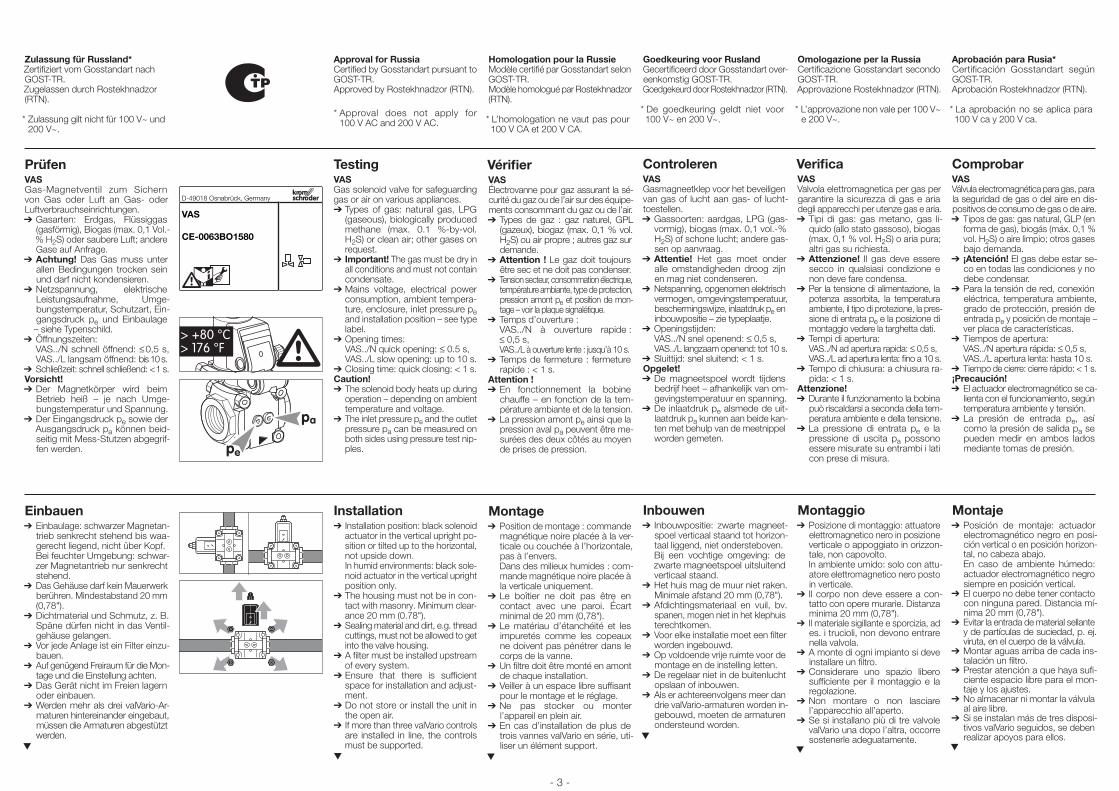
PrüfenVASGas-Magnetventil zum Sichern von Gas oder Luft an Gas- oder Luftverbrauchs einrichtungen.➔ Gasarten: Erdgas, Flüssiggas
(gasförmig), Biogas (max. 0,1 Vol.-% H2S) oder saubere Luft; andere Gase auf Anfrage.
➔ Achtung! Das Gas muss unter allen Bedingungen trocken sein und darf nicht kondensieren.
➔Netzspannung, elektrische Leistungsaufnahme, Umge-bungstemperatur, Schutzart, Ein-gangsdruck pe und Einbaulage – siehe Typenschild.
➔ Öffnungszeiten: VAS../N schnell öffnend: ≤ 0,5 s, VAS../L langsam öffnend: bis 10 s.
➔ Schließzeit: schnell schließend: < 1 s.Vorsicht!➔Der Magnetkörper wird beim
Betrieb heiß – je nach Umge-bungstemperatur und Spannung.
➔Der Eingangsdruck pe sowie der Ausgangsdruck pa können beid-seitig mit Mess-Stutzen abgegrif-fen werden.
Einbauen➔ Einbaulage: schwarzer Magnetan-
trieb senkrecht stehend bis waa-gerecht liegend, nicht über Kopf.
Bei feuchter Umgebung: schwar-zer Magnetantrieb nur senkrecht stehend.
➔ Das Gehäuse darf kein Mauerwerk berühren. Mindestabstand 20 mm (0,78").
➔ Dichtmaterial und Schmutz, z. B. Späne dürfen nicht in das Ventil-gehäuse gelangen.
➔ Vor jede Anlage ist ein Filter einzu-bauen.
➔ Auf genügend Freiraum für die Mon-tage und die Einstellung achten.
➔ Das Gerät nicht im Freien lagern oder einbauen.
➔ Werden mehr als drei valVario-Ar-maturen hintereinander eingebaut, müssen die Armaturen abgestützt werden.
▼
Homologation pour la RussieModèle certifié par Gosstandart selon GOST-TR.Modèle homologué par Rostekhnadzor (RTN).
* L’homologation ne vaut pas pour 100 V CA et 200 V CA.
VérifierVASÉlectrovanne pour gaz assurant la sé-curité du gaz ou de l’air sur des équipe-ments consommant du gaz ou de l’air.➔Types de gaz : gaz naturel, GPL
(gazeux), biogaz (max. 0,1 % vol. H2S) ou air propre ; autres gaz sur demande.
➔Attention ! Le gaz doit toujours être sec et ne doit pas condenser.
➔Tension secteur, consommation électrique, température ambiante, type de protection, pression amont pe et position de mon-tage – voir la plaque signalétique.
➔Temps d’ouverture : VAS../N à ouverture rapide :
≤ 0,5 s, VAS../L à ouverture lente : jusqu’à 10 s.➔Temps de fermeture : fermeture
rapide : < 1 s.Attention !➔En fonctionnement la bobine
chauffe – en fonction de la tem-pérature ambiante et de la tension.
➔La pression amont pe ainsi que la pression aval pa peuvent être me-surées des deux côtés au moyen de prises de pression.
Montage➔Position de montage : commande
magnétique noire placée à la ver-ticale ou couchée à l’horizontale, pas à l’envers.
Dans des milieux humides : com-mande magnétique noire placée à la verticale uniquement.
➔Le boîtier ne doit pas être en contact avec une paroi. Écart minimal de 20 mm (0,78").
➔Le matériau d’étanchéité et les impuretés comme les copeaux ne doivent pas pénétrer dans le corps de la vanne.
➔Un filtre doit être monté en amont de chaque installation.
➔Veiller à un espace libre suffisant pour le montage et le réglage.
➔ Ne pas stocker ou monter l’appareil en plein air.
➔En cas d’installation de plus de trois vannes valVario en série, uti-liser un élément support.
▼
Goedkeuring voor RuslandGecertificeerd door Gosstandart over-eenkomstig GOST-TR.Goedgekeurd door Rostekhnadzor (RTN).
* De goedkeuring geldt niet voor 100 V~ en 200 V~.
ControlerenVASGasmagneetklep voor het beveiligen van gas of lucht aan gas- of lucht-toestellen.➔Gassoorten: aardgas, LPG (gas-
vormig), biogas (max. 0,1 vol.-% H2S) of schone lucht; andere gas-sen op aanvraag.
➔Attentie! Het gas moet onder alle omstandigheden droog zijn en mag niet condenseren.
➔Netspanning, opgenomen elektrisch vermogen, omgevingstemperatuur, beschermingswijze, inlaatdruk pe en inbouwpositie – zie typeplaatje.
➔Openingstijden: VAS../N snel openend: ≤ 0,5 s, VAS../L langzaam openend: tot 10 s.➔Sluittijd: snel sluitend: < 1 s.Opgelet!➔De magneetspoel wordt tijdens
bedrijf heet – afhankelijk van om-gevingstemperatuur en spanning.
➔De inlaatdruk pe alsmede de uit-laatdruk pa kunnen aan beide kan-ten met behulp van de meetnippel worden gemeten.
Inbouwen➔ Inbouwpositie: zwarte magneet-
spoel verticaal staand tot horizon-taal liggend, niet ondersteboven.
Bij een vochtige omgeving: de zwarte magneetspoel uitsluitend verticaal staand.
➔Het huis mag de muur niet raken. Minimale afstand 20 mm (0,78").
➔Afdichtingsmateriaal en vuil, bv. spanen, mogen niet in het klephuis terechtkomen.
➔Voor elke installatie moet een filter worden ingebouwd.
➔Op voldoende vrije ruimte voor de montage en de instelling letten.
➔ De regelaar niet in de buitenlucht opslaan of inbouwen.
➔Als er achtereenvolgens meer dan drie valVario-armaturen worden in-gebouwd, moeten de armaturen ondersteund worden.
▼
Omologazione per la RussiaCertificazione Gosstandart secondo GOST-TR.Approvazione Rostekhnadzor (RTN).
* L’approvazione non vale per 100 V~ e 200 V~.
VerificaVASValvola elettromagnetica per gas per garantire la sicurezza di gas e aria degli apparecchi per utenze gas e aria.➔Tipi di gas: gas metano, gas li-
quido (allo stato gassoso), biogas (max. 0,1 % vol. H2S) o aria pura; altri gas su richiesta.
➔Attenzione! Il gas deve essere secco in qualsiasi condizione e non deve fare condensa.
➔Per la tensione di alimentazione, la potenza assorbita, la temperatura ambiente, il tipo di protezione, la pres-sione di entrata pe e la posizione di montaggio vedere la targhetta dati.
➔Tempi di apertura: VAS../N ad apertura rapida: ≤ 0,5 s, VAS../L ad apertura lenta: fino a 10 s.➔Tempo di chiusura: a chiusura ra-
pida: < 1 s.Attenzione!➔Durante il funzionamento la bobina
può riscaldarsi a seconda della tem-peratura ambiente e della tensione.
➔La pressione di entrata pe e la pressione di uscita pa possono essere misurate su entrambi i lati con prese di misura.
Montaggio➔Posizione di montaggio: attuatore
elettromagnetico nero in posizione verticale o appoggiato in orizzon-tale, non capovolto.
In ambiente umido: solo con attu-atore elettromagnetico nero posto in verticale.
➔ Il corpo non deve essere a con-tatto con opere murarie. Distanza minima 20 mm (0,78").
➔ Il materiale sigillante e sporcizia, ad es. i trucioli, non devono entrare nella valvola.
➔A monte di ogni impianto si deve installare un filtro.
➔Considerare uno spazio libero sufficiente per il montaggio e la regolazione.
➔ Non montare o non lasciare l’apparecchio all’aperto.
➔Se si installano più di tre valvole valVario una dopo l’altra, occorre sostenerle adeguatamente.
▼
Aprobación para Rusia*Certificación Gosstandart según GOST-TR.Aprobación Rostekhnadzor (RTN).
* La aprobación no se aplica para 100 V ca y 200 V ca.
ComprobarVASVálvula electromagnética para gas, para la seguridad de gas o del aire en dis-positivos de consumo de gas o de aire.➔Tipos de gas: gas natural, GLP (en
forma de gas), biogás (máx. 0,1 % vol. H2S) o aire limpio; otros gases bajo demanda.
➔ ¡Atención! El gas debe estar se-co en todas las condiciones y no debe condensar.
➔Para la tensión de red, conexión eléctrica, temperatura ambiente, grado de protección, presión de entrada pe y posición de montaje – ver placa de características.
➔Tiempos de apertura: VAS../N apertura rápida: ≤ 0,5 s, VAS../L apertura lenta: hasta 10 s.➔Tiempo de cierre: cierre rápido: < 1 s.¡Precaución!➔El actuador electromagnético se ca-
lienta con el funcionamiento, según temperatura ambiente y tensión.
➔La presión de entrada pe, así como la presión de salida pa se pueden medir en ambos lados mediante tomas de presión.
Montaje➔Posición de montaje: actuador
electromagnético negro en posi-ción vertical o en posición horizon-tal, no cabeza abajo.
En caso de ambiente húmedo: actuador electromagnético negro siempre en posición vertical.
➔El cuerpo no debe tener contacto con ninguna pared. Distancia mí-nima 20 mm (0,78").
➔Evitar la entrada de material sellante y de partículas de suciedad, p. ej. viruta, en el cuerpo de la válvula.
➔Montar aguas arriba de cada ins-talación un filtro.
➔Prestar atención a que haya sufi-ciente espacio libre para el mon-taje y los ajustes.
➔ No almacenar ni montar la válvula al aire libre.
➔Si se instalan más de tres disposi-tivos valVario seguidos, se deben realizar apoyos para ellos.
▼
Approval for RussiaCertified by Gosstandart pursuant to GOST-TR.Approved by Rostekhnadzor (RTN).
* Approval does not apply for 100 V AC and 200 V AC.
TestingVASGas solenoid valve for safeguarding gas or air on various appliances.➔Types of gas: natural gas, LPG
(gaseous), biologically produced methane (max. 0.1 %-by-vol. H2S) or clean air; other gases on request.
➔Important! The gas must be dry in all conditions and must not contain condensate.
➔Mains voltage, electrical power consumption, ambient tempera-ture, enclosure, inlet pressure pe and installation position – see type label.
➔Opening times: VAS../N quick opening: ≤ 0.5 s, VAS../L slow opening: up to 10 s.➔Closing time: quick closing: < 1 s.Caution!➔The solenoid body heats up during
operation – depending on ambient temperature and voltage.
➔The inlet pressure pe and the outlet pressure pa can be measured on both sides using pressure test nip-ples.
Installation➔Installation position: black solenoid
actuator in the vertical upright po-sition or tilted up to the horizontal, not upside down.
In humid environments: black sole-noid actuator in the vertical upright position only.
➔The housing must not be in con-tact with masonry. Minimum clear-ance 20 mm (0.78").
➔Sealing material and dirt, e.g. thread cuttings, must not be allowed to get into the valve housing.
➔A filter must be installed upstream of every system.
➔Ensure that there is sufficient space for installation and adjust-ment.
➔ Do not store or install the unit in the open air.
➔If more than three valVario controls are installed in line, the controls must be supported.
▼
- 3 -
pa
pe
D-49018 Osnabrück, Germany
VAS
CE-0063BO1580
> +80 °C> 176 °F
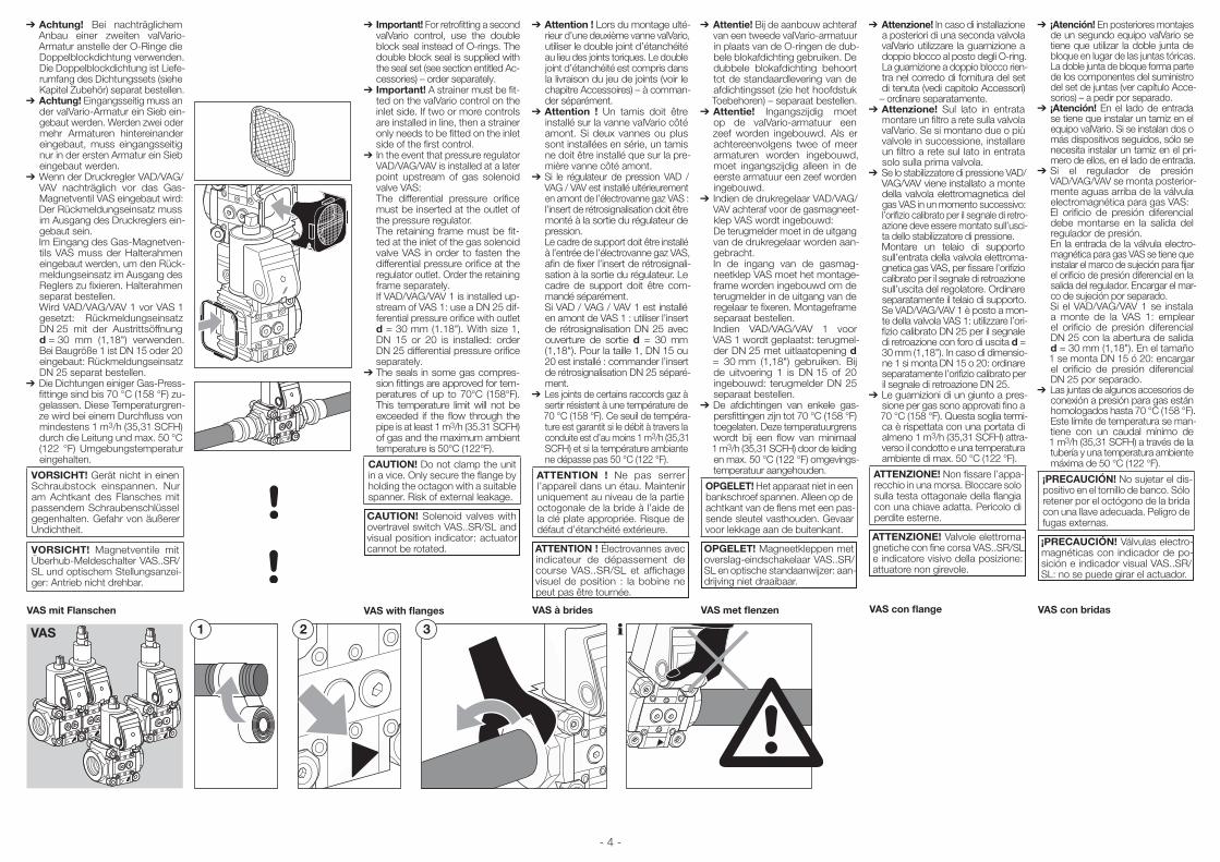
➔ Attention ! Lors du montage ulté-rieur d’une deuxième vanne valVario, utiliser le double joint d’étanchéité au lieu des joints to riques. Le double joint d’étanchéité est compris dans la livraison du jeu de joints (voir le chapitre Accessoires) – à comman-der séparément.
➔ Attention ! Un tamis doit être installé sur la vanne valVario côté amont. Si deux vannes ou plus sont installées en série, un tamis ne doit être installé que sur la pre-mière vanne côté amont.
➔ Si le régulateur de pression VAD / VAG / VAV est installé ultérieurement en amont de l’électrovanne gaz VAS :
l’insert de rétrosignalisation doit être monté à la sortie du régulateur de pression.
Le cadre de support doit être installé à l’entrée de l’électrovanne gaz VAS, afin de fixer l’insert de rétrosignali-sation à la sortie du régulateur. Le cadre de support doit être com-mandé séparément.
Si VAD / VAG / VAV 1 est installé en amont de VAS 1 : utiliser l’insert de rétrosignalisation DN 25 avec ouverture de sortie d = 30 mm (1,18"). Pour la taille 1, DN 15 ou 20 est installé : commander l’insert de rétrosignalisation DN 25 séparé-ment.
➔ Les joints de certains raccords gaz à sertir résistent à une température de 70 °C (158 °F). Ce seuil de tempéra-ture est garantit si le débit à travers la conduite est d’au moins 1 m3/h (35,31 SCFH) et si la température ambiante ne dépasse pas 50 °C (122 °F).
ATTENTION ! Ne pas serrer l’appareil dans un étau. Maintenir uniquement au niveau de la partie octogonale de la bride à l’aide de la clé plate appropriée. Risque de défaut d’étanchéité extérieure.
ATTENTION ! Électrovannes avec indicateur de dépassement de course VAS..SR/SL et affichage visuel de position : la bobine ne peut pas être tournée.
VAS à brides
➔ Important! For retrofitting a second valVario control, use the double block seal instead of O-rings. The double block seal is supplied with the seal set (see section entitled Ac-cessories) – order separately.
➔ Important! A strainer must be fit-ted on the valVario control on the inlet side. If two or more controls are installed in line, then a strainer only needs to be fitted on the inlet side of the first control.
➔ In the event that pressure regulator VAD/VAG/VAV is installed at a later point upstream of gas solenoid valve VAS:
The differential pressure orifice must be inserted at the outlet of the pressure regulator.
The retaining frame must be fit-ted at the inlet of the gas solenoid valve VAS in order to fasten the differential pressure orifice at the regulator outlet. Order the retaining frame separately.
If VAD/VAG/VAV 1 is installed up-stream of VAS 1: use a DN 25 dif-ferential pressure orifice with outlet d = 30 mm (1.18"). With size 1, DN 15 or 20 is installed: order DN 25 differential pressure orifice separately.
➔ The seals in some gas compres-sion fittings are approved for tem-peratures of up to 70°C (158°F). This temperature limit will not be exceeded if the flow through the pipe is at least 1 m3/h (35.31 SCFH) of gas and the maximum ambient temperature is 50°C (122°F).
CAUTION! Do not clamp the unit in a vice. Only secure the flange by holding the octagon with a suitable spanner. Risk of external leakage.
CAUTION! Solenoid valves with overtravel switch VAS..SR/SL and visual position indicator: actuator cannot be rotated.
VAS with flanges
➔ Achtung! Bei nachträglichem Anbau einer zweiten valVario-Armatur anstelle der O-Ringe die Doppelblockdichtung verwenden. Die Doppelblockdichtung ist Liefe-rumfang des Dichtungssets (siehe Kapitel Zubehör) separat bestellen.
➔ Achtung! Eingangsseitig muss an der valVario-Armatur ein Sieb ein-gebaut werden. Werden zwei oder mehr Armaturen hintereinander eingebaut, muss eingangsseitig nur in der ersten Armatur ein Sieb eingebaut werden.
➔ Wenn der Druckregler VAD/VAG/VAV nachträglich vor das Gas-Magnetventil VAS eingebaut wird:
Der Rückmeldungseinsatz muss im Ausgang des Druckreglers ein-gebaut sein.
Im Eingang des Gas-Magnetven-tils VAS muss der Halterahmen eingebaut werden, um den Rück-meldungseinsatz im Ausgang des Reglers zu fixieren. Halterahmen separat bestellen.
Wird VAD/VAG/VAV 1 vor VAS 1 gesetzt: Rückmeldungseinsatz DN 25 mit der Austritts öffnung d = 30 mm (1,18") verwenden. Bei Baugröße 1 ist DN 15 oder 20 eingebaut: Rückmeldungseinsatz DN 25 separat bestellen.
➔ Die Dichtungen einiger Gas-Press-fittinge sind bis 70 °C (158 °F) zu-gelassen. Diese Temperaturgren-ze wird bei einem Durchfluss von mindestens 1 m3/h (35,31 SCFH) durch die Leitung und max. 50 °C (122 °F) Umgebungstemperatur eingehalten.
VORSICHT! Gerät nicht in einen Schraubstock einspannen. Nur am Achtkant des Flansches mit passendem Schraubenschlüssel gegenhalten. Gefahr von äußerer Undichtheit.
VORSICHT! Magnetventile mit Überhub-Meldeschalter VAS..SR/SL und optischem Stellungsanzei-ger: Antrieb nicht drehbar.
VAS mit Flanschen
VAS 1 2 3
- 4 -
➔ Attentie! Bij de aanbouw achteraf van een tweede valVario-armatuur in plaats van de O-ringen de dub-bele blok afdichting gebruiken. De dubbele blokafdichting behoort tot de standaardlevering van de afdichtingsset (zie het hoofdstuk Toebehoren) – separaat bestellen.
➔ Attentie! Ingangszijdig moet op de valVario-armatuur een zeef worden ingebouwd. Als er achtereenvolgens twee of meer armaturen worden ingebouwd, moet ingangszijdig alleen in de eerste armatuur een zeef worden ingebouwd.
➔ Indien de drukregelaar VAD/VAG/VAV achteraf voor de gasmagneet-klep VAS wordt ingebouwd: De terugmelder moet in de uitgang van de drukregelaar worden aan-gebracht.
In de ingang van de gasmag-neetklep VAS moet het montage-frame worden ingebouwd om de terugmelder in de uitgang van de regelaar te fixeren. Montageframe separaat bestellen.
Indien VAD/VAG/VAV 1 voor VAS 1 wordt geplaatst: terugmel-der DN 25 met uitlaatopening d = 30 mm (1,18") gebruiken. Bij de uitvoering 1 is DN 15 of 20 ingebouwd: terugmelder DN 25 separaat bestellen.
➔ De afdichtingen van enkele gas-persfittingen zijn tot 70 °C (158 °F) toegelaten. Deze temperatuurgrens wordt bij een flow van minimaal 1 m3/h (35,31 SCFH) door de leiding en max. 50 °C (122 °F) omgevings-temperatuur aangehouden.
OPGELET! Het apparaat niet in een bankschroef spannen. Alleen op de achtkant van de flens met een pas-sende sleutel vasthouden. Gevaar voor lekkage aan de buitenkant.
OPGELET! Magneetkleppen met overslag-eindschakelaar VAS..SR/SL en optische standaanwijzer: aan-drijving niet draaibaar.
VAS met flenzen
➔ Attenzione! In caso di installazione a posteriori di una seconda valvola valVario utilizzare la guarnizione a doppio blocco al posto degli O-ring. La guarnizione a doppio blocco rien-tra nel corredo di fornitura del set di tenuta (vedi capitolo Accessori) – ordinare separatamente.
➔ Attenzione! Sul lato in entrata montare un filtro a rete sulla valvola valVario. Se si montano due o più valvole in successione, installare un filtro a rete sul lato in entrata solo sulla prima valvola.
➔ Se lo stabilizzatore di pressione VAD/VAG/VAV viene installato a monte della valvola elettromagnetica del gas VAS in un momento successivo:
l’orifizio calibrato per il segnale di retro-azione deve essere montato sull’usci-ta dello stabilizzatore di pressione.
Montare un telaio di supporto sull’entrata della valvola elettroma-gnetica gas VAS, per fissare l’orifizio calibrato per il segnale di retroazione sull’uscita del regolatore. Ordinare separatamente il telaio di supporto.
Se VAD/VAG/VAV 1 è posto a mon-te della valvola VAS 1: utilizzare l’ori-fizio calibrato DN 25 per il segnale di retroazione con foro di uscita d = 30 mm (1,18"). In caso di dimensio-ne 1 si monta DN 15 o 20: ordinare separatamente l’orifizio calibrato per il segnale di retroazione DN 25.
➔ Le guarnizioni di un giunto a pres-sione per gas sono approvati fino a 70 °C (158 °F). Questa soglia termi-ca è rispettata con una portata di almeno 1 m3/h (35,31 SCFH) attra-verso il condotto e una temperatura ambiente di max. 50 °C (122 °F).
ATTENZIONE! Non fissare l’appa-recchio in una morsa. Bloccare solo sulla testa ottagonale della flangia con una chiave adatta. Pericolo di perdite esterne.
ATTENZIONE! Valvole elettroma-gnetiche con fine corsa VAS..SR/SL e indicatore visivo della posizione: attuatore non girevole.
VAS con flange
➔ ¡Atención! En posteriores montajes de un segundo equipo valVario se tiene que utilizar la doble junta de bloque en lugar de las juntas tóricas. La doble junta de bloque forma parte de los componentes del suministro del set de juntas (ver capítulo Acce-sorios) – a pedir por separado.
➔ ¡Atención! En el lado de entrada se tiene que instalar un tamiz en el equipo valVario. Si se instalan dos o más dispositivos seguidos, sólo se necesita instalar un tamiz en el pri-mero de ellos, en el lado de entrada.
➔ Si el regulador de presión VAD/VAG/VAV se monta posterior-mente aguas arriba de la válvula electromagnética para gas VAS:
El orificio de presión diferencial debe montarse en la salida del regulador de presión.
En la entrada de la válvula electro-magnética para gas VAS se tiene que instalar el marco de sujeción para fijar el orificio de presión diferencial en la salida del regulador. Encargar el mar-co de sujeción por separado.
Si el VAD/VAG/VAV 1 se instala a monte de la VAS 1: emplear el orificio de presión diferencial DN 25 con la abertura de salida d = 30 mm (1,18"). En el tamaño 1 se monta DN 15 ó 20: encargar el orificio de presión diferencial DN 25 por separado.
➔ Las juntas de algunos accesorios de conexión a presión para gas están homologados hasta 70 °C (158 °F). Este límite de temperatura se man-tiene con un caudal mínimo de 1 m3/h (35,31 SCFH) a través de la tubería y una temperatura ambiente máxima de 50 °C (122 °F).
¡PRECAUCIóN! No sujetar el dis-positivo en el tornillo de banco. Sólo retener por el octógono de la brida con una llave adecuada. Peligro de fugas externas.
¡PRECAUCIóN! Válvulas electro-magnéticas con indicador de po-sición e indicador visual VAS..SR/SL: no se puede girar el actuador.
VAS con bridas
VAS ohne Flansche
1 432VAS
65 7
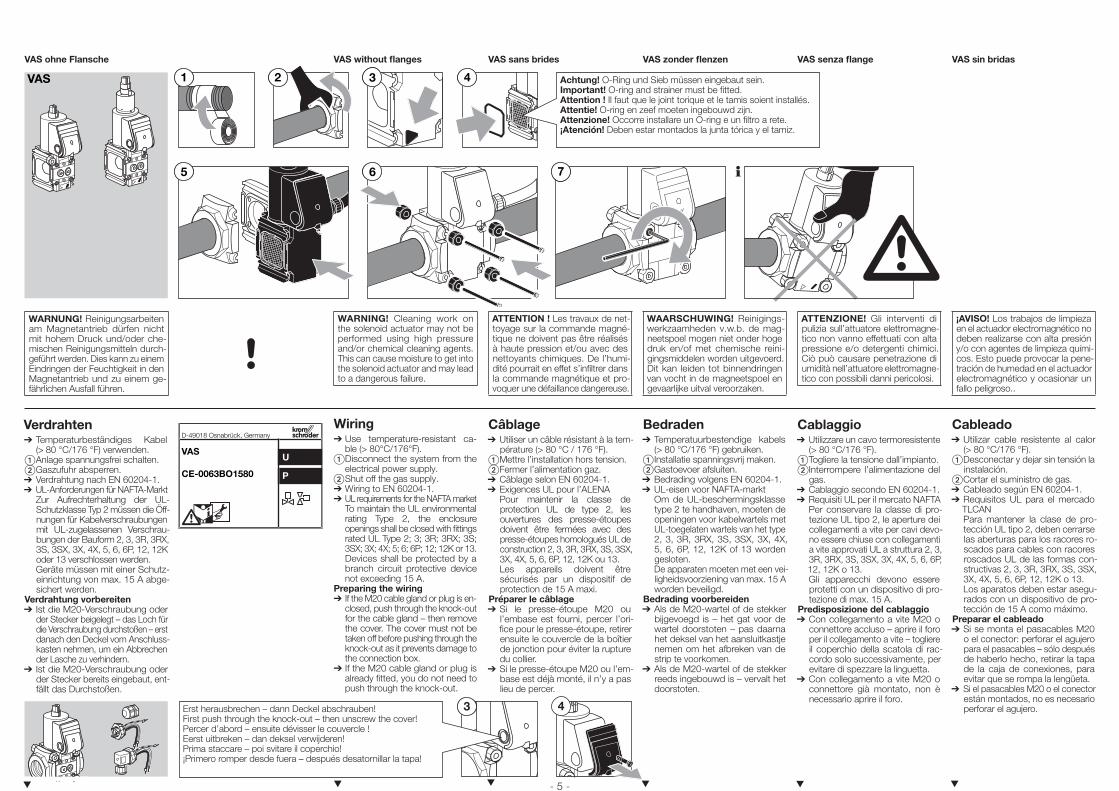
Achtung! O-Ring und Sieb müssen eingebaut sein.Important! O-ring and strainer must be fitted.Attention ! Il faut que le joint torique et le tamis soient installés.Attentie! O-ring en zeef moeten ingebouwd zijn.Attenzione! Occorre installare un O-ring e un filtro a rete.¡Atención! Deben estar montados la junta tórica y el tamiz.
WARNUNG! Reinigungsarbeiten am Magnetantrieb dürfen nicht mit hohem Druck und/oder che-mischen Reinigungsmitteln durch-geführt werden. Dies kann zu einem Eindringen der Feuchtigkeit in den Magnetantrieb und zu einem ge-fährlichen Ausfall führen.
Verdrahten➔ Temperaturbeständiges Kabel
(> 80 °C/176 °F) verwenden. Anlage spannungsfrei schalten. Gaszufuhr absperren.➔ Verdrahtung nach EN 60204-1.➔ UL-Anforderungen für NAFTA-Markt Zur Aufrechterhaltung der UL-
Schutzklasse Typ 2 müssen die Öff-nungen für Kabelverschraubungen mit UL-zugelassenen Verschrau-bungen der Bauform 2, 3, 3R, 3RX, 3S, 3SX, 3X, 4X, 5, 6, 6P, 12, 12K oder 13 verschlossen werden.
Geräte müssen mit einer Schutz-einrichtung von max. 15 A abge-sichert werden.
Verdrahtung vorbereiten➔ Ist die M20-Verschraubung oder
der Stecker beigelegt – das Loch für die Verschraubung durchstoßen – erst danach den Deckel vom Anschluss-kasten nehmen, um ein Abbrechen der Lasche zu verhindern.
➔ Ist die M20-Verschraubung oder der Stecker bereits eingebaut, ent-fällt das Durchstoßen.
3 4Erst herausbrechen – dann Deckel abschrauben!First push through the knock-out – then unscrew the cover!Percer d’abord – ensuite dévisser le couvercle !Eerst uitbreken – dan deksel verwijderen!Prima staccare – poi svitare il coperchio!¡Primero romper desde fuera – después desatornillar la tapa!
▼
VAS without flanges
WARNING! Cleaning work on the solenoid actuator may not be performed using high pressure and/or chemical cleaning agents. This can cause moisture to get into the solenoid actuator and may lead to a dangerous failure.
Wiring➔ Use temperature-resistant ca-
ble (> 80°C/176°F). Disconnect the system from the
electrical power supply. Shut off the gas supply.➔ Wiring to EN 60204-1.➔ UL requirements for the NAFTA market To maintain the UL environmental
rating Type 2, the enclosure openings shall be closed with fittings rated UL Type 2; 3; 3R; 3RX; 3S; 3SX; 3X; 4X; 5; 6; 6P; 12; 12K or 13.
Devices shall be protected by a branch circuit protective device not exceeding 15 A.
Preparing the wiring➔If the M20 cable gland or plug is en-
closed, push through the knock-out for the cable gland – then remove the cover. The cover must not be taken off before pushing through the knock-out as it prevents damage to the connection box.
➔If the M20 cable gland or plug is already fitted, you do not need to push through the knock-out.
▼
VAS sans brides
ATTENTION ! Les travaux de net-toyage sur la commande magné-tique ne doivent pas être réalisés à haute pression et/ou avec des nettoyants chimiques. De l’humi-dité pourrait en effet s’infiltrer dans la commande magnétique et pro-voquer une défaillance dangereuse.
Câblage➔ Utiliser un câble résistant à la tem-
pérature (> 80 °C / 176 °F). Mettre l’installation hors tension. Fermer l’alimentation gaz.➔ Câblage selon EN 60204-1.➔ Exigences UL pour l’ALENA Pour maintenir la classe de
protection UL de type 2, les ouvertures des presse-étoupes doivent être fermées avec des presse-étoupes homologués UL de construction 2, 3, 3R, 3RX, 3S, 3SX, 3X, 4X, 5, 6, 6P, 12, 12K ou 13.
Les appareils doivent être sécurisés par un dispositif de protection de 15 A maxi.
Préparer le câblage➔Si le presse-étoupe M20 ou
l’embase est fourni, percer l’ori-fice pour le presse-étoupe, retirer ensuite le couvercle de la boîtier de jonction pour éviter la rupture du collier.
➔Si le presse-étoupe M20 ou l’em-base est déjà monté, il n’y a pas lieu de percer.
▼
VAS zonder flenzen
WAARSCHUWING! Reinigings-werkzaamheden v.w.b. de mag-neetspoel mogen niet onder hoge druk en/of met chemische reini-gingsmiddelen worden uitgevoerd. Dit kan leiden tot binnendringen van vocht in de magneetspoel en gevaarlijke uitval veroorzaken.
Bedraden➔ Temperatuurbestendige kabels
(> 80 °C/176 °F) gebruiken. Installatie spanningsvrij maken. Gastoevoer afsluiten.➔ Bedrading volgens EN 60204-1.➔ UL-eisen voor NAFTA-markt Om de UL-beschermingsklasse
type 2 te handhaven, moeten de openingen voor kabelwartels met UL-toegelaten wartels van het type 2, 3, 3R, 3RX, 3S, 3SX, 3X, 4X, 5, 6, 6P, 12, 12K of 13 worden gesloten.
De apparaten moeten met een vei-ligheidsvoorziening van max. 15 A worden beveiligd.
Bedrading voorbereiden➔Als de M20-wartel of de stekker
bijgevoegd is – het gat voor de wartel doorstoten – pas daarna het deksel van het aansluitkastje nemen om het afbreken van de strip te voorkomen.
➔Als de M20-wartel of de stekker reeds ingebouwd is – vervalt het doorstoten.
▼
VAS senza flange
ATTENZIONE! Gli interventi di pulizia sull’attuatore elettromagne-tico non vanno effettuati con alta pressione e/o detergenti chimici. Ciò può causare penetrazione di umidità nell’attuatore elettromagne-tico con possibili danni pericolosi.
Cablaggio➔ Utilizzare un cavo termoresistente
(> 80 °C/176 °F). Togliere la tensione dall’impianto. Interrompere l’alimentazione del
gas.➔ Cablaggio secondo EN 60204-1.➔ Requisiti UL per il mercato NAFTA Per conservare la classe di pro-
tezione UL tipo 2, le aperture dei collegamenti a vite per cavi devo-no essere chiuse con collegamenti a vite approvati UL a struttura 2, 3, 3R, 3RX, 3S, 3SX, 3X, 4X, 5, 6, 6P, 12, 12K o 13.
Gli apparecchi devono essere protetti con un dispositivo di pro-tezione di max. 15 A.
Predisposizione del cablaggio➔Con collegamento a vite M20 o
connettore accluso – aprire il foro per il collegamento a vite – togliere il coperchio della scatola di rac-cordo solo successivamente, per evitare di spezzare la linguetta.
➔Con collegamento a vite M20 o connettore già montato, non è necessario aprire il foro.
▼
VAS sin bridas
¡AVISO! Los trabajos de limpieza en el actuador electromagnético no deben realizarse con alta presión y/o con agentes de limpieza quími-cos. Esto puede provocar la pene-tración de humedad en el actuador electromagnético y ocasionar un fallo peligroso..
Cableado➔ Utilizar cable resistente al calor
(> 80 °C/176 °F). Desconectar y dejar sin tensión la
instalación. Cortar el suministro de gas.➔ Cableado según EN 60204-1.➔ Requisitos UL para el mercado
TLCAN Para mantener la clase de pro-
tección UL tipo 2, deben cerrarse las aberturas para los racores ro-scados para cables con racores roscados UL de las formas con-structivas 2, 3, 3R, 3RX, 3S, 3SX, 3X, 4X, 5, 6, 6P, 12, 12K o 13.
Los aparatos deben estar asegu-rados con un dispositivo de pro-tección de 15 A como máximo.
Preparar el cableado➔Si se monta el pasacables M20
o el conector: perforar el agujero para el pasacables – sólo después de haberlo hecho, retirar la tapa de la caja de conexiones, para evitar que se rompa la lengüeta.
➔Si el pasacables M20 o el conector están montados, no es necesario perforar el agujero.
▼
D-49018 Osnabrück, Germany
VAS
CE-0063BO1580
U
P
- 5 -
- 6 -
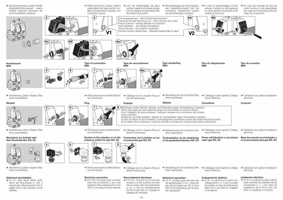
➔ Bei Zusammenbau zweier Ventile Kabeldurchführungsset (siehe Kapitel Zubehör) zwischen die Anschlusskästen einbauen.
4b4 4a
V1 V2
3
4c 4d 4e
Erst herausbrechen – dann Deckel abschrauben!First push through the knock-out – then unscrew the cover!Percer d’abord – ensuite dévisser le couvercle !Eerst uitbreken – dan deksel verwijderen!Prima staccare – poi svitare il coperchio!¡Primero romper desde fuera – después desatornillar la tapa!
AnschlussartM20
7 865 8a
➔ Verdrahtung (siehe Kapitel Elek-trisch anschließen).
Stecker
65 7 8 Bei Einsatz zweier Stecker: Stecker und Steckdose gegen Verwechslung markieren.When two plugs are used: label the plugs and the sockets to avoid confusion.Pour l’utilisation de deux embases : marquer l’embase et le connecteur afin d’éviter toute confusion.Bij gebruik van twee stekkers: stekker en contrastekker tegen verwisseling markeren.In caso di utilizzo di due connettori: contrassegnare connettore e presa per evitare eventuali scambi.Si se utilizan dos conectores: marcar el conector y la base de conector para evitar confusiones.
➔ Verdrahtung (siehe Kapitel Elek-trisch anschließen).
Steckdose am Antrieb oder Gas-Druckwächter DG..VC
5 6 8 7
➔ Verdrahtung (siehe Kapitel Elek-trisch anschließen).
Elektrisch anschließen➔ 24 V=: Das Ventil öffnet nicht,
wenn die Anschlüsse (+ und -) verpolt sind. Bei Austausch VG..K gegen VAS..K den Stecker umver-drahten.
➔When joining two valves, install a cable gland set (see section en-titled Accessories) between the connection boxes.
Type of connectionM20
➔Wiring (see section entitled Electri-cal connection).
Plug
➔Wiring (see section entitled Electri-cal connection).
Socket on the actuator or on the pressure switch for gas DG..VC
➔Wiring (see section entitled Electri-cal connection).
Electrical connection➔ 24 V DC: the valve does not open
when the connections (+ and -) are reversed. When replacing VG..K by VAS..K, the plug must be rewired.
➔Lors de l’assemblage de deux vannes, insérer le kit presse-étoupe (voir le chapitre Accessoires) entre les boîtiers de jonction.
Type de raccordementM20
➔Câblage (voir le chapitre Raccor-dement électrique).
Embase
➔Câblage (voir le chapitre Raccor-dement électrique).
Connecteur sur la bobine ou sur le pressostat gaz DG..VC
➔Câblage (voir le chapitre Raccor-dement électrique).
Raccordement électrique➔ 24 V CC : la vanne ne s’ouvre pas
lorsqu’il y a une inversion de pola-rité au niveau des raccordements (+ et -). Lors du remplacement de VG..K par VAS..K, changer le câblage de l’embase.
➔Bij assemblage van twee kleppen, een kabeldoorvoerset (zie het hoofdstuk Toebehoren) tussen de aansluitkastjes monteren.
Type aansluitingM20
➔Bedrading (zie het hoofdstuk Elek-trisch aansluiten).
Stekker
➔Bedrading (zie het hoofdstuk Elek-trisch aansluiten).
Contrastekker op de aandrijving of de gasdrukschakelaar DG..VC
➔Bedrading (zie het hoofdstuk Elek-trisch aansluiten).
Elektrisch aansluiten➔ 24 V=: de klep gaat niet open als
de aansluitingen (+ en -) verpoold zijn. Bij vervangen van VG..K door VAS..K de bedrading van de stek-ker aanpassen.
➔ In caso di assemblaggio di due valvole, montare un set passaca-vo (vedi capitolo Accessori) tra le scatole di raccordo.
Tipo di collegamentoM20
➔Cablaggio (vedi capitolo Collega-mento elettrico).
Connettore
➔Cablaggio (vedi capitolo Collega-mento elettrico).
Presa sull’attuatore o sul presso-stato gas DG..VC
➔Cablaggio (vedi capitolo Collega-mento elettrico).
Collegamento elettrico➔ 24 V=: la valvola non si apre, se i
collegamenti (+ e -) sono a polari-tà invertita. In caso di sostituzione della VG..K con VAS..K, ricablare il connettore.
➔En caso de montaje de dos vál-vulas montar un set pasacables (ver capítulo Accesorios) entre las cajas de conexiones.
Tipo de conexiónM20
➔Cableado (ver capítulo Instalación eléctrica).
Conector
➔Cableado (ver capítulo Instalación eléctrica).
Base de conector en el actuador o en el presostato para gas DG..VC
➔Cableado (ver capítulo Instalación eléctrica).
Instalación eléctrica➔ 24 V cc: la válvula no abre cuando
está invertida la polaridad de las conexiones (+ y -). En caso de sustitución de la VG..K por una VAS..K, recablear el conector.
- 7 -
Raccordement électrique avec indicateur de positionVAS..SR/SL : 120 V / 230 V,VAS..GR/GL : 24 V.➔VAS ouverte : contacts 1 et 2 fer-
més, VAS fermée : contacts 1 et 3 fer-
més.➔Attention ! Risque d’interférence
entre la tension vanne et la tension de l’indicateur de position. Faire passer les câbles de la vanne et de l’indicateur de position séparé-ment à travers des presse-étoupes M20 ou utiliser deux embases séparées.
Elektrisch aansluiten met eind-schakelaarVAS..SR/SL: 120 V/230 V,VAS..GR/GL: 24 V.➔VAS open: contacten 1 en 2 ge-
sloten, VAS gesloten: contacten 1 en 3
gesloten.➔Attentie! Gevaar door beïnvloe-
ding van klepspanning en span-ning van de eindschakelaar. De bedrading van klep en eindscha-kelaar telkens gescheiden door een M20-wartel voeren of telkens een stekker gebruiken.
Collegamento elettrico con fine corsaVAS..SR/SL: 120 V/230 V,VAS..GR/GL: 24 V.➔VAS aperta: contatti 1 e 2 chiusi, VAS chiusa: contatti 1 e 3 chiusi.➔Attenzione! Pericolo di un influsso
della tensione della valvola e della tensione del fine corsa. Eseguire i cablaggi di valvola e fine corsa separati, ognuno con un collega-mento a vite M20 oppure con un connettore.
Instalación eléctrica en válvulas con indicador de posiciónVAS..SR/SL: 120 V / 230 V,VAS..GR/GL: 24 V.➔VAS abierta: contactos 1 y 2 ce-
rrados. VAS cerrada: contactos 1 y 3 ce-
rrados.➔ ¡Atención! Peligro de influencia de
la tensión de la válvula y la tensión del indicador de posición. Pasar los cables eléctricos de la válvula y del indicador de posición sepa-radamente por pasacables M20 o utilizar un conector para cada uno.
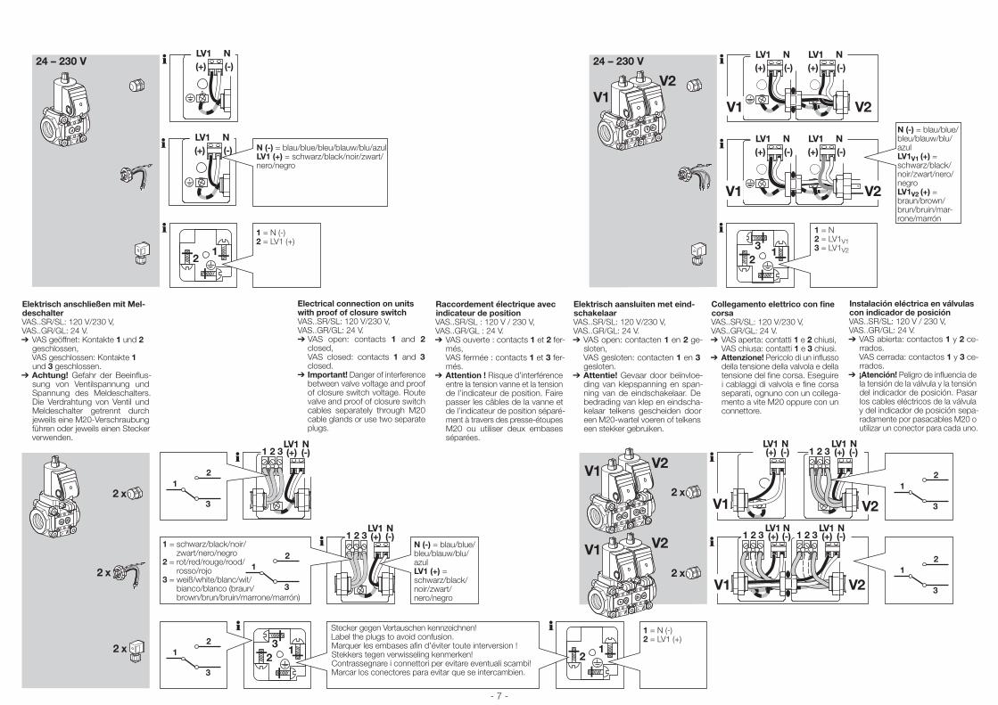
Electrical connection on units with proof of closure switchVAS..SR/SL: 120 V/230 V,VAS..GR/GL: 24 V.➔VAS open: contacts 1 and 2
closed, VAS closed: contacts 1 and 3
closed.➔Important! Danger of interference
between valve voltage and proof of closure switch voltage. Route valve and proof of closure switch cables separately through M20 cable glands or use two separate plugs.
(+) LV1 N
(-)
(+) LV1 N
(-)
2 1
(+) LV1 N
(+) LV1 N
(-) (-)
V1
V1V2
V2
(+) LV1 N
(+) LV1 N
(-) (-)
V1 V2
2 1 3
24 – 230 V
24 – 230 V
N (-) = blau/blue/bleu/blauw/blu/azulLV1 (+) = schwarz/black/noir/zwart/ nero/negro
1 = N (-)2 = LV1 (+)
N (-) = blau/blue/bleu/blauw/blu/azulLV1V1 (+) = schwarz/black/noir/zwart/nero/negro LV1V2 (+) = braun/brown/brun/bruin/mar-rone/marrón
1 = N2 = LV1V13 = LV1V2
Elektrisch anschließen mit Mel-deschalterVAS..SR/SL: 120 V/230 V, VAS..GR/GL: 24 V.➔ VAS geöffnet: Kontakte 1 und 2
geschlossen, VAS geschlossen: Kontakte 1 und 3 geschlossen.
➔ Achtung! Gefahr der Beeinflus-sung von Ventilspannung und Spannung des Meldeschalters. Die Verdrahtung von Ventil und Meldeschalter getrennt durch jeweils eine M20-Verschraubung führen oder jeweils einen Stecker verwenden.
1 3 2 LV1 (+)
N (-)
V1
V1
V1
V2
2 x
V2
V2
V1 V2
1 3 2 LV1 (+)
N (-)
2 x
2 x
2 x
2 x
1 3 2
1 3 2 1 3 2 LV1 (+)
N (-)
LV1 (+)
N (-)
LV1 (+)
N (-)
LV1 (+)
N (-)
2 1
2 1 3
1 2
3
1 2
3
1 2
3
1 2
3
1 2
3
N (-) = blau/blue/ bleu/blauw/blu/azulLV1 (+) = schwarz/black/noir/zwart/ nero/negro
1 = schwarz/black/noir/ zwart/nero/negro
2 = rot/red/rouge/rood/ rosso/rojo
3 = weiß/white/blanc/wit/ bianco/blanco (braun/ brown/brun/bruin/marrone/marrón)
1 = N (-)2 = LV1 (+)
Stecker gegen Vertauschen kennzeichnen!Label the plugs to avoid confusion.Marquer les embases afin d’éviter toute interversion !Stekkers tegen verwisseling kenmerken!Contrassegnare i connettori per evitare eventuali scambi!Marcar los conectores para evitar que se intercambien.
- 8 -
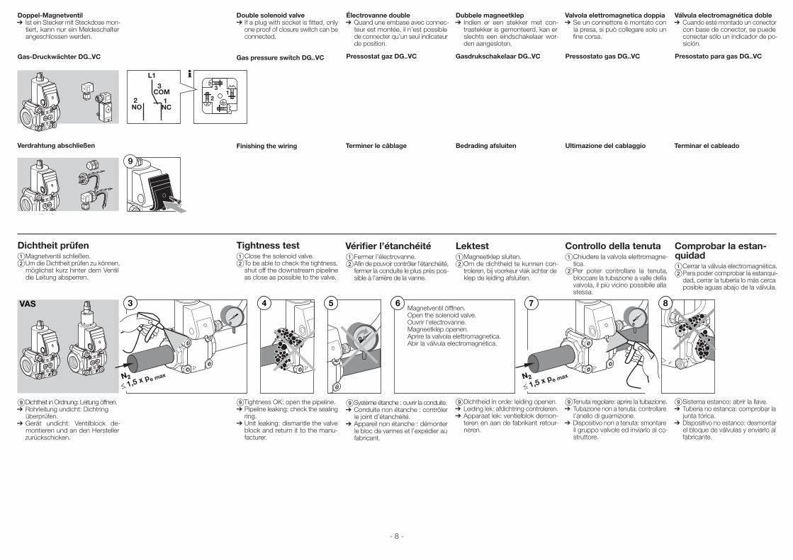
Doppel-Magnetventil ➔ Ist ein Stecker mit Steckdose mon-
tiert, kann nur ein Meldeschalter angeschlossen werden.
Gas-Druckwächter DG..VC
Verdrahtung abschließen
Dichtheit prüfen Magnetventil schließen. Um die Dichtheit prüfen zu können,
möglichst kurz hinter dem Ventil die Leitung absperren.
6
0
0 0
3 4
N2
5 7
N2
8VAS Magnetventil öfffnen.Open the solenoid valve.Ouvrir l'electrovanne.Magneetklep openen.Aprire la valvola elettromagnetica.Abir la válvula electromagnética.
Dichtheit in Ordnung: Leitung öffnen.➔ Rohrleitung undicht: Dichtring
überprüfen.➔ Gerät undicht: Ventilblock de-
montieren und an den Hersteller zurückschicken.
Électrovanne double➔ Quand une embase avec connec-
teur est montée, il n’est possible de connecter qu’un seul indicateur de position.
Pressostat gaz DG..VC
Terminer le câblage
Vérifier l’étanchéité Fermer l’électrovanne. Afin de pouvoir contrôler l’étanchéité,
fermer la conduite le plus près pos-sible à l’arrière de la vanne.
Système étanche : ouvrir la conduite.➔Conduite non étanche : contrôler
le joint d’étanchéité.➔Appareil non étanche : démonter
le bloc de vannes et l’expédier au fabricant.
Dubbele magneetklep➔ Indien er een stekker met con-
trastekker is gemonteerd, kan er slechts een eindschakelaar wor-den aangesloten.
Gasdrukschakelaar DG..VC
Bedrading afsluiten
Lektest Magneetklep sluiten. Om de dichtheid te kunnen con-
troleren, bij voorkeur vlak achter de klep de leiding afsluiten.
Dichtheid in orde: leiding openen.➔Leiding lek: afdichtring controleren.➔Apparaat lek: ventielblok demon-
teren en aan de fabrikant retour-neren.
Valvola elettromagnetica doppia➔ Se un connettore è montato con
la presa, si può collegare solo un fine corsa.
Pressostato gas DG..VC
Ultimazione del cablaggio
Controllo della tenuta Chiudere la valvola elettromagne-
tica. Per poter controllare la tenuta,
bloccare la tubazione a valle della valvola, il più vicino possibile alla stessa.
Tenuta regolare: aprire la tubazione.➔Tubazione non a tenuta: controllare
l’anello di guarnizione.➔Dispositivo non a tenuta: smontare
il gruppo valvole ed inviarlo al co-struttore.
Válvula electromagnética doble➔ Cuando esté montado un conector
con base de conector, se puede conectar sólo un indicador de po-sición.
Presostato para gas DG..VC
Terminar el cableado
Comprobar la estan-quidad Cerrar la válvula electromagnética. Para poder comprobar la estanqui-
dad, cerrar la tubería lo más cerca posible aguas abajo de la válvula.
Sistema estanco: abrir la llave.➔Tubería no estanca: comprobar la
junta tórica.➔Dispositivo no estanco: desmontar
el bloque de válvulas y enviarlo al fabricante.
Double solenoid valve➔ If a plug with socket is fitted, only
one proof of closure switch can be connected.
Gas pressure switch DG..VC
Finishing the wiring
Tightness test Close the solenoid valve. To be able to check the tightness,
shut off the downstream pipeline as close as possible to the valve.
Tightness OK: open the pipeline.➔Pipeline leaking: check the sealing
ring.➔Unit leaking: dismantle the valve
block and return it to the manu-facturer.
9
21
3
NO2
NC1
COM3
L1
- 9 -
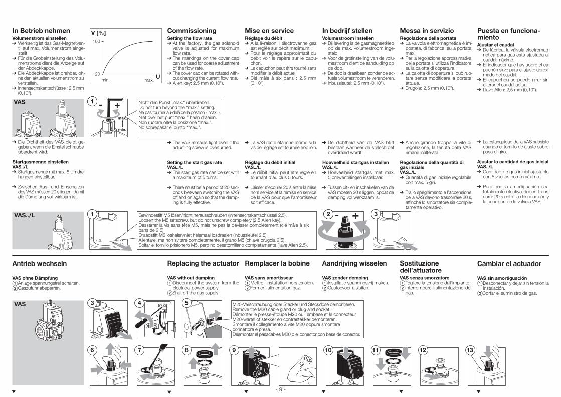
In Betrieb nehmenVo lumenstrom einstellen➔ Werkseitig ist das Gas-Magnetven-
til auf max. Volumenstrom einge-stellt.
➔ Für die Grobeinstellung des Volu-menstroms dient die Anzeige auf der Abdeckkappe.
➔ Die Abdeckkappe ist drehbar, oh-ne den aktuellen Volumenstrom zu verstellen.
➔ Innensechskantschlüssel: 2,5 mm (0,10").
1 - +
min.
max.
VAS Nicht den Punkt „max.“ überdrehen.Do not turn beyond the “max.” setting.Ne pas tourner au-delà de la position « max. ».Niet over het punt “max.” heen draaien.Non ruotare oltre la posizione “max.”.No sobrepasar el punto “max.”.
➔ Die Dichtheit des VAS bleibt ge-geben, wenn die Einstellschraube überdreht wird.
Startgasmenge einstellenVAS../L ➔ Startgasmenge mit max. 5 Umdre-
hungen einstellbar.
➔ Zwischen Aus- und Einschalten des VAS müssen 20 s liegen, damit die Dämpfung voll wirksam ist.
3- +2VAS../L
1 Gewindestift M5 lösen/nicht herausschrauben (Innensechskantschlüssel 2,5).Loosen the M5 setscrew, but do not unscrew completely (2.5 Allen key).Desserrer la vis sans tête M5, mais ne pas la dévisser complètement (clé mâle à six pans de 2,5).Draadstift M5 loshalen/niet helemaal losdraaien (inbussleutel 2,5).Allentare, ma non svitare completamente, il grano M5 (chiave brugola 2,5).Soltar el tornillo prisionero M5, pero no desatornillarlo comple tamente (llave Allen 2,5).
Antrieb wechseln
VAS ohne Dämpfung Anlage spannungsfrei schalten. Gaszufuhr absperren.
▼
CommissioningSetting the flow rate➔ At the factory, the gas solenoid
valve is adjusted for maximum flow rate.
➔The markings on the cover cap can be used for coarse adjustment of the flow rate.
➔The cover cap can be rotated with-out changing the current flow rate.
➔Allen key: 2.5 mm (0.10").
➔The VAS remains tight even if the adjusting screw is overturned.
Setting the start gas rateVAS../L➔The start gas rate can be set with
a maximum of 5 turns.
➔There must be a period of 20 sec-onds between switching the VAS off and on again so that the damp-ing is fully effective.
Replacing the actuator
VAS without damping Disconnect the system from the
electrical power supply.Shut off the gas supply.
▼
Mise en serviceRéglage du débit➔ À la livraison, l’électrovanne gaz
est réglée sur débit maximum.➔Pour le réglage approximatif du
débit voir le repère sur le capu-chon.
➔Le capuchon peut être tourné sans modifier le débit actuel.
➔Clé mâle à six pans : 2,5 mm (0,10").
➔La VAS reste étanche même si la vis de réglage est tournée trop loin.
Réglage du débit initialVAS../L➔Le débit initial peut être réglé en
tournant d’au plus 5 tours.
➔Laisser s’écouler 20 s entre la mise hors service et la remise en service de la VAS pour que l’amortisseur soit efficace.
Remplacer la bobine
VAS sans amortisseur Mettre l’installation hors tension.Fermer l’alimentation gaz.
▼
In bedrijf stellenVolumestroom instellen➔ Bij levering is de gasmagneetklep
op de max. volumestroom inge-steld.
➔Voor de grofinstelling van de volu-mestroom dient de aanduiding op de dop.
➔De dop is draaibaar, zonder de ac-tuele volumestroom te veranderen.
➔ Inbussleutel: 2,5 mm (0,10").
➔De dichtheid van de VAS blijft bestaan wanneer de stelschroef overdraaid wordt.
Hoeveelheid startgas instellenVAS../L➔Hoeveelheid startgas met max.
5 omwentelingen instelbaar.
➔Tussen uit- en inschakelen van de VAS moeten 20 s liggen, opdat de demping vol werkzaam is.
Aandrijving wisselen
VAS zonder demping Installatie spanningsvrij maken. Gastoevoer afsluiten.
▼
Messa in servizioRegolazione della portata➔ La valvola elettromagnetica è im-
postata, di fabbrica, sulla portata max.
➔Per la regolazione approssimativa della portata si utilizza l’indicatore sulla calotta di copertura.
➔La calotta di copertura si può ruo-tare senza modificare la portata attuale.
➔Brugola: 2,5 mm (0,10").
➔Anche girando troppo la vite di regolazione, la tenuta della VAS rimane inalterata.
Regolazione della quantità di gas inizialeVAS../L➔Quantità di gas iniziale regolabile
con max. 5 giri.
➔Tra lo spegnimento e l’accensione della VAS devono trascorrere 20 s, affinché lo smorzatore sia comple-tamente operativo.
Sostituzione dell’attuatoreVAS senza smorzatore Togliere la tensione dall’impianto.Interrompere l’alimentazione del
gas.
▼
9
4
7 10
VAS 5
12 8 11
3
136
M20-Verschraubung oder Stecker und Steckdose demontieren.Remove the M20 cable gland or plug and socket.Démonter le presse-étoupe M20 ou l’embase et le connecteur.M20-wartel of stekker en contrastekker demonteren.Smontare il collegamento a vite M20 oppure smontare connettore e presa.Desmontar el pasacables M20 o el conector con base de conector.
V [%]
max. min.
100
20
.
U
Puesta en funciona-mientoAjustar el caudal➔ De fábrica, la válvula electromag-
nética para gas está ajustada al caudal máximo.
➔El indicador que hay sobre el ca-puchón sirve para el ajuste aproxi-mado del caudal.
➔El capuchón se puede girar sin alterar el caudal actual.
➔Llave Allen: 2,5 mm (0,10").
➔La estanquidad de la VAS subsiste cuando el tornillo de ajuste sobre-pasa el giro.
Ajustar la cantidad de gas inicialVAS../L➔Cantidad de gas inicial ajustable
con 5 vueltas como máximo.
➔Para que la amortiguación sea totalmente efectiva deben trans-currir 20 s entre la desconexión y la conexión de la válvula VAS.
Cambiar el actuador
VAS sin amortiguación Desconectar y dejar sin tensión la
instalación.Cortar el suministro de gas.
▼
- 10 -
➔Pour le câblage (voir le chapitre Câblage).
➔Assemblage dans l’ordre inverse.
VAS avec amortisseur Mettre l’installation hors tension. Fermer l’alimentation gaz.
➔ Assemblage dans l’ordre inverse.
➔Bedraden (zie het hoofdstuk Be-draden).
➔Montage in omgekeerde volgorde.
VAS met demping Installatie spanningsvrij maken. Gastoevoer afsluiten.
➔ Montage in omgekeerde volgorde.
➔Para el cableado (ver capítulo Ca-bleado).
➔Montaje en orden inverso.
VAS con amortiguaciónDesconectar y dejar sin tensión la
instalación. Cortar el suministro de gas.
➔ Montaje en orden inverso.
➔Cablare (vedi capitolo Cablaggio).➔Assemblaggio in sequenza inversa.
VAS con smorzatore Togliere la tensione dall’impianto. Interrompere l’alimentazione del
gas.
➔ Assemblaggio in sequenza inversa.
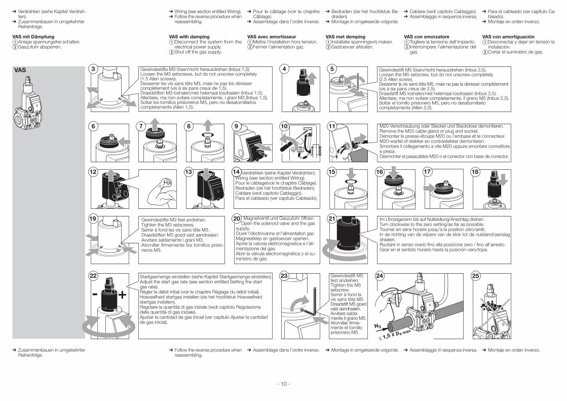
➔Wiring (see section entitled Wiring).➔Follow the reverse procedure when
reassembling.
VAS with damping Disconnect the system from the
electrical power supply. Shut off the gas supply.
➔ Follow the reverse procedure when reassembling.
➔ Verdrahten (siehe Kapitel Verdrah-ten).
➔ Zusammenbauen in umgekehrter Reihenfolge.
VAS mit Dämpfung Anlage spannungsfrei schalten. Gaszufuhr absperren.
➔ Zusammenbauen in umgekehrter Reihenfolge.
12
4
13 14
VAS 3 5
6 7 8 10 9 11
24
19
1715
20
22
N2
- + 23 25
21
16 18
M20-Verschraubung oder Stecker und Steckdose demontieren.Remove the M20 cable gland or plug and socket.Démonter le presse-étoupe M20 ou l’embase et le connecteur.M20-wartel of stekker en contrastekker demonteren.Smontare il collegamento a vite M20 oppure smontare connettore e presa.Desmontar el pasacables M20 o el conector con base de conector.
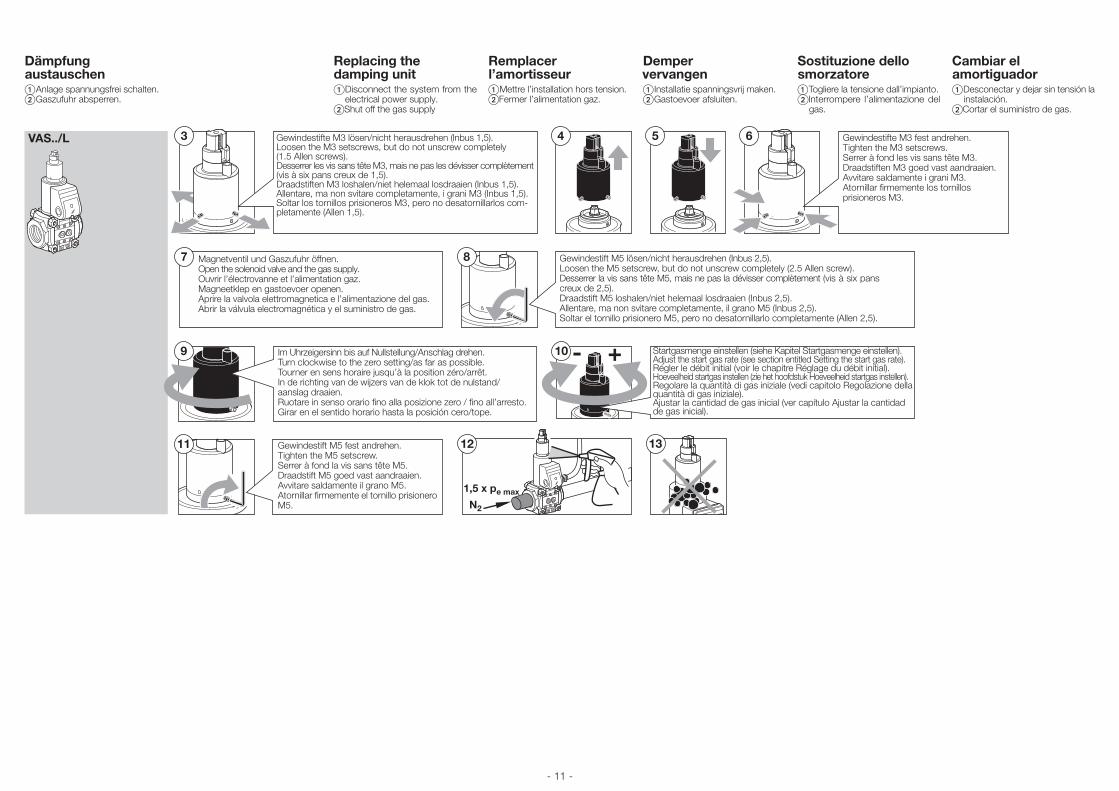
Gewindestifte M3 lösen/nicht herausdrehen (Inbus 1,5).Loosen the M3 setscrews, but do not unscrew completely (1.5 Allen screws).Desserrer les vis sans tête M3, mais ne pas les dévisser complètement (vis à six pans creux de 1,5).Draadstiften M3 loshalen/niet helemaal losdraaien (Inbus 1,5).Allentare, ma non svitare completamente, i grani M3 (Inbus 1,5).Soltar los tornillos prisioneros M3, pero no desatornillarlos completamente (Allen 1,5).
Gewindestift M5 lösen/nicht herausdrehen (Inbus 2,5).Loosen the M5 setscrew, but do not unscrew completely (2.5 Allen screw).Desserrer la vis sans tête M5, mais ne pas la dévisser complètement (vis à six pans creux de 2,5).Draadstift M5 loshalen/niet helemaal losdraaien (Inbus 2,5).Allentare, ma non svitare completamente, il grano M5 (Inbus 2,5).Soltar el tornillo prisionero M5, pero no desatornillarlo completamente (Allen 2,5).
Gewindestifte M3 fest andrehen.Tighten the M3 setscrews.Serrer à fond les vis sans tête M3.Draadstiften M3 goed vast aandraaien.Avvitare saldamente i grani M3.Atornillar firmemente los tornillos prisio-neros M3.
Gewindestift M5 fest andrehen.Tighten the M5 setscrew.Serrer à fond la vis sans tête M5.Draadstift M5 goed vast aandraaien.Avvitare salda-mente il grano M5.Atornillar firme-mente el tornillo prisionero M5.
Magnetventil und Gaszufuhr öffnen. Open the solenoid valve and the gas supply.Ouvrir l’électrovanne et l’alimentation gaz.Magneetklep en gastoevoer openen.Aprire la valvola elettromagnetica e l’ali-mentazione del gas.Abrir la válvula electromagnética y el su-ministro de gas.
Im Uhrzeigersinn bis auf Nullstellung/Anschlag drehen.Turn clockwise to the zero setting/as far as possible.Tourner en sens horaire jusqu’à la position zéro/arrêt.In de richting van de wijzers van de klok tot de nulstand/aanslag draaien.Ruotare in senso orario fino alla posizione zero / fino all’arresto.Girar en el sentido horario hasta la posición cero/tope.
Verdrahten (siehe Kapitel Verdrahten).Wiring (see section entitled Wiring).Pour le câblage(voir le chapitre Câblage).Bedraden (zie het hoofdstuk Bedraden).Cablare (vedi capitolo Cablaggio).Para el cableado (ver capítulo Cableado).
Startgasmenge einstellen (siehe Kapitel Startgasmenge einstellen).Adjust the start gas rate (see section entitled Setting the start gas rate). Régler le débit initial (voir le chapitre Réglage du débit initial).Hoeveelheid startgas instellen (zie het hoofdstuk Hoeveelheid startgas instellen).Regolare la quantità di gas iniziale (vedi capitolo Regolazione della quantità di gas iniziale).Ajustar la cantidad de gas inicial (ver capítulo Ajustar la cantidad de gas inicial).
- 11 -
Replacing the damping unit Disconnect the system from the
electrical power supply.Shut off the gas supply
Remplacer l’amortisseur Mettre l’installation hors tension.Fermer l’alimentation gaz.
Demper vervangen Installatie spanningsvrij maken.Gastoevoer afsluiten.
Sostituzione dello smorzatore Togliere la tensione dall’impianto.Interrompere l’alimentazione del
gas.
Cambiar el amortiguador Desconectar y dejar sin tensión la
instalación.Cortar el suministro de gas.
Dämpfung austauschen Anlage spannungsfrei schalten. Gaszufuhr absperren.
10
3VAS../L 4 5
7 8
11
- +
6
9
12 13
N2
1,5 x pe max
Gewindestifte M3 lösen/nicht herausdrehen (Inbus 1,5).Loosen the M3 setscrews, but do not unscrew completely (1.5 Allen screws).Desserrer les vis sans tête M3, mais ne pas les dévisser complètement (vis à six pans creux de 1,5).Draadstiften M3 loshalen/niet helemaal losdraaien (Inbus 1,5).Allentare, ma non svitare completamente, i grani M3 (Inbus 1,5).Soltar los tornillos prisioneros M3, pero no desatornillarlos com-pletamente (Allen 1,5).
Gewindestift M5 lösen/nicht herausdrehen (Inbus 2,5).Loosen the M5 setscrew, but do not unscrew completely (2.5 Allen screw).Desserrer la vis sans tête M5, mais ne pas la dévisser complètement (vis à six pans creux de 2,5).Draadstift M5 loshalen/niet helemaal losdraaien (Inbus 2,5).Allentare, ma non svitare completamente, il grano M5 (Inbus 2,5).Soltar el tornillo prisionero M5, pero no desatornillarlo completamente (Allen 2,5).
Gewindestifte M3 fest andrehen.Tighten the M3 setscrews.Serrer à fond les vis sans tête M3.Draadstiften M3 goed vast aandraaien.Avvitare saldamente i grani M3.Atornillar firmemente los tornillos prisioneros M3.
Startgasmenge einstellen (siehe Kapitel Startgasmenge einstellen).Adjust the start gas rate (see section entitled Setting the start gas rate).Régler le débit initial (voir le chapitre Réglage du débit initial).Hoeveelheid startgas instellen (zie het hoofdstuk Hoeveelheid startgas instellen).Regolare la quantità di gas iniziale (vedi capitolo Regolazione della quantità di gas iniziale).Ajustar la cantidad de gas inicial (ver capítulo Ajustar la cantidad de gas inicial).
Gewindestift M5 fest andrehen.Tighten the M5 setscrew.Serrer à fond la vis sans tête M5.Draadstift M5 goed vast aandraaien.Avvitare saldamente il grano M5.Atornillar firmemente el tornillo prisionero M5.
Magnetventil und Gaszufuhr öffnen.Open the solenoid valve and the gas supply.Ouvrir l’électrovanne et l’alimentation gaz.Magneetklep en gastoevoer openen.Aprire la valvola elettromagnetica e l’alimentazione del gas.Abrir la válvula electromagnética y el suministro de gas.
Im Uhrzeigersinn bis auf Nullstellung/Anschlag drehen.Turn clockwise to the zero setting/as far as possible.Tourner en sens horaire jusqu’à la position zéro/arrêt.In de richting van de wijzers van de klok tot de nulstand/aanslag draaien.Ruotare in senso orario fino alla posizione zero / fino all’arresto.Girar en el sentido horario hasta la posición cero/tope.
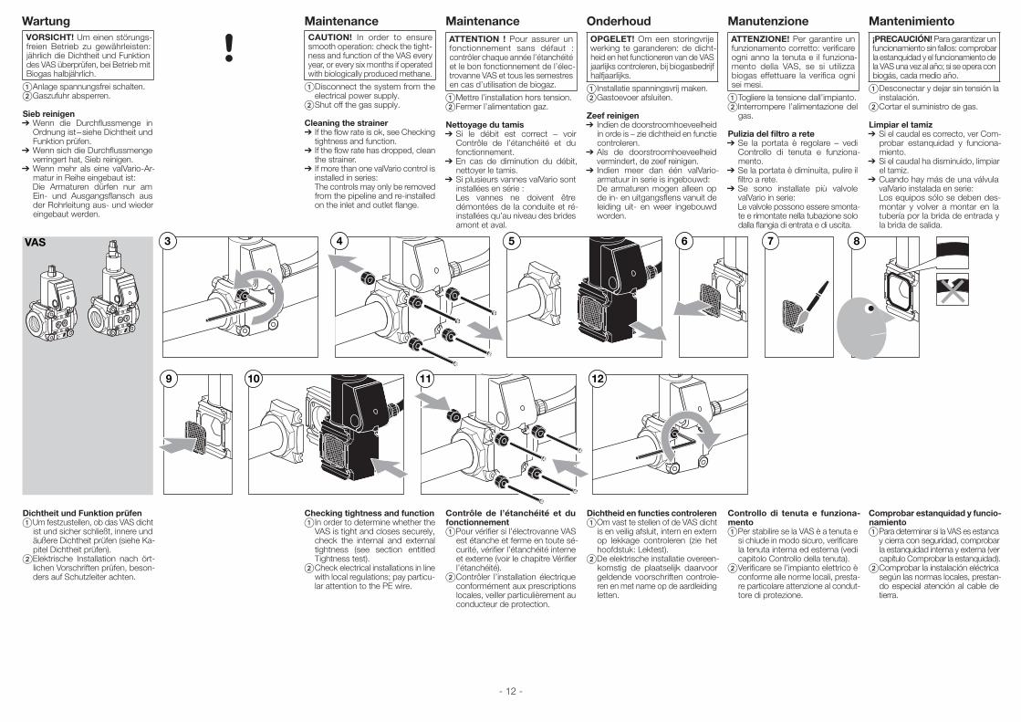
- 12 -
WartungVORSICHT! Um einen störungs-freien Betrieb zu gewährleisten: jährlich die Dichtheit und Funktion des VAS überprüfen, bei Betrieb mit Biogas halbjährlich.
Anlage spannungsfrei schalten. Gaszufuhr absperren.
Sieb reinigen➔ Wenn die Durchflussmenge in
Ordnung ist – siehe Dichtheit und Funktion prüfen.
➔ Wenn sich die Durchflussmenge verringert hat, Sieb reinigen.
➔ Wenn mehr als eine valVario-Ar-matur in Reihe eingebaut ist:
Die Armaturen dürfen nur am Ein- und Ausgangsflansch aus der Rohrleitung aus- und wieder eingebaut werden.
Dichtheit und Funktion prüfen Um festzustellen, ob das VAS dicht
ist und sicher schließt, innere und äußere Dichtheit prüfen (siehe Ka-pitel Dichtheit prüfen).
Elektrische Installation nach ört-lichen Vorschriften prüfen, beson-ders auf Schutzleiter achten.
MaintenanceATTENTION ! Pour assurer un fonctionnement sans défaut : contrôler chaque année l’étanchéité et le bon fonctionnement de l’élec-trovanne VAS et tous les semestres en cas d’utilisation de biogaz.
Mettre l’installation hors tension. Fermer l’alimentation gaz.
Nettoyage du tamis➔ Si le débit est correct – voir
Contrôle de l’étanchéité et du fonctionnement.
➔ En cas de diminution du débit, nettoyer le tamis.
➔ Si plusieurs vannes valVario sont installées en série :
Les vannes ne doivent être démontées de la conduite et ré-installées qu’au niveau des brides amont et aval.
Contrôle de l’étanchéité et du fonctionnement Pour vérifier si l’électrovanne VAS
est étanche et ferme en toute sé-curité, vérifier l’étanchéité interne et externe (voir le chapitre Vérifier l’étanchéité).
Contrôler l’installation électrique conformément aux prescriptions locales, veiller particulièrement au conducteur de protection.
OnderhoudOPGELET! Om een storingvrije werking te garanderen: de dicht-heid en het functioneren van de VAS jaarlijks controleren, bij biogasbedrijf halfjaarlijks.
Installatie spanningsvrij maken. Gastoevoer afsluiten.
Zeef reinigen➔ Indien de doorstroomhoeveelheid
in orde is – zie dichtheid en functie controleren.
➔ Als de doorstroomhoeveelheid vermindert, de zeef reinigen.
➔ Indien meer dan één valVario-armatuur in serie is ingebouwd:
De armaturen mogen alleen op de in- en uitgangsflens vanuit de leiding uit- en weer ingebouwd worden.
Dichtheid en functies controleren Om vast te stellen of de VAS dicht
is en veilig afsluit, intern en extern op lekkage controleren (zie het hoofdstuk: Lektest).
De elektrische installatie overeen-komstig de plaatselijk daarvoor geldende voorschriften controle-ren en met name op de aardleiding letten.
ManutenzioneATTENZIONE! Per garantire un funzionamento corretto: verificare ogni anno la tenuta e il funziona-mento della VAS, se si utilizza biogas effettuare la verifica ogni sei mesi.
Togliere la tensione dall’impianto. Interrompere l’alimentazione del
gas.
Pulizia del filtro a rete➔ Se la portata è regolare – vedi
Controllo di tenuta e funziona-mento.
➔ Se la portata è diminuita, pulire il filtro a rete.
➔ Se sono installate più valvole valVario in serie:
Le valvole possono essere smonta-te e rimontate nella tubazione solo dalla flangia di entrata e di uscita.
Controllo di tenuta e funziona-mento Per stabilire se la VAS è a tenuta e
si chiude in modo sicuro, verificare la tenuta interna ed esterna (vedi capitolo Controllo della tenuta).
Verificare se l’impianto elettrico è conforme alle norme locali, presta-re particolare attenzione al condut-tore di protezione.
Mantenimiento¡PRECAUCIóN! Para garantizar un funcionamiento sin fallos: comprobar la estanquidad y el funcionamiento de la VAS una vez al año; si se opera con biogás, cada medio año.
Desconectar y dejar sin tensión la instalación.
Cortar el suministro de gas.
Limpiar el tamiz➔ Si el caudal es correcto, ver Com-
probar estanquidad y funciona-miento.
➔ Si el caudal ha disminuido, limpiar el tamiz.
➔ Cuando hay más de una válvula valVario instalada en serie:
Los equipos sólo se deben des-montar y volver a montar en la tubería por la brida de entrada y la brida de salida.
Comprobar estanquidad y funcio-namiento Para determinar si la VAS es estanca
y cierra con seguridad, comprobar la estanquidad interna y externa (ver capítulo Comprobar la estanquidad).
Comprobar la instalación eléctrica según las normas locales, prestan-do especial atención al cable de tierra.
MaintenanceCAUTION! In order to ensure smooth operation: check the tight-ness and function of the VAS every year, or every six months if operated with biologically produced methane.
Disconnect the system from the electrical power supply.
Shut off the gas supply.
Cleaning the strainer➔ If the flow rate is ok, see Checking
tightness and function.➔ If the flow rate has dropped, clean
the strainer.➔ If more than one valVario control is
installed in series: The controls may only be removed
from the pipeline and re-installed on the inlet and outlet flange.
Checking tightness and function In order to determine whether the
VAS is tight and closes securely, check the internal and external tightness (see section entitled Tightness test).
Check electrical installations in line with local regulations; pay particu-lar attention to the PE wire.
12
7VAS 4 5 6
9
83
1110
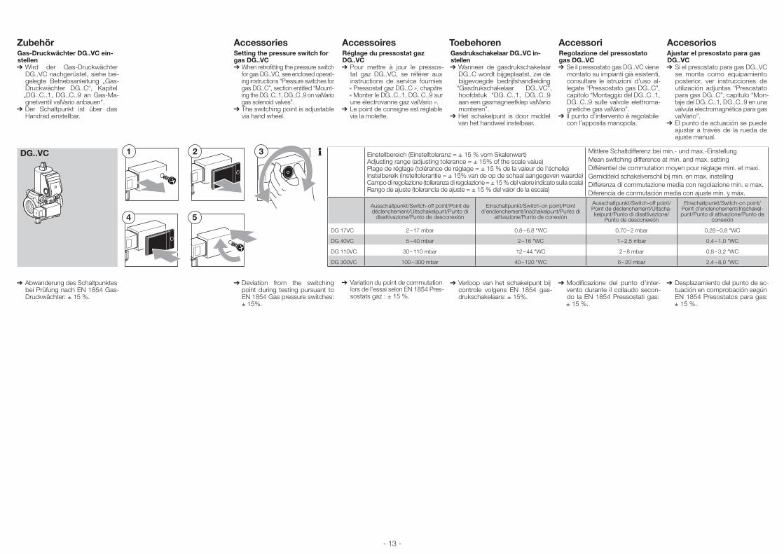
- 13 -
AccessoiresRéglage du pressostat gaz DG..VC➔ Pour mettre à jour le pressos-
tat gaz DG..VC, se référer aux instructions de service fournies « Pressostat gaz DG..C », chapitre « Monter le DG..C..1, DG..C..9 sur une électrovanne gaz valVario ».
➔ Le point de consigne est réglable via la molette.
➔Variation du point de commutation lors de l’essai selon EN 1854 Pres-sostats gaz : ± 15 %.
ToebehorenGasdrukschakelaar DG..VC in-stellen➔ Wanneer de gasdrukschakelaar
DG..C wordt bijgeplaatst, zie de bijgevoegde bedrijfshandleiding
“Gasdrukschakelaar DG..VC”, hoofdstuk “DG..C..1, DG..C..9 aan een gasmagneetklep valVario monteren”.
➔ Het schakelpunt is door middel van het handwiel instelbaar.
➔Verloop van het schakelpunt bij controle volgens EN 1854 gas-drukschakelaars: ± 15%.
AccessoriRegolazione del pressostato gas DG..VC➔ Se il pressostato gas DG..VC viene
montato su impianti già esistenti, consultare le istruzioni d’uso al-legate “Pressostato gas DG..C”, capitolo “Montaggio del DG..C..1, DG..C..9 sulle valvole elettroma-gnetiche gas valVario”.
➔ Il punto d’intervento è regolabile con l’apposita manopola.
➔Modificazione del punto d’inter-vento durante il collaudo secon-do la EN 1854 Pressostati gas: ± 15 %.
AccesoriosAjustar el presostato para gas DG..VC➔ Si el presostato para gas DG..VC
se monta como equipamiento posterior, ver instrucciones de utilización adjuntas “Presostato para gas DG..C”, capítulo “Mon-taje del DG..C..1, DG..C..9 en una válvula electromagnética para gas valVario”.
➔ El punto de actuación se puede ajustar a través de la rueda de ajuste manual.
➔Desplazamiento del punto de ac-tuación en comprobación según EN 1854 Presostatos para gas: ± 15 %.
AccessoriesSetting the pressure switch for gas DG..VC➔ When retrofitting the pressure switch
for gas DG..VC, see enclosed operat-ing instructions “Pressure switches for gas DG..C”, section entitled “Mount-ing the DG..C..1, DG..C..9 on valVario gas solenoid valves”.
➔ The switching point is adjustable via hand wheel.
➔ Deviation from the switching point during testing pursuant to EN 1854 Gas pressure switches: ± 15%.
ZubehörGas-Druckwächter DG..VC ein-stellen➔ Wird der Gas-Druckwächter
DG..VC nachgerüstet, siehe bei-gelegte Betriebsanleitung „Gas-Druckwächter DG..C“, Kapitel „DG..C..1, DG..C..9 an Gas-Ma-gnetventil valVario anbauen“.
➔ Der Schaltpunkt ist über das Handrad einstellbar.
➔ Abwanderung des Schaltpunktes bei Prüfung nach EN 1854 Gas-Druckwächter: ± 15 %.
3
5
2
4
1DG..VC
Einstellbereich (Einstelltoleranz = ± 15 % vom Skalenwert)Adjusting range (adjusting tolerance = ± 15% of the scale value)Plage de réglage (tolérance de réglage = ± 15 % de la valeur de l’échelle)Instelbereik (insteltolerantie = ± 15% van de op de schaal aangegeven waarde)Campo di regolazione (tolleranza di regolazione = ± 15 % del valore indicato sulla scala)Rango de ajuste (tolerancia de ajuste = ± 15 % del valor de la escala)
Mittlere Schaltdifferenz bei min.- und max.-Einstellung Mean switching difference at min. and max. settingDifférentiel de commutation moyen pour réglage mini. et maxi.Gemiddeld schakelverschil bij min. en max. instellingDifferenza di commutazione media con regolazione min. e max.Diferencia de conmutación media con ajuste mín. y máx.
Ausschaltpunkt/Switch-off point/Point de déclenchement/Uitschakelpunt/Punto di
disattivazione/Punto de desconexión
Einschaltpunkt/Switch-on point/Point d’enclenchement/Inschakelpunt/Punto di
attivazione/Punto de conexión
Ausschaltpunkt/Switch-off point/Point de déclenchement/Uitscha-kelpunt/Punto di disattivazione/
Punto de desconexión
Einschaltpunkt/Switch-on point/Point d’enclenchement/Inschakel-punt/Punto di attivazione/Punto de
conexión
DG 17VC 2 – 17 mbar 0,8 – 6,8 "WC 0,70 – 2 mbar 0,28 – 0,8 "WC
DG 40VC 5 – 40 mbar 2 – 16 "WC 1 – 2,5 mbar 0,4 – 1,0 "WC
DG 110VC 30 – 110 mbar 12 – 44 "WC 2 – 8 mbar 0,8 – 3,2 "WC
DG 300VC 100 – 300 mbar 40 – 120 "WC 6 – 20 mbar 2,4 – 8,0 "WC
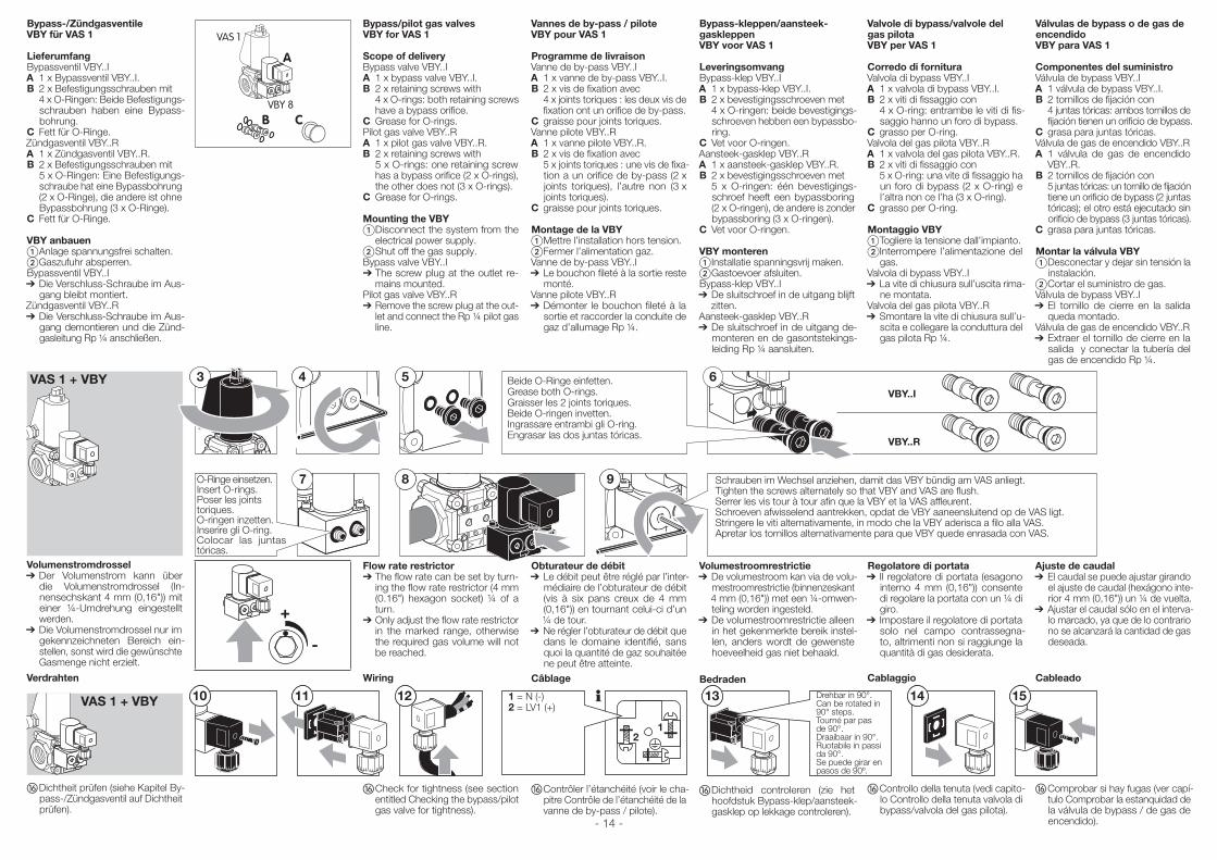
- 14 -
Bypass-kleppen/aansteek-gaskleppenVBY voor VAS 1
LeveringsomvangBypass-klep VBY..IA 1 x bypass-klep VBY..I.B 2 x bevestigingsschroeven met 4 x O-ringen: beide bevestigings-
schroeven hebben een bypassbo-ring.
C Vet voor O-ringen.Aansteek-gasklep VBY..RA 1 x aansteek-gasklep VBY..R.B 2 x bevestigingsschroeven met 5 x O-ringen: één bevestigings-
schroef heeft een bypassboring (2 x O-ringen), de andere is zonder bypassboring (3 x O-ringen).
C Vet voor O-ringen.
VBY monteren Installatie spanningsvrij maken. Gastoevoer afsluiten.Bypass-klep VBY..I➔De sluitschroef in de uitgang blijft
zitten.Aansteek-gasklep VBY..R➔De sluitschroef in de uitgang de-
monteren en de gasontstekings-leiding Rp ¼ aansluiten.
Volumestroomrestrictie➔De volumestroom kan via de volu-
mestroomrestrictie (binnenzeskant 4 mm (0,16")) met een ¼-omwen-teling worden ingesteld.
➔De volumestroomrestrictie alleen in het gekenmerkte bereik instel-len, anders wordt de gewenste hoeveelheid gas niet behaald.
Bedraden
Dichtheid controleren (zie het hoofdstuk Bypass-klep/aansteek-gasklep op lekkage controleren).
Valvole di bypass/valvole del gas pilotaVBY per VAS 1
Corredo di fornituraValvola di bypass VBY..IA 1 x valvola di bypass VBY..I.B 2 x viti di fissaggio con 4 x O-ring: entrambe le viti di fis-
saggio hanno un foro di bypass.C grasso per O-ring.Valvola del gas pilota VBY..RA 1 x valvola del gas pilota VBY..R.B 2 x viti di fissaggio con 5 x O-ring: una vite di fissaggio ha
un foro di bypass (2 x O-ring) e l’altra non ce l’ha (3 x O-ring).
C grasso per O-ring.
Montaggio VBY Togliere la tensione dall’impianto. Interrompere l’alimentazione del
gas.Valvola di bypass VBY..I➔La vite di chiusura sull’uscita rima-
ne montata.Valvola del gas pilota VBY..R➔Smontare la vite di chiusura sull’u-
scita e collegare la conduttura del gas pilota Rp ¼.
Regolatore di portata➔ Il regolatore di portata (esagono
interno 4 mm (0,16")) consente di regolare la portata con un ¼ di giro.
➔ Impostare il regolatore di portata solo nel campo contrassegna-to, altrimenti non si raggiunge la quantità di gas desiderata.
Cablaggio
Controllo della tenuta (vedi capito-lo Controllo della tenuta valvola di bypass/valvola del gas pilota).
Válvulas de bypass o de gas de encendidoVBY para VAS 1
Componentes del suministroVálvula de bypass VBY..IA 1 válvula de bypass VBY..I.B 2 tornillos de fijación con 4 juntas tóricas: ambos tornillos de
fijación tienen un orificio de bypass.C grasa para juntas tóricas.Válvula de gas de encendido VBY..RA 1 válvula de gas de encendido
VBY..R.B 2 tornillos de fijación con 5 juntas tóricas: un tornillo de fijación
tiene un orificio de bypass (2 juntas tóricas); el otro está ejecutado sin orificio de bypass (3 juntas tóricas).
C grasa para juntas tóricas.
Montar la válvula VBY Desconectar y dejar sin tensión la
instalación. Cortar el suministro de gas.Válvula de bypass VBY..I➔El tornillo de cierre en la salida
queda montado.Válvula de gas de encendido VBY..R➔Extraer el tornillo de cierre en la
salida y conectar la tubería del gas de encendido Rp ¼.
Ajuste de caudal➔El caudal se puede ajustar girando
el ajuste de caudal (hexágono inte-rior 4 mm (0,16")) un ¼ de vuelta.
➔Ajustar el caudal sólo en el interva-lo marcado, ya que de lo contrario no se alcanzará la cantidad de gas deseada.
Cableado
Comprobar si hay fugas (ver capí-tulo Comprobar la estanquidad de la válvula de bypass / de gas de encendido).
Bypass-/ZündgasventileVBY für VAS 1
LieferumfangBypassventil VBY..IA 1 x Bypassventil VBY..I.B 2 x Befestigungsschrauben mit 4 x O-Ringen: Beide Befestigungs-
schrauben haben eine Bypass-bohrung.
C Fett für O-Ringe.Zündgasventil VBY..RA 1 x Zündgasventil VBY..R.B 2 x Befestigungsschrauben mit
5 x O-Ringen: Eine Befestigungs-schraube hat eine Bypassbohrung (2 x O-Ringe), die andere ist ohne Bypassbohrung (3 x O-Ringe).
C Fett für O-Ringe.
VBY anbauen Anlage spannungsfrei schalten. Gaszufuhr absperren.Bypassventil VBY..I➔ Die Verschluss-Schraube im Aus-
gang bleibt montiert.Zündgasventil VBY..R➔ Die Verschluss-Schraube im Aus-
gang demontieren und die Zünd-gasleitung Rp ¼ anschließen.
Volumenstromdrossel➔ Der Volumenstrom kann über
die Volumenstromdrossel (In-nensechskant 4 mm (0,16")) mit einer ¼-Umdrehung eingestellt werden.
➔ Die Volumenstromdrossel nur im gekennzeichneten Bereich ein-stellen, sonst wird die gewünschte Gasmenge nicht erzielt.
+
-
Verdrahten
14VAS 1 + VBY
2 1
11 1310 12 15Drehbar in 90°.Can be rotated in 90° steps.Tourné par pas de 90°.Draaibaar in 90°.Ruotabile in passi da 90°.Se puede girar en pasos de 90º.
1 = N (-)2 = LV1 (+)
Dichtheit prüfen (siehe Kapitel By-pass-/Zündgasventil auf Dichtheit prüfen).
Vannes de by-pass / pilote VBY pour VAS 1
Programme de livraisonVanne de by-pass VBY..IA 1 x vanne de by-pass VBY..I.B 2 x vis de fixation avec 4 x joints toriques : les deux vis de
fixation ont un orifice de by-pass.C graisse pour joints toriques.Vanne pilote VBY..RA 1 x vanne pilote VBY..R.B 2 x vis de fixation avec 5 x joints toriques : une vis de fixa-
tion a un orifice de by-pass (2 x joints toriques), l’autre non (3 x joints toriques).
C graisse pour joints toriques.
Montage de la VBY Mettre l’installation hors tension. Fermer l’alimentation gaz.Vanne de by-pass VBY..I➔Le bouchon fileté à la sortie reste
monté.Vanne pilote VBY..R➔Démonter le bouchon fileté à la
sortie et raccorder la conduite de gaz d’allumage Rp ¼.
Obturateur de débit➔Le débit peut être réglé par l’inter-
médiaire de l’obturateur de débit (vis à six pans creux de 4 mm (0,16")) en tournant celui-ci d’un ¼ de tour.
➔Ne régler l’obturateur de débit que dans le domaine identifié, sans quoi la quantité de gaz souhaitée ne peut être atteinte.
Câblage
Contrôler l’étanchéité (voir le cha-pitre Contrôle de l’étanchéité de la vanne de by-pass / pilote).
Bypass/pilot gas valvesVBY for VAS 1
Scope of deliveryBypass valve VBY..IA 1 x bypass valve VBY..I.B 2 x retaining screws with 4 x O-rings: both retaining screws
have a bypass orifice.C Grease for O-rings.Pilot gas valve VBY..RA 1 x pilot gas valve VBY..R.B 2 x retaining screws with 5 x O-rings: one retaining screw
has a bypass orifice (2 x O-rings), the other does not (3 x O-rings).
C Grease for O-rings.
Mounting the VBY Disconnect the system from the
electrical power supply. Shut off the gas supply.Bypass valve VBY..I➔The screw plug at the outlet re-
mains mounted.Pilot gas valve VBY..R➔Remove the screw plug at the out-
let and connect the Rp ¼ pilot gas line.
Flow rate restrictor➔The flow rate can be set by turn-
ing the flow rate restrictor (4 mm (0.16") hexagon socket) ¼ of a turn.
➔Only adjust the flow rate restrictor in the marked range, otherwise the required gas volume will not be reached.
Wiring
Check for tightness (see section entitled Checking the bypass/pilot gas valve for tightness).
B C
A
VBY 8
VAS 1
3 4VAS 1 + VBY 5
8 9
VBY..I
VBY..R
6
7O-Ringe einsetzen.Insert O-rings.Poser les joints toriques.O-ringen inzetten.Inserire gli O-ring.Colocar las juntas tóricas.
Schrauben im Wechsel anziehen, damit das VBY bündig am VAS anliegt.Tighten the screws alternately so that VBY and VAS are flush.Serrer les vis tour à tour afin que la VBY et la VAS affleurent.Schroeven afwisselend aantrekken, opdat de VBY aaneensluitend op de VAS ligt.Stringere le viti alternativamente, in modo che la VBY aderisca a filo alla VAS.Apretar los tornillos alternativamente para que VBY quede enrasada con VAS.
Beide O-Ringe einfetten.Grease both O-rings.Graisser les 2 joints toriques.Beide O-ringen invetten.Ingrassare entrambi gli O-ring.Engrasar las dos juntas tóricas.
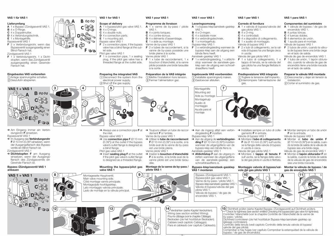
VAS 1 für VAS 1
LieferumfangA 1 x Bypass-/Zündgasventil VAS 1.B 4 x O-Ringe.C 4 x Doppelmutter.D 4 x Verbindungstechnik.E 1 x Montagehilfe.Bypassventil VAS 1F 2 x Verbindungsrohr, wenn das
Bypassventil ausgangsseitig einen Blind-Flansch hat.
Zündgasventil VAS 1F 1 x Verbindungsrohr, 1 x Dicht-
stopfen, wenn das Zündgasventil ausgangsseitig einen Gewinde-Flansch hat.
Eingebautes VAS vorbereiten Anlage spannungsfrei schalten. Gaszufuhr absperren.
75 4 3 V AS 1 + V AS 1
A 6
F
B
B
B C
D
F E
MontagehilfeMounting aidAide au montageMontagehulpAusilio di montaggioAyuda para el montaje
➔ Am Eingang immer ein Verbin-dungsrohr F einsetzen.
Bypassventil VAS 1➔ Im Ausgang das Verbindungsrohr
F Ø 10 mm (0,39") einsetzen, wenn der Ausgangsflansch des Bypass-ventils ein Blind-Flansch ist.
Zündgasventil VAS 1➔ Dichtstopfen F am Ausgang
einsetzen, wenn der Ausgangs-flansch des Zündgasventils ein Gewinde-Flansch ist.
Bypass-/Zündgasventil VAS 1 anbauen
VAS 1 pour VAS 1
Programme de livraisonA 1 x vanne de by-pass / pilote
VAS 1.B 4 x joints toriques.C 4 x contre-écrous.D 4 x éléments d’assemblage.E 1 x aide au montage.Vanne de by-pass VAS 1F 2 x tubes de raccordement, si la
vanne de by-pass possède une bride pleine à la sortie.
Vanne pilote VAS 1F 1 x tube de raccordement, 1 x
bouchon d’étanchéité, si la vanne pilote possède une bride taraudée à la sortie.
Préparation de la VAS intégrée Mettre l’installation hors tension. Fermer l’alimentation gaz.
➔Toujours utiliser un tube de raccor-dement F à l’entrée.
Vanne de by-pass VAS 1➔Utiliser le tube de raccordement
F Ø 10 mm (0,39") à la sortie, si la bride aval de la vanne de by-pass est une bride pleine.
Vanne pilote VAS 1➔ Insérer le bouchon d’étanchéité
F à la sortie, si la bride aval de la vanne pilote est une bride tarau-dée.
Montage de la vanne de by-pass / pilote VAS 1
VAS 1 voor VAS 1
LeveringsomvangA 1 x bypass-klep/aansteek-gasklep
VAS 1.B 4 x O-ringen.C 4 x dubbele moer.D 4 x verbindingstechniek.E 1 x montagehulp.Bypass-klep VAS 1F 2 x verbindingsleiding wanneer de
bypass-klep aan de uitgang een blinde flens heeft.
Aansteek-gasklep VAS 1F 1 x verbindingsleiding, 1 x afdicht-
stop wanneer de aansteek-gas-klep aan de uitgang een schroef-draadflens heeft.
Ingebouwde VAS voorbereiden Installatie spanningsvrij maken. Gastoevoer afsluiten.
➔Aan de ingang altijd een verbin-dingsleiding F inzetten.
Bypass-klep VAS 1➔Aan de uitgang de verbindingslei-
ding F (Ø 10 mm (0,39")) inzetten wanneer de uitgangsflens van de bypass-klep een blinde flens is.
Aansteek-gasklep VAS 1➔Afdichtstop F aan de uitgang in-
zetten wanneer de uitgangsflens van de aansteek-gasklep een schroefdraadflens is.
Bypass-klep/aansteek-gasklep VAS 1 monteren
VAS 1 per VAS 1
Corredo di fornituraA 1 x valvola di bypass/valvola del
gas pilota VAS 1.B 4 x O-ring.C 4 x controdadi.D 4 x dispositivi di collegamento.E 1 x ausilio di montaggio.Valvola di bypass VAS 1F 2 x tubi di collegamento, se la val-
vola di bypass ha una flangia cieca in uscita.
Valvola del gas pilota VAS 1F 1 x tubo di collegamento, 1 x
tappo di tenuta, se la valvola del gas pilota ha una flangia filettata in uscita.
Predisposizione VAS integrata Togliere la tensione dall’impianto. Interrompere l’alimentazione del
gas.
➔ Installare sempre un tubo di colle-gamento F in entrata.
Valvola di bypass VAS 1➔Montare il tubo di collegamento
F da Ø 10 mm (0,39") sull’uscita, se la flangia della valvola di bypass in uscita è cieca.
Valvola del gas pilota VAS 1➔Montare il tappo di tenuta F
sull’uscita, se la flangia della valvo-la del gas pilota in uscita è filettata.
Montaggio valvola di bypass/val-vola del gas pilota VAS 1
VAS 1 para VAS 1
Componentes del suministroA 1 válvula de bypass / de gas de
encendido VAS 1.B 4 juntas tóricas.C 4 tuercas dobles.D 4 elementos de unión.E 1 ayuda para el montaje.Válvula de bypass VAS 1F 2 tubos de unión, cuando la válvu-
la de bypass tiene una brida ciega en el lado de salida.
Válvula de gas de encendido VAS 1F 1 tubo de unión, 1 tapón obtura-
dor, cuando la válvula de gas de encendido tiene una brida roscada en el lado de salida.
Preparar la válvula VAS montada Desconectar y dejar sin tensión la
instalación. Cortar el suministro de gas.
➔Montar siempre un tubo de unión F en la entrada.
Válvula de bypass VAS 1➔Montar el tubo de unión F
(Ø 10 mm (0,39")) en la salida, cuan-do la brida de salida de la válvula de bypass sea una brida ciega.
Válvula de gas de encendido VAS 1➔Montar el tapón obturador F en
la salida, cuando la brida de salida de la válvula de gas de encendido sea una brida roscada.
Montar la válvula de bypass / de gas de encendido VAS 1
VAS 1 for VAS 1
Scope of deliveryA 1 x bypass/pilot gas valve VAS 1.B 4 x O-rings.C 4 x double nuts.D 4 x connection parts.E 1 x mounting aid.Bypass valve VAS 1F 2 x connection pipes, if the bypass
valve has a blind flange at the out-let side.
Pilot gas valve VAS 1F 1 x connection pipe, 1 x sealing
plug, if the pilot gas valve has a threaded flange at the outlet side.
Preparing the integrated VAS Disconnect the system from the
electrical power supply. Shut off the gas supply.
➔Always use a connection pipe F at the inlet.
Bypass valve VAS 1➔Use connection pipe F (Ø 10 mm
(0.39")) at the outlet if the bypass valve’s outlet flange is designed as a blind flange.
Pilot gas valve VAS 1➔Insert sealing plug F at the outlet
if the pilot gas valve’s outlet flange is designed as a threaded flange.
Mounting the bypass/pilot gas valve VAS 1
8 9 1110 A
C
12
D
13 14 15
VAS 1 + VAS 1
A BC
D
FE
Verdrahten (siehe Kapitel Verdrahten).Wiring (see section entitled Wiring).Pour le câblage (voir le chapitre Câblage).Bedraden (zie het hoofdstuk Bedraden).Cablare (vedi capitolo Cablaggio).Para el cableado (ver capítulo Cableado).
Dichtheit prüfen (siehe Kapitel Bypass-/Zündgasventil auf Dichtheit prüfen). Check for tightness (see section entitled Checking the bypass/pilot gas valve for tightness).Contrôler l’étanchéité (voir le chapitre Contrôle de l’étanchéité de la vanne de by-pass / pilote).Dichtheid controleren (zie het hoofdstuk Bypass-klep/aansteek-gasklep op lekkage controleren).Controllo della tenuta (vedi capitolo Controllo della tenuta valvola di bypass/valvola del gas pilota).Comprobar si hay fugas (ver capítulo Comprobar la estanquidad de la válvula de bypass / de gas de encendido).
Montageseite Hauptventil.Main valve mounting side.Côté montage vanne principale.Montagezijde hoofdgasklep.Lato montaggio valvola principale.Lado de montaje en la válvula principal.
Bypass-/Zündgasventil VAS 1.Bypass/pilot gas valve VAS 1.Vanne de by-pass / pilote VAS 1.Bypass-klep/aansteek-gasklep VAS 1.Valvola di bypass/valvola del gas pilota VAS 1.Válvula de bypass / de gas de encendido VAS 1.
- 15 -
A BC
D
FE
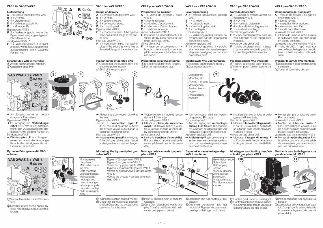
- 16 -
VAS 1 für VAS 2/VAS 3
LieferumfangA 1 x Bypass-/Zündgasventil VAS 1.B 4 x O-Ringe.C 4 x Distanzhülsen.D 4 x Verbindungstechnik.E 1 x Montagehilfe.Bypassventil VAS 1F 2 x Verbindungsrohr, wenn das
Bypassventil ausgangsseitig einen Blind-Flansch hat.
Zündgasventil VAS 1F 1 x Verbindungsrohr, 1 x Dicht-
stopfen, wenn das Zündgasventil ausgangsseitig einen Gewinde-Flansch hat.
Eingebautes VAS vorbereiten Anlage spannungsfrei schalten. Gaszufuhr absperren
3VAS 2/VAS 3 + VAS 1 6
F B
B
54 7
EA C
D
B
FE
MontagehilfeMounting aidAide au montageMontagehulpAusilio di mon-taggioAyuda para el montaje
➔ Am Eingang immer ein Verbin-dungsrohr F einsetzen.
Bypassventil VAS 1➔ Im Ausgang ein Verbindungs-
rohr F Ø 10 mm (0,39") einsetzen, wenn der Ausgangsflansch des Bypass-ventils ein Blind-Flansch ist.
Zündgasventil VAS 1➔ Dichtstopfen F am Ausgang
einsetzen, wenn der Ausgangs-flansch des Zündgasventils ein Gewinde-Flansch ist.
Bypass-/Zündgasventil VAS 1 anbauen
8 109 A
C
D
11VAS 2/VAS 3 + VAS 1
A C
D
B
FE
Montageseite Hauptventil.Main valve mount-ing side.Côté montage vanne principale.Montagezijde hoofdgasklep.Lato montaggio valvola principale.Lado de montaje en la válvula prin-cipal.
Bypass-/Zündgasventil VAS 1.Bypass/pilot gas valve VAS 1.Vanne de by-pass / pilote VAS 1.Bypass-klep/aansteek-gasklep VAS 1.Valvola di bypass/valvola del gas pilota VAS 1.Válvula de bypass / de gas de encen-dido VAS 1.
Gewindeformende Schrauben.Self-tapping screws.Vis taraudeuses.Zelftappende schroeven.Viti autofilettanti.Tornillos autorros-cantes.
Verdrahten (siehe Kapitel Verdrah-ten).
Dichtheit prüfen (siehe Kapitel By-pass-/Zündgasventil auf Dichtheit prüfen).
VAS 1 pour VAS 2 / VAS 3
Programme de livraisonA 1 x vanne de by-pass / pilote
VAS 1.B 4 x joints toriques.C 4 x douilles d’écartement.D 4 x éléments d’assemblage.E 1 x aide au montage.Vanne de by-pass VAS 1F 2 x tubes de raccordement, si la
vanne de by-pass possède une bride pleine à la sortie.
Vanne pilote VAS 1F 1 x tube de raccordement, 1 x
bouchon d’étanchéité, si la vanne pilote possède une bride taraudée à la sortie.
Préparation de la VAS intégrée Mettre l’installation hors tension. Fermer l’alimentation gaz.
➔Toujours utiliser un tube de raccor-dement F à l’entrée.
Vanne de by-pass VAS 1➔Utiliser un tube de raccorde-
ment F Ø 10 mm (0,39") à la sor-tie, si la bride aval de la vanne de by-pass est une bride pleine.
Vanne pilote VAS 1➔ Insérer le bouchon d’étanchéité
F à la sortie, si la bride aval de la vanne pilote est une bride tarau-dée.
Montage de la vanne de by-pass / pilote VAS 1
Pour le câblage (voir le chapitre Câblage).
Contrôler l’étanchéité (voir le cha-pitre Contrôle de l’étanchéité de la vanne de by-pass / pilote).
VAS 1 voor VAS 2/VAS 3
LeveringsomvangA 1 x bypass-klep/aansteek-gasklep
VAS 1.B 4 x O-ringen.C 4 x afstandshulzen.D 4 x verbindingstechniek.E 1 x montagehulp.Bypass-klep VAS 1F 2 x verbindingsleiding wanneer de
bypass-klep aan de uitgang een blinde flens heeft.
Aansteek-gasklep VAS 1F 1 x verbindingsleiding, 1 x afdicht-
stop wanneer de aansteek-gas-klep aan de uitgang een schroef-draadflens heeft.
Ingebouwde VAS voorbereiden Installatie spanningsvrij maken. Gastoevoer afsluiten.
➔Aan de ingang altijd een verbin-dingsleiding F inzetten.
Bypass-klep VAS 1➔Aan de uitgang een verbindings-
leiding F (Ø 10 mm (0,39")) inzet-ten wanneer de uitgangsflens van de bypass-klep een blinde flens is.
Aansteek-gasklep VAS 1➔Afdichtstop F aan de uitgang in-
zetten wanneer de uitgangsflens van de aansteek-gasklep een schroefdraadflens is.
Bypass-klep/aansteek-gasklep VAS 1 monteren
Bedraden (zie het hoofdstuk Be-draden).
Dichtheid controleren (zie het hoofdstuk Bypass-klep/aansteek-gasklep op lekkage controleren).
VAS 1 per VAS 2/VAS 3
Corredo di fornituraA 1 x valvola di bypass/valvola del
gas pilota VAS 1.B 4 x O-ring.C 4 x manicotti distanziali.D 4 x dispositivi di collegamento.E 1 x ausilio di montaggio.Valvola di bypass VAS 1F 2 x tubi di collegamento, se la val-
vola di bypass ha una flangia cieca in uscita.
Valvola del gas pilota VAS 1F 1 x tubo di collegamento, 1 x tappo
di tenuta, se la valvola del gas pilota ha una flangia filettata in uscita.
Predisposizione VAS integrata Togliere la tensione dall’impianto. Interrompere l’alimentazione del
gas.
➔ Installare sempre un tubo di colle-gamento F in entrata.
Valvola di bypass VAS 1➔Montare il tubo di collegamento
F da Ø 10 mm (0,39") sull’uscita, se la flangia della valvola di bypass in uscita è cieca.
Valvola del gas pilota VAS 1➔Montare il tappo di tenuta F
sull’uscita, se la flangia della valvo-la del gas pilota in uscita è filettata.
Montaggio valvola di bypass/val-vola del gas pilota VAS 1
Cablare (vedi capitolo Cablaggio). Controllo della tenuta (vedi capito-
lo Controllo della tenuta valvola di bypass/valvola del gas pilota).
VAS 1 para VAS 2 / VAS 3
Componentes del suministroA 1 válvula de bypass / de gas de
encendido VAS 1.B 4 juntas tóricas.C 4 casquillos distanciadores.D 4 elementos de unión.E 1 ayuda para el montaje.Válvula de bypass VAS 1F 2 tubos de unión, cuando la válvu-
la de bypass tiene una brida ciega en el lado de salida.
Válvula de gas de encendido VAS 1F 1 tubo de unión, 1 tapón obturador,
cuando la válvula de gas de encendido tiene una brida roscada en el lado de salida.
Preparar la válvula VAS montada Desconectar y dejar sin tensión la
instalación. Cortar el suministro de gas.
➔Montar siempre un tubo de unión F en la entrada.
Válvula de bypass VAS 1➔Montar un tubo de unión F
(Ø 10 mm (0,39")) en la salida, cuan-do la brida de salida de la válvula de bypass sea una brida ciega.
Válvula de gas de encendido VAS 1➔Montar el tapón obturador F en
la salida, cuando la brida de salida de la válvula de gas de encendido sea una brida roscada.
Montar la válvula de bypass / de gas de encendido VAS 1
Para el cableado (ver capítulo Ca-bleado).
Comprobar si hay fugas (ver capí-tulo Comprobar la estanquidad de la válvula de bypass / de gas de encendido).
VAS 1 for VAS 2/VAS 3
Scope of deliveryA 1 x bypass/pilot gas valve VAS 1.B 4 x O-rings.C 4 x spacer sleeves.D 4 x connection parts.E 1 x mounting aid.Bypass valve VAS 1F 2 x connection pipes, if the bypass
valve has a blind flange at the out-let side.
Pilot gas valve VAS 1F 1 x connection pipe, 1 x sealing
plug, if the pilot gas valve has a threaded flange at the outlet side.
Preparing the integrated VAS Disconnect the system from the
electrical power supply. Shut off the gas supply.
➔Always use a connection pipe F at the inlet.
Bypass valve VAS 1➔Use a connection pipe F
(Ø 10 mm (0.39")) at the outlet if the bypass valve’s outlet flange is designed as a blind flange.
Pilot gas valve VAS 1➔Insert sealing plug F at the outlet
if the pilot gas valve’s outlet flange is designed as a threaded flange.
Mounting the bypass/pilot gas valve VAS 1
Wiring (see section entitled Wiring). Check for tightness (see section
entitled Checking the bypass/pilot gas valve for tightness).
A BC
D
FE
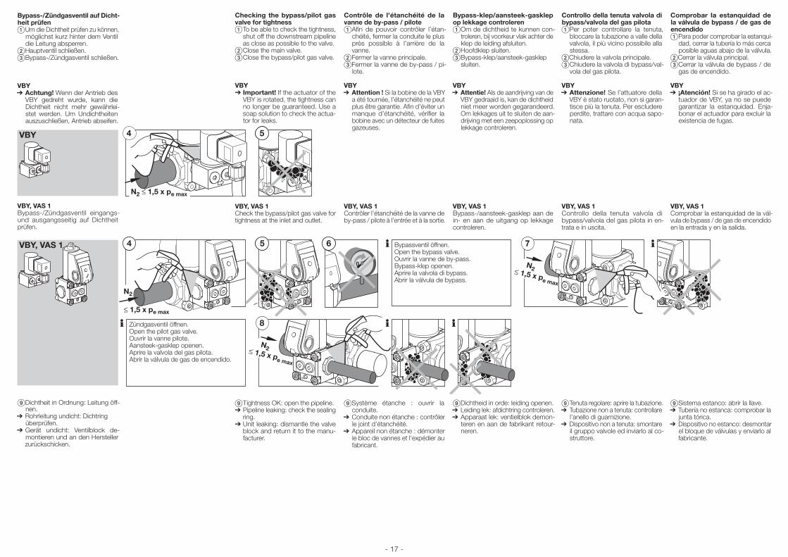
Bypass-/Zündgasventil auf Dicht-heit prüfen Um die Dichtheit prüfen zu können,
möglichst kurz hinter dem Ventil die Leitung absperren.
Hauptventil schließen. Bypass-/Zündgasventil schließen.
VBY➔ Achtung! Wenn der Antrieb des
VBY gedreht wurde, kann die Dichtheit nicht mehr gewährlei-stet werden. Um Undichtheiten auszuschließen, Antrieb abseifen.
VBY, VAS 1Bypass-/Zündgasventil eingangs- und ausgangsseitig auf Dichtheit prüfen.
Dichtheit in Ordnung: Leitung öff-nen.
➔ Rohrleitung undicht: Dichtring überprüfen.
➔ Gerät undicht: Ventilblock de-montieren und an den Hersteller zurückschicken.
Contrôle de l’étanchéité de la vanne de by-pass / pilote Afin de pouvoir contrôler l’étan-
chéité, fermer la conduite le plus près possible à l’arrière de la vanne.
Fermer la vanne principale. Fermer la vanne de by-pass / pi-
lote.
VBY➔Attention ! Si la bobine de la VBY
a été tournée, l’étanchéité ne peut plus être garantie. Afin d’éviter un manque d’étanchéité, vérifier la bobine avec un détecteur de fuites gazeuses.
VBY, VAS 1Contrôler l’étanchéité de la vanne de by-pass / pilote à l’entrée et à la sortie.
Système étanche : ouvrir la conduite.
➔Conduite non étanche : contrôler le joint d’étanchéité.
➔Appareil non étanche : démonter le bloc de vannes et l’expédier au fabricant.
Comprobar la estanquidad de la válvula de bypass / de gas de encendido Para poder comprobar la estanqui-
dad, cerrar la tubería lo más cerca posible aguas abajo de la válvula.
Cerrar la válvula principal. Cerrar la válvula de bypass / de
gas de encendido.
VBY➔ ¡Atención! Si se ha girado el ac-
tuador de VBY, ya no se puede garantizar la estanquidad. Enja-bonar el actuador para excluir la existencia de fugas.
VBY, VAS 1Comprobar la estanquidad de la vál-vula de bypass / de gas de encendido en la entrada y en la salida.
Sistema estanco: abrir la llave.➔Tubería no estanca: comprobar la
junta tórica.➔Dispositivo no estanco: desmontar
el bloque de válvulas y enviarlo al fabricante.
Checking the bypass/pilot gas valve for tightness To be able to check the tightness,
shut off the downstream pipeline as close as possible to the valve.
Close the main valve. Close the bypass/pilot gas valve.
VBY➔ Important! If the actuator of the
VBY is rotated, the tightness can no longer be guaranteed. Use a soap solution to check the actua-tor for leaks.
VBY, VAS 1Check the bypass/pilot gas valve for tightness at the inlet and outlet.
Tightness OK: open the pipeline.➔Pipeline leaking: check the sealing
ring.➔Unit leaking: dismantle the valve
block and return it to the manu-facturer.
Controllo della tenuta valvola di bypass/valvola del gas pilota Per poter controllare la tenuta,
bloccare la tubazione a valle della valvola, il più vicino possibile alla stessa.
Chiudere la valvola principale. Chiudere la valvola di bypass/val-
vola del gas pilota.
VBY➔Attenzione! Se l’attuatore della
VBY è stato ruotato, non si garan-tisce più la tenuta. Per escludere perdite, trattare con acqua sapo-nata.
VBY, VAS 1Controllo della tenuta valvola di bypass/valvola del gas pilota in en-trata e in uscita.
Tenuta regolare: aprire la tubazione.➔Tubazione non a tenuta: controllare
l’anello di guarnizione.➔Dispositivo non a tenuta: smontare
il gruppo valvole ed inviarlo al co-struttore.
Bypass-klep/aansteek-gasklep op lekkage controleren Om de dichtheid te kunnen con-
troleren, bij voorkeur vlak achter de klep de leiding afsluiten.
Hoofdklep sluiten. Bypass-klep/aansteek-gasklep
sluiten.
VBY➔Attentie! Als de aandrijving van de
VBY gedraaid is, kan de dichtheid niet meer worden gegarandeerd. Om lekkages uit te sluiten de aan-drijving met een zeepoplossing op lekkage controleren.
VBY, VAS 1Bypass-/aansteek-gasklep aan de in- en aan de uitgang op lekkage controleren.
Dichtheid in orde: leiding openen.➔Leiding lek: afdichtring controleren.➔Apparaat lek: ventielblok demon-
teren en aan de fabrikant retour-neren.
- 17 -
VBY
N2 ≤ 1,5 x pe max
4 5
VBY, VAS 1 4
N2
5
0
6
8
N2≤ 1,5 x pe max
7
N2≤ 1,5 x pe max
Bypassventil öffnen.Open the bypass valve.Ouvrir la vanne de by-pass.Bypass-klep openen.Aprire la valvola di bypass.Abrir la válvula de bypass.
Zündgasventil öffnen.Open the pilot gas valve.Ouvrir la vanne pilote.Aansteek-gasklep openen.Aprire la valvola del gas pilota.Abrir la válvula de gas de encendido.
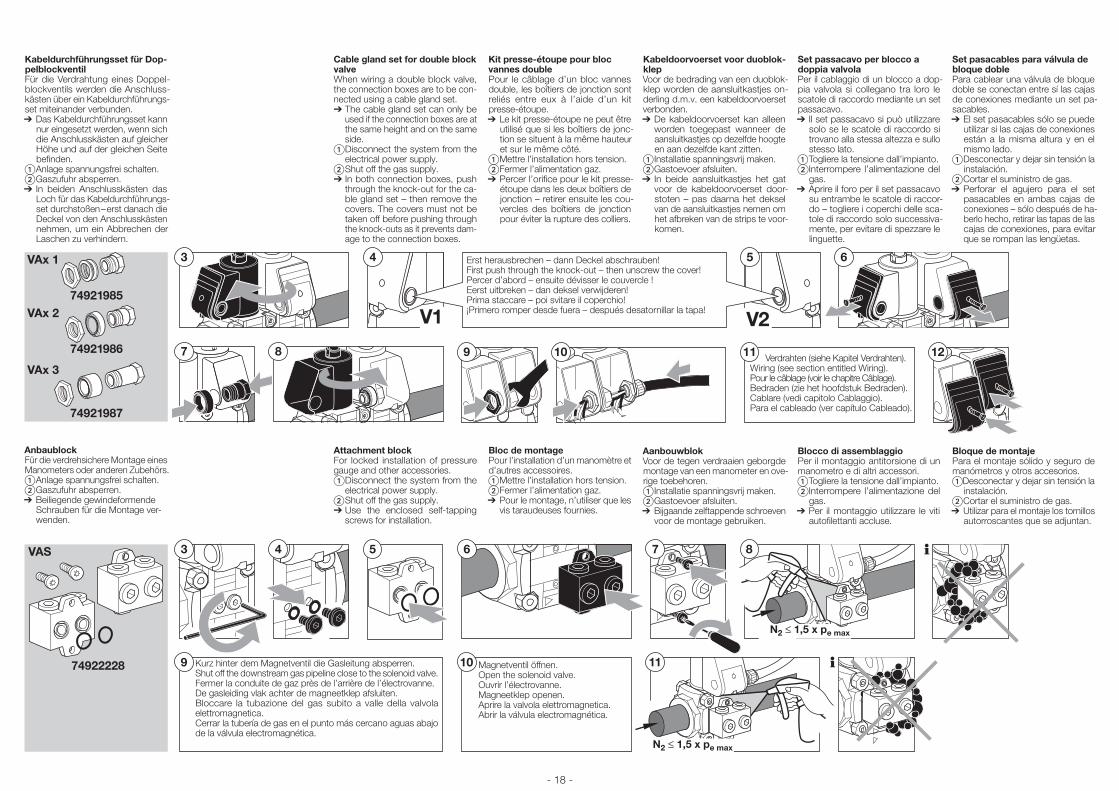
Kabeldurchführungsset für Dop-pelblockventilFür die Verdrahtung eines Doppel-blockventils werden die Anschluss-kästen über ein Kabeldurchführungs-set miteinander verbunden.➔ Das Kabeldurchführungsset kann
nur eingesetzt werden, wenn sich die Anschlusskästen auf gleicher Höhe und auf der gleichen Seite befinden.
Anlage spannungsfrei schalten. Gaszufuhr absperren.➔ In beiden Anschlusskästen das
Loch für das Kabeldurchführungs-set durchstoßen – erst danach die Deckel von den Anschlusskästen nehmen, um ein Abbrechen der Laschen zu verhindern.
AnbaublockFür die verdrehsichere Montage eines Manometers oder anderen Zubehörs. Anlage spannungsfrei schalten. Gaszufuhr absperren. ➔ Beiliegende gewindeformende
Schrauben für die Montage ver-wenden.
Cable gland set for double block valveWhen wiring a double block valve, the connection boxes are to be con-nected using a cable gland set.➔The cable gland set can only be
used if the connection boxes are at the same height and on the same side.
Disconnect the system from the electrical power supply.
Shut off the gas supply.➔In both connection boxes, push
through the knock-out for the ca-ble gland set – then remove the covers. The covers must not be taken off before pushing through the knock-outs as it prevents dam-age to the connection boxes.
Attachment blockFor locked installation of pressure gauge and other accessories.Disconnect the system from the
electrical power supply. Shut off the gas supply.➔Use the enclosed self-tapping
screws for installation.
Kit presse-étoupe pour bloc vannes doublePour le câblage d’un bloc vannes double, les boîtiers de jonction sont reliés entre eux à l’aide d’un kit presse-étoupe.➔Le kit presse-étoupe ne peut être
utilisé que si les boîtiers de jonc-tion se situent à la même hauteur et sur le même côté.
Mettre l’installation hors tension. Fermer l’alimentation gaz.➔Percer l’orifice pour le kit presse-
étoupe dans les deux boîtiers de jonction – retirer ensuite les cou-vercles des boîtiers de jonction pour éviter la rupture des colliers.
Bloc de montagePour l’installation d’un manomètre et d’autres accessoires.Mettre l’installation hors tension. Fermer l’alimentation gaz.➔Pour le montage, n’utiliser que les
vis taraudeuses fournies.
Set passacavo per blocco a doppia valvolaPer il cablaggio di un blocco a dop-pia valvola si collegano tra loro le scatole di raccordo mediante un set passacavo.➔ Il set passacavo si può utilizzare
solo se le scatole di raccordo si trovano alla stessa altezza e sullo stesso lato.
Togliere la tensione dall’impianto. Interrompere l’alimentazione del
gas.➔Aprire il foro per il set passacavo
su entrambe le scatole di raccor-do – togliere i coperchi delle sca-tole di raccordo solo successiva-mente, per evitare di spezzare le linguette.
Blocco di assemblaggioPer il montaggio antitorsione di un manometro e di altri accessori.Togliere la tensione dall’impianto. Interrompere l’alimentazione del
gas.➔Per il montaggio utilizzare le viti
autofilettanti accluse.
Set pasacables para válvula de bloque doblePara cablear una válvula de bloque doble se conectan entre sí las cajas de conexiones mediante un set pa-sacables.➔El set pasacables sólo se puede
utilizar si las cajas de conexiones están a la misma altura y en el mismo lado.
Desconectar y dejar sin tensión la instalación.
Cortar el suministro de gas.➔Perforar el agujero para el set
pasacables en ambas cajas de conexiones – sólo después de ha-berlo hecho, retirar las tapas de las cajas de conexiones, para evitar que se rompan las lengüetas.
Bloque de montajePara el montaje sólido y seguro de manómetros y otros accesorios.Desconectar y dejar sin tensión la
instalación. Cortar el suministro de gas.➔Utilizar para el montaje los tornillos
autorroscantes que se adjuntan.
Kabeldoorvoerset voor duoblok-klepVoor de bedrading van een duoblok-klep worden de aansluitkastjes on-derling d.m.v. een kabeldoorvoerset verbonden.➔De kabeldoorvoerset kan alleen
worden toegepast wanneer de aansluitkastjes op dezelfde hoogte en aan dezelfde kant zitten.
Installatie spanningsvrij maken. Gastoevoer afsluiten.➔ In beide aansluitkastjes het gat
voor de kabeldoorvoerset door-stoten – pas daarna het deksel van de aansluitkastjes nemen om het afbreken van de strips te voor-komen.
AanbouwblokVoor de tegen verdraaien geborgde montage van een manometer en ove-rige toebehoren. Installatie spanningsvrij maken. Gastoevoer afsluiten.➔Bijgaande zelftappende schroeven
voor de montage gebruiken.
- 18 -
74921987
74921985
74921986 11
VAx 1
VAx 2
VAx 3
6 4 5
V1 V2
3
7 8 9 1210
Erst herausbrechen – dann Deckel abschrauben!First push through the knock-out – then unscrew the cover!Percer d’abord – ensuite dévisser le couvercle !Eerst uitbreken – dan deksel verwijderen!Prima staccare – poi svitare il coperchio!¡Primero romper desde fuera – después desatornillar la tapa!
Verdrahten (siehe Kapitel Verdrahten).Wiring (see section entitled Wiring).Pour le câblage (voir le chapitre Câblage).Bedraden (zie het hoofdstuk Bedraden).Cablare (vedi capitolo Cablaggio).Para el cableado (ver capítulo Cableado).
8 VAS
74922228
4 5 3 6 7
10
N2 ≤ 1,5 x pe max
9 11
N2 ≤ 1,5 x pe max
Magnetventil öffnen.Open the solenoid valve.Ouvrir l’électrovanne.Magneetklep openen.Aprire la valvola elettromagnetica.Abrir la válvula electromagnética.
Kurz hinter dem Magnetventil die Gasleitung absperren.Shut off the downstream gas pipeline close to the solenoid valve.Fermer la conduite de gaz près de l’arrière de l’électrovanne.De gasleiding vlak achter de magneetklep afsluiten.Bloccare la tubazione del gas subito a valle della valvola elettromagnetica.Cerrar la tubería de gas en el punto más cercano aguas abajo de la válvula electromagnética.
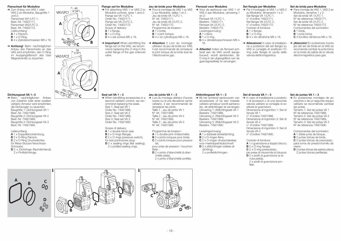
- 19 -
Flanschset für Moduline➔ Zum Anbau von VAS 1 oder
VAS 2 an Moduline, Baugröße 1 und 2: Flanschset VA1/LFC 1,
Best.-Nr. 74922171, Flanschset VA2/LFC 2, Best.-Nr. 74922172. Lieferumfang: A 1 x Flansch, B 1 x O-Ring, C 4 x Zylinderschrauben M5 x 16.
➔ Achtung! Beim nachträglichen Anbau des Flanschsets an das VAS wird empfohlen, den O-Ring im Ausgangsflansch des Gas-Magnetventils zu tauschen.
Dichtungsset VA 1 – 3➔ Beim nachträglichen Anbau
von Zubehör oder einer zweiten valVario-Armatur wird empfohlen, die Dichtungen zu tauschen.
Baugröße 1: Dichtungsset VA 1 Best.-Nr. 74921988, Baugröße 2: Dichtungsset VA 2 Best.-Nr. 74921989, Baugröße 3: Dichtungsset VA 3 Best.-Nr. 74921990.
Lieferumfang: A 1 x Doppelblockdichtung, B 2 x O-Ring Flansch, C 2 x O-Ring Druckwächter, für Mess-Stutzen/Verschluss-
Schraube: D 2 x Dichtringe (flachdichtend),
2 x Profildichtringe.
Flange set for Moduline➔ For attaching VAS 1 or VAS 2 to
Moduline controls, sizes 1 and 2: Flange set VA 1/LFC 1, Order No. 74922171, Flange set VA 2/LFC 2, Order No. 74922172. Scope of delivery: A 1 x flange, B 1 x O-ring, C 4 x set screws M5 x 16.
➔ Important! When retrofitting the flange set on the VAS, we recom-mend replacing the O-ring in the outlet flange of the gas solenoid valve.
Seal set VA 1 – 3➔ When retrofitting accessories or a
second valVario control, we rec-ommend replacing the seals.
Size 1: Seal set VA 1 Order No. 74921988, Size 2: Seal set VA 2 Order No. 74921989, Size 3: Seal set VA 3 Order No. 74921990.
Scope of delivery: A 1 x double block seal, B 2 x O-rings (flange), C 2 x O-rings (pressure switch), for test point/screw plug: D 2 x sealing rings (flat sealing),
2 x profiled sealing rings.
Jeu de bride pour Moduline➔ Pour le montage de VAS 1 ou VAS
2 sur Moduline, tailles 1 et 2 : Jeu de bride VA 1/LFC 1, N° réf. 74922171, Jeu de bride VA 2/LFC 2, N° réf. 74922172. Programme de livraison : A 1 x bride, B 1 x joint torique, C 4 x vis cylindriques M5 x 16.
➔ Attention ! Lors du montage ultérieur du jeu de bride sur VAS, il est recommandé de remplacer le joint torique de la bride aval de l’électrovanne gaz.
Jeu de joints VA 1 – 3➔ Lors du montage ultérieur d’acces-
soires ou d’une deuxième vanne valVario, il est recommandé de remplacer les joints.
Taille 1 : Jeu de joints VA 1 N° réf. 74921988, Taille 2 : Jeu de joints VA 2 N° réf. 74921989, Taille 3 : Jeu de joints VA 3 N° réf. 74921990.
Programme de livraison : A 1 x double joint d’étanchéité, B 2 x joints toriques pour bride, C 2 x joints toriques pour pressos-
tat, pour prise de pression / bouchon
fileté : D 2 x joints d’étanchéité (à étan-
chéité plate), 2 x joints d’étanchéité profilés.
Flensset voor Moduline➔ Voor de aanbouw van VAS 1 of
VAS 2 aan Moduline, uitvoering 1 en 2:
Flensset VA 1/LFC 1, Bestelnr. 74922171, Flensset VA 2/LFC 2, Bestelnr. 74922172. Leveringsomvang: A 1 x flens, B 1 x O-ring, C 4 x cilinderkopschroeven M5 x
16.
➔ Attentie! Indien de flensset ach-teraf aan de VAS wordt aange-bouwd, wordt aanbevolen, de O-ring in de uitgangsflens van de gasmagneetklep te vervangen.
Afdichtingsset VA 1 – 3➔ Bij het achteraf aanbouwen van
accessoires of bij een tweede valVario-armatuur wordt aanbevo-len, de afdichtingen te vervangen.
Uitvoering 1: Afdichtingsset VA 1 Bestelnr. 74921988, Uitvoering 2: Afdichtingsset VA 2 Bestelnr. 74921989, Uitvoering 3: Afdichtingsset VA 3 Bestelnr. 74921990.
Leveringsomvang: A 1 x dubbele blokafdichting, B 2 x O-ringen flens, C 2 x O-ringen drukschakelaar, voor meetnippel/sluitschroef: D 2 x afdichtringen (vlakke af-
dichting), 2 x profieldichtringen.
Set flangia per Moduline➔ Per il montaggio di VAS 1 o VAS 2
su Moduline, dimensioni 1 e 2: Set flangia VA 1/LFC 1, n° d’ordine 74922171, Set flangia VA 2/LFC 2, n° d’ordine 74922172. Corredo di fornitura: A 1 x flangia, B 1 x O-ring, C 4 x viti cilindriche M5 x 16.
➔ Attenzione! In caso di installazio-ne a posteriori del set flangia su VAS si consiglia di sostituire l’O-ring sulla flangia di uscita della valvola elettromagnetica.
Set di tenuta VA 1 – 3➔ In caso di installazione a posterio-
ri di accessori o di una seconda valvola valVario si consiglia di so-stituire le guarnizioni.
Dimensione di ingombro 1: Set di tenuta VA 1
n° d’ordine 74921988, Dimensione di ingombro 2: Set di
tenuta VA 2 n° d’ordine 74921989, Dimensione di ingombro 3: Set di
tenuta VA 3 n° d’ordine 74921990.
Corredo di fornitura: A 1 x guarnizione a doppio blocco, B 2 x O-ring flangia, C 2 x O-ring pressostato, per presa di misura/vite di chiusura: D 2 x anelli di guarnizione (a te-
nuta piatta), 2 x anelli di guarnizione pro-filati.
Set de brida para Moduline➔ Para montaje de VAS 1, VAS 2 en
Moduline, tamaños 1 y 2: Set de brida VA 1/LFC 1, Nº de referencia 74922171, Set de brida VA 2/LFC 2, Nº de referencia 74922172. Componentes del suministro: A 1 brida, B 1 junta tórica, C 4 tornillos cilíndricos M5 x 16.
➔ ¡Atención! En posteriores monta-jes del set de brida en la VAS se recomienda cambiar la junta tórica en la brida de salida de la válvula electromagnética para gas.
Set de juntas VA 1 – 3➔ En posteriores montajes de ac-
cesorios o de un segundo equipo valVario se recomienda cambiar las juntas.
Tamaño 1: Set de juntas VA 1 Nº de referencia 74921988, Tamaño 2: Set de juntas VA 2 Nº de referencia 74921989, Tamaño 3: Set de juntas VA 3 Nº de referencia 74921990.
Componentes del suministro: A 1 doble junta de bloque, B 2 juntas tóricas de brida, C 2 juntas tóricas de presostato, para toma de presión/tornillo de
cierre: D 2 juntas tóricas (de asiento plano),
2 juntas tóricas perfiladas.
60(2.36")
50(1.97")
VA1/LFC1
VA2/LFC2
A A
C CB
B
60(2.36")
50(1.97")
VA1/LFC1
VA2/LFC2
A A
C CB
B
AB
B
BD
CA
D
C
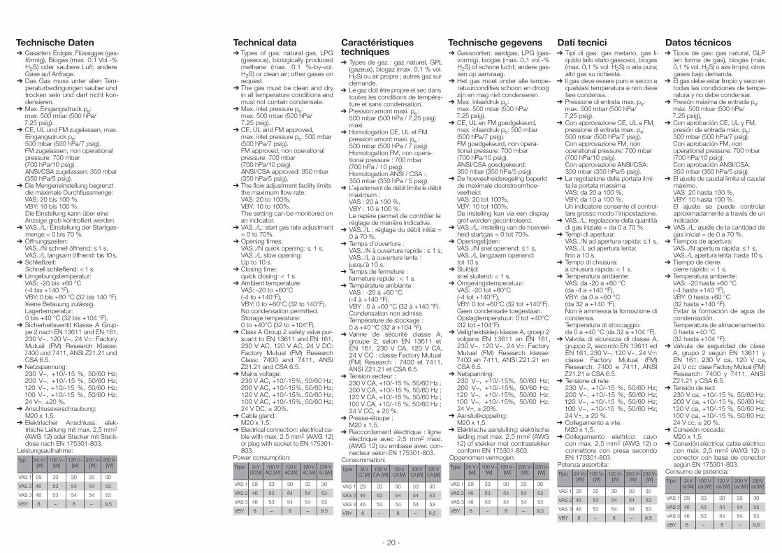
- 20 -
Dati tecnici➔Tipi di gas: gas metano, gas li-
quido (allo stato gassoso), biogas (max. 0,1 % vol. H2S) o aria pura; altri gas su richiesta.
➔ Il gas deve essere puro e secco a qualsiasi temperatura e non deve fare condensa.
➔Pressione di entrata max. pe: max. 500 mbar (500 hPa/
7,25 psig).➔Con approvazione CE, UL e FM, pressione di entrata max. pe:
500 mbar (500 hPa/7 psig). Con approvazione FM, non
operational pressure: 700 mbar (700 hPa/10 psig).
Con approvazione ANSI/CSA: 350 mbar (350 hPa/5 psig).
➔La regolazione della portata limi-ta la portata massima:
VAS: da 20 a 100 %, VBY: da 10 a 100 %. Un indicatore consente di control-
lare grosso modo l’impostazione.➔VAS../L: regolazione della quantità
di gas iniziale = da 0 a 70 %.➔Tempi di apertura: VAS../N ad apertura rapida: ≤ 1 s, VAS../L ad apertura lenta: fino a 10 s.➔Tempo di chiusura: a chiusura rapida: < 1 s.➔Temperatura ambiente: VAS: da -20 a +60 °C (da -4 a +140 °F), VBY: da 0 a +60 °C (da 32 a +140 °F). Non è ammessa la formazione di
condensa. Temperatura di stoccaggio: da 0 a +40 °C (da 32 a +104 °F).➔Valvola di sicurezza di classe A,
gruppo 2, secondo EN 13611 ed EN 161, 230 V~, 120 V~, 24 V=: classe Factory Mutual (FM) Research: 7400 e 7411, ANSI Z21.21 e CSA 6.5.
➔Tensione di rete: 230 V~, +10/-15 %, 50/60 Hz;
200 V~, +10/-15 %, 50/60 Hz; 120 V~, +10/-15 %, 50/60 Hz; 100 V~, +10/-15 %, 50/60 Hz; 24 V=, ± 20 %.
➔Collegamento a vite: M20 x 1,5.➔ Collegamento elettrico: cavo
con max. 2,5 mm2 (AWG 12) o connettore con presa secondo EN 175301-803.
Potenza assorbita:Tipo 24 V=
[W]100 V~
[W]120 V~
[W]200 V~
[W]230 V~
[W]
VAS 1 29 33 30 33 30
VAS 2 46 53 54 54 53
VAS 3 46 53 54 54 53
VBY 8 – 8 – 9,5
Technische Daten➔ Gasarten: Erdgas, Flüssiggas (gas-
förmig), Biogas (max. 0,1 Vol.-% H2S) oder saubere Luft; andere Gase auf Anfrage.
➔ Das Gas muss unter allen Tem-peraturbedingungen sauber und trocken sein und darf nicht kon-densieren.
➔ Max. Eingangsdruck pe: max. 500 mbar (500 hPa/
7,25 psig).➔ CE, UL und FM zugelassen, max.
Eingangsdruck pe: 500 mbar (500 hPa/7 psig). FM zugelassen, non operational
pressure: 700 mbar (700 hPa/10 psig). ANSI/CSA zugelassen: 350 mbar (350 hPa/5 psig).➔ Die Mengeneinstellung begrenzt
die maximale Durchflussmenge: VAS: 20 bis 100 %, VBY: 10 bis 100 %. Die Einstellung kann über eine Anzeige grob kontrolliert werden.
➔ VAS../L: Einstellung der Startgas-menge = 0 bis 70 %.
➔ Öffnungszeiten: VAS../N schnell öffnend: ≤ 1 s,
VAS../L langsam öffnend: bis 10 s.➔ Schließzeit:
Schnell schließend: < 1 s.➔ Umgebungstemperatur:
VAS: -20 bis +60 °C (-4 bis +140 °F), VBY: 0 bis +60 °C (32 bis 140 °F). Keine Betauung zulässig.
Lagertemperatur: 0 bis +40 °C (32 bis +104 °F).
➔ Sicherheitsventil Klasse A Grup-pe 2 nach EN 13611 und EN 161, 230 V~, 120 V~, 24 V=: Factory Mutual (FM) Research Klasse: 7400 und 7411, ANSI Z21.21 und CSA 6.5.
➔ Netzspannung: 230 V~, +10/-15 %, 50/60 Hz; 200 V~, +10/-15 %, 50/60 Hz; 120 V~, +10/-15 %, 50/60 Hz; 100 V~, +10/-15 %, 50/60 Hz; 24 V=, ±20 %.
➔ Anschlussverschraubung: M20 x 1,5.
➔ Elektrischer Anschluss: elek-trische Leitung mit max. 2,5 mm2
(AWG 12) oder Stecker mit Steck-dose nach EN 175301-803.
Leistungsaufnahme:Typ 24 V=
[W]100 V~
[W]120 V~
[W]200 V~
[W]230 V~
[W]
VAS 1 29 33 30 33 30
VAS 2 46 53 54 54 53
VAS 3 46 53 54 54 53
VBY 8 – 8 – 9,5
Technical data➔Types of gas: natural gas, LPG
(gaseous), biologically produced methane (max. 0.1 %-by-vol. H2S) or clean air; other gases on request.
➔The gas must be clean and dry in all temperature conditions and must not contain condensate.
➔Max. inlet pressure pe: max. 500 mbar (500 hPa/
7.25 psig).➔CE, UL and FM approved, max. inlet pressure pe: 500 mbar
(500 hPa/7 psig). FM approved, non operational
pressure: 700 mbar (700 hPa/10 psig).
ANSI/CSA approved: 350 mbar (350 hPa/5 psig).
➔The flow adjustment facility limits the maximum flow rate:
VAS: 20 to 100%, VBY: 10 to 100%. The setting can be monitored on
an indicator.➔VAS../L: start gas rate adjustment
= 0 to 70%.➔Opening times: VAS../N quick opening: ≤ 1 s, VAS../L slow opening: Up to 10 s.➔Closing time: quick closing: < 1 s.➔Ambient temperature: VAS: -20 to +60°C (-4 to +140°F), VBY: 0 to +60°C (32 to 140°F). No condensation permitted. Storage temperature: 0 to +40°C (32 to +104°F).➔Class A Group 2 safety valve pur-
suant to EN 13611 and EN 161, 230 V AC, 120 V AC, 24 V DC: Factory Mutual (FM) Research Class: 7400 and 7411, ANSI Z21.21 and CSA 6.5.
➔Mains voltage: 230 V AC, +10/-15%, 50/60 Hz;
200 V AC, +10/-15%, 50/60 Hz; 120 V AC, +10/-15%, 50/60 Hz; 100 V AC, +10/-15%, 50/60 Hz; 24 V DC, ± 20%.
➔Cable gland: M20 x 1.5.➔ Electrical connection: electrical ca-
ble with max. 2.5 mm2 (AWG 12) or plug with socket to EN 175301-803.
Power consumption:Type 24 V
DC [W]100 V AC [W]
120 V AC [W]
200 V AC [W]
230 V AC [W]
VAS 1 29 33 30 33 30
VAS 2 46 53 54 54 53
VAS 3 46 53 54 54 53
VBY 8 – 8 – 9.5
Caractéristiques techniques➔Types de gaz : gaz naturel, GPL
(gazeux), biogaz (max. 0,1 % vol. H2S) ou air propre ; autres gaz sur demande.
➔Le gaz doit être propre et sec dans toutes les conditions de tempéra-ture et sans condensation.
➔Pression amont maxi. pe : 500 mbar (500 hPa / 7,25 psig)
maxi.➔Homologation CE, UL et FM, pression amont maxi. pe :
500 mbar (500 hPa / 7 psig). Homologation FM, non opera-
tional pressure : 700 mbar (700 hPa / 10 psig).
Homologation ANSI / CSA : 350 mbar (350 hPa / 5 psig).
➔L’ajustement de débit limite le débit maximum :
VAS : 20 à 100 %, VBY : 10 à 100 %. Le repère permet de contrôler le
réglage de manière indicative.➔VAS../L : réglage du débit initial =
0 à 70 %.➔Temps d’ouverture : VAS../N à ouverture rapide : ≤ 1 s, VAS../L à ouverture lente : jusqu’à 10 s.➔Temps de fermeture : fermeture rapide : < 1 s.➔Température ambiante : VAS : -20 à +60 °C (-4 à +140 °F), VBY : 0 à +60 °C (32 à +140 °F). Condensation non admise. Température de stockage : 0 à +40 °C (32 à +104 °F).➔Vanne de sécurité classe A,
groupe 2, selon EN 13611 et EN 161, 230 V CA, 120 V CA, 24 V CC : classe Factory Mutual (FM) Research : 7400 et 7411, ANSI Z21.21 et CSA 6.5.
➔Tension secteur : 230 V CA, +10/-15 %, 50/60 Hz ;
200 V CA, +10/-15 %, 50/60 Hz ; 120 V CA, +10/-15 %, 50/60 Hz ; 100 V CA, +10/-15 %, 50/60 Hz ; 24 V CC, ± 20 %.
➔Presse-étoupe : M20 x 1,5.➔ Raccordement électrique : ligne
électrique avec 2,5 mm2 maxi. (AWG 12) ou embase avec con-necteur selon EN 175301-803.
Consommation:Type 24 V
CC [W]100 V CA [W]
120 V CA [W]
200 V CA [W]
230 V CA [W]
VAS 1 29 33 30 33 30
VAS 2 46 53 54 54 53
VAS 3 46 53 54 54 53
VBY 8 – 8 – 9,5
Technische gegevens➔Gassoorten: aardgas, LPG (gas-
vormig), biogas (max. 0,1 vol.-% H2S) of schone lucht; andere gas-sen op aanvraag.
➔Het gas moet onder alle tempe-ratuurcondities schoon en droog zijn en mag niet condenseren.
➔Max. inlaatdruk pe: max. 500 mbar (500 hPa/
7,25 psig).➔CE, UL en FM goedgekeurd, max. inlaatdruk pe: 500 mbar
(500 hPa/7 psig). FM goedgekeurd, non opera-
tional pressure: 700 mbar (700 hPa/10 psig).
ANSI/CSA goedgekeurd: 350 mbar (350 hPa/5 psig).
➔De hoeveelheidsregeling beperkt de maximale doorstroomhoe-veelheid:
VAS: 20 tot 100%, VBY: 10 tot 100%. De instelling kan via een display
grof worden gecontroleerd.➔VAS../L: instelling van de hoeveel-
heid startgas = 0 tot 70%.➔Openingstijden: VAS../N snel openend: ≤ 1 s, VAS../L langzaam openend: tot 10 s.➔Sluittijd: snel sluitend: < 1 s.➔Omgevingstemperatuur: VAS: -20 tot +60°C (-4 tot +140°F), VBY: 0 tot +60°C (32 tot +140°F). Geen condensatie toegestaan. Opslagtemperatuur: 0 tot +40°C
(32 tot +104°F).➔Veiligheidsklep klasse A, groep 2
volgens EN 13611 en EN 161, 230 V~, 120 V~, 24 V=: Factory Mutual (FM) Research klasse: 7400 en 7411, ANSI Z21.21 en CSA 6.5.
➔Netspanning: 230 V~, +10/-15%, 50/60 Hz;
200 V~, +10/-15%, 50/60 Hz; 120 V~, +10/-15%, 50/60 Hz; 100 V~, +10/-15%, 50/60 Hz; 24 V=, ± 20%.
➔Aansluitkoppeling: M20 x 1,5.➔ Elektrische aansluiting: elektrische
leiding met max. 2,5 mm2 (AWG 12) of stekker met contrastekker conform EN 175301-803.
Opgenomen vermogen:Type 24 V=
[W]100 V~
[W]120 V~
[W]200 V~
[W]230 V~
[W]
VAS 1 29 33 30 33 30
VAS 2 46 53 54 54 53
VAS 3 46 53 54 54 53
VBY 8 – 8 – 9,5
Datos técnicos➔Tipos de gas: gas natural, GLP
(en forma de gas), biogás (máx. 0,1 % vol. H2S) o aire limpio; otros gases bajo demanda.
➔El gas debe estar limpio y seco en todas las condiciones de tempe-ratura y no debe condensar.
➔Presión máxima de entrada pe: máx. 500 mbar (500 hPa/
7,25 psig),➔Con aprobación CE, UL y FM, presión de entrada máx. pe:
500 mbar (500 hPa/7 psig). Con aprobación FM, non
opera tional pressure: 700 mbar (700 hPa/10 psig).
Con aprobación ANSI/CSA: 350 mbar (350 hPa/5 psig).
➔El ajuste de caudal limita el caudal máximo.
VAS: 20 hasta 100 %, VBY: 10 hasta 100 %. El ajuste se puede controlar
aproximadamente a través de un indicador.
➔VAS../L: ajuste de la cantidad de gas inicial = de 0 a 70 %.
➔Tiempos de apertura: VAS../N apertura rápida: ≤ 1 s, VAS../L apertura lenta: hasta 10 s.➔Tiempo de cierre: cierre rápido: < 1 s.➔Temperatura ambiente: VAS: -20 hasta +60 °C (-4 hasta +140 °F), VBY: 0 hasta +60 °C (32 hasta +140 °F). Evitar la formación de agua de
condensación. Temperatura de almacenamiento:
0 hasta +40 °C (32 hasta +104 °F).➔Válvula de seguridad de clase
A, grupo 2 según EN 13611 y EN 161, 230 V ca, 120 V ca, 24 V cc: clase Factory Mutual (FM) Research: 7400 y 7411, ANSI Z21.21 y CSA 6.5.
➔Tensión de red: 230 V ca, +10/-15 %, 50/60 Hz;
200 V ca, +10/-15 %, 50/60 Hz; 120 V ca, +10/-15 %, 50/60 Hz; 100 V ca, +10/-15 %, 50/60 Hz; 24 V cc, ± 20 %.
➔Conexión roscada: M20 x 1,5.➔ Conexión eléctrica: cable eléctrico
con máx. 2,5 mm2 (AWG 12) o conector con base de conector según EN 175301-803.
Consumo de potencia:Tipo 24 V
cc [W]100 V ca [W]
120 V ca [W]
200 V ca [W]
230 V ca [W]
VAS 1 29 33 30 33 30
VAS 2 46 53 54 54 53
VAS 3 46 53 54 54 53
VBY 8 – 8 – 9,5
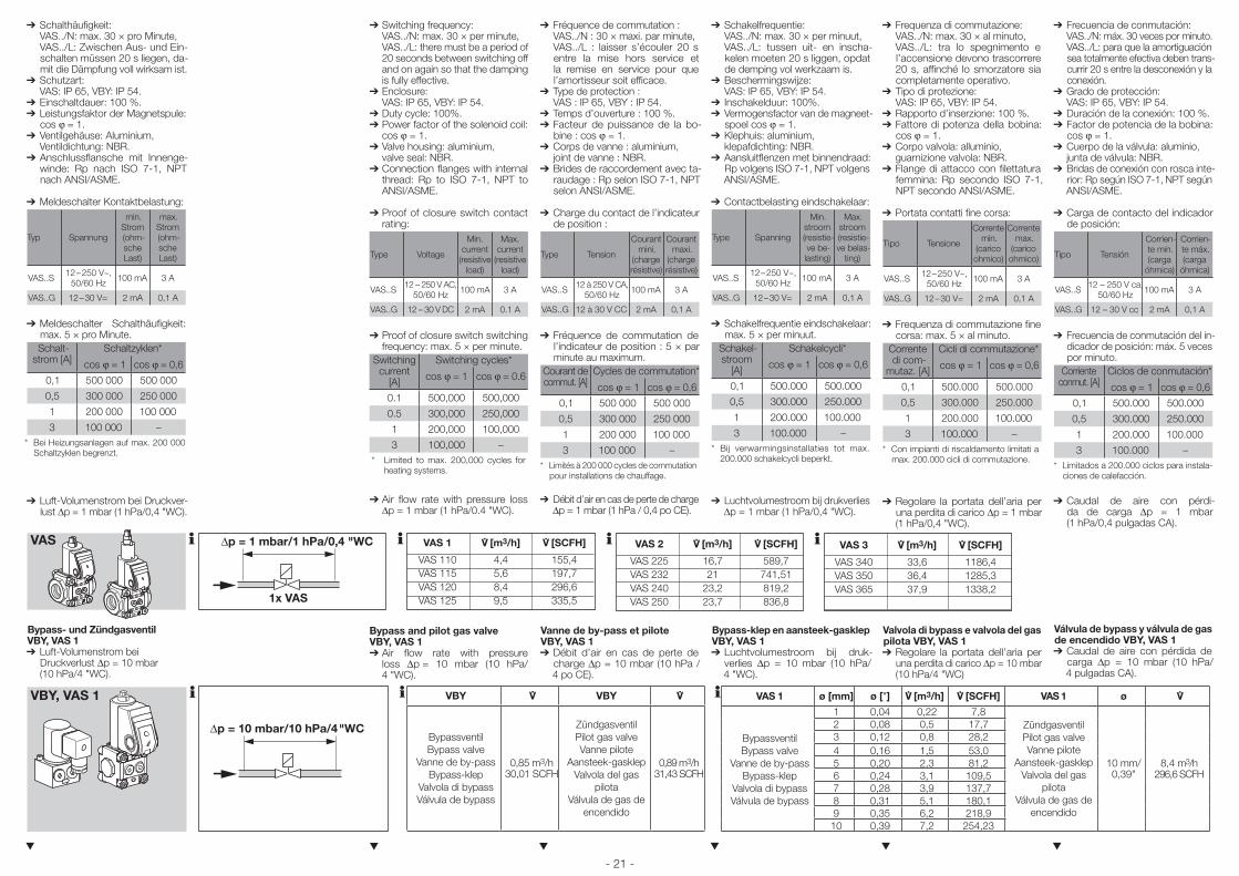
- 21 -
➔ Schalthäufigkeit: VAS../N: max. 30 × pro Minute, VAS../L: Zwischen Aus- und Ein-
schalten müssen 20 s liegen, da-mit die Dämpfung voll wirksam ist.
➔ Schutzart: VAS: IP 65, VBY: IP 54.
➔ Einschaltdauer: 100 %.➔ Leistungsfaktor der Magnetspule:
cos ϕ = 1.➔ Ventilgehäuse: Aluminium,
Ventildichtung: NBR.➔ Anschlussflansche mit Innenge-
winde: Rp nach ISO 7-1, NPT nach ANSI/ASME.
➔ Meldeschalter Kontaktbelastung:
Typ Spannung
min. Strom(ohm-sche Last)
max. Strom(ohm-sche Last)
VAS..S 12 – 250 V~, 50/60 Hz 100 mA 3 A
VAS..G 12 – 30 V= 2 mA 0,1 A
➔ Meldeschalter Schalthäufigkeit: max. 5 × pro Minute.Schalt-
strom [A]Schaltzyklen*
cos ϕ = 1 cos ϕ = 0,6
0,1 500 000 500 000
0,5 300 000 250 000
1 200 000 100 000
3 100 000 –* Bei Heizungsanlagen auf max. 200 000
Schaltzyklen begrenzt.
➔ Luft-Volumenstrom bei Druckver-lust ∆p = 1 mbar (1 hPa/0,4 "WC).
Bypass- und Zündgasventil VBY, VAS 1➔ Luft-Volumenstrom bei
Druckverlust ∆p = 10 mbar (10 hPa/4 "WC).
▼
➔ Switching frequency: VAS../N: max. 30 × per minute, VAS../L: there must be a period of
20 seconds between switching off and on again so that the damping is fully effective.
➔Enclosure: VAS: IP 65, VBY: IP 54.➔Duty cycle: 100%.➔Power factor of the solenoid coil:
cos ϕ = 1.➔Valve housing: aluminium, valve seal: NBR.➔Connection flanges with internal
thread: Rp to ISO 7-1, NPT to ANSI/ASME.
➔ Proof of closure switch contact rating:
Type Voltage
Min. current
(resistive load)
Max. current
(resistive load)
VAS..S 12 – 250 V AC,50/60 Hz 100 mA 3 A
VAS..G 12 – 30 V DC 2 mA 0.1 A
➔Proof of closure switch switching frequency: max. 5 × per minute.
Switching current
[A]
Switching cycles*
cos ϕ = 1 cos ϕ = 0.6
0.1 500,000 500,000
0.5 300,000 250,000
1 200,000 100,000
3 100,000 –* Limited to max. 200,000 cycles for
heating systems.
➔Air flow rate with pressure loss ∆p = 1 mbar (1 hPa/0.4 "WC).
Bypass and pilot gas valve VBY, VAS 1➔Air flow rate with pressure
loss ∆p = 10 mbar (10 hPa/ 4 "WC).
▼
➔ Fréquence de commutation : VAS../N : 30 × maxi. par minute, VAS../L : laisser s’écouler 20 s
entre la mise hors service et la remise en service pour que l’amortisseur soit efficace.
➔Type de protection : VAS : IP 65, VBY : IP 54.➔Temps d’ouverture : 100 %.➔Facteur de puissance de la bo-
bine : cos ϕ = 1.➔Corps de vanne : aluminium, joint de vanne : NBR.➔Brides de raccordement avec ta-
raudage : Rp selon ISO 7-1, NPT selon ANSI/ASME.
➔ Charge du contact de l’indicateur de position :
Type Tension
Courant mini.
(charge résistive)
Courant maxi.
(charge résistive)
VAS..S 12 à 250 V CA,50/60 Hz 100 mA 3 A
VAS..G 12 à 30 V CC 2 mA 0,1 A
➔Fréquence de commutation de l’indicateur de position : 5 × par minute au maximum.
Courant de commut. [A]
Cycles de commutation*
cos ϕ = 1 cos ϕ = 0,6
0,1 500 000 500 000
0,5 300 000 250 000
1 200 000 100 000
3 100 000 –* Limités à 200 000 cycles de commutation
pour installations de chauffage.
➔Débit d’air en cas de perte de charge ∆p = 1 mbar (1 hPa / 0,4 po CE).
Vanne de by-pass et pilote VBY, VAS 1➔Débit d’air en cas de perte de
charge ∆p = 10 mbar (10 hPa / 4 po CE).
▼
➔ Schakelfrequentie: VAS../N: max. 30 × per minuut, VAS../L: tussen uit- en inscha-
kelen moeten 20 s liggen, opdat de demping vol werkzaam is.
➔Beschermingswijze: VAS: IP 65, VBY: IP 54.➔ Inschakelduur: 100%.➔Vermogensfactor van de magneet-
spoel cos ϕ = 1.➔Klephuis: aluminium, klepafdichting: NBR.➔Aansluitflenzen met binnendraad:
Rp volgens ISO 7-1, NPT volgens ANSI/ASME.
➔ Contactbelasting eindschakelaar:
Type Spanning
Min. stroom(resistie-ve be-lasting)
Max. stroom(resistie-ve belas-
ting)
VAS..S 12 – 250 V~, 50/60 Hz 100 mA 3 A
VAS..G 12 – 30 V= 2 mA 0,1 A
➔Schakelfrequentie eindschakelaar: max. 5 × per minuut.
Schakel-stroom
[A]
Schakelcycli*
cos ϕ = 1 cos ϕ = 0,6
0,1 500.000 500.000
0,5 300.000 250.000
1 200.000 100.000
3 100.000 –* Bij verwarmingsinstallaties tot max.
200.000 schakelcycli beperkt.
➔Luchtvolumestroom bij drukverlies ∆p = 1 mbar (1 hPa/0,4 "WC).
Bypass-klep en aansteek-gasklep VBY, VAS 1➔Luchtvolumestroom bij druk-
verlies ∆p = 10 mbar (10 hPa/ 4 "WC).
▼
➔ Frequenza di commutazione: VAS../N: max. 30 × al minuto, VAS../L: tra lo spegnimento e
l’accensione devono trascorrere 20 s, affinché lo smorzatore sia completamente operativo.
➔Tipo di protezione: VAS: IP 65, VBY: IP 54.➔Rapporto d’inserzione: 100 %.➔Fattore di potenza della bobina:
cos ϕ = 1.➔Corpo valvola: alluminio, guarnizione valvola: NBR.➔Flange di attacco con filettatura
femmina: Rp secondo ISO 7-1, NPT secondo ANSI/ASME.
➔ Portata contatti fine corsa:
Tipo Tensione
Corrente min.
(carico ohmico)
Corrente max.
(carico ohmico)
VAS..S 12 – 250 V~, 50/60 Hz 100 mA 3 A
VAS..G 12 – 30 V= 2 mA 0,1 A
➔Frequenza di commutazione fine corsa: max. 5 × al minuto.
Corrente di com-
mutaz. [A]
Cicli di commutazione*
cos ϕ = 1 cos ϕ = 0,6
0,1 500.000 500.000
0,5 300.000 250.000
1 200.000 100.000
3 100.000 –* Con impianti di riscaldamento limitati a
max. 200.000 cicli di commutazione.
➔Regolare la portata dell’aria per una perdita di carico ∆p = 1 mbar (1 hPa/0,4 "WC).
Valvola di bypass e valvola del gas pilota VBY, VAS 1➔Regolare la portata dell’aria per
una perdita di carico ∆p = 10 mbar (10 hPa/4 "WC)
▼
➔ Frecuencia de conmutación: VAS../N: máx. 30 veces por minuto. VAS../L: para que la amortiguación
sea totalmente efectiva deben trans-currir 20 s entre la desconexión y la conexión.
➔Grado de protección: VAS: IP 65, VBY: IP 54.➔Duración de la conexión: 100 %.➔Factor de potencia de la bobina:
cos ϕ = 1.➔Cuerpo de la válvula: aluminio, junta de válvula: NBR.➔Bridas de conexión con rosca inte-
rior: Rp según ISO 7-1, NPT según ANSI/ASME.
➔ Carga de contacto del indicador de posición:
Tipo Tensión
Corrien-te mín.(carga
óhmica)
Corrien-te máx.(carga
óhmica)
VAS..S 12 – 250 V ca,50/60 Hz 100 mA 3 A
VAS..G 12 – 30 V cc 2 mA 0,1 A
➔ Frecuencia de conmutación del in-dicador de posición: máx. 5 veces por minuto.
Corriente conmut. [A]
Ciclos de conmutación*
cos ϕ = 1 cos ϕ = 0,6
0,1 500.000 500.000
0,5 300.000 250.000
1 200.000 100.000
3 100.000 –* Limitados a 200.000 ciclos para instala-
ciones de calefacción.
➔Caudal de aire con pérdi-da de carga ∆p = 1 mbar (1 hPa/0,4 pulgadas CA).
Válvula de bypass y válvula de gas de encendido VBY, VAS 1➔Caudal de aire con pérdida de
carga ∆p = 10 mbar (10 hPa/ 4 pulgadas CA).
▼
p = 1 mbar/1 hPa/0,4 "WCVAS
1x VAS
VAS 1 V. [m3/h] V
. [SCFH]
VAS 110 4,4 155,4VAS 115 5,6 197,7VAS 120 8,4 296,6VAS 125 9,5 335,5
VAS 2 V. [m3/h] V
. [SCFH]
VAS 225 16,7 589,7VAS 232 21 741,51VAS 240 23,2 819,2VAS 250 23,7 836,8
VAS 3 V. [m3/h] V
. [SCFH]
VAS 340 33,6 1186,4VAS 350 36,4 1285,3VAS 365 37,9 1338,2
VBY, VAS 1 VAS 1 ø [mm] ø ["] V. [m3/h] V
. [SCFH] VAS 1 ø V
.
Bypassventil Bypass valve
Vanne de by-pass Bypass-klep
Valvola di bypass Válvula de bypass
1 0,04 0,22 7,8Zündgasventil Pilot gas valve Vanne pilote
Aansteek-gasklep Valvola del gas
pilota Válvula de gas de
encendido
10 mm/0,39"
8,4 m3/h296,6 SCFH
2 0,08 0,5 17,73 0,12 0,8 28,24 0,16 1,5 53,05 0,20 2,3 81,26 0,24 3,1 109,57 0,28 3,9 137,78 0,31 5,1 180,19 0,35 6,2 218,910 0,39 7,2 254,23
VBY V. VBY V
.
Bypassventil Bypass valve
Vanne de by-pass Bypass-klep
Valvola di bypass Válvula de bypass
0,85 m3/h30,01 SCFH
Zündgasventil Pilot gas valve Vanne pilote
Aansteek-gasklep Valvola del gas
pilota Válvula de gas de
encendido
0,89 m3/h31,43 SCFH
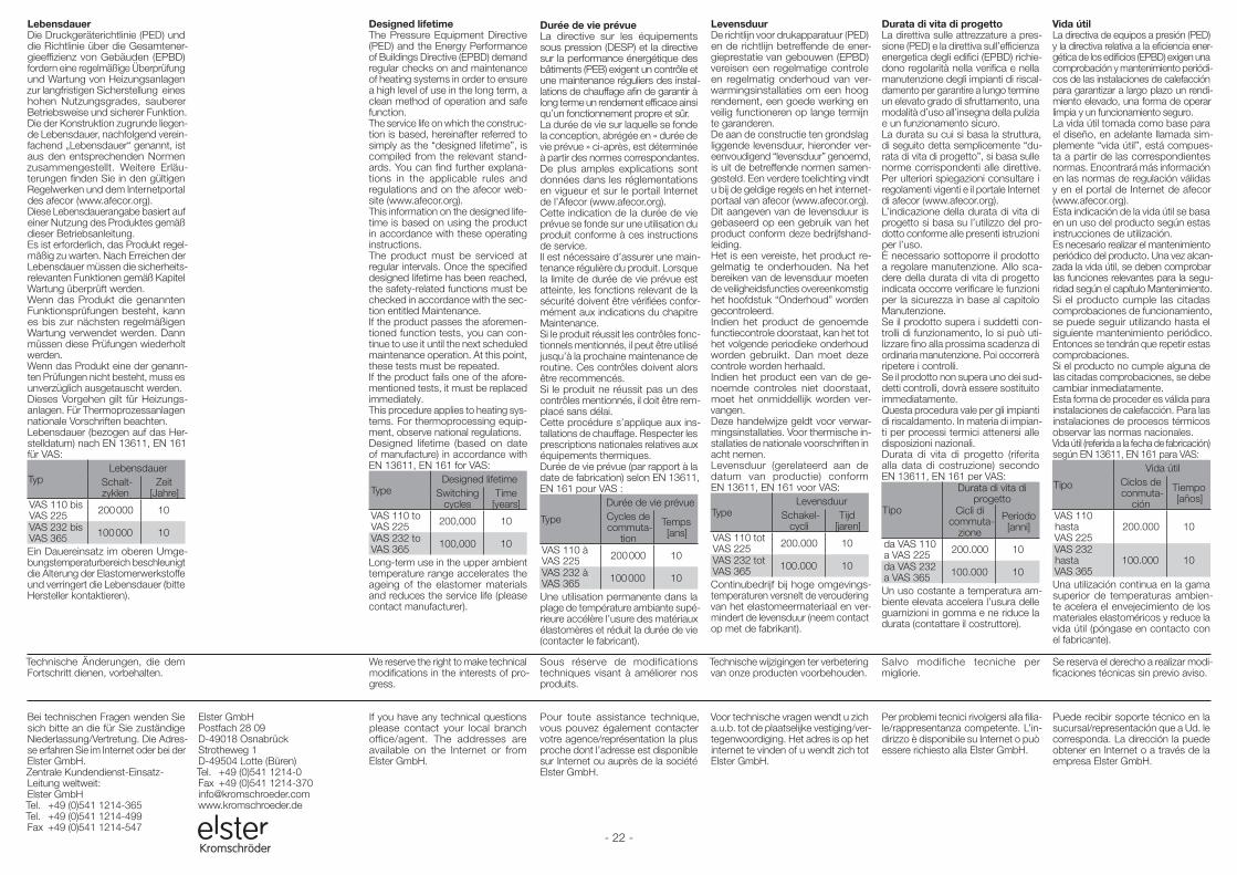
- 22 -
Technische wijzigingen ter verbetering van onze producten voorbehouden.
Voor technische vragen wendt u zich a.u.b. tot de plaatselijke vestiging/vertegenwoordiging. Het adres is op het internet te vinden of u wendt zich tot Elster GmbH.
We reserve the right to make technical modifications in the interests of progress.
If you have any technical questions please contact your local branch office/agent. The addresses are available on the Internet or from Elster GmbH.
Sous réserve de modifications techniques visant à améliorer nos produits.
Pour toute assistance technique, vous pouvez également contacter votre agence/représentation la plus proche dont l’adresse est disponible sur Internet ou auprès de la société Elster GmbH.
Salvo modifiche tecniche per migliorie.
Per problemi tecnici rivolgersi alla filiale/rappresentanza competente. L’indirizzo è disponibile su Internet o può essere richiesto alla Elster GmbH.
Se reserva el derecho a realizar modificaciones técnicas sin previo aviso.
Puede recibir soporte técnico en la sucursal/representación que a Ud. le corresponda. La dirección la puede obtener en Internet o a través de la empresa Elster GmbH.
Technische Änderungen, die dem Fortschritt dienen, vorbehalten.
Bei technischen Fragen wenden Sie sich bitte an die für Sie zuständige Nieder lassung/Vertretung. Die Adresse erfahren Sie im Internet oder bei der Elster GmbH.Zentrale KundendienstEinsatzLeitung weltweit:Elster GmbH Tel. +49 (0)541 1214365Tel. +49 (0)541 1214499Fax +49 (0)541 1214547
Elster GmbHPostfach 28 09D49018 OsnabrückStrotheweg 1D49504 Lotte (Büren)Tel. +49 (0)541 12140Fax +49 (0)541 1214[email protected]
LebensdauerDie Druckgeräterichtlinie (PED) und die Richtlinie über die Gesamtener-gieeffizienz von Gebäuden (EPBD) fordern eine regelmäßige Überprüfung und Wartung von Heizungsanlagen zur langfristigen Sicherstellung eines hohen Nutzungsgrades, sauberer Betriebsweise und sicherer Funktion.Die der Konstruktion zugrunde liegen-de Lebensdauer, nachfolgend verein-fachend „Lebensdauer“ genannt, ist aus den entsprechenden Normen zusammengestellt. Weitere Erläu-terungen finden Sie in den gültigen Regelwerken und dem Internetportal des afecor (www.afecor.org).Diese Lebensdauerangabe basiert auf einer Nutzung des Produktes gemäß dieser Betriebsanleitung. Es ist erforderlich, das Produkt regel-mäßig zu warten. Nach Erreichen der Lebensdauer müssen die sicherheits-relevanten Funktionen gemäß Kapitel Wartung überprüft werden.Wenn das Produkt die genannten Funktionsprüfungen besteht, kann es bis zur nächsten regelmäßigen Wartung verwendet werden. Dann müssen diese Prüfungen wiederholt werden.Wenn das Produkt eine der genann-ten Prüfungen nicht besteht, muss es unverzüglich ausgetauscht werden.Dieses Vorgehen gilt für Heizungs-anlagen. Für Thermoprozessanlagen nationale Vorschriften beachten.Lebensdauer (bezogen auf das Her-stelldatum) nach EN 13611, EN 161 für VAS:
TypLebensdauer
Schalt-zyklen
Zeit [Jahre]
VAS 110 bisVAS 225 200 000 10
VAS 232 bisVAS 365 100 000 10
Ein Dauereinsatz im oberen Umge-bungstemperaturbereich beschleunigt die Alterung der Elastomerwerkstoffe und verringert die Lebensdauer (bitte Hersteller kontaktieren).
LevensduurDe richtlijn voor drukapparatuur (PED) en de richtlijn betreffende de ener-gieprestatie van gebouwen (EPBD) vereisen een regelmatige controle en regelmatig onderhoud van ver-warmingsinstallaties om een hoog rendement, een goede werking en veilig functioneren op lange termijn te garanderen.De aan de constructie ten grondslag liggende levensduur, hieronder ver-eenvoudigend “levensduur” genoemd, is uit de betreffende normen samen-gesteld. Een verdere toelichting vindt u bij de geldige regels en het internet-portaal van afecor (www.afecor.org).Dit aangeven van de levensduur is gebaseerd op een gebruik van het product conform deze bedrijfshand-leiding.Het is een vereiste, het product re-gelmatig te onderhouden. Na het bereiken van de levensduur moeten de veiligheidsfuncties overeenkomstig het hoofdstuk “Onderhoud” worden gecontroleerd.Indien het product de genoemde functiecontrole doorstaat, kan het tot het volgende periodieke onderhoud worden gebruikt. Dan moet deze controle worden herhaald.Indien het product een van de ge-noemde controles niet doorstaat, moet het onmiddellijk worden ver-vangen.Deze handelwijze geldt voor verwar-mingsinstallaties. Voor thermische in-stallaties de nationale voorschriften in acht nemen.Levensduur (gerelateerd aan de datum van productie) conform EN 13611, EN 161 voor VAS:
TypeLevensduur
Schakel-cycli
Tijd [jaren]
VAS 110 totVAS 225 200.000 10
VAS 232 totVAS 365 100.000 10
Continubedrijf bij hoge omgevings-temperaturen versnelt de veroudering van het elastomeermateriaal en ver-mindert de levensduur (neem contact op met de fabrikant).
Durata di vita di progettoLa direttiva sulle attrezzature a pres-sione (PED) e la direttiva sull’efficienza energetica degli edifici (EPBD) richie-dono regolarità nella verifica e nella manutenzione degli impianti di riscal-damento per garantire a lungo termine un elevato grado di sfruttamento, una modalità d’uso all’insegna della pulizia e un funzionamento sicuro.La durata su cui si basa la struttura, di seguito detta semplicemente “du-rata di vita di progetto”, si basa sulle norme corrispondenti alle direttive. Per ulteriori spiegazioni consultare i regolamenti vigenti e il portale Internet di afecor (www.afecor.org).L’indicazione della durata di vita di progetto si basa su l’utilizzo del pro-dotto conforme alle presenti istruzioni per l’uso.È necessario sottoporre il prodotto a regolare manutenzione. Allo sca-dere della durata di vita di progetto indicata occorre verificare le funzioni per la sicurezza in base al capitolo Manutenzione.Se il prodotto supera i suddetti con-trolli di funzionamento, lo si può uti-lizzare fino alla prossima scadenza di ordinaria manutenzione. Poi occorrerà ripetere i controlli.Se il prodotto non supera uno dei sud-detti controlli, dovrà essere sostituito immediatamente.Questa procedura vale per gli impianti di riscaldamento. In materia di impian-ti per processi termici attenersi alle disposizioni nazionali.Durata di vita di progetto (riferita alla data di costruzione) secondo EN 13611, EN 161 per VAS:
Tipo
Durata di vita di progetto
Cicli di commuta-
zione
Periodo [anni]
da VAS 110 a VAS 225 200.000 10
da VAS 232 a VAS 365 100.000 10
Un uso costante a temperatura am-biente elevata accelera l’usura delle guarnizioni in gomma e ne riduce la durata (contattare il costruttore).
Designed lifetimeThe Pressure Equipment Directive (PED) and the Energy Performance of Buildings Directive (EPBD) demand regular checks on and maintenance of heating systems in order to ensure a high level of use in the long term, a clean method of operation and safe function.The service life on which the construc-tion is based, hereinafter referred to simply as the “designed lifetime”, is compiled from the relevant stand-ards. You can find further explana-tions in the applicable rules and regulations and on the afecor web-site (www.afecor.org).This information on the designed life-time is based on using the product in accordance with these operating instructions.The product must be serviced at regular intervals. Once the specified designed lifetime has been reached, the safety-related functions must be checked in accordance with the sec-tion entitled Maintenance.If the product passes the aforemen-tioned function tests, you can con-tinue to use it until the next scheduled maintenance operation. At this point, these tests must be repeated.If the product fails one of the afore-mentioned tests, it must be replaced immediately.This procedure applies to heating sys-tems. For thermoprocessing equip-ment, observe national regulations.Designed lifetime (based on date of manufacture) in accordance with EN 13611, EN 161 for VAS:
TypeDesigned lifetime
Switching cycles
Time [years]
VAS 110 toVAS 225 200,000 10
VAS 232 toVAS 365 100,000 10
Long-term use in the upper ambient temperature range accelerates the ageing of the elastomer materials and reduces the service life (please contact manufacturer).
Durée de vie prévueLa directive sur les équipements sous pression (DESP) et la directive sur la performance énergétique des bâtiments (PEB) exigent un contrôle et une maintenance réguliers des instal-lations de chauffage afin de garantir à long terme un rendement efficace ainsi qu’un fonctionnement propre et sûr.La durée de vie sur laquelle se fonde la conception, abrégée en « durée de vie prévue » ci-après, est déterminée à partir des normes correspondantes. De plus amples explications sont données dans les réglementations en vigueur et sur le portail Internet de l’Afecor (www.afecor.org).Cette indication de la durée de vie prévue se fonde sur une utilisation du produit conforme à ces instructions de service.Il est nécessaire d’assurer une main-tenance régulière du produit. Lorsque la limite de durée de vie prévue est atteinte, les fonctions relevant de la sécurité doivent être vérifiées confor-mément aux indications du chapitre Maintenance.Si le produit réussit les contrôles fonc-tionnels mentionnés, il peut être utilisé jusqu’à la prochaine maintenance de routine. Ces contrôles doivent alors être recommencés.Si le produit ne réussit pas un des contrôles mentionnés, il doit être rem-placé sans délai.Cette procédure s’applique aux ins-tallations de chauffage. Respecter les prescriptions nationales relatives aux équipements thermiques.Durée de vie prévue (par rapport à la date de fabrication) selon EN 13611, EN 161 pour VAS :
Type
Durée de vie prévueCycles de commuta-
tion
Temps [ans]
VAS 110 àVAS 225 200 000 10
VAS 232 àVAS 365 100 000 10
Une utilisation permanente dans la plage de température ambiante supé-rieure accélère l’usure des matériaux élastomères et réduit la durée de vie (contacter le fabricant).
Vida útilLa directiva de equipos a presión (PED) y la directiva relativa a la eficiencia ener-gética de los edificios (EPBD) exigen una comprobación y mantenimiento periódi-cos de las instalaciones de calefacción para garantizar a largo plazo un rendi-miento elevado, una forma de operar limpia y un funcionamiento seguro.La vida útil tomada como base para el diseño, en adelante llamada sim-plemente “vida útil”, está compues-ta a partir de las correspondientes normas. Encontrará más información en las normas de regulación válidas y en el portal de Internet de afecor (www.afecor.org).Esta indicación de la vida útil se basa en un uso del producto según estas instrucciones de utilización.Es necesario realizar el mantenimiento periódico del producto. Una vez alcan-zada la vida útil, se deben comprobar las funciones relevantes para la segu-ridad según el capítulo Mantenimiento.Si el producto cumple las citadas comprobaciones de funcionamiento, se puede seguir utilizando hasta el siguiente mantenimiento periódico. Entonces se tendrán que repetir estas comprobaciones.Si el producto no cumple alguna de las citadas comprobaciones, se debe cambiar inmediatamente.Esta forma de proceder es válida para instalaciones de calefacción. Para las instalaciones de procesos térmicos observar las normas nacionales.Vida útil (referida a la fecha de fabricación) según EN 13611, EN 161 para VAS:
Tipo
Vida útilCiclos de conmuta-
ción
Tiempo [años]
VAS 110 hastaVAS 225
200.000 10
VAS 232 hastaVAS 365
100.000 10
Una utilización continua en la gama superior de temperaturas ambien-te acelera el envejecimiento de los materiales elastoméricos y reduce la vida útil (póngase en contacto con el fabricante).