Datenblatt und Doku zu - robotikhardware.de
16
Deutsche und Englische Dokumentation - www.robotikhardware.de Datenblatt und Doku zu Kompaß-Modul CMPS03 • 5 Volt Betriebsspannung • Verbrauch nur- 20mA (Typ) • Auflösung 0.1 Grad • Genauigkeit: - 3 bis 4 Grad nach Justierung • Ausgangssignal 1: Signalpuls von einer 1ms bis 37ms in 0.1ms Schritten. Die Länge des Signales ergibt somit den Grad Wert 0 bis 360 Grad • Ausgangssignal 2: Das der beliebte I2C Bus. Hier kann die Richtung entweder in dem Bereich von 0 bis 255 oder dem Wertebereich von 0 bis 3599 abgerufen werden. Einfacher geht’s nicht! • SCL Geschwindigkeit bis zu 1 MHz • Sehr kompakte Größe 32mm x 35mm • Sehr günstiger Preis - Low Cost Preis für Qualitätsmodul Seite 1 von 16
Transcript of Datenblatt und Doku zu - robotikhardware.de
Deutsche und Englische Dokumentation - www.robotikhardware.de
Datenblatt und Doku zu
Kompaß-Modul CMPS03
• 5 Volt Betriebsspannung • Verbrauch nur- 20mA (Typ) • Auflösung 0.1 Grad • Genauigkeit: - 3 bis 4 Grad nach Justierung • Ausgangssignal 1: Signalpuls von einer 1ms bis 37ms in 0.1ms Schritten. Die Länge des
Signales ergibt somit den Grad Wert 0 bis 360 Grad • Ausgangssignal 2: Das der beliebte I2C Bus. Hier kann die Richtung entweder in dem Bereich von
0 bis 255 oder dem Wertebereich von 0 bis 3599 abgerufen werden. Einfacher geht’s nicht! • SCL Geschwindigkeit bis zu 1 MHz • Sehr kompakte Größe 32mm x 35mm • Sehr günstiger Preis - Low Cost Preis für Qualitätsmodul
Seite 1 von 16

Deutsche und Englische Dokumentation - www.robotikhardware.de
Dieses elektronische Kompassmodul eignet sich ideal für mobile Roboter oder Fahrzeuge welche sich in einer Umgebung orientieren müssen. Das Modul ermittelt anhand des Erdmagnetfeldes die genaue Himmelsrichtung in Schritten von 0,1 Grad. Die Orientierung wird dadurch ergeblich vereinfacht. Das Modul arbeitet auch in geschlossenen Räumen korrekt.
Die Anschlüsse des Modules:
Pin 1 und 9Das Kompassmodul benötigt lediglich 5V und verbraucht im Durchschnitt ca. 15 mA. Da jedoch kurzzeitig Stromspitzen von bis zu 100mA auftreten können, sollte sich in der Nähe ein Elko zur Bufferung befinden.
Pin 4Neben der Spannung ist für den normalen Betrieb entweder nur noch Pin 4 (PWM Signal) oder die zwei Leitungen für den I2C Bus notwendig. Bin Das PWM-Signal an Pin 4 gibt den Kompasswert 0 bis 359,9 Grad in Form eines High.Impules aus. Die Länge des High-Impules kann zwischen 1 Millisekunde und 36,99 Millisekunden liegen. Also 0,1 Millisekunde (100us) entspricht demnach einem Grad. Es muss somit nur die Signallänge gemessen werden, danach ist eine Umrechnung sehr einfach. Für das Messen der Signallänge bieten Hochsprachen bei Microcontrollern beispielsweise einfachfache Befehle wie PULSEIN beim Bascom Compiler.
Pin 2 und 3Dies sind die Anschlüsse SDA und SCL für den I2C-Bus. Über den I2C-Bus lassen sich mehrere verschiedenartige Boards über 2 Leitungen betreiben, siehe dazu im Tutorial auf der Webseite RN-Wissen http://www.roboternetz.de/wissen/index.php/I2C
Oft werden für den I2C-Buch auch 10 polige Wannenstecker genutzt (wie bei den Roboternetz-Boards). In diesem Fall müssen lediglich GND,+5V,SDA und SCL des Kabels zum Betreiben von CMPS03 verwendet werden.
Siehe auch http://www.roboternetz.de/wissen/index.php/RN-Definitionen#I2C-Bus_Stecker
Seite 2 von 16

Deutsche und Englische Dokumentation - www.robotikhardware.de
CMPS03 besitzt keine Pullup-Widerstände wie sie für den I2C-Bus notwendig sind. Das Masterboard am I2C-Bus sollte demnach diese I2C-Leitungen mit ca. 5k bis 47k Widerständen mit +5V verbinden. Bei RN-Boards (RN-Control, RN-BFRA, RN-MiniControl u.a.) ist das nicht notwendig da bereits solche Widerstände auf dem Board sind. Auch andere Boards haben oft solche Pullup-Widerstände auf dem Board.Wird der I2C-Bus bei CMPS03 nicht genutzt, so sollte man Pin 2 und 3 über einen Widerstand (ca. 10k bis 47k) mit +5V verbinden um Störungen zu vermeiden.
Die Kommunikation über den I2C-Bus erfolgt wie bei fast allen Modulen über verschiedene Register. Es stehen folgende Register zur Verfügung:
Register Function
0 Software Version (Firmware Version)
1 Kompaßwert – Ein Byte 0 bis 255 entspricht 0 bis 359,9 Grad
2,3Kompasswert als Word (also 2 Byte / Low and High) Der Wert von 0 bis 3599 entspricht somit 0 bis 359,9 Grad.
4,5 Interne Testregister – werden nur vom Hersteller genutzt
6,7 Interne Testregister – werden nur vom Hersteller genutzt
8,9 Interne Testregister – werden nur vom Hersteller genutzt
10,11 Interne Testregister – werden nur vom Hersteller genutzt
12 Unbenutzt, liefert immer 0 zurück
13 Unbenutzt, liefert immer 0 zurück
14 Unbenutzt, liefert undefinierten Wert zurück
15 255 :startet die Kalibrierung (Justierung der Richtungen)0 : Beendet Kalibierung. Werte werden im EEPROM gespeichert
Die Slave-Adresse ist fest auf Hex C0 (also Dezimal 192) eingestellt.Wie bei I2C üblich wird immer erst die SLAVE Adresse und dann das abzurufende Register als Byte versendet. Anschließend erfolgt ein Lesezugriff wo die SLAVE Adresse +1 gesendet und danach 1 oder 2 Bytes abgerufen werden.
Das nachfolgende Bascom Beispiel demonstriert wie man beispielsweise den Kompaßwert als WORD-Zahlenwert (0 bis 3599) abruft.
I2cstart I2cwbyte 192 'I2C Slaveadresse C0 I2cwbyte 2 'Register 2 und 3 auswählen
I2cstart I2cwbyte 193 'Slaveadresse+1 (C1) I2crbyte Msb, Ack I2crbyte Lsb, Nack I2cstop
Richtungint = Makeint(Lsb, Msb) 'Word aus 2 Byte machen Richtung = Richtungint 'Wahlweise in Single umrechnen Richtung = Richtung / 10 'Wert mit einer Nachkommastelle Print "Richtung: " + Str(Richtung) 'Ausgeben
Ein vollständiges Beispiel für das Board RN-Control finden Sie etwas weiter hinten in dieser Doku.
CMPS03 unterstützt die Standard I2C Taktraten von 100 und 400 khz. Wird mehr als 100khz genutzt, sollte man nach schreiben der Registeradresse eine kurze Pause von ca. 50us einbauen.
Seite 3 von 16
Deutsche und Englische Dokumentation - www.robotikhardware.de
Pin 7 - WechselspannungsfelderDie Abtastrate der Kompaßposition erfolgt bei unbeschalteten Pin intern gewöhnlich mit 60 Hz. In Umgebungen mit starken Wechselspannungsfeldern kann es wegen dem dadurch erzeugten Magnetfeld zu Ungenauigkeiten kommen. In diesem Fall kann es günstig ein über diesen Pin die Netzfrequenz mit dem Modul zu synchonisieren. Dazu muss in diesem Fall hier das passende 50 Hz Taktsignal mit TTL Pegel angelegt werden. Dies kann das Ergebnis in solch schwierigen Umgebungen verbessern.In der Regel kann man den Pin unbeschaltet lassen.
Pin 6 - KalibrierungDamit das Modul in jeder Umgebung möglichst genau arbeitet, ist eine einmalige Justierung (Kalibrierung) empfehlenswert. Die Kalibrierung erfolgt indem man das Modul exakt waagerecht in alle viel Himmelsrichtungen ausrichtet und jedemal dabei diesen Pin Kurz mit GND verbindet.Praktisch kann man also an diesen Pin sowie GND einfach einen Taster anschließen. Dann richtet man das Modul in eine Richtung aus (welche ist egal, das erkennt das Modul automatisch) und drückt kurz den Taster. Danach fährt man mit der nächsten Himmelsrichtung genauso fort.Durch 4 Tasterbetätigungen legen Sie also exakt alle 4 Himmelsrichtungen fest.Das Ergebnis wird intern gespeichert und bleibt natürlich auch dann erhalten wenn keine Spannung anliegt.Alternativ kann man auch über den I2C-Bus die Kalibrierung durchführen. Dort funktioniert es auf die gleiche Weise nur das man statt des Tasterdrucks eine 255 in das Register 15 schreibt.
Die hier beschriebenen Kalibrierungsmethoden gelten nur für das CMPS03 mit der neusten Firmware ab V. 7.0, so wie sie z.B. über www.robotikhardware vertrieben werden. Ältere Module / Firmware-Versionen werden etwas anders/umständlicher kalibriert. Dort muss man noch das Modul ganz langsam waagerecht um 360 Grad drehen.
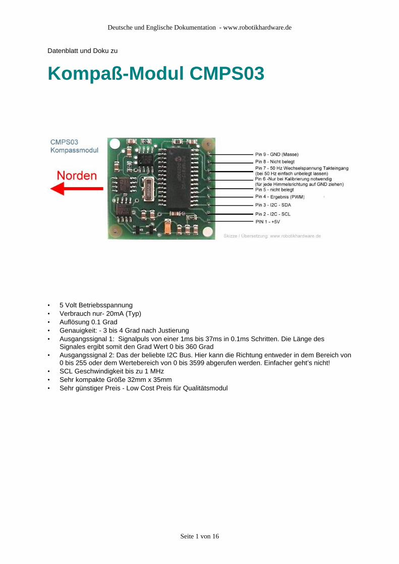
Die Platinengröße und Bohrlöcher
Seite 4 von 16
Deutsche und Englische Dokumentation - www.robotikhardware.de
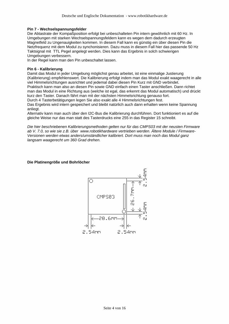
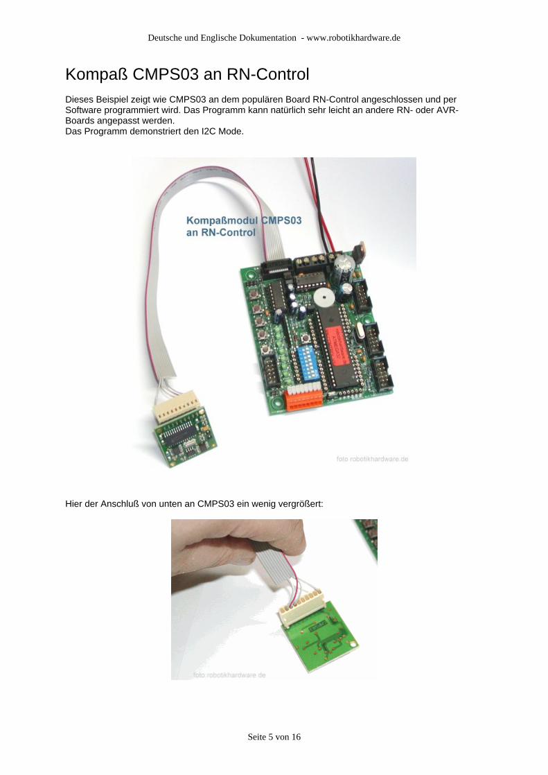
Kompaß CMPS03 an RN-ControlDieses Beispiel zeigt wie CMPS03 an dem populären Board RN-Control angeschlossen und per Software programmiert wird. Das Programm kann natürlich sehr leicht an andere RN- oder AVR-Boards angepasst werden.Das Programm demonstriert den I2C Mode.
Hier der Anschluß von unten an CMPS03 ein wenig vergrößert:
Seite 5 von 16
Deutsche und Englische Dokumentation - www.robotikhardware.de
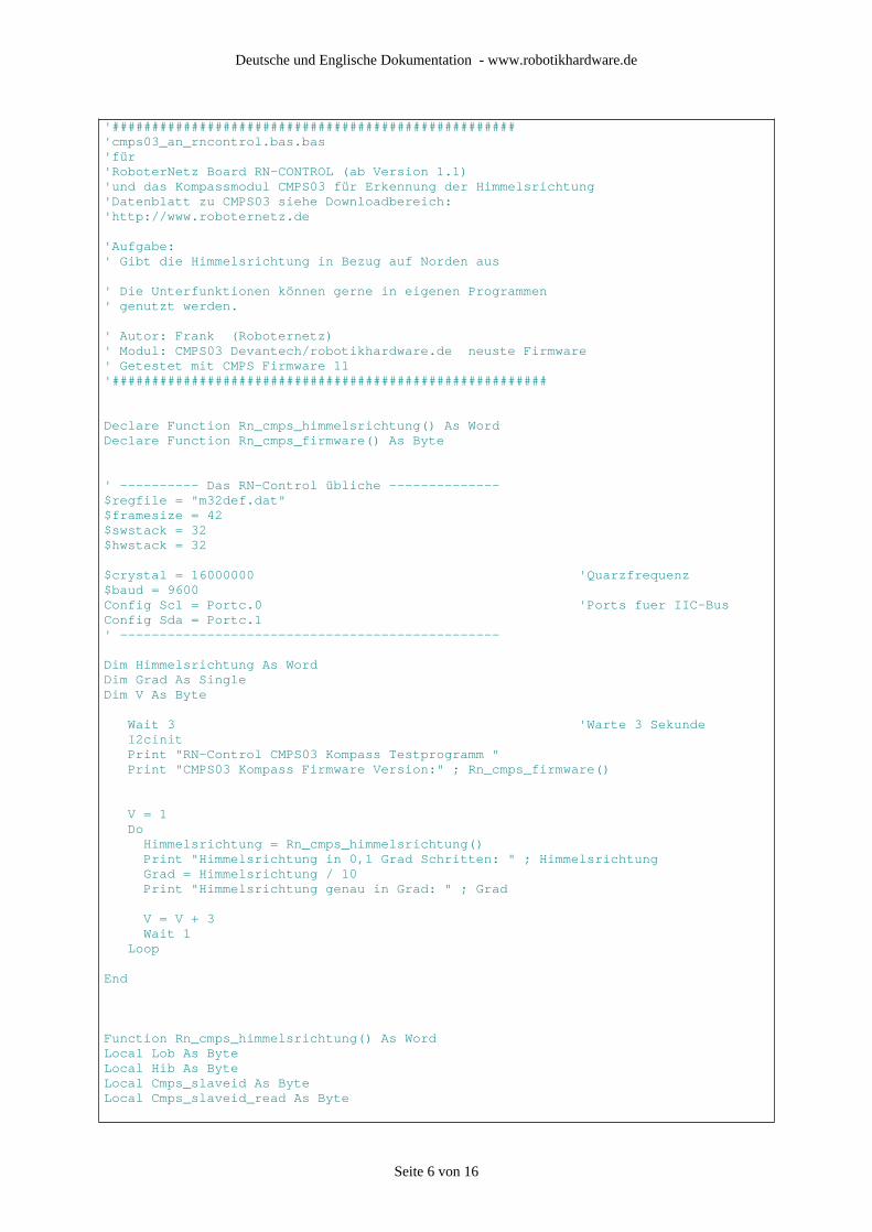
'###################################################'cmps03_an_rncontrol.bas.bas'für'RoboterNetz Board RN-CONTROL (ab Version 1.1)'und das Kompassmodul CMPS03 für Erkennung der Himmelsrichtung'Datenblatt zu CMPS03 siehe Downloadbereich:'http://www.roboternetz.de
'Aufgabe:' Gibt die Himmelsrichtung in Bezug auf Norden aus
' Die Unterfunktionen können gerne in eigenen Programmen' genutzt werden.
' Autor: Frank (Roboternetz)' Modul: CMPS03 Devantech/robotikhardware.de neuste Firmware' Getestet mit CMPS Firmware 11'#######################################################
Declare Function Rn_cmps_himmelsrichtung() As WordDeclare Function Rn_cmps_firmware() As Byte
' ---------- Das RN-Control übliche --------------$regfile = "m32def.dat"$framesize = 42$swstack = 32$hwstack = 32
$crystal = 16000000 'Quarzfrequenz$baud = 9600Config Scl = Portc.0 'Ports fuer IIC-BusConfig Sda = Portc.1' ------------------------------------------------
Dim Himmelsrichtung As WordDim Grad As SingleDim V As Byte
Wait 3 'Warte 3 Sekunde I2cinit Print "RN-Control CMPS03 Kompass Testprogramm " Print "CMPS03 Kompass Firmware Version:" ; Rn_cmps_firmware()
V = 1 Do Himmelsrichtung = Rn_cmps_himmelsrichtung() Print "Himmelsrichtung in 0,1 Grad Schritten: " ; Himmelsrichtung Grad = Himmelsrichtung / 10 Print "Himmelsrichtung genau in Grad: " ; Grad
V = V + 3 Wait 1 Loop
End
Function Rn_cmps_himmelsrichtung() As WordLocal Lob As ByteLocal Hib As ByteLocal Cmps_slaveid As ByteLocal Cmps_slaveid_read As Byte
Seite 6 von 16
Deutsche und Englische Dokumentation - www.robotikhardware.de
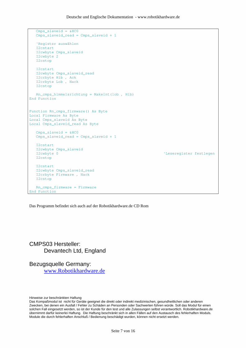
Cmps_slaveid = &HC0 Cmps_slaveid_read = Cmps_slaveid + 1
'Register auswählen I2cstart I2cwbyte Cmps_slaveid I2cwbyte 2 I2cstop
I2cstart I2cwbyte Cmps_slaveid_read I2crbyte Hib , Ack I2crbyte Lob , Nack I2cstop
Rn_cmps_himmelsrichtung = Makeint(lob , Hib)End Function
Function Rn_cmps_firmware() As ByteLocal Firmware As ByteLocal Cmps_slaveid As ByteLocal Cmps_slaveid_read As Byte
Cmps_slaveid = &HC0 Cmps_slaveid_read = Cmps_slaveid + 1
I2cstart I2cwbyte Cmps_slaveid I2cwbyte 0 'Leseregister festlegen I2cstop
I2cstart I2cwbyte Cmps_slaveid_read I2crbyte Firmware , Nack I2cstop
Rn_cmps_firmware = FirmwareEnd Function
Das Programm befindet sich auch auf der Robotikhardware.de CD Rom
CMPS03 Hersteller: Devantech Ltd, England
Bezugsquelle Germany: www.Robotikhardware.de
Hinweise zur beschränkten HaftungDas Kompaßmodul ist nicht für Geräte geeignet die direkt oder indirekt medizinischen, gesundheitlichen oder anderen Zwecken, bei denen ein Ausfall / Fehler zu Schäden an Personden oder Sachwerten führen würde. Soll das Modul für einen solchen Fall eingesetzt werden, so ist der Kunde für den test und alle Zulassungen selbst verantwortlich. Robotikhardware.de übernimmt darfür keinerlei Haftung. Die Haftung beschränkt sich in allen Fällen auf den Austausch des fehlerhaften Moduls. Module die durch fehlerhaften Anschluß / Bedienung beschädigt wurden, können nicht ersetzt werden.
Seite 7 von 16
Deutsche und Englische Dokumentation - www.robotikhardware.de
Englische Original-Doku
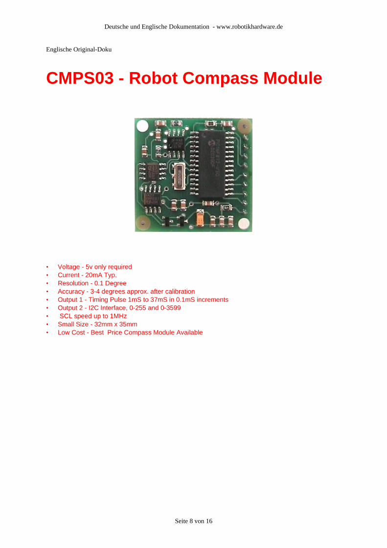
CMPS03 - Robot Compass Module
• Voltage - 5v only required • Current - 20mA Typ. • Resolution - 0.1 Degree • Accuracy - 3-4 degrees approx. after calibration • Output 1 - Timing Pulse 1mS to 37mS in 0.1mS increments • Output 2 - I2C Interface, 0-255 and 0-3599 • SCL speed up to 1MHz • Small Size - 32mm x 35mm • Low Cost - Best Price Compass Module Available
Seite 8 von 16

Deutsche und Englische Dokumentation - www.robotikhardware.de
This compass module has been specifically designed for use in robots as an aid to navigation. The aim was to produce a unique number to represent the direction the robot is facing. The compass uses the Philips KMZ51 magnetic field sensor, which is sensitive enough to detect the Earths magnetic field. The output from two of them mounted at right angles to each other is used to compute the direction of the horizontal component of the Earths magnetic field. We have examples of using the Compass module with a wide range of popular controllers.
Connections to the compass module:
The compass module requires a 5v power supply at a nominal 15mA. There are two ways of getting the bearing from the module. A PWM signal is available on pin 4, or an I2C interface is provided on pins 2,3.
The PWM signal is a pulse width modulated signal with the positive width of the pulse representing the angle. The pulse width varies from 1mS (0° ) to 36.99mS (359.9° ) – in other words 100uS/° with a +1mS offset. The signal goes low for 65mS between pulses, so the cycle time is 65mS + the pulse width - ie. 66ms-102ms. The pulse is generated by a 16 bit timer in the processor giving a 1uS resolution, however I would not recommend measuring this to anything better than 0.1° (10uS). Make sure you connect the I2C pins, SCL and SDA, to the 5v supply if you are using the PWM, as there are no pull-up resistors on these pins.
Pin 2,3 are an I2C interface and can be used to get a direct readout of the bearing. If the I2C interface is not used then these pins should be pulled high (to +5v) via a couple of resistors. Around 47k is ok, the values are not at all critical.
Seite 9 von 16
Deutsche und Englische Dokumentation - www.robotikhardware.de
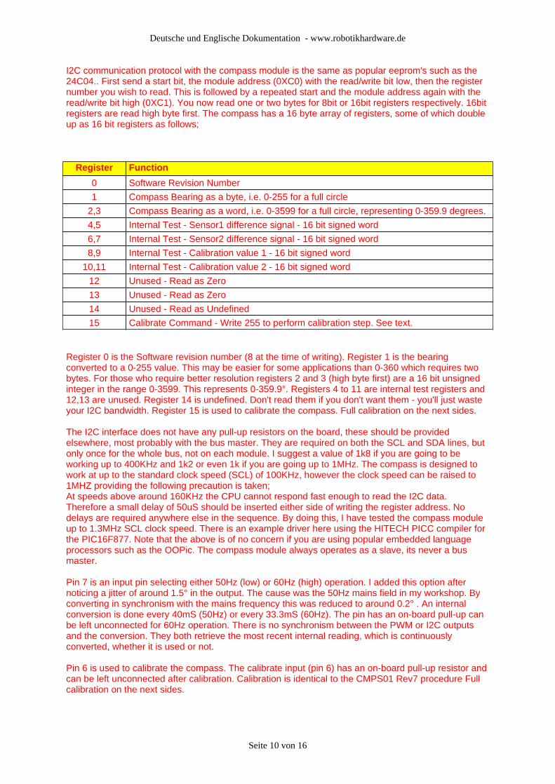
I2C communication protocol with the compass module is the same as popular eeprom's such as the 24C04.. First send a start bit, the module address (0XC0) with the read/write bit low, then the register number you wish to read. This is followed by a repeated start and the module address again with the read/write bit high (0XC1). You now read one or two bytes for 8bit or 16bit registers respectively. 16bit registers are read high byte first. The compass has a 16 byte array of registers, some of which double up as 16 bit registers as follows;
Register Function
0 Software Revision Number
1 Compass Bearing as a byte, i.e. 0-255 for a full circle
2,3 Compass Bearing as a word, i.e. 0-3599 for a full circle, representing 0-359.9 degrees.
4,5 Internal Test - Sensor1 difference signal - 16 bit signed word
6,7 Internal Test - Sensor2 difference signal - 16 bit signed word
8,9 Internal Test - Calibration value 1 - 16 bit signed word
10,11 Internal Test - Calibration value 2 - 16 bit signed word
12 Unused - Read as Zero
13 Unused - Read as Zero
14 Unused - Read as Undefined
15 Calibrate Command - Write 255 to perform calibration step. See text.
Register 0 is the Software revision number (8 at the time of writing). Register 1 is the bearing converted to a 0-255 value. This may be easier for some applications than 0-360 which requires two bytes. For those who require better resolution registers 2 and 3 (high byte first) are a 16 bit unsigned integer in the range 0-3599. This represents 0-359.9°. Registers 4 to 11 are internal test registers and 12,13 are unused. Register 14 is undefined. Don't read them if you don't want them - you'll just waste your I2C bandwidth. Register 15 is used to calibrate the compass. Full calibration on the next sides.
The I2C interface does not have any pull-up resistors on the board, these should be provided elsewhere, most probably with the bus master. They are required on both the SCL and SDA lines, but only once for the whole bus, not on each module. I suggest a value of 1k8 if you are going to be working up to 400KHz and 1k2 or even 1k if you are going up to 1MHz. The compass is designed to work at up to the standard clock speed (SCL) of 100KHz, however the clock speed can be raised to 1MHZ providing the following precaution is taken;At speeds above around 160KHz the CPU cannot respond fast enough to read the I2C data. Therefore a small delay of 50uS should be inserted either side of writing the register address. No delays are required anywhere else in the sequence. By doing this, I have tested the compass module up to 1.3MHz SCL clock speed. There is an example driver here using the HITECH PICC compiler for the PIC16F877. Note that the above is of no concern if you are using popular embedded language processors such as the OOPic. The compass module always operates as a slave, its never a bus master.
Pin 7 is an input pin selecting either 50Hz (low) or 60Hz (high) operation. I added this option after noticing a jitter of around 1.5° in the output. The cause was the 50Hz mains field in my workshop. By converting in synchronism with the mains frequency this was reduced to around 0.2° . An internal conversion is done every 40mS (50Hz) or every 33.3mS (60Hz). The pin has an on-board pull-up can be left unconnected for 60Hz operation. There is no synchronism between the PWM or I2C outputs and the conversion. They both retrieve the most recent internal reading, which is continuously converted, whether it is used or not.
Pin 6 is used to calibrate the compass. The calibrate input (pin 6) has an on-board pull-up resistor and can be left unconnected after calibration. Calibration is identical to the CMPS01 Rev7 procedure Full calibration on the next sides.
Seite 10 von 16
Deutsche und Englische Dokumentation - www.robotikhardware.de
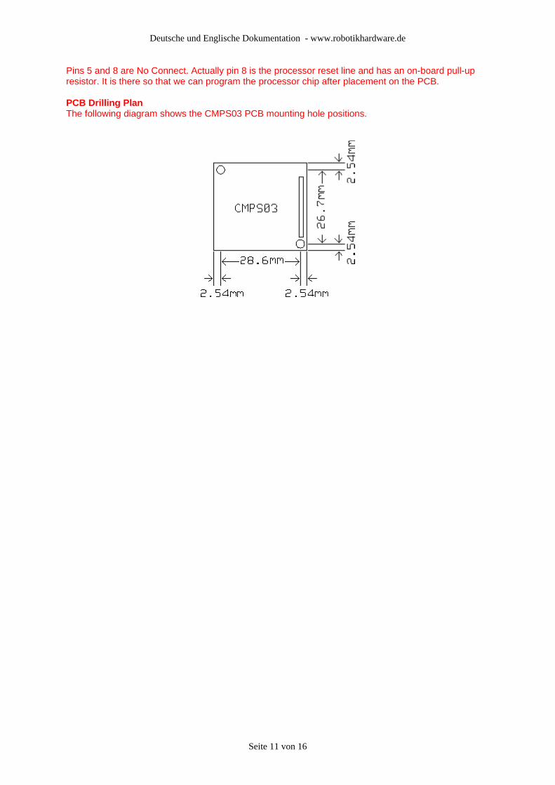
Pins 5 and 8 are No Connect. Actually pin 8 is the processor reset line and has an on-board pull-up resistor. It is there so that we can program the processor chip after placement on the PCB.
PCB Drilling PlanThe following diagram shows the CMPS03 PCB mounting hole positions.
Seite 11 von 16
Deutsche und Englische Dokumentation - www.robotikhardware.de
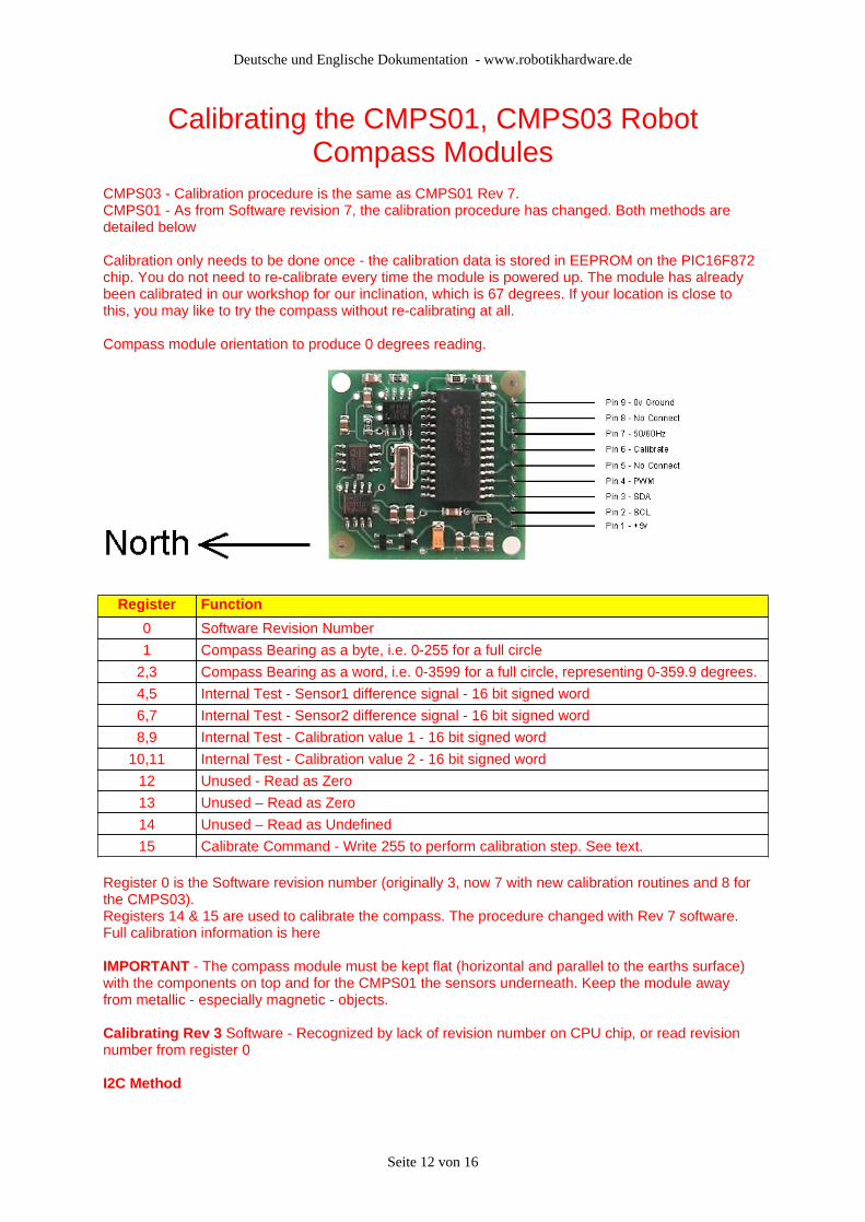
Calibrating the CMPS01, CMPS03 Robot Compass Modules
CMPS03 - Calibration procedure is the same as CMPS01 Rev 7.CMPS01 - As from Software revision 7, the calibration procedure has changed. Both methods are detailed below
Calibration only needs to be done once - the calibration data is stored in EEPROM on the PIC16F872 chip. You do not need to re-calibrate every time the module is powered up. The module has already been calibrated in our workshop for our inclination, which is 67 degrees. If your location is close to this, you may like to try the compass without re-calibrating at all.
Compass module orientation to produce 0 degrees reading.
Register Function
0 Software Revision Number
1 Compass Bearing as a byte, i.e. 0-255 for a full circle
2,3 Compass Bearing as a word, i.e. 0-3599 for a full circle, representing 0-359.9 degrees.
4,5 Internal Test - Sensor1 difference signal - 16 bit signed word
6,7 Internal Test - Sensor2 difference signal - 16 bit signed word
8,9 Internal Test - Calibration value 1 - 16 bit signed word
10,11 Internal Test - Calibration value 2 - 16 bit signed word
12 Unused - Read as Zero
13 Unused – Read as Zero
14 Unused – Read as Undefined
15 Calibrate Command - Write 255 to perform calibration step. See text.
Register 0 is the Software revision number (originally 3, now 7 with new calibration routines and 8 for the CMPS03). Registers 14 & 15 are used to calibrate the compass. The procedure changed with Rev 7 software. Full calibration information is here
IMPORTANT - The compass module must be kept flat (horizontal and parallel to the earths surface) with the components on top and for the CMPS01 the sensors underneath. Keep the module away from metallic - especially magnetic - objects.
Calibrating Rev 3 Software - Recognized by lack of revision number on CPU chip, or read revision number from register 0
I2C Method
Seite 12 von 16
Deutsche und Englische Dokumentation - www.robotikhardware.de
To calibrate the compass using the I2C bus, you only have to write 255 to register 15 and rotate the module very slowly through 360° . Writing zero to register 15 will store the calibration values in the processors internal EEPROM. Readings are taken by the processor at four compass points and these values are used to generate the calibration values. Register 14 reads 255 during normal operation. It reads zero when Calibrate mode is entered and 255 again when the four compass points have been measured. Register 14 will therefore indicate that the four points have been acquired and that zero can be written to register 15 to store the calibration and return to normal operation. It is necessary to rotate the compass very slowly during calibration to avoid missing the required compass points and to keep it horizontal to ensure the calibration figures are accurate.Pin MethodPins 5,6 are used to calibrate the compass. The calibrate input (pin 6) has an on-board pull-up resistor and can be left unconnected after calibration. To calibrate the compass you only have to take the calibrate pin low and rotate the module very slowly through 360° . Taking the calibrate pin high will store the calibration values in the processors internal EEPROM. Readings are taken by the processor at four compass points and these values are used to generate the calibration values. The CalDone output pin (pin 5) is high during normal operation. It goes low when the Calibrate pin is pulled low and high again when the four compass points have been measured. The CalDone pin will therefore indicate that the four points have been acquired and that the Calibrate pin can be raised high again. It is necessary to rotate the compass slowly during calibration to avoid missing the required compass points and to keep it horizontal to ensure the calibration figures are accurate.
Calibrating Rev 7 Software - Recognized by revision number label on CMPS01 CPU chip, or read revision number from register 0.Also applies to Calibrating the CMPS03 Module (all revisions).
Note that pin 5 (CalDone) and register 14 (Calibration Done Flag) are not used with Rev 7 software or the CMPS03. Pin 5 should be left unconnected and register 14 ignored. When calibrating the compass, you must know exactly which direction is North, East, South and West. Don't guess at it. Get a magnetic needle compass and check it.
I2C MethodTo calibrate using the I2C bus, you only have to write 255 (0xff) to register 15 for each of the four major compass points North, East, South and West. The 255 is cleared internally automatically after each point is calibrated. The compass points can be set in any order, but all four points must be calibrated. For example 1. Set the compass module flat, pointing North. Write 255 to register 152. Set the compass module flat, pointing East. Write 255 to register 153. Set the compass module flat, pointing South. Write 255 to register 154. Set the compass module flat, pointing West. Write 255 to register 15
That's it.
Pin MethodPin 6 is used to calibrate the compass. The calibrate input (pin 6) has an on-board pull-up resistor and can be left unconnected after calibration. To calibrate the compass you only have to take the calibrate pin low and then high again for each of the four major compass points North, East, South and West. A simple push switch wired from pin6 to 0v (Ground) is OK for this. The compass points can be set in any order, but all four points must be calibrated. For example 1. Set the compass module flat, pointing North. Press and release the switch2. Set the compass module flat, pointing East. Press and release the switch3. Set the compass module flat, pointing South. Press and release the switch4. Set the compass module flat, pointing West. Press and release the switch
That's it.
Seite 13 von 16
Deutsche und Englische Dokumentation - www.robotikhardware.de
Seite 14 von 16

Deutsche und Englische Dokumentation - www.robotikhardware.de
CMPS03 - Compass Module FAQ Q. Will your compass tell me which direction is north?A. No.
Q. Ok, will your compass tell me which way the magnetic north pole is?A. No.
Q. So what does it do?A. It gives you the direction of the horizontal component of the prevailing magnetic flux. OK, so I’m making a point here and it’s this: The magnetic field in a building can vary hugely. Don’t expect it to be always pointing north. By walking around my workshop with a standard magnetic needle compass I can make it point in any direction I like by moving past various machines, and I can do the same thing at home by going near the fridge or even the central heating radiators. The compass module will give the same results. It can only provide information about the field at its current location.
Q. Is the Compass affected by Motors, Magnets, Ferrous objects etc?A. Yes. Anything that affects the local magnetic field will affect the Compass module. Motors in particular contain strong magnets. The only solution is to mount the compass as far away from magnetic/ferrous objects as is practicable. Also see the previous questions and answers above
Q. If the accuracy of the compass is 3-4° , how can you provide a resolution of 0.1° ?A. Accuracy and resolution are not the same thing. A 3.5 digit multi-meter has a resolution of 1 in 2000 or 0.05%, yet the accuracy on some ranges can be 5% - a hundred time worse. A robot can use the resolution to detect small changes in direction even though there is uncertainty about the absolute direction. Also see previous answer.
Q. How do I select between I2C and PWM outputs?A. No need to. The PWM output is always present whether you use it or not and does not require a trigger signal. The I2C interface is also always available – just connect it up and start talking.
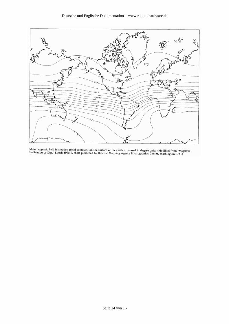
Q. How many degrees can the module be tilted before the readings become inaccurate?A. None. Moving the compass off horizontal will result in increasing error. The sensors are sensitive to the vertical component of the Earths magnetic field as well. The angle of the Earths field is not horizontal, it dives into the ground at an angle which varies according to location. It is this which produces an inherent error in the reading, and makes calibration of the compass required at the point where it is to be operated. After calibration you can expect 3-4° accuracy if you keep it horizontal.
Q. When measuring the PWM signal the maximum reading (which should be 359 degrees) is actually 357 degrees (or similar). Why is this?A. This is because of slight differences in CMPS01/03 and Controller oscillators and the internal software generating and measuring the pulse. If a 359 degree roll-over is important, then you can add a "fiddle factor" to the calculation or alternatively, use the I2C Bus.
Q. Which way up should the Compass be?A. The Compass module should be horizontal, with the PCB parallel to the earths surface. The IC's should be on top and (for the CMPS01) the Sensors underneath.
Q. What is the difference between the CMPS01 and the CMPS03?A. For most purposes, not a lot really. The coils around the KMZ10 sensors on the underside were proving way to expensive to assemble and still sell the module at such a low cost. When Philips produced the KMZ51 sensor, an 8 pin surface mount chip with the coils built in, it was time to change. The PCB is the same physical size as the CMPS01 with the same connections and uses the same software. Calibrating the CMPS03 is the same as CMPS01 Rev7.
Q. Can the Compass be mounted near to the speaker on the SP03 speech synthesizer?A. The speaker magnet will effect the Compass. The effects reduce with distance and are negligible at 10-12 inches
Q. My software master I2C code does not read correct data from the compass, but its works fine with an I2C EEPROM chip. Why is this?A. The most likely cause is the master code not waiting for the I2C bus hold. This is where the slave can hold the SCL line low until it is ready. When the master releases SCL (remember it's a passive pull-up, not driven high) the slave may still be holding it low. The master code should then wait until it actually does go high before proceeding. If you are writing your own code, have a look at our I2C Tutorial.
Seite 15 von 16

Deutsche und Englische Dokumentation - www.robotikhardware.de
Hersteller:
Devantech Ltd, England
Bezugsquelle Germany:
www.Robotikhardware.de
Hinweise zur beschränkten HaftungDas Kompaßmodul ist nicht für Geräte geeignet die direkt oder indirekt medizinischen, gesundheitlichen oder anderen Zwecken, bei denen ein Ausfall / Fehler zu Schäden an Personden oder Sachwerten führen würde. Soll das Modul für einen solchen Fall eingesetzt werden, so ist der Kunde für den test und alle Zulassungen selbst verantwortlich. Robotikhardware.de übernimmt darfür keinerlei Haftung. Die Haftung beschränkt sich in allen Fällen auf den Austausch des fehlerhaften Moduls. Module die durch fehlerhaften Anschluß / Bedienung beschädigt wurden, können nicht ersetzt werden.
Seite 16 von 16