DC/DC Converter BSC624- 12V-B - brusa.biz · Betriebsanleitung BSC624-12V-B User’s manual...
52
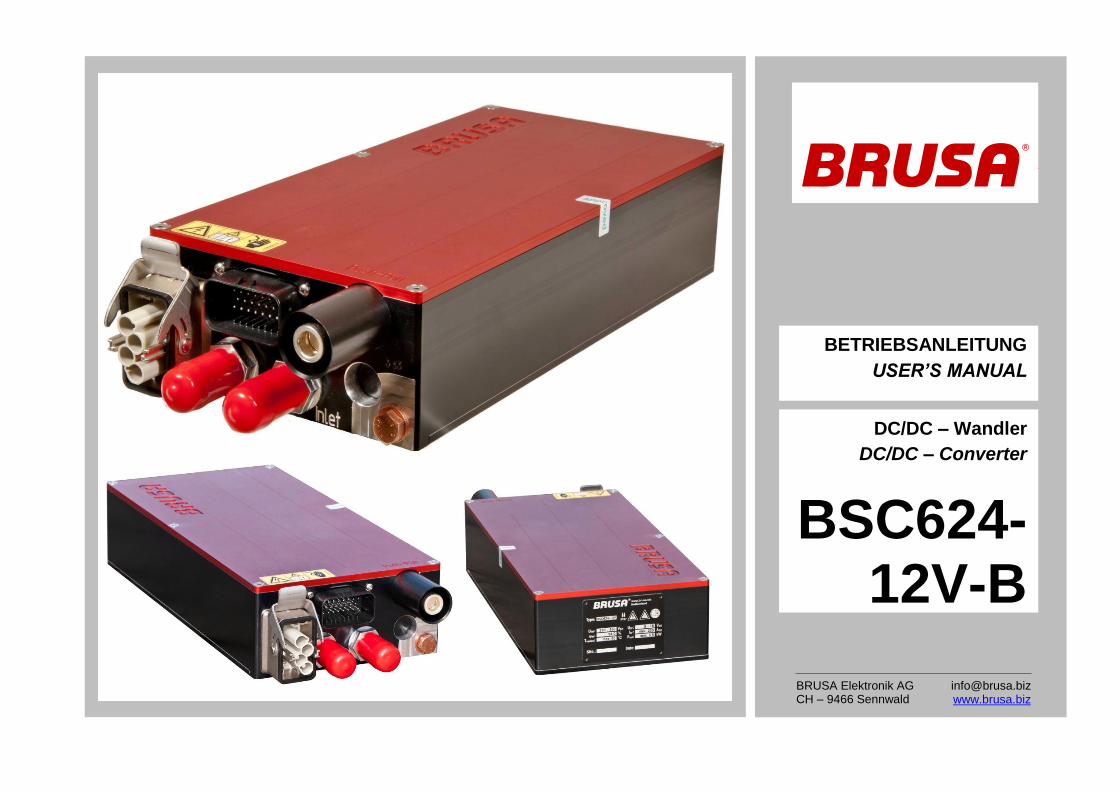
DC/DC – Wandler DC/DC – Converter BSC624- 12V-B BETRIEBSANLEITUNG USER’S MANUAL BRUSA Elektronik AG CH – 9466 Sennwald [email protected] www.brusa.biz
-
Upload
trannguyet -
Category
Documents
-
view
326 -
download
8
Transcript of DC/DC Converter BSC624- 12V-B - brusa.biz · Betriebsanleitung BSC624-12V-B User’s manual...
DC/DC – Wandler
DC/DC – Converter
BSC624-12V-B
BETRIEBSANLEITUNG
USER’S MANUAL
BRUSA Elektronik AG CH – 9466 Sennwald
[email protected] www.brusa.biz

Betriebsanleitung BSC624-12V-B User’s manual BSC624-12V-B
BSC624-12V-B_User_Manual_110531a.docx 2 / 52
Inhaltsverzeichnis Table of contents
1 Vor der Inbetriebnahme
2 Sicherheitsmassnahmen 2.1 Zu Ihrer Sicherheit 2.2 Um einen Schaden am Gerät zu vermeiden
3 Lieferumfang
4 Spezifikationen 4.1 Übersicht 4.2 Einführung 4.3 Terminologie 4.4 Elektrische Eckdaten 4.5 Mechanische Eckdaten 4.6 Blockschaltbild
5 Schnittstellen 5.1 Leistungsanschlüsse 5.2 Steueranschluss 5.2.1 Pinbelegung des Steuersteckers 5.2.2 Beschreibung der Steuersteckerpins
6 Technische Eigenschaften 6.1 Interne Stromversorgungen 6.2 Schutzfunktionen 6.2.1 Überlastschutz – Derating 6.2.2 Kurzschlussschutz 6.2.3 HV – Überspannungsabschaltung 6.2.4 LV – Überspannungsabschaltung 6.2.5 HV – Unterspannungsabschaltung 6.2.6 LV – Unterspannungsabschaltung 6.2.7 Interlock – Safety line 6.2.8 Fehlermeldungen und Fehlerbehandlung 6.2.9 HV – Automatische Entladung 6.3 EMV – Betrachtungen 6.3.1 Topologievorteile 6.3.2 AUX – Filterkonzept 6.3.3 LV – Filterkonzept 6.3.4 HV – Filterkonzept 6.3.5 Taktfrequenzen
7 Inbetriebnahme des Geräts 7.1 Montage und Einsatzbedingungen
Before operation .................................................................. 4
For safe use of this unit ....................................................... 5 For your safety ................................................................... 5 To prevent from damage of the device ............................... 6
Scope of delivery .................................................................. 7
Specifications ....................................................................... 8 Overview ............................................................................ 8 Introduction ........................................................................ 9 Terminology ....................................................................... 9 Electrical parameters .......................................................... 9 Mechanical parameters .................................................... 11 Block diagram................................................................... 11
Interfaces ............................................................................ 12 Power connectors ............................................................. 12 Control interface ............................................................... 13 Pin assignment of control connector ........................................... 13 Description of the control connector pins .................................... 14
Technical characteristics ................................................... 23 Internal power supplies ..................................................... 23 Safety functions ................................................................ 25 Overload protection – derating .................................................... 25 Short circuit protection ................................................................ 26 HV – overvoltage shut down ....................................................... 26 LV – overvoltage shut down ........................................................ 27 HV – Undervoltage shut down .................................................... 27 LV – undervoltage shut down ..................................................... 27 Interlock – Safety line .................................................................. 28 Error messages and error handling ............................................ 29 HV – Automatic discharge........................................................... 29 EMC – considerations ...................................................... 30 Advantages of the topology ........................................................ 30 AUX – filter concept .................................................................... 31 LV – filter concept ....................................................................... 32 HV – filter concept ....................................................................... 33 Clock frequencies ........................................................................ 34
Take the device into operation........................................... 35 Installation and conditions of use ...................................... 35

Betriebsanleitung BSC624-12V-B User’s manual BSC624-12V-B
BSC624-12V-B_User_Manual_110531a.docx 3 / 52
7.1.1 Einbaulage 7.1.2 Einbauort 7.1.3 Befestigung des Geräts 7.1.4 Maximale Einsatzhöhe 7.2 Verdrahtung des Geräts 7.2.1 Steuerstecker 7.2.2 HV-Leistungsstecker / HV-Kabel 7.2.3 LV-Leistungsstecker / LV-Kabel 7.2.4 LV- / PGND – Verbindung 7.2.5 Zulässige Steckzyklen der Stecker 7.2.6 Maximale Auszugskräfte der Stecker 7.2.7 Zugentlastung für Kabel 7.2.8 Kühlwasseranschluss 7.3 Vorladevorgang 7.4 Bedienung des Geräts 7.5 Programmieren der Firmware 7.5.1 PC – Systemanforderungen 7.5.2 Einstellungen am Gerät und PC 7.5.3 Installation der Programmiersoftware 7.5.4 Anlegen eines Projekts 7.5.5 Download der Firmware
8 Garantie
Mounting position ........................................................................ 35 Mounting location ........................................................................ 35 Fixation of the device .................................................................. 36 Maximum altitude ........................................................................ 36 Wiring the device .............................................................. 37 Control connector ........................................................................ 37 HV-power connector / HV-cable ................................................. 38 LV-power connector / LV-cable ................................................... 40 LV- / PGND – connection ............................................................ 41 Permissible connection cycles of connectors ............................. 42 Maximum extraction forces of connectors .................................. 42 Pull relief for cables ..................................................................... 43 Coolant connection ..................................................................... 43 Precharge process ........................................................... 44 Operation of the device .................................................... 45 Download the firmware ..................................................... 45 Requirements to the PC- system ................................................ 45 Configuration of device and PC .................................................. 46 Installation of the programming software .................................... 46 Create a project ........................................................................... 47 Download of the firmware ........................................................... 51
Warranty ............................................................................ 52
Betriebsanleitung BSC624-12V-B User’s manual BSC624-12V-B
BSC624-12V-B_User_Manual_110531a.docx 4 / 52
1 Vor der Inbetriebnahme Before operation
Geschätzter Kunde!
Mit dem BRUSA DC/DC-Wandler BSC624-12V ha-ben Sie ein sehr leistungsfähiges und vielseitiges Gerät erworben. Um dessen Vorzüge zu nutzen und jegliche Gefahr für Mensch und Material zu vermeiden, lesen Sie bitte vor der Inbetriebnahme diese Anleitung sorgfältig durch. Wir empfehlen Ihnen die Anleitung für späteres Nachschlagen auf-zubewahren.
Änderungen an der Betriebsanleitung sind vorbe-halten und werden nicht angekündigt. Holen Sie sich bitte die aktuelle Version von unserer Home-page: www.brusa.biz.
Dear Customer!
With the BRUSA DC/DC-Converter BSC624-12V you purchased a powerful and versatile product. To take advantage of its features and to avoid danger for man and material please read the operating in-structions carefully before operating the unit. We recommend to retain the user’s manual for later ref-erence.
Changes of the user’s manual are subject to further development of the device and will not be an-nounced. Please download the latest version of this manual from: www.brusa.biz.
Betriebsanleitung BSC624-12V-B User’s manual BSC624-12V-B
BSC624-12V-B_User_Manual_110531a.docx 5 / 52
2 Sicherheitsmassnahmen For safe use of this unit
2.1 Zu Ihrer Sicherheit For your safety
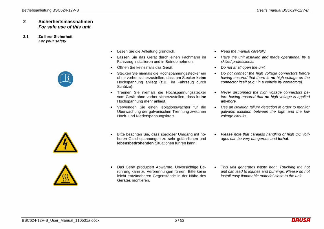
Lesen Sie die Anleitung gründlich.
Lassen Sie das Gerät durch einen Fachmann im Fahrzeug installieren und in Betrieb nehmen.
Öffnen Sie keinesfalls das Gerät.
Stecken Sie niemals die Hochspannungsstecker ein ohne vorher sicherzustellen, dass am Stecker keine Hochspannung anliegt (z.B.: im Fahrzeug durch Schütze).
Trennen Sie niemals die Hochspannungsstecker vom Gerät ohne vorher sicherzustellen, dass keine Hochspannung mehr anliegt.
Verwenden Sie einen Isolationswächter für die Überwachung der galvanischen Trennung zwischen Hoch- und Niederspannungskreis.
Read the manual carefully.
Have the unit installed and made operational by a skilled professional.
Do not at all open the unit.
Do not connect the high voltage connectors before having ensured that there is no high voltage on the connector itself (e.g.: in a vehicle by contactors).
Never disconnect the high voltage connectors be-fore having ensured that no high voltage is applied anymore.
Use an isolation failure detection in order to monitor galvanic isolation between the high and the low voltage circuits.
Bitte beachten Sie, dass sorgloser Umgang mit hö-heren Gleichspannungen zu sehr gefährlichen und lebensbedrohenden Situationen führen kann.
Please note that careless handling of high DC volt-ages can be very dangerous and lethal.
Das Gerät produziert Abwärme. Unvorsichtige Be-rührung kann zu Verbrennungen führen. Bitte keine leicht entzündbaren Gegenstände in der Nähe des Gerätes montieren.
This unit generates waste heat. Touching the hot unit can lead to injuries and burnings. Please do not install easy flammable material close to the unit.

Betriebsanleitung BSC624-12V-B User’s manual BSC624-12V-B
BSC624-12V-B_User_Manual_110531a.docx 6 / 52
2.2 Um einen Schaden am Gerät zu vermeiden
To prevent from damage of the device
Sorgen Sie für ausreichende Kühlung des Gerätes. Eine niedrige Kühlwassertemperatur kann die Le-bensdauer beträchtlich erhöhen.
Vermeiden Sie den Betrieb nahe an Wärmequellen oder in direkter Sonnenstrahlung.
Trotz des hohen IP-Schutzes empfehlen wir, das Gerät soweit als möglich von Umwelteinflüssen wie Regen oder Spritzwasser zu schützen.
Schliessen Sie niemals das Gerät direkt an Hoch-spannung an, sondern verwenden Sie eine ent-sprechende Vorladeeinrichtung. Dadurch werden hohe kapazitive Ströme einerseits und Spannungs-überhöhungen aufgrund von Filterbauteilen andrer-seits vermieden.
Ensure sufficient cooling of the device. A low tem-perature of the cooling water has a considerable positive effect on the lifetime.
Avoid operation of the device next to a heat source or in direct sunlight.
In spite of the high IP-protection we recommend to not expose the unit to rain or splash water.
Do never directly connect the device to high voltage but use an appropriate pre-charge circuitry instead. Hence, excessive capacitive currents on the one hand as well as voltage peaks due to filter compo-nents on the other hand can be avoided.

Betriebsanleitung BSC624-12V-B User’s manual BSC624-12V-B
BSC624-12V-B_User_Manual_110531a.docx 7 / 52
3 Lieferumfang Scope of delivery
DCDC- Wandler BSC624-12V-B DC/DC-converter BSC624-12V-B
Harting Hochspannungssteckverbindung kunden-seitig HAN-Modular Compact:
Tüllengehäuse gerade HAN-Modular Compact
Trägergehäuse HAN-Modular Compact
Buchseneinsatz HAN CC
4mm2 Krimpkontaktbuchsen
Kabelverschraubung HSK-M-EMV M25x1.5 für Kabeldurchmesser 9-16mm
Harting high voltage connector customer side HAN-Modular Compact:
Hood top entry HAN-Modular Compact
Carrier hood HAN-Modular Compact
Socket module HAN CC
4mm2 crimp contact plug sockets
Cable gland HSK-M-EMV M25x1.5 for cable di-ameter 9-16mm
Niederspannungssteckverbindung kundenseitig:
Pluspolsteckergehäuse für 50mm2-Kabel
MC-Kontakt SP10AR-N/50
O-Ring
M3x5 Gewindestift
M8/50mm2 gerader Kabelschuh für 12V-Minusanschluss
M8/50mm2 abgewinkelter Kabelschuh für 12V-Minusanschluss
Low voltage connectors customer side:
Plus pole connector housing for 50mm2-cable
MC-contact SP10AR-N/50
O-ring seal
M3x5 set screw
M8/50mm2 straight cable shoe for 12V-minus
connection
M8/50mm2 right angle cable shoe for 12V-minus
connection
23-poliger Steuerstecker mit Krimpkontakten:
AMPSEAL Buchse: 770680-1
AMPSEAL Kontakte: 770854-1
Drahtquerschnitt: 0.5mm2
23-pole control connector with crimp contacts:
AMPSEAL socket: 770680-1
AMPSEAL contacts: 770854-1
Wire cross section: 0.5mm2

Betriebsanleitung BSC624-12V-B User’s manual BSC624-12V-B
BSC624-12V-B_User_Manual_110531a.docx 8 / 52
4 Spezifikationen Specifications
4.1 Übersicht Overview
1
4
5 6
2
3
7
1. HV-Leistungsstecker
2. Wasseranschlüsse 3. Druckausgleichsmembran 4. LV-Minuspol 5. LV-Pluspol Leistungsstecker 6. Steuerstecker 7. Befestigungslöcher
1. HV-power connector 2. Cooling pipes 3. Pressure balance membrane 4. LV-minus pole 5. LV-plus pole power connector 6. Control connector 7. Mounting holes
Betriebsanleitung BSC624-12V-B User’s manual BSC624-12V-B
BSC624-12V-B_User_Manual_110531a.docx 9 / 52
4.2 Einführung Introduction
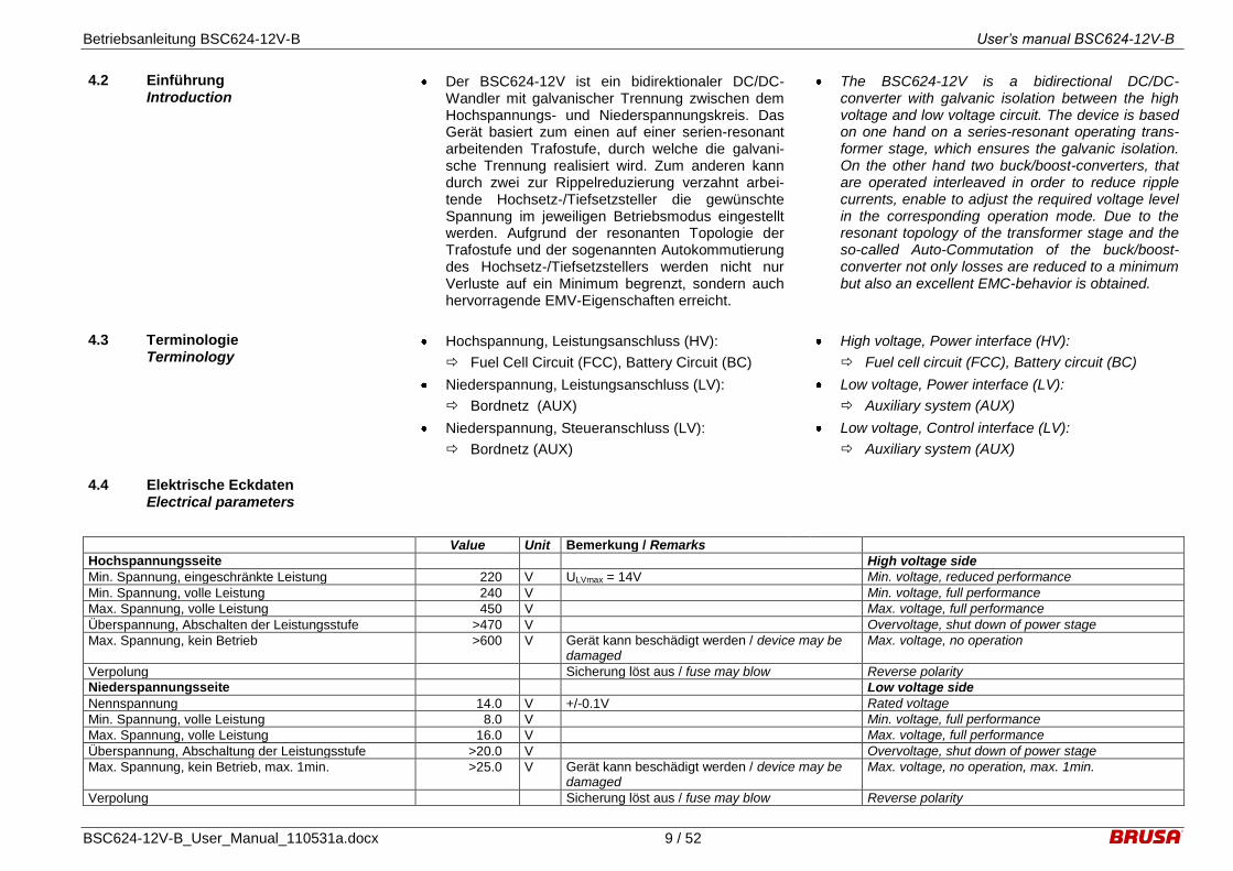
Der BSC624-12V ist ein bidirektionaler DC/DC-Wandler mit galvanischer Trennung zwischen dem Hochspannungs- und Niederspannungskreis. Das Gerät basiert zum einen auf einer serien-resonant arbeitenden Trafostufe, durch welche die galvani-sche Trennung realisiert wird. Zum anderen kann durch zwei zur Rippelreduzierung verzahnt arbei-tende Hochsetz-/Tiefsetzsteller die gewünschte Spannung im jeweiligen Betriebsmodus eingestellt werden. Aufgrund der resonanten Topologie der Trafostufe und der sogenannten Autokommutierung des Hochsetz-/Tiefsetzstellers werden nicht nur Verluste auf ein Minimum begrenzt, sondern auch hervorragende EMV-Eigenschaften erreicht.
The BSC624-12V is a bidirectional DC/DC-converter with galvanic isolation between the high voltage and low voltage circuit. The device is based on one hand on a series-resonant operating trans-former stage, which ensures the galvanic isolation. On the other hand two buck/boost-converters, that are operated interleaved in order to reduce ripple currents, enable to adjust the required voltage level in the corresponding operation mode. Due to the resonant topology of the transformer stage and the so-called Auto-Commutation of the buck/boost-converter not only losses are reduced to a minimum but also an excellent EMC-behavior is obtained.
4.3 Terminologie Terminology
Hochspannung, Leistungsanschluss (HV):
Fuel Cell Circuit (FCC), Battery Circuit (BC)
Niederspannung, Leistungsanschluss (LV):
Bordnetz (AUX)
Niederspannung, Steueranschluss (LV):
Bordnetz (AUX)
High voltage, Power interface (HV):
Fuel cell circuit (FCC), Battery circuit (BC)
Low voltage, Power interface (LV):
Auxiliary system (AUX)
Low voltage, Control interface (LV):
Auxiliary system (AUX)
4.4 Elektrische Eckdaten Electrical parameters
Value Unit Bemerkung / Remarks
Hochspannungsseite High voltage side
Min. Spannung, eingeschränkte Leistung 220 V ULVmax = 14V Min. voltage, reduced performance
Min. Spannung, volle Leistung 240 V Min. voltage, full performance
Max. Spannung, volle Leistung 450 V Max. voltage, full performance
Überspannung, Abschalten der Leistungsstufe >470 V Overvoltage, shut down of power stage
Max. Spannung, kein Betrieb >600 V Gerät kann beschädigt werden / device may be damaged
Max. voltage, no operation
Verpolung Sicherung löst aus / fuse may blow Reverse polarity
Niederspannungsseite Low voltage side
Nennspannung 14.0 V +/-0.1V Rated voltage
Min. Spannung, volle Leistung 8.0 V Min. voltage, full performance
Max. Spannung, volle Leistung 16.0 V Max. voltage, full performance
Überspannung, Abschaltung der Leistungsstufe >20.0 V Overvoltage, shut down of power stage
Max. Spannung, kein Betrieb, max. 1min. >25.0 V Gerät kann beschädigt werden / device may be damaged
Max. voltage, no operation, max. 1min.
Verpolung Sicherung löst aus / fuse may blow Reverse polarity

Betriebsanleitung BSC624-12V-B User’s manual BSC624-12V-B
BSC624-12V-B_User_Manual_110531a.docx 10 / 52
Leistungsdaten Power rating
LV-Dauerstrom 200 A Continuous LV current
LV-Spitzenstrom 250 A Peak buck mode LV current
HV-Dauerstrom Hochsetzbetrieb 3.6 A @ UHV = 400V, ULV = 8V, η = 90% Continuous boost mode HV current
HV-Spitzenstrom Hochsetzbetrieb 4.5 A @ UHV = 400V, ULV = 8V, η = 90% Peak boost mode HV current
Dauerleistung Tiefsetzbetrieb 2.8 kW @ Nennspannung / @ rated voltage Continuous buck mode output power
Spitzenleistung Tiefsetzbetrieb 3.5 kW @ Nennspannung / @ rated voltage Peak buck mode output power
Dynamisches Verhalten Dynamic performance
Sprungantwort LV-Spannung <500 us UHV = 360V, ULV_com = 13.0V 14.0V, ILV = 150A, buck mode
LV voltage command step response
Sprungantwort HV-Spannung <500 us ULV = 12.6V, UHV_com = 350V 360V; ILV = 156A, boost mode
HV voltage command step response
Regelgrenzfrequenz 1 kHz PWM-Stellgrösse auf 1kHz begrenzt / PWM command value limited to 1kHz
Critical regulation frequency
Standby mode Standby mode
Stromaufnahme an AUX (Steuerstecker) 58.0 uA @ UHV = 0V, ULV = UAUX = 14V, enable = low Current consumption at AUX (Control connector)
220.2 mA @ UHV = 0V, ULV = UAUX = 14V, enable = high
14.2 mA @ UHV = 330V, ULV = UAUX = 14V, enable = high
Galvanische Isolation Galvanic isolation
Spannungsfestigkeit zwischen HV und LV 3000 VDC Prüfspannung / test voltage Withstand voltage between HV and LV
Galvanische Trennung zwischen Signal- und Leis-tungsmasse
10 VDC Prüfspannung / test voltage Galvanic isolation between signal and power ground
Steuerschaltkreise Galvanisch getrennt von Leistungskreis / galvani-cally isolated from power circuit
Control circuit
Min. Spannung für Signale am Steuerstecker (AUX) 7 V Min. voltage for signals of control connector (AUX)
Max. Spannung für Signale am Steuerstecker (AUX) 32 V Max. voltage for signals of control connector (AUX)
Tiefsetzbetrieb: LV-Spannungsregelung mit HV-Unterspannungsbegrenzung und Stromlimits
Buck mode: LV voltage control with HV undervoltage limit and current limits
Hochsetzbetrieb: HV-Spannungsregelung mit LV-Unterspannungsbegrenzung und Stromlimits
Boost mode: HV voltage control with LV undervolt-age limit and current limits
LV-Spannung Messbereich 0…20.0 V LV voltage signal range
LV-Spannung Signalgenauigkeit +/-1 % Bezogen auf Skalenende / related to scale maxi-mum value
LV voltage signal accuracy
HV-Spannung Messbereich 0…480.0 V Begrenzt durch Wertebereich in CAN-Matrix / Limited by range of values in CAN-matrix
HV voltage signal range
HV-Spannung Signalgenauigkeit +/-1 % Bezogen auf Skalenende / related to scale maxi-mum value
HV voltage signal accuracy
HV (Low Side)-Strom Messbereich +/-30.0 A Begrenzt durch Wertebereich in CAN-Matrix / Limited by range of values in CAN-matrix
HV (low side) current signal range
HV (Low Side)-Strom Signalgenauigkeit +/-3.5 % LEM HV (low side) current signal accuracy
Taktfrequenzen Switching frequencies
Trafostufe 197 kHz Transformer stage
Hoch-/Tiefsetzsteller, min. 40 kHz @ UHV = 220V, ULV = 14.0V, ILV = 250A Buck/Boost stage, min.
Hoch-/Tiefsetzsteller, max. 150 kHz @ UHV = 450V, ULV = 16.0V, ILV = 0A Buck/Boost stage, max.
Wirkungsgrad Efficiency
Typisch 94.4 % @ UHV = 330V, ULV = 14.0V, ILV = 150A Typical

Betriebsanleitung BSC624-12V-B User’s manual BSC624-12V-B
BSC624-12V-B_User_Manual_110531a.docx 11 / 52
4.5 Mechanische Eckdaten Mechanical parameters
Kühlung Thermal
Kühlmedium 50% water, 50% ethylene glycol Coolant medium
Kühlmittelvolumen 225 ml Inklusive Anschlussstutzen / Including nozzle Coolant volume
Min. Kühlmitteltemperatur -40 °C Min. coolant temperature
Max. Kühlmitteltemperatur 65 °C Max. coolant temperature
Durchflussrate >4 l/min Cooling flow rate
Druckabfall <0.1 bar @ 4l/min Pressure loss
Max. statischer Druck 2 bar Max. static pressure
Umgebungstemperaturbereich (Lagerung) -40...105 °C Ambient temperature range (storing)
Umgebungstemperaturbereich (Betrieb) -40….85 °C Ambient temperature range (operating)
Mechanik Mechanical
Material AlMgSi1 Korrosionsfestes Aluminium / Corrosion-resistant aluminum
Material
Länge 300 mm Length
Breite 150 mm Width
Höhe 70 mm Height
Volumen 3.15 l Ohne Stecker / without connectors Volume
Gewicht 4.8 kg +/- 0.05kg Weight
IP-Schutz IP65 / IP67 IP-protection
Wasserdichte Druckausgleichsmembran Integriert / Integrated Water resistant pressure balance
Aussendurchmesser Kühlwasserstutzen 16 mm Outer diameter of coolant pipe
4.6 Blockschaltbild Block diagram
Resonant galvanically isolated bidirectional DC/DC -converter with constant voltage ratio 12:1
AC DC
DC AC
Low Voltage
8…16VDC max. 250A
Max. voltage loss: +/-0,5V
Low voltage
filter
High voltage
220…450VDC max. 18.5A
Resonant bidirectional buck/boost - converter
with variable voltage ratio 0,20…0,83
90…198VDC max. 22A
High
voltage filter
12 : 1

Betriebsanleitung BSC624-12V-B User’s manual BSC624-12V-B
BSC624-12V-B_User_Manual_110531a.docx 12 / 52
5 Schnittstellen Interfaces
5.1 Leistungsanschlüsse Power connectors
Hochspannungs – Steckverbindung:
Niederspannungs – Steckverbindung:
Beim LV-Pluspolstecker handelt es sich um einen sogenannten „Push-Pull-Stecker“. Um die Steck-verbindung zu trennen, muss der Stecker vorgängig ganz hineingedrückt werden, bevor er dann her-ausgezogen werden kann.
Interlock:
Mittels dieser Funktion kann überprüft werden, ob die Stecker ordnungsgemäss angeschlossen sind, sodass davon abhängig entsprechende Massnah-men ergriffen werden können:
Durch die voreilenden Interlock-Kontakte wird beim Trennen der HV-Steckverbindung ein Feh-ler erkannt und das Gerät unmittelbar abge-schaltet, sodass ein möglicher Lichtbogen ver-hindert wird.
Die Hochspannung im Gerät wird beim Erken-nen einer getrennten HV-Steckverbindung un-verzüglich mittels der ohnehin vorhandenen in-ternen HV-Versorgung entladen (<350ms).
Nr. Abk. Funktion
1 IL1 Interlock
2 IL2 Interlock
3 HV+ Hochspannung Plus
4 HV- Hochspannung Minus
Nr. Abk. Funktion
5 LV+ Bordnetz Plus
6 LV- / PGND
Bordnetz Leistungsmasse / Fahr-zeugmasse
High voltage – connector:
Low voltage – connector:
The LV plus pole connector is a so-called “push-pull connector”. In order to disconnect it, the connector must be pushed in completely before it can be un-plugged finally.
Interlock:
This feature allows to monitor if the connectors are connected properly and hence appropriate actions can be taken:
Through the leading interlock contacts an error
will be detected and the device shut down im-mediately in case of disconnecting the HV-connector which will prevent from possible arcs.
The high voltage inside of the device will be dis-
charged immediately (<350ms) by the internal HV-supply after disconnecting the HV-connector.
No. Abbr. Function
1 IL1 Interlock
2 IL2 Interlock
3 HV+ High voltage plus
4 HV- High voltage minus
No. Abbr. Function
1 LV+ Auxiliary system plus
2 LV- / PGND
Auxiliary system power ground / vehi-cle ground
1 2 3 4
5
6
Betriebsanleitung BSC624-12V-B User’s manual BSC624-12V-B
BSC624-12V-B_User_Manual_110531a.docx 13 / 52
5.2 Steueranschluss Control interface
5.2.1 Pinbelegung des Steuersteckers Pin assignment of control connector
Nr. Abk. Funktion
1 GND Signalmasse (Bordnetzmasse, Klemme 31)
2 AUX +12V (Bordnetz Plus, Klemme 30)
3 EN Enable (Power ON, Klemme 15)
4 DO0 Digitaler Ausgang 1 (programmierbar)
5 DO1 Digitaler Ausgang 2 (programmierbar)
6 DO2 Digitaler Ausgang 3 (programmierbar)
7 DO3 Digitaler Ausgang 4 (programmierbar)
8 PG1 Analoge Masse (für Pins 21 – 23)
9 CNL CAN Low
10 CNH CAN High
11 TXD RS232 Transmit (9-pol D-Sub: Pin 2)
12 RXD RS232 Receive (9-pol D-Sub: Pin 3)
13 PRO Enable Firmware-Programmierung
14 PG2 Reserve-Masse
15 PG3 RS232 Masse (9-pol D-Sub: Pin 5)
16 DI0 Digitaler Eingang 1
17 DI1 Digitaler Eingang 2
18 DI2 Digitaler Eingang 3
19 IL1 Interlock - Signaleinspeisung
20 IL2 Interlock - Signaleinspeisung
21 AI1 Analoger Eingang 1 (programmierbar)
22 AI2 Analoger Eingang 2 (programmierbar)
23 AI3 Analoger Eingang 3 (programmierbar)
Nr. Abbr. Function
1 GND Signal ground (Auxiliary system ground, terminal 31)
2 AUX +12V (Auxiliary system plus, terminal 30)
3 EN Enable (Power ON, terminal 15)
4 DO0 Digital output 1 (programmable)
5 DO1 Digital output 2 (programmable)
6 DO2 Digital output 3 (programmable)
7 DO3 Digital output 4 (programmable)
8 PG1 Analog ground (for pins 21 – 23)
9 CNL CAN low
10 CNH CAN high
11 TXD RS232 transmit (9-pole D-Sub: Pin 2)
12 RXD RS232 receive (9-pole D-Sub: Pin 3)
13 PRO Enable firmware download
14 PG2 Reserve ground
15 PG3 RS232 ground (9-pole D-Sub: Pin 5)
16 DI0 Digital input 1
17 DI1 Digital input 2
18 DI2 Digital input 3
19 IL1 Interlock – Signal input
20 IL2 Interlock - Signal input
21 AI1 Analog Input 1 (programmable)
22 AI2 Analog Input 2 (programmable)
23 AI3 Analog Input 2 (programmable)
23 15 8 1
9 16
Betriebsanleitung BSC624-12V-B User’s manual BSC624-12V-B
BSC624-12V-B_User_Manual_110531a.docx 14 / 52
5.2.2 Beschreibung der Steuersteckerpins Description of the control connector
pins
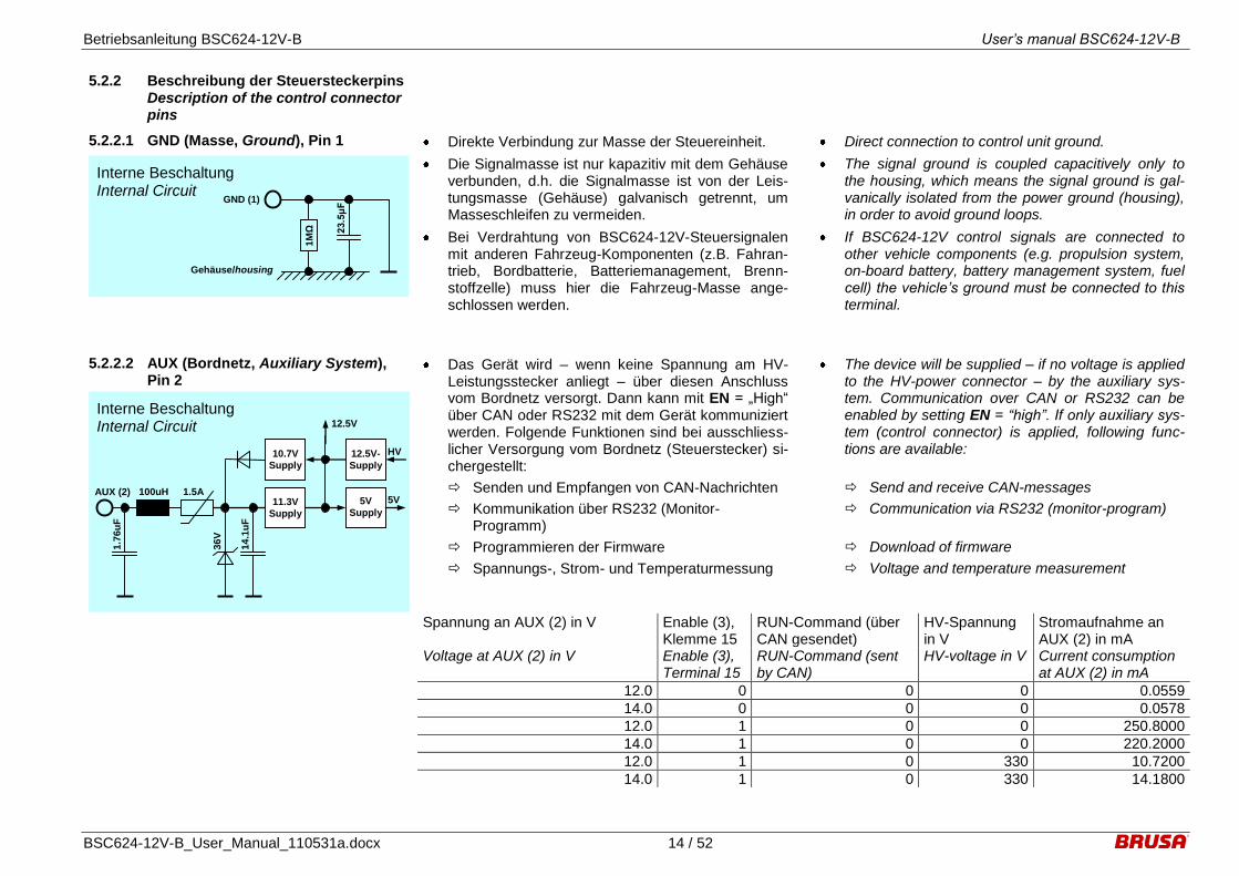
5.2.2.1 GND (Masse, Ground), Pin 1 Direkte Verbindung zur Masse der Steuereinheit.
Die Signalmasse ist nur kapazitiv mit dem Gehäuse verbunden, d.h. die Signalmasse ist von der Leis-tungsmasse (Gehäuse) galvanisch getrennt, um Masseschleifen zu vermeiden.
Bei Verdrahtung von BSC624-12V-Steuersignalen mit anderen Fahrzeug-Komponenten (z.B. Fahran-trieb, Bordbatterie, Batteriemanagement, Brenn-stoffzelle) muss hier die Fahrzeug-Masse ange-schlossen werden.
Direct connection to control unit ground.
The signal ground is coupled capacitively only to the housing, which means the signal ground is gal-vanically isolated from the power ground (housing), in order to avoid ground loops.
If BSC624-12V control signals are connected to other vehicle components (e.g. propulsion system, on-board battery, battery management system, fuel cell) the vehicle’s ground must be connected to this terminal.
Interne Beschaltung Internal Circuit
1MΩ
23.5μF
GND (1)
Gehäuse/housing
5.2.2.2 AUX (Bordnetz, Auxiliary System), Pin 2
Das Gerät wird – wenn keine Spannung am HV-Leistungsstecker anliegt – über diesen Anschluss vom Bordnetz versorgt. Dann kann mit EN = „High“ über CAN oder RS232 mit dem Gerät kommuniziert werden. Folgende Funktionen sind bei ausschliess-licher Versorgung vom Bordnetz (Steuerstecker) si-chergestellt:
Senden und Empfangen von CAN-Nachrichten
Kommunikation über RS232 (Monitor-Programm)
Programmieren der Firmware
Spannungs-, Strom- und Temperaturmessung
The device will be supplied – if no voltage is applied to the HV-power connector – by the auxiliary sys-tem. Communication over CAN or RS232 can be enabled by setting EN = “high”. If only auxiliary sys-tem (control connector) is applied, following func-tions are available:
Send and receive CAN-messages
Communication via RS232 (monitor-program)
Download of firmware
Voltage and temperature measurement
Interne Beschaltung Internal Circuit
1.7
6u
F
AUX (2) 100uH 1.5A 5V
36V
5V
Supply
12.5V
14
.1u
F
12.5V-
Supply
HV
11.3V
Supply
10.7V
Supply
Spannung an AUX (2) in V Enable (3),
Klemme 15 RUN-Command (über CAN gesendet)
HV-Spannung in V
Stromaufnahme an AUX (2) in mA
Voltage at AUX (2) in V Enable (3), Terminal 15
RUN-Command (sent by CAN)
HV-voltage in V Current consumption at AUX (2) in mA
12.0 0 0 0 0.0559
14.0 0 0 0 0.0578
12.0 1 0 0 250.8000
14.0 1 0 0 220.2000
12.0 1 0 330 10.7200
14.0 1 0 330 14.1800

Betriebsanleitung BSC624-12V-B User’s manual BSC624-12V-B
BSC624-12V-B_User_Manual_110531a.docx 15 / 52
5.2.2.3 EN (Enable, Power ON), Pin 3 Bei Anlegen einer Spannung an AUX und mit EN = „High“ (+7V...32V) wird das Gerät in den betriebs-bereiten Modus versetzt. Sinnvollerweise erfolgt dies durch eine Verbindung des Enable-Pins über einen Schalter mit dem Bordnetz Plus.
Um eine neue Firmware zu programmieren, ist es nicht erforderlich, dass EN = „High“ ist.
Auch wenn am HV-Stecker Hochspannung anliegt, wird die geräteinterne Logik nur dann versorgt, wenn der Pin EN = „High“ ist (oder Pin PROG = „High“ ist).
By applying voltage at AUX and by setting EN = „high” (+7V...32V) the device will be ready to oper-ate. Reasonably this is realized by using a switch in order to connect the enable-pin to the auxiliary sys-tem plus.
In order to download a new firmware, EN does not have to be „high”.
Even when high voltage is applied to the HV-connector, the device internal logic is only supplied, if the pin EN = „high“ (or pin PROG = “high”).
Interne Beschaltung Internal Circuit
47n
F
EN (3)
5V 2.7
kΩ
220p
F
1,0V
3,3V
Schmitt
Trigger
120kΩ
5V Supply Enable
23
.5kΩ
2.7
kΩ
5V
Supply
11.3V
Supply
10
0n
F
100n
F
11.3V Supply Enable
22kΩ
33V

Betriebsanleitung BSC624-12V-B User’s manual BSC624-12V-B
BSC624-12V-B_User_Manual_110531a.docx 16 / 52
5.2.2.4 DO0 – DO3 (Digitale Ausgänge, Digi-tal Outputs), Pins 3 - 7
Mit diesen vier programmierbaren digitalen Aus-gängen können optional niederfrequente Anwen-dungen realisiert werden:
Ansteuerung von LEDs für Statusfunktionen (z.B. Unter- bzw. Überspannung, Überschrei-tung einer Stromgrenze, Temperaturrückreg-lung,...).
Ansteuerung von anderen externen Komponen-ten (PWM für Anzeigeinstrumente, Relais, klei-ne Lüfter,...).
Alle vier digitalen Ausgänge weisen folgende Merkmale auf:
RDSON = 1,7Ω bei Ta = 25°C
VOUTmax = 32V
VCLAMP 45V (Spannungsfestigkeit für induktive Lasten)
Kurzschlussfestigkeit (Imax = 700mA)
Abschaltung bei zu hoher Temperatur aufgrund von Überbelastung
Bei Auftreten eines Fehlers an einem Ausgang sind die restlichen Ausgänge weiter funktionstauglich, wenn es durch den einen Fehler nicht zu einer Ab-schaltung bei den restlichen Ausgängen aufgrund zu hoher Temperatur führt.
Die Ausgänge können mit Frequenzen bis zu 10kHz betrieben werden. Um auch bei diesen Frequenzen noch ordentliche Signalverläufe zu ermöglichen, ist jeder Ausgang mit einem 500Ω/2W Pull-up-Widerstand beschaltet.
With these four programmable digital outputs low frequency applications can be realized optionally:
Drive LEDs for status functions (e.g.: under- or
overvoltage, exceeding of current limit, tempera-ture derating,...).
Drive other external components (PWM for dis-play instruments, relays, small fans,...).
All four digital outputs show the following features:
RDSON = 1,7Ω at Ta = 25°C
VOUTmax = 32V
VCLAMP 45V (clamping voltage for inductive loads)
Short circuit detection (Imax = 700mA)
Over-temperature shutdown due to overload
In case of such a failure at one of the outputs the other outputs remain still fully functional as long as such a failure does not lead to over-temperature shut down of the other outputs.
All outputs can be driven with a frequency up to 10kHz. In order to ensure proper signals even at such frequencies, each output has a 500Ω/2W pull-up resistor.
Interne Beschaltung Internal Circuit
10
nF
DO0 - DO3 (4 - 7)
AUX
50
0Ω
33V

Betriebsanleitung BSC624-12V-B User’s manual BSC624-12V-B
BSC624-12V-B_User_Manual_110531a.docx 17 / 52
5.2.2.5 PG1 – PG3 (Analoge Masse, Analog Ground), Pins 8, 14, 15
Zur Vereinfachung der externen Verdrahtung ste-hen drei zusätzliche Masse-Anschlüsse zur Verfü-gung. Diese sind über je eine PTC-Sicherung mit der Versorgungs-Masse GND verbunden.
Folgende Zuordnung wird vorgeschlagen:
Nr. Abk. Funktion
8 PG1 Analoge Masse (für Pins 21 - 23)
14 PG2 Reserve Masse
15 PG3 RS232 - Masse (9-pol D-Sub: Pin 5)
In order to simplify external wiring, three additional ground pins are available. Each pin is connected to the supply’s ground GND by a PTC-fuse.
Following pin assignment is suggested:
No. Abbr. Function
8 PG1 Analog ground (for pins 21 - 23)
14 PG2 Reserve ground
15 PG3 RS232 - ground (9-pol D-Sub: Pin 5)
Interne Beschaltung Internal Circuit
4.7μF
PG1 – PG3 (8, 14, 15) (1)
300m
A
5.2.2.6 CNH, CNL (CAN-BUS, CAN-Interface), Pins 9, 10
Die CAN-Schnittstelle weist folgende Eigen-schaften auf:
CAN 2.0 B, 500 kBit (Standard)
Die CAN-Schnittstelle weist eine Potentialtren-nung von der Masse und den übrigen Steuer-signalen auf, um Störungen durch Potentialver-schiebungen zu vermeiden.
Der 120Ω Abschlusswiderstand kann durch BRUSA auf Wunsch bestückt werden. Diese In-formation muss bei der Bestellung angeführt werden.
Über die CAN-Schnittstelle können Informatio-nen gemäss der seitens BRUSA als dbc-Datei zur Verfügung gestellten CAN-Matrix gesendet und empfangen werden.
Die Identifier der jeweiligen Nachricht, die Baud-rate als auch der Abtastpunkt für die CAN-Signale können optional durch das PARAM-Tool verändert werden.
The CAN interface has following characteristics:
CAN 2.0 B, 500 kBit (default)
Galvanic isolation from ground and all other control signals in order to avoid interferences caused by ground offset voltages.
The 120Ω termination resistor can be mounted
by BRUSA if desired. This information must be included in the order.
The CAN interface allows to transmit and re-ceive messages according to the CAN-matrix provided by BRUSA, which is available as dbc-file.
The identifiers of each message, the baud rate as well as the sampling point of the CAN-signals can be modified optionally by the PARAM-tool.
Interne Beschaltung Internal Circuit
47
pF
CNL (9)
33V
51uH
47
pF
CNH (10)
120Ω
33V
51uH
Termination resistor is
optional
CAN-Transceiver and galvanic
isolation

Betriebsanleitung BSC624-12V-B User’s manual BSC624-12V-B
BSC624-12V-B_User_Manual_110531a.docx 18 / 52
5.2.2.7 TXD, RXD (RS232-Schnittstelle, RS232-Interface), Pins 11, 12
Die RS232-Schnittstelle ermöglicht eine direkte se-rielle Verbindung zwischen dem BSC624-12V und einem Computer. Gerade für Prüfstände oder Pro-totypenfahrzeuge empfehlen wir unbedingt die Ver-drahtung der RS232-Schnittstelle, um im Bedarfsfall ein Firmware-Update durchführen zu können. Fol-gende Funktionen stehen zur Verfügung:
Programmieren der von BRUSA mitgelieferten oder nachgereichten Firmware (durch Setzen von PRO = „High“). Für weitere Informationen zum Programmieren kontaktieren Sie bitte direkt BRUSA.
Anzeige der Momentanwerte von Strom, Span-nung und Temperatur. Die dafür notwendige Software „HyperTerminal“ ist prinzipiell auf je-dem Windows-Computer unter „Programme → Zubehör → Kommunikation“ bereits verfügbar. Bitte beachten Sie, dass diese Funktionalität neuerdings durch das sogenannte über CAN laufende PARAM-Tool wesentlich komfortabler abgedeckt wird.
Belegung der 9-poligen D-Sub Kabelbuchse:
RXD (12)
TXD (11)
9-polige D-Sub Kabelbuchse Transceiver
PG3 (15) 5
2
3
The RS232 interface provides a direct serial con-nection between the BSC624-12V and a computer Especially for test benches or prototype vehicles we strongly recommend to wire the RS232-interface, in order to make a firmware-update if necessary. Fol-lowing functions are provided:
Download the firmware provided by BRUSA (by
setting PRO = “high”). For further information regarding the download please contact directly BRUSA.
Display the actual current, voltage and tempera-
ture values (monitor program). The required software “HyperTerminal” is basically available on every Windows-Computer under “Programs → Accessories → Communication”. Please take note that this feature will be newly covered by the over CAN operated so-called PARAM-tool which is much more convenient.
Pin assignment of the 9-pole D-sub socket:
RXD (12)
TXD (11)
9 pin D-Sub connector, female Kabelbuchse Transceiver PG3 (15) 5
2
3
Interne Beschaltung Internal Circuit
470
pF
RXD (12)
10V
470
pF
TXD (11)
15V
RS232-
Transeiver
200Ω
200Ω
470
pF
470
pF
100Ω
100Ω
33V
33V

Betriebsanleitung BSC624-12V-B User’s manual BSC624-12V-B
BSC624-12V-B_User_Manual_110531a.docx 19 / 52
5.2.2.8 PRO (Enable Firmware Programmi-erung, Enable firmware download), Pin 13
Dieser Anschluss wird ausschliesslich für das Pro-grammieren einer neuen Firmware aktiviert (PRO = „High“), wobei dann EN nicht „High“ sein muss.
Sowohl bei Versorgung von Hochspannung als auch vom Bordnetz löst PRO = „High“ folgende Vorgänge aus:
Falls das Gerät im Betrieb ist, wird dieser ge-stoppt.
Das Gerät ist dann empfangsbereit und kann über die serielle Schnittstelle programmiert wer-den.
Das Programmieren einer neuen Firmware darf nur in Absprache mit BRUSA durchgeführt werden. Die Firmware wird dann allenfalls per Email zugestellt.
This pin is exclusively activated (PRO = „high“) to download a new firmware, whereas EN does not have to be „high”.
PRO = „high” causes the following actions regard-less of supplying the device from high voltage or auxiliary system:
If the device is in operation, it will be shut down.
The device is then ready to be programmed via
the serial interface.
The download of a new firmware may only be done with agreement of BRUSA. A new firmware can be provided by email then.
Interne Beschaltung Internal Circuit
47n
F
PRO (13)
5V
2.7
kΩ
220p
F
1,0V
3,3V
Schmitt
Trigger
120kΩ
5V Supply Enable
23
.5kΩ
2.7
kΩ
5V
Supply
11.3V
Supply
10
0n
F
100n
F
11.3V Supply Enable
22kΩ
33V
5.2.2.9 DI0 – DI2 (Digitale Eingänge, Digital Inputs), Pins 16 – 18
Mit diesen drei Eingängen können optional ver-schiedene Funktionen realisiert werden wie folgen-der Vorschlag zeigt:
DI0: Hochsetzbetrieb
DI1: Tiefsetzbetrieb
DI2: Spannungs- oder Stromregelmodus
With these three inputs various functions can be re-alized optionally as the following proposal shows:
DI0: Boost mode
DI1: Buck mode
DI2: Voltage or current regulation mode
Interne Beschaltung Internal Circuit
10
nF
DI0 – DI2 (16 - 18)
5V
220
pF
1,0V
3,3V
Schmitt Trigger
22kΩ
23
.5kΩ
uC
33V

Betriebsanleitung BSC624-12V-B User’s manual BSC624-12V-B
BSC624-12V-B_User_Manual_110531a.docx 20 / 52
5.2.2.10 IL1, IL2 (Interlock), Pins 19, 20 Der Interlock ist eine sicherheitsrelevante Funktion, die intern verarbeitet wird, aber auch durch ein übergeordnetes System (Bsp.: Fahrzeugsystem) ausgewertet werden kann. Die Interlockverbindung ist durch die HV-Steckverbindung geschleift (Brücke im kundenseitigen HV-Stecker) und erlaubt so die Überprüfung, ob dieser Stecker ordnungsgemäss angeschlossen ist. Das Gerät verfügt über zwei un-abhängige Interlocküberwachungsschaltungen:
Interne Interlockerkennung
Externe Interlockerkennung
Die interne Interlockerkennung funktioniert unab-hängig von der Verwendung der externen Erken-nung und überwacht ausschliesslich, ob der HV-Stecker richtig angeschlossen ist. Bei einem Fehler wird das Signal INTL_OC_int* gesetzt und über CAN der Fehler „CRE_INTERLOCK“ ausgegeben. Aus Sicherheitsgründen kann die interne Interlo-ckerkennung nicht deaktiviert werden.
Durch Verwendung der externen Interlockerken-nung kann nicht nur die eigene HV-Steckverbin-dung, sondern auch jene von zusätzlichen Geräten überprüft werden.
Hierfür muss durch den Kunden das Inter-locksignal in Form eines DC-Stroms von min-destens 20mA bei Pin 19 bzw. 20 eingespeist werden, wobei die Polarität keine Rolle spielt.
Im PARAM-Tool überprüfen, ob die externe In-terlockerkennung tatsächlich aktiviert ist und gegebenenfalls korrigieren.
Falls nun irgendeine der überwachten Steck-verbindungen nicht richtig kontaktiert ist, ist die Schleife offen und der eingeprägte Strom kann nicht mehr fliessen. Bei Unterschreiten einer Schwelle von ca. 15mA wird das Signal INTL_OC_ext* gesetzt und über CAN der Feh-ler „CRE_INTERLOCK“ ausgegeben.
The interlock is a safety relevant function, which is processed internally but may also be evaluated by a superior system (e.g.: vehicle system). The interlock is looped through the HV-connection (wire link in customer side HV-connector) and allows therefore to monitor if this connector is connected properly to the device. The device offers two independently op-erating interlock monitoring circuits:
Internal interlock detection
External interlock detection
The internal interlock detection operates inde-pendently of the usage of the external interlock de-tection and monitors exclusively, if the HV-connector is plugged in properly. In case of a failure the signal INTL_OC_int* is set and the error „CRE_INTERLOCK“ is sent by CAN. Due to safety reasons the internal interlock detection cannot be deactivated.
The usage of the external interlock detection al-lows to not only monitor the own HV-connection but also those of additional devices.
For this purpose the customer must inject the in-
terlock signal in form of a DC-current of mini-mum 20mA at pin 19, resp. 20, whereas the po-larity does not matter.
Check in the PARAM-tool, whether the external interlock detection is actually activated and cor-rect if necessary.
If now any of the monitored connections is not connected properly to the device, the loop is open and the injected current may not flow. When the current falls below a level of app. 15mA, the signal INTL_OC_ext* is set and the error „CRE_INTERLOCK“ is sent by CAN.
Interne Beschaltung Internal Circuit
10
nF
IL2 (20)
IL1 (19)
IL2 (2)
IL1 (1)
High voltage
power connector
12mH
12mH
10
nF
470
pF
470
pF
51uH
51uH
Int. Interlock Processing
(INTL_OC_int*)
62Ω
100nF
30kΩ
10
uF
5V
Interlock-Error
(INTL_OC_ext*)
R4

Betriebsanleitung BSC624-12V-B User’s manual BSC624-12V-B
BSC624-12V-B_User_Manual_110531a.docx 21 / 52
Die Erkennung des internen und externen Interlock-fehlers – vorausgesetzt der letztere ist überhaupt aktiviert – führt unverzüglich zum Abschalten des Geräts.
Mit Hilfe des PARAM-Tools kann aufgeschlüsselt werden, ob ein vorliegender Interlockfehler durch die interne oder externe Erkennung detektiert wur-de.
Die LV-Steckverbindung ist im Interlockkreis nicht integriert!
Die im kundenseitigen HV-Stecker bereits be-stückte Drahtbrücke darf keinesfalls entfernt oder abgeändert (z.B. verlängert) werden!
Für Kunden, die ein alternatives Interlockkonzept verwenden (z.B. Einspeisen eines Rechtecksignals, Vergleichen der Spannungspegel am Anfang und am Ende der Interlockschleife), kann R4 optional mit einem 0Ω Widerstand bestückt werden, um jeg-lichen ungewünschten Spannungsabfall zu vermei-den.
Bitte beachten Sie, dass in diesem Fall die ex-terne Interlockerkennung des Geräts nicht mehr funktioniert und deshalb im PARAM-Tool deak-tiviert werden muss.
Bei der Bestellung ist darauf zu achten, dass die zum verwendeten Interlockkonzept passende Gerä-teversion gewählt wird:
BSC624-12V-B01: R4 = 62R (hierbei handelt es sich um eine kundenspezifische Version)
BSC624-12V-B02: R4 = 62R
BSC624-12V-B03: R4 = 0R
The detection of an internal and external interlock failure – presumed the latter one is activated in fact – results in immediate shut-down of the device.
By means of the PARAM-tool it is possible to diag-nose whether an interlock failure was detected by the internal or the external detection.
The LV-connection is not integrated in the interlock-circuit!
The wire link in the customer side HV-connector must not be removed or changed (for instance to lengthen) in any way!
For customers, who take use of an alternative inter-lock concept (i.e. injection of rectangular signal, comparison of voltage levels at beginning and end of interlock loop), R4 can be mounted with a 0Ω re-sistor optionally, in order to prevent from any unde-sired voltage drop.
Please be aware that in this case the external
interlock detection of the device is not functional anymore and must therefore be deactivated in the PARAM-tool.
When ordering the device, please take care that the device version suits to the interlock concept being used:
BSC624-12V-B01: R4 = 62R (this is a customer specific version)
BSC624-12V-B02: R4 = 62R
BSC624-12V-B03: R4 = 0R

Betriebsanleitung BSC624-12V-B User’s manual BSC624-12V-B
BSC624-12V-B_User_Manual_110531a.docx 22 / 52
5.2.2.11 AI1 – AI3 (Analoge Eingänge, Analog Inputs), Pins 21 – 23
Mit diesen drei analogen Eingängen können optio-nal jeweils zwei unterschiedliche Funktionen reali-siert werden:
1mA – Stromquelle für externes 5kΩ Potentio-meter
33kΩ Pull-up – Widerstand für externen 33kΩ NTC-Temperatursensor.
Jeder der drei analogen Eingänge kann individuell gemäss Kundenanforderung programmiert werden. Bei der Einstellung aller drei Eingänge als Strom-quelle können z.B. folgende Funktionen realisiert werden:
AI1: Spannungsregelung LV
AI2: Stromlimit Buck-Mode
AI3: Stromlimit Boost-Mode
Bei der Einstellung zur Temperaturmessung (Tmin = 25°C) von externen Komponenten ist z.B. folgende Konfiguration möglich:
AI1: Batterietemperatur
AI2: Kühlwassertemperatur
AI3: Reserve
With each of these three analog inputs two different functions can be realized optionally:
1mA – current source for an external 5kΩ po-tentiometer
33kΩ pull-up – resistor for external 33kΩ NTC-
temperature sensor.
Each of these three analog inputs can be pro-grammed individually according to the customer’s requirements. If all three inputs are configured as current source, the following functions can be real-ized:
AI1: Voltage regulation LV
AI2: Current limit buck-mode
AI3: Current limit boost-mode
If the inputs are configured for temperature meas-urement (Tmin = 25°C) of external components, the following configuration is proposed:
AI1: Battery temperature
AI2: Cooling water temperature
AI3: Reserve
Interne Beschaltung Internal Circuitp
10
nF
AI1 – AI3 (21 - 23)
5V
Analog Multiplexer
22kΩ
150Ω
33kΩ
10
nF
I = 1
mA
5V
An
alo
g
Mu
ltip
lexer
uC

Betriebsanleitung BSC624-12V-B User’s manual BSC624-12V-B
BSC624-12V-B_User_Manual_110531a.docx 23 / 52
6 Technische Eigenschaften Technical characteristics
6.1 Interne Stromversorgungen Internal power supplies
1.7
6u
F
AUX (2) 100uH 1.5A
Regulation & measurement
circuits
36V
5V/1A
Supply
14.1
uF
HV
11.3V/1A
Supply
10.7V/0.1A
Supply
PRO (13)
47
nF
EN (3)
2.7
kΩ
120
kΩ
5V Supply
Enable
100
nF
11.3V Supply
Enable
47
nF
2.7
kΩ
100
nF
uC-Enable 1
10kΩ
Driver
+6V/0.1A
Supply
-6V/0.1A
Supply
5V-CAN Supply
Galvanically isolated
CAN supply
Controller
PWM-Unit
12.5V/2.5ASupply
GND (1)
33V
33V
Das Gerät kann prinzipiell sowohl von HV als auch von AUX (2) versorgt werden, wobei für die voll-ständige Betriebsbereitschaft die 12.5V/2.5A-Versorgung aktiv sein muss. Diese läuft bei einer HV-Spannung von etwa 75V an und deaktiviert durch die höhere Ausgangsspannung automatisch die 11.3V/1A-Versorgung von AUX (2), um den Stromverbrauch ab Bordnetz zu reduzieren.
The device can be supplied from HV as well as from AUX (2), whereas for the complete ready status the 12.5V/2.5A-supply has to be active. This supply starts operating at a HV-voltage of approximately 75V and automatically deactivates then due to the higher output voltage the 11.3V/1A-supply from AUX (2), in order to reduce the current consumption from the auxiliary system.

Betriebsanleitung BSC624-12V-B User’s manual BSC624-12V-B
BSC624-12V-B_User_Manual_110531a.docx 24 / 52
Die 5V-Versorgung wird erst gewährleistet, wenn entweder EN (3) oder PRO (13) mit AUX (2) ver-bunden wird. Die für den uC über Enable1 hard-waremässig vorgesehene Selbsthaltefunktion ist aus Sicherheitsgründen softwareseitig deaktiviert.
Um optional einen autarken Betrieb des Geräts ge-währleisten zu können, ist eine 10.7V/0.1A-Versorgung implementiert. Auf diese Weise kann beispielsweise EN (3) durch eine Verbindung mit AUX (2) im kundenseitigen Stecker aktiviert wer-den, sodass das Gerät immer eingeschaltet ist.
Die 12.5V/2.5A-Versorgung ist ebenfalls mit der – auch im Hoch-/Tiefsetzsteller eingesetzten – Auto-kommutierung-Topologie realisiert. Diese Speisung ist galvanisch vom Hochspannungskreis getrennt und funktioniert zudem ohne Optokoppler.
Im Hochsetzstellbetrieb werden die Treiber beim Hochstarten zu Beginn von AUX (2) versorgt.
Sämtliche Versorgungsschaltkreise sind kurz-schlussfest.
Die Signalmasse GND (1) ist von der Leistungs-masse PGND galvanisch getrennt, um Potentialver-schleppungen bzw. Masseschleifen zu verhindern.
The 5V-supply will be provided, if either EN (3) or PRO (13) will be connected to AUX (2). On hard-ware level Enable 1 features a self-sustaining func-tion for the uC, which is however deactivated due to safety reasons.
A 10.7V/0.1A-supply is implemented, in order to enable an optional autarkic operation of the device. Thus, EN (3) for instance could be activated by a connection to AUX (2) in the customer-side con-nector, so that the device will be permanently switched on.
The 12.5V/2.5A-supply is realized again with the – also in the buck/boost converter used – Auto-Commutation-topology. This supply is galvanically isolated from the high voltage circuit and further-more functions without an optocoupler.
In boost mode the drivers will be supplied from AUX (2) in the very beginning of the start-up.
All supply circuits are short-circuit-proof.
The signal ground GND (1) is galvanically isolated from the power ground PGND, in order to avoid ac-cidental potential transfer, resp. ground loops.
Betriebsanleitung BSC624-12V-B User’s manual BSC624-12V-B
BSC624-12V-B_User_Manual_110531a.docx 25 / 52
6.2 Schutzfunktionen Safety functions
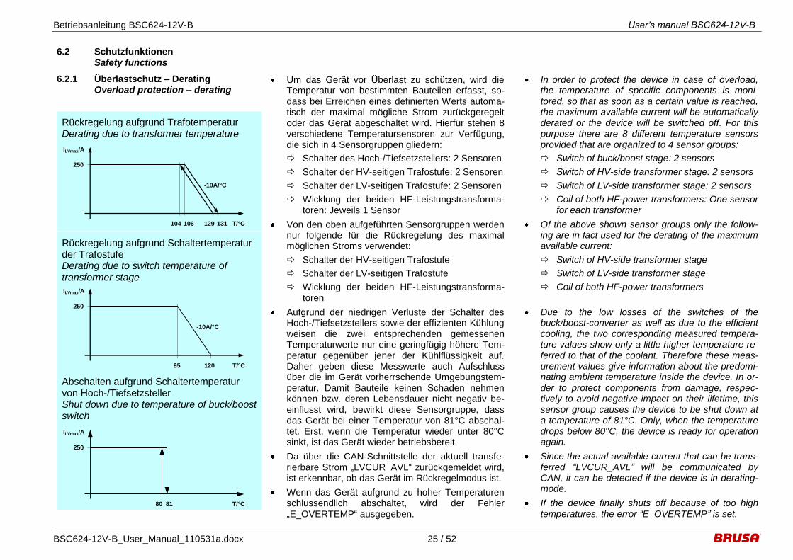
6.2.1 Überlastschutz – Derating Overload protection – derating
Um das Gerät vor Überlast zu schützen, wird die Temperatur von bestimmten Bauteilen erfasst, so-dass bei Erreichen eines definierten Werts automa-tisch der maximal mögliche Strom zurückgeregelt oder das Gerät abgeschaltet wird. Hierfür stehen 8 verschiedene Temperatursensoren zur Verfügung, die sich in 4 Sensorgruppen gliedern:
Schalter des Hoch-/Tiefsetzstellers: 2 Sensoren
Schalter der HV-seitigen Trafostufe: 2 Sensoren
Schalter der LV-seitigen Trafostufe: 2 Sensoren
Wicklung der beiden HF-Leistungstransforma-toren: Jeweils 1 Sensor
Von den oben aufgeführten Sensorgruppen werden nur folgende für die Rückregelung des maximal möglichen Stroms verwendet:
Schalter der HV-seitigen Trafostufe
Schalter der LV-seitigen Trafostufe
Wicklung der beiden HF-Leistungstransforma-toren
Aufgrund der niedrigen Verluste der Schalter des Hoch-/Tiefsetzstellers sowie der effizienten Kühlung weisen die zwei entsprechenden gemessenen Temperaturwerte nur eine geringfügig höhere Tem-peratur gegenüber jener der Kühlflüssigkeit auf. Daher geben diese Messwerte auch Aufschluss über die im Gerät vorherrschende Umgebungstem-peratur. Damit Bauteile keinen Schaden nehmen können bzw. deren Lebensdauer nicht negativ be-einflusst wird, bewirkt diese Sensorgruppe, dass das Gerät bei einer Temperatur von 81°C abschal-tet. Erst, wenn die Temperatur wieder unter 80°C sinkt, ist das Gerät wieder betriebsbereit.
Da über die CAN-Schnittstelle der aktuell transfe-rierbare Strom „LVCUR_AVL“ zurückgemeldet wird, ist erkennbar, ob das Gerät im Rückregelmodus ist.
Wenn das Gerät aufgrund zu hoher Temperaturen schlussendlich abschaltet, wird der Fehler „E_OVERTEMP“ ausgegeben.
In order to protect the device in case of overload, the temperature of specific components is moni-tored, so that as soon as a certain value is reached, the maximum available current will be automatically derated or the device will be switched off. For this purpose there are 8 different temperature sensors provided that are organized to 4 sensor groups:
Switch of buck/boost stage: 2 sensors
Switch of HV-side transformer stage: 2 sensors
Switch of LV-side transformer stage: 2 sensors
Coil of both HF-power transformers: One sensor for each transformer
Of the above shown sensor groups only the follow-ing are in fact used for the derating of the maximum available current:
Switch of HV-side transformer stage
Switch of LV-side transformer stage
Coil of both HF-power transformers
Due to the low losses of the switches of the buck/boost-converter as well as due to the efficient cooling, the two corresponding measured tempera-ture values show only a little higher temperature re-ferred to that of the coolant. Therefore these meas-urement values give information about the predomi-nating ambient temperature inside the device. In or-der to protect components from damage, respec-tively to avoid negative impact on their lifetime, this sensor group causes the device to be shut down at a temperature of 81°C. Only, when the temperature drops below 80°C, the device is ready for operation again.
Since the actual available current that can be trans-ferred “LVCUR_AVL” will be communicated by CAN, it can be detected if the device is in derating-mode.
If the device finally shuts off because of too high temperatures, the error “E_OVERTEMP” is set.
Rückregelung aufgrund Trafotemperatur Derating due to transformer temperature
T/°C 131 106
-10A/°C
ILVmax/A
250
129 104
Rückregelung aufgrund Schaltertemperatur der Trafostufe Derating due to switch temperature of transformer stage
T/°C 120 95
-10A/°C
ILVmax/A
250
Abschalten aufgrund Schaltertemperatur von Hoch-/Tiefsetzsteller Shut down due to temperature of buck/boost switch
ILVmax/A
T/°C 81 80
250

Betriebsanleitung BSC624-12V-B User’s manual BSC624-12V-B
BSC624-12V-B_User_Manual_110531a.docx 26 / 52
6.2.2 Kurzschlussschutz Short circuit protection
Da die Trafostufe aufgrund ihrer resonant taktenden Topologie einen bestimmten Innenwiderstand hat, ist diese und damit das Gerät prinzipiell kurz-schlussfest. Dies hat zur Folge, dass im Fall eines Kurzschluss, der extern durch den Anwender verur-sacht wird, die Spannung zusammenbricht und der Fehler „E_LV_UNDERVOL“ erkannt wird.
Im Tiefsetzstellbetrieb wird bei einem Kurzschluss auf der LV-Seite Unterspannung erkannt.
Im Hochsetzstellbetrieb wird bei einem Kurzschluss auf der HV-Seite Unterspannung erkannt.
Natürlich wird unabhängig vom Betriebsmodus auch auf dem jeweiligen Leistungseingang Unter-spannung erkannt.
Since the transformer stage with its resonant topol-ogy has a certain internal resistance, it and there-fore the device is basically short-circuit-proof. As a consequence, in case of short-circuit, that is caused by the user externally, the voltage drops and the er-ror “E_LV_UNDERVOL” is detected.
In buck mode short-circuit on the LV-side will be de-tected by undervoltage.
In boost mode short-circuit on the HV-side will be detected by undervoltage.
Regardless of the operation mode undervoltage will be detected on the corresponding power input as well.
6.2.3 HV – Überspannungsabschaltung HV – overvoltage shut down
Das Gerät verfügt über zwei verschiedene Möglich-keiten, um Überspannung „E_HV_OVERVOL“ auf der HV-Seite zu erkennen:
Schnelle HW-Überspannungserkennung
Langsame SW-Überspannungserkennung
Die schnelle HW-Überspannungserkennung schal-tet das Gerät unmittelbar ab, wenn die HV-Spannung ungefähr 470V überschreitet.
Die langsame SW-Überspannungserkennung schal-tet das Gerät ab, wenn die HV-Spannung 456V er-reicht. Das Gerät schaltet automatisch wieder ein, wenn die HV-Spannung unter 454V liegt.
The device features two different possibilities, in or-der to detect overvoltage “E_HV_OVERVOL” at the HV-side:
Fast HW-overvoltage detection
Slow SW-overvoltage detection
The fast HW-overvoltage detection shuts off the de-vice immediately, if the HV-voltage exceeds approx-imately 470V.
The slow SW-overvoltage detection shuts off the device, if the HV-voltage reaches 456V. The device will be activated again automatically as soon as the HV-voltage is below 454V.

Betriebsanleitung BSC624-12V-B User’s manual BSC624-12V-B
BSC624-12V-B_User_Manual_110531a.docx 27 / 52
6.2.4 LV – Überspannungsabschaltung LV – overvoltage shut down
Das Gerät verfügt über zwei verschiedene Möglich-keiten, um Überspannung „E_LV_OVERVOL“ auf der LV-Seite zu erkennen:
Schnelle HW-Überspannungserkennung
Langsame SW-Überspannungserkennung
Die schnelle HW-Überspannungserkennung schal-tet das Gerät unmittelbar ab, wenn die LV-Spannung ungefähr 20V überschreitet.
Die langsame SW-Überspannungserkennung schal-tet das Gerät ab, wenn die LV-Spannung 16.4V er-reicht. Das Gerät schaltet automatisch wieder ein, wenn die LV-Spannung unter 16.2V liegt.
The device features two different possibilities, in or-der to detect overvoltage “E_LV_OVERVOL” at the LV-side:
Fast HW-overvoltage detection
Slow SW-overvoltage detection
The fast HW-overvoltage detection shuts off the de-vice immediately, if the LV-voltage exceeds approx-imately 20V.
The slow SW-overvoltage detection shuts off the device, if the LV-voltage reaches 16.4V. The device will be activated again automatically as soon as the LV-voltage is below 16.2V.
6.2.5 HV – Unterspannungsabschaltung HV – Undervoltage shut down
Die HV-Unterspannungserkennung schaltet die Leistungsstufe ab und gibt den Fehler „E_HV_UNDERVOL“ aus, wenn die HV-Spannung unter 215V sinkt.
Diese Fehlererkennung ist beim Starten des Geräts im Hochsetzbetrieb für 3s deaktiviert.
The HV-undervoltage detection shuts down the power stage and sets the error “E_HV_UNDERVOL”, if the HV-voltage drops below 215V.
This error detection is deactivated for 3s at start-up of the device in boost mode.
6.2.6 LV – Unterspannungsabschaltung LV – undervoltage shut down
Die LV-Unterspannungserkennung schaltet die Leistungsstufe ab und gibt den Fehler „E_LV_UNDERVOL“ aus, wenn die LV-Spannung unter 7V sinkt.
Diese Fehlererkennung ist beim Starten des Geräts im Tiefsetzbetrieb für 5s deaktiviert.
The LV-undervoltage detection shuts down the power stage and sets the error “E_LV_UNDERVOL”, if the LV-voltage drops below 7V.
This error detection is deactivated for 5s at start-up of the device in boost mode.

Betriebsanleitung BSC624-12V-B User’s manual BSC624-12V-B
BSC624-12V-B_User_Manual_110531a.docx 28 / 52
6.2.7 Interlock – Safety line Interlock – Safety line
Mittels dieser Funktion wird überprüft, ob die Ste-cker ordnungsgemäss angeschlossen sind. Im Ge-rät ist sowohl eine interne als auch eine externe In-terlockerkennung implementiert, die unabhängig voneinander funktionieren und den Fehler „CRE_INTERLOCK“ auslösen.
Während die interne Erkennung zwar immer aktiv ist, aber ausschliesslich den eigenen HV-Stecker überprüft, kann zusätzlich optional das Gerät über die entsprechenden Pins am Steuerstecker in eine Interlockschleife eingebunden werden (externe In-terlockerkennung). Auf diese Weise kann ein ent-sprechendes Gerät im Interlockkreis den ordnungs-gemässen Kontakt aller Steckverbindungen über-prüfen.
Damit die korrekte Auswertung der internen Interlo-ckerkennung gewährleistet ist, darf die Interlock-schlaufe im kundenseitigen HV-Leistungsstecker NICHT abgeändert werden.
Weitere Details zur Interlockfunktion siehe unter 5.2.2.10.
This feature allows to monitor if the connectors are connected properly. There is an internal as well as an external interlock detection implemented in the device that function and set the error “CRE_INTERLOCK” independently.
While the internal detection is always active but only monitors the own HV-connector, it is also optionally possible to integrate the device into an interlock loop by using the corresponding pins on the control connector (external interlock detection). By this means a dedicated device in the interlock loop can monitor the proper connection of all connectors.
In order to ensure correct processing of the internal interlock detection, the interlock loop in the HV-connector must NOT be changed.
Refer to 5.2.2.10 for further details regarding the in-terlock function.

Betriebsanleitung BSC624-12V-B User’s manual BSC624-12V-B
BSC624-12V-B_User_Manual_110531a.docx 29 / 52
6.2.8 Fehlermeldungen und Fehlerbehand-lung
Error messages and error handling
Das Gerät unterscheidet zwei Fehlerkategorien:
Critical Errors (CRE): Fehler dieser Art treten im
Normalfall und bei ordnungsgemässer Bedie-nung des Geräts nicht auf. Mit Ausnahme des Fehlers „CRE_INTERLOCK“ deuten solche Fehler also auf einen internen Bauteildefekt hin.
Errors (E): Hierbei handelt es sich um Fehler, die in der Regel auf eine Fehlbedienung hindeu-ten. Hiervon ausgenommen ist der Fehler „E_TEMP“ sowie „E_INT_SUPPLY“.
Damit Sie einen Anhaltspunkt haben, wann ein Ge-rät zur Analyse und Reparatur eingeschickt werden muss, definieren wir folgende Anzahl an maximal jeweils wiederkehrenden Fehlerereignissen:
Critical Errors (CRE): 10
Errors (E): 50
Detaillierte Informationen zu möglichen Fehlermel-dungen und deren Behandlung finden sich im fol-genden Dokument:
„BSC624-12V-B_Errors_and_Warnings…“
The device distinguishes between two error catego-ries:
Critical Errors (CRE): Errors of this kind do usu-ally not occur if the device is operated according to specification. Hence, with the exception of the error “CRE_INTERLOCK” such errors do sug-gest a component defect.
Errors (E): These are errors that indicate a faulty operation as a general rule, except the er-ror “E_TEMP” and “E_INT_SUPPLY”.
In order to give a clue when a device needs to be sent back for analysis and repair, following number of maximum recurring error events is defined:
Critical Errors (CRE): 10
Errors (E): 50
Detailed information concerning possible error mes-sages and their handling can be found in the follow-ing document:
“BSC624-12V-B_Error_and_Warnings…”
6.2.9 HV – Automatische Entladung HV – Automatic discharge
Wenn das Gerät von der Hochspannung getrennt wird, entladen sich die internen HV-Schaltkreise in-nerhalb weniger als 350ms auf Werte unter 50V.
If the device is disconnected from the high voltage, the internal HV-circuitries are discharged within less than 350ms to values below 50V.
Betriebsanleitung BSC624-12V-B User’s manual BSC624-12V-B
BSC624-12V-B_User_Manual_110531a.docx 30 / 52
6.3 EMV – Betrachtungen EMC – considerations
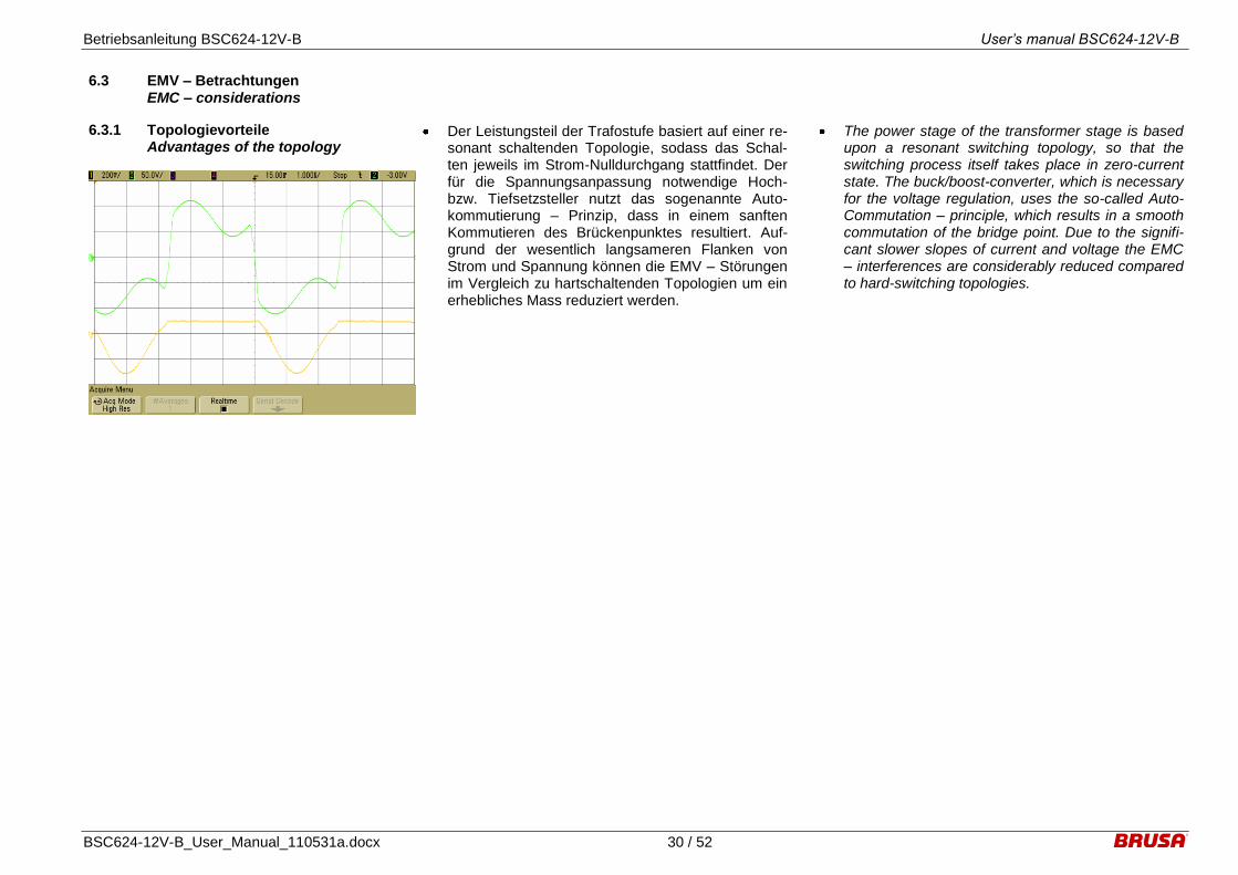
6.3.1 Topologievorteile Advantages of the topology
Der Leistungsteil der Trafostufe basiert auf einer re-sonant schaltenden Topologie, sodass das Schal-ten jeweils im Strom-Nulldurchgang stattfindet. Der für die Spannungsanpassung notwendige Hoch- bzw. Tiefsetzsteller nutzt das sogenannte Auto-kommutierung – Prinzip, dass in einem sanften Kommutieren des Brückenpunktes resultiert. Auf-grund der wesentlich langsameren Flanken von Strom und Spannung können die EMV – Störungen im Vergleich zu hartschaltenden Topologien um ein erhebliches Mass reduziert werden.
The power stage of the transformer stage is based upon a resonant switching topology, so that the switching process itself takes place in zero-current state. The buck/boost-converter, which is necessary for the voltage regulation, uses the so-called Auto-Commutation – principle, which results in a smooth commutation of the bridge point. Due to the signifi-cant slower slopes of current and voltage the EMC – interferences are considerably reduced compared to hard-switching topologies.

Betriebsanleitung BSC624-12V-B User’s manual BSC624-12V-B
BSC624-12V-B_User_Manual_110531a.docx 31 / 52
6.3.2 AUX – Filterkonzept AUX – filter concept
Um eine bestmögliche Dämpfung der leitungsge-bundenen Störungen zu erreichen, sind alle Pins des Steuersteckers durch SMD-Kondensatoren auf GND gefiltert. GND ist wiederum sehr nieder-impedant mit dem Gehäuse verbunden. Auf diese Weise kann ein Übersprechen von Gleichtaktstö-rungen von einem Pin auf andere weitgehend un-terdrückt werden.
AUX ist zusätzlich mit einem X-Filter versehen. Ausserdem ist der Pin durch eine flinke PTC-Sicherung und einer 36V-Suppressordiode gegen-über Surge- und Burst-Störungen geschützt.
Die CAN-Schnittstelle ist durch eine spezielle Dros-sel gegenüber Gleichtaktstörungen gefiltert.
Alle Pins des Steuersteckers sind gegen luft- oder kontaktentladene ESD-Störungen geschützt. Bei der CAN- und RS232-Schnittstelle erfolgt dies durch spezielle ESD-Dioden.
Für die Unterdrückung von hochfrequenten Gleich-taktstörungen sind alle Pins durch einen Ferritkern geführt.
Weitere Details zur Beschaltung der Steuerstecker-pins siehe unter 5.2 Steueranschluss.
In order to obtain a best possible attenuation of conducted interferences all pins of the control con-nector are filtered by SMD-capacitors to GND. GND itself is connected to the housing with a very low impedance. Hence the cross talk of common mode interferences can be suppressed extensively.
AUX is additionally provided with a X-filter. Fur-thermore this pin is protected against surge- and burst disturbances with a fast PTC-fuse and a 36V-suppressor diode.
The CAN-interface is filtered by a special choke against common mode interferences.
All pins of the control connector are protected against air- or contact-discharged ESD-disturbances. The CAN- and RS232-interface are therefore equipped with special ESD-diodes.
In order to suppress high frequent common mode interferences all pins are conducted through a fer-rite core.
Refer to 5.2 Control interface for further details re-garding the circuitry of the control connector.
Betriebsanleitung BSC624-12V-B User’s manual BSC624-12V-B
BSC624-12V-B_User_Manual_110531a.docx 32 / 52
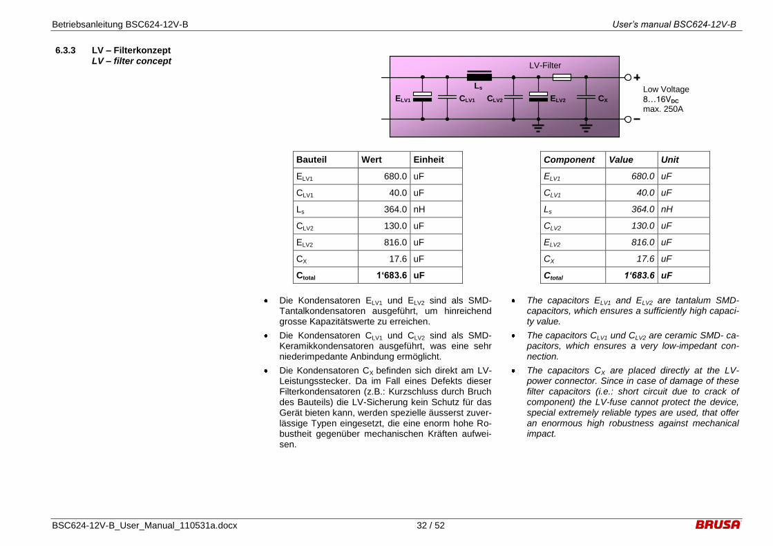
6.3.3 LV – Filterkonzept LV – filter concept
Low Voltage
8…16VDC max. 250A
Ls
ELV2 CX ELV1
LV-Filter
CLV1 CLV2
Bauteil Wert Einheit
ELV1 680.0 uF
CLV1 40.0 uF
Ls 364.0 nH
CLV2 130.0 uF
ELV2 816.0 uF
CX 17.6 uF
Ctotal 1‘683.6 uF
Die Kondensatoren ELV1 und ELV2 sind als SMD-Tantalkondensatoren ausgeführt, um hinreichend grosse Kapazitätswerte zu erreichen.
Die Kondensatoren CLV1 und CLV2 sind als SMD- Keramikkondensatoren ausgeführt, was eine sehr niederimpedante Anbindung ermöglicht.
Die Kondensatoren CX befinden sich direkt am LV-Leistungsstecker. Da im Fall eines Defekts dieser Filterkondensatoren (z.B.: Kurzschluss durch Bruch des Bauteils) die LV-Sicherung kein Schutz für das Gerät bieten kann, werden spezielle äusserst zuver-lässige Typen eingesetzt, die eine enorm hohe Ro-bustheit gegenüber mechanischen Kräften aufwei-sen.
Component Value Unit
ELV1 680.0 uF
CLV1 40.0 uF
Ls 364.0 nH
CLV2 130.0 uF
ELV2 816.0 uF
CX 17.6 uF
Ctotal 1‘683.6 uF
The capacitors ELV1 and ELV2 are tantalum SMD-capacitors, which ensures a sufficiently high capaci-ty value.
The capacitors CLV1 und CLV2 are ceramic SMD- ca-pacitors, which ensures a very low-impedant con-nection.
The capacitors CX are placed directly at the LV-power connector. Since in case of damage of these filter capacitors (i.e.: short circuit due to crack of component) the LV-fuse cannot protect the device, special extremely reliable types are used, that offer an enormous high robustness against mechanical impact.

Betriebsanleitung BSC624-12V-B User’s manual BSC624-12V-B
BSC624-12V-B_User_Manual_110531a.docx 33 / 52
6.3.4 HV – Filterkonzept HV – filter concept
HV-Filter
High Voltage
220…450VDC max. 18.5A
Cb
Buck/Boost-Converter External HV components (Inverter, power source, ...)
Cy2 Cy2
Lh
Cye Cye
Cxe
Cy1 Cy1
Ls
Bauteil Wert Einheit
Cy1 6.6 nF
Lh 2314.0 uH
Ls 5.8 uH
Cy2 15.0 nF
Cb 16.2 uF
Die am Eingang befindliche HV-Drossel ist prinzipi-ell als Gleichtaktdrossel (Lh) ausgeführt, hilft aber auch durch die vorhandene Streuinduktivität (Ls), um Gegentaktstörungen zu filtern.
Die bedrahteten Y-Kondensatoren (Cy2) bilden zu-sammen mit der Gleichtaktdrossel (Lh) das Gleicht-aktfilter.
Um besonders hochfrequente Gleichtaktstörungen zu filtern, sind direkt am Eingang sehr nieder-impedante Y-Kondensatoren (Cy1) geschaltet.
Der Zwischenkreiskondensator (Cb) formt gemein-sam mit der Streuinduktivität der HV-Drossel (Ls) das Gegentaktfilter. Aufgrund der hohen Taktfre-quenzen kann der Kondensator sehr klein dimensi-oniert werden, was eine sehr rasche Entladung des Zwischenkreises ermöglicht.
Component Value Unit
Cy1 6.6 nF
Lh 2314.0 uH
Ls 5.8 uH
Cy2 15.0 nF
Cb 16.2 uF
The HV-choke located at the input is basically de-signed as a common mode choke (Lh). Even though it helps to filter differential mode disturbances due to the existing stray inductance (Ls).
The through-hole Y-capacitors build together with the common mode choke (Lh) the common mode fil-ter.
In order to filter particularly high-frequency common mode disturbances, very low-impedant Y-capacitors (Cy1) are connected directly to the input.
The DC-link capacitor (Cb) forms jointly with the stray inductance of the HV-choke (Ls) the differential mode filter. Due to the high switching frequencies this capacitor can be designed very little, which en-hances a quick discharge of the DC-link.

Betriebsanleitung BSC624-12V-B User’s manual BSC624-12V-B
BSC624-12V-B_User_Manual_110531a.docx 34 / 52
6.3.5 Taktfrequenzen Clock frequencies
Die im Gerät vorkommenden taktenden Schal-tungsteile weisen verschiedene Frequenzen auf:
Quarz – Oszillator:
6.00MHz
Microcontroller Hitachi HD64F7045FI28:
24.00MHz (4 x fQuarz)
Hoch-/Tiefsetzsteller:
Min. 40kHz (@ UHV = 220V, ULV = 14.0V, ILV = 250A)
Max. 150kHz (@ UHV = 450V, ULV = 16.0V, ILV = 0A)
Trafostufe:
197kHz
Versorgung HV → 12.4VDC:
UHV = 85V: 88kHz
UHV = 170V: 126kHz
UHV = 240V: 142kHz
UHV = 450V: 166kHz
Versorgung 12.4VDC → 5VDC:
260kHz
Versorgung AUX → 11.7VDC:
260kHz
Versorgung CAN:
230kHz
The clocked circuitries inside the device work with various frequencies:
Quartz – oscillator:
6.00MHz
Microcontroller Hitachi HD64F7045FI28:
24.00MHz (4 x fquartz)
Buck/boost stage:
Min. 40kHz (@ UHV = 220V, ULV = 14.0V, ILV = 250A)
Max. 150kHz (@ UHV = 450V, ULV = 16.0V, ILV = 0A)
Transformer stage:
197kHz
Supply HV → 12.4VDC:
UHV = 85V: 88kHz
UHV = 170V: 126kHz
UHV = 240V: 142kHz
UHV = 450V: 166kHz
Supply 12.4VDC → 5VDC:
260kHz
Supply AUX → 11.7VDC:
260kHz
Supply CAN:
230kHz
Betriebsanleitung BSC624-12V-B User’s manual BSC624-12V-B
BSC624-12V-B_User_Manual_110531a.docx 35 / 52
7 Inbetriebnahme des Geräts Take the device into operation
Bevor das Gerät in Betrieb genommen werden kann, müssen folgende Tätigkeiten durchgeführt werden. Nehmen Sie sich Zeit dafür und lesen Sie die Anleitung gründlich durch. Die Arbeiten dürfen nur durch einen Fachmann durchgeführt werden.
Before the device can be taken into operation fol-lowing steps have to be done. Take your time for it and read the manual carefully. The mounting work has to be done by an expert.
7.1 Montage und Einsatzbedingungen Installation and conditions of use
7.1.1 Einbaulage Mounting position
Prinzipiell ist keine spezielle Einbaulage für das Ge-rät vorgeschrieben, da die internen Bauteile vibrati-onsfest montiert sind. Folgende zwei Lagen sind al-lerdings NICHT erlaubt:
Gerät zeigt mit Steckerseite nach oben:
Dadurch besteht die Gefahr der Kondenswas-serablagerung auf den Steckern und damit ein-hergehend ein erhöhtes Korrosionsrisiko.
Gerät zeigt mit Steckerseite nach unten: Der Wasserkühlkreislauf des Geräts weist die Form eines U auf, welches nun auf den Kopf gestellt wäre. Daher ist die Entlüftung des Kühlkreis-laufs problematisch und es besteht das Risiko von unzureichender Kühlung des Geräts.
Basically there is no directive regarding a specific mounting position of the device, as the internal components are fixated firmly against vibrations. Following two mounting positions are NOT permis-sible:
Device shows with connectors to the top: Hence, there is a hazard regarding deposition of condensation water on the connectors and therefore increased risk of corrosion.
Device shows with connectors to the bottom: The coolant circuit has the form of a U, which is now upside down. As a consequence, deairing is problematic and there is a risk of insufficient cooling of the device
7.1.2 Einbauort Mounting location
Prinzipiell ist kein spezieller Einbauort für das Gerät vorgeschrieben, da die Stecker als auch das Ge-häuse einen hohen IP-Schutz aufweisen.
Um jedenfalls das Risiko eines Ausfalls aufgrund von zu starken Vibrationsbelastungen sowie extre-men Umwelteinflüssen zu reduzieren, sind folgende Einbauorte NICHT zulässig:
Montage auf Verbrennungsmotor
Montage an ungefederten Massen (Rad/Achse)
Montage im Radhaus oder im Unterboden ohne entsprechenden Schutz
Gerät darf generell nicht an Stellen im Fahrzeug verbaut werden, wo der spezifizierte IP-Schutz den Anforderungen und Umwelteinflüssen nicht genügt.
Basically there is no directive regarding a specific mounting location of the device, as the connectors as well as the enclosure offer a high IP-protection grade.
However, in order to decrease the risk of failure due to excess of vibration load as well as extreme envi-ronmental impacts, following mounting locations are NOT admissible:
Mounting on combustion engine
Mounting at unsprung masses (wheel / axle)
Mounting in wheel houses or in underbody with-out appropriate protection
Device may not be installed in locations where the specified IP-protection will not comply with requirements and environmental impacts.

Betriebsanleitung BSC624-12V-B User’s manual BSC624-12V-B
BSC624-12V-B_User_Manual_110531a.docx 36 / 52
7.1.3 Befestigung des Geräts Fixation of the device
Befestigungslöcher (Tiefe 11mm) mit Gewinde M5x11 Mounting holes (depth 11mm) with thread M5x11
Befestigungslöcher (Tiefe 15mm) mit Gewinde M5x15 Mounting holes (depth 15mm) with thread M5x15
Das Gerät verfügt auf der Unterseite über 6 Befes-tigungslöcher mit einer Tiefe von 15mm mit folgen-den Daten hinsichtlich Gewinde:
4 Montagelöcher mit Gewinde M5x11
2 Montagelöcher mit Gewinde M5x15
Das Gehäuse ist für Befestigungsdrehmomente bis 5Nm ausgelegt.
Wir empfehlen die Verwendung von Schrauben der Festigkeitsklasse 8.8, die mit einem Dreh-moment von 5Nm angezogen werden.
The device has 6 mounting holes with a depth of 15mm at the bottom, whereas these have following specification regarding the thread:
4 mounting holes with thread M5x11
2 mounting holes with thread M5x15
The housing is specified for mounting torques of up to 5Nm.
We recommend the use of screws with a strength class of 8.8, which can be mounted with a torque of 5Nm.
7.1.4 Maximale Einsatzhöhe Maximum altitude
Das Gerät ist für einen Einsatz bis zu einer maxima-len Meereshöhe von 4„000m geeignet.
The device is designed for use up to an altitude of 4’000m sea level.
Betriebsanleitung BSC624-12V-B User’s manual BSC624-12V-B
BSC624-12V-B_User_Manual_110531a.docx 37 / 52
7.2 Verdrahtung des Geräts Wiring the device
7.2.1 Steuerstecker Control connector
23 15 8 1
9 16
Mitgelieferter Steuerstecker den Anforderungen (EMV, Umwelteinflüsse,...) entsprechend konfektio-nieren, wobei nur die tatsächlich verwendeten Pins verdrahtet werden müssen. Folgende Pins sind für den Betrieb zwingend notwendig bzw. sehr empfoh-len:
Orange eingefärbt: Zwingend notwendig
Olivgrün eingefärbt: Sehr empfohlen
Der Pin EN muss über einen Schalter mit AUX ver-drahtet werden (z.B.: im Fahrzeug über den Zünd-schlüssel mit dem Bordnetz Plus).
Nr. Abk. Funktion
1 GND Signalmasse (Bordnetzmasse, Klemme 31)
2 AUX +12V (Bordnetz Plus, Klemme 30)
3 EN Enable (Power ON, Klemme 15)
9 CNL CAN Low
10 CNH CAN High
11 TXD RS232 Transmit (9-pol D-Sub: Pin 2)
12 RXD RS232 Receive (9-pol D-Sub: Pin 3)
13 PRO Enable Firmware-Programmierung
15 PG3 RS232 Masse (9-pol D-Sub: Pin 5)
19 IL1 Interlock - Signaleinspeisung
20 IL2 Interlock - Signaleinspeisung
Assemble delivered control connector according to the requirements (EMC, environmental influ-ence,...), whereas only the actual pins which are used have to be wired. Following pins are absolute-ly necessary for operation, resp. strongly recom-mended:
Dyed orange: Absolutely necessary
Dyed olive green: Strongly recommended
The pin EN has to be wired to AUX by a switch (e.g.: in the vehicle by the ignition key to the auxilia-ry system plus).
Nr. Abbr. Function
1 GND Signal ground (Auxiliary system ground, terminal 31)
2 AUX +12V (Auxiliary system plus, terminal 30)
3 EN Enable (Power ON, terminal 15)
9 CNL CAN low
10 CNH CAN high
11 TXD RS232 transmit (9-pole D-Sub: Pin 2)
12 RXD RS232 receive (9-pole D-Sub: Pin 3)
13 PRO Enable firmware download
15 PG3 RS232 ground (9-pole D-Sub: Pin 5)
19 IL1 Interlock – Signal input
20 IL2 Interlock - Signal input
Betriebsanleitung BSC624-12V-B User’s manual BSC624-12V-B
BSC624-12V-B_User_Manual_110531a.docx 38 / 52
7.2.2 HV-Leistungsstecker / HV-Kabel HV-power connector / HV-cable
Der mitgelieferte HV-Leistungsstecker ist mit einem Kabel gemäss folgender Vorgabe zu konfektionie-ren. Auf Anfrage kann dies auch durch BRUSA durchgeführt werden:
Zweiadriges Kabel 2 x 4.0mm2 mit Schirm
Zulässiger Manteldurchmesser: 9 – 16mm
Die maximale Länge des HV-Kabels zwischen BSC624-12V und Traktionsbatterie bzw. Brenn-stoffzelle beträgt 5m, um einen stabilen Betrieb aller Regler zu gewährleisten.
Für die Konfektionierung der Leistungskontakte sind die Werkzeuge gemäss Tabelle unten zu verwen-den.
Die Interlockschleife im HV-Leistungsstecker darf nicht abgeändert werden!
Der HV-Leistungsstecker darf ausschliesslich dann an das Gerät angeschlossen werden, wenn KEINE Hochspannung angelegt ist!
Aus EMV-Sicht empfehlen wir eine beidseitige Schirmanbindung, d.h. der Schirm soll sowohl am Gerät als auch am anderen Ende des HV-Kabels, beispielsweise beim HV-Verteiler angeschlossen werden.
The delivered HV-power connector has to be as-sembled with a cable according to following specifi-cation. Upon request this can also be done by BRUSA:
Cable consisting of two conductors 2 x 4.0mm2
with shield
Permissible diameter of cable sheath: 9 – 16mm
The maximum length of the HV-cable between BSC624-12V and traction battery, respectively fuel cell is 5m in order to ensure stable opera-tion of all regulators.
For the assembly of the power contacts tools ac-cording to the below table have to be used.
The interlock-loop in the HV-power connector must not be changed.
The HV-power connector may only be plugged to the device, as long as NO high voltage is applied!
In terms of EMC we recommend a both-sided shield-connection, i.e. the shield should be con-nected at the device as well as at the other side of the HV-cable, for instance at the HV-distribution.
Bezeichnung Harting Bestellnummer /
Harting order number
Bemerkung / Remarks Designation
Buchanan Vierkerbcrimpzange 09 99 000 0001 Empfohlen / Recommended Buchanan four-notch crimping tool
Positionshülse Han C 09 99 000 0308 Locator Han C
Mehrfach-Justierdorn zum Einstellen der Crimp-tiefe
09 99 000 0379 Multiple crimping tool depth adjustment gauge
Harting Crimpzange 1.5 – 4.0mm2 09 99 000 0110 Alternativ / Optional Harting crimping tool 1.5 – 4.0mm
2
Harting Crimpzange 4.0 – 6.0mm2 09 99 000 0303 Alternativ / Optional Harting crimping tool 4.0 – 6.0mm
2
Demontagewerkzeug für Crimpkontakte 1.5 – 6.0mm2
09 99 000 0305 Removal tool for crimp contacts

Betriebsanleitung BSC624-12V-B User’s manual BSC624-12V-B
BSC624-12V-B_User_Manual_110531a.docx 39 / 52
7.2.2.1 Kabelverschraubung beim HV-Leistungsstecker
Cable gland at HV-power connector
Die Montage der Kabelverschraubung sowie die Anbindung des Kabelschirms an die Kabelver-schraubung im HV-Stecker muss gemäss folgender Anleitung erfolgen, welche alternativ auch von der Herstellerseite heruntergeladen werden kann:
http://www.hummel.com/fileadmin/hummel/Produktinformatio-nen/ET/KV/Montageanleitungen/MA-HSK_M_EMV-METRICA_M_EMV-0410-de.pdf
Kabel abisolieren
Schirmgeflecht freilegen
Kabel durch Überwurfmutter führen
Kabel in Klemmeinsatz einführen
Schirmgeflecht über Klemmeinsatz stülpen
Schirmgeflecht muss O-Ring um ca. 2mm überdecken
Klemmeinsatz in Zwischenstutzen stecken
Verschraubung montieren
Bitte beachten Sie folgende Drehmomentvorgaben:
Montage der Kabelverschraubung am HV-Steckergehäuse: 15Nm
Montage der Überwurfmutter zwecks Sicherstel-lung des IP-Schutz: 12Nm
The assembly of the cable gland as well as the connection of the cable shield to the cable gland at the HV-connector must be done according to the in-struction as follows, which can be downloaded from the supplier website alternatively as well:
http://www.hummel.com/fileadmin/hummel/Produktinformatio-nen/ET/KV/Montageanleitungen/MA-HSK_M_EMV-METRICA_M_EMV-0410-en.pdf
Strip cable
Expose braided shield
Feed cable through dome nut
Feed cable through clamping insert
Fold braided shield over clamping insert
Make sure that braided shield overlaps the O-ring by app. 2mm
Push clamping insert into body and tighten dome nut
Assemble into housing
Please note following torque specifications:
Mounting of cable gland at HV-connector hous-ing: 15Nm
Mounting of dome nut in order to ensure the IP-protection: 12Nm

Betriebsanleitung BSC624-12V-B User’s manual BSC624-12V-B
BSC624-12V-B_User_Manual_110531a.docx 40 / 52
7.2.3 LV-Leistungsstecker / LV-Kabel LV-power connector / LV-cable
Der mitgelieferte LV-Leistungsstecker ist mit einem Kabel gemäss folgender Vorgabe zu konfektionie-ren. Auf Anfrage kann dies auch durch BRUSA durchgeführt werden:
Einadriges Kabel 1 x 50mm2 ohne Schirm
Der Manteldurchmesser ist so zu wählen, dass
das Kabel bei der Konfektionierung in das Ste-ckergehäuse eingeführt werden kann.
Die maximale Länge des LV-Kabels zwischen BSC624-12V und Pluspol der 12V-Batterie be-trägt 2m, um einen stabilen Betrieb aller Regler, insbesondere des HV-Spannungsreglers im Hochsetzstellbetrieb, zu gewährleisten.
Für die Konfektionierung des LV-Steckers ist eine Sechskant-Crimpung des 50mm
2 Kontaktelements
vorgeschrieben. Es empfiehlt sich zwei bis drei ne-beneinander liegende Crimpungen zu machen, um eine zuverlässige Verbindung zu gewährleisten.
Das Kontaktelement und das Steckergehäuse müs-sen so ausgerichtet sein, dass der Gewindestift vollständig eingeschraubt werden kann.
Beim LV-Pluspolstecker handelt es sich um einen sogenannten „Push-Pull-Stecker“. Um die Steck-verbindung zu trennen, muss der Stecker vorgängig ganz hineingedrückt werden bevor er schlussend-lich herausgezogen werden kann.
The delivered HV-power connector has to be as-sembled with a cable according to following specifi-cation. Upon request this can also be done by BRUSA:
Cable consisting of one conductor 1 x 50mm2
without shield
The diameter of the cable sheath has to be cho-sen that way that the cable can be inserted into the connector housing when assembled.
The maximum length of the LV-cable between BSC624-12V and plus pole of the 12V-battery is 2m in order to ensure stable operation of all regulators, especially the HV-voltage regulator in boost mode.
For the assembly of the LV-connector a hexagonal crimping of the 50mm
2 contact element is pre-
scribed. It is recommended to make two to three crimpings next to each other in order to ensure a re-liable contact.
The contact element and the connector housing must be aligned that way that the set screw can be screwed in completely.
The LV plus pole connector is a so-called “push-pull connector”. In order to disconnect it, the connector must be pushed in completely before it can be un-plugged finally.
Betriebsanleitung BSC624-12V-B User’s manual BSC624-12V-B
BSC624-12V-B_User_Manual_110531a.docx 41 / 52
7.2.4 LV- / PGND – Verbindung LV- / PGND – connection
1 2
3
Der LV(-) – Anschluss ist mit einem Kabel gemäss folgender Vorgabe zu konfektionieren. Auf Anfrage kann dies auch durch BRUSA durchgeführt werden:
Einadriges Kabel 1 x 50mm2 ohne Schirm
Die maximale Länge des LV-Kabels zwischen
BSC624-12V und Minuspol der 12V-Batterie be-trägt 2m, um einen stabilen Betrieb aller Regler, insbesondere des HV-Spannungsreglers im Hochsetzstellbetrieb, zu gewährleisten.
Achten Sie bei der Installation der Kabel für LV+ und LV- im Fahrzeug darauf, dass die aufgespannte Fläche minimal bleibt und dazwischen keine sensib-len Steuersignale durchgeführt werden.
Für die PGND-Verbindung ist eine Sechskant-Crimpung des 50mm
2 Kabelschuhs vorgeschrieben.
Es empfiehlt sich zwei bis drei nebeneinander lie-gende Crimpungen zu machen, um eine zuverlässi-ge Verbindung zu gewährleisten.
Die Schraube für den LV(-) – Anschluss muss mit einem Drehmoment von 16Nm angezogen werden.
Zwischen Schraube und Kabelschuh muss zwin-gend eine Unterlegscheibe gelegt werden.
ACHTUNG: Vergessen Sie NIEMALS die LV(-) – Verbindung ordnungsgemäss anzuschliessen. An-dernfalls kann der Bordnetzstrom über den Schirm des HV-Kabels zurückfliessen und daher einen Ka-belbrand verursachen!
Nr. Funktion
1 M8 Kupferschraube
2 Unterlegscheibe
3 Kabelschuh
The LV(-) – connection has to be assembled with a cable according to following specification. Upon re-quest this can also be done by BRUSA:
Cable consisting of one conductor 1 x 50mm2
without shield
The maximum length of the LV-cable between BSC624-12V and minus pole of the 12V-battery is 2m in order to ensure stable operation of all regulators, especially the HV-voltage regulator in boost mode.
When installing the cables for LV+ and LV- in the vehicle, take care that the spanned area remains a minimum and no sensitive control signals will be wired through.
For the PGND-connection a hexagonal crimping of the 50mm
2 cable lug is prescribed. It is recom-
mended to make two to three crimpings next to each other in order to ensure a reliable contact.
The screw for the LV(-) – connection has to be tightened with a torque of 16Nm.
In between of screw and cable lug a washer must be placed stringently.
ATTENTION: Do NEVER forget to properly attach the LV(-) – connection. Otherwise the current of the auxiliary system may flow back over the shield of the HV-cable and hence cause a cable fire!
No. Function
1 M8 copper screw
2 Washer
3 Cable lug

Betriebsanleitung BSC624-12V-B User’s manual BSC624-12V-B
BSC624-12V-B_User_Manual_110531a.docx 42 / 52
7.2.5 Zulässige Steckzyklen der Stecker Permissible connection cycles of
connectors
Die jeweiligen Stecker des Geräts sind für eine de-finierte Anzahl von Ein- bzw. Aussteckvorgängen ausgelegt. Innerhalb dieser Anzahl an Steckzyklen ist sichergestellt, dass der elektrische Kontakt ein-wandfrei ist und die Dichtungen voll funktionstaug-lich sind:
HV-Leistungsstecker: 500 Steckzyklen
LV-Leistungsstecker: 1000 Steckzyklen
Steuerstecker: 10 Steckzyklen
Um die oben angegebene Anzahl an Steckzyklen sicherzustellen, muss der LV-Leistungsstecker mit einem Schmierfilm versehen werden. Folgende Schmiermittel sind hierfür gemäss Steckerhersteller Multicontact geeignet:
Metalon HAT-1.5-50ML (73.1052)
Kontasynth BA100 SPRAY (73.1051)
Barrierta I EL-102
Barrierta I S-402
Barrierta I MI-202
Each of the connectors of the device is designed for a defined number of connection, resp. disconnec-tion cycles. Within this number of connection cycles it is ensured that the electrical contact is impeccable and the sealings are fully functional:
HV-power connector: 500 mating cycles
LV-power connector: 1000 mating cycles
Control connector: 10 mating cycles
In order to ensure the above defined mating cycles, the LV-power connector must be plated with a lubri-cation film. Following lubricants are permissible ac-cording to the connector supplier:
Metalon HAT-1.5-50ML (73.1052)
Kontasynth BA100 SPRAY (73.1051)
Barrierta I EL-102
Barrierta I S-402
Barrierta I MI-202
7.2.6 Maximale Auszugskräfte der Stecker Maximum extraction forces of con-
nectors
Der verwendete Steuerstecker ist diesbezüglich im Vergleich zu den anderen Steckern am besten do-kumentiert. Gemäss den durchgeführten Qualifika-tionstests werden folgende axiale Auszugskräfte si-chergestellt:
Zugbelastbarkeit der Krimpungen: 80N
Kontaktarretierung: 115N
Steckergehäuseverriegelung: 160N
Der entsprechende Qualifikationstestreport kann von der Herstellerseite herunter geladen werden:
Suchwörter: “ampseal”, “501-231”, “qualification test report”
Der HV-Leistungsstecker weist einen Verriege-lungsbügel auf. Mögliche Zugkräfte wirken aller-dings auch auf die Kabelverschraubung.
Der verwendete LV-Leistungsstecker ist ein soge-nannter Push/Pull-Stecker, der ebenfalls eine Arre-tierung aufweist. Mögliche Zugkräfte wirken aller-dings auch auf den Krimpkontakt.
Concerning this matter the control connector being used is documented very well compared to the oth-er connectors. According to the conducted qualifica-tion tests following axial extraction forces may be ensured:
Tensile-load capacity of crimpings: 80N
Contact retention: 115N
Housing lock strength: 160N
The corresponding qualification test report can be downloaded from the supplier website:
Keywords: “ampseal”, “501-231”, “qualification test report”
The HV-power connector offers a locking bracket. Potential tensile forces appear however also at the cable gland.
The LV-power connector is a so-called push/pull-connector, which offers a locking mechanism too. Potential tensile forces appear however also at the crimping contact.

Betriebsanleitung BSC624-12V-B User’s manual BSC624-12V-B
BSC624-12V-B_User_Manual_110531a.docx 43 / 52
7.2.7 Zugentlastung für Kabel Pull relief for cables
Sämtliche Anschlüsse sind innerhalb einer Distanz von weniger als 30cm ab Gerät mit einer Zugentlas-tung zu befestigen, um die Kabel bzw. den Kabel-baum beim Steuerstecker vor Vibrationen zu schüt-zen
All connections have to be fastened within a dis-tance of less than 30cm from device by a pull relief in order to protect the cables, respectively the cable harness of the control connector from vibrations.
7.2.8 Kühlwasseranschluss Coolant connection
2 1
Die Kühlwasserschläuche sind entsprechend der Kühlwasserstutzen (Aussendurchmesser 16mm) zu wählen, um eine dichte Verbindung zu gewährleis-ten.
Die minimale Durchflussrate des Kühlmediums ist auf 4l/min definiert, um stets die spezifizierte Leis-tung des Geräts sicherzustellen.
Die maximale Durchflussrate des Kühlmediums darf 10l/min nicht überschreiten.
Achten Sie darauf, dass die spezifizierte Durch-flussrichtung eingehalten wird:
Kühlwassereingang: 1
Kühlwasserausgang: 2
Achten Sie darauf, dass die Kühlschläuche ord-nungsgemäss auf die Anschlussstutzen montiert werden, damit die Verbindung dicht ist und keine Kühlflüssigkeit austritt.
The coolant hose has to be chosen according to the coolant pipe (outer diameter 16mm) in order to en-sure a leak-proof connection.
The minimum flow rate of the coolant is defined to be 4l/min so as to guarantee the specified power can always be provided.
The maximum flow rate of the coolant must not ex-ceed 10l/min.
Take sure that the specified flow direction is ad-hered:
Coolant inlet: 1
Coolant outlet: 2
Take sure that the coolant hoses are properly mounted on the pipes so that the connection is sealed and no coolant may leak.
Betriebsanleitung BSC624-12V-B User’s manual BSC624-12V-B
BSC624-12V-B_User_Manual_110531a.docx 44 / 52
7.3 Vorladevorgang Precharge process
HV-Power
Supply
High Voltage 220…450VDC Max. 18.5A
U1
Main Contactor HV+
Rp ≥ 10 Ω
Pre-charge Relay
U2
BSC624-12V-B
HV
Control Interface
LV+
LV- (Housing) Main
Contactor HV-
Das Gerät muss immer über eine Vorladeeinrich-tung gemäss Abbildung oben an den HV-Zwischenkreis angeschlossen werden. Der Ablauf ist dabei wie folgt:
Hauptschütz HV- schliessen.
Vorlade-Relay schliessen.
Wenn die Spannungsdifferenz U1 - U2 < 10V ist, Hauptschütz HV+ schliessen.
Wenn Hauptschütz geschlossen ist, kann das Vorlade-Relay wieder geöffnet werden.
Um die Vorladeeinrichtung vor einem Schaden zu schützen, sind folgende Zusatzmassnahmen not-wendig:
Überwachen Sie die Vorladezeit und öffnen Sie das Vorlade-Relay wieder, falls auch nach einer bestimmten maximalen Zeit die Bedingung U1 - U2 < 10V NICHT erfüllt ist.
Stellen Sie sicher, dass das Vorlade-Relay und der Vorladewiderstand auf den maximalen Vor-ladestrom ausgelegt sind. Beachten Sie, dass das Relay im Fehlerfall diesen Strom unterbre-chen können muss!
Alternativ kann statt dem Vorladewiderstand auch ein PTC eingesetzt werden. Allerdings muss dann berücksichtigt werden, dass bedingt durch die Er-wärmung nur eine bestimmte Anzahl von aufeinan-der folgenden Vorladeversuchen möglich ist.
The device must always be connected to the DC-link by a so-called pre-charge circuitry according to the illustration shown above. The procedure is as follows:
Close main contactor HV-.
Close pre-charge relay.
When the voltage difference is U1 - U2 < 10V, close main contactor HV+.
When the main contactor is closed, the pre-charge relay can be opened again.
In order to protect the pre-charge circuitry from damage, following additional measures are neces-sary:
Monitor the pre-charge time and open the pre-charge relay again, if the condition U1 - U2 < 10V is still NOT fulfilled after a certain maximum time.
Take sure that the pre-charge relay and the pre-charge resistor are designed for the maximum pre-charge current. Notice that the relay must be able to interrupt this current in case of a fail-ure.
Optionally, a PTC can be used instead of the pre-charge resistor. However, it must be considered then, that due to the temperature rise only a limited number of consecutive pre-charge trials are possi-ble.

Betriebsanleitung BSC624-12V-B User’s manual BSC624-12V-B
BSC624-12V-B_User_Manual_110531a.docx 45 / 52
7.4 Bedienung des Geräts Operation of the device
Pin EN mit AUX verbinden (Zündschlüssel betäti-gen, Schalter schliessen).
Die CAN – Bedienoberfläche (CVI) kann optional auch durch BRUSA erstellt werden, falls das Gerät nicht ohnehin in ein vorhandenes CAN-Kommunikationsnetzwerk integriert wird. Ein sol-ches Beispiel ist auf dem Bild links gezeigt, wobei die Inbetriebnahme dann folgendermassen abläuft:
CAN – Bedienoberfläche starten und „Start“-Button drücken, um die Kommunikation mit dem Gerät zu ermöglichen. Mit dem Button „Run“ wie im Bild beschrieben wird die Leistungsstufe ak-tiviert.
Die Kommunikation mit dem Gerät ist gewähr-leistet, wenn die Anzeige „Tx“ und „Rx“ blinkt.
Damit der Hauptregler seine Funktion erfüllen kann, muss sichergestellt sein, dass kein Begrenzungs-regler im Eingriff ist.
Das Gerät kann in jedem Betriebszustand durch er-neutes Betätigen des Button „Run“ und Deaktivie-ren des Pin EN abgeschaltet werden.
Auch das schlagartige Wegschalten der Hochspan-nung durch das Öffnen der Schütze ist im Notfall zulässig.
Connect the pin EN to AUX (activate ignition key, close switch).
The CAN – user interface (CVI) can be provided op-tionally by BRUSA, if the device will not be integrat-ed in an anyway existing CAN-communication net-work. Such an example is shown on the picture on the left side, whereas the device has to be started as follows:
Start the CAN – user interface and press the “Start”-button in order to allow communication with the device. With the button “Run” like de-scribed in the picture the power stage is activat-ed.
Communication with the device is ensured, if the displays “Tx” and “Rx” are blinking.
In order to allow the main regulator to fulfill its func-tion ensure that no limiting regulator is active.
The device can be switched off in any operational condition by pressing again the button “Run” and deactivating the pin EN.
Even the sudden disconnection of the high voltage by opening the contactors in case of emergency is permissible as well.
7.5 Programmieren der Firmware Download the firmware
Beim BSC624-12V besteht die Möglichkeit die Firmware des Gerätes zu aktualisieren. Dies darf jedoch ausdrücklich nur nach Absprache mit BRUSA erfolgen. Die Firmware kann von einem gewöhnlichen PC über die RS232 – Schnittstelle programmiert werden. Nachfolgend sind die not-wendigen Schritte genauer erläutert.
The BSC624-12V has the possibility to be updated with a new firmware. This may only be done with agreement of BRUSA. The firmware can be down-loaded from an ordinary PC over the RS232 – inter-face. The necessary steps are described hereafter.
7.5.1 PC – Systemanforderungen Requirements to the PC- system
Windows 2000, Windows XP oder Windows Vista (Installationsschritte können leicht von den Anwei-sungen abweichen)
Serielle Schnittstelle RS232
Windows 2000, Windows XP, Windows Vista (In-stallation steps may slightly be different from in-structions).
Serial interface RS232

Betriebsanleitung BSC624-12V-B User’s manual BSC624-12V-B
BSC624-12V-B_User_Manual_110531a.docx 46 / 52
7.5.2 Einstellungen am Gerät und PC Configuration of device and PC
Verbinden Sie den Pin PRO (Pin 13 des Steuerste-ckers) mit dem Pin AUX (Pin 2 des Steuersteckers).
Stellen Sie eine Verbindung der RS232 – Schnitt-stelle am Gerät mit der seriellen Schnittstelle COM1 am Computer her.
Stellen Sie sicher, dass die RS232 – Schnittstelle am Computer von keiner anderen Anwendung be-legt ist.
Versorgen Sie das Gerät entweder von Hochspan-nung oder vom Bordnetz.
Für detaillierte Informationen bezüglich der Ver-drahtung siehe unter 5.2 Steueranschluss.
Connect the pin PRO (pin 13 of control connector) with the pin AUX (pin 2 of control connector).
Provide a connection of the RS232 – interface at the device with the serial interface COM1 at the computer.
Ensure that the RS232 – interface at the computer is not used by another application.
Supply the device either from high voltage or from the auxiliary system.
For further information regarding the wiring refer to 5.2 control connector.
7.5.3 Installation der Programmiersoftware Installation of the programming
software
Um eine neue Firmware programmieren zu können, muss das „FDT Flash Development Toolkit 4.03“ von RENESAS sowie das FDT 3.05 Protocol A Plugin installiert werden. Diese können unter fol-gendem Link heruntergeladen werden:
FDT Flash Development Toolkit 4.00: http://eu.renesas.com/media/products/tools/eu_download/fdtv403r01.exe
FDT 3.05 Protocol A plugin: http://eu.renesas.com/media/products/software_and_tools/Flash_programming/european_zips/fdt3_05_prota_A.zip
In order to download a new firmware, it is necessary to install the “FDT Flash Development Toolkit 4.03“ from RENESAS as well as the “FDT 3.05 Protocol A plugin”. Use the following two links to download the setup files:
FDT Flash Development Toolkit 4.00: http://eu.renesas.com/media/products/tools/eu_download/fdtv403r01.exe
FDT 3.05 Protocol A plugin: http://eu.renesas.com/media/products/software_and_tools/Flash_programming/european_zips/fdt3_05_prota_A.zip
Führen Sie zuerst die Datei „Fdtv403r01.exe“ aus, um die Installation des FDT Flash Development Toolkit 4.03 zu starten.
First, execute the file “Fdtv403r01.exe” for installing the FDT Flash Development Toolkit 4.03.

Betriebsanleitung BSC624-12V-B User’s manual BSC624-12V-B
BSC624-12V-B_User_Manual_110531a.docx 47 / 52
An diesem Punkt können alle optionalen Kernel ab-gewählt werden.
Nur „FDT Application“ anwählen.
Klicken Sie „Next“.
In this part, deselect all optional kernel.
Only select “FDT Application”.
Click “Next”.
Wenn die Installation des FDT Flash Development Toolkit 4.03 abgeschlossen ist, kann jetzt die Datei „fdt3_05_prota_A.EXE“ ausgeführt werden.
Once the installation of the FDT Flash Development Toolkit 4.03 is finished, execute the file “fdt3_05_prota_A.EXE”.
Wählen Sie das Installationsverzeichnis aus.
Der Installationspfad muss so angepasst werden, dass die Kernels im „FDT4.03“ Ordner installiert werden.
Beispiel: C:\Programme\Renessas\FDT4.03
Choose the installation-directory.
The installation path has to be adapted so that the kernels are installed in the “FDT4.03” directory.
Example: C:\Programme\Renessas\FDT4.03
7.5.4 Anlegen eines Projekts Create a project
Wenn beide Dateien installiert sind, kann das „Flash Development Toolkit 4.03 Basic“ gestartet werden.
When both files are installed, start the “Flash De-velopment Toolkit 4.03 Basic”.
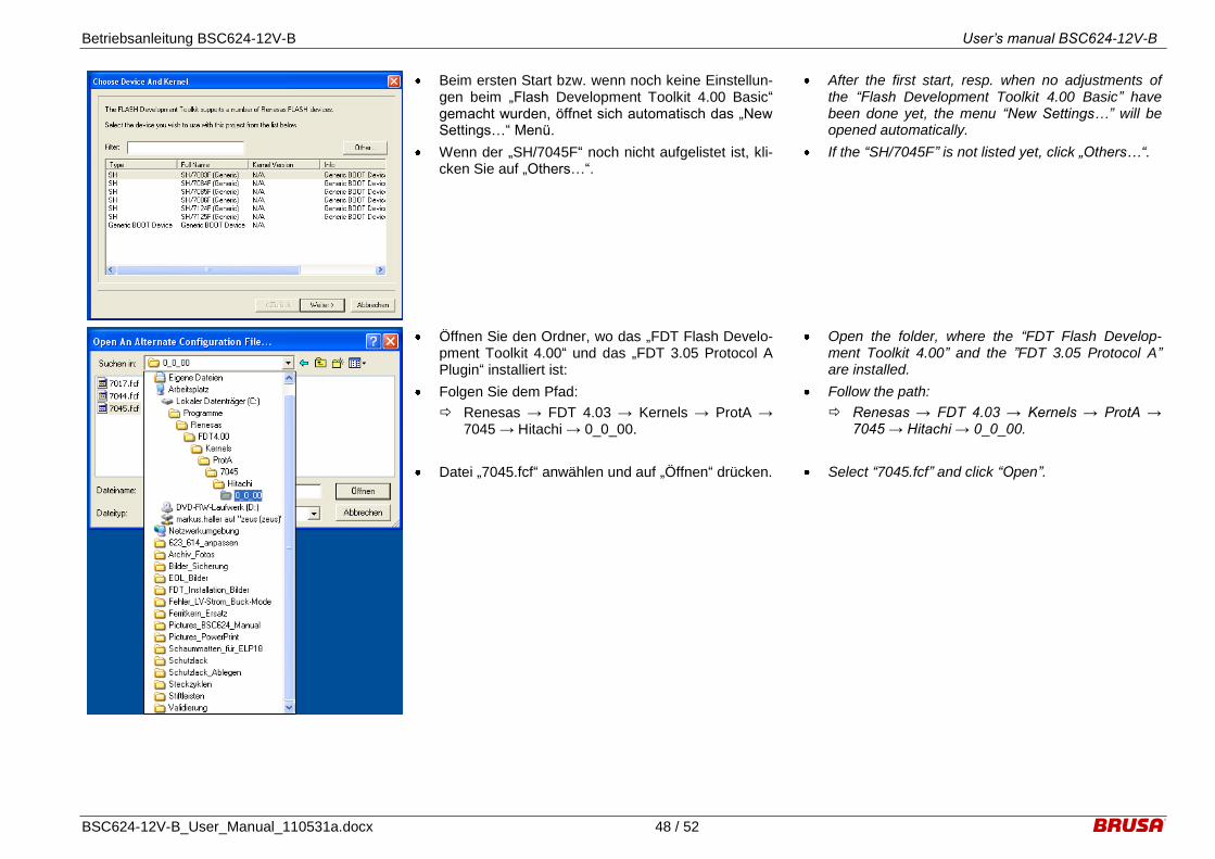
Betriebsanleitung BSC624-12V-B User’s manual BSC624-12V-B
BSC624-12V-B_User_Manual_110531a.docx 48 / 52
Beim ersten Start bzw. wenn noch keine Einstellun-gen beim „Flash Development Toolkit 4.00 Basic“ gemacht wurden, öffnet sich automatisch das „New Settings…“ Menü.
Wenn der „SH/7045F“ noch nicht aufgelistet ist, kli-cken Sie auf „Others…“.
After the first start, resp. when no adjustments of the “Flash Development Toolkit 4.00 Basic” have been done yet, the menu “New Settings…” will be opened automatically.
If the “SH/7045F” is not listed yet, click „Others…“.
Öffnen Sie den Ordner, wo das „FDT Flash Develo-pment Toolkit 4.00“ und das „FDT 3.05 Protocol A Plugin“ installiert ist:
Folgen Sie dem Pfad:
Renesas → FDT 4.03 → Kernels → ProtA → 7045 → Hitachi → 0_0_00.
Datei „7045.fcf“ anwählen und auf „Öffnen“ drücken.
Open the folder, where the “FDT Flash Develop-ment Toolkit 4.00” and the ”FDT 3.05 Protocol A” are installed.
Follow the path:
Renesas → FDT 4.03 → Kernels → ProtA → 7045 → Hitachi → 0_0_00.
Select “7045.fcf” and click “Open”.

Betriebsanleitung BSC624-12V-B User’s manual BSC624-12V-B
BSC624-12V-B_User_Manual_110531a.docx 49 / 52
„SH/7045F“ ist jetzt vorhanden.
„SH/7045F“ anwählen und „Weiter“ drücken.
“SH/7045F” is available now.
Select “SH/7045F” and press “next”.
Wählen Sie den entsprechenden Port aus, an dem das Gerät angeschlossen ist.
Bei „Select Interface“ wählen Sie “Direct Connec-tion”.
Klicken Sie „Weiter“.
Choose the port, which is used for connecting the computer to the device.
At “Select Interface” choose “Direct Connection”.
Click “Next”.
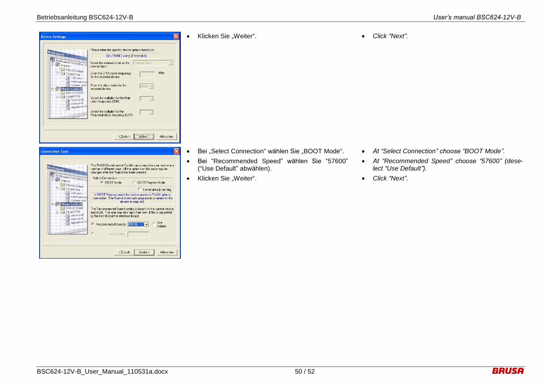
Betriebsanleitung BSC624-12V-B User’s manual BSC624-12V-B
BSC624-12V-B_User_Manual_110531a.docx 50 / 52
Klicken Sie „Weiter“. Click “Next”.
Bei „Select Connection“ wählen Sie „BOOT Mode“.
Bei “Recommended Speed” wählen Sie “57600” (“Use Default” abwählen).
Klicken Sie „Weiter“.
At “Select Connection” choose “BOOT Mode”.
At “Recommended Speed” choose “57600” (dese-lect “Use Default”).
Click “Next”.
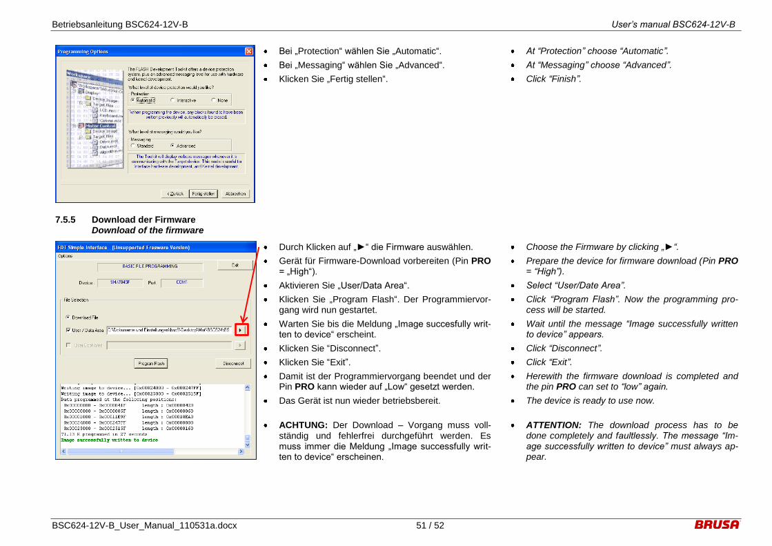
Betriebsanleitung BSC624-12V-B User’s manual BSC624-12V-B
BSC624-12V-B_User_Manual_110531a.docx 51 / 52
Bei „Protection“ wählen Sie „Automatic“.
Bei „Messaging“ wählen Sie „Advanced“.
Klicken Sie „Fertig stellen“.
At “Protection” choose “Automatic”.
At “Messaging” choose “Advanced”.
Click “Finish”.
7.5.5 Download der Firmware Download of the firmware
Durch Klicken auf „“ die Firmware auswählen.
Gerät für Firmware-Download vorbereiten (Pin PRO = „High“).
Aktivieren Sie „User/Data Area“.
Klicken Sie „Program Flash“. Der Programmiervor-gang wird nun gestartet.
Warten Sie bis die Meldung „Image succesfully writ-ten to device“ erscheint.
Klicken Sie “Disconnect”.
Klicken Sie “Exit”.
Damit ist der Programmiervorgang beendet und der Pin PRO kann wieder auf „Low“ gesetzt werden.
Das Gerät ist nun wieder betriebsbereit.
ACHTUNG: Der Download – Vorgang muss voll-ständig und fehlerfrei durchgeführt werden. Es muss immer die Meldung „Image successfully writ-ten to device“ erscheinen.
Choose the Firmware by clicking „“.
Prepare the device for firmware download (Pin PRO = “High”).
Select “User/Date Area”.
Click “Program Flash”. Now the programming pro-cess will be started.
Wait until the message “Image successfully written to device” appears.
Click “Disconnect”.
Click “Exit”.
Herewith the firmware download is completed and the pin PRO can set to “low” again.
The device is ready to use now.
ATTENTION: The download process has to be done completely and faultlessly. The message “Im-age successfully written to device” must always ap-pear.
Betriebsanleitung BSC624-12V-B User’s manual BSC624-12V-B
BSC624-12V-B_User_Manual_110531a.docx 52 / 52
8 Garantie Warranty
Wir gewähren eine Garantie von 24 Monaten ab dem Kaufdatum auf Material- und Verarbeitungsfeh-ler.
Die Garantie erlischt bei unsachgemässer Behand-lung des Gerätes.
Technische Änderungen sind jederzeit ohne An-kündigung möglich.
Wir weisen ausdrücklich darauf hin, dass mit die-sem Gerät lebensgefährliche Spannungen verarbei-tet werden können. Wir lehnen diesbezüglich jede Haftung ab.
Wir übernehmen keine Haftung durch Folgeschä-den, die durch die Anwendung dieses Gerätes ent-standen sind.
We assure a warranty for a period of 24 month from the date of purchase for defects of material and by workmanship.
Improper use or handling of the product causes the warranty to be void.
Specifications are subject to change without notice.
Note that this device processes lethal voltages. We cannot accept any liability concerning this danger.
We cannot accept any liability for consequential damages which arose from the use of this device.


![Vulcan 180 [IND] - Fantalux GmbH · Vulcan 180 Fahrzeugmontage System - 12V DC Direkt-Anschluss Ladestation, Inklusive Schultergurt - Gelb - Div 2 080926-44305-1 44305 Garantie: Streamlight](https://static.fdokument.com/doc/165x107/60626f0b95e86554da234cce/vulcan-180-ind-fantalux-vulcan-180-fahrzeugmontage-system-12v-dc-direkt-anschluss.jpg)