Die Simulation von Crash- und Impaktvorgängen auf ... · Die Simulation von Crash- und...
38
1 composite simulation – Ludwigsburg – Dr. André Haufe – 23. Februar 2012 Die Simulation von Crash- und Impaktvorgängen auf Faserverbundstrukturen: Eine Herausforderung in der Produktauslegung. Dr. André Haufe, Dr. Stefan Hartmann, Dr. Thomas Münz DYNAmore GmbH Stuttgart
Transcript of Die Simulation von Crash- und Impaktvorgängen auf ... · Die Simulation von Crash- und...
1 composite simulation – Ludwigsburg – Dr. André Haufe – 23. Februar 2012
Die Simulation von Crash- und Impaktvorgängen
auf Faserverbundstrukturen:
Eine Herausforderung in der Produktauslegung.
Dr. André Haufe, Dr. Stefan Hartmann, Dr. Thomas Münz
DYNAmore GmbH
Stuttgart
2 composite simulation – Ludwigsburg – Dr. André Haufe – 23. Februar 2012
DYNAmore GmbH Gesellschaft für
FEM-Ingenieurdienstleistungen
Stuttgart - Karlsruhe - Ingolstadt - Langlingen - Berlin
Dresden - Linköping - Götheburg - Zürich
Industriestraße 2
D-70565 Stuttgart
Tel. 07 11 - 45 96 00 - 0
Fax 07 11 - 45 96 00 - 29
e-mail: [email protected]
Internet: www.dynamore.de
3 composite simulation – Ludwigsburg – Dr. André Haufe – 23. Februar 2012
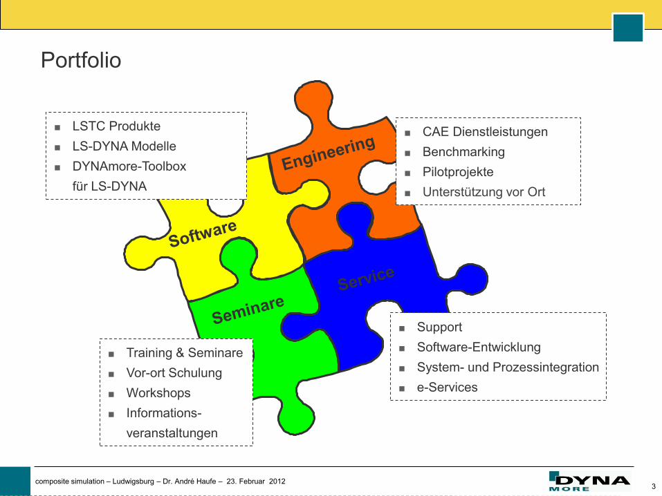
LSTC Produkte
LS-DYNA Modelle
DYNAmore-Toolbox
für LS-DYNA
Training & Seminare
Vor-ort Schulung
Workshops
Informations-
veranstaltungen
CAE Dienstleistungen
Benchmarking
Pilotprojekte
Unterstützung vor Ort
Support
Software-Entwicklung
System- und Prozessintegration
e-Services
Portfolio
4 composite simulation – Ludwigsburg – Dr. André Haufe – 23. Februar 2012
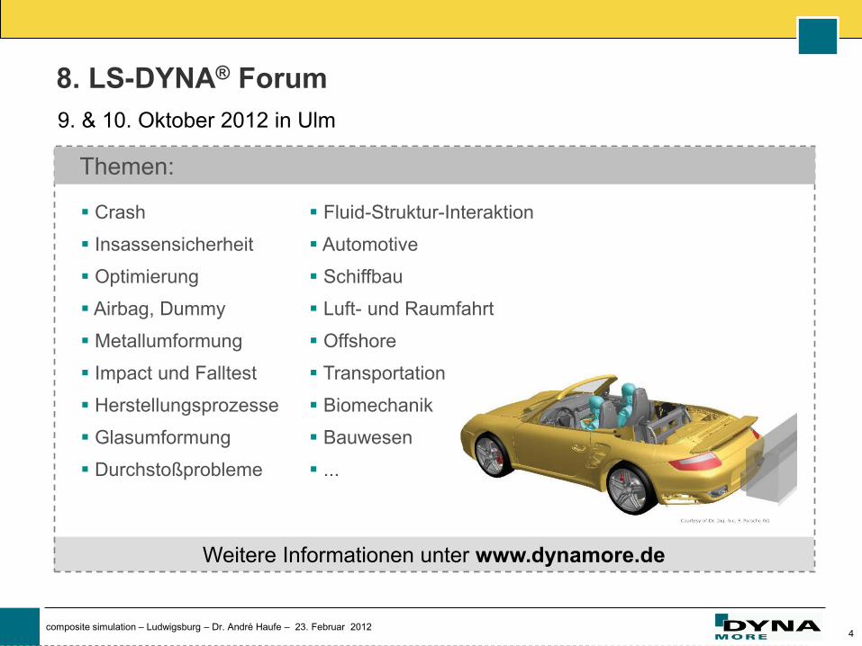
Fluid-Struktur-Interaktion
Automotive
Schiffbau
Luft- und Raumfahrt
Offshore
Transportation
Biomechanik
Bauwesen
...
Crash
Insassensicherheit
Optimierung
Airbag, Dummy
Metallumformung
Impact und Falltest
Herstellungsprozesse
Glasumformung
Durchstoßprobleme
Weitere Informationen unter www.dynamore.de
Themen:
9. & 10. Oktober 2012 in Ulm
8. LS-DYNA® Forum
5 composite simulation – Ludwigsburg – Dr. André Haufe – 23. Februar 2012
Composites
in technical applications
6 composite simulation – Ludwigsburg – Dr. André Haufe – 23. Februar 2012
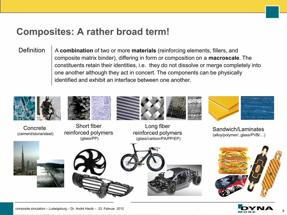
Composites: A rather broad term!
A combination of two or more materials (reinforcing elements, fillers, and
composite matrix binder), differing in form or composition on a macroscale. The
constituents retain their identities, i.e. they do not dissolve or merge completely into
one another although they act in concert. The components can be physically
identified and exhibit an interface between one another.
Definition
Concrete (cement/stone/steel)
Long fiber
reinforced polymers (glass/carbon/PA/PP/EP)
Sandwich/Laminates (alloy/polymer/..glass/PVB/…)
Short fiber
reinforced polymers (glass/PP)
7 composite simulation – Ludwigsburg – Dr. André Haufe – 23. Februar 2012
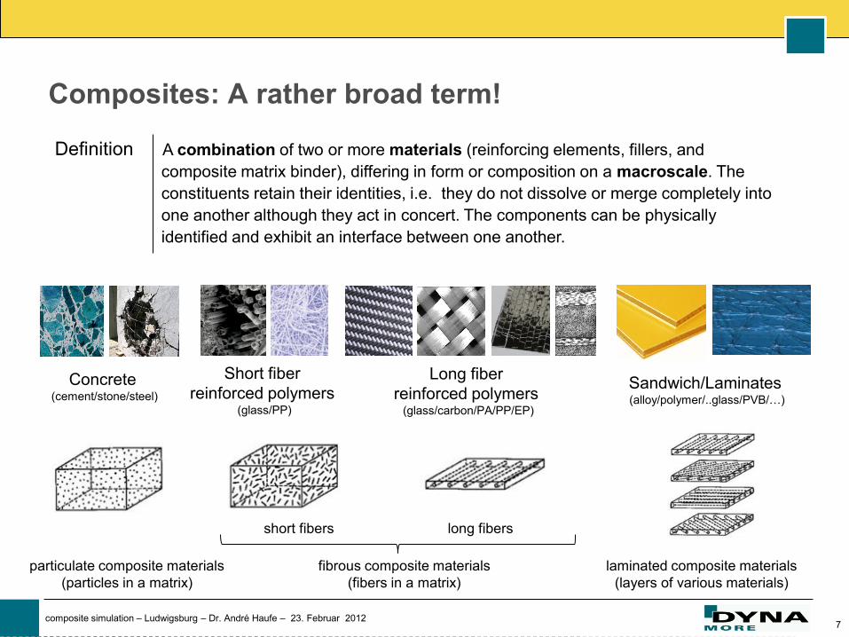
Composites: A rather broad term!
A combination of two or more materials (reinforcing elements, fillers, and
composite matrix binder), differing in form or composition on a macroscale. The
constituents retain their identities, i.e. they do not dissolve or merge completely into
one another although they act in concert. The components can be physically
identified and exhibit an interface between one another.
Definition
Concrete (cement/stone/steel)
Long fiber
reinforced polymers (glass/carbon/PA/PP/EP)
Sandwich/Laminates (alloy/polymer/..glass/PVB/…)
Short fiber
reinforced polymers (glass/PP)
fibrous composite materials
(fibers in a matrix)
laminated composite materials
(layers of various materials)
particulate composite materials
(particles in a matrix)
short fibers long fibers
8 composite simulation – Ludwigsburg – Dr. André Haufe – 23. Februar 2012
Composites: A rather broad term!
A combination of two or more materials (reinforcing elements, fillers, and
composite matrix binder), differing in form or composition on a macroscale. The
constituents retain their identities, i.e. they do not dissolve or merge completely into
one another although they act in concert. The components can be physically
identified and exhibit an interface between one another.
Definition
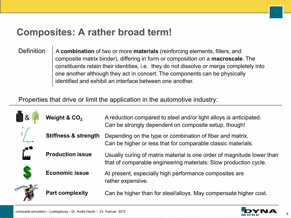
Properties that drive or limit the application in the automotive industry:
Weight & CO2 A reduction compared to steel and/or light alloys is anticipated.
Can be strongly dependent on composite setup, though!
Stiffness & strength Depending on the type or combination of fiber and matrix.
Can be higher or less that for comparable classic materials.
Production issue Usually curing of matrix material is one order of magnitude lower than
that of comparable engineering materials: Slow production cycle.
Economic issue At present, especially high performance composites are
rather expensive.
Part complexity Can be higher than for steel/alloys. May compensate higher cost.
&
9 composite simulation – Ludwigsburg – Dr. André Haufe – 23. Februar 2012
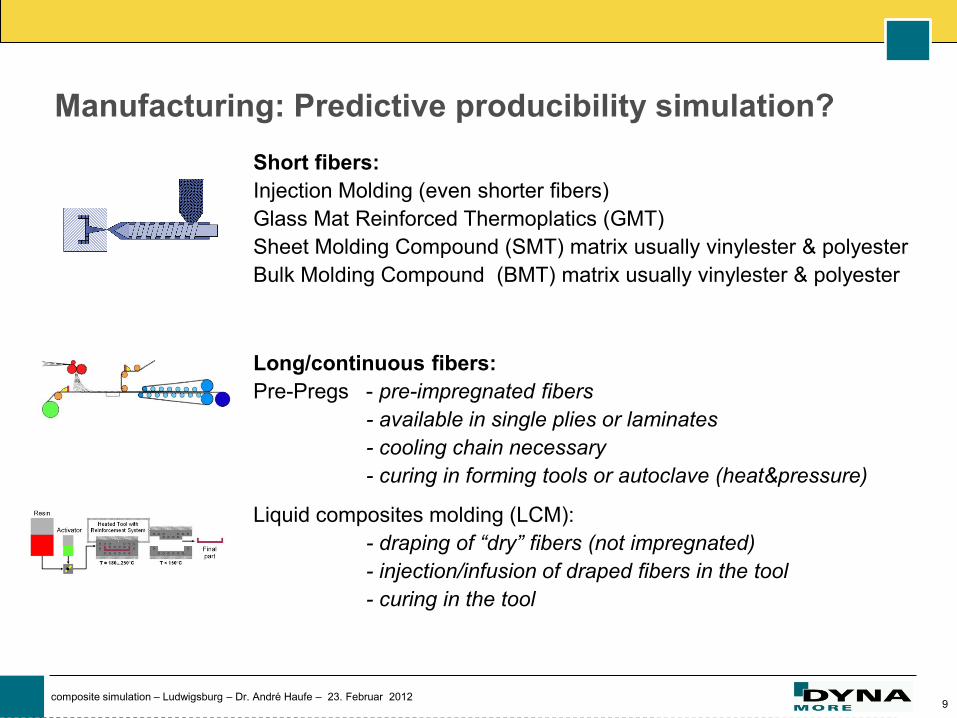
Manufacturing: Predictive producibility simulation?
Short fibers:
Injection Molding (even shorter fibers)
Glass Mat Reinforced Thermoplatics (GMT)
Sheet Molding Compound (SMT) matrix usually vinylester & polyester
Bulk Molding Compound (BMT) matrix usually vinylester & polyester
Long/continuous fibers:
Pre-Pregs - pre-impregnated fibers
- available in single plies or laminates
- cooling chain necessary
- curing in forming tools or autoclave (heat&pressure)
Liquid composites molding (LCM):
- draping of “dry” fibers (not impregnated)
- injection/infusion of draped fibers in the tool
- curing in the tool
10 composite simulation – Ludwigsburg – Dr. André Haufe – 23. Februar 2012
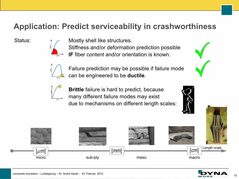
Application: Predict serviceability in crashworthiness
Length scale [ ]m [ ]mm [ ]cm
micro meso macro sub-ply
Status: Mostly shell like structures.
Stiffness and/or deformation prediction possible
IF fiber content and/or orientation is known.
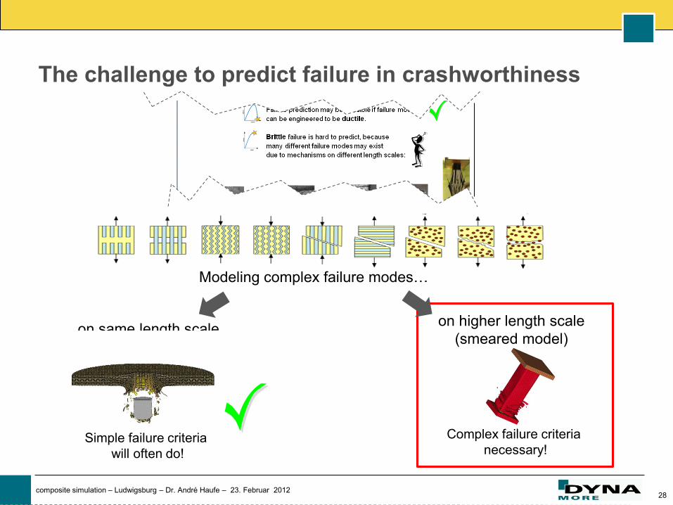
Failure prediction may be possible if failure mode
can be engineered to be ductile.
Brittle failure is hard to predict, because
many different failure modes may exist
due to mechanisms on different length scales:
11 composite simulation – Ludwigsburg – Dr. André Haufe – 23. Februar 2012
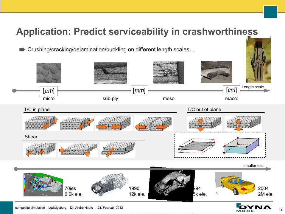
Application: Predict serviceability in crashworthiness
Length scale
[ ]m [ ]mm [ ]cm
micro meso macro sub-ply
Crushing/cracking/delamination/buckling on different length scales…
T/C in plane T/C out of plane
Shear
70ies
0.6k ele.
1990
12k ele.
1994
75k ele.
2004
2M ele.
smaller ele.
12 composite simulation – Ludwigsburg – Dr. André Haufe – 23. Februar 2012
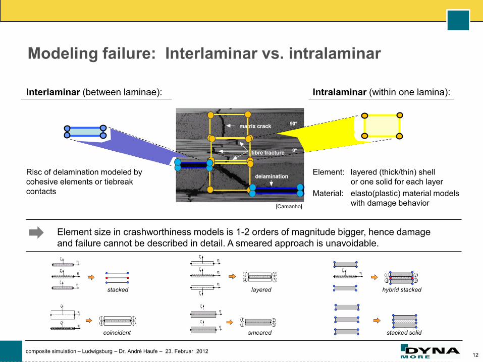
Modeling failure: Interlaminar vs. intralaminar
[Camanho]
Intralaminar (within one lamina):
Element: layered (thick/thin) shell
or one solid for each layer
Material: elasto(plastic) material models
with damage behavior
Interlaminar (between laminae):
Risc of delamination modeled by
cohesive elements or tiebreak
contacts
Element size in crashworthiness models is 1-2 orders of magnitude bigger, hence damage
and failure cannot be described in detail. A smeared approach is unavoidable.
stacked
coincident
layered
smeared stacked solid
hybrid stacked
13 composite simulation – Ludwigsburg – Dr. André Haufe – 23. Februar 2012
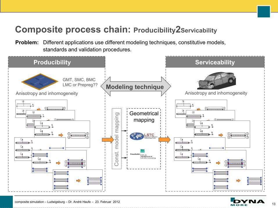
Composite process chain: Producibility2Servicability
Problem: Different applications use different modeling techniques, constitutive models,
standards and validation procedures.
Producibility Serviceability
GMT, SMC, BMC
LMC or Prepreg??
Anisotropy and inhomogeneity Anisotropy and inhomogeneity
Co
nst.
mo
de
l m
ap
pin
g
Geometrical
mapping
Modeling technique
14 composite simulation – Ludwigsburg – Dr. André Haufe – 23. Februar 2012
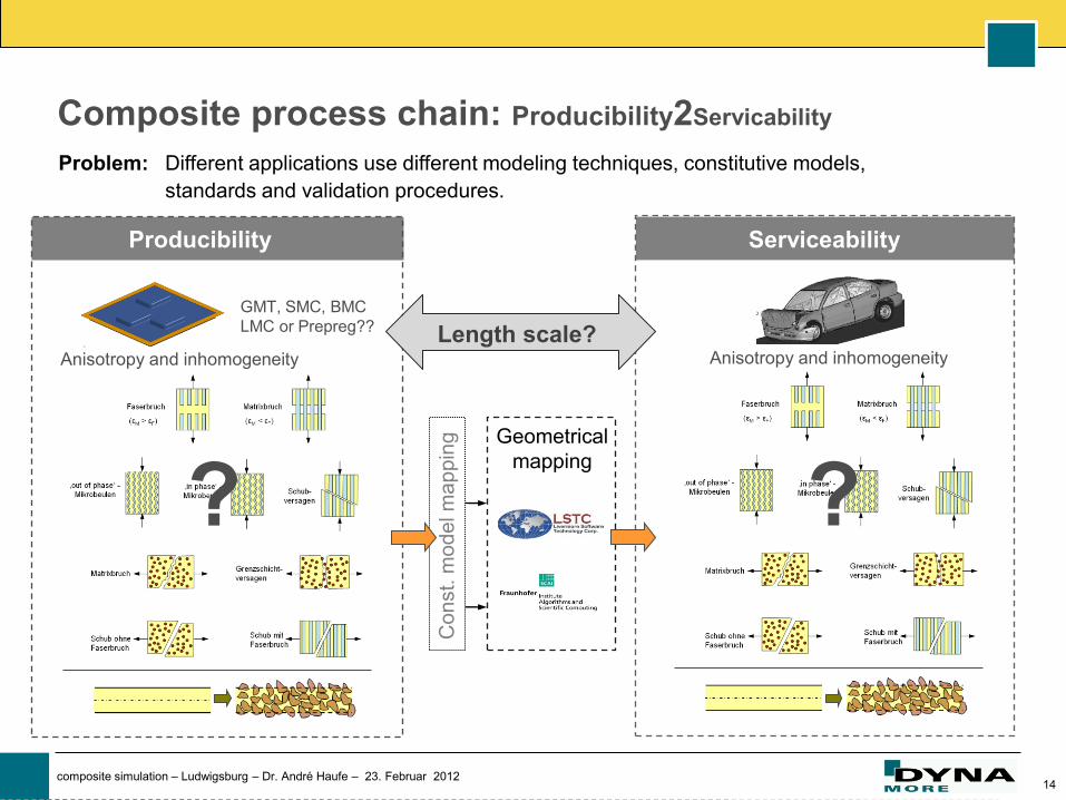
Producibility Serviceability
Geometrical
mapping C
on
st.
mo
de
l m
ap
pin
g
GMT, SMC, BMC
LMC or Prepreg??
Anisotropy and inhomogeneity Anisotropy and inhomogeneity
Composite process chain: Producibility2Servicability
? ?
Length scale?
Problem: Different applications use different modeling techniques, constitutive models,
standards and validation procedures.
15 composite simulation – Ludwigsburg – Dr. André Haufe – 23. Februar 2012
Producibility
16 composite simulation – Ludwigsburg – Dr. André Haufe – 23. Februar 2012
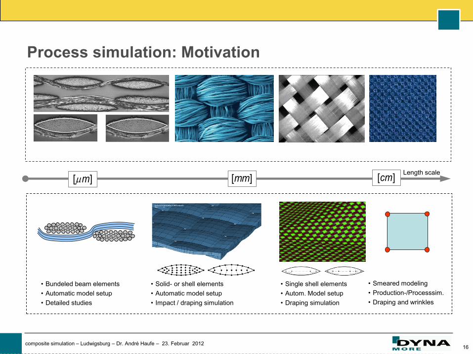
Process simulation: Motivation
Length scale
• Bundeled beam elements
• Automatic model setup
• Detailed studies
• Solid- or shell elements
• Automatic model setup
• Impact / draping simulation
• Single shell elements
• Autom. Model setup
• Draping simulation
• Smeared modeling
• Production-/Processsim.
• Draping and wrinkles
[ ]m [ ]mm [ ]cm
17 composite simulation – Ludwigsburg – Dr. André Haufe – 23. Februar 2012
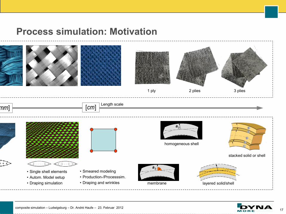
Process simulation: Motivation
Length scale
• Single shell elements
• Autom. Model setup
• Draping simulation
• Smeared modeling
• Production-/Processsim.
• Draping and wrinkles
[ ]mm [ ]cm
1 ply 2 plies 3 plies
membrane
homogeneous shell
layered solid/shell
stacked solid or shell
18 composite simulation – Ludwigsburg – Dr. André Haufe – 23. Februar 2012
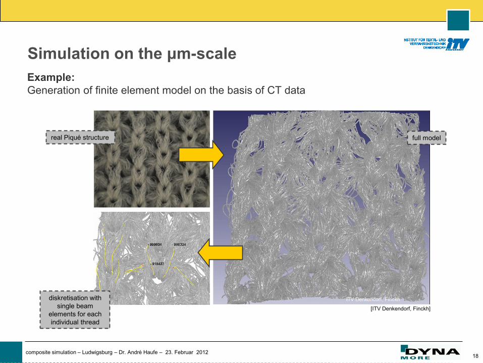
Example:
Generation of finite element model on the basis of CT data
Simulation on the μm-scale
real Piqué structure
diskretisation with
single beam
elements for each
individual thread
full model
[ITV Denkendorf, Finckh]
19 composite simulation – Ludwigsburg – Dr. André Haufe – 23. Februar 2012
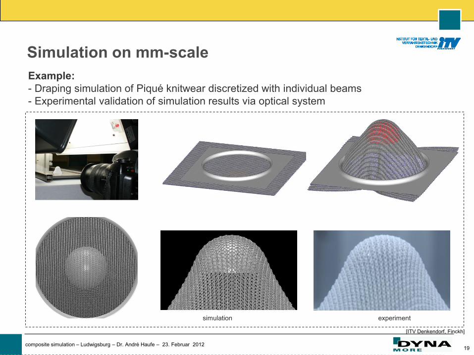
Example:
- Draping simulation of Piqué knitwear discretized with individual beams
- Experimental validation of simulation results via optical system
Simulation on mm-scale
[ITV Denkendorf, Finckh]
simulation experiment
20 composite simulation – Ludwigsburg – Dr. André Haufe – 23. Februar 2012
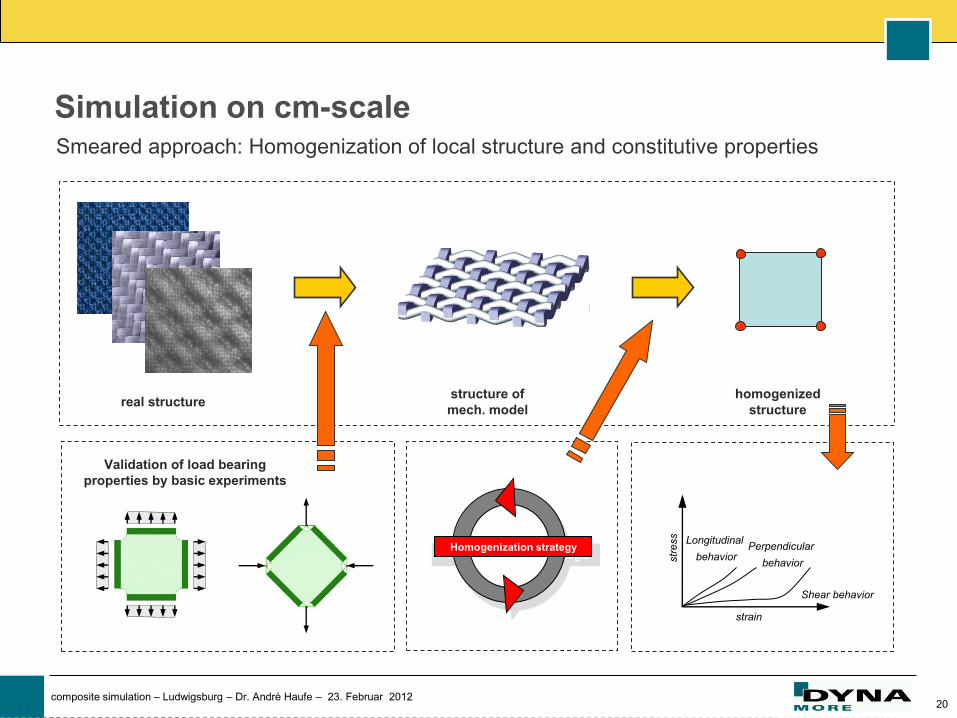
Simulation on cm-scale
real structure structure of
mech. model
homogenized
structure
Smeared approach: Homogenization of local structure and constitutive properties
Validation of load bearing
properties by basic experiments
Homogenisierungsstrategie Homogenization strategy
str
ess
strain
Perpendicular
behavior
Longitudinal
behavior
Shear behavior
21 composite simulation – Ludwigsburg – Dr. André Haufe – 23. Februar 2012
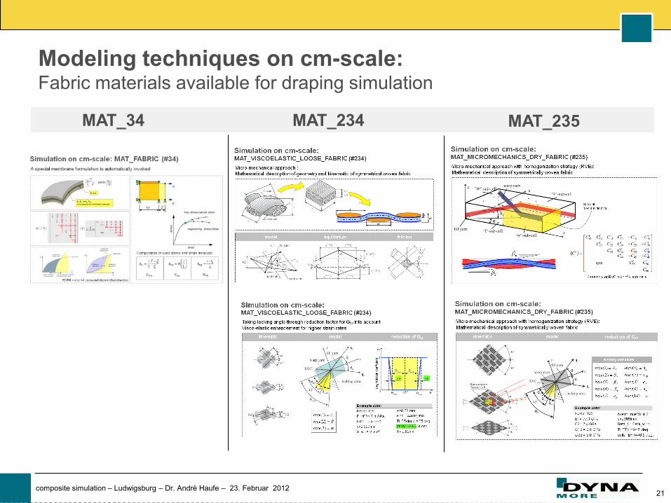
Modeling techniques on cm-scale: Fabric materials available for draping simulation
MAT_34 MAT_235 MAT_234
22 composite simulation – Ludwigsburg – Dr. André Haufe – 23. Februar 2012
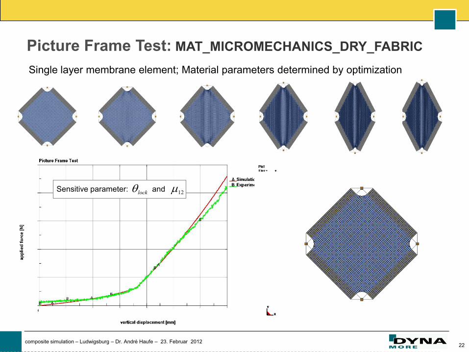
Picture Frame Test: MAT_MICROMECHANICS_DRY_FABRIC
Sensitive parameter: and lock 12
Single layer membrane element; Material parameters determined by optimization
23 composite simulation – Ludwigsburg – Dr. André Haufe – 23. Februar 2012
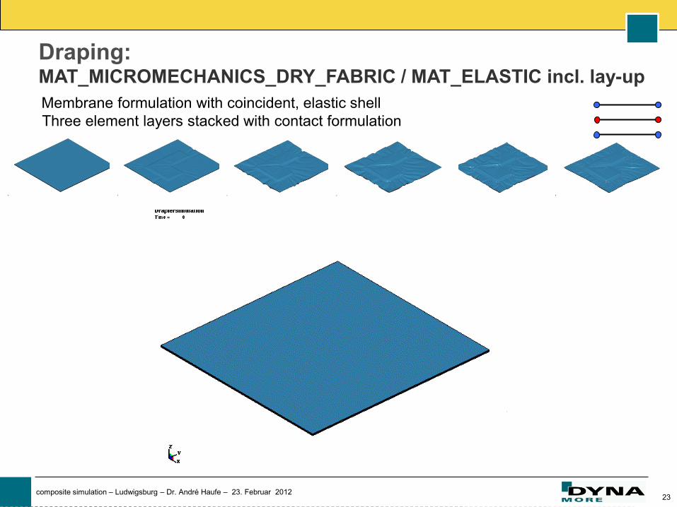
Draping: MAT_MICROMECHANICS_DRY_FABRIC / MAT_ELASTIC incl. lay-up
Membrane formulation with coincident, elastic shell
Three element layers stacked with contact formulation
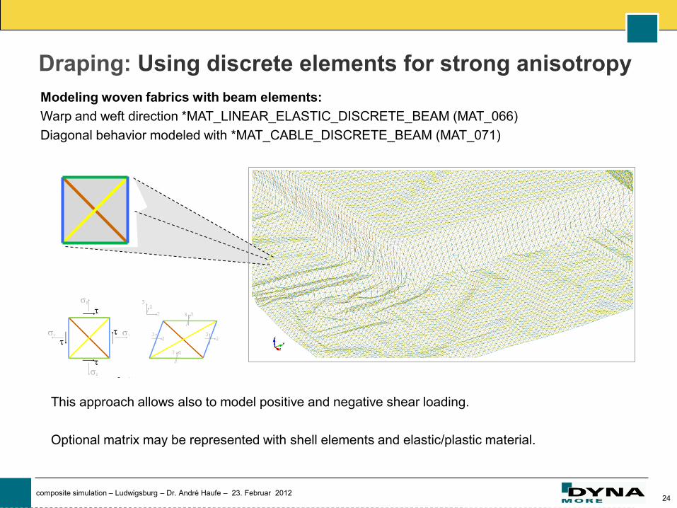
24 composite simulation – Ludwigsburg – Dr. André Haufe – 23. Februar 2012
Modeling woven fabrics with beam elements:
Warp and weft direction *MAT_LINEAR_ELASTIC_DISCRETE_BEAM (MAT_066)
Diagonal behavior modeled with *MAT_CABLE_DISCRETE_BEAM (MAT_071)
Draping: Using discrete elements for strong anisotropy
This approach allows also to model positive and negative shear loading.
Optional matrix may be represented with shell elements and elastic/plastic material.
25 composite simulation – Ludwigsburg – Dr. André Haufe – 23. Februar 2012
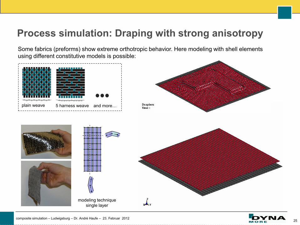
plain weave 5 harness weave
Process simulation: Draping with strong anisotropy
Some fabrics (preforms) show extreme orthotropic behavior. Here modeling with shell elements
using different constitutive models is possible:
and more…
modeling technique
single layer
26 composite simulation – Ludwigsburg – Dr. André Haufe – 23. Februar 2012
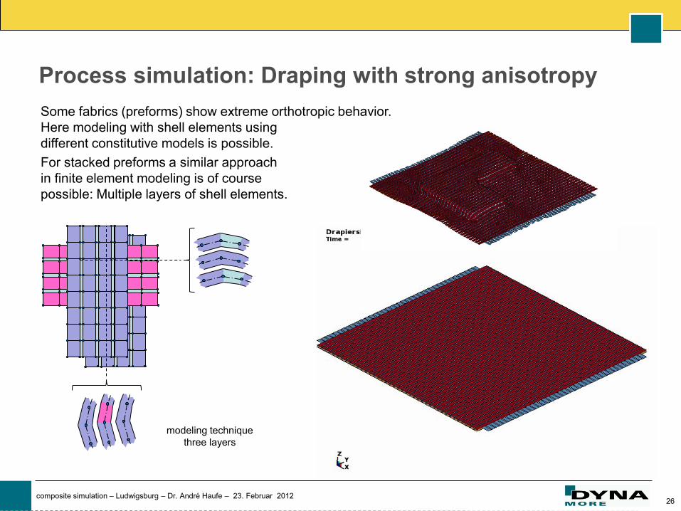
Process simulation: Draping with strong anisotropy
Some fabrics (preforms) show extreme orthotropic behavior.
Here modeling with shell elements using
different constitutive models is possible.
For stacked preforms a similar approach
in finite element modeling is of course
possible: Multiple layers of shell elements.
modeling technique
three layers
y
27 composite simulation – Ludwigsburg – Dr. André Haufe – 23. Februar 2012
Serviceability
(crashworthiness)
28 composite simulation – Ludwigsburg – Dr. André Haufe – 23. Februar 2012
The challenge to predict failure in crashworthiness
on higher length scale
(smeared model) on same length scale
(detailed model)
Modeling complex failure modes…
Simple failure criteria
will often do!
Complex failure criteria
necessary!
29 composite simulation – Ludwigsburg – Dr. André Haufe – 23. Februar 2012
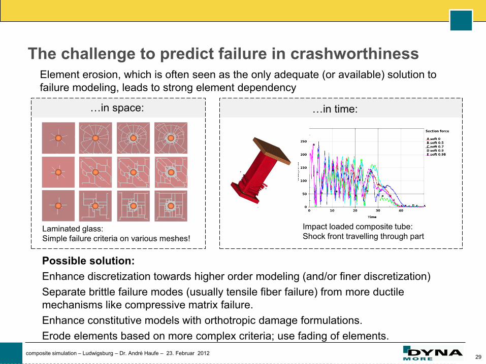
The challenge to predict failure in crashworthiness
Element erosion, which is often seen as the only adequate (or available) solution to
failure modeling, leads to strong element dependency
Laminated glass:
Simple failure criteria on various meshes!
Possible solution:
Enhance discretization towards higher order modeling (and/or finer discretization)
Separate brittle failure modes (usually tensile fiber failure) from more ductile
mechanisms like compressive matrix failure.
Enhance constitutive models with orthotropic damage formulations.
Erode elements based on more complex criteria; use fading of elements.
Impact loaded composite tube:
Shock front travelling through part
…in space: …in time:
30 composite simulation – Ludwigsburg – Dr. André Haufe – 23. Februar 2012
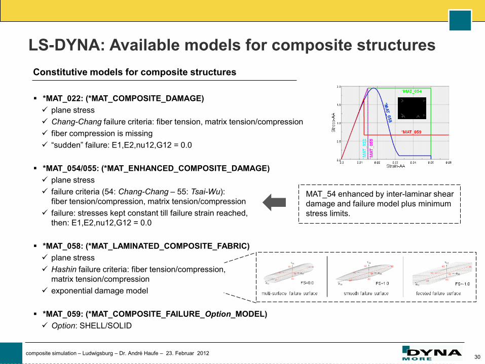
*MAT_022: (*MAT_COMPOSITE_DAMAGE)
plane stress
Chang-Chang failure criteria: fiber tension, matrix tension/compression
fiber compression is missing
“sudden” failure: E1,E2,nu12,G12 = 0.0
*MAT_054/055: (*MAT_ENHANCED_COMPOSITE_DAMAGE)
plane stress
failure criteria (54: Chang-Chang – 55: Tsai-Wu):
fiber tension/compression, matrix tension/compression
failure: stresses kept constant till failure strain reached,
then: E1,E2,nu12,G12 = 0.0
*MAT_058: (*MAT_LAMINATED_COMPOSITE_FABRIC)
plane stress
Hashin failure criteria: fiber tension/compression,
matrix tension/compression
exponential damage model
*MAT_059: (*MAT_COMPOSITE_FAILURE_Option_MODEL)
Option: SHELL/SOLID
LS-DYNA: Available models for composite structures
MAT_54 enhanced by inter-laminar shear
damage and failure model plus minimum
stress limits.
Constitutive models for composite structures
31 composite simulation – Ludwigsburg – Dr. André Haufe – 23. Februar 2012
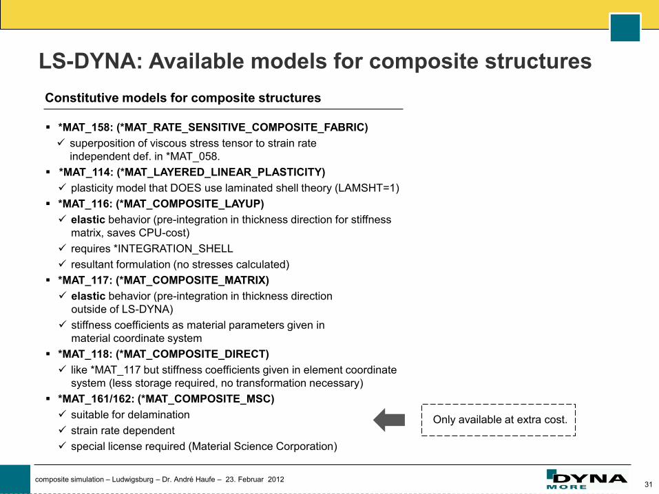
*MAT_158: (*MAT_RATE_SENSITIVE_COMPOSITE_FABRIC)
superposition of viscous stress tensor to strain rate
independent def. in *MAT_058.
*MAT_114: (*MAT_LAYERED_LINEAR_PLASTICITY)
plasticity model that DOES use laminated shell theory (LAMSHT=1)
*MAT_116: (*MAT_COMPOSITE_LAYUP)
elastic behavior (pre-integration in thickness direction for stiffness
matrix, saves CPU-cost)
requires *INTEGRATION_SHELL
resultant formulation (no stresses calculated)
*MAT_117: (*MAT_COMPOSITE_MATRIX)
elastic behavior (pre-integration in thickness direction
outside of LS-DYNA)
stiffness coefficients as material parameters given in
material coordinate system
*MAT_118: (*MAT_COMPOSITE_DIRECT)
like *MAT_117 but stiffness coefficients given in element coordinate
system (less storage required, no transformation necessary)
*MAT_161/162: (*MAT_COMPOSITE_MSC)
suitable for delamination
strain rate dependent
special license required (Material Science Corporation)
LS-DYNA: Available models for composite structures
Only available at extra cost.
Constitutive models for composite structures

32 composite simulation – Ludwigsburg – Dr. André Haufe – 23. Februar 2012
*MAT_Camanho (Continuum-Damage-Model)
plane stress
coupled failure criteria
bi-linear softening law based on fracture toughness
1D-plasticity-model (mixed hardening) for in-plane shear
behavior
*MAT_Pinho (Continuum-Damage-Model)
3D-stress space
coupled failure criteria
complex 3D-fibre kinking model
linear softening law based on fracture toughness
1D-plasticity-model (mixed hardening) in in-plane shear behavior
LS-DYNA: Recent developments
*PART_Composite
Easier definition of lay-ups in part-section by just defining MATID, thickness and orientation.
*ELEMENT_(t)shell_composite
Same input scheme as in *PART_Composite but on element level.
Useful to define different lay-ups within one part (elementwise definition of lay-up).
Constitutive models for composite structures
New options for composite (part) modeling
Damage models with softening properties.
Usable for inter- and intra-laminar modeling.
Implemented in collaboration with Daimler AG.
Available in future releases.
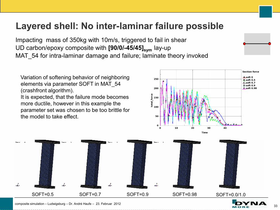
33 composite simulation – Ludwigsburg – Dr. André Haufe – 23. Februar 2012
Impacting mass of 350kg with 10m/s, triggered to fail in shear
UD carbon/epoxy composite with [90/0/-45/45]sym lay-up
MAT_54 for intra-laminar damage and failure; laminate theory invoked
Layered shell: No inter-laminar failure possible
Variation of softening behavior of neighboring
elements via parameter SOFT in MAT_54
(crashfront algorithm).
It is expected, that the failure mode becomes
more ductile, however in this example the
parameter set was chosen to be too brittle for
the model to take effect.
SOFT=0.5 SOFT=0.7 SOFT=0.9 SOFT=0.98 SOFT=0.0/1.0
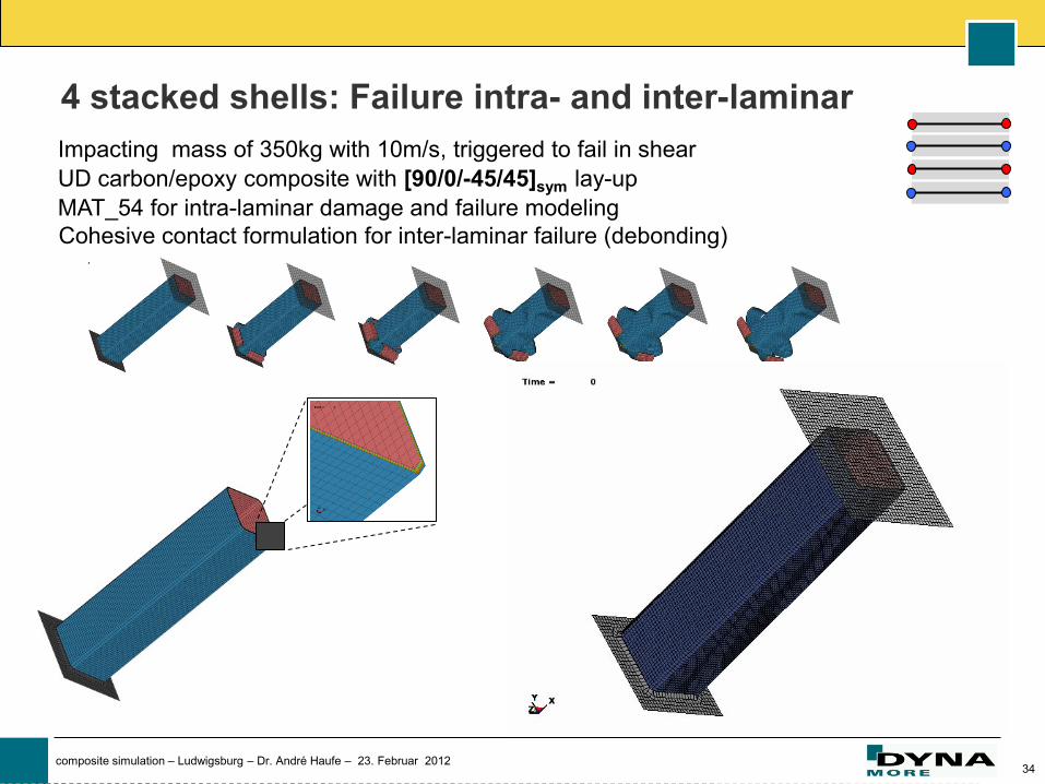
34 composite simulation – Ludwigsburg – Dr. André Haufe – 23. Februar 2012
4 stacked shells: Failure intra- and inter-laminar
Impacting mass of 350kg with 10m/s, triggered to fail in shear
UD carbon/epoxy composite with [90/0/-45/45]sym lay-up
MAT_54 for intra-laminar damage and failure modeling
Cohesive contact formulation for inter-laminar failure (debonding)
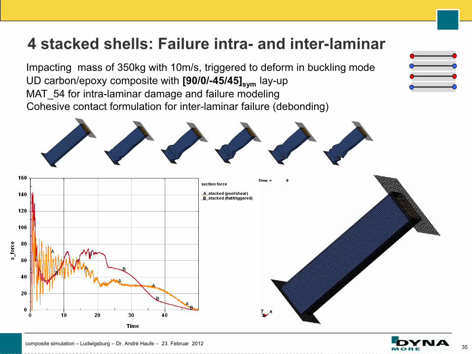
35 composite simulation – Ludwigsburg – Dr. André Haufe – 23. Februar 2012
4 stacked shells: Failure intra- and inter-laminar
Impacting mass of 350kg with 10m/s, triggered to deform in buckling mode
UD carbon/epoxy composite with [90/0/-45/45]sym lay-up
MAT_54 for intra-laminar damage and failure modeling
Cohesive contact formulation for inter-laminar failure (debonding)
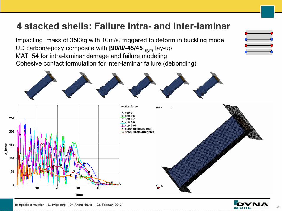
36 composite simulation – Ludwigsburg – Dr. André Haufe – 23. Februar 2012
4 stacked shells: Failure intra- and inter-laminar
Impacting mass of 350kg with 10m/s, triggered to deform in buckling mode
UD carbon/epoxy composite with [90/0/-45/45]sym lay-up
MAT_54 for intra-laminar damage and failure modeling
Cohesive contact formulation for inter-laminar failure (debonding)
37 composite simulation – Ludwigsburg – Dr. André Haufe – 23. Februar 2012
Summary
Process simulation of different preforms is state-of-the-art and necessary to
transport important orthotropic properties into the world of crashworthiness.
A number of modeling techniques was presented.
Mapping of relevant data from forming/draping to the crash application is
available. However, the various modeling techniques require some adjustments.
Prediction of failure and crushing in crashworthiness applications is an ongoing
and very challenging topic. Transferring history variables is a must for more
complex part designs that one expects in the near future.
Simple failure models (stress or strain based) as used in the past will be
replaced by more sophisticated orthotropic damage evolution models. Partially
these are already available.
Rigorous testing and validation of code-procedures but also of hard-testing-
procedures is necessary to correlate models up to the needed quality.
38 composite simulation – Ludwigsburg – Dr. André Haufe – 23. Februar 2012
FIN