Diesel Fire Pump Controllers
44
Joslyn Clark Controls Fire Pump Controls B-Series Diesel Fire Pump Controller Training and Customer Certification Class January 2007
-
Upload
danaher-specialty-products -
Category
Devices & Hardware
-
view
514 -
download
0
Transcript of Diesel Fire Pump Controllers
Joslyn Clark Controls
Fire Pump Controls B-Series Diesel
Fire Pump Controller Training
and Customer Certification Class
January 2007
Fundamentals Of Controllers
1) Monitor Sprinkler System Pressures and Start the Pump Driver When Needed.
Pressure Switches
Pressure Transducers
Remote Starting from other signal panel or device.
Fundamentals Of Controllers
2) Monitor Pump Driver and Alarm on Trouble Conditions.
Phases Reversed Signal in Electric Controllers
Power Available in Electric Controllers
Low Oil Pressure in Diesel Controllers
High Engine Temperature in Diesel Controllers
Fundamentals Of Controllers
3) Allow a Distressed Pump to Operate Even to the Point of Damage to Pump or Driver
Locked Rotor Protector set to trip at no less than 300% of Motor Full Load Current of an Electric Driver.
Diesel Controllers do not shut down the engine even though Low Oil Pressure is observed or High Engine Temperature.
Fundamentals Of Controllers
4) Shutdown the Pump and Controller Only When the Possibility Exists that Continued Operation of the Pump Would Add to the Damage already done by the Fire. Locked Rotor Protector will shut down the
controller when current reaches and excessive amount indicating the pump has stopped.
Diesel Controllers - Overspeed will Stop Fuel Flow if Engine Speed increases beyond Overspeed Setting.
Diesel Controllers
Let’s take a Look at the
B-Series Diesel Fire Pump Controller
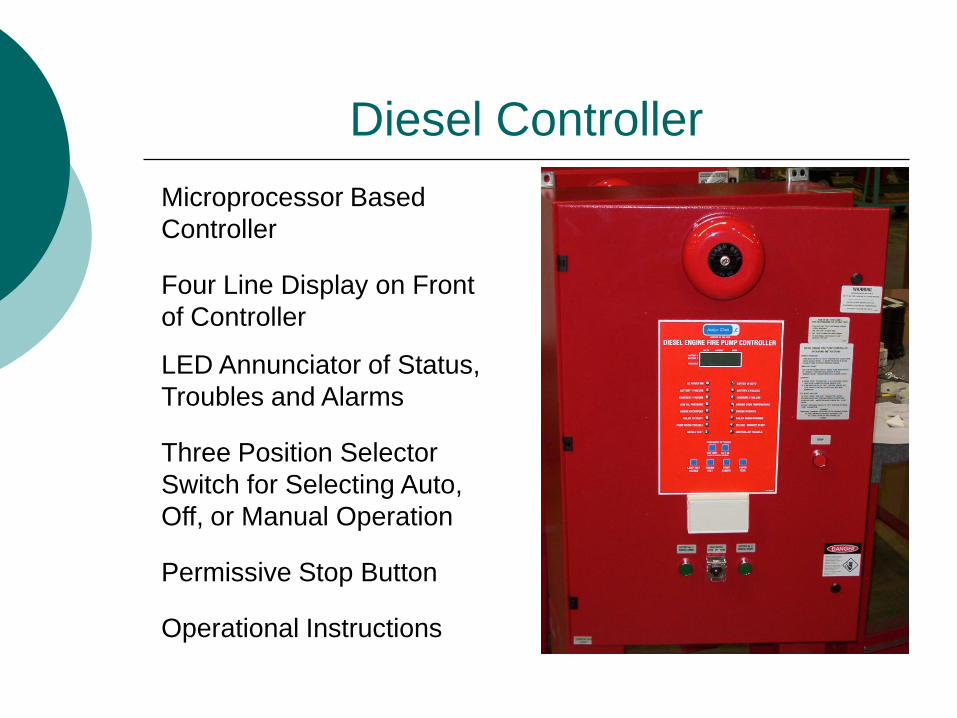
Diesel Controller
Microprocessor Based
Controller
Four Line Display on Front
of Controller
LED Annunciator of Status,
Troubles and Alarms
Three Position Selector
Switch for Selecting Auto,
Off, or Manual Operation
Permissive Stop Button
Operational Instructions
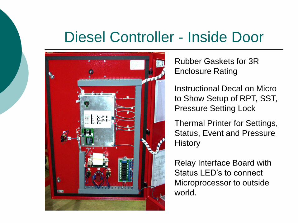
Diesel Controller - Inside Door
Rubber Gaskets for 3R
Enclosure Rating
Instructional Decal on Micro
to Show Setup of RPT, SST,
Pressure Setting Lock
Thermal Printer for Settings,
Status, Event and Pressure
History
Relay Interface Board with
Status LED’s to connect
Microprocessor to outside
world.

Diesel Controller – Inside
Dual Battery Chargers
10Amp Rated, With
Individual Transformers
Circuit Breakers in AC Line
Feeding Transformers
Circuit Breakers in DC Line
Feeding Controller
Alarm and Status
Connections Terminal Block
Pressure Transducer and
Test Solenoid Valve
Engine Connections
Terminal Block
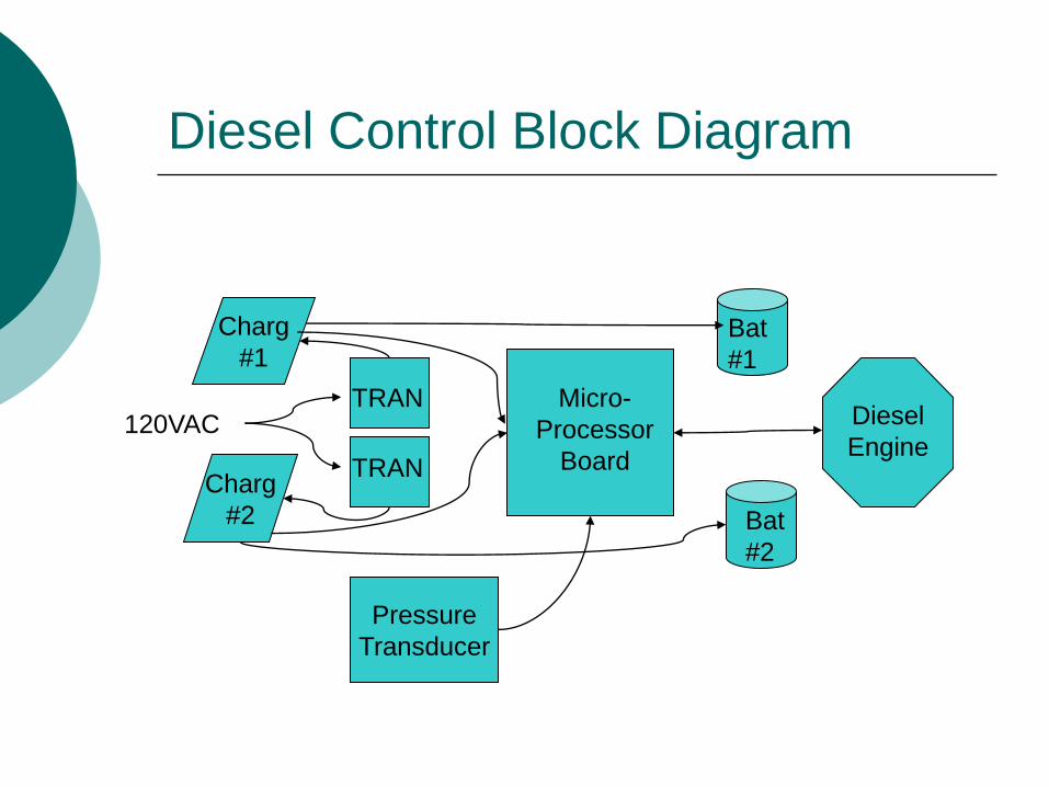
Diesel Control Block Diagram
Pressure
Transducer
Charg
#1
Charg
#2
Micro-
Processor
Board
Bat
#1
Bat
#2
Diesel
Engine
TRAN
TRAN
120VAC
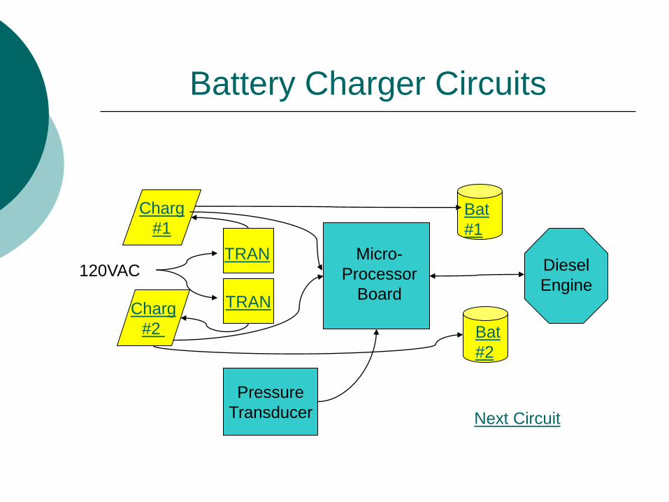
Battery Charger Circuits
Pressure
Transducer
Charg
#1
Charg
#2
TRAN
Micro-
Processor
Board
Bat
#1
Bat
#2
Diesel
Engine
TRAN 120VAC
Next Circuit
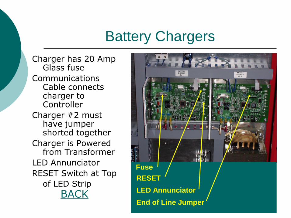
Battery Chargers
Charger has 20 Amp Glass fuse
Communications Cable connects charger to Controller
Charger #2 must have jumper shorted together
Charger is Powered from Transformer
LED Annunciator
RESET Switch at Top
of LED Strip BACK
Fuse
RESET
LED Annunciator
End of Line Jumper
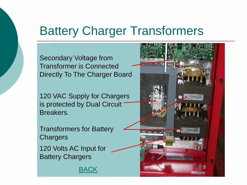
Transformers for Battery
Chargers
120 VAC Supply for Chargers
is protected by Dual Circuit
Breakers.
120 Volts AC Input for
Battery Chargers
Secondary Voltage from
Transformer is Connected
Directly To The Charger Board
BACK
Battery Charger Transformers
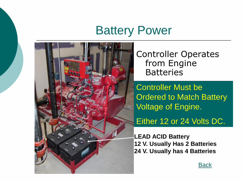
Battery Power
Controller Must be
Ordered to Match Battery
Voltage of Engine.
Either 12 or 24 Volts DC.
Controller Operates from Engine Batteries
LEAD ACID Battery
12 V. Usually Has 2 Batteries
24 V. Usually has 4 Batteries
Back
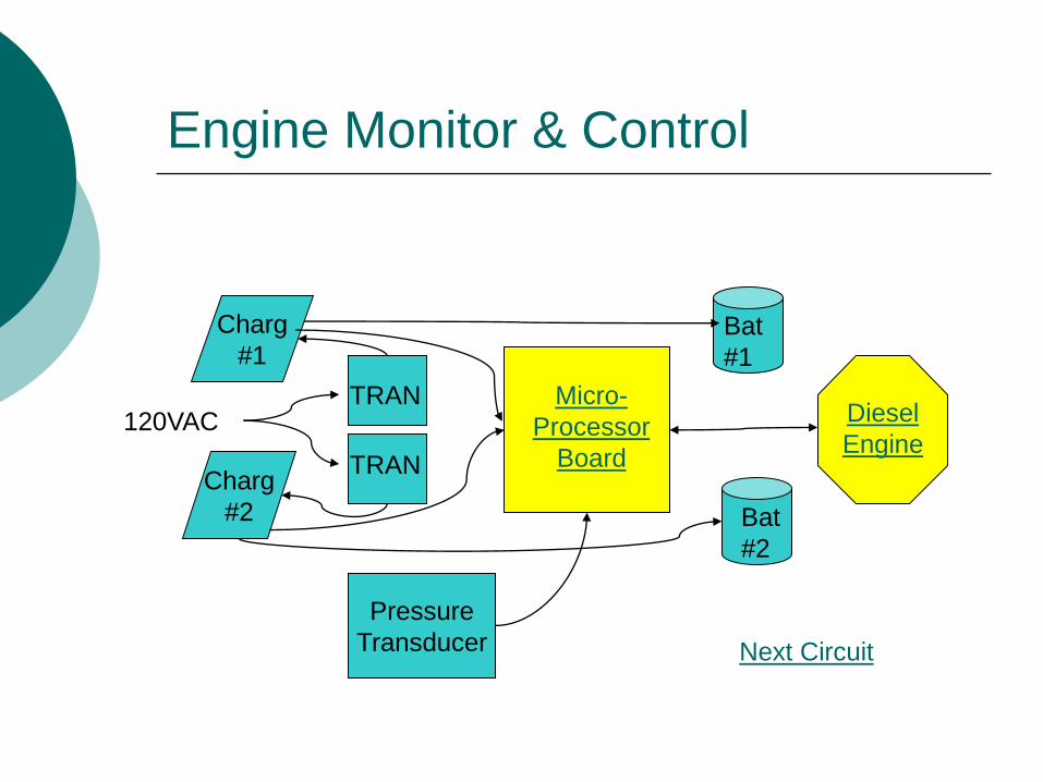
Engine Monitor & Control
Pressure
Transducer
Charg
#1
Charg
#2
Micro-
Processor
Board
Bat
#1
Bat
#2
Diesel
Engine
TRAN
TRAN
120VAC
Next Circuit
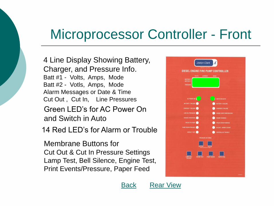
Microprocessor Controller - Front
4 Line Display Showing Battery,
Charger, and Pressure Info. Batt #1 - Volts, Amps, Mode
Batt #2 - Votls, Amps, Mode
Alarm Messages or Date & Time
Cut Out , Cut In, Line Pressures
Green LED’s for AC Power On
and Switch in Auto
14 Red LED’s for Alarm or Trouble
Membrane Buttons for Cut Out & Cut In Pressure Settings
Lamp Test, Bell Silence, Engine Test,
Print Events/Pressure, Paper Feed
Back Rear View

Microprocessor – Rear View
Pressure Transducer
Input
Charger Comm.
Connection
DIP Switch for Setup
DIP Switch Setting
Decal
Regulated Voltage
Output from CPU
DC Voltage Input to
CPU
Memory Support
Battery
Back Front
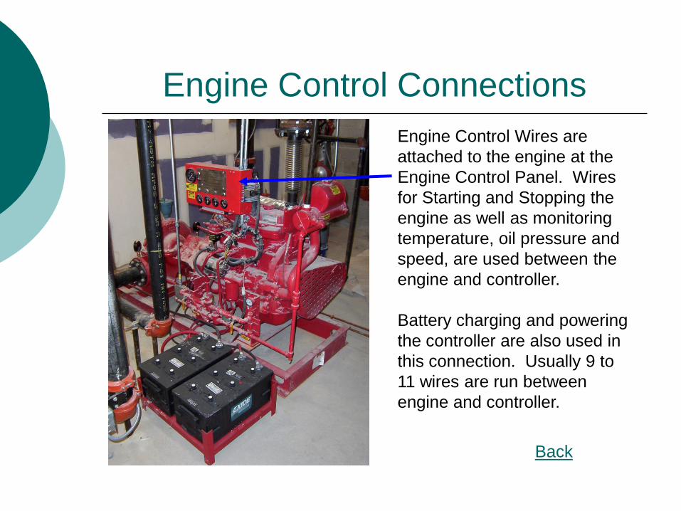
Engine Control Connections
Back
Engine Control Wires are
attached to the engine at the
Engine Control Panel. Wires
for Starting and Stopping the
engine as well as monitoring
temperature, oil pressure and
speed, are used between the
engine and controller.
Battery charging and powering
the controller are also used in
this connection. Usually 9 to
11 wires are run between
engine and controller.
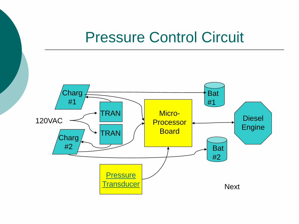
Pressure Control Circuit
Pressure
Transducer
Charg
#1
Charg
#2
Micro-
Processor
Board
Bat
#1
Bat
#2
Diesel
Engine
TRAN
TRAN
120VAC
Next
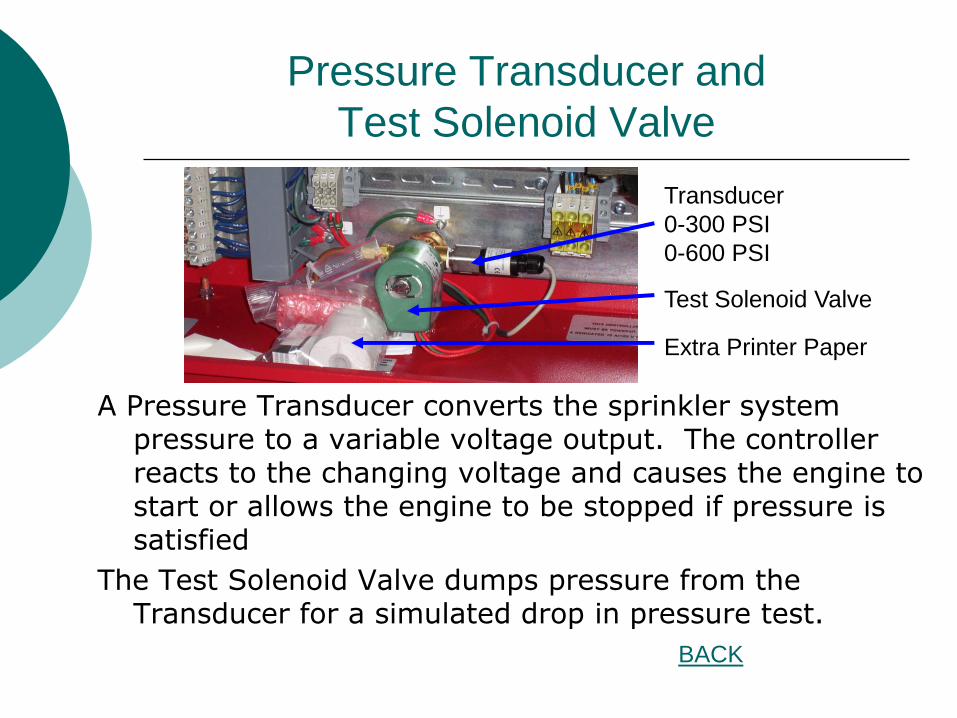
Pressure Transducer and
Test Solenoid Valve
A Pressure Transducer converts the sprinkler system pressure to a variable voltage output. The controller reacts to the changing voltage and causes the engine to start or allows the engine to be stopped if pressure is satisfied
The Test Solenoid Valve dumps pressure from the Transducer for a simulated drop in pressure test.
Transducer
0-300 PSI
0-600 PSI
Test Solenoid Valve
Extra Printer Paper
BACK
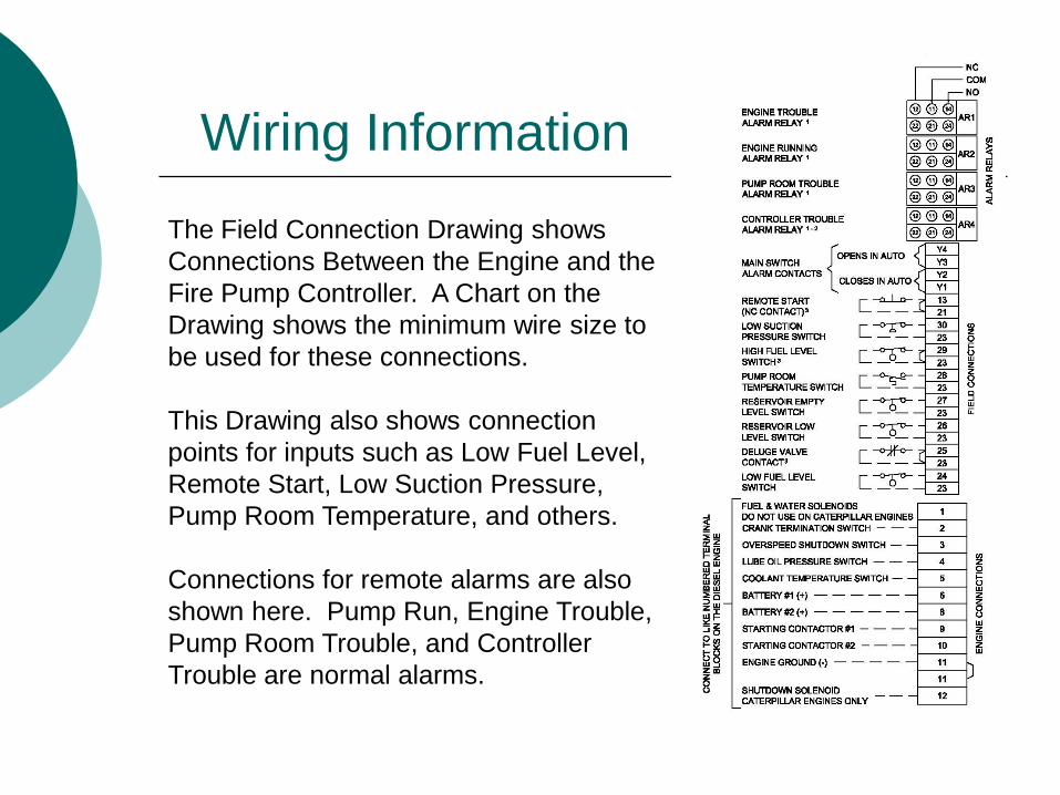
Wiring Information
The Field Connection Drawing shows
Connections Between the Engine and the
Fire Pump Controller. A Chart on the
Drawing shows the minimum wire size to
be used for these connections.
This Drawing also shows connection
points for inputs such as Low Fuel Level,
Remote Start, Low Suction Pressure,
Pump Room Temperature, and others.
Connections for remote alarms are also
shown here. Pump Run, Engine Trouble,
Pump Room Trouble, and Controller
Trouble are normal alarms.
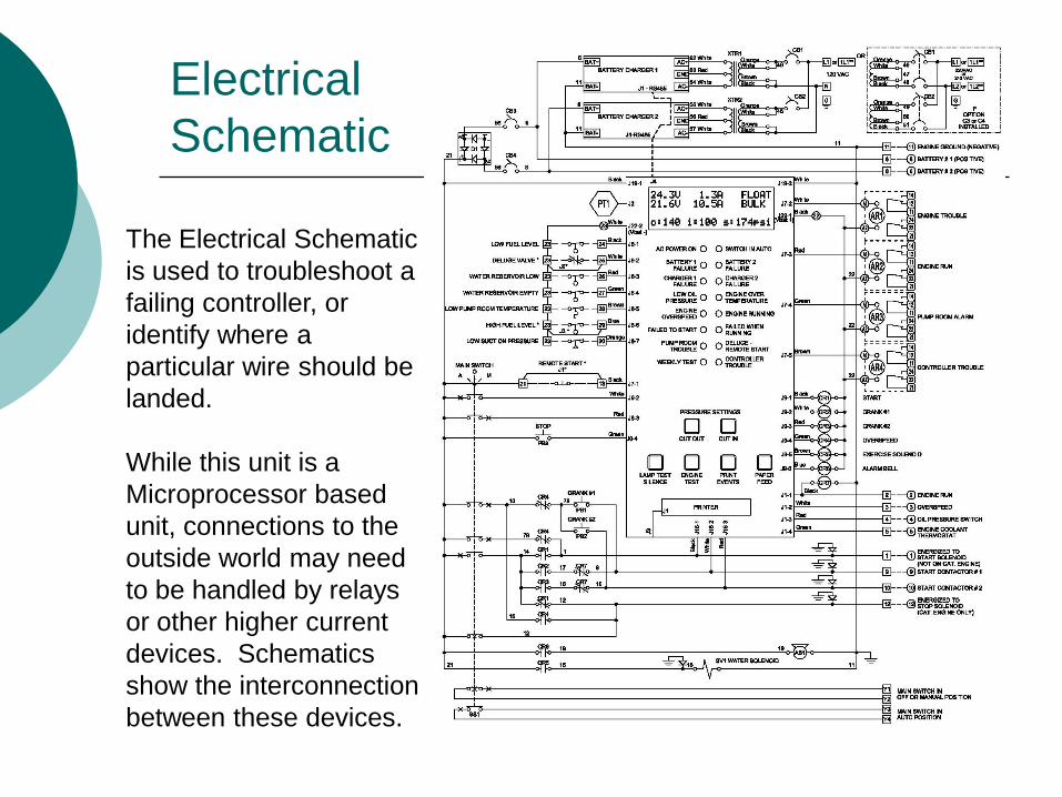
Electrical
Schematic
The Electrical Schematic
is used to troubleshoot a
failing controller, or
identify where a
particular wire should be
landed.
While this unit is a
Microprocessor based
unit, connections to the
outside world may need
to be handled by relays
or other higher current
devices. Schematics
show the interconnection
between these devices.
Diesel Fire Pump Controls
Testing the Fire Pump Controller
Testing the Fire Pump Controller
When Testing the fire pump Controller, the controller mounted buttons and devices need to be tested as well as the devices on the engine and in the pump room. Manual Operation, Automatic Operation, Alarms, Shutdowns, all should be checked out to make sure they are working correctly.
Testing Manual Operation
Place the Selector Switch in the Manual Position.
Monitor the Water Solenoid Valve on the engine cooling loop. It should energize when the selector is moved to the Manual Position.
Pushing the Controller Mounted Start #1 Button Causes the Engine to start.
Testing Continued
When the engine starts, it should run until you switch the Selector to the OFF position. The Permissive Stop does not operate in Manual Mode.
Moving the Selector to the Auto Position tests the Automatic portion of the controller.
Testing Automatic Operation
If pressure at the sensing line is above the start setpoint of the controller, the unit will not start.
Open the pressure line and drop the pressure at the transducer. The engine should start and run.
Once the engine beings acceleration, watch the front of the controller for a Red LED at Engine Running.
Testing Automatic Continued
When the engine reaches about 15% of its rated speed, a device called an Engine Speed Switch, sends a signal back to the controller telling it that engine is running and stop trying to start. If the engine accelerates over 120% rated speed, another contact closes and causes the engine to stop. A test button allows testing of the overspeed device without damage to the engine.
Testing Automatic Continued
If the line pressure has exceeded the upper set point of the pressure controller, pressing the Permissive Stop Push Button will cause the Engine to Stop. If pressure is still below upper set point, then the selector must be moved to the OFF position.
Testing Continued
Next, Start the Engine in the Automatic Mode.
Go to the Engine Temperature Switch and short the terminals with a piece of wire. The Bell on the Controller should ring and the Over-Temperature light should come on. The engine should not stop.
Using the same wire, short between terminals 11 and 4 on the terminal strip. Wait for 3 to 6 seconds for the Timer to time out, then observe Low Oil Pressure light on the Controller and ringing bell. Again, the Engine should not stop
Testing Continued
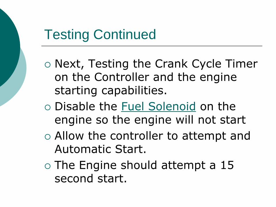
Next, Testing the Crank Cycle Timer on the Controller and the engine starting capabilities.
Disable the Fuel Solenoid on the engine so the engine will not start
Allow the controller to attempt and Automatic Start.
The Engine should attempt a 15 second start.
Testing Continued
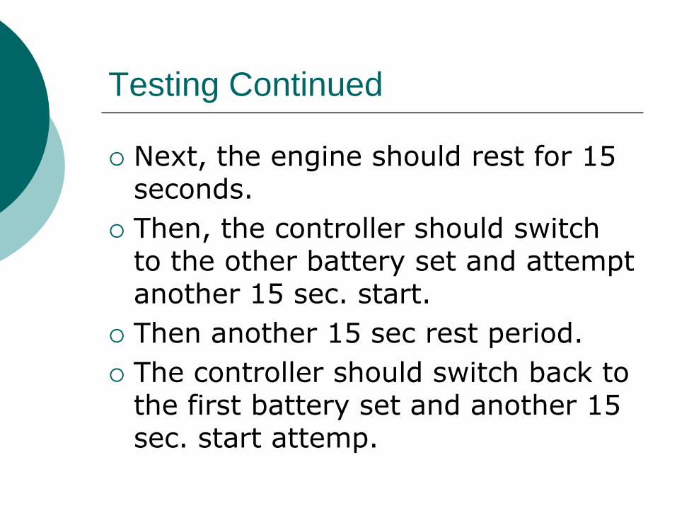
Next, the engine should rest for 15 seconds.
Then, the controller should switch to the other battery set and attempt another 15 sec. start.
Then another 15 sec rest period.
The controller should switch back to the first battery set and another 15 sec. start attemp.
Testing Continued
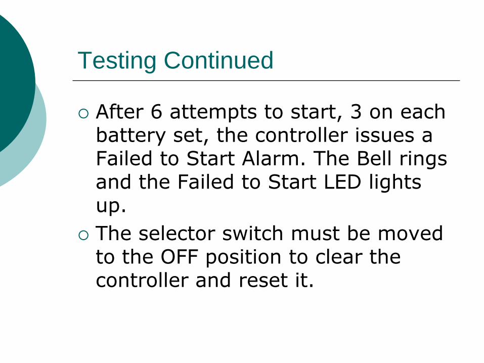
After 6 attempts to start, 3 on each battery set, the controller issues a Failed to Start Alarm. The Bell rings and the Failed to Start LED lights up.
The selector switch must be moved to the OFF position to clear the controller and reset it.
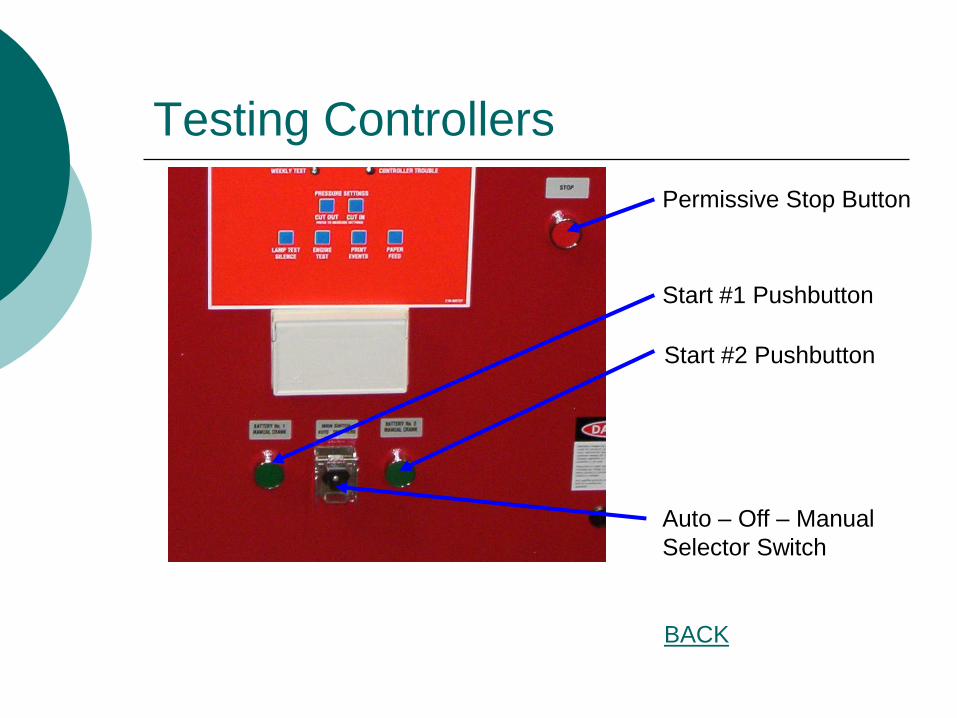
Testing Controllers
Permissive Stop Button
Start #1 Pushbutton
Start #2 Pushbutton
Auto – Off – Manual
Selector Switch
BACK
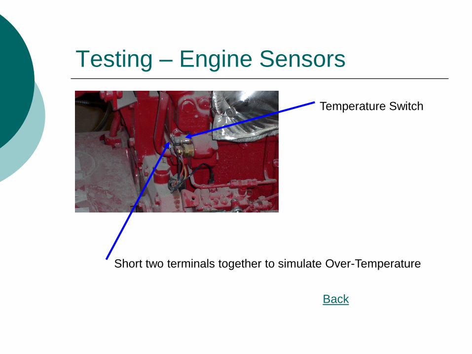
Testing – Engine Sensors
Temperature Switch
Short two terminals together to simulate Over-Temperature
Back
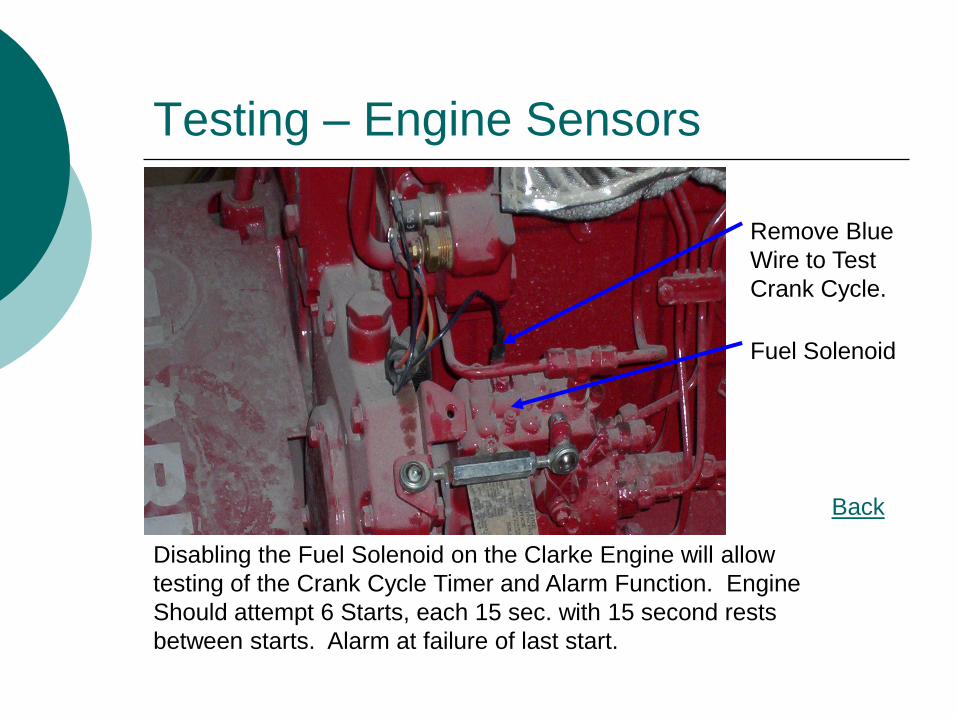
Testing – Engine Sensors
Back
Disabling the Fuel Solenoid on the Clarke Engine will allow
testing of the Crank Cycle Timer and Alarm Function. Engine
Should attempt 6 Starts, each 15 sec. with 15 second rests
between starts. Alarm at failure of last start.
Fuel Solenoid
Remove Blue
Wire to Test
Crank Cycle.

Joslyn Clark Controls
Jockey Pump Controls
Auxiliary Panels
Remote Alarm Panel
Low Suction Control Panel
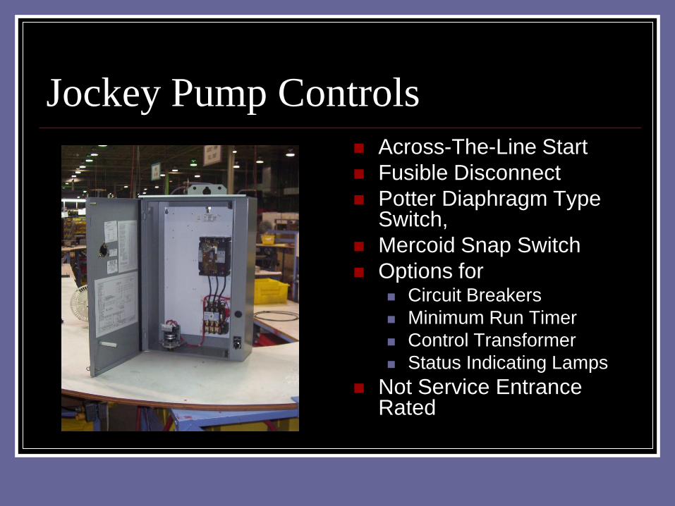
Jockey Pump Controls
Across-The-Line Start
Fusible Disconnect
Potter Diaphragm Type Switch,
Mercoid Snap Switch
Options for Circuit Breakers
Minimum Run Timer
Control Transformer
Status Indicating Lamps
Not Service Entrance Rated
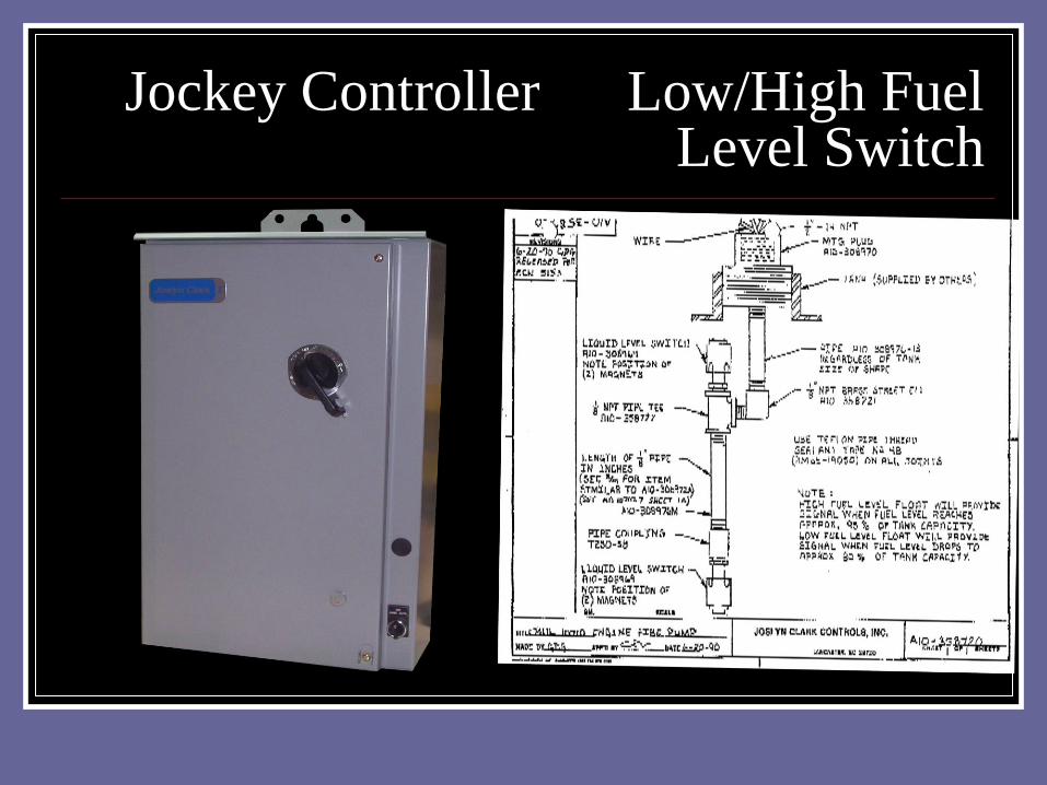
Jockey Controller Low/High Fuel Level Switch
Auxiliary Equipment
Remote Alarm Panel - Electric Controls Pump Run
Power Failure
Phases Reversed
Pump Start (Optional)
Remote Alarm Panel - Diesel Controls Pump Run
Engine Failure
Controller Not in Auto
Auxiliary Equipment
Low Suction Cutoff Panel
Manual Reset
Delay on Cutoff, Automatic Reset
Delay on Cutoff, Delay on Automatic Reset
Auxiliary Panels
Low Suction Alarm Panels
Not Required in all Locations, But Some Do!
Requires a Second Source of 120V for
Supervisory Power.
Connects to Fire Pump Controller. Not usually in
Electricians Contract, or so they say!
Signal line should be on pump side of Suction
Control Valve for ease of testing.
Auxiliary Panels
Remote Alarm Panels
Usually Require Second Source of 120V for
Supervisory Power.
If Building Already has Building Alarm System, Is
the Remote Alarm Panel needed?
Should you Mount the Remote Alarm Panel Next
to the Fire Pump Controller? NO!!!