Dreidimensionale, zeitaufgelöste Messung der ... 2013/pdf/14.pdf · Dreidimensionale,...
12
Fachtagung “Lasermethoden in der Strömungsmesstechnik” 3. – 5. September 2013, München Dreidimensionale, zeitaufgelöste Messung der Partikelgeschwin- digkeit im Überschallstrahl mit einer Kamera Single Camera High-speed 3D Particle Tracking in Supersonic Jet Flows Nicolas A. Buchmann 1,2 , Christian Cierpka 2 , Christian J. Kähler 2 and Julio Soria 1 1 Laboratory of Turbulence Research in Aerospace and Combustion, Monash University, Melbourne, Australia, [email protected] 2 Institute for Fluid Mechanics and Aerodynamics, Bundeswehr University Munich, Germany Schlagworte: Astigmatismus Partikel Tracking, Dreidimensionale Hochgeschwindigkeits- messung, Überschallströmung Keywords: Astigmatism Particle Tracking, three-dimensional high-speed imaging, super- sonic jet flow ABSTRACT This paper demonstrates ultra-high-speed (up to 1,000,000fps) time-resolved three- component, three-dimensional (3C3D) particle velocity measurements of micron-sized parti- cles in a supersonic underexpanded jet flow using a single high-speed camera for the first time. The underexpanded jet flow is produced via a converging nozzle and the micron-sized particles with mean diameter d = 110μm are introduced co-axially into the gas flow. The im- aging system consist of an ultra-high-speed digital camera (Shimadzu HPV-1) capable of recording 102 consecutive image frames at a rate of up to 1,000,000fps. Astigmatism particle tracking velocimetry (APTV) is used to measure the 3C3D particle velocities with a single camera (Cierpka et al., 2010). The depth position of the particles is coded in the 2D images by adding a cylindrical lens to the high-speed imaging system. The particle images appear elliptically distorted according to their depth position in the volume, which can be related to physical space by an appropriate calibration (Cierpka et al., 2011). The size of the measure- ment volume is approximately 6D × 8 D × 6 D (x,y,z) where D = 2mm is the nozzle diameter. The particles are illuminated with a single high-power LED synchronised with the high-speed camera and pulsed at kHz rates (Willert et al., 2012). Based on the reconstructed 3D particle positions the particle trajectories are obtained via an advanced tracking scheme that takes advantage of the high temporal resolution to increase robustness and accuracy of the meas- urement (Cierpka et al., 2013). 1. INTRODUCTION High-speed particle laden flows can be found in a number of applications such as particle impactors (Forney, 1991), needle free drug delivery systems (Quinlan, et al., 2001) or cold gas dynamic spray processes (Jodoin et al., 2006; Lange et al., 2011; Papyrin et al., 2007; Pardhasaradhi et al., 2008). Common to all these processes are the acceleration of micron- sized particles (1-100µm) to very high particle velocities (300-1200m/s) via a high-speed gas 14 - 1
Transcript of Dreidimensionale, zeitaufgelöste Messung der ... 2013/pdf/14.pdf · Dreidimensionale,...
Fachtagung “Lasermethoden in der Strömungsmesstechnik” 3. – 5. September 2013, München
Dreidimensionale, zeitaufgelöste Messung der Partikelgeschwin-digkeit im Überschallstrahl mit einer Kamera Single Camera High-speed 3D Particle Tracking in Supersonic Jet Flows
Nicolas A. Buchmann1,2, Christian Cierpka2, Christian J. Kähler2 and Julio Soria1 1 Laboratory of Turbulence Research in Aerospace and Combustion, Monash University, Melbourne, Australia, [email protected] 2 Institute for Fluid Mechanics and Aerodynamics, Bundeswehr University Munich, Germany Schlagworte: Astigmatismus Partikel Tracking, Dreidimensionale Hochgeschwindigkeits-messung, Überschallströmung Keywords: Astigmatism Particle Tracking, three-dimensional high-speed imaging, super-sonic jet flow ABSTRACT This paper demonstrates ultra-high-speed (up to 1,000,000fps) time-resolved three-component, three-dimensional (3C3D) particle velocity measurements of micron-sized parti-cles in a supersonic underexpanded jet flow using a single high-speed camera for the first time. The underexpanded jet flow is produced via a converging nozzle and the micron-sized particles with mean diameter d = 110µm are introduced co-axially into the gas flow. The im-aging system consist of an ultra-high-speed digital camera (Shimadzu HPV-1) capable of recording 102 consecutive image frames at a rate of up to 1,000,000fps. Astigmatism particle tracking velocimetry (APTV) is used to measure the 3C3D particle velocities with a single camera (Cierpka et al., 2010). The depth position of the particles is coded in the 2D images by adding a cylindrical lens to the high-speed imaging system. The particle images appear elliptically distorted according to their depth position in the volume, which can be related to physical space by an appropriate calibration (Cierpka et al., 2011). The size of the measure-ment volume is approximately 6D × 8D × 6D (x,y,z) where D = 2mm is the nozzle diameter. The particles are illuminated with a single high-power LED synchronised with the high-speed camera and pulsed at kHz rates (Willert et al., 2012). Based on the reconstructed 3D particle positions the particle trajectories are obtained via an advanced tracking scheme that takes advantage of the high temporal resolution to increase robustness and accuracy of the meas-urement (Cierpka et al., 2013).
1. INTRODUCTION High-speed particle laden flows can be found in a number of applications such as particle impactors (Forney, 1991), needle free drug delivery systems (Quinlan, et al., 2001) or cold gas dynamic spray processes (Jodoin et al., 2006; Lange et al., 2011; Papyrin et al., 2007; Pardhasaradhi et al., 2008). Common to all these processes are the acceleration of micron-sized particles (1-100µm) to very high particle velocities (300-1200m/s) via a high-speed gas
14 - 1

flow such that the particles attain sufficient kinetic energy to penetrate or deposit onto a solid substrate upon impaction. For example in cold gas dynamic spraying the gas flow is super-sonic and the highly accelerated particles form a solid deposit on the substrate thus enabling the coating of chemically incompatible materials. The optimal application of these processes is characterised by a critical particle impact velocity and particle impact angle, both of which are a complicated function of the fluid dynamics of the impinging supersonic jet flow. Under-standing how the particle trajectories are affected by the highly unsteady, turbulent and three-dimensional nature of the supersonic gas flow and its complex shock structure requires experimental data to resolve the individual three-component, three-dimensional (3C3D) par-ticle velocity over a time and length scales comparable to their size and velocity. However, this is exceedingly difficult to achieve due to the large dimensional difference between the very small particles (O(10-6) m) and their very large velocities (O(103) m/s). In order to re-solve the motion associated with these particles ultra-high-speed imaging and 3C3D particle reconstruction and tracking methods that can be applied at the micro-scale level are re-quired. 1.1. High-Speed Imaging Considerations Therefore, successful measurements require capturing the particle motion in both time and space at the highest possible resolution and with good contrast. This is to fulfill the temporal and spatial Nyquist criteria, to maximise the signal-to-noise ratio (SNR) at the imaging sensor and to minimise motion blur (see Versluis, 2013 for a detailed discussion). For time-resolved imaging the optimal temporal sampling or frame rate f is given as
(1) where D and u are typical length and velocity scales and n the required number of snapshots to fulfill the sampling criterion (i.e. n > 2). For example a velocity of 100m/s corresponds to 100µm/µs, which means that if imaging at the micron-size level MHz frame rates are required for the temporal resolution. Furthermore, the exposure time must be short enough to avoid motion blur, but at the same time long enough to obtain an adequate signal level. Defining ε = τu/d as the displacement of a particle of diameter d during the exposure time τ the mini-mum required exposure or illumination time can be expressed as (2)
where ε < 1. It must be noted that decreasing the exposure time will reduce the signal level and hence the SNR. Therefore imaging at high frame rates and short exposure times (e.g. τ < 1µs) requires particular considerations of the illumination system to ensure adequate SNR at short exposure times. This illumination can be provided by powerful CW lasers, flash-light illumination or high frequency pulsed LED illumination for example. Equation (1) and (2) are illustrated graphically in Figure 1a & b, which shows the maximum required frame rate and minimum exposure time for a range of particle diameters and particle velocities. As can be seen, already for relatively large particles and moderate velocities (d = 100µm, u = 200m/s), exposure times of less than 0.5µs and frame rates in excess of 200,000fps are required. An overview of currently available CCD, high-speed CMOS and ultra-high-speed CCD cameras is given in Table 1, where it can be seen that recording rates at Mpfs and ns exposure times are achievable, but only at the expense of drastically reduced spatial resolution and sensor size. It is this reduction in spatial resolution that creates serious problems when imaging micron-sized particles that are at the resolution limit of the imaging array. By using appropriate mag-nification optics this lack of spatial resolution can be overcome and the spatial Nyquist crite-rion can be fulfilled; this is that the particle must be sampled by at least 2 pixels on the
14 - 2
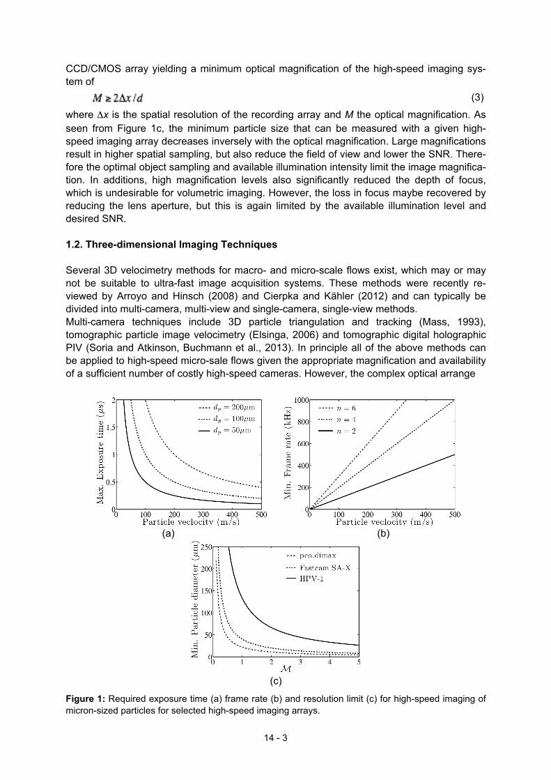
CCD/CMOS array yielding a minimum optical magnification of the high-speed imaging sys-tem of (3)
where Δx is the spatial resolution of the recording array and M the optical magnification. As seen from Figure 1c, the minimum particle size that can be measured with a given high-speed imaging array decreases inversely with the optical magnification. Large magnifications result in higher spatial sampling, but also reduce the field of view and lower the SNR. There-fore the optimal object sampling and available illumination intensity limit the image magnifica-tion. In additions, high magnification levels also significantly reduced the depth of focus, which is undesirable for volumetric imaging. However, the loss in focus maybe recovered by reducing the lens aperture, but this is again limited by the available illumination level and desired SNR. 1.2. Three-dimensional Imaging Techniques Several 3D velocimetry methods for macro- and micro-scale flows exist, which may or may not be suitable to ultra-fast image acquisition systems. These methods were recently re-viewed by Arroyo and Hinsch (2008) and Cierpka and Kähler (2012) and can typically be divided into multi-camera, multi-view and single-camera, single-view methods. Multi-camera techniques include 3D particle triangulation and tracking (Mass, 1993), tomographic particle image velocimetry (Elsinga, 2006) and tomographic digital holographic PIV (Soria and Atkinson, Buchmann et al., 2013). In principle all of the above methods can be applied to high-speed micro-sale flows given the appropriate magnification and availability of a sufficient number of costly high-speed cameras. However, the complex optical arrange
(a)
(b)
(c)
Figure 1: Required exposure time (a) frame rate (b) and resolution limit (c) for high-speed imaging of micron-sized particles for selected high-speed imaging arrays.
14 - 3
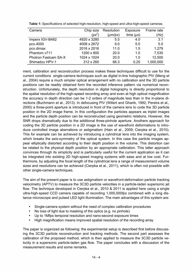
Table 1: Specifications of selected high-resolution, high-speed and ultra-high-speed cameras.
Camera Chip size (px2)
Resolution (µm/px)
Exposure time (µs)
Frame rate (Hz)
Imperx IGV-B482 4920 x 3280 5.5 4.0 3.1 pco.4000 4008 x 2672 9.0 5.0 5.0 pco.dimax 2016 x 2016 11.0 1.5 1,279 Phantom v711 1200 x 800 20.0 1.0 7,530 Photron Fastcam SA-X 1024 x 1024 20.0 1.0 12,500 Shimadzu HPV-1 312 x 260 66.3 0.25 1,000,000 ment, calibration and reconstruction process makes these techniques difficult to use for the current conditions single-camera techniques such as digital in-line holographic PIV (Meng et al., 2004) require a much simpler optical arrangement with no calibration and the 3D particle positions can be readily obtained form the recorded inference pattern via numerical recon-struction. Unfortunately, the depth resolution in digital holography is directly proportional to the spatial resolution of the high-speed recording array and even at high optical magnification the accuracy in depth direction can be 1-2 orders of magnitude less than in the in-plane di-rections (Buchmann et al., 2013). In defocusing PIV (Willert and Gharib, 1992; Pereira et al., 2000) a three-point aperture is introduced in front of the camera lens to code the 3D particle position in the 2D image frame. In this configuration the particles appears as triplet images and the particle depth position can be reconstructed using geometric relations. However, the SNR drops dramatically due to the additional three-pinhole aperture. Anothers approach for coding the 3D particle position in a 2D image is the use of wavefront deformations to intro-duce controlled image aberrations or astigmatism (Hain et al., 2009; Cierpka et al., 2010). This for example can be achieved by introducing a cylindrical lens into the imaging system, which breaks the axis-symmetry of the optical system. In this case the particle images ap-pear elliptically distorted according to their depth position in the volume. This distortion can be related to the physical depth position by an appropriate calibration. This latter approach convinces through its simplicity and is particularly useful for the current application as it can be integrated into existing 2D high-speed imaging systems with ease and at low cost. Fur-thermore, by adjusting the focal length of the cylindrical lens a range of measurement volume sizes and resolutions can be achieved (Cierpka et al., 2011), which is often not possible with other single-camera techniques. The aim of the present paper is to use astigmatism or wavefront-deformation particle tracking velocimetry (APTV) to measure the 3C3D particle velocities in a particle-laden supersonic jet flow. The technique developed in Cierpka et al., 2010 & 2011 is applied here using a single ultra-high-speed CCD camera capable of recording 1,000,000fps combined with a long dis-tance microscope and pulsed LED light illumination. The main advantages of this system are:
• Single-camera system without the need of complex calibration procedures • No loss of light due to masking of the optics (e.g. no pinhole) • Up to 1Mfps temporal resolution and nano-second exposure times • High magnification means improved spatial resolution of the recording array
The paper is organized as following; the experimental setup is described first before discuss-ing the 3C3D particle reconstruction and tracking methods. The second part assesses the calibration of the proposed method, which is then applied to measure the 3C3D particle ve-locity in a supersonic particle-laden gas flow. The paper concludes with a discussion of the measurement results and some remarks.
14 - 4
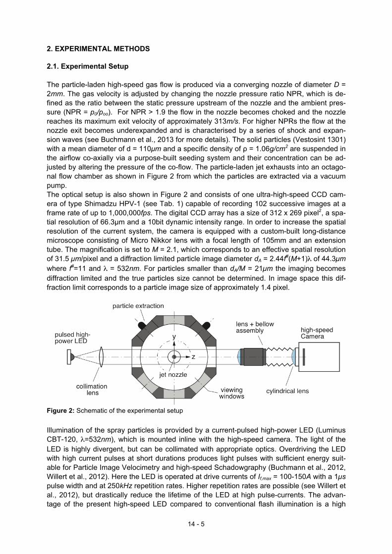
2. EXPERIMENTAL METHODS 2.1. Experimental Setup The particle-laden high-speed gas flow is produced via a converging nozzle of diameter D = 2mm. The gas velocity is adjusted by changing the nozzle pressure ratio NPR, which is de-fined as the ratio between the static pressure upstream of the nozzle and the ambient pres-sure (NPR = p0/poo). For NPR > 1.9 the flow in the nozzle becomes choked and the nozzle reaches its maximum exit velocity of approximately 313m/s. For higher NPRs the flow at the nozzle exit becomes underexpanded and is characterised by a series of shock and expan-sion waves (see Buchmann et al., 2013 for more details). The solid particles (Vestosint 1301) with a mean diameter of d = 110µm and a specific density of ρ = 1.06g/cm2 are suspended in the airflow co-axially via a purpose-built seeding system and their concentration can be ad-justed by altering the pressure of the co-flow. The particle-laden jet exhausts into an octago-nal flow chamber as shown in Figure 2 from which the particles are extracted via a vacuum pump. The optical setup is also shown in Figure 2 and consists of one ultra-high-speed CCD cam-era of type Shimadzu HPV-1 (see Tab. 1) capable of recording 102 successive images at a frame rate of up to 1,000,000fps. The digital CCD array has a size of 312 x 269 pixel2, a spa-tial resolution of 66.3µm and a 10bit dynamic intensity range. In order to increase the spatial resolution of the current system, the camera is equipped with a custom-built long-distance microscope consisting of Micro Nikkor lens with a focal length of 105mm and an extension tube. The magnification is set to M = 2.1, which corresponds to an effective spatial resolution of 31.5 µm/pixel and a diffraction limited particle image diameter dA = 2.44f#(M+1)λ of 44.3µm where f#=11 and λ = 532nm. For particles smaller than dA/M = 21µm the imaging becomes diffraction limited and the true particles size cannot be determined. In image space this dif-fraction limit corresponds to a particle image size of approximately 1.4 pixel.
Figure 2: Schematic of the experimental setup
Illumination of the spray particles is provided by a current-pulsed high-power LED (Luminus CBT-120, λ=532nm), which is mounted inline with the high-speed camera. The light of the LED is highly divergent, but can be collimated with appropriate optics. Overdriving the LED with high current pulses at short durations produces light pulses with sufficient energy suit-able for Particle Image Velocimetry and high-speed Schadowgraphy (Buchmann et al., 2012, Willert et al., 2012). Here the LED is operated at drive currents of If,max = 100-150A with a 1µs pulse width and at 250kHz repetition rates. Higher repetition rates are possible (see Willert et al., 2012), but drastically reduce the lifetime of the LED at high pulse-currents. The advan-tage of the present high-speed LED compared to conventional flash illumination is a high
14 - 5
degree of spatial and temporal uniformity of the illumination and the ability to reduce the ex-posure time below the limit of the high-speed camera (e.g. pulse width less than 250ns are possible). A summary of the acquisition parameters for the current high-speed experiment is given in Table 2 together with the required parameters calculated by Equations (1−3) for a 50µm and 110µm particle. Table 2: Required and actual acquisition parameters of the high-speed particle tracking experiment; (u = 200m/s, D = 2mm, n = 2).
f (Hz)
τ (µs)
ε M
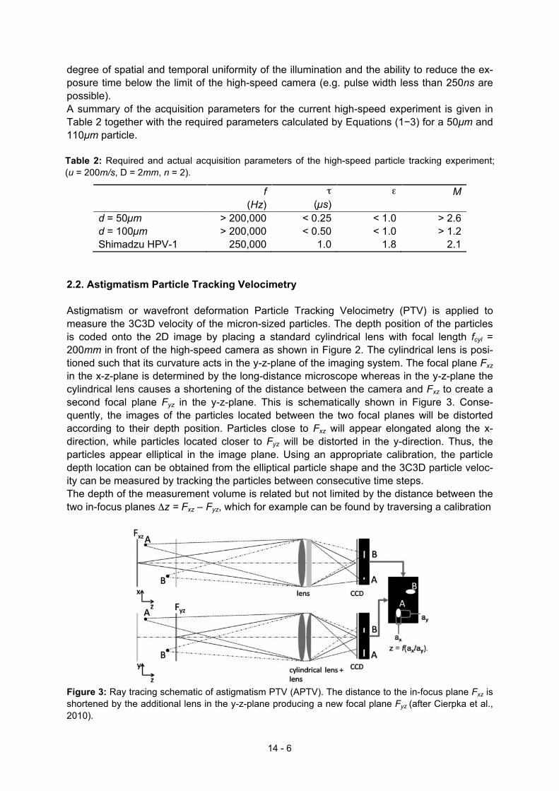
d = 50µm > 200,000 < 0.25 < 1.0 > 2.6 d = 100µm > 200,000 < 0.50 < 1.0 > 1.2 Shimadzu HPV-1 250,000 1.0 1.8 2.1 2.2. Astigmatism Particle Tracking Velocimetry Astigmatism or wavefront deformation Particle Tracking Velocimetry (PTV) is applied to measure the 3C3D velocity of the micron-sized particles. The depth position of the particles is coded onto the 2D image by placing a standard cylindrical lens with focal length fcyl = 200mm in front of the high-speed camera as shown in Figure 2. The cylindrical lens is posi-tioned such that its curvature acts in the y-z-plane of the imaging system. The focal plane Fxz in the x-z-plane is determined by the long-distance microscope whereas in the y-z-plane the cylindrical lens causes a shortening of the distance between the camera and Fxz to create a second focal plane Fyz in the y-z-plane. This is schematically shown in Figure 3. Conse-quently, the images of the particles located between the two focal planes will be distorted according to their depth position. Particles close to Fxz will appear elongated along the x-direction, while particles located closer to Fyz will be distorted in the y-direction. Thus, the particles appear elliptical in the image plane. Using an appropriate calibration, the particle depth location can be obtained from the elliptical particle shape and the 3C3D particle veloc-ity can be measured by tracking the particles between consecutive time steps. The depth of the measurement volume is related but not limited by the distance between the two in-focus planes Δz = Fxz – Fyz, which for example can be found by traversing a calibration
Figure 3: Ray tracing schematic of astigmatism PTV (APTV). The distance to the in-focus plane Fxz is shortened by the additional lens in the y-z-plane producing a new focal plane Fyz (after Cierpka et al., 2010).
14 - 6
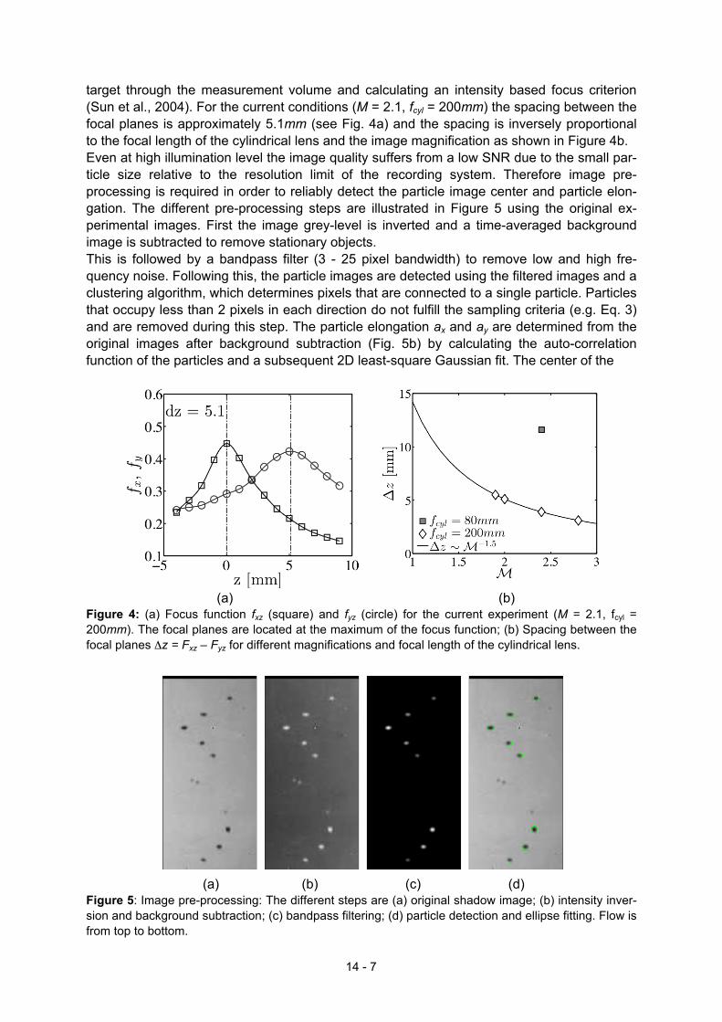
target through the measurement volume and calculating an intensity based focus criterion (Sun et al., 2004). For the current conditions (M = 2.1, fcyl = 200mm) the spacing between the focal planes is approximately 5.1mm (see Fig. 4a) and the spacing is inversely proportional to the focal length of the cylindrical lens and the image magnification as shown in Figure 4b. Even at high illumination level the image quality suffers from a low SNR due to the small par-ticle size relative to the resolution limit of the recording system. Therefore image pre-processing is required in order to reliably detect the particle image center and particle elon-gation. The different pre-processing steps are illustrated in Figure 5 using the original ex-perimental images. First the image grey-level is inverted and a time-averaged background image is subtracted to remove stationary objects. This is followed by a bandpass filter (3 - 25 pixel bandwidth) to remove low and high fre-quency noise. Following this, the particle images are detected using the filtered images and a clustering algorithm, which determines pixels that are connected to a single particle. Particles that occupy less than 2 pixels in each direction do not fulfill the sampling criteria (e.g. Eq. 3) and are removed during this step. The particle elongation ax and ay are determined from the original images after background subtraction (Fig. 5b) by calculating the auto-correlation function of the particles and a subsequent 2D least-square Gaussian fit. The center of the
(a) (b)
Figure 4: (a) Focus function fxz (square) and fyz (circle) for the current experiment (M = 2.1, fcyl = 200mm). The focal planes are located at the maximum of the focus function; (b) Spacing between the focal planes Δz = Fxz – Fyz for different magnifications and focal length of the cylindrical lens.
(a) (b) (c) (d)
Figure 5: Image pre-processing: The different steps are (a) original shadow image; (b) intensity inver-sion and background subtraction; (c) bandpass filtering; (d) particle detection and ellipse fitting. Flow is from top to bottom.
14 - 7
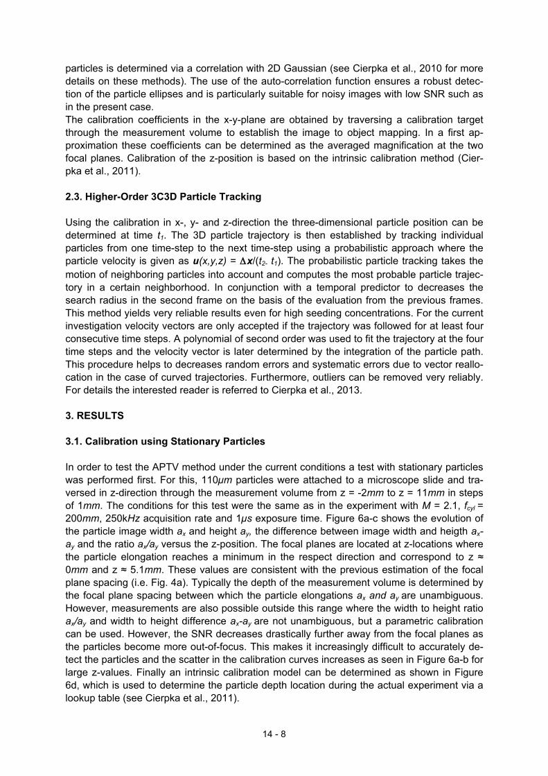
particles is determined via a correlation with 2D Gaussian (see Cierpka et al., 2010 for more details on these methods). The use of the auto-correlation function ensures a robust detec-tion of the particle ellipses and is particularly suitable for noisy images with low SNR such as in the present case. The calibration coefficients in the x-y-plane are obtained by traversing a calibration target through the measurement volume to establish the image to object mapping. In a first ap-proximation these coefficients can be determined as the averaged magnification at the two focal planes. Calibration of the z-position is based on the intrinsic calibration method (Cier-pka et al., 2011). 2.3. Higher-Order 3C3D Particle Tracking Using the calibration in x-, y- and z-direction the three-dimensional particle position can be determined at time t1. The 3D particle trajectory is then established by tracking individual particles from one time-step to the next time-step using a probabilistic approach where the particle velocity is given as u(x,y,z) = Δx/(t2- t1). The probabilistic particle tracking takes the motion of neighboring particles into account and computes the most probable particle trajec-tory in a certain neighborhood. In conjunction with a temporal predictor to decreases the search radius in the second frame on the basis of the evaluation from the previous frames. This method yields very reliable results even for high seeding concentrations. For the current investigation velocity vectors are only accepted if the trajectory was followed for at least four consecutive time steps. A polynomial of second order was used to fit the trajectory at the four time steps and the velocity vector is later determined by the integration of the particle path. This procedure helps to decreases random errors and systematic errors due to vector reallo-cation in the case of curved trajectories. Furthermore, outliers can be removed very reliably. For details the interested reader is referred to Cierpka et al., 2013. 3. RESULTS 3.1. Calibration using Stationary Particles In order to test the APTV method under the current conditions a test with stationary particles was performed first. For this, 110µm particles were attached to a microscope slide and tra-versed in z-direction through the measurement volume from z = -2mm to z = 11mm in steps of 1mm. The conditions for this test were the same as in the experiment with M = 2.1, fcyl = 200mm, 250kHz acquisition rate and 1µs exposure time. Figure 6a-c shows the evolution of the particle image width ax and height ay, the difference between image width and heigth ax-ay and the ratio ax/ay versus the z-position. The focal planes are located at z-locations where the particle elongation reaches a minimum in the respect direction and correspond to z ≈ 0mm and z ≈ 5.1mm. These values are consistent with the previous estimation of the focal plane spacing (i.e. Fig. 4a). Typically the depth of the measurement volume is determined by the focal plane spacing between which the particle elongations ax and ay are unambiguous. However, measurements are also possible outside this range where the width to height ratio ax/ay and width to height difference ax-ay are not unambiguous, but a parametric calibration can be used. However, the SNR decreases drastically further away from the focal planes as the particles become more out-of-focus. This makes it increasingly difficult to accurately de-tect the particles and the scatter in the calibration curves increases as seen in Figure 6a-b for large z-values. Finally an intrinsic calibration model can be determined as shown in Figure 6d, which is used to determine the particle depth location during the actual experiment via a lookup table (see Cierpka et al., 2011).
14 - 8
(a) (b)
(c) (d)
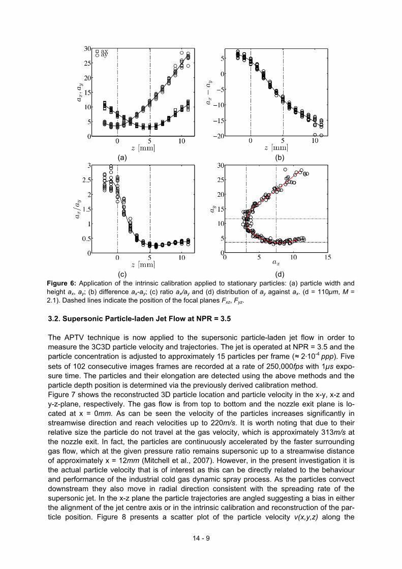
Figure 6: Application of the intrinsic calibration applied to stationary particles: (a) particle width and height ax, ay; (b) difference ax-ay; (c) ratio ax/ay and (d) distribution of ay against ax. (d = 110µm, M = 2.1). Dashed lines indicate the position of the focal planes Fxz, Fyz. 3.2. Supersonic Particle-laden Jet Flow at NPR = 3.5 The APTV technique is now applied to the supersonic particle-laden jet flow in order to measure the 3C3D particle velocity and trajectories. The jet is operated at NPR = 3.5 and the particle concentration is adjusted to approximately 15 particles per frame (≈ 2⋅10-4 ppp). Five sets of 102 consecutive images frames are recorded at a rate of 250,000fps with 1µs expo-sure time. The particles and their elongation are detected using the above methods and the particle depth position is determined via the previously derived calibration method. Figure 7 shows the reconstructed 3D particle location and particle velocity in the x-y, x-z and y-z-plane, respectively. The gas flow is from top to bottom and the nozzle exit plane is lo-cated at x = 0mm. As can be seen the velocity of the particles increases significantly in streamwise direction and reach velocities up to 220m/s. It is worth noting that due to their relative size the particle do not travel at the gas velocity, which is approximately 313m/s at the nozzle exit. In fact, the particles are continuously accelerated by the faster surrounding gas flow, which at the given pressure ratio remains supersonic up to a streamwise distance of approximately x = 12mm (Mitchell et al., 2007). However, in the present investigation it is the actual particle velocity that is of interest as this can be directly related to the behaviour and performance of the industrial cold gas dynamic spray process. As the particles convect downstream they also move in radial direction consistent with the spreading rate of the supersonic jet. In the x-z plane the particle trajectories are angled suggesting a bias in either the alignment of the jet centre axis or in the intrinsic calibration and reconstruction of the par-ticle position. Figure 8 presents a scatter plot of the particle velocity v(x,y,z) along the
14 - 9
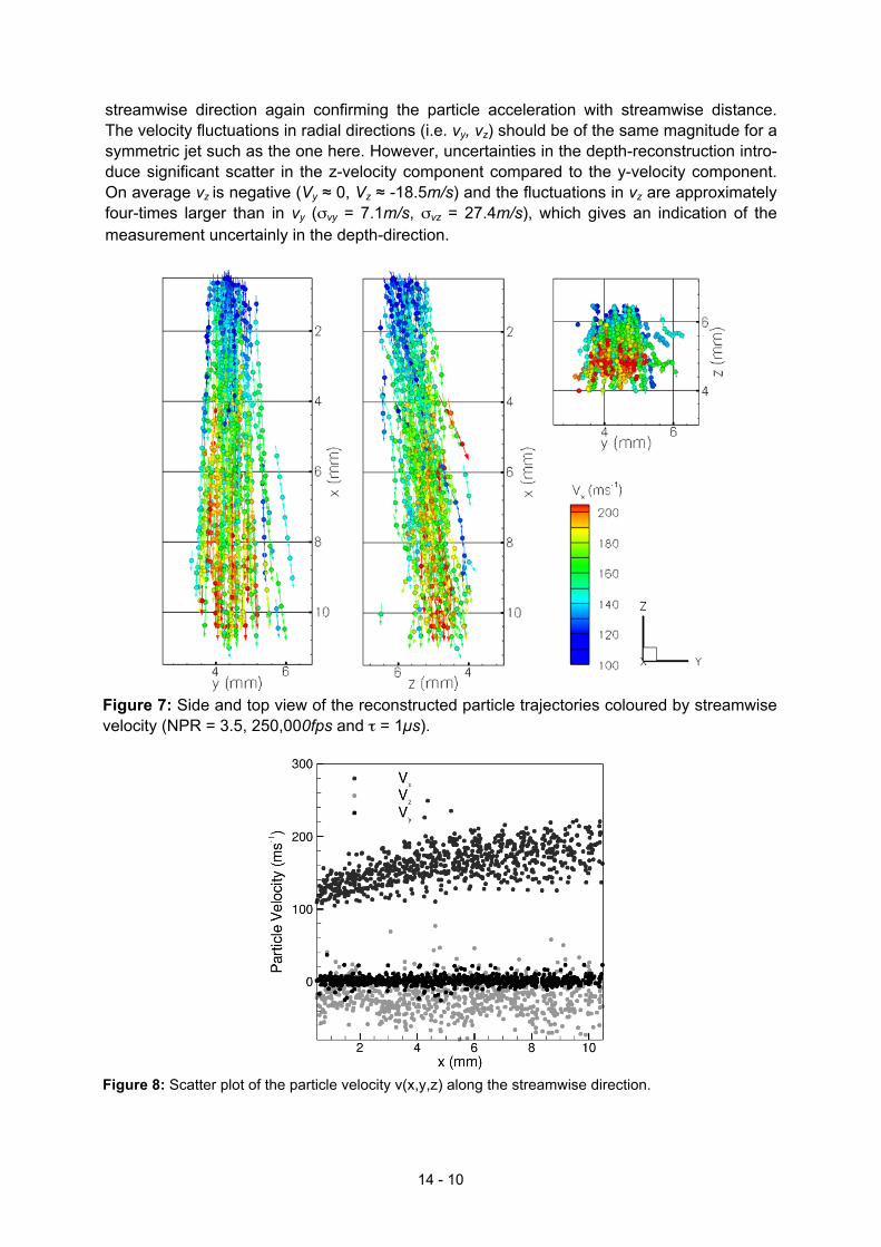
streamwise direction again confirming the particle acceleration with streamwise distance. The velocity fluctuations in radial directions (i.e. vy, vz) should be of the same magnitude for a symmetric jet such as the one here. However, uncertainties in the depth-reconstruction intro-duce significant scatter in the z-velocity component compared to the y-velocity component. On average vz is negative (Vy ≈ 0, Vz ≈ -18.5m/s) and the fluctuations in vz are approximately four-times larger than in vy (σvy = 7.1m/s, σvz = 27.4m/s), which gives an indication of the measurement uncertainly in the depth-direction.
Figure 7: Side and top view of the reconstructed particle trajectories coloured by streamwise velocity (NPR = 3.5, 250,000fps and τ = 1µs).
Figure 8: Scatter plot of the particle velocity v(x,y,z) along the streamwise direction.
14 - 10
4. CONCLUDING REMARKS This paper shows for the first time three-dimensional ultra-high-speed measurements of mi-cron-sized particles in a supersonic underexpanded gas flow using astigmatism particle tracking velocimetry (APTV). The necessary requirements and limitations to perform such high-speed measurements were discussed and guidelines for the appropriate choice of image magnification, frame rate and exposure time where derived. While modern digital high-speed recording arrays are capable of recording rates of up to 1,000,000fps, it is the limited spatial resolution and sensor size of these arrays that causes the greatest impediment for such measurements. In the present case employing a highly magnified high-speed imaging system could mitigate the limited spatial resolution. By introducing controlled image distortions to the imaging sys-tem is was possible to code the 3D particle position in a 2D image requiring only a single camera to the measure the 3C3D particle velocity field. This was achieved by including a cylindrical lens in front of the high-speed recording array, which causes an elliptical distortion of the particle images according to their depth position in the measurement volume. Using a high power LED the illumination is sufficient to record particle images with an SNR that al-lows for the reliable determination of the particle image position and shape. From the recon-structed 3D particle position the 3C3D particle trajectories were obtained using a higher-order particle tracking scheme that takes into account the high temporal resolution of the measurement to improve the robustness and accuracy of the tracking scheme. The paper clearly shows the applicability of high-speed imaging and APTV to measure the particle velocity in a supersonic underexpanded jet. Due to their relative size the particles do not attain the gas velocity at the nozzle exit, but continue to accelerate outside the nozzle due to a persistently higher gas velocity. Since the ratio of the main flow direction to the di-rections perpendicular to the jet axis is very large (O(100)), the movement in the z-direction between two exposures is very small and thus the relative error of the velocity determination is large. The main sources of this uncertainty is the lack of spatial resolution and SNR par-ticularly outside the focal planes as well as non-uniform image aberrations that are not ac-counted for in the calibration. However, further advanced image pre-processing and an im-proved calibration are expected to decrease the random errors in the viewing direction. The system will later be used to investigate an impinging jet with a dramatic change in flow direc-tion. ACKNOWLEDGMENTS The financial support of the Australian Research Council through the Discovery Project DP1096474 as well as financial support from DFG in the individual grants program under grant number KA 1808/8 is gratefully acknowledged by the authors. BIBLIOGRAPHY Arroyo M. P. and Hinsch K. D., Recent developments of PIV towards 3D measurements. In Particle Image Velocimetry: New Developments and Recent Applications. Springer- Verlag Berlin-Heidelberg, 2008. Buchmann N. A., Atkinson C. and Soria J., Ultra-high-speed tomographic digital holographic velocime-try in supersonic particle-laden jet flows. Measurement Science & Technology, 24:024005, 2013. Buchmann N. A., Willert C. E. and Soria J., Pulsed, high-power led illumination for tomographic parti-cle image velocimetry. Experiments in Fluids, 53:1545–1560, 2012. Cierpka C., Lütke B. and Kähler C. J., Higher order multi-frame particle tracking velocimetry. Experi-ments in Fluids, 54:1533, 2013.
14 - 11
Cierpka C. and Kähler C. J., Particle imaging techniques for volumetric three-component (3D3C) ve-locity measurements in microfluidics. Journal of Visualization, 15:1–31, 2012. Cierpka C., Rossi M., Segura R. and Kähler C. J., On the calibration of astigmatism particle tracking velocimetry for microflows. Measurement Science & Technology, 22:01540, 2011. Cierpka C., Segura R., Hain R. and Kähler C. J., A simple single camera 3C3D velocity measurement technique without errors due to depth of correlation and spatial averaging for microfluidics. Measure-ment Science & Technology, 21:045401, 2010. Elsinga G. E., Scarano F., Wieneke B. and B. W. van Oudheusden. Tomographic particle image ve- locimetry. Experiments in Fluids, 41:933–947, 2006. Forney L. J., Particle impaction in axially symmetric supersonic flow. Aerosol Science and Technology, 15:49–59, 1991. Hain R., Kähler C.J. and Radespiel R., Principles of a volumetric velocity measurement technique based on optical aberrations. Imaging Measurement Methods for Flow Analysis (Notes on Numerical Fluid Mechanics and Multidisciplinary Design Vol 106), 2009. Jodoin B., Raletz F. and M. Vardelle., Cold spray modeling and validation using an optical diagnostic method. Surf. Coat. Tech., 200:4424–4432, 2006. Lange, S., Sieber, M., Forster, G., Marqués-López, J. L., Schein, J. and Kähler, C. J., Velocity Diag-nostics for Gas Velocity Distributions in Cold Gas and Plasma Spraying Using Non-Resonant Laser Scattering. Journal of Thermal Spray Technology, 20:12-20, 2011. Mass H. G., Gruen A. and Papantoniou D., Particle tracking velocimetry in three-dimensional flows. part I. photogrammetric determination of particle coordinates. Experiments in Fluids, 15:133–146, 1993. Meng H., Pan G., Pu Y. and Woodward S. H., Holographic particle image velocimetry: from film to digital recording. Measurement Science & Technology, 15:673–685, 2004. Papyrin A., Kosarev V., Klinkov S., Alkimov A. and Fomin V., Cold Spray Technology. Elsevier, 2007. Pardhasaradhi S. P., Venkatachalapathy V., Joshi S. V. and Govindan, S., Optical diagnostics study of gas particle transport phenomena in cold gas dynamic spraying and comparison with model predic-tions. J. Therm. Spray Technol., 17:551–563, 2008. Pereira F., Gharib M., Dabiri D. and Modarress D., Defocusing digital particle image velocimetry: a 3-component 3-dimensional DPIV measurement technique. Application to bubbly flows. Experiments in Fluids, 29:S78–S84, 2000. Quinlan N., Kendall M., Bellhouse B., and Ainsworth R.. Investigations of gas and particle dynamics in first generation needle-free drug delivery devices. Shock Waves, 10:395–404, 2001. Soria J. and Atkinson C., Towards 3C-3D digital holographic fluid velocity vector field measurement—tomographic digital holographic PIV (Tomo-HPIV) Measurement Science & Technology, 19:074002, 2008. Sun Y., Duthaler S. and Nelson B. J. Autofocusing in computer microscopy: selecting the optimal fo-cus algorithm. Microsc. Res Tech 65:139–149, 2004. Versluis M., High-speed imaging in fluids. Experiments in Fluids, 54:1458, 2013. Willert C. E., Mitchell D. M. and Soria J., An assessment of high-power light-emitting diodes for high frame rate schlieren imaging. Experiments in Fluids, 53:413–421, 2012. Willert C. E. and Gharib M.. Three-dimensional particle imaging with a single camera. Experiments in Fluids, 12:353–358,1992.
14 - 12