
Embedding Model Specifications in Object-Oriented Program ...
194
Embedding Model Specifications in Object-Oriented Program Code: A Bottom-up Approach for Model-based Software Development Dissertation zur Erlangung des akademischen Grades eines Doktors der Naturwissenschaften (Dr. rer. nat.) durch die Fakultät für Wirtschaftswissenschaften Institut für Informatik und Wirtschaftsinformatik Universität Duisburg-Essen Campus Essen vorgelegt von Dipl.-Wirt.Inf. Moritz Balz geboren in Essen Essen (2011)
Transcript of Embedding Model Specifications in Object-Oriented Program ...
Embedding Model Specifications inObject-Oriented Program Code:
A Bottom-up Approach for Model-basedSoftware Development
Dissertation
zur Erlangung des akademischen Grades eines
Doktors der Naturwissenschaften(Dr. rer. nat.)
durch dieFakultät für Wirtschaftswissenschaften
Institut für Informatik und WirtschaftsinformatikUniversität Duisburg-Essen
Campus Essen
vorgelegt vonDipl.-Wirt.Inf. Moritz Balz
geboren in Essen
Essen (2011)

ii
Tag der mündlichen Prüfung: 31. August 2011
Erstgutachter: Prof. Dr. Michael Goedicke
Zweitgutachter: Prof. Dr. Bruno Müller-Clostermann

Acknowledgements
I would like to thank all who supportedme during the completion of the thesis.This thesis would not have been possible without the valuable feedback frommy first supervisor, Prof. Dr. Michael Goedicke, and the freedomhe gaveme topursue my interests. I would also like to thank Prof. Dr. Müller-Clostermannfor agreeing to be my second supervisor.
I’m really grateful for all the helpful comments and hints I received frommy friends and from my colleagues in the institute. My special thanks go toMichael Striewe: He was the first to grasp the idea of embedded models, andwe discussed it intensely in the last years, which helped me to shape the ap-proach described in this thesis. Michael especially contributed the applicationof graph transformations to embedded models and the related tools (cf. sec-tions 4.4.3.3 and 4.4.7). I would also like to thank Malte Goddemeier who de-veloped the state machine design tool in his master’s thesis (cf. section 4.4.1).
iii

iv
Abstract
Models in software engineering are descriptive structures so that transforma-tions can connect their contents at a semantic level. In model-based softwaredevelopment, algorithmic program code usually exists alongside models – de-rived from them or with the purpose to amend them. While thus both kinds ofnotations must be considered by developers, no consistent mapping is givensince transformations between models and code are usually unidirectional forcode generation. This impedes a continuous integration of both, limits the ap-plicability of models, and prevents error tracking and monitoring at run timewith respect to models.
In this thesis, the approach of embedded models is introduced. Embeddedmodels define patterns in program code whose elements have formal relationsto models and can be executed by reflection at the same time. Model specifica-tions are thus embedded in implementations and can be accessed by bidirec-tional transformations for design, verification, execution, and monitoring. Thethesis focuses on the development of such patterns and their precise descrip-tion as well as on the connection to other program code surrounding embed-ded models. Implementations are described for two modeling domains, statemachines and process models, including tools for design, verification, execu-tion, monitoring, and design recovery. The approach is evaluated with twocase studies, the modeling of a real-world load generator for performance testsand the development of model-based educational graphical scenarios for uni-versity teaching.
Both case studies show that the approach is valid and fulfills its purpose fora certain class of applications. Focusing on the integration in implementations,embedded models are thus a bottom-up approach for model-based softwaredevelopment.
v

vi
Contents
Contents vii
Figures xiii
Listings xv
1 Introduction 11.1 Background and Motivation . . . . . . . . . . . . . . . . . . . . . 11.2 Problem Definition . . . . . . . . . . . . . . . . . . . . . . . . . . 21.3 Requirements and Objectives . . . . . . . . . . . . . . . . . . . . 41.4 Thesis Contribution . . . . . . . . . . . . . . . . . . . . . . . . . . 51.5 Thesis Justification . . . . . . . . . . . . . . . . . . . . . . . . . . 61.6 Structure of the Conceptual Thesis Part . . . . . . . . . . . . . . 71.7 Thesis Road Map . . . . . . . . . . . . . . . . . . . . . . . . . . . 8
2 RelatedWork 112.1 Top-down MDSD Approaches . . . . . . . . . . . . . . . . . . . . 12
2.1.1 Modeling Languages . . . . . . . . . . . . . . . . . . . . . 122.1.2 UML and MDA . . . . . . . . . . . . . . . . . . . . . . . . 132.1.3 Code Generation . . . . . . . . . . . . . . . . . . . . . . . 152.1.4 Management of Inconsistencies . . . . . . . . . . . . . . . 172.1.5 Model Execution . . . . . . . . . . . . . . . . . . . . . . . 18
2.2 Source Code Semantics and Design Patterns . . . . . . . . . . . 192.2.1 Abstract Specifications in Program Code . . . . . . . . . 192.2.2 Detection of Patterns and Models . . . . . . . . . . . . . 232.2.3 Considering Program Code as a Model . . . . . . . . . . 24
2.3 Chapter Summary . . . . . . . . . . . . . . . . . . . . . . . . . . . 24
3 The EmbeddedModels Approach 273.1 Definition of Embedded Models . . . . . . . . . . . . . . . . . . 27
3.1.1 Definition . . . . . . . . . . . . . . . . . . . . . . . . . . . 273.1.2 Model Specifications . . . . . . . . . . . . . . . . . . . . . 293.1.3 Program Code Patterns . . . . . . . . . . . . . . . . . . . 30
3.1.3.1 Host Language Requirements . . . . . . . . . . 303.1.3.2 Pattern Specification . . . . . . . . . . . . . . . . 313.1.3.3 Implementation Languages . . . . . . . . . . . 343.1.3.4 Pattern Instantiation . . . . . . . . . . . . . . . . 34
3.1.4 Execution Semantics . . . . . . . . . . . . . . . . . . . . . 353.1.5 Interface Definitions . . . . . . . . . . . . . . . . . . . . . 36
vii
viii CONTENTS
3.1.5.1 Interface Semantics . . . . . . . . . . . . . . . . 363.1.5.2 Implications for Other Program Code . . . . . . 37
3.1.6 Transformations . . . . . . . . . . . . . . . . . . . . . . . 383.2 Views on Embedded Models . . . . . . . . . . . . . . . . . . . . 40
3.2.1 Design and Implementation . . . . . . . . . . . . . . . . . 413.2.2 Verification . . . . . . . . . . . . . . . . . . . . . . . . . . 423.2.3 Execution . . . . . . . . . . . . . . . . . . . . . . . . . . . 433.2.4 Monitoring . . . . . . . . . . . . . . . . . . . . . . . . . . 433.2.5 Design Recovery . . . . . . . . . . . . . . . . . . . . . . . 43
3.3 Software Architecture . . . . . . . . . . . . . . . . . . . . . . . . . 443.3.1 Principles . . . . . . . . . . . . . . . . . . . . . . . . . . . 443.3.2 Model Definition Scope . . . . . . . . . . . . . . . . . . . 453.3.3 Program Code Pattern Requirements . . . . . . . . . . . 473.3.4 Execution Semantics . . . . . . . . . . . . . . . . . . . . . 483.3.5 Interface Definitions . . . . . . . . . . . . . . . . . . . . . 493.3.6 Development Process . . . . . . . . . . . . . . . . . . . . 50
3.4 Chapter Summary . . . . . . . . . . . . . . . . . . . . . . . . . . . 51
4 Implementation 534.1 State Machines . . . . . . . . . . . . . . . . . . . . . . . . . . . . . 54
4.1.1 Model Definition . . . . . . . . . . . . . . . . . . . . . . . 544.1.1.1 States . . . . . . . . . . . . . . . . . . . . . . . . 544.1.1.2 Transitions and Actions . . . . . . . . . . . . . . 554.1.1.3 Variables, Guards, and Updates . . . . . . . . . 554.1.1.4 Channels . . . . . . . . . . . . . . . . . . . . . . 564.1.1.5 Example . . . . . . . . . . . . . . . . . . . . . . . 56
4.1.2 Program Code Pattern . . . . . . . . . . . . . . . . . . . . 574.1.2.1 States . . . . . . . . . . . . . . . . . . . . . . . . 574.1.2.2 Transitions and Actions . . . . . . . . . . . . . . 584.1.2.3 Variables, Guards, and Updates . . . . . . . . . 604.1.2.4 Channels . . . . . . . . . . . . . . . . . . . . . . 63
4.1.3 Execution Semantics . . . . . . . . . . . . . . . . . . . . . 644.1.3.1 Execution Algorithm . . . . . . . . . . . . . . . 644.1.3.2 State Machine Interaction . . . . . . . . . . . . . 664.1.3.3 Use of Program Code Fragments . . . . . . . . 68
4.1.4 Interface Definitions . . . . . . . . . . . . . . . . . . . . . 684.1.5 Transformations . . . . . . . . . . . . . . . . . . . . . . . 70
4.1.5.1 Default Transformations . . . . . . . . . . . . . 704.1.5.2 UPPAAL . . . . . . . . . . . . . . . . . . . . . . 71
4.2 Process Models . . . . . . . . . . . . . . . . . . . . . . . . . . . . 734.2.1 Model Definition . . . . . . . . . . . . . . . . . . . . . . . 74
4.2.1.1 Package ore . . . . . . . . . . . . . . . . . . . . 754.2.1.2 Packages data and primitiveTypes . . . . . . 754.2.1.3 Package appli ation . . . . . . . . . . . . . . . 764.2.1.4 Package pro esses . . . . . . . . . . . . . . . . 764.2.1.5 Unused packages . . . . . . . . . . . . . . . . . 784.2.1.6 Example . . . . . . . . . . . . . . . . . . . . . . . 78
4.2.2 Program Code Pattern . . . . . . . . . . . . . . . . . . . . 794.2.2.1 Applications . . . . . . . . . . . . . . . . . . . . 794.2.2.2 Data . . . . . . . . . . . . . . . . . . . . . . . . . 81
CONTENTS ix
4.2.2.3 Activities . . . . . . . . . . . . . . . . . . . . . . 824.2.2.4 Edges . . . . . . . . . . . . . . . . . . . . . . . . 85
4.2.3 Execution Semantics . . . . . . . . . . . . . . . . . . . . . 874.2.3.1 Execution Algorithm . . . . . . . . . . . . . . . 874.2.3.2 Use of Program Code Fragments . . . . . . . . 88
4.2.4 Interface Definitions . . . . . . . . . . . . . . . . . . . . . 894.2.5 Transformations . . . . . . . . . . . . . . . . . . . . . . . 90
4.3 Comparison of the Embedded Models . . . . . . . . . . . . . . . 914.3.1 Representation of Model Elements . . . . . . . . . . . . . 914.3.2 State Space . . . . . . . . . . . . . . . . . . . . . . . . . . . 924.3.3 Scalability . . . . . . . . . . . . . . . . . . . . . . . . . . . 92
4.4 Tools . . . . . . . . . . . . . . . . . . . . . . . . . . . . . . . . . . 934.4.1 Design Tool for State Machines . . . . . . . . . . . . . . . 944.4.2 Design Tool for Process Models . . . . . . . . . . . . . . . 95
4.4.2.1 Approach . . . . . . . . . . . . . . . . . . . . . . 964.4.2.2 Code Generation . . . . . . . . . . . . . . . . . . 974.4.2.3 Model Extraction . . . . . . . . . . . . . . . . . 98
4.4.3 Verification Tools for State Machines . . . . . . . . . . . . 984.4.3.1 Code Structure Verification . . . . . . . . . . . . 984.4.3.2 Code Semantics Verification . . . . . . . . . . . 1014.4.3.3 Model Verification . . . . . . . . . . . . . . . . . 101
4.4.4 Execution of State Machines . . . . . . . . . . . . . . . . . 1034.4.5 Execution of Process Models . . . . . . . . . . . . . . . . 1054.4.6 Monitoring Tool for State Machines . . . . . . . . . . . . 107
4.4.6.1 Concept . . . . . . . . . . . . . . . . . . . . . . . 1074.4.6.2 Listener Approach . . . . . . . . . . . . . . . . . 1084.4.6.3 Aspect-oriented Approach . . . . . . . . . . . . 1094.4.6.4 Debugging Approach . . . . . . . . . . . . . . . 1114.4.6.5 Monitoring Tool . . . . . . . . . . . . . . . . . . 113
4.4.7 Design Recovery Tool . . . . . . . . . . . . . . . . . . . . 1154.4.7.1 Concept . . . . . . . . . . . . . . . . . . . . . . . 1154.4.7.2 Implementation . . . . . . . . . . . . . . . . . . 116
4.5 Chapter Summary . . . . . . . . . . . . . . . . . . . . . . . . . . . 117
5 Evaluation 1195.1 Criteria . . . . . . . . . . . . . . . . . . . . . . . . . . . . . . . . . 1195.2 Case Study “Load Generator” . . . . . . . . . . . . . . . . . . . . 120
5.2.1 Description of “SyLaGen” . . . . . . . . . . . . . . . . . . 1205.2.1.1 Modules . . . . . . . . . . . . . . . . . . . . . . 1215.2.1.2 Exploration Measurement . . . . . . . . . . . . 122
5.2.2 State Machine . . . . . . . . . . . . . . . . . . . . . . . . . 1235.2.2.1 Structure . . . . . . . . . . . . . . . . . . . . . . 1235.2.2.2 Variables . . . . . . . . . . . . . . . . . . . . . . 1255.2.2.3 Actions . . . . . . . . . . . . . . . . . . . . . . . 1265.2.2.4 Implementation . . . . . . . . . . . . . . . . . . 128
5.2.3 Process Model . . . . . . . . . . . . . . . . . . . . . . . . . 1305.2.3.1 Structure . . . . . . . . . . . . . . . . . . . . . . 1305.2.3.2 Variables . . . . . . . . . . . . . . . . . . . . . . 1305.2.3.3 Actions . . . . . . . . . . . . . . . . . . . . . . . 1315.2.3.4 Implementation . . . . . . . . . . . . . . . . . . 133
x CONTENTS
5.2.4 Evaluation . . . . . . . . . . . . . . . . . . . . . . . . . . . 1345.2.4.1 Abstraction . . . . . . . . . . . . . . . . . . . . . 134
5.2.4.2 Understandability . . . . . . . . . . . . . . . . . 135
5.2.4.3 Accuracy . . . . . . . . . . . . . . . . . . . . . . 1355.2.4.4 Predictiveness . . . . . . . . . . . . . . . . . . . 136
5.2.4.5 Inexpensiveness . . . . . . . . . . . . . . . . . . 1365.3 Case Study “Game Design with Greenfoot” . . . . . . . . . . . . 136
5.3.1 Requirements . . . . . . . . . . . . . . . . . . . . . . . . . 136
5.3.1.1 Concept for “Stateful Wombats” . . . . . . . . . 1375.3.1.2 Wombat Requirements . . . . . . . . . . . . . . 138
5.3.1.3 Leaf Requirements . . . . . . . . . . . . . . . . . 139
5.3.2 Implementation . . . . . . . . . . . . . . . . . . . . . . . . 1415.3.3 Verification . . . . . . . . . . . . . . . . . . . . . . . . . . 143
5.3.3.1 Model Verification . . . . . . . . . . . . . . . . . 143
5.3.3.2 Code Semantics Verification . . . . . . . . . . . 1445.3.4 User Study . . . . . . . . . . . . . . . . . . . . . . . . . . . 146
5.3.4.1 First Exercise: Design Recovery . . . . . . . . . 146
5.3.4.2 Second Exercise: Implementation . . . . . . . . 1465.3.4.3 Third Exercise: Model Verification . . . . . . . . 146
5.3.5 Evaluation . . . . . . . . . . . . . . . . . . . . . . . . . . . 1475.3.5.1 Abstraction . . . . . . . . . . . . . . . . . . . . . 147
5.3.5.2 Understandability . . . . . . . . . . . . . . . . . 148
5.3.5.3 Accuracy . . . . . . . . . . . . . . . . . . . . . . 1485.3.5.4 Predictiveness . . . . . . . . . . . . . . . . . . . 148
5.3.5.5 Inexpensiveness . . . . . . . . . . . . . . . . . . 149
5.4 Overall Evaluation . . . . . . . . . . . . . . . . . . . . . . . . . . 1495.4.1 Abstraction . . . . . . . . . . . . . . . . . . . . . . . . . . 149
5.4.2 Understandability . . . . . . . . . . . . . . . . . . . . . . 149
5.4.3 Accuracy . . . . . . . . . . . . . . . . . . . . . . . . . . . . 1495.4.4 Predictiveness . . . . . . . . . . . . . . . . . . . . . . . . . 150
5.4.5 Inexpensiveness . . . . . . . . . . . . . . . . . . . . . . . . 150
5.5 Chapter Summary . . . . . . . . . . . . . . . . . . . . . . . . . . . 150
6 Impact and Future Work 151
6.1 Evaluation . . . . . . . . . . . . . . . . . . . . . . . . . . . . . . . 151
6.1.1 Program Comprehension Approach . . . . . . . . . . . . 1516.1.2 Program Comprehension with Embedded Models . . . . 152
6.2 Additional Modeling Domains . . . . . . . . . . . . . . . . . . . 153
6.3 Interaction of Embedded Models . . . . . . . . . . . . . . . . . . 1546.4 Meta Modeling . . . . . . . . . . . . . . . . . . . . . . . . . . . . 154
6.5 Software Description Languages . . . . . . . . . . . . . . . . . . 154
6.6 Chapter Summary . . . . . . . . . . . . . . . . . . . . . . . . . . . 155
7 Conclusion 157
7.1 Embedded Models Approach . . . . . . . . . . . . . . . . . . . . 157
7.2 Embedded State Machines and Process Models . . . . . . . . . . 157
7.3 Applicability of the Approach . . . . . . . . . . . . . . . . . . . . 1587.4 Conclusions . . . . . . . . . . . . . . . . . . . . . . . . . . . . . . 159

CONTENTS xi
A CD-ROM Contents 161A.1 Program Code . . . . . . . . . . . . . . . . . . . . . . . . . . . . . 161A.2 Executable Tools . . . . . . . . . . . . . . . . . . . . . . . . . . . . 163A.3 Videos . . . . . . . . . . . . . . . . . . . . . . . . . . . . . . . . . 164
Bibliography 165

xii CONTENTS
Figures
1.1 Different stages of development processes and notations. . . . . 31.2 The structure of the conceptual thesis part. . . . . . . . . . . . . 8
2.1 The principle of top-down MDSD approaches. . . . . . . . . . . 132.2 The principle of interpretational MDSD approaches. . . . . . . . 182.3 Overview of related work. . . . . . . . . . . . . . . . . . . . . . . 25
3.1 Different abstraction levels maintained in the program code. . . 293.2 Elements and relations of program code patterns. . . . . . . . . 333.3 The development process and tools for embedded models. . . . 403.4 Integration of embedded models in model transformations. . . 413.5 Embedded models in modules. . . . . . . . . . . . . . . . . . . . 463.6 Types of models in a system architecture. . . . . . . . . . . . . . 473.7 Requirements of program code patterns. . . . . . . . . . . . . . . 483.8 Atomicity and granularity of embedded model execution. . . . 483.9 The interface types of an embedded model. . . . . . . . . . . . . 493.10 Interfaces connecting embedded models. . . . . . . . . . . . . . 503.11 The development process for the software architecture. . . . . . 50
4.1 An exemplary state machine. . . . . . . . . . . . . . . . . . . . . 564.2 State definition in the program code pattern. . . . . . . . . . . . 584.3 A transition in the embedded state machine pattern. . . . . . . . 594.4 A variable facade type. . . . . . . . . . . . . . . . . . . . . . . . . 604.5 A contract class. . . . . . . . . . . . . . . . . . . . . . . . . . . . . 624.6 A channel class. . . . . . . . . . . . . . . . . . . . . . . . . . . . . 634.7 Execution sequence in an embedded state machine system. . . . 674.8 The role of interfaces in embedded state machines. . . . . . . . . 694.9 The UPPAAL templates for the state machine example. . . . . . 724.10 The example state machine in UPPAAL’s simulator. . . . . . . . 734.11 The Ecore meta model of JWT. . . . . . . . . . . . . . . . . . . . . 744.12 The model for the process example in JWT. . . . . . . . . . . . . 804.13 The definition of data items in a variables interface. . . . . . . . . 824.14 A simple process node represented in the design pattern. . . . . 834.15 A sub process node in the program code pattern. . . . . . . . . . 844.16 An action in the process program code pattern. . . . . . . . . . . 854.17 An edge without guard. . . . . . . . . . . . . . . . . . . . . . . . 864.18 A guard with simple expressions comparing variables. . . . . . 874.19 The role of interfaces in embedded process models. . . . . . . . 89
xiii
xiv FIGURES
4.20 Scaling mechanisms of embedded models. . . . . . . . . . . . . 934.21 The design tool for state machines in the Eclipse IDE. . . . . . . 954.22 The design approach for embedded process models. . . . . . . . 964.23 AGG type graph for transitions. . . . . . . . . . . . . . . . . . . . 1024.24 Graph transformation between program code and UPPAAL. . . 1034.25 The monitoring tool showing the load generator example. . . . 1144.26 Component architecture for the monitoring listener. . . . . . . . 1154.27 Simplified graph transformation rule. . . . . . . . . . . . . . . . 116
5.1 The SyLaGen master modules. . . . . . . . . . . . . . . . . . . . 1215.2 The “exploration” strategy in SyLaGen. . . . . . . . . . . . . . . 1225.3 The states of the exploration strategy. . . . . . . . . . . . . . . . . 1245.4 The exploration strategy as a state machine in UPPAAL. . . . . 1265.5 A part of the exploration state machine with action labels. . . . 1285.6 An overview of the process structure in SyLaGen. . . . . . . . . 1315.7 The use of variables in the top-level activity in SyLaGen. . . . . 1325.8 The upwards measurement in detail. . . . . . . . . . . . . . . . . 1335.9 Greenfoot actors in the use case. . . . . . . . . . . . . . . . . . . . 1385.10 The state machine controlling the wombat’s behavior. . . . . . . 1395.11 The state machine controlling the leaf’s behavior. . . . . . . . . . 1405.12 The UPPAAL verifier. . . . . . . . . . . . . . . . . . . . . . . . . . 1445.13 Slices for code semantics verification in the Greenfoot example. 1455.14 The “Space” simulation in Greenfoot. . . . . . . . . . . . . . . . 1475.15 The “Space” simulation in UPPAAL. . . . . . . . . . . . . . . . . 148
7.1 The structure of the conceptual thesis part. . . . . . . . . . . . . 158
Listings
2.1 An embedded DSL example for the Squill framework. . . . . . . 212.2 An EJB example for attribute-enabled programming. . . . . . . 223.1 Sample code using the elements of PMeta. . . . . . . . . . . . . . 324.1 System declaration for the state machine example in UPPAAL. . 724.2 Code generation out of JWT process models. . . . . . . . . . . . 974.3 JWT model extraction from program code. . . . . . . . . . . . . 994.4 PMD rules for static validation. . . . . . . . . . . . . . . . . . . . 1004.5 PMD rule detecting invalid assignments. . . . . . . . . . . . . . 1004.6 Node traversal and instantiation in state machine execution. . . 1044.7 Creation of a dynamic proxy storing variables. . . . . . . . . . . 1044.8 Selection and invocation of transitions. . . . . . . . . . . . . . . . 1054.9 A simple execution framework for process models. . . . . . . . 1064.10 The AspectJ monitoring aspect. . . . . . . . . . . . . . . . . . . . 1105.1 SyLaGen variables facade for embedded state machines. . . . . 1285.2 The node class AfterMeasurementState. . . . . . . . . . . . . . 1295.3 A contract class in the embedded exploration state machine. . . 1305.4 SyLaGen variables facade for embedded process models. . . . . 1335.5 An action node represented in the program code. . . . . . . . . . 1345.6 Guards in edge methods of the embedded process model. . . . 1345.7 The source code of the Greenfoot world. . . . . . . . . . . . . . . 1415.8 The classes representing the wombat variables and actor. . . . . 1415.9 The source code of the channel. . . . . . . . . . . . . . . . . . . . 142
xv

xvi LISTINGS
Chapter 1
Introduction
This chapter outlines the background and motivates the work of this thesis insection 1.1. Based upon this we define the related problems and the goals thatmust be reached to solve them in sections 1.2 and 1.3. The approach of thethesis is summarized in section 1.4, followed by a justification that no priorresearch has solved the problems in section 1.5. We present the structure of theconceptual thesis part in section 1.6 and give a road map of the entire thesis insection 1.7.
1.1 Background and Motivation
The use of models for the specification of software is desirable when the soft-ware is comprehensible at different levels of abstraction. Models allow to con-sider aspects of a system under development from a domain-specific view.Often a visualization concept exists that eases development. An example forthis are process models which allow to represent certain activities, their se-quences, and decisions for different paths graphically. If the models are for-mally founded, they can be simulated and even be used to prove certain prop-erties. A simulation is possible, for example, for state machines whose well-defined state space enables a thorough verification.
However, real-world software systems are usually larger and more multi-faceted than such domain-specific aspects. This means that such a systemmustat least be assembled from different domain-specific views. In many cases,some aspects of the system are not covered by modeling techniques at all. Thereasons aremanifold: (1) Software can be very specific to a certain purpose andthus very complex, e.g. due to the need for particular algorithms, communi-cation with special hardware, or the use of certain programming interfaces; (2)software may use new or experimental technologies which are not covered bydomain-specific models, e.g. new application frameworks, programming lan-guages, or server components, so that appropriate algorithms are developedmanually; (3) software can embrace legacy systems that are not covered bycurrent modeling technologies.
Thus the information expressed in models at higher levels of abstractionmust be broken down to achieve complete implementations. This can happenalong different abstraction levels wherein the abstract information is gradually
1
2 CHAPTER 1. INTRODUCTION
supplemented with detailed specifications, e.g. with respect to frameworks orserver software that will execute the complete application later on. This refine-ment, be it manual or automated with appropriate tools, leads to lower levelsof abstraction containing detailed imperative statements that will be executedat run time. In most cases, general-purpose programming languages are usedthat can represent arbitrary execution logic. The fact that not every aspect of asystem can be modeled does often lead to the situation that a large portion offunctionality as well as implicit knowledge and documentation of the softwareis still represented within manually-written source code.
This leaves a semantic gap between high-level representations of softwareand the actual systems they abstract from: The desire to model different well-defined aspects of software contradicts the fact that parts of the software arenot covered by appropriate models. Thus different levels of abstraction existthat have to be synchronized. Even worse, this gap becomes manifest with theexistence of different explicit notations: Beside the general-purpose programcode, description languages for model specifications exist that cannot be con-nected to implementations directly since they represent different abstractionlevels. The need to expressmore andmore aspects of software in modeling lan-guages leads to the situation that these languages are becoming more andmorecomplex, as has been observed by Martin Fowler in the context of the Model-Driven Architecture (MDA) [Mukerji and Miller, 2003]: “MDA uses a bunch ofOMG standards (UML, MOF, XMI, CWM etc), these standards are every bit asmuch a platform as the Java stack (or the .NET stack for that matter).” [Fowler,2003a] Such stacks of modeling languages exist in parallel to general-purposeprogramming languages, which are still needed to derive compiled byte codeor machine code.
The current approaches to model-driven software development (MDSD)acknowledge these problems and provide assistance in working with differentabstraction levels and different notations. However, some inherent problemsremain that we will consider in the next section.
1.2 Problem Definition
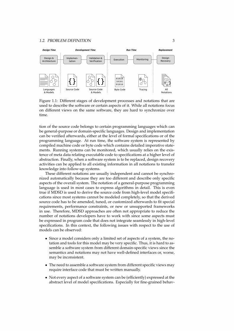
When software systems are developed, several stages are passed through, inwhich different notations are used to describe certain overlapping aspects ofthe software under development at different abstraction levels and with differ-ent purposes. This is especially true when formal models are used to specifythe software, since multiple abstraction levels are maintained in different no-tations in this case. The existence of different notations entails that importantinformation is not available in a consistent way; even worse, different piecesof information in different notations are hard to synchronize if the software isdeveloped and changed over longer periods of time. An overview of notationsto encounter during development is given in figure 1.1. They can roughly beclassified as follows:
At design time, the software architecture and its provided functionality isderived from the requirements and recorded in semi-formalized descriptionlanguages or formalized models. Based on this, source code is derived fromthe specifications during implementation, either with manual programmingor – in the case of some MDSD approaches – with code generation. The nota-
1.2. PROBLEM DEFINITION 3
{} {}01010
10101
01010
Languages
& Models
Source Code Source Code
& Models
Byte Code Tracing
@@ }10
All
Notations
Implemen-
tation
Validation &
VerificationExecution Monitoring
Development Time Run Time
Design &
Architecture
Design Time
Design
Recovery
Replacement
Figure 1.1: Different stages of development processes and notations that areused to describe the software or certain aspects of it. While all notations focuson different views on the same software, they are hard to synchronize overtime.
tion of the source code belongs to certain programming languages which canbe general-purpose or domain-specific languages. Design and implementationcan be verified afterwards, either at the level of formal specifications or of theprogramming language. At run time, the software system is represented bycompiled machine code or byte code which contains detailed imperative state-ments. Running systems can be monitored, which usually relies on the exis-tence of meta data relating executable code to specifications at a higher level ofabstraction. Finally, when a software system is to be replaced, design recoveryactivities can be applied to all existing information in all notations to transferknowledge into follow-up systems.
These different notations are usually independent and cannot be synchro-nized automatically because they are too different and describe only specificaspects of the overall system. The notation of a general-purpose programminglanguage is used in most cases to express algorithms in detail. This is eventrue if MDSD is used to derive the source code from high-level model specifi-cations since most systems cannot be modeled completely, so that the derivedsource code has to be amended, tuned, or customized afterwards to fit specialrequirements, performance constraints, or new or unsupported frameworksin use. Therefore, MDSD approaches are often not appropriate to reduce thenumber of notations developers have to work with since some aspects mustbe expressed in program code that does not integrate seamlessly in high-levelspecifications. In this context, the following issues with respect to the use ofmodels can be observed:
• Since a model considers only a limited set of aspects of a system, the no-tation and tools for this model may be very specific. Thus, it is hard to as-semble a software system from different domain-specific views since thesemantics and notations may not have well-defined interfaces or, worse,may be inconsistent.
• The need to assemble a software system fromdifferent specific viewsmayrequire interface code that must be written manually.
• Not every aspect of a software system can be (efficiently) expressed at theabstract level of model specifications. Especially for fine-grained behav-
4 CHAPTER 1. INTRODUCTION
ioral semantics, this leads to source code being written manually to fulfillrequirements.
• The integration of specific, innovative, or legacy components may requireprogram code that is not covered bymodeling technologies. The softwareunder development will in this case consist of different parts that aredeveloped at different levels of abstraction.
In this context, current MDSD approaches usually assume that source codecan be derived from abstract semantic model representations, either manuallyor in an automated way. The semantic gaps are by this means bridged onlyunidirectionally. This leads to additional problems:
• Considering the issues listed above, generated program code is often cus-tomized or amended. In general, the derived system will thus consist ofgenerated and manually-written program code at the same time.
• Changes or supplements to generated source code cannot easily betracked back into the model, which impedes a continuous integration.
• At run time, the software is represented by low-level imperative state-ments in compiled code and not by sophisticated models. This makes itdifficult to track errors with respect to model semantics.
• Because of different representations at development time and run time,it is also in many cases not possible to apply meaningful monitoring thatis related to the semantics of models.
In summary, the advantage of model-driven software development – toworkwith domain-specific views at different levels of abstraction – is accompa-nied by differences and possible inconsistencies regarding semantics and no-tations. Thus the abstraction levels are not bridged in an unambiguous andconsistent way. In the next section, we will outline the requirements of an ap-proach that aims at overcoming such difficulties.
1.3 Requirements and Objectives
The origin of the problems described above are inconsistencies that can occurbetween different representations and abstraction levels. Hence the objectiveof our approach to MDSD must be to avoid them. This leads to the followingrequirements:
• The approach should provide consistency between model specifications andsource code. The relation between model specifications and source codeshould thus be bidirectional so that it is not only possible to derive sourcecode from a model, but also to reconstruct model semantics unambi-giously from the source code.
• The approach should allow for integration of arbitrary source code, includ-ing interfaces to source code derived from other models as well as sourcecode that is not based on models at all.
1.4. THESIS CONTRIBUTION 5
• The approach should provide consistency between model specifications andexecuting program code. The program code must hence at run time reflectthe specifications derived from the model. This includes all structuresand algorithms that are concerned when the origin of errors or unex-pected behavior is to be found as well as error messages which must beinterpretable in the context of the model.
• Based upon this, the approach should also provide consistency betweenmodel specifications and monitoring. In addition to tracking of errors, thisaffects all structures and algorithms that may represent the model seman-tics implicitly or explicitly.
In summary, the objective of our approach must be to find a common rep-resentation (or a set of common representations) that are capable of expressingthe specifications of multiple classes of models as well as arbitrary fine-grainedalgorithms. We will now present the contribution of the thesis that aims to findsuch a common representation for different levels of abstraction.
1.4 Thesis Contribution
The inconsistencies described in section 1.2 exist due to different notations thatare used to describe software under development with different views at dif-ferent abstraction levels. Above we thus stated the goal to reduce the numberof notations present in many software development activities. However, it isnot desirable to reduce the number of views on the software since the variousabstraction levels fulfill different purposes, especially when model specifica-tions are used. Thus it is necessary to decouple notations and views by findingrepresentations that are capable to represent more than one abstraction level orspecific view on the software under development.
Considering the representations that are currently used during develop-ment, the source code is – despite all approaches to develop software at higherlevels of abstraction – still a vital part of the set of notations in use. Evenmore, program code of modern programming languages became more andmore expressive over time. In object-oriented programming languages, staticstructures exist that can be arranged according to (informal or formalized) pat-terns. Some of the languages support compiled, type-safe meta data that canbe added to object-oriented structures to give them certain semantics. Relatedapproaches, which are subsumed under the concept of attribute-enabled pro-gramming [Schwarz, 2004], interpret the meta data during development timeand run time with respect to certain frameworks, e.g. for the definition ofcomponents. The use at run time is possible in environments that providestructural reflection to access information about program code during execu-tion [Cazzola, 1998]. One can hence state that program code written in suchlanguages also contains information at different levels of abstraction. By thismeans, the programs aremore than just code since they reflect a certain amountof design information.
Based on this perception, the contribution of this thesis is to use ageneral-purpose programming language as a common representation formodel specifications as well as detailed algorithms. The idea of designpatterns [Gamma et al., 1995], which are specified informally, is extended for
6 CHAPTER 1. INTRODUCTION
this purpose: For abstract models of interest, a program code pattern will bedefined that arranges fragments of program code inside this language so thatthey represent the model specifications. This bottom-up approach embedsmodel specifications inside arbitrary program code, thus creating what wewill call an embedded model. The program code is hence comprehensible atdifferent levels of abstraction: Besides the semantics that are inherent to theprogramming language, subsets of the program code can be interpretedregarding their embedded model specifications. By this means a tightcoupling between specifications and implementation is given. This allows towork with embedded models for the following purposes:
• The program code including its meta programming attributes is the mainnotation for different abstraction levels. It can represent model specifi-cations as well as program code that is written manually. The programcode patterns that form the embeddedmodel syntax can define interfacesto arbitrary program code outside the model. A software system is hencenot assembled from different views. Instead, these specialized views canbe extracted from the code on demand.
• For each embedded model, a lean execution framework is created thataccesses the embeddedmodel fragments bymeans of structural reflectionsince they are available at run time. Based on this, it invokes fragmentsof program code to create a sequence of actions matching the executionsemantics of the model.
• Monitoring and debugging of applications with respect to their embed-ded models is thus possible by considering the program code patternwhile it is executed.
The approach therefore fulfills the requirements defined in section 1.3. Itaims to be applicable in cases when software is developed in terms of pro-gram code (and not only with notations representing abstract models), so thatthe code is a notation that is considered explicitly during development. Otheruse cases for the utilization of MDSD techniques are not covered by this ap-proach, for example business process platforms that allow for re-configurationat run time or rule-based deployments of customized software products. Wewill now justify that for the given focus no prior research exists that fulfills therequirements.
1.5 Thesis Justification
The development of complex systems is based on a hierarchical understand-ing. This applies to software systems, too. The principle of hierarchic compre-hension is for example described by Herbert A. Simon’s theory of Near Decom-posability [Simon, 1996]: A nearly decomposable system is constituted by clearhierarchy of single parts, which interact with well-defined interfaces.
Such clear hierarchies are not present during software development whenwe consider the issues defined in section 1.2: In MDSD, the transformations areusually unidirectional. At development time, information from a model nota-tion is transformed into source code [Brown et al., 2006]. The translation of
1.6. STRUCTURE OF THE CONCEPTUAL THESIS PART 7
abstract representations into low-level representations entails that different hi-erarchies are in use. When one modeling language is used and the source codeis generated from it, the number of hierarchies in use is 2. When more mod-eling languages are used, for example domain-specific languages which havedifferent semantics, the number of hierarchies is even higher. When sourcecode is developed manually – to adapt generated code or to supplement it– the hierarchies will intersect partly. Since changes are possible in all hierar-chies in parallel during development, a permanent synchronization is not com-pletely possible, since the semantics can be inconsistent [Hailpern and Tarr,2006; Demeyer et al., 1999]. When only semantics of lower abstraction levels,i.e. the program code, are considered, additional information can be gained,but only related to low-level specifications [Nierstrasz et al., 2007], so that in-consistencies between the hierarchies cannot be overcome. Models can alsobe transformed into executable systems at run time when model notations areinterpreted [Luz and da Silva, 2004]. However, they must in this case be in-tegrated into larger systems, which are specified in a different way, since thefact that low-level access to the hardware and software environment is oftennecessary contradicts the fact that models are intended to abstract from thosedetails.
In embedded models, the program code is considered for model transfor-mations and refinement in the same way as any other model notation. By thismeans only one hierarchy regarding notations exists: Parts of the program codecan contain information at higher levels of abstraction, but are connected toprogram code with implementation details at the same time. The programcode is thus structured hierarchically when some of its fragments are empha-sized and have a semantics of their own, but also well-defined interfaces to theother program code.
However, the embedded models approach is not applicable to every soft-ware development task, but only to those where different abstraction levels areconsidered. It does not apply to cases where software is configured or assem-bled only with descriptive languages, for example business process models inservice-oriented architectures (SOAs) [Brahe, 2007]. In such situations the in-ternal structure of a program is not of interest, but only its descriptive serviceinterfaces, so that only one abstraction level is concerned. However, situationslike these are rare since they require limited domains of applications and a con-trolled infrastructure. The implementation tasks will most likely consider pro-gram code that is engineered in detail, so that embeddedmodels are of interest.In summary, when different abstraction levels are concerned, the approach sat-isfies the requirements named above and provides a relevant contribution forthe field of model-driven software development.
1.6 Structure of the Conceptual Thesis Part
The problem description in section 1.2 referred to several notations in use dur-ing development. As outlined in section 1.4, these notations are to be replacedby views, which are extracted from the program code on demand. This leadsto two perspectives the conceptual part of this thesis will take:
The vertical perspective considers maintaining multiple abstraction layers inprogram code. Since the goal is to reduce the number of notations and use the
8 CHAPTER 1. INTRODUCTION
Interfaces
Model Specifications
Program Code Pattern
Execution Semantics
Development Time Run TimeDesign Time
Design
Views
Verification
Views
Monitoring
Views
Replacement
Design
Views
Implementation
Views
Execution
Views
Transformations
Figure 1.2: The structure of the conceptual thesis part.
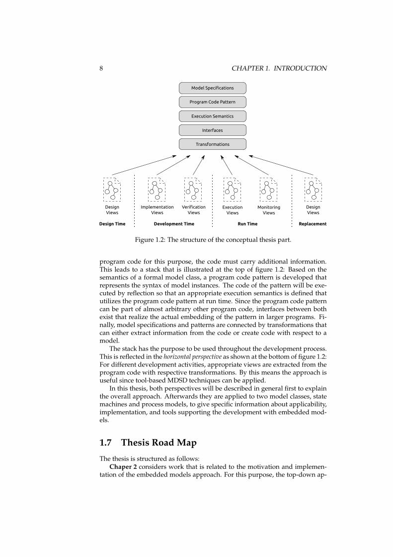
program code for this purpose, the code must carry additional information.This leads to a stack that is illustrated at the top of figure 1.2: Based on thesemantics of a formal model class, a program code pattern is developed thatrepresents the syntax of model instances. The code of the pattern will be exe-cuted by reflection so that an appropriate execution semantics is defined thatutilizes the program code pattern at run time. Since the program code patterncan be part of almost arbitrary other program code, interfaces between bothexist that realize the actual embedding of the pattern in larger programs. Fi-nally, model specifications and patterns are connected by transformations thatcan either extract information from the code or create code with respect to amodel.
The stack has the purpose to be used throughout the development process.This is reflected in the horizontal perspective as shown at the bottom of figure 1.2:For different development activities, appropriate views are extracted from theprogram code with respective transformations. By this means the approach isuseful since tool-based MDSD techniques can be applied.
In this thesis, both perspectives will be described in general first to explainthe overall approach. Afterwards they are applied to two model classes, statemachines and process models, to give specific information about applicability,implementation, and tools supporting the development with embedded mod-els.
1.7 Thesis Road Map
The thesis is structured as follows:Chaper 2 considers work that is related to the motivation and implemen-
tation of the embedded models approach. For this purpose, the top-down ap-
1.7. THESIS ROADMAP 9
proaches to MDSD with their concepts, problems, and possible solutions willbe described. Afterwards, a review of approaches to make program code inter-pretable at different abstraction levels is given. The chapter concludes with thedefinition of a gap in existing approaches that embedded models aim to fill.
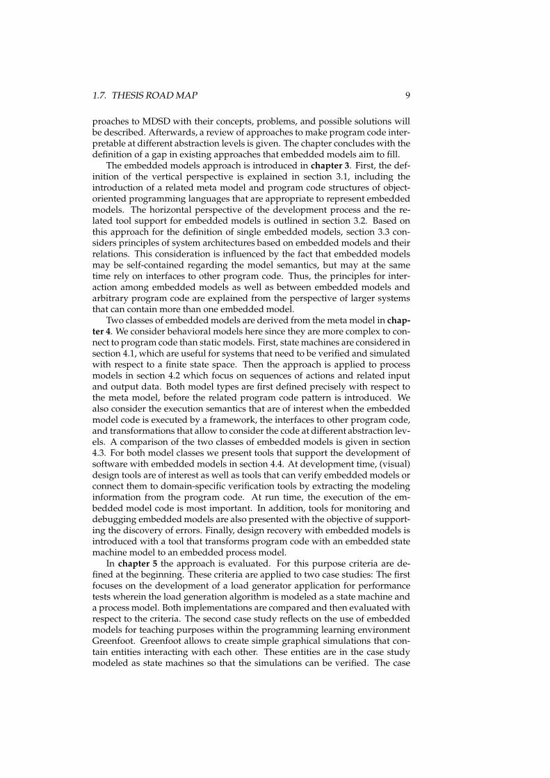
The embedded models approach is introduced in chapter 3. First, the def-inition of the vertical perspective is explained in section 3.1, including theintroduction of a related meta model and program code structures of object-oriented programming languages that are appropriate to represent embeddedmodels. The horizontal perspective of the development process and the re-lated tool support for embedded models is outlined in section 3.2. Based onthis approach for the definition of single embedded models, section 3.3 con-siders principles of system architectures based on embedded models and theirrelations. This consideration is influenced by the fact that embedded modelsmay be self-contained regarding the model semantics, but may at the sametime rely on interfaces to other program code. Thus, the principles for inter-action among embedded models as well as between embedded models andarbitrary program code are explained from the perspective of larger systemsthat can contain more than one embedded model.
Two classes of embeddedmodels are derived from the meta model in chap-ter 4. We consider behavioral models here since they are more complex to con-nect to program code than static models. First, statemachines are considered insection 4.1, which are useful for systems that need to be verified and simulatedwith respect to a finite state space. Then the approach is applied to processmodels in section 4.2 which focus on sequences of actions and related inputand output data. Both model types are first defined precisely with respect tothe meta model, before the related program code pattern is introduced. Wealso consider the execution semantics that are of interest when the embeddedmodel code is executed by a framework, the interfaces to other program code,and transformations that allow to consider the code at different abstraction lev-els. A comparison of the two classes of embedded models is given in section4.3. For both model classes we present tools that support the development ofsoftware with embedded models in section 4.4. At development time, (visual)design tools are of interest as well as tools that can verify embedded models orconnect them to domain-specific verification tools by extracting the modelinginformation from the program code. At run time, the execution of the em-bedded model code is most important. In addition, tools for monitoring anddebugging embeddedmodels are also presented with the objective of support-ing the discovery of errors. Finally, design recovery with embedded models isintroduced with a tool that transforms program code with an embedded statemachine model to an embedded process model.
In chapter 5 the approach is evaluated. For this purpose criteria are de-fined at the beginning. These criteria are applied to two case studies: The firstfocuses on the development of a load generator application for performancetests wherein the load generation algorithm is modeled as a state machine anda process model. Both implementations are compared and then evaluated withrespect to the criteria. The second case study reflects on the use of embeddedmodels for teaching purposes within the programming learning environmentGreenfoot. Greenfoot allows to create simple graphical simulations that con-tain entities interacting with each other. These entities are in the case studymodeled as state machines so that the simulations can be verified. The case

10 CHAPTER 1. INTRODUCTION
study comprises a small user study performed with students in a master’scourse.
Chapter 6 considers the impact that embedded models can have on differ-ent aspects of software development and outlines areas of future work at thesame time. The topics to be discussed are directions for additional evaluationbased on program comprehension concepts, additional modeling domains, in-teraction of embedded models and meta models, and the question how mod-eling and implementation languages can be combined.
Finally, chapter 7 summarizes the problem domain and the approach of thethesis. The novel contributions are emphasized and the applicability of theapproach is considered.
The next section will now introduce related work that is important in thecontext of a bottom-up approach to MDSD.
Chapter 2
Related Work
The problemsmentioned in section 1.2 are subject to various research activities,and different classes of related approaches exist. A brief overview of them willbe given in this chapter. For this purpose we roughly classify these approachesinto two groups:
First, top-down approaches focus on models and theircomputation-independent semantics. Their purpose is to define applicationlogic without consideration of actual platforms and implementation details,thus decoupling the core functionality from underlying technical systems. Inthese approaches, executable systems are derived from the abstract modelsand at most amended with manually-written source code. The semantics offormal models are thus considered at a high level of abstraction only. Theseapproaches will be considered in this chapter in section 2.1.
Second, code-oriented approaches center on source code that is not derivedfrom other representations, but instead constructed during software develop-ment. These approaches focus on the fact that program code does often notonly express algorithms in detail, but is at the same time related to abstractconcepts also. In section 2.2 we thus describe approaches that try to relatesource code to model specifications. This includes a consideration of designpatterns and approaches to relate them to abstract specifications.
The consideration of all this related work leads to the question whethercompeting approaches exist. To determine this, the following criteria were de-rived from the objectives given in section 1.3:
• Focus on formal high-level models: We are interested in formal models thatare developed to serve a certain purpose at a higher level of abstraction(e.g. statemachines or processmodels). This excludes, for example, mod-els for verifying low-level algorithms.
• Consistency between model specifications and static program code structures:Static program code structures defining the pattern must represent thesyntax of the model. The code must therefore be interpretable at designtime.
• Integration in arbitrary program code: The models must be seamlessly inte-grated in applications that are not based on the same modeling class or
11
12 CHAPTER 2. RELATEDWORK
anymodel at all, and therefore be appropriate to interact with applicationlogic that is not part of the models.
• Consistency between model specifications and executed program code: The pro-gram code must at run time reflect the semantics of the model. Executionsemantics will be defined that allow for execution by a framework thatinterprets the model syntax at run time. This consistency must also allowfor monitoring and debugging.
During the more than three years of research for this thesis, no approachesfulfilling all these requirements were found. We will now explain the existingwork that is related to the thesis and its differences to our concept. The chap-ter summary will provide a classification of the existing approaches and theembedded models approach.
2.1 Top-down MDSD Approaches
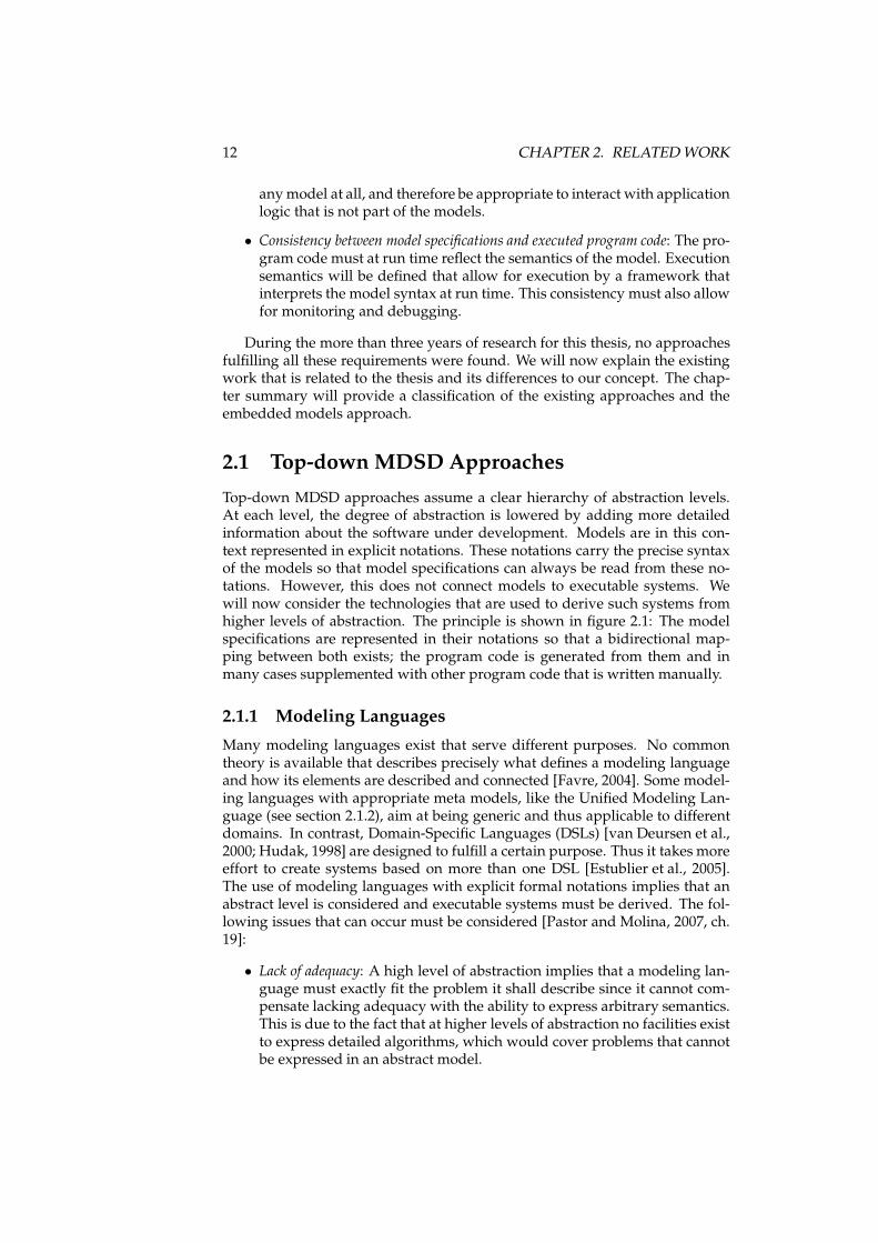
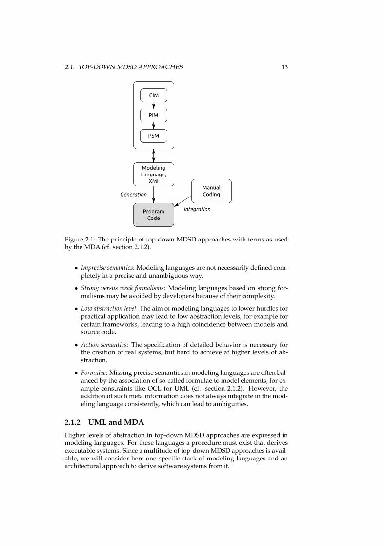
Top-down MDSD approaches assume a clear hierarchy of abstraction levels.At each level, the degree of abstraction is lowered by adding more detailedinformation about the software under development. Models are in this con-text represented in explicit notations. These notations carry the precise syntaxof the models so that model specifications can always be read from these no-tations. However, this does not connect models to executable systems. Wewill now consider the technologies that are used to derive such systems fromhigher levels of abstraction. The principle is shown in figure 2.1: The modelspecifications are represented in their notations so that a bidirectional map-ping between both exists; the program code is generated from them and inmany cases supplemented with other program code that is written manually.
2.1.1 Modeling Languages
Many modeling languages exist that serve different purposes. No commontheory is available that describes precisely what defines a modeling languageand how its elements are described and connected [Favre, 2004]. Some model-ing languages with appropriate meta models, like the Unified Modeling Lan-guage (see section 2.1.2), aim at being generic and thus applicable to differentdomains. In contrast, Domain-Specific Languages (DSLs) [van Deursen et al.,2000; Hudak, 1998] are designed to fulfill a certain purpose. Thus it takes moreeffort to create systems based on more than one DSL [Estublier et al., 2005].The use of modeling languages with explicit formal notations implies that anabstract level is considered and executable systems must be derived. The fol-lowing issues that can occur must be considered [Pastor and Molina, 2007, ch.19]:
• Lack of adequacy: A high level of abstraction implies that a modeling lan-guage must exactly fit the problem it shall describe since it cannot com-pensate lacking adequacy with the ability to express arbitrary semantics.This is due to the fact that at higher levels of abstraction no facilities existto express detailed algorithms, which would cover problems that cannotbe expressed in an abstract model.
2.1. TOP-DOWN MDSD APPROACHES 13
Modeling
Language,
XMI
Program
Code
Generation
Manual
Coding
Integration
CIM
PIM
PSM
Figure 2.1: The principle of top-down MDSD approaches with terms as usedby the MDA (cf. section 2.1.2).
• Imprecise semantics: Modeling languages are not necessarily defined com-pletely in a precise and unambiguous way.
• Strong versus weak formalisms: Modeling languages based on strong for-malisms may be avoided by developers because of their complexity.
• Low abstraction level: The aim of modeling languages to lower hurdles forpractical application may lead to low abstraction levels, for example forcertain frameworks, leading to a high coincidence between models andsource code.
• Action semantics: The specification of detailed behavior is necessary forthe creation of real systems, but hard to achieve at higher levels of ab-straction.
• Formulae: Missing precise semantics in modeling languages are often bal-anced by the association of so-called formulae to model elements, for ex-ample constraints like OCL for UML (cf. section 2.1.2). However, theaddition of such meta information does not always integrate in the mod-eling language consistently, which can lead to ambiguities.
2.1.2 UML and MDA
Higher levels of abstraction in top-down MDSD approaches are expressed inmodeling languages. For these languages a procedure must exist that derivesexecutable systems. Since a multitude of top-downMDSD approaches is avail-able, we will consider here one specific stack of modeling languages and anarchitectural approach to derive software systems from it.
14 CHAPTER 2. RELATEDWORK
The most widespread modeling language is currently the UnifiedModeling Language (UML) [OMG, 2010] which is standardized by the ObjectManagement Group (OMG). The UML consists of certain so-called diagrams[Fowler, 2003b] which describe certain functional aspects of a system, forexample packages, processes, or state charts [Crane and Dingel, 2005]. Thesediagrams are derived from a meta model, the Meta Object Facility (MOF)[OMG, 2006; Atkinson and Kühne, 2003]. The meta model is also related to anXML-based interchange format, XML Metadata Interchange (XMI) [OMG,2007]. XMI is thus a notation for different UML and other MOF-based models.
The best-known UML diagrams are class diagrams which model object-oriented properties of software under development including attributes, oper-ations, and relations. Since these diagrams can be mapped to code structuresdirectly, they are easy to use and thus widely accepted. Modeling a completeprogram, however, includesmodeling of its behavior, which is more difficult toexpress in diagrams. Thus UML offers two ways to specify behavior [Frankel,2003, ch. 3]:
• Design by Contract principles define contracts for operations. The ObjectConstraint Language (OCL) [Beckert et al., 2007] allows to define con-straints where they are appropriate in UML diagrams. This includesamong others invariants and pre- and postconditions for operations. It istherefore appropriate to define interfaces and thus to describe the behav-ioral aspects, but not to specify them.
• Behavioral models describe the behavior of programs at a higher level ofabstraction, e.g. with sequence diagrams, activity diagrams, or statecharts. Because of the higher level of abstraction, the specification of thebehavior in this diagrams does not cover all details, but in many casesonly a simplified view on the software system that must be amendedwith detailed algorithms to be executable.
While the static diagrams like class or use case diagrams are easy to use,these concepts for behavioral specifications are harder to grasp and to apply,so their usage varies [Dobing and Parsons, 2006; Agarwal and Sinha, 2003].Furthermore, UML diagrams are not completely formally founded and thusnot in every case appropriate for precise modeling. Therefore, approachesexist that connect UML diagrams to formal modeling techniques like Petrinets [Saldhana and Shatz, 2000; Bernardi et al., 2002; Fernandes et al., 2007] oraim at supplementing the diagrams with formal semantics, for example forstate charts [Jürjens, 2002; Gogolla and Presicce, 1998; Varró, 2002; Evans,1998; McUmber and Cheng, 2001].
Since these techniques are not appropriate to model a complete system,behavioral languages are connected to UML that can help to express moredetailed aspects of software under development. To connect different UMLfragments, a language is needed that executes actions which are defined inUMLmodels. For this reason, Action Semantics [OMG, 2001; Sunyé et al., 2002;Raistrick et al., 2004] are required that allow to specify the behavior of such ac-tions in detail. UML therefore defines the function set that Action SemanticLanguages (ASL) are expected to provide. However, the languages itself arenot specified, so that different ASLs exist that are specific to tools they are used
2.1. TOP-DOWN MDSD APPROACHES 15
in. With their ability to define almost arbitrary actions, ASLs resemble general-purpose programming languages to a certain degree.
The Model-Driven Architecture (MDA) [Bézivin and Gerbé, 2001;Mukerji and Miller, 2003; Frankel, 2003] is an approach using UML andthe related specifications to create software by following the principle ofseparating functional and technical aspects. MDA proposes three levels ofabstraction: The computation independent model (CIM) defines the merefunctionality as domain or business models. It may consist of one or moremodels derived from the MOF. The platform independent model (PIM) isbuilt afterwards by incorporating information about the software architectureof the system to develop. Finally, one or more platform specific models(PSM) are used to define actual implementations for concrete platforms[Wagelaar and Jonckers, 2005]. Thus, the degree of detail is increased at eachlevel. The objectives of the MDA are to make development faster andmore efficient by facilitating reuse and also to protect investments againstchanges in underlying platforms. While the MDA relies on the fact thatsome platform-dependent program code has to be written manually, theobjectives should be accomplished by finding an appropriate balance betweenthe amount of functionality that is modeled and the amount that is writtenmanually.
For this thesis it is of interest that modeling of such systems comprises sev-eral different languages, including general-purpose programming languagesfor platform-specific tasks. For this reason the objective of platform indepen-dence is questionable: While the models are indeed independent from actualplatforms like server environments, they depend on several specifications ofthe UML, modeling languages expressing the specifications, and also on spe-cific tools [Fowler, 2003a]. The latter are necessary to create andmaintain mod-els as well as transformations and to derive executable systems from them. Inaddition, the MDA does not provide sufficient support for connections to arbi-trary application logic since manually-written program code is only consideredat lower levels of abstraction.
In contrast, the approach of this thesis facilitates the use of only one nota-tion that is appropriate to maintain different levels of abstractions and differentdomain-specific views on the software to develop. As will be seen, the objec-tive of the MDA to be more efficient is supported by embedded models withthe provision of several views on the program which enable efficient and tool-supported development of domain-specific aspects within the program code.The MDA’s objective of being platform independent is naturally in contrast tothe use of a certain programming language. However, since the model syntaxis completely available in an embedded model, the specifications can alwaysbe extracted and employed for several purposes, including transformation intoa modeling language or into embedded models in other programming lan-guages.
2.1.3 Code Generation
When models are defined at higher levels of abstraction, it is necessary to de-rive executable programs from them. These programs are not only required tofollow themodel semantics in the first place, butmust also consider actual plat-forms, for example operating systems, programming languages, frameworks,
16 CHAPTER 2. RELATEDWORK
or server software. Top-down MDSD approaches acknowledge that general-purpose programming languages are appropriate to express all needed seman-tics and integrate them in actual platforms. The preferred way to propagatehigh-level representations into executable programs is therefore to generatesuch source code [Brown et al., 2006]. This implies that at different levels ofabstraction, different kinds of semantics exist: Besides the abstract model se-mantics, code generation also introduces execution semantics that depend onthe generation strategy, programming language, and also platforms to be used.The differences can for example be seen for the approach of generating Javasource code fromUML state charts [Niaz and Tanaka, 2003]: While parts of thestate chart are represented as static structures in the program code and thusidentifiable as part of the model, the generated code also contains fine-grainedbehavioral logic that cannot be related to the model fragments.
Generated code can be complete in cases where the environment is limited[Lindlar and Zimmermann, 2008]. However, since (meaningful) models mustabstract from all details, the generated source code is likely not to be completewhen it must be connected to complex environments or other parts of larger ap-plications. Besides model-based enrichment at the PIM and PSM layers, it is of-ten necessary to amend the generated source codemanually. Such changes leadto the situation that generated source code has no completely formal referenceto the higher-level model semantics. Models are in many cases related to de-veloped systems only by the developer’s knowledge [Tichy and Giese, 2003].This prevents at first an automatic back tracking of changes [Hailpern and Tarr,2006; Baker et al., 2005]. Even worse, when generated source code is amendedor tuned after generation, a regeneration of parts of it after changes on themodel levels defies a gradual integration [Vokác and Glattetre, 2005] and in-cremental development.
This problem is considered by several approaches, for example the Gener-ation Gap Pattern [Vlissides, 1996]. In the motivation it is stated that “havinga computer generate code for you is usually preferable to writing it yourself,provided the code it generates is correct, efficient enough, functionally com-plete, and maintainable.” Because of this, the pattern proposes to differentiatebetween generated and non-generated source code by using sub classes: “Itencapsulates generated code in a class and then splits that class into two, oneclass for encapsulating generated code and another for encapsulating modi-fications.“ The approach has a limited applicability as some conditions mustbe met, especially that “generated code can be encapsulated in one or moreclasses“ and “regenerated code [. . . ] retains the interface and instance vari-ables of the previous generation”.
The OO-Method approach [Pastor and Molina, 2007] distinguishesbetween model-driven and model-based code generation and classifiesitself as the latter. The basic idea is that the code is generated out ofso-called Conceptual Schemas [Olivé, 2005] and therefore the properties ofobject-oriented artifacts as well as formal methods based on them can beconsidered. However, generation of executable source code is still necessary.MetaBorg [Bravenboer et al., 2006; Riehl, 2006] aims at “embedding” DSLsinto general-purpose programming languages, however, this means that codein the general-purpose programming language is generated from DSLs andinserted at the right place in other program code.
In summary, code generation is a way to derive executable programs from
2.1. TOP-DOWN MDSD APPROACHES 17
higher-level representations. However, the different explicit notations used atthe different abstraction levels lead to inconsistencies since they are based ondifferent semantics. While differences between the notations can be bridgedunidirectionally from the technical perspective and as long as several restric-tions as mentioned above are accepted, an automated mapping between thedifferent semantics is currently not feasible. Considering the criteria definedabove, code generation can therefore not accomplish the objectives of this the-sis: A consistency between model specifications and program code is givenneither at development time nor at run time. It is also difficult to integrategenerated and non-generated program code systematically.
2.1.4 Management of Inconsistencies
Since such a mapping between different semantics is not directly available,approaches exist that aim at reconstructing model semantics from generatedprogram code and thereforemake a round-trip engineering with code synchro-nisation possible [Sendall and Küster, 2004]. However, these approaches stillrequire manual effort and are thus error-prone since the required informationis not available at all abstraction levels, so that they aremostly based on heuris-tics [Hailpern and Tarr, 2006; Demeyer et al., 1999]. A precise and automatedround-trip engineering is only possible for models at the level of the seman-tics of the programming language like class diagrams or behavioral modelsdescribing the control flow in detail, like realized by FUJABA [Nickel et al.,2000]. The approach of mapping UML models to code structures by meansof metadata inside the source code [Wada and Suzuki, 2005] eases the identi-fication of code fragments that are subject to round-trip engineering, but stillcannot avoid or fully automate it.
Similarly, reverse engineering approaches utilize patterns and models torecover design information from existing software systems. In the case of FU-JABA, design patterns are detected by means of static analysis of source code,and behavioral models are inferred from run time traces [Wendehals et al.,2004], e.g. based on automata [Wendehals and Orso, 2006]. This is imple-mented by the tool Reclipse [von Detten et al., 2010]. However, neither infor-mal design patterns nor low-level models are of interest in the context of thisthesis. Instead, embedded models focus on an unambiguous connection be-tween program code and abstract models in order to eliminate the need forreverse engineering.
Several approaches exist that aim at managing the inconsistencies that oc-cur throughout the development process [Nuseibeh, 1996] or resolve them, forexample by means of graph transformations between different so-called View-Points [Goedicke et al., 1999]. Both considerations assume that different no-tations are necessary and are thus only partly related to the approach of thisthesis: If different notations including program code are used to specify de-sign and implementation information at different abstraction levels, embeddedmodels are applicable so that the number of notations can be reduced and thedifferent abstraction levels are only views on one notation. In the case that dif-ferent notations are necessary nonetheless, for example if different stakehold-ers use different tools during development, management of inconsistencies isstill necessary and applies to the program code patterns of embedded models,too.
18 CHAPTER 2. RELATEDWORK
CIM
PIM
PSM
Modeling
Language,
XMI
Interface
Code
interprets
Arbitrary
Program
Codeuses
Execution
Framework
communicates
Figure 2.2: The principle of interpretational MDSD approaches.
In summary, the aim of model round-trip engineering and inconsistencymanagement is to bridge the gaps between different abstraction levels by en-abling transformations that will work regardless where changes were made.However, as long as ambiguities cannot be precluded, the related concepts arenot appropriate to accomplish the objectives introduced in section 1.3.
2.1.5 Model Execution
Away to avoid the generation of source code is to execute model specificationsdirectly, as for example done by Executable UML (xUML) [Luz and da Silva,2004; Mellor and Balcer, 2002]. As usual for UML, the fundamental UML staticclass diagrams are used in the first place [Starr, 2001]. However, in order tocreate executable systems, xUML also employs several specifications related toUML,mainly diagrams, but also languages to express behavior and constraints[Raistrick et al., 2004] (see also section 2.1.2).
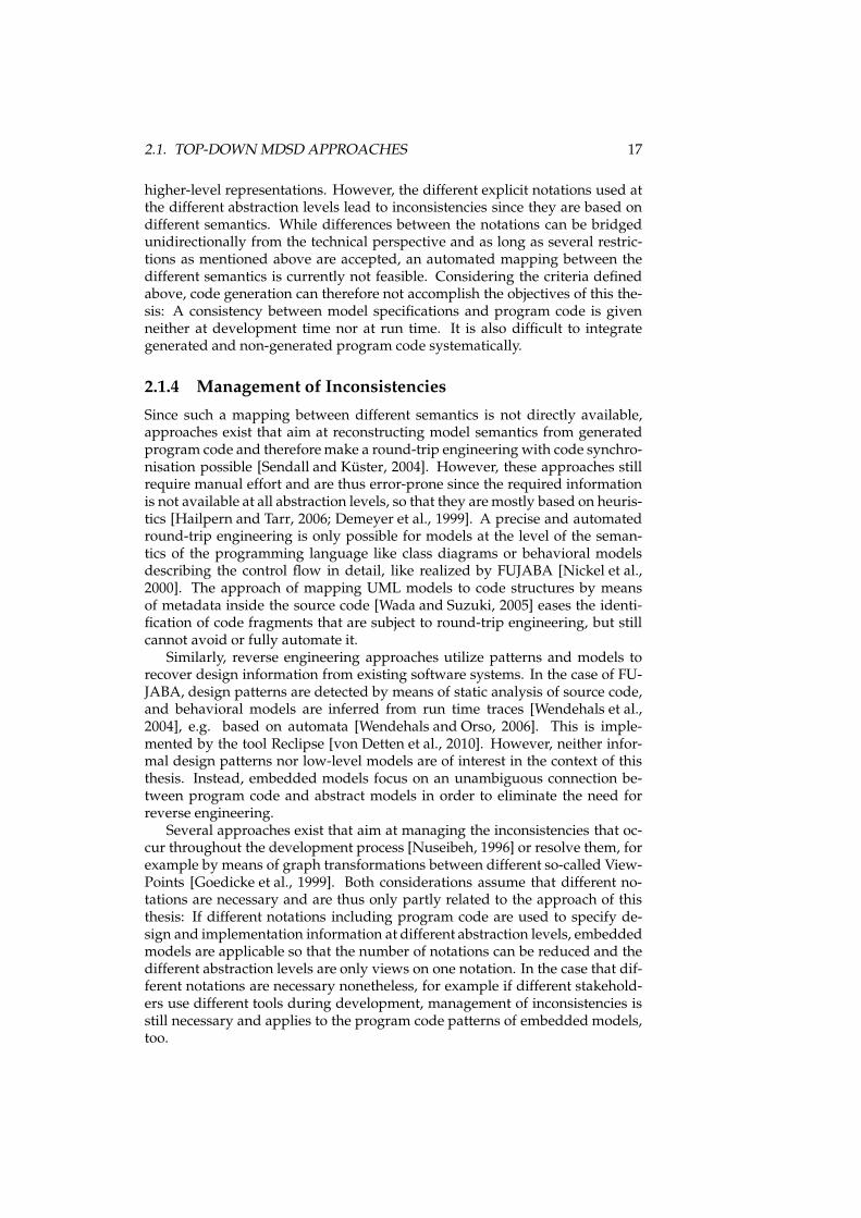
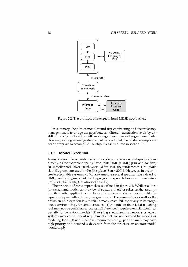
The principle of these approaches is outlined in figure 2.2. While it allowsfor a clean and model-centric view of systems, it either relies on the assump-tion that entire applications can be expressed as a model or must provide in-tegration layers with arbitrary program code. The assumption as well as theprovision of integration layers will in many cases fail, especially in heteroge-neous environments, for certain reasons: (1) A model or the related modelingtool may not be sufficient to express all functional requirements in detail, es-pecially for behavioral models; (2) existing specialized frameworks or legacysystems may cause special requirements that are not covered by models ormodeling tools; (3) non-functional requirements, e.g. performance, may havehigh priority and demand a deviation from the structure an abstract modelwould imply.
2.2. SOURCE CODE SEMANTICS AND DESIGN PATTERNS 19
The Executable OCL (xOCL) approach [Jiang et al., 2007, 2008] acknowl-edges that “UML is not defined precisely enough for unambiguous model ex-ecution. Therefore, the first and most important requirement for model execu-tion is precisely modeling the actions.” [Jiang et al., 2007] The approach triesto combine ASLs and OCL to reach a higher expressiveness. Similar to this iseXecutable OCL [XOCL, 2008]. While the scope of the executed models is bythis means enhanced, the problems of executable models as stated above arenot solved.
The UniMod tool [Gurov et al., 2005] connects executable UML to programcode by defining a state machine model that executes Java code in every transi-tion. While this allows to structure the program code and model the behaviorof an application at different levels of abstraction, it requires at the same timedifferent notations with possible inconsistencies. A verification and simulationof the model is also difficult because modifications of the system state in thearbitrary program code are not considered part of the model. The ModelTalkframework [Hen-Tov et al., 2008] executing domain-specific models alongsideJava program code relies on different notations, too, as the models are specifiedin XML-based languages. At run time they are instantiated by the frameworkand their representations in Java objects are injected into other objects using theframework. Despite the integration in Java, the development of applicationsusing this approach still requires different languages with different semanticsand notations. The approach of Kermeta to weave executability into meta-modeling languages [Muller et al., 2005] embraces explicit modeling notationsfor the meta models, for example OCL for constraints.
Several similar approaches exist. However, they do not satisfactorily an-swer the question how to deal with different notations. This means that allgeneral-purpose executable model languages either imply that all details ofprograms must be modeled cumbersome in detail or that interfaces to arbi-trary program code must be defined which are not seamlessly integrated in themodeling languages. They do therefore not fulfill the criterion of seamless in-tegration in other program code, and are in many use cases not applicable ingeneral since not every implementation detail can be efficiently expressed inabstract models.
2.2 Source Code Semantics and Design Patterns
So far we considered top-down approaches that focus on modeling languagesand derive implementations (or at least parts of implementations) from them.Since embedded models are not only closely related to models, but also to pro-gram code, we will now also look at approaches that interpret program codewith respect to the semantics it contains. Depending on the approach, thesesemantics can be considered at higher levels of abstraction, be formalized, andalso be related to models.
2.2.1 Abstract Specifications in Program Code
Several concepts exist that enrich program code with specification informationthat is interpretable at different abstraction levels.
20 CHAPTER 2. RELATEDWORK
This thesis considers object-oriented programming languages that addadditional abstraction layers to plain algorithms by defining the semanticsof objects and their relations [Craig, 2001]. Thus, they are interpretable atmultiple levels [Pastor and Molina, 2007]: Classes “appear in the statementof the problem in a more or less natural way”. The meaning of theirrelationships depends on the “preciseness of the associated semantics”: “classrelationships have more semantics than those proposed by most methods, andthe conceptual schema will be precise only if these relationships are clearlydefined.” [Pastor and Molina, 2007] Thus, object-oriented languages must besupplemented with formal specifications if their expressiveness should beincreased.
For this purpose, formal specification languages and architecturalpatterns are appropriate. This is for example done in the approach ofSpecification-Carrying Code [Serugendo and Deriaz, 2005]. The semantics ofmethods are described as formal specifications, for example in Prolog [Kim,1991], and stored in an appropriate XML-based notation. Implementingclasses register themselves in a framework that provides services according tospecification files. Clients can lookup service implementations by giving thespecification file and make according method calls. While this enhances theformal description of object-oriented programs, the implementation is stillindependent from the formal specification, since notation and semanticsof specification and implementation language are different. Thus, thecorrectness of an implementation can hardly be determined automatically.Similar, Software Reflexion Models [Murphy et al., 2001] connect programcode fragments to high-level models, but do not facilitate a single-sourcestrategy. Proof-Carrying Code [Necula, 2002] supplies program code that is tobe executed in a specific environment with meta data proving that the code isworking as intended and proposes verification mechanisms, too. However,this also relies on external notations and is not related to higher-level formalmodels, but to specification details instead.
Framework Specific Modeling Languages [Antkiewicz and Czarnecki,2006] are similar to DSLs, but consider source code fragments that are relatedto certain domain-specific frameworks. Thus, the program code elements areclearly identifiable so that references to model elements can be extractedfrom the program code [Antkiewicz et al., 2007]. This makes a continuousround-trip engineering possible [Antkiewicz, 2007]. While it allows tomaintain different abstraction levels in the program code, the objectives aredifferent to our approach: Framework-specific models aim at increasing thequality of program code that is based on existing frameworks like JavaApplets, Struts applications, or Eclipse plugins [Antkiewicz et al., 2009]. Thus,they consider only the semantics of frameworks and not that of formalmodels.
Introspective Model-Driven Development (IMDD) [Büchner and Matthes,2006] has similar objectives as the Embedded Models approach proposed inthis thesis: “[An] advantage of IMDD is the possibility to achieve symbolicintegration between declarative models and imperative artifacts. This makesit easy to mix both programming styles, and get the benefits of modeling thedeclarative aspects on a high level of abstraction.” This single-source approachalso avoids the need to work with different explicit notations to derive exe-cutable systems. But, the references to model elements are generic and not

2.2. SOURCE CODE SEMANTICS AND DESIGN PATTERNS 21for (Tuple2 tuple2:squill.from( , . ustomer).where(gt( . ustomer.isA tive, 0),notNull( .per entSolved),notNull( .refoundSum)).orderBy(des ( . ustomer.id)).sele tList( . ustomer.lastName, .per entSolved)) {System.out.println("Customer " + tuple2.v1 + " has a omplaint solved " + tuple2.v2 + "%");}Listing 2.1: An embedded DSL example for the Squill framework [Squill].
related to specific properties of formal models, thus leading to another focalpoint than embedded models.
Similar to this, Internal DSLs “are particular ways of using a host languageto give the host language the feel of a particular language.” [Fowler, 2006a]This means that the semantics of a DSL are available inside program code writ-ten in general-purpose programming languages and at the same time that therelated program code is interpretable with respect to the DSL [Fowler, 2006b;Bravenboer and Visser, 2004; Cuadrado and Molina, 2009; Hofer et al., 2008].An example for this is the Squill framework [Squill] which arranges methodcalls inside Java so that they resemble SQL statements (see listing 2.1). An-other example is LIQUidFORM [LIQUidFORM] which uses similar patterns toallow building queries for the Java Persistence API [Sun Microsystems, Inc., b].While internal DSLs make source code interpretable with respect to the under-lying domain concepts, their usage is limited to simple DSLs whose semanticscan be represented in chains of statements [Freeman and Pryce, 2006], whichprecludes consideration of more sophisticated models. In addition, they areonly partly represented by static structures that are accessible by reflection atrun time. The concept of internal DSLs has therefore similar purposes, but doesnot accomplish all objectives of embedded models.
Design patterns [Gamma et al., 1995] propose unified program code struc-tures for repetitive tasks. They establish relations between program code andmental models the code is based on [Storey, 2005; Schauer and Keller, 1998],but have limitations: Design patterns were originally intended to be easilyadaptable for special situations and thus are not formalized. Approaches todescribe intentions of patterns explicitly [Meffert, 2006] are informal and there-fore not of interest with respect to our objectives. Approaches to formalize de-sign patterns [Soundarajan and Hallstrom, 2004;Mikkonen, 1998; Meijler et al.,1997; Eden et al., 1997a,b] aim at specifying the relation between the patternand the related program code more precisely. This often involves the defini-tion of a Pattern Description Language (PDL) [Albin-Amiot et al., 2001] or aPattern Specification Language (PSL) [Taibi and Ngo, 2003], respectively. SuchPSLs can even be used for code generation [Taibi and Mkadmi, 2006]. Thepatterns themselves can also be specified more precisely by using a model-ing language like the UML [Guennec et al., 2000; Mak et al., 2004] or a mod-eling language that is specific for this purpose [Mili and El-Boussaidi, 2005;El Boussaidi and Mili, 2007]. In addition, appropriate meta models can be de-
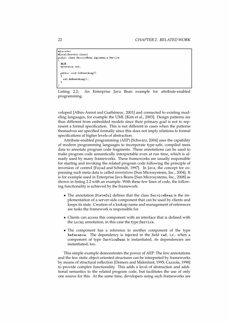
22 CHAPTER 2. RELATEDWORK�Stateful�Lo al(Servi e. lass)publi lass Servi eBean implements Servi e{ �EJBReferen e ref;publi void doSomething(){ ref.doSomething();}}Listing 2.2: An Enterprise Java Bean example for attribute-enabledprogramming.
veloped [Albin-Amiot and Guéhéneuc, 2001] and connected to existing mod-eling languages, for example the UML [Kim et al., 2003]. Design patterns arethus different from embedded models since their primary goal is not to rep-resent a formal specification. This is not different in cases when the patternsthemselves are specified formally since this does not imply relations to formalspecifications at higher levels of abstraction.
Attribute-enabled programming (AEP) [Schwarz, 2004] uses the capabilityof modern programming languages to incorporate type-safe, compiled metadata to annotate program code fragments. These annotations can be used tomake program code semantically interpretable even at run time, which is al-ready used by many frameworks. These frameworks are usually responsiblefor starting and invoking the related program code following the principle ofinversion of control [Fayad and Schmidt, 1997]. In Java, the concept for ex-pressing such meta data is called annotations [Sun Microsystems, Inc., 2004]. Itis for example used in Enterprise Java Beans [Sun Microsystems, Inc., 2008] asshown in listing 2.2 with an example. With these few lines of code, the follow-ing functionality is achieved by the framework:
• The annotation Stateful defines that the class Servi eBean is the im-plementation of a server-side component that can be used by clients andkeeps its state. Creation of a lookup name andmanagement of referencesare tasks the framework is responsible for.
• Clients can access this component with an interface that is defined withthe Lo al annotation, in this case the type Servi e.
• The component has a reference to another component of the typeReferen e. The dependency is injected in the field ref, i.e., when acomponent of type Servi eBean is instantiated, its dependencies areinstantiated, too.
This simple example demonstrates the power of AEP: The few annotationsand the few static object-oriented structures can be interpreted by frameworksby means of structural reflection [Demers and Malenfant, 1995; Cazzola, 1998]to provide complex functionality. This adds a level of abstraction and addi-tional semantics to the related program code, but facilitates the use of onlyone source for this. At the same time, developers using such frameworks are
2.2. SOURCE CODE SEMANTICS AND DESIGN PATTERNS 23
freed from repetitive tasks and can instead direct the framework by annotat-ing their code according to the given rules. But, considering the context of thisthesis, AEP does not imply the use of any formal model for the specification ofprogram code elements. It is therefore a mechanism for maintaining differentabstraction levels in program code, but not related to formal models by itself.Although AEP could be a tool for approaches that maintain different abstrac-tion levels in the program code, no such approaches are currently known.
In summary, approaches exist that increase expressiveness ofobject-oriented source code. This is achieved by supplementing the code withinformation about its relation to high-level specifications or an arrangementof code fragments that allows to interpret them at different abstractionlevels. However, none of these approaches accomplishes the goals of thisthesis: Either they are not related to formal models, like for example designpatterns, or they rely on the existence of external notations, like for exampleFSML. Internal DSLs and AEP accomplish the goals partly, but are so farnot combined to enable embedding of complex model specifications in theprogram code. Thus no systematical approach exists that maintains differentabstraction levels in the program code and makes them accessible not only atdevelopment time, but also at run time.
2.2.2 Detection of Patterns and Models
Besides the approaches to enrich program code with additional specificationinformation, there is also continuous work in progress that aims at detectingsemantics of patterns and models in arbitrary program code. This is of interestwhen architecture, design, and structure of program code are unknown andshall be related to higher levels of abstraction.
Several approaches target the detection of design patterns [Shull et al., 1996;Dong et al., 2007; Niere et al., 2002; Philippow et al., 2005]. This leads to thecreation of flexible reverse-engineering tools like PINOT [Shi and Olsson, 2006]that are able to recognize design patterns based on descriptions of the programcode fragments to expect [Shi, 2007]. This is similar to Reclipse (cf. section2.1.4). These approaches varywith respect to their course of action, for examplewith respect to the number of phases used during design pattern detection[De Lucia et al., 2007]. The objectives of the detection are also manyfold, oneexample is the extraction of patterns that relate to the UML [Niere et al., 2001].These approaches do not fulfill the same purpose as embedded models sincethey are based on design patterns, which have no clearly defined syntax andsemantics, and thus are based on heuristics to detect design information.
Similar approaches exist that do not target design patterns, but seman-tics of models. This applies to the Query-driven State Merging (QSM) algo-rithm for software behavior model induction [Dupont et al., 2008] which isused for Grammar Inference, for example for the domain of state machines[Walkinshaw et al., 2007]. The approach of example-driven reconstruction ofsoftware models [Nierstrasz et al., 2007] is intended for situations where littleinformation about the properties of model elements to be searched is available,but similarities to existing program code are to be found. A different approachis taken by DiscoTect [Yan et al., 2004] which aims at recovering architecturalinformation. This is not extracted from source code, but from compiled Javacode at run time, which is for this purpose accessed through the Java Plat-
24 CHAPTER 2. RELATEDWORK
form Debugging Architecture [Sun Microsystems, Inc., a]. These approachesare certainly helpful for the given purpose, which is identification of seman-tics in program code unknown so far. Hence, they are based on heuristics.Their application has thus other focal points than this thesis which aims for anapproach that allows to supplement program code with well-defined specifica-tions that can be reconstructed unambiguously instead of relying on heuristics.
2.2.3 Considering Program Code as a Model
Since general-purpose programming languages are used to expressalgorithms in potentially large and very different programs, approachesexist that use their semantics with formal models, but at the level of theprogramming language. Thus, the program code itself is considered a modelfor validation and verification of related programs. Various techniques embedsemantic information and modeling constraints into object-oriented sourcecode [Beckert et al., 2007]. Examples are the Java Modeling Language (JML)[Leavens et al., 1999] offering an extensive syntax for specification annotationsor the approach to use Smalltalk with its introspection capabilities as a metalanguage [Ducasse and Gîrba, 2006]. In contrast to such universal approacheswe do not aim to present a notation for the specification of all possiblesystems, but only designated parts of it. Domain-specific models can thus beexamined more thoroughly and with respect to a formally well-foundedbackground.
Model Checking for such arbitrary source code is also possible. A tool forthis is Java PathFinder [Visser et al., 2003] which instruments compiled Javabyte code, produces inputs in ranges defined by the user beforehand, and val-idates constraints inserted in the program code. Similar verification is possiblewith external model checkers like Spin [Holzmann, 2003] when appropriatemodels are related to Java code [Holzmann et al., 2008]. Model checking tech-niques can also be used to improve validation without explicit specifications[Holzmann and Smith, 2001] and at compile time [Volanschi, 2006]. Explicitmodel specifications for program code are used by the approach of Bandera[Corbett et al., 2000] which extracts finite-state models from Java code. Theextracted models represent single statements and fragments of Java programsand can be verified like other state machines [Peled et al., 2001]. In contrast tothe goals of this thesis, these approaches work at the low-level semantics ofthe programming language. While this allows for verification of detailed algo-rithms, it does not contribute to the maintenance of different abstraction levelsin the program code.
2.3 Chapter Summary
The evaluation of related work presented here was based on the objectives de-fined in section 1.3 and evaluation criteria defined at the beginning of this chap-ter. For the different classes of approacheswe described for which reasons theydo not fulfill the objectives. However, several approaches with similar objec-tives exist, which are depicted in relation to our approach in figure 2.3. Thisoverview shows that these approaches cannot be considered competing ap-proaches. The criteria taken for this visualization are the abstraction level and
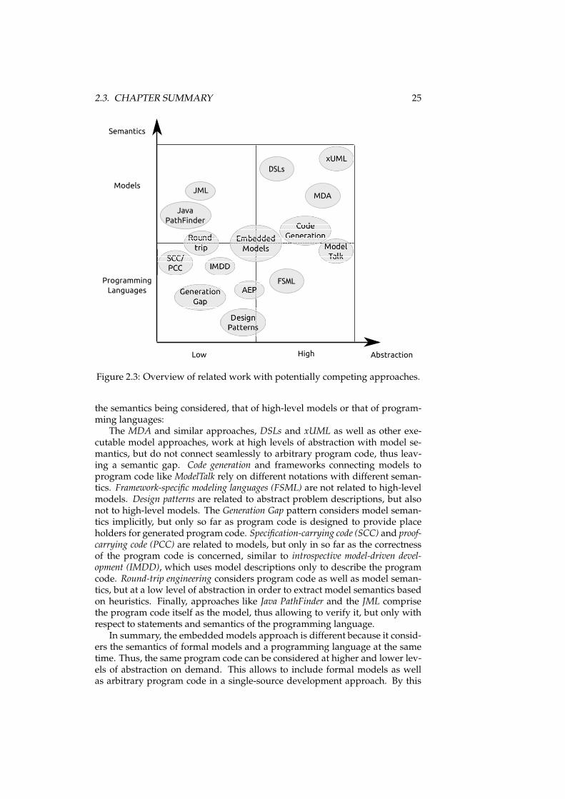
2.3. CHAPTER SUMMARY 25
AbstractionHighLow
Semantics
Models
Programming
Languages
MDA
FSML
DSLs
JML
Java
PathFinder
Figure 2.3: Overview of related work with potentially competing approaches.
the semantics being considered, that of high-level models or that of program-ming languages:
The MDA and similar approaches, DSLs and xUML as well as other exe-cutable model approaches, work at high levels of abstraction with model se-mantics, but do not connect seamlessly to arbitrary program code, thus leav-ing a semantic gap. Code generation and frameworks connecting models toprogram code like ModelTalk rely on different notations with different seman-tics. Framework-specific modeling languages (FSML) are not related to high-levelmodels. Design patterns are related to abstract problem descriptions, but alsonot to high-level models. The Generation Gap pattern considers model seman-tics implicitly, but only so far as program code is designed to provide placeholders for generated program code. Specification-carrying code (SCC) and proof-carrying code (PCC) are related to models, but only in so far as the correctnessof the program code is concerned, similar to introspective model-driven devel-opment (IMDD), which uses model descriptions only to describe the programcode. Round-trip engineering considers program code as well as model seman-tics, but at a low level of abstraction in order to extract model semantics basedon heuristics. Finally, approaches like Java PathFinder and the JML comprisethe program code itself as the model, thus allowing to verify it, but only withrespect to statements and semantics of the programming language.
In summary, the embedded models approach is different because it consid-ers the semantics of formal models and a programming language at the sametime. Thus, the same program code can be considered at higher and lower lev-els of abstraction on demand. This allows to include formal models as wellas arbitrary program code in a single-source development approach. By this

26 CHAPTER 2. RELATEDWORK
means we achieve consistency between model semantics and program code atdevelopment and run time. In the following chapter we will introduce the ap-proach in detail and afterwards describe the implementation for two differentmodeling domains fulfilling the objectives described above.
Chapter 3
The Embedded ModelsApproach
The consideration of related work shows that none of the existing approachesfulfills the requirements defined in section 1.3. Thus there is still need for anapproach that bridges the gap between higher and lower levels of abstractionas well as between the semantics of models and of programming languages.In this chapter we will introduce the embedded models approach that embedsmodel specifications in arbitrary program code by defining appropriate pro-gram code patterns, and makes them executable by means of reflection. Keep-ing different abstraction levels in the program code allows to consider the codewith several views in different stages of the development process. In this chap-ter the definition of embedded models is given and maintaining different ab-straction levels in the program code is explained in section 3.1. The resultingdevelopment process that comprises different views on the program code thatcan be provided by appropriate tools is introduced in 3.2. Afterwards the ar-chitecture of software systems containing embedded models is considered insection 3.3 before we summarize the chapter in section 3.4.
3.1 Definition of Embedded Models
To create an embeddedmodel, the specifications of a formal model aremappedto a program code pattern in a general-purpose programming language. If thismapping is unambiguous and bidirectional, the program code is interpretableat different levels of abstraction. The specification of the program code patterndepends on the semantics and expressiveness of the chosen programming lan-guage. We will now give the basic definition of embedded models and thendescribe the elements of an embedded model in detail.
3.1.1 Definition
For the definitions to give, we consider a model to be “[. . . ] an abstractionover some (part of a) software product (e.g., requirements specification, de-sign, code, test, call-flow graph). There is a variety of kinds of models [. . . ]”
27
28 CHAPTER 3. THE EMBEDDEDMODELS APPROACH
[Hailpern and Tarr, 2006]. The kinds of models are denoted model classes in thefollowing. E.g., UML activity diagrams are a model class.
Above we stated the goal to represent such model specifications in programcode patterns. Actual program code following the pattern is then a notation fora model. “Notation” is in this context defined as follows:
Definition 1 N(AM, L) is a notation for a model class M with
• AM the abstract syntax of M,
• L a language with its elements, attributes of elements, and rules to com-bine elements,
• the notation N(AM, L) being the elements, attributes, and rules of L sothat ∀m ∈ M : ∃nm ∈ N(AM, L), am ∈ AM is the concrete syntax for amodel instance m ∈ M, nm is an instance of N(AM, L) that represents theelements of am. ✷
In embedded models, the connection between models and code is not onlyconstituted by a notation, but also by appropriate execution semantics in thecase of behavioral models:
Definition 2 Given AM the abstract syntax of a model class M.α(am) = 〈Λm,→〉, am ∈ AM is a transition system representing the executionsemantics of a model m ∈ M with
• am the concrete syntax for a model instance m,
• Λm = {α0 . . . αn} a finite set of possible actions defined by the model m,
• →⊆ Λm × Λm the valid transitions between actions of Λm derived fromthe interpretation of am. ✷
This leads to the following definition for embedded models:
Definition 3 EM,G = 〈AM, P〉 is a class of embedded modelswith
1. AM the abstract syntax of a model class M,
2. G a general-purpose object-oriented programming language (called“host language” in the following),
3. P ≡ N(AM,G) a program code pattern built from elements of G that isa notation for M so that a bidirectional mapping between AM and P isgiven,
4. execution of EM,G being possible so that ∀m ∈ M : ∃α(p), p ∈ P, p repre-sents the elements of am, α(p) is bisimilar to α(am). ✷
An embedded model thus establishes a connection between different levelsof abstraction, that of the formal model and that of a host language. Thesedifferent abstraction levels are maintained in program code written in the hostlanguage G. By this means each embedded model is specific to G as well as tomodel specifications of M. In order to create embedded models according todefinition 3, each class of embedded models must comprise the following fiveelements as illustrated in figure 3.1:
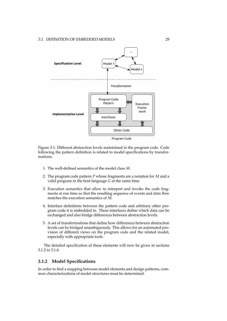
3.1. DEFINITION OF EMBEDDEDMODELS 29
Program Code
Pattern
Interfaces
Other Code
Execution
Frame-
work
Transformation
Program Code
Implementation Level
Specification Level Model 1
...
Model n
Figure 3.1: Different abstraction levels maintained in the program code. Codefollowing the pattern definition is related to model specifications by transfor-mations.
1. The well-defined semantics of the model class M.
2. The program code pattern Pwhose fragments are a notation for M and avalid program in the host language G at the same time.
3. Execution semantics that allow to interpret and invoke the code frag-ments at run time so that the resulting sequence of events and data flowmatches the execution semantics of M.
4. Interface definitions between the pattern code and arbitrary other pro-gram code it is embedded in. These interfaces define which data can beexchanged and also bridge differences between abstraction levels.
5. A set of transformations that define how differences between abstractionlevels can be bridged unambiguously. This allows for an automated pro-vision of different views on the program code and the related model,especially with appropriate tools.
The detailed specification of these elements will now be given in sections3.1.2 to 3.1.6.
3.1.2 Model Specifications
In order to find a mapping between model elements and design patterns, com-mon characterizations of model structures must be determined.
30 CHAPTER 3. THE EMBEDDEDMODELS APPROACH
This is for example done by Hailperrn & Tarr who define models to be“an annotated graph over a set of model nodes, a set of model edges, an al-phabet of labels, and a function annotating nodes and edges“, where “the an-notation function maps either nodes or edges into labels” [Hailpern and Tarr,2006]. Such static structures are already sufficient for example for data mod-els like entity-relationship diagrams [Chen, 1976]. However, more complexbehavioral models require additional facilities to describe dynamic aspects ofsoftware systems, which will thus be considered explicitly here. These can beexpressed by connecting static structures with logical formulas. This appliesfor example to expressions in state machines or process models. In addition,labels are not that much of interest to connect elements inside the model, butinstead to refer to elements outside the model. In general, connections betweenthese static structures and formulas are realized as relations or functions.
Since formal models are usually domain-specific and not always backed bya common meta model, no unified definition of the elements of such a modelcan be given. But, we can categorize the elements to expect in such models. Forthe purpose of embedded models, the abstract syntax of a model specificationis defined to be based on the following meta model:
Definition 4 AMeta = 〈S,Σ, L, F〉 is the meta model for the abstract syntax ofmodel specifications with:
• S a set of static elements of a formal model,
• Σ a logic for expressions in a formal model,
• L a set of labels that denote model elements or entities outside a model,
• F a set of functions that arrange and combine model elements. ✷
Instances of this meta model may have several instances of the members ofthe tuple, e.g. one set of entities and one set of relationships which are bothsets of static structures. This meta model is merely a categorization, but willhelp to define systematically (1) the host language elements used for embeddedmodels in object-oriented programming languages and (2) implementationsfor certain modeling domains.
3.1.3 Program Code Patterns
Based on this abstract categorization, developing program code patterns to em-bed model specifications into program code means to describe a subset of allpossible program code structures in the host language that can be mapped tothe abstract syntax of the model.
3.1.3.1 Host Language Requirements
Whether a program code pattern for embedded models can be defined de-pends on the expressiveness of the chosen host language. Considering relatedwork, embedded models enhance two existing concepts: Internal DSLs, whichprovide a single-source approach for high-level specifications in the program
3.1. DEFINITION OF EMBEDDEDMODELS 31
code, and AEP, which enables meta data in the program code to maintain dif-ferent abstraction levels (cf. section 2.2.1). Therefore, a host language appro-priate to embed model specifications with our approachmust at least fulfill thefollowing requirements:
• It must be object-oriented and thus provide the mechanisms to specifystatic structures for objects, their relationships, and functionality they canexecute.
• It must be typed, i.e. the objects must be specified as classes that arecontained in a type hierarchy.
• It must be capable of handling meta-information for its structural ele-ments, e.g. for classes and methods.
• It must support structural reflection that allows to access informationabout structural elements at run time. This concerns classes, methods,and also the meta data attached to them.
3.1.3.2 Pattern Specification
Considering these features of host languages, we can use the related static el-ements to define program code patterns that are appropriate to represent theabstract syntax of formal specifications.
Definition 5 PMeta = 〈T ,K,M,MP ,A,AP ,S ,R〉 is the meta model for pro-gram code pattern specifications with the following sets of static program codeelements and relations between them:
• T a set of types in the programming language,
• K a set of packages in the programming language,
• M a set of methods in types,
• MP a set of method parameters,
• A a set of meta data annotations in the programming language,
• AP a set of annotation parameters,
• S a set of statements in expressions in the programming language,
• R = {isO f−−→,
contains−−−−→,
returns−−−−→,
has−→,
re f ers−−−→,
invokes−−−−→,
constitutes−−−−−→} relations be-
tween the static elements. ✷
The single elements will now be explained in detail. Examples will be givenfor a small code fragment shown in Java in listing 3.1.
Named Elements Named = T ∪ K ∪M∪MP ∪ A ∪ AP is the set of ele-ments that have a name, which is assigned to them with the function name sothat ∀n ∈ Named : name(n) 6= ǫ. They are thus appropriate to represent labels.
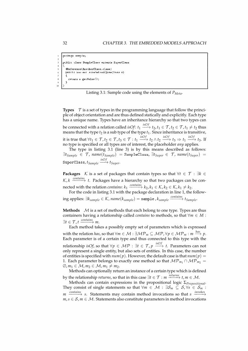
32 CHAPTER 3. THE EMBEDDEDMODELS APPROACH
1 pa kage sample;2
3 publi lass SampleClass extends SuperClass4 {5 �Referen e(AnotherClass. lass)6 publi boolean someMethod(SomeClass s)7 {8 return s.getValue();9 }
10 }Listing 3.1: Sample code using the elements of PMeta.
Types T is a set of types in the programming language that follow the princi-ple of object orientation and are thus defined statically and explicitly. Each typehas a unique name. Types have an inheritance hierarchy so that two types can
be connected with a relation called isOf : t1isO f−−→ t2, t1 ∈ T , t2 ∈ T , t1 6= t2 thus
means that the type t2 is a sub type of the type t1. Since inheritance is transitive,
it is true that ∀t1 ∈ T , t2 ∈ T , t3 ∈ T : t1isO f−−→ t2 ∧ t2
isO f−−→ t3 ⇒ t1
isO f−−→ t3. If
no type is specified or all types are of interest, the placeholder any applies.The type in listing 3.1 (line 3) is by this means described as follows:
∃tSample ∈ T , name(tSample) = SampleClass, ∃tSuper ∈ T , name(tSuper) =SuperClass, tSampleisO f−−→ tSuper.
Packages K is a set of packages that contain types so that ∀t ∈ T : ∃k ∈
K, kcontains−−−−→ t. Packages have a hierarchy so that two packages can be con-
nected with the relation contains: k1contains−−−−→ k2, k1 ∈ K, k2 ∈ K, k1 6= k2.
For the code in listing 3.1 with the package declaration in line 1, the follow-
ing applies: ∃ksample ∈ K, name(ksample) = sample , ksamplecontains−−−−→ tSample.
Methods M is a set of methods that each belong to one type. Types are thuscontainers having a relationship called contains to methods, so that ∀m ∈ M :
∃t ∈ T , tcontains−−−−→ m.
Each method takes a possibly empty set of parameters which is expressed
with the relation has, so that ∀m ∈ M : ∃MPm ⊆ MP , ∀p ∈ MPm : mhas−→ p.
Each parameter is of a certain type and thus connected to this type with the
relationship isOf, so that ∀p ∈ MP : ∃t ∈ T , pisO f−−→ t. Parameters can not
only represent a single entity, but also sets of entities. In this case, the numberof entities is specifiedwith num(p). However, the default case is that num(p) =1. Each parameter belongs to exactly one method so that MPm1 ∩MPm2 =∅,m1 ∈ M,m2 ∈ M,m1 6= m2.
Methods can optionally return an instance of a certain typewhich is defined
by the relationship returns, so that in this case ∃t ∈ T : mreturns−−−−→ t,m ∈ M.
Methods can contain expressions in the propositional logic ΣPropositional.They consist of single statements so that ∀m ∈ M : ∃Sm ⊆ S , ∀s ∈ Sm :
mcontains−−−−→ s. Statements may contain method invocations so that s
invokes−−−−→
m, s ∈ S ,m ∈ M. Statements also constitute parameters in method invocations
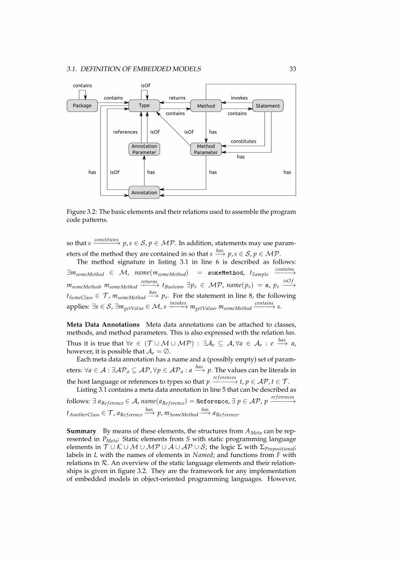
3.1. DEFINITION OF EMBEDDEDMODELS 33
Type Method
Method
Parameter
Annotation
Statement
contains
invokes
contains
isOf
isOf
returns
Package
has
contains
contains
constitutes
has
has
Annotation
Parameter
isOf isOf
has
references
has
has
Figure 3.2: The basic elements and their relations used to assemble the programcode patterns.
so that sconstitutes−−−−−→ p, s ∈ S , p ∈ MP . In addition, statements may use param-
eters of the method they are contained in so that shas−→ p, s ∈ S , p ∈ MP .
The method signature in listing 3.1 in line 6 is described as follows:
∃msomeMethod ∈ M, name(msomeMethod) = someMethod, tSamplecontains−−−−→
msomeMethod, msomeMethodreturns−−−−→ tBoolean, ∃ps ∈ MP , name(ps) = s, ps isO f
−−→
tSomeClass ∈ T , msomeMethodhas−→ ps. For the statement in line 8, the following
applies: ∃s ∈ S , ∃mgetValue ∈ M, sinvokes−−−−→ mgetValue, msomeMethod
contains−−−−→ s.
Meta Data Annotations Meta data annotations can be attached to classes,methods, and method parameters. This is also expressed with the relation has.
Thus it is true that ∀e ∈ (T ∪M ∪ MP) : ∃Ae ⊆ A, ∀a ∈ Ae : ehas−→ a,
however, it is possible that Ae = ∅.Eachmeta data annotation has a name and a (possibly empty) set of param-
eters: ∀a ∈ A : ∃AP a ⊆ AP , ∀p ∈ AP a : ahas−→ p. The values can be literals in
the host language or references to types so that pre f erences−−−−−→ t, p ∈ AP , t ∈ T .
Listing 3.1 contains a meta data annotation in line 5 that can be described as
follows: ∃ aRe f erence ∈ A, name(aRe f erence) = Referen e, ∃ p ∈ AP , pre f erences−−−−−→
tAnotherClass ∈ T , aRe f erencehas−→ p, mSomeMethod
has−→ aRe f erence.
Summary By means of these elements, the structures from AMeta can be rep-resented in PMeta: Static elements from S with static programming languageelements in T ∪ K ∪M ∪MP ∪ A ∪ AP ∪ S ; the logic Σ with ΣPropositional;labels in L with the names of elements in Named; and functions from F withrelations in R. An overview of the static language elements and their relation-ships is given in figure 3.2. They are the framework for any implementationof embedded models in object-oriented programming languages. However,
34 CHAPTER 3. THE EMBEDDEDMODELS APPROACH
the detailed implementation depends on semantics and expressiveness of suchprogramming languages. Examples will be given for two modeling domainsin chapter 4.
3.1.3.3 Implementation Languages
Ahost language that is appropriate to express embeddedmodels with programcode patterns as defined above is Java in version 5 or higher [Gosling et al.,2005]. It provides classes, interfaces, methods, and expressions in proposi-tional logic as described in section 3.1.3 and thus can represent the elementsin T , M, and MP . When methods are used to encapsulate classes, nam-ing conventions apply following the JavaBeans specification [Englander, 1997]:Methods that are used to retrieve a hidden class attribute are named with theprefix get (in the following called “get methods”); methods that set a hid-den class attribute are named with the prefix set (in the following called “setmethods”). Metadata annotations (A, AP ) are mapped to Java annotations[Sun Microsystems, Inc., 2004]. Their parameters can be literal values (includ-ing strings), nested annotations, enumerations, and references to Java class def-initions (extending java.lang.Class). The source code is compiled into Javabytecode [Lindholm and Yellin, 1999] that is executed by Java VirtualMachines(JVMs) at run time. In the bytecode, the static structures of classes, meth-ods, parameters, and annotations are available. Differences exist at the levelof method bodies: The Java expressions from the source code are compiled toa reduced instruction set that is processed sequentially, for example with thereplacement of for and while loops by goto statements. While the executionsemantics of both representations are the same, less structural information isavailable at run time. Depending on this, Java’s reflection mechanisms allowto access classes, methods, parameters, and annotations, but not method bod-ies.
Virtually the same capabilities and limitations apply to the languagesrunning on top of the Common Language Infrastructure (CLI)[ECMA International, 2006b] provided by the .NET platform, for example C#[ECMA International, 2006a]. For information hiding the concept of methodsis supplemented with so-called properties that publish class attributes, sothat no naming conventions are needed in the source code. In the compiledbytecode, however, the properties are realized as methods with namingconventions similar to JavaBeans. The meta data annotations are calledattributes and take the same parameter types, i.e. literal values includingstrings, nested attributes, enumerations, and references to type definitions(extending System.Type).
In summary, general-purpose programming languages exist that fulfill therequirements for notations of embedded models as sketched in figure 3.2.
3.1.3.4 Pattern Instantiation
When instances of a program code pattern are created they contain informationabout the instance of one formal model. At the same time, the program code isexpected to be accessible from outside, since at least the execution frameworkmust use it for execution. For this reason, instantiation of embedded modelsmust consider two aspects of program code patterns:
3.1. DEFINITION OF EMBEDDEDMODELS 35
First, program code patterns follow certain rules, some of which are givenby the definition of program code fragments. These provide a frame for imple-mentations and make the program code following the pattern accessible fromoutside, which is required for execution by means of a framework using reflec-tion. Such rules may imply that certain types or meta data annotations may beused that can be identified accordingly. These are pre-defined, i.e. they are spec-ified and implemented when an embedded model definition is being created.Afterwards they are shared among implementations of this embedded modeland are used by the appropriate tools. Types are identifiable by fully-qualifiednames in host languages. They can define methods to be implemented whena pattern instance is created. In addition, interfaces or abstract classes can actas so-called “marker interfaces” [Newkirk and Vorontsov, 2002] that do not re-quire extending types to implement methods, but exist only to mark themwiththeir fully-qualified name. Meta data annotations have the purpose of beingaccessible for interpretation, so they are appropriate to decorate other staticelements of the program code. In Java and C#, meta data annotations can beapplied to classes, methods, and method parameters. The program code be-ing connected to any pre-defined program code fragments is by such meansaccessible at development time and run time and can serve as entry points tothe embedded model instance. This is the foundation not only for execution atrun time, but for any tool that accesses the program code pattern instances toconsider them at different abstraction levels.
Second, inside the frame of the pre-defined program code,implementations of embedded models consist of program code that iscreated per instance. This program code is itself not interpretable with respectto an embedded model, but gains additional semantics within the contextinformation of the pre-defined program code. For this purpose it must followthe rules that make it interpretable at different abstraction levels within thiscontext.
An example for pre-defined and per-instance code fragments can be seenin listing 3.1: We can assume that the annotation Referen e is pre-defined andallows to identify methods of interest. In contrast, its parameter referring toanother class describes the current instance of the embeddedmodel. Completeexamples for program code pattern instances will be shown in chapter 4.
3.1.4 Execution Semantics
As defined above, the program code specified by embedded models carriesmultiple abstraction levels at the same time. Sections 3.1.2 and 3.1.3 introducedthe possible structures for model specifications and representations in the pro-gram code that are to be mapped to each other. This already allows to representmodels in the program code that are based on static structures only. However,when models specify behavior also, this behavior must be realized at run timewhen the programs containing embedded model instances are executed.
For this reason each embedded model specifying behavior is accompaniedby an execution framework that accesses, interprets, and invokes the relatedprogram code fragments. For this purpose, appropriate execution semanticsfor the formal model must be defined. The static structures of the model areused to determine the behavior of the application at run time and denote singleactions which can be executed in the host programming language. The execu-
36 CHAPTER 3. THE EMBEDDEDMODELS APPROACH
tion semantics thus denote sequences of actions that correspond to the semanticsof the formal model.
The execution semantics of the embedded model are based on the pre-defined program code fragments of the pattern since they can provide appro-priate entry points for the interpretation of the program code. They also in-dicate the location of methods containing behavioral logic in expressions thatare defined per instance. The execution framework therefore accesses programcode in the context of the pre-defined code and realizes behavioral executionwith the invocation of appropriate methods. We thus distinguish two types ofprogram code: Some of the code following the patterns is interpreted, i.e. thestatic structures are read by the execution framework to make decisions. Thisentails the use of pre-defined program code fragments to enable interpretation.Some of the code is invoked, i.e. it contains statements that are executed. Thiscan either apply to statements which are interpretable at higher abstractionlevels, too; or it can apply to interfaces which abstract from program code thatdoes not belong to the model.
It must be considered that execution will not rely on the source code, but oncompiled bytecode. Therefore the information being available is more coarse-grained than in the source code as described in section 3.1.3. The embeddedmodel must thus be defined such that single actions in the execution semanticsare accessible at run time. This entails that the parts of the pattern to be inter-preted are completely available at run time, too. The program code that willbe invoked is not required to be represented in the same detail as in the sourcecode, since invocation of method considers the method bodies black boxes.
3.1.5 Interface Definitions
Program code specified by embedded models is part of arbitrary other pro-gram code. This arbitrary other program code can be based on other embed-ded models, design patterns, or not on any abstract specification at all. Thisco-existence of fragments based on different specifications in the same set ofprogram code is the foundation for the objective of embedded models to re-duce the number of notations used to describe the software to develop.
It also entails that program code of embedded models is not self-contained,but must have well-defined interfaces between the program code pattern rep-resenting the model syntax and the arbitrary program code to allow for dataexchange and application logic invocation. For the definition of interfaces, thesemantics of the formal model must be considered. In section 3.1.2, labels wereintroduced which are part of the model specification, but refer to the worldoutside the actual model. Such labels would be represented by program codeelements from Named. By this means, parts of the program code pattern serveas interfaces to arbitrary other program code.
3.1.5.1 Interface Semantics
These interfaces play an important role in the maintenance of different abstrac-tion levels in the program code: When arbitrary program code is connectedto the embedded model with labels, the interfaces realize the abstraction thatallows to interpret parts of the program code with respect to the abstract spec-ifications of a model. Interfaces can be known to the execution framework
3.1. DEFINITION OF EMBEDDEDMODELS 37
so that it can control communication between the embedded model code andother program code if reasonable. Two properties of interfaces can be distin-guished:
First, interfaces can be data-oriented, meaning that they are used to exchangedata with arbitrary other program code. Such data exchange must be definedwith respect to the model semantics since incoming and outgoing data may bedefined explicitly in the model or implicitly assumed by the execution frame-work controlling the communication. Abstraction to other program code canbe realized in data-oriented interfaces when data is aggregated. By this meanscomplex data structures can be simplified if necessary to be handled by an ab-stract model.
Second, interfaces can be action-oriented. In this case they provide entrypoints from an embeddedmodel into other program code that is to be invoked.By this means execution of arbitrary application logic can be initiated fromthe embedded model, even if its specification is not covered by the relatedformal model (or any model at all). For such actions the model specificationscan define contracts (cf. section 2.1.2) in an embedded model: Pre-conditionsrestrict the circumstances when actions are invoked; post-conditions demandthat invoked actions leave the overall application in a certain state with respectto themodel specification. Both can be necessary to realize an abstractionwheninteraction with arbitrary program code is desirable.
The distinction between data-oriented and action-oriented interfaces is notexclusive since interfaces or parts of them can have one or both properties.
3.1.5.2 Implications for Other Program Code
Embedded models do not consider the content and semantics of applicationlogic connected to them. By this means their flexibility will be maximized sinceno limitations for their application are given, except that the interfaces must beserved by the application’s program code. However, it is important to note thatembeddedmodels assume that such arbitrary program code is compliant to thesemantics of the model as defined by the interfaces. While they cannot forceany compliance, implications regarding the nature of the arbitrary programcode are possible.
These implications are based on the fact that program code connected to in-terfaces of embeddedmodels can be considered as slices [Weiser, 1981] with theinterface methods being the entry points. Depending on the requirements ofspecific embeddedmodel instances, assertions about single slices can be made.While the execution of certain actions itself is not of interest, changes to thestate space of the application can influence the embedded model and are thusof interest. Based on the interface semantics introduced above, the the follow-ing assertions are possible:
• Expected changes: Post-conditions of action-oriented interfaces are asser-tions which changes to the state space of the application a certain slicehas to perform in order to conform to the model specifications.
• Reproducible reading: When embedded models access data from the statespace of the surrounding application, this may be expected to be repro-ducible. A related slice may thus be required not to change the statespace, but only to read variables.
38 CHAPTER 3. THE EMBEDDEDMODELS APPROACH
• Exclusive writing: An embedded model may be responsible for storingdata in the state space of the surrounding application. In certain cases,it can be desirable that such data is not modified by other parts of theapplication. Any slices without that for outgoing data are then forbiddento modify the related parts of the state space.
The implications are used for verification in two ways: The interfaces andthe execution framework must be designed in a way that a validation of ex-changed data is possible where necessary at run time. A validation can alsooccur with appropriate tools considering the program code during the devel-opment process as will be explained in section 3.2.2.
3.1.6 Transformations
The aim of embedded models is to consider programs at different levels of ab-straction, while only one notation – that of the program code – is necessary.This entails that different views on this program code must exist to facilitateworking with the different abstraction levels. These views may consider onlyparts of the program code, interpret it with different semantic specifications,and utilize external tools. To enable this, transformations between the programcode pattern and the views must exist. These must be unambiguous to allowfor automatic transformations and tool support, which is necessary for embed-ded models to be fully beneficial. We consider two different types, externaland internal transformations.
External transformations transformmodel information between the programcode pattern and an external notation. This can be used for example to createa model description in the notation of an external verification tool. Externaltransformations have the following properties:
• The model must be transformed completely to the extent that the trans-formed information is useful.
• A single transformation is unidirectional, although the opposite waymaybe supported by a separate transformation as well, of course.
• They are performed as one action with a clearly defined beginning andending.
• When amodel is being transformed and amodel definition already existsin the target, the model information must be merged. This may, for exam-ple, happen when a model definition was extracted from program code,modified in an external tool, and is to be written back to the programcode. For this case, collision detection strategies must exist.
In contrast, internal transformations do not rely on a separate notation, butprovide non-persistent views on the program code. This is for example thecase with editors that arrange fragments of the program code pattern directlyaccording to the model specifications. Internal transformations have the fol-lowing properties:
• Only the information that is currently needed by the target of the trans-formation must be extracted.
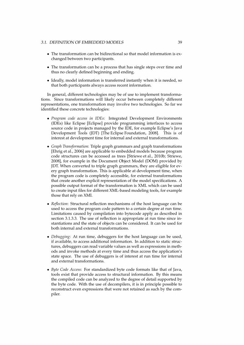
3.1. DEFINITION OF EMBEDDEDMODELS 39
• The transformation can be bidirectional so that model information is ex-changed between two participants.
• The transformation can be a process that has single steps over time andthus no clearly defined beginning and ending.
• Ideally, model information is transferred instantly when it is needed, sothat both participants always access recent information.
In general, different technologies may be of use to implement transforma-tions. Since transformations will likely occur between completely differentrepresentations, one transformation may involve two technologies. So far weidentified these concrete technologies:
• Program code access in IDEs: Integrated Development Environments(IDEs) like Eclipse [Eclipse] provide programming interfaces to accesssource code in projects managed by the IDE, for example Eclipse’s JavaDevelopment Tools (JDT) [The Eclipse Foundation, 2008]. This is ofinterest at development time for internal and external transformations.
• Graph Transformation: Triple graph grammars and graph transformations[Ehrig et al., 2006] are applicable to embedded models because programcode structures can be accessed as trees [Striewe et al., 2010b; Striewe,2008], for example in the Document Object Model (DOM) provided byJDT. When converted to triple graph grammars, they are eligible for ev-ery graph transformation. This is applicable at development time, whenthe program code is completely accessible, for external transformationsthat create another explicit representation of the model specifications. Apossible output format of the transformation is XML which can be usedto create input files for different XML-based modeling tools, for examplethose that rely on XMI.
• Reflection: Structural reflection mechanisms of the host language can beused to access the program code pattern to a certain degree at run time.Limitations caused by compilation into bytecode apply as described insection 3.1.3.3. The use of reflection is appropriate at run time since in-stantiations and the state of objects can be considered. It can be used forboth internal and external transformations.
• Debugging: At run time, debuggers for the host language can be used,if available, to access additional information. In addition to static struc-tures, debuggers can read variable values as well as expressions in meth-ods and invoke methods at every time and thus access the application’sstate space. The use of debuggers is of interest at run time for internaland external transformations.
• Byte Code Access: For standardized byte code formats like that of Java,tools exist that provide access to structural information. By this meansthe compiled code can be analyzed to the degree of detail supported bythe byte code. With the use of decompilers, it is in principle possible toreconstruct even expressions that were not retained as such by the com-piler.

40 CHAPTER 3. THE EMBEDDEDMODELS APPROACH
Implemen-
tation
Validation &
VerificationExecution Monitoring
Development Time Run Time
Design &
Architecture
Design Time
{}01010
10101
01010
Design
Model Views
Source Code
Verification
Model Views
Byte Code
Monitoring
Model Views
Design
Recovery
Replacement
Design
Model Views
Trans-
formation
Compilation
Trans-
formation
Trans-
formation
Trans-
formation
Figure 3.3: The development process that is supported by tools for embeddedmodels. Depending on their purpose, transformations can be unidirectional,e.g. for extraction of information for monitoring, or bidirectional, e.g. for de-sign views that read and write source code.
Two transformations are needed in every case, which we will refer to asdefault transformations in the following: One that considers the source code toextract the complete model elements from it, and one that considers compiledbyte code to extract the model elements from it that are still available aftercompilation. These are needed for the basic representation of the model spec-ifications during development time and run time. However, apart from these,a number of specific views can exist that are each realized by special transfor-mations.
The use of transformations throughout the development process will nowbe explained in section 3.2 and later discussed with examples in chapter 4.
3.2 Views on Embedded Models
Following the definition of embedded models as given above, program codecan carry information at different abstraction levels. Thus the number of nota-tions in use during development can be reduced as shown in figure 3.3: Sourcecode and compiled program code are the main explicit notations, with the com-piled code being derived from the source code. During design, verification,execution, monitoring, and design recovery, the models are only specific viewson the program code that are extracted from this notation on demand. Theprogram code is thus interpretable at different levels of abstraction: that of theprogramming language itself and that of the formal models, leading to dif-ferent views for different purposes. The views that are applicable to differentstages of the development process will now be explained; examples will begiven in chapter 4.
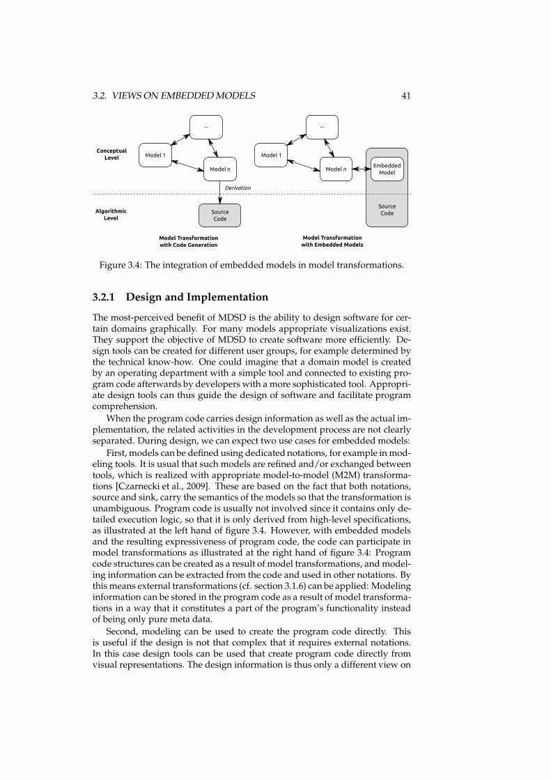
3.2. VIEWS ON EMBEDDEDMODELS 41
Conceptual
Level
Algorithmic
LevelSource
Code
Source
Code
Embedded
Model
Model Transformation
with Code Generation
Model Transformation
with Embedded Models
Derivation
Model 1
...
Model n
Model 1
...
Model n
Figure 3.4: The integration of embedded models in model transformations.
3.2.1 Design and Implementation
The most-perceived benefit of MDSD is the ability to design software for cer-tain domains graphically. For many models appropriate visualizations exist.They support the objective of MDSD to create software more efficiently. De-sign tools can be created for different user groups, for example determined bythe technical know-how. One could imagine that a domain model is createdby an operating department with a simple tool and connected to existing pro-gram code afterwards by developers with a more sophisticated tool. Appropri-ate design tools can thus guide the design of software and facilitate programcomprehension.
When the program code carries design information as well as the actual im-plementation, the related activities in the development process are not clearlyseparated. During design, we can expect two use cases for embedded models:
First, models can be defined using dedicated notations, for example inmod-eling tools. It is usual that such models are refined and/or exchanged betweentools, which is realized with appropriate model-to-model (M2M) transforma-tions [Czarnecki et al., 2009]. These are based on the fact that both notations,source and sink, carry the semantics of the models so that the transformation isunambiguous. Program code is usually not involved since it contains only de-tailed execution logic, so that it is only derived from high-level specifications,as illustrated at the left hand of figure 3.4. However, with embedded modelsand the resulting expressiveness of program code, the code can participate inmodel transformations as illustrated at the right hand of figure 3.4: Programcode structures can be created as a result of model transformations, andmodel-ing information can be extracted from the code and used in other notations. Bythis means external transformations (cf. section 3.1.6) can be applied: Modelinginformation can be stored in the program code as a result of model transforma-tions in a way that it constitutes a part of the program’s functionality insteadof being only pure meta data.
Second, modeling can be used to create the program code directly. Thisis useful if the design is not that complex that it requires external notations.In this case design tools can be used that create program code directly fromvisual representations. The design information is thus only a different view on
42 CHAPTER 3. THE EMBEDDEDMODELS APPROACH
the system to develop and by this means an internal transformation betweenthe model specifications and the program code.
At the same time, the implementation of other program code must be con-sidered. With embeddedmodels, the development of model specifications andother program code can happen in parallel. Consequently it is much easier toalign the different views than in cases where different notations are used. Atthe same time, the separation of different concerns must be represented in theprogram code, for example with modularization concepts.
3.2.2 Verification
When the program code has been designed and implemented with embed-ded models, the resulting source code contains the modeling information inthe program code pattern. This allows for model verification at different ab-straction levels. However, model verification relies not only on the existenceof a model, but also of a specification the model is verified against. Thus ap-propriate views must exist for this purpose that provide model specificationsand interpret the program code and the embedded specifications accordingly.The modeling information or subsets of interest are then extracted for verifica-tion from the program code. Any abstraction or refinement explicitly happensalongside interfaces or pre-defined code fragments. The verification tools caneither work on the program code directly with internal transformations, or beseparate tools that are comprised into the development by external transfor-mations providing data in the notation of such tools.
Verification is also possible for slices of program code connected to the em-bedded model (cf. section 3.1.5.2). Views for static program code analysis candetermine if the arbitrary program code is validwith respect to the model spec-ifications it is interacting with. The search space can be reduced considerablyso that starting points for slices [Tip, 1995] can be provided if the program codepattern defines entry points from the model specifications into arbitrary pro-gram code. In addition, different approaches and tools for automated verifica-tion are applicable. Static analysis is possible based on rules, e.g. with PMD[Copeland, 2005] proving certain structural properties, or with advanced ap-proaches like the Hoare logic [Hoare, 1969] proving correctness of algorithms.Dynamic analysis and model checking [Holzmann et al., 2008], e.g. with JavaPathFinder [Visser et al., 2003], can be used to validate data exchange and statespaces of the program at run time. Depending on the model, static or dy-namic analysis are enabled since the model specifications reduce the searchspace with the definition of slices and provide assertions and constraints thatwould otherwise have to be inserted manually.
While design and verification are different tasks, it is likely that a smoothtransition between the related tools will exist: Even a simple design tool canverify basic properties of the model, and a verification and simulation tool willin most cases visualize the model appropriately. A sophisticated tool thus maycover both stages of the development process since the related information isconsistently available in the notation of the source code.

3.2. VIEWS ON EMBEDDEDMODELS 43
3.2.3 Execution
Since the program code structures defined by embedded models are not di-rectly executable, but instead only descriptions of modeling information, theyare processed by execution frameworks at run time as described in section3.1.4. The execution frameworks read and interpret the structures of the em-bedded model code and invoke methods if appropriate. The execution is bythis means a specific view on the compiled program code that accesses a partof the modeling information to create the required sequences of actions.
3.2.4 Monitoring
The compiled code is also interpretable at run time for tracing and monitoringwith respect to the abstract model [Maoz, 2009; Bodden, 2007], even if relateddocumentation is not available. This is of interest for embedded models sincethey are not isolated, but interact with arbitrary application logic. Thus theymay act differently than expected from the results of verification views, sinceverification will likely focus on certain aspects and not on all possible statespaces that can be introduced with real data at run time. For monitoring, tracesin terms of class instantiations, method calls, and changes of variable valuescan be generated. Two kinds of monitoring are distinguished in the context ofembedded models:
Active monitoring is controlled by the execution framework sending infor-mation to possible listeners. Due to compilation, the degree of detail is limitedas explained in section 3.1.3.3. For example, reflection in Java allows access tostructural elements, but not to details of method bodies, whose structures havedifferent semantics in byte code than in source code. The advantage of suchapproaches is that they can be realized at the level of the framework. How-ever, the overhead introduced by interpretation and emission of informationmust be considered for production systems.
Passive monitoring does not require modifications to or support bythe execution framework. Instead it relies on instrumentation techniquesprovided by the platform. In Java, for example, the debugging interface[Sun Microsystems, Inc., a] is appropriate to gather information about runningsoftware. Since the program code patterns define well-known entry pointsand markers that identify program code as part of the model, instantiationsand invocations of related code structures can be surveyed. With debugging,the monitoring can be applied to all elements of the programming language,including method bodies. However, such instrumentation is likely not tobe available in production systems for performance reasons. In the case ofdebugging, the monitoring requires two running systems: The system that isdebugged, and the debugger itself that controls the execution and gathersthe data. Passive monitoring is therefore much more appropriate to inspectthe running embedded model in detail, but harder to apply to productionenvironments.
3.2.5 Design Recovery
Finally, after years of service a system may need to be replaced. However,most software systems are not simply abandoned. In many cases, data and
44 CHAPTER 3. THE EMBEDDEDMODELS APPROACH
application logic defined in them are to be transferred to successional systems.However, experience shows that documentation is often incomplete, out ofsync with the actual system, not known for sure to be in sync, or not existentat all. Especially modeling information would in such cases be of help sincemodel specifications are often used to describe essential parts of the systemthat may be of interest for reengineering or can support the recovery of designin the software.
If the source code of software is still available, the modeling informationof embedded models can be accessed directly. As described for execution andmonitoring, the specifications of models are retained in executable systems toa certain degree, too. This information is appropriate for reengineering anddesign recovery since it is no external meta data, but constitutes (a part of) theactual system that is to be replaced. It is desirable to apply information used inthe other views for design recovery too. Thus embedded models can supportdesign recovery as long as the basic information is available about the fact thatan embedded model is in use.
3.3 Software Architecture
The approach as explained so far is valid for the creation of embedded modelsfor one modeling domain. However, when large systems and a respective ar-chitecture are developed, embedded models must be considered in a broaderscope. We will in this section outline general properties of architectures em-bracing (multiple classes and instances of) embedded models while leveragingthe characteristics of large, module-based software systems.
3.3.1 Principles
When large software systems are created, a software architecture[Buschmann et al., 2007, ch. 6] has to be developed that defines basic rulesfacilitating a structured development. In addition, some technological aspectshave to be considered:
• Software systems can be modeled with more than one model class.
• Module concepts [Szyperski, 2002, ch. 4] or plug-in mechanisms can beused to assemble software systems not completely at development time,but at deployment time, when they are put into operation.
• Software systems can be dynamically configured for example with pro-cess model platforms so that their behavior is defined not until run timeand can be adapted on demand.
A larger software system can thus be expected to consist of modules and de-pendencies between them. Properties of single modules as well as relations be-tween models may be subject to dynamic configuration even not until the sys-tem is executed. To consider software systems with characteristics like these,the following has to be taken into account for embedded model definitions:
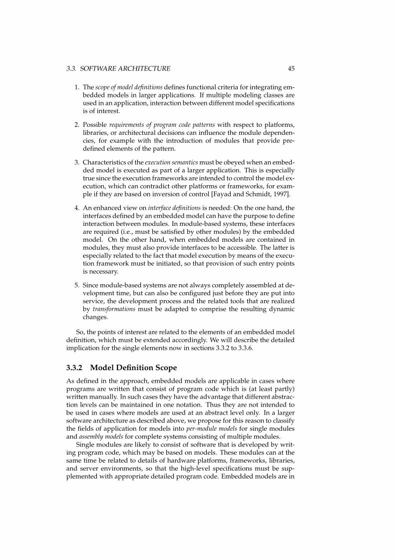
3.3. SOFTWARE ARCHITECTURE 45
1. The scope of model definitions defines functional criteria for integrating em-bedded models in larger applications. If multiple modeling classes areused in an application, interaction between differentmodel specificationsis of interest.
2. Possible requirements of program code patterns with respect to platforms,libraries, or architectural decisions can influence the module dependen-cies, for example with the introduction of modules that provide pre-defined elements of the pattern.
3. Characteristics of the execution semanticsmust be obeyedwhen an embed-ded model is executed as part of a larger application. This is especiallytrue since the execution frameworks are intended to control the model ex-ecution, which can contradict other platforms or frameworks, for exam-ple if they are based on inversion of control [Fayad and Schmidt, 1997].
4. An enhanced view on interface definitions is needed: On the one hand, theinterfaces defined by an embeddedmodel can have the purpose to defineinteraction between modules. In module-based systems, these interfacesare required (i.e., must be satisfied by other modules) by the embeddedmodel. On the other hand, when embedded models are contained inmodules, they must also provide interfaces to be accessible. The latter isespecially related to the fact that model execution by means of the execu-tion framework must be initiated, so that provision of such entry pointsis necessary.
5. Since module-based systems are not always completely assembled at de-velopment time, but can also be configured just before they are put intoservice, the development process and the related tools that are realizedby transformations must be adapted to comprise the resulting dynamicchanges.
So, the points of interest are related to the elements of an embedded modeldefinition, which must be extended accordingly. We will describe the detailedimplication for the single elements now in sections 3.3.2 to 3.3.6.
3.3.2 Model Definition Scope
As defined in the approach, embedded models are applicable in cases whereprograms are written that consist of program code which is (at least partly)written manually. In such cases they have the advantage that different abstrac-tion levels can be maintained in one notation. Thus they are not intended tobe used in cases where models are used at an abstract level only. In a largersoftware architecture as described above, we propose for this reason to classifythe fields of application for models into per-module models for single modulesand assembly models for complete systems consisting of multiple modules.
Single modules are likely to consist of software that is developed by writ-ing program code, which may be based on models. These modules can at thesame time be related to details of hardware platforms, frameworks, libraries,and server environments, so that the high-level specifications must be sup-plemented with appropriate detailed program code. Embedded models are in
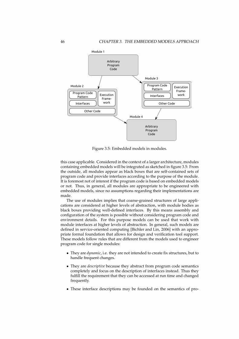
46 CHAPTER 3. THE EMBEDDEDMODELS APPROACH
Module 2
Module 3
Module 1
Module 4
Program Code
Pattern
Interfaces
Other Code
Execution
Frame-
work
Program Code
Pattern
Interfaces
Other Code
Execution
Frame-
work
Arbitrary
Program
Code
Arbitrary
Program
Code
Figure 3.5: Embedded models in modules.
this case applicable. Considered in the context of a larger architecture, modulescontaining embeddedmodels will be integrated as sketched in figure 3.5: Fromthe outside, all modules appear as black boxes that are self-contained sets ofprogram code and provide interfaces according to the purpose of the module.It is foremost not of interest if the program code is based on embedded modelsor not. Thus, in general, all modules are appropriate to be engineered withembedded models, since no assumptions regarding their implementations aremade.
The use of modules implies that coarse-grained structures of large appli-cations are considered at higher levels of abstraction, with module bodies asblack boxes providing well-defined interfaces. By this means assembly andconfiguration of the system is possible without considering program code andenvironment details. For this purpose models can be used that work withmodule interfaces at higher levels of abstraction. In general, such models aredefined in service-oriented computing [Bichler and Lin, 2006] with an appro-priate formal foundation that allows for design and verification tool support.These models follow rules that are different from the models used to engineerprogram code for single modules:
• They are dynamic, i.e. they are not intended to create fix structures, but tohandle frequent changes.
• They are descriptive because they abstract from program code semanticscompletely and focus on the description of interfaces instead. Thus theyfulfill the requirement that they can be accessed at run time and changedfrequently.
• These interface descriptions may be founded on the semantics of pro-
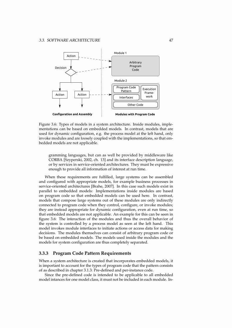
3.3. SOFTWARE ARCHITECTURE 47
Module 2
Module 1Action
Decision
ActionAction
Configuration and Assembly Modules with Program Code
Arbitrary
Program
Code
Program Code
Pattern
Interfaces
Other Code
Execution
Frame-
work
Figure 3.6: Types of models in a system architecture. Inside modules, imple-mentations can be based on embedded models. In contrast, models that areused for dynamic configuration, e.g. the process model at the left hand, onlyinvoke modules and are loosely coupled with the implementations, so that em-bedded models are not applicable.
gramming languages, but can as well be provided by middleware likeCORBA [Szyperski, 2002, ch. 13] and its interface description language,or by services in service-oriented architectures. They must be expressiveenough to provide all information of interest at run time.
When these requirements are fulfilled, large systems can be assembledand configured with appropriate models, for example business processes inservice-oriented architectures [Brahe, 2007]. In this case such models exist inparallel to embedded models: Implementations inside modules are basedon program code so that embedded models can be used here. In contrast,models that compose large systems out of these modules are only indirectlyconnected to program code when they control, configure, or invoke modules;they are instead appropriate for dynamic configuration, even at run time, sothat embedded models are not applicable. An example for this can be seen infigure 3.6: The interaction of the modules and thus the overall behavior ofthe system is controlled by a process model as seen at the left hand. Thismodel invokes module interfaces to initiate actions or access data for makingdecisions. The modules themselves can consist of arbitrary program code orbe based on embedded models. The models used inside the modules and themodels for system configuration are thus completely separated.
3.3.3 Program Code Pattern Requirements
When a system architecture is created that incorporates embedded models, itis important to account for the types of program code that the pattern consistsof as described in chapter 3.1.3: Pre-defined and per-instance code.
Since the pre-defined code is intended to be applicable to all embeddedmodel intances for one model class, it must not be included in eachmodule. In-
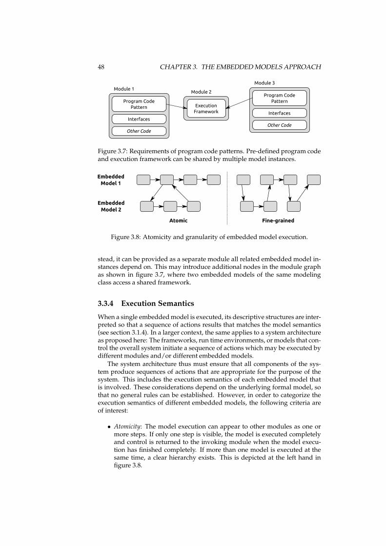
48 CHAPTER 3. THE EMBEDDEDMODELS APPROACH
Module 2
Module 3
Module 1
Program Code
Pattern
Interfaces
Other Code
Execution
Framework
Program Code
Pattern
Interfaces
Other Code
Figure 3.7: Requirements of program code patterns. Pre-defined program codeand execution framework can be shared by multiple model instances.
Embedded
Model 1
Embedded
Model 2
Atomic Fine-grained
Figure 3.8: Atomicity and granularity of embedded model execution.
stead, it can be provided as a separate module all related embedded model in-stances depend on. This may introduce additional nodes in the module graphas shown in figure 3.7, where two embedded models of the same modelingclass access a shared framework.
3.3.4 Execution Semantics
When a single embeddedmodel is executed, its descriptive structures are inter-preted so that a sequence of actions results that matches the model semantics(see section 3.1.4). In a larger context, the same applies to a system architectureas proposed here: The frameworks, run time environments, ormodels that con-trol the overall system initiate a sequence of actions which may be executed bydifferent modules and/or different embedded models.
The system architecture thus must ensure that all components of the sys-tem produce sequences of actions that are appropriate for the purpose of thesystem. This includes the execution semantics of each embedded model thatis involved. These considerations depend on the underlying formal model, sothat no general rules can be established. However, in order to categorize theexecution semantics of different embedded models, the following criteria areof interest:
• Atomicity: The model execution can appear to other modules as one ormore steps. If only one step is visible, the model is executed completelyand control is returned to the invoking module when the model execu-tion has finished completely. If more than one model is executed at thesame time, a clear hierarchy exists. This is depicted at the left hand infigure 3.8.
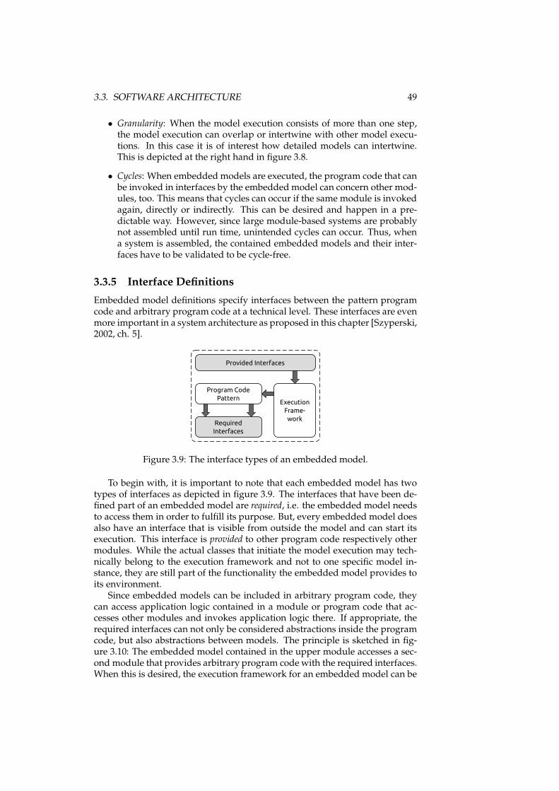
3.3. SOFTWARE ARCHITECTURE 49
• Granularity: When the model execution consists of more than one step,the model execution can overlap or intertwine with other model execu-tions. In this case it is of interest how detailed models can intertwine.This is depicted at the right hand in figure 3.8.
• Cycles: When embedded models are executed, the program code that canbe invoked in interfaces by the embedded model can concern other mod-ules, too. This means that cycles can occur if the same module is invokedagain, directly or indirectly. This can be desired and happen in a pre-dictable way. However, since large module-based systems are probablynot assembled until run time, unintended cycles can occur. Thus, whena system is assembled, the contained embedded models and their inter-faces have to be validated to be cycle-free.
3.3.5 Interface Definitions
Embedded model definitions specify interfaces between the pattern programcode and arbitrary program code at a technical level. These interfaces are evenmore important in a system architecture as proposed in this chapter [Szyperski,2002, ch. 5].
Program Code
Pattern
Required
Interfaces
Execution
Frame-
work
Provided Interfaces
Figure 3.9: The interface types of an embedded model.
To begin with, it is important to note that each embedded model has twotypes of interfaces as depicted in figure 3.9. The interfaces that have been de-fined part of an embedded model are required, i.e. the embedded model needsto access them in order to fulfill its purpose. But, every embedded model doesalso have an interface that is visible from outside the model and can start itsexecution. This interface is provided to other program code respectively othermodules. While the actual classes that initiate the model execution may tech-nically belong to the execution framework and not to one specific model in-stance, they are still part of the functionality the embedded model provides toits environment.
Since embedded models can be included in arbitrary program code, theycan access application logic contained in a module or program code that ac-cesses other modules and invokes application logic there. If appropriate, therequired interfaces can not only be considered abstractions inside the programcode, but also abstractions between models. The principle is sketched in fig-ure 3.10: The embedded model contained in the upper module accesses a sec-ond module that provides arbitrary program code with the required interfaces.When this is desired, the execution framework for an embedded model can be
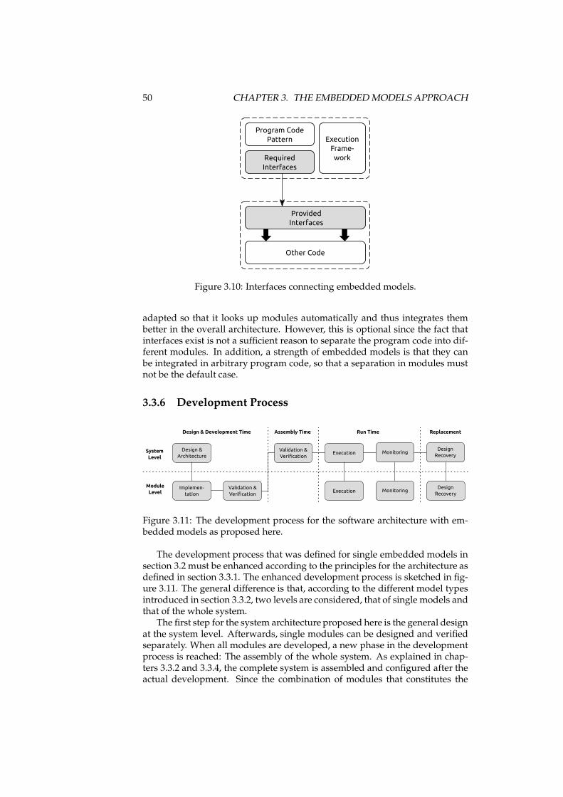
50 CHAPTER 3. THE EMBEDDEDMODELS APPROACH
Program Code
Pattern Execution
Frame-
work
Other Code
Provided
Interfaces
Required
Interfaces
Figure 3.10: Interfaces connecting embedded models.
adapted so that it looks up modules automatically and thus integrates thembetter in the overall architecture. However, this is optional since the fact thatinterfaces exist is not a sufficient reason to separate the program code into dif-ferent modules. In addition, a strength of embedded models is that they canbe integrated in arbitrary program code, so that a separation in modules mustnot be the default case.
3.3.6 Development Process
Implemen-
tation
Validation &
VerificationExecution
Monitoring
Design & Development Time Run Time
Design &
Architecture
Design
Recovery
Replacement
Execution
Module
Level
System
Level
Assembly Time
Validation &
Verification
MonitoringDesign
Recovery
Figure 3.11: The development process for the software architecture with em-bedded models as proposed here.
The development process that was defined for single embedded models insection 3.2 must be enhanced according to the principles for the architecture asdefined in section 3.3.1. The enhanced development process is sketched in fig-ure 3.11. The general difference is that, according to the different model typesintroduced in section 3.3.2, two levels are considered, that of single models andthat of the whole system.
The first step for the system architecture proposed here is the general designat the system level. Afterwards, single modules can be designed and verifiedseparately. When all modules are developed, a new phase in the developmentprocess is reached: The assembly of the whole system. As explained in chap-ters 3.3.2 and 3.3.4, the complete system is assembled and configured after theactual development. Since the combination of modules that constitutes the
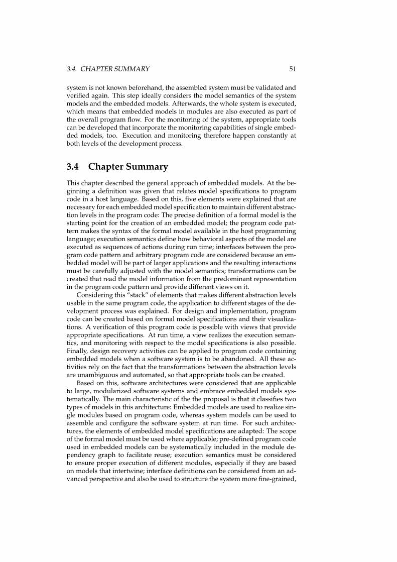
3.4. CHAPTER SUMMARY 51
system is not known beforehand, the assembled system must be validated andverified again. This step ideally considers the model semantics of the systemmodels and the embedded models. Afterwards, the whole system is executed,which means that embedded models in modules are also executed as part ofthe overall program flow. For the monitoring of the system, appropriate toolscan be developed that incorporate the monitoring capabilities of single embed-ded models, too. Execution and monitoring therefore happen constantly atboth levels of the development process.
3.4 Chapter Summary
This chapter described the general approach of embedded models. At the be-ginning a definition was given that relates model specifications to programcode in a host language. Based on this, five elements were explained that arenecessary for each embeddedmodel specification tomaintain different abstrac-tion levels in the program code: The precise definition of a formal model is thestarting point for the creation of an embedded model; the program code pat-tern makes the syntax of the formal model available in the host programminglanguage; execution semantics define how behavioral aspects of the model areexecuted as sequences of actions during run time; interfaces between the pro-gram code pattern and arbitrary program code are considered because an em-bedded model will be part of larger applications and the resulting interactionsmust be carefully adjusted with the model semantics; transformations can becreated that read the model information from the predominant representationin the program code pattern and provide different views on it.
Considering this “stack” of elements that makes different abstraction levelsusable in the same program code, the application to different stages of the de-velopment process was explained. For design and implementation, programcode can be created based on formal model specifications and their visualiza-tions. A verification of this program code is possible with views that provideappropriate specifications. At run time, a view realizes the execution seman-tics, and monitoring with respect to the model specifications is also possible.Finally, design recovery activities can be applied to program code containingembedded models when a software system is to be abandoned. All these ac-tivities rely on the fact that the transformations between the abstraction levelsare unambiguous and automated, so that appropriate tools can be created.
Based on this, software architectures were considered that are applicableto large, modularized software systems and embrace embedded models sys-tematically. The main characteristic of the the proposal is that it classifies twotypes of models in this architecture: Embedded models are used to realize sin-gle modules based on program code, whereas system models can be used toassemble and configure the software system at run time. For such architec-tures, the elements of embedded model specifications are adapted: The scopeof the formal model must be used where applicable; pre-defined program codeused in embedded models can be systematically included in the module de-pendency graph to facilitate reuse; execution semantics must be consideredto ensure proper execution of different modules, especially if they are basedon models that intertwine; interface definitions can be considered from an ad-vanced perspective and also be used to structure the systemmore fine-grained,
52 CHAPTER 3. THE EMBEDDEDMODELS APPROACH
if appropriate; finally, the development process must cover the additional ab-straction level considering the whole system. While these principles are rathergeneral, they are a starting point for the creation of such software architectures.However, since the semantics of formal models can be very specific, an actualsoftware architecture will have to be developed individually for each systemand consider the embedded models in detail.
We have thus laid the foundation for the creation of embedded models.In the next chapter we describe two implementations for state machines andprocess models, including tools that enable continuous working at differentabstraction levels in program code during the development process.
Chapter 4
Implementation
In chapter 3 the foundations for embedded models have been laid. We espe-cially described the elements an embeddedmodel specificationmust comprise.In this chapter, we use these general definitions to build concrete embeddedmodels for the domains of state machines and process models.
These modeling domains are of interest for several reasons: The modelsthemselves are applicable to many situations where a software is consideredto switch between different states under well-defined circumstances. A modeldefining such states is appropriate to control larger parts of an application.This applies to embedded models in particular since transitions between statesor actions in states can imply that application logic is executed which is notpart of the model. For this reason, behavioral models have to cover structuralaspects as well as the execution of low-level algorithms. While state machinesemphasize the description of the state space, process models focus on the dataflow. Both kinds of models are easy to visualize, and tools exist that verifyand simulate model instances. In addition, state machines and process modelswere chosen for this thesis because studies show that behavioral models areused infrequently in MDSD projects in comparison to static models like classdiagrams [Dobing and Parsons, 2006]. The reason is that they are not as easyto map to program code structures. We thus decided to consider behavioralmodels as non-trivial cases to determine the influence of embedded modelshere.
The structure of this chapter follows the general structure given for embed-ded model definitions. In sections 4.1 and 4.2, the embedded models for statemachines and process models are defined. This definition comprises the fiveelements as introduced in section 3.1: Model definition, program code pattern,execution semantics, interfaces, and transformations (sections 4.1.1 to 4.1.5 and4.2.1 to 4.2.5). Afterwards the tools are described that were developed for em-bedded state machines and embedded process models in section 4.4. Theirpresentation follows the stages of the development process as introduced insection 3.2: Design & implementation, verification, execution, monitoring, anddesign recovery. The chapter is then summarized in section 4.5.
53
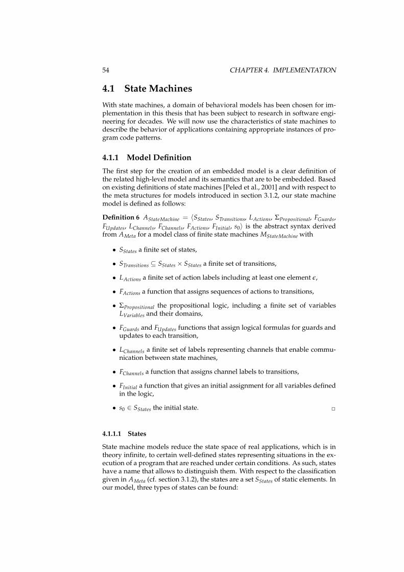
54 CHAPTER 4. IMPLEMENTATION
4.1 State Machines
With state machines, a domain of behavioral models has been chosen for im-plementation in this thesis that has been subject to research in software engi-neering for decades. We will now use the characteristics of state machines todescribe the behavior of applications containing appropriate instances of pro-gram code patterns.
4.1.1 Model Definition
The first step for the creation of an embedded model is a clear definition ofthe related high-level model and its semantics that are to be embedded. Basedon existing definitions of state machines [Peled et al., 2001] and with respect tothe meta structures for models introduced in section 3.1.2, our state machinemodel is defined as follows:
Definition 6 AStateMachine = 〈SStates, STransitions, LActions, ΣPropositional, FGuards,
FUpdates, LChannels, FChannels, FActions, FInitial, s0〉 is the abstract syntax derivedfrom AMeta for a model class of finite state machines MStateMachine with
• SStates a finite set of states,
• STransitions ⊆ SStates × SStates a finite set of transitions,
• LActions a finite set of action labels including at least one element ǫ,
• FActions a function that assigns sequences of actions to transitions,
• ΣPropositional the propositional logic, including a finite set of variablesLVariables and their domains,
• FGuards and FUpdates functions that assign logical formulas for guards andupdates to each transition,
• LChannels a finite set of labels representing channels that enable commu-nication between state machines,
• FChannels a function that assigns channel labels to transitions,
• FInitial a function that gives an initial assignment for all variables definedin the logic,
• s0 ∈ SStates the initial state. ✷
4.1.1.1 States
State machine models reduce the state space of real applications, which is intheory infinite, to certain well-defined states representing situations in the ex-ecution of a program that are reached under certain conditions. As such, stateshave a name that allows to distinguish them. With respect to the classificationgiven in AMeta (cf. section 3.1.2), the states are a set SStates of static elements. Inour model, three types of states can be found:
4.1. STATE MACHINES 55
• Exactly one state s0 ∈ SStates is the initial state denoting the start of thestate machine flow.
• Some states are final states. They have only incoming transitions. Atleast one final state exists in each model if the state machine is expectedto terminate. This is especially important for embedded state machinessince they are expected to return control to the surrounding application.
• States between the initial and final state have incoming and outgoingtransitions.
4.1.1.2 Transitions and Actions
The transitions in the set STransitions are also considered static elements. Theyare a subset of all possible transitions SStates × SStates and represent a switchbetween states in a program. Thus each transition has a source state and atarget state.
Transitions switch between states and thus modify the state space of theapplication. We define therefore that all activities happen when transitionsfire. For this reason, action labels are attached to transitions by a function.Actions are represented by a set of labels LActions. Sequences of actions areassigned to transitions with the function FActions so that each ∀t ∈ STransitions :∃LActionst ⊆ LActions. It is also possible that LActionst = ∅.
4.1.1.3 Variables, Guards, and Updates
In this state machine model, a set of variable labels LVariables and their datatypes is defined as part of the propositional logic ΣPropositional. When the statemachine is started, the function FInitial assigns an initial value to each variable.ΣPropositional itself is used to build expressions that access these variables. Inthe state machine model, expressions and variables are used for two purposes:Guards decide which outgoing transition to choose in the current state. Up-dates represent the changes to the state space that occured when transitionsfired and the related actions were initiated.
Guards are assigned to transitions with the function FGuards. They consistof an expression that is evaluated to a boolean value. The basic expression hasthree components:
• a left side which is always a variable identifier,
• an operator out of {==, ! =,<,<=,>,>=},
• a right side which is a literal value or another variable identifier.
Basic expressions can be aggregated to complex expressions with union (||)and intersection (&&) operators.
Updates are assigned to transitions with the function FUpdates. They consistof a set of expressions that assign new values to variables. The left-hand side ofeach assignment is always a variable. The right-hand side consists of expres-sions that follow the same rules as guards. However, updates are expected toallow for comparisons with the point in time before the transition fired in order
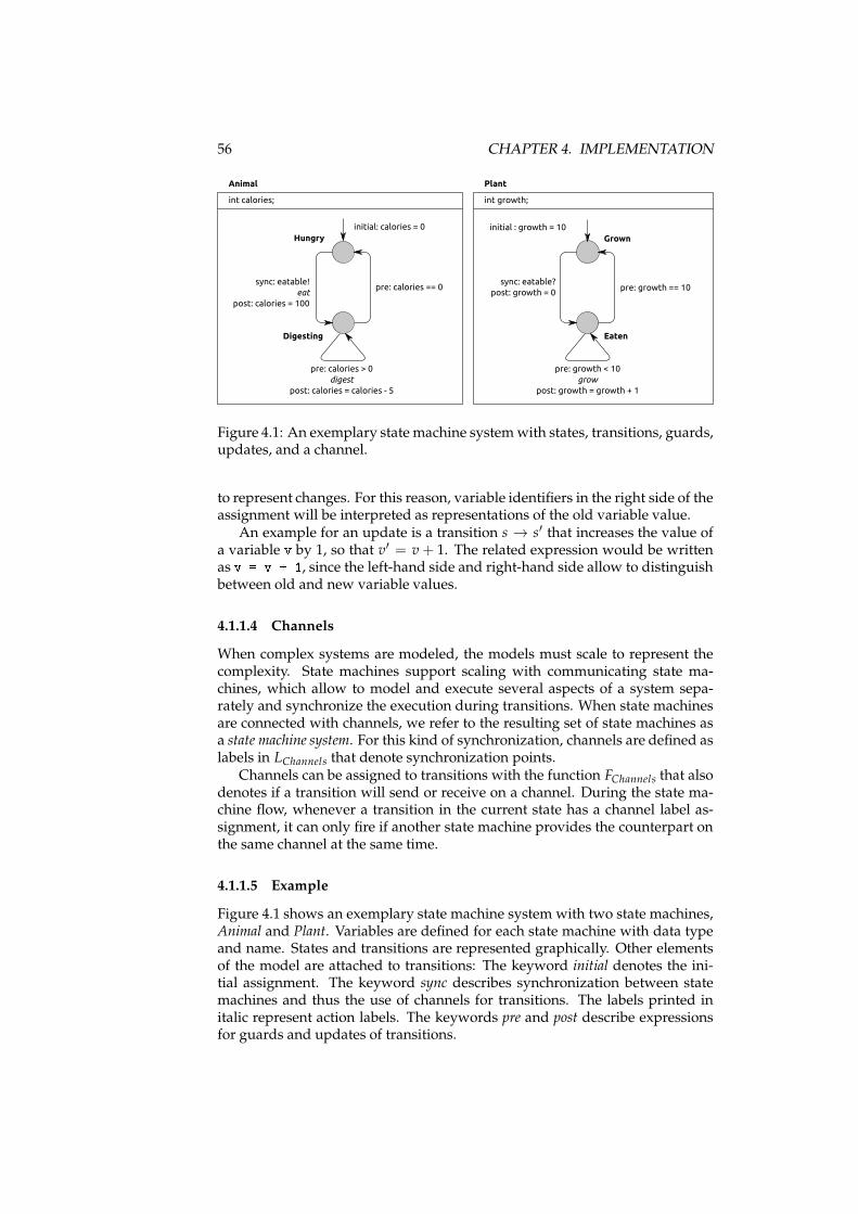
56 CHAPTER 4. IMPLEMENTATION
Hungry
Digesting
Grown
Eaten
sync: eatable!
eat
post: calories = 100
sync: eatable?
post: growth = 0pre: calories == 0
pre: calories > 0
digest
post: calories = calories - 5
pre: growth == 10
pre: growth < 10
grow
post: growth = growth + 1
Animal Plant
initial: calories = 0 initial : growth = 10
int calories; int growth;
Figure 4.1: An exemplary state machine systemwith states, transitions, guards,updates, and a channel.
to represent changes. For this reason, variable identifiers in the right side of theassignment will be interpreted as representations of the old variable value.
An example for an update is a transition s → s′ that increases the value ofa variable v by 1, so that v′ = v+ 1. The related expression would be writtenas v = v + 1, since the left-hand side and right-hand side allow to distinguishbetween old and new variable values.
4.1.1.4 Channels
When complex systems are modeled, the models must scale to represent thecomplexity. State machines support scaling with communicating state ma-chines, which allow to model and execute several aspects of a system sepa-rately and synchronize the execution during transitions. When state machinesare connected with channels, we refer to the resulting set of state machines asa state machine system. For this kind of synchronization, channels are defined aslabels in LChannels that denote synchronization points.
Channels can be assigned to transitions with the function FChannels that alsodenotes if a transition will send or receive on a channel. During the state ma-chine flow, whenever a transition in the current state has a channel label as-signment, it can only fire if another state machine provides the counterpart onthe same channel at the same time.
4.1.1.5 Example
Figure 4.1 shows an exemplary state machine system with two state machines,Animal and Plant. Variables are defined for each state machine with data typeand name. States and transitions are represented graphically. Other elementsof the model are attached to transitions: The keyword initial denotes the ini-tial assignment. The keyword sync describes synchronization between statemachines and thus the use of channels for transitions. The labels printed initalic represent action labels. The keywords pre and post describe expressionsfor guards and updates of transitions.
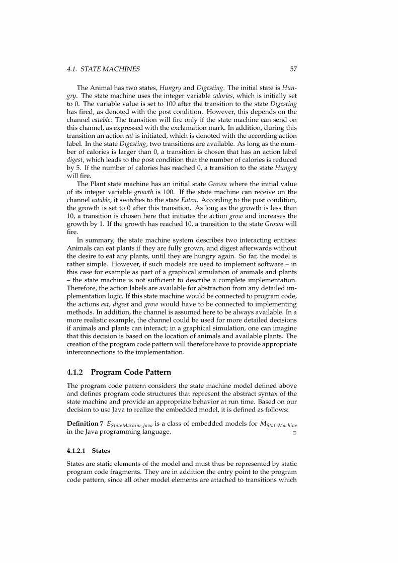
4.1. STATE MACHINES 57
The Animal has two states, Hungry and Digesting. The initial state is Hun-gry. The state machine uses the integer variable calories, which is initially setto 0. The variable value is set to 100 after the transition to the state Digestinghas fired, as denoted with the post condition. However, this depends on thechannel eatable: The transition will fire only if the state machine can send onthis channel, as expressed with the exclamation mark. In addition, during thistransition an action eat is initiated, which is denoted with the according actionlabel. In the state Digesting, two transitions are available. As long as the num-ber of calories is larger than 0, a transition is chosen that has an action labeldigest, which leads to the post condition that the number of calories is reducedby 5. If the number of calories has reached 0, a transition to the state Hungrywill fire.
The Plant state machine has an initial state Grown where the initial valueof its integer variable growth is 100. If the state machine can receive on thechannel eatable, it switches to the state Eaten. According to the post condition,the growth is set to 0 after this transition. As long as the growth is less than10, a transition is chosen here that initiates the action grow and increases thegrowth by 1. If the growth has reached 10, a transition to the state Grown willfire.
In summary, the state machine system describes two interacting entities:Animals can eat plants if they are fully grown, and digest afterwards withoutthe desire to eat any plants, until they are hungry again. So far, the model israther simple. However, if such models are used to implement software – inthis case for example as part of a graphical simulation of animals and plants– the state machine is not sufficient to describe a complete implementation.Therefore, the action labels are available for abstraction from any detailed im-plementation logic. If this state machine would be connected to program code,the actions eat, digest and grow would have to be connected to implementingmethods. In addition, the channel is assumed here to be always available. In amore realistic example, the channel could be used for more detailed decisionsif animals and plants can interact; in a graphical simulation, one can imaginethat this decision is based on the location of animals and available plants. Thecreation of the program code patternwill therefore have to provide appropriateinterconnections to the implementation.
4.1.2 Program Code Pattern
The program code pattern considers the state machine model defined aboveand defines program code structures that represent the abstract syntax of thestate machine and provide an appropriate behavior at run time. Based on ourdecision to use Java to realize the embedded model, it is defined as follows:
Definition 7 EStateMachine,Java is a class of embedded models for MStateMachine
in the Java programming language. ✷
4.1.2.1 States
States are static elements of the model and must thus be represented by staticprogram code fragments. They are in addition the entry point to the programcode pattern, since all other model elements are attached to transitions which
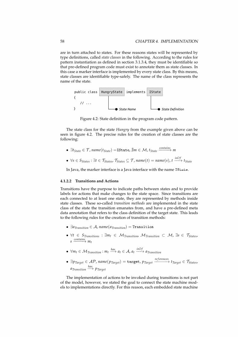
58 CHAPTER 4. IMPLEMENTATION
are in turn attached to states. For these reasons states will be represented bytype definitions, called state classes in the following. According to the rules forpattern instantiation as defined in section 3.1.3.4, they must be identifiable sothat pre-defined program code must exist to annotate them as state classes. Inthis case a marker interface is implemented by every state class. By this means,state classes are identifiable type-safely. The name of the class represents thename of the state.
public class HungryState implements IState
{
// ...
} State DefinitionState Name
Figure 4.2: State definition in the program code pattern.
The state class for the state Hungry from the example given above can beseen in figure 4.2. The precise rules for the creation of state classes are thefollowing:
• ∃tState ∈ T , name(tState) =IState, ∄m ∈ M, tStatecontains−−−−→ m
• ∀s ∈ SStates : ∃t ∈ TStates, TStates ⊆ T , name(t) = name(s), tisO f−−→ tState
In Java, the marker interface is a Java interface with the name IState.4.1.2.2 Transitions and Actions
Transitions have the purpose to indicate paths between states and to providelabels for actions that make changes to the state space. Since transitions areeach connected to at least one state, they are represented by methods insidestate classes. These so-called transition methods are implemented in the stateclass of the state the transition emanates from, and have a pre-defined metadata annotation that refers to the class definition of the target state. This leadsto the following rules for the creation of transition methods:
• ∃aTransition ∈ A, name(aTransition) = Transition• ∀t ∈ STransitions : ∃mt ∈ MTransition, MTransition ⊂ M, ∃s ∈ TStates,
scontains−−−−→ mt
• ∀mt ∈ MTransition : mthas−→ at ∈ A, at
isO f−−→ aTransition
• ∃pTarget ∈ AP , name(pTarget) = target, pTarget re f erences−−−−−→ tTarget ∈ TStates,
aTransitionhas−→ pTarget
The implementation of actions to be invoked during transitions is not partof the model, however, we stated the goal to connect the state machine mod-els to implementations directly. For this reason, each embedded state machine
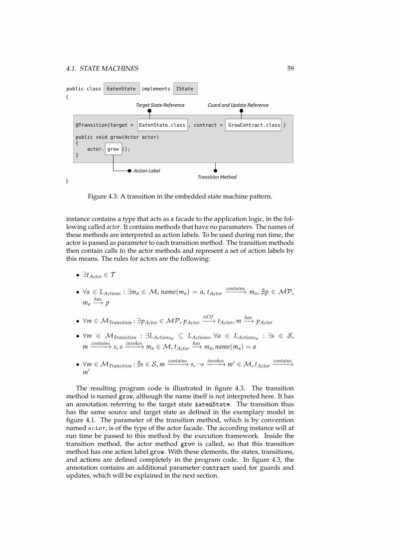
4.1. STATE MACHINES 59
public class EatenState implements IState
{
@Transition(target = EatenState.class , contract = GrowContract.class )
public void grow(Actor actor)
{
actor. grow ();
}
}
Target State Reference
Action Label
Guard and Update Reference
Transition Method
Figure 4.3: A transition in the embedded state machine pattern.
instance contains a type that acts as a facade to the application logic, in the fol-lowing called actor. It contains methods that have no paramaters. The names ofthese methods are interpreted as action labels. To be used during run time, theactor is passed as parameter to each transition method. The transition methodsthen contain calls to the actor methods and represent a set of action labels bythis means. The rules for actors are the following:
• ∃tActor ∈ T
• ∀a ∈ LActions : ∃ma ∈ M, name(ma) = a, tActorcontains−−−−→ ma, ∄p ∈ MP ,
mahas−→ p
• ∀m ∈ MTransition : ∃pActor ∈ MP , pActorisO f−−→ tActor, m
has−→ pActor
• ∀m ∈ MTransition : ∃LActionsm ⊆ LActions, ∀a ∈ LActionsm : ∃s ∈ S ,
mcontains−−−−→ s, s
invokes−−−−→ ma ∈ M, tActor
has−→ ma, name(ma) = a
• ∀m ∈ MTransition : ∄s ∈ S , mcontains−−−−→ s, ¬s
invokes−−−−→ m′ ∈ M, tActor
contains−−−−→
m′
The resulting program code is illustrated in figure 4.3. The transitionmethod is named grow, although the name itself is not interpreted here. It hasan annotation referring to the target state EatenState. The transition thushas the same source and target state as defined in the exemplary model infigure 4.1. The parameter of the transition method, which is by conventionnamed a tor, is of the type of the actor facade. The according instance will atrun time be passed to this method by the execution framework. Inside thetransition method, the actor method grow is called, so that this transitionmethod has one action label grow. With these elements, the states, transitions,and actions are defined completely in the program code. In figure 4.3, theannotation contains an additional parameter ontra t used for guards andupdates, which will be explained in the next section.
60 CHAPTER 4. IMPLEMENTATION
public interface IAnimalVariables
{
int getCalories ();
}
Variable Name
Variable Data Type
Figure 4.4: A variable facade type defining a variable alories as used in theexample in section 4.1.1.5.
4.1.2.3 Variables, Guards, and Updates
One of the focal points of the state machine model introduced above is the con-sideration of a state space defined by variables that have a name and a datatype. This state space is on the one hand interpreted by guards in order todecide which transitions are to fire. On the other hand, it is modified by up-dates to denote changes to the state space that occur during transitions. Theconsideration of the state space is of special interest in the context of embed-ded models: In contrast to the formal model itself, they are not self-contained,but instead part of larger applications. By this means the state space of theembedded state machine is only part of the larger state space of the overallapplication. However, the overall state space is not defined within the contextof state machines, or may even consist of data types and value ranges that arenot appropriate for use in the context of state machines. For this reason, theabstraction defining the limits between model and other program code mustbe reflected to focus on the subset of the state space that is of interest to themodel accordingly.
Similar to actions, variables are defined in a facade type, too. This is realizedby an interface containing a method for each variable that defines its name anddata type as shown in figure 4.4. For this purpose the following rules apply:
• ∃tVariables ∈ T
• ∀v ∈ LVariables : ∃mv ∈ M, name(mv) = v, tVariablescontains−−−−→ mv,
mvreturns−−−−→ tv ∈ T , mv
contains−−−−→ ǫ
FInitial is by this means defined by the return values of all methods of thevariables facade instance at the point in time when the state machine is exe-cuted.
In Java, the methods in the variables interface are defined as get methods(cf. section 3.1.3.3).
As shown in figure 4.3, guards and updates are assigned to transitions by areference to a so-called “contract class” in the meta data annotation. Contractclasses define two methods containing the expressions for guard and update.Both return a boolean value. Classes are denoted contract classes with theimplementation of a pre-defined interface named IContra t that defines theguard and update methods, which are named he kCondition and validate.Guards and updates both consist of expressions with formulas in ΣPropositional
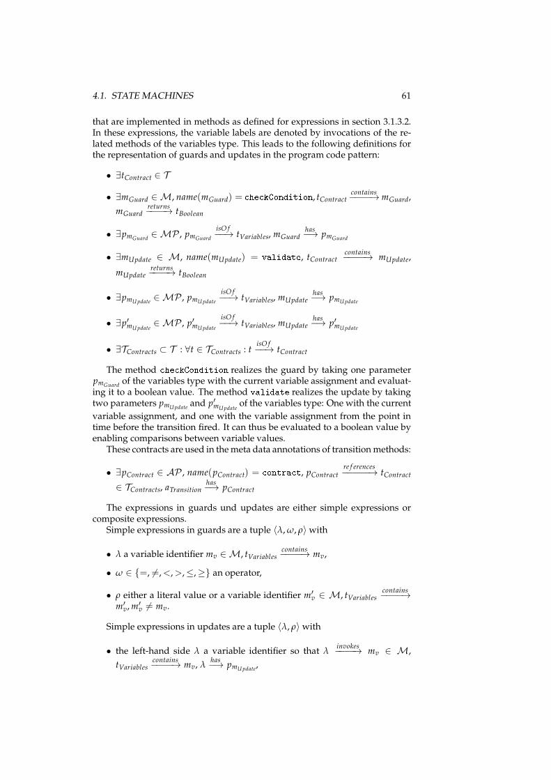
4.1. STATE MACHINES 61
that are implemented in methods as defined for expressions in section 3.1.3.2.In these expressions, the variable labels are denoted by invocations of the re-lated methods of the variables type. This leads to the following definitions forthe representation of guards and updates in the program code pattern:
• ∃tContract ∈ T
• ∃mGuard ∈ M, name(mGuard) = he kCondition, tContract contains−−−−→mGuard,
mGuardreturns−−−−→ tBoolean
• ∃pmGuard∈ MP , pmGuard
isO f−−→ tVariables, mGuard
has−→ pmGuard
• ∃mUpdate ∈ M, name(mUpdate) = validate, tContract contains−−−−→ mUpdate,
mUpdatereturns−−−−→ tBoolean
• ∃pmUpdate∈ MP , pmUpdate
isO f−−→ tVariables, mUpdate
has−→ pmUpdate
• ∃p′mUpdate∈ MP , p′mUpdate
isO f−−→ tVariables, mUpdate
has−→ p′mUpdate
• ∃TContracts ⊂ T : ∀t ∈ TContracts : tisO f−−→ tContract
The method he kCondition realizes the guard by taking one parameterpmGuard
of the variables type with the current variable assignment and evaluat-ing it to a boolean value. The method validate realizes the update by takingtwo parameters pmUpdate
and p′mUpdateof the variables type: One with the current
variable assignment, and one with the variable assignment from the point intime before the transition fired. It can thus be evaluated to a boolean value byenabling comparisons between variable values.
These contracts are used in themeta data annotations of transitionmethods:
• ∃pContract ∈ AP , name(pContract) = ontra t, pContract re f erences−−−−−→ tContract
∈ TContracts, aTransitionhas−→ pContract
The expressions in guards und updates are either simple expressions orcomposite expressions.
Simple expressions in guards are a tuple 〈λ,ω, ρ〉with
• λ a variable identifier mv ∈ M, tVariablescontains−−−−→ mv,
• ω ∈ {=, 6=,<,>,≤,≥} an operator,
• ρ either a literal value or a variable identifier m′v ∈ M, tVariables
contains−−−−→
m′v,m
′v 6= mv.
Simple expressions in updates are a tuple 〈λ, ρ〉with
• the left-hand side λ a variable identifier so that λinvokes−−−−→ mv ∈ M,
tVariablescontains−−−−→ mv, λ
has−→ pmUpdate
,
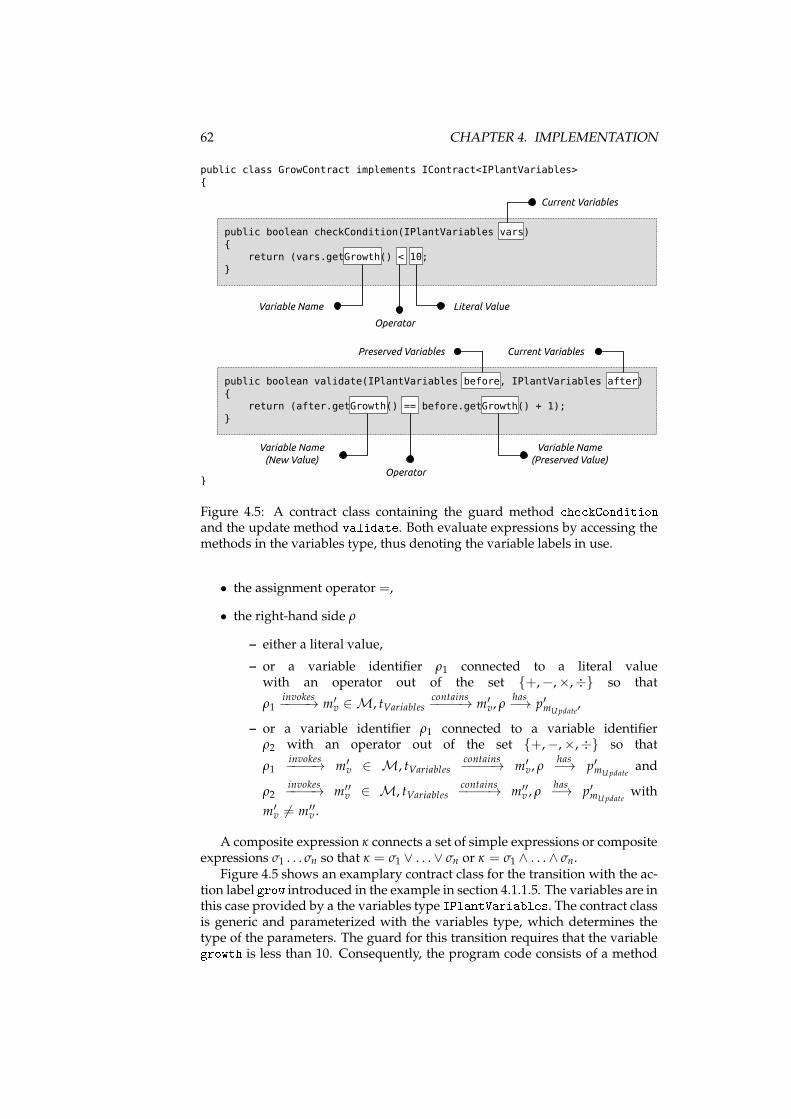
62 CHAPTER 4. IMPLEMENTATION
public class GrowContract implements IContract<IPlantVariables>
{
public boolean checkCondition(IPlantVariables vars)
{
return (vars.getGrowth() < 10;
}
public boolean validate(IPlantVariables before, IPlantVariables after)
{
return (after.getGrowth() == before.getGrowth() + 1);
}
}
Variable Name
Current Variables
Literal Value
Operator
Current VariablesPreserved Variables
Variable Name
(New Value)
Operator
Variable Name
(Preserved Value)
Figure 4.5: A contract class containing the guard method he kConditionand the update method validate. Both evaluate expressions by accessing themethods in the variables type, thus denoting the variable labels in use.
• the assignment operator =,
• the right-hand side ρ
– either a literal value,
– or a variable identifier ρ1 connected to a literal valuewith an operator out of the set {+,−,×,÷} so that
ρ1invokes−−−−→ m′
v ∈ M, tVariablescontains−−−−→ m′
v, ρhas−→ p′mUpdate
,
– or a variable identifier ρ1 connected to a variable identifierρ2 with an operator out of the set {+,−,×,÷} so that
ρ1invokes−−−−→ m′
v ∈ M, tVariablescontains−−−−→ m′
v, ρhas−→ p′mUpdate
and
ρ2invokes−−−−→ m′′
v ∈ M, tVariablescontains−−−−→ m′′
v , ρhas−→ p′mUpdate
with
m′v 6= m′′
v .
A composite expression κ connects a set of simple expressions or compositeexpressions σ1 . . . σn so that κ = σ1 ∨ . . .∨ σn or κ = σ1 ∧ . . . ∧ σn.
Figure 4.5 shows an examplary contract class for the transition with the ac-tion label grow introduced in the example in section 4.1.1.5. The variables are inthis case provided by a the variables type IPlantVariables. The contract classis generic and parameterized with the variables type, which determines thetype of the parameters. The guard for this transition requires that the variablegrowth is less than 10. Consequently, the program code consists of a method
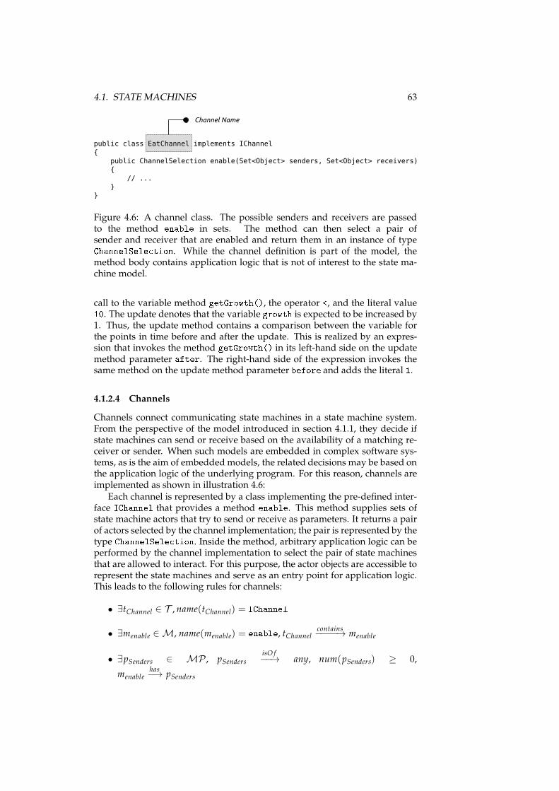
4.1. STATE MACHINES 63
public class EatChannel implements IChannel
{
public ChannelSelection enable(Set<Object> senders, Set<Object> receivers)
{
// ...
}
}
Channel Name
Figure 4.6: A channel class. The possible senders and receivers are passedto the method enable in sets. The method can then select a pair ofsender and receiver that are enabled and return them in an instance of typeChannelSele tion. While the channel definition is part of the model, themethod body contains application logic that is not of interest to the state ma-chine model.
call to the variable method getGrowth(), the operator <, and the literal value10. The update denotes that the variable growth is expected to be increased by1. Thus, the update method contains a comparison between the variable forthe points in time before and after the update. This is realized by an expres-sion that invokes the method getGrowth() in its left-hand side on the updatemethod parameter after. The right-hand side of the expression invokes thesame method on the update method parameter before and adds the literal 1.4.1.2.4 Channels
Channels connect communicating state machines in a state machine system.From the perspective of the model introduced in section 4.1.1, they decide ifstate machines can send or receive based on the availability of a matching re-ceiver or sender. When such models are embedded in complex software sys-tems, as is the aim of embedded models, the related decisions may be based onthe application logic of the underlying program. For this reason, channels areimplemented as shown in illustration 4.6:
Each channel is represented by a class implementing the pre-defined inter-face IChannel that provides a method enable. This method supplies sets ofstate machine actors that try to send or receive as parameters. It returns a pairof actors selected by the channel implementation; the pair is represented by thetype ChannelSele tion. Inside the method, arbitrary application logic can beperformed by the channel implementation to select the pair of state machinesthat are allowed to interact. For this purpose, the actor objects are accessible torepresent the state machines and serve as an entry point for application logic.This leads to the following rules for channels:
• ∃tChannel ∈ T , name(tChannel) = IChannel• ∃menable ∈ M, name(menable) = enable, tChannel contains
−−−−→ menable
• ∃pSenders ∈ MP , pSendersisO f−−→ any, num(pSenders) ≥ 0,
menablehas−→ pSenders
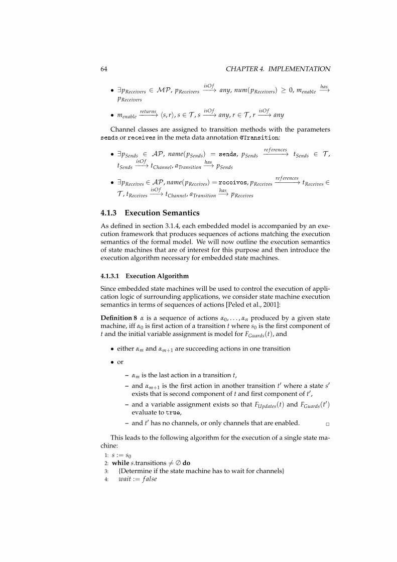
64 CHAPTER 4. IMPLEMENTATION
• ∃pReceivers ∈ MP , pReceiversisO f−−→ any, num(pReceivers) ≥ 0, menable
has−→
pReceivers
• menablereturns−−−−→ 〈s, r〉, s ∈ T , s
isO f−−→ any, r ∈ T , r
isO f−−→ any
Channel classes are assigned to transition methods with the parameterssends or re eives in the meta data annotation �Transition:• ∃pSends ∈ AP , name(pSends) = sends, pSends
re f erences−−−−−→ tSends ∈ T ,
tSendsisO f−−→ tChannel, aTransition
has−→ pSends
• ∃pReceives ∈ AP , name(pReceives) = re eives, pReceives re f erences−−−−−→ tReceives ∈
T , tReceivesisO f−−→ tChannel, aTransition
has−→ pReceives
4.1.3 Execution Semantics
As defined in section 3.1.4, each embedded model is accompanied by an exe-cution framework that produces sequences of actions matching the executionsemantics of the formal model. We will now outline the execution semanticsof state machines that are of interest for this purpose and then introduce theexecution algorithm necessary for embedded state machines.
4.1.3.1 Execution Algorithm
Since embedded state machines will be used to control the execution of appli-cation logic of surrounding applications, we consider state machine executionsemantics in terms of sequences of actions [Peled et al., 2001]:
Definition 8 α is a sequence of actions α0, . . . , αn produced by a given statemachine, iff α0 is first action of a transition t where s0 is the first component oft and the initial variable assignment is model for FGuards(t), and
• either αm and αm+1 are succeeding actions in one transition
• or
– αm is the last action in a transition t,
– and αm+1 is the first action in another transition t′ where a state s′
exists that is second component of t and first component of t′,
– and a variable assignment exists so that FUpdates(t) and FGuards(t′)
evaluate to true,– and t′ has no channels, or only channels that are enabled. ✷
This leads to the following algorithm for the execution of a single state ma-chine:
1: s := s02: while s.transitions 6= ∅ do3: {Determine if the state machine has to wait for channels}4: wait := f alse
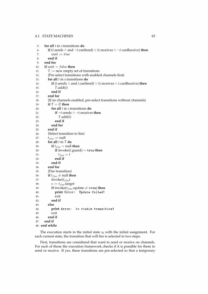
4.1. STATE MACHINES 65
5: for all t in s.transitions do6: if (t.sends ∧ and ¬t.canSend) ∨ (t.receives ∧ ¬t.canReceive) then7: wait := true8: end if9: end for10: if wait = f alse then11: T := new empty set of transitions12: {Pre-select transitions with enabled channels first}13: for all t in s.transitions do14: if (t.sends ∧ and t.canSend) ∨ (t.receives ∧ t.canReceive) then15: T.add(t)16: end if17: end for18: {If no channels enabled, pre-select transitions without channels}19: if T = ∅ then20: for all t in s.transitions do21: if ¬t.sends ∧ ¬t.receives then22: T.add(t)23: end if24: end for25: end if26: {Select transition to fire}27: t f ire := null28: for all t in T do29: if t f ire = null then30: if invoke(t.guard) = true then31: t f ire = t32: end if33: end if34: end for35: {Fire transition}36: if t f ire 6= null then37: invoke(t f ire)38: s := t f ire.target39: if invoke(t f ire.update 6= true) then40: print Error: Update failed!41: exit42: end if43: else44: print Error: No viable transition!45: exit46: end if47: end if48: end while
The execution starts in the initial state s0 with the initial assignment. Foreach current state, the transition that will fire is selected in two steps.
First, transitions are considered that want to send or receive on channels.For each of those the execution framework checks if it is possible for them tosend or receive. If yes, these transitions are pre-selected so that a temporary
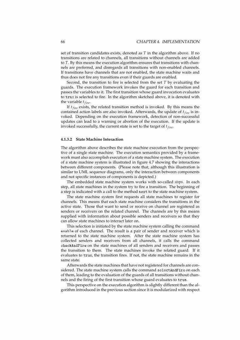
66 CHAPTER 4. IMPLEMENTATION
set of transition candidates exists, denoted as T in the algorithm above. If notransitions are related to channels, all transitions without channels are addedto T. By this means the execution algorithm ensures that transitions with chan-nels are preferred, and disregards all transitions with non-enabled channels.If transitions have channels that are not enabled, the state machine waits andthus does not fire any transitions even if their guards are enabled.
Second, the transition to fire is selected from the set T by evaluating theguards. The execution framework invokes the guard for each transition andpasses the variables to it. The first transition whose guard invocation evaluatesto true is selected to fire. In the algorithm sketched above, it is denoted withthe variable t f ire.
If t f ire exists, the related transition method is invoked. By this means thecontained action labels are also invoked. Afterwards, the update of t f ire is in-voked. Depending on the execution framework, detection of non-successfulupdates can lead to a warning or abortion of the execution. If the update isinvoked successfully, the current state is set to the target of t f ire.
4.1.3.2 State Machine Interaction
The algorithm above describes the state machine execution from the perspec-tive of a single state machine. The execution semantics provided by a frame-work must also accomplish execution of a state machine system. The executionof a state machine system is illustrated in figure 4.7 showing the interactionsbetween different components. (Please note that, although this illustration issimilar to UML sequence diagrams, only the interaction between componentsand not specific instances of components is depicted.)
The embedded state machine system works with so-called steps. In eachstep, all state machines in the system try to fire a transition. The beginning ofa step is indicated with a call to the method next to the state machine system.
The state machine system first requests all state machines to register forchannels. This means that each state machine considers the transitions in theactive state. Those that want to send or receive on channel are registered assenders or receivers on the related channel. The channels are by this meanssupplied with information about possible senders and receivers so that theycan allow state machines to interact later on.
This selection is initiated by the state machine system calling the commandenable of each channel. The result is a pair of sender and receiver which isreturned to the state machine system. After the state machine system hascollected senders and receivers from all channels, it calls the command he kAndFire on the state machines of all senders and receivers and passesthe transition to them. The state machines invoke the related guard. If itevaluates to true, the transition fires. If not, the state machine remains in thesame state.
Afterwards the statemachines that have not registered for channels are con-sidered. The state machine system calls the command sele tAndFire on eachof them, leading to the evaluation of the guards of all transitions without chan-nels and the firing of the first transition whose guard evaluates to true.
This perspective on the execution algorithm is slightly different than the al-gorithm introduced in the previous section since it is modularized with respect
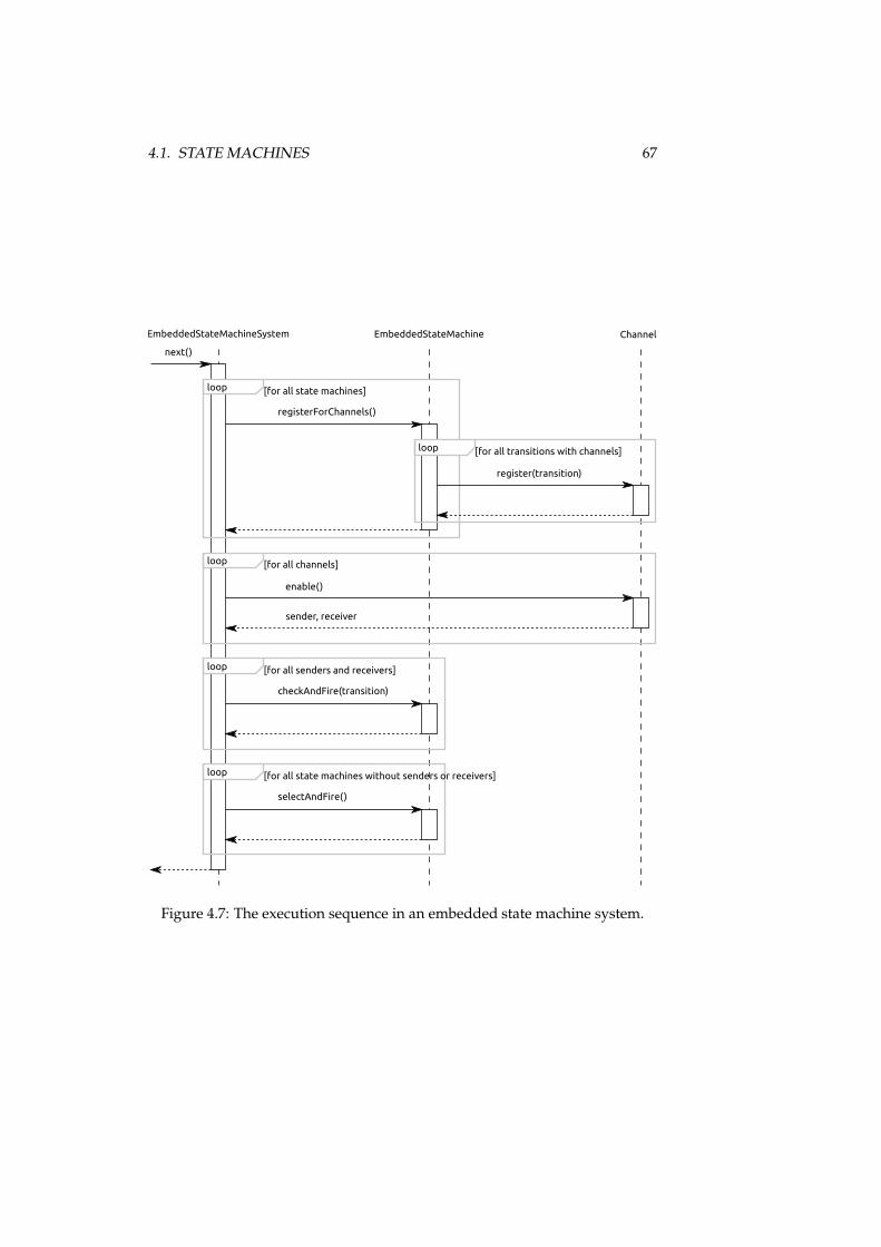
4.1. STATE MACHINES 67
EmbeddedStateMachineSystem EmbeddedStateMachine
loop [for all state machines]
registerForChannels()
Channel
loop [for all transitions with channels]
register(transition)
loop [for all channels]
enable()
sender, receiver
loop [for all senders and receivers]
checkAndFire(transition)
loop [for all state machines without senders or receivers]
selectAndFire()
next()
Figure 4.7: The execution sequence in an embedded state machine system.
68 CHAPTER 4. IMPLEMENTATION
to the participating components. However, the execution semantics are equiva-lent since the algorithm for single state machines abstracts from the interactiondetails, but performs the same actions.
4.1.3.3 Use of Program Code Fragments
The execution framework for embedded state machines works with the ele-ments of the program code pattern.
For this purpose, the graph of states and transitions is interpreted by the ex-ecution framework. It reads the static structures of state classes marked withthe interface IState, transition methods, and the transition meta data annota-tion �Transition with the parameter target. The framework also interpretsthe transition meta data parameter ontra t and the related contract classesthat implement the interface IContra t. For channels, the transition meta dataparameters sends or re eives are read together with the channel classes im-plementing the interface IChannel.
These static structures are interpreted by the execution framework to deter-mine invocations of program code for making decisions or initiating the execu-tion of actions. Following the execution semantics introduced above, this firstconcerns the method enable provided by the interface IChannel for the chan-nel types. Before transitions fire, their guards are checked with the method he kCondition determined by the interface IContra t for contract classes.When a transition is selected, its method is invoked so that the contained actormethods representing the action labels are invoked by this means, too. After-wards, the method validate in the related contract is invoked. The locationsof these four executable parts are determined by the static structures that areinterpreted. The executable parts themselves are considered black boxes by theexecution framework.
4.1.4 Interface Definitions
As described in section 3.1.5, interfaces are an important part of the programcode patterns since they connect embedded models to arbitrary applicationlogic of the programs the models are embedded in. In embedded state ma-chines, three kinds of interfaces exist:
• The actor is a collection of labels. It is action-oriented since the methodsprovide entry points to the application logic, but do not return any data.Actors are accessed in transition methods and channel classes.
• The variables facade is a collection of labels. It is data-oriented sincevariable methods deliver variable values from the state space of thesurrounding program, which are possibly aggregated. Variables areaccessed in guard and update methods.
• Channels each represent one label. They are data-oriented, too, since theyprocess application logic to determine which pair of sender or receiverwill be enabled, and thus only return this pair. Channels are not accessedfrom inside the program code pattern, but only from the execution frame-work.
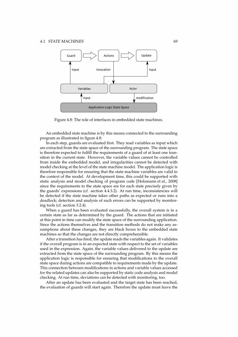
4.1. STATE MACHINES 69
Guard Actions Update
Variables Actor
Application Logic State Space
input inputinvocation
modificationinput
Figure 4.8: The role of interfaces in embedded state machines.
An embedded state machine is by this means connected to the surroundingprogram as illustrated in figure 4.8:
In each step, guards are evaluated first. They read variables as input whichare extracted from the state space of the surrounding program. The state spaceis therefore expected to fulfill the requirements of a guard of at least one tran-sition in the current state. However, the variable values cannot be controlledfrom inside the embedded model, and irregularities cannot be detected withmodel checking at the level of the statemachine model. The application logic istherefore responsible for ensuring that the state machine variables are valid inthe context of the model. At development time, this could be supported withstatic analysis and model checking of program code [Holzmann et al., 2008]since the requirements to the state space are for each state precisely given bythe guards’ expressions (cf. section 4.4.3.2). At run time, inconsistencies willbe detected if the state machine takes other paths as expected or runs into adeadlock; detection and analysis of such errors can be supported by monitor-ing tools (cf. section 3.2.4).
When a guard has been evaluated successfully, the overall system is in acertain state as far as determined by the guard. The actions that are initiatedat this point in time can modify the state space of the surrounding application.Since the actions themselves and the transition methods do not make any as-sumptions about these changes, they are black boxes to the embedded statemachines so that the changes are not directly comprehensible.
After a transition has fired, the update reads the variables again. It validatesif the overall program is in an expected state with respect to the set of variablesused in the expression. Again, the variable values delivered to the update areextracted from the state space of the surrounding program. By this means theapplication logic is responsible for ensuring that modifications to the overallstate space during actions are compatible to requirements made by the update.This connection betweenmodifications in actions and variable values accessedfor the related updates can also be supported by static code analysis andmodelchecking. At run time, deviations can be detected with monitoring, too.
After an update has been evaluated and the target state has been reached,the evaluation of guards will start again. Therefore the update must leave the
70 CHAPTER 4. IMPLEMENTATION
system in a state that is compatible to the requirements of the next guard. Sincethis affects the variables of the state machine, it can be validated at the level ofthemodel. However, for this validation to bemeaningful, the variablemethodsare required not to change the overall state space themselves. Modifications tothe state space should occur during actions only, which conforms to the modelsemantics. This requirement can also be validated with static code analysis.
The method enable in channels can access the application logic via actorsto decide which pair of sender and receiver will be enabled. Since the princi-ple that only actions should modify the state space applies here, too, channelsshould access actors only for reading. Since the enable methods are not partof the model, but represented in the model only with the channel’s name, theinteractions there are not comprehensible at the level of the model. Again, theapplication logic is responsible for working in a way that is compatible withthe model semantics, which can be validated with static code analysis basedon slicing (cf. section 3.1.5.2).
4.1.5 Transformations
To enable working at different abstraction levels, transformations are necessaryfor embedded state machines as described in section 3.1.6. For the domain ofstate machines, several views can exist for editing, verification, model check-ing, and monitoring. We will outline the default transformations here and thenintroduce a special transformation to the automata model checking tool UP-PAAL.
4.1.5.1 Default Transformations
The default transformation extracting the model from source code considersthe elements of the program code pattern as introduced in section 4.1.2:
• States with their names;
• transitions with their names, action labels, and references to targets, con-tracts, and channels;
• channels with their names;
• variables with their names and data types;
• actor methods with their names;
• guards and updates with their expressions.
The default transformation extracting the model from byte code works withthe following elements:
• States with their names;
• transitions with their names, target, contract, and channels references;
• channels with their names;
• variables with their names and data types;
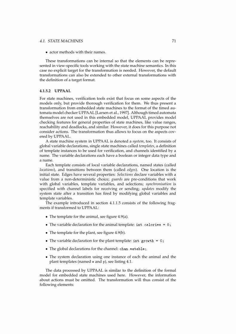
4.1. STATE MACHINES 71
• actor methods with their names.
These transformations can be internal so that the elements can be repre-sented in view-specific tools working with the state machine semantics. In thiscase no explicit target for the transformation is needed. However, the defaulttransformations can also be extended to other external transformations withthe definition of a target format.
4.1.5.2 UPPAAL
For state machines, verification tools exist that focus on some aspects of themodels only, but provide thorough verification for them. We thus present atransformation from embedded state machines to the format of the timed au-tomatamodel checker UPPAAL [Larsen et al., 1997]. Although timed automatathemselves are not used in this embedded model, UPPAAL provides modelchecking features for general properties of state machines, like value ranges,reachability and deadlocks, and similar. However, it does for this purpose notconsider actions. The transformation thus allows to focus on the aspects cov-ered by UPPAAL.
A state machine system in UPPAAL is denoted a system, too. It consists ofglobal variable declarations, single state machines called templates, a definitionof template instances to be used for verification, and channels identified by aname. The variable declarations each have a boolean or integer data type anda name.
Each template consists of local variable declarations, named states (calledlocations), and transitions between them (called edges). One location is theinitial state. Edges have several properties: Selections declare variables with avalue from a non-deterministic choice; guards are pre-conditions that workwith global variables, template variables, and selections; synchronisation isspecified with channel labels for receiving or sending; updates modify thesystem state after a transition has fired by modifying global variables andtemplate variables.
The example introduced in section 4.1.1.5 consists of the following frag-ments if transformed to UPPAAL:
• The template for the animal, see figure 4.9(a).
• The variable declaration for the animal template: int alories = 0;• The template for the plant, see figure 4.9(b).
• The variable declaration for the plant template: int growth = 0;• The global declarations for the channel: han eatable;• The system declaration using one instance of each the animal and theplant templates (named a and p), see listing 4.1.
The data processed by UPPAAL is similar to the definition of the formalmodel for embedded state machines used here. However, the informationabout actions must be omitted. The transformation will thus consist of thefollowing elements:
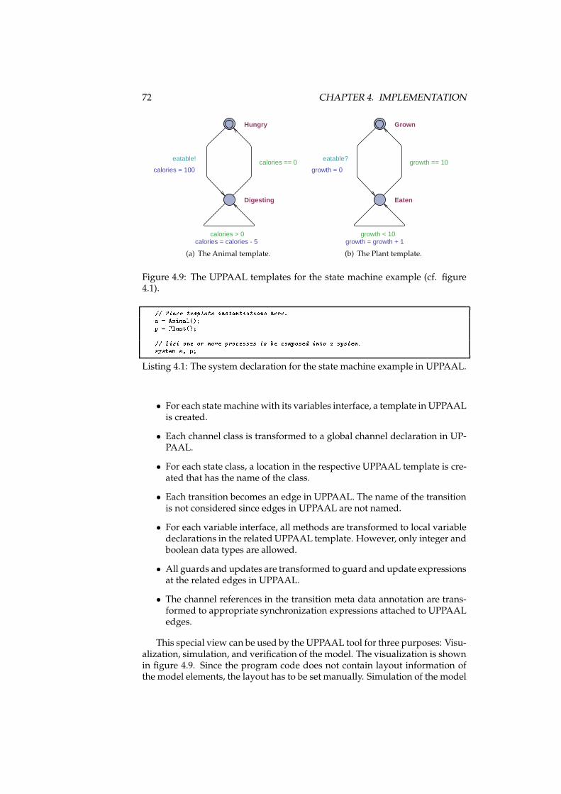
72 CHAPTER 4. IMPLEMENTATION
Digesting
Hungry
calories > 0calories = calories - 5
calories == 0eatable!
calories = 100
(a) The Animal template.
Eaten
Grown
growth < 10growth = growth + 1
growth == 10eatable?
growth = 0
(b) The Plant template.
Figure 4.9: The UPPAAL templates for the state machine example (cf. figure4.1).// Pla e template instantiations here.a = Animal();p = Plant();// List one or more pro esses to be omposed into a system.system a, p;Listing 4.1: The system declaration for the state machine example in UPPAAL.
• For each state machine with its variables interface, a template in UPPAALis created.
• Each channel class is transformed to a global channel declaration in UP-PAAL.
• For each state class, a location in the respective UPPAAL template is cre-ated that has the name of the class.
• Each transition becomes an edge in UPPAAL. The name of the transitionis not considered since edges in UPPAAL are not named.
• For each variable interface, all methods are transformed to local variabledeclarations in the related UPPAAL template. However, only integer andboolean data types are allowed.
• All guards and updates are transformed to guard and update expressionsat the related edges in UPPAAL.
• The channel references in the transition meta data annotation are trans-formed to appropriate synchronization expressions attached to UPPAALedges.
This special view can be used by the UPPAAL tool for three purposes: Visu-alization, simulation, and verification of the model. The visualization is shownin figure 4.9. Since the program code does not contain layout information ofthe model elements, the layout has to be set manually. Simulation of the model
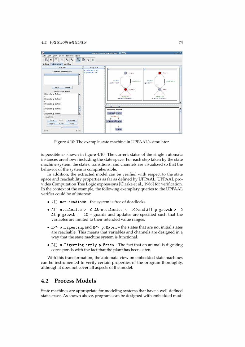
4.2. PROCESS MODELS 73
Figure 4.10: The example state machine in UPPAAL’s simulator.
is possible as shown in figure 4.10: The current states of the single automatainstances are shown including the state space. For each step taken by the statemachine system, the states, transitions, and channels are visualized so that thebehavior of the system is comprehensible.
In addition, the extracted model can be verified with respect to the statespace and reachability properties as far as defined by UPPAAL. UPPAAL pro-vides Computation Tree Logic expressions [Clarke et al., 1986] for verification.In the context of the example, the following exemplary queries to the UPPAALverifier could be of interest:
• A[℄ not deadlo k – the system is free of deadlocks.
• A[℄ a. alories >= 0 && a. alories <= 100 and A[℄ p.growth >= 0&& p.growth <= 10 – guards and updates are specified such that thevariables are limited to their intended value ranges.
• E<> a.Digesting and E<> p.Eaten – the states that are not initial statesare reachable. This means that variables and channels are designed in away that the state machine system is functional.
• E[℄ a.Digesting imply p.Eaten – The fact that an animal is digestingcorresponds with the fact that the plant has been eaten.
With this transformation, the automata view on embedded state machinescan be instrumented to verify certain properties of the program thoroughly,although it does not cover all aspects of the model.
4.2 Process Models
State machines are appropriate for modeling systems that have a well-definedstate space. As shown above, programs can be designed with embedded mod-
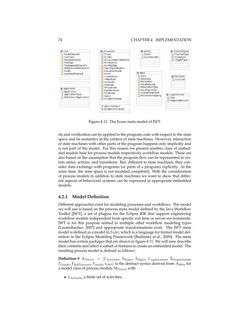
74 CHAPTER 4. IMPLEMENTATION
Figure 4.11: The Ecore meta model of JWT.
els and verification can be applied to the program code with respect to the statespace and its semantics in the context of state machines. However, interactionof state machines with other parts of the program happens only implicitly andis not part of the model. For this reason we present another class of embed-ded models here for process models respectively workflow models. These arealso based on the assumption that the program flow can be represented in cer-tain states, actions, and transitions. But, different to state machines, they con-sider data exchange with programs (or parts of a program) explicitly. At thesame time, the state space is not modeled completely. With the considerationof process models in addition to state machines we want to show that differ-ent aspects of behavioral systems can be expressed in appropriate embeddedmodels.
4.2.1 Model Definition
Different approaches exist for modeling processes and workflows. The modelwe will use is based on the process meta model defined by the Java WorkflowToolkit [JWT], a set of plugins for the Eclipse IDE that support engineeringworkflow models independent from specific run time or server environments.JWT is for this purpose related to multiple other workflow modeling types[Lautenbacher, 2007] and appropriate transformations exist. The JWT metamodel is defined as a model in Ecore, which is a language for formal model def-inition in the Eclipse Modeling Framework [Budinsky et al., 2009]. The metamodel has certain packages that are shown in figure 4.11. Wewill now describetheir contents and select a subset of features to create an embeddedmodel. Theresulting process model is defined as follows:
Definition 9 AProcess = 〈LActivities, SNodes, SEdges, LApplications, ΣPropositional,
FGuards, FSubProcesses, FInitial, sstart〉 is the abstract syntax derived from AMeta fora model class of process models MProcess with
• LActivities a finite set of activities,
4.2. PROCESS MODELS 75
• SNodes a finite set of nodes in activities,
• SEdges ⊆ SNodes × SNodes a finite set of edges,
• LApplications a finite set of application labels,
• ΣPropositional the propositional logic, including a finite set of variables(called data in the context of JWT) LData and a finite set of data types forvariables LDataTypes, which are combined in a set of variable declarationsSVariables,
• FSubProcesses a function that assigns sub process invocations to some nodes,
• FGuards a function that assigns logical formulas for guards to edges,
• FInitial a function that gives an initial assignment for all data defined inthe logic,
• sstart ∈ SNodes the initial node. ✷
4.2.1.1 Package oreThis package contains common supertypes for model elements and the basicelement Model that is the root object for all information in a JWT workflowmodel. It contains meta data for process models with the attributes author,version, des ription, and fileversion. These are not of interest for the em-bedded model itself. Considering the common supertypes in this package, themodel element NamedElement is of interest since many other elements extendit. It provides the attribute name that assigns a name to elements.
Model Definition These common supertypes do not contribute to the defini-tion of MProcess.
4.2.1.2 Packages data and primitiveTypesThe packages data and primitiveTypes contain descriptions for data used asinput and output of actions. Two basic data types are pre-defined: StringTypefor character strings and IntegerType for integer numbers. They do not haveany attributes since they are only used to identify data elements. Arbitrarytypes can be identified with model elements of type DataType that are de-scribed with a name. Data types are used by elements of type Data that have aname (attribute name), a value (attribute value), and a relation to the data type(attribute dataType). Each process model can thus have a set of data units thatcan be referenced by other model elements.
The package data also contains the model elements InputParameter andOutputParameter that define names and default values for parameters of ac-tions.
Furthermore, the package data contains model elements that allow to mapdata types. This is not of interest for embeddedmodels since the data definitionis to be integrated in the program code of surrounding applications, so we willnot consider this functionality.
76 CHAPTER 4. IMPLEMENTATION
Model Definition In AProcess, a set of variable labels LData and the set of theirdata types LDataTypes is defined as part of the propositional logic ΣPropositional.They represent the Data and DataType elements. We say that a variable declara-tion v is a tuple 〈d, t〉, d ∈ LData, t ∈ LDataTypes. SVariables is the set of all variabledeclarations. When the process is started, the function FInitial assigns an ini-tial value to each variable. ΣPropositional itself is used to build expressions thataccess these variables in guards. In addition, the values can be read from ele-ments out of LData as parameters to actions and be assigned to them as a resultof actions.
4.2.1.3 Package appli ationThe package appli ation contains foremost the model element Appli ationrepresenting an application that can be invoked during actions. It has two at-tributes of interest: javaClass refers to a fully-qualified class name of a Javaclass that provides this application, and method is the name of the methodinside the Java class that constitutes the application. Applications also havea list of input and output parameters (models elements InputParameter andOutputParameter). We define for our embedded model that each applicationdoes only have 0 or 1 output parameters; the reasonwill be explained in section4.2.2.3 when the program code pattern is introduced.
In addition, this package contains model elements describing differenttypes of applications. Since the embedded model will connect the processes toapplication code only, this is not of interest and will not be considered.
Model Definition For the embeddedmodel, we assume that exactly one Javaclass provides methods as entry points to the application logic that are calledfrom actions. Therefore, only a method name is needed to describe actions.AProcess thus contains a set of application labels LApplications. Input and outputparameters will be defined by the method signatures and are thus not modeledexplicitly.
4.2.1.4 Package pro essesThis package contains model elements representing the static structure of pro-cesses. In JWT, the graph of a workflow built from these elements is calledactivity and represented by the type A tivity. Its contents can be roughly cat-egorized in model elements for control nodes, executable nodes, and edges.Control nodes and executable nodes share a super type A tivityNode that hastwo attributes in and outwith lists of incoming and outgoing edges.
Control Nodes Control nodes have a super type ControlNode that doesnot specify any attributes. The control nodes themselves do not have anyattributes, too. InitialNode and FinalNode represent beginning and end ofan activity. A De isionNode has multiple outgoing edges that are equippedwith guards to make decisions. Multiple paths started in decision nodes arebrought together in nodes of type MergeNode. If parallel processing of tasks inactivities is possible, a ForkNode represents the beginning of multiple threads.These different paths are brought together in nodes of type JoinNode. For our
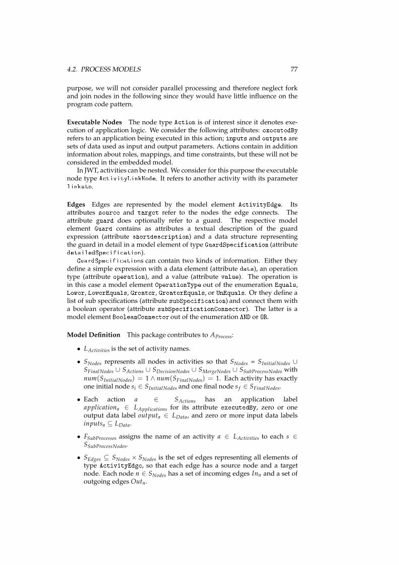
4.2. PROCESS MODELS 77
purpose, we will not consider parallel processing and therefore neglect forkand join nodes in the following since they would have little influence on theprogram code pattern.
Executable Nodes The node type A tion is of interest since it denotes exe-cution of application logic. We consider the following attributes: exe utedByrefers to an application being executed in this action; inputs and outputs aresets of data used as input and output parameters. Actions contain in additioninformation about roles, mappings, and time constraints, but these will not beconsidered in the embedded model.
In JWT, activities can be nested. We consider for this purpose the executablenode type A tivityLinkNode. It refers to another activity with its parameterlinksto.Edges Edges are represented by the model element A tivityEdge. Itsattributes sour e and target refer to the nodes the edge connects. Theattribute guard does optionally refer to a guard. The respective modelelement Guard contains as attributes a textual description of the guardexpression (attribute shortdes ription) and a data structure representingthe guard in detail in a model element of type GuardSpe ifi ation (attributedetailedSpe ifi ation).GuardSpe ifi ations can contain two kinds of information. Either theydefine a simple expression with a data element (attribute data), an operationtype (attribute operation), and a value (attribute value). The operation isin this case a model element OperationType out of the enumeration Equals,Lower, LowerEquals, Greater, GreaterEquals, or UnEquals. Or they define alist of sub specifications (attribute subSpe ifi ation) and connect them witha boolean operator (attribute subSpe ifi ationConne tor). The latter is amodel element BooleanConne tor out of the enumeration AND or OR.Model Definition This package contributes to AProcess:
• LActivities is the set of activity names.
• SNodes represents all nodes in activities so that SNodes = SInitialNodes ∪SFinalNodes ∪ SActions ∪ SDecisionNodes ∪ SMergeNodes ∪ SSubProcessNodes with
num(SInitialNodes) = 1 ∧ num(SFinalNodes) = 1. Each activity has exactlyone initial node si ∈ SInitialNodes and one final node s f ∈ SFinalNodes.
• Each action a ∈ SActions has an application labelapplicationa ∈ LApplications for its attribute exe utedBy, zero or oneoutput data label outputa ∈ LData, and zero or more input data labelsinputsa ⊆ LData.
• FSubProcesses assigns the name of an activity a ∈ LActivities to each s ∈SSubProcessNodes.
• SEdges ⊆ SNodes × SNodes is the set of edges representing all elements oftype A tivityEdge, so that each edge has a source node and a targetnode. Each node n ∈ SNodes has a set of incoming edges Inn and a set ofoutgoing edges Outn.
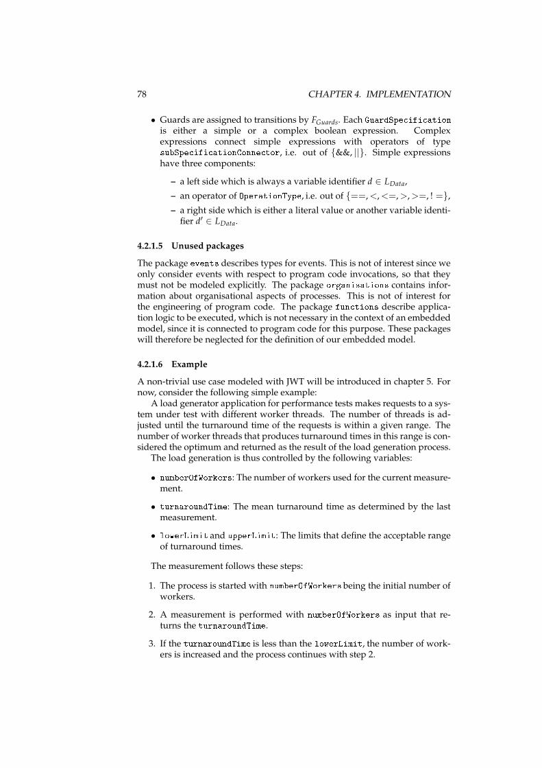
78 CHAPTER 4. IMPLEMENTATION
• Guards are assigned to transitions by FGuards. Each GuardSpe ifi ationis either a simple or a complex boolean expression. Complexexpressions connect simple expressions with operators of typesubSpe ifi ationConne tor, i.e. out of {&&, ||}. Simple expressionshave three components:
– a left side which is always a variable identifier d ∈ LData,
– an operator of OperationType, i.e. out of {==,<,<=,>,>=, ! =},
– a right side which is either a literal value or another variable identi-fier d′ ∈ LData.
4.2.1.5 Unused packages
The package events describes types for events. This is not of interest since weonly consider events with respect to program code invocations, so that theymust not be modeled explicitly. The package organisations contains infor-mation about organisational aspects of processes. This is not of interest forthe engineering of program code. The package fun tions describe applica-tion logic to be executed, which is not necessary in the context of an embeddedmodel, since it is connected to program code for this purpose. These packageswill therefore be neglected for the definition of our embedded model.
4.2.1.6 Example
A non-trivial use case modeled with JWT will be introduced in chapter 5. Fornow, consider the following simple example:
A load generator application for performance tests makes requests to a sys-tem under test with different worker threads. The number of threads is ad-justed until the turnaround time of the requests is within a given range. Thenumber of worker threads that produces turnaround times in this range is con-sidered the optimum and returned as the result of the load generation process.
The load generation is thus controlled by the following variables:
• numberOfWorkers: The number of workers used for the current measure-ment.
• turnaroundTime: The mean turnaround time as determined by the lastmeasurement.
• lowerLimit and upperLimit: The limits that define the acceptable rangeof turnaround times.
The measurement follows these steps:
1. The process is started with numberOfWorkers being the initial number ofworkers.
2. A measurement is performed with numberOfWorkers as input that re-turns the turnaroundTime.
3. If the turnaroundTime is less than the lowerLimit, the number of work-ers is increased and the process continues with step 2.
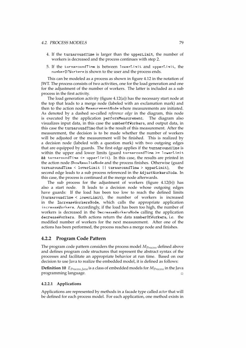
4.2. PROCESS MODELS 79
4. If the turnaroundTime is larger than the upperLimit, the number ofworkers is decreased and the process continues with step 2.
5. If the turnaroundTime is between lowerLimit and upperLimit, thenumberOfWorkers is shown to the user and the process ends.
This can be modeled as a process as shown in figure 4.12 in the notation ofJWT. The process consists of two activities, one for the load generation and onefor the adjustment of the number of workers. The latter is included as a subprocess in the first activity.
The load generation activity (figure 4.12(a)) has the necessary start node atthe top that leads to a merge node (labeled with an exclamation mark) andthen to the action node MeasurementNode where measurements are initiated.As denoted by a dashed so-called reference edge in the diagram, this nodeis executed by the application performMeasurement. The diagram alsovisualizes input data, in this case the numberOfWorkers, and output data, inthis case the turnaroundTime that is the result of this measurement. After themeasurement, the decision is to be made whether the number of workerswill be adjusted or the measurement will be finished. This is realized bya decision node (labeled with a question mark) with two outgoing edgesthat are equipped by guards. The first edge applies if the turnaroundTime iswithin the upper and lower limits (guard turnaroundTime >= lowerLimit&& turnaroundTime <= upperLimit). In this case, the results are printed inthe action node ShowResultsNode and the process finishes. Otherwise (guardturnaroundTime < lowerLimit || turnaroundTime > upperLimit), thesecond edge leads to a sub process referenced in the AdjustWorkersNode. Inthis case, the process is continued at the merge node afterwards.
The sub process for the adjustment of workers (figure 4.12(b)) hasalso a start node. It leads to a decision node whose outgoing edgeshave guards: If the load has been too low to reach the defined limits(turnaroundTime < lowerLimit), the number of workers is increasedin the In reaseWorkersNode, which calls the appropriate applicationin reaseWorkers. Accordingly, if the load has been too high, the number ofworkers is decreased in the De reaseWorkersNode calling the applicationde reaseWorkers. Both actions return the data numberOfWorkers, i.e. themodified number of workers for the next measurement. After one of theactions has been performed, the process reaches a merge node and finishes.
4.2.2 Program Code Pattern
The program code pattern considers the process model MProcess defined aboveand defines program code structures that represent the abstract syntax of theprocesses and facilitate an appropriate behavior at run time. Based on ourdecision to use Java to realize the embedded model, it is defined as follows:
Definition 10 EProcess,Java is a class of embeddedmodels for MProcess in the Javaprogramming language. ✷
4.2.2.1 Applications
Applications are represented by methods in a facade type called actor that willbe defined for each process model. For each application, one method exists in
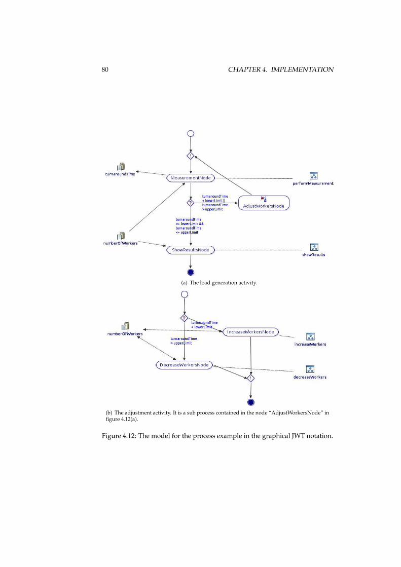
80 CHAPTER 4. IMPLEMENTATION
(a) The load generation activity.
(b) The adjustment activity. It is a sub process contained in the node “AdjustWorkersNode” infigure 4.12(a).
Figure 4.12: The model for the process example in the graphical JWT notation.
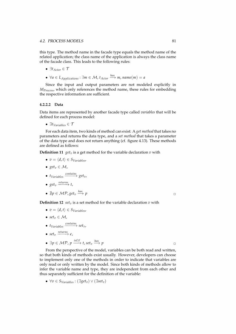
4.2. PROCESS MODELS 81
this type. The method name in the facade type equals the method name of therelated application; the class name of the application is always the class nameof the facade class. This leads to the following rules:
• ∃tActor ∈ T
• ∀a ∈ LApplications : ∃m ∈ M, tActorhas−→ m, name(m) = a
Since the input and output parameters are not modeled explicitly inMProcess, which only references the method name, these rules for embeddingthe respective information are sufficient.
4.2.2.2 Data
Data items are represented by another facade type called variables that will bedefined for each process model:
• ∃tVariables ∈ T
For each data item, two kinds of method can exist: A get method that takes noparameters and returns the data type, and a set method that takes a parameterof the data type and does not return anything (cf. figure 4.13). These methodsare defined as follows:
Definition 11 getv is a get method for the variable declaration v with
• v = 〈d, t〉 ∈ SVariables,
• getv ∈ M,
• tVariablescontains−−−−→ getv,
• getvreturns−−−−→ t,
• ∄p ∈ MP , getvhas−→ p ✷
Definition 12 setv is a set method for the variable declaration v with
• v = 〈d, t〉 ∈ SVariables,
• setv ∈ M,
• tVariablescontains−−−−→ setv,
• setvreturns−−−−→ ǫ,
• ∃p ∈ MP , pisO f−−→ t, setv
has−→ p ✷
From the perspective of the model, variables can be both read and written,so that both kinds of methods exist usually. However, developers can chooseto implement only one of the methods in order to indicate that variables areonly read or only written by the model. Since both kinds of methods allow toinfer the variable name and type, they are independent from each other andthus separately sufficient for the definition of the variable:
• ∀v ∈ SVariables : (∃getv) ∨ (∃setv)
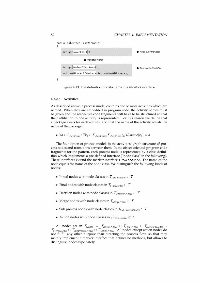
82 CHAPTER 4. IMPLEMENTATION
public interface LoadVariables
{
int getLowerLimit();
int getNumberOfWorkers();
void setNumberOfWorkers(int numberOfWorkers);
}
Read-only Variable
Variable Name
Read-write Variable
Figure 4.13: The definition of data items in a variables interface.
4.2.2.3 Activities
As described above, a process model contains one or more activities which arenamed. When they are embedded in program code, the activity names mustbe given and the respective code fragments will have to be structured so thattheir affiliation to one activity is represented. For this reason we define thata package exists for each activity, and that the name of the activity equals thename of the package:
• ∀a ∈ LActivities : ∃ka ∈ KActivities,KActivities ⊆ K, name(ka) = a
The foundation of process models is the activities’ graph structure of pro-cess nodes and transitions between them. In the object-oriented program codefragments for the pattern, each process node is represented by a class defini-tion which implements a pre-defined interface (“node class” in the following).These interfaces extend the marker interface IPro essNode. The name of thenode equals the name of the node class. We distinguish the following kinds ofnodes:
• Initial nodes with node classes in TInitialNodes ⊂ T
• Final nodes with node classes in TFinalNodes ⊂ T
• Decision nodes with node classes in TDecisionNodes ⊂ T
• Merge nodes with node classes in TMergeNodes ⊂ T
• Sub process nodes with node classes in TSubProcessNodes ⊂ T
• Action nodes with node classes in TActionNodes ⊂ T
All nodes are in TNodes = TInitialNodes ∪ TFinalNodes ∪ TDecisionNodes ∪TMergeNodes ∪ TSubProcessNodes ∪ TActionNodes. All nodes except action nodes donot fulfill any other purpose than directing the process flow, so that theymainly implement a marker interface that defines no methods, but allows todistinguish nodes type-safely.
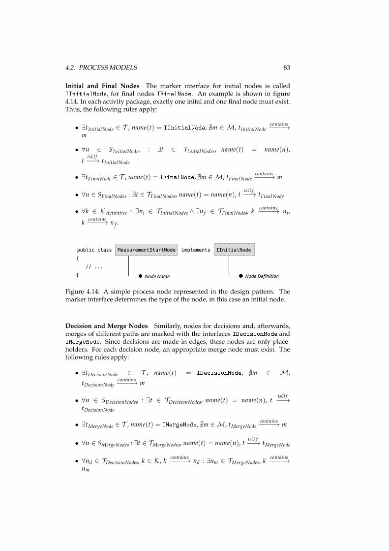
4.2. PROCESS MODELS 83
Initial and Final Nodes The marker interface for initial nodes is calledIInitialNode, for final nodes IFinalNode. An example is shown in figure4.14. In each activity package, exactly one inital and one final node must exist.Thus, the following rules apply:
• ∃tInitialNode ∈ T , name(t) = IInitialNode, ∄m ∈ M, tInitialNodecontains−−−−→
m
• ∀n ∈ SInitialNodes : ∃t ∈ TInitialNodes, name(t) = name(n),
tisO f−−→ tInitialNode
• ∃tFinalNode ∈ T , name(t) = IFinalNode, ∄m ∈ M, tFinalNodecontains−−−−→ m
• ∀n ∈ SFinalNodes : ∃t ∈ TFinalNodes, name(t) = name(n), tisO f−−→ tFinalNode
• ∀k ∈ KActivities : ∃ni ∈ TInitialNodes ∧ ∃n f ∈ TFinalNodes, kcontains−−−−→ ni,
kcontains−−−−→ n f .
public class MeasurementStartNode implements IInitialNode
{
// ...
} Node DefinitionNode Name
Figure 4.14: A simple process node represented in the design pattern. Themarker interface determines the type of the node, in this case an initial node.
Decision and Merge Nodes Similarly, nodes for decisions and, afterwards,merges of different paths are marked with the interfaces IDe isionNode andIMergeNode. Since decisions are made in edges, these nodes are only place-holders. For each decision node, an appropriate merge node must exist. Thefollowing rules apply:
• ∃tDecisionNode ∈ T , name(t) = IDe isionNode, ∄m ∈ M,
tDecisionNodecontains−−−−→ m
• ∀n ∈ SDecisionNodes : ∃t ∈ TDecisionNodes, name(t) = name(n), tisO f−−→
tDecisionNode
• ∃tMergeNode ∈ T , name(t) = IMergeNode, ∄m ∈ M, tMergeNodecontains−−−−→ m
• ∀n ∈ SMergeNodes : ∃t ∈ TMergeNodes, name(t) = name(n), tisO f−−→ tMergeNode
• ∀nd ∈ TDecisionNodes, k ∈ K, kcontains−−−−→ nd : ∃nm ∈ TMergeNodes, k
contains−−−−→
nm
84 CHAPTER 4. IMPLEMENTATION
Sub Process Nodes Activity links are represented by node classes imple-menting the marker interface ISubPro essNode. To reference the actual subprocess, they have an annotation SubPro esswith a parameter of a class def-inition implementing IStartNode, thus referencing the entry point to the subprocess. An example is shown in figure 4.15. The following rules apply:
• ∃tSubProcessNode ∈ T , name(t) = ISubPro essNode, ∄m ∈ M,
tSubProcessNodecontains−−−−→ m
• ∀n ∈ SSubProcessNodes : ∃t ∈ TSubProcessNodes, name(t) = name(n), tisO f−−→
tSubProcessNode
• ∃aSubProcess ∈ A, name(aSubProcess) = SubPro ess• ∃pTarget ∈ AP , pTarget
re f erences−−−−−→ tTarget ∈ TInitialNodes, aSubProcess
has−→ pTarget
• ∀s ∈ TSubProcessNodes : sisO f−−→ tSubProcessNode ∧ s
has−→ aSubProcess
@SubProcess( StartAdjustmentNode.class )
public class AdjustWorkersNode implements ISubProcessNode
{
// ...
} Sub Process Node Definition
Sub Process Reference
Figure 4.15: A sub process node in the program code pattern. The type of thenode is determined by the marker interface. The annotation refers to the initialstate of the sub process.
Actions Actions are represented by node classes implementing the interfaceIA tionNode. It defines themethod a tionwhose method body in implement-ing node classes constitutes the actual action executed at run time. The methodtakes two parameters: The first is called a tor and has the type of the actor fa-cade. The second ist called variables and has the type of the variables facade:
• ∃tActionNode ∈ T , name(tActionNode) = IA tionNode• ∃mAction ∈ M, name(mAction) = a tion, tActionNode
has−→ mAction
• ∃pActor ∈ MP , name(pActor) = a tor, pActorisO f−−→ tActor, mAction
has−→
pActor
• ∃pVariables ∈ MP , name(pVariables) = variables, pVariables isO f−−→ tVariables,
mActionhas−→ pVariables
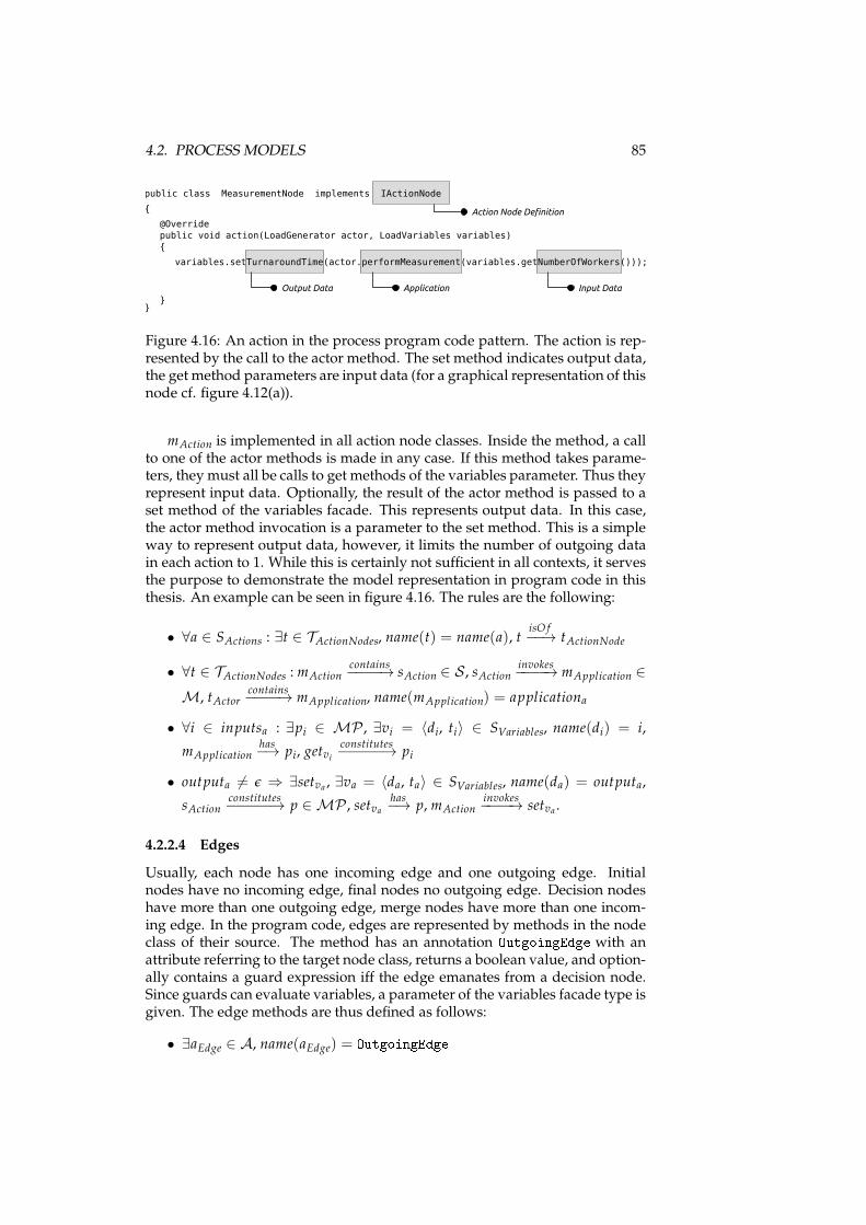
4.2. PROCESS MODELS 85
public class MeasurementNode implements IActionNode
{
@Override
public void action(LoadGenerator actor, LoadVariables variables)
}
Action Node Definition
Output Data
{
}
variables.setTurnaroundTime(actor.performMeasurement(variables.getNumberOfWorkers()));
Application Input Data
Figure 4.16: An action in the process program code pattern. The action is rep-resented by the call to the actor method. The set method indicates output data,the get method parameters are input data (for a graphical representation of thisnode cf. figure 4.12(a)).
mAction is implemented in all action node classes. Inside the method, a callto one of the actor methods is made in any case. If this method takes parame-ters, they must all be calls to get methods of the variables parameter. Thus theyrepresent input data. Optionally, the result of the actor method is passed to aset method of the variables facade. This represents output data. In this case,the actor method invocation is a parameter to the set method. This is a simpleway to represent output data, however, it limits the number of outgoing datain each action to 1. While this is certainly not sufficient in all contexts, it servesthe purpose to demonstrate the model representation in program code in thisthesis. An example can be seen in figure 4.16. The rules are the following:
• ∀a ∈ SActions : ∃t ∈ TActionNodes, name(t) = name(a), tisO f−−→ tActionNode
• ∀t ∈ TActionNodes : mActioncontains−−−−→ sAction ∈ S , sAction
invokes−−−−→ mApplication ∈
M, tActorcontains−−−−→ mApplication, name(mApplication) = applicationa
• ∀i ∈ inputsa : ∃pi ∈ MP , ∃vi = 〈di, ti〉 ∈ SVariables, name(di) = i,
mApplicationhas−→ pi, getvi
constitutes−−−−−→ pi
• outputa 6= ǫ ⇒ ∃setva , ∃va = 〈da, ta〉 ∈ SVariables, name(da) = outputa,
sActionconstitutes−−−−−→ p ∈ MP , setva
has−→ p, mAction
invokes−−−−→ setva .
4.2.2.4 Edges
Usually, each node has one incoming edge and one outgoing edge. Initialnodes have no incoming edge, final nodes no outgoing edge. Decision nodeshave more than one outgoing edge, merge nodes have more than one incom-ing edge. In the program code, edges are represented by methods in the nodeclass of their source. The method has an annotation OutgoingEdge with anattribute referring to the target node class, returns a boolean value, and option-ally contains a guard expression iff the edge emanates from a decision node.Since guards can evaluate variables, a parameter of the variables facade type isgiven. The edge methods are thus defined as follows:
• ∃aEdge ∈ A, name(aEdge) = OutgoingEdge
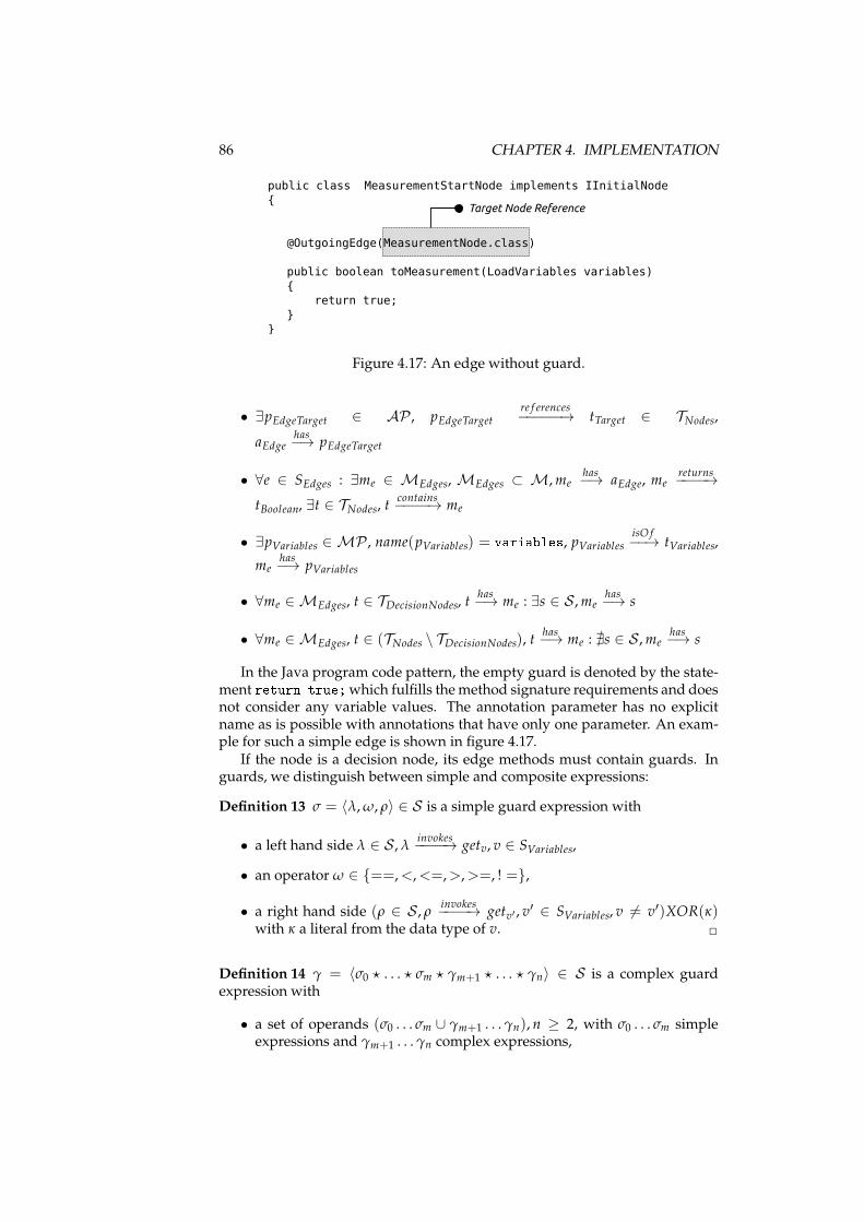
86 CHAPTER 4. IMPLEMENTATION
{
@OutgoingEdge(MeasurementNode.class)
}
Target Node Reference
public class MeasurementStartNode implements IInitialNode
public boolean toMeasurement(LoadVariables variables)
{
return true;
}
Figure 4.17: An edge without guard.
• ∃pEdgeTarget ∈ AP , pEdgeTargetre f erences−−−−−→ tTarget ∈ TNodes,
aEdgehas−→ pEdgeTarget
• ∀e ∈ SEdges : ∃me ∈ MEdges, MEdges ⊂ M,mehas−→ aEdge, me
returns−−−−→
tBoolean, ∃t ∈ TNodes, tcontains−−−−→ me
• ∃pVariables ∈ MP , name(pVariables) = variables, pVariables isO f−−→ tVariables,
mehas−→ pVariables
• ∀me ∈ MEdges, t ∈ TDecisionNodes, thas−→ me : ∃s ∈ S ,me
has−→ s
• ∀me ∈ MEdges, t ∈ (TNodes \ TDecisionNodes), thas−→ me : ∄s ∈ S ,me
has−→ s
In the Java program code pattern, the empty guard is denoted by the state-ment return true;which fulfills themethod signature requirements and doesnot consider any variable values. The annotation parameter has no explicitname as is possible with annotations that have only one parameter. An exam-ple for such a simple edge is shown in figure 4.17.
If the node is a decision node, its edge methods must contain guards. Inguards, we distinguish between simple and composite expressions:
Definition 13 σ = 〈λ,ω, ρ〉 ∈ S is a simple guard expression with
• a left hand side λ ∈ S , λinvokes−−−−→ getv, v ∈ SVariables,
• an operator ω ∈ {==,<,<=,>,>=, ! =},
• a right hand side (ρ ∈ S , ρinvokes−−−−→ getv′ , v
′ ∈ SVariables, v 6= v′)XOR(κ)with κ a literal from the data type of v. ✷
Definition 14 γ = 〈σ0 ⋆ . . . ⋆ σm ⋆ γm+1 ⋆ . . . ⋆ γn〉 ∈ S is a complex guardexpression with
• a set of operands (σ0 . . . σm ∪ γm+1 . . . γn), n ≥ 2, with σ0 . . . σm simpleexpressions and γm+1 . . . γn complex expressions,
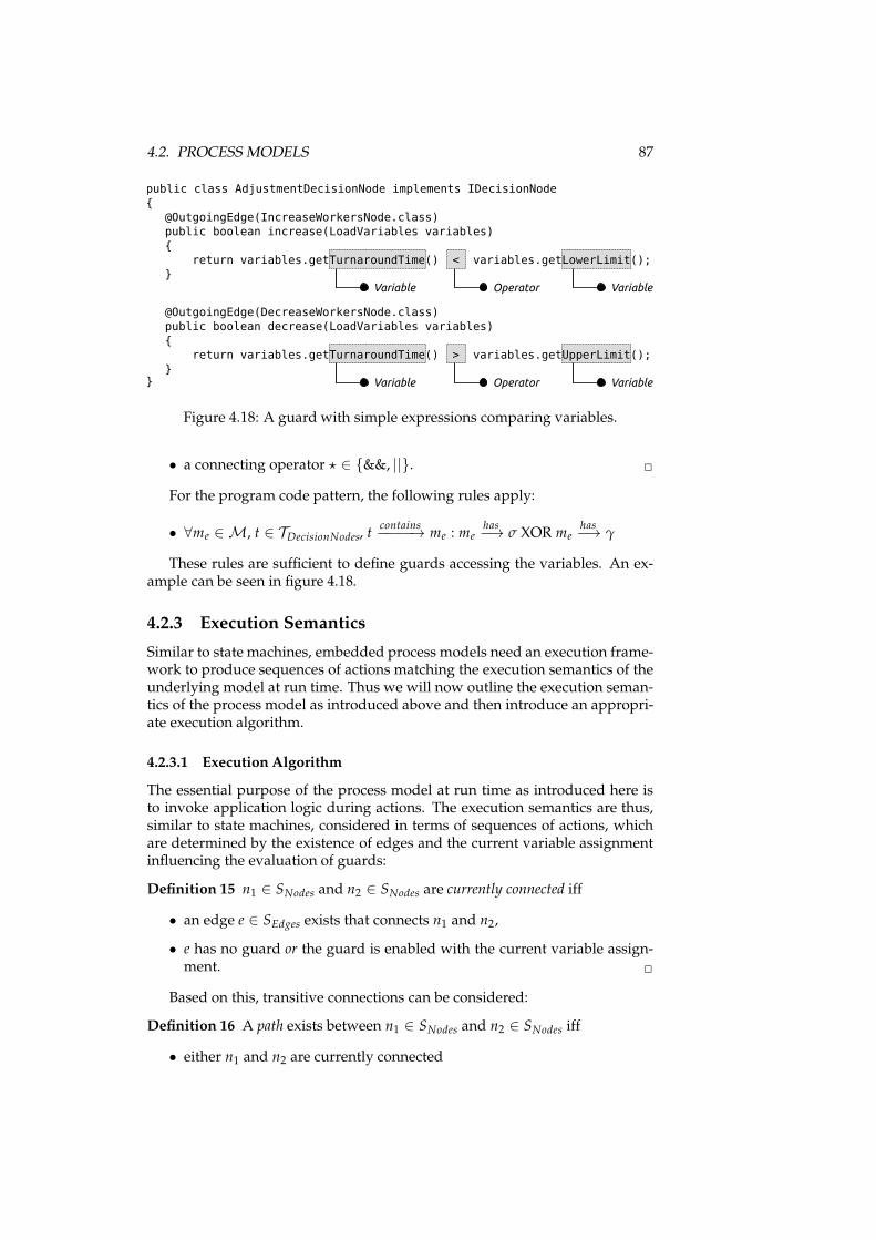
4.2. PROCESS MODELS 87
{
}
Variable
public class AdjustmentDecisionNode implements IDecisionNode
@OutgoingEdge(IncreaseWorkersNode.class)
public boolean increase(LoadVariables variables)
{
return variables.getTurnaroundTime() < variables.getLowerLimit();
}Operator Variable
@OutgoingEdge(DecreaseWorkersNode.class)
public boolean decrease(LoadVariables variables)
{
return variables.getTurnaroundTime() > variables.getUpperLimit();
}Variable Operator Variable
Figure 4.18: A guard with simple expressions comparing variables.
• a connecting operator ⋆ ∈ {&&, ||}. ✷
For the program code pattern, the following rules apply:
• ∀me ∈ M, t ∈ TDecisionNodes, tcontains−−−−→ me : me
has−→ σ XOR me
has−→ γ
These rules are sufficient to define guards accessing the variables. An ex-ample can be seen in figure 4.18.
4.2.3 Execution Semantics
Similar to state machines, embedded process models need an execution frame-work to produce sequences of actions matching the execution semantics of theunderlying model at run time. Thus we will now outline the execution seman-tics of the process model as introduced above and then introduce an appropri-ate execution algorithm.
4.2.3.1 Execution Algorithm
The essential purpose of the process model at run time as introduced here isto invoke application logic during actions. The execution semantics are thus,similar to state machines, considered in terms of sequences of actions, whichare determined by the existence of edges and the current variable assignmentinfluencing the evaluation of guards:
Definition 15 n1 ∈ SNodes and n2 ∈ SNodes are currently connected iff
• an edge e ∈ SEdges exists that connects n1 and n2,
• e has no guard or the guard is enabled with the current variable assign-ment. ✷
Based on this, transitive connections can be considered:
Definition 16 A path exists between n1 ∈ SNodes and n2 ∈ SNodes iff
• either n1 and n2 are currently connected
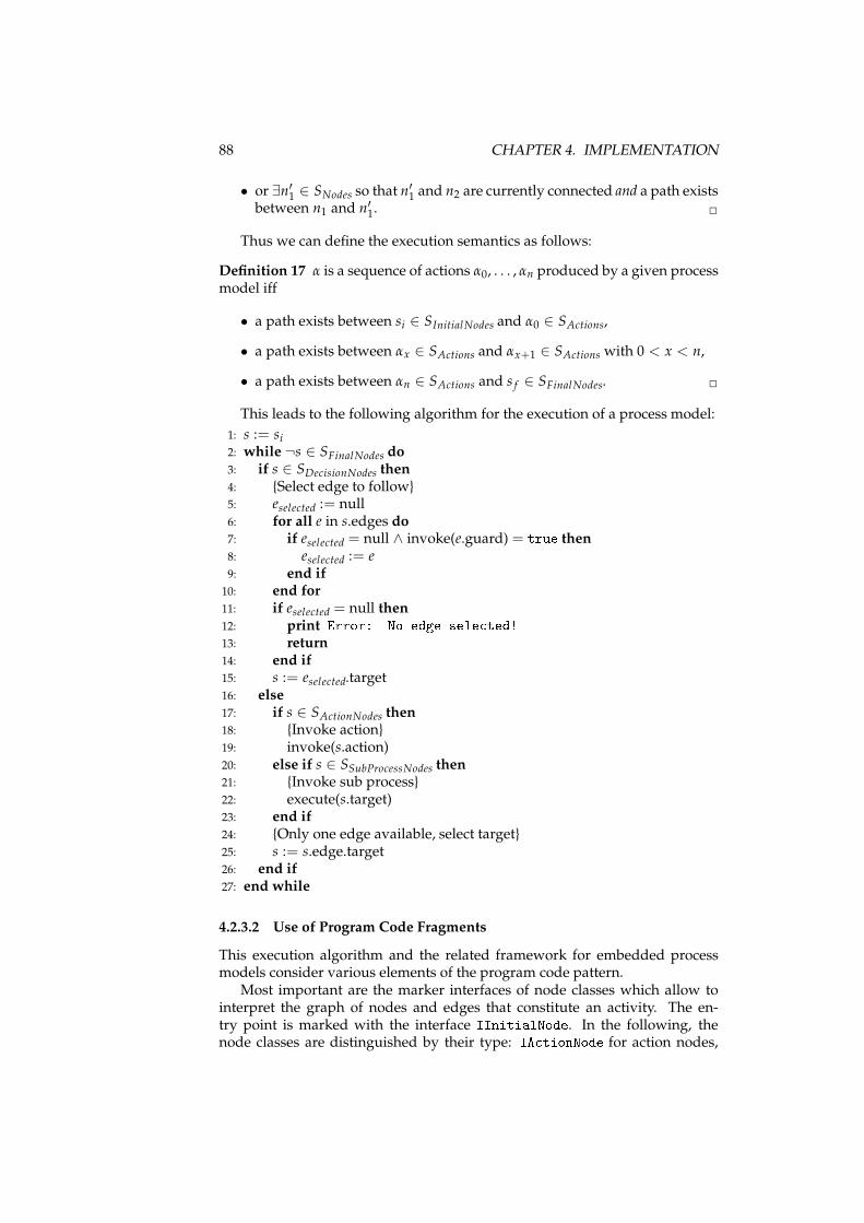
88 CHAPTER 4. IMPLEMENTATION
• or ∃n′1 ∈ SNodes so that n′1 and n2 are currently connected and a path existsbetween n1 and n′1. ✷
Thus we can define the execution semantics as follows:
Definition 17 α is a sequence of actions α0, . . . , αn produced by a given processmodel iff
• a path exists between si ∈ SInitialNodes and α0 ∈ SActions,
• a path exists between αx ∈ SActions and αx+1 ∈ SActions with 0 < x < n,
• a path exists between αn ∈ SActions and s f ∈ SFinalNodes. ✷
This leads to the following algorithm for the execution of a process model:
1: s := si2: while ¬s ∈ SFinalNodes do3: if s ∈ SDecisionNodes then4: {Select edge to follow}5: eselected := null6: for all e in s.edges do7: if eselected = null ∧ invoke(e.guard) = true then8: eselected := e9: end if
10: end for11: if eselected = null then12: print Error: No edge sele ted!13: return14: end if15: s := eselected.target16: else17: if s ∈ SActionNodes then18: {Invoke action}19: invoke(s.action)20: else if s ∈ SSubProcessNodes then21: {Invoke sub process}22: execute(s.target)23: end if24: {Only one edge available, select target}25: s := s.edge.target26: end if27: end while
4.2.3.2 Use of Program Code Fragments
This execution algorithm and the related framework for embedded processmodels consider various elements of the program code pattern.
Most important are the marker interfaces of node classes which allow tointerpret the graph of nodes and edges that constitute an activity. The en-try point is marked with the interface IInitialNode. In the following, thenode classes are distinguished by their type: IA tionNode for action nodes,
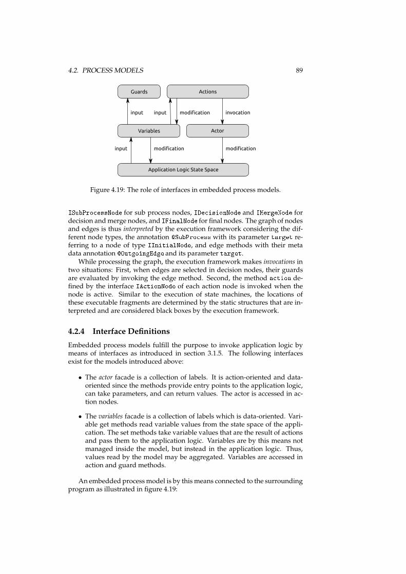
4.2. PROCESS MODELS 89
Guards Actions
Variables Actor
Application Logic State Space
input invocation
modificationinput modification
input modification
Figure 4.19: The role of interfaces in embedded process models.ISubPro essNode for sub process nodes, IDe isionNode and IMergeNode fordecision andmerge nodes, and IFinalNode for final nodes. The graph of nodesand edges is thus interpreted by the execution framework considering the dif-ferent node types, the annotation �SubPro ess with its parameter target re-ferring to a node of type IInitialNode, and edge methods with their metadata annotation �OutgoingEdge and its parameter target.
While processing the graph, the execution framework makes invocations intwo situations: First, when edges are selected in decision nodes, their guardsare evaluated by invoking the edge method. Second, the method a tion de-fined by the interface IA tionNode of each action node is invoked when thenode is active. Similar to the execution of state machines, the locations ofthese executable fragments are determined by the static structures that are in-terpreted and are considered black boxes by the execution framework.
4.2.4 Interface Definitions
Embedded process models fulfill the purpose to invoke application logic bymeans of interfaces as introduced in section 3.1.5. The following interfacesexist for the models introduced above:
• The actor facade is a collection of labels. It is action-oriented and data-oriented since the methods provide entry points to the application logic,can take parameters, and can return values. The actor is accessed in ac-tion nodes.
• The variables facade is a collection of labels which is data-oriented. Vari-able get methods read variable values from the state space of the appli-cation. The set methods take variable values that are the result of actionsand pass them to the application logic. Variables are by this means notmanaged inside the model, but instead in the application logic. Thus,values read by the model may be aggregated. Variables are accessed inaction and guard methods.
An embedded processmodel is by this means connected to the surroundingprogram as illustrated in figure 4.19:
90 CHAPTER 4. IMPLEMENTATION
In decision nodes, guards access variableswhich are extracted as input fromthe state space of the surrounding applications. The state space must thus ful-fill the requirements of the guard of at least one edge in the current decisionnode. However, this cannot be controlled from inside the embedded model,and irregularities cannot be detected with a validation of the process model.The application logic is thus responsible for ensuring that the variables arevalid in the context of the process model. At development time, this could besupported with static analysis and model checking of program code (cf. sec-tion 3.2.2) since the requirements to the state space are for each decision nodeprecisely given by the guards’ expressions. At run time, inconsistencies will bedetected if the process takes other paths as expected or runs into a deadlock;detection and analysis of such errors can be supported by monitoring tools (cf.section 3.2.4).
During actions, the state space of the application can bemodified with actormethods as well as set methods of variables. However, both kinds of methodsare black boxes to the model, so that changes are not comprehensible. Onlythe fact that values are passed is defined in the model, but not their content orvalue range, since they are the result of action methods.
In summary, the state space is modeled only by the requirements of guards.While this is implicit, it is certainly a starting point for static analysis of theprogram code since method invocations in guards allow for slicing of the ap-plication’s program code (cf. section 3.1.5.2).
4.2.5 Transformations
Since the embedded process model is to be considered at different abstractionlevels, transformations will be used to provide abstract views on the programcode. These transformations follow the rules defined in section 3.1.6. Sincethe model is entirely based on JWT, the transformation to the JWT format isconsidered the default transformation. The single elements of the pattern aretransformed to JWT (and vice versa) based on the derivation of the patternfrom the model as introduced above:
Applications As defined above, the mapping requires that all applications ina JWT model used for the embedded process model have the same im-plementing class. This class is an interface in the program code and canbe identified since its fully-qualified name is given in the JWT model.Single applications have a name that equals the name of the related actormethod.
Data Single data entries consist of a name and a data type which is definedby a name again. Both are directly mapped to the signature of variablemethods. However, these methods are contained in a facade interfacewhich is not part of the model. Thus the transformation must have aparameter denoting the location and class name of the interface.
Activities Activities are extracted from packages. For this reason, the transfor-mation must know packages with activities inside; this information willhave to be provided by tools that control the transformation. The simplename of the package is considered the activity’s name. When program
4.3. COMPARISON OF THE EMBEDDEDMODELS 91
code is generated from a JWT model, the single activities are mapped topackages again.
Nodes Nodes and their names can be identified in the source code bymeans oftheir marker interfaces. The names correspond to the class names. How-ever, the transformation must consider that the program code pattern asintroduced above does not support all node types defined by JWT.
Sub Processes Nodes with sub processes contain the reference information inthe annotation �SubPro ess. While the JWT model links to the name ofthe activity, the annotation in the code links to an initial node fromwhichthe package and thus the activity name can be inferred. This differencecan be resolved unambiguously and is thus supported by the transfor-mation.
Edges Edges are determined from edge methods in the program code pattern.When program code is generated from the model, the method namesmust be provided by a tool based on heuristics since edges are not namedin JWT.
Guards Guards can be inferred directly from the source code. For this pur-pose, expressions are read and the variable method invocations are inter-preted as data entries.
Actions Contents of action methods in action nodes can be transformed di-rectly: The name of the method invoked in the actor class is the applica-tion name; its input parameters being calls to variable get methods are in-terpreted as input data labels; the result of the actor method being passedto a variable set method is considered an output data label. The sole lim-itation is that only one output data label can exist for each action, whichis different in JWT (cf. section 4.2.2.3). Thus, JWT models used for em-bedded process models must conform to this limitation, which must bevalidated by the transformation.
4.3 Comparison of the Embedded Models
The two embedded model classes introduced in sections 4.1 and 4.2 are similarto a certain degree. However, considered together, state machines and processmodels cover many aspects of behavioral models. We will thus draw somegeneral conclusions now.
4.3.1 Representation of Model Elements
The basic structure of behavioral models is usually some kind of graph denot-ing paths a program can take which are influenced by decisions depending onvariable values. This is not only true for state machines and processes, but alsofor models like UML activity diagrams or state charts [OMG, 2010]. Commonto both embedded models is the use of program code fragments to representthis structure:
92 CHAPTER 4. IMPLEMENTATION
Classes as the basic static structures in the program code can representnamed nodes in such a graph. Edges in the graph can be represented by refer-ences between classes given in meta data annotations. Decisions that consist ofexpressions are realized in method contents. In addition, method contents cancontain calls to interface methods, thus initiating arbitrary application logic.Although the specific location of such elements varies in both embedded mod-els, the principles are the same. Considering the two embeddedmodels, we arethus confident that program code patterns can be created with such buildingblocks for these kinds of behavioral models.
4.3.2 State Space
Embedded models are connected to other program code so that the state spacemay not be entirely under control of the model. This is different than in spe-cific modeling environments like UPPAAL which control all variables exceptwhen random values are generated, but in this case even the random numbergeneration is under control of the environment. In contrast, variables in bothembedded models are managed by the application logic and are not directlyvisible from the model or from modeling tools. Considering the models intro-duced above, control over the state space by the model can be categorized asfollows:
Complete Control The modeling environment manages the state space com-pletely. Changes can be made only from inside the model. This is truee.g. for UPPAAL.
Emulated Updates The model defines changes to the state space. This allowsto extract a completemodel into amodeling environment considering thestate space, e.g. embedded state machines to UPPAAL. It also enablesmodel checking at an abstract level. However, at run time the variablesare not managed by the execution framework, but instead influenced bythe application logic, so that differences can occur.
Partial Updates The state space is mostly only read by the model. Updatesmay be defined in the model, but are not complete. Such models cannotbe model-checked since the state space is never defined completely, noteven at development time. This is the case for process models.
Thus, depending on the purpose of the model, the application logic canhave different degrees of influence on the state space. While partial updatescertainly provide higher flexibility, a more restrictive control over the statespace allows for thorough verification and model checking (cf. section 3.1.5.2).When a program code pattern for an embedded model is defined, both objec-tives must be balanced.
4.3.3 Scalability
When considering abstract models, it is important how they can scale in orderto represent larger or growing system descriptions. For embedded models,the question arises whether and how scaling models can be represented in the
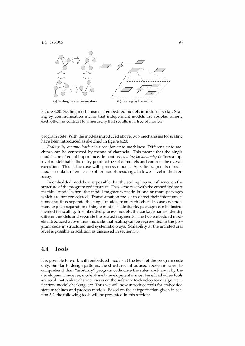
4.4. TOOLS 93
(a) Scaling by communication (b) Scaling by hierarchy
Figure 4.20: Scaling mechanisms of embedded models introduced so far. Scal-ing by communication means that independent models are coupled amongeach other, in contrast to a hierarchy that results in a tree of models.
program code. With the models introduced above, twomechanisms for scalinghave been introduced as sketched in figure 4.20:
Scaling by communication is used for state machines: Different state ma-chines can be connected by means of channels. This means that the singlemodels are of equal importance. In contrast, scaling by hierarchy defines a top-level model that is the entry point to the set of models and controls the overallexecution. This is the case with process models. Specific fragments of suchmodels contain references to other models residing at a lower level in the hier-archy.
In embedded models, it is possible that the scaling has no influence on thestructure of the program code pattern. This is the case with the embedded statemachine model where the model fragments reside in one or more packageswhich are not considered. Transformation tools can detect their interconnec-tions and thus separate the single models from each other. In cases where amore explicit separation of single models is desirable, packages can be instru-mented for scaling. In embedded process models, the package names identifydifferent models and separate the related fragments. The two embedded mod-els introduced above thus inidicate that scaling can be represented in the pro-gram code in structured and systematic ways. Scalability at the architecturallevel is possible in addition as discussed in section 3.3.
4.4 Tools
It is possible to work with embedded models at the level of the program codeonly. Similar to design patterns, the structures introduced above are easier tocomprehend than “arbitrary” program code once the rules are known by thedevelopers. However, model-based development is most beneficial when toolsare used that realize abstract views on the software to develop for design, veri-fication, model checking, etc. Thus we will now introduce tools for embeddedstate machines and process models. Based on the categorization given in sec-tion 3.2, the following tools will be presented in this section:
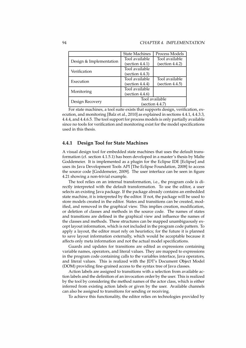
94 CHAPTER 4. IMPLEMENTATION
State Machines Process Models
Design & ImplementationTool available Tool available(section 4.4.1) (section 4.4.2)
VerificationTool available(section 4.4.3)
ExecutionTool available Tool available(section 4.4.4) (section 4.4.5)
MonitoringTool available(section 4.4.6)
Design RecoveryTool available(section 4.4.7)
For state machines, a tool suite exists that supports design, verification, ex-ecution, and monitoring [Balz et al., 2010] as explained in sections 4.4.1, 4.4.3.3,4.4.4, and 4.4.6.5. The tool support for processmodels is only partially availablesince no tools for verification and monitoring exist for the model specificationsused in this thesis.
4.4.1 Design Tool for State Machines
A visual design tool for embedded state machines that uses the default trans-formation (cf. section 4.1.5.1) has been developed in a master’s thesis by MalteGoddemeier. It is implemented as a plugin for the Eclipse IDE [Eclipse] anduses its Java Development Tools API [The Eclipse Foundation, 2008] to accessthe source code [Goddemeier, 2009]. The user interface can be seen in figure4.21 showing a non-trivial example.
The tool relies on an internal transformation, i.e., the program code is di-rectly interpreted with the default transformation. To use the editor, a userselects an existing Java package. If the package already contains an embeddedstate machine, it is interpreted by the editor. If not, the package will be used tostore models created in the editor. States and transitions can be created, mod-ified, and removed in the graphical view. This implies creation, modification,or deletion of classes and methods in the source code. The names of statesand transitions are defined in the graphical view and influence the names ofthe classes and methods. These structures can be mapped unambiguously ex-cept layout information, which is not included in the program code pattern. Toapply a layout, the editor must rely on heuristics; for the future it is plannedto save layout information externally, which would be acceptable because itaffects only meta information and not the actual model specifications.
Guards and updates for transitions are edited as expressions containingvariable names, operators, and literal values. They are mapped to expressionsin the program code containing calls to the variables interface, Java operators,and literal values. This is realized with the JDT’s Document Object Model(DOM) providing fine-grained access to the syntax tree of Java classes.
Action labels are assigned to transitions with a selection from available ac-tion labels and the definition of an invocation order by the user. This is realizedby the tool by considering the method names of the actor class, which is eitherinferred from existing action labels or given by the user. Available channelscan also be assigned to transitions for sending or receiving.
To achieve this functionality, the editor relies on technologies provided by
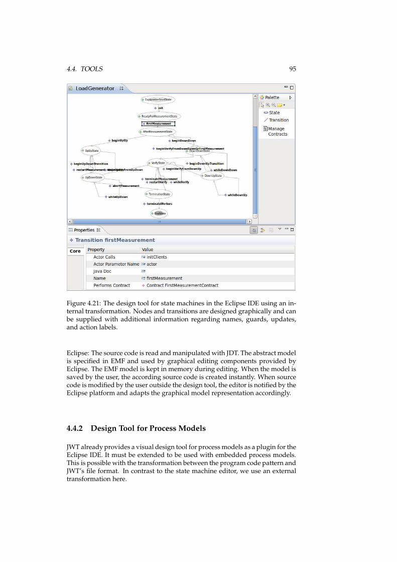
4.4. TOOLS 95
Figure 4.21: The design tool for state machines in the Eclipse IDE using an in-ternal transformation. Nodes and transitions are designed graphically and canbe supplied with additional information regarding names, guards, updates,and action labels.
Eclipse: The source code is read andmanipulated with JDT. The abstract modelis specified in EMF and used by graphical editing components provided byEclipse. The EMFmodel is kept in memory during editing. When the model issaved by the user, the according source code is created instantly. When sourcecode is modified by the user outside the design tool, the editor is notified by theEclipse platform and adapts the graphical model representation accordingly.
4.4.2 Design Tool for Process Models
JWT alreadyprovides a visual design tool for processmodels as a plugin for theEclipse IDE. It must be extended to be used with embedded process models.This is possible with the transformation between the program code pattern andJWT’s file format. In contrast to the state machine editor, we use an externaltransformation here.
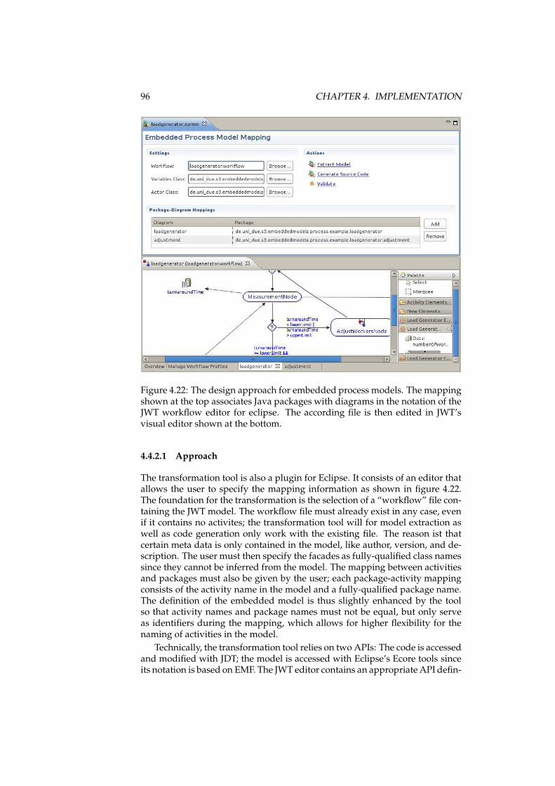
96 CHAPTER 4. IMPLEMENTATION
Figure 4.22: The design approach for embedded process models. The mappingshown at the top associates Java packages with diagrams in the notation of theJWT workflow editor for eclipse. The according file is then edited in JWT’svisual editor shown at the bottom.
4.4.2.1 Approach
The transformation tool is also a plugin for Eclipse. It consists of an editor thatallows the user to specify the mapping information as shown in figure 4.22.The foundation for the transformation is the selection of a “workflow” file con-taining the JWT model. The workflow file must already exist in any case, evenif it contains no activites; the transformation tool will for model extraction aswell as code generation only work with the existing file. The reason ist thatcertain meta data is only contained in the model, like author, version, and de-scription. The user must then specify the facades as fully-qualified class namessince they cannot be inferred from the model. The mapping between activitiesand packages must also be given by the user; each package-activity mappingconsists of the activity name in the model and a fully-qualified package name.The definition of the embedded model is thus slightly enhanced by the toolso that activity names and package names must not be equal, but only serveas identifiers during the mapping, which allows for higher flexibility for thenaming of activities in the model.
Technically, the transformation tool relies on two APIs: The code is accessedand modified with JDT; the model is accessed with Eclipse’s Ecore tools sinceits notation is based on EMF. The JWT editor contains an appropriateAPI defin-
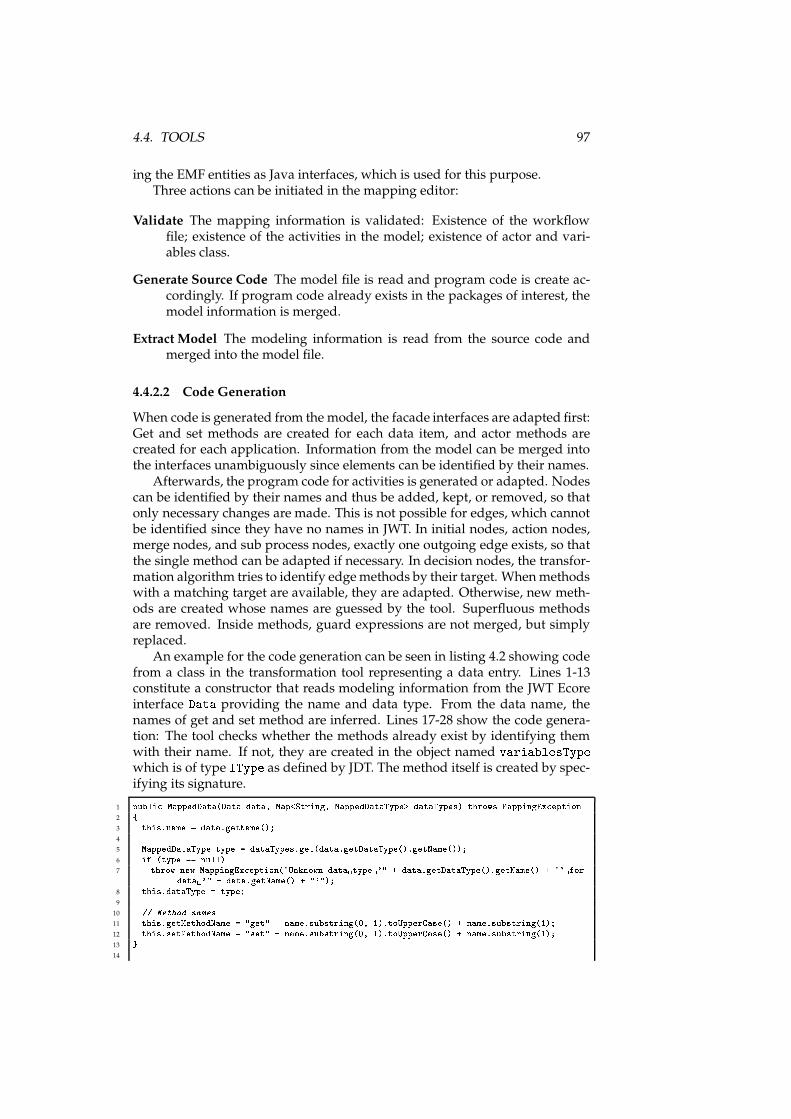
4.4. TOOLS 97
ing the EMF entities as Java interfaces, which is used for this purpose.Three actions can be initiated in the mapping editor:
Validate The mapping information is validated: Existence of the workflowfile; existence of the activities in the model; existence of actor and vari-ables class.
Generate Source Code The model file is read and program code is create ac-cordingly. If program code already exists in the packages of interest, themodel information is merged.
Extract Model The modeling information is read from the source code andmerged into the model file.
4.4.2.2 Code Generation
When code is generated from the model, the facade interfaces are adapted first:Get and set methods are created for each data item, and actor methods arecreated for each application. Information from the model can be merged intothe interfaces unambiguously since elements can be identified by their names.
Afterwards, the program code for activities is generated or adapted. Nodescan be identified by their names and thus be added, kept, or removed, so thatonly necessary changes are made. This is not possible for edges, which cannotbe identified since they have no names in JWT. In initial nodes, action nodes,merge nodes, and sub process nodes, exactly one outgoing edge exists, so thatthe single method can be adapted if necessary. In decision nodes, the transfor-mation algorithm tries to identify edgemethods by their target. Whenmethodswith a matching target are available, they are adapted. Otherwise, new meth-ods are created whose names are guessed by the tool. Superfluous methodsare removed. Inside methods, guard expressions are not merged, but simplyreplaced.
An example for the code generation can be seen in listing 4.2 showing codefrom a class in the transformation tool representing a data entry. Lines 1-13constitute a constructor that reads modeling information from the JWT Ecoreinterface Data providing the name and data type. From the data name, thenames of get and set method are inferred. Lines 17-28 show the code genera-tion: The tool checks whether the methods already exist by identifying themwith their name. If not, they are created in the object named variablesTypewhich is of type IType as defined by JDT. The method itself is created by spec-ifying its signature.
1 publi MappedData(Data data, Map<String, MappedDataType> dataTypes) throws MappingEx eption2 {3 this.name = data.getName();4
5 MappedDataType type = dataTypes.get(data.getDataType().getName());6 if (type == null)7 throw new MappingEx eption("Unknown data type '" + data.getDataType().getName() + "' for data '" + data.getName() + "'");8 this.dataType = type;9
10 // Method names11 this.getMethodName = "get" + name.substring(0, 1).toUpperCase() + name.substring(1);12 this.setMethodName = "set" + name.substring(0, 1).toUpperCase() + name.substring(1);13 }14
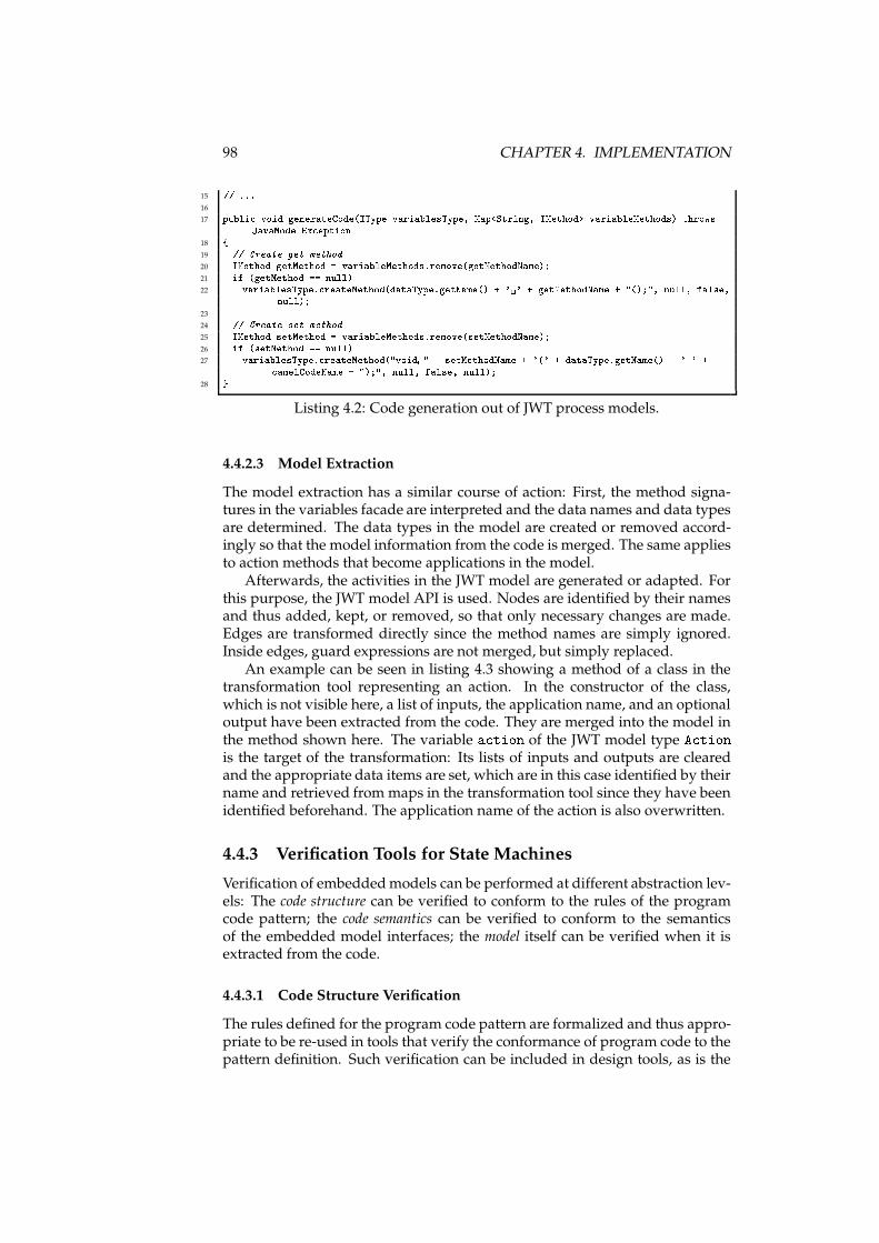
98 CHAPTER 4. IMPLEMENTATION
15 // ...16
17 publi void generateCode(IType variablesType, Map<String, IMethod> variableMethods) throwsJavaModelEx eption18 {19 // Create get method20 IMethod getMethod = variableMethods.remove(getMethodName);21 if (getMethod == null)22 variablesType. reateMethod(dataType.getName() + ' ' + getMethodName + "();", null, false,null);23
24 // Create set method25 IMethod setMethod = variableMethods.remove(setMethodName);26 if (setMethod == null)27 variablesType. reateMethod("void " + setMethodName + '(' + dataType.getName() + ' ' + amelCodeName + ");", null, false, null);28 }
Listing 4.2: Code generation out of JWT process models.
4.4.2.3 Model Extraction
The model extraction has a similar course of action: First, the method signa-tures in the variables facade are interpreted and the data names and data typesare determined. The data types in the model are created or removed accord-ingly so that the model information from the code is merged. The same appliesto action methods that become applications in the model.
Afterwards, the activities in the JWT model are generated or adapted. Forthis purpose, the JWT model API is used. Nodes are identified by their namesand thus added, kept, or removed, so that only necessary changes are made.Edges are transformed directly since the method names are simply ignored.Inside edges, guard expressions are not merged, but simply replaced.
An example can be seen in listing 4.3 showing a method of a class in thetransformation tool representing an action. In the constructor of the class,which is not visible here, a list of inputs, the application name, and an optionaloutput have been extracted from the code. They are merged into the model inthe method shown here. The variable a tion of the JWT model type A tionis the target of the transformation: Its lists of inputs and outputs are clearedand the appropriate data items are set, which are in this case identified by theirname and retrieved from maps in the transformation tool since they have beenidentified beforehand. The application name of the action is also overwritten.
4.4.3 Verification Tools for State Machines
Verification of embeddedmodels can be performed at different abstraction lev-els: The code structure can be verified to conform to the rules of the programcode pattern; the code semantics can be verified to conform to the semanticsof the embedded model interfaces; the model itself can be verified when it isextracted from the code.
4.4.3.1 Code Structure Verification
The rules defined for the program code pattern are formalized and thus appro-priate to be re-used in tools that verify the conformance of program code to thepattern definition. Such verification can be included in design tools, as is the
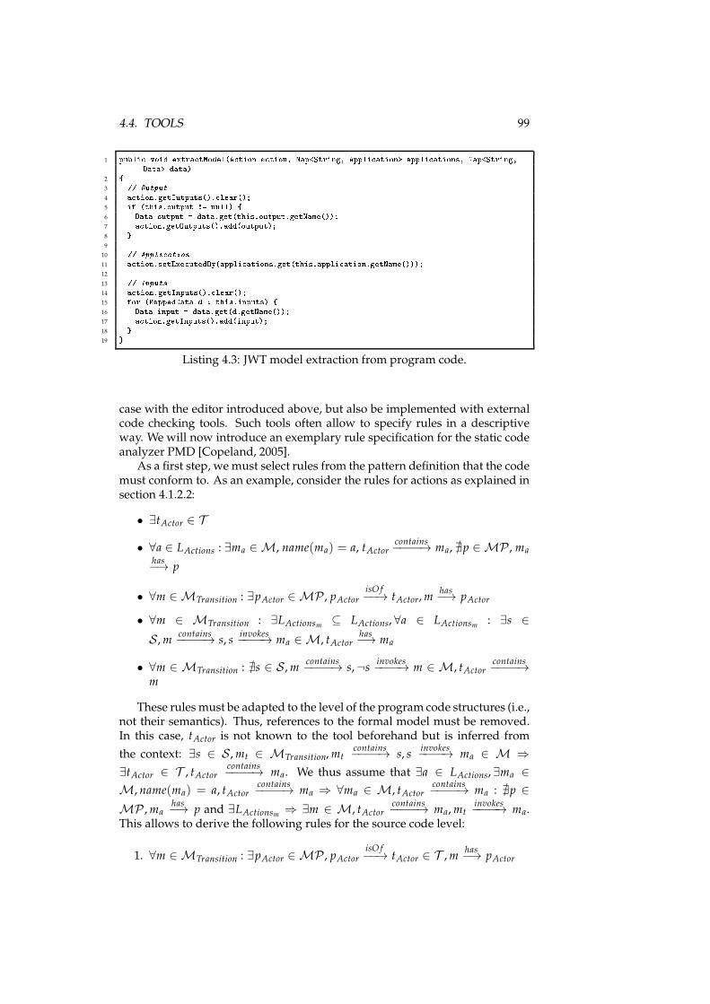
4.4. TOOLS 99
1 publi void extra tModel(A tion a tion, Map<String, Appli ation> appli ations, Map<String,Data> data)2 {3 // Output4 a tion.getOutputs(). lear();5 if (this.output != null) {6 Data output = data.get(this.output.getName());7 a tion.getOutputs().add(output);8 }9
10 // Appli ation11 a tion.setExe utedBy(appli ations.get(this.appli ation.getName()));12
13 // Inputs14 a tion.getInputs(). lear();15 for (MappedData d : this.inputs) {16 Data input = data.get(d.getName());17 a tion.getInputs().add(input);18 }19 }
Listing 4.3: JWT model extraction from program code.
case with the editor introduced above, but also be implemented with externalcode checking tools. Such tools often allow to specify rules in a descriptiveway. We will now introduce an exemplary rule specification for the static codeanalyzer PMD [Copeland, 2005].
As a first step, we must select rules from the pattern definition that the codemust conform to. As an example, consider the rules for actions as explained insection 4.1.2.2:
• ∃tActor ∈ T
• ∀a ∈ LActions : ∃ma ∈ M, name(ma) = a, tActorcontains−−−−→ ma, ∄p ∈ MP , ma
has−→ p
• ∀m ∈ MTransition : ∃pActor ∈ MP , pActorisO f−−→ tActor,m
has−→ pActor
• ∀m ∈ MTransition : ∃LActionsm ⊆ LActions, ∀a ∈ LActionsm : ∃s ∈
S ,mcontains−−−−→ s, s
invokes−−−−→ ma ∈ M, tActor
has−→ ma
• ∀m ∈ MTransition : ∄s ∈ S ,mcontains−−−−→ s,¬s
invokes−−−−→ m ∈ M, tActor
contains−−−−→
m
These rules must be adapted to the level of the program code structures (i.e.,not their semantics). Thus, references to the formal model must be removed.In this case, tActor is not known to the tool beforehand but is inferred from
the context: ∃s ∈ S ,mt ∈ MTransition,mtcontains−−−−→ s, s
invokes−−−−→ ma ∈ M ⇒
∃tActor ∈ T , tActorcontains−−−−→ ma. We thus assume that ∃a ∈ LActions, ∃ma ∈
M, name(ma) = a, tActorcontains−−−−→ ma ⇒ ∀ma ∈ M, tActor
contains−−−−→ ma : ∄p ∈
MP ,mahas−→ p and ∃LActionsm ⇒ ∃m ∈ M, tActor
contains−−−−→ ma,mt
invokes−−−−→ ma.
This allows to derive the following rules for the source code level:
1. ∀m ∈ MTransition : ∃pActor ∈ MP , pActorisO f−−→ tActor ∈ T ,m
has−→ pActor
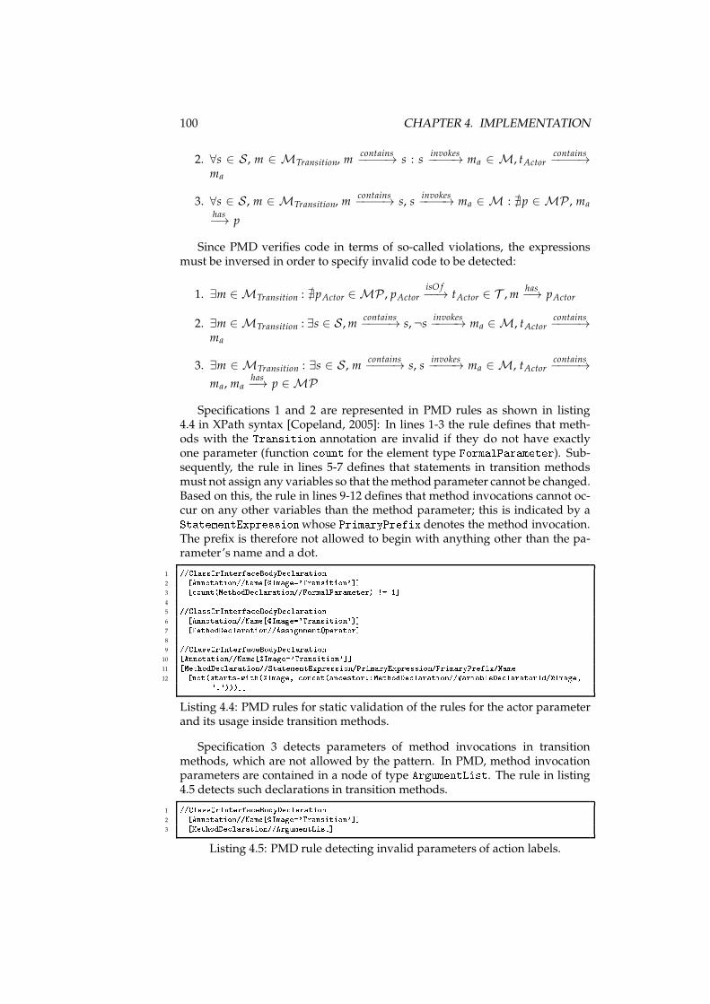
100 CHAPTER 4. IMPLEMENTATION
2. ∀s ∈ S , m ∈ MTransition, mcontains−−−−→ s : s
invokes−−−−→ ma ∈ M, tActor
contains−−−−→
ma
3. ∀s ∈ S , m ∈ MTransition, mcontains−−−−→ s, s
invokes−−−−→ ma ∈ M : ∄p ∈ MP , ma
has−→ p
Since PMD verifies code in terms of so-called violations, the expressionsmust be inversed in order to specify invalid code to be detected:
1. ∃m ∈ MTransition : ∄pActor ∈ MP , pActorisO f−−→ tActor ∈ T ,m
has−→ pActor
2. ∃m ∈ MTransition : ∃s ∈ S ,mcontains−−−−→ s,¬s
invokes−−−−→ ma ∈ M, tActor
contains−−−−→
ma
3. ∃m ∈ MTransition : ∃s ∈ S , mcontains−−−−→ s, s
invokes−−−−→ ma ∈ M, tActor
contains−−−−→
ma, mahas−→ p ∈ MP
Specifications 1 and 2 are represented in PMD rules as shown in listing4.4 in XPath syntax [Copeland, 2005]: In lines 1-3 the rule defines that meth-ods with the Transition annotation are invalid if they do not have exactlyone parameter (function ount for the element type FormalParameter). Sub-sequently, the rule in lines 5-7 defines that statements in transition methodsmust not assign any variables so that themethod parameter cannot be changed.Based on this, the rule in lines 9-12 defines that method invocations cannot oc-cur on any other variables than the method parameter; this is indicated by aStatementExpressionwhose PrimaryPrefix denotes the method invocation.The prefix is therefore not allowed to begin with anything other than the pa-rameter’s name and a dot.
1 //ClassOrInterfa eBodyDe laration2 [Annotation//Name[�Image='Transition'℄℄3 [ ount(MethodDe laration//FormalParameter) != 1℄4
5 //ClassOrInterfa eBodyDe laration6 [Annotation//Name[�Image='Transition'℄℄7 [MethodDe laration//AssignmentOperator℄8
9 //ClassOrInterfa eBodyDe laration10 [Annotation//Name[�Image='Transition'℄℄11 [MethodDe laration//StatementExpression/PrimaryExpression/PrimaryPrefix/Name12 [not(starts-with(�Image, on at(an estor::MethodDe laration//VariableDe laratorId/�Image,'.')))℄℄
Listing 4.4: PMD rules for static validation of the rules for the actor parameterand its usage inside transition methods.
Specification 3 detects parameters of method invocations in transitionmethods, which are not allowed by the pattern. In PMD, method invocationparameters are contained in a node of type ArgumentList. The rule in listing4.5 detects such declarations in transition methods.
1 //ClassOrInterfa eBodyDe laration2 [Annotation//Name[�Image='Transition'℄℄3 [MethodDe laration//ArgumentList℄
Listing 4.5: PMD rule detecting invalid parameters of action labels.
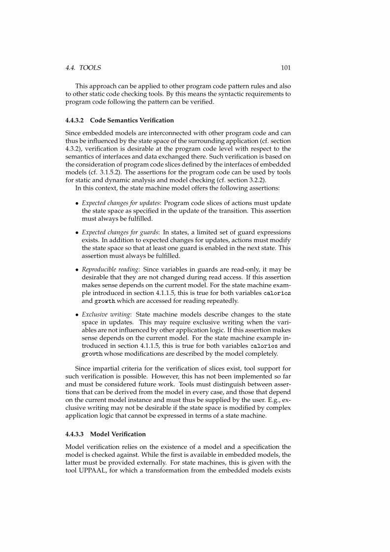
4.4. TOOLS 101
This approach can be applied to other program code pattern rules and alsoto other static code checking tools. By this means the syntactic requirements toprogram code following the pattern can be verified.
4.4.3.2 Code Semantics Verification
Since embedded models are interconnected with other program code and canthus be influenced by the state space of the surrounding application (cf. section4.3.2), verification is desirable at the program code level with respect to thesemantics of interfaces and data exchanged there. Such verification is based onthe consideration of program code slices defined by the interfaces of embeddedmodels (cf. 3.1.5.2). The assertions for the program code can be used by toolsfor static and dynamic analysis and model checking (cf. section 3.2.2).
In this context, the state machine model offers the following assertions:
• Expected changes for updates: Program code slices of actions must updatethe state space as specified in the update of the transition. This assertionmust always be fulfilled.
• Expected changes for guards: In states, a limited set of guard expressionsexists. In addition to expected changes for updates, actions must modifythe state space so that at least one guard is enabled in the next state. Thisassertion must always be fulfilled.
• Reproducible reading: Since variables in guards are read-only, it may bedesirable that they are not changed during read access. If this assertionmakes sense depends on the current model. For the state machine exam-ple introduced in section 4.1.1.5, this is true for both variables aloriesand growthwhich are accessed for reading repeatedly.
• Exclusive writing: State machine models describe changes to the statespace in updates. This may require exclusive writing when the vari-ables are not influenced by other application logic. If this assertion makessense depends on the current model. For the state machine example in-troduced in section 4.1.1.5, this is true for both variables alories andgrowthwhose modifications are described by the model completely.
Since impartial criteria for the verification of slices exist, tool support forsuch verification is possible. However, this has not been implemented so farand must be considered future work. Tools must distinguish between asser-tions that can be derived from the model in every case, and those that dependon the current model instance and must thus be supplied by the user. E.g., ex-clusive writing may not be desirable if the state space is modified by complexapplication logic that cannot be expressed in terms of a state machine.
4.4.3.3 Model Verification
Model verification relies on the existence of a model and a specification themodel is checked against. While the first is available in embedded models, thelatter must be provided externally. For state machines, this is given with thetool UPPAAL, for which a transformation from the embedded models exists
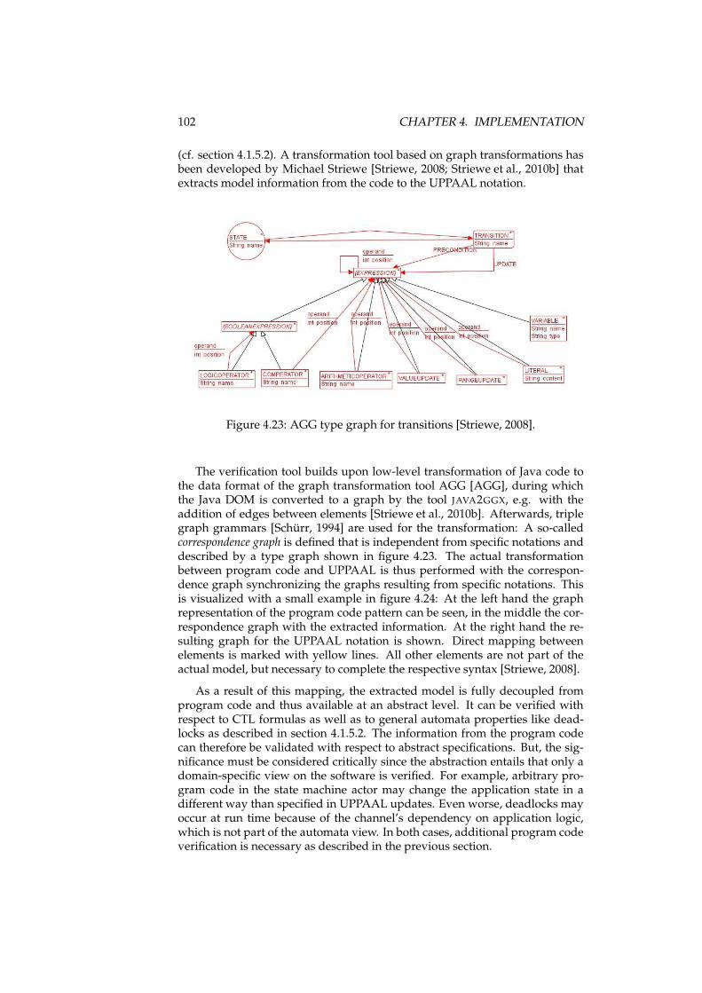
102 CHAPTER 4. IMPLEMENTATION
(cf. section 4.1.5.2). A transformation tool based on graph transformations hasbeen developed by Michael Striewe [Striewe, 2008; Striewe et al., 2010b] thatextracts model information from the code to the UPPAAL notation.
Figure 4.23: AGG type graph for transitions [Striewe, 2008].
The verification tool builds upon low-level transformation of Java code tothe data format of the graph transformation tool AGG [AGG], during whichthe Java DOM is converted to a graph by the tool JAVA2GGX, e.g. with theaddition of edges between elements [Striewe et al., 2010b]. Afterwards, triplegraph grammars [Schürr, 1994] are used for the transformation: A so-calledcorrespondence graph is defined that is independent from specific notations anddescribed by a type graph shown in figure 4.23. The actual transformationbetween program code and UPPAAL is thus performed with the correspon-dence graph synchronizing the graphs resulting from specific notations. Thisis visualized with a small example in figure 4.24: At the left hand the graphrepresentation of the program code pattern can be seen, in the middle the cor-respondence graph with the extracted information. At the right hand the re-sulting graph for the UPPAAL notation is shown. Direct mapping betweenelements is marked with yellow lines. All other elements are not part of theactual model, but necessary to complete the respective syntax [Striewe, 2008].
As a result of this mapping, the extracted model is fully decoupled fromprogram code and thus available at an abstract level. It can be verified withrespect to CTL formulas as well as to general automata properties like dead-locks as described in section 4.1.5.2. The information from the program codecan therefore be validated with respect to abstract specifications. But, the sig-nificance must be considered critically since the abstraction entails that only adomain-specific view on the software is verified. For example, arbitrary pro-gram code in the state machine actor may change the application state in adifferent way than specified in UPPAAL updates. Even worse, deadlocks mayoccur at run time because of the channel’s dependency on application logic,which is not part of the automata view. In both cases, additional program codeverification is necessary as described in the previous section.
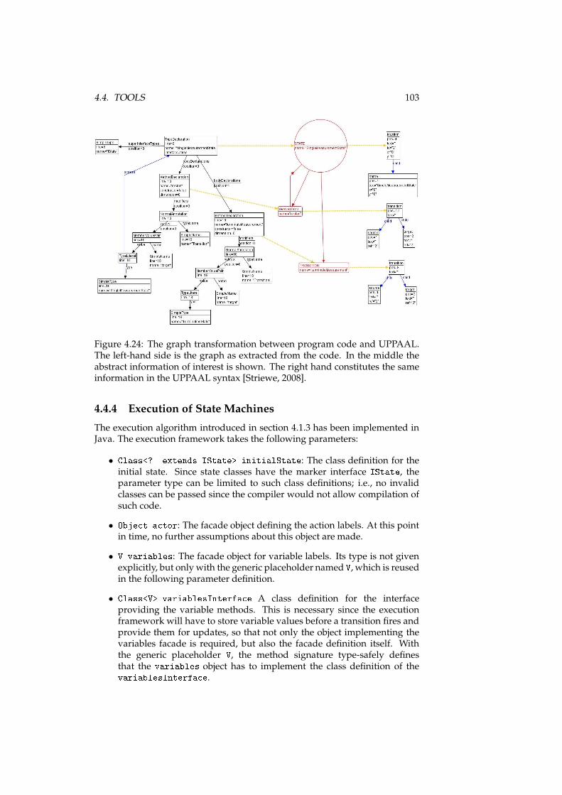
4.4. TOOLS 103
Figure 4.24: The graph transformation between program code and UPPAAL.The left-hand side is the graph as extracted from the code. In the middle theabstract information of interest is shown. The right hand constitutes the sameinformation in the UPPAAL syntax [Striewe, 2008].
4.4.4 Execution of State Machines
The execution algorithm introduced in section 4.1.3 has been implemented inJava. The execution framework takes the following parameters:
• Class<? extends IState> initialState: The class definition for theinitial state. Since state classes have the marker interface IState, theparameter type can be limited to such class definitions; i.e., no invalidclasses can be passed since the compiler would not allow compilation ofsuch code.
• Obje t a tor: The facade object defining the action labels. At this pointin time, no further assumptions about this object are made.
• V variables: The facade object for variable labels. Its type is not givenexplicitly, but only with the generic placeholder named V, which is reusedin the following parameter definition.
• Class<V> variablesInterfa e A class definition for the interfaceproviding the variable methods. This is necessary since the executionframework will have to store variable values before a transition fires andprovide them for updates, so that not only the object implementing thevariables facade is required, but also the facade definition itself. Withthe generic placeholder V, the method signature type-safely definesthat the variables object has to implement the class definition of thevariablesInterfa e.
104 CHAPTER 4. IMPLEMENTATION
First, the graph of node classes and transition methods is traversed and allnodes are initialized as shown in listing 4.6: The state instances are stored in amap with the class definition being the identifier (line 1). A recursive methodchecks if instances exist (line 8), creates new instances if necessary, and storesthem (line 9). Afterwards, transition methods are identified (line 11) and themethod is called for the target node recursively (line 12).
1 Map<Class<IState>, IState> states = new HashMap<Class<IState>, IState>();2 reateStateDefinition(initialState);3
4 // ...5
6 void reateStateDefinition(Class<? extends IState> s)7 {8 if (!states. ontainsKey(s)) {9 states.put(s, s.newInstan e());
10 for (Method m : s.getMethods())11 if (m.isAnnotationPresent(Transition. lass))12 reateState(m.getAnnotation(Transition. lass).target());13 }14 }
Listing 4.6: Node traversal and instantiation in the state machine executionframework.
The variable storage for updates is realized as shown in listing 4.7: In line 1,an object of type VariableWrapper is instantiated. In the following line, a so-called dynamic proxy [Forman and Forman, 2004] is created. Dynamic proxiesin Java are objects that provide a certain interface, but are not instance of a spe-cific type implementing the interface. Instead, they are notified about methodinvocations and handle them. Thus, the proxy is of type V and can be passedto update methods alongside the variables facade.
The object variables will handle method calls in the proxy. It is of typeVariableWrapper that is shown in lines 6-24: The wrapper takes the vari-ables interface and the variables facade as parameters. It has a map namedvalues that assigns Java objects to method definitions. They are filled when themethod read is invoked, which happens before a transition fires: All methodsin the variables facade are invoked and the current values retrieved from themare stored in the map and identified by the method (lines 20-21). This is helpfulwhen the methods provided by the proxy are accessed in updates: Accordingto the definition of dynamic proxies, invocations are forwarded to the methodinvoke defined by the interface Invo ationHandler,which is implemented bythe wrapper. The Java platform supplies in this method information about themethod that was called, e.g. getCalories(). The wrapper object simply re-turns the value that was stored for this method beforehand (line 14) and thusrealizes the provision of cached values for updates.
1 VariableWrapper<V> wrapper = new VariableWrapper<V>(variablesInterfa e, variables);2 V proxy = (V)(Proxy.newProxyInstan e(variablesInterfa e.getClassLoader(), new Class<?>[℄{variablesInterfa e }, wrapper));3
4 // ...5
6 publi lass VariableWrapper<V> implements Invo ationHandler7 {8 private final Map<Method, Obje t> values = new HashMap<Method, Obje t>();9
10 // ...11
12 publi Obje t invoke(Obje t proxy, Method method, Obje t[℄ args) throws Throwable13 {
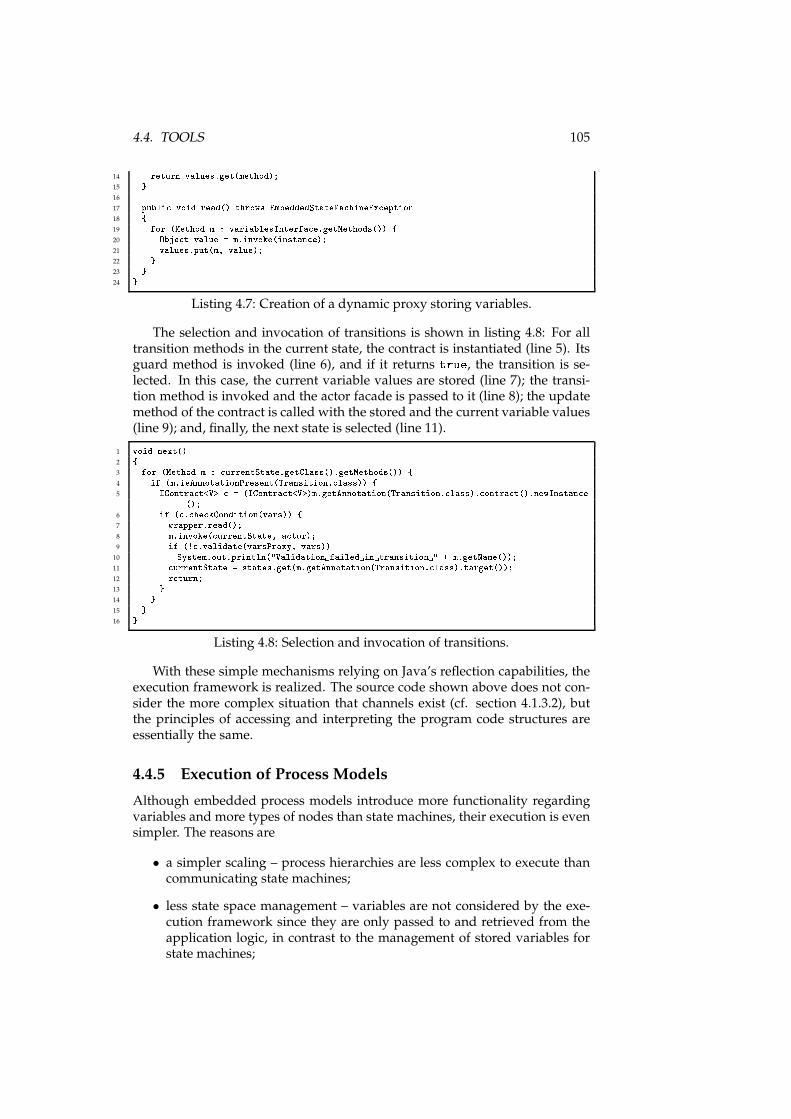
4.4. TOOLS 105
14 return values.get(method);15 }16
17 publi void read() throws EmbeddedStateMa hineEx eption18 {19 for (Method m : variablesInterfa e.getMethods()) {20 Obje t value = m.invoke(instan e);21 values.put(m, value);22 }23 }24 }
Listing 4.7: Creation of a dynamic proxy storing variables.
The selection and invocation of transitions is shown in listing 4.8: For alltransition methods in the current state, the contract is instantiated (line 5). Itsguard method is invoked (line 6), and if it returns true, the transition is se-lected. In this case, the current variable values are stored (line 7); the transi-tion method is invoked and the actor facade is passed to it (line 8); the updatemethod of the contract is called with the stored and the current variable values(line 9); and, finally, the next state is selected (line 11).
1 void next()2 {3 for (Method m : urrentState.getClass().getMethods()) {4 if (m.isAnnotationPresent(Transition. lass)) {5 IContra t<V> = (IContra t<V>)m.getAnnotation(Transition. lass). ontra t().newInstan e();6 if ( . he kCondition(vars)) {7 wrapper.read();8 m.invoke( urrentState, a tor);9 if (! .validate(varsProxy, vars))
10 System.out.println("Validation failed in transition " + m.getName());11 urrentState = states.get(m.getAnnotation(Transition. lass).target());12 return;13 }14 }15 }16 }
Listing 4.8: Selection and invocation of transitions.
With these simple mechanisms relying on Java’s reflection capabilities, theexecution framework is realized. The source code shown above does not con-sider the more complex situation that channels exist (cf. section 4.1.3.2), butthe principles of accessing and interpreting the program code structures areessentially the same.
4.4.5 Execution of Process Models
Although embedded process models introduce more functionality regardingvariables and more types of nodes than state machines, their execution is evensimpler. The reasons are
• a simpler scaling – process hierarchies are less complex to execute thancommunicating state machines;
• less state space management – variables are not considered by the exe-cution framework since they are only passed to and retrieved from theapplication logic, in contrast to the management of stored variables forstate machines;
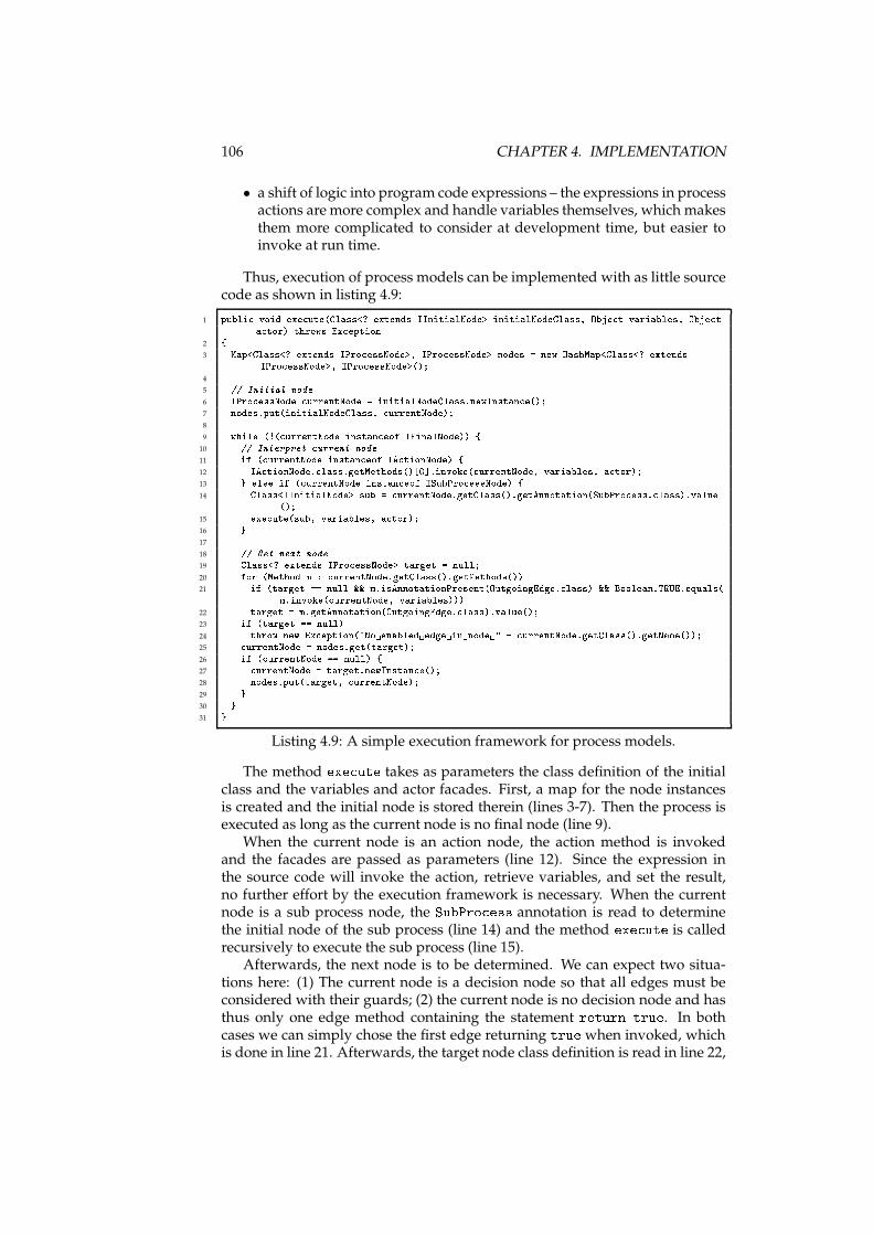
106 CHAPTER 4. IMPLEMENTATION
• a shift of logic into program code expressions – the expressions in processactions are more complex and handle variables themselves, which makesthem more complicated to consider at development time, but easier toinvoke at run time.
Thus, execution of process models can be implemented with as little sourcecode as shown in listing 4.9:
1 publi void exe ute(Class<? extends IInitialNode> initialNodeClass, Obje t variables, Obje ta tor) throws Ex eption2 {3 Map<Class<? extends IPro essNode>, IPro essNode> nodes = new HashMap<Class<? extendsIPro essNode>, IPro essNode>();4
5 // Initial node6 IPro essNode urrentNode = initialNodeClass.newInstan e();7 nodes.put(initialNodeClass, urrentNode);8
9 while (!( urrentNode instan eof IFinalNode)) {10 // Interpret urrent node11 if ( urrentNode instan eof IA tionNode) {12 IA tionNode. lass.getMethods()[0℄.invoke( urrentNode, variables, a tor);13 } else if ( urrentNode instan eof ISubPro essNode) {14 Class<IInitialNode> sub = urrentNode.getClass().getAnnotation(SubPro ess. lass).value();15 exe ute(sub, variables, a tor);16 }17
18 // Get next node19 Class<? extends IPro essNode> target = null;20 for (Method m : urrentNode.getClass().getMethods())21 if (target == null && m.isAnnotationPresent(OutgoingEdge. lass) && Boolean.TRUE.equals(m.invoke( urrentNode, variables)))22 target = m.getAnnotation(OutgoingEdge. lass).value();23 if (target == null)24 throw new Ex eption("No enabled edge in node " + urrentNode.getClass().getName());25 urrentNode = nodes.get(target);26 if ( urrentNode == null) {27 urrentNode = target.newInstan e();28 nodes.put(target, urrentNode);29 }30 }31 }
Listing 4.9: A simple execution framework for process models.
The method exe ute takes as parameters the class definition of the initialclass and the variables and actor facades. First, a map for the node instancesis created and the initial node is stored therein (lines 3-7). Then the process isexecuted as long as the current node is no final node (line 9).
When the current node is an action node, the action method is invokedand the facades are passed as parameters (line 12). Since the expression inthe source code will invoke the action, retrieve variables, and set the result,no further effort by the execution framework is necessary. When the currentnode is a sub process node, the SubPro ess annotation is read to determinethe initial node of the sub process (line 14) and the method exe ute is calledrecursively to execute the sub process (line 15).
Afterwards, the next node is to be determined. We can expect two situa-tions here: (1) The current node is a decision node so that all edges must beconsidered with their guards; (2) the current node is no decision node and hasthus only one edge method containing the statement return true. In bothcases we can simply chose the first edge returning true when invoked, whichis done in line 21. Afterwards, the target node class definition is read in line 22,
4.4. TOOLS 107
a possible deadlock handled in lines 23-24, and the target class is instantiatedin lines 25-29.
This simple execution framework is fully functional. It relies on the as-sumption that all rules of the program code pattern are obeyed (e.g., transitionmethods in non-decision nodes always returning true). A more sophisticatedexecution framework would certainly provide more validation facilities, butthe principle of the execution remains the same.
4.4.6 Monitoring Tool for State Machines
The pattern code fragments that are considered by tools at development timeare interpreted and invoked at run time by the execution framework. Thus,the model specifications are available at run time to a certain degree, so thatthe program can be monitored with respect to abstract models.
4.4.6.1 Concept
Considering embedded models for state machines, the following steps are un-der control of the execution framework and desirable for monitoring:
• Initialization and start of a state machine. This includes informationabout all states, transitions, and variables as extracted from the Java codevia reflection. States are uniquely identified by their fully qualified classnames.
• Activation of states. This indicates that guard evaluation and transitionselection in this state will happen subsequently.
• Selection of transitions. This indicates that program control will behanded over to the application logic in this transition.
• Validation of updates after a transition. The variable values are updatedin this event. Additionally, the cached variable values from the point intime before the transition fired are also supplied to allow for compar-isons. Additional information is supplied if the validation failed. Whenthis event is fired, program control has been taken over by the state ma-chine execution framework again.
A monitoring tool must thus work with the program code fragments de-fined by the pattern. Since this must happen at run time, the degree of detailvaries as the bytecode has partly different structures than the source code (cf.section 3.1.3.3). Several ways exist to obtain information at run time, however,they have different advantages and implications. The following criteria are ofinterest:
• Integration: First, it is of interest if and how a technology can be integratedin existing environments, in this case the Java platform.
• Accessibility: The most important question will be which informationabout the state machine semantics is generally available at run time andat which points in time it is accessible.
108 CHAPTER 4. IMPLEMENTATION
• Intrusiveness: We will consider what changes to source code or byte codeof the modeled system or the execution framework are indispensable tofacilitate monitoring.
• Self-monitoring: Use cases are imaginable that systems beingmonitored gain access to the monitoring information, for example forself-inspection, validation, or dynamic adaption.
• Performance: Possible performance issues related to each approach willbe considered.
• Tools: Regarding tool support it is of interest how the monitoring can becontrolled and how far it can be integrated into development tools.
We now introduce three approaches in sections 4.4.6.2 to 4.4.6.4 that allowto access the required information in different ways and evaluate them brieflywith respect to these criteria.
4.4.6.2 Listener Approach
Since all information about the running system and the embedded state ma-chine semantics is available to the statemachine execution framework, the easi-est way formonitoring is to extend this framework in order to emit informationof interest for active monitoring (cf. section 3.2.4). The execution framework isbased on structural reflection and accesses and interprets a considerable part ofthe program code structures constituting the pattern. Besides setting listenersprogrammatically, module-based platforms (like OSGi [OSGi Alliance, 2005a]in the context of Java) allow for a loose coupling of execution framework andcomponents receiving information about the execution. In the case of statemachines, listeners can be notified about each step performed on the embed-ded model by the execution framework (cf. section 4.4.6.1). With respect tothe criteria defined above, listeners are appropriate for monitoring embeddedmodels as follows:
Integration Listener concepts can be realized in the programming languageand the related platform without using any additional technologies or tools,since they are only an addition to the execution framework. They are thus easyto integrate.
Accessibility Considering the accessibility of elements of the program codepattern, the listener approach is clearly limited since expressions inside meth-ods are not available by means of reflection (cf. section 3.1.3.3). Thus, opera-tions inside guards and updates are not visible, but only their results after therelated method was invoked by the framework. They must thus be consideredblack boxes.
Intrusiveness The approach is intrusive to the source code of the executionframework since it must be extended for the listener implementation. Sincelisteners rely on information extracted by reflection, they are completely non-intrusive to the application being monitored.
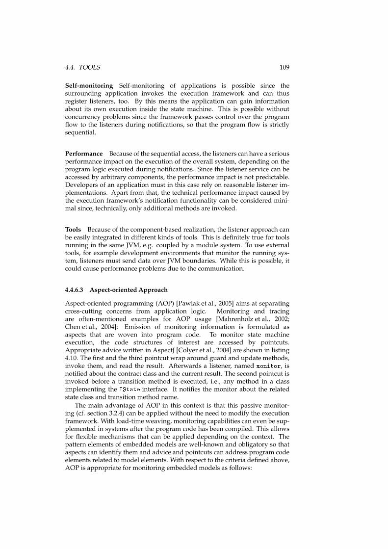
4.4. TOOLS 109
Self-monitoring Self-monitoring of applications is possible since thesurrounding application invokes the execution framework and can thusregister listeners, too. By this means the application can gain informationabout its own execution inside the state machine. This is possible withoutconcurrency problems since the framework passes control over the programflow to the listeners during notifications, so that the program flow is strictlysequential.
Performance Because of the sequential access, the listeners can have a seriousperformance impact on the execution of the overall system, depending on theprogram logic executed during notifications. Since the listener service can beaccessed by arbitrary components, the performance impact is not predictable.Developers of an application must in this case rely on reasonable listener im-plementations. Apart from that, the technical performance impact caused bythe execution framework’s notification functionality can be considered mini-mal since, technically, only additional methods are invoked.
Tools Because of the component-based realization, the listener approach canbe easily integrated in different kinds of tools. This is definitely true for toolsrunning in the same JVM, e.g. coupled by a module system. To use externaltools, for example development environments that monitor the running sys-tem, listeners must send data over JVM boundaries. While this is possible, itcould cause performance problems due to the communication.
4.4.6.3 Aspect-oriented Approach
Aspect-oriented programming (AOP) [Pawlak et al., 2005] aims at separatingcross-cutting concerns from application logic. Monitoring and tracingare often-mentioned examples for AOP usage [Mahrenholz et al., 2002;Chen et al., 2004]: Emission of monitoring information is formulated asaspects that are woven into program code. To monitor state machineexecution, the code structures of interest are accessed by pointcuts.Appropriate advice written in AspectJ [Colyer et al., 2004] are shown in listing4.10. The first and the third pointcut wrap around guard and update methods,invoke them, and read the result. Afterwards a listener, named monitor, isnotified about the contract class and the current result. The second pointcut isinvoked before a transition method is executed, i.e., any method in a classimplementing the IState interface. It notifies the monitor about the relatedstate class and transition method name.
The main advantage of AOP in this context is that this passive monitor-ing (cf. section 3.2.4) can be applied without the need to modify the executionframework. With load-time weaving, monitoring capabilities can even be sup-plemented in systems after the program code has been compiled. This allowsfor flexible mechanisms that can be applied depending on the context. Thepattern elements of embedded models are well-known and obligatory so thataspects can identify them and advice and pointcuts can address program codeelements related to model elements. With respect to the criteria defined above,AOP is appropriate for monitoring embedded models as follows:

110 CHAPTER 4. IMPLEMENTATION// Wrap guard method invo ation and notify about the resultboolean around(Obje t vars) : exe ution(* IContra t. he kCondition(..)) && args(vars) {boolean result = pro eed(vars);monitor.notifyGuard(thisJoinPointStati Part.getSignature().getDe laringType(), result);return result;}// Notify about forth oming transition method invo ationbefore() : exe ution(* *.*(..)) && target(IState) {monitor.notifyTransition(thisJoinPointStati Part.getSignature().getDe laringType(),thisJoinPointStati Part.getSignature().getName());}// Wrap update method invo ation and notify about the resultboolean around(Obje t before, Obje t after) :exe ution(* IContra t.validate(..)) && args(before, after) {boolean result = pro eed(vars);monitor.notifyUpdate(thisJoinPointStati Part.getSignature().getDe laringType(), result);return result;}Listing 4.10: The AspectJ monitoring aspect. All points of interest in theprogram code pattern are clearly identifiable by simple rules regarding theirclass and method names, so that pointcuts can be defined unambiguously.
Integration AOP technologies are available for many platforms, includingJava. However, their use can be restricted by frameworks or technologies inuse, e.g. module systems that control the class loading and thus may preventthe weaving. When weaving is possible, AOPmonitoring can be applied with-out support by the execution framework and thus provides a certain flexibility.
Accessibility The information that can be accessed this way is the same asin the listener concept, i.e. with the limitation of black box methods in Javabyte code. In addition, due to the limitations of pointcuts, the monitoring toolcannot observe the whole process of transition selection:
Pointcuts can handle information regarding the location of program code inwhich they are executed (keyword thisJoinPointStati Part). But, they donot gain access to information in terms of sequences of pointcuts: In each state,a certain number of guards is evaluated. Afterwards, one transition method isinvoked. While pointcuts are informed about the single actions, they cannotdetermine which guard belongs to the transition being executed; this infor-mation has to be guessed or supplemented by interpreting the program codeafterwards.
The aspect-oriented approach is thus only capable of explaining decisionsafter the transition method has been selected and is about to be called.
Intrusiveness The usage of AOP does not require modifications in the exe-cution framework architecture. Instead, modifications are applied to the com-piled Java bytecode by the aspect weaver at compile or load time and thustransparent to the developer. However, which modifications are applied towhich parts of the byte code is controlled by the weavers and thus out of con-trol of the developer. When the correctness of the code is of interest in detail,further examinations would have to be undertaken to determine the changesand possible impacts when errors occur.
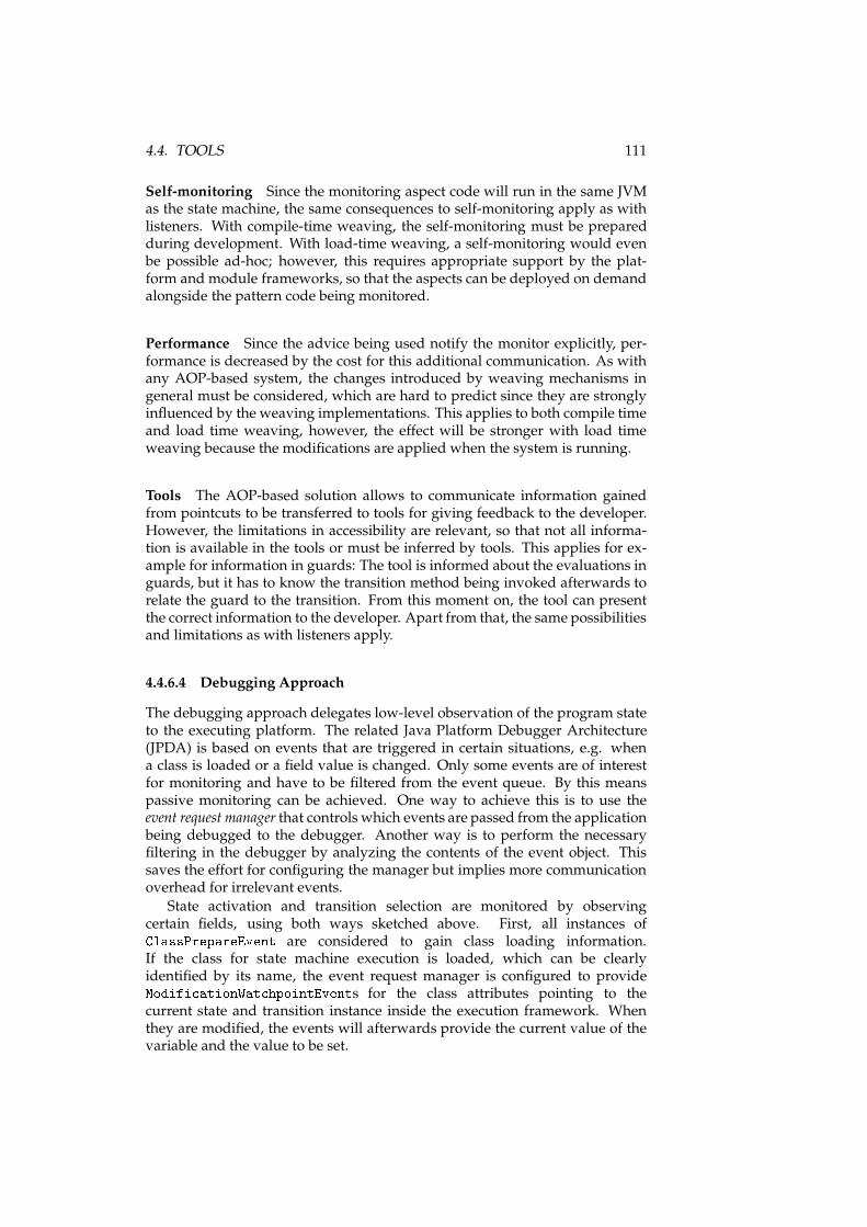
4.4. TOOLS 111
Self-monitoring Since the monitoring aspect code will run in the same JVMas the state machine, the same consequences to self-monitoring apply as withlisteners. With compile-time weaving, the self-monitoring must be preparedduring development. With load-time weaving, a self-monitoring would evenbe possible ad-hoc; however, this requires appropriate support by the plat-form and module frameworks, so that the aspects can be deployed on demandalongside the pattern code being monitored.
Performance Since the advice being used notify the monitor explicitly, per-formance is decreased by the cost for this additional communication. As withany AOP-based system, the changes introduced by weaving mechanisms ingeneral must be considered, which are hard to predict since they are stronglyinfluenced by the weaving implementations. This applies to both compile timeand load time weaving, however, the effect will be stronger with load timeweaving because the modifications are applied when the system is running.
Tools The AOP-based solution allows to communicate information gainedfrom pointcuts to be transferred to tools for giving feedback to the developer.However, the limitations in accessibility are relevant, so that not all informa-tion is available in the tools or must be inferred by tools. This applies for ex-ample for information in guards: The tool is informed about the evaluations inguards, but it has to know the transition method being invoked afterwards torelate the guard to the transition. From this moment on, the tool can presentthe correct information to the developer. Apart from that, the same possibilitiesand limitations as with listeners apply.
4.4.6.4 Debugging Approach
The debugging approach delegates low-level observation of the program stateto the executing platform. The related Java Platform Debugger Architecture(JPDA) is based on events that are triggered in certain situations, e.g. whena class is loaded or a field value is changed. Only some events are of interestfor monitoring and have to be filtered from the event queue. By this meanspassive monitoring can be achieved. One way to achieve this is to use theevent request manager that controls which events are passed from the applicationbeing debugged to the debugger. Another way is to perform the necessaryfiltering in the debugger by analyzing the contents of the event object. Thissaves the effort for configuring the manager but implies more communicationoverhead for irrelevant events.
State activation and transition selection are monitored by observingcertain fields, using both ways sketched above. First, all instances ofClassPrepareEvent are considered to gain class loading information.If the class for state machine execution is loaded, which can be clearlyidentified by its name, the event request manager is configured to provideModifi ationWat hpointEvents for the class attributes pointing to thecurrent state and transition instance inside the execution framework. Whenthey are modified, the events will afterwards provide the current value of thevariable and the value to be set.
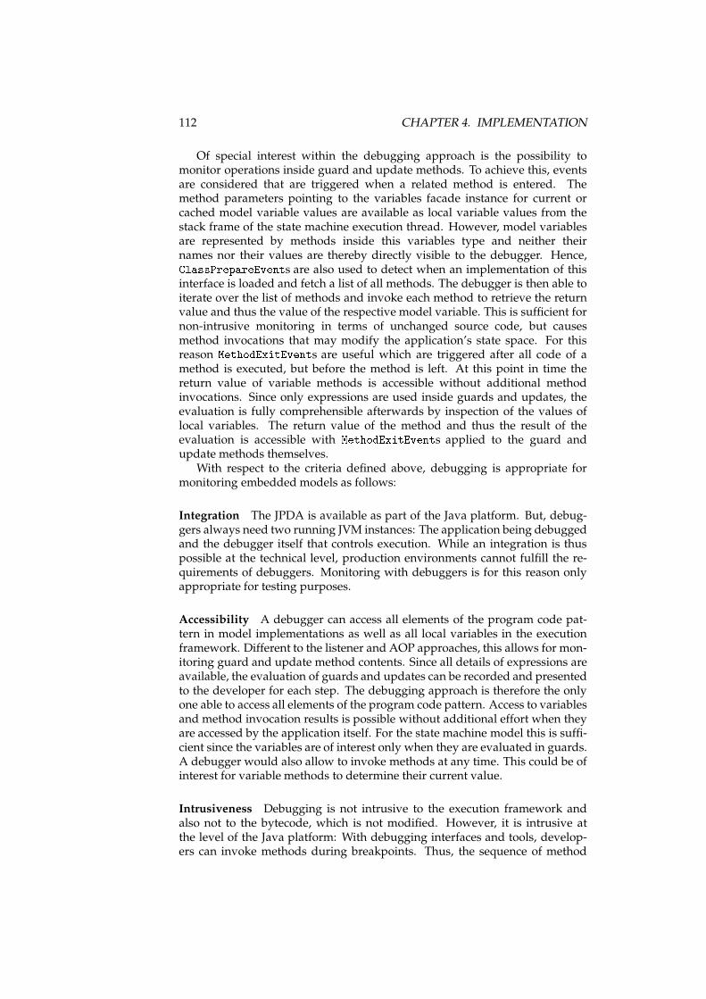
112 CHAPTER 4. IMPLEMENTATION
Of special interest within the debugging approach is the possibility tomonitor operations inside guard and update methods. To achieve this, eventsare considered that are triggered when a related method is entered. Themethod parameters pointing to the variables facade instance for current orcached model variable values are available as local variable values from thestack frame of the state machine execution thread. However, model variablesare represented by methods inside this variables type and neither theirnames nor their values are thereby directly visible to the debugger. Hence,ClassPrepareEvents are also used to detect when an implementation of thisinterface is loaded and fetch a list of all methods. The debugger is then able toiterate over the list of methods and invoke each method to retrieve the returnvalue and thus the value of the respective model variable. This is sufficient fornon-intrusive monitoring in terms of unchanged source code, but causesmethod invocations that may modify the application’s state space. For thisreason MethodExitEvents are useful which are triggered after all code of amethod is executed, but before the method is left. At this point in time thereturn value of variable methods is accessible without additional methodinvocations. Since only expressions are used inside guards and updates, theevaluation is fully comprehensible afterwards by inspection of the values oflocal variables. The return value of the method and thus the result of theevaluation is accessible with MethodExitEvents applied to the guard andupdate methods themselves.
With respect to the criteria defined above, debugging is appropriate formonitoring embedded models as follows:
Integration The JPDA is available as part of the Java platform. But, debug-gers always need two running JVM instances: The application being debuggedand the debugger itself that controls execution. While an integration is thuspossible at the technical level, production environments cannot fulfill the re-quirements of debuggers. Monitoring with debuggers is for this reason onlyappropriate for testing purposes.
Accessibility A debugger can access all elements of the program code pat-tern in model implementations as well as all local variables in the executionframework. Different to the listener and AOP approaches, this allows for mon-itoring guard and update method contents. Since all details of expressions areavailable, the evaluation of guards and updates can be recorded and presentedto the developer for each step. The debugging approach is therefore the onlyone able to access all elements of the program code pattern. Access to variablesand method invocation results is possible without additional effort when theyare accessed by the application itself. For the state machine model this is suffi-cient since the variables are of interest only when they are evaluated in guards.A debugger would also allow to invoke methods at any time. This could be ofinterest for variable methods to determine their current value.
Intrusiveness Debugging is not intrusive to the execution framework andalso not to the bytecode, which is not modified. However, it is intrusive atthe level of the Java platform: With debugging interfaces and tools, develop-ers can invoke methods during breakpoints. Thus, the sequence of method
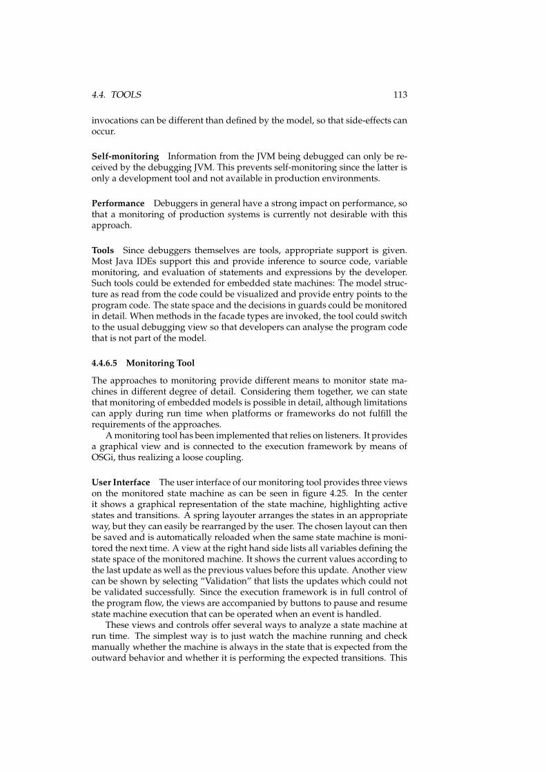
4.4. TOOLS 113
invocations can be different than defined by the model, so that side-effects canoccur.
Self-monitoring Information from the JVM being debugged can only be re-ceived by the debugging JVM. This prevents self-monitoring since the latter isonly a development tool and not available in production environments.
Performance Debuggers in general have a strong impact on performance, sothat a monitoring of production systems is currently not desirable with thisapproach.
Tools Since debuggers themselves are tools, appropriate support is given.Most Java IDEs support this and provide inference to source code, variablemonitoring, and evaluation of statements and expressions by the developer.Such tools could be extended for embedded state machines: The model struc-ture as read from the code could be visualized and provide entry points to theprogram code. The state space and the decisions in guards could be monitoredin detail. When methods in the facade types are invoked, the tool could switchto the usual debugging view so that developers can analyse the program codethat is not part of the model.
4.4.6.5 Monitoring Tool
The approaches to monitoring provide different means to monitor state ma-chines in different degree of detail. Considering them together, we can statethat monitoring of embeddedmodels is possible in detail, although limitationscan apply during run time when platforms or frameworks do not fulfill therequirements of the approaches.
Amonitoring tool has been implemented that relies on listeners. It providesa graphical view and is connected to the execution framework by means ofOSGi, thus realizing a loose coupling.
User Interface The user interface of our monitoring tool provides three viewson the monitored state machine as can be seen in figure 4.25. In the centerit shows a graphical representation of the state machine, highlighting activestates and transitions. A spring layouter arranges the states in an appropriateway, but they can easily be rearranged by the user. The chosen layout can thenbe saved and is automatically reloaded when the same state machine is moni-tored the next time. A view at the right hand side lists all variables defining thestate space of the monitored machine. It shows the current values according tothe last update as well as the previous values before this update. Another viewcan be shown by selecting “Validation” that lists the updates which could notbe validated successfully. Since the execution framework is in full control ofthe program flow, the views are accompanied by buttons to pause and resumestate machine execution that can be operated when an event is handled.
These views and controls offer several ways to analyze a state machine atrun time. The simplest way is to just watch the machine running and checkmanually whether the machine is always in the state that is expected from theoutward behavior and whether it is performing the expected transitions. This
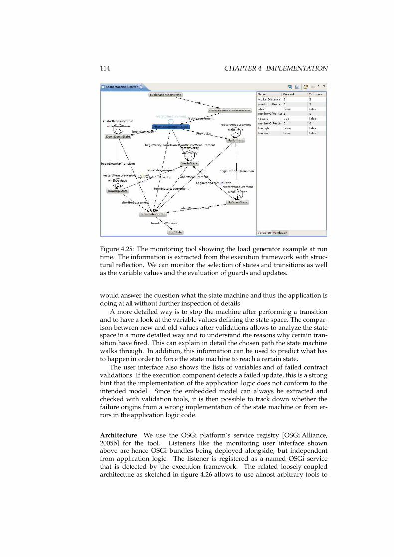
114 CHAPTER 4. IMPLEMENTATION
Figure 4.25: The monitoring tool showing the load generator example at runtime. The information is extracted from the execution framework with struc-tural reflection. We can monitor the selection of states and transitions as wellas the variable values and the evaluation of guards and updates.
would answer the question what the state machine and thus the application isdoing at all without further inspection of details.
A more detailed way is to stop the machine after performing a transitionand to have a look at the variable values defining the state space. The compar-ison between new and old values after validations allows to analyze the statespace in a more detailed way and to understand the reasons why certain tran-sition have fired. This can explain in detail the chosen path the state machinewalks through. In addition, this information can be used to predict what hasto happen in order to force the state machine to reach a certain state.
The user interface also shows the lists of variables and of failed contractvalidations. If the execution component detects a failed update, this is a stronghint that the implementation of the application logic does not conform to theintended model. Since the embedded model can always be extracted andchecked with validation tools, it is then possible to track down whether thefailure origins from a wrong implementation of the state machine or from er-rors in the application logic code.
Architecture We use the OSGi platform’s service registry [OSGi Alliance,2005b] for the tool. Listeners like the monitoring user interface shownabove are hence OSGi bundles being deployed alongside, but independentfrom application logic. The listener is registered as a named OSGi servicethat is detected by the execution framework. The related loosely-coupledarchitecture as sketched in figure 4.26 allows to use almost arbitrary tools to
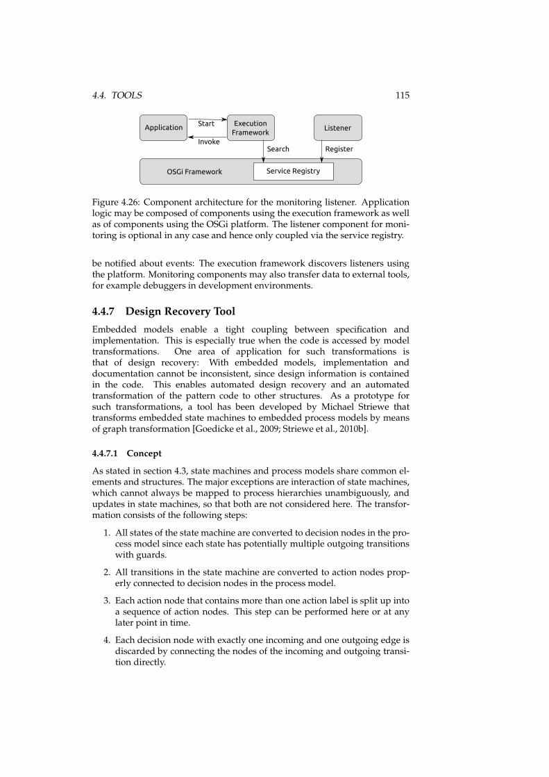
4.4. TOOLS 115
OSGi Framework Service Registry
ApplicationExecution
FrameworkListener
Start
InvokeSearch Register
Figure 4.26: Component architecture for the monitoring listener. Applicationlogic may be composed of components using the execution framework as wellas of components using the OSGi platform. The listener component for moni-toring is optional in any case and hence only coupled via the service registry.
be notified about events: The execution framework discovers listeners usingthe platform. Monitoring components may also transfer data to external tools,for example debuggers in development environments.
4.4.7 Design Recovery Tool
Embedded models enable a tight coupling between specification andimplementation. This is especially true when the code is accessed by modeltransformations. One area of application for such transformations isthat of design recovery: With embedded models, implementation anddocumentation cannot be inconsistent, since design information is containedin the code. This enables automated design recovery and an automatedtransformation of the pattern code to other structures. As a prototype forsuch transformations, a tool has been developed by Michael Striewe thattransforms embedded state machines to embedded process models by meansof graph transformation [Goedicke et al., 2009; Striewe et al., 2010b].
4.4.7.1 Concept
As stated in section 4.3, state machines and process models share common el-ements and structures. The major exceptions are interaction of state machines,which cannot always be mapped to process hierarchies unambiguously, andupdates in state machines, so that both are not considered here. The transfor-mation consists of the following steps:
1. All states of the state machine are converted to decision nodes in the pro-cess model since each state has potentially multiple outgoing transitionswith guards.
2. All transitions in the state machine are converted to action nodes prop-erly connected to decision nodes in the process model.
3. Each action node that contains more than one action label is split up intoa sequence of action nodes. This step can be performed here or at anylater point in time.
4. Each decision node with exactly one incoming and one outgoing edge isdiscarded by connecting the nodes of the incoming and outgoing transi-tion directly.
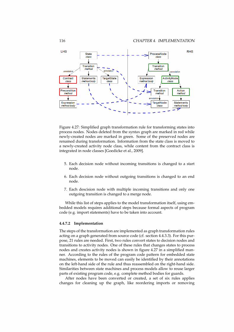
116 CHAPTER 4. IMPLEMENTATION
Figure 4.27: Simplified graph transformation rule for transforming states intoprocess nodes. Nodes deleted from the syntax graph are marked in red whilenewly-created nodes are marked in green. Some of the preserved nodes arerenamed during transformation. Information from the state class is moved toa newly-created activity node class, while content from the contract class isintegrated in node classes [Goedicke et al., 2009].
5. Each decision node without incoming transitions is changed to a startnode.
6. Each decision node without outgoing transitions is changed to an endnode.
7. Each descision node with multiple incoming transitions and only oneoutgoing transition is changed to a merge node.
While this list of steps applies to the model transformation itself, using em-bedded models requires additional steps because formal aspects of programcode (e.g. import statements) have to be taken into account.
4.4.7.2 Implementation
The steps of the transformation are implemented as graph transformation rulesacting on a graph generated from source code (cf. section 4.4.3.3). For this pur-pose, 21 rules are needed. First, two rules convert states to decision nodes andtransitions to activity nodes. One of these rules that changes states to processnodes and creates activity nodes is shown in figure 4.27 in a simplified man-ner. According to the rules of the program code pattern for embedded statemachines, elements to be moved can easily be identified by their annotationson the left-hand side of the rule and thus reassembled on the right-hand side.Similarities between state machines and process models allow to reuse largerparts of existing program code, e.g. complete method bodies for guards.
After nodes have been converted or created, a set of six rules applieschanges for cleaning up the graph, like reordering imports or removing
4.5. CHAPTER SUMMARY 117
unnecessary annotations. These rules are not strictly necessary, but desirablefor a clean implementation. Two additional rules remove the contract classeswhich are not needed in the process model as well as useless decision nodesthat have been introduced by rules applied earlier. Afterwards, the set ofnodes is complete, so three rules can be applied for marking start nodes, endnodes, and merge nodes. An additional rule splits action nodes with morethan one action label; this is necessary since state machine transitions canhave multiple action labels, while action nodes will have exactly one actionlabel. Another set of seven rules is finally concerned with some adjustmentsto the code.
4.5 Chapter Summary
In this chapter we introduced implementations of the embedded models ap-proach from chapter 3.
The first implementation is for the modeling domain of state machines insection 4.1. After a definition of the formal model, the program code patternwas defined and its interfaces, execution semantics, and transformations wereexplained.
The second implementation in section 4.2 is based on process models, inthis case the meta model of JWT. A program code pattern was derived and theinterfaces to other program code were defined. The definition was completedwith execution semantics and transformations.
Both embedded models were compared in section 4.3 with respect to theirrepresentation of model elements, the management of the state space, and theirparticular scaling mechanisms.
Based on the embedded model definitions, tools supporting developmentat different levels of abstraction were introduced in section 4.4 for design, veri-fication, execution, monitoring, and design recovery. For state machines, a toolsuite exists that supports all these stages of the development process. For pro-cess models, design and execution tools exist. Design recovery is realized by atransformation from state machines to process models.
In the next chapter wewill evaluate the approachwith two case studies thatuse embedded state machines and process models.

118 CHAPTER 4. IMPLEMENTATION
Chapter 5
Evaluation
So far, the approach for embeddedmodels and specific implementations for thedomains of statemachines and processmodels have been presented in chapters3 and 4. In this chapter wewill evaluate the approach based on criteria that willbe introduced in section 5.1. The evaluation is performed by considering twocase studies:
First, the approach is applied to a load generator for performance tests,called “SyLaGen”, in section 5.2. Essential algorithms for controlling the loadgeneration aremodeled with both embedded state machines and process mod-els. These models are integrated in the larger context of the actual applica-tion. This will demonstrate the applicability of the approach for non-trivialreal-world applications.
The second case study in section 5.3 is small, but focuses on different as-pects. Embedded state machines are here integrated in a visual programminglearning environment. Based on this, small games are developed, whose actorsare communicating state machines. The software has been used for teachingformal methods in a university master’s course. In this context, a small userstudy has been performed.
An overall evaluation of the approach that considers the partial evaluationresults from both case studies will finally be given in section 5.4.
5.1 Criteria
Based on the objectives from chapters 1 and 3, embeddedmodels have the goalto apply the advantages of models to program code patterns that are connectedto application logic. An evaluation of the approach must thus focus on advan-tages of models and validate their usefulness in the case studies. We will useas criteria what is called by Selic the quality of models [Selic, 2003]:
Abstraction “Amodel is always a reduced rendering of the system that it rep-resents. By removing or hiding detail that is irrelevant for a given view-point, it lets us understand the essence more easily.” [Selic, 2003] In ourcontext, it is of interest if a meaningful abstraction from program codedetails is possible. This is to be considered especially careful for the in-terfaces where other application logic is connected to the model.
119
120 CHAPTER 5. EVALUATION
Understandability “A good model provides a shortcut by reducing theamount of intellectual effort required for understanding.” [Selic,2003] For embedded models, we do not evaluate the formal modelsthemselves. Instead, two aspects of the understandability are ofinterest: First, we must evaluate how the entirety of program code withembedded models is comprehensible. Second, we must evaluate theunderstandability of model instances that are not only driven bydomain requirements, but also by the consideration of embedded modelconventions and interfaces to application logic.
Accuracy “A model must provide a true-to-life representation of the modeledsystem’s features of interest.” [Selic, 2003] Since embedded models arenot considered stand-alone, but always in connection with interfaces toapplication logic, the models may be influenced. We will consider howaccurate the models in use will reflect the domain requirements undersuch circumstances.
Predictiveness “You should be able to use a model to correctly predict themodeled system’s interesting but nonobvious properties [. . . ].” [Selic,2003] While this depends heavily on the formal model in use, we willevaluate here howmodels that are influenced by interface considerationsare still eligible for model checking and analysis.
Inexpensiveness “A model [. . . ] must be significantly cheaper to constructand analyze than the modeled system.” [Selic, 2003] In the context of em-bedded models, two kinds of overhead have to be considered: First, theprogram code is likely to consist of more static fragments than manually-written algorithms. Second, models considering rules of embeddedmod-els and interface definitions may be more complex than pure abstractmodels would have been. For both, we will evaluate the tool supportfor working at different abstraction levels.
With these criteria in mind, we introduce the case studies now. Each casestudy will be evaluated separately in sections 5.2.4 and 5.3.5. Afterwards, anoverall evaluation will be given in section 5.4.
5.2 Case Study “Load Generator”
The first case study focuses on the use of embedded models in a non-trivial,real-world application. We describe SyLaGen first in section 5.2.1. The imple-mentation of embedded state machines is described in section 5.2.2 and theimplementation of embedded process models in section 5.2.3. Afterwards theevaluation criteria are applied to this case study in section 5.2.4.
5.2.1 Description of “SyLaGen”
SyLaGen is a load generator for performance tests [Striewe et al., 2010a;Bordewisch et al., 2003] that has been under development since 1999by the working group Specification of Software Systems at University ofDuisburg-Essen. The overall architecture has two distributed components:

5.2. CASE STUDY “LOAD GENERATOR” 121
Clients
Configuration
Connection
User Interface
ReportingResults
Workload
Measurement
Single
Exploration
Stress
Figure 5.1: The SyLaGenmastermodules. In the center, the measurementmod-ule can be seen with its different load strategies. It coordinates the actual loadgeneration.
The so-called master controls a measurement by directing clients that run ondifferent physical machines. Each client has a certain number of threads calledworkers that generate the actual load.
5.2.1.1 Modules
The master has a high complexity and is for this reason split into differentmodules as sketched in figure 5.1:
The workload module manages, stores, and validates load descriptions.These are edited by the user in the user interface. When a performance testis started, control is passed to the measurement module. It reads generalconfiguration from the configuration module. The measurement module itselfcontains different strategies for generating load: The single strategy performsonly one measurement with load that is specified for a certain time frame. Thestress strategy performs also one measurement, but generates as much loadas possible. The exploration strategy is the most complex since it performsa sequence of measurements by evaluating the results after each singlemeasurement and adapting the number of workers in use in order to find theoptimum.
The measurement module and its strategies use the clientmodule that man-ages clients connected to the master. It also distributes commands given by themeasurement module to all clients that are used in the current measurement.The actual communication with clients occurs in the connectionmodule, whichalso receives data from the clients after a single measurement has finished.These results are passed to the result module which receives them from sin-
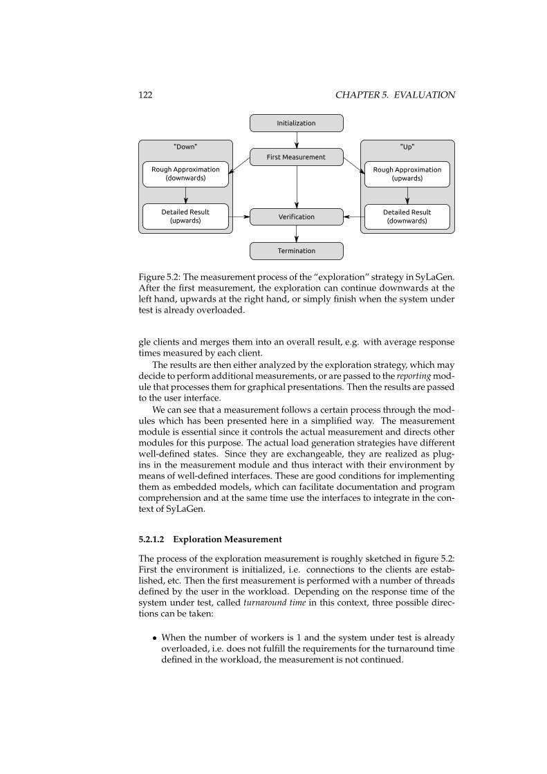
122 CHAPTER 5. EVALUATION
"Down"
Rough Approximation
(downwards)
Detailed Result
(upwards)
First Measurement
Verification
Termination
Initialization
"Up"
Rough Approximation
(upwards)
Detailed Result
(downwards)
Figure 5.2: Themeasurement process of the “exploration” strategy in SyLaGen.After the first measurement, the exploration can continue downwards at theleft hand, upwards at the right hand, or simply finish when the system undertest is already overloaded.
gle clients and merges them into an overall result, e.g. with average responsetimes measured by each client.
The results are then either analyzed by the exploration strategy, which maydecide to perform additionalmeasurements, or are passed to the reportingmod-ule that processes them for graphical presentations. Then the results are passedto the user interface.
We can see that a measurement follows a certain process through the mod-ules which has been presented here in a simplified way. The measurementmodule is essential since it controls the actual measurement and directs othermodules for this purpose. The actual load generation strategies have differentwell-defined states. Since they are exchangeable, they are realized as plug-ins in the measurement module and thus interact with their environment bymeans of well-defined interfaces. These are good conditions for implementingthem as embedded models, which can facilitate documentation and programcomprehension and at the same time use the interfaces to integrate in the con-text of SyLaGen.
5.2.1.2 Exploration Measurement
The process of the exploration measurement is roughly sketched in figure 5.2:First the environment is initialized, i.e. connections to the clients are estab-lished, etc. Then the first measurement is performed with a number of threadsdefined by the user in the workload. Depending on the response time of thesystem under test, called turnaround time in this context, three possible direc-tions can be taken:
• When the number of workers is 1 and the system under test is alreadyoverloaded, i.e. does not fulfill the requirements for the turnaround timedefined in the workload, the measurement is not continued.
5.2. CASE STUDY “LOAD GENERATOR” 123
• When the number of workers is >1 and the system under test is over-loaded, the exploration measurement is continued downwards: The num-ber of workers is decreased in larger steps (also defined by the user, e.g.5 workers) until the system is no longer overloaded. After this roughapproximation, the number of clients is increased again by 1 until thesystem is overloaded again, so that the exact limit is known.
• When the system under test is not overloaded, the exploration measure-ment is continued upwards: The number of workers is increased in largersteps until the system is overloaded. After this rough approximation, thenumber of clients is decreased again by 1 until the system is no longeroverloaded, so that the exact limit is known.
Whether the system is overloaded is decided as follows. Two constraintsare given by the user: The expected turnaround time that should not be exceededon average and themaximum turnaround time that is not allowed to be exceededat all. The system is overloaded if either the mean turnaround time is greaterthan the expected turnaround time or if one of the workers encountered aturnaround time that is greater than the maximum turnaround time. This de-cision is non-trivial as it requires access to each single result of all workers, sothat it is hard to integrate in abstract models and must be abstracted from.
After all of the three steps, a last measurement is performed called verifica-tion: The number of workers is decreased again in larger steps and measure-ments are performed until the last measurement is performed with 1 worker.This is done in order to verify that the system under test is fully functionaland the previous measurement results have not been corrupted by errors. Af-terwards, the environment is terminated, i.e. the clients are instructed to shutdown the workers, the results are stored and passed to the reporting module,etc.
In the implementation, this process is more complicated as more decisionsare possible after each measurement. The user can abort the measurement sothat after each measurement the termination can occur. When errors are de-tected, the measurement is restarted a certain number of times as defined bythe user; this can lead to repetitions and also to abortion of the measurement.
We will now describe the implementation of this algorithm with two al-ternative embedded model classes, state machines (section 5.2.2) and processmodels (section 5.2.3).
5.2.2 State Machine
The exploration strategies have been documented for a certain time with UP-PAAL, but we made the experience that documentation and implementationwere out of sync quite often. Thus the decision was made four years ago toapply embedded state machines to SyLaGen based on the requirements de-scribed in the previous section. Since then, the strategies are maintained withthe related program code pattern.
5.2.2.1 Structure
The exploration measurement as described in section 5.2.1.2 is implemented interms of states and transitions as shown in figure 5.3:
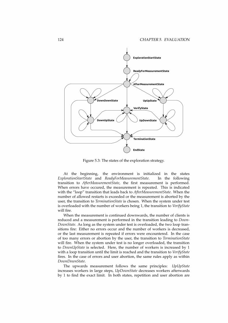
124 CHAPTER 5. EVALUATION
ExplorationStartState
ReadyForMeasurementState
AfterMeasurementState
VerifyState
UpUpStateDownDownState
TerminationState
EndState
UpDownStateDownUpState
Figure 5.3: The states of the exploration strategy.
At the beginning, the environment is initialized in the statesExplorationStartState and ReadyForMeasurementState. In the followingtransition to AfterMeasurementState, the first measurement is performed.When errors have occured, the measurement is repeated. This is indicatedwith the “loop” transition that leads back to AfterMeasurementState. When thenumber of allowed restarts is exceeded or the measurement is aborted by theuser, the transition to TerminationState is chosen. When the system under testis overloaded with the number of workers being 1, the transition to VerifyStatewill fire.
When the measurement is continued downwards, the number of clients isreduced and a measurement is performed in the transition leading to Down-DownState. As long as the system under test is overloaded, the two loop tran-sitions fire: Either no errors occur and the number of workers is decreased,or the last measurement is repeated if errors were encountered. In the caseof too many errors or abortion by the user, the transition to TerminationStatewill fire. When the system under test is no longer overloaded, the transitionto DownUpState is selected. Here, the number of workers is increased by 1with a loop transition until the limit is reached and the transition to VerifyStatefires. In the case of errors and user abortion, the same rules apply as withinDownDownState.
The upwards measurement follows the same principles: UpUpStateincreases workers in large steps, UpDownState decreases workers afterwardsby 1 to find the exact limit. In both states, repetition and user abortion are
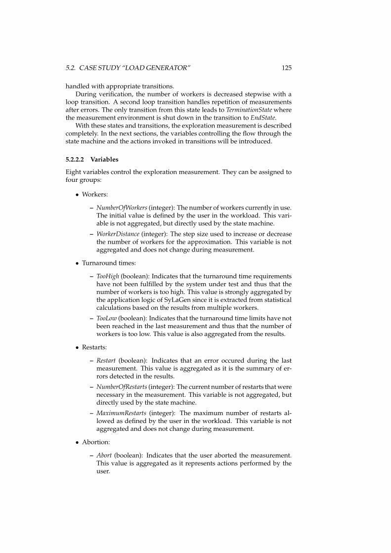
5.2. CASE STUDY “LOAD GENERATOR” 125
handled with appropriate transitions.During verification, the number of workers is decreased stepwise with a
loop transition. A second loop transition handles repetition of measurementsafter errors. The only transition from this state leads to TerminationStatewherethe measurement environment is shut down in the transition to EndState.
With these states and transitions, the exploration measurement is describedcompletely. In the next sections, the variables controlling the flow through thestate machine and the actions invoked in transitions will be introduced.
5.2.2.2 Variables
Eight variables control the exploration measurement. They can be assigned tofour groups:
• Workers:
– NumberOfWorkers (integer): The number of workers currently in use.The initial value is defined by the user in the workload. This vari-able is not aggregated, but directly used by the state machine.
– WorkerDistance (integer): The step size used to increase or decreasethe number of workers for the approximation. This variable is notaggregated and does not change during measurement.
• Turnaround times:
– TooHigh (boolean): Indicates that the turnaround time requirementshave not been fulfilled by the system under test and thus that thenumber of workers is too high. This value is strongly aggregated bythe application logic of SyLaGen since it is extracted from statisticalcalculations based on the results from multiple workers.
– TooLow (boolean): Indicates that the turnaround time limits have notbeen reached in the last measurement and thus that the number ofworkers is too low. This value is also aggregated from the results.
• Restarts:
– Restart (boolean): Indicates that an error occured during the lastmeasurement. This value is aggregated as it is the summary of er-rors detected in the results.
– NumberOfRestarts (integer): The current number of restarts that werenecessary in the measurement. This variable is not aggregated, butdirectly used by the state machine.
– MaximumRestarts (integer): The maximum number of restarts al-lowed as defined by the user in the workload. This variable is notaggregated and does not change during measurement.
• Abortion:
– Abort (boolean): Indicates that the user aborted the measurement.This value is aggregated as it represents actions performed by theuser.
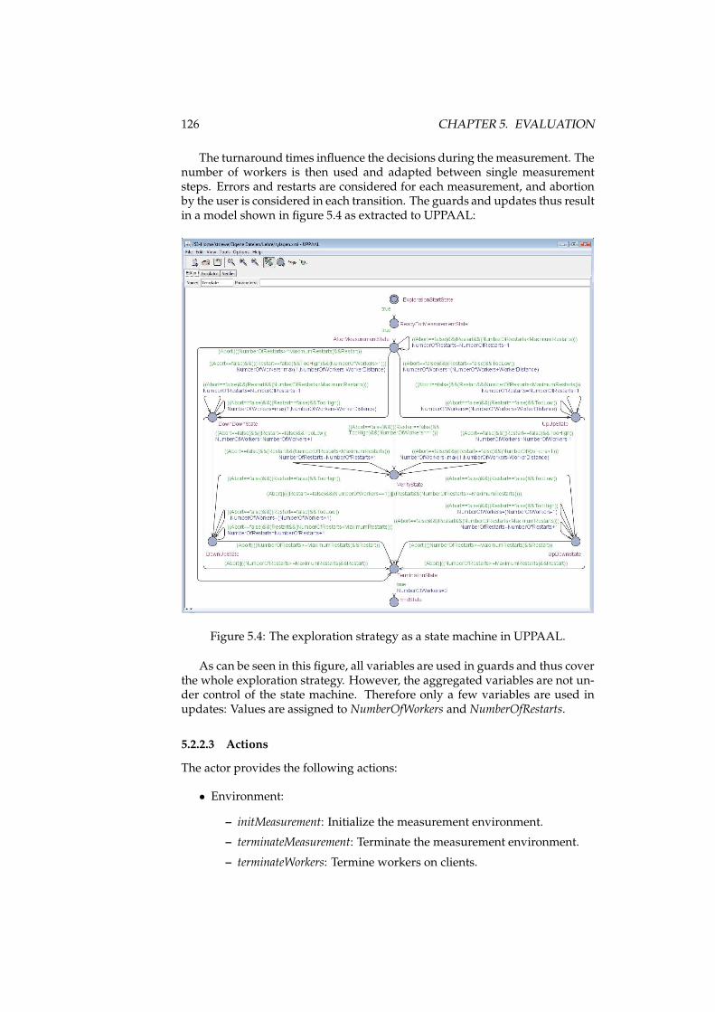
126 CHAPTER 5. EVALUATION
The turnaround times influence the decisions during the measurement. Thenumber of workers is then used and adapted between single measurementsteps. Errors and restarts are considered for each measurement, and abortionby the user is considered in each transition. The guards and updates thus resultin a model shown in figure 5.4 as extracted to UPPAAL:
Figure 5.4: The exploration strategy as a state machine in UPPAAL.
As can be seen in this figure, all variables are used in guards and thus coverthe whole exploration strategy. However, the aggregated variables are not un-der control of the state machine. Therefore only a few variables are used inupdates: Values are assigned to NumberOfWorkers and NumberOfRestarts.
5.2.2.3 Actions
The actor provides the following actions:
• Environment:
– initMeasurement: Initialize the measurement environment.
– terminateMeasurement: Terminate the measurement environment.
– terminateWorkers: Termine workers on clients.
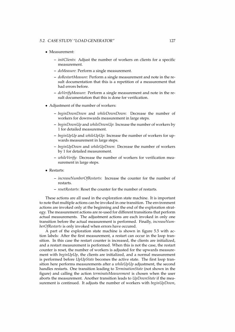
5.2. CASE STUDY “LOAD GENERATOR” 127
• Measurement:
– initClients: Adjust the number of workers on clients for a specificmeasurement.
– doMeasure: Perform a single measurement.
– doRestartMeasure: Perform a single measurement and note in the re-sult documentation that this is a repetition of a measurement thathad errors before.
– doVerifyMeasure: Perform a single measurement and note in the re-sult documentation that this is done for verification.
• Adjustment of the number of workers:
– beginDownDown and whileDownDown: Decrease the number ofworkers for downwards measurement in large steps.
– beginDownUp and whileDownUp: Increase the number of workers by1 for detailed measurement.
– beginUpUp and whileUpUp: Increase the number of workers for up-wards measurement in large steps.
– beginUpDown and whileUpDown: Decrease the number of workersby 1 for detailed measurement.
– whileVerify: Decrease the number of workers for verification mea-surement in large steps.
• Restarts:
– increaseNumberOfRestarts: Increase the counter for the number ofrestarts.
– resetRestarts: Reset the counter for the number of restarts.
These actions are all used in the exploration state machine. It is importantto note that multiple actions can be invoked in one transition. The environmentactions are invoked only at the beginning and the end of the exploration strat-egy. Themeasurement actions are re-used for different transitions that performactual measurements. The adjustment actions are each invoked in only onetransition before the actual measurement is performed. Finally, increaseNum-berOfRestarts is only invoked when errors have occured.
A part of the exploration state machine is shown in figure 5.5 with ac-tion labels: After the first measurement, a restart can occur in the loop tran-sition. In this case the restart counter is increased, the clients are initialized,and a restart measurement is performed. When this is not the case, the restartcounter is reset, the number of workers is adjusted for the upwards measure-ment with beginUpUp, the clients are initialized, and a normal measurementis performed before UpUpState becomes the active state. The first loop tran-sition here performs measurements after a whileUpUp adjustment, the secondhandles restarts. One transition leading to TerminationState (not shown in thefigure) and calling the action terminateMeasurement is chosen when the useraborts the measurement. Another transition leads to UpDownState if the mea-surement is continued. It adjusts the number of workers with beginUpDown,
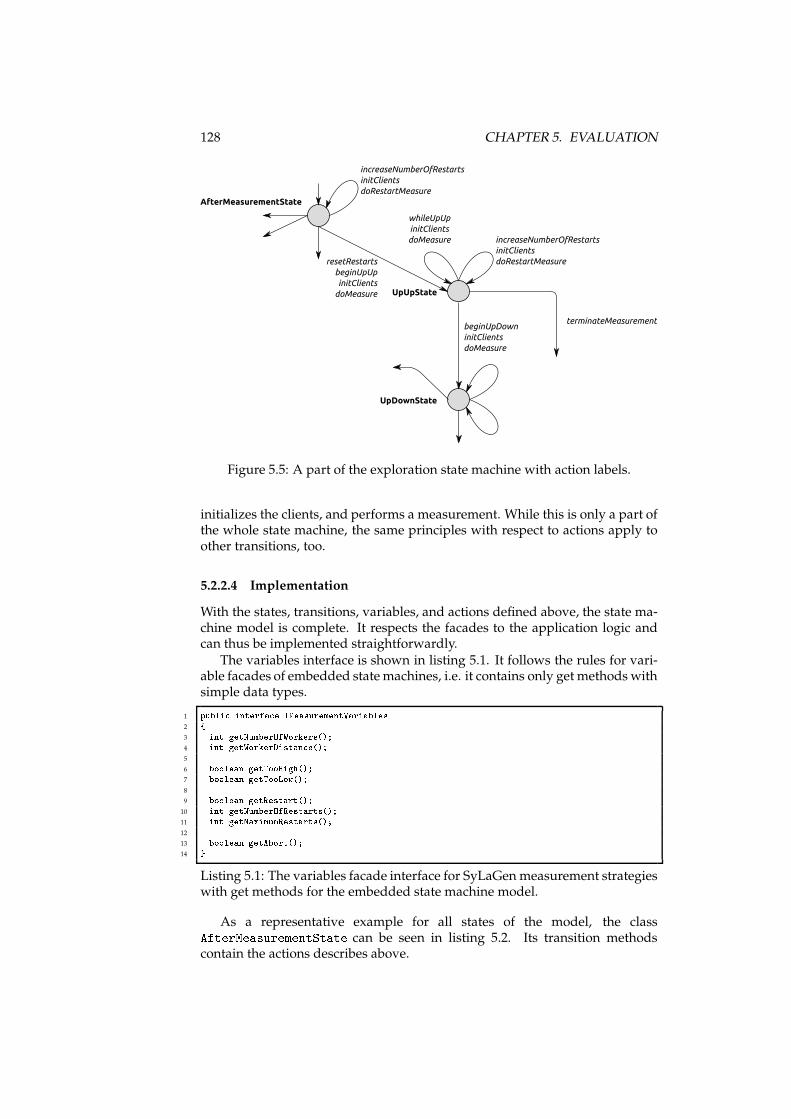
128 CHAPTER 5. EVALUATION
AfterMeasurementState
UpUpState
UpDownState
resetRestarts
beginUpUp
initClients
doMeasure
increaseNumberOfRestarts
initClients
doRestartMeasure
whileUpUp
initClients
doMeasure increaseNumberOfRestarts
initClients
doRestartMeasure
beginUpDown
initClients
doMeasure
terminateMeasurement
Figure 5.5: A part of the exploration state machine with action labels.
initializes the clients, and performs a measurement. While this is only a part ofthe whole state machine, the same principles with respect to actions apply toother transitions, too.
5.2.2.4 Implementation
With the states, transitions, variables, and actions defined above, the state ma-chine model is complete. It respects the facades to the application logic andcan thus be implemented straightforwardly.
The variables interface is shown in listing 5.1. It follows the rules for vari-able facades of embedded statemachines, i.e. it contains only get methods withsimple data types.
1 publi interfa e IMeasurementVariables2 {3 int getNumberOfWorkers();4 int getWorkerDistan e();5
6 boolean getTooHigh();7 boolean getTooLow();8
9 boolean getRestart();10 int getNumberOfRestarts();11 int getMaximumRestarts();12
13 boolean getAbort();14 }
Listing 5.1: The variables facade interface for SyLaGenmeasurement strategieswith get methods for the embedded state machine model.
As a representative example for all states of the model, the classAfterMeasurementState can be seen in listing 5.2. Its transition methodscontain the actions describes above.
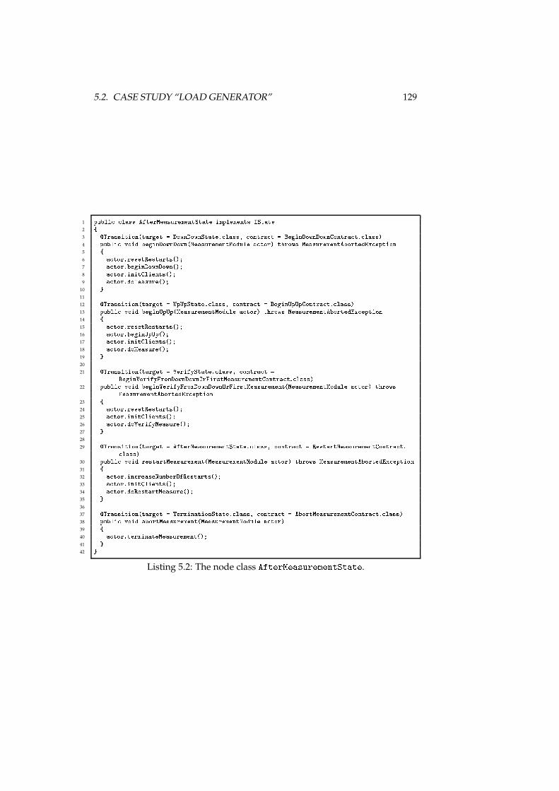
5.2. CASE STUDY “LOAD GENERATOR” 129
1 publi lass AfterMeasurementState implements IState2 {3 �Transition(target = DownDownState. lass, ontra t = BeginDownDownContra t. lass)4 publi void beginDownDown(MeasurementModule a tor) throws MeasurementAbortedEx eption5 {6 a tor.resetRestarts();7 a tor.beginDownDown();8 a tor.initClients();9 a tor.doMeasure();
10 }11
12 �Transition(target = UpUpState. lass, ontra t = BeginUpUpContra t. lass)13 publi void beginUpUp(MeasurementModule a tor) throws MeasurementAbortedEx eption14 {15 a tor.resetRestarts();16 a tor.beginUpUp();17 a tor.initClients();18 a tor.doMeasure();19 }20
21 �Transition(target = VerifyState. lass, ontra t =BeginVerifyFromDownDownOrFirstMeasurementContra t. lass)22 publi void beginVerifyFromDownDownOrFirstMeasurement(MeasurementModule a tor) throwsMeasurementAbortedEx eption23 {24 a tor.resetRestarts();25 a tor.initClients();26 a tor.doVerifyMeasure();27 }28
29 �Transition(target = AfterMeasurementState. lass, ontra t = RestartMeasurementContra t. lass)30 publi void restartMeasurement(MeasurementModule a tor) throws MeasurementAbortedEx eption31 {32 a tor.in reaseNumberOfRestarts();33 a tor.initClients();34 a tor.doRestartMeasure();35 }36
37 �Transition(target = TerminationState. lass, ontra t = AbortMeasurementContra t. lass)38 publi void abortMeasurement(MeasurementModule a tor)39 {40 a tor.terminateMeasurement();41 }42 }
Listing 5.2: The node class AfterMeasurementState.
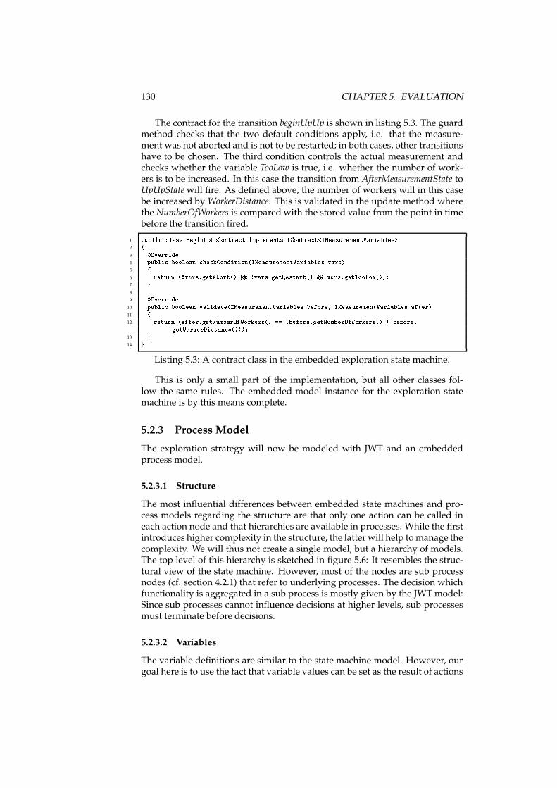
130 CHAPTER 5. EVALUATION
The contract for the transition beginUpUp is shown in listing 5.3. The guardmethod checks that the two default conditions apply, i.e. that the measure-ment was not aborted and is not to be restarted; in both cases, other transitionshave to be chosen. The third condition controls the actual measurement andchecks whether the variable TooLow is true, i.e. whether the number of work-ers is to be increased. In this case the transition from AfterMeasurementState toUpUpStatewill fire. As defined above, the number of workers will in this casebe increased by WorkerDistance. This is validated in the update method wherethe NumberOfWorkers is compared with the stored value from the point in timebefore the transition fired.
1 publi lass BeginUpUpContra t implements IContra t<IMeasurementVariables>2 {3 �Override4 publi boolean he kCondition(IMeasurementVariables vars)5 {6 return (!vars.getAbort() && !vars.getRestart() && vars.getTooLow());7 }8
9 �Override10 publi boolean validate(IMeasurementVariables before, IMeasurementVariables after)11 {12 return (after.getNumberOfWorkers() == (before.getNumberOfWorkers() + before.getWorkerDistan e()));13 }14 }
Listing 5.3: A contract class in the embedded exploration state machine.
This is only a small part of the implementation, but all other classes fol-low the same rules. The embedded model instance for the exploration statemachine is by this means complete.
5.2.3 Process Model
The exploration strategy will now be modeled with JWT and an embeddedprocess model.
5.2.3.1 Structure
The most influential differences between embedded state machines and pro-cess models regarding the structure are that only one action can be called ineach action node and that hierarchies are available in processes. While the firstintroduces higher complexity in the structure, the latter will help tomanage thecomplexity. We will thus not create a single model, but a hierarchy of models.The top level of this hierarchy is sketched in figure 5.6: It resembles the struc-tural view of the state machine. However, most of the nodes are sub processnodes (cf. section 4.2.1) that refer to underlying processes. The decision whichfunctionality is aggregated in a sub process is mostly given by the JWT model:Since sub processes cannot influence decisions at higher levels, sub processesmust terminate before decisions.
5.2.3.2 Variables
The variable definitions are similar to the state machine model. However, ourgoal here is to use the fact that variable values can be set as the result of actions
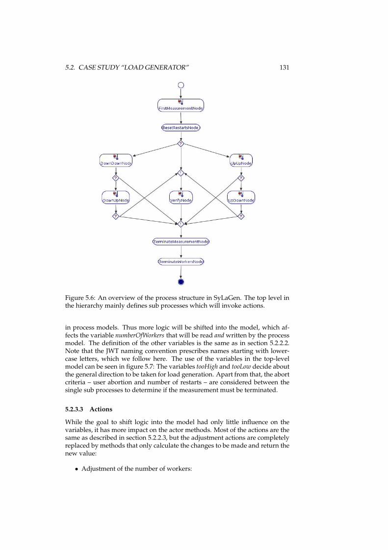
5.2. CASE STUDY “LOAD GENERATOR” 131
Figure 5.6: An overview of the process structure in SyLaGen. The top level inthe hierarchy mainly defines sub processes which will invoke actions.
in process models. Thus more logic will be shifted into the model, which af-fects the variable numberOfWorkers that will be read andwritten by the processmodel. The definition of the other variables is the same as in section 5.2.2.2.Note that the JWT naming convention prescribes names starting with lower-case letters, which we follow here. The use of the variables in the top-levelmodel can be seen in figure 5.7: The variables tooHigh and tooLow decide aboutthe general direction to be taken for load generation. Apart from that, the abortcriteria – user abortion and number of restarts – are considered between thesingle sub processes to determine if the measurement must be terminated.
5.2.3.3 Actions
While the goal to shift logic into the model had only little influence on thevariables, it has more impact on the actor methods. Most of the actions are thesame as described in section 5.2.2.3, but the adjustment actions are completelyreplaced by methods that only calculate the changes to be made and return thenew value:
• Adjustment of the number of workers:
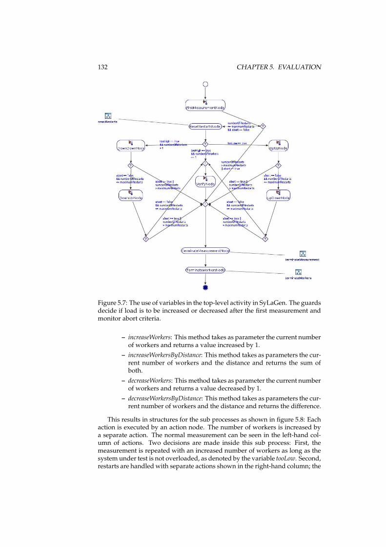
132 CHAPTER 5. EVALUATION
Figure 5.7: The use of variables in the top-level activity in SyLaGen. The guardsdecide if load is to be increased or decreased after the first measurement andmonitor abort criteria.
– increaseWorkers: This method takes as parameter the current numberof workers and returns a value increased by 1.
– increaseWorkersByDistance: This method takes as parameters the cur-rent number of workers and the distance and returns the sum ofboth.
– decreaseWorkers: This method takes as parameter the current numberof workers and returns a value decreased by 1.
– decreaseWorkersByDistance: This method takes as parameters the cur-rent number of workers and the distance and returns the difference.
This results in structures for the sub processes as shown in figure 5.8: Eachaction is executed by an action node. The number of workers is increased bya separate action. The normal measurement can be seen in the left-hand col-umn of actions. Two decisions are made inside this sub process: First, themeasurement is repeated with an increased number of workers as long as thesystem under test is not overloaded, as denoted by the variable tooLow. Second,restarts are handled with separate actions shown in the right-hand column; the
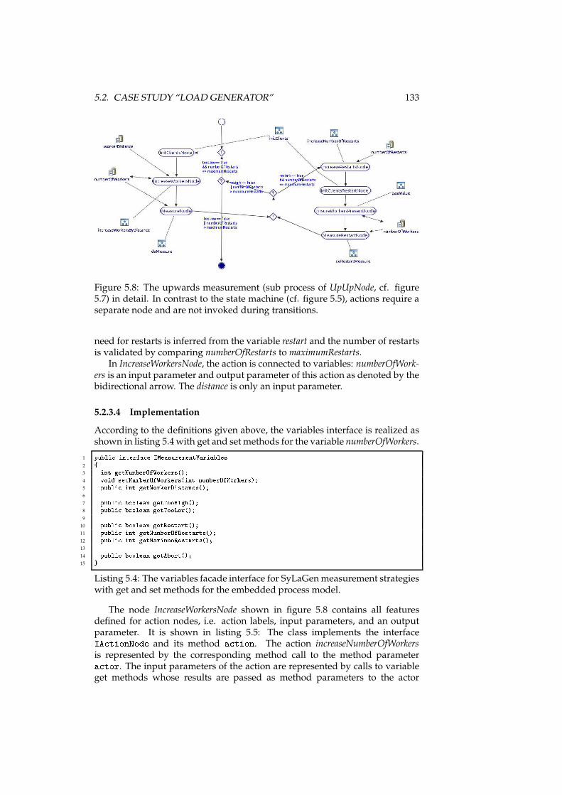
5.2. CASE STUDY “LOAD GENERATOR” 133
Figure 5.8: The upwards measurement (sub process of UpUpNode, cf. figure5.7) in detail. In contrast to the state machine (cf. figure 5.5), actions require aseparate node and are not invoked during transitions.
need for restarts is inferred from the variable restart and the number of restartsis validated by comparing numberOfRestarts to maximumRestarts.
In IncreaseWorkersNode, the action is connected to variables: numberOfWork-ers is an input parameter and output parameter of this action as denoted by thebidirectional arrow. The distance is only an input parameter.
5.2.3.4 Implementation
According to the definitions given above, the variables interface is realized asshown in listing 5.4 with get and set methods for the variable numberOfWorkers.
1 publi interfa e IMeasurementVariables2 {3 int getNumberOfWorkers();4 void setNumberOfWorkers(int numberOfWorkers);5 publi int getWorkerDistan e();6
7 publi boolean getTooHigh();8 publi boolean getTooLow();9
10 publi boolean getRestart();11 publi int getNumberOfRestarts();12 publi int getMaximumRestarts();13
14 publi boolean getAbort();15 }
Listing 5.4: The variables facade interface for SyLaGenmeasurement strategieswith get and set methods for the embedded process model.
The node IncreaseWorkersNode shown in figure 5.8 contains all featuresdefined for action nodes, i.e. action labels, input parameters, and an outputparameter. It is shown in listing 5.5: The class implements the interfaceIA tionNode and its method a tion. The action increaseNumberOfWorkersis represented by the corresponding method call to the method parametera tor. The input parameters of the action are represented by calls to variableget methods whose results are passed as method parameters to the actor
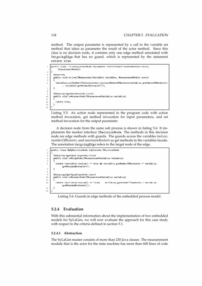
134 CHAPTER 5. EVALUATION
method. The output parameter is represented by a call to the variable setmethod that takes as parameter the result of the actor method. Since thisclass is no decision node, it contains only one edge method annotated withOutgoingEdge that has no guard, which is represented by the statementreturn true.
1 publi lass In reaseWorkersNode implements IA tionNode<IMeasurementVariables,MeasurementModule>2 {3 �Override4 publi void a tion(IMeasurementVariables variables, MeasurementModule a tor)5 {6 variables.setNumberOfWorkers(a tor.in reaseNumberOfWorkers(variables.getNumberOfWorkers(), variables.getWorkerDistan e()));7 }8
9 �OutgoingEdge(MeasureNode. lass)10 publi void toMeasureNode(IMeasurementVariables variables)11 {12 return true;13 }14 }
Listing 5.5: An action node represented in the program code with actionmethod invocation, get method invocation for input parameters, and setmethod invocation for the output parameter.
A decision node from the same sub process is shown in listing 5.6: It im-plements the marker interface IDe isionNode. The methods in this decisionnode are edge methods with guards. The guards access the variables tooLow,numberOfRestarts, andmaximumRestarts as get methods in the variables facade.The annotation OutgoingEdge refers to the target node of the edge.
1 publi lass UpUpDe isionNode implements IDe isionNode2 {3 �OutgoingEdge(UpUpMergeNode. lass)4 publi void toMergeNode(IMeasurementVariables variables)5 {6 return (variables.tooLow() == true && variables.getNumberOfRestarts <= variables.getMaximumRestarts());7 }8
9 �OutgoingEdge(UpUpFinalNode. lass)10 publi void toMeasureNode(IMeasurementVariables variables)11 {12 return (variables.tooLow() == false || variables.getNumberOfRestarts > variables.getMaximumRestarts());13 }14 }
Listing 5.6: Guards in edge methods of the embedded process model.
5.2.4 Evaluation
With this substantial information about the implementation of two embeddedmodels for SyLaGen, we will now evaluate the approach for this case studywith respect to the criteria defined in section 5.1.
5.2.4.1 Abstraction
The SyLaGen master consists of more than 230 Java classes. The measurementmodule that is the actor for the state machine has more than 600 lines of code
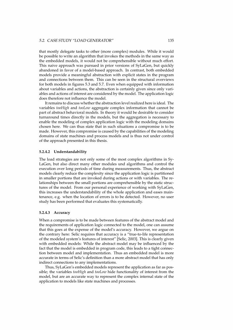
5.2. CASE STUDY “LOAD GENERATOR” 135
that mostly delegate tasks to other (more complex) modules. While it wouldbe possible to write an algorithm that invokes the methods in the same way asthe embedded models, it would not be comprehensible without much effort.This naive approach was pursued in prior versions of SyLaGen, but quicklyabandoned in favor of a model-based approach. In contrast, both embeddedmodels provide a meaningful abstraction with explicit states in the programand connections between them. This can be seen in the structural overviewsfor both models in figures 5.3 and 5.7. Even when equipped with informationabout variables and actions, the abstraction is certainly given since only vari-ables and actions of interest are considered by the model. The application logicdoes therefore not influence the model.
It remains to discusswhether the abstraction level realized here is ideal. Thevariables tooHigh and tooLow aggregate complex information that cannot bepart of abstract behavioral models. In theory it would be desirable to considerturnaround times directly in the models, but the aggregation is necessary toenable the modeling of complex application logic with the modeling domainschosen here. We can thus state that in such situations a compromise is to bemade. However, this compromise is caused by the capabilities of the modelingdomains of state machines and process models and is thus not under controlof the approach presented in this thesis.
5.2.4.2 Understandability
The load strategies are not only some of the most complex algorithms in Sy-LaGen, but also direct many other modules und algorithms and control theexecution over long periods of time during measurements. Thus, the abstractmodels clearly reduce the complexity since the application logic is partitionedin smaller portions that are invoked during actions or with variables. The re-lationships between the small portions are comprehensible by the static struc-tures of the model. From our personal experience of working with SyLaGen,this increases the understandability of the whole application and eases main-tenance, e.g. when the location of errors is to be detected. However, no userstudy has been performed that evaluates this systematically.
5.2.4.3 Accuracy
When a compromise is to be made between features of the abstract model andthe requirements of application logic connected to the model, one can assumethat this goes at the expense of the model’s accuracy. However, we argue onthe contrary here: Selic requires that accuracy is a “true-to-life representationof the modeled system’s features of interest” [Selic, 2003]. This is clearly givenwith embedded models: While the abstract model may be influenced by thefact that the model is embedded in program code, this leads to a tight connec-tion between model and implementation. Thus an embedded model is moreaccurate in terms of Selic’s definition than a more abstract model that has onlyindirect connections to any implementations.
Thus, SyLaGen’s embedded models represent the application as far as pos-sible; the variables tooHigh and tooLow hide functionality of interest from themodel, but are an accurate way to represent the complex internal state of theapplication to models like state machines and processes.
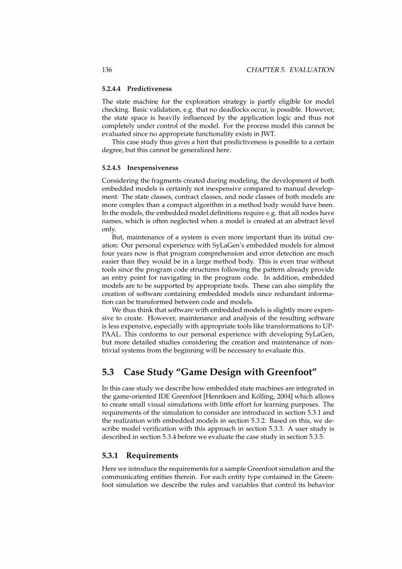
136 CHAPTER 5. EVALUATION
5.2.4.4 Predictiveness
The state machine for the exploration strategy is partly eligible for modelchecking. Basic validation, e.g. that no deadlocks occur, is possible. However,the state space is heavily influenced by the application logic and thus notcompletely under control of the model. For the process model this cannot beevaluated since no appropriate functionality exists in JWT.
This case study thus gives a hint that predictiveness is possible to a certaindegree, but this cannot be generalized here.
5.2.4.5 Inexpensiveness
Considering the fragments created during modeling, the development of bothembedded models is certainly not inexpensive compared to manual develop-ment: The state classes, contract classes, and node classes of both models aremore complex than a compact algorithm in a method body would have been.In the models, the embeddedmodel definitions require e.g. that all nodes havenames, which is often neglected when a model is created at an abstract levelonly.
But, maintenance of a system is even more important than its initial cre-ation: Our personal experience with SyLaGen’s embedded models for almostfour years now is that program comprehension and error detection are mucheasier than they would be in a large method body. This is even true withouttools since the program code structures following the pattern already providean entry point for navigating in the program code. In addition, embeddedmodels are to be supported by appropriate tools. These can also simplify thecreation of software containing embedded models since redundant informa-tion can be transformed between code and models.
We thus think that software with embeddedmodels is slightly more expen-sive to create. However, maintenance and analysis of the resulting softwareis less expensive, especially with appropriate tools like transformations to UP-PAAL. This conforms to our personal experience with developing SyLaGen,but more detailed studies considering the creation and maintenance of non-trivial systems from the beginning will be necessary to evaluate this.
5.3 Case Study “Game Design with Greenfoot”
In this case study we describe how embedded state machines are integrated inthe game-oriented IDE Greenfoot [Henriksen and Kölling, 2004] which allowsto create small visual simulations with little effort for learning purposes. Therequirements of the simulation to consider are introduced in section 5.3.1 andthe realization with embedded models in section 5.3.2. Based on this, we de-scribe model verification with this approach in section 5.3.3. A user study isdescribed in section 5.3.4 before we evaluate the case study in section 5.3.5.
5.3.1 Requirements
Herewe introduce the requirements for a sample Greenfoot simulation and thecommunicating entities therein. For each entity type contained in the Green-foot simulation we describe the rules and variables that control its behavior
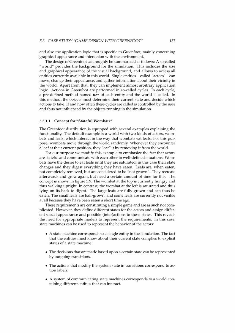
5.3. CASE STUDY “GAME DESIGN WITH GREENFOOT” 137
and also the application logic that is specific to Greenfoot, mainly concerninggraphical appearance and interaction with the environment.
The design of Greenfoot can roughly be summarized as follows: A so-called“world” provides the background for the simulation. This includes the sizeand graphical appearance of the visual background, and allows to access allentities currently available in this world. Single entities – called “actors" – canmove, change their appearance, and gather information about their vicinity inthe world. Apart from that, they can implement almost arbitrary applicationlogic. Actions in Greenfoot are performed in so-called cycles. In each cycle,a pre-defined method named a t of each entity and the world is called. Inthis method, the objects must determine their current state and decide whichactions to take. If and how often these cycles are called is controlled by the userand thus not influenced by the objects running in the simulation.
5.3.1.1 Concept for “Stateful Wombats”
The Greenfoot distribution is equipped with several examples explaining thefunctionality. The default example is a world with two kinds of actors, wom-bats and leafs, which interact in the way that wombats eat leafs. For this pur-pose, wombats move through the world randomly. Whenever they encountera leaf at their current position, they “eat” it by removing it from the world.
For our purpose we modify this example to emphasize the fact that actorsare stateful and communicate with each other in well-defined situations: Wom-bats have the desire to eat leafs until they are saturated; in this case their statechanges and they digest everything they have eaten. Leafs are, when eaten,not completely removed, but are considered to be “not grown”. They recreateafterwards and grow again, but need a certain amount of time for this. Theconcept is shown in figure 5.9: The wombat at the top is currently hungry andthus walking upright. In contrast, the wombat at the left is saturated and thuslying on its back to digest. The large leafs are fully grown and can thus beeaten. The small leafs are half-grown, and some leafs are currently not visibleat all because they have been eaten a short time ago.
These requirements are constituting a simple game and are as such not com-plicated. However, they define different states for the actors and assign differ-ent visual appearance and possible (inter)actions to these states. This revealsthe need for appropriate models to represent the requirements. In this case,state machines can be used to represent the behavior of the actors:
• A state machine corresponds to a single entity in the simulation. The factthat the entities must know about their current state complies to explicitstates of a state machine.
• The decisions that aremade based upon a certain state can be representedby outgoing transitions.
• The actions that modify the system state in transitions correspond to ac-tion labels.
• A system of communicating state machines corresponds to a world con-taining different entities that can interact.
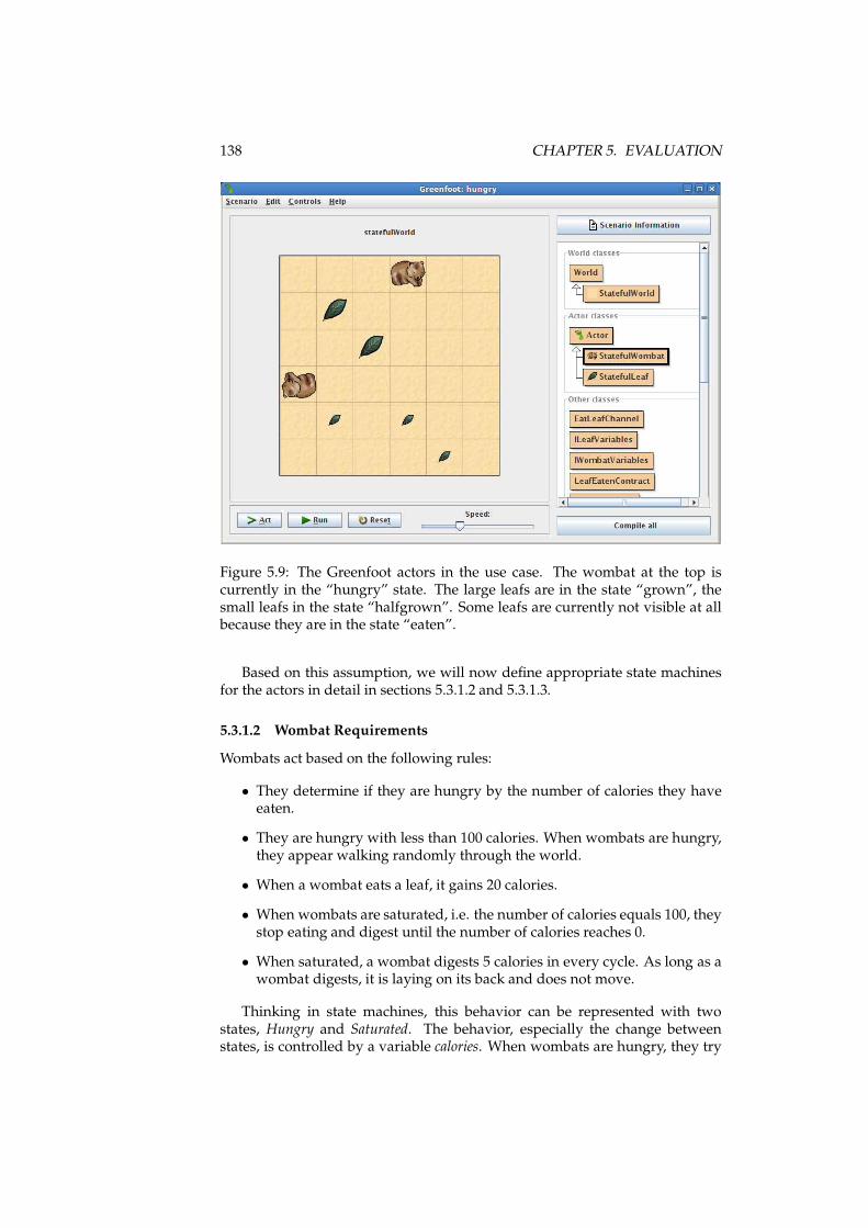
138 CHAPTER 5. EVALUATION
Figure 5.9: The Greenfoot actors in the use case. The wombat at the top iscurrently in the “hungry” state. The large leafs are in the state “grown”, thesmall leafs in the state “halfgrown”. Some leafs are currently not visible at allbecause they are in the state “eaten”.
Based on this assumption, we will now define appropriate state machinesfor the actors in detail in sections 5.3.1.2 and 5.3.1.3.
5.3.1.2 Wombat Requirements
Wombats act based on the following rules:
• They determine if they are hungry by the number of calories they haveeaten.
• They are hungry with less than 100 calories. When wombats are hungry,they appear walking randomly through the world.
• When a wombat eats a leaf, it gains 20 calories.
• When wombats are saturated, i.e. the number of calories equals 100, theystop eating and digest until the number of calories reaches 0.
• When saturated, a wombat digests 5 calories in every cycle. As long as awombat digests, it is laying on its back and does not move.
Thinking in state machines, this behavior can be represented with twostates, Hungry and Saturated. The behavior, especially the change betweenstates, is controlled by a variable calories. When wombats are hungry, they try
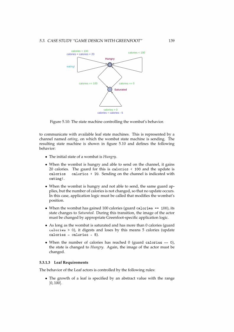
5.3. CASE STUDY “GAME DESIGN WITH GREENFOOT” 139
Saturated
Hungry
calories > 0calories = calories - 5
calories == 0calories == 100
calories < 100calories < 100
eating!
calories = calories + 20
Figure 5.10: The state machine controlling the wombat’s behavior.
to communicate with available leaf state machines. This is represented by achannel named eating, on which the wombat state machine is sending. Theresulting state machine is shown in figure 5.10 and defines the followingbehavior:
• The initial state of a wombat is Hungry.
• When the wombat is hungry and able to send on the channel, it gains20 calories. The guard for this is alories < 100 and the update is alories = alories + 20. Sending on the channel is indicated witheating!.
• When the wombat is hungry and not able to send, the same guard ap-plies, but the number of calories is not changed, so that no update occurs.In this case, application logic must be called that modifies the wombat’sposition.
• When the wombat has gained 100 calories (guard alories == 100), itsstate changes to Saturated. During this transition, the image of the actormust be changed by appropriate Greenfoot-specific application logic.
• As long as the wombat is saturated and has more than 0 calories (guard alories > 0), it digests and loses by this means 5 calories (update alories = alories - 5).• When the number of calories has reached 0 (guard alories == 0),the state is changed to Hungry. Again, the image of the actor must bechanged.
5.3.1.3 Leaf Requirements
The behavior of the Leaf actors is controlled by the following rules:
• The growth of a leaf is specified by an abstract value with the range[0, 100].
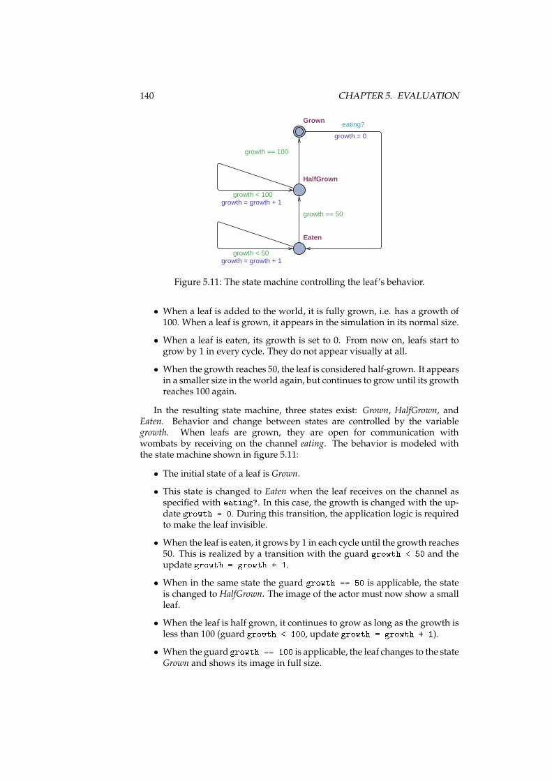
140 CHAPTER 5. EVALUATION
HalfGrown
Eaten
Grown
growth < 50growth = growth + 1
growth < 100growth = growth + 1
growth == 100
growth == 50
eating?
growth = 0
Figure 5.11: The state machine controlling the leaf’s behavior.
• When a leaf is added to the world, it is fully grown, i.e. has a growth of100. When a leaf is grown, it appears in the simulation in its normal size.
• When a leaf is eaten, its growth is set to 0. From now on, leafs start togrow by 1 in every cycle. They do not appear visually at all.
• When the growth reaches 50, the leaf is considered half-grown. It appearsin a smaller size in theworld again, but continues to growuntil its growthreaches 100 again.
In the resulting state machine, three states exist: Grown, HalfGrown, andEaten. Behavior and change between states are controlled by the variablegrowth. When leafs are grown, they are open for communication withwombats by receiving on the channel eating. The behavior is modeled withthe state machine shown in figure 5.11:
• The initial state of a leaf is Grown.
• This state is changed to Eaten when the leaf receives on the channel asspecified with eating?. In this case, the growth is changed with the up-date growth = 0. During this transition, the application logic is requiredto make the leaf invisible.
• When the leaf is eaten, it grows by 1 in each cycle until the growth reaches50. This is realized by a transition with the guard growth < 50 and theupdate growth = growth + 1.
• When in the same state the guard growth == 50 is applicable, the stateis changed to HalfGrown. The image of the actor must now show a smallleaf.
• When the leaf is half grown, it continues to grow as long as the growth isless than 100 (guard growth < 100, update growth = growth + 1).
• When the guard growth == 100 is applicable, the leaf changes to the stateGrown and shows its image in full size.

5.3. CASE STUDY “GAME DESIGN WITH GREENFOOT” 141
5.3.2 Implementation
These domain specifications can be implemented with embedded state ma-chines directly. First, the execution mechanism is integrated in the Greenfootsimulation. We use the world for this purpose since it has access to all actorsin the simulation and has also an a t method that is called in each cycle. Theworld is shown in listing 5.7: In the constructor, the world size is initializedwith a specific size in line 7. In line 8, the class EmbeddedStateMa hineSystemfrom the execution framework is instantiated. It provides an execution envi-ronment for communicating state machines as described in section 4.1.3.2. Thechannel is then added to the system in line 9. In each cycle, the method nextof the execution framework is invoked which will select and fire the next tran-sition for all state machines.
1 publi lass StatefulWorld extends World2 {3 private final EmbeddedStateMa hineSystem system;4
5 publi StatefulWorld()6 {7 super(6, 6, 60);8 system = new EmbeddedStateMa hineSystem();9 system.add(new EatLeafChannel());
10 }11
12 publi void a t()13 {14 system.next();15 }16
17 // ...18 }
Listing 5.7: The source code of the Greenfoot world. The state machine systemcontrols the actors in the world that use embedded state machines.
The wombat implementation is shown in listing 5.8 with the variablesinterface and the actor class. It fulfills the following purposes: (1) Instantiatinga state machine and adding it to the state machine system (methodaddedToWorld defined by Greenfoot and called from the framework afterinstantiation of the object), (2) providing the variable method implementation(getCalories), (3) providing actor methods that are called during transitions(eat, sear h, digest, beginDigest, be omeHungry), (4) providing a methodthat is called from the channel ( anEat).
1 publi interfa e IWombatVariables2 {3 int getCalories();4 }5
6 publi lass StatefulWombat extends A tor implements IWombatVariables7 {8 private int alories = 0;9
10 prote ted void addedToWorld(World world) {11 EmbeddedStateMa hineSystem s = ((StatefulWorld)getWorld()).getSystem();12 s.add(WombatHungryState. lass, this, this, IWombatVariables. lass);13 }14
15 publi void eat() {16 { alories += 20; }17
18 publi void sear h()19 { /* Random sele tion of new lo ation o urs here */ }
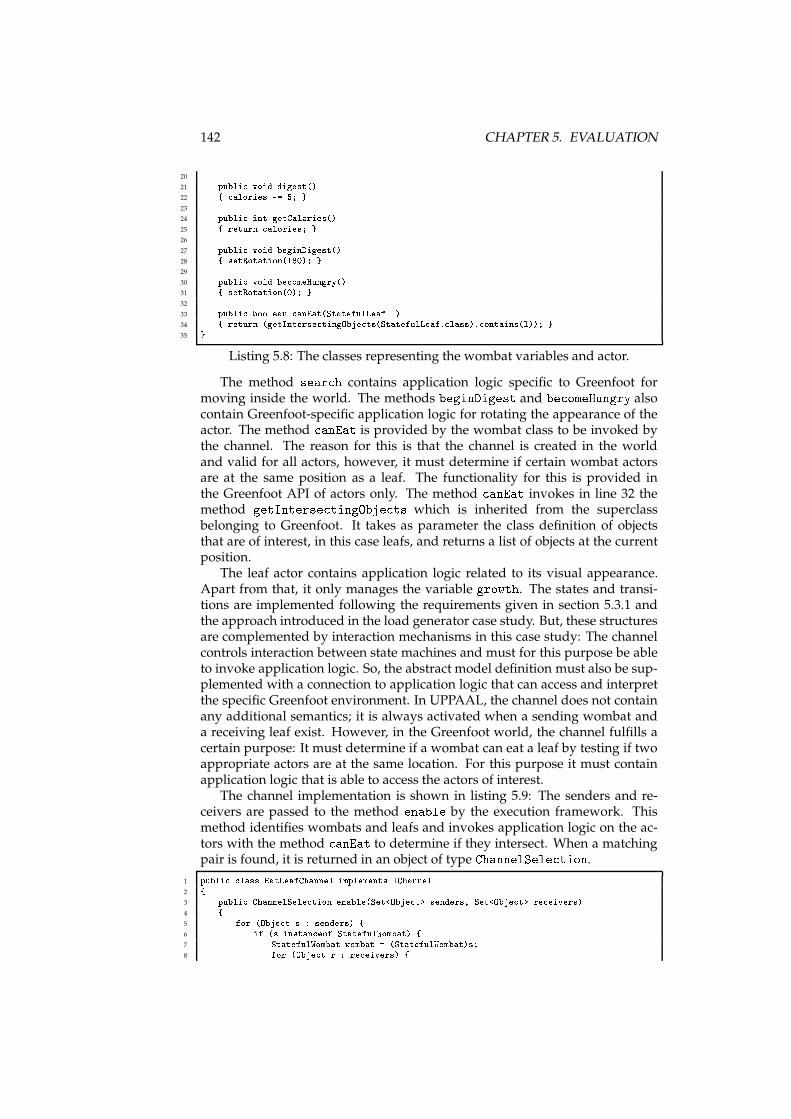
142 CHAPTER 5. EVALUATION
20
21 publi void digest()22 { alories -= 5; }23
24 publi int getCalories()25 { return alories; }26
27 publi void beginDigest()28 { setRotation(180); }29
30 publi void be omeHungry()31 { setRotation(0); }32
33 publi boolean anEat(StatefulLeaf l)34 { return (getInterse tingObje ts(StatefulLeaf. lass). ontains(l)); }35 }
Listing 5.8: The classes representing the wombat variables and actor.
The method sear h contains application logic specific to Greenfoot formoving inside the world. The methods beginDigest and be omeHungry alsocontain Greenfoot-specific application logic for rotating the appearance of theactor. The method anEat is provided by the wombat class to be invoked bythe channel. The reason for this is that the channel is created in the worldand valid for all actors, however, it must determine if certain wombat actorsare at the same position as a leaf. The functionality for this is provided inthe Greenfoot API of actors only. The method anEat invokes in line 32 themethod getInterse tingObje ts which is inherited from the superclassbelonging to Greenfoot. It takes as parameter the class definition of objectsthat are of interest, in this case leafs, and returns a list of objects at the currentposition.
The leaf actor contains application logic related to its visual appearance.Apart from that, it only manages the variable growth. The states and transi-tions are implemented following the requirements given in section 5.3.1 andthe approach introduced in the load generator case study. But, these structuresare complemented by interaction mechanisms in this case study: The channelcontrols interaction between state machines and must for this purpose be ableto invoke application logic. So, the abstract model definition must also be sup-plemented with a connection to application logic that can access and interpretthe specific Greenfoot environment. In UPPAAL, the channel does not containany additional semantics; it is always activated when a sending wombat anda receiving leaf exist. However, in the Greenfoot world, the channel fulfills acertain purpose: It must determine if a wombat can eat a leaf by testing if twoappropriate actors are at the same location. For this purpose it must containapplication logic that is able to access the actors of interest.
The channel implementation is shown in listing 5.9: The senders and re-ceivers are passed to the method enable by the execution framework. Thismethod identifies wombats and leafs and invokes application logic on the ac-tors with the method anEat to determine if they intersect. When a matchingpair is found, it is returned in an object of type ChannelSele tion.
1 publi lass EatLeafChannel implements IChannel2 {3 publi ChannelSele tion enable(Set<Obje t> senders, Set<Obje t> re eivers)4 {5 for (Obje t s : senders) {6 if (s instan eof StatefulWombat) {7 StatefulWombat wombat = (StatefulWombat)s;8 for (Obje t r : re eivers) {
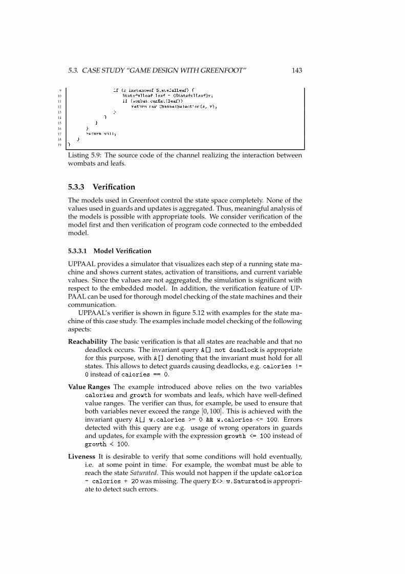
5.3. CASE STUDY “GAME DESIGN WITH GREENFOOT” 143
9 if (r instan eof StatefulLeaf) {10 StatefulLeaf leaf = (StatefulLeaf)r;11 if (wombat. anEat(leaf))12 return new ChannelSele tion(s, r);13 }14 }15 }16 }17 return null;18 }19 }
Listing 5.9: The source code of the channel realizing the interaction betweenwombats and leafs.
5.3.3 Verification
The models used in Greenfoot control the state space completely. None of thevalues used in guards and updates is aggregated. Thus, meaningful analysis ofthe models is possible with appropriate tools. We consider verification of themodel first and then verification of program code connected to the embeddedmodel.
5.3.3.1 Model Verification
UPPAAL provides a simulator that visualizes each step of a running state ma-chine and shows current states, activation of transitions, and current variablevalues. Since the values are not aggregated, the simulation is significant withrespect to the embedded model. In addition, the verification feature of UP-PAAL can be used for thorough model checking of the state machines and theircommunication.
UPPAAL’s verifier is shown in figure 5.12 with examples for the state ma-chine of this case study. The examples include model checking of the followingaspects:
Reachability The basic verification is that all states are reachable and that nodeadlock occurs. The invariant query A[℄ not deadlo k is appropriatefor this purpose, with A[℄ denoting that the invariant must hold for allstates. This allows to detect guards causing deadlocks, e.g. alories !=0 instead of alories == 0.
Value Ranges The example introduced above relies on the two variables alories and growth for wombats and leafs, which have well-definedvalue ranges. The verifier can thus, for example, be used to ensure thatboth variables never exceed the range [0, 100]. This is achieved with theinvariant query A[℄ w. alories >= 0 && w. alories <= 100. Errorsdetected with this query are e.g. usage of wrong operators in guardsand updates, for example with the expression growth <= 100 instead ofgrowth < 100.
Liveness It is desirable to verify that some conditions will hold eventually,i.e. at some point in time. For example, the wombat must be able toreach the state Saturated. This would not happen if the update alories= alories + 20was missing. The query E<> w.Saturated is appropri-ate to detect such errors.
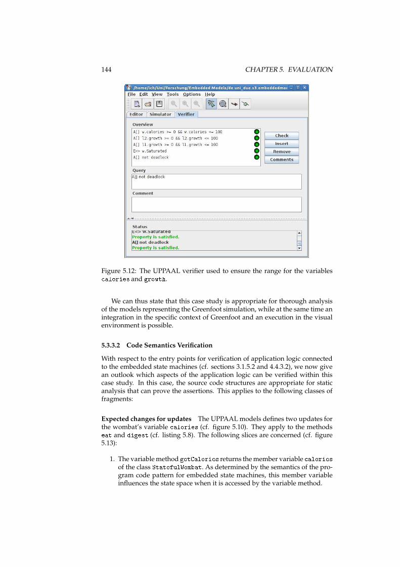
144 CHAPTER 5. EVALUATION
Figure 5.12: The UPPAAL verifier used to ensure the range for the variables alories and growth.We can thus state that this case study is appropriate for thorough analysis
of the models representing the Greenfoot simulation, while at the same time anintegration in the specific context of Greenfoot and an execution in the visualenvironment is possible.
5.3.3.2 Code Semantics Verification
With respect to the entry points for verification of application logic connectedto the embedded state machines (cf. sections 3.1.5.2 and 4.4.3.2), we now givean outlook which aspects of the application logic can be verified within thiscase study. In this case, the source code structures are appropriate for staticanalysis that can prove the assertions. This applies to the following classes offragments:
Expected changes for updates The UPPAALmodels defines two updates forthe wombat’s variable alories (cf. figure 5.10). They apply to the methodseat and digest (cf. listing 5.8). The following slices are concerned (cf. figure5.13):
1. The variablemethod getCalories returns themember variable aloriesof the class StatefulWombat. As determined by the semantics of the pro-gram code pattern for embedded state machines, this member variableinfluences the state space when it is accessed by the variable method.
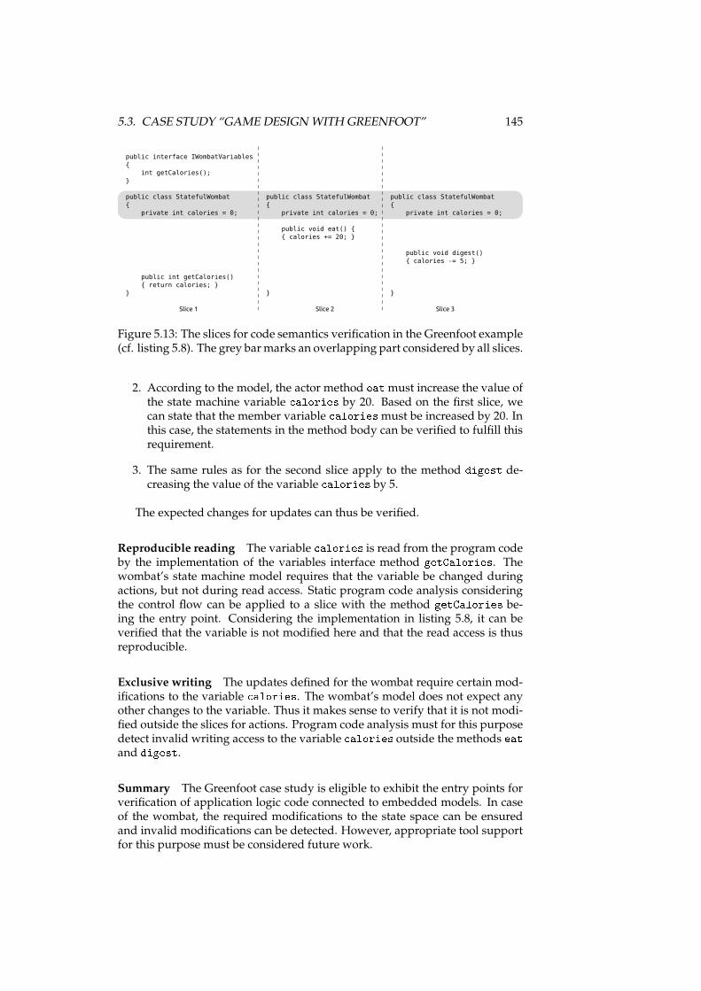
5.3. CASE STUDY “GAME DESIGN WITH GREENFOOT” 145
public interface IWombatVariables
{
int getCalories();
}
public class StatefulWombat
{
private int calories = 0;
public int getCalories()
{ return calories; }
}
public class StatefulWombat
{
private int calories = 0;
public void eat() {
{ calories += 20; }
}
public class StatefulWombat
{
private int calories = 0;
public void digest()
{ calories -= 5; }
}
Slice 1 Slice 2 Slice 3
Figure 5.13: The slices for code semantics verification in the Greenfoot example(cf. listing 5.8). The grey barmarks an overlapping part considered by all slices.
2. According to the model, the actor method eatmust increase the value ofthe state machine variable alories by 20. Based on the first slice, wecan state that the member variable aloriesmust be increased by 20. Inthis case, the statements in the method body can be verified to fulfill thisrequirement.
3. The same rules as for the second slice apply to the method digest de-creasing the value of the variable alories by 5.
The expected changes for updates can thus be verified.
Reproducible reading The variable alories is read from the program codeby the implementation of the variables interface method getCalories. Thewombat’s state machine model requires that the variable be changed duringactions, but not during read access. Static program code analysis consideringthe control flow can be applied to a slice with the method getCalories be-ing the entry point. Considering the implementation in listing 5.8, it can beverified that the variable is not modified here and that the read access is thusreproducible.
Exclusive writing The updates defined for the wombat require certain mod-ifications to the variable alories. The wombat’s model does not expect anyother changes to the variable. Thus it makes sense to verify that it is not modi-fied outside the slices for actions. Program code analysis must for this purposedetect invalid writing access to the variable alories outside the methods eatand digest.Summary The Greenfoot case study is eligible to exhibit the entry points forverification of application logic code connected to embedded models. In caseof the wombat, the required modifications to the state space can be ensuredand invalid modifications can be detected. However, appropriate tool supportfor this purpose must be considered future work.
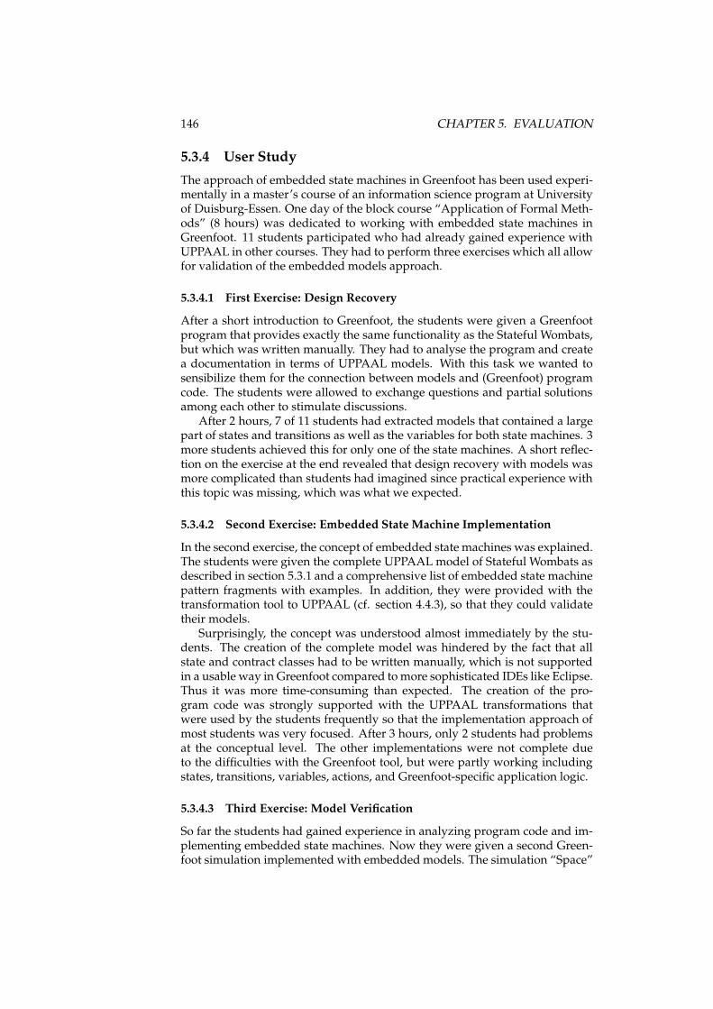
146 CHAPTER 5. EVALUATION
5.3.4 User Study
The approach of embedded state machines in Greenfoot has been used experi-mentally in a master’s course of an information science program at Universityof Duisburg-Essen. One day of the block course “Application of Formal Meth-ods” (8 hours) was dedicated to working with embedded state machines inGreenfoot. 11 students participated who had already gained experience withUPPAAL in other courses. They had to perform three exercises which all allowfor validation of the embedded models approach.
5.3.4.1 First Exercise: Design Recovery
After a short introduction to Greenfoot, the students were given a Greenfootprogram that provides exactly the same functionality as the Stateful Wombats,but which was written manually. They had to analyse the program and createa documentation in terms of UPPAAL models. With this task we wanted tosensibilize them for the connection between models and (Greenfoot) programcode. The students were allowed to exchange questions and partial solutionsamong each other to stimulate discussions.
After 2 hours, 7 of 11 students had extracted models that contained a largepart of states and transitions as well as the variables for both state machines. 3more students achieved this for only one of the state machines. A short reflec-tion on the exercise at the end revealed that design recovery with models wasmore complicated than students had imagined since practical experience withthis topic was missing, which was what we expected.
5.3.4.2 Second Exercise: Embedded State Machine Implementation
In the second exercise, the concept of embedded state machines was explained.The students were given the complete UPPAAL model of Stateful Wombats asdescribed in section 5.3.1 and a comprehensive list of embedded state machinepattern fragments with examples. In addition, they were provided with thetransformation tool to UPPAAL (cf. section 4.4.3), so that they could validatetheir models.
Surprisingly, the concept was understood almost immediately by the stu-dents. The creation of the complete model was hindered by the fact that allstate and contract classes had to be written manually, which is not supportedin a usable way in Greenfoot compared tomore sophisticated IDEs like Eclipse.Thus it was more time-consuming than expected. The creation of the pro-gram code was strongly supported with the UPPAAL transformations thatwere used by the students frequently so that the implementation approach ofmost students was very focused. After 3 hours, only 2 students had problemsat the conceptual level. The other implementations were not complete dueto the difficulties with the Greenfoot tool, but were partly working includingstates, transitions, variables, actions, and Greenfoot-specific application logic.
5.3.4.3 Third Exercise: Model Verification
So far the students had gained experience in analyzing program code and im-plementing embedded state machines. Now they were given a second Green-foot simulation implemented with embedded models. The simulation “Space”
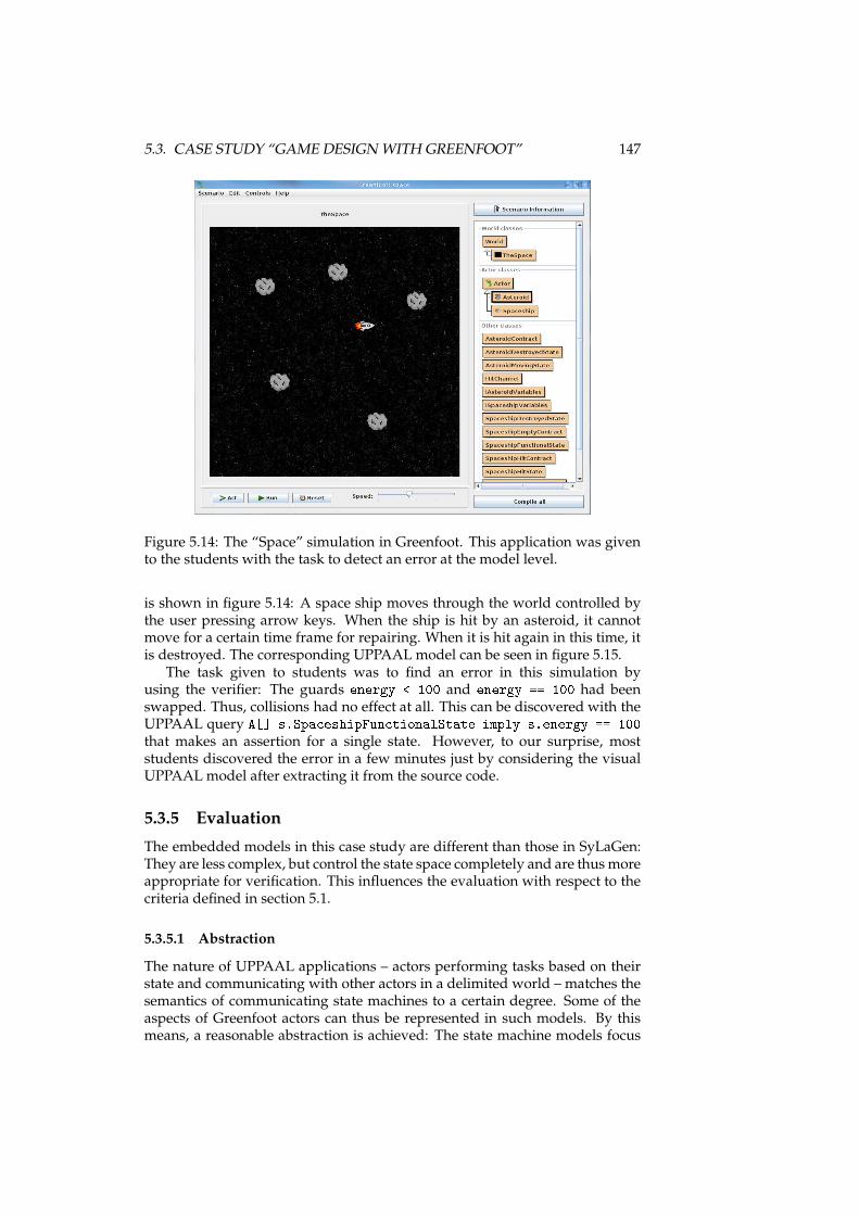
5.3. CASE STUDY “GAME DESIGN WITH GREENFOOT” 147
Figure 5.14: The “Space” simulation in Greenfoot. This application was givento the students with the task to detect an error at the model level.
is shown in figure 5.14: A space ship moves through the world controlled bythe user pressing arrow keys. When the ship is hit by an asteroid, it cannotmove for a certain time frame for repairing. When it is hit again in this time, itis destroyed. The corresponding UPPAAL model can be seen in figure 5.15.
The task given to students was to find an error in this simulation byusing the verifier: The guards energy < 100 and energy == 100 had beenswapped. Thus, collisions had no effect at all. This can be discovered with theUPPAAL query A[℄ s.Spa eshipFun tionalState imply s.energy == 100that makes an assertion for a single state. However, to our surprise, moststudents discovered the error in a few minutes just by considering the visualUPPAAL model after extracting it from the source code.
5.3.5 Evaluation
The embedded models in this case study are different than those in SyLaGen:They are less complex, but control the state space completely and are thusmoreappropriate for verification. This influences the evaluation with respect to thecriteria defined in section 5.1.
5.3.5.1 Abstraction
The nature of UPPAAL applications – actors performing tasks based on theirstate and communicating with other actors in a delimited world – matches thesemantics of communicating state machines to a certain degree. Some of theaspects of Greenfoot actors can thus be represented in such models. By thismeans, a reasonable abstraction is achieved: The state machine models focus
148 CHAPTER 5. EVALUATION
Figure 5.15: The “Space” simulation modeled in UPPAAL. In the embeddedmodel given to the students, the guards energy < 100 and energy == 100were swapped.
on states and variables and enable meaningful verification of them. The actionlabels are not considered in the UPPAAL model and are thus abstracted from.Greenfoot simulations are thus appropriate for modeling with state machinesand embedded models connect them to the Greenfoot environment with well-defined interfaces.
5.3.5.2 Understandability
The understandability of embedded state machines in Greenfoot can be evalu-ated by considering the user study. First, we can state that the students wereable to comprehend the rules for embedded models quite fast and apply themto create simulations as described in section 5.3.4.2. Second, the connectionbetween the executable simulation in Greenfoot and an abstract model wasunderstood by the students fast as described in section 5.3.4.3: The deductionfrom the error in the “Space” simulation to the errors in the guards was drawnin minutes by most of them. The user study thus confirms that understand-ability is given in this context.
5.3.5.3 Accuracy
In this case study, the variable values were not aggregated. Instead, they wereused in guards and updates directly so that the state space of the model canbe considered a subset of the state space of the application. The behavior ofthe Greenfoot actors with respect to states and variables is thus reflected in theformal model very accurately.
5.3.5.4 Predictiveness
Since the state space is in this case study completely under control of themodel,the verification concept described in section 5.3.3 shows that the models can beanalysed and checked soundly with respect to states and variables andwithoutdistracting influence from the interfaces to Greenfoot. This is supported by theresults of the user study confirming that the students were able to identify
5.4. OVERALL EVALUATION 149
errors. Thus, a high degree of predictiveness is given with embedded statemachines in this context.
5.3.5.5 Inexpensiveness
Reflecting the results from the user study, we can state that the expensivenessof developing with embedded model correlates with the availability of appro-priate tools. The implementation of the model was not supported by a de-sign tool and thus cumbersome for the students. But, the availability of a toolfor visual representation focussed the development. We expect that the prob-lems can be resolved completely with the integration of a visual embeddedstate machine editor in Greenfoot since no conceptual issues occured. The er-ror detection by students described in section 5.3.4.3 was supported by tools,i.e. the transformation tools and UPPAAL itself, so that design recovery andmodel analysis were performed by the students very fast. This indicates thatmaintenance of software is less expensive if embedded models are used withappropriate tools.
5.4 Overall Evaluation
Considering the results of the evaluation of both case studies, we can summa-rize the results as follows.
5.4.1 Abstraction
In both case studies, the embedded models allow for abstraction from the de-tailed application logic. In SyLaGen, the degree of aggregation had to be highsince state machines are not appropriate for representing the complex exami-nation of measurement results. In Greenfoot, more details of the applicationwere considered in the model due to the strong correlation of simulations andstate machine systems. While the SyLaGen state machines are mainly used fordocumentation, the Greenfoot state machines are appropriate for sound verifi-cation. The degree of abstraction thus depends on the modeling domain andthe system to model; the embedded models approach supports the differentobjectives of both case studies.
5.4.2 Understandability
The objective to achieve better understandability for applications containingembedded models is reached. This is not only our personal experience withSyLaGen, but also confirmed by the user study: The application itself as wellas the relations between the different abstraction levels were clearly compre-hensible with less effort.
5.4.3 Accuracy
Aswe argued for SyLaGen, accuracy requires that models reflect the character-istics of the actual software and not only that of an abstract model itself. Whileit is open for discussion if the abstract models and their domains are the best
150 CHAPTER 5. EVALUATION
choice for modeling the applications, the embedded models introduced heredo not compromise the accuracy: In both case studies, the limits of modelingwere caused at the model level; the interfaces of the embedded models realizethese limits and connect application logic to it.
5.4.4 Predictiveness
Embeddedmodels support predictiveness depending on the capabilities of themodeling domains regarding the software to develop. While variable valuesin SyLaGen must be aggregated and thus have limited significance, Greenfootmodels can be verified soundly. In both case studies, no influence of the inter-faces on predictiveness can be observed.
5.4.5 Inexpensiveness
In the evaluation of the SyLaGen and Greenfoot case studies we reached thesame conclusion: The costs of developing with embedded models depend onthe tool support. This is especially true for the creation of applications wherethe necessary fragments have to be created according to the pattern definition.The difference between situations with and without tools were observable inthe user study. However, even in this case the students were able to grasp theconcept at the source code level and create valid implementations, so that toolsare not mandatory.
5.5 Chapter Summary
In this chapter the embedded models approach was evaluated with two casestudies. The SyLaGen case study in section 5.2 introduced a situation whereembedded models are used in a non-trivial software product with complexapplication logic that was only partly representable by the abstract models. Inthis case, two differentmodeling domains were used that are similar, but focuson different aspects. The Greenfoot case study (cf. section 5.3) put emphasison smaller projects that can be modeled and thus verified in detail.
The evaluation was performed with criteria defined in section 5.1. Abstrac-tion and predictiveness are given with both models, but only influenced by theabstract models and not the approach presented in this thesis. Inexpensivenessstrongly depends on tool support. The evaluation result for these criteria istrue for almost all model-based approaches in software development; the im-portant conclusion for this thesis is that no impact of embedded models couldbe detected that impairs one of them in the case studies.
In contrast, accuracy in terms of the “true-to-life representation” is in ouropinion strongly supported by embedded models since the overall applicationis tightly connected to the model specifications. Based on this, understandabilitycould be verified in the user study to be given across different abstraction levelsduring software development. By this means, the criteria introduced in section5.1 are satisfied.
Chapter 6
Impact and Future Work
In this chapter we give a short outlook to future work and possible impact ofthe embedded models approach.
First, starting points for additional evaluation are introduced in section 6.1.So far, only behavioral models have been considered; additional modeling do-mains of interest are stated in section 6.2. When different modeling domainsare of interest, interaction of different embedded model domains must be con-sidered as will be sketched in section 6.3. This leads to thoughts about metamodels for embedded models in section 6.4. Finally, possible consequences forfuture software description languages are discussed in section 6.5.
6.1 Evaluation
The case studies described in chapter 5 already provide evaluation results thatare promising. However, they are both specific: SyLaGen is a non-trivial real-world application, but is only partly adequate for verification. The Greenfoot-based applications can be verified, but are too small to have significance for thedevelopment of large applications.
Thus, additional evaluation makes sense with an application that is largeand suited for modeling with state machines in a way that the state space isrepresented in the model in more detail. Such evaluation should be performedusing the tool suite introduced in section 4.4, thus reducing the complexity fordevelopers.
In further case studies, understandabilitywill be of interest. To evaluate thismore thoroughly, the evaluationmust consider existing approaches for programcomprehension [Storey, 2005]. We propose to apply the integrated code comprehen-sion model [Mayrhauser and Vans, 1995] to this situation. The approach for thiswill be sketched now.
6.1.1 Program Comprehension Approach
In the integrated code comprehension model, a domain model describes the situ-ation when programmers have knowledge about a certain application domain.Programmers act in this case on certain assumptions or hypotheses to reach
151
152 CHAPTER 6. IMPACT AND FUTUREWORK
specific objectives. They can thus analyse a system based on their expecta-tions and enhance their knowledge with specific information. This strategy isclassified as opportunistic, i.e. not based on a structured approach to under-standing of code. Support can be given by abstraction utilities like visualiza-tion tools, documentation, and formal models. This leads to a process wheregeneral conditions are determined at abstract layers and then gradually sup-plemented with program-specific information.
The program model applies when programmers have no domain knowledge.In this case they build their ownmental representations and abstractionswhichare technical and based on control flow in the first place and do not considerprogram semantics immediately. The overall picture is developed over timewhen single well-understood pieces are aggregated and connections are found.Tools of value may be debuggers or slicers. The familiarization process is inthis situation considered systematic (in contrast to opportunistic) because miss-ing domain knowledge prevents the programmer from making assumptionsbeforehand. When a mental representation is built from the program model,programmers elaborate it into a situation model. This elaboration leads to inter-connection of understood pieces and may be systematic or opportunistic. Thisbears the risk of misunderstandings: While single programming constructs areeasy to understand, their side effects and impact on whole applications arehard to determine by programmers with little experience regarding a specificapplication.
6.1.2 Program Comprehension with EmbeddedModels
We assume that embedded models can at development time support theprogram comprehension process as defined in the domain model componentfor two reasons: First, the model definition that is embedded can be thedomain knowledge a programmer already has. In this case he can easilygain an overview of the program structure, as was indicated in the userstudy. Second, the well-defined interfaces provide structured entry pointsinto the arbitrary program code. The programmer can thus navigate in thewell-defined source code structures and examine arbitrary application logicstep-by-step.
For the program and situation model components, the value of embeddedmodels is not that easy to define because knowledge regarding model seman-tics cannot be assumed. However, the program comprehension theories sug-gest that program understanding is likely to happen in a more systematic waybecause of the programmer’s uncertainty. Embedded models can here be ofuse if we can consider knowledge about the concept of embedded models (notof specific embedded model domains) to be part of the basic knowledge of de-velopment techniques that programmers are supposed to have. In this case,the systematic familiarization could include the search for possible embeddedmodels. This would require appropriate documentation inside the source codesince a multitude of embedded models is imaginable that feature completelydifferent structures.
By this means, starting points for a systematic evaluation of embeddedmodels with respect to understandability and program comprehension aregiven. Appropriate studies must consider the relation between domainknowledge and familiarization with specific program code. When correlations
6.2. ADDITIONAL MODELING DOMAINS 153
are detected, the effects of program comprehension as described in theintegrated code comprehension model are supported by embedded models.
6.2 Additional Modeling Domains
In this thesis, two classes of behavioral models have been considered. This wasintentional since many modeling approaches focus on static models like classdiagrams, which are easy to represent in program code, but neglect semanticalconnections to application logic. However, the embedded models approach isnot limited to behavioral models. We will sketch an approach for the applica-tion to component models now.
The basic features of component models are the representation of modules,their interfaces, interaction, hierarchies, and assembly [Müller et al., 2010]. Forsuch features, the elements of an embedded model definition (cf. section 3.1)can be defined as follows:
• Model Specifications: The structural elements of such component mod-els can be directly represented with the meta model described in section3.1.2.
• Program Code Pattern: The definition of program code patterns has tobe extended: While interfaces can be described with the program codepattern elements introduced so far, modules are not completely repre-sentable at the level of classes in a programming language. In addition,module description files and library files (e.g. Java’s JAR files) must beincluded [Müller et al., 2010]. The meta model in section 3.1.3 has to beextended for this purpose. The result is that not only program code isconsidered, but also other configuration files which are used by the plat-form and describe the program code.
• Execution Semantics: The main difference to behavioral models concernsthe execution: Component models usually control the life cycle of mod-ules, e.g. in OSGi [OSGi Alliance, 2005a], but do not access their contentin detail. The “execution” of component models is thus limited to the lifecycle.
• Interfaces: When components provide services, their description can beconsidered by the component model. In this case, the interface descrip-tion serves as an abstraction to the contents of the component, which areconsidered a black box. This corresponds to the semantics of interfacesin the embedded models definition.
• Transformations: When the program code pattern is defined completely,the model can in general be transformed to component modeling tools.As described for the embedded model implementations so far, appro-priate tools must be selected or developed according to the focus of themodel.
The implementation of this concept with precise model specifications andan extended program code pattern will be an interesting extension of the ap-proach in future work.
154 CHAPTER 6. IMPACT AND FUTUREWORK
6.3 Interaction of Embedded Models
The case studies introduced in chapter 5 use only one modeling domain at thesame time. However, as sketched in section 3.3, complex software systems canconsist of different embeddedmodels. Due to the nature of embeddedmodels,an interaction between the models is always possible – the integration of themodels in the program code does not require a common meta model, but al-lows developers to faciliate interaction with appropriate algorithms. However,a consideration of different embedded models at higher levels of abstractionis desirable, too. When different models are to be coupled, model-based ap-proaches for interaction will be developed as future work. However, this willnever be a general approach, but only a pair-wise coupling of models, as longas no common meta model is used (cf. section 6.4).
6.4 Meta Modeling
Manymodel specifications are based onmeta models that cover multiple mod-eling domains. This is true e.g. for UML and EMF models. Instead of creatingembedded model definitions for each modeling domain separately, it will beinteresting future work to evaluate if meta models can be embedded in pro-gram code, too. This seems reasonable since they are covered by our metamodel (cf. section 3.1.2). However, two issues will be non-trivial to handle:
• Efficiency: The embedded models described in this thesis focus on effi-cient implementation. Embedded meta models may be inappropriate forsuch optimization so that the number of fragments to create for imple-mentations may be considerably larger.
• Execution: When a meta model is embedded in program code and differ-ent specific modeling domains are covered by it, execution semantics willbe necessary that cover all modeling domains, too. However, no commonexecution semantics exist for meta models like UML and EMF – instead,they are defined in different ways for different purposes [Mellor et al.,2004; Soden and Eichler, 2009]. This is not a problem to be solved at thelevel of embedded models since it concerns the abstract model specifi-cations. Thus, a general solution would have to be found – either withseparate execution semantics being coupled, or with execution semanticsthat cover different modeling domains.
6.5 Software Description Languages
The embeddedmodels approach closes a gap between different notations usedfor different purposes in software engineering (cf. section 3.2). However, onecan argue that the program code is misused for other purposes than it wasinvented for. While this is not unusual (cf. section 2.2.1), future work mayconsider more elegant solutions for this problem. One possible solution canbe a removal of the semantic gap between model notations and program codeby creating a common language for both purposes, whose principles will besketched here.
6.6. CHAPTER SUMMARY 155
Embedded models couple models and program code by the followingmeans:
1. Model elements represented in the code can be connected to arbitraryimplementations at the level of the programming language.
2. Program code can reference code fragments that represent model ele-ments.
3. Some parts of the program code follow certains rules so that they can beinterpreted with respect to models.
This leads to the following requirements for a common language:
Common Type Concept The language needs a type concept that applies tomodels and code. Model types must be given with their properties as e.g.in EMF, while code types must follow object-oriented principles. This isnot exclusive, so that types may be model types and at the same timeobject-oriented classes.
Common Reflection Concept The reflection functionality of such a languagemust consider all types. This is necessary e.g. to let execution frame-works interpret model elements.
Common Schema Concept Schemata are used to define valid structures. Thisapplies to models e.g. in the way that XML schemata can be used tovalidate XML-based modeling notations. In addition, this must apply toprogram code, too: By this means a mechanism is introduced that makespattern definitions a core concept of the language, so that no externaltools (cf. section 4.4.3.1) have to be used.
Development with this language can be supported by tools that enable dif-ferent views at different abstraction levels on software described in one consis-tent notation. The different views are realized based on appropriate schemata.The tools can thus be specific and adapted even for different types of users.For example, a process design tool based on a schema that excludes algorith-mic details can be used by non-programmers, but work on the same code baseas programmers.
6.6 Chapter Summary
In this chapter we gave an outlook on future work regarding embedded mod-els. This concerns further evaluation of the approach first. Then, differentaspects have been considered for extending the approach: Additional model-ing domains, interaction of embedded models, and meta models. Finally, wegave an outlook on possible consequences for the development of new soft-ware description languages that may facilitate the tight connection betweenspecifications and program code even further than embedded models.

156 CHAPTER 6. IMPACT AND FUTUREWORK
Chapter 7
Conclusion
In this chapter we summarize the thesis and present conclusions for the em-bedded models approach. The approach itself is summarized in section 7.1.The implementations for specific modeling domains are reflected in section7.2. The applicability in the case studies is subsumed in section 7.3, before weconclude in section 7.4.
7.1 Embedded Models Approach
The aim of embedded models is to close the semantic gap between modelingnotations and program code constituting the actual implementations. For thispurpose, we propose to write program code according to certain rules so thatit reflects the model specifications unambiguously. This results in an approachas sketched in figure 7.1 and introduced in chapter 3: Model specifications fora certain modeling domain are defined clearly and a program code pattern isdeveloped that represents the abstract syntax of the models in static programcode structures. Appropriate execution semantics enable frameworks to invokethe program code at run time so that the models are executable. Their execu-tion can be part of other program code since well-defined interfaces exist thatallow for data exchange and program code invocation. A set of transformationsenables considering the program code with embedded models at different lev-els of abstraction. This is embraced by tools that can e.g. visualize, verify, andmonitor the model specifications. The semantic gap is by this means narrowedsince the program code is a valid notation for the model specifications.
7.2 Embedded State Machines and Process Models
In chapter 4, two implementations for the domains of state machines and pro-cess models were introduced and appropriate tools were presented.
State machine models focus on the structure of states and transitions aswell as the management of the state space. The state space is constituted byvariables that are defined in interfaces and extracted from the application logicof the surrounding program. Transitions are equipped with action labels thatdenote application program code to be invoked in interfaces. Different state
157
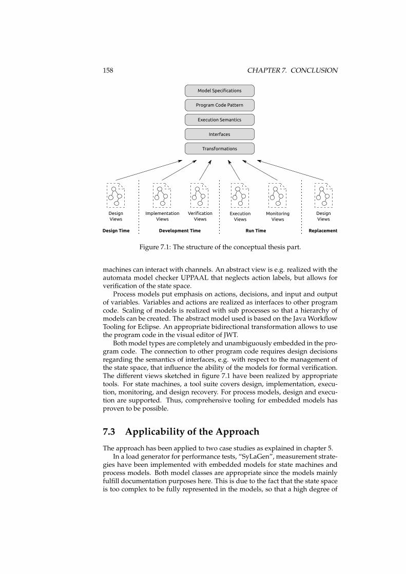
158 CHAPTER 7. CONCLUSION
Interfaces
Model Specifications
Program Code Pattern
Execution Semantics
Development Time Run TimeDesign Time
Design
Views
Verification
Views
Monitoring
Views
Replacement
Design
Views
Implementation
Views
Execution
Views
Transformations
Figure 7.1: The structure of the conceptual thesis part.
machines can interact with channels. An abstract view is e.g. realized with theautomata model checker UPPAAL that neglects action labels, but allows forverification of the state space.
Process models put emphasis on actions, decisions, and input and outputof variables. Variables and actions are realized as interfaces to other programcode. Scaling of models is realized with sub processes so that a hierarchy ofmodels can be created. The abstract model used is based on the JavaWorkflowTooling for Eclipse. An appropriate bidirectional transformation allows to usethe program code in the visual editor of JWT.
Bothmodel types are completely and unambiguously embedded in the pro-gram code. The connection to other program code requires design decisionsregarding the semantics of interfaces, e.g. with respect to the management ofthe state space, that influence the ability of the models for formal verification.The different views sketched in figure 7.1 have been realized by appropriatetools. For state machines, a tool suite covers design, implementation, execu-tion, monitoring, and design recovery. For process models, design and execu-tion are supported. Thus, comprehensive tooling for embedded models hasproven to be possible.
7.3 Applicability of the Approach
The approach has been applied to two case studies as explained in chapter 5.In a load generator for performance tests, “SyLaGen”, measurement strate-
gies have been implemented with embedded models for state machines andprocess models. Both model classes are appropriate since the models mainlyfulfill documentation purposes here. This is due to the fact that the state spaceis too complex to be fully represented in the models, so that a high degree of
7.4. CONCLUSIONS 159
abstraction is necessary and formal verification is not applicable. However, themodels are represented in the program code and allow for a maintenance ofembedded models over longer time so that the approach fulfills the expecta-tions.
In contrast, the second case study concerned the development of small vi-sual simulations in the learner’s IDE “Greenfoot” with embedded state ma-chines. The state space is in this case completely represented in the model sothat verification and model checking in UPPAAL are possible. The approachwas applied in university teaching for formal methods. In this context, a userstudy was performed showing that the connection between formal models andimplementations is clarified with embedded models; however, the productiv-ity of the use of embedded models strongly depends on the availability of ap-propriate tools.
7.4 Conclusions
In section 1.3, objectives for the approach were stated. Considering the overallresults of the thesis, the objectives are fulfilled as follows:
• Consistency between model semantics and source code is given since the pro-gram code patterns introduced so far enable bidirectional and unambigu-ous transformations.
• Integration of arbitrary source code is possible since the interfaces proposedin this thesis allow for data exchange and program code invocation in amanner that reflects the model specifications.
• Consistency between model semantics and executing program code is realizedby the execution semantics and execution frameworks providing appro-priate sequences of actions.
• Consistency between model semantics and monitoring has proven to be possi-ble since the embedded model specifications can be accessed at run timeso that tools provide this functionality.
The objectives are by this means fulfilled completely. Thus the approach inthis thesis is novel and a relevant contribution to model-based software devel-opment has been made.

160 CHAPTER 7. CONCLUSION
Appendix A
CD-ROM Contents
The CD-ROM enclosed with this thesis contains the software artifacts devel-oped during creation of the embeddedmodels approach. On the one hand, theprogram code of the patterns, the related tools, and the case studies is given.On the other hand, a virtual machine is provided that contains the tools andthe case studies in an executable way.
A.1 Program Code
The folder ode contains the program code developed in this thesis. Most ofthe folders contain Eclipse projects.
The projects for embedded state machines are:
• de.uni_due.s3.embeddedmodels.statema hine.definitionsThe pre-defined program code of the embedded state machine pattern.
• de.uni_due.s3.embeddedmodels.statema hine.exe utionThe execution framework for embedded state machines.
• de.uni_due.s3.embeddedmodels.statema hine.exe ution.osgiThe OSGi integration for the listeners of the execution framework for em-bedded state machines.
• de.uni_due.s3.embeddedmodels.statema hine.greenfoot.runtimeThe execution framework for embedded state machines in Greenfoot.
• de.uni_due.s3.embeddedmodels.statema hine.monitor.e lipseThe Eclipse-based monitoring tool for embedded state machines.
• de.uni_due.s3.embeddedmodels.statema hine.monitor.e lipse.listenerThe OSGi listener integration for the Eclipse-based monitoring tool forembedded state machines.
• de.uni_due.s3.StateMa hineEditor,de.uni_due.s3.StateMa hineEditor.CodeEditorInterfa e,161
162 APPENDIX A. CD-ROM CONTENTSde.uni_due.s3.StateMa hineEditor.diagram,de.uni_due.s3.StateMa hineEditor.edit, andde.uni_due.s3.StateMa hineEditor.editorThe state machine editor as developed by Malte Goddemeier.
• rules_verifi ationThe graph transformation artifacts for verification (i.e., transformation toUPPAAL). These files were contributed by Michael Striewe.
• rules_designre overyThe graph transformation artifacts for model transformation from em-bedded state machines to process models. These files were contributedby Michael Striewe.
The projects for embedded process models are:
• de.uni_due.s3.embeddedmodels.pro ess.definitionThe pre-defined program code of the embedded process model pattern.
• de.uni_due.s3.embeddedmodels.pro ess.exe utionThe execution framework for embedded process models.
• de.uni_due.s3.embeddedmodels.pro ess.jdt_jwtThe design tool for embedded process models.
The projects for case studies are:
• de.uni_due.s3.sylagen.master_statema hineThe packages of interest for the SyLaGenmaster with the embedded statemachine. Since SyLaGen is proprietary, the application logic is replacedby dummy classes.
• de.uni_due.s3.sylagen.master_pro essThe packages of interest for the SyLaGenmaster with the embedded pro-cess model. Since SyLaGen is proprietary, the application logic is re-placed by dummy classes.
• hungryThe hungry scenario with the embedded state machine.
• hungry_manualThe hungry scenario developed manually.
• spa eThe space scenario with the embedded state machine.
A.2. EXECUTABLE TOOLS 163
A.2 Executable Tools
The folder exe utable contains a virtual machine that is executable with Vir-tualBox1. The operating system is Ubuntu 11.04. User name and password areboth “embeddedmodels”. The following executable programs are available:
• Eclipse for embedded state machines:
A ready-to-use Eclipse installation for embedded state machines is pro-vided in the folder e lipse_statema hineon the desktop. All necessarytools are deployed as plugins in the dropins folder.The workspace contains the packages of interest for the SyLaGen casestudy. Since SyLaGen is proprietary, the application logic is replacedby dummy classes. The embedded state machine is used in the projectde.uni_due.s3.sylagen.master in three packages:
– de.uni_due.s3.sylagen.master.measurement.impl.single– de.uni_due.s3.sylagen.master.measurement.impl.stress– de.uni_due.s3.sylagen.master.measurement.impl.exploration
The context menu for these packages has a category Embedded State Ma-chine with the entries Edit and Verify. Edit opens the visual editor forthe embedded state machine in the current package. To use Verify, theclass IMeasurementVariables.java in the parent package must also beselected. The entry then extracts the model and opens UPPAAL. UP-PAAL must be downloaded2 and installed in the virtual machine for thispurpose. The path to the UPPAAL binary must be given in the Eclipsepreferences in category “Embedded State Machine”.
• Eclipse for embedded process models:
A ready-to-use Eclipse installation for embedded process models is pro-vided in the folder e lipse_pro ess on the desktop. All necessary toolsare deployed as plugins in the dropins folder.The workspace contains the packages of interest for the SyLaGencase study. Since SyLaGen is proprietary, the application logic isreplaced by dummy classes. The embedded process model is usedin the project de.uni_due.s3.sylagen.master in the packagede.uni_due.s3.sylagen.master.measurement.impl.exploration.The models are stored in the project folder models. The filesylagen-exploration.workflow contains the JWT model. The filesylagen-exploration.epmm is the mapping between model and code.
• Greenfoot with embedded state machines:
Greenfoot is provided in the folder Greenfoot on the desktop. The fol-lowing scenarios are contained in the folder s enarios:
– hungryThe hungry scenario with the embedded state machine.
1http://www.virtualbox.org/2http://www.uppaal. om
164 APPENDIX A. CD-ROM CONTENTS
– hungry_manualThe hungry scenario developed manually.
– spa eThe space scenario with the embedded state machine.
After opening a scenario, it can be used as any other Greenfoot program.
• GGX Toolbox:
The GGX Toolbox3 is provided in the folder ggxToolbox on the desk-top. It realizes graph transformations for embedded models, in this casefor verificationwith UPPAAL andmodel transformation from embeddedstate machines to process models.
For verification, the Java files of interest must be selected, e.g. all Java filesfrom one of the Greenfoot scenarios. Then an output file must be given,e.g. /home/embeddedmodels/output.xml, and the UPPAAL button mustbe selected. The output file can be opened with UPPAAL later on.
The model transformation takes the same Java files as input. In addi-tion, the rule files and the control script must be selected from the folderrules_designre overy (see above) according to the GGX Toolbox docu-mentation. To start the transformation, the Run button must be selected.
A.3 Videos
The folder videos contains three screen casts illustrating the basic usage oftools for embedded models with SyLaGen:
• StateMa hine Editor.ogv: Parallel editing of the exploration state ma-chine in source code and visual editor.
• StateMa hine Monitoring.ogv: Monitoring of the exploration state ma-chine while SyLaGen is executed.
• Pro ess Editor.ogv: Parallel editing of the exploration process modelin source code and visual editor.
3developed by Michael Striewe, http://www.s3.uni-due.de/resear h/ggx-toolbox.html
Bibliography
Ritu Agarwal and Atish P. Sinha. Object-Oriented Modeling with UML: AStudy of Developers’ Perceptions. Communications of the ACM, 46(9):248–256, 2003. ISSN 0001-0782.
AGG. AGG website. http://tfs. s.tu-berlin.de/agg/.Hervé Albin-Amiot and Yann-Gaël Guéhéneuc. Meta-modeling Design Pat-terns: Application to Pattern Detection and Code Synthesis. In Proceedingsof the First ECOOP Workshop on Automating Object-Oriented Software Develop-ment Methods, 2001.
Hervé Albin-Amiot, Pierre Cointe, Yann-Gaël Guéhéneuc, and NarendraJussien. Instantiating and Detecting Design Patterns: Putting Bits and PiecesTogether. In Proceedings of the 16th Annual International Conference on Auto-mated Software Engineering (ASE 2001), pages 166–173, 2001.
Michał Antkiewicz. Round-Trip Engineering Using Framework-Specific Mod-eling Languages. InOOPSLA ’07: Companion to the 22nd ACM SIGPLAN Con-ference on Object-oriented Programming Systems and Applications, pages 927–928, New York, NY, USA, 2007. ACM. ISBN 978-1-59593-865-7.
Michał Antkiewicz and Krzysztof Czarnecki. Framework-Specific ModelingLanguages with Round-Trip Engineering. In Nierstrasz et al. [2006], pages692–706. ISBN 3-540-45772-0.
Michał Antkiewicz, Thiago Tonelli Bartolomei, and Krzysztof Czarnecki. Au-tomatic Extraction of Framework-Specific Models From Framework-BasedApplication Code. InASE ’07: Proceedings of the 22nd IEEE/ACM InternationalConference on Automated Software Engineering, pages 214–223, New York, NY,USA, 2007. ACM. ISBN 978-1-59593-882-4. doi: http://doi.acm.org/10.1145/1321631.1321664.
Michał Antkiewicz, Thiago T. Bartolomei, and Krzysztof Czarnecki. FastExtraction of High-Quality Framework-Specific Models from ApplicationCode. Automated Software Engineering, 16(1):101–144, 2009. ISSN 0928-8910.doi: http://dx.doi.org/10.1007/s10515-008-0040-x.
Colin Atkinson and Thomas Kühne. Model-Driven Development: A Meta-modeling Foundation. IEEE Software, 20(5):36–41, 2003. ISSN 0740-7459. doi:http://doi.ieeecomputersociety.org/10.1109/MS.2003.1231149.
165
166 BIBLIOGRAPHY
Paul Baker, Shiou Loh, and Frank Weil. Model-Driven Engineering in a LargeIndustrial Context – Motorola Case Study. In Briand and Williams [2005],pages 476–491. ISBN 3-540-29010-9.
Moritz Balz, Michael Striewe, and Michael Goedicke. Tool Support for Contin-uous Maintenance of State Machine Models in Program Code. In Proceedingsof the 25th IEEE/ACM International Conference on Automated Software Engineer-ing, Antwerp, Belgium, September 20-24, 2010, 2010.
Bernhard Beckert, Reiner Hähnle, and Peter H. Schmitt. Verification of Object-Oriented Software. The KeY Approach. Springer-Verlag New York, Inc., 2007.
Simona Bernardi, SusannaDonatelli, and JoséMerseguer. FromUMLSequenceDiagrams and Statecharts to analysable Petri Net models. InWOSP ’02: Pro-ceedings of the 3rd International Workshop on Software and Performance, pages35–45, New York, NY, USA, 2002. ACM.
Martin Bichler andKwei-Jay Lin. Service-OrientedComputing. IEEEComputer,39(3):99–101, 2006.
Eric Bodden. The Design and Implementation of Formal Monitoring Tech-niques. In Companion to the 22nd Annual ACM SIGPLAN Conference on Object-Oriented Programming, Systems, Languages, and Applications, OOPSLA 2007,October 21-25, 2007, Montreal, Quebec, Canada, pages 939–940. ACM, 2007.ISBN 978-1-59593-865-7.
Reinhard Bordewisch, Bärbel Schwärmer, Michael Goedicke, and PeterTröpfner. Lastsimulation für Anwendungsumgebungen in vernetzten IT-Architekturen. Mitteilungen der GI-Fachgruppe MMB Nr. 43, 2003.
Steen Brahe. BPM on Top of SOA: Experiences from the Financial Industry. InBusiness Process Management, 5th International Conference, BPM 2007, Brisbane,Australia, September 24-28, 2007, Proceedings, volume 4714 of Lecture Notes inComputer Science, pages 96–111. Springer, 2007. ISBN 978-3-540-75182-3.
Martin Bravenboer and Eelco Visser. Concrete Syntax for Objects: Domain-Specific Language Embedding and Assimilation without Restrictions. InOOPSLA ’04: Proceedings of the 19th annual ACM SIGPLAN Conference onObject-oriented Programming, Systems, Languages, and Applications, pages 365–383, New York, NY, USA, 2004. ACM. ISBN 1-58113-831-9.
Martin Bravenboer, René de Groot, and Eelco Visser. MetaBorg in Action:Examples of Domain-specific Language Embedding and Assimilation usingStratego/XT. Technical report, Department Information and Computing Sci-ences, Utrecht University, 2006.
Lionel C. Briand and Clay Williams, editors. Model Driven Engineering Lan-guages and Systems, 8th International Conference, MoDELS 2005, Montego Bay,Jamaica, October 2-7, 2005, Proceedings, volume 3713 of Lecture Notes in Com-puter Science, 2005. Springer. ISBN 3-540-29010-9.
Alan W. Brown, Sridhar Iyengar, and Simon Johnston. A Rational approach tomodel-driven development. IBM Systems Journal, 45(3):463–480, 2006.
BIBLIOGRAPHY 167
Frank Budinsky, David Steinberg, Marcelo Paternostro, and Ed Merks. EMF:Eclipse Modeling Framework. Eclipse Series. Addison-Wesley, 2009. ISBN 978-0-321-33188-5.
Frank Buschmann, Kevlin Henney, and Douglas C. Schmidt. Pattern-OrientedSoftware Architecture: A Pattern Language for Distributed Computing, volume 4of Wiley Series in Software Design Patterns. John Wiley & Sons, 2007.
Jean Bézivin and Olivier Gerbé. Towards a Precise Definition of theOMG/MDA Framework. In ASE ’01: Proceedings of the 16th IEEE Interna-tional Conference on Automated Software Engineering, page 273, Washington,DC, USA, 2001. IEEE Computer Society.
Thomas Büchner and Florian Matthes. Introspective Model-Driven Develop-ment. In Software Architecture, Third European Workshop, EWSA 2006, Nantes,France, September 4-5, 2006, volume 4344 of Lecture Notes in Computer Science,pages 33–49. Springer, 2006.
Walter Cazzola. Evaluation of Object-Oriented Reflective Models. In ECOOP’98: Workshop on Object-Oriented Technology, pages 386–387, London, UK,1998. Springer-Verlag.
Feng Chen, Marcelo D’Amorim, and Grigore Rosu. A Formal Monitoring-based Framework for Software Development and Analysis. In Proceedingsof the 6th International Conference on Formal Engineering Methods (ICFEM’04),volume 3308 of LNCS, pages 357–373. Springer-Verlag, 2004.
Peter P. Chen. The Entity-Relationship Model – Toward a Unified View of Data.ACM Transactions on Database Systems, 1(1):9–36, 1976.
E. M. Clarke, E. A. Emerson, and A. P. Sistla. Automatic Verification of Finite-State Concurrent Systems Using Temporal Logic Specifications. ACM Trans-actions on Programming Languages and Systems, 8:244–263, April 1986. ISSN0164-0925. doi: http://doi.acm.org/10.1145/5397.5399.
Adrian Colyer, Andy Clement, and George Harley. Eclipse AspectJ. Addison-Wesley, 2004.
Tom Copeland. PMD applied. Centennial Books, 2005.
James C. Corbett, Matthew B. Dwyer, John Hatcliff, Shawn Laubach, Corina S.Pasareanu, Robby, and Hongjun Zheng. Bandera: Extracting Finite-stateModels from Java Source Code. In ICSE ’00: Proceedings of the 22nd Inter-national Conference on Software Engineering, pages 439–448, New York, NY,USA, 2000. ACM. ISBN 1-58113-206-9. doi: http://doi.acm.org/10.1145/337180.337234.
Iain Craig. The Interpretation of Object-Oriented Programming Languages.Springer-Verlag New York, Inc., Secaucus, NJ, USA, 2001. ISBN 1-85233-547-2.
Michaelle L. Crane and Jürgen Dingel. UML vs. Classical vs. Rhapsody Stat-echarts: Not All Models Are Created Equal. In Briand and Williams [2005],pages 97–112. ISBN 3-540-29010-9.
168 BIBLIOGRAPHY
Jesus Sanchez Cuadrado and Jesus Garcia Molina. A Model-Based Approachto Families of Embedded Domain-Specific Languages. IEEE Transactionson Software Engineering, 35(6):825–840, Nov.-Dec. 2009. doi: http://doi.ieeecomputersociety.org/10.1109/TSE.2009.14.
Krzysztof Czarnecki, J. Nathan Foster, Zhenjiang Hu, Ralf Lämmel, AndySchürr, and James F. Terwilliger. Bidirectional Transformations: A Cross-Discipline Perspective – GRACE Meeting Notes, State of the Art, and Out-look. In ICMT2009 - International Conference on Model Transformation, Proceed-ings, LNCS. Springer, 2009.
Andrea De Lucia, Vincenzo Deufemia, Carmine Gravino, and Michele Risi. ATwo Phase Approach to Design Pattern Recovery. In CSMR ’07: Proceed-ings of the 11th European Conference on Software Maintenance and Reengineering,pages 297–306, Washington, DC, USA, 2007. IEEE Computer Society. ISBN0-7695-2802-3. doi: http://dx.doi.org/10.1109/CSMR.2007.10.
François-Nicola Demers and Jacques Malenfant. Reflection in logic, functionaland object-oriented programming: a Short Comparative Study. In Proceed-ings of the IJCAI’95 Workshop on Reflection and Metalevel Architectures and theirApplications in AI, pages 29–38, 1995.
Serge Demeyer, Stéphane Ducasse, and Sander Tichelaar. Why Unified is notUniversal? UML Shortcomings for Coping with Round-trip Engineering. InRobert B. France and Bernhard Rumpe, editors, UML’99: The Unified Model-ing Language - Beyond the Standard, Second International Conference, Fort Collins,CO, USA, October 28-30, 1999, Proceedings, volume 1723 of Lecture Notes inComputer Science, pages 630–644. Springer, 1999.
Brian Dobing and Jeffrey Parsons. How UML is used. Communications of theACM, 49(5):109–113, 2006. ISSN 0001-0782.
Jing Dong, Yajing Zhao, and Tu Peng. Architecture and Design Pattern Dis-covery Techniques – A Review. In Proceedings of the International Workshop onSystem/Software Architectures (IWSSA) 2007, pages 621–627, 2007.
Stéphane Ducasse and Tudor Gîrba. Using Smalltalk as a Reflective ExecutableMeta-language. In Nierstrasz et al. [2006], pages 604–618. ISBN 3-540-45772-0.
Pierre Dupont, Bernard Lambeau, Christophe Damas, and Axel van Lam-sweerde. The QSM Algorithm and its Application to Software BehaviorModel Induction. Applied Artificial Intelligence, 22(1-2):77–115, 2008. ISSN0883-9514. doi: http://dx.doi.org/10.1080/08839510701853200.
Eclipse. Eclipse website. http://www.e lipse.org/.ECMA International. Standard ECMA-334 – C# Language Specification, 2006a.
ECMA International. StandardECMA-335 – Common Language Infrastructure(CLI), 2006b.
BIBLIOGRAPHY 169
Amnon H. Eden, Amiram Yehudai, and Joseph Gil. Precise Specification andAutomatic Application of Design Patterns. In ASE ’97: Proceedings of the12th International Conference on Automated Software Engineering, pages 143–152, Nov 1997a. doi: 10.1109/ASE.1997.632834.
Amnon H. Eden, Amiram Yehudai, Yoram Hirshfeld, and Joseph Gil. Towardsa Mathematical foundation for Design Patterns. Technical report, Depart-ment of Information Technology, Uppsala University, 1997b.
Hartmut Ehrig, Karsten Ehrig, Ulrike Prange, and Gabriele Taentzer. Funda-mentals of Algebraic Graph Transformations. Springer, 2006.
Ghizlane El Boussaidi and Hafedh Mili. A Model-driven Framework for Rep-resenting and Applying Design Patterns. In COMPSAC ’07: Proceedings of the31st Annual International Computer Software and Applications Conference, pages97–100, Washington, DC, USA, 2007. IEEE Computer Society. ISBN 0-7695-2870-8. doi: http://dx.doi.org/10.1109/COMPSAC.2007.31.
Robert Englander. Developing Java Beans. O’Reilly & Associates, Inc., Se-bastopol, CA, USA, 1997. ISBN 1-56592-289-1.
Jacky Estublier, Germán Vega, and Anca Daniela Ionita. Composing Domain-Specific Languages for Wide-Scope Software Engineering Applications. InBriand and Williams [2005], pages 69–83. ISBN 3-540-29010-9.
Andy S. Evans. Reasoning with UMLClass Diagrams. InWIFT ’98: Proceedingsof the Second IEEE Workshop on Industrial Strength Formal Specification Tech-niques, page 102, Washington, DC, USA, 1998. IEEE Computer Society.
Jean-Marie Favre. Towards a Basic Theory to Model Driven Engineering. In3rd Workshop in Software Model Engineering (WiSME 2004), 2004.
Mohamed Fayad and Douglas C. Schmidt. Object-Oriented ApplicationFrameworks. Communications of the ACM, 40(10):32–38, 1997. ISSN 0001-0782. doi: http://doi.acm.org/10.1145/262793.262798.
Joao M. Fernandes, Simon Tjell, Jens Bæk Jørgensen, and Oscar Ribeiro. De-signing Tool Support for Translating Use Cases and UML 2.0 Sequence Di-agrams into a Coloured Petri Net. In SCESM ’07: Proceedings of the SixthInternational Workshop on Scenarios and State Machines, page 2, Washington,DC, USA, 2007. IEEE Computer Society. ISBN 0-7695-2958-5.
Ira R. Forman andNate Forman. Java Reflection in Action. Manning PublicationsCo., Greenwich, CT, USA, 2004. ISBN 1-9323-9418-4.
Martin Fowler. PlatformIndependentMalapropism, 2003a. http://martinfowler. om/bliki/PlatformIndependentMalapropism.html.Martin Fowler. UML Distilled: A Brief Guide to the Standard Object ModelingLanguage. Addison-Wesley Longman Publishing Co., Inc., Boston, MA, USA,2003b.
Martin Fowler. DomainSpecificLanguage, 2006a. http://www.martinfowler. om/bliki/DomainSpe ifi Language.html.
170 BIBLIOGRAPHY
Martin Fowler. InternalDslStyle, 2006b. http://www.martinfowler. om/bliki/InternalDslStyle.html.David S. Frankel. Model Driven Architecture: Applying MDA to Enterprise Com-puting. OMG Press, 2003.
Steve Freeman and Nat Pryce. Evolving an Embedded Domain-Specific Lan-guage in Java. In OOPSLA ’06: Companion to the 21st ACM SIGPLAN Sym-posium on Object-oriented Programming Systems, Languages, and Applications,pages 855–865, New York, NY, USA, 2006. ACM.
Erich Gamma, Richard Helm, Ralph Johnson, and John Vlissides. Design Pat-terns. Addison-Wesley, 1995. ISBN 0-201-63361-2.
Malte Goddemeier. Entwicklung eines grafischen Editors für Zustandsauto-maten im Quellcode. Diploma thesis, Specification of Software Systems,University of Duisburg-Essen, September 2009.
Michael Goedicke, Torsten Meyer, and Gabriele Taentzer. ViewPoint-OrientedSoftwareDevelopment by Distributed Graph Transformation: Towards a Ba-sis for Living with Inconsistencies. In RE ’99: Proceedings of the 4th IEEE In-ternational Symposium on Requirements Engineering, pages 92–99, Washington,DC, USA, 1999. IEEE Computer Society. ISBN 0-7695-0188-5.
Michael Goedicke, Michael Striewe, and Moritz Balz. Support for Evolution ofSoftware Systems using Embedded Models. In Design for Future – LanglebigeSoftwaresysteme, 2009.
Martin Gogolla and Francesco Parisi Presicce. State Diagrams in UML: A For-mal Semantics using Graph Transformations - or Diagrams are nice, butgraphs are worth their price. In Proceedings PSMT’98 Workshop on PreciseSemantics for Modeling Techniques, pages 55–72, 1998.
James Gosling, Bill Joy, Guy Steele, and Gilad Bracha. The Java(TM) LanguageSpecification, 3rd Edition. Addison-Wesley Professional, 2005. ISBN 978-0-3212-4678-3.
Alain Le Guennec, Gerson Sunyé, and Jean-Marc Jézéquel. Precise Modelingof Design Patterns. In UML 2000 - The Unified Modeling Language, Advanc-ing the Standard, Third International Conference, York, UK, October 2-6, 2000,Proceedings, pages 482–496, 2000.
Vadim S. Gurov, MaximA.Mazin, Andrey S. Narvsky, and Anatoly A. Shalyto.UniMod: Method and Tool for Development of Reactive Object-OrientedPrograms with Explicit States Emphasis. In Proceedings of St. Petersburg IEEEChapters, pages 106–110, 2005.
Brent Hailpern and Peri Tarr. Model-driven development: The good, the bad,and the ugly. IBM Systems Journal, 45(3):451–461, 2006.
Atzmon Hen-Tov, David H. Lorenz, and Lior Schachter. ModelTalk: A Frame-work for Developing Domain Specific Executable Models. In Proceedings ofthe 8th OOPSLAWorkshop on Domain-Specific Modeling, 2008.
BIBLIOGRAPHY 171
Poul Henriksen and Michael Kölling. greenfoot: Combining Object Visuali-sation with Interaction. In OOPSLA ’04: Companion to the 19th annual ACMSIGPLAN Conference on Object-oriented Programming Systems, Languages, andApplications, pages 73–82, New York, NY, USA, 2004. ACM. ISBN 1-58113-833-4. doi: http://doi.acm.org/10.1145/1028664.1028701.
C. A. R. Hoare. An Axiomatic Basis for Computer Programming. Com-munications of the ACM, 12:576–580, October 1969. ISSN 0001-0782. doi:http://doi.acm.org/10.1145/363235.363259.
Christian Hofer, Klaus Ostermann, Tillmann Rendel, and Adriaan Moors.Polymorphic Embedding of DSLs. In GPCE ’08: Proceedings of the 7th In-ternational Conference on Generative Programming and Component Engineering,pages 137–148, New York, NY, USA, 2008. ACM. ISBN 978-1-60558-267-2.doi: http://doi.acm.org/10.1145/1449913.1449935.
Gerard Holzmann. The Spin Model Checker: Primer and Reference Manual.Addison-Wesley Professional, 2003. ISBN 0-321-22862-6.
Gerard J. Holzmann and Margaret H. Smith. Software model checking: ex-tracting verification models from source code. Software Testing, Verificationand Reliability, 11(2):65–79, 2001.
Gerard J. Holzmann, Rajeev Joshi, and Alex Groce. Model driven code check-ing. Automated Software Engineering, 15(3-4):283–297, 2008. ISSN 0928-8910.doi: http://dx.doi.org/10.1007/s10515-008-0033-9.
Paul Hudak. Modular Domain Specific Languages and Tools. In ICSR ’98: Pro-ceedings of the 5th International Conference on Software Reuse, page 134, Wash-ington, DC, USA, 1998. IEEE Computer Society. ISBN 0-8186-8377-5.
Ke Jiang, Lei Zhang, and Shigeru Miyake. OCL4X: An Action Semantics Lan-guage for UML Model Execution. In COMPSAC ’07: Proceedings of the 31stAnnual International Computer Software and Applications Conference, pages 633–636, Washington, DC, USA, 2007. IEEE Computer Society. ISBN 0-7695-2870-8. doi: http://dx.doi.org/10.1109/COMPSAC.2007.158.
Ke Jiang, Lei Zhang, and Shigeru Miyake. Using OCL in Executable UML.ECEASST, 9, 2008.
JWT. JWT website. http://www.e lipse.org/jwt/.Jan Jürjens. A UML statecharts semantics with message-passing. In SAC ’02:Proceedings of the 2002 ACM Symposium on Applied Computing, pages 1009–1013, New York, NY, USA, 2002. ACM. ISBN 1-58113-445-2.
Dae-Kyoo Kim, Robert France, Sudipto Ghosh, and Eunjee Song. A UML-Based Metamodeling Language to Specify Design Patterns. In Workshop inSoftware Model Engineering (WisME) 2003, 2003.
Steven H. Kim. Knowledge Systems Through Prolog: An Introduction. OxfordUniversity Press, Inc., New York, NY, USA, 1991. ISBN 0-19-507241-3.
Kim G. Larsen, Paul Pettersson, and Wang Yi. UPPAAL in a Nutshell. Int.Journal on Software Tools for Technology Transfer, 1(1–2):134–152,Oct 1997.
172 BIBLIOGRAPHY
Florian Lautenbacher. Comparison of Business Process Metamodels. Techni-cal report, Programming Distributed Systems Lab, University of Augsburg,2007.
Gary T. Leavens, Albert L. Baker, and Clyde Ruby. JML: A Notation for De-tailed Design. In Haim Kilov, Bernhard Rumpe, and Ian Simmonds, edi-tors, Behavioral Specifications of Businesses and Systems, pages 175–188.Kluwer,1999.
Tim Lindholm and Frank Yellin. Java Virtual Machine Specification. Addison-Wesley Longman Publishing Co., Inc., Boston, MA, USA, 1999. ISBN 0-201-43294-3.
Felix Lindlar andArmin Zimmermann. A CodeGeneration Tool for EmbeddedAutomotive Systems Based on Finite State Machines. In Proceedings of the 6thIEEE International Conference on Industrial Informatics (INDIN), 2008, pages1539–1544, July 2008.
LIQUidFORM. LIQUidFORM Website. http:// ode.google. om/p/liquidform/.Miguel Pinto Luz and Alberto Rodrigues da Silva. Executing UMLModels. In3rd Workshop in Software Model Engineering (WiSME 2004), 2004.
Daniel Mahrenholz, Olaf Spinczyk, and Wolfgang Schröder-Preikschat. Pro-gram Instrumentation for Debugging and Monitoring with AspectC++.In Symposium on Object-Oriented Real-Time Distributed Computing (ISORC),pages 249–256. IEEE Computer Society, 2002.
JeffreyK. H.Mak, Clifford S. T. Choy, andDaniel P. K. Lun. PreciseModeling ofDesign Patterns in UML. In ICSE ’04: Proceedings of the 26th International Con-ference on Software Engineering, pages 252–261, Washington, DC, USA, 2004.IEEE Computer Society. ISBN 0-7695-2163-0.
Shahar Maoz. Using Model-Based Traces as Runtime Models. Computer, 42(10):28–36, 2009. ISSN 0018-9162. doi: http://doi.ieeecomputersociety.org/10.1109/MC.2009.336.
Anneliese von Mayrhauser and A. Marie Vans. Industrial experience with anintegrated code comprehension model. Software Engineering Journal, 10(5):171–182, 1995.
William E. McUmber and Betty H. C. Cheng. A General Framework for For-malizing UML with Formal Languages. In ICSE ’01: Proceedings of the 23rdInternational Conference on Software Engineering, pages 433–442, Washington,DC, USA, 2001. IEEE Computer Society. ISBN 0-7695-1050-7.
Klaus Meffert. Supporting Design Patterns with Annotations. In ECBS ’06:Proceedings of the 13th Annual IEEE International Symposium and Workshop onEngineering of Computer Based Systems, pages 437–445,Washington, DC, USA,2006. IEEE Computer Society. ISBN 0-7695-2546-6. doi: http://dx.doi.org/10.1109/ECBS.2006.67.
BIBLIOGRAPHY 173
Theo Dirk Meijler, Serge Demeyer, and Robert Engel. Making Design PatternsExplicit in FACE. ACM SIGSOFT Software Engineering Notes, 22(6):94–110,1997. ISSN 0163-5948. doi: http://doi.acm.org/10.1145/267896.267905.
Stephan J. Mellor and Marc J. Balcer. Executable UML. Addison-Wesley, 2002.
Stephen J. Mellor, Steve Tockey, Rodolphe Arthaud, and Philippe Leblanc.An Action Language for UML: Proposal for a Precise Execution Semantics.In Jean Bézivin and Pierre-Alain Muller, editors, The Unified Modeling Lan-guage. «UML»’98: Beyond the Notation, volume 1618 of LNCS, pages 514–514. Springer Berlin / Heidelberg, 2004. doi: http://dx.doi.org/10.1007/978-3-540-48480-6_24.
Tommi Mikkonen. Formalizing Design Patterns. In ICSE ’98: Proceedings of the20th International Conference on Software Engineering, pages 115–124, Wash-ington, DC, USA, 1998. IEEE Computer Society. ISBN 0-8186-8368-6.
Hafedh Mili and Ghizlane El-Boussaidi. Representing and Applying DesignPatterns: What Is the Problem? In Briand and Williams [2005], pages 186–200. ISBN 3-540-29010-9.
Jishnu Mukerji and Joaquin Miller. Technical Guide to Model Driven Architec-ture: The MDA Guide v1.0.1, 2003.
Pierre-Alain Muller, Franck Fleurey, and Jean-Marc Jézéquel. Weaving Exe-cutability into Object-Oriented Meta-languages. InModel Driven EngineeringLanguages and Systems, volume 3713, pages 264–278. Springer, 2005.
Gail C. Murphy, David Notkin, and Kevin J. Sullivan. Software ReflexionMod-els: Bridging the Gap between Design and Implementation. IEEE Trans-actions on Software Engineering, 27(4):364–380, 2001. ISSN 0098-5589. doi:http://dx.doi.org/10.1109/32.917525.
Marco Müller, Moritz Balz, and Michael Goedicke. Representing Formal Com-ponent Models in OSGi. In Proceedings of Software Engineering 2010, Pader-born, Germany, pages 45–56, 2010.
George C. Necula. Proof-Carrying Code. Design and Implementation. In Proofand System Reliability, pages 261–288, 2002.
James Newkirk and Alexei A. Vorontsov. How .NET’s Custom Attributes Af-fect Design. Software, IEEE, 19(5):18–20, Sep/Oct 2002. ISSN 0740-7459. doi:10.1109/MS.2002.1032846.
Iftikhar AzimNiaz and Jiro Tanaka. Code Generation fromUMLStatecharts. InProceedings of the 7th IASTED International Conference on Software Engineeringand Applications (SEA 2003), Marina Del Rey, USA, pages 315–321, 2003.
Ulrich A. Nickel, Jörg Niere, Jörg P. Wadsack, and Albert Zündorf. RoundtripEngineering with FUJABA. In Proceedings of the 2nd Workshop on Software-Reengineering (WSR), Bad Honnef, Germany, 2000.
174 BIBLIOGRAPHY
Jörg Niere, Jörg P. Wadsack, and Albert Zündorf. Recovering UML Diagramsfrom Java Code using Patterns. In Proceedings of the 2ndWorkshop on Soft Com-puting Applied to Software Engineering, Enschede, The Netherlands (J.H. Jahnkeand C. Ryan, eds.), 2001.
Jörg Niere, Wilhelm Schäfer, Jörg P. Wadsack, Lothar Wendehals, and JimWelsh. Towards Pattern-Based Design Recovery. In ICSE ’02: Proceedingsof the 24th International Conference on Software Engineering, pages 338–348,New York, NY, USA, 2002. ACM. doi: http://doi.acm.org/10.1145/581339.581382.
Oscar Nierstrasz, Jon Whittle, David Harel, and Gianna Reggio, editors. ModelDriven Engineering Languages and Systems, 9th International Conference, MoD-ELS 2006, Genova, Italy, October 1-6, 2006, Proceedings, volume 4199 of LectureNotes in Computer Science, 2006. Springer. ISBN 3-540-45772-0.
Oscar Nierstrasz, Markus Kobel, Tudor Gîrba, Michaele Lanza, and HorstBunke. Example-Driven Reconstruction of Software Models. In Proceed-ings of the 11th European Conference on Software Maintenance and Reengineering(CSMR) 2007, pages 275–286, 2007.
Bashar Nuseibeh. To Be andNot to Be: OnManaging Inconsistency in SoftwareDevelopment. In IWSSD ’96: Proceedings of the 8th International Workshop onSoftware Specification and Design, page 164, Washington, DC, USA, 1996. IEEEComputer Society.
Antoni Olivé. Conceptual Schema-Centric Development: A Grand Challengefor Information Systems Research. In Oscar Pastor and João Falcão e Cunha,editors, Advanced Information Systems Engineering, 17th International Confer-ence, CAiSE 2005, Porto, Portugal, June 13-17, 2005, Proceedings, volume 3520of Lecture Notes in Computer Science, pages 1–15. Springer, 2005. ISBN 3-540-26095-1.
OMG. Action Semantics for the UML, 2001.
OMG. Meta Object Facility (MOF) Core Specification, 2006.
OMG. MOF 2.0 / XMLMetadata Interchange (XMI), v2.1.1 specification, 2007.
OMG. OMGUnifiedModeling LanguageTM(OMGUML), Superstructure, Ver-sion 2.3. Technical report, Object Management Group (OMG), May 2010.
OSGi Alliance. OSGi Service Platform, Core Specification, Release 4, Version 4.1.IOS Press, Inc., 2005a. ISBN 978-90-79350-01-8.
OSGi Alliance. OSGi Service Platform, Service Compendium, Release 4, Version 4.1.IOS Press, Inc., 2005b. ISBN 978-90-79350-02-5.
Oscar Pastor and Juan Carlos Molina. Model-Driven Architecture in Practice:A Software Production Environment Based on Conceptual Modeling. Springer-Verlag New York, Inc., Secaucus, NJ, USA, 2007. ISBN 978-3-540-71867-3.
Renaud Pawlak, Lionel Seinturier, and Jean-Philippe Retaille. Foundations ofAOP for J2EE Development. Apress, 2005.
BIBLIOGRAPHY 175
Doron A. Peled, David Gries, and Fred B. Schneider, editors. Software reliabilitymethods. Springer-Verlag New York, Inc., Secaucus, NJ, USA, 2001. ISBN0-387-95106-7.
Ilka Philippow, Detlef Streitferdt, Matthias Riebisch, and Sebastian Naumann.An approach for reverse engineering of design patterns. Software and Sys-tems Modeling, 4(1):55–70, February 2005. doi: http://dx.doi.org/10.1007/s10270-004-0059-9.
Chris Raistrick, Paul Francis, and John Wright. Model Driven Architecture withExecutable UML. Cambridge University Press, New York, NY, USA, 2004.
Jonathan Riehl. Assimilating MetaBorg: Embedding language tools in lan-guages. In GPCE ’06: Proceedings of the 5th International Conference on Gener-ative Programming and Component Engineering, pages 21–28, New York, NY,USA, 2006. ACM. ISBN 1-59593-237-2. doi: http://doi.acm.org/10.1145/1173706.1173710.
John Anil Saldhana and Sol M. Shatz. UML Diagrams to Object Petri Net Mod-els: An Approach for Modeling and Analysis. In International Conference onSoftware Engineering and Knowledge Engineering, pages 103–110, 2000.
Reinhard Schauer and Rudolf K. Keller. Pattern Visualization for SoftwareComprehension. In IWPC ’98: Proceedings of the 6th International Workshopon Program Comprehension, page 4, Washington, DC, USA, 1998. IEEE Com-puter Society.
Don Schwarz. Peeking Inside the Box: Attribute-Oriented Programming withJava 1.5. ONJava.com, June 2004. http://www.onjava. om/pub/a/onjava/2004/06/30/insidebox1.html.
Andy Schürr. Specification of Graph Translators with Triple Graph Grammars.In Ernst W. Mayr, Gunther Schmidt, and Gottfried Tinhofer, editors, Graph-Theoretic Concepts in Computer Science, volume 903 of LNCS, 1994.
Bran Selic. The Pragmatics of Model-Driven Development. IEEE Software, 20(5):19–25, 2003. ISSN 0740-7459. doi: http://dx.doi.org/10.1109/MS.2003.1231146.
Shane Sendall and Jochen Küster. Taming Model Round-Trip Engineering. InProceedings of Workshop on Best Practices for Model-Driven Software Develop-ment, 2004.
Giovanna Di Marzo Serugendo and Michel Deriaz. Specification-CarryingCode for Self-Managed Systems. In IFIP/IEEE International Workshop on Self-Managed Systems and Services, 2005.
Nija Shi. Reverse Engineering of Design Patterns from Java Source Code. PhD thesis,University of California, Davis, 2007.
Nija Shi and Ronald A. Olsson. Reverse Engineering of Design Patterns fromJava Source Code. In ASE ’06: Proceedings of the 21st IEEE/ACM Interna-tional Conference on Automated Software Engineering, pages 123–134, Wash-ington, DC, USA, 2006. IEEE Computer Society. ISBN 0-7695-2579-2. doi:http://dx.doi.org/10.1109/ASE.2006.57.
176 BIBLIOGRAPHY
Forrest Shull, Walcélio L. Melo, and Victor R. Basili. An Inductive Method forDiscovering Design Patterns fromObject-oriented Software Systems. Techni-cal report, University of Maryland, Computer Science Department, CollegePark, MD, 1996.
Herbert A. Simon. The Sciences of the Artificial. The MIT Press, 3rd edition, 1996.
Michael Soden and Hajo Eichler. Towards a Model Execution Framework forEclipse. In Proceedings of the 1st Workshop on Behaviour Modelling in Model-Driven Architecture, pages 4:1–4:7, New York, NY, USA, 2009. ACM. ISBN978-1-60558-503-1. doi: http://doi.acm.org/10.1145/1555852.1555856.
Neelam Soundarajan and Jason O. Hallstrom. Responsibilities and Rewards:Specifying Design Patterns. In ICSE ’04: Proceedings of the 26th InternationalConference on Software Engineering, pages 666–675, Washington, DC, USA,2004. IEEE Computer Society. ISBN 0-7695-2163-0.
Squill. Squill Website. https://squill.dev.java.net/.Leon Starr. Executable UML: How to Build Class Models. Prentice Hall PTR,Upper Saddle River, NJ, USA, 2001. ISBN 0-130-67479-6.
Margaret-Anne Storey. Theories, Methods and Tools in Program Comprehen-sion: Past, Present and Future. In IWPC ’05: Proceedings of the 13th Interna-tional Workshop on Program Comprehension, pages 181–191, Washington, DC,USA, 2005. IEEE Computer Society. ISBN 0-7695-2254-8.
Michael Striewe. Using a Triple Graph Grammar for State Machine Implemen-tations. In Hartmut Ehrig, Reiko Heckel, Grzegorz Rozenberg, and GabrieleTaentzer, editors, Proceedings of the 4th International Conference on Graph Trans-formations (ICGT) 2008, Leicester, volume 5214 of LNCS, pages 514–516, 2008.
Michael Striewe, Moritz Balz, and Michael Goedicke. SyLaGen – An Extend-able Tool Environment for Generating Load. In Bruno Müller-Clostermann,Klaus Echtle, and Erwin Rathgeb, editors, Proceedings of “Measurement, Mod-elling and Evaluation of Computing Systems” and “Dependability and Fault Tol-erance” 2010, March 15 - 17, Essen, Germany, volume 5987 of LNCS, pages307–310. Springer, 2010a.
Michael Striewe, Moritz Balz, and Michael Goedicke. Enabling Graph Trans-formations on Program Code. In Proceedings of the 4th International Workshopon Graph Based Tools, Enschede, The Netherlands, 2010, 2010b.
Sun Microsystems, Inc. JavaTMPlatform Debugging Architecture API, a.http://java.sun. om/javase/te hnologies/ ore/toolsapis/jpda/.Sun Microsystems, Inc. JSR 220: Enterprise JavaBeansTM, Version 3.0 - JavaPersistence API, b. http://j p.org/en/jsr/detail?id=220.
Sun Microsystems, Inc. JSR 175: A Metadata Facility for theJavaTMProgramming Language, 2004. http://j p.org/en/jsr/detail?id=175.
Sun Microsystems, Inc. JSR 318: Enterprise JavaBeansTM3.1 - Proposed FinalDraft, March 2008. http://j p.org/en/jsr/detail?id=318.
BIBLIOGRAPHY 177
Gerson Sunyé, Alain Le Guennec, and Jean-Marc Jézéquel. Using UML Ac-tion Semantics for Model Execution and Transformation. Information Sys-tems, 27(6):445–457, 2002. ISSN 0306-4379. doi: http://dx.doi.org/10.1016/S0306-4379(02)00014-5.
Clemens Szyperski. Component Software: Beyond Object-Oriented Programming.Addison-Wesley Longman Publishing Co., Inc., Boston, MA, USA, 2002.ISBN 0-201-74572-0.
Toufik Taibi and Taieb Mkadmi. Generating Java Code from Design PatternsFormalized in BPSL. In Innovations in Information Technology, 2006, 2006.
Toufik Taibi and David Chek Ling Ngo. Formal specification of design patterns– a balanced approach. Journal of Object Technology, 2(4):127–140, 2003.
The Eclipse Foundation. Eclipse Java Development Tools, 2008. http://www.e lipse.org/jdt/.Matthias Tichy and Holger Giese. Seamless UML Support for Service-basedSoftware Architectures. In N Guefi, E Artesiano, and G Reggio, editors, Pro-ceedings of the InternationalWorkshop on scientiFic engIneering of Distributed JavaapplIcations (FIDJI) 2003, Luxembourg, volume 2952 of Lecture Notes in Com-puter Science, pages 128–138. Springer-Verlag, November 2003.
Frank Tip. A Survey of Program Slicing Techniques. Journal of ProgrammingLanguages, 3:121–189, 1995.
Arie van Deursen, Paul Klint, and Joost Visser. Domain-Specific Languages:An Annotated Bibliography. ACM SIGPLANNotices, 35(6):26–36, 2000. ISSN0362-1340.
Dániel Varró. A Formal Semantics of UML Statecharts by Model TransitionSystems. In ICGT ’02: Proceedings of the First International Conference on GraphTransformation, pages 378–392, London, UK, 2002. Springer-Verlag.
Willem Visser, Klaus Havelund, Guillaume Brat, SeungJoon Park, and FlavioLerda. Model Checking Programs. Automated Software Engineering Journal,10(2), 2003.
John Vlissides. Generation Gap. C++ Report, 8(10):12, 14–18, 1996.
Marek Vokác and Jens M. Glattetre. Using a Domain-Specific Language andCustom Tools to Model a Multi-tier Service-Oriented Application – Experi-ences and Challenges. In Briand and Williams [2005], pages 492–506. ISBN3-540-29010-9.
Nic Volanschi. A Portable Compiler-IntegratedApproach to Permanent Check-ing. In ASE ’06: Proceedings of the 21st IEEE/ACM International Conferenceon Automated Software Engineering, pages 103–112, Washington, DC, USA,2006. IEEE Computer Society. ISBN 0-7695-2579-2. doi: http://dx.doi.org/10.1109/ASE.2006.8.
Markus von Detten, Matthias Meyer, and Dietrich Travkin. Reclipse – A Re-verse Engineering Tool Suite. Technical report, Software Engineering Group,Heinz Nixdorf Institute, University of Paderborn, 2010.

178 BIBLIOGRAPHY
Hiroshi Wada and Junichi Suzuki. Modeling Turnpike Frontend System: AModel-Driven Development Framework Leveraging UML Metamodelingand Attribute-Oriented Programming. In Briand and Williams [2005], pages584–600. ISBN 3-540-29010-9.
Dennis Wagelaar and Viviane Jonckers. Explicit PlatformModels for MDA. InBriand and Williams [2005], pages 367–381. ISBN 3-540-29010-9.
Neil Walkinshaw, Kirill Bogdanov, Mike Holcombe, and Sarah Salahuddin.Reverse Engineering State Machines by Interactive Grammar Inference. InWCRE ’07: Proceedings of the 14th Working Conference on Reverse Engineering,pages 209–218, Washington, DC, USA, 2007. IEEE Computer Society. ISBN0-7695-3034-6. doi: http://dx.doi.org/10.1109/WCRE.2007.45.
Mark Weiser. Program slicing. In ICSE ’81: Proceedings of the 5th InternationalConference on Software Engineering, pages 439–449, Piscataway, NJ, USA, 1981.IEEE Press. ISBN 0-89791-146-6.
Lothar Wendehals and Alessandro Orso. Recognizing Behavioral Patterns atRuntime using Finite Automata. In Proceedings of the 4th ICSE 2006 Workshopon Dynamic Analysis (WODA), Shanghai, China, 2006.
Lothar Wendehals, Matthias Meyer, and Andreas Elsner. Selective Tracing ofJava Programs. In Proceedings of the 2nd International Fujaba Days 2004, Darm-stadt, Germany, 2004.
XOCL. eXecutable OCL webpage, 2008. http://xo l.sour eforge.net/.Hong Yan, David Garlan, Bradley Schmerl, Jonathan Aldrich, and Rick Kaz-man. DiscoTect: A System for Discovering Architectures from Running Sys-tems. In ICSE ’04: Proceedings of the 26th International Conference on SoftwareEngineering, pages 470–479,Washington, DC, USA, 2004. IEEE Computer So-ciety. ISBN 0-7695-2163-0.